EP2350439B1 - Method for optimising the shape of an aerofoil and corresponding aerofoil - Google Patents
Method for optimising the shape of an aerofoil and corresponding aerofoilDownload PDFInfo
- Publication number
- EP2350439B1 EP2350439B1EP09756146.8AEP09756146AEP2350439B1EP 2350439 B1EP2350439 B1EP 2350439B1EP 09756146 AEP09756146 AEP 09756146AEP 2350439 B1EP2350439 B1EP 2350439B1
- Authority
- EP
- European Patent Office
- Prior art keywords
- leading edge
- aerofoil
- thickness
- space
- incidence
- Prior art date
- Legal status (The legal status is an assumption and is not a legal conclusion. Google has not performed a legal analysis and makes no representation as to the accuracy of the status listed.)
- Not-in-force
Links
- 238000000034methodMethods0.000titleclaimsdescription20
- 230000001131transforming effectEffects0.000claims3
- 238000013461designMethods0.000description17
- 230000007704transitionEffects0.000description9
- 230000000694effectsEffects0.000description6
- 230000008901benefitEffects0.000description5
- 239000007789gasSubstances0.000description4
- 238000012886linear functionMethods0.000description3
- 230000002028prematureEffects0.000description3
- 238000004519manufacturing processMethods0.000description2
- 238000013459approachMethods0.000description1
- 238000001816coolingMethods0.000description1
- 230000007547defectEffects0.000description1
- 230000001627detrimental effectEffects0.000description1
- 230000003628erosive effectEffects0.000description1
- 239000012530fluidSubstances0.000description1
- 238000013507mappingMethods0.000description1
- 239000000463materialSubstances0.000description1
- 230000000737periodic effectEffects0.000description1
- 230000008569processEffects0.000description1
- 230000009467reductionEffects0.000description1
- 238000000926separation methodMethods0.000description1
- 230000035939shockEffects0.000description1
- 238000012421spikingMethods0.000description1
- 238000012360testing methodMethods0.000description1
- 230000009466transformationEffects0.000description1
- XLYOFNOQVPJJNP-UHFFFAOYSA-NwaterSubstancesOXLYOFNOQVPJJNP-UHFFFAOYSA-N0.000description1
Images


Classifications
- F—MECHANICAL ENGINEERING; LIGHTING; HEATING; WEAPONS; BLASTING
- F01—MACHINES OR ENGINES IN GENERAL; ENGINE PLANTS IN GENERAL; STEAM ENGINES
- F01D—NON-POSITIVE DISPLACEMENT MACHINES OR ENGINES, e.g. STEAM TURBINES
- F01D5/00—Blades; Blade-carrying members; Heating, heat-insulating, cooling or antivibration means on the blades or the members
- F01D5/12—Blades
- F01D5/14—Form or construction
- F01D5/141—Shape, i.e. outer, aerodynamic form
- B—PERFORMING OPERATIONS; TRANSPORTING
- B64—AIRCRAFT; AVIATION; COSMONAUTICS
- B64C—AEROPLANES; HELICOPTERS
- B64C3/00—Wings
- B64C3/10—Shape of wings
- B64C3/14—Aerofoil profile
- F—MECHANICAL ENGINEERING; LIGHTING; HEATING; WEAPONS; BLASTING
- F01—MACHINES OR ENGINES IN GENERAL; ENGINE PLANTS IN GENERAL; STEAM ENGINES
- F01D—NON-POSITIVE DISPLACEMENT MACHINES OR ENGINES, e.g. STEAM TURBINES
- F01D9/00—Stators
- F01D9/02—Nozzles; Nozzle boxes; Stator blades; Guide conduits, e.g. individual nozzles
- F01D9/04—Nozzles; Nozzle boxes; Stator blades; Guide conduits, e.g. individual nozzles forming ring or sector
- F01D9/041—Nozzles; Nozzle boxes; Stator blades; Guide conduits, e.g. individual nozzles forming ring or sector using blades
- F—MECHANICAL ENGINEERING; LIGHTING; HEATING; WEAPONS; BLASTING
- F03—MACHINES OR ENGINES FOR LIQUIDS; WIND, SPRING, OR WEIGHT MOTORS; PRODUCING MECHANICAL POWER OR A REACTIVE PROPULSIVE THRUST, NOT OTHERWISE PROVIDED FOR
- F03D—WIND MOTORS
- F03D1/00—Wind motors with rotation axis substantially parallel to the air flow entering the rotor
- F03D1/06—Rotors
- F—MECHANICAL ENGINEERING; LIGHTING; HEATING; WEAPONS; BLASTING
- F04—POSITIVE - DISPLACEMENT MACHINES FOR LIQUIDS; PUMPS FOR LIQUIDS OR ELASTIC FLUIDS
- F04D—NON-POSITIVE-DISPLACEMENT PUMPS
- F04D27/00—Control, e.g. regulation, of pumps, pumping installations or pumping systems specially adapted for elastic fluids
- F04D27/001—Testing thereof; Determination or simulation of flow characteristics; Stall or surge detection, e.g. condition monitoring
- F—MECHANICAL ENGINEERING; LIGHTING; HEATING; WEAPONS; BLASTING
- F04—POSITIVE - DISPLACEMENT MACHINES FOR LIQUIDS; PUMPS FOR LIQUIDS OR ELASTIC FLUIDS
- F04D—NON-POSITIVE-DISPLACEMENT PUMPS
- F04D29/00—Details, component parts, or accessories
- F04D29/26—Rotors specially for elastic fluids
- F04D29/32—Rotors specially for elastic fluids for axial flow pumps
- F04D29/321—Rotors specially for elastic fluids for axial flow pumps for axial flow compressors
- F04D29/324—Blades
- F—MECHANICAL ENGINEERING; LIGHTING; HEATING; WEAPONS; BLASTING
- F04—POSITIVE - DISPLACEMENT MACHINES FOR LIQUIDS; PUMPS FOR LIQUIDS OR ELASTIC FLUIDS
- F04D—NON-POSITIVE-DISPLACEMENT PUMPS
- F04D29/00—Details, component parts, or accessories
- F04D29/40—Casings; Connections of working fluid
- F04D29/52—Casings; Connections of working fluid for axial pumps
- F04D29/54—Fluid-guiding means, e.g. diffusers
- F04D29/541—Specially adapted for elastic fluid pumps
- F04D29/542—Bladed diffusers
- F04D29/544—Blade shapes
- B—PERFORMING OPERATIONS; TRANSPORTING
- B64—AIRCRAFT; AVIATION; COSMONAUTICS
- B64C—AEROPLANES; HELICOPTERS
- B64C3/00—Wings
- B64C3/10—Shape of wings
- B64C3/14—Aerofoil profile
- B64C2003/146—Aerofoil profile comprising leading edges of particular shape
- B—PERFORMING OPERATIONS; TRANSPORTING
- B64—AIRCRAFT; AVIATION; COSMONAUTICS
- B64C—AEROPLANES; HELICOPTERS
- B64C3/00—Wings
- B64C3/10—Shape of wings
- B64C3/14—Aerofoil profile
- B64C2003/147—Aerofoil profile comprising trailing edges of particular shape
- F—MECHANICAL ENGINEERING; LIGHTING; HEATING; WEAPONS; BLASTING
- F05—INDEXING SCHEMES RELATING TO ENGINES OR PUMPS IN VARIOUS SUBCLASSES OF CLASSES F01-F04
- F05B—INDEXING SCHEME RELATING TO WIND, SPRING, WEIGHT, INERTIA OR LIKE MOTORS, TO MACHINES OR ENGINES FOR LIQUIDS COVERED BY SUBCLASSES F03B, F03D AND F03G
- F05B2240/00—Components
- F05B2240/20—Rotors
- F05B2240/30—Characteristics of rotor blades, i.e. of any element transforming dynamic fluid energy to or from rotational energy and being attached to a rotor
- F05B2240/301—Cross-section characteristics
- F—MECHANICAL ENGINEERING; LIGHTING; HEATING; WEAPONS; BLASTING
- F05—INDEXING SCHEMES RELATING TO ENGINES OR PUMPS IN VARIOUS SUBCLASSES OF CLASSES F01-F04
- F05D—INDEXING SCHEME FOR ASPECTS RELATING TO NON-POSITIVE-DISPLACEMENT MACHINES OR ENGINES, GAS-TURBINES OR JET-PROPULSION PLANTS
- F05D2240/00—Components
- F05D2240/20—Rotors
- F05D2240/30—Characteristics of rotor blades, i.e. of any element transforming dynamic fluid energy to or from rotational energy and being attached to a rotor
- F05D2240/301—Cross-sectional characteristics
- F—MECHANICAL ENGINEERING; LIGHTING; HEATING; WEAPONS; BLASTING
- F05—INDEXING SCHEMES RELATING TO ENGINES OR PUMPS IN VARIOUS SUBCLASSES OF CLASSES F01-F04
- F05D—INDEXING SCHEME FOR ASPECTS RELATING TO NON-POSITIVE-DISPLACEMENT MACHINES OR ENGINES, GAS-TURBINES OR JET-PROPULSION PLANTS
- F05D2250/00—Geometry
- F05D2250/70—Shape
- Y—GENERAL TAGGING OF NEW TECHNOLOGICAL DEVELOPMENTS; GENERAL TAGGING OF CROSS-SECTIONAL TECHNOLOGIES SPANNING OVER SEVERAL SECTIONS OF THE IPC; TECHNICAL SUBJECTS COVERED BY FORMER USPC CROSS-REFERENCE ART COLLECTIONS [XRACs] AND DIGESTS
- Y02—TECHNOLOGIES OR APPLICATIONS FOR MITIGATION OR ADAPTATION AGAINST CLIMATE CHANGE
- Y02E—REDUCTION OF GREENHOUSE GAS [GHG] EMISSIONS, RELATED TO ENERGY GENERATION, TRANSMISSION OR DISTRIBUTION
- Y02E10/00—Energy generation through renewable energy sources
- Y02E10/70—Wind energy
- Y02E10/72—Wind turbines with rotation axis in wind direction
- Y—GENERAL TAGGING OF NEW TECHNOLOGICAL DEVELOPMENTS; GENERAL TAGGING OF CROSS-SECTIONAL TECHNOLOGIES SPANNING OVER SEVERAL SECTIONS OF THE IPC; TECHNICAL SUBJECTS COVERED BY FORMER USPC CROSS-REFERENCE ART COLLECTIONS [XRACs] AND DIGESTS
- Y02—TECHNOLOGIES OR APPLICATIONS FOR MITIGATION OR ADAPTATION AGAINST CLIMATE CHANGE
- Y02T—CLIMATE CHANGE MITIGATION TECHNOLOGIES RELATED TO TRANSPORTATION
- Y02T50/00—Aeronautics or air transport
- Y02T50/10—Drag reduction
- Y—GENERAL TAGGING OF NEW TECHNOLOGICAL DEVELOPMENTS; GENERAL TAGGING OF CROSS-SECTIONAL TECHNOLOGIES SPANNING OVER SEVERAL SECTIONS OF THE IPC; TECHNICAL SUBJECTS COVERED BY FORMER USPC CROSS-REFERENCE ART COLLECTIONS [XRACs] AND DIGESTS
- Y02—TECHNOLOGIES OR APPLICATIONS FOR MITIGATION OR ADAPTATION AGAINST CLIMATE CHANGE
- Y02T—CLIMATE CHANGE MITIGATION TECHNOLOGIES RELATED TO TRANSPORTATION
- Y02T50/00—Aeronautics or air transport
- Y02T50/60—Efficient propulsion technologies, e.g. for aircraft
Definitions
- This inventionrelates to aerofoil design, and more particularly to methods for optimising the shape of leading and trailing edges of aerofoils.
- the leading edge of a turbomachinery aerofoilis known to have a significant effect on the loss, efficiency and operating range of the aerofoil.
- leading edge spikescan affect blade loss if they initiate premature boundary layer transition. Large spikes will result in separated flow transition while smaller spikes may result in attached flow transition. If early transition is initiated the profile loss will rise due to an increase in turbulent wetted area and an additional mixing loss associated with the separation bubble, should one exist. Thus for a leading edge to be considered "good", the spike must be absent, or at least small enough to prevent transition.
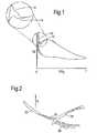
- Figure 1is a graph of surface pressure coefficient c p against fraction of suction surface length s/s 0 , showing a comparison between the spikes produced in use by two known designs of leading edge. Considering the upper pair of curves, these show the spike 12 produced by a circular leading edge and the spike 14 produced by an elliptical leading edge. It will be observed that although the elliptical leading edge produces a smaller spike than the circular leading edge, there is still a significant spike (and therefore a significant risk that premature boundary layer transition will be initiated).
- the leading edgeshould operate efficiently over a range of incidence angles.
- the incidence angle of the gas impinging on the blade leading edge(the "local incidence") is affected by two principal factors - the blade incidence and the wake incidence. Blade incidence varies between about zero and 3 degrees according to the blade's operating condition.
- Wake incidenceis a periodic disturbance to the local incidence.
- Figure 2shows a single rotor blade 22 and a single stator 24. As the rotor blade 22 rotates with speed U, the stator 24 will, in effect, pass through its wake 26. Within the wake, therefore, the local incidence is affected by the wake incidence (typically by about 18 degrees). Between the wakes 26 of succeeding rotor blades 22, the wake incidence has a reduced effect on the local incidence depending on the wake size and the distance from the wake.
- the blade incidencehas the greater influence on the local incidence. This is because the blade lift amplifies blade incidence by a factor of about 5 in the region of the leading edge, but has no effect on the wake incidence.
- leading edge spikesWith compressor blades, it is particularly difficult to avoid leading edge spikes in use. This is because structural integrity requirements limit the minimum allowable leading edge thickness. Also, the leading edge radii are typically small and therefore manufacturing defects and in-service erosion result in relatively large geometry variations. To ensure that all blades have no spike throughout engine life would therefore be practically very difficult and extremely costly. Thus, if these spikes exist in practice, their detrimental effect on loss must be quantifiable.
- leading edge designrely on prescribed geometry (e.g. ellipses), or point definition (which lacks control), and cannot produce leading edge designs that avoid spikes in use.
- Known methods of designdo not take full account of the relative importance of the region of the aerofoil nearest to the edge, in comparison to the regions further back, particularly when the edge is not designed to be circular (for example, when it is elliptical).
- the inventionprovides a method for defining the shape of an aerofoil, and the resulting aerofoil, as set out in the claims.
- the inventionprovides a leading edge shape for an aerofoil with a higher incidence range than known leading edge designs.
- the inventionprovides a method that combines the strengths of known alternatives, allowing both freedom and control. It provides leading edge designs that overcome, or at least greatly reduce, spikes in use. It has the further benefit that it can be implemented with existing design tools and manufacturing methods.
- the idealised leading edgeis one that achieves minimum design incidence loss while maximising operating incidence range; two design objectives which are often considered as opposed. However, these two design objectives can be achieved if the leading edge spike is removed at both design and high incidence.
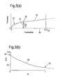
- Figure 3 (a)shows the leading edge profile 32 of a compressor rotor aerofoil with a known elliptical leading edge 33, having a 3:1 semi-axis ratio.
- the leading edge thickness 34, t LEis defined as the thickness of the leading edge at the point 35 where the ellipse joins the blade surface.
- the camberline 36is a notional line running along the centre of the blade from the leading to the trailing edge. In this drawing it has been normalised to lie along the X-axis, and thus it appears to be a straight line; in a real blade it may not be a straight line.
- the curve 38characterises the geometry of the leading edge region.
- Point 40represents the point at which the leading edge reattaches to the blade surface, and point 42 defines the leading edge radius.
- the curve 38should be well defined and continuous.
- the function S( ⁇ )must therefore be modified. This can be achieved by dividing by a function that has the same qualities.
- the thickness distributionis divided by two functions, a parabolic function and a linear function.
- the transformed space, S'was parameterised using 10th order Bernstein polynomials.
- Thetais defined in the range between 0 and ⁇ /2.
- the optimised leading edge shapemay be generated, as shown in Figure 4(a) .
- the optimised leading edge shape 48is shown together with the original leading edge shape 50 for comparison.
- the optimised leading edgeis more slender than an ellipse, but it is still sufficiently robust for use in a gas turbine engine.
- Figure 5 (a)shows the loss loop 52 associated with the optimised leading edge.
- the corresponding loss loop for the original leading edgeis shown by the dashed line 54.
- Loss y pis plotted against incidence in degrees. It can be seen that the loss for the optimised leading edge remains low over a considerably wider range of incidence. The reason for this is that the spike is removed over a large incidence range, preventing premature transition at the leading edge.
- Figure 5(b)shows surface pressure c p against distance along the suction surface s/s 0 for a small value of incidence (about 0.5 degrees). In the enlarged portion of the graph it can be seen that there is no spike in surface pressure for the optimised leading edge 56 whereas the original leading edge displays a prominent spike 58.
- the inventionthus provides a method whereby by parameterising the leading edge surface profile, and modifying the resulting transformed space, an optimised leading edge profile can be defined with minimised leading edge pressure spike over the blade's operating range of incidence.
- Such leading edgestypically have no leading edge spike for incidences up to 4°. This so-called spikeless leading edge is a parabolic function.
- the leading edge shapeis optimised over a distance of 2.5t LE .
- a different multipliermay be appropriate; for example, where the Reynolds number of the flow is different or where the thickness-to-chord ratio of the aerofoil is different.
- the transformed spacewas parameterised using 10th order Bernstein polynomials, it will be appreciated that other polynomials may be used.
- the principles of the inventionmay, as outlined above, be applied equally to the trailing edge of an aerofoil.
- the inventionmay equally be applied to stator aerofoils as to rotor aerofoils.
- the inventionis also applicable to aerofoils in different types of machines, and could be applied to hydrofoils.
- a known elliptical leading edge profileis used as the starting point for the method according to the invention.
- any leading edge profileknown or notional, could be used as a starting point. If the starting profile is very far from the optimised shape for the flow conditions under consideration, it may be necessary to repeat the parameterisation and optimisation process, perhaps more than once, until the optimal leading edge profile is achieved.
- leading edge shapehas an effect on the downstream transition, but the degree of this effect depends upon design and operation.
- the new leading edge shapereduces the (audio) noise generated by the aerofoil. This is of particular benefit in unducted or undamped systems.
- insensitivity to inlet angle, and the ability to apply the principles of this invention also to the trailing edge of an aerofoil,is of great benefit in bi-directional turbines or compressors (e.g. Wells turbine, reciprocating column turbine). It may likewise be employed in other components, such as the cooling fins of bi-directional equipment such as a motor / generator or hybrid drive set, where the reduction in noise is advantageous and the increase in efficiency allows the equipment to be contained in a smaller space envelope.
- the methodcould be applied to turbine aerofoils, including steam turbines.
- the featuresare particularly useful for high mach number turbines.
- This methodcould be applied to optimise any aerofoil shape, or part aerofoil shape (for example, splitters, struts, fairings, pylons, nacelles, centrifugal or axial compressors or turbines, hollow axis turbines, windmills, wind turbines, propeller blades (ships), water jets, propulsors) running in fluids or gases.
- the featuresare of particular use where shocks or gusts are encountered by the aerofoils, such as wind turbines (especially those within the built environment), Wells turbines, bi-directional turbines, and open rotors or propellers.
Landscapes
- Engineering & Computer Science (AREA)
- Mechanical Engineering (AREA)
- General Engineering & Computer Science (AREA)
- Physics & Mathematics (AREA)
- Aviation & Aerospace Engineering (AREA)
- Fluid Mechanics (AREA)
- Life Sciences & Earth Sciences (AREA)
- Sustainable Development (AREA)
- Sustainable Energy (AREA)
- Chemical & Material Sciences (AREA)
- Combustion & Propulsion (AREA)
- Geometry (AREA)
- Structures Of Non-Positive Displacement Pumps (AREA)
- Turbine Rotor Nozzle Sealing (AREA)
Description
- This invention relates to aerofoil design, and more particularly to methods for optimising the shape of leading and trailing edges of aerofoils.
- Known methods for designing entire aerofoils include those disclosed in
US2003/0194327A1 andEP704602A2 - In this specification, for conciseness and clarity, the invention and the background to it will be described principally with reference to the leading edges of aerofoils (and, specifically, to the leading edge of a compressor aerofoil in a gas turbine engine). As will be explained, however, the principles of the invention are applicable equally to the trailing edge as to the leading edge. Furthermore, the principles of the invention may equally well be applied to other types of aerofoils, or to hydrofoils, and will deliver substantially the same benefits and advantages as in the specific embodiment described. It should be understood, therefore, that references in the following description to terms such as "aerofoil" and "leading edge" are not intended to limit the scope of the invention.
- The leading edge of a turbomachinery aerofoil is known to have a significant effect on the loss, efficiency and operating range of the aerofoil.
- Many approaches to leading edge design have been tried in the past, including circular, closed curve fit, elliptical, free-form and component centre line.
- All of these leading edge designs have certain characteristic disadvantages. For example: circular are robust but inflexible, and cause losses due to high curvature changes; closed curve fit tends to remove too much material and 'snub' the leading edge; elliptical are more difficult to implement, and lack subtle control and flexibility; free-form are difficult to control and systemise; component centre line with tangential fit rely on symmetrical profiles based on circles.
- Where there are large changes in surface curvature on an aerofoil, as tends to occur near to the leading edge, small local overspeeds (sometimes called spikes) occur in use in the surface pressure distribution. Such leading edge spikes can affect blade loss if they initiate premature boundary layer transition. Large spikes will result in separated flow transition while smaller spikes may result in attached flow transition. If early transition is initiated the profile loss will rise due to an increase in turbulent wetted area and an additional mixing loss associated with the separation bubble, should one exist. Thus for a leading edge to be considered "good", the spike must be absent, or at least small enough to prevent transition.
Figure 1 is a graph of surface pressure coefficient cp against fraction of suction surface length s/s0, showing a comparison between the spikes produced in use by two known designs of leading edge. Considering the upper pair of curves, these show thespike 12 produced by a circular leading edge and thespike 14 produced by an elliptical leading edge. It will be observed that although the elliptical leading edge produces a smaller spike than the circular leading edge, there is still a significant spike (and therefore a significant risk that premature boundary layer transition will be initiated).- It is also necessary that the leading edge should operate efficiently over a range of incidence angles. The incidence angle of the gas impinging on the blade leading edge (the "local incidence") is affected by two principal factors - the blade incidence and the wake incidence. Blade incidence varies between about zero and 3 degrees according to the blade's operating condition.
- Wake incidence is a periodic disturbance to the local incidence.
Figure 2 shows asingle rotor blade 22 and asingle stator 24. As therotor blade 22 rotates with speed U, thestator 24 will, in effect, pass through itswake 26. Within the wake, therefore, the local incidence is affected by the wake incidence (typically by about 18 degrees). Between thewakes 26 of succeedingrotor blades 22, the wake incidence has a reduced effect on the local incidence depending on the wake size and the distance from the wake. - Although the variation in wake incidence is greater than the variation in blade incidence, the blade incidence has the greater influence on the local incidence. This is because the blade lift amplifies blade incidence by a factor of about 5 in the region of the leading edge, but has no effect on the wake incidence.
- In general, increased local incidence increases spike height. This makes the leading edge more susceptible to transition, with an increase in the turbulent wetted area and a consequent increase in losses.
- With compressor blades, it is particularly difficult to avoid leading edge spikes in use. This is because structural integrity requirements limit the minimum allowable leading edge thickness. Also, the leading edge radii are typically small and therefore manufacturing defects and in-service erosion result in relatively large geometry variations. To ensure that all blades have no spike throughout engine life would therefore be practically very difficult and extremely costly. Thus, if these spikes exist in practice, their detrimental effect on loss must be quantifiable.
- Known methods of leading edge design rely on prescribed geometry (e.g. ellipses), or point definition (which lacks control), and cannot produce leading edge designs that avoid spikes in use. Known methods of design do not take full account of the relative importance of the region of the aerofoil nearest to the edge, in comparison to the regions further back, particularly when the edge is not designed to be circular (for example, when it is elliptical).
- The invention provides a method for defining the shape of an aerofoil, and the resulting aerofoil, as set out in the claims. The invention provides a leading edge shape for an aerofoil with a higher incidence range than known leading edge designs.
- The invention provides a method that combines the strengths of known alternatives, allowing both freedom and control. It provides leading edge designs that overcome, or at least greatly reduce, spikes in use. It has the further benefit that it can be implemented with existing design tools and manufacturing methods.
- An embodiment of the invention will now be described, by way of example, with reference to the following drawings:
Figure 3 is a schematic illustration of an initial leading edge profile, and a graph showing its parameterisation;Figure 4 is a schematic illustration of an optimised leading edge profile and its corresponding parameterisation; andFigure 5 is a comparison of the spiking associated with the initial and final profiles, for two values of local incidence.- The idealised leading edge is one that achieves minimum design incidence loss while maximising operating incidence range; two design objectives which are often considered as opposed. However, these two design objectives can be achieved if the leading edge spike is removed at both design and high incidence.
Figure 3 (a) shows the leadingedge profile 32 of a compressor rotor aerofoil with a known elliptical leadingedge 33, having a 3:1 semi-axis ratio. The leadingedge thickness 34, tLE, is defined as the thickness of the leading edge at thepoint 35 where the ellipse joins the blade surface. Thecamberline 36 is a notional line running along the centre of the blade from the leading to the trailing edge. In this drawing it has been normalised to lie along the X-axis, and thus it appears to be a straight line; in a real blade it may not be a straight line.- In this example, only that part of the blade profile nearest to the leading edge is to be optimised; specifically, the region within 2.5tLE of the leading edge, as shown in
Figure 3(a) . - The leading edge thickness, as shown in
Figure 3(a) , is first transformed into a new space by normalising both the camberline and the thickness by the value 2.5tLE.Figure 3(b) shows the result of this transformation, in which
- The
curve 38 characterises the geometry of the leading edge region.Point 40 represents the point at which the leading edge reattaches to the blade surface, andpoint 42 defines the leading edge radius. - In order to optimise the leading edge design, the
curve 38 should be well defined and continuous. In particular, the infinite gradient at (ψ = 0) should be removed, as well as the high curvature over the front of the leading edge. - The function S(ψ) must therefore be modified. This can be achieved by dividing by a function that has the same qualities. The thickness distribution is divided by two functions, a parabolic function and a linear function. The parabolic dominates close to the leading edge (i.e. close to ψ=0), removing the high curvature and the infinite gradient. The linear function ensures that where the leading edge joins the surface of the blade, at ψ = 1, the function remains smooth. In the numerator a linear function is removed from the leading edge. This ensures the function does not go to infinity at ψ = 1. The equation therefore becomes


- The transformed space, S', was parameterised using 10th order Bernstein polynomials. The clustering of the polynomials was increased close to the leading edge point for increased resolution in this area. This was achieved by mapping the polynomials onto a circular arc: (ψ = 1 - cos(θ)). Theta is defined in the range between 0 and π/2. The equation for the Bernstein polynomials as a function of θ is

- The design space is spanned by changing the magnitude of the (r+1) parameters, ci (i = 0:r).
- The result of the optimisation is to produce a function that is almost linear in the transformed space.
Figure 4(b) shows the optimised function S' (44) together with the original function S (46) for comparison. - By reversing the parameterisation described above, the optimised leading edge shape may be generated, as shown in
Figure 4(a) . The optimisedleading edge shape 48 is shown together with the originalleading edge shape 50 for comparison. The optimised leading edge is more slender than an ellipse, but it is still sufficiently robust for use in a gas turbine engine. Figure 5 (a) shows theloss loop 52 associated with the optimised leading edge. The corresponding loss loop for the original leading edge is shown by the dashedline 54. Loss yp is plotted against incidence in degrees. It can be seen that the loss for the optimised leading edge remains low over a considerably wider range of incidence. The reason for this is that the spike is removed over a large incidence range, preventing premature transition at the leading edge.Figure 5(b) shows surface pressure cp against distance along the suction surface s/s0 for a small value of incidence (about 0.5 degrees). In the enlarged portion of the graph it can be seen that there is no spike in surface pressure for the optimised leadingedge 56 whereas the original leading edge displays aprominent spike 58. At the highest operating incidence of the blade the spike is only just beginning to appear. This can be seen inFigure 5(c) , for an incidence of about 3 degrees. The originalleading edge 60 still shows a distinct spike, whereas the optimised leadingedge 62 shows only a very slight overshoot in surface pressure. The increase in usable incidence range for the blade with the optimised leading edge is around 3°.- The invention thus provides a method whereby by parameterising the leading edge surface profile, and modifying the resulting transformed space, an optimised leading edge profile can be defined with minimised leading edge pressure spike over the blade's operating range of incidence. Such leading edges typically have no leading edge spike for incidences up to 4°. This so-called spikeless leading edge is a parabolic function.
- In the described embodiment, the leading edge shape is optimised over a distance of 2.5tLE. In other embodiments of the invention, a different multiplier may be appropriate; for example, where the Reynolds number of the flow is different or where the thickness-to-chord ratio of the aerofoil is different.
- Although, in the described embodiment, the transformed space was parameterised using 10th order Bernstein polynomials, it will be appreciated that other polynomials may be used.
- Although the described embodiment relates to a leading edge for a compressor aerofoil, the principles of the invention may, as outlined above, be applied equally to the trailing edge of an aerofoil. The invention may equally be applied to stator aerofoils as to rotor aerofoils. The invention is also applicable to aerofoils in different types of machines, and could be applied to hydrofoils.
- In the described embodiment, a known elliptical leading edge profile is used as the starting point for the method according to the invention. In fact, any leading edge profile, known or notional, could be used as a starting point. If the starting profile is very far from the optimised shape for the flow conditions under consideration, it may be necessary to repeat the parameterisation and optimisation process, perhaps more than once, until the optimal leading edge profile is achieved.
- Testing has also demonstrated that the leading edge shape has an effect on the downstream transition, but the degree of this effect depends upon design and operation.
- The new leading edge shape reduces the (audio) noise generated by the aerofoil. This is of particular benefit in unducted or undamped systems.
- The insensitivity to inlet angle, and the ability to apply the principles of this invention also to the trailing edge of an aerofoil, is of great benefit in bi-directional turbines or compressors (e.g. Wells turbine, reciprocating column turbine). It may likewise be employed in other components, such as the cooling fins of bi-directional equipment such as a motor / generator or hybrid drive set, where the reduction in noise is advantageous and the increase in efficiency allows the equipment to be contained in a smaller space envelope.
- The method could be applied to turbine aerofoils, including steam turbines. The features are particularly useful for high mach number turbines.
- This method could be applied to optimise any aerofoil shape, or part aerofoil shape (for example, splitters, struts, fairings, pylons, nacelles, centrifugal or axial compressors or turbines, hollow axis turbines, windmills, wind turbines, propeller blades (ships), water jets, propulsors) running in fluids or gases. The features are of particular use where shocks or gusts are encountered by the aerofoils, such as wind turbines (especially those within the built environment), Wells turbines, bi-directional turbines, and open rotors or propellers.


Claims (7)
- A method for defining the shape of a leading or trailing edge (33) of an aerofoil,characterised in that the method comprises the following steps:obtaining a starting value for the thickness (34) of the selected edge;defining a distance from the selected edge in terms of the thickness;over the defined distance, defining a space S in terms of normalised camberline and normalised thickness, where camberline and thickness are normalised with respect to the leading edge thickness;transforming the space S to a new space S';parameterising the new space S' to obtain new values for normalised camberline and normalised thickness;defining a new shape (48) for the selected edge using the new parameter values.
- A method as claimed in claim 1, in which the transforming step comprises applying a parabolic function to the space S.
- A method as claimed in claim 1, in which the transforming step comprises applying a function of the form


- A method as claimed in claim 3, in which the value of K is 2.5.
- A method as claimed in any preceding claim, in which the space S' is parameterised using 10th order Bernstein polynomials.
- A method as claimed in any preceding claim, in which the aerofoil is a compressor blade for a gas turbine engine.
- A method as claimed in any preceding claim, in which the aerofoil is a compressor stator for a gas turbine engine.


Applications Claiming Priority (2)
| Application Number | Priority Date | Filing Date | Title |
|---|---|---|---|
| GBGB0821429.8AGB0821429D0 (en) | 2008-11-24 | 2008-11-24 | A method for optimising the shape of an aerofoil |
| PCT/EP2009/008216WO2010057627A1 (en) | 2008-11-24 | 2009-11-18 | Method for optimising the shape of an aerofoil and corresponding aerofoil |
Publications (2)
| Publication Number | Publication Date |
|---|---|
| EP2350439A1 EP2350439A1 (en) | 2011-08-03 |
| EP2350439B1true EP2350439B1 (en) | 2015-08-26 |
Family
ID=40230723
Family Applications (1)
| Application Number | Title | Priority Date | Filing Date |
|---|---|---|---|
| EP09756146.8ANot-in-forceEP2350439B1 (en) | 2008-11-24 | 2009-11-18 | Method for optimising the shape of an aerofoil and corresponding aerofoil |
Country Status (7)
| Country | Link |
|---|---|
| US (1) | US20110202321A1 (en) |
| EP (1) | EP2350439B1 (en) |
| JP (1) | JP5530453B2 (en) |
| GB (1) | GB0821429D0 (en) |
| IL (1) | IL212595A (en) |
| SG (1) | SG10201400168TA (en) |
| WO (1) | WO2010057627A1 (en) |
Families Citing this family (18)
| Publication number | Priority date | Publication date | Assignee | Title |
|---|---|---|---|---|
| US20110117926A1 (en)* | 2009-11-17 | 2011-05-19 | Mediatek Inc. | Network-based positioning mechanism and reference signal design in OFDMA systems |
| US9309769B2 (en)* | 2010-12-28 | 2016-04-12 | Rolls-Royce Corporation | Gas turbine engine airfoil shaped component |
| GB201119531D0 (en) | 2011-11-14 | 2011-12-21 | Rolls Royce Plc | Aerofoils |
| US9102397B2 (en) | 2011-12-20 | 2015-08-11 | General Electric Company | Airfoils including tip profile for noise reduction and method for fabricating same |
| CN104696158B (en)* | 2014-08-20 | 2018-08-03 | 深圳市深田蒙业新能源有限公司 | A kind of vertical axis aerogenerator group lift-type vane airfoil profile |
| CN104401504B (en)* | 2014-11-19 | 2016-01-06 | 中国地质大学(武汉) | A kind of fixed-wing aerial survey type unmanned aerial vehicle design method |
| EP3088663A1 (en)* | 2015-04-28 | 2016-11-02 | Siemens Aktiengesellschaft | Method for profiling a blade |
| EP3239460A1 (en)* | 2016-04-27 | 2017-11-01 | Siemens Aktiengesellschaft | Method for profiling blades of an axial turbo machine |
| CN106089569A (en)* | 2016-07-20 | 2016-11-09 | 湘潭大学 | A kind of Miniature Wind Turbine Blades aerofoil profile being applicable to low reynolds number flow |
| US10823055B2 (en) | 2016-08-08 | 2020-11-03 | Pratt & Whitney Canada Corp. | Bypass duct louver for noise mitigation |
| CN106227978B (en)* | 2016-08-12 | 2019-04-12 | 北京航空航天大学 | Compressor blade suction surface primitive curve modeling method based on second order ordinary differential equation |
| WO2018193656A1 (en) | 2017-04-17 | 2018-10-25 | 株式会社Ihi | Method for designing blade of axial-flow fluid machine and blade |
| EP3850192B1 (en)* | 2018-09-12 | 2023-12-27 | General Electric Technology GmbH | Hybrid elliptical-circular trailing edge for a turbine airfoil |
| US11480073B2 (en)* | 2020-11-24 | 2022-10-25 | Rolls-Royce Plc | Gas turbine engine nacelle and method of designing same |
| US12385399B2 (en) | 2022-08-09 | 2025-08-12 | Rtx Corporation | Fan blade or vane with improved bird impact capability |
| US12366167B2 (en) | 2022-08-09 | 2025-07-22 | Rtx Corporation | Fan blade or vane with improved bird impact capability |
| US11952912B2 (en) | 2022-08-24 | 2024-04-09 | General Electric Company | Turbine engine airfoil |
| US12305537B2 (en)* | 2023-08-04 | 2025-05-20 | General Electric Company | Vane assembly for open fan engine |
Family Cites Families (9)
| Publication number | Priority date | Publication date | Assignee | Title |
|---|---|---|---|---|
| US4813631A (en)* | 1982-09-13 | 1989-03-21 | The Boeing Company | Laminar flow control airfoil |
| GB9417406D0 (en)* | 1994-08-30 | 1994-10-19 | Gec Alsthom Ltd | Turbine blade |
| JPH09256998A (en)* | 1996-03-25 | 1997-09-30 | Senshin Zairyo Riyou Gas Jienereeta Kenkyusho:Kk | Compressor wings |
| US6856941B2 (en)* | 1998-07-20 | 2005-02-15 | Minebea Co., Ltd. | Impeller blade for axial flow fan having counter-rotating impellers |
| JP2000297789A (en)* | 1999-04-14 | 2000-10-24 | Tokyo Electric Power Co Inc:The | Axial compressor |
| EP1435432B1 (en)* | 2001-10-10 | 2016-05-18 | Mitsubishi Hitachi Power Systems, Ltd. | Turbine blade |
| US6709232B1 (en)* | 2002-09-05 | 2004-03-23 | Honeywell International Inc. | Cambered vane for use in turbochargers |
| US7497663B2 (en)* | 2006-10-26 | 2009-03-03 | General Electric Company | Rotor blade profile optimization |
| US20080118362A1 (en)* | 2006-11-16 | 2008-05-22 | Siemens Power Generation, Inc. | Transonic compressor rotors with non-monotonic meanline angle distributions |
- 2008
- 2008-11-24GBGBGB0821429.8Apatent/GB0821429D0/ennot_activeCeased
- 2009
- 2009-11-18WOPCT/EP2009/008216patent/WO2010057627A1/enactiveApplication Filing
- 2009-11-18EPEP09756146.8Apatent/EP2350439B1/ennot_activeNot-in-force
- 2009-11-18JPJP2011536771Apatent/JP5530453B2/ennot_activeExpired - Fee Related
- 2009-11-18SGSG10201400168TApatent/SG10201400168TA/enunknown
- 2009-11-18USUS13/125,410patent/US20110202321A1/ennot_activeAbandoned
- 2011
- 2011-05-01ILIL212595Apatent/IL212595A/enactiveIP Right Grant
Also Published As
| Publication number | Publication date |
|---|---|
| JP2012510018A (en) | 2012-04-26 |
| IL212595A0 (en) | 2011-07-31 |
| US20110202321A1 (en) | 2011-08-18 |
| GB0821429D0 (en) | 2008-12-31 |
| SG10201400168TA (en) | 2014-04-28 |
| WO2010057627A1 (en) | 2010-05-27 |
| IL212595A (en) | 2016-04-21 |
| JP5530453B2 (en) | 2014-06-25 |
| EP2350439A1 (en) | 2011-08-03 |
Similar Documents
| Publication | Publication Date | Title |
|---|---|---|
| EP2350439B1 (en) | Method for optimising the shape of an aerofoil and corresponding aerofoil | |
| US8814525B2 (en) | Profile of a rotor blade and rotor blade of a wind power plant | |
| CA2697121C (en) | Intentionally mistuned integrally bladed rotor | |
| EP3121376B1 (en) | Aerofoil | |
| EP1798377B1 (en) | Airfoil embodying mixed loading conventions | |
| EP3613995B1 (en) | Method for designing blade of axial-flow fluid machine and blade | |
| US8393872B2 (en) | Turbine airfoil | |
| EP2631474A1 (en) | Wind turbine, wind power generation device provided therewith, and wind turbine design method | |
| EP3653513B1 (en) | Boundary layer ingestion fan system | |
| Korakianitis et al. | Surface-curvature-distribution effects on turbine-cascade performance | |
| EP2441964B1 (en) | Airfoil design method for an axial compressor and axial compressor | |
| EP3379029B1 (en) | Fan rotor with flow induced resonance control | |
| EP2957766A1 (en) | Pressure side stall strip for wind turbine blade | |
| US20020085918A1 (en) | Turbine blade airfoil, turbine blade and turbine blade cascade for axial-flow turbine | |
| Ji et al. | Numerical studies on improving performance of rotor-67 by blended blade and endwall technique | |
| Zhang et al. | A parametric study of the effects of inlet distortion on fan aerodynamic stability | |
| Senoo et al. | Development of design method for supersonic turbine aerofoils near the tip of long blades in steam turbines: part 2—configuration details and validation | |
| Eckel et al. | Numerical investigation of the aerodynamic performance of hybrid aerofoils in a 1.5-stage low-speed compressor | |
| EP3653508B1 (en) | Boundary layer ingestion fan system | |
| EP2592227B1 (en) | Aerofoils | |
| Wang et al. | Study of shock wave control by suction & blowing on a highly-loaded transonic compressor cascade | |
| EP3653509B1 (en) | Boundary layer ingestion fan system | |
| EP3653507B1 (en) | Boundary layer ingestion fan system | |
| US20240125241A1 (en) | Axial compressor stator | |
| EP3653510A1 (en) | Boundary layer ingestion fan system |
Legal Events
| Date | Code | Title | Description |
|---|---|---|---|
| PUAI | Public reference made under article 153(3) epc to a published international application that has entered the european phase | Free format text:ORIGINAL CODE: 0009012 | |
| 17P | Request for examination filed | Effective date:20110420 | |
| AK | Designated contracting states | Kind code of ref document:A1 Designated state(s):AT BE BG CH CY CZ DE DK EE ES FI FR GB GR HR HU IE IS IT LI LT LU LV MC MK MT NL NO PL PT RO SE SI SK SM TR | |
| DAX | Request for extension of the european patent (deleted) | ||
| 17Q | First examination report despatched | Effective date:20140801 | |
| REG | Reference to a national code | Ref country code:DE Ref legal event code:R079 Ref document number:602009033198 Country of ref document:DE Free format text:PREVIOUS MAIN CLASS: F01D0005140000 Ipc:F04D0029320000 | |
| GRAP | Despatch of communication of intention to grant a patent | Free format text:ORIGINAL CODE: EPIDOSNIGR1 | |
| GRAS | Grant fee paid | Free format text:ORIGINAL CODE: EPIDOSNIGR3 | |
| RIC1 | Information provided on ipc code assigned before grant | Ipc:F01D 9/04 20060101ALI20150615BHEP Ipc:B64C 3/14 20060101ALI20150615BHEP Ipc:F04D 29/32 20060101AFI20150615BHEP Ipc:F04D 27/00 20060101ALI20150615BHEP Ipc:F01D 5/14 20060101ALI20150615BHEP Ipc:F03D 1/06 20060101ALI20150615BHEP | |
| GRAA | (expected) grant | Free format text:ORIGINAL CODE: 0009210 | |
| INTG | Intention to grant announced | Effective date:20150630 | |
| RAP1 | Party data changed (applicant data changed or rights of an application transferred) | Owner name:ROLLS-ROYCE PLC | |
| AK | Designated contracting states | Kind code of ref document:B1 Designated state(s):AT BE BG CH CY CZ DE DK EE ES FI FR GB GR HR HU IE IS IT LI LT LU LV MC MK MT NL NO PL PT RO SE SI SK SM TR | |
| REG | Reference to a national code | Ref country code:GB Ref legal event code:FG4D | |
| REG | Reference to a national code | Ref country code:CH Ref legal event code:EP | |
| REG | Reference to a national code | Ref country code:AT Ref legal event code:REF Ref document number:745342 Country of ref document:AT Kind code of ref document:T Effective date:20150915 | |
| REG | Reference to a national code | Ref country code:IE Ref legal event code:FG4D | |
| REG | Reference to a national code | Ref country code:DE Ref legal event code:R096 Ref document number:602009033198 Country of ref document:DE | |
| REG | Reference to a national code | Ref country code:FR Ref legal event code:PLFP Year of fee payment:7 | |
| REG | Reference to a national code | Ref country code:AT Ref legal event code:MK05 Ref document number:745342 Country of ref document:AT Kind code of ref document:T Effective date:20150826 | |
| REG | Reference to a national code | Ref country code:LT Ref legal event code:MG4D | |
| PG25 | Lapsed in a contracting state [announced via postgrant information from national office to epo] | Ref country code:FI Free format text:LAPSE BECAUSE OF FAILURE TO SUBMIT A TRANSLATION OF THE DESCRIPTION OR TO PAY THE FEE WITHIN THE PRESCRIBED TIME-LIMIT Effective date:20150826 Ref country code:GR Free format text:LAPSE BECAUSE OF FAILURE TO SUBMIT A TRANSLATION OF THE DESCRIPTION OR TO PAY THE FEE WITHIN THE PRESCRIBED TIME-LIMIT Effective date:20151127 Ref country code:NO Free format text:LAPSE BECAUSE OF FAILURE TO SUBMIT A TRANSLATION OF THE DESCRIPTION OR TO PAY THE FEE WITHIN THE PRESCRIBED TIME-LIMIT Effective date:20151126 Ref country code:LV Free format text:LAPSE BECAUSE OF FAILURE TO SUBMIT A TRANSLATION OF THE DESCRIPTION OR TO PAY THE FEE WITHIN THE PRESCRIBED TIME-LIMIT Effective date:20150826 Ref country code:LT Free format text:LAPSE BECAUSE OF FAILURE TO SUBMIT A TRANSLATION OF THE DESCRIPTION OR TO PAY THE FEE WITHIN THE PRESCRIBED TIME-LIMIT Effective date:20150826 | |
| REG | Reference to a national code | Ref country code:NL Ref legal event code:MP Effective date:20150826 | |
| PG25 | Lapsed in a contracting state [announced via postgrant information from national office to epo] | Ref country code:ES Free format text:LAPSE BECAUSE OF FAILURE TO SUBMIT A TRANSLATION OF THE DESCRIPTION OR TO PAY THE FEE WITHIN THE PRESCRIBED TIME-LIMIT Effective date:20150826 Ref country code:PT Free format text:LAPSE BECAUSE OF FAILURE TO SUBMIT A TRANSLATION OF THE DESCRIPTION OR TO PAY THE FEE WITHIN THE PRESCRIBED TIME-LIMIT Effective date:20151228 Ref country code:IS Free format text:LAPSE BECAUSE OF FAILURE TO SUBMIT A TRANSLATION OF THE DESCRIPTION OR TO PAY THE FEE WITHIN THE PRESCRIBED TIME-LIMIT Effective date:20151226 Ref country code:HR Free format text:LAPSE BECAUSE OF FAILURE TO SUBMIT A TRANSLATION OF THE DESCRIPTION OR TO PAY THE FEE WITHIN THE PRESCRIBED TIME-LIMIT Effective date:20150826 Ref country code:PL Free format text:LAPSE BECAUSE OF FAILURE TO SUBMIT A TRANSLATION OF THE DESCRIPTION OR TO PAY THE FEE WITHIN THE PRESCRIBED TIME-LIMIT Effective date:20150826 Ref country code:SE Free format text:LAPSE BECAUSE OF FAILURE TO SUBMIT A TRANSLATION OF THE DESCRIPTION OR TO PAY THE FEE WITHIN THE PRESCRIBED TIME-LIMIT Effective date:20150826 Ref country code:AT Free format text:LAPSE BECAUSE OF FAILURE TO SUBMIT A TRANSLATION OF THE DESCRIPTION OR TO PAY THE FEE WITHIN THE PRESCRIBED TIME-LIMIT Effective date:20150826 | |
| PG25 | Lapsed in a contracting state [announced via postgrant information from national office to epo] | Ref country code:NL Free format text:LAPSE BECAUSE OF FAILURE TO SUBMIT A TRANSLATION OF THE DESCRIPTION OR TO PAY THE FEE WITHIN THE PRESCRIBED TIME-LIMIT Effective date:20150826 | |
| PG25 | Lapsed in a contracting state [announced via postgrant information from national office to epo] | Ref country code:DK Free format text:LAPSE BECAUSE OF FAILURE TO SUBMIT A TRANSLATION OF THE DESCRIPTION OR TO PAY THE FEE WITHIN THE PRESCRIBED TIME-LIMIT Effective date:20150826 Ref country code:IT Free format text:LAPSE BECAUSE OF FAILURE TO SUBMIT A TRANSLATION OF THE DESCRIPTION OR TO PAY THE FEE WITHIN THE PRESCRIBED TIME-LIMIT Effective date:20150826 Ref country code:EE Free format text:LAPSE BECAUSE OF FAILURE TO SUBMIT A TRANSLATION OF THE DESCRIPTION OR TO PAY THE FEE WITHIN THE PRESCRIBED TIME-LIMIT Effective date:20150826 Ref country code:SK Free format text:LAPSE BECAUSE OF FAILURE TO SUBMIT A TRANSLATION OF THE DESCRIPTION OR TO PAY THE FEE WITHIN THE PRESCRIBED TIME-LIMIT Effective date:20150826 Ref country code:CZ Free format text:LAPSE BECAUSE OF FAILURE TO SUBMIT A TRANSLATION OF THE DESCRIPTION OR TO PAY THE FEE WITHIN THE PRESCRIBED TIME-LIMIT Effective date:20150826 | |
| REG | Reference to a national code | Ref country code:DE Ref legal event code:R082 Ref document number:602009033198 Country of ref document:DE Representative=s name:HERNANDEZ, YORCK, DIPL.-ING., DE | |
| REG | Reference to a national code | Ref country code:DE Ref legal event code:R097 Ref document number:602009033198 Country of ref document:DE | |
| PG25 | Lapsed in a contracting state [announced via postgrant information from national office to epo] | Ref country code:RO Free format text:LAPSE BECAUSE OF FAILURE TO SUBMIT A TRANSLATION OF THE DESCRIPTION OR TO PAY THE FEE WITHIN THE PRESCRIBED TIME-LIMIT Effective date:20150826 | |
| PG25 | Lapsed in a contracting state [announced via postgrant information from national office to epo] | Ref country code:LU Free format text:LAPSE BECAUSE OF FAILURE TO SUBMIT A TRANSLATION OF THE DESCRIPTION OR TO PAY THE FEE WITHIN THE PRESCRIBED TIME-LIMIT Effective date:20151118 Ref country code:MC Free format text:LAPSE BECAUSE OF FAILURE TO SUBMIT A TRANSLATION OF THE DESCRIPTION OR TO PAY THE FEE WITHIN THE PRESCRIBED TIME-LIMIT Effective date:20150826 | |
| REG | Reference to a national code | Ref country code:CH Ref legal event code:PL | |
| PLBE | No opposition filed within time limit | Free format text:ORIGINAL CODE: 0009261 | |
| STAA | Information on the status of an ep patent application or granted ep patent | Free format text:STATUS: NO OPPOSITION FILED WITHIN TIME LIMIT | |
| PG25 | Lapsed in a contracting state [announced via postgrant information from national office to epo] | Ref country code:CH Free format text:LAPSE BECAUSE OF NON-PAYMENT OF DUE FEES Effective date:20151130 Ref country code:LI Free format text:LAPSE BECAUSE OF NON-PAYMENT OF DUE FEES Effective date:20151130 | |
| 26N | No opposition filed | Effective date:20160530 | |
| REG | Reference to a national code | Ref country code:IE Ref legal event code:MM4A | |
| PG25 | Lapsed in a contracting state [announced via postgrant information from national office to epo] | Ref country code:SI Free format text:LAPSE BECAUSE OF FAILURE TO SUBMIT A TRANSLATION OF THE DESCRIPTION OR TO PAY THE FEE WITHIN THE PRESCRIBED TIME-LIMIT Effective date:20150826 | |
| PG25 | Lapsed in a contracting state [announced via postgrant information from national office to epo] | Ref country code:IE Free format text:LAPSE BECAUSE OF NON-PAYMENT OF DUE FEES Effective date:20151118 | |
| REG | Reference to a national code | Ref country code:FR Ref legal event code:PLFP Year of fee payment:8 | |
| PG25 | Lapsed in a contracting state [announced via postgrant information from national office to epo] | Ref country code:BE Free format text:LAPSE BECAUSE OF FAILURE TO SUBMIT A TRANSLATION OF THE DESCRIPTION OR TO PAY THE FEE WITHIN THE PRESCRIBED TIME-LIMIT Effective date:20150826 | |
| PG25 | Lapsed in a contracting state [announced via postgrant information from national office to epo] | Ref country code:SM Free format text:LAPSE BECAUSE OF FAILURE TO SUBMIT A TRANSLATION OF THE DESCRIPTION OR TO PAY THE FEE WITHIN THE PRESCRIBED TIME-LIMIT Effective date:20150826 Ref country code:HU Free format text:LAPSE BECAUSE OF FAILURE TO SUBMIT A TRANSLATION OF THE DESCRIPTION OR TO PAY THE FEE WITHIN THE PRESCRIBED TIME-LIMIT; INVALID AB INITIO Effective date:20091118 Ref country code:BG Free format text:LAPSE BECAUSE OF FAILURE TO SUBMIT A TRANSLATION OF THE DESCRIPTION OR TO PAY THE FEE WITHIN THE PRESCRIBED TIME-LIMIT Effective date:20150826 | |
| PG25 | Lapsed in a contracting state [announced via postgrant information from national office to epo] | Ref country code:CY Free format text:LAPSE BECAUSE OF FAILURE TO SUBMIT A TRANSLATION OF THE DESCRIPTION OR TO PAY THE FEE WITHIN THE PRESCRIBED TIME-LIMIT Effective date:20150826 | |
| PG25 | Lapsed in a contracting state [announced via postgrant information from national office to epo] | Ref country code:MT Free format text:LAPSE BECAUSE OF FAILURE TO SUBMIT A TRANSLATION OF THE DESCRIPTION OR TO PAY THE FEE WITHIN THE PRESCRIBED TIME-LIMIT Effective date:20150826 Ref country code:TR Free format text:LAPSE BECAUSE OF FAILURE TO SUBMIT A TRANSLATION OF THE DESCRIPTION OR TO PAY THE FEE WITHIN THE PRESCRIBED TIME-LIMIT Effective date:20150826 | |
| REG | Reference to a national code | Ref country code:FR Ref legal event code:PLFP Year of fee payment:9 | |
| PG25 | Lapsed in a contracting state [announced via postgrant information from national office to epo] | Ref country code:MK Free format text:LAPSE BECAUSE OF FAILURE TO SUBMIT A TRANSLATION OF THE DESCRIPTION OR TO PAY THE FEE WITHIN THE PRESCRIBED TIME-LIMIT Effective date:20150826 | |
| PGFP | Annual fee paid to national office [announced via postgrant information from national office to epo] | Ref country code:GB Payment date:20201126 Year of fee payment:12 Ref country code:FR Payment date:20201126 Year of fee payment:12 | |
| PGFP | Annual fee paid to national office [announced via postgrant information from national office to epo] | Ref country code:DE Payment date:20210128 Year of fee payment:12 | |
| REG | Reference to a national code | Ref country code:DE Ref legal event code:R119 Ref document number:602009033198 Country of ref document:DE | |
| GBPC | Gb: european patent ceased through non-payment of renewal fee | Effective date:20211118 | |
| PG25 | Lapsed in a contracting state [announced via postgrant information from national office to epo] | Ref country code:GB Free format text:LAPSE BECAUSE OF NON-PAYMENT OF DUE FEES Effective date:20211118 Ref country code:DE Free format text:LAPSE BECAUSE OF NON-PAYMENT OF DUE FEES Effective date:20220601 | |
| PG25 | Lapsed in a contracting state [announced via postgrant information from national office to epo] | Ref country code:FR Free format text:LAPSE BECAUSE OF NON-PAYMENT OF DUE FEES Effective date:20211130 |