EP2349652B1 - Enhanced pneumatic tool actuation device - Google Patents
Enhanced pneumatic tool actuation deviceDownload PDFInfo
- Publication number
- EP2349652B1 EP2349652B1EP09825170.5AEP09825170AEP2349652B1EP 2349652 B1EP2349652 B1EP 2349652B1EP 09825170 AEP09825170 AEP 09825170AEP 2349652 B1EP2349652 B1EP 2349652B1
- Authority
- EP
- European Patent Office
- Prior art keywords
- pneumatic tool
- piston
- housing
- drive chamber
- air inlet
- Prior art date
- Legal status (The legal status is an assumption and is not a legal conclusion. Google has not performed a legal analysis and makes no representation as to the accuracy of the status listed.)
- Active
Links
- 229910001369BrassInorganic materials0.000claimsdescription4
- 239000010951brassSubstances0.000claimsdescription4
- XAGFODPZIPBFFR-UHFFFAOYSA-NaluminiumChemical compound[Al]XAGFODPZIPBFFR-UHFFFAOYSA-N0.000claimsdescription3
- 229910052782aluminiumInorganic materials0.000claimsdescription3
- 239000000463materialSubstances0.000description6
- 230000003252repetitive effectEffects0.000description5
- 230000004913activationEffects0.000description4
- 239000003562lightweight materialSubstances0.000description3
- 229910000831SteelInorganic materials0.000description2
- 230000003466anti-cipated effectEffects0.000description2
- 239000002131composite materialSubstances0.000description2
- 238000000034methodMethods0.000description2
- 239000004033plasticSubstances0.000description2
- 229920003023plasticPolymers0.000description2
- 239000010959steelSubstances0.000description2
- 238000010276constructionMethods0.000description1
- 230000000881depressing effectEffects0.000description1
Images


Classifications
- B—PERFORMING OPERATIONS; TRANSPORTING
- B25—HAND TOOLS; PORTABLE POWER-DRIVEN TOOLS; MANIPULATORS
- B25C—HAND-HELD NAILING OR STAPLING TOOLS; MANUALLY OPERATED PORTABLE STAPLING TOOLS
- B25C1/00—Hand-held nailing tools; Nail feeding devices
- B25C1/04—Hand-held nailing tools; Nail feeding devices operated by fluid pressure, e.g. by air pressure
- B25C1/047—Mechanical details
- B—PERFORMING OPERATIONS; TRANSPORTING
- B25—HAND TOOLS; PORTABLE POWER-DRIVEN TOOLS; MANIPULATORS
- B25C—HAND-HELD NAILING OR STAPLING TOOLS; MANUALLY OPERATED PORTABLE STAPLING TOOLS
- B25C7/00—Accessories for nailing or stapling tools, e.g. supports
Definitions
- Prior artincludes at least US-A1-2005/189127 and US-A-2,954,009 .
- the present inventionrelates to pneumatic tools. Specifically, the present invention is directed to a pneumatic tool actuation device.
- Pneumatic toolsare becoming increasingly common in many industries, including the construction industry.
- pneumatic toolsinclude pneumatic nailers, jackhammers, riveters, staplers, and the like.
- the operation of most pneumatically-operated toolsis relatively simple: compressed air flows through a tube into the housing of the pneumatic tool and the pressure of the compressed air is used to force movement of a piston or other mechanism in the tool to do work.
- a pneumatic tooltypically is activated by depressing a trigger to drive the nails, rivets, staples, or similar fasteners from the tool.
- actuation devicesare used to depress the trigger of the pneumatic tool. These actuation devices, though, can be large and involve complicated assembly. For example, known actuation devices use elaborate pulley systems; these devices, however, can be heavy and sometimes interfere with the use of the tool. In cases where the tool is relatively small, no comparably small automatic actuation devices are available.
- such an actuatoris made of a lightweight material and is able to withstand fast, repetitive use. More desirably, such an actuator is readily made and usable, and has a high degree of integrity at minimal cost.
- the present teachingpertains to an actuation device or actuator configured to depress a trigger on a pneumatically driven tool as illustrated in the figures.
- the actuatorcan be used on a pneumatic nailer as shown; however, it is also contemplated that the actuator can be used on other pneumatic tools and such uses should be considered to be within the scope of this invention.
- the actuatoris configured to depress a trigger on the pneumatic tool when the actuator is actuated, thereby actuating the pneumatic tool.
- the main body 13 of the housing 12has a triangular-shaped clearance cutout 40 formed on an outer surface of the actuator housing 12 to accommodate a follower N on a pneumatic nailer 50.
- Actuator attachment arms 22, 23are integral with the main body 13 of the actuator housing 12.
- the actuator arms 22, 23are spaced apart, allowing for the attachment arms 22, 23 to straddle the trigger housing 54 of the tool 50.
- the actuator 10is attached to the pneumatic tool 50 by pins 18, 19.
- the pins 18, 19attach the actuator housing 12 to the trigger housing 54 through pin holes 20, 21 in the actuator housing 12 and through the trigger housing holes 56, 57 on the tool 50.
- the pneumatic tool 50has pre-formed holes in the trigger housing 54 to accept pins 18.
- holesmay need to be formed in other pneumatic tools to attach the actuator 10 or that other attachment methods may be required depending on the design of the particular pneumatic tool.
- the airis released from hose 26, and the trigger 52, which is spring-loaded in most pneumatic tools, returns to its original position, forcing the piston 14 to retract and slidably move within the drive chamber 42 toward the housing 12 in preparation for the next actuation.
- a shuttle valvemay be used in conjunction with the compressor to control the flow of air to and from the actuator 10.
- an air inlet chamber 134is formed as a cylindrical bore extending partially through the main body 113 of the actuator housing 112, contiguous with and generally normal to the drive chamber 142, and is configured to accept and direct a pressurized gas to the drive chamber 142.
- the actuator 100is attached to the pneumatic tool 150 by pins 118, 119.
- the pins 118, 119attach the actuator housing 112 to the trigger housing 154 through fastener receiving openings or pin holes 120, 122 in the actuator housing 112 and through the trigger housing holes 156, 157.
- the pneumatic tool 150has pre-formed holes in the trigger housing 154 to accept pins 118.
- holesmay need to be formed in other pneumatic tools to attach the actuator 100 or that other attachment methods may be required depending on the design of the particular pneumatic tool.
- the actual trigger of the toolneed not be present.
- the trigger valve pinis directly actuated by the piston.
Landscapes
- Engineering & Computer Science (AREA)
- Mechanical Engineering (AREA)
- Physics & Mathematics (AREA)
- Fluid Mechanics (AREA)
- Portable Nailing Machines And Staplers (AREA)
Description
- Prior art includes at least
US-A1-2005/189127 andUS-A-2,954,009 . - The present invention relates to pneumatic tools. Specifically, the present invention is directed to a pneumatic tool actuation device.
- Pneumatic tools are becoming increasingly common in many industries, including the construction industry. Examples of pneumatic tools include pneumatic nailers, jackhammers, riveters, staplers, and the like. The operation of most pneumatically-operated tools is relatively simple: compressed air flows through a tube into the housing of the pneumatic tool and the pressure of the compressed air is used to force movement of a piston or other mechanism in the tool to do work.
- A pneumatic tool typically is activated by depressing a trigger to drive the nails, rivets, staples, or similar fasteners from the tool. In automated applications, actuation devices are used to depress the trigger of the pneumatic tool. These actuation devices, though, can be large and involve complicated assembly. For example, known actuation devices use elaborate pulley systems; these devices, however, can be heavy and sometimes interfere with the use of the tool. In cases where the tool is relatively small, no comparably small automatic actuation devices are available.
- Accordingly, there is a need for a simple, easy to use, lightweight pneumatic tool actuation device. Desirably, such an actuator is made of a lightweight material and is able to withstand fast, repetitive use. More desirably, such an actuator is readily made and usable, and has a high degree of integrity at minimal cost.
- The present invention is directed to a pneumatic tool according to
claim 1. - The benefits and advantages of the present invention will become more readily apparent to those of ordinary skill in the relevant art after reviewing the following detailed description and accompanying drawings, wherein:
FIG. 1 is a left side view of the pneumatic tool actuation device shown attached to a pneumatic tool;FIG. 2 is a right side view of the actuation device attached to a pneumatic tool;FIG. 3 is a bottom perspective view of the actuation device attached to a pneumatic tool;FIG. 4 is a top perspective view of the actuation deviceFIGS. 4A and 4B are perspective views of the actuation deviceFIG. 5 is a top plan view of the actuation deviceFIG. 6 is a right side plan view of the actuation deviceFIGS. 6A and 6B are right and left side views, respectively, of the actuation deviceFIG. 7 is a side view of the piston elementFIG. 8 is a perspective view of first and second examples of the activation deviceFIG. 9 is a side view of the second example of the activation device illustrated inFIG. 8 ;FIG. 10 is a top view of the second example of the activation device illustrated inFIG. 8 ;FIG. 11 is a side view of the second example of the activation device illustrated inFIG. 8 mounted to a small tool;FIG. 12 is a perspective view of the piston element of the second example of the actuation device actuating the trigger valve pin on a pneumatic tool;FIGS. 13-15 are various views of the second example of the actuation device showing interior portions in phantom lines.- While the present invention is susceptible of embodiment in various forms, there is shown in the drawings and will hereinafter be described a presently preferred embodiment with the understanding that the present disclosure is to be considered an exemplification of the invention and is not intended to limit the invention to the specific embodiment illustrated.
- It should be further understood that the title of this section of this specification, namely, "Detailed Description Of The Invention," relates to a requirement of the United States Patent Office, and does not imply, nor should be inferred to limit the subject matter disclosed herein.
- In the present disclosure, the words "a" or "an" are to be taken to include both the singular and the plural. Conversely, any reference to plural items shall, where appropriate, include the singular.
- The present teaching pertains to an actuation device or actuator configured to depress a trigger on a pneumatically driven tool as illustrated in the figures. The actuator can be used on a pneumatic nailer as shown; however, it is also contemplated that the actuator can be used on other pneumatic tools and such uses should be considered to be within the scope of this invention. The actuator is configured to depress a trigger on the pneumatic tool when the actuator is actuated, thereby actuating the pneumatic tool.
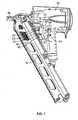
- Turning now to the figures and in particular
FIGS. 1-6 , theactuator 10 includes ahousing 12 having apiston 14 disposed therein. Theactuator housing 12 is a one-piece unit composed of amain body 13 and integralactuator attachment arms FIGS. 5 and 6 . In one embodiment, as shown inFIG. 1 , thehousing 12 is configured to be used with a pneumatic nailer, such as a nailer available from ITW Industrial Fastening of Elgin, Illinois, an Illinois Tool Works company. Preferably, thehousing 12 is formed of a strong, durable, lightweight material, such as aluminum. - As the nail count in a magazine in the
tool 50 is depleted, a nail follower (nail pusher) N moves toward the front or disbursal section of thenailer 50. Thus, in a preferred embodiment, themain body 13 of thehousing 12 has a triangular-shaped clearance cutout 40 formed on an outer surface of theactuator housing 12 to accommodate a follower N on apneumatic nailer 50. - A
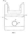
drive chamber 42 is formed as a cylindrical bore extending partially through themain body 13 of theactuator housing 12, as shown inFIGS. 4-7 . Apiston 14 is disposed and slidably movable within thecylindrical drive chamber 42. Thepiston 14 is made from brass in the present embodiment, but other materials such as steel or plastics or composites thereof are also contemplated. The material of thepiston 14 should be capable of withstanding continuous and repetitive strikes/stresses, as well as stresses due to friction. Actuator attachment arms main body 13 of theactuator housing 12. Theactuator arms attachment arms trigger housing 54 of thetool 50.- The
piston 14 comprises apiston head 15, a groove G, a support plate P, and a shaft S. An O-ring 16 is disposed in the groove G of thepiston 14. The O-ring 16 acts as a seal or gasket to prevent air from escaping up along the sides of thedrive chamber 42, between thepiston 14 and thedrive chamber 42. It is contemplated that the material used for the O-ring is suitable for extremes in temperature and capable of withstanding repetitive movement and/or vibration, such as a rubber O-ring as is known in the art. - The
piston head 15 is configured to extend outwardly fromactuator housing 12 through an opening formed bydrive chamber 42. In its non-actuated state, thepiston head 15 is configured to lie adjacent to or in close proximity of thetrigger 52 when theactuator 10 is attached to thepneumatic tool 50. - An
air inlet chamber 34 is formed as a cylindrical bore extending partially through themain body 13 of theactuator housing 12, contiguous with and generally normal to drivechamber 42. Theair inlet chamber 34 is configured to accept and direct a pressurized gas to thedrive chamber 42, as discussed below. - The
actuator 10 is attached to thepneumatic tool 50 bypins pins actuator housing 12 to thetrigger housing 54 through pin holes 20, 21 in theactuator housing 12 and through the trigger housing holes 56, 57 on thetool 50. It is anticipated that thepneumatic tool 50 has pre-formed holes in thetrigger housing 54 to accept pins 18. However, those skilled in the art will recognized that holes may need to be formed in other pneumatic tools to attach theactuator 10 or that other attachment methods may be required depending on the design of the particular pneumatic tool. - Looking to
FIGS. 2 through 4 , theactuator 10 is shown with ahose 26 that carries air from a compressor (not shown) to theactuator 10. Thehose 26 has two ends, acompressor end 28 that connects thehose 26 to the air compressor, and anactuator end 30, which comprises a brass elbow connector connecting thehose 26 to theactuator 10 at opening 30b formed by the air inlet chamber 34 (FIG. 6 ) on themain body 13 of theactuator housing 12. - Air from a compressor is pressurized; therefore, when a control valve is opened, or when a signal from a control system activates, air flows from the compressor through the
hose 26, throughair inlet chamber 34 and into thedrive chamber 42 of theactuator 10. The pressurized air in thedrive chamber 42 pushes against the support plate P of thepiston 14, forcing thepiston 14 to move slidably within thedrive chamber 42 and toward thetrigger 52 of thepneumatic tool 50. Thepiston 14 then contacts thetrigger 52 of thepneumatic tool 50 and depresses thetrigger 52, thereby actuatingpneumatic tool 50. - After the
pneumatic tool 50 is actuated, the air is released fromhose 26, and thetrigger 52, which is spring-loaded in most pneumatic tools, returns to its original position, forcing thepiston 14 to retract and slidably move within thedrive chamber 42 toward thehousing 12 in preparation for the next actuation. As will be appreciated by those skilled in the art, a shuttle valve may be used in conjunction with the compressor to control the flow of air to and from theactuator 10. - An alternate embodiment of a pneumatic tool actuation device that can be used for smaller pneumatic tools is illustrated in
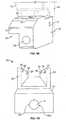
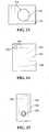
FIGS. 8-15 . InFIG. 8 , the example 10 described above is shown side-by-side with thealternate embodiment 100. - The
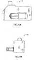
actuator 100 can be used for smaller devices configured for driving staples, wires, and other like fasteners. Theactuator 100 is used to directly actuate a trigger valve pin.Actuator 100 is comprised of ahousing 112 having apiston 114 disposed therein. Theactuator housing 112 is a one-piece unit having amain body 113 and integral actuator attachment points 120, 122 as seen inFIG. 9 . Preferably, thehousing 112 is formed of a strong, durable, lightweight material, such as aluminum. - In this embodiment, the relatively smaller size (as seen in
FIG. 8 ) of themain body 113 precludes the need for a clearance cutout to accommodate a follower (nail pusher) on thepneumatic nailer 150. The follower moves toward the front or disbursal section of thenailer 150 as the nail count in the magazine is depleted and easily bypasses thehousing 112 of thepneumatic actuator 100. - A
drive chamber 142 is formed as a cylindrical bore extending partially through themain body 113 of theactuator housing 112, as shown inFIGS. 13-15 . Apiston 114 is disposed and slidably movable within thecylindrical drive chamber 142. Thepiston 114 is made from brass in the present embodiment, but other materials such as steel or plastics or composites thereof are also contemplated. The material of thepiston 114 should be capable of withstanding continuous and repetitive strikes/stresses as well as stresses due to friction. - Actuator attachment points 120, 122 allow the
main body 113 of theactuator housing 112 to be integrated to thepneumatic tool 150. The actuator attachment points 120, 122 in this embodiment are positioned in and secured to the interior of thetrigger housing 154 of thepneumatic tool 150, as shown inFIG. 11 . - The
piston 114 comprises a piston head, a groove, a support plate, and a shaft similar to or the same as previously described. An O-ring 141 is disposed in the groove of thepiston 114. The O-ring 141 acts as a seal or gasket to prevent air from escaping up along the sides of thedrive chamber 142, between thepiston 114 and thedrive chamber 142. It is contemplated that the material used for the O-ring 141 is suitable for extremes in temperature and capable of withstanding repetitive movement and/or vibration. - As shown in
FIG. 9 , thepiston head 115 is configured to extend outwardly from theactuator housing 112 through an opening formed bydrive chamber 142. In its non-actuated state, thepiston head 115 is configured to lie adjacent to or in close proximity of thetrigger valve pin 152 when the actuator 110 is attached to thepneumatic tool 150. - As shown in
FIGS. 13-15 , anair inlet chamber 134 is formed as a cylindrical bore extending partially through themain body 113 of theactuator housing 112, contiguous with and generally normal to thedrive chamber 142, and is configured to accept and direct a pressurized gas to thedrive chamber 142. - The
actuator 100 is attached to thepneumatic tool 150 bypins pins actuator housing 112 to thetrigger housing 154 through fastener receiving openings or pinholes actuator housing 112 and through thetrigger housing holes pneumatic tool 150 has pre-formed holes in thetrigger housing 154 to acceptpins 118. However, those skilled in the art will recognized that holes may need to be formed in other pneumatic tools to attach theactuator 100 or that other attachment methods may be required depending on the design of the particular pneumatic tool. In this embodiment, the actual trigger of the tool need not be present. The trigger valve pin is directly actuated by the piston. - When a control valve is opened, or when a signal from a control system activates, air flows from the compressor through a hose and through the
air inlet chamber 134 and into thedrive chamber 142 of theactuator 100. The pressurized air in thedrive chamber 142 pushes against thepiston 114, forcing thepiston 114 to move slidably within thedrive chamber 142 and toward thetrigger valve pin 152 of thepneumatic tool 150. Thepiston 114 then contacts thetrigger valve pin 152 of thepneumatic tool 150 and depresses thetrigger valve pin 152, thereby actuatingpneumatic tool 150. - After the
pneumatic tool 150 is actuated, the air is released, and thetrigger valve pin 152, which is spring-loaded in most pneumatic tools, returns to its original position, forcing thepiston 114 to retract and slidably move within thedrive chamber 142 toward thehousing 112 in preparation for the next actuation. As will be appreciated by those skilled in the art, a shuttle valve may be used in conjunction with the compressor to control the flow of air to and from theactuator 100.
Claims (13)
- An automatically actuable pneumatic tool (150) comprising:a pneumatic tool (150) having a trigger valve pin (152) ; anda pneumatic tool actuation device (110) which comprises:a housing (112) having a piston drive chamber (142) and an air inlet chamber (134) formed therein, the housing having a fastener receiving opening (120, 122), wherein the fastener receiving opening is configured to attach the actuation device to the pneumatic tool;a piston (114) disposed within the piston drive chamber and configured to slidably move within the piston drive chamber, the piston having a piston head (115) and a support plate (P), a shaft (S) and an annular groove (G) formed between the piston head and the support plate; andan O-ring, wherein the O-ring is disposed in the annular groove and wherein the O-ring forms a seal between the piston and the piston drive chamber,characterized in that said pneumatic tool is not provided with a trigger andin that said piston is configured to actuate the trigger valve pin directly.
- The pneumatic tool (150) of claim 1 wherein the piston drive chamber (142) and the air inlet chamber (134) are contiguous.
- The pneumatic tool (150) of claim 1 wherein a longitudinal axis of the piston drive chamber (142) is generally normal to a longitudinal axis of the air inlet chamber (134).
- The pneumatic tool (150) of claim 1 wherein the piston drive chamber (142) is cylindrical.
- The pneumatic tool (150) of claim 1 wherein the air inlet chamber (134) is cylindrical.
- The pneumatic tool (150) of claim 1 wherein at least one fastener receiving opening (120, 122) is configured to attach the actuation device (110) to the pneumatic tool (150) using at least one pin.
- The pneumatic tool (150) of claim 1 further comprising a connector for operably engaging a gas supply, the connector disposed at an entrance of the air inlet chamber.
- The pneumatic tool (150) of claim 7 wherein the connector comprises an elbow connector.
- The pneumatic tool (150) of claim 8 wherein a gas from the gas supply enters the piston drive chamber (142) through the air inlet chamber (134) and moves the piston (114).
- The pneumatic tool (150) of claim 1, wherein the housing (112) is positionable on an interior surface of a pneumatic tool trigger housing (154).
- The pneumatic tool (150) of claim 1 wherein the housing (112) is formed of aluminum.
- The pneumatic tool (150) of claim 1 wherein the piston (114) is formed of brass.
- The pneumatic tool (150) of claim 1 wherein said housing (112) is a one-piece unit having a main body (113) and integral actuator attachment points (120, 122).
Applications Claiming Priority (2)
| Application Number | Priority Date | Filing Date | Title |
|---|---|---|---|
| US12/265,944US8881963B2 (en) | 2007-08-31 | 2008-11-06 | Enhanced pneumatic tool actuation device |
| PCT/US2009/059183WO2010053640A1 (en) | 2008-11-06 | 2009-10-01 | Enhanced pneumatic tool actuation device |
Publications (3)
| Publication Number | Publication Date |
|---|---|
| EP2349652A1 EP2349652A1 (en) | 2011-08-03 |
| EP2349652A4 EP2349652A4 (en) | 2018-03-14 |
| EP2349652B1true EP2349652B1 (en) | 2020-03-18 |
Family
ID=42153162
Family Applications (1)
| Application Number | Title | Priority Date | Filing Date |
|---|---|---|---|
| EP09825170.5AActiveEP2349652B1 (en) | 2008-11-06 | 2009-10-01 | Enhanced pneumatic tool actuation device |
Country Status (7)
| Country | Link |
|---|---|
| US (1) | US8881963B2 (en) |
| EP (1) | EP2349652B1 (en) |
| CN (1) | CN102271875B (en) |
| AU (1) | AU2009311556B2 (en) |
| CA (1) | CA2742591C (en) |
| NZ (1) | NZ592720A (en) |
| WO (1) | WO2010053640A1 (en) |
Families Citing this family (3)
| Publication number | Priority date | Publication date | Assignee | Title |
|---|---|---|---|---|
| US8387846B2 (en) | 2009-06-08 | 2013-03-05 | Illinois Tool Works Inc | Fastening tool with blind guide work contact tip |
| EP3037216A1 (en)* | 2014-12-22 | 2016-06-29 | HILTI Aktiengesellschaft | Handheld tool and device comprising the handheld tool |
| CA2981019A1 (en)* | 2016-10-10 | 2018-04-10 | Power Tech Staple and Nail, Inc. | Accessory attachment for driven fastener hand tool |
Family Cites Families (31)
| Publication number | Priority date | Publication date | Assignee | Title |
|---|---|---|---|---|
| US2954009A (en) | 1959-06-10 | 1960-09-27 | Senco Products | Remote control air valve |
| US3272267A (en) | 1963-10-21 | 1966-09-13 | Signode Corp | Walking stick for fastening tool |
| US3563438A (en)* | 1968-12-05 | 1971-02-16 | Fastener Corp | Fastener driving tool |
| US3653299A (en) | 1970-05-11 | 1972-04-04 | Signode Corp | Pneumatic piston return system and valve assembly for impact tools |
| DE2131849B2 (en) | 1971-06-26 | 1973-08-23 | Bukama GmbH Hannover, 3005 Hem mingen Westerfeld | RELEASE LOCK ON A PNEUMATIC NAILER |
| US3815475A (en)* | 1972-11-20 | 1974-06-11 | Signode Corp | Fastener driving tool with improved piston return |
| US3815627A (en) | 1972-12-19 | 1974-06-11 | Rockwell International Corp | Valve assembly |
| US3828458A (en)* | 1973-06-11 | 1974-08-13 | Palmer J Skone | Remotely operable trigger actuator |
| US4122904A (en) | 1977-01-27 | 1978-10-31 | Pneutek, Inc. | Pneumatic hammer driver |
| DE2811339C2 (en)* | 1978-03-16 | 1979-09-20 | Heinrich Buehnen Kg, Maschinenfabrik, Im- Und Export, 2800 Bremen | Release protection on a pneumatic nailer |
| US4196833A (en)* | 1978-10-10 | 1980-04-08 | Haytayan Harry M | Pneumatic tacking tool |
| US4284223A (en)* | 1979-09-24 | 1981-08-18 | Salcido Albert R | Device for stapling material on ceilings |
| US4385297A (en)* | 1980-01-14 | 1983-05-24 | Schmitt Wilhelm E | Arrangement for sensing proximity of a reciprocating member |
| DE3047638A1 (en)* | 1980-12-17 | 1982-07-22 | Hilti AG, 9494 Schaan | Pneumatic nailer |
| DE3119956C2 (en) | 1981-05-20 | 1984-11-22 | Joh. Friedrich Behrens AG, 2070 Ahrensburg | Sound-damped driving tool for fasteners |
| JPH0544550Y2 (en) | 1985-02-20 | 1993-11-11 | ||
| US4869008A (en)* | 1987-11-12 | 1989-09-26 | Bull-Pup Industries, Inc. | Replacement gun stock unit |
| US4932313A (en)* | 1988-09-30 | 1990-06-12 | Gutknecht William H | Air bearing piston and cylinder assembly |
| FR2671866B1 (en)* | 1991-01-22 | 1993-03-26 | Giat Ind Sa | PERCUSSION FIRE DEVICE FOR MORTAR OR THE LIKE AND MORTAR COMPRISING SUCH A DEVICE. |
| US5463918A (en)* | 1993-06-11 | 1995-11-07 | Lemieux; Thomas | Hand tool extension handle |
| JP3419535B2 (en)* | 1994-03-11 | 2003-06-23 | 株式会社マキタ | Nailing machine |
| US5850961A (en)* | 1997-01-07 | 1998-12-22 | Stanley-Bostitch, Inc. | Quick exhaust remote trigger valve for fastener driving tool |
| AUPQ420099A0 (en) | 1999-11-23 | 1999-12-16 | Metal Storm Limited | Driver for power tools |
| US6712256B1 (en)* | 2001-10-25 | 2004-03-30 | Kevin James Curry | Nail gun carriage |
| US6722547B1 (en) | 2003-03-21 | 2004-04-20 | Nailermate Enterprise Corp. | Method and apparatus for controlling electronic nail gun |
| JP4374907B2 (en) | 2003-05-26 | 2009-12-02 | 日立工機株式会社 | Nailer |
| US6837415B1 (en) | 2003-09-29 | 2005-01-04 | Wen-Sheng Huang | Flooring nailer |
| US7124837B2 (en) | 2004-02-26 | 2006-10-24 | The Boeing Company | Pneumatic motor trigger actuator |
| US7228917B2 (en) | 2005-09-22 | 2007-06-12 | Illinois Tool Works Inc. | Remote trigger actuating mechanism for power tool |
| US8875969B2 (en)* | 2007-02-09 | 2014-11-04 | Tricord Solutions, Inc. | Fastener driving apparatus |
| US7690546B2 (en)* | 2007-08-31 | 2010-04-06 | Illinois Tool Works Inc. | Pneumatic tool actuation device |
- 2008
- 2008-11-06USUS12/265,944patent/US8881963B2/enactiveActive
- 2009
- 2009-10-01WOPCT/US2009/059183patent/WO2010053640A1/enactiveApplication Filing
- 2009-10-01NZNZ592720Apatent/NZ592720A/enunknown
- 2009-10-01EPEP09825170.5Apatent/EP2349652B1/enactiveActive
- 2009-10-01CNCN200980153768.XApatent/CN102271875B/enactiveActive
- 2009-10-01CACA2742591Apatent/CA2742591C/enactiveActive
- 2009-10-01AUAU2009311556Apatent/AU2009311556B2/enactiveActive
Non-Patent Citations (1)
| Title |
|---|
| None* |
Also Published As
| Publication number | Publication date |
|---|---|
| US20090072005A1 (en) | 2009-03-19 |
| US8881963B2 (en) | 2014-11-11 |
| EP2349652A1 (en) | 2011-08-03 |
| WO2010053640A1 (en) | 2010-05-14 |
| NZ592720A (en) | 2013-08-30 |
| CA2742591A1 (en) | 2010-05-14 |
| AU2009311556A1 (en) | 2010-05-14 |
| EP2349652A4 (en) | 2018-03-14 |
| AU2009311556B2 (en) | 2016-03-31 |
| CN102271875B (en) | 2015-08-12 |
| CA2742591C (en) | 2014-07-15 |
| CN102271875A (en) | 2011-12-07 |
Similar Documents
| Publication | Publication Date | Title |
|---|---|---|
| US7690546B2 (en) | Pneumatic tool actuation device | |
| TWI239881B (en) | Fastener driving tool having contact arm in contact with workpiece | |
| EP2781307B1 (en) | An actuation lockout for a fastener-driving tool | |
| EP2533944B1 (en) | Pneumatic nailer with sleeve actuated piston return | |
| AU2008276314B2 (en) | Actuator pin guide for a fastener driving tool | |
| US8579175B2 (en) | Valve cap for pneumatic nailer | |
| US11407094B2 (en) | Fastening tool having a low nail, lockout mechanism | |
| WO2008115721A1 (en) | Nose assembly for a fastener driving tool | |
| EP2349652B1 (en) | Enhanced pneumatic tool actuation device | |
| US9770819B2 (en) | Pneumatically actuated mechanical hand tool | |
| US5711471A (en) | Magnetic biased driving element for a fastener driving tool | |
| US20130056515A1 (en) | Powered stapling device | |
| US4726504A (en) | Portable self-piercing riveting apparatus | |
| US20070267458A1 (en) | Pneumatic nail gun | |
| US8746527B2 (en) | High efficiency pneumatic nailer | |
| US20080272326A1 (en) | Driving tool and head valve assembly for a driving tool | |
| JPH0544061Y2 (en) | ||
| JP2020196073A (en) | Driving machine | |
| JP2005334982A (en) | Nailer and fastening structure used therefor |
Legal Events
| Date | Code | Title | Description |
|---|---|---|---|
| PUAI | Public reference made under article 153(3) epc to a published international application that has entered the european phase | Free format text:ORIGINAL CODE: 0009012 | |
| 17P | Request for examination filed | Effective date:20110525 | |
| AK | Designated contracting states | Kind code of ref document:A1 Designated state(s):AT BE BG CH CY CZ DE DK EE ES FI FR GB GR HR HU IE IS IT LI LT LU LV MC MK MT NL NO PL PT RO SE SI SK SM TR | |
| DAX | Request for extension of the european patent (deleted) | ||
| RAP1 | Party data changed (applicant data changed or rights of an application transferred) | Owner name:ILLINOIS TOOL WORKS INC. | |
| RA4 | Supplementary search report drawn up and despatched (corrected) | Effective date:20180209 | |
| RIC1 | Information provided on ipc code assigned before grant | Ipc:B25C 1/04 20060101AFI20180205BHEP Ipc:B25C 7/00 20060101ALI20180205BHEP | |
| STAA | Information on the status of an ep patent application or granted ep patent | Free format text:STATUS: EXAMINATION IS IN PROGRESS | |
| 17Q | First examination report despatched | Effective date:20181119 | |
| GRAP | Despatch of communication of intention to grant a patent | Free format text:ORIGINAL CODE: EPIDOSNIGR1 | |
| STAA | Information on the status of an ep patent application or granted ep patent | Free format text:STATUS: GRANT OF PATENT IS INTENDED | |
| INTG | Intention to grant announced | Effective date:20191016 | |
| GRAS | Grant fee paid | Free format text:ORIGINAL CODE: EPIDOSNIGR3 | |
| GRAA | (expected) grant | Free format text:ORIGINAL CODE: 0009210 | |
| STAA | Information on the status of an ep patent application or granted ep patent | Free format text:STATUS: THE PATENT HAS BEEN GRANTED | |
| AK | Designated contracting states | Kind code of ref document:B1 Designated state(s):AT BE BG CH CY CZ DE DK EE ES FI FR GB GR HR HU IE IS IT LI LT LU LV MC MK MT NL NO PL PT RO SE SI SK SM TR | |
| REG | Reference to a national code | Ref country code:GB Ref legal event code:FG4D | |
| REG | Reference to a national code | Ref country code:DE Ref legal event code:R096 Ref document number:602009061490 Country of ref document:DE | |
| REG | Reference to a national code | Ref country code:AT Ref legal event code:REF Ref document number:1245369 Country of ref document:AT Kind code of ref document:T Effective date:20200415 Ref country code:IE Ref legal event code:FG4D | |
| PG25 | Lapsed in a contracting state [announced via postgrant information from national office to epo] | Ref country code:FI Free format text:LAPSE BECAUSE OF FAILURE TO SUBMIT A TRANSLATION OF THE DESCRIPTION OR TO PAY THE FEE WITHIN THE PRESCRIBED TIME-LIMIT Effective date:20200318 Ref country code:NO Free format text:LAPSE BECAUSE OF FAILURE TO SUBMIT A TRANSLATION OF THE DESCRIPTION OR TO PAY THE FEE WITHIN THE PRESCRIBED TIME-LIMIT Effective date:20200618 | |
| REG | Reference to a national code | Ref country code:NL Ref legal event code:MP Effective date:20200318 | |
| PG25 | Lapsed in a contracting state [announced via postgrant information from national office to epo] | Ref country code:GR Free format text:LAPSE BECAUSE OF FAILURE TO SUBMIT A TRANSLATION OF THE DESCRIPTION OR TO PAY THE FEE WITHIN THE PRESCRIBED TIME-LIMIT Effective date:20200619 Ref country code:BG Free format text:LAPSE BECAUSE OF FAILURE TO SUBMIT A TRANSLATION OF THE DESCRIPTION OR TO PAY THE FEE WITHIN THE PRESCRIBED TIME-LIMIT Effective date:20200618 Ref country code:HR Free format text:LAPSE BECAUSE OF FAILURE TO SUBMIT A TRANSLATION OF THE DESCRIPTION OR TO PAY THE FEE WITHIN THE PRESCRIBED TIME-LIMIT Effective date:20200318 Ref country code:LV Free format text:LAPSE BECAUSE OF FAILURE TO SUBMIT A TRANSLATION OF THE DESCRIPTION OR TO PAY THE FEE WITHIN THE PRESCRIBED TIME-LIMIT Effective date:20200318 Ref country code:SE Free format text:LAPSE BECAUSE OF FAILURE TO SUBMIT A TRANSLATION OF THE DESCRIPTION OR TO PAY THE FEE WITHIN THE PRESCRIBED TIME-LIMIT Effective date:20200318 | |
| REG | Reference to a national code | Ref country code:LT Ref legal event code:MG4D | |
| PG25 | Lapsed in a contracting state [announced via postgrant information from national office to epo] | Ref country code:NL Free format text:LAPSE BECAUSE OF FAILURE TO SUBMIT A TRANSLATION OF THE DESCRIPTION OR TO PAY THE FEE WITHIN THE PRESCRIBED TIME-LIMIT Effective date:20200318 | |
| PG25 | Lapsed in a contracting state [announced via postgrant information from national office to epo] | Ref country code:CZ Free format text:LAPSE BECAUSE OF FAILURE TO SUBMIT A TRANSLATION OF THE DESCRIPTION OR TO PAY THE FEE WITHIN THE PRESCRIBED TIME-LIMIT Effective date:20200318 Ref country code:IS Free format text:LAPSE BECAUSE OF FAILURE TO SUBMIT A TRANSLATION OF THE DESCRIPTION OR TO PAY THE FEE WITHIN THE PRESCRIBED TIME-LIMIT Effective date:20200718 Ref country code:LT Free format text:LAPSE BECAUSE OF FAILURE TO SUBMIT A TRANSLATION OF THE DESCRIPTION OR TO PAY THE FEE WITHIN THE PRESCRIBED TIME-LIMIT Effective date:20200318 Ref country code:SK Free format text:LAPSE BECAUSE OF FAILURE TO SUBMIT A TRANSLATION OF THE DESCRIPTION OR TO PAY THE FEE WITHIN THE PRESCRIBED TIME-LIMIT Effective date:20200318 Ref country code:RO Free format text:LAPSE BECAUSE OF FAILURE TO SUBMIT A TRANSLATION OF THE DESCRIPTION OR TO PAY THE FEE WITHIN THE PRESCRIBED TIME-LIMIT Effective date:20200318 Ref country code:PT Free format text:LAPSE BECAUSE OF FAILURE TO SUBMIT A TRANSLATION OF THE DESCRIPTION OR TO PAY THE FEE WITHIN THE PRESCRIBED TIME-LIMIT Effective date:20200812 Ref country code:EE Free format text:LAPSE BECAUSE OF FAILURE TO SUBMIT A TRANSLATION OF THE DESCRIPTION OR TO PAY THE FEE WITHIN THE PRESCRIBED TIME-LIMIT Effective date:20200318 Ref country code:SM Free format text:LAPSE BECAUSE OF FAILURE TO SUBMIT A TRANSLATION OF THE DESCRIPTION OR TO PAY THE FEE WITHIN THE PRESCRIBED TIME-LIMIT Effective date:20200318 | |
| REG | Reference to a national code | Ref country code:AT Ref legal event code:MK05 Ref document number:1245369 Country of ref document:AT Kind code of ref document:T Effective date:20200318 | |
| REG | Reference to a national code | Ref country code:DE Ref legal event code:R097 Ref document number:602009061490 Country of ref document:DE | |
| PLBE | No opposition filed within time limit | Free format text:ORIGINAL CODE: 0009261 | |
| STAA | Information on the status of an ep patent application or granted ep patent | Free format text:STATUS: NO OPPOSITION FILED WITHIN TIME LIMIT | |
| PG25 | Lapsed in a contracting state [announced via postgrant information from national office to epo] | Ref country code:ES Free format text:LAPSE BECAUSE OF FAILURE TO SUBMIT A TRANSLATION OF THE DESCRIPTION OR TO PAY THE FEE WITHIN THE PRESCRIBED TIME-LIMIT Effective date:20200318 Ref country code:IT Free format text:LAPSE BECAUSE OF FAILURE TO SUBMIT A TRANSLATION OF THE DESCRIPTION OR TO PAY THE FEE WITHIN THE PRESCRIBED TIME-LIMIT Effective date:20200318 Ref country code:AT Free format text:LAPSE BECAUSE OF FAILURE TO SUBMIT A TRANSLATION OF THE DESCRIPTION OR TO PAY THE FEE WITHIN THE PRESCRIBED TIME-LIMIT Effective date:20200318 Ref country code:DK Free format text:LAPSE BECAUSE OF FAILURE TO SUBMIT A TRANSLATION OF THE DESCRIPTION OR TO PAY THE FEE WITHIN THE PRESCRIBED TIME-LIMIT Effective date:20200318 | |
| 26N | No opposition filed | Effective date:20201221 | |
| PG25 | Lapsed in a contracting state [announced via postgrant information from national office to epo] | Ref country code:PL Free format text:LAPSE BECAUSE OF FAILURE TO SUBMIT A TRANSLATION OF THE DESCRIPTION OR TO PAY THE FEE WITHIN THE PRESCRIBED TIME-LIMIT Effective date:20200318 | |
| PG25 | Lapsed in a contracting state [announced via postgrant information from national office to epo] | Ref country code:SI Free format text:LAPSE BECAUSE OF FAILURE TO SUBMIT A TRANSLATION OF THE DESCRIPTION OR TO PAY THE FEE WITHIN THE PRESCRIBED TIME-LIMIT Effective date:20200318 | |
| REG | Reference to a national code | Ref country code:CH Ref legal event code:PL | |
| PG25 | Lapsed in a contracting state [announced via postgrant information from national office to epo] | Ref country code:MC Free format text:LAPSE BECAUSE OF FAILURE TO SUBMIT A TRANSLATION OF THE DESCRIPTION OR TO PAY THE FEE WITHIN THE PRESCRIBED TIME-LIMIT Effective date:20200318 Ref country code:LU Free format text:LAPSE BECAUSE OF NON-PAYMENT OF DUE FEES Effective date:20201001 | |
| REG | Reference to a national code | Ref country code:BE Ref legal event code:MM Effective date:20201031 | |
| PG25 | Lapsed in a contracting state [announced via postgrant information from national office to epo] | Ref country code:BE Free format text:LAPSE BECAUSE OF NON-PAYMENT OF DUE FEES Effective date:20201031 Ref country code:LI Free format text:LAPSE BECAUSE OF NON-PAYMENT OF DUE FEES Effective date:20201031 Ref country code:CH Free format text:LAPSE BECAUSE OF NON-PAYMENT OF DUE FEES Effective date:20201031 | |
| PG25 | Lapsed in a contracting state [announced via postgrant information from national office to epo] | Ref country code:IE Free format text:LAPSE BECAUSE OF NON-PAYMENT OF DUE FEES Effective date:20201001 | |
| PG25 | Lapsed in a contracting state [announced via postgrant information from national office to epo] | Ref country code:TR Free format text:LAPSE BECAUSE OF FAILURE TO SUBMIT A TRANSLATION OF THE DESCRIPTION OR TO PAY THE FEE WITHIN THE PRESCRIBED TIME-LIMIT Effective date:20200318 Ref country code:MT Free format text:LAPSE BECAUSE OF FAILURE TO SUBMIT A TRANSLATION OF THE DESCRIPTION OR TO PAY THE FEE WITHIN THE PRESCRIBED TIME-LIMIT Effective date:20200318 Ref country code:CY Free format text:LAPSE BECAUSE OF FAILURE TO SUBMIT A TRANSLATION OF THE DESCRIPTION OR TO PAY THE FEE WITHIN THE PRESCRIBED TIME-LIMIT Effective date:20200318 | |
| PG25 | Lapsed in a contracting state [announced via postgrant information from national office to epo] | Ref country code:MK Free format text:LAPSE BECAUSE OF FAILURE TO SUBMIT A TRANSLATION OF THE DESCRIPTION OR TO PAY THE FEE WITHIN THE PRESCRIBED TIME-LIMIT Effective date:20200318 | |
| P01 | Opt-out of the competence of the unified patent court (upc) registered | Effective date:20230606 | |
| PGFP | Annual fee paid to national office [announced via postgrant information from national office to epo] | Ref country code:DE Payment date:20241029 Year of fee payment:16 | |
| PGFP | Annual fee paid to national office [announced via postgrant information from national office to epo] | Ref country code:GB Payment date:20241028 Year of fee payment:16 | |
| PGFP | Annual fee paid to national office [announced via postgrant information from national office to epo] | Ref country code:FR Payment date:20241025 Year of fee payment:16 |