EP2349040B1 - Intramedullary nail - Google Patents
Intramedullary nailDownload PDFInfo
- Publication number
- EP2349040B1 EP2349040B1EP09740851.2AEP09740851AEP2349040B1EP 2349040 B1EP2349040 B1EP 2349040B1EP 09740851 AEP09740851 AEP 09740851AEP 2349040 B1EP2349040 B1EP 2349040B1
- Authority
- EP
- European Patent Office
- Prior art keywords
- intramedullary nail
- transverse bore
- elongate body
- proximal
- distal
- Prior art date
- Legal status (The legal status is an assumption and is not a legal conclusion. Google has not performed a legal analysis and makes no representation as to the accuracy of the status listed.)
- Not-in-force
Links
- 238000000926separation methodMethods0.000claims2
- 230000007704transitionEffects0.000description31
- 239000000463materialSubstances0.000description30
- 238000005520cutting processMethods0.000description29
- 210000000689upper legAnatomy0.000description21
- 210000000988bone and boneAnatomy0.000description12
- 238000009826distributionMethods0.000description5
- 238000004519manufacturing processMethods0.000description5
- 230000003247decreasing effectEffects0.000description4
- 230000000399orthopedic effectEffects0.000description3
- 230000015572biosynthetic processEffects0.000description2
- 238000009795derivationMethods0.000description2
- 210000002436femur neckAnatomy0.000description2
- 239000007943implantSubstances0.000description2
- 238000003754machiningMethods0.000description2
- 210000002303tibiaAnatomy0.000description2
- 229910001069Ti alloyInorganic materials0.000description1
- 229910000883Ti6Al4VInorganic materials0.000description1
- WAIPAZQMEIHHTJ-UHFFFAOYSA-N[Cr].[Co]Chemical class[Cr].[Co]WAIPAZQMEIHHTJ-UHFFFAOYSA-N0.000description1
- 210000003484anatomyAnatomy0.000description1
- 238000005266castingMethods0.000description1
- 210000003109clavicleAnatomy0.000description1
- 239000012141concentrateSubstances0.000description1
- 230000000694effectsEffects0.000description1
- 210000002082fibulaAnatomy0.000description1
- 238000005242forgingMethods0.000description1
- 208000014674injuryDiseases0.000description1
- 238000000034methodMethods0.000description1
- 210000002320radiusAnatomy0.000description1
- 239000010935stainless steelSubstances0.000description1
- 229910001220stainless steelInorganic materials0.000description1
- 230000008733traumaEffects0.000description1
- 210000000623ulnaAnatomy0.000description1
Images


Classifications
- A—HUMAN NECESSITIES
- A61—MEDICAL OR VETERINARY SCIENCE; HYGIENE
- A61B—DIAGNOSIS; SURGERY; IDENTIFICATION
- A61B17/00—Surgical instruments, devices or methods
- A61B17/56—Surgical instruments or methods for treatment of bones or joints; Devices specially adapted therefor
- A61B17/58—Surgical instruments or methods for treatment of bones or joints; Devices specially adapted therefor for osteosynthesis, e.g. bone plates, screws or setting implements
- A61B17/68—Internal fixation devices, including fasteners and spinal fixators, even if a part thereof projects from the skin
- A61B17/72—Intramedullary devices, e.g. pins or nails
- A61B17/7283—Intramedullary devices, e.g. pins or nails with special cross-section of the nail
- A—HUMAN NECESSITIES
- A61—MEDICAL OR VETERINARY SCIENCE; HYGIENE
- A61B—DIAGNOSIS; SURGERY; IDENTIFICATION
- A61B17/00—Surgical instruments, devices or methods
- A61B17/56—Surgical instruments or methods for treatment of bones or joints; Devices specially adapted therefor
- A61B17/58—Surgical instruments or methods for treatment of bones or joints; Devices specially adapted therefor for osteosynthesis, e.g. bone plates, screws or setting implements
- A61B17/68—Internal fixation devices, including fasteners and spinal fixators, even if a part thereof projects from the skin
- A61B17/74—Devices for the head or neck or trochanter of the femur
- A61B17/742—Devices for the head or neck or trochanter of the femur having one or more longitudinal elements oriented along or parallel to the axis of the neck
- A61B17/744—Devices for the head or neck or trochanter of the femur having one or more longitudinal elements oriented along or parallel to the axis of the neck the longitudinal elements coupled to an intramedullary nail
- A—HUMAN NECESSITIES
- A61—MEDICAL OR VETERINARY SCIENCE; HYGIENE
- A61B—DIAGNOSIS; SURGERY; IDENTIFICATION
- A61B17/00—Surgical instruments, devices or methods
- A61B17/56—Surgical instruments or methods for treatment of bones or joints; Devices specially adapted therefor
- A61B17/58—Surgical instruments or methods for treatment of bones or joints; Devices specially adapted therefor for osteosynthesis, e.g. bone plates, screws or setting implements
- A61B17/68—Internal fixation devices, including fasteners and spinal fixators, even if a part thereof projects from the skin
- A61B17/72—Intramedullary devices, e.g. pins or nails
- A61B17/7291—Intramedullary devices, e.g. pins or nails for small bones, e.g. in the foot, ankle, hand or wrist
Definitions
- the present inventionrelates to orthopedic components, and, particularly, to intramedullary nails.
- Intramedullary nailsmay be used to align and stabilize fractures of a long bone, such as a femur.
- an intramedullary nailmay be inserted into the intramedullary canal of the femur and positioned to extend across the fracture line of the femur. Then, screws or other securement devices may be inserted through bores formed in the intramedullary nail on opposing sides of the fractured femur to secure the opposing portions of the fractured femur together.
- a lag screwmay be inserted into a transverse bore formed in the intramedullary nail. This bore is aligned so that the lag screw extends through the neck and into the head of the long bone and across the fracture line, allowing the lag screw to reduce the fracture of the neck and/or head of the long bone.
- femur 10is shown including shaft 12, neck 14, and head 16. As shown, neck 14 of femur 10 has been fractured at line 17.
- Transverse bore 18extends through intramedullary nail 20 and is sized to receive lag screw 22 therethrough.
- lag screw 22has an outer diameter that is slightly smaller than the diameter of transverse bore 18. This allows lag screw 22 to pass through transverse bore 18 and reduce the fracture at line 17.
- lag screw 22will pivot slightly within transverse bore 18 of intramedullary nail 20 when a force is applied to the end of lag screw 22.
- force FGmay be exerted on the end of lag screw 22, which results from head 16 of femur 10 bearing the weight of an individual.
- lag screw 22pivots slightly within transverse bore 18 of intramedullary nail 20 to create two support points that bear the resultant forces.
- First support point 24is a medial, distal support point, where force FM acts on lag screw 22, and second support point 26 is a lateral, proximal support point, where force FL acts on lag screw 22.
- force FMinduces a compressive stress in the mass of the lower part of intramedullary nail 20, while force FL induces a tensile stress in the region of transverse bore 18.
- force FL acting on support point 26is amplified by the leverage ratio of lag screw 22 within transverse bore 18. The resulting, theoretical stress distribution is shown in Fig. 3 , where the stress is concentrated around the medial and lateral openings of transverse bore 18.
- Fig. 2which shows a cross-section of intramedullary nail 20
- the maximum tension caused by force FLis found near the lateral opening of transverse bore 18, which has sharp edges 27 that are formed in a region with very critical geometry.
- the formation of transverse bore 18 in intramedullary nail 20creates a notch effect that further concentrates stress along sharp edges 27 of the lateral opening of transverse bore 18, where a minimal amount of material is provided.
- the region about the lateral opening of transverse bore 18, for examplehas a minimal amount of material positioned thereabove as a result of the shape of intramedullary nail 20.
- intramedullary nail 20has a substantially circular cross-section in a direction perpendicular to the longitudinal axis of intramedullary nail 20 and because the lateral opening to transverse bore 18 is located at an outer edge of intramedullary nail 20, a minimal amount of material is provided in the region of support point 26 and the lateral opening of transverse bore 18, as compared to the amount of material in the region closer to the longitudinal axis of intramedullary nail 20.
- the material in the region of the lateral opening of transverse bore 18has a greater concentration of stress than the material that is closer to the longitudinal axis of intramedullary nail 20.
- intramedullary nail 20is formed from stronger, more expensive materials in order to withstand the increased concentration of stress in the material adjacent to the lateral opening of transverse bore 18 and/or has an increased size in the region of intramedullary nail 20 near the lateral opening of transverse bore 18 in order to increase the volume of material present and to decrease the concentration of stress adjacent to the lateral opening of transverse bore 18.
- EP 1 452 144 A2discloses an intramedullary nail having a local recess at the lateral end of the bore which recess has a rounded transition into a sharp distal edge portion.
- US 2006/0200160 A1discloses an intramedullary nail which comprises an elongate body including a proximal end defined by a proximal portion, a distal end defined by a distal portion, a medial side, a lateral side, and a longitudinal axis, the elongate body defining an elongate body periphery, the proximal portion of the elongate body having an interior wall defining a transverse bore extending therethrough, the transverse bore extending from the lateral side to the medial side of the elongate body in a direction transverse to the longitudinal axis of the elongate body, the proximal portion including a cutout positioned adjacent to the transverse bore on the lateral side of the elongate body.
- the cutoutcomprises a ledge portion positioned adjacent to a proximal most edge of said wall defining said transverse bore; a ramp portion configured as a single curved surface which does not include any strictly planar or flattened portions, wherein said ramp portion extends along the longitudinal axis of the elongate body in a distal direction, said ramp portion terminating distally at said elongate body periphery, wherein said ramp portion terminates at a position spaced distally from a distal most edge of said wall defining said transverse bore; and an intermediate portion positioned between the ledge portion and the ramp portion, the intermediate portion having an intermediate portion radius of curvature.
- the present inventionprovides an intramedullary nail having a body with a transverse bore extending through the body and having an area of enhanced stress distribution on at least the lateral side of the transverse bore.
- the intramedullary nailincludes a cutout adjacent to the transverse bore, such as an oblique cutout, that enhances the stress distribution of the intramedullary nail in the region around the lateral opening of the transverse bore.
- the cutoutincludes a ramp portion or area that defines the lateral opening of the transverse bore.
- the ramp portion of the cutoutdefines a runout or a substantially flat portion that defines the lateral opening of the transverse bore.
- the stresses induced at the lateral opening of the intramedullary nailare distributed in a direction toward the longitudinal axis of the intramedullary nail.
- the stresses introduced at the lateral support pointare distributed through a different portion of the intramedullary nail, i.e., through a portion of the intramedullary nail spaced a decreased lateral distance from the longitudinal axis of the intramedullary nail relative to the material directly adjacent to the lateral opening of the transverse bore. This allows for the concentration of the stress at the lateral support point adjacent to the lateral opening of the transverse bore to be decreased, as the stress is borne throughout the body of the intramedullary nail.
- the cutout formed in the intramedullary naillacks a sharp edge at the distal end thereof. Instead, each embodiment of the present invention utilizes a smooth transition zone at the distal end of the cutout.
- the distal portion of the cutoutforms an oblique surface that terminates distally at the outer surface of a proximal portion of the intramedullary nail and forms an angle with the longitudinal axis of the intramedullary nail.
- the intramedullary nailmay be readily removed from a patient's body, even if bone ingrowth has occurred in the area of the cutout. Specifically, if cancellous bone tissue grows into the area defined by the cutout, when the intramedullary nail is removed, the surface defining the distal portion of the cutout may temporarily displace the elastic cancellous bone tissue and allow the intramedullary nail to slide smoothly along the displaced bone.
- the bone tissuemay extend back into the space within the intramedullary canal previously occupied by the intramedullary nail. As a result, trauma to the bone tissue is substantially lessened if the intramedullary nail is removed.
- distalrefers to the area away from the point of attachment to the body
- proximalrefers to the area near the point of attachment the body.
- proximal femurrefers to the portion of the femur near the hip
- distal femurrefers to the portion of the femur near the tibia.
- medial and lateralare also essentially opposites, where “medial” refers to something situated closer to the middle of the body, while “lateral” refers to something situated closer to the left side or the right side of the body (rather than to the middle of the body).
- anterior and posteriorrefers to something situated closer to the front of the body and “posterior” refers to something situated closer to the rear of the body.
- anatomical termsare used with specific reference to an orthopedic implant, such as an intramedullary nail, the terms are used with respect to the implant being positioned as intended within the human body, which is shown in the various drawings of the present application.
- the present inventionprovides an intramedullary nail, including an elongate body including a proximal end, a distal end, a medial side, a lateral side, and a longitudinal axis.
- the elongate bodydefines an elongate body periphery.
- the proximal portion of the elongate bodyhas an interior wall defining a transverse bore extending therethrough.
- the transverse boreextends from the lateral side to the medial side of the elongate body in a direction transverse to the longitudinal axis of the elongate body.
- the proximal portionincludes a cutout positioned adjacent to the transverse bore on the lateral side of the elongate body.
- the cutoutincludes a ledge portion extending in a substantially medial-lateral direction and positioned adj acent to a proximal most edge of the wall defining the transverse bore.
- the cutoutalso includes a ramp portion defining a substantially planar surface.
- the ramp portionforms a ramp angle with the longitudinal axis of the elongate body.
- the ramp angleis between approximately four degrees and approximately twelve degrees, wherein the ramp portion extends along the longitudinal axis of the elongate body in a distal direction.
- the ramp portionterminating distally at the elongate body periphery, wherein the ramp portion terminates at a position spaced distally from a distal most edge of the wall defining the transverse bore.
- the cutoutalso includes an intermediate portion positioned between the ledge portion and the ramp portion.
- the intermediate portionhas an intermediate portion radius of curvature.
- the present inventionprovides an intramedullary nail including an elongate body having a proximal end, a distal end, a medial side, a lateral side, and a longitudinal axis.
- the elongate bodyincludes a distal portion defining the distal end of the elongate body and a transition portion extending proximally from the distal portion along the longitudinal axis.
- the transition portionhas a proximal end having a proximal diameter and a distal end having a distal diameter. The proximal diameter is greater than the distal diameter.
- the transition portiondefines a transition portion periphery.
- the elongate bodyalso includes a proximal portion extending proximally from the transition portion and defining a proximal end of the elongate body.
- the proximal portiondefines a proximal portion periphery.
- the proximal portionhas a diameter substantially equal to the proximal diameter of the transition portion.
- the proximal portionhas an interior wall defining a transverse bore extending therethrough.
- the transverse boreextends from the lateral side of the elongate body to the medial side of the elongate body in a direction transverse to the longitudinal axis of the elongate body.
- the proximal portionhas a cutout positioned adjacent to the transverse bore on the lateral side of the elongate body. The cutout defines a deviation from in particular at least one of the proximal portion periphery and the transition portion periphery having a volume of at least 100 cubic millimeters.
- intramedullary nail 30is shown and includes cutout 32 of Figs. 7A and 7B , as described in detail below.
- Intramedullary nail 30forms a substantially cylindrical, elongate body including distal portion 34, transition portion 36, and proximal portion 38.
- longitudinal bore 40extends along longitudinal axis LA of intramedullary nail 30.
- Intramedullary nail 30may be made of a titanium alloy, such as Ti-6Al-4V, or any other biocompatible orthopedic material, such as medical grade stainless steel or a cobalt-chromium alloy.
- Transverse, distal bores 42extend through distal portion 34 of intramedullary nail 30 and receive fixation screws 44 therein.
- fixation screws 44are positioned to extend through transverse bores 42 and are secured to shaft 12 of femur 10. Fixation screws 44 function to prevent rotation within and/or removal of intramedullary nail 30 from intramedullary canal 46 of femur 10.
- proximal portion 38 of intramedullary nail 30includes wall 49 defining transverse bore 48 through which a lag screw, such as lag screw 50, is positioned.
- Transverse bore 48 of intramedullary nail 30is aligned with the axis of neck 14 of femur 10, such that lag screw 50 may be extended through transverse bore 48 and implanted into neck 14 and/or head 16 of femur 10 to reduce a fracture in neck 14 and/or head 16 of femur 10.
- intramedullary nail 30 and lag screw 50may form a collodiaphyseal ("CCD") angle of approximately 125 degrees, 130 degrees, or 135 degrees. While described herein with specific reference to a femur, intramedullary nail 30 may also be used other long bones, such as a tibia, fibula, radius, ulna, and/or clavicle.
- proximal portion 38 of intramedullary nail 30defines a proximal end of intramedullary nail 30 and has a proximal diameter. In one exemplary embodiment, the diameter of proximal portion 38 is approximately 15.5 mm. In one exemplary embodiment, proximal portion 38 defines a proximal portion periphery having a substantially cylindrical shape having a diameter equal to the diameter of proximal portion 38 and extending along proximal length PL of proximal portion 38. Referring to Fig. 9 , in one exemplary embodiment, distal portion 34 defines a distal end of intramedullary nail 30 and has a distal diameter.
- the diameter of distal portion 34is approximately between 10 mm and 15 mm. In exemplary embodiments, the diameter of distal portion 34 may be equal to approximately 10 mm, 11.5 mm, 13 mm, or 14.5 mm.
- Transition portion 36extends between proximal portion 38 and distal portion 34 and provides a substantially conical transition section between proximal portion 38 and distal portion 34. In one exemplary embodiment, transition portion 36 has a distal end having a diameter substantially equal to the diameter of the proximal most portion of distal portion 34 and a proximal end having a diameter substantially equal to the diameter of proximal portion 38.
- transition portion 36may have a diameter of approximately 15.5 mm at a proximal end thereof and a diameter of approximately 10 mm at a distal end thereof.
- transition portion 36defines a transition portion periphery having a substantially conical shape with a proximal diameter equal to the diameter at a proximal end of transition portion 36 and a distal diameter equal to the diameter at a distal end of transition portion 36 and extending along transition portion length TL.
- the proximal portion 38 of intramedullary nail 30has a proximal length PL of approximately 58 mm
- transition portion 36has a transition portion length TL of approximately 31 mm
- distal portion 34 of intramedullary nail 30has a distal portion length DL of between approximately 120 mm and 395 mm.
- distal portion 34may have a distal portion length DL as small as approximately 126 mm, 211 mm, 231 mm, 251 mm, or 271 mm and as large as approximately 291 mm, 311 mm, 331 mm, 351 mm, 371 mm, or 391 mm.
- intramedullary nail 30has an overall length L between approximately 210 mm and approximately 480 mm.
- intramedullary nail 30may have a length L as small as approximately 215 mm, 300 mm, 320 mm, 340 mm, or 360 mm and as large as approximately 380 mm, 400 mm, 420 mm, 440 mm, 460 mm, or 480 mm.
- length Lis equal to approximately 215 mm.
- transverse bore 48 of the intramedullary nail 30forms angle ⁇ with longitudinal axis LA of intramedullary nail 30.
- angle ⁇is between approximately 48 degrees and 60 degrees.
- angle ⁇may be equal to approximately 49 degrees, 54 degrees, or 59 degrees.
- longitudinal bore 40in one exemplary embodiment, longitudinal bore 40 has a diameter of approximately 4.8 mm, except in the area of proximal portion 38 where longitudinal bore 40 may be enlarged to accommodate a set screw (not shown) and/or other components that function to prevent and/or limit translation of lag screw 50 within transverse bore 48 of intramedullary nail 30.
- a patient's weightmay be transferred to the tip of a lag screw, such as lag screw 50 of Fig. 8 .
- lag screw 50applies a force to intramedullary nail 30 at medial and lateral support points 52, 54, adjacent to medial and lateral openings of transverse bore 48, respectively.
- the lateral side of proximal portion 38 of intramedullary nail 30includes a cutout formed therein. As shown in Figs.
- intramedullary nail 30includes cutout 32, which is described in detail below with respect to Figs. 7A and 7B . While described and depicted herein with the cutout formed on the lateral side of intramedullary nail 30, the cutout may, in other exemplary embodiments, be formed on both the lateral and the medial sides of intramedullary nail 30 adjacent to the lateral and medial openings of transverse bore 48, respectively.
- intramedullary nail 30may include any of the cutout designs set forth herein, including the use of different cutout designs on the medial and lateral sides of intramedullary nail 30.
- the term "cutout”refers generally to an area of a material in which the cross-section of the material deviates from an otherwise substantially consistent cross-section, but does not require the independent removal of the material.
- intramedullary nail 30may be cast or otherwise formed to include a cutout, even though no machining or manufacturing steps were undertaken to remove material from intramedullary nail 30 to form the cutout.
- the cutouts of the present inventionresult in the creation of a deviation in the periphery of proximal portion 38, i.e., the proximal portion periphery described above, and/or the periphery of transition portion 36, i.e., the transition portion periphery described above.
- the derivation in the periphery of proximal portion 38 and transition portion 36 from a cylindrical geometry with a 15.5 mm diametermay be as small as 90 mm 3 , 95 mm 3 , 100 mm 3 , or 105 mm 3 , and may be as high as 110 mm 3 , 115 mm 3 , 120 mm 3 , or 125 mm 3 .
- the derivation in the periphery of proximal portion 38 and transition portion 36 from a cylindrical geometry with a 15.5 mm diametermay be equal to substantially 106 mm 3 .
- the cutouts of the present inventiondefine ramp portions that form oblique surfaces with respect to the longitudinal axis LA of intramedullary nail 30.
- intramedullary nail 30has higher safety margins than similar intramedullary nails, such as those shown in Figs. 1-3 , which are formed in a traditional manner without the cutouts of the present invention.
- cutout 56which is not formed according to an exemplary embodiment of the claimed invention, is shown in conjunction with intramedullary nail 30.
- Cutout 56is positioned adjacent to and defines the lateral opening of transverse bore 48.
- Cutout 56includes ledge portion 58 and runout portion 60.
- Runout portion 60defines a substantially planar surface that extends in a direction substantially parallel to longitudinal axis LA of intramedullary nail 30 and defines flattened sides surfaces 62, 64 on opposing anterior and posterior sides of transverse bore 48.
- runout portion 60may form an angle as small as 1 degree, 2 degrees, or 3 degrees with longitudinal axis LA and as large as 177 degrees, 178 degrees, or 179 degrees with longitudinal axis LA.
- flattened side surfaces 62, 64have a width W of at least 0.2 mm. By ensuring that width W of flattened side surfaces 62, 64 is at least 0.2 mm, a manufacturing tolerance is provide that helps to ensure that flattened side surfaces 62, 64 are properly formed during the manufacturing process.
- Ledge portion 58 and runout portion 60are connected to one another by intermediate portion 66 and are separated from one another by angle a.
- intermediate portion 66has a radius of curvature of approximately 3 mm.
- angle ais substantially equal to 90 degrees.
- ledge potion 58is substantially perpendicular to longitudinal axis LA of intramedullary nail 30.
- runout portion 60extends along longitudinal axis LA of intramedullary nail 30, through transition portion 36, and terminates at the proximal end of distal portion 34 of intramedullary nail 30. Specifically, in this variant runout portion 60 is substantially coplanar with a plane tangent to a lateral most portion of distal portion 34 and parallel to longitudinal axis LA of intramedullary nail 30. In other variants, runout portion 60 extends into and terminates within distal portion 34. In these variants, runout portion 60 is not substantially coplanar with a plane tangent to a lateral most portion of distal portion 34, but may be substantially parallel to longitudinal axis LA of intramedullary nail 30.
- runout portion 60terminates within transition portion 36.
- runout portion 60may terminate at the periphery of transition portion 36 as described above with reference to the transition portion periphery.
- runout portion 60in order to alter the position at which runout portion 60 terminates distally, i.e., the distal most point of runout portion 60, runout portion 60 is maintained in a plane parallel to longitudinal axis LA of intramedullary nail 30 and is moved closer to or further away from longitudinal axis LA of intramedullary nail 30.
- cutout 56 in intramedullary nail 30By forming cutout 56 in intramedullary nail 30, material having a thickness T is positioned on the proximal side of lag screw 50 between runout portion 60 and the lateral-most surface of intramedullary nail 30 positioned proximal of lag screw 50, while a corresponding amount of material is removed from the distal side of lag screw 50.
- the stresses that are introduced in the material directly adjacent to the lateral opening of transverse bore 48, such as in the area distal of support point 54, and described in detail above,are distributed in a direction toward longitudinal axis LA of intramedullary nail 30.
- the stresses introduced in the material directly adjacent to the lateral opening of transverse bore 48are distributed through a portion of intramedullary nail 30 where the material forming intramedullary nail 30 is thicker, i.e., through a portion of intramedullary nail 30 spaced a decreased lateral distance from longitudinal axis LA of intramedullary nail 30 relative to the material directly adjacent to the lateral opening of transverse bore 48.
- Thisallows for the concentration of the stresses in the area of the lateral opening of transverse bore 48 to be reduced, as the stresses are spread throughout the body of intramedullary nail 30.
- intramedullary nail 30may have a decreased thickness relative to known intramedullary nails while providing substantially similar or improved strength properties as compared to known intramedullary nails.
- the diameter of proximal portion 38 of intramedullary nail 30may be as small as 15.5 mm, while the diameter of a proximal portion of a comparable prior art intramedullary nail is 17 mm.
- the diameter of transverse bore 48 of intramedullary nail 30may be as small as 10.5 mm, while the diameter of the corresponding transverse bore of a comparable prior art intramedullary nail is 12 mm.
- flattened side surfaces 62, 64may be formed on opposing sides of lateral opening 68 of transverse bore 48 as shown in Fig. 4B and described in detail above. Additionally, as shown in Figs. 4A and 4B , the lateral most point of ledge portion 58 defines support point 54. As a result, support point 54 is maintained in its relative position even in the presence of cutout 56.
- cutout 70an exemplary embodiment of a cutout formed in accordance with the teachings of the present invention is shown as cutout 70.
- Cutout 70may be utilized with intramedullary nail 30 of Figs. 8 and 9 and like reference numerals have been used to represent corresponding components therebetween.
- cutout 70includes ledge portion 72, intermediate portion 74, longitudinal portion 76, and ramp portion 78.
- Intermediate portion 74connects ledge portion 72 to longitudinal portion 76.
- intermediate portion 74has a radius of curvature of approximately 3 mm.
- longitudinal portion 76defines a substantially planar surface extending in a plane that is substantially parallel to longitudinal axis LA of intramedullary nail 30.
- longitudinal portion 76terminates at a point near, but proximal of, the distal most portion of the wall defining transverse bore 48. Stated another way, longitudinal portion 76 terminates before reaching the distal most portion of transverse bore 48.
- longitudinal portion 76defines flattened side surfaces 80, 82 adjacent to the anterior and posterior sides of transverse bore 48.
- flattened side surfaces 80, 82have a width W of at least 0.2 mm.
- Ramp portion 78 of cutout 70defines a substantially planar, oblique surface that extends distally from longitudinal portion 76.
- Ramp portion 78forms angle ⁇ with longitudinal axis LA of intramedullary nail 30.
- Ramp portion 78is oriented such that ramp portion 78 angles toward longitudinal axis LA of intramedullary nail 30 in a proximal direction and away from longitudinal axis LA of intramedullary nail 30 in a distal direction.
- Angle ⁇is between approximately 4 degrees and approximately 12 degrees. Additionally, the smaller that angle ⁇ is, the closer ramp portion 78 is to being parallel to longitudinal axis LA of intramedullary nail 30. As a result, it is easier to form ramp portion 78 during the manufacturing process and the volume of the space provided for bone ingrowth is increased.
- Cutout 84is substantially similar to cutout 70 of Figs. 5A and 5B and may be utilized with intramedullary nail 30 of Figs. 8 and 9 and like reference numerals have been used to represent identical or substantially identical components therebetween.
- longitudinal portion 86 of cutout 84terminates at a point distal of the distal most portion of transverse bore 48.
- longitudinal portion 86may terminate at a point that coincides with the distal most point of transverse bore 48.
- cutout 32is substantially similar to cutout 70 of Figs. 5A and 5B and like reference numerals have been used to identify identical or substantially identical components therebetween.
- no portion of cutout 32is parallel to longitudinal axis LA of intramedullary nail 30 and cutout 32 lacks longitudinal portion 76.
- ledge portion 92 and ramp portion 94 of cutout 32are connected to one another by intermediate portion 96 and are separated from one another by angle ⁇ .
- angle ⁇is substantially equal to 90 degrees.
- intermediate portion 96has a radius of curvature of approximately 3 mm.
- ledge portion 92is also curved.
- ledge portion 32has a radius of curvature of approximately 3 mm.
- ledge portion 92may include a substantially planar portion.
- a plane containing ledge portion 92intersects the longitudinal axis of transverse bore 48 and is substantially perpendicular to longitudinal axis LA of intramedullary nail 30.
- ramp portion 94defines substantially planar surface 98 that tapers away from the longitudinal axis LA of intramedullary nail 30 in a distal direction to form angle ⁇ ( Fig. 7A ) relative to longitudinal axis LA of intramedullary nail 30.
- angle ⁇is 9 degrees.
- angle ⁇is 10 degrees.
- angle ⁇is 6 degrees.
- angle ⁇may be any angle in the range of 4-12 degrees.
- ledge portion 92may form a slight angle relative to a line that is perpendicular to longitudinal axis LA of intramedullary nail 30.
- ledge portion 92may still remain substantially perpendicular to longitudinal axis LA
- ledge portion 92may form an angle ⁇ ( Fig. 7A ) with longitudinal axis LA of intramedullary nail 30.
- angle ⁇instead of angle ⁇ being 90 degrees from longitudinal axis LA and ledge portion 92 being perpendicular with longitudinal axis LA, angle ⁇ will, for any particular embodiment, be equal to 180 degrees minus the sum of angle ⁇ and angle ⁇ . For example, when angle ⁇ is 90 degrees and angle ⁇ is 10 degrees, angle ⁇ will be equal to 80 degrees.
- cutouts 32, 56, 70, 84may be machined into intramedullary nail 30 by advancing a cutting tool having a radius substantially equal to the desired radius of intermediate portion 66, 74, 96 in a direction substantially transverse to longitudinal axis LA of intramedullary nail 30.
- a longitudinal axis of the cutting toolis aligned perpendicularly to the longitudinal axis of transverse bore 48.
- the movement of the cutting toolmay be automatically controlled, such as by the use of a computer numerical control (“CNC”) machine.
- CNCcomputer numerical control
- the cutting toolis moved in a distal direction substantially parallel with longitudinal axis LA of intramedullary nail 30.
- ramp portion 78, 90may be formed.
- longitudinal portion 76, 86is not required, such as for cutout 32, the step of forming longitudinal portion 76, 86 is skipped and ramp or runout portion 60, 78, 90 is formed directly after forming ledge portion 58, 72, 92 and intermediate portion 66, 74, 96.
- the cutting toolmay be advanced from the desired depth in both a distal direction and a direction out of, i.e., away from the longitudinal axis LA of, intramedullary nail 30. Stated another way, the cutting tool is advanced away from longitudinal axis LA along a plane forming angle ⁇ , ⁇ ( Figs. 5A , 7A ) relative to longitudinal axis LA. The advancement of the cutting tool in this manner is continued until the cutting tool no longer contacts the material forming intramedullary nail 30. Once the cutting tool no longer contacts the material forming intramedullary nail 30, ramp portion 78, 94 is formed.
- the cutting toolin order to form ramp portion 78, 94 and/or longitudinal portion 76, 86, the cutting tool may be removed from intramedullary nail 30 after forming ledge portion 58, 72, 92, intermediate portion 66, 74, 96, and, in some embodiments, longitudinal portion 76, 86 and repositioned at a point that is at the desired distal most point of the cutout.
- the cutting toolmay be advanced from this distal point in a direction that is both into, i.e., toward longitudinal axis LA, and proximal relative to intramedullary nail 30. Stated another way, the cutting tool is advanced toward longitudinal axis LA along a plane forming angle ⁇ , ⁇ ( Figs.
- longitudinal portion 76, 86may be formed by advancing the cutting tool in a proximal direction parallel with longitudinal axis LA of intramedullary nail 30.
- cutouts 32are machined into intramedullary nail 30 by advancing a cutting tool having a radius that is greater than the desired radius of intermediate portions 96 from one of an anterior side and a posterior side of intramedullary nail 30 to the other of the anterior side and the posterior side of intramedullary nail 30.
- a longitudinal axis of the cutting toolis aligned to form angle ⁇ with longitudinal axis LA of intramedullary nail 30.
- the cutting toolis positioned at one of the anterior or posterior sides of intramedullary nail 30 with the tip of the cutting tool advanced to a proximal position equal to the desire proximal most point of ledge portion 92.
- the cutting toolis then advanced across the lateral side of intramedullary nail 30 to the opposing anterior or posterior side and ledge portion 92 and ramp portion 94 of cutout 32 are formed. Additionally, by using a standard cylindrical cutting tool, ledge portion 92 may be formed with angle ⁇ ( Fig. 7A ) being substantially equal to ninety degrees. Once ledge portion 92 and ramp portion 94 are formed, an additional machining step, such as one of the steps described in detail above, is needed to form intermediate portion 96. In one exemplary embodiment, the movement of the cutting tool may be automatically controlled, such as by the use of a computer numerical control (“CNC”) machine.
- CNCcomputer numerical control
- cutouts 32by using a cutting tool having a diameter greater than the desired diameter of intermediate portions 96 and by advancing the cutting tool across intramedullary nail 30 instead of along the longitudinal axis LA of intramedullary nail 30, less vibration is generated in intramedullary nail 30 during the formation of cutouts 32, 56.
- cutouts 32, 70, 84may be formed in intramedullary nail 30 by casting, forging, or other known manufacturing techniques.
Landscapes
- Health & Medical Sciences (AREA)
- Orthopedic Medicine & Surgery (AREA)
- Surgery (AREA)
- Life Sciences & Earth Sciences (AREA)
- Heart & Thoracic Surgery (AREA)
- Nuclear Medicine, Radiotherapy & Molecular Imaging (AREA)
- Engineering & Computer Science (AREA)
- Biomedical Technology (AREA)
- Neurology (AREA)
- Medical Informatics (AREA)
- Molecular Biology (AREA)
- Animal Behavior & Ethology (AREA)
- General Health & Medical Sciences (AREA)
- Public Health (AREA)
- Veterinary Medicine (AREA)
- Surgical Instruments (AREA)
Description
- The present invention relates to orthopedic components, and, particularly, to intramedullary nails.
- Intramedullary nails may be used to align and stabilize fractures of a long bone, such as a femur. In a fractured femur, an intramedullary nail may be inserted into the intramedullary canal of the femur and positioned to extend across the fracture line of the femur. Then, screws or other securement devices may be inserted through bores formed in the intramedullary nail on opposing sides of the fractured femur to secure the opposing portions of the fractured femur together.
- If the head and/or neck of a long bone, such as the head and/or neck of the femur, has fractured, a lag screw may be inserted into a transverse bore formed in the intramedullary nail. This bore is aligned so that the lag screw extends through the neck and into the head of the long bone and across the fracture line, allowing the lag screw to reduce the fracture of the neck and/or head of the long bone.
- For example, referring to
Fig. 1 ,femur 10 is shown includingshaft 12,neck 14, and head 16. As shown,neck 14 offemur 10 has been fractured atline 17.Transverse bore 18 extends throughintramedullary nail 20 and is sized to receivelag screw 22 therethrough. Specifically,lag screw 22 has an outer diameter that is slightly smaller than the diameter oftransverse bore 18. This allowslag screw 22 to pass throughtransverse bore 18 and reduce the fracture atline 17. - However, due to the need for
lag screw 22 to have an outer diameter that is less than the diameter oftransverse bore 18,lag screw 22 will pivot slightly withintransverse bore 18 ofintramedullary nail 20 when a force is applied to the end oflag screw 22. For example, force FG may be exerted on the end oflag screw 22, which results from head 16 offemur 10 bearing the weight of an individual. When force FG is applied to the end oflag screw 22, lag screw 22 pivots slightly withintransverse bore 18 ofintramedullary nail 20 to create two support points that bear the resultant forces.First support point 24 is a medial, distal support point, where force FM acts onlag screw 22, and second support point 26 is a lateral, proximal support point, where force FL acts onlag screw 22. By exerting a force on first andsecond support points intramedullary nail 20, while force FL induces a tensile stress in the region oftransverse bore 18. Additionally, force FL acting on support point 26 is amplified by the leverage ratio oflag screw 22 withintransverse bore 18. The resulting, theoretical stress distribution is shown inFig. 3 , where the stress is concentrated around the medial and lateral openings oftransverse bore 18. - Referring to
Fig. 2 , which shows a cross-section ofintramedullary nail 20, the maximum tension caused by force FL is found near the lateral opening oftransverse bore 18, which hassharp edges 27 that are formed in a region with very critical geometry. In addition to the maximum tension occurring at the lateral most side ofintramedullary nail 10, the formation oftransverse bore 18 inintramedullary nail 20 creates a notch effect that further concentrates stress alongsharp edges 27 of the lateral opening oftransverse bore 18, where a minimal amount of material is provided. Specifically, the region about the lateral opening oftransverse bore 18, for example, has a minimal amount of material positioned thereabove as a result of the shape ofintramedullary nail 20. Stated another way, becauseintramedullary nail 20 has a substantially circular cross-section in a direction perpendicular to the longitudinal axis ofintramedullary nail 20 and because the lateral opening totransverse bore 18 is located at an outer edge ofintramedullary nail 20, a minimal amount of material is provided in the region of support point 26 and the lateral opening oftransverse bore 18, as compared to the amount of material in the region closer to the longitudinal axis ofintramedullary nail 20. As a result of having a minimal amount of material in the region of the lateral opening oftransverse bore 18, the material in the region of the lateral opening oftransverse bore 18 has a greater concentration of stress than the material that is closer to the longitudinal axis ofintramedullary nail 20. This requires thatintramedullary nail 20 is formed from stronger, more expensive materials in order to withstand the increased concentration of stress in the material adjacent to the lateral opening oftransverse bore 18 and/or has an increased size in the region ofintramedullary nail 20 near the lateral opening oftransverse bore 18 in order to increase the volume of material present and to decrease the concentration of stress adjacent to the lateral opening oftransverse bore 18.EP 1 452 144 A2 discloses an intramedullary nail having a local recess at the lateral end of the bore which recess has a rounded transition into a sharp distal edge portion.US 2006/0200160 A1 discloses an intramedullary nail which comprises an elongate body including a proximal end defined by a proximal portion, a distal end defined by a distal portion, a medial side, a lateral side, and a longitudinal axis, the elongate body defining an elongate body periphery, the proximal portion of the elongate body having an interior wall defining a transverse bore extending therethrough, the transverse bore extending from the lateral side to the medial side of the elongate body in a direction transverse to the longitudinal axis of the elongate body, the proximal portion including a cutout positioned adjacent to the transverse bore on the lateral side of the elongate body. The cutout comprises a ledge portion positioned adjacent to a proximal most edge of said wall defining said transverse bore; a ramp portion configured as a single curved surface which does not include any strictly planar or flattened portions, wherein said ramp portion extends along the longitudinal axis of the elongate body in a distal direction, said ramp portion terminating distally at said elongate body periphery, wherein said ramp portion terminates at a position spaced distally from a distal most edge of said wall defining said transverse bore; and an intermediate portion positioned between the ledge portion and the ramp portion, the intermediate portion having an intermediate portion radius of curvature. - The present invention provides an intramedullary nail having a body with a transverse bore extending through the body and having an area of enhanced stress distribution on at least the lateral side of the transverse bore. The intramedullary nail includes a cutout adjacent to the transverse bore, such as an oblique cutout, that enhances the stress distribution of the intramedullary nail in the region around the lateral opening of the transverse bore. In one exemplary embodiment, the cutout includes a ramp portion or area that defines the lateral opening of the transverse bore. In other exemplary embodiments, the ramp portion of the cutout defines a runout or a substantially flat portion that defines the lateral opening of the transverse bore.
- Specifically, in forming a cutout adjacent to a transverse bore of an intramedullary nail in accordance with the teachings of the present invention, as set forth in detail below, material positioned on the distal side of the transverse bore and/or adjacent to the lateral opening of the transverse bore is removed. However, the material positioned on the proximal side of the transverse bore is maintained. For example, as compared to traditional intramedullary nails having a substantially cylindrical shape in the area adjacent to the transverse bore, material is absent in the present intramedullary nail in the area directly distal of and/or adjacent to a lateral opening of the transverse bore. By creating an absence of material distal of the transverse bore, the stresses induced at the lateral opening of the intramedullary nail, such as in the area distal of lateral support point 54 (
Fig. 4A ), are distributed in a direction toward the longitudinal axis of the intramedullary nail. As a result, the stresses introduced at the lateral support point are distributed through a different portion of the intramedullary nail, i.e., through a portion of the intramedullary nail spaced a decreased lateral distance from the longitudinal axis of the intramedullary nail relative to the material directly adjacent to the lateral opening of the transverse bore. This allows for the concentration of the stress at the lateral support point adjacent to the lateral opening of the transverse bore to be decreased, as the stress is borne throughout the body of the intramedullary nail. - In each of the exemplary embodiments of the present invention, the cutout formed in the intramedullary nail lacks a sharp edge at the distal end thereof. Instead, each embodiment of the present invention utilizes a smooth transition zone at the distal end of the cutout. The distal portion of the cutout forms an oblique surface that terminates distally at the outer surface of a proximal portion of the intramedullary nail and forms an angle with the longitudinal axis of the intramedullary nail. By altering the angle that the oblique, distal surface portion of the cutout forms with the longitudinal axis of the intramedullary nail, the specific stress transfer properties of the intramedullary nail may be correspondingly modified and/or optimized for a particular application.
- Further, by replacing a sharp edge at the distal end of the cutout with a smooth transition zone, a portion of the intramedullary nail that is subjected to high, oscillating tensile stresses is removed. Additionally, the intramedullary nail may be readily removed from a patient's body, even if bone ingrowth has occurred in the area of the cutout. Specifically, if cancellous bone tissue grows into the area defined by the cutout, when the intramedullary nail is removed, the surface defining the distal portion of the cutout may temporarily displace the elastic cancellous bone tissue and allow the intramedullary nail to slide smoothly along the displaced bone. Then, once the intramedullary nail is removed, the bone tissue may extend back into the space within the intramedullary canal previously occupied by the intramedullary nail. As a result, trauma to the bone tissue is substantially lessened if the intramedullary nail is removed.
- Throughout the present application various positional terms, such as distal, proximal, medial, lateral, anterior, and posterior, will be used in the customary manner when referring to the human anatomy. More specifically, "distal" refers to the area away from the point of attachment to the body, while "proximal" refers to the area near the point of attachment the body. For example, the proximal femur refers to the portion of the femur near the hip, while the distal femur refers to the portion of the femur near the tibia. The terms "medial" and "lateral" are also essentially opposites, where "medial" refers to something situated closer to the middle of the body, while "lateral" refers to something situated closer to the left side or the right side of the body (rather than to the middle of the body). With regard to anterior and posterior, "anterior" refers to something situated closer to the front of the body and "posterior" refers to something situated closer to the rear of the body. Additionally, when anatomical terms are used with specific reference to an orthopedic implant, such as an intramedullary nail, the terms are used with respect to the implant being positioned as intended within the human body, which is shown in the various drawings of the present application.
- In one form thereof, the present invention provides an intramedullary nail, including an elongate body including a proximal end, a distal end, a medial side, a lateral side, and a longitudinal axis. The elongate body defines an elongate body periphery. The proximal portion of the elongate body has an interior wall defining a transverse bore extending therethrough. The transverse bore extends from the lateral side to the medial side of the elongate body in a direction transverse to the longitudinal axis of the elongate body. The proximal portion includes a cutout positioned adjacent to the transverse bore on the lateral side of the elongate body. The cutout includes a ledge portion extending in a substantially medial-lateral direction and positioned adj acent to a proximal most edge of the wall defining the transverse bore. The cutout also includes a ramp portion defining a substantially planar surface. The ramp portion forms a ramp angle with the longitudinal axis of the elongate body. The ramp angle is between approximately four degrees and approximately twelve degrees, wherein the ramp portion extends along the longitudinal axis of the elongate body in a distal direction. The ramp portion terminating distally at the elongate body periphery, wherein the ramp portion terminates at a position spaced distally from a distal most edge of the wall defining the transverse bore. The cutout also includes an intermediate portion positioned between the ledge portion and the ramp portion. The intermediate portion has an intermediate portion radius of curvature.
- In another form thereof, the present invention provides an intramedullary nail including an elongate body having a proximal end, a distal end, a medial side, a lateral side, and a longitudinal axis. The elongate body includes a distal portion defining the distal end of the elongate body and a transition portion extending proximally from the distal portion along the longitudinal axis. The transition portion has a proximal end having a proximal diameter and a distal end having a distal diameter. The proximal diameter is greater than the distal diameter. The transition portion defines a transition portion periphery. The elongate body also includes a proximal portion extending proximally from the transition portion and defining a proximal end of the elongate body. The proximal portion defines a proximal portion periphery. The proximal portion has a diameter substantially equal to the proximal diameter of the transition portion. The proximal portion has an interior wall defining a transverse bore extending therethrough. The transverse bore extends from the lateral side of the elongate body to the medial side of the elongate body in a direction transverse to the longitudinal axis of the elongate body. The proximal portion has a cutout positioned adjacent to the transverse bore on the lateral side of the elongate body. The cutout defines a deviation from in particular at least one of the proximal portion periphery and the transition portion periphery having a volume of at least 100 cubic millimeters.
- The above-mentioned and other features and advantages of this invention, and the manner of attaining them, will become more apparent and the invention itself will be better understood by reference to the following description of an embodiment of the invention taken in conjunction with the accompanying drawings, wherein:
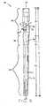
Fig. 1 is a fragmentary, cross-sectional view of a prior art intramedullary nail positioned within a femur and a lag screw extending through a transverse bore of the intramedullary nail to reduce a fracture in the neck of the femur;Fig. 2 is a cross-sectional view of the intramedullary nail ofFig. 1 taken along line 2-2 ofFig. 1 ;Fig. 3 is a fragmentary, side view of the intramedullary nail ofFig. 1 depicting theoretical stress lines extending therethrough that are created during loading of the lag screw shown inFig. 1 ;Fig. 4A is a fragmentary, side view of an intramedullary nail not being an embodiment of the claimed invention.Fig. 4B is a fragmentary view of the intramedullary nail ofFig 4A taken in the direction of line 4B-4B ofFig. 4A ;Fig. 5A is a fragmentary, side view of an intramedullary nail of the present invention according to another exemplary embodiment;Fig. 5B is a fragmentary view of the intramedullary nail ofFig. 5A taken in the direction ofline 5B-5B ofFig. 5A ;Fig. 6A is a fragmentary, side view of an intramedullary nail of the present invention according to another exemplary embodiment;Fig. 6B is a fragmentary view of the intramedullary nail ofFig. 6A taken in the direction of line 6B-6B ofFig. 6A ;Fig. 7A is a fragmentary, side view of an intramedullary nail of the present invention according to another exemplary embodiment; andFig. 7B is a fragmentary view of the intramedullary nail ofFig. 7A taken in the direction of line 7B-7B ofFig. 7A ;Fig. 8 is a cross-sectional view of the intramedullary nail ofFigs 7A and 7B positioned within a femur and further depicting fixation screws and a lag screw; andFig. 9 is a front, side view of the intramedullary nail ofFig. 8 .- Corresponding reference characters indicate corresponding parts throughout the several views. The exemplifications set out herein illustrate preferred embodiments of the invention and such exemplifications are not to be construed as limiting the scope of the invention in any manner.
- Referring to
Figs. 8 and9 ,intramedullary nail 30 is shown and includescutout 32 ofFigs. 7A and 7B , as described in detail below.Intramedullary nail 30 forms a substantially cylindrical, elongate body includingdistal portion 34,transition portion 36, andproximal portion 38. In one exemplary embodiment, longitudinal bore 40 extends along longitudinal axis LA ofintramedullary nail 30.Intramedullary nail 30 may be made of a titanium alloy, such as Ti-6Al-4V, or any other biocompatible orthopedic material, such as medical grade stainless steel or a cobalt-chromium alloy. Transverse,distal bores 42 extend throughdistal portion 34 ofintramedullary nail 30 and receivefixation screws 44 therein. Referring toFig. 8 , fixation screws 44 are positioned to extend throughtransverse bores 42 and are secured toshaft 12 offemur 10. Fixation screws 44 function to prevent rotation within and/or removal ofintramedullary nail 30 fromintramedullary canal 46 offemur 10. - As shown in
Figs. 8 and9 , in addition tobores 42,proximal portion 38 ofintramedullary nail 30 includeswall 49 defining transverse bore 48 through which a lag screw, such aslag screw 50, is positioned. Transverse bore 48 ofintramedullary nail 30 is aligned with the axis ofneck 14 offemur 10, such thatlag screw 50 may be extended throughtransverse bore 48 and implanted intoneck 14 and/or head 16 offemur 10 to reduce a fracture inneck 14 and/or head 16 offemur 10. In exemplary embodiments,intramedullary nail 30 andlag screw 50 may form a collodiaphyseal ("CCD") angle of approximately 125 degrees, 130 degrees, or 135 degrees. While described herein with specific reference to a femur,intramedullary nail 30 may also be used other long bones, such as a tibia, fibula, radius, ulna, and/or clavicle. - In one exemplary embodiment,
proximal portion 38 ofintramedullary nail 30 defines a proximal end ofintramedullary nail 30 and has a proximal diameter. In one exemplary embodiment, the diameter ofproximal portion 38 is approximately 15.5 mm. In one exemplary embodiment,proximal portion 38 defines a proximal portion periphery having a substantially cylindrical shape having a diameter equal to the diameter ofproximal portion 38 and extending along proximal length PL ofproximal portion 38. Referring toFig. 9 , in one exemplary embodiment,distal portion 34 defines a distal end ofintramedullary nail 30 and has a distal diameter. In exemplary embodiments, the diameter ofdistal portion 34 is approximately between 10 mm and 15 mm. In exemplary embodiments, the diameter ofdistal portion 34 may be equal to approximately 10 mm, 11.5 mm, 13 mm, or 14.5 mm.Transition portion 36 extends betweenproximal portion 38 anddistal portion 34 and provides a substantially conical transition section betweenproximal portion 38 anddistal portion 34. In one exemplary embodiment,transition portion 36 has a distal end having a diameter substantially equal to the diameter of the proximal most portion ofdistal portion 34 and a proximal end having a diameter substantially equal to the diameter ofproximal portion 38. For example,transition portion 36 may have a diameter of approximately 15.5 mm at a proximal end thereof and a diameter of approximately 10 mm at a distal end thereof. In one exemplary embodiment,transition portion 36 defines a transition portion periphery having a substantially conical shape with a proximal diameter equal to the diameter at a proximal end oftransition portion 36 and a distal diameter equal to the diameter at a distal end oftransition portion 36 and extending along transition portion length TL. - Still referring to
Fig. 9 , in one exemplary embodiment, theproximal portion 38 ofintramedullary nail 30 has a proximal length PL of approximately 58 mm,transition portion 36 has a transition portion length TL of approximately 31 mm, anddistal portion 34 ofintramedullary nail 30 has a distal portion length DL of between approximately 120 mm and 395 mm. For example,distal portion 34 may have a distal portion length DL as small as approximately 126 mm, 211 mm, 231 mm, 251 mm, or 271 mm and as large as approximately 291 mm, 311 mm, 331 mm, 351 mm, 371 mm, or 391 mm. By combining the overall lengths PL, TL, DL of theproximal portion 38,transition portion 36, anddistal portion 34, respectively, the overall length L ofintramedullary nail 30 is determined. In one exemplary embodiment,intramedullary nail 30 has an overall length L between approximately 210 mm and approximately 480 mm. For example,intramedullary nail 30 may have a length L as small as approximately 215 mm, 300 mm, 320 mm, 340 mm, or 360 mm and as large as approximately 380 mm, 400 mm, 420 mm, 440 mm, 460 mm, or 480 mm. In one exemplary embodiment, length L is equal to approximately 215 mm. - Referring to
transverse bore 48 as shown inFig. 9 , transverse bore 48 of theintramedullary nail 30 forms angle λ with longitudinal axis LA ofintramedullary nail 30. In one exemplary embodiment, angle λ is between approximately 48 degrees and 60 degrees. For example, angle λ may be equal to approximately 49 degrees, 54 degrees, or 59 degrees. Referring to longitudinal bore 40, in one exemplary embodiment, longitudinal bore 40 has a diameter of approximately 4.8 mm, except in the area ofproximal portion 38 where longitudinal bore 40 may be enlarged to accommodate a set screw (not shown) and/or other components that function to prevent and/or limit translation oflag screw 50 within transverse bore 48 ofintramedullary nail 30. - As described in detail above with respect to prior art intramedullary nail (
Fig. 1 ), during walking or other movement, a patient's weight may be transferred to the tip of a lag screw, such aslag screw 50 ofFig. 8 . As a result,lag screw 50 applies a force tointramedullary nail 30 at medial and lateral support points 52, 54, adjacent to medial and lateral openings oftransverse bore 48, respectively. In order to enhance the stress distribution ofintramedullary nail 30 in the vicinity ofsupport point 52, the lateral side ofproximal portion 38 ofintramedullary nail 30 includes a cutout formed therein. As shown inFigs. 8 and9 ,intramedullary nail 30 includescutout 32, which is described in detail below with respect toFigs. 7A and 7B . While described and depicted herein with the cutout formed on the lateral side ofintramedullary nail 30, the cutout may, in other exemplary embodiments, be formed on both the lateral and the medial sides ofintramedullary nail 30 adjacent to the lateral and medial openings oftransverse bore 48, respectively. - Additionally, while
intramedullary nail 30 is shown as includingcutout 32,intramedullary nail 30 may include any of the cutout designs set forth herein, including the use of different cutout designs on the medial and lateral sides ofintramedullary nail 30. Further, as used herein, the term "cutout" refers generally to an area of a material in which the cross-section of the material deviates from an otherwise substantially consistent cross-section, but does not require the independent removal of the material. Thus, as used herein,intramedullary nail 30 may be cast or otherwise formed to include a cutout, even though no machining or manufacturing steps were undertaken to remove material fromintramedullary nail 30 to form the cutout. Further, the cutouts of the present invention result in the creation of a deviation in the periphery ofproximal portion 38, i.e., the proximal portion periphery described above, and/or the periphery oftransition portion 36, i.e., the transition portion periphery described above. For example, the derivation in the periphery ofproximal portion 38 andtransition portion 36 from a cylindrical geometry with a 15.5 mm diameter may be as small as 90 mm3, 95 mm3, 100 mm3, or 105 mm3, and may be as high as 110 mm3, 115 mm3, 120 mm3, or 125 mm3. In one exemplary embodiment, the derivation in the periphery ofproximal portion 38 andtransition portion 36 from a cylindrical geometry with a 15.5 mm diameter may be equal to substantially 106 mm3. - In exemplary embodiments, described in detail below, the cutouts of the present invention define ramp portions that form oblique surfaces with respect to the longitudinal axis LA of
intramedullary nail 30. As a result,intramedullary nail 30 has higher safety margins than similar intramedullary nails, such as those shown inFigs. 1-3 , which are formed in a traditional manner without the cutouts of the present invention. - Referring to
Fig. 4A and 4B ,cutout 56, which is not formed according to an exemplary embodiment of the claimed invention, is shown in conjunction withintramedullary nail 30.Cutout 56 is positioned adjacent to and defines the lateral opening oftransverse bore 48.Cutout 56 includesledge portion 58 and runout portion 60. Runout portion 60 defines a substantially planar surface that extends in a direction substantially parallel to longitudinal axis LA ofintramedullary nail 30 and defines flattened sides surfaces 62, 64 on opposing anterior and posterior sides oftransverse bore 48. For example, runout portion 60 may form an angle as small as 1 degree, 2 degrees, or 3 degrees with longitudinal axis LA and as large as 177 degrees, 178 degrees, or 179 degrees with longitudinal axis LA. In one variant flattened side surfaces 62, 64 have a width W of at least 0.2 mm. By ensuring that width W of flattened side surfaces 62, 64 is at least 0.2 mm, a manufacturing tolerance is provide that helps to ensure that flattened side surfaces 62, 64 are properly formed during the manufacturing process. Ledge portion 58 and runout portion 60 are connected to one another by intermediate portion 66 and are separated from one another by angle a. In one variant, intermediate portion 66 has a radius of curvature of approximately 3 mm. In one variant angle a is substantially equal to 90 degrees. In this embodiment,ledge potion 58 is substantially perpendicular to longitudinal axis LA ofintramedullary nail 30.- In one variant runout portion 60 extends along longitudinal axis LA of
intramedullary nail 30, throughtransition portion 36, and terminates at the proximal end ofdistal portion 34 ofintramedullary nail 30. Specifically, in this variant runout portion 60 is substantially coplanar with a plane tangent to a lateral most portion ofdistal portion 34 and parallel to longitudinal axis LA ofintramedullary nail 30. In other variants, runout portion 60 extends into and terminates withindistal portion 34. In these variants, runout portion 60 is not substantially coplanar with a plane tangent to a lateral most portion ofdistal portion 34, but may be substantially parallel to longitudinal axis LA ofintramedullary nail 30. Alternatively, in other variants, runout portion 60 terminates withintransition portion 36. For example, runout portion 60 may terminate at the periphery oftransition portion 36 as described above with reference to the transition portion periphery. In variants, in order to alter the position at which runout portion 60 terminates distally, i.e., the distal most point of runout portion 60, runout portion 60 is maintained in a plane parallel to longitudinal axis LA ofintramedullary nail 30 and is moved closer to or further away from longitudinal axis LA ofintramedullary nail 30. - By forming
cutout 56 inintramedullary nail 30, material having a thickness T is positioned on the proximal side oflag screw 50 between runout portion 60 and the lateral-most surface ofintramedullary nail 30 positioned proximal oflag screw 50, while a corresponding amount of material is removed from the distal side oflag screw 50. By removing material distally oflag screw 50, the stresses that are introduced in the material directly adjacent to the lateral opening oftransverse bore 48, such as in the area distal ofsupport point 54, and described in detail above, are distributed in a direction toward longitudinal axis LA ofintramedullary nail 30. As a result, the stresses introduced in the material directly adjacent to the lateral opening oftransverse bore 48 are distributed through a portion ofintramedullary nail 30 where the material formingintramedullary nail 30 is thicker, i.e., through a portion ofintramedullary nail 30 spaced a decreased lateral distance from longitudinal axis LA ofintramedullary nail 30 relative to the material directly adjacent to the lateral opening oftransverse bore 48. This allows for the concentration of the stresses in the area of the lateral opening of transverse bore 48 to be reduced, as the stresses are spread throughout the body ofintramedullary nail 30. - As a result,
intramedullary nail 30 may have a decreased thickness relative to known intramedullary nails while providing substantially similar or improved strength properties as compared to known intramedullary nails. For example, as indicated above, the diameter ofproximal portion 38 ofintramedullary nail 30 may be as small as 15.5 mm, while the diameter of a proximal portion of a comparable prior art intramedullary nail is 17 mm. Similarly, the diameter oftransverse bore 48 ofintramedullary nail 30 may be as small as 10.5 mm, while the diameter of the corresponding transverse bore of a comparable prior art intramedullary nail is 12 mm. - In order to further enhance the preferential stress distribution of
intramedullary nail 30 of the present invention, flattened side surfaces 62, 64 may be formed on opposing sides oflateral opening 68 of transverse bore 48 as shown inFig. 4B and described in detail above. Additionally, as shown inFigs. 4A and 4B , the lateral most point ofledge portion 58 definessupport point 54. As a result,support point 54 is maintained in its relative position even in the presence ofcutout 56. - Referring to
Figs. 5A and 5B , an exemplary embodiment of a cutout formed in accordance with the teachings of the present invention is shown ascutout 70.Cutout 70 may be utilized withintramedullary nail 30 ofFigs. 8 and9 and like reference numerals have been used to represent corresponding components therebetween. Referring toFigs. 5A and 5B ,cutout 70 includesledge portion 72,intermediate portion 74,longitudinal portion 76, andramp portion 78.Intermediate portion 74 connectsledge portion 72 tolongitudinal portion 76. In one exemplary embodiment,intermediate portion 74 has a radius of curvature of approximately 3 mm. - Referring to
Figs. 5A and 5B ,longitudinal portion 76 defines a substantially planar surface extending in a plane that is substantially parallel to longitudinal axis LA ofintramedullary nail 30. In one exemplary embodiment,longitudinal portion 76 terminates at a point near, but proximal of, the distal most portion of the wall definingtransverse bore 48. Stated another way,longitudinal portion 76 terminates before reaching the distal most portion oftransverse bore 48. In a similar manner asrunout portion 78 ofcutout 70,longitudinal portion 76 defines flattened side surfaces 80, 82 adjacent to the anterior and posterior sides oftransverse bore 48. In one exemplary embodiment, flattened side surfaces 80, 82 have a width W of at least 0.2 mm. Ramp portion 78 ofcutout 70 defines a substantially planar, oblique surface that extends distally fromlongitudinal portion 76.Ramp portion 78 forms angle β with longitudinal axis LA ofintramedullary nail 30.Ramp portion 78 is oriented such thatramp portion 78 angles toward longitudinal axis LA ofintramedullary nail 30 in a proximal direction and away from longitudinal axis LA ofintramedullary nail 30 in a distal direction. Angle β is between approximately 4 degrees and approximately 12 degrees. Additionally, the smaller that angle β is, thecloser ramp portion 78 is to being parallel to longitudinal axis LA ofintramedullary nail 30. As a result, it is easier to formramp portion 78 during the manufacturing process and the volume of the space provided for bone ingrowth is increased.- Referring to
Figs. 6A and 6B , another exemplary embodiment of a cutout formed in accordance with the teachings of the present invention is shown ascutout 84.Cutout 84 is substantially similar tocutout 70 ofFigs. 5A and 5B and may be utilized withintramedullary nail 30 ofFigs. 8 and9 and like reference numerals have been used to represent identical or substantially identical components therebetween. In contrast tolongitudinal portion 76 ofcutout 70, longitudinal portion 86 ofcutout 84 terminates at a point distal of the distal most portion oftransverse bore 48. In another exemplary embodiment, longitudinal portion 86 may terminate at a point that coincides with the distal most point oftransverse bore 48. - Referring to
Figs. 7A and 7B , another exemplary embodiment of a cutout formed in accordance with the teachings of the present invention is shown ascutout 32.Cutout 32 is substantially similar tocutout 70 ofFigs. 5A and 5B and like reference numerals have been used to identify identical or substantially identical components therebetween. Referring toFigs. 7A and 7B , unlikecutout 70 ofFigs. 5A and 5B , no portion ofcutout 32 is parallel to longitudinal axis LA ofintramedullary nail 30 andcutout 32 lackslongitudinal portion 76. Thus,ledge portion 92 andramp portion 94 ofcutout 32 are connected to one another by intermediate portion 96 and are separated from one another by angle γ. In one exemplary embodiment, angle γ is substantially equal to 90 degrees. In one exemplary embodiment, intermediate portion 96 has a radius of curvature of approximately 3 mm. In one exemplary embodiment,ledge portion 92 is also curved. In one exemplary embodiment,ledge portion 32 has a radius of curvature of approximately 3 mm. - Alternatively, in another exemplary embodiment,
ledge portion 92 may include a substantially planar portion. In one exemplary embodiment, a plane containingledge portion 92 intersects the longitudinal axis oftransverse bore 48 and is substantially perpendicular to longitudinal axis LA ofintramedullary nail 30. Referring now to rampportion 94,ramp portion 94 defines substantiallyplanar surface 98 that tapers away from the longitudinal axis LA ofintramedullary nail 30 in a distal direction to form angle ε (Fig. 7A ) relative to longitudinal axis LA ofintramedullary nail 30. In one exemplary embodiment, angle ε is 9 degrees. In another exemplary embodiment, angle ε is 10 degrees. In a further exemplary embodiment, angle ε is 6 degrees. In exemplary embodiments, angle ε may be any angle in the range of 4-12 degrees. - In exemplary embodiments, due to angles γ and angles ε (
Fig. 7A ),ledge portion 92 may form a slight angle relative to a line that is perpendicular to longitudinal axis LA ofintramedullary nail 30. Thus, whileledge portion 92 may still remain substantially perpendicular to longitudinal axis LA,ledge portion 92 may form an angle δ (Fig. 7A ) with longitudinal axis LA ofintramedullary nail 30. Thus, in exemplary embodiments, instead of angle δ being 90 degrees from longitudinal axis LA andledge portion 92 being perpendicular with longitudinal axis LA, angle δ will, for any particular embodiment, be equal to 180 degrees minus the sum of angle γ and angle ε. For example, when angle γ is 90 degrees and angle ε is 10 degrees, angle δ will be equal to 80 degrees. - In order to form any of
cutouts intramedullary nail 30,cutouts intramedullary nail 30 by advancing a cutting tool having a radius substantially equal to the desired radius ofintermediate portion 66, 74, 96 in a direction substantially transverse to longitudinal axis LA ofintramedullary nail 30. In one exemplary embodiment, a longitudinal axis of the cutting tool is aligned perpendicularly to the longitudinal axis oftransverse bore 48. In one exemplary embodiment, the movement of the cutting tool may be automatically controlled, such as by the use of a computer numerical control ("CNC") machine. Once the cutting tool has reached the desired depth, further movement of the cutting tool into, i.e., in a direction toward longitudinal axis LA ofintramedullary nail 30, is stopped. By advancing a cutting tool having a radius of curvature substantially similar to the radius of curvature ofintermediate portion 66, 74, 96 to the desired depth, bothledge portion intermediate portion 66, 74, 96 are created substantially simultaneously. - Then, in order to form
longitudinal portion 76, 86 or runout portion 60, if required, the cutting tool is moved in a distal direction substantially parallel with longitudinal axis LA ofintramedullary nail 30. Once the cutting tool has been advanced to the desired distal termination point oflongitudinal portion 76, 86 or, for runout portion 60, out of the material formingintramedullary nail 30,ramp portion 78, 90 may be formed. Alternatively, iflongitudinal portion 76, 86 is not required, such as forcutout 32, the step of forminglongitudinal portion 76, 86 is skipped and ramp orrunout portion 60, 78, 90 is formed directly after formingledge portion intermediate portion 66, 74, 96. - In order to form
ramp portion intramedullary nail 30. Stated another way, the cutting tool is advanced away from longitudinal axis LA along a plane forming angle β, ε (Figs. 5A ,7A ) relative to longitudinal axis LA. The advancement of the cutting tool in this manner is continued until the cutting tool no longer contacts the material formingintramedullary nail 30. Once the cutting tool no longer contacts the material formingintramedullary nail 30,ramp portion - Alternatively, in another exemplary embodiment, in order to form
ramp portion longitudinal portion 76, 86, the cutting tool may be removed fromintramedullary nail 30 after formingledge portion intermediate portion 66, 74, 96, and, in some embodiments,longitudinal portion 76, 86 and repositioned at a point that is at the desired distal most point of the cutout. The cutting tool may be advanced from this distal point in a direction that is both into, i.e., toward longitudinal axis LA, and proximal relative tointramedullary nail 30. Stated another way, the cutting tool is advanced toward longitudinal axis LA along a plane forming angle β, ε (Figs. 5A ,7A ) with longitudinal axis LA. As the cutting tool continues to be advanced, the length and depth oframp portion intermediate portion 66, 74, 96 or a distal most point oflongitudinal portion 76, 86. Then, if not yet formed,longitudinal portion 76, 86 may be formed by advancing the cutting tool in a proximal direction parallel with longitudinal axis LA ofintramedullary nail 30. - In another exemplary embodiment,
cutouts 32 are machined intointramedullary nail 30 by advancing a cutting tool having a radius that is greater than the desired radius of intermediate portions 96 from one of an anterior side and a posterior side ofintramedullary nail 30 to the other of the anterior side and the posterior side ofintramedullary nail 30. Specifically, referring toFig. 7A andcutout 32, a longitudinal axis of the cutting tool is aligned to form angle ε with longitudinal axis LA ofintramedullary nail 30. Then, the cutting tool is positioned at one of the anterior or posterior sides ofintramedullary nail 30 with the tip of the cutting tool advanced to a proximal position equal to the desire proximal most point ofledge portion 92. The cutting tool is then advanced across the lateral side ofintramedullary nail 30 to the opposing anterior or posterior side andledge portion 92 andramp portion 94 ofcutout 32 are formed. Additionally, by using a standard cylindrical cutting tool,ledge portion 92 may be formed with angle γ (Fig. 7A ) being substantially equal to ninety degrees. Onceledge portion 92 andramp portion 94 are formed, an additional machining step, such as one of the steps described in detail above, is needed to form intermediate portion 96. In one exemplary embodiment, the movement of the cutting tool may be automatically controlled, such as by the use of a computer numerical control ("CNC") machine. Advantageously, by formingcutouts 32 by using a cutting tool having a diameter greater than the desired diameter of intermediate portions 96 and by advancing the cutting tool acrossintramedullary nail 30 instead of along the longitudinal axis LA ofintramedullary nail 30, less vibration is generated inintramedullary nail 30 during the formation ofcutouts - In other exemplary embodiments,
cutouts intramedullary nail 30 by casting, forging, or other known manufacturing techniques. - While this invention has been described as having a preferred design, the present invention can be further modified within the limits of the appended claims.
Claims (8)
- An intramedullary nail (30), comprising:an elongate body including a proximal end defined by a proximal portion (38), a distal end defined by a distal portion (34), a medial side, a lateral side, and a longitudinal axis (LA), said elongate body defining an elongate body periphery, said proximal portion of said elongate body having an interior wall (49) defining a transverse bore (48) extending therethrough, said transverse bore (48) extending from said lateral side to said medial side of said elongate body in a direction transverse to said longitudinal axis of said elongate body, said proximal portion including a cutout (32) positionedtransverse lateral side said said adjacent to said transverse bore (48) on said lateral side of said elongate body, said cutout (32) comprising:a ledge portion (72) extending in a substantially medial-lateral direction and positioned adjacent to a proximal most edge of said wall defining said transverse bore;a ramp portion (78) defining a substantially planar surface, said ramp portion (78) forming a ramp angle with said longitudinal axis (LA) of said elongate body, wherein said ramp portion extends along the longitudinal axis (LA) of the elongate body in a distal direction, said ramp portion terminating distally at said elongate body periphery, wherein said ramp portion terminates at a position spaced distally from a distal most edge of said wall (49) defining said transverse bore (48); andan intermediate portion (74) positioned between said ledge portion (72) and said ramp portion (78), said intermediate portion having an intermediate portion radius of curvature,characterized in that said ramp angle is between approximately four degrees and approximately twelve degrees.
- The intramedullary nail of Claim 1, wherein said ramp angle is between approximately five degrees and approximately six degrees.
- The intramedullary nail of any one of Claims 1 to 2, wherein said radius of curvature of said intermediate portion is substantially three millimeters.
- The intramedullary nail of any one of Claims 1 to 3, wherein at least a portion of said ledge portion (72) is positioned no more proximally than a proximal most portion of said wall defining said transverse bore, wherein said ledge portion defines a lateral support point for a lag screw received within said transverse bore of said elongate body.
- The intramedullary nail of any one of Claims 1 to 4, wherein said cutout (32) further comprises a longitudinal portion (76) extending between said intermediate portion (74) and said ramp portion (78), said longitudinal portion defining a substantially flat surface extending substantially parallel to said longitudinal axis of said elongate body.
- The intramedullary nail of Claim 5, wherein said longitudinal portion (76) terminates distally at a position between a proximal most edge of said wall defining said transverse bore (48) and a distal most edge of said wall (49) defining said transverse bore, and/or said longitudinal portion terminates distally at a position spaced distally from a distal most edge of said wall (49) defining said transverse bore (48).
- The intramedullary nail of any one of Claims 5 to 6, wherein said longitudinal portion (76) and/or said ramp portion (78) defines flattened side surfaces on opposing anterior and posterior sides of said transverse bore, each of said flattened side surfaces having a width of at least two millimeters.
- The intramedullary nail of any one of Claims 1 to 7, wherein said ledge portion (72) forms a separation angle with said ramp portion (78), said separation angle being equal to substantially ninety degrees.
Applications Claiming Priority (2)
| Application Number | Priority Date | Filing Date | Title |
|---|---|---|---|
| US10558308P | 2008-10-15 | 2008-10-15 | |
| PCT/EP2009/007353WO2010043380A1 (en) | 2008-10-15 | 2009-10-13 | Intramedullary nail |
Publications (3)
| Publication Number | Publication Date |
|---|---|
| EP2349040A1 EP2349040A1 (en) | 2011-08-03 |
| EP2349040B1true EP2349040B1 (en) | 2014-08-20 |
| EP2349040B9 EP2349040B9 (en) | 2014-12-17 |
Family
ID=41460134
Family Applications (1)
| Application Number | Title | Priority Date | Filing Date |
|---|---|---|---|
| EP09740851.2ANot-in-forceEP2349040B9 (en) | 2008-10-15 | 2009-10-13 | Intramedullary nail |
Country Status (7)
| Country | Link |
|---|---|
| US (2) | US8668695B2 (en) |
| EP (1) | EP2349040B9 (en) |
| JP (1) | JP5702290B2 (en) |
| KR (1) | KR101631610B1 (en) |
| CN (1) | CN102176873A (en) |
| ES (1) | ES2524076T3 (en) |
| WO (1) | WO2010043380A1 (en) |
Cited By (2)
| Publication number | Priority date | Publication date | Assignee | Title |
|---|---|---|---|---|
| US11446072B2 (en) | 2017-10-10 | 2022-09-20 | DePuy Synthes Products, Inc. | Self-retaining nail to insertion handle interface |
| US12004785B2 (en) | 2022-04-21 | 2024-06-11 | DePuy Synthes Products, Inc. | Retrograde femoral intramedullary nail, and related systems and methods |
Families Citing this family (38)
| Publication number | Priority date | Publication date | Assignee | Title |
|---|---|---|---|---|
| US20030055316A1 (en)* | 2001-09-19 | 2003-03-20 | Brannon James Kevin | Endoscopic bone debridement |
| EP2094197B8 (en)* | 2006-12-07 | 2016-03-09 | IHip Surgical, LLC | Apparatus for total hip replacement |
| US8579985B2 (en)* | 2006-12-07 | 2013-11-12 | Ihip Surgical, Llc | Method and apparatus for hip replacement |
| US8974540B2 (en) | 2006-12-07 | 2015-03-10 | Ihip Surgical, Llc | Method and apparatus for attachment in a modular hip replacement or fracture fixation device |
| US8328806B2 (en) | 2008-06-24 | 2012-12-11 | Extremity Medical, Llc | Fixation system, an intramedullary fixation assembly and method of use |
| US8303589B2 (en) | 2008-06-24 | 2012-11-06 | Extremity Medical Llc | Fixation system, an intramedullary fixation assembly and method of use |
| US9289220B2 (en) | 2008-06-24 | 2016-03-22 | Extremity Medical Llc | Intramedullary fixation assembly and method of use |
| US9044282B2 (en) | 2008-06-24 | 2015-06-02 | Extremity Medical Llc | Intraosseous intramedullary fixation assembly and method of use |
| US8313487B2 (en)* | 2008-06-24 | 2012-11-20 | Extremity Medical Llc | Fixation system, an intramedullary fixation assembly and method of use |
| US9017329B2 (en) | 2008-06-24 | 2015-04-28 | Extremity Medical, Llc | Intramedullary fixation assembly and method of use |
| ES2524076T3 (en) | 2008-10-15 | 2014-12-04 | Zimmer Gmbh | Intramedullary nail |
| WO2011044917A1 (en)* | 2009-10-13 | 2011-04-21 | Zimmer Gmbh | An orthopedic nail and an orthopedic nail system |
| US8556896B2 (en)* | 2010-01-27 | 2013-10-15 | Zimmer, Inc. | Distal relief for a surgical device |
| USD638125S1 (en)* | 2010-04-13 | 2011-05-17 | Zimmer, Gmbh | Intramedullary nail |
| USD638126S1 (en)* | 2010-04-13 | 2011-05-17 | Zimmer, Gmbh | Intramedullary nail |
| JP5930506B2 (en)* | 2010-09-08 | 2016-06-08 | 帝人ナカシマメディカル株式会社 | Femoral insertion nail |
| CN103648440B (en) | 2011-07-15 | 2017-08-08 | 史密夫和内修有限公司 | Reduced implant stress zones |
| US9427266B2 (en)* | 2012-04-16 | 2016-08-30 | DePuy Synthes Products, Inc. | Bump cut on hole edge |
| EP2712562B1 (en) | 2012-10-01 | 2015-07-29 | Stryker Trauma GmbH | Intramedullary nail and implant system comprising the nail |
| TR201808051T4 (en) | 2012-10-12 | 2018-06-21 | Adc Therapeutics Sa | Pyrrolobenzodiazepine antibody conjugates. |
| DK2906251T3 (en) | 2012-10-12 | 2017-11-20 | Adc Therapeutics Sa | Pyrrolobenzodiazepine-anti-CD22-antibody conjugates |
| SMT201900017T1 (en) | 2012-10-12 | 2019-02-28 | Medimmune Ltd | Pyrrolobenzodiazepine-antibody conjugates |
| ES2660029T3 (en) | 2012-10-12 | 2018-03-20 | Medimmune Limited | Antibody-pyrrolobenzodiazepine conjugates |
| DK2906253T3 (en) | 2012-10-12 | 2018-10-22 | Adc Therapeutics Sa | Pyrrolobenzodiazepine anti-PSMA antibody conjugates |
| KR20150083994A (en) | 2012-10-12 | 2015-07-21 | 스피로즌 살 | Pyrrolobenzodiazepines and conjugates thereof |
| DE102013005414A1 (en)* | 2013-03-28 | 2014-10-02 | Dietmar Wolter | Osteosynthesis system for the multidirectional, angularly stable treatment of fractures of long bones including an intramedullary nail and bone screws |
| ES2701245T3 (en)* | 2014-11-25 | 2019-02-21 | Swemac Innovation Ab | Intramedullary nail |
| US9895177B2 (en) | 2016-01-15 | 2018-02-20 | ARTHREX, GmbH | Bone fixation device for treatment of femoral fractures |
| WO2018042595A1 (en)* | 2016-09-01 | 2018-03-08 | 株式会社オーミック | Thighbone fixing tool |
| US11083503B2 (en) | 2016-09-22 | 2021-08-10 | Globus Medical, Inc. | Systems and methods for intramedullary nail implantation |
| US10492803B2 (en) | 2016-09-22 | 2019-12-03 | Globus Medical, Inc. | Systems and methods for intramedullary nail implantation |
| US10610270B2 (en) | 2018-01-15 | 2020-04-07 | Glw, Inc. | Hybrid intramedullary rods |
| GB201908128D0 (en) | 2019-06-07 | 2019-07-24 | Adc Therapeutics Sa | Pyrrolobenzodiazepine-antibody conjugates |
| US11633219B2 (en) | 2019-06-26 | 2023-04-25 | Globus Medical, Inc. | Fenestrated pedicle nail |
| US11285008B1 (en)* | 2019-11-08 | 2022-03-29 | Omnes Medical Inc. | Hip implant with compression resistance and self-centering features |
| KR102276643B1 (en) | 2019-11-11 | 2021-07-13 | 주식회사 제일메디칼코퍼레이션 | Leg screw for bone fixation having separate structure |
| KR102153491B1 (en) | 2020-03-31 | 2020-09-08 | 한국건설기술연구원 | Apparatus and method for estimating the sound source arrival angle |
| CN116133605A (en) | 2020-05-29 | 2023-05-16 | 史赛克欧洲运营有限公司 | Funnel Hole for Intramedullary Nails |
Family Cites Families (164)
| Publication number | Priority date | Publication date | Assignee | Title |
|---|---|---|---|---|
| US2239088A (en) | 1940-03-30 | 1941-04-22 | Joe J Ettinger | Fracture nail |
| US2518019A (en) | 1946-11-29 | 1950-08-08 | Kane John Timothy | Intramedullary splint |
| US3433220A (en) | 1966-12-30 | 1969-03-18 | Robert E Zickel | Intramedullary rod and cross-nail assembly for treating femur fractures |
| US3996931A (en) | 1975-07-03 | 1976-12-14 | Callender Jr George R | Fractured bone setting fastener assembly |
| US4103683A (en) | 1977-06-03 | 1978-08-01 | Neufeld John A | Sub-trochanteric nail |
| CH651192A5 (en) | 1980-11-20 | 1985-09-13 | Synthes Ag | OSTEOSYNTHETIC DEVICE AND CORRESPONDING DRILL GAUGE. |
| CA1178150A (en) | 1981-06-18 | 1984-11-20 | Emmanuel Anapliotis | Nail for fixing a fracture of the femur |
| US4976258A (en) | 1983-03-09 | 1990-12-11 | Howmedica International, Inc. | Locking nail |
| CH668173A5 (en) | 1984-05-14 | 1988-12-15 | Synthes Ag | DEVICE FOR FIXING TUBE BONE FRACTURES WITH A BONE MARBLE NAIL AND AT LEAST ONE CROSS-BOLT LOCKING. |
| CH666176A5 (en) | 1984-11-30 | 1988-07-15 | Straumann Inst Ag | DEVICE FOR TREATING A BONE AND NAIL FOR SUCH A DEVICE. |
| US4622959A (en) | 1985-03-05 | 1986-11-18 | Marcus Randall E | Multi-use femoral intramedullary nail |
| US4776330A (en) | 1986-06-23 | 1988-10-11 | Pfizer Hospital Products Group, Inc. | Modular femoral fixation system |
| DE8620399U1 (en) | 1986-07-30 | 1986-10-09 | Howmedica GmbH Werk Schönkirchen, 2314 Schönkirchen | Osteosynthesis aids for the treatment of subtrochanteric fractures |
| US4827917A (en) | 1986-12-30 | 1989-05-09 | Richards Medical Company | Fermoral fracture device |
| US5167663A (en) | 1986-12-30 | 1992-12-01 | Smith & Nephew Richards Inc. | Femoral fracture device |
| US5312406A (en) | 1986-12-30 | 1994-05-17 | Smith & Nephew Richards Inc. | Method of treating an intertrochanteric fracture |
| DE3729840C1 (en) | 1987-09-05 | 1989-02-02 | Dauerer Hermann Heinrich Micha | Medullary cavity - locking nail |
| US4846162A (en) | 1987-09-14 | 1989-07-11 | Moehring H David | Orthopedic nail and method of bone fracture fixation |
| DE3734111A1 (en) | 1987-10-06 | 1989-04-20 | Mecron Med Prod Gmbh | INTERMEDIATE NAIL FOR TREATMENT OF BONE BREAKS ACCORDING TO THE PRINCIPLE OF MARBLE NAILING AND MARNEL TOOL |
| US4805607A (en) | 1987-12-03 | 1989-02-21 | Boehringer Mannheim Corporation | Modular intramedullary nail system |
| US5176681A (en) | 1987-12-14 | 1993-01-05 | Howmedica International Inc. | Intramedullary intertrochanteric fracture fixation appliance and fitting device |
| US4875474A (en) | 1988-01-29 | 1989-10-24 | Biomet, Inc. | Variable wall thickness interlocking intramedullary nail |
| CH674613A5 (en) | 1988-03-14 | 1990-06-29 | Synthes Ag | |
| US4895572A (en) | 1988-11-25 | 1990-01-23 | Ira Chernoff | Interlocking femoral prosthesis device |
| DE3840798A1 (en) | 1988-12-01 | 1990-06-21 | Mecron Med Prod Gmbh | MARKING NAIL |
| US5066296A (en) | 1989-02-02 | 1991-11-19 | Pfizer Hopsital Products Group, Inc. | Apparatus for treating a fracture |
| US5034013A (en) | 1989-04-24 | 1991-07-23 | Zimmer Inc. | Intramedullary nail |
| US4978349A (en) | 1989-08-03 | 1990-12-18 | Synthes (U.S.A.) | Fixation plate |
| US5032125A (en) | 1990-02-06 | 1991-07-16 | Smith & Nephew Richards Inc. | Intramedullary hip screw |
| US5112333A (en) | 1990-02-07 | 1992-05-12 | Fixel Irving E | Intramedullary nail |
| US5057103A (en) | 1990-05-01 | 1991-10-15 | Davis Emsley A | Compressive intramedullary nail |
| US5122141A (en) | 1990-08-30 | 1992-06-16 | Zimmer, Inc. | Modular intramedullary nail |
| FR2668360B1 (en) | 1990-10-25 | 1993-02-19 | Armor | DEVICE FOR OSTEOSYNTHESIS OF A HIGH OR STAGEED FRACTURE OF THE FEMUR. |
| GB9111826D0 (en) | 1991-06-01 | 1991-07-24 | Halder Subhash C Dr | Improvements in or relating to bone support |
| DE9109883U1 (en) | 1991-08-09 | 1991-09-26 | Howmedica GmbH, 2314 Schönkirchen | Locking nail for the treatment of femoral fractures in the middle and trochanteric region |
| DE9115201U1 (en) | 1991-12-07 | 1992-02-06 | Howmedica GmbH, 2314 Schönkirchen | Bone nail for the treatment of radius fractures |
| US5356410A (en) | 1991-12-13 | 1994-10-18 | Dietmar Pennig | Adjuvant for osteosynthesis in the case of pertrochanteric fracture of the neck of the femur |
| DE4318150C2 (en) | 1993-06-01 | 1996-08-01 | Endocare Ag | Osteosynthesis tools for the treatment of subtrochanteric and pertrochanteric fractures as well as fractures of the femoral neck |
| FR2698261B1 (en) | 1992-11-24 | 1995-03-17 | Lacaffiniere Jean Yves De | Device for guiding a double screw of the neck of the femur for locked trochantero-diaphyseal nail. |
| US5429640A (en) | 1992-11-27 | 1995-07-04 | Clemson University | Intramedullary rod for fracture fixation of femoral shaft independent of ipsilateral femoral neck fracture fixation |
| WO1994013219A1 (en) | 1992-12-04 | 1994-06-23 | Frigg, Robert | Modular marrow nail |
| US5499986A (en) | 1994-01-07 | 1996-03-19 | Smith & Nephew Richards Inc. | Quick release handle apparatus for removing and inserting intramedullary nails |
| ATE188363T1 (en) | 1994-02-21 | 2000-01-15 | Collux Ab | IMPLANT FOR THE TREATMENT OF FRACTURES OF THE FEMUR |
| US5489284A (en) | 1994-07-15 | 1996-02-06 | Smith & Nephew Richards Inc. | Cannulated modular intramedullary nail |
| US5855579A (en)* | 1994-07-15 | 1999-01-05 | Smith & Nephew, Inc. | Cannulated modular intramedullary nail |
| US5620445A (en) | 1994-07-15 | 1997-04-15 | Brosnahan; Robert | Modular intramedullary nail |
| US5549610A (en) | 1994-10-31 | 1996-08-27 | Smith & Nephew Richards Inc. | Femoral intramedullary nail |
| US5578035A (en) | 1995-05-16 | 1996-11-26 | Lin; Chih-I | Expandable bone marrow cavity fixation device |
| IT1275300B (en) | 1995-06-05 | 1997-08-05 | Gruppo Ind Bioimpianti Srl | BLOCKED ENDOMIDOLLAR NAIL SUITABLE FOR FEMORE FRACTURES IN PARTICULAR |
| US5766174A (en)* | 1995-09-26 | 1998-06-16 | Orthologic Corporation | Intramedullary bone fixation device |
| DE19544750A1 (en) | 1995-11-30 | 1997-06-05 | Christoph Rehberg | Implantable device with internal electrode to promote tissue growth |
| US5658339A (en) | 1996-01-05 | 1997-08-19 | Wright Medical Technology, Inc. | Compression hip screw plate |
| US5658288A (en) | 1996-03-19 | 1997-08-19 | Kim; Andrew C. | Universal dynamic compression device for intramedullary system |
| US5779704A (en) | 1996-03-19 | 1998-07-14 | Kim; Andrew C. | Bi-directional universal dynamic compression device |
| DE69624008T2 (en) | 1996-12-02 | 2003-05-22 | Synthes Ag Chur, Chur | FLAT MARKEL NAIL |
| US6106528A (en) | 1997-02-11 | 2000-08-22 | Orthomatrix, Inc. | Modular intramedullary fixation system and insertion instrumentation |
| EP1342453B1 (en) | 1997-03-19 | 2005-08-24 | Stryker Trauma GmbH | Modular intramedullary nail |
| US5810821A (en) | 1997-03-28 | 1998-09-22 | Biomet Inc. | Bone fixation screw system |
| DE59710521D1 (en) | 1997-10-20 | 2003-09-04 | Synthes Ag | BONE FIXATION DEVICE |
| EP1059888B8 (en) | 1998-03-05 | 2004-03-03 | Synthes AG, Chur | Intramedullary nail with locking hole |
| CN2362450Y (en) | 1998-06-02 | 2000-02-09 | 潘滔 | Femur neck axial controlled inner bone marrow locking nail |
| EP0976365A1 (en) | 1998-07-27 | 2000-02-02 | Osteo Ag | Tibia nail for retrograde insertion |
| JP2973316B1 (en) | 1998-08-05 | 1999-11-08 | 洋司 村嶋 | Fixing structure of lag screw used for nail for implant |
| US6010506A (en) | 1998-09-14 | 2000-01-04 | Smith & Nephew, Inc. | Intramedullary nail hybrid bow |
| US6261289B1 (en) | 1998-10-26 | 2001-07-17 | Mark Levy | Expandable orthopedic device |
| DE19858889B4 (en) | 1998-12-19 | 2008-08-07 | Wolter, Dietmar, Prof. Dr.Med. | Fixation system for bones |
| US6019761A (en) | 1998-12-23 | 2000-02-01 | Gustilo; Ramon B. | Intramedullary nail and method of use |
| US6123708A (en)* | 1999-02-03 | 2000-09-26 | Pioneer Laboratories, Inc. | Intramedullary bone fixation rod |
| US6296645B1 (en) | 1999-04-09 | 2001-10-02 | Depuy Orthopaedics, Inc. | Intramedullary nail with non-metal spacers |
| DE50015249D1 (en) | 1999-05-12 | 2008-08-21 | Zimmer Gmbh | Locking nail for the treatment of femoral stem fractures |
| US7008425B2 (en) | 1999-05-27 | 2006-03-07 | Jonathan Phillips | Pediatric intramedullary nail and method |
| US7018380B2 (en) | 1999-06-10 | 2006-03-28 | Cole J Dean | Femoral intramedullary rod system |
| US6221074B1 (en) | 1999-06-10 | 2001-04-24 | Orthodyne, Inc. | Femoral intramedullary rod system |
| DE50013117D1 (en) | 1999-08-30 | 2006-08-17 | Zimmer Gmbh | Intramedullary nail for the humerus |
| US6926719B2 (en) | 1999-10-21 | 2005-08-09 | Gary W. Sohngen | Modular intramedullary nail |
| ES2214071T3 (en) | 1999-12-03 | 2004-09-01 | Synthes Ag Chur | INTRAMEDULAR KEY. |
| US6706046B2 (en) | 2000-02-01 | 2004-03-16 | Hand Innovations, Inc. | Intramedullary fixation device for metaphyseal long bone fractures and methods of using the same |
| US20040153073A1 (en) | 2000-02-01 | 2004-08-05 | Hand Innovations, Inc. | Orthopedic fixation system including plate element with threaded holes having divergent axes |
| US6235031B1 (en) | 2000-02-04 | 2001-05-22 | Encore Medical Corporation | Intramedullary fracture fixation device |
| US6808527B2 (en) | 2000-04-10 | 2004-10-26 | Depuy Orthopaedics, Inc. | Intramedullary nail with snap-in window insert |
| US6210414B1 (en) | 2000-04-20 | 2001-04-03 | Chin Lin | Bone fastener for shinbone and thighbone |
| US7963966B2 (en) | 2000-06-06 | 2011-06-21 | Cole J Dean | Bone fixation system and method of use |
| JP4278289B2 (en) | 2000-07-27 | 2009-06-10 | 有限会社ケイオーアイ | Intramedullary nail |
| US6579293B1 (en) | 2000-08-02 | 2003-06-17 | Rama E. Chandran | Intramedullary rod with interlocking oblique screw for tibio-calcaneal arthrodesis |
| US6527775B1 (en) | 2000-09-22 | 2003-03-04 | Piper Medical, Inc. | Intramedullary interlocking fixation device for the distal radius |
| YU73000A (en) | 2000-11-22 | 2003-02-28 | Milorad Mitković | Internal fixator of bones |
| CN2471292Y (en) | 2001-01-11 | 2002-01-16 | 万黎 | Automatic pressurized anti-rotation intramedullary nail |
| GB0102141D0 (en) | 2001-01-27 | 2001-03-14 | Davies John B C | Improvements in or relating to expandable bone nails |
| DE20101917U1 (en) | 2001-02-03 | 2002-06-06 | stryker Trauma GmbH, 24232 Schönkirchen | Osteosynthesis aids made of a steel, cobalt and / or titanium alloy |
| US20020151897A1 (en) | 2001-03-30 | 2002-10-17 | Zirkle Lewis G. | Method and apparatus for locating and stabilizing an orthopedic implant |
| US7066943B2 (en) | 2001-03-30 | 2006-06-27 | Zirkle Jr Lewis G | Method and apparatus for locating and stabilizing an orthopedic implant |
| US6818006B2 (en) | 2001-04-03 | 2004-11-16 | Medtronic Vascular, Inc. | Temporary intraluminal filter guidewire |
| DE20105775U1 (en) | 2001-04-03 | 2001-06-07 | Joos, Martin, 95100 Selb | Bone nail for surgical purposes |
| US6648889B2 (en) | 2001-04-24 | 2003-11-18 | Dale G. Bramlet | Intramedullary hip nail with bifurcated lock |
| US6443954B1 (en) | 2001-04-24 | 2002-09-03 | Dale G. Bramlet | Femoral nail intramedullary system |
| US6488684B2 (en) | 2001-04-25 | 2002-12-03 | Dale G. Bramlet | Intramedullary nail |
| US6652528B2 (en)* | 2001-07-17 | 2003-11-25 | Biomet, Inc. | Intramedullary nail with modular sleeve |
| US20030069581A1 (en) | 2001-10-04 | 2003-04-10 | Stinson David T. | Universal intramedullary nails, systems and methods of use thereof |
| WO2003030749A1 (en) | 2001-10-12 | 2003-04-17 | Flores Davila Jorge P | Grooved centro-medullary nail and a method for the osteosynthesis of diaphyseal segments |
| US6835197B2 (en) | 2001-10-17 | 2004-12-28 | Christoph Andreas Roth | Bone fixation system |
| IL147783A0 (en) | 2002-01-23 | 2002-08-14 | Disc O Tech Medical Tech Ltd | Locking mechanism for intramedulliary nails |
| US7247171B2 (en) | 2002-03-11 | 2007-07-24 | Sotereanos Nicholas G | Modular hip implants |
| DE20204655U1 (en) | 2002-03-21 | 2002-06-13 | stryker Trauma GmbH, 24232 Schönkirchen | Locking nail and target device |
| US6981976B1 (en) | 2002-05-13 | 2006-01-03 | Biomet, Inc. | Method and apparatus for inserting and countersinking a modular screw |
| US20060161156A1 (en) | 2002-05-30 | 2006-07-20 | Orbay Jorge L | Fracture fixation device |
| US20060149257A1 (en) | 2002-05-30 | 2006-07-06 | Orbay Jorge L | Fracture fixation device |
| FR2841460B1 (en) | 2002-06-28 | 2005-04-01 | Sanortho | EPIPHYSARY OSTEOSYNTHESIS SCREW IN TWO PARTS, IN PARTICULAR FOR NAILS OR PLATES, AND OSTEOSYNTHESIS DEVICE INCORPORATING IT |
| US7001386B2 (en) | 2002-07-23 | 2006-02-21 | Advanced Orthopaedic Solutions, Inc. | Intramedullary nail for long bone fractures |
| DE60214251T2 (en) | 2002-09-27 | 2007-08-30 | Synthes Gmbh | MARK NAGEL |
| WO2004030550A1 (en) | 2002-10-03 | 2004-04-15 | Synthes Ag Chur | Device for bone fixation |
| WO2004039270A1 (en) | 2002-10-29 | 2004-05-13 | Mathys Medizinaltechnik Ag | Device for the treatment of fractures of the femur |
| US7780664B2 (en) | 2002-12-10 | 2010-08-24 | Depuy Products, Inc. | Endosteal nail |
| DE20301902U1 (en) | 2003-02-07 | 2003-05-15 | stryker Trauma GmbH, 24232 Schönkirchen | Locking nail, especially for proximal femur fractures |
| CN1762010A (en) | 2003-03-18 | 2006-04-19 | 皇家飞利浦电子股份有限公司 | Smooth heat sink or reflector layer for optical record carrier |
| ATE477757T1 (en) | 2003-03-21 | 2010-09-15 | Synthes Gmbh | INTRAMEDULLARY NAIL |
| US20050075637A1 (en) | 2003-04-04 | 2005-04-07 | Semet Elliot Charles | Interlocking IM nails with outer screw |
| AU2004228764B2 (en) | 2003-04-09 | 2007-10-04 | Synthes Gmbh | Intramedullary nail for femur fracture fixation |
| DE10320855B4 (en) | 2003-05-09 | 2008-08-14 | Aesculap Ag & Co. Kg | Implant with a threaded hole for a bone screw |
| EP1624820B1 (en) | 2003-05-17 | 2011-11-16 | Depuy International Limited | An intramedullary nail assembly |
| WO2004110291A1 (en) | 2003-06-12 | 2004-12-23 | Synthes Ag Chur | Surgical nail |
| ES2348003T3 (en) | 2003-06-12 | 2010-11-26 | Synthes Gmbh | SURGICAL KEY. |
| DE20309399U1 (en) | 2003-06-18 | 2003-08-28 | stryker Trauma GmbH, 24232 Schönkirchen | Bone nail, especially proximal femoral nail |
| US7455673B2 (en) | 2003-07-08 | 2008-11-25 | Yechiel Gotfried | Intramedullary nail system and method for fixation of a fractured bone |
| ES2319179T3 (en) | 2003-07-30 | 2009-05-05 | Synthes Gmbh | SURGICAL KEY. |
| NZ545342A (en) | 2003-08-29 | 2008-11-28 | Synthes Gmbh | Intramedullary nail |
| US20050055024A1 (en) | 2003-09-08 | 2005-03-10 | James Anthony H. | Orthopaedic implant and screw assembly |
| US7799030B2 (en) | 2003-09-08 | 2010-09-21 | Smith & Nephew, Inc. | Orthopaedic plate and screw assembly |
| CN100393287C (en) | 2003-09-18 | 2008-06-11 | 斯恩蒂斯有限公司 | Device for treating femoral fractures |
| DE20314742U1 (en) | 2003-09-24 | 2003-12-04 | Stryker Trauma Gmbh | Aiming device for a locking nail and locking nail |
| ES2340479T3 (en) | 2003-10-21 | 2010-06-04 | Synthes Gmbh | INTRAMEDULAR KEY. |
| US6932818B2 (en) | 2003-10-30 | 2005-08-23 | Alfred F. Behrens | Intramedullary nail-based bone fracture treatment |
| CN1886097B (en) | 2003-12-19 | 2010-04-28 | 斯恩蒂斯有限公司 | Intramedullary nail |
| US7601153B2 (en) | 2003-12-25 | 2009-10-13 | Homs Engineering Inc. | Intramedullary nail |
| AU2005206175A1 (en) | 2004-01-16 | 2005-08-04 | Expanding Orthopedics, Inc. | Bone fracture treatment devices |
| US7947043B2 (en)* | 2004-01-20 | 2011-05-24 | Depuy Products, Inc. | Intramedullary nail and associated method |
| US8092454B2 (en) | 2004-03-11 | 2012-01-10 | Sohngen Gary W | Fixation instrument for treating a bone fracture |
| US7771428B2 (en) | 2004-06-11 | 2010-08-10 | Synthes Usa, Llc | Intramedullary rod with spiraling flutes |
| US20060015101A1 (en) | 2004-07-15 | 2006-01-19 | Wright Medical Technology, Inc. | Intramedullary fixation assembly and devices and methods for installing the same |
| ES2306976T3 (en) | 2004-09-27 | 2008-11-16 | Orthofix S.R.L. | INTRAMEDULAR SCREW FOR THE TREATMENT OF FEMUR PROXIMAL FRACTURES. |
| US8435238B2 (en) | 2004-10-05 | 2013-05-07 | Michigan State University | Devices and methods for interlocking surgical screws and nails |
| US20060106389A1 (en) | 2004-11-12 | 2006-05-18 | Reber Erik W | Anti-migration threaded fastener |
| FR2881340B1 (en) | 2005-02-01 | 2008-01-11 | Tornier Sas | HUMERAL NUTS |
| US20060200160A1 (en)* | 2005-02-18 | 2006-09-07 | Ebi, L.P. | Internal fixation assemblies and associated instruments |
| US7232442B2 (en) | 2005-02-22 | 2007-06-19 | Advanced Orthopaedic Solutions | Humeral nail |
| WO2006105673A1 (en) | 2005-04-06 | 2006-10-12 | Synthes Ag Chur | Aiming device |
| WO2007009123A2 (en) | 2005-07-14 | 2007-01-18 | Stout Medical Group, L.P. | Implant systems and methods for use |
| DE102005039854B4 (en) | 2005-08-23 | 2007-07-12 | Königsee Implantate und Instrumente zur Osteosynthese GmbH | Proximal femoral nail |
| US20070049938A1 (en) | 2005-08-31 | 2007-03-01 | Wallace Matthew S | Intramedullary nail assembly with locking component, locking component and nail for use therewith |
| US20070049939A1 (en) | 2005-08-31 | 2007-03-01 | Wallace Matthew S | Intramedullary nail assembly with sleeve and screw for use therewith |
| US20070049940A1 (en) | 2005-08-31 | 2007-03-01 | Wallace Matthew S | Intramedullary nail assembly with fixed securement and associated method |
| US20080249580A1 (en) | 2005-09-28 | 2008-10-09 | Smith & Nephew, Inc. | Methods and Instruments of Reducing a Fracture |
| US7785326B2 (en) | 2005-10-14 | 2010-08-31 | Green Daniel W | System for intramedullary rod fixation and method therefor |
| US20070123876A1 (en) | 2005-10-31 | 2007-05-31 | Czartoski Timothy J | Multiple purpose nail, nail assembly and associated method |
| US20070233104A1 (en) | 2006-03-31 | 2007-10-04 | Metzinger Anthony J | Intramedullary nail implant assembly, kit and method |
| JP4703508B2 (en)* | 2006-08-04 | 2011-06-15 | シンセス株式会社 | Intramedullary nail and nail system with the same |
| US20080119856A1 (en) | 2006-11-20 | 2008-05-22 | Yechiel Gotfried | Intramedullary nail system and method for fixation of a fractured bone |
| US7763023B2 (en) | 2007-02-09 | 2010-07-27 | Yechiel Gotfried | Intramedullary nail system and method for fixation of a fractured bone |
| FR2913876B1 (en)* | 2007-03-20 | 2009-06-05 | Memometal Technologies Soc Par | OSTEOSYNTHESIS DEVICE |
| AU2008256740A1 (en)* | 2007-05-25 | 2008-12-04 | Zimmer, Gmbh | Reinforced intramedullary nail |
| KR101503665B1 (en)* | 2007-06-22 | 2015-03-18 | 이픽스 오소페딕스, 인코포레이티드 | Intramedullary rod for pivoting a fastener |
| US8157803B1 (en)* | 2007-08-21 | 2012-04-17 | Surgical Implant Generation Network | Bone fixation using an intramedullary nail interlocked with a buttress member |
| ES2524076T3 (en) | 2008-10-15 | 2014-12-04 | Zimmer Gmbh | Intramedullary nail |
| USD638126S1 (en) | 2010-04-13 | 2011-05-17 | Zimmer, Gmbh | Intramedullary nail |
| USD638125S1 (en) | 2010-04-13 | 2011-05-17 | Zimmer, Gmbh | Intramedullary nail |
- 2009
- 2009-10-13ESES09740851.2Tpatent/ES2524076T3/enactiveActive
- 2009-10-13KRKR1020117008644Apatent/KR101631610B1/ennot_activeExpired - Fee Related
- 2009-10-13USUS12/578,038patent/US8668695B2/enactiveActive
- 2009-10-13JPJP2011531392Apatent/JP5702290B2/ennot_activeExpired - Fee Related
- 2009-10-13WOPCT/EP2009/007353patent/WO2010043380A1/enactiveApplication Filing
- 2009-10-13CNCN2009801405110Apatent/CN102176873A/enactivePending
- 2009-10-13EPEP09740851.2Apatent/EP2349040B9/ennot_activeNot-in-force
- 2014
- 2014-01-20USUS14/158,946patent/US9474557B2/enactiveActive
Cited By (2)
| Publication number | Priority date | Publication date | Assignee | Title |
|---|---|---|---|---|
| US11446072B2 (en) | 2017-10-10 | 2022-09-20 | DePuy Synthes Products, Inc. | Self-retaining nail to insertion handle interface |
| US12004785B2 (en) | 2022-04-21 | 2024-06-11 | DePuy Synthes Products, Inc. | Retrograde femoral intramedullary nail, and related systems and methods |
Also Published As
| Publication number | Publication date |
|---|---|
| JP2012505672A (en) | 2012-03-08 |
| JP5702290B2 (en) | 2015-04-15 |
| US20140135767A1 (en) | 2014-05-15 |
| KR20110084187A (en) | 2011-07-21 |
| CN102176873A (en) | 2011-09-07 |
| US9474557B2 (en) | 2016-10-25 |
| US20100174284A1 (en) | 2010-07-08 |
| KR101631610B1 (en) | 2016-06-17 |
| WO2010043380A8 (en) | 2011-05-19 |
| WO2010043380A1 (en) | 2010-04-22 |
| EP2349040A1 (en) | 2011-08-03 |
| ES2524076T3 (en) | 2014-12-04 |
| EP2349040B9 (en) | 2014-12-17 |
| US8668695B2 (en) | 2014-03-11 |
Similar Documents
| Publication | Publication Date | Title |
|---|---|---|
| EP2349040B1 (en) | Intramedullary nail | |
| EP2166973B1 (en) | Reinforced intramedullary nail | |
| EP2712562B1 (en) | Intramedullary nail and implant system comprising the nail | |
| US4791918A (en) | Femoral-neck implant | |
| US5041115A (en) | Medullary nail for the tibia | |
| JP3009232B2 (en) | Hip intramedullary screw | |
| US9532818B2 (en) | Orthopedic nail and an orthopedic nail system | |
| JP2001520071A (en) | Bone fixation device | |
| JPH04221548A (en) | Nail in shank pulpa fitted to cross section | |
| MXPA02011712A (en) | Humeral spiral blade. | |
| WO1997047251A9 (en) | Upper extremity bone plate | |
| US8758345B2 (en) | Interlocking nail geometry and method of use | |
| US20210346075A1 (en) | A femoral nail and instrumentation system | |
| EP4268741A1 (en) | Retrograde nail with bone plate | |
| EP4268742A1 (en) | Internal brace plate | |
| JP7637389B2 (en) | Intramedullary nail | |
| EP2473127B1 (en) | An orthopedic nail and an orthopedic nail system | |
| KR101200899B1 (en) | Intramedullary rod with spiraling flutes |
Legal Events
| Date | Code | Title | Description |
|---|---|---|---|
| PUAI | Public reference made under article 153(3) epc to a published international application that has entered the european phase | Free format text:ORIGINAL CODE: 0009012 | |
| 17P | Request for examination filed | Effective date:20110316 | |
| AK | Designated contracting states | Kind code of ref document:A1 Designated state(s):AT BE BG CH CY CZ DE DK EE ES FI FR GB GR HR HU IE IS IT LI LT LU LV MC MK MT NL NO PL PT RO SE SI SK SM TR | |
| DAX | Request for extension of the european patent (deleted) | ||
| 17Q | First examination report despatched | Effective date:20120705 | |
| RIN1 | Information on inventor provided before grant (corrected) | Inventor name:SCHWAMMBERGER, ANDREAS Inventor name:SENGER, RETO Inventor name:DITTMANN, ROLF Inventor name:VELIKOV, JORDAN | |
| GRAP | Despatch of communication of intention to grant a patent | Free format text:ORIGINAL CODE: EPIDOSNIGR1 | |
| INTG | Intention to grant announced | Effective date:20140210 | |
| RIN1 | Information on inventor provided before grant (corrected) | Inventor name:SENGER, RETO Inventor name:DITTMANN, ROLF Inventor name:SCHWAMMBERGER, ANDREAS Inventor name:VELIKOV, JORDAN | |
| GRAS | Grant fee paid | Free format text:ORIGINAL CODE: EPIDOSNIGR3 | |
| GRAP | Despatch of communication of intention to grant a patent | Free format text:ORIGINAL CODE: EPIDOSNIGR1 | |
| GRAA | (expected) grant | Free format text:ORIGINAL CODE: 0009210 | |
| INTG | Intention to grant announced | Effective date:20140704 | |
| AK | Designated contracting states | Kind code of ref document:B1 Designated state(s):AT BE BG CH CY CZ DE DK EE ES FI FR GB GR HR HU IE IS IT LI LT LU LV MC MK MT NL NO PL PT RO SE SI SK SM TR | |
| REG | Reference to a national code | Ref country code:GB Ref legal event code:FG4D | |
| REG | Reference to a national code | Ref country code:CH Ref legal event code:NV Representative=s name:DR. GRAF AND PARTNER AG INTELLECTUAL PROPERTY, CH Ref country code:CH Ref legal event code:EP | |
| REG | Reference to a national code | Ref country code:AT Ref legal event code:REF Ref document number:682977 Country of ref document:AT Kind code of ref document:T Effective date:20140915 | |
| REG | Reference to a national code | Ref country code:IE Ref legal event code:FG4D | |
| REG | Reference to a national code | Ref country code:DE Ref legal event code:R096 Ref document number:602009026136 Country of ref document:DE Effective date:20141002 | |
| REG | Reference to a national code | Ref country code:ES Ref legal event code:FG2A Ref document number:2524076 Country of ref document:ES Kind code of ref document:T3 Effective date:20141204 | |
| REG | Reference to a national code | Ref country code:AT Ref legal event code:MK05 Ref document number:682977 Country of ref document:AT Kind code of ref document:T Effective date:20140820 | |
| REG | Reference to a national code | Ref country code:NL Ref legal event code:VDEP Effective date:20140820 | |
| REG | Reference to a national code | Ref country code:LT Ref legal event code:MG4D | |
| PG25 | Lapsed in a contracting state [announced via postgrant information from national office to epo] | Ref country code:BG Free format text:LAPSE BECAUSE OF FAILURE TO SUBMIT A TRANSLATION OF THE DESCRIPTION OR TO PAY THE FEE WITHIN THE PRESCRIBED TIME-LIMIT Effective date:20141120 Ref country code:SE Free format text:LAPSE BECAUSE OF FAILURE TO SUBMIT A TRANSLATION OF THE DESCRIPTION OR TO PAY THE FEE WITHIN THE PRESCRIBED TIME-LIMIT Effective date:20140820 Ref country code:GR Free format text:LAPSE BECAUSE OF FAILURE TO SUBMIT A TRANSLATION OF THE DESCRIPTION OR TO PAY THE FEE WITHIN THE PRESCRIBED TIME-LIMIT Effective date:20141121 Ref country code:FI Free format text:LAPSE BECAUSE OF FAILURE TO SUBMIT A TRANSLATION OF THE DESCRIPTION OR TO PAY THE FEE WITHIN THE PRESCRIBED TIME-LIMIT Effective date:20140820 Ref country code:NO Free format text:LAPSE BECAUSE OF FAILURE TO SUBMIT A TRANSLATION OF THE DESCRIPTION OR TO PAY THE FEE WITHIN THE PRESCRIBED TIME-LIMIT Effective date:20141120 Ref country code:LT Free format text:LAPSE BECAUSE OF FAILURE TO SUBMIT A TRANSLATION OF THE DESCRIPTION OR TO PAY THE FEE WITHIN THE PRESCRIBED TIME-LIMIT Effective date:20140820 Ref country code:PT Free format text:LAPSE BECAUSE OF FAILURE TO SUBMIT A TRANSLATION OF THE DESCRIPTION OR TO PAY THE FEE WITHIN THE PRESCRIBED TIME-LIMIT Effective date:20141222 | |
| PG25 | Lapsed in a contracting state [announced via postgrant information from national office to epo] | Ref country code:AT Free format text:LAPSE BECAUSE OF FAILURE TO SUBMIT A TRANSLATION OF THE DESCRIPTION OR TO PAY THE FEE WITHIN THE PRESCRIBED TIME-LIMIT Effective date:20140820 Ref country code:IS Free format text:LAPSE BECAUSE OF FAILURE TO SUBMIT A TRANSLATION OF THE DESCRIPTION OR TO PAY THE FEE WITHIN THE PRESCRIBED TIME-LIMIT Effective date:20141220 Ref country code:LV Free format text:LAPSE BECAUSE OF FAILURE TO SUBMIT A TRANSLATION OF THE DESCRIPTION OR TO PAY THE FEE WITHIN THE PRESCRIBED TIME-LIMIT Effective date:20140820 Ref country code:HR Free format text:LAPSE BECAUSE OF FAILURE TO SUBMIT A TRANSLATION OF THE DESCRIPTION OR TO PAY THE FEE WITHIN THE PRESCRIBED TIME-LIMIT Effective date:20140820 | |
| PG25 | Lapsed in a contracting state [announced via postgrant information from national office to epo] | Ref country code:NL Free format text:LAPSE BECAUSE OF FAILURE TO SUBMIT A TRANSLATION OF THE DESCRIPTION OR TO PAY THE FEE WITHIN THE PRESCRIBED TIME-LIMIT Effective date:20140820 | |
| PG25 | Lapsed in a contracting state [announced via postgrant information from national office to epo] | Ref country code:SK Free format text:LAPSE BECAUSE OF FAILURE TO SUBMIT A TRANSLATION OF THE DESCRIPTION OR TO PAY THE FEE WITHIN THE PRESCRIBED TIME-LIMIT Effective date:20140820 Ref country code:CZ Free format text:LAPSE BECAUSE OF FAILURE TO SUBMIT A TRANSLATION OF THE DESCRIPTION OR TO PAY THE FEE WITHIN THE PRESCRIBED TIME-LIMIT Effective date:20140820 Ref country code:EE Free format text:LAPSE BECAUSE OF FAILURE TO SUBMIT A TRANSLATION OF THE DESCRIPTION OR TO PAY THE FEE WITHIN THE PRESCRIBED TIME-LIMIT Effective date:20140820 Ref country code:DK Free format text:LAPSE BECAUSE OF FAILURE TO SUBMIT A TRANSLATION OF THE DESCRIPTION OR TO PAY THE FEE WITHIN THE PRESCRIBED TIME-LIMIT Effective date:20140820 Ref country code:RO Free format text:LAPSE BECAUSE OF FAILURE TO SUBMIT A TRANSLATION OF THE DESCRIPTION OR TO PAY THE FEE WITHIN THE PRESCRIBED TIME-LIMIT Effective date:20140820 | |
| REG | Reference to a national code | Ref country code:DE Ref legal event code:R097 Ref document number:602009026136 Country of ref document:DE | |
| PG25 | Lapsed in a contracting state [announced via postgrant information from national office to epo] | Ref country code:MC Free format text:LAPSE BECAUSE OF FAILURE TO SUBMIT A TRANSLATION OF THE DESCRIPTION OR TO PAY THE FEE WITHIN THE PRESCRIBED TIME-LIMIT Effective date:20140820 Ref country code:LU Free format text:LAPSE BECAUSE OF FAILURE TO SUBMIT A TRANSLATION OF THE DESCRIPTION OR TO PAY THE FEE WITHIN THE PRESCRIBED TIME-LIMIT Effective date:20141013 Ref country code:PL Free format text:LAPSE BECAUSE OF FAILURE TO SUBMIT A TRANSLATION OF THE DESCRIPTION OR TO PAY THE FEE WITHIN THE PRESCRIBED TIME-LIMIT Effective date:20140820 | |
| PLBE | No opposition filed within time limit | Free format text:ORIGINAL CODE: 0009261 | |
| STAA | Information on the status of an ep patent application or granted ep patent | Free format text:STATUS: NO OPPOSITION FILED WITHIN TIME LIMIT | |
| PG25 | Lapsed in a contracting state [announced via postgrant information from national office to epo] | Ref country code:BE Free format text:LAPSE BECAUSE OF NON-PAYMENT OF DUE FEES Effective date:20141031 | |
| 26N | No opposition filed | Effective date:20150521 | |
| REG | Reference to a national code | Ref country code:IE Ref legal event code:MM4A | |
| PG25 | Lapsed in a contracting state [announced via postgrant information from national office to epo] | Ref country code:IE Free format text:LAPSE BECAUSE OF NON-PAYMENT OF DUE FEES Effective date:20141013 | |
| PG25 | Lapsed in a contracting state [announced via postgrant information from national office to epo] | Ref country code:SI Free format text:LAPSE BECAUSE OF FAILURE TO SUBMIT A TRANSLATION OF THE DESCRIPTION OR TO PAY THE FEE WITHIN THE PRESCRIBED TIME-LIMIT Effective date:20140820 | |
| PG25 | Lapsed in a contracting state [announced via postgrant information from national office to epo] | Ref country code:SM Free format text:LAPSE BECAUSE OF FAILURE TO SUBMIT A TRANSLATION OF THE DESCRIPTION OR TO PAY THE FEE WITHIN THE PRESCRIBED TIME-LIMIT Effective date:20140820 | |
| PG25 | Lapsed in a contracting state [announced via postgrant information from national office to epo] | Ref country code:CY Free format text:LAPSE BECAUSE OF FAILURE TO SUBMIT A TRANSLATION OF THE DESCRIPTION OR TO PAY THE FEE WITHIN THE PRESCRIBED TIME-LIMIT Effective date:20140820 | |
| PG25 | Lapsed in a contracting state [announced via postgrant information from national office to epo] | Ref country code:BE Free format text:LAPSE BECAUSE OF FAILURE TO SUBMIT A TRANSLATION OF THE DESCRIPTION OR TO PAY THE FEE WITHIN THE PRESCRIBED TIME-LIMIT Effective date:20140820 Ref country code:MT Free format text:LAPSE BECAUSE OF FAILURE TO SUBMIT A TRANSLATION OF THE DESCRIPTION OR TO PAY THE FEE WITHIN THE PRESCRIBED TIME-LIMIT Effective date:20140820 Ref country code:HU Free format text:LAPSE BECAUSE OF FAILURE TO SUBMIT A TRANSLATION OF THE DESCRIPTION OR TO PAY THE FEE WITHIN THE PRESCRIBED TIME-LIMIT; INVALID AB INITIO Effective date:20091013 | |
| REG | Reference to a national code | Ref country code:FR Ref legal event code:PLFP Year of fee payment:8 | |
| REG | Reference to a national code | Ref country code:FR Ref legal event code:PLFP Year of fee payment:9 | |
| PGFP | Annual fee paid to national office [announced via postgrant information from national office to epo] | Ref country code:TR Payment date:20171013 Year of fee payment:9 | |
| PG25 | Lapsed in a contracting state [announced via postgrant information from national office to epo] | Ref country code:MK Free format text:LAPSE BECAUSE OF FAILURE TO SUBMIT A TRANSLATION OF THE DESCRIPTION OR TO PAY THE FEE WITHIN THE PRESCRIBED TIME-LIMIT Effective date:20140820 | |
| REG | Reference to a national code | Ref country code:FR Ref legal event code:PLFP Year of fee payment:10 | |
| PGFP | Annual fee paid to national office [announced via postgrant information from national office to epo] | Ref country code:FR Payment date:20200921 Year of fee payment:12 Ref country code:GB Payment date:20200918 Year of fee payment:12 | |
| PGFP | Annual fee paid to national office [announced via postgrant information from national office to epo] | Ref country code:CH Payment date:20200922 Year of fee payment:12 | |
| PGFP | Annual fee paid to national office [announced via postgrant information from national office to epo] | Ref country code:DE Payment date:20200918 Year of fee payment:12 Ref country code:ES Payment date:20201118 Year of fee payment:12 Ref country code:IT Payment date:20200922 Year of fee payment:12 | |
| REG | Reference to a national code | Ref country code:DE Ref legal event code:R119 Ref document number:602009026136 Country of ref document:DE | |
| REG | Reference to a national code | Ref country code:CH Ref legal event code:PL | |
| GBPC | Gb: european patent ceased through non-payment of renewal fee | Effective date:20211013 | |
| PG25 | Lapsed in a contracting state [announced via postgrant information from national office to epo] | Ref country code:TR Free format text:LAPSE BECAUSE OF NON-PAYMENT OF DUE FEES Effective date:20181013 | |
| PG25 | Lapsed in a contracting state [announced via postgrant information from national office to epo] | Ref country code:GB Free format text:LAPSE BECAUSE OF NON-PAYMENT OF DUE FEES Effective date:20211013 Ref country code:DE Free format text:LAPSE BECAUSE OF NON-PAYMENT OF DUE FEES Effective date:20220503 | |
| PG25 | Lapsed in a contracting state [announced via postgrant information from national office to epo] | Ref country code:LI Free format text:LAPSE BECAUSE OF NON-PAYMENT OF DUE FEES Effective date:20211031 Ref country code:CH Free format text:LAPSE BECAUSE OF NON-PAYMENT OF DUE FEES Effective date:20211031 | |
| PG25 | Lapsed in a contracting state [announced via postgrant information from national office to epo] | Ref country code:FR Free format text:LAPSE BECAUSE OF NON-PAYMENT OF DUE FEES Effective date:20211031 | |
| PG25 | Lapsed in a contracting state [announced via postgrant information from national office to epo] | Ref country code:IT Free format text:LAPSE BECAUSE OF NON-PAYMENT OF DUE FEES Effective date:20211013 | |
| REG | Reference to a national code | Ref country code:ES Ref legal event code:FD2A Effective date:20230216 | |
| PG25 | Lapsed in a contracting state [announced via postgrant information from national office to epo] | Ref country code:ES Free format text:LAPSE BECAUSE OF NON-PAYMENT OF DUE FEES Effective date:20211014 |