EP2348192B1 - Fan airfoil sheath - Google Patents
Fan airfoil sheathDownload PDFInfo
- Publication number
- EP2348192B1 EP2348192B1EP11250080.6AEP11250080AEP2348192B1EP 2348192 B1EP2348192 B1EP 2348192B1EP 11250080 AEP11250080 AEP 11250080AEP 2348192 B1EP2348192 B1EP 2348192B1
- Authority
- EP
- European Patent Office
- Prior art keywords
- sheath
- airfoil
- blade
- solid portion
- tip
- Prior art date
- Legal status (The legal status is an assumption and is not a legal conclusion. Google has not performed a legal analysis and makes no representation as to the accuracy of the status listed.)
- Active
Links
- 239000007787solidSubstances0.000claimsdescription39
- 239000002131composite materialSubstances0.000claimsdescription33
- RTAQQCXQSZGOHL-UHFFFAOYSA-NTitaniumChemical compound[Ti]RTAQQCXQSZGOHL-UHFFFAOYSA-N0.000claimsdescription8
- 239000010936titaniumSubstances0.000claimsdescription8
- 229910052719titaniumInorganic materials0.000claimsdescription8
- 238000004519manufacturing processMethods0.000claimsdescription2
- 238000000034methodMethods0.000claims4
- 238000005336crackingMethods0.000description15
- 230000032798delaminationEffects0.000description15
- 239000003562lightweight materialSubstances0.000description5
- 239000000463materialSubstances0.000description4
- 229910052782aluminiumInorganic materials0.000description2
- XAGFODPZIPBFFR-UHFFFAOYSA-NaluminiumChemical compound[Al]XAGFODPZIPBFFR-UHFFFAOYSA-N0.000description2
- 238000002485combustion reactionMethods0.000description2
- 230000000977initiatory effectEffects0.000description2
- 229910052751metalInorganic materials0.000description2
- 239000002184metalSubstances0.000description2
- 229920000049Carbon (fiber)Polymers0.000description1
- 239000000853adhesiveSubstances0.000description1
- 230000001070adhesive effectEffects0.000description1
- -1but not limited toSubstances0.000description1
- 239000004917carbon fiberSubstances0.000description1
- 229920001971elastomerPolymers0.000description1
- 239000003822epoxy resinSubstances0.000description1
- 230000003628erosive effectEffects0.000description1
- 239000000446fuelSubstances0.000description1
- 230000007246mechanismEffects0.000description1
- 150000002739metalsChemical class0.000description1
- VNWKTOKETHGBQD-UHFFFAOYSA-NmethaneChemical compoundCVNWKTOKETHGBQD-UHFFFAOYSA-N0.000description1
- 238000012986modificationMethods0.000description1
- 230000004048modificationEffects0.000description1
- 229920000647polyepoxidePolymers0.000description1
- 230000001681protective effectEffects0.000description1
- 230000009467reductionEffects0.000description1
- 229920002050silicone resinPolymers0.000description1
- 230000007704transitionEffects0.000description1
- 238000003466weldingMethods0.000description1
Images


Classifications
- F—MECHANICAL ENGINEERING; LIGHTING; HEATING; WEAPONS; BLASTING
- F01—MACHINES OR ENGINES IN GENERAL; ENGINE PLANTS IN GENERAL; STEAM ENGINES
- F01D—NON-POSITIVE DISPLACEMENT MACHINES OR ENGINES, e.g. STEAM TURBINES
- F01D5/00—Blades; Blade-carrying members; Heating, heat-insulating, cooling or antivibration means on the blades or the members
- F01D5/12—Blades
- F01D5/14—Form or construction
- F01D5/147—Construction, i.e. structural features, e.g. of weight-saving hollow blades
- F—MECHANICAL ENGINEERING; LIGHTING; HEATING; WEAPONS; BLASTING
- F04—POSITIVE - DISPLACEMENT MACHINES FOR LIQUIDS; PUMPS FOR LIQUIDS OR ELASTIC FLUIDS
- F04D—NON-POSITIVE-DISPLACEMENT PUMPS
- F04D29/00—Details, component parts, or accessories
- F04D29/02—Selection of particular materials
- F04D29/023—Selection of particular materials especially adapted for elastic fluid pumps
- F—MECHANICAL ENGINEERING; LIGHTING; HEATING; WEAPONS; BLASTING
- F04—POSITIVE - DISPLACEMENT MACHINES FOR LIQUIDS; PUMPS FOR LIQUIDS OR ELASTIC FLUIDS
- F04D—NON-POSITIVE-DISPLACEMENT PUMPS
- F04D29/00—Details, component parts, or accessories
- F04D29/26—Rotors specially for elastic fluids
- F04D29/32—Rotors specially for elastic fluids for axial flow pumps
- F04D29/321—Rotors specially for elastic fluids for axial flow pumps for axial flow compressors
- F04D29/324—Blades
- F—MECHANICAL ENGINEERING; LIGHTING; HEATING; WEAPONS; BLASTING
- F05—INDEXING SCHEMES RELATING TO ENGINES OR PUMPS IN VARIOUS SUBCLASSES OF CLASSES F01-F04
- F05D—INDEXING SCHEME FOR ASPECTS RELATING TO NON-POSITIVE-DISPLACEMENT MACHINES OR ENGINES, GAS-TURBINES OR JET-PROPULSION PLANTS
- F05D2230/00—Manufacture
- F05D2230/20—Manufacture essentially without removing material
- F05D2230/23—Manufacture essentially without removing material by permanently joining parts together
- F—MECHANICAL ENGINEERING; LIGHTING; HEATING; WEAPONS; BLASTING
- F05—INDEXING SCHEMES RELATING TO ENGINES OR PUMPS IN VARIOUS SUBCLASSES OF CLASSES F01-F04
- F05D—INDEXING SCHEME FOR ASPECTS RELATING TO NON-POSITIVE-DISPLACEMENT MACHINES OR ENGINES, GAS-TURBINES OR JET-PROPULSION PLANTS
- F05D2240/00—Components
- F05D2240/20—Rotors
- F05D2240/30—Characteristics of rotor blades, i.e. of any element transforming dynamic fluid energy to or from rotational energy and being attached to a rotor
- F05D2240/303—Characteristics of rotor blades, i.e. of any element transforming dynamic fluid energy to or from rotational energy and being attached to a rotor related to the leading edge of a rotor blade
- F—MECHANICAL ENGINEERING; LIGHTING; HEATING; WEAPONS; BLASTING
- F05—INDEXING SCHEMES RELATING TO ENGINES OR PUMPS IN VARIOUS SUBCLASSES OF CLASSES F01-F04
- F05D—INDEXING SCHEME FOR ASPECTS RELATING TO NON-POSITIVE-DISPLACEMENT MACHINES OR ENGINES, GAS-TURBINES OR JET-PROPULSION PLANTS
- F05D2300/00—Materials; Properties thereof
- F05D2300/10—Metals, alloys or intermetallic compounds
- F05D2300/13—Refractory metals, i.e. Ti, V, Cr, Zr, Nb, Mo, Hf, Ta, W
- F05D2300/133—Titanium
- F—MECHANICAL ENGINEERING; LIGHTING; HEATING; WEAPONS; BLASTING
- F05—INDEXING SCHEMES RELATING TO ENGINES OR PUMPS IN VARIOUS SUBCLASSES OF CLASSES F01-F04
- F05D—INDEXING SCHEME FOR ASPECTS RELATING TO NON-POSITIVE-DISPLACEMENT MACHINES OR ENGINES, GAS-TURBINES OR JET-PROPULSION PLANTS
- F05D2300/00—Materials; Properties thereof
- F05D2300/60—Properties or characteristics given to material by treatment or manufacturing
- F05D2300/603—Composites; e.g. fibre-reinforced
- Y—GENERAL TAGGING OF NEW TECHNOLOGICAL DEVELOPMENTS; GENERAL TAGGING OF CROSS-SECTIONAL TECHNOLOGIES SPANNING OVER SEVERAL SECTIONS OF THE IPC; TECHNICAL SUBJECTS COVERED BY FORMER USPC CROSS-REFERENCE ART COLLECTIONS [XRACs] AND DIGESTS
- Y02—TECHNOLOGIES OR APPLICATIONS FOR MITIGATION OR ADAPTATION AGAINST CLIMATE CHANGE
- Y02T—CLIMATE CHANGE MITIGATION TECHNOLOGIES RELATED TO TRANSPORTATION
- Y02T50/00—Aeronautics or air transport
- Y02T50/60—Efficient propulsion technologies, e.g. for aircraft
- Y—GENERAL TAGGING OF NEW TECHNOLOGICAL DEVELOPMENTS; GENERAL TAGGING OF CROSS-SECTIONAL TECHNOLOGIES SPANNING OVER SEVERAL SECTIONS OF THE IPC; TECHNICAL SUBJECTS COVERED BY FORMER USPC CROSS-REFERENCE ART COLLECTIONS [XRACs] AND DIGESTS
- Y10—TECHNICAL SUBJECTS COVERED BY FORMER USPC
- Y10T—TECHNICAL SUBJECTS COVERED BY FORMER US CLASSIFICATION
- Y10T29/00—Metal working
- Y10T29/49—Method of mechanical manufacture
- Y10T29/49316—Impeller making
- Y10T29/49336—Blade making
Definitions
- Composite materialsoffer potential design improvements in gas turbine engines. For example, in recent years composite materials have been replacing metals in gas turbine engine fan blades because of their high strength and low weight. Most legacy gas turbine engine fan blades are titanium with a thin cross-section. The ductility of titanium fan blades enables the fan to ingest a bird and remain operable or be safely shut down. The thin cross-section allows high levels of aerodynamic efficiency. The same requirements are present for composite fan blades.
- a composite airfoilhas a root, which connects to the fan mechanism, and a tip opposite the root.
- a composite airfoil for a turbine engine fan bladeis typically designed with a divergent root portion known as a dovetail root.
- the thickness of the airfoilgreatly changes over the length from the tip to the root. This is due to various strength and stiffness requirements in various locations of the airfoil to optimize the performance of the airfoil under various conditions, including a bird strike.
- the composite fan bladeis a two-dimensional laminate fan blade made of many layers of composite material.
- a composite fan bladecan also be made of a three-dimensionally woven preform. Often a sheath is placed over the leading edge of the blade to protect the blade against erosion and damage from the strike of a foreign object, such as a bird.
- EP 1995412 , US 2008/0159868 and EP 0863072teach sheathed fan airfoils.
- a sheath for a fan airfoilaccording to claim 1.
- FIG. 1is a cross-sectional view of gas turbine engine 10, which includes turbofan 12, fan case 13, compressor section 14, combustion section 16 and turbine section 18.
- Compressor section 14includes low-pressure compressor 20 and high-pressure compressor 22. Air is taken in through fan 12 as fan 12 spins in fan case 13. A portion of the inlet air is directed to compressor section 14 where it is compressed by a series of rotating blades and vanes. The compressed air is mixed with fuel, and then ignited in combustor section 16. The combustion exhaust is directed to turbine section 18. Blades and vanes in turbine section 18 extract kinetic energy from the exhaust to turn shaft 24 and provide power output for engine 10.
- Fan 12includes a plurality of composite blades 30 which spin in fan case 13.
- FIG. 2illustrates composite blade 30 with sheath 32.
- FIG. 2Aillustrates a cross-sectional view of composite blade 30 with sheath 32 taken along line A-A in FIG. 2.
- FIG. 2Billustrates a cross-sectional view of composite blade 30 with sheath 32 taken along line B-B in FIG. 2 .
- Composite blade 30includes airfoil 34 with leading edge 36, trailing edge 38, tip 40, root 42, suction side 44 and pressure side 46.
- Sheath 32includes solid portion 48 covering leading edge 36 and tip 40, and tapered flanks 50 extending from each side of solid portion 48.
- the cross-sectional view of composite blade 30 with sheath 32 in FIG. 2Aincludes sheath solid portion 48 with tapered flanks 50, and composite airfoil 34 with leading edge 36, trailing edge 38, suction side 44 and pressure side 46.
- Cross-sectional view of composite blade 30 with sheath 32 in FIG. 2Bincludes solid portion 48 and tapered flanks 50 of sheath 32, and composite airfoil 34 with tip 40, suction side 44 and pressure side 46.
- Sheath 32covers leading edge 36 and tip 40 of airfoil 34 with solid portion 48 by bonding tapered flanks 50 to suction side 44 and pressure side 46 of airfoil 34. Tapered flanks 50 can be bonded to suction side 44 and pressure side 46 with various adhesives including, but not limited to, rubber, silicone or epoxy resin. Sheath 32 can be made of titanium which has sufficient stiffness and strength to withstand an impact load, such as a bird strike. Solid portion 48 of sheath 32 can vary in thickness to ensure that it covers the entire thickness (from suction side 44 to pressure side 46) of leading edge 36 and tip 40 of airfoil 34. The distance which solid portion 48 of sheath 32 extends out from leading edge 36 (see FIG.
- Solid portion 48 covering tip 40can extend about 0.5 inches (12.7 mm) above tip 40, but may vary to ensure a smooth transition from solid portion 48 covering leading edge 36 to solid portion 48 covering tip 40.
- the length of solid portion 48(extending out from leading edge 36 and from tip 40) can vary widely, but must be sufficiently long to provide protection for leading edge 36 and tip 40 of blade 30.
- the length of tapered flanks 50(which bond to suction side 44 and pressure side 46 of airfoil 34) can be about 2 inches (50.8 mm) to about 5 inches (127 mm), but may vary depending on requirements of blade 30 and sheath 32.
- the maximum thickness of each flank 50can vary considerably depending on the length of solid portion 48 of sheath 32, but can be about 0.03 inches (0.762 mm) to about 1 inch (25.4 mm).
- the lengths and percentages for the dimensions of sheath 32are given for example purposes, and can vary depending on requirements for blade 30, sheath 32 and engine 12.
- Sheath 32provides extra strength and stiffness to blade 30, allowing blade 30 to be made of lightweight materials, and still maintain optimal performance and levels of aerodynamic efficiency under impact loading similar to the levels of prior art metal blades.
- Solid portion 48 of sheath 32provides a layer of protection for tip 40 and leading edge 36 of airfoil.
- Tapered flanks 50bond solid portion 48 to airfoil to hold solid portion 48 in place. Tapered flanks 50 further provide extra stiffness to airfoil 48 and more surface area for a smooth load transfer during impacts to blade 30.
- a bladeWhen subject to impact loading, a blade is subject to cracking, delamination (if the blade is a composite laminate blade) and deformation.
- a blade with a sheathis also subject to delamination of the sheath material from the substructure under impact loading. This is especially true for composite blades, as they are usually made from laminates or woven out of lightweight materials.
- Composite blades (and other lightweight blades)are especially subject to deformations, cracking and delamination during impact loading due to reduced stiffness and strain capability of light-weight composite materials as compared to legacy titanium airfoils (which are much stiffer but much heavier).
- This cracking or delamination from an impact loadingis usually initiated at tip 40 or leading edge 36 of airfoil 34.
- This initiation of cracking or delamination at tip 40 or at leading edge 36is also due to the tip (and sometimes the leading edge) of prior art blades not being covered with a protective sheath.
- the cracking and delaminationcan then spread to other sections of the blade, potentially resulting in catastrophic failure of the blade.
- Sheath 32provides significant stiffness improvements to composite blade 30, protecting areas where most failures through delamination or cracking are initiated (leading edge 36 and tip 40) with solid portion 48.
- Solid portion 48provides stiffness and strength to protect areas where most blade failures are initiated, allowing airfoil 34 to be made of light-weight materials and still maintain optimal performance, even under impact loading.
- Tapered flanks 50bond to suction side 44 and pressure side 46 of airfoil 34 to hold solid portion 48 in place. Tapered flanks 50 also provide extra stiffness to blade 30 and help ensure a smooth transfer of impact loads to blade 30. The tapering of flanks 50 helps to reduce stress discontinuities, therefore reducing the likelihood that flanks 50 will peel away from blade 30. Sheath 32 further provides extra protection for tip 40 of blade 30 in situations where blade 30 is designed to rub against fan case 13 (see FIG. 1 ) to minimize the clearance between tip 40 of blade 30 and fan case 13 for aerodynamic efficiency.
- Sheath 32(by providing this extra protection to sections of blade most vulnerable to cracking and deformation from impact loading) also allows blade 30 to maintain a thin cross-section (and thereby maintain levels of aerodynamic efficiency similar to legacy titanium blades) despite using light weight materials in composite blade 30.
- the thickness in some prior art composite (or generally light-weight) bladeswas increased. This additional thickness resulted in a reduction in local strain under impact loading, making the blade more resistant to cracking and delamination failures. However, this additional thickness also resulted in significant aerodynamic efficiency penalties.
- the current inventionallows for a lightweight blade to maintain a thin cross-section (and therefore be able to maintain aerodynamic efficiency) and resist cracking and delamination failures by providing sheath 32 extending across leading edge 36 of blade 30 and over the outer diameter of tip 40 (all places where cracking or delamination is likely to be initiated).
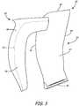
- FIG. 3illustrates an exploded view of composite fan blade 30 and sheath 32 of the current invention.
- Composite fan blade 30includes airfoil 34 with leading edge 36, trailing edge 38, tip 40, root 42, suction side 44 and pressure side 46 (not shown).
- Sheath 32includes solid portion 48 and tapered flanks 50 (with line 52 inserted for illustration purposes only to show where solid portion 48 ends and tapered flanks 50 begin). Sheath 32 is attached to composite airfoil 34 by tapered flanks 50, one of which is bonded onto suction side 44, and one of which is bonded onto pressure side 46 of airfoil 34.
- Solid section 48 of sheath 32fully protects leading edge 36 and tip 40 of airfoil 34 by wrapping one solid portion 48 around airfoil 34 to cover all of leading edge 36 and tip 40. By wrapping one solid portion 48 around leading edge 36 and tip 40, sheath 32 provides extra strength for all areas of airfoil 34 where most delamination failures and/or cracking are initiated.
- the geometry of sheath 32also adds significant stiffness to a blade made of more ductile materials (e.g., aluminum), where post impact permanent deformations are critical to run-on capability of the engine.
- Sheath 32is formed as a single piece.
- the sheathmay be formed from more than one piece (e.g., one piece to wrap around airfoil 34 leading edge 36 and a second piece to wrap around tip 40 of airfoil 34). If formed from more than one piece, pieces of sheath 32 can be secured together (by welding, bonding, etc.) into one piece before bonding sheath 32 onto airfoil 34. This single piece will ensure maximum strength of sheath 32 and therefore maximum protection for airfoil 34.
- Sheath 32is generally made of titanium or another material with similar strength to weight ratios and/or other characteristics which would make it ideal to use in protecting leading edge 36 and tip 40 of airfoil 34. While the present invention has been discussed mainly in relation to composite blades, it is understood that sheath 32 can be used to protect against delamination, deformation and cracking in any type of light weight blade (carbon fiber, aluminum, etc.). While the means of securing sheath 32 to blade 30 is discussed as tapered flanks 50, different means can be used to secure solid portion 48 of sheath 32 to airfoil 34.
- sheath 32includes a solid portion 48 to provide protection to tip 40 and leading edge 36 of blade 30, specifically protecting from the initiation of cracking or delamination failures; and tapered flanks 50 to provide additional stiffness to blade 30 and bond solid portion 48 onto blade 30.
- Sheath 32allows blade 30 to be made of lightweight materials, and still maintain a thin cross-section (to maintain aerodynamic efficiency) as well as maintain the ability to resist cracking or delamination failures due to impact loading.
Landscapes
- Engineering & Computer Science (AREA)
- Mechanical Engineering (AREA)
- General Engineering & Computer Science (AREA)
- Architecture (AREA)
- Structures Of Non-Positive Displacement Pumps (AREA)
Description
- Composite materials offer potential design improvements in gas turbine engines. For example, in recent years composite materials have been replacing metals in gas turbine engine fan blades because of their high strength and low weight. Most legacy gas turbine engine fan blades are titanium with a thin cross-section. The ductility of titanium fan blades enables the fan to ingest a bird and remain operable or be safely shut down. The thin cross-section allows high levels of aerodynamic efficiency. The same requirements are present for composite fan blades.
- A composite airfoil has a root, which connects to the fan mechanism, and a tip opposite the root. A composite airfoil for a turbine engine fan blade is typically designed with a divergent root portion known as a dovetail root. The thickness of the airfoil greatly changes over the length from the tip to the root. This is due to various strength and stiffness requirements in various locations of the airfoil to optimize the performance of the airfoil under various conditions, including a bird strike.
- Traditionally the composite fan blade is a two-dimensional laminate fan blade made of many layers of composite material. A composite fan blade can also be made of a three-dimensionally woven preform. Often a sheath is placed over the leading edge of the blade to protect the blade against erosion and damage from the strike of a foreign object, such as a bird.
EP 1995412 ,US 2008/0159868 andEP 0863072 teach sheathed fan airfoils. - According to a first aspect, there is provided a sheath for a fan airfoil according to claim 1.
- According to a second aspect, there is provided a method of fabricating a fan airfoil according to
claim 10. FIG. 1 is a cross-sectional view of a gas turbine engine.FIG. 2 is a perspective view of a composite blade with sheath according to the present invention.FIG. 2A is a cross-sectional view of the composite blade with sheath ofFIG. 2 from line A-A.FIG. 2B is a cross-sectional view of the composite blade with sheath ofFIG. 2 from line B-B.FIG. 3 is an exploded view of a blade with sheath according to the present invention.FIG. 1 is a cross-sectional view ofgas turbine engine 10, which includesturbofan 12,fan case 13,compressor section 14,combustion section 16 andturbine section 18.Compressor section 14 includes low-pressure compressor 20 and high-pressure compressor 22. Air is taken in throughfan 12 asfan 12 spins infan case 13. A portion of the inlet air is directed tocompressor section 14 where it is compressed by a series of rotating blades and vanes. The compressed air is mixed with fuel, and then ignited incombustor section 16. The combustion exhaust is directed toturbine section 18. Blades and vanes inturbine section 18 extract kinetic energy from the exhaust to turnshaft 24 and provide power output forengine 10.- The portion of inlet air which is taken in through
fan 12 and not directed throughcompressor section 14 is bypass air. Bypass air is directed throughbypass duct 26 by guide vanes 28. Some of the bypass air flows through opening 29 to coolcombustor section 16,high pressure compressor 22 andturbine section 18.Fan 12 includes a plurality ofcomposite blades 30 which spin infan case 13. FIG. 2 illustratescomposite blade 30 withsheath 32.FIG. 2A illustrates a cross-sectional view ofcomposite blade 30 withsheath 32 taken along line A-A inFIG. 2. FIG. 2B illustrates a cross-sectional view ofcomposite blade 30 withsheath 32 taken along line B-B inFIG. 2 .Composite blade 30 includes airfoil 34 with leadingedge 36,trailing edge 38,tip 40,root 42,suction side 44 andpressure side 46. Sheath 32 includessolid portion 48 covering leadingedge 36 andtip 40, andtapered flanks 50 extending from each side ofsolid portion 48. The cross-sectional view ofcomposite blade 30 withsheath 32 inFIG. 2A includes sheathsolid portion 48 withtapered flanks 50, andcomposite airfoil 34 with leadingedge 36,trailing edge 38,suction side 44 andpressure side 46. Cross-sectional view ofcomposite blade 30 withsheath 32 inFIG. 2B includessolid portion 48 andtapered flanks 50 ofsheath 32, andcomposite airfoil 34 withtip 40,suction side 44 andpressure side 46.- Sheath 32 covers leading
edge 36 andtip 40 ofairfoil 34 withsolid portion 48 by bondingtapered flanks 50 tosuction side 44 andpressure side 46 ofairfoil 34. Taperedflanks 50 can be bonded tosuction side 44 andpressure side 46 with various adhesives including, but not limited to, rubber, silicone or epoxy resin. Sheath 32 can be made of titanium which has sufficient stiffness and strength to withstand an impact load, such as a bird strike.Solid portion 48 ofsheath 32 can vary in thickness to ensure that it covers the entire thickness (fromsuction side 44 to pressure side 46) of leadingedge 36 andtip 40 ofairfoil 34. The distance whichsolid portion 48 ofsheath 32 extends out from leading edge 36 (seeFIG. 2A ) can vary across the span (fromroot 42 to tip 40) ofsheath 32, and can be about 5% to about 6% of the length of the chord (the length from leadingedge 36 to trailingedge 38 of airfoil 34) to about 20% of the length of the chord ofairfoil 34.Solid portion 48 covering tip 40 (seeFIG. 2B ) can extend about 0.5 inches (12.7 mm) abovetip 40, but may vary to ensure a smooth transition fromsolid portion 48 covering leadingedge 36 tosolid portion 48 coveringtip 40. The length of solid portion 48 (extending out from leadingedge 36 and from tip 40) can vary widely, but must be sufficiently long to provide protection for leadingedge 36 andtip 40 ofblade 30. The length of tapered flanks 50 (which bond tosuction side 44 andpressure side 46 of airfoil 34) can be about 2 inches (50.8 mm) to about 5 inches (127 mm), but may vary depending on requirements ofblade 30 andsheath 32. The maximum thickness of eachflank 50 can vary considerably depending on the length ofsolid portion 48 ofsheath 32, but can be about 0.03 inches (0.762 mm) to about 1 inch (25.4 mm). The lengths and percentages for the dimensions ofsheath 32 are given for example purposes, and can vary depending on requirements forblade 30,sheath 32 andengine 12. - Sheath 32 provides extra strength and stiffness to
blade 30, allowingblade 30 to be made of lightweight materials, and still maintain optimal performance and levels of aerodynamic efficiency under impact loading similar to the levels of prior art metal blades.Solid portion 48 ofsheath 32 provides a layer of protection fortip 40 and leadingedge 36 of airfoil. Taperedflanks 50 bondsolid portion 48 to airfoil to holdsolid portion 48 in place. Taperedflanks 50 further provide extra stiffness toairfoil 48 and more surface area for a smooth load transfer during impacts toblade 30. - When subject to impact loading, a blade is subject to cracking, delamination (if the blade is a composite laminate blade) and deformation. A blade with a sheath is also subject to delamination of the sheath material from the substructure under impact loading. This is especially true for composite blades, as they are usually made from laminates or woven out of lightweight materials. Composite blades (and other lightweight blades) are especially subject to deformations, cracking and delamination during impact loading due to reduced stiffness and strain capability of light-weight composite materials as compared to legacy titanium airfoils (which are much stiffer but much heavier).
- This cracking or delamination from an impact loading is usually initiated at
tip 40 or leadingedge 36 ofairfoil 34. This initiation of cracking or delamination attip 40 or at leadingedge 36 is also due to the tip (and sometimes the leading edge) of prior art blades not being covered with a protective sheath. The cracking and delamination can then spread to other sections of the blade, potentially resulting in catastrophic failure of the blade.Sheath 32 provides significant stiffness improvements tocomposite blade 30, protecting areas where most failures through delamination or cracking are initiated (leadingedge 36 and tip 40) withsolid portion 48.Solid portion 48 provides stiffness and strength to protect areas where most blade failures are initiated, allowingairfoil 34 to be made of light-weight materials and still maintain optimal performance, even under impact loading. Tapered flanks 50 bond to suctionside 44 andpressure side 46 ofairfoil 34 to holdsolid portion 48 in place. Taperedflanks 50 also provide extra stiffness toblade 30 and help ensure a smooth transfer of impact loads toblade 30. The tapering offlanks 50 helps to reduce stress discontinuities, therefore reducing the likelihood that flanks 50 will peel away fromblade 30.Sheath 32 further provides extra protection fortip 40 ofblade 30 in situations whereblade 30 is designed to rub against fan case 13 (seeFIG. 1 ) to minimize the clearance betweentip 40 ofblade 30 andfan case 13 for aerodynamic efficiency. - Sheath 32 (by providing this extra protection to sections of blade most vulnerable to cracking and deformation from impact loading) also allows
blade 30 to maintain a thin cross-section (and thereby maintain levels of aerodynamic efficiency similar to legacy titanium blades) despite using light weight materials incomposite blade 30. To protect against cracking and delamination failures, the thickness in some prior art composite (or generally light-weight) blades was increased. This additional thickness resulted in a reduction in local strain under impact loading, making the blade more resistant to cracking and delamination failures. However, this additional thickness also resulted in significant aerodynamic efficiency penalties. The current invention allows for a lightweight blade to maintain a thin cross-section (and therefore be able to maintain aerodynamic efficiency) and resist cracking and delamination failures by providingsheath 32 extending across leadingedge 36 ofblade 30 and over the outer diameter of tip 40 (all places where cracking or delamination is likely to be initiated). FIG. 3 illustrates an exploded view ofcomposite fan blade 30 andsheath 32 of the current invention.Composite fan blade 30 includesairfoil 34 with leadingedge 36, trailingedge 38,tip 40,root 42,suction side 44 and pressure side 46 (not shown).Sheath 32 includessolid portion 48 and tapered flanks 50 (withline 52 inserted for illustration purposes only to show wheresolid portion 48 ends and taperedflanks 50 begin).Sheath 32 is attached tocomposite airfoil 34 by taperedflanks 50, one of which is bonded ontosuction side 44, and one of which is bonded ontopressure side 46 ofairfoil 34.Solid section 48 ofsheath 32 fully protects leadingedge 36 andtip 40 ofairfoil 34 by wrapping onesolid portion 48 aroundairfoil 34 to cover all of leadingedge 36 andtip 40. By wrapping onesolid portion 48 around leadingedge 36 andtip 40,sheath 32 provides extra strength for all areas ofairfoil 34 where most delamination failures and/or cracking are initiated. The geometry ofsheath 32 also adds significant stiffness to a blade made of more ductile materials (e.g., aluminum), where post impact permanent deformations are critical to run-on capability of the engine.Sheath 32 is formed as a single piece. In an embodiment not forming part of the present invention, the sheath may be formed from more than one piece (e.g., one piece to wrap aroundairfoil 34 leadingedge 36 and a second piece to wrap aroundtip 40 of airfoil 34). If formed from more than one piece, pieces ofsheath 32 can be secured together (by welding, bonding, etc.) into one piece before bondingsheath 32 ontoairfoil 34. This single piece will ensure maximum strength ofsheath 32 and therefore maximum protection forairfoil 34.Sheath 32 is generally made of titanium or another material with similar strength to weight ratios and/or other characteristics which would make it ideal to use in protecting leadingedge 36 andtip 40 ofairfoil 34. While the present invention has been discussed mainly in relation to composite blades, it is understood thatsheath 32 can be used to protect against delamination, deformation and cracking in any type of light weight blade (carbon fiber, aluminum, etc.). While the means of securingsheath 32 toblade 30 is discussed as taperedflanks 50, different means can be used to securesolid portion 48 ofsheath 32 toairfoil 34.- In summary,
sheath 32 includes asolid portion 48 to provide protection to tip 40 and leadingedge 36 ofblade 30, specifically protecting from the initiation of cracking or delamination failures; and taperedflanks 50 to provide additional stiffness toblade 30 and bondsolid portion 48 ontoblade 30.Sheath 32 allowsblade 30 to be made of lightweight materials, and still maintain a thin cross-section (to maintain aerodynamic efficiency) as well as maintain the ability to resist cracking or delamination failures due to impact loading. - While the invention has been described with reference to an exemplary embodiment(s), it will be understood by those skilled in the art that various changes may be made and equivalents may be substituted for elements thereof without departing from the scope of the invention as defined by the claims. In addition, many modifications may be made to adapt a particular situation or material to the teachings of the invention without departing from the essential scope thereof. Therefore, it is intended that the invention not be limited to the particular embodiment(s) disclosed, but that the invention will include all embodiments falling within the scope of the appended claims.
Claims (13)
- A single piece sheath (32) for a fan airfoil (34), for a gas turbine engine (10), having a leading edge (36), a trailing edge (38), a tip (40), a root (42), a suction side (44) and a pressure side (46), the single piece sheath comprising:a solid portion (48) to wrap around the airfoil to cover all of the leading edge and the airfoil tip; andmeans for securing the solid portion to the airfoil.
- The sheath of claim 1, wherein the means for securing the solid portion to the airfoil comprises a first and a second flank (50) attached to the solid portion (48); preferably wherein the first flank is adapted to be secured to the suction side of the airfoil and the second flank is adapted to be secured to the pressure side of the airfoil.
- The sheath of claim 2, wherein the first and the second flanks (50) are each tapered.
- The sheath of claim 1, 2 or 3, wherein the sheath (32) is titanium.
- A fan blade (30) for a gas turbine engine (10) comprising:a blade (34) with a leading edge (36) and a trailing edge (38) in a chordwise direction, a tip (40) and a root (42) in a spanwise direction, and a suction side (44) and a pressure side (46) in a thickness direction; anda sheath (32) as claimed in any preceding claim with the solid portion (48) covering all of the leading edge and the tip, and first and second tapered flanks (50) securing the solid portion to the blade.
- The fan blade of claim 5, wherein the first flank secures the solid portion to the blade suction side (44) by bonding and the second flank secures the solid portion to the blade pressure side (46) by bonding.
- The fan blade of claim 5 or 6, wherein the solid portion (48) of the sheath extends out from the leading edge (36) at a length of about 5% to about 20% of the length of the blade in the chordwise direction; and/or wherein the solid portion (48) of the sheath extends out from the tip (40) of the blade about 0.5 inches (12.7 mm).
- The fan blade of claim 5, 6 or 7, wherein the first and second flanks (50) are about 2 inches (50.8 mm) to about 5 inches (127 mm) in length.
- The fan blade of claim 5, 6, 7 or 8, wherein the blade is made of composite materials.
- A method of fabricating a fan airfoil (34) for a gas turbine engine (10) with a sheath (32), the method comprising:fabricating the airfoil with a leading edge (36), a trailing edge (38), a tip (40), a root (42), a suction side (44) and a pressure side (46);forming a single piece sheath (32) with a solid portion (48) and a first flank and a second flank attached to the solid portion; andsecuring the single piece sheath to the airfoil so that the solid portion covers all of the leading edge and tip of the airfoil.
- The method of claim 10, wherein the step of fabricating the airfoil comprises:fabricating the airfoil with a composite material.
- The method of claim 10 or 11, wherein the step of forming the sheath comprises forming the sheath of titanium.
- The method of claim 10, 11 or 12, wherein the step of securing the sheath to the airfoil comprises:bonding the first sheath flank (50) to the airfoil suction side (44); andbonding the second sheath flank (50) to the airfoil pressure side (46).
Applications Claiming Priority (1)
| Application Number | Priority Date | Filing Date | Title |
|---|---|---|---|
| US12/693,949US8376712B2 (en) | 2010-01-26 | 2010-01-26 | Fan airfoil sheath |
Publications (3)
| Publication Number | Publication Date |
|---|---|
| EP2348192A2 EP2348192A2 (en) | 2011-07-27 |
| EP2348192A3 EP2348192A3 (en) | 2014-07-23 |
| EP2348192B1true EP2348192B1 (en) | 2018-08-08 |
Family
ID=43629652
Family Applications (1)
| Application Number | Title | Priority Date | Filing Date |
|---|---|---|---|
| EP11250080.6AActiveEP2348192B1 (en) | 2010-01-26 | 2011-01-26 | Fan airfoil sheath |
Country Status (2)
| Country | Link |
|---|---|
| US (1) | US8376712B2 (en) |
| EP (1) | EP2348192B1 (en) |
Families Citing this family (30)
| Publication number | Priority date | Publication date | Assignee | Title |
|---|---|---|---|---|
| US9121294B2 (en) | 2011-12-20 | 2015-09-01 | General Electric Company | Fan blade with composite core and wavy wall trailing edge cladding |
| JP6083112B2 (en)* | 2012-01-30 | 2017-02-22 | 株式会社Ihi | Aircraft jet engine fan blades |
| JP5982837B2 (en)* | 2012-01-30 | 2016-08-31 | 株式会社Ihi | Aircraft jet engine fan blades |
| US9140130B2 (en)* | 2012-03-08 | 2015-09-22 | United Technologies Corporation | Leading edge protection and method of making |
| FR2987867B1 (en) | 2012-03-09 | 2016-05-06 | Snecma | TURBOMACHINE DAWN COMPRISING A PROTECTIVE INSERT FOR THE HEAD OF THE DAWN |
| US20140013599A1 (en)* | 2012-07-11 | 2014-01-16 | Pratt & Whitney | Method of Manufacturing Fan Blade Shields |
| US20140219808A1 (en)* | 2012-10-01 | 2014-08-07 | United Technologies Corporation | Sheath with extended wings |
| US9617860B2 (en) | 2012-12-20 | 2017-04-11 | United Technologies Corporation | Fan blades for gas turbine engines with reduced stress concentration at leading edge |
| WO2014143262A1 (en)* | 2013-03-15 | 2014-09-18 | United Technologies Corporation | Locally extended leading edge sheath for fan airfoil |
| US9845162B2 (en)* | 2013-05-03 | 2017-12-19 | The Boeing Company | Protective finish for wing tip devices |
| WO2015034612A1 (en)* | 2013-09-09 | 2015-03-12 | United Technologies Corporation | Fan blades and manufacture methods |
| EP3044417B1 (en)* | 2013-09-09 | 2019-10-02 | United Technologies Corporation | Fan blades and manufacture methods |
| US20160201482A1 (en)* | 2013-09-17 | 2016-07-14 | United Technologies Corporation | Aluminum airfoil with titanium coating |
| US10107105B2 (en)* | 2014-06-11 | 2018-10-23 | United Technologies Corporation | Fan blade grounding tab |
| EP3020925A1 (en)* | 2014-10-29 | 2016-05-18 | Alstom Technology Ltd | Rotor blade with edge protection |
| CN105604978B (en)* | 2014-11-21 | 2018-03-23 | 中国航发商用航空发动机有限责任公司 | The enhanced turbogenerator fan blade of shock resistance |
| US9745851B2 (en)* | 2015-01-15 | 2017-08-29 | General Electric Company | Metal leading edge on composite blade airfoil and shank |
| FR3035679B1 (en)* | 2015-04-29 | 2018-06-01 | Safran Aircraft Engines | COMPOSITE AUBE COMPRISING AN ATTACK EDGE REINFORCEMENT IN ANOTHER MATERIAL |
| FR3045713B1 (en)* | 2015-12-21 | 2020-09-18 | Snecma | ATTACK EDGE SHIELD |
| US10677259B2 (en) | 2016-05-06 | 2020-06-09 | General Electric Company | Apparatus and system for composite fan blade with fused metal lead edge |
| JP7116459B2 (en)* | 2017-10-05 | 2022-08-10 | 国立研究開発法人宇宙航空研究開発機構 | Ducted fan, multicopter, vertical take-off and landing aircraft, CPU cooling fan and radiator cooling fan |
| US10760428B2 (en)* | 2018-10-16 | 2020-09-01 | General Electric Company | Frangible gas turbine engine airfoil |
| GB201900911D0 (en) | 2019-01-23 | 2019-03-13 | Rolls Royce Plc | A method of forming a protective sheath for an aerofoil component |
| US11215054B2 (en)* | 2019-10-30 | 2022-01-04 | Raytheon Technologies Corporation | Airfoil with encapsulating sheath |
| US11466576B2 (en) | 2019-11-04 | 2022-10-11 | Raytheon Technologies Corporation | Airfoil with continuous stiffness joint |
| US11225874B2 (en) | 2019-12-20 | 2022-01-18 | Raytheon Technologies Corporation | Turbine engine rotor blade with castellated tip surface |
| FR3112821B1 (en)* | 2020-07-22 | 2023-05-12 | Safran Aircraft Engines | BLADE SHIELD IN COMPOSITE MATERIAL, BLADE AND TURBOMACHINE COMPRISING THE SHIELD, PROCESS FOR MANUFACTURING THE BLADE |
| US20220136394A1 (en)* | 2020-10-30 | 2022-05-05 | Raytheon Technologies Corporation | Composite fan blade leading edge sheath with encapsulating extension |
| US11988103B2 (en)* | 2021-10-27 | 2024-05-21 | General Electric Company | Airfoils for a fan section of a turbine engine |
| US20250243766A1 (en)* | 2024-01-31 | 2025-07-31 | Honeywell International Inc. | Polymer-metal composite stator vanes and methods for manufacturing the same |
Family Cites Families (15)
| Publication number | Priority date | Publication date | Assignee | Title |
|---|---|---|---|---|
| US1793775A (en)* | 1929-06-04 | 1931-02-24 | Hartzell Industries | Metal tipping for propellers |
| US4006999A (en) | 1975-07-17 | 1977-02-08 | The United States Of America As Represented By The Administrator Of The National Aeronautics And Space Administration | Leading edge protection for composite blades |
| US4010530A (en) | 1975-07-24 | 1977-03-08 | United Technologies Corporation | Method for making blade protective sheaths |
| FR2599425B1 (en) | 1986-05-28 | 1988-08-05 | Alsthom | PROTECTIVE PLATE FOR TITANIUM BLADE AND METHOD OF BRAZING SUCH A PLATE. |
| US5261796A (en) | 1991-04-18 | 1993-11-16 | Vickers, Incorporated | Electric-motor in-line integrated hydraulic pump |
| US5449273A (en) | 1994-03-21 | 1995-09-12 | United Technologies Corporation | Composite airfoil leading edge protection |
| FR2745589B1 (en)* | 1996-02-29 | 1998-04-30 | Snecma | HIGH STRENGTH-TO-MASS HYBRID PART AND METHOD FOR PRODUCING THE SAME |
| US5881972A (en)* | 1997-03-05 | 1999-03-16 | United Technologies Corporation | Electroformed sheath and airfoiled component construction |
| US6341747B1 (en) | 1999-10-28 | 2002-01-29 | United Technologies Corporation | Nanocomposite layered airfoil |
| US6413051B1 (en) | 2000-10-30 | 2002-07-02 | General Electric Company | Article including a composite laminated end portion with a discrete end barrier and method for making and repairing |
| US6607358B2 (en) | 2002-01-08 | 2003-08-19 | General Electric Company | Multi-component hybrid turbine blade |
| US7186092B2 (en) | 2004-07-26 | 2007-03-06 | General Electric Company | Airfoil having improved impact and erosion resistance and method for preparing same |
| US7780410B2 (en)* | 2006-12-27 | 2010-08-24 | General Electric Company | Method and apparatus for gas turbine engines |
| US20080253922A1 (en)* | 2007-04-13 | 2008-10-16 | General Electric Company | Method for roughening metal surfaces and article manufactured thereby |
| US8088498B2 (en)* | 2007-05-23 | 2012-01-03 | Hamilton Sundstrand Corporation | Electro-formed sheath for use on airfoil components |
- 2010
- 2010-01-26USUS12/693,949patent/US8376712B2/enactiveActive
- 2011
- 2011-01-26EPEP11250080.6Apatent/EP2348192B1/enactiveActive
Non-Patent Citations (1)
| Title |
|---|
| None* |
Also Published As
| Publication number | Publication date |
|---|---|
| US20110182740A1 (en) | 2011-07-28 |
| EP2348192A2 (en) | 2011-07-27 |
| US8376712B2 (en) | 2013-02-19 |
| EP2348192A3 (en) | 2014-07-23 |
Similar Documents
| Publication | Publication Date | Title |
|---|---|---|
| EP2348192B1 (en) | Fan airfoil sheath | |
| US8851855B2 (en) | Composite turbomachine blade | |
| US8858182B2 (en) | Fan blade with sheath | |
| CN111287802B (en) | Multi-material leading edge protector | |
| EP2971528B2 (en) | Hollow fan blade with extended wing sheath | |
| US9157327B2 (en) | Hybrid metal fan blade | |
| EP3364042B1 (en) | Fan for gas turbine engine with mistuned blades | |
| US8721294B2 (en) | Airfoil with galvanically isolated metal coating | |
| EP2971526B1 (en) | Locally extended leading edge sheath for fan airfoil | |
| EP3816399B1 (en) | Airfoil with encapsulating sheath | |
| US20160003060A1 (en) | Hybrid fan blades for jet engines | |
| EP3049635B1 (en) | Aluminum airfoil with titanium coating | |
| US20140219808A1 (en) | Sheath with extended wings | |
| EP2900922B1 (en) | Airfoil with galvanic corrosion preventive shims |
Legal Events
| Date | Code | Title | Description |
|---|---|---|---|
| PUAI | Public reference made under article 153(3) epc to a published international application that has entered the european phase | Free format text:ORIGINAL CODE: 0009012 | |
| AK | Designated contracting states | Kind code of ref document:A2 Designated state(s):AL AT BE BG CH CY CZ DE DK EE ES FI FR GB GR HR HU IE IS IT LI LT LU LV MC MK MT NL NO PL PT RO RS SE SI SK SM TR | |
| AX | Request for extension of the european patent | Extension state:BA ME | |
| PUAL | Search report despatched | Free format text:ORIGINAL CODE: 0009013 | |
| AK | Designated contracting states | Kind code of ref document:A3 Designated state(s):AL AT BE BG CH CY CZ DE DK EE ES FI FR GB GR HR HU IE IS IT LI LT LU LV MC MK MT NL NO PL PT RO RS SE SI SK SM TR | |
| AX | Request for extension of the european patent | Extension state:BA ME | |
| RIC1 | Information provided on ipc code assigned before grant | Ipc:B23P 15/04 20060101ALI20140613BHEP Ipc:F01D 5/14 20060101AFI20140613BHEP | |
| 17P | Request for examination filed | Effective date:20150123 | |
| RBV | Designated contracting states (corrected) | Designated state(s):AL AT BE BG CH CY CZ DE DK EE ES FI FR GB GR HR HU IE IS IT LI LT LU LV MC MK MT NL NO PL PT RO RS SE SI SK SM TR | |
| RAP1 | Party data changed (applicant data changed or rights of an application transferred) | Owner name:UNITED TECHNOLOGIES CORPORATION | |
| STAA | Information on the status of an ep patent application or granted ep patent | Free format text:STATUS: EXAMINATION IS IN PROGRESS | |
| 17Q | First examination report despatched | Effective date:20170913 | |
| GRAP | Despatch of communication of intention to grant a patent | Free format text:ORIGINAL CODE: EPIDOSNIGR1 | |
| STAA | Information on the status of an ep patent application or granted ep patent | Free format text:STATUS: GRANT OF PATENT IS INTENDED | |
| INTG | Intention to grant announced | Effective date:20180226 | |
| GRAS | Grant fee paid | Free format text:ORIGINAL CODE: EPIDOSNIGR3 | |
| GRAA | (expected) grant | Free format text:ORIGINAL CODE: 0009210 | |
| STAA | Information on the status of an ep patent application or granted ep patent | Free format text:STATUS: THE PATENT HAS BEEN GRANTED | |
| AK | Designated contracting states | Kind code of ref document:B1 Designated state(s):AL AT BE BG CH CY CZ DE DK EE ES FI FR GB GR HR HU IE IS IT LI LT LU LV MC MK MT NL NO PL PT RO RS SE SI SK SM TR | |
| REG | Reference to a national code | Ref country code:GB Ref legal event code:FG4D | |
| REG | Reference to a national code | Ref country code:CH Ref legal event code:EP Ref country code:AT Ref legal event code:REF Ref document number:1027246 Country of ref document:AT Kind code of ref document:T Effective date:20180815 | |
| REG | Reference to a national code | Ref country code:IE Ref legal event code:FG4D | |
| REG | Reference to a national code | Ref country code:DE Ref legal event code:R096 Ref document number:602011050775 Country of ref document:DE | |
| REG | Reference to a national code | Ref country code:NL Ref legal event code:MP Effective date:20180808 | |
| REG | Reference to a national code | Ref country code:LT Ref legal event code:MG4D | |
| REG | Reference to a national code | Ref country code:AT Ref legal event code:MK05 Ref document number:1027246 Country of ref document:AT Kind code of ref document:T Effective date:20180808 | |
| PG25 | Lapsed in a contracting state [announced via postgrant information from national office to epo] | Ref country code:BG Free format text:LAPSE BECAUSE OF FAILURE TO SUBMIT A TRANSLATION OF THE DESCRIPTION OR TO PAY THE FEE WITHIN THE PRESCRIBED TIME-LIMIT Effective date:20181108 Ref country code:NL Free format text:LAPSE BECAUSE OF FAILURE TO SUBMIT A TRANSLATION OF THE DESCRIPTION OR TO PAY THE FEE WITHIN THE PRESCRIBED TIME-LIMIT Effective date:20180808 Ref country code:PL Free format text:LAPSE BECAUSE OF FAILURE TO SUBMIT A TRANSLATION OF THE DESCRIPTION OR TO PAY THE FEE WITHIN THE PRESCRIBED TIME-LIMIT Effective date:20180808 Ref country code:LT Free format text:LAPSE BECAUSE OF FAILURE TO SUBMIT A TRANSLATION OF THE DESCRIPTION OR TO PAY THE FEE WITHIN THE PRESCRIBED TIME-LIMIT Effective date:20180808 Ref country code:RS Free format text:LAPSE BECAUSE OF FAILURE TO SUBMIT A TRANSLATION OF THE DESCRIPTION OR TO PAY THE FEE WITHIN THE PRESCRIBED TIME-LIMIT Effective date:20180808 Ref country code:IS Free format text:LAPSE BECAUSE OF FAILURE TO SUBMIT A TRANSLATION OF THE DESCRIPTION OR TO PAY THE FEE WITHIN THE PRESCRIBED TIME-LIMIT Effective date:20181208 Ref country code:AT Free format text:LAPSE BECAUSE OF FAILURE TO SUBMIT A TRANSLATION OF THE DESCRIPTION OR TO PAY THE FEE WITHIN THE PRESCRIBED TIME-LIMIT Effective date:20180808 Ref country code:GR Free format text:LAPSE BECAUSE OF FAILURE TO SUBMIT A TRANSLATION OF THE DESCRIPTION OR TO PAY THE FEE WITHIN THE PRESCRIBED TIME-LIMIT Effective date:20181109 Ref country code:NO Free format text:LAPSE BECAUSE OF FAILURE TO SUBMIT A TRANSLATION OF THE DESCRIPTION OR TO PAY THE FEE WITHIN THE PRESCRIBED TIME-LIMIT Effective date:20181108 Ref country code:SE Free format text:LAPSE BECAUSE OF FAILURE TO SUBMIT A TRANSLATION OF THE DESCRIPTION OR TO PAY THE FEE WITHIN THE PRESCRIBED TIME-LIMIT Effective date:20180808 Ref country code:FI Free format text:LAPSE BECAUSE OF FAILURE TO SUBMIT A TRANSLATION OF THE DESCRIPTION OR TO PAY THE FEE WITHIN THE PRESCRIBED TIME-LIMIT Effective date:20180808 | |
| PG25 | Lapsed in a contracting state [announced via postgrant information from national office to epo] | Ref country code:ES Free format text:LAPSE BECAUSE OF FAILURE TO SUBMIT A TRANSLATION OF THE DESCRIPTION OR TO PAY THE FEE WITHIN THE PRESCRIBED TIME-LIMIT Effective date:20180808 Ref country code:HR Free format text:LAPSE BECAUSE OF FAILURE TO SUBMIT A TRANSLATION OF THE DESCRIPTION OR TO PAY THE FEE WITHIN THE PRESCRIBED TIME-LIMIT Effective date:20180808 Ref country code:AL Free format text:LAPSE BECAUSE OF FAILURE TO SUBMIT A TRANSLATION OF THE DESCRIPTION OR TO PAY THE FEE WITHIN THE PRESCRIBED TIME-LIMIT Effective date:20180808 Ref country code:LV Free format text:LAPSE BECAUSE OF FAILURE TO SUBMIT A TRANSLATION OF THE DESCRIPTION OR TO PAY THE FEE WITHIN THE PRESCRIBED TIME-LIMIT Effective date:20180808 | |
| PG25 | Lapsed in a contracting state [announced via postgrant information from national office to epo] | Ref country code:EE Free format text:LAPSE BECAUSE OF FAILURE TO SUBMIT A TRANSLATION OF THE DESCRIPTION OR TO PAY THE FEE WITHIN THE PRESCRIBED TIME-LIMIT Effective date:20180808 Ref country code:RO Free format text:LAPSE BECAUSE OF FAILURE TO SUBMIT A TRANSLATION OF THE DESCRIPTION OR TO PAY THE FEE WITHIN THE PRESCRIBED TIME-LIMIT Effective date:20180808 Ref country code:CZ Free format text:LAPSE BECAUSE OF FAILURE TO SUBMIT A TRANSLATION OF THE DESCRIPTION OR TO PAY THE FEE WITHIN THE PRESCRIBED TIME-LIMIT Effective date:20180808 Ref country code:IT Free format text:LAPSE BECAUSE OF FAILURE TO SUBMIT A TRANSLATION OF THE DESCRIPTION OR TO PAY THE FEE WITHIN THE PRESCRIBED TIME-LIMIT Effective date:20180808 | |
| REG | Reference to a national code | Ref country code:DE Ref legal event code:R097 Ref document number:602011050775 Country of ref document:DE | |
| PG25 | Lapsed in a contracting state [announced via postgrant information from national office to epo] | Ref country code:SM Free format text:LAPSE BECAUSE OF FAILURE TO SUBMIT A TRANSLATION OF THE DESCRIPTION OR TO PAY THE FEE WITHIN THE PRESCRIBED TIME-LIMIT Effective date:20180808 Ref country code:SK Free format text:LAPSE BECAUSE OF FAILURE TO SUBMIT A TRANSLATION OF THE DESCRIPTION OR TO PAY THE FEE WITHIN THE PRESCRIBED TIME-LIMIT Effective date:20180808 Ref country code:DK Free format text:LAPSE BECAUSE OF FAILURE TO SUBMIT A TRANSLATION OF THE DESCRIPTION OR TO PAY THE FEE WITHIN THE PRESCRIBED TIME-LIMIT Effective date:20180808 | |
| PLBE | No opposition filed within time limit | Free format text:ORIGINAL CODE: 0009261 | |
| STAA | Information on the status of an ep patent application or granted ep patent | Free format text:STATUS: NO OPPOSITION FILED WITHIN TIME LIMIT | |
| 26N | No opposition filed | Effective date:20190509 | |
| PG25 | Lapsed in a contracting state [announced via postgrant information from national office to epo] | Ref country code:SI Free format text:LAPSE BECAUSE OF FAILURE TO SUBMIT A TRANSLATION OF THE DESCRIPTION OR TO PAY THE FEE WITHIN THE PRESCRIBED TIME-LIMIT Effective date:20180808 Ref country code:MC Free format text:LAPSE BECAUSE OF FAILURE TO SUBMIT A TRANSLATION OF THE DESCRIPTION OR TO PAY THE FEE WITHIN THE PRESCRIBED TIME-LIMIT Effective date:20180808 | |
| REG | Reference to a national code | Ref country code:CH Ref legal event code:PL | |
| PG25 | Lapsed in a contracting state [announced via postgrant information from national office to epo] | Ref country code:LU Free format text:LAPSE BECAUSE OF NON-PAYMENT OF DUE FEES Effective date:20190126 | |
| REG | Reference to a national code | Ref country code:BE Ref legal event code:MM Effective date:20190131 | |
| REG | Reference to a national code | Ref country code:IE Ref legal event code:MM4A | |
| PG25 | Lapsed in a contracting state [announced via postgrant information from national office to epo] | Ref country code:BE Free format text:LAPSE BECAUSE OF NON-PAYMENT OF DUE FEES Effective date:20190131 | |
| PG25 | Lapsed in a contracting state [announced via postgrant information from national office to epo] | Ref country code:LI Free format text:LAPSE BECAUSE OF NON-PAYMENT OF DUE FEES Effective date:20190131 Ref country code:CH Free format text:LAPSE BECAUSE OF NON-PAYMENT OF DUE FEES Effective date:20190131 | |
| PG25 | Lapsed in a contracting state [announced via postgrant information from national office to epo] | Ref country code:IE Free format text:LAPSE BECAUSE OF NON-PAYMENT OF DUE FEES Effective date:20190126 | |
| PG25 | Lapsed in a contracting state [announced via postgrant information from national office to epo] | Ref country code:TR Free format text:LAPSE BECAUSE OF FAILURE TO SUBMIT A TRANSLATION OF THE DESCRIPTION OR TO PAY THE FEE WITHIN THE PRESCRIBED TIME-LIMIT Effective date:20180808 | |
| PG25 | Lapsed in a contracting state [announced via postgrant information from national office to epo] | Ref country code:MT Free format text:LAPSE BECAUSE OF NON-PAYMENT OF DUE FEES Effective date:20190126 Ref country code:PT Free format text:LAPSE BECAUSE OF FAILURE TO SUBMIT A TRANSLATION OF THE DESCRIPTION OR TO PAY THE FEE WITHIN THE PRESCRIBED TIME-LIMIT Effective date:20181208 | |
| PG25 | Lapsed in a contracting state [announced via postgrant information from national office to epo] | Ref country code:CY Free format text:LAPSE BECAUSE OF FAILURE TO SUBMIT A TRANSLATION OF THE DESCRIPTION OR TO PAY THE FEE WITHIN THE PRESCRIBED TIME-LIMIT Effective date:20180808 | |
| PG25 | Lapsed in a contracting state [announced via postgrant information from national office to epo] | Ref country code:HU Free format text:LAPSE BECAUSE OF FAILURE TO SUBMIT A TRANSLATION OF THE DESCRIPTION OR TO PAY THE FEE WITHIN THE PRESCRIBED TIME-LIMIT; INVALID AB INITIO Effective date:20110126 | |
| PG25 | Lapsed in a contracting state [announced via postgrant information from national office to epo] | Ref country code:MK Free format text:LAPSE BECAUSE OF FAILURE TO SUBMIT A TRANSLATION OF THE DESCRIPTION OR TO PAY THE FEE WITHIN THE PRESCRIBED TIME-LIMIT Effective date:20180808 | |
| REG | Reference to a national code | Ref country code:DE Ref legal event code:R081 Ref document number:602011050775 Country of ref document:DE Owner name:RAYTHEON TECHNOLOGIES CORPORATION (N.D.GES.D.S, US Free format text:FORMER OWNER: UNITED TECHNOLOGIES CORPORATION, FARMINGTON, CONN., US | |
| P01 | Opt-out of the competence of the unified patent court (upc) registered | Effective date:20230520 | |
| PGFP | Annual fee paid to national office [announced via postgrant information from national office to epo] | Ref country code:GB Payment date:20241224 Year of fee payment:15 | |
| PGFP | Annual fee paid to national office [announced via postgrant information from national office to epo] | Ref country code:FR Payment date:20241219 Year of fee payment:15 | |
| PGFP | Annual fee paid to national office [announced via postgrant information from national office to epo] | Ref country code:DE Payment date:20241218 Year of fee payment:15 |