EP2347072B1 - Bolt mechanism - Google Patents
Bolt mechanismDownload PDFInfo
- Publication number
- EP2347072B1 EP2347072B1EP09821643.5AEP09821643AEP2347072B1EP 2347072 B1EP2347072 B1EP 2347072B1EP 09821643 AEP09821643 AEP 09821643AEP 2347072 B1EP2347072 B1EP 2347072B1
- Authority
- EP
- European Patent Office
- Prior art keywords
- bolt
- locking
- opening
- locking bolt
- striking plate
- Prior art date
- Legal status (The legal status is an assumption and is not a legal conclusion. Google has not performed a legal analysis and makes no representation as to the accuracy of the status listed.)
- Active
Links
- 238000009434installationMethods0.000description2
- 230000001419dependent effectEffects0.000description1
- 230000002708enhancing effectEffects0.000description1
- 238000004519manufacturing processMethods0.000description1
Images
Classifications
- E—FIXED CONSTRUCTIONS
- E05—LOCKS; KEYS; WINDOW OR DOOR FITTINGS; SAFES
- E05B—LOCKS; ACCESSORIES THEREFOR; HANDCUFFS
- E05B57/00—Locks in which a pivoted latch is used also as locking means
- E—FIXED CONSTRUCTIONS
- E05—LOCKS; KEYS; WINDOW OR DOOR FITTINGS; SAFES
- E05C—BOLTS OR FASTENING DEVICES FOR WINGS, SPECIALLY FOR DOORS OR WINDOWS
- E05C3/00—Fastening devices with bolts moving pivotally or rotatively
- E—FIXED CONSTRUCTIONS
- E05—LOCKS; KEYS; WINDOW OR DOOR FITTINGS; SAFES
- E05B—LOCKS; ACCESSORIES THEREFOR; HANDCUFFS
- E05B15/00—Other details of locks; Parts for engagement by bolts of fastening devices
- E05B15/02—Striking-plates; Keepers; Bolt staples; Escutcheons
- E05B15/0205—Striking-plates, keepers, staples
- E05B15/022—Striking-plates, keepers, staples movable, resilient or yieldable
- E—FIXED CONSTRUCTIONS
- E05—LOCKS; KEYS; WINDOW OR DOOR FITTINGS; SAFES
- E05B—LOCKS; ACCESSORIES THEREFOR; HANDCUFFS
- E05B47/00—Operating or controlling locks or other fastening devices by electric or magnetic means
- E05B47/0046—Electric or magnetic means in the striker or on the frame; Operating or controlling the striker plate
- E—FIXED CONSTRUCTIONS
- E05—LOCKS; KEYS; WINDOW OR DOOR FITTINGS; SAFES
- E05B—LOCKS; ACCESSORIES THEREFOR; HANDCUFFS
- E05B17/00—Accessories in connection with locks
- E05B17/0045—Silencing devices; Noise reduction
- E—FIXED CONSTRUCTIONS
- E05—LOCKS; KEYS; WINDOW OR DOOR FITTINGS; SAFES
- E05C—BOLTS OR FASTENING DEVICES FOR WINGS, SPECIALLY FOR DOORS OR WINDOWS
- E05C3/00—Fastening devices with bolts moving pivotally or rotatively
- E05C3/12—Fastening devices with bolts moving pivotally or rotatively with latching action
- E05C3/122—Fastening devices with bolts moving pivotally or rotatively with latching action flush
Definitions
- the present inventionrelates to a bolt mechanism according to the preamble of claim 1.
- a bolt mechanismwas earlier known from Finnish patent application 20041131 in which on an axis parallel with the surface of the door is arranged a laminar element which forms a so-called locking bolt in an opening of a striking plate and slides in front of the bolt as the door closes.
- the bolt mechanismis locked after the bolt has fallen on the rear edge of the opening of the striking plate and rotates the bolt such that a locking slide reaches behind a locking surface preventing the bolt from opening.
- the boltis released when the locking slide is transferred away from the locking surface.
- a problem in this caseis that the distance between the door and the jamb varies, whereby the striking plate must always be adjusted case-specifically. Furthermore, manufacturing the striking plate becomes complex.
- a bolt mechanism according to the inventionis characterised by what is stated in the characterising part of independent claim 1.
- the arrangement according to the inventionprovides a bolt mechanism the installation of which is easy, because it does not limit the installation of the lock in the door and the lock fits in doors thinner than earlier.
- the lock body or the striking platehas no elements protruding from the surface plane when the door is open.
- the bolt mechanismis in practice non-manipulatable, whereby it is suitable for use in fire and emergency exit doors.
- the bolt mechanismis close to frictionless when closing and opening, whereby its motion is to the plate and is almost soundless.
- the locking boltcan be locked at some other than a 90-degree angle in relation to the front shield of the lock.
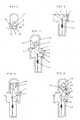
- Fig. 1shows a striking plate 11 of a bolt mechanism and an opening 7 of the striking plate, a magnetic element 10 being freely in the opening and a magnet 9 within it, which is magnetised such that the north pole is 12 and the south pole is 13, and a rear edge 8 of the striking plate.
- Fig. 2shows a bolt mechanism in which on a bolt axis 2 is arranged a rotatable element which forms a locking bolt 1 which includes a locking surface 6. Furthermore, Fig. I shows a front shield 3 of the lock on the plane of which the locking bolt has rotated due to a spring 5.
- Fig. 3shows the locking bolt 1 of the bolt mechanism when stuck in the magnetic element 10, whereby it has rotated against a wall 14 and the locking bolt 1 has reached the rear edge 8 of the striking plate.
- Fig. 4shows the locking bolt 1 of the bolt mechanism partially pushed within the opening 7 of the striking plate, the locking bolt 1 is in this stage in contact with the rear edge 8 of the striking plate, the magnetic element has slid along the wall 14.
- Fig. 5shows a bolt mechanism in a locking position.
- the locking bolt 1has rotated against a front edge 15 of the striking plate, the magnetic element has rotated and stuck from its end 13 on a lower side 16 of the locking bolt 1 and a corner of the element 10 is fast in the wall 14.
- the locking slidehas reached behind the locking surface 6 preventing the locking bolt 1 from turning to the open position.
- the locking bolt 1which also includes the locking surface 6.
- the locking slide 4which is locked against the locking surface 6.
- the striking plate 11reacting to a magnet slightly or not at all, in which there is the opening 7 for the locking bolt 1, the freely moving magnetic element 10 which slides and then rotates as the locking bolt 1 is being locked.
- the locking bolt 1has been designed to hold the locking bolt 1 on the plane of the front shield 3 of the lock body when the door is open by a spring 7 or some other advantageous element, e.g. a magnet.
- a spring 7 or some other advantageous elemente.g. a magnet.
- the locking bolt 1stays on the plane of the front shield 3 until it reaches the opening 7 of the striking plate 11 located in the jamb.
- the magnet 9including the magnetic element 11 which first pulls the locking bolt 1 into the opening 7 of the striking plate 11.
- the bolt 1hits the rear edge 8 of the opening 7 of the striking plate 1.
- the door further closing, the bolt 1pushes the magnetic element in front of it such that it starts to slide along the wall 14, when further sliding, the magnetic element is released from the wall 12 and rotates from its magnet end 13 fast on the lower surface 16 of the bolt 1 and simultaneously the corner 17 of the magnetic element hits the wall 14.
- the spring-loaded locking slide 4automatically locks the locking bolt 1 by sliding behind the locking surface 6.
- the locking bolt 1always rotates in the opposite direction in relation to the opening direction of the door, whereby the sticking of the locking bolt in the striking plate 11 is impossible.
- the magnetic element 10 freely moving in the opening 7 of the striking plate 11makes locking and opening almost soundless and frictionless.
- the locking bolt 1rotates from the force of the magnet 10 to the front edge 15 of the striking plate 11 in the final stage of the rotation of the locking bolt.
Landscapes
- Engineering & Computer Science (AREA)
- Mechanical Engineering (AREA)
- Specific Sealing Or Ventilating Devices For Doors And Windows (AREA)
- Wing Frames And Configurations (AREA)
- Closing And Opening Devices For Wings, And Checks For Wings (AREA)
Description
- The present invention relates to a bolt mechanism according to the preamble of
claim 1. - A bolt mechanism was earlier known from Finnish patent application
20041131 - A problem in this case is that the distance between the door and the jamb varies, whereby the striking plate must always be adjusted case-specifically. Furthermore, manufacturing the striking plate becomes complex.
- Specifications
US3129986 andUS3273925 describe a pivoted bolt structure in which a triangular bolt is pulled into a bolt housing by a magnet. The arrangement does not give information on how deep the bolt is within the bolt housing. The bolt is pulled by the fixed magnet into the bolt housing, whereby the distance between the door and the jamb is critical. The bolt opens at the opening direction of the door, whereby the bolt can stick in the bolt housing if the door is pushed at the same time as the door is being opened. Furthermore, a problem of patentUS3273925 is that, if the motion distance of the door is great, the bolt will then rotate more and more within the magnet, whereby sticking to the magnet increases and it will not open at all in the worst case. - The purpose of this invention is to solve the above-described problems. A bolt mechanism according to the invention is characterised by what is stated in the characterising part of
independent claim 1. - Advantageous embodiment examples of the invention are specified in the dependent claims.
- The arrangement according to the invention provides a bolt mechanism the installation of which is easy, because it does not limit the installation of the lock in the door and the lock fits in doors thinner than earlier. The lock body or the striking plate has no elements protruding from the surface plane when the door is open. The bolt mechanism is in practice non-manipulatable, whereby it is suitable for use in fire and emergency exit doors. The bolt mechanism is close to frictionless when closing and opening, whereby its motion is to the plate and is almost soundless. The locking bolt can be locked at some other than a 90-degree angle in relation to the front shield of the lock.
- Next, the invention will be described by means of advantageous embodiment examples with reference to the accompanying drawings in which
Fig. 1 shows a striking plate according to the invention.Fig. 2 schematically shows a bolt mechanism according to the invention in an open position.Fig. 3 shows a bolt mechanism according to the invention when starting to close.Fig. 4 shows a bolt mechanism according to the invention partially closed.Fig. 5 schematically shows a bolt mechanism in a locking position.Fig. 1 then shows astriking plate 11 of a bolt mechanism and anopening 7 of the striking plate, amagnetic element 10 being freely in the opening and amagnet 9 within it, which is magnetised such that the north pole is 12 and the south pole is 13, and arear edge 8 of the striking plate.Fig. 2 shows a bolt mechanism in which on abolt axis 2 is arranged a rotatable element which forms alocking bolt 1 which includes alocking surface 6. Furthermore,Fig. I shows afront shield 3 of the lock on the plane of which the locking bolt has rotated due to a spring 5.Fig. 3 shows thelocking bolt 1 of the bolt mechanism when stuck in themagnetic element 10, whereby it has rotated against awall 14 and thelocking bolt 1 has reached therear edge 8 of the striking plate.Fig. 4 shows thelocking bolt 1 of the bolt mechanism partially pushed within theopening 7 of the striking plate, thelocking bolt 1 is in this stage in contact with therear edge 8 of the striking plate, the magnetic element has slid along thewall 14.Fig. 5 shows a bolt mechanism in a locking position. Thelocking bolt 1 has rotated against afront edge 15 of the striking plate, the magnetic element has rotated and stuck from itsend 13 on alower side 16 of thelocking bolt 1 and a corner of theelement 10 is fast in thewall 14. The locking slide has reached behind thelocking surface 6 preventing thelocking bolt 1 from turning to the open position.- Next, the operation of the bolt mechanism will be described in more detail. In the lock body installed in a door, on the
axis 2 parallel with the surface of the door is arranged thelocking bolt 1 which also includes thelocking surface 6. In the lock body, there is thelocking slide 4 which is locked against thelocking surface 6. In the jamb is located thestriking plate 11 reacting to a magnet slightly or not at all, in which there is theopening 7 for thelocking bolt 1, the freely movingmagnetic element 10 which slides and then rotates as thelocking bolt 1 is being locked. - In an advantageous embodiment of the invention, the
locking bolt 1 has been designed to hold thelocking bolt 1 on the plane of thefront shield 3 of the lock body when the door is open by aspring 7 or some other advantageous element, e.g. a magnet. When the door closes, thelocking bolt 1 stays on the plane of thefront shield 3 until it reaches the opening 7 of thestriking plate 11 located in the jamb. Within the opening is installed themagnet 9 including themagnetic element 11 which first pulls thelocking bolt 1 into the opening 7 of thestriking plate 11. After thebolt 1 has stuck in themagnetic element 10, the door further closing, thebolt 1 hits therear edge 8 of theopening 7 of thestriking plate 1. The door further closing, thebolt 1 pushes the magnetic element in front of it such that it starts to slide along thewall 14, when further sliding, the magnetic element is released from thewall 12 and rotates from itsmagnet end 13 fast on thelower surface 16 of thebolt 1 and simultaneously thecorner 17 of the magnetic element hits thewall 14. The spring-loadedlocking slide 4 automatically locks thelocking bolt 1 by sliding behind thelocking surface 6. - When the locking slide 4 exits from preventing the
locking bolt 1 from turning out of the locking position and the door opens, themagnetic element 10 stuck in thelocking bolt 1 follows thelocking bolt 1 until the locking bolt passes by the inner surface of thestriking plate 11, whereby theelement 10 is released from thelocking bolt 1 and rotates onto the plane of thefront shield 3 of the lock. - The
locking bolt 1 always rotates in the opposite direction in relation to the opening direction of the door, whereby the sticking of the locking bolt in thestriking plate 11 is impossible. Themagnetic element 10 freely moving in the opening 7 of thestriking plate 11 makes locking and opening almost soundless and frictionless. When enhancing the performance of themagnet 9 within theelement 10 and the design of theelement 10, thelocking bolt 1 rotates from the force of themagnet 10 to thefront edge 15 of thestriking plate 11 in the final stage of the rotation of the locking bolt.
Claims (2)
- A bolt mechanism which comprises a rotatable locking bolt (1) arranged on a bolt axis (2) parallel with the surface of the door, in the locking position of which bolt, a locking slide (4) included in the bolt mechanism is located behind a locking surface (6) of the locking bolt (1) locking the bolt mechanism, a striking plate (11), in which there is an opening (7) and a magnetic element (10) magnetising the locking bolt (1) into the opening (7), moving in the depth and horizontal direction of the opening, a spring (5) fastened from one end to the locking bolt (1) and from the other end to a body (18), and a front shield (3),characterised in that- the magnetic element (10) is arranged to slide and rotate in front of the locking bolt (1) when the locking bolt (1) goes to the opening (7) of the striking plate (11),- the bolt mechanism being in the open position, the spring (5) is arranged to hold the locking bolt (1) substantially on the plane of the front shield (3) of the lock.
- A bolt mechanism according to claim 1,characterised in that the magnetic element (10) is arranged such that the locking bolt (1) is rotatable by the magnetic element at an angle below 90 degrees in relation to the front shield (3) in the opening direction of the door.
Applications Claiming Priority (2)
| Application Number | Priority Date | Filing Date | Title |
|---|---|---|---|
| FI20080585AFI121435B (en) | 2008-10-22 | 2008-10-22 | The bolt mechanism |
| PCT/FI2009/050835WO2010046528A1 (en) | 2008-10-22 | 2009-10-19 | Bolt mechanism |
Publications (3)
| Publication Number | Publication Date |
|---|---|
| EP2347072A1 EP2347072A1 (en) | 2011-07-27 |
| EP2347072A4 EP2347072A4 (en) | 2014-11-19 |
| EP2347072B1true EP2347072B1 (en) | 2015-06-17 |
Family
ID=39924556
Family Applications (1)
| Application Number | Title | Priority Date | Filing Date |
|---|---|---|---|
| EP09821643.5AActiveEP2347072B1 (en) | 2008-10-22 | 2009-10-19 | Bolt mechanism |
Country Status (4)
| Country | Link |
|---|---|
| EP (1) | EP2347072B1 (en) |
| CN (1) | CN102239305B (en) |
| FI (1) | FI121435B (en) |
| WO (1) | WO2010046528A1 (en) |
Families Citing this family (3)
| Publication number | Priority date | Publication date | Assignee | Title |
|---|---|---|---|---|
| FI125042B (en) | 2013-05-29 | 2015-05-15 | Rollock Oy | Lock of the door |
| EP3498955B1 (en)* | 2017-12-13 | 2020-01-29 | Sick Ag | Safety locking device |
| AU2023308728A1 (en)* | 2022-07-18 | 2024-10-10 | D & D Group Pty Ltd | Improvements to latches for movable barriers or the like |
Family Cites Families (5)
| Publication number | Priority date | Publication date | Assignee | Title |
|---|---|---|---|---|
| JP3377600B2 (en)* | 1994-07-04 | 2003-02-17 | 株式会社サンポウロック | Magnetic latch lock |
| FI20050641A7 (en)* | 2004-08-30 | 2006-03-01 | Seppo Ilmari Kankkunen | Latching mechanism |
| CN100529320C (en)* | 2005-05-08 | 2009-08-19 | 索斯科公司 | Magnetic latch mechanism |
| GB2440025A (en)* | 2006-07-03 | 2008-01-16 | Accesorios Y Resortes S L | Magnetic lock with follower having two extensions |
| FI120841B (en)* | 2007-11-27 | 2010-03-31 | Seppo Kankkunen | The bolt mechanism |
- 2008
- 2008-10-22FIFI20080585Apatent/FI121435B/enactiveIP Right Grant
- 2009
- 2009-10-19WOPCT/FI2009/050835patent/WO2010046528A1/enactiveApplication Filing
- 2009-10-19CNCN200980142339.2Apatent/CN102239305B/ennot_activeExpired - Fee Related
- 2009-10-19EPEP09821643.5Apatent/EP2347072B1/enactiveActive
Also Published As
| Publication number | Publication date |
|---|---|
| EP2347072A1 (en) | 2011-07-27 |
| FI121435B (en) | 2010-11-15 |
| EP2347072A4 (en) | 2014-11-19 |
| WO2010046528A1 (en) | 2010-04-29 |
| FI20080585L (en) | 2010-04-23 |
| CN102239305B (en) | 2014-06-04 |
| FI20080585A0 (en) | 2008-10-22 |
| CN102239305A (en) | 2011-11-09 |
Similar Documents
| Publication | Publication Date | Title |
|---|---|---|
| US20090115204A1 (en) | Self latching latch | |
| US20140292001A1 (en) | Door lock with integrated door position sensor | |
| US8287010B2 (en) | Door locking system having a planar striker plate | |
| US3350127A (en) | Magnetic latch for a door | |
| EP2453082B1 (en) | Self-aligning safety lock | |
| US20080157542A1 (en) | Security Lock Arrangement | |
| CA2540421A1 (en) | Magneto-mechanical locking device | |
| AU2011213786B2 (en) | A Cavity Door End Pull Lock Set and Latch Set | |
| EP2347072B1 (en) | Bolt mechanism | |
| US4036517A (en) | Rotary door latch | |
| WO2009082778A1 (en) | Mortice lock with adjustable handing | |
| WO2012100107A2 (en) | Mortise lock with deadbolt and magnetic latch | |
| KR20090008685U (en) | Sliding door stopper | |
| RU180731U1 (en) | SUVALD LOCK KEY | |
| CN110998046B (en) | Safety device for closing two hinged elements, door opener and door comprising said device | |
| CN101864871B (en) | An exterior door lock | |
| AU2016201251B2 (en) | Magnetic gate latch | |
| WO2015145202A1 (en) | Door lock protection device | |
| EP4141201B1 (en) | Latch device and lock with clamp for a sliding door or window | |
| EP2171190B1 (en) | Bolt housing comprising a bolt, as well as a method of installing it | |
| FI120841B (en) | The bolt mechanism | |
| JP3377600B2 (en) | Magnetic latch lock | |
| RU2266383C1 (en) | Locking device | |
| CN115680378B (en) | A handle device | |
| IE54456B1 (en) | Locks |
Legal Events
| Date | Code | Title | Description |
|---|---|---|---|
| PUAI | Public reference made under article 153(3) epc to a published international application that has entered the european phase | Free format text:ORIGINAL CODE: 0009012 | |
| 17P | Request for examination filed | Effective date:20110517 | |
| AK | Designated contracting states | Kind code of ref document:A1 Designated state(s):AT BE BG CH CY CZ DE DK EE ES FI FR GB GR HR HU IE IS IT LI LT LU LV MC MK MT NL NO PL PT RO SE SI SK SM TR | |
| AX | Request for extension of the european patent | Extension state:AL BA RS | |
| RIN1 | Information on inventor provided before grant (corrected) | Inventor name:KANKKUNEN, HANNU | |
| DAX | Request for extension of the european patent (deleted) | ||
| A4 | Supplementary search report drawn up and despatched | Effective date:20141020 | |
| RIC1 | Information provided on ipc code assigned before grant | Ipc:E05C 3/00 20060101AFI20141014BHEP Ipc:E05B 47/00 20060101ALI20141014BHEP Ipc:E05C 19/16 20060101ALI20141014BHEP Ipc:E05B 15/02 20060101ALI20141014BHEP | |
| GRAP | Despatch of communication of intention to grant a patent | Free format text:ORIGINAL CODE: EPIDOSNIGR1 | |
| GRAS | Grant fee paid | Free format text:ORIGINAL CODE: EPIDOSNIGR3 | |
| INTG | Intention to grant announced | Effective date:20150420 | |
| GRAA | (expected) grant | Free format text:ORIGINAL CODE: 0009210 | |
| AK | Designated contracting states | Kind code of ref document:B1 Designated state(s):AT BE BG CH CY CZ DE DK EE ES FI FR GB GR HR HU IE IS IT LI LT LU LV MC MK MT NL NO PL PT RO SE SI SK SM TR | |
| REG | Reference to a national code | Ref country code:GB Ref legal event code:FG4D | |
| REG | Reference to a national code | Ref country code:CH Ref legal event code:EP | |
| REG | Reference to a national code | Ref country code:AT Ref legal event code:REF Ref document number:732037 Country of ref document:AT Kind code of ref document:T Effective date:20150715 | |
| REG | Reference to a national code | Ref country code:IE Ref legal event code:FG4D | |
| REG | Reference to a national code | Ref country code:DE Ref legal event code:R096 Ref document number:602009031797 Country of ref document:DE | |
| REG | Reference to a national code | Ref country code:FR Ref legal event code:PLFP Year of fee payment:7 | |
| PG25 | Lapsed in a contracting state [announced via postgrant information from national office to epo] | Ref country code:NO Free format text:LAPSE BECAUSE OF FAILURE TO SUBMIT A TRANSLATION OF THE DESCRIPTION OR TO PAY THE FEE WITHIN THE PRESCRIBED TIME-LIMIT Effective date:20150917 Ref country code:HR Free format text:LAPSE BECAUSE OF FAILURE TO SUBMIT A TRANSLATION OF THE DESCRIPTION OR TO PAY THE FEE WITHIN THE PRESCRIBED TIME-LIMIT Effective date:20150617 Ref country code:FI Free format text:LAPSE BECAUSE OF FAILURE TO SUBMIT A TRANSLATION OF THE DESCRIPTION OR TO PAY THE FEE WITHIN THE PRESCRIBED TIME-LIMIT Effective date:20150617 Ref country code:LT Free format text:LAPSE BECAUSE OF FAILURE TO SUBMIT A TRANSLATION OF THE DESCRIPTION OR TO PAY THE FEE WITHIN THE PRESCRIBED TIME-LIMIT Effective date:20150617 | |
| REG | Reference to a national code | Ref country code:AT Ref legal event code:MK05 Ref document number:732037 Country of ref document:AT Kind code of ref document:T Effective date:20150617 | |
| REG | Reference to a national code | Ref country code:LT Ref legal event code:MG4D Ref country code:NL Ref legal event code:MP Effective date:20150617 | |
| PG25 | Lapsed in a contracting state [announced via postgrant information from national office to epo] | Ref country code:GR Free format text:LAPSE BECAUSE OF FAILURE TO SUBMIT A TRANSLATION OF THE DESCRIPTION OR TO PAY THE FEE WITHIN THE PRESCRIBED TIME-LIMIT Effective date:20150918 Ref country code:LV Free format text:LAPSE BECAUSE OF FAILURE TO SUBMIT A TRANSLATION OF THE DESCRIPTION OR TO PAY THE FEE WITHIN THE PRESCRIBED TIME-LIMIT Effective date:20150617 Ref country code:BG Free format text:LAPSE BECAUSE OF FAILURE TO SUBMIT A TRANSLATION OF THE DESCRIPTION OR TO PAY THE FEE WITHIN THE PRESCRIBED TIME-LIMIT Effective date:20150917 | |
| PG25 | Lapsed in a contracting state [announced via postgrant information from national office to epo] | Ref country code:EE Free format text:LAPSE BECAUSE OF FAILURE TO SUBMIT A TRANSLATION OF THE DESCRIPTION OR TO PAY THE FEE WITHIN THE PRESCRIBED TIME-LIMIT Effective date:20150617 | |
| PG25 | Lapsed in a contracting state [announced via postgrant information from national office to epo] | Ref country code:RO Free format text:LAPSE BECAUSE OF NON-PAYMENT OF DUE FEES Effective date:20150617 Ref country code:CZ Free format text:LAPSE BECAUSE OF FAILURE TO SUBMIT A TRANSLATION OF THE DESCRIPTION OR TO PAY THE FEE WITHIN THE PRESCRIBED TIME-LIMIT Effective date:20150617 Ref country code:PT Free format text:LAPSE BECAUSE OF FAILURE TO SUBMIT A TRANSLATION OF THE DESCRIPTION OR TO PAY THE FEE WITHIN THE PRESCRIBED TIME-LIMIT Effective date:20151019 Ref country code:ES Free format text:LAPSE BECAUSE OF FAILURE TO SUBMIT A TRANSLATION OF THE DESCRIPTION OR TO PAY THE FEE WITHIN THE PRESCRIBED TIME-LIMIT Effective date:20150617 Ref country code:AT Free format text:LAPSE BECAUSE OF FAILURE TO SUBMIT A TRANSLATION OF THE DESCRIPTION OR TO PAY THE FEE WITHIN THE PRESCRIBED TIME-LIMIT Effective date:20150617 Ref country code:SK Free format text:LAPSE BECAUSE OF FAILURE TO SUBMIT A TRANSLATION OF THE DESCRIPTION OR TO PAY THE FEE WITHIN THE PRESCRIBED TIME-LIMIT Effective date:20150617 Ref country code:IS Free format text:LAPSE BECAUSE OF FAILURE TO SUBMIT A TRANSLATION OF THE DESCRIPTION OR TO PAY THE FEE WITHIN THE PRESCRIBED TIME-LIMIT Effective date:20151017 Ref country code:PL Free format text:LAPSE BECAUSE OF FAILURE TO SUBMIT A TRANSLATION OF THE DESCRIPTION OR TO PAY THE FEE WITHIN THE PRESCRIBED TIME-LIMIT Effective date:20150617 | |
| REG | Reference to a national code | Ref country code:DE Ref legal event code:R097 Ref document number:602009031797 Country of ref document:DE | |
| PLBE | No opposition filed within time limit | Free format text:ORIGINAL CODE: 0009261 | |
| STAA | Information on the status of an ep patent application or granted ep patent | Free format text:STATUS: NO OPPOSITION FILED WITHIN TIME LIMIT | |
| PG25 | Lapsed in a contracting state [announced via postgrant information from national office to epo] | Ref country code:DK Free format text:LAPSE BECAUSE OF FAILURE TO SUBMIT A TRANSLATION OF THE DESCRIPTION OR TO PAY THE FEE WITHIN THE PRESCRIBED TIME-LIMIT Effective date:20150617 Ref country code:IT Free format text:LAPSE BECAUSE OF FAILURE TO SUBMIT A TRANSLATION OF THE DESCRIPTION OR TO PAY THE FEE WITHIN THE PRESCRIBED TIME-LIMIT Effective date:20150617 | |
| 26N | No opposition filed | Effective date:20160318 | |
| PG25 | Lapsed in a contracting state [announced via postgrant information from national office to epo] | Ref country code:LU Free format text:LAPSE BECAUSE OF FAILURE TO SUBMIT A TRANSLATION OF THE DESCRIPTION OR TO PAY THE FEE WITHIN THE PRESCRIBED TIME-LIMIT Effective date:20151019 | |
| REG | Reference to a national code | Ref country code:CH Ref legal event code:PL | |
| PG25 | Lapsed in a contracting state [announced via postgrant information from national office to epo] | Ref country code:MC Free format text:LAPSE BECAUSE OF FAILURE TO SUBMIT A TRANSLATION OF THE DESCRIPTION OR TO PAY THE FEE WITHIN THE PRESCRIBED TIME-LIMIT Effective date:20150617 | |
| REG | Reference to a national code | Ref country code:IE Ref legal event code:MM4A | |
| PG25 | Lapsed in a contracting state [announced via postgrant information from national office to epo] | Ref country code:LI Free format text:LAPSE BECAUSE OF NON-PAYMENT OF DUE FEES Effective date:20151031 Ref country code:CH Free format text:LAPSE BECAUSE OF NON-PAYMENT OF DUE FEES Effective date:20151031 | |
| PG25 | Lapsed in a contracting state [announced via postgrant information from national office to epo] | Ref country code:SI Free format text:LAPSE BECAUSE OF FAILURE TO SUBMIT A TRANSLATION OF THE DESCRIPTION OR TO PAY THE FEE WITHIN THE PRESCRIBED TIME-LIMIT Effective date:20150617 | |
| REG | Reference to a national code | Ref country code:FR Ref legal event code:PLFP Year of fee payment:8 | |
| PG25 | Lapsed in a contracting state [announced via postgrant information from national office to epo] | Ref country code:IE Free format text:LAPSE BECAUSE OF NON-PAYMENT OF DUE FEES Effective date:20151019 | |
| PG25 | Lapsed in a contracting state [announced via postgrant information from national office to epo] | Ref country code:BE Free format text:LAPSE BECAUSE OF FAILURE TO SUBMIT A TRANSLATION OF THE DESCRIPTION OR TO PAY THE FEE WITHIN THE PRESCRIBED TIME-LIMIT Effective date:20150617 | |
| PG25 | Lapsed in a contracting state [announced via postgrant information from national office to epo] | Ref country code:SM Free format text:LAPSE BECAUSE OF FAILURE TO SUBMIT A TRANSLATION OF THE DESCRIPTION OR TO PAY THE FEE WITHIN THE PRESCRIBED TIME-LIMIT Effective date:20150617 Ref country code:HU Free format text:LAPSE BECAUSE OF FAILURE TO SUBMIT A TRANSLATION OF THE DESCRIPTION OR TO PAY THE FEE WITHIN THE PRESCRIBED TIME-LIMIT; INVALID AB INITIO Effective date:20091019 | |
| PG25 | Lapsed in a contracting state [announced via postgrant information from national office to epo] | Ref country code:CY Free format text:LAPSE BECAUSE OF FAILURE TO SUBMIT A TRANSLATION OF THE DESCRIPTION OR TO PAY THE FEE WITHIN THE PRESCRIBED TIME-LIMIT Effective date:20150617 Ref country code:SE Free format text:LAPSE BECAUSE OF FAILURE TO SUBMIT A TRANSLATION OF THE DESCRIPTION OR TO PAY THE FEE WITHIN THE PRESCRIBED TIME-LIMIT Effective date:20150617 Ref country code:NL Free format text:LAPSE BECAUSE OF FAILURE TO SUBMIT A TRANSLATION OF THE DESCRIPTION OR TO PAY THE FEE WITHIN THE PRESCRIBED TIME-LIMIT Effective date:20150617 | |
| PG25 | Lapsed in a contracting state [announced via postgrant information from national office to epo] | Ref country code:MT Free format text:LAPSE BECAUSE OF FAILURE TO SUBMIT A TRANSLATION OF THE DESCRIPTION OR TO PAY THE FEE WITHIN THE PRESCRIBED TIME-LIMIT Effective date:20150617 Ref country code:TR Free format text:LAPSE BECAUSE OF FAILURE TO SUBMIT A TRANSLATION OF THE DESCRIPTION OR TO PAY THE FEE WITHIN THE PRESCRIBED TIME-LIMIT Effective date:20150617 | |
| REG | Reference to a national code | Ref country code:FR Ref legal event code:PLFP Year of fee payment:9 | |
| PG25 | Lapsed in a contracting state [announced via postgrant information from national office to epo] | Ref country code:MK Free format text:LAPSE BECAUSE OF FAILURE TO SUBMIT A TRANSLATION OF THE DESCRIPTION OR TO PAY THE FEE WITHIN THE PRESCRIBED TIME-LIMIT Effective date:20150617 | |
| REG | Reference to a national code | Ref country code:FR Ref legal event code:PLFP Year of fee payment:10 | |
| PGFP | Annual fee paid to national office [announced via postgrant information from national office to epo] | Ref country code:DE Payment date:20241029 Year of fee payment:16 | |
| PGFP | Annual fee paid to national office [announced via postgrant information from national office to epo] | Ref country code:GB Payment date:20241029 Year of fee payment:16 | |
| PGFP | Annual fee paid to national office [announced via postgrant information from national office to epo] | Ref country code:FR Payment date:20241023 Year of fee payment:16 |