EP2346544B1 - Irrigation and suction system, in particular for laparoscopic surgery - Google Patents
Irrigation and suction system, in particular for laparoscopic surgeryDownload PDFInfo
- Publication number
- EP2346544B1 EP2346544B1EP09741006.2AEP09741006AEP2346544B1EP 2346544 B1EP2346544 B1EP 2346544B1EP 09741006 AEP09741006 AEP 09741006AEP 2346544 B1EP2346544 B1EP 2346544B1
- Authority
- EP
- European Patent Office
- Prior art keywords
- pump
- motor
- electronics means
- controlling electronics
- flow rate
- Prior art date
- Legal status (The legal status is an assumption and is not a legal conclusion. Google has not performed a legal analysis and makes no representation as to the accuracy of the status listed.)
- Active
Links
- UHOVQNZJYSORNB-UHFFFAOYSA-Nc1ccccc1Chemical compoundc1ccccc1UHOVQNZJYSORNB-UHFFFAOYSA-N0.000description1
Images


Classifications
- A—HUMAN NECESSITIES
- A61—MEDICAL OR VETERINARY SCIENCE; HYGIENE
- A61M—DEVICES FOR INTRODUCING MEDIA INTO, OR ONTO, THE BODY; DEVICES FOR TRANSDUCING BODY MEDIA OR FOR TAKING MEDIA FROM THE BODY; DEVICES FOR PRODUCING OR ENDING SLEEP OR STUPOR
- A61M3/00—Medical syringes, e.g. enemata; Irrigators
- A61M3/02—Enemata; Irrigators
- A61M3/0204—Physical characteristics of the irrigation fluid, e.g. conductivity or turbidity
- A61M3/022—Volume; Flow rate
- A—HUMAN NECESSITIES
- A61—MEDICAL OR VETERINARY SCIENCE; HYGIENE
- A61M—DEVICES FOR INTRODUCING MEDIA INTO, OR ONTO, THE BODY; DEVICES FOR TRANSDUCING BODY MEDIA OR FOR TAKING MEDIA FROM THE BODY; DEVICES FOR PRODUCING OR ENDING SLEEP OR STUPOR
- A61M1/00—Suction or pumping devices for medical purposes; Devices for carrying-off, for treatment of, or for carrying-over, body-liquids; Drainage systems
- A61M1/71—Suction drainage systems
- A61M1/77—Suction-irrigation systems
- A61M1/774—Handpieces specially adapted for providing suction as well as irrigation, either simultaneously or independently
- A—HUMAN NECESSITIES
- A61—MEDICAL OR VETERINARY SCIENCE; HYGIENE
- A61M—DEVICES FOR INTRODUCING MEDIA INTO, OR ONTO, THE BODY; DEVICES FOR TRANSDUCING BODY MEDIA OR FOR TAKING MEDIA FROM THE BODY; DEVICES FOR PRODUCING OR ENDING SLEEP OR STUPOR
- A61M3/00—Medical syringes, e.g. enemata; Irrigators
- A61M3/02—Enemata; Irrigators
- A61M3/0202—Enemata; Irrigators with electronic control means or interfaces
- A—HUMAN NECESSITIES
- A61—MEDICAL OR VETERINARY SCIENCE; HYGIENE
- A61M—DEVICES FOR INTRODUCING MEDIA INTO, OR ONTO, THE BODY; DEVICES FOR TRANSDUCING BODY MEDIA OR FOR TAKING MEDIA FROM THE BODY; DEVICES FOR PRODUCING OR ENDING SLEEP OR STUPOR
- A61M3/00—Medical syringes, e.g. enemata; Irrigators
- A61M3/02—Enemata; Irrigators
- A61M3/0204—Physical characteristics of the irrigation fluid, e.g. conductivity or turbidity
- A61M3/0208—Physical characteristics of the irrigation fluid, e.g. conductivity or turbidity before use
- A—HUMAN NECESSITIES
- A61—MEDICAL OR VETERINARY SCIENCE; HYGIENE
- A61M—DEVICES FOR INTRODUCING MEDIA INTO, OR ONTO, THE BODY; DEVICES FOR TRANSDUCING BODY MEDIA OR FOR TAKING MEDIA FROM THE BODY; DEVICES FOR PRODUCING OR ENDING SLEEP OR STUPOR
- A61M3/00—Medical syringes, e.g. enemata; Irrigators
- A61M3/02—Enemata; Irrigators
- A61M3/0275—Pulsating jets; Vibrating nozzles
- A—HUMAN NECESSITIES
- A61—MEDICAL OR VETERINARY SCIENCE; HYGIENE
- A61M—DEVICES FOR INTRODUCING MEDIA INTO, OR ONTO, THE BODY; DEVICES FOR TRANSDUCING BODY MEDIA OR FOR TAKING MEDIA FROM THE BODY; DEVICES FOR PRODUCING OR ENDING SLEEP OR STUPOR
- A61M2205/00—General characteristics of the apparatus
- A61M2205/33—Controlling, regulating or measuring
- A61M2205/3331—Pressure; Flow
- A—HUMAN NECESSITIES
- A61—MEDICAL OR VETERINARY SCIENCE; HYGIENE
- A61M—DEVICES FOR INTRODUCING MEDIA INTO, OR ONTO, THE BODY; DEVICES FOR TRANSDUCING BODY MEDIA OR FOR TAKING MEDIA FROM THE BODY; DEVICES FOR PRODUCING OR ENDING SLEEP OR STUPOR
- A61M2205/00—General characteristics of the apparatus
- A61M2205/35—Communication
- A61M2205/3546—Range
- A61M2205/3561—Range local, e.g. within room or hospital
- A—HUMAN NECESSITIES
- A61—MEDICAL OR VETERINARY SCIENCE; HYGIENE
- A61M—DEVICES FOR INTRODUCING MEDIA INTO, OR ONTO, THE BODY; DEVICES FOR TRANSDUCING BODY MEDIA OR FOR TAKING MEDIA FROM THE BODY; DEVICES FOR PRODUCING OR ENDING SLEEP OR STUPOR
- A61M2205/00—General characteristics of the apparatus
- A61M2205/35—Communication
- A61M2205/3576—Communication with non implanted data transmission devices, e.g. using external transmitter or receiver
- A61M2205/3592—Communication with non implanted data transmission devices, e.g. using external transmitter or receiver using telemetric means, e.g. radio or optical transmission
- A—HUMAN NECESSITIES
- A61—MEDICAL OR VETERINARY SCIENCE; HYGIENE
- A61M—DEVICES FOR INTRODUCING MEDIA INTO, OR ONTO, THE BODY; DEVICES FOR TRANSDUCING BODY MEDIA OR FOR TAKING MEDIA FROM THE BODY; DEVICES FOR PRODUCING OR ENDING SLEEP OR STUPOR
- A61M2205/00—General characteristics of the apparatus
- A61M2205/50—General characteristics of the apparatus with microprocessors or computers
- A61M2205/502—User interfaces, e.g. screens or keyboards
Definitions
- the present inventionrelates to an irrigation and suction system, in particular for laparoscopic surgery, that allows in a manner that is reliable, versatile, simple, comfortable for the operator and safe for the patient to carry out a lavage and/or a drainage of the surgical site, in particular during interventions performed by laparoscopy, the system being further capable to be made in an inexpensive way.
- an apparatusalso called laparoscopic suction irrigator, that comprises, in most advanced configurations, a control base provided with a pumping unit and a handpiece, that has the function of producing an irrigation jet of physiological liquid and carrying out a drainage suction in order to maintain the surgical site view clean during the interventions.
- the liquid jet and/or the suctionoccur through a steel probe that is attached to the handpiece and placed by the surgeon close to the intervention location, wherein it is inserted through a device known with the term of "trocar".
- the irrigation liquidis drawn from a bag of physiological solution, connected through an infusion line provided with a spike, and it is sent by means of a pump, through an irrigation line, to the probe, that may also operate as suction device depending on specific commands that the surgeon imparts to a valve assembly placed on the handpiece. Depression necessary to aspiration is given by a vacuum line of the operating room, that is connected through disposable collection devices for active drainages.
- Patent US 5303735concerns a trumpet valve assembly usable for a surgical irrigation and suction system.
- Application EP 1086713concerns an irrigation and suction system for use during endoscopic surgery, provided with a trumpet valve fed, for irrigation, by a reusable motor to which a disposable sterile pump may be coupled through a quick connection.
- Patent US 5484402concerns a surgical irrigation and suction apparatus having a handpiece provided with a control rocking lever.
- an irrigation and suction systemin particular for laparoscopic surgery, comprising an active control apparatus, provided with a reusable motor capable to be attached to and to operate a disposable pump, and a disposable handpiece provided with two valves capable to be connected respectively to an output duct from the pump and to a suction line, the two valves being operatable for making respectively the pump and the suction line communicate with an output nozzle of the handpiece, the nozzle being capable to support a probe, the apparatus comprising controlling electronics means for controlling electronics means for driving the motor, the system being characterised in that it comprises interface means connected to said controlling electronics means capable to select an operation mode of the motor between continuous mode, wherein the pump delivers fluid in a continuous and uniform way, and pulse mode, wherein the pump flow rate switches between a minimum flow rate and a maximum flow rate with a switching period.
- said interface meansmay be capable to further select a flow rate of the pump and/or, in case of pulse operation, said minimum flow rate and/or said maximum flow rate and/or said switching period.
- said interface meansmay comprise a keyboard, preferably along with a display, more preferably along with one or more light signalling LEDs, still more preferably along with an electro-acoustic indicator, or buzzer.
- said interface meansmay be housed within the apparatus and/or the handpiece, being connected to said controlling electronics means through a cable or wireless connection, preferably through a radio frequency or infrared connection.
- the apparatusmay comprise detecting, preferably optical, means, connected to said controlling electronics means and capable to detect a priming state of the pump, whereby said controlling electronics means enables or disables said electronics means for driving the motor when said detecting means detects that the pump is, respectively, primed or unprimed.
- said detecting meansmay be capable to detect the attaching of a pump to the motor, whereby said controlling electronics means enables or disables said electronics means for driving the motor when said detecting means detects that a pump is, respectively, attached or not attached.
- said interface meansmay be further capable to cause an attempt of priming the pump within a maximum period (time-out), whereby the pump is operated for a pre-established period.
- the apparatusmay comprise current detecting means connected to said controlling electronics means capable to detect a current absorbed by the motor, said current detecting means being preferably capable to further detect when said current absorbed by the motor exceeds a maximum threshold value, more preferably directly inhibiting said electronics means for driving the motor.
- said controlling electronics meansmay be capable to detect an unpriming state of the pump on the basis of a current absorbed by the motor as detected by said current detecting means, whereby said controlling electronics means enables or inhibits said electronics means for driving the motor when it detects that the pump is respectively primed or unprimed.
- said controlling electronics meansmay be capable to detect a number of revolutions of the motor, whereby it inhibits said electronics means for driving the motor when said number of revolutions of the motor is incorrect.
- the apparatusmay comprise watching means connected to said controlling electronics means capable to detect a power-on state of the apparatus and/or malfunctions signalled by said controlling electronics means and/or an insufficient power supply, consequently resetting said controlling electronics means and/or inhibiting said electronics means for driving the motor for at least a time period.
- the attaching between the motor and the pumpmay be of coaxial bevel gear pair type, comprising a male driver and a corresponding female driver, preferably according to a labyrinth type geometry seal.
- an active control apparatusprovided with a reusable motor capable to be attached to and to operate a disposable pump, characterised in that it is used in an irrigation and suction system, in particular for laparoscopic surgery, as previously described, the apparatus comprising controlling electronics means for controlling electronics means for driving the motor connected to interface means capable to select an operation mode of the motor between continuous mode, wherein the pump delivers fluid in a continuous and uniform way, and pulse mode, wherein the pump flow rate switches between a minimum flow rate and a maximum flow rate with a switching period, said interface means being preferably housed at least partially within the apparatus.
- a handpiece usable in an irrigation and suction systemin particular for laparoscopic surgery, preferably as previously described, comprising an irrigation valve and a suction valve wherein corresponding shutters slide, which shutters are operated respectively by an irrigation button and a suction button for making the respective valves communicate with an output nozzle, the nozzle being preferably capable to be snap-connected through fast coupling to a probe holder, characterised in that the handpiece is ergonomically banana shaped, whereby it allows a comfortable and steady grip by an operator both when it is oriented with the nozzle above the four hand fingers different from the thumb, and when it is oriented in overturned position with the nozzle below such four fingers, the surfaces of the two buttons onto which the fingers of an operator exert a pressure being preferably one convex and the other concave, the handpiece more preferably housing interface means capable to communicate with a control apparatus through a cable and/or wireless connection, still more preferably through a radio frequency or infrared connection.
- the handpiecemay be provided with an anti-skidding coating, preferably in Laprene®, that at least partially covers it.
- each shuttermay be operated by the corresponding button through a respective gear-rack transmission, the buttons and the shutters being provided of end racks engaging two respective gear wheels.
- the system according to the inventionmade with a reduced number of moving mechanical parts which are hence subject to wear, is extremely reliable and has a long service life.
- adoption of an electric motor of brushless typeallows to eliminate the wear problems of the brushes (proportionally to the operation hours), as well as the physiological dispersion of particles, typically of carbon, removed during rotation phase of the same brushes which, if not well insulated, may be source of serious contamination of the surgical site; moreover, motor shaft is keyed on ball bearings, subject to less wearing rolling friction.
- the other moving partis a female driver, made of plastic material, directly keyed on the driving shaft, that is therefore not subject to backlashes which could bring the same to "interfere” with the body of the housing. Also, it is not possible that an important wear of the "polygroove" taper hole occurs because it is not possible the motor start without the consent of the sensors checking the complete insertion of the disposable pump and hence of the male driver.
- the electronic circuitprovides for monitoring of motor power absorption, of acceleration and of reached revolutions compared with the nominal ones at a given power supply condition.
- the preferred embodiment of the system according to the inventioncomprises an active control apparatus 100, supplied by the mains (preferably at 230Vac), provided with a re-usable motor, housed inside a seat 101, on which an extractable disposable centrifugal pump 102 is mounted, connectable through an irrigation pipe 103 to a handpiece 104.
- the mainspreferably at 230Vac
- a re-usable motorhoused inside a seat 101, on which an extractable disposable centrifugal pump 102 is mounted, connectable through an irrigation pipe 103 to a handpiece 104.
- the apparatus 100is capable to be attached to a normal infusion stand 105 through a rear fastening clamp (illustrated later).
- a suction pipe 106is further associated to the irrigation pipe 103 that is also connectable to the handpiece 104 for connecting the latter to a suction point, such as for instance a vacuum line of an operating room, through a disposable collection device for active drainages.
- the pump 102is further connectable through an infusion pipe 107 provided with a spike 108 to a bag 109 of liquid, preferably physiological solution, that may be hung on the stand 105.
- the handpiece 104comprises two valves (illustrated later) for manually controlling irrigation and aspiration, and it supports a steel probe 110 that is coupled to a snap fast coupling fastener with which the same handpiece 104 is frontally provided.
- the apparatus 100is a non sterile, reusable device, whereas the pump 102 and the handpiece 104 are sterile and disposable.
- the control apparatus 100comprises a substantially cylindrical side slot 101 in which the motor 101' for operating a pump 102 is housed (the pump also comprises all the connection pipes, not shown in Figures 2-6 ) which pump may be stably attached to the slot 101 through a suitable fast coupling 111.
- the pump 102preferably of centrifugal type, is engageable through mechanical guides 111 and tight limit stop snap, whereas a tapered notch 111' on the chassis of the slot 101 aids manual extraction of the pump 102.
- the control apparatus 100is capable to be fastened to a hospital metal stand through a suitable rear clamp 113, preferably provided, as shown in Figure 7 , with a clamping handwheel 114.
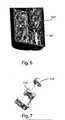
- FIG. 5 and 6Also three components of the ch assis of the apparatus 100 are shown in Figures 5 and 6 : a front main container 501 (housing, among other things, the electronic boards), a support 502 for the motor-pump assembly, and a rear end cover 503, from which an electric tap 500 for supplying power to the apparatus 100 projects.
- a front main container 501housing, among other things, the electronic boards
- a support 502 for the motor-pump assemblyfor the motor-pump assembly
- a rear end cover 503from which an electric tap 500 for supplying power to the apparatus 100 projects.
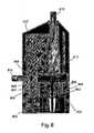
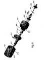
- the pump 102comprises a lower pump casing 102' and in an upper pump casing 102".
- the lower pump casing 102'comprises a spindle 801 to which a male driver 802 (capable to insert in a corresponding female driver directly keyed on the driving shaft) is coupled, a shielded bearing 803 being housed in a suitable support 804 on which tight membranes 805 are applied which separate it from a bush 806, preferably of Teflon, guiding the spindle 801; a first O-ring 807 ensures the tightness of the bush 806.
- the upper pump casing 102"comprises an impeller 808 (shown in detail in Figure 10 ) coupled to the spindle 801, whereas a second O-ring 809 ensures the tightness of the pump 102; in the upper pump casing 102" is further housed a channel 810 for inletting the liquid solution (connectable to an external bag) that houses downwards a bade duct 811 in which a float 812 for sensing presence of liquid in the pump 102 is inserted, which liquid is capable to exit from an outlet channel 813.
- two holes 814 and 815are present on the wall of the upper pump casing 102" for allowing detection by respective optical sensors (illustrated later) with which the apparatus 100 is provided for sensing, respectively, the position of the float 812 (i.e. of the priming state of the pump 102) and the attachment of the pump on the coupling 111.
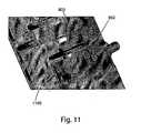
- Figure 11shows a particular of the coaxial bevel gear pair connection (comprising male driver 802 and corresponding female driver 1100) of the spindle 801 of the pump 102 with the driving shaft, which connection guarantees a maximum level of system electrical insulation.
- the apparatus 100includes a man-machine interface, or MMI, comprising a keypad 112 and a display 113, the MMI being further provided with three LEDs of different colours, preferably blue, green and red, for signalling the state (not shown in the Figures).
- MMIman-machine interface
- the function of the MMIis to allow the interaction by man, in our case by an operator in operating room, with the system according to the invention.
- the MMIindicates to the operator, in optical and/or acoustic way, the current state of the irrigation process, and it allows selection of the operation type between continuous and pulsatile, adjustment of parameters such as pump flow rate and, in case of pulse operation, switching times between minimum flow rate and maximum flow rate.
- the graphic display 113shows, in the lower part, a horizontal bar indicating current percentage flow rate (or, in case of pulse operation, current percentage switching frequency) of the pump, and in the upper part it shows the general state of the system (as it will be illustrated later with reference to Figure 21 ).
- Other embodiments of the system according to the inventionprovide that, through the MMI, it is possible to further set the minimum and maximum rate limits in case of pulse operation.
- the keypad 112comprises four keys 112A, 112B, 112C AND 112D.
- the first key 112Aallows either the pump flow rate to be increased in case of continuous operation, or the ON and OFF pulse times to be reduced in case of pulse operation (i.e. the switching period to be reduced, increasing the frequency of the same switching).
- the second key 112Ballows either the pump flow rate to be reduced in case of continuous operation, or the ON and OFF pulse times to be increased in case of pulse operation (i.e. the switching period to be increased, reducing the frequency of the same switching).
- the third key 112Callows selection of the pump operation type.
- the operation that is automatically set at power on(default operation) is continuous, i.e. the pump operates in a continuous and uniform way.
- Pressure on the key PULSE 112Csets the operation in "pulse" mode, that is the pump flow rate is modified at time intervals between a minimum and a maximum, i.e. switching between a minimum flow rate and a maximum flow rate with a switching period; in other words, in pulse operation an alternative passage from the minimum flow rate to the maximum flow rate, and vice versa, occurs (in a Pause-Operation logic, the times of which are variable through the two keys UP 112A and DOWN 112B). If the key PULSE 112C is pressed when the operation has been already switched to pulsatile, the operation returns to continuous mode. The operation mode is visible on the display 113.
- the fourth key 112Dallows to manually require an attempt to prime the pump within a maximum time (time-out), i.e. the pump is activated for a predetermined time, during which if pump priming is not obtained, the pump is automatically stopped and the system passes in a state of failed priming.
- time-outi.e. the pump is activated for a predetermined time, during which if pump priming is not obtained, the pump is automatically stopped and the system passes in a state of failed priming.
- the MMIis further provided with three LEDs for signalling the state of the pump 102, preferably of blue, green and red colours, respectively.
- the LEDsturn on as follows: in case of pump not inserted on the coupling 111, all the three LEDs are off; in case of just inserted pump 102, only the blue LED is on; in case of primed pump, only the green LED is on; in case of unprimed pump, only the red LED is on.
- the MMIfurther comprises an electroacoustic signaller, or buzzer, that is used both as confirmation of keystroke of a key of the keypad 112 through a beep, and as indication of an alarm state, such as for instance loss of pump priming due to lack of liquid in the bag 109.
- an electroacoustic signalleror buzzer
- the chassispreferably comprises three components: the front main container 501 (housing, among other things, the electronic boards, the keypad 112, and the display 113), the support 502 for the motor-pump assembly, and the rear end cover 503.
- the support 502 for the motor-pump assemblyis fastened on the front container 501 through a metal bracket plus a sealing along the perimeter of contact between the two parts.
- the rear cover 503is fastened to the front container 501 through screws.
- the chassishas the following possible ways of penetration of liquids which are tight sealed:
- the apparatus 100comprises electronic boards, on which the electronic circuits are mounted, preferably provided with a processor (or a microcontroller), for controlling the system.
- a processoror a microcontroller
- a schematic circuit diagram, immediately understandable to those skilled in the art, of the electronic circuits of the apparatus 100may be observed, supplied by the power supply tap 500, that comprises the following modules controlled by a processor 20: a first module 1500 of power supply (PWM: Power Module); a second module 1501 for driving the motor 101' (MDM: Motor Driver Module); a third module 1502 for controlling the current absorbed by the motor (CCM: Current Control Module); a fourth module 1503 of surveillance (WDM: Watch Dog Module); a fifth module 1504 of proximity detection (PXM: Proximity Module); and a sixth module 1505 of interface (MMI: Man Machine Interface).
- PWMPower Module
- MDMMotor Driver Module
- CCMCurrent Control Module
- WDMWatch Dog Module
- PXMProximity Module
- MMIMan Machine Interface
- the first module PWM 1500constitutes the power supply section of the whole system and it is of AC/DC conversion type with galvanic insulation of inductive and optical type.
- the module PWM 1500may be supplied, through the tap 500, preferably with voltage ranging from 90 to 230 Vac with frequency 50-60 Hz, and it generates all the dc voltages necessary to the operation of the apparatus 100.
- the module PWM 1500comprises a fuse section 1 connected to a low pass filter 2, for the electromagnetic compatibility related to the ducts, in turn connected to an AC/DC converter 3 and to a block 4 for sensing mains with galvanic insulation, which is capable to inform the processor 20 of the occurrence of transients of power down of the apparatus (sending a respective signal to a WUP input of the processor 20), which force the same processor 20 to perform data save and protection subroutines.
- the second module MDM 1501drives the motor 101', that is a three-phase dc low voltage (24Vdc) BLDC (Brushless Direct Current) motor.
- the module MDM 1501comprises a driving circuit (5, 6, 7) for each phase, followed by a respective EMI filter 5", 6" and 7" connected to the corresponding phase of the motor 101'.
- the phase controlscoming from three outputs (Phase A, Phase B, Phase C) of the processor 20 which control the motor 101', before reaching the respective driving circuits 5, 6 and 7, are placed at the input of respective AND gates 5', 6' and 7', along with failure signals described later. In this way, the phase controls may reach and activate the respective driving circuits 5, 6 and 7 only if the failure signals are OFF.
- Said failure signalscome from the modules CCM 1502 and WDM 1503 and they indicate, respectively, an excess of current absorbed by the motor 101' and a hardware breakdown due to malfunction of software or hardware or for lack of mains (power-off).
- the processor 20is capable to generate the phase controls on the basis of three signals received (inputs HLLA, HLLB, HLLC) from a block 21 detecting the position of the rotor comprising three Hall sensors. Moreover, on the basis of such three signals, the processor 20 is further capable to detect an incorrect number of revolutions of the motor 101'.
- the third module CCM 1502carries out the detection of the current absorbed by the motor 101' through a current sensor 11 that converts current in voltage and sends the result towards the processor 20 (input IMOT) for its measurement.
- Current measurementis used (along with the signals coming from the block 21 of the module MDM) via firmware for controlling the correct operation of the motor 101' and verifying possible failure states.
- a threshold detector 12, connected before the sensor 11, and a monostable circuit 13, in turn connected before the detector 12,are also part of the same module CCM 1502; in particular, the same detector 12 receives from the sensor 11 the value of the current absorbed by the motor 101', it carries out the continuous control whether current exceeds the allowed maximum current and, in the positive, the monostable circuit 13 inhibits the circuits 5, 6 and 7 driving the motor 101', sending a low signal to the inputs of the AND gates 5', 6', and 7', besides to a corresponding input (FAULT) of the processor 20.
- FAULTcorresponding input
- the fourth module WDM 1503has the function to reset the processor 20 and to inhibit the circuits 5, 6 and 7 driving the motor 101' in case of power-on or firmware malfunction detection.
- the module WDM 1503comprises a supervisor block 18 that monitors the power supply voltage and cyclically receives a WD pulse from the processor 20 (output WDP). In case of lack of said pulse within a predetermined time or in case of out-of-tolerance supply voltage, the supervisor block 18 generates a reset signal sent to the processor 20 (input RES) and to a delay block 19 (also belonging to the module WDM 1503).
- the block 19behaves as a re-triggerable one-shot multivibrator sending a low signal to the input of the AND gates 5', 6', and 7' (thus inhibiting the circuits 5, 6 and 7 driving the motor 101') and to a corresponding input (HWE) of the processor 20, which signal stops the whole hardware for a time equal to about 2 seconds.
- the fifth module PXM 1504comprises a proximity optical detector 15 and a limit stop optical switcher 14.
- the optical detector 15has the function of reading the position of the float 812 of the pump 102 necessary to the system operation, whereas the optical switcher 14 is used as sensor of presence of the pump 102 on the coupling 111 on the slot 101 of the motor 101'.
- the sixth module MMI 1505 of interfacecomprises the graphic display 113, preferably a 128x128 pixel one, and the keypad 112 with four keys, which allow an operator to program and control the system operation.
- the handpiece 104is the part handled by the surgeon allowing, through an irrigation button 1601 and a suction button 1602, to control the operation of two corresponding valves, respectively an irrigation one 1603 and a suction one 1604 (preferably integrally coupled to each other) in which corresponding shutters, respectively 1605 and 1606, slide, which in turn regulate the irrigation and suction phases through a steel probe 110 (shown in Figures 1 and 18 ) provided with a probe holder 1900 (shown in detail in Figures 18 and 19 ) that connects by snap connection to a fast coupling nozzle 1607 of the handpiece 104.
- the inlets of the valves 1603 and 1604must be connected to respective irrigation and suction pipes (indicated with the reference numbers 103 and 106 in Figure 1 ).
- each button, 1601 or 1602is transmitted to the corresponding shutter, 1605 or 1606, through a respective gear-rack transmission.
- both the buttons 1601 and 1602 and the shutters 1605 and 1606are provided with end racks engaging two respective gear wheels 1608 and 1609 rotatably coupled to the chassis of the handpiece 104.
- the handpiece topis provided with an anti-skidding coating 1610, preferably of Laprene®.
- the form of the handpiece 104having a banana shape, is ergonomic, allowing a comfortable and firm grip by an operator both when it is placed with the nozzle 1607 above the four fingers of the hand different from the thumb (i.e. when the handpiece 104 is handled as a pistol with the inlets of the valves 1603 and 1604 below the hand), and when it is placed with the nozzle 1607 below such four fingers (i.e. when it is in overturned position with the inlets of the valves 1603 and 1604 above the hand).
- the surfaces of the buttons 1601 and 1602 on which the operator's fingers (preferably index and middle fingers in the pistol-like grip and vice versa in the overturned grip) exert a pressureare respectively convex and concave.
- control keyssimilar to those of the keypad 112, (and possibly a display and/or signalling LEDs and/or a buzzer) are present on the handpiece 104 for allowing to control the operation of the apparatus 100 directly from the handpiece 104.
- the control signalsmay be sent from the handpiece 104 to the processor 20 (and possibly vice versa) by wired or wireless connection, e.g. through radio frequency or infrared connection.
- handpiece 104is also applicable to irrigation and suction systems comprising control apparatuses different from the one of the system according to the present invention.
- the apparatus 100fastens, through the clamp 113, to a hospital metal stand 105 under the bag 109 of physiological liquid, that is also hung on the top of the stand 105.
- the apparatus 100is supplied by connecting the power supply tap 500 to the mains, preferably at 230Vac.
- the apparatus 100is in a stand-by state indicated by both the display 113 and the signalling LEDs, all off, indicating that no pump has been inserted yet.
- a pump 102is inserted, the handpiece 104 provided with probe 110 is coupled to the pump 102 through the irrigation pipe 103, the infusion pipe 107 of the pump 102 is inserted into the bag 109 of liquid through the spike 108 and the suction pipe 106 coming from the handpiece 104 is connected to the point at negative pressure present in the operating room.
- the bag 109is placed above the apparatus 100 using all the available length of the infusion pipe 107, whereas the suction pipe 106 must be connected to the operating room suction system provided for the normal surgical aspirators interposing a reservoir for collecting liquids with adequate capacity in relation to the foreseen needs.
- the apparatus 1 00checks th e presence of the pu mp 102 and passes in the pre-priming state indicated by both the display 113 and turning-on of the signalling blue LED.
- the subsequent stepis to prime the pump 102.
- an operatorpresses the irrigation button 1601 on the handpiece 104, the liquid begins to flow by gravity through the pump 102 until it exits from the steel probe 110.
- the operatorreleases the irrigation button 1601, and the apparatus 100 checks the presence of liquid in the hydraulic circuit and passes in the primed pump state, indicated by both the display 113 and turning-on of the signalling green LED.
- the apparatus 100checks and activates the pump 102 that pushes the liquid towards the handpiece 104.
- the pump 102automatically stops when the irrigation button 1601 is released.
- the first loss of priming due to the exhaustion of the physiological liquid in the bag 109 or to any anomalyis detected by the apparatus 100 that stops the pump 102 and indicates the state of unprimed pump 102 on the display 113, with simultaneous turning-on of the signalling red LED.
- the new priming of the pump 102occurs manually through pressure of the key PRIME 112D of the keypad 112 of the apparatus 100, after either the cause of the anomaly has been removed or the bag 109 of liquid has been replaced.
- surgeonmay set the operating functions through the keypad 112, whereas the display 113 shows the information on the system state.
- Figure 20schematically shows the eight machi ne states of the apparatus 100, according to which the electronics operates, whereas Figure 21 shows the graphic information displayed by the display 113.
- the apparatus 100is in the first state S1 (Power-ON). In such state, the apparatus 100 performs a test for analysing whether the pump 102 is inserted in the coupling 111 and whether it is primed or not. Depending on the result of the test, the apparatus enters one of three subsequent machine states S2, S3 or S4.
- the second state S2(Stand-by) is the state in which the apparatus 100 is immediately after having been supplied in the case where the pump 102 has not yet been inserted, or after that the pump 102 has been disconnected starting from any operation condition.
- Figure 21ashows the display 113 in state S2.
- the third state S3(Pre-priming) is the state in which the apparatus 100 is immediately after having been supplied in the case where the pump 102 has been already inserted prior to applying the power supply, but it is not yet primed (i.e. in the condition of no liquid within the pump 102), or an unprimed pump 102 has been inserted with the apparatus 100 in stand-by state S2.
- Figure 21bshows the display 113 in state S3.
- the fourth state S4is the state indicating that the pump 102 is ready to pump since it is already charged with liquid.
- a new plump 102is coupled in the apparatus 100 and it is connected to the bag 109 of solution, it is necessary to provide for its priming by opening the irrigation valve 1603 on the handpiece 104 and making an adequate quantity of liquid flow by gravity.
- this state S4it is possible to modify the flow rate of the pump 102 through the keys 112A and 112B of the keypad 112, and to set the operation type by selecting it between continuous and pulsatile through the key 112C.
- Figures 21c and 21dshow the display 113 in state S4 with operation, respectively, continuous and pulsatile, wherein the bar 113' signalling the flow rate (or the frequency, in case of pulse operation) is visible.
- Pumping state S7is the state with which the irrigation function is obtained and it is reached by the apparatus 100 when the button 1601 opening the irrigation valve 1603 on the handpiece 104 is pressed.
- the pump 102is active and the operator may modify the flow rate of the pump 102 (through the keys 112A and 112B of the keypad 112) and he may set the operation type between continuous and pulsatile (through the key 112C).
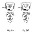
- Figures 21e and 21fshow the display 113 in state S7 with continuous and pulsatile, respectively, operation, wherein the bar 113' signalling the flow rate (or the frequency) is visible.
- Unprimingi.e. loss of priming, possibly during pumping, i.e. "end of liquid"
- state S6is the state in which the apparatus 100 arrives when the pump 102 has lost its priming, i.e. when a lack of liquid in the pump 102 occurs. The cause is normally due to the exhaustion of the liquid in the bag 109. In this state S6 is also activated the alarm buzzer.
- Figure 21gshows the display 113 in state S6.
- Manual Priming state S5is the state in which the apparatus 100 arrives in the case where it fails to automatically prime and the key 112D PRIME is pressed for manually forcing an attempt of priming the pump 102 with time-out. If in the predetermined time the priming of the pump 102 is not obtained, the latter is automatically stopped and the apparatus 100 passed in Unpriming state S6.
- Figure 21hshows the display 113 in state S5.
- Failure state S8occurs when the control processor 20 detects an incorrect number of revolutions of the motor 101' or an excessive current load, beyond the nominal operation threshold.
- State S8corresponds to a malfunction of mechanical type that may be induced by a plurality of factors, such as for instance the stop of the impeller 808 of the pump 102, or a failure of the electric motor 101' implying a loss of revolutions, thus not ensuring an adequate flow rate.
- Figure 21ishows the display 113 in state S8.
Landscapes
- Health & Medical Sciences (AREA)
- Heart & Thoracic Surgery (AREA)
- General Health & Medical Sciences (AREA)
- Public Health (AREA)
- Anesthesiology (AREA)
- Hematology (AREA)
- Life Sciences & Earth Sciences (AREA)
- Animal Behavior & Ethology (AREA)
- Engineering & Computer Science (AREA)
- Biomedical Technology (AREA)
- Veterinary Medicine (AREA)
- Pulmonology (AREA)
- Vascular Medicine (AREA)
- Physics & Mathematics (AREA)
- Fluid Mechanics (AREA)
- External Artificial Organs (AREA)
- Endoscopes (AREA)
- Surgical Instruments (AREA)
Description
- The present invention relates to an irrigation and suction system, in particular for laparoscopic surgery, that allows in a manner that is reliable, versatile, simple, comfortable for the operator and safe for the patient to carry out a lavage and/or a drainage of the surgical site, in particular during interventions performed by laparoscopy, the system being further capable to be made in an inexpensive way.
- It is known that laparoscopic surgery has been widely spread in recent years thanks to its reduced invasivity.
- In order to perform an intervention with laparoscopic technique, an apparatus, also called laparoscopic suction irrigator, is used, that comprises, in most advanced configurations, a control base provided with a pumping unit and a handpiece, that has the function of producing an irrigation jet of physiological liquid and carrying out a drainage suction in order to maintain the surgical site view clean during the interventions. The liquid jet and/or the suction occur through a steel probe that is attached to the handpiece and placed by the surgeon close to the intervention location, wherein it is inserted through a device known with the term of "trocar".
- The irrigation liquid is drawn from a bag of physiological solution, connected through an infusion line provided with a spike, and it is sent by means of a pump, through an irrigation line, to the probe, that may also operate as suction device depending on specific commands that the surgeon imparts to a valve assembly placed on the handpiece. Depression necessary to aspiration is given by a vacuum line of the operating room, that is connected through disposable collection devices for active drainages.
- In the prior art many irrigation and suction systems for laparoscopic surgery are known.
- International Application
WO 98/03214 - Patent
US 5303735 concerns a trumpet valve assembly usable for a surgical irrigation and suction system. - Application
EP 1086713 concerns an irrigation and suction system for use during endoscopic surgery, provided with a trumpet valve fed, for irrigation, by a reusable motor to which a disposable sterile pump may be coupled through a quick connection. - Patent
US 5484402 concerns a surgical irrigation and suction apparatus having a handpiece provided with a control rocking lever. - However, all the irrigation and suction apparatuses of the prior art suffer from some drawbacks.
- First of all, they are not much versatile, their dynamic application under variations of surgical conditions being complex and not much reliable.
- Moreover, they are uncomfortable to be used by the surgeon, since the means controlling their operation are not easily activatable.
- In this context, the solution proposed according to the present invention is introduced, allowing to overcome the aforementioned problems.
- It is therefore an object of the present invention to allow in a manner that is reliable, versatile, simple, comfortable for the operator, safe for the patient, and inexpensive to carry out a lavage and/or a drainage of the surgical site, in particular during interventions performed by laparoscopy.
- This is achieved by the invention as claimed. It is specific subject matter of this invention an irrigation and suction system, in particular for laparoscopic surgery, comprising an active control apparatus, provided with a reusable motor capable to be attached to and to operate a disposable pump, and a disposable handpiece provided with two valves capable to be connected respectively to an output duct from the pump and to a suction line, the two valves being operatable for making respectively the pump and the suction line communicate with an output nozzle of the handpiece, the nozzle being capable to support a probe, the apparatus comprising controlling electronics means for controlling electronics means for driving the motor, the system being characterised in that it comprises interface means connected to said controlling electronics means capable to select an operation mode of the motor between continuous mode, wherein the pump delivers fluid in a continuous and uniform way, and pulse mode, wherein the pump flow rate switches between a minimum flow rate and a maximum flow rate with a switching period.
- Always according to the invention, said interface means may be capable to further select a flow rate of the pump and/or, in case of pulse operation, said minimum flow rate and/or said maximum flow rate and/or said switching period.
- Still according to the invention, said interface means may comprise a keyboard, preferably along with a display, more preferably along with one or more light signalling LEDs, still more preferably along with an electro-acoustic indicator, or buzzer.
- Furthermore according to the invention, said interface means may be housed within the apparatus and/or the handpiece, being connected to said controlling electronics means through a cable or wireless connection, preferably through a radio frequency or infrared connection.
- Always according to the invention, the apparatus may comprise detecting, preferably optical, means, connected to said controlling electronics means and capable to detect a priming state of the pump, whereby said controlling electronics means enables or disables said electronics means for driving the motor when said detecting means detects that the pump is, respectively, primed or unprimed.
- Still according to the invention, said detecting means may be capable to detect the attaching of a pump to the motor, whereby said controlling electronics means enables or disables said electronics means for driving the motor when said detecting means detects that a pump is, respectively, attached or not attached.
- Furthermore according to the invention, said interface means may be further capable to cause an attempt of priming the pump within a maximum period (time-out), whereby the pump is operated for a pre-established period.
- Always according to the invention, the apparatus may comprise current detecting means connected to said controlling electronics means capable to detect a current absorbed by the motor, said current detecting means being preferably capable to further detect when said current absorbed by the motor exceeds a maximum threshold value, more preferably directly inhibiting said electronics means for driving the motor.
- Furthermore according to the invention, said controlling electronics means may be capable to detect an unpriming state of the pump on the basis of a current absorbed by the motor as detected by said current detecting means, whereby said controlling electronics means enables or inhibits said electronics means for driving the motor when it detects that the pump is respectively primed or unprimed.
- Still according to the invention, said controlling electronics means may be capable to detect a number of revolutions of the motor, whereby it inhibits said electronics means for driving the motor when said number of revolutions of the motor is incorrect.
- Furthermore according to the invention, the apparatus may comprise watching means connected to said controlling electronics means capable to detect a power-on state of the apparatus and/or malfunctions signalled by said controlling electronics means and/or an insufficient power supply, consequently resetting said controlling electronics means and/or inhibiting said electronics means for driving the motor for at least a time period.
- Always according to the invention, the attaching between the motor and the pump may be of coaxial bevel gear pair type, comprising a male driver and a corresponding female driver, preferably according to a labyrinth type geometry seal.
- It is still specific subject matter of the present invention an active control apparatus, provided with a reusable motor capable to be attached to and to operate a disposable pump, characterised in that it is used in an irrigation and suction system, in particular for laparoscopic surgery, as previously described, the apparatus comprising controlling electronics means for controlling electronics means for driving the motor connected to interface means capable to select an operation mode of the motor between continuous mode, wherein the pump delivers fluid in a continuous and uniform way, and pulse mode, wherein the pump flow rate switches between a minimum flow rate and a maximum flow rate with a switching period, said interface means being preferably housed at least partially within the apparatus.
- It is further specific subject matter of the present invention a handpiece usable in an irrigation and suction system, in particular for laparoscopic surgery, preferably as previously described, comprising an irrigation valve and a suction valve wherein corresponding shutters slide, which shutters are operated respectively by an irrigation button and a suction button for making the respective valves communicate with an output nozzle, the nozzle being preferably capable to be snap-connected through fast coupling to a probe holder, characterised in that the handpiece is ergonomically banana shaped, whereby it allows a comfortable and steady grip by an operator both when it is oriented with the nozzle above the four hand fingers different from the thumb, and when it is oriented in overturned position with the nozzle below such four fingers, the surfaces of the two buttons onto which the fingers of an operator exert a pressure being preferably one convex and the other concave, the handpiece more preferably housing interface means capable to communicate with a control apparatus through a cable and/or wireless connection, still more preferably through a radio frequency or infrared connection.
- Always according to the invention, the handpiece may be provided with an anti-skidding coating, preferably in Laprene®, that at least partially covers it.
- Still according to the invention, each shutter may be operated by the corresponding button through a respective gear-rack transmission, the buttons and the shutters being provided of end racks engaging two respective gear wheels.
- The system according to the invention, made with a reduced number of moving mechanical parts which are hence subject to wear, is extremely reliable and has a long service life. In this regard, in the preferred embodiment, adoption of an electric motor of brushless type allows to eliminate the wear problems of the brushes (proportionally to the operation hours), as well as the physiological dispersion of particles, typically of carbon, removed during rotation phase of the same brushes which, if not well insulated, may be source of serious contamination of the surgical site; moreover, motor shaft is keyed on ball bearings, subject to less wearing rolling friction. The other moving part is a female driver, made of plastic material, directly keyed on the driving shaft, that is therefore not subject to backlashes which could bring the same to "interfere" with the body of the housing. Also, it is not possible that an important wear of the "polygroove" taper hole occurs because it is not possible the motor start without the consent of the sensors checking the complete insertion of the disposable pump and hence of the male driver.
- As far as the electronic part is concerned, all power components are oversized with respect to the nominal operation conditions. Moreover, the system is provided with operation controls which avoid transients and excessive loads; in fact, the electronic circuit provides for monitoring of motor power absorption, of acceleration and of reached revolutions compared with the nominal ones at a given power supply condition.
- As a consequence, system service life is extremely long even in case of heavy use of the same.
- The present invention will be now described, by way of illustration and not by way of limitation, according to its preferred embodiments, by particularly referring to the Figures of the enclosed drawings, in which:
Figure 1 shows a schematic view of a preferred embodiment of the system according to the invention;Figure 2 shows a front view of the control apparatus of the system ofFigure 1 ;Figure 3 shows a perspective top front view of the control apparatus ofFigure 2 ;Figure 4 shows a perspective top front view of a first particular of the control apparatus ofFigure 2 , wherein internal components are visible;Figure 5 shows a perspective bottom rear view of the control apparatus ofFigure 2 , wherein internal components are visible;Figure 6 shows a perspective bottom rear view of a second particular of the control apparatus ofFigure 2 ;Figure 7 shows a perspective view of a third particular of the control apparatus ofFigure 2 ;Figure 8 shows a cross-section view of the pump of the system ofFigure 1 ;Figure 9 shows an exploded perspective view of the pump ofFigure 8 ;Figure 10 shows a perspective view of a particular of the pump ofFigure 8 ;Figure 11 shows a perspective view of the coaxial bevel gear pair connection of the pump with the motor of the system ofFigure 1 ;Figure 12 shows a front view of the display and keypads of the control apparatus ofFigure 2 ;Figure 13 shows a cross-section partial view of the control apparatus ofFigure 2 ;Figure 14 shows a cross-section view of the coaxial bevel gear pair connection of the pump with the motor of the system ofFigure 1 ;Figure 15 shows a schematic circuit diagram (Fig. 15a ), and a related legend (Fig. 15b ) of the electronic circuits of the control apparatus ofFigure 2 ;Figure 16 shows a perspective view of the handpiece of the system ofFigure 1 ;Figure 17 shows a view of internal components of the handpiece ofFigure 16 ;Figure 18 shows an exploded perspective view of the handpiece ofFigure 16 and of the probe of the system ofFigure 1 ;Figure 19 shows a top view (Fig. 19a ), a side view (Fig. 19b ), a bottom view (Fig. 19c ), and a cross-section view along the line A-A ofFig. 19a (Fig. 19d ) of a probe holder of the system ofFigure 1 ;Figure 20 schematically shows the machine states of the control apparatus ofFigure 2 ; andFigure 21 shows graphical information displayed by the display ofFigure 12 in the various machine states of the control apparatus ofFigure 2 .- In the Figures, identical reference numbers are used for alike elements.
- With reference to
Figure 1 , it may be observed that the preferred embodiment of the system according to the invention comprises anactive control apparatus 100, supplied by the mains (preferably at 230Vac), provided with a re-usable motor, housed inside aseat 101, on which an extractable disposablecentrifugal pump 102 is mounted, connectable through anirrigation pipe 103 to ahandpiece 104. - The
apparatus 100 is capable to be attached to anormal infusion stand 105 through a rear fastening clamp (illustrated later). Asuction pipe 106 is further associated to theirrigation pipe 103 that is also connectable to thehandpiece 104 for connecting the latter to a suction point, such as for instance a vacuum line of an operating room, through a disposable collection device for active drainages. Thepump 102 is further connectable through aninfusion pipe 107 provided with aspike 108 to abag 109 of liquid, preferably physiological solution, that may be hung on thestand 105. - The
handpiece 104 comprises two valves (illustrated later) for manually controlling irrigation and aspiration, and it supports asteel probe 110 that is coupled to a snap fast coupling fastener with which thesame handpiece 104 is frontally provided. - The
apparatus 100 is a non sterile, reusable device, whereas thepump 102 and thehandpiece 104 are sterile and disposable. - With reference to
Figures 2-6 , it may be observed that thecontrol apparatus 100 comprises a substantiallycylindrical side slot 101 in which the motor 101' for operating apump 102 is housed (the pump also comprises all the connection pipes, not shown inFigures 2-6 ) which pump may be stably attached to theslot 101 through a suitablefast coupling 111. In particular, thepump 102, preferably of centrifugal type, is engageable throughmechanical guides 111 and tight limit stop snap, whereas a tapered notch 111' on the chassis of theslot 101 aids manual extraction of thepump 102. Thecontrol apparatus 100 is capable to be fastened to a hospital metal stand through a suitablerear clamp 113, preferably provided, as shown inFigure 7 , with a clampinghandwheel 114. Also three components of the ch assis of theapparatus 100 are shown inFigures 5 and6 : a front main container 501 (housing, among other things, the electronic boards), asupport 502 for the motor-pump assembly, and arear end cover 503, from which anelectric tap 500 for supplying power to theapparatus 100 projects. - With reference to
Figures 8 and9 , it may be observed that thepump 102 comprises a lower pump casing 102' and in anupper pump casing 102". The lower pump casing 102' comprises aspindle 801 to which a male driver 802 (capable to insert in a corresponding female driver directly keyed on the driving shaft) is coupled, a shieldedbearing 803 being housed in asuitable support 804 on whichtight membranes 805 are applied which separate it from abush 806, preferably of Teflon, guiding thespindle 801; a first O-ring 807 ensures the tightness of thebush 806. Theupper pump casing 102" comprises an impeller 808 (shown in detail inFigure 10 ) coupled to thespindle 801, whereas a second O-ring 809 ensures the tightness of thepump 102; in theupper pump casing 102" is further housed achannel 810 for inletting the liquid solution (connectable to an external bag) that houses downwards abade duct 811 in which afloat 812 for sensing presence of liquid in thepump 102 is inserted, which liquid is capable to exit from anoutlet channel 813. Finally, twoholes upper pump casing 102" for allowing detection by respective optical sensors (illustrated later) with which theapparatus 100 is provided for sensing, respectively, the position of the float 812 (i.e. of the priming state of the pump 102) and the attachment of the pump on thecoupling 111. Figure 11 shows a particular of the coaxial bevel gear pair connection (comprisingmale driver 802 and corresponding female driver 1100) of thespindle 801 of thepump 102 with the driving shaft, which connection guarantees a maximum level of system electrical insulation.- Still with reference to
Figures 2-4 , it may be observed that theapparatus 100 includes a man-machine interface, or MMI, comprising akeypad 112 and adisplay 113, the MMI being further provided with three LEDs of different colours, preferably blue, green and red, for signalling the state (not shown in the Figures). - The function of the MMI is to allow the interaction by man, in our case by an operator in operating room, with the system according to the invention. The MMI indicates to the operator, in optical and/or acoustic way, the current state of the irrigation process, and it allows selection of the operation type between continuous and pulsatile, adjustment of parameters such as pump flow rate and, in case of pulse operation, switching times between minimum flow rate and maximum flow rate. In particular, the
graphic display 113 shows, in the lower part, a horizontal bar indicating current percentage flow rate (or, in case of pulse operation, current percentage switching frequency) of the pump, and in the upper part it shows the general state of the system (as it will be illustrated later with reference toFigure 21 ). Other embodiments of the system according to the invention provide that, through the MMI, it is possible to further set the minimum and maximum rate limits in case of pulse operation. - As shown in
Figure 12 , thekeypad 112 comprises fourkeys - The first key 112A, called "UP", allows either the pump flow rate to be increased in case of continuous operation, or the ON and OFF pulse times to be reduced in case of pulse operation (i.e. the switching period to be reduced, increasing the frequency of the same switching).
- The second key 112B, called "DOWN", allows either the pump flow rate to be reduced in case of continuous operation, or the ON and OFF pulse times to be increased in case of pulse operation (i.e. the switching period to be increased, reducing the frequency of the same switching).
- The third key 112C, called "PULSE", allows selection of the pump operation type. In particular, the operation that is automatically set at power on (default operation) is continuous, i.e. the pump operates in a continuous and uniform way. Pressure on the
key PULSE 112C sets the operation in "pulse" mode, that is the pump flow rate is modified at time intervals between a minimum and a maximum, i.e. switching between a minimum flow rate and a maximum flow rate with a switching period; in other words, in pulse operation an alternative passage from the minimum flow rate to the maximum flow rate, and vice versa, occurs (in a Pause-Operation logic, the times of which are variable through the two keys UP 112A andDOWN 112B). If thekey PULSE 112C is pressed when the operation has been already switched to pulsatile, the operation returns to continuous mode. The operation mode is visible on thedisplay 113. - The fourth key 112D, called "PRIME", allows to manually require an attempt to prime the pump within a maximum time (time-out), i.e. the pump is activated for a predetermined time, during which if pump priming is not obtained, the pump is automatically stopped and the system passes in a state of failed priming.
- As said, the MMI is further provided with three LEDs for signalling the state of the
pump 102, preferably of blue, green and red colours, respectively. Depending on the state of the pump, the LEDs turn on as follows: in case of pump not inserted on thecoupling 111, all the three LEDs are off; in case of just insertedpump 102, only the blue LED is on; in case of primed pump, only the green LED is on; in case of unprimed pump, only the red LED is on. - Preferably, the MMI further comprises an electroacoustic signaller, or buzzer, that is used both as confirmation of keystroke of a key of the
keypad 112 through a beep, and as indication of an alarm state, such as for instance loss of pump priming due to lack of liquid in thebag 109. - For ensuring a sufficient protection from sprinkles, which usually may occur in operating room, all possible ways of penetration of liquids into the chassis of the
apparatus 100 are tight sealed. As said, the chassis preferably comprises three components: the front main container 501 (housing, among other things, the electronic boards, thekeypad 112, and the display 113), thesupport 502 for the motor-pump assembly, and therear end cover 503. Thesupport 502 for the motor-pump assembly is fastened on thefront container 501 through a metal bracket plus a sealing along the perimeter of contact between the two parts. Therear cover 503 is fastened to thefront container 501 through screws. - Therefore, the chassis has the following possible ways of penetration of liquids which are tight sealed:
- line closing
rear cover 503 on thefront container 501, housing a tight O-ring; line closing support 502 for the motor-pump assembly on thefront container 501, that is sealed with impermeable glue;- holes for fastening the
rear clamp 113 to therear cover 503, closed through insertion of a tight seal with counterflange; - with reference to
Figure 13 , hole in thesupport 502 for the motor-pump assembly for the passage of thesnap pin 1300 elastically holding thepump 102, which hole is closed through insertion of a tight seal with counterflange; holes support 502 for the motor-pump assembly for the optical sensors, closed through insertion of a tight seal with counterflange;- holes and lines closing the
keypad 112 and thedisplay 113 on thefront container 501, protected by a tight mask made of a thin plate of polycarbonate; and - hole in the
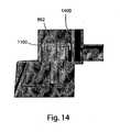
support 502 for the motor-pump assembly for the exit of thefemale driver 1100 of the driving shaft, that is closed by adopting particular geometries, in particular labyrinth seal ones, for the coupling for transmitting the motor torque, as shown inFigure 14 wherein the significantly tortuous path that a liquid must follow to penetrate inside thesupport 502 may be observed. - The
apparatus 100 comprises electronic boards, on which the electronic circuits are mounted, preferably provided with a processor (or a microcontroller), for controlling the system. - With reference to
Figure 15 , a schematic circuit diagram, immediately understandable to those skilled in the art, of the electronic circuits of theapparatus 100 may be observed, supplied by thepower supply tap 500, that comprises the following modules controlled by a processor 20: afirst module 1500 of power supply (PWM: Power Module); asecond module 1501 for driving the motor 101' (MDM: Motor Driver Module); athird module 1502 for controlling the current absorbed by the motor (CCM: Current Control Module); afourth module 1503 of surveillance (WDM: Watch Dog Module); afifth module 1504 of proximity detection (PXM: Proximity Module); and asixth module 1505 of interface (MMI: Man Machine Interface). - The
first module PWM 1500 constitutes the power supply section of the whole system and it is of AC/DC conversion type with galvanic insulation of inductive and optical type. Themodule PWM 1500 may be supplied, through thetap 500, preferably with voltage ranging from 90 to 230 Vac with frequency 50-60 Hz, and it generates all the dc voltages necessary to the operation of theapparatus 100. In particular, themodule PWM 1500 comprises afuse section 1 connected to alow pass filter 2, for the electromagnetic compatibility related to the ducts, in turn connected to an AC/DC converter 3 and to ablock 4 for sensing mains with galvanic insulation, which is capable to inform theprocessor 20 of the occurrence of transients of power down of the apparatus (sending a respective signal to a WUP input of the processor 20), which force thesame processor 20 to perform data save and protection subroutines. - The
second module MDM 1501 drives the motor 101', that is a three-phase dc low voltage (24Vdc) BLDC (Brushless Direct Current) motor. Themodule MDM 1501 comprises a driving circuit (5, 6, 7) for each phase, followed by arespective EMI filter 5", 6" and 7" connected to the corresponding phase of the motor 101'. The phase controls coming from three outputs (Phase A, Phase B, Phase C) of theprocessor 20 which control the motor 101', before reaching therespective driving circuits gates 5', 6' and 7', along with failure signals described later. In this way, the phase controls may reach and activate therespective driving circuits modules CCM 1502 andWDM 1503 and they indicate, respectively, an excess of current absorbed by the motor 101' and a hardware breakdown due to malfunction of software or hardware or for lack of mains (power-off). In particular, theprocessor 20 is capable to generate the phase controls on the basis of three signals received (inputs HLLA, HLLB, HLLC) from ablock 21 detecting the position of the rotor comprising three Hall sensors. Moreover, on the basis of such three signals, theprocessor 20 is further capable to detect an incorrect number of revolutions of the motor 101'. - The
third module CCM 1502 carries out the detection of the current absorbed by the motor 101' through acurrent sensor 11 that converts current in voltage and sends the result towards the processor 20 (input IMOT) for its measurement. Current measurement is used (along with the signals coming from theblock 21 of the module MDM) via firmware for controlling the correct operation of the motor 101' and verifying possible failure states. Athreshold detector 12, connected before thesensor 11, and amonostable circuit 13, in turn connected before thedetector 12, are also part of thesame module CCM 1502; in particular, thesame detector 12 receives from thesensor 11 the value of the current absorbed by the motor 101', it carries out the continuous control whether current exceeds the allowed maximum current and, in the positive, themonostable circuit 13 inhibits thecircuits gates 5', 6', and 7', besides to a corresponding input (FAULT) of theprocessor 20. - The
fourth module WDM 1503 has the function to reset theprocessor 20 and to inhibit thecircuits module WDM 1503 comprises asupervisor block 18 that monitors the power supply voltage and cyclically receives a WD pulse from the processor 20 (output WDP). In case of lack of said pulse within a predetermined time or in case of out-of-tolerance supply voltage, thesupervisor block 18 generates a reset signal sent to the processor 20 (input RES) and to a delay block 19 (also belonging to the module WDM 1503). Theblock 19 behaves as a re-triggerable one-shot multivibrator sending a low signal to the input of the ANDgates 5', 6', and 7' (thus inhibiting thecircuits processor 20, which signal stops the whole hardware for a time equal to about 2 seconds. - The
fifth module PXM 1504 comprises a proximityoptical detector 15 and a limit stopoptical switcher 14. Theoptical detector 15 has the function of reading the position of thefloat 812 of thepump 102 necessary to the system operation, whereas theoptical switcher 14 is used as sensor of presence of thepump 102 on thecoupling 111 on theslot 101 of the motor 101'. - The
sixth module MMI 1505 of interface comprises thegraphic display 113, preferably a 128x128 pixel one, and thekeypad 112 with four keys, which allow an operator to program and control the system operation. - With reference to
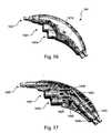
Figures 16-18 , it may be observed that thehandpiece 104 is the part handled by the surgeon allowing, through anirrigation button 1601 and asuction button 1602, to control the operation of two corresponding valves, respectively an irrigation one 1603 and a suction one 1604 (preferably integrally coupled to each other) in which corresponding shutters, respectively 1605 and 1606, slide, which in turn regulate the irrigation and suction phases through a steel probe 110 (shown inFigures 1 and18 ) provided with a probe holder 1900 (shown in detail inFigures 18 and19 ) that connects by snap connection to afast coupling nozzle 1607 of thehandpiece 104. The inlets of thevalves reference numbers Figure 1 ). - In particular, motion of each button, 1601 or 1602, is transmitted to the corresponding shutter, 1605 or 1606, through a respective gear-rack transmission. In fact, both the
buttons shutters respective gear wheels handpiece 104. - The handpiece top is provided with an
anti-skidding coating 1610, preferably of Laprene®. - Moreover, the form of the
handpiece 104, having a banana shape, is ergonomic, allowing a comfortable and firm grip by an operator both when it is placed with thenozzle 1607 above the four fingers of the hand different from the thumb (i.e. when thehandpiece 104 is handled as a pistol with the inlets of thevalves nozzle 1607 below such four fingers (i.e. when it is in overturned position with the inlets of thevalves buttons - It must be noted that it is possible to simultaneously control the
shutters related buttons 1601 and 1602) towards theoutlet nozzle 1607. Even if this would occur during system operation, this causes the direct canalisation of the irrigation line towards the suction line, and hence the probe would be at a pressure only slightly different from the ambient pressure whereby such situation does not constitute a danger for the patient. - Other embodiments of the system according to the invention may provide that control keys, similar to those of the
keypad 112, (and possibly a display and/or signalling LEDs and/or a buzzer) are present on thehandpiece 104 for allowing to control the operation of theapparatus 100 directly from thehandpiece 104. The control signals may be sent from thehandpiece 104 to the processor 20 (and possibly vice versa) by wired or wireless connection, e.g. through radio frequency or infrared connection. - It must be noted that the
handpiece 104 is also applicable to irrigation and suction systems comprising control apparatuses different from the one of the system according to the present invention. - In order to better understand the present invention, the operating modes of the preferred embodiment of the system according to the invention will be described in the following, similar modes being valid for the other embodiments.
- As shown in
Figure 1 , theapparatus 100 fastens, through theclamp 113, to a hospital metal stand 105 under thebag 109 of physiological liquid, that is also hung on the top of thestand 105. Once fastened, theapparatus 100 is supplied by connecting thepower supply tap 500 to the mains, preferably at 230Vac. In this condition, theapparatus 100 is in a stand-by state indicated by both thedisplay 113 and the signalling LEDs, all off, indicating that no pump has been inserted yet. - At this point a
pump 102 is inserted, thehandpiece 104 provided withprobe 110 is coupled to thepump 102 through theirrigation pipe 103, theinfusion pipe 107 of thepump 102 is inserted into thebag 109 of liquid through thespike 108 and thesuction pipe 106 coming from thehandpiece 104 is connected to the point at negative pressure present in the operating room. For a correct and safe operation, it is necessary that thebag 109 is placed above theapparatus 100 using all the available length of theinfusion pipe 107, whereas thesuction pipe 106 must be connected to the operating room suction system provided for the normal surgical aspirators interposing a reservoir for collecting liquids with adequate capacity in relation to the foreseen needs. - The
apparatus 1 00 checks th e presence of the pump 102 and passes in the pre-priming state indicated by both thedisplay 113 and turning-on of the signalling blue LED. - The subsequent step is to prime the
pump 102. To this end, an operator presses theirrigation button 1601 on thehandpiece 104, the liquid begins to flow by gravity through thepump 102 until it exits from thesteel probe 110. When a sufficient quantity of liquid has flowed by gravity from theprobe 110, the operator releases theirrigation button 1601, and theapparatus 100 checks the presence of liquid in the hydraulic circuit and passes in the primed pump state, indicated by both thedisplay 113 and turning-on of the signalling green LED. - Once the priming state has been reached, whenever the surgeon presses the
irrigation button 1601, theapparatus 100 checks and activates thepump 102 that pushes the liquid towards thehandpiece 104. Thepump 102 automatically stops when theirrigation button 1601 is released. - The first loss of priming due to the exhaustion of the physiological liquid in the
bag 109 or to any anomaly is detected by theapparatus 100 that stops thepump 102 and indicates the state ofunprimed pump 102 on thedisplay 113, with simultaneous turning-on of the signalling red LED. - The new priming of the
pump 102 occurs manually through pressure of thekey PRIME 112D of thekeypad 112 of theapparatus 100, after either the cause of the anomaly has been removed or thebag 109 of liquid has been replaced. - As said before, the surgeon may set the operating functions through the
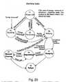
keypad 112, whereas thedisplay 113 shows the information on the system state. Figure 20 schematically shows the eight machi ne states of theapparatus 100, according to which the electronics operates, whereasFigure 21 shows the graphic information displayed by thedisplay 113.- At power-on, the
apparatus 100 is in the first state S1 (Power-ON). In such state, theapparatus 100 performs a test for analysing whether thepump 102 is inserted in thecoupling 111 and whether it is primed or not. Depending on the result of the test, the apparatus enters one of three subsequent machine states S2, S3 or S4. - The second state S2 (Stand-by) is the state in which the
apparatus 100 is immediately after having been supplied in the case where thepump 102 has not yet been inserted, or after that thepump 102 has been disconnected starting from any operation condition.Figure 21a shows thedisplay 113 in state S2. - The third state S3 (Pre-priming) is the state in which the
apparatus 100 is immediately after having been supplied in the case where thepump 102 has been already inserted prior to applying the power supply, but it is not yet primed (i.e. in the condition of no liquid within the pump 102), or anunprimed pump 102 has been inserted with theapparatus 100 in stand-by state S2.Figure 21b shows thedisplay 113 in state S3. - The fourth state S4 (Priming) is the state indicating that the
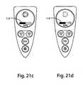
pump 102 is ready to pump since it is already charged with liquid. In the case where a new plump 102 is coupled in theapparatus 100 and it is connected to thebag 109 of solution, it is necessary to provide for its priming by opening theirrigation valve 1603 on thehandpiece 104 and making an adequate quantity of liquid flow by gravity. In this state S4 it is possible to modify the flow rate of thepump 102 through thekeys keypad 112, and to set the operation type by selecting it between continuous and pulsatile through the key 112C.Figures 21c and 21d show thedisplay 113 in state S4 with operation, respectively, continuous and pulsatile, wherein the bar 113' signalling the flow rate (or the frequency, in case of pulse operation) is visible. - Pumping state S7 is the state with which the irrigation function is obtained and it is reached by the
apparatus 100 when thebutton 1601 opening theirrigation valve 1603 on thehandpiece 104 is pressed. In this state S7 thepump 102 is active and the operator may modify the flow rate of the pump 102 (through thekeys Figures 21e and 21f show thedisplay 113 in state S7 with continuous and pulsatile, respectively, operation, wherein the bar 113' signalling the flow rate (or the frequency) is visible. - Unpriming (i.e. loss of priming, possibly during pumping, i.e. "end of liquid") state S6 is the state in which the
apparatus 100 arrives when thepump 102 has lost its priming, i.e. when a lack of liquid in thepump 102 occurs. The cause is normally due to the exhaustion of the liquid in thebag 109. In this state S6 is also activated the alarm buzzer.Figure 21g shows thedisplay 113 in state S6. - Manual Priming state S5 is the state in which the
apparatus 100 arrives in the case where it fails to automatically prime and the key 112D PRIME is pressed for manually forcing an attempt of priming thepump 102 with time-out. If in the predetermined time the priming of thepump 102 is not obtained, the latter is automatically stopped and theapparatus 100 passed in Unpriming state S6.Figure 21h shows thedisplay 113 in state S5. - Finally, Failure state S8 occurs when the
control processor 20 detects an incorrect number of revolutions of the motor 101' or an excessive current load, beyond the nominal operation threshold. State S8 corresponds to a malfunction of mechanical type that may be induced by a plurality of factors, such as for instance the stop of theimpeller 808 of thepump 102, or a failure of the electric motor 101' implying a loss of revolutions, thus not ensuring an adequate flow rate.Figure 21i shows thedisplay 113 in state S8. - The preferred embodiments have been above described and some modifications of this invention have been suggested, but it should be understood that those skilled in the art can make variations and changes, without so departing from the related scope of protection, as defined by the following claims.
Claims (12)
- Irrigation and suction system, in particular for laparoscopic surgery, comprising an active control apparatus (100), provided with a reusable motor (101') capable to be attached to and to operate a disposable pump (102), and a disposable handpiece (104) provided with two valves (1603, 1604) capable to be connected respectively to an output duct (813) from the pump (102) and to a suction line, the two valves being operatable (1603, 1604) for making respectively the pump (102) and the suction line communicate with an output nozzle (1607) of the handpiece (104), the nozzle (1607) being capable to support a probe (110), the apparatus (100) comprising controlling electronics means (20) for controlling electronics means (1501) for driving the motor (101'), wherein the system comprises interface means (1505, 16, 17, 112, 113) connected to said controlling electronics means (20) capable to select an operation mode of the motor (101') between continuous mode, wherein the pump (102) delivers fluid in a continuous and uniform way, and pulse mode, wherein the pump flow rate switches between a minimum flow rate and a maximum flow rate with a switching period,said interface means (1505, 16, 17, 112, 113) comprising a keypad (112) with keys (112A, 112B, 112C, 112D) suitable to allow to select an operation mode of the motor (101'), characterized in that the interface means (1505, 16, 17, 112, 113) also comprise a graphic display (113) suitable to visualize an operation state of the system and a man-machine interface electronic module (1505, 16,17) to which said keys (112A, 112B, 112C, 112D) and graphic display (113) are connected, and in that said interface means (1505, 16, 17, 112, 113) are housed in the handpiece (104).
- System according to claim 1,characterized in that said interface means (1505, 16, 17, 112, 113) is capable to further select a flow rate of the pump (102) and/or, in case of pulse operation, said minimum flow rate and/or said maximum flow rate and/or said switching period.
- System according to claim 1 or 2,characterized in that said interface means comprises a keyboard (112), preferably along with a display (113), more preferably along with one or more light signalling LEDs, still more preferably along with an electro-acoustic indicator, or buzzer.
- System according to any one of the preceding claims,characterized in that said interface means (1505, 16, 17, 112, 113) is connected to said controlling electronics means (20) through a cable or wireless connection, preferably through a radio frequency or infrared connection.
- System according to any one of the preceding claims,characterized in that the apparatus (100) comprises detecting, preferably optical, means (14, 15), connected to said controlling electronics means (20) and capable to detect a priming state of the pump (102), whereby said controlling electronics means (20) enables or disables said electronics means (1501) for driving the motor (101') when said detecting means (14, 15) detects that the pump (102) is, respectively, primed or unprimed.
- System according to claim 5,characterized in that said detecting means (14, 15) is capable to detect the attaching of a pump (102) to the motor (101'), whereby said controlling electronics means (20) enables or disables said electronics means (1501) for driving the motor (101') when said detecting means (14, 15) detects that a pump (102) is, respectively, attached or not attached.
- System according to claim 5 or 6,characterized in that said interface means (1505, 16, 17, 112, 113) is further capable to cause an attempt of priming the pump (102) within a maximum period (time-out), whereby the pump (102) is operated for a pre-established period.
- System according to any one of the preceding claims,characterized in that the apparatus (100) comprises current detecting means (1502) connected to said controlling electronics means (20) capable to detect a current absorbed by the motor (101'), said current detecting means (1502) being preferably capable to further detect when said current absorbed by the motor (101') exceeds a maximum threshold value, more preferably directly inhibiting said electronics means (1501) for driving the motor (101').
- System according to claim 8,characterized in that said controlling electronics means (20) is capable to detect an unpriming state of the pump (102) on the basis of a current absorbed by the motor (101') as detected by said current detecting means (1502), whereby said controlling electronics means (20) enables or inhibits said electronics means (1501) for driving the motor (101') when it detects that the pump (102) is respectively primed or unprimed.
- System according to claim 8 or 9,characterized in that said controlling electronics means (20) is capable to detect a number of revolutions of the motor (101'), whereby it inhibits said electronics means (1501) for driving the motor (101') when said number of revolutions of the motor (101') is incorrect.
- System according to any one of the preceding claims,characterized in that the apparatus (100) comprises watching means (1503) connected to said controlling electronics means (20) capable to detect a power-on state of the apparatus (100) and/or malfunctions signalled by said controlling electronics means (20) and/or an insufficient power supply, consequently resetting said controlling electronics means (20) and/or inhibiting said electronics means (1501) for driving the motor (101') for at least a time period.
- System according to any one of the preceding claims,characterized in that the attaching between the motor (101') and the pump (102) is of coaxial bevel gear pair type, comprising a male driver (802) and a corresponding female driver (1100), preferably according to a labyrinth type geometry seal.
Applications Claiming Priority (2)
| Application Number | Priority Date | Filing Date | Title |
|---|---|---|---|
| ITRM2008A000447AIT1391274B1 (en) | 2008-08-08 | 2008-08-08 | IRRIGATION AND SUCTION SYSTEM, IN PARTICULAR FOR LAPAROSCOPIC SURGERY |
| PCT/IT2009/000375WO2010016089A2 (en) | 2008-08-08 | 2009-08-07 | Irrigation and suction system, in particular for laparoscopic surgery |
Publications (2)
| Publication Number | Publication Date |
|---|---|
| EP2346544A2 EP2346544A2 (en) | 2011-07-27 |
| EP2346544B1true EP2346544B1 (en) | 2015-10-07 |
Family
ID=40834546
Family Applications (1)
| Application Number | Title | Priority Date | Filing Date |
|---|---|---|---|
| EP09741006.2AActiveEP2346544B1 (en) | 2008-08-08 | 2009-08-07 | Irrigation and suction system, in particular for laparoscopic surgery |
Country Status (5)
| Country | Link |
|---|---|
| US (1) | US9314554B2 (en) |
| EP (1) | EP2346544B1 (en) |
| ES (1) | ES2559702T3 (en) |
| IT (1) | IT1391274B1 (en) |
| WO (1) | WO2010016089A2 (en) |
Families Citing this family (16)
| Publication number | Priority date | Publication date | Assignee | Title |
|---|---|---|---|---|
| JP5251832B2 (en)* | 2009-11-04 | 2013-07-31 | 富士通株式会社 | Electronic device, power supply control device, and power supply control method |
| DE102010033240B4 (en)* | 2010-08-03 | 2015-07-09 | Volker A. Schwarz | Handpiece unit for a disposable irrigation nozzle unit for cleaning and / or irrigation of surgical wounds |
| ITRM20110607A1 (en)* | 2011-11-16 | 2013-05-17 | Ab Medica Spa | HANDPIECE FOR AN IRRIGATION AND SUCTION SYSTEM, IN PARTICULAR FOR LAPAROSCOPIC SURGERY. |
| DK2679259T3 (en) | 2012-06-29 | 2017-07-24 | Dentsply Ih Ab | ENGINE RINSE SYSTEM |
| US9332998B2 (en) | 2012-08-13 | 2016-05-10 | Covidien Lp | Apparatus and methods for clot disruption and evacuation |
| US9332999B2 (en) | 2012-08-13 | 2016-05-10 | Covidien Lp | Apparatus and methods for clot disruption and evacuation |
| US9546662B2 (en) | 2012-11-20 | 2017-01-17 | Smith & Nephew, Inc. | Medical pump |
| US9693896B2 (en) | 2013-03-15 | 2017-07-04 | Novartis Ag | Systems and methods for ocular surgery |
| AU2015259400B2 (en)* | 2014-05-12 | 2019-12-19 | Smith & Nephew, Inc. | Closed loop surgical system |
| JP2017064165A (en)* | 2015-09-30 | 2017-04-06 | 株式会社ニデック | Ophthalmic surgical apparatus |
| US11026715B2 (en) | 2017-09-28 | 2021-06-08 | John Mayberry | Chest cavity suction medical apparatus and method |
| US11471660B2 (en)* | 2018-10-25 | 2022-10-18 | Covidien Lp | Vacuum driven suction and irrigation system |
| US11698059B2 (en) | 2018-12-29 | 2023-07-11 | Biosense Webster (Israel) Ltd. | Disposable dual-action reciprocating pump assembly |
| US12011211B2 (en) | 2018-12-29 | 2024-06-18 | Biosense Webster (Israel) Ltd. | Irrigation pump with ablation and non-ablation operational modes |
| US11877818B2 (en)* | 2020-06-26 | 2024-01-23 | Procept Biorobotics Corporation | Integration of robotic arms with surgical probes |
| CN114099835A (en)* | 2021-12-28 | 2022-03-01 | 肖强胜 | Biliary pulse type frequency conversion irrigator |
Family Cites Families (46)
| Publication number | Priority date | Publication date | Assignee | Title |
|---|---|---|---|---|
| US3508546A (en)* | 1968-06-04 | 1970-04-28 | Adelle M Rogers | Douche and enema apparatus |
| US4184510A (en)* | 1977-03-15 | 1980-01-22 | Fibra-Sonics, Inc. | Valued device for controlling vacuum in surgery |
| US5993378A (en)* | 1980-10-28 | 1999-11-30 | Lemelson; Jerome H. | Electro-optical instruments and methods for treating disease |
| US4803992A (en)* | 1980-10-28 | 1989-02-14 | Lemelson Jerome H | Electro-optical instruments and methods for producing same |
| US4519385A (en)* | 1982-12-01 | 1985-05-28 | Snyder Laboratories, Inc. | Lavage handpiece |
| US4635621A (en)* | 1982-12-01 | 1987-01-13 | Snyder Laboratories, Inc. | Lavage system with replaceable pump |
| US4669453A (en)* | 1982-12-01 | 1987-06-02 | Snyder Laboratories, Inc. | Lavage system |
| US4561431A (en)* | 1982-12-01 | 1985-12-31 | Snyder Laboratories, Inc. | Lavage system with linear motor |
| US4655197A (en)* | 1982-12-01 | 1987-04-07 | Snyder Laboratories, Inc. | Lavage system with variable frequency, flow rate and pressure |
| US5152746A (en)* | 1990-04-30 | 1992-10-06 | Zimmer, Inc. | Low pressure irrigation system |
| US5373317B1 (en)* | 1993-05-28 | 2000-11-21 | Welch Allyn Inc | Control and display section for borescope or endoscope |
| US5805140A (en)* | 1993-07-16 | 1998-09-08 | Immersion Corporation | High bandwidth force feedback interface using voice coils and flexures |
| US5484402A (en) | 1993-12-30 | 1996-01-16 | Stryker Corporation | Surgical suction irrigator |
| US5647852A (en)* | 1995-01-31 | 1997-07-15 | Zimmer, Inc. | Lavage system including a cassette assembly |
| US5531680A (en)* | 1995-05-05 | 1996-07-02 | Zevex, Inc. | Enteral feeding pump motor unit and method of use |
| IT1278142B1 (en)* | 1995-07-13 | 1997-11-17 | Consiglio Nazionale Ricerche | SURGICAL PROBE FOR LOCATION OF TUMORS FOR LAPAROSCOPIC OR INTRACAVITARY USE. |
| US5879289A (en)* | 1996-07-15 | 1999-03-09 | Universal Technologies International, Inc. | Hand-held portable endoscopic camera |
| DE69731472T2 (en)* | 1996-08-15 | 2005-10-20 | Deka Products Ltd. Partnership | PUMP AND SYSTEM FOR MEDICAL IRRIGATION |
| US7776014B2 (en)* | 1998-01-29 | 2010-08-17 | Peter Visconti | Disposable surgical suction/irrigation trumpet valve tube cassette |
| US6210404B1 (en)* | 1998-10-28 | 2001-04-03 | John H. Shadduck | Microjoule electrical discharge catheter for thrombolysis in stroke patients |
| FR2785132B1 (en)* | 1998-10-27 | 2000-12-22 | Tokendo Sarl | DISTAL COLOR CCD SENSOR VIDEOENDOSCOPIC PROBE |
| US7193521B2 (en)* | 1998-10-29 | 2007-03-20 | Medtronic Minimed, Inc. | Method and apparatus for detecting errors, fluid pressure, and occlusions in an ambulatory infusion pump |
| US6652453B2 (en)* | 1999-03-03 | 2003-11-25 | Vincent A. Smith | Portable video laryngoscope |
| EP1331954B1 (en)* | 2000-09-22 | 2007-01-03 | C.R. Bard, Inc. | Surgical irrigation system |
| US7056123B2 (en)* | 2001-07-16 | 2006-06-06 | Immersion Corporation | Interface apparatus with cable-driven force feedback and grounded actuators |
| US6929600B2 (en)* | 2001-07-24 | 2005-08-16 | Stephen D. Hill | Apparatus for intubation |
| DE10239784B4 (en)* | 2002-08-29 | 2004-12-30 | Tecpharma Licensing Ag | Injection, infusion or inhalation device with dose display device |
| TW581668B (en)* | 2003-10-15 | 2004-04-01 | Der-Yang Tien | Endoscopic device |
| US8864787B2 (en)* | 2004-04-21 | 2014-10-21 | Acclarent, Inc. | Ethmoidotomy system and implantable spacer devices having therapeutic substance delivery capability for treatment of paranasal sinusitis |
| EP1841353A4 (en)* | 2004-12-28 | 2011-09-21 | Patrick C Melder | Endoscopic imaging system |
| US10064540B2 (en)* | 2005-02-02 | 2018-09-04 | Intuitive Surgical Operations, Inc. | Visualization apparatus for transseptal access |
| US7918787B2 (en)* | 2005-02-02 | 2011-04-05 | Voyage Medical, Inc. | Tissue visualization and manipulation systems |
| US8221310B2 (en)* | 2005-10-25 | 2012-07-17 | Voyage Medical, Inc. | Tissue visualization device and method variations |
| US8052644B2 (en)* | 2005-12-14 | 2011-11-08 | Stryker Corporation | Surgical irrigation system |
| US20100063437A1 (en)* | 2006-07-12 | 2010-03-11 | Nelson Drew V | Multifunctional surgical instrument |
| WO2008019367A2 (en)* | 2006-08-07 | 2008-02-14 | Innovative Medical Devices, Inc. | System to aid in the positioning, confirmation and documentation of an endotracheal tube |
| US8992424B2 (en)* | 2007-02-09 | 2015-03-31 | Skeletal Dynamics Llc | Endo-surgical device and method |
| US9138534B2 (en)* | 2007-05-11 | 2015-09-22 | Roche Diabetes Care, Inc. | Positive displacement pump |
| US20100241185A1 (en)* | 2007-11-09 | 2010-09-23 | University Of Virginia Patent Foundation | Steerable epicardial pacing catheter system placed via the subxiphoid process |
| US9161817B2 (en)* | 2008-03-27 | 2015-10-20 | St. Jude Medical, Atrial Fibrillation Division, Inc. | Robotic catheter system |
| KR101038417B1 (en)* | 2009-02-11 | 2011-06-01 | 주식회사 이턴 | Surgical Robot System and Its Control Method |
| US8361041B2 (en)* | 2009-04-09 | 2013-01-29 | University Of Utah Research Foundation | Optically guided feeding tube, catheters and associated methods |
| US8322365B2 (en)* | 2010-08-17 | 2012-12-04 | Codman & Shurtleff, Inc. | Implantable adjustable valve |
| US20130253368A1 (en)* | 2010-12-08 | 2013-09-26 | Chandrakanth Are | Portable laparoscope system |
| US9547752B2 (en)* | 2010-12-31 | 2017-01-17 | St. Jude Medical, Atrial Fibrillation Division, Inc. | Automated catheter guidance system |
| US8323181B2 (en)* | 2011-02-17 | 2012-12-04 | Apurba Mukherjee | Endoscope with variable incident light and laser source platform |
- 2008
- 2008-08-08ITITRM2008A000447Apatent/IT1391274B1/enactive
- 2009
- 2009-08-07EPEP09741006.2Apatent/EP2346544B1/enactiveActive
- 2009-08-07ESES09741006.2Tpatent/ES2559702T3/enactiveActive
- 2009-08-07USUS13/058,185patent/US9314554B2/enactiveActive
- 2009-08-07WOPCT/IT2009/000375patent/WO2010016089A2/enactiveApplication Filing
Also Published As
| Publication number | Publication date |
|---|---|
| ES2559702T3 (en) | 2016-02-15 |
| WO2010016089A3 (en) | 2011-01-06 |
| IT1391274B1 (en) | 2011-12-01 |
| WO2010016089A2 (en) | 2010-02-11 |
| EP2346544A2 (en) | 2011-07-27 |
| ITRM20080447A1 (en) | 2010-02-09 |
| US20110224600A1 (en) | 2011-09-15 |
| US9314554B2 (en) | 2016-04-19 |
Similar Documents
| Publication | Publication Date | Title |
|---|---|---|
| EP2346544B1 (en) | Irrigation and suction system, in particular for laparoscopic surgery | |
| US20250222191A1 (en) | Medical waste collection system including a mobile rover removably couplable to a chassis | |
| US20250170322A1 (en) | Methods Of Operating A Waste Collection Unit Including A Light Assembly | |
| JP6208838B2 (en) | Medical waste collection unit capable of aspiration at two aspiration levels | |
| EP2650028B1 (en) | Wound treatment apparatus | |
| US8858517B2 (en) | Power saving control system for negative pressure wound therapy pumps | |
| EP3860477B1 (en) | Endoscope | |
| US7763000B2 (en) | Wound treatment apparatus having a display | |
| WO2016183290A1 (en) | Fluid collection and disposal system | |
| US12420004B2 (en) | System for vacuum-assisted venous drainage (VAVD) | |
| US20240100235A1 (en) | Pressure measuring device and medical device | |
| ITRM20110607A1 (en) | HANDPIECE FOR AN IRRIGATION AND SUCTION SYSTEM, IN PARTICULAR FOR LAPAROSCOPIC SURGERY. | |
| KR100696431B1 (en) | Biological Liquid Suction Device | |
| JP2006283680A (en) | Sanitizer |
Legal Events
| Date | Code | Title | Description |
|---|---|---|---|
| PUAI | Public reference made under article 153(3) epc to a published international application that has entered the european phase | Free format text:ORIGINAL CODE: 0009012 | |
| 17P | Request for examination filed | Effective date:20110512 | |
| AK | Designated contracting states | Kind code of ref document:A2 Designated state(s):AT BE BG CH CY CZ DE DK EE ES FI FR GB GR HR HU IE IS IT LI LT LU LV MC MK MT NL NO PL PT RO SE SI SK SM TR | |
| AX | Request for extension of the european patent | Extension state:AL BA RS | |
| DAX | Request for extension of the european patent (deleted) | ||
| GRAP | Despatch of communication of intention to grant a patent | Free format text:ORIGINAL CODE: EPIDOSNIGR1 | |
| INTG | Intention to grant announced | Effective date:20150506 | |
| RIN1 | Information on inventor provided before grant (corrected) | Inventor name:ORLANDI, FABIO | |
| RAP1 | Party data changed (applicant data changed or rights of an application transferred) | Owner name:AB MEDICA HOLDING S.P.A. | |
| GRAS | Grant fee paid | Free format text:ORIGINAL CODE: EPIDOSNIGR3 | |
| GRAA | (expected) grant | Free format text:ORIGINAL CODE: 0009210 | |
| AK | Designated contracting states | Kind code of ref document:B1 Designated state(s):AT BE BG CH CY CZ DE DK EE ES FI FR GB GR HR HU IE IS IT LI LT LU LV MC MK MT NL NO PL PT RO SE SI SK SM TR | |
| REG | Reference to a national code | Ref country code:GB Ref legal event code:FG4D | |
| REG | Reference to a national code | Ref country code:AT Ref legal event code:REF Ref document number:753336 Country of ref document:AT Kind code of ref document:T Effective date:20151015 Ref country code:CH Ref legal event code:EP | |
| REG | Reference to a national code | Ref country code:CH Ref legal event code:NV Representative=s name:RENTSCH PARTNER AG, CH | |
| REG | Reference to a national code | Ref country code:IE Ref legal event code:FG4D | |
| REG | Reference to a national code | Ref country code:DE Ref legal event code:R096 Ref document number:602009034034 Country of ref document:DE | |
| REG | Reference to a national code | Ref country code:NL Ref legal event code:MP Effective date:20151007 | |
| REG | Reference to a national code | Ref country code:AT Ref legal event code:MK05 Ref document number:753336 Country of ref document:AT Kind code of ref document:T Effective date:20151007 Ref country code:ES Ref legal event code:FG2A Ref document number:2559702 Country of ref document:ES Kind code of ref document:T3 Effective date:20160215 | |
| REG | Reference to a national code | Ref country code:LT Ref legal event code:MG4D | |
| PG25 | Lapsed in a contracting state [announced via postgrant information from national office to epo] | Ref country code:HR Free format text:LAPSE BECAUSE OF FAILURE TO SUBMIT A TRANSLATION OF THE DESCRIPTION OR TO PAY THE FEE WITHIN THE PRESCRIBED TIME-LIMIT Effective date:20151007 Ref country code:NO Free format text:LAPSE BECAUSE OF FAILURE TO SUBMIT A TRANSLATION OF THE DESCRIPTION OR TO PAY THE FEE WITHIN THE PRESCRIBED TIME-LIMIT Effective date:20160107 Ref country code:IS Free format text:LAPSE BECAUSE OF FAILURE TO SUBMIT A TRANSLATION OF THE DESCRIPTION OR TO PAY THE FEE WITHIN THE PRESCRIBED TIME-LIMIT Effective date:20160207 Ref country code:LT Free format text:LAPSE BECAUSE OF FAILURE TO SUBMIT A TRANSLATION OF THE DESCRIPTION OR TO PAY THE FEE WITHIN THE PRESCRIBED TIME-LIMIT Effective date:20151007 Ref country code:NL Free format text:LAPSE BECAUSE OF FAILURE TO SUBMIT A TRANSLATION OF THE DESCRIPTION OR TO PAY THE FEE WITHIN THE PRESCRIBED TIME-LIMIT Effective date:20151007 | |
| PG25 | Lapsed in a contracting state [announced via postgrant information from national office to epo] | Ref country code:AT Free format text:LAPSE BECAUSE OF FAILURE TO SUBMIT A TRANSLATION OF THE DESCRIPTION OR TO PAY THE FEE WITHIN THE PRESCRIBED TIME-LIMIT Effective date:20151007 Ref country code:PT Free format text:LAPSE BECAUSE OF FAILURE TO SUBMIT A TRANSLATION OF THE DESCRIPTION OR TO PAY THE FEE WITHIN THE PRESCRIBED TIME-LIMIT Effective date:20160208 Ref country code:LV Free format text:LAPSE BECAUSE OF FAILURE TO SUBMIT A TRANSLATION OF THE DESCRIPTION OR TO PAY THE FEE WITHIN THE PRESCRIBED TIME-LIMIT Effective date:20151007 Ref country code:GR Free format text:LAPSE BECAUSE OF FAILURE TO SUBMIT A TRANSLATION OF THE DESCRIPTION OR TO PAY THE FEE WITHIN THE PRESCRIBED TIME-LIMIT Effective date:20160108 Ref country code:PL Free format text:LAPSE BECAUSE OF FAILURE TO SUBMIT A TRANSLATION OF THE DESCRIPTION OR TO PAY THE FEE WITHIN THE PRESCRIBED TIME-LIMIT Effective date:20151007 Ref country code:FI Free format text:LAPSE BECAUSE OF FAILURE TO SUBMIT A TRANSLATION OF THE DESCRIPTION OR TO PAY THE FEE WITHIN THE PRESCRIBED TIME-LIMIT Effective date:20151007 Ref country code:SE Free format text:LAPSE BECAUSE OF FAILURE TO SUBMIT A TRANSLATION OF THE DESCRIPTION OR TO PAY THE FEE WITHIN THE PRESCRIBED TIME-LIMIT Effective date:20151007 | |
| REG | Reference to a national code | Ref country code:DE Ref legal event code:R097 Ref document number:602009034034 Country of ref document:DE | |
| PG25 | Lapsed in a contracting state [announced via postgrant information from national office to epo] | Ref country code:CZ Free format text:LAPSE BECAUSE OF FAILURE TO SUBMIT A TRANSLATION OF THE DESCRIPTION OR TO PAY THE FEE WITHIN THE PRESCRIBED TIME-LIMIT Effective date:20151007 | |
| PLBE | No opposition filed within time limit | Free format text:ORIGINAL CODE: 0009261 | |
| STAA | Information on the status of an ep patent application or granted ep patent | Free format text:STATUS: NO OPPOSITION FILED WITHIN TIME LIMIT | |
| REG | Reference to a national code | Ref country code:FR Ref legal event code:PLFP Year of fee payment:8 | |
| PG25 | Lapsed in a contracting state [announced via postgrant information from national office to epo] | Ref country code:SK Free format text:LAPSE BECAUSE OF FAILURE TO SUBMIT A TRANSLATION OF THE DESCRIPTION OR TO PAY THE FEE WITHIN THE PRESCRIBED TIME-LIMIT Effective date:20151007 Ref country code:DK Free format text:LAPSE BECAUSE OF FAILURE TO SUBMIT A TRANSLATION OF THE DESCRIPTION OR TO PAY THE FEE WITHIN THE PRESCRIBED TIME-LIMIT Effective date:20151007 Ref country code:EE Free format text:LAPSE BECAUSE OF FAILURE TO SUBMIT A TRANSLATION OF THE DESCRIPTION OR TO PAY THE FEE WITHIN THE PRESCRIBED TIME-LIMIT Effective date:20151007 Ref country code:SM Free format text:LAPSE BECAUSE OF FAILURE TO SUBMIT A TRANSLATION OF THE DESCRIPTION OR TO PAY THE FEE WITHIN THE PRESCRIBED TIME-LIMIT Effective date:20151007 Ref country code:RO Free format text:LAPSE BECAUSE OF FAILURE TO SUBMIT A TRANSLATION OF THE DESCRIPTION OR TO PAY THE FEE WITHIN THE PRESCRIBED TIME-LIMIT Effective date:20151007 | |
| 26N | No opposition filed | Effective date:20160708 | |
| PG25 | Lapsed in a contracting state [announced via postgrant information from national office to epo] | Ref country code:SI Free format text:LAPSE BECAUSE OF FAILURE TO SUBMIT A TRANSLATION OF THE DESCRIPTION OR TO PAY THE FEE WITHIN THE PRESCRIBED TIME-LIMIT Effective date:20151007 | |
| PG25 | Lapsed in a contracting state [announced via postgrant information from national office to epo] | Ref country code:BE Free format text:LAPSE BECAUSE OF FAILURE TO SUBMIT A TRANSLATION OF THE DESCRIPTION OR TO PAY THE FEE WITHIN THE PRESCRIBED TIME-LIMIT Effective date:20151007 | |
| PG25 | Lapsed in a contracting state [announced via postgrant information from national office to epo] | Ref country code:MC Free format text:LAPSE BECAUSE OF FAILURE TO SUBMIT A TRANSLATION OF THE DESCRIPTION OR TO PAY THE FEE WITHIN THE PRESCRIBED TIME-LIMIT Effective date:20151007 | |
| REG | Reference to a national code | Ref country code:IE Ref legal event code:MM4A | |
| PG25 | Lapsed in a contracting state [announced via postgrant information from national office to epo] | Ref country code:IE Free format text:LAPSE BECAUSE OF NON-PAYMENT OF DUE FEES Effective date:20160807 | |
| REG | Reference to a national code | Ref country code:FR Ref legal event code:PLFP Year of fee payment:9 | |
| PG25 | Lapsed in a contracting state [announced via postgrant information from national office to epo] | Ref country code:LU Free format text:LAPSE BECAUSE OF NON-PAYMENT OF DUE FEES Effective date:20160807 | |
| REG | Reference to a national code | Ref country code:CH Ref legal event code:PCAR Free format text:NEW ADDRESS: BELLERIVESTRASSE 203 POSTFACH, 8034 ZUERICH (CH) | |
| PG25 | Lapsed in a contracting state [announced via postgrant information from national office to epo] | Ref country code:HU Free format text:LAPSE BECAUSE OF FAILURE TO SUBMIT A TRANSLATION OF THE DESCRIPTION OR TO PAY THE FEE WITHIN THE PRESCRIBED TIME-LIMIT; INVALID AB INITIO Effective date:20090807 Ref country code:CY Free format text:LAPSE BECAUSE OF FAILURE TO SUBMIT A TRANSLATION OF THE DESCRIPTION OR TO PAY THE FEE WITHIN THE PRESCRIBED TIME-LIMIT Effective date:20151007 | |
| PG25 | Lapsed in a contracting state [announced via postgrant information from national office to epo] | Ref country code:MT Free format text:LAPSE BECAUSE OF NON-PAYMENT OF DUE FEES Effective date:20160831 Ref country code:MK Free format text:LAPSE BECAUSE OF FAILURE TO SUBMIT A TRANSLATION OF THE DESCRIPTION OR TO PAY THE FEE WITHIN THE PRESCRIBED TIME-LIMIT Effective date:20151007 | |
| PG25 | Lapsed in a contracting state [announced via postgrant information from national office to epo] | Ref country code:BG Free format text:LAPSE BECAUSE OF FAILURE TO SUBMIT A TRANSLATION OF THE DESCRIPTION OR TO PAY THE FEE WITHIN THE PRESCRIBED TIME-LIMIT Effective date:20151007 | |
| REG | Reference to a national code | Ref country code:FR Ref legal event code:PLFP Year of fee payment:10 | |
| REG | Reference to a national code | Ref country code:CH Ref legal event code:PUE Owner name:AB MEDICA S.P.A., IT Free format text:FORMER OWNER: AB MEDICA HOLDING S.P.A., IT | |
| REG | Reference to a national code | Ref country code:GB Ref legal event code:732E Free format text:REGISTERED BETWEEN 20190321 AND 20190327 | |
| REG | Reference to a national code | Ref country code:DE Ref legal event code:R082 Ref document number:602009034034 Country of ref document:DE Ref country code:DE Ref legal event code:R081 Ref document number:602009034034 Country of ref document:DE Owner name:AB MEDICA S.P.A., IT Free format text:FORMER OWNER: AB MEDICA HOLDING S.P.A, MILANO, IT | |
| REG | Reference to a national code | Ref country code:ES Ref legal event code:PC2A Owner name:AB MEDICA S.P.A. Effective date:20190510 | |
| PGFP | Annual fee paid to national office [announced via postgrant information from national office to epo] | Ref country code:DE Payment date:20240821 Year of fee payment:16 | |
| PGFP | Annual fee paid to national office [announced via postgrant information from national office to epo] | Ref country code:GB Payment date:20240826 Year of fee payment:16 | |
| PGFP | Annual fee paid to national office [announced via postgrant information from national office to epo] | Ref country code:FR Payment date:20240829 Year of fee payment:16 | |
| PGFP | Annual fee paid to national office [announced via postgrant information from national office to epo] | Ref country code:CH Payment date:20240901 Year of fee payment:16 | |
| PGFP | Annual fee paid to national office [announced via postgrant information from national office to epo] | Ref country code:IT Payment date:20240802 Year of fee payment:16 | |
| PGFP | Annual fee paid to national office [announced via postgrant information from national office to epo] | Ref country code:TR Payment date:20240729 Year of fee payment:16 | |
| PGFP | Annual fee paid to national office [announced via postgrant information from national office to epo] | Ref country code:ES Payment date:20250925 Year of fee payment:17 |