EP2343027B1 - Distal protection device - Google Patents
Distal protection deviceDownload PDFInfo
- Publication number
- EP2343027B1 EP2343027B1EP10185102AEP10185102AEP2343027B1EP 2343027 B1EP2343027 B1EP 2343027B1EP 10185102 AEP10185102 AEP 10185102AEP 10185102 AEP10185102 AEP 10185102AEP 2343027 B1EP2343027 B1EP 2343027B1
- Authority
- EP
- European Patent Office
- Prior art keywords
- protection device
- guidewire
- mouth
- filter
- distal protection
- Prior art date
- Legal status (The legal status is an assumption and is not a legal conclusion. Google has not performed a legal analysis and makes no representation as to the accuracy of the status listed.)
- Expired - Lifetime
Links
- 210000004369bloodAnatomy0.000claimsabstractdescription8
- 239000008280bloodSubstances0.000claimsabstractdescription8
- 230000007246mechanismEffects0.000claimsdescription9
- 239000000853adhesiveSubstances0.000claimsdescription7
- 230000001070adhesive effectEffects0.000claimsdescription7
- 239000012530fluidSubstances0.000claimsdescription2
- 208000031481Pathologic ConstrictionDiseases0.000description26
- 230000036262stenosisEffects0.000description26
- 208000037804stenosisDiseases0.000description26
- 238000003780insertionMethods0.000description23
- 230000037431insertionEffects0.000description23
- 239000000463materialSubstances0.000description23
- 238000000034methodMethods0.000description23
- 238000011282treatmentMethods0.000description17
- 238000003032molecular dockingMethods0.000description16
- 230000017531blood circulationEffects0.000description14
- 210000005166vasculatureAnatomy0.000description11
- 210000004204blood vesselAnatomy0.000description9
- 230000002966stenotic effectEffects0.000description8
- 238000013151thrombectomyMethods0.000description8
- 230000002792vascularEffects0.000description8
- 239000013013elastic materialSubstances0.000description6
- 239000012634fragmentSubstances0.000description6
- 230000006835compressionEffects0.000description5
- 238000007906compressionMethods0.000description5
- 230000003073embolic effectEffects0.000description5
- 238000001914filtrationMethods0.000description5
- 239000002245particleSubstances0.000description5
- 229920002635polyurethanePolymers0.000description5
- 239000004814polyurethaneSubstances0.000description5
- 208000007536ThrombosisDiseases0.000description4
- 238000010276constructionMethods0.000description4
- HLXZNVUGXRDIFK-UHFFFAOYSA-Nnickel titaniumChemical compound[Ti].[Ti].[Ti].[Ti].[Ti].[Ti].[Ti].[Ti].[Ti].[Ti].[Ti].[Ni].[Ni].[Ni].[Ni].[Ni].[Ni].[Ni].[Ni].[Ni].[Ni].[Ni].[Ni].[Ni].[Ni]HLXZNVUGXRDIFK-UHFFFAOYSA-N0.000description4
- 229910001000nickel titaniumInorganic materials0.000description4
- 229920000642polymerPolymers0.000description4
- 239000002861polymer materialSubstances0.000description4
- 206010003210ArteriosclerosisDiseases0.000description3
- 208000037260Atherosclerotic PlaqueDiseases0.000description3
- 206010053567CoagulopathiesDiseases0.000description3
- 230000035602clottingEffects0.000description3
- 230000003902lesionEffects0.000description3
- 238000002399angioplastyMethods0.000description2
- 210000000709aortaAnatomy0.000description2
- 210000001367arteryAnatomy0.000description2
- 208000006170carotid stenosisDiseases0.000description2
- 239000002131composite materialSubstances0.000description2
- 238000012544monitoring processMethods0.000description2
- 229920005597polymer membranePolymers0.000description2
- 230000001681protective effectEffects0.000description2
- 239000000126substanceSubstances0.000description2
- 230000007704transitionEffects0.000description2
- 208000005189EmbolismDiseases0.000description1
- 229910045601alloyInorganic materials0.000description1
- 239000000956alloySubstances0.000description1
- 230000015572biosynthetic processEffects0.000description1
- 230000000903blocking effectEffects0.000description1
- 210000000601blood cellAnatomy0.000description1
- 239000004020conductorSubstances0.000description1
- 210000004351coronary vesselAnatomy0.000description1
- 238000002347injectionMethods0.000description1
- 239000007924injectionSubstances0.000description1
- 230000003993interactionEffects0.000description1
- 210000004072lungAnatomy0.000description1
- 238000005259measurementMethods0.000description1
- 230000001537neural effectEffects0.000description1
- 230000008569processEffects0.000description1
- 230000000717retained effectEffects0.000description1
- 210000003752saphenous veinAnatomy0.000description1
- 238000004804windingMethods0.000description1
Images


Classifications
- A—HUMAN NECESSITIES
- A61—MEDICAL OR VETERINARY SCIENCE; HYGIENE
- A61F—FILTERS IMPLANTABLE INTO BLOOD VESSELS; PROSTHESES; DEVICES PROVIDING PATENCY TO, OR PREVENTING COLLAPSING OF, TUBULAR STRUCTURES OF THE BODY, e.g. STENTS; ORTHOPAEDIC, NURSING OR CONTRACEPTIVE DEVICES; FOMENTATION; TREATMENT OR PROTECTION OF EYES OR EARS; BANDAGES, DRESSINGS OR ABSORBENT PADS; FIRST-AID KITS
- A61F2/00—Filters implantable into blood vessels; Prostheses, i.e. artificial substitutes or replacements for parts of the body; Appliances for connecting them with the body; Devices providing patency to, or preventing collapsing of, tubular structures of the body, e.g. stents
- A61F2/01—Filters implantable into blood vessels
- A61F2/0108—Both ends closed, i.e. legs gathered at both ends
- A—HUMAN NECESSITIES
- A61—MEDICAL OR VETERINARY SCIENCE; HYGIENE
- A61F—FILTERS IMPLANTABLE INTO BLOOD VESSELS; PROSTHESES; DEVICES PROVIDING PATENCY TO, OR PREVENTING COLLAPSING OF, TUBULAR STRUCTURES OF THE BODY, e.g. STENTS; ORTHOPAEDIC, NURSING OR CONTRACEPTIVE DEVICES; FOMENTATION; TREATMENT OR PROTECTION OF EYES OR EARS; BANDAGES, DRESSINGS OR ABSORBENT PADS; FIRST-AID KITS
- A61F2/00—Filters implantable into blood vessels; Prostheses, i.e. artificial substitutes or replacements for parts of the body; Appliances for connecting them with the body; Devices providing patency to, or preventing collapsing of, tubular structures of the body, e.g. stents
- A61F2/01—Filters implantable into blood vessels
- A61F2/011—Instruments for their placement or removal
- A—HUMAN NECESSITIES
- A61—MEDICAL OR VETERINARY SCIENCE; HYGIENE
- A61F—FILTERS IMPLANTABLE INTO BLOOD VESSELS; PROSTHESES; DEVICES PROVIDING PATENCY TO, OR PREVENTING COLLAPSING OF, TUBULAR STRUCTURES OF THE BODY, e.g. STENTS; ORTHOPAEDIC, NURSING OR CONTRACEPTIVE DEVICES; FOMENTATION; TREATMENT OR PROTECTION OF EYES OR EARS; BANDAGES, DRESSINGS OR ABSORBENT PADS; FIRST-AID KITS
- A61F2/00—Filters implantable into blood vessels; Prostheses, i.e. artificial substitutes or replacements for parts of the body; Appliances for connecting them with the body; Devices providing patency to, or preventing collapsing of, tubular structures of the body, e.g. stents
- A61F2/01—Filters implantable into blood vessels
- A61F2002/018—Filters implantable into blood vessels made from tubes or sheets of material, e.g. by etching or laser-cutting
- A—HUMAN NECESSITIES
- A61—MEDICAL OR VETERINARY SCIENCE; HYGIENE
- A61F—FILTERS IMPLANTABLE INTO BLOOD VESSELS; PROSTHESES; DEVICES PROVIDING PATENCY TO, OR PREVENTING COLLAPSING OF, TUBULAR STRUCTURES OF THE BODY, e.g. STENTS; ORTHOPAEDIC, NURSING OR CONTRACEPTIVE DEVICES; FOMENTATION; TREATMENT OR PROTECTION OF EYES OR EARS; BANDAGES, DRESSINGS OR ABSORBENT PADS; FIRST-AID KITS
- A61F2210/00—Particular material properties of prostheses classified in groups A61F2/00 - A61F2/26 or A61F2/82 or A61F9/00 or A61F11/00 or subgroups thereof
- A61F2210/0014—Particular material properties of prostheses classified in groups A61F2/00 - A61F2/26 or A61F2/82 or A61F9/00 or A61F11/00 or subgroups thereof using shape memory or superelastic materials, e.g. nitinol
- A—HUMAN NECESSITIES
- A61—MEDICAL OR VETERINARY SCIENCE; HYGIENE
- A61F—FILTERS IMPLANTABLE INTO BLOOD VESSELS; PROSTHESES; DEVICES PROVIDING PATENCY TO, OR PREVENTING COLLAPSING OF, TUBULAR STRUCTURES OF THE BODY, e.g. STENTS; ORTHOPAEDIC, NURSING OR CONTRACEPTIVE DEVICES; FOMENTATION; TREATMENT OR PROTECTION OF EYES OR EARS; BANDAGES, DRESSINGS OR ABSORBENT PADS; FIRST-AID KITS
- A61F2230/00—Geometry of prostheses classified in groups A61F2/00 - A61F2/26 or A61F2/82 or A61F9/00 or A61F11/00 or subgroups thereof
- A61F2230/0002—Two-dimensional shapes, e.g. cross-sections
- A61F2230/0004—Rounded shapes, e.g. with rounded corners
- A61F2230/0006—Rounded shapes, e.g. with rounded corners circular
- A—HUMAN NECESSITIES
- A61—MEDICAL OR VETERINARY SCIENCE; HYGIENE
- A61F—FILTERS IMPLANTABLE INTO BLOOD VESSELS; PROSTHESES; DEVICES PROVIDING PATENCY TO, OR PREVENTING COLLAPSING OF, TUBULAR STRUCTURES OF THE BODY, e.g. STENTS; ORTHOPAEDIC, NURSING OR CONTRACEPTIVE DEVICES; FOMENTATION; TREATMENT OR PROTECTION OF EYES OR EARS; BANDAGES, DRESSINGS OR ABSORBENT PADS; FIRST-AID KITS
- A61F2230/00—Geometry of prostheses classified in groups A61F2/00 - A61F2/26 or A61F2/82 or A61F9/00 or A61F11/00 or subgroups thereof
- A61F2230/0002—Two-dimensional shapes, e.g. cross-sections
- A61F2230/0004—Rounded shapes, e.g. with rounded corners
- A61F2230/0008—Rounded shapes, e.g. with rounded corners elliptical or oval
- A—HUMAN NECESSITIES
- A61—MEDICAL OR VETERINARY SCIENCE; HYGIENE
- A61F—FILTERS IMPLANTABLE INTO BLOOD VESSELS; PROSTHESES; DEVICES PROVIDING PATENCY TO, OR PREVENTING COLLAPSING OF, TUBULAR STRUCTURES OF THE BODY, e.g. STENTS; ORTHOPAEDIC, NURSING OR CONTRACEPTIVE DEVICES; FOMENTATION; TREATMENT OR PROTECTION OF EYES OR EARS; BANDAGES, DRESSINGS OR ABSORBENT PADS; FIRST-AID KITS
- A61F2230/00—Geometry of prostheses classified in groups A61F2/00 - A61F2/26 or A61F2/82 or A61F9/00 or A61F11/00 or subgroups thereof
- A61F2230/0002—Two-dimensional shapes, e.g. cross-sections
- A61F2230/0028—Shapes in the form of latin or greek characters
- A61F2230/005—Rosette-shaped, e.g. star-shaped
- A—HUMAN NECESSITIES
- A61—MEDICAL OR VETERINARY SCIENCE; HYGIENE
- A61F—FILTERS IMPLANTABLE INTO BLOOD VESSELS; PROSTHESES; DEVICES PROVIDING PATENCY TO, OR PREVENTING COLLAPSING OF, TUBULAR STRUCTURES OF THE BODY, e.g. STENTS; ORTHOPAEDIC, NURSING OR CONTRACEPTIVE DEVICES; FOMENTATION; TREATMENT OR PROTECTION OF EYES OR EARS; BANDAGES, DRESSINGS OR ABSORBENT PADS; FIRST-AID KITS
- A61F2230/00—Geometry of prostheses classified in groups A61F2/00 - A61F2/26 or A61F2/82 or A61F9/00 or A61F11/00 or subgroups thereof
- A61F2230/0063—Three-dimensional shapes
- A61F2230/0067—Three-dimensional shapes conical
Definitions
- the present inventiondeals with an emboli capturing system. More specifically, the present invention deals with an emboli capturing system for capturing embolic material in a blood vessel during an atherectomy or thrombectomy procedure.
- Blood vesselscan become occluded (blocked) or stenotic (narrowed) in a number of ways.
- a stenosismay be formed by an atheroma, which is typically a harder, calcified substance which forms on the lumen walls of the blood vessel.
- a stenosismay also be formed of a thrombus material, which is typically much softer than an atheroma but can nonetheless cause restricted blood flow in the lumen of the blood vessel. Thrombus formation can be particularly problematic in a saphenous vein graft ("SVG”) .
- SVGsaphenous vein graft
- stenosisstenotic lesion
- Another method of treating stenotic vasculatureis to attempt to completely remove the entire stenosis, or enough of the stenosis to relieve the restriction in the blood vessel. Removal of the stenotic lesion has been performed through use of radio frequency ("RF") signals transmitted via conductors, and also through use of lasers. Both of these treatments are intended to ablate (i.e., super heat and vaporize) the stenosis. Removal of the stenosis has also been accomplished using thrombectomy or atherectomy. During thrombectomy and atherectomy, the stenosis is mechanically cut or abraded away from the vessel.
- RFradio frequency
- problemsmay be encountered during thrombectomy and atherectomy because the stenotic debris which is separated from the stenosis is free to flow within the lumen of the vessel. If the debris flows distally, it can occlude distal vasculature and cause significant problems. If it flows proximally, it can enter the circulatory system and form a clot in the neural vasculature or in the lungs, both of which are highly undesirable.
- a final technique for dealing with the fragments severed during atherectomy of the stenosisis placement of a device distal to the stenosis during atherectomy to catch the pieces of the stenosis as they are severed, and removal of those pieces along with the capturing device when the atherectomy procedure is complete.
- capture deviceshave included expandable filters which are placed distal of the stenosis to capture stenosis fragments. Problems are also associated with this technique. For example, delivery of such devices in a low-profile pre-deployment configuration can be difficult. Further, some devices include complex and cumbersome actuation mechanisms. Also, retrieving such capture devices, after they have captured emboli may be difficult.
- US 5,695,519 Adiscloses a distal intravascular filter for filtering blood flow therethrough and entrapping and retaining embolic debris.
- the intravascular filterincludes a small diameter hollow guide wire or tube capable of percutaneous placement of the distal end thereof beyond a carotid stenosis.
- the distal portion of the tubeincludes a filter mounted thereon.
- the filteris deployable from a tightly closed configuration to an open circumference for blocking the unfiltered flow of blood beyond the carotid stenosis.
- the filteris deployable between open and closed positions by manipulation of an actuating wire extending from the filter and out the proximal end of the tube.
- US 5,662,671 Adescribes an arterial catheter system for removing plaque from the aorta and other arteries.
- the systemincludes an elongate catheter member, a filtration apparatus disposed within the distal region, and an atherectomy assembly which includes a mechanism for trapping and holding mobile or fixed plaque and an excising mechanism for removing the plaque.
- the catheteris positioned so that the atherectomy assembly lies within a region of interest, the filtration apparatus is deployed downstream of the region of interest, the plaque is trapped and held by a snare, vacuum, or other trapping means, and then the excising mechanism is activated to remove the plaque.
- WO 97/17100 A1discloses devices and methods for filtering blood.
- the devicesgenerally comprise a mesh for filtering blood flowing within a blood vessel, particularly within an artery such as the aorta; a structure adapted to open and close the mesh within the blood vessel; and a means to actuate the structure.
- the present inventionprovides a distal protection device according to claim 1.
- the present inventionrelates to protection devices deployed in a body vessel or cavity for collection of loosened or floating debris such as embolic material dislodged during atherectomy or thrombectomy.
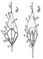
- FIGS. 1-7illustrate an example of a protection device 20 or filter for collecting loosened debris in a body lumen.
- device 20operates between a closed collapsed profile, adapted for insertion into a body lumen as illustrated in FIG. 2 , and an open radially-expanded deployed profile for collecting debris in a body lumen as illustrated in FIG. 1 .
- Device 20includes a filter 22 and a collapsible proximally-tapered frame 24.
- Frame 24supports filter 22 and is operably coupled to an elongated guidewire 32 or other support device.
- Frame 24includes a mouth 28 and a plurality of longitudinally-extending ribs 30. In an expanded profile, mouth 28 is opened and the ribs extend radially outwardly to support mouth 28.
- a collar 33movably couples the proximal ends of ribs 30 to guidewire 32. Mouth 28 is thus coupled to collar 33 through ribs 30 and is movable between a collapsed profile and an opened deployed profile, as will be explained.
- filter 22is generally cone-shaped, having a proximal and a distal end.
- the distal endis a narrow, "V"-shaped end and is preferably fixedly secured or formed to guidewire 32.
- the proximal endhas a relatively wide opening and is coupled to mouth 28 of frame 24.
- filter 22is formed of a polymer membrane.
- filter 22is preferably formed of a porous polyurethane material having a plurality of small openings 40.
- Filter 22may be constructed of a polyurethane sheet, and openings 40 may be formed in the polyurethane sheet by known laser techniques. Holes or openings 40 are sized to allow blood flow therethrough but restrict flow of debris or emboli floating in the body lumen or cavity.
- guidewire 32extends through mouth 28 of device 20 and along the entire length of the device and is fixed to the distal end of filter 22.
- Mouth 28is generally formed of a pleated ring 34 having an expanded dimension to support filter 22 in the opened deployed profile as illustrated in FIGS- 1-3, and a collapsed dimension to support the filter in the closed collapsed profile as illustrated in FIG. 2 .
- FIG. 3is an end view of device 20 which illustrates pleated ring 34 in an open expanded profile.
- ring 34includes a plurality of folds 36 which are spaced so that the diameter of the pleated ring 34 forms a mouth of sufficient diameter so that an opening to filter 22 conforms to a desired body lumen.
- Pleated ring 34is collapsed by closing folds 36 as illustrated by arrows 38 so that adjacent folds 36 are positioned in close proximity. In such a position, the mouth assumes a relatively small dimension to collapse filter 22 for insertion and retrieval.
- pleated ring 34is coupled to guidewire 32 via ribs 30 as shown in FIG. 3 .
- FIG. 4illustrates a process of forming frame 24 and folds 36.
- Frame 24may be formed from a wire mesh sheet 42 having a series of rows of generally diamond-shaped structures 44.
- a portion 46 of a rowis cut from wire mesh sheet 42 to form the frame 24.
- Portion 46is rolled and sides 50, 52 are joined to form a continuous circular frame.
- a series of tips 54 on a first endare joined and coupled to ring 33 which slides over guidewire 26.
- a series of tips 56 on the second endform pleated ring 34 of mouth 28.
- tips 56form the apex of folds 36, which expand and collapse as illustrated by arrows 38 in FIG. 3 , to open and close mouth 28.
- the wire mesh sheet 42is formed of Nitinol or similar material having sufficient elasticity or resilience, as will be explained.
- the proximal end of filter 22is then secured to mouth 28 via an adhesive or other suitable connection method.
- the distal end of filter 22is then secured to guidewire 26 via adhesive or other techniques.
- FIGS. 5-7illustrate operation of protection device 20 which is inserted into a body lumen to collect floating debris or emboli.
- device 20is inserted into a body lumen 60, such as a vascular lumen having a stenosis 62.
- Device 20may be deployed distal of the blocked region or stenosis 62 to capture calcified material or substances dislodged during a medical procedure to open the stenosis 62.
- the stenosis 62 in a coronary vesselmay be opened by known medical procedures such as dilatation or atherectomy.
- device 20is first collapsed and inserted in the collapsed profile into a delivery sheath 64.
- Sheath 64is formed of a tubular member 66 including an inner lumen 68 extending therethrough.
- the profile of sheath 64is relatively small to facilitate insertion and placement of device 20.
- Device 20is placed in lumen 68 for insertion.
- Folds 36 of frame 24are collapsed and are maintained in the collapsed profile by the inner surface of lumen 68.
- collar 33slides proximally along guidewire 32 to accommodate for the proximal longitudinal movement of ribs 30 as device 20 is collapsed.
- sheath 64is inserted through the vasculature of a patient and has its distal end positioned distal of the stenosis or blocked region 62.
- Mouth 28is sized so that when folds 36 separate, mouth 28 conforms to the dimensions of vascular lumen 60. Mouth 28 supports filter 22 relative to the circumference of vascular lumen 60 so that blood flows through the filter and debris and particles floating in the blood are trapped by the filter. In particular, holes 40 of the filter allow blood to flow therethrough, but restrict flow of debris and clotting material so that loosened debris does not migrate and clog alternate body sites.
- frame 28is formed of a Nitinol alloy or other elastic material so that the frame "springs" back to an expanded profile after the confining force imparted via sheath 64 is released.
- the relatively elastic materialprovides sufficient resilient force for a tight interaction between mouth 28 and lumen 60 to assure that blood flows through filter 22 to capture floating debris and particles.
- sheath 64may be completely withdrawn and various treatment devices, such as an angioplasty dilatation catheter, stent delivery catheter or other atherectomy or thrombectomy devices, may be inserted for treatment.
- the treatment devicesare inserted over guidewire 32 for placement relative to the treatment site.
- device 20is removed as illustrated in FIG. 7 .
- a retrieval sheath 72is inserted as illustrated via arrow 74 for removal of device 20.
- Retrieval sheath 72is formed of a tubular member 75 having a central lumen 76 and a distal opening sized to capture device 20.
- Retrieval sheath 72is inserted to align the distal opening of sheath 72 with the proximal end of frame 24. Thereafter, sheath 72 is advanced; or, alternatively, in the embodiment shown, guidewire 32 is retracted, to collapse ribs 30, thereby collapsing mouth 28 and filter 22 as illustrated by arrows 78.
- ribs 30(and the frame 24) are proximally sloped or tapered so that as sheath 72 is advanced over ribs 30, they collapse radially inwardly and collar 33 rides proximally on guidewire 32. As ribs 30 collapse inwardly, frame 24 folds at folds 36 until mouth 28 resides within retrieval sheath 72, or closely proximate the distal end of sheath 72, thereby trapping emboli therein. Device 20 and sheath 72 are then withdrawn from the vasculature.
- ribs 30may be directly fixed to guidewire 32 so that the filter is loosely supported in the collapsed profile.
- the devicemay be supported via an alternate core wire or guidewire structure (not shown) which is coupled to frame 24 via ribs 30 but unlike guidewire 32 does not extend through the mouth and along the entire length of the filter so that device 20 does not have radial slack in the collapsed profile.
- device 20is shown inserted distal of stenotic region 62 to capture material and debris dislodged during a treatment procedure, device 20 may be deployed in alternate positions for capturing floating debris or particles in other body cavities.
- FIGS. 8-11illustrate an alternate example of a protection device 90.
- protection device 90includes a filter 92, a frame 94 and a collar 96.
- Protection device 90is operably coupled to a guidewire 32 for operation as will be explained.
- Guidewire 32is a typical guidewire having a small diameter for insertion into a tract to a treatment site, and preferably includes a spring coil tip.
- Filter 92includes a cone-shaped porous portion 100 and a pleated portion 102.
- Porous portion 100includes a plurality of openings 104 to permit blood flow through filter 92 while restricting flow of debris or particles.
- a distal tip 106 of filter 92is fixedly secured to guidewire 32.
- filter portion 100is formed of a polymer material, such as a polyurethane material, and holes or openings 104 are formed via known laser techniques.
- Collar 96is preferably formed of a relatively short tubular member having an inner lumen 108 and having notches 110 formed on an outer perimeter.
- Guidewire 32extends through lumen 108 so collar 96 is slidably coupled to guidewire 32.
- Frame 94is coupled to collar 96, and filter 92 is coupled to frame 94.
- frame 94is formed of an elongated wire 112 having opposed ends. Opposed ends of wire 112 are coupled to collar 96 to form a mouth, and filter 92 (in particular, pleated portion 102) is coupled to wire 112 along substantially the entire length of wire 112.
- guidewire 32extends through collar 96 and through the mouth and extends along the entire longitudinal length of filter 92.
- collar 96is moved proximally as illustrated by arrow 114 to collapse the mouth formed by frame 94 for insertion.
- Collar 96is slid distally to expand the mouth formed by frame 94 and filter 92 to a deployment position.
- wire 112is formed of a relatively elastic material such as Nitinol.
- Filter portion 102is secured to wire loop 112 by one of various suitable attachment methods, including adhesives, stitching, or other known methods, to define the mouth of the device 90.
- Ends of wire 112are also preferably coupled to collar 96 by known attachment methods, including adhesives.
- pleated filter portion 102is formed of a polymer material such as polyurethane.
- the pleated filter portion 102is preferably manufactured by winding a wire or other suitable coil around a polymer tube material. After the wire is wound around the tube, the tube is pressurized, causing the tube material to expand between the gaps in the wire, creating the pleats or creases which allow portion 102 to collapse. The coil is then removed, leaving collapsible portion 102. Construction of collapsible portion 102 is described in St. Germain, U.S. Patent No. 5,534,005, issued July 9, 1997 , and assigned to Scimed Life Systems, Inc., hereby incorporated by reference.
- the pleated filter portion 102allows for the filter to expand or extend longitudinally to absorb impact pressure caused by embolic material received by filter portion 92 to maintain the placement of the device 90 during operation.
- Filter portion 100 and pleated portion 102may be formed separately or from a single sheet of polymer material.
- FIGS. 9-12illustrate operation of device 90 in a patient's vasculature. Some parts are similar to those shown in FIGS. 5-7 , and similar numbers are used to identify similar parts.
- device 90is inserted in a collapsed profile in cooperation with an insertion sheath 64 similar to that shown and described in FIG. 5 .
- Tube 66exerts a force on wire 112 and filter portions 100, 102 to collapse device 90.
- collar 96moves along wire 32 to longitudinally accommodate for radial slack of the collapsed device 90.
- Sheath 64 and device 90are advanced to a deployment site, preferably distal of a stenotic region 62, for operation during a treatment procedure.
- sheath 64is withdrawn (while the position of guidewire 32 is maintained) as illustrated by arrow 116 so that the wire 112 expands radially outwardly (since the compression force is released).
- Thiscauses filter 92 to expand to conform to the inner diameter of the vessel 60.
- collar 96slides distally along guidewire 32 for radial expansion of wire 112 and filter 92.
- wire 112is formed of a sufficiently elastic material to essentially spring outwardly after pressure is released, so that a tight interference between frame wire 112 and the vessel walls of vessel 60 is maintained.
- treatment devicesmay be advanced along guidewire 32 for placement relative to a stenosis 62 for treatment.
- treatment devicesmay include a dilatation catheter, stent delivery catheter or atherectomy or thrombectomy devices, etc.
- device 90may be withdrawn as illustrated in FIGS. 11 and 12 .
- Device 90is withdrawn via a retrieval device 120.
- Retrieval device 120is formed of a tubular member 122 having an inner lumen 124 and a locking tab 126 formed on an inner surface of the tubular member 122. Locking tab 126 mates with notch 110 formed on collar 96 for retrieval and removal of device 90.
- locking tab 126is formed of a rigid extension having a sloped camming surface 130 and a flat locking surface 132.
- Notch 110also includes a camming surface 134 and a flat locking surface 136.
- the camming surfaces 130, 134are aligned so that, as sheath 120 is advanced, camming surfaces 130, 134 mate to slightly expand tube 122 so that locking member 126 on sheath 120 advances past notch 110 until the locking surfaces 132, 136 align and the camming force is released. This allows tube 122 to collapse to its original dimension with surfaces 132, 136 aligned to lock device 90 to sheath 120 for withdrawing device 90.
- Sheath 120is withdrawn proximally, as illustrated by arrow 140, while maintaining the position of guidewire 32. This causes collar 96 to slide proximally to collapse device 90 along guidewire 32 thereby drawing wire 112 down over wire 32 and collapsing device 90. Once device 90 is collapsed, guidewire 32 and sheath 120 are collectively withdrawn to remove collapsed device 90.
- FIGS. 13-16illustrate an alternate example of a protection device 150 where similar numbers are used to identify similar parts of previous embodiments.
- Device 150is shown in operation in a vessel 60 having a stenosis 62.
- Device 150includes a filter 152, a frame 154, and a collar 156.
- Device 150is operably coupled to guidewire 32 for operation.
- Filter 152is preferably a cone-shaped member having proximal and distal ends 158, 160.
- the distal end 160is generally "V"-shaped.
- Filter 152may be formed from a polymer sheet material similar to that described for previous embodiments and filter holes or openings 180 may be formed therein by laser techniques. Material and debris generally collect at the "V"-shaped tip to limit interference with blood flow through filter 152.
- the "V"-shaped end 160is fixedly coupled relative to guidewire 32.
- Proximal end 158includes an opening which is supported relative to frame 154 to form a mouth of the device, as will be explained.
- Collar 156is a tubular member 164 having an inner lumen 166 slidably coupled relative to guidewire 32.
- Frame 154includes a generally circular mouth member 170 and a plurality of struts or ribs 172.
- Mouth 170supports filter 152 and is preferably formed of a wire loop which is coupled thereto via a known adhesive or other suitable means.
- the mouthis coupled to collar 156 via struts or ribs 172 so that the collar slides along guidewire 32 to selectively longitudinally extend device 150 to collapse device 150 for insertion and retrieval, and longitudinally shorten device 150 to expand device 150 (and mouth 170) for deployment.
- struts 172are attached to collar 156 and mouth 170 by any suitable means.
- frame 154(mouth 170 and struts or ribs 172) are formed of a wire or strip of a relatively elastic material such as a Nitinol material.
- Device 150includes compression spring 176 to bias device 150 in the longitudinally shortened (and thus radially expanded) profile having mouth 170 radially expanded for operation.
- spring 176includes opposed ends, a first end is attached to collar 156, and a second end is attached to end 160 of filter 152.
- the compression spring 176is normally biased to compress as illustrated by arrows 178 to bias the device in an opened deployed profile.
- device 150is maintained in a low-profile position via sheath 64 as illustrated in FIG. 13 similar to that described for previous embodiments.
- sheath 64exerts a force on frame 154 and filter 152 to compress frame 154 and filter 152 against the spring bias provided by compression spring 176.
- insertion sheath 64 and device 150are inserted into a patient and located distal of a stenosis 62 for deployment.
- the sheath 64is withdrawn while the operator maintains the position of guidewire 32.
- frame 154 and filter 152expands radially outwardly under the force of the compression spring 176 to expand mouth 170 to conform to the vessel walls 60 as illustrated in FIG. 14 .
- Ribs 172are extended outwardly to support mouth 170 in a radially-expanded position.
- the spring 176maintains device 150 in a deployed position so that mouth 170 conforms to the opening of the vessel. Debris is captured and device 150 does not migrate under the load of the debris collected in filter 152.
- device 150may be withdrawn.
- device 150is withdrawn via a removal sheath 184 , as illustrated in FIGS. 15-16 .
- the removal sheath 184includes an outer tubular extent 186 supporting an inner tube 188.
- the inner tube 188includes a docking tip 190.
- Docking tip 190includes docking latch 192 which cooperate with a latch 194 formed on an inner surface of collar 156.
- Docking latch 192is formed of an arrow tip 190 defining sloped camming surface 196 and a lateral locking surface 198.
- Latch 194 on collar 156includes a camming surface 200 and a lateral locking surface 202.
- Sheath 184is advanced over the guidewire 32 to insert tip 190 through the opening in tubular collar 156. Tip 190 is advanced until camming surfaces 196, 200 expand collar 156 to further advance arrow-shaped tip 190 until collar 156 collapses to align locking surfaces 198, 202 to lock device 150 to sheath 184 for withdrawal. After device 150 is locked to sheath 184, retrieval device 184 is first withdrawn proximally, as illustrated by arrow 204, while maintaining the position of guidewire 32 to force the frame 154 and filter 152 against the spring bias to a low-profile dimension. Thereafter, retrieval sheath 184 and guidewire 32 are collectively proximally withdrawn as illustrated to remove the device.
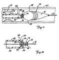
- FIGS. 17-20An alternate example of a protective device is illustrated in FIGS. 17-20 and is formed independently of a guidewire 210.
- Guidewire 210is formed of an elongated wire 212, preferably having a spring coil tip 214, and a protective device docking member 216 coupled to a distal portion of wire 212, as illustrated in FIG. 17 .
- Docking member 216is rigidly coupled to wire 212 and in one embodiment is formed of a generally "V"-shaped member 218 including a docking channel 220. Member 218 includes groove 222 which opens to channel 220. Docking member 216 is used to removably secure a protection device thereto as will be explained.
- Docking member 216may be permanently formed on the guidewire 210. Alternatively, docking member 216 may be detachably connected to guidewire 210 such as by a friction fit between guidewire 210 and a channel (not shown) of the docking member 216 or by a mechanical attachment mechanism. If a detachable, docking member 216 may be used on any suitable guidewire, thereby adapting the guidewire for operation with a protection device.
- FIG. 18illustrates an example of a protection device 230 which may be selectively coupled to docking member 216.
- Protection device 230includes a distal cone 232, a filter 152, a frame 154, and a collar 156.
- Cone 232is coupled to a distal end of filter 152.
- Cone 232is generally "V"-shaped and is formed of a rigid member having a distal opening (not shown) sized for insertion of guidewire 210 therethrough.
- Cone 232includes a locking ring 242 extending about an outer perimeter of cone 232. Locking ring 242 is sized for insertion into groove 222 of docking member 216.
- device 230is mounted relative to the guidewire by inserting guidewire 210 through an opening in cone 232.
- Device 230is advanced over guidewire 210 to align cone 232 with docking member 216.
- Cone 232is forced into channel 220 of docking member 216 until ring 242 snaps into groove 222 and is maintained therein.
- Device 230is inserted in a low-profile collapsed condition via cooperation with sheath 64, and is deployed by withdrawing sheath 64 while maintaining the position of guidewire 210 after device 230 is positioned at a treatment site (as comparatively illustrated in FIGS. 18-19 ) similar to that previously described with reference to FIGS. 13-14 .
- FIG. 20illustrates withdrawal of device 230 via retrieval sheath 184, as previously described with reference to FIGS. 15-16 .
- Sheath 184is coupled to collar 156 and is then withdrawn proximally while maintaining the position of guidewire 210 to collapse device 230 to a low profile. Thereafter, sheath 184 and guidewire 210 are withdrawn to remove guidewire 210, protection device 230, and sheath 184 from the patient after treatment.
- FIG. 21illustrates a retrieval sheath 280 for operation with a distal protection device 282 for collapsing the distal protection device for withdrawal.
- the retrieval sheath 280includes a telescoping tubular structure including an outer tubular member 283 and an inner tubular member 284.
- Outer tubular member 283includes a lumen 286, and inner tubular member 284 extends through lumen 286 and is movable therein to form the telescoping tubular structure.
- Outer tubular member 283is formed of a composite structure including a first tubular portion 288 and a second tubular portion 290.
- the first tubular portion 288includes a proximal end (not shown) and a distal end 292.
- the second tubular portion 290includes a proximal end 294 and a distal end 296.
- Proximal end 294is coupled to distal end 292 of tubular member 288 to form a composite outer tubular structure 283 having a proximal end (not shown) and distal end 296.
- Inner tube 284includes a proximal end (not shown) and a distal end 298.
- Inner tube 284includes a first diameter portion 300, a second diameter portion 304, a transition portion 306, and tapered flanged end 308.
- First and second portions 300, 304are coupled via transition portion 306.
- Flanged end 308has a relatively large tapered mouth for capturing and progressively collapsing a deployed protection device as will be explained.
- the proximal end of inner tube 284extends through outer tube 283 and exits from proximal end of outer tube 283 for providing a mechanism for slidably moving inner tube 284 within outer tube 283.
- Flanged end 308is relatively flexible and resilient and is biased in a radially expanded position so that it opens to an expanded tapered profile, as illustrated in FIG. 21 , when flanged end 308 extends beyond distal end 296 of outer tube 283.
- Flanged end 308When flanged end 308 is retracted within inner tube 283 as illustrated via arrow 310, flanged end 308 collapses as illustrated by arrows 312 to assume the dimension of outer tube 283 in a collapsed position (not shown).
- Flanged end 308may be formed of a pleated material or simply a relatively elastic material.
- retrieval sheath 280is inserted into a patient's vasculature with flanged end 308 in a collapsed position within inner tube 283 to provide a low profile for insertion.
- Retrieval sheath 280is inserted and aligned closely proximate to deployed protection device 282. Once retrieval device 280 is aligned, inner tube 284 is slid distally relative to outer tube 282 to expand flanged end 308 to an expanded profile, as illustrated in FIG. 21 , to surround the deployed protection device.
- sheath 280may be advanced, or protection device 282 may be withdrawn proximally via guidewire 32 to forcibly collapse protection device 282 as protection device 282 is withdrawn along the tapered inner channel of flanged end 308.
- Retrieval device 280, protection device 282, and guidewire 32are then withdrawn.
- the devicethus provides a system for capturing a protection device 282 and filtered contents (debris, emboli, etc.) along therewith to minimize post-procedural embolic events.
- inner and outer tubes 282, 284are formed of a polymer material, and flanged end 308 is formed of a polymer membrane.
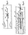
- FIGS. 22-24illustrate an embodiment of a distal protection device 320.
- distal protection device 320is coupled to a guidewire 322 to operate between a radially-expanded deployed profile illustrated in FIGS. 22 and 24 , and a collapsed profile illustrated in FIG. 23 for insertion and retrieval.
- Guidewire 322is formed of a tubular member 324 including a central lumen 326 therethrough.
- the guidewire 322may be formed of a hypo tube or other material.
- the distal protection device 320includes a filter 328 and a frame 330.
- frame 330is formed of an elongate wire 332 and a polymer sleeve 334.
- Frame 330is coupled to guidewire 322 and is supported thereby between the insertion dimension illustrated in FIG. 23 and the deployed dimension illustrated in FIGS. 22 and 24 .
- Filter 328is coupled to frame 330 and is supported thereby at its proximal end by frame 330.
- Filter 328may be formed of a polymer sheet material or a mesh-like material having holes or openings 336 therein to allow blood to flow therethrough while restricting flow of emboli, debris and clotting material.
- Filter 328is cone-shaped, preferably having a "V"-shaped tip and a large opening to funnel debris for collection.
- Filter 328 and sleeve 334may be integrally or separately formed, and secured via known attachment methods such as known adhesives.
- Guidewire 322includes spaced distal openings 338, 340 which communicates with inner lumen 326. Opposed ends of sleeve 334 are coupled to spaced openings 338, 340 so the lumen through sleeve 334 forms a path for frame wire 332.
- Frame wire 332extends from a proximal end (not shown) of the guidewire 322 through lumen 326, through openings 338 and 340, and is anchored at a distal end of lumen 326 (preferably proximate to opening 340).
- Frame wire 332also extends through sleeve 334 to form an external loop 342 defining the mouth of the protection device 320. External loop 342 is tightened by pulling the wire 332 proximally, and is opened by pushing the wire 332 distally, as illustrated by arrow 344, to open and close the mouth of protection device 320.
- FIGS. 23-24illustrate operation of protection device 320.
- the deviceis inserted in a low-profile dimension by proximally retracting wire 332 to close external loop 342 to locate device 320 at a deployment site, preferably distal of a stenosis 62.
- Frame wire 332is moved distally as illustrated by arrow 344 to expand loop 342 to open the mouth to filter 328 to conform to the dimension of vascular lumen 60, as illustrated in FIG. 24 .
- guidewire 322pushes against a lumen wall to provide a tight fit between filter 328 and vascular wall 60.
- the mouthhas a dimension which conforms to the vascular wall, and cone-shaped filter 328 funnels material to a tip of the filter to allow bloodflow to continue therethrough.
- Device 320is collapsed after use for removal. To collapse the device for withdrawal, frame wire 332 is moved proximally, as illustrated by arrow 346 in FIG. 24 , to collapse or close external loop 342 to the low-profile collapsed dimension illustrated in FIG. 23 .
- a pressure-sensing device 350may be inserted through lumen 326 of guidewire 322.
- the pressure-sensing device 350is formed of an elongated member 352 having a distal tip 354 which is curve-shaped to align a pressure sensor facing the direction of blood flow or fluid flow through vessel 60.
- Proximal circuitryis coupled to the pressure sensor at distal tip 354 to provide a pressure reading to an operator.
- device 350may simply be a hollow tube with the pressure sensing mechanism located entirely at a proximal end of device 350. The pressure reading indicates whether the blood vessel or vascular vessel 60 is occluded distal of protection device 320, to ensure proper blood flow through protection device 320.
- protection devices describedare illustrated for use as temporary filters, it should be understood that the devices of the present invention are not so limited and may be used for permanent filters which are retained in a patient to filter debris and clotting material.
Landscapes
- Health & Medical Sciences (AREA)
- General Health & Medical Sciences (AREA)
- Veterinary Medicine (AREA)
- Transplantation (AREA)
- Engineering & Computer Science (AREA)
- Biomedical Technology (AREA)
- Heart & Thoracic Surgery (AREA)
- Vascular Medicine (AREA)
- Life Sciences & Earth Sciences (AREA)
- Animal Behavior & Ethology (AREA)
- Cardiology (AREA)
- Oral & Maxillofacial Surgery (AREA)
- Public Health (AREA)
- Surgical Instruments (AREA)
- Prostheses (AREA)
- Window Of Vehicle (AREA)
- Amplifiers (AREA)
- Emergency Protection Circuit Devices (AREA)
- Shovels (AREA)
- Inorganic Insulating Materials (AREA)
- Air Bags (AREA)
- Electronic Switches (AREA)
Abstract
Description
- The present invention deals with an emboli capturing system. More specifically, the present invention deals with an emboli capturing system for capturing embolic material in a blood vessel during an atherectomy or thrombectomy procedure.
- Blood vessels can become occluded (blocked) or stenotic (narrowed) in a number of ways. For instance, a stenosis may be formed by an atheroma, which is typically a harder, calcified substance which forms on the lumen walls of the blood vessel. A stenosis may also be formed of a thrombus material, which is typically much softer than an atheroma but can nonetheless cause restricted blood flow in the lumen of the blood vessel. Thrombus formation can be particularly problematic in a saphenous vein graft ("SVG") .
- Two different procedures have been developed to treat a stenotic lesion (stenosis) in vasculature. One is deformation of the stenosis to reduce the restriction within the lumen of the blood vessel. This type of deformation, or dilatation, is typically performed using balloon angioplasty.
- Another method of treating stenotic vasculature is to attempt to completely remove the entire stenosis, or enough of the stenosis to relieve the restriction in the blood vessel. Removal of the stenotic lesion has been performed through use of radio frequency ("RF") signals transmitted via conductors, and also through use of lasers. Both of these treatments are intended to ablate (i.e., super heat and vaporize) the stenosis. Removal of the stenosis has also been accomplished using thrombectomy or atherectomy. During thrombectomy and atherectomy, the stenosis is mechanically cut or abraded away from the vessel. However, problems may be encountered during thrombectomy and atherectomy because the stenotic debris which is separated from the stenosis is free to flow within the lumen of the vessel. If the debris flows distally, it can occlude distal vasculature and cause significant problems. If it flows proximally, it can enter the circulatory system and form a clot in the neural vasculature or in the lungs, both of which are highly undesirable.
- Prior attempts to deal with the debris or fragments produced during thrombectomy and atherectomy have included cutting the debris into pieces small enough (having a size on the order of a blood cell) that they will not occlude vessels within the vasculature. However, this technique has certain problems. For instance, it is difficult to control the size of the fragments which are severed from the stenotic lesion. Larger fragments may be severed accidentally. Also, since thrombus is much softer than an atheroma, it tends to break up easier when mechanically engaged by a cutting instrument. Therefore, at the moment that the thrombus is mechanically engaged, there is a danger that it can be dislodged in large fragments which would occlude the vasculature.
- Another attempt to deal with debris severed from a stenosis is to remove the debris as it is severed, using suction. However, it may be necessary to pull quite a high vacuum in order to remove all of the pieces severed from the stenosis. If the vacuum used is not high enough, all of the severed pieces will not be removed. Further, use of a high vacuum may tend to cause the vasculature to collapse.
- A final technique for dealing with the fragments severed during atherectomy of the stenosis is placement of a device distal to the stenosis during atherectomy to catch the pieces of the stenosis as they are severed, and removal of those pieces along with the capturing device when the atherectomy procedure is complete. Such capture devices have included expandable filters which are placed distal of the stenosis to capture stenosis fragments. Problems are also associated with this technique. For example, delivery of such devices in a low-profile pre-deployment configuration can be difficult. Further, some devices include complex and cumbersome actuation mechanisms. Also, retrieving such capture devices, after they have captured emboli may be difficult.
US 5,695,519 A discloses a distal intravascular filter for filtering blood flow therethrough and entrapping and retaining embolic debris. The intravascular filter includes a small diameter hollow guide wire or tube capable of percutaneous placement of the distal end thereof beyond a carotid stenosis. The distal portion of the tube includes a filter mounted thereon. The filter is deployable from a tightly closed configuration to an open circumference for blocking the unfiltered flow of blood beyond the carotid stenosis. The filter is deployable between open and closed positions by manipulation of an actuating wire extending from the filter and out the proximal end of the tube.US 5,662,671 A describes an arterial catheter system for removing plaque from the aorta and other arteries. The system includes an elongate catheter member, a filtration apparatus disposed within the distal region, and an atherectomy assembly which includes a mechanism for trapping and holding mobile or fixed plaque and an excising mechanism for removing the plaque. In use, the catheter is positioned so that the atherectomy assembly lies within a region of interest, the filtration apparatus is deployed downstream of the region of interest, the plaque is trapped and held by a snare, vacuum, or other trapping means, and then the excising mechanism is activated to remove the plaque.WO 97/17100 A1 - The present invention provides a distal protection device according to claim 1.
FIG. 1 is a perspective view of an example of a protection device in a radially-expanded deployed profile.FIG. 2 is a view of the protection device ofFIG. 1 in a somewhat collapsed profile.FIG. 3 is an end view of the protection device ofFIG. 1 in a radially-expanded deployed profile.FIG. 4 is a plan view of a wire mesh sheet for construction of a frame of the protection device illustrated inFIG. 1 .FIG. 5 is a view of the protection device ofFIGS. 1-3 in a collapsed profile being inserted through a vessel via an insertion sheath.FIG. 6 . is a view of the protection device ofFIGS. 1-3 inserted into a vessel via the insertion sheath, where the insertion sheath is withdrawn to deploy the protection device for operation.FIG. 7 is a view of the protection device ofFIGS. 1-3 operating in a vessel in an expanded deployed profile and illustrating a retrieval sheath for withdrawal of the deployed protection device.FIG. 8 is a perspective view of an alternate example of a protection device shown in a radially-expanded deployed profile.FIG. 9 is a view of the protection device ofFIG. 8 in a collapsed profile, inserted into a vessel via an insertion sheath.FIG. 10 is a view of the protection device ofFIG. 8 in an expanded deployed profile in a vessel, shown with the insertion sheath withdrawn.FIG. 11 is a view of the protection device ofFIG. 8 in a somewhat collapsed profile being withdrawn from the vessel via a retrieval sheath.FIG. 12 is a detailed view ofportion 120 of the device shown inFIG. 11 .FIG. 13 is a view of an alternate example of a protection device in a collapsed profile being inserted into a vessel via an insertion sheath.FIG. 14 is a view of the protection device ofFIG. 13 in an expanded deployed profile in a vessel.FIG. 15 is a view of the protection device ofFIG. 13 in a collapsed profile being withdrawn from the vessel via a retrieval sheath.FIG. 16 is a detailed view of portion 16 of the device shown inFIG. 15 .FIG. 17 is a view of a guidewire adapted to support a protection device.FIG. 18 is a view of an alternate example of a protection device in a collapsed profile, inserted into a vessel via an insertion sheath.FIG. 19 is a view of the protection device ofFIG. 18 in an expanded deployed profile in a vessel, shown with the insertion sheath withdrawn proximally.FIG. 20 is a view of the protection device ofFIG. 18 in a collapsed profile being withdrawn from the vessel via a retrieval sheath.FIG. 21 illustrates an example of a retrieval sheath for withdrawal of a protection device.FIG. 22 is a perspective view of an embodiment of a protection device, coupled to a guidewire in an expanded deployed profile.FIG. 23 is a view of the protection device ofFIG. 22 in a collapsed profile in a vessel.FIG. 24 is a view of the protection device ofFIG. 22 in an expanded deployed profile in a vessel.- These drawings are for illustrative purposes only and are not necessarily drawn to scale.
- The present invention relates to protection devices deployed in a body vessel or cavity for collection of loosened or floating debris such as embolic material dislodged during atherectomy or thrombectomy.
FIGS. 1-7 illustrate an example of aprotection device 20 or filter for collecting loosened debris in a body lumen. As illustrated comparatively inFIGS. 1-2 ,device 20 operates between a closed collapsed profile, adapted for insertion into a body lumen as illustrated inFIG. 2 , and an open radially-expanded deployed profile for collecting debris in a body lumen as illustrated inFIG. 1 .Device 20 includes afilter 22 and a collapsible proximally-taperedframe 24.Frame 24 supports filter 22 and is operably coupled to anelongated guidewire 32 or other support device.Frame 24 includes amouth 28 and a plurality of longitudinally-extendingribs 30. In an expanded profile,mouth 28 is opened and the ribs extend radially outwardly to supportmouth 28. Preferably, acollar 33 movably couples the proximal ends ofribs 30 to guidewire 32.Mouth 28 is thus coupled tocollar 33 throughribs 30 and is movable between a collapsed profile and an opened deployed profile, as will be explained.- Preferably, filter 22 is generally cone-shaped, having a proximal and a distal end. The distal end is a narrow, "V"-shaped end and is preferably fixedly secured or formed to
guidewire 32. The proximal end has a relatively wide opening and is coupled tomouth 28 offrame 24. Preferably, filter 22 is formed of a polymer membrane. In particular,filter 22 is preferably formed of a porous polyurethane material having a plurality ofsmall openings 40.Filter 22 may be constructed of a polyurethane sheet, andopenings 40 may be formed in the polyurethane sheet by known laser techniques. Holes oropenings 40 are sized to allow blood flow therethrough but restrict flow of debris or emboli floating in the body lumen or cavity. In the embodiment shown,guidewire 32 extends throughmouth 28 ofdevice 20 and along the entire length of the device and is fixed to the distal end offilter 22. Mouth 28 is generally formed of apleated ring 34 having an expanded dimension to supportfilter 22 in the opened deployed profile as illustrated in FIGS- 1-3, and a collapsed dimension to support the filter in the closed collapsed profile as illustrated inFIG. 2 .FIG. 3 is an end view ofdevice 20 which illustrates pleatedring 34 in an open expanded profile. In the opened expanded profile,ring 34 includes a plurality offolds 36 which are spaced so that the diameter of thepleated ring 34 forms a mouth of sufficient diameter so that an opening to filter 22 conforms to a desired body lumen.Pleated ring 34 is collapsed by closing folds 36 as illustrated byarrows 38 so thatadjacent folds 36 are positioned in close proximity. In such a position, the mouth assumes a relatively small dimension to collapsefilter 22 for insertion and retrieval. As previously explained,pleated ring 34 is coupled to guidewire 32 viaribs 30 as shown inFIG. 3 .FIG. 4 illustrates a process of formingframe 24 and folds 36.Frame 24 may be formed from a wire mesh sheet 42 having a series of rows of generally diamond-shapedstructures 44. In one preferred embodiment, aportion 46 of a row is cut from wire mesh sheet 42 to form theframe 24.Portion 46 is rolled andsides 50, 52 are joined to form a continuous circular frame. A series oftips 54 on a first end are joined and coupled to ring 33 which slides over guidewire 26. A series oftips 56 on the second end form pleatedring 34 ofmouth 28. In particular,tips 56 form the apex offolds 36, which expand and collapse as illustrated byarrows 38 inFIG. 3 , to open andclose mouth 28. Preferably, the wire mesh sheet 42 is formed of Nitinol or similar material having sufficient elasticity or resilience, as will be explained. The proximal end offilter 22 is then secured tomouth 28 via an adhesive or other suitable connection method. The distal end offilter 22 is then secured to guidewire 26 via adhesive or other techniques.FIGS. 5-7 illustrate operation ofprotection device 20 which is inserted into a body lumen to collect floating debris or emboli. Briefly, as shown inFIG. 5 ,device 20 is inserted into abody lumen 60, such as a vascular lumen having astenosis 62.Device 20 may be deployed distal of the blocked region orstenosis 62 to capture calcified material or substances dislodged during a medical procedure to open thestenosis 62. Thestenosis 62 in a coronary vessel may be opened by known medical procedures such as dilatation or atherectomy.- More specifically, as shown in
FIG. 5 ,device 20 is first collapsed and inserted in the collapsed profile into adelivery sheath 64.Sheath 64 is formed of atubular member 66 including aninner lumen 68 extending therethrough. The profile ofsheath 64 is relatively small to facilitate insertion and placement ofdevice 20.Device 20 is placed inlumen 68 for insertion.Folds 36 offrame 24 are collapsed and are maintained in the collapsed profile by the inner surface oflumen 68. In the collapsed profile,collar 33 slides proximally alongguidewire 32 to accommodate for the proximal longitudinal movement ofribs 30 asdevice 20 is collapsed. Oncedevice 20 is insidedelivery sheath 64,sheath 64 is inserted through the vasculature of a patient and has its distal end positioned distal of the stenosis or blockedregion 62. - To deploy
device 20 after it is suitably located,sheath 64 is withdrawn as illustrated by arrow 70 inFIG. 6 , thus releasing the pressure exerted via thetube 66 to maintainframe 24 in the collapsed profile. Thus, folds 36 resiliently separate to openmouth 28 and thefilter 22 for operation, as illustrated inFIG. 6 .Mouth 28 is sized so that when folds 36 separate,mouth 28 conforms to the dimensions ofvascular lumen 60.Mouth 28 supports filter 22 relative to the circumference ofvascular lumen 60 so that blood flows through the filter and debris and particles floating in the blood are trapped by the filter. In particular, holes 40 of the filter allow blood to flow therethrough, but restrict flow of debris and clotting material so that loosened debris does not migrate and clog alternate body sites. - Preferably, as previously explained,
frame 28 is formed of a Nitinol alloy or other elastic material so that the frame "springs" back to an expanded profile after the confining force imparted viasheath 64 is released. The relatively elastic material provides sufficient resilient force for a tight interaction betweenmouth 28 andlumen 60 to assure that blood flows throughfilter 22 to capture floating debris and particles. - After deployment,
sheath 64 may be completely withdrawn and various treatment devices, such as an angioplasty dilatation catheter, stent delivery catheter or other atherectomy or thrombectomy devices, may be inserted for treatment. The treatment devices are inserted overguidewire 32 for placement relative to the treatment site. After treatment is complete,device 20 is removed as illustrated inFIG. 7 . - As shown in
FIG. 7 , aretrieval sheath 72 is inserted as illustrated viaarrow 74 for removal ofdevice 20.Retrieval sheath 72 is formed of atubular member 75 having acentral lumen 76 and a distal opening sized to capturedevice 20.Retrieval sheath 72 is inserted to align the distal opening ofsheath 72 with the proximal end offrame 24. Thereafter,sheath 72 is advanced; or, alternatively, in the embodiment shown,guidewire 32 is retracted, to collapseribs 30, thereby collapsingmouth 28 andfilter 22 as illustrated byarrows 78. In particular, ribs 30 (and the frame 24) are proximally sloped or tapered so that assheath 72 is advanced overribs 30, they collapse radially inwardly andcollar 33 rides proximally onguidewire 32. Asribs 30 collapse inwardly,frame 24 folds atfolds 36 untilmouth 28 resides withinretrieval sheath 72, or closely proximate the distal end ofsheath 72, thereby trapping emboli therein.Device 20 andsheath 72 are then withdrawn from the vasculature. - Although longitudinally sloped
ribs 30 are coupled tocollar 33 in the device shown,ribs 30 may be directly fixed to guidewire 32 so that the filter is loosely supported in the collapsed profile. Alternatively, the device may be supported via an alternate core wire or guidewire structure (not shown) which is coupled to frame 24 viaribs 30 but unlikeguidewire 32 does not extend through the mouth and along the entire length of the filter so thatdevice 20 does not have radial slack in the collapsed profile. Also, althoughdevice 20 is shown inserted distal ofstenotic region 62 to capture material and debris dislodged during a treatment procedure,device 20 may be deployed in alternate positions for capturing floating debris or particles in other body cavities. FIGS. 8-11 illustrate an alternate example of aprotection device 90. As illustrated inFIG. 8 ,protection device 90 includes afilter 92, aframe 94 and acollar 96.Protection device 90 is operably coupled to aguidewire 32 for operation as will be explained.Guidewire 32 is a typical guidewire having a small diameter for insertion into a tract to a treatment site, and preferably includes a spring coil tip.Filter 92 includes a cone-shapedporous portion 100 and apleated portion 102.Porous portion 100 includes a plurality ofopenings 104 to permit blood flow throughfilter 92 while restricting flow of debris or particles. Adistal tip 106 offilter 92 is fixedly secured toguidewire 32. Preferably,filter portion 100 is formed of a polymer material, such as a polyurethane material, and holes oropenings 104 are formed via known laser techniques.Collar 96 is preferably formed of a relatively short tubular member having aninner lumen 108 and havingnotches 110 formed on an outer perimeter.Guidewire 32 extends throughlumen 108 socollar 96 is slidably coupled toguidewire 32.Frame 94 is coupled tocollar 96, and filter 92 is coupled toframe 94.- Preferably,
frame 94 is formed of anelongated wire 112 having opposed ends. Opposed ends ofwire 112 are coupled tocollar 96 to form a mouth, and filter 92 (in particular, pleated portion 102) is coupled towire 112 along substantially the entire length ofwire 112. Preferably, guidewire 32 extends throughcollar 96 and through the mouth and extends along the entire longitudinal length offilter 92. Thus,collar 96 is moved proximally as illustrated by arrow 114 to collapse the mouth formed byframe 94 for insertion.Collar 96 is slid distally to expand the mouth formed byframe 94 andfilter 92 to a deployment position. - Preferably,
wire 112 is formed of a relatively elastic material such as Nitinol.Filter portion 102 is secured towire loop 112 by one of various suitable attachment methods, including adhesives, stitching, or other known methods, to define the mouth of thedevice 90. Ends ofwire 112 are also preferably coupled tocollar 96 by known attachment methods, including adhesives. - Preferably,
pleated filter portion 102 is formed of a polymer material such as polyurethane. Thepleated filter portion 102 is preferably manufactured by winding a wire or other suitable coil around a polymer tube material. After the wire is wound around the tube, the tube is pressurized, causing the tube material to expand between the gaps in the wire, creating the pleats or creases which allowportion 102 to collapse. The coil is then removed, leavingcollapsible portion 102. Construction ofcollapsible portion 102 is described in St. Germain,U.S. Patent No. 5,534,005, issued July 9, 1997 , and assigned to Scimed Life Systems, Inc., hereby incorporated by reference. - The
pleated filter portion 102 allows for the filter to expand or extend longitudinally to absorb impact pressure caused by embolic material received byfilter portion 92 to maintain the placement of thedevice 90 during operation.Filter portion 100 andpleated portion 102 may be formed separately or from a single sheet of polymer material. FIGS. 9-12 illustrate operation ofdevice 90 in a patient's vasculature. Some parts are similar to those shown inFIGS. 5-7 , and similar numbers are used to identify similar parts. As shown inFIG. 9 ,device 90 is inserted in a collapsed profile in cooperation with aninsertion sheath 64 similar to that shown and described inFIG. 5 .Tube 66 exerts a force onwire 112 and filterportions device 90. As illustrated, in the collapsed profile,collar 96 moves alongwire 32 to longitudinally accommodate for radial slack of thecollapsed device 90.Sheath 64 anddevice 90 are advanced to a deployment site, preferably distal of astenotic region 62, for operation during a treatment procedure.- Once
device 90 andsheath 64 are located at the deployment site,sheath 64 is withdrawn (while the position ofguidewire 32 is maintained) as illustrated byarrow 116 so that thewire 112 expands radially outwardly (since the compression force is released). This causesfilter 92 to expand to conform to the inner diameter of thevessel 60. Aswire 112 expands outwardly,collar 96 slides distally alongguidewire 32 for radial expansion ofwire 112 andfilter 92. Preferably, as previously explained,wire 112 is formed of a sufficiently elastic material to essentially spring outwardly after pressure is released, so that a tight interference betweenframe wire 112 and the vessel walls ofvessel 60 is maintained. This helps to ensure that thedevice 90 is sufficiently lodged againstvessel wall 60 so that it stays in position during treatment and is not dislodged as a result of blood flow through thefilter 92. In particular, sufficient pressure must be maintained so that the filter conforms to the diameter ofvessel 60 and does not migrate due to force imparted to the filter when debris collects in the filter and so that no embolic material can slip between the filter and the walls ofvessel 60. - Thereafter, treatment devices (not shown) may be advanced along
guidewire 32 for placement relative to astenosis 62 for treatment. Such treatment devices may include a dilatation catheter, stent delivery catheter or atherectomy or thrombectomy devices, etc. After treatment is completed,device 90 may be withdrawn as illustrated inFIGS. 11 and 12 .Device 90 is withdrawn via aretrieval device 120.Retrieval device 120 is formed of atubular member 122 having aninner lumen 124 and alocking tab 126 formed on an inner surface of thetubular member 122. Lockingtab 126 mates withnotch 110 formed oncollar 96 for retrieval and removal ofdevice 90. - preferably, locking
tab 126 is formed of a rigid extension having a slopedcamming surface 130 and aflat locking surface 132.Notch 110 also includes acamming surface 134 and aflat locking surface 136. The camming surfaces 130, 134 are aligned so that, assheath 120 is advanced, camming surfaces 130, 134 mate to slightly expandtube 122 so that lockingmember 126 onsheath 120 advancespast notch 110 until the locking surfaces 132, 136 align and the camming force is released. This allowstube 122 to collapse to its original dimension withsurfaces device 90 tosheath 120 for withdrawingdevice 90.Sheath 120 is withdrawn proximally, as illustrated byarrow 140, while maintaining the position ofguidewire 32. This causescollar 96 to slide proximally to collapsedevice 90 alongguidewire 32 thereby drawingwire 112 down overwire 32 and collapsingdevice 90. Oncedevice 90 is collapsed, guidewire 32 andsheath 120 are collectively withdrawn to removecollapsed device 90. FIGS. 13-16 illustrate an alternate example of aprotection device 150 where similar numbers are used to identify similar parts of previous embodiments.Device 150 is shown in operation in avessel 60 having astenosis 62.Device 150 includes afilter 152, aframe 154, and acollar 156.Device 150 is operably coupled toguidewire 32 for operation.Filter 152 is preferably a cone-shaped member having proximal anddistal ends distal end 160 is generally "V"-shaped.Filter 152 may be formed from a polymer sheet material similar to that described for previous embodiments and filter holes oropenings 180 may be formed therein by laser techniques. Material and debris generally collect at the "V"-shaped tip to limit interference with blood flow throughfilter 152. The "V"-shapedend 160 is fixedly coupled relative to guidewire 32.Proximal end 158 includes an opening which is supported relative to frame 154 to form a mouth of the device, as will be explained.Collar 156 is atubular member 164 having aninner lumen 166 slidably coupled relative to guidewire 32.Frame 154 includes a generallycircular mouth member 170 and a plurality of struts orribs 172.Mouth 170 supportsfilter 152 and is preferably formed of a wire loop which is coupled thereto via a known adhesive or other suitable means. The mouth is coupled tocollar 156 via struts orribs 172 so that the collar slides alongguidewire 32 to selectively longitudinally extenddevice 150 to collapsedevice 150 for insertion and retrieval, and longitudinally shortendevice 150 to expand device 150 (and mouth 170) for deployment. Preferably, struts 172 are attached tocollar 156 andmouth 170 by any suitable means. Preferably, frame 154 (mouth 170 and struts or ribs 172) are formed of a wire or strip of a relatively elastic material such as a Nitinol material.Device 150 includescompression spring 176 tobias device 150 in the longitudinally shortened (and thus radially expanded)profile having mouth 170 radially expanded for operation. In particular,spring 176 includes opposed ends, a first end is attached tocollar 156, and a second end is attached to end 160 offilter 152. Thecompression spring 176 is normally biased to compress as illustrated by arrows 178 to bias the device in an opened deployed profile.- For insertion,
device 150 is maintained in a low-profile position viasheath 64 as illustrated inFIG. 13 similar to that described for previous embodiments. In particular,sheath 64 exerts a force onframe 154 and filter 152 to compressframe 154 and filter 152 against the spring bias provided bycompression spring 176. As shown inFIG. 13 ,insertion sheath 64 anddevice 150 are inserted into a patient and located distal of astenosis 62 for deployment. - To deploy the device, the
sheath 64 is withdrawn while the operator maintains the position ofguidewire 32. Oncesheath 64 is withdrawn fromdevice 150,frame 154 andfilter 152 expands radially outwardly under the force of thecompression spring 176 to expandmouth 170 to conform to thevessel walls 60 as illustrated inFIG. 14 .Ribs 172 are extended outwardly to supportmouth 170 in a radially-expanded position. Thespring 176 maintainsdevice 150 in a deployed position so thatmouth 170 conforms to the opening of the vessel. Debris is captured anddevice 150 does not migrate under the load of the debris collected infilter 152. - After treatment is completed,
device 150 may be withdrawn. Preferably,device 150 is withdrawn via aremoval sheath 184 , as illustrated inFIGS. 15-16 . Theremoval sheath 184 includes an outertubular extent 186 supporting aninner tube 188. Theinner tube 188 includes adocking tip 190.Docking tip 190 includesdocking latch 192 which cooperate with alatch 194 formed on an inner surface ofcollar 156.Docking latch 192 is formed of anarrow tip 190 defining slopedcamming surface 196 and alateral locking surface 198.Latch 194 oncollar 156 includes acamming surface 200 and a lateral locking surface 202. Sheath 184 is advanced over theguidewire 32 to inserttip 190 through the opening intubular collar 156.Tip 190 is advanced until camming surfaces 196, 200 expandcollar 156 to further advance arrow-shapedtip 190 untilcollar 156 collapses to align lockingsurfaces 198, 202 to lockdevice 150 tosheath 184 for withdrawal. Afterdevice 150 is locked tosheath 184,retrieval device 184 is first withdrawn proximally, as illustrated byarrow 204, while maintaining the position ofguidewire 32 to force theframe 154 and filter 152 against the spring bias to a low-profile dimension. Thereafter,retrieval sheath 184 and guidewire 32 are collectively proximally withdrawn as illustrated to remove the device.- An alternate example of a protective device is illustrated in
FIGS. 17-20 and is formed independently of aguidewire 210.Guidewire 210 is formed of anelongated wire 212, preferably having aspring coil tip 214, and a protectivedevice docking member 216 coupled to a distal portion ofwire 212, as illustrated inFIG. 17 .Docking member 216 is rigidly coupled towire 212 and in one embodiment is formed of a generally "V"-shapedmember 218 including adocking channel 220.Member 218 includesgroove 222 which opens to channel 220.Docking member 216 is used to removably secure a protection device thereto as will be explained. Docking member 216 may be permanently formed on theguidewire 210. Alternatively,docking member 216 may be detachably connected to guidewire 210 such as by a friction fit betweenguidewire 210 and a channel (not shown) of thedocking member 216 or by a mechanical attachment mechanism. If a detachable,docking member 216 may be used on any suitable guidewire, thereby adapting the guidewire for operation with a protection device.FIG. 18 illustrates an example of aprotection device 230 which may be selectively coupled to dockingmember 216.Protection device 230 includes adistal cone 232, afilter 152, aframe 154, and acollar 156.Cone 232 is coupled to a distal end offilter 152.Cone 232 is generally "V"-shaped and is formed of a rigid member having a distal opening (not shown) sized for insertion ofguidewire 210 therethrough.Cone 232 includes alocking ring 242 extending about an outer perimeter ofcone 232. Lockingring 242 is sized for insertion intogroove 222 of dockingmember 216.- Thus,
device 230 is mounted relative to the guidewire by insertingguidewire 210 through an opening incone 232.Device 230 is advanced overguidewire 210 to aligncone 232 withdocking member 216.Cone 232 is forced intochannel 220 of dockingmember 216 untilring 242 snaps intogroove 222 and is maintained therein.Device 230 is inserted in a low-profile collapsed condition via cooperation withsheath 64, and is deployed by withdrawingsheath 64 while maintaining the position ofguidewire 210 afterdevice 230 is positioned at a treatment site (as comparatively illustrated inFIGS. 18-19 ) similar to that previously described with reference toFIGS. 13-14 . FIG. 20 illustrates withdrawal ofdevice 230 viaretrieval sheath 184, as previously described with reference toFIGS. 15-16 .Sheath 184 is coupled tocollar 156 and is then withdrawn proximally while maintaining the position ofguidewire 210 to collapsedevice 230 to a low profile. Thereafter,sheath 184 and guidewire 210 are withdrawn to removeguidewire 210,protection device 230, andsheath 184 from the patient after treatment.FIG. 21 illustrates aretrieval sheath 280 for operation with adistal protection device 282 for collapsing the distal protection device for withdrawal. Theretrieval sheath 280 includes a telescoping tubular structure including an outertubular member 283 and an innertubular member 284. Outertubular member 283 includes alumen 286, and innertubular member 284 extends throughlumen 286 and is movable therein to form the telescoping tubular structure.- Outer
tubular member 283 is formed of a composite structure including a firsttubular portion 288 and a secondtubular portion 290. The firsttubular portion 288 includes a proximal end (not shown) and adistal end 292. The secondtubular portion 290 includes aproximal end 294 and adistal end 296.Proximal end 294 is coupled todistal end 292 oftubular member 288 to form a composite outertubular structure 283 having a proximal end (not shown) anddistal end 296. Inner tube 284 includes a proximal end (not shown) and adistal end 298.Inner tube 284 includes afirst diameter portion 300, asecond diameter portion 304, atransition portion 306, and taperedflanged end 308. First andsecond portions transition portion 306.Flanged end 308 has a relatively large tapered mouth for capturing and progressively collapsing a deployed protection device as will be explained.- The proximal end of
inner tube 284 extends throughouter tube 283 and exits from proximal end ofouter tube 283 for providing a mechanism for slidably movinginner tube 284 withinouter tube 283.Flanged end 308 is relatively flexible and resilient and is biased in a radially expanded position so that it opens to an expanded tapered profile, as illustrated inFIG. 21 , whenflanged end 308 extends beyonddistal end 296 ofouter tube 283. Whenflanged end 308 is retracted withininner tube 283 as illustrated viaarrow 310,flanged end 308 collapses as illustrated byarrows 312 to assume the dimension ofouter tube 283 in a collapsed position (not shown).Flanged end 308 may be formed of a pleated material or simply a relatively elastic material. - In operation,
retrieval sheath 280 is inserted into a patient's vasculature withflanged end 308 in a collapsed position withininner tube 283 to provide a low profile for insertion.Retrieval sheath 280 is inserted and aligned closely proximate to deployedprotection device 282. Onceretrieval device 280 is aligned,inner tube 284 is slid distally relative toouter tube 282 to expandflanged end 308 to an expanded profile, as illustrated inFIG. 21 , to surround the deployed protection device. Thereafter,sheath 280 may be advanced, orprotection device 282 may be withdrawn proximally viaguidewire 32 to forcibly collapseprotection device 282 asprotection device 282 is withdrawn along the tapered inner channel offlanged end 308.Retrieval device 280,protection device 282, and guidewire 32 are then withdrawn. The device thus provides a system for capturing aprotection device 282 and filtered contents (debris, emboli, etc.) along therewith to minimize post-procedural embolic events. Preferably, inner andouter tubes flanged end 308 is formed of a polymer membrane. Although a particular embodiment ofretrieval device 280 is shown, it should be understood that construction ofdevice 280 is not limited to the exact construction shown. FIGS. 22-24 illustrate an embodiment of adistal protection device 320. As shown inFIG. 23 ,distal protection device 320 is coupled to aguidewire 322 to operate between a radially-expanded deployed profile illustrated inFIGS. 22 and24 , and a collapsed profile illustrated inFIG. 23 for insertion and retrieval.Guidewire 322 is formed of atubular member 324 including acentral lumen 326 therethrough. Theguidewire 322 may be formed of a hypo tube or other material. Thedistal protection device 320 includes afilter 328 and aframe 330.- Preferably,
frame 330 is formed of anelongate wire 332 and apolymer sleeve 334.Frame 330 is coupled toguidewire 322 and is supported thereby between the insertion dimension illustrated inFIG. 23 and the deployed dimension illustrated inFIGS. 22 and24 .Filter 328 is coupled to frame 330 and is supported thereby at its proximal end byframe 330.Filter 328 may be formed of a polymer sheet material or a mesh-like material having holes oropenings 336 therein to allow blood to flow therethrough while restricting flow of emboli, debris and clotting material.Filter 328 is cone-shaped, preferably having a "V"-shaped tip and a large opening to funnel debris for collection.Filter 328 andsleeve 334 may be integrally or separately formed, and secured via known attachment methods such as known adhesives. Guidewire 322 includes spaceddistal openings inner lumen 326. Opposed ends ofsleeve 334 are coupled to spacedopenings sleeve 334 forms a path forframe wire 332.Frame wire 332 extends from a proximal end (not shown) of theguidewire 322 throughlumen 326, throughopenings Frame wire 332 also extends throughsleeve 334 to form anexternal loop 342 defining the mouth of theprotection device 320.External loop 342 is tightened by pulling thewire 332 proximally, and is opened by pushing thewire 332 distally, as illustrated byarrow 344, to open and close the mouth ofprotection device 320.FIGS. 23-24 illustrate operation ofprotection device 320. As illustrated inFIG. 23 , the device is inserted in a low-profile dimension by proximally retractingwire 332 to closeexternal loop 342 to locatedevice 320 at a deployment site, preferably distal of astenosis 62.Frame wire 332 is moved distally as illustrated byarrow 344 to expandloop 342 to open the mouth to filter 328 to conform to the dimension ofvascular lumen 60, as illustrated inFIG. 24 . As the mouth of thedevice 320 is expanded to conform to the vascular dimension, guidewire 322 pushes against a lumen wall to provide a tight fit betweenfilter 328 andvascular wall 60.- The mouth has a dimension which conforms to the vascular wall, and cone-shaped
filter 328 funnels material to a tip of the filter to allow bloodflow to continue therethrough.Device 320 is collapsed after use for removal. To collapse the device for withdrawal,frame wire 332 is moved proximally, as illustrated byarrow 346 inFIG. 24 , to collapse or closeexternal loop 342 to the low-profile collapsed dimension illustrated inFIG. 23 . - In the embodiment illustrated in
FIGS. 23-24 , a pressure-sensingdevice 350 may be inserted throughlumen 326 ofguidewire 322. The pressure-sensingdevice 350 is formed of anelongated member 352 having adistal tip 354 which is curve-shaped to align a pressure sensor facing the direction of blood flow or fluid flow throughvessel 60. Proximal circuitry is coupled to the pressure sensor atdistal tip 354 to provide a pressure reading to an operator. Of course,device 350 may simply be a hollow tube with the pressure sensing mechanism located entirely at a proximal end ofdevice 350. The pressure reading indicates whether the blood vessel orvascular vessel 60 is occluded distal ofprotection device 320, to ensure proper blood flow throughprotection device 320. Thus, if emboli, particles, or debris clogs filter 328 ofdistal protection device 320, the pressure will drop, thus indicating restricted blood flow for real-time monitoring of blood flow through thedistal protection device 320. Use of a pressure sensor provides advantages over use of dye-injection techniques to provide continuous real-time quantitative measurement of blood flow for monitoring operation. - Although the protection devices described are illustrated for use as temporary filters, it should be understood that the devices of the present invention are not so limited and may be used for permanent filters which are retained in a patient to filter debris and clotting material. Although the present invention has been described with reference to preferred embodiments, workers skilled in the art will recognize that changes may be made in form and detail without departing from the scope of the invention.
Claims (14)
- A distal protection device (320) adapted for deployment in a body vessel comprising:a guidewire (322) having a lumen (326) and first and second spaced distal openings (338, 340) which communicate with the lumen (326);a cone-shaped filter (328) having a mouth and holes therein to allow blood to flow therethrough while restricting flow of emboli; anda frame (330) coupled to the guidewire (322),characterized in that said frame further comprises.a sleeve (334) having a lumen andan elongate wire (332),wherein the mouth of the cone-shaped filter (328) is coupled to the sleeve (334) of the frame (330), andfurther the elongate wire (332) extends from a proximal end of the guidewire (322), through the first opening (338), the sleeve (334) of the frame (330), and the second opening (340).
- The distal protection device of claim 1, wherein the elongate wire (332) is anchored proximate the second opening (340).
- The distal protection device of claim 1, wherein the mouth of the cone-shaped filter (328) and the sleeve (334) are integrally formed.
- The distal protection device of claim 1, wherein the mouth of the cone-shaped filter (328) and the sleeve (334) are separately formed.
- The distal protection device of claim 4, wherein the mouth of the cone-shaped filter (328) and the sleeve (334) are secured by adhesives.
- The distal protection device of claim 1, wherein the mouth of the cone-shaped filter (328) and the sleeve (334) are capable of being tightened by proximally retracting the elongate wire (332).
- The distal protection device of claim 1, wherein the mouth of the cone-shaped filter (328) and the sleeve (334) are capable of being expanded by moving the elongate wire (332) distally.
- The distal protection device of claim 7, wherein the mouth of the cone-shaped filter (328) pushes against a lumen wall when expanded in a body vessel.
- The distal protection device of claim 1, further comprising a pressure-sensing device (350) disposed within the lumen (326) of the guidewire (322).
- The distal protection device of claim 9, wherein the pressure-sensing device (350) comprises a curve-shaped distal tip (354) facing in the direction of fluid flow.
- The distal protection device of claim 10, wherein the pressure-sensing device (350) is coupled to proximal circuitry to provide a pressure reading to an operator.
- The distal protection device of claim 10, wherein the pressure-sensing device (3 50) is a hollow tube.
- The distal protection device of claim 12, wherein the pressure-sensing device (350) includes a pressure-sensing mechanism located at the proximal end thereof.
- The distal protection device of claim 13, wherein the pressure-sensing mechanism is coupled to proximal circuitry to provide a pressure reading to an operator.
Applications Claiming Priority (4)
| Application Number | Priority Date | Filing Date | Title |
|---|---|---|---|
| US09/035,740US6152946A (en) | 1998-03-05 | 1998-03-05 | Distal protection device and method |
| EP99909708AEP1059890B8 (en) | 1998-03-05 | 1999-03-01 | Emboli protection device |
| EP04019833AEP1479357B1 (en) | 1998-03-05 | 1999-03-01 | Distal protection device |
| EP09006137AEP2113223B1 (en) | 1998-03-05 | 1999-03-01 | Distal protection device |
Related Parent Applications (3)
| Application Number | Title | Priority Date | Filing Date |
|---|---|---|---|
| EP99909708.2Division | 1999-03-01 | ||
| EP04019833.5Division | 2004-08-20 | ||
| EP09006137.5Division | 2009-05-05 |
Publications (2)
| Publication Number | Publication Date |
|---|---|
| EP2343027A1 EP2343027A1 (en) | 2011-07-13 |
| EP2343027B1true EP2343027B1 (en) | 2012-12-26 |
Family
ID=21884520
Family Applications (4)
| Application Number | Title | Priority Date | Filing Date |
|---|---|---|---|
| EP09006137AExpired - LifetimeEP2113223B1 (en) | 1998-03-05 | 1999-03-01 | Distal protection device |
| EP10185102AExpired - LifetimeEP2343027B1 (en) | 1998-03-05 | 1999-03-01 | Distal protection device |
| EP99909708AExpired - LifetimeEP1059890B8 (en) | 1998-03-05 | 1999-03-01 | Emboli protection device |
| EP04019833AExpired - LifetimeEP1479357B1 (en) | 1998-03-05 | 1999-03-01 | Distal protection device |
Family Applications Before (1)
| Application Number | Title | Priority Date | Filing Date |
|---|---|---|---|
| EP09006137AExpired - LifetimeEP2113223B1 (en) | 1998-03-05 | 1999-03-01 | Distal protection device |
Family Applications After (2)
| Application Number | Title | Priority Date | Filing Date |
|---|---|---|---|
| EP99909708AExpired - LifetimeEP1059890B8 (en) | 1998-03-05 | 1999-03-01 | Emboli protection device |
| EP04019833AExpired - LifetimeEP1479357B1 (en) | 1998-03-05 | 1999-03-01 | Distal protection device |
Country Status (8)
| Country | Link |
|---|---|
| US (1) | US6152946A (en) |
| EP (4) | EP2113223B1 (en) |
| JP (1) | JP4102023B2 (en) |
| AT (3) | ATE515243T1 (en) |
| CA (1) | CA2322451C (en) |
| DE (4) | DE69922351T2 (en) |
| ES (1) | ES2325018T3 (en) |
| WO (1) | WO1999044542A2 (en) |
Families Citing this family (565)
| Publication number | Priority date | Publication date | Assignee | Title |
|---|---|---|---|---|
| US6736843B1 (en) | 1994-07-25 | 2004-05-18 | Advanced Cardiovascular Systems, Inc. | Cylindrically-shaped balloon-expandable stent |
| US5636641A (en) | 1994-07-25 | 1997-06-10 | Advanced Cardiovascular Systems, Inc. | High strength member for intracorporeal use |
| US6994689B1 (en) | 1995-06-05 | 2006-02-07 | Medtronic Vascular, Inc. | Occlusion of a vessel |
| US6168604B1 (en)* | 1995-10-06 | 2001-01-02 | Metamorphic Surgical Devices, Llc | Guide wire device for removing solid objects from body canals |
| US6544276B1 (en) | 1996-05-20 | 2003-04-08 | Medtronic Ave. Inc. | Exchange method for emboli containment |
| EP1226797B1 (en) | 1997-02-03 | 2005-05-25 | Angioguard, Inc. | Vascular filter |
| US6251086B1 (en)* | 1999-07-27 | 2001-06-26 | Scimed Life Systems, Inc. | Guide wire with hydrophilically coated tip |
| EP0934092A4 (en)* | 1997-03-06 | 2008-03-26 | Boston Scient Scimed Inc | DEVICE AND METHOD FOR DISTAL PROTECTION |
| US6974469B2 (en) | 1997-03-06 | 2005-12-13 | Scimed Life Systems, Inc. | Distal protection device and method |
| US7094249B1 (en) | 1997-03-06 | 2006-08-22 | Boston Scientific Scimed, Inc. | Distal protection device and method |
| US5814064A (en) | 1997-03-06 | 1998-09-29 | Scimed Life Systems, Inc. | Distal protection device |
| US6676682B1 (en) | 1997-05-08 | 2004-01-13 | Scimed Life Systems, Inc. | Percutaneous catheter and guidewire having filter and medical device deployment capabilities |
| US5911734A (en) | 1997-05-08 | 1999-06-15 | Embol-X, Inc. | Percutaneous catheter and guidewire having filter and medical device deployment capabilities |
| US6066149A (en) | 1997-09-30 | 2000-05-23 | Target Therapeutics, Inc. | Mechanical clot treatment device with distal filter |
| US7491216B2 (en) | 1997-11-07 | 2009-02-17 | Salviac Limited | Filter element with retractable guidewire tip |
| EP1028670B1 (en)* | 1997-11-07 | 2008-01-02 | Salviac Limited | An embolic protection device |
| US9498604B2 (en) | 1997-11-12 | 2016-11-22 | Genesis Technologies Llc | Medical device and method |
| WO2001072205A2 (en) | 1998-01-26 | 2001-10-04 | Advanced Cardiovascular Systems, Inc. | Method and apparatus for capturing objects beyond an operative site in medical procedures |
| JP2002510526A (en) | 1998-04-02 | 2002-04-09 | サルヴィアック・リミテッド | Delivery catheter |
| IL124958A0 (en)* | 1998-06-16 | 1999-01-26 | Yodfat Ofer | Implantable blood filtering device |
| US7169160B1 (en)* | 1998-07-28 | 2007-01-30 | Medtronic, Inc. | Device for anchoring tubular element |
| US6991641B2 (en)* | 1999-02-12 | 2006-01-31 | Cordis Corporation | Low profile vascular filter system |
| US20020138094A1 (en)* | 1999-02-12 | 2002-09-26 | Thomas Borillo | Vascular filter system |
| US6171327B1 (en) | 1999-02-24 | 2001-01-09 | Scimed Life Systems, Inc. | Intravascular filter and method |
| US6355051B1 (en) | 1999-03-04 | 2002-03-12 | Bioguide Consulting, Inc. | Guidewire filter device |
| US20020169474A1 (en)* | 1999-03-08 | 2002-11-14 | Microvena Corporation | Minimally invasive medical device deployment and retrieval system |
| US6277138B1 (en)* | 1999-08-17 | 2001-08-21 | Scion Cardio-Vascular, Inc. | Filter for embolic material mounted on expandable frame |
| WO2000067666A1 (en) | 1999-05-07 | 2000-11-16 | Salviac Limited | Improved filter element for embolic protection device |
| US7014647B2 (en) | 1999-05-07 | 2006-03-21 | Salviac Limited | Support frame for an embolic protection device |
| US20020058911A1 (en)* | 1999-05-07 | 2002-05-16 | Paul Gilson | Support frame for an embolic protection device |
| US6964672B2 (en) | 1999-05-07 | 2005-11-15 | Salviac Limited | Support frame for an embolic protection device |
| GB2365356A (en) | 1999-05-07 | 2002-02-20 | Salviac Ltd | An embolic protection device |
| US6918921B2 (en) | 1999-05-07 | 2005-07-19 | Salviac Limited | Support frame for an embolic protection device |
| WO2000067665A1 (en)* | 1999-05-07 | 2000-11-16 | Salviac Limited | Support frame for embolic protection device |
| US7416554B2 (en) | 2002-12-11 | 2008-08-26 | Usgi Medical Inc | Apparatus and methods for forming and securing gastrointestinal tissue folds |
| US20030150821A1 (en)* | 1999-07-16 | 2003-08-14 | Bates Mark C. | Emboli filtration system and methods of use |
| US6544279B1 (en) | 2000-08-09 | 2003-04-08 | Incept, Llc | Vascular device for emboli, thrombus and foreign body removal and methods of use |
| US6616679B1 (en) | 1999-07-30 | 2003-09-09 | Incept, Llc | Rapid exchange vascular device for emboli and thrombus removal and methods of use |
| US7229462B2 (en)* | 1999-07-30 | 2007-06-12 | Angioguard, Inc. | Vascular filter system for carotid endarterectomy |
| US7306618B2 (en)* | 1999-07-30 | 2007-12-11 | Incept Llc | Vascular device for emboli and thrombi removal and methods of use |
| US6530939B1 (en) | 1999-07-30 | 2003-03-11 | Incept, Llc | Vascular device having articulation region and methods of use |
| US7229463B2 (en)* | 1999-07-30 | 2007-06-12 | Angioguard, Inc. | Vascular filter system for cardiopulmonary bypass |
| US7320697B2 (en) | 1999-07-30 | 2008-01-22 | Boston Scientific Scimed, Inc. | One piece loop and coil |
| US6620182B1 (en)* | 1999-07-30 | 2003-09-16 | Incept Llc | Vascular filter having articulation region and methods of use in the ascending aorta |
| US6589263B1 (en) | 1999-07-30 | 2003-07-08 | Incept Llc | Vascular device having one or more articulation regions and methods of use |
| US6371970B1 (en) | 1999-07-30 | 2002-04-16 | Incept Llc | Vascular filter having articulation region and methods of use in the ascending aorta |
| EP1207933B1 (en)* | 1999-07-30 | 2011-05-11 | Incept Llc | Vascular filter having articulation region |
| US6245087B1 (en)* | 1999-08-03 | 2001-06-12 | Embol-X, Inc. | Variable expansion frame system for deploying medical devices and methods of use |
| US6142987A (en)* | 1999-08-03 | 2000-11-07 | Scimed Life Systems, Inc. | Guided filter with support wire and methods of use |
| US6346116B1 (en) | 1999-08-03 | 2002-02-12 | Medtronic Ave, Inc. | Distal protection device |
| US6168579B1 (en) | 1999-08-04 | 2001-01-02 | Scimed Life Systems, Inc. | Filter flush system and methods of use |
| US6235044B1 (en) | 1999-08-04 | 2001-05-22 | Scimed Life Systems, Inc. | Percutaneous catheter and guidewire for filtering during ablation of mycardial or vascular tissue |
| FR2797390B1 (en)* | 1999-08-10 | 2001-12-28 | Braun Celsa Sa | DEVICE FOR TREATING A BODY DUCT THAT HAS AT LEAST ONE PARTIAL OBSTRUCTION |
| WO2001015629A1 (en)* | 1999-08-27 | 2001-03-08 | Microvena Corporation | Slideable vascular filter |
| US6454775B1 (en) | 1999-12-06 | 2002-09-24 | Bacchus Vascular Inc. | Systems and methods for clot disruption and retrieval |
| US7655016B2 (en) | 1999-09-17 | 2010-02-02 | Covidien | Mechanical pump for removal of fragmented matter and methods of manufacture and use |
| US6702830B1 (en) | 1999-09-17 | 2004-03-09 | Bacchus Vascular, Inc. | Mechanical pump for removal of fragmented matter and methods of manufacture and use |
| US6325815B1 (en)* | 1999-09-21 | 2001-12-04 | Microvena Corporation | Temporary vascular filter |
| US8414543B2 (en) | 1999-10-22 | 2013-04-09 | Rex Medical, L.P. | Rotational thrombectomy wire with blocking device |
| US6217589B1 (en) | 1999-10-27 | 2001-04-17 | Scimed Life Systems, Inc. | Retrieval device made of precursor alloy cable and method of manufacturing |
| US6425909B1 (en)* | 1999-11-04 | 2002-07-30 | Concentric Medical, Inc. | Methods and devices for filtering fluid flow through a body structure |
| US6371971B1 (en) | 1999-11-15 | 2002-04-16 | Scimed Life Systems, Inc. | Guidewire filter and methods of use |
| JP2003517870A (en)* | 1999-12-22 | 2003-06-03 | ボストン サイエンティフィック リミテッド | Endovascular occlusion irrigation catheter and its use |
| US6660021B1 (en) | 1999-12-23 | 2003-12-09 | Advanced Cardiovascular Systems, Inc. | Intravascular device and system |
| US6402771B1 (en) | 1999-12-23 | 2002-06-11 | Guidant Endovascular Solutions | Snare |
| US6575997B1 (en) | 1999-12-23 | 2003-06-10 | Endovascular Technologies, Inc. | Embolic basket |
| US6695813B1 (en) | 1999-12-30 | 2004-02-24 | Advanced Cardiovascular Systems, Inc. | Embolic protection devices |
| US6702834B1 (en)* | 1999-12-30 | 2004-03-09 | Advanced Cardiovascular Systems, Inc. | Embolic protection devices |
| US7918820B2 (en) | 1999-12-30 | 2011-04-05 | Advanced Cardiovascular Systems, Inc. | Device for, and method of, blocking emboli in vessels such as blood arteries |
| US6540722B1 (en) | 1999-12-30 | 2003-04-01 | Advanced Cardiovascular Systems, Inc. | Embolic protection devices |
| US6361546B1 (en)* | 2000-01-13 | 2002-03-26 | Endotex Interventional Systems, Inc. | Deployable recoverable vascular filter and methods for use |
| US6540768B1 (en)* | 2000-02-09 | 2003-04-01 | Cordis Corporation | Vascular filter system |
| US6485502B2 (en) | 2000-03-10 | 2002-11-26 | T. Anthony Don Michael | Vascular embolism prevention device employing filters |
| US6695865B2 (en) | 2000-03-20 | 2004-02-24 | Advanced Bio Prosthetic Surfaces, Ltd. | Embolic protection device |
| DE60140363D1 (en)* | 2000-03-24 | 2009-12-17 | Abbott Cardiovascular Systems | DEVICE FOR GRIPPING OBJECTS OUTSIDE OF AN OPERATING AREA USING A GRAPHIC APPARATUS ARRANGED ON A MEDICAL GUIDE WIRE |
| US20040167567A1 (en)* | 2001-03-23 | 2004-08-26 | Cano Gerald G. | Method and apparatus for capturing objects beyond an operative site in medical procedures |
| US7517352B2 (en) | 2000-04-07 | 2009-04-14 | Bacchus Vascular, Inc. | Devices for percutaneous remote endarterectomy |
| GB2369575A (en) | 2000-04-20 | 2002-06-05 | Salviac Ltd | An embolic protection system |
| EP1149566A3 (en)* | 2000-04-24 | 2003-08-06 | Cordis Corporation | Vascular filter systems with guidewire and capture mechanism |
| US6706053B1 (en) | 2000-04-28 | 2004-03-16 | Advanced Cardiovascular Systems, Inc. | Nitinol alloy design for sheath deployable and re-sheathable vascular devices |
| US6520978B1 (en)* | 2000-05-15 | 2003-02-18 | Intratherapeutics, Inc. | Emboli filter |
| FR2808991A1 (en)* | 2000-05-18 | 2001-11-23 | Perret Emile Lamy | Extending internal surgical probe esp for removing blood clots has expanding head made from bending strips with saw-toothed edges |
| US6602271B2 (en) | 2000-05-24 | 2003-08-05 | Medtronic Ave, Inc. | Collapsible blood filter with optimal braid geometry |
| DE60117261T2 (en)* | 2000-05-24 | 2006-10-26 | Medtronic Vascular, Inc., Santa Rosa | VASCULAR FILTER |
| AUPQ831500A0 (en)* | 2000-06-22 | 2000-07-13 | White, Geoffrey H. | Method and apparatus for performing percutaneous thromboembolectomies |
| US6565591B2 (en) | 2000-06-23 | 2003-05-20 | Salviac Limited | Medical device |
| DE10191982T1 (en)* | 2000-06-23 | 2003-11-06 | Salviac Ltd | Filter element for embolic protection device |
| US6824545B2 (en)* | 2000-06-29 | 2004-11-30 | Concentric Medical, Inc. | Systems, methods and devices for removing obstructions from a blood vessel |
| US6964670B1 (en) | 2000-07-13 | 2005-11-15 | Advanced Cardiovascular Systems, Inc. | Embolic protection guide wire |
| US6679902B1 (en) | 2000-07-19 | 2004-01-20 | Advanced Cardiovascular Systems, Inc. | Reduced profile delivery sheath for use in interventional procedures |
| US6740061B1 (en)* | 2000-07-28 | 2004-05-25 | Ev3 Inc. | Distal protection device |
| EP1309289A2 (en) | 2000-08-18 | 2003-05-14 | Atritech, Inc. | Expandable implant devices for filtering blood flow from atrial appendages |
| US6558405B1 (en) | 2000-08-29 | 2003-05-06 | Advanced Cardiovascular Systems, Inc. | Embolic filter |
| US6511496B1 (en) | 2000-09-12 | 2003-01-28 | Advanced Cardiovascular Systems, Inc. | Embolic protection device for use in interventional procedures |
| WO2002026139A1 (en) | 2000-09-29 | 2002-04-04 | Cordis Corporation | Coated medical devices |
| US6616681B2 (en) | 2000-10-05 | 2003-09-09 | Scimed Life Systems, Inc. | Filter delivery and retrieval device |
| US6537294B1 (en) | 2000-10-17 | 2003-03-25 | Advanced Cardiovascular Systems, Inc. | Delivery systems for embolic filter devices |
| US6616680B1 (en)* | 2000-11-01 | 2003-09-09 | Joseph M. Thielen | Distal protection and delivery system and method |
| US7976648B1 (en)* | 2000-11-02 | 2011-07-12 | Abbott Cardiovascular Systems Inc. | Heat treatment for cold worked nitinol to impart a shape setting capability without eventually developing stress-induced martensite |
| US6602272B2 (en) | 2000-11-02 | 2003-08-05 | Advanced Cardiovascular Systems, Inc. | Devices configured from heat shaped, strain hardened nickel-titanium |
| US6893451B2 (en) | 2000-11-09 | 2005-05-17 | Advanced Cardiovascular Systems, Inc. | Apparatus for capturing objects beyond an operative site utilizing a capture device delivered on a medical guide wire |
| WO2002043595A2 (en)* | 2000-11-28 | 2002-06-06 | Advanced Cardiovascular Systems, Inc. | Embolic protection devices |
| US6506203B1 (en)* | 2000-12-19 | 2003-01-14 | Advanced Cardiovascular Systems, Inc. | Low profile sheathless embolic protection system |
| US6855161B2 (en) | 2000-12-27 | 2005-02-15 | Advanced Cardiovascular Systems, Inc. | Radiopaque nitinol alloys for medical devices |
| WO2002094111A2 (en) | 2001-01-16 | 2002-11-28 | Incept Llc | Vascular device for emboli and thrombi removal |
| US6936059B2 (en) | 2001-01-16 | 2005-08-30 | Scimed Life Systems, Inc. | Endovascular guidewire filter and methods of use |
| US6663651B2 (en) | 2001-01-16 | 2003-12-16 | Incept Llc | Systems and methods for vascular filter retrieval |
| US7169165B2 (en)* | 2001-01-16 | 2007-01-30 | Boston Scientific Scimed, Inc. | Rapid exchange sheath for deployment of medical devices and methods of use |
| US6610077B1 (en)* | 2001-01-23 | 2003-08-26 | Endovascular Technologies, Inc. | Expandable emboli filter and thrombectomy device |
| US6689151B2 (en) | 2001-01-25 | 2004-02-10 | Scimed Life Systems, Inc. | Variable wall thickness for delivery sheath housing |
| US6840950B2 (en) | 2001-02-20 | 2005-01-11 | Scimed Life Systems, Inc. | Low profile emboli capture device |
| US6569184B2 (en) | 2001-02-27 | 2003-05-27 | Advanced Cardiovascular Systems, Inc. | Recovery system for retrieving an embolic protection device |
| US6974468B2 (en)* | 2001-02-28 | 2005-12-13 | Scimed Life Systems, Inc. | Filter retrieval catheter |
| US7226464B2 (en)* | 2001-03-01 | 2007-06-05 | Scimed Life Systems, Inc. | Intravascular filter retrieval device having an actuatable dilator tip |
| US20020123755A1 (en) | 2001-03-01 | 2002-09-05 | Scimed Life Systems, Inc. | Embolic protection filter delivery sheath |
| US6562058B2 (en) | 2001-03-02 | 2003-05-13 | Jacques Seguin | Intravascular filter system |
| US6537295B2 (en)* | 2001-03-06 | 2003-03-25 | Scimed Life Systems, Inc. | Wire and lock mechanism |
| US7214237B2 (en) | 2001-03-12 | 2007-05-08 | Don Michael T Anthony | Vascular filter with improved strength and flexibility |
| US20040243175A1 (en)* | 2001-03-12 | 2004-12-02 | Don Michael T. Anthony | Vascular obstruction removal system and method |
| US6428559B1 (en) | 2001-04-03 | 2002-08-06 | Cordis Corporation | Removable, variable-diameter vascular filter system |
| US6818006B2 (en)* | 2001-04-03 | 2004-11-16 | Medtronic Vascular, Inc. | Temporary intraluminal filter guidewire |
| US20020161395A1 (en)* | 2001-04-03 | 2002-10-31 | Nareak Douk | Guide wire apparatus for prevention of distal atheroembolization |
| US7044958B2 (en) | 2001-04-03 | 2006-05-16 | Medtronic Vascular, Inc. | Temporary device for capturing embolic material |
| US6866677B2 (en) | 2001-04-03 | 2005-03-15 | Medtronic Ave, Inc. | Temporary intraluminal filter guidewire and methods of use |
| US6635070B2 (en) | 2001-05-21 | 2003-10-21 | Bacchus Vascular, Inc. | Apparatus and methods for capturing particulate material within blood vessels |
| US6551341B2 (en) | 2001-06-14 | 2003-04-22 | Advanced Cardiovascular Systems, Inc. | Devices configured from strain hardened Ni Ti tubing |
| WO2002102280A2 (en) | 2001-06-18 | 2002-12-27 | Rex Medical, L.P. | Removable vein filter |
| US6783538B2 (en) | 2001-06-18 | 2004-08-31 | Rex Medical, L.P | Removable vein filter |
| US6623506B2 (en) | 2001-06-18 | 2003-09-23 | Rex Medical, L.P | Vein filter |
| US8282668B2 (en) | 2001-06-18 | 2012-10-09 | Rex Medical, L.P. | Vein filter |
| US6793665B2 (en) | 2001-06-18 | 2004-09-21 | Rex Medical, L.P. | Multiple access vein filter |
| US7179275B2 (en) | 2001-06-18 | 2007-02-20 | Rex Medical, L.P. | Vein filter |
| US7789860B2 (en)* | 2001-06-27 | 2010-09-07 | Salviac Limited | Catheter for delivery and/or retrieval of a medical device |
| US7338510B2 (en) | 2001-06-29 | 2008-03-04 | Advanced Cardiovascular Systems, Inc. | Variable thickness embolic filtering devices and method of manufacturing the same |
| US6599307B1 (en) | 2001-06-29 | 2003-07-29 | Advanced Cardiovascular Systems, Inc. | Filter device for embolic protection systems |
| US6997939B2 (en) | 2001-07-02 | 2006-02-14 | Rubicon Medical, Inc. | Methods, systems, and devices for deploying an embolic protection filter |
| US6951570B2 (en) | 2001-07-02 | 2005-10-04 | Rubicon Medical, Inc. | Methods, systems, and devices for deploying a filter from a filter device |
| US6962598B2 (en) | 2001-07-02 | 2005-11-08 | Rubicon Medical, Inc. | Methods, systems, and devices for providing embolic protection |
| US6878153B2 (en)* | 2001-07-02 | 2005-04-12 | Rubicon Medical, Inc. | Methods, systems, and devices for providing embolic protection and removing embolic material |
| US20040241539A1 (en)* | 2001-07-11 | 2004-12-02 | Hitoshi Katayama | Battery |
| EP1277448B1 (en)* | 2001-07-13 | 2006-06-07 | B. Braun Medical SAS | System of vascular protection and angioplasty device |
| FR2827152B1 (en)* | 2001-07-13 | 2004-03-05 | Braun Medical | DOUBLE-BRANCH VASCULAR PROTECTION SYSTEM |
| US6656203B2 (en)* | 2001-07-18 | 2003-12-02 | Cordis Corporation | Integral vascular filter system |
| US20030023263A1 (en) | 2001-07-24 | 2003-01-30 | Incept Llc | Apparatus and methods for aspirating emboli |
| US20030023261A1 (en) | 2001-07-30 | 2003-01-30 | Scimed Life Systems Inc. | Chronic total occlusion device with variable stiffness shaft |
| US7063714B2 (en)* | 2001-08-22 | 2006-06-20 | Gore Enterprise Holdings, Inc. | Apparatus and methods for treating stroke and controlling cerebral flow characteristics |
| US6902540B2 (en)* | 2001-08-22 | 2005-06-07 | Gerald Dorros | Apparatus and methods for treating stroke and controlling cerebral flow characteristics |
| US6929634B2 (en)* | 2001-08-22 | 2005-08-16 | Gore Enterprise Holdings, Inc. | Apparatus and methods for treating stroke and controlling cerebral flow characteristics |
| US6638294B1 (en) | 2001-08-30 | 2003-10-28 | Advanced Cardiovascular Systems, Inc. | Self furling umbrella frame for carotid filter |
| US6592606B2 (en)* | 2001-08-31 | 2003-07-15 | Advanced Cardiovascular Systems, Inc. | Hinged short cage for an embolic protection device |
| US6616682B2 (en)* | 2001-09-19 | 2003-09-09 | Jomed Gmbh | Methods and apparatus for distal protection during a medical procedure |
| US20030060843A1 (en)* | 2001-09-27 | 2003-03-27 | Don Boucher | Vascular filter system with encapsulated filter |
| DE60138969D1 (en) | 2001-09-28 | 2009-07-23 | Kanji Inoue | TOOL FOR CAPTURING FREE THROMBS |
| US8262689B2 (en)* | 2001-09-28 | 2012-09-11 | Advanced Cardiovascular Systems, Inc. | Embolic filtering devices |
| US6755847B2 (en) | 2001-10-05 | 2004-06-29 | Scimed Life Systems, Inc. | Emboli capturing device and method of manufacture therefor |
| US20030078614A1 (en) | 2001-10-18 | 2003-04-24 | Amr Salahieh | Vascular embolic filter devices and methods of use therefor |
| US7052500B2 (en) | 2001-10-19 | 2006-05-30 | Scimed Life Systems, Inc. | Embolus extractor |
| US6887257B2 (en) | 2001-10-19 | 2005-05-03 | Incept Llc | Vascular embolic filter exchange devices and methods of use thereof |
| US20030083692A1 (en)* | 2001-10-29 | 2003-05-01 | Scimed Life Systems, Inc. | Distal protection device and method of use thereof |
| US7594926B2 (en) | 2001-11-09 | 2009-09-29 | Boston Scientific Scimed, Inc. | Methods, systems and devices for delivering stents |
| EP1441666B1 (en) | 2001-11-09 | 2008-01-23 | Rubicon Medical, Inc. | Stent delivery device with embolic protection |
| US6837898B2 (en) | 2001-11-30 | 2005-01-04 | Advanced Cardiovascular Systems, Inc. | Intraluminal delivery system for an attachable treatment device |
| US7153320B2 (en)* | 2001-12-13 | 2006-12-26 | Scimed Life Systems, Inc. | Hydraulic controlled retractable tip filter retrieval catheter |
| US6793666B2 (en)* | 2001-12-18 | 2004-09-21 | Scimed Life Systems, Inc. | Distal protection mechanically attached filter cartridge |
| EP1455686A2 (en) | 2001-12-21 | 2004-09-15 | Salviac Limited | A support frame for an embolic protection device |
| US7241304B2 (en) | 2001-12-21 | 2007-07-10 | Advanced Cardiovascular Systems, Inc. | Flexible and conformable embolic filtering devices |
| US7322958B2 (en)* | 2001-12-27 | 2008-01-29 | Wholey Mark H | Apparatus for thromboembolic protection |
| US6958074B2 (en) | 2002-01-07 | 2005-10-25 | Cordis Corporation | Releasable and retrievable vascular filter system |
| US8647359B2 (en) | 2002-01-10 | 2014-02-11 | Boston Scientific Scimed, Inc. | Distal protection filter |
| US6932830B2 (en)* | 2002-01-10 | 2005-08-23 | Scimed Life Systems, Inc. | Disc shaped filter |
| US20030135162A1 (en) | 2002-01-17 | 2003-07-17 | Scimed Life Systems, Inc. | Delivery and retrieval manifold for a distal protection filter |
| US7344549B2 (en)* | 2002-01-31 | 2008-03-18 | Advanced Cardiovascular Systems, Inc. | Expandable cages for embolic filtering devices |
| US6997938B2 (en) | 2002-02-12 | 2006-02-14 | Scimed Life Systems, Inc. | Embolic protection device |
| US7118539B2 (en)* | 2002-02-26 | 2006-10-10 | Scimed Life Systems, Inc. | Articulating guide wire for embolic protection and methods of use |
| DE60315425T2 (en) | 2002-03-05 | 2008-06-26 | Salviac Ltd. | SYSTEM FOR PROTECTION FROM EMBOLICS |
| US7349995B2 (en)* | 2002-03-07 | 2008-03-25 | Intel Corporation | Computing device with scalable logic block to respond to data transfer requests |
| US20030176886A1 (en)* | 2002-03-12 | 2003-09-18 | Wholey Mark H. | Vascular catheter with expanded distal tip for receiving a thromboembolic protection device and method of use |
| US7029440B2 (en) | 2002-03-13 | 2006-04-18 | Scimed Life Systems, Inc. | Distal protection filter and method of manufacture |
| US20030187495A1 (en)* | 2002-04-01 | 2003-10-02 | Cully Edward H. | Endoluminal devices, embolic filters, methods of manufacture and use |
| AU2006203686B2 (en)* | 2002-04-01 | 2008-11-20 | W. L. Gore & Associates, Inc. | Endoluminal devices, embolic filters, methods of manufacture and use |
| US20030204168A1 (en)* | 2002-04-30 | 2003-10-30 | Gjalt Bosma | Coated vascular devices |
| US7060082B2 (en)* | 2002-05-06 | 2006-06-13 | Scimed Life Systems, Inc. | Perfusion guidewire in combination with a distal filter |
| US8070769B2 (en) | 2002-05-06 | 2011-12-06 | Boston Scientific Scimed, Inc. | Inverted embolic protection filter |
| WO2003094790A2 (en)* | 2002-05-13 | 2003-11-20 | Salviac Limited | Catheter system with procedural catheter and embolic proctection system |
| US7585309B2 (en)* | 2002-05-16 | 2009-09-08 | Boston Scientific Scimed, Inc. | Aortic filter |
| US7001406B2 (en) | 2002-05-23 | 2006-02-21 | Scimed Life Systems Inc. | Cartridge embolic protection filter and methods of use |
| US7959584B2 (en) | 2002-05-29 | 2011-06-14 | Boston Scientific Scimed, Inc. | Dedicated distal protection guidewires |
| US7326224B2 (en) | 2002-06-11 | 2008-02-05 | Boston Scientific Scimed, Inc. | Shaft and wire lock |
| US6887258B2 (en) | 2002-06-26 | 2005-05-03 | Advanced Cardiovascular Systems, Inc. | Embolic filtering devices for bifurcated vessels |
| US7172614B2 (en) | 2002-06-27 | 2007-02-06 | Advanced Cardiovascular Systems, Inc. | Support structures for embolic filtering devices |
| US7232452B2 (en)* | 2002-07-12 | 2007-06-19 | Ev3 Inc. | Device to create proximal stasis |
| DE10233085B4 (en) | 2002-07-19 | 2014-02-20 | Dendron Gmbh | Stent with guide wire |
| US8425549B2 (en) | 2002-07-23 | 2013-04-23 | Reverse Medical Corporation | Systems and methods for removing obstructive matter from body lumens and treating vascular defects |
| EP1402826B1 (en)* | 2002-08-20 | 2013-06-12 | Nipro Corporation | Thrombus capture catheter |
| US7174636B2 (en) | 2002-09-04 | 2007-02-13 | Scimed Life Systems, Inc. | Method of making an embolic filter |
| US7115138B2 (en)* | 2002-09-04 | 2006-10-03 | Boston Scientific Scimed, Inc. | Sheath tip |
| US8444666B2 (en) | 2002-09-12 | 2013-05-21 | Cook Medical Technologies Llc | Retrievable filter |
| US7056328B2 (en)* | 2002-09-18 | 2006-06-06 | Arnott Richard J | Apparatus for capturing objects beyond an operative site utilizing a capture device delivered on a medical guide wire |
| US8229572B2 (en)* | 2008-06-27 | 2012-07-24 | Medtronic, Inc. | Lead delivery device and method |
| US9849279B2 (en) | 2008-06-27 | 2017-12-26 | Medtronic, Inc. | Lead delivery device and method |
| US9636499B2 (en)* | 2002-09-24 | 2017-05-02 | Medtronic, Inc. | Lead delivery device and method |
| US9480839B2 (en) | 2002-09-24 | 2016-11-01 | Medtronic, Inc. | Lead delivery device and method |
| US8920432B2 (en)* | 2002-09-24 | 2014-12-30 | Medtronic, Inc. | Lead delivery device and method |
| US7331973B2 (en) | 2002-09-30 | 2008-02-19 | Avdanced Cardiovascular Systems, Inc. | Guide wire with embolic filtering attachment |
| US7252675B2 (en) | 2002-09-30 | 2007-08-07 | Advanced Cardiovascular, Inc. | Embolic filtering devices |
| US20040093011A1 (en)* | 2002-10-01 | 2004-05-13 | Scimed Life Systems, Inc. | Embolic protection device with lesion length assessment markers |
| US7998163B2 (en) | 2002-10-03 | 2011-08-16 | Boston Scientific Scimed, Inc. | Expandable retrieval device |
| US8468678B2 (en) | 2002-10-02 | 2013-06-25 | Boston Scientific Scimed, Inc. | Expandable retrieval device |
| US20040093012A1 (en)* | 2002-10-17 | 2004-05-13 | Cully Edward H. | Embolic filter frame having looped support strut elements |
| US7481823B2 (en) | 2002-10-25 | 2009-01-27 | Boston Scientific Scimed, Inc. | Multiple membrane embolic protection filter |
| WO2004039287A2 (en)* | 2002-10-29 | 2004-05-13 | Peacock James C Iii | Embolic filter device and related systems and methods |
| US20040088000A1 (en) | 2002-10-31 | 2004-05-06 | Muller Paul F. | Single-wire expandable cages for embolic filtering devices |
| US20040102789A1 (en)* | 2002-11-22 | 2004-05-27 | Scimed Life Systems, Inc. | Selectively locking device |
| US20040102806A1 (en)* | 2002-11-27 | 2004-05-27 | Scimed Life Systems, Inc. | Intravascular filter monitoring |
| US20040111111A1 (en)* | 2002-12-10 | 2004-06-10 | Scimed Life Systems, Inc. | Intravascular filter membrane with shape memory |
| US7942898B2 (en) | 2002-12-11 | 2011-05-17 | Usgi Medical, Inc. | Delivery systems and methods for gastric reduction |
| US7942884B2 (en) | 2002-12-11 | 2011-05-17 | Usgi Medical, Inc. | Methods for reduction of a gastric lumen |
| US20040116831A1 (en)* | 2002-12-13 | 2004-06-17 | Scimed Life Systems, Inc. | Distal protection guidewire with nitinol core |
| US7625389B2 (en) | 2002-12-30 | 2009-12-01 | Boston Scientific Scimed, Inc. | Embolic protection device |
| US20040147955A1 (en)* | 2003-01-28 | 2004-07-29 | Scimed Life Systems, Inc. | Embolic protection filter having an improved filter frame |
| US20040153119A1 (en)* | 2003-01-30 | 2004-08-05 | Kusleika Richard S. | Embolic filters with a distal loop or no loop |
| US7163549B2 (en) | 2003-02-11 | 2007-01-16 | Boston Scientific Scimed Inc. | Filter membrane manufacturing method |
| US7137991B2 (en) | 2003-02-24 | 2006-11-21 | Scimed Life Systems, Inc. | Multi-wire embolic protection filtering device |
| US7740644B2 (en) | 2003-02-24 | 2010-06-22 | Boston Scientific Scimed, Inc. | Embolic protection filtering device that can be adapted to be advanced over a guidewire |
| US6878291B2 (en) | 2003-02-24 | 2005-04-12 | Scimed Life Systems, Inc. | Flexible tube for cartridge filter |
| US20040167566A1 (en)* | 2003-02-24 | 2004-08-26 | Scimed Life Systems, Inc. | Apparatus for anchoring an intravascular device along a guidewire |
| US8591540B2 (en)* | 2003-02-27 | 2013-11-26 | Abbott Cardiovascular Systems Inc. | Embolic filtering devices |
| EP3103422A1 (en) | 2003-03-14 | 2016-12-14 | Intersect ENT, Inc. | Sinus delivery of sustained release therapeutics |
| US20040186510A1 (en)* | 2003-03-18 | 2004-09-23 | Scimed Life Systems, Inc. | Embolic protection ivc filter |
| US7163550B2 (en) | 2003-03-26 | 2007-01-16 | Scimed Life Systems, Inc. | Method for manufacturing medical devices from linear elastic materials while maintaining linear elastic properties |
| US6960370B2 (en) | 2003-03-27 | 2005-11-01 | Scimed Life Systems, Inc. | Methods of forming medical devices |
| US20040193208A1 (en)* | 2003-03-27 | 2004-09-30 | Scimed Life Systems, Inc. | Radiopaque embolic protection filter membrane |
| EP1608295B1 (en) | 2003-03-28 | 2017-05-03 | Covidien LP | Double ended intravascular medical device |
| US6902572B2 (en) | 2003-04-02 | 2005-06-07 | Scimed Life Systems, Inc. | Anchoring mechanisms for intravascular devices |
| US7597704B2 (en)* | 2003-04-28 | 2009-10-06 | Atritech, Inc. | Left atrial appendage occlusion device with active expansion |
| US7604649B2 (en) | 2003-04-29 | 2009-10-20 | Rex Medical, L.P. | Distal protection device |
| US7331976B2 (en) | 2003-04-29 | 2008-02-19 | Rex Medical, L.P. | Distal protection device |
| US20040220612A1 (en)* | 2003-04-30 | 2004-11-04 | Swainston Kyle W | Slidable capture catheter |
| US7780611B2 (en) | 2003-05-01 | 2010-08-24 | Boston Scientific Scimed, Inc. | Medical instrument with controlled torque transmission |
| US7942892B2 (en)* | 2003-05-01 | 2011-05-17 | Abbott Cardiovascular Systems Inc. | Radiopaque nitinol embolic protection frame |
| US6969396B2 (en)* | 2003-05-07 | 2005-11-29 | Scimed Life Systems, Inc. | Filter membrane with increased surface area |
| WO2004100772A2 (en)* | 2003-05-12 | 2004-11-25 | University Of Florida | Devices and methods for disruption and removal of luninal occlusions |
| US7537600B2 (en) | 2003-06-12 | 2009-05-26 | Boston Scientific Scimed, Inc. | Valved embolic protection filter |
| US8337519B2 (en) | 2003-07-10 | 2012-12-25 | Boston Scientific Scimed, Inc. | Embolic protection filtering device |
| US9301829B2 (en)* | 2003-07-30 | 2016-04-05 | Boston Scientific Scimed, Inc. | Embolic protection aspirator |
| US7896898B2 (en)* | 2003-07-30 | 2011-03-01 | Boston Scientific Scimed, Inc. | Self-centering blood clot filter |
| US7316692B2 (en)* | 2003-08-12 | 2008-01-08 | Boston Scientific Scimed, Inc. | Laser-cut clot puller |
| US8535344B2 (en) | 2003-09-12 | 2013-09-17 | Rubicon Medical, Inc. | Methods, systems, and devices for providing embolic protection and removing embolic material |
| US7699865B2 (en) | 2003-09-12 | 2010-04-20 | Rubicon Medical, Inc. | Actuating constraining mechanism |
| US20050059993A1 (en)* | 2003-09-17 | 2005-03-17 | Kamal Ramzipoor | Embolectomy device |
| US7409798B2 (en)* | 2003-09-23 | 2008-08-12 | Freeby James L | Device for protecting an object from encroaching elements |
| US20050113804A1 (en)* | 2003-10-03 | 2005-05-26 | Von Lehe Cathleen | Variable diameter delivery catheter |
| US7344550B2 (en)* | 2003-10-21 | 2008-03-18 | Boston Scientific Scimed, Inc. | Clot removal device |
| US8048103B2 (en)* | 2003-11-06 | 2011-11-01 | Boston Scientific Scimed, Inc. | Flattened tip filter wire design |
| US7056286B2 (en) | 2003-11-12 | 2006-06-06 | Adrian Ravenscroft | Medical device anchor and delivery system |
| US7892251B1 (en) | 2003-11-12 | 2011-02-22 | Advanced Cardiovascular Systems, Inc. | Component for delivering and locking a medical device to a guide wire |
| US7651514B2 (en) | 2003-12-11 | 2010-01-26 | Boston Scientific Scimed, Inc. | Nose rider improvement for filter exchange and methods of use |
| US7347863B2 (en) | 2004-05-07 | 2008-03-25 | Usgi Medical, Inc. | Apparatus and methods for manipulating and securing tissue |
| WO2005058197A1 (en)* | 2003-12-16 | 2005-06-30 | Wholey Mark H | Vascular catheter with an expandable section and a distal tip for delivering a thromboembolic protection device and method of use |
| US7748389B2 (en) | 2003-12-23 | 2010-07-06 | Sadra Medical, Inc. | Leaflet engagement elements and methods for use thereof |
| US8182528B2 (en) | 2003-12-23 | 2012-05-22 | Sadra Medical, Inc. | Locking heart valve anchor |
| US8287584B2 (en) | 2005-11-14 | 2012-10-16 | Sadra Medical, Inc. | Medical implant deployment tool |
| US7824443B2 (en) | 2003-12-23 | 2010-11-02 | Sadra Medical, Inc. | Medical implant delivery and deployment tool |
| US7780725B2 (en) | 2004-06-16 | 2010-08-24 | Sadra Medical, Inc. | Everting heart valve |
| US8828078B2 (en) | 2003-12-23 | 2014-09-09 | Sadra Medical, Inc. | Methods and apparatus for endovascular heart valve replacement comprising tissue grasping elements |
| US7445631B2 (en) | 2003-12-23 | 2008-11-04 | Sadra Medical, Inc. | Methods and apparatus for endovascularly replacing a patient's heart valve |
| US20050137687A1 (en) | 2003-12-23 | 2005-06-23 | Sadra Medical | Heart valve anchor and method |
| US8840663B2 (en) | 2003-12-23 | 2014-09-23 | Sadra Medical, Inc. | Repositionable heart valve method |
| US7959666B2 (en) | 2003-12-23 | 2011-06-14 | Sadra Medical, Inc. | Methods and apparatus for endovascularly replacing a heart valve |
| US7381219B2 (en) | 2003-12-23 | 2008-06-03 | Sadra Medical, Inc. | Low profile heart valve and delivery system |
| US9526609B2 (en) | 2003-12-23 | 2016-12-27 | Boston Scientific Scimed, Inc. | Methods and apparatus for endovascularly replacing a patient's heart valve |
| US8603160B2 (en) | 2003-12-23 | 2013-12-10 | Sadra Medical, Inc. | Method of using a retrievable heart valve anchor with a sheath |
| US20050137694A1 (en) | 2003-12-23 | 2005-06-23 | Haug Ulrich R. | Methods and apparatus for endovascularly replacing a patient's heart valve |
| US11278398B2 (en) | 2003-12-23 | 2022-03-22 | Boston Scientific Scimed, Inc. | Methods and apparatus for endovascular heart valve replacement comprising tissue grasping elements |
| US8579962B2 (en) | 2003-12-23 | 2013-11-12 | Sadra Medical, Inc. | Methods and apparatus for performing valvuloplasty |
| EP2529699B1 (en) | 2003-12-23 | 2014-01-29 | Sadra Medical, Inc. | Repositionable heart valve |
| US20120041550A1 (en) | 2003-12-23 | 2012-02-16 | Sadra Medical, Inc. | Methods and Apparatus for Endovascular Heart Valve Replacement Comprising Tissue Grasping Elements |
| US7824442B2 (en) | 2003-12-23 | 2010-11-02 | Sadra Medical, Inc. | Methods and apparatus for endovascularly replacing a heart valve |
| US9005273B2 (en) | 2003-12-23 | 2015-04-14 | Sadra Medical, Inc. | Assessing the location and performance of replacement heart valves |
| US8343213B2 (en) | 2003-12-23 | 2013-01-01 | Sadra Medical, Inc. | Leaflet engagement elements and methods for use thereof |
| US7329279B2 (en) | 2003-12-23 | 2008-02-12 | Sadra Medical, Inc. | Methods and apparatus for endovascularly replacing a patient's heart valve |
| US20050159772A1 (en)* | 2004-01-20 | 2005-07-21 | Scimed Life Systems, Inc. | Sheath for use with an embolic protection filtering device |
| US8500774B2 (en) | 2004-01-22 | 2013-08-06 | Rex Medical, L.P. | Vein filter |
| US7704266B2 (en) | 2004-01-22 | 2010-04-27 | Rex Medical, L.P. | Vein filter |
| US8062326B2 (en) | 2004-01-22 | 2011-11-22 | Rex Medical, L.P. | Vein filter |
| US9510929B2 (en) | 2004-01-22 | 2016-12-06 | Argon Medical Devices, Inc. | Vein filter |
| US8211140B2 (en) | 2004-01-22 | 2012-07-03 | Rex Medical, L.P. | Vein filter |
| US7976562B2 (en) | 2004-01-22 | 2011-07-12 | Rex Medical, L.P. | Method of removing a vein filter |
| US8162972B2 (en) | 2004-01-22 | 2012-04-24 | Rex Medical, Lp | Vein filter |
| US7338512B2 (en) | 2004-01-22 | 2008-03-04 | Rex Medical, L.P. | Vein filter |
| US7323003B2 (en) | 2004-02-13 | 2008-01-29 | Boston Scientific Scimed, Inc. | Centering intravascular filters and devices and methods for deploying and retrieving intravascular filters |
| US7473265B2 (en) | 2004-03-15 | 2009-01-06 | Boston Scientific Scimed, Inc. | Filter media and methods of manufacture |
| US7678129B1 (en) | 2004-03-19 | 2010-03-16 | Advanced Cardiovascular Systems, Inc. | Locking component for an embolic filter assembly |
| US7686825B2 (en) | 2004-03-25 | 2010-03-30 | Hauser David L | Vascular filter device |
| US7799050B2 (en)* | 2004-05-05 | 2010-09-21 | Boston Scientific Scimed, Inc. | Devices and methods for magnetically manipulating intravascular devices |
| US20050251198A1 (en)* | 2004-05-06 | 2005-11-10 | Scimed Life Systems, Inc. | Intravascular filter membrane and method of forming |
| US7918869B2 (en) | 2004-05-07 | 2011-04-05 | Usgi Medical, Inc. | Methods and apparatus for performing endoluminal gastroplasty |
| US8257394B2 (en) | 2004-05-07 | 2012-09-04 | Usgi Medical, Inc. | Apparatus and methods for positioning and securing anchors |
| US8241315B2 (en) | 2004-06-24 | 2012-08-14 | Boston Scientific Scimed, Inc. | Apparatus and method for treating occluded vasculature |
| US7794472B2 (en) | 2004-08-11 | 2010-09-14 | Boston Scientific Scimed, Inc. | Single wire intravascular filter |
| EP1858437B1 (en)* | 2004-09-17 | 2011-08-24 | Nitinol Development Corporation | Shape memory thin film embolic protection device |
| ES2444590T3 (en) | 2004-09-27 | 2014-02-25 | Rex Medical, L.P. | Venous filter |
| US20060074409A1 (en)* | 2004-10-05 | 2006-04-06 | Scimed Life Systems, Inc. | Detachable shaft medical retrieval device and related methods of use |
| WO2006042114A1 (en) | 2004-10-06 | 2006-04-20 | Cook, Inc. | Emboli capturing device having a coil and method for capturing emboli |
| US7621904B2 (en)* | 2004-10-21 | 2009-11-24 | Boston Scientific Scimed, Inc. | Catheter with a pre-shaped distal tip |
| US8038696B2 (en) | 2004-12-06 | 2011-10-18 | Boston Scientific Scimed, Inc. | Sheath for use with an embolic protection filter |
| US20060149312A1 (en)* | 2004-12-30 | 2006-07-06 | Edward Arguello | Distal protection device with improved wall apposition |
| US7478465B1 (en) | 2005-01-10 | 2009-01-20 | Boston Scientific Scimed, Inc. | Method of securing a restraining member on a medical device |
| DE102005003632A1 (en) | 2005-01-20 | 2006-08-17 | Fraunhofer-Gesellschaft zur Förderung der angewandten Forschung e.V. | Catheter for the transvascular implantation of heart valve prostheses |
| US7204464B2 (en) | 2005-01-21 | 2007-04-17 | Boston Scientific Scimed, Inc. | Medical wire holder |
| US8480629B2 (en) | 2005-01-28 | 2013-07-09 | Boston Scientific Scimed, Inc. | Universal utility board for use with medical devices and methods of use |
| US8945169B2 (en) | 2005-03-15 | 2015-02-03 | Cook Medical Technologies Llc | Embolic protection device |
| US8221446B2 (en) | 2005-03-15 | 2012-07-17 | Cook Medical Technologies | Embolic protection device |
| US9259305B2 (en) | 2005-03-31 | 2016-02-16 | Abbott Cardiovascular Systems Inc. | Guide wire locking mechanism for rapid exchange and other catheter systems |
| US20070233174A1 (en)* | 2005-04-01 | 2007-10-04 | Gordon Hocking | Trapping Filter for Blood Vessel |
| JP5247428B2 (en) | 2005-04-04 | 2013-07-24 | インターセクト エント, インコーポレイテッド | Apparatus and method for treating sinus symptoms |
| US20060229658A1 (en)* | 2005-04-07 | 2006-10-12 | Stivland Timothy M | Embolic protection filter with reduced landing zone |
| US7962208B2 (en) | 2005-04-25 | 2011-06-14 | Cardiac Pacemakers, Inc. | Method and apparatus for pacing during revascularization |
| US8298291B2 (en) | 2005-05-26 | 2012-10-30 | Usgi Medical, Inc. | Methods and apparatus for securing and deploying tissue anchors |
| US9585651B2 (en) | 2005-05-26 | 2017-03-07 | Usgi Medical, Inc. | Methods and apparatus for securing and deploying tissue anchors |
| US20060282115A1 (en)* | 2005-06-09 | 2006-12-14 | Abrams Robert M | Thin film vessel occlusion device |
| US8109962B2 (en) | 2005-06-20 | 2012-02-07 | Cook Medical Technologies Llc | Retrievable device having a reticulation portion with staggered struts |
| US7850708B2 (en) | 2005-06-20 | 2010-12-14 | Cook Incorporated | Embolic protection device having a reticulated body with staggered struts |
| US20070005097A1 (en)* | 2005-06-20 | 2007-01-04 | Renati Richard J | Intravascular filter |
| US7766934B2 (en) | 2005-07-12 | 2010-08-03 | Cook Incorporated | Embolic protection device with an integral basket and bag |
| US7771452B2 (en) | 2005-07-12 | 2010-08-10 | Cook Incorporated | Embolic protection device with a filter bag that disengages from a basket |
| US8187298B2 (en) | 2005-08-04 | 2012-05-29 | Cook Medical Technologies Llc | Embolic protection device having inflatable frame |
| US7712606B2 (en) | 2005-09-13 | 2010-05-11 | Sadra Medical, Inc. | Two-part package for medical implant |
| US8377092B2 (en) | 2005-09-16 | 2013-02-19 | Cook Medical Technologies Llc | Embolic protection device |
| US8632562B2 (en) | 2005-10-03 | 2014-01-21 | Cook Medical Technologies Llc | Embolic protection device |
| US8182508B2 (en) | 2005-10-04 | 2012-05-22 | Cook Medical Technologies Llc | Embolic protection device |
| US8252017B2 (en) | 2005-10-18 | 2012-08-28 | Cook Medical Technologies Llc | Invertible filter for embolic protection |
| US8784860B2 (en)* | 2005-10-27 | 2014-07-22 | Cordis Corporation | Local administration of a combination of rapamycin and cilostazol for the treatment of vascular disease |
| US8216269B2 (en) | 2005-11-02 | 2012-07-10 | Cook Medical Technologies Llc | Embolic protection device having reduced profile |
| US8152831B2 (en) | 2005-11-17 | 2012-04-10 | Cook Medical Technologies Llc | Foam embolic protection device |
| US20070135826A1 (en) | 2005-12-01 | 2007-06-14 | Steve Zaver | Method and apparatus for delivering an implant without bias to a left atrial appendage |
| US20070213813A1 (en) | 2005-12-22 | 2007-09-13 | Symetis Sa | Stent-valves for valve replacement and associated methods and systems for surgery |
| ES2315070B1 (en)* | 2005-12-27 | 2010-01-04 | Universidad De Zaragoza | INSTRUMENT TO QUANTIFY THE FORCE OF DEINLAVATION AND REMOVAL OF REMOVABLE FILTERS FROM THE VENA CAVA. |
| US9730781B2 (en) | 2005-12-30 | 2017-08-15 | C. R. Bard, Inc. | Embolus blood clot filter removal system and method |
| US20070185525A1 (en)* | 2006-02-07 | 2007-08-09 | White Bradley R | Floating on the wire filter wire |
| EP1988851A2 (en) | 2006-02-14 | 2008-11-12 | Sadra Medical, Inc. | Systems and methods for delivering a medical implant |
| US8500772B2 (en)* | 2006-03-20 | 2013-08-06 | Cook Medical Technologies Llc | Distal protection device |
| US20070219577A1 (en)* | 2006-03-20 | 2007-09-20 | Boston Scientific Scimed, Inc. | Sprayed in delivery sheath tubes |
| US7846175B2 (en)* | 2006-04-03 | 2010-12-07 | Medrad, Inc. | Guidewire and collapsable filter system |
| US20070239198A1 (en)* | 2006-04-03 | 2007-10-11 | Boston Scientific Scimed, Inc. | Filter and wire with distal isolation |
| US20070265655A1 (en)* | 2006-05-09 | 2007-11-15 | Boston Scientific Scimed, Inc. | Embolic protection filter with enhanced stability within a vessel |
| US8409238B2 (en)* | 2006-05-18 | 2013-04-02 | Boston Scientific Scimed, Inc. | Mini cams on support loop for vessel stabilization |
| US20080234722A1 (en)* | 2006-06-14 | 2008-09-25 | Possis Medical, Inc. | Inferior vena cava filter on guidewire |
| US8277479B2 (en)* | 2006-06-26 | 2012-10-02 | Boston Scientific Scimed, Inc. | Self-opening filter with wire actuation |
| US8870916B2 (en) | 2006-07-07 | 2014-10-28 | USGI Medical, Inc | Low profile tissue anchors, tissue anchor systems, and methods for their delivery and use |
| US10076401B2 (en) | 2006-08-29 | 2018-09-18 | Argon Medical Devices, Inc. | Vein filter |
| US9480548B2 (en) | 2006-09-11 | 2016-11-01 | Edwards Lifesciences Ag | Embolic protection device and method of use |
| US9339367B2 (en) | 2006-09-11 | 2016-05-17 | Edwards Lifesciences Ag | Embolic deflection device |
| US8460335B2 (en)* | 2006-09-11 | 2013-06-11 | Embrella Cardiovascular, Inc. | Method of deflecting emboli from the cerebral circulation |
| US20080071307A1 (en) | 2006-09-19 | 2008-03-20 | Cook Incorporated | Apparatus and methods for in situ embolic protection |
| US20080147110A1 (en)* | 2006-12-19 | 2008-06-19 | Lalith Hiran Wijeratne | Embolic protection device with distal tubular member for improved torque response |
| US7941213B2 (en) | 2006-12-28 | 2011-05-10 | Medtronic, Inc. | System and method to evaluate electrode position and spacing |
| US9901434B2 (en) | 2007-02-27 | 2018-02-27 | Cook Medical Technologies Llc | Embolic protection device including a Z-stent waist band |
| CA2673213A1 (en)* | 2007-03-20 | 2008-09-25 | Minvasys | Apparatus and methods for stent delivery with embolic protection |
| US7686783B2 (en)* | 2007-03-30 | 2010-03-30 | Boston Scientific Scimed, Inc. | Perfusion and embolic protection |
| US7780630B2 (en)* | 2007-03-30 | 2010-08-24 | Boston Scientific Scimed, Inc. | Perfusion device |
| US20080243170A1 (en)* | 2007-03-30 | 2008-10-02 | Boston Scientific Scimed, Inc. | Embolic capturing devices and methods |
| US8795351B2 (en)* | 2007-04-13 | 2014-08-05 | C.R. Bard, Inc. | Migration resistant embolic filter |
| US7896915B2 (en) | 2007-04-13 | 2011-03-01 | Jenavalve Technology, Inc. | Medical device for treating a heart valve insufficiency |
| CN101711125B (en) | 2007-04-18 | 2016-03-16 | 美敦力公司 | Long-term implantable active fixed medical electronic leads for non-fluoroscopy implants |
| US8216209B2 (en) | 2007-05-31 | 2012-07-10 | Abbott Cardiovascular Systems Inc. | Method and apparatus for delivering an agent to a kidney |
| US7867273B2 (en) | 2007-06-27 | 2011-01-11 | Abbott Laboratories | Endoprostheses for peripheral arteries and other body vessels |
| US9744022B2 (en)* | 2011-11-09 | 2017-08-29 | BiO2 Medical, Inc. | Detachment mechanism for a central venous access filter and method of use |
| US8252018B2 (en) | 2007-09-14 | 2012-08-28 | Cook Medical Technologies Llc | Helical embolic protection device |
| US9138307B2 (en) | 2007-09-14 | 2015-09-22 | Cook Medical Technologies Llc | Expandable device for treatment of a stricture in a body vessel |
| US8419748B2 (en) | 2007-09-14 | 2013-04-16 | Cook Medical Technologies Llc | Helical thrombus removal device |
| US11337714B2 (en) | 2007-10-17 | 2022-05-24 | Covidien Lp | Restoring blood flow and clot removal during acute ischemic stroke |
| US9220522B2 (en) | 2007-10-17 | 2015-12-29 | Covidien Lp | Embolus removal systems with baskets |
| US8088140B2 (en) | 2008-05-19 | 2012-01-03 | Mindframe, Inc. | Blood flow restorative and embolus removal methods |
| EP3791826B1 (en) | 2007-12-18 | 2025-01-29 | Intersect ENT, Inc. | Self-expanding devices |
| JP5457373B2 (en) | 2008-02-22 | 2014-04-02 | コヴィディエン リミテッド パートナーシップ | Device for blood flow recovery |
| BR112012021347A2 (en) | 2008-02-26 | 2019-09-24 | Jenavalve Tecnology Inc | stent for positioning and anchoring a valve prosthesis at an implantation site in a patient's heart |
| US9044318B2 (en) | 2008-02-26 | 2015-06-02 | Jenavalve Technology Gmbh | Stent for the positioning and anchoring of a valvular prosthesis |
| US8663120B2 (en) | 2008-04-18 | 2014-03-04 | Regents Of The University Of Minnesota | Method and apparatus for mapping a structure |
| US8340751B2 (en) | 2008-04-18 | 2012-12-25 | Medtronic, Inc. | Method and apparatus for determining tracking a virtual point defined relative to a tracked member |
| US8260395B2 (en) | 2008-04-18 | 2012-09-04 | Medtronic, Inc. | Method and apparatus for mapping a structure |
| US8839798B2 (en) | 2008-04-18 | 2014-09-23 | Medtronic, Inc. | System and method for determining sheath location |
| US8494608B2 (en) | 2008-04-18 | 2013-07-23 | Medtronic, Inc. | Method and apparatus for mapping a structure |
| US8532734B2 (en) | 2008-04-18 | 2013-09-10 | Regents Of The University Of Minnesota | Method and apparatus for mapping a structure |
| US9775990B2 (en)* | 2008-06-27 | 2017-10-03 | Medtronic, Inc. | Lead delivery device and method |
| US9775989B2 (en)* | 2008-06-27 | 2017-10-03 | Medtronic, Inc. | Lead delivery device and method |
| US11931523B2 (en) | 2008-06-27 | 2024-03-19 | Medtronic, Inc. | Lead delivery device and method |
| US20100010535A1 (en)* | 2008-07-14 | 2010-01-14 | Boston Scientific Scimed, Inc. | Embolic protection device |
| AU2009276505B2 (en) | 2008-08-01 | 2015-04-23 | Intersect Ent, Inc. | Methods and devices for crimping self-expanding devices |
| EP3238661B1 (en) | 2008-10-10 | 2019-05-22 | Boston Scientific Scimed, Inc. | Medical devices and delivery systems for delivering medical devices |
| US8444669B2 (en) | 2008-12-15 | 2013-05-21 | Boston Scientific Scimed, Inc. | Embolic filter delivery system and method |
| US8175681B2 (en) | 2008-12-16 | 2012-05-08 | Medtronic Navigation Inc. | Combination of electromagnetic and electropotential localization |
| US8388644B2 (en) | 2008-12-29 | 2013-03-05 | Cook Medical Technologies Llc | Embolic protection device and method of use |
| CA2749385C (en) | 2009-01-09 | 2018-04-17 | Embrella Cardiovascular, Inc. | Embolic deflection device and method of use |
| EP2387427B1 (en) | 2009-01-16 | 2014-08-27 | Claret Medical, Inc. | Intravascular blood filter |
| US9636205B2 (en) | 2009-01-16 | 2017-05-02 | Claret Medical, Inc. | Intravascular blood filters and methods of use |
| US9326843B2 (en) | 2009-01-16 | 2016-05-03 | Claret Medical, Inc. | Intravascular blood filters and methods of use |
| US20170202657A1 (en) | 2009-01-16 | 2017-07-20 | Claret Medical, Inc. | Intravascular blood filters and methods of use |
| US20100185179A1 (en)* | 2009-01-21 | 2010-07-22 | Abbott Cardiovascular Systems Inc. | Needled cannula with filter device |
| US8518073B2 (en)* | 2009-01-29 | 2013-08-27 | Claret Medical, Inc. | Illuminated intravascular blood filter |
| EP2754463B1 (en) | 2009-05-15 | 2016-06-22 | Intersect ENT, Inc. | Expandable devices |
| US8974489B2 (en) | 2009-07-27 | 2015-03-10 | Claret Medical, Inc. | Dual endovascular filter and methods of use |
| US8494614B2 (en) | 2009-08-31 | 2013-07-23 | Regents Of The University Of Minnesota | Combination localization system |
| US8494613B2 (en) | 2009-08-31 | 2013-07-23 | Medtronic, Inc. | Combination localization system |
| US8355774B2 (en) | 2009-10-30 | 2013-01-15 | Medtronic, Inc. | System and method to evaluate electrode position and spacing |
| US10092427B2 (en) | 2009-11-04 | 2018-10-09 | Confluent Medical Technologies, Inc. | Alternating circumferential bridge stent design and methods for use thereof |
| US8696698B2 (en) | 2009-12-02 | 2014-04-15 | Surefire Medical, Inc. | Microvalve protection device and method of use for protection against embolization agent reflux |
| US9539081B2 (en) | 2009-12-02 | 2017-01-10 | Surefire Medical, Inc. | Method of operating a microvalve protection device |
| GB2478592B (en)* | 2010-03-12 | 2012-02-29 | Cook Medical Technologies Llc | Obstruction removal assembly and method |
| CA2794738A1 (en)* | 2010-04-01 | 2011-10-06 | Xenolith Medical Ltd. | Expandable devices and methods of use |
| US10856978B2 (en) | 2010-05-20 | 2020-12-08 | Jenavalve Technology, Inc. | Catheter system |
| WO2011147849A1 (en) | 2010-05-25 | 2011-12-01 | Jenavalve Technology Inc. | Prosthetic heart valve and transcatheter delivered endoprosthesis comprising a prosthetic heart valve and a stent |
| EP2588042A4 (en)* | 2010-06-29 | 2015-03-18 | Artventive Medical Group Inc | Reducing flow through a tubular structure |
| US9247942B2 (en) | 2010-06-29 | 2016-02-02 | Artventive Medical Group, Inc. | Reversible tubal contraceptive device |
| US9561094B2 (en) | 2010-07-23 | 2017-02-07 | Nfinium Vascular Technologies, Llc | Devices and methods for treating venous diseases |
| JP5470197B2 (en)* | 2010-08-19 | 2014-04-16 | アクセスポイント テクノロジーズ有限会社 | Embolization capture device |
| AU2011300644B2 (en) | 2010-09-10 | 2015-08-20 | Symetis Sa | Valve replacement devices and a system comprising the valve replacement device and a delivery device therefor |
| US9039749B2 (en) | 2010-10-01 | 2015-05-26 | Covidien Lp | Methods and apparatuses for flow restoration and implanting members in the human body |
| WO2012047308A1 (en) | 2010-10-08 | 2012-04-12 | Nitinol Devices And Components, Inc. | Alternating circumferential bridge stent design and methods for use thereof |
| US9149277B2 (en) | 2010-10-18 | 2015-10-06 | Artventive Medical Group, Inc. | Expandable device delivery |
| US9770319B2 (en) | 2010-12-01 | 2017-09-26 | Surefire Medical, Inc. | Closed tip dynamic microvalve protection device |
| US10123865B2 (en)* | 2010-12-16 | 2018-11-13 | BiO2 Medical, Inc. | Vascular filter assembly having low profile sheath |
| US9492264B2 (en) | 2010-12-30 | 2016-11-15 | Claret Medical, Inc. | Embolic protection device for protecting the cerebral vasculature |
| US12150851B2 (en) | 2010-12-30 | 2024-11-26 | Claret Medical, Inc. | Method of isolating the cerebral circulation during a cardiac procedure |
| US8948848B2 (en) | 2011-01-07 | 2015-02-03 | Innovative Cardiovascular Solutions, Llc | Angiography catheter |
| US8821478B2 (en) | 2011-03-04 | 2014-09-02 | Boston Scientific Scimed, Inc. | Catheter with variable stiffness |
| EP2688516B1 (en) | 2011-03-21 | 2022-08-17 | Cephea Valve Technologies, Inc. | Disk-based valve apparatus |
| EP2520251A1 (en) | 2011-05-05 | 2012-11-07 | Symetis SA | Method and Apparatus for Compressing Stent-Valves |
| US8998976B2 (en) | 2011-07-12 | 2015-04-07 | Boston Scientific Scimed, Inc. | Coupling system for medical devices |
| US9089668B2 (en) | 2011-09-28 | 2015-07-28 | Surefire Medical, Inc. | Flow directional infusion device |
| US9131926B2 (en) | 2011-11-10 | 2015-09-15 | Boston Scientific Scimed, Inc. | Direct connect flush system |
| US8940014B2 (en) | 2011-11-15 | 2015-01-27 | Boston Scientific Scimed, Inc. | Bond between components of a medical device |
| US8951243B2 (en) | 2011-12-03 | 2015-02-10 | Boston Scientific Scimed, Inc. | Medical device handle |
| US9277993B2 (en) | 2011-12-20 | 2016-03-08 | Boston Scientific Scimed, Inc. | Medical device delivery systems |
| US9510945B2 (en) | 2011-12-20 | 2016-12-06 | Boston Scientific Scimed Inc. | Medical device handle |
| WO2013112547A1 (en) | 2012-01-25 | 2013-08-01 | Boston Scientific Scimed, Inc. | Valve assembly with a bioabsorbable gasket and a replaceable valve implant |
| US9089341B2 (en) | 2012-02-28 | 2015-07-28 | Surefire Medical, Inc. | Renal nerve neuromodulation device |
| JP6220386B2 (en) | 2012-05-14 | 2017-10-25 | シー・アール・バード・インコーポレーテッドC R Bard Incorporated | Uniformly expandable stent |
| US9358022B2 (en)* | 2012-05-21 | 2016-06-07 | Noha, Llc | Clot removal device and method of using same |
| US9883941B2 (en) | 2012-06-19 | 2018-02-06 | Boston Scientific Scimed, Inc. | Replacement heart valve |
| US9204887B2 (en) | 2012-08-14 | 2015-12-08 | W. L. Gore & Associates, Inc. | Devices and systems for thrombus treatment |
| WO2014047650A1 (en) | 2012-09-24 | 2014-03-27 | Inceptus Medical LLC | Device and method for treating vascular occlusion |
| US9456834B2 (en) | 2012-10-31 | 2016-10-04 | Covidien Lp | Thrombectomy device with distal protection |
| US8784434B2 (en) | 2012-11-20 | 2014-07-22 | Inceptus Medical, Inc. | Methods and apparatus for treating embolism |
| US10307240B2 (en) | 2012-12-11 | 2019-06-04 | Alan Zajarias | Methods and apparatus for capturing embolic debris during endovascular procedures |
| US9095344B2 (en) | 2013-02-05 | 2015-08-04 | Artventive Medical Group, Inc. | Methods and apparatuses for blood vessel occlusion |
| USD723165S1 (en) | 2013-03-12 | 2015-02-24 | C. R. Bard, Inc. | Stent |
| CA2905422A1 (en) | 2013-03-14 | 2014-10-02 | Cardiovantage Medical, Inc. | Embolic protection devices and methods of use |
| AU2014236729B2 (en) | 2013-03-14 | 2018-11-22 | Intersect Ent, Inc. | Systems, devices, and method for treating a sinus condition |
| US8679150B1 (en) | 2013-03-15 | 2014-03-25 | Insera Therapeutics, Inc. | Shape-set textile structure based mechanical thrombectomy methods |
| US8715314B1 (en) | 2013-03-15 | 2014-05-06 | Insera Therapeutics, Inc. | Vascular treatment measurement methods |
| CN105228688B (en) | 2013-03-15 | 2019-02-19 | 伊瑟拉医疗公司 | Vascular treatment devices and methods |
| US8690907B1 (en) | 2013-03-15 | 2014-04-08 | Insera Therapeutics, Inc. | Vascular treatment methods |
| US9737306B2 (en) | 2013-06-14 | 2017-08-22 | Artventive Medical Group, Inc. | Implantable luminal devices |
| US9737308B2 (en) | 2013-06-14 | 2017-08-22 | Artventive Medical Group, Inc. | Catheter-assisted tumor treatment |
| US9636116B2 (en) | 2013-06-14 | 2017-05-02 | Artventive Medical Group, Inc. | Implantable luminal devices |
| US10149968B2 (en) | 2013-06-14 | 2018-12-11 | Artventive Medical Group, Inc. | Catheter-assisted tumor treatment |
| EP3666227A1 (en) | 2013-06-14 | 2020-06-17 | Avantec Vascular Corporation | Inferior vena cava filter and retrieval systems |
| US8870948B1 (en) | 2013-07-17 | 2014-10-28 | Cephea Valve Technologies, Inc. | System and method for cardiac valve repair and replacement |
| US9402708B2 (en) | 2013-07-25 | 2016-08-02 | Covidien Lp | Vascular devices and methods with distal protection |
| CN105491978A (en) | 2013-08-30 | 2016-04-13 | 耶拿阀门科技股份有限公司 | Radially collapsible frame for a prosthetic valve and method for manufacturing such a frame |
| US10076399B2 (en) | 2013-09-13 | 2018-09-18 | Covidien Lp | Endovascular device engagement |
| US10238406B2 (en) | 2013-10-21 | 2019-03-26 | Inari Medical, Inc. | Methods and apparatus for treating embolism |
| US9889031B1 (en) | 2014-03-25 | 2018-02-13 | Surefire Medical, Inc. | Method of gastric artery embolization |
| US9968740B2 (en) | 2014-03-25 | 2018-05-15 | Surefire Medical, Inc. | Closed tip dynamic microvalve protection device |
| WO2015159759A1 (en) | 2014-04-15 | 2015-10-22 | ニプロ株式会社 | Filter device |
| US10363043B2 (en) | 2014-05-01 | 2019-07-30 | Artventive Medical Group, Inc. | Treatment of incompetent vessels |
| EP3141191A4 (en)* | 2014-05-09 | 2018-04-04 | Toray Industries, Inc. | Endovascular treatment assistance tool |
| EP3151904A4 (en) | 2014-06-04 | 2018-02-14 | Nfinium Vascular Technologies, LLC | Low radial force vascular device and method of occlusion |
| CN106470728A (en) | 2014-06-09 | 2017-03-01 | 因赛普特斯医学有限责任公司 | Retraction and suction device and related systems and methods for treating embolism |
| US9901445B2 (en) | 2014-11-21 | 2018-02-27 | Boston Scientific Scimed, Inc. | Valve locking mechanism |
| WO2016093877A1 (en) | 2014-12-09 | 2016-06-16 | Cephea Valve Technologies, Inc. | Replacement cardiac valves and methods of use and manufacture |
| EP3229729B1 (en) | 2014-12-12 | 2023-03-15 | Avantec Vascular Corporation | Ivc filter retrieval systems with interposed support members |
| WO2016115375A1 (en) | 2015-01-16 | 2016-07-21 | Boston Scientific Scimed, Inc. | Displacement based lock and release mechanism |
| JP2018504209A (en) | 2015-01-22 | 2018-02-15 | インターセクト エント, インコーポレイテッド | Drug coated balloon |
| US9861477B2 (en) | 2015-01-26 | 2018-01-09 | Boston Scientific Scimed Inc. | Prosthetic heart valve square leaflet-leaflet stitch |
| US9788942B2 (en) | 2015-02-03 | 2017-10-17 | Boston Scientific Scimed Inc. | Prosthetic heart valve having tubular seal |
| WO2016126524A1 (en) | 2015-02-03 | 2016-08-11 | Boston Scientific Scimed, Inc. | Prosthetic heart valve having tubular seal |
| US10285809B2 (en) | 2015-03-06 | 2019-05-14 | Boston Scientific Scimed Inc. | TAVI anchoring assist device |
| US10426617B2 (en) | 2015-03-06 | 2019-10-01 | Boston Scientific Scimed, Inc. | Low profile valve locking mechanism and commissure assembly |
| US10080652B2 (en) | 2015-03-13 | 2018-09-25 | Boston Scientific Scimed, Inc. | Prosthetic heart valve having an improved tubular seal |
| EP3270825B1 (en) | 2015-03-20 | 2020-04-22 | JenaValve Technology, Inc. | Heart valve prosthesis delivery system |
| US20160287839A1 (en) | 2015-03-31 | 2016-10-06 | Surefire Medical, Inc. | Apparatus and Method for Infusing an Immunotherapy Agent to a Solid Tumor for Treatment |
| US9566144B2 (en) | 2015-04-22 | 2017-02-14 | Claret Medical, Inc. | Vascular filters, deflectors, and methods |
| US10709555B2 (en) | 2015-05-01 | 2020-07-14 | Jenavalve Technology, Inc. | Device and method with reduced pacemaker rate in heart valve replacement |
| AU2016262564B2 (en) | 2015-05-14 | 2020-11-05 | Cephea Valve Technologies, Inc. | Replacement mitral valves |
| WO2018136959A1 (en) | 2017-01-23 | 2018-07-26 | Cephea Valve Technologies, Inc. | Replacement mitral valves |
| EP3294220B1 (en) | 2015-05-14 | 2023-12-06 | Cephea Valve Technologies, Inc. | Cardiac valve delivery devices and systems |
| WO2017004377A1 (en) | 2015-07-02 | 2017-01-05 | Boston Scientific Scimed, Inc. | Adjustable nosecone |
| US10195392B2 (en) | 2015-07-02 | 2019-02-05 | Boston Scientific Scimed, Inc. | Clip-on catheter |
| US10136991B2 (en) | 2015-08-12 | 2018-11-27 | Boston Scientific Scimed Inc. | Replacement heart valve implant |
| US10179041B2 (en) | 2015-08-12 | 2019-01-15 | Boston Scientific Scimed Icn. | Pinless release mechanism |
| US10779940B2 (en) | 2015-09-03 | 2020-09-22 | Boston Scientific Scimed, Inc. | Medical device handle |
| JP6578164B2 (en)* | 2015-09-07 | 2019-09-18 | テルモ株式会社 | Medical device |
| US9700332B2 (en) | 2015-10-23 | 2017-07-11 | Inari Medical, Inc. | Intravascular treatment of vascular occlusion and associated devices, systems, and methods |
| US10342571B2 (en) | 2015-10-23 | 2019-07-09 | Inari Medical, Inc. | Intravascular treatment of vascular occlusion and associated devices, systems, and methods |
| CN113796927B (en) | 2015-10-23 | 2025-03-04 | 伊纳里医疗公司 | Intravascular treatment of vascular occlusion and related devices, systems and methods |
| WO2017100563A1 (en) | 2015-12-10 | 2017-06-15 | Avantec Vascular Corporation | Ivc filter retrieval system sheath improvements |
| CN115300748A (en) | 2015-12-18 | 2022-11-08 | 伊纳里医疗有限公司 | Catheter shaft and related devices, systems and methods |
| EP3184077B1 (en) | 2015-12-22 | 2021-09-22 | Cook Medical Technologies LLC | Filter device for implantation into a body vessel |
| US10342660B2 (en) | 2016-02-02 | 2019-07-09 | Boston Scientific Inc. | Tensioned sheathing aids |
| CN108697423A (en) | 2016-02-16 | 2018-10-23 | 伊瑟拉医疗公司 | The part flow arrangement of suction unit and anchoring |
| US10813644B2 (en) | 2016-04-01 | 2020-10-27 | Artventive Medical Group, Inc. | Occlusive implant and delivery system |
| US10583005B2 (en) | 2016-05-13 | 2020-03-10 | Boston Scientific Scimed, Inc. | Medical device handle |
| WO2017195125A1 (en) | 2016-05-13 | 2017-11-16 | Jenavalve Technology, Inc. | Heart valve prosthesis delivery system and method for delivery of heart valve prosthesis with introducer sheath and loading system |
| US10245136B2 (en) | 2016-05-13 | 2019-04-02 | Boston Scientific Scimed Inc. | Containment vessel with implant sheathing guide |
| US10201416B2 (en) | 2016-05-16 | 2019-02-12 | Boston Scientific Scimed, Inc. | Replacement heart valve implant with invertible leaflets |
| WO2017218877A1 (en) | 2016-06-17 | 2017-12-21 | Cephea Valve Technologies, Inc. | Cardiac valve delivery devices and systems |
| US10780250B1 (en) | 2016-09-19 | 2020-09-22 | Surefire Medical, Inc. | System and method for selective pressure-controlled therapeutic delivery |
| US11400263B1 (en) | 2016-09-19 | 2022-08-02 | Trisalus Life Sciences, Inc. | System and method for selective pressure-controlled therapeutic delivery |
| FI3528717T3 (en) | 2016-10-24 | 2024-08-09 | Inari Medical Inc | Devices for treating vascular occlusion |
| WO2018118938A1 (en)* | 2016-12-20 | 2018-06-28 | W. L. Gore & Associates, Inc. | Anticannulation web |
| CN110167482A (en) | 2016-12-22 | 2019-08-23 | 阿万泰血管公司 | Systems, devices and methods for retrieval systems with tethers |
| US10953204B2 (en) | 2017-01-09 | 2021-03-23 | Boston Scientific Scimed, Inc. | Guidewire with tactile feel |
| AU2018203053B2 (en) | 2017-01-23 | 2020-03-05 | Cephea Valve Technologies, Inc. | Replacement mitral valves |
| WO2018138658A1 (en) | 2017-01-27 | 2018-08-02 | Jenavalve Technology, Inc. | Heart valve mimicry |
| US11337790B2 (en) | 2017-02-22 | 2022-05-24 | Boston Scientific Scimed, Inc. | Systems and methods for protecting the cerebral vasculature |
| US10588636B2 (en) | 2017-03-20 | 2020-03-17 | Surefire Medical, Inc. | Dynamic reconfigurable microvalve protection device |
| US10828154B2 (en) | 2017-06-08 | 2020-11-10 | Boston Scientific Scimed, Inc. | Heart valve implant commissure support structure |
| EP3661458A1 (en) | 2017-08-01 | 2020-06-10 | Boston Scientific Scimed, Inc. | Medical implant locking mechanism |
| US10939996B2 (en) | 2017-08-16 | 2021-03-09 | Boston Scientific Scimed, Inc. | Replacement heart valve commissure assembly |
| WO2019050765A1 (en) | 2017-09-06 | 2019-03-14 | Inari Medical, Inc. | Hemostasis valves and methods of use |
| US10258357B1 (en) | 2017-10-16 | 2019-04-16 | Michael Bruce Horowitz | Catheter based retrieval device with proximal body having axial freedom of movement |
| US12114877B2 (en) | 2017-10-16 | 2024-10-15 | Retriever Medical, Inc. | Clot removal methods and devices with multiple independently controllable elements |
| US12201315B2 (en) | 2017-10-16 | 2025-01-21 | Retriever Medical, Inc. | Clot removal methods and devices with multiple independently controllable elements |
| EP3700464B1 (en) | 2017-10-27 | 2024-02-14 | Boston Scientific Scimed, Inc. | Systems for protecting the cerebral vasculature |
| US11154390B2 (en) | 2017-12-19 | 2021-10-26 | Claret Medical, Inc. | Systems for protection of the cerebral vasculature during a cardiac procedure |
| US11246625B2 (en) | 2018-01-19 | 2022-02-15 | Boston Scientific Scimed, Inc. | Medical device delivery system with feedback loop |
| EP3740160A2 (en) | 2018-01-19 | 2020-11-25 | Boston Scientific Scimed Inc. | Inductance mode deployment sensors for transcatheter valve system |
| US11154314B2 (en) | 2018-01-26 | 2021-10-26 | Inari Medical, Inc. | Single insertion delivery system for treating embolism and associated systems and methods |
| EP3749252A1 (en) | 2018-02-07 | 2020-12-16 | Boston Scientific Scimed, Inc. | Medical device delivery system with alignment feature |
| EP3758651B1 (en) | 2018-02-26 | 2022-12-07 | Boston Scientific Scimed, Inc. | Embedded radiopaque marker in adaptive seal |
| SG11202008410YA (en)* | 2018-03-07 | 2020-09-29 | Innovative Cardiovascular Solutions Llc | Embolic protection device |
| US11439491B2 (en) | 2018-04-26 | 2022-09-13 | Claret Medical, Inc. | Systems and methods for protecting the cerebral vasculature |
| WO2019217666A1 (en) | 2018-05-09 | 2019-11-14 | Boston Scientific Scimed, Inc. | Pedal access embolic filtering sheath |
| CN112399836B (en) | 2018-05-15 | 2024-10-15 | 波士顿科学国际有限公司 | Replacement heart valve commissure assembly |
| US11241310B2 (en) | 2018-06-13 | 2022-02-08 | Boston Scientific Scimed, Inc. | Replacement heart valve delivery device |
| CN112584799A (en) | 2018-06-29 | 2021-03-30 | 阿万泰血管公司 | Systems and methods for implants and deployment devices |
| US11850398B2 (en) | 2018-08-01 | 2023-12-26 | Trisalus Life Sciences, Inc. | Systems and methods for pressure-facilitated therapeutic agent delivery |
| CA3114285A1 (en) | 2018-08-13 | 2020-02-20 | Inari Medical, Inc. | System for treating embolism and associated devices and methods |
| JP2021535778A (en) | 2018-08-21 | 2021-12-23 | ボストン サイエンティフィック サイムド, インコーポレイテッドBoston Scientific Scimed, Inc. | A system to protect the cerebrovascular system |
| US11338117B2 (en) | 2018-10-08 | 2022-05-24 | Trisalus Life Sciences, Inc. | Implantable dual pathway therapeutic agent delivery port |
| US11241312B2 (en) | 2018-12-10 | 2022-02-08 | Boston Scientific Scimed, Inc. | Medical device delivery system including a resistance member |
| US11439504B2 (en) | 2019-05-10 | 2022-09-13 | Boston Scientific Scimed, Inc. | Replacement heart valve with improved cusp washout and reduced loading |
| WO2020243571A1 (en)* | 2019-05-31 | 2020-12-03 | Microvention, Inc. | Clot retrieval |
| US12433597B2 (en) | 2019-06-04 | 2025-10-07 | Trisalus Life Sciences, Inc. | Atraumatic occlusive system with compartment for measurement of vascular pressure change |
| US12274844B2 (en) | 2019-06-24 | 2025-04-15 | Covidien Lp | Thrombus removal device |
| US20200397452A1 (en)* | 2019-06-24 | 2020-12-24 | Covidien Lp | Thrombus removal device |
| CN114126540A (en) | 2019-07-17 | 2022-03-01 | 波士顿科学医学有限公司 | Continuously covered left atrial appendage implant |
| US11707351B2 (en) | 2019-08-19 | 2023-07-25 | Encompass Technologies, Inc. | Embolic protection and access system |
| US12403291B2 (en) | 2019-08-30 | 2025-09-02 | Intersect Ent, Inc. | Submucosal bioresorbable drug eluting platform |
| EP4563099A3 (en) | 2019-08-30 | 2025-08-06 | Boston Scientific Scimed, Inc. | Left atrial appendage implant with sealing disk |
| JP7638273B2 (en) | 2019-10-16 | 2025-03-03 | イナリ メディカル, インコーポレイテッド | Systems, devices and methods for treating vascular obstructions |
| CN110801197B (en)* | 2019-11-13 | 2022-03-08 | 漯河医学高等专科学校 | a medical examiner |
| WO2021195085A1 (en) | 2020-03-24 | 2021-09-30 | Boston Scientific Scimed, Inc. | Medical system for treating a left atrial appendage |
| JP7627761B2 (en) | 2020-11-30 | 2025-02-06 | ボストン サイエンティフィック サイムド,インコーポレイテッド | Implantable passive mean pressure sensor |
| US12383201B2 (en) | 2021-02-03 | 2025-08-12 | Boston Scientific Scimed, Inc. | Medical system for treating a left atrial appendage |
| US12390236B2 (en) | 2021-03-10 | 2025-08-19 | Covidien Lp | Thrombus removal device |
| EP4358872A1 (en) | 2021-06-22 | 2024-05-01 | Boston Scientific Scimed, Inc. | Left atrial appendage implant |
| CN117615720A (en) | 2021-07-08 | 2024-02-27 | 波士顿科学医学有限公司 | Left auricle closing device |
| WO2023038929A1 (en) | 2021-09-08 | 2023-03-16 | Boston Scientific Scimed, Inc. | Occlusive implant with multi-sharpness split tip soft tissue anchors |
| CN114209958A (en)* | 2021-11-29 | 2022-03-22 | 中国人民解放军总医院第一医学中心 | Embolic protection device |
| EP4463083A1 (en) | 2022-01-11 | 2024-11-20 | Inari Medical, Inc. | Devices for removing clot material from intravascularly implanted devices, and associated systems and methods |
| US20230414337A1 (en)* | 2022-06-22 | 2023-12-28 | Fortuna Clinical, Llc | Embolic Protection Device |
| WO2024102411A1 (en) | 2022-11-09 | 2024-05-16 | Jenavalve Technology, Inc. | Catheter system for sequential deployment of an expandable implant |
Family Cites Families (37)
| Publication number | Priority date | Publication date | Assignee | Title |
|---|---|---|---|---|
| SU764684A1 (en)* | 1978-01-31 | 1980-09-25 | Челябинский государственный медицинский институт | Trap filter |
| DE2821048C2 (en)* | 1978-05-13 | 1980-07-17 | Willy Ruesch Gmbh & Co Kg, 7053 Kernen | Medical instrument |
| US4425908A (en)* | 1981-10-22 | 1984-01-17 | Beth Israel Hospital | Blood clot filter |
| US5190546A (en)* | 1983-10-14 | 1993-03-02 | Raychem Corporation | Medical devices incorporating SIM alloy elements |
| US4926858A (en)* | 1984-05-30 | 1990-05-22 | Devices For Vascular Intervention, Inc. | Atherectomy device for severe occlusions |
| US4706671A (en)* | 1985-05-02 | 1987-11-17 | Weinrib Harry P | Catheter with coiled tip |
| US4790812A (en)* | 1985-11-15 | 1988-12-13 | Hawkins Jr Irvin F | Apparatus and method for removing a target object from a body passsageway |
| US4728319A (en)* | 1986-03-20 | 1988-03-01 | Helmut Masch | Intravascular catheter |
| US4723549A (en)* | 1986-09-18 | 1988-02-09 | Wholey Mark H | Method and apparatus for dilating blood vessels |
| US4794928A (en)* | 1987-06-10 | 1989-01-03 | Kletschka Harold D | Angioplasty device and method of using the same |
| US4873978A (en)* | 1987-12-04 | 1989-10-17 | Robert Ginsburg | Device and method for emboli retrieval |
| US4832055A (en)* | 1988-07-08 | 1989-05-23 | Palestrant Aubrey M | Mechanically locking blood clot filter |
| US5011488A (en)* | 1988-12-07 | 1991-04-30 | Robert Ginsburg | Thrombus extraction system |
| US5152777A (en) | 1989-01-25 | 1992-10-06 | Uresil Corporation | Device and method for providing protection from emboli and preventing occulsion of blood vessels |
| DE4030998C2 (en)* | 1989-10-04 | 1995-11-23 | Ernst Peter Prof Dr M Strecker | Percutaneous vascular filter |
| US5421832A (en)* | 1989-12-13 | 1995-06-06 | Lefebvre; Jean-Marie | Filter-catheter and method of manufacturing same |
| US5071407A (en)* | 1990-04-12 | 1991-12-10 | Schneider (U.S.A.) Inc. | Radially expandable fixation member |
| CA2048307C (en)* | 1990-08-14 | 1998-08-18 | Rolf Gunther | Method and apparatus for filtering blood in a blood vessel of a patient |
| US5108419A (en)* | 1990-08-16 | 1992-04-28 | Evi Corporation | Endovascular filter and method for use thereof |
| US5100423A (en)* | 1990-08-21 | 1992-03-31 | Medical Engineering & Development Institute, Inc. | Ablation catheter |
| FR2685190B1 (en)* | 1991-12-23 | 1998-08-07 | Jean Marie Lefebvre | ROTARY ATHERECTOMY OR THROMBECTOMY DEVICE WITH CENTRIFUGAL TRANSVERSE DEVELOPMENT. |
| CA2161640C (en)* | 1993-04-29 | 2005-04-12 | Thomas V. Ressemann | Expandable intravascular occlusion material removal device |
| ES2340142T3 (en)* | 1994-07-08 | 2010-05-31 | Ev3 Inc. | SYSTEM TO CARRY OUT AN INTRAVASCULAR PROCEDURE. |
| US5534005A (en) | 1994-10-05 | 1996-07-09 | Smith & Nephew Richards, Inc. | Surgical milling system |
| US5709704A (en)* | 1994-11-30 | 1998-01-20 | Boston Scientific Corporation | Blood clot filtering |
| US5549626A (en)* | 1994-12-23 | 1996-08-27 | New York Society For The Ruptured And Crippled Maintaining The Hospital For Special Surgery | Vena caval filter |
| NL1000105C2 (en)* | 1995-04-10 | 1996-10-11 | Cordis Europ | Catheter with filter and thrombi draining device. |
| US5769816A (en)* | 1995-11-07 | 1998-06-23 | Embol-X, Inc. | Cannula with associated filter |
| US5695519A (en)* | 1995-11-30 | 1997-12-09 | American Biomed, Inc. | Percutaneous filter for carotid angioplasty |
| WO1998002112A1 (en)* | 1996-07-12 | 1998-01-22 | Alain Fouere | Extensible filtering sheath for surgical use for vena cava or large blood vessels |
| US5662671A (en)* | 1996-07-17 | 1997-09-02 | Embol-X, Inc. | Atherectomy device having trapping and excising means for removal of plaque from the aorta and other arteries |
| US5876367A (en)* | 1996-12-05 | 1999-03-02 | Embol-X, Inc. | Cerebral protection during carotid endarterectomy and downstream vascular protection during other surgeries |
| EP1226797B1 (en)* | 1997-02-03 | 2005-05-25 | Angioguard, Inc. | Vascular filter |
| US5814064A (en)* | 1997-03-06 | 1998-09-29 | Scimed Life Systems, Inc. | Distal protection device |
| US5827324A (en)* | 1997-03-06 | 1998-10-27 | Scimed Life Systems, Inc. | Distal protection device |
| US5911734A (en)* | 1997-05-08 | 1999-06-15 | Embol-X, Inc. | Percutaneous catheter and guidewire having filter and medical device deployment capabilities |
| US6361545B1 (en)* | 1997-09-26 | 2002-03-26 | Cardeon Corporation | Perfusion filter catheter |
- 1998
- 1998-03-05USUS09/035,740patent/US6152946A/ennot_activeExpired - Lifetime
- 1999
- 1999-03-01DEDE69922351Tpatent/DE69922351T2/ennot_activeExpired - Lifetime
- 1999-03-01WOPCT/US1999/004460patent/WO1999044542A2/enactiveIP Right Grant
- 1999-03-01ATAT09006137Tpatent/ATE515243T1/ennot_activeIP Right Cessation
- 1999-03-01ATAT99909708Tpatent/ATE283674T1/ennot_activeIP Right Cessation
- 1999-03-01EPEP09006137Apatent/EP2113223B1/ennot_activeExpired - Lifetime
- 1999-03-01EPEP10185102Apatent/EP2343027B1/ennot_activeExpired - Lifetime
- 1999-03-01ESES04019833Tpatent/ES2325018T3/ennot_activeExpired - Lifetime
- 1999-03-01CACA002322451Apatent/CA2322451C/ennot_activeExpired - Fee Related
- 1999-03-01EPEP99909708Apatent/EP1059890B8/ennot_activeExpired - Lifetime
- 1999-03-01DEDE29924224Upatent/DE29924224U1/ennot_activeExpired - Lifetime
- 1999-03-01DEDE69940860Tpatent/DE69940860D1/ennot_activeExpired - Lifetime
- 1999-03-01JPJP2000534150Apatent/JP4102023B2/ennot_activeExpired - Fee Related
- 1999-03-01DEDE1059890Tpatent/DE1059890T1/enactivePending
- 1999-03-01ATAT04019833Tpatent/ATE430532T1/ennot_activeIP Right Cessation
- 1999-03-01EPEP04019833Apatent/EP1479357B1/ennot_activeExpired - Lifetime
Also Published As
| Publication number | Publication date |
|---|---|
| CA2322451C (en) | 2008-10-28 |
| ATE430532T1 (en) | 2009-05-15 |
| EP1059890B8 (en) | 2005-02-02 |
| ATE283674T1 (en) | 2004-12-15 |
| WO1999044542A2 (en) | 1999-09-10 |
| ES2325018T3 (en) | 2009-08-24 |
| DE29924224U1 (en) | 2002-07-25 |
| US6152946A (en) | 2000-11-28 |
| EP2343027A1 (en) | 2011-07-13 |
| JP2002505151A (en) | 2002-02-19 |
| CA2322451A1 (en) | 1999-09-10 |
| DE69922351D1 (en) | 2005-01-05 |
| EP2113223B1 (en) | 2011-07-06 |
| DE1059890T1 (en) | 2001-09-06 |
| EP1059890B1 (en) | 2004-12-01 |
| EP2113223A1 (en) | 2009-11-04 |
| JP4102023B2 (en) | 2008-06-18 |
| WO1999044542A3 (en) | 1999-11-04 |
| EP1479357B1 (en) | 2009-05-06 |
| DE69940860D1 (en) | 2009-06-18 |
| EP1059890A2 (en) | 2000-12-20 |
| DE69922351T2 (en) | 2005-11-10 |
| EP1479357A1 (en) | 2004-11-24 |
| ATE515243T1 (en) | 2011-07-15 |
Similar Documents
| Publication | Publication Date | Title |
|---|---|---|
| EP2343027B1 (en) | Distal protection device | |
| US6974469B2 (en) | Distal protection device and method | |
| US7094249B1 (en) | Distal protection device and method | |
| US6726703B2 (en) | Distal protection device and method | |
| EP2057967B1 (en) | A filter device for capturing embolic material in a blood vessel | |
| US6964673B2 (en) | Percutaneous catheter and guidewire having filter and medical device deployment capabilities | |
| EP2283892B1 (en) | Retrieval device for withdrawing a protection device from a body lumen | |
| US20050101986A1 (en) | Distal protection device and method |
Legal Events
| Date | Code | Title | Description |
|---|---|---|---|
| PUAI | Public reference made under article 153(3) epc to a published international application that has entered the european phase | Free format text:ORIGINAL CODE: 0009012 | |
| 17P | Request for examination filed | Effective date:20101027 | |
| AC | Divisional application: reference to earlier application | Ref document number:2113223 Country of ref document:EP Kind code of ref document:P Ref document number:1059890 Country of ref document:EP Kind code of ref document:P Ref document number:1479357 Country of ref document:EP Kind code of ref document:P | |
| AK | Designated contracting states | Kind code of ref document:A1 Designated state(s):AT BE CH CY DE DK ES FI FR GB GR IE IT LI LU MC NL PT SE | |
| GRAP | Despatch of communication of intention to grant a patent | Free format text:ORIGINAL CODE: EPIDOSNIGR1 | |
| RIC1 | Information provided on ipc code assigned before grant | Ipc:A61F 2/01 20060101AFI20120131BHEP | |
| GRAS | Grant fee paid | Free format text:ORIGINAL CODE: EPIDOSNIGR3 | |
| GRAA | (expected) grant | Free format text:ORIGINAL CODE: 0009210 | |
| AC | Divisional application: reference to earlier application | Ref document number:1479357 Country of ref document:EP Kind code of ref document:P Ref document number:2113223 Country of ref document:EP Kind code of ref document:P Ref document number:1059890 Country of ref document:EP Kind code of ref document:P | |
| AK | Designated contracting states | Kind code of ref document:B1 Designated state(s):AT BE CH CY DE DK ES FI FR GB GR IE IT LI LU MC NL PT SE | |
| REG | Reference to a national code | Ref country code:GB Ref legal event code:FG4D | |
| REG | Reference to a national code | Ref country code:CH Ref legal event code:EP | |
| REG | Reference to a national code | Ref country code:AT Ref legal event code:REF Ref document number:590037 Country of ref document:AT Kind code of ref document:T Effective date:20130115 | |
| REG | Reference to a national code | Ref country code:DE Ref legal event code:R096 Ref document number:69944547 Country of ref document:DE Effective date:20130307 | |
| PG25 | Lapsed in a contracting state [announced via postgrant information from national office to epo] | Ref country code:SE Free format text:LAPSE BECAUSE OF FAILURE TO SUBMIT A TRANSLATION OF THE DESCRIPTION OR TO PAY THE FEE WITHIN THE PRESCRIBED TIME-LIMIT Effective date:20121226 Ref country code:FI Free format text:LAPSE BECAUSE OF FAILURE TO SUBMIT A TRANSLATION OF THE DESCRIPTION OR TO PAY THE FEE WITHIN THE PRESCRIBED TIME-LIMIT Effective date:20121226 | |
| PGFP | Annual fee paid to national office [announced via postgrant information from national office to epo] | Ref country code:GB Payment date:20130228 Year of fee payment:15 Ref country code:FR Payment date:20130325 Year of fee payment:15 | |
| REG | Reference to a national code | Ref country code:AT Ref legal event code:MK05 Ref document number:590037 Country of ref document:AT Kind code of ref document:T Effective date:20121226 | |
| REG | Reference to a national code | Ref country code:NL Ref legal event code:VDEP Effective date:20121226 | |
| PG25 | Lapsed in a contracting state [announced via postgrant information from national office to epo] | Ref country code:GR Free format text:LAPSE BECAUSE OF FAILURE TO SUBMIT A TRANSLATION OF THE DESCRIPTION OR TO PAY THE FEE WITHIN THE PRESCRIBED TIME-LIMIT Effective date:20130327 | |
| PG25 | Lapsed in a contracting state [announced via postgrant information from national office to epo] | Ref country code:AT Free format text:LAPSE BECAUSE OF FAILURE TO SUBMIT A TRANSLATION OF THE DESCRIPTION OR TO PAY THE FEE WITHIN THE PRESCRIBED TIME-LIMIT Effective date:20121226 Ref country code:BE Free format text:LAPSE BECAUSE OF FAILURE TO SUBMIT A TRANSLATION OF THE DESCRIPTION OR TO PAY THE FEE WITHIN THE PRESCRIBED TIME-LIMIT Effective date:20121226 Ref country code:ES Free format text:LAPSE BECAUSE OF FAILURE TO SUBMIT A TRANSLATION OF THE DESCRIPTION OR TO PAY THE FEE WITHIN THE PRESCRIBED TIME-LIMIT Effective date:20130406 | |
| PG25 | Lapsed in a contracting state [announced via postgrant information from national office to epo] | Ref country code:PT Free format text:LAPSE BECAUSE OF FAILURE TO SUBMIT A TRANSLATION OF THE DESCRIPTION OR TO PAY THE FEE WITHIN THE PRESCRIBED TIME-LIMIT Effective date:20130426 Ref country code:NL Free format text:LAPSE BECAUSE OF FAILURE TO SUBMIT A TRANSLATION OF THE DESCRIPTION OR TO PAY THE FEE WITHIN THE PRESCRIBED TIME-LIMIT Effective date:20121226 | |
| PGFP | Annual fee paid to national office [announced via postgrant information from national office to epo] | Ref country code:IT Payment date:20130312 Year of fee payment:15 | |
| PG25 | Lapsed in a contracting state [announced via postgrant information from national office to epo] | Ref country code:MC Free format text:LAPSE BECAUSE OF NON-PAYMENT OF DUE FEES Effective date:20130331 Ref country code:DK Free format text:LAPSE BECAUSE OF FAILURE TO SUBMIT A TRANSLATION OF THE DESCRIPTION OR TO PAY THE FEE WITHIN THE PRESCRIBED TIME-LIMIT Effective date:20121226 | |
| REG | Reference to a national code | Ref country code:CH Ref legal event code:PL | |
| PLBE | No opposition filed within time limit | Free format text:ORIGINAL CODE: 0009261 | |
| STAA | Information on the status of an ep patent application or granted ep patent | Free format text:STATUS: NO OPPOSITION FILED WITHIN TIME LIMIT | |
| PG25 | Lapsed in a contracting state [announced via postgrant information from national office to epo] | Ref country code:CY Free format text:LAPSE BECAUSE OF FAILURE TO SUBMIT A TRANSLATION OF THE DESCRIPTION OR TO PAY THE FEE WITHIN THE PRESCRIBED TIME-LIMIT Effective date:20121226 | |
| 26N | No opposition filed | Effective date:20130927 | |
| REG | Reference to a national code | Ref country code:DE Ref legal event code:R097 Ref document number:69944547 Country of ref document:DE Effective date:20130927 | |
| PG25 | Lapsed in a contracting state [announced via postgrant information from national office to epo] | Ref country code:CH Free format text:LAPSE BECAUSE OF NON-PAYMENT OF DUE FEES Effective date:20130331 Ref country code:LI Free format text:LAPSE BECAUSE OF NON-PAYMENT OF DUE FEES Effective date:20130331 | |
| GBPC | Gb: european patent ceased through non-payment of renewal fee | Effective date:20140301 | |
| REG | Reference to a national code | Ref country code:FR Ref legal event code:ST Effective date:20141128 | |
| PG25 | Lapsed in a contracting state [announced via postgrant information from national office to epo] | Ref country code:FR Free format text:LAPSE BECAUSE OF NON-PAYMENT OF DUE FEES Effective date:20140331 Ref country code:GB Free format text:LAPSE BECAUSE OF NON-PAYMENT OF DUE FEES Effective date:20140301 | |
| REG | Reference to a national code | Ref country code:DE Ref legal event code:R082 Ref document number:69944547 Country of ref document:DE Representative=s name:VOSSIUS & PARTNER PATENTANWAELTE RECHTSANWAELT, DE | |
| REG | Reference to a national code | Ref country code:DE Ref legal event code:R081 Ref document number:69944547 Country of ref document:DE Owner name:BOSTON SCIENTIFIC LIMITED, BM Free format text:FORMER OWNER: BOSTON SCIENTIFIC LIMITED, ST. MICHAEL, BB Effective date:20150202 Ref country code:DE Ref legal event code:R082 Ref document number:69944547 Country of ref document:DE Representative=s name:VOSSIUS & PARTNER PATENTANWAELTE RECHTSANWAELT, DE Effective date:20150202 | |
| PG25 | Lapsed in a contracting state [announced via postgrant information from national office to epo] | Ref country code:IT Free format text:LAPSE BECAUSE OF NON-PAYMENT OF DUE FEES Effective date:20140301 | |
| PGFP | Annual fee paid to national office [announced via postgrant information from national office to epo] | Ref country code:IE Payment date:20150309 Year of fee payment:17 | |
| PG25 | Lapsed in a contracting state [announced via postgrant information from national office to epo] | Ref country code:LU Free format text:LAPSE BECAUSE OF NON-PAYMENT OF DUE FEES Effective date:20130301 | |
| PGFP | Annual fee paid to national office [announced via postgrant information from national office to epo] | Ref country code:DE Payment date:20160223 Year of fee payment:18 | |
| REG | Reference to a national code | Ref country code:IE Ref legal event code:MM4A | |
| PG25 | Lapsed in a contracting state [announced via postgrant information from national office to epo] | Ref country code:IE Free format text:LAPSE BECAUSE OF NON-PAYMENT OF DUE FEES Effective date:20160301 | |
| REG | Reference to a national code | Ref country code:DE Ref legal event code:R119 Ref document number:69944547 Country of ref document:DE | |
| PG25 | Lapsed in a contracting state [announced via postgrant information from national office to epo] | Ref country code:DE Free format text:LAPSE BECAUSE OF NON-PAYMENT OF DUE FEES Effective date:20171003 |