EP2342597B1 - Interleaving laser beams - Google Patents
Interleaving laser beamsDownload PDFInfo
- Publication number
- EP2342597B1 EP2342597B1EP09744547AEP09744547AEP2342597B1EP 2342597 B1EP2342597 B1EP 2342597B1EP 09744547 AEP09744547 AEP 09744547AEP 09744547 AEP09744547 AEP 09744547AEP 2342597 B1EP2342597 B1EP 2342597B1
- Authority
- EP
- European Patent Office
- Prior art keywords
- laser
- sources
- laser beams
- coordinate
- beams
- Prior art date
- Legal status (The legal status is an assumption and is not a legal conclusion. Google has not performed a legal analysis and makes no representation as to the accuracy of the status listed.)
- Active
Links
- 230000003287optical effectEffects0.000claimsdescription25
- 230000005855radiationEffects0.000description12
- 239000004065semiconductorSubstances0.000description7
- 239000002826coolantSubstances0.000description4
- 230000001902propagating effectEffects0.000description4
- 238000001816coolingMethods0.000description2
- 239000011521glassSubstances0.000description2
- 238000000034methodMethods0.000description2
- 230000004048modificationEffects0.000description2
- 238000012986modificationMethods0.000description2
- 239000013307optical fiberSubstances0.000description2
- 238000005086pumpingMethods0.000description2
- 239000007787solidSubstances0.000description2
- 101100437784Drosophila melanogaster bocks geneProteins0.000description1
- 239000000919ceramicSubstances0.000description1
- 238000000576coating methodMethods0.000description1
- 238000010586diagramMethods0.000description1
- 230000000694effectsEffects0.000description1
- 239000000835fiberSubstances0.000description1
- 230000003993interactionEffects0.000description1
- 238000003698laser cuttingMethods0.000description1
- 230000007257malfunctionEffects0.000description1
- 239000000463materialSubstances0.000description1
- 238000002310reflectometryMethods0.000description1
- 238000005476solderingMethods0.000description1
- 238000003892spreadingMethods0.000description1
- 238000004381surface treatmentMethods0.000description1
- 238000003466weldingMethods0.000description1
Images


Classifications
- G—PHYSICS
- G02—OPTICS
- G02B—OPTICAL ELEMENTS, SYSTEMS OR APPARATUS
- G02B27/00—Optical systems or apparatus not provided for by any of the groups G02B1/00 - G02B26/00, G02B30/00
- G02B27/09—Beam shaping, e.g. changing the cross-sectional area, not otherwise provided for
- G02B27/0911—Anamorphotic systems
- G—PHYSICS
- G02—OPTICS
- G02B—OPTICAL ELEMENTS, SYSTEMS OR APPARATUS
- G02B27/00—Optical systems or apparatus not provided for by any of the groups G02B1/00 - G02B26/00, G02B30/00
- G02B27/09—Beam shaping, e.g. changing the cross-sectional area, not otherwise provided for
- G02B27/0905—Dividing and/or superposing multiple light beams
- G—PHYSICS
- G02—OPTICS
- G02B—OPTICAL ELEMENTS, SYSTEMS OR APPARATUS
- G02B27/00—Optical systems or apparatus not provided for by any of the groups G02B1/00 - G02B26/00, G02B30/00
- G02B27/09—Beam shaping, e.g. changing the cross-sectional area, not otherwise provided for
- G02B27/0938—Using specific optical elements
- G02B27/0977—Reflective elements
- H—ELECTRICITY
- H01—ELECTRIC ELEMENTS
- H01S—DEVICES USING THE PROCESS OF LIGHT AMPLIFICATION BY STIMULATED EMISSION OF RADIATION [LASER] TO AMPLIFY OR GENERATE LIGHT; DEVICES USING STIMULATED EMISSION OF ELECTROMAGNETIC RADIATION IN WAVE RANGES OTHER THAN OPTICAL
- H01S5/00—Semiconductor lasers
- H01S5/40—Arrangement of two or more semiconductor lasers, not provided for in groups H01S5/02 - H01S5/30
- H01S5/4025—Array arrangements, e.g. constituted by discrete laser diodes or laser bar
- H01S5/4031—Edge-emitting structures
- H01S5/4056—Edge-emitting structures emitting light in more than one direction
- H—ELECTRICITY
- H01—ELECTRIC ELEMENTS
- H01S—DEVICES USING THE PROCESS OF LIGHT AMPLIFICATION BY STIMULATED EMISSION OF RADIATION [LASER] TO AMPLIFY OR GENERATE LIGHT; DEVICES USING STIMULATED EMISSION OF ELECTROMAGNETIC RADIATION IN WAVE RANGES OTHER THAN OPTICAL
- H01S5/00—Semiconductor lasers
- H01S5/005—Optical components external to the laser cavity, specially adapted therefor, e.g. for homogenisation or merging of the beams or for manipulating laser pulses, e.g. pulse shaping
- H01S5/0071—Optical components external to the laser cavity, specially adapted therefor, e.g. for homogenisation or merging of the beams or for manipulating laser pulses, e.g. pulse shaping for beam steering, e.g. using a mirror outside the cavity to change the beam direction
- H—ELECTRICITY
- H01—ELECTRIC ELEMENTS
- H01S—DEVICES USING THE PROCESS OF LIGHT AMPLIFICATION BY STIMULATED EMISSION OF RADIATION [LASER] TO AMPLIFY OR GENERATE LIGHT; DEVICES USING STIMULATED EMISSION OF ELECTROMAGNETIC RADIATION IN WAVE RANGES OTHER THAN OPTICAL
- H01S5/00—Semiconductor lasers
- H01S5/02—Structural details or components not essential to laser action
- H01S5/022—Mountings; Housings
- H01S5/02208—Mountings; Housings characterised by the shape of the housings
- H—ELECTRICITY
- H01—ELECTRIC ELEMENTS
- H01S—DEVICES USING THE PROCESS OF LIGHT AMPLIFICATION BY STIMULATED EMISSION OF RADIATION [LASER] TO AMPLIFY OR GENERATE LIGHT; DEVICES USING STIMULATED EMISSION OF ELECTROMAGNETIC RADIATION IN WAVE RANGES OTHER THAN OPTICAL
- H01S5/00—Semiconductor lasers
- H01S5/02—Structural details or components not essential to laser action
- H01S5/022—Mountings; Housings
- H01S5/023—Mount members, e.g. sub-mount members
- H01S5/02325—Mechanically integrated components on mount members or optical micro-benches
- H01S5/02326—Arrangements for relative positioning of laser diodes and optical components, e.g. grooves in the mount to fix optical fibres or lenses
- H—ELECTRICITY
- H01—ELECTRIC ELEMENTS
- H01S—DEVICES USING THE PROCESS OF LIGHT AMPLIFICATION BY STIMULATED EMISSION OF RADIATION [LASER] TO AMPLIFY OR GENERATE LIGHT; DEVICES USING STIMULATED EMISSION OF ELECTROMAGNETIC RADIATION IN WAVE RANGES OTHER THAN OPTICAL
- H01S5/00—Semiconductor lasers
- H01S5/02—Structural details or components not essential to laser action
- H01S5/024—Arrangements for thermal management
- H01S5/02407—Active cooling, e.g. the laser temperature is controlled by a thermo-electric cooler or water cooling
- H01S5/02423—Liquid cooling, e.g. a liquid cools a mount of the laser
- H—ELECTRICITY
- H01—ELECTRIC ELEMENTS
- H01S—DEVICES USING THE PROCESS OF LIGHT AMPLIFICATION BY STIMULATED EMISSION OF RADIATION [LASER] TO AMPLIFY OR GENERATE LIGHT; DEVICES USING STIMULATED EMISSION OF ELECTROMAGNETIC RADIATION IN WAVE RANGES OTHER THAN OPTICAL
- H01S5/00—Semiconductor lasers
- H01S5/40—Arrangement of two or more semiconductor lasers, not provided for in groups H01S5/02 - H01S5/30
- H01S5/4012—Beam combining, e.g. by the use of fibres, gratings, polarisers, prisms
- H—ELECTRICITY
- H01—ELECTRIC ELEMENTS
- H01S—DEVICES USING THE PROCESS OF LIGHT AMPLIFICATION BY STIMULATED EMISSION OF RADIATION [LASER] TO AMPLIFY OR GENERATE LIGHT; DEVICES USING STIMULATED EMISSION OF ELECTROMAGNETIC RADIATION IN WAVE RANGES OTHER THAN OPTICAL
- H01S5/00—Semiconductor lasers
- H01S5/40—Arrangement of two or more semiconductor lasers, not provided for in groups H01S5/02 - H01S5/30
- H01S5/4025—Array arrangements, e.g. constituted by discrete laser diodes or laser bar
- H01S5/4031—Edge-emitting structures
- H01S5/4043—Edge-emitting structures with vertically stacked active layers
- H01S5/405—Two-dimensional arrays
Definitions
- This inventionrelates to interleaving laser beams, for example, for a high power diode laser system.
- Laser systems for a high-performance solid state lasercan be based on laser diodes and laser diode bars.
- emitted laser beams of multiple laser diodes or laser diode barsare combined to form a pump laser beam.
- US Patent Publication Application US 2006/0018356 A1describes a diode laser apparatus which includes a plurality of laser bars, each laser bar having an emission direction and a beam path.
- the laser barsare disposed I along an arc, the emission directions of the laser bars are directed toward an inside of the arc, and a slow-axis direction of each laser bar is oriented along the arc.
- a laser systemincludes at least two sources, each source configured to provide at least two spatially separated laser beams, and a mount configured to mount the at least two sources along an arc, the arc defining an angular coordinate and a radial coordinate, where an axial coordinate is orthogonal to the angular coordinate and the radial coordinate, and the spatially separated laser beams are separated in the axial coordinate.
- the mountis further configured to mount the at least two sources providing thereby an offset of the laser beams in the axial coordinate such that the laser beams interleave in the axial direction at a center region of the arc.
- a beam forming system for interleaving laser beams of at least two sourcesincludes a mount for at least two sources, the mount configured to have mounted thereon the at least two sources along an arc with an offset in an axial coordinate, the arc defining an angular coordinate and a radial coordinate, where the axial coordinate is orthogonal to the angular coordinate and the radial coordinate, such that laser beams provided from different sources of the at least two sources interleave in the axial coordinate at a center region of the arc, and an aligning optics in the center region to direct the interleaved laser beams in a common direction.
- a methodin another aspect, includes providing a first set of laser beams propagating in a radial direction towards a center region, the first set of laser beams being displaced in an axial coordinate of a cylindrical coordinate system, providing a second set of laser beams propagating in a radial direction of the cylindrical coordinate system towards the center region, the second set of laser beams being displaced in an axial coordinate, where in the axial coordinate, the laser beams of the first set of laser beams is interleaved with the laser beams of the second set of laser beams.
- a laser systemin another aspect, includes at least two sources, each source configured to provide at least two laser beams separated in an axial coordinate of a cylindrical coordinate system, the at least two sources being positioned along a circular arc at different angular coordinates and identical radial coordinates of the cylindrical coordinate system, where at least one of the sources includes a laser diode and a deflecting optics, where the laser diode is configured to emit a first laser beam of the at least two laser beams along the axial direction having its fast axis along the radial coordinate, and the deflecting optics is configured to deflect the first laser beam in a direction towards a center region of the cylindrical coordinate system, thereby changing the fast axis into the direction along the axial coordinate.
- Implementationsmay include one or more of the following features.
- One of the source of the at least two sourcescan be mounted for providing a laser beam that has an axial coordinate in between the axial coordinates of a pair of laser beams provided by another of the at least two sources.
- An aligning opticscan be positioned at the center region to direct the interleaved laser beams in a common direction.
- the aligning opticscan include a stack of optical elements. Moreover, neighboring optical elements of the stack of optical elements can direct laser beams of different sources. Examples for the optical elements include flat mirrors, parabolic mirrors, and prisms.
- the mountcan be configured to mount six identical sources and the arc can be a circular arc.
- the mount and the aligning opticscan be configured to provide the same optical path length for the laser beams of the at least two sources.
- At least one of the sourcescan include a stack of laser diode units.
- At least one of the sourcescan include a heat sink and two laser diodes.
- at least one of the laser diodescan be arranged flat on the heat sink such that an emitting surface of the laser diode is perpendicular to the heat sink for emitting a laser beam parallel to the heat sink with a fast axis perpendicular to the heat sink.
- a deflecting opticscan be configured to deflect the laser beam being emitted parallel to the heat sink in a direction towards the center region.
- the heat sink of one of the sourcescan be electrically insolated from the laser diodes with a ceramic layer.
- the laser diodes of one of the sourcescan be electrically connected for supplying a current serially through all laser diodes.
- the laser systemcan further include a beam forming optics positioned in the optical path of the interleaved laser beams after the aligning optics.
- a beam forming opticscan be partially or complete incorporated in the aligning optics.
- the sourcescan be configured to provide multiple in the axial coordinate displaced laser beams with a pitch of at least the length of the laser diode in direction orthogonal to the emitting surface.
- the sourcescan be further configured to emit multiple vertically displaced laser beams with a pitch of several millimeters, for example, at least 5 mm, 10 mm, or 15 mm.
- the laser systemcan further include a collimating optics for at least one of a fast axis and a slow axis of the emitted laser beams.
- the collimating opticscan include a cylindrical optical telescope for adjusting the fast axis.
- At least one of the laser diodescan be a laser diode bar.
- the laser diode barcan include, for example, between 20 and 50 emitting regions for emitting laser beams at the same axial coordinate.
- the emitting regionscan be arranged over a width of about 10 mm.
- the laser systemcan further include a folding mirror.
- the beam forming systemcan be configured to provide the same optical path length for the laser beams.
- the aligning opticscan include a stack of optical elements and neighboring optical elements can be configured to direct laser beams of different sources.
- the beam forming systemcan further include a collimating optics for at least one of the fast axis and the slow axis and/or a cylindrical optical telescope for adjusting the fast axis.
- the mount and the sourcescan be configured such that in the center region and before interaction with the aligning optics, the directions of the fast axis of the laser beams provided by at least one of the sources can be along the axial coordinate and the direction of the slow-axis of the laser diodes can be perpendicular to the axial coordinate.
- the beam forming devicecan be configured to provide a geometrically interleaved laser beam.
- the methodcan further include pumping a laser medium with the interleaved laser beams.
- the direction of a slow axis of the first laser beamcan be tangentially to the circular arc.
- Advantages of some of the embodimentscan include a simple mechanical arrangement allowing a mounting of sources that is easy to align and gives direct access to individual sources, thereby improving, for example, the serviceability (e.g., replacement of a source).
- laser light from a single sourcecan contribute to various areas in the cross-section of the interleaved beam.
- malfunction of a single sourcecan affect the pump beam at those spread out regions only. Accordingly, asymmetric effects to the pump beam and therefore to the pumped volume of the laser medium can be reduced.
- sourcescan provide beams at a larger distance in order to increase the cooling performance for individual diode lasers.
- the larger "radiation free" areas between (e.g., high power) laser beamscan be filled with laser beams of the remaining sources of the system.
- a group of laser diodes or laser diode barscan be arranged to provide laser beams that are spatially separated.
- a source of (stacked) laser beamscan therefore emit several laser beams that have similar beam parameters, i.e., similar parameters for the slow axis and the fast axis.
- By combining the laser beams of multiple sources of stacked laser beamsone can form a beam with a radiance that is higher than that for a single source of stacked laser beams, i.e., one can increase the power within a given area of the cross section of the beam.
- Appropriate beam forming elementscan further be applied to improve the quality of the beam to allow, for example, efficient optical pumping of a laser medium.
- an optically pumped laser system 1provides a high power laser beam 3 to a laser processing system 5 such as a laser cutting system or a laser welding system.
- the laser system 1can be a disk laser system that provides a several kW laser beam to the laser processing system 5 .
- a further exemplary laser systemcan be a fiber laser.
- a laser medium 7 of the laser system 1is optically pumped with an interleaved beam 9 that is generated by a laser system 11.
- the pump laser system 11could also be configured as an independent laser system that is used for laser applications, such as surface treatment, hardening, material processing, and soldering.
- the laser system 11includes, for example, a plurality of sources mounted in an arrangement 15 and beam forming optics 17 .
- the arrangement 15is configured to provide a laser beam grouping 13 of a plurality of laser beams, with each laser beam being displaced in one dimension and being directed in a direction that is different from the directions of the other laser beams of other sources.
- the beam forming optics 17redirects the laser beams within the grouping 13 to travel in a common direction thereby forming the interleaved beam 9 .
- the beam forming optics 17can include optics to collimate the laser beams within the grouping 13 .
- the interleaved beam 9is provided as a pump laser beam to the laser system 1 , for example, directly or through a waveguide such as an optical fiber.
- FIG. 2shows schematically a source 19 that can be used in the arrangement 15 .
- FIG. 3illustrates a cross-section taken along view III-III of the interleaved beam 9 of FIG. 1 ; this cross-section could be created with three of the sources 19 of FIG. 2 .
- FIGS. 4-12Various embodiments of interleaving laser systems are described in detail in connection with FIGS. 4-12 that can be used, for example, as the laser system 11 in FIG. 1 .
- the exemplary source 19includes three laser diode bars 20 that are mounted on a common heat sink 21 .
- Each laser diode bar 20includes a semiconductor structure with five neighboring emitting regions.
- the laser light of a single emitting regionhas an elliptical beam profile 22 .
- the elliptic shape of the beam profiles 22indicates the different optical properties of a fast axis and a slow axis of a laser beam. For example, the laser light of an emitting region diverges more in the direction of the fast axis due to the thinness of the emitting region than in direction of the slow axis.
- the light of the five emitting regionsforms a laser beam 23 of the laser beam grouping 13 and each laser beam 23 has an elongated shape.
- the emitting regionsemit light orthogonal to the heat sink 21 , while in other embodiments the light can be, for example, first emitted parallel to the surface of the heat sink 21 and then deflected by, e.g., 90°.
- the three laser diode bars 20are displaced from each other by a pitch P and therefore the three laser beams 23 are also displaced by the pitch P .
- the three laser beams 23 emitted from a single source 19form a beam having its own cross-section, the cross-section includes regions with laser light displaced by the pitch P and regions 29 without laser light in between the regions with laser light.
- Some high power sourcesprovide laser beams at a large pitch of, e.g., several millimeters. Examples of such high power sources include a source with flat mounted laser diode bars (flat source) as described in connection with FIGS. 9-11 and an arrangement with stacked laser diode bars (group source) as described in connection with FIG. 12 .
- Interleaving laser systemscan be specifically suited for the use of sources having a large pitch.
- a simplified cross-section along the view III-III of the interleaved beam 9 in FIG. 1is based on three sources 19 with each source 19 having three laser diode bars 20 and with each laser diode bar 20 producing five laser beams 22 (as shown in FIG. 2 ).
- the laser system 11interleaves the three laser beams 23 from each of the three laser diode bars 20 (for a total of nine laser beams in the grouping 13 ) such that, within the cross-section of the interleaved beam 9 , light of neighboring rows of the beam originate from different sources 19 .
- a single laser diode bar 20 of one of the sources 19contributes to a row 24 in the cross-section indicated through the elliptical beam profiles 22 associated to the five emitting regions of the laser diode bar.
- three rows of laser beamsoriginate from each of the three sources 19 .
- the row 24 and two other unlabeled rowsrelate to laser radiation A of a first source
- the row 25 and two other unlabeled rowsrelate to laser radiation B of a second source
- the row 26 and two other unlabeled rowsrelate to laser radiation C of a third source.
- the radiation-free areas 29 in between the emitted light of the laser diode bars 20 of each of the sources 19can be at least partially filled with laser radiation originating from the two remaining sources 19 of the arrangement 15.
- the laser radiation of a source 19does not contribute to a single area of the cross-section of the interleaved beam 9 but contributes to different regions (labeled as row 24 or as radiation A ) within the entire cross-section of the beam 9 .
- Such a spreading of contributions to the cross-section from each of the sourcesis increased when sources with a larger number of laser diode bars are interleaved with each other.
- each of the sources 419includes twelve laser diode bars emitting laser beams 423 that are spatially displaced by a pitch of ten millimeters.
- similar interleavingcan also be performed for more or less sources having a smaller or larger pitch.
- FIG. 4shows a first embodiment of an interleaving laser system 411 with an arrangement 415 of six sources 419 .
- the sources 419are arranged side by side along a circular arc thereby surrounding a wall portion of an imaginary cylinder.
- Each of the sources 419is configured to emit the laser beams 423 from each of the diode laser bars towards a center region 432 of an imaginary cylinder.
- the laser beams 423which are propagating from different directions, are interleaved and the beam forming optics 417 captures the interleaving and aligns the laser beam 423 to propagate in the same direction.
- the beam forming optics 417includes a reflector system 433 positioned in the center region 432 .
- the reflector system 433includes a stack of mirrors 439 , with each of the mirrors 439 positioned at an angle relative to the adjacent mirrors 439 of the stack.
- the reflector system 433includes mirrors that are displaced by the pitch p and that are oriented in the same direction so that the laser beams 423 of the corresponding source 419 are directed in the same direction.
- the mirrors 439 for neighboring sourcesare neighboring as well.
- the orientation of the mirrors 439changes mirror by mirror from a maximum incidence angle to a minimum incidence angle and then jumps back to the maximum incidence angle and so on.
- Each mirror 439has a mirror area having a height and a width, where the height depends on the pitch and the number of beams that shall be interleaved and the required width depends on the incident angle. In the presented example of FIG. 4 , the mirror area is chosen to be 1.66 mm x 100 mm for interleaving six beams over a pitch of 10 mm.
- the mirrors 439can have reflective coatings that are adapted to the specific incidence angles of the laser beams 423 .
- the reflector system 433redirects the incoming laser beams 423 to travel in a common direction towards an optical element 435 of the beam forming optics 417 . In the embodiment of FIGS. 4 and 5 , the optical element 435 is a cylindrical mirror.
- An angular coordinate ⁇indicates the azimuth of incidence (e.g., the angular position of the source along the arc).
- a radial coordinate rindicates the radial distance to a center axis 437 of the cylindrical coordinate system.
- An axial coordinate zindicates the position along the center axis 437 of the cylindrical coordinate system.
- each source 419is associated with its angular coordinate.
- the distance of the sources 419 to the center axis 437corresponds to its radial coordinate, and each emission region of the sources 419 is further associated with a respective axial coordinate.
- the reflector system 433 of FIG. 4can be grouped in sets of six individual mirrors 439 that are stacked on top of each other in the axial direction and are rotated relative to each other about the center axis 437 through the same angle thereby generating a fan-shaped arrangement.
- the fan-shaped arrangementrepeats itself twelve times in axial direction.
- the incidence angles of the light beams 423 onto the flat mirrors 439can be limited to about 45°, wherein the incident angle is measured relative to the surface normal of the mirror surface.
- the six sources 419are positioned, for example, with an 18°-difference in the angular coordinate along the arc. Additionally, as described below in connection with FIG. 6 , the sources 419 are mounted at differing axial coordinates, such that each laser beam 423 is emitted at its own specific axial coordinate.
- each of the laser beams 423propagates parallel to the radial direction associated with the angular coordinate of its source 419 towards the center region 432 and is then reflected by one of the flat mirrors 439 of the reflector system 433 towards the cylindrical mirror 435 such that one single (common) emission direction is formed through reflection.
- the laser beams 423which are laterally offset with respect to each other in the axial direction, thereby combine into one common interleaved laser beam grouping 440 .
- the individual laser beams 423no longer extend radially next to each other; rather they are parallel to and on top of each other.
- the cylindrical mirror 435can form an entrance lens of a telescope system 441 .
- a lens 443forms the exit lens of the telescope system 441 and can additionally perform a collimation of the interleaved laser beam grouping 440 in the slow and fast axes.
- the reflector system 433 with the flat mirrors 439 , the cylindrical mirror 435 , and the lens 443are part of the beam forming optics 417 that adjusts the various optical parameters of the laser beam grouping 413 and the interleaved laser beam grouping 440 to form and output the interleaved pump beam 409 .
- FIG. 4shows coolant connections 449 for cooling the sources 419 .
- the top view of the interleaving laser system 411 shown in FIG. 5illustrates further the arrangement 425 of the sources 419 along an arc segment of an imaginary circle 451 .
- the laser beams 423 of the grouping 413are directed using the beam forming optics 417 to form the interleaved beam 409.
- the optical path lengths of each of the laser beams 423 of the grouping 413can be considered identical.
- the arrangement 415is configured for identical sources 419 with, e.g., a pre-aligned emission angle of 90° with respect to a front side of the sources 419 .
- Each source 419is mounted to a wall segment 453 such that the emission regions of the laser diode bars is tangential to the surface of the imaginary circle 451 at the angular coordinate of the source 419 defined, e.g., by the center of the emission regions. Accordingly, the laser beams 423 of the grouping 413 propagate along approximately the same optical path length and experience approximately the same divergence within the interleaving laser system 411.
- the wall segments 453include alignment pins for mounting the sources 419 in reproducible position. Thus, one can replace a source 419 without realigning the reflector system 433 .
- the wall segments 453include mounts for mounting the sources 431 to be parallel to the axial direction.
- FIG. 6is a view taken along the direction VI-VI as shown in FIG. 5 .
- Each of the six identical sources 419is attached to the corresponding wall segment 453 at a position 455 that is axially offset relative to a housing top 457 and can be defined, for example, by alignment pins of the wall segments 453 , which are adapted to fit into alignment holes 459 of the sources 419 . Accordingly, the laser beams 423 are emitted at different axial coordinates between the housing top 457 and a housing bottom 461 .
- the laser beams 423 of the grouping 413 -each propagating at its own axial coordinate - interleave at the center region, where the laser beams 423 are reflected by the reflector system 433 to form the interleaved laser beam grouping 440 .
- the individual laser beams 423 of all the sources 419are guided one on top of the other, such that the radiation-free space 420 in the axial direction 437 of each of the sources 419 is at least partially filled with the laser beams 423 of the remaining sources 419 .
- the beam forming optics 717can include a cylindrical lens 763 and a flat mirror 765 that perform the collimation of the slow axis.
- the beam forming optics 817 of a interleaving laser system 811can include a reflector system of stacked parabolic mirrors 867 and a parabolic folding mirror 869 , or a concave parabolic surface shape of a backside of a telescope lens 871 .
- the beam forming opticscan include folding mirrors to provide a more compact telescope and/or a collimating optical system.
- the cylindrical mirror 435 of FIG. 4can be used as a folding mirror.
- additional optical componentscan be used to adapt and improve various beam parameters such as, for example, beam divergence, smoothness of the beam profile.
- high power sourcessuch as described in connection with FIGS. 9-12 can be used in the arrangement 15 .
- a flat source 919includes twelve laser diode bar units 981 , which each include a laser diode bar 920, a prism lens 987 , and electrical connections 950 .
- the diode laser bars 920are arranged with a flat side onto a single piece rectangular heat sink 921 . Therefore, the source is referred to as a flat source, in which each laser diode bar 920 can be efficiently cooled through the large area that is in thermal contact with the heat sink 921 .
- Generated heatis removed from the flat sources 919 by a coolant being pumped through the heat sink 921 through the coolant connections at the backside as shown, e.g., in FIG. 4 .
- Mount holes 991are located at each corner and alignment holes 959 are located at the short sides of the rectangular heat sink 921 .
- the twelve laser diode bars 920are arranged along a direction 937 of the length of the rectangular heat sink 921 , which in FIG. 4 is arranged along the axial direction 437 .
- the heat sink 921has an insulating layer 995 as a top layer to electrically insulate the laser diode bars 920 from the heat sink 921 .
- Each of the laser diode bars 920includes a semiconductor structure 910 with an active region having multiple emitting regions.
- the semiconductor structure 910is attached to a p-contact 930 .
- Electrical connections 950e.g.
- each of the diode laser bars 920can be controlled with a chip element 990 .
- Each of the semiconductor structures 910has an elongated emitting surface, e.g., 30-45 neighboring active regions that are evenly distributed on a length of about 10 mm. Each emitting surface is perpendicularly oriented to the heat sink 921 and has an emission direction along the direction 937 .
- the laser diode bars 920emit laser beams 923 essentially in the same plane, which is parallel to a planar surface 924 of the heat sink 921 .
- Each laser beam 923has an elongated beam profile, with its slow axis oriented in direction of the elongation of the emitting surface of the laser diode bar 920 , i.e., in a direction 939 of a width of the heat sink 921 (as similarly discussed above with respect to FIGS. 2 and 3 ), and initially a fast axis oriented in a direction perpendicular to the planar surface 924 of the heat sink 921 .
- the emitted laser beam 923is internally reflected by the prism lens 987 and then propagates away from the heat sink 921 along a direction that is orthogonal to the surface 924 of the heat sink 921 .
- the fast axis of the laser beams 923is in the direction 937 along the length of the heat sink 921, while the direction of the slow axis of the laser diode bar 920 is not changed and remains along the direction 939 .
- the prism lens 987collimates the laser beam 923 that is strongly divergent in the direction of the fast axis.
- the orientations of the prism lenses 987are secured by a common glass mount 999 .
- the flat source 919can have the following parameters. Each source 919 can provide an output power of about 1700 W based on twelve laser diode bars 920 .
- the width of a laser diode bar 920 in the slow axis directioncan be about 10 mm.
- the full-angle divergence of the laser beams 923 in the slow axis directioncan be approximately 6°-10°.
- the emission in the fast axis direction from the individual laser diode bars 920is achieved through an emission surface having a height of approximately 1 ⁇ m. Initially, the laser beams 923 have a full-angle divergence of approximately 40°-70° in the fast axis direction.
- Each of the laser beams 923 emitted from each laser diode bar 920is collimated in the fast axis direction using the prism lens 987 .
- the collimated laser beams 923typically extend about 0.6-1.2 mm in the fast axis direction.
- the full-angle divergence of the collimated laser beams 923 after passing through the prism lens 987is approximately 0.5°-2° in the fast axis direction.
- the quality of the prism lens 987 , the accuracy of the prism lens' alignment, and the straightness of the laser diode bar 920determine the divergence angles.
- the fast-axes of the emitted laser beams 923are oriented initially, i.e., when leaving the semiconductor structures 910 , in the radial direction of the corresponding position of the flat source 919 .
- the fast axes of the emitted laser beams 923are directed in the direction of the axial coordinate z.
- the pitch between two emitted laser beams 923is about ten times larger then the size of the laser beam 923 when leaving the prism lens 987 .
- about 9/10 of the cross-section of a beam of a flat source 919is free from any laser radiation.
- the laser radiation free partcan be filled with laser beams 923 from other flat sources 919 .
- FIG. 12An alternative high power source is shown in FIG. 12 in form of a group source 1019 , in which multiple laser diode bar units 1081 are grouped together.
- the group source 1019includes 12 laser diode bar units 1081 , which each include a laser diode bar 1020 , a lens 1090 , and electrical connections.
- Each of the diode laser bars 1020is arranged on a surface of a cupper block 1030 and emits laser beams though a lens 1090 at a front side 1040 of the group source 1019 .
- the neighboring cupper blocks 1030are hold in tight contact such that the cupper bocks 1030 can be cooled with a common coolant system.
- the twelve laser diode bars 1020are arranged along a direction 1037 of the length of the group source 1019 .
- Each of the laser diode bars 1020includes a semiconductor structure with an active region having multiple emitting regions that form an elongated emitting surface.
- Each emitting surfaceis parallel to the front side 1040 of the group source 1019 and has an emission direction perpendicular to the front side 1040 .
- Each laser beamhas an elongated beam profile, with its slow axis oriented in direction of the elongation of the emitting surface of the laser diode bar 1020 , and a fast axis in the direction 1037 .
- the lens 1090collimates the laser beam that is strongly divergent in the direction of the fast axis.
- the orientations of the prism lenses 1090can be secured by an extension 1031 of the cupper block 1030 or by a glass block that is attached to the cupper block 1030 .
- the group source 1019can have beam parameters similar to the flat source 919 .
- the pitch between two emitted laser beamscan be, for example, about ten times larger then the size of the laser beam when leaving the lens 1090 .
- about 9/10 of the cross-section of a beam of a group source 1019is free from any laser radiation.
- the laser radiation free partcan be filled with laser beams from other group sources 1019 .
- the sourcescan further be geometrically well aligned, as the contacting surface or contact points between the wall segments 453 and the heat sink can extend over the complete length of the sources 419 thereby providing a high angular precision of the alignment of the fast axis.
- a second set of six sources 419can be positioned on the other side of the cylindrical mirror 435 .
- the cylindrical mirror 435could then be positioned outside the circle 451 or could be replaced with a cylindrical lens.
Landscapes
- Physics & Mathematics (AREA)
- General Physics & Mathematics (AREA)
- Optics & Photonics (AREA)
- Condensed Matter Physics & Semiconductors (AREA)
- Electromagnetism (AREA)
- Semiconductor Lasers (AREA)
- Lasers (AREA)
Abstract
Description
- This invention relates to interleaving laser beams, for example, for a high power diode laser system.
- Laser systems for a high-performance solid state laser can be based on laser diodes and laser diode bars. To provide a high pump power to, for example, a solid state laser medium of a disk laser, emitted laser beams of multiple laser diodes or laser diode bars are combined to form a pump laser beam.
- US Patent Publication Application
US 2006/0018356 A1 describes a diode laser apparatus which includes a plurality of laser bars, each laser bar having an emission direction and a beam path. The laser bars are disposed I along an arc, the emission directions of the laser bars are directed toward an inside of the arc, and a slow-axis direction of each laser bar is oriented along the arc. - The systems disclosed herein and defined in claims 1-14 provide a simple and cost-effective way of combining laser beams, e.g., of laser diodes and laser diode bars in high power laser diodes applications.
- In one general aspect, a laser system includes at least two sources, each source configured to provide at least two spatially separated laser beams, and a mount configured to mount the at least two sources along an arc, the arc defining an angular coordinate and a radial coordinate, where an axial coordinate is orthogonal to the angular coordinate and the radial coordinate, and the spatially separated laser beams are separated in the axial coordinate. The mount is further configured to mount the at least two sources providing thereby an offset of the laser beams in the axial coordinate such that the laser beams interleave in the axial direction at a center region of the arc.
- In another aspect, a beam forming system for interleaving laser beams of at least two sources includes a mount for at least two sources, the mount configured to have mounted thereon the at least two sources along an arc with an offset in an axial coordinate, the arc defining an angular coordinate and a radial coordinate, where the axial coordinate is orthogonal to the angular coordinate and the radial coordinate, such that laser beams provided from different sources of the at least two sources interleave in the axial coordinate at a center region of the arc, and an aligning optics in the center region to direct the interleaved laser beams in a common direction.
- In another aspect, a method includes providing a first set of laser beams propagating in a radial direction towards a center region, the first set of laser beams being displaced in an axial coordinate of a cylindrical coordinate system, providing a second set of laser beams propagating in a radial direction of the cylindrical coordinate system towards the center region, the second set of laser beams being displaced in an axial coordinate, where in the axial coordinate, the laser beams of the first set of laser beams is interleaved with the laser beams of the second set of laser beams.
- In another aspect, a laser system includes at least two sources, each source configured to provide at least two laser beams separated in an axial coordinate of a cylindrical coordinate system, the at least two sources being positioned along a circular arc at different angular coordinates and identical radial coordinates of the cylindrical coordinate system, where at least one of the sources includes a laser diode and a deflecting optics, where the laser diode is configured to emit a first laser beam of the at least two laser beams along the axial direction having its fast axis along the radial coordinate, and the deflecting optics is configured to deflect the first laser beam in a direction towards a center region of the cylindrical coordinate system, thereby changing the fast axis into the direction along the axial coordinate.
- Implementations may include one or more of the following features.
- One of the source of the at least two sources can be mounted for providing a laser beam that has an axial coordinate in between the axial coordinates of a pair of laser beams provided by another of the at least two sources.
- An aligning optics can be positioned at the center region to direct the interleaved laser beams in a common direction. The aligning optics can include a stack of optical elements. Moreover, neighboring optical elements of the stack of optical elements can direct laser beams of different sources. Examples for the optical elements include flat mirrors, parabolic mirrors, and prisms.
- The mount can be configured to mount six identical sources and the arc can be a circular arc.
- The mount and the aligning optics can be configured to provide the same optical path length for the laser beams of the at least two sources.
- At least one of the sources can include a stack of laser diode units.
- At least one of the sources can include a heat sink and two laser diodes. In particular, at least one of the laser diodes can be arranged flat on the heat sink such that an emitting surface of the laser diode is perpendicular to the heat sink for emitting a laser beam parallel to the heat sink with a fast axis perpendicular to the heat sink. Moreover, a deflecting optics can be configured to deflect the laser beam being emitted parallel to the heat sink in a direction towards the center region.
- The heat sink of one of the sources can be electrically insolated from the laser diodes with a ceramic layer.
- The laser diodes of one of the sources can be electrically connected for supplying a current serially through all laser diodes.
- The laser system can further include a beam forming optics positioned in the optical path of the interleaved laser beams after the aligning optics. Alternatively, or additionally, a beam forming optics can be partially or complete incorporated in the aligning optics.
- The sources can be configured to provide multiple in the axial coordinate displaced laser beams with a pitch of at least the length of the laser diode in direction orthogonal to the emitting surface. The sources can be further configured to emit multiple vertically displaced laser beams with a pitch of several millimeters, for example, at least 5 mm, 10 mm, or 15 mm.
- The laser system can further include a collimating optics for at least one of a fast axis and a slow axis of the emitted laser beams. The collimating optics can include a cylindrical optical telescope for adjusting the fast axis.
- At least one of the laser diodes can be a laser diode bar. The laser diode bar can include, for example, between 20 and 50 emitting regions for emitting laser beams at the same axial coordinate. The emitting regions can be arranged over a width of about 10 mm.
- The laser system can further include a folding mirror.
- The beam forming system can be configured to provide the same optical path length for the laser beams.
- The aligning optics can include a stack of optical elements and neighboring optical elements can be configured to direct laser beams of different sources.
- The beam forming system can further include a collimating optics for at least one of the fast axis and the slow axis and/or a cylindrical optical telescope for adjusting the fast axis.
- The mount and the sources can be configured such that in the center region and before interaction with the aligning optics, the directions of the fast axis of the laser beams provided by at least one of the sources can be along the axial coordinate and the direction of the slow-axis of the laser diodes can be perpendicular to the axial coordinate.
- The beam forming device can be configured to provide a geometrically interleaved laser beam.
- The method can further include pumping a laser medium with the interleaved laser beams.
- The direction of a slow axis of the first laser beam can be tangentially to the circular arc.
- Advantages of some of the embodiments can include a simple mechanical arrangement allowing a mounting of sources that is easy to align and gives direct access to individual sources, thereby improving, for example, the serviceability (e.g., replacement of a source).
- Moreover, in some embodiments, laser light from a single source can contribute to various areas in the cross-section of the interleaved beam. Thus, malfunction of a single source can affect the pump beam at those spread out regions only. Accordingly, asymmetric effects to the pump beam and therefore to the pumped volume of the laser medium can be reduced.
- In some embodiments of high power (pump) laser systems, sources can provide beams at a larger distance in order to increase the cooling performance for individual diode lasers. Specifically for such systems, the larger "radiation free" areas between (e.g., high power) laser beams can be filled with laser beams of the remaining sources of the system.
- The details of one or more embodiments of the invention are set forth in the accompanying drawings and the description below. Other features and advantages of the invention will be apparent from the description and drawings, and from the claims.
FIG 1 is a schematic block diagram of an optically pumped laser system using an interleaved pump beam.FIG 2 is a schematic front view of a source that can be used in the laser system ofFIG. 1 .FIG 3 is a cross-sectional view of an interleaved pump beam shown inFIG 1 taken along cross-section III-III generated with three sources as shown inFIG 2 .FIG 4 is a perspective view of an implementation of a laser system that can be used in the laser system ofFIG 1 .FIG 5 is a top view of the laser system ofFIG 4 .FIG 6 is a side view of sources of the laser system ofFIGS. 4 and5 .FIG 7 is a top view of an implementation of a laser system with a first modification of a beam forming unit that can be used in the laser system ofFIG 1 .FIG 8 is a top view of an implementation of a laser system with a second modification of a beam forming unit that can be used in the laser system ofFIG 1 .FIG 9 is a front view of a source of the laser systems shown inFIGS. 4-7 .FIG 10 is an enlarged cross-section of the source along cross-section X-X ofFIG 9 illustrating an emitting single laser diode taken.FIG 11 is an enlarged perspective view of a section XI of the source ofFIG 9 .FIG 12 is a perspective view of an alternative source that can be used in connection with the laser system shown inFIGS. 4-7 .- A group of laser diodes or laser diode bars can be arranged to provide laser beams that are spatially separated. Herein, such an arrangement is referred to as a source of (stacked) laser beams. A source of stacked laser beams can therefore emit several laser beams that have similar beam parameters, i.e., similar parameters for the slow axis and the fast axis. By combining the laser beams of multiple sources of stacked laser beams, one can form a beam with a radiance that is higher than that for a single source of stacked laser beams, i.e., one can increase the power within a given area of the cross section of the beam. Appropriate beam forming elements can further be applied to improve the quality of the beam to allow, for example, efficient optical pumping of a laser medium.
- In
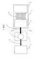
FIG. 1 , an optically pumpedlaser system 1 provides a highpower laser beam 3 to alaser processing system 5 such as a laser cutting system or a laser welding system. For example, thelaser system 1 can be a disk laser system that provides a several kW laser beam to thelaser processing system 5. A further exemplary laser system can be a fiber laser. To generate thelaser beam 3, a laser medium7 of thelaser system 1 is optically pumped with an interleavedbeam 9 that is generated by alaser system 11. However, thepump laser system 11 could also be configured as an independent laser system that is used for laser applications, such as surface treatment, hardening, material processing, and soldering. - The
laser system 11 includes, for example, a plurality of sources mounted in anarrangement 15 andbeam forming optics 17. Thearrangement 15 is configured to provide alaser beam grouping 13 of a plurality of laser beams, with each laser beam being displaced in one dimension and being directed in a direction that is different from the directions of the other laser beams of other sources. Thebeam forming optics 17 redirects the laser beams within thegrouping 13 to travel in a common direction thereby forming the interleavedbeam 9. Additionally, thebeam forming optics 17 can include optics to collimate the laser beams within thegrouping 13. The interleavedbeam 9 is provided as a pump laser beam to thelaser system 1, for example, directly or through a waveguide such as an optical fiber. FIG. 2 shows schematically asource 19 that can be used in thearrangement 15.FIG. 3 illustrates a cross-section taken along view III-III of the interleavedbeam 9 ofFIG. 1 ; this cross-section could be created with three of thesources 19 ofFIG. 2 . Various embodiments of interleaving laser systems are described in detail in connection withFIGS. 4-12 that can be used, for example, as thelaser system 11 inFIG. 1 .- As shown in
FIG. 2 , theexemplary source 19 includes three laser diode bars20 that are mounted on acommon heat sink 21. Eachlaser diode bar 20 includes a semiconductor structure with five neighboring emitting regions. The laser light of a single emitting region has anelliptical beam profile 22. The elliptic shape of the beam profiles22 indicates the different optical properties of a fast axis and a slow axis of a laser beam. For example, the laser light of an emitting region diverges more in the direction of the fast axis due to the thinness of the emitting region than in direction of the slow axis. - The light of the five emitting regions forms a
laser beam 23 of thelaser beam grouping 13 and eachlaser beam 23 has an elongated shape. In some embodiments, the emitting regions emit light orthogonal to theheat sink 21, while in other embodiments the light can be, for example, first emitted parallel to the surface of theheat sink 21 and then deflected by, e.g., 90°. - In one dimension, the three laser diode bars20 are displaced from each other by a pitchP and therefore the three
laser beams 23 are also displaced by the pitchP. Thus, the threelaser beams 23 emitted from asingle source 19 form a beam having its own cross-section, the cross-section includes regions with laser light displaced by the pitchP andregions 29 without laser light in between the regions with laser light. Some high power sources provide laser beams at a large pitch of, e.g., several millimeters. Examples of such high power sources include a source with flat mounted laser diode bars (flat source) as described in connection withFIGS. 9-11 and an arrangement with stacked laser diode bars (group source) as described in connection withFIG. 12 . - Interleaving laser systems can be specifically suited for the use of sources having a large pitch.
- Referring again to
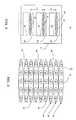
FIG. 3 , a simplified cross-section along the view III-III of the interleavedbeam 9 inFIG. 1 is based on threesources 19 with eachsource 19 having three laser diode bars20 and with eachlaser diode bar 20 producing five laser beams22 (as shown inFIG.2 ). Thelaser system 11 interleaves the threelaser beams 23 from each of the three laser diode bars20 (for a total of nine laser beams in the grouping13) such that, within the cross-section of the interleavedbeam 9, light of neighboring rows of the beam originate fromdifferent sources 19. Within the cross-section, a singlelaser diode bar 20 of one of thesources 19 contributes to arow 24 in the cross-section indicated through the elliptical beam profiles22 associated to the five emitting regions of the laser diode bar. - In the example of
FIG 3 , three rows of laser beams originate from each of the threesources 19. For example, therow 24 and two other unlabeled rows relate to laser radiationA of a first source, therow 25 and two other unlabeled rows relate to laser radiation B ofa second source, and therow 26 and two other unlabeled rows relate to laser radiationC of a third source. Accordingly, the radiation-free areas 29 in between the emitted light of the laser diode bars20 of each of thesources 19 can be at least partially filled with laser radiation originating from the two remainingsources 19 of thearrangement 15. Thus, the laser radiation of a source19 (for example, the laser radiationA from the first source19) does not contribute to a single area of the cross-section of the interleavedbeam 9 but contributes to different regions (labeled asrow 24 or as radiationA) within the entire cross-section of thebeam 9. Such a spreading of contributions to the cross-section from each of the sources is increased when sources with a larger number of laser diode bars are interleaved with each other. - The embodiments described in connection with
FIGS. 4-12 illustrate such geometrical interleaving oflaser beams 423 of sixsources 419. In the embodiments, each of thesources 419 includes twelve laser diode bars emittinglaser beams 423 that are spatially displaced by a pitch of ten millimeters. However, similar interleaving can also be performed for more or less sources having a smaller or larger pitch. - Specifically,
FIG. 4 shows a first embodiment of aninterleaving laser system 411 with anarrangement 415 of sixsources 419. Thesources 419 are arranged side by side along a circular arc thereby surrounding a wall portion of an imaginary cylinder. Each of thesources 419 is configured to emit thelaser beams 423 from each of the diode laser bars towards acenter region 432 of an imaginary cylinder. In thecenter region 432, thelaser beams 423, which are propagating from different directions, are interleaved and thebeam forming optics 417 captures the interleaving and aligns thelaser beam 423 to propagate in the same direction. - To form the
beam 409 from thoselaser beams 423, thebeam forming optics 417 includes areflector system 433 positioned in thecenter region 432. Thereflector system 433 includes a stack ofmirrors 439, with each of themirrors 439 positioned at an angle relative to theadjacent mirrors 439 of the stack. Thus, for eachsource 419, thereflector system 433 includes mirrors that are displaced by the pitchp and that are oriented in the same direction so that thelaser beams 423 of thecorresponding source 419 are directed in the same direction. As can be seen inFIG. 4 , themirrors 439 for neighboring sources are neighboring as well. Accordingly, the orientation of themirrors 439 changes mirror by mirror from a maximum incidence angle to a minimum incidence angle and then jumps back to the maximum incidence angle and so on. Thus, thereflector system 433 includes 6x12=72 mirrors439. Eachmirror 439 has a mirror area having a height and a width, where the height depends on the pitch and the number of beams that shall be interleaved and the required width depends on the incident angle. In the presented example ofFIG. 4 , the mirror area is chosen to be 1.66 mm x 100 mm for interleaving six beams over a pitch of 10 mm. Themirrors 439 can have reflective coatings that are adapted to the specific incidence angles of thelaser beams 423. Thereflector system 433 redirects theincoming laser beams 423 to travel in a common direction towards anoptical element 435 of thebeam forming optics 417. In the embodiment ofFIGS. 4 and5 , theoptical element 435 is a cylindrical mirror. - Based on the cylinder-like shape of the
arrangement 415, geometric relations can be described in a cylindrical coordinate system. An angular coordinate ϕ indicates the azimuth of incidence (e.g., the angular position of the source along the arc). A radial coordinate r indicates the radial distance to acenter axis 437 of the cylindrical coordinate system. An axial coordinate z indicates the position along thecenter axis 437 of the cylindrical coordinate system. - Accordingly, each
source 419 is associated with its angular coordinate. The distance of thesources 419 to thecenter axis 437 corresponds to its radial coordinate, and each emission region of thesources 419 is further associated with a respective axial coordinate. Moreover, thereflector system 433 ofFIG. 4 can be grouped in sets of sixindividual mirrors 439 that are stacked on top of each other in the axial direction and are rotated relative to each other about thecenter axis 437 through the same angle thereby generating a fan-shaped arrangement. The fan-shaped arrangement repeats itself twelve times in axial direction. - To provide a sufficiently high reflectivity, the incidence angles of the
light beams 423 onto theflat mirrors 439 can be limited to about 45°, wherein the incident angle is measured relative to the surface normal of the mirror surface. Then, the sixsources 419 are positioned, for example, with an 18°-difference in the angular coordinate along the arc. Additionally, as described below in connection withFIG. 6 , thesources 419 are mounted at differing axial coordinates, such that eachlaser beam 423 is emitted at its own specific axial coordinate. Therefore, each of thelaser beams 423 propagates parallel to the radial direction associated with the angular coordinate of itssource 419 towards thecenter region 432 and is then reflected by one of theflat mirrors 439 of thereflector system 433 towards thecylindrical mirror 435 such that one single (common) emission direction is formed through reflection. Thelaser beams 423, which are laterally offset with respect to each other in the axial direction, thereby combine into one common interleavedlaser beam grouping 440. In thelaser beam grouping 440, theindividual laser beams 423 no longer extend radially next to each other; rather they are parallel to and on top of each other. - The
cylindrical mirror 435 can form an entrance lens of atelescope system 441. Alens 443 forms the exit lens of thetelescope system 441 and can additionally perform a collimation of the interleavedlaser beam grouping 440 in the slow and fast axes. Thereflector system 433 with theflat mirrors 439, thecylindrical mirror 435, and thelens 443 are part of thebeam forming optics 417 that adjusts the various optical parameters of thelaser beam grouping 413 and the interleavedlaser beam grouping 440 to form and output the interleavedpump beam 409. Moreover,FIG. 4 showscoolant connections 449 for cooling thesources 419. - The top view of the
interleaving laser system 411 shown inFIG. 5 illustrates further the arrangement425 of thesources 419 along an arc segment of animaginary circle 451. As shown, thelaser beams 423 of thegrouping 413 are directed using thebeam forming optics 417 to form the interleavedbeam 409. In addition, the optical path lengths of each of thelaser beams 423 of thegrouping 413 can be considered identical. Thearrangement 415 is configured foridentical sources 419 with, e.g., a pre-aligned emission angle of 90° with respect to a front side of thesources 419. Eachsource 419 is mounted to awall segment 453 such that the emission regions of the laser diode bars is tangential to the surface of theimaginary circle 451 at the angular coordinate of thesource 419 defined, e.g., by the center of the emission regions. Accordingly, thelaser beams 423 of thegrouping 413 propagate along approximately the same optical path length and experience approximately the same divergence within theinterleaving laser system 411. - The
wall segments 453 include alignment pins for mounting thesources 419 in reproducible position. Thus, one can replace asource 419 without realigning thereflector system 433. In the embodiment ofFIGS. 5 and 6 , thewall segments 453 include mounts for mounting the sources431 to be parallel to the axial direction. FIG. 6 is a view taken along the direction VI-VI as shown inFIG. 5 . Each of the sixidentical sources 419 is attached to thecorresponding wall segment 453 at aposition 455 that is axially offset relative to ahousing top 457 and can be defined, for example, by alignment pins of thewall segments 453, which are adapted to fit intoalignment holes 459 of thesources 419. Accordingly, thelaser beams 423 are emitted at different axial coordinates between thehousing top 457 and ahousing bottom 461. Thelaser beams 423 of the grouping413 - each propagating at its own axial coordinate - interleave at the center region, where thelaser beams 423 are reflected by thereflector system 433 to form the interleavedlaser beam grouping 440. Thus, in theinterleaving laser system 411, theindividual laser beams 423 of all thesources 419 are guided one on top of the other, such that the radiation-free space420 in theaxial direction 437 of each of thesources 419 is at least partially filled with thelaser beams 423 of the remainingsources 419.- Referring to an
interleaving laser system 711 ofFig. 7 , additionally, or alternatively, thebeam forming optics 717 can include acylindrical lens 763 and aflat mirror 765 that perform the collimation of the slow axis. As another example as shown inFig. 8 , thebeam forming optics 817 of ainterleaving laser system 811 can include a reflector system of stackedparabolic mirrors 867 and aparabolic folding mirror 869, or a concave parabolic surface shape of a backside of atelescope lens 871. Additionally, the beam forming optics can include folding mirrors to provide a more compact telescope and/or a collimating optical system. For example, thecylindrical mirror 435 ofFIG. 4 can be used as a folding mirror. - Before the interleaved
laser beam 9 is, e.g., coupled into an optical fiber or a laser medium, additional optical components can be used to adapt and improve various beam parameters such as, for example, beam divergence, smoothness of the beam profile. - For high power applications, high power sources such as described in connection with
FIGS. 9-12 can be used in thearrangement 15. - Referring to
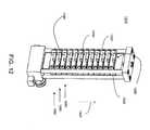
FIGS. 9-11 , aflat source 919 includes twelve laserdiode bar units 981, which each include alaser diode bar 920, aprism lens 987, andelectrical connections 950. The diode laser bars920 are arranged with a flat side onto a single piecerectangular heat sink 921. Therefore, the source is referred to as a flat source, in which eachlaser diode bar 920 can be efficiently cooled through the large area that is in thermal contact with theheat sink 921. Generated heat is removed from theflat sources 919 by a coolant being pumped through theheat sink 921 through the coolant connections at the backside as shown, e.g., inFIG.4 . Mount holes991 are located at each corner andalignment holes 959 are located at the short sides of therectangular heat sink 921. - The twelve laser diode bars920 are arranged along a
direction 937 of the length of therectangular heat sink 921, which inFIG. 4 is arranged along theaxial direction 437. Theheat sink 921 has an insulatinglayer 995 as a top layer to electrically insulate the laser diode bars920 from theheat sink 921. Each of the laser diode bars920 includes asemiconductor structure 910 with an active region having multiple emitting regions. Thesemiconductor structure 910 is attached to a p-contact 930.Electrical connections 950, e.g. wire bonds, electrically connect thesemiconductor structure 910 with an n-contact 970, and the n-contact 970 is electrically connected to the p-contact of a neighboring diode laser unit. Thus, when operating thesource 919, the (identical) current flows serially through all laser diode bars920. Additionally, each of the diode laser bars920 can be controlled with achip element 990. - Each of the
semiconductor structures 910 has an elongated emitting surface, e.g., 30-45 neighboring active regions that are evenly distributed on a length of about 10 mm. Each emitting surface is perpendicularly oriented to theheat sink 921 and has an emission direction along thedirection 937. Thus, the laser diode bars920 emitlaser beams 923 essentially in the same plane, which is parallel to aplanar surface 924 of theheat sink 921. Eachlaser beam 923 has an elongated beam profile, with its slow axis oriented in direction of the elongation of the emitting surface of thelaser diode bar 920, i.e., in adirection 939 of a width of the heat sink921 (as similarly discussed above with respect toFIGS. 2 and 3 ), and initially a fast axis oriented in a direction perpendicular to theplanar surface 924 of theheat sink 921. - The emitted
laser beam 923 is internally reflected by theprism lens 987 and then propagates away from theheat sink 921 along a direction that is orthogonal to thesurface 924 of theheat sink 921. Thus, after exiting the prism lens, the fast axis of thelaser beams 923 is in thedirection 937 along the length of theheat sink 921, while the direction of the slow axis of thelaser diode bar 920 is not changed and remains along thedirection 939. Additionally, theprism lens 987 collimates thelaser beam 923 that is strongly divergent in the direction of the fast axis. The orientations of theprism lenses 987 are secured by acommon glass mount 999. - The
flat source 919 can have the following parameters. Eachsource 919 can provide an output power of about 1700 W based on twelve laser diode bars920. The width of alaser diode bar 920 in the slow axis direction can be about 10 mm. The full-angle divergence of thelaser beams 923 in the slow axis direction can be approximately 6°-10°. The emission in the fast axis direction from the individual laser diode bars920 is achieved through an emission surface having a height of approximately 1 µm. Initially, thelaser beams 923 have a full-angle divergence of approximately 40°-70° in the fast axis direction. Each of thelaser beams 923 emitted from eachlaser diode bar 920 is collimated in the fast axis direction using theprism lens 987. The collimatedlaser beams 923 typically extend about 0.6-1.2 mm in the fast axis direction. The full-angle divergence of the collimatedlaser beams 923 after passing through theprism lens 987 is approximately 0.5°-2° in the fast axis direction. The quality of theprism lens 987, the accuracy of the prism lens' alignment, and the straightness of thelaser diode bar 920 determine the divergence angles. - Applying the
flat sources 919 in the embodiment of thearrangement 15 ofFIGS. 4-8 , the fast-axes of the emittedlaser beams 923 are oriented initially, i.e., when leaving thesemiconductor structures 910, in the radial direction of the corresponding position of theflat source 919. After the reflection within theprism lenses 987, the fast axes of the emittedlaser beams 923 are directed in the direction of the axial coordinate z. - Referring again to the
flat source 919 ofFIGS. 9-11 , the pitch between two emittedlaser beams 923 is about ten times larger then the size of thelaser beam 923 when leaving theprism lens 987. Thus, about 9/10 of the cross-section of a beam of aflat source 919 is free from any laser radiation. Using thearrangement 15 and thebeam forming optics 17, the laser radiation free part can be filled withlaser beams 923 from otherflat sources 919. - An alternative high power source is shown in
FIG. 12 in form of agroup source 1019, in which multiple laserdiode bar units 1081 are grouped together. InFig. 12 , for example, thegroup source 1019 includes 12 laserdiode bar units 1081, which each include a laser diode bar1020, alens 1090, and electrical connections. Each of the diode laser bars1020 is arranged on a surface of acupper block 1030 and emits laser beams though alens 1090 at afront side 1040 of thegroup source 1019. In a region behind the laser diode bars1020, the neighboring cupper blocks1030 are hold in tight contact such that thecupper bocks 1030 can be cooled with a common coolant system. - The twelve laser diode bars1020 are arranged along a
direction 1037 of the length of thegroup source 1019. Each of the laser diode bars1020 includes a semiconductor structure with an active region having multiple emitting regions that form an elongated emitting surface. Each emitting surface is parallel to thefront side 1040 of thegroup source 1019 and has an emission direction perpendicular to thefront side 1040. Each laser beam has an elongated beam profile, with its slow axis oriented in direction of the elongation of the emitting surface of the laser diode bar1020, and a fast axis in thedirection 1037. - The
lens 1090 collimates the laser beam that is strongly divergent in the direction of the fast axis. The orientations of theprism lenses 1090 can be secured by anextension 1031 of thecupper block 1030 or by a glass block that is attached to thecupper block 1030. - The
group source 1019 can have beam parameters similar to theflat source 919. - As for the
flat source 919 ofFIGS. 9-11 , the pitch between two emitted laser beams can be, for example, about ten times larger then the size of the laser beam when leaving thelens 1090. Thus, about 9/10 of the cross-section of a beam of agroup source 1019 is free from any laser radiation. Using thearrangement 15 and thebeam forming optics 17, the laser radiation free part can be filled with laser beams fromother group sources 1019. - In the described
arrangement 415, the sources can further be geometrically well aligned, as the contacting surface or contact points between thewall segments 453 and the heat sink can extend over the complete length of thesources 419 thereby providing a high angular precision of the alignment of the fast axis. - Various configurations can use the described concept to increase the number of integrated sources. For example, in
FIG. 4 , a second set of sixsources 419 can be positioned on the other side of thecylindrical mirror 435. Thecylindrical mirror 435 could then be positioned outside thecircle 451 or could be replaced with a cylindrical lens. - Accordingly, other embodiments are within the scope of the following claims.
Claims (14)
- A laser system (411; 711; 811) comprising:at least two sources (19; 419; 919) configured to provide laser beams (423; 923), anda mount configured to mount the at least two sources (19; 419; 919) along an arc, the arc defining an angular coordinate (ϕ) and a radial coordinate (r),wherein an axial coordinate (z) is orthogonal to the angular coordinate (ϕ) andthe radial coordinate (r) and wherein the mount is further configured to mount the at least two sources (19; 419; 919) providing thereby an offset of the laser beams (423; 923) in the axial coordinate (z) such that the laser beams (423; 923) interleave in the axial direction (z) at a center region (432) of the arc,characterized in thateach of the at least two sources (19; 419; 919) is configured to provide at least two spatially separated laser beams (423; 923) which are separated in the axial coordinate (z), andone of the at least two sources (19; 419; 919) is mounted for providing a laser beam (423; 923) that has an axial coordinate (z) in between the axial coordinates (z) of a pair of laser beams (423; 923) provided by another of the at least two sources (19; 419; 919).
- The laser system of claim 1 further comprising an aligning optics (417; 817) positioned at the center region (432) to direct the interleaved laser beams (423; 923) in a common direction.
- The laser system of claim 2 wherein the aligning optics (417; 817) includes a stack of optical elements (439; 867), preferably wherein neighboring optical elements of the stack of optical elements (439; 867) direct laser beams (423; 923) of different sources (19; 419; 919).
- The laser system of claim 2 wherein the mount and the aligning optics (417; 817) are arranged to provide the same optical path length for the laser beams (423; 923) of the at least two sources (419; 919).
- The laser system of claim 1 wherein at least one of the sources (19; 419; 919) includes a heat sink (21; 921) and two laser diodes (920).
- The laser system of claim 5 wherein at least one of the laser diodes (920) is arranged flat an the heat sink (921) such that an emitting surface (912) of the laser diode (920) is perpendicular to the heat sink (921) for emitting a laser beam (923) parallel to the heat sink (921) with a fast axis perpendicular to the heat sink (921), preferably wherein a deflecting optics (987) is configured to deflect the laser beam (923) being emitted parallel to the heat sink (921) in a direction towards the center region (432).
- The laser system of claim 5 wherein the laser diodes (920) of one of the sources (919) are electrically connected for supplying a current serially through all laser diodes (920).
- The laser system of claim 1 wherein at least one of the sources (919) includes a stack of laser diode units (981).
- The laser system of claim 1 further comprising a beam forming optics positioned in the optical path of the interleaved laser beams (423; 923) after the aligning optics (417; 817).
- The laser system of claim 1 further comprising a beam forming optics, which is partially or completely incorporated in the aligning optics (417; 817).
- The laser system of claim 1 wherein the sources (919) are configured to provide multiple in the axial coordinate (z) displaced laser beams (923) with a pitch of at least the length of the laser diode (920) in direction orthogonal to the emitting surface (912).
- The laser system of claim 1 further comprising a collimating optics (443; 763; 987) for at least one of a fast axis and a slow axis of the emitted laser beams.
- The laser system of claim 1 wherein at least one of the sources (19; 419; 919) includes a laser diode bar (920).
- The laser system of claim 14 wherein the laser diode bar (920) includes between 20 and 50 emitting regions for emitting laser beams (923) at the same axial coordinate (z), preferably wherein the emitting regions are arranged over a width of about 10 mm.
Applications Claiming Priority (2)
| Application Number | Priority Date | Filing Date | Title |
|---|---|---|---|
| US12/258,622US7936799B2 (en) | 2008-10-27 | 2008-10-27 | Interleaving laser beams |
| PCT/US2009/061475WO2010051200A1 (en) | 2008-10-27 | 2009-10-21 | Interleaving laser beams |
Publications (2)
| Publication Number | Publication Date |
|---|---|
| EP2342597A1 EP2342597A1 (en) | 2011-07-13 |
| EP2342597B1true EP2342597B1 (en) | 2012-08-15 |
Family
ID=41382365
Family Applications (1)
| Application Number | Title | Priority Date | Filing Date |
|---|---|---|---|
| EP09744547AActiveEP2342597B1 (en) | 2008-10-27 | 2009-10-21 | Interleaving laser beams |
Country Status (4)
| Country | Link |
|---|---|
| US (1) | US7936799B2 (en) |
| EP (1) | EP2342597B1 (en) |
| CN (1) | CN102227669B (en) |
| WO (1) | WO2010051200A1 (en) |
Cited By (1)
| Publication number | Priority date | Publication date | Assignee | Title |
|---|---|---|---|---|
| WO2014140112A1 (en) | 2013-03-15 | 2014-09-18 | Trumpf Laser Gmbh + Co. Kg | Device for coupling wavelengths of laser beams |
Families Citing this family (9)
| Publication number | Priority date | Publication date | Assignee | Title |
|---|---|---|---|---|
| US20100260210A1 (en)* | 2009-04-13 | 2010-10-14 | Coherent, Inc. | Ops-laser pumped fiber-laser |
| US8816249B2 (en)* | 2009-04-28 | 2014-08-26 | Industrial Technology Research Institute | Apparatuses for fabricating patterns using laser diode |
| CN103472582A (en)* | 2012-06-07 | 2013-12-25 | 苏州长光华芯光电技术有限公司 | Light beam shaping device for realizing high-power and high-brightness semiconductor laser |
| CN108886232B (en)* | 2015-12-25 | 2021-08-17 | 鸿海精密工业股份有限公司 | Wire harness light source, wire harness irradiation device, and laser lift-off method |
| CN106025788B (en)* | 2016-07-22 | 2018-12-18 | 合肥芯碁微电子装备有限公司 | A kind of circulating water cooling device for semiconductor laser |
| JP2022549941A (en)* | 2019-09-30 | 2022-11-29 | エイエムエス-オスラム インターナショナル ゲーエムベーハー | Laser packages and systems with laser packages |
| WO2022098569A1 (en)* | 2020-11-04 | 2022-05-12 | Panasonic Intellectual Propertymanagement Co., Ltd. | Helical emitter stacking for wavelength-beam-combining laser systems |
| EP4323712A4 (en)* | 2021-04-12 | 2025-04-02 | Leonardo Electronics US Inc. | ULTRA-COMPACT HIGH-POWER FIBER PUMP MODULE |
| DE112022003585T5 (en)* | 2021-07-16 | 2024-06-20 | Panasonic Intellectual Property Management Co., Ltd. | SINGLE EMITTER STACKING FOR WAVELENGTH BEAM COMBINATING LASER SYSTEMS |
Family Cites Families (27)
| Publication number | Priority date | Publication date | Assignee | Title |
|---|---|---|---|---|
| JPS5971377A (en) | 1982-10-15 | 1984-04-23 | Kanegafuchi Chem Ind Co Ltd | Adhesive composition |
| US4826269A (en) | 1987-10-16 | 1989-05-02 | Spectra Diode Laboratories, Inc. | Diode laser arrangement forming bright image |
| US5513201A (en) | 1993-04-30 | 1996-04-30 | Nippon Steel Corporation | Optical path rotating device used with linear array laser diode and laser apparatus applied therewith |
| US6331692B1 (en) | 1996-10-12 | 2001-12-18 | Volker Krause | Diode laser, laser optics, device for laser treatment of a workpiece, process for a laser treatment of workpiece |
| DE19645150C2 (en) | 1996-10-28 | 2002-10-24 | Fraunhofer Ges Forschung | Optical arrangement for symmetrizing the radiation from laser diodes |
| JPH1187816A (en) | 1997-09-12 | 1999-03-30 | Fanuc Ltd | Ld excitation solid laser oscillator |
| US6229831B1 (en) | 1997-12-08 | 2001-05-08 | Coherent, Inc. | Bright diode-laser light-source |
| US6259713B1 (en) | 1997-12-15 | 2001-07-10 | The University Of Utah Research Foundation | Laser beam coupler, shaper and collimator device |
| IL140386A0 (en) | 2000-12-18 | 2002-02-10 | Rayteq Laser Ind Ltd | Optical device for unifying light beams emitted by several light sources |
| US6005717A (en) | 1998-11-17 | 1999-12-21 | Ceramoptec Industries, Inc. | Diode laser beam combiner system |
| ITMI991271A1 (en) | 1999-06-08 | 2000-12-08 | Bright Solutions Soluzioni Las | METHOD AND DEVICE TO CONDITION THE LIGHT EMISSION OF A LASER DIODE SET |
| DE19939750C2 (en) | 1999-08-21 | 2001-08-23 | Laserline Ges Fuer Entwicklung | Optical arrangement for use in a laser diode arrangement and laser diode arrangement with such an optical arrangement |
| US6556352B2 (en) | 2000-08-23 | 2003-04-29 | Apollo Instruments Inc. | Optical coupling system |
| US6516011B1 (en) | 2000-11-08 | 2003-02-04 | Opto-Power Corp. | Focusing multiple laser beams |
| JP2002151799A (en) | 2000-11-14 | 2002-05-24 | Shibaura Mechatronics Corp | Laser diode module device |
| DE10061265A1 (en) | 2000-12-06 | 2002-06-27 | Jenoptik Jena Gmbh | The diode laser assembly |
| JP2002335047A (en) | 2001-05-10 | 2002-11-22 | Hamamatsu Photonics Kk | Semiconductor laser device |
| US6943957B2 (en) | 2001-08-10 | 2005-09-13 | Hamamatsu Photonics K.K. | Laser light source and an optical system for shaping light from a laser-bar-stack |
| US6650668B2 (en) | 2001-10-02 | 2003-11-18 | Coherent, Inc. | Cylindrical two-dimensional diode-laser arrays and method for making same |
| JP2003124558A (en) | 2001-10-15 | 2003-04-25 | Hamamatsu Photonics Kk | Semiconductor laser device |
| US6975465B1 (en) | 2002-04-03 | 2005-12-13 | University Of Central Florida Research Foundation, Inc. | Method and apparatus for use of beam control prisms with diode laser arrays |
| DE10229711B4 (en) | 2002-07-02 | 2009-09-03 | Curamik Electronics Gmbh | Semiconductor module with microcooler |
| JP4264231B2 (en) | 2002-08-07 | 2009-05-13 | 浜松ホトニクス株式会社 | Concentrator |
| AU2003274969A1 (en) | 2002-09-12 | 2004-04-30 | Visotek, Inc. | Contact lens package and storage case, holder, and system and method of making and using |
| US7006549B2 (en) | 2003-06-11 | 2006-02-28 | Coherent, Inc. | Apparatus for reducing spacing of beams delivered by stacked diode-laser bars |
| DE502004007897D1 (en) | 2004-07-19 | 2008-10-02 | Trumpf Laser Gmbh & Co Kg | Diode laser arrangement and beam shaping unit therefor |
| US20070115617A1 (en)* | 2005-11-22 | 2007-05-24 | Nlight Photonics Corporation | Modular assembly utilizing laser diode subassemblies with winged mounting blocks |
- 2008
- 2008-10-27USUS12/258,622patent/US7936799B2/enactiveActive
- 2009
- 2009-10-21EPEP09744547Apatent/EP2342597B1/enactiveActive
- 2009-10-21WOPCT/US2009/061475patent/WO2010051200A1/enactiveApplication Filing
- 2009-10-21CNCN200980147759.XApatent/CN102227669B/enactiveActive
Cited By (2)
| Publication number | Priority date | Publication date | Assignee | Title |
|---|---|---|---|---|
| WO2014140112A1 (en) | 2013-03-15 | 2014-09-18 | Trumpf Laser Gmbh + Co. Kg | Device for coupling wavelengths of laser beams |
| US9690107B2 (en) | 2013-03-15 | 2017-06-27 | Trumpf Laser Gmbh | Device for wavelength combining of laser beams |
Also Published As
| Publication number | Publication date |
|---|---|
| CN102227669A (en) | 2011-10-26 |
| WO2010051200A1 (en) | 2010-05-06 |
| US7936799B2 (en) | 2011-05-03 |
| CN102227669B (en) | 2014-04-02 |
| EP2342597A1 (en) | 2011-07-13 |
| US20100103973A1 (en) | 2010-04-29 |
Similar Documents
| Publication | Publication Date | Title |
|---|---|---|
| EP2342597B1 (en) | Interleaving laser beams | |
| US8345724B2 (en) | Laser beam interleaving | |
| US10833482B2 (en) | Diode laser apparatus with FAC lens out-of-plane beam steering | |
| EP2003484B1 (en) | A Light Source | |
| US7773655B2 (en) | High brightness laser diode module | |
| JP3862657B2 (en) | Semiconductor laser device and solid-state laser device using the same | |
| US9455552B1 (en) | Laser diode apparatus utilizing out of plane combination | |
| JP4980329B2 (en) | High power laser diode array including at least one high power diode laser and laser light source including the same | |
| CN110299668B (en) | Construction of multiple diode laser modules and method of operating the same | |
| US7773653B2 (en) | Diode laser arrangement and associated beam shaping unit | |
| CN101833150A (en) | Fiber coupling module of high-power semiconductor laser | |
| FI116010B (en) | Method and laser device for producing high optical power density | |
| CN104678557B (en) | Wavelength stabilizing beam combiner | |
| US20140240831A1 (en) | Stabilization of High-Power WBC Systems | |
| US9377611B2 (en) | Light-source including a planar array of diode-laser bars | |
| JP4580236B2 (en) | Semiconductor laser device | |
| JPH07287189A (en) | Optical path changer and laser device using the same |
Legal Events
| Date | Code | Title | Description |
|---|---|---|---|
| PUAI | Public reference made under article 153(3) epc to a published international application that has entered the european phase | Free format text:ORIGINAL CODE: 0009012 | |
| 17P | Request for examination filed | Effective date:20110527 | |
| AK | Designated contracting states | Kind code of ref document:A1 Designated state(s):AT BE BG CH CY CZ DE DK EE ES FI FR GB GR HR HU IE IS IT LI LT LU LV MC MK MT NL NO PL PT RO SE SI SK SM TR | |
| AX | Request for extension of the european patent | Extension state:AL BA RS | |
| RIN1 | Information on inventor provided before grant (corrected) | Inventor name:VETHAKE, THILO Inventor name:BONNA, ULRICH Inventor name:TILLKORN, CHRISTOPH Inventor name:LIERMANN, MARTIN Inventor name:KILLI, ALEXANDER Inventor name:NEGOITA, VIOREL, C. | |
| RIN1 | Information on inventor provided before grant (corrected) | Inventor name:TILLKORN, CHRISTOPH Inventor name:VETHAKE, THILO Inventor name:BONNA, ULRICH Inventor name:NEGOITA, VIOREL, C. Inventor name:KILLI, ALEXANDER Inventor name:LIERMANN, MARTIN | |
| DAX | Request for extension of the european patent (deleted) | ||
| GRAP | Despatch of communication of intention to grant a patent | Free format text:ORIGINAL CODE: EPIDOSNIGR1 | |
| GRAS | Grant fee paid | Free format text:ORIGINAL CODE: EPIDOSNIGR3 | |
| GRAA | (expected) grant | Free format text:ORIGINAL CODE: 0009210 | |
| AK | Designated contracting states | Kind code of ref document:B1 Designated state(s):AT BE BG CH CY CZ DE DK EE ES FI FR GB GR HR HU IE IS IT LI LT LU LV MC MK MT NL NO PL PT RO SE SI SK SM TR | |
| REG | Reference to a national code | Ref country code:AT Ref legal event code:REF Ref document number:571122 Country of ref document:AT Kind code of ref document:T Effective date:20120815 Ref country code:GB Ref legal event code:FG4D Ref country code:CH Ref legal event code:EP | |
| REG | Reference to a national code | Ref country code:IE Ref legal event code:FG4D | |
| REG | Reference to a national code | Ref country code:DE Ref legal event code:R096 Ref document number:602009009018 Country of ref document:DE Effective date:20121011 | |
| REG | Reference to a national code | Ref country code:NL Ref legal event code:VDEP Effective date:20120815 | |
| REG | Reference to a national code | Ref country code:AT Ref legal event code:MK05 Ref document number:571122 Country of ref document:AT Kind code of ref document:T Effective date:20120815 | |
| PG25 | Lapsed in a contracting state [announced via postgrant information from national office to epo] | Ref country code:FI Free format text:LAPSE BECAUSE OF FAILURE TO SUBMIT A TRANSLATION OF THE DESCRIPTION OR TO PAY THE FEE WITHIN THE PRESCRIBED TIME-LIMIT Effective date:20120815 Ref country code:NO Free format text:LAPSE BECAUSE OF FAILURE TO SUBMIT A TRANSLATION OF THE DESCRIPTION OR TO PAY THE FEE WITHIN THE PRESCRIBED TIME-LIMIT Effective date:20121115 Ref country code:IS Free format text:LAPSE BECAUSE OF FAILURE TO SUBMIT A TRANSLATION OF THE DESCRIPTION OR TO PAY THE FEE WITHIN THE PRESCRIBED TIME-LIMIT Effective date:20121215 Ref country code:LT Free format text:LAPSE BECAUSE OF FAILURE TO SUBMIT A TRANSLATION OF THE DESCRIPTION OR TO PAY THE FEE WITHIN THE PRESCRIBED TIME-LIMIT Effective date:20120815 Ref country code:AT Free format text:LAPSE BECAUSE OF FAILURE TO SUBMIT A TRANSLATION OF THE DESCRIPTION OR TO PAY THE FEE WITHIN THE PRESCRIBED TIME-LIMIT Effective date:20120815 Ref country code:HR Free format text:LAPSE BECAUSE OF FAILURE TO SUBMIT A TRANSLATION OF THE DESCRIPTION OR TO PAY THE FEE WITHIN THE PRESCRIBED TIME-LIMIT Effective date:20120815 | |
| PG25 | Lapsed in a contracting state [announced via postgrant information from national office to epo] | Ref country code:PL Free format text:LAPSE BECAUSE OF FAILURE TO SUBMIT A TRANSLATION OF THE DESCRIPTION OR TO PAY THE FEE WITHIN THE PRESCRIBED TIME-LIMIT Effective date:20120815 Ref country code:GR Free format text:LAPSE BECAUSE OF FAILURE TO SUBMIT A TRANSLATION OF THE DESCRIPTION OR TO PAY THE FEE WITHIN THE PRESCRIBED TIME-LIMIT Effective date:20121116 Ref country code:BE Free format text:LAPSE BECAUSE OF FAILURE TO SUBMIT A TRANSLATION OF THE DESCRIPTION OR TO PAY THE FEE WITHIN THE PRESCRIBED TIME-LIMIT Effective date:20120815 Ref country code:SI Free format text:LAPSE BECAUSE OF FAILURE TO SUBMIT A TRANSLATION OF THE DESCRIPTION OR TO PAY THE FEE WITHIN THE PRESCRIBED TIME-LIMIT Effective date:20120815 Ref country code:PT Free format text:LAPSE BECAUSE OF FAILURE TO SUBMIT A TRANSLATION OF THE DESCRIPTION OR TO PAY THE FEE WITHIN THE PRESCRIBED TIME-LIMIT Effective date:20121217 Ref country code:LV Free format text:LAPSE BECAUSE OF FAILURE TO SUBMIT A TRANSLATION OF THE DESCRIPTION OR TO PAY THE FEE WITHIN THE PRESCRIBED TIME-LIMIT Effective date:20120815 Ref country code:SE Free format text:LAPSE BECAUSE OF FAILURE TO SUBMIT A TRANSLATION OF THE DESCRIPTION OR TO PAY THE FEE WITHIN THE PRESCRIBED TIME-LIMIT Effective date:20120815 | |
| PG25 | Lapsed in a contracting state [announced via postgrant information from national office to epo] | Ref country code:NL Free format text:LAPSE BECAUSE OF FAILURE TO SUBMIT A TRANSLATION OF THE DESCRIPTION OR TO PAY THE FEE WITHIN THE PRESCRIBED TIME-LIMIT Effective date:20120815 | |
| PG25 | Lapsed in a contracting state [announced via postgrant information from national office to epo] | Ref country code:DK Free format text:LAPSE BECAUSE OF FAILURE TO SUBMIT A TRANSLATION OF THE DESCRIPTION OR TO PAY THE FEE WITHIN THE PRESCRIBED TIME-LIMIT Effective date:20120815 Ref country code:RO Free format text:LAPSE BECAUSE OF FAILURE TO SUBMIT A TRANSLATION OF THE DESCRIPTION OR TO PAY THE FEE WITHIN THE PRESCRIBED TIME-LIMIT Effective date:20120815 Ref country code:CZ Free format text:LAPSE BECAUSE OF FAILURE TO SUBMIT A TRANSLATION OF THE DESCRIPTION OR TO PAY THE FEE WITHIN THE PRESCRIBED TIME-LIMIT Effective date:20120815 Ref country code:EE Free format text:LAPSE BECAUSE OF FAILURE TO SUBMIT A TRANSLATION OF THE DESCRIPTION OR TO PAY THE FEE WITHIN THE PRESCRIBED TIME-LIMIT Effective date:20120815 | |
| PG25 | Lapsed in a contracting state [announced via postgrant information from national office to epo] | Ref country code:SK Free format text:LAPSE BECAUSE OF FAILURE TO SUBMIT A TRANSLATION OF THE DESCRIPTION OR TO PAY THE FEE WITHIN THE PRESCRIBED TIME-LIMIT Effective date:20120815 Ref country code:IT Free format text:LAPSE BECAUSE OF FAILURE TO SUBMIT A TRANSLATION OF THE DESCRIPTION OR TO PAY THE FEE WITHIN THE PRESCRIBED TIME-LIMIT Effective date:20120815 Ref country code:MC Free format text:LAPSE BECAUSE OF NON-PAYMENT OF DUE FEES Effective date:20121031 | |
| PLBE | No opposition filed within time limit | Free format text:ORIGINAL CODE: 0009261 | |
| STAA | Information on the status of an ep patent application or granted ep patent | Free format text:STATUS: NO OPPOSITION FILED WITHIN TIME LIMIT | |
| REG | Reference to a national code | Ref country code:IE Ref legal event code:MM4A | |
| 26N | No opposition filed | Effective date:20130516 | |
| PG25 | Lapsed in a contracting state [announced via postgrant information from national office to epo] | Ref country code:IE Free format text:LAPSE BECAUSE OF NON-PAYMENT OF DUE FEES Effective date:20121021 Ref country code:BG Free format text:LAPSE BECAUSE OF FAILURE TO SUBMIT A TRANSLATION OF THE DESCRIPTION OR TO PAY THE FEE WITHIN THE PRESCRIBED TIME-LIMIT Effective date:20121115 | |
| REG | Reference to a national code | Ref country code:DE Ref legal event code:R097 Ref document number:602009009018 Country of ref document:DE Effective date:20130516 | |
| PG25 | Lapsed in a contracting state [announced via postgrant information from national office to epo] | Ref country code:ES Free format text:LAPSE BECAUSE OF FAILURE TO SUBMIT A TRANSLATION OF THE DESCRIPTION OR TO PAY THE FEE WITHIN THE PRESCRIBED TIME-LIMIT Effective date:20121126 | |
| PG25 | Lapsed in a contracting state [announced via postgrant information from national office to epo] | Ref country code:MT Free format text:LAPSE BECAUSE OF FAILURE TO SUBMIT A TRANSLATION OF THE DESCRIPTION OR TO PAY THE FEE WITHIN THE PRESCRIBED TIME-LIMIT Effective date:20120815 Ref country code:CY Free format text:LAPSE BECAUSE OF FAILURE TO SUBMIT A TRANSLATION OF THE DESCRIPTION OR TO PAY THE FEE WITHIN THE PRESCRIBED TIME-LIMIT Effective date:20120815 | |
| PG25 | Lapsed in a contracting state [announced via postgrant information from national office to epo] | Ref country code:TR Free format text:LAPSE BECAUSE OF FAILURE TO SUBMIT A TRANSLATION OF THE DESCRIPTION OR TO PAY THE FEE WITHIN THE PRESCRIBED TIME-LIMIT Effective date:20120815 | |
| PG25 | Lapsed in a contracting state [announced via postgrant information from national office to epo] | Ref country code:SM Free format text:LAPSE BECAUSE OF FAILURE TO SUBMIT A TRANSLATION OF THE DESCRIPTION OR TO PAY THE FEE WITHIN THE PRESCRIBED TIME-LIMIT Effective date:20120815 Ref country code:LU Free format text:LAPSE BECAUSE OF NON-PAYMENT OF DUE FEES Effective date:20121021 | |
| PG25 | Lapsed in a contracting state [announced via postgrant information from national office to epo] | Ref country code:HU Free format text:LAPSE BECAUSE OF FAILURE TO SUBMIT A TRANSLATION OF THE DESCRIPTION OR TO PAY THE FEE WITHIN THE PRESCRIBED TIME-LIMIT Effective date:20091021 | |
| PG25 | Lapsed in a contracting state [announced via postgrant information from national office to epo] | Ref country code:MK Free format text:LAPSE BECAUSE OF FAILURE TO SUBMIT A TRANSLATION OF THE DESCRIPTION OR TO PAY THE FEE WITHIN THE PRESCRIBED TIME-LIMIT Effective date:20120815 | |
| REG | Reference to a national code | Ref country code:FR Ref legal event code:PLFP Year of fee payment:7 | |
| REG | Reference to a national code | Ref country code:FR Ref legal event code:PLFP Year of fee payment:8 | |
| REG | Reference to a national code | Ref country code:FR Ref legal event code:PLFP Year of fee payment:9 | |
| REG | Reference to a national code | Ref country code:FR Ref legal event code:PLFP Year of fee payment:10 | |
| PGFP | Annual fee paid to national office [announced via postgrant information from national office to epo] | Ref country code:DE Payment date:20241021 Year of fee payment:16 | |
| PGFP | Annual fee paid to national office [announced via postgrant information from national office to epo] | Ref country code:GB Payment date:20241022 Year of fee payment:16 | |
| PGFP | Annual fee paid to national office [announced via postgrant information from national office to epo] | Ref country code:FR Payment date:20241021 Year of fee payment:16 | |
| PGFP | Annual fee paid to national office [announced via postgrant information from national office to epo] | Ref country code:CH Payment date:20241101 Year of fee payment:16 |