EP2342146B1 - A fluid dispenser - Google Patents
A fluid dispenserDownload PDFInfo
- Publication number
- EP2342146B1 EP2342146B1EP09740915.5AEP09740915AEP2342146B1EP 2342146 B1EP2342146 B1EP 2342146B1EP 09740915 AEP09740915 AEP 09740915AEP 2342146 B1EP2342146 B1EP 2342146B1
- Authority
- EP
- European Patent Office
- Prior art keywords
- dispenser
- container
- fluid
- fluid dispenser
- dip tube
- Prior art date
- Legal status (The legal status is an assumption and is not a legal conclusion. Google has not performed a legal analysis and makes no representation as to the accuracy of the status listed.)
- Not-in-force
Links
- 239000012530fluidSubstances0.000titleclaimsdescription45
- 239000012528membraneSubstances0.000claimsdescription27
- 239000007788liquidSubstances0.000claimsdescription19
- 239000007921spraySubstances0.000claimsdescription19
- 239000003380propellantSubstances0.000claimsdescription10
- 239000006260foamSubstances0.000claimsdescription9
- 239000002304perfumeSubstances0.000claimsdescription8
- 239000000443aerosolSubstances0.000claimsdescription6
- -1atomiserSubstances0.000claimsdescription5
- 239000006210lotionSubstances0.000claimsdescription3
- 239000000835fiberSubstances0.000description12
- 239000000047productSubstances0.000description10
- 239000000203mixtureSubstances0.000description7
- 239000000463materialSubstances0.000description6
- 239000000499gelSubstances0.000description5
- 229920000036polyvinylpyrrolidonePolymers0.000description5
- 239000001267polyvinylpyrrolidoneSubstances0.000description5
- 235000013855polyvinylpyrrolidoneNutrition0.000description5
- 239000004695Polyether sulfoneSubstances0.000description3
- 239000003595mistSubstances0.000description3
- 229920006393polyether sulfonePolymers0.000description3
- 239000011148porous materialSubstances0.000description3
- 239000002033PVDF binderSubstances0.000description2
- 239000004479aerosol dispenserSubstances0.000description2
- 230000001166anti-perspirative effectEffects0.000description2
- 239000003213antiperspirantSubstances0.000description2
- 229920002678cellulosePolymers0.000description2
- 239000001913celluloseSubstances0.000description2
- 229920002301cellulose acetatePolymers0.000description2
- 229920001577copolymerPolymers0.000description2
- 239000002781deodorant agentSubstances0.000description2
- 239000002917insecticideSubstances0.000description2
- 239000003973paintSubstances0.000description2
- 229920003023plasticPolymers0.000description2
- 239000004033plasticSubstances0.000description2
- 229920002492poly(sulfone)Polymers0.000description2
- 229920002239polyacrylonitrilePolymers0.000description2
- 229920002981polyvinylidene fluoridePolymers0.000description2
- 238000007789sealingMethods0.000description2
- 238000003466weldingMethods0.000description2
- OKTJSMMVPCPJKN-UHFFFAOYSA-NCarbonChemical compound[C]OKTJSMMVPCPJKN-UHFFFAOYSA-N0.000description1
- ZAMOUSCENKQFHK-UHFFFAOYSA-NChlorine atomChemical compound[Cl]ZAMOUSCENKQFHK-UHFFFAOYSA-N0.000description1
- CBENFWSGALASAD-UHFFFAOYSA-NOzoneChemical compound[O-][O+]=OCBENFWSGALASAD-UHFFFAOYSA-N0.000description1
- 229920012266Poly(ether sulfone) PESPolymers0.000description1
- 239000004952PolyamideSubstances0.000description1
- 239000004642PolyimideSubstances0.000description1
- 239000004743PolypropyleneSubstances0.000description1
- 238000004026adhesive bondingMethods0.000description1
- 238000000889atomisationMethods0.000description1
- 210000001601blood-air barrierAnatomy0.000description1
- 239000000919ceramicSubstances0.000description1
- 229910052801chlorineInorganic materials0.000description1
- 239000000460chlorineSubstances0.000description1
- 239000002131composite materialSubstances0.000description1
- 230000008878couplingEffects0.000description1
- 238000010168coupling processMethods0.000description1
- 238000005859coupling reactionMethods0.000description1
- 238000002788crimpingMethods0.000description1
- 230000000694effectsEffects0.000description1
- 239000011521glassSubstances0.000description1
- 239000004009herbicideSubstances0.000description1
- 239000002184metalSubstances0.000description1
- 229910052751metalInorganic materials0.000description1
- 150000002739metalsChemical class0.000description1
- 239000007800oxidant agentSubstances0.000description1
- 230000001590oxidative effectEffects0.000description1
- 239000000123paperSubstances0.000description1
- 239000000575pesticideSubstances0.000description1
- 229920002647polyamidePolymers0.000description1
- 229920000515polycarbonatePolymers0.000description1
- 239000004417polycarbonateSubstances0.000description1
- 229920001721polyimidePolymers0.000description1
- 229920001155polypropylenePolymers0.000description1
- 229920001343polytetrafluoroethylenePolymers0.000description1
- 239000004810polytetrafluoroethyleneSubstances0.000description1
- 229920000915polyvinyl chloridePolymers0.000description1
- 239000004800polyvinyl chlorideSubstances0.000description1
- 239000000126substanceSubstances0.000description1
Images


Classifications
- B—PERFORMING OPERATIONS; TRANSPORTING
- B65—CONVEYING; PACKING; STORING; HANDLING THIN OR FILAMENTARY MATERIAL
- B65D—CONTAINERS FOR STORAGE OR TRANSPORT OF ARTICLES OR MATERIALS, e.g. BAGS, BARRELS, BOTTLES, BOXES, CANS, CARTONS, CRATES, DRUMS, JARS, TANKS, HOPPERS, FORWARDING CONTAINERS; ACCESSORIES, CLOSURES, OR FITTINGS THEREFOR; PACKAGING ELEMENTS; PACKAGES
- B65D1/00—Rigid or semi-rigid containers having bodies formed in one piece, e.g. by casting metallic material, by moulding plastics, by blowing vitreous material, by throwing ceramic material, by moulding pulped fibrous material or by deep-drawing operations performed on sheet material
- B65D1/02—Bottles or similar containers with necks or like restricted apertures, designed for pouring contents
- B65D1/0223—Bottles or similar containers with necks or like restricted apertures, designed for pouring contents characterised by shape
- B65D1/0292—Foldable bottles
- B—PERFORMING OPERATIONS; TRANSPORTING
- B05—SPRAYING OR ATOMISING IN GENERAL; APPLYING FLUENT MATERIALS TO SURFACES, IN GENERAL
- B05B—SPRAYING APPARATUS; ATOMISING APPARATUS; NOZZLES
- B05B11/00—Single-unit hand-held apparatus in which flow of contents is produced by the muscular force of the operator at the moment of use
- B05B11/01—Single-unit hand-held apparatus in which flow of contents is produced by the muscular force of the operator at the moment of use characterised by the means producing the flow
- B05B11/02—Membranes or pistons acting on the contents inside the container, e.g. follower pistons
- B05B11/026—Membranes separating the content remaining in the container from the atmospheric air to compensate underpressure inside the container
- B—PERFORMING OPERATIONS; TRANSPORTING
- B05—SPRAYING OR ATOMISING IN GENERAL; APPLYING FLUENT MATERIALS TO SURFACES, IN GENERAL
- B05B—SPRAYING APPARATUS; ATOMISING APPARATUS; NOZZLES
- B05B15/00—Details of spraying plant or spraying apparatus not otherwise provided for; Accessories
- B05B15/30—Dip tubes
- B—PERFORMING OPERATIONS; TRANSPORTING
- B65—CONVEYING; PACKING; STORING; HANDLING THIN OR FILAMENTARY MATERIAL
- B65D—CONTAINERS FOR STORAGE OR TRANSPORT OF ARTICLES OR MATERIALS, e.g. BAGS, BARRELS, BOTTLES, BOXES, CANS, CARTONS, CRATES, DRUMS, JARS, TANKS, HOPPERS, FORWARDING CONTAINERS; ACCESSORIES, CLOSURES, OR FITTINGS THEREFOR; PACKAGING ELEMENTS; PACKAGES
- B65D83/00—Containers or packages with special means for dispensing contents
- B65D83/14—Containers for dispensing liquid or semi-liquid contents by internal gaseous pressure, i.e. aerosol containers comprising propellant
- B65D83/32—Dip-tubes
- B—PERFORMING OPERATIONS; TRANSPORTING
- B05—SPRAYING OR ATOMISING IN GENERAL; APPLYING FLUENT MATERIALS TO SURFACES, IN GENERAL
- B05B—SPRAYING APPARATUS; ATOMISING APPARATUS; NOZZLES
- B05B11/00—Single-unit hand-held apparatus in which flow of contents is produced by the muscular force of the operator at the moment of use
- B05B11/01—Single-unit hand-held apparatus in which flow of contents is produced by the muscular force of the operator at the moment of use characterised by the means producing the flow
- B05B11/10—Pump arrangements for transferring the contents from the container to a pump chamber by a sucking effect and forcing the contents out through the dispensing nozzle
- B05B11/1042—Components or details
- B05B11/1052—Actuation means
- B05B11/1056—Actuation means comprising rotatable or articulated levers
- B05B11/1057—Triggers, i.e. actuation means consisting of a single lever having one end rotating or pivoting around an axis or a hinge fixedly attached to the container, and another end directly actuated by the user
Definitions
- Spray dispensersare used in many different applications including kitchen products, perfumes, deodorants and anti-perspirants, spray paints, atomisers, inhalers, hair products, liquid/foam/gel products, pesticides, herbicides and insecticides. There are of course many others.
- the fluid dispensermay be self-pressurised or may instead rely on the dispenser head or external pressure applied to the body of the dispenser to establish the necessary pressure differential.
- Typical dispenser heads known in the artinclude trigger spays, atomisers, aerosol sprayers, perfume sprayers, lotion pumps, inhalers, foam pumps and screw micro pumps.
- the fluid dispenser headmay eject fluid as a spray, stream, foam, fine-mist or gel.
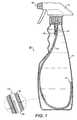
- FIG. 1shows an example of a fluid dispenser 10 in accordance with the present invention.
- the fluid dispenser 10has a hollow plastics bottle 11 fitted with a conventional trigger spray dispenser head 12.
- the fluid dispenser 10includes a dip tube 13 formed from a length of hollow membrane, the hollow membrane having an open end 14 which is coupled to a fluid port 15 in the trigger spray head 12 so as to be able to communicate with the outlet 16 of the trigger spray head 12, and having a closed end 17 that sits within the body of the bottle 11.
- Hollow fibre membranes suitable for use as dip tubes 13 with the present inventionare available commercially, for example X-flow (TM) capillary membranes from Norit (www.norit.com) may be used.
- TMX-flow
- Noritwww.norit.com
- Preferred dip tubeshave a pore size in the range of 0.01 microns to 250 microns.
- the precise pore size, wall thickness, length, shape and configuration of the dip tube, internal bore, colour, and transparencycan be selected according to the fluid to be dispensed and/or the propellant to be used, the resultant nature of the fluid once it is expelled i.e. the consistency of the foam, the fineness of the mist to be created, the degree of atomisation, the mix of propellant to product, and the nature of the container body in terms of size, shape, and colour.
- the external diameter of the dip tubemay be selected according to the internal or external diameter of the fluid port within the dispenser head or any other connecting body.
- the hollow fibre membrane used to form the dip tubecan be closed at one end by heat sealing/welding, crimping, gluing, chemical sealing, and ultrasonic or high frequency welding.
- the hollow fibre membrane for the dip tubepreferably comprises materials selected from the group consisting of polytetrafluoroethylene, polyamide, polyimide, polysulfone, polyethersulfone, polyvinylidene fluoride, polypropylene, polyvinyl chloride, polyvinyl pyrrolidone, polycarbonate, polyacrylonitrile, cellulose, cellulose acetate, mixtures, blends and co-polymers thereof.
- Preferred hollow fibre membrane materials for the dip tubeare selected from the group consisting of polysulfone, polyethersulfone, polyvinylidene fluoride, polyvinyl pyrrolidone, polyacrylonitrile, cellulose, cellulose acetate, mixtures, blends and co-polymers thereof.
- a particularly preferred hollow fibre membrane materialcomprises a blend of polyethersulfone and polyvinylpyrrolidone.
- Polyethersulfone (PES) polyvinylpyrrolidone (PVP) blendsare highly oxidant tolerant (>250,000 ppm hours for chlorine, tolerant to permanganate and ozone), are tolerant to wide pH range, and are highly hydrophilic.
- the dip tubewill preferably operate under a minimum operational pressure differential of at least 500Pa.
- the operational pressure differentialmay be as much as 1000kPa.
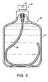
- Figure 2shows another example of a fluid dispenser 20 in accordance with the present invention.
- the containeris a conventional aerosol spay canister 21 having a conventional aerosol push-button spray head 22, but with a dip tube 23 formed from a hollow fibre membrane having an open end which is coupled to a fluid port 24 in the aerosol dispenser head so as to be able to communicate with the outlet 25, and having a closed end that sits within the body of the spray canister.
- the spray canister 21is self pressurised, containing a suitable propellant in addition to a fluid to be dispensed.
- the propellantcreates a pressure differential so that when the push-button is manually actuated any liquid within the bottle in contact with any portion of the surface of the dip tube 23 travels through the wall of the dip tube and thereafter along it's internal bore to the outlet 25.
- This spray canisteroperates in substantially any orientation and is effective to dispense substantially the entire contents of the canister. If the propellant used is a liquefied gas then in its liquid state the propellant will also be dispensed.
- Figure 3shows yet another example of a fluid dispenser 30 in accordance with the present invention.
- the container 31is a conventional perfume bottle having a conventional push-button atomiser head 32, but with a dip tube 33 formed from a hollow fibre membrane having an open end which is coupled to a fluid port 34 in the atomiser head so as to be able to communicate with the outlet 35, and having a closed end that sits within the body of the bottle.
- dip tubes shown in the examples in Figures 1 to 3are arranged to contact opposite sidewalls and the base of the respective containers to ensure as far as possible that liquid within the container is substantially always in contact with the dip tube irrespective of the orientation of the container. Nevertheless, other configurations are possible.
- the configuration of the dip tube within the containercan also be chosen in dependence on the shape of the container and the contents to be dispensed.
- Figures 4A to 4Eshow some different dip tube geometries that may be useful.
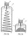
- Figures 5A and 5Bshow a further example of a fluid dispenser 50 in accordance with the present invention.
- the side walls of the container 51are concertinaed so as to be collapsible.
- Figure 5Ashows the fluid dispenser in an erected configuration whilst Figure 5B shows the fluid dispenser in a collapsed configuration.
- This collapsible designis especially useful for reducing the storage and shipping volume of the container, which typically is manufactured in one country or location before being shipped elsewhere to be filled.
- the container 51has a conventional push-button spray head 52, but with a collapsible spiral-shaped dip tube 53 formed from a hollow fibre membrane.
- the hollow fibre membrane dip tube 53has an open end 56 which is coupled to a fluid port 54 in the aerosol dispenser head so as to be able to communicate with an outlet 55, and a closed end 57 that sits within the body of the container 51.
- the closed end 57 of the dip tube 53is attached to the floor of the container 51 so that it deploys from its coiled state when the container side walls are extended.
- the fluid dispenser of the present inventionis useful for dispensing many different fluids, including gels and foams.
- the fluid dispensercan be used in many different applications including kitchen products, perfumes, deodorants and anti-perspirants, spray paints, hair products, liquid/foam/gel products, and insecticides. There are of course many others.
- Typical dispenser heads known in the artinclude trigger spays, atomisers, aerosol sprayers, perfume sprayers, lotion pumps, foam pumps, inhalers and screw micro pumps. Any of these can be used with the hollow fibre membrane dip tube described above to put the present invention into effect.
- the dispenser headmay eject fluid as a spray, stream, foam, fine-mist or gel.
- Suitable containersinclude those made of plastics, glass, metals, ceramics, paper or composites.
- the containermay be provided with flexible walls so that when squeezed by hand a pressure differential is created sufficient to forced fluid through the wall of the hollow membrane dip tube to an outlet in the associated dispenser head.
- dip tubesmay have the same material properties and performance.
- the dip tubesmay be manufactured to perform differently, for example by varying the pore size, wall thickness, rigidity, shape, materials, coupling position and length.
- the dip tubemay be directly coupled to the dispenser head (as shown in the examples) or may instead be coupled indirectly to the dispenser head via another length of tubing.
Landscapes
- Engineering & Computer Science (AREA)
- Mechanical Engineering (AREA)
- Chemical & Material Sciences (AREA)
- Dispersion Chemistry (AREA)
- Ceramic Engineering (AREA)
- Containers And Packaging Bodies Having A Special Means To Remove Contents (AREA)
Description
- Spray dispensers are used in many different applications including kitchen products, perfumes, deodorants and anti-perspirants, spray paints, atomisers, inhalers, hair products, liquid/foam/gel products, pesticides, herbicides and insecticides. There are of course many others.
- Traditional spray dispensers suffer from two inconvenient design flaws associated with the use of a standard "dip tube" to extract fluid, namely they are generally incapable of working regardless of the orientation of the dispenser body and it is virtually impossible to remove the entire contents. These two fundamental problems have existed since spray dispensers were first invented.
W02008/037969 describes a fluid dispenser comprising a hollow membrane adapted to pass liquid in preference to gas. - In the present invention we replace a standard dip tube in a fluid dispenser with a hollow fibre membrane that passes liquid in preference to gas. Under the influence of a pressure differential, any liquid in contact with any portion of the hollow fibre membrane passes through the wall of the membrane and travels internally along the length of the membrane to a dispenser head.
- The fluid dispenser may be self-pressurised or may instead rely on the dispenser head or external pressure applied to the body of the dispenser to establish the necessary pressure differential.
- Typical dispenser heads known in the art include trigger spays, atomisers, aerosol sprayers, perfume sprayers, lotion pumps, inhalers, foam pumps and screw micro pumps.
- The fluid dispenser head may eject fluid as a spray, stream, foam, fine-mist or gel.
- Examples of the present invention will now be described in detail with reference to the accompanying drawings, in which:
Figure 1 shows an example of a trigger spray;Figure 2 shows an example of an aerosol spray canister;Figure 3 shows an example of a perfume dispenser;Figures 4A to 4E show side views of a hollow membrane dip tube in various configurations; and,Figures 5A and 5B show a collapsible container.Figure 1 shows an example of afluid dispenser 10 in accordance with the present invention. Thefluid dispenser 10 has ahollow plastics bottle 11 fitted with a conventional triggerspray dispenser head 12. Thefluid dispenser 10 includes adip tube 13 formed from a length of hollow membrane, the hollow membrane having anopen end 14 which is coupled to afluid port 15 in thetrigger spray head 12 so as to be able to communicate with theoutlet 16 of thetrigger spray head 12, and having a closedend 17 that sits within the body of thebottle 11.- When the
trigger spray 12 is manually actuated a pressure differential is established across thewall 18 of thedip tube 13 so that any liquid within the bottle in contact with any portion of the surface of the dip tube travels through thewall 18 of thedip tube 13 and thereafter along it'sinternal bore 19 to theoutlet 16. This fluid dispenser is thereby capable of operating in substantially any orientation and is effective to dispense substantially the entire contents of the bottle. - One of the advantages of dispensing substantially the entire contents is that in some countries manufacturers are required by law to put more product and propellant in the container to compensate for the fact that in traditional containers there is often product left in the container at the end of its life. So for example, a container containing a stated amount of product of say 330ml might actually have 350ml. to allow for the fact that a traditional dip tube generally leaves around 20ml in the container.
- Hollow fibre membranes suitable for use as
dip tubes 13 with the present invention are available commercially, for example X-flow (TM) capillary membranes from Norit (www.norit.com) may be used. - Preferred dip tubes have a pore size in the range of 0.01 microns to 250 microns. The precise pore size, wall thickness, length, shape and configuration of the dip tube, internal bore, colour, and transparency can be selected according to the fluid to be dispensed and/or the propellant to be used, the resultant nature of the fluid once it is expelled i.e. the consistency of the foam, the fineness of the mist to be created, the degree of atomisation, the mix of propellant to product, and the nature of the container body in terms of size, shape, and colour.
- The external diameter of the dip tube may be selected according to the internal or external diameter of the fluid port within the dispenser head or any other connecting body.
- The hollow fibre membrane used to form the dip tube can be closed at one end by heat sealing/welding, crimping, gluing, chemical sealing, and ultrasonic or high frequency welding.
- The hollow fibre membrane for the dip tube preferably comprises materials selected from the group consisting of polytetrafluoroethylene, polyamide, polyimide, polysulfone, polyethersulfone, polyvinylidene fluoride, polypropylene, polyvinyl chloride, polyvinyl pyrrolidone, polycarbonate, polyacrylonitrile, cellulose, cellulose acetate, mixtures, blends and co-polymers thereof.
- Preferred hollow fibre membrane materials for the dip tube are selected from the group consisting of polysulfone, polyethersulfone, polyvinylidene fluoride, polyvinyl pyrrolidone, polyacrylonitrile, cellulose, cellulose acetate, mixtures, blends and co-polymers thereof.
- A particularly preferred hollow fibre membrane material comprises a blend of polyethersulfone and polyvinylpyrrolidone. Polyethersulfone (PES) polyvinylpyrrolidone (PVP) blends are highly oxidant tolerant (>250,000 ppm hours for chlorine, tolerant to permanganate and ozone), are tolerant to wide pH range, and are highly hydrophilic.
- The dip tube will preferably operate under a minimum operational pressure differential of at least 500Pa. For high pressure systems the operational pressure differential may be as much as 1000kPa.
Figure 2 shows another example of afluid dispenser 20 in accordance with the present invention. In this example the container is a conventionalaerosol spay canister 21 having a conventional aerosol push-button spray head 22, but with adip tube 23 formed from a hollow fibre membrane having an open end which is coupled to afluid port 24 in the aerosol dispenser head so as to be able to communicate with theoutlet 25, and having a closed end that sits within the body of the spray canister.- The
spray canister 21 is self pressurised, containing a suitable propellant in addition to a fluid to be dispensed. The propellant creates a pressure differential so that when the push-button is manually actuated any liquid within the bottle in contact with any portion of the surface of thedip tube 23 travels through the wall of the dip tube and thereafter along it's internal bore to theoutlet 25. This spray canister operates in substantially any orientation and is effective to dispense substantially the entire contents of the canister. If the propellant used is a liquefied gas then in its liquid state the propellant will also be dispensed. Figure 3 shows yet another example of afluid dispenser 30 in accordance with the present invention. In this example thecontainer 31 is a conventional perfume bottle having a conventional push-buttonatomiser head 32, but with adip tube 33 formed from a hollow fibre membrane having an open end which is coupled to afluid port 34 in the atomiser head so as to be able to communicate with theoutlet 35, and having a closed end that sits within the body of the bottle.- When the push-button is manually actuated it creates a pressure differential across the walls of the
dip tube 33. Any liquid within thebottle 31 in contact with any portion of the surface of thedip tube 33 travels through the wall of thedip tube 33 and thereafter along it's internal bore to theoutlet 35. This perfume bottle operates in substantially any orientation and is effective to dispense substantially the entire contents of the bottle. - The dip tubes shown in the examples in
Figures 1 to 3 are arranged to contact opposite sidewalls and the base of the respective containers to ensure as far as possible that liquid within the container is substantially always in contact with the dip tube irrespective of the orientation of the container. Nevertheless, other configurations are possible. The configuration of the dip tube within the container can also be chosen in dependence on the shape of the container and the contents to be dispensed.Figures 4A to 4E show some different dip tube geometries that may be useful. Figures 5A and 5B show a further example of afluid dispenser 50 in accordance with the present invention. The side walls of thecontainer 51 are concertinaed so as to be collapsible.Figure 5A shows the fluid dispenser in an erected configuration whilstFigure 5B shows the fluid dispenser in a collapsed configuration. This collapsible design is especially useful for reducing the storage and shipping volume of the container, which typically is manufactured in one country or location before being shipped elsewhere to be filled.- In this example the
container 51 has a conventional push-button spray head 52, but with a collapsible spiral-shaped dip tube 53 formed from a hollow fibre membrane. The hollow fibremembrane dip tube 53 has anopen end 56 which is coupled to afluid port 54 in the aerosol dispenser head so as to be able to communicate with anoutlet 55, and a closedend 57 that sits within the body of thecontainer 51. In this example, the closedend 57 of thedip tube 53 is attached to the floor of thecontainer 51 so that it deploys from its coiled state when the container side walls are extended. - Other collapsible configurations for the container and dip tube are possible depending on the shape of the container and materials used to form the side walls, in order to minimise the collapsed volume.
- The fluid dispenser of the present invention is useful for dispensing many different fluids, including gels and foams.
- The fluid dispenser can be used in many different applications including kitchen products, perfumes, deodorants and anti-perspirants, spray paints, hair products, liquid/foam/gel products, and insecticides. There are of course many others.
- Typical dispenser heads known in the art include trigger spays, atomisers, aerosol sprayers, perfume sprayers, lotion pumps, foam pumps, inhalers and screw micro pumps. Any of these can be used with the hollow fibre membrane dip tube described above to put the present invention into effect. The dispenser head may eject fluid as a spray, stream, foam, fine-mist or gel.
- Suitable containers include those made of plastics, glass, metals, ceramics, paper or composites. In some preferred embodiments the container may be provided with flexible walls so that when squeezed by hand a pressure differential is created sufficient to forced fluid through the wall of the hollow membrane dip tube to an outlet in the associated dispenser head.
- Although in the above examples only one dip tube is provided, in some preferred embodiments more than one dip tube may be provided. The dip tubes may have the same material properties and performance. Alternatively, the dip tubes may be manufactured to perform differently, for example by varying the pore size, wall thickness, rigidity, shape, materials, coupling position and length.
- The dip tube may be directly coupled to the dispenser head (as shown in the examples) or may instead be coupled indirectly to the dispenser head via another length of tubing.
Claims (13)
- A fluid dispenser (10) comprising:a container (11) for a liquid;a dispenser head (12) fitted to the container (11) and having a fluid outlet (16); and,a dip tube (13) formed from a length of hollow hydrophilic membrane, the hollow hydrophilic membrane having an open end (14) which is coupled to the dispenser head (12) so as to be able to communicate with the fluid outlet (16), and having a closed end (17) that sits within the container (11),wherein the hollow hydrophilic membrane is adapted to pass liquid in preference to gas so that when the dispenser head (12) is actuated liquid travels from the liquid container (11) through the wall of the dip tube (13) to the fluid outlet (16) under a pressure differential established across the wall of the membrane.
- A fluid dispenser (10) according to claim 1, wherein the dispenser head (12) is actuable to establish the pressure differential to draw liquid from the container (11).
- A fluid dispenser (10) according to claim 1, wherein the liquid container (11) is self-pressurised.
- A fluid dispenser (10) according to claim 1, including a propellant.
- A fluid dispenser (10) according to claim 4, in which the propellant is a liquefied gas propellant.
- A fluid dispenser (10) according to any preceding claim, wherein the dispenser head (12) is one of a trigger spray, atomiser, aerosol sprayer, perfume sprayer, lotion pump, foam pump, and a screw micro pump.
- A fluid dispenser (10) according to any preceding claim, wherein the dip tube (13) is coupled directly to the dispenser head (12).
- A fluid dispenser (10) according to any of claims 1 to 6, in which the dip tube (13) is indirectly coupled to the dispenser head (12).
- A fluid dispenser (10) according to any preceding claim, wherein the hollow membrane is arranged within the liquid container (11) such that it is in communication with liquid regardless of the orientation of the container (11).
- A fluid dispenser (10) according to any preceding claim, comprising a plurality of hollow hydrophilic membranes coupled to the dispenser head (12).
- A fluid dispenser (10) according to any preceding claim, wherein the hollow hydrophilic membrane is flexible.
- A fluid dispenser (10) according to any preceding claim, wherein the hollow hydrophilic membrane extends substantially across an entire length of the liquid reservoir.
- A fluid dispenser (10) according to any preceding claim, in which the container (11) and the dip tube (13) are collapsible together between an erected configuration and a collapsed configuration.
Applications Claiming Priority (2)
| Application Number | Priority Date | Filing Date | Title |
|---|---|---|---|
| US12/240,664US8091741B2 (en) | 2006-09-25 | 2008-09-29 | Fluid dispenser |
| PCT/GB2009/002261WO2010034983A1 (en) | 2008-09-29 | 2009-09-22 | A fluid dispenser |
Publications (2)
| Publication Number | Publication Date |
|---|---|
| EP2342146A1 EP2342146A1 (en) | 2011-07-13 |
| EP2342146B1true EP2342146B1 (en) | 2014-05-21 |
Family
ID=41482453
Family Applications (1)
| Application Number | Title | Priority Date | Filing Date |
|---|---|---|---|
| EP09740915.5ANot-in-forceEP2342146B1 (en) | 2008-09-29 | 2009-09-22 | A fluid dispenser |
Country Status (6)
| Country | Link |
|---|---|
| US (1) | US8091741B2 (en) |
| EP (1) | EP2342146B1 (en) |
| JP (1) | JP5532266B2 (en) |
| CN (1) | CN102164831B (en) |
| AU (1) | AU2009295702B2 (en) |
| WO (1) | WO2010034983A1 (en) |
Families Citing this family (30)
| Publication number | Priority date | Publication date | Assignee | Title |
|---|---|---|---|---|
| US20090008414A1 (en)* | 2005-02-18 | 2009-01-08 | Michael Tinsley | Sure Shot |
| GB2443608B (en)* | 2006-09-25 | 2008-11-12 | Michael Pritchard | A water purifying device |
| CN101885923B (en)* | 2009-05-13 | 2014-04-23 | 鸿富锦精密工业(深圳)有限公司 | Conductive foam and method of use thereof |
| EP2455126B2 (en) | 2010-11-15 | 2023-06-14 | F. Hoffmann-La Roche AG | Container for storing medical or pharmaceutical liquids |
| US9701430B2 (en) | 2011-05-16 | 2017-07-11 | The Procter & Gamble Company | Components for aerosol dispenser |
| JP5793371B2 (en)* | 2011-08-23 | 2015-10-14 | 株式会社初田製作所 | Fire extinguisher storage container and fire extinguisher equipped with the same |
| US9498554B2 (en) | 2012-07-24 | 2016-11-22 | S.C. Johnson & Son, Inc. | Dispensing device |
| AR091887A1 (en) | 2012-07-24 | 2015-03-11 | Johnson & Son Inc S C | VOLATILE MATERIAL DISPENSING SYSTEM |
| USD730505S1 (en) | 2012-07-24 | 2015-05-26 | S.C. Johnson & Son, Inc. | Dispensing device |
| US10694747B2 (en) | 2012-11-21 | 2020-06-30 | S. C. Johnson & Son, Inc. | Dispenser comprising only one single hinge |
| US9227211B2 (en)* | 2013-02-06 | 2016-01-05 | Elizabeth M Sammons | Spray dispenser and method for using |
| HUE027578T2 (en)* | 2013-06-03 | 2016-10-28 | Dentsply Ih Ab | Cylindrical collapsible container |
| JP2015002921A (en)* | 2013-06-21 | 2015-01-08 | パナソニックIpマネジメント株式会社 | Oral cleaning device |
| JP5850207B2 (en)* | 2013-12-20 | 2016-02-03 | 大日本印刷株式会社 | Chemical container, chemical nozzle, liquid filling method, and liquid discharging method |
| US9527095B2 (en)* | 2014-06-03 | 2016-12-27 | Solomon L. Kim | Pumping nozzle including suction tube having multiple openings, and pump type container using the same |
| US9604238B2 (en)* | 2014-07-03 | 2017-03-28 | Stephen F. C. Geldard | Multiple input dip tube |
| USD782606S1 (en) | 2015-07-02 | 2017-03-28 | Flambeau, Inc. | Bait container |
| WO2017064621A1 (en)* | 2015-10-13 | 2017-04-20 | Airopack Technology Group Ag | Fluid dispenser |
| US10144021B2 (en) | 2015-12-11 | 2018-12-04 | Michael Tinsley | Container with improved liquid dispensing ability |
| WO2017156438A1 (en)* | 2016-03-10 | 2017-09-14 | Ecolab Usa Inc. | Measured dosing and spray bottle for multi-use applications and associated method of using |
| JP2017210251A (en)* | 2016-05-24 | 2017-11-30 | 株式会社三谷バルブ | Metering valve device and aerosol sprayer container using the same |
| US10207061B2 (en)* | 2016-08-25 | 2019-02-19 | Michelle Vidal | Multi-chambered dispenser for the topical application of infused fluid |
| US11161661B2 (en) | 2017-09-13 | 2021-11-02 | The Procter & Gamble Company | Aerosol dispenser with valve anti-removal feature |
| WO2019084054A1 (en)* | 2017-10-27 | 2019-05-02 | Ozone Clean Technologies, Inc. | Portable water treatment system using ozone |
| WO2019094980A1 (en)* | 2017-11-13 | 2019-05-16 | Ozone Clean Technologies, Inc. | Water treatment system using ozone |
| GB202005499D0 (en)* | 2020-04-15 | 2020-05-27 | Pritchard Spray Ip Ltd | An aerosol dispenser |
| FR3113909B1 (en)* | 2020-09-10 | 2022-08-26 | Commissariat Energie Atomique | KIT FOR ANALYSIS AND MONITORING OF A PARAMETER, BY MEANS OF A MOBILE SENSOR, OF A CHEMICAL OR BIOCHEMICAL OR BIOLOGICAL REACTION IN A REACTION CHAMBER |
| US11535415B2 (en) | 2021-03-16 | 2022-12-27 | Berlin Packaging, Llc | Compressible and expandable bottle |
| USD998472S1 (en) | 2021-03-17 | 2023-09-12 | Berlin Packaging, Llc | Expandable bottle |
| GB2631709A (en) | 2023-07-10 | 2025-01-15 | Athos Medical Tech Ltd | Liquid metering dispensing apparatus and method of metering thereof |
Family Cites Families (26)
| Publication number | Priority date | Publication date | Assignee | Title |
|---|---|---|---|---|
| US2681252A (en)* | 1951-01-17 | 1954-06-15 | Bridgeport Brass Co | Spray device |
| BE623486A (en)* | 1961-10-18 | |||
| US3184118A (en)* | 1963-06-14 | 1965-05-18 | Bernz O Matic Corp | Aerosol spray container |
| US3209954A (en)* | 1963-11-07 | 1965-10-05 | Bernz O Matic Corp | Aerosol spray container and filter |
| US3785537A (en)* | 1970-12-03 | 1974-01-15 | V Appleby | Dispenser for immiscible liquids |
| US3788521A (en)* | 1972-07-10 | 1974-01-29 | Laauwe Robert H | Aerosol package |
| US4142652A (en)* | 1977-09-02 | 1979-03-06 | Warner-Lambert Company | Aerosol metering |
| US4398654A (en)* | 1978-12-26 | 1983-08-16 | American Cyanamid Company | Aerosol dispensing system |
| US4418846A (en)* | 1980-01-04 | 1983-12-06 | American Cyanamid Company | Aerosol dispensing system |
| US4530450A (en)* | 1983-02-07 | 1985-07-23 | American Cyanamid Co. | Aerosol dispensing system |
| JPH0755286B2 (en)* | 1988-04-21 | 1995-06-14 | トーメー産業株式会社 | Simple liquid purification device |
| JP2781432B2 (en)* | 1989-12-01 | 1998-07-30 | 日本ミリポア株式会社 | Filter structure for liquid container with pump |
| JP2888902B2 (en) | 1990-03-03 | 1999-05-10 | トーメー産業株式会社 | Attachment for simple liquid purification |
| FR2687643B1 (en)* | 1992-02-24 | 1995-04-28 | Oreal | FLUID DISPENSER CONTAINER. |
| DE4231826A1 (en)* | 1992-09-23 | 1994-03-24 | Wunsch Eckart | Device for atomizing liquids |
| JPH08133358A (en)* | 1994-11-04 | 1996-05-28 | Masayuki Hayashi | Variable capacity spray container |
| US5552046A (en) | 1995-01-23 | 1996-09-03 | Johnston; Arthur W. | Multi-stage microbiological water filter |
| CN1122540C (en)* | 1995-06-07 | 2003-10-01 | 亚历山大·乔治·布赖恩·奥尼尔 | Patient controlled drug delivery device |
| US5875933A (en)* | 1996-03-18 | 1999-03-02 | Ellion; M. Edmund | Invertible spray dispensing container |
| US5897032A (en)* | 1996-03-18 | 1999-04-27 | Ellion; M. Edmund | Invertible spray dispensing container |
| US5934519A (en)* | 1997-11-17 | 1999-08-10 | Kim; Hee Soo | Weighted dip tube |
| US6379544B1 (en) | 2000-12-19 | 2002-04-30 | Han-Ming Chen | Portable device for supplying filtered water |
| US6820769B2 (en)* | 2003-03-12 | 2004-11-23 | Continental Afa Dispensing Company | Child proof connection for remote trigger sprayer and bottle container |
| JP2006027650A (en)* | 2004-07-15 | 2006-02-02 | Yukihiro Hirose | Bag |
| WO2006021966A1 (en) | 2004-08-24 | 2006-03-02 | Mon Chatrath | Improvement in or relating to personal filter bottle |
| GB2443608B (en)* | 2006-09-25 | 2008-11-12 | Michael Pritchard | A water purifying device |
- 2008
- 2008-09-29USUS12/240,664patent/US8091741B2/ennot_activeExpired - Fee Related
- 2009
- 2009-09-22EPEP09740915.5Apatent/EP2342146B1/ennot_activeNot-in-force
- 2009-09-22CNCN200980138257.0Apatent/CN102164831B/ennot_activeExpired - Fee Related
- 2009-09-22WOPCT/GB2009/002261patent/WO2010034983A1/enactiveApplication Filing
- 2009-09-22JPJP2011528413Apatent/JP5532266B2/ennot_activeExpired - Fee Related
- 2009-09-22AUAU2009295702Apatent/AU2009295702B2/ennot_activeCeased
Also Published As
| Publication number | Publication date |
|---|---|
| CN102164831A (en) | 2011-08-24 |
| AU2009295702A1 (en) | 2010-04-01 |
| JP5532266B2 (en) | 2014-06-25 |
| AU2009295702B2 (en) | 2014-06-12 |
| US8091741B2 (en) | 2012-01-10 |
| JP2012504079A (en) | 2012-02-16 |
| CN102164831B (en) | 2014-05-07 |
| HK1159580A1 (en) | 2012-08-03 |
| WO2010034983A1 (en) | 2010-04-01 |
| EP2342146A1 (en) | 2011-07-13 |
| US20090071983A1 (en) | 2009-03-19 |
Similar Documents
| Publication | Publication Date | Title |
|---|---|---|
| EP2342146B1 (en) | A fluid dispenser | |
| US20150166252A1 (en) | Compressed Gas Dispensers | |
| US4067499A (en) | Non-aerosol continuous spray dispenser | |
| US6056213A (en) | Modular system for atomizing a liquid | |
| EP2855029B1 (en) | A foam dispenser | |
| CA2637867C (en) | Aerosol dispenser assembly having voc-free propellant and dispensing mechanism therefor | |
| WO2003051523A1 (en) | Dispensing means for dispensing atomized liquid | |
| US20130068797A1 (en) | Manual pump type fluid dispenser | |
| IE80891B1 (en) | Atomizing nozzle | |
| US20180214894A1 (en) | Droplet dispensing assembly and converter attachment for spray-to-droplet conversion | |
| AU2016275311B2 (en) | Spray dispenser for nasal drugs | |
| US8152077B2 (en) | Flat atomizer pump | |
| WO2017051178A1 (en) | Twin bottle manifold | |
| US10640283B2 (en) | Aerosol valve system and a container containing such an aerosol valve system | |
| EP2121462B1 (en) | Inlet for pump | |
| US20090200335A1 (en) | Spray Device, Method for Spraying a Certain Quantity of Fluid and a Process for Manufacturing the Device | |
| US20150166251A1 (en) | Compressed Gas Dispensers | |
| HK1159580B (en) | A fluid dispenser | |
| US6036113A (en) | Dual head spray applicator | |
| CA2753764A1 (en) | Pressurized liquid dispensing system | |
| US20220280960A1 (en) | Solution Dispensing Device | |
| US20060006200A1 (en) | Device for dispensing a product | |
| US20160003367A1 (en) | Springless regulator | |
| HU213355B (en) | Packaging device for dispersion and pression of several chemicals |
Legal Events
| Date | Code | Title | Description |
|---|---|---|---|
| PUAI | Public reference made under article 153(3) epc to a published international application that has entered the european phase | Free format text:ORIGINAL CODE: 0009012 | |
| 17P | Request for examination filed | Effective date:20110428 | |
| AK | Designated contracting states | Kind code of ref document:A1 Designated state(s):AT BE BG CH CY CZ DE DK EE ES FI FR GB GR HR HU IE IS IT LI LT LU LV MC MK MT NL NO PL PT RO SE SI SK SM TR | |
| AX | Request for extension of the european patent | Extension state:AL BA RS | |
| DAX | Request for extension of the european patent (deleted) | ||
| GRAP | Despatch of communication of intention to grant a patent | Free format text:ORIGINAL CODE: EPIDOSNIGR1 | |
| INTG | Intention to grant announced | Effective date:20131213 | |
| GRAS | Grant fee paid | Free format text:ORIGINAL CODE: EPIDOSNIGR3 | |
| GRAA | (expected) grant | Free format text:ORIGINAL CODE: 0009210 | |
| AK | Designated contracting states | Kind code of ref document:B1 Designated state(s):AT BE BG CH CY CZ DE DK EE ES FI FR GB GR HR HU IE IS IT LI LT LU LV MC MK MT NL NO PL PT RO SE SI SK SM TR | |
| REG | Reference to a national code | Ref country code:GB Ref legal event code:FG4D | |
| REG | Reference to a national code | Ref country code:CH Ref legal event code:EP | |
| REG | Reference to a national code | Ref country code:AT Ref legal event code:REF Ref document number:669477 Country of ref document:AT Kind code of ref document:T Effective date:20140615 | |
| REG | Reference to a national code | Ref country code:IE Ref legal event code:FG4D | |
| REG | Reference to a national code | Ref country code:NL Ref legal event code:T3 | |
| REG | Reference to a national code | Ref country code:DE Ref legal event code:R096 Ref document number:602009024266 Country of ref document:DE Effective date:20140710 | |
| RAP2 | Party data changed (patent owner data changed or rights of a patent transferred) | Owner name:PRITCHARD IP LIMITED | |
| REG | Reference to a national code | Ref country code:AT Ref legal event code:MK05 Ref document number:669477 Country of ref document:AT Kind code of ref document:T Effective date:20140521 | |
| REG | Reference to a national code | Ref country code:LT Ref legal event code:MG4D | |
| PG25 | Lapsed in a contracting state [announced via postgrant information from national office to epo] | Ref country code:FI Free format text:LAPSE BECAUSE OF FAILURE TO SUBMIT A TRANSLATION OF THE DESCRIPTION OR TO PAY THE FEE WITHIN THE PRESCRIBED TIME-LIMIT Effective date:20140521 Ref country code:NO Free format text:LAPSE BECAUSE OF FAILURE TO SUBMIT A TRANSLATION OF THE DESCRIPTION OR TO PAY THE FEE WITHIN THE PRESCRIBED TIME-LIMIT Effective date:20140821 Ref country code:LT Free format text:LAPSE BECAUSE OF FAILURE TO SUBMIT A TRANSLATION OF THE DESCRIPTION OR TO PAY THE FEE WITHIN THE PRESCRIBED TIME-LIMIT Effective date:20140521 Ref country code:GR Free format text:LAPSE BECAUSE OF FAILURE TO SUBMIT A TRANSLATION OF THE DESCRIPTION OR TO PAY THE FEE WITHIN THE PRESCRIBED TIME-LIMIT Effective date:20140822 Ref country code:IS Free format text:LAPSE BECAUSE OF FAILURE TO SUBMIT A TRANSLATION OF THE DESCRIPTION OR TO PAY THE FEE WITHIN THE PRESCRIBED TIME-LIMIT Effective date:20140921 | |
| PG25 | Lapsed in a contracting state [announced via postgrant information from national office to epo] | Ref country code:LV Free format text:LAPSE BECAUSE OF FAILURE TO SUBMIT A TRANSLATION OF THE DESCRIPTION OR TO PAY THE FEE WITHIN THE PRESCRIBED TIME-LIMIT Effective date:20140521 Ref country code:ES Free format text:LAPSE BECAUSE OF FAILURE TO SUBMIT A TRANSLATION OF THE DESCRIPTION OR TO PAY THE FEE WITHIN THE PRESCRIBED TIME-LIMIT Effective date:20140521 Ref country code:AT Free format text:LAPSE BECAUSE OF FAILURE TO SUBMIT A TRANSLATION OF THE DESCRIPTION OR TO PAY THE FEE WITHIN THE PRESCRIBED TIME-LIMIT Effective date:20140521 Ref country code:HR Free format text:LAPSE BECAUSE OF FAILURE TO SUBMIT A TRANSLATION OF THE DESCRIPTION OR TO PAY THE FEE WITHIN THE PRESCRIBED TIME-LIMIT Effective date:20140521 Ref country code:PL Free format text:LAPSE BECAUSE OF FAILURE TO SUBMIT A TRANSLATION OF THE DESCRIPTION OR TO PAY THE FEE WITHIN THE PRESCRIBED TIME-LIMIT Effective date:20140521 Ref country code:SE Free format text:LAPSE BECAUSE OF FAILURE TO SUBMIT A TRANSLATION OF THE DESCRIPTION OR TO PAY THE FEE WITHIN THE PRESCRIBED TIME-LIMIT Effective date:20140521 | |
| PG25 | Lapsed in a contracting state [announced via postgrant information from national office to epo] | Ref country code:PT Free format text:LAPSE BECAUSE OF FAILURE TO SUBMIT A TRANSLATION OF THE DESCRIPTION OR TO PAY THE FEE WITHIN THE PRESCRIBED TIME-LIMIT Effective date:20140922 | |
| PG25 | Lapsed in a contracting state [announced via postgrant information from national office to epo] | Ref country code:EE Free format text:LAPSE BECAUSE OF FAILURE TO SUBMIT A TRANSLATION OF THE DESCRIPTION OR TO PAY THE FEE WITHIN THE PRESCRIBED TIME-LIMIT Effective date:20140521 Ref country code:CZ Free format text:LAPSE BECAUSE OF FAILURE TO SUBMIT A TRANSLATION OF THE DESCRIPTION OR TO PAY THE FEE WITHIN THE PRESCRIBED TIME-LIMIT Effective date:20140521 Ref country code:DK Free format text:LAPSE BECAUSE OF FAILURE TO SUBMIT A TRANSLATION OF THE DESCRIPTION OR TO PAY THE FEE WITHIN THE PRESCRIBED TIME-LIMIT Effective date:20140521 Ref country code:RO Free format text:LAPSE BECAUSE OF FAILURE TO SUBMIT A TRANSLATION OF THE DESCRIPTION OR TO PAY THE FEE WITHIN THE PRESCRIBED TIME-LIMIT Effective date:20140521 Ref country code:BE Free format text:LAPSE BECAUSE OF FAILURE TO SUBMIT A TRANSLATION OF THE DESCRIPTION OR TO PAY THE FEE WITHIN THE PRESCRIBED TIME-LIMIT Effective date:20140521 Ref country code:SK Free format text:LAPSE BECAUSE OF FAILURE TO SUBMIT A TRANSLATION OF THE DESCRIPTION OR TO PAY THE FEE WITHIN THE PRESCRIBED TIME-LIMIT Effective date:20140521 | |
| REG | Reference to a national code | Ref country code:DE Ref legal event code:R097 Ref document number:602009024266 Country of ref document:DE | |
| PLBE | No opposition filed within time limit | Free format text:ORIGINAL CODE: 0009261 | |
| STAA | Information on the status of an ep patent application or granted ep patent | Free format text:STATUS: NO OPPOSITION FILED WITHIN TIME LIMIT | |
| 26N | No opposition filed | Effective date:20150224 | |
| PG25 | Lapsed in a contracting state [announced via postgrant information from national office to epo] | Ref country code:MC Free format text:LAPSE BECAUSE OF FAILURE TO SUBMIT A TRANSLATION OF THE DESCRIPTION OR TO PAY THE FEE WITHIN THE PRESCRIBED TIME-LIMIT Effective date:20140521 Ref country code:LU Free format text:LAPSE BECAUSE OF FAILURE TO SUBMIT A TRANSLATION OF THE DESCRIPTION OR TO PAY THE FEE WITHIN THE PRESCRIBED TIME-LIMIT Effective date:20140922 | |
| REG | Reference to a national code | Ref country code:CH Ref legal event code:PL | |
| REG | Reference to a national code | Ref country code:DE Ref legal event code:R097 Ref document number:602009024266 Country of ref document:DE Effective date:20150224 | |
| REG | Reference to a national code | Ref country code:IE Ref legal event code:MM4A | |
| PG25 | Lapsed in a contracting state [announced via postgrant information from national office to epo] | Ref country code:LI Free format text:LAPSE BECAUSE OF NON-PAYMENT OF DUE FEES Effective date:20140930 Ref country code:SI Free format text:LAPSE BECAUSE OF FAILURE TO SUBMIT A TRANSLATION OF THE DESCRIPTION OR TO PAY THE FEE WITHIN THE PRESCRIBED TIME-LIMIT Effective date:20140521 Ref country code:CH Free format text:LAPSE BECAUSE OF NON-PAYMENT OF DUE FEES Effective date:20140930 | |
| PG25 | Lapsed in a contracting state [announced via postgrant information from national office to epo] | Ref country code:IE Free format text:LAPSE BECAUSE OF NON-PAYMENT OF DUE FEES Effective date:20140922 | |
| PG25 | Lapsed in a contracting state [announced via postgrant information from national office to epo] | Ref country code:SM Free format text:LAPSE BECAUSE OF FAILURE TO SUBMIT A TRANSLATION OF THE DESCRIPTION OR TO PAY THE FEE WITHIN THE PRESCRIBED TIME-LIMIT Effective date:20140521 | |
| PG25 | Lapsed in a contracting state [announced via postgrant information from national office to epo] | Ref country code:CY Free format text:LAPSE BECAUSE OF FAILURE TO SUBMIT A TRANSLATION OF THE DESCRIPTION OR TO PAY THE FEE WITHIN THE PRESCRIBED TIME-LIMIT Effective date:20140521 Ref country code:MT Free format text:LAPSE BECAUSE OF FAILURE TO SUBMIT A TRANSLATION OF THE DESCRIPTION OR TO PAY THE FEE WITHIN THE PRESCRIBED TIME-LIMIT Effective date:20140521 Ref country code:BG Free format text:LAPSE BECAUSE OF FAILURE TO SUBMIT A TRANSLATION OF THE DESCRIPTION OR TO PAY THE FEE WITHIN THE PRESCRIBED TIME-LIMIT Effective date:20140521 | |
| PG25 | Lapsed in a contracting state [announced via postgrant information from national office to epo] | Ref country code:TR Free format text:LAPSE BECAUSE OF FAILURE TO SUBMIT A TRANSLATION OF THE DESCRIPTION OR TO PAY THE FEE WITHIN THE PRESCRIBED TIME-LIMIT Effective date:20140521 Ref country code:HU Free format text:LAPSE BECAUSE OF FAILURE TO SUBMIT A TRANSLATION OF THE DESCRIPTION OR TO PAY THE FEE WITHIN THE PRESCRIBED TIME-LIMIT; INVALID AB INITIO Effective date:20090922 | |
| REG | Reference to a national code | Ref country code:FR Ref legal event code:PLFP Year of fee payment:8 | |
| REG | Reference to a national code | Ref country code:DE Ref legal event code:R081 Ref document number:602009024266 Country of ref document:DE Owner name:PRITCHARD SPRAY IP LTD., COLCHESTER, GB Free format text:FORMER OWNER: PRITCHARD IP LTD., PUCKERIDGE, HERTFORDSHIRE, GB | |
| REG | Reference to a national code | Ref country code:FR Ref legal event code:PLFP Year of fee payment:9 | |
| REG | Reference to a national code | Ref country code:FR Ref legal event code:TP Owner name:PRITCHARD SPRAY IP LIMITED, GB Effective date:20171031 Ref country code:FR Ref legal event code:CD Owner name:PRITCHARD SPRAY IP LIMITED, GB Effective date:20171031 | |
| PG25 | Lapsed in a contracting state [announced via postgrant information from national office to epo] | Ref country code:MK Free format text:LAPSE BECAUSE OF FAILURE TO SUBMIT A TRANSLATION OF THE DESCRIPTION OR TO PAY THE FEE WITHIN THE PRESCRIBED TIME-LIMIT Effective date:20140521 | |
| REG | Reference to a national code | Ref country code:FR Ref legal event code:PLFP Year of fee payment:10 | |
| PGFP | Annual fee paid to national office [announced via postgrant information from national office to epo] | Ref country code:FR Payment date:20210810 Year of fee payment:13 Ref country code:IT Payment date:20210827 Year of fee payment:13 | |
| PGFP | Annual fee paid to national office [announced via postgrant information from national office to epo] | Ref country code:DE Payment date:20210810 Year of fee payment:13 | |
| PGFP | Annual fee paid to national office [announced via postgrant information from national office to epo] | Ref country code:GB Payment date:20220926 Year of fee payment:14 | |
| PGFP | Annual fee paid to national office [announced via postgrant information from national office to epo] | Ref country code:NL Payment date:20221018 Year of fee payment:14 | |
| REG | Reference to a national code | Ref country code:DE Ref legal event code:R119 Ref document number:602009024266 Country of ref document:DE | |
| PG25 | Lapsed in a contracting state [announced via postgrant information from national office to epo] | Ref country code:FR Free format text:LAPSE BECAUSE OF NON-PAYMENT OF DUE FEES Effective date:20220930 Ref country code:DE Free format text:LAPSE BECAUSE OF NON-PAYMENT OF DUE FEES Effective date:20230401 | |
| PG25 | Lapsed in a contracting state [announced via postgrant information from national office to epo] | Ref country code:IT Free format text:LAPSE BECAUSE OF NON-PAYMENT OF DUE FEES Effective date:20220922 | |
| REG | Reference to a national code | Ref country code:NL Ref legal event code:MM Effective date:20231001 | |
| GBPC | Gb: european patent ceased through non-payment of renewal fee | Effective date:20230922 | |
| PG25 | Lapsed in a contracting state [announced via postgrant information from national office to epo] | Ref country code:NL Free format text:LAPSE BECAUSE OF NON-PAYMENT OF DUE FEES Effective date:20231001 | |
| PG25 | Lapsed in a contracting state [announced via postgrant information from national office to epo] | Ref country code:NL Free format text:LAPSE BECAUSE OF NON-PAYMENT OF DUE FEES Effective date:20231001 | |
| PG25 | Lapsed in a contracting state [announced via postgrant information from national office to epo] | Ref country code:GB Free format text:LAPSE BECAUSE OF NON-PAYMENT OF DUE FEES Effective date:20230922 | |
| PG25 | Lapsed in a contracting state [announced via postgrant information from national office to epo] | Ref country code:GB Free format text:LAPSE BECAUSE OF NON-PAYMENT OF DUE FEES Effective date:20230922 |