EP2341841B1 - Endoscopic suturing device - Google Patents
Endoscopic suturing deviceDownload PDFInfo
- Publication number
- EP2341841B1 EP2341841B1EP08877102.7AEP08877102AEP2341841B1EP 2341841 B1EP2341841 B1EP 2341841B1EP 08877102 AEP08877102 AEP 08877102AEP 2341841 B1EP2341841 B1EP 2341841B1
- Authority
- EP
- European Patent Office
- Prior art keywords
- needle
- suture tag
- tissue
- suture
- tag
- Prior art date
- Legal status (The legal status is an assumption and is not a legal conclusion. Google has not performed a legal analysis and makes no representation as to the accuracy of the status listed.)
- Active
Links
- 239000002775capsuleSubstances0.000claimsdescription38
- 230000037361pathwayEffects0.000claimsdescription15
- 230000004044responseEffects0.000claimsdescription3
- 230000006835compressionEffects0.000claimsdescription2
- 238000007906compressionMethods0.000claimsdescription2
- 238000000034methodMethods0.000description9
- 238000009958sewingMethods0.000description9
- 239000000463materialSubstances0.000description5
- 230000007246mechanismEffects0.000description4
- 229910001220stainless steelInorganic materials0.000description4
- 239000010935stainless steelSubstances0.000description4
- 208000021302gastroesophageal reflux diseaseDiseases0.000description3
- 125000006850spacer groupChemical group0.000description3
- 210000002784stomachAnatomy0.000description3
- 208000008589ObesityDiseases0.000description2
- 238000011846endoscopic investigationMethods0.000description2
- 238000001839endoscopyMethods0.000description2
- 210000003238esophagusAnatomy0.000description2
- 238000003780insertionMethods0.000description2
- 230000037431insertionEffects0.000description2
- 230000014759maintenance of locationEffects0.000description2
- 235000020824obesityNutrition0.000description2
- 230000000717retained effectEffects0.000description2
- 238000001356surgical procedureMethods0.000description2
- 238000002627tracheal intubationMethods0.000description2
- 238000005452bendingMethods0.000description1
- 230000015572biosynthetic processEffects0.000description1
- 230000008859changeEffects0.000description1
- 238000004140cleaningMethods0.000description1
- 230000001419dependent effectEffects0.000description1
- 210000002249digestive systemAnatomy0.000description1
- 238000006073displacement reactionMethods0.000description1
- 210000005069earsAnatomy0.000description1
- 208000014674injuryDiseases0.000description1
- 239000007788liquidSubstances0.000description1
- 238000012986modificationMethods0.000description1
- 230000004048modificationEffects0.000description1
- 230000000149penetrating effectEffects0.000description1
- 230000036316preloadEffects0.000description1
- 239000007787solidSubstances0.000description1
- 208000024891symptomDiseases0.000description1
- 230000008733traumaEffects0.000description1
- 238000011282treatmentMethods0.000description1
Images


Classifications
- A—HUMAN NECESSITIES
- A61—MEDICAL OR VETERINARY SCIENCE; HYGIENE
- A61B—DIAGNOSIS; SURGERY; IDENTIFICATION
- A61B17/00—Surgical instruments, devices or methods
- A61B17/04—Surgical instruments, devices or methods for suturing wounds; Holders or packages for needles or suture materials
- A61B17/0469—Suturing instruments for use in minimally invasive surgery, e.g. endoscopic surgery
Definitions
- the present inventionrelates to a device for securing tissue of the human body, and more particularly relates to an endoscopic suturing device for endoscopically suturing tissue with minimally invasive techniques.
- Endoscopic apposition devicescan be used in the body of a patient without the need to make an external incision in the patient.
- the deviceis controlled outside the patient by endoscopic techniques.
- the devicemay comprise a sewing or stapling device for use in flexible endoscopy, although it is also applicable to devices for use in rigid endoscopy.
- Endoscopic apposition deviceshave been found to be useful in the treatments of the digestive system, with the endoscope being transorally inserted through a patient's esophagus.
- such deviceshave been found useful in treating gastro-esophageal reflux disease (GERD) by placing stitches to form tissue plications at the junction of the esophagus and stomach.
- GEFgastro-esophageal reflux disease
- the minor anatomical change resulting from the plication formationappears to relieve the symptoms of GERD in some patients.
- Endoscopic sewing devices of this general typeare described in, for example, U.S. Pat. Nos. 5,080,663 and 5,792,153 , which disclose a sewing device for passing a thread or suture through a tissue portion.
- the sewing devicecomprises a hollow needle movable between a first position in which it is out of the tissue portion and a second position in which it passes through the tissue portion, and a thread carrier adapted to be attached to the thread and being receivable within the hollow needle.
- the sewing devicealso comprises a body which defines a cavity within which the tissue portion can be held by suction.
- the hollow needleis mounted for movement in the body between the first and second positions.
- the sewing devicesinclude a single stitch sewing device and a multiple stitch sewing device.
- the thread carrieris transported by the needle through the tissue as the needle passes from its first position to its second position. When the needle returns to its first position, the thread carrier is maintained in the distal end of the sewing capsule.
- the multiple stitch devicethe same procedure occurs, but it is followed by a further step in which the hollow needle travels from its first position to its second position, picks up the thread carrier, and returns it to the first position. A second stitch may be formed during the next step. The sequence of steps is repeated as many times as may be required to form the desired number of stitches.
- An endoscopic tissue suturing deviceis characterised in that the tag locking clip is movable in a longitudinal direction along the pathway, the locking fingers being movable in a direction transverse to the pathway in response to movement of the tag locking clip in the longitudinal direction along the pathway.
- Preferred features of the endoscopic tissue suturing device according to the inventionare defined in the dependent claims.
- the present inventionis directed to an endoscopic suturing device that can be employed to suture tissue using endoscopic techniques.
- the suturing devicemay be used to place one or more stitches in tissue during a single intubation of an endoscope.
- the suturing devicemay be detachably mounted to any of various conventional endoscopes, although aspects of the device may be integrated with an endoscope configured specifically for endoscopic suturing procedures.
- the suturing devicemay include a suturing capsule that is configured to capture tissue that is to be sutured.
- the capsuleis mountable to the distal end of an endoscope.
- the capsulemay include a suction chamber into which is drawn tissue via a vacuum.
- the devicemay employ other arrangements for capturing tissue as would be apparent to one of skill in the art.
- the suturing devicemay include a needle to penetrate and place a suture through captured tissue.
- the needlemay be positioned in the capsule through a working channel of the endoscope.
- the needlemay be arranged so that it can be moved along a pathway across the suction chamber to penetrate and place stitches in the captured tissue.
- the devicemay employ other needle arrangements as would be apparent to one of skill in the art.
- the suturing devicemay include a catch that is located distal to the suction chamber to receive and retain the suture during a stitching sequence.
- the catchis movable along the needle pathway and configured to release the suture when the catch moves a predetermined distance along the pathway.
- the needle and the catchmay be configured to move in a longitudinal direction.
- the catchmay be positioned coaxial with the needle.
- the catchmay be configured so that a predetermined amount of force is required to move the catch the predetermined distance required to release the suture. Such an arrangement may reduce inadvertent release of the suture from the catch during a stitching sequence.
- the catchmay be biased in a distal direction away from the needle toward a locked position to retain the suture.
- the catchmay be opened to release the suture by moving the catch in a proximal direction against the distally directed biasing force to its unlocked position.
- the suturing devicemay include a suture tag that is attached to the suture.
- the suture tagfacilitates passage of the suture through tissue and retention of the suture by the catch.
- the suture tagmay be carried by the needle through tissue and into the catch.
- a locking arrangementmay be provided to secure the suture tag to the needle and to release the suture tag from the needle during the stitching sequence.
- the catchmay be configured to receive the suture tag when the needle is extended distally across the suction chamber and into the catch, and then retain the suture tag when the suture tag lock is unlocked and the needle is withdrawn proximally from the catch and retracted across the chamber.
- the catchmay be configured to strip the suture tag from the needle.
- the catchmay include a tag locking clip that is configured to receive and retain the suture tag.
- the clipmay include at least a pair of resilient fingers that are configured to open and close in a direction transverse to the needle pathway to receive and retain the suture tag.
- the fingersmay be configured to open and close in a lateral or radial direction relative to the pathway. The fingers may be configured so that they are biased in an inward lateral or radial direction to a closed position to retain the suture tag and expand outwardly to an open position against the lateral or radial biasing force to receive and release the tag.
- the devicemay employ other catch arrangements to retain and release the suture tag as would be apparent to one of skill in the art.
- the catchmay employ a cam arrangement configured to open the catch and release the suture tag.
- the cam arrangementis configured to open the resilient fingers when the tag locking clip is moved the predetermined distance along the needle pathway.
- the cam arrangementmay include a cam tube with a tapered cam surface that is engaged by and coacts with corresponding cam surfaces provided on the resilient fingers.
- Each of the resilient fingersmay include an offset bend along a portion thereof that forms the cam surface for engaging the tapered cam surface of the cam tube.
- the devicemay employ other arrangements to open the catch as would be apparent to one of skill in the art.
- the suture tagmay be configured to be supported and secured about the exterior surface of the needle.
- a suture tag lockmay be provided between the suture tag and the needle with the lock being actuatable between a locked position to secure the suture tag to the needle and an unlocked position to release the suture tag from the needle.
- the suture tag lockmay include a locking sleeve that is actuatable between the locked and unlocked positions by expanding and reducing a portion of the sleeve by way of relative sliding movement between the needle and sleeve.
- the endoscopic suturing device 20includes a suturing capsule 100 that is releasably secured to the distal end 22 of an endoscope 24.
- the devicealso includes a needle (not shown) that passes through a working channel of the endoscope and into the capsule.
- the suturing deviceis operated by a control handle 200 releasably mounted to the proximal end 26 of the endoscope. As shown, the control handle may be mounted adjacent the endoscope control handle 28.
- the suturing capsule 100includes a cylindrical body 102 having an atraumatic shape to reduce the chance of trauma to internal tissues during an endoscopic suturing procedure.
- the capsuleis similar in configuration and operation to a capsule disclosed in U.S. Pat. Publication 2005/0033319 .
- the capsulemay include a tissue capture region 103 that is configured to capture tissue.
- the capsuleincludes a suction port 104 that opens to a tissue suction chamber 106 into which tissue portions to be sutured may be collected via a vacuum introduced into the chamber.
- an elongated channel 108is provided at the bottom of the suction chamber for introducing negative pressure (i.e., vacuum) to the suction chamber 106 to selectively capture a tissue portion that is to be sutured.
- the vacuumis introduced to the channel 108 through vacuum tube 110 extending proximally from the capsule 100 and joined to a separate vacuum line 112 ( FIG. 1 ) that extends along the exterior of the endoscope.
- the capsuleis configured to receive a needle 114 that is slidable through a needle track 116 formed through the capsule.
- the needlemay include a solid shaft with a sharpened distal tip 118 that is joined at its proximal end to a pusher shaft (not shown) that extends proximally from the suture capsule, through the working channel of the endoscope.
- a pusher shaft(not shown) that extends proximally from the suture capsule, through the working channel of the endoscope.
- the pusher shaftexits the proximal end of the endoscope where it may be joined to and manipulated by the control handle 200.
- One example of a control handle that may be particularly suited for use with the suturing deviceis disclosed in US 2005/0033319 .
- the needlemay be employed to place a suture through tissue drawn into the suction chamber.
- the needle 114carries an annular suture tag 120 that fits closely about the outside surface of the needle.
- a suture 122is joined to the suture tag to be carried through a suctioned tissue portion when the needle carrying the suture tag is advanced distally.
- the suturing devicemay be configured to selectively secure and release the suture tag to and from the needle.
- the suturing devicemay be configured so that full distal advancement of the needle places the suture tag 120 within a suture tag catch 130 located distal to the suction chamber. After penetrating a captured tissue portion and entering the suture catch, the suture tag 120 may be released and the needle withdrawn proximally leaving behind the suture tag in the suture tag catch.
- the suture tag catch 130may be configured to release the suture by moving the catch a predetermined distance in the longitudinal direction.
- the suture tag catch 130may also be configured so that movement of the catch to release the suture tag requires the application of a predetermined axial force to the catch.
- the suture tag catch 130includes a tag locking clip 132 that is movable in the longitudinal direction 134.
- the locking clip 132includes a plurality of fingers 136 that are movable between a closed or locked position to secure the suture tag and an open or unlocked position to release the suture tag from the catch.
- the locking clipmay employ resilient fingers 136 that are self-biasing inwardly in a lateral or radial direction 138 ( FIG. 6 ) to the closed or locked position to secure the suture tag within the catch. In this manner, the fingers are movable in both the longitudinal and lateral directions to secure and release the suture tag.
- the suture tag 120has a tapered or conically shaped distal end portion 140 that expands the locking fingers 136 outwardly (illustrated by arrow 139) as the needle and the suture tag are extended in the distal direction into the catch.
- the tips 142 of the resilient fingersmay be provided with a tapered edge 144 ( FIG. 11 ) that coact with the suture tag to facilitate opening the fingers and allow passage of the suture tag into the catch.
- the tapered distal end 140also creates a low profile that may facilitate passage of the suture tag through tissue as the needle and suture tag are advanced distally through the tissue.
- the locking fingers 136return to the closed or locked position behind the suture tag 120 once the needle has been fully extended in the distal direction into the catch. In this locked position, the suture tag 120 is retained by and cannot be removed from the catch until a predetermined axial force is exerted in the proximal direction to withdraw the suture tag from the catch.
- the suture tag 120can be unlocked from the needle and the needle withdrawn across the chamber, thereby stripping the suture tag from the needle and retaining the tag at the distal end of the chamber with the catch.
- the needlemay be withdrawn proximally and the tissue released from the suction chamber 106 with a suture 122 left passing through the tissue (not shown) and having one end joined to the captured suture tag 120 within the catch and the other end of the suture extending into the needle track 116, through the working channel of the endoscope and exiting the proximal end of the endoscope.
- the needle 114is extended into the catch 130 and the suture tag 120 is secured to the needle.
- the needlecan be retracted in the proximal direction 146 causing the tag locking clip 132, which is gripping the secured suture tag, to similarly move in the proximal direction 147.
- the suture tag catch 130may be configured so that drawing the tag locking clip 132 in the proximal direction opens the locking fingers to release the suture tag 120 from the catch.
- the suture tag catch 130employs a cam arrangement to open the tag locking clip.
- the cam arrangementincludes a cam tube 150 with an external cam surface 152 that co-acts with a cam follower 154 provided on each of the locking fingers 136 to expand the locking clip to an open position once the locking clip is drawn a predetermined distance in the proximal direction.
- the cam surface 152is located at the proximal end of the tube and tapers outwardly in the proximal direction to expand the locking fingers 136 as the clip is drawn in the proximal direction.
- the cam follower 154includes an offset bend formed in each locking finger 136 that engages and interacts with the cam surface 152 of the tube to spread open the fingers of the locking clip. Similar to the cam surface, the offset bend 154 is angled outwardly in the proximal direction.
- the cam surfacehas a taper of approximately 15° and the cam follower has an offset bend angle of approximately 12°. It is to be appreciated, however, that other arrangements may be used to open the tag locking clip to release the suture tag from the catch, as would be apparent to one of skill in the art.
- the cam tube 150is supported within the capsule and maintained in axial alignment with the needle.
- the cam tubemay be configured to receive at least a portion of the needle 114 therein ( FIGS. 7-8 ) when the needle is extended into the suture tag catch.
- the capsulemay provided with an elongated channel 156 that is aligned with and receives the needle 114 as the needle is extended across the suction chamber 106 and into the catch 130.
- the proximal end of the cam tube 150is supported in the distal end of the channel 156 and the elongated fingers 136 extend in the proximal direction along a portion of the channel toward the suction chamber.
- the needle 114may potentially angle off and become misaligned with the suture tag catch 130 as the needle 114 penetrates and is driven through tissue.
- the capsulemay be provided with a needle guide that directs a misaligned needle into the channel and the suture tag catch.
- the guide 158includes a conical surface at the proximal end of the channel 156. As shown, the conical surface 158 tapers inwardly in a direction from the proximal end toward the distal end of the channel so that a misaligned needle will be funneled into the channel.
- the catchmay be configured so that drawing the tag locking clip the predetermined distance in the proximal direction to release the locking fingers requires a predetermined amount of force to overcome the locking force of the catch.
- the catchmay be configured so that the grip force of the fingers is greater than the release force of the catch.
- the suture tag catchis configured with a release force having a range of approximately 0.34-0.91 Kg (0.75-2.0 lbs) applied in a straight axial direction.
- the release forceis approximately 0.45Kg (1.0 lbs). It is to be appreciated, however, that the catch may be configured to require any suitable release force as would be apparent to one of skill in the art.
- the suture tag catchIt may be desirable to configure the suture tag catch so that it securely retains the suture tag as a suture attached to the tag is pulled or otherwise manipulated through tissue with the suturing device.
- the suturing capsule arrangementrequires a suture to pull on the suture tag at an angle relative to the axial release direction of the catch during a suturing procedure. This arrangement requires that the suture apply a relatively large force on the suture tag to generate sufficient force in the axial direction to release the tag from the catch.
- the retention force of the catchis created with a compression spring 160 that exerts a force against the base of the catch clip to bias the clip in the distal direction.
- the spring 160is located within a cavity 162 of the capsule with one end of the spring engaging a proximal wall 164 of the cavity and the other end of the spring engaging a spacer 166 provided between the spring and a distal wall 168 of the cavity.
- the catch clip 132includes a pair of ears 170 that engage the opposite side of the spacer 166 and pull the spacer in the proximal direction to compress the spring as the catch clip is drawn proximally by the suture tag.
- the suture tag catch 130is configured so that the spring 160 applies a preload of approximately 0.86Kg (1.9 lbs) on the clip with the clip in its locked position.
- a clip displacement in the axial direction of approximately 0.076-0.102 cm (0.030-0.040 inches)is required to sufficiently open the clip to release the suture tag.
- the spring 160is a coil spring with a spring rate of approximately 1.74 N/mm (9.91 lbs/in) with a free length of approximately 0.635cm (0.25 inches) and an outer diameter of approximately 0.376cm (0.148 inches).
- the springis formed of spring tempered stainless steel, type 316, wire having a diameter of approximately 0.041cm (0.016 inches). It is to be appreciated, however, that the spring may be fabricated from any suitable material and in other configurations to provide desired loading properties as would apparent to one of ordinary skill in the art.
- the tag locking clip 132includes a U-shaped base 172 with the pair of fingers 136 extending from opposite sides of the base.
- the fingersextend longitudinally in a proximal direction terminating in a free-end having an inwardly curved tip 142 to catch the proximal facing surface after the tag has entered the catch.
- the catch clip 132may be formed from a sheet of hardened stainless steel, type 304, having a thickness of approximately 0.025cm (0.010 inches). The material has a hardness of Rockwell C 40-45. The clip is formed by bending the sheet into the desired shape. It is to be appreciated, however, that the clip may be configured in other suitable shapes and fabricated from any suitable material using other techniques as would be apparent to one of ordinary skill in the art.
- the suturing devicemay be configured to selectively secure and release the suture tag to and from the needle.
- a suture tag lock 180releasably and selectively secures the suture tag 120 about the outside surface of the needle 114.
- the suture tag lock 180is remotely operable from the proximal end of the endoscope with the control handle 200.
- the suture tag lockincludes a locking sleeve 182 through which extends the needle. A portion of the locking sleeve may be configured to expand and contract in response to relative movement between the needle and the locking sleeve to secure and release the suture tag.
- the distal end of the locking sleeve 182includes resilient locking splines 184 that are configured to move in a radial direction to secure and release the suture tag.
- the locking splinescooperate with the needle to increase and decrease the diameter of the locking sleeve relative to the through bore of the suture tag to secure and release the suture tag to and from the needle.
- the distal end of the needlehas a generally spear-like shape with a proximal increasing barrel taper 186 converging with a distal increasing barrel taper 188 to create an enlarged portion of the tip 190.
- the locking splines 184ride over the proximal barrel taper 186 of the needle 114 and expand radially outward to create locking surfaces 192 that prevent distal sliding of the suture tag 120 over the needle.
- the splayed splines 184effectively increases the profile of the locking sleeve to an extent that the suture tag 120 cannot fit over it, thereby locking the suture tag in place on the needle.
- a stiffening sleeve 194which has a diameter larger than the bore of the suture tag, may be provided to prevent the suture tag 120 from sliding proximally relative to the needle and the locking sleeve.
- the needle 114is moved distally relative to the locking sleeve 182. As shown in FIG. 13 , movement of the needle distally relative to the locking sleeve moves the proximal barrel taper 186 away from the splines 184 so that a reduced diameter of the needle shaft 196 underlies the splines which then resiliently conform to the reduced diameter shaft. In this manner, the profile of the locking sleeve is effectively reduced to an extent that the suture tag 120 can be removed from the needle.
- the enlarged portion 190 of the needlewithout the added thickness of the two splines 184 of the locking sleeve, has a profile over which the suture tag 120 may pass freely.
- the locking sleeve 182is slidable over the shaft of the needle 114.
- the locking sleeveis a stainless steel hypotube having an inner diameter of approximately 0.041cm (0.016 inch) sized to fit closely over the outside surface of the needle shaft, which has a diameter of approximately 0.039cm (0.0155 inch). It is to be understood that other suture tag lock arrangements are contemplated and may be employed as would be apparent to one of skill in the art.
- the capsulemay be joined to the distal end of an endoscope.
- the capsule 100includes a proximally extending guide tube 210 that is inserted into the working channel of the endoscope.
- the guide tube 210is rigid and extends proximally from the proximal end 212 of the capsule to protrude a short distance into the working channel of the endoscope.
- the guide tubeis open to receive the needle during operation.
- the capsulemay be secured to the distal end of the endoscope with a reverse wedge securement mechanism.
- a reverse wedge and an endoscopic accessory securement mechanismis fully described in U.S. Patent No. 6,869,395, issued March 22, 2005 , and titled "Endoscopic Accessory Attachment Mechanism".
- the reverse wedge securement mechanism 220includes a wedge 222 that is slidable along an angled ramp 224 to become wedged between the distal end 22 of the endoscope 24 and the ramp surface as it slides up the ramp 224. Leverage against the distal end of the endoscope is maintained by the presence of the guide tube 210 through the working channel.
- One or more return springs 226maintain force against the wedge 222 to bias the wedge upward along the ramp 224 and maintain wedge contact with the endoscope. It is to be appreciated that the capsule may be secured to an endoscope using other suitable arrangements apparent to one of skill in the art.
- the suture capsule bodymay be fabricated from a rigid material, such as stainless steel. It is to be understood, however, that the capsule body may be fabricated from other suitable materials apparent to one of skill in the art.
- suture tag catch 130operation of the suture tag catch 130 to retain and release the suture tag is described below with reference to FIGS. 6-10 .
- the needle 114is extended across suction chamber 106 through the tissue and enters the tag locking clip 132 with the suture tag 120 approaching the inwardly projecting tips 142 of the resilient fingers 136.
- the sharpened distal tip 118 of the needleenters the cam tube 150 and the suture tag 120 engages and spreads apart the resilient fingers 136 to allow entry of the suture tag into the catch.
- the fingers 136close so that the inwardly projecting tips 142 are located behind and engage the proximal end of the suture tag to secure the tag in the catch.
- the suture tag lock 180may be actuated to unlock the suture tag from the needle 114.
- the suture tag lockis unlocked by advancing the needle 114 distally relative to the locking sleeve 182 to reduce the effective profile of the locking splines 184.
- the needle(not shown) is withdrawn from the suture tag 120 as the needle is retracted in the proximal direction from the catch.
- the needlemay be extended distally across the suction chamber and into the catch.
- the suture tag lock 180is then locked to secure the suture tag to the needle by withdrawing the needle into the locking sleeve 182, thereby expanding the locking splines 184 to increase the effective profile of the splines.
- the needlemay be retracted in the proximal direction. Because the suture tag is still secured by the catch, the suture tag clip 132 similarly is drawn in the proximal direction by the needle. When the suture tag clip 132 has been drawn a predetermined distance, the fingers 136 of the clip coact with the cam tube 150 and open to release the suture tag 120 from the catch.
- an endoscopeconventionally includes a working channel and a viewing channel that extend along the length of the elongated shaft of the endoscope.
- An endoscopemay also include other channels that can be used for a light source or a liquid cleaning source.
Landscapes
- Health & Medical Sciences (AREA)
- Life Sciences & Earth Sciences (AREA)
- Surgery (AREA)
- Heart & Thoracic Surgery (AREA)
- Engineering & Computer Science (AREA)
- Biomedical Technology (AREA)
- Nuclear Medicine, Radiotherapy & Molecular Imaging (AREA)
- Medical Informatics (AREA)
- Molecular Biology (AREA)
- Animal Behavior & Ethology (AREA)
- General Health & Medical Sciences (AREA)
- Public Health (AREA)
- Veterinary Medicine (AREA)
- Surgical Instruments (AREA)
Description
- The present invention relates to a device for securing tissue of the human body, and more particularly relates to an endoscopic suturing device for endoscopically suturing tissue with minimally invasive techniques.
- Endoscopic apposition devices can be used in the body of a patient without the need to make an external incision in the patient. The device is controlled outside the patient by endoscopic techniques. The device may comprise a sewing or stapling device for use in flexible endoscopy, although it is also applicable to devices for use in rigid endoscopy.
- Endoscopic apposition devices have been found to be useful in the treatments of the digestive system, with the endoscope being transorally inserted through a patient's esophagus. In particular, such devices have been found useful in treating gastro-esophageal reflux disease (GERD) by placing stitches to form tissue plications at the junction of the esophagus and stomach. The minor anatomical change resulting from the plication formation appears to relieve the symptoms of GERD in some patients. It is also being proposed to employ such devices in treating obesity by placing stitches to segregate portions of a stomach or revise prior surgical procedures. It is also being proposed to employ such devices in treating obesity by placing stitches to segregate portions of a stomach or revise prior surgical procedures.
- Endoscopic sewing devices of this general type are described in, for example,
U.S. Pat. Nos. 5,080,663 and5,792,153 , which disclose a sewing device for passing a thread or suture through a tissue portion. The sewing device comprises a hollow needle movable between a first position in which it is out of the tissue portion and a second position in which it passes through the tissue portion, and a thread carrier adapted to be attached to the thread and being receivable within the hollow needle. The sewing device also comprises a body which defines a cavity within which the tissue portion can be held by suction. The hollow needle is mounted for movement in the body between the first and second positions. - The sewing devices include a single stitch sewing device and a multiple stitch sewing device. In the single stitch device, the thread carrier is transported by the needle through the tissue as the needle passes from its first position to its second position. When the needle returns to its first position, the thread carrier is maintained in the distal
end of the sewing capsule. In the multiple stitch device, the same procedure occurs, but it is followed by a further step in which the hollow needle travels from its first position to its second position, picks up the thread carrier, and returns it to the first position. A second stitch may be formed during the next step. The sequence of steps is repeated as many times as may be required to form the desired number of stitches. - After placement of the sutures through the tissue, the suture can be secured tightly by knots or by a mechanical locking device.
U.S. application Ser. Nos. 10/220,413 10/275,534 - It would be desirable to provide an endoscopic tissue apposition device that can place multiple stitches in tissue during a single intubation.
- It is known from
US2005/033319A1 to provide an endoscopic tissue suturing device having the features recited in the pre-characterising portion of claim 1. - An endoscopic tissue suturing device according to the present invention is characterised in that the tag locking clip is movable in a longitudinal direction along the pathway, the locking fingers being movable in a direction transverse to the pathway in response to movement of the tag locking clip in the longitudinal direction along the pathway. Preferred features of the endoscopic tissue suturing device according to the invention are defined in the dependent claims.
- Various embodiments of the invention will now be described, by way of example, with reference to the accompanying drawings, in which:
FIG. 1 is a perspective view of an endoscopic suturing device according to one illustrative embodiment employed with an endoscope;FIG. 2 is a perspective view of a suturing capsule according to one illustrative embodiment of the suturing device ofFIG. 1 ;FIG. 3 is a top plan view of the suturing capsule ofFIG. 2 ;FIG. 4 is a cross sectional view of the suturing capsule taken along section line 4-4 ofFIG. 3 ;FIG. 5 is an enlarged view of a suture tag catch according to one illustrative embodiment employed with the suturing capsule ofFIGS. 2-4 ;FIG. 5 is an enlarged view of a suture tag catch according to one illustrative embodiment employed with the suturing capsule ofFIGS. 2-4 ;FIG. 6 is a cross sectional view of the suture tag catch taken along section line 6-6 ofFIG. 5 illustrating the needle being extended distally toward the catch;FIG. 7 illustrates the suture tag expanding the suture tag clip to an open position as the needle is extended further into the suture tag catch;FIG. 8 illustrates the suture tag being fully advanced into the suture tag catch with the suture tag clip in a closed position to secure the suture clip;FIG. 9 illustrates the needle having been withdrawn proximally from the suture tag catch with suture tag retained by the suture tag clip;FIG. 10 illustrates the suture tag clip being drawn in the proximal direction by the needle and the suture tag with the clip being opened to release the suture tag;FIG. 11 is an exploded perspective view of the suture tag clip and a cam arrangement for the suture tag catch according to one illustrative embodiment;FIG. 12 is a side view of the needle with a suture tag lock according to one illustrative embodiment shown in a locked position to secure the suture tag to the needle;FIG. 13 illustrates the suture tag lock in an unlocked position to release the suture tag from the needle; andFIG. 14 is a side view of the suturing capsule ofFIGS. 2-4 mounted to the distal end of an endoscope.- The present invention is directed to an endoscopic suturing device that can be employed to suture tissue using endoscopic techniques. The suturing device may be used to place one or more stitches in tissue during a single intubation of an endoscope. The suturing device may be detachably mounted to any of various conventional endoscopes, although aspects of the device may be integrated with an endoscope configured specifically for endoscopic suturing procedures.
- The suturing device may include a suturing capsule that is configured to capture tissue that is to be sutured. In one embodiment, the capsule is mountable to the distal end of an endoscope. The capsule may include a suction chamber into which is drawn tissue via a vacuum. However, the device may employ other arrangements for capturing tissue as would be apparent to one of skill in the art.
- The suturing device may include a needle to penetrate and place a suture through captured tissue. The needle may be positioned in the capsule through a working channel of the endoscope. The needle may be arranged so that it can be moved along a pathway across the suction chamber to penetrate and place stitches in the captured tissue. However, the device may employ other needle arrangements as would be apparent to one of skill in the art.
- The suturing device may include a catch that is located distal to the suction chamber to receive and retain the suture during a stitching sequence. In one embodiment, the catch is movable along the needle pathway and configured to release the suture when the catch moves a predetermined distance along the pathway. The needle and the catch may be configured to move in a longitudinal direction. The catch may be positioned coaxial with the needle.
- The catch may be configured so that a predetermined amount of force is required to move the catch the predetermined distance required to release the suture. Such an arrangement may reduce inadvertent release of the suture from the catch during a stitching sequence. In one embodiment, the catch may be biased in a distal direction away from the needle toward a locked position to retain the suture. The catch may be opened to release the suture by moving the catch in a proximal direction against the distally directed biasing force to its unlocked position.
- The suturing device may include a suture tag that is attached to the suture. The suture tag facilitates passage of the suture through tissue and retention of the suture by the catch. In this regard, the suture tag may be carried by the needle through tissue and into the catch. A locking arrangement may be provided to secure the suture tag to the needle and to release the suture tag from the needle during the stitching sequence.
- The catch may be configured to receive the suture tag when the needle is extended distally across the suction chamber and into the catch, and then retain the suture tag when the suture tag lock is unlocked and the needle is withdrawn proximally from the catch and retracted across the chamber. In this regard, the catch may be configured to strip the suture tag from the needle.
- The catch may include a tag locking clip that is configured to receive and retain the suture tag. In one embodiment, the clip may include at least a pair of resilient fingers that are configured to open and close in a direction transverse to the needle pathway to receive and retain the suture tag. In one embodiment, the fingers may be configured to open and close in a lateral or radial direction relative to the pathway. The fingers may be configured so that they are biased in an inward lateral or radial direction to a closed position to retain the suture tag and expand outwardly to an open position against the lateral or radial biasing force to receive and release the tag. However, the device may employ other catch arrangements to retain and release the suture tag as would be apparent to one of skill in the art.
- The catch may employ a cam arrangement configured to open the catch and release the suture tag. In one embodiment, the cam arrangement is configured to open the resilient fingers when the tag locking clip is moved the predetermined distance along the needle pathway. The cam arrangement may include a cam tube with a tapered cam surface that is engaged by and coacts with corresponding cam surfaces provided on the resilient fingers. Each of the resilient fingers may include an offset bend along a portion thereof that forms the cam surface for engaging the tapered cam surface of the cam tube. However, the device may employ other arrangements to open the catch as would be apparent to one of skill in the art.
- In one embodiment, the suture tag may be configured to be supported and secured about the exterior surface of the needle. A suture tag lock may be provided between the suture tag and the needle with the lock being actuatable between a locked position to secure the suture tag to the needle and an unlocked position to release the suture tag from the needle. The suture tag lock may include a locking sleeve that is actuatable between the locked and unlocked positions by expanding and reducing a portion of the sleeve by way of relative sliding movement between the needle and sleeve.
- In one illustrative embodiment shown in
FIG. 1 , theendoscopic suturing device 20 includes asuturing capsule 100 that is releasably secured to thedistal end 22 of anendoscope 24. The device also includes a needle (not shown) that passes through a working channel of the endoscope and into the capsule. The suturing device is operated by acontrol handle 200 releasably mounted to theproximal end 26 of the endoscope. As shown, the control handle may be mounted adjacent the endoscope control handle 28. - In one illustrative embodiment shown in
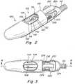
FIGS. 2-4 , thesuturing capsule 100 includes acylindrical body 102 having an atraumatic shape to reduce the chance of trauma to internal tissues during an endoscopic suturing procedure. The capsule is similar in configuration and operation to a capsule disclosed inU.S. Pat. Publication 2005/0033319 . - The capsule may include a
tissue capture region 103 that is configured to capture tissue. In one illustrative embodiment, the capsule includes asuction port 104 that opens to atissue suction chamber 106 into which tissue portions to be sutured may be collected via a vacuum introduced into the chamber. As shown inFIG. 3 , anelongated channel 108 is provided at the bottom of the suction chamber for introducing negative pressure (i.e., vacuum) to thesuction chamber 106 to selectively capture a tissue portion that is to be sutured. The vacuum is introduced to thechannel 108 throughvacuum tube 110 extending proximally from thecapsule 100 and joined to a separate vacuum line 112 (FIG. 1 ) that extends along the exterior of the endoscope. - The capsule is configured to receive a
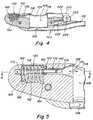
needle 114 that is slidable through aneedle track 116 formed through the capsule. The needle may include a solid shaft with a sharpeneddistal tip 118 that is joined at its proximal end to a pusher shaft (not shown) that extends proximally from the suture capsule, through the working channel of the endoscope. When the needle is moved longitudinally through the needle track, it passes through and traverses thesuction chamber 106 so that tissue suctioned into the chamber will be penetrated by the distally advancing needle. - The pusher shaft exits the proximal end of the endoscope where it may be joined to and manipulated by the
control handle 200. One example of a control handle that may be particularly suited for use with the suturing device is disclosed inUS 2005/0033319 . - The needle may be employed to place a suture through tissue drawn into the suction chamber. In one illustrative embodiment shown in
FIG. 2 , theneedle 114 carries anannular suture tag 120 that fits closely about the outside surface of the needle. Asuture 122 is joined to the suture tag to be carried through a suctioned tissue portion when the needle carrying the suture tag is advanced distally. The suturing device may be configured to selectively secure and release the suture tag to and from the needle. - The suturing device may be configured so that full distal advancement of the needle places the
suture tag 120 within asuture tag catch 130 located distal to the suction chamber. After penetrating a captured tissue portion and entering the suture catch, thesuture tag 120 may be released and the needle withdrawn proximally leaving behind the suture tag in the suture tag catch. - The
suture tag catch 130 may be configured to release the suture by moving the catch a predetermined distance in the longitudinal direction. Thesuture tag catch 130 may also be configured so that movement of the catch to release the suture tag requires the application of a predetermined axial force to the catch. - In one illustrative embodiment shown in
FIGS. 4-6 , thesuture tag catch 130 includes atag locking clip 132 that is movable in thelongitudinal direction 134. Thelocking clip 132 includes a plurality offingers 136 that are movable between a closed or locked position to secure the suture tag and an open or unlocked position to release the suture tag from the catch. The locking clip may employresilient fingers 136 that are self-biasing inwardly in a lateral or radial direction 138 (FIG. 6 ) to the closed or locked position to secure the suture tag within the catch. In this manner, the fingers are movable in both the longitudinal and lateral directions to secure and release the suture tag. - One or both of the suture tag and the tag locking clip may be configured to facilitate insertion of the suture tag into the catch. In one illustrative embodiment shown in
FIGS. 6-7 , thesuture tag 120 has a tapered or conically shapeddistal end portion 140 that expands the lockingfingers 136 outwardly (illustrated by arrow 139) as the needle and the suture tag are extended in the distal direction into the catch. Thetips 142 of the resilient fingers may be provided with a tapered edge 144 (FIG. 11 ) that coact with the suture tag to facilitate opening the fingers and allow passage of the suture tag into the catch. The tapereddistal end 140 also creates a low profile that may facilitate passage of the suture tag through tissue as the needle and suture tag are advanced distally through the tissue. - As shown in
FIG. 8 , the lockingfingers 136 return to the closed or locked position behind thesuture tag 120 once the needle has been fully extended in the distal direction into the catch. In this locked position, thesuture tag 120 is retained by and cannot be removed from the catch until a predetermined axial force is exerted in the proximal direction to withdraw the suture tag from the catch. - As shown in
FIG. 9 , with thesuture tag 120 secured within thecatch 130, the suture tag can be unlocked from the needle and the needle withdrawn across the chamber, thereby stripping the suture tag from the needle and retaining the tag at the distal end of the chamber with the catch. - After capture and release of the suture tag in the
suture tag catch 130, the needle may be withdrawn proximally and the tissue released from thesuction chamber 106 with asuture 122 left passing through the tissue (not shown) and having one end joined to the capturedsuture tag 120 within the catch and the other end of the suture extending into theneedle track 116, through the working channel of the endoscope and exiting the proximal end of the endoscope. - As shown in
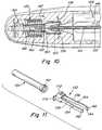
Fig. 10 , to release the suture tag from the suture tag catch, theneedle 114 is extended into thecatch 130 and thesuture tag 120 is secured to the needle. With the suture tag secured, the needle can be retracted in theproximal direction 146 causing thetag locking clip 132, which is gripping the secured suture tag, to similarly move in theproximal direction 147. Thesuture tag catch 130 may be configured so that drawing thetag locking clip 132 in the proximal direction opens the locking fingers to release thesuture tag 120 from the catch. - In one illustrative embodiment shown in
FIG. 11 , thesuture tag catch 130 employs a cam arrangement to open the tag locking clip. The cam arrangement includes acam tube 150 with anexternal cam surface 152 that co-acts with acam follower 154 provided on each of the lockingfingers 136 to expand the locking clip to an open position once the locking clip is drawn a predetermined distance in the proximal direction. Thecam surface 152 is located at the proximal end of the tube and tapers outwardly in the proximal direction to expand the lockingfingers 136 as the clip is drawn in the proximal direction. Thecam follower 154 includes an offset bend formed in each lockingfinger 136 that engages and interacts with thecam surface 152 of the tube to spread open the fingers of the locking clip. Similar to the cam surface, the offsetbend 154 is angled outwardly in the proximal direction. - In one embodiment, the cam surface has a taper of approximately 15° and the cam follower has an offset bend angle of approximately 12°. It is to be appreciated, however, that other arrangements may be used to open the tag locking clip to release the suture tag from the catch, as would be apparent to one of skill in the art.
- As shown in
FIGS. 5-6 , thecam tube 150 is supported within the capsule and maintained in axial alignment with the needle. The cam tube may be configured to receive at least a portion of theneedle 114 therein (FIGS. 7-8 ) when the needle is extended into the suture tag catch. The capsule may provided with anelongated channel 156 that is aligned with and receives theneedle 114 as the needle is extended across thesuction chamber 106 and into thecatch 130. As shown, the proximal end of thecam tube 150 is supported in the distal end of thechannel 156 and theelongated fingers 136 extend in the proximal direction along a portion of the channel toward the suction chamber. - During operation, the
needle 114 may potentially angle off and become misaligned with thesuture tag catch 130 as theneedle 114 penetrates and is driven through tissue. To facilitate alignment with and insertion of theneedle 114 into thesuture tag catch 130, the capsule may be provided with a needle guide that directs a misaligned needle into the channel and the suture tag catch. In one illustrative embodiment shown inFIG. 5 , theguide 158 includes a conical surface at the proximal end of thechannel 156. As shown, theconical surface 158 tapers inwardly in a direction from the proximal end toward the distal end of the channel so that a misaligned needle will be funneled into the channel. - The catch may be configured so that drawing the tag locking clip the predetermined distance in the proximal direction to release the locking fingers requires a predetermined amount of force to overcome the locking force of the catch. The catch may be configured so that the grip force of the fingers is greater than the release force of the catch.
- In one embodiment, the suture tag catch is configured with a release force having a range of approximately 0.34-0.91 Kg (0.75-2.0 lbs) applied in a straight axial direction. Preferably, the release force is approximately 0.45Kg (1.0 lbs). It is to be appreciated, however, that the catch may be configured to require any suitable release force as would be apparent to one of skill in the art.
- It may be desirable to configure the suture tag catch so that it securely retains the suture tag as a suture attached to the tag is pulled or otherwise manipulated through tissue with the suturing device. In this regard, the suturing capsule arrangement requires a suture to pull on the suture tag at an angle relative to the axial release direction of the catch during a suturing procedure. This arrangement requires that the suture apply a relatively large force on the suture tag to generate sufficient force in the axial direction to release the tag from the catch.
- In one illustrative embodiment shown in
FIGS. 4-5 , the retention force of the catch is created with acompression spring 160 that exerts a force against the base of the catch clip to bias the clip in the distal direction. As shown, thespring 160 is located within acavity 162 of the capsule with one end of the spring engaging aproximal wall 164 of the cavity and the other end of the spring engaging aspacer 166 provided between the spring and adistal wall 168 of the cavity. As shown inFIGS. 5 and11 , thecatch clip 132 includes a pair ofears 170 that engage the opposite side of thespacer 166 and pull the spacer in the proximal direction to compress the spring as the catch clip is drawn proximally by the suture tag. - In one embodiment, the
suture tag catch 130 is configured so that thespring 160 applies a preload of approximately 0.86Kg (1.9 lbs) on the clip with the clip in its locked position. A clip displacement in the axial direction of approximately 0.076-0.102 cm (0.030-0.040 inches) is required to sufficiently open the clip to release the suture tag. Thespring 160 is a coil spring with a spring rate of approximately 1.74 N/mm (9.91 lbs/in) with a free length of approximately 0.635cm (0.25 inches) and an outer diameter of approximately 0.376cm (0.148 inches). The spring is formed of spring tempered stainless steel, type 316, wire having a diameter of approximately 0.041cm (0.016 inches). It is to be appreciated, however, that the spring may be fabricated from any suitable material and in other configurations to provide desired loading properties as would apparent to one of ordinary skill in the art. - In one illustrative embodiment shown in
FIG. 11 , thetag locking clip 132 includes aU-shaped base 172 with the pair offingers 136 extending from opposite sides of the base. The fingers extend longitudinally in a proximal direction terminating in a free-end having an inwardlycurved tip 142 to catch the proximal facing surface after the tag has entered the catch. - The
catch clip 132 may be formed from a sheet of hardened stainless steel, type 304, having a thickness of approximately 0.025cm (0.010 inches). The material has a hardness of Rockwell C 40-45. The clip is formed by bending the sheet into the desired shape. It is to be appreciated, however, that the clip may be configured in other suitable shapes and fabricated from any suitable material using other techniques as would be apparent to one of ordinary skill in the art. - As indicated above, the suturing device may be configured to selectively secure and release the suture tag to and from the needle. In one illustrative embodiment shown in
FIGS. 12-13 , asuture tag lock 180 releasably and selectively secures thesuture tag 120 about the outside surface of theneedle 114. Thesuture tag lock 180 is remotely operable from the proximal end of the endoscope with thecontrol handle 200. The suture tag lock includes a lockingsleeve 182 through which extends the needle. A portion of the locking sleeve may be configured to expand and contract in response to relative movement between the needle and the locking sleeve to secure and release the suture tag. - In one illustrative embodiment shown in
FIGS. 12-13 , the distal end of the lockingsleeve 182 includes resilient locking splines 184 that are configured to move in a radial direction to secure and release the suture tag. As described below, the locking splines cooperate with the needle to increase and decrease the diameter of the locking sleeve relative to the through bore of the suture tag to secure and release the suture tag to and from the needle. - As shown in
FIGS. 12-13 , the distal end of the needle has a generally spear-like shape with a proximal increasingbarrel taper 186 converging with a distal increasingbarrel taper 188 to create an enlarged portion of thetip 190. - As shown in
FIG. 12 , when the needle is withdrawn proximally into the lockingsleeve 182 of the suture tag lock, the lockingsplines 184 ride over theproximal barrel taper 186 of theneedle 114 and expand radially outward to create lockingsurfaces 192 that prevent distal sliding of thesuture tag 120 over the needle. The splayedsplines 184 effectively increases the profile of the locking sleeve to an extent that thesuture tag 120 cannot fit over it, thereby locking the suture tag in place on the needle. A stiffeningsleeve 194, which has a diameter larger than the bore of the suture tag, may be provided to prevent thesuture tag 120 from sliding proximally relative to the needle and the locking sleeve. - To release the suture tag so that it may slide distally relative to the needle as would be desired when leaving the tag in the
suture tag catch 130 during suturing procedure, theneedle 114 is moved distally relative to the lockingsleeve 182. As shown inFIG. 13 , movement of the needle distally relative to the locking sleeve moves theproximal barrel taper 186 away from thesplines 184 so that a reduced diameter of theneedle shaft 196 underlies the splines which then resiliently conform to the reduced diameter shaft. In this manner, the profile of the locking sleeve is effectively reduced to an extent that thesuture tag 120 can be removed from the needle. Theenlarged portion 190 of the needle, without the added thickness of the twosplines 184 of the locking sleeve, has a profile over which thesuture tag 120 may pass freely. - The locking
sleeve 182 is slidable over the shaft of theneedle 114. In one embodiment, the locking sleeve is a stainless steel hypotube having an inner diameter of approximately 0.041cm (0.016 inch) sized to fit closely over the outside surface of the needle shaft, which has a diameter of approximately 0.039cm (0.0155 inch). It is to be understood that other suture tag lock arrangements are contemplated and may be employed as would be apparent to one of skill in the art. - As indicated above, the capsule may be joined to the distal end of an endoscope. In one illustrative embodiment shown in
FIGS. 2-4 , thecapsule 100 includes a proximally extendingguide tube 210 that is inserted into the working channel of the endoscope. Theguide tube 210 is rigid and extends proximally from theproximal end 212 of the capsule to protrude a short distance into the working channel of the endoscope. The guide tube is open to receive the needle during operation. - In one illustrative embodiment shown in
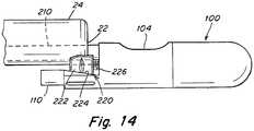
FIG. 14 , the capsule may be secured to the distal end of the endoscope with a reverse wedge securement mechanism. A reverse wedge and an endoscopic accessory securement mechanism is fully described inU.S. Patent No. 6,869,395, issued March 22, 2005 , and titled "Endoscopic Accessory Attachment Mechanism". - The reverse
wedge securement mechanism 220 includes awedge 222 that is slidable along anangled ramp 224 to become wedged between thedistal end 22 of theendoscope 24 and the ramp surface as it slides up theramp 224. Leverage against the distal end of the endoscope is maintained by the presence of theguide tube 210 through the working channel. One or more return springs 226 maintain force against thewedge 222 to bias the wedge upward along theramp 224 and maintain wedge contact with the endoscope. It is to be appreciated that the capsule may be secured to an endoscope using other suitable arrangements apparent to one of skill in the art. - In one embodiment, the suture capsule body may be fabricated from a rigid material, such as stainless steel. It is to be understood, however, that the capsule body may be fabricated from other suitable materials apparent to one of skill in the art.
- In one illustrative embodiment, operation of the
suture tag catch 130 to retain and release the suture tag is described below with reference toFIGS. 6-10 . - As shown in
FIG. 6 , after capturing tissue (not shown), theneedle 114 is extended acrosssuction chamber 106 through the tissue and enters thetag locking clip 132 with thesuture tag 120 approaching the inwardly projectingtips 142 of theresilient fingers 136. - As shown in
FIG. 7 , as the needle proceeds distally, the sharpeneddistal tip 118 of the needle enters thecam tube 150 and thesuture tag 120 engages and spreads apart theresilient fingers 136 to allow entry of the suture tag into the catch. - As shown in
FIG. 8 , once thesuture tag 120 is advanced fully into the catch, thefingers 136 close so that the inwardly projectingtips 142 are located behind and engage the proximal end of the suture tag to secure the tag in the catch. - After the
suture tag 120 is secured by the catch, thesuture tag lock 180 may be actuated to unlock the suture tag from theneedle 114. As described above, the suture tag lock is unlocked by advancing theneedle 114 distally relative to the lockingsleeve 182 to reduce the effective profile of the locking splines 184. As shown inFIG. 9 , the needle (not shown) is withdrawn from thesuture tag 120 as the needle is retracted in the proximal direction from the catch. - After the captured tissue is released, the needle may be extended distally across the suction chamber and into the catch. The
suture tag lock 180 is then locked to secure the suture tag to the needle by withdrawing the needle into the lockingsleeve 182, thereby expanding the locking splines 184 to increase the effective profile of the splines. - As shown in
FIG. 10 , with thesuture tag 120 secured to theneedle 114, the needle may be retracted in the proximal direction. Because the suture tag is still secured by the catch, thesuture tag clip 132 similarly is drawn in the proximal direction by the needle. When thesuture tag clip 132 has been drawn a predetermined distance, thefingers 136 of the clip coact with thecam tube 150 and open to release thesuture tag 120 from the catch. - As indicated above, the suturing device may be employed with any of various conventional endoscopes. As would be understood by one of ordinary skill in the art, an endoscope conventionally includes a working channel and a viewing channel that extend along the length of the elongated shaft of the endoscope. An endoscope may also include other channels that can be used for a light source or a liquid cleaning source.
- It should be understood that the foregoing description of various embodiments of the invention are intended merely to be illustrative thereof and that other embodiments, modifications, and equivalents of the invention are within the scope of the invention recited in the claims appended hereto.
Claims (13)
- An endoscopic tissue suturing device (20), comprising:a suturing capsule (100) that is mountable to a distal end (22) of an endoscope (24), the suturing capsule (100) adapted to capture tissue at a tissue capture region (103) thereof;a needle (114) that is slidable in a longitudinal direction within the suturing capsule (100) along a pathway that extends from a first end of the tissue capture region (103) to a second end of the tissue capture region (103), the needle (114) being adapted to penetrate tissue captured within the tissue capture region (103) when the needle (114) is extended in the longitudinal direction from the first end to the second end of the tissue capture region (103);a suture tag (120) that is securable to the needle (114) to carry a suture across the tissue capture region (103); anda suture tag catch (130) positioned at the second end of the tissue capture region (103) to retain the suture tag (120) when the suture tag (120) is released from the needle (114) and the needle (114) is retracted to the first end of the tissue capture region (103), the suture tag catch (130) comprising a tag locking clip (132) having locking fingers (136) being movable in a direction transverse to the pathway, to release the suture tag (120) when the suture tag (120) is locked to the needle (114) and the needle (114) is retracted toward the first end of the tissue capture region (103) in the longitudinal direction along the pathway,characterised in that the tag locking clip (132) is movable in a longitudinal direction along the pathway, the locking fingers (136) being movable in a direction transverse to the pathway in response to movement of the tag locking clip (132) in the longitudinal direction along the pathway.
- The endoscopic tissue suturing device according to claim 1, wherein the suturing capsule (100) includes a tissue suction chamber (106) at the tissue capture region (103) that is adapted to capture tissue therein when a vacuum is applied thereto.
- The endoscopic tissue suturing device according to claims 1 or 2, wherein the suture tag catch (130) is biased to a locked position in a second direction away from the first end of the tissue capture region (103).
- The endoscopic tissue suturing device according to claim 3, further comprising a compression spring (160) positioned between a second end of the suture tag catch (130) and the second end of the tissue capture region (103) to bias the suture tag catch (130) in the second direction.
- The endoscopic tissue suturing device according to any preceding claim, wherein the locking fingers (136) are biased inwardly to a locked position to retain the suture tag (120) when the suture tag (120) is received in the suture tag catch (130).
- The endoscopic tissue suturing device according to any preceding claim, wherein the suture tag (120) is configured to expand the locking fingers (136) outwardly to receive the suture tag (120) as the needle (114) is extended toward the second end of the tissue capture region (103).
- The endoscopic tissue suturing device according to claim 6, wherein the suture tag (120) includes a tapered end (140) configured to expand the locking fingers (136).
- The endoscopic tissue suturing device according to any of claims 4 to 7, further comprising a cam tube (150) that is configured to open the locking fingers (136) as the suture tag catch (130) is moved in the first direction.
- The endoscopic tissue suturing device according to claim 8, wherein the cam tube (150) includes a tapered surface (152) that is adapted to engage and open the locking fingers (136).
- The endoscopic tissue suturing device according to claim 9, wherein each locking finger (136) includes a follower (154) that is configured to coact with the tapered surface (152).
- The endoscopic tissue suturing device according to claim 10, wherein the follower (154) includes an offset bend (154) in the locking finger (136).
- The endoscopic tissue suturing device according to any of claims 8 to 11, wherein the cam tube (150) is adapted to receive the needle (114) when the needle (114) is extended toward the second end of the tissue capture region (103).
- The endoscopic tissue suturing device according to any of claims 4 to 12, wherein the locking fingers (136) are configured to grasp a first end of the suture tag (120) to retain the suture tag (120) in the suture tag catch (130), the locking fingers (136) being pulled in the first direction by the suture tag (120) when the suture tag (120) is locked to the needle (114) and the needle (114) is retracted toward the first end of the tissue capture region (103), movement of the needle (114) a predetermined distance causes the locking fingers (136) to open to release the suture tag (120).
Applications Claiming Priority (1)
| Application Number | Priority Date | Filing Date | Title |
|---|---|---|---|
| PCT/US2008/011244WO2010036227A1 (en) | 2008-09-29 | 2008-09-29 | Endoscopic suturing device |
Publications (3)
| Publication Number | Publication Date |
|---|---|
| EP2341841A1 EP2341841A1 (en) | 2011-07-13 |
| EP2341841A4 EP2341841A4 (en) | 2015-01-28 |
| EP2341841B1true EP2341841B1 (en) | 2019-12-04 |
Family
ID=42059976
Family Applications (1)
| Application Number | Title | Priority Date | Filing Date |
|---|---|---|---|
| EP08877102.7AActiveEP2341841B1 (en) | 2008-09-29 | 2008-09-29 | Endoscopic suturing device |
Country Status (4)
| Country | Link |
|---|---|
| US (1) | US8882785B2 (en) |
| EP (1) | EP2341841B1 (en) |
| CA (1) | CA2738426C (en) |
| WO (1) | WO2010036227A1 (en) |
Families Citing this family (30)
| Publication number | Priority date | Publication date | Assignee | Title |
|---|---|---|---|---|
| US8465505B2 (en) | 2011-05-06 | 2013-06-18 | Ceterix Orthopaedics, Inc. | Suture passer devices and methods |
| US8663253B2 (en) | 2007-07-03 | 2014-03-04 | Ceterix Orthopaedics, Inc. | Methods of meniscus repair |
| US8821518B2 (en) | 2007-11-05 | 2014-09-02 | Ceterix Orthopaedics, Inc. | Suture passing instrument and method |
| US9861354B2 (en) | 2011-05-06 | 2018-01-09 | Ceterix Orthopaedics, Inc. | Meniscus repair |
| JP5719374B2 (en) | 2009-11-09 | 2015-05-20 | セテリックス オーソピーディクス インコーポレイテッド | Device, system, and method for repairing a meniscus |
| US11744575B2 (en) | 2009-11-09 | 2023-09-05 | Ceterix Orthopaedics, Inc. | Suture passer devices and methods |
| US9011454B2 (en) | 2009-11-09 | 2015-04-21 | Ceterix Orthopaedics, Inc. | Suture passer with radiused upper jaw |
| CA2856346C (en)* | 2011-08-18 | 2022-08-30 | Anchor Orthopedics Xt Inc. | Suture passing instrumentation and methods of use thereof |
| US11311285B2 (en)* | 2015-12-21 | 2022-04-26 | Lsi Solutions, Inc. | Prosthetic suturing device and methods thereof |
| TR201700324A2 (en) | 2017-01-10 | 2017-07-21 | Alper Celik | ENDOSCOPIC SEWING THREAD |
| US10751044B2 (en) | 2017-02-02 | 2020-08-25 | Covidien Lp | Vaginal tissue closure |
| CA3052298C (en) | 2017-02-22 | 2021-12-21 | Boston Scientific Scimed, Inc. | Suture based closure device |
| US10898181B2 (en) | 2017-03-17 | 2021-01-26 | Cypris Medical, Inc. | Suturing system |
| US10660637B2 (en)* | 2018-04-06 | 2020-05-26 | Cypris Medical, Inc. | Suturing system |
| JP7279092B2 (en)* | 2018-04-06 | 2023-05-22 | サイプリス メディカル, インコーポレイテッド | suture system |
| EP3801294B1 (en) | 2018-05-25 | 2025-01-22 | Boston Scientific Scimed, Inc. | Device for applying a cinch to a suture |
| US11033261B2 (en) | 2018-05-31 | 2021-06-15 | Cypris Medical, Inc. | Suture system |
| US11298122B2 (en) | 2018-06-07 | 2022-04-12 | EnVision Endoscopy, Inc. | Endoscopic suturing device with circular needle |
| WO2019246275A1 (en) | 2018-06-19 | 2019-12-26 | Boston Scientific Scimed, Inc. | Endoscopic suturing device and associated control handle |
| WO2020006122A1 (en)* | 2018-06-27 | 2020-01-02 | Boston Scientific Scimed, Inc. | Endoscope attachment mechanism for use with suture based closure device |
| WO2020051348A1 (en) | 2018-09-06 | 2020-03-12 | Boston Scientific Scimed, Inc. | Endoscopic suturing needle and suture assembly attachment methods |
| EP4582011A3 (en) | 2019-05-16 | 2025-08-20 | Boston Scientific Scimed, Inc. | Suture based closure device for use with endoscope |
| EP4106603B1 (en) | 2020-02-18 | 2025-03-26 | Boston Scientific Scimed Inc. | Suture based closure device for use with endoscope |
| CN115135259A (en) | 2020-02-19 | 2022-09-30 | 波士顿科学国际有限公司 | High-power plaque removal system with multiple safety limits |
| KR20220162764A (en) | 2020-03-31 | 2022-12-08 | 보스톤 싸이엔티픽 싸이메드 인코포레이티드 | Suture-based suturing device |
| US12137899B2 (en) | 2020-05-11 | 2024-11-12 | Cypris Medical, Inc. | Multiple suture placement system |
| EP4231947A4 (en) | 2020-10-23 | 2024-10-02 | Envision Endoscopy, Inc. | ENDOSCOPIC SUTURE STRAP |
| WO2022094228A1 (en) | 2020-10-30 | 2022-05-05 | Boston Scientific Scimed, Inc. | Atherectomy burrs with blood flow enhancements |
| CN117545411A (en) | 2021-04-26 | 2024-02-09 | 波士顿科学国际有限公司 | suture-based closure device |
| CA3217853A1 (en) | 2021-04-26 | 2022-11-03 | Boston Scientific Scimed, Inc. | Suture based closure device |
Family Cites Families (280)
| Publication number | Priority date | Publication date | Assignee | Title |
|---|---|---|---|---|
| US453508A (en) | 1891-06-02 | Veterinary instrument | ||
| US1325699A (en) | 1919-12-23 | John h | ||
| US730152A (en) | 1902-12-06 | 1903-06-02 | Marion W Pitner | Fabric-turfing machine. |
| US979342A (en) | 1908-03-11 | 1910-12-20 | Charles B A Schaefer | Collar-fastener. |
| US1868308A (en) | 1930-02-01 | 1932-07-19 | Ross E Brumfield | Capsule gun |
| US2170599A (en) | 1937-07-20 | 1939-08-22 | Elza A Stricklen | Veterinary dose gun |
| US2587364A (en) | 1948-05-20 | 1952-02-26 | Edith Mitchell | Balling gun |
| US2601852A (en) | 1950-05-19 | 1952-07-01 | Delbert O Wendt | Device for dispensing tablets and the like |
| US2650593A (en) | 1951-08-22 | 1953-09-01 | Jay D Weil | Balling gun |
| US2621655A (en) | 1951-10-11 | 1952-12-16 | Kenneth L Gothard | Tablet dispensing gun |
| US2880728A (en) | 1958-02-03 | 1959-04-07 | Clyde S Rights | Ligature inserter |
| US3013559A (en) | 1959-05-06 | 1961-12-19 | Wesley C Thomas | Instrument for closing flesh wounds |
| US3238941A (en) | 1963-06-19 | 1966-03-08 | Frost Eng Dev | Balling gun |
| US3470875A (en) | 1966-10-06 | 1969-10-07 | Alfred A Johnson | Surgical clamping and suturing instrument |
| US3716058A (en) | 1970-07-17 | 1973-02-13 | Atlanta Res Inst | Barbed suture |
| DE2157911C2 (en) | 1970-12-11 | 1982-02-04 | Marc Edmond Jean van Bruxelles Hoorn | Surgical device for ligating internal structures |
| US3757781A (en) | 1971-09-17 | 1973-09-11 | R Smart | Tool for administering pills to animals |
| US3858571A (en) | 1973-07-02 | 1975-01-07 | Arthur I Rudolph | Cornual plug |
| US3845772A (en) | 1973-09-17 | 1974-11-05 | D Smith | Retention suture device and method |
| US4126124A (en) | 1975-12-05 | 1978-11-21 | Hairegenics, Inc. | Method of sizing a hair anchor |
| US4216777A (en) | 1977-07-01 | 1980-08-12 | Pridemore William J | Method for artificially implanting hair |
| DE2734441C2 (en) | 1977-07-30 | 1979-09-06 | Gebhard 7710 Donaueschingen Dischinger | Hand tool for threading strings |
| US4144876A (en) | 1977-12-20 | 1979-03-20 | Deleo David B | Hair implanting method |
| US4164225A (en) | 1977-12-28 | 1979-08-14 | Johnson & Lorenz, Inc. | Surgical suturing instrument |
| US4226239A (en) | 1978-01-31 | 1980-10-07 | Kli, Inc. | Surgical ligating instrument and method |
| US4210148A (en) | 1978-11-03 | 1980-07-01 | Stivala Oscar G | Retention suture system |
| DE2853289C2 (en) | 1978-12-09 | 1980-12-18 | B. Braun Melsungen Ag, 3508 Melsungen | Button for surgical use |
| US4236470A (en) | 1979-01-17 | 1980-12-02 | Stenson Thomas K | Portable stitching device |
| DE3045295A1 (en) | 1979-05-21 | 1982-02-18 | American Cystoscope Makers Inc | Surgical instrument for an endoscope |
| US4414908A (en) | 1979-12-04 | 1983-11-15 | Janome Sewing Machine Co. Ltd. | Suturing machine for medical treatment |
| US4345601A (en) | 1980-04-07 | 1982-08-24 | Mamoru Fukuda | Continuous suturing device |
| US4469101A (en) | 1980-10-23 | 1984-09-04 | Battelle Memorial Institute | Suture device |
| JPS57170239A (en) | 1981-04-13 | 1982-10-20 | Janome Sewing Machine Co Ltd | Holding of shuttle of suturing device for operation |
| USD279504S (en) | 1981-05-15 | 1985-07-02 | Ortho Pharmaceutical Corporation | Vaginal applicator |
| US4415092A (en) | 1981-06-01 | 1983-11-15 | Boyer Thomas B | Holder for uniformly shaped articles |
| US4493319A (en) | 1981-06-29 | 1985-01-15 | Cabot Medical Corporation | Ring applicator having floating inner tube |
| US4860746A (en) | 1982-04-20 | 1989-08-29 | Inbae Yoon | Elastic surgical ring clip and ring loader |
| US4741330A (en) | 1983-05-19 | 1988-05-03 | Hayhurst John O | Method and apparatus for anchoring and manipulating cartilage |
| US5417691A (en) | 1982-05-20 | 1995-05-23 | Hayhurst; John O. | Apparatus and method for manipulating and anchoring tissue |
| EP0117894B1 (en) | 1983-02-08 | 1989-11-08 | Storz-Endoskop GmbH | Endoscope comprising a medical gripping instrument |
| GB8311345D0 (en) | 1983-04-26 | 1983-06-02 | Dobson Park Ind | Oral administration of capsules to animals |
| US5220928A (en) | 1983-08-22 | 1993-06-22 | Stryker Sales Corporation | Surgical procedure for joining tissue in an internal body cavity |
| US5125553A (en) | 1987-03-02 | 1992-06-30 | Stryker Sales Corporation | Surgical suturing instrument and method |
| US4665906A (en) | 1983-10-14 | 1987-05-19 | Raychem Corporation | Medical devices incorporating sim alloy elements |
| US4621640A (en) | 1984-01-09 | 1986-11-11 | Mulhollan James S | Mechanical needle carrier and method for its use |
| US4597390A (en) | 1984-04-02 | 1986-07-01 | Mulhollan James S | Surgical needle manipulator |
| GB8422863D0 (en)* | 1984-09-11 | 1984-10-17 | Univ London | Sewing machine |
| US4721103A (en) | 1985-01-31 | 1988-01-26 | Yosef Freedland | Orthopedic device |
| US4615472A (en) | 1985-06-19 | 1986-10-07 | Intravascular Surgical Instruments, Inc. | Catheter placement device |
| JPH0434499Y2 (en) | 1985-08-26 | 1992-08-17 | ||
| DE3533423A1 (en) | 1985-09-19 | 1987-03-26 | Wolf Gmbh Richard | APPLICATOR PLIERS FOR SURGICAL HANDLING FOR USE IN ENDOSCOPY |
| US4672979A (en) | 1986-01-30 | 1987-06-16 | Cordis Corporation | Suture sleeve assembly |
| US4738255A (en) | 1986-04-07 | 1988-04-19 | Biotron Labs, Inc. | Suture anchor system |
| US4794911A (en) | 1986-09-20 | 1989-01-03 | Olympus Optical Company Ltd. | Means to facilitate detachably mounting cap to distal end of endoscope |
| US4735194C1 (en) | 1987-01-13 | 2001-05-08 | Dept Of Veterans Affairs The U | Flexile endoscopic ligating instrument |
| US5478353A (en) | 1987-05-14 | 1995-12-26 | Yoon; Inbae | Suture tie device system and method for suturing anatomical tissue proximate an opening |
| US5437680A (en) | 1987-05-14 | 1995-08-01 | Yoon; Inbae | Suturing method, apparatus and system for use in endoscopic procedures |
| US5366459A (en) | 1987-05-14 | 1994-11-22 | Inbae Yoon | Surgical clip and clip application procedures |
| US5100418A (en) | 1987-05-14 | 1992-03-31 | Inbae Yoon | Suture tie device system and applicator therefor |
| US4898156A (en) | 1987-05-18 | 1990-02-06 | Mitek Surgical Products, Inc. | Suture anchor |
| US4890615B1 (en) | 1987-11-05 | 1993-11-16 | Linvatec Corporation | Arthroscopic suturing instrument |
| US4968315A (en) | 1987-12-15 | 1990-11-06 | Mitek Surgical Products, Inc. | Suture anchor and suture anchor installation tool |
| US4899743A (en) | 1987-12-15 | 1990-02-13 | Mitek Surgical Products, Inc. | Suture anchor installation tool |
| US5383881A (en) | 1989-07-18 | 1995-01-24 | United States Surgical Corporation | Safety device for use with endoscopic instrumentation |
| US4825259A (en) | 1988-02-03 | 1989-04-25 | Berry Jr Robert F | Adapter tip for remote measuring device |
| US4936823A (en) | 1988-05-04 | 1990-06-26 | Triangle Research And Development Corp. | Transendoscopic implant capsule |
| JP2503900Y2 (en) | 1988-07-06 | 1996-07-03 | オリンパス光学工業株式会社 | Endoscope |
| US4927428A (en) | 1988-10-07 | 1990-05-22 | Ophthalmic Ventures Limited Partnership | Surgical suturing system and probe assembly |
| DE3909999A1 (en) | 1989-03-25 | 1990-09-27 | Storz Karl | Surgical gripping forceps |
| US4932962A (en) | 1989-05-16 | 1990-06-12 | Inbae Yoon | Suture devices particularly useful in endoscopic surgery and methods of suturing |
| US4946468A (en) | 1989-06-06 | 1990-08-07 | Mitek Surgical Products, Inc. | Suture anchor and suture anchor installation tool |
| US5002550A (en) | 1989-06-06 | 1991-03-26 | Mitek Surgical Products, Inc. | Suture anchor installation tool |
| US5123913A (en) | 1989-11-27 | 1992-06-23 | Wilk Peter J | Suture device |
| US4950285A (en) | 1989-11-27 | 1990-08-21 | Wilk Peter J | Suture device |
| US5100042A (en) | 1990-03-05 | 1992-03-31 | United States Surgical Corporation | Surgical fastener apparatus |
| US5037433A (en) | 1990-05-17 | 1991-08-06 | Wilk Peter J | Endoscopic suturing device and related method and suture |
| US5116349A (en) | 1990-05-23 | 1992-05-26 | United States Surgical Corporation | Surgical fastener apparatus |
| US5078731A (en) | 1990-06-05 | 1992-01-07 | Hayhurst John O | Suture clip |
| US5102421A (en) | 1990-06-14 | 1992-04-07 | Wm. E. Anpach, III | Suture anchor and method of forming |
| US5236445A (en) | 1990-07-02 | 1993-08-17 | American Cyanamid Company | Expandable bone anchor and method of anchoring a suture to a bone |
| US5037422A (en) | 1990-07-02 | 1991-08-06 | Acufex Microsurgical, Inc. | Bone anchor and method of anchoring a suture to a bone |
| US5224946A (en) | 1990-07-02 | 1993-07-06 | American Cyanamid Company | Bone anchor and method of anchoring a suture to a bone |
| US5269809A (en) | 1990-07-02 | 1993-12-14 | American Cyanamid Company | Locking mechanism for use with a slotted suture anchor |
| US5041129A (en) | 1990-07-02 | 1991-08-20 | Acufex Microsurgical, Inc. | Slotted suture anchor and method of anchoring a suture |
| US5258016A (en) | 1990-07-13 | 1993-11-02 | American Cyanamid Company | Suture anchor and driver assembly |
| US5100417A (en) | 1990-07-13 | 1992-03-31 | American Cyanamid Company | Suture anchor and driver assembly |
| ATE174777T1 (en) | 1990-09-25 | 1999-01-15 | Innovasive Devices Inc | BONE FIXATION DEVICE |
| US5080663A (en) | 1990-09-26 | 1992-01-14 | Univerity College London | Sewing device |
| US5147379A (en) | 1990-11-26 | 1992-09-15 | Louisiana State University And Agricultural And Mechanical College | Insertion instrument for vena cava filter |
| US5193525A (en) | 1990-11-30 | 1993-03-16 | Vision Sciences | Antiglare tip in a sheath for an endoscope |
| US5211650A (en) | 1991-01-07 | 1993-05-18 | Laparomed Corporation | Dual function suturing device and method |
| US5100421A (en) | 1991-02-05 | 1992-03-31 | Cyprus Endosurgical Tools, Inc. | Christoudias curved needle suture assembly |
| IT1247468B (en) | 1991-03-06 | 1994-12-17 | Gianfranco Bidoia | TOOL FOR BINDING HEMORRHOIDS OR SIMILAR |
| US5354298A (en) | 1991-03-22 | 1994-10-11 | United States Surgical Corporation | Suture anchor installation system |
| US5203864A (en) | 1991-04-05 | 1993-04-20 | Phillips Edward H | Surgical fastener system |
| US5258015A (en) | 1991-05-03 | 1993-11-02 | American Cyanamid Company | Locking filament caps |
| US5213093A (en) | 1991-05-29 | 1993-05-25 | Applied Vascular Devices, Inc. | Endoscope with non-circular probe and method of making same |
| WO1993001750A1 (en) | 1991-07-23 | 1993-02-04 | Kernforschungszentrum Karlsruhe Gmbh | Surgical stitching instrument |
| US5207679A (en) | 1991-09-26 | 1993-05-04 | Mitek Surgical Products, Inc. | Suture anchor and installation tool |
| US5163945A (en) | 1991-10-18 | 1992-11-17 | Ethicon, Inc. | Surgical clip applier |
| US5199566A (en) | 1991-10-18 | 1993-04-06 | Ethicon, Inc. | Surgical clip applier |
| US5152769A (en) | 1991-11-04 | 1992-10-06 | Will Baber | Apparatus for laparoscopic suturing with improved suture needle |
| US5439467A (en) | 1991-12-03 | 1995-08-08 | Vesica Medical, Inc. | Suture passer |
| US5433722A (en) | 1992-01-08 | 1995-07-18 | Sharpe Endosurgical Corporation | Ligature carrier for endoscopic use |
| US5542432A (en) | 1992-02-18 | 1996-08-06 | Symbiosis Corporation | Endoscopic multiple sample bioptome |
| US5217486A (en) | 1992-02-18 | 1993-06-08 | Mitek Surgical Products, Inc. | Suture anchor and installation tool |
| US5333624A (en) | 1992-02-24 | 1994-08-02 | United States Surgical Corporation | Surgical attaching apparatus |
| US5171251A (en) | 1992-03-02 | 1992-12-15 | Ethicon, Inc. | Surgical clip having hole therein and method of anchoring suture |
| US5368601A (en) | 1992-04-30 | 1994-11-29 | Lasersurge, Inc. | Trocar wound closure device |
| US5306309A (en) | 1992-05-04 | 1994-04-26 | Calcitek, Inc. | Spinal disk implant and implantation kit |
| US5176682A (en) | 1992-06-01 | 1993-01-05 | Chow James C Y | Surgical implement |
| US5242431A (en) | 1992-06-11 | 1993-09-07 | Siemens Pacesetter, Inc. | Suture sleeve assembly with slidable compression collar |
| US5207694A (en) | 1992-06-18 | 1993-05-04 | Surgical Invent Ab | Method for performing a surgical occlusion, and kit and applicator for carrying out the method |
| US5281236A (en) | 1992-06-23 | 1994-01-25 | Boston Scientific Corporation | Method and device for intracorporeal knot tying |
| US5254126A (en) | 1992-06-24 | 1993-10-19 | Ethicon, Inc. | Endoscopic suture punch |
| US5330486A (en) | 1992-07-29 | 1994-07-19 | Wilk Peter J | Laparoscopic or endoscopic anastomosis technique and associated instruments |
| US5297536A (en) | 1992-08-25 | 1994-03-29 | Wilk Peter J | Method for use in intra-abdominal surgery |
| US5207690A (en) | 1992-09-02 | 1993-05-04 | Bel-Art Products, Inc. | Arrangement for stabilizing the hormonal effects produced by the ovaries of a small female mammalian creature |
| US6010515A (en) | 1993-09-03 | 2000-01-04 | University College London | Device for use in tying knots |
| GB9218754D0 (en) | 1992-09-04 | 1992-10-21 | Univ London | Device for use in securing a thread |
| US5364408A (en) | 1992-09-04 | 1994-11-15 | Laurus Medical Corporation | Endoscopic suture system |
| US5578044A (en) | 1992-09-04 | 1996-11-26 | Laurus Medical Corporation | Endoscopic suture system |
| US5284485A (en) | 1992-09-16 | 1994-02-08 | Ethicon, Inc. | Endoscopic knotting device |
| US5281237A (en) | 1992-09-25 | 1994-01-25 | Gimpelson Richard J | Surgical stitching device and method of use |
| US5368599A (en) | 1992-10-08 | 1994-11-29 | United States Surgical Corporation | Surgical fastening apparatus with suture array |
| US5356416A (en) | 1992-10-09 | 1994-10-18 | Boston Scientific Corporation | Combined multiple ligating band dispenser and sclerotherapy needle instrument |
| US5282832A (en) | 1992-10-09 | 1994-02-01 | United States Surgical Corporation | Suture clip |
| US5383905A (en) | 1992-10-09 | 1995-01-24 | United States Surgical Corporation | Suture loop locking device |
| US5330442A (en) | 1992-10-09 | 1994-07-19 | United States Surgical Corporation | Suture retaining clip |
| US5269789A (en) | 1992-10-09 | 1993-12-14 | Boston Scientific Corporation | Multiple ligating band dispenser for ligating instruments |
| US5545170A (en) | 1992-10-09 | 1996-08-13 | Innovasive Devices, Inc. | Surgical instrument |
| US5304184A (en) | 1992-10-19 | 1994-04-19 | Indiana University Foundation | Apparatus and method for positive closure of an internal tissue membrane opening |
| US5273053A (en) | 1992-11-02 | 1993-12-28 | Medtronic, Inc. | Suture sleeve with lead locking device |
| US5259366A (en) | 1992-11-03 | 1993-11-09 | Boris Reydel | Method of using a catheter-sleeve assembly for an endoscope |
| IL103737A (en) | 1992-11-13 | 1997-02-18 | Technion Res & Dev Foundation | Stapler device particularly useful in medical suturing |
| US5693060A (en) | 1992-11-17 | 1997-12-02 | Smith & Nephew, Inc. | Suture securing device and method |
| DE69315808T2 (en) | 1992-11-17 | 1998-04-09 | Smith & Nephew Inc | Device for fastening sutures |
| US5417699A (en) | 1992-12-10 | 1995-05-23 | Perclose Incorporated | Device and method for the percutaneous suturing of a vascular puncture site |
| US5413585A (en) | 1992-12-22 | 1995-05-09 | Pagedas; Anthony C. | Self locking suture lock |
| US5403346A (en) | 1992-12-31 | 1995-04-04 | Loeser; Edward A. | Self-affixing suture assembly |
| WO1994015535A1 (en) | 1993-01-07 | 1994-07-21 | Hayhurst, John, O. | Clip for suture |
| US5336229A (en) | 1993-02-09 | 1994-08-09 | Laparomed Corporation | Dual ligating and dividing apparatus |
| US5380334A (en) | 1993-02-17 | 1995-01-10 | Smith & Nephew Dyonics, Inc. | Soft tissue anchors and systems for implantation |
| US5569274A (en) | 1993-02-22 | 1996-10-29 | Heartport, Inc. | Endoscopic vascular clamping system and method |
| US5462559A (en) | 1993-02-23 | 1995-10-31 | Ahmed; Munir | Endoscopic ligating instrument |
| US6007551A (en) | 1993-02-23 | 1999-12-28 | Wilson-Cook Medical Inc. | Endoscopic ligating apparatus |
| US5624453A (en) | 1993-02-23 | 1997-04-29 | Wilson-Cook Medical, Inc. | Endoscopic ligating instrument |
| US5320630A (en) | 1993-02-23 | 1994-06-14 | Munir Ahmed | Endoscopic ligating instrument for applying elastic bands |
| US5334200A (en) | 1993-03-02 | 1994-08-02 | Lanny L. Johnson | Suture knot making device and method for use |
| US5372599A (en) | 1993-03-12 | 1994-12-13 | Mitek Surgical Products, Inc. | Surgical anchor and method for deploying the same |
| US5356413A (en) | 1993-03-12 | 1994-10-18 | Mitek Surgical Products, Inc. | Surgical anchor and method for deploying the same |
| FR2704132B1 (en) | 1993-04-23 | 1995-07-13 | Ethnor | System for ligature and / or suture for endoscopic surgery. |
| US5312438A (en) | 1993-05-03 | 1994-05-17 | Lanny L. Johnson | Suture anchor and method of use |
| US5403348A (en) | 1993-05-14 | 1995-04-04 | Bonutti; Peter M. | Suture anchor |
| US5549630A (en) | 1993-05-14 | 1996-08-27 | Bonutti; Peter M. | Method and apparatus for anchoring a suture |
| US5464426A (en) | 1993-05-14 | 1995-11-07 | Bonutti; Peter M. | Method of closing discontinuity in tissue |
| US5423860A (en) | 1993-05-28 | 1995-06-13 | American Cyanamid Company | Protective carrier for suture anchor |
| US5391176A (en) | 1993-06-02 | 1995-02-21 | General Surgical Innovations, Inc. | Surgical instrument for tying a knot in a length of suture at a remote location |
| US5458608A (en) | 1993-06-03 | 1995-10-17 | Surgin Surgical Instrumentation Inc. | Laparoscopic instruments and methods |
| US5520703A (en) | 1993-06-07 | 1996-05-28 | Essig; Mitchell N. | Laparoscopic deschamp and associated suturing technique |
| US5409499A (en) | 1993-06-18 | 1995-04-25 | Ethicon, Inc. | Biocompatible suture knot clip |
| US5372604A (en) | 1993-06-18 | 1994-12-13 | Linvatec Corporation | Suture anchor for soft tissue fixation |
| US5370662A (en) | 1993-06-23 | 1994-12-06 | Kevin R. Stone | Suture anchor assembly |
| US5417697A (en) | 1993-07-07 | 1995-05-23 | Wilk; Peter J. | Polyp retrieval assembly with cauterization loop and suction web |
| US5391182A (en) | 1993-08-03 | 1995-02-21 | Origin Medsystems, Inc. | Apparatus and method for closing puncture wounds |
| US5462561A (en) | 1993-08-05 | 1995-10-31 | Voda; Jan K. | Suture device |
| US5405354A (en) | 1993-08-06 | 1995-04-11 | Vance Products Inc. | Suture driver |
| US5431639A (en) | 1993-08-12 | 1995-07-11 | Boston Scientific Corporation | Treating wounds caused by medical procedures |
| CA2124651C (en) | 1993-08-20 | 2004-09-28 | David T. Green | Apparatus and method for applying and adjusting an anchoring device |
| JP2958219B2 (en) | 1993-08-20 | 1999-10-06 | 住友ベークライト株式会社 | Endoscopic ligation kit |
| US5507754A (en) | 1993-08-20 | 1996-04-16 | United States Surgical Corporation | Apparatus and method for applying and adjusting an anchoring device |
| US5411522A (en) | 1993-08-25 | 1995-05-02 | Linvatec Corporation | Unitary anchor for soft tissue fixation |
| US5507758A (en) | 1993-08-25 | 1996-04-16 | Inlet Medical, Inc. | Insertable suture grasping probe guide, and methodology for using same |
| US5324308A (en) | 1993-10-28 | 1994-06-28 | Javin Pierce | Suture anchor |
| US5405359A (en) | 1994-04-29 | 1995-04-11 | Pierce; Javi | Toggle wedge |
| US5536273A (en) | 1993-12-09 | 1996-07-16 | Lehrer; Theodor | Apparatus and method of extracorporeally applying and locking laparoscopic suture and loop ligatures |
| US5609597A (en) | 1993-12-09 | 1997-03-11 | Lehrer; Theodor | Apparatus and method of extracorporeally applying and locking laparoscopic suture and loop ligatures |
| US5545180A (en) | 1993-12-13 | 1996-08-13 | Ethicon, Inc. | Umbrella-shaped suture anchor device with actuating ring member |
| US5618314A (en) | 1993-12-13 | 1997-04-08 | Harwin; Steven F. | Suture anchor device |
| USRE36289E (en) | 1993-12-13 | 1999-08-31 | Ethicon, Inc. | Umbrella shaped suture anchor device with actuating ring member |
| US5398844A (en) | 1994-01-31 | 1995-03-21 | Boston Scientific Corporation | Multiple ligating band dispenser |
| US5391173A (en) | 1994-02-10 | 1995-02-21 | Wilk; Peter J. | Laparoscopic suturing technique and associated device |
| US5520702A (en) | 1994-02-24 | 1996-05-28 | United States Surgical Corporation | Method and apparatus for applying a cinch member to the ends of a suture |
| US5431666A (en) | 1994-02-24 | 1995-07-11 | Lasersurge, Inc. | Surgical suture instrument |
| US5364407A (en) | 1994-03-21 | 1994-11-15 | Poll Wayne L | Laparoscopic suturing system |
| GB9405790D0 (en)* | 1994-03-23 | 1994-05-11 | Univ London | Sewing device |
| GB9405791D0 (en) | 1994-03-23 | 1994-05-11 | Univ London | Device for use in cutting threads |
| US5411523A (en) | 1994-04-11 | 1995-05-02 | Mitek Surgical Products, Inc. | Suture anchor and driver combination |
| US5411506A (en) | 1994-04-11 | 1995-05-02 | Mitek Surgical Products, Inc. | Anchor driver |
| ES2094010T3 (en) | 1994-05-11 | 1997-01-01 | Schneider Europ Ag | ASSEMBLY FOR THE EXTENSION OF A GUIDE WIRE. |
| US5601571A (en) | 1994-05-17 | 1997-02-11 | Moss; Gerald | Surgical fastener implantation device |
| US5470337A (en) | 1994-05-17 | 1995-11-28 | Moss; Gerald | Surgical fastener |
| US5630824A (en) | 1994-06-01 | 1997-05-20 | Innovasive Devices, Inc. | Suture attachment device |
| US5474573A (en) | 1994-08-22 | 1995-12-12 | Hatcher; Charles W. | Toggle suture handling means and method |
| US5462558A (en) | 1994-08-29 | 1995-10-31 | United States Surgical Corporation | Suture clip applier |
| US5514159A (en) | 1994-09-13 | 1996-05-07 | United States Surgical Corporation | Guillotine suture clip |
| US5531763A (en) | 1994-10-07 | 1996-07-02 | United States Surgical Corporation | Suture cinching apparatus |
| US5681351A (en) | 1994-10-21 | 1997-10-28 | Ethicon, Inc. | Suture clip suitable for use on monofilament sutures |
| US5487746A (en) | 1994-11-23 | 1996-01-30 | Yu; George W. | Surgical clip having a longitudinal opening through which clamped tissue protrudes |
| JPH09500811A (en) | 1994-12-20 | 1997-01-28 | シー・アール・バード・インコーポレイテッド | Reciprocating continuous transparent elastic band ligating device |
| US5665109A (en) | 1994-12-29 | 1997-09-09 | Yoon; Inbae | Methods and apparatus for suturing tissue |
| US5735793A (en) | 1995-01-12 | 1998-04-07 | Olympus Optical Co., Ltd. | Endoscope |
| EP0754012B1 (en) | 1995-02-07 | 2002-10-16 | C.R. Bard, Inc. | Telescoping serial elastic band ligator |
| US5695505A (en) | 1995-03-09 | 1997-12-09 | Yoon; Inbae | Multifunctional spring clips and cartridges and applicators therefor |
| US5562686A (en) | 1995-04-19 | 1996-10-08 | United States Surgical Corporation | Apparaus and method for suturing body tissue |
| US5591180A (en) | 1995-04-19 | 1997-01-07 | United States Surgical Corporation | Surgical suturing apparatus |
| US5569306A (en) | 1995-06-06 | 1996-10-29 | Thal; Raymond | Knotless suture anchor assembly |
| US5935149A (en) | 1995-06-07 | 1999-08-10 | Smith & Nephew Inc. | Suturing tissue |
| US5730747A (en) | 1995-06-07 | 1998-03-24 | Smith & Nephew, Inc. | Suture passing forceps |
| US5601530A (en) | 1995-06-07 | 1997-02-11 | Kimberly-Clark Corporation | Paper applicator containing a water-insoluble coating |
| US6086608A (en) | 1996-02-22 | 2000-07-11 | Smith & Nephew, Inc. | Suture collet |
| US6132438A (en) | 1995-06-07 | 2000-10-17 | Ep Technologies, Inc. | Devices for installing stasis reducing means in body tissue |
| US5827298A (en) | 1995-11-17 | 1998-10-27 | Innovasive Devices, Inc. | Surgical fastening system and method for using the same |
| US5626614A (en) | 1995-12-22 | 1997-05-06 | Applied Medical Resources Corporation | T-anchor suturing device and method for using same |
| US5810853A (en) | 1996-01-16 | 1998-09-22 | Yoon; Inbae | Knotting element for use in suturing anatomical tissue and methods therefor |
| US5702397A (en) | 1996-02-20 | 1997-12-30 | Medicinelodge, Inc. | Ligament bone anchor and method for its use |
| US5735877A (en) | 1996-02-28 | 1998-04-07 | Pagedas; Anthony C. | Self locking suture lock |
| US5746694A (en) | 1996-05-16 | 1998-05-05 | Wilk; Peter J. | Endoscope biopsy channel liner and associated method |
| US6126677A (en) | 1996-05-20 | 2000-10-03 | Noknots Group Inc. | Suture fastener and instrument |
| WO1997046161A1 (en) | 1996-06-06 | 1997-12-11 | C.R. Bard, Inc. | Hydraulically actuated multiband ligator |
| US5919208A (en) | 1996-06-27 | 1999-07-06 | Valenti; Gabriele | Suture block for surgical sutures |
| WO1998001180A1 (en) | 1996-07-05 | 1998-01-15 | Novo Nordisk A/S | Instrument for inserting a suppository |
| DE19628909C2 (en) | 1996-07-18 | 1999-11-18 | Ruesch Willy Ag | Closure |
| US5683417A (en) | 1996-08-14 | 1997-11-04 | Cooper; William I. | Suture and method for endoscopic surgery |
| US5752963A (en) | 1996-08-19 | 1998-05-19 | Bristol-Myers Squibb Company | Suture anchor driver |
| US5766183A (en) | 1996-10-21 | 1998-06-16 | Lasersurge, Inc. | Vascular hole closure |
| US5972001A (en) | 1996-11-25 | 1999-10-26 | Yoon; Inbae | Method of ligating anatomical tissue with a suture spring device |
| US6149658A (en) | 1997-01-09 | 2000-11-21 | Coalescent Surgical, Inc. | Sutured staple surgical fasteners, instruments and methods for minimally invasive vascular and endoscopic surgery |
| US6074401A (en) | 1997-01-09 | 2000-06-13 | Coalescent Surgical, Inc. | Pinned retainer surgical fasteners, instruments and methods for minimally invasive vascular and endoscopic surgery |
| US5810854A (en) | 1997-01-24 | 1998-09-22 | Beach; William R. | Method and apparatus for attaching connective tissue to each other or underlying bone |
| US5910105A (en) | 1997-04-14 | 1999-06-08 | C.R. Bard, Inc. | Control handle for an endoscope |
| US5897487A (en) | 1997-04-15 | 1999-04-27 | Asahi Kogaku Kogyo Kabushiki Kaisha | Front end hood for endoscope |
| US6015428A (en) | 1997-06-03 | 2000-01-18 | Anthony C. Pagedas | Integrally formed suture and suture lock |
| US5853416A (en) | 1997-06-04 | 1998-12-29 | Boston Scientific Corporation | Distal end for ligating band dispenser |
| US6001110A (en) | 1997-06-20 | 1999-12-14 | Boston Scientific Corporation | Hemostatic clips |
| US6071292A (en) | 1997-06-28 | 2000-06-06 | Transvascular, Inc. | Transluminal methods and devices for closing, forming attachments to, and/or forming anastomotic junctions in, luminal anatomical structures |
| US5997556A (en) | 1997-06-30 | 1999-12-07 | Eva Corporation | Surgical fastener |
| US5899921A (en) | 1997-07-25 | 1999-05-04 | Innovasive Devices, Inc. | Connector device and method for surgically joining and securing flexible tissue repair members |
| US6010525A (en) | 1997-08-01 | 2000-01-04 | Peter M. Bonutti | Method and apparatus for securing a suture |
| US6159234A (en) | 1997-08-01 | 2000-12-12 | Peter M. Bonutti | Method and apparatus for securing a suture |
| US6059719A (en) | 1997-08-06 | 2000-05-09 | Olympus Optical Co., Ltd. | Endoscope system |
| JP4121615B2 (en) | 1997-10-31 | 2008-07-23 | オリンパス株式会社 | Endoscope |
| GB9722939D0 (en) | 1997-10-31 | 1998-01-07 | Univ Dundee | Delivery service |
| US6086600A (en) | 1997-11-03 | 2000-07-11 | Symbiosis Corporation | Flexible endoscopic surgical instrument for invagination and fundoplication |
| US5947983A (en) | 1998-03-16 | 1999-09-07 | Boston Scientific Corporation | Tissue cutting and stitching device and method |
| US5931844A (en) | 1998-03-31 | 1999-08-03 | Smith & Nephew, Inc. | Surgical drive tool |
| US6129661A (en) | 1998-04-09 | 2000-10-10 | Smith & Nephew, Inc. | Endoscopic instrumentation with working channel |
| US6136009A (en) | 1998-05-06 | 2000-10-24 | Ensurg, Inc. | Ligating band dispenser |
| US6514265B2 (en) | 1999-03-01 | 2003-02-04 | Coalescent Surgical, Inc. | Tissue connector apparatus with cable release |
| US6607541B1 (en) | 1998-06-03 | 2003-08-19 | Coalescent Surgical, Inc. | Tissue connector apparatus and methods |
| US6629630B2 (en) | 1998-06-19 | 2003-10-07 | Scimed Life Systems, Inc. | Non-circular resection device and endoscope |
| US6126058A (en) | 1998-06-19 | 2000-10-03 | Scimed Life Systems, Inc. | Method and device for full thickness resectioning of an organ |
| US6280452B1 (en) | 1998-06-22 | 2001-08-28 | Ensurg, Inc. | Balloon actuated ligating band dispenser |
| US6200329B1 (en) | 1998-08-31 | 2001-03-13 | Smith & Nephew, Inc. | Suture collet |
| US6066160A (en) | 1998-11-23 | 2000-05-23 | Quickie Llc | Passive knotless suture terminator for use in minimally invasive surgery and to facilitate standard tissue securing |
| US6024755A (en) | 1998-12-11 | 2000-02-15 | Embol-X, Inc. | Suture-free clamp and sealing port and methods of use |
| US7744613B2 (en) | 1999-06-25 | 2010-06-29 | Usgi Medical, Inc. | Apparatus and methods for forming and securing gastrointestinal tissue folds |
| EP1261282B1 (en) | 2000-03-03 | 2013-09-25 | C. R. Bard, Inc. | Endoscopic tissue apposition device with multiple suction ports |
| JP2004500206A (en) | 2000-03-03 | 2004-01-08 | シー・アール・バード・インク | Suture clip, supply device and method |
| US7993368B2 (en) | 2003-03-13 | 2011-08-09 | C.R. Bard, Inc. | Suture clips, delivery devices and methods |
| US6551332B1 (en) | 2000-03-31 | 2003-04-22 | Coalescent Surgical, Inc. | Multiple bias surgical fastener |
| US6436108B1 (en) | 2000-04-19 | 2002-08-20 | Ensurg, Inc. | Movable ligating band dispenser |
| DE60115020T2 (en) | 2000-05-15 | 2006-08-03 | C.R. Bard, Inc. | ENDOSCOPIC ACCESSORY DEVICE MECHANISM |
| WO2001089393A1 (en) | 2000-05-19 | 2001-11-29 | C.R. Bard, Inc. | Tissue capturing and suturing device and method |
| ES2435094T3 (en) | 2000-05-19 | 2013-12-18 | C.R. Bard, Inc. | Device and method of tissue capture and suturing |
| WO2001089370A2 (en) | 2000-05-19 | 2001-11-29 | C.R. Bard, Inc. | Method of promoting tissue adhesion |
| US8105351B2 (en) | 2001-05-18 | 2012-01-31 | C.R. Bard, Inc. | Method of promoting tissue adhesion |
| WO2001097677A2 (en) | 2000-06-22 | 2001-12-27 | Arthrex, Inc. | Graft fixation using a screw or plug against suture or tissue |
| US6719763B2 (en) | 2000-09-29 | 2004-04-13 | Olympus Optical Co., Ltd. | Endoscopic suturing device |
| US6736828B1 (en) | 2000-09-29 | 2004-05-18 | Scimed Life Systems, Inc. | Method for performing endoluminal fundoplication and apparatus for use in the method |
| US6997931B2 (en)* | 2001-02-02 | 2006-02-14 | Lsi Solutions, Inc. | System for endoscopic suturing |
| US20020177847A1 (en) | 2001-03-30 | 2002-11-28 | Long Gary L. | Endoscopic ablation system with flexible coupling |
| JP3722729B2 (en) | 2001-06-04 | 2005-11-30 | オリンパス株式会社 | Endoscope treatment device |
| US7261728B2 (en) | 2002-03-15 | 2007-08-28 | Ethicon Endo-Surgery, Inc. | Biopsy forceps device and method |
| JP3890589B2 (en) | 2002-04-15 | 2007-03-07 | ニプロ株式会社 | Intracardiac suture device |
| US7442198B2 (en)* | 2002-06-12 | 2008-10-28 | Boston Scientific Scimed, Inc. | Suturing instrument with multi-load cartridge |
| US20040138704A1 (en) | 2002-09-06 | 2004-07-15 | Gambale Richard A. | Tissue capturing devices |
| WO2004021873A2 (en) | 2002-09-06 | 2004-03-18 | C.R. Bard, Inc. | Integrated endoscope and accessory treatment device |
| CN1822794B (en) | 2003-05-16 | 2010-05-26 | C.R.巴德有限公司 | Single cannula, multiple needle endoscopic suturing system |
| US8172857B2 (en)* | 2004-08-27 | 2012-05-08 | Davol, Inc. | Endoscopic tissue apposition device and method of use |
- 2008
- 2008-09-29EPEP08877102.7Apatent/EP2341841B1/enactiveActive
- 2008-09-29CACA2738426Apatent/CA2738426C/enactiveActive
- 2008-09-29WOPCT/US2008/011244patent/WO2010036227A1/enactiveApplication Filing
- 2008-09-29USUS13/121,213patent/US8882785B2/enactiveActive
Non-Patent Citations (1)
| Title |
|---|
| None* |
Also Published As
| Publication number | Publication date |
|---|---|
| EP2341841A1 (en) | 2011-07-13 |
| CA2738426A1 (en) | 2010-04-01 |
| US20120029536A1 (en) | 2012-02-02 |
| CA2738426C (en) | 2016-03-15 |
| EP2341841A4 (en) | 2015-01-28 |
| US8882785B2 (en) | 2014-11-11 |
| WO2010036227A1 (en) | 2010-04-01 |
Similar Documents
| Publication | Publication Date | Title |
|---|---|---|
| EP2341841B1 (en) | Endoscopic suturing device | |
| US12201292B2 (en) | Method and apparatus for passing suture through tissue | |
| US9386979B2 (en) | Endoscopic suturing device with suture management | |
| AU2004240645B2 (en) | Single intubation, multi-stitch endoscopic suturing system | |
| CN106604684B (en) | Hemostatic clamp with needle threading device | |
| US7156857B2 (en) | Endoscopic instruments | |
| US7033378B2 (en) | Surgical fastener, particularly for the endoluminal treatment of gastroesophageal reflux disease (GERD) | |
| AU2008331095B2 (en) | Suturing assembly and method | |
| US20040059358A1 (en) | Methods for the surgical application of a fastener and the endoluminal treatment of gastroesphageal reflux disease (GERD) |
Legal Events
| Date | Code | Title | Description |
|---|---|---|---|
| PUAI | Public reference made under article 153(3) epc to a published international application that has entered the european phase | Free format text:ORIGINAL CODE: 0009012 | |
| 17P | Request for examination filed | Effective date:20110414 | |
| AK | Designated contracting states | Kind code of ref document:A1 Designated state(s):AT BE BG CH CY CZ DE DK EE ES FI FR GB GR HR HU IE IS IT LI LT LU LV MC MT NL NO PL PT RO SE SI SK TR | |
| AX | Request for extension of the european patent | Extension state:AL BA MK RS | |
| DAX | Request for extension of the european patent (deleted) | ||
| A4 | Supplementary search report drawn up and despatched | Effective date:20150107 | |
| RIC1 | Information provided on ipc code assigned before grant | Ipc:A61B 17/04 20060101AFI20141219BHEP | |
| STAA | Information on the status of an ep patent application or granted ep patent | Free format text:STATUS: EXAMINATION IS IN PROGRESS | |
| 17Q | First examination report despatched | Effective date:20180216 | |
| GRAP | Despatch of communication of intention to grant a patent | Free format text:ORIGINAL CODE: EPIDOSNIGR1 | |
| STAA | Information on the status of an ep patent application or granted ep patent | Free format text:STATUS: GRANT OF PATENT IS INTENDED | |
| INTG | Intention to grant announced | Effective date:20190621 | |
| GRAS | Grant fee paid | Free format text:ORIGINAL CODE: EPIDOSNIGR3 | |
| GRAA | (expected) grant | Free format text:ORIGINAL CODE: 0009210 | |
| STAA | Information on the status of an ep patent application or granted ep patent | Free format text:STATUS: THE PATENT HAS BEEN GRANTED | |
| AK | Designated contracting states | Kind code of ref document:B1 Designated state(s):AT BE BG CH CY CZ DE DK EE ES FI FR GB GR HR HU IE IS IT LI LT LU LV MC MT NL NO PL PT RO SE SI SK TR | |
| REG | Reference to a national code | Ref country code:GB Ref legal event code:FG4D | |
| REG | Reference to a national code | Ref country code:CH Ref legal event code:EP | |
| REG | Reference to a national code | Ref country code:AT Ref legal event code:REF Ref document number:1208396 Country of ref document:AT Kind code of ref document:T Effective date:20191215 | |
| REG | Reference to a national code | Ref country code:DE Ref legal event code:R096 Ref document number:602008061785 Country of ref document:DE | |
| REG | Reference to a national code | Ref country code:IE Ref legal event code:FG4D | |
| REG | Reference to a national code | Ref country code:NL Ref legal event code:MP Effective date:20191204 | |
| REG | Reference to a national code | Ref country code:LT Ref legal event code:MG4D | |
| PG25 | Lapsed in a contracting state [announced via postgrant information from national office to epo] | Ref country code:NO Free format text:LAPSE BECAUSE OF FAILURE TO SUBMIT A TRANSLATION OF THE DESCRIPTION OR TO PAY THE FEE WITHIN THE PRESCRIBED TIME-LIMIT Effective date:20200304 Ref country code:BG Free format text:LAPSE BECAUSE OF FAILURE TO SUBMIT A TRANSLATION OF THE DESCRIPTION OR TO PAY THE FEE WITHIN THE PRESCRIBED TIME-LIMIT Effective date:20200304 Ref country code:LT Free format text:LAPSE BECAUSE OF FAILURE TO SUBMIT A TRANSLATION OF THE DESCRIPTION OR TO PAY THE FEE WITHIN THE PRESCRIBED TIME-LIMIT Effective date:20191204 Ref country code:FI Free format text:LAPSE BECAUSE OF FAILURE TO SUBMIT A TRANSLATION OF THE DESCRIPTION OR TO PAY THE FEE WITHIN THE PRESCRIBED TIME-LIMIT Effective date:20191204 Ref country code:SE Free format text:LAPSE BECAUSE OF FAILURE TO SUBMIT A TRANSLATION OF THE DESCRIPTION OR TO PAY THE FEE WITHIN THE PRESCRIBED TIME-LIMIT Effective date:20191204 Ref country code:LV Free format text:LAPSE BECAUSE OF FAILURE TO SUBMIT A TRANSLATION OF THE DESCRIPTION OR TO PAY THE FEE WITHIN THE PRESCRIBED TIME-LIMIT Effective date:20191204 Ref country code:GR Free format text:LAPSE BECAUSE OF FAILURE TO SUBMIT A TRANSLATION OF THE DESCRIPTION OR TO PAY THE FEE WITHIN THE PRESCRIBED TIME-LIMIT Effective date:20200305 Ref country code:ES Free format text:LAPSE BECAUSE OF FAILURE TO SUBMIT A TRANSLATION OF THE DESCRIPTION OR TO PAY THE FEE WITHIN THE PRESCRIBED TIME-LIMIT Effective date:20191204 | |
| PG25 | Lapsed in a contracting state [announced via postgrant information from national office to epo] | Ref country code:HR Free format text:LAPSE BECAUSE OF FAILURE TO SUBMIT A TRANSLATION OF THE DESCRIPTION OR TO PAY THE FEE WITHIN THE PRESCRIBED TIME-LIMIT Effective date:20191204 | |
| PG25 | Lapsed in a contracting state [announced via postgrant information from national office to epo] | Ref country code:PT Free format text:LAPSE BECAUSE OF FAILURE TO SUBMIT A TRANSLATION OF THE DESCRIPTION OR TO PAY THE FEE WITHIN THE PRESCRIBED TIME-LIMIT Effective date:20200429 Ref country code:EE Free format text:LAPSE BECAUSE OF FAILURE TO SUBMIT A TRANSLATION OF THE DESCRIPTION OR TO PAY THE FEE WITHIN THE PRESCRIBED TIME-LIMIT Effective date:20191204 Ref country code:CZ Free format text:LAPSE BECAUSE OF FAILURE TO SUBMIT A TRANSLATION OF THE DESCRIPTION OR TO PAY THE FEE WITHIN THE PRESCRIBED TIME-LIMIT Effective date:20191204 Ref country code:NL Free format text:LAPSE BECAUSE OF FAILURE TO SUBMIT A TRANSLATION OF THE DESCRIPTION OR TO PAY THE FEE WITHIN THE PRESCRIBED TIME-LIMIT Effective date:20191204 Ref country code:RO Free format text:LAPSE BECAUSE OF FAILURE TO SUBMIT A TRANSLATION OF THE DESCRIPTION OR TO PAY THE FEE WITHIN THE PRESCRIBED TIME-LIMIT Effective date:20191204 | |
| PG25 | Lapsed in a contracting state [announced via postgrant information from national office to epo] | Ref country code:SK Free format text:LAPSE BECAUSE OF FAILURE TO SUBMIT A TRANSLATION OF THE DESCRIPTION OR TO PAY THE FEE WITHIN THE PRESCRIBED TIME-LIMIT Effective date:20191204 Ref country code:IS Free format text:LAPSE BECAUSE OF FAILURE TO SUBMIT A TRANSLATION OF THE DESCRIPTION OR TO PAY THE FEE WITHIN THE PRESCRIBED TIME-LIMIT Effective date:20200404 | |
| REG | Reference to a national code | Ref country code:DE Ref legal event code:R097 Ref document number:602008061785 Country of ref document:DE | |
| REG | Reference to a national code | Ref country code:AT Ref legal event code:MK05 Ref document number:1208396 Country of ref document:AT Kind code of ref document:T Effective date:20191204 | |
| PLBE | No opposition filed within time limit | Free format text:ORIGINAL CODE: 0009261 | |
| STAA | Information on the status of an ep patent application or granted ep patent | Free format text:STATUS: NO OPPOSITION FILED WITHIN TIME LIMIT | |
| PG25 | Lapsed in a contracting state [announced via postgrant information from national office to epo] | Ref country code:DK Free format text:LAPSE BECAUSE OF FAILURE TO SUBMIT A TRANSLATION OF THE DESCRIPTION OR TO PAY THE FEE WITHIN THE PRESCRIBED TIME-LIMIT Effective date:20191204 | |
| 26N | No opposition filed | Effective date:20200907 | |
| PG25 | Lapsed in a contracting state [announced via postgrant information from national office to epo] | Ref country code:AT Free format text:LAPSE BECAUSE OF FAILURE TO SUBMIT A TRANSLATION OF THE DESCRIPTION OR TO PAY THE FEE WITHIN THE PRESCRIBED TIME-LIMIT Effective date:20191204 Ref country code:PL Free format text:LAPSE BECAUSE OF FAILURE TO SUBMIT A TRANSLATION OF THE DESCRIPTION OR TO PAY THE FEE WITHIN THE PRESCRIBED TIME-LIMIT Effective date:20191204 Ref country code:SI Free format text:LAPSE BECAUSE OF FAILURE TO SUBMIT A TRANSLATION OF THE DESCRIPTION OR TO PAY THE FEE WITHIN THE PRESCRIBED TIME-LIMIT Effective date:20191204 | |
| PG25 | Lapsed in a contracting state [announced via postgrant information from national office to epo] | Ref country code:IT Free format text:LAPSE BECAUSE OF FAILURE TO SUBMIT A TRANSLATION OF THE DESCRIPTION OR TO PAY THE FEE WITHIN THE PRESCRIBED TIME-LIMIT Effective date:20191204 | |
| PG25 | Lapsed in a contracting state [announced via postgrant information from national office to epo] | Ref country code:MC Free format text:LAPSE BECAUSE OF FAILURE TO SUBMIT A TRANSLATION OF THE DESCRIPTION OR TO PAY THE FEE WITHIN THE PRESCRIBED TIME-LIMIT Effective date:20191204 | |
| REG | Reference to a national code | Ref country code:CH Ref legal event code:PL | |
| REG | Reference to a national code | Ref country code:BE Ref legal event code:MM Effective date:20200930 | |
| PG25 | Lapsed in a contracting state [announced via postgrant information from national office to epo] | Ref country code:LU Free format text:LAPSE BECAUSE OF NON-PAYMENT OF DUE FEES Effective date:20200929 | |
| PG25 | Lapsed in a contracting state [announced via postgrant information from national office to epo] | Ref country code:IE Free format text:LAPSE BECAUSE OF NON-PAYMENT OF DUE FEES Effective date:20200929 Ref country code:LI Free format text:LAPSE BECAUSE OF NON-PAYMENT OF DUE FEES Effective date:20200930 Ref country code:CH Free format text:LAPSE BECAUSE OF NON-PAYMENT OF DUE FEES Effective date:20200930 Ref country code:BE Free format text:LAPSE BECAUSE OF NON-PAYMENT OF DUE FEES Effective date:20200930 | |
| PG25 | Lapsed in a contracting state [announced via postgrant information from national office to epo] | Ref country code:TR Free format text:LAPSE BECAUSE OF FAILURE TO SUBMIT A TRANSLATION OF THE DESCRIPTION OR TO PAY THE FEE WITHIN THE PRESCRIBED TIME-LIMIT Effective date:20191204 Ref country code:MT Free format text:LAPSE BECAUSE OF FAILURE TO SUBMIT A TRANSLATION OF THE DESCRIPTION OR TO PAY THE FEE WITHIN THE PRESCRIBED TIME-LIMIT Effective date:20191204 Ref country code:CY Free format text:LAPSE BECAUSE OF FAILURE TO SUBMIT A TRANSLATION OF THE DESCRIPTION OR TO PAY THE FEE WITHIN THE PRESCRIBED TIME-LIMIT Effective date:20191204 | |
| PGFP | Annual fee paid to national office [announced via postgrant information from national office to epo] | Ref country code:DE Payment date:20240820 Year of fee payment:17 | |
| PGFP | Annual fee paid to national office [announced via postgrant information from national office to epo] | Ref country code:GB Payment date:20240822 Year of fee payment:17 | |
| PGFP | Annual fee paid to national office [announced via postgrant information from national office to epo] | Ref country code:FR Payment date:20240820 Year of fee payment:17 |