EP2340078B1 - Non-regular electrical stimulation patterns for treating neurological disorders - Google Patents
Non-regular electrical stimulation patterns for treating neurological disordersDownload PDFInfo
- Publication number
- EP2340078B1 EP2340078B1EP09818122.5AEP09818122AEP2340078B1EP 2340078 B1EP2340078 B1EP 2340078B1EP 09818122 AEP09818122 AEP 09818122AEP 2340078 B1EP2340078 B1EP 2340078B1
- Authority
- EP
- European Patent Office
- Prior art keywords
- stimulation
- pulse
- frequency
- regular
- patterns
- Prior art date
- Legal status (The legal status is an assumption and is not a legal conclusion. Google has not performed a legal analysis and makes no representation as to the accuracy of the status listed.)
- Active
Links
Images

Classifications
- A—HUMAN NECESSITIES
- A61—MEDICAL OR VETERINARY SCIENCE; HYGIENE
- A61N—ELECTROTHERAPY; MAGNETOTHERAPY; RADIATION THERAPY; ULTRASOUND THERAPY
- A61N1/00—Electrotherapy; Circuits therefor
- A61N1/18—Applying electric currents by contact electrodes
- A61N1/32—Applying electric currents by contact electrodes alternating or intermittent currents
- A61N1/36—Applying electric currents by contact electrodes alternating or intermittent currents for stimulation
- A61N1/3605—Implantable neurostimulators for stimulating central or peripheral nerve system
- A61N1/36128—Control systems
- A61N1/36146—Control systems specified by the stimulation parameters
- A61N1/36167—Timing, e.g. stimulation onset
- A61N1/36178—Burst or pulse train parameters
- A—HUMAN NECESSITIES
- A61—MEDICAL OR VETERINARY SCIENCE; HYGIENE
- A61N—ELECTROTHERAPY; MAGNETOTHERAPY; RADIATION THERAPY; ULTRASOUND THERAPY
- A61N1/00—Electrotherapy; Circuits therefor
- A61N1/18—Applying electric currents by contact electrodes
- A61N1/32—Applying electric currents by contact electrodes alternating or intermittent currents
- A61N1/36—Applying electric currents by contact electrodes alternating or intermittent currents for stimulation
- A61N1/3605—Implantable neurostimulators for stimulating central or peripheral nerve system
- A61N1/3606—Implantable neurostimulators for stimulating central or peripheral nerve system adapted for a particular treatment
- A61N1/36064—Epilepsy
- A—HUMAN NECESSITIES
- A61—MEDICAL OR VETERINARY SCIENCE; HYGIENE
- A61N—ELECTROTHERAPY; MAGNETOTHERAPY; RADIATION THERAPY; ULTRASOUND THERAPY
- A61N1/00—Electrotherapy; Circuits therefor
- A61N1/18—Applying electric currents by contact electrodes
- A61N1/32—Applying electric currents by contact electrodes alternating or intermittent currents
- A61N1/36—Applying electric currents by contact electrodes alternating or intermittent currents for stimulation
- A61N1/3605—Implantable neurostimulators for stimulating central or peripheral nerve system
- A61N1/3606—Implantable neurostimulators for stimulating central or peripheral nerve system adapted for a particular treatment
- A61N1/36067—Movement disorders, e.g. tremor or Parkinson disease
- A—HUMAN NECESSITIES
- A61—MEDICAL OR VETERINARY SCIENCE; HYGIENE
- A61N—ELECTROTHERAPY; MAGNETOTHERAPY; RADIATION THERAPY; ULTRASOUND THERAPY
- A61N1/00—Electrotherapy; Circuits therefor
- A61N1/18—Applying electric currents by contact electrodes
- A61N1/32—Applying electric currents by contact electrodes alternating or intermittent currents
- A61N1/36—Applying electric currents by contact electrodes alternating or intermittent currents for stimulation
- A61N1/3605—Implantable neurostimulators for stimulating central or peripheral nerve system
- A61N1/3606—Implantable neurostimulators for stimulating central or peripheral nerve system adapted for a particular treatment
- A61N1/36071—Pain
- A—HUMAN NECESSITIES
- A61—MEDICAL OR VETERINARY SCIENCE; HYGIENE
- A61N—ELECTROTHERAPY; MAGNETOTHERAPY; RADIATION THERAPY; ULTRASOUND THERAPY
- A61N1/00—Electrotherapy; Circuits therefor
- A61N1/18—Applying electric currents by contact electrodes
- A61N1/32—Applying electric currents by contact electrodes alternating or intermittent currents
- A61N1/36—Applying electric currents by contact electrodes alternating or intermittent currents for stimulation
- A61N1/3605—Implantable neurostimulators for stimulating central or peripheral nerve system
- A61N1/3606—Implantable neurostimulators for stimulating central or peripheral nerve system adapted for a particular treatment
- A61N1/36082—Cognitive or psychiatric applications, e.g. dementia or Alzheimer's disease
- A61N1/36096—Mood disorders, e.g. depression, anxiety or panic disorder
- A—HUMAN NECESSITIES
- A61—MEDICAL OR VETERINARY SCIENCE; HYGIENE
- A61N—ELECTROTHERAPY; MAGNETOTHERAPY; RADIATION THERAPY; ULTRASOUND THERAPY
- A61N1/00—Electrotherapy; Circuits therefor
- A61N1/18—Applying electric currents by contact electrodes
- A61N1/32—Applying electric currents by contact electrodes alternating or intermittent currents
- A61N1/36—Applying electric currents by contact electrodes alternating or intermittent currents for stimulation
- A61N1/3605—Implantable neurostimulators for stimulating central or peripheral nerve system
- A61N1/36128—Control systems
- A61N1/36146—Control systems specified by the stimulation parameters
- A61N1/3615—Intensity
- A—HUMAN NECESSITIES
- A61—MEDICAL OR VETERINARY SCIENCE; HYGIENE
- A61N—ELECTROTHERAPY; MAGNETOTHERAPY; RADIATION THERAPY; ULTRASOUND THERAPY
- A61N1/00—Electrotherapy; Circuits therefor
- A61N1/18—Applying electric currents by contact electrodes
- A61N1/32—Applying electric currents by contact electrodes alternating or intermittent currents
- A61N1/36—Applying electric currents by contact electrodes alternating or intermittent currents for stimulation
- A61N1/3605—Implantable neurostimulators for stimulating central or peripheral nerve system
- A61N1/36128—Control systems
- A61N1/36146—Control systems specified by the stimulation parameters
- A61N1/36167—Timing, e.g. stimulation onset
- A61N1/36171—Frequency
- A—HUMAN NECESSITIES
- A61—MEDICAL OR VETERINARY SCIENCE; HYGIENE
- A61N—ELECTROTHERAPY; MAGNETOTHERAPY; RADIATION THERAPY; ULTRASOUND THERAPY
- A61N1/00—Electrotherapy; Circuits therefor
- A61N1/18—Applying electric currents by contact electrodes
- A61N1/32—Applying electric currents by contact electrodes alternating or intermittent currents
- A61N1/36—Applying electric currents by contact electrodes alternating or intermittent currents for stimulation
- A61N1/372—Arrangements in connection with the implantation of stimulators
- A61N1/37211—Means for communicating with stimulators
- A61N1/37235—Aspects of the external programmer
- A—HUMAN NECESSITIES
- A61—MEDICAL OR VETERINARY SCIENCE; HYGIENE
- A61N—ELECTROTHERAPY; MAGNETOTHERAPY; RADIATION THERAPY; ULTRASOUND THERAPY
- A61N1/00—Electrotherapy; Circuits therefor
- A61N1/02—Details
- A61N1/04—Electrodes
- A61N1/05—Electrodes for implantation or insertion into the body, e.g. heart electrode
- A61N1/0526—Head electrodes
- A61N1/0529—Electrodes for brain stimulation
- A61N1/0534—Electrodes for deep brain stimulation
- A—HUMAN NECESSITIES
- A61—MEDICAL OR VETERINARY SCIENCE; HYGIENE
- A61N—ELECTROTHERAPY; MAGNETOTHERAPY; RADIATION THERAPY; ULTRASOUND THERAPY
- A61N1/00—Electrotherapy; Circuits therefor
- A61N1/18—Applying electric currents by contact electrodes
- A61N1/32—Applying electric currents by contact electrodes alternating or intermittent currents
- A61N1/36—Applying electric currents by contact electrodes alternating or intermittent currents for stimulation
- A61N1/3605—Implantable neurostimulators for stimulating central or peripheral nerve system
- A61N1/36128—Control systems
- A61N1/36189—Control systems using modulation techniques
- A61N1/36196—Frequency modulation
Definitions
- This descriptionrelates to systems and methods for stimulating nerves in animals, including humans.
- the present inventionis set out in claim 1 as appended thereto, and pertains to an implantable system for stimulating nerves.
- DBSDeep Brain Stimulation
- a DBS type leadinto a targeted region of the brain through a burr hole drilled in the patient's skull, and the application of appropriate stimulation through the lead to the targeted region.
- DBSbeneficial (symptom-relieving) effects are observed primarily at high stimulation frequencies above 100 Hz that are delivered in stimulation patterns or trains in which the interval between electrical pulses (the inter-pulse intervals) is constant over time.
- the trace of a conventional stimulation train for DBSis shown in Fig. 2 .
- the beneficial effects of DBS on motor symptomsare only observed at high frequencies, while low frequency stimulation may exacerbate symptoms.
- Thalamic DBS at less than or equal to 50 Hzincreases tremor in patients with essential tremor. See Kuncel et al. 2006.
- DBSproduces tremor in pain patients receiving simulation of the ventral posterior medial nucleus of the thalamus (VPM), but the tremor disappears when the frequency is increased. See Constantoyannis 2004.
- DBS of the subthalamic nucleus (STN) at 10 Hzworsens akinesia in patients with Parkinson's disease (PD), while DBS at 130 Hz leads to significant improvement in motor function
- STNsubthalamic nucleus
- GPglobus pallidus
- stimulation at either 5 or 50 Hzleads to significant worsening. See Kupsch et al. 2003.
- high frequency stimulationgenerates stronger side-effects than low frequency stimulation, and the therapeutic window between the voltage that generates the desired clinical effect(s) and the voltage that generates undesired side effects decreases with increasing frequency. Precise lead placement therefore becomes important.
- high stimulation frequenciesincrease power consumption.
- the need for higher frequencies and increased power consumptionshortens the useful lifetime and/or increases the physical size of battery-powered implantable pulse generators.
- the need for higher frequencies and increased power consumptionrequires a larger battery size, and frequent charging of the battery, if the battery is rechargeable.
- US 2006/015153 A1relates to systems and methods for enhancing or affecting neural stimulation efficiency and/or efficacy in which a system and/or method may apply electromagnetic stimulation to a patient's nervous system over a first time domain according to a first set of stimulation parameters and over a second time domain according to a second set of stimulation parameters.
- EP 1 145 735 A2relates to a neurostimulator that is configured to treat epilepsy and other neurological disorders using certain stimulation strategies, particularly changing various pulse parameters, during the imposition of a burst of those pulses.
- US 2005/060009relates to a technique for selection of parameter configurations for a neurostimulator using genetic algorithms.
- the present inventionis defined in claim 1.
- an implantable system for stimulating nervescomprising a pulse generator connected to a lead sized and configured for implantation in the brain or in, on or near the spinal cord or a peripheral nerve and having an electrode, the pulse generator configured to transmit to the electrode, through the lead, an electrical signal comprising a prescribed temporal pattern of stimulation for application to targeted neurological tissue comprising a repeating succession of non-regular pulse trains, each pulse train comprising combinations of single pulses and groups of multiple pulses comprising two or more pulses, wherein: the single pulses are spaced apart by varying non-regular inter-pulse intervals, non-regular inter-pulse intervals being not constant over time; the two or more pulses embedded in the groups of multiple pulses are spaced apart by varying non-regular inter-pulse intervals; and adjacent groups of multiple pulses are spaced apart by varying non-regular inter-pulse intervals, wherein the prescribed temporal pattern of stimulation is generated through a genetic algorithm.
- the intervals between stimulation pulses in a pulse pattern or train(in shorthand called “the inter-pulse intervals") is not constant over time, but changes or varies over time.
- These patterns or trainsare consequently called in shorthand "non-regularThe non- regular (i.e., not constant) pulse patterns or trains provide a lower average frequency for a given pulse pattern or train, compared to conventional continuous, high rate pulse trains having regular (i.e., constant) inter-pulse intervals.
- the non-regular stimulus patterns or trainsmake possible an increase in the efficacy of stimulation by reducing the intensity of side effects; by increasing the dynamic range between the onset of the desired clinical effect(s) and side effects (and thereby reducing sensitivity to the position of the lead electrode); and by decreasing power consumption, thereby providing a longer useful battery- life and/or a smaller implantable pulse generator, allowing battery size reduction and/or, for rechargeable batteries, longer intervals between recharging.
- the non-regular stimulation patterns or trainscan be readily applied to deep brain stimulation, to treat a variety of neurological disorders, such as Parkinson's disease, movement disorders, epilepsy, and psychiatric disorders such as obsessive -compulsion disorder and depression.
- the non-regular stimulation patterns or trainscan also be readily applied to other classes electrical stimulation of the nervous system including, but not limited to, cortical stimulation, spinal cord stimulation, and peripheral nerve stimulation (including sensory and motor), to provide the attendant benefits described above and to treat diseases such as but not limited to Parkinson's Disease, Essential Tremor, Movement Disorders, Dystonia, Epilepsy, Pain, psychiatric disorders such as Obsessive Compulsive Disorder, Depression, and Tourette's Symdrome.
- diseasessuch as but not limited to Parkinson's Disease, Essential Tremor, Movement Disorders, Dystonia, Epilepsy, Pain, psychiatric disorders such as Obsessive Compulsive Disorder, Depression, and Tourette's Symdrome.
- the systems and methodologies described hereinemploy a genetic algorithm, coupled to a computational model of DBS of the STN, to develop non-regular patterns of stimulation that produced efficacy (as measured by a low error function, E) at lower stimulation frequencies, F.
- the error function, Eis a quantitative measure from the model which assesses how faithfully the thalamus transmitted motor commands that are generated by inputs from the cortex.
- Eis a valid predictor for the efficacy of a stimulation train in relieving symptoms (see Dorval et al., 2007).
- Previous efforts(see Feng et al. 2007) sought to design stimulation trains that minimized the total current injection.
- the systems and methodologies disclosed hereininclude an objective function that maximizes therapeutic benefit (by minimizing the error function) and improves stimulation efficiency (by reducing the stimulation frequency), using a model of the STN that reproduces the frequency tuning of symptom reduction that has been documented clinically.
- the Feng et al. modelshowed, incorrectly, symptom reduction with regular, low frequency stimulation.
- the inventorshave identified novel non-regular temporal patterns of stimulation, while Feng et al. identified regular low frequency ( ⁇ 10 Hz) trains that previous clinical work has demonstrated to be ineffective.
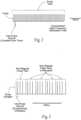
- Fig. 1is a system 10 for stimulating tissue of the central nervous system.
- the systemincludes a lead 12 placed in a desired position in contact with central nervous system tissue.
- the lead 12is implanted in a region of the brain, such as the thalamus, subthalamus, or globus pallidus for the purpose of deep brain stimulation.
- the lead 12could be implanted in, on, or near the spinal cord; or in, on, or near a peripheral nerve (sensory or motor) for the purpose of selective stimulation to achieve a therapeutic purpose.
- the distal end of the lead 12carries one or more electrodes 14 to apply electrical pulses to the targeted tissue region.
- the electrical pulsesare supplied by a pulse generator 16 coupled to the lead 12.
- the pulse generator 16may be implanted in a suitable location remote from the lead 12, e.g., in the shoulder region. It should be appreciated, however, that the pulse generator 16 could be placed in other regions of the body or externally.
- the case of the pulse generatorcan serve as a reference or return electrode.
- the lead 12can include a reference or return electrode (comprising a bi-polar arrangement) , or a separate reference or return electrode can be implanted or attached elsewhere on the body (comprising a mono-polar arrangement) .
- the pulse generator 16includes an on-board, programmable microprocessor 18, which carries embedded code.
- the codeexpresses pre-programmed rules or algorithms under which a desired electrical stimulation waveform pattern or train is generated and distributed to the electrode (s) 14 on the lead 12. According to these programmed rules, the pulse generator 16 directs the prescribed stimulation waveform patterns or trains through the lead 12 to the electrode (s) 14, which serve to selectively stimulate the targeted tissue region.
- the codeis preprogrammed by a clinician to achieve the particular physiologic response desired.
- An on-board battery 20may supply power to the microprocessor 18.
- batteries 20must be replaced every 1 to 9 years, depending on the stimulation parameters needed to treat a disorder.
- the replacement of batteriesrequires another invasive surgical procedure to gain access to the implanted pulse generator.
- the system 10makes possible, among its several benefits, an increase in battery life.
- the stimulation waveform pattern or train generated by the pulse generatordiffers from convention pulse patterns or trains in that the waveform comprises repeating non-regular (i.e., not constant) pulse patterns or trains, in which the interval between electrical pulses (the inter-pulse intervals or IPI) changes or varies over time. Examples of these repeating non-regular pulse patterns or trains are shown in Figs. 3 to 5 . Compared to conventional pulse trains having regular (i.e., constant) inter-pulse intervals (as shown in Fig.
- the non-regular (i.e., not constant) pulse patterns or trainsprovide a lower average frequency for a given pulse pattern or train, where the average frequency for a given pulse train (expressed in hertz or Hz) is defined as the sum of the inter-pulse intervals for the pulse train in seconds ( ⁇ IPI ) divided by the number of pulses (n) in the given pulse train, or ( ⁇ IPI )/n.
- ⁇ IPIthe average frequency for a given pulse train
- a lower average frequencymakes possible a reduction in the intensity of side effects, as well as an increase in the dynamic range between the onset of the desired clinical effect(s) and side effects, thereby increasing the clinical efficacy and reducing sensitivity to the position of the electrode(s).
- a lower average frequency brought about by a non-regular pulse pattern or trainalso leads to a decrease in power consumption, thereby prolonging battery life and reducing battery size.
- the repeating non-regular (i.e., not constant) pulse patterns or trainscan take a variety of different forms.
- the inter-pulse intervalscan be linearly cyclically ramped over time in non-regular temporal patterns (growing larger and/or smaller or a combination of each over time); or be periodically embedded in non-regular temporal patterns comprising clusters or groups of multiple pulses (called n-lets), wherein n is two or more.
- n-letscomprising clusters or groups of multiple pulses
- the repeating non-regular pulse patterns or trainscan comprise combinations of single pulses (called singlets) spaced apart by varying non-regular inter-pulse intervals and n-lets interspersed among the singlets, the n-lets themselves being spaced apart by varying non-regular inter-pulse intervals both between adjacent n-lets and between the n pulses embedded in the n-let.
- the non-regularity of the pulse pattern or traincan be accompanied by concomitant changes in waveform and/or amplitude, and/or duration in each pulse pattern or train or in successive pulse patterns or trains.
- Each pulse comprising a singlet or imbedded in an n-let in a given traincomprises a waveform that can be monophasic, biphasic, or multiphasic.
- Each waveformpossesses a given amplitude (expressed, e.g., in amperes) that can, by way of example, range from 10 ⁇ a (E -6 ) to 10 ma (E -3 ).
- the amplitude of a given phase in a waveformcan be the same or differ among the phases.
- Each waveformalso possesses a duration (expressed, e.g., in seconds) that can, by way of example, range from 10 ⁇ s (E -6 ) to 2 ms (E -3 ).
- the duration of the phases in a given waveformcan likewise be the same or different. It is emphasized that all numerical values expressed herein are given by way of example only. They can be varied, increased or decreased, according to the clinical objectives.
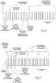
- Fig. 3shows a representative example of a repeating non-regular pulse pattern or train in which the inter-pulse intervals are linearly cyclically ramped over time. As shown in Fig.
- the pulse pattern or trainincludes singlet pulses (singlets) spaced apart by progressively increasing inter-pulse intervals providing a decrease in frequency over time, e.g., having an initial instantaneous frequency of 140 Hz, decreasing with doubling inter-pulse intervals, to a final instantaneous frequency of 40 Hz.
- the inter-pulse intervalscan vary within a specified range selected based upon clinical objections, e.g., not to exceed 25 ms, or not to exceed 100 ms, or not to exceed 200 ms, to take into account burst responses and subsequent disruption of thalamic fidelity. ).
- the non-regular pulse trainsrepeat themselves for a clinically appropriate period of time. As shown in Fig.
- the first pulse traincomprises progressively increasing inter-pulse intervals from smallest to largest, followed immediately by another essentially identical second pulse train comprising progressively increasing inter-pulse intervals from smallest to largest, followed immediately by an essentially identical third pulse train, and so on. Therefore, between successive pulse trains, there is an instantaneous change from the largest inter-pulse interval (at the end of one train) to the smallest inter-pulse interval (at the beginning of the next successive train) .
- the train shown in Fig. 3has an average frequency of 85 Hz and is highly non-regular, with a coefficient of variation (CV) of about 0.5.
- CVcoefficient of variation
- the train shown in Fig. 3exploits the dynamics of burst generation in thalamic neurons.
- the early high frequency phase of the trainmasks intrinsic activity in subthalamic nucleus (STN) neurons, and the inter-pulse interval increases reduce the average frequency.
- a family of trainscan be provided by varying the initial frequency, final frequency, and rate of change within the train, with the objective to prevent thalamic bursting with a lower average stimulation frequency than required with constant frequency trains.
- Figs. 4 and 5show other representative examples of repeating non-regular pulse patterns or trains.
- the pulse trains in Figs. 4 and 5comprise within, a single pulse train, a combination of single pulses (singlets) and embedded multiple pulse groups (n-lets), with non-regular inter-pulse intervals between singlets and n-lets, as well as non-regular inter-pulse intervals within the n-lets themselves.
- the non-regular pulse trainsrepeat themselves for a clinically appropriate period of time.
- the non-regular pulse traincan be characterized as comprising one or more singlets spaced apart by a minimum inter-pulse singlet interval and one or more n-lets comprising, for each n-let, two or more pulses spaced apart by an inter-pulse interval (called the "n-let inter-pulse interval") that is less than the minimum singlet inter-pulse interval.
- the n-let inter-pulse intervalcan itself vary within the train, as can the interval between successive n-lets or a successive n-lets and singlets.
- the non-regular pulse trains comprising singlets and n-letsrepeat themselves for a clinically appropriate period of time.
- each pulse traincomprises four singlets in succession (with non-regular inter-pulse intervals there between); followed by four doublets in succession (with non-regular inter-doublet pulse intervals there between and non-regular inter-pulse intervals within each n-let); followed by a singlet, three doublets, and a singlet (with non-regular inter- pulse intervals there between and non-regular inter-pulse intervals within each n-let).
- the temporal pattern of this pulse trainrepeats itself in succession for a clinically appropriate period of time.
- the non-regular temporal pulse pattern shown in Fig. 4has an average frequency of 67.82 Hz without loss of efficacy, as is demonstrated in the following Example, Batch 17.
- each pulse traincomprises four singlets in succession (with non-regular inter-pulse intervals there between); followed by three doublets in succession (with non-regular inter-doublet pulse intervals there between and non-regular inter-pulse intervals within each n-let).
- the temporal pattern of this pulse trainrepeats itself in succession for a clinically appropriate period of time.
- the non-regular temporal pulse pattern shown in Fig. 5has an average frequency of 87.62 Hz without loss of efficacy, as is demonstrated in the following Example, Batch 18.
- Exampleillustrates a representative methodology for developing and identifying candidate non-regular stimulation trains as shown in Figs. 3 to 5 that achieve comparable or better efficacy at a lower average frequency (i.e., more efficiency) than constant inter-pulse interval trains.
- the stimulus trainis the chromosome of the organism, and each gene in the chromosome is the IPI between two successive pulses in the train.
- the implementationcan start, e.g., with trains of 21 pulses (20 genes) yielding a train length of -400 ms (at average frequency of 50 Hz), and the 6 s trains required for stimulation are built by serial concatenation of 15 identical pulse trains.
- the processcan start with an initial population of, e.g., 50 organisms, constituted of random IPI's drawn from a uniform distribution.
- the fitness of each pulse trainis evaluated using either the TC or basal ganglia network model (identified above) and calculating a cost function, C.
- the 10 best stimulus trains(lowest C) are selected, to be carried forward to the next generation. They will also be combined (mated) and random variations (mutations) introduced into the 40 offspring, yielding 50 trains in each generation. This process assures that the best stimulation trains (traits) are carried through to the next generation, while avoiding local minima (i.e., mating and mutations preserve genetic diversity). See Grefenstette 1986. The GA continues through successive generations until the median and minimum values of the cost function reach a plateau, and this will yield candidate trains.
- the objectiveis to find patterns of non-constant inter-pulse interval deep brain stimulation trains that provide advantageous results, as defined by low frequency and low error rate.
- An error functionis desirably created that assigns the output of each temporal pattern of stimulation a specific error fraction (E) based on how the voltage output of the thalamic cells correspond to the timing of the input stimulus.
- the weighting factors W and Kallow quantitative differentiation between efficacy (E) and efficiency (f) to generate patterns of non-constant inter-pulse interval deep brain stimulation trains that provide advantageous results with lower average frequencies, compared to conventional constant frequency pulse trains.
- Temporal patterns of stimulation with a low costcan then be used to create new temporal patterns of similar features in an attempt to achieve even lower costs. In this way, new temporal patterns of stimulation can be "bred" for a set number of generations and the best temporal patterns of stimulation of each batch recorded.
- Example Figure 1a baseline was established by running constant-frequency patterns of stimulation through the model and analyzing the associated error fractions.
- the healthy conditionproduced a low error fraction of 0.1 while the Parkinsonian condition without DBS yielded a higher error fraction of 0.5.
- constant highfrequency patterns of stimulationranging from 100-200 Hz gave near perfect results. Novel non-constant temporal patterns of stimulation would then be considered advantageous if they showed error fractions very close to 0.1 with average frequencies less than 100-200 Hz.
- the resultsare summarized according to average frequency and error fraction (Example Table 1).
- the associated inter-pulse intervals (IPI's)can be seen in Example Figure 2 .
- Batch 3outputted an error fraction 0.054.
- Another interesting featureis that the IPI's in Batch 3 gradually increased until about 40 msec, and then repeated itself. This provides support that ramp trains are advantageous..
- the trace shown in Fig. 3generally incorporates the temporal features of Batch 3.
- the constant-frequency patterns of stimulationwere evaluated again according to the new cost function (Example Figure 3 ).
- the healthy conditionreported a cost of 90.65 and the Parkinson case with no DBS yielded 505.50.
- the best constant-frequency pattern of stimulation with the new cost functionwas the 100 Hz case with a cost of 231.11. This new cost function allowed for a wider range of solutions, because a temporal pattern of stimulation would be considered useful if it had a cost less than 231.11 but presumably higher than 90.65.
- Example Table 2The results of the new cost function can be seen in Example Table 2 and the IPI's visualized in Example Figure 4 .
- Batch 18is interesting in that it also exhibits a ramp-like pattern of increasing interpulse intervals. It shows a steadily falling IPI, followed by a sudden rise, and then a quick fall, rise, and fall-almost as if it consists of 3 smaller ramps.
- the trace shown in Fig. 5generally incorporates the temporal features of Batch 18 Batch 15 also performed very well, but its qualitative features are more difficult to discern.
- Example Table 3The results of the revised cost function can be seen in Example Table 3 and the IPI's visualized in Example Figure 5.
- batch 17proved most interesting because of its very low average frequency of 67.82 Hz. Even with such a low frequency, it managed to prove better than the 100 Hz condition with a reduction in cost of about 10.
- the waveform of batch 17is interesting in that it consists of a ramp pattern of decreasing IPI in the first 100 msec, followed by a continual shift between large IPI and small IPI. The qualitative feature of quickly changing between large and small IPI's may prove advantageous.
- the trace shown in Fig. 4generally incorporates the temporal features of Batch 17.
- the most interesting temporal patterns of stimulation in this Exampleare from batches 15, 17, and 18.
- Batch 15produced a temporal pattern of stimulation with an average frequency of 98 Hz with an error fraction as low as 0.098.
- it outperformed the 100 Hz constant-frequency caseby managing to lower the error even further at roughly the same frequency.
- the qualitatively useful features of batch 15are difficult to discern.
- Batch 17was also appealing because of its very low frequency of 67.82. This low frequency was gained at the cost of increased error at 0.253, but it may nonetheless be useful if emphasis is placed on maintaining low frequency DBS.
- the qualitative features of batch 17indicated at first a ramp followed by a continual switching between low and high IPI's.
- batch 18stood somewhere in the middle with a fairly low frequency of 87.62 and low error fraction of 0.116, only marginally higher than the healthy condition of 0.1.
- the dominant qualitative feature of batch 18's waveformis that it too shows a ramp nature in that the IPI initially steadily falls, then quickly rises, falls, and then rises.
- the rapid changing between high and low IPI of batch 17can be envisioned as a set of steep ramps.
- a comparison of Batch 17 ( Fig. 4 ) and Batch 18 ( Fig. 5 )demonstrates how the balance between efficacy (E) and efficiency (f) in non-regular temporal patterns of stimulation can be purposefully tailored to meet clinical objectives.
- the systems and methodologies discussedallow changing the cost function by weighting efficacy (E) or frequency (f) more heavily (i.e., by changing W and/or K), while still yielding temporal patterns of stimulation with lower cost results than the constant-frequency waveforms.
- the non-regular temporal patterns of stimulation generated and disclosed abovetherefore make possible achieving at least the same or equivalent (and expectedly better) clinical efficacy at a lower average frequency compared to conventional constant-frequency temporal patterns.
- the lower average frequencies of the non-regular temporal stimulation patternsmake possible increases in efficiency and expand the therapeutic window of amplitudes that can be applied to achieve the desired result before side effects are encountered.
- DBSis a well-established therapy for treatment of movement disorders, but the lack of understanding of mechanisms of action has limited full development and optimization of this treatment.
- Previous studieshave focused on DBS-induced increases or decreases in neuronal firing rates in the basal ganglia and thalamus.
- changes in neuronal firing patternsmay be at least as important as changes in firing rates.
- the above described systems and methodologiesmake it possible to determine the effects of the temporal pattern of DBS on simulated and measured neuronal activity, as well as motor symptoms in both animals and humans.
- the methodologiesmake possible the qualitative and quantitative determination of the temporal features of low frequency stimulation trains that preserve efficacy.
- This descriptionprovides non-regular stimulation patterns or trains that can create a range of motor effects from exacerbation of symptoms to relief of symptoms.
- the non-regular stimulation patterns or trains described herein and their testing according to the methodology described hereinwill facilitate the selection of optimal surgical targets as well as treatments for new disorders.
- the non-regular stimulation patterns or trains described hereinmake possible improved outcomes of DBS by reducing side effects and prolonging battery life.
Landscapes
- Health & Medical Sciences (AREA)
- Neurology (AREA)
- Neurosurgery (AREA)
- Life Sciences & Earth Sciences (AREA)
- General Health & Medical Sciences (AREA)
- Biomedical Technology (AREA)
- Nuclear Medicine, Radiotherapy & Molecular Imaging (AREA)
- Radiology & Medical Imaging (AREA)
- Veterinary Medicine (AREA)
- Animal Behavior & Ethology (AREA)
- Engineering & Computer Science (AREA)
- Public Health (AREA)
- Hospice & Palliative Care (AREA)
- Psychiatry (AREA)
- Psychology (AREA)
- Child & Adolescent Psychology (AREA)
- Developmental Disabilities (AREA)
- Pain & Pain Management (AREA)
- Electrotherapy Devices (AREA)
Description
- This description relates to systems and methods for stimulating nerves in animals, including humans. The present invention is set out in claim 1 as appended thereto, and pertains to an implantable system for stimulating nerves.
- Deep Brain Stimulation (DBS) has been found to be successful in treating a variety of brain-controlled disorders, including movement disorders. Generally, such treatment involves placement of a DBS type lead into a targeted region of the brain through a burr hole drilled in the patient's skull, and the application of appropriate stimulation through the lead to the targeted region.
- Presently, in DBS, beneficial (symptom-relieving) effects are observed primarily at high stimulation frequencies above 100 Hz that are delivered in stimulation patterns or trains in which the interval between electrical pulses (the inter-pulse intervals) is constant over time. The trace of a conventional stimulation train for DBS is shown in
Fig. 2 . The beneficial effects of DBS on motor symptoms are only observed at high frequencies, while low frequency stimulation may exacerbate symptomsSee Benabid et al. 1991, Limousin et al. 1995. Thalamic DBS at less than or equal to 50 Hz increases tremor in patients with essential tremor.See Kuncel et al. 2006. Similarly, 50 Hz DBS produces tremor in pain patients receiving simulation of the ventral posterior medial nucleus of the thalamus (VPM), but the tremor disappears when the frequency is increased.See Constantoyannis 2004. Likewise, DBS of the subthalamic nucleus (STN) at 10 Hz worsens akinesia in patients with Parkinson's disease (PD), while DBS at 130 Hz leads to significant improvement in motor function See Timmermann et al. 2004, Fogelson et al. 2005. Similarly, stimulation of the globus pallidus (GP) at or above 130 Hz significantly improves dystonia, whereas stimulation at either 5 or 50 Hz leads to significant worsening. See Kupsch et al. 2003. - Model studies also indicate that the masking of pathological burst activity occurs only with sufficiently high stimulation frequencies.See Grill et al. 2004,
Figure 1 . Responsiveness of tremor to changes in DBS amplitude and frequency are strongly correlated with the ability of applied stimuli to mask neuronal bursting.See Kuncel et al. 2007,Figure 2 . - Although effective, conventional high frequency stimulation generates stronger side-effects than low frequency stimulation, and the therapeutic window between the voltage that generates the desired clinical effect(s) and the voltage that generates undesired side effects decreases with increasing frequency. Precise lead placement therefore becomes important. Further, high stimulation frequencies increase power consumption. The need for higher frequencies and increased power consumption shortens the useful lifetime and/or increases the physical size of battery-powered implantable pulse generators. The need for higher frequencies and increased power consumption requires a larger battery size, and frequent charging of the battery, if the battery is rechargeable.
US 2006/015153 A1 relates to systems and methods for enhancing or affecting neural stimulation efficiency and/or efficacy in which a system and/or method may apply electromagnetic stimulation to a patient's nervous system over a first time domain according to a first set of stimulation parameters and over a second time domain according to a second set of stimulation parameters.EP 1 145 735 A2 relates to a neurostimulator that is configured to treat epilepsy and other neurological disorders using certain stimulation strategies, particularly changing various pulse parameters, during the imposition of a burst of those pulses.US 2005/060009 relates to a technique for selection of parameter configurations for a neurostimulator using genetic algorithms.- The present invention is defined in claim 1.
- According to the present disclosure, an implantable system for stimulating nerves is provided, the system comprising a pulse generator connected to a lead sized and configured for implantation in the brain or in, on or near the spinal cord or a peripheral nerve and having an electrode, the pulse generator configured to transmit to the electrode, through the lead, an electrical signal comprising a prescribed temporal pattern of stimulation for application to targeted neurological tissue comprising a repeating succession of non-regular pulse trains, each pulse train comprising combinations of single pulses and groups of multiple pulses comprising two or more pulses, wherein: the single pulses are spaced apart by varying non-regular inter-pulse intervals, non-regular inter-pulse intervals being not constant over time; the two or more pulses embedded in the groups of multiple pulses are spaced apart by varying non-regular inter-pulse intervals; and adjacent groups of multiple pulses are spaced apart by varying non-regular inter-pulse intervals, wherein the prescribed temporal pattern of stimulation is generated through a genetic algorithm.
- The intervals between stimulation pulses in a pulse pattern or train (in shorthand called "the inter-pulse intervals") is not constant over time, but changes or varies over time. These patterns or trains are consequently called in shorthand "non-regularThe non- regular (i.e., not constant) pulse patterns or trains provide a lower average frequency for a given pulse pattern or train, compared to conventional continuous, high rate pulse trains having regular (i.e., constant) inter-pulse intervals. Having a lower average frequency, the non-regular stimulus patterns or trains make possible an increase in the efficacy of stimulation by reducing the intensity of side effects; by increasing the dynamic range between the onset of the desired clinical effect(s) and side effects (and thereby reducing sensitivity to the position of the lead electrode); and by decreasing power consumption, thereby providing a longer useful battery- life and/or a smaller implantable pulse generator, allowing battery size reduction and/or, for rechargeable batteries, longer intervals between recharging. The non-regular stimulation patterns or trains can be readily applied to deep brain stimulation, to treat a variety of neurological disorders, such as Parkinson's disease, movement disorders, epilepsy, and psychiatric disorders such as obsessive -compulsion disorder and depression. The non-regular stimulation patterns or trains can also be readily applied to other classes electrical stimulation of the nervous system including, but not limited to, cortical stimulation, spinal cord stimulation, and peripheral nerve stimulation (including sensory and motor), to provide the attendant benefits described above and to treat diseases such as but not limited to Parkinson's Disease, Essential Tremor, Movement Disorders, Dystonia, Epilepsy, Pain, psychiatric disorders such as Obsessive Compulsive Disorder, Depression, and Tourette's Symdrome.
- The systems and methodologies described herein employ a genetic algorithm, coupled to a computational model of DBS of the STN, to develop non-regular patterns of stimulation that produced efficacy (as measured by a low error function, E) at lower stimulation frequencies, F. The error function, E, is a quantitative measure from the model which assesses how faithfully the thalamus transmitted motor commands that are generated by inputs from the cortex. A very high correlation exists between E and symptoms in persons with PD, and therefore E is a valid predictor for the efficacy of a stimulation train in relieving symptoms (see Dorval et al., 2007). Previous efforts (see Feng et al. 2007) sought to design stimulation trains that minimized the total current injection. The systems and methodologies disclosed herein include an objective function that maximizes therapeutic benefit (by minimizing the error function) and improves stimulation efficiency (by reducing the stimulation frequency), using a model of the STN that reproduces the frequency tuning of symptom reduction that has been documented clinically. In contrast, the Feng et al. model showed, incorrectly, symptom reduction with regular, low frequency stimulation. The inventors have identified novel non-regular temporal patterns of stimulation, while Feng et al. identified regular low frequency (~ 10 Hz) trains that previous clinical work has demonstrated to be ineffective.
Fig. 1 is an anatomic view of a system for stimulating tissue of the central nervous system that includes an lead implanted in brain tissue coupled to a pulse generator that is programmed to provide non-regular (i.e., not constant) pulse patterns or trains, in which the interval between electrical pulses (the inter-pulse intervals) changes or varies over time.Fig. 2 is a diagrammatic trace that shows a conventional regular high frequency stimulation train, in which the interval between electrical pulses (the inter-pulse intervals) is constant.Fig. 3 is a diagrammatic trace showing a representative example of a repeating non-regular pulse pattern or train in which the inter-pulse intervals are linearly cyclically ramped over time.Figs. 4 and 5 are diagrammatic traces showing other representative examples of repeating non-regular pulse patterns or trains comprising within, a single pulse train, a combination of single pulses (singlets) and embedded multiple pulse groups (n-lets) , with non-regular inter-pulse intervals between singlets and n-lets as well as non-regular inter-pulse intervals within the multiple pulse n-lets.Fig. 1 is asystem 10 for stimulating tissue of the central nervous system. The system includes alead 12 placed in a desired position in contact with central nervous system tissue. In the illustrated embodiment, thelead 12 is implanted in a region of the brain, such as the thalamus, subthalamus, or globus pallidus for the purpose of deep brain stimulation. However, it should be understood, thelead 12 could be implanted in, on, or near the spinal cord; or in, on, or near a peripheral nerve (sensory or motor) for the purpose of selective stimulation to achieve a therapeutic purpose.- The distal end of the
lead 12 carries one ormore electrodes 14 to apply electrical pulses to the targeted tissue region. The electrical pulses are supplied by apulse generator 16 coupled to thelead 12. - The
pulse generator 16 may be implanted in a suitable location remote from thelead 12, e.g., in the shoulder region. It should be appreciated, however, that thepulse generator 16 could be placed in other regions of the body or externally. - When implanted, the case of the pulse generator can serve as a reference or return electrode. Alternatively, the
lead 12 can include a reference or return electrode (comprising a bi-polar arrangement) , or a separate reference or return electrode can be implanted or attached elsewhere on the body (comprising a mono-polar arrangement) . - The
pulse generator 16 includes an on-board,programmable microprocessor 18, which carries embedded code. The code expresses pre-programmed rules or algorithms under which a desired electrical stimulation waveform pattern or train is generated and distributed to the electrode (s) 14 on thelead 12. According to these programmed rules, thepulse generator 16 directs the prescribed stimulation waveform patterns or trains through thelead 12 to the electrode (s) 14, which serve to selectively stimulate the targeted tissue region. The code is preprogrammed by a clinician to achieve the particular physiologic response desired. - An on-
board battery 20 may supply power to themicroprocessor 18. Currently,batteries 20 must be replaced every 1 to 9 years, depending on the stimulation parameters needed to treat a disorder. When the battery life ends, the replacement of batteries requires another invasive surgical procedure to gain access to the implanted pulse generator. As will be described, thesystem 10 makes possible, among its several benefits, an increase in battery life. - The stimulation waveform pattern or train generated by the pulse generator differs from convention pulse patterns or trains in that the waveform comprises repeating non-regular (i.e., not constant) pulse patterns or trains, in which the interval between electrical pulses (the inter-pulse intervals or IPI) changes or varies over time. Examples of these repeating non-regular pulse patterns or trains are shown in
Figs. 3 to 5 . Compared to conventional pulse trains having regular (i.e., constant) inter-pulse intervals (as shown inFig. 2 ) , the non-regular (i.e., not constant) pulse patterns or trains provide a lower average frequency for a given pulse pattern or train, where the average frequency for a given pulse train (expressed in hertz or Hz) is defined as the sum of the inter-pulse intervals for the pulse train in seconds (ΣIPI) divided by the number of pulses (n) in the given pulse train, or (ΣIPI)/n. A lower average frequency makes possible a reduction in the intensity of side effects, as well as an increase in the dynamic range between the onset of the desired clinical effect(s) and side effects, thereby increasing the clinical efficacy and reducing sensitivity to the position of the electrode(s). A lower average frequency brought about by a non-regular pulse pattern or train also leads to a decrease in power consumption, thereby prolonging battery life and reducing battery size. - The repeating non-regular (i.e., not constant) pulse patterns or trains can take a variety of different forms. For example, as will be described in greater detail later, the inter-pulse intervals can be linearly cyclically ramped over time in non-regular temporal patterns (growing larger and/or smaller or a combination of each over time); or be periodically embedded in non-regular temporal patterns comprising clusters or groups of multiple pulses (called n-lets), wherein n is two or more. For example, when n=2, the n-let can be called a doublet; when n=3, the n-let can be called a triplet; when n=4, the n-let can be called a quadlet; and so on. The repeating non-regular pulse patterns or trains can comprise combinations of single pulses (called singlets) spaced apart by varying non-regular inter-pulse intervals and n-lets interspersed among the singlets, the n-lets themselves being spaced apart by varying non-regular inter-pulse intervals both between adjacent n-lets and between the n pulses embedded in the n-let. If desired, the non-regularity of the pulse pattern or train can be accompanied by concomitant changes in waveform and/or amplitude, and/or duration in each pulse pattern or train or in successive pulse patterns or trains.
- Each pulse comprising a singlet or imbedded in an n-let in a given train comprises a waveform that can be monophasic, biphasic, or multiphasic. Each waveform possesses a given amplitude (expressed, e.g., in amperes) that can, by way of example, range from 10 µa (E-6) to 10 ma (E-3). The amplitude of a given phase in a waveform can be the same or differ among the phases. Each waveform also possesses a duration (expressed, e.g., in seconds) that can, by way of example, range from 10 µs (E-6) to 2 ms (E-3). The duration of the phases in a given waveform can likewise be the same or different. It is emphasized that all numerical values expressed herein are given by way of example only. They can be varied, increased or decreased, according to the clinical objectives.
- When applied in deep brain stimulation, it is believed that repeating stimulation patterns or trains applied with non-regular inter-pulse intervals can regularize the output of disordered neuronal firing, to thereby prevent the generation and propagation of bursting activity with a lower average stimulation frequency than required with conventional constant frequency trains, i.e., with a lower average frequency than about 100 Hz..
Fig. 3 shows a representative example of a repeating non-regular pulse pattern or train in which the inter-pulse intervals are linearly cyclically ramped over time. As shown inFig. 3 , the pulse pattern or train includes singlet pulses (singlets) spaced apart by progressively increasing inter-pulse intervals providing a decrease in frequency over time, e.g., having an initial instantaneous frequency of 140 Hz, decreasing with doubling inter-pulse intervals, to a final instantaneous frequency of 40 Hz. The inter-pulse intervals can vary within a specified range selected based upon clinical objections, e.g., not to exceed 25 ms, or not to exceed 100 ms, or not to exceed 200 ms, to take into account burst responses and subsequent disruption of thalamic fidelity. ). The non-regular pulse trains repeat themselves for a clinically appropriate period of time. As shown inFig. 3 , the first pulse train comprises progressively increasing inter-pulse intervals from smallest to largest, followed immediately by another essentially identical second pulse train comprising progressively increasing inter-pulse intervals from smallest to largest, followed immediately by an essentially identical third pulse train, and so on. Therefore, between successive pulse trains, there is an instantaneous change from the largest inter-pulse interval (at the end of one train) to the smallest inter-pulse interval (at the beginning of the next successive train) . The train shown inFig. 3 has an average frequency of 85 Hz and is highly non-regular, with a coefficient of variation (CV) of about 0.5. As is demonstrated in the following Example (Batch 3), the increased efficiency of the pulse train shown inFig. 3 (due to the lower average frequency) also can provide greater efficacy, as compared to a constant 100 Hz pulse pattern. - The train shown in
Fig. 3 exploits the dynamics of burst generation in thalamic neurons. The early high frequency phase of the train masks intrinsic activity in subthalamic nucleus (STN) neurons, and the inter-pulse interval increases reduce the average frequency. A family of trains can be provided by varying the initial frequency, final frequency, and rate of change within the train, with the objective to prevent thalamic bursting with a lower average stimulation frequency than required with constant frequency trains. Figs. 4 and 5 show other representative examples of repeating non-regular pulse patterns or trains. The pulse trains inFigs. 4 and 5 comprise within, a single pulse train, a combination of single pulses (singlets) and embedded multiple pulse groups (n-lets), with non-regular inter-pulse intervals between singlets and n-lets, as well as non-regular inter-pulse intervals within the n-lets themselves. The non-regular pulse trains repeat themselves for a clinically appropriate period of time.- The non-regular pulse train can be characterized as comprising one or more singlets spaced apart by a minimum inter-pulse singlet interval and one or more n-lets comprising, for each n-let, two or more pulses spaced apart by an inter-pulse interval (called the "n-let inter-pulse interval") that is less than the minimum singlet inter-pulse interval. The n-let inter-pulse interval can itself vary within the train, as can the interval between successive n-lets or a successive n-lets and singlets. The non-regular pulse trains comprising singlets and n-lets repeat themselves for a clinically appropriate period of time.
- In
Fig. 4 , each pulse train comprises four singlets in succession (with non-regular inter-pulse intervals there between); followed by four doublets in succession (with non-regular inter-doublet pulse intervals there between and non-regular inter-pulse intervals within each n-let); followed by a singlet, three doublets, and a singlet (with non-regular inter- pulse intervals there between and non-regular inter-pulse intervals within each n-let). The temporal pattern of this pulse train repeats itself in succession for a clinically appropriate period of time. The non-regular temporal pulse pattern shown inFig. 4 has an average frequency of 67.82 Hz without loss of efficacy, as is demonstrated in the following Example, Batch 17. - In
Fig. 5 , each pulse train comprises four singlets in succession (with non-regular inter-pulse intervals there between); followed by three doublets in succession (with non-regular inter-doublet pulse intervals there between and non-regular inter-pulse intervals within each n-let). The temporal pattern of this pulse train repeats itself in succession for a clinically appropriate period of time. The non-regular temporal pulse pattern shown inFig. 5 has an average frequency of 87.62 Hz without loss of efficacy, as is demonstrated in the following Example,Batch 18. - The following Example illustrates a representative methodology for developing and identifying candidate non-regular stimulation trains as shown in
Figs. 3 to 5 that achieve comparable or better efficacy at a lower average frequency (i.e., more efficiency) than constant inter-pulse interval trains. - Computational models of thalamic DBS (McIntyre et al. 2004, Birdno, 2009) and subthalamic DBS (Rubin and Terman, 2004) can be used with genetic-algorithm-based optimization (Davis, 1991) (GA) to design non-regular stimulation patterns or trains that produce desired relief of symptoms with a lower average stimulation frequency than regular, high-rate stimulation.
- In the GA implementation, the stimulus train (pattern) is the chromosome of the organism, and each gene in the chromosome is the IPI between two successive pulses in the train. The implementation can start, e.g., with trains of 21 pulses (20 genes) yielding a train length of -400 ms (at average frequency of 50 Hz), and the 6 s trains required for stimulation are built by serial concatenation of 15 identical pulse trains. The process can start with an initial population of, e.g., 50 organisms, constituted of random IPI's drawn from a uniform distribution. At each step (generation) of the GA, the fitness of each pulse train is evaluated using either the TC or basal ganglia network model (identified above) and calculating a cost function, C. From each generation, the 10 best stimulus trains (lowest C) are selected, to be carried forward to the next generation. They will also be combined (mated) and random variations (mutations) introduced into the 40 offspring, yielding 50 trains in each generation. This process assures that the best stimulation trains (traits) are carried through to the next generation, while avoiding local minima (i.e., mating and mutations preserve genetic diversity).See Grefenstette 1986. The GA continues through successive generations until the median and minimum values of the cost function reach a plateau, and this will yield candidate trains.
- The objective is to find patterns of non-constant inter-pulse interval deep brain stimulation trains that provide advantageous results, as defined by low frequency and low error rate. An error function is desirably created that assigns the output of each temporal pattern of stimulation a specific error fraction (E) based on how the voltage output of the thalamic cells correspond to the timing of the input stimulus. Using this error fraction, a cost function (C) is desirably created to minimize both frequency and error fraction, according to representative equation C = W*E + K*f, where C is the cost, E is the error fraction, f is the average frequency of the temporal pattern of stimulation, W is an appropriate weighting factor for the error function, and K is an appropriate weighting factor for the frequency. The weighting factors W and K allow quantitative differentiation between efficacy (E) and efficiency (f) to generate patterns of non-constant inter-pulse interval deep brain stimulation trains that provide advantageous results with lower average frequencies, compared to conventional constant frequency pulse trains.
- With this cost function, the voltage output of several candidate temporal patterns of stimulation can be evaluated and the cost calculated. Temporal patterns of stimulation with a low cost can then be used to create new temporal patterns of similar features in an attempt to achieve even lower costs. In this way, new temporal patterns of stimulation can be "bred" for a set number of generations and the best temporal patterns of stimulation of each batch recorded.
- Several batches of the genetic algorithm yields useful results in that they achieve lower costs than the corresponding constant frequency DBS waveforms. Some batches can be run in an attempt to find especially low frequency temporal patterns of stimulation, by changing the cost function to weight frequency more heavily, or vice versa (i.e., by changing W and/or K). These batches can also yield lower cost results than the constant-frequency waveforms.
- By way of example, a total of 14 batches of the genetic algorithm were run and evaluated with various cost functions and modified initial parameters.
- Before the trials were run, a baseline was established by running constant-frequency patterns of stimulation through the model and analyzing the associated error fractions (Example
Figure 1 ). As can be seen from ExampleFigure 1 , the healthy condition produced a low error fraction of 0.1 while the Parkinsonian condition without DBS yielded a higher error fraction of 0.5. From these results, constant highfrequency patterns of stimulation ranging from 100-200 Hz gave near perfect results. Novel non-constant temporal patterns of stimulation would then be considered advantageous if they showed error fractions very close to 0.1 with average frequencies less than 100-200 Hz.
- The first set of batches was run by minimizing only the error fraction (E). Thus, the associated cost function was simply C = E. The results are summarized according to average frequency and error fraction (Example Table 1). The associated inter-pulse intervals (IPI's) can be seen in Example
Figure 2 . Batch 3 outputted an error fraction 0.054. Another interesting feature is that the IPI's in Batch 3 gradually increased until about 40 msec, and then repeated itself. This provides support that ramp trains are advantageous.. The trace shown inFig. 3 generally incorporates the temporal features of Batch 3. - The remaining batches yielded error fractions higher than 0.1 and were no better than the 150 Hz constant-frequency case.
# Average Frequency Error Fraction IPI Length 3 127.5 0.054 5 4 95.62 0.162 39 5 113.6 0.139 13 6 94.64 0.132 26 7 101.6 0.142 31 
- Because many batches were yielding error fractions above 0.1 (healthy condition), and only a small window of error fraction less than the 150 Hz DBS case would be useful, a new cost function was constructed to minimize an alternate feature of the temporal patterns of stimulation; namely, frequency. This new cost function weighted the error fraction and frequency, yielding the equation C = 1000*E + F, where C is cost, E is error fraction, and F is the average frequency of the waveform in Hz, W = 1000, and K=1.
- In order to establish a new baseline cost, the constant-frequency patterns of stimulation were evaluated again according to the new cost function (Example
Figure 3 ). As can be seen from the graph, the healthy condition reported a cost of 90.65 and the Parkinson case with no DBS yielded 505.50. The best constant-frequency pattern of stimulation with the new cost function was the 100 Hz case with a cost of 231.11. This new cost function allowed for a wider range of solutions, because a temporal pattern of stimulation would be considered useful if it had a cost less than 231.11 but presumably higher than 90.65.
- The results of the new cost function can be seen in Example Table 2 and the IPI's visualized in Example
Figure 4 . The best results were seen inbatches 15 and 18, which had the lowest costs.Batch 18 is interesting in that it also exhibits a ramp-like pattern of increasing interpulse intervals. It shows a steadily falling IPI, followed by a sudden rise, and then a quick fall, rise, and fall-almost as if it consists of 3 smaller ramps. The trace shown inFig. 5 generally incorporates the temporal features ofBatch 18 Batch 15 also performed very well, but its qualitative features are more difficult to discern. # Average Frequency IPI Length Error Fraction Cost 9 94.74 34 0.124 218.8 13 132.9 12 0.087 219.4 15 98.00 17 0.098 196.0 18 81.28 10 0.116 197.3 19 84.70 20 0.116 201.2 
- The advantage of low frequency was emphasized with a new cost function, which weighted frequency more heavily, C = 1000*E + 2*F. Because the frequency of DBS does not affect the healthy condition or the PD with no DBS, these baseline costs stayed the same at 90.65 and 505.50, respectively. The 100 Hz was again the best constant-frequency temporal pattern of stimulation, with a cost of 331.11. The following temporal patterns of stimulation, then, were considered useful if they had low frequencies and costs less than 331.11 and greater than 90.65.
- The results of the revised cost function can be seen in Example Table 3 and the IPI's visualized in ExampleFigure 5. Of the resulting batches, batch 17 proved most interesting because of its very low average frequency of 67.82 Hz. Even with such a low frequency, it managed to prove better than the 100 Hz condition with a reduction in cost of about 10. The waveform of batch 17 is interesting in that it consists of a ramp pattern of decreasing IPI in the first 100 msec, followed by a continual shift between large IPI and small IPI. The qualitative feature of quickly changing between large and small IPI's may prove advantageous. The trace shown in
Fig. 4 generally incorporates the temporal features of Batch 17. # Average Frequency IPI Length Error Fraction Cost 16 84.92 47 0.239 323.8 17 67.82 20 0.253 321.1 20 79.25 10 0.236 315.4 21 77.15 20 0.269 346.6 
- The most interesting temporal patterns of stimulation in this Example are from
batches 15, 17, and 18. Batch 15 produced a temporal pattern of stimulation with an average frequency of 98 Hz with an error fraction as low as 0.098. Thus, it outperformed the 100 Hz constant-frequency case by managing to lower the error even further at roughly the same frequency. Still, the qualitatively useful features of batch 15 are difficult to discern. Batch 17 was also appealing because of its very low frequency of 67.82. This low frequency was gained at the cost of increased error at 0.253, but it may nonetheless be useful if emphasis is placed on maintaining low frequency DBS. The qualitative features of batch 17 indicated at first a ramp followed by a continual switching between low and high IPI's. Lastly,batch 18 stood somewhere in the middle with a fairly low frequency of 87.62 and low error fraction of 0.116, only marginally higher than the healthy condition of 0.1. The dominant qualitative feature ofbatch 18's waveform is that it too shows a ramp nature in that the IPI initially steadily falls, then quickly rises, falls, and then rises. The rapid changing between high and low IPI of batch 17 can be envisioned as a set of steep ramps. - A comparison of Batch 17 (
Fig. 4 ) and Batch 18 (Fig. 5 ) demonstrates how the balance between efficacy (E) and efficiency (f) in non-regular temporal patterns of stimulation can be purposefully tailored to meet clinical objectives. The systems and methodologies discussed allow changing the cost function by weighting efficacy (E) or frequency (f) more heavily (i.e., by changing W and/or K), while still yielding temporal patterns of stimulation with lower cost results than the constant-frequency waveforms. Comparing Batch 17 withBatch 18, one sees that the error fraction (E) (i.e., the efficacy of the temporal pattern) of Batch 17 (0.253) is greater than the error fraction (E) (i.e., the efficacy of the temporal pattern) of Batch 18 (0.116). However, one can also see that the efficiency (i.e., the average frequency) of Batch 17 (67.82 Hz) is lower than the efficiency (i.e., the average frequency) of Batch 18 (81.28 Hz). Through different in terms of efficacy and efficiency, both Batch 17 andBatch 18 have costs better than constant-frequency temporal patterns. - The non-regular temporal patterns of stimulation generated and disclosed above therefore make possible achieving at least the same or equivalent (and expectedly better) clinical efficacy at a lower average frequency compared to conventional constant-frequency temporal patterns. The lower average frequencies of the non-regular temporal stimulation patterns make possible increases in efficiency and expand the therapeutic window of amplitudes that can be applied to achieve the desired result before side effects are encountered.
- DBS is a well-established therapy for treatment of movement disorders, but the lack of understanding of mechanisms of action has limited full development and optimization of this treatment. Previous studies have focused on DBS-induced increases or decreases in neuronal firing rates in the basal ganglia and thalamus. However, recent data suggest that changes in neuronal firing patterns may be at least as important as changes in firing rates.
- The above described systems and methodologies make it possible to determine the effects of the temporal pattern of DBS on simulated and measured neuronal activity, as well as motor symptoms in both animals and humans. The methodologies make possible the qualitative and quantitative determination of the temporal features of low frequency stimulation trains that preserve efficacy.
- The systems and methodologies described herein provide robust insight into the effects of the temporal patterns of DBS, and thereby illuminate the mechanisms of action. Exploiting this understanding, new temporal patterns of stimulation can be developed, using model-based optimization, and tested, with the objective and expectation to increase DBS efficacy and increase DBS efficiency by reducing DBS side effects.
- This description provides non-regular stimulation patterns or trains that can create a range of motor effects from exacerbation of symptoms to relief of symptoms. The non-regular stimulation patterns or trains described herein and their testing according to the methodology described herein will facilitate the selection of optimal surgical targets as well as treatments for new disorders. The non-regular stimulation patterns or trains described herein make possible improved outcomes of DBS by reducing side effects and prolonging battery life.
- Benabid AL, Pollak P, Gervason C, Hoffmann D, Gao DM, Hommel M, Perret JE, de Rougemont J(1991) Long-term suppression of tremor by chronic stimulation of the ventral intermediate thalamic nucleus. Lancet. 337:403-6.
- Birdno MJ "Analyzing the mechanisms of thalamic deep brain stimulation: computational and clinical studies". Ph.D. Dissertation. Department of Biomedical Engineering, Duke University, Durham, NC, USA, August 2009.
- Constantoyannis C, Kumar A, Stoessl AJ, Honey CR (2004) Tremor induced by thalamic deep brain stimulation in patients with complex regional facial pain. Mov Disord. 19:933-936.
- Davis L (1991) Handbook of genetic algorithms. Van Nostrand Reinhold, NY.
- Dorval AD, Kuncel AM, Birdno MJ, Turner DA, Grill WM (2007) Deep brain stimulation alleviates Parkinsonian bradykinesia by regularizing thalamic throughput in human subjects. Society for Neuroscience Abstracts 32.
- Feng XJ, Shea-Brown E, Greenwald B, Kosut R, Rabitz H (2007) Optimal deep brain stimulation of the subthalamic nucleus-a computational study. J Comput Neurosci. 23(3) :265-282.
- Fogelson N, Kuhn AA, Silberstein P, Limousin PD, Hariz M, Trottenberg T, Kupsch A, Brown P (2005) Frequency dependent effects of subthalamic nucleus stimulation in Parkinson's disease. Neuroscience Letters 382:5-9.
- Grefenstette JJ (1986) Optimization of Control Parameters for Genetic Algorithms. IEEE Transactions on Systems, Man and Cybernetics 16:122-128.
- Grill WM, Cooper SE, Montgomery EB (2003) Effect of stimulus waveform on tremor suppression and paresthesias evoked by thalamic deep brain stimulation. Society for Neuroscience Abstracts 29.
- Kuncel AM, Cooper SE, Montgomery EB, Baker KB, Rezai AR, Grill WM (2006) Clinical response to varying the stimulus parameters in deep brain stimulation for essential tremor. Movement Disorders 21(11):1920-1928.
- Kupsch A, Klaffke S, Kuhn AA, Meissner W, Arnold G, Schneider GH, Maier-Hauff K, Trottenberg T (2003) The effects of frequency in pallidal deep brain stimulation for primary dystonia. J Neurol 250:1201-1204.
- Limousin P, Pollack P, Benazzouz A (1995) Effect on Parkinsonian signs and symptoms of bilateral stimulation. The Lancet 345:91-95.
- McIntyre CC, Grill WM, Sherman DL, Thakor NV (2004) Cellular effects of deep brain stimulation: model-based analysis of activation and inhibition. J Neurophysiol 91:1457-1469.
- Rubin JE, Terman D (2004) High frequency stimulation of the subthalamic nucleus eliminates pathological thalamic rhythmicity in a computational model. J Comput Neurosci 16:211-235.
- Timmermann L, Gross J, Dirks M, Volkmann J, Freund HJ, Schnitzler A (2003) The cerebral oscillatory network of parkinsonian resting tremor. Brain, 126:199-212.
- The present invention is as defined in the following claim:


Claims (1)
- An implantable system for stimulating nerves, the system comprising a pulse generator (16) connected to a lead (12) having an electrode (14), the pulse generator (16) configured to transmit to the electrode (14), through the lead (12), an electrical signal comprising a temporal pattern of stimulation for application to targeted neurological tissue wherein the pulse generator (16) comprises a microprocessor (18) configured to generate and distribute to the electrode (14) on the lead (12) an electrical stimulation waveform pattern comprising non-regular stimulation trains selected according to the following programmed rules:(i) providing an error function (E) for a given temporal pattern of stimulation that quantifies how voltage output of thalamic cells correspond to timing of inputs,(ii) providing a cost function (C) expressed as C = W*E + K*f, wherein C is the cost, E is the error fraction, f is the average frequency of the temporal pattern waveform, W is an appropriate weighting factor assigned for the error function, and K is an appropriate weighting factor assigned for the frequency, the weighting factors W and K being applied to quantitatively minimize efficacy, based upon the error function (E), and efficiency based upon the average frequency (f), at a given cost,(iii) applying the cost function to evaluate the cost of candidate temporal patterns of 15 stimulation, using a selected computational model,(iv) selecting temporal patterns of stimulation with a low cost based upon the computational model,(v) using a genetic algorithm to create new temporal patterns bred from the selected-temporal patterns,(vi) repeating (iii), (iv), and (v) to bred batches of new temporal patterns of stimulation for a determined number of generations, and(vii) selecting from the batches the best temporal patterns of stimulation in terms of low cost (C), efficacy, and efficiency.
Applications Claiming Priority (2)
| Application Number | Priority Date | Filing Date | Title |
|---|---|---|---|
| US10257508P | 2008-10-03 | 2008-10-03 | |
| PCT/US2009/005459WO2010039274A1 (en) | 2008-10-03 | 2009-10-05 | Non-regular electrical stimulation patterns for treating neurological disorders |
Publications (3)
| Publication Number | Publication Date |
|---|---|
| EP2340078A1 EP2340078A1 (en) | 2011-07-06 |
| EP2340078A4 EP2340078A4 (en) | 2013-09-04 |
| EP2340078B1true EP2340078B1 (en) | 2023-08-30 |
Family
ID=42073788
Family Applications (1)
| Application Number | Title | Priority Date | Filing Date |
|---|---|---|---|
| EP09818122.5AActiveEP2340078B1 (en) | 2008-10-03 | 2009-10-05 | Non-regular electrical stimulation patterns for treating neurological disorders |
Country Status (7)
| Country | Link |
|---|---|
| US (7) | US8447405B2 (en) |
| EP (1) | EP2340078B1 (en) |
| JP (5) | JP5936034B2 (en) |
| CN (1) | CN102238978B (en) |
| AU (1) | AU2009300264B2 (en) |
| CA (3) | CA3178974A1 (en) |
| WO (1) | WO2010039274A1 (en) |
Families Citing this family (47)
| Publication number | Priority date | Publication date | Assignee | Title |
|---|---|---|---|---|
| US8798755B2 (en) | 2008-10-03 | 2014-08-05 | Duke University | Non-regular electrical stimulation patterns for treating neurological disorders |
| US11013924B2 (en)* | 2008-10-03 | 2021-05-25 | Duke University | Non-regular electrical stimulation patterns for treating neurological disorders |
| US9802046B2 (en) | 2008-10-03 | 2017-10-31 | Duke University | Non-regular electrical stimulation patterns for improved efficiency in treating Parkinson's Disease |
| US8923981B2 (en) | 2008-10-03 | 2014-12-30 | Duke University | Non-regular electrical stimulation patterns designed with a cost function for treating neurological disorders |
| CA3178974A1 (en) | 2008-10-03 | 2010-04-08 | Duke University | Non-regular electrical stimulation patterns for treating neurological disorders |
| US9002472B2 (en)* | 2010-02-26 | 2015-04-07 | Intelect Medical, Inc. | Neuromodulation having non-linear dynamics |
| JP5847167B2 (en) | 2010-05-27 | 2016-01-20 | エヌディーアイ メディカル, エルエルシー | Waveform shapes for neurological disorder treatment optimized for energy efficiency |
| EP2699309B1 (en)* | 2011-04-20 | 2017-08-09 | Medtronic, Inc. | Electrical therapy parameter determination based on a bioelectrical resonance response |
| EP2766087A4 (en)* | 2011-10-11 | 2015-05-06 | Univ Duke | NON-REGULAR ELECTRIC STIMULATION REASONS FOR THE TREATMENT OF NEUROLOGICAL DISORDERS |
| US9814884B2 (en) | 2011-11-04 | 2017-11-14 | Nevro Corp. | Systems and methods for detecting faults and/or adjusting electrical therapy based on impedance changes |
| BR112015017042B1 (en)* | 2013-01-21 | 2022-03-03 | Cala Health, Inc | Device to treat tremor |
| CA3120293C (en)* | 2013-02-19 | 2024-04-09 | Duke University | Non-regular electrical stimulation patterns for improved efficiency in treating parkinson's disease |
| JP2016515025A (en)* | 2013-03-13 | 2016-05-26 | デューク ユニバーシティ | System and method for applying spinal cord stimulation based on electrical stimulation time patterns |
| US9934488B2 (en) | 2013-03-13 | 2018-04-03 | Autodesk, Inc. | User interface navigation elements for navigating datasets |
| US9841889B2 (en)* | 2013-03-13 | 2017-12-12 | Autodesk, Inc. | User interface navigation elements for navigating datasets |
| US9996244B2 (en) | 2013-03-13 | 2018-06-12 | Autodesk, Inc. | User interface navigation elements for navigating datasets |
| AU2014268697A1 (en)* | 2013-05-21 | 2016-01-21 | Duke University | Devices, systems and methods for deep brain stimulation parameters |
| CA2916241C (en)* | 2013-05-22 | 2023-07-04 | Deep Brain Innovations LLC | Deep brain stimulator and method of use |
| WO2015095233A1 (en)* | 2013-12-19 | 2015-06-25 | Boston Scientific Neuromodulation Corporation | Methods and systems for employing a duty cycle in electrical stimulation of patient tissue |
| AU2014369910B2 (en) | 2013-12-23 | 2019-05-16 | Deep Brain Innovations LLC | Programming systems for deep brain stimulator system |
| EP2959939A3 (en)* | 2014-06-26 | 2016-04-13 | Oticon Medical A/S | A hearing assistance device comprising an implantable part |
| US10096386B2 (en) | 2014-07-03 | 2018-10-09 | Duke University | Systems and methods for model-based optimization of spinal cord stimulation electrodes and devices |
| EP3197539B1 (en) | 2014-09-26 | 2025-03-19 | Duke University | Systems for spinal cord stimulation |
| US9974959B2 (en) | 2014-10-07 | 2018-05-22 | Boston Scientific Neuromodulation Corporation | Systems, devices, and methods for electrical stimulation using feedback to adjust stimulation parameters |
| DE102014117429A1 (en)* | 2014-11-27 | 2016-06-02 | Forschungszentrum Jülich GmbH | Apparatus and method for effective invasive neurostimulation by means of varying stimulus sequences |
| CN104548342A (en)* | 2014-12-31 | 2015-04-29 | 清华大学 | Implantable electric pulse stimulation system |
| US10542961B2 (en) | 2015-06-15 | 2020-01-28 | The Research Foundation For The State University Of New York | System and method for infrasonic cardiac monitoring |
| DE102015109988B4 (en)* | 2015-06-22 | 2017-04-27 | Forschungszentrum Jülich GmbH | Device for effective invasive two-stage neurostimulation |
| WO2017035140A1 (en) | 2015-08-26 | 2017-03-02 | Boston Scientific Neuromodulation Corporation | Machine learning to optimize spinal cord stimulation |
| US10391313B2 (en) | 2015-12-04 | 2019-08-27 | Boston Scientific Neuromodulation Corporation | Systems and methods for the development of therapy paradigms for neurological treatments |
| US10300277B1 (en)* | 2015-12-14 | 2019-05-28 | Nevro Corp. | Variable amplitude signals for neurological therapy, and associated systems and methods |
| DE102015122888B4 (en)* | 2015-12-29 | 2017-12-21 | Forschungszentrum Jülich GmbH | Apparatus and method for effective invasive multi-segment neurostimulation |
| EP3463551A4 (en) | 2016-06-01 | 2020-01-29 | Duke University | SYSTEMS AND METHODS FOR DETERMINING OPTIMAL TEMPORAL NERVOUS STIMULATION PATTERNS |
| WO2018035067A1 (en)* | 2016-08-15 | 2018-02-22 | University Of Southern California | Stochastic-switched noise stimulation for identification of input-output brain network dynamics and closed loop control |
| US11045650B2 (en) | 2016-12-06 | 2021-06-29 | Medtronic, Inc. | High frequency neurostimulation for pelvic symptom control |
| US11351378B2 (en) | 2016-12-21 | 2022-06-07 | Duke University | Method to design temporal patterns of nervous system stimulation |
| WO2018187734A1 (en) | 2017-04-07 | 2018-10-11 | Medtronic, Inc. | Complex variation of electrical stimulation therapy parameters |
| US11298546B2 (en)* | 2017-12-12 | 2022-04-12 | Duke University | Systems and methods for minimizing response variability of spinal cord stimulation |
| US11631151B2 (en) | 2018-09-30 | 2023-04-18 | Strong Force Tp Portfolio 2022, Llc | Intelligent transportation systems |
| WO2020069517A2 (en) | 2018-09-30 | 2020-04-02 | Strong Force Intellectual Capital, Llc | Intelligent transportation systems |
| US20200324117A1 (en)* | 2019-04-15 | 2020-10-15 | Advanced Neuromodulation Systems, Inc. | Systems and methods of generating stimulation patterns |
| US11338129B2 (en) | 2019-04-17 | 2022-05-24 | Boston Scientific Neuromodulation Corporation | Selective electrical modulation of neural populations |
| GB2583789B (en)* | 2019-09-19 | 2021-06-09 | Bioinduction Ltd | Apparatus for deep brain stimulation |
| US12370367B2 (en) | 2020-08-14 | 2025-07-29 | University Of Houston System | System and method for determining deep brain stimulation parameters |
| US12403315B2 (en) | 2021-04-27 | 2025-09-02 | Boston Scientific Neuromodulation Corporation | Systems and methods for automated programming of electrical stimulation |
| US12403313B2 (en) | 2021-06-15 | 2025-09-02 | Boston Scientific Neuromodulation Corporation | Methods and systems for estimating neural activation by stimulation using a stimulation system |
| EP4440687A1 (en)* | 2022-02-24 | 2024-10-09 | Boston Scientific Neuromodulation Corporation | Systems and methods for using cost parameters for programming electrical stimulation |
Citations (1)
| Publication number | Priority date | Publication date | Assignee | Title |
|---|---|---|---|---|
| US20050060009A1 (en)* | 2003-09-15 | 2005-03-17 | Goetz Steven M. | Selection of neurostimulator parameter configurations using genetic algorithms |
Family Cites Families (69)
| Publication number | Priority date | Publication date | Assignee | Title |
|---|---|---|---|---|
| US3833005A (en) | 1971-07-26 | 1974-09-03 | Medtronic Inc | Compared count digitally controlled pacemaker |
| JPS54119792A (en)* | 1978-03-03 | 1979-09-17 | Iriyou Kougaku Kenkiyuushiyo K | Electric stimulation device for removing pain |
| CN1003839B (en) | 1986-04-24 | 1989-04-12 | 顾涵森 | Device and method for generating vital information signal |
| CA1278045C (en) | 1985-05-15 | 1990-12-18 | Wu Dumin | Apparatus and method for generating vital information signals |
| US5073544A (en) | 1986-08-15 | 1991-12-17 | Whitby, Inc. | Transdermal compositions of 1-oxohydrocarbyl-substituted azacyclohexanes |
| DE3816042A1 (en) | 1988-05-10 | 1989-11-23 | Alt Eckhard | ENERGY SAVING HEART PACEMAKER |
| US5095904A (en) | 1989-09-08 | 1992-03-17 | Cochlear Pty. Ltd. | Multi-peak speech procession |
| US5226413A (en) | 1990-08-14 | 1993-07-13 | Medtronic, Inc. | Rate responsive pacemaker and method for automatically initializing the same |
| US5184616A (en) | 1991-10-21 | 1993-02-09 | Telectronics Pacing Systems, Inc. | Apparatus and method for generation of varying waveforms in arrhythmia control system |
| US5485851A (en)* | 1994-09-21 | 1996-01-23 | Medtronic, Inc. | Method and apparatus for arousal detection |
| US5724985A (en) | 1995-08-02 | 1998-03-10 | Pacesetter, Inc. | User interface for an implantable medical device using an integrated digitizer display screen |
| US6944501B1 (en) | 2000-04-05 | 2005-09-13 | Neurospace, Inc. | Neurostimulator involving stimulation strategies and process for using it |
| US6066163A (en) | 1996-02-02 | 2000-05-23 | John; Michael Sasha | Adaptive brain stimulation method and system |
| US5716377A (en) | 1996-04-25 | 1998-02-10 | Medtronic, Inc. | Method of treating movement disorders by brain stimulation |
| AU2976997A (en) | 1996-05-31 | 1998-01-05 | Masayuki Matsuura | Low frequency therapy method, low frequency therapy apparatus and low frequency therapy system |
| US6366813B1 (en) | 1998-08-05 | 2002-04-02 | Dilorenzo Daniel J. | Apparatus and method for closed-loop intracranical stimulation for optimal control of neurological disease |
| US9101765B2 (en) | 1999-03-05 | 2015-08-11 | Metacure Limited | Non-immediate effects of therapy |
| US6466822B1 (en)* | 2000-04-05 | 2002-10-15 | Neuropace, Inc. | Multimodal neurostimulator and process of using it |
| US6560487B1 (en)* | 2000-05-08 | 2003-05-06 | International Rehabilitative Sciences, Inc. | Electro-medical device for use with biologics |
| US7010351B2 (en) | 2000-07-13 | 2006-03-07 | Northstar Neuroscience, Inc. | Methods and apparatus for effectuating a lasting change in a neural-function of a patient |
| US7305268B2 (en) | 2000-07-13 | 2007-12-04 | Northstar Neurscience, Inc. | Systems and methods for automatically optimizing stimulus parameters and electrode configurations for neuro-stimulators |
| US6560490B2 (en) | 2000-09-26 | 2003-05-06 | Case Western Reserve University | Waveforms for selective stimulation of central nervous system neurons |
| US6738668B1 (en) | 2001-11-01 | 2004-05-18 | Pacesetter, Inc. | Implantable cardiac stimulation device having a capture assurance system which minimizes battery current drain and method for operating the same |
| US7151963B2 (en) | 2001-12-03 | 2006-12-19 | Medtronic, Inc. | Control of arbitrary waveforms for constant delivered energy |
| US7050856B2 (en) | 2002-01-11 | 2006-05-23 | Medtronic, Inc. | Variation of neural-stimulation parameters |
| US20070067004A1 (en) | 2002-05-09 | 2007-03-22 | Boveja Birinder R | Methods and systems for modulating the vagus nerve (10th cranial nerve) to provide therapy for neurological, and neuropsychiatric disorders |
| JP4627958B2 (en)* | 2002-07-19 | 2011-02-09 | ミナト医科学株式会社 | Pulse electrical stimulator |
| US6934580B1 (en) | 2002-07-20 | 2005-08-23 | Flint Hills Scientific, L.L.C. | Stimulation methodologies and apparatus for control of brain states |
| US7236830B2 (en) | 2002-12-10 | 2007-06-26 | Northstar Neuroscience, Inc. | Systems and methods for enhancing or optimizing neural stimulation therapy for treating symptoms of Parkinson's disease and/or other movement disorders |
| US7627384B2 (en) | 2004-11-15 | 2009-12-01 | Bio Control Medical (B.C.M.) Ltd. | Techniques for nerve stimulation |
| US6879860B2 (en) | 2003-03-11 | 2005-04-12 | Gregory Howard Wakefield | Cochlear implant MAP optimization with use of a genetic algorithm |
| DE10318071A1 (en)* | 2003-04-17 | 2004-11-25 | Forschungszentrum Jülich GmbH | Device for desynchronizing neuronal brain activity |
| US7321796B2 (en) | 2003-05-01 | 2008-01-22 | California Institute Of Technology | Method and system for training a visual prosthesis |
| JP4174825B2 (en)* | 2003-05-23 | 2008-11-05 | 株式会社テクノリンク | Biological stimulator |
| US20040243192A1 (en) | 2003-06-02 | 2004-12-02 | Hepp Dennis G. | Physiologic stimulator tuning apparatus and method |
| CA2454184A1 (en) | 2003-12-23 | 2005-06-23 | Andres M. Lozano | Method and apparatus for treating neurological disorders by electrical stimulation of the brain |
| US7346382B2 (en) | 2004-07-07 | 2008-03-18 | The Cleveland Clinic Foundation | Brain stimulation models, systems, devices, and methods |
| US8180601B2 (en)* | 2006-03-09 | 2012-05-15 | The Cleveland Clinic Foundation | Systems and methods for determining volume of activation for deep brain stimulation |
| CA2573763A1 (en)* | 2004-07-15 | 2006-02-23 | Northstar Neuroscience, Inc. | Systems and methods for enhancing or affecting neural stimulation efficiency and/or efficacy |
| US7460912B2 (en) | 2004-11-19 | 2008-12-02 | Cardiac Pacemakers, Inc. | System and method for temporary programming for implanted medical devices |
| EP1906815A2 (en) | 2005-07-12 | 2008-04-09 | Alfred E. Mann Institute for Biomedical Engineering at the University of Southern California | Method and apparatus for detecting object orientation and position |
| US20070198066A1 (en) | 2005-11-03 | 2007-08-23 | Greenberg Robert J | Method and apparatus for visual neural stimulation |
| US8355789B2 (en)* | 2006-04-28 | 2013-01-15 | Medtronic, Inc. | Method and apparatus providing asynchronous neural stimulation |
| US8221690B2 (en) | 2007-10-30 | 2012-07-17 | The Invention Science Fund I, Llc | Systems and devices that utilize photolyzable nitric oxide donors |
| US8364273B2 (en) | 2007-04-24 | 2013-01-29 | Dirk De Ridder | Combination of tonic and burst stimulations to treat neurological disorders |
| CA2694498C (en) | 2007-07-20 | 2014-12-02 | Boston Scientific Neuromodulation Corporation | Use of stimulation pulse shape to control neural recruitment order and clinical effect |
| US8027737B2 (en) | 2007-08-01 | 2011-09-27 | Intelect Medical, Inc. | Lead extension with input capabilities |
| US8376943B2 (en) | 2007-09-24 | 2013-02-19 | Medtronic, Inc. | Patient event information |
| US10688303B2 (en) | 2008-04-18 | 2020-06-23 | Medtronic, Inc. | Therapy target selection for psychiatric disorder therapy |
| US8923981B2 (en) | 2008-10-03 | 2014-12-30 | Duke University | Non-regular electrical stimulation patterns designed with a cost function for treating neurological disorders |
| CA3178974A1 (en) | 2008-10-03 | 2010-04-08 | Duke University | Non-regular electrical stimulation patterns for treating neurological disorders |
| US9802046B2 (en) | 2008-10-03 | 2017-10-31 | Duke University | Non-regular electrical stimulation patterns for improved efficiency in treating Parkinson's Disease |
| US8798755B2 (en) | 2008-10-03 | 2014-08-05 | Duke University | Non-regular electrical stimulation patterns for treating neurological disorders |
| WO2010056580A1 (en) | 2008-11-11 | 2010-05-20 | Boston Scientific Neuromodulation Corporation | System and method for increasing relative intensity between cathodes and anodes of neurostimulation system using pulse slicing |
| WO2010056632A1 (en) | 2008-11-13 | 2010-05-20 | The Rockefeller University | Neuromodulation having non-linear dynamics |
| US8774923B2 (en) | 2009-03-22 | 2014-07-08 | Sorin Crm Sas | Optimal deep brain stimulation therapy with Q learning |
| US8509903B2 (en) | 2009-06-05 | 2013-08-13 | Intelect Medical, Inc. | Neuromodulation using energy-efficient waveforms |
| US9399132B2 (en) | 2009-06-30 | 2016-07-26 | Boston Scientific Neuromodulation Corporation | Method and device for acquiring physiological data during tissue stimulation procedure |
| US9259571B2 (en) | 2009-10-21 | 2016-02-16 | Medtronic, Inc. | Electrical stimulation therapy using decaying current pulses |
| US10204706B2 (en) | 2009-10-29 | 2019-02-12 | Medtronic, Inc. | User interface for optimizing energy management in a neurostimulation system |
| US8209010B2 (en) | 2010-02-09 | 2012-06-26 | Pacesetter, Inc. | Systems and methods for optimizing multi-site cardiac pacing and sensing configurations for use with an implantable medical device |
| WO2011119224A2 (en) | 2010-03-24 | 2011-09-29 | Steven John Schiff | Model based control of parkinson's disease |
| US8364272B2 (en) | 2010-04-30 | 2013-01-29 | Medtronic, Inc. | Brain stimulation programming |
| JP5847167B2 (en) | 2010-05-27 | 2016-01-20 | エヌディーアイ メディカル, エルエルシー | Waveform shapes for neurological disorder treatment optimized for energy efficiency |
| EP2707089A2 (en) | 2011-05-13 | 2014-03-19 | Boston Scientific Neuromodulation Corporation | Neurostimulation system with on-effector programmer control |
| US20130006330A1 (en) | 2011-06-28 | 2013-01-03 | Greatbatch, Ltd. | Dual patient controllers |
| EP2766087A4 (en) | 2011-10-11 | 2015-05-06 | Univ Duke | NON-REGULAR ELECTRIC STIMULATION REASONS FOR THE TREATMENT OF NEUROLOGICAL DISORDERS |
| CA3120293C (en) | 2013-02-19 | 2024-04-09 | Duke University | Non-regular electrical stimulation patterns for improved efficiency in treating parkinson's disease |
| US9174053B2 (en) | 2013-03-08 | 2015-11-03 | Boston Scientific Neuromodulation Corporation | Neuromodulation using modulated pulse train |
- 2009
- 2009-10-05CACA3178974Apatent/CA3178974A1/enactivePending
- 2009-10-05WOPCT/US2009/005459patent/WO2010039274A1/enactiveApplication Filing
- 2009-10-05CNCN200980148499.8Apatent/CN102238978B/enactiveActive
- 2009-10-05CACA3099328Apatent/CA3099328C/enactiveActive
- 2009-10-05JPJP2011530063Apatent/JP5936034B2/enactiveActive
- 2009-10-05AUAU2009300264Apatent/AU2009300264B2/enactiveActive
- 2009-10-05USUS12/587,295patent/US8447405B2/enactiveActive
- 2009-10-05CACA2739401Apatent/CA2739401C/enactiveActive
- 2009-10-05EPEP09818122.5Apatent/EP2340078B1/enactiveActive
- 2013
- 2013-05-20USUS13/897,504patent/US9259579B2/enactiveActive
- 2014
- 2014-11-17USUS14/542,785patent/US10086204B2/enactiveActive
- 2016
- 2016-02-15USUS15/043,852patent/US9744363B2/enactiveActive
- 2016-04-27JPJP2016088963Apatent/JP6317390B2/enactiveActive
- 2017
- 2017-08-25USUS15/686,760patent/US10086205B2/enactiveActive
- 2018
- 2018-03-29JPJP2018065515Apatent/JP6767418B2/enactiveActive
- 2018-09-28USUS16/145,785patent/US11633605B2/enactiveActive
- 2020
- 2020-09-17JPJP2020156056Apatent/JP2020195922A/enactivePending
- 2022
- 2022-04-07JPJP2022063966Apatent/JP2022082756A/enactivePending
- 2023
- 2023-04-24USUS18/138,176patent/US20230264027A1/ennot_activeAbandoned
Patent Citations (1)
| Publication number | Priority date | Publication date | Assignee | Title |
|---|---|---|---|---|
| US20050060009A1 (en)* | 2003-09-15 | 2005-03-17 | Goetz Steven M. | Selection of neurostimulator parameter configurations using genetic algorithms |
Also Published As
| Publication number | Publication date |
|---|---|
| JP2020195922A (en) | 2020-12-10 |
| AU2009300264A1 (en) | 2010-04-08 |
| JP2022082756A (en) | 2022-06-02 |
| US20190030341A1 (en) | 2019-01-31 |
| US10086204B2 (en) | 2018-10-02 |
| US20150073495A1 (en) | 2015-03-12 |
| JP6317390B2 (en) | 2018-04-25 |
| JP5936034B2 (en) | 2016-06-15 |
| JP2012504458A (en) | 2012-02-23 |
| US11633605B2 (en) | 2023-04-25 |
| US20100152807A1 (en) | 2010-06-17 |
| US9259579B2 (en) | 2016-02-16 |
| US20230264027A1 (en) | 2023-08-24 |
| AU2009300264B2 (en) | 2014-07-17 |
| EP2340078A1 (en) | 2011-07-06 |
| CN102238978B (en) | 2014-09-24 |
| CA3099328C (en) | 2023-01-03 |
| US8447405B2 (en) | 2013-05-21 |
| US20160158555A1 (en) | 2016-06-09 |
| JP6767418B2 (en) | 2020-10-14 |
| JP2016135358A (en) | 2016-07-28 |
| CN102238978A (en) | 2011-11-09 |
| JP2018118104A (en) | 2018-08-02 |
| WO2010039274A1 (en) | 2010-04-08 |
| CA3178974A1 (en) | 2010-04-08 |
| CA2739401A1 (en) | 2010-04-08 |
| US20170348531A1 (en) | 2017-12-07 |
| US20130304161A1 (en) | 2013-11-14 |
| CA2739401C (en) | 2021-01-12 |
| EP2340078A4 (en) | 2013-09-04 |
| US9744363B2 (en) | 2017-08-29 |
| CA3099328A1 (en) | 2010-04-08 |
| US10086205B2 (en) | 2018-10-02 |
Similar Documents
| Publication | Publication Date | Title |
|---|---|---|
| US20230264027A1 (en) | Non-regular electrical stimulation patterns for treating neurological disorders | |
| US9572988B2 (en) | Non-regular electrical stimulation patterns designed with a cost function for treating neurological disorders | |
| US12246179B2 (en) | Non-regular electrical stimulation patterns for treating neurological disorders | |
| AU2020213383B2 (en) | Non-regular electrical stimulation patterns for treating neurological disorders | |
| AU2022209223A1 (en) | Non-regular electrical stimulation patterns for treating neurological disorders | |
| HK1158125A (en) | Non-regular electrical stimulation patterns for treating neurological disorders | |
| HK1158125B (en) | Non-regular electrical stimulation patterns for treating neurological disorders |
Legal Events
| Date | Code | Title | Description |
|---|---|---|---|
| PUAI | Public reference made under article 153(3) epc to a published international application that has entered the european phase | Free format text:ORIGINAL CODE: 0009012 | |
| 17P | Request for examination filed | Effective date:20110428 | |
| AK | Designated contracting states | Kind code of ref document:A1 Designated state(s):AT BE BG CH CY CZ DE DK EE ES FI FR GB GR HR HU IE IS IT LI LT LU LV MC MK MT NL NO PL PT RO SE SI SK SM TR | |
| AX | Request for extension of the european patent | Extension state:AL BA RS | |
| DAX | Request for extension of the european patent (deleted) | ||
| REG | Reference to a national code | Ref country code:HK Ref legal event code:DE Ref document number:1158125 Country of ref document:HK | |
| A4 | Supplementary search report drawn up and despatched | Effective date:20130802 | |
| RIC1 | Information provided on ipc code assigned before grant | Ipc:A61N 1/00 20060101AFI20130729BHEP Ipc:A61N 1/36 20060101ALN20130729BHEP | |
| 17Q | First examination report despatched | Effective date:20160323 | |
| STAA | Information on the status of an ep patent application or granted ep patent | Free format text:STATUS: EXAMINATION IS IN PROGRESS | |
| GRAP | Despatch of communication of intention to grant a patent | Free format text:ORIGINAL CODE: EPIDOSNIGR1 | |
| STAA | Information on the status of an ep patent application or granted ep patent | Free format text:STATUS: GRANT OF PATENT IS INTENDED | |
| RIC1 | Information provided on ipc code assigned before grant | Ipc:A61N 1/36 20060101ALN20220412BHEP Ipc:A61N 1/00 20060101AFI20220412BHEP | |
| INTG | Intention to grant announced | Effective date:20220513 | |
| GRAJ | Information related to disapproval of communication of intention to grant by the applicant or resumption of examination proceedings by the epo deleted | Free format text:ORIGINAL CODE: EPIDOSDIGR1 | |
| STAA | Information on the status of an ep patent application or granted ep patent | Free format text:STATUS: EXAMINATION IS IN PROGRESS | |
| INTC | Intention to grant announced (deleted) | ||
| RIC1 | Information provided on ipc code assigned before grant | Ipc:A61N 1/36 20060101ALN20220927BHEP Ipc:A61N 1/00 20060101AFI20220927BHEP | |
| RIC1 | Information provided on ipc code assigned before grant | Ipc:A61N 1/36 19680901ALN20230110BHEP Ipc:A61N 1/00 19680901AFI20230110BHEP | |
| GRAP | Despatch of communication of intention to grant a patent | Free format text:ORIGINAL CODE: EPIDOSNIGR1 | |
| STAA | Information on the status of an ep patent application or granted ep patent | Free format text:STATUS: GRANT OF PATENT IS INTENDED | |
| GRAJ | Information related to disapproval of communication of intention to grant by the applicant or resumption of examination proceedings by the epo deleted | Free format text:ORIGINAL CODE: EPIDOSDIGR1 | |
| STAA | Information on the status of an ep patent application or granted ep patent | Free format text:STATUS: EXAMINATION IS IN PROGRESS | |
| GRAP | Despatch of communication of intention to grant a patent | Free format text:ORIGINAL CODE: EPIDOSNIGR1 | |
| RIC1 | Information provided on ipc code assigned before grant | Ipc:A61N 1/36 20060101ALN20230203BHEP Ipc:A61N 1/00 20060101AFI20230203BHEP | |
| STAA | Information on the status of an ep patent application or granted ep patent | Free format text:STATUS: GRANT OF PATENT IS INTENDED | |
| INTG | Intention to grant announced | Effective date:20230223 | |
| RIC1 | Information provided on ipc code assigned before grant | Ipc:A61N 1/36 20060101ALN20230215BHEP Ipc:A61N 1/00 20060101AFI20230215BHEP | |
| RIN1 | Information on inventor provided before grant (corrected) | Inventor name:DORVAL, ALAN D. Inventor name:GRILL, WARREN M. | |
| INTC | Intention to grant announced (deleted) | ||
| RIC1 | Information provided on ipc code assigned before grant | Ipc:A61N 1/36 20060101ALN20230224BHEP Ipc:A61N 1/00 20060101AFI20230224BHEP | |
| INTG | Intention to grant announced | Effective date:20230316 | |
| RIC1 | Information provided on ipc code assigned before grant | Ipc:A61N 1/36 20060101ALN20230307BHEP Ipc:A61N 1/00 20060101AFI20230307BHEP | |
| GRAS | Grant fee paid | Free format text:ORIGINAL CODE: EPIDOSNIGR3 | |
| GRAA | (expected) grant | Free format text:ORIGINAL CODE: 0009210 | |
| STAA | Information on the status of an ep patent application or granted ep patent | Free format text:STATUS: THE PATENT HAS BEEN GRANTED | |
| AK | Designated contracting states | Kind code of ref document:B1 Designated state(s):AT BE BG CH CY CZ DE DK EE ES FI FR GB GR HR HU IE IS IT LI LT LU LV MC MK MT NL NO PL PT RO SE SI SK SM TR | |
| P01 | Opt-out of the competence of the unified patent court (upc) registered | Effective date:20230726 | |
| REG | Reference to a national code | Ref country code:GB Ref legal event code:FG4D | |
| REG | Reference to a national code | Ref country code:CH Ref legal event code:EP | |
| REG | Reference to a national code | Ref country code:DE Ref legal event code:R096 Ref document number:602009064981 Country of ref document:DE | |
| REG | Reference to a national code | Ref country code:IE Ref legal event code:FG4D | |
| REG | Reference to a national code | Ref country code:LT Ref legal event code:MG9D | |
| REG | Reference to a national code | Ref country code:NL Ref legal event code:MP Effective date:20230830 | |
| REG | Reference to a national code | Ref country code:AT Ref legal event code:MK05 Ref document number:1604629 Country of ref document:AT Kind code of ref document:T Effective date:20230830 | |
| PG25 | Lapsed in a contracting state [announced via postgrant information from national office to epo] | Ref country code:GR Free format text:LAPSE BECAUSE OF FAILURE TO SUBMIT A TRANSLATION OF THE DESCRIPTION OR TO PAY THE FEE WITHIN THE PRESCRIBED TIME-LIMIT Effective date:20231201 | |
| PG25 | Lapsed in a contracting state [announced via postgrant information from national office to epo] | Ref country code:IS Free format text:LAPSE BECAUSE OF FAILURE TO SUBMIT A TRANSLATION OF THE DESCRIPTION OR TO PAY THE FEE WITHIN THE PRESCRIBED TIME-LIMIT Effective date:20231230 | |
| PG25 | Lapsed in a contracting state [announced via postgrant information from national office to epo] | Ref country code:SE Free format text:LAPSE BECAUSE OF FAILURE TO SUBMIT A TRANSLATION OF THE DESCRIPTION OR TO PAY THE FEE WITHIN THE PRESCRIBED TIME-LIMIT Effective date:20230830 Ref country code:NO Free format text:LAPSE BECAUSE OF FAILURE TO SUBMIT A TRANSLATION OF THE DESCRIPTION OR TO PAY THE FEE WITHIN THE PRESCRIBED TIME-LIMIT Effective date:20231130 Ref country code:LV Free format text:LAPSE BECAUSE OF FAILURE TO SUBMIT A TRANSLATION OF THE DESCRIPTION OR TO PAY THE FEE WITHIN THE PRESCRIBED TIME-LIMIT Effective date:20230830 Ref country code:LT Free format text:LAPSE BECAUSE OF FAILURE TO SUBMIT A TRANSLATION OF THE DESCRIPTION OR TO PAY THE FEE WITHIN THE PRESCRIBED TIME-LIMIT Effective date:20230830 Ref country code:IS Free format text:LAPSE BECAUSE OF FAILURE TO SUBMIT A TRANSLATION OF THE DESCRIPTION OR TO PAY THE FEE WITHIN THE PRESCRIBED TIME-LIMIT Effective date:20231230 Ref country code:HR Free format text:LAPSE BECAUSE OF FAILURE TO SUBMIT A TRANSLATION OF THE DESCRIPTION OR TO PAY THE FEE WITHIN THE PRESCRIBED TIME-LIMIT Effective date:20230830 Ref country code:GR Free format text:LAPSE BECAUSE OF FAILURE TO SUBMIT A TRANSLATION OF THE DESCRIPTION OR TO PAY THE FEE WITHIN THE PRESCRIBED TIME-LIMIT Effective date:20231201 Ref country code:FI Free format text:LAPSE BECAUSE OF FAILURE TO SUBMIT A TRANSLATION OF THE DESCRIPTION OR TO PAY THE FEE WITHIN THE PRESCRIBED TIME-LIMIT Effective date:20230830 Ref country code:AT Free format text:LAPSE BECAUSE OF FAILURE TO SUBMIT A TRANSLATION OF THE DESCRIPTION OR TO PAY THE FEE WITHIN THE PRESCRIBED TIME-LIMIT Effective date:20230830 | |
| PG25 | Lapsed in a contracting state [announced via postgrant information from national office to epo] | Ref country code:PL Free format text:LAPSE BECAUSE OF FAILURE TO SUBMIT A TRANSLATION OF THE DESCRIPTION OR TO PAY THE FEE WITHIN THE PRESCRIBED TIME-LIMIT Effective date:20230830 Ref country code:NL Free format text:LAPSE BECAUSE OF FAILURE TO SUBMIT A TRANSLATION OF THE DESCRIPTION OR TO PAY THE FEE WITHIN THE PRESCRIBED TIME-LIMIT Effective date:20230830 | |
| PG25 | Lapsed in a contracting state [announced via postgrant information from national office to epo] | Ref country code:ES Free format text:LAPSE BECAUSE OF FAILURE TO SUBMIT A TRANSLATION OF THE DESCRIPTION OR TO PAY THE FEE WITHIN THE PRESCRIBED TIME-LIMIT Effective date:20230830 | |
| PG25 | Lapsed in a contracting state [announced via postgrant information from national office to epo] | Ref country code:SM Free format text:LAPSE BECAUSE OF FAILURE TO SUBMIT A TRANSLATION OF THE DESCRIPTION OR TO PAY THE FEE WITHIN THE PRESCRIBED TIME-LIMIT Effective date:20230830 Ref country code:RO Free format text:LAPSE BECAUSE OF FAILURE TO SUBMIT A TRANSLATION OF THE DESCRIPTION OR TO PAY THE FEE WITHIN THE PRESCRIBED TIME-LIMIT Effective date:20230830 Ref country code:ES Free format text:LAPSE BECAUSE OF FAILURE TO SUBMIT A TRANSLATION OF THE DESCRIPTION OR TO PAY THE FEE WITHIN THE PRESCRIBED TIME-LIMIT Effective date:20230830 Ref country code:EE Free format text:LAPSE BECAUSE OF FAILURE TO SUBMIT A TRANSLATION OF THE DESCRIPTION OR TO PAY THE FEE WITHIN THE PRESCRIBED TIME-LIMIT Effective date:20230830 Ref country code:DK Free format text:LAPSE BECAUSE OF FAILURE TO SUBMIT A TRANSLATION OF THE DESCRIPTION OR TO PAY THE FEE WITHIN THE PRESCRIBED TIME-LIMIT Effective date:20230830 Ref country code:CZ Free format text:LAPSE BECAUSE OF FAILURE TO SUBMIT A TRANSLATION OF THE DESCRIPTION OR TO PAY THE FEE WITHIN THE PRESCRIBED TIME-LIMIT Effective date:20230830 Ref country code:SK Free format text:LAPSE BECAUSE OF FAILURE TO SUBMIT A TRANSLATION OF THE DESCRIPTION OR TO PAY THE FEE WITHIN THE PRESCRIBED TIME-LIMIT Effective date:20230830 Ref country code:PT Free format text:LAPSE BECAUSE OF FAILURE TO SUBMIT A TRANSLATION OF THE DESCRIPTION OR TO PAY THE FEE WITHIN THE PRESCRIBED TIME-LIMIT Effective date:20240102 | |
| PG25 | Lapsed in a contracting state [announced via postgrant information from national office to epo] | Ref country code:IT Free format text:LAPSE BECAUSE OF FAILURE TO SUBMIT A TRANSLATION OF THE DESCRIPTION OR TO PAY THE FEE WITHIN THE PRESCRIBED TIME-LIMIT Effective date:20230830 Ref country code:MC Free format text:LAPSE BECAUSE OF FAILURE TO SUBMIT A TRANSLATION OF THE DESCRIPTION OR TO PAY THE FEE WITHIN THE PRESCRIBED TIME-LIMIT Effective date:20230830 | |
| REG | Reference to a national code | Ref country code:CH Ref legal event code:PL | |
| REG | Reference to a national code | Ref country code:DE Ref legal event code:R097 Ref document number:602009064981 Country of ref document:DE | |
| REG | Reference to a national code | Ref country code:BE Ref legal event code:MM Effective date:20231031 | |
| PG25 | Lapsed in a contracting state [announced via postgrant information from national office to epo] | Ref country code:LU Free format text:LAPSE BECAUSE OF NON-PAYMENT OF DUE FEES Effective date:20231005 | |
| PG25 | Lapsed in a contracting state [announced via postgrant information from national office to epo] | Ref country code:LU Free format text:LAPSE BECAUSE OF NON-PAYMENT OF DUE FEES Effective date:20231005 | |
| PLBE | No opposition filed within time limit | Free format text:ORIGINAL CODE: 0009261 | |
| STAA | Information on the status of an ep patent application or granted ep patent | Free format text:STATUS: NO OPPOSITION FILED WITHIN TIME LIMIT | |
| PG25 | Lapsed in a contracting state [announced via postgrant information from national office to epo] | Ref country code:CH Free format text:LAPSE BECAUSE OF NON-PAYMENT OF DUE FEES Effective date:20231031 | |
| PG25 | Lapsed in a contracting state [announced via postgrant information from national office to epo] | Ref country code:CH Free format text:LAPSE BECAUSE OF NON-PAYMENT OF DUE FEES Effective date:20231031 Ref country code:SI Free format text:LAPSE BECAUSE OF FAILURE TO SUBMIT A TRANSLATION OF THE DESCRIPTION OR TO PAY THE FEE WITHIN THE PRESCRIBED TIME-LIMIT Effective date:20230830 | |
| 26N | No opposition filed | Effective date:20240603 | |
| PG25 | Lapsed in a contracting state [announced via postgrant information from national office to epo] | Ref country code:BE Free format text:LAPSE BECAUSE OF NON-PAYMENT OF DUE FEES Effective date:20231031 | |
| PG25 | Lapsed in a contracting state [announced via postgrant information from national office to epo] | Ref country code:IE Free format text:LAPSE BECAUSE OF NON-PAYMENT OF DUE FEES Effective date:20231005 | |
| PG25 | Lapsed in a contracting state [announced via postgrant information from national office to epo] | Ref country code:IE Free format text:LAPSE BECAUSE OF NON-PAYMENT OF DUE FEES Effective date:20231005 | |
| PG25 | Lapsed in a contracting state [announced via postgrant information from national office to epo] | Ref country code:BG Free format text:LAPSE BECAUSE OF FAILURE TO SUBMIT A TRANSLATION OF THE DESCRIPTION OR TO PAY THE FEE WITHIN THE PRESCRIBED TIME-LIMIT Effective date:20230830 | |
| PG25 | Lapsed in a contracting state [announced via postgrant information from national office to epo] | Ref country code:BG Free format text:LAPSE BECAUSE OF FAILURE TO SUBMIT A TRANSLATION OF THE DESCRIPTION OR TO PAY THE FEE WITHIN THE PRESCRIBED TIME-LIMIT Effective date:20230830 | |
| PGFP | Annual fee paid to national office [announced via postgrant information from national office to epo] | Ref country code:DE Payment date:20241029 Year of fee payment:16 | |
| PGFP | Annual fee paid to national office [announced via postgrant information from national office to epo] | Ref country code:GB Payment date:20241028 Year of fee payment:16 | |
| PGFP | Annual fee paid to national office [announced via postgrant information from national office to epo] | Ref country code:FR Payment date:20241025 Year of fee payment:16 | |
| PG25 | Lapsed in a contracting state [announced via postgrant information from national office to epo] | Ref country code:HU Free format text:LAPSE BECAUSE OF FAILURE TO SUBMIT A TRANSLATION OF THE DESCRIPTION OR TO PAY THE FEE WITHIN THE PRESCRIBED TIME-LIMIT; INVALID AB INITIO Effective date:20091005 | |
| PG25 | Lapsed in a contracting state [announced via postgrant information from national office to epo] | Ref country code:CY Free format text:LAPSE BECAUSE OF FAILURE TO SUBMIT A TRANSLATION OF THE DESCRIPTION OR TO PAY THE FEE WITHIN THE PRESCRIBED TIME-LIMIT; INVALID AB INITIO Effective date:20091005 |