EP2338541A1 - Radial compressible and expandable rotor for a fluid pump - Google Patents
Radial compressible and expandable rotor for a fluid pumpDownload PDFInfo
- Publication number
- EP2338541A1 EP2338541A1EP09075572AEP09075572AEP2338541A1EP 2338541 A1EP2338541 A1EP 2338541A1EP 09075572 AEP09075572 AEP 09075572AEP 09075572 AEP09075572 AEP 09075572AEP 2338541 A1EP2338541 A1EP 2338541A1
- Authority
- EP
- European Patent Office
- Prior art keywords
- hub
- struts
- rotor according
- rotor
- recess
- Prior art date
- Legal status (The legal status is an assumption and is not a legal conclusion. Google has not performed a legal analysis and makes no representation as to the accuracy of the status listed.)
- Withdrawn
Links
- 239000012530fluidSubstances0.000titleclaimsabstractdescription18
- 239000012528membraneSubstances0.000claimsabstractdescription29
- 238000010276constructionMethods0.000abstract1
- 210000004379membraneAnatomy0.000description27
- 210000004204blood vesselAnatomy0.000description8
- 210000005242cardiac chamberAnatomy0.000description7
- 101100390736Danio rerio fign geneProteins0.000description5
- 101100390738Mus musculus Fign geneProteins0.000description5
- 238000004519manufacturing processMethods0.000description5
- 239000000463materialSubstances0.000description4
- 238000007598dipping methodMethods0.000description3
- 239000007788liquidSubstances0.000description3
- 230000007246mechanismEffects0.000description3
- 239000004033plasticSubstances0.000description3
- 229920003023plasticPolymers0.000description3
- 238000005452bendingMethods0.000description2
- 230000006835compressionEffects0.000description2
- 238000007906compressionMethods0.000description2
- 238000001746injection mouldingMethods0.000description2
- 238000003780insertionMethods0.000description2
- 230000037431insertionEffects0.000description2
- 238000000034methodMethods0.000description2
- 229910045601alloyInorganic materials0.000description1
- 239000000956alloySubstances0.000description1
- 239000008280bloodSubstances0.000description1
- 210000004369bloodAnatomy0.000description1
- 230000000747cardiac effectEffects0.000description1
- 238000006073displacement reactionMethods0.000description1
- 239000003814drugSubstances0.000description1
- 230000000694effectsEffects0.000description1
- 238000005516engineering processMethods0.000description1
- 230000007613environmental effectEffects0.000description1
- 230000002349favourable effectEffects0.000description1
- 230000006870functionEffects0.000description1
- 238000007654immersionMethods0.000description1
- 238000009434installationMethods0.000description1
- 230000003993interactionEffects0.000description1
- 238000011089mechanical engineeringMethods0.000description1
- 239000012778molding materialSubstances0.000description1
- HLXZNVUGXRDIFK-UHFFFAOYSA-Nnickel titaniumChemical compound[Ti].[Ti].[Ti].[Ti].[Ti].[Ti].[Ti].[Ti].[Ti].[Ti].[Ti].[Ni].[Ni].[Ni].[Ni].[Ni].[Ni].[Ni].[Ni].[Ni].[Ni].[Ni].[Ni].[Ni].[Ni]HLXZNVUGXRDIFK-UHFFFAOYSA-N0.000description1
- 229910001000nickel titaniumInorganic materials0.000description1
- 230000002093peripheral effectEffects0.000description1
- 229920002635polyurethanePolymers0.000description1
- 239000004814polyurethaneSubstances0.000description1
- 239000000243solutionSubstances0.000description1
- 230000003313weakening effectEffects0.000description1
Images


Classifications
- F—MECHANICAL ENGINEERING; LIGHTING; HEATING; WEAPONS; BLASTING
- F04—POSITIVE - DISPLACEMENT MACHINES FOR LIQUIDS; PUMPS FOR LIQUIDS OR ELASTIC FLUIDS
- F04D—NON-POSITIVE-DISPLACEMENT PUMPS
- F04D29/00—Details, component parts, or accessories
- F04D29/18—Rotors
- F04D29/22—Rotors specially for centrifugal pumps
- F04D29/24—Vanes
- F04D29/247—Vanes elastic or self-adjusting
- A—HUMAN NECESSITIES
- A61—MEDICAL OR VETERINARY SCIENCE; HYGIENE
- A61M—DEVICES FOR INTRODUCING MEDIA INTO, OR ONTO, THE BODY; DEVICES FOR TRANSDUCING BODY MEDIA OR FOR TAKING MEDIA FROM THE BODY; DEVICES FOR PRODUCING OR ENDING SLEEP OR STUPOR
- A61M60/00—Blood pumps; Devices for mechanical circulatory actuation; Balloon pumps for circulatory assistance
- A61M60/20—Type thereof
- A61M60/205—Non-positive displacement blood pumps
- A61M60/216—Non-positive displacement blood pumps including a rotating member acting on the blood, e.g. impeller
- A61M60/237—Non-positive displacement blood pumps including a rotating member acting on the blood, e.g. impeller the blood flow through the rotating member having mainly axial components, e.g. axial flow pumps
- A—HUMAN NECESSITIES
- A61—MEDICAL OR VETERINARY SCIENCE; HYGIENE
- A61M—DEVICES FOR INTRODUCING MEDIA INTO, OR ONTO, THE BODY; DEVICES FOR TRANSDUCING BODY MEDIA OR FOR TAKING MEDIA FROM THE BODY; DEVICES FOR PRODUCING OR ENDING SLEEP OR STUPOR
- A61M60/00—Blood pumps; Devices for mechanical circulatory actuation; Balloon pumps for circulatory assistance
- A61M60/40—Details relating to driving
- A61M60/403—Details relating to driving for non-positive displacement blood pumps
- A61M60/408—Details relating to driving for non-positive displacement blood pumps the force acting on the blood contacting member being mechanical, e.g. transmitted by a shaft or cable
- A61M60/411—Details relating to driving for non-positive displacement blood pumps the force acting on the blood contacting member being mechanical, e.g. transmitted by a shaft or cable generated by an electromotor
- A61M60/414—Details relating to driving for non-positive displacement blood pumps the force acting on the blood contacting member being mechanical, e.g. transmitted by a shaft or cable generated by an electromotor transmitted by a rotating cable, e.g. for blood pumps mounted on a catheter
- A—HUMAN NECESSITIES
- A61—MEDICAL OR VETERINARY SCIENCE; HYGIENE
- A61M—DEVICES FOR INTRODUCING MEDIA INTO, OR ONTO, THE BODY; DEVICES FOR TRANSDUCING BODY MEDIA OR FOR TAKING MEDIA FROM THE BODY; DEVICES FOR PRODUCING OR ENDING SLEEP OR STUPOR
- A61M60/00—Blood pumps; Devices for mechanical circulatory actuation; Balloon pumps for circulatory assistance
- A61M60/40—Details relating to driving
- A61M60/403—Details relating to driving for non-positive displacement blood pumps
- A61M60/422—Details relating to driving for non-positive displacement blood pumps the force acting on the blood contacting member being electromagnetic, e.g. using canned motor pumps
- A—HUMAN NECESSITIES
- A61—MEDICAL OR VETERINARY SCIENCE; HYGIENE
- A61M—DEVICES FOR INTRODUCING MEDIA INTO, OR ONTO, THE BODY; DEVICES FOR TRANSDUCING BODY MEDIA OR FOR TAKING MEDIA FROM THE BODY; DEVICES FOR PRODUCING OR ENDING SLEEP OR STUPOR
- A61M60/00—Blood pumps; Devices for mechanical circulatory actuation; Balloon pumps for circulatory assistance
- A61M60/80—Constructional details other than related to driving
- A61M60/802—Constructional details other than related to driving of non-positive displacement blood pumps
- A61M60/804—Impellers
- A61M60/806—Vanes or blades
- A61M60/808—Vanes or blades specially adapted for deformable impellers, e.g. expandable impellers
- F—MECHANICAL ENGINEERING; LIGHTING; HEATING; WEAPONS; BLASTING
- F04—POSITIVE - DISPLACEMENT MACHINES FOR LIQUIDS; PUMPS FOR LIQUIDS OR ELASTIC FLUIDS
- F04D—NON-POSITIVE-DISPLACEMENT PUMPS
- F04D29/00—Details, component parts, or accessories
- F04D29/60—Mounting; Assembling; Disassembling
- F04D29/605—Mounting; Assembling; Disassembling specially adapted for liquid pumps
- F04D29/606—Mounting in cavities
- F04D29/607—Mounting in cavities means for positioning from outside
- A—HUMAN NECESSITIES
- A61—MEDICAL OR VETERINARY SCIENCE; HYGIENE
- A61M—DEVICES FOR INTRODUCING MEDIA INTO, OR ONTO, THE BODY; DEVICES FOR TRANSDUCING BODY MEDIA OR FOR TAKING MEDIA FROM THE BODY; DEVICES FOR PRODUCING OR ENDING SLEEP OR STUPOR
- A61M60/00—Blood pumps; Devices for mechanical circulatory actuation; Balloon pumps for circulatory assistance
- A61M60/10—Location thereof with respect to the patient's body
- A61M60/122—Implantable pumps or pumping devices, i.e. the blood being pumped inside the patient's body
- A61M60/126—Implantable pumps or pumping devices, i.e. the blood being pumped inside the patient's body implantable via, into, inside, in line, branching on, or around a blood vessel
- A61M60/13—Implantable pumps or pumping devices, i.e. the blood being pumped inside the patient's body implantable via, into, inside, in line, branching on, or around a blood vessel by means of a catheter allowing explantation, e.g. catheter pumps temporarily introduced via the vascular system
- A—HUMAN NECESSITIES
- A61—MEDICAL OR VETERINARY SCIENCE; HYGIENE
- A61M—DEVICES FOR INTRODUCING MEDIA INTO, OR ONTO, THE BODY; DEVICES FOR TRANSDUCING BODY MEDIA OR FOR TAKING MEDIA FROM THE BODY; DEVICES FOR PRODUCING OR ENDING SLEEP OR STUPOR
- A61M60/00—Blood pumps; Devices for mechanical circulatory actuation; Balloon pumps for circulatory assistance
- A61M60/10—Location thereof with respect to the patient's body
- A61M60/122—Implantable pumps or pumping devices, i.e. the blood being pumped inside the patient's body
- A61M60/126—Implantable pumps or pumping devices, i.e. the blood being pumped inside the patient's body implantable via, into, inside, in line, branching on, or around a blood vessel
- A61M60/135—Implantable pumps or pumping devices, i.e. the blood being pumped inside the patient's body implantable via, into, inside, in line, branching on, or around a blood vessel inside a blood vessel, e.g. using grafting
- A—HUMAN NECESSITIES
- A61—MEDICAL OR VETERINARY SCIENCE; HYGIENE
- A61M—DEVICES FOR INTRODUCING MEDIA INTO, OR ONTO, THE BODY; DEVICES FOR TRANSDUCING BODY MEDIA OR FOR TAKING MEDIA FROM THE BODY; DEVICES FOR PRODUCING OR ENDING SLEEP OR STUPOR
- A61M60/00—Blood pumps; Devices for mechanical circulatory actuation; Balloon pumps for circulatory assistance
- A61M60/10—Location thereof with respect to the patient's body
- A61M60/122—Implantable pumps or pumping devices, i.e. the blood being pumped inside the patient's body
- A61M60/126—Implantable pumps or pumping devices, i.e. the blood being pumped inside the patient's body implantable via, into, inside, in line, branching on, or around a blood vessel
- A61M60/148—Implantable pumps or pumping devices, i.e. the blood being pumped inside the patient's body implantable via, into, inside, in line, branching on, or around a blood vessel in line with a blood vessel using resection or like techniques, e.g. permanent endovascular heart assist devices
Definitions
- the present inventionis in the field of mechanical engineering and microtechnology, and is particularly concerned with liquid and fluid handling equipment in general.
- Such conveyorsare already known in many forms as pumps with different delivery principles. Particularly interesting in this context are rotatably drivable pumps which have rotors which convey fluids radially or axially.
- pumpsare made in such a small form that they can be moved through body vessels and brought to their place of use.
- Such pumpsare already known in the function of heart-assisting pumps, which can be guided, for example, through blood vessels in a patient's body into a heart chamber and operated there.
- a corresponding compressible rotoris for example from US Pat. No. 6,860,713 known.
- Another such pumpis from the US Pat. No. 7,393,181 B2 known.
- the compression and expansion mechanismmust be made so safe that it works reliably, that in operation, the pump has a stable state and that the pump is reliably compressible and transportable in the compressed state.
- the object of the present inventionis to provide such a pump which operates reliably and can be compressed and expanded easily and reliably with good efficiency.
- the inventionprovides that at least a first group of struts starting from a common base in a pivoting plane pivotally and thus fan-like clamped and that the conveying element rests in the expanded state along the hub over its full length at this.
- the surface of the conveying elementis formed by the membrane spanned between the struts, and this can be folded fan-like for transport, wherein the struts in the collapsed state radially occupy a significantly smaller space than in the clamped state.
- At least a portion of the struts, in particular all strutscan converge fan-like on a common base and be pivotally mounted there in a suitable form.
- the strutscan then be used to clamp the conveying element completely to one side of the hub at a fan angle of 90 ° or to spanned on both sides to the hub, for example, at an angle of 180 °, so that the conveyor element on both sides of the base ideally rests against the hub.
- the hubhas a first recess in which at least the first group of struts or even all struts in the compressed state is at least partially included / are.
- the hubcan be basically cylindrical or cylindrically symmetric.
- a common pivot axis of a plurality of struts in the region of the first recessmay be arranged.
- the pursuit to operate the pump at the job sitecan easily swing out of the recess.
- pivot axispasses through the first recess and tangential to the circumferential direction of the hub.
- the pivotable part of the strutsis pivoted out of the recess, while a region of the struts opposite the struts is movable within the recess.
- two conveying elementsare provided, each with a group of fan-like alsspannbaren struts, which are opposite to each other on the circumference of the hub and are at least partially accommodated in particular in the compressed state in a recess of the hub.
- two conveying elementsmay be arranged symmetrically on the hub in order to achieve a good efficiency.
- the shape of the conveying elementswhich may be provided inclined as flat surfaces, for example with respect to the rotor axis or which may also have a helical shape, it may be provided to allow different conveying elements offset from each other to rotate around the hub.
- a plurality of recessesmay be provided on the circumference of the hub, in the presence of two conveying elements, for example, two recesses which are diametrically opposed to each other on the circumference of the hub and, for example, can be combined to form a through opening of the hub.
- the recess in the hub manufacturing technologyis particularly easy to manufacture and there is also sufficient space for a pivoting movement of the struts within the recess.
- each of the conveying elements in each case in the expanded state along the hubrests on both sides of the respective recess on the hub.
- the struts of the conveying element on both sidesare so far pivotable that they cover an angle of 180 ° along the hub and axially to both sides of the recess, if one is provided, or a corresponding pivot point, if the conveyor element the hub surface is stored, cover and fit tightly against the peripheral surface of the hub.
- the membrane in the expanded stateis at least partially inclined relative to the rotor axis.
- a helical circulation of the membrane around the hubis also provided.
- An advantageous embodiment of the inventionmay also provide that at least one strut is angled at least over part of its length to other struts from the pivot plane of the struts out.
- any desired fluidic and favorable for the delivery efficiency three-dimensional shape of the membrane / conveying surface of the conveying elementcan be realized.
- the strutsmay, for example, at their opposite end of the pivot axis or on the farther from the pivot axis half of their length accordingly be bent or angled so as not to complicate or hinder immersion in the recess of the hub in the region of the pivot axis.
- a particularly simple embodiment of the rotor according to the inventionprovides that at least the struts of the respective fan-like alsspannbaren group within the respective recess are pivotally mounted on a shaft.
- the provision of a corresponding shaft in the recessrepresents a particularly simple and permanent solution for the pivotable mounting of the struts.
- the pivotable strutsare connected at their base by film joints.
- the strutscan be made of the same material and integrally formed, for example, from an injection molding material.
- the membranecan be applied, for example, by dipping the struts in a liquid plastic, such as polyurethane, in the dipping process, but it is also conceivable to make the membrane of the same material as the struts with appropriate design of the thickness of the membrane. In this case, the provision of film hinges by weakening the material in the corresponding bendable desired areas can be realized.
- strutswithin the conveyor element with different lengths.
- the appropriate length design of the strutscan For example, depending on how the housing is formed in which the rotor moves.
- At least one receiving devicesuch as a rail, may be provided for receiving the outer struts of the conveying element in the expanded state.
- the outermost strutswhich extend directly from the base approximately parallel to the hub axially in one or both directions, be fixed in each case such a receiving device, for example fork-like can be pronounced.
- the respective outer strutcan be inserted at the hub.
- Itcan also be another form of fixing the struts to the hub, such as by magnets or by inserting into a rail-like recess or increase of the hub done.
- bloodcan be conveyed between the heart chamber 1 and the blood vessel, for example sucked by the pump 2 and pressed into the blood vessel 7.
- the pump 2may have a diameter or general dimensions in the operating state, which would be too large to be transported through the blood vessel 7.
- the pumpis radially compressible.
- Fig. 1it is shown in the expanded state, which they can take after introduction by means of the hollow catheter 6 in the heart chamber 1.
- the pumpis pushed so far together with the hollow catheter 6 in the compressed state through the blood vessel 7 until it protrudes into the heart chamber 1 before it is expanded.
- the pump 2Prior to removal, which happens by pulling out the catheter 6, the pump 2 must be compressed again, which can be done for example by appropriate, not shown in detail tension elements, or, if the pump is only expanded by centrifugal forces, it is stopped and then falls in itself.
- the shape of the hub 4is in the Fig. 2 shown in more detail, wherein the struts of the / of the conveying elements in the compressed, ie applied to the hub state are shown.
- the strutscan be placed so close to the hub, that they occupy only a negligible amount of space in the radial direction of the rotor. Between the struts in the compressed state, the membrane is rolled or folded.
- Fig. 3shows the at least partially expanded state of a rotor with the hub 4, wherein two conveying elements 10, 11 are provided, which are diametrically opposed to each other on the circumference of the cylindrically shaped hub 4.
- Each of the conveying elementsbasically has the shape of a quarter of an ellipse, so that the individual struts 12, 13, 14, 15, 16 total starting from the base 17 cover an angular range of about 90 °.
- the conveying element 10lies exactly opposite the conveying element 11 described in more detail, so that together they form a half ellipse in cooperation with the hub 4.
- the closest to the hub 4 struts 16may be fixed there, for example, with a receiving device or at least out.
- a receiving devicemay be formed, for example, U-shaped with two legs, so that the strut 16 in the expansion of the conveying element 11 can immerse in this and there is optionally held. This ensures that there is virtually no gap between the strut 16 and the hub 4, which could cause fluid leakage between the hub and the impeller upon rotation of the rotor, if present, and thus pressure loss.
- the Fig. 4shows two mutually at the periphery of the hub 4 opposite semi-elliptical conveying elements 19, 20, which are constructed by means of struts as well like in the Fig. 3 shown and the axially abut on both sides of the respective base 17 on the hub 4 such that there is a tight connection between the hub and the conveying element.
- Each of the conveyor elementscovers according to the Fig. 4 an angle of 180 °. Again, by different design of the length of the struts other, for example rectangular shapes can be achieved.
- the conveyor elements off Fig. 4Similarly, from each two conveyor elements according to Fig. 3 be formed, in which case the respective pivot axes need not be identical.
- the struts of a single conveyor element 19, 20are quite different in length, so that the base 17 does not have to be axially in the middle of the conveyor element.
- the strut 21is shorter than the opposite strut 22.
- the individual strutscan be made for example of a plastic in injection molding, for. B. also connected to the base 17, wherein between the struts a membrane is stretched, either by dipping the struts in a liquid plastic or by integral production of the individual conveying elements 19, 20 as a whole from the same material, in which case the membrane as a film between the struts is provided.
- Fig. 5shows a side view of a hub 4 with two recesses 23, 24 on both sides of the hub, which are connected through the hub to a common opening.
- struts 27, 28consist of the common pivoting plane of the struts, which correspond to the course of the drawing plane Fig. 5 corresponds, at least at their each of the pivot axis 25, 26 facing away from the ends are a little far out angled.
- This design of the strutsentails that the struts can not be completely accommodated in the recesses 23, 24, but causes a three-dimensional, optimized design of the conveying element.
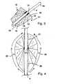
- Fig. 7is a three-dimensional representation of the rotor can be seen, which clearly shows the outstanding angled ends of the struts.
- FIG. 8which has an axial plan view of the rotor from the FIGS. 5 to 7 shows, clearly illustrates the protruding ends of the struts 27, 28 and the opposing struts of the further conveying element.
- Fig. 9shows in the expanded state of the rotor from the FIGS. 5 to 8 in that the angled struts 27, 28 effect a deflection of the front edge of the conveying element out of the plane of the membrane, resulting in a helical structure of the conveying elements.
- Fig. 10 or 11can be seen.
- Fig. 12clearly shows in plan view that the tensioned between the struts membrane is not in a flat shape, but is curved.
- Fig. 13makes clear on the basis of another embodiment that the struts 29, 30 with respect to its pivoting plane can also be inclined relative to the longitudinal axis / rotation axis 40 of the hub 4. This is for example possible by a corresponding inclination of the shaft 31 on which the struts 29, 30 are pivotally mounted, as in Fig. 13 shown.
- the respective other pivot axiswhich belongs to the opposite conveyor element, is then also mirror-symmetrical to the pivot axis 31 also inclined.
- the Fig. 14shows a design of a conveying element 32 in the form of a folded membrane, wherein the individual kinks of the membrane, denoted 33, 34, form the struts.
- the kinksare formed in parallel. But these can also be formed at an angle to each other or curved.
- the membranecan be clamped like a fan in a recess 35 of the hub 4 and folded axially on both sides of the hub, the membrane itself stretches. This results in a particularly simple production method for the conveying element.
- the arrows 36, 37denote the Anklappmonyen of the conveying element to the hub 4 on both sides of the recess 35th
- the Fig. 15shows again the conveying element 38 as a kinked membrane with the creases / struts 33, 34 prior to installation in the recess 35 of the hub 4.
- the recess 35can be introduced, for example, as a slot in the hub, wherein the slot also obliquely or curved opposite the longitudinal axis 27 may extend to achieve a helical rotation of the conveying element to the hub.
Landscapes
- Health & Medical Sciences (AREA)
- Engineering & Computer Science (AREA)
- Heart & Thoracic Surgery (AREA)
- Mechanical Engineering (AREA)
- Life Sciences & Earth Sciences (AREA)
- Public Health (AREA)
- Biomedical Technology (AREA)
- Hematology (AREA)
- Cardiology (AREA)
- Animal Behavior & Ethology (AREA)
- General Health & Medical Sciences (AREA)
- Anesthesiology (AREA)
- Veterinary Medicine (AREA)
- General Engineering & Computer Science (AREA)
- Structures Of Non-Positive Displacement Pumps (AREA)
- External Artificial Organs (AREA)
- Reciprocating Pumps (AREA)
- Infusion, Injection, And Reservoir Apparatuses (AREA)
Abstract
Translated fromGerman
Description
Translated fromGermanDie vorliegende Erfindung liegt auf dem Gebiet des Maschinenbaus und der Mikrotechnik und befasst sich insbesondere mit Fördereinrichtungen für Flüssigkeiten und Fluide im Allgemeinen.The present invention is in the field of mechanical engineering and microtechnology, and is particularly concerned with liquid and fluid handling equipment in general.
Derartige Fördereinrichtungen sind in vielfältigsten Erscheinungsformen als Pumpen mit verschiedenen Förderprinzipien bereits bekannt. Besonders interessant sind in diesem Zusammenhang rotatorisch antreibbare Pumpen, die Rotoren aufweisen, welche Fluide radial oder axial fördern.Such conveyors are already known in many forms as pumps with different delivery principles. Particularly interesting in this context are rotatably drivable pumps which have rotors which convey fluids radially or axially.
Dabei werden an solche Pumpen verschiedenste Anforderungen gestellt, was die Lagerung des Rotors, die Beständigkeit gegenüber Umwelteinwirkungen und die Wechselwirkung mit den zu fördernden Fluiden angeht. Insbesondere bei der Förderung von Fluiden mit komplexen, biologisch wirksamen Molekülen, z. B. innerhalb von lebenden Körpern, sind besondere Anforderungen an die Relativgeschwindigkeit zwischen entsprechenden Förderelementen und dem Fluid sowie Verwirbelungen und Scherkräfte zu stellen.In this case, a variety of demands are placed on such pumps, which concerns the storage of the rotor, the resistance to environmental influences and the interaction with the fluids to be delivered. Especially in the promotion of fluids with complex, biologically active molecules, e.g. B. within living bodies, special demands are placed on the relative speed between the corresponding conveyor elements and the fluid as well as turbulence and shear forces.
Ein besonderer Bereich derartiger Pumpen besteht im Bereich der Mikrotechnik beim Einsatz in der invasiven Medizin, wo Pumpen in derart kleiner Bauart hergestellt werden, dass sie durch Körpergefäße bewegt und an ihren Einsatzort gebracht werden können.A particular area of such pumps is in the field of microtechnology for use in invasive medicine, where pumps are made in such a small form that they can be moved through body vessels and brought to their place of use.
Solche Pumpen sind bereits in der Funktion als herzunterstützende Pumpen bekannt, die beispielsweise durch Blutgefäße in einem Patientenkörper bis hinein in eine Herzkammer geführt und dort betrieben werden können.Such pumps are already known in the function of heart-assisting pumps, which can be guided, for example, through blood vessels in a patient's body into a heart chamber and operated there.
Um den Wirkungsgrad derartiger Pumpen zu optimieren, ist auch bereits bekannt, diese Pumpen mit komprimierbaren und expandierbaren Rotoren auszustatten, die während des Transports durch ein Blutgefäß radial komprimiert sind und erst innerhalb eines größeren Körperraums expandiert werden können, beispielsweise in einer Herzkammer.In order to optimize the efficiency of such pumps, it is already known to provide these pumps with compressible and expandable rotors which are radially compressed during transport through a blood vessel and can be expanded only within a larger body space, for example in a heart chamber.
Die konstruktiven Anforderungen an solche komprimierbaren und expandierbaren Rotoren sind insbesondere wegen der kleinen Bauweise und der Bioverträglichkeit sowie den Anforderungen an die Zuverlässigkeit sehr hoch.The design requirements for such compressible and expandable rotors are very high, in particular because of the small size and the biocompatibility and the reliability requirements.
Ein entsprechender komprimierbarer Rotor ist beispielsweise aus der
Es sind auch Rotoren bekannt, die im Betrieb durch den Fluidgegendruck oder durch Zentrifugalkräfte expandierbar sind.There are also known rotors which are expandable in operation by the fluid back pressure or by centrifugal forces.
Es sind zudem verschiedenste Mechanismen bekannt, nach denen Schaufeln an entsprechenden Naben abklappbar, abbiegbar oder auf ähnliche Weise radial anlegbar sind.There are also known a variety of mechanisms, according to which blades on corresponding hubs are hinged, bendable or can be applied radially in a similar manner.
Bei derartig aufwendigen Konstruktionen ist dafür Sorge zu tragen, dass die Förderflächen eines entsprechenden Förderelementes möglichst glatt sind, um einen hohen Wirkungsgrad zu erzielen, dass die Förderfläche im Winkel in Bezug auf die Rotationsachse optimierbar ist und dass die Rotationsgeschwindigkeit in einem sinnvollen Bereich gewählt werden kann.In such complex structures, care must be taken to ensure that the conveying surfaces of a corresponding conveying element are as smooth as possible in order to achieve high efficiency, that the conveying surface can be optimized at an angle with respect to the axis of rotation, and that the rotational speed can be selected within a reasonable range ,
Zudem muss der Kompressions- und Expansionsmechanismus derart sicher gestaltet werden, dass er verlässlich funktioniert, dass im Betrieb die Pumpe einen stabilen Zustand aufweist und dass die Pumpe zuverlässig komprimierbar und im komprimierten Zustand transportierbar ist.In addition, the compression and expansion mechanism must be made so safe that it works reliably, that in operation, the pump has a stable state and that the pump is reliably compressible and transportable in the compressed state.
Der vorliegenden Erfindung liegt vor dem Hintergrund dieser Anforderungen und des Standes der Technik die Aufgabe zugrunde, eine derartige Pumpe zu schaffen, die zuverlässig funktioniert und bei gutem Wirkungsgrad einfach und zuverlässig komprimierbar und expandierbar ist.Against the background of these requirements and the state of the art, the object of the present invention is to provide such a pump which operates reliably and can be compressed and expanded easily and reliably with good efficiency.
Die Aufgabe wird gemäß der Erfindung mit den Merkmalen des Patentanspruchs 1 gelöst.The object is achieved according to the invention with the features of claim 1.
Um einen radial komprimierbaren und expandierbaren Rotor für eine Fluidpumpe mit einer Nabe und wenigstens einem Förderelement zu schaffen, das eine Mehrzahl von Streben und wenigstens eine zwischen diesen spannbare Membran aufweist, und um den entsprechenden Rotor besonders einfach und zuverlässig komprimierbar und expandierbar zu machen, sieht die Erfindung vor, dass wenigstens eine erste Gruppe von Streben von einer gemeinsamen Basis ausgehend in einer Schwenkebene schwenkbar und damit fächerartig aufspannbar ist und dass das Förderelement im expandierten Zustand längs der Nabe auf seiner vollen Länge an dieser anliegt.In order to provide a radially compressible and expandable rotor for a fluid pump with a hub and at least one conveying element, which has a plurality of struts and at least one tensionable between these membrane, and to make the corresponding rotor particularly simple and reliable compressible and expandable sees The invention provides that at least a first group of struts starting from a common base in a pivoting plane pivotally and thus fan-like clamped and that the conveying element rests in the expanded state along the hub over its full length at this.
Damit ist die Fläche des Förderelementes durch die zwischen den Streben aufgespannte Membran gebildet, und diese kann zum Transport fächerartig zusammengelegt werden, wobei die Streben im zusammengelegten Zustand radial einen deutlich geringeren Platz beanspruchen als im aufgespannten Zustand. Wenigstens ein Teil der Streben, insbesondere alle Streben können fächerartig an einer gemeinsamen Basis zusammenlaufen und dort in einer geeigneten Form schwenkbar gelagert sein. In diesem Fall können die Streben dann zum Aufspannen des Förderelementes komplett zu einer Seite der Nabe in einem Fächerwinkel von 90° oder zu beiden Seiten bis zur Nabe hin beispielsweise in einem Winkel von 180° aufgespannt werden, so dass das Förderelement zu beiden Seiten der Basis idealerweise an der Nabe anliegt. Dadurch wird ein besonders guter Wirkungsgrad bei der Förderung von Fluiden verwirklicht, indem Druckausgleichsvorgänge des Fluids zwischen dem Förderelement und der Nabe minimiert werden.Thus, the surface of the conveying element is formed by the membrane spanned between the struts, and this can be folded fan-like for transport, wherein the struts in the collapsed state radially occupy a significantly smaller space than in the clamped state. At least a portion of the struts, in particular all struts can converge fan-like on a common base and be pivotally mounted there in a suitable form. In this case, the struts can then be used to clamp the conveying element completely to one side of the hub at a fan angle of 90 ° or to spanned on both sides to the hub, for example, at an angle of 180 °, so that the conveyor element on both sides of the base ideally rests against the hub. Thereby, a particularly good efficiency in the delivery of fluids is realized by minimizing pressure equalization processes of the fluid between the delivery element and the hub.
Um den Platzbedarf des Förderelementes oder mehrerer Förderelemente, sofern zwei oder mehr Förderelemente an der Nabe vorgesehen sind, im komprimierten Zustand, beispielsweise während des Transports der Fluidpumpe, zu minimieren, kann vorteilhaft vorgesehen sein, dass die Nabe eine erste Ausnehmung aufweist, in der wenigstens die erste Gruppe von Streben oder auch alle Streben im komprimierten Zustand wenigstens teilweise aufgenommen ist/sind. Die Nabe kann dabei grundsätzlich zylindrisch oder zylindersymmetrisch sein.In order to minimize the space requirement of the conveying element or of a plurality of conveying elements, provided two or more conveying elements are provided on the hub in the compressed state, for example during the transport of the fluid pump, it can be advantageously provided that the hub has a first recess in which at least the first group of struts or even all struts in the compressed state is at least partially included / are. The hub can be basically cylindrical or cylindrically symmetric.
Auf diese Weise wird eine radial besonders wenig ausladende und je nach dem Anteil der Streben, der innerhalb der Ausnehmung aufgenommen werden kann, auch glatte Kontur der Nabe verwirklicht, die eine einfache Verschiebung beispielsweise innerhalb eines Blutgefäßes ermöglicht.In this way, a radially particularly little bulging and depending on the proportion of the struts, which can be accommodated within the recess, also smooth contour of the hub is realized, which allows a simple displacement, for example within a blood vessel.
Vorteilhaft kann auch eine gemeinsame Schwenkachse mehrerer Streben im Bereich der ersten Ausnehmung angeordnet sein. In diesem Fall lassen sich die Streben zum Betrieb der Pumpe am Einsatzort leicht aus der Ausnehmung herausschwenken.Advantageously, a common pivot axis of a plurality of struts in the region of the first recess may be arranged. In this case, the pursuit to operate the pump at the job site can easily swing out of the recess.
Besonders platzsparend kann sich auswirken, wenn die Schwenkachse die erste Ausnehmung durchsetzt und tangential zur Umfangsrichtung der Nabe verläuft. In diesem Fall wird der schwenkbare Teil der Streben aus der Ausnehmung herausgeschwenkt, während ein an den Streben jeweils dem Lagerpunkt gegenüberliegender Bereich der Streben innerhalb der Ausnehmung bewegbar ist.Particularly space-saving can be effective if the pivot axis passes through the first recess and tangential to the circumferential direction of the hub. In this case, the pivotable part of the struts is pivoted out of the recess, while a region of the struts opposite the struts is movable within the recess.
Als besonders vorteilhaft kann es sich erweisen, wenn zwei Förderelemente mit jeweils einer Gruppe von fächerartig aufspannbaren Streben vorgesehen sind, die einander am Umfang der Nabe gegenüberliegen und insbesondere im komprimierten Zustand in eine Ausnehmung der Nabe wenigstens teilweise aufgenommen sind. In diesem Fall können zwei Förderelemente symmetrisch an der Nabe angeordnet sein, um einen guten Wirkungsgrad zu erzielen. Je nach der Form der Förderelemente, die als ebene Flächen beispielsweise gegenüber der Rotorachse schräggestellt vorgesehen sein können oder die auch eine Wendelform aufweisen können, kann vorgesehen sein, verschiedene Förderelemente gegeneinander versetzt um die Nabe umlaufen zu lassen.It may prove to be particularly advantageous if two conveying elements are provided, each with a group of fan-like aufspannbaren struts, which are opposite to each other on the circumference of the hub and are at least partially accommodated in particular in the compressed state in a recess of the hub. In this case, two conveying elements may be arranged symmetrically on the hub in order to achieve a good efficiency. Depending on the shape of the conveying elements, which may be provided inclined as flat surfaces, for example with respect to the rotor axis or which may also have a helical shape, it may be provided to allow different conveying elements offset from each other to rotate around the hub.
Dabei können mehrere Ausnehmungen am Umfang der Nabe vorgesehen sein, bei Vorhandensein zweier Förderelemente beispielsweise zwei Ausnehmungen, die einander am Umfang der Nabe diametral gegenüberliegen und beispielsweise auch zu einer durchgehenden Öffnung der Nabe zusammengefasst sein können. Damit ist die Ausnehmung in der Nabe fertigungstechnisch besonders einfach herstellbar und es ergibt sich auch ausreichend Platz für eine Schwenkbewegung der Streben innerhalb der Ausnehmung.In this case, a plurality of recesses may be provided on the circumference of the hub, in the presence of two conveying elements, for example, two recesses which are diametrically opposed to each other on the circumference of the hub and, for example, can be combined to form a through opening of the hub. Thus, the recess in the hub manufacturing technology is particularly easy to manufacture and there is also sufficient space for a pivoting movement of the struts within the recess.
Zudem kann vorteilhaft vorgesehen sein, dass jedes der Förderelemente jeweils im expandierten Zustand längs der Nabe zu beiden Seiten der jeweiligen Ausnehmung an der Nabe anliegt. In diesem Fall sind die Streben des Förderelementes zu beiden Seiten so weit schwenkbar, dass sie einen Winkel von 180° entlang der Nabe abdecken und axial zu beiden Seiten der Ausnehmung, sofern eine solche vorgesehen ist, bzw. eines entsprechenden Schwenkpunktes, sofern das Förderelement an der Nabenoberfläche gelagert ist, abdecken und an der Umfangsfläche der Nabe eng anliegen.In addition, it can be advantageously provided that each of the conveying elements in each case in the expanded state along the hub rests on both sides of the respective recess on the hub. In this case, the struts of the conveying element on both sides are so far pivotable that they cover an angle of 180 ° along the hub and axially to both sides of the recess, if one is provided, or a corresponding pivot point, if the conveyor element the hub surface is stored, cover and fit tightly against the peripheral surface of the hub.
Um eine optimale axiale Förderung und einen guten Wirkungsgrad des Rotors zu erreichen, ist vorteilhaft vorgesehen, dass die Membran im expandierten Zustand wenigstens abschnittsweise gegenüber der Rotorachse geneigt ist. Dabei ist je nach dem Winkel, den die Membran bzw. die Förderfläche des Förderelementes gegenüber der Rotorlängsachse einnimmt, auch ein wendelartiger Umlauf der Membran um die Nabe vorgesehen. Es kann jedoch auch eine ebene Form der Membran vorgesehen sein.In order to achieve an optimal axial promotion and a good efficiency of the rotor, it is advantageously provided that the membrane in the expanded state is at least partially inclined relative to the rotor axis. Depending on the angle which the membrane or the conveying surface of the conveying element occupies with respect to the rotor longitudinal axis, a helical circulation of the membrane around the hub is also provided. However, it may also be provided a planar shape of the membrane.
Eine vorteilhafte Ausgestaltung der Erfindung kann auch vorsehen, dass wenigstens eine Strebe wenigstens auf einem Teil ihrer Länge gegenüber weiteren Streben aus der Schwenkebene der Streben heraus abgewinkelt ist.An advantageous embodiment of the invention may also provide that at least one strut is angled at least over part of its length to other struts from the pivot plane of the struts out.
Durch das Abwinkeln bzw. Abbiegen von einzelnen oder Gruppen von Streben kann jede beliebige strömungstechnisch und für den Förderwirkungsgrad günstige dreidimensionale Form der Membran/Förderfläche des Förderelementes verwirklicht werden. Die Streben können beispielsweise an ihrem der Schwenkachse gegenüberliegenden Ende oder auf der von der Schwenkachse weiter entfernten Hälfte ihrer Länge entsprechend gebogen oder abgewinkelt sein, um im Bereich der Schwenkachse ein Eintauchen in die Ausnehmung der Nabe nicht zu erschweren oder zu behindern.By bending or bending of individual or groups of struts, any desired fluidic and favorable for the delivery efficiency three-dimensional shape of the membrane / conveying surface of the conveying element can be realized. The struts may, for example, at their opposite end of the pivot axis or on the farther from the pivot axis half of their length accordingly be bent or angled so as not to complicate or hinder immersion in the recess of the hub in the region of the pivot axis.
Eine besonders einfache Ausführungsform des erfindungsgemäßen Rotors sieht vor, dass wenigstens die Streben der jeweils fächerartig aufspannbaren Gruppe innerhalb der jeweiligen Ausnehmung auf einer Welle schwenkbar gelagert sind. Das Vorsehen einer entsprechenden Welle in der Ausnehmung stellt eine besonders einfache und dauerhafte Lösung für die schwenkbare Lagerung der Streben dar.A particularly simple embodiment of the rotor according to the invention provides that at least the struts of the respective fan-like aufspannbaren group within the respective recess are pivotally mounted on a shaft. The provision of a corresponding shaft in the recess represents a particularly simple and permanent solution for the pivotable mounting of the struts.
Es kann jedoch auch vorgesehen sein, dass die schwenkbaren Streben an ihrer Basis durch Filmgelenke miteinander verbunden sind. Beispielsweise können die Streben aus demselben Material hergestellt und einstückig zusammenhängend ausgebildet sein, beispielsweise aus einem Spritzgusswerkstoff. In diesem Fall kann die Membran beispielsweise im Tauchverfahren durch Eintauchen der Streben in einen flüssigen Kunststoff, beispielsweise Polyurethan, aufgebracht sein, es ist jedoch auch denkbar, die Membran aus demselben Material herzustellen wie die Streben mit entsprechender Gestaltung der Dicke der Membran. In diesem Fall ist das Vorsehen von Filmgelenken durch Schwächung des Materials in den entsprechend biegbar gewünschten Bereichen verwirklichbar.However, it can also be provided that the pivotable struts are connected at their base by film joints. For example, the struts can be made of the same material and integrally formed, for example, from an injection molding material. In this case, the membrane can be applied, for example, by dipping the struts in a liquid plastic, such as polyurethane, in the dipping process, but it is also conceivable to make the membrane of the same material as the struts with appropriate design of the thickness of the membrane. In this case, the provision of film hinges by weakening the material in the corresponding bendable desired areas can be realized.
Um eine ideale äußere Kontur des Förderelementes zu schaffen, kann es sinnvoll oder notwendig sein, verschiedene Streben innerhalb des Förderelements mit unterschiedlichen Längen miteinander zu kombinieren. Die entsprechende Längengestaltung der Streben kann beispielsweise auch davon abhängen, wie das Gehäuse geformt ist, in dem der Rotor sich bewegt.In order to create an ideal outer contour of the conveyor element, it may be useful or necessary to combine different struts within the conveyor element with different lengths. The appropriate length design of the struts can For example, depending on how the housing is formed in which the rotor moves.
Zudem kann zur Erhöhung des Wirkungsgrades und zur Verbesserung der Stabilität des Rotors im Betrieb entlang der Nabe wenigstens eine Aufnahmevorrichtung, beispielsweise eine Schiene, zur Aufnahme der äußeren Streben des Förderelementes im expandierten Zustand vorgesehen sein.In addition, in order to increase the efficiency and to improve the stability of the rotor during operation along the hub at least one receiving device, such as a rail, may be provided for receiving the outer struts of the conveying element in the expanded state.
Entsprechend können nach der Expansion und dem fächerartigen Aufspannen der Streben bzw. dem Spannen der Membran die äußersten Streben, die direkt von der Basis ausgehend ungefähr parallel zur Nabe axial in einer oder beiden Richtungen verlaufen, in jeweils einer derartigen Aufnahmevorrichtung fixiert sein, die beispielsweise gabelartig ausgeprägt sein kann. In eine derartige Gabel kann dann die jeweils äußere Strebe an der Nabe eingelegt sein. Es kann auch eine andere Form der Fixierung der Streben an der Nabe, wie beispielsweise durch Magnete oder durch Einlegen in eine schienenartige Ausnehmung oder Erhöhung der Nabe, erfolgen.Accordingly, after the expansion and the fan-like clamping of the struts or the clamping of the membrane, the outermost struts, which extend directly from the base approximately parallel to the hub axially in one or both directions, be fixed in each case such a receiving device, for example fork-like can be pronounced. In such a fork then the respective outer strut can be inserted at the hub. It can also be another form of fixing the struts to the hub, such as by magnets or by inserting into a rail-like recess or increase of the hub done.
Damit wird sichergestellt, dass das zu fördernde Fluid nicht zwischen dem Förderelement und der Nabe im Zuge von Druckausgleichsvorgängen durchfließen kann und dass andererseits dem Förderelement zusätzlicher Halt und Stabilität durch die Nabe gegeben wird.This ensures that the fluid to be pumped can not flow between the conveyor element and the hub in the course of pressure equalization operations and that on the other hand the conveyor element additional support and stability is given by the hub.
Im Folgenden wird die Erfindung anhand eines Ausführungsbeispiels in einer Zeichnung gezeigt und anschließend näher erläutert. Dabei zeigt
- Fig. 1
- schematisch eine Ansicht einer Fluidpumpe bei der Verwendung als Herzkatheterpumpe,
- Fig. 2
- einen Rotor in einer Ansicht im komprimierten Zustand,
- Fig. 3
- eine Ausführungsform eines Rotors im expandierten Zustand,
- Fig. 4
- eine Ansicht einer weiteren Ausführungsform eines Rotors im expandierten Zustand,
- Fig. 5
- eine Seitenansicht eines Rotors im komprimierten Zustand,
- Fig. 6
- eine Ansicht der Anordnung aus
Fig. 5 um 90° um die Rotorlängsachse gedreht, - Fig. 7
- eine Ansicht wie aus den
Fign. 5 und 6 , dreidimensional in einer Schrägansicht dargestellt, - Fig. 8
- die Anordnung aus den
Fign. 5, 6 und 7 in einer axialen Draufsicht auf den Rotor, - Fig. 9
- eine Seitenansicht auf den Rotor aus den
Fign. 5 im expandierten Zustand,bis 8 - Fig. 10
- die Ansicht aus
Fig. 9 um 90° um die Längsachse des Rotors gedreht, - Fig. 11
- eine Schrägansicht der Anordnung aus den
Fign. 9 ,und 10 - Fig. 12
- eine axiale Draufsicht auf den Rotor aus den
Fign. 9 ,bis 11 - Fig. 13
- eine Seitenansicht eines Rotors mit einer geneigten Schwenkebene der Streben,
- Fig. 14
- eine weitere Ausführungsform mit einem Fächer und einer Befestigung an der Nabe sowie
- Fig. 15
- eine dreidimensionale Ansicht des Förderelements als gefaltete Membran.
- Fig. 1
- 1 is a schematic view of a fluid pump when used as a cardiac catheter pump;
- Fig. 2
- a rotor in a compressed state,
- Fig. 3
- an embodiment of a rotor in the expanded state,
- Fig. 4
- a view of another embodiment of a rotor in the expanded state,
- Fig. 5
- a side view of a rotor in the compressed state,
- Fig. 6
- a view of the arrangement
Fig. 5 rotated by 90 ° around the rotor's longitudinal axis, - Fig. 7
- a view like that
FIGS. 5 and 6 , shown in three dimensions in an oblique view, - Fig. 8
- the arrangement of the
FIGS. 5, 6 and 7 in an axial plan view of the rotor, - Fig. 9
- a side view of the rotor from the
FIGS. 5 to 8 in the expanded state, - Fig. 10
- the view
Fig. 9 rotated 90 ° about the longitudinal axis of the rotor, - Fig. 11
- an oblique view of the arrangement of the
FIGS. 9 and 10 . - Fig. 12
- an axial plan view of the rotor from the
FIGS. 9 to 11 . - Fig. 13
- a side view of a rotor with an inclined pivot plane of the struts,
- Fig. 14
- another embodiment with a fan and a fastening to the hub as well
- Fig. 15
- a three-dimensional view of the conveyor element as a folded membrane.
Mittels der auf die Nabe 4 und die Förderelemente der Pumpe übertragenen Rotationsbewegung kann Blut zwischen der Herzkammer 1 und dem Blutgefäß befördert, beispielsweise durch die Pumpe 2 angesaugt und in das Blutgefäß 7 hineingedrückt werden.By means of the rotational movement transmitted to the
Die Pumpe 2 kann im Betriebszustand einen Durchmesser bzw. allgemeine Abmaße haben, die zu groß wären, um sie durch das Blutgefäß 7 zu transportieren. Zu diesem Zweck ist die Pumpe radial komprimierbar. In der
Die Pumpe wird mitsamt dem Hohlkatheter 6 im komprimierten Zustand durch das Blutgefäß 7 so weit eingeschoben, bis dass sie in die Herzkammer 1 hineinragt, bevor sie expandiert wird.The pump is pushed so far together with the
Vor dem Entnehmen, das durch Herausziehen des Katheters 6 geschieht, muss die Pumpe 2 wieder komprimiert werden, was beispielsweise durch entsprechende, im Einzelnen nicht dargestellte Zugelemente geschehen kann, oder, sofern die Pumpe nur durch Fliehkräfte expandiert wird, wird sie angehalten und fällt dann in sich zusammen.Prior to removal, which happens by pulling out the
Es ist auch denkbar, die Pumpe durch Hineinziehen in den Hohlkatheter wenigstens ein Stück weit zu komprimieren, dadurch, dass beispielsweise am distalen Ende des Hohlkatheters 6 ein Einführtrichter vorgesehen ist.It is also conceivable to compress the pump at least to some extent by pulling it into the hollow catheter, in that, for example, an insertion funnel is provided at the distal end of the
Die Gestalt der Nabe 4 ist in der
Die Streben lassen sich so eng an die Nabe legen, dass sie in radialer Richtung des Rotors nur einen verschwindend geringen Platz einnehmen. Zwischen den Streben ist im komprimierten Zustand die Membran eingerollt bzw. eingefaltet.The struts can be placed so close to the hub, that they occupy only a negligible amount of space in the radial direction of the rotor. Between the struts in the compressed state, the membrane is rolled or folded.
Zwischen den Streben 12 bis 16 ist im expandierten Zustand die Membran 18 flach und straff gespannt.
Das Förderelement 10 liegt dem näher beschriebenen Förderelement 11 genau gegenüber, so dass beide gemeinsam im Zusammenspiel mit der Nabe 4 eine halbe Ellipse bilden. Die am nächsten an der Nabe 4 anliegenden Streben 16 können dort beispielsweise mit einer Aufnahmevorrichtung fixiert oder zumindest geführt sein. Eine solche Aufnahmevorrichtung kann beispielsweise U-förmig mit zwei Schenkeln ausgebildet sein, so dass die Strebe 16 bei der Expansion des Förderelementes 11 in diese eintauchen kann und dort gegebenenfalls festgehalten wird. Dadurch ist sichergestellt, dass zwischen der Strebe 16 und der Nabe 4 so gut wie kein Zwischenraum entsteht, der bei Rotation des Rotors, wenn er vorhanden wäre, ein Abströmen des Fluids zwischen der Nabe und dem Förderelement und damit einen Druckverlust verursachen könnte.Between the
The conveying
Die
Die Streben eines einzelnen Förderelementes 19, 20 sind durchaus unterschiedlich lang, so dass die Basis 17 axial nicht in der Mitte des Förderelementes liegen muss. Wie in der
Die einzelnen Streben können beispielsweise aus einem Kunststoff in Spritzgusstechnik hergestellt sein, z. B. auch an der Basis 17 zusammenhängend, wobei zwischen den Streben eine Membran gespannt ist, entweder durch Eintauchen der Streben in einen flüssigen Kunststoff oder durch einstückige Herstellung der einzelnen Förderelemente 19, 20 im Ganzen aus demselben Werkstoff, wobei dann die Membran als Film zwischen den Streben vorgesehen ist.The individual struts can be made for example of a plastic in injection molding, for. B. also connected to the
In dieser Öffnung sind zwei Wellen 25, 26 befestigt, auf denen die Streben schwenkbar gelagert sind. Die einzelnen Streben finden im komprimierten Zustand im Wesentlichen innerhalb der Ausnehmungen 23, 24 Platz, wie dies deutlicher in der Ansicht der
Aus der
In der
Auch die
Besonders deutlich ist dies aus der
Es ergibt sich somit auch bei Vorliegen einer ebenen Membran zwischen den Streben 29, 30 ein wendelförmiger Umlauf des Förderelementes / der Membran um die Nabe 4, so dass bei Rotation der Nabe ein axialer Vortrieb des zu fördernden Fluids entsteht.Thus, even in the presence of a flat membrane between the
Die jeweils andere Schwenkachse, die zu dem gegenüberliegenden Förderelement gehört, ist dann spiegelsymmetrisch zu der Schwenkachse 31 ebenfalls schräg gestellt.The respective other pivot axis, which belongs to the opposite conveyor element, is then also mirror-symmetrical to the
Die
Die Membran kann fächerartig in einer Ausnehmung 35 der Nabe 4 eingeklemmt und axial zu beiden Seiten der Nabe angeklappt werden, wobei die Membran sich streckt. Damit ergibt sich eine besonders einfache Herstellungsweise für das Förderelement.The membrane can be clamped like a fan in a
Die Pfeile 36, 37 bezeichnen die Anklappbewegungen des Förderelementes an die Nabe 4 beiderseits der Ausnehmung 35.The
Die
Durch die erfindungsgemäße Gestaltung eines Rotors mit entsprechenden Förderelementen wird eine besonders kostengünstige und einfache Herstellungsart der Förderelemente geschaffen, die zudem ein einfaches Komprimieren und Expandieren der Förderelemente erlaubt. Der Platzbedarf des Rotors beim Transport in die Betriebsstellung ist durch die Erfindung minimiert.The inventive design of a rotor with corresponding conveyor elements, a particularly cost-effective and simple production of the conveyor elements is created, which also allows easy compression and expansion of the conveying elements. The space requirement of the rotor during transport into the operating position is minimized by the invention.
Claims (13)
Translated fromGermanPriority Applications (11)
| Application Number | Priority Date | Filing Date | Title |
|---|---|---|---|
| EP09075572AEP2338541A1 (en) | 2009-12-23 | 2009-12-23 | Radial compressible and expandable rotor for a fluid pump |
| DE112010004977.7TDE112010004977B4 (en) | 2009-12-23 | 2010-12-23 | Radially compressible and expandable rotor for a fluid pump |
| US13/261,315US9339596B2 (en) | 2009-12-23 | 2010-12-23 | Radially compressible and expandable rotor for a fluid pump |
| PCT/EP2010/007996WO2011076439A1 (en) | 2009-12-23 | 2010-12-23 | Radially compressible and expandable rotor for a fluid pump |
| CN201080058891.6ACN102665788B (en) | 2009-12-23 | 2010-12-23 | Radially compressible and expandable rotor for a fluid pump |
| US15/142,292US9903384B2 (en) | 2009-12-23 | 2016-04-29 | Radially compressible and expandable rotor for a fluid pump |
| US15/869,285US10557475B2 (en) | 2009-12-23 | 2018-01-12 | Radially compressible and expandable rotor for a fluid pump |
| US16/725,703US11434922B2 (en) | 2009-12-23 | 2019-12-23 | Radially compressible and expandable rotor for a fluid pump |
| US17/871,153US11781557B2 (en) | 2009-12-23 | 2022-07-22 | Radially compressible and expandable rotor for a fluid pump |
| US18/238,002US12085088B2 (en) | 2009-12-23 | 2023-08-25 | Radially compressible and expandable rotor for a fluid pump |
| US18/795,914US20250067273A1 (en) | 2009-12-23 | 2024-08-06 | Radially compressible and expandable rotor for a fluid pump |
Applications Claiming Priority (1)
| Application Number | Priority Date | Filing Date | Title |
|---|---|---|---|
| EP09075572AEP2338541A1 (en) | 2009-12-23 | 2009-12-23 | Radial compressible and expandable rotor for a fluid pump |
Publications (1)
| Publication Number | Publication Date |
|---|---|
| EP2338541A1true EP2338541A1 (en) | 2011-06-29 |
Family
ID=42211651
Family Applications (1)
| Application Number | Title | Priority Date | Filing Date |
|---|---|---|---|
| EP09075572AWithdrawnEP2338541A1 (en) | 2009-12-23 | 2009-12-23 | Radial compressible and expandable rotor for a fluid pump |
Country Status (5)
| Country | Link |
|---|---|
| US (7) | US9339596B2 (en) |
| EP (1) | EP2338541A1 (en) |
| CN (1) | CN102665788B (en) |
| DE (1) | DE112010004977B4 (en) |
| WO (1) | WO2011076439A1 (en) |
Cited By (17)
| Publication number | Priority date | Publication date | Assignee | Title |
|---|---|---|---|---|
| WO2013082053A1 (en)* | 2011-11-28 | 2013-06-06 | MI-VAD, Inc. | Ventricular assist device and method |
| US8734331B2 (en) | 2011-08-29 | 2014-05-27 | Minnetronix, Inc. | Expandable blood pumps and methods of their deployment and use |
| US8849398B2 (en) | 2011-08-29 | 2014-09-30 | Minnetronix, Inc. | Expandable blood pump for cardiac support |
| US9162017B2 (en) | 2011-08-29 | 2015-10-20 | Minnetronix, Inc. | Expandable vascular pump |
| US10426880B2 (en) | 2014-02-25 | 2019-10-01 | MI-VAD, Inc. | Ventricular assist device and method |
| US10722631B2 (en) | 2018-02-01 | 2020-07-28 | Shifamed Holdings, Llc | Intravascular blood pumps and methods of use and manufacture |
| EP3852245A1 (en) | 2013-10-11 | 2021-07-21 | ECP Entwicklungsgesellschaft mbH | Compressible motor, implanting assembly and method for positioning the motor |
| US11185677B2 (en) | 2017-06-07 | 2021-11-30 | Shifamed Holdings, Llc | Intravascular fluid movement devices, systems, and methods of use |
| US11511103B2 (en) | 2017-11-13 | 2022-11-29 | Shifamed Holdings, Llc | Intravascular fluid movement devices, systems, and methods of use |
| US11654275B2 (en) | 2019-07-22 | 2023-05-23 | Shifamed Holdings, Llc | Intravascular blood pumps with struts and methods of use and manufacture |
| US11724089B2 (en) | 2019-09-25 | 2023-08-15 | Shifamed Holdings, Llc | Intravascular blood pump systems and methods of use and control thereof |
| US11964145B2 (en) | 2019-07-12 | 2024-04-23 | Shifamed Holdings, Llc | Intravascular blood pumps and methods of manufacture and use |
| US12102815B2 (en) | 2019-09-25 | 2024-10-01 | Shifamed Holdings, Llc | Catheter blood pumps and collapsible pump housings |
| US12121713B2 (en) | 2019-09-25 | 2024-10-22 | Shifamed Holdings, Llc | Catheter blood pumps and collapsible blood conduits |
| US12161857B2 (en) | 2018-07-31 | 2024-12-10 | Shifamed Holdings, Llc | Intravascular blood pumps and methods of use |
| US12220570B2 (en) | 2018-10-05 | 2025-02-11 | Shifamed Holdings, Llc | Intravascular blood pumps and methods of use |
| US12409310B2 (en) | 2019-12-11 | 2025-09-09 | Shifamed Holdings, Llc | Descending aorta and vena cava blood pumps |
Families Citing this family (84)
| Publication number | Priority date | Publication date | Assignee | Title |
|---|---|---|---|---|
| US7393181B2 (en) | 2004-09-17 | 2008-07-01 | The Penn State Research Foundation | Expandable impeller pump |
| CN102380135A (en) | 2006-03-23 | 2012-03-21 | 宾州研究基金会 | Heart assist device with expandable impeller pump |
| EP2194278A1 (en) | 2008-12-05 | 2010-06-09 | ECP Entwicklungsgesellschaft mbH | Fluid pump with a rotor |
| EP2216059A1 (en) | 2009-02-04 | 2010-08-11 | ECP Entwicklungsgesellschaft mbH | Catheter device with a catheter and an actuation device |
| EP2229965A1 (en) | 2009-03-18 | 2010-09-22 | ECP Entwicklungsgesellschaft mbH | Fluid pump with particular form of a rotor blade |
| EP2246078A1 (en) | 2009-04-29 | 2010-11-03 | ECP Entwicklungsgesellschaft mbH | Shaft assembly with a shaft which moves within a fluid-filled casing |
| EP2248544A1 (en) | 2009-05-05 | 2010-11-10 | ECP Entwicklungsgesellschaft mbH | Fluid pump with variable circumference, particularly for medical use |
| EP2266640A1 (en) | 2009-06-25 | 2010-12-29 | ECP Entwicklungsgesellschaft mbH | Compressible and expandable turbine blade for a fluid pump |
| EP2282070B1 (en) | 2009-08-06 | 2012-10-17 | ECP Entwicklungsgesellschaft mbH | Catheter device with a coupling device for a drive device |
| EP2299119B1 (en) | 2009-09-22 | 2018-11-07 | ECP Entwicklungsgesellschaft mbH | Inflatable rotor for a fluid pump |
| EP2298371A1 (en) | 2009-09-22 | 2011-03-23 | ECP Entwicklungsgesellschaft mbH | Function element, in particular fluid pump with a housing and a transport element |
| EP2298373A1 (en) | 2009-09-22 | 2011-03-23 | ECP Entwicklungsgesellschaft mbH | Fluid pump with at least one turbine blade and a seating device |
| EP2298372A1 (en) | 2009-09-22 | 2011-03-23 | ECP Entwicklungsgesellschaft mbH | Rotor for an axial pump for transporting a fluid |
| EP2314330A1 (en) | 2009-10-23 | 2011-04-27 | ECP Entwicklungsgesellschaft mbH | Flexible shaft arrangement |
| EP2314331B1 (en) | 2009-10-23 | 2013-12-11 | ECP Entwicklungsgesellschaft mbH | Catheter pump arrangement and flexible shaft arrangement with a cable core |
| EP2338540A1 (en) | 2009-12-23 | 2011-06-29 | ECP Entwicklungsgesellschaft mbH | Delivery blade for a compressible rotor |
| EP2338539A1 (en) | 2009-12-23 | 2011-06-29 | ECP Entwicklungsgesellschaft mbH | Pump device with a detection device |
| EP2338541A1 (en) | 2009-12-23 | 2011-06-29 | ECP Entwicklungsgesellschaft mbH | Radial compressible and expandable rotor for a fluid pump |
| EP2347778A1 (en) | 2010-01-25 | 2011-07-27 | ECP Entwicklungsgesellschaft mbH | Fluid pump with a radially compressible rotor |
| EP2363157A1 (en) | 2010-03-05 | 2011-09-07 | ECP Entwicklungsgesellschaft mbH | Device for exerting mechanical force on a medium, in particular fluid pump |
| EP2388029A1 (en) | 2010-05-17 | 2011-11-23 | ECP Entwicklungsgesellschaft mbH | Pump array |
| EP2399639A1 (en) | 2010-06-25 | 2011-12-28 | ECP Entwicklungsgesellschaft mbH | System for introducing a pump |
| EP2407185A1 (en) | 2010-07-15 | 2012-01-18 | ECP Entwicklungsgesellschaft mbH | Radial compressible and expandable rotor for a pump with a turbine blade |
| EP2407187A3 (en) | 2010-07-15 | 2012-06-20 | ECP Entwicklungsgesellschaft mbH | Blood pump for invasive application within the body of a patient |
| EP2407186A1 (en) | 2010-07-15 | 2012-01-18 | ECP Entwicklungsgesellschaft mbH | Rotor for a pump, produced with an initial elastic material |
| EP2422735A1 (en) | 2010-08-27 | 2012-02-29 | ECP Entwicklungsgesellschaft mbH | Implantable blood transportation device, manipulation device and coupling device |
| WO2012094641A2 (en) | 2011-01-06 | 2012-07-12 | Thoratec Corporation | Percutaneous heart pump |
| EP2497521A1 (en) | 2011-03-10 | 2012-09-12 | ECP Entwicklungsgesellschaft mbH | Push device for axial insertion of a string-shaped, flexible body |
| EP2564771A1 (en) | 2011-09-05 | 2013-03-06 | ECP Entwicklungsgesellschaft mbH | Medicinal product with a functional element for invasive use in the body of a patient |
| US8926492B2 (en) | 2011-10-11 | 2015-01-06 | Ecp Entwicklungsgesellschaft Mbh | Housing for a functional element |
| US9446179B2 (en) | 2012-05-14 | 2016-09-20 | Thoratec Corporation | Distal bearing support |
| EP4218887A1 (en) | 2012-05-14 | 2023-08-02 | Tc1 Llc | Mechanical circulatory support device for stabilizing a patient after cardiogenic shock |
| US9327067B2 (en) | 2012-05-14 | 2016-05-03 | Thoratec Corporation | Impeller for catheter pump |
| US8721517B2 (en) | 2012-05-14 | 2014-05-13 | Thoratec Corporation | Impeller for catheter pump |
| US9872947B2 (en) | 2012-05-14 | 2018-01-23 | Tc1 Llc | Sheath system for catheter pump |
| CN108742951B (en) | 2012-06-06 | 2021-05-25 | 洋红医疗有限公司 | Artificial kidney valve |
| US9421311B2 (en) | 2012-07-03 | 2016-08-23 | Thoratec Corporation | Motor assembly for catheter pump |
| US9358329B2 (en) | 2012-07-03 | 2016-06-07 | Thoratec Corporation | Catheter pump |
| EP4186557A1 (en) | 2012-07-03 | 2023-05-31 | Tc1 Llc | Motor assembly for catheter pump |
| WO2014164136A1 (en) | 2013-03-13 | 2014-10-09 | Thoratec Corporation | Fluid handling system |
| US11077294B2 (en) | 2013-03-13 | 2021-08-03 | Tc1 Llc | Sheath assembly for catheter pump |
| US11033728B2 (en) | 2013-03-13 | 2021-06-15 | Tc1 Llc | Fluid handling system |
| US10583231B2 (en) | 2013-03-13 | 2020-03-10 | Magenta Medical Ltd. | Blood pump |
| EP4233702A3 (en) | 2013-03-13 | 2023-12-20 | Magenta Medical Ltd. | Manufacture of an impeller |
| EP4190376A1 (en) | 2013-03-15 | 2023-06-07 | Tc1 Llc | Catheter pump assembly including a stator |
| US9308302B2 (en) | 2013-03-15 | 2016-04-12 | Thoratec Corporation | Catheter pump assembly including a stator |
| WO2015160943A1 (en) | 2014-04-15 | 2015-10-22 | Thoratec Corporation | Sensors for catheter pumps |
| EP3131597B1 (en) | 2014-04-15 | 2020-12-02 | Tc1 Llc | Catheter pump introducer systems |
| EP3131599B1 (en) | 2014-04-15 | 2019-02-20 | Tc1 Llc | Catheter pump with access ports |
| US10583232B2 (en) | 2014-04-15 | 2020-03-10 | Tc1 Llc | Catheter pump with off-set motor position |
| EP3583973A1 (en) | 2014-08-18 | 2019-12-25 | Tc1 Llc | Guide features for percutaneous catheter pump |
| US9770543B2 (en) | 2015-01-22 | 2017-09-26 | Tc1 Llc | Reduced rotational mass motor assembly for catheter pump |
| WO2016118781A2 (en) | 2015-01-22 | 2016-07-28 | Thoratec Corporation | Motor assembly with heat exchanger for catheter pump |
| US9675738B2 (en) | 2015-01-22 | 2017-06-13 | Tc1 Llc | Attachment mechanisms for motor of catheter pump |
| US10350341B2 (en)* | 2015-03-20 | 2019-07-16 | Drexel University | Impellers, blood pumps, and methods of treating a subject |
| US9907890B2 (en) | 2015-04-16 | 2018-03-06 | Tc1 Llc | Catheter pump with positioning brace |
| WO2016185473A1 (en) | 2015-05-18 | 2016-11-24 | Magenta Medical Ltd. | Blood pump |
| EP3808401A1 (en) | 2016-07-21 | 2021-04-21 | Tc1 Llc | Gas-filled chamber for catheter pump motor assembly |
| US11160970B2 (en) | 2016-07-21 | 2021-11-02 | Tc1 Llc | Fluid seals for catheter pump motor assembly |
| CA3039285A1 (en) | 2016-10-25 | 2018-05-03 | Magenta Medical Ltd. | Ventricular assist device |
| JP7094279B2 (en) | 2016-11-23 | 2022-07-01 | マジェンタ・メディカル・リミテッド | Blood pump |
| JP7150615B2 (en)* | 2017-01-18 | 2022-10-11 | テルモ株式会社 | blood pump |
| WO2018139508A1 (en)* | 2017-01-27 | 2018-08-02 | テルモ株式会社 | Impeller and blood pump |
| US10905808B2 (en) | 2018-01-10 | 2021-02-02 | Magenta Medical Ltd. | Drive cable for use with a blood pump |
| EP3638336B1 (en) | 2018-01-10 | 2022-04-06 | Magenta Medical Ltd. | Ventricular assist device |
| DE102018201030B4 (en) | 2018-01-24 | 2025-10-16 | Kardion Gmbh | Magnetic dome element with magnetic bearing function |
| DE102018207611A1 (en) | 2018-05-16 | 2019-11-21 | Kardion Gmbh | Rotor bearing system |
| DE102018207575A1 (en) | 2018-05-16 | 2019-11-21 | Kardion Gmbh | Magnetic face turning coupling for the transmission of torques |
| DE102018208539A1 (en) | 2018-05-30 | 2019-12-05 | Kardion Gmbh | A motor housing module for sealing an engine compartment of a motor of a cardiac assist system and cardiac assistance system and method for mounting a cardiac assist system |
| DE102018208541A1 (en) | 2018-05-30 | 2019-12-05 | Kardion Gmbh | Axial pump for a cardiac assist system and method of making an axial pump for a cardiac assist system |
| DE102018208538A1 (en) | 2018-05-30 | 2019-12-05 | Kardion Gmbh | Intravascular blood pump and process for the production of electrical conductors |
| DE102018208550A1 (en) | 2018-05-30 | 2019-12-05 | Kardion Gmbh | A lead device for directing blood flow to a cardiac assist system, cardiac assist system, and method of making a lead device |
| DE102018210058A1 (en) | 2018-06-21 | 2019-12-24 | Kardion Gmbh | Stator blade device for guiding the flow of a fluid flowing out of an outlet opening of a heart support system, heart support system with stator blade device, method for operating a stator blade device and manufacturing method |
| DE102018210076A1 (en) | 2018-06-21 | 2019-12-24 | Kardion Gmbh | Method and device for detecting a state of wear of a cardiac support system, method and device for operating a cardiac support system and cardiac support system |
| DE102018211327A1 (en) | 2018-07-10 | 2020-01-16 | Kardion Gmbh | Impeller for an implantable vascular support system |
| DE102018212153A1 (en) | 2018-07-20 | 2020-01-23 | Kardion Gmbh | Inlet line for a pump unit of a cardiac support system, cardiac support system and method for producing an inlet line for a pump unit of a cardiac support system |
| US11541224B2 (en) | 2018-07-30 | 2023-01-03 | Cardiovascular Systems, Inc. | Intravascular pump without inducer and centrifugal force-driven expansion of impeller blades and/or expandable and collapsible impeller housing |
| CN112654389A (en) | 2018-08-07 | 2021-04-13 | 开迪恩有限公司 | Bearing device for a cardiac support system and method for flushing an intermediate space in a bearing device for a cardiac support system |
| AU2020211431B2 (en) | 2019-01-24 | 2024-10-24 | Magenta Medical Ltd | Ventricular assist device |
| US12097016B2 (en) | 2019-03-14 | 2024-09-24 | Abiomed, Inc. | Blood flow rate measurement system |
| EP3972661B1 (en) | 2019-05-23 | 2024-09-11 | Magenta Medical Ltd. | Blood pumps |
| DE102020102474A1 (en) | 2020-01-31 | 2021-08-05 | Kardion Gmbh | Pump for conveying a fluid and method for manufacturing a pump |
| EP3984589B1 (en) | 2020-04-07 | 2023-08-23 | Magenta Medical Ltd. | Magnetic phase sensing |
| CN114949584A (en)* | 2022-02-25 | 2022-08-30 | 浙江迪远医疗器械有限公司 | Blood pump |
Citations (7)
| Publication number | Priority date | Publication date | Assignee | Title |
|---|---|---|---|---|
| US20020094273A1 (en)* | 2001-01-16 | 2002-07-18 | Yung-Chung Huang | Blade structure for ceiling fan |
| US6860713B2 (en) | 2002-11-27 | 2005-03-01 | Nidec Corporation | Fan with collapsible blades, redundant fan system, and related method |
| EP1061968B1 (en)* | 1998-03-07 | 2005-08-10 | Thomas Schmitz-Rode | Self-deploying axial-flow pump introduced intravascularly for temporary cardiac support |
| US20080073983A1 (en)* | 2006-09-21 | 2008-03-27 | Dezi Krajcir | Resilient motor mounting system and method of use |
| US7393181B2 (en) | 2004-09-17 | 2008-07-01 | The Penn State Research Foundation | Expandable impeller pump |
| WO2009029959A2 (en)* | 2007-08-29 | 2009-03-05 | Medical Value Partners, Llc | Article comprising an impeller |
| EP2047872A1 (en)* | 2007-10-08 | 2009-04-15 | Ais Gmbh Aachen Innovative Solutions | Catheter device |
Family Cites Families (182)
| Publication number | Priority date | Publication date | Assignee | Title |
|---|---|---|---|---|
| US3510229A (en) | 1968-07-23 | 1970-05-05 | Maytag Co | One-way pump |
| US3568659A (en) | 1968-09-24 | 1971-03-09 | James N Karnegis | Disposable percutaneous intracardiac pump and method of pumping blood |
| CH538410A (en) | 1971-02-17 | 1973-06-30 | L Somers S Brice | Flexible device for the transport of granular, powdery or fluid products |
| DE2113986A1 (en) | 1971-03-23 | 1972-09-28 | Svu Textilni | Artificial heart machine - with ptfe or similar inert plastic coated parts,as intracorperal replacement |
| SU400331A1 (en) | 1971-07-06 | 1973-10-01 | ||
| US4014317A (en) | 1972-02-18 | 1977-03-29 | The United States Of America As Represented By The Department Of Health, Education And Welfare | Multipurpose cardiocirculatory assist cannula and methods of use thereof |
| US3812812A (en) | 1973-06-25 | 1974-05-28 | M Hurwitz | Trolling propeller with self adjusting hydrodynamic spoilers |
| US4207028A (en) | 1979-06-12 | 1980-06-10 | Ridder Sven O | Extendable and retractable propeller for watercraft |
| US4559951A (en) | 1982-11-29 | 1985-12-24 | Cardiac Pacemakers, Inc. | Catheter assembly |
| US4563181A (en) | 1983-02-18 | 1986-01-07 | Mallinckrodt, Inc. | Fused flexible tip catheter |
| US4686982A (en) | 1985-06-19 | 1987-08-18 | John Nash | Spiral wire bearing for rotating wire drive catheter |
| US4679558A (en) | 1985-08-12 | 1987-07-14 | Intravascular Surgical Instruments, Inc. | Catheter based surgical methods and apparatus therefor |
| US4801243A (en) | 1985-12-28 | 1989-01-31 | Bird-Johnson Company | Adjustable diameter screw propeller |
| US4681512A (en)* | 1986-06-06 | 1987-07-21 | Barnard Maxwell K | Self-fairing windmill vane |
| US4747821A (en) | 1986-10-22 | 1988-05-31 | Intravascular Surgical Instruments, Inc. | Catheter with high speed moving working head |
| US4753221A (en) | 1986-10-22 | 1988-06-28 | Intravascular Surgical Instruments, Inc. | Blood pumping catheter and method of use |
| US4749376A (en) | 1986-10-24 | 1988-06-07 | Intravascular Surgical Instruments, Inc. | Reciprocating working head catheter |
| US4817613A (en) | 1987-07-13 | 1989-04-04 | Devices For Vascular Intervention, Inc. | Guiding catheter |
| US5154705A (en) | 1987-09-30 | 1992-10-13 | Lake Region Manufacturing Co., Inc. | Hollow lumen cable apparatus |
| US5061256A (en) | 1987-12-07 | 1991-10-29 | Johnson & Johnson | Inflow cannula for intravascular blood pumps |
| US5183384A (en) | 1988-05-16 | 1993-02-02 | Trumbly Joe H | Foldable propeller assembly |
| US5011469A (en) | 1988-08-29 | 1991-04-30 | Shiley, Inc. | Peripheral cardiopulmonary bypass and coronary reperfusion system |
| US4919647A (en) | 1988-10-13 | 1990-04-24 | Kensey Nash Corporation | Aortically located blood pumping catheter and method of use |
| US4957504A (en) | 1988-12-02 | 1990-09-18 | Chardack William M | Implantable blood pump |
| US4969865A (en) | 1989-01-09 | 1990-11-13 | American Biomed, Inc. | Helifoil pump |
| US5112292A (en) | 1989-01-09 | 1992-05-12 | American Biomed, Inc. | Helifoil pump |
| US4944722A (en) | 1989-02-23 | 1990-07-31 | Nimbus Medical, Inc. | Percutaneous axial flow blood pump |
| US5052404A (en) | 1989-03-02 | 1991-10-01 | The Microspring Company, Inc. | Torque transmitter |
| US4995857A (en) | 1989-04-07 | 1991-02-26 | Arnold John R | Left ventricular assist device and method for temporary and permanent procedures |
| US5097849A (en) | 1989-08-17 | 1992-03-24 | Kensey Nash Corporation | Method of use of catheter with working head having selectable impacting surfaces |
| US5042984A (en) | 1989-08-17 | 1991-08-27 | Kensey Nash Corporation | Catheter with working head having selectable impacting surfaces and method of using the same |
| US5040944A (en) | 1989-09-11 | 1991-08-20 | Cook Einar P | Pump having impeller rotational about convoluted stationary member |
| GB2239675A (en) | 1989-12-05 | 1991-07-10 | Man Fai Shiu | Pump for pumping liquid |
| US5118264A (en) | 1990-01-11 | 1992-06-02 | The Cleveland Clinic Foundation | Purge flow control in rotary blood pumps |
| US5145333A (en) | 1990-03-01 | 1992-09-08 | The Cleveland Clinic Foundation | Fluid motor driven blood pump |
| JPH0636821B2 (en) | 1990-03-08 | 1994-05-18 | 健二 山崎 | Implantable auxiliary artificial heart |
| US5108411A (en) | 1990-03-28 | 1992-04-28 | Cardiovascular Imaging Systems, Inc. | Flexible catheter drive cable |
| US5163910A (en) | 1990-04-10 | 1992-11-17 | Mayo Foundation For Medical Education And Research | Intracatheter perfusion pump apparatus and method |
| US5092844A (en) | 1990-04-10 | 1992-03-03 | Mayo Foundation For Medical Education And Research | Intracatheter perfusion pump apparatus and method |
| US5191888A (en) | 1990-04-18 | 1993-03-09 | Cordis Corporation | Assembly of an extension guidewire and an alignment tool for same |
| US5117838A (en) | 1990-04-18 | 1992-06-02 | Cordis Corporation | Rotating guidewire extension system |
| US5113872A (en) | 1990-04-18 | 1992-05-19 | Cordis Corporation | Guidewire extension system with connectors |
| US5813405A (en) | 1990-04-18 | 1998-09-29 | Cordis Corporation | Snap-in connection assembly for extension guidewire system |
| US5151721A (en) | 1990-05-15 | 1992-09-29 | Corning Incorporated | Compression joint for eyeglasses |
| ES2020787A6 (en) | 1990-07-20 | 1991-09-16 | Figuera Aymerich Diego | Intra-ventricular expansible assist pump |
| US5192286A (en) | 1991-07-26 | 1993-03-09 | Regents Of The University Of California | Method and device for retrieving materials from body lumens |
| US5188621A (en) | 1991-08-26 | 1993-02-23 | Target Therapeutics Inc. | Extendable guidewire assembly |
| IT1251758B (en) | 1991-11-05 | 1995-05-23 | Roberto Parravicini | VENTRICULAR PUMPING ASSISTANCE ELEMENT, WITH EXTERNAL DRIVE |
| US5201679A (en) | 1991-12-13 | 1993-04-13 | Attwood Corporation | Marine propeller with breakaway hub |
| US5271415A (en) | 1992-01-28 | 1993-12-21 | Baxter International Inc. | Guidewire extension system |
| US6302910B1 (en) | 1992-06-23 | 2001-10-16 | Sun Medical Technology Research Corporation | Auxiliary artificial heart of an embedded type |
| US5300112A (en) | 1992-07-14 | 1994-04-05 | Aai Corporation | Articulated heart pump |
| US5676651A (en) | 1992-08-06 | 1997-10-14 | Electric Boat Corporation | Surgically implantable pump arrangement and method for pumping body fluids |
| SE501215C2 (en) | 1992-09-02 | 1994-12-12 | Oeyvind Reitan | catheter Pump |
| US5376114A (en) | 1992-10-30 | 1994-12-27 | Jarvik; Robert | Cannula pumps for temporary cardiac support and methods of their application and use |
| US5365943A (en) | 1993-03-12 | 1994-11-22 | C. R. Bard, Inc. | Anatomically matched steerable PTCA guidewire |
| JPH06346917A (en) | 1993-06-03 | 1994-12-20 | Shicoh Eng Co Ltd | Pressure-proof water-proof sealing system using unidirectional dynamic pressure bearing |
| US5368438A (en) | 1993-06-28 | 1994-11-29 | Baxter International Inc. | Blood pump |
| US5720300A (en) | 1993-11-10 | 1998-02-24 | C. R. Bard, Inc. | High performance wires for use in medical devices and alloys therefor |
| DK145093D0 (en) | 1993-12-23 | 1993-12-23 | Gori 1902 As | PROPELLER |
| US5531789A (en) | 1993-12-24 | 1996-07-02 | Sun Medical Technology Research Corporation | Sealing system of an artificial internal organ |
| US5613935A (en) | 1994-12-16 | 1997-03-25 | Jarvik; Robert | High reliability cardiac assist system |
| DE19535781C2 (en) | 1995-09-26 | 1999-11-11 | Fraunhofer Ges Forschung | Device for active flow support of body fluids |
| EP0768091B1 (en) | 1995-10-16 | 2003-07-30 | Sun Medical Technology Research Corporation | Artificial heart |
| US5877566A (en) | 1996-03-22 | 1999-03-02 | Chen; Chi-Der | Submersible magnetic motor having improved rotary blades |
| US5701911A (en) | 1996-04-05 | 1997-12-30 | Medtronic, Inc. | Guide wire extension docking system |
| US6254359B1 (en) | 1996-05-10 | 2001-07-03 | The United States Of America As Represented By The Administrator Of The National Aeronautics And Space Administration | Method for providing a jewel bearing for supporting a pump rotor shaft |
| IL118352A0 (en) | 1996-05-21 | 1996-09-12 | Sudai Amnon | Apparatus and methods for revascularization |
| US5820571A (en) | 1996-06-24 | 1998-10-13 | C. R. Bard, Inc. | Medical backloading wire |
| US6015272A (en) | 1996-06-26 | 2000-01-18 | University Of Pittsburgh | Magnetically suspended miniature fluid pump and method of designing the same |
| US5779721A (en) | 1996-07-26 | 1998-07-14 | Kensey Nash Corporation | System and method of use for revascularizing stenotic bypass grafts and other blood vessels |
| US5851174A (en) | 1996-09-17 | 1998-12-22 | Robert Jarvik | Cardiac support device |
| ES2227718T3 (en) | 1996-10-04 | 2005-04-01 | United States Surgical Corporation | CIRCULATORY SUPPORT SYSTEM. |
| US5882329A (en) | 1997-02-12 | 1999-03-16 | Prolifix Medical, Inc. | Apparatus and method for removing stenotic material from stents |
| CA2206644A1 (en) | 1997-05-30 | 1998-11-30 | L. Conrad Pelletier | Ventricular assist device comprising enclosed-impeller axial flow blood pump |
| US6129704A (en) | 1997-06-12 | 2000-10-10 | Schneider (Usa) Inc. | Perfusion balloon catheter having a magnetically driven impeller |
| US6183412B1 (en) | 1997-10-02 | 2001-02-06 | Micromed Technology, Inc. | Implantable pump system |
| US5980471A (en) | 1997-10-10 | 1999-11-09 | Advanced Cardiovascular System, Inc. | Guidewire with tubular connector |
| US6007478A (en) | 1997-11-13 | 1999-12-28 | Impella Cardiotechnik Aktiengesellschaft | Cannula having constant wall thickness with increasing distal flexibility and method of making |
| GB9824436D0 (en) | 1998-11-06 | 1999-01-06 | Habib Nagy A | Methods of treatment |
| US6308632B1 (en) | 1998-11-23 | 2001-10-30 | James E. Shaffer | Deployable folded propeller assembly for aerial projectiles |
| CA2256131A1 (en) | 1998-12-16 | 2000-06-16 | Micro Therapeutics, Inc. | Miniaturized medical brush |
| US7780628B1 (en) | 1999-01-11 | 2010-08-24 | Angiodynamics, Inc. | Apparatus and methods for treating congestive heart disease |
| US6123659A (en) | 1999-01-26 | 2000-09-26 | Nimbus Inc. | Blood pump with profiled outflow region |
| EP1034808A1 (en) | 1999-03-09 | 2000-09-13 | Paul Frederik Gründeman | A device for transventricular mechanical circulatory support |
| DE20007581U1 (en) | 1999-04-20 | 2000-10-19 | Mediport Kardiotechnik GmbH, 12247 Berlin | Device for the axial conveyance of fluid media |
| JP2001017552A (en) | 1999-06-18 | 2001-01-23 | Medos Medizintechnik Gmbh | Method to inject fluid in blood vessel of human body, and corresponding cannula |
| US6458139B1 (en) | 1999-06-21 | 2002-10-01 | Endovascular Technologies, Inc. | Filter/emboli extractor for use in variable sized blood vessels |
| US6506025B1 (en) | 1999-06-23 | 2003-01-14 | California Institute Of Technology | Bladeless pump |
| US6247892B1 (en) | 1999-07-26 | 2001-06-19 | Impsa International Inc. | Continuous flow rotary pump |
| AU5317799A (en) | 1999-07-26 | 2001-02-13 | Impsa International, Inc. | Continuous flow rotary pump |
| US6398714B1 (en) | 1999-07-29 | 2002-06-04 | Intra-Vasc.Nl B.V. | Cardiac assist catheter pump and catheter and fitting for use therein |
| US7022100B1 (en) | 1999-09-03 | 2006-04-04 | A-Med Systems, Inc. | Guidable intravascular blood pump and related methods |
| US6454775B1 (en) | 1999-12-06 | 2002-09-24 | Bacchus Vascular Inc. | Systems and methods for clot disruption and retrieval |
| JP2001207988A (en) | 2000-01-26 | 2001-08-03 | Nipro Corp | Magnetic driving type axial flow pump |
| US20010031981A1 (en) | 2000-03-31 | 2001-10-18 | Evans Michael A. | Method and device for locating guidewire and treating chronic total occlusions |
| US6592612B1 (en) | 2000-05-04 | 2003-07-15 | Cardeon Corporation | Method and apparatus for providing heat exchange within a catheter body |
| US6537030B1 (en) | 2000-10-18 | 2003-03-25 | Fasco Industries, Inc. | Single piece impeller having radial output |
| DE20119322U1 (en) | 2000-11-21 | 2002-02-21 | Schering Ag, 13353 Berlin | Tubular vascular grafts (stents) |
| DE10058669B4 (en) | 2000-11-25 | 2004-05-06 | Impella Cardiotechnik Ag | micromotor |
| DE10059714C1 (en) | 2000-12-01 | 2002-05-08 | Impella Cardiotech Ag | Intravasal pump has pump stage fitted with flexible expandible sleeve contricted during insertion through blood vessel |
| DE10108810A1 (en) | 2001-02-16 | 2002-08-29 | Berlin Heart Ag | Device for the axial conveyance of liquids |
| US6517315B2 (en) | 2001-05-29 | 2003-02-11 | Hewlett-Packard Company | Enhanced performance fan with the use of winglets |
| DE10155011B4 (en) | 2001-11-02 | 2005-11-24 | Impella Cardiosystems Ag | Intra-aortic pump |
| US6981942B2 (en) | 2001-11-19 | 2006-01-03 | University Of Medicine And Dentristy Of New Jersey | Temporary blood circulation assist device |
| ATE485850T1 (en) | 2002-01-08 | 2010-11-15 | Micromed Technology Inc | SYSTEM FOR DETECTING VENTRICULAR COLLAPSE |
| RU2229899C2 (en) | 2002-03-20 | 2004-06-10 | Федеральный научно-производственный центр закрытое акционерное общество "Научно-производственный концерн (объединение) "ЭНЕРГИЯ" | Device for supporting assist blood circulation |
| AU2003236497A1 (en) | 2002-06-11 | 2003-12-22 | Walid Aboul-Hosn | Expandable blood pump and related methods |
| US20030231959A1 (en) | 2002-06-12 | 2003-12-18 | William Hackett | Impeller assembly for centrifugal pumps |
| US7118356B2 (en) | 2002-10-02 | 2006-10-10 | Nanyang Technological University | Fluid pump with a tubular driver body capable of selective axial expansion and contraction |
| US20040215222A1 (en)* | 2003-04-25 | 2004-10-28 | Michael Krivoruchko | Intravascular material removal device |
| US7655022B2 (en) | 2003-04-28 | 2010-02-02 | Cardiac Pacemakers, Inc. | Compliant guiding catheter sheath system |
| US7074018B2 (en) | 2003-07-10 | 2006-07-11 | Sheldon Chang | Direct drive linear flow blood pump |
| DE10336902C5 (en) | 2003-08-08 | 2019-04-25 | Abiomed Europe Gmbh | Intracardiac pumping device |
| US7054156B2 (en) | 2003-09-02 | 2006-05-30 | Hewlett-Packard Development Company, L.P. | Fan rotor systems having collapsible fan blades |
| AU2003261026A1 (en) | 2003-09-02 | 2005-03-16 | Intra-Vasc.Nl B.V. | Catheter pump, catheter and fittings therefore and methods of using a catheter pump. |
| US20050101200A1 (en) | 2003-09-09 | 2005-05-12 | Chad Townsend | Paddle blade |
| WO2005030316A1 (en) | 2003-09-26 | 2005-04-07 | Medtronic, Inc. | Sutureless pump connector |
| EP1670524A4 (en) | 2003-10-09 | 2012-12-26 | Thoratec Corp | Impeller |
| EP1718361B1 (en) | 2004-02-11 | 2015-06-17 | Fort Wayne Metals Research Products Corporation | Drawn strand filled tubing wire |
| US7942804B2 (en) | 2004-05-20 | 2011-05-17 | Cor-Med Vascular, Inc. | Replaceable expandable transmyocardial ventricular assist device |
| EP2151257B1 (en) | 2004-08-13 | 2013-04-17 | Delgado, Reynolds M., III | Apparatus for long-term assisting a left ventricle to pump blood |
| DE102004054714A1 (en) | 2004-11-12 | 2006-05-24 | Impella Cardiosystems Gmbh | Foldable intravascular insertable blood pump |
| US7479102B2 (en) | 2005-02-28 | 2009-01-20 | Robert Jarvik | Minimally invasive transvalvular ventricular assist device |
| AU2006255059A1 (en) | 2005-06-06 | 2006-12-14 | Foster-Miller, Inc. | Blood pump |
| EP1738783A1 (en) | 2005-07-01 | 2007-01-03 | Universitätsspital Basel | Axial flow pump with helical blade |
| WO2007062239A2 (en)* | 2005-11-28 | 2007-05-31 | Myotech Llc | Method and apparatus for minimally invasive direct mechanical ventricular actuation |
| US7438699B2 (en) | 2006-03-06 | 2008-10-21 | Orqis Medical Corporation | Quick priming connectors for blood circuit |
| US20070213690A1 (en) | 2006-03-08 | 2007-09-13 | Nickolas Phillips | Blood conduit connector |
| CN102380135A (en)* | 2006-03-23 | 2012-03-21 | 宾州研究基金会 | Heart assist device with expandable impeller pump |
| DE102006018248A1 (en) | 2006-04-13 | 2007-10-18 | Karl Storz Gmbh & Co. Kg | Medical instrument for spreading vertebral bodies apart |
| DE102006036948A1 (en) | 2006-08-06 | 2008-02-07 | Akdis, Mustafa, Dipl.-Ing. | blood pump |
| EP2061531B1 (en) | 2006-09-14 | 2016-04-13 | CircuLite, Inc. | Intravascular blood pump and catheter |
| US7988674B2 (en) | 2006-10-30 | 2011-08-02 | Medtronic, Inc. | Externally releasable body portal anchors and systems |
| US20080132748A1 (en)* | 2006-12-01 | 2008-06-05 | Medical Value Partners, Llc | Method for Deployment of a Medical Device |
| US9028392B2 (en) | 2006-12-01 | 2015-05-12 | NuCardia, Inc. | Medical device |
| AU2008219653B2 (en) | 2007-02-26 | 2014-01-16 | Heartware, Inc. | Intravascular ventricular assist device |
| ES2605170T3 (en) | 2007-03-19 | 2017-03-13 | Boston Scientific Neuromodulation Corporation | Cable manufacturing procedures and apparatus with conductors and related flexible cable configurations |
| DE102007014224A1 (en) | 2007-03-24 | 2008-09-25 | Abiomed Europe Gmbh | Blood pump with micromotor |
| US9974894B2 (en) | 2007-04-05 | 2018-05-22 | Reliantheart, Inc. | Blood pump system |
| US20080275427A1 (en) | 2007-05-01 | 2008-11-06 | Sage Shahn S | Threaded catheter connector, system, and method |
| US8512312B2 (en) | 2007-05-01 | 2013-08-20 | Medtronic, Inc. | Offset catheter connector, system and method |
| US7828710B2 (en) | 2007-06-05 | 2010-11-09 | Medical Value Partners, Llc | Apparatus comprising a drive cable for a medical device |
| WO2009015784A1 (en) | 2007-07-30 | 2009-02-05 | Ifw Manfred Otte Gmbh | Mould-integrated plastifying unit |
| US8489190B2 (en) | 2007-10-08 | 2013-07-16 | Ais Gmbh Aachen Innovative Solutions | Catheter device |
| US8439859B2 (en) | 2007-10-08 | 2013-05-14 | Ais Gmbh Aachen Innovative Solutions | Catheter device |
| EP2047873B1 (en) | 2007-10-08 | 2010-12-15 | Ais Gmbh Aachen Innovative Solutions | Catheter device |
| AU2007362036B2 (en) | 2007-12-07 | 2012-01-19 | NuCardia, Inc. | Medical device |
| EP2341956B1 (en) | 2008-10-06 | 2015-12-23 | Indiana University Research and Technology Corporation | Methods and apparatus for active or passive assistance in the circulatory system |
| EP2194278A1 (en) | 2008-12-05 | 2010-06-09 | ECP Entwicklungsgesellschaft mbH | Fluid pump with a rotor |
| EP2216059A1 (en) | 2009-02-04 | 2010-08-11 | ECP Entwicklungsgesellschaft mbH | Catheter device with a catheter and an actuation device |
| EP2218469B1 (en) | 2009-02-12 | 2012-10-31 | ECP Entwicklungsgesellschaft mbH | Casing for a functional element |
| EP2229965A1 (en)* | 2009-03-18 | 2010-09-22 | ECP Entwicklungsgesellschaft mbH | Fluid pump with particular form of a rotor blade |
| DE102010011998A1 (en) | 2009-03-24 | 2010-09-30 | Ecp Entwicklungsgesellschaft Mbh | Fluid pumping unit, particularly for medical area for use within body vessel, has fluid pump which consists of pump rotor and drive device for driving fluid pump, where drive device has fluid supply line and drive rotor driven by fluid |
| EP2246078A1 (en) | 2009-04-29 | 2010-11-03 | ECP Entwicklungsgesellschaft mbH | Shaft assembly with a shaft which moves within a fluid-filled casing |
| EP2248544A1 (en)* | 2009-05-05 | 2010-11-10 | ECP Entwicklungsgesellschaft mbH | Fluid pump with variable circumference, particularly for medical use |
| US8617239B2 (en) | 2009-05-18 | 2013-12-31 | Cardiobridge Gmbh | Catheter pump |
| EP2266640A1 (en) | 2009-06-25 | 2010-12-29 | ECP Entwicklungsgesellschaft mbH | Compressible and expandable turbine blade for a fluid pump |
| EP2282070B1 (en) | 2009-08-06 | 2012-10-17 | ECP Entwicklungsgesellschaft mbH | Catheter device with a coupling device for a drive device |
| EP2298372A1 (en) | 2009-09-22 | 2011-03-23 | ECP Entwicklungsgesellschaft mbH | Rotor for an axial pump for transporting a fluid |
| EP2298371A1 (en) | 2009-09-22 | 2011-03-23 | ECP Entwicklungsgesellschaft mbH | Function element, in particular fluid pump with a housing and a transport element |
| EP2299119B1 (en) | 2009-09-22 | 2018-11-07 | ECP Entwicklungsgesellschaft mbH | Inflatable rotor for a fluid pump |
| EP2298373A1 (en) | 2009-09-22 | 2011-03-23 | ECP Entwicklungsgesellschaft mbH | Fluid pump with at least one turbine blade and a seating device |
| EP2314330A1 (en) | 2009-10-23 | 2011-04-27 | ECP Entwicklungsgesellschaft mbH | Flexible shaft arrangement |
| EP2314331B1 (en) | 2009-10-23 | 2013-12-11 | ECP Entwicklungsgesellschaft mbH | Catheter pump arrangement and flexible shaft arrangement with a cable core |
| EP2338540A1 (en) | 2009-12-23 | 2011-06-29 | ECP Entwicklungsgesellschaft mbH | Delivery blade for a compressible rotor |
| EP2338541A1 (en) | 2009-12-23 | 2011-06-29 | ECP Entwicklungsgesellschaft mbH | Radial compressible and expandable rotor for a fluid pump |
| EP2338539A1 (en) | 2009-12-23 | 2011-06-29 | ECP Entwicklungsgesellschaft mbH | Pump device with a detection device |
| EP2343091B1 (en) | 2010-01-08 | 2014-05-14 | ECP Entwicklungsgesellschaft mbH | Fluid pump with a transport device with controllable volume alteration |
| EP2347778A1 (en) | 2010-01-25 | 2011-07-27 | ECP Entwicklungsgesellschaft mbH | Fluid pump with a radially compressible rotor |
| EP2353626A1 (en) | 2010-01-27 | 2011-08-10 | ECP Entwicklungsgesellschaft mbH | Supply device for a fluid |
| EP2363157A1 (en) | 2010-03-05 | 2011-09-07 | ECP Entwicklungsgesellschaft mbH | Device for exerting mechanical force on a medium, in particular fluid pump |
| EP2388029A1 (en) | 2010-05-17 | 2011-11-23 | ECP Entwicklungsgesellschaft mbH | Pump array |
| EP2399639A1 (en) | 2010-06-25 | 2011-12-28 | ECP Entwicklungsgesellschaft mbH | System for introducing a pump |
| EP2407185A1 (en) | 2010-07-15 | 2012-01-18 | ECP Entwicklungsgesellschaft mbH | Radial compressible and expandable rotor for a pump with a turbine blade |
| EP2407187A3 (en) | 2010-07-15 | 2012-06-20 | ECP Entwicklungsgesellschaft mbH | Blood pump for invasive application within the body of a patient |
| EP2407186A1 (en) | 2010-07-15 | 2012-01-18 | ECP Entwicklungsgesellschaft mbH | Rotor for a pump, produced with an initial elastic material |
| EP2497521A1 (en) | 2011-03-10 | 2012-09-12 | ECP Entwicklungsgesellschaft mbH | Push device for axial insertion of a string-shaped, flexible body |
| EP2564771A1 (en) | 2011-09-05 | 2013-03-06 | ECP Entwicklungsgesellschaft mbH | Medicinal product with a functional element for invasive use in the body of a patient |
| EP2606919A1 (en) | 2011-12-22 | 2013-06-26 | ECP Entwicklungsgesellschaft mbH | Sluice device for inserting a catheter |
| EP2606920A1 (en) | 2011-12-22 | 2013-06-26 | ECP Entwicklungsgesellschaft mbH | Sluice device for inserting a catheter |
| EP2607712B1 (en) | 2011-12-22 | 2016-07-13 | ECP Entwicklungsgesellschaft mbH | Pump housing with an interior for holding a pump rotor |
- 2009
- 2009-12-23EPEP09075572Apatent/EP2338541A1/ennot_activeWithdrawn
- 2010
- 2010-12-23CNCN201080058891.6Apatent/CN102665788B/enactiveActive
- 2010-12-23DEDE112010004977.7Tpatent/DE112010004977B4/enactiveActive
- 2010-12-23USUS13/261,315patent/US9339596B2/enactiveActive
- 2010-12-23WOPCT/EP2010/007996patent/WO2011076439A1/enactiveIP Right Grant
- 2016
- 2016-04-29USUS15/142,292patent/US9903384B2/enactiveActive
- 2018
- 2018-01-12USUS15/869,285patent/US10557475B2/enactiveActive
- 2019
- 2019-12-23USUS16/725,703patent/US11434922B2/enactiveActive
- 2022
- 2022-07-22USUS17/871,153patent/US11781557B2/enactiveActive
- 2023
- 2023-08-25USUS18/238,002patent/US12085088B2/enactiveActive
- 2024
- 2024-08-06USUS18/795,914patent/US20250067273A1/enactivePending
Patent Citations (7)
| Publication number | Priority date | Publication date | Assignee | Title |
|---|---|---|---|---|
| EP1061968B1 (en)* | 1998-03-07 | 2005-08-10 | Thomas Schmitz-Rode | Self-deploying axial-flow pump introduced intravascularly for temporary cardiac support |
| US20020094273A1 (en)* | 2001-01-16 | 2002-07-18 | Yung-Chung Huang | Blade structure for ceiling fan |
| US6860713B2 (en) | 2002-11-27 | 2005-03-01 | Nidec Corporation | Fan with collapsible blades, redundant fan system, and related method |
| US7393181B2 (en) | 2004-09-17 | 2008-07-01 | The Penn State Research Foundation | Expandable impeller pump |
| US20080073983A1 (en)* | 2006-09-21 | 2008-03-27 | Dezi Krajcir | Resilient motor mounting system and method of use |
| WO2009029959A2 (en)* | 2007-08-29 | 2009-03-05 | Medical Value Partners, Llc | Article comprising an impeller |
| EP2047872A1 (en)* | 2007-10-08 | 2009-04-15 | Ais Gmbh Aachen Innovative Solutions | Catheter device |
Cited By (29)
| Publication number | Priority date | Publication date | Assignee | Title |
|---|---|---|---|---|
| US8734331B2 (en) | 2011-08-29 | 2014-05-27 | Minnetronix, Inc. | Expandable blood pumps and methods of their deployment and use |
| US8849398B2 (en) | 2011-08-29 | 2014-09-30 | Minnetronix, Inc. | Expandable blood pump for cardiac support |
| US9162017B2 (en) | 2011-08-29 | 2015-10-20 | Minnetronix, Inc. | Expandable vascular pump |
| WO2013082053A1 (en)* | 2011-11-28 | 2013-06-06 | MI-VAD, Inc. | Ventricular assist device and method |
| CN104168932A (en)* | 2011-11-28 | 2014-11-26 | Mi-Vad公司 | Ventricular assist device and method |
| US9107992B2 (en) | 2011-11-28 | 2015-08-18 | MI-VAD, Inc. | Ventricular assist device and method |
| CN104168932B (en)* | 2011-11-28 | 2016-03-23 | Mi-Vad公司 | Ventricular assist devices and methods |
| US10398822B2 (en) | 2011-11-28 | 2019-09-03 | MI-VAD, Inc. | Ventricular assist device and method |
| US11458295B2 (en) | 2011-11-28 | 2022-10-04 | MI-VAD, Inc. | Ventricular assist device and method |
| US11253692B2 (en) | 2013-10-11 | 2022-02-22 | Ecp Entwicklungsgesellschaft Mbh | Compressible motor, implantation arrangement, and method for positioning the motor |
| US12395033B2 (en) | 2013-10-11 | 2025-08-19 | Ecp Entwicklungsgesellschaft Mbh | Compressible motor, implantation arrangement, and method for positioning the motor |
| EP3852245A1 (en) | 2013-10-11 | 2021-07-21 | ECP Entwicklungsgesellschaft mbH | Compressible motor, implanting assembly and method for positioning the motor |
| US11863037B2 (en) | 2013-10-11 | 2024-01-02 | Ecp Entwicklungsgesellschaft Mbh | Compressible motor, implantation arrangement, and method for positioning the motor |
| US11154700B2 (en) | 2014-02-25 | 2021-10-26 | MI-VAD, Inc. | Ventricular assist device and method |
| US10426880B2 (en) | 2014-02-25 | 2019-10-01 | MI-VAD, Inc. | Ventricular assist device and method |
| US11717670B2 (en) | 2017-06-07 | 2023-08-08 | Shifamed Holdings, LLP | Intravascular fluid movement devices, systems, and methods of use |
| US11185677B2 (en) | 2017-06-07 | 2021-11-30 | Shifamed Holdings, Llc | Intravascular fluid movement devices, systems, and methods of use |
| US11511103B2 (en) | 2017-11-13 | 2022-11-29 | Shifamed Holdings, Llc | Intravascular fluid movement devices, systems, and methods of use |
| US10722631B2 (en) | 2018-02-01 | 2020-07-28 | Shifamed Holdings, Llc | Intravascular blood pumps and methods of use and manufacture |
| US12076545B2 (en) | 2018-02-01 | 2024-09-03 | Shifamed Holdings, Llc | Intravascular blood pumps and methods of use and manufacture |
| US11229784B2 (en) | 2018-02-01 | 2022-01-25 | Shifamed Holdings, Llc | Intravascular blood pumps and methods of use and manufacture |
| US12161857B2 (en) | 2018-07-31 | 2024-12-10 | Shifamed Holdings, Llc | Intravascular blood pumps and methods of use |
| US12220570B2 (en) | 2018-10-05 | 2025-02-11 | Shifamed Holdings, Llc | Intravascular blood pumps and methods of use |
| US11964145B2 (en) | 2019-07-12 | 2024-04-23 | Shifamed Holdings, Llc | Intravascular blood pumps and methods of manufacture and use |
| US11654275B2 (en) | 2019-07-22 | 2023-05-23 | Shifamed Holdings, Llc | Intravascular blood pumps with struts and methods of use and manufacture |
| US11724089B2 (en) | 2019-09-25 | 2023-08-15 | Shifamed Holdings, Llc | Intravascular blood pump systems and methods of use and control thereof |
| US12102815B2 (en) | 2019-09-25 | 2024-10-01 | Shifamed Holdings, Llc | Catheter blood pumps and collapsible pump housings |
| US12121713B2 (en) | 2019-09-25 | 2024-10-22 | Shifamed Holdings, Llc | Catheter blood pumps and collapsible blood conduits |
| US12409310B2 (en) | 2019-12-11 | 2025-09-09 | Shifamed Holdings, Llc | Descending aorta and vena cava blood pumps |
Also Published As
| Publication number | Publication date |
|---|---|
| US9339596B2 (en) | 2016-05-17 |
| US20180135642A1 (en) | 2018-05-17 |
| DE112010004977T5 (en) | 2013-03-07 |
| US20120294727A1 (en) | 2012-11-22 |
| DE112010004977B4 (en) | 2025-09-11 |
| US9903384B2 (en) | 2018-02-27 |
| WO2011076439A1 (en) | 2011-06-30 |
| US20240052847A1 (en) | 2024-02-15 |
| CN102665788B (en) | 2015-03-11 |
| US20250067273A1 (en) | 2025-02-27 |
| US10557475B2 (en) | 2020-02-11 |
| US20200309147A1 (en) | 2020-10-01 |
| CN102665788A (en) | 2012-09-12 |
| US20160298641A1 (en) | 2016-10-13 |
| US11434922B2 (en) | 2022-09-06 |
| US11781557B2 (en) | 2023-10-10 |
| US20230045694A1 (en) | 2023-02-09 |
| US12085088B2 (en) | 2024-09-10 |
Similar Documents
| Publication | Publication Date | Title |
|---|---|---|
| EP2338541A1 (en) | Radial compressible and expandable rotor for a fluid pump | |
| DE112010003744B4 (en) | Rotor for an axial pump for conveying a fluid | |
| DE112012005415B4 (en) | Pump housing with an interior space for accommodating a pump rotor | |
| EP2338540A1 (en) | Delivery blade for a compressible rotor | |
| EP3393543B1 (en) | Catheter pump with pump head for introduction in arterial vessel system | |
| DE112011102353T5 (en) | Radially compressible and expandable rotor for a pump with an airfoil | |
| EP2218469B1 (en) | Casing for a functional element | |
| EP2298373A1 (en) | Fluid pump with at least one turbine blade and a seating device | |
| EP2299119B1 (en) | Inflatable rotor for a fluid pump | |
| DE112010002711B4 (en) | Compressible and expandable blade for a fluid pump | |
| EP2298374B1 (en) | Catheter device | |
| EP2366412B1 (en) | Catheter device | |
| DE112011100345T5 (en) | Conveying device for a fluid | |
| EP2248544A1 (en) | Fluid pump with variable circumference, particularly for medical use | |
| EP3088018A1 (en) | Rotor for a fluid pump and method and mould for its preparation | |
| DE112011100328T5 (en) | Fluid pump with a radially compressible rotor | |
| EP2194278A1 (en) | Fluid pump with a rotor | |
| DE112010003741T5 (en) | Functional element, in particular fluid pump, with a housing and a conveying element | |
| EP2363157A1 (en) | Device for exerting mechanical force on a medium, in particular fluid pump | |
| DE102010011998A1 (en) | Fluid pumping unit, particularly for medical area for use within body vessel, has fluid pump which consists of pump rotor and drive device for driving fluid pump, where drive device has fluid supply line and drive rotor driven by fluid | |
| DE102006013983B4 (en) | Heart support system or artificial heart | |
| WO1998028543A2 (en) | Device for feeding single-phase and polyphase fluids |
Legal Events
| Date | Code | Title | Description |
|---|---|---|---|
| PUAI | Public reference made under article 153(3) epc to a published international application that has entered the european phase | Free format text:ORIGINAL CODE: 0009012 | |
| AK | Designated contracting states | Kind code of ref document:A1 Designated state(s):AT BE BG CH CY CZ DE DK EE ES FI FR GB GR HR HU IE IS IT LI LT LU LV MC MK MT NL NO PL PT RO SE SI SK SM TR | |
| AX | Request for extension of the european patent | Extension state:AL BA RS | |
| STAA | Information on the status of an ep patent application or granted ep patent | Free format text:STATUS: THE APPLICATION IS DEEMED TO BE WITHDRAWN | |
| 18D | Application deemed to be withdrawn | Effective date:20111230 |