EP2335660B1 - Minimally invasive glaucoma surgical instrument - Google Patents
Minimally invasive glaucoma surgical instrumentDownload PDFInfo
- Publication number
- EP2335660B1 EP2335660B1EP10179648.0AEP10179648AEP2335660B1EP 2335660 B1EP2335660 B1EP 2335660B1EP 10179648 AEP10179648 AEP 10179648AEP 2335660 B1EP2335660 B1EP 2335660B1
- Authority
- EP
- European Patent Office
- Prior art keywords
- probe
- electrode
- surgical instrument
- instrument according
- probe tip
- Prior art date
- Legal status (The legal status is an assumption and is not a legal conclusion. Google has not performed a legal analysis and makes no representation as to the accuracy of the status listed.)
- Expired - Lifetime
Links
- 208000010412GlaucomaDiseases0.000titleclaimsdescription30
- 239000000523sampleSubstances0.000claimsdescription217
- 210000001585trabecular meshworkAnatomy0.000claimsdescription66
- 230000002262irrigationEffects0.000claimsdescription48
- 238000003973irrigationMethods0.000claimsdescription48
- 210000002159anterior chamberAnatomy0.000claimsdescription35
- 230000001681protective effectEffects0.000claimsdescription12
- 238000011282treatmentMethods0.000claimsdescription11
- 238000009413insulationMethods0.000claimsdescription8
- 238000001802infusionMethods0.000claimsdescription6
- 238000000576coating methodMethods0.000claimsdescription5
- 230000003685thermal hair damageEffects0.000claimsdescription5
- 238000012800visualizationMethods0.000claimsdescription5
- 239000011248coating agentSubstances0.000claimsdescription4
- 210000002889endothelial cellAnatomy0.000claimsdescription4
- 230000000670limiting effectEffects0.000claimsdescription2
- 210000001519tissueAnatomy0.000description70
- 210000001508eyeAnatomy0.000description54
- 238000000034methodMethods0.000description33
- 239000012530fluidSubstances0.000description26
- 238000010586diagramMethods0.000description21
- 210000001742aqueous humorAnatomy0.000description19
- 238000005520cutting processMethods0.000description17
- 238000001356surgical procedureMethods0.000description17
- 210000000695crystalline lenAnatomy0.000description16
- 239000000463materialSubstances0.000description15
- 229910052751metalInorganic materials0.000description15
- 230000004410intraocular pressureEffects0.000description13
- 210000004087corneaAnatomy0.000description12
- 239000002184metalSubstances0.000description11
- 239000004020conductorSubstances0.000description10
- 206010016717FistulaDiseases0.000description9
- 239000000835fiberSubstances0.000description9
- 230000003890fistulaEffects0.000description9
- PXHVJJICTQNCMI-UHFFFAOYSA-NNickelChemical compound[Ni]PXHVJJICTQNCMI-UHFFFAOYSA-N0.000description8
- 230000006378damageEffects0.000description8
- 229910001220stainless steelInorganic materials0.000description8
- 239000010935stainless steelSubstances0.000description8
- 239000002470thermal conductorSubstances0.000description8
- 210000005252bulbus oculiAnatomy0.000description7
- 210000000795conjunctivaAnatomy0.000description7
- 239000003814drugSubstances0.000description7
- 229940079593drugDrugs0.000description7
- 230000000694effectsEffects0.000description7
- 238000001914filtrationMethods0.000description7
- 239000007943implantSubstances0.000description7
- 239000004033plasticSubstances0.000description7
- 229920003023plasticPolymers0.000description7
- 230000008569processEffects0.000description7
- 238000010438heat treatmentMethods0.000description6
- 230000002829reductive effectEffects0.000description6
- 238000002679ablationMethods0.000description5
- 210000004027cellAnatomy0.000description5
- 230000001886ciliary effectEffects0.000description5
- 210000003128headAnatomy0.000description5
- 238000012544monitoring processMethods0.000description5
- 230000005855radiationEffects0.000description5
- 238000010521absorption reactionMethods0.000description4
- 239000003855balanced salt solutionSubstances0.000description4
- 230000005540biological transmissionEffects0.000description4
- 230000015572biosynthetic processEffects0.000description4
- 210000004369bloodAnatomy0.000description4
- 239000008280bloodSubstances0.000description4
- 210000004240ciliary bodyAnatomy0.000description4
- 230000004087circulationEffects0.000description4
- 238000005516engineering processMethods0.000description4
- 230000007246mechanismEffects0.000description4
- 210000005036nerveAnatomy0.000description4
- 229910052759nickelInorganic materials0.000description4
- BASFCYQUMIYNBI-UHFFFAOYSA-NplatinumChemical compound[Pt]BASFCYQUMIYNBI-UHFFFAOYSA-N0.000description4
- 230000004044responseEffects0.000description4
- 210000003786scleraAnatomy0.000description4
- 239000007787solidSubstances0.000description4
- 230000002123temporal effectEffects0.000description4
- 210000001760tenon capsuleAnatomy0.000description4
- 238000002604ultrasonographyMethods0.000description4
- XLYOFNOQVPJJNP-UHFFFAOYSA-NwaterSubstancesOXLYOFNOQVPJJNP-UHFFFAOYSA-N0.000description4
- 201000002862Angle-Closure GlaucomaDiseases0.000description3
- 229910052691ErbiumInorganic materials0.000description3
- 206010030348Open-Angle GlaucomaDiseases0.000description3
- 239000000853adhesiveSubstances0.000description3
- 230000001070adhesive effectEffects0.000description3
- 210000003484anatomyAnatomy0.000description3
- 230000004888barrier functionEffects0.000description3
- 230000008901benefitEffects0.000description3
- 238000010276constructionMethods0.000description3
- 230000008878couplingEffects0.000description3
- 238000010168coupling processMethods0.000description3
- 238000005859coupling reactionMethods0.000description3
- 210000002919epithelial cellAnatomy0.000description3
- UYAHIZSMUZPPFV-UHFFFAOYSA-NerbiumChemical compound[Er]UYAHIZSMUZPPFV-UHFFFAOYSA-N0.000description3
- 238000003780insertionMethods0.000description3
- 230000037431insertionEffects0.000description3
- 230000007774longtermEffects0.000description3
- 210000004379membraneAnatomy0.000description3
- 239000012528membraneSubstances0.000description3
- 210000002381plasmaAnatomy0.000description3
- 210000001747pupilAnatomy0.000description3
- 230000037390scarringEffects0.000description3
- 229910001369BrassInorganic materials0.000description2
- 206010018325Congenital glaucomasDiseases0.000description2
- RYGMFSIKBFXOCR-UHFFFAOYSA-NCopperChemical compound[Cu]RYGMFSIKBFXOCR-UHFFFAOYSA-N0.000description2
- 206010012565Developmental glaucomaDiseases0.000description2
- 229910052689HolmiumInorganic materials0.000description2
- 206010061218InflammationDiseases0.000description2
- 229910000831SteelInorganic materials0.000description2
- RTAQQCXQSZGOHL-UHFFFAOYSA-NTitaniumChemical compound[Ti]RTAQQCXQSZGOHL-UHFFFAOYSA-N0.000description2
- 208000027418Wounds and injuryDiseases0.000description2
- HZEWFHLRYVTOIW-UHFFFAOYSA-N[Ti].[Ni]Chemical compound[Ti].[Ni]HZEWFHLRYVTOIW-UHFFFAOYSA-N0.000description2
- 239000008186active pharmaceutical agentSubstances0.000description2
- 229910045601alloyInorganic materials0.000description2
- 239000000956alloySubstances0.000description2
- 229910052782aluminiumInorganic materials0.000description2
- XAGFODPZIPBFFR-UHFFFAOYSA-NaluminiumChemical compound[Al]XAGFODPZIPBFFR-UHFFFAOYSA-N0.000description2
- 210000000746body regionAnatomy0.000description2
- 239000010951brassSubstances0.000description2
- 230000005587bubblingEffects0.000description2
- 239000002775capsuleSubstances0.000description2
- 230000008859changeEffects0.000description2
- 230000001427coherent effectEffects0.000description2
- 238000004891communicationMethods0.000description2
- 239000002131composite materialSubstances0.000description2
- 230000001276controlling effectEffects0.000description2
- 229910052802copperInorganic materials0.000description2
- 239000010949copperSubstances0.000description2
- 238000013461designMethods0.000description2
- 201000010099diseaseDiseases0.000description2
- 208000037265diseases, disorders, signs and symptomsDiseases0.000description2
- 239000012777electrically insulating materialSubstances0.000description2
- 230000006870functionEffects0.000description2
- KJZYNXUDTRRSPN-UHFFFAOYSA-Nholmium atomChemical compound[Ho]KJZYNXUDTRRSPN-UHFFFAOYSA-N0.000description2
- 230000004054inflammatory processEffects0.000description2
- 238000002347injectionMethods0.000description2
- 239000007924injectionSubstances0.000description2
- 208000014674injuryDiseases0.000description2
- 238000002955isolationMethods0.000description2
- WABPQHHGFIMREM-UHFFFAOYSA-Nlead(0)Chemical compound[Pb]WABPQHHGFIMREM-UHFFFAOYSA-N0.000description2
- 238000004519manufacturing processMethods0.000description2
- 230000013011matingEffects0.000description2
- 238000005259measurementMethods0.000description2
- QSHDDOUJBYECFT-UHFFFAOYSA-NmercuryChemical compound[Hg]QSHDDOUJBYECFT-UHFFFAOYSA-N0.000description2
- 229910052753mercuryInorganic materials0.000description2
- 239000007769metal materialSubstances0.000description2
- 238000000386microscopyMethods0.000description2
- 229910001000nickel titaniumInorganic materials0.000description2
- 229910000510noble metalInorganic materials0.000description2
- 239000000615nonconductorSubstances0.000description2
- 210000003733optic diskAnatomy0.000description2
- 210000001328optic nerveAnatomy0.000description2
- 230000007170pathologyEffects0.000description2
- 230000002093peripheral effectEffects0.000description2
- 229910052697platinumInorganic materials0.000description2
- 201000006366primary open angle glaucomaDiseases0.000description2
- 239000000047productSubstances0.000description2
- 230000000750progressive effectEffects0.000description2
- -1proteinsChemical class0.000description2
- 230000002441reversible effectEffects0.000description2
- 231100000241scarToxicity0.000description2
- 229910052709silverInorganic materials0.000description2
- 239000004332silverSubstances0.000description2
- 239000010959steelSubstances0.000description2
- 239000000126substanceSubstances0.000description2
- 239000010936titaniumSubstances0.000description2
- 229910052719titaniumInorganic materials0.000description2
- 238000012546transferMethods0.000description2
- 230000008733traumaEffects0.000description2
- 230000002792vascularEffects0.000description2
- 230000000007visual effectEffects0.000description2
- QCHFTSOMWOSFHM-WPRPVWTQSA-N(+)-PilocarpineChemical compoundC1OC(=O)[C@@H](CC)[C@H]1CC1=CN=CN1CQCHFTSOMWOSFHM-WPRPVWTQSA-N0.000description1
- TWBNMYSKRDRHAT-RCWTXCDDSA-N(S)-timolol hemihydrateChemical compoundO.CC(C)(C)NC[C@H](O)COC1=NSN=C1N1CCOCC1.CC(C)(C)NC[C@H](O)COC1=NSN=C1N1CCOCC1TWBNMYSKRDRHAT-RCWTXCDDSA-N0.000description1
- MLIREBYILWEBDM-UHFFFAOYSA-M2-cyanoacetateChemical compound[O-]C(=O)CC#NMLIREBYILWEBDM-UHFFFAOYSA-M0.000description1
- 206010002091AnaesthesiaDiseases0.000description1
- 206010003694AtrophyDiseases0.000description1
- 201000004569BlindnessDiseases0.000description1
- 102000008186CollagenHuman genes0.000description1
- 108010035532CollagenProteins0.000description1
- 239000004593EpoxySubstances0.000description1
- GHASVSINZRGABV-UHFFFAOYSA-NFluorouracilChemical compoundFC1=CNC(=O)NC1=OGHASVSINZRGABV-UHFFFAOYSA-N0.000description1
- 208000032843HemorrhageDiseases0.000description1
- DGAQECJNVWCQMB-PUAWFVPOSA-MIlexoside XXIXChemical compoundC[C@@H]1CC[C@@]2(CC[C@@]3(C(=CC[C@H]4[C@]3(CC[C@@H]5[C@@]4(CC[C@@H](C5(C)C)OS(=O)(=O)[O-])C)C)[C@@H]2[C@]1(C)O)C)C(=O)O[C@H]6[C@@H]([C@H]([C@@H]([C@H](O6)CO)O)O)O.[Na+]DGAQECJNVWCQMB-PUAWFVPOSA-M0.000description1
- 206010051450IridoceleDiseases0.000description1
- QCHFTSOMWOSFHM-UHFFFAOYSA-NSJ000285536Natural productsC1OC(=O)C(CC)C1CC1=CN=CN1CQCHFTSOMWOSFHM-UHFFFAOYSA-N0.000description1
- VYPSYNLAJGMNEJ-UHFFFAOYSA-NSilicium dioxideChemical compoundO=[Si]=OVYPSYNLAJGMNEJ-UHFFFAOYSA-N0.000description1
- 206010066902Surgical failureDiseases0.000description1
- 241001255741VannaSpecies0.000description1
- 230000002159abnormal effectEffects0.000description1
- 230000005856abnormalityEffects0.000description1
- 230000001133accelerationEffects0.000description1
- BZKPWHYZMXOIDC-UHFFFAOYSA-NacetazolamideChemical compoundCC(=O)NC1=NN=C(S(N)(=O)=O)S1BZKPWHYZMXOIDC-UHFFFAOYSA-N0.000description1
- 229960000571acetazolamideDrugs0.000description1
- 230000009471actionEffects0.000description1
- 230000009056active transportEffects0.000description1
- 230000001154acute effectEffects0.000description1
- 239000000556agonistSubstances0.000description1
- 230000037005anaesthesiaEffects0.000description1
- 230000003466anti-cipated effectEffects0.000description1
- 230000004509aqueous humor productionEffects0.000description1
- 230000037444atrophyEffects0.000description1
- 210000003050axonAnatomy0.000description1
- 239000011324beadSubstances0.000description1
- 239000002876beta blockerSubstances0.000description1
- 229940097320beta blocking agentDrugs0.000description1
- 230000004397blinkingEffects0.000description1
- 230000000903blocking effectEffects0.000description1
- 238000004364calculation methodMethods0.000description1
- 230000000711cancerogenic effectEffects0.000description1
- 231100000315carcinogenicToxicity0.000description1
- 210000000170cell membraneAnatomy0.000description1
- 230000004663cell proliferationEffects0.000description1
- 230000001413cellular effectEffects0.000description1
- 239000003795chemical substances by applicationSubstances0.000description1
- 210000003161choroidAnatomy0.000description1
- 229920001436collagenPolymers0.000description1
- 239000012141concentrateSubstances0.000description1
- 210000003683corneal stromaAnatomy0.000description1
- 230000003247decreasing effectEffects0.000description1
- 230000007547defectEffects0.000description1
- 230000001419dependent effectEffects0.000description1
- 229910003460diamondInorganic materials0.000description1
- 239000010432diamondSubstances0.000description1
- 238000009792diffusion processMethods0.000description1
- 239000002934diureticSubstances0.000description1
- 229940030606diureticsDrugs0.000description1
- 239000006196dropSubstances0.000description1
- 238000002651drug therapyMethods0.000description1
- 230000001700effect on tissueEffects0.000description1
- 239000003792electrolyteSubstances0.000description1
- 239000008151electrolyte solutionSubstances0.000description1
- 230000004406elevated intraocular pressureEffects0.000description1
- 238000004945emulsificationMethods0.000description1
- 210000003038endotheliumAnatomy0.000description1
- 210000005081epithelial layerAnatomy0.000description1
- 210000003560epithelium cornealAnatomy0.000description1
- 125000003700epoxy groupChemical group0.000description1
- 239000003889eye dropSubstances0.000description1
- 229940012356eye dropsDrugs0.000description1
- 210000000887faceAnatomy0.000description1
- 230000008713feedback mechanismEffects0.000description1
- 229960002949fluorouracilDrugs0.000description1
- 238000011010flushing procedureMethods0.000description1
- 238000013467fragmentationMethods0.000description1
- 238000006062fragmentation reactionMethods0.000description1
- 239000005350fused silica glassSubstances0.000description1
- YBMRDBCBODYGJE-UHFFFAOYSA-Ngermanium oxideInorganic materialsO=[Ge]=OYBMRDBCBODYGJE-UHFFFAOYSA-N0.000description1
- 208000035474group of diseaseDiseases0.000description1
- 230000035876healingEffects0.000description1
- 230000002706hydrostatic effectEffects0.000description1
- 230000001771impaired effectEffects0.000description1
- 230000001939inductive effectEffects0.000description1
- 208000015181infectious diseaseDiseases0.000description1
- 230000002401inhibitory effectEffects0.000description1
- 150000002605large moleculesChemical class0.000description1
- 238000013532laser treatmentMethods0.000description1
- 229920002521macromoleculePolymers0.000description1
- 238000002483medicationMethods0.000description1
- 230000008018meltingEffects0.000description1
- 238000002844meltingMethods0.000description1
- 230000004060metabolic processEffects0.000description1
- 239000002207metaboliteSubstances0.000description1
- 230000003547miosisEffects0.000description1
- 239000000203mixtureSubstances0.000description1
- 238000012986modificationMethods0.000description1
- 230000004048modificationEffects0.000description1
- 210000003205muscleAnatomy0.000description1
- 231100000219mutagenicToxicity0.000description1
- 230000003505mutagenic effectEffects0.000description1
- 210000001087myotubuleAnatomy0.000description1
- 235000015097nutrientsNutrition0.000description1
- 235000006180nutrition needsNutrition0.000description1
- 239000013307optical fiberSubstances0.000description1
- 230000010355oscillationEffects0.000description1
- 230000003204osmotic effectEffects0.000description1
- 238000012261overproductionMethods0.000description1
- PVADDRMAFCOOPC-UHFFFAOYSA-NoxogermaniumChemical compound[Ge]=OPVADDRMAFCOOPC-UHFFFAOYSA-N0.000description1
- 230000036961partial effectEffects0.000description1
- 239000002245particleSubstances0.000description1
- 230000037361pathwayEffects0.000description1
- 230000035515penetrationEffects0.000description1
- 238000011458pharmacological treatmentMethods0.000description1
- 229960001416pilocarpineDrugs0.000description1
- 231100000614poisonToxicity0.000description1
- 229920000647polyepoxidePolymers0.000description1
- 230000002980postoperative effectEffects0.000description1
- 238000004886process controlMethods0.000description1
- 230000035755proliferationEffects0.000description1
- 230000002035prolonged effectEffects0.000description1
- 230000000272proprioceptive effectEffects0.000description1
- 150000003180prostaglandinsChemical class0.000description1
- 102000004169proteins and genesHuman genes0.000description1
- 108090000623proteins and genesProteins0.000description1
- 230000001105regulatory effectEffects0.000description1
- 210000001525retinaAnatomy0.000description1
- 229910052594sapphireInorganic materials0.000description1
- 239000010980sapphireSubstances0.000description1
- 230000028327secretionEffects0.000description1
- 230000018448secretion by cellEffects0.000description1
- 230000035945sensitivityEffects0.000description1
- 239000013464silicone adhesiveSubstances0.000description1
- 229910052708sodiumInorganic materials0.000description1
- 239000011734sodiumSubstances0.000description1
- 239000000243solutionSubstances0.000description1
- 238000001228spectrumMethods0.000description1
- 239000013589supplementSubstances0.000description1
- 238000007910systemic administrationMethods0.000description1
- 230000001839systemic circulationEffects0.000description1
- 238000002560therapeutic procedureMethods0.000description1
- 210000001578tight junctionAnatomy0.000description1
- 229960004605timololDrugs0.000description1
- 231100000331toxicToxicity0.000description1
- 230000002588toxic effectEffects0.000description1
- 239000003440toxic substanceSubstances0.000description1
- 230000007306turnoverEffects0.000description1
- 238000000108ultra-filtrationMethods0.000description1
- 238000009834vaporizationMethods0.000description1
- 230000008016vaporizationEffects0.000description1
- 210000003462veinAnatomy0.000description1
- 210000004127vitreous bodyAnatomy0.000description1
- 239000002699waste materialSubstances0.000description1
Images


Classifications
- A—HUMAN NECESSITIES
- A61—MEDICAL OR VETERINARY SCIENCE; HYGIENE
- A61F—FILTERS IMPLANTABLE INTO BLOOD VESSELS; PROSTHESES; DEVICES PROVIDING PATENCY TO, OR PREVENTING COLLAPSING OF, TUBULAR STRUCTURES OF THE BODY, e.g. STENTS; ORTHOPAEDIC, NURSING OR CONTRACEPTIVE DEVICES; FOMENTATION; TREATMENT OR PROTECTION OF EYES OR EARS; BANDAGES, DRESSINGS OR ABSORBENT PADS; FIRST-AID KITS
- A61F9/00—Methods or devices for treatment of the eyes; Devices for putting in contact-lenses; Devices to correct squinting; Apparatus to guide the blind; Protective devices for the eyes, carried on the body or in the hand
- A61F9/007—Methods or devices for eye surgery
- A61F9/00781—Apparatus for modifying intraocular pressure, e.g. for glaucoma treatment
- A—HUMAN NECESSITIES
- A61—MEDICAL OR VETERINARY SCIENCE; HYGIENE
- A61F—FILTERS IMPLANTABLE INTO BLOOD VESSELS; PROSTHESES; DEVICES PROVIDING PATENCY TO, OR PREVENTING COLLAPSING OF, TUBULAR STRUCTURES OF THE BODY, e.g. STENTS; ORTHOPAEDIC, NURSING OR CONTRACEPTIVE DEVICES; FOMENTATION; TREATMENT OR PROTECTION OF EYES OR EARS; BANDAGES, DRESSINGS OR ABSORBENT PADS; FIRST-AID KITS
- A61F9/00—Methods or devices for treatment of the eyes; Devices for putting in contact-lenses; Devices to correct squinting; Apparatus to guide the blind; Protective devices for the eyes, carried on the body or in the hand
- A61F9/007—Methods or devices for eye surgery
- A61F9/00736—Instruments for removal of intra-ocular material or intra-ocular injection, e.g. cataract instruments
- A61F9/00745—Instruments for removal of intra-ocular material or intra-ocular injection, e.g. cataract instruments using mechanical vibrations, e.g. ultrasonic
- A—HUMAN NECESSITIES
- A61—MEDICAL OR VETERINARY SCIENCE; HYGIENE
- A61F—FILTERS IMPLANTABLE INTO BLOOD VESSELS; PROSTHESES; DEVICES PROVIDING PATENCY TO, OR PREVENTING COLLAPSING OF, TUBULAR STRUCTURES OF THE BODY, e.g. STENTS; ORTHOPAEDIC, NURSING OR CONTRACEPTIVE DEVICES; FOMENTATION; TREATMENT OR PROTECTION OF EYES OR EARS; BANDAGES, DRESSINGS OR ABSORBENT PADS; FIRST-AID KITS
- A61F9/00—Methods or devices for treatment of the eyes; Devices for putting in contact-lenses; Devices to correct squinting; Apparatus to guide the blind; Protective devices for the eyes, carried on the body or in the hand
- A61F9/007—Methods or devices for eye surgery
- A61F9/0079—Methods or devices for eye surgery using non-laser electromagnetic radiation, e.g. non-coherent light or microwaves
- A—HUMAN NECESSITIES
- A61—MEDICAL OR VETERINARY SCIENCE; HYGIENE
- A61F—FILTERS IMPLANTABLE INTO BLOOD VESSELS; PROSTHESES; DEVICES PROVIDING PATENCY TO, OR PREVENTING COLLAPSING OF, TUBULAR STRUCTURES OF THE BODY, e.g. STENTS; ORTHOPAEDIC, NURSING OR CONTRACEPTIVE DEVICES; FOMENTATION; TREATMENT OR PROTECTION OF EYES OR EARS; BANDAGES, DRESSINGS OR ABSORBENT PADS; FIRST-AID KITS
- A61F9/00—Methods or devices for treatment of the eyes; Devices for putting in contact-lenses; Devices to correct squinting; Apparatus to guide the blind; Protective devices for the eyes, carried on the body or in the hand
- A61F9/007—Methods or devices for eye surgery
- A61F9/008—Methods or devices for eye surgery using laser
- A61F9/00802—Methods or devices for eye surgery using laser for photoablation
- A—HUMAN NECESSITIES
- A61—MEDICAL OR VETERINARY SCIENCE; HYGIENE
- A61F—FILTERS IMPLANTABLE INTO BLOOD VESSELS; PROSTHESES; DEVICES PROVIDING PATENCY TO, OR PREVENTING COLLAPSING OF, TUBULAR STRUCTURES OF THE BODY, e.g. STENTS; ORTHOPAEDIC, NURSING OR CONTRACEPTIVE DEVICES; FOMENTATION; TREATMENT OR PROTECTION OF EYES OR EARS; BANDAGES, DRESSINGS OR ABSORBENT PADS; FIRST-AID KITS
- A61F9/00—Methods or devices for treatment of the eyes; Devices for putting in contact-lenses; Devices to correct squinting; Apparatus to guide the blind; Protective devices for the eyes, carried on the body or in the hand
- A61F9/007—Methods or devices for eye surgery
- A61F9/008—Methods or devices for eye surgery using laser
- A61F9/00825—Methods or devices for eye surgery using laser for photodisruption
- A—HUMAN NECESSITIES
- A61—MEDICAL OR VETERINARY SCIENCE; HYGIENE
- A61B—DIAGNOSIS; SURGERY; IDENTIFICATION
- A61B18/00—Surgical instruments, devices or methods for transferring non-mechanical forms of energy to or from the body
- A61B18/04—Surgical instruments, devices or methods for transferring non-mechanical forms of energy to or from the body by heating
- A61B18/12—Surgical instruments, devices or methods for transferring non-mechanical forms of energy to or from the body by heating by passing a current through the tissue to be heated, e.g. high-frequency current
- A61B18/14—Probes or electrodes therefor
- A61B18/1477—Needle-like probes
- A—HUMAN NECESSITIES
- A61—MEDICAL OR VETERINARY SCIENCE; HYGIENE
- A61B—DIAGNOSIS; SURGERY; IDENTIFICATION
- A61B17/00—Surgical instruments, devices or methods
- A61B17/32—Surgical cutting instruments
- A61B17/320068—Surgical cutting instruments using mechanical vibrations, e.g. ultrasonic
- A61B2017/320069—Surgical cutting instruments using mechanical vibrations, e.g. ultrasonic for ablating tissue
- A—HUMAN NECESSITIES
- A61—MEDICAL OR VETERINARY SCIENCE; HYGIENE
- A61B—DIAGNOSIS; SURGERY; IDENTIFICATION
- A61B17/00—Surgical instruments, devices or methods
- A61B17/32—Surgical cutting instruments
- A61B17/320068—Surgical cutting instruments using mechanical vibrations, e.g. ultrasonic
- A61B2017/32007—Surgical cutting instruments using mechanical vibrations, e.g. ultrasonic with suction or vacuum means
- A—HUMAN NECESSITIES
- A61—MEDICAL OR VETERINARY SCIENCE; HYGIENE
- A61B—DIAGNOSIS; SURGERY; IDENTIFICATION
- A61B17/00—Surgical instruments, devices or methods
- A61B17/32—Surgical cutting instruments
- A61B17/320068—Surgical cutting instruments using mechanical vibrations, e.g. ultrasonic
- A61B2017/320072—Working tips with special features, e.g. extending parts
- A61B2017/320073—Working tips with special features, e.g. extending parts probe
- A—HUMAN NECESSITIES
- A61—MEDICAL OR VETERINARY SCIENCE; HYGIENE
- A61B—DIAGNOSIS; SURGERY; IDENTIFICATION
- A61B17/00—Surgical instruments, devices or methods
- A61B17/32—Surgical cutting instruments
- A61B17/320068—Surgical cutting instruments using mechanical vibrations, e.g. ultrasonic
- A61B2017/320072—Working tips with special features, e.g. extending parts
- A61B2017/320074—Working tips with special features, e.g. extending parts blade
- A61B2017/320075—Working tips with special features, e.g. extending parts blade single edge blade, e.g. for cutting
- A—HUMAN NECESSITIES
- A61—MEDICAL OR VETERINARY SCIENCE; HYGIENE
- A61B—DIAGNOSIS; SURGERY; IDENTIFICATION
- A61B18/00—Surgical instruments, devices or methods for transferring non-mechanical forms of energy to or from the body
- A61B18/04—Surgical instruments, devices or methods for transferring non-mechanical forms of energy to or from the body by heating
- A61B18/12—Surgical instruments, devices or methods for transferring non-mechanical forms of energy to or from the body by heating by passing a current through the tissue to be heated, e.g. high-frequency current
- A61B18/14—Probes or electrodes therefor
- A61B2018/1405—Electrodes having a specific shape
- A61B2018/1425—Needle
- A—HUMAN NECESSITIES
- A61—MEDICAL OR VETERINARY SCIENCE; HYGIENE
- A61B—DIAGNOSIS; SURGERY; IDENTIFICATION
- A61B34/00—Computer-aided surgery; Manipulators or robots specially adapted for use in surgery
- A61B34/25—User interfaces for surgical systems
- A61B2034/254—User interfaces for surgical systems being adapted depending on the stage of the surgical procedure
- A—HUMAN NECESSITIES
- A61—MEDICAL OR VETERINARY SCIENCE; HYGIENE
- A61B—DIAGNOSIS; SURGERY; IDENTIFICATION
- A61B90/00—Instruments, implements or accessories specially adapted for surgery or diagnosis and not covered by any of the groups A61B1/00 - A61B50/00, e.g. for luxation treatment or for protecting wound edges
- A61B90/08—Accessories or related features not otherwise provided for
- A61B2090/0801—Prevention of accidental cutting or pricking
- A61B2090/08021—Prevention of accidental cutting or pricking of the patient or his organs
- A—HUMAN NECESSITIES
- A61—MEDICAL OR VETERINARY SCIENCE; HYGIENE
- A61B—DIAGNOSIS; SURGERY; IDENTIFICATION
- A61B2218/00—Details of surgical instruments, devices or methods for transferring non-mechanical forms of energy to or from the body
- A61B2218/001—Details of surgical instruments, devices or methods for transferring non-mechanical forms of energy to or from the body having means for irrigation and/or aspiration of substances to and/or from the surgical site
- A61B2218/002—Irrigation
- A61B2218/003—Irrigation using a spray or a foam
- A—HUMAN NECESSITIES
- A61—MEDICAL OR VETERINARY SCIENCE; HYGIENE
- A61B—DIAGNOSIS; SURGERY; IDENTIFICATION
- A61B2218/00—Details of surgical instruments, devices or methods for transferring non-mechanical forms of energy to or from the body
- A61B2218/001—Details of surgical instruments, devices or methods for transferring non-mechanical forms of energy to or from the body having means for irrigation and/or aspiration of substances to and/or from the surgical site
- A61B2218/007—Aspiration
- A—HUMAN NECESSITIES
- A61—MEDICAL OR VETERINARY SCIENCE; HYGIENE
- A61F—FILTERS IMPLANTABLE INTO BLOOD VESSELS; PROSTHESES; DEVICES PROVIDING PATENCY TO, OR PREVENTING COLLAPSING OF, TUBULAR STRUCTURES OF THE BODY, e.g. STENTS; ORTHOPAEDIC, NURSING OR CONTRACEPTIVE DEVICES; FOMENTATION; TREATMENT OR PROTECTION OF EYES OR EARS; BANDAGES, DRESSINGS OR ABSORBENT PADS; FIRST-AID KITS
- A61F9/00—Methods or devices for treatment of the eyes; Devices for putting in contact-lenses; Devices to correct squinting; Apparatus to guide the blind; Protective devices for the eyes, carried on the body or in the hand
- A61F9/007—Methods or devices for eye surgery
- A61F9/008—Methods or devices for eye surgery using laser
- A61F2009/00844—Feedback systems
- A—HUMAN NECESSITIES
- A61—MEDICAL OR VETERINARY SCIENCE; HYGIENE
- A61F—FILTERS IMPLANTABLE INTO BLOOD VESSELS; PROSTHESES; DEVICES PROVIDING PATENCY TO, OR PREVENTING COLLAPSING OF, TUBULAR STRUCTURES OF THE BODY, e.g. STENTS; ORTHOPAEDIC, NURSING OR CONTRACEPTIVE DEVICES; FOMENTATION; TREATMENT OR PROTECTION OF EYES OR EARS; BANDAGES, DRESSINGS OR ABSORBENT PADS; FIRST-AID KITS
- A61F9/00—Methods or devices for treatment of the eyes; Devices for putting in contact-lenses; Devices to correct squinting; Apparatus to guide the blind; Protective devices for the eyes, carried on the body or in the hand
- A61F9/007—Methods or devices for eye surgery
- A61F9/008—Methods or devices for eye surgery using laser
- A61F2009/00861—Methods or devices for eye surgery using laser adapted for treatment at a particular location
- A61F2009/00868—Ciliary muscles or trabecular meshwork
- A—HUMAN NECESSITIES
- A61—MEDICAL OR VETERINARY SCIENCE; HYGIENE
- A61F—FILTERS IMPLANTABLE INTO BLOOD VESSELS; PROSTHESES; DEVICES PROVIDING PATENCY TO, OR PREVENTING COLLAPSING OF, TUBULAR STRUCTURES OF THE BODY, e.g. STENTS; ORTHOPAEDIC, NURSING OR CONTRACEPTIVE DEVICES; FOMENTATION; TREATMENT OR PROTECTION OF EYES OR EARS; BANDAGES, DRESSINGS OR ABSORBENT PADS; FIRST-AID KITS
- A61F9/00—Methods or devices for treatment of the eyes; Devices for putting in contact-lenses; Devices to correct squinting; Apparatus to guide the blind; Protective devices for the eyes, carried on the body or in the hand
- A61F9/007—Methods or devices for eye surgery
- A61F9/008—Methods or devices for eye surgery using laser
- A61F2009/00885—Methods or devices for eye surgery using laser for treating a particular disease
- A61F2009/00891—Glaucoma
Definitions
- the present inventionrelates to a new glaucoma surgical instrument and, in particular, removal of the trabecular meshwork.
- Aqueousis a clear, colorless fluid that fills the anterior and posterior chambers of the eye.
- the aqueousis formed by the ciliary body in the eye and supplies nutrients to the lens and cornea.
- the aqueousprovides a continuous stream into which surrounding tissues can discharge the waste products of metabolism.
- the aqueous produced in the ciliary processcirculates from the posterior chamber to the anterior chamber of the eye through the pupil and is absorbed through the trabecular meshwork, a plurality of crisscrossing collagen cords covered by endothelium. Once through the trabecular meshwork, the aqueous passes through Schlemm's canal into collector channels that pass through the scleral and empty into the episcleral venous circulation. The rate of production in a normal eye is typically 2.1 ⁇ L/min. Intraocular pressure in the eye is maintained by the formation and drainage of the aqueous. All the tissues within the corneoscleral coat covering the eyeball are subject to this pressure, which is higher than pressure exerted on tissues at other locations in the body.
- Glaucomais a group of diseases characterized by progressive atrophy of the optic nerve head leading to visual field loss, and ultimately, blindness. Glaucoma is generally associated with elevated intraocular pressure, which is an important risk factor for visual field loss because it causes further damage to optic nerve fibers. Other causes of glaucoma may be that the nerve is particularly vulnerable to the pressure due to poor local circulation, tissue weakness or abnormality of structure. In a "normal" eye, intraocular pressure ranges from 10 to 21 mm mercury. In an eye with glaucoma, this pressure can rise to as much as 75 mm mercury.
- glaucomaThere are several types of glaucoma, including open and closed angle glaucoma, which involve the abnormal increase in intraocular pressure, primarily by obstruction of the outflow of aqueous humor from the eye, or, less frequently, by over production of aqueous humor within the eye.
- the most prevalent typeis primary open angle glaucoma in which the aqueous humor has free access to the irridocorneal angle, but aqueous humor drainage is impaired through obstruction of the trabecular meshwork.
- closed angle glaucomathe irridocorneal angle is closed by the peripheral iris. The angle block can usually be corrected by surgery.
- Less prevalent types of glaucomainclude secondary glaucomas related to inflammation, trauma, and hemorrhage.
- Aqueous humoris similar in electrolyte composition to plasma, but has a lower protein content.
- the aqueous humorkeeps the eyeball inflated, supplies the nutritional needs of the vascular lens and cornea and washes away metabolites and toxic substances within the eye.
- the bulk of aqueous humor formationis the product of active cellular secretion by nonpigmented epithelial cells of the ciliary process from the active transport of solute, probably sodium, followed by the osmotic flow of water from the plasma.
- the nonpigmented epithelial cells of the ciliary processare connected at their apical cell membranes by tight junctions. These cells participate in forming the blood/aqueous barrier through which blood-borne large molecules, including proteins, do not pass.
- Intraocular pressureis a function of the difference between the rate at which aqueous humor enters and leaves the eye.
- Aqueous humorenters the posterior chamber by three means: 1) active secretion by nonpigmented epithelial cells of the ciliary process; 2) ultrafiltration of blood plasma; and 3) diffusion.
- Newly formed aqueous humorflows from the posterior chamber around the lens and through the pupil into the anterior chamber; aqueous humor leaves the eye by 1) passive bulk flow at the irridocorneal angle by means of the uveloscleral outflow, or by 2) active transportation through the trabecular meshwork, specifically the juxta canalicar portion. Any change in 1), 2), or 3) will disturb aqueous humor dynamics and likely alter intraocular pressure.
- Primary open angle glaucomais caused by a blockage in the trabecular meshwork. This leads to an increase in intraocular pressure.
- the major obstructionis at the juxta-canalicular portion which is situated adjacent to Schlemm's canal.
- a goniotomy or a trabeculotomycan be performed.
- a small needle or probeis introduced into Schlemm's canal and the trabecular meshwork is mechanically disrupted into the anterior chamber. Approximately 90°-120° of trabecular meshwork can be disrupted.
- congenital glaucomaThe anatomical difference between congenital glaucoma and adult glaucoma is that in congenital glaucoma the ciliary body muscle fibers insert into the trabecular meshwork and once disrupted the trabecular meshwork is pulled posteriorly allowing fluid to enter Schlemm's canal and to be removed through the normal collector channels that are present in the wall of Schlemm's canal. In adults the trabecular meshwork tears but remains intact and reattaches to the posterior scleral wall of Schlemm's canal blocking the collector channels.
- Treatmenthas involved administration of beta-blockers such as timolol to decrease aqueous humor production, adranergic agonists to lower intraocular pressure or diuretics such as acetazolamide to reduce aqueous production, administration of miotic eyedrops such as pilocarpine to facilitate the outflow of aqueous humor, or prostaglandin analogs to increase uveoscleral outflow.
- beta-blockerssuch as timolol to decrease aqueous humor production
- adranergic agoniststo lower intraocular pressure or diuretics
- miotic eyedropssuch as pilocarpine to facilitate the outflow of aqueous humor
- prostaglandin analogsto increase uveoscleral outflow.
- Acute forms of glaucomamay require peripheral iridectomy surgery to relieve pressure where drug therapy is ineffective and the patient's vision is at immediate risk.
- Other forms of treatmenthave included physical or thermal destruction ("cyclo-destruction") of the
- a fistula created through the limbal sclerais protected by an overlying partial thickness sutured scleral flap.
- the scleral flapprovides additional resistance to excessive loss of aqueous humor from the eyeball, thereby reducing the risk of early postoperative hypotony.
- a full thickness filtering fistulamay be created by a holmium laser probe, with minimal surgically induced trauma. After retrobulbar anesthesia, a conjunctiva incision (approximately 1 mm) is made about 12-15 mm posterior to the intended sclerostomy site, and a laser probe is advanced through the sub-conjunctival space to the limbus. Then, multiple laser pulses are applied until a full thickness fistula is created. This technique has sometimes resulted in early hypotony on account of a difficulty in controlling the sclerostomy size.
- ophthalmic implant instrumentssuch as the Baerveldt Glaucoma Implant.
- Typical ophthalmic implantsutilize drainage tubes so as to maintain the integrity of the openings formed in the eyeball for the relief of the IOP.
- Typical ophthalmic implantssuffer from several disadvantages.
- the implantsmay utilize a valve mechanism for regulating the flow of aqueous humor from the eyeball; defects in and/or failure of such valve mechanisms could lead to excessive loss of aqueous humor from the eyeball and possible hypotony.
- the implantsalso tend to clog over time, either from the inside by tissue, such as the iris, being sucked into the inlet, or from the outside by the proliferation of cells, for example by scarring.
- the typical implant insertion operationis complicated, costly and takes a long time and is reserved for complicated glaucoma problems.
- Glaucomais a progressively worsening disease, so that a filtration operation for control of intraocular pressure may become necessary.
- Present surgical techniques to lower intraocular pressure, when medication fails to decrease fluid flow into the eye or to increase fluid outflowinclude procedures that permit fluid to drain from within the eye to extraocular sites by creating a fluid passageway between the anterior chamber of the eye and the potential supra-scleral/sub-Tenon's space, or, alternatively, into or through the Canal of Schlemm (see, e. g., U. S. Patent No. 4,846,172 ).
- the most common operations for glaucomaare glaucoma filtering operations, particularly trabeculectomy.
- This fistulacan be made by creating a hole at the limbus by either cutting out a portion of the limbal tissues with either a scalpel blade or by burning with a cautery through the subconjunctival space into the anterior chamber. Fluid then filters through the fistula and is absorbed by episcleral and conjunctival. In order for the surgery to be effective, the fistula must remain substantially unobstructed. These drainage or filtering procedures, however, often fail by virtue of closure of the passageway resulting from the healing of the very wound created for gaining access to the surgical site.
- the present inventionis a surgical instrument to remove at least a portion of the trabecular meshwork of the eye, providing for aqueous drainage in the treatment of glaucoma.
- a preferred exampleinvolves inserting a surgical instrument through a small corneal incision transcamerally under direct visualization to ablate the trabecular meshwork.
- the instrumentmay include a foot plate, such that the instrument can penetrate the trabecular meshwork into Schlemm's canal.
- the footplateacts as a protective device for the endothelial cells and collector channels lining the scleral wall of Schlemm's canal.
- the instrumentalso comprises an infusion system and aspiration system. Infusion maintains and deepens the anterior chamber so that easy access of the angle of the eye is obtained to the trabecular meshwork and Schlemm's canal.
- Infusionalso allows fluid to flow out to the collector channels whilst the surgery is being performed, thus keeping the surgical site blood free.
- Aspirationis designed to remove ablated tissue, gas and bubble formation, and all intraocular debris generated.
- the instrumentalso comprises a cautery element, capable of substantially complete tissue removal by cautery.
- the surgical instrumentis used to perform a goniectomy procedure, by removing a portion of the trabecular meshwork consisting of the pigmented trabecular meshwork, allowing free access of aqueous from the anterior chamber through to the scleral portion of Schlemm's canal that contains the endothelial cells and most importantly the collector channels that lead back to the episcleral venous system.
- a Schlemmectomy surgical proceduresimilar to a trabeculotomy, a schlemmectomy probe is inserted into Schlemm's canal under direct visualization through a scleral incision, such that the surface of the instrument faces the trabecular meshwork and the tissue comprising the pigmented and a portion of the nonpigmented trabecular meshwork facing into Schlemm's canal is removed by a cautery element.
- This instrumentis advantageous because it combines existing procedures with new technology, providing a simple solution for glaucoma treatment.
- the cornea 103is a thin, transparent membrane which is part of the outer eye and lies in front of the iris 104.
- the cornea 103merges into the sclera 102 at a juncture referred to as the limbus 108.
- a layer of tissue called bulbar conjunctiva 106covers the exterior of the sclera 102.
- the bulbar conjunctiva 106is thinnest anteriorly at the limbus 108 where it becomes a thin epithelial layer which continues over the cornea 103 to the corneal epithelium. As the bulbar conjunctiva 106 extends posteriorly, it becomes more substantial with greater amounts of fibrous tissue.
- the bulbar conjunctiva 106descends over Tenon's capsule approximately 3 mm from the limbus 108. Tenon's capsule is thicker and more substantial encapsulatory tissue which covers the remaining portion of the eyeball. The subconjunctival and sub-Tenon's capsule space become one when these two tissues meet, approximately 3mm from the limbus.
- the ciliary body or ciliary process 110is part of the uveal tract. It begins at the limbus 108 and extends along the interior of the sclera 102.
- the choroid 112is the vascular membrane which extends along the retina back towards the optic nerve.
- the anterior chamber 114 of the eyeis the space between the cornea 103 and a crystalline lens 116 of the eye.
- the crystalline lens of the eyeis situated between the iris 104 and the vitreous body 120 and is enclosed in a transparent membrane called a lens capsule 122.
- the anterior chamber 114is filled with aqueous humor 118.
- the trabecular meshwork 121removes excess aqueous humor 118 from the anterior chamber 114 through Schlemm's canal 124 into collector channels which merge with blood-carrying veins to take the aqueous humor 118 away from the eye.
- the flow of aqueous 118is from the posterior chamber, through the pupil, into the anterior chamber 114.
- Figures 3a-dshow longitudinal sections through the optic nerve head, illustrating the progressive deepening of the cup 302 in the nerve head from normal to advanced glaucoma.
- Figure 3ashows a normal nerve and
- Figure 3dshows an effected nerve in advanced glaucoma.
- axons 304 passing through the lamina 306are subject to kinking and pressure as they make their way through the lamina 306.
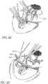
- Figures 4a-cshow the steps for performing a goniotomy procedure.
- locking forceps 406are typically used to grasp the inferior and superior rectus muscles.
- a goniotomy lens 408is positioned on the eye.
- a goniotomy knife 400is inserted from the temporal aspect beneath the goniotomy lens and viewed through a microscope.
- the corneais irrigated with balanced salt solution.
- the surgeonpositions the goniotomy lens 408 on the cornea, holding the lens 408 with an angled, toothed forceps 406 placed into the two dimples at the top of the lens 408.
- the surgeonplaces the goniotomy knife 400 into and through the cornea 1.0mm anterior to the limbus, maintaining the knife 400 parallel to the plane of the iris ( Figure 4b ). Slight rotation of the knife 400 facilitates smooth penetration into the anterior chamber without a sudden break through the cornea. The surgeon continues to gently apply pressure and rotate the goniotomy knife 400, directing it across the chamber, parallel to the plane of the iris, until reaching the trabecular meshwork in the opposite angle.
- the surgeonvisualizes the trabecular meshwork under direct microscopy and engages the superficial layers of the meshwork at the midpoint of the trabecular band.
- the incisionis typically made 100° to 120° circumferentially, first incising clockwise 50° to 60°, then counterclockwise for 50° to 60°.
- the surgeoncompletes the goniotomy incision and promptly withdraws the blade. If aqueous escapes from the wound and the chamber is shallow, the surgeon can slide the goniotomy lens over the incision as the blade is withdrawn.
- the anterior chambercan be reformed with an injection of balanced salt solution through the external edge of the corneal incision. The leak can be stopped using a suture and burying the knot.
- Trabeculodialysisis similar to goniotomy but is performed primarily in young patients with glaucoma secondary to inflammation. Trabeculodialysis differs from goniotomy only in the position of the incision.
- Figures 5a-dshow the steps of a trabeculodialysis procedure. The knife 500 passes across the anterior chamber and engages the trabecular meshwork at Schwalbe's line rather than at the midline of the meshwork, as shown in Figure 5a .
- the incisionis typically made 100° to 120° circumferentially, first incising clockwise 50° to 60°, then counterclockwise for 50° to 60° ( Figure 5b ).
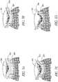
- FIG. 6dshows the meshwork disinserted from the scleral sulcus, exposing the outer wall of Schlemm's canal.
- Trabeculotomydisplaces trabecular meshwork as a barrier to aqueous outflow.
- the surgeoncreates a triangular scleral flap 604 that is dissected anteriorly of the limbus, as shown in Figure 6a .
- a radial incisionis made over the anticipated site of Schlemm's canal ( Figure 6b ).
- the incisionis deepened until the roof of Schlemm's canal is opened ( Figure 6c ).
- the surgeonlocates Schlemm's canal through the external surface of the limbus, threads a trabeculotome 600 into the canal and rotates the instrument into the anterior chamber, as shown in Figure 6d .
- the upper arm 610 of the instrumentshould be kept parallel to the plane of the iris.
- the instrument 600is then rotated within the anterior chamber and maintained parallel to the iris. After rotating the instrument 600 through the meshwork in one direction, the surgeon withdraws the instrument and inserts a second instrument with the opposite curve. The identical procedure is then performed in the opposite direction.
- the chambercan be reformed by injecting irrigation fluid. Aspiration may be used to remove the tissue.
- the scleral flap 604may then be sutured closed, as shown in Figure 6e .
- the probe 700comprises a handle 705 and a probe tip 710.
- the handleis approximately 20 gauge and the probe tip is approximately 27 gauge.
- the proximal end of the handleis adapted for mating with a connector 712 to the output terminals of an energy source 760.
- the probealso includes electrical leads 834 ( Figure 8 ), a power cable 708, preferably a coaxial cable, and actuation means. These components extend from the handle 705, through an electrical lead lumen 832 ( Figure 8 ) in the probe shaft 705, to the corresponding components of the probe 700 disposed on the distal end. The proximal ends of the cables and lumens connect to the corresponding connectors that extend from the distal end of the probe handle 705.
- Aspiration and irrigationmay be provided by an aspiration pump 770 and irrigation pump 780.
- the aspiration pump 770is connected to a standard vacuum supply line to promote the withdrawal of the aspiration fluid.
- Aspiration vacuum controlmay be provided by an aspiration valve.
- both irrigation and aspirationmay be provided by the same lumen 822, alternating the pump as needed.
- the irrigation lumen 922 and aspiration lumen 924are separate in the embodiment of Figure 9 , providing for simultaneous irrigation and aspiration. Irrigation under pressure flushes blood from the eye and expands the anterior chamber, providing more room for the procedure.
- the handle 705may be made of an electrically insulating polymeric material, configured in a pencil-shape form having a cylindrical body region 702 and a tapered forward region 704.
- a contoured handlehelps to reduce the holding force required and increase proprioceptive sensitivity.
- a pencil-shape configurationis preferred, it is noted that any configuration of the handle 705 which is easily, comfortably and conveniently grasped by the operator will also be suitable and is considered to be within the scope of the present invention.
- the probe tip 710is connected to the main body of the handle 705 by way of a longitudinal shaft 740.
- the probe tip 710further comprises a footplate 721 which extends at an angle from the distal end of the longitudinal shaft 740.
- the footplate 721has a proximal surface PS, a distal surface DS and a footplate tip FPT.
- the footplate tip FPTis advanceable through the trabecular meshwork and the footplate 721 is positionable in Schlemm's canal with its distal surface DS adjacent to the scleral wall of Schlemm's canal and its proximal surface PS adjacent to the trabecular meshwork.
- the footplate 721protects the collector channels from being damaged by the cautery element 730 while the cautery element is used to ablate the trabecular meshwork tissue and serves as a guide in Schlemm's canal.
- the cautery element 730, located at the probe tip 710 on the proximal side of the footplate 721may have a variety of configurations.
- the tip 710may be any material, such as titanium, brass, nickel, aluminum, stainless steel, other types of steels, or alloys. Alternatively, non-metallic substances may also be used, such as certain plastics.
- the malleable probe tipscan be configured as straight, angled or curved, for example, which provides for optimal access to specific anatomy and pathology. Unique tip designs improve tactile feedback for optimal control and access, and provide for improved tissue visualization with greatly reduced bubbling or charring.
- the probe tip 710comprises an electrode 730, suitable for cautery, as known to those of skill in the art.
- the cautery element 730may be any electrode that may provide ablation or cauterization of tissue, such as an ultrasound transducer, a RF electrode, or any other suitable electrode.
- the cautery elementmay also include other cautery energy sources or sinks, and particularly may include a thermal conductor.
- suitable thermal conductor arrangementsinclude a metallic element which may, for example, be constructed as previously described. However, in the thermal conductor embodiment such a metallic element would be generally resistively heated in a closed loop circuit internal to the probe, or conductively heated by a heat source coupled to the thermal conductor.
- the probe tipmay have a coating such as a non-stick plastic or a coating comprising diamond to prevent undesirable sticking or charring of tissue.
- the electrodemay be provided on the inner surface of the tip. Alternatively, the electrode is embedded in a sheath of a tube. Insulation is provided around the cautery element so that other areas of the eye are not affected by the cauterization.
- a sleeve shield or a non-conductive layermay be provided on the probe tip to expose only a selected portion of the electrode. The sleeve preferably has sufficient thickness to prevent both current flow and capacitance coupling with the tissue.
- the electrode or other device used to deliver energycan be made of a number of different materials including, but not limited to stainless steel, platinum, other noble metals, and the like.
- the electrodecan also be made of a memory metal, such as nickel titanium.
- the electrodecan also be made of composite construction, whereby different sections are constructed from different materials.
- the probe assemblyis bipolar.
- two electrodes of reversed polarityare located on the probe tip, thus eliminating the contact plate for completion of the circuit. Additionally, any number of pairs of electrodes may be provided on the probe tip.
- the probe assemblyis monopolar.
- the systemcomprises a single electrode and a contact plate is attached to the surface of the human body.
- the contact plateis further connected to the minus terminal of the power source via a lead wire. Voltages of reversed polarity are applied to the electrode and the contact plate.
- an electrode assembly of a bipolar probeincludes one electrode 1020 made from a stainless steel 20 gauge hollow needle and a second electrode 1030 formed as a layer of electrically conductive material (such as silver or nickel) deposited over and adhered on an exterior surface of the needle electrode 1020.
- a thin electrical insulator 1028separates the electrodes 1020, 1030, along their lengths to avoid short circuiting.
- the electrode 1020extends along a longitudinal axis 1072 of the footplate 721 ( Fig. 7 ) from a proximal region at which bipolar electrical power is applied to a distal region of the electrode assembly.
- the second electrode 1030extends over a limited portion of the circumference of the first electrode 1020, rather than entirely around the first electrode. Current flows over a relatively small portion of the circumference and length of the first electrode 1020. This limits the area in the body that receives current, and provides the operator with a high degree of control as to where the current is applied.
- the second electrode 1030extends over an arc of approximately one quarter of the circumference of the first electrode 1020.
- the second electrode 1030is disposed symmetrically about an axis 1072.
- the first electrodeand thus the footplate 721, has a central passage 1022 that is open at the distal region, providing for irrigation and aspiration.
- the irrigation and aspiration lumensextend from the distal end of the probe tip 1010, through the probe handle, to the connector, providing for irrigation and aspiration capability.
- the electrode assemblyincludes a central or axial electrode 1120 formed by a solid cylindrical metal member, and an elongate hollow outer electrode 1130 formed by a cylindrical metal tube member, which is coaxially positioned around the central electrode 1120.
- the cylindrical outer surface of electrode 1130forms the circumferential surface of the probe.
- the outer electrode 1130is preferably made of stainless steel or other corrosive resistant, conductive material for strength as well as conductivity.
- the inner electrode 1120may be made of copper, but less conductive materials may also be employed.
- the coaxial relationship and spacing between the electrodes 1120, 1130, as well as their electrical isolation from one another,is provided by a tubular sleeve 1128 of an electrically insulating material between the electrode.
- a layer of insulation 1132may also surround the second electrode 1130.
- One or more regions of insulating area 1132may be removed at any suitable location along the axis to expose a region of electrode 1130. Cauterization would occur at the exposed region.
- the circumferential extent of the second electrode 1130can be further limited, depending on the degree of control desired over the size of the area to which current is applied.
- the active region at a remote end of a bipolar electrodeis formed by a hollow metal tube 1200 having a substantially cylindrical layer of insulation 1228 on the outer surface of the metal tube.
- the metallic tube 1200is not an electrode and is provided only for the strength of the probe assembly.
- the tipsupports two metal electrodes 1230, 1240. Each of the electrodes 1230, 1240 have electric leads, which extend through the hollow interior of the tube 1200 to a supporting insulative handle where it is coupled by appropriate means with a power source in the manner previously described. Energy flows between the electrodes 1230, 1240, heating only the tissue adjacent the gap therebetween. Aspiration and irrigation may be provided through a lumen 1222.
- Figures 13 and 14show alternative embodiments of a goniectomy cauterization probe 1300, 1400.
- the probecomprises a handle 1305, 1405 and a probe tip 1310, 1410.
- the probe tipincludes a cautery element 1330, 1430.
- the probes 1300, 1400are provided with an energy source; however, probe 1400 also includes an irrigation supply 1480 and an aspiration pump 1470. These components connect to the probe 1300, 1400 at connector 1308, 1408.
- Figures 15 a,bshow detailed views of probe tip 1310.
- the probe tip 1510is straight and includes an electrode 1530 attached to electrode 1520, which are separated by a layer of insulation 1528.
- Figures 16 a,bshow detailed views of probe tip 1410.
- the probe tip 1610is straight and includes an electrode 1630 attached to a hollow electrode 1620, which are separated by a layer of insulation 1628.
- the hollow electrode 1620forms a hollow passage 1622 for irrigation and aspiration.
- the needle tip of Figure 14may comprise a hollow needle, with or without a cauterizing element, acoustically coupled to an ultrasonic handle and surrounded by a hollow sleeve.
- the handleincludes an ultrasonic transducer, such as that used for phacoemulsification, which may be either piezoelectric or magnetostrictive.
- the needleWhen the handle is activated, the needle is vibrated longitudinally at an ultrasonic rate. Simultaneously, a hydrodynamic flow of irrigation fluid may be introduced into the eye.
- the vibrating needleemulsifies the tissue, and the particles are preferably simultaneously aspirated, along with the fluid, out of the eye through the hollow needle tip.
- Aspirationis effected by a vacuum pump, which is connected to the handle.
- the ultrasonically vibrated needleemulsifies the tissue by combining i) the mechanical impact of the needle tip which varies depending on its mass, sharpness, and acceleration, ii) the ultrasonic acoustical waves generated by the metal surfaces of the vibrating needle, iii) the fluid wave created at the needle's leading edge, and iv) implosion of cavitation bubbles created at the tip of the vibrating needle.
- sonic technologymay be used to ablate the tissue.
- Sonic technologyoffers an innovative means of removing material without the generation of heat or cavitational energy by using sonic rather than ultrasonic technology.
- the tipexpands and contracts, generating heat, due to intermolecular frictional forces at the tip, that can be conducted to the surrounding tissues.
- the tipdoes not need a hollow sleeve if sonic energy is used to remove the trabecular meshwork.
- acoustic energyand particularly ultrasonic energy, offers the advantage of simultaneously applying a dose of energy sufficient to ablate the area without exposing the eye to current.
- the ultrasonic drivercan also modulate the driving frequencies and/or vary power in order to smooth or unify the produced collimated ultrasonic beam.
- the amount of heat generatedis directly proportional to the operating frequency.
- the sonic tipdoes not generate cavitational effects and thus true fragmentation, rather than emulsification or vaporization, of the tissue takes place. This adds more precision and predictability in cutting and less likelihood of damage to other areas of the eye.
- the tipcan be utilized for both sonic and ultrasonic modes. The surgeon can alternate between the two modes using a toggle switch on a foot pedal when more or less energy is required.
- FIG 17shows the control system for a goniectomy cauterization probe.
- the cautery element 1730is coupled to a cautery actuator.
- the cautery actuatorgenerally includes a radio-frequency ("RF") current source 1760 that is coupled to both the RF electrode and also a ground patch 1750 which is in skin contact with the patient to complete an RF circuit, in the case of a monopolar system.
- the cautery actuatormay include a monitoring circuit 1744 and a control circuit 1746 which together use either the electrical parameters of the RF circuit or tissue parameters such as temperature in a feedback control loop to drive current through the electrode element during cauterization. Also, where a plurality of cautery elements or electrodes are used, switching capability may be provided to multiplex the RF current source between the various elements or electrodes.
- the probeis connected to a low voltage power source via a power cord that mates with the handle.
- the sourcemay be a high frequency, bipolar power supply, preferably, a solid state unit having a bipolar output continuously adjustable between minimum and maximum power settings.
- the sourceis activated by an on/off switch, which may comprise a foot pedal, or a button on the probe or interface.
- the sourceprovides a relatively low bipolar output voltage.
- a low voltage sourceis preferred to avoid arcing between the electrode tips, which could damage the eye tissue.
- the generatoris coupled to first and second electrodes to apply a biologically safe voltage to the surgical site.
- the energy sourcepreferably provides RF energy, but is not limited to RF and can include microwave, ultrasonic, coherent and incoherent light thermal transfer and resistance heating or other forms of energy as known to those of skill in the art.
- Energyis typically delivered to the cautery element via electrical conductor leads.
- the cautery control systemmay include a current source for supplying current to the cautery element.
- the current sourceis coupled to the cautery element via a lead set (and to a ground patch in some modes).
- the monitor circuit 1744desirably communicates with one or more sensors (e.g., temperature) 1730 which monitor the operation of the cautery element.
- the control circuit 1746may be connected to the monitoring circuit 1744 and to the current source 1760 in order to adjust the output level of the current driving the cautery element based upon the sensed condition (e.g. upon the relationship between the monitored temperature and a predetermined temperature set point).
- the procedure for performing goniectomy with the goniectomy cauterization probe of an embodiment of the present inventionis similar to a traditional goniotomy surgery, as previously described.
- the surgeonpreferably sits on the temporal side of the operating room table utilizing an operating microscope.
- the patient's headis rotated 45° away from the surgeon after a retrobulbar injection has anesthetized the eye.
- a knifepreferably 20 gauge, is used to make a clear corneal temporal incision.
- the goniectomy instrumentis inserted into the anterior chamber up to the infusion sleeve to maintain the intraocular pressure and deepen the anterior chamber.
- the surgeonpositions the gonio lens, preferably a Schwann-Jacobs lens or a modified Barkan goniotomy lens, on the cornea.
- the goniectomy probeis advanced to the trabecular meshwork.
- the sharp end point of the footplateincises the middle one third of the trabecular meshwork, which is known as the pigmented portion of the trabecular meshwork.
- the footplate 721( Fig. 7 ) is further inserted into Schlemm's canal.
- the cautery elementis activated, preferably by a footplate, which may also be used to activate irrigation and aspiration.
- the current provided to the cautery elementheats the tissue.
- the instrumentis slowly advanced through the trabecular meshwork maintaining the footplate 721 in Schlemm's canal, feeding the pigmented trabecular meshwork into the opening of the instrument where the tissue removal occurs.
- the instrumentis advanced until no further tissue can be removed inferiorly.
- the tissuemay also be aspirated through the probe, thus substantially removing a portion of the trabecular meshwork.
- the instrumentmay be rotated in the eye and reintroduced into Schlemm's canal where the initial incision began.
- the superior portion of the trabecular meshworkis then removed using cautery and aspiration.
- a substantial portion, preferably at least half, of the trabecular meshworkis removed.
- the corneal incisionis preferably sealed by injecting a balanced salt solution into the corneal stroma or by placing a suture.
- the anterior chamberis reformed.
- a visceolastic substancemay be utilized to maintain the anterior chamber with the initial incision and at the end of the surgery.
- Trabeculodialysisis similar to goniectomy; therefore, a goniectomy cauterization probe may also be used to perform trabeculodialysis.
- the procedure for performing a trabeculodialysis procedure with a cauterization probeis similar to the trabeculodialysis procedure previously described. However, rather than cutting the tissue with a knife, the tissue is ablated with the probe. Similarly, in a preferred embodiment, a substantial portion, preferably at least half, of the trabecular meshwork is removed.
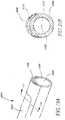
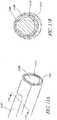
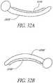
- the probecomprises a handle 1805 and a probe tip 1810.
- the handleis 25 gauge and the probe tip is approximately 25 gauge.
- the handle 2405is sized and configured to fit completely and comfortably within a hand.
- the handle 2405may be formed of a variety of materials, including plastics, and may be designed in a variety of shapes. Generally, it will be preferred that a convenient shape for gripping, such as a cylindrical shape, be provided.
- the probe tip 1810further comprises a footplate 1820, protecting endothelial cells and collector channels lining the scleral wall of Schlemm's canal.
- the footplate 1820also serves as a guide in Schlemm's canal. The sharpened end of the footplate is used to penetrate the trabecular meshwork.
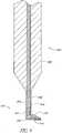
- Figures 19-20show sectional views of different examples of the internal components and construction of the probe 1800.
- the probeis configured to define therewithin a hollow inner chamber.
- a drive membercoupled to a rotatable drive cable within a drive cable assembly, extend into the hollow inner chamber, as shown.
- a rotatable drive shaft 1944, 2044is rotatably connected or engaged to the drive member, such that the shaft may be rotatably driven at speeds required for the trabecular meshwork removal.
- the rotatable drive shaftis inserted into a bore formed in the distal face of the drive member.
- the elongate rotatable drive shaft 1944, 2044passes longitudinally through the probe and terminates, at its distal end, in a cutting head 1945, 2045.
- a protective tubular sheathmay be disposed about the rotatable shaft.
- the rotatable shaft and/or sheathare axially movable so as to allow the cutting head to be alternately deployed in a) a first non-operative position wherein the cutting head is fully located within the inner bore of the tubular sheath so as to be shielded during insertion and retraction of the instrument or b) a second operative position wherein the cutting head is advanced out of the distal end of the sheath so as to contact and remove the trabecular meshwork.
- the cutting head 1945, 2045may be configured such that rotation of the head will create and sustain a forced circulation of fluid within the meshwork. Such forced circulation causes the trabecular meshwork to be pulled or drawn into contact with the rotating cutting head, without the need for significant axial movement or manipulation of the probe while the cutting head is rotating.
- a control pedalmay be connected to the motor-drive system to induce actuation/deactuation, and speed control of the rotatable drive cable within the drive cable assembly by the operator. Additional switches or control pedals may be provided for triggering and actuating irrigation and/or aspiration of fluid and/or debris through the probe.
- the probe of Figure 19shows the probe 1900 having two separate lumens, 1922, 1924, for irrigation and aspiration.
- the hollow passageway 2022extending longitudinally through the probe of Figure 20 , containing the rotatable drive shaft, is in fluid communication with an irrigation pump (not shown). By such arrangement, a flow of irrigation fluid may be infused through the tube.
- a separate lumen 2024is also provided for aspiration.
- independent processes of irrigation and aspirationmay be performed simultaneously with the rotation of the head or while the head is in a non-rotating, stationary mode. It will also be appreciated that the infusion and aspiration pathways may be reversed or interchanged by alternately connecting the aspiration pump to the irrigation tubing and irrigation pump to the aspiration tubing.
- the probecuts tissue in a guillotine fashion.
- the probe 2100may include an inner sleeve 2144 that moves relative to an outer sleeve 2146.
- the sleevesare coupled to the handle.
- the inner sleeve 2144may be coupled to a vacuum system which pulls tissue into the port 2125 when the inner sleeve 2144 moves away from the port.
- the inner sleeve 2144then moves in a reverse direction past the outer port to sever tissue in a guillotine fashion.
- the vacuum systemdraws the severed tissue away from the port, so the process may be repeated.
- the inner sleevemay be connected to a diaphragm and a spring, rigidly attached to the handle.
- the diaphragmis adjacent to a pneumatic drive chamber that is in fluid communication with a source of pressurized air (not shown).
- the drive chamberis pressurized, expanding the diaphragm. Expansion of the diaphragm moves the inner sleeve so that the tissue within the port is severed by the sleeve.
- the inner sleeve 2144is driven by a motor located within the handle.
- the inner sleeve 2144is coupled to the motor by a rotating lever mechanism or wobble plate, inducing an oscillating translational movement of the sleeve in response to a rotation of the output shaft.
- the motoris preferably an electrical device coupled to an external power source by wires that are attached to a control system at the handle.
- Figure 22shows an example wherein the irrigation lumen 2222 contains the cutting sleeve 2244.
- Cutting sleeve 2244has a cutting blade 2245 integrally formed at its distal end.
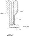
- Figure 23shows an alternative example, wherein the irrigation lumen 2322 does not contain the cutting sleeve.
- An aspiration lumen 2224, 2324is also provided.
- the aspiration linemay be directly coupled to an aspiration pump; the irrigation lumen may be directly coupled to an irrigation pump.
- the procedure for goniectomy with the goniectomy cutting probeis similar to the goniectomy procedure discussed for the goniectomy cauterization probe.
- the tissueis cut using a rotatable blade or cut in a guillotine fashion, and subsequently aspirated.
- a substantial portion, preferably at least half, of the trabecular meshworkis removed.
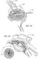
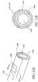
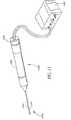
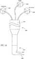
- a laser probe 2400as shown in Figures 24a and 24b , is provided to ablate the trabecular meshwork.
- the probe 2400comprises a handle 2405 and a probe tip 2410.
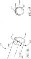
- the handle 2405is sized and configured to fit completely and comfortably within a hand. It will be understood that the handle 2405 may be formed from a variety of materials, including plastics, and may be designed in a variety of shapes. Generally, it will be preferred that a convenient shape for gripping, such as a cylindrical shape, be provided.
- the main body of the handle 2405comprises a plastic housing within which a laser system is contained. The plastic housing is provided to enable easy manipulation of the handle 2405 by the user.
- the laseris preferably an excimer laser.
- Figure 24ashows an example wherein the laser source is contained within the probe, but rather within the control system.
- a fiberis provided to direct the light energy from the source to the proximal end of the probe tip.
- the laser radiationis generated in close proximity to the eye, so that relatively little laser light is lost during transmission.
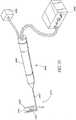
- Figure 24bshows an example wherein the laser source is not contained within the probe.
- the sourcemay include a longitudinal flashlamp.
- a fiberis provided to direct the light energy from the source to the proximal end of the probe tip.
- the probe tip 2410is connected to the main body 2405.
- the probe tipcomprises a footplate to protect the outer wall of Schlemm's canal, such that only the tissue of the trabecular meshwork is cauterized.
- the footplatealso is used to penetrate the trabecular meshwork and serves as a guide in Schlemm's canal.
- the probe tip 2410is straight or curved.
- Figure 25shows a detailed view of Figure 24a .
- the handleincludes a reflective tube 2508 which has a mirrored inside surface.
- An Er: YAG rod 2513is located along the axis of the tube 2508.
- the pump for the laser light sourceis preferably a high pressure flashtube 2512 or a similar suitable light source which is located adjacent the rod 2513 within the reflective tube 2508.
- the flashtube 2512produces very brief, intense flashes of light, there being approximately 10 to 100 pulses per second.
- Er:YAG rodsgenerate an output wavelength of approximately 2.94 microns.
- Use of an erbium doped laser, such as an Er: YAG laseris advantageous because it requires less power to ablate the eye tissue than do the Nd: YAG and Holmium:YAG lasers of the prior art.
- the Er: YAG laserhas a pulse repetition rate of 5 to 100Hz, a pulse duration of 250 ⁇ s to 300 ⁇ s, and a pulse energy of 10 to 14mJ per pulse.
- Using an Er: YAG laser at the above parameterslimits the thermal damage of surrounding tissue to a depth of 5 to 50 microns. By reducing the thermal damage of surrounding tissue, the amount of scar tissue buildup caused by the laser is minimal. Thus, the likelihood that the passageway will become blocked with scar tissue is reduced, and the likelihood that the procedure will need to be repeated is reduced.
- the reflective inner surface 2546 of the tube 2508serves to reflect light from the flashlamp 2512 to the rod 2513. Reflection of the light by the cylindrical mirror focuses as much light as possible toward the rod 2513. This results in efficient coupling between the light source 2512 and the laser rod 2513. Thus, essentially all light generated in the flashtube 2512 is absorbed by the laser rod 2513.
- the rod 2513has a totally reflective mirror 2514 and output mirror 2517 at its two ends.
- the mirror 2514 at the proximal end of the rod 2513provides 100% reflection of light back to the rod 2513.
- the output mirror 2517provides less than 100% reflection.
- a reflective coating on the end of the laser rod 2513may be used to supplement or replace the mirrors 2517,2514.
- the mirrors 2517, 2514 on either end of the rodform a resonator. Radiation that is directed straight along the axis of the rod 2513 bounces back and forth between the mirrors 2517, 2514 and builds a strong oscillation. Radiation is coupled out through the partially transparent mirror 2517.
- the transmission system 251is preferably an optical fiber.
- a sapphire or fused silica fiberwill be used with the laser, contained within the handle.
- a germanium oxide Type IV fiberis also suitable for carrying erbium laser light with reduced attenuation. It is also possible to deliver laser light through hollow waveguides. Such waveguides often include multi-layer dielectric coatings to enhance transmission.
- Figure 26shows a detailed view of one example of a probe tip 2600, in which the fiber 2610 is centrally located within the probe tip 2600.
- the probe tipmay be hollow, forming an aspiration/irrigation lumen (not shown).
- the lumenextends the entire length of the probe.
- the lumen 2722may extend adjacent the probe tip 2710.
- the aspiration lumen 2722communicates with a vacuum source for withdrawal of emulsified material through an aperture or aspiration port.
- the vacuum sourcecan be employed to aspirate material which has been fragmented or ablated by the pulsed laser light.
- the vacuum sourcecan also be used to draw the tissue into close proximity with the delivery end of the probe thereby facilitating its destruction. Fluid introduced through the lumen, chamber, and aperture can provide for flushing of the site and replacement of lost volume due to removal of the emulsified material.
- the probeis inserted under direct vision to ablate the trabecular meshwork for use in treating glaucoma, thus obtaining a free flow of aqueous from the anterior chamber into Schlemm's canal and through the collector channels.
- the end of the probeis inserted through a relatively small incision in the eye, and can be maneuvered very close to the tissue to be emulsified.
- the procedureis similar to the goniectomy procedure previously discussed with reference to the goniectomy cauterization probe.
- the surgeonvisualizes the trabecular meshwork under direct microscopy and engages the superficial layers of the meshwork at the midpoint of the trabecular band, by placing the tissue between the end 2521 of the fiber 2511 and the probe tip (footplate) 2519.
- the fiber 2511is positioned to focus laser energy directly on the trabecular meshwork.
- the probe tip 2519absorbs any laser energy which is not absorbed by the trabecular meshwork, thus protecting Schlemm's canal from damage.
- Lightis transmitted to and through the probe, and the tissue is ablated.
- the areamay be irrigated and aspirated, removing the tissue from the eye.
- a substantial portion, preferably at least half, of the trabecular meshworkis removed.
- the probeis readily withdrawn from the eye. Leakage may be stopped using a suture and burying the knot.
- Laser treatment with an Er:YAG laseris advantageous because as wavelength increases, contiguous thermal effects decrease. In the visible portion of the spectrum, water has minimal absorption. Above 2.1 ⁇ m however, this absorption increases to a level comparable to excimer lasers operating around 200nm. This increase is quite rapid. A marked difference therefore exists between radiation at 2.79 ⁇ m and 2.94 ⁇ m. This confines the energy delivered to a smaller volume, allowing more ablation to occur at lower total energy levels and limiting contiguous thermal damage. Er: YAG lasers produce ablations with minimal amounts of contiguous thermal damage. Light in the infrared region has an additional advantage over ultraviolet radiation in that it is not known to have mutagenic or carcinogenic potential.
- Schlemmectomyis a new surgical procedure, similar to trabeculotomy.
- a schlemmectomy proceduredisrupted tissue is removed using a schlemmectomy cauterization probe.
- Figure 28illustrates a probe 2800 in accordance with this invention for removal of the trabecular meshwork, using a cautery element 2830 on a probe similar to a traditional trabeculotome, such as Harm's trabeculotome.
- the probeuses both cautery and mechanical disruption to ablate the fibers of the trabecular meshwork, leaving a patent open Schlemm's canal.
- the probe 2800comprises a handle 2805 and a probe tip 2810.
- the proximal end of the handleis adapted for mating with a connector 2812 to the output terminals of an energy source 2860.
- the probealso includes electrical leads 2934 ( Figure 29 ), a power cable 2808, preferably a coaxial cable, and an actuator. These components extend from the handle 2805, through an electrical lead lumen 2932 ( Figure 29 ) in the probe shaft 2805, to the corresponding components of the probe 2800 disposed on the distal end. The proximal ends of the cables and lumens connect to the corresponding connectors that extend from the distal end of the probe handle 2805.
- Figures 29a-cillustrate one probe tip configuration.
- the probe tip 2910comprises two parallel arms 2920, 2950.
- the probe tip 2910comprises an electrode 2930, which will be described in further detail below, disposed on the lower arm 2920.
- the probe tip 2910comprises an electrical lead lumen 2932 which extends the length of the probe tip 2910 from the electrode 2930 through the cylindrical body 2802 to the connector of the probe handle 2812. ( Figure 28 )
- Figure 30shows a preferred embodiment of a probe 3000.
- the probe of Figure 30is similar to the probe of Figure 28 , except that probe 3000 further comprises irrigation means. Irrigation may be provided by an irrigation pump 3080 or hydrostatic pressure from a balanced salt solution bottle and tubing.
- the irrigation lumen 3122is situated at the end of the probe. Irrigation under pressure flushes blood from the eye and expands Schlemm's canal and the anterior chamber, providing more room for the procedure.
- lumen 3122provides for aspiration by connecting the lumen to an aspiration pump. Aspiration ports may be provided equidistantly along the length of the cauterizing element of the trabeculotome, as shown in Figure 31b .
- two lumensare provided, an irrigation lumen 3122 and an aspiration lumen 3124. Two separate lumens provide for simultaneous irrigation and aspiration.
- the handle 2805, 3005may be made of an electrically insulating polymeric material, configured in a pencil-shape form having a cylindrical body region 2802, 3002 and a tapered forward region 2804, 3004.
- a pencil-shape configurationis preferred, it is noted that any configuration of the handle 2805, 3005 which is easily, comfortably and conveniently grasped by the operator will also be suitable and is considered to be within the scope of the present invention.
- the probe tip 2810, 3010is connected to the main body of the handle 2805, 3005.
- the cautery element 2830, 3030 at the distal end of the probe tip 2810, 3010can have a variety of configurations.
- the tip 2810, 3010may be any material, such as titanium, brass, nickel, aluminum, stainless steel, other types of steels, or alloys. Alternatively, non-metallic substances may also be used, such as certain plastics.
- the tipmay be conductive or non-conductive, depending on the specific embodiment, as will be discussed.
- Figures 32a and 32bshow alternative distal probe tip configurations, wherein the second electrode 3230 extends along the entire length of the first electrode 3220.
- the probe tip 3210maybe curved to better maneuver within the anatomy of the eye.
- the malleable probe tipscan be configured as straight, angled or curved, for example, which provides for optimal access to specific anatomy and pathology.
- Unique tip designsimprove tactile feedback for optimal control and access, and provide for improved tissue visualization with greatly reduced bubbling or charring.
- the probe tip 2810, 3010comprises an electrode or cautery element 2830, 3030, suitable for cautery, as known to those of skill in the art.
- the cautery element 2830, 3030is any electrode that may provide ablation or cauterization of tissue, such as a RF electrode, an ultrasound transducer, or any other suitable electrode.
- the cautery elementmay also include other cautery energy sources or sinks, and particularly may include a thermal conductor.
- suitable thermal conductor arrangementsinclude a metallic element which may, for example, be constructed as previously described. In the thermal conductor embodiment such a metallic element would be generally resistively heated in a closed loop circuit internal to the probe, or conductively heated by a heat source coupled to the thermal conductor.
- the electrode 2830, 3030may be provided on the inner surface of the tip. Alternatively, the electrode 2830, 3030 may be embedded in a sheath of a tube. Insulation may be provided around the cautery element so that other areas of the eye are not affected by the cauterization. A sleeve shield or a non-conductive layer may also be provided on the probe tip to expose only a selected portion of the electrode. The sleeve preferably has sufficient thickness to prevent both current flow and capacitance coupling with the tissue.
- the cautery elementcan be made of a number of different materials including, but not limited to stainless steel, platinum, other noble metals, and the like.
- the electrodecan also be made of a memory metal, such as nickel titanium.
- the electrodecan also be made of composite construction, whereby different sections are constructed from different materials.
- the electrode systemis bipolar.
- two electrodes of reversed polarityare located on the probe tip and RF energy bridges the electrodes. Additionally, any number of pairs of electrodes may be provided on the probe tip.
- the electrode systemis monopolar.
- the systemcomprises a single electrode and a contact plate.
- the contact plateis attached to the surface of the human body.
- the contact plateis further connected to the return terminal of the power source via a lead wire. Voltages of reverse polarity are applied to the electrode and the contact plate.
- an electrode assembly of a bipolar probeincludes one electrode 3320 made from a stainless steel 20 gauge hollow needle and a second electrode 3330 formed as a layer of electrically conductive material (such as silver or nickel) deposited over and adhered to an exterior surface of the needle electrode.
- a thin electrical insulator 3324separates the electrodes 3320, 3330, along their lengths to avoid short circuiting.
- the electrodes 3320, 3330extend along a longitudinal axis 3372 of the instrument from a proximal region at which bipolar electrical power is applied to a distal region of the electrode assembly.
- the second electrode 3330extends over a limited portion of the circumference of the first electrode 3320, rather than entirely around the first electrode 3320.
- Currentflows from the relatively small portion of the circumference of the second electrode 3330 where heat is generated in the adjacent tissue, and into the layer surface of the first electrode 3320, where little heat is generated. This limits the area in the body that receives dense current, and provides the operator with a high degree of control as to where the current is applied.
- the second electrode 3330extends over an arc of approximately one quarter of the circumference of the first electrode.
- the second electrode 3330is disposed symmetrically about an axis 3372.
- the first electrode 3320has a central passage 3322 that is open at the distal region, providing for irrigation.
- the irrigation lumen 3322extends from the distal end of the probe tip, through the probe handle, to the connector, providing for irrigation capability.
- Figure 34shows an alternative embodiment, wherein the electrode assembly includes a central or axial electrode 3420 formed by a solid cylindrical metal member, and an elongate hollow outer electrode 3430 formed by a cylindrical metal tube member, which is coaxially positioned around the central electrode.
- the cylindrical outer surface of electrode 3430forms the circumferential surface of the probe.
- the outer electrode 3430is preferably made of stainless steel or other corrosive resistant, conductive material for strength as well as conductivity.
- the inner electrode 3420may be made of copper, but less conductive materials may also be employed.
- the coaxial relationship and spacing between the electrodes, as well as their electrical isolation from one another,is provided by a tubular sleeve 3424 of an electrically insulating material between the electrode, completing the probe assembly.
- An additional layer of insulation 3434may be provided on outer electrode 3430 to expose only a limited portion of the electrode to concentrate RF energy at the limited exposed region.
- one or more regions of insulating area 3434may be removed at any suitable location along the axis to expose a region of electrode 3430. Cauterization would then occur at the exposed region.
- the circumferential extent of the second electrode 3430can be further limited, depending on the degree of control desired over the size of the area to which current is applied.
- the active region of a bipolar electrode probe assemblyis formed by a hollow metal tube 3515 having a substantially semi-cylindrical sleeve 3524 on tube 3515.
- the metallic tube 3515is not an electrode and is provided only for the strength of the probe assembly.
- the tipsupports two cautery elements 3520, 3530. Each of the elements 3520, 3530 is connected to electrical leads, which extend through the hollow interior of the tip 3510 to a supporting insulative handle where it is coupled by appropriate means with a power source in the manner previously described.
- the probeis connected to a low voltage RF power source via a power cord that mates with the handle.
- the sourcemay be a high frequency, bipolar power supply, preferably, a solid state unit having a bipolar output continuously adjustable between minimum and maximum power settings.
- the sourceis activated by an on/off switch, which may comprise a foot pedal, or a button on the probe or interface.
- the sourceprovides a relatively low bipolar output voltage.
- a low voltage sourceis preferred to avoid arcing between the electrode tips, which could damage the eye tissue.
- the RF generatoris coupled to first and second electrodes to apply a biologically safe voltage to the surgical site. This probe has the advantage of cauterizing at both of the bipolar elements, each of which has a limited, RF current concentration area.
- the energy sourcepreferably provides RF energy, but is not limited to RF and can include microwave, electrical, ultrasonic, coherent and incoherent light thermal transfer and resistance heating or other forms of energy, as known to those of skill in the art.
- the cautery actuatormay include a monitoring circuit 1744 and a control circuit 1746 ( Figure 17 ) which together use either the electrical parameters of the RF circuit or tissue parameters such as temperature in a feedback control loop to drive current through the electrode element during cauterization.
- Feedback control systemscan be used to obtain the desired degree of heating by maintaining the selected sight at a desired temperature for a desired time.
- a sensorsuch as a thermocouple may be used to monitor temperature in a feedback loop. Where a plurality of cautery elements or electrodes are used, switching capability may be provided to multiplex the RF current source between the various elements or electrodes.
- Figure 17shows the monitor circuit 1744, which desirably communicates with one or more sensors (e.g., temperature) 1740 which monitor the operation of the cautery element 1730.
- the control circuit 1746may be connected to the monitoring circuit 1744 and to the current source in order to adjust the output level of the current driving the cautery element 1730 based upon the sensed condition (e.g. upon the relationship between the monitored temperature and a predetermined temperature set point).
- Circuitry, software and feedback to a controllermay be used to change (i) power - including RF, incoherent light, microwave, ultrasound, and the like, (ii) the duty cycle, (iii) monopolar or bipolar energy delivery, (iv) fluid (electrolyte solution delivery, flow rate and pressure) and (v) determine when ablation is completed through time, temperature and/or impendance.
- a bipolar electrodeis part of a circuit that includes the RF signal generator, connecting cables, probe tip for insertion into the eye, a grounding electrode attached to the probe and a return cable that connects the grounding electrode to the RF generator completing the circuit.
- a RF electrodeis a relatively good conductor, the electrode itself does not heat up.
- the tissueheats up because it is a relatively poor conductor as compared to the rest of the circuit. It is when the tissues heat up as a result of molecular friction, that heat is then conducted back to the electrode itself.
- a thermocouplesenses the increase in temperature and supplies that information to the RF generator so that the feedback mechanism can attenuate the energy delivered in order to attain temperature control.
- RF deliverymay also be advantageous to regulate RF delivery through both temperature and impedance monitoring. It may also be advantageous to monitor irrigation fluid flow to maintain clarity at the site. There is also an opportunity for synergy between RF and irrigation fluid delivery to the surgical site to provide, for example, a greater level of control of temperatures at the site.
- the controllermay include an RF generator, temperature profile, temperature regulator, temperature monitor, surgical instrument, impendance monitor, impendance regulator, pump, flow regulator and flow monitor.
- the RF generatormay be capable of delivering monopolar or bipolar power to the probe.
- the probeis positioned at the surgical site.
- the impedance monitorobtains impendance measurements by, for example, measuring current and voltage and performing a RMS calculation.
- the measurements of the impedance monitorare delivered to the impendance regulator.
- the impedance regulatorperforms several functions. Generally the impedance regulator keeps the impendance levels within acceptable limits by controlling the power supplied by the RF generator. In one embodiment of the current invention the impedance regulator can control the flow regulator to deliver more or less irrigation fluid to the surgical site.
- the distal tip of the probemay also be equipped with a thermocouple 1740. Temperature feedback, in combination with a timing device, permits a precise degree of cautery to be delivered, obtaining the desired effect without causing any intraocular heating. The heating effect on tissue may be mitigated with a viscoelastic agent to deepen the anterior chamber.
- the temperature monitor 1744may include one or more types of temperature sensors, e.g. thermocouples, thermistors, resistive temperature device (RTD), infrared detectors, etc.
- thermocoupleSuitable shapes for the thermocouple include, but are not limited to, a loop, an oval loop, a "T” configuration, an "S” configuration, a hook configuration or a spherical ball configuration. These shapes provide more surface area for the thermocouple without lengthening the thermocouple. These thermocouples, with more exposed area than a straight thermocouple, are believed to have better accuracy and response time.
- the thermocoupleis attached by a fastener.
- the fastenermay be a bead of adhesive, such as, but not limited to, epoxies, cyanoacetate adhesives, silicone adhesives, flexible adhesives, etc. It may also be desirable to provide multiple thermocouples at different locations and compare their operating parameters (e.g. response times, etc.), which may provide useful information to allow certain such variables to be filtered and thereby calculate an accurate temperature at the thermocouple location.
- the output of the temperature monitor 1744is delivered to the temperature regulator 1746.
- the temperature regulator 1746may control both the RF generator 1760 and the flow regulator. When, for example, temperatures have increased beyond an acceptable limit, power supplied by the RF generator to the surgical instrument may be reduced. Alternately, the temperature regulator may cause the flow regulator to increase irrigation fluid, thereby decreasing the temperature at the surgical site. Conversely, the temperature regulator can interface with either the RF generator or the flow regulator when measured temperatures do not match the required temperatures. The flow regulator interfaces with the pump to control the volume of irrigation fluid delivered to the surgical site.
- the procedure for performing a Schlemmectomy with the probe of the present inventionis similar to a traditional trabeculotomy procedure, as previously described.
- the surgeonpreferably sits on the temporal side of the operating room table utilizing the operating microscope.
- An infrotemporal fornix based conjunctival flapis made and the conjunctive and Tenons capsule are mobilized posteriorly.
- a triangular flapis made and the superficial flab is mobilized into the cornea.
- a radial incisionis made over the canal of Schlemm, thus creating an entrance into the canal.
- Vanna scissorsare preferably introduced into the Schlemm's canal, opening the canal for approximately 1mm on either side.
- a clear corneal parenthesisis performed and the anterior chamber is deepened, preferably with Haelon GV.
- the probeis introduced into Schlemm's canal inferiorly.
- the instrumentis now aligned such that the cauterization element faces into the deepened anterior chamber.
- the cauterization surfacefaces the trabecular meshwork and is activated by the foot switch at the time of the rotation of the probe into the anterior chamber.
- the foot switchmay then be used to activate cauterization.
- Aspiration and irrigationmay also be activated using the foot switch.
- the trabeculotomeis slowly rotated into the anterior chamber and when the blade of the trabeculotome is seen in the anterior chamber, the cautery (and aspiration and/or irrigation) are deactivated.
- the superior aspect of Schlemm's canalmay be entered with a trabeculotome having the opposite curvature.
- trabecular meshworkis removed.
- a substantial portion, preferably at least half, of the trabecular meshworkis removed.
- the superficial trabeculotomy flapis sutured closed using sutures.
- Radiowave surgeryuses high frequency radio waves instead of heat to cut and coagulate tissue without the burning effect that is common with traditional electrosurgical devices and cautery equipment.
- the resistance of tissue to the spread of radio wave energyproduces heat within the cell, causing the water within the cell to volatilize and destroy the cell without damaging other cellular layers.
Landscapes
- Health & Medical Sciences (AREA)
- Ophthalmology & Optometry (AREA)
- Heart & Thoracic Surgery (AREA)
- Vascular Medicine (AREA)
- Veterinary Medicine (AREA)
- Surgery (AREA)
- Engineering & Computer Science (AREA)
- Biomedical Technology (AREA)
- Public Health (AREA)
- Nuclear Medicine, Radiotherapy & Molecular Imaging (AREA)
- Life Sciences & Earth Sciences (AREA)
- Animal Behavior & Ethology (AREA)
- General Health & Medical Sciences (AREA)
- Physics & Mathematics (AREA)
- Optics & Photonics (AREA)
- Electromagnetism (AREA)
- Surgical Instruments (AREA)
- Laser Surgery Devices (AREA)
Description
- The present invention relates to a new glaucoma surgical instrument and, in particular, removal of the trabecular meshwork.
- Aqueous is a clear, colorless fluid that fills the anterior and posterior chambers of the eye. The aqueous is formed by the ciliary body in the eye and supplies nutrients to the lens and cornea. In addition, the aqueous provides a continuous stream into which surrounding tissues can discharge the waste products of metabolism.
- The aqueous produced in the ciliary process circulates from the posterior chamber to the anterior chamber of the eye through the pupil and is absorbed through the trabecular meshwork, a plurality of crisscrossing collagen cords covered by endothelium. Once through the trabecular meshwork, the aqueous passes through Schlemm's canal into collector channels that pass through the scleral and empty into the episcleral venous circulation. The rate of production in a normal eye is typically 2.1 µL/min. Intraocular pressure in the eye is maintained by the formation and drainage of the aqueous. All the tissues within the corneoscleral coat covering the eyeball are subject to this pressure, which is higher than pressure exerted on tissues at other locations in the body.
- Glaucoma is a group of diseases characterized by progressive atrophy of the optic nerve head leading to visual field loss, and ultimately, blindness. Glaucoma is generally associated with elevated intraocular pressure, which is an important risk factor for visual field loss because it causes further damage to optic nerve fibers. Other causes of glaucoma may be that the nerve is particularly vulnerable to the pressure due to poor local circulation, tissue weakness or abnormality of structure. In a "normal" eye, intraocular pressure ranges from 10 to 21 mm mercury. In an eye with glaucoma, this pressure can rise to as much as 75 mm mercury.
- There are several types of glaucoma, including open and closed angle glaucoma, which involve the abnormal increase in intraocular pressure, primarily by obstruction of the outflow of aqueous humor from the eye, or, less frequently, by over production of aqueous humor within the eye. The most prevalent type is primary open angle glaucoma in which the aqueous humor has free access to the irridocorneal angle, but aqueous humor drainage is impaired through obstruction of the trabecular meshwork. In contrast, in closed angle glaucoma, the irridocorneal angle is closed by the peripheral iris. The angle block can usually be corrected by surgery. Less prevalent types of glaucoma include secondary glaucomas related to inflammation, trauma, and hemorrhage.
- Aqueous humor is similar in electrolyte composition to plasma, but has a lower protein content. The aqueous humor keeps the eyeball inflated, supplies the nutritional needs of the vascular lens and cornea and washes away metabolites and toxic substances within the eye. The bulk of aqueous humor formation is the product of active cellular secretion by nonpigmented epithelial cells of the ciliary process from the active transport of solute, probably sodium, followed by the osmotic flow of water from the plasma. The nonpigmented epithelial cells of the ciliary process are connected at their apical cell membranes by tight junctions. These cells participate in forming the blood/aqueous barrier through which blood-borne large molecules, including proteins, do not pass.
- Intraocular pressure (IOP) is a function of the difference between the rate at which aqueous humor enters and leaves the eye. Aqueous humor enters the posterior chamber by three means: 1) active secretion by nonpigmented epithelial cells of the ciliary process; 2) ultrafiltration of blood plasma; and 3) diffusion. Newly formed aqueous humor flows from the posterior chamber around the lens and through the pupil into the anterior chamber; aqueous humor leaves the eye by 1) passive bulk flow at the irridocorneal angle by means of the uveloscleral outflow, or by 2) active transportation through the trabecular meshwork, specifically the juxta canalicar portion. Any change in 1), 2), or 3) will disturb aqueous humor dynamics and likely alter intraocular pressure.
- Primary open angle glaucoma is caused by a blockage in the trabecular meshwork. This leads to an increase in intraocular pressure. The major obstruction is at the juxta-canalicular portion which is situated adjacent to Schlemm's canal. In infants a goniotomy or a trabeculotomy can be performed. In goniotomy or trabeculotomy a small needle or probe is introduced into Schlemm's canal and the trabecular meshwork is mechanically disrupted into the anterior chamber. Approximately 90°-120° of trabecular meshwork can be disrupted. The anatomical difference between congenital glaucoma and adult glaucoma is that in congenital glaucoma the ciliary body muscle fibers insert into the trabecular meshwork and once disrupted the trabecular meshwork is pulled posteriorly allowing fluid to enter Schlemm's canal and to be removed through the normal collector channels that are present in the wall of Schlemm's canal. In adults the trabecular meshwork tears but remains intact and reattaches to the posterior scleral wall of Schlemm's canal blocking the collector channels.
- Most treatments for glaucoma focus on reducing intraocular pressure. Treatment has involved administration of beta-blockers such as timolol to decrease aqueous humor production, adranergic agonists to lower intraocular pressure or diuretics such as acetazolamide to reduce aqueous production, administration of miotic eyedrops such as pilocarpine to facilitate the outflow of aqueous humor, or prostaglandin analogs to increase uveoscleral outflow. Acute forms of glaucoma may require peripheral iridectomy surgery to relieve pressure where drug therapy is ineffective and the patient's vision is at immediate risk. Other forms of treatment have included physical or thermal destruction ("cyclo-destruction") of the ciliary body of the eye, commonly by surgery or application of a laser beam, cryogenic fluid or high frequency ultrasound.
- In guarded filtration surgery (trabeculectomy), a fistula created through the limbal sclera is protected by an overlying partial thickness sutured scleral flap. The scleral flap provides additional resistance to excessive loss of aqueous humor from the eyeball, thereby reducing the risk of early postoperative hypotony.
- In accordance with one recently introduced procedure, a full thickness filtering fistula may be created by a holmium laser probe, with minimal surgically induced trauma. After retrobulbar anesthesia, a conjunctiva incision (approximately 1 mm) is made about 12-15 mm posterior to the intended sclerostomy site, and a laser probe is advanced through the sub-conjunctival space to the limbus. Then, multiple laser pulses are applied until a full thickness fistula is created. This technique has sometimes resulted in early hypotony on account of a difficulty in controlling the sclerostomy size. In addition, early and late iris prolapse into the sclerostomy has resulted in abrupt closure of the fistula and eventual surgical failure. Further, despite its relative simplicity, the disadvantage of this procedure, as well as other types of glaucoma filtration surgery, is the propensity of the fistula to be sealed by scarring.
- Various attempts have been made to overcome the problems of filtration surgery, for example, by using ophthalmic implant instruments such as the Baerveldt Glaucoma Implant. Typical ophthalmic implants utilize drainage tubes so as to maintain the integrity of the openings formed in the eyeball for the relief of the IOP.
- Typical ophthalmic implants suffer from several disadvantages. For example, the implants may utilize a valve mechanism for regulating the flow of aqueous humor from the eyeball; defects in and/or failure of such valve mechanisms could lead to excessive loss of aqueous humor from the eyeball and possible hypotony. The implants also tend to clog over time, either from the inside by tissue, such as the iris, being sucked into the inlet, or from the outside by the proliferation of cells, for example by scarring. Additionally, the typical implant insertion operation is complicated, costly and takes a long time and is reserved for complicated glaucoma problems.
- There are many problems, however, in effectively treating glaucoma with long term medicinal or surgical therapies. One problem is the difficulty in devising means to generate pharmacologically effective intraocular concentrations and to prevent extraocular side effects elicited by a systemic administration. Many drugs are administered topically or locally. The amount of a drug that gets into the eye is, however, only a small percentage of the topically applied dose because the tissues of the eye are protected from such substances by numerous mechanisms, including tear turnover, blinking, conjunctiva absorption into systemic circulation, and a highly selective corneal barrier.
- Pharmacological treatment is prohibitively expensive to a large majority of glaucoma patients. In addition, many people afflicted with the disease live in remote or undeveloped areas where the drugs are not readily accessible. The drugs used in the treatment often have undesirable side effects and many of the long-term effects resulting from prolonged use are not yet known. Twenty-five percent of patients do not use their medications correctly.
- Glaucoma is a progressively worsening disease, so that a filtration operation for control of intraocular pressure may become necessary. Present surgical techniques to lower intraocular pressure, when medication fails to decrease fluid flow into the eye or to increase fluid outflow, include procedures that permit fluid to drain from within the eye to extraocular sites by creating a fluid passageway between the anterior chamber of the eye and the potential supra-scleral/sub-Tenon's space, or, alternatively, into or through the Canal of Schlemm (see, e. g.,
U. S. Patent No. 4,846,172 ). The most common operations for glaucoma are glaucoma filtering operations, particularly trabeculectomy. These operations involve creation of a fistula between the subconjunctival space and the anterior chamber. This fistula can be made by creating a hole at the limbus by either cutting out a portion of the limbal tissues with either a scalpel blade or by burning with a cautery through the subconjunctival space into the anterior chamber. Fluid then filters through the fistula and is absorbed by episcleral and conjunctival. In order for the surgery to be effective, the fistula must remain substantially unobstructed. These drainage or filtering procedures, however, often fail by virtue of closure of the passageway resulting from the healing of the very wound created for gaining access to the surgical site. Failures most frequently result from scarring at the site of the incisions in the conjunctiva and the Tenon's capsule. The surgery fails immediately in at least 15% of patients, and long term in a much higher percentage. Presently, this consequence of trabeculectomy, closure of the passageway, is treated with 5-fluorouracil and Mitomycin_C, which apparently prevent closure by inhibiting cellular proliferation. These drugs, however, are highly toxic and have undesirable side effects, including scleral melting, hypotony, leaks, and late infections. - Other surgical procedures have been developed in an effort to treat victims of glaucoma. An iridectomy, removal of a portion of the iris, is often used in angleclosure glaucoma wherein there is an occlusion of the trabecular meshwork by iris contact. Removal of a piece of the iris then gives the aqueous free passage from the posterior to the anterior chambers in the eye. The tissue of the eye can grow back to the pre-operative condition, thereby necessitating the need for further treatment.
US5893862 discloses an instrument for eye surgery, having an outer cannula and an inner cannula received within the outer cannula, which are longitudinally moveable relative to each other for removing lens tissue from the eye. - In view of the limited effectiveness of treatment options, there is, therefore, a need to develop more effective treatments for glaucoma.
- The present invention is a surgical instrument to remove at least a portion of the trabecular meshwork of the eye, providing for aqueous drainage in the treatment of glaucoma.
- The invention is described in claim 1. Preferred embodiments are described in the dependent claims. A preferred example involves inserting a surgical instrument through a small corneal incision transcamerally under direct visualization to ablate the trabecular meshwork. The instrument may include a foot plate, such that the instrument can penetrate the trabecular meshwork into Schlemm's canal. The footplate acts as a protective device for the endothelial cells and collector channels lining the scleral wall of Schlemm's canal. The instrument also comprises an infusion system and aspiration system. Infusion maintains and deepens the anterior chamber so that easy access of the angle of the eye is obtained to the trabecular meshwork and Schlemm's canal. Infusion also allows fluid to flow out to the collector channels whilst the surgery is being performed, thus keeping the surgical site blood free. Aspiration is designed to remove ablated tissue, gas and bubble formation, and all intraocular debris generated. The instrument also comprises a cautery element, capable of substantially complete tissue removal by cautery.
- The surgical instrument is used to perform a goniectomy procedure, by removing a portion of the trabecular meshwork consisting of the pigmented trabecular meshwork, allowing free access of aqueous from the anterior chamber through to the scleral portion of Schlemm's canal that contains the endothelial cells and most importantly the collector channels that lead back to the episcleral venous system.
- In another example, a Schlemmectomy surgical procedure, similar to a trabeculotomy, a schlemmectomy probe is inserted into Schlemm's canal under direct visualization through a scleral incision, such that the surface of the instrument faces the trabecular meshwork and the tissue comprising the pigmented and a portion of the nonpigmented trabecular meshwork facing into Schlemm's canal is removed by a cautery element.
- This instrument is advantageous because it combines existing procedures with new technology, providing a simple solution for glaucoma treatment.
Figure 1 is a cross sectional schematic diagram of a human eye.Figure 2 is a cross sectional schematic diagram which shows aqueous flow into and through the anterior chamber in a human eye.Figures 3a-d shows diagrammatically the progression of the deformation of the lamina cribrosa in glaucoma.Figures 4a-c show diagrammatically the steps of performing a goniectomy.Figures 5a-d show diagrammatically the steps of performing a trabeculodialysis.Figures 6a-e show diagrammatically the steps of a trabeculotomy procedure using a probe of a preferred embodiment.Figure 7 is a perspective view which shows a goniectomy cautery probe of a preferred embodiment, in accordance with the invention.Figure 8 is a cross-sectional schematic diagram which shows the goniectomy cautery probe ofFigure 7 .Figure 9 is a cross sectional schematic diagram which shows another embodiment of the goniectomy cautery probe ofFigure 7 , in accordance with the invention.Figure 10a is a detailed view which shows the probe tip of the goniectomy cautery probe ofFigure 7 .Figure 10b is a cross-sectional schematic diagram which shows the probe tip of the goniectomy cautery probe ofFigure 7 .Figure 11a is a detailed view which shows the probe tip of the goniectomy cautery probe ofFigure 7 .Figure 11b is a cross-sectional schematic diagram which shows the probe tip of the goniectomy cautery probe ofFigure 7 .Figure 12a is a detailed view which shows the probe tip of the goniectomy cautery probe ofFigure 7 .Figure 12b is a cross-sectional schematic diagram which shows the probe tip of the goniectomy cautery probe ofFigure 7 .Figure 13 is a perspective view which shows a goniectomy cautery probe of a preferred embodiment.Figure 14 is a perspective view which shows a goniectomy cautery probe of a preferred embodiment.Figure 15a is a detailed view which shows the probe tip of the goniectomy cautery probe ofFigure 13 .Figure 15b is a cross-sectional schematic diagram which shows the probe tip of the goniectomy cautery probe ofFigure 13 .Figure 16a is a detailed view which shows the probe tip of the cautery probe ofFigure 14 .Figure 16b is a cross-sectional schematic diagram which shows the probe tip of the cautery probe ofFigure 14 .Figure 17 shows a schematic of a circuit diagram of a preferred embodiment of a goniectomy probe.Figure 18 is a perspective view which shows a goniectomy probe.Figure 19 is a cross-sectional schematic diagram which shows an example of the probe ofFigure 18 .Figure 20 is a cross-sectional schematic diagram which shows an example of the probe ofFigure 18 .Figure 21 is a cross-sectional schematic diagram which shows an example of the probe ofFigure 18 .Figure 22 is a cross-sectional schematic diagram which shows an example of the probe ofFigure 18 .Figure 23 is a cross-sectional schematic diagram which shows an example of the probe ofFigure 18 .Figure 24a is a perspective view which shows a preferred example of a laser goniectomy probe.Figure 24b is a perspective view which shows a preferred example of a laser goniectomy probe.Figure 25 is a cross sectional schematic diagram of the laser goniectomy probe ofFigure 24a .Figure 26 is a cross sectional schematic diagram of the laser goniectomy probe ofFigure 24b .Figure 27 is a cross sectional schematic diagram of the laser goniectomy probe ofFigure 24b .Figure 28 is a perspective view which shows a Schlemmectomy probe of a preferred embodiment.Figures 29a-c are detailed views which show the probe tip of the probe ofFigure 28 .Figure 30 is a perspective view of an alternative preferred embodiment of the probe ofFigure 28 .Figures 31a,b,c are detailed views of the probe tip ofFigure 30 .Figures 32a,b are detailed views which show the probe tip of the probe ofFigure 30 .Figure 33a is a detailed view which shows the probe tip of the probe ofFigure 30 .Figure 33b is a cross-sectional schematic diagram which shows the probe tip of the probe ofFigure 30 .Figure 34a is a detailed view which shows the probe tip of the probe ofFigure 30 .Figure 34b is a cross-sectional schematic diagram which shows the probe tip of the probe ofFigure 30 .Figure 35a is a detailed view which shows the probe tip of the probe ofFigure 30 .Figure 35b is a cross-sectional schematic diagram which shows the probe tip of the probe ofFigure 30 .- Referring to
Figure 1 , relevant structures of the eye will be briefly described, so as to provide background for the anatomical terms used herein. Certain anatomical details, well known to those skilled in the art, have been omitted for clarity and convenience. - As shown in
Figure 1 , thecornea 103 is a thin, transparent membrane which is part of the outer eye and lies in front of theiris 104. Thecornea 103 merges into thesclera 102 at a juncture referred to as thelimbus 108. A layer of tissue calledbulbar conjunctiva 106 covers the exterior of thesclera 102. Thebulbar conjunctiva 106 is thinnest anteriorly at thelimbus 108 where it becomes a thin epithelial layer which continues over thecornea 103 to the corneal epithelium. As thebulbar conjunctiva 106 extends posteriorly, it becomes more substantial with greater amounts of fibrous tissue. Thebulbar conjunctiva 106 descends over Tenon's capsule approximately 3 mm from thelimbus 108. Tenon's capsule is thicker and more substantial encapsulatory tissue which covers the remaining portion of the eyeball. The subconjunctival and sub-Tenon's capsule space become one when these two tissues meet, approximately 3mm from the limbus. The ciliary body orciliary process 110 is part of the uveal tract. It begins at thelimbus 108 and extends along the interior of thesclera 102. Thechoroid 112 is the vascular membrane which extends along the retina back towards the optic nerve. Theanterior chamber 114 of the eye is the space between thecornea 103 and acrystalline lens 116 of the eye. The crystalline lens of the eye is situated between theiris 104 and thevitreous body 120 and is enclosed in a transparent membrane called alens capsule 122. Theanterior chamber 114 is filled withaqueous humor 118. Thetrabecular meshwork 121 removes excessaqueous humor 118 from theanterior chamber 114 through Schlemm'scanal 124 into collector channels which merge with blood-carrying veins to take theaqueous humor 118 away from the eye. - As shown in
Figure 2 , the flow ofaqueous 118 is from the posterior chamber, through the pupil, into theanterior chamber 114. Figures 3a-d show longitudinal sections through the optic nerve head, illustrating the progressive deepening of thecup 302 in the nerve head from normal to advanced glaucoma.Figure 3a shows a normal nerve andFigure 3d shows an effected nerve in advanced glaucoma. As thecup 302 deepens and thelamina cribrosa 306 becomes more curved,axons 304 passing through thelamina 306 are subject to kinking and pressure as they make their way through thelamina 306.Figures 4a-c show the steps for performing a goniotomy procedure. As shown inFigure 4a , lockingforceps 406 are typically used to grasp the inferior and superior rectus muscles. Agoniotomy lens 408 is positioned on the eye. Agoniotomy knife 400 is inserted from the temporal aspect beneath the goniotomy lens and viewed through a microscope. The cornea is irrigated with balanced salt solution. The surgeon positions thegoniotomy lens 408 on the cornea, holding thelens 408 with an angled,toothed forceps 406 placed into the two dimples at the top of thelens 408.- The surgeon places the
goniotomy knife 400 into and through the cornea 1.0mm anterior to the limbus, maintaining theknife 400 parallel to the plane of the iris (Figure 4b ). Slight rotation of theknife 400 facilitates smooth penetration into the anterior chamber without a sudden break through the cornea. The surgeon continues to gently apply pressure and rotate thegoniotomy knife 400, directing it across the chamber, parallel to the plane of the iris, until reaching the trabecular meshwork in the opposite angle. - The surgeon visualizes the trabecular meshwork under direct microscopy and engages the superficial layers of the meshwork at the midpoint of the trabecular band. The incision is typically made 100° to 120° circumferentially, first incising clockwise 50° to 60°, then counterclockwise for 50° to 60°.
- As the tissue is incised, a white line can be seen and the iris usually drops posteriorly. An assistant facilitates incision by rotating the eye in the opposite direction of the action of the blade (
Figure 4c ). - The surgeon completes the goniotomy incision and promptly withdraws the blade. If aqueous escapes from the wound and the chamber is shallow, the surgeon can slide the goniotomy lens over the incision as the blade is withdrawn. The anterior chamber can be reformed with an injection of balanced salt solution through the external edge of the corneal incision. The leak can be stopped using a suture and burying the knot.
- Trabeculodialysis is similar to goniotomy but is performed primarily in young patients with glaucoma secondary to inflammation. Trabeculodialysis differs from goniotomy only in the position of the incision.
Figures 5a-d show the steps of a trabeculodialysis procedure. Theknife 500 passes across the anterior chamber and engages the trabecular meshwork at Schwalbe's line rather than at the midline of the meshwork, as shown inFigure 5a . - The incision is typically made 100° to 120° circumferentially, first incising clockwise 50° to 60°, then counterclockwise for 50° to 60° (
Figure 5b ). - With the flat side of the blade, the surgeon pushes the trabecular meshwork inferiorly toward the surface of the iris, as shown in
Figure 5c .Figure 6d shows the meshwork disinserted from the scleral sulcus, exposing the outer wall of Schlemm's canal. - Trabeculotomy displaces trabecular meshwork as a barrier to aqueous outflow. Initially, the surgeon creates a triangular
scleral flap 604 that is dissected anteriorly of the limbus, as shown inFigure 6a . A radial incision is made over the anticipated site of Schlemm's canal (Figure 6b ). The incision is deepened until the roof of Schlemm's canal is opened (Figure 6c ). - The surgeon locates Schlemm's canal through the external surface of the limbus, threads a
trabeculotome 600 into the canal and rotates the instrument into the anterior chamber, as shown inFigure 6d . Theupper arm 610 of the instrument should be kept parallel to the plane of the iris. Theinstrument 600 is then rotated within the anterior chamber and maintained parallel to the iris. After rotating theinstrument 600 through the meshwork in one direction, the surgeon withdraws the instrument and inserts a second instrument with the opposite curve. The identical procedure is then performed in the opposite direction. - Collapse of the anterior chamber often occurs during the procedure. The chamber can be reformed by injecting irrigation fluid. Aspiration may be used to remove the tissue. The
scleral flap 604 may then be sutured closed, as shown inFigure 6e . - A preferred embodiment of a goniectomy probe, used to cauterize and ablate the trabecular meshwork is shown in
Figures 7 and8 . Theprobe 700 comprises ahandle 705 and aprobe tip 710. Preferably, the handle is approximately 20 gauge and the probe tip is approximately 27 gauge. The proximal end of the handle is adapted for mating with aconnector 712 to the output terminals of anenergy source 760. - The probe also includes electrical leads 834 (
Figure 8 ), apower cable 708, preferably a coaxial cable, and actuation means. These components extend from thehandle 705, through an electrical lead lumen 832 (Figure 8 ) in theprobe shaft 705, to the corresponding components of theprobe 700 disposed on the distal end. The proximal ends of the cables and lumens connect to the corresponding connectors that extend from the distal end of theprobe handle 705. - Aspiration and irrigation may be provided by an
aspiration pump 770 andirrigation pump 780. Theaspiration pump 770 is connected to a standard vacuum supply line to promote the withdrawal of the aspiration fluid. Aspiration vacuum control may be provided by an aspiration valve. In a preferred embodiment, as shown inFigure 8 , both irrigation and aspiration may be provided by thesame lumen 822, alternating the pump as needed. However, theirrigation lumen 922 andaspiration lumen 924 are separate in the embodiment ofFigure 9 , providing for simultaneous irrigation and aspiration. Irrigation under pressure flushes blood from the eye and expands the anterior chamber, providing more room for the procedure. - The
handle 705 may be made of an electrically insulating polymeric material, configured in a pencil-shape form having acylindrical body region 702 and a taperedforward region 704. A contoured handle helps to reduce the holding force required and increase proprioceptive sensitivity. Although a pencil-shape configuration is preferred, it is noted that any configuration of thehandle 705 which is easily, comfortably and conveniently grasped by the operator will also be suitable and is considered to be within the scope of the present invention. - The
probe tip 710 is connected to the main body of thehandle 705 by way of alongitudinal shaft 740. Theprobe tip 710 further comprises afootplate 721 which extends at an angle from the distal end of thelongitudinal shaft 740. Thefootplate 721 has a proximal surface PS, a distal surface DS and a footplate tip FPT. As explained herein, after thelongitudinal shaft 740 has been inserted into the anterior chamber of the eye, the footplate tip FPT is advanceable through the trabecular meshwork and thefootplate 721 is positionable in Schlemm's canal with its distal surface DS adjacent to the scleral wall of Schlemm's canal and its proximal surface PS adjacent to the trabecular meshwork. In this manner, thefootplate 721 protects the collector channels from being damaged by thecautery element 730 while the cautery element is used to ablate the trabecular meshwork tissue and serves as a guide in Schlemm's canal. Thecautery element 730, located at theprobe tip 710 on the proximal side of thefootplate 721 may have a variety of configurations. - The
tip 710 may be any material, such as titanium, brass, nickel, aluminum, stainless steel, other types of steels, or alloys. Alternatively, non-metallic substances may also be used, such as certain plastics. The malleable probe tips can be configured as straight, angled or curved, for example, which provides for optimal access to specific anatomy and pathology. Unique tip designs improve tactile feedback for optimal control and access, and provide for improved tissue visualization with greatly reduced bubbling or charring. - The
probe tip 710 comprises anelectrode 730, suitable for cautery, as known to those of skill in the art. Various electrode configurations and shapes may be suitable. Thecautery element 730 may be any electrode that may provide ablation or cauterization of tissue, such as an ultrasound transducer, a RF electrode, or any other suitable electrode. - The cautery element may also include other cautery energy sources or sinks, and particularly may include a thermal conductor. Examples of suitable thermal conductor arrangements include a metallic element which may, for example, be constructed as previously described. However, in the thermal conductor embodiment such a metallic element would be generally resistively heated in a closed loop circuit internal to the probe, or conductively heated by a heat source coupled to the thermal conductor.
- The probe tip may have a coating such as a non-stick plastic or a coating comprising diamond to prevent undesirable sticking or charring of tissue. The electrode may be provided on the inner surface of the tip. Alternatively, the electrode is embedded in a sheath of a tube. Insulation is provided around the cautery element so that other areas of the eye are not affected by the cauterization. A sleeve shield or a non-conductive layer may be provided on the probe tip to expose only a selected portion of the electrode. The sleeve preferably has sufficient thickness to prevent both current flow and capacitance coupling with the tissue.
- The electrode or other device used to deliver energy can be made of a number of different materials including, but not limited to stainless steel, platinum, other noble metals, and the like. The electrode can also be made of a memory metal, such as nickel titanium. The electrode can also be made of composite construction, whereby different sections are constructed from different materials.
- In a preferred embodiment, the probe assembly is bipolar. In a bipolar system, two electrodes of reversed polarity are located on the probe tip, thus eliminating the contact plate for completion of the circuit. Additionally, any number of pairs of electrodes may be provided on the probe tip.
- In an alternative embodiment, the probe assembly is monopolar. In a monopolar system, the system comprises a single electrode and a contact plate is attached to the surface of the human body. The contact plate is further connected to the minus terminal of the power source via a lead wire. Voltages of reversed polarity are applied to the electrode and the contact plate.
- In a preferred embodiment as shown in
Figures 10a and 10b , an electrode assembly of a bipolar probe includes oneelectrode 1020 made from a stainless steel 20 gauge hollow needle and asecond electrode 1030 formed as a layer of electrically conductive material (such as silver or nickel) deposited over and adhered on an exterior surface of theneedle electrode 1020. A thinelectrical insulator 1028 separates theelectrodes - The
electrode 1020 extends along alongitudinal axis 1072 of the footplate 721 (Fig. 7 ) from a proximal region at which bipolar electrical power is applied to a distal region of the electrode assembly. - In a preferred embodiment, the
second electrode 1030 extends over a limited portion of the circumference of thefirst electrode 1020, rather than entirely around the first electrode. Current flows over a relatively small portion of the circumference and length of thefirst electrode 1020. This limits the area in the body that receives current, and provides the operator with a high degree of control as to where the current is applied. Thesecond electrode 1030 extends over an arc of approximately one quarter of the circumference of thefirst electrode 1020. Thesecond electrode 1030 is disposed symmetrically about anaxis 1072. - In a preferred embodiment, the first electrode, and thus the
footplate 721, has acentral passage 1022 that is open at the distal region, providing for irrigation and aspiration. The irrigation and aspiration lumens extend from the distal end of theprobe tip 1010, through the probe handle, to the connector, providing for irrigation and aspiration capability. - In an embodiment as shown in
Figures 11a and 11b , the electrode assembly includes a central oraxial electrode 1120 formed by a solid cylindrical metal member, and an elongate hollowouter electrode 1130 formed by a cylindrical metal tube member, which is coaxially positioned around thecentral electrode 1120. The cylindrical outer surface ofelectrode 1130 forms the circumferential surface of the probe. Theouter electrode 1130 is preferably made of stainless steel or other corrosive resistant, conductive material for strength as well as conductivity. Theinner electrode 1120 may be made of copper, but less conductive materials may also be employed. The coaxial relationship and spacing between theelectrodes tubular sleeve 1128 of an electrically insulating material between the electrode. - A layer of
insulation 1132 may also surround thesecond electrode 1130. One or more regions of insulatingarea 1132 may be removed at any suitable location along the axis to expose a region ofelectrode 1130. Cauterization would occur at the exposed region. The circumferential extent of thesecond electrode 1130 can be further limited, depending on the degree of control desired over the size of the area to which current is applied. - In an alternative embodiment, as shown in
Figure 12 , the active region at a remote end of a bipolar electrode is formed by ahollow metal tube 1200 having a substantially cylindrical layer ofinsulation 1228 on the outer surface of the metal tube. Themetallic tube 1200 is not an electrode and is provided only for the strength of the probe assembly. The tip supports twometal electrodes electrodes tube 1200 to a supporting insulative handle where it is coupled by appropriate means with a power source in the manner previously described. Energy flows between theelectrodes lumen 1222. Figures 13 and14 show alternative embodiments of agoniectomy cauterization probe handle probe tip cautery element - The
probes probe 1400 also includes anirrigation supply 1480 and anaspiration pump 1470. These components connect to theprobe connector Figures 15 a,b show detailed views ofprobe tip 1310. Theprobe tip 1510 is straight and includes anelectrode 1530 attached toelectrode 1520, which are separated by a layer ofinsulation 1528.Figures 16 a,b show detailed views ofprobe tip 1410. Theprobe tip 1610 is straight and includes anelectrode 1630 attached to ahollow electrode 1620, which are separated by a layer of insulation 1628. Thehollow electrode 1620 forms ahollow passage 1622 for irrigation and aspiration.- In an alternative embodiment, the needle tip of
Figure 14 may comprise a hollow needle, with or without a cauterizing element, acoustically coupled to an ultrasonic handle and surrounded by a hollow sleeve. The handle includes an ultrasonic transducer, such as that used for phacoemulsification, which may be either piezoelectric or magnetostrictive. When the handle is activated, the needle is vibrated longitudinally at an ultrasonic rate. Simultaneously, a hydrodynamic flow of irrigation fluid may be introduced into the eye. The vibrating needle emulsifies the tissue, and the particles are preferably simultaneously aspirated, along with the fluid, out of the eye through the hollow needle tip. Aspiration is effected by a vacuum pump, which is connected to the handle. The ultrasonically vibrated needle emulsifies the tissue by combining i) the mechanical impact of the needle tip which varies depending on its mass, sharpness, and acceleration, ii) the ultrasonic acoustical waves generated by the metal surfaces of the vibrating needle, iii) the fluid wave created at the needle's leading edge, and iv) implosion of cavitation bubbles created at the tip of the vibrating needle. - In an alternative embodiment, sonic technology may be used to ablate the tissue. Sonic technology offers an innovative means of removing material without the generation of heat or cavitational energy by using sonic rather than ultrasonic technology. The tip expands and contracts, generating heat, due to intermolecular frictional forces at the tip, that can be conducted to the surrounding tissues. The tip does not need a hollow sleeve if sonic energy is used to remove the trabecular meshwork.
- The use of acoustic energy, and particularly ultrasonic energy, offers the advantage of simultaneously applying a dose of energy sufficient to ablate the area without exposing the eye to current. The ultrasonic driver can also modulate the driving frequencies and/or vary power in order to smooth or unify the produced collimated ultrasonic beam.
- The amount of heat generated is directly proportional to the operating frequency. The sonic tip does not generate cavitational effects and thus true fragmentation, rather than emulsification or vaporization, of the tissue takes place. This adds more precision and predictability in cutting and less likelihood of damage to other areas of the eye. The tip can be utilized for both sonic and ultrasonic modes. The surgeon can alternate between the two modes using a toggle switch on a foot pedal when more or less energy is required.
Figure 17 shows the control system for a goniectomy cauterization probe. Thecautery element 1730 is coupled to a cautery actuator. The cautery actuator generally includes a radio-frequency ("RF")current source 1760 that is coupled to both the RF electrode and also aground patch 1750 which is in skin contact with the patient to complete an RF circuit, in the case of a monopolar system. The cautery actuator may include amonitoring circuit 1744 and acontrol circuit 1746 which together use either the electrical parameters of the RF circuit or tissue parameters such as temperature in a feedback control loop to drive current through the electrode element during cauterization. Also, where a plurality of cautery elements or electrodes are used, switching capability may be provided to multiplex the RF current source between the various elements or electrodes.- The probe is connected to a low voltage power source via a power cord that mates with the handle. The source may be a high frequency, bipolar power supply, preferably, a solid state unit having a bipolar output continuously adjustable between minimum and maximum power settings. The source is activated by an on/off switch, which may comprise a foot pedal, or a button on the probe or interface. The source provides a relatively low bipolar output voltage. A low voltage source is preferred to avoid arcing between the electrode tips, which could damage the eye tissue. The generator is coupled to first and second electrodes to apply a biologically safe voltage to the surgical site.
- Delivery of energy to the tissue is commenced once the cautery element is positioned at the desired location. The energy source preferably provides RF energy, but is not limited to RF and can include microwave, ultrasonic, coherent and incoherent light thermal transfer and resistance heating or other forms of energy as known to those of skill in the art. Energy is typically delivered to the cautery element via electrical conductor leads. The cautery control system may include a current source for supplying current to the cautery element.
- The current source is coupled to the cautery element via a lead set (and to a ground patch in some modes). The
monitor circuit 1744 desirably communicates with one or more sensors (e.g., temperature) 1730 which monitor the operation of the cautery element. Thecontrol circuit 1746 may be connected to themonitoring circuit 1744 and to thecurrent source 1760 in order to adjust the output level of the current driving the cautery element based upon the sensed condition (e.g. upon the relationship between the monitored temperature and a predetermined temperature set point). - The procedure for performing goniectomy with the goniectomy cauterization probe of an embodiment of the present invention is similar to a traditional goniotomy surgery, as previously described. The surgeon preferably sits on the temporal side of the operating room table utilizing an operating microscope. The patient's head is rotated 45° away from the surgeon after a retrobulbar injection has anesthetized the eye. A knife, preferably 20 gauge, is used to make a clear corneal temporal incision. The goniectomy instrument is inserted into the anterior chamber up to the infusion sleeve to maintain the intraocular pressure and deepen the anterior chamber. The surgeon positions the gonio lens, preferably a Schwann-Jacobs lens or a modified Barkan goniotomy lens, on the cornea. The goniectomy probe is advanced to the trabecular meshwork. The sharp end point of the footplate incises the middle one third of the trabecular meshwork, which is known as the pigmented portion of the trabecular meshwork. The footplate 721 (
Fig. 7 ) is further inserted into Schlemm's canal. The cautery element is activated, preferably by a footplate, which may also be used to activate irrigation and aspiration. The current provided to the cautery element heats the tissue. The instrument is slowly advanced through the trabecular meshwork maintaining thefootplate 721 in Schlemm's canal, feeding the pigmented trabecular meshwork into the opening of the instrument where the tissue removal occurs. The instrument is advanced until no further tissue can be removed inferiorly. The tissue may also be aspirated through the probe, thus substantially removing a portion of the trabecular meshwork. The instrument may be rotated in the eye and reintroduced into Schlemm's canal where the initial incision began. The superior portion of the trabecular meshwork is then removed using cautery and aspiration. In a preferred embodiment, a substantial portion, preferably at least half, of the trabecular meshwork is removed. The corneal incision is preferably sealed by injecting a balanced salt solution into the corneal stroma or by placing a suture. The anterior chamber is reformed. A visceolastic substance may be utilized to maintain the anterior chamber with the initial incision and at the end of the surgery. - Trabeculodialysis is similar to goniectomy; therefore, a goniectomy cauterization probe may also be used to perform trabeculodialysis. The procedure for performing a trabeculodialysis procedure with a cauterization probe is similar to the trabeculodialysis procedure previously described. However, rather than cutting the tissue with a knife, the tissue is ablated with the probe. Similarly, in a preferred embodiment, a substantial portion, preferably at least half, of the trabecular meshwork is removed.
- Another example of a goniectomy cutting probe, used to cut and remove trabecular meshwork, is shown in
Figure 18 . The probe comprises ahandle 1805 and aprobe tip 1810. Preferably, the handle is 25 gauge and the probe tip is approximately 25 gauge. Thehandle 2405 is sized and configured to fit completely and comfortably within a hand. Thehandle 2405 may be formed of a variety of materials, including plastics, and may be designed in a variety of shapes. Generally, it will be preferred that a convenient shape for gripping, such as a cylindrical shape, be provided. Theprobe tip 1810 further comprises afootplate 1820, protecting endothelial cells and collector channels lining the scleral wall of Schlemm's canal. Thefootplate 1820 also serves as a guide in Schlemm's canal. The sharpened end of the footplate is used to penetrate the trabecular meshwork. Figures 19-20 show sectional views of different examples of the internal components and construction of theprobe 1800. The probe is configured to define therewithin a hollow inner chamber. A drive member, coupled to a rotatable drive cable within a drive cable assembly, extend into the hollow inner chamber, as shown. Arotatable drive shaft - The elongate
rotatable drive shaft cutting head head - A control pedal may be connected to the motor-drive system to induce actuation/deactuation, and speed control of the rotatable drive cable within the drive cable assembly by the operator. Additional switches or control pedals may be provided for triggering and actuating irrigation and/or aspiration of fluid and/or debris through the probe.
- The probe of
Figure 19 , shows the probe 1900 having two separate lumens, 1922, 1924, for irrigation and aspiration. Thehollow passageway 2022 extending longitudinally through the probe ofFigure 20 , containing the rotatable drive shaft, is in fluid communication with an irrigation pump (not shown). By such arrangement, a flow of irrigation fluid may be infused through the tube. Aseparate lumen 2024 is also provided for aspiration. - The independent processes of irrigation and aspiration may be performed simultaneously with the rotation of the head or while the head is in a non-rotating, stationary mode. It will also be appreciated that the infusion and aspiration pathways may be reversed or interchanged by alternately connecting the aspiration pump to the irrigation tubing and irrigation pump to the aspiration tubing.
- In an alternative example, as shown in
Figures 21-23 , the probe cuts tissue in a guillotine fashion. As shown inFigure 21 , the probe 2100 may include an inner sleeve 2144 that moves relative to anouter sleeve 2146. The sleeves are coupled to the handle. The inner sleeve 2144 may be coupled to a vacuum system which pulls tissue into theport 2125 when the inner sleeve 2144 moves away from the port. The inner sleeve 2144 then moves in a reverse direction past the outer port to sever tissue in a guillotine fashion. The vacuum system draws the severed tissue away from the port, so the process may be repeated. The inner sleeve may be connected to a diaphragm and a spring, rigidly attached to the handle. The diaphragm is adjacent to a pneumatic drive chamber that is in fluid communication with a source of pressurized air (not shown). The drive chamber is pressurized, expanding the diaphragm. Expansion of the diaphragm moves the inner sleeve so that the tissue within the port is severed by the sleeve. Alternatively, the inner sleeve 2144 is driven by a motor located within the handle. The inner sleeve 2144 is coupled to the motor by a rotating lever mechanism or wobble plate, inducing an oscillating translational movement of the sleeve in response to a rotation of the output shaft. The motor is preferably an electrical device coupled to an external power source by wires that are attached to a control system at the handle. Figure 22 shows an example wherein theirrigation lumen 2222 contains thecutting sleeve 2244. Cuttingsleeve 2244 has acutting blade 2245 integrally formed at its distal end.Figure 23 shows an alternative example, wherein theirrigation lumen 2322 does not contain the cutting sleeve. Anaspiration lumen - The procedure for goniectomy with the goniectomy cutting probe is similar to the goniectomy procedure discussed for the goniectomy cauterization probe. However, rather than cauterizing the trabecular meshwork, the tissue is cut using a rotatable blade or cut in a guillotine fashion, and subsequently aspirated. In a preferred embodiment, a substantial portion, preferably at least half, of the trabecular meshwork is removed.
- A
laser probe 2400, as shown inFigures 24a and 24b , is provided to ablate the trabecular meshwork. Theprobe 2400 comprises ahandle 2405 and aprobe tip 2410. Thehandle 2405 is sized and configured to fit completely and comfortably within a hand. It will be understood that thehandle 2405 may be formed from a variety of materials, including plastics, and may be designed in a variety of shapes. Generally, it will be preferred that a convenient shape for gripping, such as a cylindrical shape, be provided. The main body of thehandle 2405 comprises a plastic housing within which a laser system is contained. The plastic housing is provided to enable easy manipulation of thehandle 2405 by the user. The laser is preferably an excimer laser. Figure 24a shows an example wherein the laser source is contained within the probe, but rather within the control system. A fiber is provided to direct the light energy from the source to the proximal end of the probe tip. The laser radiation is generated in close proximity to the eye, so that relatively little laser light is lost during transmission.Figure 24b shows an example wherein the laser source is not contained within the probe. The source may include a longitudinal flashlamp. A fiber is provided to direct the light energy from the source to the proximal end of the probe tip.- The
probe tip 2410 is connected to themain body 2405. The probe tip comprises a footplate to protect the outer wall of Schlemm's canal, such that only the tissue of the trabecular meshwork is cauterized. The footplate also is used to penetrate the trabecular meshwork and serves as a guide in Schlemm's canal. In general, theprobe tip 2410 is straight or curved. Figure 25 shows a detailed view ofFigure 24a . The handle includes areflective tube 2508 which has a mirrored inside surface. An Er:YAG rod 2513 is located along the axis of thetube 2508. The pump for the laser light source is preferably a high pressure flashtube 2512 or a similar suitable light source which is located adjacent therod 2513 within thereflective tube 2508. Theflashtube 2512 produces very brief, intense flashes of light, there being approximately 10 to 100 pulses per second.- Er:YAG rods generate an output wavelength of approximately 2.94 microns. Use of an erbium doped laser, such as an Er: YAG laser, is advantageous because it requires less power to ablate the eye tissue than do the Nd: YAG and Holmium:YAG lasers of the prior art. Preferably the Er: YAG laser has a pulse repetition rate of 5 to 100Hz, a pulse duration of 250 µs to 300 µs, and a pulse energy of 10 to 14mJ per pulse. Using an Er: YAG laser at the above parameters limits the thermal damage of surrounding tissue to a depth of 5 to 50 microns. By reducing the thermal damage of surrounding tissue, the amount of scar tissue buildup caused by the laser is minimal. Thus, the likelihood that the passageway will become blocked with scar tissue is reduced, and the likelihood that the procedure will need to be repeated is reduced.
- The reflective
inner surface 2546 of thetube 2508 serves to reflect light from theflashlamp 2512 to therod 2513. Reflection of the light by the cylindrical mirror focuses as much light as possible toward therod 2513. This results in efficient coupling between thelight source 2512 and thelaser rod 2513. Thus, essentially all light generated in theflashtube 2512 is absorbed by thelaser rod 2513. - The
rod 2513 has a totallyreflective mirror 2514 andoutput mirror 2517 at its two ends. Themirror 2514 at the proximal end of therod 2513 provides 100% reflection of light back to therod 2513. At the remote end of therod 2513, theoutput mirror 2517 provides less than 100% reflection. Thus, while most of the light energy directed toward theoutput mirror 2517 of therod 2513 is reflected back into therod 2513, intensifying the beam, some of the waves of energy pass through theoutput mirror 2517 and into thetransmission system 2511 for conducting it toward the probe tip 2515. A reflective coating on the end of thelaser rod 2513 may be used to supplement or replace themirrors - The
mirrors rod 2513 bounces back and forth between themirrors transparent mirror 2517. - The transmission system 251 is preferably an optical fiber. Preferably, a sapphire or fused silica fiber will be used with the laser, contained within the handle. A germanium oxide Type IV fiber is also suitable for carrying erbium laser light with reduced attenuation. It is also possible to deliver laser light through hollow waveguides. Such waveguides often include multi-layer dielectric coatings to enhance transmission.
Figure 26 shows a detailed view of one example of aprobe tip 2600, in which thefiber 2610 is centrally located within theprobe tip 2600.- Alternatively, the probe tip may be hollow, forming an aspiration/irrigation lumen (not shown). The lumen extends the entire length of the probe. Alternatively, as shown in
Figure 27 , thelumen 2722 may extend adjacent theprobe tip 2710. Theaspiration lumen 2722 communicates with a vacuum source for withdrawal of emulsified material through an aperture or aspiration port. During use, the vacuum source can be employed to aspirate material which has been fragmented or ablated by the pulsed laser light. The vacuum source can also be used to draw the tissue into close proximity with the delivery end of the probe thereby facilitating its destruction. Fluid introduced through the lumen, chamber, and aperture can provide for flushing of the site and replacement of lost volume due to removal of the emulsified material. - The probe is inserted under direct vision to ablate the trabecular meshwork for use in treating glaucoma, thus obtaining a free flow of aqueous from the anterior chamber into Schlemm's canal and through the collector channels. The end of the probe is inserted through a relatively small incision in the eye, and can be maneuvered very close to the tissue to be emulsified.
- The procedure is similar to the goniectomy procedure previously discussed with reference to the goniectomy cauterization probe. The surgeon visualizes the trabecular meshwork under direct microscopy and engages the superficial layers of the meshwork at the midpoint of the trabecular band, by placing the tissue between the
end 2521 of thefiber 2511 and the probe tip (footplate) 2519. Once inserted, thefiber 2511 is positioned to focus laser energy directly on the trabecular meshwork. Theprobe tip 2519 absorbs any laser energy which is not absorbed by the trabecular meshwork, thus protecting Schlemm's canal from damage. Light is transmitted to and through the probe, and the tissue is ablated. The area may be irrigated and aspirated, removing the tissue from the eye. In a preferred embodiment, a substantial portion, preferably at least half, of the trabecular meshwork is removed. After treatment, the probe is readily withdrawn from the eye. Leakage may be stopped using a suture and burying the knot. - Laser treatment with an Er:YAG laser is advantageous because as wavelength increases, contiguous thermal effects decrease. In the visible portion of the spectrum, water has minimal absorption. Above 2.1 µm however, this absorption increases to a level comparable to excimer lasers operating around 200nm. This increase is quite rapid. A marked difference therefore exists between radiation at 2.79 µm and 2.94 µm. This confines the energy delivered to a smaller volume, allowing more ablation to occur at lower total energy levels and limiting contiguous thermal damage. Er: YAG lasers produce ablations with minimal amounts of contiguous thermal damage. Light in the infrared region has an additional advantage over ultraviolet radiation in that it is not known to have mutagenic or carcinogenic potential.
- Due to the large absorption band of the water at the wavelength of the erbium laser, no formation of sticky material on the probe tip takes place, which can be a serious problem at other wavelengths.
- Schlemmectomy is a new surgical procedure, similar to trabeculotomy. However, in a schlemmectomy procedure, disrupted tissue is removed using a schlemmectomy cauterization probe.
Figure 28 illustrates aprobe 2800 in accordance with this invention for removal of the trabecular meshwork, using acautery element 2830 on a probe similar to a traditional trabeculotome, such as Harm's trabeculotome. The probe uses both cautery and mechanical disruption to ablate the fibers of the trabecular meshwork, leaving a patent open Schlemm's canal. - The
probe 2800 comprises ahandle 2805 and aprobe tip 2810. The proximal end of the handle is adapted for mating with aconnector 2812 to the output terminals of anenergy source 2860. - The probe also includes electrical leads 2934 (
Figure 29 ), apower cable 2808, preferably a coaxial cable, and an actuator. These components extend from thehandle 2805, through an electrical lead lumen 2932 (Figure 29 ) in theprobe shaft 2805, to the corresponding components of theprobe 2800 disposed on the distal end. The proximal ends of the cables and lumens connect to the corresponding connectors that extend from the distal end of theprobe handle 2805. Figures 29a-c illustrate one probe tip configuration. Theprobe tip 2910 comprises twoparallel arms probe tip 2910 comprises anelectrode 2930, which will be described in further detail below, disposed on thelower arm 2920. Theprobe tip 2910 comprises anelectrical lead lumen 2932 which extends the length of theprobe tip 2910 from theelectrode 2930 through thecylindrical body 2802 to the connector of theprobe handle 2812. (Figure 28 )Figure 30 shows a preferred embodiment of aprobe 3000. The probe ofFigure 30 is similar to the probe ofFigure 28 , except thatprobe 3000 further comprises irrigation means. Irrigation may be provided by anirrigation pump 3080 or hydrostatic pressure from a balanced salt solution bottle and tubing.- In a preferred embodiment, as shown in
Figure 31a , theirrigation lumen 3122 is situated at the end of the probe. Irrigation under pressure flushes blood from the eye and expands Schlemm's canal and the anterior chamber, providing more room for the procedure. Alternatively,lumen 3122 provides for aspiration by connecting the lumen to an aspiration pump. Aspiration ports may be provided equidistantly along the length of the cauterizing element of the trabeculotome, as shown inFigure 31b . In an embodiment, as shown inFigure 31c , two lumens are provided, anirrigation lumen 3122 and anaspiration lumen 3124. Two separate lumens provide for simultaneous irrigation and aspiration. - With reference to the schlemmectomy probes of
Figures 28 and30 , thehandle cylindrical body region 2802, 3002 and a taperedforward region 2804, 3004. Although a pencil-shape configuration is preferred, it is noted that any configuration of thehandle - The
probe tip handle cautery element 2830, 3030 at the distal end of theprobe tip - The
tip Figures 32a and 32b show alternative distal probe tip configurations, wherein thesecond electrode 3230 extends along the entire length of thefirst electrode 3220. The probe tip 3210 maybe curved to better maneuver within the anatomy of the eye. The malleable probe tips can be configured as straight, angled or curved, for example, which provides for optimal access to specific anatomy and pathology. Unique tip designs improve tactile feedback for optimal control and access, and provide for improved tissue visualization with greatly reduced bubbling or charring.- Referring again to the probes of
Figures 28 and30 , theprobe tip cautery element 2830, 3030, suitable for cautery, as known to those of skill in the art. Various electrode configurations and shapes may be suitable. Thecautery element 2830, 3030 is any electrode that may provide ablation or cauterization of tissue, such as a RF electrode, an ultrasound transducer, or any other suitable electrode. Alternatively, or in addition to the RF electrode variations, the cautery element may also include other cautery energy sources or sinks, and particularly may include a thermal conductor. Examples of suitable thermal conductor arrangements include a metallic element which may, for example, be constructed as previously described. In the thermal conductor embodiment such a metallic element would be generally resistively heated in a closed loop circuit internal to the probe, or conductively heated by a heat source coupled to the thermal conductor. - The
electrode 2830, 3030 may be provided on the inner surface of the tip. Alternatively, theelectrode 2830, 3030 may be embedded in a sheath of a tube. Insulation may be provided around the cautery element so that other areas of the eye are not affected by the cauterization. A sleeve shield or a non-conductive layer may also be provided on the probe tip to expose only a selected portion of the electrode. The sleeve preferably has sufficient thickness to prevent both current flow and capacitance coupling with the tissue. - The cautery element can be made of a number of different materials including, but not limited to stainless steel, platinum, other noble metals, and the like. The electrode can also be made of a memory metal, such as nickel titanium. The electrode can also be made of composite construction, whereby different sections are constructed from different materials.
- In a preferred embodiment of an RF electrode, the electrode system is bipolar. In a bipolar system, two electrodes of reversed polarity are located on the probe tip and RF energy bridges the electrodes. Additionally, any number of pairs of electrodes may be provided on the probe tip.
- In an alternative RF electrode embodiment, the electrode system is monopolar. In a monopolar system, the system comprises a single electrode and a contact plate. The contact plate is attached to the surface of the human body. The contact plate is further connected to the return terminal of the power source via a lead wire. Voltages of reverse polarity are applied to the electrode and the contact plate.
- In a preferred embodiment, as shown in
Figures 33a and 33b , an electrode assembly of a bipolar probe includes oneelectrode 3320 made from a stainless steel 20 gauge hollow needle and asecond electrode 3330 formed as a layer of electrically conductive material (such as silver or nickel) deposited over and adhered to an exterior surface of the needle electrode. A thinelectrical insulator 3324 separates theelectrodes - The
electrodes - In a preferred embodiment, the
second electrode 3330 extends over a limited portion of the circumference of thefirst electrode 3320, rather than entirely around thefirst electrode 3320. Current flows from the relatively small portion of the circumference of thesecond electrode 3330 where heat is generated in the adjacent tissue, and into the layer surface of thefirst electrode 3320, where little heat is generated. This limits the area in the body that receives dense current, and provides the operator with a high degree of control as to where the current is applied. Thesecond electrode 3330 extends over an arc of approximately one quarter of the circumference of the first electrode. Thesecond electrode 3330 is disposed symmetrically about an axis 3372. - In a preferred embodiment, the
first electrode 3320 has acentral passage 3322 that is open at the distal region, providing for irrigation. Theirrigation lumen 3322 extends from the distal end of the probe tip, through the probe handle, to the connector, providing for irrigation capability. Figure 34 shows an alternative embodiment, wherein the electrode assembly includes a central oraxial electrode 3420 formed by a solid cylindrical metal member, and an elongate hollowouter electrode 3430 formed by a cylindrical metal tube member, which is coaxially positioned around the central electrode. The cylindrical outer surface ofelectrode 3430 forms the circumferential surface of the probe. Theouter electrode 3430 is preferably made of stainless steel or other corrosive resistant, conductive material for strength as well as conductivity. Theinner electrode 3420 may be made of copper, but less conductive materials may also be employed. The coaxial relationship and spacing between the electrodes, as well as their electrical isolation from one another, is provided by a tubular sleeve 3424 of an electrically insulating material between the electrode, completing the probe assembly. An additional layer ofinsulation 3434 may be provided onouter electrode 3430 to expose only a limited portion of the electrode to concentrate RF energy at the limited exposed region.- Alternatively, one or more regions of insulating
area 3434 may be removed at any suitable location along the axis to expose a region ofelectrode 3430. Cauterization would then occur at the exposed region. The circumferential extent of thesecond electrode 3430 can be further limited, depending on the degree of control desired over the size of the area to which current is applied. - In an alternative embodiment as shown in
Figures 35a and 35b , the active region of a bipolar electrode probe assembly is formed by ahollow metal tube 3515 having a substantiallysemi-cylindrical sleeve 3524 ontube 3515. Themetallic tube 3515 is not an electrode and is provided only for the strength of the probe assembly. The tip supports twocautery elements elements - The probe is connected to a low voltage RF power source via a power cord that mates with the handle. The source may be a high frequency, bipolar power supply, preferably, a solid state unit having a bipolar output continuously adjustable between minimum and maximum power settings. The source is activated by an on/off switch, which may comprise a foot pedal, or a button on the probe or interface. The source provides a relatively low bipolar output voltage. A low voltage source is preferred to avoid arcing between the electrode tips, which could damage the eye tissue. The RF generator is coupled to first and second electrodes to apply a biologically safe voltage to the surgical site. This probe has the advantage of cauterizing at both of the bipolar elements, each of which has a limited, RF current concentration area.
- Delivery of energy to the tissue is commenced once the cautery element is positioned at the desired location. Energy is typically delivered to the cautery element via electrical conductor leads. The energy source preferably provides RF energy, but is not limited to RF and can include microwave, electrical, ultrasonic, coherent and incoherent light thermal transfer and resistance heating or other forms of energy, as known to those of skill in the art.
- The cautery actuator may include a
monitoring circuit 1744 and a control circuit 1746 (Figure 17 ) which together use either the electrical parameters of the RF circuit or tissue parameters such as temperature in a feedback control loop to drive current through the electrode element during cauterization. Feedback control systems can be used to obtain the desired degree of heating by maintaining the selected sight at a desired temperature for a desired time. A sensor, such as a thermocouple may be used to monitor temperature in a feedback loop. Where a plurality of cautery elements or electrodes are used, switching capability may be provided to multiplex the RF current source between the various elements or electrodes. Figure 17 shows themonitor circuit 1744, which desirably communicates with one or more sensors (e.g., temperature) 1740 which monitor the operation of thecautery element 1730. Thecontrol circuit 1746 may be connected to themonitoring circuit 1744 and to the current source in order to adjust the output level of the current driving thecautery element 1730 based upon the sensed condition (e.g. upon the relationship between the monitored temperature and a predetermined temperature set point).- Circuitry, software and feedback to a controller, which result in full process control, may be used to change (i) power - including RF, incoherent light, microwave, ultrasound, and the like, (ii) the duty cycle, (iii) monopolar or bipolar energy delivery, (iv) fluid (electrolyte solution delivery, flow rate and pressure) and (v) determine when ablation is completed through time, temperature and/or impendance.
- In a preferred embodiment, a bipolar electrode is part of a circuit that includes the RF signal generator, connecting cables, probe tip for insertion into the eye, a grounding electrode attached to the probe and a return cable that connects the grounding electrode to the RF generator completing the circuit. Because such a RF electrode is a relatively good conductor, the electrode itself does not heat up. The tissues that the electrode comes in contact with heat up in response to current passing from the electrode through the tissues. The tissue heats up because it is a relatively poor conductor as compared to the rest of the circuit. It is when the tissues heat up as a result of molecular friction, that heat is then conducted back to the electrode itself. At that point, a thermocouple senses the increase in temperature and supplies that information to the RF generator so that the feedback mechanism can attenuate the energy delivered in order to attain temperature control.
- It may also be advantageous to regulate RF delivery through both temperature and impedance monitoring. It may also be advantageous to monitor irrigation fluid flow to maintain clarity at the site. There is also an opportunity for synergy between RF and irrigation fluid delivery to the surgical site to provide, for example, a greater level of control of temperatures at the site.
- The controller may include an RF generator, temperature profile, temperature regulator, temperature monitor, surgical instrument, impendance monitor, impendance regulator, pump, flow regulator and flow monitor.
- The RF generator may be capable of delivering monopolar or bipolar power to the probe. The probe is positioned at the surgical site. The impedance monitor obtains impendance measurements by, for example, measuring current and voltage and performing a RMS calculation. The measurements of the impedance monitor are delivered to the impendance regulator. The impedance regulator performs several functions. Generally the impedance regulator keeps the impendance levels within acceptable limits by controlling the power supplied by the RF generator. In one embodiment of the current invention the impedance regulator can control the flow regulator to deliver more or less irrigation fluid to the surgical site.
- To maintain the appropriate temperature for cauterizing tissue, the distal tip of the probe may also be equipped with a
thermocouple 1740. Temperature feedback, in combination with a timing device, permits a precise degree of cautery to be delivered, obtaining the desired effect without causing any intraocular heating. The heating effect on tissue may be mitigated with a viscoelastic agent to deepen the anterior chamber. - Referring to
Figure 17 , thetemperature monitor 1744 may include one or more types of temperature sensors, e.g. thermocouples, thermistors, resistive temperature device (RTD), infrared detectors, etc. - Suitable shapes for the thermocouple include, but are not limited to, a loop, an oval loop, a "T" configuration, an "S" configuration, a hook configuration or a spherical ball configuration. These shapes provide more surface area for the thermocouple without lengthening the thermocouple. These thermocouples, with more exposed area than a straight thermocouple, are believed to have better accuracy and response time. The thermocouple is attached by a fastener. The fastener may be a bead of adhesive, such as, but not limited to, epoxies, cyanoacetate adhesives, silicone adhesives, flexible adhesives, etc. It may also be desirable to provide multiple thermocouples at different locations and compare their operating parameters (e.g. response times, etc.), which may provide useful information to allow certain such variables to be filtered and thereby calculate an accurate temperature at the thermocouple location.
- The output of the
temperature monitor 1744 is delivered to thetemperature regulator 1746. Thetemperature regulator 1746 may control both theRF generator 1760 and the flow regulator. When, for example, temperatures have increased beyond an acceptable limit, power supplied by the RF generator to the surgical instrument may be reduced. Alternately, the temperature regulator may cause the flow regulator to increase irrigation fluid, thereby decreasing the temperature at the surgical site. Conversely, the temperature regulator can interface with either the RF generator or the flow regulator when measured temperatures do not match the required temperatures. The flow regulator interfaces with the pump to control the volume of irrigation fluid delivered to the surgical site. - The procedure for performing a Schlemmectomy with the probe of the present invention is similar to a traditional trabeculotomy procedure, as previously described. The surgeon preferably sits on the temporal side of the operating room table utilizing the operating microscope. An infrotemporal fornix based conjunctival flap is made and the conjunctive and Tenons capsule are mobilized posteriorly. A triangular flap is made and the superficial flab is mobilized into the cornea. A radial incision is made over the canal of Schlemm, thus creating an entrance into the canal. Vanna scissors are preferably introduced into the Schlemm's canal, opening the canal for approximately 1mm on either side. A clear corneal parenthesis is performed and the anterior chamber is deepened, preferably with Haelon GV. The probe is introduced into Schlemm's canal inferiorly. The instrument is now aligned such that the cauterization element faces into the deepened anterior chamber. Alternatively, the cauterization surface faces the trabecular meshwork and is activated by the foot switch at the time of the rotation of the probe into the anterior chamber. The foot switch may then be used to activate cauterization. Aspiration and irrigation may also be activated using the foot switch. The trabeculotome is slowly rotated into the anterior chamber and when the blade of the trabeculotome is seen in the anterior chamber, the cautery (and aspiration and/or irrigation) are deactivated. The superior aspect of Schlemm's canal may be entered with a trabeculotome having the opposite curvature. Following the same steps, more of the trabecular meshwork is removed. In a preferred embodiment, a substantial portion, preferably at least half, of the trabecular meshwork is removed. After removing the trabeculotome, the superficial trabeculotomy flap is sutured closed using sutures.
- Radiowave surgery uses high frequency radio waves instead of heat to cut and coagulate tissue without the burning effect that is common with traditional electrosurgical devices and cautery equipment. The resistance of tissue to the spread of radio wave energy produces heat within the cell, causing the water within the cell to volatilize and destroy the cell without damaging other cellular layers.
- While particular forms of the invention have been described, it will be apparent that various modifications can be made without departing from the spirit and scope of the invention. Accordingly, it is not intended that the invention be limited, except as by the appended claims.
Claims (16)
- A surgical instrument that is insertable through a small corneal incision transcamerally under direct visualization in a human eye, said surgical instrument comprising a probe (700, 800, 900) having a handle (705, 805, 905) and a longitudinal shaft (720, 820, 920) which is insertable into the anterior chamber of the eye, an infusion system (780, 1870) and an aspiration system (770, 1870); wherein the surgical instrument is furthercharacterized by;
a probe tip (710, 810, 910) which comprises a protective device (721, 821, 921) that extends laterally from a distal end of the longitudinal shaft, the protective device having a distal surface and a proximal surface and being configured to penetrate through the trabecular meshwork and into Schlemm's canal;
wherein a cautery element (730, 830, 930) operative to ablate trabecular meshwork tissue for treatment of glaucoma is positioned at a fixed location on the instrument adjacent the upper surface of the protective device so that, after the protective device has penetrated through the trabecular meshwork and become positioned in Schlemm's canal with its distal surface adjacent to the scleral wall of Schlemm's canal and its proximal surface adjacent to the trabecular meshwork, the protective device may advance through a segment of Schlemm's canal with trabecular meshwork tissue passing over the proximal surface of the protective device and becoming ablated by the cautery element while the protective device protects endothelial cells and collector channels lining the scleral wall of Schlemm's canal. - A surgical instrument according to claim 1 wherein the instrument comprises a probe (700, 800, 900, 1300, 1400, 1700, 1800, 2400, 2800, 3000) having a handle (705, 805, 905, 1305, 1405, 1805, 2805, 3005) and a probe tip (710, 810, 910, 1010, 1310, 1410, 1510, 1610, 2010, 2110, 2210, 2310, 2600, 2700, 2810, 2910, 3010), wherein the protective device (721, 821, 921, 1820, 1920, 2020, 2120, 2220, 2320, 2410, 2519, 2620, 2720) is on the probe tip.
- A surgical instrument according to claim 2 wherein the protective device comprises a foot plate (721, 821, 921,1820, 1920, 2020, 2120, 2220, 2320,2620,2720).
- A surgical instrument according to any preceding claim wherein the irrigation and aspiration systems (780, 770) comprise a single lumen (822) through which irrigation and aspiration are carried out at separate times.
- A surgical instrument according to any preceding claim wherein the irrigation and aspiration systems comprise separate irrigation and aspiration lumens (922, 924, 1922, 1924, 2022, 2024).
- A surgical instrument according to Claim 3 wherein the foot plate is configured to a) penetrate the trabecular meshwork, b) protect the collector channels and c) serve as a guide in Schlemm's canal.
- A surgical instrument according to any preceding claim wherein the cautery element comprises an electrode (730, 830, 930, 1020, 1030, 1120, 1130, 1220, 1240, 1330, 1430, 1520, 1530, 1620, 1630, 2930, 3030, 3230, 3320,3330,3420,3430).
- A surgical instrument according to claim 7 wherein the instrument comprises a probe having a probe tip and wherein both the electrode and the protective device are located on the probe tip.
- A surgical instrument according to any preceding claim wherein the instrument comprises a probe having a probe tip and wherein the probe tip is malleable.
- A surgical instrument according to any preceding claim wherein the instrument comprises a probe having a probe tip and wherein the probe tip comprises a coating which prevents undesirable sticking or charring of tissue.
- A surgical instrument according to any preceding claim wherein the tissue ablator comprises a cautery element and wherein Insulation is provided around the cautery element to deter thermal damage to other areas of the eye.
- A surgical instrument according to any preceding claim wherein the tissue ablator comprises an electrode and wherein a sleeve shield or a nonconductive layer is provided to expose only a selected portion of the electrode.
- A surgical instrument according to any preceding claim wherein the cautery element comprises a bipolar electrode.
- A surgical instrument according to claim 13 wherein the bipolar electrode comprises a first electrode (1020, 1120, 3320) and a second electrode (1030, 1130, 3330), the second electrode extending over only a portion of the first electrode thereby limiting the area to which current is applied.
- A surgical instrument according to any preceding claim wherein the tissue ablator comprises a monopolar electrode.
- A surgical instrument according to claim 15 further comprising a contact plate.
Applications Claiming Priority (2)
| Application Number | Priority Date | Filing Date | Title |
|---|---|---|---|
| US26361701P | 2001-01-18 | 2001-01-18 | |
| EP02709109AEP1353617A2 (en) | 2001-01-18 | 2002-01-17 | Minimally invasive glaucoma surgical instrument and method |
Related Parent Applications (2)
| Application Number | Title | Priority Date | Filing Date |
|---|---|---|---|
| EP02709109ADivisionEP1353617A2 (en) | 2001-01-18 | 2002-01-17 | Minimally invasive glaucoma surgical instrument and method |
| EP02709109.9Division | 2002-01-17 |
Publications (2)
| Publication Number | Publication Date |
|---|---|
| EP2335660A1 EP2335660A1 (en) | 2011-06-22 |
| EP2335660B1true EP2335660B1 (en) | 2018-03-28 |
Family
ID=23002520
Family Applications (2)
| Application Number | Title | Priority Date | Filing Date |
|---|---|---|---|
| EP10179648.0AExpired - LifetimeEP2335660B1 (en) | 2001-01-18 | 2002-01-17 | Minimally invasive glaucoma surgical instrument |
| EP02709109ACeasedEP1353617A2 (en) | 2001-01-18 | 2002-01-17 | Minimally invasive glaucoma surgical instrument and method |
Family Applications After (1)
| Application Number | Title | Priority Date | Filing Date |
|---|---|---|---|
| EP02709109ACeasedEP1353617A2 (en) | 2001-01-18 | 2002-01-17 | Minimally invasive glaucoma surgical instrument and method |
Country Status (9)
| Country | Link |
|---|---|
| US (8) | US6979328B2 (en) |
| EP (2) | EP2335660B1 (en) |
| JP (1) | JP4194842B2 (en) |
| AU (1) | AU2002243612A1 (en) |
| CA (1) | CA2434173C (en) |
| IL (3) | IL156831A0 (en) |
| MX (1) | MXPA03006394A (en) |
| WO (1) | WO2002056805A2 (en) |
| ZA (1) | ZA200305317B (en) |
Families Citing this family (428)
| Publication number | Priority date | Publication date | Assignee | Title |
|---|---|---|---|---|
| US7572251B1 (en) | 1995-06-07 | 2009-08-11 | Arthrocare Corporation | Systems and methods for electrosurgical tissue treatment |
| US6149620A (en) | 1995-11-22 | 2000-11-21 | Arthrocare Corporation | System and methods for electrosurgical tissue treatment in the presence of electrically conductive fluid |
| US7186234B2 (en) | 1995-11-22 | 2007-03-06 | Arthrocare Corporation | Electrosurgical apparatus and methods for treatment and removal of tissue |
| US6638239B1 (en) | 2000-04-14 | 2003-10-28 | Glaukos Corporation | Apparatus and method for treating glaucoma |
| US7867186B2 (en) | 2002-04-08 | 2011-01-11 | Glaukos Corporation | Devices and methods for treatment of ocular disorders |
| US9603741B2 (en) | 2000-05-19 | 2017-03-28 | Michael S. Berlin | Delivery system and method of use for the eye |
| US8679089B2 (en) | 2001-05-21 | 2014-03-25 | Michael S. Berlin | Glaucoma surgery methods and systems |
| DE60131273T2 (en) | 2000-05-19 | 2008-08-28 | Michael S. Beverly Hills Berlin | LASER APPLICATION SYSTEM AND METHOD FOR EYE-USE |
| US6962573B1 (en) | 2000-10-18 | 2005-11-08 | Wilcox Michael J | C-shaped cross section tubular ophthalmic implant for reduction of intraocular pressure in glaucomatous eyes and method of use |
| US6962818B2 (en) | 2000-10-19 | 2005-11-08 | Target Discovery | Mass defect labeling for the determination of oligomer sequences |
| EP2335660B1 (en) | 2001-01-18 | 2018-03-28 | The Regents of The University of California | Minimally invasive glaucoma surgical instrument |
| AU2002258754B2 (en) | 2001-04-07 | 2006-08-17 | Glaukos Corporation | Glaucoma stent and methods thereof for glaucoma treatment |
| US7331984B2 (en) | 2001-08-28 | 2008-02-19 | Glaukos Corporation | Glaucoma stent for treating glaucoma and methods of use |
| US6733491B2 (en)* | 2001-09-07 | 2004-05-11 | Advanced Medical Optics | Cataract extraction apparatus and method |
| US7182759B2 (en)* | 2001-09-07 | 2007-02-27 | Advanced Medical Optics, Inc. | Cataract extraction apparatus and method with rapid pulse phaco power |
| US6830555B2 (en)* | 2001-10-09 | 2004-12-14 | Advanced Medical Optics | Multi-functional second instrument for cataract removal |
| US10285694B2 (en) | 2001-10-20 | 2019-05-14 | Covidien Lp | Surgical stapler with timer and feedback display |
| US7464847B2 (en) | 2005-06-03 | 2008-12-16 | Tyco Healthcare Group Lp | Surgical stapler with timer and feedback display |
| US7147636B1 (en)* | 2002-09-19 | 2006-12-12 | Minu, Llc | Method and apparatus for corneal shrinkage using a plurality of electrodes |
| US20070088415A1 (en)* | 2001-11-07 | 2007-04-19 | Minu Llc | Method of treating the eye using controlled heat delivery |
| US20050177149A1 (en)* | 2001-11-07 | 2005-08-11 | Peyman Gholam A. | Method and apparatus for reshaping the cornea by controlled thermal delivery |
| US20070142828A1 (en)* | 2001-11-07 | 2007-06-21 | Minu, Llc | Method and system for altering the refractive properties of the eye |
| US20050149006A1 (en)* | 2001-11-07 | 2005-07-07 | Peyman Gholam A. | Device and method for reshaping the cornea |
| JP4427327B2 (en)* | 2001-11-15 | 2010-03-03 | イオプティマ リミテッド | Non-perforated leaky surgery |
| US7186232B1 (en) | 2002-03-07 | 2007-03-06 | Glaukoa Corporation | Fluid infusion methods for glaucoma treatment |
| US7247161B2 (en)* | 2002-03-22 | 2007-07-24 | Gyrus Ent L.L.C. | Powered surgical apparatus, method of manufacturing powered surgical apparatus, and method of using powered surgical apparatus |
| US6893442B2 (en) | 2002-06-14 | 2005-05-17 | Ablatrics, Inc. | Vacuum coagulation probe for atrial fibrillation treatment |
| US9439714B2 (en)* | 2003-04-29 | 2016-09-13 | Atricure, Inc. | Vacuum coagulation probes |
| US8235990B2 (en) | 2002-06-14 | 2012-08-07 | Ncontact Surgical, Inc. | Vacuum coagulation probes |
| US7063698B2 (en) | 2002-06-14 | 2006-06-20 | Ncontact Surgical, Inc. | Vacuum coagulation probes |
| US7572257B2 (en)* | 2002-06-14 | 2009-08-11 | Ncontact Surgical, Inc. | Vacuum coagulation and dissection probes |
| US7201766B2 (en) | 2002-07-03 | 2007-04-10 | Life Support Technologies, Inc. | Methods and apparatus for light therapy |
| US7169163B2 (en)* | 2002-09-30 | 2007-01-30 | Bruce Becker | Transnasal method and catheter for lacrimal system |
| US7367342B2 (en)* | 2002-12-02 | 2008-05-06 | Life Support Technologies, Inc. | Wound management systems and methods for using the same |
| US20040152990A1 (en)* | 2003-01-29 | 2004-08-05 | Mackool Richard J. | Monitoring thermal conditions to vary operation of an ultrasonic needle tip of a surgical instrument |
| US20040254567A1 (en)* | 2003-02-12 | 2004-12-16 | Holz Frank G. | Surgical method for ablating tissue |
| US20040225250A1 (en) | 2003-05-05 | 2004-11-11 | Michael Yablonski | Internal shunt and method for treating glaucoma |
| US7842034B2 (en)* | 2003-06-10 | 2010-11-30 | Neomedix Corporation | Electrosurgical devices and methods for selective cutting of tissue |
| US20060241580A1 (en)* | 2003-06-10 | 2006-10-26 | Neomedix Corporation | Device and methods useable for treatment of glaucoma and other surgical procedures |
| EP1631204B1 (en) | 2003-06-10 | 2012-04-04 | Neomedix Corporation | Tubular cutter device |
| US8251057B2 (en) | 2003-06-30 | 2012-08-28 | Life Support Technologies, Inc. | Hyperbaric chamber control and/or monitoring system and methods for using the same |
| US7850680B2 (en)* | 2003-10-08 | 2010-12-14 | Abbott Medical Optics Inc. | Flexible infusion line for ocular surgery |
| US7291125B2 (en) | 2003-11-14 | 2007-11-06 | Transcend Medical, Inc. | Ocular pressure regulation |
| AU2005208820A1 (en)* | 2004-01-22 | 2005-08-11 | Solx, Inc. | Glaucoma treatment method |
| US20050209618A1 (en)* | 2004-03-05 | 2005-09-22 | Auld Michael D | Rigid shafted instrumentation for vitreoretinal surgery |
| US7761945B2 (en) | 2004-05-28 | 2010-07-27 | Life Support Technologies, Inc. | Apparatus and methods for preventing pressure ulcers in bedfast patients |
| US7252006B2 (en)* | 2004-06-07 | 2007-08-07 | California Institute Of Technology | Implantable mechanical pressure sensor and method of manufacturing the same |
| WO2006019893A2 (en)* | 2004-07-15 | 2006-02-23 | Coopervision, Inc. | Intrastromal devices and method for improving vision |
| US20060064083A1 (en)* | 2004-09-17 | 2006-03-23 | Steve Khalaj | Multi-tip probe used for an ocular procedure |
| US7713228B2 (en)* | 2005-01-28 | 2010-05-11 | Alcon, Inc. | Surgical method |
| US20070049928A1 (en)* | 2005-02-08 | 2007-03-01 | Fleenor Richard P | Nickel titanium alloy electrosurgery instrument |
| US7601149B2 (en)* | 2005-03-07 | 2009-10-13 | Boston Scientific Scimed, Inc. | Apparatus for switching nominal and attenuated power between ablation probes |
| US20060217741A1 (en)* | 2005-03-28 | 2006-09-28 | Ghannoum Ziad R | Irrigation tip |
| CA2541108A1 (en)* | 2005-03-31 | 2006-09-30 | Sherwood Services Ag | Electrosurgical cannulas, systems and method |
| CA2609970C (en) | 2005-06-03 | 2014-08-12 | Tyco Healthcare Group Lp | Battery powered surgical instrument |
| US11291443B2 (en) | 2005-06-03 | 2022-04-05 | Covidien Lp | Surgical stapler with timer and feedback display |
| US7632267B2 (en) | 2005-07-06 | 2009-12-15 | Arthrocare Corporation | Fuse-electrode electrosurgical apparatus |
| US7981146B2 (en)* | 2006-05-15 | 2011-07-19 | Tearscience Inc. | Inner eyelid treatment for treating meibomian gland dysfunction |
| US8950405B2 (en)* | 2006-05-15 | 2015-02-10 | Tearscience, Inc. | Treatment of obstructive disorders of the eye or eyelid |
| US20070016256A1 (en)* | 2005-07-18 | 2007-01-18 | Korb Donald R | Method and apparatus for treating gland dysfunction |
| USD535744S1 (en)* | 2005-07-18 | 2007-01-23 | Wright Kenneth W | Muscle surgery instrument |
| US20090043365A1 (en) | 2005-07-18 | 2009-02-12 | Kolis Scientific, Inc. | Methods, apparatuses, and systems for reducing intraocular pressure as a means of preventing or treating open-angle glaucoma |
| US7981145B2 (en)* | 2005-07-18 | 2011-07-19 | Tearscience Inc. | Treatment of meibomian glands |
| US20070060988A1 (en)* | 2005-07-18 | 2007-03-15 | Grenon Stephen M | Melting meibomian gland obstructions |
| WO2013003594A2 (en) | 2011-06-28 | 2013-01-03 | Tearscience, Inc. | Methods and systems for treating meibomian gland dysfunction using radio-frequency energy |
| US20080114423A1 (en) | 2006-05-15 | 2008-05-15 | Grenon Stephen M | Apparatus for inner eyelid treatment of meibomian gland dysfunction |
| US7981095B2 (en)* | 2005-07-18 | 2011-07-19 | Tearscience, Inc. | Methods for treating meibomian gland dysfunction employing fluid jet |
| US8016843B2 (en)* | 2005-09-09 | 2011-09-13 | Alcon Research Ltd | Ultrasonic knife |
| US20070088352A1 (en)* | 2005-10-14 | 2007-04-19 | Rosen Robert S | Method and system for radio frequency ophthalmological presbyopia surgery |
| US7959632B2 (en)* | 2005-10-20 | 2011-06-14 | Fugo Richard J | Plasma incising device including disposable incising tips for performing surgical procedures |
| RU2304947C2 (en)* | 2005-11-14 | 2007-08-27 | ЗАКРЫТОЕ АКЦИОНЕРНОЕ ОБЩЕСТВО "ОПТИМЕДСЕРВИС" (ЗАО "Оптимедсервис") | Method for carrying out ultrasonic phacoemulsification |
| US7091416B1 (en)* | 2005-12-30 | 2006-08-15 | Steris Inc. | Cover assembly for video monitor |
| US8876746B2 (en) | 2006-01-06 | 2014-11-04 | Arthrocare Corporation | Electrosurgical system and method for treating chronic wound tissue |
| US7691101B2 (en) | 2006-01-06 | 2010-04-06 | Arthrocare Corporation | Electrosurgical method and system for treating foot ulcer |
| WO2007084582A2 (en) | 2006-01-17 | 2007-07-26 | Forsight Labs, Llc | Drug delivery treatment device |
| WO2007087061A2 (en) | 2006-01-17 | 2007-08-02 | Transcend Medical, Inc. | Glaucoma treatment device |
| US20070202186A1 (en) | 2006-02-22 | 2007-08-30 | Iscience Interventional Corporation | Apparatus and formulations for suprachoroidal drug delivery |
| US8479745B2 (en)* | 2006-04-26 | 2013-07-09 | Biolase, Inc. | Methods and devices for treating presbyopia |
| US7976573B2 (en)* | 2006-05-15 | 2011-07-12 | Tearscience, Inc. | Inner eyelid heat and pressure treatment for treating meibomian gland dysfunction |
| US7981147B2 (en)* | 2006-05-15 | 2011-07-19 | Tearscience, Inc. | Outer eyelid heat and pressure treatment for treating meibomian gland dysfunction |
| US8128674B2 (en) | 2006-05-15 | 2012-03-06 | Tearscience, Inc. | System for outer eyelid heat and pressure treatment for treating meibomian gland dysfunction |
| US9314369B2 (en)* | 2006-05-15 | 2016-04-19 | Tearscience, Inc. | System for inner eyelid treatment of meibomian gland dysfunction |
| US8128673B2 (en) | 2006-05-15 | 2012-03-06 | Tearscience, Inc. | System for inner eyelid heat and pressure treatment for treating meibomian gland dysfunction |
| US8007524B2 (en)* | 2006-05-15 | 2011-08-30 | Tearscience, Inc. | Heat treatment and heat loss reduction for treating meibomian gland dysfunction |
| US8137390B2 (en)* | 2006-05-15 | 2012-03-20 | Tearscience, Inc. | System for providing heat treatment and heat loss reduction for treating meibomian gland dysfunction |
| WO2007143445A2 (en) | 2006-05-30 | 2007-12-13 | Arthrocare Corporation | Hard tissue ablation system |
| US7909789B2 (en) | 2006-06-26 | 2011-03-22 | Sight Sciences, Inc. | Intraocular implants and methods and kits therefor |
| US8828070B2 (en) | 2010-11-15 | 2014-09-09 | Aquesys, Inc. | Devices for deploying intraocular shunts |
| JP5396272B2 (en)* | 2006-06-30 | 2014-01-22 | アクエシス インコーポレイテッド | Method, system and apparatus for reducing pressure in an organ |
| US8801766B2 (en) | 2010-11-15 | 2014-08-12 | Aquesys, Inc. | Devices for deploying intraocular shunts |
| US8663303B2 (en) | 2010-11-15 | 2014-03-04 | Aquesys, Inc. | Methods for deploying an intraocular shunt from a deployment device and into an eye |
| US8852137B2 (en) | 2010-11-15 | 2014-10-07 | Aquesys, Inc. | Methods for implanting a soft gel shunt in the suprachoroidal space |
| US10085884B2 (en) | 2006-06-30 | 2018-10-02 | Aquesys, Inc. | Intraocular devices |
| US8974511B2 (en) | 2010-11-15 | 2015-03-10 | Aquesys, Inc. | Methods for treating closed angle glaucoma |
| US8758290B2 (en) | 2010-11-15 | 2014-06-24 | Aquesys, Inc. | Devices and methods for implanting a shunt in the suprachoroidal space |
| US9095411B2 (en) | 2010-11-15 | 2015-08-04 | Aquesys, Inc. | Devices for deploying intraocular shunts |
| US20120123316A1 (en) | 2010-11-15 | 2012-05-17 | Aquesys, Inc. | Intraocular shunts for placement in the intra-tenon's space |
| US8721702B2 (en) | 2010-11-15 | 2014-05-13 | Aquesys, Inc. | Intraocular shunt deployment devices |
| US8852256B2 (en) | 2010-11-15 | 2014-10-07 | Aquesys, Inc. | Methods for intraocular shunt placement |
| US8308701B2 (en) | 2010-11-15 | 2012-11-13 | Aquesys, Inc. | Methods for deploying intraocular shunts |
| US20120123317A1 (en)* | 2010-11-15 | 2012-05-17 | Aquesys, Inc. | Methods for implanation of glaucoma shunts |
| US20100262174A1 (en)* | 2006-08-11 | 2010-10-14 | The Regents Of The University Of California | Microsurgery for Treatment of Glaucoma |
| WO2008027069A1 (en)* | 2006-08-21 | 2008-03-06 | Tearscience, Inc. | Method and apparatus for treating meibomian gland dysfunction employing fluid |
| US8043235B2 (en)* | 2006-08-22 | 2011-10-25 | Schwartz Donald N | Ultrasonic treatment of glaucoma |
| RU2466698C2 (en)* | 2006-08-22 | 2012-11-20 | Дональд Н. ШВАРЦ | Ultrasound therapy of glaucoma |
| US20080058803A1 (en)* | 2006-08-30 | 2008-03-06 | Kenichi Kimura | Surgical instrument and surgical instrument driving method |
| JP5054116B2 (en)* | 2006-11-09 | 2012-10-24 | エヌコンタクト サージカル, インコーポレイテッド | Vacuum coagulation probe |
| EP2088976B1 (en) | 2006-11-10 | 2019-07-03 | Glaukos Corporation | Uveoscleral shunt |
| US9232959B2 (en) | 2007-01-02 | 2016-01-12 | Aquabeam, Llc | Multi fluid tissue resection methods and devices |
| US12290277B2 (en) | 2007-01-02 | 2025-05-06 | Aquabeam, Llc | Tissue resection with pressure sensing |
| GB2452103B (en) | 2007-01-05 | 2011-08-31 | Arthrocare Corp | Electrosurgical system with suction control apparatus and system |
| US7431188B1 (en) | 2007-03-15 | 2008-10-07 | Tyco Healthcare Group Lp | Surgical stapling apparatus with powered articulation |
| US7862560B2 (en) | 2007-03-23 | 2011-01-04 | Arthrocare Corporation | Ablation apparatus having reduced nerve stimulation and related methods |
| CN101677812B (en) | 2007-03-23 | 2013-06-12 | 显著外科技术公司 | Surgical device and method of use thereof |
| US20080262512A1 (en)* | 2007-04-02 | 2008-10-23 | Doheny Eye Institute | Thrombolysis In Retinal Vessels With Ultrasound |
| US8764658B2 (en)* | 2007-04-02 | 2014-07-01 | Doheny Eye Institute | Ultrasound and microbubbles in ocular diagnostics and therapies |
| US8800837B2 (en) | 2007-04-13 | 2014-08-12 | Covidien Lp | Powered surgical instrument |
| US7950560B2 (en) | 2007-04-13 | 2011-05-31 | Tyco Healthcare Group Lp | Powered surgical instrument |
| US11259801B2 (en) | 2007-04-13 | 2022-03-01 | Covidien Lp | Powered surgical instrument |
| US20080255413A1 (en) | 2007-04-13 | 2008-10-16 | Michael Zemlok | Powered surgical instrument |
| US7823760B2 (en) | 2007-05-01 | 2010-11-02 | Tyco Healthcare Group Lp | Powered surgical stapling device platform |
| US20080275370A1 (en)* | 2007-05-01 | 2008-11-06 | Mcintyre Jon T | Apparatus and method for treating visual disorders |
| US7931660B2 (en) | 2007-05-10 | 2011-04-26 | Tyco Healthcare Group Lp | Powered tacker instrument |
| USD589614S1 (en)* | 2007-05-15 | 2009-03-31 | Wayne Cook | Pneumatic vitreous cutting handpiece |
| US7566173B2 (en)* | 2007-07-09 | 2009-07-28 | Alcon, Inc. | Multi-spot ophthalmic laser probe |
| WO2009012406A1 (en)* | 2007-07-17 | 2009-01-22 | Transcend Medical, Inc. | Ocular implant with hydrogel expansion capabilities reference to priority document |
| US8968396B2 (en) | 2007-07-23 | 2015-03-03 | Powervision, Inc. | Intraocular lens delivery systems and methods of use |
| US8425449B2 (en) | 2009-07-09 | 2013-04-23 | Ivantis, Inc. | Ocular implants and methods for delivering ocular implants into the eye |
| US7740604B2 (en)* | 2007-09-24 | 2010-06-22 | Ivantis, Inc. | Ocular implants for placement in schlemm's canal |
| US8734377B2 (en) | 2007-09-24 | 2014-05-27 | Ivantis, Inc. | Ocular implants with asymmetric flexibility |
| US20090082862A1 (en) | 2007-09-24 | 2009-03-26 | Schieber Andrew T | Ocular Implant Architectures |
| US20170360609A9 (en) | 2007-09-24 | 2017-12-21 | Ivantis, Inc. | Methods and devices for increasing aqueous humor outflow |
| US20090090201A1 (en)* | 2007-10-05 | 2009-04-09 | Tyco Healthcare Group Lp | Nutating Gear Drive Mechanism for Surgical Devices |
| US7922063B2 (en) | 2007-10-31 | 2011-04-12 | Tyco Healthcare Group, Lp | Powered surgical instrument |
| RU2352310C1 (en)* | 2007-11-07 | 2009-04-20 | Галина Ивановна Должич | Method of treatment of primary open angle glaucoma |
| US20090177138A1 (en)* | 2007-11-07 | 2009-07-09 | Brown Reay H | Shunt Device for Glaucoma Treatment |
| US8808222B2 (en) | 2007-11-20 | 2014-08-19 | Ivantis, Inc. | Methods and apparatus for delivering ocular implants into the eye |
| US8512404B2 (en)* | 2007-11-20 | 2013-08-20 | Ivantis, Inc. | Ocular implant delivery system and method |
| US20090137992A1 (en)* | 2007-11-27 | 2009-05-28 | Ravi Nallakrishnan | Apparatus and Method for Treating Glaucoma |
| US8230866B2 (en)* | 2007-12-13 | 2012-07-31 | Carl Zeiss Meditec Ag | Systems and methods for treating glaucoma and systems and methods for imaging a portion of an eye |
| USD613408S1 (en) | 2008-02-06 | 2010-04-06 | Tearscience, Inc. | Eye treatment head gear |
| USD617443S1 (en) | 2008-02-06 | 2010-06-08 | Tearscience, Inc. | Eye treatment goggles |
| JP2011513002A (en) | 2008-03-05 | 2011-04-28 | イバンティス インコーポレイテッド | Method and apparatus for treating glaucoma |
| ES2769535T3 (en) | 2008-03-06 | 2020-06-26 | Aquabeam Llc | Tissue ablation and cauterization with optical energy carried in a fluid stream |
| US20090247938A1 (en)* | 2008-03-28 | 2009-10-01 | Buboltz David C | Intraoperative hypotony mitigation |
| US20090254080A1 (en)* | 2008-04-07 | 2009-10-08 | Satoshi Honda | Surgical operation apparatus |
| US20090287143A1 (en)* | 2008-05-15 | 2009-11-19 | Casey Line | Small Gauge Mechanical Tissue Cutter/Aspirator Probe For Glaucoma Surgery |
| US20090287233A1 (en)* | 2008-05-15 | 2009-11-19 | Huculak John C | Small Gauge Mechanical Tissue Cutter/Aspirator Probe For Glaucoma Surgery |
| EP2291156A4 (en)* | 2008-05-30 | 2014-02-12 | Univ Colorado Regents | NON-INVASIVE DEVICE FOR LOWERING INTRAOCULAR PRESSURE |
| EP2334268B1 (en) | 2008-06-25 | 2017-08-02 | Novartis Ag | Ocular implant with shape change capabilities |
| US8011551B2 (en) | 2008-07-01 | 2011-09-06 | Tyco Healthcare Group Lp | Retraction mechanism with clutch-less drive for use with a surgical apparatus |
| US8074858B2 (en) | 2008-07-17 | 2011-12-13 | Tyco Healthcare Group Lp | Surgical retraction mechanism |
| JP5267020B2 (en)* | 2008-09-30 | 2013-08-21 | セイコーエプソン株式会社 | Fluid ejecting apparatus, driving method of fluid ejecting apparatus, and surgical instrument |
| US9125720B2 (en) | 2008-10-13 | 2015-09-08 | Alcon Research, Ltd. | Capsularhexis device with flexible heating element |
| CN102238926B (en)* | 2008-12-05 | 2015-09-16 | 伊万提斯公司 | Methods and devices for delivering ocular implants into the eye |
| US8137344B2 (en) | 2008-12-10 | 2012-03-20 | Alcon Research, Ltd. | Flexible, automated capsulorhexis device |
| US8157797B2 (en) | 2009-01-12 | 2012-04-17 | Alcon Research, Ltd. | Capsularhexis device with retractable bipolar electrodes |
| ES2920877T3 (en) | 2009-01-28 | 2022-08-11 | Alcon Inc | Ocular implant placement system |
| US8574187B2 (en) | 2009-03-09 | 2013-11-05 | Arthrocare Corporation | System and method of an electrosurgical controller with output RF energy control |
| US20100237850A1 (en)* | 2009-03-19 | 2010-09-23 | Ahmed Abdullah Salem Al-Ghamdi | Device and method for testing food quality |
| WO2012071476A2 (en) | 2010-11-24 | 2012-05-31 | David Haffner | Drug eluting ocular implant |
| US20100312252A1 (en)* | 2009-06-03 | 2010-12-09 | Guangyao Jia | Capsularhexis device with flexible heating element having an angled transitional neck |
| US8814854B2 (en) | 2009-06-03 | 2014-08-26 | Alcon Research, Ltd. | Capsulotomy repair device and method for capsulotomy repair |
| US8821514B2 (en) | 2009-06-08 | 2014-09-02 | Covidien Lp | Powered tack applier |
| US8257350B2 (en) | 2009-06-17 | 2012-09-04 | Arthrocare Corporation | Method and system of an electrosurgical controller with wave-shaping |
| AU2010271274B2 (en) | 2009-07-09 | 2015-05-21 | Alcon Inc. | Single operator device for delivering an ocular implant |
| US8527055B2 (en)* | 2009-07-23 | 2013-09-03 | Alcon Research, Ltd. | Application of an electrical field in the vicinity of the trabecular meshwork to treat glaucoma |
| US8257295B2 (en) | 2009-09-21 | 2012-09-04 | Alcon Research, Ltd. | Intraocular pressure sensor with external pressure compensation |
| US8361069B2 (en)* | 2009-09-25 | 2013-01-29 | Covidien Lp | Energized needles for wound sealing |
| USD638128S1 (en) | 2009-10-06 | 2011-05-17 | Tearscience, Inc. | Ocular device design |
| CN102647960A (en) | 2009-10-23 | 2012-08-22 | 伊万提斯公司 | Ocular implant system and method |
| EP2322123A1 (en)* | 2009-11-13 | 2011-05-18 | Carl Zeiss Surgical GmbH | Surgical device |
| BR112012012240A2 (en)* | 2009-11-24 | 2016-04-12 | Alcon Res Ltd | ophthalmic illuminator and method |
| US8372067B2 (en) | 2009-12-09 | 2013-02-12 | Arthrocare Corporation | Electrosurgery irrigation primer systems and methods |
| CN102655906B (en)* | 2009-12-15 | 2015-03-25 | 爱尔康研究有限公司 | Multi-spot laser probe |
| US8882759B2 (en) | 2009-12-18 | 2014-11-11 | Covidien Lp | Microwave ablation system with dielectric temperature probe |
| US8529492B2 (en) | 2009-12-23 | 2013-09-10 | Trascend Medical, Inc. | Drug delivery devices and methods |
| NL2004047C2 (en)* | 2010-01-04 | 2011-07-05 | D O R C Dutch Ophthalmic Res Ct International B V | An ophthalmic surgical device and a method of performing ophthalmic surgery. |
| US8529622B2 (en) | 2010-02-05 | 2013-09-10 | Sight Sciences, Inc. | Intraocular implants and related kits and methods |
| US20110202049A1 (en)* | 2010-02-18 | 2011-08-18 | Alcon Research, Ltd. | Small Gauge Ablation Probe For Glaucoma Surgery |
| US8568404B2 (en) | 2010-02-19 | 2013-10-29 | Covidien Lp | Bipolar electrode probe for ablation monitoring |
| US20110230877A1 (en)* | 2010-03-16 | 2011-09-22 | Alcon Research, Ltd. | Pulsed Electric Field Probe for Glaucoma Surgery |
| US8747399B2 (en) | 2010-04-06 | 2014-06-10 | Arthrocare Corporation | Method and system of reduction of low frequency muscle stimulation during electrosurgical procedures |
| CN103025282B (en)* | 2010-05-10 | 2015-03-11 | 特拉维夫大学拉玛特有限公司 | System for treating glaucoma by directing electromagnetic energy to the limbal area of an eye |
| US9241755B2 (en) | 2010-05-11 | 2016-01-26 | Alcon Research, Ltd. | Capsule polishing device and method for capsule polishing |
| US8545430B2 (en) | 2010-06-09 | 2013-10-01 | Transcend Medical, Inc. | Expandable ocular devices |
| US9510973B2 (en) | 2010-06-23 | 2016-12-06 | Ivantis, Inc. | Ocular implants deployed in schlemm's canal of the eye |
| US9149388B2 (en)* | 2010-09-29 | 2015-10-06 | Alcon Research, Ltd. | Attenuated RF power for automated capsulorhexis |
| US8568405B2 (en) | 2010-10-15 | 2013-10-29 | Arthrocare Corporation | Electrosurgical wand and related method and system |
| JP5996544B2 (en) | 2010-10-15 | 2016-09-21 | クリアサイド・バイオメディカル・インコーポレーテッドClearside Biomedical Incorporated | Eye access device |
| US8685018B2 (en) | 2010-10-15 | 2014-04-01 | Arthrocare Corporation | Electrosurgical wand and related method and system |
| USD658760S1 (en) | 2010-10-15 | 2012-05-01 | Arthrocare Corporation | Wound care electrosurgical wand |
| US20160256320A1 (en) | 2010-11-15 | 2016-09-08 | Aquesys, Inc. | Intraocular shunt placement in the suprachoroidal space |
| US8585629B2 (en) | 2010-11-15 | 2013-11-19 | Aquesys, Inc. | Systems for deploying intraocular shunts |
| US9308126B2 (en) | 2010-11-29 | 2016-04-12 | The Regents Of The University Of Colorado, A Body Corporate | Non-invasive devices and methods for lowering intra-ocular pressure |
| US9101441B2 (en) | 2010-12-21 | 2015-08-11 | Alcon Research, Ltd. | Vitrectomy probe with adjustable cutter port size |
| US8888802B2 (en) | 2010-12-21 | 2014-11-18 | Alcon Research, Ltd. | Vitrectomy probe with adjustable cutter port size |
| US20120191079A1 (en) | 2011-01-20 | 2012-07-26 | Hansen Medical, Inc. | System and method for endoluminal and translumenal therapy |
| US9131597B2 (en) | 2011-02-02 | 2015-09-08 | Arthrocare Corporation | Electrosurgical system and method for treating hard body tissue |
| US20120283804A1 (en)* | 2011-05-04 | 2012-11-08 | The Johns Hopkins University | Mid-infrared laser therapy device and system |
| US20120283557A1 (en) | 2011-05-05 | 2012-11-08 | Berlin Michael S | Methods and Apparatuses for the Treatment of Glaucoma using visible and infrared ultrashort laser pulses |
| TWI561204B (en)* | 2011-05-06 | 2016-12-11 | Alcon Res Ltd | Illuminated microsurgical instrument including optical fiber with beveled end face |
| US8657776B2 (en) | 2011-06-14 | 2014-02-25 | Ivantis, Inc. | Ocular implants for delivery into the eye |
| US8915848B1 (en)* | 2011-08-02 | 2014-12-23 | James P. Rixen | Apparatus and method for eyelid everter |
| US9788882B2 (en)* | 2011-09-08 | 2017-10-17 | Arthrocare Corporation | Plasma bipolar forceps |
| EP3453353A3 (en)* | 2011-09-29 | 2019-06-19 | Biolase, Inc. | Devices for treating eye conditions |
| EP2763636B1 (en) | 2011-10-03 | 2017-12-06 | Biolase, Inc. | Systems for disruption of an eye lens |
| US10117703B2 (en) | 2011-10-17 | 2018-11-06 | Beaver-Visitec International (Us), Inc. | Method of, and device for, marking a patients eye for reference during a toric lens implantation procedure |
| US9333370B2 (en) | 2011-12-07 | 2016-05-10 | Lumenis Ltd. | Apparatus and method for applying light in ocular and periocular areas |
| US8771220B2 (en) | 2011-12-07 | 2014-07-08 | Alcon Research, Ltd. | Glaucoma active pressure regulation shunt |
| US9610195B2 (en) | 2013-02-27 | 2017-04-04 | Aquesys, Inc. | Intraocular shunt implantation methods and devices |
| US8852136B2 (en) | 2011-12-08 | 2014-10-07 | Aquesys, Inc. | Methods for placing a shunt into the intra-scleral space |
| US8765210B2 (en) | 2011-12-08 | 2014-07-01 | Aquesys, Inc. | Systems and methods for making gelatin shunts |
| US10080682B2 (en) | 2011-12-08 | 2018-09-25 | Aquesys, Inc. | Intrascleral shunt placement |
| US9808373B2 (en) | 2013-06-28 | 2017-11-07 | Aquesys, Inc. | Intraocular shunt implantation |
| US9339187B2 (en) | 2011-12-15 | 2016-05-17 | Alcon Research, Ltd. | External pressure measurement system and method for an intraocular implant |
| US8663150B2 (en) | 2011-12-19 | 2014-03-04 | Ivantis, Inc. | Delivering ocular implants into the eye |
| US9517161B2 (en) | 2011-12-20 | 2016-12-13 | Alcon Research, Ltd. | Vitrectomy probe with adjustable cutter port size |
| WO2013126653A1 (en)* | 2012-02-22 | 2013-08-29 | Amo Development, Llc | Preformed lens systems and methods |
| EP3351196A1 (en) | 2012-02-29 | 2018-07-25 | Procept Biorobotics Corporation | Automated image-guided tissue resection and treatment |
| ES2842454T3 (en) | 2012-03-20 | 2021-07-14 | Sight Sciences Inc | Eye delivery systems |
| CA2868341C (en) | 2012-03-26 | 2021-01-12 | Glaukos Corporation | System and method for delivering multiple ocular implants |
| US9358156B2 (en) | 2012-04-18 | 2016-06-07 | Invantis, Inc. | Ocular implants for delivery into an anterior chamber of the eye |
| US10085633B2 (en) | 2012-04-19 | 2018-10-02 | Novartis Ag | Direct visualization system for glaucoma treatment |
| US9872799B2 (en) | 2012-04-24 | 2018-01-23 | The Regents Of The University Of Colorado, A Body Corporate | Intraocular device for dual incisions |
| US10327947B2 (en) | 2012-04-24 | 2019-06-25 | The Regents Of The University Of Colorado, A Body Corporate | Modified dual-blade cutting system |
| US9241832B2 (en) | 2012-04-24 | 2016-01-26 | Transcend Medical, Inc. | Delivery system for ocular implant |
| US10682254B2 (en) | 2012-04-24 | 2020-06-16 | The Regents Of The University Of Colorado, A Body Corporate | Intraocular device for dual incisions |
| CA2877900A1 (en)* | 2012-05-25 | 2013-11-28 | Abbott Medical Optics Inc. | Surgical handpiece having directional fluid control capabilities |
| US8888734B2 (en) | 2012-06-05 | 2014-11-18 | Alcon Research, Ltd. | Functionally graded material tube and method for use of the same in implantation |
| US9757536B2 (en) | 2012-07-17 | 2017-09-12 | Novartis Ag | Soft tip cannula |
| US20140052113A1 (en)* | 2012-08-17 | 2014-02-20 | Carl Zeiss Meditec Ag | Instrument system and procedure for phacoemulsification |
| US10842670B2 (en) | 2012-08-22 | 2020-11-24 | Johnson & Johnson Vision Care, Inc. | Apparatuses and methods for diagnosing and/or treating lipid transport deficiency in ocular tear films, and related components and devices |
| JP6046955B2 (en)* | 2012-08-28 | 2016-12-21 | マニー株式会社 | Vitreous surgery probe and method of manufacturing the same |
| CA2884145C (en) | 2012-09-11 | 2017-03-14 | American Eagle Instruments, Inc. | Electrical discharge irrigator apparatus and method |
| US10898705B2 (en) | 2012-09-11 | 2021-01-26 | G&H Technologies, Llc | Electrical discharge irrigator apparatus and method |
| EP2895123B1 (en) | 2012-09-17 | 2017-06-07 | Novartis Ag | Expanding ocular implant devices |
| EP2897546B1 (en) | 2012-09-20 | 2017-08-16 | Mynosys Cellular Devices, Inc. | Device for automated capsulotomy |
| US20140088670A1 (en)* | 2012-09-25 | 2014-03-27 | Ines Verner Rashkovsky | Devices and methods for stimulation of hair growth |
| RU2512936C1 (en)* | 2012-10-24 | 2014-04-10 | Александр Николаевич Епихин | Device for destruction and removal of pathologically changed crystalline lens - micromilling high-speed cataract extractor |
| KR20210133321A (en) | 2012-11-08 | 2021-11-05 | 클리어사이드 바이오메디컬, 인코포레이드 | Methods and devices for the treatment of ocular disease in human subjects |
| US9763829B2 (en) | 2012-11-14 | 2017-09-19 | Novartis Ag | Flow promoting ocular implant |
| US10617558B2 (en) | 2012-11-28 | 2020-04-14 | Ivantis, Inc. | Apparatus for delivering ocular implants into an anterior chamber of the eye |
| US9528633B2 (en) | 2012-12-17 | 2016-12-27 | Novartis Ag | MEMS check valve |
| US9295389B2 (en) | 2012-12-17 | 2016-03-29 | Novartis Ag | Systems and methods for priming an intraocular pressure sensor in an intraocular implant |
| US9572712B2 (en) | 2012-12-17 | 2017-02-21 | Novartis Ag | Osmotically actuated fluidic valve |
| US9271867B2 (en)* | 2012-12-17 | 2016-03-01 | Abbott Medical Optics Inc. | Vitrectomy surgical apparatus with regulating of material processed |
| US9498376B2 (en) | 2012-12-17 | 2016-11-22 | Abbott Medical Optics Inc. | Vitrectomy surgical apparatus with cut timing based on pressures encountered |
| US9486358B2 (en)* | 2012-12-17 | 2016-11-08 | Abbott Medical Optics Inc. | Vitrectomy surgical apparatus |
| US10245181B2 (en) | 2012-12-21 | 2019-04-02 | Alcon Research, Ltd. | Grin fiber multi-spot laser probe |
| US10231867B2 (en) | 2013-01-18 | 2019-03-19 | Auris Health, Inc. | Method, apparatus and system for a water jet |
| US10159600B2 (en) | 2013-02-19 | 2018-12-25 | Aquesys, Inc. | Adjustable intraocular flow regulation |
| US9125723B2 (en) | 2013-02-19 | 2015-09-08 | Aquesys, Inc. | Adjustable glaucoma implant |
| ES2799154T3 (en) | 2013-02-26 | 2020-12-15 | Belkin Laser Ltd | Glaucoma treatment system |
| RU2533987C2 (en)* | 2013-02-26 | 2014-11-27 | Федеральное государственное бюджетное учреждение "Всероссийский центр глазной и пластической хирургии" Министерства здравоохранения Российской Федерации | Method for surgical management of glaucoma with minimally invasive sponge drainage of anterior chamber |
| US20140243712A1 (en)* | 2013-02-28 | 2014-08-28 | Doheny Eye Institute | Thrombolysis in retinal vessels with ultrasound |
| USD707818S1 (en) | 2013-03-05 | 2014-06-24 | Alcon Research Ltd. | Capsulorhexis handpiece |
| US9693818B2 (en) | 2013-03-07 | 2017-07-04 | Arthrocare Corporation | Methods and systems related to electrosurgical wands |
| US9713489B2 (en) | 2013-03-07 | 2017-07-25 | Arthrocare Corporation | Electrosurgical methods and systems |
| US9801678B2 (en) | 2013-03-13 | 2017-10-31 | Arthrocare Corporation | Method and system of controlling conductive fluid flow during an electrosurgical procedure |
| EP2967746B1 (en)* | 2013-03-15 | 2019-05-08 | Baylis Medical Company Inc. | Electrosurgical device having a distal aperture |
| EP3785668A1 (en) | 2013-03-15 | 2021-03-03 | Alcon Inc. | Intraocular lens storage and loading devices and methods of use |
| US9592151B2 (en) | 2013-03-15 | 2017-03-14 | Glaukos Corporation | Systems and methods for delivering an ocular implant to the suprachoroidal space within an eye |
| CA3220441A1 (en) | 2013-03-15 | 2015-09-17 | Boston Scientific Medical Device Limited | Electrosurgical device having a distal aperture |
| US9987163B2 (en) | 2013-04-16 | 2018-06-05 | Novartis Ag | Device for dispensing intraocular substances |
| US9763827B2 (en) | 2013-04-30 | 2017-09-19 | Tear Film Innovations, Inc. | Systems and methods for the treatment of eye conditions |
| EP3744391B1 (en) | 2013-04-30 | 2023-03-01 | Alcon Inc. | Systems for the treatment of eye conditions |
| CA2911290C (en) | 2013-05-03 | 2021-07-27 | Clearside Biomedical, Inc. | Apparatus and methods for ocular injection |
| EP3003454B1 (en) | 2013-06-03 | 2020-01-08 | Clearside Biomedical, Inc. | Apparatus for drug delivery using multiple reservoirs |
| WO2014201165A1 (en)* | 2013-06-11 | 2014-12-18 | Auris Surgical Robotics, Inc. | System for robotic assisted cataract surgery |
| US10426661B2 (en) | 2013-08-13 | 2019-10-01 | Auris Health, Inc. | Method and apparatus for laser assisted cataract surgery |
| CA2923256C (en)* | 2013-09-20 | 2019-05-14 | American Eagle Instruments, Inc. | Electrical discharge irrigator apparatus and method |
| KR101478463B1 (en)* | 2013-10-10 | 2014-12-31 | 가천대학교 산학협력단 | An illumination chopper |
| EP3068354B1 (en) | 2013-11-14 | 2023-06-28 | Aquesys, Inc. | Intraocular shunt inserter |
| AU2014354716B2 (en)* | 2013-11-28 | 2018-12-06 | Alcon Inc. | Ophtalmic surgical systems, methods, and devices |
| US9962226B2 (en) | 2013-11-28 | 2018-05-08 | Alcon Pharmaceuticals Ltd. | Ophthalmic surgical systems, methods, and devices |
| WO2015108866A1 (en)* | 2014-01-15 | 2015-07-23 | Ocutherix, Inc. | Non-invasive device for lowering intra-ocular pressure |
| USD737438S1 (en) | 2014-03-04 | 2015-08-25 | Novartis Ag | Capsulorhexis handpiece |
| WO2015164459A1 (en) | 2014-04-23 | 2015-10-29 | Abbott Medical Optics Inc. | Vitrectomy surgical apparatus employing multisensor pressure feedback |
| WO2016011056A1 (en) | 2014-07-14 | 2016-01-21 | Ivantis, Inc. | Ocular implant delivery system and method |
| US10173000B1 (en)* | 2014-10-01 | 2019-01-08 | Daniel A. Del Vecchio | Systems, apparatuses and methods for tissue and substance removal, delivery and/or transplantation |
| US10835217B1 (en) | 2014-12-18 | 2020-11-17 | New Wave Endo-Surgery Inc. | Assembly for doubly securing needlescopic instrument shafts to laparoscopic instrument heads |
| US10433899B2 (en) | 2015-01-13 | 2019-10-08 | Megadyne Medical Products, Inc. | Precision blade electrosurgical instrument |
| US10433898B2 (en) | 2015-01-13 | 2019-10-08 | Megadyne Medical Products, Inc. | Tapered precision blade electrosurgical instrument |
| EP3256084B1 (en)* | 2015-02-13 | 2020-06-03 | The Regents of The University of California | Device, system, and method for functional imaging of episcleral vessels |
| US10299958B2 (en) | 2015-03-31 | 2019-05-28 | Sight Sciences, Inc. | Ocular delivery systems and methods |
| US20160287279A1 (en) | 2015-04-01 | 2016-10-06 | Auris Surgical Robotics, Inc. | Microsurgical tool for robotic applications |
| MA42406A (en) | 2015-06-03 | 2018-05-16 | Aquesys Inc | IMPLEMENTATION OF INTRAOCULAR AB EXTERNO SHUNT |
| US9498300B1 (en)* | 2015-07-30 | 2016-11-22 | Novartis Ag | Communication system for surgical devices |
| AU2016307951B2 (en) | 2015-08-14 | 2021-04-01 | Alcon Inc. | Ocular implant with pressure sensor and delivery system |
| US11241334B2 (en)* | 2015-09-24 | 2022-02-08 | Visionage Therapies, Llc | Sonic and ultrasonic contact lens apparatus |
| US9949749B2 (en) | 2015-10-30 | 2018-04-24 | Auris Surgical Robotics, Inc. | Object capture with a basket |
| US10231793B2 (en) | 2015-10-30 | 2019-03-19 | Auris Health, Inc. | Object removal through a percutaneous suction tube |
| US9955986B2 (en) | 2015-10-30 | 2018-05-01 | Auris Surgical Robotics, Inc. | Basket apparatus |
| WO2017106517A1 (en) | 2015-12-15 | 2017-06-22 | Ivantis, Inc. | Ocular implant and delivery system |
| JP6380937B2 (en)* | 2015-12-16 | 2018-08-29 | 株式会社日本未来医療研究所 | Tissue resection tool |
| US10779991B2 (en) | 2015-12-23 | 2020-09-22 | The Regents of the University of Colorado, a body corporated | Ophthalmic knife and methods of use |
| US10213342B2 (en) | 2015-12-23 | 2019-02-26 | The Regents Of The University Of Colorado, A Body Corporate | Ophthalmic knife and methods of use |
| EP3402449A1 (en) | 2016-01-14 | 2018-11-21 | Beaver-Visitec International, Inc. | Ophthalmic marking device and method of using same |
| US10251634B2 (en)* | 2016-02-19 | 2019-04-09 | Brett Foxman | Scleral depressor |
| US10695219B2 (en)* | 2016-04-08 | 2020-06-30 | ThermiGen, LLC | Apparatus and method for treatment of dry eye using radio frequency heating |
| WO2017190142A1 (en)* | 2016-04-29 | 2017-11-02 | Clearside Biomedical, Inc. | Formulations and methods for reduction of intraocular pressure |
| WO2017192565A1 (en) | 2016-05-02 | 2017-11-09 | Clearside Biomedical, Inc. | Systems and methods for ocular drug delivery |
| EP3429454B1 (en) | 2016-05-05 | 2025-01-01 | Alcon Inc. | Fogging prevention for surgical contact lenses |
| MX2018014763A (en) | 2016-06-02 | 2019-04-29 | Aquesys Inc | Intraocular drug delivery. |
| US10974063B2 (en) | 2016-06-30 | 2021-04-13 | Alcon Inc. | Light therapy for eyelash growth |
| US10973681B2 (en) | 2016-08-12 | 2021-04-13 | Clearside Biomedical, Inc. | Devices and methods for adjusting the insertion depth of a needle for medicament delivery |
| EP3318226B1 (en) | 2016-11-03 | 2021-01-06 | This AG | Clean venturi aspiration |
| EP4480518A3 (en)* | 2016-12-19 | 2025-03-05 | New World Medical, Inc. | Ocular treatment devices |
| RU2639852C1 (en)* | 2017-01-27 | 2017-12-22 | Владимир Иванович Лапочкин | Tool kit for synustrabeculecectomy |
| US11730940B2 (en) | 2017-02-07 | 2023-08-22 | New Wave Endo-Surgical Corp. | System, method and apparatus for providing multiple functions in a surgical procedure |
| EP3582728A4 (en) | 2017-02-16 | 2020-11-25 | Microsurgical Technology, Inc. | Devices, systems and methods for minimally invasive glaucoma surgery |
| US11896525B2 (en)* | 2017-02-27 | 2024-02-13 | Oregon Health & Science University | Laser thermal conjunctivoplasty |
| US11020178B2 (en) | 2017-03-14 | 2021-06-01 | Biosense Webster (Israel) Ltd. | Simultaneous control of power and irrigation during ablation |
| CN108934160B (en) | 2017-03-28 | 2021-08-31 | 奥瑞斯健康公司 | Shaft actuating handle |
| US10285574B2 (en) | 2017-04-07 | 2019-05-14 | Auris Health, Inc. | Superelastic medical instrument |
| EP3606400B1 (en) | 2017-04-07 | 2022-03-09 | Auris Health, Inc. | Patient introducer alignment |
| US12090294B2 (en) | 2017-05-02 | 2024-09-17 | Georgia Tech Research Corporation | Targeted drug delivery methods using a microneedle |
| GB2563377A (en)* | 2017-05-04 | 2018-12-19 | Creo Medical Ltd | Electrosurgical apparatus and method of tissue ablation |
| US11311295B2 (en) | 2017-05-15 | 2022-04-26 | Covidien Lp | Adaptive powered stapling algorithm with calibration factor |
| US11116625B2 (en) | 2017-09-28 | 2021-09-14 | Glaukos Corporation | Apparatus and method for controlling placement of intraocular implants |
| CN110573117B (en) | 2017-10-06 | 2021-10-26 | 格劳科斯公司 | Systems and methods for delivering multiple ocular implants |
| USD846738S1 (en) | 2017-10-27 | 2019-04-23 | Glaukos Corporation | Implant delivery apparatus |
| US10987104B2 (en) | 2017-10-30 | 2021-04-27 | Covidien Lp | Apparatus for endoscopic procedures |
| US11207066B2 (en) | 2017-10-30 | 2021-12-28 | Covidien Lp | Apparatus for endoscopic procedures |
| US12185949B2 (en) | 2017-10-30 | 2025-01-07 | Covidien Lp | Apparatus for endoscopic procedures |
| US11246753B2 (en) | 2017-11-08 | 2022-02-15 | Aquesys, Inc. | Manually adjustable intraocular flow regulation |
| US11369513B2 (en)* | 2017-11-22 | 2022-06-28 | Surgical Design Corporation | Low-cost disposable ultrasonic surgical handpiece |
| US11207212B2 (en)* | 2018-03-30 | 2021-12-28 | Surgical Design Corporation | Phaco cone work tip for a surgical hand-piece |
| US11690757B2 (en) | 2018-03-30 | 2023-07-04 | Surgical Design Corporation | Surgical hand piece with post-occlusion surge elimination |
| WO2019160508A1 (en)* | 2018-02-19 | 2019-08-22 | Singapore Health Services Pte Ltd | Method and apparatus for shearing tissue at a target surgical site |
| CA3207829A1 (en) | 2018-02-22 | 2019-08-29 | Alcon Inc. | Ocular implant and delivery system |
| US11135089B2 (en) | 2018-03-09 | 2021-10-05 | Aquesys, Inc. | Intraocular shunt inserter |
| US10952898B2 (en) | 2018-03-09 | 2021-03-23 | Aquesys, Inc. | Intraocular shunt inserter |
| US11504271B2 (en)* | 2018-03-30 | 2022-11-22 | Surgical Design Corporation | Surgical hand-piece with a bottom fluid tube convertible from irrigation to aspiration |
| JP7267309B2 (en) | 2018-06-07 | 2023-05-01 | オーリス ヘルス インコーポレイテッド | Robotic medical system with high-strength instruments |
| JP7391886B2 (en) | 2018-06-28 | 2023-12-05 | オーリス ヘルス インコーポレイテッド | Medical system incorporating pulley sharing |
| IL308110A (en) | 2018-07-02 | 2023-12-01 | Belkin Vision Ltd | Direct selective laser trabeculoplasty |
| US11497490B2 (en) | 2018-07-09 | 2022-11-15 | Covidien Lp | Powered surgical devices including predictive motor control |
| US10821023B2 (en) | 2018-07-16 | 2020-11-03 | Vialase, Inc. | Integrated surgical system and method for treatment in the irido-corneal angle of the eye |
| US10821024B2 (en) | 2018-07-16 | 2020-11-03 | Vialase, Inc. | System and method for angled optical access to the irido-corneal angle of the eye |
| US11110006B2 (en) | 2018-09-07 | 2021-09-07 | Vialase, Inc. | Non-invasive and minimally invasive laser surgery for the reduction of intraocular pressure in the eye |
| US11246754B2 (en) | 2018-07-16 | 2022-02-15 | Vialase, Inc. | Surgical system and procedure for treatment of the trabecular meshwork and Schlemm's canal using a femtosecond laser |
| US11986424B2 (en) | 2018-07-16 | 2024-05-21 | Vialase, Inc. | Method, system, and apparatus for imaging and surgical scanning of the irido-corneal angle for laser surgery of glaucoma |
| US12245974B2 (en) | 2018-07-16 | 2025-03-11 | Vialase, Inc. | System and method for clearing an obstruction from the path of a surgical laser |
| US11173067B2 (en) | 2018-09-07 | 2021-11-16 | Vialase, Inc. | Surgical system and procedure for precise intraocular pressure reduction |
| CH715201B1 (en) | 2018-07-25 | 2022-06-15 | This Ag | Interchangeable cassette for an ophthalmological system and ophthalmological system. |
| US12137902B2 (en) | 2018-07-25 | 2024-11-12 | Covidien Lp | Adaptive anti-twitch algorithm for powered surgical devices |
| WO2020036685A1 (en) | 2018-08-15 | 2020-02-20 | Auris Health, Inc. | Medical instruments for tissue cauterization |
| WO2020036686A1 (en) | 2018-08-17 | 2020-02-20 | Auris Health, Inc. | Bipolar medical instrument |
| US20200100941A1 (en) | 2018-08-25 | 2020-04-02 | Thad Anthony Labbe | Ophthalmic surgical instruments for removal of lens materials and methods of use |
| RU191438U1 (en)* | 2018-08-30 | 2019-08-05 | федеральное государственное автономное учреждение "Национальный медицинский исследовательский центр "Межотраслевой научно-технический комплекс "Микрохирургия глаза" имени академика С.Н. Федорова" Министерства здравоохранения Российской Федерации | NEEDLE INJECTION |
| CN112770689B (en) | 2018-09-26 | 2024-07-19 | 奥瑞斯健康公司 | Systems and instruments for suction and irrigation |
| US11576738B2 (en) | 2018-10-08 | 2023-02-14 | Auris Health, Inc. | Systems and instruments for tissue sealing |
| JP7448973B2 (en) | 2018-10-28 | 2024-03-13 | ベルキン ヴィジョン リミテッド | Direct selective laser trabeculoplasty protection |
| US11197734B2 (en) | 2018-10-30 | 2021-12-14 | Covidien Lp | Load sensing devices for use in surgical instruments |
| US11369372B2 (en) | 2018-11-28 | 2022-06-28 | Covidien Lp | Surgical stapler adapter with flexible cable assembly, flexible fingers, and contact clips |
| CA3116618A1 (en)* | 2018-12-03 | 2020-06-11 | Woodwelding Ag | Surgical apparatus, surgical system and method of setting up a surgical apparatus |
| WO2020131529A1 (en) | 2018-12-20 | 2020-06-25 | Auris Health, Inc. | Shielding for wristed instruments |
| EP3911284B1 (en) | 2019-01-14 | 2023-11-01 | Raico International, LLC | Surgical instrument for goniotomy procedure and method of manufacture |
| EP3883492B1 (en) | 2019-01-25 | 2025-05-21 | Auris Health, Inc. | Vessel sealer with heating capabilities |
| US11202635B2 (en) | 2019-02-04 | 2021-12-21 | Covidien Lp | Programmable distal tilt position of end effector for powered surgical devices |
| DE102019102841A1 (en) | 2019-02-05 | 2020-08-06 | Olympus Winter & Ibe Gmbh | Detachable insulating insert for use in a resectoscope |
| DE102019102839A1 (en) | 2019-02-05 | 2020-08-06 | Olympus Winter & Ibe Gmbh | Irrigation fluid for resection |
| US11376006B2 (en) | 2019-02-06 | 2022-07-05 | Covidien Lp | End effector force measurement with digital drive circuit |
| US11219461B2 (en) | 2019-03-08 | 2022-01-11 | Covidien Lp | Strain gauge stabilization in a surgical device |
| DE102019106430A1 (en) | 2019-03-13 | 2020-09-17 | Olympus Winter & Ibe Gmbh | Electrode instrument and resectoscope with gripping function |
| WO2020198049A1 (en)* | 2019-03-22 | 2020-10-01 | Lightscalpel Llc | Surgical device, laser surgery system, and methods of operation thereof |
| EP3908201B1 (en) | 2019-03-25 | 2024-04-24 | Auris Health, Inc. | Instruments for medical stapling |
| US11103382B2 (en) | 2019-04-19 | 2021-08-31 | Elt Sight, Inc. | Systems and methods for preforming an intraocular procedure for treating an eye condition |
| US11389239B2 (en)* | 2019-04-19 | 2022-07-19 | Elios Vision, Inc. | Enhanced fiber probes for ELT |
| US11234866B2 (en) | 2019-04-19 | 2022-02-01 | Elios Vision, Inc. | Personalization of excimer laser fibers |
| CN114126529A (en) | 2019-06-25 | 2022-03-01 | 奥瑞斯健康公司 | Medical instrument including a wrist with hybrid redirecting surfaces |
| WO2020263629A1 (en) | 2019-06-27 | 2020-12-30 | Auris Health, Inc. | Systems and methods for a medical clip applier |
| WO2020263949A1 (en) | 2019-06-28 | 2020-12-30 | Auris Health, Inc. | Medical instruments including wrists with hybrid redirect surfaces |
| US11259961B2 (en) | 2019-07-22 | 2022-03-01 | Iantrek, Inc. | Methods and devices for increasing aqueous drainage of the eye |
| US11896330B2 (en) | 2019-08-15 | 2024-02-13 | Auris Health, Inc. | Robotic medical system having multiple medical instruments |
| US10959792B1 (en) | 2019-09-26 | 2021-03-30 | Auris Health, Inc. | Systems and methods for collision detection and avoidance |
| WO2021059100A1 (en) | 2019-09-26 | 2021-04-01 | Auris Health, Inc. | Systems and methods for collision avoidance using object models |
| US11504270B1 (en) | 2019-09-27 | 2022-11-22 | Sight Sciences, Inc. | Ocular delivery systems and methods |
| US11737845B2 (en) | 2019-09-30 | 2023-08-29 | Auris Inc. | Medical instrument with a capstan |
| WO2021071829A1 (en)* | 2019-10-07 | 2021-04-15 | Surgical Design Corporation | A surgical hand-piece with a bottom fluid tube convertible from irrigation to aspiration |
| US11737835B2 (en) | 2019-10-29 | 2023-08-29 | Auris Health, Inc. | Braid-reinforced insulation sheath |
| CN114727850A (en) | 2019-11-21 | 2022-07-08 | 奥瑞斯健康公司 | Systems and methods for draping surgical systems |
| JP7685496B2 (en) | 2019-12-04 | 2025-05-29 | ザ リージェンツ オブ ザ ユニバーシティ オブ コロラド,ア ボディー コーポレイト | Ophthalmic knife |
| WO2021119626A1 (en) | 2019-12-14 | 2021-06-17 | Weinstock Robert | Near eye reflective devices for diagnostic and therapeutic ophthalmic procedures |
| CN114901188A (en) | 2019-12-31 | 2022-08-12 | 奥瑞斯健康公司 | Dynamic pulley system |
| EP4084724A4 (en) | 2019-12-31 | 2023-12-27 | Auris Health, Inc. | ADVANCED BASKET DRIVE MODE |
| US11564567B2 (en) | 2020-02-04 | 2023-01-31 | Vialase, Inc. | System and method for locating a surface of ocular tissue for glaucoma surgery based on dual aiming beams |
| US11458244B2 (en) | 2020-02-07 | 2022-10-04 | Covidien Lp | Irrigating surgical apparatus with positive pressure fluid |
| US11553913B2 (en) | 2020-02-11 | 2023-01-17 | Covidien Lp | Electrically-determining tissue cut with surgical stapling apparatus |
| JP6934685B2 (en)* | 2020-03-05 | 2021-09-15 | 株式会社中京メディカル | Ophthalmic surgical instruments |
| US12370002B2 (en) | 2020-03-30 | 2025-07-29 | Auris Health, Inc. | Workspace optimization for robotic surgery |
| US11612315B2 (en) | 2020-04-09 | 2023-03-28 | Vialase, Inc. | Alignment and diagnostic device and methods for imaging and surgery at the irido-corneal angle of the eye |
| US11622886B2 (en) | 2020-05-18 | 2023-04-11 | Johnson & Johnson Surgical Vision, Inc. | Thermocouple coupled with a piezoelectric crystal for feedback on vibration frequency |
| US12029470B2 (en) | 2020-05-21 | 2024-07-09 | Covidien Lp | Simultaneous RF monopolar calibration using a shared return electrode |
| CN115802975A (en) | 2020-06-29 | 2023-03-14 | 奥瑞斯健康公司 | System and method for detecting contact between a connecting rod and an external object |
| US11357586B2 (en) | 2020-06-30 | 2022-06-14 | Auris Health, Inc. | Systems and methods for saturated robotic movement |
| CN115734765A (en) | 2020-06-30 | 2023-03-03 | 奥瑞斯健康公司 | Robotic medical system with crash proximity indicator |
| US11622768B2 (en) | 2020-07-13 | 2023-04-11 | Covidien Lp | Methods and structure for confirming proper assembly of powered surgical stapling systems |
| WO2022018525A1 (en) | 2020-07-19 | 2022-01-27 | Belkin Vision Ltd. | Automated capsulotomy |
| US20220054309A1 (en)* | 2020-08-22 | 2022-02-24 | Jaie Chia-Hsin Kuo | Glaucoma treatment methods |
| CN111973265B (en)* | 2020-09-16 | 2022-08-05 | 中国科学院大学宁波华美医院 | Plasma radio frequency surgical knife head |
| US12193884B2 (en) | 2020-11-17 | 2025-01-14 | Covidien Lp | Contactless force measurement of motor torque in powered surgical device |
| US11653919B2 (en) | 2020-11-24 | 2023-05-23 | Covidien Lp | Stapler line reinforcement continuity |
| US11744580B2 (en) | 2020-11-24 | 2023-09-05 | Covidien Lp | Long stapler reloads with continuous cartridge |
| US11540940B2 (en) | 2021-01-11 | 2023-01-03 | Alcon Inc. | Systems and methods for viscoelastic delivery |
| US12016556B2 (en) | 2021-05-03 | 2024-06-25 | Covidien Lp | Handheld electromechanical surgical system |
| US11684362B2 (en) | 2021-06-07 | 2023-06-27 | Covidien Lp | Handheld electromechanical surgical system |
| US11771432B2 (en) | 2021-06-29 | 2023-10-03 | Covidien Lp | Stapling and cutting to default values in the event of strain gauge data integrity loss |
| US12161341B2 (en) | 2021-09-07 | 2024-12-10 | Covidien Lp | Slow speed staple and staple relaxation for stapling optimization |
| CA3231671A1 (en) | 2021-09-10 | 2023-03-16 | Iantrek, Inc. | Methods and devices for increasing aqueous drainage of the eye |
| US12002567B2 (en) | 2021-11-29 | 2024-06-04 | Vialase, Inc. | System and method for laser treatment of ocular tissue based on patient biometric data and apparatus and method for determining laser energy based on an anatomical model |
| US11642246B1 (en) | 2021-12-06 | 2023-05-09 | Jon Gordon Dishler | Vibrating surgical instrument |
| US20230172753A1 (en)* | 2021-12-07 | 2023-06-08 | Zhongshan Ophthalmic Center Of Sun Yat-Sen University | Method for treating advanced primary angle-closure glaucoma with cataract |
| WO2023137375A1 (en)* | 2022-01-12 | 2023-07-20 | Innovative Drive Corporation | Mechanical hole punch for the reduction of intraocular pressure and methods of use |
| US11832823B2 (en) | 2022-02-08 | 2023-12-05 | Covidien Lp | Determination of anvil release during anastomosis |
| EP4479008A1 (en)* | 2022-02-16 | 2024-12-25 | Clauson Creative Engineering | Piezo-driven agitator for the treatment of glaucoma |
| WO2023177761A2 (en)* | 2022-03-16 | 2023-09-21 | Sight Sciences, Inc. | Devices and methods for intraocular tissue manipulation |
| JP2025515878A (en)* | 2022-05-13 | 2025-05-20 | ライコ インターナショナル,リミティド ライアビリティ カンパニー | Surgical Instruments for Anterior Goniotomy |
| US12409069B2 (en) | 2022-08-30 | 2025-09-09 | Elios Vision, Inc. | Systems and methods for a combined excimer laser and phacoemulsification unit |
| US11903876B1 (en) | 2022-08-30 | 2024-02-20 | Elios Vision, Inc. | Systems and methods for prophylactic treatment of an eye using an excimer laser unit |
| US20240206961A1 (en)* | 2022-12-27 | 2024-06-27 | Biosense Webster (Israel) Ltd. | Precise irrigation rate for ablation catheter |
| DE102023108809B4 (en)* | 2023-04-06 | 2025-03-06 | Carl Zeiss Meditec Ag | Instrument for opening a capsular bag of an eye and treatment device with the instrument |
| WO2024254146A2 (en)* | 2023-06-08 | 2024-12-12 | Raico International, Llc | Surgical systems and methods for anterior goniotomy |
| WO2025117392A1 (en) | 2023-11-29 | 2025-06-05 | Iantrek, Inc. | Methods and devices for increasing aqueous drainage of the eye |
| US12042432B1 (en) | 2024-01-11 | 2024-07-23 | Michael Reynard | Method and device for the treatment of glaucoma |
| US12274640B1 (en) | 2024-11-08 | 2025-04-15 | Michael Reynard | Implant for electrolysis of aqueous humor |
Citations (2)
| Publication number | Priority date | Publication date | Assignee | Title |
|---|---|---|---|---|
| US5690641A (en)* | 1992-11-30 | 1997-11-25 | Optex Ophthalmologics, Inc. | Rotary device for removing ophthalmic lens |
| US5893862A (en)* | 1997-04-10 | 1999-04-13 | Pratt; Arthur William | Surgical apparatus |
Family Cites Families (150)
| Publication number | Priority date | Publication date | Assignee | Title |
|---|---|---|---|---|
| US590681A (en) | 1897-09-28 | Starch ing-machine | ||
| US2130949A (en) | 1937-01-23 | 1938-09-20 | Collens Campbell Wharton | Citrus fruit knife and seed extractor |
| US2850007A (en) | 1956-05-31 | 1958-09-02 | American Cyanamid Co | Biopsy device |
| US3007471A (en) | 1959-04-27 | 1961-11-07 | Jr John N Mcclure | Biopsy instrument |
| JPS4625677Y1 (en) | 1967-03-07 | 1971-09-03 | ||
| US3583390A (en) | 1968-08-12 | 1971-06-08 | Mario Enrique Jascalevich | Biopsy device |
| US3844272A (en) | 1969-02-14 | 1974-10-29 | A Banko | Surgical instruments |
| US3996935A (en) | 1969-02-14 | 1976-12-14 | Surgical Design Corporation | Surgical-type method for removing material |
| US3882872A (en) | 1970-01-05 | 1975-05-13 | Nicholas G Douvas | Method and apparatus for cataract surgery |
| US3776238A (en) | 1971-08-24 | 1973-12-04 | Univ California | Ophthalmic instrument |
| US3929123A (en) | 1973-02-07 | 1975-12-30 | Khosrow Jamshidi | Muscle biopsy needle |
| US3893445A (en) | 1974-01-09 | 1975-07-08 | Becton Dickinson Co | Bone marrow biopsy instrument |
| US4041947A (en) | 1974-01-28 | 1977-08-16 | Cavitron Corporation | Flow control system |
| US4011869A (en) | 1975-08-01 | 1977-03-15 | David Kopf Instruments | Tubular cutting instrument |
| US4111207A (en) | 1976-10-28 | 1978-09-05 | David Kopf Instruments | Notched tubular cutting instrument |
| GB2022421B (en) | 1978-06-08 | 1982-09-15 | Wolf Gmbh Richard | Devices for obtaining tissure samples |
| US4320761A (en) | 1979-02-06 | 1982-03-23 | Haddad Heskel M | Surgical device for excision of tissue |
| US4301802A (en)* | 1980-03-17 | 1981-11-24 | Stanley Poler | Cauterizing tool for ophthalmological surgery |
| US4428748A (en) | 1980-04-09 | 1984-01-31 | Peyman Gholam A | Combined ultrasonic emulsifier and mechanical cutter for surgery |
| US4674499A (en)* | 1980-12-08 | 1987-06-23 | Pao David S C | Coaxial bipolar probe |
| US4805616A (en) | 1980-12-08 | 1989-02-21 | Pao David S C | Bipolar probes for ophthalmic surgery and methods of performing anterior capsulotomy |
| US4481948A (en) | 1980-12-29 | 1984-11-13 | Sole Gary M | Medical instrument, and methods of constructing and utilizing same |
| US4308875A (en) | 1981-03-11 | 1982-01-05 | Universal Medical Instrument Corporation | Amniocentesis needle |
| NO147900C (en) | 1981-03-12 | 1983-07-06 | Finn Skjaerpe | MICROSURGICAL INSTRUMENT. |
| US4590935A (en) | 1981-11-02 | 1986-05-27 | Optikon Oftalmologia, S.P.A. | Control system for intraocular surgical device |
| US4538611A (en) | 1983-06-13 | 1985-09-03 | Kelman Charles D | Surgical instrument and method of cutting a lens of an eye |
| US4577629A (en) | 1983-10-28 | 1986-03-25 | Coopervision, Inc. | Surgical cutting instrument for ophthalmic surgery |
| US4559942A (en)* | 1984-02-29 | 1985-12-24 | William Eisenberg | Method utilizing a laser for eye surgery |
| US4570632A (en) | 1984-03-16 | 1986-02-18 | Woods Randall L | Cystotome for eye surgery and method of opening lens capsule |
| US4649919A (en) | 1985-01-23 | 1987-03-17 | Precision Surgical Instruments, Inc. | Surgical instrument |
| US4689040A (en) | 1985-04-29 | 1987-08-25 | Thompson Robert J | Tip for a phacoemulsification needle |
| US4682597A (en) | 1985-07-15 | 1987-07-28 | Myers William D | Scleral dissector |
| US4694828A (en) | 1986-04-21 | 1987-09-22 | Eichenbaum Daniel M | Laser system for intraocular tissue removal |
| US4846172A (en) | 1987-05-26 | 1989-07-11 | Berlin Michael S | Laser-delivery eye-treatment method |
| US4900300A (en) | 1987-07-06 | 1990-02-13 | Lee David A | Surgical instrument |
| US5074861A (en) | 1988-05-23 | 1991-12-24 | Schneider Richard T | Medical laser device and method |
| US4955883A (en) | 1988-08-29 | 1990-09-11 | Diversatronics | Glaucoma needle with a thermal heat band |
| DE3831141A1 (en)* | 1988-09-13 | 1990-03-22 | Zeiss Carl Fa | METHOD AND DEVICE FOR MICROSURGERY ON EYE BY LASER RADIATION |
| JP2832998B2 (en) | 1989-04-27 | 1998-12-09 | 日本電気株式会社 | Nonvolatile MOS semiconductor storage device |
| KR0180709B1 (en)* | 1989-10-25 | 1999-05-01 | 잭 머래이 도딕 | Surgical instruments with input energy converters |
| US5163433A (en)* | 1989-11-01 | 1992-11-17 | Olympus Optical Co., Ltd. | Ultrasound type treatment apparatus |
| US5025811A (en)* | 1990-02-16 | 1991-06-25 | Dobrogowski Michael J | Method for focal destruction of eye tissue by electroablation |
| US5135295A (en) | 1990-02-27 | 1992-08-04 | Queen's University At Kingston | Fiber-optic piezoelectric devices |
| ATE97345T1 (en) | 1990-04-10 | 1993-12-15 | Zeofuels Res Pty Ltd | THE PRODUCTION OF METHYLAMINES. |
| US5129895A (en)* | 1990-05-16 | 1992-07-14 | Sunrise Technologies, Inc. | Laser sclerostomy procedure |
| US5178604A (en) | 1990-05-31 | 1993-01-12 | Iovision, Inc. | Glaucoma implant |
| US5222959A (en) | 1990-07-17 | 1993-06-29 | Anis Aziz Y | Removal of tissue |
| US5688261A (en)* | 1990-11-07 | 1997-11-18 | Premier Laser Systems, Inc. | Transparent laser surgical probe |
| US5722970A (en) | 1991-04-04 | 1998-03-03 | Premier Laser Systems, Inc. | Laser surgical method using transparent probe |
| US5312394A (en) | 1991-04-29 | 1994-05-17 | Hugh Beckman | Apparatus and method for surgically performing a filtering operation on an eye for glaucoma |
| US5133714A (en)* | 1991-05-06 | 1992-07-28 | Kirwan Surgical Products, Inc. | Electrosurgical suction coagulator |
| US5224950A (en) | 1991-10-02 | 1993-07-06 | Prywes Arnold S | Color calibrated multi-function scalpel blade for intraocular and other surgery and associated methods of use |
| US6325792B1 (en) | 1991-11-06 | 2001-12-04 | Casimir A. Swinger | Ophthalmic surgical laser and method |
| US5360399A (en) | 1992-01-10 | 1994-11-01 | Robert Stegmann | Method and apparatus for maintaining the normal intraocular pressure |
| US5830209A (en) | 1992-02-05 | 1998-11-03 | Angeion Corporation | Multi-fiber laser catheter |
| AU678967B2 (en) | 1992-04-10 | 1997-06-19 | Premier Laser Systems, Inc. | Apparatus and method for performing eye surgery |
| US5370641A (en)* | 1992-05-22 | 1994-12-06 | O'donnell, Jr.; Francis E. | Laser trabeculodissection |
| US5308355A (en) | 1992-11-06 | 1994-05-03 | Alexander Dybbs | Ophthalmic surgical instrument and method |
| JPH06174960A (en) | 1992-12-06 | 1994-06-24 | Topcon Corp | Laser beam transmission device |
| US5697926A (en) | 1992-12-17 | 1997-12-16 | Megadyne Medical Products, Inc. | Cautery medical instrument |
| ATE168260T1 (en) | 1993-05-07 | 1998-08-15 | Grieshaber & Co Ag | EYE SURGICAL DEVICE FOR Crushing and removing the lens nucleus from the eye of a living creature |
| US5431671A (en) | 1993-05-28 | 1995-07-11 | Nallakrishnan; Ravi | Surgical knife with retractable and angularly adjustable blade |
| US5722972A (en)* | 1993-08-12 | 1998-03-03 | Power; John A. | Method and apparatus for ablation of atherosclerotic blockage |
| US6213997B1 (en) | 1993-08-23 | 2001-04-10 | Refractec, Inc. | Apparatus for modifications of visual acuity by thermal means |
| US5569283A (en) | 1993-09-03 | 1996-10-29 | United States Surgical Corporation | Surgical cutting instrument with guarded blade |
| US5478338A (en)* | 1993-09-24 | 1995-12-26 | Reynard; Michael | Fiber optic sleeve for surgical instruments |
| FI934513L (en) | 1993-10-13 | 1995-04-14 | Leiras Oy | Anordning Foer injektion av implantat |
| US5620453A (en) | 1993-11-05 | 1997-04-15 | Nallakrishnan; Ravi | Surgical knife with retractable blade and depth of cut control |
| EP0651974B1 (en) | 1993-11-10 | 2000-05-03 | Xomed, Inc. | Bipolar electrosurgical instrument and method for making the instrument |
| US6102045A (en)* | 1994-07-22 | 2000-08-15 | Premier Laser Systems, Inc. | Method and apparatus for lowering the intraocular pressure of an eye |
| US5738676A (en) | 1995-01-03 | 1998-04-14 | Hammer; Daniel X. | Laser surgical probe for use in intraocular surgery |
| US6059772A (en) | 1995-03-10 | 2000-05-09 | Candela Corporation | Apparatus and method for treating glaucoma using a gonioscopic laser trabecular ablation procedure |
| WO1996033538A1 (en) | 1995-04-17 | 1996-10-24 | Coherent, Inc. | High repetition rate erbium: yag laser for tissue ablation |
| US5549598A (en) | 1995-05-22 | 1996-08-27 | O'donnell, Jr.; Francis E. | Glaucoma laser trabeculodissection |
| WO1996038091A1 (en) | 1995-06-02 | 1996-12-05 | Surgical Design Corporation | Phacoemulsification handpiece, sleeve, and tip |
| US5817115A (en) | 1995-12-04 | 1998-10-06 | Chiron Vision Corporation | Apparatus for resecting corneal tissue |
| US5825958A (en) | 1996-01-25 | 1998-10-20 | Pharos Optics, Inc. | Fiber optic delivery system for infrared lasers |
| US5865831A (en) | 1996-04-17 | 1999-02-02 | Premier Laser Systems, Inc. | Laser surgical procedures for treatment of glaucoma |
| US5989249A (en)* | 1996-04-29 | 1999-11-23 | Kirwan Surgical Products, Inc. | Bipolar suction coagulator |
| US5833643A (en) | 1996-06-07 | 1998-11-10 | Scieran Technologies, Inc. | Apparatus for performing ophthalmic procedures |
| US5788679A (en) | 1996-06-26 | 1998-08-04 | Gravlee, Jr.; Joseph F. | Phacoemulsification needle |
| US5755716A (en)* | 1996-08-30 | 1998-05-26 | Garito; Jon C. | Method for using an electrosurgical electrode for treating glaucoma |
| US6352535B1 (en) | 1997-09-25 | 2002-03-05 | Nanoptics, Inc. | Method and a device for electro microsurgery in a physiological liquid environment |
| US5733256A (en) | 1996-09-26 | 1998-03-31 | Micro Medical Devices | Integrated phacoemulsification system |
| US5957921A (en) | 1996-11-07 | 1999-09-28 | Optex Ophthalmologics, Inc. | Devices and methods useable for forming small openings in the lens capsules of mammalian eyes |
| US5713915A (en) | 1996-11-15 | 1998-02-03 | Rhein Medical, Inc. | Surgical knife blade |
| US5913867A (en) | 1996-12-23 | 1999-06-22 | Smith & Nephew, Inc. | Surgical instrument |
| WO1998030157A1 (en) | 1997-01-09 | 1998-07-16 | Scieran Technologies, Inc. | A radio frequency device for the treatment of glaucoma |
| JP2002515801A (en) | 1997-02-12 | 2002-05-28 | オーレイテック インターヴェンションズ インコーポレイテッド | Concave tip for arthroscopic surgery |
| DE19705815C2 (en) | 1997-02-15 | 1999-02-11 | Heidelberg Engineering Optisch | Medical device for microsurgery on the eye |
| US6007555A (en) | 1997-04-25 | 1999-12-28 | Surgical Design Corp | Ultrasonic needle for surgical emulsification |
| US6086583A (en) | 1997-06-05 | 2000-07-11 | Asahi Kogaku Kogyo Kabushiki Kaisha | Electric cautery for endoscope |
| US5906611A (en)* | 1997-07-28 | 1999-05-25 | Dodick; Jack Murray | Surgical instrument with laser target |
| EP0898947A3 (en) | 1997-08-15 | 1999-09-08 | GRIESHABER & CO. AG SCHAFFHAUSEN | Method and apparatus to improve the outflow of the aqueous humor of an eye |
| US6220247B1 (en) | 1997-10-20 | 2001-04-24 | Arturo Rodolfo Del Rosario Maldonado Bas | Method of treatment of glaucoma with an excimer laser |
| US5958266A (en) | 1997-10-24 | 1999-09-28 | Fugo; Richard J. | Method of plasma incision of matter with a specifically tuned radiofrequency electromagnetic field generator |
| US5980548A (en) | 1997-10-29 | 1999-11-09 | Kensey Nash Corporation | Transmyocardial revascularization system |
| US6126629A (en) | 1997-12-18 | 2000-10-03 | Bausch & Lomb Surgical, Inc. | Multiple port phaco needle |
| US6140740A (en) | 1997-12-30 | 2000-10-31 | Remon Medical Technologies, Ltd. | Piezoelectric transducer |
| DE69931474T2 (en) | 1998-02-23 | 2007-05-10 | Mnemoscience Gmbh | SHAPE MEMORY POLYMER |
| US6083193A (en)* | 1998-03-10 | 2000-07-04 | Allergan Sales, Inc. | Thermal mode phaco apparatus and method |
| US6213998B1 (en)* | 1998-04-02 | 2001-04-10 | Vanderbilt University | Laser surgical cutting probe and system |
| US6139559A (en) | 1998-04-07 | 2000-10-31 | Nordan; Lee T. | Surgical blade |
| US6319274B1 (en) | 1998-06-22 | 2001-11-20 | John H. Shadduck | Devices and techniques for light-mediated stimulation of trabecular meshwork in glaucoma therapy |
| US6264668B1 (en) | 1998-09-16 | 2001-07-24 | Arnold S. Prywes | Ophthalmologic instrument for producing a fistula in the sclera |
| US6241721B1 (en)* | 1998-10-09 | 2001-06-05 | Colette Cozean | Laser surgical procedures for treatment of glaucoma |
| US6013049A (en)* | 1998-10-29 | 2000-01-11 | Allergan Sales, Inc. | Controlled outflow sleeve |
| US6135998A (en) | 1999-03-16 | 2000-10-24 | Board Of Trustees Of The Leland Stanford Junior University | Method and apparatus for pulsed plasma-mediated electrosurgery in liquid media |
| US6228084B1 (en)* | 1999-04-06 | 2001-05-08 | Kirwan Surgical Products, Inc. | Electro-surgical forceps having recessed irrigation channel |
| KR20020035476A (en) | 1999-04-26 | 2002-05-11 | 지엠피 비젼 솔루션즈 인코포레이티드 | Shunt device and method for treating glaucoma |
| DE19920615A1 (en)* | 1999-05-05 | 2000-12-07 | Tui Laser Ag | Device for treating glaucorn of the eye |
| DK1239774T3 (en)* | 1999-12-10 | 2006-01-16 | Iscience Corp | Apparatus for the treatment of eye diseases |
| US7604663B1 (en) | 1999-12-30 | 2009-10-20 | St. Jude Medical, Inc. | Medical devices with polymer/inorganic substrate composites |
| US6497712B1 (en) | 2000-02-14 | 2002-12-24 | Fred T. Feaster | Keratotomy surgery knife |
| JP4269299B2 (en) | 2000-02-29 | 2009-05-27 | マニー株式会社 | Medical knife |
| US6638239B1 (en)* | 2000-04-14 | 2003-10-28 | Glaukos Corporation | Apparatus and method for treating glaucoma |
| DE60131273T2 (en)* | 2000-05-19 | 2008-08-28 | Michael S. Beverly Hills Berlin | LASER APPLICATION SYSTEM AND METHOD FOR EYE-USE |
| US7632303B1 (en) | 2000-06-07 | 2009-12-15 | Advanced Cardiovascular Systems, Inc. | Variable stiffness medical devices |
| US6503262B1 (en) | 2000-07-19 | 2003-01-07 | Escalon Medical Corporation | Retractable micro-surgical tool |
| US6406476B1 (en)* | 2000-08-15 | 2002-06-18 | Kirwan Surgical Products, Inc. | Bipolar, fluid assisted coagulator/ablator probe for arthroscopy |
| JP4269300B2 (en) | 2000-08-30 | 2009-05-27 | マニー株式会社 | Ophthalmic knife |
| US6428501B1 (en) | 2000-09-19 | 2002-08-06 | K2 Limited Partnership U/A/D | Surgical instrument sleeve |
| EP2335660B1 (en) | 2001-01-18 | 2018-03-28 | The Regents of The University of California | Minimally invasive glaucoma surgical instrument |
| EP1373339B1 (en) | 2001-01-24 | 2006-01-18 | Johnson & Johnson Vision Care, Inc. | Shape memory styrene copolymer |
| US6626890B2 (en)* | 2001-06-06 | 2003-09-30 | Tony R. Brown | Fat removal device and method |
| US6533408B1 (en)* | 2001-06-21 | 2003-03-18 | Eastman Kodak Company | Ink jet printing method |
| US7182759B2 (en)* | 2001-09-07 | 2007-02-27 | Advanced Medical Optics, Inc. | Cataract extraction apparatus and method with rapid pulse phaco power |
| US6733491B2 (en)* | 2001-09-07 | 2004-05-11 | Advanced Medical Optics | Cataract extraction apparatus and method |
| EP1455698A1 (en) | 2001-11-21 | 2004-09-15 | Iscience Corporation | Ophthalmic microsurgical system |
| US7699849B2 (en) | 2002-01-17 | 2010-04-20 | Concept Matrix, Llc | Diskectomy instrument with disposable blade head |
| US20030181909A1 (en)* | 2002-03-21 | 2003-09-25 | Kirwan Surgical Products, Inc. | Electro-surgical forceps having double recessed irrigation channels |
| US7041114B2 (en)* | 2002-05-01 | 2006-05-09 | D.O.T. Dan Ophthalmic Technologies Ltd. | Surgical tool and method for extracting tissue from wall of an organ |
| US7374566B1 (en) | 2002-10-10 | 2008-05-20 | Schossau Tom M | Surgical knives for large, self-sealing corneal incisions coupled to a universal intraocular lens (IOL) injector |
| US6902526B2 (en)* | 2002-10-23 | 2005-06-07 | Orthopaedic Development, Llc | Visualizing ablation device and procedure |
| US6869398B2 (en) | 2003-01-06 | 2005-03-22 | Theodore G. Obenchain | Four-blade surgical speculum |
| DE602004022526D1 (en) | 2003-04-16 | 2009-09-24 | Iscience Interventional Corp | MICRO-SURGICAL INSTRUMENTS FOR OPHTHALMOLOGY |
| EP1631204B1 (en) | 2003-06-10 | 2012-04-04 | Neomedix Corporation | Tubular cutter device |
| US20060241580A1 (en) | 2003-06-10 | 2006-10-26 | Neomedix Corporation | Device and methods useable for treatment of glaucoma and other surgical procedures |
| JP4226429B2 (en) | 2003-09-30 | 2009-02-18 | 株式会社貝印刃物開発センター | Medical knife |
| US20060015128A1 (en) | 2004-07-13 | 2006-01-19 | Mike Fard | Surgical devices and method for skin removal |
| WO2006096251A2 (en) | 2005-03-03 | 2006-09-14 | Icon Medical Corp. | Improved metal alloys for medical device |
| US8298291B2 (en) | 2005-05-26 | 2012-10-30 | Usgi Medical, Inc. | Methods and apparatus for securing and deploying tissue anchors |
| US20070100363A1 (en) | 2005-10-27 | 2007-05-03 | Dollar Michael L | Aortic lancet |
| EP2007288A4 (en) | 2006-03-30 | 2011-03-16 | Univ Colorado Regents | MEDICAL DEVICES IN MEMORY MEMORY POLYMER |
| US20090287233A1 (en) | 2008-05-15 | 2009-11-19 | Huculak John C | Small Gauge Mechanical Tissue Cutter/Aspirator Probe For Glaucoma Surgery |
| US9186170B2 (en) | 2008-06-05 | 2015-11-17 | Cardiovascular Systems, Inc. | Bidirectional expandable head for rotational atherectomy device |
| US8172772B2 (en) | 2008-12-11 | 2012-05-08 | Ethicon Endo-Surgery, Inc. | Specimen retrieval device |
| US9364259B2 (en) | 2009-04-21 | 2016-06-14 | Xlumena, Inc. | System and method for delivering expanding trocar through a sheath |
| PT2475342T (en) | 2009-09-10 | 2020-06-25 | Core Surgical Ltd | Surgical knife handle and knife |
| US10327947B2 (en) | 2012-04-24 | 2019-06-25 | The Regents Of The University Of Colorado, A Body Corporate | Modified dual-blade cutting system |
- 2002
- 2002-01-17EPEP10179648.0Apatent/EP2335660B1/ennot_activeExpired - Lifetime
- 2002-01-17MXMXPA03006394Apatent/MXPA03006394A/enactiveIP Right Grant
- 2002-01-17AUAU2002243612Apatent/AU2002243612A1/ennot_activeAbandoned
- 2002-01-17WOPCT/US2002/001665patent/WO2002056805A2/enactiveApplication Filing
- 2002-01-17EPEP02709109Apatent/EP1353617A2/ennot_activeCeased
- 2002-01-17ILIL15683102Apatent/IL156831A0/enactiveIP Right Grant
- 2002-01-17CACA002434173Apatent/CA2434173C/ennot_activeExpired - Lifetime
- 2002-01-17JPJP2002557316Apatent/JP4194842B2/ennot_activeExpired - Lifetime
- 2002-01-18USUS10/052,473patent/US6979328B2/ennot_activeExpired - Lifetime
- 2003
- 2003-07-08ILIL156831Apatent/IL156831A/enunknown
- 2003-07-09ZAZA200305317Apatent/ZA200305317B/enunknown
- 2005
- 2005-11-14USUS11/273,914patent/US7785321B2/ennot_activeExpired - Lifetime
- 2008
- 2008-01-08ILIL188676Apatent/IL188676A/enactiveIP Right Grant
- 2010
- 2010-07-26USUS12/843,458patent/US8512321B2/ennot_activeExpired - Fee Related
- 2013
- 2013-03-25USUS13/850,231patent/US9226850B2/ennot_activeExpired - Lifetime
- 2015
- 2015-07-24USUS14/809,043patent/US9999544B2/ennot_activeExpired - Lifetime
- 2017
- 2017-05-23USUS15/602,882patent/US10085885B2/ennot_activeExpired - Fee Related
- 2018
- 2018-08-27USUS16/113,891patent/US10744033B2/ennot_activeExpired - Fee Related
- 2020
- 2020-07-07USUS16/922,393patent/US20200330273A1/ennot_activeAbandoned
Patent Citations (2)
| Publication number | Priority date | Publication date | Assignee | Title |
|---|---|---|---|---|
| US5690641A (en)* | 1992-11-30 | 1997-11-25 | Optex Ophthalmologics, Inc. | Rotary device for removing ophthalmic lens |
| US5893862A (en)* | 1997-04-10 | 1999-04-13 | Pratt; Arthur William | Surgical apparatus |
Also Published As
| Publication number | Publication date |
|---|---|
| US20130289545A1 (en) | 2013-10-31 |
| US20020111608A1 (en) | 2002-08-15 |
| US7785321B2 (en) | 2010-08-31 |
| AU2002243612A1 (en) | 2002-07-30 |
| CA2434173A1 (en) | 2002-07-25 |
| EP1353617A2 (en) | 2003-10-22 |
| US9999544B2 (en) | 2018-06-19 |
| US10744033B2 (en) | 2020-08-18 |
| US9226850B2 (en) | 2016-01-05 |
| IL188676A (en) | 2011-06-30 |
| MXPA03006394A (en) | 2003-10-15 |
| US20170258636A1 (en) | 2017-09-14 |
| JP4194842B2 (en) | 2008-12-10 |
| CA2434173C (en) | 2009-09-29 |
| US8512321B2 (en) | 2013-08-20 |
| WO2002056805A3 (en) | 2002-11-21 |
| US20110077626A1 (en) | 2011-03-31 |
| US6979328B2 (en) | 2005-12-27 |
| JP2004520120A (en) | 2004-07-08 |
| EP2335660A1 (en) | 2011-06-22 |
| US20200330273A1 (en) | 2020-10-22 |
| US20060106370A1 (en) | 2006-05-18 |
| WO2002056805A2 (en) | 2002-07-25 |
| ZA200305317B (en) | 2004-10-15 |
| IL156831A (en) | 2008-04-13 |
| WO2002056805A8 (en) | 2003-10-16 |
| IL156831A0 (en) | 2004-02-08 |
| US20190060119A1 (en) | 2019-02-28 |
| US20160051408A1 (en) | 2016-02-25 |
| IL188676A0 (en) | 2008-04-13 |
| US10085885B2 (en) | 2018-10-02 |
Similar Documents
| Publication | Publication Date | Title |
|---|---|---|
| US10744033B2 (en) | Minimally invasive glaucoma surgical instrument and method | |
| US10687978B2 (en) | Delivery system and method of use for the eye | |
| US10383689B2 (en) | Delivery system and method of use for the eye | |
| US20190209375A1 (en) | Devices and Methods Useable for Treatment of Glaucoma and Other Surgical Procedures | |
| US8679089B2 (en) | Glaucoma surgery methods and systems |
Legal Events
| Date | Code | Title | Description |
|---|---|---|---|
| PUAI | Public reference made under article 153(3) epc to a published international application that has entered the european phase | Free format text:ORIGINAL CODE: 0009012 | |
| AC | Divisional application: reference to earlier application | Ref document number:1353617 Country of ref document:EP Kind code of ref document:P | |
| AK | Designated contracting states | Kind code of ref document:A1 Designated state(s):AT BE CH CY DE DK ES FI FR GB GR IE IT LI LU MC NL PT SE TR | |
| AX | Request for extension of the european patent | Extension state:AL LT LV MK RO SI | |
| 17P | Request for examination filed | Effective date:20111222 | |
| 17Q | First examination report despatched | Effective date:20130916 | |
| STAA | Information on the status of an ep patent application or granted ep patent | Free format text:STATUS: EXAMINATION IS IN PROGRESS | |
| RIC1 | Information provided on ipc code assigned before grant | Ipc:A61F 9/008 20060101ALI20170904BHEP Ipc:A61F 9/007 20060101AFI20170904BHEP Ipc:A61F 9/011 20060101ALI20170904BHEP Ipc:A61B 18/00 20060101ALI20170904BHEP | |
| GRAP | Despatch of communication of intention to grant a patent | Free format text:ORIGINAL CODE: EPIDOSNIGR1 | |
| STAA | Information on the status of an ep patent application or granted ep patent | Free format text:STATUS: GRANT OF PATENT IS INTENDED | |
| INTG | Intention to grant announced | Effective date:20171020 | |
| GRAS | Grant fee paid | Free format text:ORIGINAL CODE: EPIDOSNIGR3 | |
| GRAA | (expected) grant | Free format text:ORIGINAL CODE: 0009210 | |
| STAA | Information on the status of an ep patent application or granted ep patent | Free format text:STATUS: THE PATENT HAS BEEN GRANTED | |
| AC | Divisional application: reference to earlier application | Ref document number:1353617 Country of ref document:EP Kind code of ref document:P | |
| AK | Designated contracting states | Kind code of ref document:B1 Designated state(s):AT BE CH CY DE DK ES FI FR GB GR IE IT LI LU MC NL PT SE TR | |
| REG | Reference to a national code | Ref country code:GB Ref legal event code:FG4D | |
| REG | Reference to a national code | Ref country code:CH Ref legal event code:EP | |
| REG | Reference to a national code | Ref country code:AT Ref legal event code:REF Ref document number:982717 Country of ref document:AT Kind code of ref document:T Effective date:20180415 | |
| REG | Reference to a national code | Ref country code:IE Ref legal event code:FG4D | |
| REG | Reference to a national code | Ref country code:DE Ref legal event code:R096 Ref document number:60249356 Country of ref document:DE | |
| REG | Reference to a national code | Ref country code:CH Ref legal event code:NV Representative=s name:TR-IP CONSULTING LLC, CH | |
| PG25 | Lapsed in a contracting state [announced via postgrant information from national office to epo] | Ref country code:FI Free format text:LAPSE BECAUSE OF FAILURE TO SUBMIT A TRANSLATION OF THE DESCRIPTION OR TO PAY THE FEE WITHIN THE PRESCRIBED TIME-LIMIT Effective date:20180328 | |
| REG | Reference to a national code | Ref country code:NL Ref legal event code:MP Effective date:20180328 | |
| PG25 | Lapsed in a contracting state [announced via postgrant information from national office to epo] | Ref country code:GR Free format text:LAPSE BECAUSE OF FAILURE TO SUBMIT A TRANSLATION OF THE DESCRIPTION OR TO PAY THE FEE WITHIN THE PRESCRIBED TIME-LIMIT Effective date:20180629 Ref country code:SE Free format text:LAPSE BECAUSE OF FAILURE TO SUBMIT A TRANSLATION OF THE DESCRIPTION OR TO PAY THE FEE WITHIN THE PRESCRIBED TIME-LIMIT Effective date:20180328 | |
| PG25 | Lapsed in a contracting state [announced via postgrant information from national office to epo] | Ref country code:NL Free format text:LAPSE BECAUSE OF FAILURE TO SUBMIT A TRANSLATION OF THE DESCRIPTION OR TO PAY THE FEE WITHIN THE PRESCRIBED TIME-LIMIT Effective date:20180328 Ref country code:ES Free format text:LAPSE BECAUSE OF FAILURE TO SUBMIT A TRANSLATION OF THE DESCRIPTION OR TO PAY THE FEE WITHIN THE PRESCRIBED TIME-LIMIT Effective date:20180328 | |
| REG | Reference to a national code | Ref country code:AT Ref legal event code:MK05 Ref document number:982717 Country of ref document:AT Kind code of ref document:T Effective date:20180328 | |
| PG25 | Lapsed in a contracting state [announced via postgrant information from national office to epo] | Ref country code:PT Free format text:LAPSE BECAUSE OF FAILURE TO SUBMIT A TRANSLATION OF THE DESCRIPTION OR TO PAY THE FEE WITHIN THE PRESCRIBED TIME-LIMIT Effective date:20180730 | |
| REG | Reference to a national code | Ref country code:DE Ref legal event code:R097 Ref document number:60249356 Country of ref document:DE | |
| PG25 | Lapsed in a contracting state [announced via postgrant information from national office to epo] | Ref country code:DK Free format text:LAPSE BECAUSE OF FAILURE TO SUBMIT A TRANSLATION OF THE DESCRIPTION OR TO PAY THE FEE WITHIN THE PRESCRIBED TIME-LIMIT Effective date:20180328 Ref country code:AT Free format text:LAPSE BECAUSE OF FAILURE TO SUBMIT A TRANSLATION OF THE DESCRIPTION OR TO PAY THE FEE WITHIN THE PRESCRIBED TIME-LIMIT Effective date:20180328 | |
| PLBE | No opposition filed within time limit | Free format text:ORIGINAL CODE: 0009261 | |
| STAA | Information on the status of an ep patent application or granted ep patent | Free format text:STATUS: NO OPPOSITION FILED WITHIN TIME LIMIT | |
| PG25 | Lapsed in a contracting state [announced via postgrant information from national office to epo] | Ref country code:IT Free format text:LAPSE BECAUSE OF FAILURE TO SUBMIT A TRANSLATION OF THE DESCRIPTION OR TO PAY THE FEE WITHIN THE PRESCRIBED TIME-LIMIT Effective date:20180328 | |
| 26N | No opposition filed | Effective date:20190103 | |
| PG25 | Lapsed in a contracting state [announced via postgrant information from national office to epo] | Ref country code:MC Free format text:LAPSE BECAUSE OF FAILURE TO SUBMIT A TRANSLATION OF THE DESCRIPTION OR TO PAY THE FEE WITHIN THE PRESCRIBED TIME-LIMIT Effective date:20180328 | |
| PG25 | Lapsed in a contracting state [announced via postgrant information from national office to epo] | Ref country code:LU Free format text:LAPSE BECAUSE OF NON-PAYMENT OF DUE FEES Effective date:20190117 | |
| REG | Reference to a national code | Ref country code:BE Ref legal event code:MM Effective date:20190131 | |
| REG | Reference to a national code | Ref country code:IE Ref legal event code:MM4A | |
| PG25 | Lapsed in a contracting state [announced via postgrant information from national office to epo] | Ref country code:FR Free format text:LAPSE BECAUSE OF NON-PAYMENT OF DUE FEES Effective date:20190131 | |
| PG25 | Lapsed in a contracting state [announced via postgrant information from national office to epo] | Ref country code:BE Free format text:LAPSE BECAUSE OF NON-PAYMENT OF DUE FEES Effective date:20190131 | |
| PG25 | Lapsed in a contracting state [announced via postgrant information from national office to epo] | Ref country code:IE Free format text:LAPSE BECAUSE OF NON-PAYMENT OF DUE FEES Effective date:20190117 | |
| REG | Reference to a national code | Ref country code:CH Ref legal event code:PCAR Free format text:NEW ADDRESS: ROUTE DU COUTSET 18, 1485 NUVILLY (CH) | |
| PG25 | Lapsed in a contracting state [announced via postgrant information from national office to epo] | Ref country code:TR Free format text:LAPSE BECAUSE OF FAILURE TO SUBMIT A TRANSLATION OF THE DESCRIPTION OR TO PAY THE FEE WITHIN THE PRESCRIBED TIME-LIMIT Effective date:20180328 | |
| PGFP | Annual fee paid to national office [announced via postgrant information from national office to epo] | Ref country code:CH Payment date:20210203 Year of fee payment:20 | |
| PG25 | Lapsed in a contracting state [announced via postgrant information from national office to epo] | Ref country code:CY Free format text:LAPSE BECAUSE OF FAILURE TO SUBMIT A TRANSLATION OF THE DESCRIPTION OR TO PAY THE FEE WITHIN THE PRESCRIBED TIME-LIMIT Effective date:20180328 | |
| PGFP | Annual fee paid to national office [announced via postgrant information from national office to epo] | Ref country code:GB Payment date:20210128 Year of fee payment:20 Ref country code:DE Payment date:20210127 Year of fee payment:20 | |
| REG | Reference to a national code | Ref country code:DE Ref legal event code:R071 Ref document number:60249356 Country of ref document:DE | |
| REG | Reference to a national code | Ref country code:CH Ref legal event code:PL | |
| REG | Reference to a national code | Ref country code:GB Ref legal event code:PE20 Expiry date:20220116 | |
| PG25 | Lapsed in a contracting state [announced via postgrant information from national office to epo] | Ref country code:GB Free format text:LAPSE BECAUSE OF EXPIRATION OF PROTECTION Effective date:20220116 | |
| P01 | Opt-out of the competence of the unified patent court (upc) registered | Effective date:20230523 |