EP2332477B1 - Software center and highly configurable robotic systems for surgery and other uses - Google Patents
Software center and highly configurable robotic systems for surgery and other usesDownload PDFInfo
- Publication number
- EP2332477B1 EP2332477B1EP10196664.6AEP10196664AEP2332477B1EP 2332477 B1EP2332477 B1EP 2332477B1EP 10196664 AEP10196664 AEP 10196664AEP 2332477 B1EP2332477 B1EP 2332477B1
- Authority
- EP
- European Patent Office
- Prior art keywords
- joint
- instrument
- manipulator
- link
- pivotal
- Prior art date
- Legal status (The legal status is an assumption and is not a legal conclusion. Google has not performed a legal analysis and makes no representation as to the accuracy of the status listed.)
- Active
Links
- 238000001356surgical procedureMethods0.000titledescription23
- 230000033001locomotionEffects0.000claimsabstractdescription238
- 239000012636effectorSubstances0.000claimsabstractdescription166
- 230000004044responseEffects0.000claimsdescription37
- 230000000694effectsEffects0.000claimsdescription21
- 230000000712assemblyEffects0.000claimsdescription16
- 238000000429assemblyMethods0.000claimsdescription16
- 210000000707wristAnatomy0.000claimsdescription11
- 238000003780insertionMethods0.000claimsdescription7
- 230000037431insertionEffects0.000claimsdescription7
- 230000008878couplingEffects0.000claimsdescription6
- 238000010168coupling processMethods0.000claimsdescription6
- 238000005859coupling reactionMethods0.000claimsdescription6
- 210000003857wrist jointAnatomy0.000claimsdescription3
- 238000000034methodMethods0.000abstractdescription53
- 210000001503jointAnatomy0.000description87
- 239000013598vectorSubstances0.000description82
- 239000011159matrix materialSubstances0.000description31
- 238000004364calculation methodMethods0.000description29
- 230000006870functionEffects0.000description22
- 230000003190augmentative effectEffects0.000description19
- 230000001419dependent effectEffects0.000description16
- 230000008901benefitEffects0.000description14
- 238000005457optimizationMethods0.000description12
- 230000008859changeEffects0.000description11
- 238000013459approachMethods0.000description9
- 238000010586diagramMethods0.000description9
- 238000013507mappingMethods0.000description9
- 230000007246mechanismEffects0.000description9
- 238000012545processingMethods0.000description9
- 230000029058respiratory gaseous exchangeEffects0.000description8
- 230000003416augmentationEffects0.000description7
- 238000005259measurementMethods0.000description7
- 238000013461designMethods0.000description6
- 230000009471actionEffects0.000description5
- 230000008569processEffects0.000description5
- 230000009466transformationEffects0.000description5
- 230000003993interactionEffects0.000description4
- 230000004048modificationEffects0.000description4
- 238000012986modificationMethods0.000description4
- 230000000747cardiac effectEffects0.000description3
- 238000004891communicationMethods0.000description3
- 230000006378damageEffects0.000description3
- 238000001914filtrationMethods0.000description3
- 230000005484gravityEffects0.000description3
- 230000002401inhibitory effectEffects0.000description3
- 208000014674injuryDiseases0.000description3
- 230000000670limiting effectEffects0.000description3
- 230000036961partial effectEffects0.000description3
- 230000002829reductive effectEffects0.000description3
- 238000002432robotic surgeryMethods0.000description3
- 208000027418Wounds and injuryDiseases0.000description2
- 210000003815abdominal wallAnatomy0.000description2
- 230000003044adaptive effectEffects0.000description2
- 238000003491arrayMethods0.000description2
- 238000010009beatingMethods0.000description2
- 230000009286beneficial effectEffects0.000description2
- 238000006243chemical reactionMethods0.000description2
- 238000000354decomposition reactionMethods0.000description2
- 238000001514detection methodMethods0.000description2
- 210000002310elbow jointAnatomy0.000description2
- 210000000245forearmAnatomy0.000description2
- 210000004247handAnatomy0.000description2
- 239000012456homogeneous solutionSubstances0.000description2
- 230000006872improvementEffects0.000description2
- 238000002324minimally invasive surgeryMethods0.000description2
- 230000007935neutral effectEffects0.000description2
- 230000003287optical effectEffects0.000description2
- 239000000523sampleSubstances0.000description2
- 238000000926separation methodMethods0.000description2
- 101100087530Caenorhabditis elegans rom-1 geneProteins0.000description1
- 101100305983Mus musculus Rom1 geneProteins0.000description1
- 230000001133accelerationEffects0.000description1
- 230000006978adaptationEffects0.000description1
- 239000000654additiveSubstances0.000description1
- 230000000996additive effectEffects0.000description1
- 238000004458analytical methodMethods0.000description1
- 210000003484anatomyAnatomy0.000description1
- 238000013476bayesian approachMethods0.000description1
- 238000013398bayesian methodMethods0.000description1
- 230000006399behaviorEffects0.000description1
- 230000005540biological transmissionEffects0.000description1
- 238000000205computational methodMethods0.000description1
- 230000001143conditioned effectEffects0.000description1
- 230000003750conditioning effectEffects0.000description1
- 239000004020conductorSubstances0.000description1
- 235000009508confectioneryNutrition0.000description1
- 210000004351coronary vesselAnatomy0.000description1
- 230000007423decreaseEffects0.000description1
- 230000002939deleterious effectEffects0.000description1
- 230000000994depressogenic effectEffects0.000description1
- 238000002405diagnostic procedureMethods0.000description1
- 238000005516engineering processMethods0.000description1
- 238000002474experimental methodMethods0.000description1
- 238000009472formulationMethods0.000description1
- 238000003384imaging methodMethods0.000description1
- 230000003601intercostal effectEffects0.000description1
- 238000012978minimally invasive surgical procedureMethods0.000description1
- 239000000203mixtureSubstances0.000description1
- 239000013307optical fiberSubstances0.000description1
- 230000001766physiological effectEffects0.000description1
- 238000002360preparation methodMethods0.000description1
- 238000011084recoveryMethods0.000description1
- 230000000284resting effectEffects0.000description1
- 230000000630rising effectEffects0.000description1
- 210000000115thoracic cavityAnatomy0.000description1
- 238000012549trainingMethods0.000description1
- 238000000844transformationMethods0.000description1
- 238000013519translationMethods0.000description1
- 230000008733traumaEffects0.000description1
Images


Classifications
- A—HUMAN NECESSITIES
- A61—MEDICAL OR VETERINARY SCIENCE; HYGIENE
- A61B—DIAGNOSIS; SURGERY; IDENTIFICATION
- A61B34/00—Computer-aided surgery; Manipulators or robots specially adapted for use in surgery
- A61B34/30—Surgical robots
- A61B34/35—Surgical robots for telesurgery
- B—PERFORMING OPERATIONS; TRANSPORTING
- B25—HAND TOOLS; PORTABLE POWER-DRIVEN TOOLS; MANIPULATORS
- B25J—MANIPULATORS; CHAMBERS PROVIDED WITH MANIPULATION DEVICES
- B25J9/00—Programme-controlled manipulators
- B25J9/16—Programme controls
- A—HUMAN NECESSITIES
- A61—MEDICAL OR VETERINARY SCIENCE; HYGIENE
- A61B—DIAGNOSIS; SURGERY; IDENTIFICATION
- A61B34/00—Computer-aided surgery; Manipulators or robots specially adapted for use in surgery
- A61B34/30—Surgical robots
- A—HUMAN NECESSITIES
- A61—MEDICAL OR VETERINARY SCIENCE; HYGIENE
- A61B—DIAGNOSIS; SURGERY; IDENTIFICATION
- A61B34/00—Computer-aided surgery; Manipulators or robots specially adapted for use in surgery
- A61B34/30—Surgical robots
- A61B34/37—Leader-follower robots
- A—HUMAN NECESSITIES
- A61—MEDICAL OR VETERINARY SCIENCE; HYGIENE
- A61B—DIAGNOSIS; SURGERY; IDENTIFICATION
- A61B34/00—Computer-aided surgery; Manipulators or robots specially adapted for use in surgery
- A61B34/70—Manipulators specially adapted for use in surgery
- A61B34/71—Manipulators operated by drive cable mechanisms
- A—HUMAN NECESSITIES
- A61—MEDICAL OR VETERINARY SCIENCE; HYGIENE
- A61B—DIAGNOSIS; SURGERY; IDENTIFICATION
- A61B34/00—Computer-aided surgery; Manipulators or robots specially adapted for use in surgery
- A61B34/70—Manipulators specially adapted for use in surgery
- A61B34/77—Manipulators with motion or force scaling
- A—HUMAN NECESSITIES
- A61—MEDICAL OR VETERINARY SCIENCE; HYGIENE
- A61B—DIAGNOSIS; SURGERY; IDENTIFICATION
- A61B90/00—Instruments, implements or accessories specially adapted for surgery or diagnosis and not covered by any of the groups A61B1/00 - A61B50/00, e.g. for luxation treatment or for protecting wound edges
- A61B90/36—Image-producing devices or illumination devices not otherwise provided for
- A61B90/37—Surgical systems with images on a monitor during operation
- B—PERFORMING OPERATIONS; TRANSPORTING
- B25—HAND TOOLS; PORTABLE POWER-DRIVEN TOOLS; MANIPULATORS
- B25J—MANIPULATORS; CHAMBERS PROVIDED WITH MANIPULATION DEVICES
- B25J3/00—Manipulators of leader-follower type, i.e. both controlling unit and controlled unit perform corresponding spatial movements
- B—PERFORMING OPERATIONS; TRANSPORTING
- B25—HAND TOOLS; PORTABLE POWER-DRIVEN TOOLS; MANIPULATORS
- B25J—MANIPULATORS; CHAMBERS PROVIDED WITH MANIPULATION DEVICES
- B25J9/00—Programme-controlled manipulators
- B25J9/16—Programme controls
- B25J9/1679—Programme controls characterised by the tasks executed
- B25J9/1682—Dual arm manipulator; Coordination of several manipulators
- B—PERFORMING OPERATIONS; TRANSPORTING
- B25—HAND TOOLS; PORTABLE POWER-DRIVEN TOOLS; MANIPULATORS
- B25J—MANIPULATORS; CHAMBERS PROVIDED WITH MANIPULATION DEVICES
- B25J9/00—Programme-controlled manipulators
- B25J9/16—Programme controls
- B25J9/1679—Programme controls characterised by the tasks executed
- B25J9/1689—Teleoperation
- A—HUMAN NECESSITIES
- A61—MEDICAL OR VETERINARY SCIENCE; HYGIENE
- A61B—DIAGNOSIS; SURGERY; IDENTIFICATION
- A61B34/00—Computer-aided surgery; Manipulators or robots specially adapted for use in surgery
- A61B34/30—Surgical robots
- A61B2034/301—Surgical robots for introducing or steering flexible instruments inserted into the body, e.g. catheters or endoscopes
- A—HUMAN NECESSITIES
- A61—MEDICAL OR VETERINARY SCIENCE; HYGIENE
- A61B—DIAGNOSIS; SURGERY; IDENTIFICATION
- A61B34/00—Computer-aided surgery; Manipulators or robots specially adapted for use in surgery
- A61B34/30—Surgical robots
- A61B2034/302—Surgical robots specifically adapted for manipulations within body cavities, e.g. within abdominal or thoracic cavities
- A—HUMAN NECESSITIES
- A61—MEDICAL OR VETERINARY SCIENCE; HYGIENE
- A61B—DIAGNOSIS; SURGERY; IDENTIFICATION
- A61B34/00—Computer-aided surgery; Manipulators or robots specially adapted for use in surgery
- A61B34/30—Surgical robots
- A61B2034/305—Details of wrist mechanisms at distal ends of robotic arms
- A—HUMAN NECESSITIES
- A61—MEDICAL OR VETERINARY SCIENCE; HYGIENE
- A61B—DIAGNOSIS; SURGERY; IDENTIFICATION
- A61B90/00—Instruments, implements or accessories specially adapted for surgery or diagnosis and not covered by any of the groups A61B1/00 - A61B50/00, e.g. for luxation treatment or for protecting wound edges
- A61B90/06—Measuring instruments not otherwise provided for
- A61B2090/064—Measuring instruments not otherwise provided for for measuring force, pressure or mechanical tension
- A61B2090/065—Measuring instruments not otherwise provided for for measuring force, pressure or mechanical tension for measuring contact or contact pressure
- A—HUMAN NECESSITIES
- A61—MEDICAL OR VETERINARY SCIENCE; HYGIENE
- A61B—DIAGNOSIS; SURGERY; IDENTIFICATION
- A61B90/00—Instruments, implements or accessories specially adapted for surgery or diagnosis and not covered by any of the groups A61B1/00 - A61B50/00, e.g. for luxation treatment or for protecting wound edges
- A61B90/36—Image-producing devices or illumination devices not otherwise provided for
- A61B90/361—Image-producing devices, e.g. surgical cameras
- G—PHYSICS
- G05—CONTROLLING; REGULATING
- G05B—CONTROL OR REGULATING SYSTEMS IN GENERAL; FUNCTIONAL ELEMENTS OF SUCH SYSTEMS; MONITORING OR TESTING ARRANGEMENTS FOR SUCH SYSTEMS OR ELEMENTS
- G05B2219/00—Program-control systems
- G05B2219/30—Nc systems
- G05B2219/39—Robotics, robotics to robotics hand
- G05B2219/39135—For multiple manipulators operating at same time, avoid collision
- G—PHYSICS
- G05—CONTROLLING; REGULATING
- G05B—CONTROL OR REGULATING SYSTEMS IN GENERAL; FUNCTIONAL ELEMENTS OF SUCH SYSTEMS; MONITORING OR TESTING ARRANGEMENTS FOR SUCH SYSTEMS OR ELEMENTS
- G05B2219/00—Program-control systems
- G05B2219/30—Nc systems
- G05B2219/39—Robotics, robotics to robotics hand
- G05B2219/39212—Select between autonomous or teleoperation control
- G—PHYSICS
- G05—CONTROLLING; REGULATING
- G05B—CONTROL OR REGULATING SYSTEMS IN GENERAL; FUNCTIONAL ELEMENTS OF SUCH SYSTEMS; MONITORING OR TESTING ARRANGEMENTS FOR SUCH SYSTEMS OR ELEMENTS
- G05B2219/00—Program-control systems
- G05B2219/30—Nc systems
- G05B2219/39—Robotics, robotics to robotics hand
- G05B2219/39322—Force and position control
- G—PHYSICS
- G05—CONTROLLING; REGULATING
- G05B—CONTROL OR REGULATING SYSTEMS IN GENERAL; FUNCTIONAL ELEMENTS OF SUCH SYSTEMS; MONITORING OR TESTING ARRANGEMENTS FOR SUCH SYSTEMS OR ELEMENTS
- G05B2219/00—Program-control systems
- G05B2219/30—Nc systems
- G05B2219/40—Robotics, robotics mapping to robotics vision
- G05B2219/40184—Compliant teleoperation, operator controls motion, system controls contact, force
- G—PHYSICS
- G05—CONTROLLING; REGULATING
- G05B—CONTROL OR REGULATING SYSTEMS IN GENERAL; FUNCTIONAL ELEMENTS OF SUCH SYSTEMS; MONITORING OR TESTING ARRANGEMENTS FOR SUCH SYSTEMS OR ELEMENTS
- G05B2219/00—Program-control systems
- G05B2219/30—Nc systems
- G05B2219/45—Nc applications
- G05B2219/45117—Medical, radio surgery manipulator
Definitions
- the present inventionis generally related to medical, telesurgical, telepresence, telerobotic, and/or robotic devices, systems, and methods.
- the inventionprovides a surgical robotic system with sufficient degrees of freedom to provide both a desired movement within an internal surgical site and pivotal motion about a minimally invasive surgical aperture.
- the inventionalso provides systems, methods, and devices that can be used for the set-up and/or control of robotic systems.
- Minimally invasive medical techniquesare intended to reduce the amount of tissue that is damaged during diagnostic or surgical procedures. Minimally invasive surgery can reduce patient recovery time, discomfort, and many of the deleterious side effects of surgery. While many of the surgeries performed each year in the US could potentially be performed in a minimally invasive manner, only a limited portion of current surgeries use these advantageous techniques due in part to limitations in existing minimally invasive surgical instruments and the challenges of mastering their use.
- Minimally invasive robotic systemshave recently been developed to increase a surgeon's dexterity and avoid some of the limitations of traditional minimally invasive surgery.
- robotic surgerythe surgeon uses some form of robotic control (such as a master-slave servomechanism or the like) to manipulate surgical instruments, rather than directly holding and moving the instruments by hand.
- the surgeoncan view with an image of an internal surgical site to help the surgeon direct the treatment of tissues.
- the surgeonWhile viewing a two or three dimensional image on a display, the surgeon performs the surgical procedures on the patient by manipulating master control input devices, which in turn control the motion of robotic instruments.
- the robotic surgical instrumentscan be inserted through small, minimally invasive surgical apertures to treat tissues at surgical sites within the patient, often the trauma associated with accessing for open surgery.
- robotic systemscan move the working ends of the surgical instruments with sufficient dexterity to perform quite intricate surgical tasks, often by pivoting shafts of the instruments at the minimally invasive aperture, sliding of the shaft axially through the aperture, rotating of the shaft within the aperture, and/or the like.
- the servomechanism used for telesurgerywill often accept input from two master controllers (one for each of the surgeon's hands) and may include two or more robotic arms or manipulators. Mapping of the hand movements to the image of the robotic instruments displayed by the image capture device can help provide the surgeon with accurate control over the instruments associated with each hand. In many surgical robotic systems, one or more additional robotic manipulators are included for moving an endoscope or other image capture device, additional surgical instruments, or the like.
- robotic surgical manipulatorsmay exhibit a significant amount of movement outside the patient, particularly when pivoting instruments about minimally invasive apertures. As the instruments may independently pivot about their associated apertures at the same time, the robotic manipulators disposed outside the patient may sometimes collide with each other (or with other structures or personnel). Additionally, set-up of the surgical robotic system in preparation for surgery can be challenging, and re-configuring the system to access different tissues of the patient during different phases of a procedure can be inconvenient.
- US2004/111183discloses a robot system for use in surgical procedures that has two movable arms each carried on a wheeled base with each arm having six of degrees of freedom of movement and an end effector which can be rolled about its axis and an actuator which can slide along the axis for operating different tools adapted to be supported by the effector.
- Each end effectorincluding optical force sensors for detecting forces applied to the tool by engagement with the part of the patient.
- a microscopeis located at a position for viewing part of the patient. The position of the tool tip can be digitized relative to fiducial markers visible in an MRI experiment.
- the workstation and control systemhas a pair of hand-controllers simultaneously manipulable by an operator to control movement of a respective one or both of the arms.
- the image from the microscopeis displayed on a monitor in 2D and stereoscopically on a microscope viewer.
- a second MRI displayshows an image of the part of the patient the real-time location of the tool.
- the robotis MRI compatible and can be configured to operate within a closed magnet bore.
- the armsare driven about vertical and horizontal axes by piezoelectric motors.
- US 5,855,583discloses a system for performing minimally invasive cardiac procedures.
- the systemincludes a pair of surgical instruments that are coupled to a pair of robotic arms.
- the instrumentshave end effectors that can be manipulated to hold and suture tissue.
- the robotic armsare coupled to a pair of master handles by a controller.
- the handlescan be moved by the surgeon to produce a corresponding movement of the end effectors.
- the movement of the handlesis scaled so that the end effectors have a corresponding movement that is different, typically smaller, than the movement performed by the hands of the surgeon.
- the scale factoris adjustable so that the surgeon can control the resolution of the end effector movement.
- the movement of the end effectorcan be controlled by an input button, so that the end effector only moves when the button is depressed by the surgeon.
- the input buttonallows the surgeon to adjust the position of the handles without moving the end effector, so that the handles can be moved to a more comfortable position.
- the systemmay also have a robotically controlled endoscope which allows the surgeon to remotely view the surgical site.
- a cardiac procedurecan be performed by making small incisions in the patient's skin and inserting the instrument and endoscope into the patient. The surgeon manipulates the handles and moves the end effectors to perform a cardiac procedure such as a coronary artery bypass graft.
- the present inventionprovides robotic manipulator systems as set out in the appended claims.
- Optional featuresare defined in the dependent claims.
- the inventionwill employ highly configurable surgical robotic manipulators. These manipulators, for example, may have more degrees of freedom of movement than the associated surgical end effectors have within a surgical workspace.
- the present inventionwill often include a processor configured by software instructions to calculate a motion of the robotic linkage that includes pivoting a shaft of the manipulator linkage about an aperture site hence the notion of software centering.
- the joints of the robotic manipulators supporting the end effectorscan allow the manipulator to move throughout a range of different configurations for a given end effector position, in some cases even when constraining lateral movement of the shaft from the aperture site so as to avoid injury to the adjacent tissues.
- the processorcan take advantage of such manipulators to drive the manipulators to configurations which inhibit collisions involving one or more moving robotic structures.
- Set-up of such highly configurable robotic manipulatorscan be facilitated by processors which drive one or more joints of the manipulators while the manipulator is being positioned manually by the system operator (or by some other external interaction), with the joints optionally being driven in response to movements of other joints along the kinematic chain of the manipulator.
- Embodimentscan adjust a center of pivotal motion of the manipulator in response to patient breathing and/or movement, in some cases by sensing forces applied between the manipulator and the tissues along the aperture site.
- Refined robotic structures for use in minimally invasive surgical applications and other applicationsare also provided, along with related robotic methods.
- the RDOF surgical robotic systemcomprises a manipulator assembly, an input device, and a processor.
- the manipulator assemblymanipulates a distal end effector relative to a proximal base.
- the manipulatorhas a plurality of joints providing sufficient degrees of freedom to allow a range of joint states for an end effector position.
- the processorcouples the input device to the manipulator assembly and may be configured to operate in different modes.
- the processordetermines movements of the joints in response to the command so as to move the end effector with the desired movement.
- the processordrives at least one of the joints in response to an external articulation of another joint of the manipulator assembly.
- the clutch modemay be a pose clutch mode, an instrument clutch mode, or a port clutch mode.
- the RDOF software centering surgical robotic systemcomprises a processor, an input device, a manipulator, and a surgical instrument.
- the surgical instrumenthas a proximal end, a distal end effector suitable for insertion into a patient, and an intermediate portion therebetween.
- the manipulatorsupports the proximal end of the instrument and is therefore capable of moving/controlling the instrument from outside the patient.
- Between the manipulator and the instrumentthere are a plurality of driven joints providing sufficient degrees of freedom to allow a range of joint states for an end effector position when the intermediate portion of the end effector passes through an access site.
- the input devicereceives a command to effect a desired end effector's movement.
- the processorcouples the input device to the manipulator. In response to the commanded movement, the processor determines movements of the joints so that the intermediate portion of the instrument is within the access site during the end effector's desired movement.
- the movements of the joints as determined by the processormay also be designed to inhibit manipulator collision.
- the movements of the joints as determined by the processormay be designed to drive the manipulator to desired combinations of joint states that achieve the underconstrained primary solution and a secondary control task.
- the movements of the joints as determined by the processormay be designed to inhibit movement of a pivotal center of the intermediate portion of the instrument in response to a port stiffness factor.
- the movements of the joints as determined by the processorcomply with a priority task selected from a priority list.
- the RDOF software centering surgical robotic systemfurther include a sensor system to indicate to the processor a position of the access site and/or a reactive force between the intermediate portion of the instrument and the access site aperture.
- the multi-manipulator RDOF surgical robotcomprises a first manipulator assembly, a second manipulator assembly, an input device, and a processor.
- the first manipulator assemblyhas a first end effector and a plurality of joint states for one first end effector position.
- the second manipulator assemblyhas a second end effector and has the capability to transmit state signals indicating movement of the second manipulator assembly.
- the input devicereceives an input for a first desired movement of the first end effector.
- the processoris coupled to the input, the first manipulator assembly, and the second manipulator assembly.
- the processordetermines a movement of the first manipulator assembly in response to the input but with the second manipulator assembly state signals being taken into consideration so as to inhibit collisions between the manipulator assemblies. Using the determined movement, the processor controls the first end effector to effect the first desired movement.
- the surgical robotic manipulatorcomprises a moveable surgical instrument holder, a base which is positionable near a workspace, and an arm assembly which is pivotally coupled between the base and instrument holder.
- the arm assemblyincludes a first link having a first axis, a second link having a second axis, a pivotal arm joint coupled between the first link and the second link to vary an angle between the first axis and the second axis, and a first roll joint between the base and the pivotal arm joint.
- the first roll jointhas an arm roll axis extending along the first axis.
- the present inventiongenerally provides improved surgical and robotic devices, systems, and methods.
- the inventionis particularly advantageous for use with surgical robotic systems in which a plurality of surgical tools or instruments will be mounted on and moved by an associated plurality of robotic manipulators during a surgical procedure.
- the robotic systemswill often comprise telerobotic, telesurgical, and/or telepresence systems that include processors configured as master-slave controllers.
- processorsconfigured as master-slave controllers.
- the robotic manipulator assemblies described hereinwill often include a robotic manipulator and a tool mounted thereon (the tool often comprising a surgical instrument in surgical versions), although the term “robotic assembly” will also encompass the manipulator without the tool mounted thereon.
- the term “tool”encompasses both general or industrial robotic tools and specialized robotic surgical instruments, with these later structures often including an end effector which is suitable for manipulation of tissue, treatment of tissue, imaging of tissue, or the like.
- the tool/manipulator interfacewill often be a quick disconnect tool holder or coupling, allowing rapid removal and replacement of the tool with an alternate tool.
- the manipulator assemblywill often have a base which is fixed in space during at least a portion of a robotic procedure, and the manipulator assembly may include a number of degrees of freedom between the base and an end effector of the tool. Actuation of the end effector (such as opening or closing of the jaws of a gripping device, energizing an electrosurgical paddle, or the like) will often be separate from, and in addition to, these manipulator assembly degrees of freedom.
- the end effectorwill typically move in the workspace with between two and six degrees of freedom.
- positionencompasses both location and orientation.
- a change in a position of an end effectormay involve a translation of the end effector from a first location to a second location, a rotation of the end effector from a first orientation to a second orientation, or a combination of both.
- movement of the manipulator assemblymay be controlled by a processor of the system so that a shaft or intermediate portion of the tool or instrument is constrained to a safe motion through a minimally invasive surgical access site or other aperture.
- Such motionmay include, for example, axial insertion of the shaft through the aperture site, rotation of the shaft about its axis, and pivotal motion of the shaft about a pivot point adjacent the access site, but will often preclude excessive lateral motion of the shaft which might otherwise tear the tissues adjacent the aperture or enlarge the access site inadvertently.
- Some or all of such constraint on the manipulator motion at the access sitemay be imposed using mechanical manipulator joint linkages which inhibit improper motions, or may in part or in full be imposed using robotic data processing and control techniques.
- such minimally invasive aperture-constrained motion of the manipulator assemblymay employ between zero and three degrees of freedom of the manipulator assembly.
- a surgical end effector that can be positioned with six degrees of freedom at an internal surgical site through a minimally invasive aperturemay in some embodiments have nine degrees of freedom (six end effector degrees of freedom--three for location, and three for orientation--plus three degrees of freedom to comply with the access site constraints), but will often have ten or more degrees of freedom.
- Highly configurable manipulator assemblies having more degrees of freedom than are needed for a given end effector positioncan be described as having or providing sufficient degrees of freedom to allow a range of joint states for an end effector position in a workspace.
- the manipulator assemblymay occupy (and be driven between) any of a range of alternative manipulator linkage positions.
- the manipulator assemblymay have a range of differing joint movement speeds for the various joints of the manipulator assembly.
- the inventionprovides robotic linkage structures which are particularly well suited for surgical (and other) applications in which a wide range of motion is desired, and for which a limited dedicated volume is available due to the presence of other robotic linkages, surgical personnel and equipment, and the like.
- the large range of motion and reduced volume needed for each robotic linkagemay also provide greater flexibility between the location of the robotic support structure and the surgical or other workspace, thereby facilitating and speeding up setup.
- the most immediate applications for the present inventionmay include telesurgical systems
- the structures, devices, and systems described hereinmay also find applications in a wide variety of other telerobotic and robotic applications.
- state of a joint or the likewill often herein refer to the control variables associated with the joint.
- the state of an angular jointcan refer to the angle defined by that joint within its range of motion, and/or to the angular velocity of the joint.
- the state of an axial or prismatic jointmay refer to the joint's axial position, and/or to its axial velocity.
- the controllers described hereincomprise velocity controllers, they often also have some position control aspects. Alternative embodiments may rely primarily or entirely on position controllers, acceleration controllers, or the like. Hence, so long as the movements described are based on the associated calculations, the calculations of movements of the joints and movements of an end effector described herein may by performed using a position control algorithm, a velocity control algorithm, a combination of both, and/or the like.
- Embodiments of the inventionmay include a processor which is configured to take advantage of the degrees of freedom of a manipulator structure for a plurality of tasks, goals, or purposes.
- these processorsmay have joint controller programming instructions or code which allows them to derive generally suitable joint commands that could be used for one control task, such as moving the end effector to a desired position.
- the solution generated by the joint controllerwill often be underconstrained.
- one joint controller of the processorwill often calculate a range of joint positions and/or relationships, any of which could result in the desired end effector position in space.
- the controllermay perform at least some of the calculations of the joint commands using vectors and/or matrices, some of which may have elements corresponding to configurations or velocities of the joints.
- the range of alternative joint configurations available to the processormay be conceptualized as a joint space.
- the joint spacemay, for example, have as many dimensions as the manipulator has degrees of freedom, and a particular configuration of the manipulator may represent a particular point in the joint space, with each coordinate corresponding to a joint state of an associated joint of the manipulator.
- the solution provided by that joint controllermay represent a subset of the joint space.
- additional programming instructions or code of the processormay effectively act as a subspace filter, selecting a desirable manipulator state and specific set of joint commands from the range of alternatives generated by the joint controller.
- the selected commandscan be used to serve a second goal, task, or function.
- a primary joint controllerwhen a primary joint controller is implemented as a velocity controller, such a filter can identify a linear combination of joint velocities that are orthogonal to the function of the primary joint controller, with these additional velocities driving the manipulator so that it passes through an aperture, toward a desired high-dexterity pose, and/or to inhibit collisions.
- the filterwill often be configuration-dependent, so that the joint commands selected by the filter will depend on the configuration or state of the joints, manipulator, and/or workspace.
- the primary joint controllermay also effectively comprise a filter selecting the primary solution from the overall joint space based on an input command and/or the like.
- the term "overconstrained”encompass robotic systems in which a task or tasks of one or more controller will, at least at times and if maintained as rigid constraints, be capable of exceeding the available degrees of freedom of an associated manipulator assembly.
- an "external" force or articulation of a robotic systemincludes forces of movement of the manipulator assembly which are applied by a system user or other person, a workspace or environment, an unintended collision with another structure, and the like; but generally does not encompass robotically calculated and intended forces and movements applied by driving the manipulator of the system.
- processors described hereinmay also have a plurality of filters (optionally being three or more filters), three or more modules for three or more different control tasks, and the like.
- the processorwill often define one or more priority between the tasks associated with these filters and modules, thereby assigning greater weight or importance to a higher priority task than a lower priority task.
- the tasks associated with the joint controller and filter(s)may combine to overconstrain the system if such priorities were absent, so that the lower-priority tasks or goals may have little or no effect on at least some manipulator movements.
- an operator workstation or surgeon's console of a minimally invasive telesurgical systemis generally indicated by reference numeral 200.
- the workstation 200includes a viewer 202 where an image of a surgical site is displayed in use.
- a support 204is provided on which an operator, typically a surgeon, can rest his or her forearms while gripping two master controls 220 (see Fig. 2 ), one in each hand.
- the master controls or input devicesare positioned in a space 206 inwardly beyond the support 204.
- a processor 210 of the workstationWhen using workstation 200, the surgeon typically sits in a chair in front of the workstation, positions his or her eyes in front of viewer 202 and grips the master controls, one in each hand, while resting his or her forearms on support 204.
- a processor 210 of the workstationgenerates signals in response to the motion of the input devices.
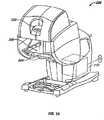
- a surgical stationis generally indicated by reference numeral 300.
- a patient Pis supported by a table T adjacent one or more manipulator support bases 302.
- Base 302is generally supported from above, and may be ceiling mounted, supported by a wall of a room in which surgical station 300 is disposed, mounted to a surgical table, mounted to an arm of a cart having wheels or casters for moving the manipulators within the operating room or between operating rooms, or the like.
- the structure supporting base 302is not shown.
- Base 302will typically remain in a fixed location over patient P during at least a portion of a surgical procedure.
- the workstation 200see Fig.
- surgical station 300is typically positioned at some distance from the surgical station 300, optionally being separated by a few feet within an operating room. In other embodiments, surgical station 300 and workstation 200 may be separated by a significant distance, optionally being disposed in separate rooms or even different buildings.
- Surgical station 300typically includes a plurality of robotic manipulators 304, often having three or more robotic manipulators, with the exemplary embodiment including four robotic manipulators supported by base 302.
- Exemplary base 302comprises an elongate base body supported in a horizontal orientation, with manipulators 304 being distributed horizontally along the length of the base.
- a plurality of separately positionable basesmay support the manipulators.
- each of the robotic manipulatorssupports an associated surgical instrument 306.
- One or more of the instrumentsmay comprise an image capturing device 308 such as an endoscope or the like.
- Each of the other three manipulators 304may support an instrument adapted for manipulating tissues at an internal surgical site 3 10.
- Endoscope 308is operatively connected to viewer 202 to display an image captured at its viewing end on the viewer.
- Two of the other robotic manipulators 304may each be operatively connected to one of the master controls, and a processor 210 may alter which manipulator is operatively connected with which master control.
- the movement of all the manipulatorsmay be controlled by manipulation of the master controls.
- additional input devicesmay be provided for use by another surgeon, a surgical assistant, or the like.
- Input device 220includes an arm 222 and a wrist 224 which together allow translational and orientational movement of an input handle 226 relative to the structure of workstation 200 (see Fig. 1A ).
- Handle 222will generally move with a plurality of degrees of freedom relative to the workstation structure, the exemplary input device 220 providing six degrees of freedom of movement of handle 226.
- the linkage supporting the handlemay include more or less than six degrees of freedom.
- Grip membersare movably coupled to handle 226 and the handle generates a grip signal indicating separation between the grip members.
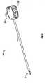
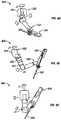
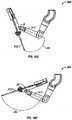
- surgical tool or instrument 306generally includes a surgical end effector 50 supported relative to a housing 53 by an intermediate portion of the instrument, the intermediate portion often comprising of an elongate shaft 14.1.
- End effector 50may be supported relative to the shaft by a distal joint or wrist so as to facilitate orienting the end effector within an internal surgical workspace.
- Proximal housing 53will typically include an interface 232 adapted for coupling to a holder of a manipulator 304.
- instrument 306will often include a memory 230, with the memory typically being electrically coupled to a data interface (the data interface typically forming a portion of interface 232). This allows data communication between memory 230 and the robotic surgical processor 210 of workstation 200 (see Fig. 1A ) when the instrument is mounted on the manipulator.
- a variety of alternative robotic surgical instruments of different types and differing end effectors 50may be used, with the instruments of at least some of the manipulators being removed and replaced during a surgical procedure.
- end effectorsincluding DeBakey Forceps 56i, microforceps 56 ii , Potts scissors 56 iii, and clip a plier 56 iv include first and second end effector elements 56a, 56b which pivot relative to each other so as to define a pair of end effector jaws.
- Other end effectors, including scalpel 56v and electrocautery probe 56vihave a single end effector element.
- the jawswill often be actuated by squeezing the grip members of handle 226.
- Single end effector instrumentsmay also be actuated by gripping of the grip members, for example, so as to energize an electrocautery probe.
- the elongate shafts 14.1 of instruments 306allow the end effectors 50 and the distal end of the shaft to be inserted distally into a surgical worksite through a minimally invasive aperture, often through an abdominal wall or the like.
- the surgical worksitemay be insufflated, and movement of the end effectors within the patient will often be effected, at least in part, by pivoting of the instruments 306 about the location at which the shaft 14.1 passes through the minimally invasive aperture.
- manipulators 304will move the proximal housing 53 outside the patient so that shaft 14.1 extends through a minimally invasive aperture location so as to help provide a desired movement of end effector 50.
- manipulators 304will often undergo significant movement outside patient P during a surgical procedure.
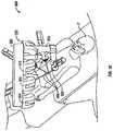
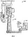
- manipulator 304An exemplary structure of manipulator 304 can be understood with reference to Figs. 4A-4C , 5A and 5B , and Fig. 6 .
- manipulator 304generally supports an instrument 306 and effects movements of the instrument relative to a base 302.
- an instrument holder 320will preferably allow rapid removal and replacement of the mounted instrument.
- the manipulatorwill often be covered by a sterile drape while the instrument may not be.
- An exemplary sterile adaptor and drapeare described in U.S. Patent No. 6,331,181 . As can be understood with reference the Figs.
- manipulators 304are mounted to base 302 by a pivotal mounting joint 322 so as to allow the remainder of manipulator 304 to rotate about a first joint axis J1, with the first joint 322 providing rotation about a vertical axis in the exemplary embodiment.
- Base 302 and first joint 322generally comprise a proximal portion of manipulator 304, with the manipulator extending distally from the base toward instrument holder 320 and end effector 50.
- first link 324extends distally from base 302 and rotates about first pivotal joint axis J1 at joint 322. Many of the remainder of the joints can be identified by their associated rotational axes in Fig. 6 .
- a distal end of first link 324is coupled to a proximal end of a second link 326 at a joint providing a horizontal pivotal axis J2.
- a proximal end of a third link 328is coupled to the distal end of the second link 326 at a roll joint so that the third link generally rotates or rolls at joint J3 about an axis extending along (and ideally aligned with) axes of both the second and third links.
- the distal end of a fourth link 330is coupled to instrument holder 320 by a pair of pivotal joints J5, J6 that together define an instrument holder wrist 332.
- a translational or prismatic joint J7 of the manipulatorfacilitates axial movement of instrument 306 through the minimally invasive aperture, and also facilitates attachment of the instrument holder to a cannula through which the instrument is slidably inserted.
- instrument 306may include additional degrees of freedom. Actuation of the degrees of freedom of the instrument will often be driven by motors of the manipulator, and alternative embodiments may separate the instrument from the supporting manipulator structure at a quickly detachable instrument holder/instrument interface so that one or more joints shown here as being on the instrument are instead on the interface, or vice versa. In other words, the interface between the instrument and manipulator may be disposed more proximally or distally along the kinematic chain of the manipulator assembly (which may include both the instrument and manipulator).
- instrument 306includes a rotational joint J8 proximally of the pivot point PP, which generally is disposed at the site of a minimally invasive aperture. A distal wrist of the instrument allows pivotal motion of end effector 50 about instrument wrist joint axes J9, J10. An angle ⁇ between end effector jaw elements may be controlled independently of the end effector location and orientation.
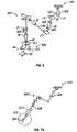
- a manipulator assembly 502here includes a manipulator 504 and an instrument 506 having an end effector 508.
- the term manipulator assemblymay in some cases also encompass the manipulator without the instrument mounted thereon.
- the illustrated manipulator assemblygenerally extends from a proximal base 510 distally to the end effector 508, with the end effector and distal portion of the instrument being configured for insertion into an internal surgical site 512 via a minimally invasive surgical access 514.
- the joint structure of manipulator assembly 502is similar to that described above regarding Fig. 6 , and includes sufficient degrees of freedom so as to allow the manipulator assembly to be anywhere within a range of differing joint states for a given end effector position, even when the instrument is constrained to passage through minimally invasive aperture 514.
- Fig. 7AOne of the challenges of working with the highly configurable manipulator assembly of Fig. 7A can be understood with reference to Figs. 7A and 7B .
- the access site to a minimally invasive surgical procedureis to be changed from a first aperture location 514a to a second aperture location 514b
- the manipulatormay be manually moved into a desired position aligned with the aperture location through which the associated instrument is to access the surgical site.
- the highly configurable manipulator structurehaving a relatively large number of joints between (for example) base 510 and the instrument/manipulator interface (see Fig.
- the controller 210 of workstation 200may actively drive joints of the manipulator assembly during (and preferably in response to) manual movement of at least one joint of the manipulator.
- a hand H of a system operator(optionally a surgeon, assistant, technician, or the like) manually moves a link of manipulator 504 or instrument 506 into alignment with a desired minimally invasive aperture 514b.
- the processordrives joints proximal of the hand/manipulator engagement.
- the proximal jointsmay be driven to a desired manipulator state without inhibiting the manual positioning of the distal portion of the manipulator assembly.
- the jointsmay be driven so as to compensate for gravity, to inhibit momentum effects, to provide a desired (and often readily overcome) resistance to the manual movement so as to give the hand the impression of plastically deforming the manipulator structure at its joints, so as to keep the configurable linkage assembly in a desired pose, or the like. While this movement is shown in Fig. 7C as being performed with instrument 506 attached to manipulator 504, the manipulator assembly will often be manually positioned prior to attachment of instrument 506 to the manipulator.
- moving a location of a minimally invasive access site relative to base 510may significantly alter a desired pose or configuration of the manipulator so as to maintain a desirable range of motion, avoid singularities of the manipulator structure, and the like.
- the processormay reconfigure the joint states in a large variety of ways in response to the manual movement of a link and/or articulation of one or more of the manipulator assembly joints.
- the processorwill often drive joints other than that being articulated manually, optionally in combination with driving of the manually articulated joint so as to allow the link to be moved.
- movement of a minimally invasive access sitemay result from movement of the patient, optionally via movement of a table on which the patient is supported, due to physiological movement such as breathing or the like, and may optionally occur during manipulation of tissues at the internal surgical site by the end effector.
- FIG. 8another alternative manipulator assembly 520 includes a manipulator linkage arm 522 for removably supporting a surgical instrument 524.
- a port clutch input 516comprises an input button which can be actuated by a hand engaging a link 518 of the manipulator that is to be disposed adjacent to access site 514 during surgery, such as the link to which the instrument holder is attached. This allows the hand to both actuate the input and help maneuver the manipulator into the appropriate configuration for surgery.
- the link 518 on which port clutch input 516 is disposedwill be coupleable to the shaft of the instrument by an axial insertion joint (although the instrument may not be attached at the time).
- the hand which actuates the port clutch input 516may be capable of repositioning the manipulator in the clutch mode without assistance from another hand.
- repositioning of the manipulatormay be facilitated by having a user position both a first hand on the manipulator link 518 adjacent port clutch input 516, and a second hand at a distance from the port clutch input, particularly when reorienting the link to a desired axial insertion angle.
- the system processorWhile port clutch input 516 is actuated by the hand, the system processor will drive joints of manipulator 520 in response to manual movement of link 518. In so doing, the processor will generally provide combinations of joint commands and/or velocities that limit the movement of the manipulator while it is in the clutch mode to one or more effective degrees of freedom.
- coupling the joint movements togethercan provide one or more effective clutch degrees of freedom that differ from each of the degrees of freedom of the individual joints.
- more than one jointwill be externally articulated, and more than one associated joint velocity command will be calculated.
- FIG. 8A-8DThree exemplary clutch modes (and some or all of their associated effective degrees of freedom) can be understood by reference to Figs. 8A-8D .
- manipulator 520three clutch inputs are shown, a port clutch input 516a and an instrument clutch input 516b mounted to link 518 adjacent the axial insertion axis of the manipulator assembly, and a pose clutch input 516c mounted along a link of the manipulator assembly between (and kinematically separated from) the base 510 and the instrument holder.
- Other clutch modes and combinationsare also possible.
- clutchencompasses signal and/or data processing techniques which allow, for example, a robotic manipulator assembly to be articulated manually, often while the processor of the robotic system provides joint command signals to at least some of the joints of the manipulator assembly, and/or while an input to a master/slave controller of the processor is temporarily operationally disassociated from the manipulator assembly, either partially or fully.
- port clutchbroadly encompass clutching that involves or relates to an aperture (such as a minimally invasive aperture or port, or any other opening in any structure), a robotic instrument or robotic tool, and a pose or configuration of the manipulator, respectively.
- actuation of port clutch input 516aallows manipulator 520 assembly to be reconfigured manually, generally allowing a system user to manually articulate at least one joint (and typically a plurality of joints) of the manipulator assembly.
- the processormay drive one or more joints of the manipulator assembly by transmitting signals to effect desired combinations of joint velocities of the joints, with the desired combinations varying with changes in the manipulator assembly configuration.
- at least one joint of the manipulator assemblyis being externally articulated (typically being articulated by a user or the like, rather than the robotic controller and drive system) at least one joint of the manipulator assembly is being robotically driven.
- the processorcan thereby maintain a desired relationship between the joint states so that at least a portion of the manipulator moves with a desired constrained movement.
- the processorconstrains manual movement of an instrument holder so as to translate an initial instrument shaft axis 511a to desired instrument shaft axis 511b while maintaining an orientation of the axis throughout the movement.
- the manipulator assemblyis moved from alignment with first aperture site 514a to alignment with a second aperture site 514b at least in part by manual articulation of joint J2
- the processorcalculates coordinated movements of joints J5, J7, and the like, in response to the changing joint state of joint J2.
- the processor in the clutch modecalculates commands for joints J5, J7, etc. so as to provide only the desired translational movement, so that the manipulator assembly has an effective translational degree of freedom which maintains the orientation of the instrument shaft axis.
- the shaft axismay be translated in one, two or three degrees of freedom, and the instrument need not be mounted to the manipulator at the time the manipulator is being moved, as the instrument holder of link 518 can define the instrument axis.
- linkagescould provide similar mechanically constrained parallel-axis motion, but in this embodiment no mechanical joint(s) of the manipulator need provide such a parallel-motion degree of freedom.
- Port and other clutch modesmight provide a variety of alternative clutch degrees of freedom, such as maintaining a desired pose of the manipulator assembly with ranges of motions maximized for the manipulator assembly configuration throughout translational and/or rotational movement, and the like.
- a variety of alternative coordinated manual and driven joint movementsmay be employed, with one, some, or all of the joints of the manipulator assembly being driven robotically in response to manual articulation of one, some, or all of the joints. External joint articulation may be sensed or monitored using joint state sensors of the robotic system.
- a port clutch modemay be provided, either instead of or in combination with those described above.
- articulation of port clutch input 516acan prompt the processor to identify a location of the port.
- Link 518(which supports the port clutch input 516a) will often be coupleable to the instrument shaft by an axial joint, and a distal end of link 518 (and/or a cannula affixed thereto) will often be positioned at or adjacent to desired aperture site 514b.
- the processorcan determine the location of the distal end of link 518 and or cannula from the joint states of the manipulator in response to actuation of the port clutch input 516a, and can thereafter use this information to calculate motions of the instrument shaft so that it pivots within desired aperture site 514b.
- the manipulator assembly in the port clutch modecan be used as an input for the aperture site location.
- Instrument clutchingis useful after the manipulator assembly is aligned with the aperture site, and can facilitate manually orienting of an instrument, cannula, or other structure of the manipulator assembly toward an internal target tissue site, optionally after the cannula and/or end effector has been at least partially inserted into the patient.
- the processordrives the manipulator assembly so as to inhibit lateral movement of shaft axis 511 at a pivotal center 513 adjacent aperture site 514, while allowing lateral movement of the proximal end of link 518.
- the processormay drive a combination of the manipulator joints to as to effect two-dimensional pivotal movements of link 518 centered at pivotal center 513, as schematically illustrated by arrows 515 and cone 517.
- movement of link 518 and/or the instrument along the shaft axismay be allowed, and in other embodiments such axial movement of the instrument and/or link 518 may be inhibited.
- a remote spherical center mechanical linkagemay be simulated in the instrument clutch mode without limiting the movements of the manipulator assembly joints in other modes.
- a pose clutch modecan be understood with reference to Figs. 8A and 8D .
- a pose clutch modeIn response to actuation of a pose clutch input 516c mounted to link 330 proximal of link 518, at least one joint of manipulator 520 can be articulated manually.
- the processordrives one or more joints of the manipulator assembly so that link 518 (and its instrument holder) remains at a fixed position.
- the processorcan coordinate motions of the joints so as to keep the manipulator assembly within that range of configurations.
- Such a pose clutch modecould allow a system user to manually reconfigure manipulator assembly 518 from an apex downward configuration (as shown in Fig. 8A ) to an apex upward configuration (as illustrated in Fig. 8D ) while the processor maintains a position of a distal portion of the manipulator assembly.
- Pose clutch input 516ccan provide a relatively simple approach to allow manual adjustment of the pose.
- the system processorwill often maintain the port and/or end-effector constraints when the manipulator assembly is in a pose clutch mode, but may not apply any pose constraint.
- Backdriveable manipulator assembliesmay benefit from a gravity compensation system (hardware and/or software) while in pose clutch mode, and such a pose clutch mode may allow manual adjustment of the pose without sensing forces (for example) between the base and the cannula.
- pose clutch modethe null space could be velocity controlled, and may not be position controlled.
- clutch inputs 516a, 516b, and/or 516cmay provide advantages in simplicity of implementation, ease of understanding of the various clutch modes, and the like, a variety of other clutch mode user interfaces might also be employed.
- manipulator assemblieshaving systems capable of indicating forces applied to a cannula, an end effector, or the like
- a buttonless haptic clutch user interfacemight be implemented. Rather than pushing a button to alter a mode of the processor, the user might manually articulate the manipulator assembly by applying haptic threshold-exceeding forces against appropriate structures of the manipulator assembly.
- the processormay counteract forces below an appropriate haptic threshold, but may treat external articulations exceeding the threshold as an input into the manipulator assembly, for example, by prioritized saturation of the end-effector, port, and/or pose constraints so that the system conforms to the external articulation.
- a processorcan be configured to determine that a predetermined force threshold has been exceeded in a lateral direction on the cannula so as to indicate that complying with a change in the port location (and hence the pivotal center for future end effector movements) is appropriate.
- the port positioncould be maintained unless the forces applied at the cannula exceeds the threshold.
- the external articulation of the manipulator assemblymight be induced by a system operator intentionally trying to change the port position, or by the patient's body wall such as when the patient moves or is repositioned on the table.
- the processorcould allow the port to be moved to a new position, optionally while constraining manipulator movement to a desired port-clutch mode as described above.
- the processorcould maintain the new port position.
- a similar haptic force thresholdcould be applied to an instrument clutch mode, particularly given a force sensing system capable of sensing joint torques.
- a haptic force threshold instrument clutchcould be implemented on a mechanically constrained remote pivotal center robotic system. In either case, backdriving of the manipulator using external forces exceeding the threshold would cause the processor to modify the set point of the end effector so as to maintain the new position, rather than returning the instrument to the prior position.
- Such instrument clutchingmay be most useful if implemented with a force sensing system capable of distinguishing between forces applied within the body and forces applied outside the body. Instrument clutching might then only occur if forces applied to the manipulator outside the body exceeded the threshold.
- haptic force thresholds or haptic wells for altering processor modemay be combined with processors configured to (typically using software code) prioritize controller tasks such as maintaining port position, end-effector position, and pose, optionally in that in priority order.
- controller taskssuch as maintaining port position, end-effector position, and pose, optionally in that in priority order.
- Such force thresholds(and the other processor control tasks described herein) may be included in systems that implement the controller priorities using prioritized actuator torque saturation.
- Force thresholdsmay also be embodied using processors which drive manipulators according to a primary solution and a secondary control task having a priority therebetween, as described herein.
- the primary prioritymay comprise holding the port position
- the secondary prioritymay comprise maintaining end-effector position.
- a tertiary prioritymay comprise maintaining pose.
- manipulator assembly 502may be reconfigured by the processor for any of a variety of differing reasons.
- a joint 526may be driven from a downward oriented apex configuration to an upward oriented apex configuration so as to inhibit collisions with an adjacent arm, equipment, or personnel; to enhance a range of motion of the end effector 508; in response to physiological movement of the patient such as patient breathing or the like; in response to repositioning of the patient, such as by reorienting a surgical table; and the like.
- Some, but not all, of these changes in configuration of the manipulator assemblymay be in response to external forces applied to the manipulator assembly, with the processor often driving a different joint of the manipulator than that which is being acted upon by the external force.
- the processorwill reconfigure the manipulator assembly in response to calculations performed by the processor.
- the processormay vary from a simple master-slave controller so as to drive manipulator assembly in response to a signal so as to provide a preferred manipulator assembly configuration.
- Such configuring of the manipulator assemblymay occur during master-slave end effector movements, during manual or other reconfiguration of the manipulator assembly, and/or at least in part at a different time, such as after releasing a clutch input.
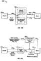
- a simplified controller schematic diagram 530shows a master/slave controller 532 coupling a master input device 534 to a slave manipulator 536.
- the controller inputs, outputs, and computationsare described using vector mathematical notation in which the vector x will often refer to a position vector in a Cartesian coordinates, and in which the vector q will reference a joint articulation configuration vector of an associated linkage (most often of the manipulator slave linkage), sometimes referred to as the linkage position in joint space.
- Subscriptscan be appended to these vectors to identify a specific structure when ambiguity might otherwise exist, so that x m (for example) is a position of the master input device in the associated master workspace or coordinate system, while x s indicates a position of the slave in the workspace.
- Velocity vectors associated with the position vectorsare indicated by a dot over the vector or the word "dot" between the vector and the subscript, such as xdot m or ⁇ m for the master velocity vector, with the velocity vectors being mathematically defined as the change in the position vector with a change in time ( dx m / dt for the master velocity vector example).
- controller 532comprises an inverse Jacobian velocity controller. Where x m is a position of the master input device and ⁇ m is the velocity of the master input device, the controller 532 calculates motor commands for transmission to the manipulator 536 so as to effect slave end effector motions which correspond to the input device from the master velocities. Similarly, controller 532 can calculate force reflection signals to be applied to the master input device (and from there to the operator's hand) from the slave position x s and/or slave velocity ⁇ s .
- a number of refinements to this simple master/slave inverse Jacobian controller schematicare desirable, including those illustrated in Fig. 11 and described in detail in U.S. Patent No. 6,424,885 .
- a processor 542may by characterized as including a first controller module 544 and a second controller module 546.
- the first module 544may comprise a primary joint controller, such as an inverse Jacobian master-slave controller.
- the primary joint controller of first module 544may be configured for generating the desired manipulator assembly movements in response to inputs from the master input device 534.
- many of the manipulator linkages described hereinhave a range of alternative configurations for a given end effector position in space. As a result, a command for the end effector to assume a given position could result in a wide variety of different joint movements and configurations, some of which may be much more desirable than others.
- the second module 546may be configured to help drive the manipulator assembly to a desired configuration, in some embodiments driving the manipulator toward a preferred configuration during master-slave movements.
- second module 546will comprise a configuration dependent filter.
- both the primary joint controller of first module 544 and the configuration dependent filter of second module 546may comprise filters used by processor 542 to route control authority for linear combinations of joints to the service of one or more surgical goals or tasks. If we assume that X is the space of joint motion, F ( X ) might be a filter giving control over the joints to i) provide a desired end effector movement, and ii) provide pivotal motion of the instrument shaft at the aperture site. Hence, the primary joint controller of first module 544 may comprise filter F (X).
- (1- F 1 F )( X )could describe a configuration dependent subspace filter giving control actuation authority to the linear combination of joint velocities that are orthogonal to serving the goal of the primary joint controller (in this example, end effector movement and pivotal instrument shaft motion).
- this configuration dependent filtercould be used by the second module 546 of controller 542 to service a second goal, such as maintaining a desired pose of the manipulator assembly, inhibiting collisions, or the like. Both filters may be further sub-divided into more filters corresponding to serving more specific tasks.
- filter F ( X )could be separated into F 1 ( X ) and F 2 ( X ) for control of the end effector and control of the pivotal shaft motion, respectively, either of which may be chosen as the primary or highest priority task of the processor.
- the robotic processors and control techniques described hereinwill often make use of a primary joint controller configured for a first (sometimes referred to as a primary) controller task, and a configuration dependent filter which makes use of an underconstrained solution generated by the primary joint controller for a second (sometimes referred to as secondary) task.
- a primary joint controllerconfigured for a first (sometimes referred to as a primary) controller task
- a configuration dependent filterwhich makes use of an underconstrained solution generated by the primary joint controller for a second (sometimes referred to as secondary) task.
- the primary joint controllerwill be described with reference to a first module, while the configuration dependent filter will be described with reference to a second module. Additional functions (such as additional subspace filters) and or additional modules of varying priorities may also be included.
- Controller 542may employ the functions of the two modules simultaneously, and/or may have a plurality of differing modes in which one or both modules are used separately or in different ways.
- first module 544might be used with little or no influence from second module 546 during master-slave manipulations, and the second module 546 having a greater role during setup of the system when the end effector is not being driven robotically, such as during port clutching or other manual articulations of the manipulator assembly. Nonetheless, in many embodiments both modules may be active most of or all the time robotic motion is enabled.
- the influence of the first module on the state of the manipulator assemblycan be reduced or eliminated so as to change a mode of processor 542 from a tissue manipulator mode to a clutch mode.
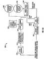
- Fig. 10Cillustrates a refinement of the simplified master-slave control schematic 540 from Fig. 10B , and shows how different modules might be used in different processor modes.
- first module 544may, for example, comprise some form of a Jacobian controller having a Jacobian-related matrix.
- Second module 546may, in a port clutch mode, receive signals from the slave 536 indicating a position or velocity of the slave generated at least in part by manual articulation of the slave manipulator linkage. In response to this input, the second module 536 can generate motor commands appropriate for driving the joints of the slave so as to allow the manual articulation of the slave linkage while configuring the slave in the desired joint configuration.
- the controllermay use second module 546 to help derive motor commands based on a different signal b q ⁇ 0 .
- This alternative input signal to the second module 546 of controller 542may be used to drive the manipulator linkage so as to maintain or move the minimally invasive aperture pivot location along the manipulator structure, so as to avoid collisions between a plurality of manipulators, so as to enhance a range of motion of the manipulator structure and/or avoid singularities, so as to produce a desired pose of the manipulator, or the like.
- b q ⁇ 0can generally comprise and/or indicate (for example) a desired set of joint velocities, more generally representing a secondary control goal, typically in joint space.
- the processormay include separate modules and/or dependent configuration filters for clutching, secondary controller tasks, and the like
- a partial control schematic 550illustrates modifications of the controller illustrated in Fig. 11 .
- Control schematic 550very roughly represents a modification of portion 551 of the controller of Fig. 11 to facilitate control over manipulator assemblies have large numbers of degrees of freedom.
- the first module 544comprises an inverse Jacobian velocity controller, with the output from calculations made using an inverse Jacobian matrix modified according to a virtual slave path 552.
- vectors associated with the virtual slaveare generally indicated by a v subscript, so that a virtual slave velocity in joint space q ⁇ v is integrated to provide q v , which is processed using an inverse kinematic module 554 to generate a virtual slave joint position signal x v .
- the virtual slave position and master input command x mare combined and processed using forward kinematics 556.
- the use of a virtual slave(often having simplified dynamics) facilitates smooth control and force reflection when approaching hard limits of the system, when transgressing soft limits of the system, and the like, as can be more fully understood with reference to the '885 patent previously cited.
- these structureswill often comprise data processing hardware, software, and/or firmware.
- Such structureswill often include reprogrammable software, data, and the like, which may be embodied in machine-readable code and stored in a tangible medium for use by processor 210 of workstation 200 (see Fig. 1A ).
- the machine-readable codemay be stored in a wide variety of different configurations, including random access memory, non-volatile memory, write-once memory, magnetic recording media, optical recording media, and the like.
- Processor 210may, as illustrated in Fig. 1A , comprise one or more data processors of workstation 200, and/or may include localized data processing circuits of one or more of the manipulators, the instruments, a separate and/or remote processing structure or location, and the like, and the modules described herein may comprise (for example) a single common processor board, a plurality of separate boards, or one or more of the modules may be separated onto a plurality of boards, some of which also run some or all of the calculation of another module.
- the software code of the modulesmay be written as a single integrated software code, the modules may each be separated into individual subroutines, or parts of the code of one module may be combined with some or all of the code of another module.
- the data and processing structuresmay include any of a wide variety of centralized or distributed data processing and/or programming architectures.
- the controllerwill often seek to solve for one particular manipulator joint configuration vector q for use in generating commands for these highly configurable slave manipulator mechanisms.
- the manipulator linkagesoften have sufficient degrees of freedom so as to occupy a range of joint states for a given end effector state.
- Such structuresmay (but will often not) comprise linkages having true redundant degrees of freedom, that is, structures in which actuation of one joint may be directly replaced by a similar actuation of a different joint along the kinematic chain.
- the primary joint controller of the first moduleWhen directing movement of highly configurable manipulators using the velocity controller of Fig. 12 , the primary joint controller of the first module often seeks to determine or solve for a virtual joint velocity vector q ⁇ v that can be used to drive the joints of slave 536 in such a way that the end effector will accurately follow the master command x m .
- an inverse Jacobian Matrixgenerally does not fully define a joint vector solution.
- the mapping from Cartesian command ⁇ to joint motion q ⁇ in a system that can occupy a range of joint states for a given end effector stateis a mapping of one-to-many.
- the controllermay embody this relationship using a Jacobian matrix that has more columns than rows, mapping a plurality of joint velocities into comparatively few Cartesian velocities.
- Our solution J ⁇ 1 x ⁇will often seek to undo this collapsing of the degrees of freedom of the slave mechanism into the Cartesian workspace.
- the primary joint controller of the first modulemay employ a number of different techniques to generate such a primary solution.
- a linear mapsuch as a Jacobian matrix
- itmay be said to have a non-trivial null space, the null space typically comprising a subspace of the input space spanning one or more dimensions.
- the pseudo inverse solution q ⁇is equal to the combination of any particular solution q ⁇ part added to the homogeneous solution q ⁇ h .
- x ⁇J q ⁇ part
- the least-mean-squares solutionis one exemplary choice for the first term of the above general joint space solution equation, as it provides one particular solution to the Jacobian.
- This pseudo inverseyields the final solution vector with ⁇ q ⁇ part + q ⁇ h ⁇ 2 minimized, and is among the alternative pseudo inverses described below.
- J #J T J J T ⁇ 1
- J Tis the transpose of the Jacobian matrix.
- thisgenerally corresponds to a solution that achieves the primary control objective (such as a master-slave movement of the end effector corresponding to that of a handle of the input device) with the smallest joint velocities, a reasonable goal for many robotic systems. It is also mathematically extremely convenient, being one of the easiest solutions to compute. However, this is not the only pseudo inverse of Jacobian J , and indeed there may be more appropriate task-based solutions, particularly when there are additional constraints or goals for movement of a system beyond (in our initial example) a commanded movement of the end effector with a minimum joint velocity. As the minimum norm inverse is just one example of a pseudo-inverse, where J -! or J # appears herein it will often be reasonable to think of these as generally representing any pseudo-inverse, not merely the minimum norm inverse.
- the desired control space ⁇may optionally be more complex than simple end effector motion, particularly in systems in which the complexity of redundant manipulator linkages is justified.
- Combining of controller tasks or objectiveswill generally make use of a configuration dependent filter of the second module.
- filtersmay be used.
- multiple objectivesmay be adjoined or stacked to form an augmented desired vector, particularly if the objectives are independent.
- Such pivotal motionis sometimes referred to as a software center motion. Augmenting the problem statement in this manner is most easily applicable when the manipulator assembly has sufficient degrees of freedom to provide a solution to the augmented equation, as there generally are in the above-described robot manipulator assembly linkages. That is, the augmented Cartesian command vector (with the pivotal motion constraint) q ⁇ still has a lower dimension than the joint velocity vector q ⁇ , whose dimension is typically the number of manipulator joints.
- An exemplary augmented end effector and cannula control problem formulationmay comprise computing a Jacobian J for each control objective.
- J eff mapping q ⁇ to ⁇ effwhere eff is here used to indicate the vector and/or matrix that is associated with the end effector.
- a Jacobian J canmaps the joint velocities of the manipulator assembly to the cannula Cartesian velocities, written ⁇ can .
- x ⁇ eff x ⁇ canJ eff J can q ⁇
- position loopsmay be closed using signals from the manipulator assembly slave 536 to control positions (including location and orientation) as well.
- Additional control objectivessuch as driving toward a preferred collision-inhibiting pose or the like, may also be added in a similar manner. However, as such objectives are added the dimension of the desired vector space ⁇ may equal or surpass that of the solution space q ⁇ .
- the subspace filter of the second modulemay take another form.
- the pseudo inverseWhen the dimensions of the vector space and solution space are equal, the pseudo inverse should become a true inverse, and the minimum-norm pseudo inverse conveniently reduces to the true inverse. Should more augmented solutions be sought, however, the controller and the robot will not in general have sufficient degrees of freedom to satisfy all the constraints. Such a problem is described as over-constrained, so that a new kind of pseudo inverse may be created. Such a pseudo inverse attempts to compromise in some mathematical sense, returning a solution that does not perfectly satisfy all of the constraints but may still be mathematically determined to be the best solution in some identifiable sense. For example, a residual error resulting from the imperfect inverse may be computed, such as by using the minimum two-norm pseudo inverse to return a solution that minimizes the two-norm of the residual error.
- Examples of additional constraints that may be addedinclude maintaining a pose constraint, and/or avoiding a collision with an object which may be present in the workspace.
- ⁇ kis the desired control variable
- q ⁇ jis the joint velocities of joints 1, 2, ... n
- J kjare the Jacobians of the desired control variable for each joint
- ris the residual error appropriate for our quadratic cost function C.
- an augmented controllerwe can control a joint to maintain a pose using the above framework by creating a desired control variable ⁇ k and making it identical to a selected joint q ⁇ j .
- the augmented Jacobiancan in this example be a trivial matrix with a one in the column for the selected joint.
- the analysisis more complex for an over-constrained system in comparison to an under-constrained system.
- Robots in general, and surgical robots in particularshould be designed and controlled so as to make advantageous use of all their joints.
- a plurality of commandsmay optionally be combined by the controller with associated weights, for example by applying a weighted minimum norm solution.
- the minimum normcan be computed with respect to a set of basis vectors representing the solution space.
- the solutionmay then comprise a linear combination of those basis vectors. While basis vectors are sometimes visualized as one unit in the x direction, one unit in the y direction, etc., this is not necessarily required. For example, joints may differ significantly, with some being axial or prismatic, others being pivotal or rotational, and the like.
- basis vectorsmay be understood from a simple example, in which e 1 is one degree/sec for a first motor, e 2 is one degree/sec for a second motor, etc, and in which an initial minimum norm solution space is computed.
- This solution spacecould be arbitrarily weighted by instead choosing different basis vectors. For example, we could make e 1 equate to ten degrees/sec for the first motor, while e 2 remains one degree/sec for the second motor.
- a minimum norm solutionwill tend to make coefficients for e 1 no bigger, on average, than those for e 2 and the rest. Thus, this weighting approach can tend to make the first motor's velocity smaller, because of the weighting of basis functions we have chosen.
- e 1may be one degree/sec in the positive direction for the first motor, and one degree/sec in the positive direction for the second motor.
- e 2could then be one degree/sec in the positive direction for the first motor, and one degree/sec in the negative direction for the second motor.
- C weightedr T W T Wr , where W is a weighting matrix, and r is the residual error. In this sense, we weight the residual error as desired, thereby helping to shape the answer.
- weightingcan be used to make some parts of the solution more important than others.
- Wcan be made diagonal with large weights for important components and small weights for less important components of the augmented solution vector.
- linear combinations of any solution componentscan be arbitrarily weighted.
- condition numberFor robotic systems, the loss of precision associated with an increase in condition number happens when the Jacobian becomes ill conditioned, which in turn happens near singularities. As the condition number grows, the map acts more and more like its null space is growing by one or more dimension, but the effect is continuous, not discrete. Instead, a new subspace of joint (solution) vectors map almost to zero in the desired (master) vector space. Any noise, even round-off error in numeric calculations, can and often does result in phantom solutions, in which unrealistic joint velocities are commanded for minor velocities in command space, including minor contributions due to noise.
- a number of subspace filter techniquescan address this ill-conditioned map effect, including conditioning the solution by truncating the singular value decomposition ("SVD") of the Jacobian, effectively forcing the nearly grown null space to grow a full dimension.
- SVDsingular value decomposition
- Bayesian estimationwhich is also referred to as maximum a posteriori estimation. In its simplest form it reduces to something equivalent to a regularizing inverse.
- the main conceptis to find the free parameters q ⁇ j that maximize the a posteriori probability density function of a noisy measurement p ( q ⁇ j , ⁇ 1 ,..., ⁇ n ) .
- PDFsprobability density functions
- the secondis the a priori (or prior) distribution for the solution vector.
- Ais a matrix formed of the variances of the measurement process divided by the variances of the prior distribution.
- Bayesian methodschange the solution. In this case, the change is physically motivated by an optimization technique meant to handle measurements in the presence of noise, and to handle the availability of prior information about the probable solution.
- a still further augmented optimization subspace filter approach which may be applied to over constrained redundant degree of freedom surgical robotic systemsis constrained convex optimization.
- a minimum norm solution based on minimizing a quadratic formhas the mathematical elegance of reducing to a system of linear equations.
- these simultaneous linear equationsmay be solved rapidly and with high accuracy, and are approachable and easy to understand, and this ease of implementation certainly encourages their use.
- a class of such problemsis termed convex optimization, and a corresponding class of algorithms exists that yield efficient solutions, including those algorithms described by Boyd and Vandenberghe.
- controllers of surgical robotic systems having redundant degrees of freedommight also benefit from mathematical approaches for addressing constraints that respect priority.
- the above discussionhas largely centered on optimization of a problem where constraints are imposed using augmented optimization. However, there may be differences in importance between a central, main control problem and any desirable, but not necessarily required solutions that we can add in.
- Several mathematical mechanismsare introduced below for making constraints soft, so that they fold back or can be relaxed gracefully as the main control problem gets harder, employing more of the degrees of freedom of the system.
- An example of a soft constraintwould be to maintain an elbow or joint apex of a manipulator pointing up, as described above regarding Figs. 5A and 5B .
- Another constraintmight be to maximize the robot's workspace dexterity, or some other mathematical measure or robotic effectiveness.
- Wemight, for example, wish our controller to gradually abandon these secondary goals as the primary task (for example, complying with an end effector movement command vector), thereby allowing the system to achieve the primary objective at the cost of these soft, lower priority goals.
- wemight need and use the otherwise extra degrees of freedom to avoid a singularity or the like.
- One way to establish a system having a plurality of constraints, tasks, or goals with priorities therebetweenis to construct the secondary task as an augmented part of the solution, per the discussion above.
- We can also adjust this weighting matrix during useso that the weighting is neutral when the robot is in its sweet spot, while the weighting might exert a very strong clamp on any augmented solution (making the secondary constraint contribute almost nothing to the final solution) as the difficult region was approached. It is also possible to turn on and off the weighting altogether, so as to achieve a discrete switch that respects priority. Similar techniques may be used for the regularized solution and the Bayesian approach. For example, the parameter ⁇ , as well as the prior distribution, may be tuned in a configuration dependent manner.
- projector methodsmay make use of input vector bq ⁇ 0 .
- J effmapping q ⁇ to ⁇ for the end effector
- any task that can be written as a linear controller of rates with a position feedbacksuch as the remote center cannula motion task described above.
- Still further secondary tasksmay be performed using projection, augmentation, and/or other methods, including some or all of the robotic manipulations and/or set up methods described above.
- the generation of secondary tasks to perform collision avoidance described herein and elsewhere in the literaturecan, for example, be revised so as to inhibit collisions between two simultaneously moving manipulator assemblies.
- One solutionwill use the general formalism of augmented tasks to generate rate controllers, as discussed above.
- Additional modified control approachesmay be implemented for other operation modes. For example, to lock an arm or manipulator assembly, or a subset of the degrees of freedom of such a structure (see clutching below), we can deliberately clamp some or all of the output vector of the first module 544 to zero. To re-establish master-slave following, we release the clamp, preferably after satisfying elementary matching conditions to rule out jump discontinuities in the input command.
- an instrument clutch modewill generally allow manual articulation of the manipulator assembly with limited degrees of freedom.
- an assistantmay want to be able to manually move the manipulator assembly so as to advance and retract the instrument through the access site, to pivot the instrument about the access site to orient and position the new end effector, and the like.
- a port clutch modemay allow the canula or access site to be moved (and optionally to identify the new access site location when the move is completed), but may maintain an orientation and/or pose of some or all of the manipulator assembly during manual movement.
- clutchingis direct: one simply turns off the controller for those joints that are free to move.
- the controllercan effect this motion, which will often be different than any degree of freedom of the mechanical system, by defining any desired arbitrary linear combination of rates that can be treated as a single degree of freedom that the operator may manipulate, optionally while some or all of the other mechanical degrees of freedom remain locked.
- This general conceptincludes port clutching, instrument clutching, elbow clutching (in which an intermediate elbow is allowed to move, for example, from an upward oriented apex configuration around to a laterally oriented apex configuration while movement at the end effector remains inhibited), and other clutching modes. Normal joint-by-joint clutching falls out as a special case.
- Still further tasks or goals of the systemmay be implemented using the controller techniques described herein. Adaptive filtering and learning of a pivotal access site location from instrument movements are described below. Additionally, haptic constraints may be implemented using another variation on these techniques.
- haptic constraintsit is often useful to provide cues to the operator during the manipulation of the slave arm via the master input device. For example, it may be desirable to indicate to the operator to keep away from suboptimal configurations that will cause controllability problems later.
- One simple method to provide such haptic constraintsis to implement a joint limit technique.
- Another methodis to turn on a one-sided servo whenever a threshold is crossed. This can be done using any of the projector or augmentation methods above.
- a one-sided servowould often push back toward or away from a control point if the sensors indicate that the threshold is crossed and motion is further in the wrong direction.
- a velocity that is parallel to the boundarycan be described for every point along the boundary.
- a dot product of the velocity vector and the thresholdthen indicates whether the operator is moving toward or away from the boundary, and the projection in the wrong direction is resisted. This can all be done with the above-described projector operators and a comparison with zero.
- a software center surgical robotic manipulator assembly 560has particular advantages relating to movement of a pivotal center of motion 562 of a robotic instrument 564 with movement of an associated port site or minimally invasive surgical access into a patient 566.
- Manipulator assembly 560may be mounted to a patient side table, ceiling mount or floor mount, and can compensate for port site motion (e.g., patient breathing) by independently controlling the location of the port site.
- the port site locationcan be controlled in response to Cartesian force information at the cannula pivotal center point as sensed by a force sensing cannula 568.
- the coordinate frame attached to the cannulais designated Ocan in Figure 13 .
- This frameis distinct from a base frame, Obase, at the base of the manipulator and the tip frame, Otip, at the tip of the instrument.
- the Cartesian forces on the cannulacan be resolved to control the position of the cannula (Ocan).
- the torques about Ocanare not needed for such position control.
- Some or all of the forces at the portcan be resolved using a force sensing system of cannula 568, and/or at least some of the forces may be resolved using a force sensing system of the instrument 564, the manipulator assembly 560 (e.g., joint torque sensors of the manipulator), or the like.
- control lawscan move the cannula position in response to reaction forces at the cannula.
- One example of such a control lawis to set a commanded cannula Cartesian force to zero. The controller will then try to move the manipulator assembly such that the resulting Cartesian force on the cannula is minimized. It is also possible to set a nonzero commanded cannula force, e.g., 5 lbs in the positive Z cannula direction to have the arm help retract the cannula from the patient. This can also be achieved using the same controller.
- FIG. 13Ashows the overall block diagram for the cannula motion controller as it would fit into an overall software center tele-operation controller.
- Signals from force sensors 572can be derived from the sensor characteristics and their placement in the arm.
- a transform module 574(typically a Jacobian operator) transforms measured force sensor information into the reference frame of Cartesian cannula forces.
- Filter module 578creates a filtered error signal from the actual cannula force and the commanded cannula force.
- the commanded slave tip position 580comes from the master side of the teleoperation loop (see, for example, Fig. 11 ) and a commanded slave tip velocity 582 may also be provided.
- Hybrid controller module 584accepts command and actual slave position and velocity signals, along with filtered cannula force error signals, and creates joint motor torque signals.
- the dynamics of the software center manipulator assemblyare shown as 586, which interact with the dynamics of the patient environment 588.
- Figs. 13B and 13Cshow representative control arrangements or algorithms for filter module 578 and hybrid controller 584, respectively.
- a simple compare module 590can create an error signal between commanded and actual cannula force. The filtered error can then be generated by a low pass filter 592.
- a good method of controlmay be to convert the commanded cannula force into a commanded cannula motion 594. This can be done by creating an incremental commanded position proportional to the cannula force error and adding this incremental cannula position to the current (actual) cannula position to create a commanded cannula position.
- the commanded cannula positionis vector assembled 596 with the commanded slave tip position, to create a command position vector for the manipulator assembly. This is combined with actual joint positions and velocities and fed into the software center slave controller 598 to create commanded motor torques, which are in turn used to drive the manipulator assembly motors.
- pivot point PPis the position relative to the minimally invasive access port at which an instrument shaft pivots.
- Pivot point PPmay, for example, be calculated by initially determining an original position of the interface between the manipulator instrument 14.1 and a unit vector Uo which has the same orientation as the instrument shaft.
- the pivot point position PP(x,y,z) valuescan be derived from various sensors of the manipulator assembly.
- the instrumentcan be within a first coordinate frame (x,y,z) which has the angles ⁇ 4 and ⁇ 5.
- an angular movement of the instrument ⁇can be computed by taking the arcsin of the cross-product of the first and second unit vectors Uo and U1 of the instrument in accordance with the following line equations Lo and L1.
- the unit vector of the new instrument position U1may again be determined using the position sensors and the transformation matrix described above. If the angle ⁇ ⁇ is greater than a threshold value, then a new pivot point may be calculated and Uo set to U1.
- the pivot points of the instrument in the first orientation Lo (pivot point Ro) and in the second orientation L1 (pivot point R1)can be determined, and the distance half way between the two points Ro and R1 is computed and stored as the pivot point R ave of the instrument.
- the pivot point R aveis determined by using the cross-product vector T.
- the pivot point locationcan be regularly continually updated with the above described calculations.
- FIG. 14A, 14B , and 15another control system schematic 400 illustrates how a movement of the master controller or manipulator can be used to calculate a corresponding movement of a surgical instrument so that the instrument pivots about a pivot point using an alternative controller architecture.
- the processorcomputes output signals for the manipulators so that the instruments move in conjunction and coordination with the movements of the master input handle.
- Many aspects of control system 400are more fully described in U.S. Patent No. 6,699,177 .
- the location of a pivot point at which an instrument is inserted into an internal surgical sitecan be calculated by a pivot point calculation module 404 from instrument movements.
- the various modules shown in Figs. 15 and 16may again comprise hardware, software, firmware, a combination of hardware and software, or the like.
- the moduleswill often comprise data processing hardware configured to perform the calculations described herein using software, and the calculations of multiple modules may be integrated together in a common program or module, and/or the calculation of a single module may be separated into multiple programs or subroutines to be run on separate processor boards.
- the above descriptionsenable the pivot (center) point to be determined/estimated through software.
- different modes characterized by the compliance or stiffness of the systemcan be selectively implemented. More particularly, different system modes over a range of pivot points/centers (i.e., ranging from one have a passive pivot point to one having a fixed/rigid pivot point) can be implemented after an estimate pivot point is computed. For example, in a fixed pivot implementation, the estimated pivot point can be compared to a desired pivot point to generate an error output which can be used to drive the instrument's pivot to the desired location.
- an estimated pivot pointcan be used for error detection and consequently safety because changes in estimated pivot point locations may indicate that the patient has been moved or a sensor is malfunctioning thereby giving the system an opportunity to take corrective action.
- the interaction between the moving instrument and the tissue of the minimally invasive aperturemay be determined at least in part by the processor, the processor optionally allowing the compliance or stiffness of the system to be changed throughout a range extending from a passive pivot point to a fixed pivot point.
- the proximal end of the instrumentmay be moved in space while the motors of the instrument holder wrist joint apply little or no torque, so that the instrument acts effectively like it is coupled to the manipulator or robotic arm by a pair of passive joints.
- the interaction between the instrument shaft and the tissue along the minimally invasive apertureinduces the pivotal motion of the instrument about the pivot point PP.
- the surgical instrumentwas not inserted into the minimally invasive aperture or otherwise constrained, it may point downward under the influence of gravity, and movement of the manipulator arm would translate the hanging instrument without pivotal motion about a site along the instrument shaft.
- the location of the minimally invasive aperturemay be input or calculated as a fixed point in space.
- the motors associated with each joint of the kinematic chain disposed proximal of the pivot pointmay then drive the manipulator so that any lateral force laterally against the shaft at the calculate pivot point results in a reaction force to keep the shaft through the pivot point.
- Such a systemmay, in some ways, behave similar to mechanically constrained remote center linkages. Many embodiments will fall between these two extremes, providing calculated motion which generally pivots at the access site, and which adapts or moves the pivotal center of motion within an acceptable range when the tissue along the minimally invasive access site moves, without imposing excessive lateral forces on that tissue.
- a software center manipulator assembly controllersuch as that illustrated in Fig. 12 can leave the software center rather soft or lightly held so that the tissue forces applied by the interaction with the patient are allowed to overpower the commands sent to the manipulator motors.
- Such calculated saturation of the manipulator drive torquesmay be allowed while still controlling the end effector position to quite tight tolerances, since all motions of the manipulator assembly can be determined from the sensors of the manipulator.
- Several mechanismsmay be applied for gradually increasing the stiffness of the software center control, including the weighted augmentation solutions discussed above. By starting with a small weighting value for the remote center, and by gradually increasing those weights to be on a par with the end effector weights, one could (for example) gradually stiffen control over the pivotal center location.
- the body wall and any other exogenous forces applied to the manipulator assemblycan affect the motion of the pivotal center if the pivotal center is held softly by the controller.
- the above-described calculations for determining the remote center locationcan be applied if the instrument is allowed to passively pivot adjacent the interface with the manipulator, for example. As the variance of the estimates for the pivotal motion center decreases, the weighting factor or gain may be increased. Tracking of the changes in pivotal center location may allow identification of and compensation for cyclical physiological movements such as patient breathing, beating of the heart, or the like. In some embodiments, similar calculations will allow the controller to compensate for movement of the patient such as by reorienting a surgical table, repositioning a patient on the surgical table, or the like.
- the systems described hereinmay optionally include a modified manipulator command module 406 of controller 400 having a software center joint command calculation module 410 as illustrated in Fig. 16 .
- Software center module 410 of processor 210receives an input command corresponding to a desired end effector motion, typically in the form of signal generated in response to a master input handle movement.
- Software center module 410calculates the desired corresponding end effector movement or vector at calculation module 412, optionally using coordinate system transformations such as those described in Patent Nos. 6,424,885 and/or 6,699,177 .
- the desired end effector movementis then transmitted to an inverse kinematics solver 414.
- the desired end effector motionis also used by a remote center locator 416 so as to generate a solved center about which the instrument will pivot.
- the remote center locator 416makes use of actual joint motion information from the slave manipulator 418.
- the information from manipulator 418may comprise actual joint motions from prior end effector movements.
- the datamay originate in the form of positions of each of the individual joints from potentiometers or the like, discrete steps of the individual joints from encoders or the like, or a wide variety of alternative motion indicators.
- joint torques as detected at the joints of the manipulatormay also be provided, and both joint positions and joint velocities may be transmitted to a forward kinematics module 420.
- the forward kinematics module 420can calculate an observed minimally invasive aperture pivotal center location from the behavior of the slave manipulator during prior movements of the instrument.
- the software center module 410may also determine forces associated with the pivoting about the minimally invasive aperture, properties of the tissue tract (for example, the lateral or pivotal spring forces applied by the tissue tract to the instrument during movement of the instrument shaft and/or any lateral movement of the patient anatomy adjacent the aperture) and the like. Still further, properties of the observed pivotal center may also be determined. For example, the software center module 410 may determine any cyclical movements of the observed pivotal center with a physiological activity such as breathing or beating of the heart. Shifting of the pivotal center with changing pivotal angles or orientations may also be identified.
- intercostal access to the chest cavitymay result in a first pivotal center when a instrument inserted between the ribs is pivoted generally across the rib orientation, and a slightly different pivotal center when the instrument is angled along the lengths of the adjacent ribs.
- Tissue stiffnessmay also vary along the axis of the tissue tract and/or at differing distances from the tissue tract, so that pivoting of a shaft inserted through a minimally invasive aperture at a relatively small angle may result in a pivotal center which is disposed at a first point along a tissue tract extending through the abdominal wall, while increasing the angle of the shaft inserted through the same tract may shift the pivotal center axially along the tissue tract either proximally or distally.
- the observed pivotal center information from the forward kinematics module 420may be combined with the commanded end effector motion from desired end effector calculation module 412 so as to generate a solved or desired center of the desired motion.
- the observed pivotal center and commanded tip motionmay be combined using an adaptive filter, and the input to the inverse kinematic solver from the combination of the observed pivotal center and the commanded end effector motion may comprise a desired remote center motion 422.
- manipulator linkageswhich are not easily back driven will tend to keep a remote center location at a calculated position. Assuming the drive system of the linkage is not overpowered, the observed remote center will remain within a close proximity to the desired or calculated remote center location, with the difference between the observed center and desired center often falling within a relatively small servo error of the manipulator.
- the systemmay determine that the remote center should be removed to alleviate forces and/or torques applied to the manipulator structure.
- the forces and/or torquesmay be applied to and measured at the cannula, for example, by reactive forces of the tissue against the cannula, by physiological movement of the patient during breathing or patient repositioning, or the like.
- an operatormay manually push on the arm to move the remote center to a new location, optionally before, during, or after transmitting a pivot center repositioning signal to the processor, such as by pushing a port clutch button.
- a large number of computational methodsmay be used to choose a new remote center based on the data provided by such manual movement of the manipulator linkage.
- the output of such calculationsmay be termed a solved center or a desired center, and will often represent an input from a system user to the processor, optionally by releasing the port clutch input when the appropriate structure along the kinematic chain of the manipulator assembly (such as a cannula) is disposed at the desired access site location.
- a solved center or desired centermay simply be a filtered version of an observed center.
- Such back drivable linkageslend themselves more directly to observing actual motions of the remote center and,adjusting the control appropriately.
- a torque or force sensorto measure disturbance forces acting on the arm at the pivot center (such as a cannula force sensor) may facilitate such pivot location movement, rather than relying solely on joint torque or position measurements.
- the shaft of the instrument between the end effector and the proximal instrument housingwill typically extend through the minimally invasive aperture.
- the motion of this intermediate portion of the instrumentwill be calculated so that the instrument does not impose injury on the patient, but instead remains within the minimally invasive access site.
- the instrumentmay rotate about its shaft, and the shaft may be inserted distally or withdrawn proximally along the shaft axis.
- the vector of the commanded Cartesian velocities and angular velocities of the tip of end effectormay be provided from the slave vector calculator 414, the exemplary end effector vector comprising a 1 x 6 vector, with actuation of grip on end effector often being handled separately from the inverse kinematic computations.
- the desired remote center motion 422 input into the inverse kinematic solvermay comprise a vector of Cartesian velocities of the pivotal center, such as a 1 x 3 vector.
- inverse kinematic solver 414can be used for manipulator structures which are a combination of a compliant or passive rotational center and a more rigidly calculated rotational center.
- Inverse kinematic solver 414may nonetheless make use of controller schemes similar to those of more constrained mechanical systems, such as those described in U.S. Patent No. 6,493,608 . More specifically, the use of modified inverse kinematics with a feedback tuned to correct for integrator drift may have some benefits for the joint motion calculator 410 of Fig. 16 . However, certain modifications to the inverse kinematic solver 414 may be employed to adapt the joint calculator for use with a larger number of degrees of freedom and/or for the use of a calculated remote center.
- inverse kinematic solver 414uses the desired end effector motion and the desired pivotal center motion to determine velocities of the instrument.
- the velocitieswill include a vector of the desired Cartesian velocities of the end effector, the desired angular velocities of the end effector, and the Cartesian velocities of the pivotal center, often in the form of a 1 x 9 vector V.
- q ⁇ baseW ⁇ 1 J T J W ⁇ 1 J T ⁇ 1 V in which W is a weighting matrix and J is the Jacobian matrix.
- the Jacobian matrixis a 9 x 10 matrix.
- the exemplary armswill again often include more degrees of freedom than the combination of the degrees of freedom of the end effector in space (often 6) and the constraint of maintaining the instrument shaft at the aperture (3), so that they are underconstrained for the end effector and shaft pivoting tasks.
- these linkage systemsmay have more than 10 degrees of freedom, and their kinematic chains often define a null space or range of alternative configurations and/or joint velocities which the kinematic chain can have for a given end effector position.
- auxiliary joint velocities q auxthat minimizes one or more cost functions can then be computed, with the cost function often having a configuration which drives the manipulator away from joint range-of-motion limitations, away from singularities, free from obstacles, and the like.
- These auxiliary joint velocitiescan then be projected into the null space of the Jacobian matrix.
- kinematic solver 414can calculate the joint motions based at least in part on information regarding the motions of other manipulators.
- a pose optimizer module 430receives actual joint motion data from the manipulator, and also receives actual joint motion information from the other manipulators. Based on the motions of the manipulators, the pose optimizer calculates additional inverse kinematic constraints to be input into the inverse kinematic solver 414.
- the pose optimizermay again drive the joint configuration of the kinematic chain using a goal function, such as to enhance separation between adjacent manipulators while effecting the commanded movement of the end effector, and while also maintaining an intermediate portion of the instrument within a minimally invasive aperture site.
- Pose optimizer 430thereby takes advantage of the excess degrees of freedom of the kinematic linkage (beyond those of the end effector in the surgical site), as can be understood with reference to Figs. 5A and 5B .
- manipulator 304holds instrument 306 at a given location in space.
- An intermediate joint J4 of the manipulatoris configured so that the axes of the links coupled together at joint J4 generally define a downward oriented apex 350.
- manipulator armcan be driven from this downward apex configuration to an upward oriented apex configuration illustrated in Fig. 5B , with the upward oriented apex indicated by reference numeral 352.
- the end effector(and in fact, the entire instrument) may be at the same location in space relative to the base supporting the manipulator when the manipulator is in either of these two configurations, and while the manipulator moves between these two configurations.
- adjacent manipulatorssuch that collisions between the manipulators are inhibited.
- adjacent manipulatorswhen two manipulators are supported by one or more bases such that the manipulator arms are adjacent to each other, and when the surgical instruments supported by the manipulators are inserted through adjacent minimally invasive apertures, having the manipulators in similar configurations may lead to configurations when the manipulators move towards each other.
- adjacent manipulatorsalternate between a downward oriented apex configuration such as that illustrated in Fig. 5A and an upward oriented apex configuration such as that illustrated in Fig. 5B
- the overall configuration of the manipulator systemmay have fewer or no collisions.
- pose optimizer 430 and joint calculator 410may be implemented in different embodiments for a multiple manipulator system.
- a joint calculation and associated pose optimizationmay be performed individually for each manipulator motion. The calculations will be performed iteratively for each manipulator, and the joint calculations may be performed by a single program running on a single processor board, by separate programs running on dedicated processor boards, or the like. Regardless, at least some of the pose optimization program may run a pose optimization routine specifically for a single manipulator.
- a single global pose optimizermay take observed slave motion data from a plurality of manipulators, optionally from all of the manipulators in the manipulator system. From this information, a globally optimized solution for the manipulator pose may be computed. This globally optimized solution may then be used as an input for the inverse kinematic solver 414 for each of the manipulators. Still further alternatives are possible, including using inverse kinematic solver to simultaneously determine actual joint motions of all joints throughout the manipulator arms.
- each manipulator assemblyshould be compact and highly dexterous.
- Compact sizeenables multiple arms to share a limited space available in a vicinity of a patient while minimizing collisions between manipulator assemblies during a surgical procedure.
- Compact sizealso reduces the torque and power specifications of the motors and actuators, and helps make the system more safe for surgical staff and the patient.
- Compact manipulator assembly structuresalso tend to have lighter weight, which reduces the size of the manipulator support and setup system, and can make a manual setup process easier for a surgical staff.
- High dexteritygenerally allows the surgical end effector to be located, oriented, and moved within the patient's body in the most clinically advantageous manner.
- Fig. 18Aillustrates an exemplary kinematic structure which provides both compactness and high dexterity.
- the exemplary manipulator assembly 304includes a kinematic chain of links and joints defining two arm portions.
- a first arm portionextends between pivotal joint J2 and pivotal joint J4 and has a length of L1.
- a second arm portionextends between pivotal joint J4 and pivotal joint j6 and has a length of L2.
- Lengths L1 and L2 of these first and second arm portions 602, 604each extend along an associated axis of the associated arm portion, and a roll joint is present along each arm portion (see joints j3 andj5 in Fig. 6 ).
- the useful work volume of manipulator assembly 304is generally improved by keeping lengths L1 and L2 within about 20% of one another. If these lengths differ significantly more than that amount, volumetric holes or unreachable areas in the work volume can become problematic. Balancing lengths L1 and L2 also help to balance the angular range of motion for driving the joints J2 and J4. As the mechanical design of the joints gets significantly more complex when the range of motion increases excessively, it is generally beneficial to avoid designs involving very large ranges of motions about these pivotal joints.
- a distal width W dis less than a proximal width W p .
- manipulator assembly 304will move from the planar configuration during robotic operation, it will often be advantageous to drive the linkages so as to maintain a substantially planar profile along plane PL, and/or to minimize the protrusions or widths of the arm from the central plane in a direction of an adjacent manipulator assembly.
- Such limiting of lateral kinematic offsets in the arm design and/or drive control logicmay avoid mechanical protrusions or bumps which can potentially collide with other manipulator assemblies, the setup and manipulator support structure, the patient, surgical staff, and the like. Reducing offsets from plane PL may also help avoid holes or unreachable spaces in the arm work volume.
- Driving the manipulator to avoid unnecessary lateral offsets from a planar configurationcan be achieved by the augmented and projector solutions described above, with this constraint or task often being lower in priority that end effector following, pivoting about the cannula, and the like.
- adjacent arms 304a and 304bwhich are designed for use along an associated plane PL 1 and PL2, when driven by controllers having a goal of maintaining a planar configuration of each arm at planes which are laterally and/or angularly offset, can inhibit collisions between these adjacent arms.
- alternating adjacent arms between apex upward and apex downward configurationsmay also be employed, as described above.
- range of motionmay be enhanced by providing at least one of the minimum ranges of motion in the following table for the associated joint, preferably some of the ranges of motions in this table, and ideally all of the minimum ranges of motions ("ROM") in the following table: Joint Min ROM 1 90° 2 135° 3 180° 4 180° 5 180° 6 90° 7 8 inches
- the upper arm roll joint J3can be thought of as the redundant or extra degree of freedom of the arm. Without it, manipulator assembly 304 would work very effectively in three-dimensional space.
- the armis able to attain an infinite number of poses or configurations for a given end effector position, even while the shaft of the instrument remains constrained to pivotal motion about a minimally invasive aperture. This can allow the arm to avoid obstacles, avoid collisions with other arms, and the like. This flexibility also can be used to optimize the kinematics of the manipulator linkage so as to avoid joint limits, singularities, and the like.
- the manipulator linkage 304When used for robotic surgical systems having a plurality of manipulator assemblies, the manipulator linkage 304 will ideally be able to invert itself from an apex oriented downward configuration to an apex oriented upward configuration and back, as illustrated in Figs. 5A and 5B .
- Thiscan enable adjacent arms to alternate between these two configurations in primary pose (e.g., nominal starting pose), giving each arm a larger obstacle-free workspace in which to move, for example.
- This ability to invert the armis facilitated by providing upper arm roll joint J3 with at least 180 degrees of travel, preferably with 360 degrees or more of travel.
- angle J6A when the end effector of the instrument is as close as possible to the apex of the manipulator armwill preferably be 45 degrees or less
- angle J6Bwill preferably be 135 degrees or more when the end effector is moved as far away as possible from the apex of arm 304.
- the sensorswill often be disposed on the manipulator assembly's outer surfaces.
- the sensorsmay comprise contact and/or proximity sensors, and may be monitored on a real time or near real time basis by the controller.
- the control systemmay take appropriate action such as driving the manipulator to a different pose, generating a soft fault, generating a hard fault, or simply generating some type of alert, such as an audible beep, a warning light, or the like to the system operator.
- the appropriate actionmay depend on the location of the sensor and/or other characteristics of the collision detection signal.
- Suitable collision sensorsmay employ tape switches such as those commercially available from Tape Switch Corporation of New York; flexible sensing arrays such as those developed by the University of Tokyo (including Takao Someya), and described in an article entitled " Flexible Sensors Make Robot Skin” in www.trnmag.com on September 22/29, 2004 ; individual force sensing resistors or force sensing resistor arrays available commercially from Interlink Electronics; capaciflector active or passive capacitive sensing systems such as those developed by John Vranish at NASA-Goddard, or the like.
Landscapes
- Engineering & Computer Science (AREA)
- Health & Medical Sciences (AREA)
- Robotics (AREA)
- Life Sciences & Earth Sciences (AREA)
- Surgery (AREA)
- Nuclear Medicine, Radiotherapy & Molecular Imaging (AREA)
- Molecular Biology (AREA)
- Veterinary Medicine (AREA)
- Heart & Thoracic Surgery (AREA)
- Medical Informatics (AREA)
- Biomedical Technology (AREA)
- Animal Behavior & Ethology (AREA)
- General Health & Medical Sciences (AREA)
- Public Health (AREA)
- Mechanical Engineering (AREA)
- Gynecology & Obstetrics (AREA)
- Radiology & Medical Imaging (AREA)
- Oral & Maxillofacial Surgery (AREA)
- Pathology (AREA)
- Manipulator (AREA)
Abstract
Description
- The present invention is generally related to medical, telesurgical, telepresence, telerobotic, and/or robotic devices, systems, and methods. In an exemplary embodiment, the invention provides a surgical robotic system with sufficient degrees of freedom to provide both a desired movement within an internal surgical site and pivotal motion about a minimally invasive surgical aperture. In related embodiments, the invention also provides systems, methods, and devices that can be used for the set-up and/or control of robotic systems.
- Minimally invasive medical techniques are intended to reduce the amount of tissue that is damaged during diagnostic or surgical procedures. Minimally invasive surgery can reduce patient recovery time, discomfort, and many of the deleterious side effects of surgery. While many of the surgeries performed each year in the US could potentially be performed in a minimally invasive manner, only a limited portion of current surgeries use these advantageous techniques due in part to limitations in existing minimally invasive surgical instruments and the challenges of mastering their use.
- Minimally invasive robotic systems have recently been developed to increase a surgeon's dexterity and avoid some of the limitations of traditional minimally invasive surgery. In robotic surgery, the surgeon uses some form of robotic control (such as a master-slave servomechanism or the like) to manipulate surgical instruments, rather than directly holding and moving the instruments by hand. The surgeon can view with an image of an internal surgical site to help the surgeon direct the treatment of tissues. While viewing a two or three dimensional image on a display, the surgeon performs the surgical procedures on the patient by manipulating master control input devices, which in turn control the motion of robotic instruments. The robotic surgical instruments can be inserted through small, minimally invasive surgical apertures to treat tissues at surgical sites within the patient, often the trauma associated with accessing for open surgery. These robotic systems can move the working ends of the surgical instruments with sufficient dexterity to perform quite intricate surgical tasks, often by pivoting shafts of the instruments at the minimally invasive aperture, sliding of the shaft axially through the aperture, rotating of the shaft within the aperture, and/or the like.
- The servomechanism used for telesurgery will often accept input from two master controllers (one for each of the surgeon's hands) and may include two or more robotic arms or manipulators. Mapping of the hand movements to the image of the robotic instruments displayed by the image capture device can help provide the surgeon with accurate control over the instruments associated with each hand. In many surgical robotic systems, one or more additional robotic manipulators are included for moving an endoscope or other image capture device, additional surgical instruments, or the like.
- While the new robotic surgical systems and devices have proven highly effective and advantageous, still further improvements would be desirable. For example, when moving the surgical instruments within a minimally invasive surgical site, robotic surgical manipulators may exhibit a significant amount of movement outside the patient, particularly when pivoting instruments about minimally invasive apertures. As the instruments may independently pivot about their associated apertures at the same time, the robotic manipulators disposed outside the patient may sometimes collide with each other (or with other structures or personnel). Additionally, set-up of the surgical robotic system in preparation for surgery can be challenging, and re-configuring the system to access different tissues of the patient during different phases of a procedure can be inconvenient.
- For these and other reasons, it would be advantageous to provide improved devices, systems, and methods for surgery, robotic surgery, and other robotic applications. It would be particularly beneficial if these improved technologies provided a faster and easier set-up, and/or inhibited collisions of the robotic devices during use. Ideally, these improvements would be provided without significantly increasing the size, mechanical complexity, or costs of these systems, and while maintaining or improving their dexterity.
US2004/111183 discloses a robot system for use in surgical procedures that has two movable arms each carried on a wheeled base with each arm having six of degrees of freedom of movement and an end effector which can be rolled about its axis and an actuator which can slide along the axis for operating different tools adapted to be supported by the effector. Each end effector including optical force sensors for detecting forces applied to the tool by engagement with the part of the patient. A microscope is located at a position for viewing part of the patient. The position of the tool tip can be digitized relative to fiducial markers visible in an MRI experiment. The workstation and control system has a pair of hand-controllers simultaneously manipulable by an operator to control movement of a respective one or both of the arms. The image from the microscope is displayed on a monitor in 2D and stereoscopically on a microscope viewer. A second MRI display shows an image of the part of the patient the real-time location of the tool. The robot is MRI compatible and can be configured to operate within a closed magnet bore. The arms are driven about vertical and horizontal axes by piezoelectric motors.US 5,855,583 discloses a system for performing minimally invasive cardiac procedures. The system includes a pair of surgical instruments that are coupled to a pair of robotic arms. The instruments have end effectors that can be manipulated to hold and suture tissue. The robotic arms are coupled to a pair of master handles by a controller. The handles can be moved by the surgeon to produce a corresponding movement of the end effectors. The movement of the handles is scaled so that the end effectors have a corresponding movement that is different, typically smaller, than the movement performed by the hands of the surgeon. The scale factor is adjustable so that the surgeon can control the resolution of the end effector movement. The movement of the end effector can be controlled by an input button, so that the end effector only moves when the button is depressed by the surgeon. The input button allows the surgeon to adjust the position of the handles without moving the end effector, so that the handles can be moved to a more comfortable position. The system may also have a robotically controlled endoscope which allows the surgeon to remotely view the surgical site. A cardiac procedure can be performed by making small incisions in the patient's skin and inserting the instrument and endoscope into the patient. The surgeon manipulates the handles and moves the end effectors to perform a cardiac procedure such as a coronary artery bypass graft.- The present invention provides robotic manipulator systems as set out in the appended claims. Optional features are defined in the dependent claims.
- In many embodiments, the invention will employ highly configurable surgical robotic manipulators. These manipulators, for example, may have more degrees of freedom of movement than the associated surgical end effectors have within a surgical workspace. The present invention will often include a processor configured by software instructions to calculate a motion of the robotic linkage that includes pivoting a shaft of the manipulator linkage about an aperture site hence the notion of software centering. The joints of the robotic manipulators supporting the end effectors can allow the manipulator to move throughout a range of different configurations for a given end effector position, in some cases even when constraining lateral movement of the shaft from the aperture site so as to avoid injury to the adjacent tissues. The processor can take advantage of such manipulators to drive the manipulators to configurations which inhibit collisions involving one or more moving robotic structures. Set-up of such highly configurable robotic manipulators can be facilitated by processors which drive one or more joints of the manipulators while the manipulator is being positioned manually by the system operator (or by some other external interaction), with the joints optionally being driven in response to movements of other joints along the kinematic chain of the manipulator. Embodiments can adjust a center of pivotal motion of the
manipulator in response to patient breathing and/or movement, in some cases by sensing forces applied between the manipulator and the tissues along the aperture site. Refined robotic structures for use in minimally invasive surgical applications and other applications are also provided, along with related robotic methods. - Also disclosed is a redundant degree of freedom (RDOF) surgical robotic system with manipulate input. The RDOF surgical robotic system comprises a manipulator assembly, an input device, and a processor. In response to a command to effect a desired movement of the end effector as received by the input device, the manipulator assembly manipulates a distal end effector relative to a proximal base. The manipulator has a plurality of joints providing sufficient degrees of freedom to allow a range of joint states for an end effector position. The processor couples the input device to the manipulator assembly and may be configured to operate in different modes. In the end effector manipulation mode, the processor determines movements of the joints in response to the command so as to move the end effector with the desired movement. In the clutch mode, the processor drives at least one of the joints in response to an external articulation of another joint of the manipulator assembly. The clutch mode may be a pose clutch mode, an instrument clutch mode, or a port clutch mode.
- Also disclosed is a RDOF software centering surgical robotic system. The RDOF software centering surgical robotic system comprises a processor, an input device, a manipulator, and a surgical instrument. The surgical instrument has a proximal end, a distal end effector suitable for insertion into a patient, and an intermediate portion therebetween. The manipulator supports the proximal end of the instrument and is therefore capable of moving/controlling the instrument from outside the patient. Between the manipulator and the instrument, there are a plurality of driven joints providing sufficient degrees of freedom to allow a range of joint states for an end effector position when the intermediate portion of the end effector passes through an access site. The input device receives a command to effect a desired end effector's movement. The processor couples the input device to the manipulator. In response to the commanded movement, the processor determines movements of the joints so that the intermediate portion of the instrument is within the access site during the end effector's desired movement.
- In one embodiment, the movements of the joints as determined by the processor may also be designed to inhibit manipulator collision. In another embodiment, the movements of the joints as determined by the processor may be designed to drive the manipulator to desired combinations of joint states that achieve the underconstrained primary solution and a secondary control task. In yet another embodiment, the movements of the joints as determined by the processor may be designed to inhibit movement of a pivotal center of the intermediate portion of the instrument in response to a port stiffness factor. In yet another embodiment, the movements of the joints as determined by the processor comply with a priority task selected from a priority list. In yet another embodiment, the RDOF software centering surgical robotic system further include a sensor system to indicate to the processor a position of the access site and/or a reactive force between the intermediate portion of the instrument and the access site aperture.
- Also disclosed is a multi-manipulator RDOF surgical robot with collision avoidance capability is provided. The multi-manipulator RDOF surgical robot comprises a first manipulator assembly, a second manipulator assembly, an input device, and a processor. The first manipulator assembly has a first end effector and a plurality of joint states for one first end effector position. The second manipulator assembly has a second end effector and has the capability to transmit state signals indicating movement of the second manipulator assembly. The input device receives an input for a first desired movement of the first end effector. The processor is coupled to the input, the first manipulator assembly, and the second manipulator assembly. The processor determines a movement of the first manipulator assembly in response to the input but with the second manipulator assembly state signals being taken into consideration so as to inhibit collisions between the manipulator assemblies. Using the determined movement, the processor controls the first end effector to effect the first desired movement.
- Also disclosed is a surgical robotic manipulator with an upper arm roll. The surgical robotic manipulator comprises a moveable surgical instrument holder, a base which is positionable near a workspace, and an arm assembly which is pivotally coupled between the base and instrument holder. The arm assembly includes a first link having a first axis, a second link having a second axis, a pivotal arm joint coupled between the first link and the second link to vary an angle between the first axis and the second axis, and a first roll joint between the base and the pivotal arm joint. The first roll joint has an arm roll axis extending along the first axis.
- A further understanding of the nature and advantages of the present invention will become apparent by reference to the remaining portions of the specification and drawings.
Fig. 1A is a perspective view illustrating a master surgeon console or workstation for inputting surgical procedure commands, the console including a processor for generating manipulator command signals in response to the input commands.Fig. 1B is a side view schematically illustrating a surgical station having a plurality of robotic manipulators for robotic ally moving surgical instruments having surgical end effectors at an internal surgical site within a patient, and a method for performing a surgical procedure with the manipulator-instrument assemblies.Fig. 1C is a perspective view schematically illustrating a surgical method performed at a minimally invasive surgical site within a patient using the manipulator assemblies and surgeon console ofFigs. 1A and1B .Fig. 2 is a side view illustrating a master controller input device having a handle for inputting a desired movement to the workstation ofFig. 1A .Fig. 3 is perspective view of an exemplary robotic surgical instrument or tool to be mounted on the manipulators ofFig. 1B .Figs. 3A-3F are perspective views of a plurality of different end effectors for surgical instruments of different types.Figs. 4A-4C are bottom, side, and back views of an exemplary robotic manipulator assembly having a range of joint states for a given end effector position.Figs. 5A and 5B are side views of the manipulator ofFigs. 4A-C , and illustrate a downwardly oriented elbow joint configuration and an upwardly oriented elbow joint configuration of the manipulator for a given end effector position.Fig. 6 schematically illustrates the degrees of freedom provided by the manipulator ofFigs. 4A-C and the instrument ofFig. 3 mounted thereon.Fig. 7A schematically illustrates a manipulator assembly inserted through an aperture.Fig. 7B schematically illustrates some of the challenges in manually repositioning the highly configurable manipulator assembly ofFig. 7A to a new aperture position.Fig. 7C schematically illustrates reconfiguring of the arm ofFig. 7A so as to enhance range of motion or the like during manual repositioning of the manipulator to a new aperture position.Fig. 8 schematically illustrates a highly configurable manipulator assembly having a clutch input switch so as to facilitate manual positioning of a surgical instrument adjacent a minimally invasive aperture while a processor configures the manipulator joint in response to the manual movement.Figs. 8A-8D schematically illustrate different clutching modes for manually repositioning at least a portion of a robotic manipulator assembly to accommodate a new aperture position, to pivot an instrument holder about an aperture, to change a pose of the manipulator without moving the end effector or instrument holder, and the like.Figs. 9A and9B schematically illustrate robotically reconfiguring of the joints of the manipulator assembly within a range of alternative joint configurations during manual movement of the arm.Fig. 10A is a simplified block diagram schematically illustrating a fully constrained inverse Jacobian master/slave velocity controller.Fig. 10B is a simplified diagram of a modified master/slave controller in which an inverse Jacobian controller module is combined with a second module having a configuration dependent subspace filter so as to allow control over a manipulator which is overconstrained or underconstrained.Fig. 11 schematically illustrates an exemplary inverse Jacobian controller for a fully constrained master/slave robotic surgical system.Fig. 12 schematically illustrates a modified portion of the controller ofFig. 11 , in which the inverse Jacobian controller has been modified with a configuration dependent filter so that the controller respects priority of differing levels of system constraints and/or goals.Fig. 13 schematically illustrates a slave manipulator assembly having a cannula force sensor.Fig. 13A schematically illustrates a hybrid force/position controller for use with the manipulator assembly ofFig. 13 or other manipulator systems described herein.Figs. 13B and 13C schematically illustrate aspects of the control system ofFig. 13A .Figs. 14A and 14B schematically illustrate an instrument coordinate frame and an instrument shaft moving pivotally about a minimally invasive access site, respectively.Fig. 15 is a schematic of an alternative control system of the workstation processor in which embodiment of the present invention may be implemented.Fig. 16 schematically illustrates a modified control system with modules for solving for joint motions of manipulators having excess degrees of freedom, as suitable for modifying the system ofFig. 15 so as to implement an embodiment of the invention.Fig. 17 schematically illustrates an inverse kinematic solution calculation as performed in one or more control module ofFig. 16 .Fig. 18A illustrates exemplary linkage assembly geometry and a preferred joint configuration for the linkage assembly.Fig. 18B is a top view of the manipulator assembly ofFig. 18A , and illustrates a planar configuration of the manipulator assembly.Figs. 18C and 18D are top views illustrating planar poses for adjacent manipulator assemblies in a multi-manipulator slave system.Figs. 18E and 18F illustrate a manipulator assembly and show a desired range of motion for one of the joints of the assembly.Fig. 18G is a perspective view showing an exemplary collision sensor system along a surface of a manipulator assembly.- The present invention generally provides improved surgical and robotic devices, systems, and methods. The invention is particularly advantageous for use with surgical robotic systems in which a plurality of surgical tools or instruments will be mounted on and moved by an associated plurality of robotic manipulators during a surgical procedure. The robotic systems will often comprise telerobotic, telesurgical, and/or telepresence systems that include processors configured as master-slave controllers. By providing robotic systems employing processors appropriately configured to move manipulator assemblies with articulated linkages having relatively large numbers of degrees of freedom, the motion of the linkages can be tailored for work through a minimally invasive access site. The large number of degrees of freedom may also allow a processor to position the manipulators so as to inhibit interference or collisions between these moving structures, and the like.
- The robotic manipulator assemblies described herein will often include a robotic manipulator and a tool mounted thereon (the tool often comprising a surgical instrument in surgical versions), although the term "robotic assembly" will also encompass the manipulator without the tool mounted thereon. The term "tool" encompasses both general or industrial robotic tools and specialized robotic surgical instruments, with these later structures often including an end effector which is suitable for manipulation of tissue, treatment of tissue, imaging of tissue, or the like. The tool/manipulator interface will often be a quick disconnect tool holder or coupling, allowing rapid removal and replacement of the tool with an alternate tool. The manipulator assembly will often have a base which is fixed in space during at least a portion of a robotic procedure, and the manipulator assembly may include a number of degrees of freedom between the base and an end effector of the tool. Actuation of the end effector (such as opening or closing of the jaws of a gripping device, energizing an electrosurgical paddle, or the like) will often be separate from, and in addition to, these manipulator assembly degrees of freedom.
- The end effector will typically move in the workspace with between two and six degrees of freedom. As used herein, the term "position" encompasses both location and orientation. Hence, a change in a position of an end effector (for example) may involve a translation of the end effector from a first location to a second location, a rotation of the end effector from a first orientation to a second orientation, or a combination of both. When used for minimally invasive robotic surgery, movement of the manipulator assembly may be controlled by a processor of the system so that a shaft or intermediate portion of the tool or instrument is constrained to a safe motion through a minimally invasive surgical access site or other aperture. Such motion may include, for example, axial insertion of the shaft through the aperture site, rotation of the shaft about its axis, and pivotal motion of the shaft about a pivot point adjacent the access site, but will often preclude excessive lateral motion of the shaft which might otherwise tear the tissues adjacent the aperture or enlarge the access site inadvertently. Some or all of such constraint on the manipulator motion at the access site may be imposed using mechanical manipulator joint linkages which inhibit improper motions, or may in part or in full be imposed using robotic data processing and control techniques. Hence, such minimally invasive aperture-constrained motion of the manipulator assembly may employ between zero and three degrees of freedom of the manipulator assembly.
- Many of the exemplary manipulator assemblies described herein will have more degrees of freedom than are needed to position and move an end effector within a surgical site. For example, a surgical end effector that can be positioned with six degrees of freedom at an internal surgical site through a minimally invasive aperture may in some embodiments have nine degrees of freedom (six end effector degrees of freedom--three for location, and three for orientation--plus three degrees of freedom to comply with the access site constraints), but will often have ten or more degrees of freedom. Highly configurable manipulator assemblies having more degrees of freedom than are needed for a given end effector position can be described as having or providing sufficient degrees of freedom to allow a range of joint states for an end effector position in a workspace. For example, for a given end effector position, the manipulator assembly may occupy (and be driven between) any of a range of alternative manipulator linkage positions. Similarly, for a given end effector velocity vector, the manipulator assembly may have a range of differing joint movement speeds for the various joints of the manipulator assembly.
- The invention provides robotic linkage structures which are particularly well suited for surgical (and other) applications in which a wide range of motion is desired, and for which a limited dedicated volume is available due to the presence of other robotic linkages, surgical personnel and equipment, and the like. The large range of motion and reduced volume needed for each robotic linkage may also provide greater flexibility between the location of the robotic support structure and the surgical or other workspace, thereby facilitating and speeding up setup. Hence, while the most immediate applications for the present invention may include telesurgical systems, the structures, devices, and systems described herein may also find applications in a wide variety of other telerobotic and robotic applications.
- The term "state" of a joint or the like will often herein refer to the control variables associated with the joint. For example, the state of an angular joint can refer to the angle defined by that joint within its range of motion, and/or to the angular velocity of the joint. Similarly, the state of an axial or prismatic joint may refer to the joint's axial position, and/or to its axial velocity. While many of the controllers described herein comprise velocity controllers, they often also have some position control aspects. Alternative embodiments may rely primarily or entirely on position controllers, acceleration controllers, or the like. Hence, so long as the movements described are based on the associated calculations, the calculations of movements of the joints and movements of an end effector described herein may by performed using a position control algorithm, a velocity control algorithm, a combination of both, and/or the like.
- Embodiments of the invention may include a processor which is configured to take advantage of the degrees of freedom of a manipulator structure for a plurality of tasks, goals, or purposes. When used with highly configurable manipulators, these processors may have joint controller programming instructions or code which allows them to derive generally suitable joint commands that could be used for one control task, such as moving the end effector to a desired position. However, as the manipulators may have more degrees of freedom than are needed to accomplish this task, the solution generated by the joint controller will often be underconstrained. In other words, one joint controller of the processor will often calculate a range of joint positions and/or relationships, any of which could result in the desired end effector position in space.
- Mathematically, the controller may perform at least some of the calculations of the joint commands using vectors and/or matrices, some of which may have elements corresponding to configurations or velocities of the joints. The range of alternative joint configurations available to the processor may be conceptualized as a joint space. The joint space may, for example, have as many dimensions as the manipulator has degrees of freedom, and a particular configuration of the manipulator may represent a particular point in the joint space, with each coordinate corresponding to a joint state of an associated joint of the manipulator.
- When the solution calculated by a joint controller of the processor is underconstrained, the solution provided by that joint controller may represent a subset of the joint space. To identify what specific commands are to be transmitted to the joints of the manipulator when a primary solution is underconstrained, additional programming instructions or code of the processor may effectively act as a subspace filter, selecting a desirable manipulator state and specific set of joint commands from the range of alternatives generated by the joint controller. Advantageously, the selected commands can be used to serve a second goal, task, or function. For example, when a primary joint controller is implemented as a velocity controller, such a filter can identify a linear combination of joint velocities that are orthogonal to the function of the primary joint controller, with these additional velocities driving the manipulator so that it passes through an aperture, toward a desired high-dexterity pose, and/or to inhibit collisions. The filter will often be configuration-dependent, so that the joint commands selected by the filter will depend on the configuration or state of the joints, manipulator, and/or workspace. In fact, the primary joint controller may also effectively comprise a filter selecting the primary solution from the overall joint space based on an input command and/or the like.
- As used herein the term "overconstrained" encompass robotic systems in which a task or tasks of one or more controller will, at least at times and if maintained as rigid constraints, be capable of exceeding the available degrees of freedom of an associated manipulator assembly.
- As used herein, an "external" force or articulation of a robotic system includes forces of movement of the manipulator assembly which are applied by a system user or other person, a workspace or environment, an unintended collision with another structure, and the like; but generally does not encompass robotically calculated and intended forces and movements applied by driving the manipulator of the system.
- As used herein, the term "null space" is defined as the subspaceS of a vector input space for a linear operator (a matrix)M, such that for any vectorx inS,M .x=0.
- While the processor is often described herein as having a primary joint controller and/or a configuration-dependent filter, and/or as having a first module and a second module performing functions related to such a controller and filter, the processors described herein may also have a plurality of filters (optionally being three or more filters), three or more modules for three or more different control tasks, and the like. The processor will often define one or more priority between the tasks associated with these filters and modules, thereby assigning greater weight or importance to a higher priority task than a lower priority task. In many embodiments, even when a primary solution is underconstrained, the tasks associated with the joint controller and filter(s) may combine to overconstrain the system if such priorities were absent, so that the lower-priority tasks or goals may have little or no effect on at least some manipulator movements.
- Referring to
Fig. 1A of the drawings, an operator workstation or surgeon's console of a minimally invasive telesurgical system is generally indicated byreference numeral 200. Theworkstation 200 includes aviewer 202 where an image of a surgical site is displayed in use. Asupport 204 is provided on which an operator, typically a surgeon, can rest his or her forearms while gripping two master controls 220 (seeFig. 2 ), one in each hand. The master controls or input devices are positioned in aspace 206 inwardly beyond thesupport 204. When usingworkstation 200, the surgeon typically sits in a chair in front of the workstation, positions his or her eyes in front ofviewer 202 and grips the master controls, one in each hand, while resting his or her forearms onsupport 204. Aprocessor 210 of the workstation generates signals in response to the motion of the input devices. - In
Fig. 1B of the drawings, a surgical station is generally indicated byreference numeral 300. In use, a patient P is supported by a table T adjacent one or more manipulator support bases 302.Base 302 is generally supported from above, and may be ceiling mounted, supported by a wall of a room in whichsurgical station 300 is disposed, mounted to a surgical table, mounted to an arm of a cart having wheels or casters for moving the manipulators within the operating room or between operating rooms, or the like. Thestructure supporting base 302 is not shown.Base 302 will typically remain in a fixed location over patient P during at least a portion of a surgical procedure. The workstation 200 (seeFig. 1A ) is typically positioned at some distance from thesurgical station 300, optionally being separated by a few feet within an operating room. In other embodiments,surgical station 300 andworkstation 200 may be separated by a significant distance, optionally being disposed in separate rooms or even different buildings. Surgical station 300 typically includes a plurality ofrobotic manipulators 304, often having three or more robotic manipulators, with the exemplary embodiment including four robotic manipulators supported bybase 302.Exemplary base 302 comprises an elongate base body supported in a horizontal orientation, withmanipulators 304 being distributed horizontally along the length of the base. In other embodiments, a plurality of separately positionable bases may support the manipulators.- As can be seen in
Figs. 1B and1C , each of the robotic manipulators supports an associatedsurgical instrument 306. One or more of the instruments may comprise an image capturing device 308 such as an endoscope or the like. Each of the other threemanipulators 304 may support an instrument adapted for manipulating tissues at an internal surgical site 3 10. Endoscope 308 is operatively connected toviewer 202 to display an image captured at its viewing end on the viewer. Two of the otherrobotic manipulators 304 may each be operatively connected to one of the master controls, and aprocessor 210 may alter which manipulator is operatively connected with which master control. Thus, the movement of all the manipulators may be controlled by manipulation of the master controls. In some embodiments, additional input devices may be provided for use by another surgeon, a surgical assistant, or the like. - An
exemplary input device 220 andsurgical instrument 306 are illustrated inFigs. 2 and3 , respectively.Input device 220 includes anarm 222 and awrist 224 which together allow translational and orientational movement of aninput handle 226 relative to the structure of workstation 200 (seeFig. 1A ). Handle 222 will generally move with a plurality of degrees of freedom relative to the workstation structure, theexemplary input device 220 providing six degrees of freedom of movement ofhandle 226. The linkage supporting the handle may include more or less than six degrees of freedom. Grip members are movably coupled to handle 226 and the handle generates a grip signal indicating separation between the grip members. - Referring now to
Fig. 3 , surgical tool orinstrument 306 generally includes asurgical end effector 50 supported relative to ahousing 53 by an intermediate portion of the instrument, the intermediate portion often comprising of an elongate shaft 14.1.End effector 50 may be supported relative to the shaft by a distal joint or wrist so as to facilitate orienting the end effector within an internal surgical workspace.Proximal housing 53 will typically include aninterface 232 adapted for coupling to a holder of amanipulator 304. As described in more detail inU.S. Patent No. 6,331,181 ,instrument 306 will often include amemory 230, with the memory typically being electrically coupled to a data interface (the data interface typically forming a portion of interface 232). This allows data communication betweenmemory 230 and the roboticsurgical processor 210 of workstation 200 (seeFig. 1A ) when the instrument is mounted on the manipulator. - Referring now to
Figs. 3A-3F , a variety of alternative robotic surgical instruments of different types anddiffering end effectors 50 may be used, with the instruments of at least some of the manipulators being removed and replaced during a surgical procedure. Several of these end effectors, includingDeBakey Forceps 56i, microforceps 56ii, Potts scissors 56iii, and clip a plier 56iv include first and secondend effector elements scalpel 56v and electrocautery probe 56vi have a single end effector element. For instruments having end effector jaws, the jaws will often be actuated by squeezing the grip members ofhandle 226. Single end effector instruments may also be actuated by gripping of the grip members, for example, so as to energize an electrocautery probe. - The elongate shafts 14.1 of
instruments 306 allow theend effectors 50 and the distal end of the shaft to be inserted distally into a surgical worksite through a minimally invasive aperture, often through an abdominal wall or the like. The surgical worksite may be insufflated, and movement of the end effectors within the patient will often be effected, at least in part, by pivoting of theinstruments 306 about the location at which the shaft 14.1 passes through the minimally invasive aperture. In other words,manipulators 304 will move theproximal housing 53 outside the patient so that shaft 14.1 extends through a minimally invasive aperture location so as to help provide a desired movement ofend effector 50. Hence,manipulators 304 will often undergo significant movement outside patient P during a surgical procedure. - An exemplary structure of
manipulator 304 can be understood with reference toFigs. 4A-4C ,5A and5B , andFig. 6 . As described above,manipulator 304 generally supports aninstrument 306 and effects movements of the instrument relative to abase 302. As a number of different instruments having differing end effectors may be sequentially mounted on eachmanipulator 304 during a surgical procedure (typically with the help of a surgical assistant), aninstrument holder 320 will preferably allow rapid removal and replacement of the mounted instrument. The manipulator will often be covered by a sterile drape while the instrument may not be. An exemplary sterile adaptor and drape are described inU.S. Patent No. 6,331,181 . As can be understood with reference theFigs. 1B and1C ,manipulators 304 are mounted tobase 302 by a pivotal mounting joint 322 so as to allow the remainder ofmanipulator 304 to rotate about a first joint axis J1, with the first joint 322 providing rotation about a vertical axis in the exemplary embodiment.Base 302 and first joint 322 generally comprise a proximal portion ofmanipulator 304, with the manipulator extending distally from the base towardinstrument holder 320 andend effector 50. - Describing the individual links of
manipulator linkage 304 as illustrated inFigs. 4A-C along with the axes of rotation of the joints connecting the links as illustrated inFig. 6 , afirst link 324 extends distally frombase 302 and rotates about first pivotal joint axis J1 at joint 322. Many of the remainder of the joints can be identified by their associated rotational axes inFig. 6 . For example, a distal end offirst link 324 is coupled to a proximal end of asecond link 326 at a joint providing a horizontal pivotal axis J2. A proximal end of athird link 328 is coupled to the distal end of thesecond link 326 at a roll joint so that the third link generally rotates or rolls at joint J3 about an axis extending along (and ideally aligned with) axes of both the second and third links. Proceeding distally, after another pivotal joint J4, the distal end of afourth link 330 is coupled toinstrument holder 320 by a pair of pivotal joints J5, J6 that together define aninstrument holder wrist 332. A translational or prismatic joint J7 of the manipulator facilitates axial movement ofinstrument 306 through the minimally invasive aperture, and also facilitates attachment of the instrument holder to a cannula through which the instrument is slidably inserted. - Distally of
instrument holder 320,instrument 306 may include additional degrees of freedom. Actuation of the degrees of freedom of the instrument will often be driven by motors of the manipulator, and alternative embodiments may separate the instrument from the supporting manipulator structure at a quickly detachable instrument holder/instrument interface so that one or more joints shown here as being on the instrument are instead on the interface, or vice versa. In other words, the interface between the instrument and manipulator may be disposed more proximally or distally along the kinematic chain of the manipulator assembly (which may include both the instrument and manipulator). In the exemplary embodiment,instrument 306 includes a rotational joint J8 proximally of the pivot point PP, which generally is disposed at the site of a minimally invasive aperture. A distal wrist of the instrument allows pivotal motion ofend effector 50 about instrument wrist joint axes J9, J10. An angle α between end effector jaw elements may be controlled independently of the end effector location and orientation. - Referring now to
Figs. 7A-7C , amanipulator assembly 502 here includes amanipulator 504 and aninstrument 506 having anend effector 508. The term manipulator assembly, as used herein, may in some cases also encompass the manipulator without the instrument mounted thereon. The illustrated manipulator assembly generally extends from aproximal base 510 distally to theend effector 508, with the end effector and distal portion of the instrument being configured for insertion into an internalsurgical site 512 via a minimally invasivesurgical access 514. The joint structure ofmanipulator assembly 502 is similar to that described above regardingFig. 6 , and includes sufficient degrees of freedom so as to allow the manipulator assembly to be anywhere within a range of differing joint states for a given end effector position, even when the instrument is constrained to passage through minimallyinvasive aperture 514. - One of the challenges of working with the highly configurable manipulator assembly of
Fig. 7A can be understood with reference toFigs. 7A and7B . Specifically, when the access site to a minimally invasive surgical procedure is to be changed from afirst aperture location 514a to asecond aperture location 514b, it will often be desirable to manually reposition some or all of the links ofmanipulator 502. Similarly, when initially setting up the manipulator assembly for surgery, the manipulator may be manually moved into a desired position aligned with the aperture location through which the associated instrument is to access the surgical site. However, in light of the highly configurable manipulator structure having a relatively large number of joints between (for example)base 510 and the instrument/manipulator interface (seeFig. 6 ), such manual positioning of the links can be challenging. Even when the manipulator structure is balanced so as to avoid gravitational effects, attempting to align each of the joints in an appropriate arrangement can be difficult for one person, time consuming, and may involve significant training and/or skill. The challenges can be even greater when the links of the manipulator are not balanced about the joints, as positioning such a highly configurable structures in an appropriate configuration to begin surgery can be a struggle due to the manipulator's arm length and its passive and limp design. - So as to facilitate setting up of the
manipulator assembly 502 and/ormanipulator 504 for a surgical procedure (or reconfiguring the manipulator assembly for accessing a different tissue of the patient), thecontroller 210 of workstation 200 (seeFig. 1A ) may actively drive joints of the manipulator assembly during (and preferably in response to) manual movement of at least one joint of the manipulator. InFig. 7C , a hand H of a system operator (optionally a surgeon, assistant, technician, or the like) manually moves a link ofmanipulator 504 orinstrument 506 into alignment with a desired minimallyinvasive aperture 514b. During this movement, the processor drives joints proximal of the hand/manipulator engagement. As the manipulator will often have sufficient degrees of freedom so as to be in a range of alternative configurations, the proximal joints may be driven to a desired manipulator state without inhibiting the manual positioning of the distal portion of the manipulator assembly. Optionally, the joints may be driven so as to compensate for gravity, to inhibit momentum effects, to provide a desired (and often readily overcome) resistance to the manual movement so as to give the hand the impression of plastically deforming the manipulator structure at its joints, so as to keep the configurable linkage assembly in a desired pose, or the like. While this movement is shown inFig. 7C as being performed withinstrument 506 attached tomanipulator 504, the manipulator assembly will often be manually positioned prior to attachment ofinstrument 506 to the manipulator. - Referring now to
Figs. 7A and7C , moving a location of a minimally invasive access site relative to base 510 may significantly alter a desired pose or configuration of the manipulator so as to maintain a desirable range of motion, avoid singularities of the manipulator structure, and the like. Taking advantage of the large number of degrees of freedom of the manipulator assembly, the processor may reconfigure the joint states in a large variety of ways in response to the manual movement of a link and/or articulation of one or more of the manipulator assembly joints. The processor will often drive joints other than that being articulated manually, optionally in combination with driving of the manually articulated joint so as to allow the link to be moved. In some embodiments, movement of a minimally invasive access site may result from movement of the patient, optionally via movement of a table on which the patient is supported, due to physiological movement such as breathing or the like, and may optionally occur during manipulation of tissues at the internal surgical site by the end effector. - Referring now to
Fig. 8 , anotheralternative manipulator assembly 520 includes amanipulator linkage arm 522 for removably supporting asurgical instrument 524. A portclutch input 516 comprises an input button which can be actuated by a hand engaging alink 518 of the manipulator that is to be disposed adjacent to accesssite 514 during surgery, such as the link to which the instrument holder is attached. This allows the hand to both actuate the input and help maneuver the manipulator into the appropriate configuration for surgery. In many embodiments, thelink 518 on which portclutch input 516 is disposed will be coupleable to the shaft of the instrument by an axial insertion joint (although the instrument may not be attached at the time). In some embodiments, the hand which actuates the portclutch input 516 may be capable of repositioning the manipulator in the clutch mode without assistance from another hand. In other embodiments, repositioning of the manipulator may be facilitated by having a user position both a first hand on themanipulator link 518 adjacent portclutch input 516, and a second hand at a distance from the port clutch input, particularly when reorienting the link to a desired axial insertion angle. While portclutch input 516 is actuated by the hand, the system processor will drive joints ofmanipulator 520 in response to manual movement oflink 518. In so doing, the processor will generally provide combinations of joint commands and/or velocities that limit the movement of the manipulator while it is in the clutch mode to one or more effective degrees of freedom. Surprisingly, coupling the joint movements together (for example, by filtering or allowing only desired linear combinations of a manually articulated joint velocity with one or more robotically driven joint velocities) can provide one or more effective clutch degrees of freedom that differ from each of the degrees of freedom of the individual joints. In most cases, more than one joint will be externally articulated, and more than one associated joint velocity command will be calculated. - Three exemplary clutch modes (and some or all of their associated effective degrees of freedom) can be understood by reference to
Figs. 8A-8D . In this embodiment ofmanipulator 520, three clutch inputs are shown, a portclutch input 516a and an instrumentclutch input 516b mounted to link 518 adjacent the axial insertion axis of the manipulator assembly, and a poseclutch input 516c mounted along a link of the manipulator assembly between (and kinematically separated from) thebase 510 and the instrument holder. Other clutch modes and combinations are also possible. The term "clutch" as used herein encompasses signal and/or data processing techniques which allow, for example, a robotic manipulator assembly to be articulated manually, often while the processor of the robotic system provides joint command signals to at least some of the joints of the manipulator assembly, and/or while an input to a master/slave controller of the processor is temporarily operationally disassociated from the manipulator assembly, either partially or fully. The terms "port clutch," "instrument clutch," and "pose clutch" broadly encompass clutching that involves or relates to an aperture (such as a minimally invasive aperture or port, or any other opening in any structure), a robotic instrument or robotic tool, and a pose or configuration of the manipulator, respectively. - As can be understood by comparing
Figs. 8A and 8B , and as generally described above, actuation of portclutch input 516a allowsmanipulator 520 assembly to be reconfigured manually, generally allowing a system user to manually articulate at least one joint (and typically a plurality of joints) of the manipulator assembly. In response to the manual articulation, the processor may drive one or more joints of the manipulator assembly by transmitting signals to effect desired combinations of joint velocities of the joints, with the desired combinations varying with changes in the manipulator assembly configuration. Hence, while at least one joint of the manipulator assembly is being externally articulated (typically being articulated by a user or the like, rather than the robotic controller and drive system) at least one joint of the manipulator assembly is being robotically driven. The processor can thereby maintain a desired relationship between the joint states so that at least a portion of the manipulator moves with a desired constrained movement. - In
Fig. 8B , for example, the processor constrains manual movement of an instrument holder so as to translate an initial instrument shaft axis 511a to desiredinstrument shaft axis 511b while maintaining an orientation of the axis throughout the movement. Where, for example, the manipulator assembly is moved from alignment withfirst aperture site 514a to alignment with asecond aperture site 514b at least in part by manual articulation of joint J2, the processor calculates coordinated movements of joints J5, J7, and the like, in response to the changing joint state of joint J2. The processor in the clutch mode calculates commands for joints J5, J7, etc. so as to provide only the desired translational movement, so that the manipulator assembly has an effective translational degree of freedom which maintains the orientation of the instrument shaft axis. The shaft axis may be translated in one, two or three degrees of freedom, and the instrument need not be mounted to the manipulator at the time the manipulator is being moved, as the instrument holder oflink 518 can define the instrument axis. A variety of linkages could provide similar mechanically constrained parallel-axis motion, but in this embodiment no mechanical joint(s) of the manipulator need provide such a parallel-motion degree of freedom. - Port and other clutch modes might provide a variety of alternative clutch degrees of freedom, such as maintaining a desired pose of the manipulator assembly with ranges of motions maximized for the manipulator assembly configuration throughout translational and/or rotational movement, and the like. A variety of alternative coordinated manual and driven joint movements may be employed, with one, some, or all of the joints of the manipulator assembly being driven robotically in response to manual articulation of one, some, or all of the joints. External joint articulation may be sensed or monitored using joint state sensors of the robotic system.
- Additional aspects of a port clutch mode may be provided, either instead of or in combination with those described above. For example, once the manipulator assembly is aligned with the desired aperture site, articulation of port
clutch input 516a (such as by releasing the input button) can prompt the processor to identify a location of the port. Link 518 (which supports the portclutch input 516a) will often be coupleable to the instrument shaft by an axial joint, and a distal end of link 518 (and/or a cannula affixed thereto) will often be positioned at or adjacent to desiredaperture site 514b. The processor can determine the location of the distal end oflink 518 and or cannula from the joint states of the manipulator in response to actuation of the portclutch input 516a, and can thereafter use this information to calculate motions of the instrument shaft so that it pivots within desiredaperture site 514b. Hence, the manipulator assembly in the port clutch mode can be used as an input for the aperture site location. - An exemplary instrument clutch mode can be understood with reference to
Fig. 8C . Instrument clutching is useful after the manipulator assembly is aligned with the aperture site, and can facilitate manually orienting of an instrument, cannula, or other structure of the manipulator assembly toward an internal target tissue site, optionally after the cannula and/or end effector has been at least partially inserted into the patient. In response to actuation of instrumentclutch input 516b, the processor drives the manipulator assembly so as to inhibit lateral movement ofshaft axis 511 at apivotal center 513adjacent aperture site 514, while allowing lateral movement of the proximal end oflink 518. For example, in response to manual articulation of joints J6 and J7, the processor may drive a combination of the manipulator joints to as to effect two-dimensional pivotal movements oflink 518 centered atpivotal center 513, as schematically illustrated byarrows 515 andcone 517. In some embodiments, movement oflink 518 and/or the instrument along the shaft axis may be allowed, and in other embodiments such axial movement of the instrument and/or link 518 may be inhibited. Regardless, a remote spherical center mechanical linkage may be simulated in the instrument clutch mode without limiting the movements of the manipulator assembly joints in other modes. - Yet another clutch mode, here a pose clutch mode, can be understood with reference to
Figs. 8A and8D . In response to actuation of a poseclutch input 516c mounted to link 330 proximal oflink 518, at least one joint ofmanipulator 520 can be articulated manually. In response, the processor drives one or more joints of the manipulator assembly so that link 518 (and its instrument holder) remains at a fixed position. Asmanipulator assembly 520 has a range of configurations for a given position of link 518 (and/or the instrument shaft, end effector, and the like), the processor can coordinate motions of the joints so as to keep the manipulator assembly within that range of configurations. Such a pose clutch mode could allow a system user to manually reconfiguremanipulator assembly 518 from an apex downward configuration (as shown inFig. 8A ) to an apex upward configuration (as illustrated inFig. 8D ) while the processor maintains a position of a distal portion of the manipulator assembly. - Pose
clutch input 516c can provide a relatively simple approach to allow manual adjustment of the pose. The system processor will often maintain the port and/or end-effector constraints when the manipulator assembly is in a pose clutch mode, but may not apply any pose constraint. Backdriveable manipulator assemblies may benefit from a gravity compensation system (hardware and/or software) while in pose clutch mode, and such a pose clutch mode may allow manual adjustment of the pose without sensing forces (for example) between the base and the cannula. In pose clutch mode, the null space could be velocity controlled, and may not be position controlled. - While exemplary
clutch inputs - Note that the saturation will generally not involve exceeding any hardware capabilities of the manipulator assembly, but may instead be implemented in software. For example, a processor can be configured to determine that a predetermined force threshold has been exceeded in a lateral direction on the cannula so as to indicate that complying with a change in the port location (and hence the pivotal center for future end effector movements) is appropriate. The port position could be maintained unless the forces applied at the cannula exceeds the threshold. The external articulation of the manipulator assembly might be induced by a system operator intentionally trying to change the port position, or by the patient's body wall such as when the patient moves or is repositioned on the table. In either case, if external articulation forces against the manipulator exceed the threshold value, the processor could allow the port to be moved to a new position, optionally while constraining manipulator movement to a desired port-clutch mode as described above. When forces dropped below the threshold, the processor could maintain the new port position.
- A similar haptic force threshold could be applied to an instrument clutch mode, particularly given a force sensing system capable of sensing joint torques. In fact, a haptic force threshold instrument clutch could be implemented on a mechanically constrained remote pivotal center robotic system. In either case, backdriving of the manipulator using external forces exceeding the threshold would cause the processor to modify the set point of the end effector so as to maintain the new position, rather than returning the instrument to the prior position. Such instrument clutching may be most useful if implemented with a force sensing system capable of distinguishing between forces applied within the body and forces applied outside the body. Instrument clutching might then only occur if forces applied to the manipulator outside the body exceeded the threshold.
- The use of haptic force thresholds or haptic wells for altering processor mode may be combined with processors configured to (typically using software code) prioritize controller tasks such as maintaining port position, end-effector position, and pose, optionally in that in priority order. Such force thresholds (and the other processor control tasks described herein) may be included in systems that implement the controller priorities using prioritized actuator torque saturation. Force thresholds may also be embodied using processors which drive manipulators according to a primary solution and a secondary control task having a priority therebetween, as described herein. Optionally, the primary priority may comprise holding the port position, and the secondary priority may comprise maintaining end-effector position. A tertiary priority may comprise maintaining pose.
- Referring now to
Figs. 9A and9B ,manipulator assembly 502 may be reconfigured by the processor for any of a variety of differing reasons. For example, a joint 526 may be driven from a downward oriented apex configuration to an upward oriented apex configuration so as to inhibit collisions with an adjacent arm, equipment, or personnel; to enhance a range of motion of theend effector 508; in response to physiological movement of the patient such as patient breathing or the like; in response to repositioning of the patient, such as by reorienting a surgical table; and the like. Some, but not all, of these changes in configuration of the manipulator assembly may be in response to external forces applied to the manipulator assembly, with the processor often driving a different joint of the manipulator than that which is being acted upon by the external force. In other cases, the processor will reconfigure the manipulator assembly in response to calculations performed by the processor. In either case, the processor may vary from a simple master-slave controller so as to drive manipulator assembly in response to a signal so as to provide a preferred manipulator assembly configuration. Such configuring of the manipulator assembly may occur during master-slave end effector movements, during manual or other reconfiguration of the manipulator assembly, and/or at least in part at a different time, such as after releasing a clutch input. - Referring now to
Fig. 10A , a simplified controller schematic diagram 530 shows a master/slave controller 532 coupling amaster input device 534 to aslave manipulator 536. In this and many of the other controllers described herein, the controller inputs, outputs, and computations are described using vector mathematical notation in which the vector x will often refer to a position vector in a Cartesian coordinates, and in which the vector q will reference a joint articulation configuration vector of an associated linkage (most often of the manipulator slave linkage), sometimes referred to as the linkage position in joint space. Subscripts can be appended to these vectors to identify a specific structure when ambiguity might otherwise exist, so thatxm (for example) is a position of the master input device in the associated master workspace or coordinate system, whilexs indicates a position of the slave in the workspace. Velocity vectors associated with the position vectors are indicated by a dot over the vector or the word "dot" between the vector and the subscript, such as xdotm orẋm for the master velocity vector, with the velocity vectors being mathematically defined as the change in the position vector with a change in time (dxm/dt for the master velocity vector example). - In the embodiment of
Fig. 10A ,controller 532 comprises an inverse Jacobian velocity controller. Wherexm is a position of the master input device andẋm is the velocity of the master input device, thecontroller 532 calculates motor commands for transmission to themanipulator 536 so as to effect slave end effector motions which correspond to the input device from the master velocities. Similarly,controller 532 can calculate force reflection signals to be applied to the master input device (and from there to the operator's hand) from the slave positionxs and/or slave velocityẋs. A number of refinements to this simple master/slave inverse Jacobian controller schematic are desirable, including those illustrated inFig. 11 and described in detail inU.S. Patent No. 6,424,885 . - Referring now to
Fig. 10B , aprocessor 542 may by characterized as including afirst controller module 544 and asecond controller module 546. Thefirst module 544 may comprise a primary joint controller, such as an inverse Jacobian master-slave controller. The primary joint controller offirst module 544 may be configured for generating the desired manipulator assembly movements in response to inputs from themaster input device 534. However, as noted above, many of the manipulator linkages described herein have a range of alternative configurations for a given end effector position in space. As a result, a command for the end effector to assume a given position could result in a wide variety of different joint movements and configurations, some of which may be much more desirable than others. Hence, thesecond module 546 may be configured to help drive the manipulator assembly to a desired configuration, in some embodiments driving the manipulator toward a preferred configuration during master-slave movements. In many embodiments,second module 546 will comprise a configuration dependent filter. - In broad mathematical terms, both the primary joint controller of
first module 544 and the configuration dependent filter ofsecond module 546 may comprise filters used byprocessor 542 to route control authority for linear combinations of joints to the service of one or more surgical goals or tasks. If we assume thatX is the space of joint motion,F(X) might be a filter giving control over the joints to i) provide a desired end effector movement, and ii) provide pivotal motion of the instrument shaft at the aperture site. Hence, the primary joint controller offirst module 544 may comprise filterF(X). Conceptually, (1-F1F)(X) could describe a configuration dependent subspace filter giving control actuation authority to the linear combination of joint velocities that are orthogonal to serving the goal of the primary joint controller (in this example, end effector movement and pivotal instrument shaft motion). Hence, this configuration dependent filter could be used by thesecond module 546 ofcontroller 542 to service a second goal, such as maintaining a desired pose of the manipulator assembly, inhibiting collisions, or the like. Both filters may be further sub-divided into more filters corresponding to serving more specific tasks. For example, filterF(X) could be separated intoF1(X) andF2(X) for control of the end effector and control of the pivotal shaft motion, respectively, either of which may be chosen as the primary or highest priority task of the processor. - While the mathematical calculations performed by the modules may (at least in part) be similar, the robotic processors and control techniques described herein will often make use of a primary joint controller configured for a first (sometimes referred to as a primary) controller task, and a configuration dependent filter which makes use of an underconstrained solution generated by the primary joint controller for a second (sometimes referred to as secondary) task. In much of the following description, the primary joint controller will be described with reference to a first module, while the configuration dependent filter will be described with reference to a second module. Additional functions (such as additional subspace filters) and or additional modules of varying priorities may also be included.
- As noted elsewhere herein, the hardware and/or programming code for performing the functions described with reference to such first and second modules may be fully integrated, partially integrated, or fully separate.
Controller 542 may employ the functions of the two modules simultaneously, and/or may have a plurality of differing modes in which one or both modules are used separately or in different ways. For example, in some embodiments,first module 544 might be used with little or no influence fromsecond module 546 during master-slave manipulations, and thesecond module 546 having a greater role during setup of the system when the end effector is not being driven robotically, such as during port clutching or other manual articulations of the manipulator assembly. Nonetheless, in many embodiments both modules may be active most of or all the time robotic motion is enabled. For example, by setting gains of the first module to zero, by settingxs toxs, actual, and/or by reducing the matrix rank in the inverse Jacobian controller so that it doesn't control as much and letting the configuration dependent filter have more control authority, the influence of the first module on the state of the manipulator assembly can be reduced or eliminated so as to change a mode ofprocessor 542 from a tissue manipulator mode to a clutch mode. Fig. 10C illustrates a refinement of the simplified master-slave control schematic 540 fromFig. 10B , and shows how different modules might be used in different processor modes. As illustrated inFig. 10C ,first module 544 may, for example, comprise some form of a Jacobian controller having a Jacobian-related matrix.Second module 546 may, in a port clutch mode, receive signals from theslave 536 indicating a position or velocity of the slave generated at least in part by manual articulation of the slave manipulator linkage. In response to this input, thesecond module 536 can generate motor commands appropriate for driving the joints of the slave so as to allow the manual articulation of the slave linkage while configuring the slave in the desired joint configuration. During master-slave end effector manipulation, the controller may usesecond module 546 to help derive motor commands based on a different signalbq̇0 . This alternative input signal to thesecond module 546 ofcontroller 542 may be used to drive the manipulator linkage so as to maintain or move the minimally invasive aperture pivot location along the manipulator structure, so as to avoid collisions between a plurality of manipulators, so as to enhance a range of motion of the manipulator structure and/or avoid singularities, so as to produce a desired pose of the manipulator, or the like. Hence,bq̇0 can generally comprise and/or indicate (for example) a desired set of joint velocities, more generally representing a secondary control goal, typically in joint space. In other embodiments, the processor may include separate modules and/or dependent configuration filters for clutching, secondary controller tasks, and the like- Referring now to
Fig. 12 , a partial control schematic 550 illustrates modifications of the controller illustrated inFig. 11 . Control schematic 550 very roughly represents a modification ofportion 551 of the controller ofFig. 11 to facilitate control over manipulator assemblies have large numbers of degrees of freedom. In the embodiment illustrated inFig. 12 , thefirst module 544 comprises an inverse Jacobian velocity controller, with the output from calculations made using an inverse Jacobian matrix modified according to avirtual slave path 552. First describing the virtual slave path, vectors associated with the virtual slave are generally indicated by av subscript, so that a virtual slave velocity in joint spaceq̇v is integrated to provideqv, which is processed using an inversekinematic module 554 to generate a virtual slave joint position signalxv. The virtual slave position and master input command xm are combined and processed using forward kinematics 556. The use of a virtual slave (often having simplified dynamics) facilitates smooth control and force reflection when approaching hard limits of the system, when transgressing soft limits of the system, and the like, as can be more fully understood with reference to the '885 patent previously cited. Similarly, calculation of motor commands such as joint torque signals or the like from joint controllers in response to the output from the inverse Jacobian matrix (as modified or augmented by the second module 546) via appropriate joint controllers, input and output processing, and the like are more fully described in the 885 patent. - Addressing the structure generally indicated by the first and
second control modules processor 210 of workstation 200 (seeFig. 1A ). The machine-readable code may be stored in a wide variety of different configurations, including random access memory, non-volatile memory, write-once memory, magnetic recording media, optical recording media, and the like. Signals embodying the code and/or data associated therewith may be transmitted by a wide variety of communication links, including the Internet, an intranet, an Ethernet, wireless communication networks and links, electrical signals and conductors, optical fibers and networks, and the like.Processor 210 may, as illustrated inFig. 1A , comprise one or more data processors ofworkstation 200, and/or may include localized data processing circuits of one or more of the manipulators, the instruments, a separate and/or remote processing structure or location, and the like, and the modules described herein may comprise (for example) a single common processor board, a plurality of separate boards, or one or more of the modules may be separated onto a plurality of boards, some of which also run some or all of the calculation of another module. Similarly, the software code of the modules may be written as a single integrated software code, the modules may each be separated into individual subroutines, or parts of the code of one module may be combined with some or all of the code of another module. Hence, the data and processing structures may include any of a wide variety of centralized or distributed data processing and/or programming architectures. - Addressing the output of the controller of
Fig. 12 in more detail, the controller will often seek to solve for one particular manipulator joint configuration vector q for use in generating commands for these highly configurable slave manipulator mechanisms. As noted above, the manipulator linkages often have sufficient degrees of freedom so as to occupy a range of joint states for a given end effector state. Such structures may (but will often not) comprise linkages having true redundant degrees of freedom, that is, structures in which actuation of one joint may be directly replaced by a similar actuation of a different joint along the kinematic chain. Nonetheless, these structures are sometimes referred to as having excess, extra, or redundant degrees of freedom, with these terms (in the broad sense) generally encompassing kinematic chains in which (for example) intermediate links can move without changing the position (including both location and orientation) of an end effector. - When directing movement of highly configurable manipulators using the velocity controller of
Fig. 12 , the primary joint controller of the first module often seeks to determine or solve for a virtual joint velocity vectorq̇v that can be used to drive the joints ofslave 536 in such a way that the end effector will accurately follow the master commandxm. However, for slave mechanisms with redundant degrees of freedom, an inverse Jacobian Matrix generally does not fully define a joint vector solution. For example, the mapping from Cartesian commandẋ to joint motionq̇ in a system that can occupy a range of joint states for a given end effector state is a mapping of one-to-many. In other words, because the mechanism is redundant, there are a mathematically infinite number of solutions, represented by a subspace in which the inverse lives. The controller may embody this relationship using a Jacobian matrix that has more columns than rows, mapping a plurality of joint velocities into comparatively few Cartesian velocities. Our solution
- The primary joint controller of the first module may employ a number of different techniques to generate such a primary solution. Mathematically, when a linear map (such as a Jacobian matrix) is many-to-one, it may be said to have a non-trivial null space, the null space typically comprising a subspace of the input space spanning one or more dimensions. For linear maps with a non-trivial null space, various pseudo inverses may be constructed to pick an acceptable inverse solution vector falling within the null space. These pseudo inverses typically have zero residual error, and the pseudo inverse solution equation can be written as

- Here the pseudo inverse solutionq̇ is equal to the combination of any particular solutionq̇part added to the homogeneous solutionq̇h. Addressing the first term or particular solution, as the particular solution solves the inverse problem, we know that


- We can add any amount ofq̇h toq̇part and not affect at all the motion of the mechanism regarding the control objective,ẋ. Appropriate suitable pseudo inverses will typically be designed using some sort of additional constraint to effectively determine what portion (if any) of the null space to add to a particular solution so as to fully define the solution used to calculate motor commands.
- The least squares or minimum norm inverse will be indicated herein asJ#. In the case where JacobianJ is underdetermined, the minimum norm inverseJ# can be identified from:

- From the mechanisms described above, it will be understood that the desired control spaceẋ may optionally be more complex than simple end effector motion, particularly in systems in which the complexity of redundant manipulator linkages is justified. Combining of controller tasks or objectives will generally make use of a configuration dependent filter of the second module. A variety of different filters may be used. In some cases, multiple objectives may be adjoined or stacked to form an augmented desired vector, particularly if the objectives are independent. For example, in the surgical
robot manipulator assembly 502 illustrated inFig. 7a , we can stack or augment the commanded end effector vector with a desired cannula or pivot point location, so as to provide a software-induced center of pivotal motion at a minimally invasive aperture site. Such pivotal motion is sometimes referred to as a software center motion. Augmenting the problem statement in this manner is most easily applicable when the manipulator assembly has sufficient degrees of freedom to provide a solution to the augmented equation, as there generally are in the above-described robot manipulator assembly linkages. That is, the augmented Cartesian command vector (with the pivotal motion constraint)q̇ still has a lower dimension than the joint velocity vectorq̇, whose dimension is typically the number of manipulator joints. - An exemplary augmented end effector and cannula control problem formulation may comprise computing a JacobianJ for each control objective. For controlling the end effector, we haveJeff mappingq̇ toẋeff whereeff is here used to indicate the vector and/or matrix that is associated with the end effector. For controlling the cannula, we also construct a JacobianJcan that maps the joint velocities of the manipulator assembly to the cannula Cartesian velocities, writtenẋcan. Thus the mapping can be written:

- By using the above mapping, the pseudo inverse can provide a minimum-norm solution to control both the end effector and the cannula velocities. As indicated in the control diagram of
Fig. 12 , position loops may be closed using signals from themanipulator assembly slave 536 to control positions (including location and orientation) as well. - Additional control objectives, such as driving toward a preferred collision-inhibiting pose or the like, may also be added in a similar manner. However, as such objectives are added the dimension of the desired vector spaceẋ may equal or surpass that of the solution spaceq̇. Here, the subspace filter of the second module may take another form.
- When the dimensions of the vector space and solution space are equal, the pseudo inverse should become a true inverse, and the minimum-norm pseudo inverse conveniently reduces to the true inverse. Should more augmented solutions be sought, however, the controller and the robot will not in general have sufficient degrees of freedom to satisfy all the constraints. Such a problem is described as over-constrained, so that a new kind of pseudo inverse may be created. Such a pseudo inverse attempts to compromise in some mathematical sense, returning a solution that does not perfectly satisfy all of the constraints but may still be mathematically determined to be the best solution in some identifiable sense. For example, a residual error resulting from the imperfect inverse may be computed, such as by using the minimum two-norm pseudo inverse to return a solution that minimizes the two-norm of the residual error.
- Examples of additional constraints that may be added include maintaining a pose constraint, and/or avoiding a collision with an object which may be present in the workspace. In general, if a cost function C describing these or other objectives can be written in a quadratic form, we can generally state that:

joints 1, 2, ...n; Jkj are the Jacobians of the desired control variable for each joint, andr is the residual error appropriate for our quadratic cost function C. The partial derivatives can generally be taken and set equal to zero, allowing us to solve for a two-norm or least squares solution:
- Hence, taking partial derivatives of a quadratic cost function with the appropriate Jacobian matrix can lead to the minimum norm solution, regardless of the number of constraints. Where the system is over-constrained, the resulting solution has a minimum cost function in which the norm ofr is minimized. If the system is under-constrained, the resulting solution has zero cost function and solution takes the form of the minimum two-norm solution, so thatq̇optional =JT (JJT)-1ẋ.
- As a simple example of an augmented controller, we can control a joint to maintain a pose using the above framework by creating a desired control variableẋk and making it identical to a selected jointq̇j. We then write an augmented controller as described above, but here controlling the selected joint's desired velocity to be equal to zero. The augmented Jacobian can in this example be a trivial matrix with a one in the column for the selected joint. We could then close the loop around a desired joint angle, using the block diagram of
Fig. 12 in a manner similar to that ofFig. 11 while driving the selected joint toward the desired joint angle. In other words, if an embodiment of the controller ofFig. 12 were used to drive a manipulator assembly having one extra degree of freedom, but drove the extra degree of freedom to a fixed configuration, the controller would give results similar to those achieved by a fully constrained manipulator assembly driven by the controller ofFig. 11 , thereby indicating that the controller ofFig. 12 is capable of performing the primary function of producing a desired end effector movement, along with the additional (if somewhat simple) task of keeping one joint fixed. - The analysis is more complex for an over-constrained system in comparison to an under-constrained system. Robots in general, and surgical robots in particular, should be designed and controlled so as to make advantageous use of all their joints. As the demands placed on the kinematic system of a robotic manipulator vary, it is not always practical or desirable to include sufficient degrees of freedom for these robotic manipulators to simultaneously perform different tasks, even if it is occasionally desirable to perform these different tasks at the same time. As a result, these systems can often be over-constrained during at least a portion of a robotic manipulation. There are several mathematical frameworks through which constraints can be added using different subspace filters. The first is augmented desired vectors, as introduced above. Some additional augmentation techniques which may be applied are discussed below, after which alternative mathematical frameworks, including at least one having advantages over augmentation, will also be described.
- Along with simple combinations or augmentation of commands, a plurality of commands may optionally be combined by the controller with associated weights, for example by applying a weighted minimum norm solution. The minimum norm can be computed with respect to a set of basis vectors representing the solution space. The solution may then comprise a linear combination of those basis vectors. While basis vectors are sometimes visualized as one unit in the x direction, one unit in the y direction, etc., this is not necessarily required. For example, joints may differ significantly, with some being axial or prismatic, others being pivotal or rotational, and the like.
- The use of basis vectors may be understood from a simple example, in whiche1 is one degree/sec for a first motor,e2 is one degree/sec for a second motor, etc, and in which an initial minimum norm solution space is computed. This solution space could be arbitrarily weighted by instead choosing different basis vectors. For example, we could makee1 equate to ten degrees/sec for the first motor, whilee2 remains one degree/sec for the second motor. A minimum norm solution will tend to make coefficients fore1 no bigger, on average, than those fore2 and the rest. Thus, this weighting approach can tend to make the first motor's velocity smaller, because of the weighting of basis functions we have chosen.
- Further, one may chosee1 to be one degree/sec in the positive direction for the first motor, and one degree/sec in the positive direction for the second motor.e2 could then be one degree/sec in the positive direction for the first motor, and one degree/sec in the negative direction for the second motor. Again, we can thereby effectively change the weighting and/or the way the compromises are mapped into the space that the surgeon cares about. In general, we may wrap any transformation (it is helpful if the transformation is linear, constant, and invertible) around the optimization, as in:

- Hence, weighting can be used to make some parts of the solution more important than others. For example,W can be made diagonal with large weights for important components and small weights for less important components of the augmented solution vector. Alternately, linear combinations of any solution components can be arbitrarily weighted.
- Another technique which might be applied to derive motor commands for over constrained systems is to make use of techniques for optimization of noisy, ill-conditioned maps. All finite dimensional linear inverse problems have a condition number. This number is a measure of the skew or lopsidedness of the linear map. Technically, it is a ratio of the largest singular value of the linear map to the smallest, written

- If a measurement is noisy (such as the measurement of velocity of a robotic joint or a master command) and the noise is independent across joints, then it might be tempting to assume the would corrupt each solution component about equally. That is, if the desired velocity from the master, measured in the presence of noise, isẋk,noise =ẋk,true +GWN(µ,σ), (whereµ andσ are the mean and variance of a Gaussian white noise processGWN, and are constant across the different Cartesian elements xdotk) then one might expect (albeit incorrectly) thatxj,noise =q̇j,noise +GWN(µ̃,σ̃) in whichµ̃,σ̃ are also constant across the joints. In fact this is not so, and such an assumption would be in error--the additive noise is shaped by the action of the linear map, which adds some components together in a way that tends to build signal-to-noise ratio ("SNR"), and adds others in a way that tends to erode SNR. Consideration of the action of a poorly designed weighting matrix will clarify that this is possible. The measure of this effect is the condition number.
- For robotic systems, the loss of precision associated with an increase in condition number happens when the Jacobian becomes ill conditioned, which in turn happens near singularities. As the condition number grows, the map acts more and more like its null space is growing by one or more dimension, but the effect is continuous, not discrete. Instead, a new subspace of joint (solution) vectors map almost to zero in the desired (master) vector space. Any noise, even round-off error in numeric calculations, can and often does result in phantom solutions, in which unrealistic joint velocities are commanded for minor velocities in command space, including minor contributions due to noise.
- A number of subspace filter techniques can address this ill-conditioned map effect, including conditioning the solution by truncating the singular value decomposition ("SVD") of the Jacobian, effectively forcing the nearly grown null space to grow a full dimension. The following are brief descriptions of some of these techniques, including this SVD truncation.
- One technique to address an ill-conditioned map, which may be motivated by numerical approachability as much as anything else, is to reduce the condition number in a numerically tractable manner. This technique solves a problem related to the original inverse linear problem, and can be written as:


- Another subspace filter approach to improve the condition of an ill-conditioned map is Bayesian estimation, which is also referred to as maximuma posteriori estimation. In its simplest form it reduces to something equivalent to a regularizing inverse. The main concept is to find the free parametersq̇j that maximize thea posteriori probability density function of a noisy measurementp(q̇j,ẋ1,...,ẋn). Via Bayes' rule, we may write
 is obtained by

- Here the first of the two new probability density functions ("PDFs") is the measurement noise process, and the second is thea priori (or prior) distribution for the solution vector. It can be shown that, if the noise processes are zero mean, independent and Gaussian, and if the prior estimates on the solution are also zero mean, independent and Gaussian, then the solution may be generally written as:

- As a final note regarding subspace filtering of ill-conditioned maps, similar truncation methods using the singular value decomposition can be used with great effect. In particular, this approach can be applied in the control system illustrated in
Fig. 11 with a six-by-six Jacobian. These methods are also extensible to the over- and under-constrained cases. One disadvantage of this approach is that the overhead of computing the inverse can be higher than other techniques discussed here, although not necessarily by much. An advantage is that the damaging condition number may be directly inspected and controlled. - A still further augmented optimization subspace filter approach which may be applied to over constrained redundant degree of freedom surgical robotic systems is constrained convex optimization. A minimum norm solution based on minimizing a quadratic form has the mathematical elegance of reducing to a system of linear equations. In general, these simultaneous linear equations may be solved rapidly and with high accuracy, and are approachable and easy to understand, and this ease of implementation certainly encourages their use. It is possible to write other optimization problem statements, including some which may be well posed and also achieve solutions almost as readily. A class of such problems is termed convex optimization, and a corresponding class of algorithms exists that yield efficient solutions, including those algorithms described by Boyd and Vandenberghe.
- In addition to (or as an alternative from) the methods described above, controllers of surgical robotic systems having redundant degrees of freedom might also benefit from mathematical approaches for addressing constraints that respect priority. The above discussion has largely centered on optimization of a problem where constraints are imposed using augmented optimization. However, there may be differences in importance between a central, main control problem and any desirable, but not necessarily required solutions that we can add in. Several mathematical mechanisms are introduced below for making constraints soft, so that they fold back or can be relaxed gracefully as the main control problem gets harder, employing more of the degrees of freedom of the system. An example of a soft constraint would be to maintain an elbow or joint apex of a manipulator pointing up, as described above regarding
Figs. 5A and 5B . Another constraint might be to maximize the robot's workspace dexterity, or some other mathematical measure or robotic effectiveness. We might, for example, wish our controller to gradually abandon these secondary goals as the primary task (for example, complying with an end effector movement command vector), thereby allowing the system to achieve the primary objective at the cost of these soft, lower priority goals. For example, we might need and use the otherwise extra degrees of freedom to avoid a singularity or the like. - One way to establish a system having a plurality of constraints, tasks, or goals with priorities therebetween is to construct the secondary task as an augmented part of the solution, per the discussion above. We can then use a weighting matrix to reduce the importance of the secondary constraint as compared to that of the primary task. We can also adjust this weighting matrix during use so that the weighting is neutral when the robot is in its sweet spot, while the weighting might exert a very strong clamp on any augmented solution (making the secondary constraint contribute almost nothing to the final solution) as the difficult region was approached. It is also possible to turn on and off the weighting altogether, so as to achieve a discrete switch that respects priority. Similar techniques may be used for the regularized solution and the Bayesian approach. For example, the parameterλ, as well as the prior distribution, may be tuned in a configuration dependent manner.
- An alternative mathematical approach which can allow a control system to implement a plurality of constrains wherein the constraints have a priority therebetween is sometimes referred to as the projector method. These advantageous methods generally make use of matrix projection to add constraints, and can be used instead of and/or in addition to the augmentation methods described above.
- Referring once again to the block diagram of
Fig. 12 , projector methods may make use of input vectorbq̇0. We may first determine that our primary constraint or task is that the master-slave movement of the end effector generated by the manipulator assembly should, as practicable, always correspond to the commanded movement of the master input device. For any linear map of this main constraint or optimization of the end effector movement,Jeff (mappingq̇ toẋ for the end effector) we can construct a filter for one or more other secondary constraint or command vectorq̇0 so that this secondary constraint(s) cannot interfere with the primary commanded motionẋm. This avoidance of interference between the constraints can be achieved by constructing or limitingq̇0 so that it is entirely within the null space ofJeff. Such a limit or filter works as a mathematical projector, projecting a general constraint or goalq̇ into the special, prioritized goalq̇0 with the propertyJeffq̇0 = 0. There are many such projectors, exactly one of which is lossless. Appropriate projectors P include the lossless projector:
- Now consider any task that can be written as a linear controller of rates with a position feedback, such as the remote center cannula motion task described above. The Jacobian can be formed as before, and the joint velocities responsible for achieving the task may be computed (for example) as:

- The proposed rates for the cannula task are projected so as to have no effect on the rates for the end effector tasks, and then added to the end effector task so as to generate the virtual or proposed solution:

- In general, one may write any secondary task (such as the software center motion of the manipulator) so that its projected Jacobian has authority only over those linear combinations of joints thatare in the null space of the primary task (such asJeff) by projecting the secondary task Jacobian (in our exampleJcan) through the projector P prior to finding the secondary task manipulator movements (q̇can). These calculations may be made recursive, and additional details regarding applicable mathematical calculation techniques have been described by Sicilliano and Slotine.
- In addition to the specific projector method examples described above, similar projectors may be employed for a wide variety of uses within robotic and/or surgical master-slave controllers. The projectors developed above are powerful and may be used throughout the controller to give a directed mechanism for controlling certain degrees of freedom in certain ways. For example, to the right of "J-1" in the block diagram of
Fig. 12 is the bulk of thejoint controller system 558. Using the above techniques, we could replicate that bulk, yielding two controllers with the desired or commanded velocity fed into each. Let us further filter, or project, the desired velocity according to task. We could thus create a controller for each task, each with its own set of limits, gains, saturations, and the like. In this manner it is possible to make different tasks lose priority or give up under appropriate conditions. - Still further secondary tasks may be performed using projection, augmentation, and/or other methods, including some or all of the robotic manipulations and/or set up methods described above. The generation of secondary tasks to perform collision avoidance described herein and elsewhere in the literature (see Sicilliano and Slotine and references cited thereby) can, for example, be revised so as to inhibit collisions between two simultaneously moving manipulator assemblies. One solution will use the general formalism of augmented tasks to generate rate controllers, as discussed above.
- Additional modified control approaches may be implemented for other operation modes. For example, to lock an arm or manipulator assembly, or a subset of the degrees of freedom of such a structure (see clutching below), we can deliberately clamp some or all of the output vector of the
first module 544 to zero. To re-establish master-slave following, we release the clamp, preferably after satisfying elementary matching conditions to rule out jump discontinuities in the input command. - Using the control algorithms described above, we can also now understand how to clutch a subset of joints or a subspace of the velocity space so as to provide an instrument clutch and/or a port clutch mode. In a minimally invasive robotic surgical system, an instrument clutch mode will generally allow manual articulation of the manipulator assembly with limited degrees of freedom. For example, when removing and replacing a first instrument with a second instrument having a different surgical end effector, an assistant may want to be able to manually move the manipulator assembly so as to advance and retract the instrument through the access site, to pivot the instrument about the access site to orient and position the new end effector, and the like. These desired clutch degrees of freedom will often not be aligned with the degrees of freedom of the mechanical joints of the system, so that simply releasing one or more joints might allow undesired or even dangerous movement of the manipulator system. Such instrument replacement clutching might be facilitated, however, if the system inhibited mathematically described motions of the manipulator assembly, such as lateral movement of a shaft or canula inserted into the access site by generating and using a projector matrix or one of the augmented solutions described above in
second module 546 so as to drive one or more joints in response to manual movement of the manipulator assembly. Similarly, a port clutch mode may allow the canula or access site to be moved (and optionally to identify the new access site location when the move is completed), but may maintain an orientation and/or pose of some or all of the manipulator assembly during manual movement. - If the clutched degrees of freedom of the slave manipulator linkage coincide with one or more joint degrees of freedom (that is, if some joints are locked and some joints are free to move in the clutch mode), then clutching is direct: one simply turns off the controller for those joints that are free to move. However, it will often be advantageous to clutch joints in a dependent way, where motion of one joint is linked by the controller to motion of at least one other joint so that they can be manually articulated together as a single degree of freedom. This may be achieved by driving at least one joint of a robotic manipulator assembly in response to external articulation of at least one other joint. The controller can effect this motion, which will often be different than any degree of freedom of the mechanical system, by defining any desired arbitrary linear combination of rates that can be treated as a single degree of freedom that the operator may manipulate, optionally while some or all of the other mechanical degrees of freedom remain locked. This general concept includes port clutching, instrument clutching, elbow clutching (in which an intermediate elbow is allowed to move, for example, from an upward oriented apex configuration around to a laterally oriented apex configuration while movement at the end effector remains inhibited), and other clutching modes. Normal joint-by-joint clutching falls out as a special case.
- Giving one example of a controller system to effect clutching that can again be understood with reference to
Fig. 12 , at the beginning of the clutch, the virtual input commandxv is trackingxm and the arm appears locked. As the system switches into clutch mode, we create a projector P that describes the linear combination of joint velocities that should not be free to move:
- If such a projector is implemented while the arm is following, the arm will still attempt to follow but that linear combination of joints will not have a command. Moreover, should that linear combination of joints happen to move (as back-driven by the operator or the like), the controller will be blind to it and will not correct it.
- Still further tasks or goals of the system may be implemented using the controller techniques described herein. Adaptive filtering and learning of a pivotal access site location from instrument movements are described below. Additionally, haptic constraints may be implemented using another variation on these techniques.
- Regarding haptic constraints, it is often useful to provide cues to the operator during the manipulation of the slave arm via the master input device. For example, it may be desirable to indicate to the operator to keep away from suboptimal configurations that will cause controllability problems later. One simple method to provide such haptic constraints is to implement a joint limit technique. Another method is to turn on a one-sided servo whenever a threshold is crossed. This can be done using any of the projector or augmentation methods above.
- A one-sided servo would often push back toward or away from a control point if the sensors indicate that the threshold is crossed and motion is further in the wrong direction. A velocity that is parallel to the boundary can be described for every point along the boundary. A dot product of the velocity vector and the threshold then indicates whether the operator is moving toward or away from the boundary, and the projection in the wrong direction is resisted. This can all be done with the above-described projector operators and a comparison with zero.
- Referring now to
Fig. 13 , a software center surgicalrobotic manipulator assembly 560 has particular advantages relating to movement of a pivotal center ofmotion 562 of arobotic instrument 564 with movement of an associated port site or minimally invasive surgical access into apatient 566.Manipulator assembly 560 may be mounted to a patient side table, ceiling mount or floor mount, and can compensate for port site motion (e.g., patient breathing) by independently controlling the location of the port site. In the exemplary embodiment ofFig. 13 , the port site location can be controlled in response to Cartesian force information at the cannula pivotal center point as sensed by aforce sensing cannula 568. - The coordinate frame attached to the cannula is designated Ocan in
Figure 13 . This frame is distinct from a base frame, Obase, at the base of the manipulator and the tip frame, Otip, at the tip of the instrument. The Cartesian forces on the cannula can be resolved to control the position of the cannula (Ocan). The torques about Ocan are not needed for such position control. Some or all of the forces at the port can be resolved using a force sensing system ofcannula 568, and/or at least some of the forces may be resolved using a force sensing system of theinstrument 564, the manipulator assembly 560 (e.g., joint torque sensors of the manipulator), or the like. - Given the manipulator assembly geometry and position and sensing of Cannula forces, control laws can move the cannula position in response to reaction forces at the cannula. One example of such a control law is to set a commanded cannula Cartesian force to zero. The controller will then try to move the manipulator assembly such that the resulting Cartesian force on the cannula is minimized. It is also possible to set a nonzero commanded cannula force, e.g., 5 lbs in the positive Z cannula direction to have the arm help retract the cannula from the patient. This can also be achieved using the same controller.
- A
representative controller 570 for driving themanipulator assembly 560 in response to motion of the minimally invasive access site is shown inFigs. 13A-13C .Figure 13A shows the overall block diagram for the cannula motion controller as it would fit into an overall software center tele-operation controller. Signals fromforce sensors 572 can be derived from the sensor characteristics and their placement in the arm. A transform module 574 (typically a Jacobian operator) transforms measured force sensor information into the reference frame of Cartesian cannula forces. The commandedcannula force 576 can be provided parametrically (e.g., as a programmed value). In the case of breathing compensation, this commanded force might, for example, be zero (fx = 0, fy = 0, fz = 0). In the case of retraction, it might be (fx = 0, fy = 0, fz = a) where a is a retraction value (e.g., in Newtons).Filter module 578 creates a filtered error signal from the actual cannula force and the commanded cannula force. The commandedslave tip position 580 comes from the master side of the teleoperation loop (see, for example,Fig. 11 ) and a commandedslave tip velocity 582 may also be provided. Hybrid controller module 584 accepts command and actual slave position and velocity signals, along with filtered cannula force error signals, and creates joint motor torque signals. The dynamics of the software center manipulator assembly are shown as 586, which interact with the dynamics of thepatient environment 588.Figs. 13B and 13C show representative control arrangements or algorithms forfilter module 578 andhybrid controller 584, respectively. In the case of the filtered force command, a simple comparemodule 590 can create an error signal between commanded and actual cannula force. The filtered error can then be generated by alow pass filter 592. In the case of thehybrid controller 584, a good method of control may be to convert the commanded cannula force into a commandedcannula motion 594. This can be done by creating an incremental commanded position proportional to the cannula force error and adding this incremental cannula position to the current (actual) cannula position to create a commanded cannula position. The commanded cannula position is vector assembled 596 with the commanded slave tip position, to create a command position vector for the manipulator assembly. This is combined with actual joint positions and velocities and fed into the softwarecenter slave controller 598 to create commanded motor torques, which are in turn used to drive the manipulator assembly motors.- Reference is now made to
Figs. 14A and 14B which illustrate an instrument coordinate frame and an instrument shaft moving pivotally about a minimally invasive access site, respectively. As shown inFig. 14A , pivot point PP is the position relative to the minimally invasive access port at which an instrument shaft pivots. Pivot point PP may, for example, be calculated by initially determining an original position of the interface between the manipulator instrument 14.1 and a unit vector Uo which has the same orientation as the instrument shaft. The pivot point position PP(x,y,z) values can be derived from various sensors of the manipulator assembly. - Referring to
Fig. 14A the instrument can be within a first coordinate frame (x,y,z) which has the angles θ4 and θ5. The unit vector Uo can be computed by the transformation matrix:
- After each movement of the end effector an angular movement of the instrument ΔΘ can be computed by taking the arcsin of the cross-product of the first and second unit vectors Uo and U1 of the instrument in accordance with the following line equations Lo and L1.


- T = a vector which is a cross-product of unit vectors Uo and U1.
- The unit vector of the new instrument position U1 may again be determined using the position sensors and the transformation matrix described above. If the angle Δθ is greater than a threshold value, then a new pivot point may be calculated and Uo set to U1. As shown in
Fig. 14B , the first and second instrument orientations can be defined by the line equations Lo and LI:

- Zo = a Z coordinate along the line Lo relative to the z axis of the first coordinate system.
- Z1 = a Z coordinate along the line L1 relative to the z axis of the first coordinate system.
- Mxo = a slope of the line Lo as a function of Zo.
- Myo = a slope of the line Lo as a function of Zo.
- Mx1 = a slope of the line L1 as a function of Z1.
- My1 = a slope of the line L1 as a function of Z1.
- Cxo = a constant which represents the intersection of the line Lo and the x axis of the first coordinate system.
- Cyo = a constant which represents the intersection of the line Lo and the y axis of the first coordinate system.
- Cx1 = a constant which represents the intersection of the line L1 and the x axis of the first coordinate system.
- Cyl = a constant which represents the intersection of the line L1 and the y axis of the first coordinate system.
- The slopes may be computed using the following algorithms:


- Uo (x, y and z) = the unit vectors of the instrument in the first position within the first coordinate system.
- U1 (x, y and z) = the unit vectors of the instrument in the second position within the first coordinate system.
- Po (x, y and z) = the coordinates of the intersection of the end effector and the instrument in the first position within the first coordinate system.
- PI (x, y and z) = the coordinates of the intersection of the end effector and the instrument in the second position within the first coordinate system.
- To find an approximate pivot point location PP, the pivot points of the instrument in the first orientation Lo (pivot point Ro) and in the second orientation L1 (pivot point R1) can be determined, and the distance half way between the two points Ro and R1 is computed and stored as the pivot point Rave of the instrument. The pivot point Rave is determined by using the cross-product vector T.
- To find the points Ro and R1 the following equalities can be set to define a line with the same orientation as the vector T that passes through both Lo and L1.


- tx = the slope of a line defined by vector T relative to the Z-x plane of the first coordinate system.
- ty = the slope of a line defined by vector T relative to the Z-y plane of the first coordinate system.
- Tx = the x component of the vector T.
- Ty = the y component of the vector T.
- Tz = the z component of the vector T.
- Picking two points to determine the slopes Tx, Ty and Tz (e.g. Tx = X1-xo, Ty = y1-yo and Tz = z1-z0) and substituting the line equations Lo and LI, provides a solution for the point coordinates for Ro (xo, yo, zo) and R1 (x1, y1, z1) as follows.


- The pivot point location can be regularly continually updated with the above described calculations.
- Referring now to
Figs. 14A, 14B , and15 , another control system schematic 400 illustrates how a movement of the master controller or manipulator can be used to calculate a corresponding movement of a surgical instrument so that the instrument pivots about a pivot point using an alternative controller architecture. In accordance with the control system shown inFig. 15 , the processor computes output signals for the manipulators so that the instruments move in conjunction and coordination with the movements of the master input handle. Many aspects ofcontrol system 400 are more fully described inU.S. Patent No. 6,699,177 . In thecontrol system 400 illustrated inFig. 15 , the location of a pivot point at which an instrument is inserted into an internal surgical site can be calculated by a pivotpoint calculation module 404 from instrument movements. The various modules shown inFigs. 15 and16 may again comprise hardware, software, firmware, a combination of hardware and software, or the like. The modules will often comprise data processing hardware configured to perform the calculations described herein using software, and the calculations of multiple modules may be integrated together in a common program or module, and/or the calculation of a single module may be separated into multiple programs or subroutines to be run on separate processor boards. - In short, the above descriptions enable the pivot (center) point to be determined/estimated through software. By having the capability to compute software pivot points, different modes characterized by the compliance or stiffness of the system can be selectively implemented. More particularly, different system modes over a range of pivot points/centers (i.e., ranging from one have a passive pivot point to one having a fixed/rigid pivot point) can be implemented after an estimate pivot point is computed. For example, in a fixed pivot implementation, the estimated pivot point can be compared to a desired pivot point to generate an error output which can be used to drive the instrument's pivot to the desired location. Conversely, in a passive pivot implementation, while the a desired pivot location may not be an overriding objective, an estimated pivot point can be used for error detection and consequently safety because changes in estimated pivot point locations may indicate that the patient has been moved or a sensor is malfunctioning thereby giving the system an opportunity to take corrective action.
- The interaction between the moving instrument and the tissue of the minimally invasive aperture may be determined at least in part by the processor, the processor optionally allowing the compliance or stiffness of the system to be changed throughout a range extending from a passive pivot point to a fixed pivot point. At the passive end of the passive/rigid range, the proximal end of the instrument may be moved in space while the motors of the instrument holder wrist joint apply little or no torque, so that the instrument acts effectively like it is coupled to the manipulator or robotic arm by a pair of passive joints. In this mode, the interaction between the instrument shaft and the tissue along the minimally invasive aperture induces the pivotal motion of the instrument about the pivot point PP. If the surgical instrument was not inserted into the minimally invasive aperture or otherwise constrained, it may point downward under the influence of gravity, and movement of the manipulator arm would translate the hanging instrument without pivotal motion about a site along the instrument shaft. Toward the rigid end of the passive/rigid range, the location of the minimally invasive aperture may be input or calculated as a fixed point in space. The motors associated with each joint of the kinematic chain disposed proximal of the pivot point may then drive the manipulator so that any lateral force laterally against the shaft at the calculate pivot point results in a reaction force to keep the shaft through the pivot point. Such a system may, in some ways, behave similar to mechanically constrained remote center linkages. Many embodiments will fall between these two extremes, providing calculated motion which generally pivots at the access site, and which adapts or moves the pivotal center of motion within an acceptable range when the tissue along the minimally invasive access site moves, without imposing excessive lateral forces on that tissue.
- It should be understood that many of the calculations described herein regarding the controller architecture of
Fig. 14 may, at least in part, be interchangeable with the controller calculations described above regarding alternative control architectures. For example, a software center manipulator assembly controller such as that illustrated inFig. 12 can leave the software center rather soft or lightly held so that the tissue forces applied by the interaction with the patient are allowed to overpower the commands sent to the manipulator motors. Such calculated saturation of the manipulator drive torques may be allowed while still controlling the end effector position to quite tight tolerances, since all motions of the manipulator assembly can be determined from the sensors of the manipulator. Several mechanisms may be applied for gradually increasing the stiffness of the software center control, including the weighted augmentation solutions discussed above. By starting with a small weighting value for the remote center, and by gradually increasing those weights to be on a par with the end effector weights, one could (for example) gradually stiffen control over the pivotal center location. - The body wall and any other exogenous forces applied to the manipulator assembly can affect the motion of the pivotal center if the pivotal center is held softly by the controller. The above-described calculations for determining the remote center location can be applied if the instrument is allowed to passively pivot adjacent the interface with the manipulator, for example. As the variance of the estimates for the pivotal motion center decreases, the weighting factor or gain may be increased. Tracking of the changes in pivotal center location may allow identification of and compensation for cyclical physiological movements such as patient breathing, beating of the heart, or the like. In some embodiments, similar calculations will allow the controller to compensate for movement of the patient such as by reorienting a surgical table, repositioning a patient on the surgical table, or the like.
- To provide a calculated pivotal motion of an instrument in space, regardless of whether or not the instrument is inserted through a minimally invasive aperture, the systems described herein may optionally include a modified
manipulator command module 406 ofcontroller 400 having a software center jointcommand calculation module 410 as illustrated inFig. 16 .Software center module 410 ofprocessor 210 receives an input command corresponding to a desired end effector motion, typically in the form of signal generated in response to a master input handle movement.Software center module 410 calculates the desired corresponding end effector movement or vector atcalculation module 412, optionally using coordinate system transformations such as those described in Patent Nos.6,424,885 6,699,177 inverse kinematics solver 414. The desired end effector motion is also used by aremote center locator 416 so as to generate a solved center about which the instrument will pivot. - Along with the desired end effector motion, the
remote center locator 416 makes use of actual joint motion information from theslave manipulator 418. The information frommanipulator 418 may comprise actual joint motions from prior end effector movements. The data may originate in the form of positions of each of the individual joints from potentiometers or the like, discrete steps of the individual joints from encoders or the like, or a wide variety of alternative motion indicators. Optionally, joint torques as detected at the joints of the manipulator may also be provided, and both joint positions and joint velocities may be transmitted to aforward kinematics module 420. Theforward kinematics module 420 can calculate an observed minimally invasive aperture pivotal center location from the behavior of the slave manipulator during prior movements of the instrument. - Along with motion about a pivot point, the
software center module 410 may also determine forces associated with the pivoting about the minimally invasive aperture, properties of the tissue tract (for example, the lateral or pivotal spring forces applied by the tissue tract to the instrument during movement of the instrument shaft and/or any lateral movement of the patient anatomy adjacent the aperture) and the like. Still further, properties of the observed pivotal center may also be determined. For example, thesoftware center module 410 may determine any cyclical movements of the observed pivotal center with a physiological activity such as breathing or beating of the heart. Shifting of the pivotal center with changing pivotal angles or orientations may also be identified. For example, intercostal access to the chest cavity may result in a first pivotal center when a instrument inserted between the ribs is pivoted generally across the rib orientation, and a slightly different pivotal center when the instrument is angled along the lengths of the adjacent ribs. Tissue stiffness may also vary along the axis of the tissue tract and/or at differing distances from the tissue tract, so that pivoting of a shaft inserted through a minimally invasive aperture at a relatively small angle may result in a pivotal center which is disposed at a first point along a tissue tract extending through the abdominal wall, while increasing the angle of the shaft inserted through the same tract may shift the pivotal center axially along the tissue tract either proximally or distally. - The observed pivotal center information from the forward kinematics module 420 (along with any associated forces) may be combined with the commanded end effector motion from desired end
effector calculation module 412 so as to generate a solved or desired center of the desired motion. The observed pivotal center and commanded tip motion may be combined using an adaptive filter, and the input to the inverse kinematic solver from the combination of the observed pivotal center and the commanded end effector motion may comprise a desiredremote center motion 422. - In general, manipulator linkages which are not easily back driven will tend to keep a remote center location at a calculated position. Assuming the drive system of the linkage is not overpowered, the observed remote center will remain within a close proximity to the desired or calculated remote center location, with the difference between the observed center and desired center often falling within a relatively small servo error of the manipulator. However, the system may determine that the remote center should be removed to alleviate forces and/or torques applied to the manipulator structure. For example, the forces and/or torques may be applied to and measured at the cannula, for example, by reactive forces of the tissue against the cannula, by physiological movement of the patient during breathing or patient repositioning, or the like. In some embodiments, an operator may manually push on the arm to move the remote center to a new location, optionally before, during, or after transmitting a pivot center repositioning signal to the processor, such as by pushing a port clutch button. As described above, a large number of computational methods may be used to choose a new remote center based on the data provided by such manual movement of the manipulator linkage. The output of such calculations may be termed a solved center or a desired center, and will often represent an input from a system user to the processor, optionally by releasing the port clutch input when the appropriate structure along the kinematic chain of the manipulator assembly (such as a cannula) is disposed at the desired access site location.
- In more easily back driven arms, a solved center or desired center may simply be a filtered version of an observed center. Such back drivable linkages lend themselves more directly to observing actual motions of the remote center and,adjusting the control appropriately. As stronger or less back drivable manipulator linkages will tend to exhibit little motion of the observed center, employing a torque or force sensor to measure disturbance forces acting on the arm at the pivot center (such as a cannula force sensor) may facilitate such pivot location movement, rather than relying solely on joint torque or position measurements.
- As described above, the shaft of the instrument between the end effector and the proximal instrument housing will typically extend through the minimally invasive aperture. The motion of this intermediate portion of the instrument will be calculated so that the instrument does not impose injury on the patient, but instead remains within the minimally invasive access site. Along with pivotal motion of the instrument shaft, the instrument may rotate about its shaft, and the shaft may be inserted distally or withdrawn proximally along the shaft axis.
- So as to allow inverse
kinematic solver 414 to calculate the joint motions to effect the commanded end effector movement while maintaining the instrument within the minimally invasive aperture site, the vector of the commanded Cartesian velocities and angular velocities of the tip of end effector may be provided from theslave vector calculator 414, the exemplary end effector vector comprising a 1 x 6 vector, with actuation of grip on end effector often being handled separately from the inverse kinematic computations. The desiredremote center motion 422 input into the inverse kinematic solver may comprise a vector of Cartesian velocities of the pivotal center, such as a 1 x 3 vector. Algorithms that compute movement of the pivotal center (for example, based on measuring of forces at the pivotal center of a high impedance or rigidly driven arm) or the effective location of a pivotal center (based on observed pivotal motions using a low impedance or more passively pivoting arm) can be adjusted using these vector inputs. Hence, inversekinematic solver 414 can be used for manipulator structures which are a combination of a compliant or passive rotational center and a more rigidly calculated rotational center. - As noted above, the manipulator/instrument linkages often have a greater number of degrees of freedom than the end effector has in the surgical workspace. Inverse
kinematic solver 414 may nonetheless make use of controller schemes similar to those of more constrained mechanical systems, such as those described inU.S. Patent No. 6,493,608 . More specifically, the use of modified inverse kinematics with a feedback tuned to correct for integrator drift may have some benefits for thejoint motion calculator 410 ofFig. 16 . However, certain modifications to the inversekinematic solver 414 may be employed to adapt the joint calculator for use with a larger number of degrees of freedom and/or for the use of a calculated remote center. - Exemplary calculations performed by inverse
kinematic solver 414 are illustrated in more detail inFig. 17 . Using the desired end effector motion and the desired pivotal center motion, inversekinematic solver 414 first determines velocities of the instrument. In the exemplary embodiment the velocities will include a vector of the desired Cartesian velocities of the end effector, the desired angular velocities of the end effector, and the Cartesian velocities of the pivotal center, often in the form of a 1 x 9 vector V. From this vector, the vector of joint velocities that will cause the end effector tip and the intermediate instrument shaft adjacent the aperture to achieve the desired Cartesian and angular velocities,q̇base) may be computed as follows:
Fig. 6 , the Jacobian matrix is a 9 x 10 matrix. - The exemplary arms will again often include more degrees of freedom than the combination of the degrees of freedom of the end effector in space (often 6) and the constraint of maintaining the instrument shaft at the aperture (3), so that they are underconstrained for the end effector and shaft pivoting tasks. Hence, these linkage systems may have more than 10 degrees of freedom, and their kinematic chains often define a null space or range of alternative configurations and/or joint velocities which the kinematic chain can have for a given end effector position. A projector vectorP into the null space of the Jacobian matrix can be calculated as follows:

- A desired set of auxiliary joint velocities qaux that minimizes one or more cost functions can then be computed, with the cost function often having a configuration which drives the manipulator away from joint range-of-motion limitations, away from singularities, free from obstacles, and the like. These auxiliary joint velocities can then be projected into the null space of the Jacobian matrix. The final velocity vector may then be calculated by adding the base and auxiliary joint velocity vectors together as follows:

- Referring once again to
Fig. 9 ,kinematic solver 414 can calculate the joint motions based at least in part on information regarding the motions of other manipulators. In the exemplary embodiment, apose optimizer module 430 receives actual joint motion data from the manipulator, and also receives actual joint motion information from the other manipulators. Based on the motions of the manipulators, the pose optimizer calculates additional inverse kinematic constraints to be input into the inversekinematic solver 414. The pose optimizer may again drive the joint configuration of the kinematic chain using a goal function, such as to enhance separation between adjacent manipulators while effecting the commanded movement of the end effector, and while also maintaining an intermediate portion of the instrument within a minimally invasive aperture site.Pose optimizer 430 thereby takes advantage of the excess degrees of freedom of the kinematic linkage (beyond those of the end effector in the surgical site), as can be understood with reference toFigs. 5A and 5B . - In
Fig. 5A ,manipulator 304 holdsinstrument 306 at a given location in space. An intermediate joint J4 of the manipulator is configured so that the axes of the links coupled together at joint J4 generally define a downward orientedapex 350. Asmanipulator 304 is pivotally mounted to the base at a first pivotal joint 322, is pivotally mounted toinstrument holder 320 at aninstrument wrist 332, and includes a roll joint and two pivotal joints therebetween, manipulator arm can be driven from this downward apex configuration to an upward oriented apex configuration illustrated inFig. 5B , with the upward oriented apex indicated byreference numeral 352. Note that the end effector (and in fact, the entire instrument) may be at the same location in space relative to the base supporting the manipulator when the manipulator is in either of these two configurations, and while the manipulator moves between these two configurations. - So as to maintain accurate control over the surgical instruments and avoid wear or damage to the system, it will often be advantageous to configure adjacent manipulators such that collisions between the manipulators are inhibited. For example, when two manipulators are supported by one or more bases such that the manipulator arms are adjacent to each other, and when the surgical instruments supported by the manipulators are inserted through adjacent minimally invasive apertures, having the manipulators in similar configurations may lead to configurations when the manipulators move towards each other. By instead having adjacent manipulators alternate between a downward oriented apex configuration such as that illustrated in
Fig. 5A and an upward oriented apex configuration such as that illustrated inFig. 5B , the overall configuration of the manipulator system may have fewer or no collisions. - Referring once again to
Fig. 15 , poseoptimizer 430 andjoint calculator 410 may be implemented in different embodiments for a multiple manipulator system. For example, a joint calculation and associated pose optimization may be performed individually for each manipulator motion. The calculations will be performed iteratively for each manipulator, and the joint calculations may be performed by a single program running on a single processor board, by separate programs running on dedicated processor boards, or the like. Regardless, at least some of the pose optimization program may run a pose optimization routine specifically for a single manipulator. Alternatively, a single global pose optimizer may take observed slave motion data from a plurality of manipulators, optionally from all of the manipulators in the manipulator system. From this information, a globally optimized solution for the manipulator pose may be computed. This globally optimized solution may then be used as an input for the inversekinematic solver 414 for each of the manipulators. Still further alternatives are possible, including using inverse kinematic solver to simultaneously determine actual joint motions of all joints throughout the manipulator arms. - Referring now to
Fig. 18A , for utility of a manipulator assembly in a multiple manipulator surgical system (seeFig. 1B , for example) each manipulator assembly should be compact and highly dexterous. Compact size enables multiple arms to share a limited space available in a vicinity of a patient while minimizing collisions between manipulator assemblies during a surgical procedure. Compact size also reduces the torque and power specifications of the motors and actuators, and helps make the system more safe for surgical staff and the patient. Compact manipulator assembly structures also tend to have lighter weight, which reduces the size of the manipulator support and setup system, and can make a manual setup process easier for a surgical staff. High dexterity generally allows the surgical end effector to be located, oriented, and moved within the patient's body in the most clinically advantageous manner. - The kinematic structure of a manipulator assembly can affect the compactness and dexterity to a significant degree.
Fig. 18A illustrates an exemplary kinematic structure which provides both compactness and high dexterity. These benefits are achieved by consideration of a variety of kinematic relationships and constraints, including balancing of primary segment lengths, reducing lateral kinematic offsets, and providing at least a minimum range of motion for selected joints. These three criteria will be described in more detail in the following paragraph. - Regarding the segment for portion lengths of the manipulator assembly, and referring to
Figs. 18A ,4A-4C ,5A and 5B , and6 , theexemplary manipulator assembly 304 includes a kinematic chain of links and joints defining two arm portions. A first arm portion extends between pivotal joint J2 and pivotal joint J4 and has a length of L1. A second arm portion extends between pivotal joint J4 and pivotal joint j6 and has a length of L2. Lengths L1 and L2 of these first andsecond arm portions Fig. 6 ). - The useful work volume of
manipulator assembly 304 is generally improved by keeping lengths L1 and L2 within about 20% of one another. If these lengths differ significantly more than that amount, volumetric holes or unreachable areas in the work volume can become problematic. Balancing lengths L1 and L2 also help to balance the angular range of motion for driving the joints J2 and J4. As the mechanical design of the joints gets significantly more complex when the range of motion increases excessively, it is generally beneficial to avoid designs involving very large ranges of motions about these pivotal joints. - Next addressing the lateral kinematic offsets, and referring here to
Figs. 18B ,18C, and 18D , the kinematic, structural, and mechanical design ofmanipulator 304 as seen in these top views presents a slender profile with a limited width as measured from a central plane PL. In the exemplary embodiment a distal width Wd is less than a proximal width Wp. Althoughmanipulator assembly 304 will move from the planar configuration during robotic operation, it will often be advantageous to drive the linkages so as to maintain a substantially planar profile along plane PL, and/or to minimize the protrusions or widths of the arm from the central plane in a direction of an adjacent manipulator assembly. Such limiting of lateral kinematic offsets in the arm design and/or drive control logic may avoid mechanical protrusions or bumps which can potentially collide with other manipulator assemblies, the setup and manipulator support structure, the patient, surgical staff, and the like. Reducing offsets from plane PL may also help avoid holes or unreachable spaces in the arm work volume. Driving the manipulator to avoid unnecessary lateral offsets from a planar configuration can be achieved by the augmented and projector solutions described above, with this constraint or task often being lower in priority that end effector following, pivoting about the cannula, and the like. - In the exemplary embodiment illustrated in
Fig. 18B (and referring to the joints and their associated axes illustrated inFig. 6 ), when the arm is in a neutral pose, the pivotal axis of joint 1, the pivotal axis of joint 3, the pivotal axis of joint 5, and the linear axis of joint 7, all lie along plane PL. This condition changes as the arm moves, but in the exemplary embodiment, axes of joints J3 and J5 remain co-planar. In other words, the offsets in the kinematic chain along these joints should ideally be zero by design. - As illustrated in
Figs. 18C and 18D , the use ofadjacent arms plane PL 1 and PL2, when driven by controllers having a goal of maintaining a planar configuration of each arm at planes which are laterally and/or angularly offset, can inhibit collisions between these adjacent arms. As noted above, alternating adjacent arms between apex upward and apex downward configurations may also be employed, as described above. - Regarding the minimum ranges of motion for the joints of the manipulator assembly, range of motion may be enhanced by providing at least one of the minimum ranges of motion in the following table for the associated joint, preferably some of the ranges of motions in this table, and ideally all of the minimum ranges of motions ("ROM") in the following table:
Joint Min ROM 1 90° 2 135° 3 180° 4 180° 5 180° 6 90° 7 8 inches - Particular benefit in the overall dexterity of the highly
configurable manipulator assembly 304 is provided by attention to joints J3, sometimes referred to as upper arm roll, and J6, which is sometimes referred to as wrist pitch. In many ways, the upper arm roll joint J3 can be thought of as the redundant or extra degree of freedom of the arm. Without it,manipulator assembly 304 would work very effectively in three-dimensional space. By providing this additional degree of freedom, the arm is able to attain an infinite number of poses or configurations for a given end effector position, even while the shaft of the instrument remains constrained to pivotal motion about a minimally invasive aperture. This can allow the arm to avoid obstacles, avoid collisions with other arms, and the like. This flexibility also can be used to optimize the kinematics of the manipulator linkage so as to avoid joint limits, singularities, and the like. - When used for robotic surgical systems having a plurality of manipulator assemblies, the
manipulator linkage 304 will ideally be able to invert itself from an apex oriented downward configuration to an apex oriented upward configuration and back, as illustrated inFigs. 5A and 5B . This can enable adjacent arms to alternate between these two configurations in primary pose (e.g., nominal starting pose), giving each arm a larger obstacle-free workspace in which to move, for example. This ability to invert the arm is facilitated by providing upper arm roll joint J3 with at least 180 degrees of travel, preferably with 360 degrees or more of travel. - Referring now to
Figs. 18E and 18F , the ability to invert the arm between apex oriented upward and apex oriented downward configurations is also facilitated by providing the wrist pitch joint J6 with a range of motion sufficient to allow theinstrument axis 612 to move quite close to the adjacent distalprimary axis 614 ofmanipulator assembly 304, ideally in both directions. In other words, angle J6A when the end effector of the instrument is as close as possible to the apex of the manipulator arm, will preferably be 45 degrees or less, while angle J6B will preferably be 135 degrees or more when the end effector is moved as far away as possible from the apex ofarm 304. - Referring now to
Fig. 18G , it may be desirable to install collision sensors 622 at one or more locations on themanipulator assembly 304. The sensors will often be disposed on the manipulator assembly's outer surfaces. The sensors may comprise contact and/or proximity sensors, and may be monitored on a real time or near real time basis by the controller. In the event of arm-to-arm contact (or near contact), the control system may take appropriate action such as driving the manipulator to a different pose, generating a soft fault, generating a hard fault, or simply generating some type of alert, such as an audible beep, a warning light, or the like to the system operator. In some embodiments, the appropriate action may depend on the location of the sensor and/or other characteristics of the collision detection signal. - Suitable collision sensors may employ tape switches such as those commercially available from Tape Switch Corporation of New York; flexible sensing arrays such as those developed by the University of Tokyo (including Takao Someya), and described in an article entitled "Flexible Sensors Make Robot Skin" in www.trnmag.com on September 22/29, 2004; individual force sensing resistors or force sensing resistor arrays available commercially from Interlink Electronics; capaciflector active or passive capacitive sensing systems such as those developed by John Vranish at NASA-Goddard, or the like.
- While the exemplary embodiments have been described in some detail for clarity of understanding and by way of example, a variety of adaptations, modifications, and changes will be obvious to those of skill in the art. Hence, the scope of the present invention is limited solely by the appended claims.


Claims (15)
- A surgical robotic manipulator system comprising:a movable surgical instrument holder (320);a surgical instrument mountable to the surgical instrument holder, the surgical instrument comprising an end effector (50);a proximal base (302); andan arm assembly (304) pivotally coupled to the proximal base at a driven first pivotal joint (322) and pivotally coupled to the instrument holder,wherein the arm assembly includes:a first link (328) having a longitudinal first axis,a second link (330) having a longitudinal second axis,a driven pivotal arm joint (J4) coupling the first link to the second link to vary an angle between the longitudinal first axis and the longitudinal second axis around a pivotal axis,a driven first roll joint (J3) between the base and pivotal arm joint, wherein the first roll joint has a first roll axis extending along the longitudinal first axis,a driven second pivotal joint (J2) between the first roll joint (J3) and the first pivotal joint (322),a third link (324) having a longitudinal third axis, the third link extending between the first pivotal joint (322) and the second pivotal joint (J2), anda fourth link (326) having a longitudinal fourth axis, the fourth link extending between the second pivotal joint (J2) and the first roll joint (J3),wherein the arm assembly is configured such that the first roll joint provides an additional degree of freedom of the arm assembly that allows additional poses or configurations of the arm assembly for a given end effector position that allow the arm assembly to avoid obstacles, avoid collisions, avoid joint limits, and/or avoid singularities.
- The system of claim 1, wherein the instrument (306) comprises a shaft (14.1) and an instrument interface (232), the shaft having a first end and an opposite second end, the instrument interface being coupled to the first end of the shaft, the instrument interface being mountable to the instrument holder (320), and the end effector (50) being coupled to the second end of the shaft;
a manipulator, the manipulator comprising the arm assembly (304); and
a processor (210), wherein the processor is coupled to the manipulator and is configured to determine desired movements of the end effector (50) within a surgical space as the shaft passes through a minimally invasive access site. - The system of claim 2,
wherein the arm assembly is pivotally coupled to the instrument holder (320) at an instrument wrist (224)
wherein the pivotal arm joint (J4) defines a joint apex of the arm assembly, and
wherein the first roll joint (J3), the pivotal arm joint (J4), and the first pivotal joint (322) are configured to allow the joint apex to move while the base and the instrument holder (320) remain stationary. - The system of claim 2, wherein the pivotal arm joint (J4) defines a joint apex, and
wherein the processor (210) includes a soft constraint configured to maintain the joint apex in an upwardly oriented configuration that inhibits collisions with an adjacent arm, equipment, or personnel. - The system of claim 2, wherein the arm assembly comprises:wherein the fourth link (326) is coupled to the first link (328) by the first roll joint (J3), the fourth link having a longitudinal fourth axis extending along the longitudinal first axis; andwherein a fifth link is coupled to the second link (330) by a second roll joint (J5), the second roll joint having a second roll axis extending along the longitudinal second axis.
- The system of claim 5,
wherein the first pivotal joint (322) is configured to allow pivotal movement of the arm assembly (304) relative to the base about a first pivotal axis and about a second pivotal axis, and
wherein the arm assembly (304) is coupled to the instrument holder (320) by a wrist (224) configured to allow pivotal movement of the instrument holder (320) relative to the arm assembly (304) about a third pivotal axis. - The system of claim 2, wherein the instrument (306) is configured with a plurality of degrees of freedom between the instrument interface (232) and the end effector (50), the plurality of degrees of freedom being such that the arm assembly (304) and the instrument (306) have a range of states for an end effector position while the shaft extends through a minimally invasive aperture.
- The system of claim 7, further comprising an instrument holder wrist comprising a pair of pivotal wrist joints (J5, J6) that allow pivotal motion of the end effector (50).
- The system of claim 1, wherein a length of the first link (328) and a length of the second link (330) are within about twenty percent of one another.
- The system of claim 1, wherein at least two of the joints of the arm assembly (304) have mutually redundant degrees of freedom such that actuation of a first joint may be directly replaced by an actuation of a second joint.
- The system of claim 10, wherein the redundant degrees of freedom of the arm assembly (304) are configured to allow links of the arm assembly (304) to move without changing location and orientation of an end effector (50) coupled to the instrument holder (320).
- The system of claim 1, wherein the arm assembly (304) is pivotally mounted to the instrument holder (320) at an instrument wrist (224).
- The system of claim 1,
wherein the arm assembly (304) is a first arm assembly,
wherein the pivotal arm joint (J4) defines a joint apex of the first arm assembly (304); and
wherein the system further comprises:a second arm assembly, each of the arm assemblies supporting an associated surgical instrument (306), anda processor (210), wherein the processor is configured to drive the first arm assembly (304) so as to move the joint apex to inhibit a collision with the second arm assembly. - The system of claim 1,
wherein the surgical instrument (306) includes a proximal end, a distal end comprising the end effector (50) suitable for insertion into a patient, and an intermediate portion between the proximal end and the end effector, the surgical instrument (306) being supported within the surgical instrument holder (320);
wherein the arm assembly (304) is configured to support the proximal end of the instrument (306) with the instrument holder (320) so as to move the instrument from outside the patient;
the arm assembly (304) and instrument (306) having a plurality of driven joints, the joints providing sufficient degrees of freedom to allow a range of joint states for an end effector position while the intermediate portion passes through an access site,
the system further comprising an input and a processor, the input being configured to receive a movement command to effect a desired movement of the end effector (50) within a surgical workspace the processor (210) coupling the input to the arm assembly (304), and the processor (210) being configured to determine driven movements of the joints in response to the commanded movement so that the intermediate portion of the instrument is within the access site during the desired movement of the end effector (50). - The system of claim 1 the first pivotal joint being configured to allow rotation of the third link axis about a first pivotal joint axis angularly offset from the third link axis;
the second pivotal joint (J2) being configured to allow an angle between the fourth link axis and the first link axis to vary;
wherein the first link (328) has a proximal end and a distal end, the first longitudinal axis extending therebetween, the proximal end of the first link being coupled to the distal end of the fourth link at the first roll joint (J3) configured to allow rotation about the fourth link axis; and
wherein the second link (330) has a proximal end and a distal end, the second longitudinal axis extending therebetween, the proximal end of the second link being coupled to the distal end of the first link axis at the pivotal arm joint;
the system further comprising a fifth link having a first portion and a second portion, the first portion of the fifth link being coupled to the distal end of the second link at a second roll joint (J5) configured to allow rotation about the second longitudinal axis; and
wherein the instrument holder defines a tool axis and is coupled to the second portion of the fifth link at a third pivotal joint (J6) configured to allow changes to an angle of the tool axis relative to the second longitudinal axis.
Applications Claiming Priority (2)
| Application Number | Priority Date | Filing Date | Title |
|---|---|---|---|
| US11/133,423US8004229B2 (en) | 2005-05-19 | 2005-05-19 | Software center and highly configurable robotic systems for surgery and other uses |
| EP06752435.5AEP1885273B2 (en) | 2005-05-19 | 2006-05-08 | Highly configurable robotic systems for surgery and other uses |
Related Parent Applications (3)
| Application Number | Title | Priority Date | Filing Date |
|---|---|---|---|
| EP06752435.5Division | 2006-05-08 | ||
| EP06752435.5ADivision-IntoEP1885273B2 (en) | 2005-05-19 | 2006-05-08 | Highly configurable robotic systems for surgery and other uses |
| EP06752435.5ADivisionEP1885273B2 (en) | 2005-05-19 | 2006-05-08 | Highly configurable robotic systems for surgery and other uses |
Publications (3)
| Publication Number | Publication Date |
|---|---|
| EP2332477A2 EP2332477A2 (en) | 2011-06-15 |
| EP2332477A3 EP2332477A3 (en) | 2012-08-22 |
| EP2332477B1true EP2332477B1 (en) | 2018-03-07 |
Family
ID=36808871
Family Applications (13)
| Application Number | Title | Priority Date | Filing Date |
|---|---|---|---|
| EP10196673.7AActiveEP2332484B2 (en) | 2005-05-19 | 2006-05-08 | Software Center and Highly Configurable Robotic Systems for Surgery and other uses |
| EP10196671.1AActiveEP2332483B1 (en) | 2005-05-19 | 2006-05-08 | Software Center and Highly Configurable Robotic Systems for Surgery and other uses |
| EP10196667.9AActiveEP2332480B1 (en) | 2005-05-19 | 2006-05-08 | Software center and highly configurable robotic systems for surgery and other uses |
| EP17172595.5AActiveEP3231387B1 (en) | 2005-05-19 | 2006-05-08 | Software center and highly configurable robotic systems for surgery and other uses |
| EP10196665.3AActiveEP2332478B1 (en) | 2005-05-19 | 2006-05-08 | Software center and highly configurable robotic systems for surgery and other uses |
| EP21199257.3AWithdrawnEP3973910A1 (en) | 2005-05-19 | 2006-05-08 | Software center and highly configurable robotic systems for surgery and other uses |
| EP17172599.7AActiveEP3231388B1 (en) | 2005-05-19 | 2006-05-08 | Software center and highly configurable robotic systems for surgery and other uses |
| EP10196666.1AActiveEP2332479B1 (en) | 2005-05-19 | 2006-05-08 | Software center and highly configurable robotic systems for surgery and other uses |
| EP17172593.0AActiveEP3231386B1 (en) | 2005-05-19 | 2006-05-08 | Software center and highly configurable robotic systems for surgery and other uses |
| EP06752435.5AActiveEP1885273B2 (en) | 2005-05-19 | 2006-05-08 | Highly configurable robotic systems for surgery and other uses |
| EP10196669.5AActiveEP2332481B1 (en) | 2005-05-19 | 2006-05-08 | Software center and highly configurable robotic systems for surgery and other uses |
| EP10196670.3AActiveEP2332482B1 (en) | 2005-05-19 | 2006-05-08 | Software Center and Highly Configurable Robotic Systems for Surgery and other uses |
| EP10196664.6AActiveEP2332477B1 (en) | 2005-05-19 | 2006-05-08 | Software center and highly configurable robotic systems for surgery and other uses |
Family Applications Before (12)
| Application Number | Title | Priority Date | Filing Date |
|---|---|---|---|
| EP10196673.7AActiveEP2332484B2 (en) | 2005-05-19 | 2006-05-08 | Software Center and Highly Configurable Robotic Systems for Surgery and other uses |
| EP10196671.1AActiveEP2332483B1 (en) | 2005-05-19 | 2006-05-08 | Software Center and Highly Configurable Robotic Systems for Surgery and other uses |
| EP10196667.9AActiveEP2332480B1 (en) | 2005-05-19 | 2006-05-08 | Software center and highly configurable robotic systems for surgery and other uses |
| EP17172595.5AActiveEP3231387B1 (en) | 2005-05-19 | 2006-05-08 | Software center and highly configurable robotic systems for surgery and other uses |
| EP10196665.3AActiveEP2332478B1 (en) | 2005-05-19 | 2006-05-08 | Software center and highly configurable robotic systems for surgery and other uses |
| EP21199257.3AWithdrawnEP3973910A1 (en) | 2005-05-19 | 2006-05-08 | Software center and highly configurable robotic systems for surgery and other uses |
| EP17172599.7AActiveEP3231388B1 (en) | 2005-05-19 | 2006-05-08 | Software center and highly configurable robotic systems for surgery and other uses |
| EP10196666.1AActiveEP2332479B1 (en) | 2005-05-19 | 2006-05-08 | Software center and highly configurable robotic systems for surgery and other uses |
| EP17172593.0AActiveEP3231386B1 (en) | 2005-05-19 | 2006-05-08 | Software center and highly configurable robotic systems for surgery and other uses |
| EP06752435.5AActiveEP1885273B2 (en) | 2005-05-19 | 2006-05-08 | Highly configurable robotic systems for surgery and other uses |
| EP10196669.5AActiveEP2332481B1 (en) | 2005-05-19 | 2006-05-08 | Software center and highly configurable robotic systems for surgery and other uses |
| EP10196670.3AActiveEP2332482B1 (en) | 2005-05-19 | 2006-05-08 | Software Center and Highly Configurable Robotic Systems for Surgery and other uses |
Country Status (7)
| Country | Link |
|---|---|
| US (17) | US8004229B2 (en) |
| EP (13) | EP2332484B2 (en) |
| KR (4) | KR101304272B1 (en) |
| CN (5) | CN109700535B (en) |
| AT (1) | ATE544414T1 (en) |
| ES (1) | ES2381975T5 (en) |
| WO (1) | WO2006124390A2 (en) |
Families Citing this family (925)
| Publication number | Priority date | Publication date | Assignee | Title |
|---|---|---|---|---|
| US8944070B2 (en)* | 1999-04-07 | 2015-02-03 | Intuitive Surgical Operations, Inc. | Non-force reflecting method for providing tool force information to a user of a telesurgical system |
| US9517106B2 (en) | 1999-09-17 | 2016-12-13 | Intuitive Surgical Operations, Inc. | Systems and methods for commanded reconfiguration of a surgical manipulator using the null-space |
| US9510911B2 (en)* | 1999-09-17 | 2016-12-06 | Intuitive Surgical Operations, Inc. | System and methods for managing multiple null-space objectives and SLI behaviors |
| US9415510B2 (en) | 1999-09-17 | 2016-08-16 | Intuitive Surgical Operations, Inc. | System and methods for positioning a manipulator arm by clutching within a null-perpendicular space concurrent with null-space movement |
| US10188471B2 (en)* | 1999-09-17 | 2019-01-29 | Intuitive Surgical Operations, Inc. | Tele-operative surgical systems and methods of control at joint limits using inverse kinematics |
| US10029367B2 (en)* | 1999-09-17 | 2018-07-24 | Intuitive Surgical Operations, Inc. | System and method for managing multiple null-space objectives and constraints |
| US8004229B2 (en)* | 2005-05-19 | 2011-08-23 | Intuitive Surgical Operations, Inc. | Software center and highly configurable robotic systems for surgery and other uses |
| WO2015142796A1 (en) | 2014-03-17 | 2015-09-24 | Intuitive Surgical Operations, Inc. | Tele-operative surgical systems and methods of control at joint limits using inverse kinematics |
| US8414505B1 (en) | 2001-02-15 | 2013-04-09 | Hansen Medical, Inc. | Catheter driver system |
| US8010180B2 (en) | 2002-03-06 | 2011-08-30 | Mako Surgical Corp. | Haptic guidance system and method |
| US20100312129A1 (en) | 2005-01-26 | 2010-12-09 | Schecter Stuart O | Cardiovascular haptic handle system |
| US8945095B2 (en)* | 2005-03-30 | 2015-02-03 | Intuitive Surgical Operations, Inc. | Force and torque sensing for surgical instruments |
| US8496647B2 (en) | 2007-12-18 | 2013-07-30 | Intuitive Surgical Operations, Inc. | Ribbed force sensor |
| US8375808B2 (en) | 2005-12-30 | 2013-02-19 | Intuitive Surgical Operations, Inc. | Force sensing for surgical instruments |
| US9943372B2 (en) | 2005-04-18 | 2018-04-17 | M.S.T. Medical Surgery Technologies Ltd. | Device having a wearable interface for improving laparoscopic surgery and methods for use thereof |
| US9789608B2 (en) | 2006-06-29 | 2017-10-17 | Intuitive Surgical Operations, Inc. | Synthetic representation of a surgical robot |
| US9526587B2 (en)* | 2008-12-31 | 2016-12-27 | Intuitive Surgical Operations, Inc. | Fiducial marker design and detection for locating surgical instrument in images |
| US9867669B2 (en)* | 2008-12-31 | 2018-01-16 | Intuitive Surgical Operations, Inc. | Configuration marker design and detection for instrument tracking |
| US8010235B2 (en)* | 2005-05-31 | 2011-08-30 | The Boeing Company | Approaching and compensating for machine kinematic singularities |
| DE102005054575B3 (en)* | 2005-11-16 | 2007-04-26 | Deutsches Zentrum für Luft- und Raumfahrt e.V. | Robot arm regulating method, for medical engineering, involves utilizing redundancy of hinges to optimize quality factor to adjust hinges at angle that is perpendicular to instrument axis, where force caused by regulating hinges is zero |
| US7689320B2 (en)* | 2005-12-20 | 2010-03-30 | Intuitive Surgical Operations, Inc. | Robotic surgical system with joint motion controller adapted to reduce instrument tip vibrations |
| US8467904B2 (en)* | 2005-12-22 | 2013-06-18 | Honda Motor Co., Ltd. | Reconstruction, retargetting, tracking, and estimation of pose of articulated systems |
| US8628518B2 (en) | 2005-12-30 | 2014-01-14 | Intuitive Surgical Operations, Inc. | Wireless force sensor on a distal portion of a surgical instrument and method |
| EP2289455B1 (en)* | 2005-12-30 | 2019-11-13 | Intuitive Surgical Operations, Inc. | Modular force sensor |
| WO2007087351A2 (en)* | 2006-01-24 | 2007-08-02 | Carnegie Mellon University | Method, apparatus, and system for computer-aided tracking, navigation, and motion teaching |
| US8219178B2 (en) | 2007-02-16 | 2012-07-10 | Catholic Healthcare West | Method and system for performing invasive medical procedures using a surgical robot |
| US10653497B2 (en) | 2006-02-16 | 2020-05-19 | Globus Medical, Inc. | Surgical tool systems and methods |
| US10893912B2 (en) | 2006-02-16 | 2021-01-19 | Globus Medical Inc. | Surgical tool systems and methods |
| US10357184B2 (en) | 2012-06-21 | 2019-07-23 | Globus Medical, Inc. | Surgical tool systems and method |
| US9675375B2 (en) | 2006-03-29 | 2017-06-13 | Ethicon Llc | Ultrasonic surgical system and method |
| US8924021B2 (en)* | 2006-04-27 | 2014-12-30 | Honda Motor Co., Ltd. | Control of robots from human motion descriptors |
| KR101477133B1 (en)* | 2006-06-13 | 2014-12-29 | 인튜어티브 서지컬 인코포레이티드 | Minimally invasive surgical system |
| US10258425B2 (en) | 2008-06-27 | 2019-04-16 | Intuitive Surgical Operations, Inc. | Medical robotic system providing an auxiliary view of articulatable instruments extending out of a distal end of an entry guide |
| US12357400B2 (en) | 2006-06-29 | 2025-07-15 | Intuitive Surgical Operations, Inc. | Synthetic representation of a surgical robot |
| US10008017B2 (en) | 2006-06-29 | 2018-06-26 | Intuitive Surgical Operations, Inc. | Rendering tool information as graphic overlays on displayed images of tools |
| US20090192523A1 (en) | 2006-06-29 | 2009-07-30 | Intuitive Surgical, Inc. | Synthetic representation of a surgical instrument |
| US9718190B2 (en) | 2006-06-29 | 2017-08-01 | Intuitive Surgical Operations, Inc. | Tool position and identification indicator displayed in a boundary area of a computer display screen |
| JP2008073830A (en)* | 2006-09-25 | 2008-04-03 | Fanuc Ltd | Robot control device |
| JP4916011B2 (en)* | 2007-03-20 | 2012-04-11 | 株式会社日立製作所 | Master / slave manipulator system |
| US9096033B2 (en) | 2007-06-13 | 2015-08-04 | Intuitive Surgical Operations, Inc. | Surgical system instrument sterile adapter |
| US9089256B2 (en)* | 2008-06-27 | 2015-07-28 | Intuitive Surgical Operations, Inc. | Medical robotic system providing an auxiliary view including range of motion limitations for articulatable instruments extending out of a distal end of an entry guide |
| US9469034B2 (en) | 2007-06-13 | 2016-10-18 | Intuitive Surgical Operations, Inc. | Method and system for switching modes of a robotic system |
| US8620473B2 (en)* | 2007-06-13 | 2013-12-31 | Intuitive Surgical Operations, Inc. | Medical robotic system with coupled control modes |
| US9138129B2 (en) | 2007-06-13 | 2015-09-22 | Intuitive Surgical Operations, Inc. | Method and system for moving a plurality of articulated instruments in tandem back towards an entry guide |
| US8903546B2 (en)* | 2009-08-15 | 2014-12-02 | Intuitive Surgical Operations, Inc. | Smooth control of an articulated instrument across areas with different work space conditions |
| US9084623B2 (en)* | 2009-08-15 | 2015-07-21 | Intuitive Surgical Operations, Inc. | Controller assisted reconfiguration of an articulated instrument during movement into and out of an entry guide |
| GB2451498A (en) | 2007-07-31 | 2009-02-04 | Prosurgics Ltd | A motorised manipulator that accommodates manual movement of a surgical instrument |
| US20130165945A9 (en)* | 2007-08-14 | 2013-06-27 | Hansen Medical, Inc. | Methods and devices for controlling a shapeable instrument |
| JP4912993B2 (en)* | 2007-09-12 | 2012-04-11 | オリンパスメディカルシステムズ株式会社 | Medical equipment system |
| US8170287B2 (en)* | 2007-10-26 | 2012-05-01 | Honda Motor Co., Ltd. | Real-time self collision and obstacle avoidance |
| JP5261495B2 (en)* | 2007-11-01 | 2013-08-14 | 本田技研工業株式会社 | Real-time self-collision and obstacle avoidance using weight matrix |
| DE102007055203A1 (en)* | 2007-11-19 | 2009-05-20 | Kuka Roboter Gmbh | A robotic device, medical workstation and method for registering an object |
| US8561473B2 (en) | 2007-12-18 | 2013-10-22 | Intuitive Surgical Operations, Inc. | Force sensor temperature compensation |
| US9098766B2 (en)* | 2007-12-21 | 2015-08-04 | Honda Motor Co., Ltd. | Controlled human pose estimation from depth image streams |
| US9043018B2 (en)* | 2007-12-27 | 2015-05-26 | Intuitive Surgical Operations, Inc. | Medical device with orientable tip for robotically directed laser cutting and biomaterial application |
| US9032806B2 (en)* | 2008-02-25 | 2015-05-19 | Atrial Systems, Llc | Force assessment device and method for lead extraction |
| JP4705128B2 (en)* | 2008-04-15 | 2011-06-22 | オリンパスメディカルシステムズ株式会社 | manipulator |
| WO2009135129A1 (en)* | 2008-05-02 | 2009-11-05 | Drexel University | Tissue joining device and instrument for enabling use of a tissue joining device |
| US12239396B2 (en) | 2008-06-27 | 2025-03-04 | Intuitive Surgical Operations, Inc. | Medical robotic system providing an auxiliary view including range of motion limitations for articulatable instruments extending out of a distal end of an entry guide |
| US8414469B2 (en) | 2008-06-27 | 2013-04-09 | Intuitive Surgical Operations, Inc. | Medical robotic system having entry guide controller with instrument tip velocity limiting |
| US8864652B2 (en)* | 2008-06-27 | 2014-10-21 | Intuitive Surgical Operations, Inc. | Medical robotic system providing computer generated auxiliary views of a camera instrument for controlling the positioning and orienting of its tip |
| US9679499B2 (en)* | 2008-09-15 | 2017-06-13 | Immersion Medical, Inc. | Systems and methods for sensing hand motion by measuring remote displacement |
| US8315720B2 (en) | 2008-09-26 | 2012-11-20 | Intuitive Surgical Operations, Inc. | Method for graphically providing continuous change of state directions to a user of a medical robotic system |
| JP5242342B2 (en)* | 2008-10-31 | 2013-07-24 | 株式会社東芝 | Robot controller |
| US8423182B2 (en)* | 2009-03-09 | 2013-04-16 | Intuitive Surgical Operations, Inc. | Adaptable integrated energy control system for electrosurgical tools in robotic surgical systems |
| US12266040B2 (en) | 2009-03-31 | 2025-04-01 | Intuitive Surgical Operations, Inc. | Rendering tool information as graphic overlays on displayed images of tools |
| KR100974464B1 (en)* | 2009-04-21 | 2010-08-10 | 주식회사 래보 | Coupling structure of surgical instrument |
| GB0908368D0 (en)* | 2009-05-15 | 2009-06-24 | Univ Leuven Kath | Adjustable remote center of motion positioner |
| US8423186B2 (en)* | 2009-06-30 | 2013-04-16 | Intuitive Surgical Operations, Inc. | Ratcheting for master alignment of a teleoperated minimally-invasive surgical instrument |
| KR101180665B1 (en)* | 2009-07-03 | 2012-09-07 | 주식회사 이턴 | Hybrid surgical robot system and control method thereof |
| US9492927B2 (en) | 2009-08-15 | 2016-11-15 | Intuitive Surgical Operations, Inc. | Application of force feedback on an input device to urge its operator to command an articulated instrument to a preferred pose |
| US8918211B2 (en) | 2010-02-12 | 2014-12-23 | Intuitive Surgical Operations, Inc. | Medical robotic system providing sensory feedback indicating a difference between a commanded state and a preferred pose of an articulated instrument |
| IT1399603B1 (en)* | 2010-04-26 | 2013-04-26 | Scuola Superiore Di Studi Universitari E Di Perfez | ROBOTIC SYSTEM FOR MINIMUM INVASIVE SURGERY INTERVENTIONS |
| US9033998B1 (en) | 2010-05-13 | 2015-05-19 | Titan Medical Inc. | Independent roll wrist mechanism |
| EP2586577A4 (en)* | 2010-06-22 | 2013-12-04 | Toshiba Kk | Robot control device |
| US8672837B2 (en) | 2010-06-24 | 2014-03-18 | Hansen Medical, Inc. | Methods and devices for controlling a shapeable medical device |
| US8460236B2 (en)* | 2010-06-24 | 2013-06-11 | Hansen Medical, Inc. | Fiber optic instrument sensing system |
| FR2963693B1 (en) | 2010-08-04 | 2013-05-03 | Medtech | PROCESS FOR AUTOMATED ACQUISITION AND ASSISTED ANATOMICAL SURFACES |
| JP5612971B2 (en)* | 2010-09-07 | 2014-10-22 | オリンパス株式会社 | Master-slave manipulator |
| US20120071752A1 (en) | 2010-09-17 | 2012-03-22 | Sewell Christopher M | User interface and method for operating a robotic medical system |
| WO2013014621A2 (en) | 2011-07-27 | 2013-01-31 | Ecole Polytechnique Federale De Lausanne (Epfl) | Mechanical teleoperated device for remote manipulation |
| EP2627278B1 (en) | 2010-10-11 | 2015-03-25 | Ecole Polytechnique Fédérale de Lausanne (EPFL) | Mechanical manipulator for surgical instruments |
| US12402960B2 (en) | 2010-10-11 | 2025-09-02 | Ecole Polytechnique Federale De Lausanne (Epfl) | Mechanical manipulator for surgical instruments |
| WO2012074564A1 (en) | 2010-12-02 | 2012-06-07 | Freehand Endoscopic Devices, Inc. | Surgical tool |
| KR20120068597A (en)* | 2010-12-17 | 2012-06-27 | 주식회사 이턴 | Surgical robot system and adaptive control method thereof |
| US9921712B2 (en) | 2010-12-29 | 2018-03-20 | Mako Surgical Corp. | System and method for providing substantially stable control of a surgical tool |
| US9119655B2 (en) | 2012-08-03 | 2015-09-01 | Stryker Corporation | Surgical manipulator capable of controlling a surgical instrument in multiple modes |
| US8918215B2 (en) | 2011-01-19 | 2014-12-23 | Harris Corporation | Telematic interface with control signal scaling based on force sensor feedback |
| US8918214B2 (en) | 2011-01-19 | 2014-12-23 | Harris Corporation | Telematic interface with directional translation |
| CN102106751B (en)* | 2011-01-26 | 2012-07-04 | 周宁新 | Multiple-degree-of-freedom hemostatic cutting tool used in surgical robot and endoscopic surgery |
| FR2972132B1 (en) | 2011-03-02 | 2014-05-09 | Gen Electric | DEVICE FOR ASSISTING THE HANDLING OF AN INSTRUMENT OR TOOL |
| JP5441018B2 (en)* | 2011-03-15 | 2014-03-12 | 株式会社安川電機 | Robot system |
| US9205555B2 (en)* | 2011-03-22 | 2015-12-08 | Harris Corporation | Manipulator joint-limit handling algorithm |
| US9308050B2 (en) | 2011-04-01 | 2016-04-12 | Ecole Polytechnique Federale De Lausanne (Epfl) | Robotic system and method for spinal and other surgeries |
| US8942828B1 (en) | 2011-04-13 | 2015-01-27 | Stuart Schecter, LLC | Minimally invasive cardiovascular support system with true haptic coupling |
| WO2012143044A1 (en) | 2011-04-19 | 2012-10-26 | Abb Research Ltd. | An industrial robot having a kinematically redundant arm and a method for controlling the robot |
| US8380652B1 (en) | 2011-05-06 | 2013-02-19 | Google Inc. | Methods and systems for autonomous robotic decision making |
| KR102109615B1 (en) | 2011-05-31 | 2020-05-12 | 인튜어티브 서지컬 오퍼레이션즈 인코포레이티드 | Positive control of robotic surgical instrument end effector |
| US9381085B2 (en) | 2011-06-23 | 2016-07-05 | Stryker Corporation | Prosthetic implant and method of implantation |
| DE102011105748A1 (en)* | 2011-06-24 | 2012-12-27 | Precisis Ag | Robot for holding and handling medical instruments / equipment |
| KR101248818B1 (en)* | 2011-08-03 | 2013-04-01 | 한국과학기술원 | Surgical robot and system for minimally invasive surgery including fiber bragg grating force sensor and method for measuring force using the system |
| JP6000641B2 (en) | 2011-08-04 | 2016-10-05 | オリンパス株式会社 | Manipulator system |
| WO2013018861A1 (en) | 2011-08-04 | 2013-02-07 | オリンパス株式会社 | Medical manipulator and method for controlling same |
| JP5953058B2 (en) | 2011-08-04 | 2016-07-13 | オリンパス株式会社 | Surgery support device and method for attaching and detaching the same |
| JP6021353B2 (en) | 2011-08-04 | 2016-11-09 | オリンパス株式会社 | Surgery support device |
| WO2013018908A1 (en)* | 2011-08-04 | 2013-02-07 | オリンパス株式会社 | Manipulator for medical use and surgery support device |
| JP6009840B2 (en) | 2011-08-04 | 2016-10-19 | オリンパス株式会社 | Medical equipment |
| JP6081061B2 (en) | 2011-08-04 | 2017-02-15 | オリンパス株式会社 | Surgery support device |
| US9161772B2 (en) | 2011-08-04 | 2015-10-20 | Olympus Corporation | Surgical instrument and medical manipulator |
| JP6005950B2 (en) | 2011-08-04 | 2016-10-12 | オリンパス株式会社 | Surgery support apparatus and control method thereof |
| JP5841451B2 (en) | 2011-08-04 | 2016-01-13 | オリンパス株式会社 | Surgical instrument and control method thereof |
| JP6021484B2 (en) | 2011-08-04 | 2016-11-09 | オリンパス株式会社 | Medical manipulator |
| JP5931497B2 (en) | 2011-08-04 | 2016-06-08 | オリンパス株式会社 | Surgery support apparatus and assembly method thereof |
| JP5936914B2 (en) | 2011-08-04 | 2016-06-22 | オリンパス株式会社 | Operation input device and manipulator system including the same |
| US9026250B2 (en) | 2011-08-17 | 2015-05-05 | Harris Corporation | Haptic manipulation system for wheelchairs |
| US10052157B2 (en)* | 2011-08-21 | 2018-08-21 | M.S.T. Medical Surgery Technologies Ltd | Device and method for assisting laparoscopic surgery—rule based approach |
| WO2013027202A2 (en)* | 2011-08-21 | 2013-02-28 | M.S.T. Medical Surgery Technologies Ltd. | Device and method for asissting laparoscopic surgery - rule based approach |
| US10299773B2 (en)* | 2011-08-21 | 2019-05-28 | Transenterix Europe S.A.R.L. | Device and method for assisting laparoscopic surgery—rule based approach |
| US11561762B2 (en)* | 2011-08-21 | 2023-01-24 | Asensus Surgical Europe S.A.R.L. | Vocally actuated surgical control system |
| US9757206B2 (en)* | 2011-08-21 | 2017-09-12 | M.S.T. Medical Surgery Technologies Ltd | Device and method for assisting laparoscopic surgery—rule based approach |
| US9204939B2 (en)* | 2011-08-21 | 2015-12-08 | M.S.T. Medical Surgery Technologies Ltd. | Device and method for assisting laparoscopic surgery—rule based approach |
| US10866783B2 (en) | 2011-08-21 | 2020-12-15 | Transenterix Europe S.A.R.L. | Vocally activated surgical control system |
| US8961537B2 (en)* | 2011-08-24 | 2015-02-24 | The Chinese University Of Hong Kong | Surgical robot with hybrid passive/active control |
| US9795282B2 (en) | 2011-09-20 | 2017-10-24 | M.S.T. Medical Surgery Technologies Ltd | Device and method for maneuvering endoscope |
| US8996244B2 (en) | 2011-10-06 | 2015-03-31 | Harris Corporation | Improvised explosive device defeat system |
| US9452276B2 (en) | 2011-10-14 | 2016-09-27 | Intuitive Surgical Operations, Inc. | Catheter with removable vision probe |
| US20130303944A1 (en) | 2012-05-14 | 2013-11-14 | Intuitive Surgical Operations, Inc. | Off-axis electromagnetic sensor |
| US9387048B2 (en) | 2011-10-14 | 2016-07-12 | Intuitive Surgical Operations, Inc. | Catheter sensor systems |
| US10238837B2 (en) | 2011-10-14 | 2019-03-26 | Intuitive Surgical Operations, Inc. | Catheters with control modes for interchangeable probes |
| WO2013059643A1 (en)* | 2011-10-21 | 2013-04-25 | Intuitive Surgical Operations, Inc. | Grip force control for robotic surgical instrument end effector |
| CN111281457B (en)* | 2011-11-15 | 2023-10-20 | 直观外科手术操作公司 | Surgical instrument with retracting blade |
| FR2983059B1 (en)* | 2011-11-30 | 2014-11-28 | Medtech | ROBOTIC-ASSISTED METHOD OF POSITIONING A SURGICAL INSTRUMENT IN RELATION TO THE BODY OF A PATIENT AND DEVICE FOR CARRYING OUT SAID METHOD |
| WO2013084221A1 (en) | 2011-12-05 | 2013-06-13 | Mazor Robotics Ltd. | Active bed mount for surgical robot |
| JP5930754B2 (en)* | 2012-02-13 | 2016-06-08 | キヤノン株式会社 | Robot apparatus control method and robot apparatus |
| JP5930753B2 (en)* | 2012-02-13 | 2016-06-08 | キヤノン株式会社 | Robot apparatus control method and robot apparatus |
| WO2013123310A1 (en) | 2012-02-15 | 2013-08-22 | Intuitive Surgical Operations, Inc. | User selection of robotic system operating modes using mode distinguishing operator actions |
| JP5360254B2 (en)* | 2012-03-21 | 2013-12-04 | トヨタ自動車株式会社 | Torque detection method and arm device |
| KR101800189B1 (en) | 2012-04-30 | 2017-11-23 | 삼성전자주식회사 | Apparatus and method for controlling power of surgical robot |
| EP2845065B1 (en)* | 2012-05-04 | 2019-09-18 | Leoni Cia Cable Systems SAS | Imitation learning method for a multi-axis manipulator |
| US11871901B2 (en) | 2012-05-20 | 2024-01-16 | Cilag Gmbh International | Method for situational awareness for surgical network or surgical network connected device capable of adjusting function based on a sensed situation or usage |
| US20130317519A1 (en) | 2012-05-25 | 2013-11-28 | Hansen Medical, Inc. | Low friction instrument driver interface for robotic systems |
| CN104334109B (en)* | 2012-06-01 | 2017-06-23 | 直观外科手术操作公司 | Systems and methods for reconfiguration of commands of a surgical manipulator using null space |
| KR102386692B1 (en)* | 2012-06-01 | 2022-04-14 | 인튜어티브 서지컬 오퍼레이션즈 인코포레이티드 | Redundant axis and degree of freedom for hardware-constrained remote center robotic manipulator |
| CN107595392B (en)* | 2012-06-01 | 2020-11-27 | 直观外科手术操作公司 | Avoidance of manipulator arm collisions with patient using null space |
| EP4070755A1 (en) | 2012-06-01 | 2022-10-12 | Intuitive Surgical Operations, Inc. | Multi-port surgical robotic system architecture |
| EP3915504A1 (en) | 2012-06-01 | 2021-12-01 | Intuitive Surgical Operations, Inc. | Surgical instrument manipulator aspects |
| EP2854687B1 (en)* | 2012-06-01 | 2022-08-24 | Intuitive Surgical Operations, Inc. | Systems for avoiding collisions between manipulator arms using a null-space |
| US10013082B2 (en) | 2012-06-05 | 2018-07-03 | Stuart Schecter, LLC | Operating system with haptic interface for minimally invasive, hand-held surgical instrument |
| JP5941762B2 (en)* | 2012-06-14 | 2016-06-29 | オリンパス株式会社 | Manipulator system |
| JP6053342B2 (en)* | 2012-06-15 | 2016-12-27 | キヤノン株式会社 | Medical manipulator and medical imaging system including the medical manipulator |
| US10136954B2 (en) | 2012-06-21 | 2018-11-27 | Globus Medical, Inc. | Surgical tool systems and method |
| US11864839B2 (en) | 2012-06-21 | 2024-01-09 | Globus Medical Inc. | Methods of adjusting a virtual implant and related surgical navigation systems |
| US11589771B2 (en) | 2012-06-21 | 2023-02-28 | Globus Medical Inc. | Method for recording probe movement and determining an extent of matter removed |
| US11974822B2 (en) | 2012-06-21 | 2024-05-07 | Globus Medical Inc. | Method for a surveillance marker in robotic-assisted surgery |
| US11298196B2 (en) | 2012-06-21 | 2022-04-12 | Globus Medical Inc. | Surgical robotic automation with tracking markers and controlled tool advancement |
| US11857149B2 (en) | 2012-06-21 | 2024-01-02 | Globus Medical, Inc. | Surgical robotic systems with target trajectory deviation monitoring and related methods |
| US11793570B2 (en) | 2012-06-21 | 2023-10-24 | Globus Medical Inc. | Surgical robotic automation with tracking markers |
| US11963755B2 (en) | 2012-06-21 | 2024-04-23 | Globus Medical Inc. | Apparatus for recording probe movement |
| US11896446B2 (en) | 2012-06-21 | 2024-02-13 | Globus Medical, Inc | Surgical robotic automation with tracking markers |
| US12004905B2 (en) | 2012-06-21 | 2024-06-11 | Globus Medical, Inc. | Medical imaging systems using robotic actuators and related methods |
| US10646280B2 (en)* | 2012-06-21 | 2020-05-12 | Globus Medical, Inc. | System and method for surgical tool insertion using multiaxis force and moment feedback |
| US11607149B2 (en) | 2012-06-21 | 2023-03-21 | Globus Medical Inc. | Surgical tool systems and method |
| US11395706B2 (en) | 2012-06-21 | 2022-07-26 | Globus Medical Inc. | Surgical robot platform |
| US12262954B2 (en) | 2012-06-21 | 2025-04-01 | Globus Medical, Inc. | Surgical robotic automation with tracking markers |
| US10624710B2 (en) | 2012-06-21 | 2020-04-21 | Globus Medical, Inc. | System and method for measuring depth of instrumentation |
| US10758315B2 (en) | 2012-06-21 | 2020-09-01 | Globus Medical Inc. | Method and system for improving 2D-3D registration convergence |
| US10350013B2 (en) | 2012-06-21 | 2019-07-16 | Globus Medical, Inc. | Surgical tool systems and methods |
| US11317971B2 (en) | 2012-06-21 | 2022-05-03 | Globus Medical, Inc. | Systems and methods related to robotic guidance in surgery |
| US12220120B2 (en) | 2012-06-21 | 2025-02-11 | Globus Medical, Inc. | Surgical robotic system with retractor |
| US10799298B2 (en) | 2012-06-21 | 2020-10-13 | Globus Medical Inc. | Robotic fluoroscopic navigation |
| US10842461B2 (en) | 2012-06-21 | 2020-11-24 | Globus Medical, Inc. | Systems and methods of checking registrations for surgical systems |
| US11253327B2 (en) | 2012-06-21 | 2022-02-22 | Globus Medical, Inc. | Systems and methods for automatically changing an end-effector on a surgical robot |
| US20150032164A1 (en) | 2012-06-21 | 2015-01-29 | Globus Medical, Inc. | Methods for Performing Invasive Medical Procedures Using a Surgical Robot |
| US11399900B2 (en) | 2012-06-21 | 2022-08-02 | Globus Medical, Inc. | Robotic systems providing co-registration using natural fiducials and related methods |
| US10874466B2 (en)* | 2012-06-21 | 2020-12-29 | Globus Medical, Inc. | System and method for surgical tool insertion using multiaxis force and moment feedback |
| US12310683B2 (en) | 2012-06-21 | 2025-05-27 | Globus Medical, Inc. | Surgical tool systems and method |
| US11864745B2 (en) | 2012-06-21 | 2024-01-09 | Globus Medical, Inc. | Surgical robotic system with retractor |
| EP2863827B1 (en) | 2012-06-21 | 2022-11-16 | Globus Medical, Inc. | Surgical robot platform |
| US10231791B2 (en) | 2012-06-21 | 2019-03-19 | Globus Medical, Inc. | Infrared signal based position recognition system for use with a robot-assisted surgery |
| US12329593B2 (en) | 2012-06-21 | 2025-06-17 | Globus Medical, Inc. | Surgical robotic automation with tracking markers |
| US11045267B2 (en) | 2012-06-21 | 2021-06-29 | Globus Medical, Inc. | Surgical robotic automation with tracking markers |
| US11857266B2 (en) | 2012-06-21 | 2024-01-02 | Globus Medical, Inc. | System for a surveillance marker in robotic-assisted surgery |
| US11116576B2 (en) | 2012-06-21 | 2021-09-14 | Globus Medical Inc. | Dynamic reference arrays and methods of use |
| US11786324B2 (en) | 2012-06-21 | 2023-10-17 | Globus Medical, Inc. | Surgical robotic automation with tracking markers |
| CN104411248B (en)* | 2012-06-28 | 2017-09-26 | 皇家飞利浦有限公司 | It is used for the C-arm trajectory planning that optimized image is gathered in endo-surgical |
| US9198714B2 (en)* | 2012-06-29 | 2015-12-01 | Ethicon Endo-Surgery, Inc. | Haptic feedback devices for surgical robot |
| CN107198567B (en) | 2012-08-03 | 2021-02-09 | 史赛克公司 | Systems and methods for robotic surgery |
| US9820818B2 (en) | 2012-08-03 | 2017-11-21 | Stryker Corporation | System and method for controlling a surgical manipulator based on implant parameters |
| US9226796B2 (en) | 2012-08-03 | 2016-01-05 | Stryker Corporation | Method for detecting a disturbance as an energy applicator of a surgical instrument traverses a cutting path |
| CN104470575B (en) | 2012-08-14 | 2017-06-06 | 直观外科手术操作公司 | Systems and methods for configuring components in a minimally invasive device |
| KR102109594B1 (en)* | 2012-08-15 | 2020-05-12 | 인튜어티브 서지컬 오퍼레이션즈 인코포레이티드 | Systems and methods for cancellation of joint motion using the null-space |
| EP2884936A4 (en) | 2012-08-15 | 2016-04-27 | Intuitive Surgical Operations | Phantom degrees of freedom for manipulating the movement of surgical systems |
| WO2014028563A1 (en) | 2012-08-15 | 2014-02-20 | Intuitive Surgical Operations, Inc. | Phantom degrees of freedom in joint estimation and control |
| KR102184960B1 (en)* | 2012-08-15 | 2020-12-01 | 인튜어티브 서지컬 오퍼레이션즈 인코포레이티드 | Movable surgical mounting platform controlled by manual motion of robotic arms |
| EP2885114B1 (en) | 2012-08-15 | 2021-06-30 | Intuitive Surgical Operations, Inc. | Phantom degrees of freedom for manipulating the movement of mechanical bodies |
| KR102283182B1 (en) | 2012-08-15 | 2021-07-29 | 인튜어티브 서지컬 오퍼레이션즈 인코포레이티드 | User initiated break-away clutching of a surgical mounting platform |
| CN104640514B (en) | 2012-09-17 | 2019-05-07 | 直观外科手术操作公司 | Method and system for assigning input devices to teleoperated surgical instrument functionality |
| EP2900130A4 (en)* | 2012-09-30 | 2016-10-05 | Mst Medical Surgery Technologies Ltd | ORIENTATION AND HANDLING OF AN ARTICULATED TOOL OF LAPAROSCOPIC SURGERY |
| DE102013212887B4 (en)* | 2012-10-08 | 2019-08-01 | Deutsches Zentrum für Luft- und Raumfahrt e.V. | Method for controlling a robot device, robot device, computer program product and controller |
| US10864048B2 (en) | 2012-11-02 | 2020-12-15 | Intuitive Surgical Operations, Inc. | Flux disambiguation for teleoperated surgical systems |
| US10631939B2 (en) | 2012-11-02 | 2020-04-28 | Intuitive Surgical Operations, Inc. | Systems and methods for mapping flux supply paths |
| US8954195B2 (en) | 2012-11-09 | 2015-02-10 | Harris Corporation | Hybrid gesture control haptic system |
| WO2014078425A1 (en)* | 2012-11-14 | 2014-05-22 | Intuitive Surgical Operations, Inc. | Smart drapes for collision avoidance |
| US20140148673A1 (en) | 2012-11-28 | 2014-05-29 | Hansen Medical, Inc. | Method of anchoring pullwire directly articulatable region in catheter |
| CN104661612B (en) | 2012-11-30 | 2017-04-05 | 奥林巴斯株式会社 | Operation support system and control method of operation support system |
| CN105188590B (en)* | 2012-12-10 | 2019-04-26 | 直观外科手术操作公司 | Collision avoidance during controlled movement of an image capture device and an actuatable device movable arm |
| US20150005784A2 (en) | 2012-12-20 | 2015-01-01 | avateramedical GmBH | Device for Supporting and Positioning of a Surgical Instrument and/or an Endoscope for Use in Minimal-Invasive Surgery and a Surgical Robotic System |
| US8965620B2 (en) | 2013-02-07 | 2015-02-24 | Harris Corporation | Systems and methods for controlling movement of unmanned vehicles |
| CN104955620B (en)* | 2013-02-08 | 2016-10-05 | 奥林巴斯株式会社 | Executor |
| FR3002047B1 (en)* | 2013-02-08 | 2015-02-27 | Inst Nat Rech Inf Automat | METHOD FOR CONTROLLING A DEFORMABLE ROBOT, COMPUTER MODULE AND COMPUTER PROGRAM |
| US10507066B2 (en) | 2013-02-15 | 2019-12-17 | Intuitive Surgical Operations, Inc. | Providing information of tools by filtering image areas adjacent to or on displayed images of the tools |
| US9949837B2 (en) | 2013-03-07 | 2018-04-24 | Howmedica Osteonics Corp. | Partially porous bone implant keel |
| US9668814B2 (en) | 2013-03-07 | 2017-06-06 | Hansen Medical, Inc. | Infinitely rotatable tool with finite rotating drive shafts |
| KR20140110620A (en) | 2013-03-08 | 2014-09-17 | 삼성전자주식회사 | surgical robot system and operating method thereof |
| US9532840B2 (en) | 2013-03-08 | 2017-01-03 | Hansen Medical, Inc. | Slider control of catheters and wires |
| KR102203516B1 (en) | 2013-03-12 | 2021-01-18 | 스트리커 코포레이션 | Sensor assembly and method for measuring forces and torques |
| US9057600B2 (en) | 2013-03-13 | 2015-06-16 | Hansen Medical, Inc. | Reducing incremental measurement sensor error |
| US9173713B2 (en) | 2013-03-14 | 2015-11-03 | Hansen Medical, Inc. | Torque-based catheter articulation |
| US9498601B2 (en) | 2013-03-14 | 2016-11-22 | Hansen Medical, Inc. | Catheter tension sensing |
| EP2967623B1 (en) | 2013-03-14 | 2021-07-21 | SRI International | Compact robotic wrist |
| US11213363B2 (en) | 2013-03-14 | 2022-01-04 | Auris Health, Inc. | Catheter tension sensing |
| US9326822B2 (en) | 2013-03-14 | 2016-05-03 | Hansen Medical, Inc. | Active drives for robotic catheter manipulators |
| US20140277334A1 (en) | 2013-03-14 | 2014-09-18 | Hansen Medical, Inc. | Active drives for robotic catheter manipulators |
| JP6530368B2 (en) | 2013-03-15 | 2019-06-12 | インテュイティブ サージカル オペレーションズ, インコーポレイテッド | Surgical patient side cart with sterilization interface |
| KR102188100B1 (en)* | 2013-03-15 | 2020-12-07 | 삼성전자주식회사 | Robot and control method thereof |
| WO2014146119A1 (en) | 2013-03-15 | 2014-09-18 | Intuitive Surgical Operations, Inc. | Systems and methods for facilitating access to edges of cartesian-coordinate space using the null space |
| US20140276647A1 (en) | 2013-03-15 | 2014-09-18 | Hansen Medical, Inc. | Vascular remote catheter manipulator |
| EP2969409B1 (en) | 2013-03-15 | 2024-05-01 | Intuitive Surgical Operations, Inc. | Inter-operative switching of tools in a robotic surgical system |
| US9452018B2 (en) | 2013-03-15 | 2016-09-27 | Hansen Medical, Inc. | Rotational support for an elongate member |
| US10561470B2 (en) | 2013-03-15 | 2020-02-18 | Intuitive Surgical Operations, Inc. | Software configurable manipulator degrees of freedom |
| EP2969407B1 (en)* | 2013-03-15 | 2022-11-02 | Intuitive Surgical Operations, Inc. | System for managing multiple null-space objectives and sli behaviors |
| US9408669B2 (en) | 2013-03-15 | 2016-08-09 | Hansen Medical, Inc. | Active drive mechanism with finite range of motion |
| WO2014151744A1 (en) | 2013-03-15 | 2014-09-25 | Intuitive Surgical Operations, Inc. | Surgical patient side cart with drive system and method of moving a patient side cart |
| US20140276936A1 (en) | 2013-03-15 | 2014-09-18 | Hansen Medical, Inc. | Active drive mechanism for simultaneous rotation and translation |
| US9014851B2 (en) | 2013-03-15 | 2015-04-21 | Hansen Medical, Inc. | Systems and methods for tracking robotically controlled medical instruments |
| CN108143497B (en) | 2013-03-15 | 2020-06-26 | 直观外科手术操作公司 | System and method for tracking a path using null space |
| JP6396987B2 (en)* | 2013-03-15 | 2018-09-26 | エスアールアイ インターナショナルSRI International | Super elaborate surgical system |
| KR102214811B1 (en)* | 2013-03-15 | 2021-02-10 | 인튜어티브 서지컬 오퍼레이션즈 인코포레이티드 | Systems and methods for using the null space to emphasize manipulator joint motion anisotropically |
| CN105050527B (en) | 2013-03-15 | 2018-03-27 | 圣纳普医疗(巴巴多斯)公司 | Intelligent positioning system and method therefor |
| DE102013005982A1 (en)* | 2013-04-08 | 2014-10-09 | Kuka Laboratories Gmbh | medical robots |
| KR20140121581A (en)* | 2013-04-08 | 2014-10-16 | 삼성전자주식회사 | Surgical robot system |
| JP6010225B2 (en) | 2013-06-13 | 2016-10-19 | テルモ株式会社 | Medical manipulator |
| KR102206198B1 (en)* | 2013-07-10 | 2021-01-22 | 삼성전자주식회사 | Surgical robot system and method of controlling the same |
| DE102013012397B4 (en)* | 2013-07-26 | 2018-05-24 | Rg Mechatronics Gmbh | Surgical robot system |
| JP6116429B2 (en)* | 2013-07-26 | 2017-04-19 | オリンパス株式会社 | Therapeutic manipulator and manipulator system |
| DE102013012840B4 (en)* | 2013-08-02 | 2018-11-29 | Abb Schweiz Ag | robot system |
| JP6238628B2 (en)* | 2013-08-06 | 2017-11-29 | キヤノン株式会社 | Robot device, robot control method, robot control program, and part manufacturing method using robot device |
| KR102306959B1 (en)* | 2013-09-04 | 2021-10-01 | 삼성전자주식회사 | Surgical robot and control method thereof |
| EP3037222B1 (en) | 2013-09-24 | 2025-08-27 | Sony Olympus Medical Solutions Inc. | Medical robot arm system and program |
| US9283048B2 (en) | 2013-10-04 | 2016-03-15 | KB Medical SA | Apparatus and systems for precise guidance of surgical tools |
| CN105813585B (en)* | 2013-10-07 | 2020-01-10 | 泰克尼恩研究和发展基金有限公司 | Needle steering by lever manipulation |
| EP3060157B1 (en) | 2013-10-24 | 2019-12-11 | Auris Health, Inc. | System for robotic-assisted endolumenal surgery |
| US9737373B2 (en)* | 2013-10-24 | 2017-08-22 | Auris Surgical Robotics, Inc. | Instrument device manipulator and surgical drape |
| DE102013222456A1 (en)* | 2013-11-05 | 2015-05-07 | Kuka Laboratories Gmbh | Method for programming the motion sequences of a redundant industrial robot and associated industrial robots |
| US9295522B2 (en) | 2013-11-08 | 2016-03-29 | Covidien Lp | Medical device adapter with wrist mechanism |
| JP2015093141A (en)* | 2013-11-14 | 2015-05-18 | セイコーエプソン株式会社 | Robotic surgery device, and fluid injector for robotic surgery device |
| CN104669244A (en)* | 2013-12-02 | 2015-06-03 | 精工爱普生株式会社 | Robot |
| US20150157408A1 (en)* | 2013-12-09 | 2015-06-11 | Stereotaxis, Inc. | Method and apparatus for automated control and multidimensional positioning of multiple localized medical devices with a single interventional remote navigation system |
| CN105813582B (en) | 2013-12-11 | 2019-05-28 | 柯惠Lp公司 | Wrist and jaw assemblies for robotic surgical systems |
| CN105899146B (en) | 2013-12-15 | 2018-11-02 | 马佐尔机器人有限公司 | Semi-rigid bone is attached robotic surgical system |
| US9128507B2 (en) | 2013-12-30 | 2015-09-08 | Harris Corporation | Compact haptic interface |
| US9241771B2 (en) | 2014-01-15 | 2016-01-26 | KB Medical SA | Notched apparatus for guidance of an insertable instrument along an axis during spinal surgery |
| CN106659540B (en) | 2014-02-03 | 2019-03-05 | 迪斯塔莫申股份公司 | Mechanical teleoperated devices including interchangeable distal instruments |
| WO2015118422A1 (en)* | 2014-02-04 | 2015-08-13 | Koninklijke Philips N.V. | Remote center of motion definition using light sources for robot systems |
| US20150224639A1 (en)* | 2014-02-07 | 2015-08-13 | Control Interfaces LLC | Remotely operated manipulator and rov control systems and methods |
| US9314922B2 (en) | 2014-02-07 | 2016-04-19 | Control Interfaces LLC | Remotely operated manipulator and ROV control systems and methods |
| WO2015121311A1 (en) | 2014-02-11 | 2015-08-20 | KB Medical SA | Sterile handle for controlling a robotic surgical system from a sterile field |
| KR102237597B1 (en) | 2014-02-18 | 2021-04-07 | 삼성전자주식회사 | Master device for surgical robot and control method thereof |
| KR102327850B1 (en) | 2014-02-20 | 2021-11-17 | 인튜어티브 서지컬 오퍼레이션즈 인코포레이티드 | Limited movement of a surgical mounting platform controlled by manual motion of robotic arms |
| JP6353665B2 (en)* | 2014-02-21 | 2018-07-04 | オリンパス株式会社 | Manipulator initialization method, manipulator, and manipulator system |
| CN106061427B (en)* | 2014-02-28 | 2020-10-27 | 索尼公司 | Robot arm apparatus, robot arm control method, and program |
| GB2523831B (en)* | 2014-03-07 | 2020-09-30 | Cmr Surgical Ltd | Surgical arm |
| CN106068175B (en)* | 2014-03-14 | 2020-04-28 | 索尼公司 | Robot arm device, robot arm control method, and program |
| JP6486380B2 (en)* | 2014-03-17 | 2019-03-20 | インテュイティブ サージカル オペレーションズ, インコーポレイテッド | Method for controlling the motion of an underactuated joint of a surgical setup structure |
| KR102300251B1 (en) | 2014-03-17 | 2021-09-09 | 인튜어티브 서지컬 오퍼레이션즈 인코포레이티드 | Automatic push-out to avoid range of motion limits |
| US10166061B2 (en) | 2014-03-17 | 2019-01-01 | Intuitive Surgical Operations, Inc. | Teleoperated surgical system equipment with user interface |
| US10182873B2 (en) | 2014-03-17 | 2019-01-22 | Intuitive Surgical Operations, Inc. | Structural adjustment systems and methods for a teleoperational medical system |
| KR102470468B1 (en)* | 2014-03-17 | 2022-11-25 | 인튜어티브 서지컬 오퍼레이션즈 인코포레이티드 | System and method for aligning with a reference target |
| US9597153B2 (en) | 2014-03-17 | 2017-03-21 | Intuitive Surgical Operations, Inc. | Positions for multiple surgical mounting platform rotation clutch buttons |
| EP4248901A3 (en) | 2014-03-17 | 2023-11-29 | Intuitive Surgical Operations, Inc. | System and method for breakaway clutching in an articulated arm |
| WO2015142953A1 (en) | 2014-03-17 | 2015-09-24 | Intuitive Surgical Operations, Inc. | System and method for recentering imaging devices and input controls |
| US10258414B2 (en)* | 2014-03-17 | 2019-04-16 | Intuitive Surgical Operations, Inc. | Methods and devices for table pose tracking using fudicial markers |
| EP3243476B1 (en) | 2014-03-24 | 2019-11-06 | Auris Health, Inc. | Systems and devices for catheter driving instinctiveness |
| CN106163445B (en) | 2014-03-31 | 2019-11-29 | 直观外科手术操作公司 | Surgical instruments with switchable drives |
| CN106457569B (en)* | 2014-04-10 | 2019-03-12 | 宽射咨询公司 | Robot system and method of operating a robot system |
| US10046140B2 (en) | 2014-04-21 | 2018-08-14 | Hansen Medical, Inc. | Devices, systems, and methods for controlling active drive systems |
| EP3134022B1 (en) | 2014-04-24 | 2018-01-10 | KB Medical SA | Surgical instrument holder for use with a robotic surgical system |
| CN103919610B (en)* | 2014-04-25 | 2016-01-27 | 哈尔滨工程大学 | The armed arm mechanism of multiple degrees of freedom micro-wound surgical operation |
| US10569052B2 (en) | 2014-05-15 | 2020-02-25 | Auris Health, Inc. | Anti-buckling mechanisms for catheters |
| CN106999248B (en) | 2014-06-19 | 2021-04-06 | Kb医疗公司 | Systems and methods for performing minimally invasive surgery |
| US9561083B2 (en) | 2014-07-01 | 2017-02-07 | Auris Surgical Robotics, Inc. | Articulating flexible endoscopic tool with roll capabilities |
| US10765438B2 (en) | 2014-07-14 | 2020-09-08 | KB Medical SA | Anti-skid surgical instrument for use in preparing holes in bone tissue |
| US10357257B2 (en) | 2014-07-14 | 2019-07-23 | KB Medical SA | Anti-skid surgical instrument for use in preparing holes in bone tissue |
| KR102652836B1 (en)* | 2014-08-12 | 2024-04-01 | 인튜어티브 서지컬 오퍼레이션즈 인코포레이티드 | Detecting uncontrolled movement |
| CN106659538B (en) | 2014-08-13 | 2019-05-10 | 柯惠Lp公司 | Robot-controlled gripping with mechanical advantages |
| WO2016025544A1 (en)* | 2014-08-15 | 2016-02-18 | Intuitive Surgical Operations, Inc. | A surgical system with variable entry guide configurations |
| NL2013369B1 (en)* | 2014-08-26 | 2016-09-26 | Univ Eindhoven Tech | Surgical robotic system and control of surgical robotic system. |
| CN106687062B (en)* | 2014-09-17 | 2019-11-22 | 直观外科手术操作公司 | System and method for controlling movement of manipulator joints using augmented Jacobian matrix |
| EP3200718A4 (en) | 2014-09-30 | 2018-04-25 | Auris Surgical Robotics, Inc | Configurable robotic surgical system with virtual rail and flexible endoscope |
| US10314463B2 (en) | 2014-10-24 | 2019-06-11 | Auris Health, Inc. | Automated endoscope calibration |
| WO2016064632A1 (en) | 2014-10-24 | 2016-04-28 | Covidien Lp | Sensorizing robotic surgical system access ports |
| KR102479287B1 (en) | 2014-10-27 | 2022-12-20 | 인튜어티브 서지컬 오퍼레이션즈 인코포레이티드 | System and method for monitoring control points during reactive motion |
| WO2016069663A1 (en) | 2014-10-27 | 2016-05-06 | Intuitive Surgical Operations, Inc. | System and method for integrated surgical table motion |
| US10624807B2 (en) | 2014-10-27 | 2020-04-21 | Intuitive Surgical Operations, Inc. | System and method for integrated surgical table icons |
| CN110236853B (en) | 2014-10-27 | 2021-06-04 | 直观外科手术操作公司 | System and method for registration to an operating table |
| EP4082466B1 (en)* | 2014-10-27 | 2025-07-30 | Intuitive Surgical Operations, Inc. | System for instrument disturbance compensation |
| EP3212107B1 (en) | 2014-10-27 | 2025-04-09 | Intuitive Surgical Operations, Inc. | Medical device with active brake release control |
| KR102545930B1 (en)* | 2014-10-27 | 2023-06-22 | 인튜어티브 서지컬 오퍼레이션즈 인코포레이티드 | System and method for integrated surgical table |
| US11504192B2 (en) | 2014-10-30 | 2022-11-22 | Cilag Gmbh International | Method of hub communication with surgical instrument systems |
| GB201419645D0 (en)* | 2014-11-04 | 2014-12-17 | Cambridge Medical Robotics Ltd | Characterising motion constraints |
| DE102014224123B4 (en)* | 2014-11-26 | 2018-10-25 | Kuka Roboter Gmbh | Method for operating a robotic device and robotic device |
| EP3226781B1 (en) | 2014-12-02 | 2018-08-01 | KB Medical SA | Robot assisted volume removal during surgery |
| DE102014118001A1 (en)* | 2014-12-05 | 2016-06-09 | Broetje-Automation Gmbh | Method for simulating the motion of a manipulator |
| US10073522B2 (en) | 2014-12-12 | 2018-09-11 | Regents Of The University Of Minnesota | Articles of handwear for sensing forces applied to medical devices |
| WO2016097873A2 (en) | 2014-12-19 | 2016-06-23 | Distalmotion Sa | Articulated handle for mechanical telemanipulator |
| WO2016097861A1 (en) | 2014-12-19 | 2016-06-23 | Distalmotion Sa | Sterile interface for articulated surgical instruments |
| EP3232951B1 (en) | 2014-12-19 | 2023-10-25 | DistalMotion SA | Surgical instrument with articulated end-effector |
| WO2016097871A1 (en) | 2014-12-19 | 2016-06-23 | Distalmotion Sa | Docking system for mechanical telemanipulator |
| EP3653145B1 (en) | 2014-12-19 | 2024-01-24 | DistalMotion SA | Reusable surgical instrument for minimally invasive procedures |
| DE102015200428B3 (en)* | 2015-01-14 | 2016-03-17 | Kuka Roboter Gmbh | Method for aligning a multi-axis manipulator with an input device |
| GB2534558B (en) | 2015-01-21 | 2020-12-30 | Cmr Surgical Ltd | Robot tool retraction |
| US10013808B2 (en) | 2015-02-03 | 2018-07-03 | Globus Medical, Inc. | Surgeon head-mounted display apparatuses |
| FR3032346B1 (en)* | 2015-02-05 | 2021-10-15 | Univ Pierre Et Marie Curie Paris 6 | INSTRUMENT HANDLING ASSISTANCE PROCESS |
| WO2016131903A1 (en) | 2015-02-18 | 2016-08-25 | KB Medical SA | Systems and methods for performing minimally invasive spinal surgery with a robotic surgical system using a percutaneous technique |
| WO2016133633A1 (en) | 2015-02-19 | 2016-08-25 | Covidien Lp | Repositioning method of input device for robotic surgical system |
| EP3261574B1 (en)* | 2015-02-26 | 2024-12-18 | Covidien LP | Robotically controlling remote center of motion with software and guide tube |
| JP5987940B2 (en) | 2015-03-05 | 2016-09-07 | ソニー株式会社 | Motor, actuator and medical support arm device |
| WO2016144937A1 (en) | 2015-03-10 | 2016-09-15 | Covidien Lp | Measuring health of a connector member of a robotic surgical system |
| EP3270813A4 (en) | 2015-03-17 | 2018-11-07 | Intuitive Surgical Operations, Inc. | System and method for providing feedback during manual joint positioning |
| EP3260051A4 (en)* | 2015-03-25 | 2019-01-23 | Sony Corporation | MEDICAL SUPPORT ARM DEVICE |
| US10568709B2 (en) | 2015-04-09 | 2020-02-25 | Distalmotion Sa | Mechanical teleoperated device for remote manipulation |
| WO2016164824A1 (en) | 2015-04-09 | 2016-10-13 | Auris Surgical Robotics, Inc. | Surgical system with configurable rail-mounted mechanical arms |
| EP3280337B1 (en) | 2015-04-09 | 2019-11-13 | DistalMotion SA | Articulated hand-held instrument |
| EP3288720A4 (en)* | 2015-05-01 | 2018-04-25 | Titan Medical Inc. | Instrument collision detection and feedback |
| CN111803215B (en)* | 2015-05-15 | 2025-01-24 | 直观外科手术操作公司 | System and method for reducing blade exposure |
| US9622827B2 (en) | 2015-05-15 | 2017-04-18 | Auris Surgical Robotics, Inc. | Surgical robotics system |
| WO2016187008A1 (en) | 2015-05-15 | 2016-11-24 | Intuitive Surgical Operations, Inc. | System and method for force or torque limit compensation |
| US10959788B2 (en) | 2015-06-03 | 2021-03-30 | Covidien Lp | Offset instrument drive unit |
| EP3307197B1 (en)* | 2015-06-10 | 2024-06-26 | Intuitive Surgical Operations, Inc. | System for patient-side instrument control |
| DE102015109371A1 (en)* | 2015-06-12 | 2016-12-15 | avateramedical GmBH | Apparatus and method for robotic surgery |
| DE102015109368A1 (en)* | 2015-06-12 | 2016-12-15 | avateramedical GmBH | Device and method for robotic surgery and positioning aid |
| CA2987637C (en) | 2015-06-16 | 2023-10-03 | Covidien Lp | Robotic surgical system torque transduction sensing |
| EP3313315B1 (en) | 2015-06-23 | 2024-04-10 | Covidien LP | Robotic surgical assemblies |
| US10376325B2 (en) | 2015-07-07 | 2019-08-13 | Intuitive Surgical Operations, Inc. | Control of multiple devices |
| DE102015009151A1 (en)* | 2015-07-14 | 2017-01-19 | Kuka Roboter Gmbh | Determining an input command for a robot that is input to the robot by manually applying a force |
| CN108025445A (en)* | 2015-07-23 | 2018-05-11 | 斯里国际 | Robots arm and robotic surgical system |
| CN105056351B (en)* | 2015-07-31 | 2018-09-14 | 京东方科技集团股份有限公司 | A kind of automatic acupuncture treatment device |
| US10058394B2 (en) | 2015-07-31 | 2018-08-28 | Globus Medical, Inc. | Robot arm and methods of use |
| US10646298B2 (en) | 2015-07-31 | 2020-05-12 | Globus Medical, Inc. | Robot arm and methods of use |
| CN105127997B (en)* | 2015-08-10 | 2017-04-05 | 深圳百思拓威机器人技术有限公司 | Pharmacists' intelligent robot system and its control method |
| US10080615B2 (en) | 2015-08-12 | 2018-09-25 | Globus Medical, Inc. | Devices and methods for temporary mounting of parts to bone |
| US10136949B2 (en) | 2015-08-17 | 2018-11-27 | Ethicon Llc | Gathering and analyzing data for robotic surgical systems |
| WO2017033365A1 (en)* | 2015-08-25 | 2017-03-02 | 川崎重工業株式会社 | Remote control robot system |
| WO2017037532A1 (en) | 2015-08-28 | 2017-03-09 | Distalmotion Sa | Surgical instrument with increased actuation force |
| JP6894431B2 (en) | 2015-08-31 | 2021-06-30 | ケービー メディカル エスアー | Robotic surgical system and method |
| CN108348133B (en)* | 2015-09-09 | 2020-11-13 | 奥瑞斯健康公司 | Instrument Manipulators for Surgical Robotic Systems |
| US10034716B2 (en) | 2015-09-14 | 2018-07-31 | Globus Medical, Inc. | Surgical robotic systems and methods thereof |
| DE102015217617A1 (en) | 2015-09-15 | 2017-03-16 | Siemens Healthcare Gmbh | A method of correcting X-ray image data comprising information regarding a decay process of a radioactive material |
| US10350766B2 (en)* | 2015-09-21 | 2019-07-16 | GM Global Technology Operations LLC | Extended-reach assist device for performing assembly tasks |
| AU2016326371B2 (en) | 2015-09-25 | 2020-07-23 | Covidien Lp | Robotic surgical assemblies and instrument drive connectors thereof |
| CN108024837B (en)* | 2015-10-01 | 2021-03-16 | 索尼公司 | Medical support arm apparatus and medical system |
| US10052164B2 (en) | 2015-10-02 | 2018-08-21 | Ethicon Llc | System and method of converting user input into motion of a surgical instrument via a robotic surgical system |
| JP6648469B2 (en)* | 2015-10-07 | 2020-02-14 | セイコーエプソン株式会社 | Robot system and robot controller |
| EP3364072A4 (en)* | 2015-10-12 | 2019-06-26 | Korea University of Technology and Education Industry-University Corporation Foundation | ACTUATOR AND STRUCTURE COMPRISING IT |
| US9771092B2 (en) | 2015-10-13 | 2017-09-26 | Globus Medical, Inc. | Stabilizer wheel assembly and methods of use |
| ITUB20155057A1 (en)* | 2015-10-16 | 2017-04-16 | Medical Microinstruments S R L | Robotic surgery set |
| EP3878396A1 (en) | 2015-10-23 | 2021-09-15 | Covidien LP | Surgical system for detecting gradual changes in perfusion |
| US9955986B2 (en) | 2015-10-30 | 2018-05-01 | Auris Surgical Robotics, Inc. | Basket apparatus |
| US10231793B2 (en) | 2015-10-30 | 2019-03-19 | Auris Health, Inc. | Object removal through a percutaneous suction tube |
| US9949749B2 (en) | 2015-10-30 | 2018-04-24 | Auris Surgical Robotics, Inc. | Object capture with a basket |
| EP3373838B1 (en) | 2015-11-11 | 2020-10-28 | Intuitive Surgical Operations Inc. | Reconfigurable end effector architecture |
| CN108430375B (en)* | 2015-11-11 | 2021-05-07 | 马科外科公司 | Robotic system and method of back-driving the same |
| WO2017083453A1 (en)* | 2015-11-12 | 2017-05-18 | Covidien Lp | Robotic surgical systems and methods for monitoring applied forces |
| JP5892531B1 (en)* | 2015-11-16 | 2016-03-23 | プレンプロジェクト・ホールディングス有限会社 | Link string mapping device, link string mapping method, and program |
| EP3376988B1 (en) | 2015-11-19 | 2023-08-23 | Covidien LP | Optical force sensor for robotic surgical system |
| US10143526B2 (en) | 2015-11-30 | 2018-12-04 | Auris Health, Inc. | Robot-assisted driving systems and methods |
| US10220515B2 (en)* | 2015-11-30 | 2019-03-05 | Seiko Epson Corporation | Robot and control method for robot |
| DE102015223921A1 (en)* | 2015-12-01 | 2017-06-01 | Siemens Healthcare Gmbh | Method for operating a medical robotic device and medical robotic device |
| AU2016365808B2 (en)* | 2015-12-10 | 2021-07-29 | Covidien Lp | Robotic surgical systems with independent roll, pitch, and yaw scaling |
| US10154886B2 (en) | 2016-01-06 | 2018-12-18 | Ethicon Llc | Methods, systems, and devices for controlling movement of a robotic surgical system |
| US10219868B2 (en)* | 2016-01-06 | 2019-03-05 | Ethicon Llc | Methods, systems, and devices for controlling movement of a robotic surgical system |
| US10130429B1 (en) | 2016-01-06 | 2018-11-20 | Ethicon Llc | Methods, systems, and devices for controlling movement of a robotic surgical system |
| EP3402414A4 (en) | 2016-01-11 | 2019-08-14 | Mazor Robotics Ltd. | SURGICAL ROBOTIC SYSTEM |
| WO2017127202A1 (en) | 2016-01-20 | 2017-07-27 | Intuitive Surgical Operations, Inc. | System and method for rapid halt and recovery of motion deviations in medical device repositionable arms |
| CN108883296A (en)* | 2016-01-20 | 2018-11-23 | 富士设计科技有限公司 | Boron neutron capture therapy system |
| JP6157785B1 (en)* | 2016-01-21 | 2017-07-05 | オリンパス株式会社 | Medical manipulator system |
| CN107427328B (en)* | 2016-01-22 | 2020-03-20 | 奥林巴斯株式会社 | Medical manipulator system |
| US10772577B2 (en)* | 2016-02-01 | 2020-09-15 | Epica International, Inc. | Radiological imaging device |
| US11883217B2 (en) | 2016-02-03 | 2024-01-30 | Globus Medical, Inc. | Portable medical imaging system and method |
| US10842453B2 (en) | 2016-02-03 | 2020-11-24 | Globus Medical, Inc. | Portable medical imaging system |
| US11058378B2 (en) | 2016-02-03 | 2021-07-13 | Globus Medical, Inc. | Portable medical imaging system |
| US10117632B2 (en) | 2016-02-03 | 2018-11-06 | Globus Medical, Inc. | Portable medical imaging system with beam scanning collimator |
| US10448910B2 (en) | 2016-02-03 | 2019-10-22 | Globus Medical, Inc. | Portable medical imaging system |
| EP4375934A3 (en) | 2016-02-12 | 2024-07-31 | Intuitive Surgical Operations, Inc. | Systems and methods of pose estimation and calibration of perspective imaging system in image guided surgery |
| US10717194B2 (en) | 2016-02-26 | 2020-07-21 | Intuitive Surgical Operations, Inc. | System and method for collision avoidance using virtual boundaries |
| WO2017151850A1 (en)* | 2016-03-03 | 2017-09-08 | Covidien Lp | Input device handle for robotic surgical systems capable of large rotations about a roll axis |
| EP3422990A4 (en) | 2016-03-04 | 2019-11-13 | Covidien LP | REVERSE KINEMATIC CONTROL SYSTEMS FOR SURGICAL ROBOTIC SYSTEM |
| US10866119B2 (en) | 2016-03-14 | 2020-12-15 | Globus Medical, Inc. | Metal detector for detecting insertion of a surgical device into a hollow tube |
| CN113440259B (en) | 2016-03-25 | 2024-11-01 | 直观外科手术操作公司 | Surgical platform supported by multiple arms |
| US11576562B2 (en) | 2016-04-07 | 2023-02-14 | Titan Medical Inc. | Camera positioning method and apparatus for capturing images during a medical procedure |
| EP3241518B1 (en) | 2016-04-11 | 2024-10-23 | Globus Medical, Inc | Surgical tool systems |
| JP6831642B2 (en)* | 2016-04-15 | 2021-02-17 | 川崎重工業株式会社 | Surgical system |
| US10905505B1 (en)* | 2016-04-22 | 2021-02-02 | Memorial Sloan Kettering Cancer Center | Robotic surgical manipulation systems and methods |
| US10454347B2 (en) | 2016-04-29 | 2019-10-22 | Auris Health, Inc. | Compact height torque sensing articulation axis assembly |
| EP3463143A4 (en) | 2016-05-26 | 2020-01-22 | Covidien LP | ROBOTIC SURGICAL ARRANGEMENTS |
| EP3463159B1 (en) | 2016-05-26 | 2024-01-03 | Covidien LP | Instrument drive units |
| WO2017210500A1 (en) | 2016-06-03 | 2017-12-07 | Covidien Lp | Robotic surgical system with an embedded imager |
| CN109195543A (en) | 2016-06-03 | 2019-01-11 | 柯惠Lp公司 | Passive Shaft Systems for Robotic Surgical Systems |
| WO2017210098A1 (en)* | 2016-06-03 | 2017-12-07 | Covidien Lp | Multi-input robotic surgical system control scheme |
| WO2017210497A1 (en) | 2016-06-03 | 2017-12-07 | Covidien Lp | Systems, methods, and computer-readable program products for controlling a robotically delivered manipulator |
| CN107735040B (en) | 2016-06-03 | 2021-06-18 | 柯惠Lp公司 | Control Arms for Robotic Surgical Systems |
| US10065311B1 (en)* | 2016-06-08 | 2018-09-04 | X Development Llc | Singularity handling for robot jogging |
| KR102735980B1 (en) | 2016-06-09 | 2024-12-02 | 인튜어티브 서지컬 오퍼레이션즈 인코포레이티드 | Computer-assist remote control surgical system and method |
| CN105943163A (en)* | 2016-06-27 | 2016-09-21 | 重庆金山科技(集团)有限公司 | Minimally invasive surgery robot and control device thereof |
| DE102016111737A1 (en) | 2016-06-27 | 2017-12-28 | avateramedical GmBH | Instrument carrier device for a manipulator of a robotic surgical system |
| CN114052854B (en) | 2016-07-01 | 2024-11-12 | 直观外科手术操作公司 | Computer-assisted medical system and method |
| KR102764208B1 (en) | 2016-07-14 | 2025-02-07 | 인튜어티브 서지컬 오퍼레이션즈 인코포레이티드 | Secondary instrument control in a computer-assisted teleoperated system |
| US10111719B2 (en)* | 2016-08-16 | 2018-10-30 | Ethicon Llc | Control of the rate of actuation of tool mechanism based on inherent parameters |
| US11241559B2 (en) | 2016-08-29 | 2022-02-08 | Auris Health, Inc. | Active drive for guidewire manipulation |
| CN106361440B (en) | 2016-08-31 | 2019-07-12 | 北京术锐技术有限公司 | A kind of flexible operation tool system and its control method under kinematic constraint |
| KR20230096148A (en) | 2016-08-31 | 2023-06-29 | 아우리스 헬스, 인코포레이티드 | Length conservative surgical instrument |
| US11345053B2 (en) | 2016-09-16 | 2022-05-31 | Verb Surgical Inc. | Belt termination and tensioning in a pulley arrangement for a robotic arm |
| JP6783925B2 (en) | 2016-09-16 | 2020-11-11 | バーブ サージカル インコーポレイテッドVerb Surgical Inc. | Robot arm |
| WO2018053361A1 (en) | 2016-09-16 | 2018-03-22 | Verb Surgical Inc. | Multi-degree of freedom sensor |
| CN109310473B (en) | 2016-09-19 | 2023-02-17 | 直观外科手术操作公司 | Base positioning system for a steerable arm and related methods |
| JP6987851B2 (en) | 2016-09-19 | 2022-01-05 | インテュイティブ サージカル オペレーションズ, インコーポレイテッド | Positioning indicator system for remotely controllable arms and related methods |
| EP3328308B1 (en) | 2016-09-27 | 2019-05-29 | Brainlab AG | Efficient positioning of a mechatronic arm |
| US9931025B1 (en)* | 2016-09-30 | 2018-04-03 | Auris Surgical Robotics, Inc. | Automated calibration of endoscopes with pull wires |
| JP7005608B2 (en) | 2016-10-04 | 2022-02-04 | インテュイティブ サージカル オペレーションズ, インコーポレイテッド | Computer-aided remote-controlled surgical system and method |
| EP3525696B1 (en)* | 2016-10-12 | 2025-09-10 | Intuitive Surgical Operations, Inc. | Surgical puncture device insertion systems |
| WO2018075527A1 (en)* | 2016-10-18 | 2018-04-26 | Intuitive Surgical Operations, Inc. | Computer-assisted teleoperated surgery systems and methods |
| US11039893B2 (en) | 2016-10-21 | 2021-06-22 | Globus Medical, Inc. | Robotic surgical systems |
| KR102353178B1 (en)* | 2016-11-10 | 2022-01-20 | 코그니보티스 에이비 | Systems and methods for directing robots |
| CN110114046B (en) | 2016-11-28 | 2021-07-13 | 威博外科公司 | Robotic surgical system that reduces undesired vibrations |
| US11202682B2 (en) | 2016-12-16 | 2021-12-21 | Mako Surgical Corp. | Techniques for modifying tool operation in a surgical robotic system based on comparing actual and commanded states of the tool relative to a surgical site |
| AU2017378250B2 (en) | 2016-12-16 | 2023-09-28 | Mako Surgical Corp. | Techniques for detecting errors or loss of accuracy in a surgical robotic system |
| US10543048B2 (en) | 2016-12-28 | 2020-01-28 | Auris Health, Inc. | Flexible instrument insertion using an adaptive insertion force threshold |
| US10244926B2 (en) | 2016-12-28 | 2019-04-02 | Auris Health, Inc. | Detecting endolumenal buckling of flexible instruments |
| JP7233841B2 (en) | 2017-01-18 | 2023-03-07 | ケービー メディカル エスアー | Robotic Navigation for Robotic Surgical Systems |
| EP3351202B1 (en) | 2017-01-18 | 2021-09-08 | KB Medical SA | Universal instrument guide for robotic surgical systems |
| JP7583513B2 (en) | 2017-01-18 | 2024-11-14 | ケービー メディカル エスアー | Universal instrument guide for robotic surgical systems, surgical instrument system |
| EP4400069A3 (en)* | 2017-02-08 | 2024-10-16 | Intuitive Surgical Operations, Inc. | Repositioning system for a remotely controllable manipulator |
| DE102017102621B3 (en)* | 2017-02-09 | 2018-05-09 | Franka Emika Gmbh | robot |
| CN110139619A (en)* | 2017-02-15 | 2019-08-16 | 柯惠Lp公司 | Anti-Crush Systems and Devices for Medical Robotics Applications |
| JP2020510474A (en)* | 2017-03-07 | 2020-04-09 | インテュイティブ サージカル オペレーションズ, インコーポレイテッド | System and method for controlling a tool having an articulatable distal portion |
| JP6445604B2 (en)* | 2017-03-07 | 2018-12-26 | 上銀科技股▲フン▼有限公司 | Robot arm |
| GB2560384B (en)* | 2017-03-10 | 2022-07-20 | Cmr Surgical Ltd | Controlling a surgical instrument |
| US10820951B2 (en) | 2017-03-14 | 2020-11-03 | Verb Surgical Inc. | Techniques for damping vibration in a robotic surgical system |
| US11071594B2 (en) | 2017-03-16 | 2021-07-27 | KB Medical SA | Robotic navigation of robotic surgical systems |
| US11078945B2 (en) | 2017-03-26 | 2021-08-03 | Verb Surgical Inc. | Coupler to attach robotic arm to surgical table |
| US20180289432A1 (en) | 2017-04-05 | 2018-10-11 | Kb Medical, Sa | Robotic surgical systems for preparing holes in bone tissue and methods of their use |
| US11058503B2 (en) | 2017-05-11 | 2021-07-13 | Distalmotion Sa | Translational instrument interface for surgical robot and surgical robot systems comprising the same |
| KR102643758B1 (en) | 2017-05-12 | 2024-03-08 | 아우리스 헬스, 인코포레이티드 | Biopsy devices and systems |
| US10792119B2 (en) | 2017-05-22 | 2020-10-06 | Ethicon Llc | Robotic arm cart and uses therefor |
| EP3629979A4 (en) | 2017-05-24 | 2021-02-17 | Covidien LP | PRESENCE DETECTION FOR ELECTROSURGICAL TOOLS IN A ROBOTIC SYSTEM |
| WO2018217431A1 (en) | 2017-05-25 | 2018-11-29 | Covidien Lp | Robotic surgical system with automated guidance |
| US11510747B2 (en) | 2017-05-25 | 2022-11-29 | Covidien Lp | Robotic surgical systems and drapes for covering components of robotic surgical systems |
| JP7130003B2 (en) | 2017-05-25 | 2022-09-02 | コヴィディエン リミテッド パートナーシップ | Systems and methods for detection of objects within the field of view of an image capture device |
| US10856948B2 (en) | 2017-05-31 | 2020-12-08 | Verb Surgical Inc. | Cart for robotic arms and method and apparatus for registering cart to surgical table |
| US10485623B2 (en) | 2017-06-01 | 2019-11-26 | Verb Surgical Inc. | Robotic arm cart with fine position adjustment features and uses therefor |
| JP2020524020A (en)* | 2017-06-19 | 2020-08-13 | コーニンクレッカ フィリップス エヌ ヴェKoninklijke Philips N.V. | Configurable parallel medical robot with coaxial end effector |
| US10913145B2 (en) | 2017-06-20 | 2021-02-09 | Verb Surgical Inc. | Cart for robotic arms and method and apparatus for cartridge or magazine loading of arms |
| US11026758B2 (en) | 2017-06-28 | 2021-06-08 | Auris Health, Inc. | Medical robotics systems implementing axis constraints during actuation of one or more motorized joints |
| US10299870B2 (en) | 2017-06-28 | 2019-05-28 | Auris Health, Inc. | Instrument insertion compensation |
| US10426559B2 (en) | 2017-06-30 | 2019-10-01 | Auris Health, Inc. | Systems and methods for medical instrument compression compensation |
| CN110996825B (en)* | 2017-07-13 | 2023-12-05 | 直观外科手术操作公司 | Systems and methods for switching control between multiple instrument arms |
| US11135015B2 (en) | 2017-07-21 | 2021-10-05 | Globus Medical, Inc. | Robot surgical platform |
| CN107184275B (en)* | 2017-07-25 | 2018-09-14 | 吉林大学 | A kind of robot for assisting splanchnocoel Minimally Invasive Surgery |
| CN107374727B (en)* | 2017-07-28 | 2019-10-22 | 重庆金山医疗器械有限公司 | A kind of minimally invasive surgical operation robot simplifies the modeling method of kinematics model |
| US12029512B2 (en) | 2017-08-10 | 2024-07-09 | Intuitive Surgical Operations, Inc. | Increased usable instrument life in telesurgical systems |
| KR102607089B1 (en) | 2017-08-10 | 2023-11-29 | 인튜어티브 서지컬 오퍼레이션즈 인코포레이티드 | Increased usable instrument life in telesurgical systems |
| WO2019033070A1 (en)* | 2017-08-11 | 2019-02-14 | Neural Analytics, Inc. | Multi-device system |
| WO2019036418A1 (en) | 2017-08-16 | 2019-02-21 | Covidien Lp | End effector including wrist assembly and monopolar tool for robotic surgical systems |
| CN110461271B (en)* | 2017-08-22 | 2024-06-14 | 直观外科手术操作公司 | User installable parts installation detection technology |
| CA2977489C (en) | 2017-08-28 | 2019-11-26 | Synaptive Medical (Barbados) Inc. | Positioning arm for a surgical navigation system |
| WO2019050829A1 (en) | 2017-09-05 | 2019-03-14 | Covidien Lp | Collision handling algorithms for robotic surgical systems |
| US11583358B2 (en) | 2017-09-06 | 2023-02-21 | Covidien Lp | Boundary scaling of surgical robots |
| EP3678579A4 (en) | 2017-09-08 | 2021-06-16 | Covidien LP | Energy disconnect for robotic surgical assemblies |
| US10016900B1 (en) | 2017-10-10 | 2018-07-10 | Auris Health, Inc. | Surgical robotic arm admittance control |
| US10145747B1 (en) | 2017-10-10 | 2018-12-04 | Auris Health, Inc. | Detection of undesirable forces on a surgical robotic arm |
| US12296479B2 (en)* | 2017-10-19 | 2025-05-13 | Kinova Inc. | Admittance mode control system and method for robotic arm |
| WO2019083886A1 (en) | 2017-10-25 | 2019-05-02 | Intuitive Surgical Operations, Inc. | System and method for repositioning input control devices |
| US11510741B2 (en) | 2017-10-30 | 2022-11-29 | Cilag Gmbh International | Method for producing a surgical instrument comprising a smart electrical system |
| US11925373B2 (en) | 2017-10-30 | 2024-03-12 | Cilag Gmbh International | Surgical suturing instrument comprising a non-circular needle |
| US11291510B2 (en) | 2017-10-30 | 2022-04-05 | Cilag Gmbh International | Method of hub communication with surgical instrument systems |
| US11564756B2 (en) | 2017-10-30 | 2023-01-31 | Cilag Gmbh International | Method of hub communication with surgical instrument systems |
| US11801098B2 (en) | 2017-10-30 | 2023-10-31 | Cilag Gmbh International | Method of hub communication with surgical instrument systems |
| US11911045B2 (en) | 2017-10-30 | 2024-02-27 | Cllag GmbH International | Method for operating a powered articulating multi-clip applier |
| US11026687B2 (en) | 2017-10-30 | 2021-06-08 | Cilag Gmbh International | Clip applier comprising clip advancing systems |
| US11317919B2 (en) | 2017-10-30 | 2022-05-03 | Cilag Gmbh International | Clip applier comprising a clip crimping system |
| US11229436B2 (en) | 2017-10-30 | 2022-01-25 | Cilag Gmbh International | Surgical system comprising a surgical tool and a surgical hub |
| US11311342B2 (en) | 2017-10-30 | 2022-04-26 | Cilag Gmbh International | Method for communicating with surgical instrument systems |
| US11794338B2 (en) | 2017-11-09 | 2023-10-24 | Globus Medical Inc. | Robotic rod benders and related mechanical and motor housings |
| EP3492032B1 (en) | 2017-11-09 | 2023-01-04 | Globus Medical, Inc. | Surgical robotic systems for bending surgical rods |
| US11357548B2 (en) | 2017-11-09 | 2022-06-14 | Globus Medical, Inc. | Robotic rod benders and related mechanical and motor housings |
| US11173597B2 (en) | 2017-11-10 | 2021-11-16 | Intuitive Surgical Operations, Inc. | Systems and methods for controlling a robotic manipulator or associated tool |
| US11134862B2 (en) | 2017-11-10 | 2021-10-05 | Globus Medical, Inc. | Methods of selecting surgical implants and related devices |
| US11161243B2 (en) | 2017-11-10 | 2021-11-02 | Intuitive Surgical Operations, Inc. | Systems and methods for controlling a robotic manipulator or associated tool |
| US11602403B2 (en)* | 2017-11-13 | 2023-03-14 | Koninklijke Philips N.V | Robotic tool control |
| JP2021511087A (en) | 2017-11-15 | 2021-05-06 | スティーラブル インストゥルメンツ エヌヴイSteerable Instruments Nv | Controllable maneuverable equipment |
| US10675107B2 (en) | 2017-11-15 | 2020-06-09 | Intuitive Surgical Operations, Inc. | Surgical instrument end effector with integral FBG |
| US12029523B2 (en) | 2017-12-01 | 2024-07-09 | Covidien Lp | Drape management assembly for robotic surgical systems |
| EP3684282B1 (en) | 2017-12-06 | 2024-02-21 | Auris Health, Inc. | Systems to correct for uncommanded instrument roll |
| CN111770736A (en) | 2017-12-11 | 2020-10-13 | 奥瑞斯健康公司 | Systems and methods for instrument-based insertion architectures |
| US10786317B2 (en) | 2017-12-11 | 2020-09-29 | Verb Surgical Inc. | Active backdriving for a robotic arm |
| US11510736B2 (en) | 2017-12-14 | 2022-11-29 | Auris Health, Inc. | System and method for estimating instrument location |
| CN111973280B (en)* | 2017-12-27 | 2022-02-22 | 上海微创医疗机器人(集团)股份有限公司 | Surgical robot terminal |
| US11266468B2 (en) | 2017-12-28 | 2022-03-08 | Cilag Gmbh International | Cooperative utilization of data derived from secondary sources by intelligent surgical hubs |
| US11311306B2 (en) | 2017-12-28 | 2022-04-26 | Cilag Gmbh International | Surgical systems for detecting end effector tissue distribution irregularities |
| US11744604B2 (en) | 2017-12-28 | 2023-09-05 | Cilag Gmbh International | Surgical instrument with a hardware-only control circuit |
| US11818052B2 (en) | 2017-12-28 | 2023-11-14 | Cilag Gmbh International | Surgical network determination of prioritization of communication, interaction, or processing based on system or device needs |
| US11998193B2 (en) | 2017-12-28 | 2024-06-04 | Cilag Gmbh International | Method for usage of the shroud as an aspect of sensing or controlling a powered surgical device, and a control algorithm to adjust its default operation |
| US11389164B2 (en) | 2017-12-28 | 2022-07-19 | Cilag Gmbh International | Method of using reinforced flexible circuits with multiple sensors to optimize performance of radio frequency devices |
| US11559308B2 (en) | 2017-12-28 | 2023-01-24 | Cilag Gmbh International | Method for smart energy device infrastructure |
| US20190201039A1 (en) | 2017-12-28 | 2019-07-04 | Ethicon Llc | Situational awareness of electrosurgical systems |
| US11026751B2 (en) | 2017-12-28 | 2021-06-08 | Cilag Gmbh International | Display of alignment of staple cartridge to prior linear staple line |
| US11304763B2 (en) | 2017-12-28 | 2022-04-19 | Cilag Gmbh International | Image capturing of the areas outside the abdomen to improve placement and control of a surgical device in use |
| US11013563B2 (en) | 2017-12-28 | 2021-05-25 | Ethicon Llc | Drive arrangements for robot-assisted surgical platforms |
| US11786245B2 (en) | 2017-12-28 | 2023-10-17 | Cilag Gmbh International | Surgical systems with prioritized data transmission capabilities |
| US11308075B2 (en) | 2017-12-28 | 2022-04-19 | Cilag Gmbh International | Surgical network, instrument, and cloud responses based on validation of received dataset and authentication of its source and integrity |
| US20190201142A1 (en) | 2017-12-28 | 2019-07-04 | Ethicon Llc | Automatic tool adjustments for robot-assisted surgical platforms |
| US20190201112A1 (en) | 2017-12-28 | 2019-07-04 | Ethicon Llc | Computer implemented interactive surgical systems |
| US11273001B2 (en) | 2017-12-28 | 2022-03-15 | Cilag Gmbh International | Surgical hub and modular device response adjustment based on situational awareness |
| US11559307B2 (en)* | 2017-12-28 | 2023-01-24 | Cilag Gmbh International | Method of robotic hub communication, detection, and control |
| US11147607B2 (en) | 2017-12-28 | 2021-10-19 | Cilag Gmbh International | Bipolar combination device that automatically adjusts pressure based on energy modality |
| US11317937B2 (en) | 2018-03-08 | 2022-05-03 | Cilag Gmbh International | Determining the state of an ultrasonic end effector |
| US10918310B2 (en) | 2018-01-03 | 2021-02-16 | Biosense Webster (Israel) Ltd. | Fast anatomical mapping (FAM) using volume filling |
| US10892995B2 (en) | 2017-12-28 | 2021-01-12 | Ethicon Llc | Surgical network determination of prioritization of communication, interaction, or processing based on system or device needs |
| US11857152B2 (en) | 2017-12-28 | 2024-01-02 | Cilag Gmbh International | Surgical hub spatial awareness to determine devices in operating theater |
| US11179175B2 (en) | 2017-12-28 | 2021-11-23 | Cilag Gmbh International | Controlling an ultrasonic surgical instrument according to tissue location |
| US11696760B2 (en) | 2017-12-28 | 2023-07-11 | Cilag Gmbh International | Safety systems for smart powered surgical stapling |
| US11633237B2 (en) | 2017-12-28 | 2023-04-25 | Cilag Gmbh International | Usage and technique analysis of surgeon / staff performance against a baseline to optimize device utilization and performance for both current and future procedures |
| US11937769B2 (en) | 2017-12-28 | 2024-03-26 | Cilag Gmbh International | Method of hub communication, processing, storage and display |
| WO2019133144A1 (en) | 2017-12-28 | 2019-07-04 | Ethicon Llc | Detection and escalation of security responses of surgical instruments to increasing severity threats |
| US11424027B2 (en) | 2017-12-28 | 2022-08-23 | Cilag Gmbh International | Method for operating surgical instrument systems |
| US20190201090A1 (en) | 2017-12-28 | 2019-07-04 | Ethicon Llc | Capacitive coupled return path pad with separable array elements |
| US12096916B2 (en) | 2017-12-28 | 2024-09-24 | Cilag Gmbh International | Method of sensing particulate from smoke evacuated from a patient, adjusting the pump speed based on the sensed information, and communicating the functional parameters of the system to the hub |
| US11419667B2 (en) | 2017-12-28 | 2022-08-23 | Cilag Gmbh International | Ultrasonic energy device which varies pressure applied by clamp arm to provide threshold control pressure at a cut progression location |
| US11464535B2 (en) | 2017-12-28 | 2022-10-11 | Cilag Gmbh International | Detection of end effector emersion in liquid |
| US11410259B2 (en) | 2017-12-28 | 2022-08-09 | Cilag Gmbh International | Adaptive control program updates for surgical devices |
| US20230171304A1 (en)* | 2017-12-28 | 2023-06-01 | Cilag Gmbh International | Method of robotic hub communication, detection, and control |
| US11179208B2 (en) | 2017-12-28 | 2021-11-23 | Cilag Gmbh International | Cloud-based medical analytics for security and authentication trends and reactive measures |
| US10943454B2 (en) | 2017-12-28 | 2021-03-09 | Ethicon Llc | Detection and escalation of security responses of surgical instruments to increasing severity threats |
| US11576677B2 (en) | 2017-12-28 | 2023-02-14 | Cilag Gmbh International | Method of hub communication, processing, display, and cloud analytics |
| US11096693B2 (en) | 2017-12-28 | 2021-08-24 | Cilag Gmbh International | Adjustment of staple height of at least one row of staples based on the sensed tissue thickness or force in closing |
| US11234756B2 (en) | 2017-12-28 | 2022-02-01 | Cilag Gmbh International | Powered surgical tool with predefined adjustable control algorithm for controlling end effector parameter |
| US11324557B2 (en) | 2017-12-28 | 2022-05-10 | Cilag Gmbh International | Surgical instrument with a sensing array |
| US11364075B2 (en) | 2017-12-28 | 2022-06-21 | Cilag Gmbh International | Radio frequency energy device for delivering combined electrical signals |
| US11202570B2 (en) | 2017-12-28 | 2021-12-21 | Cilag Gmbh International | Communication hub and storage device for storing parameters and status of a surgical device to be shared with cloud based analytics systems |
| US11864728B2 (en) | 2017-12-28 | 2024-01-09 | Cilag Gmbh International | Characterization of tissue irregularities through the use of mono-chromatic light refractivity |
| US11100631B2 (en) | 2017-12-28 | 2021-08-24 | Cilag Gmbh International | Use of laser light and red-green-blue coloration to determine properties of back scattered light |
| US11419630B2 (en) | 2017-12-28 | 2022-08-23 | Cilag Gmbh International | Surgical system distributed processing |
| US11056244B2 (en) | 2017-12-28 | 2021-07-06 | Cilag Gmbh International | Automated data scaling, alignment, and organizing based on predefined parameters within surgical networks |
| US11076921B2 (en) | 2017-12-28 | 2021-08-03 | Cilag Gmbh International | Adaptive control program updates for surgical hubs |
| US11896443B2 (en) | 2017-12-28 | 2024-02-13 | Cilag Gmbh International | Control of a surgical system through a surgical barrier |
| US11304745B2 (en) | 2017-12-28 | 2022-04-19 | Cilag Gmbh International | Surgical evacuation sensing and display |
| US10966791B2 (en) | 2017-12-28 | 2021-04-06 | Ethicon Llc | Cloud-based medical analytics for medical facility segmented individualization of instrument function |
| US10758310B2 (en) | 2017-12-28 | 2020-09-01 | Ethicon Llc | Wireless pairing of a surgical device with another device within a sterile surgical field based on the usage and situational awareness of devices |
| US12127729B2 (en) | 2017-12-28 | 2024-10-29 | Cilag Gmbh International | Method for smoke evacuation for surgical hub |
| US12062442B2 (en) | 2017-12-28 | 2024-08-13 | Cilag Gmbh International | Method for operating surgical instrument systems |
| US11423007B2 (en) | 2017-12-28 | 2022-08-23 | Cilag Gmbh International | Adjustment of device control programs based on stratified contextual data in addition to the data |
| US11132462B2 (en) | 2017-12-28 | 2021-09-28 | Cilag Gmbh International | Data stripping method to interrogate patient records and create anonymized record |
| US11659023B2 (en) | 2017-12-28 | 2023-05-23 | Cilag Gmbh International | Method of hub communication |
| US11571234B2 (en) | 2017-12-28 | 2023-02-07 | Cilag Gmbh International | Temperature control of ultrasonic end effector and control system therefor |
| US11969216B2 (en) | 2017-12-28 | 2024-04-30 | Cilag Gmbh International | Surgical network recommendations from real time analysis of procedure variables against a baseline highlighting differences from the optimal solution |
| US11069012B2 (en) | 2017-12-28 | 2021-07-20 | Cilag Gmbh International | Interactive surgical systems with condition handling of devices and data capabilities |
| US11589888B2 (en) | 2017-12-28 | 2023-02-28 | Cilag Gmbh International | Method for controlling smart energy devices |
| US11896322B2 (en) | 2017-12-28 | 2024-02-13 | Cilag Gmbh International | Sensing the patient position and contact utilizing the mono-polar return pad electrode to provide situational awareness to the hub |
| US11284936B2 (en) | 2017-12-28 | 2022-03-29 | Cilag Gmbh International | Surgical instrument having a flexible electrode |
| US11304699B2 (en) | 2017-12-28 | 2022-04-19 | Cilag Gmbh International | Method for adaptive control schemes for surgical network control and interaction |
| US11291495B2 (en) | 2017-12-28 | 2022-04-05 | Cilag Gmbh International | Interruption of energy due to inadvertent capacitive coupling |
| US11166772B2 (en) | 2017-12-28 | 2021-11-09 | Cilag Gmbh International | Surgical hub coordination of control and communication of operating room devices |
| US11432885B2 (en) | 2017-12-28 | 2022-09-06 | Cilag Gmbh International | Sensing arrangements for robot-assisted surgical platforms |
| US11786251B2 (en) | 2017-12-28 | 2023-10-17 | Cilag Gmbh International | Method for adaptive control schemes for surgical network control and interaction |
| US11969142B2 (en) | 2017-12-28 | 2024-04-30 | Cilag Gmbh International | Method of compressing tissue within a stapling device and simultaneously displaying the location of the tissue within the jaws |
| US11109866B2 (en) | 2017-12-28 | 2021-09-07 | Cilag Gmbh International | Method for circular stapler control algorithm adjustment based on situational awareness |
| US11678881B2 (en) | 2017-12-28 | 2023-06-20 | Cilag Gmbh International | Spatial awareness of surgical hubs in operating rooms |
| US12376855B2 (en) | 2017-12-28 | 2025-08-05 | Cilag Gmbh International | Safety systems for smart powered surgical stapling |
| US11051876B2 (en) | 2017-12-28 | 2021-07-06 | Cilag Gmbh International | Surgical evacuation flow paths |
| US11304720B2 (en) | 2017-12-28 | 2022-04-19 | Cilag Gmbh International | Activation of energy devices |
| US11666331B2 (en) | 2017-12-28 | 2023-06-06 | Cilag Gmbh International | Systems for detecting proximity of surgical end effector to cancerous tissue |
| US11257589B2 (en) | 2017-12-28 | 2022-02-22 | Cilag Gmbh International | Real-time analysis of comprehensive cost of all instrumentation used in surgery utilizing data fluidity to track instruments through stocking and in-house processes |
| US11464559B2 (en) | 2017-12-28 | 2022-10-11 | Cilag Gmbh International | Estimating state of ultrasonic end effector and control system therefor |
| US11446052B2 (en) | 2017-12-28 | 2022-09-20 | Cilag Gmbh International | Variation of radio frequency and ultrasonic power level in cooperation with varying clamp arm pressure to achieve predefined heat flux or power applied to tissue |
| US11376002B2 (en) | 2017-12-28 | 2022-07-05 | Cilag Gmbh International | Surgical instrument cartridge sensor assemblies |
| US20190206569A1 (en) | 2017-12-28 | 2019-07-04 | Ethicon Llc | Method of cloud based data analytics for use with the hub |
| US11903601B2 (en) | 2017-12-28 | 2024-02-20 | Cilag Gmbh International | Surgical instrument comprising a plurality of drive systems |
| US11529187B2 (en) | 2017-12-28 | 2022-12-20 | Cilag Gmbh International | Surgical evacuation sensor arrangements |
| US11160605B2 (en) | 2017-12-28 | 2021-11-02 | Cilag Gmbh International | Surgical evacuation sensing and motor control |
| US11278281B2 (en) | 2017-12-28 | 2022-03-22 | Cilag Gmbh International | Interactive surgical system |
| US10898622B2 (en) | 2017-12-28 | 2021-01-26 | Ethicon Llc | Surgical evacuation system with a communication circuit for communication between a filter and a smoke evacuation device |
| US11832840B2 (en) | 2017-12-28 | 2023-12-05 | Cilag Gmbh International | Surgical instrument having a flexible circuit |
| US11602393B2 (en) | 2017-12-28 | 2023-03-14 | Cilag Gmbh International | Surgical evacuation sensing and generator control |
| US11612444B2 (en) | 2017-12-28 | 2023-03-28 | Cilag Gmbh International | Adjustment of a surgical device function based on situational awareness |
| US11832899B2 (en) | 2017-12-28 | 2023-12-05 | Cilag Gmbh International | Surgical systems with autonomously adjustable control programs |
| US11253315B2 (en) | 2017-12-28 | 2022-02-22 | Cilag Gmbh International | Increasing radio frequency to create pad-less monopolar loop |
| US11540855B2 (en) | 2017-12-28 | 2023-01-03 | Cilag Gmbh International | Controlling activation of an ultrasonic surgical instrument according to the presence of tissue |
| US12396806B2 (en) | 2017-12-28 | 2025-08-26 | Cilag Gmbh International | Adjustment of a surgical device function based on situational awareness |
| WO2019136041A1 (en) | 2018-01-04 | 2019-07-11 | Covidien Lp | Robotic surgical instrument including high articulation wrist assembly with torque transmission and mechanical manipulation |
| CN111556735A (en) | 2018-01-04 | 2020-08-18 | 柯惠Lp公司 | Systems and assemblies for mounting surgical accessories to robotic surgical systems and providing access therethrough |
| CN108186121B (en)* | 2018-01-08 | 2020-09-11 | 苏风波 | Surgical follow-up robot arm |
| CN111587095A (en) | 2018-01-10 | 2020-08-25 | 柯惠Lp公司 | Robotic surgical system and method of controlling a robotic surgical system |
| WO2019139815A1 (en) | 2018-01-12 | 2019-07-18 | Duke University | Apparatus, method and article to facilitate motion planning of an autonomous vehicle in an environment having dynamic objects |
| KR102264368B1 (en) | 2018-01-17 | 2021-06-17 | 아우리스 헬스, 인코포레이티드 | Surgical platform with adjustable arm support |
| EP3740150A4 (en) | 2018-01-17 | 2021-11-03 | Auris Health, Inc. | SURGICAL ROBOTIC SYSTEMS WITH IMPROVED ROBOTIC ARMS |
| US11114199B2 (en) | 2018-01-25 | 2021-09-07 | Mako Surgical Corp. | Workflow systems and methods for enhancing collaboration between participants in a surgical procedure |
| US12102403B2 (en) | 2018-02-02 | 2024-10-01 | Coviden Lp | Robotic surgical systems with user engagement monitoring |
| TWI822729B (en) | 2018-02-06 | 2023-11-21 | 美商即時機器人股份有限公司 | Method and apparatus for motion planning of a robot storing a discretized environment on one or more processors and improved operation of same |
| AU2019218707B2 (en) | 2018-02-07 | 2024-10-24 | Distalmotion Sa | Surgical robot systems comprising robotic telemanipulators and integrated laparoscopy |
| US12376927B2 (en) | 2018-02-07 | 2025-08-05 | Distalmotion Sa | Surgical robot systems comprising robotic telemanipulators and integrated laparoscopy |
| KR20240118200A (en) | 2018-02-13 | 2024-08-02 | 아우리스 헬스, 인코포레이티드 | System and method for driving medical instrument |
| US20190254753A1 (en) | 2018-02-19 | 2019-08-22 | Globus Medical, Inc. | Augmented reality navigation systems for use with robotic surgical systems and methods of their use |
| US11189379B2 (en) | 2018-03-06 | 2021-11-30 | Digital Surgery Limited | Methods and systems for using multiple data structures to process surgical data |
| US12303159B2 (en) | 2018-03-08 | 2025-05-20 | Cilag Gmbh International | Methods for estimating and controlling state of ultrasonic end effector |
| US11534196B2 (en) | 2018-03-08 | 2022-12-27 | Cilag Gmbh International | Using spectroscopy to determine device use state in combo instrument |
| US11259830B2 (en) | 2018-03-08 | 2022-03-01 | Cilag Gmbh International | Methods for controlling temperature in ultrasonic device |
| CN111787880A (en) | 2018-03-08 | 2020-10-16 | 柯惠Lp公司 | Surgical robot system |
| US11986233B2 (en) | 2018-03-08 | 2024-05-21 | Cilag Gmbh International | Adjustment of complex impedance to compensate for lost power in an articulating ultrasonic device |
| CN110269695B (en)* | 2018-03-14 | 2021-07-09 | 深圳市精锋医疗科技有限公司 | Coupling assembling, operation arm and surgical robot |
| EP3769174B1 (en) | 2018-03-21 | 2022-07-06 | Realtime Robotics, Inc. | Motion planning of a robot for various environments and tasks and improved operation of same |
| US10973520B2 (en) | 2018-03-28 | 2021-04-13 | Ethicon Llc | Surgical staple cartridge with firing member driven camming assembly that has an onboard tissue cutting feature |
| US11213294B2 (en) | 2018-03-28 | 2022-01-04 | Cilag Gmbh International | Surgical instrument comprising co-operating lockout features |
| US11471156B2 (en) | 2018-03-28 | 2022-10-18 | Cilag Gmbh International | Surgical stapling devices with improved rotary driven closure systems |
| US11219453B2 (en) | 2018-03-28 | 2022-01-11 | Cilag Gmbh International | Surgical stapling devices with cartridge compatible closure and firing lockout arrangements |
| US11096688B2 (en) | 2018-03-28 | 2021-08-24 | Cilag Gmbh International | Rotary driven firing members with different anvil and channel engagement features |
| US11207067B2 (en) | 2018-03-28 | 2021-12-28 | Cilag Gmbh International | Surgical stapling device with separate rotary driven closure and firing systems and firing member that engages both jaws while firing |
| US11090047B2 (en) | 2018-03-28 | 2021-08-17 | Cilag Gmbh International | Surgical instrument comprising an adaptive control system |
| US11278280B2 (en) | 2018-03-28 | 2022-03-22 | Cilag Gmbh International | Surgical instrument comprising a jaw closure lockout |
| US11589865B2 (en) | 2018-03-28 | 2023-02-28 | Cilag Gmbh International | Methods for controlling a powered surgical stapler that has separate rotary closure and firing systems |
| US10573023B2 (en) | 2018-04-09 | 2020-02-25 | Globus Medical, Inc. | Predictive visualization of medical imaging scanner component movement |
| EP3782768B1 (en)* | 2018-04-15 | 2024-10-09 | University of Tsukuba | Behavior estimation device, behavior estimation method, and behavior estimation program |
| US11647888B2 (en) | 2018-04-20 | 2023-05-16 | Covidien Lp | Compensation for observer movement in robotic surgical systems having stereoscopic displays |
| EP3781367B1 (en) | 2018-04-20 | 2025-03-05 | Covidien LP | Methods for surgical robotic cart placement |
| CN111643191B (en)* | 2018-04-27 | 2021-11-05 | 上海微创医疗机器人(集团)股份有限公司 | Surgical robot system |
| US20210121264A1 (en)* | 2018-05-02 | 2021-04-29 | Riverfield Inc. | Intraocular surgery instrument holder |
| US11179213B2 (en)* | 2018-05-18 | 2021-11-23 | Auris Health, Inc. | Controllers for robotically-enabled teleoperated systems |
| WO2019227032A1 (en) | 2018-05-25 | 2019-11-28 | Intuitive Surgical Operations, Inc. | Fiber bragg grating end effector force sensor |
| US10905499B2 (en)* | 2018-05-30 | 2021-02-02 | Auris Health, Inc. | Systems and methods for location sensor-based branch prediction |
| US11135030B2 (en) | 2018-06-15 | 2021-10-05 | Verb Surgical Inc. | User interface device having finger clutch |
| KR102712920B1 (en) | 2018-06-27 | 2024-10-07 | 아우리스 헬스, 인코포레이티드 | Alignment and attachment systems for medical devices |
| WO2020009830A1 (en) | 2018-07-03 | 2020-01-09 | Covidien Lp | Systems, methods, and computer-readable media for detecting image degradation during surgical procedures |
| CN109330689B (en)* | 2018-07-31 | 2024-01-09 | 深圳市精锋医疗科技股份有限公司 | Slave operation equipment assembly capable of adjusting operation arm and operation robot |
| TWI695765B (en)* | 2018-07-31 | 2020-06-11 | 國立臺灣大學 | Robotic arm |
| JP6685052B2 (en)* | 2018-08-30 | 2020-04-22 | リバーフィールド株式会社 | Estimating device, estimating method, and program |
| US11612438B2 (en)* | 2018-09-05 | 2023-03-28 | Point Robotics Medtech Inc. | Navigation system and method for medical operation by a robotic system using a tool |
| CN110893118B (en)* | 2018-09-12 | 2022-01-28 | 上海微创医疗机器人(集团)股份有限公司 | Surgical robot system and method for controlling movement of robot arm |
| US12178528B2 (en) | 2018-09-14 | 2024-12-31 | Covidien Lp | Surgical robotic systems and methods of tracking usage of surgical instruments thereof |
| US12186040B2 (en) | 2018-09-17 | 2025-01-07 | Covidien Lp | Surgical robotic systems |
| WO2020060790A1 (en) | 2018-09-17 | 2020-03-26 | Covidien Lp | Surgical robotic systems |
| CN112703427A (en)* | 2018-09-21 | 2021-04-23 | 深圳帧观德芯科技有限公司 | Imaging system |
| WO2020069080A1 (en) | 2018-09-28 | 2020-04-02 | Auris Health, Inc. | Devices, systems, and methods for manually and robotically driving medical instruments |
| CN112804959B (en) | 2018-09-28 | 2025-01-28 | 奥瑞斯健康公司 | Robotic systems and methods for accompanying endoscopic and percutaneous medical procedures |
| KR102852843B1 (en) | 2018-09-28 | 2025-09-03 | 아우리스 헬스, 인코포레이티드 | System and method for docking medical devices |
| EP3858283A4 (en)* | 2018-09-30 | 2022-07-06 | Anhui Happiness Workshop Medical Instruments Co., Ltd. | Surgical robot based on ball and socket joint and tactile feedback, and control device thereof |
| GB2608751B (en) | 2018-10-03 | 2023-06-14 | Cmr Surgical Ltd | Methods and systems for providing assistance to a user of a surgical robot system |
| US11648067B2 (en)* | 2018-10-05 | 2023-05-16 | Kawasaki Jukogyo Kabushiki Kaisha | Medical manipulator and surgical system including the same |
| JP6820389B2 (en)* | 2018-10-05 | 2021-01-27 | 川崎重工業株式会社 | Patient-side device of surgical system and surgical system |
| US11109746B2 (en) | 2018-10-10 | 2021-09-07 | Titan Medical Inc. | Instrument insertion system, method, and apparatus for performing medical procedures |
| US11497566B2 (en)* | 2018-10-26 | 2022-11-15 | Biosense Webster (Israel) Ltd. | Loose mode for robot |
| CA3111088A1 (en)* | 2018-10-30 | 2020-05-07 | Covidien Lp | Binding and non-binding articulation limits for robotic surgical systems |
| US11337742B2 (en) | 2018-11-05 | 2022-05-24 | Globus Medical Inc | Compliant orthopedic driver |
| US11278360B2 (en) | 2018-11-16 | 2022-03-22 | Globus Medical, Inc. | End-effectors for surgical robotic systems having sealed optical components |
| US11364084B2 (en)* | 2018-11-21 | 2022-06-21 | Biosense Webster (Israel) Ltd. | Contact force compensation in a robot manipulator |
| CN111249007B (en)* | 2018-11-30 | 2021-09-07 | 上海微创医疗机器人(集团)股份有限公司 | Medical robot and mechanical arm for clamping medical instrument |
| US12204336B2 (en) | 2018-12-04 | 2025-01-21 | Duke University | Apparatus, method and article to facilitate motion planning in an environment having dynamic objects |
| US11602402B2 (en) | 2018-12-04 | 2023-03-14 | Globus Medical, Inc. | Drill guide fixtures, cranial insertion fixtures, and related methods and robotic systems |
| US11744655B2 (en) | 2018-12-04 | 2023-09-05 | Globus Medical, Inc. | Drill guide fixtures, cranial insertion fixtures, and related methods and robotic systems |
| KR102221090B1 (en)* | 2018-12-18 | 2021-02-26 | (주)미래컴퍼니 | User interface device, master console for surgical robot apparatus and operating method of master console |
| US11586106B2 (en) | 2018-12-28 | 2023-02-21 | Titan Medical Inc. | Imaging apparatus having configurable stereoscopic perspective |
| US11631010B1 (en) | 2019-01-06 | 2023-04-18 | Adaptics Limited | System and method for use with connected kitchen appliances |
| EP3911458B1 (en)* | 2019-01-18 | 2024-09-18 | Norgren Automation Solutions, LLC | Method and apparatus for automated transforming tooling systems |
| US11717355B2 (en) | 2019-01-29 | 2023-08-08 | Covidien Lp | Drive mechanisms for surgical instruments such as for use in robotic surgical systems |
| US11576733B2 (en) | 2019-02-06 | 2023-02-14 | Covidien Lp | Robotic surgical assemblies including electrosurgical instruments having articulatable wrist assemblies |
| US11857277B2 (en)* | 2019-02-08 | 2024-01-02 | Auris Health, Inc. | Robotically controlled clot manipulation and removal |
| US11484372B2 (en) | 2019-02-15 | 2022-11-01 | Covidien Lp | Articulation mechanisms for surgical instruments such as for use in robotic surgical systems |
| US11464511B2 (en) | 2019-02-19 | 2022-10-11 | Cilag Gmbh International | Surgical staple cartridges with movable authentication key arrangements |
| US11369377B2 (en) | 2019-02-19 | 2022-06-28 | Cilag Gmbh International | Surgical stapling assembly with cartridge based retainer configured to unlock a firing lockout |
| US11357503B2 (en) | 2019-02-19 | 2022-06-14 | Cilag Gmbh International | Staple cartridge retainers with frangible retention features and methods of using same |
| US11331100B2 (en) | 2019-02-19 | 2022-05-17 | Cilag Gmbh International | Staple cartridge retainer system with authentication keys |
| US11317915B2 (en) | 2019-02-19 | 2022-05-03 | Cilag Gmbh International | Universal cartridge based key feature that unlocks multiple lockout arrangements in different surgical staplers |
| EP3927270A4 (en)* | 2019-02-22 | 2022-11-23 | Covidien LP | Input shaper for robotic surgical system |
| CN113453642B (en) | 2019-02-22 | 2025-06-03 | 奥瑞斯健康公司 | Surgical platform with motorized arm for adjustable arm support |
| KR102297517B1 (en)* | 2019-03-06 | 2021-09-02 | 서울대학교 산학협력단 | Surgical robot system for minimal invasive surgery and drive method thereof |
| US10945904B2 (en) | 2019-03-08 | 2021-03-16 | Auris Health, Inc. | Tilt mechanisms for medical systems and applications |
| CN120436784A (en)* | 2019-03-12 | 2025-08-08 | 直观外科手术操作公司 | Hierarchical functionality for user input mechanisms in computer-assisted surgery systems |
| US11918313B2 (en) | 2019-03-15 | 2024-03-05 | Globus Medical Inc. | Active end effectors for surgical robots |
| US11382549B2 (en) | 2019-03-22 | 2022-07-12 | Globus Medical, Inc. | System for neuronavigation registration and robotic trajectory guidance, and related methods and devices |
| US20200297357A1 (en) | 2019-03-22 | 2020-09-24 | Globus Medical, Inc. | System for neuronavigation registration and robotic trajectory guidance, robotic surgery, and related methods and devices |
| US11571265B2 (en) | 2019-03-22 | 2023-02-07 | Globus Medical Inc. | System for neuronavigation registration and robotic trajectory guidance, robotic surgery, and related methods and devices |
| US11419616B2 (en) | 2019-03-22 | 2022-08-23 | Globus Medical, Inc. | System for neuronavigation registration and robotic trajectory guidance, robotic surgery, and related methods and devices |
| US11317978B2 (en) | 2019-03-22 | 2022-05-03 | Globus Medical, Inc. | System for neuronavigation registration and robotic trajectory guidance, robotic surgery, and related methods and devices |
| US11806084B2 (en) | 2019-03-22 | 2023-11-07 | Globus Medical, Inc. | System for neuronavigation registration and robotic trajectory guidance, and related methods and devices |
| WO2020197671A1 (en) | 2019-03-22 | 2020-10-01 | Auris Health, Inc. | Systems and methods for aligning inputs on medical instruments |
| CN118927238A (en)* | 2019-03-29 | 2024-11-12 | 直观外科手术操作公司 | Reducing energy accumulation in servo control |
| EP3946844A4 (en) | 2019-04-04 | 2023-01-04 | Memorial Sloan Kettering Cancer Center | Robotic anatomical manipulation systems and methods |
| US11318618B2 (en) | 2019-04-05 | 2022-05-03 | Verb Surgical Inc. | Robotic surgical system and method for handling real-time and non-real-time traffic |
| CN113905855B (en) | 2019-04-17 | 2023-08-25 | 实时机器人有限公司 | Motion planning graph generation user interface, system, method and rules |
| US11045179B2 (en) | 2019-05-20 | 2021-06-29 | Global Medical Inc | Robot-mounted retractor system |
| US11504193B2 (en)* | 2019-05-21 | 2022-11-22 | Verb Surgical Inc. | Proximity sensors for surgical robotic arm manipulation |
| US11278361B2 (en)* | 2019-05-21 | 2022-03-22 | Verb Surgical Inc. | Sensors for touch-free control of surgical robotic systems |
| US12376934B2 (en) | 2019-05-22 | 2025-08-05 | Covidien Lp | Surgical robotic arm storage assemblies and methods of replacing surgical robotic arms using the storage assemblies |
| KR102225448B1 (en)* | 2019-05-24 | 2021-03-09 | 한국과학기술원 | Master device for manipulating active steering catheter and catheter system capability controlling bidirection of active steering catheter and master device |
| TWI873149B (en) | 2019-06-24 | 2025-02-21 | 美商即時機器人股份有限公司 | Motion planning system and method for multiple robots in shared workspace |
| USD950728S1 (en) | 2019-06-25 | 2022-05-03 | Cilag Gmbh International | Surgical staple cartridge |
| CN114126529A (en) | 2019-06-25 | 2022-03-01 | 奥瑞斯健康公司 | Medical instrument including a wrist with hybrid redirecting surfaces |
| USD952144S1 (en) | 2019-06-25 | 2022-05-17 | Cilag Gmbh International | Surgical staple cartridge retainer with firing system authentication key |
| USD964564S1 (en) | 2019-06-25 | 2022-09-20 | Cilag Gmbh International | Surgical staple cartridge retainer with a closure system authentication key |
| WO2020263629A1 (en) | 2019-06-27 | 2020-12-30 | Auris Health, Inc. | Systems and methods for a medical clip applier |
| WO2020263949A1 (en) | 2019-06-28 | 2020-12-30 | Auris Health, Inc. | Medical instruments including wrists with hybrid redirect surfaces |
| US11628023B2 (en) | 2019-07-10 | 2023-04-18 | Globus Medical, Inc. | Robotic navigational system for interbody implants |
| US11179214B2 (en) | 2019-07-16 | 2021-11-23 | Asensus Surgical Us, Inc. | Haptic user interface for robotically controlled surgical instruments |
| CN114364423B (en) | 2019-07-19 | 2023-03-31 | 科林达斯公司 | Load sensing of elongate medical devices in robotic actuation |
| CN114269279A (en)* | 2019-08-02 | 2022-04-01 | 奥瑞斯健康公司 | System and method for adjusting remote center distance in medical procedures |
| US11896330B2 (en) | 2019-08-15 | 2024-02-13 | Auris Health, Inc. | Robotic medical system having multiple medical instruments |
| US11696810B2 (en) | 2019-08-15 | 2023-07-11 | Verb Surgical Inc. | Engagement, homing, and control of robotics surgical instrument |
| CN110559083B (en)* | 2019-09-10 | 2020-08-25 | 深圳市精锋医疗科技有限公司 | Surgical robot and control method and control device for tail end instrument of surgical robot |
| CN114375182A (en) | 2019-09-10 | 2022-04-19 | 奥瑞斯健康公司 | System and method for kinematic optimization using shared robot degrees of freedom |
| WO2021046752A1 (en) | 2019-09-11 | 2021-03-18 | Covidien Lp | Systems and methods for neural-network based color restoration |
| US12223629B2 (en) | 2019-09-11 | 2025-02-11 | Covidien Lp | Systems and methods for smoke-reduction in images |
| FR3100970B1 (en)* | 2019-09-24 | 2021-08-27 | Collin | Robotic surgical intervention device with articulated arm carrying an instrument |
| US12396692B2 (en) | 2019-09-24 | 2025-08-26 | Globus Medical, Inc. | Compound curve cable chain |
| US11571171B2 (en) | 2019-09-24 | 2023-02-07 | Globus Medical, Inc. | Compound curve cable chain |
| WO2021059100A1 (en) | 2019-09-26 | 2021-04-01 | Auris Health, Inc. | Systems and methods for collision avoidance using object models |
| US10959792B1 (en) | 2019-09-26 | 2021-03-30 | Auris Health, Inc. | Systems and methods for collision detection and avoidance |
| US11426178B2 (en) | 2019-09-27 | 2022-08-30 | Globus Medical Inc. | Systems and methods for navigating a pin guide driver |
| US11864857B2 (en) | 2019-09-27 | 2024-01-09 | Globus Medical, Inc. | Surgical robot with passive end effector |
| US12329391B2 (en) | 2019-09-27 | 2025-06-17 | Globus Medical, Inc. | Systems and methods for robot-assisted knee arthroplasty surgery |
| US12408929B2 (en) | 2019-09-27 | 2025-09-09 | Globus Medical, Inc. | Systems and methods for navigating a pin guide driver |
| US11890066B2 (en) | 2019-09-30 | 2024-02-06 | Globus Medical, Inc | Surgical robot with passive end effector |
| US11737845B2 (en) | 2019-09-30 | 2023-08-29 | Auris Inc. | Medical instrument with a capstan |
| CN114449969B (en)* | 2019-09-30 | 2025-08-12 | 马科外科公司 | System and method for guiding movement of a tool |
| US11510684B2 (en) | 2019-10-14 | 2022-11-29 | Globus Medical, Inc. | Rotary motion passive end effector for surgical robots in orthopedic surgeries |
| US11737835B2 (en) | 2019-10-29 | 2023-08-29 | Auris Health, Inc. | Braid-reinforced insulation sheath |
| US11278416B2 (en) | 2019-11-14 | 2022-03-22 | Howmedica Osteonics Corp. | Concentric keel TKA |
| DE102019131400B4 (en)* | 2019-11-21 | 2022-03-10 | Franka Emika Gmbh | Force measurement and force generation in redundant robotic manipulators |
| CN114727850A (en) | 2019-11-21 | 2022-07-08 | 奥瑞斯健康公司 | Systems and methods for draping surgical systems |
| GB2589380B (en)* | 2019-11-29 | 2024-02-21 | Cmr Surgical Ltd | Controlling a surgical instrument |
| US12133772B2 (en) | 2019-12-10 | 2024-11-05 | Globus Medical, Inc. | Augmented reality headset for navigated robotic surgery |
| US12220176B2 (en) | 2019-12-10 | 2025-02-11 | Globus Medical, Inc. | Extended reality instrument interaction zone for navigated robotic |
| US11992373B2 (en) | 2019-12-10 | 2024-05-28 | Globus Medical, Inc | Augmented reality headset with varied opacity for navigated robotic surgery |
| US12064189B2 (en) | 2019-12-13 | 2024-08-20 | Globus Medical, Inc. | Navigated instrument for use in robotic guided surgery |
| US12350828B2 (en) | 2019-12-16 | 2025-07-08 | Covidien Lp | Surgical robotic systems including surgical instruments with articulation |
| EP4081152A1 (en) | 2019-12-23 | 2022-11-02 | Covidien LP | System for guiding surgical procedures |
| CN113040911B (en)* | 2019-12-27 | 2022-08-19 | 重庆海扶医疗科技股份有限公司 | Surgical system, surgical system control method and surgical system control method |
| EP3845346A1 (en)* | 2019-12-31 | 2021-07-07 | Fundación Tecnalia Research & Innovation | Method, system and computer program product for controlling the teleoperation of a robotic arm |
| WO2021137108A1 (en) | 2019-12-31 | 2021-07-08 | Auris Health, Inc. | Alignment interfaces for percutaneous access |
| EP4084724A4 (en) | 2019-12-31 | 2023-12-27 | Auris Health, Inc. | ADVANCED BASKET DRIVE MODE |
| CN114901188A (en) | 2019-12-31 | 2022-08-12 | 奥瑞斯健康公司 | Dynamic pulley system |
| EP4084721B1 (en) | 2019-12-31 | 2025-10-01 | Auris Health, Inc. | Anatomical feature identification and targeting |
| WO2021137109A1 (en) | 2019-12-31 | 2021-07-08 | Auris Health, Inc. | Alignment techniques for percutaneous access |
| US11464581B2 (en) | 2020-01-28 | 2022-10-11 | Globus Medical, Inc. | Pose measurement chaining for extended reality surgical navigation in visible and near infrared spectrums |
| US11382699B2 (en) | 2020-02-10 | 2022-07-12 | Globus Medical Inc. | Extended reality visualization of optical tool tracking volume for computer assisted navigation in surgery |
| WO2021163615A1 (en)* | 2020-02-12 | 2021-08-19 | The Board Of Regents Of The University Of Texas System | Microrobotic systems and methods for endovascular interventions |
| JP6807122B1 (en)* | 2020-02-12 | 2021-01-06 | リバーフィールド株式会社 | Surgical robot and control unit for surgical robot |
| US12414752B2 (en) | 2020-02-17 | 2025-09-16 | Globus Medical, Inc. | System and method of determining optimal 3-dimensional position and orientation of imaging device for imaging patient bones |
| US11207150B2 (en) | 2020-02-19 | 2021-12-28 | Globus Medical, Inc. | Displaying a virtual model of a planned instrument attachment to ensure correct selection of physical instrument attachment |
| JP6892707B1 (en)* | 2020-02-20 | 2021-06-23 | リバーフィールド株式会社 | Surgical support device |
| GB2592378B (en) | 2020-02-25 | 2024-04-03 | Cmr Surgical Ltd | Controlling movement of a surgical robot arm |
| EP4110221A1 (en) | 2020-02-26 | 2023-01-04 | Covidien LP | Robotic surgical instrument including linear encoders for measuring cable displacement |
| CN111390905B (en)* | 2020-03-18 | 2021-12-10 | 深圳市人工智能与机器人研究院 | Robot multitask control method and device and terminal equipment |
| CN115297999A (en) | 2020-03-18 | 2022-11-04 | 实时机器人有限公司 | A digital representation of the robot operating environment useful in the motion planning of robots |
| EP4120951A4 (en) | 2020-03-19 | 2024-04-24 | Auris Health, Inc. | SYSTEMS AND METHODS FOR DYNAMIC ADJUSTMENTS BASED ON LOAD INPUTS FOR ROBOTIC SYSTEMS |
| CN111388090B (en)* | 2020-03-24 | 2023-04-28 | 上海微创医疗机器人(集团)股份有限公司 | Surgical instrument, surgical instrument system and surgical robot |
| US11737663B2 (en) | 2020-03-30 | 2023-08-29 | Auris Health, Inc. | Target anatomical feature localization |
| US12370002B2 (en) | 2020-03-30 | 2025-07-29 | Auris Health, Inc. | Workspace optimization for robotic surgery |
| GB2593741B (en)* | 2020-03-31 | 2024-05-15 | Cmr Surgical Ltd | Configuring a surgical robotic system |
| CN115397355A (en) | 2020-03-31 | 2022-11-25 | 奥瑞斯健康公司 | Systems and methods for mounting robotic components on load cells |
| CN115605157A (en) | 2020-03-31 | 2023-01-13 | 奥瑞斯健康公司(Us) | Passive and active arm control schemes with sensor integration to support remote operation and direct manual interaction |
| CN115361918A (en)* | 2020-04-15 | 2022-11-18 | 柯惠Lp公司 | System and method for error handling in a surgical robotic system |
| CN115461008A (en)* | 2020-04-24 | 2022-12-09 | 威博外科公司 | Remote center of motion control for surgical robot |
| US11253216B2 (en) | 2020-04-28 | 2022-02-22 | Globus Medical Inc. | Fixtures for fluoroscopic imaging systems and related navigation systems and methods |
| EP3903717B1 (en)* | 2020-04-29 | 2023-10-25 | Microsure B.V. | Surgical robotic system with adjustable angle of approach |
| US11166765B1 (en)* | 2020-05-08 | 2021-11-09 | Verb Surgical Inc. | Feedback for surgical robotic system with virtual reality |
| US11382700B2 (en) | 2020-05-08 | 2022-07-12 | Globus Medical Inc. | Extended reality headset tool tracking and control |
| US11153555B1 (en) | 2020-05-08 | 2021-10-19 | Globus Medical Inc. | Extended reality headset camera system for computer assisted navigation in surgery |
| US11510750B2 (en) | 2020-05-08 | 2022-11-29 | Globus Medical, Inc. | Leveraging two-dimensional digital imaging and communication in medicine imagery in three-dimensional extended reality applications |
| WO2021231508A1 (en) | 2020-05-12 | 2021-11-18 | Covidien Lp | Systems and methods for image mapping and fusion during surgical procedures |
| US12030195B2 (en) | 2020-05-27 | 2024-07-09 | Covidien Lp | Tensioning mechanisms and methods for articulating surgical instruments such as for use in robotic surgical systems |
| US12070276B2 (en) | 2020-06-09 | 2024-08-27 | Globus Medical Inc. | Surgical object tracking in visible light via fiducial seeding and synthetic image registration |
| US11317973B2 (en) | 2020-06-09 | 2022-05-03 | Globus Medical, Inc. | Camera tracking bar for computer assisted navigation during surgery |
| US11382713B2 (en) | 2020-06-16 | 2022-07-12 | Globus Medical, Inc. | Navigated surgical system with eye to XR headset display calibration |
| WO2021257621A1 (en) | 2020-06-16 | 2021-12-23 | Intuitive Surgical Operations, Inc. | Techniques for selective joint floating in a computer-assisted system |
| CN115802975A (en)* | 2020-06-29 | 2023-03-14 | 奥瑞斯健康公司 | System and method for detecting contact between a connecting rod and an external object |
| CN115734765A (en) | 2020-06-30 | 2023-03-03 | 奥瑞斯健康公司 | Robotic medical system with crash proximity indicator |
| US11357586B2 (en) | 2020-06-30 | 2022-06-14 | Auris Health, Inc. | Systems and methods for saturated robotic movement |
| US11877807B2 (en) | 2020-07-10 | 2024-01-23 | Globus Medical, Inc | Instruments for navigated orthopedic surgeries |
| USD963851S1 (en) | 2020-07-10 | 2022-09-13 | Covidien Lp | Port apparatus |
| US11793588B2 (en) | 2020-07-23 | 2023-10-24 | Globus Medical, Inc. | Sterile draping of robotic arms |
| WO2022026473A2 (en) | 2020-07-28 | 2022-02-03 | Intuitive Surgical Operations, Inc. | Systems and methods for selecting assignments for manipulator assemblies |
| US12426969B2 (en) | 2020-07-28 | 2025-09-30 | Intuitive Surgical Operations, Inc. | Systems and methods for selecting assignments for components of computer-assisted devices |
| EP4203838A1 (en)* | 2020-08-28 | 2023-07-05 | Intuitive Surgical Operations, Inc. | Method and system for coordinated multiple-tool movement using a drivable assembly |
| US11737831B2 (en) | 2020-09-02 | 2023-08-29 | Globus Medical Inc. | Surgical object tracking template generation for computer assisted navigation during surgical procedure |
| US11523785B2 (en) | 2020-09-24 | 2022-12-13 | Globus Medical, Inc. | Increased cone beam computed tomography volume length without requiring stitching or longitudinal C-arm movement |
| WO2022064369A1 (en)* | 2020-09-25 | 2022-03-31 | Auris Health, Inc. | Haptic feedback for aligning robotic arms |
| WO2022063214A1 (en)* | 2020-09-25 | 2022-03-31 | 武汉联影智融医疗科技有限公司 | Surgical robot control method, computer device, and surgical robot system |
| JP2023542706A (en)* | 2020-09-25 | 2023-10-11 | オーリス ヘルス インコーポレイテッド | Haptic feedback for aligning robot arms |
| WO2022070000A1 (en) | 2020-09-30 | 2022-04-07 | Auris Health, Inc. | System and method of controlling motion of kinematic chains |
| US11748924B2 (en) | 2020-10-02 | 2023-09-05 | Cilag Gmbh International | Tiered system display control based on capacity and user operation |
| US12213801B2 (en) | 2020-10-02 | 2025-02-04 | Cilag Gmbh International | Surgical visualization and particle trend analysis system |
| US11830602B2 (en) | 2020-10-02 | 2023-11-28 | Cilag Gmbh International | Surgical hub having variable interconnectivity capabilities |
| US20220104910A1 (en)* | 2020-10-02 | 2022-04-07 | Ethicon Llc | Monitoring of user visual gaze to control which display system displays the primary information |
| US12064293B2 (en) | 2020-10-02 | 2024-08-20 | Cilag Gmbh International | Field programmable surgical visualization system |
| US11877897B2 (en) | 2020-10-02 | 2024-01-23 | Cilag Gmbh International | Situational awareness of instruments location and individualization of users to control displays |
| US11672534B2 (en) | 2020-10-02 | 2023-06-13 | Cilag Gmbh International | Communication capability of a smart stapler |
| US11992372B2 (en) | 2020-10-02 | 2024-05-28 | Cilag Gmbh International | Cooperative surgical displays |
| US11883022B2 (en) | 2020-10-02 | 2024-01-30 | Cilag Gmbh International | Shared situational awareness of the device actuator activity to prioritize certain aspects of displayed information |
| US11963683B2 (en) | 2020-10-02 | 2024-04-23 | Cilag Gmbh International | Method for operating tiered operation modes in a surgical system |
| US11911112B2 (en) | 2020-10-27 | 2024-02-27 | Globus Medical, Inc. | Robotic navigational system |
| US12076091B2 (en) | 2020-10-27 | 2024-09-03 | Globus Medical, Inc. | Robotic navigational system |
| US11941814B2 (en) | 2020-11-04 | 2024-03-26 | Globus Medical Inc. | Auto segmentation using 2-D images taken during 3-D imaging spin |
| CN114452004B (en)* | 2020-11-10 | 2023-12-12 | 重庆金山医疗机器人有限公司 | Control method for tail end position and posture of surgical robot |
| EP3995099A1 (en)* | 2020-11-10 | 2022-05-11 | Rob Surgical Systems, SL | Adaptative robotic system and method for the evaluation of the position of a trocar in a robotic laparoscopic surgery intervention |
| US11745343B2 (en)* | 2020-11-18 | 2023-09-05 | Darrion Vinh Nguyen | Method and apparatus for controlling robot arms using elastic distortion simulations |
| US11717350B2 (en) | 2020-11-24 | 2023-08-08 | Globus Medical Inc. | Methods for robotic assistance and navigation in spinal surgery and related systems |
| CN112587243B (en)* | 2020-12-15 | 2022-06-07 | 深圳市精锋医疗科技股份有限公司 | Surgical robot and control method and control device thereof |
| US12042171B2 (en)* | 2020-12-21 | 2024-07-23 | Mazor Robotics Ltd. | Systems and methods for surgical port positioning |
| US12161433B2 (en) | 2021-01-08 | 2024-12-10 | Globus Medical, Inc. | System and method for ligament balancing with robotic assistance |
| CN112957218B (en)* | 2021-01-20 | 2024-03-22 | 诺创智能医疗科技(杭州)有限公司 | Operating bed control method, operating bed control system, electronic device and storage medium |
| DE102021102251A1 (en)* | 2021-02-01 | 2022-08-04 | Volocopter Gmbh | Method and control unit for controlling an overdetermined system, system and aircraft |
| CN117754566A (en)* | 2021-02-04 | 2024-03-26 | 武汉联影智融医疗科技有限公司 | Method and device for detecting collision of mechanical arm, computer equipment and storage medium |
| JP7742229B2 (en)* | 2021-02-05 | 2025-09-19 | 川崎重工業株式会社 | Surgical support robots, surgical support systems and programs |
| SE545878C2 (en)* | 2021-02-11 | 2024-02-27 | Metso Outotec Finland Oy | Method and system for positioning a wear element relative to a supporting structure |
| IT202100003416A1 (en)* | 2021-02-16 | 2022-08-16 | Medical Microinstruments Inc | METHOD FOR DETECTING, ON THE BASIS OF MEASUREMENT OR DETECTION OF ACCELERATIONS, OPERATIONAL ANOMALIES OF AN UNLOCKED MASTER DEVICE OF A MASTER-SLAVE TYPE ROBOTIC SYSTEM FOR MEDICAL OR SURGICAL TELEOPERATION |
| US12415273B2 (en) | 2021-03-12 | 2025-09-16 | University Of South Florida | Control of robotic arms through hybrid inverse kinematics and intuitive reference frame |
| JP2022156622A (en)* | 2021-03-31 | 2022-10-14 | ソニーグループ株式会社 | Surgery system and surgery support method |
| US11812938B2 (en) | 2021-03-31 | 2023-11-14 | Moon Surgical Sas | Co-manipulation surgical system having a coupling mechanism removeably attachable to surgical instruments |
| US11819302B2 (en) | 2021-03-31 | 2023-11-21 | Moon Surgical Sas | Co-manipulation surgical system having user guided stage control |
| US11832909B2 (en) | 2021-03-31 | 2023-12-05 | Moon Surgical Sas | Co-manipulation surgical system having actuatable setup joints |
| US12178418B2 (en) | 2021-03-31 | 2024-12-31 | Moon Surgical Sas | Co-manipulation surgical system having a coupling mechanism removeably attachable to surgical instruments |
| US12167900B2 (en) | 2021-03-31 | 2024-12-17 | Moon Surgical Sas | Co-manipulation surgical system having automated preset robot arm configurations |
| US11844583B2 (en) | 2021-03-31 | 2023-12-19 | Moon Surgical Sas | Co-manipulation surgical system having an instrument centering mode for automatic scope movements |
| WO2022208414A1 (en) | 2021-03-31 | 2022-10-06 | Moon Surgical Sas | Co-manipulation surgical system for use with surgical instruments for performing laparoscopic surgery |
| US12042241B2 (en) | 2021-03-31 | 2024-07-23 | Moon Surgical Sas | Co-manipulation surgical system having automated preset robot arm configurations |
| US20240189051A1 (en)* | 2021-04-12 | 2024-06-13 | Intuitive Surgical Operations, Inc. | Controlled resistance in backdrivable joints |
| CN113211430B (en)* | 2021-04-12 | 2024-08-09 | 北京航天飞行控制中心 | Man-machine collaborative mechanical arm planning method and system |
| US12150728B2 (en) | 2021-04-14 | 2024-11-26 | Globus Medical, Inc. | End effector for a surgical robot |
| US12178523B2 (en)* | 2021-04-19 | 2024-12-31 | Globus Medical, Inc. | Computer assisted surgical navigation system for spine procedures |
| US12409003B2 (en) | 2021-05-14 | 2025-09-09 | Covidien Lp | Instrument cassette assemblies for robotic surgical instruments |
| JP7393383B2 (en)* | 2021-05-24 | 2023-12-06 | 川崎重工業株式会社 | Operation method of surgical support robot and articulated robot |
| US12369998B2 (en) | 2021-05-28 | 2025-07-29 | Covidien Lp | Real time monitoring of a robotic drive module |
| US11948226B2 (en) | 2021-05-28 | 2024-04-02 | Covidien Lp | Systems and methods for clinical workspace simulation |
| US12257014B2 (en) | 2021-06-22 | 2025-03-25 | Intuitive Surgical Operations, Inc. | Devices and methods for crimp interface for cable tension sensor |
| US12046363B2 (en)* | 2021-07-02 | 2024-07-23 | Verb Surgical Inc. | Scalable filtering infrastructure for variable control rates in a distributed system such as a surgical robotic system |
| US11857273B2 (en) | 2021-07-06 | 2024-01-02 | Globus Medical, Inc. | Ultrasonic robotic surgical navigation |
| US12023117B2 (en)* | 2021-07-06 | 2024-07-02 | Verb Surgical Inc. | Projection of user interface pose command to reduced degree of freedom space for a surgical robot |
| US12076099B2 (en)* | 2021-07-06 | 2024-09-03 | Verb Surgical Inc. | Projection operator for inverse kinematics of a surgical robot for low degree of freedom tools |
| CN114869478A (en)* | 2021-07-09 | 2022-08-09 | 武汉联影智融医疗科技有限公司 | End tool motion guiding method and system and surgical robot |
| US11439444B1 (en) | 2021-07-22 | 2022-09-13 | Globus Medical, Inc. | Screw tower and rod reduction tool |
| CN113334390B (en)* | 2021-08-06 | 2021-11-09 | 成都博恩思医学机器人有限公司 | Control method and system of mechanical arm, robot and storage medium |
| US12419703B2 (en) | 2022-08-01 | 2025-09-23 | Imperative Care, Inc. | Robotic drive system for achieving supra-aortic access |
| US20230052862A1 (en) | 2021-08-12 | 2023-02-16 | Imperative Care, Inc. | Sterile packaging assembly for robotic interventional device |
| DE102021121673A1 (en)* | 2021-08-20 | 2023-02-23 | B. Braun New Ventures GmbH | Medical collaborative robot with adjustable robotic arm and control method |
| WO2023027969A1 (en)* | 2021-08-27 | 2023-03-02 | Covidien Lp | Semi-automatic positioning of multiple passive joints in a robotic system |
| US11422632B1 (en)* | 2021-08-27 | 2022-08-23 | Andrew Flessas | System and method for precise multi-dimensional movement of haptic stimulator |
| WO2023037273A1 (en) | 2021-09-13 | 2023-03-16 | Distalmotion Sa | Instruments for surgical robotic system and interfaces for the same |
| US12213745B2 (en) | 2021-09-16 | 2025-02-04 | Globus Medical, Inc. | Extended reality systems for visualizing and controlling operating room equipment |
| US20230097023A1 (en)* | 2021-09-24 | 2023-03-30 | Covidien Lp | Surgical robotic system with daisy chaining |
| CN218899904U (en)* | 2021-10-03 | 2023-04-25 | 崔迪 | Ophthalmic surgery robot and ophthalmic surgery equipment |
| US12184636B2 (en) | 2021-10-04 | 2024-12-31 | Globus Medical, Inc. | Validating credential keys based on combinations of credential value strings and input order strings |
| US12238087B2 (en) | 2021-10-04 | 2025-02-25 | Globus Medical, Inc. | Validating credential keys based on combinations of credential value strings and input order strings |
| US20230368330A1 (en) | 2021-10-20 | 2023-11-16 | Globus Medical, Inc. | Interpolation of medical images |
| CN113662616A (en)* | 2021-10-21 | 2021-11-19 | 北京迈迪顶峰医疗科技股份有限公司 | Conveying actuator and conveying device |
| CN116000911B (en)* | 2021-10-22 | 2024-09-20 | 瑞龙诺赋(上海)医疗科技有限公司 | Mechanical arm control method and device and mechanical arm |
| CN113712671B (en)* | 2021-11-02 | 2022-02-08 | 极限人工智能(北京)有限公司 | Automatic engagement method and device for end effector, storage medium and electronic device |
| EP4434485A4 (en)* | 2021-11-19 | 2025-03-19 | Kawasaki Jukogyo Kabushiki Kaisha | SURGICAL SUPPORT SYSTEM AND METHOD FOR CONTROLLING SURGICAL SUPPORT SYSTEM |
| TWI838986B (en) | 2021-11-30 | 2024-04-11 | 美商安督奎斯特機器人公司 | Patient console, robotic surgical system having the same, and method for performing the same |
| TWI850880B (en) | 2021-11-30 | 2024-08-01 | 美商安督奎斯特機器人公司 | Disposable end effectors, medical device, and operating method thereof |
| WO2023101948A1 (en) | 2021-11-30 | 2023-06-08 | Endoquest, Inc. | Master control systems for robotic surgical systems |
| WO2023101974A1 (en) | 2021-11-30 | 2023-06-08 | Endoquest Robotics, Inc. | Force transmission systems for robotically controlled medical devices |
| EP4440481A1 (en) | 2021-11-30 | 2024-10-09 | Endoquest Robotics, Inc. | Barrier drape adapters for robotic surgical systems |
| TWI835436B (en) | 2021-11-30 | 2024-03-11 | 美商安督奎斯特機器人公司 | Steerable overtube assemblies for robotic surgical systems, control assemblies and method thereof |
| US20230165639A1 (en) | 2021-12-01 | 2023-06-01 | Globus Medical, Inc. | Extended reality systems with three-dimensional visualizations of medical image scan slices |
| US12390294B2 (en) | 2021-12-14 | 2025-08-19 | Covidien Lp | Robotic surgical assemblies including surgical instruments having articulatable wrist assemblies |
| US11911115B2 (en) | 2021-12-20 | 2024-02-27 | Globus Medical Inc. | Flat panel registration fixture and method of using same |
| CN114211493B (en)* | 2021-12-23 | 2023-10-27 | 武汉联影智融医疗科技有限公司 | Remote control system and method for mechanical arm |
| US20230263574A1 (en)* | 2021-12-29 | 2023-08-24 | Asensus Surgical Us, Inc. | Systems and methos for monitoring proximity between robotic manipulators |
| CN114083519B (en)* | 2021-12-31 | 2023-05-09 | 北京敏锐达致机器人科技有限责任公司 | Robot zero-space dragging teaching method and teaching device |
| US12433699B2 (en) | 2022-02-10 | 2025-10-07 | Covidien Lp | Surgical robotic systems and robotic arm carts thereof |
| TW202348377A (en)* | 2022-03-11 | 2023-12-16 | 美商即時機器人股份有限公司 | Motion planning and control for robots in shared workspace employing staging poses |
| US12103480B2 (en) | 2022-03-18 | 2024-10-01 | Globus Medical Inc. | Omni-wheel cable pusher |
| CN118922143A (en)* | 2022-03-25 | 2024-11-08 | 奥瑞斯健康公司 | Physician console generating haptic vibrations for remote operation |
| CN114633257B (en)* | 2022-03-29 | 2024-07-26 | 燕山大学 | Master-slave bidirectional control method and control system for remotely operated parallel manipulator |
| US12048493B2 (en) | 2022-03-31 | 2024-07-30 | Globus Medical, Inc. | Camera tracking system identifying phantom markers during computer assisted surgery navigation |
| US12394086B2 (en) | 2022-05-10 | 2025-08-19 | Globus Medical, Inc. | Accuracy check and automatic calibration of tracked instruments |
| US12161427B2 (en) | 2022-06-08 | 2024-12-10 | Globus Medical, Inc. | Surgical navigation system with flat panel registration fixture |
| US12226169B2 (en) | 2022-07-15 | 2025-02-18 | Globus Medical, Inc. | Registration of 3D and 2D images for surgical navigation and robotic guidance without using radiopaque fiducials in the images |
| US20240020840A1 (en) | 2022-07-15 | 2024-01-18 | Globus Medical, Inc. | REGISTRATION OF 3D and 2D IMAGES FOR SURGICAL NAVIGATION AND ROBOTIC GUIDANCE WITHOUT USING RADIOPAQUE FIDUCIALS IN THE IMAGES |
| CN115227408A (en)* | 2022-07-27 | 2022-10-25 | 深圳市爱博医疗机器人有限公司 | A linkage control system, method and storage medium for interventional robot |
| US20240041480A1 (en) | 2022-08-02 | 2024-02-08 | Imperative Care, Inc. | Multi catheter system with integrated fluidics management |
| US12318150B2 (en) | 2022-10-11 | 2025-06-03 | Globus Medical Inc. | Camera tracking system for computer assisted surgery navigation |
| WO2024086122A1 (en) | 2022-10-17 | 2024-04-25 | Intuitive Surgical Operations, Inc. | Controlling software remote centers of motion for computer-assisted systems subject to motion limits |
| CN115890666B (en)* | 2022-11-18 | 2025-07-08 | 深圳市优必选科技股份有限公司 | Robot and collision protection method and device thereof and storage medium |
| US20240181213A1 (en) | 2022-12-01 | 2024-06-06 | Imperative Care, Inc. | Drive table with shuttle |
| US12370001B2 (en) | 2023-01-09 | 2025-07-29 | Moon Surgical Sas | Co-manipulation surgical system having automated user override detection |
| US11839442B1 (en) | 2023-01-09 | 2023-12-12 | Moon Surgical Sas | Co-manipulation surgical system for use with surgical instruments for performing laparoscopic surgery while estimating hold force |
| US11986165B1 (en) | 2023-01-09 | 2024-05-21 | Moon Surgical Sas | Co-manipulation surgical system for use with surgical instruments for performing laparoscopic surgery while estimating hold force |
| USD1066378S1 (en) | 2023-01-13 | 2025-03-11 | Covidien Lp | Display screen with graphical user interface |
| USD1066383S1 (en) | 2023-01-13 | 2025-03-11 | Covidien Lp | Display screen with graphical user interface |
| USD1066381S1 (en) | 2023-01-13 | 2025-03-11 | Covidien Lp | Display screen with graphical user interface |
| USD1066380S1 (en) | 2023-01-13 | 2025-03-11 | Covidien Lp | Display screen with graphical user interface |
| USD1066404S1 (en) | 2023-01-13 | 2025-03-11 | Covidien Lp | Display screen with graphical user interface |
| USD1066382S1 (en) | 2023-01-13 | 2025-03-11 | Covidien Lp | Display screen with graphical user interface |
| USD1066405S1 (en) | 2023-01-13 | 2025-03-11 | Covidien Lp | Display screen with graphical user interface |
| USD1066379S1 (en) | 2023-01-13 | 2025-03-11 | Covidien Lp | Display screen with graphical user interface |
| US11844585B1 (en) | 2023-02-10 | 2023-12-19 | Distalmotion Sa | Surgical robotics systems and devices having a sterile restart, and methods thereof |
| DE102023105701A1 (en) | 2023-03-08 | 2024-03-28 | Schaeffler Technologies AG & Co. KG | Robot arm device and robot arm with such a robot arm device |
| WO2024226849A1 (en)* | 2023-04-26 | 2024-10-31 | Intuitive Surgical Operations, Inc. | Assisted positioning of a repositionable structure |
| JP2024157936A (en)* | 2023-04-26 | 2024-11-08 | 川崎重工業株式会社 | Surgery support system, operation device, and method for controlling surgery support system |
| US12377206B2 (en) | 2023-05-17 | 2025-08-05 | Imperative Care, Inc. | Fluidics control system for multi catheter stack |
| CN116619365A (en)* | 2023-05-24 | 2023-08-22 | 浙江大学 | Optimal excitation and high-precision identification method for coordination dynamics of composite robot arm |
| WO2024259112A1 (en) | 2023-06-14 | 2024-12-19 | Intuitive Surgical Operations, Inc. | Determining placement quality of a component based on motion of a remote center of motion during a strain relief operation |
| CN119257744A (en)* | 2023-07-07 | 2025-01-07 | 北京术锐机器人股份有限公司 | Motion control method of robot system and surgical robot |
| CN116549123B (en)* | 2023-07-11 | 2023-08-29 | 西安交通大学医学院第一附属医院 | A manipulator for grasping and placing oral instruments |
| USD1087995S1 (en) | 2023-08-02 | 2025-08-12 | Covidien Lp | Surgeon display screen with a transitional graphical user interface having staple firing icon |
| USD1087135S1 (en) | 2023-08-02 | 2025-08-05 | Covidien Lp | Surgeon display screen with a graphical user interface having spent staple icon |
| WO2025072418A1 (en) | 2023-09-27 | 2025-04-03 | Intuitive Surgical Operations, Inc. | Aligning an instrument supported by a computer-assisted system |
| CN116999177B (en)* | 2023-10-07 | 2024-01-12 | 北京科鹏医疗器械有限公司 | Contact force autonomous protection algorithm operated by natural channel endoscope |
| CN117084798B (en)* | 2023-10-19 | 2023-12-29 | 苏州恒瑞宏远医疗科技有限公司 | Puncture control method, puncture control device, computer equipment and storage medium |
| CN117901090B (en)* | 2023-12-25 | 2025-05-06 | 中山大学 | Visual servo method and system for lens holding robot |
| US20250221731A1 (en)* | 2024-01-09 | 2025-07-10 | Cilag Gmbh International | Replaceable surgical scissor blades for surgical instruments |
| CN118021458B (en)* | 2024-02-28 | 2025-10-03 | 山东威高手术机器人有限公司 | Wrist, main manipulator and surgical robot |
| JP2025133133A (en) | 2024-03-01 | 2025-09-11 | 川崎重工業株式会社 | Surgery support system and method for controlling the surgery support system |
| CN119097414B (en)* | 2024-08-22 | 2025-06-06 | 北京信息科技大学 | Planning control method for puncture robot |
| CN119235377B (en)* | 2024-12-02 | 2025-03-14 | 北京智愈医疗科技有限公司 | A posture control device for an actuator |
| CN119655900B (en)* | 2024-12-10 | 2025-08-29 | 重庆大学 | Master-slave control device, system and method applicable to cataract eye surgery |
Family Cites Families (78)
| Publication number | Priority date | Publication date | Assignee | Title |
|---|---|---|---|---|
| US3920972A (en) | 1974-07-16 | 1975-11-18 | Cincinnati Milacron Inc | Method and apparatus for programming a computer operated robot arm |
| US4063073A (en) | 1974-11-29 | 1977-12-13 | Strayer Larry G | Computer system to prevent collision between moving objects such as aircraft moving from one sector to another |
| US4028533A (en) | 1974-12-31 | 1977-06-07 | Techno-Venture Co., Ltd. | Robot movable in a group |
| SE456048B (en) | 1982-02-24 | 1988-08-29 | Philips Norden Ab | SET AND DEVICE FOR DETERMINING THE RISK OF COLLISION FOR TWO INBOARD'S LOVELY BODIES |
| DE3240251A1 (en) | 1982-10-30 | 1984-05-03 | Deutsche Forschungs- und Versuchsanstalt für Luft- und Raumfahrt e.V., 5000 Köln | METHOD FOR PROGRAMMING MOVEMENTS AND, IF REQUIRED, MACHINING FORCES OR -MOMENTS OF A ROBOT OR MANIPULATOR AND DEVICE FOR CARRYING OUT THIS |
| US5430543A (en) | 1984-12-26 | 1995-07-04 | Rockwell International Corporation | Ring laser gyro detector lens system |
| JPH03178788A (en) | 1989-12-06 | 1991-08-02 | Hitachi Ltd | Control method for manipulator |
| US4999553A (en) | 1989-12-28 | 1991-03-12 | The United States Of America As Represented By The Administrator Of The National Aeronautics And Space Administration | Method and apparatus for configuration control of redundant robots |
| US5350355A (en)* | 1992-02-14 | 1994-09-27 | Automated Medical Instruments, Inc. | Automated surgical instrument |
| US5430643A (en) | 1992-03-11 | 1995-07-04 | The United States Of America As Represented By The Administrator Of The National Aeronautics And Space Administration | Configuration control of seven degree of freedom arms |
| US5737500A (en)* | 1992-03-11 | 1998-04-07 | California Institute Of Technology | Mobile dexterous siren degree of freedom robot arm with real-time control system |
| US5762458A (en) | 1996-02-20 | 1998-06-09 | Computer Motion, Inc. | Method and apparatus for performing minimally invasive cardiac procedures |
| US5657429A (en) | 1992-08-10 | 1997-08-12 | Computer Motion, Inc. | Automated endoscope system optimal positioning |
| US5513100A (en)* | 1993-06-10 | 1996-04-30 | The University Of British Columbia | Velocity controller with force feedback stiffness control |
| FR2709656B1 (en)* | 1993-09-07 | 1995-12-01 | Deemed Int Sa | Installation for computer-assisted microsurgery operation and methods implemented by said installation. |
| US5625576A (en) | 1993-10-01 | 1997-04-29 | Massachusetts Institute Of Technology | Force reflecting haptic interface |
| US5876325A (en)* | 1993-11-02 | 1999-03-02 | Olympus Optical Co., Ltd. | Surgical manipulation system |
| US5623582A (en) | 1994-07-14 | 1997-04-22 | Immersion Human Interface Corporation | Computer interface or control input device for laparoscopic surgical instrument and other elongated mechanical objects |
| JPH08275958A (en)* | 1995-04-07 | 1996-10-22 | Olympus Optical Co Ltd | Manipulator device for operation |
| CN1155833A (en)* | 1995-06-20 | 1997-07-30 | 伍云升 | Articulated arm for medical procedures |
| US5710870A (en)* | 1995-09-07 | 1998-01-20 | California Institute Of Technology | Decoupled six degree-of-freedom robot manipulator |
| KR100449429B1 (en)* | 1995-09-14 | 2004-12-13 | 가부시키가이샤 야스가와덴끼 | Robot teaching device |
| US6699177B1 (en) | 1996-02-20 | 2004-03-02 | Computer Motion, Inc. | Method and apparatus for performing minimally invasive surgical procedures |
| US5855583A (en) | 1996-02-20 | 1999-01-05 | Computer Motion, Inc. | Method and apparatus for performing minimally invasive cardiac procedures |
| US5987726A (en)* | 1996-03-11 | 1999-11-23 | Fanuc Robotics North America, Inc. | Programmable positioner for the stress-free assembly of components |
| US5823980A (en) | 1996-09-20 | 1998-10-20 | Kopfer; Rudolph J. | Collapsible tactile support for body joints |
| US6331181B1 (en) | 1998-12-08 | 2001-12-18 | Intuitive Surgical, Inc. | Surgical robotic tools, data architecture, and use |
| US6098260A (en) | 1996-12-13 | 2000-08-08 | Mcdonnell Douglas Corporation | Rivet fastening system for radial fuselage joints |
| US5908458A (en) | 1997-02-06 | 1999-06-01 | Carnegie Mellon Technical Transfer | Automated system and method for control of movement using parameterized scripts |
| CN1100516C (en)* | 1997-08-27 | 2003-02-05 | 北京航空航天大学 | Cerebrosurgical operation equipment system with robot and its implement method |
| US6714839B2 (en)* | 1998-12-08 | 2004-03-30 | Intuitive Surgical, Inc. | Master having redundant degrees of freedom |
| EP2362286B1 (en)* | 1997-09-19 | 2015-09-02 | Massachusetts Institute Of Technology | Robotic apparatus |
| US20030065311A1 (en)* | 1997-12-30 | 2003-04-03 | Yulun Wang | Method and apparatus for performing minimally invasive cardiac procedures |
| WO2002051329A1 (en)* | 2000-12-21 | 2002-07-04 | Endovia Medical Inc | Tendon actuated articulated members for a telemanipulator system |
| US6692485B1 (en)* | 1998-02-24 | 2004-02-17 | Endovia Medical, Inc. | Articulated apparatus for telemanipulator system |
| DE19814630B4 (en)* | 1998-03-26 | 2011-09-29 | Carl Zeiss | Method and apparatus for manually controlled guiding a tool in a predetermined range of motion |
| WO2000007503A1 (en) | 1998-08-04 | 2000-02-17 | Intuitive Surgical, Inc. | Manipulator positioning linkage for robotic surgery |
| US6468265B1 (en) | 1998-11-20 | 2002-10-22 | Intuitive Surgical, Inc. | Performing cardiac surgery without cardioplegia |
| US6659939B2 (en)* | 1998-11-20 | 2003-12-09 | Intuitive Surgical, Inc. | Cooperative minimally invasive telesurgical system |
| US6459926B1 (en)* | 1998-11-20 | 2002-10-01 | Intuitive Surgical, Inc. | Repositioning and reorientation of master/slave relationship in minimally invasive telesurgery |
| US6493608B1 (en) | 1999-04-07 | 2002-12-10 | Intuitive Surgical, Inc. | Aspects of a control system of a minimally invasive surgical apparatus |
| US6317651B1 (en) | 1999-03-26 | 2001-11-13 | Kuka Development Laboratories, Inc. | Trajectory generation system |
| US6424885B1 (en) | 1999-04-07 | 2002-07-23 | Intuitive Surgical, Inc. | Camera referenced control in a minimally invasive surgical apparatus |
| US6788018B1 (en)* | 1999-08-03 | 2004-09-07 | Intuitive Surgical, Inc. | Ceiling and floor mounted surgical robot set-up arms |
| US8004229B2 (en) | 2005-05-19 | 2011-08-23 | Intuitive Surgical Operations, Inc. | Software center and highly configurable robotic systems for surgery and other uses |
| JP3339840B2 (en)* | 1999-09-28 | 2002-10-28 | タツモ株式会社 | Horizontal articulated industrial robot and control method thereof |
| US6312435B1 (en) | 1999-10-08 | 2001-11-06 | Intuitive Surgical, Inc. | Surgical instrument with extended reach for use in minimally invasive surgery |
| JP3473834B2 (en)* | 1999-11-29 | 2003-12-08 | 株式会社安川電機 | Robot control device |
| US6377011B1 (en)* | 2000-01-26 | 2002-04-23 | Massachusetts Institute Of Technology | Force feedback user interface for minimally invasive surgical simulator and teleoperator and other similar apparatus |
| US6379073B1 (en) | 2000-04-03 | 2002-04-30 | Wafermasters Incorporated | Adjustable joint for a positionable arm |
| US6645196B1 (en) | 2000-06-16 | 2003-11-11 | Intuitive Surgical, Inc. | Guided tool change |
| DE50111444D1 (en) | 2000-09-28 | 2006-12-28 | Leica Microsystems Schweiz Ag | tripod |
| ES2304430T3 (en) | 2001-01-29 | 2008-10-16 | The Acrobot Company Limited | ROBOTS WITH ACTIVE LIMITATION. |
| US7607440B2 (en) | 2001-06-07 | 2009-10-27 | Intuitive Surgical, Inc. | Methods and apparatus for surgical planning |
| JP3643867B2 (en)* | 2001-07-23 | 2005-04-27 | 独立行政法人情報通信研究機構 | Manipulator control method |
| US6587750B2 (en) | 2001-09-25 | 2003-07-01 | Intuitive Surgical, Inc. | Removable infinite roll master grip handle and touch sensor for robotic surgery |
| US20030208189A1 (en)* | 2001-10-19 | 2003-11-06 | Payman Gholam A. | Integrated system for correction of vision of the human eye |
| JP2003159674A (en) | 2001-11-21 | 2003-06-03 | Sony Corp | Robot system, external force detecting method and program for the system, and calibration method and program for the system |
| JP2003236787A (en) | 2002-02-18 | 2003-08-26 | Kawasaki Heavy Ind Ltd | Drive control method and drive control device |
| TW200304608A (en) | 2002-03-06 | 2003-10-01 | Z Kat Inc | System and method for using a haptic device in combination with a computer-assisted surgery system |
| US6678582B2 (en) | 2002-05-30 | 2004-01-13 | Kuka Roboter Gmbh | Method and control device for avoiding collisions between cooperating robots |
| DE10231630A1 (en) | 2002-07-12 | 2004-01-29 | Brainlab Ag | System for patient positioning for radiotherapy / radiosurgery based on a stereoscopic x-ray system |
| AU2003257309A1 (en) | 2002-08-13 | 2004-02-25 | Microbotics Corporation | Microsurgical robot system |
| US7443115B2 (en)* | 2002-10-29 | 2008-10-28 | Matsushita Electric Industrial Co., Ltd. | Apparatus and method for robot handling control |
| US6907318B2 (en)* | 2003-01-09 | 2005-06-14 | Advanced Tubing Technology, Inc. | Multi-station robotic welding assembly |
| US20040186484A1 (en) | 2003-01-29 | 2004-09-23 | Edwin Ryan | Small gauge surgical instrument with support device |
| CA2533680C (en) | 2003-08-12 | 2014-09-16 | Loma Linda University Medical Center | Modular patient support system |
| CA2535121C (en)* | 2003-08-12 | 2021-03-23 | Loma Linda University Medical Center | Patient positioning system for radiation therapy system |
| US10251532B2 (en)* | 2004-03-20 | 2019-04-09 | Karl Storz Imaging, Inc. | Method and system for using a variable direction of view endoscope with a robotic endoscope holder |
| US7763015B2 (en)* | 2005-01-24 | 2010-07-27 | Intuitive Surgical Operations, Inc. | Modular manipulator support for robotic surgery |
| DE102005023165A1 (en) | 2005-05-19 | 2006-11-23 | Siemens Ag | Medical imaging system with a patient traversable part and collision protection method |
| US7379533B2 (en) | 2006-03-10 | 2008-05-27 | Siemens Medical Solutions Usa, Inc. | Collision resolution in x-ray imaging systems |
| DE102006037564C5 (en) | 2006-08-10 | 2010-09-23 | Siemens Ag | Method for X-ray image recording with a robot-guided C-arm system and recording device for X-ray image recording |
| DE102007021769B4 (en) | 2007-05-09 | 2015-06-25 | Siemens Aktiengesellschaft | Angiography apparatus and associated recording method with a mechansimus for collision avoidance |
| US8792964B2 (en) | 2008-03-12 | 2014-07-29 | Siemens Aktiengesellschaft | Method and apparatus for conducting an interventional procedure involving heart valves using a robot-based X-ray device |
| US20090297011A1 (en) | 2008-05-28 | 2009-12-03 | Thomas Brunner | Method for obtaining a 3d (ct) image using a c-arm x-ray imaging system via rotational acquisition about a selectable 3d acquisition axis |
| DE102009006417B4 (en) | 2009-01-28 | 2016-10-06 | Siemens Healthcare Gmbh | Monitoring a medical device |
| KR102283182B1 (en) | 2012-08-15 | 2021-07-29 | 인튜어티브 서지컬 오퍼레이션즈 인코포레이티드 | User initiated break-away clutching of a surgical mounting platform |
- 2005
- 2005-05-19USUS11/133,423patent/US8004229B2/enactiveActive
- 2006
- 2006-05-08CNCN201910090569.4Apatent/CN109700535B/enactiveActive
- 2006-05-08EPEP10196673.7Apatent/EP2332484B2/enactiveActive
- 2006-05-08KRKR1020127032985Apatent/KR101304272B1/enactiveActive
- 2006-05-08EPEP10196671.1Apatent/EP2332483B1/enactiveActive
- 2006-05-08KRKR1020127032983Apatent/KR101304277B1/enactiveActive
- 2006-05-08ESES06752435Tpatent/ES2381975T5/enactiveActive
- 2006-05-08EPEP10196667.9Apatent/EP2332480B1/enactiveActive
- 2006-05-08WOPCT/US2006/017843patent/WO2006124390A2/enactiveApplication Filing
- 2006-05-08EPEP17172595.5Apatent/EP3231387B1/enactiveActive
- 2006-05-08EPEP10196665.3Apatent/EP2332478B1/enactiveActive
- 2006-05-08KRKR1020127032984Apatent/KR101304278B1/enactiveActive
- 2006-05-08EPEP21199257.3Apatent/EP3973910A1/ennot_activeWithdrawn
- 2006-05-08EPEP17172599.7Apatent/EP3231388B1/enactiveActive
- 2006-05-08EPEP10196666.1Apatent/EP2332479B1/enactiveActive
- 2006-05-08CNCN201210211381.9Apatent/CN102764159B/enactiveActive
- 2006-05-08CNCN202210121441.1Apatent/CN114469351A/enactivePending
- 2006-05-08EPEP17172593.0Apatent/EP3231386B1/enactiveActive
- 2006-05-08KRKR1020077029665Apatent/KR101283407B1/enactiveActive
- 2006-05-08ATAT06752435Tpatent/ATE544414T1/enactive
- 2006-05-08EPEP06752435.5Apatent/EP1885273B2/enactiveActive
- 2006-05-08EPEP10196669.5Apatent/EP2332481B1/enactiveActive
- 2006-05-08EPEP10196670.3Apatent/EP2332482B1/enactiveActive
- 2006-05-08EPEP10196664.6Apatent/EP2332477B1/enactiveActive
- 2006-05-08CNCN2006800264412Apatent/CN101227870B/enactiveActive
- 2006-05-08CNCN201410817955.6Apatent/CN104758055B/enactiveActive
- 2011
- 2011-07-01USUS13/175,477patent/US8749189B2/ennot_activeExpired - Lifetime
- 2011-07-01USUS13/175,572patent/US8541970B2/ennot_activeExpired - Lifetime
- 2011-07-01USUS13/175,458patent/US8786241B2/ennot_activeExpired - Lifetime
- 2011-07-01USUS13/175,498patent/US8624537B2/enactiveActive
- 2011-07-01USUS13/175,590patent/US8749190B2/ennot_activeExpired - Lifetime
- 2011-07-01USUS13/175,519patent/US8816628B2/ennot_activeExpired - Lifetime
- 2011-07-01USUS13/175,550patent/US8823308B2/ennot_activeExpired - Lifetime
- 2014
- 2014-04-30USUS14/265,671patent/US9687310B2/ennot_activeExpired - Fee Related
- 2014-08-18USUS14/462,507patent/US9554859B2/enactiveActive
- 2017
- 2017-04-14USUS15/488,173patent/US10117714B2/ennot_activeExpired - Lifetime
- 2017-04-14USUS15/488,227patent/US10123844B2/ennot_activeExpired - Lifetime
- 2017-04-14USUS15/488,219patent/US10194998B2/ennot_activeExpired - Lifetime
- 2017-10-06USUS15/726,733patent/US10512513B2/ennot_activeExpired - Lifetime
- 2017-10-23USUS15/790,767patent/US10512514B2/ennot_activeExpired - Lifetime
- 2019
- 2019-10-29USUS16/667,523patent/US11534251B2/enactiveActive
- 2021
- 2021-07-19USUS17/379,379patent/US12029513B2/ennot_activeExpired - Lifetime
Non-Patent Citations (1)
| Title |
|---|
| None* |
Also Published As
Similar Documents
| Publication | Publication Date | Title |
|---|---|---|
| US12029513B2 (en) | Software center and highly configurable robotic systems for surgery and other uses |
Legal Events
| Date | Code | Title | Description |
|---|---|---|---|
| PUAI | Public reference made under article 153(3) epc to a published international application that has entered the european phase | Free format text:ORIGINAL CODE: 0009012 | |
| AC | Divisional application: reference to earlier application | Ref document number:1885273 Country of ref document:EP Kind code of ref document:P | |
| AK | Designated contracting states | Kind code of ref document:A2 Designated state(s):AT BE BG CH CY CZ DE DK EE ES FI FR GB GR HU IE IS IT LI LT LU LV MC NL PL PT RO SE SI SK TR | |
| PUAL | Search report despatched | Free format text:ORIGINAL CODE: 0009013 | |
| AK | Designated contracting states | Kind code of ref document:A3 Designated state(s):AT BE BG CH CY CZ DE DK EE ES FI FR GB GR HU IE IS IT LI LT LU LV MC NL PL PT RO SE SI SK TR | |
| RIC1 | Information provided on ipc code assigned before grant | Ipc:A61B 19/00 20060101AFI20120719BHEP Ipc:B25J 9/16 20060101ALN20120719BHEP | |
| 17P | Request for examination filed | Effective date:20130219 | |
| 17Q | First examination report despatched | Effective date:20140103 | |
| GRAP | Despatch of communication of intention to grant a patent | Free format text:ORIGINAL CODE: EPIDOSNIGR1 | |
| STAA | Information on the status of an ep patent application or granted ep patent | Free format text:STATUS: GRANT OF PATENT IS INTENDED | |
| RIC1 | Information provided on ipc code assigned before grant | Ipc:B25J 9/16 20060101ALN20170307BHEP Ipc:B25J 3/00 20060101ALI20170307BHEP Ipc:A61B 34/30 20160101AFI20170307BHEP Ipc:A61B 90/00 20160101ALN20170307BHEP Ipc:A61B 34/37 20160101ALI20170307BHEP Ipc:A61B 34/00 20160101ALI20170307BHEP | |
| INTG | Intention to grant announced | Effective date:20170331 | |
| RIC1 | Information provided on ipc code assigned before grant | Ipc:B25J 3/00 20060101ALI20170321BHEP Ipc:A61B 34/00 20160101ALI20170321BHEP Ipc:A61B 90/00 20160101ALN20170321BHEP Ipc:B25J 9/16 20060101ALN20170321BHEP Ipc:A61B 34/37 20160101ALI20170321BHEP Ipc:A61B 34/30 20160101AFI20170321BHEP | |
| GRAJ | Information related to disapproval of communication of intention to grant by the applicant or resumption of examination proceedings by the epo deleted | Free format text:ORIGINAL CODE: EPIDOSDIGR1 | |
| STAA | Information on the status of an ep patent application or granted ep patent | Free format text:STATUS: EXAMINATION IS IN PROGRESS | |
| REG | Reference to a national code | Ref country code:DE Ref legal event code:R079 Ref document number:602006054897 Country of ref document:DE Free format text:PREVIOUS MAIN CLASS: A61B0019000000 Ipc:A61B0034300000 | |
| RAP1 | Party data changed (applicant data changed or rights of an application transferred) | Owner name:INTUITIVE SURGICAL OPERATIONS INC. | |
| GRAP | Despatch of communication of intention to grant a patent | Free format text:ORIGINAL CODE: EPIDOSNIGR1 | |
| STAA | Information on the status of an ep patent application or granted ep patent | Free format text:STATUS: GRANT OF PATENT IS INTENDED | |
| INTC | Intention to grant announced (deleted) | ||
| INTG | Intention to grant announced | Effective date:20170915 | |
| RIC1 | Information provided on ipc code assigned before grant | Ipc:A61B 34/37 20160101ALI20170904BHEP Ipc:B25J 3/00 20060101ALI20170904BHEP Ipc:A61B 34/30 20160101AFI20170904BHEP Ipc:B25J 9/16 20060101ALN20170904BHEP Ipc:A61B 34/00 20160101ALI20170904BHEP Ipc:A61B 90/00 20160101ALN20170904BHEP | |
| RIN1 | Information on inventor provided before grant (corrected) | Inventor name:NOWLIN, WILLIAM C. Inventor name:SCHENA, BRUCE M. Inventor name:MOHR, PAUL Inventor name:LARKIN, DAVID Q. Inventor name:GUTHART, GARY | |
| RAP1 | Party data changed (applicant data changed or rights of an application transferred) | Owner name:INTUITIVE SURGICAL OPERATIONS, INC. | |
| GRAS | Grant fee paid | Free format text:ORIGINAL CODE: EPIDOSNIGR3 | |
| GRAA | (expected) grant | Free format text:ORIGINAL CODE: 0009210 | |
| STAA | Information on the status of an ep patent application or granted ep patent | Free format text:STATUS: THE PATENT HAS BEEN GRANTED | |
| AC | Divisional application: reference to earlier application | Ref document number:1885273 Country of ref document:EP Kind code of ref document:P | |
| AK | Designated contracting states | Kind code of ref document:B1 Designated state(s):AT BE BG CH CY CZ DE DK EE ES FI FR GB GR HU IE IS IT LI LT LU LV MC NL PL PT RO SE SI SK TR | |
| REG | Reference to a national code | Ref country code:GB Ref legal event code:FG4D | |
| REG | Reference to a national code | Ref country code:CH Ref legal event code:EP Ref country code:AT Ref legal event code:REF Ref document number:975706 Country of ref document:AT Kind code of ref document:T Effective date:20180315 | |
| REG | Reference to a national code | Ref country code:IE Ref legal event code:FG4D | |
| REG | Reference to a national code | Ref country code:DE Ref legal event code:R096 Ref document number:602006054897 Country of ref document:DE | |
| REG | Reference to a national code | Ref country code:FR Ref legal event code:PLFP Year of fee payment:13 | |
| REG | Reference to a national code | Ref country code:NL Ref legal event code:MP Effective date:20180307 | |
| REG | Reference to a national code | Ref country code:LT Ref legal event code:MG4D | |
| PG25 | Lapsed in a contracting state [announced via postgrant information from national office to epo] | Ref country code:ES Free format text:LAPSE BECAUSE OF FAILURE TO SUBMIT A TRANSLATION OF THE DESCRIPTION OR TO PAY THE FEE WITHIN THE PRESCRIBED TIME-LIMIT Effective date:20180307 Ref country code:LT Free format text:LAPSE BECAUSE OF FAILURE TO SUBMIT A TRANSLATION OF THE DESCRIPTION OR TO PAY THE FEE WITHIN THE PRESCRIBED TIME-LIMIT Effective date:20180307 Ref country code:CY Free format text:LAPSE BECAUSE OF FAILURE TO SUBMIT A TRANSLATION OF THE DESCRIPTION OR TO PAY THE FEE WITHIN THE PRESCRIBED TIME-LIMIT Effective date:20180307 Ref country code:FI Free format text:LAPSE BECAUSE OF FAILURE TO SUBMIT A TRANSLATION OF THE DESCRIPTION OR TO PAY THE FEE WITHIN THE PRESCRIBED TIME-LIMIT Effective date:20180307 | |
| REG | Reference to a national code | Ref country code:AT Ref legal event code:MK05 Ref document number:975706 Country of ref document:AT Kind code of ref document:T Effective date:20180307 | |
| PG25 | Lapsed in a contracting state [announced via postgrant information from national office to epo] | Ref country code:GR Free format text:LAPSE BECAUSE OF FAILURE TO SUBMIT A TRANSLATION OF THE DESCRIPTION OR TO PAY THE FEE WITHIN THE PRESCRIBED TIME-LIMIT Effective date:20180608 Ref country code:BG Free format text:LAPSE BECAUSE OF FAILURE TO SUBMIT A TRANSLATION OF THE DESCRIPTION OR TO PAY THE FEE WITHIN THE PRESCRIBED TIME-LIMIT Effective date:20180607 Ref country code:SE Free format text:LAPSE BECAUSE OF FAILURE TO SUBMIT A TRANSLATION OF THE DESCRIPTION OR TO PAY THE FEE WITHIN THE PRESCRIBED TIME-LIMIT Effective date:20180307 Ref country code:LV Free format text:LAPSE BECAUSE OF FAILURE TO SUBMIT A TRANSLATION OF THE DESCRIPTION OR TO PAY THE FEE WITHIN THE PRESCRIBED TIME-LIMIT Effective date:20180307 | |
| PGFP | Annual fee paid to national office [announced via postgrant information from national office to epo] | Ref country code:NL Payment date:20180518 Year of fee payment:13 | |
| PG25 | Lapsed in a contracting state [announced via postgrant information from national office to epo] | Ref country code:RO Free format text:LAPSE BECAUSE OF FAILURE TO SUBMIT A TRANSLATION OF THE DESCRIPTION OR TO PAY THE FEE WITHIN THE PRESCRIBED TIME-LIMIT Effective date:20180307 Ref country code:PL Free format text:LAPSE BECAUSE OF FAILURE TO SUBMIT A TRANSLATION OF THE DESCRIPTION OR TO PAY THE FEE WITHIN THE PRESCRIBED TIME-LIMIT Effective date:20180307 Ref country code:NL Free format text:LAPSE BECAUSE OF FAILURE TO SUBMIT A TRANSLATION OF THE DESCRIPTION OR TO PAY THE FEE WITHIN THE PRESCRIBED TIME-LIMIT Effective date:20180307 Ref country code:EE Free format text:LAPSE BECAUSE OF FAILURE TO SUBMIT A TRANSLATION OF THE DESCRIPTION OR TO PAY THE FEE WITHIN THE PRESCRIBED TIME-LIMIT Effective date:20180307 Ref country code:IT Free format text:LAPSE BECAUSE OF FAILURE TO SUBMIT A TRANSLATION OF THE DESCRIPTION OR TO PAY THE FEE WITHIN THE PRESCRIBED TIME-LIMIT Effective date:20180307 | |
| PG25 | Lapsed in a contracting state [announced via postgrant information from national office to epo] | Ref country code:AT Free format text:LAPSE BECAUSE OF FAILURE TO SUBMIT A TRANSLATION OF THE DESCRIPTION OR TO PAY THE FEE WITHIN THE PRESCRIBED TIME-LIMIT Effective date:20180307 Ref country code:CZ Free format text:LAPSE BECAUSE OF FAILURE TO SUBMIT A TRANSLATION OF THE DESCRIPTION OR TO PAY THE FEE WITHIN THE PRESCRIBED TIME-LIMIT Effective date:20180307 Ref country code:SK Free format text:LAPSE BECAUSE OF FAILURE TO SUBMIT A TRANSLATION OF THE DESCRIPTION OR TO PAY THE FEE WITHIN THE PRESCRIBED TIME-LIMIT Effective date:20180307 | |
| REG | Reference to a national code | Ref country code:DE Ref legal event code:R097 Ref document number:602006054897 Country of ref document:DE | |
| REG | Reference to a national code | Ref country code:CH Ref legal event code:PL | |
| PG25 | Lapsed in a contracting state [announced via postgrant information from national office to epo] | Ref country code:PT Free format text:LAPSE BECAUSE OF FAILURE TO SUBMIT A TRANSLATION OF THE DESCRIPTION OR TO PAY THE FEE WITHIN THE PRESCRIBED TIME-LIMIT Effective date:20180709 | |
| PLBE | No opposition filed within time limit | Free format text:ORIGINAL CODE: 0009261 | |
| STAA | Information on the status of an ep patent application or granted ep patent | Free format text:STATUS: NO OPPOSITION FILED WITHIN TIME LIMIT | |
| REG | Reference to a national code | Ref country code:BE Ref legal event code:MM Effective date:20180531 | |
| PG25 | Lapsed in a contracting state [announced via postgrant information from national office to epo] | Ref country code:DK Free format text:LAPSE BECAUSE OF FAILURE TO SUBMIT A TRANSLATION OF THE DESCRIPTION OR TO PAY THE FEE WITHIN THE PRESCRIBED TIME-LIMIT Effective date:20180307 Ref country code:MC Free format text:LAPSE BECAUSE OF FAILURE TO SUBMIT A TRANSLATION OF THE DESCRIPTION OR TO PAY THE FEE WITHIN THE PRESCRIBED TIME-LIMIT Effective date:20180307 | |
| 26N | No opposition filed | Effective date:20181210 | |
| REG | Reference to a national code | Ref country code:IE Ref legal event code:MM4A | |
| PG25 | Lapsed in a contracting state [announced via postgrant information from national office to epo] | Ref country code:SI Free format text:LAPSE BECAUSE OF FAILURE TO SUBMIT A TRANSLATION OF THE DESCRIPTION OR TO PAY THE FEE WITHIN THE PRESCRIBED TIME-LIMIT Effective date:20180307 Ref country code:LI Free format text:LAPSE BECAUSE OF NON-PAYMENT OF DUE FEES Effective date:20180531 Ref country code:CH Free format text:LAPSE BECAUSE OF NON-PAYMENT OF DUE FEES Effective date:20180531 | |
| PG25 | Lapsed in a contracting state [announced via postgrant information from national office to epo] | Ref country code:LU Free format text:LAPSE BECAUSE OF NON-PAYMENT OF DUE FEES Effective date:20180508 | |
| PG25 | Lapsed in a contracting state [announced via postgrant information from national office to epo] | Ref country code:IE Free format text:LAPSE BECAUSE OF NON-PAYMENT OF DUE FEES Effective date:20180508 | |
| PG25 | Lapsed in a contracting state [announced via postgrant information from national office to epo] | Ref country code:BE Free format text:LAPSE BECAUSE OF NON-PAYMENT OF DUE FEES Effective date:20180531 | |
| PG25 | Lapsed in a contracting state [announced via postgrant information from national office to epo] | Ref country code:TR Free format text:LAPSE BECAUSE OF FAILURE TO SUBMIT A TRANSLATION OF THE DESCRIPTION OR TO PAY THE FEE WITHIN THE PRESCRIBED TIME-LIMIT Effective date:20180307 | |
| PG25 | Lapsed in a contracting state [announced via postgrant information from national office to epo] | Ref country code:HU Free format text:LAPSE BECAUSE OF FAILURE TO SUBMIT A TRANSLATION OF THE DESCRIPTION OR TO PAY THE FEE WITHIN THE PRESCRIBED TIME-LIMIT; INVALID AB INITIO Effective date:20060508 | |
| PG25 | Lapsed in a contracting state [announced via postgrant information from national office to epo] | Ref country code:IS Free format text:LAPSE BECAUSE OF FAILURE TO SUBMIT A TRANSLATION OF THE DESCRIPTION OR TO PAY THE FEE WITHIN THE PRESCRIBED TIME-LIMIT Effective date:20180707 | |
| P01 | Opt-out of the competence of the unified patent court (upc) registered | Effective date:20230510 | |
| PGFP | Annual fee paid to national office [announced via postgrant information from national office to epo] | Ref country code:GB Payment date:20240521 Year of fee payment:19 | |
| PGFP | Annual fee paid to national office [announced via postgrant information from national office to epo] | Ref country code:DE Payment date:20240529 Year of fee payment:19 | |
| PGFP | Annual fee paid to national office [announced via postgrant information from national office to epo] | Ref country code:FR Payment date:20240527 Year of fee payment:19 |