EP2331019B1 - Prosthetic heart valve and delivery apparatus - Google Patents
Prosthetic heart valve and delivery apparatusDownload PDFInfo
- Publication number
- EP2331019B1 EP2331019B1EP09808759.6AEP09808759AEP2331019B1EP 2331019 B1EP2331019 B1EP 2331019B1EP 09808759 AEP09808759 AEP 09808759AEP 2331019 B1EP2331019 B1EP 2331019B1
- Authority
- EP
- European Patent Office
- Prior art keywords
- valve
- shaft
- sheath
- catheter
- delivery apparatus
- Prior art date
- Legal status (The legal status is an assumption and is not a legal conclusion. Google has not performed a legal analysis and makes no representation as to the accuracy of the status listed.)
- Active
Links
Images


Classifications
- A—HUMAN NECESSITIES
- A61—MEDICAL OR VETERINARY SCIENCE; HYGIENE
- A61F—FILTERS IMPLANTABLE INTO BLOOD VESSELS; PROSTHESES; DEVICES PROVIDING PATENCY TO, OR PREVENTING COLLAPSING OF, TUBULAR STRUCTURES OF THE BODY, e.g. STENTS; ORTHOPAEDIC, NURSING OR CONTRACEPTIVE DEVICES; FOMENTATION; TREATMENT OR PROTECTION OF EYES OR EARS; BANDAGES, DRESSINGS OR ABSORBENT PADS; FIRST-AID KITS
- A61F2/00—Filters implantable into blood vessels; Prostheses, i.e. artificial substitutes or replacements for parts of the body; Appliances for connecting them with the body; Devices providing patency to, or preventing collapsing of, tubular structures of the body, e.g. stents
- A61F2/02—Prostheses implantable into the body
- A61F2/24—Heart valves ; Vascular valves, e.g. venous valves; Heart implants, e.g. passive devices for improving the function of the native valve or the heart muscle; Transmyocardial revascularisation [TMR] devices; Valves implantable in the body
- A61F2/2427—Devices for manipulating or deploying heart valves during implantation
- A61F2/2436—Deployment by retracting a sheath
- A—HUMAN NECESSITIES
- A61—MEDICAL OR VETERINARY SCIENCE; HYGIENE
- A61F—FILTERS IMPLANTABLE INTO BLOOD VESSELS; PROSTHESES; DEVICES PROVIDING PATENCY TO, OR PREVENTING COLLAPSING OF, TUBULAR STRUCTURES OF THE BODY, e.g. STENTS; ORTHOPAEDIC, NURSING OR CONTRACEPTIVE DEVICES; FOMENTATION; TREATMENT OR PROTECTION OF EYES OR EARS; BANDAGES, DRESSINGS OR ABSORBENT PADS; FIRST-AID KITS
- A61F2/00—Filters implantable into blood vessels; Prostheses, i.e. artificial substitutes or replacements for parts of the body; Appliances for connecting them with the body; Devices providing patency to, or preventing collapsing of, tubular structures of the body, e.g. stents
- A61F2/02—Prostheses implantable into the body
- A61F2/24—Heart valves ; Vascular valves, e.g. venous valves; Heart implants, e.g. passive devices for improving the function of the native valve or the heart muscle; Transmyocardial revascularisation [TMR] devices; Valves implantable in the body
- A61F2/2412—Heart valves ; Vascular valves, e.g. venous valves; Heart implants, e.g. passive devices for improving the function of the native valve or the heart muscle; Transmyocardial revascularisation [TMR] devices; Valves implantable in the body with soft flexible valve members, e.g. tissue valves shaped like natural valves
- A61F2/2418—Scaffolds therefor, e.g. support stents
- A—HUMAN NECESSITIES
- A61—MEDICAL OR VETERINARY SCIENCE; HYGIENE
- A61F—FILTERS IMPLANTABLE INTO BLOOD VESSELS; PROSTHESES; DEVICES PROVIDING PATENCY TO, OR PREVENTING COLLAPSING OF, TUBULAR STRUCTURES OF THE BODY, e.g. STENTS; ORTHOPAEDIC, NURSING OR CONTRACEPTIVE DEVICES; FOMENTATION; TREATMENT OR PROTECTION OF EYES OR EARS; BANDAGES, DRESSINGS OR ABSORBENT PADS; FIRST-AID KITS
- A61F2/00—Filters implantable into blood vessels; Prostheses, i.e. artificial substitutes or replacements for parts of the body; Appliances for connecting them with the body; Devices providing patency to, or preventing collapsing of, tubular structures of the body, e.g. stents
- A61F2/02—Prostheses implantable into the body
- A61F2/24—Heart valves ; Vascular valves, e.g. venous valves; Heart implants, e.g. passive devices for improving the function of the native valve or the heart muscle; Transmyocardial revascularisation [TMR] devices; Valves implantable in the body
- A61F2/2427—Devices for manipulating or deploying heart valves during implantation
- A61F2/243—Deployment by mechanical expansion
- A61F2/2433—Deployment by mechanical expansion using balloon catheter
- A—HUMAN NECESSITIES
- A61—MEDICAL OR VETERINARY SCIENCE; HYGIENE
- A61F—FILTERS IMPLANTABLE INTO BLOOD VESSELS; PROSTHESES; DEVICES PROVIDING PATENCY TO, OR PREVENTING COLLAPSING OF, TUBULAR STRUCTURES OF THE BODY, e.g. STENTS; ORTHOPAEDIC, NURSING OR CONTRACEPTIVE DEVICES; FOMENTATION; TREATMENT OR PROTECTION OF EYES OR EARS; BANDAGES, DRESSINGS OR ABSORBENT PADS; FIRST-AID KITS
- A61F2/00—Filters implantable into blood vessels; Prostheses, i.e. artificial substitutes or replacements for parts of the body; Appliances for connecting them with the body; Devices providing patency to, or preventing collapsing of, tubular structures of the body, e.g. stents
- A61F2/02—Prostheses implantable into the body
- A61F2/24—Heart valves ; Vascular valves, e.g. venous valves; Heart implants, e.g. passive devices for improving the function of the native valve or the heart muscle; Transmyocardial revascularisation [TMR] devices; Valves implantable in the body
- A61F2/2427—Devices for manipulating or deploying heart valves during implantation
- A61F2/2439—Expansion controlled by filaments
- A—HUMAN NECESSITIES
- A61—MEDICAL OR VETERINARY SCIENCE; HYGIENE
- A61F—FILTERS IMPLANTABLE INTO BLOOD VESSELS; PROSTHESES; DEVICES PROVIDING PATENCY TO, OR PREVENTING COLLAPSING OF, TUBULAR STRUCTURES OF THE BODY, e.g. STENTS; ORTHOPAEDIC, NURSING OR CONTRACEPTIVE DEVICES; FOMENTATION; TREATMENT OR PROTECTION OF EYES OR EARS; BANDAGES, DRESSINGS OR ABSORBENT PADS; FIRST-AID KITS
- A61F2/00—Filters implantable into blood vessels; Prostheses, i.e. artificial substitutes or replacements for parts of the body; Appliances for connecting them with the body; Devices providing patency to, or preventing collapsing of, tubular structures of the body, e.g. stents
- A61F2/95—Instruments specially adapted for placement or removal of stents or stent-grafts
- A61F2/9517—Instruments specially adapted for placement or removal of stents or stent-grafts handle assemblies therefor
- A—HUMAN NECESSITIES
- A61—MEDICAL OR VETERINARY SCIENCE; HYGIENE
- A61F—FILTERS IMPLANTABLE INTO BLOOD VESSELS; PROSTHESES; DEVICES PROVIDING PATENCY TO, OR PREVENTING COLLAPSING OF, TUBULAR STRUCTURES OF THE BODY, e.g. STENTS; ORTHOPAEDIC, NURSING OR CONTRACEPTIVE DEVICES; FOMENTATION; TREATMENT OR PROTECTION OF EYES OR EARS; BANDAGES, DRESSINGS OR ABSORBENT PADS; FIRST-AID KITS
- A61F2/00—Filters implantable into blood vessels; Prostheses, i.e. artificial substitutes or replacements for parts of the body; Appliances for connecting them with the body; Devices providing patency to, or preventing collapsing of, tubular structures of the body, e.g. stents
- A61F2/95—Instruments specially adapted for placement or removal of stents or stent-grafts
- A61F2/9522—Means for mounting a stent or stent-graft onto or into a placement instrument
- A—HUMAN NECESSITIES
- A61—MEDICAL OR VETERINARY SCIENCE; HYGIENE
- A61F—FILTERS IMPLANTABLE INTO BLOOD VESSELS; PROSTHESES; DEVICES PROVIDING PATENCY TO, OR PREVENTING COLLAPSING OF, TUBULAR STRUCTURES OF THE BODY, e.g. STENTS; ORTHOPAEDIC, NURSING OR CONTRACEPTIVE DEVICES; FOMENTATION; TREATMENT OR PROTECTION OF EYES OR EARS; BANDAGES, DRESSINGS OR ABSORBENT PADS; FIRST-AID KITS
- A61F2/00—Filters implantable into blood vessels; Prostheses, i.e. artificial substitutes or replacements for parts of the body; Appliances for connecting them with the body; Devices providing patency to, or preventing collapsing of, tubular structures of the body, e.g. stents
- A61F2/95—Instruments specially adapted for placement or removal of stents or stent-grafts
- A61F2002/9528—Instruments specially adapted for placement or removal of stents or stent-grafts for retrieval of stents
- A—HUMAN NECESSITIES
- A61—MEDICAL OR VETERINARY SCIENCE; HYGIENE
- A61F—FILTERS IMPLANTABLE INTO BLOOD VESSELS; PROSTHESES; DEVICES PROVIDING PATENCY TO, OR PREVENTING COLLAPSING OF, TUBULAR STRUCTURES OF THE BODY, e.g. STENTS; ORTHOPAEDIC, NURSING OR CONTRACEPTIVE DEVICES; FOMENTATION; TREATMENT OR PROTECTION OF EYES OR EARS; BANDAGES, DRESSINGS OR ABSORBENT PADS; FIRST-AID KITS
- A61F2/00—Filters implantable into blood vessels; Prostheses, i.e. artificial substitutes or replacements for parts of the body; Appliances for connecting them with the body; Devices providing patency to, or preventing collapsing of, tubular structures of the body, e.g. stents
- A61F2/95—Instruments specially adapted for placement or removal of stents or stent-grafts
- A61F2002/9534—Instruments specially adapted for placement or removal of stents or stent-grafts for repositioning of stents
- A—HUMAN NECESSITIES
- A61—MEDICAL OR VETERINARY SCIENCE; HYGIENE
- A61F—FILTERS IMPLANTABLE INTO BLOOD VESSELS; PROSTHESES; DEVICES PROVIDING PATENCY TO, OR PREVENTING COLLAPSING OF, TUBULAR STRUCTURES OF THE BODY, e.g. STENTS; ORTHOPAEDIC, NURSING OR CONTRACEPTIVE DEVICES; FOMENTATION; TREATMENT OR PROTECTION OF EYES OR EARS; BANDAGES, DRESSINGS OR ABSORBENT PADS; FIRST-AID KITS
- A61F2210/00—Particular material properties of prostheses classified in groups A61F2/00 - A61F2/26 or A61F2/82 or A61F9/00 or A61F11/00 or subgroups thereof
- A61F2210/0076—Particular material properties of prostheses classified in groups A61F2/00 - A61F2/26 or A61F2/82 or A61F9/00 or A61F11/00 or subgroups thereof multilayered, e.g. laminated structures
- A—HUMAN NECESSITIES
- A61—MEDICAL OR VETERINARY SCIENCE; HYGIENE
- A61F—FILTERS IMPLANTABLE INTO BLOOD VESSELS; PROSTHESES; DEVICES PROVIDING PATENCY TO, OR PREVENTING COLLAPSING OF, TUBULAR STRUCTURES OF THE BODY, e.g. STENTS; ORTHOPAEDIC, NURSING OR CONTRACEPTIVE DEVICES; FOMENTATION; TREATMENT OR PROTECTION OF EYES OR EARS; BANDAGES, DRESSINGS OR ABSORBENT PADS; FIRST-AID KITS
- A61F2220/00—Fixations or connections for prostheses classified in groups A61F2/00 - A61F2/26 or A61F2/82 or A61F9/00 or A61F11/00 or subgroups thereof
- A61F2220/0025—Connections or couplings between prosthetic parts, e.g. between modular parts; Connecting elements
- A61F2220/005—Connections or couplings between prosthetic parts, e.g. between modular parts; Connecting elements using adhesives
- A—HUMAN NECESSITIES
- A61—MEDICAL OR VETERINARY SCIENCE; HYGIENE
- A61F—FILTERS IMPLANTABLE INTO BLOOD VESSELS; PROSTHESES; DEVICES PROVIDING PATENCY TO, OR PREVENTING COLLAPSING OF, TUBULAR STRUCTURES OF THE BODY, e.g. STENTS; ORTHOPAEDIC, NURSING OR CONTRACEPTIVE DEVICES; FOMENTATION; TREATMENT OR PROTECTION OF EYES OR EARS; BANDAGES, DRESSINGS OR ABSORBENT PADS; FIRST-AID KITS
- A61F2220/00—Fixations or connections for prostheses classified in groups A61F2/00 - A61F2/26 or A61F2/82 or A61F9/00 or A61F11/00 or subgroups thereof
- A61F2220/0025—Connections or couplings between prosthetic parts, e.g. between modular parts; Connecting elements
- A61F2220/0075—Connections or couplings between prosthetic parts, e.g. between modular parts; Connecting elements sutured, ligatured or stitched, retained or tied with a rope, string, thread, wire or cable
- A—HUMAN NECESSITIES
- A61—MEDICAL OR VETERINARY SCIENCE; HYGIENE
- A61F—FILTERS IMPLANTABLE INTO BLOOD VESSELS; PROSTHESES; DEVICES PROVIDING PATENCY TO, OR PREVENTING COLLAPSING OF, TUBULAR STRUCTURES OF THE BODY, e.g. STENTS; ORTHOPAEDIC, NURSING OR CONTRACEPTIVE DEVICES; FOMENTATION; TREATMENT OR PROTECTION OF EYES OR EARS; BANDAGES, DRESSINGS OR ABSORBENT PADS; FIRST-AID KITS
- A61F2230/00—Geometry of prostheses classified in groups A61F2/00 - A61F2/26 or A61F2/82 or A61F9/00 or A61F11/00 or subgroups thereof
- A61F2230/0002—Two-dimensional shapes, e.g. cross-sections
- A61F2230/0004—Rounded shapes, e.g. with rounded corners
- A61F2230/001—Figure-8-shaped, e.g. hourglass-shaped
- A—HUMAN NECESSITIES
- A61—MEDICAL OR VETERINARY SCIENCE; HYGIENE
- A61F—FILTERS IMPLANTABLE INTO BLOOD VESSELS; PROSTHESES; DEVICES PROVIDING PATENCY TO, OR PREVENTING COLLAPSING OF, TUBULAR STRUCTURES OF THE BODY, e.g. STENTS; ORTHOPAEDIC, NURSING OR CONTRACEPTIVE DEVICES; FOMENTATION; TREATMENT OR PROTECTION OF EYES OR EARS; BANDAGES, DRESSINGS OR ABSORBENT PADS; FIRST-AID KITS
- A61F2230/00—Geometry of prostheses classified in groups A61F2/00 - A61F2/26 or A61F2/82 or A61F9/00 or A61F11/00 or subgroups thereof
- A61F2230/0002—Two-dimensional shapes, e.g. cross-sections
- A61F2230/0028—Shapes in the form of latin or greek characters
- A61F2230/0054—V-shaped
- A—HUMAN NECESSITIES
- A61—MEDICAL OR VETERINARY SCIENCE; HYGIENE
- A61F—FILTERS IMPLANTABLE INTO BLOOD VESSELS; PROSTHESES; DEVICES PROVIDING PATENCY TO, OR PREVENTING COLLAPSING OF, TUBULAR STRUCTURES OF THE BODY, e.g. STENTS; ORTHOPAEDIC, NURSING OR CONTRACEPTIVE DEVICES; FOMENTATION; TREATMENT OR PROTECTION OF EYES OR EARS; BANDAGES, DRESSINGS OR ABSORBENT PADS; FIRST-AID KITS
- A61F2230/00—Geometry of prostheses classified in groups A61F2/00 - A61F2/26 or A61F2/82 or A61F9/00 or A61F11/00 or subgroups thereof
- A61F2230/0063—Three-dimensional shapes
- A61F2230/0073—Quadric-shaped
- A61F2230/0076—Quadric-shaped ellipsoidal or ovoid
- A—HUMAN NECESSITIES
- A61—MEDICAL OR VETERINARY SCIENCE; HYGIENE
- A61F—FILTERS IMPLANTABLE INTO BLOOD VESSELS; PROSTHESES; DEVICES PROVIDING PATENCY TO, OR PREVENTING COLLAPSING OF, TUBULAR STRUCTURES OF THE BODY, e.g. STENTS; ORTHOPAEDIC, NURSING OR CONTRACEPTIVE DEVICES; FOMENTATION; TREATMENT OR PROTECTION OF EYES OR EARS; BANDAGES, DRESSINGS OR ABSORBENT PADS; FIRST-AID KITS
- A61F2250/00—Special features of prostheses classified in groups A61F2/00 - A61F2/26 or A61F2/82 or A61F9/00 or A61F11/00 or subgroups thereof
- A61F2250/0014—Special features of prostheses classified in groups A61F2/00 - A61F2/26 or A61F2/82 or A61F9/00 or A61F11/00 or subgroups thereof having different values of a given property or geometrical feature, e.g. mechanical property or material property, at different locations within the same prosthesis
- A61F2250/0039—Special features of prostheses classified in groups A61F2/00 - A61F2/26 or A61F2/82 or A61F9/00 or A61F11/00 or subgroups thereof having different values of a given property or geometrical feature, e.g. mechanical property or material property, at different locations within the same prosthesis differing in diameter
Definitions
- the present disclosureconcerns illustrative examples of a prosthetic heart valve and a delivery apparatus for implanting a prosthetic heart valve.
- Prosthetic cardiac valveshave been used for many years to treat cardiac valvular disorders.
- the native heart valves(such as the aortic, pulmonary and mitral valves) serve critical functions in assuring the forward flow of an adequate supply of blood through the cardiovascular system.
- These heart valvescan be rendered less effective by congenital, inflammatory or infectious conditions. Such damage to the valves can result in serious cardiovascular compromise or death.
- the definitive treatment for such disorderswas the surgical repair or replacement of the valve during open heart surgery, but such surgeries are prone to many complications.
- a transvascular techniquehas been developed for introducing and implanting a prosthetic heart valve using a flexible catheter in a manner that is less invasive than open heart surgery.
- a prosthetic valveis mounted in a crimped state on the end portion of a flexible catheter and advanced through a blood vessel of the patient until the valve reaches the implantation site.
- the valve at the catheter tipis then expanded to its functional size at the site of the defective native valve such as by inflating a balloon on which the valve is mounted.
- the valvecan have a resilient, self-expanding stent or frame that expands the valve to its functional size when it is advanced from a delivery sheath at the distal end of the catheter.
- Balloon-expandable valvestypically are preferred for replacing calcified native valves because the catheter balloon can apply sufficient expanding force to anchor the frame of the prosthetic valve to the surrounding calcified tissue.
- self-expanding valvestypically are preferred for replacing a defective, non-stenotic (non-calcified) native valve.
- One drawback associated with implanting a self-expanding valveis that as the operator begins to advance the valve from the open end of the delivery sheath, the valve tends to "jump" out very quickly from the end of the sheath; in other words, the outward biasing force of the valve's frame tends to cause the valve to be ejected very quickly from the distal end of the delivery sheath, making it difficult to deliver the valve from the sheath in a precise and controlled manner and increasing the risk of trauma to the patient.
- Another problem associated with implanting a percutaneous prosthetic valve in a non-stenotic native valveis that the prosthetic valve may not be able to exert sufficient force against the surrounding tissue to resist migration of the prosthetic valve.
- the stent of the prosthetic valvemust be provided with additional anchoring or attachment devices to assist in anchoring the valve to the surrounding tissue.
- anchoring devices or portions of the stent that assist in anchoring the valvetypically extend into and become fixed to non-diseased areas of the vasculature, which can result in complications if future intervention is required, for example, if the prosthetic valve needs to be removed from the patient.
- WO 01/54625 A1shows a medical device and more specifically a valve found generally within a frame.
- the framepreferably comprises a self-expanding stent frame, and the valve has at least one expandable and contractible pocket member within the stent frame for resisting and permitting fluid flow, respectively.
- US 2005/149160 A1shows a self-expanding stent delivery assembly including an elongate member with a proximal region and a distal region.
- the distal regionhas an outer tubular member.
- a self-expanding stentis disposed within the outer tubular member. Circumferential movement of at least a portion of the proximal region causes relative axial movement between the self-expanding stent and the outer tubular member, deploying the stent.
- EP 2 247 263 B1describes a delivery system for minimally invasive delivery of a self-expandable stent to a body lumen, and particularly delivery of a prosthetic valve to the right ventricular outflow tract. Also described therein is a method of loading a stent onto such a delivery system, and a method of delivering a self-expandable stent to a desired anatomic site.
- WO2007112029discloses a device for replacement of a bioprosthetic valve having an annulus and one or more leaflets, the device having an outer housing and an inner shaft with a distal end. The outer housing is slideable relative to the inner shaft such that a portion of the inner shaft may be revealed.
- a capis associated with the distal end of the inner shaft, the cap movable between a first position adjacent the inner shaft and a second position displaced from the inner shaft.
- the capis adapted to trap a skirted valve frame between said cap and the inner shaft when in the first position.
- the skirted valve framemay be released by the cap upon sliding of the outer housing relative to the inner shaft to reveal the inner shaft and upon movement of the cap to the second position.
- the present inventionis defined by the appended claims.
- the embodiments of the present disclosureprovide a heart valve delivery apparatus for delivery of a prosthetic heart valve to a native valve site via the human vasculature.
- the delivery apparatusis particularly suited for advancing a prosthetic valve through the aorta (i.e., in a retrograde approach) for replacing a diseased native aortic valve.
- the valvecomprises a radially expandable and compressible support frame, or stent, and plural leaflets supported by the stent.
- the stentdesirably comprises a plurality of strut members interconnected to each other to form a mesh structure having an inflow end and an outflow end.
- the mesh structurecan have an overall curved shape that tapers inwardly from the inflow end to a reduced diameter section, increases in diameter from the reduced diameter section to a distended intermediate section, and then tapers from the intermediate section to toward the outflow end of the mesh structure.
- the valvecan be implanted in a native aortic valve such that the reduced diameter section resides within the annulus of the native valve, the inflow end portion extends slightly below the valve annulus and the distended intermediate section extends slightly above the valve annulus into the Valsalva's sinuses.
- the flared inflow end portion and the distended intermediate sectionare greater in diameter than the native annulus and therefore assist in retaining the valve in place against forces tending to dislodge the valve in the upstream and downstream directions. Due to the geometry of the stent, the valve is particularly suited for replacing a non-stenotic valve, which typically does not anchor a prosthetic valve as well as a calcified native valve.
- the stentdesirably does not include additional anchoring devices or frame portions to assist in anchoring the valve in place. Consequently, the valve can be implanted without contacting non-diseased areas of the vasculature, which prevents or at least minimizes complications if future intervention is required.
- the plural leaflets of the valvehave respective inflow end portions and outflow end portions.
- the inflow end portions of the leafletscan be secured to the inside of the mesh structure at the inflow end portion of the mesh structure.
- the outflow end portions of the leafletsdefine angularly spaced commisures that can be secured to the inside of the mesh structure at the outflow end of the mesh structure.
- the delivery apparatus for delivering a self-expanding prosthetic valveis configured to allow controlled and precise deployment of the valve from a valve sheath so as to minimize or prevent jumping of the valve from the valve sheath.
- the valveis connected to the distal end of an elongated valve catheter and the sheath extends from a distal end of an outer catheter that extends over the valve catheter.
- the valve catheteris rotated relative to the outer catheter and the sheath to effect sliding movement of the sheath relative to the valve until the valve is deployed from the distal end of the sheath.
- the valve catheterretains the valve against uncontrolled advancement or jumping of the valve from the sheath that can be caused by the natural resiliency of the valve.
- the outer shaftcan be connected to a screw shaft located in the handle of the delivery apparatus.
- the screw shaftcan be operatively connected to an actuator knob that is rotated by the user to move the screw shaft and the outer shaft in the longitudinal directions. Longitudinal movement of the outer shaft in the proximal direction is effective to retract the sheath relative to the valve to deploy the valve from the sheath in a precise and controlled manner.
- the delivery apparatusincludes a retaining mechanism that forms a releasable connection between the valve and the distal end of the delivery apparatus.
- the retaining mechanismretains the valve relative to the delivery apparatus after the valve is deployed from the sheath to allow the user to adjust the position of the expanded valve relative to the target implantation site.
- the retaining mechanismcan include a first fork having a plurality of prongs formed with openings that receive respective posts of the valve's stent.
- a second forkhas a plurality of prongs that extend through respective openings in the prongs of the first fork to form a releasable connection with each post of the stent.
- the position of the expanded valvecan be adjusted within the patient's body by manipulating the handle of the delivery apparatus.
- the second forkis retracted to withdraw its prongs from the openings in the stent, leaving the valve implanted in the body.
- the retaining mechanismcan comprise a plurality of sutures that extend from the distal end of the delivery apparatus. Each suture extends through an opening or hook portion of the stent and has a loop at its distal end through which a release wire extends. The release wire secures each suture to a portion of the stent.
- the release wireis retracted from the suture loops, allowing the sutures to release the valve from the distal end of the delivery apparatus.
- the heart-valve delivery apparatusfor delivering a prosthetic heart valve via a patient's vasculature, comprises a catheter comprising a flexible torque shaft adapted to extend through the vasculature, the torque shaft having a distal end portion coupled to the prosthetic valve, and a valve sheath configured to receive the valve in a radially compressed state when coupled to the distal end portion of the catheter for delivery to the heart through the patient's vasculature.
- the apparatusis configured such that rotation of the torque shaft is effective to cause relative longitudinal movement between the sheath and the valve to advance the valve from the sheath for deployment in the heart.
- the retaining mechanismcomprises a first fork and a second fork, each fork having a plurality of angularly spaced prongs, each prong of the first fork cooperating with a corresponding prong of the second fork to form a releasable connection with the stent of the valve, the second fork being movable relative to the first fork to release each connection formed by the prongs and the stent.
- a prosthetic heart valvein a patient's body, the valve comprising a radially compressible and expandable stent.
- the illustrative methodcomprises connecting the valve in a compressed state to the distal end of a delivery apparatus via a retaining mechanism comprising a first fork and a second fork, each fork having a plurality of angularly spaced prongs, each prong of the first fork cooperating with a corresponding prong of the second fork to form a releasable connection with the stent of the valve.
- the illustrative methodfurther comprises inserting the delivery apparatus into the patient's vasculature and advancing the valve to an implantation site in the heart, expanding the valve at a position at or adjacent the implantation site, and moving the second fork relative to the first fork to release each connection formed by the prongs and the stent, thereby releasing the valve from the delivery apparatus.
- An illustrative prosthetic heart valve for implantation at an implantation site having an annuluscomprises a radially expandable and compressible support frame.
- the support framecomprises a plurality of strut members interconnected to each other to form a mesh structure comprising an inflow end and an outflow end.
- the mesh structurecomprises a distended intermediate portion having a first diameter at a first location, the intermediate portion tapering in a direction toward the inflow end to form an inflow end portion having a second, smaller diameter at a second location.
- the valvefurther comprises plural leaflets having respective inflow end portions and outflow end portions, the inflow end portions of the leaflets being secured to the inside of the mesh structure at the inflow end portion of the mesh structure, and the outflow end portions of the leaflets defining angularly spaced commissures that are secured to the inside of the mesh structure at the outflow end of the mesh structure.
- a delivery apparatus for delivering a prosthetic heart valvecomprises a first elongated shaft having a proximal end and a distal end adapted to be connected to the valve, and a second elongated shaft extending over the first shaft and having a proximal end and a distal end portion comprising a sheath configured to extend over the valve when the valve is in a radially compressed state.
- a handleis coupled to the proximal ends of the first and second shafts, the handle comprising a rotatable actuator and a screw operatively connected to the actuator and connected to the proximal end of the second shaft, wherein rotation of the actuator causes longitudinal movement of the screw and second shaft relative to the first shaft to retract the sheath relative to the valve.
- a delivery apparatus for delivering a prosthetic heart valve having a stentcomprises at least one elongated catheter having a distal end portion, and a releasable valve-retaining mechanism adapted to form a releasable connection between the valve and the distal end portion of the catheter.
- the valve-retaining mechanismcomprises a plurality of sutures extending from the distal end portion of the catheter, each suture extending through and engaging a portion of the stent and having a loop at one end.
- the valve-retaining mechanismfurther comprises an elongated slidable member extending through the loops of each suture so as to connect the valve to the catheter. The slidable member is retractable relative to the sutures to release the loops from the slidable member, thereby releasing the connection between the valve and the catheter.
- a delivery apparatus for delivering a prosthetic heart valvecomprises an elongated catheter having a distal end portion adapted to be coupled to the prosthetic valve, and a valve sheath.
- the valve sheathis configured to extend over the valve in a radially compressed state when coupled to the distal end portion of the catheter, and comprises a folded portion formed from a first tubular fold layer that extends over the valve and a second tubular fold layer that extends over the first fold layer.
- the second fold layeris moveable longitudinally relative to the catheter and the valve to unsheathe the valve.
- an assemblycomprises a prosthetic valve comprising a self-expanding stent, the stent having a plurality of angularly spaced posts, and a delivery apparatus for delivering the valve to an implantation site in a patient's body.
- the delivery apparatuscomprises an elongated shaft having a distal end portion, the distal end portion having a plurality of recesses formed in an outer surface thereof and sized to receive respective posts of the stent.
- the delivery apparatusalso comprises an outer sheath sized to extend over the valve and retain the valve in a compressed state with the posts disposed in respective recesses, the sheath and the shaft being moveable longitudinally relative to each other to unsheathe the valve, thereby allowing it to expand.
- An illustrative introducer sheathcomprising an elongated tubular sleeve having a lumen and adapted to be inserted into a patient's vasculature.
- the sleevecomprises a metallic layer comprising a plurality of bands spaced along a length of the metallic layer and circumferentially extending openings interposed between adjacent bands.
- the introducer sheathcan further comprise a seal housing coupled to a proximal end of the sleeve.
- An illustrative introducer sheathcomprises a housing having an inner bore, cap portion moveable longitudinally on the housing, an elastomeric seal mounted to the cap portion and having an opening aligned with the inner bore.
- the cap portionis moveable from a first position to a second position on the housing to stretch the seal in the radial direction in order to dilate the opening in the seal.
- the introducer sheathcan also include an elongated tubular sleeve extending from the inner bore of the housing, the sleeve having a lumen and adapted to be inserted into a patient's vasculature.
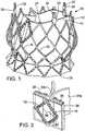
- FIG. 1there is shown a prosthetic aortic heart valve 10.
- the valve 10includes an expandable frame member, or stent, 12 that supports a flexible leaflet section 14.
- the valve 10is radially compressible to a compressed state for delivery through the body to a deployment site and expandable to its functional size shown in FIG. 1 at the deployment site.
- the valve 10can be self-expanding; that is, the valve can radially expand to its functional size when advanced from the distal end of a delivery sheath. Apparatuses particularly suited for percutaneous delivery and implantation of a self-expanding valve are described in detail below.
- the valvecan be a balloon-expandable valve that can be adapted to be mounted in a compressed state on the balloon of a delivery catheter.
- the valvecan be expanded to its functional size at a deployment site by inflating the balloon, as known in the art.
- the illustrated valve 10is adapted to be deployed in the native aortic annulus, although it also can be used to replace the other native valves of the heart. Moreover, the valve 10 can be adapted to replace other valves within the body, such a venous valve.
- FIGS. 3 and 4show the stent 12 without the leaflet section 14 for purposes of illustration.
- the stent 12can be formed from a plurality of longitudinally extending, generally sinusoidal shaped frame members, or struts, 16.
- the struts 16are formed with alternating bends and are welded or otherwise secured to each other at nodes 18 formed from the vertices of adjacent bends so as to form a mesh structure.
- the struts 16can be made of a suitable shape memory material, such as the nickel titanium alloy known as Nitinol, that allows the valve to be compressed to a reduced diameter for delivery in a delivery apparatus (such as described below) and then causes the valve to expand to its functional size inside the patient's body when deployed from the delivery apparatus.
- Nitinolnickel titanium alloy
- the stent 12can be made of a suitable ductile material, such as stainless steel.
- the stent 12has an inflow end 26 and an outflow end 27.
- the mesh structure formed by struts 16comprises a generally cylindrical "upper” or outflow end portion 20, an outwardly bowed or distended intermediate section 22, and an inwardly bowed “lower” or inflow end portion 24.
- the intermediate section 22desirably is sized and shaped to extend into the Valsalva sinuses in the root of the aorta to assist in anchoring the valve in place once implanted.
- the mesh structuredesirably has a curved shape along its entire length that gradually increases in diameter from the outflow end portion 20 to the intermediate section 22, then gradually decreases in diameter from the intermediate section 22 to a location on the inflow end portion 24, and then gradually increases in diameter to form a flared portion terminating at the inflow end 26.
- the intermediate section 22When the valve is in its expanded state, the intermediate section 22 has a diameter D 1 , the inflow end portion 24 has a minimum diameter D 2 , the inflow end 26 has a diameter D 3 , and the outflow end portion 20 has a diameter D 4 , where D 2 is less than D 1 and D 3 and D 4 is less than D 2 .
- D 1 and D 3desirably are greater than the diameter than the native annulus in which the valve is to be implanted. In this manner, the overall shape of the stent 12 assists in retaining the valve at the implantation site. More specifically, and referring to FIGS.
- the valve 10can be implanted within a native valve (the aortic valve in the illustrated example) such that the lower section 24 is positioned within the aortic annulus 28, the intermediate section 24 extends above the aortic annulus into the Valsalva's sinuses 56, and the lower flared end 26 extends below the aortic annulus.
- the valve 10is retained within the native valve by the radial outward force of the lower section 24 against the surrounding tissue of the aortic annulus 28 as well as the geometry of the stent.
- the intermediate section 24 and the flared lower end 26extend radially outwardly beyond the aortic annulus 28 to better resist against axial dislodgement of the valve in the upstream and downstream directions (toward and away from the aorta).
- the valvetypically is deployed within the native annulus 28 with the native leaflets 58 folded upwardly and compressed between the outer surface of the stent 12 and the walls of the Valsalva sinuses, as depicted in FIG. 5B . In some cases, it may be desirable to excise the leaflets 58 prior to implanting the valve 10.
- Known prosthetic valves having a self-expanding frametypically have additional anchoring devices or frame portions that extend into and become fixed to non-diseased areas of the vasculature. Because the shape of the stent 12 assists in retaining the valve, additional anchoring devices are not required and the overall length L of the stent can be minimized to prevent the stent upper portion 20 from extending into the non-diseased area of the aorta, or to at least minimize the extent to which the upper portion 20 extends into the non-diseased area of the aorta. Avoiding the non-diseased area of the patient's vasculature helps avoid complications if future intervention is required. For example, the prosthetic valve can be more easily removed from the patient because the stent is primarily anchored to the diseased part of the valve.
- the diametercan be about 28 mm to about 32 mm, with 30 mm being a specific example; the diameter D2 can be about 24 mm to about 28 mm, with 26 mm being a specific example; the diameter D3 can be about 28 mm to about 32 mm, with 30 mm being a specific example; and the diameter D4 can be about 24 mm to about 28 mm, with 26 mm being a specific example.
- the length Lcan be about 20 mm to about 24 mm, with 22 mm being a specific example.
- the stent 12can have a plurality of angularly spaced retaining arms, or projections, in the form of posts 30 (three as illustrated) that extend from the stent upper portion 20.
- Each retaining arm 30has a respective aperture 32 that is sized to receive prongs of a valve-retaining mechanism that can be used to form a releasable connection between the valve and a delivery apparatus (described below).
- the retaining arms 30need not be provided if a valve-retaining mechanism is not used.
- the leaflet assembly 14comprises three leaflets 34a, 34b, 34c made of a flexible material. Each leaflet has an inflow end portion 60 and an outflow end portion 62.
- the leafletscan comprise any suitable biological material (e.g., pericardial tissue, such as bovine or equine pericadium), bio-compatible synthetic materials, or other such materials, such as those described in U.S. Patent No. 6,730,118 .
- the leaflet assembly 14can include an annular reinforcing skirt 42 that is secured to the outer surfaces of the inflow end portions of the leaflets 34a, 34b, 34c at a suture line 44 adjacent the inflow end of the valve.
- the inflow end portion of the leaflet assembly 14can be secured to the stent 12 by suturing the skirt 42 to struts 16 of the lower section 24 of the stent (best shown in FIG. 1 ).
- the leaflet assembly 14can further include an inner reinforcing strip 46 that is secured to the inner surfaces of the inflow end portions 60 of the leaflets.
- each commissure attachmentcan be formed by wrapping a reinforcing section 36 around adjacent upper edge portions 38 at the commissure of two leaflets and securing the reinforcing section 36 to the edge portions 38 with sutures 48. The sandwiched layers of the reinforcing material and leaflets can then be secured to the struts 16 of the stent 12 with sutures 50 adjacent the outflow end of the stent.
- the leafletstherefore desirably extend the entire length or substantially the entire length of the stent from the inflow end 26 to the outflow end 27.
- the reinforcing sections 36reinforces the attachment of the leaflets to the stent so as to minimize stress concentrations at the suture lines and avoid “needle holes” on the portions of the leaflets that flex during use.
- the reinforcing sections 36, the skirt 42, and the inner reinforcing strip 46desirably are made of a bio-compatible synthetic material, such as polytetrafluoroethylene (PTFE), or a woven fabric material, such as woven polyester (e.g., polyethylene terephtalate) (PET)).
- PTFEpolytetrafluoroethylene
- PETpolyethylene terephtalate
- FIG. 7shows the operation of the valve 10.
- the leaflets 34a, 34b, 34ccollapse to effectively close the valve.
- the curved shape of the intermediate section 22 of the stent 12defines a space between the intermediate section and the leaflets that mimics the Valsalva sinuses.
- backflow entering the "sinuses”creates a turbulent flow of blood along the upper surfaces of the leaflets, as indicated by arrows 52. This turbulence assists in washing the leaflets and the skirt 42 to minimize clot formation.
- the valve 10can be implanted in a retrograde approach where the valve, mounted in a crimped state at the distal end of a delivery apparatus, is introduced into the body via the femoral artery and advanced through the aortic arch to the heart, as further described in U.S. Patent Publication No. 2008/0065011 .
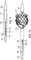
- FIG. 8shows a delivery apparatus 100, according to one embodiment, that can be used to deliver a self-expanding valve, such as valve 10 described above, through a patient's vasculature.
- the delivery apparatus 100comprises a first, outermost or main catheter 102 having an elongated shaft 104, the distal end of which is coupled to a delivery sheath 106 (also referred to as a delivery cylinder).
- the proximal end of the main catheter 102is connected to a handle of the delivery apparatus (not shown).
- the handlecan be used by a surgeon to advance and retract the delivery apparatus through the patient's vasculature.
- the main catheter 102can comprise a guide catheter that is configured to allow a surgeon to guide or control the amount the bending or flexing of a distal portion of the shaft 104 as it is advanced through the patient's vasculature, such as disclosed in U.S. Patent Publication No. 2008/0065011 .
- the delivery apparatus 100also includes a second catheter 108 (also referred to herein as a valve catheter) having an elongated shaft 110 (also referred to herein as a torque shaft), a cylindrical screw 112 disposed on the shaft 110, and a valve-retaining mechanism 114 connected to a distal end portion 116 of the shaft 110.
- the shaft 110 of the valve catheter 108extends through the delivery sheath 106 and the shaft 104 of the main catheter 102.
- the delivery apparatus 100can also include a third, nose catheter 118 having an elongated shaft 120 and a nose piece 122 secured to the distal end portion of the shaft 120.
- the nose piece 122can have a tapered outer surface as shown for atraumatic tracking through the patient's vasculature.
- the shaft 120 of the nose catheterextends through the valve 10, the retaining mechanism 114, and the shaft 110 of the valve catheter 108.
- the torque shaft 110 of valve catheter 108can be configured to be moveable axially and rotatable relative to the shaft 104 of the main catheter and the shaft 120 of the nose catheter.
- the delivery apparatus 100can also be provided with a loading cone 124 that can be used to load the valve 10 in a compressed state inside the delivery sheath 106, as further described below.
- the distal end portion 116 of the valve catheter shaft 110can include an end piece 156 on which the screw 112 is mounted.
- the end piece 156has a non-circular cross-sectional profile extending at least partially along the length of the end piece that mates with a similarly shaped inner surface of the screw 112 (as best shown in FIG. 11 ).
- a portion of the end piece 156has a square cross-sectional profile that mates with a square shaped inner surface of the screw 112. In this manner, rotation of the shaft 110 causes corresponding rotation of the screw 112.
- the valve catheter 108is configured to be rotatable relative to the delivery sheath 106 to effect incremental and controlled advancement of the valve 10 from the delivery sheath.
- the delivery sheath 106(as best shown in FIGS. 9-12 ) can include first and second elongated cam slots 126 and internal threads 128 adapted to engage external threads 132 of screw 112.
- the distal end portion of the main catheter shaft 104extends into the delivery sheath 106 and can be formed with first and second projections 130 that extend radially outwardly into the cam slots 126 of the delivery sheath.
- the distal end portion of shaft 110extends over and is secured to a proximal end portion of the end piece 156, such as with an adhesive.
- the screw 112is disposed on the end piece 56 within the delivery sheath 106.
- the distal end of the screw 112 and the end piece 56are coupled to the valve 10 via the retaining member 114 such that rotation of the valve catheter shaft 110 is effective to cause corresponding rotation of the end piece 56, the screw 112 and the valve 10.
- Rotation of the shaft 110 and the screw 112 relative to the sheath 106is effective to move the shaft 110 and the valve 10 longitudinally in either the proximal or distal directions (as indicated by arrows 134a and 134b, respectively) relative to the sheath 106.
- movement of the shaft 110 in the proximal directioncauses the valve 10 to advance from the open distal end 136 of the sheath, as further described below.
- the valve-retaining mechanism 114includes an inner fork 138 an outer fork 140.
- the inner fork 138includes a plurality of angularly-spaced prongs 142 (three in the illustrated embodiment) corresponding to the retaining arms 30 of the stent 12, which prongs extend from a head portion 144 at the proximal end of the inner fork.
- the outer fork 140similarly includes a plurality of angularly-spaced prongs 146 (three in the illustrated embodiment) corresponding to the retaining arms 30 of the stent 12, which prongs extend from a head portion 148 at the proximal end of the outer fork.
- each prong of the outer forkcooperates with a corresponding prong of the inner fork to form a releasable connection with a retaining arm 30 of the stent.
- the distal end portion of each prong 146is formed with an opening 150.
- retracting the prongs 142 proximally (in the direction of arrow 152) to remove the prongs from the openings 32is effective to release the valve 10 from the retaining mechanism.
- the retaining mechanism 114forms a releasable connection with the valve that is secure enough to retain the valve relative to the valve catheter 108 to allow the user to fine tune or adjust the position of the valve after it is deployed from the delivery sheath.
- the connection between the valve and the retaining mechanismcan be released by retracting the inner fork 138 relative to the outer fork 140, as further described below.
- the head portion 144 of the inner forkcan be connected to the valve catheter shaft 110 while the head portion 148 can be connected to the screw 112.
- the head portion 144 of the inner forkcan be formed with a plurality of angularly spaced, inwardly biased retaining flanges 154.
- the end piece 156 of the valve catheter shaft 110can be formed with a cylindrical shaft 158 having an annular groove 160.
- the shaft 158has an outer diameter that is slightly greater than the diameter defined by the inner free ends of the flanges 154.
- the inner fork 138can be secured to the end piece 156 by inserting the shaft 158 into the head portion 144 until the flanges 154 flex inwardly into the groove 160, thereby forming a snap-fit connection between the head portion 144 and the shaft 158.
- an annular shoulder 162 within the groove 160is positioned opposite the free ends of flanges 154 and another annular shoulder 164 of end piece 156 is positioned opposite the proximal end of the head portion 144 to prevent the end piece 156 from moving longitudinally in the distal and proximal directions relative to the inner fork.
- the head portion 148 of the outer forkcan be secured to the distal end of the screw 112 in a similar manner. As best shown in FIG. 16 , the head portion 148 can be formed with a plurality of angularly spaced, inwardly biased retaining flanges 155.
- the distal end portion of the screw 112can be formed with a cylindrical shaft 166 having an annular groove 168.
- the shaft 166has an outer diameter that is slightly greater than the diameter defined by the free ends of the flanges 155.
- the outer fork 140can be secured to the screw 112 by inserting the shaft 166 into the head portion 148 until the flanges flex inwardly into the groove 168, thereby forming a snap-fit connection between the head portion 148 and the shaft 166.
- an annular shoulder 170 within the groove 168is positioned opposite the free ends of flanges 156 and another annular shoulder 172 of the screw 112 is positioned opposite the proximal end of the head portion to prevent the screw from moving longitudinally in the distal and proximal directions relative to the outer fork.
- the valve 10can be compressed and loaded into the delivery sheath 106 using the loading cone 124 in the following manner.
- the valve 10can be secured to the retaining mechanism 114 as described above.
- the loading cone 124includes a first opening 176 at one end, a second, smaller opening 178 at the opposite end, and a tapered inner surface 180 that tapers from a first diameter at the first opening to a second, smaller diameter proximate the second opening 178.
- the retaining mechanism 114 and the valve 10can be pushed through the loading cone 124 in the direction of arrow 174 to radially compress the retaining member and the valve until the retaining member 114 extends outside the loading cone.
- the latter stepcan be performed while immersing the valve and the retaining mechanism in a bath of cold water.
- the end piece 156is secured to the inner fork by inserting the shaft 158 into the head portion 144 of the inner fork in the direction of arrow 182 as described above.
- the screw 112can then be slid over the end piece 156 in the direction of arrow 184 and secured to the outer fork 140 by inserting the shaft 166 into the head portion 148 of the outer fork as described above. Subsequently, referring to FIGS.
- the delivery sheath 106is placed over the screw 112 by bringing the proximal end of the screw in contact with the distal end of the sheath 106 and then rotating the valve catheter shaft 110, which causes the sheath to advance over the screw.
- the shaft 110causes the sheath 106 to advance over the retaining member 114 and the valve 10 and then push away the loading cone to allow the sheath to advance over the valve as it exits the loading cone.
- the shaft 110is rotated until the valve is completely inside the sheath, as depicted in FIGS. 9 and 11 .
- the nose coneWhen nose cone 122 is used, the nose cone desirably has an outer diameter less than the opening 178 of the loading cone so that the nose cone can slide through the loading cone along with the valve 10.
- a conventional crimping mechanismcan be used to radially compress the valve 10.
- the delivery apparatus 100can be inserted into the patient's body for delivery of the valve.
- the valvecan be delivered in a retrograde procedure where delivery apparatus is inserted into a femoral artery and advanced through the patient's vasculature to the heart.
- an introducer sheathPrior to insertion of the delivery apparatus, an introducer sheath can be inserted into the femoral artery followed by a guide wire, which is advanced through the patient's vasculature through the aorta and into the left ventricle.
- the delivery apparatus 100can then be inserted through the introducer sheath and advanced over the guide wire until the distal end portion of the delivery apparatus containing the valve 10 is advanced to a location adjacent to or within the native aortic valve.
- valve 10can be deployed from the delivery apparatus 100 by rotating the valve catheter 108 relative to the guide catheter 102.
- the valve cathetercan have a rotatable handle portion (not shown) connected to the proximal end of the valve catheter shaft 110 that allows the surgeon to effect rotation of the valve catheter 108 relative to the main catheter 102.
- Rotation of the valve catheter 108causes corresponding rotation of the valve catheter shaft 110, the end piece 156, and the screw 112 relative to the main catheter shaft 104 and the sheath, which in turn causes these components to advance distally relative to the delivery sheath 106 to advance the valve 10 from the open end of the sheath.
- Rotation of the valve catheter 108causes the valve to move relative to sheath in a precise and controlled manner as the valve advances from the open distal end of the delivery sheath and begins to expand.
- the valveis held against uncontrolled movement from the sheath caused by the expansion force of the valve against the distal end of the sheath.
- itmay be desirable to retract the valve back into the sheath, for example, to reposition the valve or to withdraw the valve entirely from the body.
- the partially deployed valvecan be retracted back into the sheath by reversing the rotation of the valve catheter, which causes the catheter shaft 110 to retract and pull the valve back into the sheath.
- the surgeonmust apply push-pull forces to the shaft and/or the sheath to unsheathe the valve. It is therefore difficult to transmit forces to the distal end of the device without distorting the shaft (e.g., compressing or stretching the shaft axially), which in turn causes uncontrolled movement of the valve during the unsheathing process.
- the shaft and/or sheathcan be made more rigid, which is undesirable because the device becomes harder to steer through the vasculature.
- the manner of unsheathing the valve described aboveeliminates the application of push-pull forces on the shaft, as required in known devices, so that relatively high and accurate forces can be applied to the distal end of the shaft without compromising the flexibility of the device.
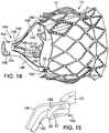
- the valve 10After the valve 10 is advanced from the delivery sheath and expands to its functional size (as shown in FIG. 10 ), the valve remains connected to the delivery apparatus via the retaining mechanism 114. Consequently, after the valve is advanced from the delivery sheath, the surgeon can reposition the valve relative to the desired implantation position in the native valve such as by moving the delivery apparatus in the proximal and distal directions or side to side, or rotating the delivery apparatus, which causes corresponding movement of the valve.
- the retaining mechanism 114desirably provides a connection between the valve and the delivery apparatus that is secure and rigid enough to retain the position of the valve relative to the delivery apparatus against the flow of the blood as the position of the valve is adjusted relative to the desired implantation position in the native valve.
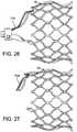
- the connection between the valve and the delivery apparatuscan be released by retracting the valve catheter shaft 110 in the proximal direction relative to the guide catheter, which is effective to retract the inner fork 138 to withdraw its prongs 142 from the openings 32 in the retaining arms 30 of the valve ( FIGS. 26 and 27 ).
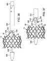
- Retraction of the delivery apparatusretracts the outer fork 140 to completely disconnect the valve from the retaining mechanism 114 ( FIG. 28 ).
- the delivery apparatuscan be withdrawn from the body, leaving the valve implanted within the native valve (such as shown in FIGS. 5A and 5B )
- the delivery apparatuscan be adapted to deliver a balloon-expandable prosthetic valve.
- the retaining mechanism 114can be used to secure the valve to the end of the delivery apparatus. The retaining mechanism 114 enhances the pushability of the delivery apparatus and valve assembly through the introducer sheath.
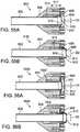
- FIG. 29Ashows the distal end portion of a delivery apparatus 200, according to an illustrative example.
- the delivery apparatus 200has a similar construction to and has many of the same components as the delivery apparatus 100 (some of the common components are removed from FIG. 29A for clarity).
- the delivery apparatus 200comprises an elongated valve catheter 202.
- the valve catheter 202comprises an elongated, flexible torque shaft 204, an end piece 206 secured to the distal end of the shaft 204, and an outer shaft 220 extending over the torque shaft 204.
- a delivery sheath 208is secured to the distal end of the outer shaft 220.
- the delivery sheath 208is disposed over a distal end portion of the shaft 204, the end piece 206, a valve-retaining mechanism 114, and a valve 10, which is retained in a compressed state inside the sheath.
- Only the outer fork 140 of the retaining mechanism 114is shown in FIG. 29A .
- the head portion 148 of the outer fork 140can be secured to the end piece 206, such as by forming a snap-fit connection with a stepped shaft portion 210 of the end piece such as described above.
- the inner fork 138(not shown in FIG. 29A ) can be connected at its head portion 144 to the distal end of an inner shaft (not shown in FIG.
- the inner shaftcan be the shaft 120 of an elongated nose catheter 118 ( FIG. 8 ).
- the prongs 142 of the inner fork 138extend through the openings 32 in the stent 12 to secure the valve 10 to the delivery apparatus, as described in detail above. Because the inner fork 138 is secured to an inner shaft that extends through shaft 204, the inner fork 138 can be retracted relative to the outer fork 140 to withdraw the prongs of the inner fork from the openings in the stent (and thereby releasing the valve 10) by retracting the inner shaft in the proximal direction relative to the shaft 204.
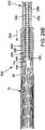
- the shaft 204 in the illustrated configurationcomprises a first layer 212 comprising a flexible, slotted tube and second layer 214 comprising a wire coil that is helically wound around the first layer 212.
- the first layer 212can be made of a metal (e.g., stainless steel), a polymeric material, or another suitable material.
- the wire coil 214can be, for example, a stainless steel wire, although other materials can be used.
- the wire coil 214extends along at least a distal end portion of the shaft 204 and engages internal threads 216 of the sheath 208. In this manner, the wire coil 214 serves as external threads of the shaft 204.
- the sheath 208When rotating the torque shaft 204 relative to the outer shaft 220, the sheath 208 is retained against rotating with the shaft 204 by the outer shaft 220 so that rotation of the shaft 204 causes the shaft 204 to advance distally relative to the sheath 208 to deploy the valve 10.
- the delivery apparatus 200is inserted into the patient's vasculature and advanced to the implantation site in the heart.
- the torque shaft 204is then rotated relative to the outer shaft 220 to cause the shaft to advance distally (as indicated by arrow 218) until the valve 10 is unsheathed and expands to its functional size.
- the valve 10remains connected to the delivery apparatus by the retaining mechanism 114 so that the user can fine-tune the position of the expanded valve at the implantation site.
- the connection formed by the retaining mechanism 114can be released by retracting the inner shaft, as described above. Thereafter, the retaining mechanism can be retracted back into the sheath and the entire delivery apparatus can be removed from the body.
- FIG. 29Bshows the distal end portion of a delivery apparatus 250, according to another embodiment.
- the delivery apparatus 250has a similar construction to and has many of the same components as the delivery apparatus 100 (some of the common components are removed from FIG. 29B for clarity).
- the delivery apparatus 250comprises an elongated valve catheter 252 comprising an elongated, flexible torque shaft 254 that extends into a delivery sheath 256.
- the shaft 254can comprise, for example, a coiled shaft as shown or a cable (e.g., a stainless steel cable).
- a first screw member 258is disposed on and secured to a distal end portion of the shaft 254 within the sheath and a second screw member 260 is disposed on the first screw member within the sheath.
- the first screw member 258has external threads that engage internal threads of the second screw member 260.
- the second screw member 260also has external threads that engage internal threads of the sheath 256.
- the delivery apparatuscan further include an outer shaft 264 that extends over the shaft 254 and has a distal end portion that is secured to the proximal end of the sheath 256.
- the torque shaft 254can be rotated relative to the outer shaft 264 and the sheath 256 to cause the torque shaft to advance longitudinally relative to the sheath for deploying the valve from the sheath.
- a ring member 266is mounted on the outer surface of the torque shaft 254 and moves longitudinally with the torque shaft relative to the outer shaft 264 upon rotation of the torque shaft. The ring member 266 is positioned to contact and cause the second screw member 260 to advance within the sheath 256 after the torque shaft 254 is advanced distally a predetermined distance, as further described below.
- the outer fork 140 of a valve-retaining mechanism 114can be secured at its head portion 148 to a stepped shaft portion 262 of the first screw member 258, which in turn is secured to the torque shaft 254.
- the inner fork 138(not shown in FIG. 29B ) can be connected at its head portion to the distal end of an inner shaft (not shown) that extends through the torque shaft 254.
- the prongs of the inner forkextend from the distal end of the shaft 254 and cooperate with the prongs of the outer fork to form releasable connections with the posts 30 of the stent, as described above.
- the inner forkcan be retracted relative to the outer fork to release the connections to the posts 30 by retracting the inner shaft relative to the torque shaft 254.
- the delivery apparatus 250is inserted into the patient's vasculature and advanced to the implantation site in the heart.
- the torque shaft 254is rotated relative to the outer shaft 264, which causes the first screw member 258 to rotate and advance distally (in the direction of arrow 268) relative to the second screw member 260 and the sheath 258 to partially advance the valve 10 from the distal end of the sheath.
- the ring member 266contacts the second screw member 260 so that further rotation of the torque shaft 254 is effective to cause the first screw member and the second screw member to advance distally relative to the sheath to completely advance the valve 10 from the sheath.
- the connection formed by the retaining mechanism 114can be released by retracting the inner shaft, as described above. Thereafter, the retaining mechanism can be retracted back into the sheath and the entire delivery apparatus can be removed from the body.
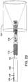
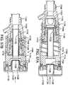
- FIGS. 30-37illustrate a delivery apparatus 300, according to another embodiment.
- FIGS. 30-33show the distal end portion of the delivery apparatus 300.
- FIGS. 34-35show the proximal end portion of the delivery apparatus 300.
- FIGS. 36-37show the deployment of a valve 10 from the delivery apparatus 300 (the leaflets of the valve are removed for clarify in the figures).
- the delivery apparatus 300comprises a first, outer catheter 302 having an elongated shaft 304 extending between a valve retaining mechanism 306 at the distal end of the apparatus ( FIGS. 32 and 33 ) and a handle portion 308 at the proximal end of the apparatus ( FIGS. 34 and 35 ).
- the distal end of the main catheter shaft 304is coupled to the valve-retaining mechanism 306, which in turn is secured to the valve 10.
- the outer catheter 302can be a guide catheter that is configured to permit selective bending or flexing of a portion of the shaft 304 to facilitate advancement of the delivery apparatus through the patient's vasculature.
- the delivery apparatusalso includes a second, torque catheter 310 having an elongated torque shaft 312 that extends through the main catheter shaft 304.
- the distal end of the torque shaft 304is connected to a flexible screw mechanism 314 comprising a flexible shaft 316 extending through the retaining mechanism 306 and one or more screw members 318 spaced along the length of the shaft 316 ( FIGS. 32 and 33 ).
- the shaft 316 of the screw mechanism 314exhibits sufficient flexibility to permit bending or flexing to assist in tracking the delivery apparatus through the patient's vasculature.
- the main catheter shaft 304can be formed with internal threads that engage the external threads of the screw members 318.
- a distal end portion of the main shaft 304(e.g., an 11-mm segment at the distal end of the shaft 304) can be formed with internal threads.
- the proximal end portion of the torque shaft 312extends into the handle portion 308 where it is coupled to a control knob 320 to permit rotation of the torque shaft relative to the main catheter shaft 304 ( FIGS. 34 and 35 ), as further described below.
- each screw member 318passes through and engages the internally threaded portion of the main shaft 304.
- the screw members 318desirably are spaced from each other such that a screw member 318 can engage one end of the internally threaded portion of the main shaft 304 before an adjacent screw member 318 disengages from the other end of the internally threaded portion of the main shaft as the screw members pass through the internally threaded portion so as to prevent or at least minimize application of axially directed forces on the torque shaft. In this manner, relatively high unsheathing forces can be applied to the sheath without compromising the overall flexibility of the delivery apparatus.
- the delivery apparatuscan also include a third, nose catheter 324 having an elongated shaft 326 that is connected at its distal end to a nose piece 328.
- the nose catheter shaft 326extends through the torque shaft 312 and has a proximal end portion that extends outwardly from the proximal end of the handle portion 308 ( FIGS. 34 and 35 ).
- the main catheter shaft 304, the torque shaft 312, and the nose catheter shaft 326desirably are configured to be moveable axially relative to each other.
- the delivery apparatusfurther includes a movable sheath 322 that extends over the compressed valve 10.
- the sheath 322is connected to screw mechanism 314 so that longitudinal movement of the torque shaft 312 and the screw mechanism 314 causes corresponding longitudinal movement of the sheath 322.
- the sheathcan have inwardly extending prongs 358 ( FIG. 31 ) extending into respective apertures 360 of fingers 362 ( FIG. 32 ), which in turn are connected to the distal end of the flexible shaft 316.
- Fingers 362desirably are connected to the shaft 316 by a swivel joint that pushes or pulls fingers 362 when the shaft 316 moves distally or proximally, respective, yet allows the shaft 316 to rotate relative to the fingers 362. Consequently, rotation of the torque shaft 312 and the screw mechanism 314 relative to the main shaft 304 is effective to cause the sheath 322 to move in the proximal and distal directions (as indicated by double-headed arrow 330 in FIG. 30 ) relative to the valve to permit controlled deployment of the valve from the sheath, as further described below.
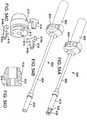
- the valve-retaining mechanism 306comprises an outer fork 330 and an inner fork 332.
- a portion of the finger 362is cut away in FIG. 33 to show the inner fork 332.
- the outer fork 330comprises a head portion 334 and a plurality of elongated, flexible prongs 336 (three in the illustrated embodiment) extending from the head portion 334.
- the head portion 334can be formed with resilient retaining flanges 338 to permit the outer fork to form a snap-fit connection with a stepped shaft portion of the main catheter shaft 304, as described above.
- the inner fork 332has a head portion 340 that is fixedly secured to the nose catheter shaft 326 and a plurality of elongated prongs 342 extending from the head portion 340.
- the distal end portions of the prongs 336 of the outer forkcan be formed with apertures 344 sized to receive respective retaining arms 30 of the valve 10.
- the distal ends of the prongs 342 of the inner fork 332extend through the apertures 32 in the retaining arms 30 to form a releasable connection for securing the valve 10, similar to valve-retaining mechanism 114 described above and shown in FIGS. 14-16 .
- connection between the valve and the retaining mechanism 306can be released by retracting the nose catheter shaft 326 relative to the main catheter shaft 304 to withdrawn the prongs 342 from the apertures 32 in the retaining arms 30.
- the outer prongs 336 and the shaft 316 of the screw mechanism 314exhibit sufficient flexibility to allow that portion of the delivery apparatus to bend or flex as the delivery apparatus is advanced through the patient's vasculature to the implantation site, yet are rigid enough to permit repositioning of the valve after it is deployed from the sheath 322.
- the outer fork 330, including prongs 336can be made from any of various suitable materials, such as metals (e.g., stainless steel) or polymers, that provide the desired flexibility.
- the handle portion 308comprises a housing 346 that houses a first gear 348 and a second gear 350.
- the first gear 348has a shaft that extends through the housing and is connected to the control knob 320 located on the outside of the housing.
- the second gear 350is disposed on and fixedly secured to the torque shaft 312.
- manual rotation of the control knob 320causes rotation of the first gear 348, which in turn rotates the second gear 350.
- the second gear 350rotates the torque shaft 312 and the screw mechanism 314 relative to the main catheter shaft 304, the valve-retaining mechanism 306, and the valve 10. Rotation of the torque shaft 312 and the screw mechanism 314 in turn causes linear movement of the sheath 322 relative to the valve.
- the valve 10is loaded into the sheath 322 in a radially compressed state (as depicted in FIG. 30 ), which can be accomplished, for example, by using the loading cone 124 described above.
- the delivery apparatus 300is then inserted into the patient's vasculature and advanced to a position at or adjacent the implantation site.
- the valve 10can then be deployed from the sheath by rotating the knob 320 on the handle portion, which in turn causes the torque shaft 312 and the screw mechanism 316 to retract within the main shaft 304, causing the sheath 322 to move in the proximal direction (arrow 352 in FIG. 31 ) to expose the valve, as depicted in FIG. 31 .
- Rotation of the knob 320enables a controlled and precise retraction of the sheath 322 during valve deployment.
- the sheathis retracted while the position of the valve can be held constant relative to the annulus at the implantation site during the unsheathing process.
- Rotation of the knob in the opposite directioncauses the sheath to move in the distal direction to again cover the valve.
- the valve 10After the valve 10 is advanced from the delivery sheath and expands to its functional size (as shown in FIG. 36 ), the valve remains connected to the delivery apparatus via the retaining mechanism 306. Consequently, after the valve is advanced from the delivery sheath, the surgeon can reposition the valve relative to the desired implantation position in the native valve such as by moving the delivery apparatus in the proximal and distal directions or side to side, or rotating the delivery apparatus, which causes corresponding movement of the valve.
- the retaining mechanism 306desirably provides a connection between the valve and the delivery apparatus that is secure and rigid enough to retain the position of the valve relative to the delivery apparatus against the flow of the blood as the position of the valve is adjusted relative to the desired implantation position in the native valve.
- the surgeoncan release the connection between the valve and the delivery apparatus by pulling the proximal end 354 of the nose catheter shaft 326 in the proximal direction (as indicated by arrow 356 in FIG. 34 ) relative to the main catheter shaft 304, which is effective to retract the inner fork 332 to withdraw its prongs 342 from the openings 32 in the retaining arms 30 of the valve ( FIG. 37 ).
- Retraction of the main catheter shaft 304retracts the outer fork 330 to completely disconnect the valve from the retaining mechanism 306 (as shown in FIG. 37 ).
- the retaining mechanismcan be retraced back into the sheath 322, the delivery apparatus can be withdrawn from the body, leaving the valve implanted within the native valve (such as shown in FIGS. 5A and 5B ).
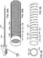
- FIGS. 38A-38Cshow a valve-retrieving device 400 that can be used with the delivery apparatus 300 to assist in retrieving the expanded valve 10 back into the sheath 322.
- the valve-retrieving device 400comprises an elongated, generally cylindrical body that is configured to be inserted into the patient's vasculature and advanced over the main catheter shaft 304.
- the distal end portion of the bodycomprises a plurality of elongated, flexible flap portions 402 that are normally retained in a compressed state, generally in the form of a cylinder (as shown in FIG. 38A ) and can flex radially outward from each other to form a generally cone-shaped receptacle large enough to receive the proximal end of the expanded valve 10 ( FIGS. 38B and 38C ).
- the flap portions 402desirably are prevented from expanding beyond the expanded state shown in FIGS. 38B and 38C .
- the flap portions 402desirably are dimensioned to overlap each other in the circumferential direction so that when the flap portions expand, they form a cone having continuous outer surface without any gaps between the flap portions.
- each flap portioncan be connected to a respective pull wire that extends along the length of the retrieving device 400 to a proximal end thereof.
- the flap portionsWhen tension is applied to the proximal ends of the pull wires, the flap portions are caused to flex radially outward from each other.
- the flap portions 402can be made from a mesh material or perforated material, such as perforated foil to allow blood to flow through the flap portions during the retrieving process.
- the flap portions 402can be made from a shape-memory material, such as Nitinol, and are self-expanding.
- the self-expanding flap portionsnormally assume the expanded configuration shown in FIGS. 38A-38B .
- the flap portions 402can be held in the radially compressed state by an outer sheath 406 ( FIG. 38A ). When the sheath 406 is retracted relative to the flap portions 402 in the direction of arrow 408, the flap portions 402 expand to the expanded configuration shown in FIGS. 38A-38B .
- the retrieving device 400can be used to retrieve a fully expanded valve and remove it from the patient's body.
- the retrieving device 400is inserted into the body over the main catheter shaft 304 and advanced toward the deployed valve 10, as shown in FIG. 38A .
- the flap portions 402are then expanded and further advanced in the distal direction to engage the valve.
- the valveis caused to compress.
- the sheath 322is advanced in the distal direction (e.g., by rotation of knob 320) until the sheath extends over the valve.
- the retrieving devicecan be removed from the patient's body, followed by the delivery apparatus and the valve.
- a portion of the elongated body of the retrieving device 400can have internal threads that are adapted to engage the threads of screw members 318 ( FIG. 32 ) so that the retrieving device can be moved in the distal and proximal directions by rotation of the knob 320 ( FIG. 34 ).
- the retrieving deviceis inserted into the body and advanced over the main catheter shaft 304 until the threaded portion of the retrieving device engages the screw members 318.
- the flap portions 402are then expanded and the retrieving device and the sheath are advanced over the expanded valve by rotation of the knob 320.
- the distal ends of flap portions 402extend past the distal end of the sheath 322 so that as both are advanced, the proximal end of the valve first comes in contact with the flap portions and begins to compress to facilitate insertion of the valve into the sheath.
- FIG. 39illustrates a modification of the delivery apparatus 300.
- the valve 10is held in its compressed state after deployment from the sheath 322 by a restraining device, such as one or more releasable bands 370 that encircle the valve.
- the bands 370can be released by pulling or moving a snare device, which allow the bands to open and the valve to expand.
- the bands 370can be made of a bio-absorbable or soluble material that dissolves in the body after the valve is advanced to the implantation site. Because the valve is held in its compressed state while it is advanced from the sheath, the problem of the valve "jumping" from the end of the sheath can be avoided to allow a more controlled delivery of the valve.
- the delivery apparatuscan employ a conventional pusher shaft that is operable to push the valve through the sheath, and need not include a rotatable torque shaft that is rotated to effect deployment of the valve from the sheath.
- the bands 370 or similar restraining devicescan be used with a conventional delivery apparatus where the operator pushes a shaft to push the valve from the sheath.
- FIG. 40illustrates a delivery apparatus 400, according to an illustrative example.
- the delivery apparatus 400includes a first, outermost or main catheter 402 having an elongated shaft 404, the distal end of which is coupled to a delivery sheath 406 that sized to extend over and retain a prosthetic valve 10 in a compressed state during valve delivery.
- the proximal end of the shaft 404is connected to a handle assembly 408 of the delivery apparatus.
- the delivery apparatusalso includes a second catheter 410 (also referred to as a valve catheter) having an elongated shaft 412 extending through the shaft 404.
- a second catheter 410also referred to as a valve catheter
- the delivery apparatuscan also include a third, nose catheter 414 having an elongated shaft 416 and a nose piece 418 secured to the distal end portion of the shaft 416.
- the nose catheter shaft 416extends through the valve catheter shaft 412 and can include a lumen for receiving a guidewire.
- the shafts 404, 412, and 416desirably are configured to be moveable axially relative to each other in the distal and proximal directions.
- the nose piece 418can have a tapered distal end portion for atraumatic tracking of the delivery apparatus through the patient's vasculature as well as a tapered proximal end portion that extends into the sheath 406.
- the tapered proximal end portion of the nose pieceallows the nose piece to be more easily inserted back into the sheath 406 for withdrawing the delivery apparatus from the body.
- the sheath 406can include a radiopaque tip portion 490 to assist the operator in retracting the nose piece back into the sheath.
- the valve catheter shaft 412can have one or more lumens 492 for introducing a contrast media, such as a radiographic contrast liquid, into the sheath 406 within the space surrounding the valve.
- the sheath 406can have one or more apertures 494 ( FIGS. 46 and 48 ) for injecting the contrast media into the patient's vasculature.
- the handle assembly 408can have a separate an inlet port in fluid communication with the lumens 492 for introducing the contrast media into the lumens.
- the contrast mediacan be injected into the patient's vasculature adjacent the native valve prior to deploying the prosthetic valve to assist in identifying the desired location for implanting the prosthetic valve.
- the contrast mediawhen replacing the aortic valve, can be injected into the aorta immediately adjacent the base of the native leaflets. This provides visual feedback to the operator to help identify the desired location for deploying the prosthetic valve. After the prosthetic valve is implanted, additional contrast media can be injected immediately adjacent the leaflets of the prosthetic valve to provide visual feedback of the operation of the prosthetic valve.
- the inner diameter of the sheath 406can be about 6.731 mm (0.265 inch) or less and the outer diameter of the sheath can be about 7.11 mm (0.28 inch) or less.
- the handle assembly in the illustrated configurationincludes a housing 420 that houses the proximal end portions of shafts 404, 412, and 416 and a screw shaft 422.
- the screw shaft 422is mounted for longitudinal movement inside the housing 420 on elongated support rods 424.
- the distal ends of the support rods 424can be supported by a distal bracket 426 and the proximal ends of the support rods can be supported by a proximal bracket 428.
- the proximal end of the main shaft 404can be secured to a stub shaft 430, which in turn can be secured, such as by bonding, to the inside of the screw shaft 422.
- the screw shaft 422is operatively connected to an actuator, or control knob, 432, which is operable to control longitudinal movement of the screw shaft 422 and the main shaft 404 upon rotation of the knob, as further described below.
- the handle assembly 408can further include a connector 470 mounted at its proximal end.
- the connector 470has a first passageway 472 that is in fluid communication with the lumen of the nose catheter shaft 416 for insertion of a guide wire through the shaft 416.
- the connector 470can have a second passageway 474 through which the proximal end portion of a release wire 506 extends (described below).
- the housing 420 of the handle assembly 408can comprise a proximal housing portion 434 and a distal housing portion 436.
- the proximal housing portion 434can comprise first and second housing portions 434a, 434b
- the distal housing portion 436can comprises first and second housing portions 436a, 436b.
- the screw shaft 422can include a flush port 462 that extends through a slot 464 in the second housing portion 436b.
- the flush portion 462has a lumen that is in fluid communication with the space between the main shaft 404 and the valve catheter shaft 412 for introducing a flush fluid between the shafts.
- the control knob 432can comprise a knob portion 438, a proximal extension 440 that extends into the proximal housing portion 434, and a distal extension 442 that extends into the distal housing portion 436.
- the knob portion 438is mounted between the proximal and distal housing portions.
- the proximal housing portion 434can be secured to the proximal extension 440 via an annular flange 444 of the proximal housing portion that extends into a corresponding annular groove 446 ( FIG. 44 ) in the proximal extension 440.
- the distal housing portioncan be secured to the distal extension 442 via an annular flange 448 of the distal housing portion that extends into a corresponding annular groove 450 ( FIG. 44 ) of the distal extension 442.
- the control knob 432can include a screw engagement latch 452 mounted on the distal extension 442.
- the screw engagement latch 452is operable to allow a user to selectively engage or disengage the screw shaft 422 for fine or course adjustment, respectively, of the main shaft 404.
- the screw engagement latch 452(which can comprise first and second latch portions 452a, 452b) is mounted within upper and lower slots 454 formed in the distal extension 442 of the control knob.
- the latch 452has upper and lower inwardly extending flanges 456 that extend through the slots 454 and can engage the external threads of the screw shaft 422.
- the latch 452is also formed with arcuate upper and lower internal surfaces 458 adjacent the flanges 456.
- the latch 452is slidable on the distal extension 442 in the lateral direction (as indicated by double headed arrow 460) between an engaged position wherein the flanges 456 extend through slots 454 and engage the screw shaft 422 and a disengaged position wherein the curved surfaces 458 are aligned within the slots 454 and the latch becomes disengaged from the screw shaft 422.
- a spring 466can be disposed between the distal extension 442 and the latch portion 452b to retain the latch 452 in the engaged position against the bias of the spring. As best shown in FIG. 43 , one end of the spring 466 can be retained in a notch 468 in the side of the distal extension 442 and the other end of the spring can be positioned to bear against the inside surface of the latch portion 452b.
- the latch 452When the latch 452 is moved to the disengaged position such that the curved surfaces 458 are aligned in the slots 454, the latch 452 becomes disengaged from the screw shaft 422 due to the fact that the internal diameter defined by the surfaces 458 is greater than the external diameter of the screw shaft 422.
- the main shaft 404In the disengaged position, the main shaft 404 can be pushed or pulled freely relative to the control knob 432 for course adjustment of the position of the sheath 406.
- the operatorcan adjust the position of the sheath 406 either by pushing or pulling on the portion of the main shaft 404 that extends from the housing 420 or by pushing or pulling on the flush port 462 (which moves within slot 464).
- the valve catheter shaft 412can comprise a guide catheter that is configured to allow a surgeon to guide or control the amount of bending or flexing of a distal portion of the delivery apparatus to facilitate guiding the delivery apparatus through the patient's vasculature.
- the handle assembly 408can include an adjustment mechanism 476 that is operable to adjust the amount of bending or flexing of the distal end of the delivery apparatus.
- the adjustment mechanism 476can include a rotatable adjustment knob 478 having a distal extension 480 that extends into the housing 420.
- the distal extension 480has a bore formed with internal threads that engages a slide nut 482, which is supported for longitudinal movement on a central slide rod 484.
- Two support rods 486extend between the inner surface of the slide nut 482 and the outer surface of the slide rod 484. Each support rod 486 is supported in an elongated notch in the outer surface of the slide rod 484 and the inner surface of the slide nut 482 so as to restrict rotation of the slide nut 482 relative to the adjustment knob 478.
- rotation of the knob 478(either clockwise or counterclockwise) causes the slide nut 482 to move longitudinally relative to the slide rod 484 in the distal and proximal directions.
- At least one pull wire(not shown) is secured at its proximal end to the slide nut 482, extends through the handle assembly and the shaft 412 and is secured at its distal end at a location adjacent the distal end of the shaft 412.
- the knob 478is rotated to cause movement of the slide nut 482 in the proximal direction, which in turn pulls the pull wire to increase the curvature of the delivery apparatus.
- the adjustment knob 478is rotated in the opposite direction to move the slide nut 482 in the distal direction, which decreases tension in the pull wire to allow the distal end portion of the delivery apparatus to straighten under its own resiliency. Further details of an adjustment mechanism for controlling the bending of a guide catheter are disclosed in U.S. Patent Publication Nos. 2008/0065011 and 2007/0005131 .
- a prosthetic valve 10can be secured to the distal end of the valve catheter shaft 412 via a releasable connection comprising a plurality of sutures 500 extending from the distal end of the valve catheter shaft 412.
- Each suture 500extends through a hook portion 502 of the valve stent 12 ( FIG. 49 ) and is formed with a loop 504 through which a release wire 506 extends.
- the release wire 506can extend through a spacer 508 mounted on the nose catheter shaft 416 to maintain the release wire in parallel alignment with the nose catheter shaft.
- the release wire 506further extends through the valve catheter shaft 412, the handle assembly 408, and the connector 470 ( FIG. 41 ). As best shown in FIG.
- the sutures 500can extend through apertures in a tip portion 510 of the valve catheter shaft and are tied off to each other or otherwise secured to the tip portion 510 to secure the sutures 500 relative to the valve catheter shaft. It should be noted that the entire valve 10 is not shown; only the valve stent 12 is shown in FIG. 49 for purposes of illustration. The valve 10 can have a construction similar to that shown in FIGS. 1-2 .
- valve deliverythe valve is mounted in a radially compressed state within the sheath 406.
- the sheathIn order to deploy the valve from the sheath 406, the sheath is retracted relative to the valve, either by rotation of the control knob 432 (when the latch 452 is in the engaged position) or by pulling the main shaft 404 in the proximal direction (when the latch 452 is in the disengaged position). Retraction of the sheath 406 uncovers the valve, which expands to its functional size while remaining connected to the valve catheter shaft 412 via sutures 500, as shown in FIG. 49 . Since the valve remains connected to the valve catheter shaft 406, the position of the expanded valve can be adjusted by moving the handle assembly 408 of the delivery apparatus.
- the valvecan be released by retracting the release wire 506 to release the suture loops 504 from the release wire, thereby releasing the sutures 500 from the hook portions 502 of the valve.
- the release wire 506can be retracted by pulling on the proximal end of the release wire that extends from the connector 470 on the handle ( FIG. 41 ).
- FIG. 50shows an alternative connection technique for forming a releasable connection between the valve and the valve catheter shaft 412.
- This techniqueis similar to the technique shown in FIG. 48 , except that the sutures 500 are not secured relative to the tip portion 510. Instead, the proximal end portions 512 of the sutures are fixedly secured to a sliding release mechanism (not shown), such as an elongated shaft or wire that extends through the valve catheter shaft 412. While the valve is connected to the shaft 412 by the sutures 500, the release mechanism can be moved distally to increase the slack in the sutures 500 to permit controlled expansion of the hook portions 502 of the valve.
- a sliding release mechanismsuch as an elongated shaft or wire that extends through the valve catheter shaft 412.
- the release mechanismcan be operatively connected to a sliding or rotating knob located on the handle assembly that can be operated by the user to effect sliding movement of the release mechanism.
- the sheath 406is retracted relative to the valve. This allows the stent 12 to expand, except for the hook portions 502, which are bent inwardly as they are still connected to the sutures 500.
- the sliding release mechanismPrior to retracting the release wire 506, the sliding release mechanism is moved distally to increase the slack in the sutures 500, allowing controlled radially expansion of the hook portions 502 of the stent. Once the stent is fully expanded, the release wire 506 can be retracted to release the hook portions 502 of the stent from the sutures 500.
- FIG. 51shows another connection technique for forming a releasable connection between the valve and the valve catheter shaft 412.
- a plurality of tethers 514(one for each hook portion 502 of the stent) extend from the distal end of the valve catheter shaft 412.
- the distal end of each tether 514is secured to a respective attachment element 516, which is connected to a respective hook portion 502 by a suture 518.
- Each suture 518has one end securely fixed to an attachment element 516, extends through a hook portion 502 and an opening 520 in the attachment element 516, and has a loop 521 at its opposite end.
- a release wire 522extends from the distal end of the shaft 412 and through the loop 521 of the respective suture 518.
- the proximal ends of the tethers 514can be secured to a sliding release mechanism that can be moved distally to increase the slack in the tethers 514 to permit controlled radially expansion of the hook portions 502 of the stent after the sheath 406 is retracted to deploy the valve from the sheath.
- each release wire 522can be retracted to release the respective suture 518, which is then pulled back through the opening 520 to release the hook portion 502.
- Each release wire 522can be retracted independently, for example by pulling on the proximal end of each release wire that extends from the handle assembly 408.
- each release wire 522can be connected to a common knob on the handle assembly that can be retracted or rotated to simultaneously retract the release wires in unison.
- FIGS. 52A and 52Billustrate the distal end portion of a delivery apparatus 600, according to another illustrative example.
- the delivery apparatus 600includes a catheter shaft 602 having a nose piece 604 at its distal end and an annular recessed portion 606 for receiving a self-expandable stented valve 608 (shown schematically in FIGS. 52A and 52B ).
- a flexible outer sheath, or sleeve, 610extends over the catheter shaft 602 and the valve 608 and maintains the valve in its compressed state within the recessed portion 606 for delivery through a patient's vasculature.
- the distal end portion of the sheath 610 that covers the valveis a folded portion having an outer fold layer 612 and an inner fold layer 614.
- the proximal end 616 of the inner fold layer 614is secured (e.g., using an adhesive) to the outer surface of the catheter shaft 602.
- the outer fold layer 612can be pulled in the proximal direction, as indicated by arrows 618, to uncover the valve and allow it to expand, as shown in FIG. 52B .
- the sleeve 610desirably exhibits sufficient rigidity to maintain a cylindrical shape against the outward expansion force of the valve 608 yet is flexible enough to allow the outer fold layer to be pulled back relative to the inner fold layer.
- a thin fluid layer 620can be formed between the outer fold layer 612 and the inner fold layer 614 to lubricate and minimize friction the adjacent surfaces of the fold layers.
- An advantage of the delivery apparatus 600is that there are no frictional forces generated between the sleeve 610 and the valve 608 as the sleeve is pulled back, and as such, less force is needed by a user to release the valve from its compressed, sheathed state.
- the sleeve 610can be constructed from any of various materials, including various polymers (e.g., nylon or PTFE) or metals (e.g., Nitinol).
- the sleevecan comprise one or more layers of material, which can be, for example, a braided layer, a mesh layer, a non-perforated layer or any combinations thereof.
- the sleeve 610can extend to the handle of the delivery apparatus for manipulation by a user.
- the sleeve 610can terminate short of the handle and can be connected to one or more pull wires extending between the proximal end of the sleeve and the handle, which pull wires can be pulled proximally to pull back the outer fold layer for deploying the valve.
- the nose piece 604is shown as part of the catheter shaft 602, this is not a requirement.
- the delivery apparatuscan include an inner nose catheter shaft that extends through the shaft 602 and mounts the nose piece 604, as described above.
- any of the various connection mechanisms disclosed herein for forming a releasable connection between the valve and the delivery apparatuscan be incorporated in the illustrative example shown in FIGS. 52A and 52B .
- the shaft 602can be the shaft of a balloon catheter having an inflatable balloon at the distal end of the shaft for mounting a balloon-expandable valve on the balloon (in which case, the valve need not be self-expandable).
- FIGS. 53A-53Eillustrate a delivery apparatus 700 according to another illustrative example.
- the delivery apparatus 700comprises an outer catheter shaft 702 and an inner catheter shaft 704 extending through the outer shaft.
- the distal end portion of the outer shaft 702comprises a sheath that extends over a prosthetic, stented valve 706 (shown schematically) and retains it in a compressed state during delivery through the patient's vasculature.
- the distal end portion of the inner shaft 704is shaped to cooperate with one or more mating extension arms, or posts, 708 that extend from the stent of the valve 706 to form a releasable connection between the valve and the delivery apparatus.
- each post 708comprises a straight portion terminating at a circular ring portion and the distal end portion of the shaft 704 has correspondingly shaped recesses 710 that receive respective posts 708.
- Each recess 710can include a radially extending projection 712 that is shaped to extend into an opening 714 in a respective post 708.
- each recess 710 and projection 712can be sized to provide a small gap between the surfaces of the post 708 and the adjacent surfaces within the recess to facilitate insertion and removal of the post from the recess in the radial direction (i.e., perpendicular to the axis of the shaft 704).
- valve 706When the valve 706 is loaded into the delivery apparatus 700, as depicted in FIG. 53A , such that each post 708 of the valve is disposed in a recess 710, the valve is retained against axial movement relative to the shaft 704 (in the proximal and distal directions) by virtue of the shape of the posts and the corresponding recesses.
- FIG. 53Das the outer shaft 702 is retracted to deploy the valve 706, the valve is allowed to expand but is retained against "jumping" from the distal end of the sheath by the connection formed by the posts and the corresponding recesses for controlled delivery of the valve.
- the partially deployed valveis still retained by the shaft 704 and can be retracted back into the outer sheath 702 by retracting the shaft 704 proximally relative to the outer sheath 702.
- the expansion force of the valve stentcauses the posts to expand radially outwardly from the recesses 710, thereby fully releasing the valve from the shaft 704.
- the posts and recesses 710can have various other shapes, such as square, oval, rectangular, triangular, or various combinations thereof.
- the postscan be formed from the same material that is used to form the valve stent (e.g., stainless steel or Nitinol).
- the postscan be loops formed from less rigid material, such as suture material. The loops are secured to the valve stent and are sized to be received in the recesses 710.
- FIGS. 54A-54Dillustrate a delivery apparatus 800 that is similar to the delivery apparatus shown in FIGS. 53A-53E .
- the delivery apparatus 800includes a handle portion 802 having a rotatable knob 804, an outer catheter shaft 806 extending from the handle portion 802, and an inner catheter shaft 808 extending from the handle portion and through the outer catheter shaft 806.
- the distal end of the inner catheter shaft 808includes an end piece 810 that is formed with an annular recess 812 and a plurality of axially extending, angularly spaced recesses 814.
- the recesses 812, 814are sized and shaped to receive T-shaped posts 816 extending from the stent of a valve (not shown in FIGS. 54A-54D ).
- Each post 816has an axially extending portion 816a that is received in a corresponding recess 814 and a transverse end portion 816b that is received in the annular recess 812.
- the outer shaft 806includes a sheath 818 that is sized and shaped to extend over the end piece 812 and the valve during delivery of the valve.
- the outer shaft 806is operatively connected to the knob 804 to effect longitudinal movement of the outer shaft 806 and the sheath 818 relative to the inner shaft 808 upon rotation of the knob 804, such as described above in connection with FIGS. 40-42 .
- the valveis mounted for delivery by placing the posts 816 of the valve in the recesses 812, 814 and moving the sheath distally to extend over the valve to maintain the valve in a compressed state.
- the knob 804is rotated to retract the sheath 818 relative to the valve.
- the valveAs the sheath is retracted to deploy the valve, the valve is allowed to expand but is retained against "jumping" from the distal end of the sheath by the connection formed by the posts and the corresponding recesses for controlled delivery of the valve. At this stage the partially deployed valve is still retained by the end piece 810 and can be retracted back into the sheath by moving the shaft 806 distally relative to the valve.
- the expansion force of the valve stentcauses the posts to expand radially outwardly from the recesses 812, 814, thereby fully releasing the valve from the end piece 810.
- FIGS. 55A-55Bshow an introducer, indicated at 900, that can be used to introduce a catheter or similar device into the body, for example, a delivery apparatus for delivering and implanting a prosthetic heart valve.
- the introducer 900includes an elongated tube, or shaft, 902 sized for insertion into a body channel (e.g., a blood vessel).
- the tube 902extends from a housing 904.
- Mounted to the proximal end of the housingis a cap portion 906 having a central opening 908 for receiving a catheter (not shown in FIGS. 55A-55B ).
- a seal 910is captured between the opposing faces of the cap portion and the housing.
- the sealcan be made from any suitable resilient material, such as silicone rubber, or any of various other suitable elastomers.
- the sealhas a central opening 912 that is aligned with the opening 908 of the cap portion and the lumen of the tube 902.
- the seal 910is sized to permit a catheter to be inserted through opening 912 while engaging the outer surface of the catheter to minimize blood loss during insertion of the catheter into the body.
- the proximal end portion of the tube 902 located within the housinghas an externally threaded portion 914 that engages corresponding internal threads on the inner surface of the housing 904.
- a proximal extension portion 916 of the threaded portion 914contacts the seal 910.
- the threaded portion 914is fixedly secured to the tube 902, such as with a suitable adhesive.
- the tube and threaded portioncan have a unitary or one-piece construction where the threaded portion is formed directly on the tube.
- the housing 904is moveable longitudinally relative to the tube 902, as indicated by double-headed arrow 917, to selectively dilate or contract the opening 912 in the seal 910.
- the housing 904is rotatable relative to the tube 902 to effect longitudinal movement of the housing relative to the tube.
- the seal 910is stretched against the extension portion 916, which dilates the seal opening 912 from a first diameter to a second, larger diameter D2.
- the introducer 900can be used to assist in the introduction of a valve-delivery apparatus (e.g., delivery apparatus 100 described above) into the body.
- the tube 902is inserted into a blood vessel (e.g., the femoral artery), which can be dilated beforehand in a conventional manner.
- the housing 904is then moved distally to dilate the opening in the seal to a diameter large enough to permit passage of the compressed valve (and any sheath covering the valve) into the lumen of the tube 902.
- the housingis rotated in the opposite direction to move the housing proximally to allow the seal opening 912 to contract back to its pre-dilated size.
- the sealengages the outer surface of the delivery apparatus to prevent or at least minimize blood loss along the outer surface of the delivery apparatus.
- FIGS. 56A-56Bshow an introducer 1000.
- the introducer 1000shares many similarities with the introducer 900 of FIGS. 55A-55B .
- components in FIGS. 56A-56B that are identical to corresponding components in FIGS. 55A-55Bhave the same respective reference numerals and are not described further.
- the introducer 1000differs from the introducer 900 in that the tube 902 of introducer 1000 includes an external portion 1002 that slidably engages an inner surface of the housing 904.
- the housingcan simply be pushed distally relative to the tube 902 in order to dilate the seal opening 912, as depicted in FIG. 56B . Removal of manual pressure from the housing 904 allows the elasticity of the seal 910 to pull the housing back proximally for contracting the seal opening.
- FIGS. 57A and 57Bshow an integrated introducer sheath and loader assembly, indicated at 1100, that can be used to facilitate insertion of a delivery apparatus (e.g., a valve delivery apparatus) into a body vessel.
- a delivery apparatuse.g., a valve delivery apparatus
- the introducer sheathis particularly suited for use with a delivery apparatus that is used to implant a prosthetic valve, such as the delivery apparatus described herein.
- the introducer sheathalso can be used to introduce other types of delivery apparatus for placing various types of intraluminal devices (e.g., stents, stented grafts, etc.) into many types of vascular and nonvascular body lumens (e.g., veins, arteries, esophagus, ducts of the biliary tree, intestine, urethra, fallopian tube, other endocrine or exocrine ducts, etc.).
- intraluminal devicese.g., stents, stented grafts, etc.
- vascular and nonvascular body lumense.g., veins, arteries, esophagus, ducts of the biliary tree, intestine, urethra, fallopian tube, other endocrine or exocrine ducts, etc.
- a conventional introducer sheathtypically requires a tubular loader to be inserted through the seals in the sheath housing to provide an unobstructed path for a valve mounted on a balloon catheter.
- the loaderextends from the proximal end of the introducer sheath, thereby increasing its working length, and decreasing the available working length of a delivery apparatus that can be inserted into the body.
- the introducer sheath 1100includes an integrated loader tube housed in the sheath housing to reduce the working length of the sheath and therefore increase the available working length of a delivery apparatus that can be inserted into the body.
- a conventional introducer sheathincludes a cap and a respective seal that typically is removed from the introducer sheath and preloaded onto the shaft of the delivery apparatus before the prosthetic valve is mounted to the distal end of the shaft, and then reattached to the sheath housing as the valve and delivery apparatus are inserted into the sheath housing.
- the procedureis carried out in this manner in order to prevent damage to the prosthetic valve that otherwise might occur if the valve, while mounted on the shaft in a crimped state, is pushed through the opening in the seal.
- the sealcan become dislodged from its intended position within the cap, which can cause damage to the seal. In such cases, the user may need to disassemble the cap and seal assembly for repair or replacement of the seal.
- the illustrated assembly 1100includes a seal housing 1102 and a tubular sleeve 1104 extending distally from the housing.
- the seal housing 1102houses one or more sealing valves, such as a cross-slit valve 1106, a disc valve 1108, and a hemostatic valve 1110 as shown.
- the valvesdesirably are fabricated from a resilient biocompatible material, such as polyisoprene, although similar biocompatible materials also can be used.
- the valves 1106, 1108, 1110are further shown and described in U.S. Pat. No. 6,379,372 .
- a spacer 1112can be interposed between the cross-slit valve 1106 and the proximal end of the seal housing.
- an end piece 1114adapted to move longitudinally along the length of the seal housing.
- the end piecehas a tubular body formed with internal threads 1116 that engage an externally threaded portion 1118 on the outer surface of the seal housing 1102.
- the end piece 1114has a cap portion 1119 at its proximal end having a central opening 1120 and an elongated loader tube 1122 fixedly secured inside the end piece.
- the opening 1120 and the loader tube 1122are dimensioned to permit passage of a valve (or other prosthesis) mounted on the delivery apparatus.
- the end piece 1114also houses a seal 1124 having a central opening 1126 aligned with the opening 1120. The seal 1124 sealingly engages the outer surface of the delivery apparatus when it is inserted into the introducer sheath assembly 1100.
- the end piece 1114can be adjusted inwardly and outwardly relative to the seal housing 1102. Adjusting the end piece 1114 from the extended position shown in FIG. 57A to the retracted position shown in FIG. 57B moves the loader tube 1122 through the seals 1106, 1108, 1110 to provide an unobstructed path for the valve to pass through the introducer sheath. Because the loader tube does not extend behind the end piece, as in a conventional introducer sheath, the loader tube does not decrease the available working length of the delivery apparatus that can be inserted into the vasculature.
- the cap portion 1119is slidably mounted for longitudinal movement on the end piece 1114 and has an inner tubular portion 1128 that is positioned to engage and stretch the seal 1124.
- the tubular portion 1128stretches the seal 1124 and dilates the seal opening 1126 from a first diameter ( FIG. 57A ) to a second, larger diameter ( FIG. 57B ) to provide an unobstructed path for the delivery apparatus and the crimped valve into the assembly.
- the cap and its respective sealneed not be removed from the sheath and preloaded onto the delivery apparatus prior to mounting the valve onto the delivery apparatus.
- the illustrated configurationfacilitates introduction of the delivery apparatus into the sheath and avoids possible seal dislodgement during the loading process.
- the introducer sheath 1100 in the extended position shown in FIG. 57Acan be placed on a previously inserted guide wire (not shown) and advanced thereon until the sleeve 1104 extends into a body vessel a desired distance.
- the cap portioncan then be pushed distally to dilate the seal 1124 to permit passage of the delivery apparatus through the seal opening 1126 to position the valve in the loader tube 1122. Thereafter the cap portion can be allowed to move back to the proximal position under the elasticity of the seal ( FIG. 57A ), thereby allowing the seal 1124 to form a fluid tight seal around the outer shaft of the delivery apparatus.
- the end piece 1114is rotated to slide the loader tube 1122 through the valves 1106, 1108, 1110 ( FIG. 57B ), thus placing the delivery apparatus in communication with the lumen of the sleeve 1104 and the body vessel in which the sleeve is inserted.
- this approachsimplifies the loading process and reduces the number of steps and parts required to load the valve into the sheath.
- the seal housing 1102can have internal threads that engage external threads on the end piece 1114.
- the end piececan be rotated to adjust the position of the loader tube 1122 as previously described.
- the pitch of the threads on the seal housing and the end piececan be varied to vary the amount of rotational movement required to extend the loader through the sealing valves.
- the end piece 1114can be slidingly positionable along the length of the seal housing by pushing and pulling the end piece without rotating the same.
- the cap portioncan be rotatable relative to the end piece 1114 to effect longitudinal movement of the cap portion for dilating the seal, such as shown in FIGS. 56A and 56B .
- FIG. 58Ashows another introducer sheath, indicated at 1200, that employs a thin metallic tubular layer that has a much smaller wall thickness compared to known devices.
- the wall thickness of the sheath 1200can be about 0.0013 mm (0.0005 inch) to about 0.005 mm (0.002 inch).
- the introducer sheath 1200includes a proximally located housing, or hub, 1202 and a distally extending sleeve, or cannula, 1204.
- the housing 1202can house a seal or a series of seals as described in detail above to minimize blood loss.
- the sleeve 1204includes a tubular layer 1206 that is formed from a metal or metal alloy, such as Nitinol or stainless steel, and desirably is formed with a series of circumferentially extending or helically extending slits or openings to impart a desired degree of flexibility to the sleeve.
- the tubular layer 1206is formed (e.g., laser cut) with an "I-beam" pattern of alternating circular bands 1207 and openings 1208 with axially extending connecting portions 1210 connecting adjacent bands 1207.
- Two adjacent bands 1207can be connected by a plurality of angularly spaced connecting portions 1210, such as four connecting portions 1210 spaced 90 degrees from each other around the axis of the sleeve, as shown.
- the sleeve 1204exhibits sufficient flexibility to allow the sleeve to flex as it is pushed through a tortuous pathway without kinking or buckling.
- FIG. 59shows another pattern of openings that can be laser cut or otherwise formed in the tubular layer 1206.
- the tubular layer in FIG. 59has a pattern of alternating bands 1212 and openings 1214 with connecting portions 1216 connecting adjacent bands 1212 and arranged in a helical pattern along the length of the sleeve.
- the pattern of bands and openings and/or the width of the bands and/or openingscan vary along the length of the sleeve in order to vary stiffness of the sleeve along its length.
- the width of the bandscan decrease from the proximal end to the distal end of the sleeve to provide greater stiffness near the proximal end and greater flexibility near the distal end of the sleeve.
- the sleevecan have a thin outer layer 1218 extending over the tubular layer 1206 and made of a low friction material to reduce friction between the sleeve and the vessel wall into which the sleeve is inserted.
- the sleevecan also have a thin inner layer 1220 covering the inner surface of the tubular layer 1206 and made of a low friction material to reduce friction between the sleeve and the delivery apparatus that is inserted into the sleeve.
- the inner and outer layerscan be made from a suitable polymer, such as PET, PTFE, and/or FEP.
- the tubular layer 1206can have a radial wall thickness in the range of about 0.0013 mm (0.0005 inch) to about 0.005 mm (0.002 inch).
- the sleevecan be provided with an outer diameter that is about 1-2 Fr smaller than known devices.
- the relatively smaller profile of the sleeve 1204improves ease of use, lowers risk of patient injury via tearing of the arterial walls, and increases the potential use of minimally invasive procedures (e.g., heart valve replacement) for patients with highly calcified arteries, tortuous pathways or small vascular diameters.
- a delivery apparatuscan be provided with a power source to effect rotation of the torque shaft in lieu of or in addition to a knob or similar mechanism that uses manual power to rotate the torque shaft.
- the handle portion 308FIG. 35
- the handle portion 308can house a small electric motor that is connected to and transfers rotational motion to the gear 348.
- the motordesirably is a two-way motor so that the torque shaft can be rotated in both directions.
- the power sourcecan be a hydraulic power source (e.g., hydraulic pump) or pneumatic (air-operated) power source that is configured to rotate the torque shaft.
- a power sourcee.g., an electric, hydraulic, or pneumatic power source
- a shaftwhich is turn is connected to a valve 10.
- the power sourceis configured to reciprocate the shaft longitudinally in the distal direction relative to a valve sheath in a precise and controlled manner in order to advance the valve from the sheath.
- the power sourcecan be operatively connected to sheath in order to reciprocate the sheath longitudinally in the proximal direction relative to the valve to deploy the valve from the sheath.
Landscapes
- Health & Medical Sciences (AREA)
- Cardiology (AREA)
- Engineering & Computer Science (AREA)
- Biomedical Technology (AREA)
- Life Sciences & Earth Sciences (AREA)
- Transplantation (AREA)
- Heart & Thoracic Surgery (AREA)
- Vascular Medicine (AREA)
- Oral & Maxillofacial Surgery (AREA)
- Animal Behavior & Ethology (AREA)
- General Health & Medical Sciences (AREA)
- Public Health (AREA)
- Veterinary Medicine (AREA)
- Mechanical Engineering (AREA)
- Prostheses (AREA)
- Materials For Medical Uses (AREA)
- External Artificial Organs (AREA)
Description
- The present disclosure concerns illustrative examples of a prosthetic heart valve and a delivery apparatus for implanting a prosthetic heart valve.
- Prosthetic cardiac valves have been used for many years to treat cardiac valvular disorders. The native heart valves (such as the aortic, pulmonary and mitral valves) serve critical functions in assuring the forward flow of an adequate supply of blood through the cardiovascular system. These heart valves can be rendered less effective by congenital, inflammatory or infectious conditions. Such damage to the valves can result in serious cardiovascular compromise or death. For many years the definitive treatment for such disorders was the surgical repair or replacement of the valve during open heart surgery, but such surgeries are prone to many complications. More recently a transvascular technique has been developed for introducing and implanting a prosthetic heart valve using a flexible catheter in a manner that is less invasive than open heart surgery.
- In this technique, a prosthetic valve is mounted in a crimped state on the end portion of a flexible catheter and advanced through a blood vessel of the patient until the valve reaches the implantation site. The valve at the catheter tip is then expanded to its functional size at the site of the defective native valve such as by inflating a balloon on which the valve is mounted. Alternatively, the valve can have a resilient, self-expanding stent or frame that expands the valve to its functional size when it is advanced from a delivery sheath at the distal end of the catheter.
- Balloon-expandable valves typically are preferred for replacing calcified native valves because the catheter balloon can apply sufficient expanding force to anchor the frame of the prosthetic valve to the surrounding calcified tissue. On the other hand, self-expanding valves typically are preferred for replacing a defective, non-stenotic (non-calcified) native valve. One drawback associated with implanting a self-expanding valve is that as the operator begins to advance the valve from the open end of the delivery sheath, the valve tends to "jump" out very quickly from the end of the sheath; in other words, the outward biasing force of the valve's frame tends to cause the valve to be ejected very quickly from the distal end of the delivery sheath, making it difficult to deliver the valve from the sheath in a precise and controlled manner and increasing the risk of trauma to the patient.
- Another problem associated with implanting a percutaneous prosthetic valve in a non-stenotic native valve is that the prosthetic valve may not be able to exert sufficient force against the surrounding tissue to resist migration of the prosthetic valve. Typically, the stent of the prosthetic valve must be provided with additional anchoring or attachment devices to assist in anchoring the valve to the surrounding tissue. Moreover, such anchoring devices or portions of the stent that assist in anchoring the valve typically extend into and become fixed to non-diseased areas of the vasculature, which can result in complications if future intervention is required, for example, if the prosthetic valve needs to be removed from the patient.
WO 01/54625 A1 US 2005/149160 A1 shows a self-expanding stent delivery assembly including an elongate member with a proximal region and a distal region. The distal region has an outer tubular member. A self-expanding stent is disposed within the outer tubular member. Circumferential movement of at least a portion of the proximal region causes relative axial movement between the self-expanding stent and the outer tubular member, deploying the stent.EP 2 247 263 B1 describes a delivery system for minimally invasive delivery of a self-expandable stent to a body lumen, and particularly delivery of a prosthetic valve to the right ventricular outflow tract. Also described therein is a method of loading a stent onto such a delivery system, and a method of delivering a self-expandable stent to a desired anatomic site.WO2007112029 discloses a device for replacement of a bioprosthetic valve having an annulus and one or more leaflets, the device having an outer housing and an inner shaft with a distal end. The outer housing is slideable relative to the inner shaft such that a portion of the inner shaft may be revealed. A cap is associated with the distal end of the inner shaft, the cap movable between a first position adjacent the inner shaft and a second position displaced from the inner shaft. The cap is adapted to trap a skirted valve frame between said cap and the inner shaft when in the first position. The skirted valve frame may be released by the cap upon sliding of the outer housing relative to the inner shaft to reveal the inner shaft and upon movement of the cap to the second position.- The present invention is defined by the appended claims. The embodiments of the present disclosure provide a heart valve delivery apparatus for delivery of a prosthetic heart valve to a native valve site via the human vasculature. The delivery apparatus is particularly suited for advancing a prosthetic valve through the aorta (i.e., in a retrograde approach) for replacing a diseased native aortic valve.
- The valve comprises a radially expandable and compressible support frame, or stent, and plural leaflets supported by the stent. The stent desirably comprises a plurality of strut members interconnected to each other to form a mesh structure having an inflow end and an outflow end. The mesh structure can have an overall curved shape that tapers inwardly from the inflow end to a reduced diameter section, increases in diameter from the reduced diameter section to a distended intermediate section, and then tapers from the intermediate section to toward the outflow end of the mesh structure. The valve can be implanted in a native aortic valve such that the reduced diameter section resides within the annulus of the native valve, the inflow end portion extends slightly below the valve annulus and the distended intermediate section extends slightly above the valve annulus into the Valsalva's sinuses. The flared inflow end portion and the distended intermediate section are greater in diameter than the native annulus and therefore assist in retaining the valve in place against forces tending to dislodge the valve in the upstream and downstream directions. Due to the geometry of the stent, the valve is particularly suited for replacing a non-stenotic valve, which typically does not anchor a prosthetic valve as well as a calcified native valve. The stent desirably does not include additional anchoring devices or frame portions to assist in anchoring the valve in place. Consequently, the valve can be implanted without contacting non-diseased areas of the vasculature, which prevents or at least minimizes complications if future intervention is required.
- The plural leaflets of the valve have respective inflow end portions and outflow end portions. The inflow end portions of the leaflets can be secured to the inside of the mesh structure at the inflow end portion of the mesh structure. The outflow end portions of the leaflets define angularly spaced commisures that can be secured to the inside of the mesh structure at the outflow end of the mesh structure.
- The delivery apparatus for delivering a self-expanding prosthetic valve is configured to allow controlled and precise deployment of the valve from a valve sheath so as to minimize or prevent jumping of the valve from the valve sheath. The valve is connected to the distal end of an elongated valve catheter and the sheath extends from a distal end of an outer catheter that extends over the valve catheter. To deploy the valve from the sheath, the valve catheter is rotated relative to the outer catheter and the sheath to effect sliding movement of the sheath relative to the valve until the valve is deployed from the distal end of the sheath. As the valve is advanced from the sheath, the valve catheter retains the valve against uncontrolled advancement or jumping of the valve from the sheath that can be caused by the natural resiliency of the valve. In another illustrative example, the outer shaft can be connected to a screw shaft located in the handle of the delivery apparatus. The screw shaft can be operatively connected to an actuator knob that is rotated by the user to move the screw shaft and the outer shaft in the longitudinal directions. Longitudinal movement of the outer shaft in the proximal direction is effective to retract the sheath relative to the valve to deploy the valve from the sheath in a precise and controlled manner.
- The delivery apparatus includes a retaining mechanism that forms a releasable connection between the valve and the distal end of the delivery apparatus. The retaining mechanism retains the valve relative to the delivery apparatus after the valve is deployed from the sheath to allow the user to adjust the position of the expanded valve relative to the target implantation site. In one embodiment, the retaining mechanism can include a first fork having a plurality of prongs formed with openings that receive respective posts of the valve's stent. A second fork has a plurality of prongs that extend through respective openings in the prongs of the first fork to form a releasable connection with each post of the stent. By virtue of this arrangement, the position of the expanded valve can be adjusted within the patient's body by manipulating the handle of the delivery apparatus. To release the valve, the second fork is retracted to withdraw its prongs from the openings in the stent, leaving the valve implanted in the body. In another illustrative example, the retaining mechanism can comprise a plurality of sutures that extend from the distal end of the delivery apparatus. Each suture extends through an opening or hook portion of the stent and has a loop at its distal end through which a release wire extends. The release wire secures each suture to a portion of the stent. To release the valve, the release wire is retracted from the suture loops, allowing the sutures to release the valve from the distal end of the delivery apparatus.
- The heart-valve delivery apparatus for delivering a prosthetic heart valve via a patient's vasculature, comprises a catheter comprising a flexible torque shaft adapted to extend through the vasculature, the torque shaft having a distal end portion coupled to the prosthetic valve, and a valve sheath configured to receive the valve in a radially compressed state when coupled to the distal end portion of the catheter for delivery to the heart through the patient's vasculature. The apparatus is configured such that rotation of the torque shaft is effective to cause relative longitudinal movement between the sheath and the valve to advance the valve from the sheath for deployment in the heart.
- An illustrative method (not being part of the invention) is provided for implanting a prosthetic, self-expanding heart valve in a patient's body comprises mounting the valve in a radially compressed state within a sheath of a delivery apparatus, the valve being coupled to an elongated catheter of the delivery apparatus, inserting the delivery apparatus into the patient's vasculature and advancing the valve toward an implantation site, and rotating the catheter relative to the sheath, which causes relative longitudinally movement between the sheath and catheter to advance the valve from the sheath and expand.
- In another illustrative example, a heart-valve delivery apparatus for delivering a prosthetic, stented heart valve via a patient's vasculature comprises at least one elongated catheter having a distal end portion, and a valve-retaining mechanism coupling the valve to the distal end portion of the catheter. The retaining mechanism comprises a first fork and a second fork, each fork having a plurality of angularly spaced prongs, each prong of the first fork cooperating with a corresponding prong of the second fork to form a releasable connection with the stent of the valve, the second fork being movable relative to the first fork to release each connection formed by the prongs and the stent.
- In another illustrative method for implanting a prosthetic heart valve in a patient's body, the valve comprising a radially compressible and expandable stent. The illustrative method comprises connecting the valve in a compressed state to the distal end of a delivery apparatus via a retaining mechanism comprising a first fork and a second fork, each fork having a plurality of angularly spaced prongs, each prong of the first fork cooperating with a corresponding prong of the second fork to form a releasable connection with the stent of the valve. The illustrative method (not being part of the invention) further comprises inserting the delivery apparatus into the patient's vasculature and advancing the valve to an implantation site in the heart, expanding the valve at a position at or adjacent the implantation site, and moving the second fork relative to the first fork to release each connection formed by the prongs and the stent, thereby releasing the valve from the delivery apparatus.
- An illustrative prosthetic heart valve for implantation at an implantation site having an annulus comprises a radially expandable and compressible support frame. The support frame comprises a plurality of strut members interconnected to each other to form a mesh structure comprising an inflow end and an outflow end. The mesh structure comprises a distended intermediate portion having a first diameter at a first location, the intermediate portion tapering in a direction toward the inflow end to form an inflow end portion having a second, smaller diameter at a second location. The valve further comprises plural leaflets having respective inflow end portions and outflow end portions, the inflow end portions of the leaflets being secured to the inside of the mesh structure at the inflow end portion of the mesh structure, and the outflow end portions of the leaflets defining angularly spaced commissures that are secured to the inside of the mesh structure at the outflow end of the mesh structure.
- In another illustrative example, a delivery apparatus for delivering a prosthetic heart valve comprises a first elongated shaft having a proximal end and a distal end adapted to be connected to the valve, and a second elongated shaft extending over the first shaft and having a proximal end and a distal end portion comprising a sheath configured to extend over the valve when the valve is in a radially compressed state. A handle is coupled to the proximal ends of the first and second shafts, the handle comprising a rotatable actuator and a screw operatively connected to the actuator and connected to the proximal end of the second shaft, wherein rotation of the actuator causes longitudinal movement of the screw and second shaft relative to the first shaft to retract the sheath relative to the valve.
- In another illustrative example, a delivery apparatus for delivering a prosthetic heart valve having a stent comprises at least one elongated catheter having a distal end portion, and a releasable valve-retaining mechanism adapted to form a releasable connection between the valve and the distal end portion of the catheter. The valve-retaining mechanism comprises a plurality of sutures extending from the distal end portion of the catheter, each suture extending through and engaging a portion of the stent and having a loop at one end. The valve-retaining mechanism further comprises an elongated slidable member extending through the loops of each suture so as to connect the valve to the catheter. The slidable member is retractable relative to the sutures to release the loops from the slidable member, thereby releasing the connection between the valve and the catheter.
- In another illustrative example, a delivery apparatus for delivering a prosthetic heart valve, comprises an elongated catheter having a distal end portion adapted to be coupled to the prosthetic valve, and a valve sheath. The valve sheath is configured to extend over the valve in a radially compressed state when coupled to the distal end portion of the catheter, and comprises a folded portion formed from a first tubular fold layer that extends over the valve and a second tubular fold layer that extends over the first fold layer. The second fold layer is moveable longitudinally relative to the catheter and the valve to unsheathe the valve.
- In another illustrative example, an assembly comprises a prosthetic valve comprising a self-expanding stent, the stent having a plurality of angularly spaced posts, and a delivery apparatus for delivering the valve to an implantation site in a patient's body. The delivery apparatus comprises an elongated shaft having a distal end portion, the distal end portion having a plurality of recesses formed in an outer surface thereof and sized to receive respective posts of the stent. The delivery apparatus also comprises an outer sheath sized to extend over the valve and retain the valve in a compressed state with the posts disposed in respective recesses, the sheath and the shaft being moveable longitudinally relative to each other to unsheathe the valve, thereby allowing it to expand.
- An illustrative introducer sheath comprising an elongated tubular sleeve having a lumen and adapted to be inserted into a patient's vasculature. The sleeve comprises a metallic layer comprising a plurality of bands spaced along a length of the metallic layer and circumferentially extending openings interposed between adjacent bands. The introducer sheath can further comprise a seal housing coupled to a proximal end of the sleeve.
- An illustrative introducer sheath comprises a housing having an inner bore, cap portion moveable longitudinally on the housing, an elastomeric seal mounted to the cap portion and having an opening aligned with the inner bore. The cap portion is moveable from a first position to a second position on the housing to stretch the seal in the radial direction in order to dilate the opening in the seal. The introducer sheath can also include an elongated tubular sleeve extending from the inner bore of the housing, the sleeve having a lumen and adapted to be inserted into a patient's vasculature.
- The foregoing and other features and advantages of the invention will become more apparent from the following detailed description, which proceeds with reference to the accompanying figures.
FIG. 1 is a perspective view of a prosthetic valve that can be used to replace the native aortic valve of the heart.FIG. 2 is a perspective view of a portion of the valve ofFIG. 1 illustrating the connection of two leaflets to the support frame of the valve.FIG. 3 is side elevation view of the support frame of the valve ofFIG. 1 .FIG. 4 is a perspective view of the support frame of the valve ofFIG. 1 .FIG. 5A is a cross-sectional view of the heart showing the prosthetic valve ofFIG. 1 implanted within the aortic annulus.FIG. 5B is an enlarged view ofFig. 5A illustrating the prosthetic valve implanted within the aortic annulus, shown with the leaflet structure of the valve removed for clarity.FIG. 6 is a perspective view of the leaflet structure of the valve ofFIG. 1 shown prior to being secured to the support frame.FIG. 7 is a cross-sectional view of the valve ofFIG. 1 .FIG. 8 is an exploded view of a delivery apparatus that can be used to deliver and implant a prosthetic valve, such as the prosthetic valve shown inFIG. 1 .FIG. 9 is a side view of the distal end portion of the delivery apparatus shown with a sheath extending over and covering a valve for delivery through a patient's vasculature.FIG. 10 is a side view of the distal end portion of the delivery apparatus shown with the sheath retracted to allow the valve to expand to its functional size.FIG. 11 is a cross-section view of the distal end portion of the delivery apparatus.FIG. 12 is a cross-sectional view of a portion of the delivery apparatus showing the inside of the sheath.FIG. 13 is an exploded, perspective view of the valve and a retaining mechanism that forms a releasable connection between the valve and the delivery apparatus.FIG. 14 is a perspective view showing the valve connected to the retaining mechanism.FIG. 15 is an enlarged, perspective view of a portion of the retaining mechanism illustrating two prongs of the retaining cooperating to form a releasable connection with the support frame of the valve.FIG. 16 is an enlarged, cross-sectional view of a portion of the delivery apparatus.FIG. 17 is a perspective view of the valve and a loading cone that can be used to radially compress the valve to a compressed stated for loading into the sheath.FIG. 18 shows the valve being inserted through the cone to compress the valve.FIGS. 19 and 20 show the distal end portion of a torque catheter being connected to an inner fork of the retaining mechanism.FIGS. 21 and 22 show a screw member disposed on the torque catheter being connected to an outer fork of the retaining mechanism.FIGS. 23 and24 show the compressed valve being loaded into the sheath of the delivery apparatus.FIG. 25 is a side view of the delivery apparatus showing the sheath partially retracted.FIGS. 26 and 27 show the inner fork of the retaining mechanism being retracted relative to the outer fork to release the valve from the retaining mechanism.FIG. 28 shows the retaining mechanism being retracted into the sheath after the valve is released and deployed in the body.FIG. 29A is a cross-sectional view of the distal end portion of another embodiment of a delivery apparatus.FIG. 29B is a cross-sectional view of the distal end portion of another embodiment of a delivery apparatus.FIG. 30 is a side view of the distal end portion of another embodiment of a delivery apparatus.FIG. 31 is a side view similar toFIG. 30 showing the sheath of the delivery apparatus in a partially retracted position.FIG. 32 is a side view similar toFIG. 30 shown with the sheath removed for purposes of illustration.FIG. 33 is a side view similar toFIG. 32 showing a portion of the delivery apparatus in a bent position. This figure illustrates that the delivery apparatus can exhibit sufficient flexibility along the portion containing the screw mechanism.FIG. 34 is a perspective view of the handle portion of the delivery apparatus shown inFIG. 30 , according to one embodiment.FIG. 35 is a perspective view illustrating the inside of the handle portion.FIG. 36 is a side view illustrating the deployment of a valve from the sheath of the delivery apparatus ofFIG. 30 .FIG. 37 is a side view illustrating the operation of the retaining mechanism of the delivery apparatus ofFIG. 30 .FIGS. 38A-38C illustrate the operation of a valve-retrieval device being used to retrieve an expanded valve back into a delivery apparatus for removal from the body.FIG. 39 is a side view of an illustrative exampleof a delivery apparatus.FIG. 40 is a perspective view of another illustrative exampleof a delivery apparatus.FIG. 41 is an enlarged, cross-sectional view of the handle assembly of the delivery apparatus ofFIG. 40 .FIG. 42 is an exploded, perspective view of the handle assembly shown inFIG. 41 .FIG. 43 is an enlarged, perspective view of the sheath adjustment knob of the handle assembly shown inFIG. 41 .FIG. 44 is a cross-sectional view of the sheath adjustment knob shown inFIG. 43 .FIG. 45 is an enlarged, front elevation view of the engagement latch of the adjustment knob shown inFIG. 43 .FIG. 46 is an enlarged, perspective view of the distal end portion of the delivery apparatus shown inFIG. 40 .FIG. 47 is an enlarged, perspective view of the distal end portion of the delivery apparatus ofFIG. 40 shown with the sheath retracted to illustrate sutures used to secure a prosthetic valve (not shown) to the delivery apparatus.FIG. 48 is an enlarged, cross-sectional view of the distal end portion of the delivery apparatus ofFIG. 40 illustrating a technique for forming a releasable connection between a prosthetic valve and the delivery apparatus.FIG. 49 is an enlarged, perspective view of the distal end portion of the delivery apparatus ofFIG. 40 shown with the sheath retracted and the expanded valve secured to the delivery apparatus by the releasable connection.FIG. 50 is an enlarged, perspective view of the distal end of the delivery apparatus similar toFIG. 49 but showing an alternative technique for forming a releasable connection between the valve and the delivery apparatus.FIG. 51 is an enlarged, perspective view of the distal end of the delivery apparatus similar toFIG. 49 but showing another technique for forming a releasable connection between the valve and the delivery apparatus.FIGS. 52A and 52B are cross-sectional views of the distal end portion of a delivery apparatus, according to another illustrative example.FIG. 53A is a cross-sectional view of the distal end portion of a delivery apparatus, according to another illustrative example.FIG. 53B is an enlarged view of a portion ofFIG. 53A showing the connection between the valve stent and the distal end of the delivery apparatus.FIG. 53C is a perspective view of the delivery apparatus ofFIG. 53A .FIGS. 53D and 53E illustrate the valve being deployed from the delivery apparatus shown inFIG. 53A .FIG. 54A is a perspective view of a delivery apparatus for a prosthetic valve shown with the sheath of the delivery apparatus in a retracted position for deploying the valve, according to another illustrative example.FIG. 54B is a perspective view of the delivery apparatus ofFIG. 54A shown with the sheath in a distal position for covering the valve during valve delivery.FIG. 54C is an enlarged, perspective view of an end piece of the delivery apparatus ofFIG. 54A and three posts of a valve stent that are received within respective recesses in the end piece.FIG. 54D is a cross-sectional view of the end piece shown inFIG. 54C .FIGS. 55A and 55B are cross-sectional views of an illustrative exampleof a loader device that can be used with an introducer sheath for introducing a delivery apparatus into the body.FIGS. 56A and 56B are cross-sectional views of another illustrative exampleof a loader device.FIGS. 57A and 57B are cross-sectional views of an introducer sheath and loader assembly, according to one illustrative example.FIG. 58A is a perspective view of an introducer sheath, according to another illustrative example.FIG. 58B is an enlarged, perspective view of the sleeve of the introducer sheath ofFIG. 58A .FIG. 59 is an enlarged, perspective view of another illustrative exampleof a sleeve that can be used with the introducer sheath ofFIG. 58A .FIG. 60 is an end view of a sleeve that can be used with the introducer sheath ofFIG. 58A .- Referring first to
FIG. 1 , there is shown a prostheticaortic heart valve 10. Thevalve 10 includes an expandable frame member, or stent, 12 that supports aflexible leaflet section 14. Thevalve 10 is radially compressible to a compressed state for delivery through the body to a deployment site and expandable to its functional size shown inFIG. 1 at the deployment site. Thevalve 10 can be self-expanding; that is, the valve can radially expand to its functional size when advanced from the distal end of a delivery sheath. Apparatuses particularly suited for percutaneous delivery and implantation of a self-expanding valve are described in detail below. Alternatively, the valve can be a balloon-expandable valve that can be adapted to be mounted in a compressed state on the balloon of a delivery catheter. The valve can be expanded to its functional size at a deployment site by inflating the balloon, as known in the art. - The illustrated
valve 10 is adapted to be deployed in the native aortic annulus, although it also can be used to replace the other native valves of the heart. Moreover, thevalve 10 can be adapted to replace other valves within the body, such a venous valve. FIGS. 3 and 4 show thestent 12 without theleaflet section 14 for purposes of illustration. As shown, thestent 12 can be formed from a plurality of longitudinally extending, generally sinusoidal shaped frame members, or struts, 16. Thestruts 16 are formed with alternating bends and are welded or otherwise secured to each other atnodes 18 formed from the vertices of adjacent bends so as to form a mesh structure. Thestruts 16 can be made of a suitable shape memory material, such as the nickel titanium alloy known as Nitinol, that allows the valve to be compressed to a reduced diameter for delivery in a delivery apparatus (such as described below) and then causes the valve to expand to its functional size inside the patient's body when deployed from the delivery apparatus. If the valve is a balloon-expandable valve that is adapted to be crimped onto an inflatable balloon of a delivery apparatus and expanded to its functional size by inflation of the balloon, thestent 12 can be made of a suitable ductile material, such as stainless steel.- The
stent 12 has aninflow end 26 and anoutflow end 27. The mesh structure formed bystruts 16 comprises a generally cylindrical "upper" oroutflow end portion 20, an outwardly bowed or distendedintermediate section 22, and an inwardly bowed "lower" orinflow end portion 24. Theintermediate section 22 desirably is sized and shaped to extend into the Valsalva sinuses in the root of the aorta to assist in anchoring the valve in place once implanted. As shown, the mesh structure desirably has a curved shape along its entire length that gradually increases in diameter from theoutflow end portion 20 to theintermediate section 22, then gradually decreases in diameter from theintermediate section 22 to a location on theinflow end portion 24, and then gradually increases in diameter to form a flared portion terminating at theinflow end 26. - When the valve is in its expanded state, the
intermediate section 22 has a diameter D1, theinflow end portion 24 has a minimum diameter D2, theinflow end 26 has a diameter D3, and theoutflow end portion 20 has a diameter D4, where D2 is less than D1 and D3 and D4 is less than D2. In addition, D1 and D3 desirably are greater than the diameter than the native annulus in which the valve is to be implanted. In this manner, the overall shape of thestent 12 assists in retaining the valve at the implantation site. More specifically, and referring toFIGS. 5A and5B , thevalve 10 can be implanted within a native valve (the aortic valve in the illustrated example) such that thelower section 24 is positioned within theaortic annulus 28, theintermediate section 24 extends above the aortic annulus into the Valsalva'ssinuses 56, and the lower flaredend 26 extends below the aortic annulus. Thevalve 10 is retained within the native valve by the radial outward force of thelower section 24 against the surrounding tissue of theaortic annulus 28 as well as the geometry of the stent. Specifically, theintermediate section 24 and the flaredlower end 26 extend radially outwardly beyond theaortic annulus 28 to better resist against axial dislodgement of the valve in the upstream and downstream directions (toward and away from the aorta). Depending on the condition of thenative leaflets 58, the valve typically is deployed within thenative annulus 28 with thenative leaflets 58 folded upwardly and compressed between the outer surface of thestent 12 and the walls of the Valsalva sinuses, as depicted inFIG. 5B . In some cases, it may be desirable to excise theleaflets 58 prior to implanting thevalve 10. - Known prosthetic valves having a self-expanding frame typically have additional anchoring devices or frame portions that extend into and become fixed to non-diseased areas of the vasculature. Because the shape of the
stent 12 assists in retaining the valve, additional anchoring devices are not required and the overall length L of the stent can be minimized to prevent the stentupper portion 20 from extending into the non-diseased area of the aorta, or to at least minimize the extent to which theupper portion 20 extends into the non-diseased area of the aorta. Avoiding the non-diseased area of the patient's vasculature helps avoid complications if future intervention is required. For example, the prosthetic valve can be more easily removed from the patient because the stent is primarily anchored to the diseased part of the valve. - For a valve intended for use in a 22-mm to 24-mm annulus, the diameter can be about 28 mm to about 32 mm, with 30 mm being a specific example; the diameter D2 can be about 24 mm to about 28 mm, with 26 mm being a specific example; the diameter D3 can be about 28 mm to about 32 mm, with 30 mm being a specific example; and the diameter D4 can be about 24 mm to about 28 mm, with 26 mm being a specific example. The length L can be about 20 mm to about 24 mm, with 22 mm being a specific example.
- Referring to
FIG. 1 , thestent 12 can have a plurality of angularly spaced retaining arms, or projections, in the form of posts 30 (three as illustrated) that extend from the stentupper portion 20. Each retainingarm 30 has arespective aperture 32 that is sized to receive prongs of a valve-retaining mechanism that can be used to form a releasable connection between the valve and a delivery apparatus (described below). Alternatively, the retainingarms 30 need not be provided if a valve-retaining mechanism is not used. - As best shown in
FIGS. 6 and 7 , theleaflet assembly 14 comprises threeleaflets inflow end portion 60 and anoutflow end portion 62. The leaflets can comprise any suitable biological material (e.g., pericardial tissue, such as bovine or equine pericadium), bio-compatible synthetic materials, or other such materials, such as those described inU.S. Patent No. 6,730,118 . Theleaflet assembly 14 can include an annular reinforcingskirt 42 that is secured to the outer surfaces of the inflow end portions of theleaflets suture line 44 adjacent the inflow end of the valve. The inflow end portion of theleaflet assembly 14 can be secured to thestent 12 by suturing theskirt 42 to struts 16 of thelower section 24 of the stent (best shown inFIG. 1 ). As shown inFIG. 7 , theleaflet assembly 14 can further include an inner reinforcingstrip 46 that is secured to the inner surfaces of theinflow end portions 60 of the leaflets. - Referring to
FIGS. 1 and 2 , the outflow end portion of theleaflet assembly 14 can be secured to the upper portion of thestent 12 at three angularly spaced commissure attachments of theleaflets FIG. 2 , each commissure attachment can be formed by wrapping a reinforcingsection 36 around adjacentupper edge portions 38 at the commissure of two leaflets and securing the reinforcingsection 36 to theedge portions 38 withsutures 48. The sandwiched layers of the reinforcing material and leaflets can then be secured to thestruts 16 of thestent 12 withsutures 50 adjacent the outflow end of the stent. The leaflets therefore desirably extend the entire length or substantially the entire length of the stent from theinflow end 26 to theoutflow end 27. The reinforcingsections 36 reinforces the attachment of the leaflets to the stent so as to minimize stress concentrations at the suture lines and avoid "needle holes" on the portions of the leaflets that flex during use. The reinforcingsections 36, theskirt 42, and the inner reinforcingstrip 46 desirably are made of a bio-compatible synthetic material, such as polytetrafluoroethylene (PTFE), or a woven fabric material, such as woven polyester (e.g., polyethylene terephtalate) (PET)). FIG. 7 shows the operation of thevalve 10. During diastole, theleaflets intermediate section 22 of thestent 12 defines a space between the intermediate section and the leaflets that mimics the Valsalva sinuses. Thus, when the leaflets close, backflow entering the "sinuses" creates a turbulent flow of blood along the upper surfaces of the leaflets, as indicated byarrows 52. This turbulence assists in washing the leaflets and theskirt 42 to minimize clot formation.- The
valve 10 can be implanted in a retrograde approach where the valve, mounted in a crimped state at the distal end of a delivery apparatus, is introduced into the body via the femoral artery and advanced through the aortic arch to the heart, as further described inU.S. Patent Publication No. 2008/0065011 . FIG. 8 shows adelivery apparatus 100, according to one embodiment, that can be used to deliver a self-expanding valve, such asvalve 10 described above, through a patient's vasculature. Thedelivery apparatus 100 comprises a first, outermost ormain catheter 102 having anelongated shaft 104, the distal end of which is coupled to a delivery sheath 106 (also referred to as a delivery cylinder). The proximal end of themain catheter 102 is connected to a handle of the delivery apparatus (not shown). During delivery of a valve, the handle can be used by a surgeon to advance and retract the delivery apparatus through the patient's vasculature. Although not required, themain catheter 102 can comprise a guide catheter that is configured to allow a surgeon to guide or control the amount the bending or flexing of a distal portion of theshaft 104 as it is advanced through the patient's vasculature, such as disclosed inU.S. Patent Publication No. 2008/0065011 .- The
delivery apparatus 100 also includes a second catheter 108 (also referred to herein as a valve catheter) having an elongated shaft 110 (also referred to herein as a torque shaft), acylindrical screw 112 disposed on theshaft 110, and a valve-retainingmechanism 114 connected to adistal end portion 116 of theshaft 110. Theshaft 110 of thevalve catheter 108 extends through thedelivery sheath 106 and theshaft 104 of themain catheter 102. Thedelivery apparatus 100 can also include a third,nose catheter 118 having anelongated shaft 120 and anose piece 122 secured to the distal end portion of theshaft 120. Thenose piece 122 can have a tapered outer surface as shown for atraumatic tracking through the patient's vasculature. Theshaft 120 of the nose catheter extends through thevalve 10, theretaining mechanism 114, and theshaft 110 of thevalve catheter 108. Thetorque shaft 110 ofvalve catheter 108 can be configured to be moveable axially and rotatable relative to theshaft 104 of the main catheter and theshaft 120 of the nose catheter. Thedelivery apparatus 100 can also be provided with aloading cone 124 that can be used to load thevalve 10 in a compressed state inside thedelivery sheath 106, as further described below. - The
distal end portion 116 of thevalve catheter shaft 110 can include anend piece 156 on which thescrew 112 is mounted. Theend piece 156 has a non-circular cross-sectional profile extending at least partially along the length of the end piece that mates with a similarly shaped inner surface of the screw 112 (as best shown inFIG. 11 ). For example, in the illustrated embodiment, a portion of theend piece 156 has a square cross-sectional profile that mates with a square shaped inner surface of thescrew 112. In this manner, rotation of theshaft 110 causes corresponding rotation of thescrew 112. - The
valve catheter 108 is configured to be rotatable relative to thedelivery sheath 106 to effect incremental and controlled advancement of thevalve 10 from the delivery sheath. To such ends, and according to one embodiment, the delivery sheath 106 (as best shown inFIGS. 9-12 ) can include first and secondelongated cam slots 126 andinternal threads 128 adapted to engageexternal threads 132 ofscrew 112. The distal end portion of themain catheter shaft 104 extends into thedelivery sheath 106 and can be formed with first andsecond projections 130 that extend radially outwardly into thecam slots 126 of the delivery sheath. - As best shown in
FIG. 11 , the distal end portion ofshaft 110 extends over and is secured to a proximal end portion of theend piece 156, such as with an adhesive. Thescrew 112 is disposed on theend piece 56 within thedelivery sheath 106. The distal end of thescrew 112 and theend piece 56 are coupled to thevalve 10 via the retainingmember 114 such that rotation of thevalve catheter shaft 110 is effective to cause corresponding rotation of theend piece 56, thescrew 112 and thevalve 10. Rotation of theshaft 110 and thescrew 112 relative to thesheath 106 is effective to move theshaft 110 and thevalve 10 longitudinally in either the proximal or distal directions (as indicated byarrows sheath 106. During valve deployment, movement of theshaft 110 in the proximal direction causes thevalve 10 to advance from the opendistal end 136 of the sheath, as further described below. - As best shown in
FIGS. 13 and14 , the valve-retainingmechanism 114 includes aninner fork 138 anouter fork 140. Theinner fork 138 includes a plurality of angularly-spaced prongs 142 (three in the illustrated embodiment) corresponding to the retainingarms 30 of thestent 12, which prongs extend from ahead portion 144 at the proximal end of the inner fork. Theouter fork 140 similarly includes a plurality of angularly-spaced prongs 146 (three in the illustrated embodiment) corresponding to the retainingarms 30 of thestent 12, which prongs extend from ahead portion 148 at the proximal end of the outer fork. - Each prong of the outer fork cooperates with a corresponding prong of the inner fork to form a releasable connection with a retaining
arm 30 of the stent. In the illustrated embodiment, for example, the distal end portion of eachprong 146 is formed with anopening 150. When assembled (as best shown inFIG. 15 ), each retainingarm 30 of the stent is inserted through anopening 150 of aprong 146 of the outer fork and aprong 142 of the inner fork is inserted through theopening 32 of the retainingarm 30 so as to retain the retainingarm 30 from backing out of theopening 150. As can be seen, retracting theprongs 142 proximally (in the direction of arrow 152) to remove the prongs from theopenings 32 is effective to release thevalve 10 from the retaining mechanism. In this manner, theretaining mechanism 114 forms a releasable connection with the valve that is secure enough to retain the valve relative to thevalve catheter 108 to allow the user to fine tune or adjust the position of the valve after it is deployed from the delivery sheath. When the valve is positioned at the desired implantation site, the connection between the valve and the retaining mechanism can be released by retracting theinner fork 138 relative to theouter fork 140, as further described below. - The
head portion 144 of the inner fork can be connected to thevalve catheter shaft 110 while thehead portion 148 can be connected to thescrew 112. As shown inFig. 13 , for example, thehead portion 144 of the inner fork can be formed with a plurality of angularly spaced, inwardly biased retainingflanges 154. Theend piece 156 of thevalve catheter shaft 110 can be formed with acylindrical shaft 158 having anannular groove 160. Theshaft 158 has an outer diameter that is slightly greater than the diameter defined by the inner free ends of theflanges 154. Thus, theinner fork 138 can be secured to theend piece 156 by inserting theshaft 158 into thehead portion 144 until theflanges 154 flex inwardly into thegroove 160, thereby forming a snap-fit connection between thehead portion 144 and theshaft 158. As can be seen inFIG. 16 , when thehead portion 144 is inserted onto theshaft 158, anannular shoulder 162 within thegroove 160 is positioned opposite the free ends offlanges 154 and anotherannular shoulder 164 ofend piece 156 is positioned opposite the proximal end of thehead portion 144 to prevent theend piece 156 from moving longitudinally in the distal and proximal directions relative to the inner fork. - The
head portion 148 of the outer fork can be secured to the distal end of thescrew 112 in a similar manner. As best shown inFIG. 16 , thehead portion 148 can be formed with a plurality of angularly spaced, inwardly biased retainingflanges 155. The distal end portion of thescrew 112 can be formed with acylindrical shaft 166 having anannular groove 168. Theshaft 166 has an outer diameter that is slightly greater than the diameter defined by the free ends of theflanges 155. Thus, theouter fork 140 can be secured to thescrew 112 by inserting theshaft 166 into thehead portion 148 until the flanges flex inwardly into thegroove 168, thereby forming a snap-fit connection between thehead portion 148 and theshaft 166. As can be seen inFIG. 16 , when thehead portion 148 is inserted onto theshaft 166, anannular shoulder 170 within thegroove 168 is positioned opposite the free ends offlanges 156 and anotherannular shoulder 172 of thescrew 112 is positioned opposite the proximal end of the head portion to prevent the screw from moving longitudinally in the distal and proximal directions relative to the outer fork. - The
valve 10 can be compressed and loaded into thedelivery sheath 106 using theloading cone 124 in the following manner. First, as shown inFIG. 17 , thevalve 10 can be secured to theretaining mechanism 114 as described above. Theloading cone 124 includes afirst opening 176 at one end, a second,smaller opening 178 at the opposite end, and a taperedinner surface 180 that tapers from a first diameter at the first opening to a second, smaller diameter proximate thesecond opening 178. As shown inFIG. 18 , theretaining mechanism 114 and thevalve 10 can be pushed through theloading cone 124 in the direction ofarrow 174 to radially compress the retaining member and the valve until the retainingmember 114 extends outside the loading cone. To facilitate compression of the valve, the latter step can be performed while immersing the valve and the retaining mechanism in a bath of cold water. - Referring to
FIGS. 19 and 20 , while the valve is retained in its compressed state by theloading cone 124, theend piece 156 is secured to the inner fork by inserting theshaft 158 into thehead portion 144 of the inner fork in the direction ofarrow 182 as described above. Referring toFIGS. 21 and 22 , thescrew 112 can then be slid over theend piece 156 in the direction ofarrow 184 and secured to theouter fork 140 by inserting theshaft 166 into thehead portion 148 of the outer fork as described above. Subsequently, referring toFIGS. 23 and24 , thedelivery sheath 106 is placed over thescrew 112 by bringing the proximal end of the screw in contact with the distal end of thesheath 106 and then rotating thevalve catheter shaft 110, which causes the sheath to advance over the screw. Continued rotation of theshaft 110 causes thesheath 106 to advance over the retainingmember 114 and thevalve 10 and then push away the loading cone to allow the sheath to advance over the valve as it exits the loading cone. Theshaft 110 is rotated until the valve is completely inside the sheath, as depicted inFIGS. 9 and11 . - When
nose cone 122 is used, the nose cone desirably has an outer diameter less than theopening 178 of the loading cone so that the nose cone can slide through the loading cone along with thevalve 10. In alternative embodiments, a conventional crimping mechanism can be used to radially compress thevalve 10. - Once the
valve 10 is loaded in thedelivery sheath 106, thedelivery apparatus 100 can be inserted into the patient's body for delivery of the valve. In one approach, the valve can be delivered in a retrograde procedure where delivery apparatus is inserted into a femoral artery and advanced through the patient's vasculature to the heart. Prior to insertion of the delivery apparatus, an introducer sheath can be inserted into the femoral artery followed by a guide wire, which is advanced through the patient's vasculature through the aorta and into the left ventricle. Thedelivery apparatus 100 can then be inserted through the introducer sheath and advanced over the guide wire until the distal end portion of the delivery apparatus containing thevalve 10 is advanced to a location adjacent to or within the native aortic valve. - Thereafter, the
valve 10 can be deployed from thedelivery apparatus 100 by rotating thevalve catheter 108 relative to theguide catheter 102. As noted above, the valve catheter can have a rotatable handle portion (not shown) connected to the proximal end of thevalve catheter shaft 110 that allows the surgeon to effect rotation of thevalve catheter 108 relative to themain catheter 102. Rotation of thevalve catheter 108 causes corresponding rotation of thevalve catheter shaft 110, theend piece 156, and thescrew 112 relative to themain catheter shaft 104 and the sheath, which in turn causes these components to advance distally relative to thedelivery sheath 106 to advance thevalve 10 from the open end of the sheath. Rotation of thevalve catheter 108 causes the valve to move relative to sheath in a precise and controlled manner as the valve advances from the open distal end of the delivery sheath and begins to expand. Hence, unlike known delivery apparatus, as the valve begins to advance from the delivery sheath and expand, the valve is held against uncontrolled movement from the sheath caused by the expansion force of the valve against the distal end of the sheath. In addition, after the valve is partially advanced from the sheath, it may be desirable to retract the valve back into the sheath, for example, to reposition the valve or to withdraw the valve entirely from the body. The partially deployed valve can be retracted back into the sheath by reversing the rotation of the valve catheter, which causes thecatheter shaft 110 to retract and pull the valve back into the sheath. - In known delivery devices, the surgeon must apply push-pull forces to the shaft and/or the sheath to unsheathe the valve. It is therefore difficult to transmit forces to the distal end of the device without distorting the shaft (e.g., compressing or stretching the shaft axially), which in turn causes uncontrolled movement of the valve during the unsheathing process. To mitigate this effect, the shaft and/or sheath can be made more rigid, which is undesirable because the device becomes harder to steer through the vasculature. In contrast, the manner of unsheathing the valve described above eliminates the application of push-pull forces on the shaft, as required in known devices, so that relatively high and accurate forces can be applied to the distal end of the shaft without compromising the flexibility of the device. In certain embodiments, as much as 89 N (20 lbs. of force) can be transmitted to the end of the torque shaft without adversely affecting the unsheathing process. In contrast, prior art devices utilizing push-pull mechanisms typically cannot exceed about 22 N (5 lbs. of force) during the unsheathing process.
- After the
valve 10 is advanced from the delivery sheath and expands to its functional size (as shown inFIG. 10 ), the valve remains connected to the delivery apparatus via theretaining mechanism 114. Consequently, after the valve is advanced from the delivery sheath, the surgeon can reposition the valve relative to the desired implantation position in the native valve such as by moving the delivery apparatus in the proximal and distal directions or side to side, or rotating the delivery apparatus, which causes corresponding movement of the valve. Theretaining mechanism 114 desirably provides a connection between the valve and the delivery apparatus that is secure and rigid enough to retain the position of the valve relative to the delivery apparatus against the flow of the blood as the position of the valve is adjusted relative to the desired implantation position in the native valve. Once the surgeon positions the valve at the desired implantation position in the native valve, the connection between the valve and the delivery apparatus can be released by retracting thevalve catheter shaft 110 in the proximal direction relative to the guide catheter, which is effective to retract theinner fork 138 to withdraw itsprongs 142 from theopenings 32 in the retainingarms 30 of the valve (FIGS. 26 and 27 ). Retraction of the delivery apparatus retracts theouter fork 140 to completely disconnect the valve from the retaining mechanism 114 (FIG. 28 ). Thereafter, the delivery apparatus can be withdrawn from the body, leaving the valve implanted within the native valve (such as shown inFIGS. 5A and5B ) - In an alternative embodiment, the delivery apparatus can be adapted to deliver a balloon-expandable prosthetic valve. As described above, the
retaining mechanism 114 can be used to secure the valve to the end of the delivery apparatus. Theretaining mechanism 114 enhances the pushability of the delivery apparatus and valve assembly through the introducer sheath. FIG. 29A shows the distal end portion of adelivery apparatus 200, according to an illustrative example. Thedelivery apparatus 200 has a similar construction to and has many of the same components as the delivery apparatus 100 (some of the common components are removed fromFIG. 29A for clarity). Thedelivery apparatus 200 comprises anelongated valve catheter 202. Thevalve catheter 202 comprises an elongated,flexible torque shaft 204, anend piece 206 secured to the distal end of theshaft 204, and anouter shaft 220 extending over thetorque shaft 204.- A
delivery sheath 208 is secured to the distal end of theouter shaft 220. Thedelivery sheath 208 is disposed over a distal end portion of theshaft 204, theend piece 206, a valve-retainingmechanism 114, and avalve 10, which is retained in a compressed state inside the sheath. Only theouter fork 140 of theretaining mechanism 114 is shown inFIG. 29A . Thehead portion 148 of theouter fork 140 can be secured to theend piece 206, such as by forming a snap-fit connection with a steppedshaft portion 210 of the end piece such as described above. The inner fork 138 (not shown inFIG. 29A ) can be connected at itshead portion 144 to the distal end of an inner shaft (not shown inFIG. 29A ) that extends through the valve-catheter shaft. The inner shaft can be theshaft 120 of an elongated nose catheter 118 (FIG. 8 ). Theprongs 142 of theinner fork 138 extend through theopenings 32 in thestent 12 to secure thevalve 10 to the delivery apparatus, as described in detail above. Because theinner fork 138 is secured to an inner shaft that extends throughshaft 204, theinner fork 138 can be retracted relative to theouter fork 140 to withdraw the prongs of the inner fork from the openings in the stent (and thereby releasing the valve 10) by retracting the inner shaft in the proximal direction relative to theshaft 204. - The
shaft 204 in the illustrated configuration comprises afirst layer 212 comprising a flexible, slotted tube andsecond layer 214 comprising a wire coil that is helically wound around thefirst layer 212. Thefirst layer 212 can be made of a metal (e.g., stainless steel), a polymeric material, or another suitable material. Thewire coil 214 can be, for example, a stainless steel wire, although other materials can be used. Thewire coil 214 extends along at least a distal end portion of theshaft 204 and engagesinternal threads 216 of thesheath 208. In this manner, thewire coil 214 serves as external threads of theshaft 204. When rotating thetorque shaft 204 relative to theouter shaft 220, thesheath 208 is retained against rotating with theshaft 204 by theouter shaft 220 so that rotation of theshaft 204 causes theshaft 204 to advance distally relative to thesheath 208 to deploy thevalve 10. - In use, the
delivery apparatus 200 is inserted into the patient's vasculature and advanced to the implantation site in the heart. Thetorque shaft 204 is then rotated relative to theouter shaft 220 to cause the shaft to advance distally (as indicated by arrow 218) until thevalve 10 is unsheathed and expands to its functional size. At this point, thevalve 10 remains connected to the delivery apparatus by theretaining mechanism 114 so that the user can fine-tune the position of the expanded valve at the implantation site. Once the valve is in the desired orientation, the connection formed by theretaining mechanism 114 can be released by retracting the inner shaft, as described above. Thereafter, the retaining mechanism can be retracted back into the sheath and the entire delivery apparatus can be removed from the body. FIG. 29B shows the distal end portion of adelivery apparatus 250, according to another embodiment. Thedelivery apparatus 250 has a similar construction to and has many of the same components as the delivery apparatus 100 (some of the common components are removed fromFIG. 29B for clarity). Thedelivery apparatus 250 comprises anelongated valve catheter 252 comprising an elongated,flexible torque shaft 254 that extends into adelivery sheath 256. Theshaft 254 can comprise, for example, a coiled shaft as shown or a cable (e.g., a stainless steel cable). Afirst screw member 258 is disposed on and secured to a distal end portion of theshaft 254 within the sheath and asecond screw member 260 is disposed on the first screw member within the sheath. Thefirst screw member 258 has external threads that engage internal threads of thesecond screw member 260. Thesecond screw member 260 also has external threads that engage internal threads of thesheath 256.- The delivery apparatus can further include an
outer shaft 264 that extends over theshaft 254 and has a distal end portion that is secured to the proximal end of thesheath 256. Thetorque shaft 254 can be rotated relative to theouter shaft 264 and thesheath 256 to cause the torque shaft to advance longitudinally relative to the sheath for deploying the valve from the sheath. Aring member 266 is mounted on the outer surface of thetorque shaft 254 and moves longitudinally with the torque shaft relative to theouter shaft 264 upon rotation of the torque shaft. Thering member 266 is positioned to contact and cause thesecond screw member 260 to advance within thesheath 256 after thetorque shaft 254 is advanced distally a predetermined distance, as further described below. - As further shown in
FIG. 29B , theouter fork 140 of a valve-retainingmechanism 114 can be secured at itshead portion 148 to a steppedshaft portion 262 of thefirst screw member 258, which in turn is secured to thetorque shaft 254. The inner fork 138 (not shown inFIG. 29B ) can be connected at its head portion to the distal end of an inner shaft (not shown) that extends through thetorque shaft 254. The prongs of the inner fork extend from the distal end of theshaft 254 and cooperate with the prongs of the outer fork to form releasable connections with theposts 30 of the stent, as described above. The inner fork can be retracted relative to the outer fork to release the connections to theposts 30 by retracting the inner shaft relative to thetorque shaft 254. - In use, the
delivery apparatus 250 is inserted into the patient's vasculature and advanced to the implantation site in the heart. To begin deployment of the valve, thetorque shaft 254 is rotated relative to theouter shaft 264, which causes thefirst screw member 258 to rotate and advance distally (in the direction of arrow 268) relative to thesecond screw member 260 and thesheath 258 to partially advance thevalve 10 from the distal end of the sheath. After thetorque shaft 254 is advanced a predetermined distance, thering member 266 contacts thesecond screw member 260 so that further rotation of thetorque shaft 254 is effective to cause the first screw member and the second screw member to advance distally relative to the sheath to completely advance thevalve 10 from the sheath. Once the valve is in the desired orientation, the connection formed by theretaining mechanism 114 can be released by retracting the inner shaft, as described above. Thereafter, the retaining mechanism can be retracted back into the sheath and the entire delivery apparatus can be removed from the body. FIGS. 30-37 illustrate adelivery apparatus 300, according to another embodiment.FIGS. 30-33 show the distal end portion of thedelivery apparatus 300.FIGS. 34-35 show the proximal end portion of thedelivery apparatus 300.FIGS. 36-37 show the deployment of avalve 10 from the delivery apparatus 300 (the leaflets of the valve are removed for clarify in the figures).- The
delivery apparatus 300 comprises a first,outer catheter 302 having anelongated shaft 304 extending between avalve retaining mechanism 306 at the distal end of the apparatus (FIGS. 32 and 33 ) and ahandle portion 308 at the proximal end of the apparatus (FIGS. 34 and 35 ). The distal end of themain catheter shaft 304 is coupled to the valve-retainingmechanism 306, which in turn is secured to thevalve 10. Theouter catheter 302 can be a guide catheter that is configured to permit selective bending or flexing of a portion of theshaft 304 to facilitate advancement of the delivery apparatus through the patient's vasculature. - The delivery apparatus also includes a second,
torque catheter 310 having anelongated torque shaft 312 that extends through themain catheter shaft 304. The distal end of thetorque shaft 304 is connected to aflexible screw mechanism 314 comprising aflexible shaft 316 extending through theretaining mechanism 306 and one ormore screw members 318 spaced along the length of the shaft 316 (FIGS. 32 and 33 ). As shown inFIG. 33 , theshaft 316 of thescrew mechanism 314 exhibits sufficient flexibility to permit bending or flexing to assist in tracking the delivery apparatus through the patient's vasculature. Themain catheter shaft 304 can be formed with internal threads that engage the external threads of thescrew members 318. For example, a distal end portion of the main shaft 304 (e.g., an 11-mm segment at the distal end of the shaft 304) can be formed with internal threads. The proximal end portion of thetorque shaft 312 extends into thehandle portion 308 where it is coupled to acontrol knob 320 to permit rotation of the torque shaft relative to the main catheter shaft 304 (FIGS. 34 and 35 ), as further described below. - In operation, each
screw member 318 passes through and engages the internally threaded portion of themain shaft 304. Thescrew members 318 desirably are spaced from each other such that ascrew member 318 can engage one end of the internally threaded portion of themain shaft 304 before anadjacent screw member 318 disengages from the other end of the internally threaded portion of the main shaft as the screw members pass through the internally threaded portion so as to prevent or at least minimize application of axially directed forces on the torque shaft. In this manner, relatively high unsheathing forces can be applied to the sheath without compromising the overall flexibility of the delivery apparatus. - The delivery apparatus can also include a third,
nose catheter 324 having anelongated shaft 326 that is connected at its distal end to anose piece 328. Thenose catheter shaft 326 extends through thetorque shaft 312 and has a proximal end portion that extends outwardly from the proximal end of the handle portion 308 (FIGS. 34 and 35 ). Themain catheter shaft 304, thetorque shaft 312, and thenose catheter shaft 326 desirably are configured to be moveable axially relative to each other. - As shown in
FIGS. 30 and 31 , the delivery apparatus further includes amovable sheath 322 that extends over thecompressed valve 10. Thesheath 322 is connected to screwmechanism 314 so that longitudinal movement of thetorque shaft 312 and thescrew mechanism 314 causes corresponding longitudinal movement of thesheath 322. For example, the sheath can have inwardly extending prongs 358 (FIG. 31 ) extending intorespective apertures 360 of fingers 362 (FIG. 32 ), which in turn are connected to the distal end of theflexible shaft 316.Fingers 362 desirably are connected to theshaft 316 by a swivel joint that pushes or pullsfingers 362 when theshaft 316 moves distally or proximally, respective, yet allows theshaft 316 to rotate relative to thefingers 362. Consequently, rotation of thetorque shaft 312 and thescrew mechanism 314 relative to themain shaft 304 is effective to cause thesheath 322 to move in the proximal and distal directions (as indicated by double-headedarrow 330 inFIG. 30 ) relative to the valve to permit controlled deployment of the valve from the sheath, as further described below. - Referring to
FIGS. 32 and 33 , the valve-retainingmechanism 306 comprises anouter fork 330 and aninner fork 332. A portion of thefinger 362 is cut away inFIG. 33 to show theinner fork 332. Theouter fork 330 comprises ahead portion 334 and a plurality of elongated, flexible prongs 336 (three in the illustrated embodiment) extending from thehead portion 334. Thehead portion 334 can be formed with resilient retainingflanges 338 to permit the outer fork to form a snap-fit connection with a stepped shaft portion of themain catheter shaft 304, as described above. Theinner fork 332 has ahead portion 340 that is fixedly secured to thenose catheter shaft 326 and a plurality ofelongated prongs 342 extending from thehead portion 340. The distal end portions of theprongs 336 of the outer fork can be formed withapertures 344 sized to receive respective retainingarms 30 of thevalve 10. The distal ends of theprongs 342 of theinner fork 332 extend through theapertures 32 in the retainingarms 30 to form a releasable connection for securing thevalve 10, similar to valve-retainingmechanism 114 described above and shown inFIGS. 14-16 . After the valve is deployed form thesheath 322, the connection between the valve and theretaining mechanism 306 can be released by retracting thenose catheter shaft 326 relative to themain catheter shaft 304 to withdrawn theprongs 342 from theapertures 32 in the retainingarms 30. Theouter prongs 336 and theshaft 316 of thescrew mechanism 314 exhibit sufficient flexibility to allow that portion of the delivery apparatus to bend or flex as the delivery apparatus is advanced through the patient's vasculature to the implantation site, yet are rigid enough to permit repositioning of the valve after it is deployed from thesheath 322. Theouter fork 330, includingprongs 336, can be made from any of various suitable materials, such as metals (e.g., stainless steel) or polymers, that provide the desired flexibility. - Referring to
FIGS. 34 and 35 , thehandle portion 308 comprises ahousing 346 that houses afirst gear 348 and asecond gear 350. Thefirst gear 348 has a shaft that extends through the housing and is connected to thecontrol knob 320 located on the outside of the housing. Thesecond gear 350 is disposed on and fixedly secured to thetorque shaft 312. Thus, manual rotation of thecontrol knob 320 causes rotation of thefirst gear 348, which in turn rotates thesecond gear 350. Thesecond gear 350 rotates thetorque shaft 312 and thescrew mechanism 314 relative to themain catheter shaft 304, the valve-retainingmechanism 306, and thevalve 10. Rotation of thetorque shaft 312 and thescrew mechanism 314 in turn causes linear movement of thesheath 322 relative to the valve. - In use, the
valve 10 is loaded into thesheath 322 in a radially compressed state (as depicted inFIG. 30 ), which can be accomplished, for example, by using theloading cone 124 described above. Thedelivery apparatus 300 is then inserted into the patient's vasculature and advanced to a position at or adjacent the implantation site. Thevalve 10 can then be deployed from the sheath by rotating theknob 320 on the handle portion, which in turn causes thetorque shaft 312 and thescrew mechanism 316 to retract within themain shaft 304, causing thesheath 322 to move in the proximal direction (arrow 352 inFIG. 31 ) to expose the valve, as depicted inFIG. 31 . Rotation of theknob 320 enables a controlled and precise retraction of thesheath 322 during valve deployment. Advantageously, the sheath is retracted while the position of the valve can be held constant relative to the annulus at the implantation site during the unsheathing process. Rotation of the knob in the opposite direction causes the sheath to move in the distal direction to again cover the valve. Thus, after the valve has been at least partially advanced from the sheath, it is possible to reverse rotation of the knob to bring the valve back into the sheath in a compressed state if it becomes necessary to reposition the delivery apparatus within the body or to completely withdraw the delivery apparatus and the valve from the body. - After the
valve 10 is advanced from the delivery sheath and expands to its functional size (as shown inFIG. 36 ), the valve remains connected to the delivery apparatus via theretaining mechanism 306. Consequently, after the valve is advanced from the delivery sheath, the surgeon can reposition the valve relative to the desired implantation position in the native valve such as by moving the delivery apparatus in the proximal and distal directions or side to side, or rotating the delivery apparatus, which causes corresponding movement of the valve. Theretaining mechanism 306 desirably provides a connection between the valve and the delivery apparatus that is secure and rigid enough to retain the position of the valve relative to the delivery apparatus against the flow of the blood as the position of the valve is adjusted relative to the desired implantation position in the native valve. Once the surgeon positions the valve at the desired implantation position in the native valve, the surgeon can release the connection between the valve and the delivery apparatus by pulling theproximal end 354 of thenose catheter shaft 326 in the proximal direction (as indicated byarrow 356 inFIG. 34 ) relative to themain catheter shaft 304, which is effective to retract theinner fork 332 to withdraw itsprongs 342 from theopenings 32 in the retainingarms 30 of the valve (FIG. 37 ). Retraction of themain catheter shaft 304 retracts theouter fork 330 to completely disconnect the valve from the retaining mechanism 306 (as shown inFIG. 37 ). Thereafter, the retaining mechanism can be retraced back into thesheath 322, the delivery apparatus can be withdrawn from the body, leaving the valve implanted within the native valve (such as shown inFIGS. 5A and5B ). - If the surgeon decides to abort the procedure after the
valve 10 is fully deployed from the sheath but still connected to theretaining mechanism 306, it may not be possible to retrieve the expanded valve back into the sheath. To such ends,FIGS. 38A-38C show a valve-retrievingdevice 400 that can be used with thedelivery apparatus 300 to assist in retrieving the expandedvalve 10 back into thesheath 322. The valve-retrievingdevice 400 comprises an elongated, generally cylindrical body that is configured to be inserted into the patient's vasculature and advanced over themain catheter shaft 304. The distal end portion of the body comprises a plurality of elongated,flexible flap portions 402 that are normally retained in a compressed state, generally in the form of a cylinder (as shown inFIG. 38A ) and can flex radially outward from each other to form a generally cone-shaped receptacle large enough to receive the proximal end of the expanded valve 10 (FIGS. 38B and 38C ). Theflap portions 402 desirably are prevented from expanding beyond the expanded state shown inFIGS. 38B and 38C . In addition, theflap portions 402 desirably are dimensioned to overlap each other in the circumferential direction so that when the flap portions expand, they form a cone having continuous outer surface without any gaps between the flap portions. To effect expansion of theflap portions 402, each flap portion can be connected to a respective pull wire that extends along the length of the retrievingdevice 400 to a proximal end thereof. When tension is applied to the proximal ends of the pull wires, the flap portions are caused to flex radially outward from each other. In addition, theflap portions 402 can be made from a mesh material or perforated material, such as perforated foil to allow blood to flow through the flap portions during the retrieving process. - Alternatively, the
flap portions 402 can be made from a shape-memory material, such as Nitinol, and are self-expanding. The self-expanding flap portions normally assume the expanded configuration shown inFIGS. 38A-38B . Theflap portions 402 can be held in the radially compressed state by an outer sheath 406 (FIG. 38A ). When thesheath 406 is retracted relative to theflap portions 402 in the direction ofarrow 408, theflap portions 402 expand to the expanded configuration shown inFIGS. 38A-38B . - As noted above, the retrieving
device 400 can be used to retrieve a fully expanded valve and remove it from the patient's body. In use, the retrievingdevice 400 is inserted into the body over themain catheter shaft 304 and advanced toward the deployedvalve 10, as shown inFIG. 38A . As shown inFIGS. 38B and 38C , theflap portions 402 are then expanded and further advanced in the distal direction to engage the valve. As the retrieving device advances over the valve, the valve is caused to compress. When the valve is compressed to a diameter small enough to permit reinsertion into thesheath 322, thesheath 322 is advanced in the distal direction (e.g., by rotation of knob 320) until the sheath extends over the valve. Once the valve is inside the sheath, the retrieving device can be removed from the patient's body, followed by the delivery apparatus and the valve. - A portion of the elongated body of the retrieving
device 400 can have internal threads that are adapted to engage the threads of screw members 318 (FIG. 32 ) so that the retrieving device can be moved in the distal and proximal directions by rotation of the knob 320 (FIG. 34 ). In use, the retrieving device is inserted into the body and advanced over themain catheter shaft 304 until the threaded portion of the retrieving device engages thescrew members 318. Theflap portions 402 are then expanded and the retrieving device and the sheath are advanced over the expanded valve by rotation of theknob 320. The distal ends offlap portions 402 extend past the distal end of thesheath 322 so that as both are advanced, the proximal end of the valve first comes in contact with the flap portions and begins to compress to facilitate insertion of the valve into the sheath. FIG. 39 illustrates a modification of thedelivery apparatus 300. Thevalve 10 is held in its compressed state after deployment from thesheath 322 by a restraining device, such as one or morereleasable bands 370 that encircle the valve. Thebands 370 can be released by pulling or moving a snare device, which allow the bands to open and the valve to expand. Alternatively, thebands 370 can be made of a bio-absorbable or soluble material that dissolves in the body after the valve is advanced to the implantation site. Because the valve is held in its compressed state while it is advanced from the sheath, the problem of the valve "jumping" from the end of the sheath can be avoided to allow a more controlled delivery of the valve. If thebands 370 or similar restraining devices are used, the delivery apparatus can employ a conventional pusher shaft that is operable to push the valve through the sheath, and need not include a rotatable torque shaft that is rotated to effect deployment of the valve from the sheath. In other words, thebands 370 or similar restraining devices can be used with a conventional delivery apparatus where the operator pushes a shaft to push the valve from the sheath.FIG. 40 illustrates adelivery apparatus 400, according to an illustrative example. Thedelivery apparatus 400 includes a first, outermost ormain catheter 402 having anelongated shaft 404, the distal end of which is coupled to adelivery sheath 406 that sized to extend over and retain aprosthetic valve 10 in a compressed state during valve delivery. The proximal end of theshaft 404 is connected to ahandle assembly 408 of the delivery apparatus. The delivery apparatus also includes a second catheter 410 (also referred to as a valve catheter) having anelongated shaft 412 extending through theshaft 404. The delivery apparatus can also include a third,nose catheter 414 having anelongated shaft 416 and anose piece 418 secured to the distal end portion of theshaft 416. Thenose catheter shaft 416 extends through thevalve catheter shaft 412 and can include a lumen for receiving a guidewire. Theshafts - As best shown in
FIG. 46 , thenose piece 418 can have a tapered distal end portion for atraumatic tracking of the delivery apparatus through the patient's vasculature as well as a tapered proximal end portion that extends into thesheath 406. After the valve is deployed, the tapered proximal end portion of the nose piece allows the nose piece to be more easily inserted back into thesheath 406 for withdrawing the delivery apparatus from the body. Thesheath 406 can include aradiopaque tip portion 490 to assist the operator in retracting the nose piece back into the sheath. - As best shown in
FIG. 48 , thevalve catheter shaft 412 can have one ormore lumens 492 for introducing a contrast media, such as a radiographic contrast liquid, into thesheath 406 within the space surrounding the valve. Thesheath 406 can have one or more apertures 494 (FIGS. 46 and 48 ) for injecting the contrast media into the patient's vasculature. Thehandle assembly 408 can have a separate an inlet port in fluid communication with thelumens 492 for introducing the contrast media into the lumens. The contrast media can be injected into the patient's vasculature adjacent the native valve prior to deploying the prosthetic valve to assist in identifying the desired location for implanting the prosthetic valve. For example, when replacing the aortic valve, the contrast media can be injected into the aorta immediately adjacent the base of the native leaflets. This provides visual feedback to the operator to help identify the desired location for deploying the prosthetic valve. After the prosthetic valve is implanted, additional contrast media can be injected immediately adjacent the leaflets of the prosthetic valve to provide visual feedback of the operation of the prosthetic valve. - The inner diameter of the
sheath 406 can be about 6.731 mm (0.265 inch) or less and the outer diameter of the sheath can be about 7.11 mm (0.28 inch) or less. - Referring to
FIG. 41 , the handle assembly in the illustrated configuration includes ahousing 420 that houses the proximal end portions ofshafts screw shaft 422. Thescrew shaft 422 is mounted for longitudinal movement inside thehousing 420 onelongated support rods 424. The distal ends of thesupport rods 424 can be supported by adistal bracket 426 and the proximal ends of the support rods can be supported by aproximal bracket 428. The proximal end of themain shaft 404 can be secured to astub shaft 430, which in turn can be secured, such as by bonding, to the inside of thescrew shaft 422. Thescrew shaft 422 is operatively connected to an actuator, or control knob, 432, which is operable to control longitudinal movement of thescrew shaft 422 and themain shaft 404 upon rotation of the knob, as further described below. Thehandle assembly 408 can further include aconnector 470 mounted at its proximal end. Theconnector 470 has afirst passageway 472 that is in fluid communication with the lumen of thenose catheter shaft 416 for insertion of a guide wire through theshaft 416. Theconnector 470 can have asecond passageway 474 through which the proximal end portion of arelease wire 506 extends (described below). - As best shown in
FIG. 42 , thehousing 420 of thehandle assembly 408 can comprise aproximal housing portion 434 and adistal housing portion 436. Theproximal housing portion 434 can comprise first andsecond housing portions distal housing portion 436 can comprises first andsecond housing portions screw shaft 422 can include aflush port 462 that extends through aslot 464 in thesecond housing portion 436b. Theflush portion 462 has a lumen that is in fluid communication with the space between themain shaft 404 and thevalve catheter shaft 412 for introducing a flush fluid between the shafts. - The
control knob 432 can comprise aknob portion 438, aproximal extension 440 that extends into theproximal housing portion 434, and adistal extension 442 that extends into thedistal housing portion 436. As best shown inFIG. 41 , when the handle assembly is assembled, theknob portion 438 is mounted between the proximal and distal housing portions. Theproximal housing portion 434 can be secured to theproximal extension 440 via anannular flange 444 of the proximal housing portion that extends into a corresponding annular groove 446 (FIG. 44 ) in theproximal extension 440. Similarly, the distal housing portion can be secured to thedistal extension 442 via anannular flange 448 of the distal housing portion that extends into a corresponding annular groove 450 (FIG. 44 ) of thedistal extension 442. - The
control knob 432 can include ascrew engagement latch 452 mounted on thedistal extension 442. Thescrew engagement latch 452 is operable to allow a user to selectively engage or disengage thescrew shaft 422 for fine or course adjustment, respectively, of themain shaft 404. Explaining further, the screw engagement latch 452 (which can comprise first andsecond latch portions lower slots 454 formed in thedistal extension 442 of the control knob. As best shown inFIG. 45 , thelatch 452 has upper and lower inwardly extendingflanges 456 that extend through theslots 454 and can engage the external threads of thescrew shaft 422. Thelatch 452 is also formed with arcuate upper and lowerinternal surfaces 458 adjacent theflanges 456. Thelatch 452 is slidable on thedistal extension 442 in the lateral direction (as indicated by double headed arrow 460) between an engaged position wherein theflanges 456 extend throughslots 454 and engage thescrew shaft 422 and a disengaged position wherein thecurved surfaces 458 are aligned within theslots 454 and the latch becomes disengaged from thescrew shaft 422. Aspring 466 can be disposed between thedistal extension 442 and thelatch portion 452b to retain thelatch 452 in the engaged position against the bias of the spring. As best shown inFIG. 43 , one end of thespring 466 can be retained in anotch 468 in the side of thedistal extension 442 and the other end of the spring can be positioned to bear against the inside surface of thelatch portion 452b. - When the latch is in the engaged position such that the
flanges 456 engage the threads of thescrew shaft 422, rotation of thecontrol knob 432 causes thescrew shaft 422 to move longitudinally within thehousing 420. Since themain shaft 404 is secured to thescrew shaft 422, longitudinal movement of the screw shaft causes corresponding longitudinal movement of themain shaft 404 and thesheath 406 relative to a valve mounted at the distal end of thevalve catheter shaft 412. Rotation of thecontrol knob 432 is effective to move thesheath 406 relative to the valve in a precise and controlled manner for controlled deployment of the valve. When thelatch 452 is moved to the disengaged position such that thecurved surfaces 458 are aligned in theslots 454, thelatch 452 becomes disengaged from thescrew shaft 422 due to the fact that the internal diameter defined by thesurfaces 458 is greater than the external diameter of thescrew shaft 422. In the disengaged position, themain shaft 404 can be pushed or pulled freely relative to thecontrol knob 432 for course adjustment of the position of thesheath 406. The operator can adjust the position of thesheath 406 either by pushing or pulling on the portion of themain shaft 404 that extends from thehousing 420 or by pushing or pulling on the flush port 462 (which moves within slot 464). - The
valve catheter shaft 412 can comprise a guide catheter that is configured to allow a surgeon to guide or control the amount of bending or flexing of a distal portion of the delivery apparatus to facilitate guiding the delivery apparatus through the patient's vasculature. For example, referring toFIGS. 41 and42 , thehandle assembly 408 can include anadjustment mechanism 476 that is operable to adjust the amount of bending or flexing of the distal end of the delivery apparatus. Theadjustment mechanism 476 can include arotatable adjustment knob 478 having adistal extension 480 that extends into thehousing 420. Thedistal extension 480 has a bore formed with internal threads that engages aslide nut 482, which is supported for longitudinal movement on acentral slide rod 484. Twosupport rods 486 extend between the inner surface of theslide nut 482 and the outer surface of theslide rod 484. Eachsupport rod 486 is supported in an elongated notch in the outer surface of theslide rod 484 and the inner surface of theslide nut 482 so as to restrict rotation of theslide nut 482 relative to theadjustment knob 478. By virtue of this arrangement, rotation of the knob 478 (either clockwise or counterclockwise) causes theslide nut 482 to move longitudinally relative to theslide rod 484 in the distal and proximal directions. At least one pull wire (not shown) is secured at its proximal end to theslide nut 482, extends through the handle assembly and theshaft 412 and is secured at its distal end at a location adjacent the distal end of theshaft 412. To increase the curvature of the distal end portion of the delivery apparatus, theknob 478 is rotated to cause movement of theslide nut 482 in the proximal direction, which in turn pulls the pull wire to increase the curvature of the delivery apparatus. To decrease the curvature of the delivery apparatus, theadjustment knob 478 is rotated in the opposite direction to move theslide nut 482 in the distal direction, which decreases tension in the pull wire to allow the distal end portion of the delivery apparatus to straighten under its own resiliency. Further details of an adjustment mechanism for controlling the bending of a guide catheter are disclosed inU.S. Patent Publication Nos. 2008/0065011 and2007/0005131 . - Referring now to
FIGS. 47-49 , aprosthetic valve 10 can be secured to the distal end of thevalve catheter shaft 412 via a releasable connection comprising a plurality ofsutures 500 extending from the distal end of thevalve catheter shaft 412. Eachsuture 500 extends through ahook portion 502 of the valve stent 12 (FIG. 49 ) and is formed with aloop 504 through which arelease wire 506 extends. Therelease wire 506 can extend through aspacer 508 mounted on thenose catheter shaft 416 to maintain the release wire in parallel alignment with the nose catheter shaft. Therelease wire 506 further extends through thevalve catheter shaft 412, thehandle assembly 408, and the connector 470 (FIG. 41 ). As best shown inFIG. 48 , thesutures 500 can extend through apertures in a tip portion 510 of the valve catheter shaft and are tied off to each other or otherwise secured to the tip portion 510 to secure thesutures 500 relative to the valve catheter shaft. It should be noted that theentire valve 10 is not shown; only thevalve stent 12 is shown inFIG. 49 for purposes of illustration. Thevalve 10 can have a construction similar to that shown inFIGS. 1-2 . - During valve delivery, the valve is mounted in a radially compressed state within the
sheath 406. In order to deploy the valve from thesheath 406, the sheath is retracted relative to the valve, either by rotation of the control knob 432 (when thelatch 452 is in the engaged position) or by pulling themain shaft 404 in the proximal direction (when thelatch 452 is in the disengaged position). Retraction of thesheath 406 uncovers the valve, which expands to its functional size while remaining connected to thevalve catheter shaft 412 viasutures 500, as shown inFIG. 49 . Since the valve remains connected to thevalve catheter shaft 406, the position of the expanded valve can be adjusted by moving thehandle assembly 408 of the delivery apparatus. Once the valve is in its desired position for implantation, the valve can be released by retracting therelease wire 506 to release thesuture loops 504 from the release wire, thereby releasing thesutures 500 from thehook portions 502 of the valve. Therelease wire 506 can be retracted by pulling on the proximal end of the release wire that extends from theconnector 470 on the handle (FIG. 41 ). FIG. 50 shows an alternative connection technique for forming a releasable connection between the valve and thevalve catheter shaft 412. This technique is similar to the technique shown inFIG. 48 , except that thesutures 500 are not secured relative to the tip portion 510. Instead, theproximal end portions 512 of the sutures are fixedly secured to a sliding release mechanism (not shown), such as an elongated shaft or wire that extends through thevalve catheter shaft 412. While the valve is connected to theshaft 412 by thesutures 500, the release mechanism can be moved distally to increase the slack in thesutures 500 to permit controlled expansion of thehook portions 502 of the valve. The release mechanism can be operatively connected to a sliding or rotating knob located on the handle assembly that can be operated by the user to effect sliding movement of the release mechanism. In use, thesheath 406 is retracted relative to the valve. This allows thestent 12 to expand, except for thehook portions 502, which are bent inwardly as they are still connected to thesutures 500. Prior to retracting therelease wire 506, the sliding release mechanism is moved distally to increase the slack in thesutures 500, allowing controlled radially expansion of thehook portions 502 of the stent. Once the stent is fully expanded, therelease wire 506 can be retracted to release thehook portions 502 of the stent from thesutures 500.FIG. 51 shows another connection technique for forming a releasable connection between the valve and thevalve catheter shaft 412. A plurality of tethers 514 (one for eachhook portion 502 of the stent) extend from the distal end of thevalve catheter shaft 412. The distal end of eachtether 514 is secured to arespective attachment element 516, which is connected to arespective hook portion 502 by asuture 518. Eachsuture 518 has one end securely fixed to anattachment element 516, extends through ahook portion 502 and anopening 520 in theattachment element 516, and has aloop 521 at its opposite end. For eachtether 514 andattachment element 516, arelease wire 522 extends from the distal end of theshaft 412 and through theloop 521 of therespective suture 518. The proximal ends of thetethers 514 can be secured to a sliding release mechanism that can be moved distally to increase the slack in thetethers 514 to permit controlled radially expansion of thehook portions 502 of the stent after thesheath 406 is retracted to deploy the valve from the sheath. Once the stent is fully expanded, eachrelease wire 522 can be retracted to release therespective suture 518, which is then pulled back through theopening 520 to release thehook portion 502. Eachrelease wire 522 can be retracted independently, for example by pulling on the proximal end of each release wire that extends from thehandle assembly 408. Alternatively, eachrelease wire 522 can be connected to a common knob on the handle assembly that can be retracted or rotated to simultaneously retract the release wires in unison.FIGS. 52A and 52B illustrate the distal end portion of adelivery apparatus 600, according to another illustrative example. Thedelivery apparatus 600 includes acatheter shaft 602 having anose piece 604 at its distal end and an annular recessedportion 606 for receiving a self-expandable stented valve 608 (shown schematically inFIGS. 52A and 52B ). A flexible outer sheath, or sleeve, 610 extends over thecatheter shaft 602 and thevalve 608 and maintains the valve in its compressed state within the recessedportion 606 for delivery through a patient's vasculature. The distal end portion of thesheath 610 that covers the valve is a folded portion having anouter fold layer 612 and aninner fold layer 614. Theproximal end 616 of theinner fold layer 614 is secured (e.g., using an adhesive) to the outer surface of thecatheter shaft 602. In use, theouter fold layer 612 can be pulled in the proximal direction, as indicated byarrows 618, to uncover the valve and allow it to expand, as shown inFIG. 52B . Thesleeve 610 desirably exhibits sufficient rigidity to maintain a cylindrical shape against the outward expansion force of thevalve 608 yet is flexible enough to allow the outer fold layer to be pulled back relative to the inner fold layer. Optionally, athin fluid layer 620 can be formed between theouter fold layer 612 and theinner fold layer 614 to lubricate and minimize friction the adjacent surfaces of the fold layers. An advantage of thedelivery apparatus 600 is that there are no frictional forces generated between thesleeve 610 and thevalve 608 as the sleeve is pulled back, and as such, less force is needed by a user to release the valve from its compressed, sheathed state.- The
sleeve 610 can be constructed from any of various materials, including various polymers (e.g., nylon or PTFE) or metals (e.g., Nitinol). The sleeve can comprise one or more layers of material, which can be, for example, a braided layer, a mesh layer, a non-perforated layer or any combinations thereof. Although not shown in the figures, thesleeve 610 can extend to the handle of the delivery apparatus for manipulation by a user. Alternatively, thesleeve 610 can terminate short of the handle and can be connected to one or more pull wires extending between the proximal end of the sleeve and the handle, which pull wires can be pulled proximally to pull back the outer fold layer for deploying the valve. - Although the
nose piece 604 is shown as part of thecatheter shaft 602, this is not a requirement. Alternatively, the delivery apparatus can include an inner nose catheter shaft that extends through theshaft 602 and mounts thenose piece 604, as described above. In addition, any of the various connection mechanisms disclosed herein for forming a releasable connection between the valve and the delivery apparatus can be incorporated in the illustrative example shown inFIGS. 52A and 52B . Moreover, theshaft 602 can be the shaft of a balloon catheter having an inflatable balloon at the distal end of the shaft for mounting a balloon-expandable valve on the balloon (in which case, the valve need not be self-expandable). FIGS. 53A-53E illustrate adelivery apparatus 700 according to another illustrative example. Thedelivery apparatus 700 comprises anouter catheter shaft 702 and aninner catheter shaft 704 extending through the outer shaft. The distal end portion of theouter shaft 702 comprises a sheath that extends over a prosthetic, stented valve 706 (shown schematically) and retains it in a compressed state during delivery through the patient's vasculature. The distal end portion of theinner shaft 704 is shaped to cooperate with one or more mating extension arms, or posts, 708 that extend from the stent of thevalve 706 to form a releasable connection between the valve and the delivery apparatus. For example, as illustrated, eachpost 708 comprises a straight portion terminating at a circular ring portion and the distal end portion of theshaft 704 has correspondingly shapedrecesses 710 that receiverespective posts 708. Eachrecess 710 can include aradially extending projection 712 that is shaped to extend into anopening 714 in arespective post 708. As best shown inFIG. 53B , eachrecess 710 andprojection 712 can be sized to provide a small gap between the surfaces of thepost 708 and the adjacent surfaces within the recess to facilitate insertion and removal of the post from the recess in the radial direction (i.e., perpendicular to the axis of the shaft 704).- When the
valve 706 is loaded into thedelivery apparatus 700, as depicted inFIG. 53A , such that eachpost 708 of the valve is disposed in arecess 710, the valve is retained against axial movement relative to the shaft 704 (in the proximal and distal directions) by virtue of the shape of the posts and the corresponding recesses. Referring toFIG. 53D , as theouter shaft 702 is retracted to deploy thevalve 706, the valve is allowed to expand but is retained against "jumping" from the distal end of the sheath by the connection formed by the posts and the corresponding recesses for controlled delivery of the valve. At this stage the partially deployed valve is still retained by theshaft 704 and can be retracted back into theouter sheath 702 by retracting theshaft 704 proximally relative to theouter sheath 702. Referring toFIG. 53E , when the outer sheath is retracted in the proximal direction past theposts 708, the expansion force of the valve stent causes the posts to expand radially outwardly from therecesses 710, thereby fully releasing the valve from theshaft 704. - While three
posts 708 andcorresponding recesses 710 are shown, any number of posts and recesses can be used. Furthermore, the posts and recesses can have various other shapes, such as square, oval, rectangular, triangular, or various combinations thereof. The posts can be formed from the same material that is used to form the valve stent (e.g., stainless steel or Nitinol). Alternatively, the posts can be loops formed from less rigid material, such as suture material. The loops are secured to the valve stent and are sized to be received in therecesses 710. FIGS. 54A-54D illustrate adelivery apparatus 800 that is similar to the delivery apparatus shown inFIGS. 53A-53E . Thedelivery apparatus 800 includes ahandle portion 802 having arotatable knob 804, anouter catheter shaft 806 extending from thehandle portion 802, and aninner catheter shaft 808 extending from the handle portion and through theouter catheter shaft 806. The distal end of theinner catheter shaft 808 includes anend piece 810 that is formed with anannular recess 812 and a plurality of axially extending, angularly spaced recesses 814. Therecesses posts 816 extending from the stent of a valve (not shown inFIGS. 54A-54D ). Eachpost 816 has anaxially extending portion 816a that is received in acorresponding recess 814 and atransverse end portion 816b that is received in theannular recess 812. Theouter shaft 806 includes asheath 818 that is sized and shaped to extend over theend piece 812 and the valve during delivery of the valve.- The
outer shaft 806 is operatively connected to theknob 804 to effect longitudinal movement of theouter shaft 806 and thesheath 818 relative to theinner shaft 808 upon rotation of theknob 804, such as described above in connection withFIGS. 40-42 . In use, the valve is mounted for delivery by placing theposts 816 of the valve in therecesses knob 804 is rotated to retract thesheath 818 relative to the valve. As the sheath is retracted to deploy the valve, the valve is allowed to expand but is retained against "jumping" from the distal end of the sheath by the connection formed by the posts and the corresponding recesses for controlled delivery of the valve. At this stage the partially deployed valve is still retained by theend piece 810 and can be retracted back into the sheath by moving theshaft 806 distally relative to the valve. When the sheath is retracted in the proximal direction past theposts 816, the expansion force of the valve stent causes the posts to expand radially outwardly from therecesses end piece 810. FIGS. 55A-55B show an introducer, indicated at 900, that can be used to introduce a catheter or similar device into the body, for example, a delivery apparatus for delivering and implanting a prosthetic heart valve. The introducer 900 includes an elongated tube, or shaft, 902 sized for insertion into a body channel (e.g., a blood vessel). Thetube 902 extends from ahousing 904. Mounted to the proximal end of the housing is acap portion 906 having acentral opening 908 for receiving a catheter (not shown inFIGS. 55A-55B ). Aseal 910 is captured between the opposing faces of the cap portion and the housing. The seal can be made from any suitable resilient material, such as silicone rubber, or any of various other suitable elastomers. The seal has acentral opening 912 that is aligned with theopening 908 of the cap portion and the lumen of thetube 902. Theseal 910 is sized to permit a catheter to be inserted throughopening 912 while engaging the outer surface of the catheter to minimize blood loss during insertion of the catheter into the body. The proximal end portion of thetube 902 located within the housing has an externally threadedportion 914 that engages corresponding internal threads on the inner surface of thehousing 904. Aproximal extension portion 916 of the threadedportion 914 contacts theseal 910. The threadedportion 914 is fixedly secured to thetube 902, such as with a suitable adhesive. Alternatively, the tube and threaded portion can have a unitary or one-piece construction where the threaded portion is formed directly on the tube.- The
housing 904 is moveable longitudinally relative to thetube 902, as indicated by double-headedarrow 917, to selectively dilate or contract theopening 912 in theseal 910. Thehousing 904 is rotatable relative to thetube 902 to effect longitudinal movement of the housing relative to the tube. As the housing is moved from a proximal position (FIG. 55A ) to a distal position (FIG. 55B ), theseal 910 is stretched against theextension portion 916, which dilates the seal opening 912 from a first diameter to a second, larger diameter D2. As mentioned above, the introducer 900 can be used to assist in the introduction of a valve-delivery apparatus (e.g.,delivery apparatus 100 described above) into the body. In use, thetube 902 is inserted into a blood vessel (e.g., the femoral artery), which can be dilated beforehand in a conventional manner. Thehousing 904 is then moved distally to dilate the opening in the seal to a diameter large enough to permit passage of the compressed valve (and any sheath covering the valve) into the lumen of thetube 902. After the valve (or the largest portion of the delivery apparatus) has passed through the seal, the housing is rotated in the opposite direction to move the housing proximally to allow theseal opening 912 to contract back to its pre-dilated size. In this state, the seal engages the outer surface of the delivery apparatus to prevent or at least minimize blood loss along the outer surface of the delivery apparatus. FIGS. 56A-56B show anintroducer 1000. Theintroducer 1000 shares many similarities with the introducer 900 ofFIGS. 55A-55B . Hence, components inFIGS. 56A-56B that are identical to corresponding components inFIGS. 55A-55B have the same respective reference numerals and are not described further. Theintroducer 1000 differs from the introducer 900 in that thetube 902 ofintroducer 1000 includes anexternal portion 1002 that slidably engages an inner surface of thehousing 904. Hence, rather than rotating thehousing 904, the housing can simply be pushed distally relative to thetube 902 in order to dilate theseal opening 912, as depicted inFIG. 56B . Removal of manual pressure from thehousing 904 allows the elasticity of theseal 910 to pull the housing back proximally for contracting the seal opening.FIGS. 57A and 57B show an integrated introducer sheath and loader assembly, indicated at 1100, that can be used to facilitate insertion of a delivery apparatus (e.g., a valve delivery apparatus) into a body vessel. The introducer sheath is particularly suited for use with a delivery apparatus that is used to implant a prosthetic valve, such as the delivery apparatus described herein. The introducer sheath also can be used to introduce other types of delivery apparatus for placing various types of intraluminal devices (e.g., stents, stented grafts, etc.) into many types of vascular and nonvascular body lumens (e.g., veins, arteries, esophagus, ducts of the biliary tree, intestine, urethra, fallopian tube, other endocrine or exocrine ducts, etc.).- A conventional introducer sheath typically requires a tubular loader to be inserted through the seals in the sheath housing to provide an unobstructed path for a valve mounted on a balloon catheter. The loader extends from the proximal end of the introducer sheath, thereby increasing its working length, and decreasing the available working length of a delivery apparatus that can be inserted into the body. The
introducer sheath 1100 includes an integrated loader tube housed in the sheath housing to reduce the working length of the sheath and therefore increase the available working length of a delivery apparatus that can be inserted into the body. Moreover, a conventional introducer sheath includes a cap and a respective seal that typically is removed from the introducer sheath and preloaded onto the shaft of the delivery apparatus before the prosthetic valve is mounted to the distal end of the shaft, and then reattached to the sheath housing as the valve and delivery apparatus are inserted into the sheath housing. The procedure is carried out in this manner in order to prevent damage to the prosthetic valve that otherwise might occur if the valve, while mounted on the shaft in a crimped state, is pushed through the opening in the seal. In some cases, the seal can become dislodged from its intended position within the cap, which can cause damage to the seal. In such cases, the user may need to disassemble the cap and seal assembly for repair or replacement of the seal. - The illustrated
assembly 1100 includes aseal housing 1102 and atubular sleeve 1104 extending distally from the housing. Theseal housing 1102 houses one or more sealing valves, such as across-slit valve 1106, adisc valve 1108, and ahemostatic valve 1110 as shown. The valves desirably are fabricated from a resilient biocompatible material, such as polyisoprene, although similar biocompatible materials also can be used. Thevalves U.S. Pat. No. 6,379,372 . Aspacer 1112 can be interposed between thecross-slit valve 1106 and the proximal end of the seal housing. - Coupled to the proximal end of the seal housing is an
end piece 1114 adapted to move longitudinally along the length of the seal housing. As illustrated, the end piece has a tubular body formed withinternal threads 1116 that engage an externally threadedportion 1118 on the outer surface of theseal housing 1102. Thus, rotation of theend piece 1114 moves the same inwardly and outwardly relative to the seal housing. Theend piece 1114 has acap portion 1119 at its proximal end having acentral opening 1120 and anelongated loader tube 1122 fixedly secured inside the end piece. Theopening 1120 and theloader tube 1122 are dimensioned to permit passage of a valve (or other prosthesis) mounted on the delivery apparatus. Theend piece 1114 also houses aseal 1124 having acentral opening 1126 aligned with theopening 1120. Theseal 1124 sealingly engages the outer surface of the delivery apparatus when it is inserted into theintroducer sheath assembly 1100. - As noted above, the
end piece 1114 can be adjusted inwardly and outwardly relative to theseal housing 1102. Adjusting theend piece 1114 from the extended position shown inFIG. 57A to the retracted position shown inFIG. 57B moves theloader tube 1122 through theseals cap portion 1119 is slidably mounted for longitudinal movement on theend piece 1114 and has aninner tubular portion 1128 that is positioned to engage and stretch theseal 1124. When thecap portion 1119 is pushed distally relative to the end piece, thetubular portion 1128 stretches theseal 1124 and dilates theseal opening 1126 from a first diameter (FIG. 57A ) to a second, larger diameter (FIG. 57B ) to provide an unobstructed path for the delivery apparatus and the crimped valve into the assembly. In contrast to a conventional introducer sheath, the cap and its respective seal need not be removed from the sheath and preloaded onto the delivery apparatus prior to mounting the valve onto the delivery apparatus. As can be appreciated, the illustrated configuration facilitates introduction of the delivery apparatus into the sheath and avoids possible seal dislodgement during the loading process. - In use, the
introducer sheath 1100 in the extended position shown inFIG. 57A can be placed on a previously inserted guide wire (not shown) and advanced thereon until thesleeve 1104 extends into a body vessel a desired distance. The cap portion can then be pushed distally to dilate theseal 1124 to permit passage of the delivery apparatus through theseal opening 1126 to position the valve in theloader tube 1122. Thereafter the cap portion can be allowed to move back to the proximal position under the elasticity of the seal (FIG. 57A ), thereby allowing theseal 1124 to form a fluid tight seal around the outer shaft of the delivery apparatus. Subsequently, theend piece 1114 is rotated to slide theloader tube 1122 through thevalves FIG. 57B ), thus placing the delivery apparatus in communication with the lumen of thesleeve 1104 and the body vessel in which the sleeve is inserted. Advantageously, this approach simplifies the loading process and reduces the number of steps and parts required to load the valve into the sheath. - In an
alternative introducer sheath 1100, theseal housing 1102 can have internal threads that engage external threads on theend piece 1114. The end piece can be rotated to adjust the position of theloader tube 1122 as previously described. In addition, the pitch of the threads on the seal housing and the end piece can be varied to vary the amount of rotational movement required to extend the loader through the sealing valves. Alternatively, theend piece 1114 can be slidingly positionable along the length of the seal housing by pushing and pulling the end piece without rotating the same. Still alternatively, the cap portion can be rotatable relative to theend piece 1114 to effect longitudinal movement of the cap portion for dilating the seal, such as shown inFIGS. 56A and 56B . - Known introducer sheaths typically employ a sleeve made from polymeric tubing having a radial wall thickness of about 0.025 mm (0.010 inch) to 0.038 mm (0.015 inch).
FIG. 58A shows another introducer sheath, indicated at 1200, that employs a thin metallic tubular layer that has a much smaller wall thickness compared to known devices. The wall thickness of thesheath 1200 can be about 0.0013 mm (0.0005 inch) to about 0.005 mm (0.002 inch). Theintroducer sheath 1200 includes a proximally located housing, or hub, 1202 and a distally extending sleeve, or cannula, 1204. Thehousing 1202 can house a seal or a series of seals as described in detail above to minimize blood loss. Thesleeve 1204 includes atubular layer 1206 that is formed from a metal or metal alloy, such as Nitinol or stainless steel, and desirably is formed with a series of circumferentially extending or helically extending slits or openings to impart a desired degree of flexibility to the sleeve. - As shown in
FIG. 58B , for example, thetubular layer 1206 is formed (e.g., laser cut) with an "I-beam" pattern of alternatingcircular bands 1207 andopenings 1208 with axially extending connectingportions 1210 connectingadjacent bands 1207. Twoadjacent bands 1207 can be connected by a plurality of angularly spaced connectingportions 1210, such as four connectingportions 1210 spaced 90 degrees from each other around the axis of the sleeve, as shown. Thesleeve 1204 exhibits sufficient flexibility to allow the sleeve to flex as it is pushed through a tortuous pathway without kinking or buckling.FIG. 59 shows another pattern of openings that can be laser cut or otherwise formed in thetubular layer 1206. The tubular layer inFIG. 59 has a pattern of alternatingbands 1212 andopenings 1214 with connectingportions 1216 connectingadjacent bands 1212 and arranged in a helical pattern along the length of the sleeve. Alternatively, the pattern of bands and openings and/or the width of the bands and/or openings can vary along the length of the sleeve in order to vary stiffness of the sleeve along its length. For example, the width of the bands can decrease from the proximal end to the distal end of the sleeve to provide greater stiffness near the proximal end and greater flexibility near the distal end of the sleeve. - As shown in
FIG. 60 , the sleeve can have a thinouter layer 1218 extending over thetubular layer 1206 and made of a low friction material to reduce friction between the sleeve and the vessel wall into which the sleeve is inserted. The sleeve can also have a thininner layer 1220 covering the inner surface of thetubular layer 1206 and made of a low friction material to reduce friction between the sleeve and the delivery apparatus that is inserted into the sleeve. The inner and outer layers can be made from a suitable polymer, such as PET, PTFE, and/or FEP. - The
tubular layer 1206 can have a radial wall thickness in the range of about 0.0013 mm (0.0005 inch) to about 0.005 mm (0.002 inch). As such, the sleeve can be provided with an outer diameter that is about 1-2 Fr smaller than known devices. The relatively smaller profile of thesleeve 1204 improves ease of use, lowers risk of patient injury via tearing of the arterial walls, and increases the potential use of minimally invasive procedures (e.g., heart valve replacement) for patients with highly calcified arteries, tortuous pathways or small vascular diameters. - A delivery apparatus can be provided with a power source to effect rotation of the torque shaft in lieu of or in addition to a knob or similar mechanism that uses manual power to rotate the torque shaft. For example, the handle portion 308 (
FIG. 35 ) can house a small electric motor that is connected to and transfers rotational motion to thegear 348. In this way, the user can effect rotation of the torque shaft 312 (to un-sheath the valve 10) by simply activating the motor of the handle portion. The motor desirably is a two-way motor so that the torque shaft can be rotated in both directions. Alternatively, the power source can be a hydraulic power source (e.g., hydraulic pump) or pneumatic (air-operated) power source that is configured to rotate the torque shaft. - Alternatively, a power source (e.g., an electric, hydraulic, or pneumatic power source) can be operatively connected to a shaft, which is turn is connected to a
valve 10. The power source is configured to reciprocate the shaft longitudinally in the distal direction relative to a valve sheath in a precise and controlled manner in order to advance the valve from the sheath. Alternatively, the power source can be operatively connected to sheath in order to reciprocate the sheath longitudinally in the proximal direction relative to the valve to deploy the valve from the sheath.
Claims (15)
- A heart-valve delivery apparatus (100) for delivering a prosthetic heart valve (10) via a patient's vasculature, comprising:a first catheter (102) having a first elongated shaft (104) adapted to extend through the patient's vasculature;characterized in that the apparatus (100) further comprises:a delivery sheath (106) coupled to a distal end of the first shaft (104);a second catheter (108) comprising a second, elongated flexible torque shaft (110) extending within the first shaft (104) of the first catheter (102), the torque shaft (110) having a distal end portion (116) adapted to be coupled to the prosthetic valve (10); anda valve-retaining mechanism (114) for coupling the second catheter (108) to the valve (10),wherein the sheath (106) is configured to receive the valve (10) in a radially compressed state when coupled to the distal end portion of the torque shaft (110) for delivery to the heart through the patient's vasculature; andwherein rotation of the torque shaft (110) relative to the first shaft (104) and the sheath (106) is effective to cause longitudinal movement of the sheath (106) relative to the torque shaft (110) and the valve (10) to retract the sheath (106) and deploy the valve (10) from an open distal end (136) of the sheath (106) for deployment in the heart, the valve-retaining mechanism (114) configured to form a releasable connection between the valve (10) and the second catheter (110), which connection can be released after the valve (10) is deployed from the sheath (106).
- The apparatus of claim 1, wherein the sheath (106) comprises a threaded portion (128) and the distal end portion (116) of the torque shaft (110) comprises a threaded portion (132) that engages the threaded portion (128) of the sheath (106) such that rotation of the torque shaft threaded portion (132) relative to the sheath threaded portion (128) causes the sheath (106) to move longitudinally relative to the torque shaft (110) and the valve (10) so as to advance the valve (10) from the sheath (106) for deployment in the heart.
- The apparatus of claim 2, wherein the threaded portion (128) of the sheath (106) comprises an internally threaded portion of the sheath (106) and the threaded portion (132) of the torque shaft distal end portion (116) comprises an externally threaded portion.
- The apparatus of claim 3, wherein the externally threaded portion (132) comprises an externally threaded cylindrical shaft.
- The apparatus of claim 3, wherein the externally threaded portion comprises a portion of a coiled shaft (254).
- The apparatus of claim 1, wherein the second catheter (108) comprises a handle portion (308) connected to the proximal end of the torque shaft (110), the handle portion (308) comprising a rotatable knob (320) coupled to the torque shaft (110) and configured to rotate the torque shaft (110) relative to the sheath (106) upon rotation of the knob (320).
- The apparatus of claim 6, wherein the handle portion (308) comprises a first gear (348) disposed on the shaft (312) and a second gear (350) engaging the first gear (348) and coupled to the knob (320) to transmit rotational movement of the knob (320) to the first gear (348) and therefore the shaft (312).
- The apparatus of claim 1, wherein:the valve (10) comprises a stent (12) having a plurality of angularly spaced posts (30) each having a respective opening (32) in an end portion thereof;the retaining mechanism (114) comprises a first fork (140) and a second fork (138), the first fork (140) having a plurality of prongs (146), each having an opening (150) that receives an end portion of a respective post (30) of the stent (12), the second fork (138) having a plurality of prongs (142), each extending through an opening (32) in a respective post (30) of the stent (12), thereby connecting the stent (12) to the retaining mechanism (114), the second fork (138) being movable longitudinally relative to the first fork (140) to remove the prongs (142) of the second fork (138) from the openings (32) in the stent posts (30) to release the connection between the valve (10) and the retaining mechanism (114).
- The apparatus of claim 8, wherein the second fork (138) is co-axially positioned with respect to the first fork (140).
- The apparatus of claim 9, wherein:the apparatus (200) further comprises an inner shaft (120) extending through the torque shaft (204) of the second catheter (202), the shafts being movable longitudinally relative to each other;the first fork (140) is coupled to the distal end portion of the torque shaft (204) and the second fork (138) is coupled to the distal end portion of the inner shaft (120) such that longitudinal movement of the inner shaft (120) of the second catheter (202) in the proximal direction is effective to move the second fork (138) in the same direction to remove its prongs (142) from the openings (32) in the stent posts (30) to release the connection between the valve (10) and the retaining mechanism (114).
- The apparatus of claim 1, further comprising a valve-retrieval device (400) adapted to be advanced over the first catheter (302) while at least the distal end portion of the first catheter (302) is in the patient's vasculature, the valve-retrieval device (400) comprising a radially expandable distal end portion (402) that is adapted to extend over the valve (10) when expanded and cause the expanded valve (10) to compress for retrieving the valve (10) back into the sheath (322).
- The apparatus of claim 1, wherein the second catheter (108) comprises a handle portion (308) connected to the proximal end of the torque shaft (110), the handle portion (308) comprising a motor coupled to the torque shaft (110) and configured to rotate the torque shaft (110) relative to the sheath (106) upon activation thereof.
- The apparatus of claim 12, wherein the motor is an electric motor.
- The apparatus of claim 12, wherein the motor is a two-way motor capable of rotating the torque shaft (110) in both directions.
- A heart-valve delivery system, comprising the heart-valve delivery apparatus (100) of any one of claims 1 to 14, and a prosthetic heart valve (10).
Priority Applications (8)
| Application Number | Priority Date | Filing Date | Title |
|---|---|---|---|
| EP18159812.9AEP3388026B1 (en) | 2008-08-22 | 2009-08-19 | Prosthetic heart valve and delivery apparatus |
| EP17197643.4AEP3315094B1 (en) | 2008-08-22 | 2009-08-19 | Prosthetic heart valve and delivery apparatus |
| EP17197642.6AEP3315093B1 (en) | 2008-08-22 | 2009-08-19 | Prosthetic heart valve and delivery apparatus |
| EP18159801.2AEP3360513B1 (en) | 2008-08-22 | 2009-08-19 | Prosthetic heart valve |
| EP21182236.6AEP3922214A1 (en) | 2008-08-22 | 2009-08-19 | Prosthetic heart valve and delivery apparatus |
| EP22200654.6AEP4137095B1 (en) | 2008-08-22 | 2009-08-19 | Prosthetic heart valve |
| EP22166172.1AEP4066787B1 (en) | 2008-08-22 | 2009-08-19 | Prosthetic heart valve and delivery apparatus |
| EP21182310.9AEP3928746B1 (en) | 2008-08-22 | 2009-08-19 | Prosthetic heart valve |
Applications Claiming Priority (3)
| Application Number | Priority Date | Filing Date | Title |
|---|---|---|---|
| US9129308P | 2008-08-22 | 2008-08-22 | |
| US12/429,040US8652202B2 (en) | 2008-08-22 | 2009-04-23 | Prosthetic heart valve and delivery apparatus |
| PCT/US2009/054290WO2010022138A2 (en) | 2008-08-22 | 2009-08-19 | Prosthetic heart valve and delivery apparatus |
Related Child Applications (12)
| Application Number | Title | Priority Date | Filing Date |
|---|---|---|---|
| EP21182236.6ADivisionEP3922214A1 (en) | 2008-08-22 | 2009-08-19 | Prosthetic heart valve and delivery apparatus |
| EP22166172.1ADivisionEP4066787B1 (en) | 2008-08-22 | 2009-08-19 | Prosthetic heart valve and delivery apparatus |
| EP22200654.6ADivisionEP4137095B1 (en) | 2008-08-22 | 2009-08-19 | Prosthetic heart valve |
| EP21182310.9ADivisionEP3928746B1 (en) | 2008-08-22 | 2009-08-19 | Prosthetic heart valve |
| EP18159812.9ADivisionEP3388026B1 (en) | 2008-08-22 | 2009-08-19 | Prosthetic heart valve and delivery apparatus |
| EP18159812.9ADivision-IntoEP3388026B1 (en) | 2008-08-22 | 2009-08-19 | Prosthetic heart valve and delivery apparatus |
| EP17197643.4ADivisionEP3315094B1 (en) | 2008-08-22 | 2009-08-19 | Prosthetic heart valve and delivery apparatus |
| EP17197643.4ADivision-IntoEP3315094B1 (en) | 2008-08-22 | 2009-08-19 | Prosthetic heart valve and delivery apparatus |
| EP17197642.6ADivisionEP3315093B1 (en) | 2008-08-22 | 2009-08-19 | Prosthetic heart valve and delivery apparatus |
| EP17197642.6ADivision-IntoEP3315093B1 (en) | 2008-08-22 | 2009-08-19 | Prosthetic heart valve and delivery apparatus |
| EP18159801.2ADivisionEP3360513B1 (en) | 2008-08-22 | 2009-08-19 | Prosthetic heart valve |
| EP18159801.2ADivision-IntoEP3360513B1 (en) | 2008-08-22 | 2009-08-19 | Prosthetic heart valve |
Publications (3)
| Publication Number | Publication Date |
|---|---|
| EP2331019A2 EP2331019A2 (en) | 2011-06-15 |
| EP2331019A4 EP2331019A4 (en) | 2014-01-29 |
| EP2331019B1true EP2331019B1 (en) | 2019-07-17 |
Family
ID=41697095
Family Applications (9)
| Application Number | Title | Priority Date | Filing Date |
|---|---|---|---|
| EP22166172.1AActiveEP4066787B1 (en) | 2008-08-22 | 2009-08-19 | Prosthetic heart valve and delivery apparatus |
| EP18159801.2AActiveEP3360513B1 (en) | 2008-08-22 | 2009-08-19 | Prosthetic heart valve |
| EP18159812.9AActiveEP3388026B1 (en) | 2008-08-22 | 2009-08-19 | Prosthetic heart valve and delivery apparatus |
| EP17197642.6AActiveEP3315093B1 (en) | 2008-08-22 | 2009-08-19 | Prosthetic heart valve and delivery apparatus |
| EP21182236.6APendingEP3922214A1 (en) | 2008-08-22 | 2009-08-19 | Prosthetic heart valve and delivery apparatus |
| EP21182310.9AActiveEP3928746B1 (en) | 2008-08-22 | 2009-08-19 | Prosthetic heart valve |
| EP17197643.4AActiveEP3315094B1 (en) | 2008-08-22 | 2009-08-19 | Prosthetic heart valve and delivery apparatus |
| EP22200654.6AActiveEP4137095B1 (en) | 2008-08-22 | 2009-08-19 | Prosthetic heart valve |
| EP09808759.6AActiveEP2331019B1 (en) | 2008-08-22 | 2009-08-19 | Prosthetic heart valve and delivery apparatus |
Family Applications Before (8)
| Application Number | Title | Priority Date | Filing Date |
|---|---|---|---|
| EP22166172.1AActiveEP4066787B1 (en) | 2008-08-22 | 2009-08-19 | Prosthetic heart valve and delivery apparatus |
| EP18159801.2AActiveEP3360513B1 (en) | 2008-08-22 | 2009-08-19 | Prosthetic heart valve |
| EP18159812.9AActiveEP3388026B1 (en) | 2008-08-22 | 2009-08-19 | Prosthetic heart valve and delivery apparatus |
| EP17197642.6AActiveEP3315093B1 (en) | 2008-08-22 | 2009-08-19 | Prosthetic heart valve and delivery apparatus |
| EP21182236.6APendingEP3922214A1 (en) | 2008-08-22 | 2009-08-19 | Prosthetic heart valve and delivery apparatus |
| EP21182310.9AActiveEP3928746B1 (en) | 2008-08-22 | 2009-08-19 | Prosthetic heart valve |
| EP17197643.4AActiveEP3315094B1 (en) | 2008-08-22 | 2009-08-19 | Prosthetic heart valve and delivery apparatus |
| EP22200654.6AActiveEP4137095B1 (en) | 2008-08-22 | 2009-08-19 | Prosthetic heart valve |
Country Status (12)
| Country | Link |
|---|---|
| US (19) | US8652202B2 (en) |
| EP (9) | EP4066787B1 (en) |
| JP (1) | JP5677954B2 (en) |
| CN (1) | CN102196784B (en) |
| AU (1) | AU2009283878B2 (en) |
| CA (4) | CA2734190C (en) |
| DK (1) | DK4066787T3 (en) |
| ES (5) | ES2746037T3 (en) |
| FI (1) | FI4066787T3 (en) |
| MX (1) | MX2011001841A (en) |
| PL (1) | PL4066787T3 (en) |
| WO (1) | WO2010022138A2 (en) |
Cited By (15)
| Publication number | Priority date | Publication date | Assignee | Title |
|---|---|---|---|---|
| US10856984B2 (en) | 2017-08-25 | 2020-12-08 | Neovasc Tiara Inc. | Sequentially deployed transcatheter mitral valve prosthesis |
| US10940001B2 (en) | 2012-05-30 | 2021-03-09 | Neovasc Tiara Inc. | Methods and apparatus for loading a prosthesis onto a delivery system |
| US11311376B2 (en) | 2019-06-20 | 2022-04-26 | Neovase Tiara Inc. | Low profile prosthetic mitral valve |
| US11357622B2 (en) | 2016-01-29 | 2022-06-14 | Neovase Tiara Inc. | Prosthetic valve for avoiding obstruction of outflow |
| US11389291B2 (en) | 2013-04-04 | 2022-07-19 | Neovase Tiara Inc. | Methods and apparatus for delivering a prosthetic valve to a beating heart |
| US11413139B2 (en) | 2011-11-23 | 2022-08-16 | Neovasc Tiara Inc. | Sequentially deployed transcatheter mitral valve prosthesis |
| US11419720B2 (en) | 2010-05-05 | 2022-08-23 | Neovasc Tiara Inc. | Transcatheter mitral valve prosthesis |
| US11464631B2 (en) | 2016-11-21 | 2022-10-11 | Neovasc Tiara Inc. | Methods and systems for rapid retraction of a transcatheter heart valve delivery system |
| US11491006B2 (en) | 2019-04-10 | 2022-11-08 | Neovasc Tiara Inc. | Prosthetic valve with natural blood flow |
| US11497602B2 (en) | 2012-02-14 | 2022-11-15 | Neovasc Tiara Inc. | Methods and apparatus for engaging a valve prosthesis with tissue |
| US11602429B2 (en) | 2019-04-01 | 2023-03-14 | Neovasc Tiara Inc. | Controllably deployable prosthetic valve |
| US11737872B2 (en) | 2018-11-08 | 2023-08-29 | Neovasc Tiara Inc. | Ventricular deployment of a transcatheter mitral valve prosthesis |
| US11779742B2 (en) | 2019-05-20 | 2023-10-10 | Neovasc Tiara Inc. | Introducer with hemostasis mechanism |
| US11998447B2 (en) | 2019-03-08 | 2024-06-04 | Neovasc Tiara Inc. | Retrievable prosthesis delivery system |
| US12109111B2 (en) | 2015-12-15 | 2024-10-08 | Neovasc Tiara Inc. | Transseptal delivery system |
Families Citing this family (907)
| Publication number | Priority date | Publication date | Assignee | Title |
|---|---|---|---|---|
| US8036741B2 (en) | 1996-04-30 | 2011-10-11 | Medtronic, Inc. | Method and system for nerve stimulation and cardiac sensing prior to and during a medical procedure |
| EP0850607A1 (en) | 1996-12-31 | 1998-07-01 | Cordis Corporation | Valve prosthesis for implantation in body channels |
| US6454799B1 (en) | 2000-04-06 | 2002-09-24 | Edwards Lifesciences Corporation | Minimally-invasive heart valves and methods of use |
| US8366769B2 (en) | 2000-06-01 | 2013-02-05 | Edwards Lifesciences Corporation | Low-profile, pivotable heart valve sewing ring |
| EP1309289A2 (en) | 2000-08-18 | 2003-05-14 | Atritech, Inc. | Expandable implant devices for filtering blood flow from atrial appendages |
| US7556646B2 (en) | 2001-09-13 | 2009-07-07 | Edwards Lifesciences Corporation | Methods and apparatuses for deploying minimally-invasive heart valves |
| US6733525B2 (en) | 2001-03-23 | 2004-05-11 | Edwards Lifesciences Corporation | Rolled minimally-invasive heart valves and methods of use |
| US6893460B2 (en) | 2001-10-11 | 2005-05-17 | Percutaneous Valve Technologies Inc. | Implantable prosthetic valve |
| US9198786B2 (en) | 2003-09-03 | 2015-12-01 | Bolton Medical, Inc. | Lumen repair device with capture structure |
| US8292943B2 (en) | 2003-09-03 | 2012-10-23 | Bolton Medical, Inc. | Stent graft with longitudinal support member |
| US11259945B2 (en) | 2003-09-03 | 2022-03-01 | Bolton Medical, Inc. | Dual capture device for stent graft delivery system and method for capturing a stent graft |
| US20070198078A1 (en) | 2003-09-03 | 2007-08-23 | Bolton Medical, Inc. | Delivery system and method for self-centering a Proximal end of a stent graft |
| US11596537B2 (en) | 2003-09-03 | 2023-03-07 | Bolton Medical, Inc. | Delivery system and method for self-centering a proximal end of a stent graft |
| US7763063B2 (en) | 2003-09-03 | 2010-07-27 | Bolton Medical, Inc. | Self-aligning stent graft delivery system, kit, and method |
| US20050075725A1 (en) | 2003-10-02 | 2005-04-07 | Rowe Stanton J. | Implantable prosthetic valve with non-laminar flow |
| US9579194B2 (en)* | 2003-10-06 | 2017-02-28 | Medtronic ATS Medical, Inc. | Anchoring structure with concave landing zone |
| US8182528B2 (en) | 2003-12-23 | 2012-05-22 | Sadra Medical, Inc. | Locking heart valve anchor |
| EP2529699B1 (en) | 2003-12-23 | 2014-01-29 | Sadra Medical, Inc. | Repositionable heart valve |
| US7780725B2 (en) | 2004-06-16 | 2010-08-24 | Sadra Medical, Inc. | Everting heart valve |
| US7959666B2 (en) | 2003-12-23 | 2011-06-14 | Sadra Medical, Inc. | Methods and apparatus for endovascularly replacing a heart valve |
| US8343213B2 (en) | 2003-12-23 | 2013-01-01 | Sadra Medical, Inc. | Leaflet engagement elements and methods for use thereof |
| US9526609B2 (en) | 2003-12-23 | 2016-12-27 | Boston Scientific Scimed, Inc. | Methods and apparatus for endovascularly replacing a patient's heart valve |
| US7329279B2 (en) | 2003-12-23 | 2008-02-12 | Sadra Medical, Inc. | Methods and apparatus for endovascularly replacing a patient's heart valve |
| US20050137694A1 (en) | 2003-12-23 | 2005-06-23 | Haug Ulrich R. | Methods and apparatus for endovascularly replacing a patient's heart valve |
| US8603160B2 (en) | 2003-12-23 | 2013-12-10 | Sadra Medical, Inc. | Method of using a retrievable heart valve anchor with a sheath |
| US11278398B2 (en) | 2003-12-23 | 2022-03-22 | Boston Scientific Scimed, Inc. | Methods and apparatus for endovascular heart valve replacement comprising tissue grasping elements |
| US20120041550A1 (en) | 2003-12-23 | 2012-02-16 | Sadra Medical, Inc. | Methods and Apparatus for Endovascular Heart Valve Replacement Comprising Tissue Grasping Elements |
| US8828078B2 (en) | 2003-12-23 | 2014-09-09 | Sadra Medical, Inc. | Methods and apparatus for endovascular heart valve replacement comprising tissue grasping elements |
| US20050137687A1 (en) | 2003-12-23 | 2005-06-23 | Sadra Medical | Heart valve anchor and method |
| US7445631B2 (en) | 2003-12-23 | 2008-11-04 | Sadra Medical, Inc. | Methods and apparatus for endovascularly replacing a patient's heart valve |
| US8840663B2 (en) | 2003-12-23 | 2014-09-23 | Sadra Medical, Inc. | Repositionable heart valve method |
| US7381219B2 (en) | 2003-12-23 | 2008-06-03 | Sadra Medical, Inc. | Low profile heart valve and delivery system |
| US8579962B2 (en) | 2003-12-23 | 2013-11-12 | Sadra Medical, Inc. | Methods and apparatus for performing valvuloplasty |
| US7871435B2 (en) | 2004-01-23 | 2011-01-18 | Edwards Lifesciences Corporation | Anatomically approximate prosthetic mitral heart valve |
| JP2007527742A (en) | 2004-02-03 | 2007-10-04 | アトリア メディカル インク | Apparatus and method for controlling pressure in a living body |
| AU2004324043A1 (en) | 2004-10-02 | 2006-04-20 | Christoph Hans Huber | Methods and devices for repair or replacement of heart valves or adjacent tissue without the need for full cardiopulmonary support |
| DE102005003632A1 (en) | 2005-01-20 | 2006-08-17 | Fraunhofer-Gesellschaft zur Förderung der angewandten Forschung e.V. | Catheter for the transvascular implantation of heart valve prostheses |
| US8608797B2 (en) | 2005-03-17 | 2013-12-17 | Valtech Cardio Ltd. | Mitral valve treatment techniques |
| US8333777B2 (en) | 2005-04-22 | 2012-12-18 | Benvenue Medical, Inc. | Catheter-based tissue remodeling devices and methods |
| US7780723B2 (en) | 2005-06-13 | 2010-08-24 | Edwards Lifesciences Corporation | Heart valve delivery system |
| US8951285B2 (en) | 2005-07-05 | 2015-02-10 | Mitralign, Inc. | Tissue anchor, anchoring system and methods of using the same |
| US8167932B2 (en) | 2005-10-18 | 2012-05-01 | Edwards Lifesciences Corporation | Heart valve delivery system with valve catheter |
| CA2881760C (en) | 2005-11-10 | 2017-06-13 | Arshad Quadri | Balloon-expandable, self-expanding, vascular prosthesis connecting stent |
| US20070213813A1 (en) | 2005-12-22 | 2007-09-13 | Symetis Sa | Stent-valves for valve replacement and associated methods and systems for surgery |
| WO2007083288A2 (en) | 2006-01-23 | 2007-07-26 | Atria Medical Inc. | Heart anchor device |
| EP1988851A2 (en)* | 2006-02-14 | 2008-11-12 | Sadra Medical, Inc. | Systems and methods for delivering a medical implant |
| WO2008013915A2 (en) | 2006-07-28 | 2008-01-31 | Arshad Quadri | Percutaneous valve prosthesis and system and method for implanting same |
| EP3360509B1 (en) | 2006-07-31 | 2022-06-22 | Syntheon TAVR, LLC | Sealable endovascular implants |
| US9585743B2 (en) | 2006-07-31 | 2017-03-07 | Edwards Lifesciences Cardiaq Llc | Surgical implant devices and methods for their manufacture and use |
| US9408607B2 (en) | 2009-07-02 | 2016-08-09 | Edwards Lifesciences Cardiaq Llc | Surgical implant devices and methods for their manufacture and use |
| EP2397108B1 (en) | 2006-09-08 | 2013-08-07 | Edwards Lifesciences Corporation | Apparatus for treating a defective heart valve |
| US11259924B2 (en) | 2006-12-05 | 2022-03-01 | Valtech Cardio Ltd. | Implantation of repair devices in the heart |
| US9883943B2 (en) | 2006-12-05 | 2018-02-06 | Valtech Cardio, Ltd. | Implantation of repair devices in the heart |
| US8236045B2 (en) | 2006-12-22 | 2012-08-07 | Edwards Lifesciences Corporation | Implantable prosthetic valve assembly and method of making the same |
| US11660190B2 (en) | 2007-03-13 | 2023-05-30 | Edwards Lifesciences Corporation | Tissue anchors, systems and methods, and devices |
| US7896915B2 (en) | 2007-04-13 | 2011-03-01 | Jenavalve Technology, Inc. | Medical device for treating a heart valve insufficiency |
| US9814611B2 (en) | 2007-07-31 | 2017-11-14 | Edwards Lifesciences Cardiaq Llc | Actively controllable stent, stent graft, heart valve and method of controlling same |
| US9566178B2 (en) | 2010-06-24 | 2017-02-14 | Edwards Lifesciences Cardiaq Llc | Actively controllable stent, stent graft, heart valve and method of controlling same |
| DE102007043830A1 (en) | 2007-09-13 | 2009-04-02 | Lozonschi, Lucian, Madison | Heart valve stent |
| US9848981B2 (en) | 2007-10-12 | 2017-12-26 | Mayo Foundation For Medical Education And Research | Expandable valve prosthesis with sealing mechanism |
| US8608792B2 (en)* | 2007-11-30 | 2013-12-17 | Scitech Produtos Medicos Ltda | Endoprosthesis and delivery system for delivering the endoprosthesis within a vessel of a patient |
| ES2781686T3 (en) | 2007-12-14 | 2020-09-04 | Edwards Lifesciences Corp | Leaflet Junction Frame for a Prosthetic Valve |
| US8157853B2 (en) | 2008-01-24 | 2012-04-17 | Medtronic, Inc. | Delivery systems and methods of implantation for prosthetic heart valves |
| AU2009206340B2 (en)* | 2008-01-24 | 2012-06-14 | Medtronic Vascular Inc. | Infundibular reducer device delivery system and related methods |
| CA2714062A1 (en) | 2008-01-24 | 2009-07-30 | Medtronic, Inc. | Stents for prosthetic heart valves |
| US9149358B2 (en)* | 2008-01-24 | 2015-10-06 | Medtronic, Inc. | Delivery systems for prosthetic heart valves |
| US9044318B2 (en) | 2008-02-26 | 2015-06-02 | Jenavalve Technology Gmbh | Stent for the positioning and anchoring of a valvular prosthesis |
| BR112012021347A2 (en) | 2008-02-26 | 2019-09-24 | Jenavalve Tecnology Inc | stent for positioning and anchoring a valve prosthesis at an implantation site in a patient's heart |
| EP3912597A1 (en) | 2008-02-29 | 2021-11-24 | Edwards Lifesciences Corporation | Expandable member for deploying a prosthetic device |
| US8382829B1 (en) | 2008-03-10 | 2013-02-26 | Mitralign, Inc. | Method to reduce mitral regurgitation by cinching the commissure of the mitral valve |
| US20090276040A1 (en) | 2008-05-01 | 2009-11-05 | Edwards Lifesciences Corporation | Device and method for replacing mitral valve |
| US9061119B2 (en) | 2008-05-09 | 2015-06-23 | Edwards Lifesciences Corporation | Low profile delivery system for transcatheter heart valve |
| PL4223257T3 (en) | 2008-06-06 | 2024-09-23 | Edwards Lifesciences Corporation | LOW-PROFILE TRANSCATHETIC HEART VALVE |
| EP2296744B1 (en) | 2008-06-16 | 2019-07-31 | Valtech Cardio, Ltd. | Annuloplasty devices |
| US8323335B2 (en) | 2008-06-20 | 2012-12-04 | Edwards Lifesciences Corporation | Retaining mechanisms for prosthetic valves and methods for using |
| CN102076281B (en) | 2008-06-30 | 2014-11-05 | 波顿医疗公司 | Systems and methods for abdominal aortic aneurysm |
| US8652202B2 (en) | 2008-08-22 | 2014-02-18 | Edwards Lifesciences Corporation | Prosthetic heart valve and delivery apparatus |
| CN102292053A (en) | 2008-09-29 | 2011-12-21 | 卡迪尔克阀门技术公司 | Heart valve |
| EP3238661B1 (en) | 2008-10-10 | 2019-05-22 | Boston Scientific Scimed, Inc. | Medical devices and delivery systems for delivering medical devices |
| US8790387B2 (en)* | 2008-10-10 | 2014-07-29 | Edwards Lifesciences Corporation | Expandable sheath for introducing an endovascular delivery device into a body |
| US8690936B2 (en) | 2008-10-10 | 2014-04-08 | Edwards Lifesciences Corporation | Expandable sheath for introducing an endovascular delivery device into a body |
| US8137398B2 (en)* | 2008-10-13 | 2012-03-20 | Medtronic Ventor Technologies Ltd | Prosthetic valve having tapered tip when compressed for delivery |
| US8147542B2 (en) | 2008-12-22 | 2012-04-03 | Valtech Cardio, Ltd. | Adjustable repair chords and spool mechanism therefor |
| US8911494B2 (en) | 2009-05-04 | 2014-12-16 | Valtech Cardio, Ltd. | Deployment techniques for annuloplasty ring |
| US8715342B2 (en) | 2009-05-07 | 2014-05-06 | Valtech Cardio, Ltd. | Annuloplasty ring with intra-ring anchoring |
| WO2010073246A2 (en) | 2008-12-22 | 2010-07-01 | Valtech Cardio, Ltd. | Adjustable annuloplasty devices and adjustment mechanisms therefor |
| US9011530B2 (en) | 2008-12-22 | 2015-04-21 | Valtech Cardio, Ltd. | Partially-adjustable annuloplasty structure |
| US10517719B2 (en) | 2008-12-22 | 2019-12-31 | Valtech Cardio, Ltd. | Implantation of repair devices in the heart |
| US8241351B2 (en) | 2008-12-22 | 2012-08-14 | Valtech Cardio, Ltd. | Adjustable partial annuloplasty ring and mechanism therefor |
| US8353956B2 (en) | 2009-02-17 | 2013-01-15 | Valtech Cardio, Ltd. | Actively-engageable movement-restriction mechanism for use with an annuloplasty structure |
| EP3284447B1 (en) | 2009-03-13 | 2020-05-20 | Bolton Medical Inc. | System for deploying an endoluminal prosthesis at a surgical site |
| US9980818B2 (en) | 2009-03-31 | 2018-05-29 | Edwards Lifesciences Corporation | Prosthetic heart valve system with positioning markers |
| US9066785B2 (en)* | 2009-04-06 | 2015-06-30 | Medtronic Vascular, Inc. | Packaging systems for percutaneously deliverable bioprosthetic valves |
| CA2961053C (en) | 2009-04-15 | 2019-04-30 | Edwards Lifesciences Cardiaq Llc | Vascular implant and delivery system |
| US8500801B2 (en) | 2009-04-21 | 2013-08-06 | Medtronic, Inc. | Stents for prosthetic heart valves and methods of making same |
| NZ596179A (en) | 2009-04-29 | 2014-05-30 | Cleveland Clinic Foundation | Apparatus and method for replacing a diseased cardiac valve |
| US9034034B2 (en) | 2010-12-22 | 2015-05-19 | V-Wave Ltd. | Devices for reducing left atrial pressure, and methods of making and using same |
| US12186176B2 (en) | 2009-05-04 | 2025-01-07 | V-Wave Ltd. | Shunt for redistributing atrial blood volume |
| WO2010128501A1 (en) | 2009-05-04 | 2010-11-11 | V-Wave Ltd. | Device and method for regulating pressure in a heart chamber |
| US10076403B1 (en) | 2009-05-04 | 2018-09-18 | V-Wave Ltd. | Shunt for redistributing atrial blood volume |
| US20210161637A1 (en) | 2009-05-04 | 2021-06-03 | V-Wave Ltd. | Shunt for redistributing atrial blood volume |
| US9968452B2 (en) | 2009-05-04 | 2018-05-15 | Valtech Cardio, Ltd. | Annuloplasty ring delivery cathethers |
| US8439970B2 (en) | 2009-07-14 | 2013-05-14 | Edwards Lifesciences Corporation | Transapical delivery system for heart valves |
| JP5685256B2 (en) | 2009-09-21 | 2015-03-18 | メドトロニック,インコーポレイテッド | Stented transcatheter prosthetic heart valve delivery system and method |
| US8652203B2 (en) | 2010-09-23 | 2014-02-18 | Cardiaq Valve Technologies, Inc. | Replacement heart valves, delivery devices and methods |
| US9011520B2 (en) | 2009-10-29 | 2015-04-21 | Valtech Cardio, Ltd. | Tissue anchor for annuloplasty device |
| US10098737B2 (en) | 2009-10-29 | 2018-10-16 | Valtech Cardio, Ltd. | Tissue anchor for annuloplasty device |
| US9180007B2 (en) | 2009-10-29 | 2015-11-10 | Valtech Cardio, Ltd. | Apparatus and method for guide-wire based advancement of an adjustable implant |
| US8734467B2 (en) | 2009-12-02 | 2014-05-27 | Valtech Cardio, Ltd. | Delivery tool for implantation of spool assembly coupled to a helical anchor |
| US8449599B2 (en) | 2009-12-04 | 2013-05-28 | Edwards Lifesciences Corporation | Prosthetic valve for replacing mitral valve |
| EP3300695B1 (en) | 2009-12-08 | 2023-05-24 | Avalon Medical Ltd. | Device and system for transcatheter mitral valve replacement |
| US8870950B2 (en) | 2009-12-08 | 2014-10-28 | Mitral Tech Ltd. | Rotation-based anchoring of an implant |
| US8926693B2 (en) | 2010-02-17 | 2015-01-06 | Medtronic, Inc. | Heart valve delivery catheter with safety button |
| US9414914B2 (en)* | 2010-02-24 | 2016-08-16 | Medtronic Ventor Technologies Ltd. | Catheter assembly with valve crimping accessories |
| EP2542184B1 (en)* | 2010-03-01 | 2016-05-25 | Colibri Heart Valve LLC | Percutaneously deliverable heart valve and methods associated therewith |
| US8795354B2 (en) | 2010-03-05 | 2014-08-05 | Edwards Lifesciences Corporation | Low-profile heart valve and delivery system |
| US20110224785A1 (en) | 2010-03-10 | 2011-09-15 | Hacohen Gil | Prosthetic mitral valve with tissue anchors |
| US9320597B2 (en)* | 2010-03-30 | 2016-04-26 | Medtronic, Inc. | Transcatheter prosthetic heart valve delivery system with recapturing feature and method |
| US8998980B2 (en)* | 2010-04-09 | 2015-04-07 | Medtronic, Inc. | Transcatheter prosthetic heart valve delivery system with recapturing feature and method |
| US8926692B2 (en)* | 2010-04-09 | 2015-01-06 | Medtronic, Inc. | Transcatheter prosthetic heart valve delivery device with partial deployment and release features and methods |
| US8512401B2 (en)* | 2010-04-12 | 2013-08-20 | Medtronic, Inc. | Transcatheter prosthetic heart valve delivery system with funnel recapturing feature and method |
| US8579963B2 (en)* | 2010-04-13 | 2013-11-12 | Medtronic, Inc. | Transcatheter prosthetic heart valve delivery device with stability tube and method |
| US8465541B2 (en)* | 2010-04-19 | 2013-06-18 | Medtronic, Inc. | Transcatheter prosthetic heart valve delivery system and method with expandable stability tube |
| WO2011139746A1 (en)* | 2010-04-27 | 2011-11-10 | Medtronic Inc. | Transcatheter prosthetic heart valve delivery device with passive trigger release |
| US8986374B2 (en) | 2010-05-10 | 2015-03-24 | Edwards Lifesciences Corporation | Prosthetic heart valve |
| US10856978B2 (en) | 2010-05-20 | 2020-12-08 | Jenavalve Technology, Inc. | Catheter system |
| IT1400327B1 (en)* | 2010-05-21 | 2013-05-24 | Sorin Biomedica Cardio Srl | SUPPORT DEVICE FOR VALVULAR PROSTHESIS AND CORRESPONDING CORRESPONDENT. |
| WO2011147849A1 (en)* | 2010-05-25 | 2011-12-01 | Jenavalve Technology Inc. | Prosthetic heart valve and transcatheter delivered endoprosthesis comprising a prosthetic heart valve and a stent |
| US9387077B2 (en)* | 2010-05-27 | 2016-07-12 | Medtronic Vascular Galway | Catheter assembly with prosthesis crimping and prosthesis retaining accessories |
| US9561102B2 (en)* | 2010-06-02 | 2017-02-07 | Medtronic, Inc. | Transcatheter delivery system and method with controlled expansion and contraction of prosthetic heart valve |
| WO2011163275A2 (en) | 2010-06-21 | 2011-12-29 | Cardiaq Valve Technologies, Inc. | Replacement heart valve |
| JP5906239B2 (en)* | 2010-07-15 | 2016-04-20 | セント・ジュード・メディカル,インコーポレイテッド | Retainer for transcatheter heart valve delivery system |
| US9763657B2 (en) | 2010-07-21 | 2017-09-19 | Mitraltech Ltd. | Techniques for percutaneous mitral valve replacement and sealing |
| US11653910B2 (en) | 2010-07-21 | 2023-05-23 | Cardiovalve Ltd. | Helical anchor implantation |
| US9326853B2 (en) | 2010-07-23 | 2016-05-03 | Edwards Lifesciences Corporation | Retaining mechanisms for prosthetic valves |
| US9192495B2 (en) | 2010-07-23 | 2015-11-24 | Medtronic, Inc. | Attachment mechanism for stent release |
| US8876878B2 (en) | 2010-07-23 | 2014-11-04 | Medtronic, Inc. | Attachment mechanism for stent release |
| US9326872B2 (en)* | 2010-08-17 | 2016-05-03 | W. L. Gore & Associates, Inc. | Forced deployment sequence handle assembly with independent actuating mechanism |
| US10130470B2 (en) | 2010-08-17 | 2018-11-20 | St. Jude Medical, Llc | Sleeve for facilitating movement of a transfemoral catheter |
| AU2015255296C1 (en)* | 2010-08-17 | 2017-11-09 | Gore Enterprise Holdings, Inc. | Forced deployment sequence handle assembly with independent actuating mechanism |
| US8814931B2 (en) | 2010-08-24 | 2014-08-26 | St. Jude Medical, Cardiology Division, Inc. | Staged deployment devices and methods for transcatheter heart valve delivery systems |
| US9039759B2 (en)* | 2010-08-24 | 2015-05-26 | St. Jude Medical, Cardiology Division, Inc. | Repositioning of prosthetic heart valve and deployment |
| EP2444030A1 (en)* | 2010-08-31 | 2012-04-25 | Biotronik AG | Medical valve implant for implantation in an animal body and/or human body |
| AU2011300644B2 (en) | 2010-09-10 | 2015-08-20 | Symetis Sa | Valve replacement devices and a system comprising the valve replacement device and a delivery device therefor |
| WO2012036741A2 (en) | 2010-09-17 | 2012-03-22 | St. Jude Medical, Cardiology Division, Inc. | Staged deployment devices and methods for transcatheter heart valve delivery |
| JP2013540481A (en) | 2010-09-17 | 2013-11-07 | セント・ジュード・メディカル,カーディオロジー・ディヴィジョン,インコーポレイテッド | Retainer for transcatheter heart valve delivery system |
| AU2011306028B2 (en) | 2010-09-20 | 2014-07-17 | St. Jude Medical, Cardiology Division, Inc. | Valve leaflet attachment in collapsible prosthetic valves |
| EP3673871B8 (en) | 2010-09-24 | 2024-01-24 | Boston Scientific Medical Device Limited | A transcatheter aortic valve implantation system |
| US8845720B2 (en) | 2010-09-27 | 2014-09-30 | Edwards Lifesciences Corporation | Prosthetic heart valve frame with flexible commissures |
| DK4233795T3 (en) | 2010-10-05 | 2024-08-26 | Edwards Lifesciences Corp | Prosthetic heart valve |
| GB201017921D0 (en) | 2010-10-22 | 2010-12-01 | Ucl Business Plc | Prothesis delivery system |
| FI122579B (en)* | 2010-10-29 | 2012-03-30 | Bayer Oy | inserter |
| AU2011343755A1 (en) | 2010-12-14 | 2013-06-06 | Colibri Heart Valve Llc | Percutaneously deliverable heart valve including folded membrane cusps with integral leaflets |
| DE102010061371A1 (en)* | 2010-12-20 | 2012-06-21 | Transcatheter Technologies Gmbh | Individual shaft fiber device and kit for folding or deploying a medical implant and method |
| CA2822381C (en) | 2010-12-23 | 2019-04-02 | Foundry Newco Xii, Inc. | System for mitral valve repair and replacement |
| US9717593B2 (en) | 2011-02-01 | 2017-08-01 | St. Jude Medical, Cardiology Division, Inc. | Leaflet suturing to commissure points for prosthetic heart valve |
| US8932343B2 (en) | 2011-02-01 | 2015-01-13 | St. Jude Medical, Cardiology Division, Inc. | Blunt ended stent for prosthetic heart valve |
| GB2488530A (en)* | 2011-02-18 | 2012-09-05 | David J Wheatley | Heart valve |
| US9155619B2 (en) | 2011-02-25 | 2015-10-13 | Edwards Lifesciences Corporation | Prosthetic heart valve delivery apparatus |
| EP2688516B1 (en) | 2011-03-21 | 2022-08-17 | Cephea Valve Technologies, Inc. | Disk-based valve apparatus |
| US9381082B2 (en)* | 2011-04-22 | 2016-07-05 | Edwards Lifesciences Corporation | Devices, systems and methods for accurate positioning of a prosthetic valve |
| EP2520251A1 (en) | 2011-05-05 | 2012-11-07 | Symetis SA | Method and Apparatus for Compressing Stent-Valves |
| US9144494B2 (en)* | 2011-05-12 | 2015-09-29 | Medtronic, Inc. | Delivery catheter system with micro and macro movement control |
| US9486604B2 (en) | 2011-05-12 | 2016-11-08 | Medtronic, Inc. | Packaging and preparation tray for a delivery system |
| US9522064B2 (en) | 2011-05-16 | 2016-12-20 | Hlt, Inc. | Inversion delivery device and method for a prosthesis |
| US8945209B2 (en) | 2011-05-20 | 2015-02-03 | Edwards Lifesciences Corporation | Encapsulated heart valve |
| US10500038B1 (en) | 2011-05-20 | 2019-12-10 | Tel Hashomer Medical Research Infrastructure And Services Ltd. | Prosthetic mitral valve, and methods and devices for deploying the prosthetic mitral valve |
| US9289282B2 (en) | 2011-05-31 | 2016-03-22 | Edwards Lifesciences Corporation | System and method for treating valve insufficiency or vessel dilatation |
| PL2724690T3 (en)* | 2011-06-01 | 2017-01-31 | Nvt Ag | Cardiac valve prosthesis deployment system |
| JP5872692B2 (en) | 2011-06-21 | 2016-03-01 | トゥエルヴ, インコーポレイテッド | Artificial therapy device |
| US10792152B2 (en) | 2011-06-23 | 2020-10-06 | Valtech Cardio, Ltd. | Closed band for percutaneous annuloplasty |
| US9918840B2 (en) | 2011-06-23 | 2018-03-20 | Valtech Cardio, Ltd. | Closed band for percutaneous annuloplasty |
| EP3345573B1 (en) | 2011-06-23 | 2020-01-29 | Valtech Cardio, Ltd. | Closure element for use with annuloplasty structure |
| US10028858B2 (en) | 2011-07-11 | 2018-07-24 | Medicines360 | Intrauterine systems, IUD insertion devices, and related methods and kits therefor |
| US8998976B2 (en) | 2011-07-12 | 2015-04-07 | Boston Scientific Scimed, Inc. | Coupling system for medical devices |
| US8795357B2 (en) | 2011-07-15 | 2014-08-05 | Edwards Lifesciences Corporation | Perivalvular sealing for transcatheter heart valve |
| US20130023984A1 (en)* | 2011-07-20 | 2013-01-24 | Edwards Lifesciences Corporation | Commissure modification of prosthetic heart valve frame for improved leaflet attachment |
| US9119716B2 (en) | 2011-07-27 | 2015-09-01 | Edwards Lifesciences Corporation | Delivery systems for prosthetic heart valve |
| EP2736450A1 (en) | 2011-07-28 | 2014-06-04 | St. Jude Medical, Inc. | Expandable radiopaque marker for transcatheter aortic valve implantation |
| US9629715B2 (en) | 2011-07-28 | 2017-04-25 | V-Wave Ltd. | Devices for reducing left atrial pressure having biodegradable constriction, and methods of making and using same |
| US11135054B2 (en) | 2011-07-28 | 2021-10-05 | V-Wave Ltd. | Interatrial shunts having biodegradable material, and methods of making and using same |
| US20140324164A1 (en) | 2011-08-05 | 2014-10-30 | Mitraltech Ltd. | Techniques for percutaneous mitral valve replacement and sealing |
| EP2739214B1 (en) | 2011-08-05 | 2018-10-10 | Cardiovalve Ltd | Percutaneous mitral valve replacement and sealing |
| US8852272B2 (en) | 2011-08-05 | 2014-10-07 | Mitraltech Ltd. | Techniques for percutaneous mitral valve replacement and sealing |
| WO2013021374A2 (en) | 2011-08-05 | 2013-02-14 | Mitraltech Ltd. | Techniques for percutaneous mitral valve replacement and sealing |
| EP4289398A3 (en) | 2011-08-11 | 2024-03-13 | Tendyne Holdings, Inc. | Improvements for prosthetic valves and related inventions |
| US9060860B2 (en)* | 2011-08-18 | 2015-06-23 | St. Jude Medical, Cardiology Division, Inc. | Devices and methods for transcatheter heart valve delivery |
| US9763780B2 (en) | 2011-10-19 | 2017-09-19 | Twelve, Inc. | Devices, systems and methods for heart valve replacement |
| JP6133309B2 (en)* | 2011-10-19 | 2017-05-24 | トゥエルヴ, インコーポレイテッド | Prosthetic heart valve device |
| US9039757B2 (en) | 2011-10-19 | 2015-05-26 | Twelve, Inc. | Prosthetic heart valve devices, prosthetic mitral valves and associated systems and methods |
| US11202704B2 (en) | 2011-10-19 | 2021-12-21 | Twelve, Inc. | Prosthetic heart valve devices, prosthetic mitral valves and associated systems and methods |
| US9655722B2 (en) | 2011-10-19 | 2017-05-23 | Twelve, Inc. | Prosthetic heart valve devices, prosthetic mitral valves and associated systems and methods |
| EA201400478A1 (en) | 2011-10-19 | 2014-10-30 | Твелв, Инк. | DEVICES, SYSTEMS AND METHODS OF PROTESIZING THE HEART VALVE |
| US9827093B2 (en) | 2011-10-21 | 2017-11-28 | Edwards Lifesciences Cardiaq Llc | Actively controllable stent, stent graft, heart valve and method of controlling same |
| US12364596B2 (en) | 2011-10-21 | 2025-07-22 | Edwards Lifesciences Cardiaq Llc | Actively controllable stent, stent graft, heart valve and method of controlling same |
| US8986368B2 (en) | 2011-10-31 | 2015-03-24 | Merit Medical Systems, Inc. | Esophageal stent with valve |
| US8858623B2 (en) | 2011-11-04 | 2014-10-14 | Valtech Cardio, Ltd. | Implant having multiple rotational assemblies |
| EP3656434B1 (en) | 2011-11-08 | 2021-10-20 | Valtech Cardio, Ltd. | Controlled steering functionality for implant-delivery tool |
| US9131926B2 (en)* | 2011-11-10 | 2015-09-15 | Boston Scientific Scimed, Inc. | Direct connect flush system |
| EP2779958B1 (en)* | 2011-11-15 | 2020-12-23 | Boston Scientific Scimed, Inc. | Medical device with one or more sheathing transition members |
| US8940014B2 (en) | 2011-11-15 | 2015-01-27 | Boston Scientific Scimed, Inc. | Bond between components of a medical device |
| US8951243B2 (en)* | 2011-12-03 | 2015-02-10 | Boston Scientific Scimed, Inc. | Medical device handle |
| CN103945793B (en) | 2011-12-06 | 2016-05-04 | 俄奥梯科创新有限公司 | For device and the using method thereof of repairing in aorta lumen |
| CN104114127B (en) | 2011-12-09 | 2017-09-05 | 爱德华兹生命科学公司 | Prosthetic heart valve with improved commissural support |
| EP2881083B1 (en) | 2011-12-12 | 2017-03-22 | David Alon | Heart valve repair device |
| US8652145B2 (en) | 2011-12-14 | 2014-02-18 | Edwards Lifesciences Corporation | System and method for crimping a prosthetic valve |
| US9827092B2 (en) | 2011-12-16 | 2017-11-28 | Tendyne Holdings, Inc. | Tethers for prosthetic mitral valve |
| EP2793748B1 (en)* | 2011-12-20 | 2017-02-22 | Boston Scientific Scimed, Inc. | Apparatus for endovascularly replacing a heart valve |
| US9510945B2 (en)* | 2011-12-20 | 2016-12-06 | Boston Scientific Scimed Inc. | Medical device handle |
| US9277993B2 (en) | 2011-12-20 | 2016-03-08 | Boston Scientific Scimed, Inc. | Medical device delivery systems |
| WO2013112547A1 (en) | 2012-01-25 | 2013-08-01 | Boston Scientific Scimed, Inc. | Valve assembly with a bioabsorbable gasket and a replaceable valve implant |
| EP3424469A1 (en) | 2012-02-22 | 2019-01-09 | Syntheon TAVR, LLC | Actively controllable stent, stent graft and heart valve |
| US9579198B2 (en) | 2012-03-01 | 2017-02-28 | Twelve, Inc. | Hydraulic delivery systems for prosthetic heart valve devices and associated methods |
| EP2644158A1 (en)* | 2012-03-28 | 2013-10-02 | Sorin Group Italia S.r.l. | A kit for the manipulation of implantable medical devices |
| US9452047B2 (en) | 2012-04-05 | 2016-09-27 | Medtronic Vascular Galway | Heart valve prosthesis recapture devices |
| EP2846743B1 (en) | 2012-04-12 | 2016-12-14 | Bolton Medical Inc. | Vascular prosthetic delivery device |
| US8968384B2 (en)* | 2012-04-27 | 2015-03-03 | Medtronic Vascular, Inc. | Circumferentially constraining sutures for a stent-graft |
| EP2849678B1 (en) | 2012-05-16 | 2022-08-10 | JenaValve Technology, Inc. | Catheter delivery system for introducing an expandable heart valve prosthesis and medical device for the treatment of a heart valve defect |
| JP6219377B2 (en)* | 2012-05-20 | 2017-10-25 | テル ハショマー メディカル リサーチ インフラストラクチャー アンド サーヴィシーズ リミテッド | Artificial mitral valve |
| US9883941B2 (en) | 2012-06-19 | 2018-02-06 | Boston Scientific Scimed, Inc. | Replacement heart valve |
| US9480561B2 (en) | 2012-06-26 | 2016-11-01 | St. Jude Medical, Cardiology Division, Inc. | Apparatus and method for aortic protection and TAVI planar alignment |
| US9918837B2 (en) | 2012-06-29 | 2018-03-20 | St. Jude Medical, Cardiology Division, Inc. | System to assist in the release of a collapsible stent from a delivery device |
| WO2014022124A1 (en) | 2012-07-28 | 2014-02-06 | Tendyne Holdings, Inc. | Improved multi-component designs for heart valve retrieval device, sealing structures and stent assembly |
| WO2014021905A1 (en) | 2012-07-30 | 2014-02-06 | Tendyne Holdings, Inc. | Improved delivery systems and methods for transcatheter prosthetic valves |
| US9693862B2 (en) | 2012-07-31 | 2017-07-04 | Edwards Lifesciences Corporation | Holders for prosthetic heart valves |
| US9510946B2 (en) | 2012-09-06 | 2016-12-06 | Edwards Lifesciences Corporation | Heart valve sealing devices |
| CN105078615B (en) | 2012-09-21 | 2018-10-09 | 上海微创心通医疗科技有限公司 | Interior tube assembly for implant delivery system |
| US9216018B2 (en) | 2012-09-29 | 2015-12-22 | Mitralign, Inc. | Plication lock delivery system and method of use thereof |
| EP2911593B1 (en) | 2012-10-23 | 2020-03-25 | Valtech Cardio, Ltd. | Percutaneous tissue anchor techniques |
| WO2014064694A2 (en) | 2012-10-23 | 2014-05-01 | Valtech Cardio, Ltd. | Controlled steering functionality for implant-delivery tool |
| US9675456B2 (en) | 2012-11-02 | 2017-06-13 | Medtronic, Inc. | Transcatheter valve prosthesis delivery system with recapturing feature and method |
| US20140135907A1 (en) | 2012-11-09 | 2014-05-15 | Medtronic CV Luxembourg S.a.r.l. | Medical Device Delivery System and Methods of Delivering Medical Devices |
| US8628571B1 (en) | 2012-11-13 | 2014-01-14 | Mitraltech Ltd. | Percutaneously-deliverable mechanical valve |
| US20140142688A1 (en) | 2012-11-20 | 2014-05-22 | Medtronic CV Luxembourg S.a.r.l. | Medical Device Delivery System and Methods of Delivering a Medical Device |
| EP4162902A1 (en) | 2012-11-21 | 2023-04-12 | Edwards Lifesciences Corporation | Retaining mechanisms for prosthetic heart valves |
| US9433521B2 (en) | 2012-11-27 | 2016-09-06 | Medtronic, Inc. | Distal tip for a delivery catheter |
| US9199348B2 (en)* | 2012-11-27 | 2015-12-01 | Medtronic, Inc. | Prosthetic valve crimping |
| WO2014087402A1 (en) | 2012-12-06 | 2014-06-12 | Valtech Cardio, Ltd. | Techniques for guide-wire based advancement of a tool |
| CA2896333C (en) | 2012-12-27 | 2021-01-12 | Transcatheter Technologies Gmbh | Apparatus and set for folding or unfolding a medical implant comprising a clamping mechanism |
| US10617517B2 (en)* | 2013-01-14 | 2020-04-14 | Medtronic CV Luxembourg S.a.r.l. | Valve prosthesis frames |
| US20150351906A1 (en) | 2013-01-24 | 2015-12-10 | Mitraltech Ltd. | Ventricularly-anchored prosthetic valves |
| CN105263442B (en)* | 2013-02-04 | 2019-02-15 | 托尔福公司 | Hydraulic delivery system and related methods for prosthetic heart valve devices |
| US9439763B2 (en) | 2013-02-04 | 2016-09-13 | Edwards Lifesciences Corporation | Prosthetic valve for replacing mitral valve |
| AU2014213982A1 (en) | 2013-02-06 | 2015-08-13 | Symetis Sa | Prosthetic valve, delivery apparatus and delivery method |
| US11793636B2 (en) | 2013-02-06 | 2023-10-24 | Symetis Sa | Prosthetic valve. delivery apparatus and delivery method |
| US9168129B2 (en) | 2013-02-12 | 2015-10-27 | Edwards Lifesciences Corporation | Artificial heart valve with scalloped frame design |
| US20140228822A1 (en)* | 2013-02-13 | 2014-08-14 | Biotronik Ag | Cover device for covering an at least partly released medical implant in a catheter, and catheter comprising a cover device, and also method for covering an at least partly released medical implant with such a cover device |
| US20140228821A1 (en)* | 2013-02-13 | 2014-08-14 | Conceptus Inc. | Delivery catheter with controlled flexibility |
| CN104000672B (en)* | 2013-02-25 | 2016-06-15 | 上海微创心通医疗科技有限公司 | Heart valve prosthesis |
| US10918479B2 (en) | 2013-02-25 | 2021-02-16 | Shanghai Microport Cardioflow Medtech Co., Ltd. | Heart valve prosthesis |
| EP2961351B1 (en) | 2013-02-26 | 2018-11-28 | Mitralign, Inc. | Devices for percutaneous tricuspid valve repair |
| US9844435B2 (en) | 2013-03-01 | 2017-12-19 | St. Jude Medical, Cardiology Division, Inc. | Transapical mitral valve replacement |
| EP2964148A4 (en)* | 2013-03-05 | 2016-08-24 | Merit Medical Systems Inc | REINFORCED VALVE |
| US10583002B2 (en) | 2013-03-11 | 2020-03-10 | Neovasc Tiara Inc. | Prosthetic valve with anti-pivoting mechanism |
| US9636222B2 (en)* | 2013-03-12 | 2017-05-02 | St. Jude Medical, Cardiology Division, Inc. | Paravalvular leak protection |
| CN107184292B (en)* | 2013-03-13 | 2020-07-10 | 爱德华兹生命科学卡迪尔克有限责任公司 | Articulating commissure valve stents and methods |
| US9730791B2 (en) | 2013-03-14 | 2017-08-15 | Edwards Lifesciences Cardiaq Llc | Prosthesis for atraumatically grasping intralumenal tissue and methods of delivery |
| US10449333B2 (en) | 2013-03-14 | 2019-10-22 | Valtech Cardio, Ltd. | Guidewire feeder |
| US9681951B2 (en) | 2013-03-14 | 2017-06-20 | Edwards Lifesciences Cardiaq Llc | Prosthesis with outer skirt and anchors |
| US20140277427A1 (en) | 2013-03-14 | 2014-09-18 | Cardiaq Valve Technologies, Inc. | Prosthesis for atraumatically grasping intralumenal tissue and methods of delivery |
| US9439751B2 (en) | 2013-03-15 | 2016-09-13 | Bolton Medical, Inc. | Hemostasis valve and delivery systems |
| US9232994B2 (en) | 2013-03-15 | 2016-01-12 | Medtronic Vascular Galway Limited | Stented prosthetic heart valve and methods for making |
| CN105473105B (en)* | 2013-03-15 | 2019-03-22 | 心脏结构导航公司 | Catheter-guided valve replacement device and method |
| CN105283214B (en) | 2013-03-15 | 2018-10-16 | 北京泰德制药股份有限公司 | Translate conduit, system and its application method |
| US20140277341A1 (en)* | 2013-03-15 | 2014-09-18 | Cook Medical Technologies Llc | Wireless medical device release mechanism |
| US11007058B2 (en) | 2013-03-15 | 2021-05-18 | Edwards Lifesciences Corporation | Valved aortic conduits |
| WO2014145811A1 (en) | 2013-03-15 | 2014-09-18 | Edwards Lifesciences Corporation | Valved aortic conduits |
| US10463489B2 (en) | 2013-04-02 | 2019-11-05 | Tendyne Holdings, Inc. | Prosthetic heart valve and systems and methods for delivering the same |
| US11224510B2 (en) | 2013-04-02 | 2022-01-18 | Tendyne Holdings, Inc. | Prosthetic heart valve and systems and methods for delivering the same |
| US9486306B2 (en) | 2013-04-02 | 2016-11-08 | Tendyne Holdings, Inc. | Inflatable annular sealing device for prosthetic mitral valve |
| US10478293B2 (en) | 2013-04-04 | 2019-11-19 | Tendyne Holdings, Inc. | Retrieval and repositioning system for prosthetic heart valve |
| US9375311B2 (en)* | 2013-05-03 | 2016-06-28 | Medtronic, Inc. | Prosthetic valves and associated appartuses, systems and methods |
| WO2014179763A1 (en)* | 2013-05-03 | 2014-11-06 | Medtronic Inc. | Valve delivery tool |
| US10188515B2 (en) | 2013-05-13 | 2019-01-29 | Medtronic Vascular Inc. | Devices and methods for crimping a medical device |
| EP2999436B1 (en)* | 2013-05-20 | 2018-08-29 | Edwards Lifesciences Corporation | Prosthetic heart valve delivery apparatus |
| AU2014268631B2 (en) | 2013-05-20 | 2019-08-01 | Twelve, Inc. | Implantable heart valve devices, mitral valve repair devices and associated systems and methods |
| EP2999412B1 (en) | 2013-05-21 | 2020-05-06 | V-Wave Ltd. | Apparatus for delivering devices for reducing left atrial pressure |
| US9610159B2 (en) | 2013-05-30 | 2017-04-04 | Tendyne Holdings, Inc. | Structural members for prosthetic mitral valves |
| CN105658178B (en) | 2013-06-25 | 2018-05-08 | 坦迪尼控股股份有限公司 | Thrombus management and structural compliance features for prosthetic heart valves |
| US9615923B2 (en) | 2013-07-17 | 2017-04-11 | Medtronic Vascular Galway | Clocking valve retainer |
| US8870948B1 (en) | 2013-07-17 | 2014-10-28 | Cephea Valve Technologies, Inc. | System and method for cardiac valve repair and replacement |
| US9414916B2 (en) | 2013-07-17 | 2016-08-16 | Medtronic Vascular Galway | Adapter to actuate a delivery system |
| AU2014296087B2 (en) | 2013-08-01 | 2019-08-01 | Tendyne Holdings, Inc. | Epicardial anchor devices and methods |
| CA3199859A1 (en) | 2013-08-12 | 2015-02-19 | Mitral Valve Technologies Sarl | Apparatus and methods for implanting a replacement heart valve |
| LT3545906T (en) | 2013-08-14 | 2021-03-10 | Mitral Valve Technologies Sarl | Replacement heart valve apparatus |
| CN105491978A (en) | 2013-08-30 | 2016-04-13 | 耶拿阀门科技股份有限公司 | Radially collapsible frame for a prosthetic valve and method for manufacturing such a frame |
| US10070857B2 (en) | 2013-08-31 | 2018-09-11 | Mitralign, Inc. | Devices and methods for locating and implanting tissue anchors at mitral valve commissure |
| EP3046512B1 (en) | 2013-09-20 | 2024-03-06 | Edwards Lifesciences Corporation | Heart valves with increased effective orifice area |
| US9387074B2 (en) | 2013-09-26 | 2016-07-12 | Medtronic Vascular Galway | Medical device delivery systems and methods |
| WO2015058039A1 (en) | 2013-10-17 | 2015-04-23 | Robert Vidlund | Apparatus and methods for alignment and deployment of intracardiac devices |
| US9925045B2 (en) | 2013-10-21 | 2018-03-27 | Medtronic Vascular Galway | Systems, devices and methods for transcatheter valve delivery |
| WO2015059699A2 (en) | 2013-10-23 | 2015-04-30 | Valtech Cardio, Ltd. | Anchor magazine |
| US10182910B2 (en)* | 2013-10-23 | 2019-01-22 | Biotronik Ag | Method for fitting an implant to a catheter |
| EP3398562B2 (en) | 2013-10-28 | 2025-10-08 | Boston Scientific Medical Device Limited | Stent-valve, delivery apparatus and method |
| EP3062744B1 (en) | 2013-10-28 | 2020-01-22 | Tendyne Holdings, Inc. | Prosthetic heart valve and systems for delivering the same |
| US9526611B2 (en) | 2013-10-29 | 2016-12-27 | Tendyne Holdings, Inc. | Apparatus and methods for delivery of transcatheter prosthetic valves |
| EP4176844B1 (en) | 2013-11-06 | 2025-08-20 | St. Jude Medical, Cardiology Division, Inc. | Reduced profile prosthetic heart valve |
| US20150122687A1 (en) | 2013-11-06 | 2015-05-07 | Edwards Lifesciences Corporation | Bioprosthetic heart valves having adaptive seals to minimize paravalvular leakage |
| CR20160240A (en) | 2013-11-11 | 2016-08-04 | Edwards Lifesciences Cardiaq Llc | SYSTEMS AND METHODS FOR THE MANUFACTURE OF THE FRAME OF A CANNULA |
| WO2015073287A1 (en) | 2013-11-12 | 2015-05-21 | St. Jude Medical, Cardiology Division, Inc. | Pneumatically power-assisted tavi delivery system |
| US9622863B2 (en) | 2013-11-22 | 2017-04-18 | Edwards Lifesciences Corporation | Aortic insufficiency repair device and method |
| US10098734B2 (en) | 2013-12-05 | 2018-10-16 | Edwards Lifesciences Corporation | Prosthetic heart valve and delivery apparatus |
| US9901444B2 (en) | 2013-12-17 | 2018-02-27 | Edwards Lifesciences Corporation | Inverted valve structure |
| US9610162B2 (en) | 2013-12-26 | 2017-04-04 | Valtech Cardio, Ltd. | Implantation of flexible implant |
| US9943408B2 (en)* | 2014-01-08 | 2018-04-17 | St. Jude Medical, Cardiology Division, Inc. | Basket delivery system |
| WO2015120122A2 (en) | 2014-02-05 | 2015-08-13 | Robert Vidlund | Apparatus and methods for transfemoral delivery of prosthetic mitral valve |
| US9986993B2 (en) | 2014-02-11 | 2018-06-05 | Tendyne Holdings, Inc. | Adjustable tether and epicardial pad system for prosthetic heart valve |
| PL4062874T4 (en) | 2014-02-18 | 2024-03-04 | Edwards Lifesciences Corporation | Flexible commissure frame |
| SG11201606836TA (en) | 2014-02-20 | 2016-09-29 | Mitral Valve Technologies Sarl | Coiled anchor for supporting prosthetic heart valve, prosthetic heart valve, and deployment device |
| EP3782585B1 (en) | 2014-02-21 | 2023-06-28 | Mitral Valve Technologies Sàrl | Prosthetic mitral valve and anchoring device |
| EP3107497B1 (en) | 2014-02-21 | 2020-07-22 | Edwards Lifesciences CardiAQ LLC | Delivery device for controlled deployment of a replacement valve |
| CN103800046B (en)* | 2014-03-07 | 2015-09-09 | 上海心瑞医疗科技有限公司 | A kind of medical cardiac tamponade thing conveyer device |
| JP6865037B2 (en) | 2014-03-10 | 2021-04-28 | テンダイン ホールディングス,インコーポレイテッド | Devices and methods for positioning the artificial mitral valve and monitoring the tether load of the artificial mitral valve |
| US9763778B2 (en)* | 2014-03-18 | 2017-09-19 | St. Jude Medical, Cardiology Division, Inc. | Aortic insufficiency valve percutaneous valve anchoring |
| US9549816B2 (en) | 2014-04-03 | 2017-01-24 | Edwards Lifesciences Corporation | Method for manufacturing high durability heart valve |
| US10154904B2 (en) | 2014-04-28 | 2018-12-18 | Edwards Lifesciences Corporation | Intravascular introducer devices |
| US10195025B2 (en) | 2014-05-12 | 2019-02-05 | Edwards Lifesciences Corporation | Prosthetic heart valve |
| EP4470506A3 (en) | 2014-05-19 | 2025-01-08 | Edwards Lifesciences CardiAQ LLC | Replacement mitral valve with annular flap |
| US9532870B2 (en) | 2014-06-06 | 2017-01-03 | Edwards Lifesciences Corporation | Prosthetic valve for replacing a mitral valve |
| EP2954875B1 (en) | 2014-06-10 | 2017-11-15 | St. Jude Medical, Cardiology Division, Inc. | Stent cell bridge for cuff attachment |
| CA2914094C (en) | 2014-06-20 | 2021-01-05 | Edwards Lifesciences Corporation | Surgical heart valves identifiable post-implant |
| USD867594S1 (en) | 2015-06-19 | 2019-11-19 | Edwards Lifesciences Corporation | Prosthetic heart valve |
| US10195026B2 (en) | 2014-07-22 | 2019-02-05 | Edwards Lifesciences Corporation | Mitral valve anchoring |
| EP3174502B1 (en) | 2014-07-30 | 2022-04-06 | Cardiovalve Ltd | Apparatus for implantation of an articulatable prosthetic valve |
| EP2979667B2 (en) | 2014-07-30 | 2020-10-28 | Biotronik AG | Insertion device for insertion of a medical implant into a human and/or animal body |
| US10058424B2 (en) | 2014-08-21 | 2018-08-28 | Edwards Lifesciences Corporation | Dual-flange prosthetic valve frame |
| US10016272B2 (en) | 2014-09-12 | 2018-07-10 | Mitral Valve Technologies Sarl | Mitral repair and replacement devices and methods |
| KR20170066470A (en) | 2014-09-28 | 2017-06-14 | 카디오키네틱스 인크. | Apparatuses for treating cardiac dysfunction |
| EP3206632B1 (en) | 2014-10-13 | 2023-01-04 | Hlt, Inc. | Inversion delivery device for a prosthesis |
| EP3009104B1 (en)* | 2014-10-14 | 2019-11-20 | St. Jude Medical, Cardiology Division, Inc. | Flexible catheter and methods of forming same |
| EP3922213A1 (en) | 2014-10-14 | 2021-12-15 | Valtech Cardio, Ltd. | Leaflet-restraining techniques |
| US20160144156A1 (en) | 2014-11-20 | 2016-05-26 | Edwards Lifesciences Corporation | Inflatable device with etched modifications |
| US9901445B2 (en) | 2014-11-21 | 2018-02-27 | Boston Scientific Scimed, Inc. | Valve locking mechanism |
| US10531951B2 (en) | 2014-11-26 | 2020-01-14 | Edwards Lifesciences Corporation | Transcatheter prosthetic heart valve and delivery system |
| CN104546242B (en)* | 2014-12-02 | 2017-01-25 | 先健科技(深圳)有限公司 | Delivery devices for implants and implanted medical devices |
| EP3028679A1 (en)* | 2014-12-04 | 2016-06-08 | Rheinisch-Westfälische Technische Hochschule Aachen | Stent removal device |
| WO2016090308A1 (en) | 2014-12-04 | 2016-06-09 | Edwards Lifesciences Corporation | Percutaneous clip for repairing a heart valve |
| CR20170245A (en) | 2014-12-05 | 2017-09-14 | Edwards Lifesciences Corp | DIRIGIBLE CATETER WITH TRACTION CABLE |
| WO2016093877A1 (en) | 2014-12-09 | 2016-06-16 | Cephea Valve Technologies, Inc. | Replacement cardiac valves and methods of use and manufacture |
| CN104546243B (en)* | 2015-01-04 | 2016-05-25 | 苏州茵络医疗器械有限公司 | Be hold by one hand intravascular stent induction system and the using method thereof of formula |
| AU2016205371B2 (en) | 2015-01-07 | 2019-10-10 | Tendyne Holdings, Inc. | Prosthetic mitral valves and apparatus and methods for delivery of same |
| PL3653177T3 (en) | 2015-01-11 | 2022-01-31 | Ascyrus Medical, Llc | Hybrid device for surgical aortic repair |
| WO2016115375A1 (en) | 2015-01-16 | 2016-07-21 | Boston Scientific Scimed, Inc. | Displacement based lock and release mechanism |
| US9861477B2 (en) | 2015-01-26 | 2018-01-09 | Boston Scientific Scimed Inc. | Prosthetic heart valve square leaflet-leaflet stitch |
| EP3250157B1 (en)* | 2015-01-28 | 2024-08-28 | Aortic Innovations, LLC | Modular endo-aortic device |
| WO2016126524A1 (en) | 2015-02-03 | 2016-08-11 | Boston Scientific Scimed, Inc. | Prosthetic heart valve having tubular seal |
| US9788942B2 (en) | 2015-02-03 | 2017-10-17 | Boston Scientific Scimed Inc. | Prosthetic heart valve having tubular seal |
| AU2016215197B2 (en) | 2015-02-05 | 2020-01-02 | Tendyne Holdings Inc. | Expandable epicardial pads and devices and methods for their delivery |
| CN110141399B (en) | 2015-02-05 | 2021-07-27 | 卡迪尔维尔福股份有限公司 | Prosthetic valve with axial sliding frame |
| US9974651B2 (en) | 2015-02-05 | 2018-05-22 | Mitral Tech Ltd. | Prosthetic valve with axially-sliding frames |
| US10231834B2 (en) | 2015-02-09 | 2019-03-19 | Edwards Lifesciences Corporation | Low profile transseptal catheter and implant system for minimally invasive valve procedure |
| US10039637B2 (en) | 2015-02-11 | 2018-08-07 | Edwards Lifesciences Corporation | Heart valve docking devices and implanting methods |
| US20160256269A1 (en) | 2015-03-05 | 2016-09-08 | Mitralign, Inc. | Devices for treating paravalvular leakage and methods use thereof |
| US10426617B2 (en) | 2015-03-06 | 2019-10-01 | Boston Scientific Scimed, Inc. | Low profile valve locking mechanism and commissure assembly |
| US10285809B2 (en) | 2015-03-06 | 2019-05-14 | Boston Scientific Scimed Inc. | TAVI anchoring assist device |
| US10080652B2 (en) | 2015-03-13 | 2018-09-25 | Boston Scientific Scimed, Inc. | Prosthetic heart valve having an improved tubular seal |
| KR20170128289A (en) | 2015-03-16 | 2017-11-22 | 에이치. 비. 풀러, 컴퍼니 | Elastic adhesive composition and elastic composite made therefrom |
| EP3270825B1 (en) | 2015-03-20 | 2020-04-22 | JenaValve Technology, Inc. | Heart valve prosthesis delivery system |
| WO2016153918A1 (en) | 2015-03-20 | 2016-09-29 | Cardiokinetix, Inc. | Systems and methods for delivering an implantable device |
| FR3034642B1 (en) | 2015-04-07 | 2021-01-15 | Benjamin Faurie | INTRODUCTOR FOR A HEART VALVE REPLACEMENT KIT OR FOR CORONARY ANGIOPLASTY KIT |
| US10327896B2 (en) | 2015-04-10 | 2019-06-25 | Edwards Lifesciences Corporation | Expandable sheath with elastomeric cross sectional portions |
| US10792471B2 (en) | 2015-04-10 | 2020-10-06 | Edwards Lifesciences Corporation | Expandable sheath |
| US12194256B2 (en) | 2015-04-10 | 2025-01-14 | Edwards Lifesciences Corporation | Expandable sheath |
| US10010417B2 (en) | 2015-04-16 | 2018-07-03 | Edwards Lifesciences Corporation | Low-profile prosthetic heart valve for replacing a mitral valve |
| CA2983002C (en) | 2015-04-16 | 2023-07-04 | Tendyne Holdings, Inc. | Apparatus and methods for delivery, repositioning, and retrieval of transcatheter prosthetic valves |
| US10064718B2 (en) | 2015-04-16 | 2018-09-04 | Edwards Lifesciences Corporation | Low-profile prosthetic heart valve for replacing a mitral valve |
| US10441416B2 (en) | 2015-04-21 | 2019-10-15 | Edwards Lifesciences Corporation | Percutaneous mitral valve replacement device |
| CN106175985B (en)* | 2015-04-29 | 2018-08-24 | 上海微创心通医疗科技有限公司 | Drive handle for delivering an implant and delivery system |
| US10232564B2 (en) | 2015-04-29 | 2019-03-19 | Edwards Lifesciences Corporation | Laminated sealing member for prosthetic heart valve |
| US10376363B2 (en)* | 2015-04-30 | 2019-08-13 | Edwards Lifesciences Cardiaq Llc | Replacement mitral valve, delivery system for replacement mitral valve and methods of use |
| CN107847320B (en) | 2015-04-30 | 2020-03-17 | 瓦尔泰克卡迪欧有限公司 | Valvuloplasty techniques |
| US10709555B2 (en) | 2015-05-01 | 2020-07-14 | Jenavalve Technology, Inc. | Device and method with reduced pacemaker rate in heart valve replacement |
| EP3291773A4 (en) | 2015-05-07 | 2019-05-01 | The Medical Research, Infrastructure, And Health Services Fund Of The Tel Aviv Medical Center | TEMPORARY INTERAURICULAR SHUNTS |
| AU2016262564B2 (en) | 2015-05-14 | 2020-11-05 | Cephea Valve Technologies, Inc. | Replacement mitral valves |
| EP3294219B1 (en)* | 2015-05-14 | 2020-05-13 | Edwards Lifesciences Corporation | Heart valve sealing devices and delivery devices therefor |
| WO2018136959A1 (en) | 2017-01-23 | 2018-07-26 | Cephea Valve Technologies, Inc. | Replacement mitral valves |
| EP3294220B1 (en) | 2015-05-14 | 2023-12-06 | Cephea Valve Technologies, Inc. | Cardiac valve delivery devices and systems |
| US10603195B1 (en) | 2015-05-20 | 2020-03-31 | Paul Sherburne | Radial expansion and contraction features of medical devices |
| AU2016271473B2 (en)* | 2015-06-05 | 2020-04-23 | Tendyne Holdings, Inc. | Apical control of transvascular delivery of prosthetic mitral valve |
| CA2990872C (en) | 2015-06-22 | 2022-03-22 | Edwards Lifescience Cardiaq Llc | Actively controllable heart valve implant and methods of controlling same |
| US10092400B2 (en) | 2015-06-23 | 2018-10-09 | Edwards Lifesciences Cardiaq Llc | Systems and methods for anchoring and sealing a prosthetic heart valve |
| US10195392B2 (en) | 2015-07-02 | 2019-02-05 | Boston Scientific Scimed, Inc. | Clip-on catheter |
| WO2017004377A1 (en) | 2015-07-02 | 2017-01-05 | Boston Scientific Scimed, Inc. | Adjustable nosecone |
| EP3679895A1 (en) | 2015-07-02 | 2020-07-15 | Boston Scientific Scimed, Inc. | Adjustable nosecone |
| US9974650B2 (en) | 2015-07-14 | 2018-05-22 | Edwards Lifesciences Corporation | Prosthetic heart valve |
| EP3175821A1 (en)* | 2015-12-02 | 2017-06-07 | Mitricares | Delivery apparatus for self-expanding medical device |
| CN104983485B (en)* | 2015-07-27 | 2024-01-02 | 上海微创医疗器械(集团)有限公司 | Valve connecting mechanism of heart valve conveying device |
| US10136991B2 (en) | 2015-08-12 | 2018-11-27 | Boston Scientific Scimed Inc. | Replacement heart valve implant |
| US10179041B2 (en) | 2015-08-12 | 2019-01-15 | Boston Scientific Scimed Icn. | Pinless release mechanism |
| US10179046B2 (en) | 2015-08-14 | 2019-01-15 | Edwards Lifesciences Corporation | Gripping and pushing device for medical instrument |
| US11026788B2 (en) | 2015-08-20 | 2021-06-08 | Edwards Lifesciences Corporation | Loader and retriever for transcatheter heart valve, and methods of crimping transcatheter heart valve |
| US10238490B2 (en) | 2015-08-21 | 2019-03-26 | Twelve, Inc. | Implant heart valve devices, mitral valve repair devices and associated systems and methods |
| US10117744B2 (en) | 2015-08-26 | 2018-11-06 | Edwards Lifesciences Cardiaq Llc | Replacement heart valves and methods of delivery |
| US10575951B2 (en)* | 2015-08-26 | 2020-03-03 | Edwards Lifesciences Cardiaq Llc | Delivery device and methods of use for transapical delivery of replacement mitral valve |
| US10350066B2 (en) | 2015-08-28 | 2019-07-16 | Edwards Lifesciences Cardiaq Llc | Steerable delivery system for replacement mitral valve and methods of use |
| US10172733B2 (en) | 2015-09-01 | 2019-01-08 | Cook Medical Technologies Llc | Modular handle for a prosthesis delivery device |
| US10350047B2 (en) | 2015-09-02 | 2019-07-16 | Edwards Lifesciences Corporation | Method and system for packaging and preparing a prosthetic heart valve and associated delivery system |
| US10779940B2 (en) | 2015-09-03 | 2020-09-22 | Boston Scientific Scimed, Inc. | Medical device handle |
| US10588744B2 (en) | 2015-09-04 | 2020-03-17 | Edwards Lifesciences Corporation | Delivery system for prosthetic heart valve |
| US10080653B2 (en) | 2015-09-10 | 2018-09-25 | Edwards Lifesciences Corporation | Limited expansion heart valve |
| US10561496B2 (en) | 2015-09-16 | 2020-02-18 | Edwards Lifesciences Corporation | Perfusion balloon designs |
| US10327894B2 (en) | 2015-09-18 | 2019-06-25 | Tendyne Holdings, Inc. | Methods for delivery of prosthetic mitral valves |
| US10314703B2 (en) | 2015-09-21 | 2019-06-11 | Edwards Lifesciences Corporation | Cylindrical implant and balloon |
| US10350067B2 (en) | 2015-10-26 | 2019-07-16 | Edwards Lifesciences Corporation | Implant delivery capsule |
| US11259920B2 (en) | 2015-11-03 | 2022-03-01 | Edwards Lifesciences Corporation | Adapter for prosthesis delivery device and methods of use |
| US10470876B2 (en) | 2015-11-10 | 2019-11-12 | Edwards Lifesciences Corporation | Transcatheter heart valve for replacing natural mitral valve |
| US10376364B2 (en) | 2015-11-10 | 2019-08-13 | Edwards Lifesciences Corporation | Implant delivery capsule |
| US10321996B2 (en) | 2015-11-11 | 2019-06-18 | Edwards Lifesciences Corporation | Prosthetic valve delivery apparatus having clutch mechanism |
| US10265169B2 (en) | 2015-11-23 | 2019-04-23 | Edwards Lifesciences Corporation | Apparatus for controlled heart valve delivery |
| US11033387B2 (en) | 2015-11-23 | 2021-06-15 | Edwards Lifesciences Corporation | Methods for controlled heart valve delivery |
| US10583007B2 (en) | 2015-12-02 | 2020-03-10 | Edwards Lifesciences Corporation | Suture deployment of prosthetic heart valve |
| AU2016362474B2 (en) | 2015-12-03 | 2021-04-22 | Tendyne Holdings, Inc. | Frame features for prosthetic mitral valves |
| US10357351B2 (en) | 2015-12-04 | 2019-07-23 | Edwards Lifesciences Corporation | Storage assembly for prosthetic valve |
| EP3184082B1 (en)* | 2015-12-23 | 2022-08-17 | P+F Products + Features Vertriebs GmbH | Stent for a surgical valve |
| WO2017117109A1 (en) | 2015-12-28 | 2017-07-06 | Tendyne Holdings, Inc. | Atrial pocket closures for prosthetic heart valves |
| US10828160B2 (en) | 2015-12-30 | 2020-11-10 | Edwards Lifesciences Corporation | System and method for reducing tricuspid regurgitation |
| US10751182B2 (en) | 2015-12-30 | 2020-08-25 | Edwards Lifesciences Corporation | System and method for reshaping right heart |
| US11833034B2 (en) | 2016-01-13 | 2023-12-05 | Shifamed Holdings, Llc | Prosthetic cardiac valve devices, systems, and methods |
| US10342660B2 (en) | 2016-02-02 | 2019-07-09 | Boston Scientific Inc. | Tensioned sheathing aids |
| US10363130B2 (en) | 2016-02-05 | 2019-07-30 | Edwards Lifesciences Corporation | Devices and systems for docking a heart valve |
| US10179043B2 (en) | 2016-02-12 | 2019-01-15 | Edwards Lifesciences Corporation | Prosthetic heart valve having multi-level sealing member |
| US10531866B2 (en) | 2016-02-16 | 2020-01-14 | Cardiovalve Ltd. | Techniques for providing a replacement valve and transseptal communication |
| US10779941B2 (en) | 2016-03-08 | 2020-09-22 | Edwards Lifesciences Corporation | Delivery cylinder for prosthetic implant |
| US10667904B2 (en) | 2016-03-08 | 2020-06-02 | Edwards Lifesciences Corporation | Valve implant with integrated sensor and transmitter |
| US10835714B2 (en) | 2016-03-21 | 2020-11-17 | Edwards Lifesciences Corporation | Multi-direction steerable handles for steering catheters |
| US10799677B2 (en) | 2016-03-21 | 2020-10-13 | Edwards Lifesciences Corporation | Multi-direction steerable handles for steering catheters |
| US11219746B2 (en) | 2016-03-21 | 2022-01-11 | Edwards Lifesciences Corporation | Multi-direction steerable handles for steering catheters |
| US10799676B2 (en) | 2016-03-21 | 2020-10-13 | Edwards Lifesciences Corporation | Multi-direction steerable handles for steering catheters |
| US10799675B2 (en) | 2016-03-21 | 2020-10-13 | Edwards Lifesciences Corporation | Cam controlled multi-direction steerable handles |
| CN108882980B (en) | 2016-03-24 | 2020-12-08 | 爱德华兹生命科学公司 | Delivery system for prosthetic heart valve |
| US10660776B2 (en)* | 2016-04-11 | 2020-05-26 | Boston Scientific Scimed, Inc. | Stent delivery system with collapsible loading frame |
| EP3445284B1 (en)* | 2016-04-21 | 2023-05-24 | Zenflow, Inc. | Systems for implants and deployment devices |
| USD815744S1 (en) | 2016-04-28 | 2018-04-17 | Edwards Lifesciences Cardiaq Llc | Valve frame for a delivery system |
| WO2017189276A1 (en) | 2016-04-29 | 2017-11-02 | Medtronic Vascular Inc. | Prosthetic heart valve devices with tethered anchors and associated systems and methods |
| US10470877B2 (en) | 2016-05-03 | 2019-11-12 | Tendyne Holdings, Inc. | Apparatus and methods for anterior valve leaflet management |
| US10667907B2 (en) | 2016-05-13 | 2020-06-02 | St. Jude Medical, Cardiology Division, Inc. | Systems and methods for device implantation |
| US10583005B2 (en) | 2016-05-13 | 2020-03-10 | Boston Scientific Scimed, Inc. | Medical device handle |
| WO2017195125A1 (en) | 2016-05-13 | 2017-11-16 | Jenavalve Technology, Inc. | Heart valve prosthesis delivery system and method for delivery of heart valve prosthesis with introducer sheath and loading system |
| US10201416B2 (en) | 2016-05-16 | 2019-02-12 | Boston Scientific Scimed, Inc. | Replacement heart valve implant with invertible leaflets |
| US10292844B2 (en)* | 2016-05-17 | 2019-05-21 | Medtronic Vascular, Inc. | Method for compressing a stented prosthesis |
| US10702274B2 (en) | 2016-05-26 | 2020-07-07 | Edwards Lifesciences Corporation | Method and system for closing left atrial appendage |
| US20170340460A1 (en) | 2016-05-31 | 2017-11-30 | V-Wave Ltd. | Systems and methods for making encapsulated hourglass shaped stents |
| US10835394B2 (en) | 2016-05-31 | 2020-11-17 | V-Wave, Ltd. | Systems and methods for making encapsulated hourglass shaped stents |
| US11039921B2 (en) | 2016-06-13 | 2021-06-22 | Tendyne Holdings, Inc. | Sequential delivery of two-part prosthetic mitral valve |
| WO2017218877A1 (en) | 2016-06-17 | 2017-12-21 | Cephea Valve Technologies, Inc. | Cardiac valve delivery devices and systems |
| US10639147B2 (en)* | 2016-06-24 | 2020-05-05 | Edwards Lifesciences Corporation | System and method for crimping a prosthetic valve |
| JP6968113B2 (en) | 2016-06-30 | 2021-11-17 | テンダイン ホールディングス,インコーポレイテッド | Transapical delivery device for artificial heart valves |
| US10973638B2 (en) | 2016-07-07 | 2021-04-13 | Edwards Lifesciences Corporation | Device and method for treating vascular insufficiency |
| US10856981B2 (en) | 2016-07-08 | 2020-12-08 | Edwards Lifesciences Corporation | Expandable sheath and methods of using the same |
| GB201611910D0 (en) | 2016-07-08 | 2016-08-24 | Valtech Cardio Ltd | Adjustable annuloplasty device with alternating peaks and troughs |
| WO2018013515A1 (en) | 2016-07-12 | 2018-01-18 | Tendyne Holdings, Inc. | Apparatus and methods for trans-septal retrieval of prosthetic heart valves |
| US11096781B2 (en) | 2016-08-01 | 2021-08-24 | Edwards Lifesciences Corporation | Prosthetic heart valve |
| US20190231525A1 (en) | 2016-08-01 | 2019-08-01 | Mitraltech Ltd. | Minimally-invasive delivery systems |
| CA3031187A1 (en)* | 2016-08-10 | 2018-02-15 | Cardiovalve Ltd. | Prosthetic valve with concentric frames |
| CN106236343B (en)* | 2016-08-20 | 2018-02-16 | 科睿驰(深圳)医疗科技发展有限公司 | Memory push elongate catheter |
| US20180055477A1 (en)* | 2016-08-23 | 2018-03-01 | Tyco Electronics Corporation | Transcatheter Aortic Valve Implantation Assembly with Integrated Imager |
| US10357361B2 (en) | 2016-09-15 | 2019-07-23 | Edwards Lifesciences Corporation | Heart valve pinch devices and delivery systems |
| US10575944B2 (en) | 2016-09-22 | 2020-03-03 | Edwards Lifesciences Corporation | Prosthetic heart valve with reduced stitching |
| CN107157621B (en)* | 2016-09-23 | 2024-07-30 | 杭州启明医疗器械股份有限公司 | Conveying system capable of recycling and repeatedly positioning interventional instrument |
| JP7073355B2 (en) | 2016-10-07 | 2022-05-23 | エレクトロデューサー | Assembly to replace the heart valve or coronary angioplasty assembly |
| US11426276B2 (en)* | 2016-10-12 | 2022-08-30 | Medtronic Vascular, Inc. | Stented prosthetic heart valve delivery system having an expandable bumper |
| CA3039285A1 (en) | 2016-10-25 | 2018-05-03 | Magenta Medical Ltd. | Ventricular assist device |
| US10758348B2 (en) | 2016-11-02 | 2020-09-01 | Edwards Lifesciences Corporation | Supra and sub-annular mitral valve delivery system |
| US10653862B2 (en) | 2016-11-07 | 2020-05-19 | Edwards Lifesciences Corporation | Apparatus for the introduction and manipulation of multiple telescoping catheters |
| US10973631B2 (en) | 2016-11-17 | 2021-04-13 | Edwards Lifesciences Corporation | Crimping accessory device for a prosthetic valve |
| US10463484B2 (en) | 2016-11-17 | 2019-11-05 | Edwards Lifesciences Corporation | Prosthetic heart valve having leaflet inflow below frame |
| WO2018102525A1 (en) | 2016-12-02 | 2018-06-07 | St. Jude Medical, Cardiology Division, Inc. | Transcatheter delivery system with two modes of actuation |
| WO2018102520A1 (en) | 2016-12-02 | 2018-06-07 | St. Jude Medical, Cardiology Division, Inc. | Transcatheter delivery system with transverse wheel actuation |
| US10603165B2 (en)* | 2016-12-06 | 2020-03-31 | Edwards Lifesciences Corporation | Mechanically expanding heart valve and delivery apparatus therefor |
| AU2017371223B2 (en) | 2016-12-09 | 2023-04-27 | Zenflow, Inc. | Systems, devices, and methods for the accurate deployment of an implant in the prostatic urethra |
| PT3554424T (en) | 2016-12-16 | 2023-04-03 | Edwards Lifesciences Corp | Deployment systems, tools, and methods for delivering an anchoring device for a prosthetic valve |
| CA3047396A1 (en) | 2016-12-20 | 2018-06-28 | Edwards Lifesciences Corporation | Systems and mechanisms for deploying a docking device for a replacement heart valve |
| US10905554B2 (en) | 2017-01-05 | 2021-02-02 | Edwards Lifesciences Corporation | Heart valve coaptation device |
| US10653523B2 (en) | 2017-01-19 | 2020-05-19 | 4C Medical Technologies, Inc. | Systems, methods and devices for delivery systems, methods and devices for implanting prosthetic heart valves |
| AU2018203053B2 (en) | 2017-01-23 | 2020-03-05 | Cephea Valve Technologies, Inc. | Replacement mitral valves |
| US11185406B2 (en) | 2017-01-23 | 2021-11-30 | Edwards Lifesciences Corporation | Covered prosthetic heart valve |
| US11654023B2 (en) | 2017-01-23 | 2023-05-23 | Edwards Lifesciences Corporation | Covered prosthetic heart valve |
| US11013600B2 (en) | 2017-01-23 | 2021-05-25 | Edwards Lifesciences Corporation | Covered prosthetic heart valve |
| US10561495B2 (en)* | 2017-01-24 | 2020-02-18 | 4C Medical Technologies, Inc. | Systems, methods and devices for two-step delivery and implantation of prosthetic heart valve |
| WO2018138658A1 (en) | 2017-01-27 | 2018-08-02 | Jenavalve Technology, Inc. | Heart valve mimicry |
| USD867595S1 (en) | 2017-02-01 | 2019-11-19 | Edwards Lifesciences Corporation | Stent |
| US11291807B2 (en) | 2017-03-03 | 2022-04-05 | V-Wave Ltd. | Asymmetric shunt for redistributing atrial blood volume |
| WO2018158747A1 (en) | 2017-03-03 | 2018-09-07 | V-Wave Ltd. | Shunt for redistributing atrial blood volume |
| US12029647B2 (en) | 2017-03-07 | 2024-07-09 | 4C Medical Technologies, Inc. | Systems, methods and devices for prosthetic heart valve with single valve leaflet |
| EP3372199A1 (en)* | 2017-03-08 | 2018-09-12 | Epygon | Delivery system for transcatheter prosthetic heart valves |
| GB201704721D0 (en)* | 2017-03-24 | 2017-05-10 | Oxford Endovascular Ltd | Delivery system for deploying a self-expanding tube, and method of deploying a self-expanding tube |
| US10667934B2 (en)* | 2017-04-04 | 2020-06-02 | Medtronic Vascular, Inc. | System for loading a transcatheter valve prosthesis into a delivery catheter |
| CN116115390A (en)* | 2017-04-05 | 2023-05-16 | 欧普斯医疗疗法有限公司 | Medical assembly |
| US10820992B2 (en) | 2017-04-05 | 2020-11-03 | Opus Medical Therapies, LLC | Transcatheter atrial sealing skirt, anchor, and tether and methods of implantation |
| US10463485B2 (en) | 2017-04-06 | 2019-11-05 | Edwards Lifesciences Corporation | Prosthetic valve holders with automatic deploying mechanisms |
| US11045627B2 (en) | 2017-04-18 | 2021-06-29 | Edwards Lifesciences Corporation | Catheter system with linear actuation control mechanism |
| EP4613214A2 (en) | 2017-04-18 | 2025-09-10 | Edwards Lifesciences Corporation | Heart valve sealing devices and delivery devices therefor |
| US10702378B2 (en)* | 2017-04-18 | 2020-07-07 | Twelve, Inc. | Prosthetic heart valve device and associated systems and methods |
| US10575950B2 (en) | 2017-04-18 | 2020-03-03 | Twelve, Inc. | Hydraulic systems for delivering prosthetic heart valve devices and associated methods |
| US11224511B2 (en) | 2017-04-18 | 2022-01-18 | Edwards Lifesciences Corporation | Heart valve sealing devices and delivery devices therefor |
| US10433961B2 (en)* | 2017-04-18 | 2019-10-08 | Twelve, Inc. | Delivery systems with tethers for prosthetic heart valve devices and associated methods |
| EP3614979B1 (en)* | 2017-04-26 | 2024-10-30 | Boston Scientific Scimed, Inc. | Proximal and distal release delivery system |
| US10973634B2 (en) | 2017-04-26 | 2021-04-13 | Edwards Lifesciences Corporation | Delivery apparatus for a prosthetic heart valve |
| US10409520B1 (en) | 2017-04-27 | 2019-09-10 | EMC IP Holding Company LLC | Replication of content-based storage using address space slices |
| US10503609B1 (en) | 2017-04-27 | 2019-12-10 | EMC IP Holding Company LLC | Replication link smoothing using historical data |
| US10799312B2 (en) | 2017-04-28 | 2020-10-13 | Edwards Lifesciences Corporation | Medical device stabilizing apparatus and method of use |
| EP3614969B1 (en) | 2017-04-28 | 2023-05-03 | Edwards Lifesciences Corporation | Prosthetic heart valve with collapsible holder |
| US10959846B2 (en) | 2017-05-10 | 2021-03-30 | Edwards Lifesciences Corporation | Mitral valve spacer device |
| US10792151B2 (en) | 2017-05-11 | 2020-10-06 | Twelve, Inc. | Delivery systems for delivering prosthetic heart valve devices and associated methods |
| US10842619B2 (en) | 2017-05-12 | 2020-11-24 | Edwards Lifesciences Corporation | Prosthetic heart valve docking assembly |
| EA201992406A1 (en)* | 2017-05-14 | 2020-04-20 | Навигейт Кардиак Стракчерз, Инк. | VALVE STENT FOR ORTHOTOPIC REPLACEMENT OF A DISABLED HEART VALVE AND DELIVERY SYSTEM |
| WO2018213091A1 (en) | 2017-05-15 | 2018-11-22 | St. Jude Medical, Cardiology Division, Inc. | Transcatheter delivery system with wheel actuation |
| US11135056B2 (en) | 2017-05-15 | 2021-10-05 | Edwards Lifesciences Corporation | Devices and methods of commissure formation for prosthetic heart valve |
| CN114631913A (en) | 2017-05-22 | 2022-06-17 | 爱德华兹生命科学公司 | Valve anchor and installation method |
| US12064341B2 (en) | 2017-05-31 | 2024-08-20 | Edwards Lifesciences Corporation | Sealing member for prosthetic heart valve |
| US10646338B2 (en) | 2017-06-02 | 2020-05-12 | Twelve, Inc. | Delivery systems with telescoping capsules for deploying prosthetic heart valve devices and associated methods |
| US11026785B2 (en) | 2017-06-05 | 2021-06-08 | Edwards Lifesciences Corporation | Mechanically expandable heart valve |
| US10869759B2 (en) | 2017-06-05 | 2020-12-22 | Edwards Lifesciences Corporation | Mechanically expandable heart valve |
| US10709591B2 (en) | 2017-06-06 | 2020-07-14 | Twelve, Inc. | Crimping device and method for loading stents and prosthetic heart valves |
| US10828154B2 (en) | 2017-06-08 | 2020-11-10 | Boston Scientific Scimed, Inc. | Heart valve implant commissure support structure |
| US12036113B2 (en) | 2017-06-14 | 2024-07-16 | 4C Medical Technologies, Inc. | Delivery of heart chamber prosthetic valve implant |
| EP3417831B2 (en) | 2017-06-19 | 2023-05-24 | HVR Cardio Oy | Delivery device for an annuloplasty implant |
| US10639152B2 (en) | 2017-06-21 | 2020-05-05 | Edwards Lifesciences Corporation | Expandable sheath and methods of using the same |
| WO2018237020A1 (en) | 2017-06-21 | 2018-12-27 | Edwards Lifesciences Corporation | CARDIAC EXPANDED CARDIAC VALVES IN THE FORM OF DOUBLE THREAD |
| CN116196149A (en) | 2017-06-30 | 2023-06-02 | 爱德华兹生命科学公司 | Transcatheter valve docking station |
| EP4397285A3 (en) | 2017-06-30 | 2024-09-25 | Edwards Lifesciences Corporation | Lock and release mechanisms for trans-catheter implantable devices |
| US10729541B2 (en) | 2017-07-06 | 2020-08-04 | Twelve, Inc. | Prosthetic heart valve devices and associated systems and methods |
| EP4112009A1 (en)* | 2017-07-06 | 2023-01-04 | Edwards Lifesciences Corporation | Steerable rail delivery system |
| US10786352B2 (en) | 2017-07-06 | 2020-09-29 | Twelve, Inc. | Prosthetic heart valve devices and associated systems and methods |
| US10857334B2 (en) | 2017-07-12 | 2020-12-08 | Edwards Lifesciences Corporation | Reduced operation force inflator |
| CN111050702B (en) | 2017-07-13 | 2022-07-05 | 坦迪尼控股股份有限公司 | Prosthetic heart valve and devices and methods for delivering the prosthetic heart valve |
| US10918473B2 (en) | 2017-07-18 | 2021-02-16 | Edwards Lifesciences Corporation | Transcatheter heart valve storage container and crimping mechanism |
| EP3661458A1 (en) | 2017-08-01 | 2020-06-10 | Boston Scientific Scimed, Inc. | Medical implant locking mechanism |
| US11666444B2 (en)* | 2017-08-03 | 2023-06-06 | The Regents Of The University Of California | Atrial cage for placement, securing and anchoring of atrioventricular valves |
| US10537426B2 (en) | 2017-08-03 | 2020-01-21 | Cardiovalve Ltd. | Prosthetic heart valve |
| US11246704B2 (en) | 2017-08-03 | 2022-02-15 | Cardiovalve Ltd. | Prosthetic heart valve |
| US10888421B2 (en) | 2017-09-19 | 2021-01-12 | Cardiovalve Ltd. | Prosthetic heart valve with pouch |
| US11793633B2 (en) | 2017-08-03 | 2023-10-24 | Cardiovalve Ltd. | Prosthetic heart valve |
| US12064347B2 (en) | 2017-08-03 | 2024-08-20 | Cardiovalve Ltd. | Prosthetic heart valve |
| US10575948B2 (en) | 2017-08-03 | 2020-03-03 | Cardiovalve Ltd. | Prosthetic heart valve |
| WO2019032992A2 (en) | 2017-08-11 | 2019-02-14 | Edwards Lifesciences Corportion | Sealing element for prosthetic heart valve |
| US11083575B2 (en) | 2017-08-14 | 2021-08-10 | Edwards Lifesciences Corporation | Heart valve frame design with non-uniform struts |
| US10932903B2 (en) | 2017-08-15 | 2021-03-02 | Edwards Lifesciences Corporation | Skirt assembly for implantable prosthetic valve |
| US10939996B2 (en) | 2017-08-16 | 2021-03-09 | Boston Scientific Scimed, Inc. | Replacement heart valve commissure assembly |
| US10898319B2 (en) | 2017-08-17 | 2021-01-26 | Edwards Lifesciences Corporation | Sealing member for prosthetic heart valve |
| US10973628B2 (en) | 2017-08-18 | 2021-04-13 | Edwards Lifesciences Corporation | Pericardial sealing member for prosthetic heart valve |
| US10722353B2 (en) | 2017-08-21 | 2020-07-28 | Edwards Lifesciences Corporation | Sealing member for prosthetic heart valve |
| US10806573B2 (en) | 2017-08-22 | 2020-10-20 | Edwards Lifesciences Corporation | Gear drive mechanism for heart valve delivery apparatus |
| EP3446731A1 (en)* | 2017-08-23 | 2019-02-27 | ECP Entwicklungsgesellschaft mbH | Device for compressing a compressible part of a catheter pump |
| AU2018323900A1 (en) | 2017-08-28 | 2020-02-27 | Tendyne Holdings, Inc. | Prosthetic heart valves with tether coupling features |
| US11051939B2 (en) | 2017-08-31 | 2021-07-06 | Edwards Lifesciences Corporation | Active introducer sheath system |
| EP3678595A1 (en)* | 2017-09-05 | 2020-07-15 | Boston Scientific Scimed, Inc. | Medical device delivery system with flexible coupler |
| US10973629B2 (en) | 2017-09-06 | 2021-04-13 | Edwards Lifesciences Corporation | Sealing member for prosthetic heart valve |
| US11051940B2 (en) | 2017-09-07 | 2021-07-06 | Edwards Lifesciences Corporation | Prosthetic spacer device for heart valve |
| US11065117B2 (en) | 2017-09-08 | 2021-07-20 | Edwards Lifesciences Corporation | Axisymmetric adjustable device for treating mitral regurgitation |
| US11147667B2 (en) | 2017-09-08 | 2021-10-19 | Edwards Lifesciences Corporation | Sealing member for prosthetic heart valve |
| US20190083242A1 (en) | 2017-09-19 | 2019-03-21 | Cardiovalve Ltd. | Systems and methods for implanting a prosthetic valve within a native heart valve |
| US11040174B2 (en) | 2017-09-19 | 2021-06-22 | Edwards Lifesciences Corporation | Multi-direction steerable handles for steering catheters |
| CN107550602B (en)* | 2017-09-28 | 2024-05-14 | 沛嘉医疗科技(苏州)有限公司 | Transcatheter aortic valve delivery system and method of use thereof |
| EP3694562A2 (en) | 2017-10-13 | 2020-08-19 | Edwards Lifesciences Corporation | Method for sterilizing heart valves |
| IL316784A (en) | 2017-10-18 | 2025-01-01 | Edwards Lifesciences Corp | Catheter assembly |
| IL274054B2 (en) | 2017-10-19 | 2024-12-01 | Anteris Tech Corporation | Replacement heart valve with reduced suturing |
| US9895226B1 (en) | 2017-10-19 | 2018-02-20 | Mitral Tech Ltd. | Techniques for use with prosthetic valve leaflets |
| US11207499B2 (en) | 2017-10-20 | 2021-12-28 | Edwards Lifesciences Corporation | Steerable catheter |
| BR112020008158A2 (en)* | 2017-10-24 | 2020-11-03 | Venus Medtech (Hangzhou) Inc. | easy-to-control interventionist instrument delivery device |
| CN207871027U (en)* | 2017-10-24 | 2018-09-18 | 杭州启明医疗器械有限公司 | A kind of conveying device of the repeatable positioning of intervention heart valve |
| US10835221B2 (en) | 2017-11-02 | 2020-11-17 | Valtech Cardio, Ltd. | Implant-cinching devices and systems |
| US11135062B2 (en) | 2017-11-20 | 2021-10-05 | Valtech Cardio Ltd. | Cinching of dilated heart muscle |
| GB201720803D0 (en) | 2017-12-13 | 2018-01-24 | Mitraltech Ltd | Prosthetic Valve and delivery tool therefor |
| CN109984867B (en)* | 2017-12-29 | 2021-05-07 | 先健科技(深圳)有限公司 | Medical instrument conveying device |
| CN109984866B (en)* | 2017-12-29 | 2021-05-07 | 先健科技(深圳)有限公司 | Medical Device Delivery Devices |
| US10111751B1 (en) | 2018-01-09 | 2018-10-30 | Edwards Lifesciences Corporation | Native valve repair devices and procedures |
| US10507109B2 (en) | 2018-01-09 | 2019-12-17 | Edwards Lifesciences Corporation | Native valve repair devices and procedures |
| US10231837B1 (en) | 2018-01-09 | 2019-03-19 | Edwards Lifesciences Corporation | Native valve repair devices and procedures |
| US10159570B1 (en) | 2018-01-09 | 2018-12-25 | Edwards Lifesciences Corporation | Native valve repair devices and procedures |
| US10136993B1 (en) | 2018-01-09 | 2018-11-27 | Edwards Lifesciences Corporation | Native valve repair devices and procedures |
| US10238493B1 (en) | 2018-01-09 | 2019-03-26 | Edwards Lifesciences Corporation | Native valve repair devices and procedures |
| US10123873B1 (en) | 2018-01-09 | 2018-11-13 | Edwards Lifesciences Corporation | Native valve repair devices and procedures |
| US10076415B1 (en) | 2018-01-09 | 2018-09-18 | Edwards Lifesciences Corporation | Native valve repair devices and procedures |
| US10973639B2 (en) | 2018-01-09 | 2021-04-13 | Edwards Lifesciences Corporation | Native valve repair devices and procedures |
| FI3964175T3 (en) | 2018-01-09 | 2024-12-03 | Edwards Lifesciences Corp | Native valve repair devices |
| US10245144B1 (en) | 2018-01-09 | 2019-04-02 | Edwards Lifesciences Corporation | Native valve repair devices and procedures |
| GB201800399D0 (en) | 2018-01-10 | 2018-02-21 | Mitraltech Ltd | Temperature-control during crimping of an implant |
| US10905808B2 (en) | 2018-01-10 | 2021-02-02 | Magenta Medical Ltd. | Drive cable for use with a blood pump |
| EP3638336B1 (en) | 2018-01-10 | 2022-04-06 | Magenta Medical Ltd. | Ventricular assist device |
| EP3740160A2 (en) | 2018-01-19 | 2020-11-25 | Boston Scientific Scimed Inc. | Inductance mode deployment sensors for transcatheter valve system |
| US11246625B2 (en) | 2018-01-19 | 2022-02-15 | Boston Scientific Scimed, Inc. | Medical device delivery system with feedback loop |
| US11458287B2 (en) | 2018-01-20 | 2022-10-04 | V-Wave Ltd. | Devices with dimensions that can be reduced and increased in vivo, and methods of making and using the same |
| WO2019142152A1 (en) | 2018-01-20 | 2019-07-25 | V-Wave Ltd. | Devices and methods for providing passage between heart chambers |
| US10898698B1 (en) | 2020-05-04 | 2021-01-26 | V-Wave Ltd. | Devices with dimensions that can be reduced and increased in vivo, and methods of making and using the same |
| EP3743016B1 (en)* | 2018-01-23 | 2024-10-02 | Edwards Lifesciences Corporation | Prosthetic valve holders, systems, and methods |
| CN116531147A (en) | 2018-01-24 | 2023-08-04 | 爱德华兹生命科学创新(以色列)有限公司 | Contraction of annuloplasty structures |
| CN117481869A (en) | 2018-01-25 | 2024-02-02 | 爱德华兹生命科学公司 | Delivery system for assisting in recapture and repositioning of replacement valves after deployment |
| EP4248904A3 (en) | 2018-01-26 | 2023-11-29 | Edwards Lifesciences Innovation (Israel) Ltd. | Techniques for facilitating heart valve tethering and chord replacement |
| EP3749252A1 (en) | 2018-02-07 | 2020-12-16 | Boston Scientific Scimed, Inc. | Medical device delivery system with alignment feature |
| CN108309521B (en)* | 2018-02-11 | 2024-04-12 | 郑州大学第一附属医院 | Thrombus-preventing bracket device of ascites hepatic vein diversion controllable one-way valve |
| EP3697352A1 (en)* | 2018-02-15 | 2020-08-26 | Boston Scientific Scimed, Inc. | Devices and methods for controlled delivery of a stent |
| US12336905B2 (en)* | 2018-02-15 | 2025-06-24 | Tricares SAS | Stent and replacement heart valve prosthesis with improved fixation features |
| WO2019161175A1 (en) | 2018-02-15 | 2019-08-22 | Boston Scientific Scimed, Inc. | Introducer with expandable capabilities |
| EP3758651B1 (en) | 2018-02-26 | 2022-12-07 | Boston Scientific Scimed, Inc. | Embedded radiopaque marker in adaptive seal |
| US11051934B2 (en) | 2018-02-28 | 2021-07-06 | Edwards Lifesciences Corporation | Prosthetic mitral valve with improved anchors and seal |
| WO2019185880A1 (en) | 2018-03-29 | 2019-10-03 | Electroducer | Assembly for placement of a cardiac, aortic or arterial implant with stimulation assistance by a peripheral venous or arterial catheter |
| FR3079404B1 (en) | 2018-03-29 | 2020-03-06 | Electroducer | REPLACEMENT ASSEMBLY OF A HEART VALVE WITH ASSISTANCE OF STIMULATION BY ARTERIAL OR PERIPHERAL VENOUS |
| US10641427B2 (en) | 2018-04-03 | 2020-05-05 | Mueller International, Llc | Stents and methods for repairing pipes |
| WO2019195860A2 (en) | 2018-04-04 | 2019-10-10 | Vdyne, Llc | Devices and methods for anchoring transcatheter heart valve |
| US11389297B2 (en) | 2018-04-12 | 2022-07-19 | Edwards Lifesciences Corporation | Mitral valve spacer device |
| US11207181B2 (en) | 2018-04-18 | 2021-12-28 | Edwards Lifesciences Corporation | Heart valve sealing devices and delivery devices therefor |
| EP3784174B8 (en)* | 2018-04-24 | 2024-12-11 | Caisson Interventional, LLC | Systems for heart valve therapy |
| US11318011B2 (en) | 2018-04-27 | 2022-05-03 | Edwards Lifesciences Corporation | Mechanically expandable heart valve with leaflet clamps |
| CN116269937A (en) | 2018-04-30 | 2023-06-23 | 爱德华兹生命科学公司 | Push-on sheath style |
| PT3787561T (en) | 2018-04-30 | 2022-05-27 | Edwards Lifesciences Corp | DEVICES FOR CRIMPING PROSTHETIC IMPLANTS |
| CN110433009B (en)* | 2018-05-03 | 2021-10-01 | 复旦大学附属中山医院 | Retrievable balloon-expandable interventional valve and system |
| US20210022594A1 (en)* | 2018-05-04 | 2021-01-28 | Prodeon, Inc. | Delivery systems and devices for the treatment of benign prostatic hyperplasia and related lower urinary tract symptoms |
| US10705753B2 (en) | 2018-05-04 | 2020-07-07 | EMC IP Holding Company LLC | Fan-out asynchronous replication logical level caching |
| CN112399836B (en) | 2018-05-15 | 2024-10-15 | 波士顿科学国际有限公司 | Replacement heart valve commissure assembly |
| US11925549B2 (en) | 2018-05-18 | 2024-03-12 | Anteris Technologies Corporation | Heart valve with gathered sealing region |
| CN112584797A (en)* | 2018-05-18 | 2021-03-30 | 安特瑞斯技术公司 | Inverted heart valve for transcatheter valve replacement |
| EP3793482A4 (en) | 2018-05-18 | 2022-03-16 | Anteris Technologies Corporation | HEART VALVE REPLACEMENT ARRANGEMENT WITH A VALVE DISTALLY STENT LOADED |
| AU2018424859B2 (en) | 2018-05-23 | 2024-04-04 | Corcym S.R.L. | A cardiac valve prosthesis |
| JP7074930B2 (en) | 2018-05-23 | 2022-05-24 | コーシム・ソチエタ・ア・レスポンサビリタ・リミタータ | Device for in-situ delivery of heart valve prosthesis |
| JP7170127B2 (en) | 2018-05-23 | 2022-11-11 | コーシム・ソチエタ・ア・レスポンサビリタ・リミタータ | Loading system and associated loading method for implantable prostheses |
| CN112437648B (en) | 2018-05-23 | 2024-08-09 | 恪心有限责任公司 | Holder for a heart valve prosthesis, storage device for a heart valve prosthesis, and crimping kit and method |
| US11844914B2 (en) | 2018-06-05 | 2023-12-19 | Edwards Lifesciences Corporation | Removable volume indicator for syringe |
| US11241310B2 (en) | 2018-06-13 | 2022-02-08 | Boston Scientific Scimed, Inc. | Replacement heart valve delivery device |
| US10779937B2 (en) | 2018-06-22 | 2020-09-22 | Vdyne, Inc. | Transcatheter heart valve with plication window and tissue anchors |
| US11083571B2 (en) | 2018-06-27 | 2021-08-10 | Edwards Lifesciences Corporation | Frame for prosthetic heart valve |
| JP7407812B2 (en)* | 2018-07-06 | 2024-01-04 | クック・メディカル・テクノロジーズ・リミテッド・ライアビリティ・カンパニー | Storage devices, loading devices, feeding systems, kits and related methods |
| EP3820406B1 (en) | 2018-07-12 | 2023-12-20 | Edwards Lifesciences Innovation (Israel) Ltd. | Annuloplasty systems and locking tools therefor |
| WO2020018697A1 (en)* | 2018-07-18 | 2020-01-23 | W. L. Gore & Associates, Inc. | Implantable medical device deployment system |
| US11786695B2 (en) | 2018-07-25 | 2023-10-17 | Edwards Lifesciences Corporation | Methods of making an expandable sheath |
| WO2020033146A1 (en) | 2018-08-06 | 2020-02-13 | Thubrikar Aortic Valve, Inc. | Apparatus and method for delivery of a prosthetic valve device |
| AU2019325548B2 (en) | 2018-08-21 | 2025-06-26 | Shifamed Holdings, Llc | Prosthetic cardiac valve devices, systems, and methods |
| US12161551B2 (en) | 2018-08-30 | 2024-12-10 | Edwards Lifesciences Corporation | Systems and methods for sizing and implanting prosthetic heart valves |
| US11857441B2 (en) | 2018-09-04 | 2024-01-02 | 4C Medical Technologies, Inc. | Stent loading device |
| US11071627B2 (en) | 2018-10-18 | 2021-07-27 | Vdyne, Inc. | Orthogonally delivered transcatheter heart valve frame for valve in valve prosthesis |
| US10321995B1 (en) | 2018-09-20 | 2019-06-18 | Vdyne, Llc | Orthogonally delivered transcatheter heart valve replacement |
| US11278437B2 (en) | 2018-12-08 | 2022-03-22 | Vdyne, Inc. | Compression capable annular frames for side delivery of transcatheter heart valve replacement |
| US11344413B2 (en) | 2018-09-20 | 2022-05-31 | Vdyne, Inc. | Transcatheter deliverable prosthetic heart valves and methods of delivery |
| US12186187B2 (en) | 2018-09-20 | 2025-01-07 | Vdyne, Inc. | Transcatheter deliverable prosthetic heart valves and methods of delivery |
| US12310850B2 (en) | 2018-09-20 | 2025-05-27 | Vdyne, Inc. | Transcatheter deliverable prosthetic heart valves and methods of delivery |
| WO2020061124A1 (en)* | 2018-09-20 | 2020-03-26 | Vdyne, Llc | Transcatheter deliverable prosthetic heart valves and methods of delivery |
| CN113260337A (en) | 2018-10-05 | 2021-08-13 | 施菲姆德控股有限责任公司 | Prosthetic heart valve devices, systems, and methods |
| WO2020073056A1 (en)* | 2018-10-06 | 2020-04-09 | Gifford Iii Hanson S | Modular valve replacement systems and associated devices and methods of use |
| US10945844B2 (en) | 2018-10-10 | 2021-03-16 | Edwards Lifesciences Corporation | Heart valve sealing devices and delivery devices therefor |
| KR20210082188A (en) | 2018-10-19 | 2021-07-02 | 에드워즈 라이프사이언시스 코포레이션 | Artificial heart valve with non-cylindrical frame |
| US12310847B2 (en) | 2018-10-19 | 2025-05-27 | Edwards Lifesciences Corporation | Prosthetic heart valve having non-cylindrical frame |
| CN113056302B (en) | 2018-10-19 | 2023-03-28 | 施菲姆德控股有限责任公司 | Adjustable medical device |
| US11109969B2 (en)* | 2018-10-22 | 2021-09-07 | Vdyne, Inc. | Guidewire delivery of transcatheter heart valve |
| JP7395598B2 (en) | 2018-10-30 | 2023-12-11 | エドワーズ ライフサイエンシーズ コーポレイション | Monitoring valve diameter and force of prosthetic valves |
| WO2020092248A1 (en) | 2018-10-30 | 2020-05-07 | Edwards Lifesciences Corporation | Prosthetic valve delivery assembly |
| US10613793B1 (en) | 2018-11-01 | 2020-04-07 | EMC IP Holding Company LLC | Method to support hash based xcopy synchronous replication |
| US11779728B2 (en) | 2018-11-01 | 2023-10-10 | Edwards Lifesciences Corporation | Introducer sheath with expandable introducer |
| JP7555919B2 (en) | 2018-11-14 | 2024-09-25 | シェバ インパクト リミテッド | Atrioventricular valve repair |
| EP4397278A3 (en) | 2018-11-14 | 2024-09-11 | Edwards Lifesciences Corporation | Prosthetic heart valve having commissure support element |
| CN113226223A (en) | 2018-11-20 | 2021-08-06 | 爱德华兹生命科学公司 | Deployment tools and methods for delivering devices to native heart valves |
| CA3118988A1 (en) | 2018-11-21 | 2020-05-28 | Edwards Lifesciences Corporation | Heart valve sealing devices, delivery devices therefor, and retrieval devices |
| CR20210312A (en) | 2018-11-29 | 2021-09-14 | Edwards Lifesciences Corp | Catheterization method and apparatus |
| WO2020117887A1 (en) | 2018-12-06 | 2020-06-11 | Edwards Lifesciences Corporation | Mechanically expandable prosthetic heart valve and delivery apparatus |
| US11241312B2 (en) | 2018-12-10 | 2022-02-08 | Boston Scientific Scimed, Inc. | Medical device delivery system including a resistance member |
| JP7502298B2 (en) | 2018-12-11 | 2024-06-18 | エドワーズ ライフサイエンシーズ コーポレイション | Delivery system for prosthetic heart valves - Patents.com |
| WO2020123281A1 (en) | 2018-12-12 | 2020-06-18 | Edwards Lifesciences Corporation | Combined introducer and expandable sheath |
| US11253359B2 (en) | 2018-12-20 | 2022-02-22 | Vdyne, Inc. | Proximal tab for side-delivered transcatheter heart valves and methods of delivery |
| EP3897461A1 (en)* | 2018-12-20 | 2021-10-27 | Biotronik AG | Prosthetic heart valve comprising a stent structure having a conical-convex inflow region and a linear cylindrical outflow region |
| EP3897370B1 (en) | 2018-12-21 | 2025-06-11 | W. L. Gore & Associates, Inc. | Medical treatment system using measurement data from multiple sensors |
| WO2020146842A1 (en) | 2019-01-10 | 2020-07-16 | Vdyne, Llc | Anchor hook for side-delivery transcatheter heart valve prosthesis |
| SG11202107448UA (en) | 2019-01-16 | 2021-08-30 | Edwards Lifesciences Corp | Apparatus and method for monitoring valve expansion |
| WO2020150378A1 (en)* | 2019-01-17 | 2020-07-23 | Edwards Lifesciences Corporation | Frame for prosthetic heart valve |
| AU2020211431B2 (en) | 2019-01-24 | 2024-10-24 | Magenta Medical Ltd | Ventricular assist device |
| US11185409B2 (en) | 2019-01-26 | 2021-11-30 | Vdyne, Inc. | Collapsible inner flow control component for side-delivered transcatheter heart valve prosthesis |
| US11273032B2 (en) | 2019-01-26 | 2022-03-15 | Vdyne, Inc. | Collapsible inner flow control component for side-deliverable transcatheter heart valve prosthesis |
| CN119857008A (en) | 2019-01-28 | 2025-04-22 | 爱德华兹生命科学公司 | Prosthetic valve |
| US10719249B1 (en) | 2019-01-31 | 2020-07-21 | EMC IP Holding Company LLC | Extent lock resolution in active/active replication |
| WO2020163145A1 (en) | 2019-02-05 | 2020-08-13 | Edwards Lifesciences Corporation | Prosthetic heart valve with suture loop preventing member |
| WO2020167531A1 (en) | 2019-02-13 | 2020-08-20 | Edwards Lifesciences Corporation | Heart valve frame design with non-uniform struts |
| ES2969252T3 (en) | 2019-02-14 | 2024-05-17 | Edwards Lifesciences Corp | Heart valve sealing devices and delivery devices therefor |
| EP4509097A3 (en) | 2019-02-19 | 2025-08-20 | Mueller International, LLC | Stent springs and stents for repairing pipes |
| JP7541023B2 (en) | 2019-03-04 | 2024-08-27 | エドワーズ ライフサイエンシーズ コーポレイション | Commissure attachment for artificial valves |
| WO2020181154A2 (en) | 2019-03-05 | 2020-09-10 | Vdyne, Inc. | Tricuspid regurgitation control devices for orthogonal transcatheter heart valve prosthesis |
| US11612482B2 (en)* | 2019-03-06 | 2023-03-28 | Medtronic, Inc. | Trans-septal delivery system and methods of use |
| US11173027B2 (en) | 2019-03-14 | 2021-11-16 | Vdyne, Inc. | Side-deliverable transcatheter prosthetic valves and methods for delivering and anchoring the same |
| US11076956B2 (en) | 2019-03-14 | 2021-08-03 | Vdyne, Inc. | Proximal, distal, and anterior anchoring tabs for side-delivered transcatheter mitral valve prosthesis |
| US11187366B2 (en) | 2019-03-15 | 2021-11-30 | Mueller International, Llc | Stent for repairing a pipe |
| EP3941391B1 (en) | 2019-03-19 | 2024-12-04 | Shifamed Holdings, LLC | Prosthetic cardiac valve devices, systems |
| JP7520034B2 (en) | 2019-03-26 | 2024-07-22 | エドワーズ ライフサイエンシーズ コーポレイション | Artificial Heart Valves |
| WO2020198101A1 (en) | 2019-03-27 | 2020-10-01 | Edwards Lifesciences Corporation | Delivery apparatus for a prosthetic valve |
| US12226602B2 (en) | 2019-04-03 | 2025-02-18 | V-Wave Ltd. | Systems for delivering implantable devices across an atrial septum |
| US11612385B2 (en) | 2019-04-03 | 2023-03-28 | V-Wave Ltd. | Systems and methods for delivering implantable devices across an atrial septum |
| EP4467102A1 (en) | 2019-04-11 | 2024-11-27 | Edwards Lifesciences Corporation | Method of assembling a prosthetic heart valve |
| US11452628B2 (en)* | 2019-04-15 | 2022-09-27 | 4C Medical Technologies, Inc. | Loading systems for collapsible prosthetic heart valve devices and methods thereof |
| ES2982566T3 (en) | 2019-04-23 | 2024-10-16 | Edwards Lifesciences Corp | Motorized implant delivery system |
| US11326731B2 (en)* | 2019-04-24 | 2022-05-10 | Mueller International, Llc | Pipe repair assembly |
| US11194666B2 (en) | 2019-04-26 | 2021-12-07 | EMC IP Holding Company LLC | Time addressable storage in a content addressable storage system |
| US10719257B1 (en) | 2019-04-29 | 2020-07-21 | EMC IP Holding Company LLC | Time-to-live (TTL) license management in an active/active replication session |
| US11216388B2 (en) | 2019-04-30 | 2022-01-04 | EMC IP Holding Company LLC | Tiering between storage media in a content aware storage system |
| CA3138875A1 (en) | 2019-05-04 | 2020-11-12 | Vdyne, Inc. | Cinch device and method for deployment of a side-delivered prosthetic heart valve in a native annulus |
| US11439504B2 (en) | 2019-05-10 | 2022-09-13 | Boston Scientific Scimed, Inc. | Replacement heart valve with improved cusp washout and reduced loading |
| EP3972499A1 (en) | 2019-05-20 | 2022-03-30 | V-Wave Ltd. | Systems and methods for creating an interatrial shunt |
| US12251308B2 (en) | 2019-05-20 | 2025-03-18 | Half Moon Medical, Inc. | Delivery systems for cardiac valve devices |
| SG11202112651QA (en) | 2019-05-29 | 2021-12-30 | Valtech Cardio Ltd | Tissue anchor handling systems and methods |
| US20200375733A1 (en)* | 2019-05-30 | 2020-12-03 | 4C Medical Technologies, Inc. | Devices, systems and methods for collapsible and expandable implant loading, transseptal delivery, positioning deployment and repositioning deployment |
| WO2021003167A1 (en) | 2019-07-02 | 2021-01-07 | Edwards Lifesciences Corporation | Prosthetic heart valve and delivery apparatus therefor |
| CA3141139A1 (en) | 2019-07-03 | 2021-01-07 | Edwards Lifesciences Corporation | Force limiting mechanism for prosthetic heart valve delivery apparatus |
| CN112207759B (en)* | 2019-07-09 | 2022-03-18 | 和嘉兴精密有限公司 | Torque Wrench Structure |
| EP3999000A1 (en) | 2019-07-19 | 2022-05-25 | Edwards Lifesciences Corporation | Crimping devices for prosthetic heart valves |
| US11301138B2 (en) | 2019-07-19 | 2022-04-12 | EMC IP Holding Company LLC | Dynamic balancing of input/output (IO) operations for a storage system |
| US12364606B2 (en) | 2019-07-23 | 2025-07-22 | Edwards Lifesciences Innovation (Israel) Ltd. | Fluoroscopic visualization of heart valve anatomy |
| US11238063B2 (en) | 2019-07-25 | 2022-02-01 | EMC IP Holding Company LLC | Provenance-based replication in a storage system |
| US10908828B1 (en) | 2019-07-25 | 2021-02-02 | EMC IP Holding Company LLC | Enhanced quality of service (QoS) for multiple simultaneous replication sessions in a replication setup |
| CN111329621A (en)* | 2019-07-26 | 2020-06-26 | 闫朝武 | Transcatheter aortic prosthetic valve, delivery system and delivery method |
| CN114502102A (en)* | 2019-07-29 | 2022-05-13 | 爱德华兹生命科学公司 | Delivery systems for medical implants |
| WO2021025979A1 (en) | 2019-08-02 | 2021-02-11 | Edwards Lifesciences Corporation | Rotary application of fibrous material to medical devices |
| US11802646B2 (en) | 2019-08-09 | 2023-10-31 | Mueller International, Llc | Pipe repair device |
| US11391405B2 (en) | 2019-08-09 | 2022-07-19 | Mueller International, Llc | Deployment probe for pipe repair device |
| CA3149527A1 (en) | 2019-08-14 | 2021-02-18 | Innovalve Bio Medical Ltd. | Atrioventricular valve replacement |
| EP4480458A3 (en) | 2019-08-20 | 2025-04-09 | Vdyne, Inc. | Delivery devices for side-deliverable transcatheter prosthetic valves |
| CN120531525A (en) | 2019-08-26 | 2025-08-26 | 维迪内股份有限公司 | Laterally deliverable transcatheter prosthetic valve and method for its delivery and anchoring |
| JP2022546160A (en) | 2019-08-30 | 2022-11-04 | エドワーズ ライフサイエンシーズ イノベーション (イスラエル) リミテッド | Anchor channel tip |
| EP4034042A1 (en) | 2019-09-25 | 2022-08-03 | Cardiac Implants LLC | Cardiac valve annulus reduction system |
| JP7489453B2 (en) | 2019-10-04 | 2024-05-23 | ボストン サイエンティフィック サイムド,インコーポレイテッド | Stent Delivery Systems |
| US11878133B2 (en) | 2019-10-08 | 2024-01-23 | Medtronic, Inc. | Methods of preparing balloon expandable catheters for cardiac and vascular interventions |
| EP4193934A1 (en) | 2019-10-29 | 2023-06-14 | Edwards Lifesciences Innovation (Israel) Ltd. | Annuloplasty and tissue anchor technologies |
| CN215960461U (en) | 2019-10-30 | 2022-03-08 | 爱德华兹生命科学公司 | Implantable prosthetic device, assembly including the same, and expansion and locking mechanism therein |
| WO2021086611A1 (en) | 2019-10-31 | 2021-05-06 | Edwards Lifesciences Corporation | Expandable transition element for a transcatheter delivery device |
| WO2021086850A1 (en) | 2019-10-31 | 2021-05-06 | Edwards Lifesciences Corporation | Prosthetic heart valve leaflet assemblies and methods of assembling |
| WO2021113395A1 (en)* | 2019-12-02 | 2021-06-10 | Venarum Medical, Llc | Process for catheter loading an implantable venous valve and apparatus |
| EP3831343B1 (en) | 2019-12-05 | 2024-01-31 | Tendyne Holdings, Inc. | Braided anchor for mitral valve |
| EP4069144A1 (en) | 2019-12-06 | 2022-10-12 | Edwards Lifesciences Corporation | Prosthetic heart valves with commissure post protrusions for commissure assembly position locking |
| JP7704689B2 (en) | 2019-12-06 | 2025-07-08 | エドワーズ ライフサイエンシーズ コーポレイション | Delivery device and method for implanting a prosthetic heart valve - Patents.com |
| CR20210655A (en) | 2019-12-16 | 2022-06-02 | Edwards Lifesciences Corp | Valve holder assembly with suture looping protection |
| US11974917B2 (en) | 2019-12-20 | 2024-05-07 | Medtronic Vascular, Inc. | Hydraulic crimping device |
| US11648114B2 (en) | 2019-12-20 | 2023-05-16 | Tendyne Holdings, Inc. | Distally loaded sheath and loading funnel |
| CN113116501B (en)* | 2019-12-31 | 2025-08-19 | 杭州诺生医疗科技有限公司 | Ostomy system |
| US12138163B2 (en) | 2020-01-08 | 2024-11-12 | St. Jude Medical, Cardiology Division, Inc. | Fully deployable and recapturable prosthetic heart valve |
| EP4061283B1 (en) | 2020-01-10 | 2024-12-04 | Edwards Lifesciences Corporation | Assembly methods for a prosthetic heart valve leaflet |
| WO2021141888A1 (en) | 2020-01-10 | 2021-07-15 | Edwards Lifesciences Corporation | Prosthetic heart valve leaflet assemblies and methods |
| CA3166717A1 (en) | 2020-01-13 | 2021-07-22 | Edwards Lifesciences Corporation | Handle locking mechanisms for a transcatheter delivery system |
| EP4065049B1 (en) | 2020-01-14 | 2024-10-30 | Edwards Lifesciences Corporation | Prosthetic heart valve leaflet assemblies and methods |
| US11234813B2 (en) | 2020-01-17 | 2022-02-01 | Vdyne, Inc. | Ventricular stability elements for side-deliverable prosthetic heart valves and methods of delivery |
| US11429493B2 (en) | 2020-01-20 | 2022-08-30 | EMC IP Holding Company LLC | Remote rollback of snapshots for asynchronous replication |
| US11633578B2 (en)* | 2020-01-23 | 2023-04-25 | CereVasc, Inc. | Apparatus and methods for loading an endovascular implant into a delivery catheter |
| US11931253B2 (en)* | 2020-01-31 | 2024-03-19 | 4C Medical Technologies, Inc. | Prosthetic heart valve delivery system: ball-slide attachment |
| US12133797B2 (en) | 2020-01-31 | 2024-11-05 | 4C Medical Technologies, Inc. | Prosthetic heart valve delivery system: paddle attachment feature |
| EP4609835A2 (en) | 2020-02-06 | 2025-09-03 | Edwards Lifesciences Corporation | Prosthetic heart valve leaflet commissure assemblies and methods |
| CN114080201A (en)* | 2020-02-18 | 2022-02-22 | 爱德华兹生命科学公司 | Device for monitoring valve dilation |
| CN115052560A (en) | 2020-02-19 | 2022-09-13 | 爱德华兹生命科学公司 | Prosthetic heart valve |
| CN115426980A (en) | 2020-03-03 | 2022-12-02 | 爱德华兹生命科学公司 | Prosthetic heart valve leaflet commissure assemblies and methods |
| US12011349B2 (en) | 2020-03-04 | 2024-06-18 | Medtronic, Inc. | Balloon expandable stent with lengthened commissure posts for transcatheter implantation of a cardiac valve prosthesis |
| US12053375B2 (en) | 2020-03-05 | 2024-08-06 | 4C Medical Technologies, Inc. | Prosthetic mitral valve with improved atrial and/or annular apposition and paravalvular leakage mitigation |
| WO2021178276A1 (en) | 2020-03-05 | 2021-09-10 | Edwards Lifesciences Corporation | Prosthetic heart valve leaflet assemblies and methods |
| JP7741083B2 (en) | 2020-03-06 | 2025-09-17 | エドワーズ ライフサイエンシーズ コーポレイション | Delivery device having a nose cone with a ball joint |
| US11992403B2 (en) | 2020-03-06 | 2024-05-28 | 4C Medical Technologies, Inc. | Devices, systems and methods for improving recapture of prosthetic heart valve device with stent frame having valve support with inwardly stent cells |
| EP4103108A2 (en) | 2020-03-17 | 2022-12-21 | Edwards Lifesciences Corporation | Modification of existing valvular structures for prosthetic heart valve implantation |
| JP2023518769A (en) | 2020-03-18 | 2023-05-08 | エドワーズ ライフサイエンシーズ コーポレイション | Fabrics, implantable medical devices using such fabrics, and processes for making same |
| EP4454619A3 (en) | 2020-03-26 | 2025-01-15 | Edwards Lifesciences Corporation | Delivery apparatus for an implantable medical device |
| US11951002B2 (en) | 2020-03-30 | 2024-04-09 | Tendyne Holdings, Inc. | Apparatus and methods for valve and tether fixation |
| EP4559504A3 (en) | 2020-04-06 | 2025-08-13 | Edwards Lifesciences Corporation | Prosthetic heart valve delivery apparatus |
| EP3984589B1 (en) | 2020-04-07 | 2023-08-23 | Magenta Medical Ltd. | Magnetic phase sensing |
| EP4424279A3 (en) | 2020-04-09 | 2024-11-20 | Edwards Lifesciences Corporation | Steerable delivery apparatus for an implantable medical device |
| EP4120965A1 (en) | 2020-04-21 | 2023-01-25 | Edwards Lifesciences Corporation | Loading apparatus for loading a prosthetic heart valve into a delivery apparatus |
| WO2021232022A1 (en)* | 2020-05-15 | 2021-11-18 | ReValve Solutions Inc. | Devices, systems, and methods for a collapsible and expandable replacement heart valve |
| US20240415643A1 (en)* | 2020-04-24 | 2024-12-19 | ReValve Solutions Inc. | Devices, systems, and methods for a valve replacement |
| WO2021221748A1 (en) | 2020-04-28 | 2021-11-04 | Edwards Lifesciences Corporation | Silk-based electrospun materials for implant systems and devices |
| EP4146122A1 (en) | 2020-05-04 | 2023-03-15 | Edwards Lifesciences Corporation | Leaflet attachment in prosthetic heart valves using buckle commissure clamps |
| US11278403B2 (en)* | 2020-05-10 | 2022-03-22 | Vitae LLC | Balloon-expandable heart valve system and method of implantation |
| JP7749594B2 (en) | 2020-05-14 | 2025-10-06 | エドワーズ ライフサイエンシーズ コーポレイション | Prosthetic heart valve leaflet commissure assembly and method |
| US12023247B2 (en) | 2020-05-20 | 2024-07-02 | Edwards Lifesciences Corporation | Reducing the diameter of a cardiac valve annulus with independent control over each of the anchors that are launched into the annulus |
| CN219289798U (en) | 2020-05-28 | 2023-07-04 | 爱德华兹生命科学公司 | System for lobule capture |
| EP4157151A1 (en) | 2020-05-29 | 2023-04-05 | Edwards Lifesciences Corporation | Delivery apparatus and methods for implanting prosthetic heart valves |
| WO2021252321A1 (en) | 2020-06-08 | 2021-12-16 | Edwards Lifesciences Corporation | Capsule for a delivery apparatus for a prosthetic medical device |
| EP4438098A3 (en) | 2020-06-10 | 2024-12-18 | Edwards Lifesciences Corporation | Release mechanism for a delivery apparatus for an implantable medical device |
| EP4167911B1 (en) | 2020-06-18 | 2024-10-30 | Edwards Lifesciences Corporation | Crimping methods |
| CA3182316A1 (en) | 2020-06-19 | 2021-12-23 | Edwards Lifesciences Innovation (Israel) Ltd. | Self-stopping tissue anchors |
| EP4585192A3 (en) | 2020-06-24 | 2025-10-15 | Bolton Medical, Inc. | Anti-backspin component for vascular prosthesis delivery device |
| CN111616835A (en)* | 2020-06-24 | 2020-09-04 | 科凯(南通)生命科学有限公司 | Implantation device for artificial heart valve |
| US20230248513A1 (en) | 2020-07-07 | 2023-08-10 | Anteris Technologies Corporation | Expandable frame for improved hemodynamic performance of transcatheter replacement heart valve |
| EP4185241B1 (en) | 2020-07-21 | 2024-11-13 | Edwards Lifesciences Corporation | Prosthetic heart valves with h-shaped commissure windows and methods for assembly thereof |
| CN220069928U (en) | 2020-07-27 | 2023-11-24 | 爱德华兹生命科学公司 | Implantable prosthetic device |
| EP4175590A1 (en) | 2020-08-17 | 2023-05-10 | Edwards Lifesciences Corporation | Implantable frame and frame retaining mechanism |
| EP4175591A1 (en) | 2020-08-17 | 2023-05-10 | Edwards Lifesciences Corporation | Docking station for prosthetic implant |
| EP4181831A1 (en) | 2020-08-18 | 2023-05-24 | Edwards Lifesciences Corporation | Prosthetic heart valve including an expansion and locking mechanism transitionable between locked and unlocked states |
| EP4199860A1 (en) | 2020-08-19 | 2023-06-28 | Tendyne Holdings, Inc. | Fully-transseptal apical pad with pulley for tensioning |
| EP4487822A3 (en) | 2020-08-24 | 2025-04-09 | Edwards Lifesciences Corporation | Commissure marker for a prosthetic heart valve |
| PL4203851T3 (en) | 2020-08-31 | 2025-06-23 | Edwards Lifesciences Corporation | Systems and methods for crimping and device preparation |
| CN116456937A (en) | 2020-08-31 | 2023-07-18 | 施菲姆德控股有限责任公司 | Prosthetic Valve Delivery System |
| CN114191143B (en)* | 2020-09-02 | 2025-06-06 | 上海微创心通医疗科技有限公司 | Implant loading tools and medical devices |
| CA3193742A1 (en)* | 2020-09-03 | 2022-03-10 | inQB8 Medical Technologies, LLC | Delivery systems and methods for prosthetic heart valve |
| EP4210634B1 (en) | 2020-09-09 | 2025-07-16 | Edwards Lifesciences Corporation | Tapered prosthetic heart valves with valvular structures forming tapered flow channels |
| US12364601B2 (en) | 2020-09-17 | 2025-07-22 | Half Moon Medical, Inc. | Delivery systems for cardiac valve devices, and associated methods of operation |
| US11593396B2 (en) | 2020-09-23 | 2023-02-28 | EMC IP Holding Company LLC | Smart data offload sync replication |
| US11281407B1 (en) | 2020-09-23 | 2022-03-22 | EMC IP Holding Company LLC | Verified write command in active-active replication |
| EP4221635B1 (en) | 2020-09-30 | 2024-11-06 | Edwards Lifesciences Corporation | Prosthetic heart valve leaflet assemblies |
| US11554034B2 (en)* | 2020-10-06 | 2023-01-17 | Venus Medtech (Hangzhou) Inc. | Method and assembly for securing an implantable medical device on a delivery system |
| MX2023004528A (en) | 2020-10-23 | 2023-05-08 | Edwards Lifesciences Corp | Prosthetic valve docking device. |
| CN116507298A (en)* | 2020-10-27 | 2023-07-28 | 堤乐哈修门医学研究基础建设及服务有限公司 | Transcatheter Deployment of Medical Devices Without the Use of a Nose Cone |
| WO2022094456A1 (en) | 2020-11-02 | 2022-05-05 | Edwards Lifesciences Corporation | Delivery apparatus for prosthetic implants |
| CN114452040A (en) | 2020-11-10 | 2022-05-10 | 爱德华兹生命科学公司 | Prosthetic heart valve with air barrier or valve structure to reduce risk of thrombosis |
| CA3199758A1 (en) | 2020-11-11 | 2022-05-19 | Edwards Lifesciences Corporation | Prosthetic heart valves with sealing frames to reduce paravalvular leakage |
| EP4243734A1 (en) | 2020-11-12 | 2023-09-20 | Edwards Lifesciences Corporation | Prosthetic heart valve leaflet assemblies and methods |
| US11234702B1 (en) | 2020-11-13 | 2022-02-01 | V-Wave Ltd. | Interatrial shunt having physiologic sensor |
| US12357459B2 (en) | 2020-12-03 | 2025-07-15 | Cardiovalve Ltd. | Transluminal delivery system |
| US12329635B2 (en) | 2020-12-04 | 2025-06-17 | Shifamed Holdings, Llc | Flared prosthetic cardiac valve delivery devices and systems |
| EP4247297A1 (en) | 2020-12-18 | 2023-09-27 | Edwards Lifesciences Corporation | Storage jar assembly for aprosthetic heart valve |
| JP2024502325A (en)* | 2020-12-31 | 2024-01-18 | アビオメド インコーポレイテッド | Crimp tool for compressible catheter pumps |
| CN112754740B (en)* | 2021-01-08 | 2025-01-10 | 中国人民解放军联勤保障部队第九〇九医院 | Esophageal stent pusher |
| EP4281012A1 (en) | 2021-01-19 | 2023-11-29 | Edwards Lifesciences Corporation | Delivery apparatus and methods for prosthetic valve docking devices |
| EP4281014A1 (en) | 2021-01-20 | 2023-11-29 | Edwards Lifesciences Corporation | Connecting skirt for attaching a leaflet to a frame of a prosthetic heart valve |
| BR112023017055A2 (en)* | 2021-03-01 | 2023-11-07 | Edwards Lifesciences Corp | APPLICATION APPARATUS AND METHODS FOR IMPLEMENTATION OF PROSTHETIC DEVICES |
| US12201521B2 (en) | 2021-03-22 | 2025-01-21 | Shifamed Holdings, Llc | Anchor position verification for prosthetic cardiac valve devices |
| KR20230160297A (en) | 2021-03-23 | 2023-11-23 | 에드워즈 라이프사이언시스 코포레이션 | Artificial heart valve with elongated sealing member |
| EP4326195A1 (en) | 2021-04-22 | 2024-02-28 | Edwards Lifesciences Corporation | Prosthetic heart valves with ratcheting lock mechanisms, and methods for fabrication and use |
| CN115399919A (en) | 2021-05-28 | 2022-11-29 | 爱德华兹生命科学公司 | Mechanically expandable prosthetic heart valves, delivery devices, and methods |
| WO2022266065A1 (en) | 2021-06-15 | 2022-12-22 | Edwards Lifesciences Corporation | Prosthetic valve assemblies |
| US20240358501A1 (en)* | 2021-06-22 | 2024-10-31 | Shifamed Holdings, Llc | Prosthetic cardiac valve delivery devices, systems, and methods |
| WO2023014555A1 (en) | 2021-08-03 | 2023-02-09 | Edwards Lifesciences Corporation | Prosthetic valves with mechanisms for controlled expansion |
| US11806233B2 (en)* | 2021-08-04 | 2023-11-07 | Laguna Tech USA Inc. | Prosthetic heart valve device |
| US20230038490A1 (en)* | 2021-08-06 | 2023-02-09 | Medtronic Vascular, Inc. | Transcatheter valve recapture devices and methods |
| JP2024530811A (en) | 2021-09-07 | 2024-08-23 | エドワーズ ライフサイエンシーズ コーポレイション | Textiles, methods for making same, and medical devices using same - Patents.com |
| CN115957046A (en) | 2021-10-08 | 2023-04-14 | 爱德华兹生命科学公司 | Prosthetic valve docking device |
| WO2023062453A1 (en)* | 2021-10-11 | 2023-04-20 | Magenta Medical Ltd | Ventricular assist device |
| WO2023062551A1 (en) | 2021-10-12 | 2023-04-20 | Laguna Tech Usa, Inc. | Prosthesis heart valve device, delivery system, interventional system and relate method |
| JP2024543493A (en) | 2021-11-15 | 2024-11-21 | エドワーズ ライフサイエンシーズ コーポレイション | Prosthetic valve with wider outflow cell |
| EP4432980A1 (en) | 2021-11-16 | 2024-09-25 | Edwards Lifesciences Corporation | Prosthetic heart valve |
| WO2023091419A1 (en) | 2021-11-16 | 2023-05-25 | Edwards Lifesciences Corporation | Device for folding valve leaflets |
| EP4433127A1 (en) | 2021-11-17 | 2024-09-25 | Edwards Lifesciences Corporation | Prosthetic valve delivery apparatus with strain relief nosecone |
| WO2023091254A1 (en) | 2021-11-19 | 2023-05-25 | Edwards Lifesciences Corporation | Prosthetic valve docking device |
| CN114081678A (en)* | 2021-11-23 | 2022-02-25 | 上海臻亿医疗科技有限公司 | Implant delivery handles, implant systems, delivery systems, and methods of use |
| EP4463103A1 (en) | 2022-01-11 | 2024-11-20 | Edwards Lifesciences Corporation | Prosthetic heart valve |
| EP4463104A1 (en) | 2022-01-11 | 2024-11-20 | Edwards Lifesciences Corporation | Mechanically-expandable prosthetic valve |
| CN114081681B (en)* | 2022-01-24 | 2022-04-26 | 科凯(南通)生命科学有限公司 | Trans-femoral valve delivery system |
| US20250143878A1 (en)* | 2022-02-25 | 2025-05-08 | Foldax, Inc. | Transcatheter valve introducer system and methods |
| WO2023168013A1 (en)* | 2022-03-02 | 2023-09-07 | Neuromedica Inc. | Medical device deployment devices and associated systems and methods |
| EP4496537A1 (en) | 2022-03-23 | 2025-01-29 | Edwards Lifesciences Corporation | Prosthetic valves with valvular structures retained between two frames |
| AU2023252664A1 (en) | 2022-04-14 | 2024-10-17 | V-Wave Ltd. | Interatrial shunt with expanded neck region |
| WO2023200925A1 (en) | 2022-04-14 | 2023-10-19 | Edwards Lifesciences Corporation | Delivery apparatus for a docking device |
| EP4516264A4 (en)* | 2022-04-29 | 2025-08-13 | Wuhan Weike Medical Tech Co Ltd | DELIVERY SYSTEM FOR INTERVENTIONAL HEART VALVE STENTS |
| CN116407363B (en)* | 2022-04-29 | 2024-11-22 | 武汉唯柯医疗科技有限公司 | A delivery device and delivery system for an interventional heart valve stent |
| CN117045397B (en)* | 2023-03-31 | 2025-08-12 | 武汉唯柯医疗科技有限公司 | Aortic valve delivery system with a variable-diameter capsule cavity |
| EP4525788A1 (en) | 2022-05-16 | 2025-03-26 | Edwards Lifesciences Corporation | Outer skirt for an expandable prosthetic heart valve |
| WO2023225236A1 (en) | 2022-05-19 | 2023-11-23 | Edwards Lifesciences Corporation | Prosthetic valve with rungs of support members |
| WO2023244612A1 (en) | 2022-06-17 | 2023-12-21 | Edwards Lifesciences Corporation | Outer skirt for a prosthetic heart valve |
| CN222444439U (en) | 2022-06-22 | 2025-02-11 | 爱德华兹生命科学公司 | Prosthetic heart valve |
| JP2025521553A (en) | 2022-06-23 | 2025-07-10 | エドワーズ ライフサイエンシーズ コーポレイション | Implant delivery device with telescopic shaft |
| WO2024006230A1 (en) | 2022-06-27 | 2024-01-04 | Edwards Lifesciences Corporation | Leaflet perforation tools and associated methods |
| EP4554517A1 (en) | 2022-07-12 | 2025-05-21 | Edwards Lifesciences Corporation | Prosthetic heart valve |
| WO2024019909A1 (en) | 2022-07-19 | 2024-01-25 | Edwards Lifesciences Corporation | Devices and systems for docking a prosthetic valve |
| US11712336B1 (en)* | 2022-07-20 | 2023-08-01 | Laplace Interventional Inc. | Prosthetic heart valves |
| CN223392559U (en) | 2022-07-22 | 2025-09-30 | 爱德华兹生命科学公司 | Prosthetic heart valve and prosthetic heart valve delivery assembly |
| EP4561499A1 (en) | 2022-07-27 | 2025-06-04 | Edwards Lifesciences Corporation | Balloon assemblies with inflatable toroid balloons |
| EP4565175A1 (en) | 2022-08-01 | 2025-06-11 | Edwards Lifesciences Corporation | Inflatable balloons with flow channels |
| EP4577156A1 (en) | 2022-08-23 | 2025-07-02 | Edwards Lifesciences Corporation | Prosthetic valve |
| USD1054562S1 (en) | 2022-08-31 | 2024-12-17 | Edwards Lifesciences Corporation | Leaflet for a prosthetic heart valve |
| KR20250059479A (en) | 2022-08-31 | 2025-05-02 | 에드워즈 라이프사이언시스 코포레이션 | Assembly and method for attaching artificial valve components to the frame of an artificial heart valve |
| WO2024050043A1 (en) | 2022-09-02 | 2024-03-07 | Edwards Lifesciences Corporation | Prosthetic valves with non-uniform valvular structures |
| WO2024059254A1 (en) | 2022-09-16 | 2024-03-21 | Edwards Lifesciences Corporation | Capsule loading assist apparatuses and associated methods |
| US11622853B1 (en) | 2022-09-30 | 2023-04-11 | Anteris Technologies Corporation | Prosthetic heart valves |
| WO2024102411A1 (en) | 2022-11-09 | 2024-05-16 | Jenavalve Technology, Inc. | Catheter system for sequential deployment of an expandable implant |
| WO2024129491A1 (en) | 2022-12-15 | 2024-06-20 | Edwards Lifesciences Corporation | Prosthetic valves with thrombus anchoring strips |
| WO2024129447A1 (en) | 2022-12-16 | 2024-06-20 | Edwards Lifesciences Corporation | Leaflet clamping members |
| WO2024151474A1 (en) | 2023-01-11 | 2024-07-18 | Edwards Lifesciences Corporation | Outer skirts for expandable prosthetic heart valves |
| DE102023200296A1 (en)* | 2023-01-16 | 2024-07-18 | Tribio Gmbh | Aortic valve prosthesis |
| WO2024177953A1 (en) | 2023-02-22 | 2024-08-29 | Edwards Lifesciences Corporation | Delivery assemblies with inflatable balloons axially movable relative to each other |
| WO2024182412A1 (en)* | 2023-02-28 | 2024-09-06 | Boston Scientific Scimed, Inc. | Replacement heart valve system with anti-migration element |
| WO2024182354A1 (en) | 2023-02-28 | 2024-09-06 | Edwards Lifesciences Corporation | Prosthetic heart valve |
| WO2024182508A1 (en) | 2023-03-02 | 2024-09-06 | Edwards Lifesciences Corporation | Perforation assembly with conductive electrode |
| WO2024182197A1 (en) | 2023-03-02 | 2024-09-06 | Edwards Lifesciences Corporation | Perforation device with conductive guidewire |
| WO2024182495A1 (en) | 2023-03-02 | 2024-09-06 | Edwards Lifesciences Corporation | Tissue cutting tool |
| WO2024186674A1 (en) | 2023-03-08 | 2024-09-12 | Edwards Lifesciences Corporation | Prosthetic valves with apex coverings |
| WO2024191984A1 (en) | 2023-03-13 | 2024-09-19 | Edwards Lifesciences Corporation | Helical nosecone |
| WO2024191987A1 (en) | 2023-03-13 | 2024-09-19 | Edwards Lifesciences Corporation | Tissue cutting assemblies with axially movable blades |
| WO2024191981A1 (en) | 2023-03-13 | 2024-09-19 | Edwards Lifesciences Corporation | Tissue perforation assemblies with stiff dilators |
| WO2024206879A1 (en) | 2023-03-30 | 2024-10-03 | Edwards Lifesciences Corporation | Prosthetic valve assemblies with expansion control rods |
| WO2024226420A1 (en) | 2023-04-25 | 2024-10-31 | Edwards Lifesciences Corporation | Prosthetic valves with releasable outer skirts |
| WO2024229310A1 (en) | 2023-05-04 | 2024-11-07 | Edwards Lifesciences Corporation | Prosthetic valves and delivery assemblies with positioning and stabilization members |
| CN116269943B (en)* | 2023-05-22 | 2023-09-01 | 上海欣吉特生物科技有限公司 | A valve release component and a device for delivering a valve |
| WO2024263683A1 (en) | 2023-06-21 | 2024-12-26 | Edwards Lifesciences Corporation | Outer skirt for prosthetic heart valve |
| WO2024263822A1 (en) | 2023-06-21 | 2024-12-26 | Edwards Lifesciences Corporation | Outer skirt for an expandable prosthetic heart valve |
| USD1071198S1 (en) | 2023-06-28 | 2025-04-15 | Edwards Lifesciences Corporation | Cradle |
| WO2025019180A1 (en) | 2023-07-20 | 2025-01-23 | Edwards Lifesciences Corporation | Transcatheter prosthetic heart valves |
| USD1084324S1 (en) | 2023-08-01 | 2025-07-15 | Edwards Lifesciences Corporation | Handle for implant delivery device |
| WO2025034732A1 (en) | 2023-08-07 | 2025-02-13 | Edwards Lifesciences Corporation | Prosthetic heart valves |
| WO2025042731A1 (en) | 2023-08-21 | 2025-02-27 | Edwards Lifesciences Corporation | Leaflets with polymeric tissue-adherent surfaces |
| US12036120B1 (en) | 2023-08-30 | 2024-07-16 | Vesalius Cardiovascular Inc. | Lock delivery system |
| WO2025054204A1 (en) | 2023-09-05 | 2025-03-13 | Edwards Lifesciences Corporation | Prosthetic heart valve |
| WO2025064478A1 (en) | 2023-09-20 | 2025-03-27 | Edwards Lifesciences Corporation | Steerable delivery systems |
| WO2025072244A1 (en) | 2023-09-27 | 2025-04-03 | Edwards Lifesciences Corporation | Stabilized tissue modification systems |
| WO2025072248A1 (en) | 2023-09-28 | 2025-04-03 | Edwards Lifesciences Corporation | Steerable tubes |
| WO2025080703A1 (en) | 2023-10-10 | 2025-04-17 | Edwards Lifesciences Corporation | Tissue perforation systems |
| WO2025080729A1 (en) | 2023-10-10 | 2025-04-17 | Edwards Lifesciences Corporation | Delivery apparatus with perforation device |
| WO2025085424A1 (en) | 2023-10-16 | 2025-04-24 | Edwards Lifesciences Corporation | Commissure cutting assemblies |
| US12296122B2 (en) | 2023-10-18 | 2025-05-13 | V-Wave Ltd. | Hybrid devices with dimensions that can be adjusted in vivo and methods of manufacturing thereof |
| WO2025090437A1 (en) | 2023-10-23 | 2025-05-01 | Edwards Lifesciences Corporation | Frames for prosthetic valves |
| WO2025093204A1 (en)* | 2023-10-31 | 2025-05-08 | Biotronik Ag | Repositionable covered stent |
| WO2025101895A1 (en) | 2023-11-09 | 2025-05-15 | Edwards Lifesciences Corporation | Percutaneous valve leaflet modification |
| WO2025101859A1 (en) | 2023-11-10 | 2025-05-15 | Edwards Lifesciences Corportion | Prosthetic valves with skirt support features |
| WO2025106473A1 (en) | 2023-11-14 | 2025-05-22 | Edwards Lifesciences Corporation | Prosthetic valves and valvular structures thereof |
| WO2025106650A1 (en) | 2023-11-17 | 2025-05-22 | Edwards Lifesciences Corporation | Systems and methods for leaflet folding |
| WO2025111203A1 (en) | 2023-11-22 | 2025-05-30 | Edwards Lifesciences Corporation | Rotation control assemblies for tubes |
| WO2025117407A1 (en) | 2023-11-30 | 2025-06-05 | Edwards Lifesciences Corporation | Reinforcement posts secured to leaflets of prosthetic valves |
| WO2025128425A1 (en) | 2023-12-15 | 2025-06-19 | Edwards Lifesciences Corporation | Devices and methods for anchoring confirmation |
| WO2025136690A1 (en) | 2023-12-19 | 2025-06-26 | Edwards Lifesciences Corporation | Tissue perforation assemblies with needle stoppers |
| CN119344923B (en)* | 2023-12-29 | 2025-06-17 | 杭州启明医疗器械股份有限公司 | Artificial heart valve control handle |
| WO2025151465A1 (en) | 2024-01-09 | 2025-07-17 | Edwards Lifesciences Corporation | Prosthetic valves and outer skirts thereof |
| WO2025151779A1 (en) | 2024-01-11 | 2025-07-17 | Edwards Lifesciences Corporation | Delivery assemblies with ultrasound sensors |
| WO2025171212A1 (en) | 2024-02-09 | 2025-08-14 | Edwards Lifesciences Corporation | Leaflet cutting apparatus |
| WO2025188826A1 (en) | 2024-03-06 | 2025-09-12 | Edwards Lifesciences Corporation | Tissue perforation systems and handles thereof |
| WO2025193696A1 (en) | 2024-03-12 | 2025-09-18 | Edwards Lifesciences Corporation | Prosthetic valves and skirts thereof |
| WO2025194032A1 (en) | 2024-03-15 | 2025-09-18 | Edwards Lifesciences Corporation | Prosthetic valves |
| WO2025199016A1 (en) | 2024-03-18 | 2025-09-25 | Edwards Lifesciences Corporation | Prosthetic valves with anchoring sections |
| WO2025199105A1 (en) | 2024-03-19 | 2025-09-25 | Edwards Lifesciences Corporation | Prosthetic valves and frames thereof |
| WO2025199221A1 (en) | 2024-03-21 | 2025-09-25 | Edwards Lifesciences Corporation | Tissue modification apparatus |
| WO2025207672A1 (en) | 2024-03-27 | 2025-10-02 | Edwards Lifesciences Corporation | Devices and methods for valvular structure replacement |
| US12376963B1 (en) | 2025-02-11 | 2025-08-05 | Laplace Interventional Inc. | Prosthetic heart valves |
Citations (4)
| Publication number | Priority date | Publication date | Assignee | Title |
|---|---|---|---|---|
| US6911039B2 (en)* | 2002-04-23 | 2005-06-28 | Medtronic Vascular, Inc. | Integrated mechanical handle with quick slide mechanism |
| US20070203503A1 (en)* | 2003-12-23 | 2007-08-30 | Amr Salahieh | Systems and methods for delivering a medical implant |
| WO2008028569A1 (en)* | 2006-09-07 | 2008-03-13 | Symetis Sa | Stent-valves for valve replacement and associated methods and systems for surgery |
| EP2247263A1 (en)* | 2008-01-24 | 2010-11-10 | Medtronic Vascular Inc. | Infundibular reducer device delivery system and related methods |
Family Cites Families (765)
| Publication number | Priority date | Publication date | Assignee | Title |
|---|---|---|---|---|
| DE144167C (en) | 1903-09-28 | |||
| GB1127325A (en) | 1965-08-23 | 1968-09-18 | Henry Berry | Improved instrument for inserting artificial heart valves |
| US3587115A (en) | 1966-05-04 | 1971-06-28 | Donald P Shiley | Prosthetic sutureless heart valves and implant tools therefor |
| US3472230A (en) | 1966-12-19 | 1969-10-14 | Fogarty T J | Umbrella catheter |
| US3548417A (en) | 1967-09-05 | 1970-12-22 | Ronnie G Kischer | Heart valve having a flexible wall which rotates between open and closed positions |
| US3476101A (en) | 1967-12-28 | 1969-11-04 | Texas Instruments Inc | Gas-fired oven |
| US3671979A (en) | 1969-09-23 | 1972-06-27 | Univ Utah | Catheter mounted artificial heart valve for implanting in close proximity to a defective natural heart valve |
| US3657744A (en) | 1970-05-08 | 1972-04-25 | Univ Minnesota | Method for fixing prosthetic implants in a living body |
| US3714671A (en) | 1970-11-30 | 1973-02-06 | Cutter Lab | Tissue-type heart valve with a graft support ring or stent |
| US3755823A (en) | 1971-04-23 | 1973-09-04 | Hancock Laboratories Inc | Flexible stent for heart valve |
| DE2232914A1 (en) | 1971-07-12 | 1973-02-08 | Jeanette Lois Rubricius | SURGICAL CLAMP |
| GB1402255A (en) | 1971-09-24 | 1975-08-06 | Smiths Industries Ltd | Medical or surgical devices of the kind having an inflatable balloon |
| US3874388A (en) | 1973-02-12 | 1975-04-01 | Ochsner Med Found Alton | Shunt defect closure system |
| US4340091A (en) | 1975-05-07 | 1982-07-20 | Albany International Corp. | Elastomeric sheet materials for heart valve and other prosthetic implants |
| US4035849A (en) | 1975-11-17 | 1977-07-19 | William W. Angell | Heart valve stent and process for preparing a stented heart valve prosthesis |
| CA1069652A (en) | 1976-01-09 | 1980-01-15 | Alain F. Carpentier | Supported bioprosthetic heart valve with compliant orifice ring |
| US4056854A (en) | 1976-09-28 | 1977-11-08 | The United States Of America As Represented By The Department Of Health, Education And Welfare | Aortic heart valve catheter |
| US4297749A (en) | 1977-04-25 | 1981-11-03 | Albany International Corp. | Heart valve prosthesis |
| US4265694A (en) | 1978-12-14 | 1981-05-05 | The United States Of America As Represented By The Department Of Health, Education And Welfare | Method of making unitized three leaflet heart valve |
| US4222126A (en) | 1978-12-14 | 1980-09-16 | The United States Of America As Represented By The Secretary Of The Department Of Health, Education & Welfare | Unitized three leaflet heart valve |
| US4574803A (en) | 1979-01-19 | 1986-03-11 | Karl Storz | Tissue cutter |
| SE7900826L (en) | 1979-03-27 | 1980-09-28 | Brodelius P | USE OF IMMOBILIZED MICROBIAL ENZYM / CELL SYSTEMS FOR PREPARING ALFA KETOS ACIDS FROM SIMILAR AMINOS ACIDS |
| GB2056023B (en) | 1979-08-06 | 1983-08-10 | Ross D N Bodnar E | Stent for a cardiac valve |
| US4373216A (en) | 1980-10-27 | 1983-02-15 | Hemex, Inc. | Heart valves having edge-guided occluders |
| US4388735A (en) | 1980-11-03 | 1983-06-21 | Shiley Inc. | Low profile prosthetic xenograft heart valve |
| US4339831A (en) | 1981-03-27 | 1982-07-20 | Medtronic, Inc. | Dynamic annulus heart valve and reconstruction ring |
| US4470157A (en) | 1981-04-27 | 1984-09-11 | Love Jack W | Tricuspid prosthetic tissue heart valve |
| US4345340A (en) | 1981-05-07 | 1982-08-24 | Vascor, Inc. | Stent for mitral/tricuspid heart valve |
| US4406022A (en) | 1981-11-16 | 1983-09-27 | Kathryn Roy | Prosthetic valve means for cardiovascular surgery |
| SE445884B (en) | 1982-04-30 | 1986-07-28 | Medinvent Sa | DEVICE FOR IMPLANTATION OF A RODFORM PROTECTION |
| JPS5936A (en) | 1982-06-24 | 1984-01-05 | オリンパス光学工業株式会社 | Flexible tube of endoscope |
| IT1212547B (en) | 1982-08-09 | 1989-11-30 | Iorio Domenico | INSTRUMENT FOR SURGICAL USE INTENDED TO MAKE INTERVENTIONS FOR THE IMPLANTATION OF BIOPROTESIS IN HUMAN ORGANS EASIER AND SAFER |
| US4506669A (en) | 1982-09-22 | 1985-03-26 | Blake Joseph W Iii | Skin approximator |
| GB8300636D0 (en) | 1983-01-11 | 1983-02-09 | Black M M | Heart valve replacements |
| US4535483A (en) | 1983-01-17 | 1985-08-20 | Hemex, Inc. | Suture rings for heart valves |
| US4693248A (en) | 1983-06-20 | 1987-09-15 | Ethicon, Inc. | Two-piece tissue fastener with deformable retaining receiver |
| US4612011A (en) | 1983-07-22 | 1986-09-16 | Hans Kautzky | Central occluder semi-biological heart valve |
| US4585705A (en) | 1983-11-09 | 1986-04-29 | Dow Corning Corporation | Hard organopolysiloxane release coating |
| US4787899A (en) | 1983-12-09 | 1988-11-29 | Lazarus Harrison M | Intraluminal graft device, system and method |
| US4627436A (en) | 1984-03-01 | 1986-12-09 | Innoventions Biomedical Inc. | Angioplasty catheter and method for use thereof |
| US4592340A (en) | 1984-05-02 | 1986-06-03 | Boyles Paul W | Artificial catheter means |
| US4979939A (en) | 1984-05-14 | 1990-12-25 | Surgical Systems & Instruments, Inc. | Atherectomy system with a guide wire |
| US4883458A (en) | 1987-02-24 | 1989-11-28 | Surgical Systems & Instruments, Inc. | Atherectomy system and method of using the same |
| US5007896A (en) | 1988-12-19 | 1991-04-16 | Surgical Systems & Instruments, Inc. | Rotary-catheter for atherectomy |
| DE3426300A1 (en) | 1984-07-17 | 1986-01-30 | Doguhan Dr.med. 6000 Frankfurt Baykut | TWO-WAY VALVE AND ITS USE AS A HEART VALVE PROSTHESIS |
| US4590937A (en) | 1985-01-07 | 1986-05-27 | American Cyanamid Company | Nonmetallic surgical clip |
| DE3442088A1 (en) | 1984-11-17 | 1986-05-28 | Beiersdorf Ag, 2000 Hamburg | HEART VALVE PROSTHESIS |
| SU1271508A1 (en) | 1984-11-29 | 1986-11-23 | Горьковский государственный медицинский институт им.С.М.Кирова | Artificial heart valve |
| US4759758A (en) | 1984-12-07 | 1988-07-26 | Shlomo Gabbay | Prosthetic heart valve |
| DE3530262A1 (en)* | 1985-08-22 | 1987-02-26 | Siemens Ag | CIRCUIT ARRANGEMENT FOR TESTING A PASSIVE BUS NETWORK SYSTEM (CSMA / CD ACCESS METHOD) |
| FR2587614B1 (en) | 1985-09-23 | 1988-01-15 | Biomasys Sa | PROSTHETIC HEART VALVE |
| US4733665C2 (en) | 1985-11-07 | 2002-01-29 | Expandable Grafts Partnership | Expandable intraluminal graft and method and apparatus for implanting an expandable intraluminal graft |
| DE3640745A1 (en) | 1985-11-30 | 1987-06-04 | Ernst Peter Prof Dr M Strecker | Catheter for producing or extending connections to or between body cavities |
| CH672247A5 (en) | 1986-03-06 | 1989-11-15 | Mo Vysshee Tekhnicheskoe Uchil | |
| US4878906A (en) | 1986-03-25 | 1989-11-07 | Servetus Partnership | Endoprosthesis for repairing a damaged vessel |
| US5125895A (en) | 1986-07-22 | 1992-06-30 | Medtronic Versaflex, Inc. | Steerable catheter |
| US4777951A (en) | 1986-09-19 | 1988-10-18 | Mansfield Scientific, Inc. | Procedure and catheter instrument for treating patients for aortic stenosis |
| US4762128A (en) | 1986-12-09 | 1988-08-09 | Advanced Surgical Intervention, Inc. | Method and apparatus for treating hypertrophy of the prostate gland |
| JPS63158064A (en) | 1986-12-23 | 1988-07-01 | テルモ株式会社 | Blood vessel dilating catheter |
| US4803983A (en) | 1987-03-23 | 1989-02-14 | Siegel Irwin M | Muscle biopsy clamp |
| US5478353A (en) | 1987-05-14 | 1995-12-26 | Yoon; Inbae | Suture tie device system and method for suturing anatomical tissue proximate an opening |
| US4878495A (en) | 1987-05-15 | 1989-11-07 | Joseph Grayzel | Valvuloplasty device with satellite expansion means |
| US4796629A (en) | 1987-06-03 | 1989-01-10 | Joseph Grayzel | Stiffened dilation balloon catheter device |
| US4829990A (en) | 1987-06-25 | 1989-05-16 | Thueroff Joachim | Implantable hydraulic penile erector |
| US4851001A (en) | 1987-09-17 | 1989-07-25 | Taheri Syde A | Prosthetic valve for a blood vein and an associated method of implantation of the valve |
| US5266073A (en) | 1987-12-08 | 1993-11-30 | Wall W Henry | Angioplasty stent |
| CA1330285C (en) | 1987-12-22 | 1994-06-21 | Geoffrey S. Martin | Triple lumen catheter |
| US5032128A (en) | 1988-07-07 | 1991-07-16 | Medtronic, Inc. | Heart valve prosthesis |
| DE8815082U1 (en) | 1988-11-29 | 1989-05-18 | Biotronik Meß- und Therapiegeräte GmbH & Co Ingenieurbüro Berlin, 1000 Berlin | Heart valve prosthesis |
| US4856516A (en) | 1989-01-09 | 1989-08-15 | Cordis Corporation | Endovascular stent apparatus and method |
| US4966604A (en) | 1989-01-23 | 1990-10-30 | Interventional Technologies Inc. | Expandable atherectomy cutter with flexibly bowed blades |
| US4994077A (en) | 1989-04-21 | 1991-02-19 | Dobben Richard L | Artificial heart valve for implantation in a blood vessel |
| JP3127378B2 (en) | 1989-05-31 | 2001-01-22 | バクスター インターナショナル インコーポレーテッド | Biological valve prosthesis |
| US5609626A (en) | 1989-05-31 | 1997-03-11 | Baxter International Inc. | Stent devices and support/restrictor assemblies for use in conjunction with prosthetic vascular grafts |
| US5047041A (en) | 1989-08-22 | 1991-09-10 | Samuels Peter B | Surgical apparatus for the excision of vein valves in situ |
| US5318529A (en) | 1989-09-06 | 1994-06-07 | Boston Scientific Corporation | Angioplasty balloon catheter and adaptor |
| US4986830A (en) | 1989-09-22 | 1991-01-22 | Schneider (U.S.A.) Inc. | Valvuloplasty catheter with balloon which remains stable during inflation |
| US5108370A (en) | 1989-10-03 | 1992-04-28 | Paul Walinsky | Perfusion balloon catheter |
| US5089015A (en) | 1989-11-28 | 1992-02-18 | Promedica International | Method for implanting unstented xenografts and allografts |
| US5591185A (en) | 1989-12-14 | 1997-01-07 | Corneal Contouring Development L.L.C. | Method and apparatus for reprofiling or smoothing the anterior or stromal cornea by scraping |
| US5141494A (en) | 1990-02-15 | 1992-08-25 | Danforth Biomedical, Inc. | Variable wire diameter angioplasty dilatation balloon catheter |
| US5037434A (en) | 1990-04-11 | 1991-08-06 | Carbomedics, Inc. | Bioprosthetic heart valve with elastic commissures |
| US5059177A (en) | 1990-04-19 | 1991-10-22 | Cordis Corporation | Triple lumen balloon catheter |
| DK124690D0 (en) | 1990-05-18 | 1990-05-18 | Henning Rud Andersen | FAT PROTECTION FOR IMPLEMENTATION IN THE BODY FOR REPLACEMENT OF NATURAL FLEET AND CATS FOR USE IN IMPLEMENTING A SUCH FAT PROTECTION |
| US5411552A (en) | 1990-05-18 | 1995-05-02 | Andersen; Henning R. | Valve prothesis for implantation in the body and a catheter for implanting such valve prothesis |
| US5085635A (en) | 1990-05-18 | 1992-02-04 | Cragg Andrew H | Valved-tip angiographic catheter |
| CA2049123C (en) | 1990-09-13 | 2002-01-15 | David T. Green | Apparatus and method for subcuticular stapling of body tissue |
| US5611794A (en) | 1990-10-11 | 1997-03-18 | Lasersurge, Inc. | Clamp for approximating tissue sections |
| US5152771A (en) | 1990-12-31 | 1992-10-06 | The Board Of Supervisors Of Louisiana State University | Valve cutter for arterial by-pass surgery |
| US5176698A (en) | 1991-01-09 | 1993-01-05 | Scimed Life Systems, Inc. | Vented dilatation cathether and method for venting |
| US5171252A (en) | 1991-02-05 | 1992-12-15 | Friedland Thomas W | Surgical fastening clip formed of a shape memory alloy, a method of making such a clip and a method of using such a clip |
| US5282847A (en) | 1991-02-28 | 1994-02-01 | Medtronic, Inc. | Prosthetic vascular grafts with a pleated structure |
| JPH05184611A (en) | 1991-03-19 | 1993-07-27 | Kenji Kusuhara | Valvular annulation retaining member and its attaching method |
| US5295958A (en) | 1991-04-04 | 1994-03-22 | Shturman Cardiology Systems, Inc. | Method and apparatus for in vivo heart valve decalcification |
| US5167628A (en) | 1991-05-02 | 1992-12-01 | Boyles Paul W | Aortic balloon catheter assembly for indirect infusion of the coronary arteries |
| US5397351A (en) | 1991-05-13 | 1995-03-14 | Pavcnik; Dusan | Prosthetic valve for percutaneous insertion |
| US5769812A (en) | 1991-07-16 | 1998-06-23 | Heartport, Inc. | System for cardiac procedures |
| US5370685A (en) | 1991-07-16 | 1994-12-06 | Stanford Surgical Technologies, Inc. | Endovascular aortic valve replacement |
| AU658932B2 (en) | 1991-10-18 | 1995-05-04 | Ethicon Inc. | Endoscopic tissue manipulator |
| US5232446A (en) | 1991-10-30 | 1993-08-03 | Scimed Life Systems, Inc. | Multi-sinus perfusion balloon dilatation catheter |
| US5363861A (en) | 1991-11-08 | 1994-11-15 | Ep Technologies, Inc. | Electrode tip assembly with variable resistance to bending |
| US5192297A (en) | 1991-12-31 | 1993-03-09 | Medtronic, Inc. | Apparatus and method for placement and implantation of a stent |
| US5756476A (en) | 1992-01-14 | 1998-05-26 | The United States Of America As Represented By The Department Of Health And Human Services | Inhibition of cell proliferation using antisense oligonucleotides |
| US5163953A (en) | 1992-02-10 | 1992-11-17 | Vince Dennis J | Toroidal artificial heart valve stent |
| US5327905A (en) | 1992-02-14 | 1994-07-12 | Boaz Avitall | Biplanar deflectable catheter for arrhythmogenic tissue ablation |
| US5683448A (en) | 1992-02-21 | 1997-11-04 | Boston Scientific Technology, Inc. | Intraluminal stent and graft |
| US5628792A (en) | 1992-03-13 | 1997-05-13 | Jcl Technic Ab | Cardiac valve with recessed valve flap hinges |
| US5201757A (en)* | 1992-04-03 | 1993-04-13 | Schneider (Usa) Inc. | Medial region deployment of radially self-expanding stents |
| US5332402A (en) | 1992-05-12 | 1994-07-26 | Teitelbaum George P | Percutaneously-inserted cardiac valve |
| US5325845A (en) | 1992-06-08 | 1994-07-05 | Adair Edwin Lloyd | Steerable sheath for use with selected removable optical catheter |
| DE4327825C2 (en) | 1992-11-24 | 1996-10-02 | Mannesmann Ag | Throttle check element |
| JPH08502438A (en) | 1993-02-22 | 1996-03-19 | ヴァリーラブ・インコーポレーテッド | Laparoscopic distraction tension retractor device and method |
| US5797960A (en) | 1993-02-22 | 1998-08-25 | Stevens; John H. | Method and apparatus for thoracoscopic intracardiac procedures |
| US6346074B1 (en) | 1993-02-22 | 2002-02-12 | Heartport, Inc. | Devices for less invasive intracardiac interventions |
| US6010531A (en) | 1993-02-22 | 2000-01-04 | Heartport, Inc. | Less-invasive devices and methods for cardiac valve surgery |
| US5389077A (en) | 1993-03-03 | 1995-02-14 | Uresil Corporation | Minimally invasive body cavity penetrating instruments |
| NL9300572A (en) | 1993-03-31 | 1994-10-17 | Cordis Europ | Method for manufacturing an extrusion profile with length-varying properties and catheter manufactured therewith. |
| GB9312666D0 (en) | 1993-06-18 | 1993-08-04 | Vesely Ivan | Bioprostetic heart valve |
| CA2125258C (en) | 1993-08-05 | 1998-12-22 | Dinah B Quiachon | Multicapsule intraluminal grafting system and method |
| US5411522A (en) | 1993-08-25 | 1995-05-02 | Linvatec Corporation | Unitary anchor for soft tissue fixation |
| US5450860A (en) | 1993-08-31 | 1995-09-19 | W. L. Gore & Associates, Inc. | Device for tissue repair and method for employing same |
| US5607462A (en) | 1993-09-24 | 1997-03-04 | Cardiac Pathways Corporation | Catheter assembly, catheter and multi-catheter introducer for use therewith |
| US5545209A (en) | 1993-09-30 | 1996-08-13 | Texas Petrodet, Inc. | Controlled deployment of a medical device |
| US5480424A (en) | 1993-11-01 | 1996-01-02 | Cox; James L. | Heart valve replacement using flexible tubes |
| US6245040B1 (en) | 1994-01-14 | 2001-06-12 | Cordis Corporation | Perfusion balloon brace and method of use |
| US5609627A (en) | 1994-02-09 | 1997-03-11 | Boston Scientific Technology, Inc. | Method for delivering a bifurcated endoluminal prosthesis |
| DE69532976T2 (en) | 1994-03-14 | 2005-05-04 | Cryolife, Inc. | METHOD OF MANUFACTURING TISSUE FOR IMPLANTATION |
| US5564004A (en) | 1994-04-13 | 1996-10-08 | International Business Machines Corporation | Method and system for facilitating the selection of icons |
| US5824044A (en) | 1994-05-12 | 1998-10-20 | Endovascular Technologies, Inc. | Bifurcated multicapsule intraluminal grafting system |
| US5728068A (en) | 1994-06-14 | 1998-03-17 | Cordis Corporation | Multi-purpose balloon catheter |
| JP3970341B2 (en) | 1994-06-20 | 2007-09-05 | テルモ株式会社 | Vascular catheter |
| US5554185A (en) | 1994-07-18 | 1996-09-10 | Block; Peter C. | Inflatable prosthetic cardiovascular valve for percutaneous transluminal implantation of same |
| IT1268777B1 (en)* | 1994-10-05 | 1997-03-06 | Fogazzi Di Venturelli Andrea & | HYDRAULIC STENT INTRODUCER |
| US5632760A (en) | 1994-10-20 | 1997-05-27 | Cordis Corporation | Balloon catheter for stent implantation |
| US5599305A (en) | 1994-10-24 | 1997-02-04 | Cardiovascular Concepts, Inc. | Large-diameter introducer sheath having hemostasis valve and removable steering mechanism |
| US5779688A (en) | 1994-10-28 | 1998-07-14 | Intella Interventional Systems, Inc. | Low profile balloon-on-a-wire catheter with shapeable and/or deflectable tip and method |
| US5487746A (en) | 1994-11-23 | 1996-01-30 | Yu; George W. | Surgical clip having a longitudinal opening through which clamped tissue protrudes |
| US5609598A (en) | 1994-12-30 | 1997-03-11 | Vnus Medical Technologies, Inc. | Method and apparatus for minimally invasive treatment of chronic venous insufficiency |
| US5695504A (en) | 1995-02-24 | 1997-12-09 | Heartport, Inc. | Devices and methods for performing a vascular anastomosis |
| US5626607A (en) | 1995-04-03 | 1997-05-06 | Heartport, Inc. | Clamp assembly and method of use |
| US5888247A (en) | 1995-04-10 | 1999-03-30 | Cardiothoracic Systems, Inc | Method for coronary artery bypass |
| US5891112A (en) | 1995-04-28 | 1999-04-06 | Target Therapeutics, Inc. | High performance superelastic alloy braid reinforced catheter |
| WO1996036297A1 (en)* | 1995-05-19 | 1996-11-21 | Kanji Inoue | Transplantation instrument, method of bending same and method of transplanting same |
| US5565004A (en) | 1995-05-30 | 1996-10-15 | Christoudias; George C. | Christoudias twin forceps approximator |
| US5639274A (en) | 1995-06-02 | 1997-06-17 | Fischell; Robert E. | Integrated catheter system for balloon angioplasty and stent delivery |
| US5571175A (en) | 1995-06-07 | 1996-11-05 | St. Jude Medical, Inc. | Suture guard for prosthetic heart valve |
| US5716417A (en) | 1995-06-07 | 1998-02-10 | St. Jude Medical, Inc. | Integral supporting structure for bioprosthetic heart valve |
| JP3782113B2 (en) | 1995-06-12 | 2006-06-07 | コーディス ウェブスター,インコーポレイティド | Catheter with electromagnetic guidance sensor |
| DE19532846A1 (en) | 1995-09-06 | 1997-03-13 | Georg Dr Berg | Valve for use in heart |
| US5836311A (en) | 1995-09-20 | 1998-11-17 | Medtronic, Inc. | Method and apparatus for temporarily immobilizing a local area of tissue |
| US5591195A (en) | 1995-10-30 | 1997-01-07 | Taheri; Syde | Apparatus and method for engrafting a blood vessel |
| US6579305B1 (en) | 1995-12-07 | 2003-06-17 | Medtronic Ave, Inc. | Method and apparatus for delivery deployment and retrieval of a stent comprising shape-memory material |
| DE19546692C2 (en) | 1995-12-14 | 2002-11-07 | Hans-Reiner Figulla | Self-expanding heart valve prosthesis for implantation in the human body via a catheter system |
| FR2742994B1 (en) | 1995-12-28 | 1998-04-03 | Sgro Jean-Claude | INTRACORPOREAL LIGHT SURGICAL TREATMENT ASSEMBLY |
| US5855602A (en) | 1996-09-09 | 1999-01-05 | Shelhigh, Inc. | Heart valve prosthesis |
| CN1142351A (en) | 1996-01-09 | 1997-02-12 | 郑宏 | Closing device for atrial septal defect |
| US5782746A (en) | 1996-02-15 | 1998-07-21 | Wright; John T. M. | Local cardiac immobilization surgical device |
| US6182664B1 (en) | 1996-02-19 | 2001-02-06 | Edwards Lifesciences Corporation | Minimally invasive cardiac valve surgery procedure |
| US5894843A (en) | 1996-02-20 | 1999-04-20 | Cardiothoracic Systems, Inc. | Surgical method for stabilizing the beating heart during coronary artery bypass graft surgery |
| US5727569A (en) | 1996-02-20 | 1998-03-17 | Cardiothoracic Systems, Inc. | Surgical devices for imposing a negative pressure to fix the position of cardiac tissue during surgery |
| US5716370A (en) | 1996-02-23 | 1998-02-10 | Williamson, Iv; Warren | Means for replacing a heart valve in a minimally invasive manner |
| US6132370A (en) | 1996-04-26 | 2000-10-17 | Genzyme Corporation | Retractor-mounted coronary stabilizer |
| US20050245894A1 (en) | 1996-05-20 | 2005-11-03 | Medtronic Vascular, Inc. | Methods and apparatuses for drug delivery to an intravascular occlusion |
| EP0808614B1 (en) | 1996-05-23 | 2003-02-26 | Samsung Electronics Co., Ltd. | Flexible self-expandable stent and method for making the same |
| US5855601A (en) | 1996-06-21 | 1999-01-05 | The Trustees Of Columbia University In The City Of New York | Artificial heart valve and method and device for implanting the same |
| DE19627992A1 (en) | 1996-07-11 | 1998-01-22 | Storz Karl Gmbh & Co | Instrument with two independent jaws |
| US6217585B1 (en) | 1996-08-16 | 2001-04-17 | Converge Medical, Inc. | Mechanical stent and graft delivery system |
| JP3968444B2 (en) | 1996-08-23 | 2007-08-29 | ボストン サイエンティフィック サイムド,インコーポレイテッド | Stent delivery mechanism with stent fixation device |
| US5741297A (en) | 1996-08-28 | 1998-04-21 | Simon; Morris | Daisy occluder and method for septal defect repair |
| US5968068A (en) | 1996-09-12 | 1999-10-19 | Baxter International Inc. | Endovascular delivery system |
| US5749890A (en) | 1996-12-03 | 1998-05-12 | Shaknovich; Alexander | Method and system for stent placement in ostial lesions |
| NL1004827C2 (en) | 1996-12-18 | 1998-06-19 | Surgical Innovations Vof | Device for regulating blood circulation. |
| US5921979A (en) | 1996-12-18 | 1999-07-13 | Guidant Corporation | Apparatus and method for tissue and organ stabilization |
| US5776142A (en) | 1996-12-19 | 1998-07-07 | Medtronic, Inc. | Controllable stent delivery system and method |
| EP0850607A1 (en) | 1996-12-31 | 1998-07-01 | Cordis Corporation | Valve prosthesis for implantation in body channels |
| GB9701479D0 (en) | 1997-01-24 | 1997-03-12 | Aortech Europ Ltd | Heart valve |
| US5891017A (en) | 1997-01-31 | 1999-04-06 | Baxter Research Medical, Inc. | Surgical stabilizer and method for isolating and immobilizing cardiac tissue |
| US5972020A (en) | 1997-02-14 | 1999-10-26 | Cardiothoracic Systems, Inc. | Surgical instrument for cardiac valve repair on the beating heart |
| US6508825B1 (en) | 1997-02-28 | 2003-01-21 | Lumend, Inc. | Apparatus for treating vascular occlusions |
| US5885271A (en) | 1997-03-14 | 1999-03-23 | Millennium Cardiac Strategies, Inc. | Device for regional immobilization of a compliant body |
| US6143016A (en) | 1997-04-21 | 2000-11-07 | Advanced Cardiovascular Systems, Inc. | Sheath and method of use for a stent delivery system |
| US6019777A (en) | 1997-04-21 | 2000-02-01 | Advanced Cardiovascular Systems, Inc. | Catheter and method for a stent delivery system |
| US6017358A (en) | 1997-05-01 | 2000-01-25 | Inbae Yoon | Surgical instrument with multiple rotatably mounted offset end effectors |
| US5957949A (en) | 1997-05-01 | 1999-09-28 | World Medical Manufacturing Corp. | Percutaneous placement valve stent |
| US6206917B1 (en) | 1997-05-02 | 2001-03-27 | St. Jude Medical, Inc. | Differential treatment of prosthetic devices |
| US5855597A (en) | 1997-05-07 | 1999-01-05 | Iowa-India Investments Co. Limited | Stent valve and stent graft for percutaneous surgery |
| US6245102B1 (en) | 1997-05-07 | 2001-06-12 | Iowa-India Investments Company Ltd. | Stent, stent graft and stent valve |
| US5957835A (en) | 1997-05-16 | 1999-09-28 | Guidant Corporation | Apparatus and method for cardiac stabilization and arterial occlusion |
| US6004329A (en) | 1997-05-29 | 1999-12-21 | Baxter International Inc. | Shape-adjustable surgical implement handle |
| US5861024A (en) | 1997-06-20 | 1999-01-19 | Cardiac Assist Devices, Inc | Electrophysiology catheter and remote actuator therefor |
| EP2133030A1 (en) | 1997-06-27 | 2009-12-16 | The Trustees of Columbia University of the City of New York | Method and apparatus for circulatory valve repair |
| AU9478498A (en) | 1997-09-11 | 1999-03-29 | Genzyme Corporation | Articulating endoscopic implant rotator surgical apparatus and method for using same |
| FR2768324B1 (en) | 1997-09-12 | 1999-12-10 | Jacques Seguin | SURGICAL INSTRUMENT FOR PERCUTANEOUSLY FIXING TWO AREAS OF SOFT TISSUE, NORMALLY MUTUALLY REMOTE, TO ONE ANOTHER |
| US5984959A (en) | 1997-09-19 | 1999-11-16 | United States Surgical | Heart valve replacement tools and procedures |
| US5916147A (en) | 1997-09-22 | 1999-06-29 | Boury; Harb N. | Selectively manipulable catheter |
| US5925063A (en) | 1997-09-26 | 1999-07-20 | Khosravi; Farhad | Coiled sheet valve, filter or occlusive device and methods of use |
| US6120496A (en) | 1998-05-05 | 2000-09-19 | Scimed Life Systems, Inc. | Surgical method and apparatus for positioning a diagnostic or therapeutic element within the body and coupling device for use with same |
| US5961536A (en) | 1997-10-14 | 1999-10-05 | Scimed Life Systems, Inc. | Catheter having a variable length balloon and method of using the same |
| US6769161B2 (en) | 1997-10-16 | 2004-08-03 | Scimed Life Systems, Inc. | Radial stent crimper |
| US6086600A (en) | 1997-11-03 | 2000-07-11 | Symbiosis Corporation | Flexible endoscopic surgical instrument for invagination and fundoplication |
| US6027510A (en) | 1997-12-08 | 2000-02-22 | Inflow Dynamics Inc. | Stent delivery system |
| US5910170A (en) | 1997-12-17 | 1999-06-08 | St. Jude Medical, Inc. | Prosthetic heart valve stent utilizing mounting clips |
| US6200315B1 (en) | 1997-12-18 | 2001-03-13 | Medtronic, Inc. | Left atrium ablation catheter |
| EP1049425B1 (en) | 1997-12-29 | 2009-11-25 | Cleveland Clinic Foundation The | System for minimally invasive insertion of a bioprosthetic heart valve |
| US6530952B2 (en) | 1997-12-29 | 2003-03-11 | The Cleveland Clinic Foundation | Bioprosthetic cardiovascular valve system |
| US6251092B1 (en) | 1997-12-30 | 2001-06-26 | Medtronic, Inc. | Deflectable guiding catheter |
| US6193734B1 (en) | 1998-01-23 | 2001-02-27 | Heartport, Inc. | System for performing vascular anastomoses |
| US5944738A (en) | 1998-02-06 | 1999-08-31 | Aga Medical Corporation | Percutaneous catheter directed constricting occlusion device |
| EP0935978A1 (en) | 1998-02-16 | 1999-08-18 | Medicorp S.A. | Angioplasty and stent delivery catheter |
| US6949106B2 (en) | 1998-02-24 | 2005-09-27 | Endovia Medical, Inc. | Surgical instrument |
| US6174327B1 (en) | 1998-02-27 | 2001-01-16 | Scimed Life Systems, Inc. | Stent deployment apparatus and method |
| EP0943300A1 (en) | 1998-03-17 | 1999-09-22 | Medicorp S.A. | Reversible action endoprosthesis delivery device. |
| US5980570A (en) | 1998-03-27 | 1999-11-09 | Sulzer Carbomedics Inc. | System and method for implanting an expandable medical device into a body |
| US6132458A (en) | 1998-05-15 | 2000-10-17 | American Medical Systems, Inc. | Method and device for loading a stent |
| US6527979B2 (en) | 1999-08-27 | 2003-03-04 | Corazon Technologies, Inc. | Catheter systems and methods for their use in the treatment of calcified vascular occlusions |
| US6165183A (en) | 1998-07-15 | 2000-12-26 | St. Jude Medical, Inc. | Mitral and tricuspid valve repair |
| US7569062B1 (en) | 1998-07-15 | 2009-08-04 | St. Jude Medical, Inc. | Mitral and tricuspid valve repair |
| US6468285B1 (en) | 1998-09-03 | 2002-10-22 | The Cleveland Clinic Foundation | Surgical instruments and procedures |
| US6334873B1 (en) | 1998-09-28 | 2002-01-01 | Autogenics | Heart valve having tissue retention with anchors and an outer sheath |
| US6203550B1 (en) | 1998-09-30 | 2001-03-20 | Medtronic, Inc. | Disposable delivery device for endoluminal prostheses |
| US6544215B1 (en) | 1998-10-02 | 2003-04-08 | Scimed Life Systems, Inc. | Steerable device for introducing diagnostic and therapeutic apparatus into the body |
| US5980534A (en) | 1998-10-07 | 1999-11-09 | Gimpelson; Richard J. | Cervical clamp |
| DE19857887B4 (en) | 1998-12-15 | 2005-05-04 | Fraunhofer-Gesellschaft zur Förderung der angewandten Forschung e.V. | Anchoring support for a heart valve prosthesis |
| SG76636A1 (en) | 1998-12-22 | 2000-11-21 | Medinol Ltd | Apparatus and method for securing a stent on a balloon |
| CA2358387C (en) | 1998-12-31 | 2007-11-13 | Jeffrey E. Yeung | Tissue fastening devices and delivery means |
| US6193732B1 (en) | 1999-01-08 | 2001-02-27 | Cardiothoracic System | Surgical clips and apparatus and method for clip placement |
| FR2788217A1 (en) | 1999-01-12 | 2000-07-13 | Brice Letac | PROSTHETIC VALVE IMPLANTABLE BY CATHETERISM, OR SURGICAL |
| US6350277B1 (en) | 1999-01-15 | 2002-02-26 | Scimed Life Systems, Inc. | Stents with temporary retaining bands |
| US6736845B2 (en) | 1999-01-26 | 2004-05-18 | Edwards Lifesciences Corporation | Holder for flexible heart valve |
| US6425916B1 (en) | 1999-02-10 | 2002-07-30 | Michi E. Garrison | Methods and devices for implanting cardiac valves |
| US6500147B2 (en) | 1999-02-22 | 2002-12-31 | Medtronic Percusurge, Inc. | Flexible catheter |
| DE19907646A1 (en) | 1999-02-23 | 2000-08-24 | Georg Berg | Valve for blood vessels uses flap holders and counterpart holders on stent to latch together in place and all channeled for guide wire. |
| US6210408B1 (en) | 1999-02-24 | 2001-04-03 | Scimed Life Systems, Inc. | Guide wire system for RF recanalization of vascular blockages |
| US6514228B1 (en) | 1999-03-05 | 2003-02-04 | Scimed Life Systems, Inc. | Balloon catheter having high flow tip |
| US20040044350A1 (en) | 1999-04-09 | 2004-03-04 | Evalve, Inc. | Steerable access sheath and methods of use |
| US7226467B2 (en) | 1999-04-09 | 2007-06-05 | Evalve, Inc. | Fixation device delivery catheter, systems and methods of use |
| US6752813B2 (en) | 1999-04-09 | 2004-06-22 | Evalve, Inc. | Methods and devices for capturing and fixing leaflets in valve repair |
| US7811296B2 (en) | 1999-04-09 | 2010-10-12 | Evalve, Inc. | Fixation devices for variation in engagement of tissue |
| US8216256B2 (en) | 1999-04-09 | 2012-07-10 | Evalve, Inc. | Detachment mechanism for implantable fixation devices |
| AU770243B2 (en) | 1999-04-09 | 2004-02-19 | Evalve, Inc. | Methods and apparatus for cardiac valve repair |
| US6231602B1 (en) | 1999-04-16 | 2001-05-15 | Edwards Lifesciences Corporation | Aortic annuloplasty ring |
| WO2000064381A2 (en) | 1999-04-28 | 2000-11-02 | St. Jude Medical, Inc. | Heart valve prostheses |
| WO2000067641A1 (en) | 1999-05-11 | 2000-11-16 | Williamson Warren P Iv | Surgical clamp devices and methods especially useful in cardiac surgery |
| US6241743B1 (en) | 1999-05-13 | 2001-06-05 | Intellicardia, Inc. | Anastomosis device and method |
| US6858034B1 (en) | 1999-05-20 | 2005-02-22 | Scimed Life Systems, Inc. | Stent delivery system for prevention of kinking, and method of loading and using same |
| EP1057460A1 (en) | 1999-06-01 | 2000-12-06 | Numed, Inc. | Replacement valve assembly and method of implanting same |
| US20040039342A1 (en) | 2000-06-08 | 2004-02-26 | Jonathan Eppstein | Transdermal integrated actuator device, methods of making and using same |
| US6544279B1 (en) | 2000-08-09 | 2003-04-08 | Incept, Llc | Vascular device for emboli, thrombus and foreign body removal and methods of use |
| US20060229491A1 (en) | 2002-08-01 | 2006-10-12 | Cardiokinetix, Inc. | Method for treating myocardial rupture |
| US7582051B2 (en) | 2005-06-10 | 2009-09-01 | Cardiokinetix, Inc. | Peripheral seal for a ventricular partitioning device |
| US8257428B2 (en) | 1999-08-09 | 2012-09-04 | Cardiokinetix, Inc. | System for improving cardiac function |
| US6299637B1 (en) | 1999-08-20 | 2001-10-09 | Samuel M. Shaolian | Transluminally implantable venous valve |
| US6352547B1 (en) | 1999-09-22 | 2002-03-05 | Scimed Life Systems, Inc. | Stent crimping system |
| IT1307268B1 (en) | 1999-09-30 | 2001-10-30 | Sorin Biomedica Cardio Spa | DEVICE FOR HEART VALVE REPAIR OR REPLACEMENT. |
| US6383171B1 (en) | 1999-10-12 | 2002-05-07 | Allan Will | Methods and devices for protecting a passageway in a body when advancing devices through the passageway |
| US6312447B1 (en) | 1999-10-13 | 2001-11-06 | The General Hospital Corporation | Devices and methods for percutaneous mitral valve repair |
| US6626930B1 (en) | 1999-10-21 | 2003-09-30 | Edwards Lifesciences Corporation | Minimally invasive mitral valve repair method and apparatus |
| US6440164B1 (en) | 1999-10-21 | 2002-08-27 | Scimed Life Systems, Inc. | Implantable prosthetic valve |
| US6302695B1 (en) | 1999-11-09 | 2001-10-16 | Minds And Technologies, Inc. | Method and apparatus for language training |
| US6471672B1 (en) | 1999-11-10 | 2002-10-29 | Scimed Life Systems | Selective high pressure dilation balloon |
| US7018406B2 (en) | 1999-11-17 | 2006-03-28 | Corevalve Sa | Prosthetic valve for transluminal delivery |
| US20070043435A1 (en) | 1999-11-17 | 2007-02-22 | Jacques Seguin | Non-cylindrical prosthetic valve system for transluminal delivery |
| US8579966B2 (en) | 1999-11-17 | 2013-11-12 | Medtronic Corevalve Llc | Prosthetic valve for transluminal delivery |
| FR2815844B1 (en) | 2000-10-31 | 2003-01-17 | Jacques Seguin | TUBULAR SUPPORT FOR THE PERCUTANEOUS POSITIONING OF A REPLACEMENT HEART VALVE |
| FR2800984B1 (en) | 1999-11-17 | 2001-12-14 | Jacques Seguin | DEVICE FOR REPLACING A HEART VALVE PERCUTANEOUSLY |
| DE19955490A1 (en) | 1999-11-18 | 2001-06-13 | Thermamed Gmbh | Medical heating device |
| US6458153B1 (en) | 1999-12-31 | 2002-10-01 | Abps Venture One, Ltd. | Endoluminal cardiac and venous valve prostheses and methods of manufacture and delivery thereof |
| BR0107897A (en) | 2000-01-27 | 2002-11-05 | 3F Therapeutics Inc | Prosthetic heart valve without stent, semi-lunar heart valve without stent, process for producing a prosthetic tubular heart valve without stent, process for making a prosthetic heart valve, and, process for producing a prosthetic valve |
| MXPA02007426A (en)* | 2000-01-31 | 2003-10-14 | Cook Biotech Inc | Stent valves and uses of same. |
| DE10010073B4 (en) | 2000-02-28 | 2005-12-22 | Fraunhofer-Gesellschaft zur Förderung der angewandten Forschung e.V. | Anchoring for implantable heart valve prostheses |
| DE10010074B4 (en) | 2000-02-28 | 2005-04-14 | Fraunhofer-Gesellschaft zur Förderung der angewandten Forschung e.V. | Device for fastening and anchoring heart valve prostheses |
| US6942688B2 (en) | 2000-02-29 | 2005-09-13 | Cordis Corporation | Stent delivery system having delivery catheter member with a clear transition zone |
| US6454799B1 (en) | 2000-04-06 | 2002-09-24 | Edwards Lifesciences Corporation | Minimally-invasive heart valves and methods of use |
| US7083628B2 (en) | 2002-09-03 | 2006-08-01 | Edwards Lifesciences Corporation | Single catheter mitral valve repair device and method for use |
| US6419695B1 (en) | 2000-05-22 | 2002-07-16 | Shlomo Gabbay | Cardiac prosthesis for helping improve operation of a heart valve |
| US6869444B2 (en) | 2000-05-22 | 2005-03-22 | Shlomo Gabbay | Low invasive implantable cardiac prosthesis and method for helping improve operation of a heart valve |
| JP4940390B2 (en) | 2000-07-14 | 2012-05-30 | クック メディカル テクノロジーズ エルエルシー | Medical device having knitted structure and coil |
| US20060030881A1 (en) | 2004-08-05 | 2006-02-09 | Cardiokinetix, Inc. | Ventricular partitioning device |
| US7399271B2 (en) | 2004-01-09 | 2008-07-15 | Cardiokinetix, Inc. | Ventricular partitioning device |
| SE0002878D0 (en) | 2000-08-11 | 2000-08-11 | Kimblad Ola | Device and method of treatment of atrioventricular regurgitation |
| US7510572B2 (en) | 2000-09-12 | 2009-03-31 | Shlomo Gabbay | Implantation system for delivery of a heart valve prosthesis |
| WO2002022054A1 (en) | 2000-09-12 | 2002-03-21 | Gabbay S | Valvular prosthesis and method of using same |
| US6461382B1 (en) | 2000-09-22 | 2002-10-08 | Edwards Lifesciences Corporation | Flexible heart valve having moveable commissures |
| US6269829B1 (en) | 2000-09-29 | 2001-08-07 | Industrial Technology Research Institute | Integrated gas meter |
| US6723038B1 (en) | 2000-10-06 | 2004-04-20 | Myocor, Inc. | Methods and devices for improving mitral valve function |
| DE10049812B4 (en) | 2000-10-09 | 2004-06-03 | Universitätsklinikum Freiburg | Device for filtering out macroscopic particles from the bloodstream during local removal of an aortic valve on the human or animal heart |
| DE10049813C1 (en) | 2000-10-09 | 2002-04-18 | Universitaetsklinikum Freiburg | Instrument for the local removal of built-up matter at an aortic valve, in a human or animal heart, is a hollow catheter with a cutting unit at the far end within a closure cap for minimum invasion |
| DE10049815B4 (en) | 2000-10-09 | 2005-10-13 | Universitätsklinikum Freiburg | Device for local ablation of an aortic valve on the human or animal heart |
| DE10049814B4 (en) | 2000-10-09 | 2006-10-19 | Universitätsklinikum Freiburg | Device for supporting surgical procedures within a vessel, in particular for minimally invasive explantation and implantation of heart valves |
| JP2002205486A (en) | 2000-11-09 | 2002-07-23 | Mitsubishi Pencil Co Ltd | Writing utensil excellent in cap-off performance |
| US6482228B1 (en) | 2000-11-14 | 2002-11-19 | Troy R. Norred | Percutaneous aortic valve replacement |
| JP4328093B2 (en) | 2000-11-21 | 2009-09-09 | レックス メディカル リミテッド パートナーシップ | Percutaneous aortic valve |
| US6440764B1 (en) | 2000-11-22 | 2002-08-27 | Agere Systems Guardian Corp. | Enhancement of carrier concentration in As-containing contact layers |
| US6494909B2 (en) | 2000-12-01 | 2002-12-17 | Prodesco, Inc. | Endovascular valve |
| US6508806B1 (en) | 2000-12-13 | 2003-01-21 | Advanced Cardiovascular Systems, Inc. | Catheter with multi-layer wire reinforced wall construction |
| EP1341487B1 (en) | 2000-12-15 | 2005-11-23 | Angiomed GmbH & Co. Medizintechnik KG | Stent with valve |
| US6716244B2 (en) | 2000-12-20 | 2004-04-06 | Carbomedics, Inc. | Sewing cuff assembly for heart valves |
| US6468660B2 (en) | 2000-12-29 | 2002-10-22 | St. Jude Medical, Inc. | Biocompatible adhesives |
| US6764504B2 (en) | 2001-01-04 | 2004-07-20 | Scimed Life Systems, Inc. | Combined shaped balloon and stent protector |
| EP1355590B1 (en) | 2001-01-30 | 2008-12-10 | Edwards Lifesciences AG | Medical system for remodeling an extravascular tissue structure |
| US20020107531A1 (en) | 2001-02-06 | 2002-08-08 | Schreck Stefan G. | Method and system for tissue repair using dual catheters |
| US6783542B2 (en) | 2001-02-22 | 2004-08-31 | Scimed Life Systems, Inc | Crimpable balloon/stent protector |
| ES2257539T3 (en) | 2001-02-28 | 2006-08-01 | Rex Medical, L.P. | APPLIANCE TO SUPPLY ABLATIVE FLUID FOR THE TREATMENT OF INJURIES. |
| US6537290B2 (en) | 2001-03-05 | 2003-03-25 | Edwards Lifesciences Corporation | Sealing access cannula system |
| US6488704B1 (en) | 2001-05-07 | 2002-12-03 | Biomed Solutions, Llc | Implantable particle measuring apparatus |
| US6733525B2 (en) | 2001-03-23 | 2004-05-11 | Edwards Lifesciences Corporation | Rolled minimally-invasive heart valves and methods of use |
| US7374571B2 (en) | 2001-03-23 | 2008-05-20 | Edwards Lifesciences Corporation | Rolled minimally-invasive heart valves and methods of manufacture |
| US7556646B2 (en) | 2001-09-13 | 2009-07-07 | Edwards Lifesciences Corporation | Methods and apparatuses for deploying minimally-invasive heart valves |
| US6837867B2 (en) | 2001-04-30 | 2005-01-04 | Biosense Webster, Inc. | Steerable catheter with reinforced tip |
| US6585718B2 (en) | 2001-05-02 | 2003-07-01 | Cardiac Pacemakers, Inc. | Steerable catheter with shaft support system for resisting axial compressive loads |
| US6936067B2 (en) | 2001-05-17 | 2005-08-30 | St. Jude Medical Inc. | Prosthetic heart valve with slit stent |
| US20020173811A1 (en) | 2001-05-21 | 2002-11-21 | Hosheng Tu | Apparatus and methods for valve removal |
| US7338514B2 (en) | 2001-06-01 | 2008-03-04 | St. Jude Medical, Cardiology Division, Inc. | Closure devices, related delivery methods and tools, and related methods of use |
| US7377938B2 (en) | 2001-07-19 | 2008-05-27 | The Cleveland Clinic Foundation | Prosthetic cardiac value and method for making same |
| FR2828263B1 (en) | 2001-08-03 | 2007-05-11 | Philipp Bonhoeffer | DEVICE FOR IMPLANTATION OF AN IMPLANT AND METHOD FOR IMPLANTATION OF THE DEVICE |
| US6776765B2 (en) | 2001-08-21 | 2004-08-17 | Synovis Life Technologies, Inc. | Steerable stylet |
| EP1432369B1 (en) | 2001-08-31 | 2008-02-27 | Mitral Interventions | Apparatus for valve repair |
| US20070112358A1 (en) | 2001-09-06 | 2007-05-17 | Ryan Abbott | Systems and Methods for Treating Septal Defects |
| US6760883B2 (en) | 2001-09-13 | 2004-07-06 | Agere Systems Inc. | Generating log-likelihood values in a maximum a posteriori processor |
| US6893460B2 (en) | 2001-10-11 | 2005-05-17 | Percutaneous Valve Technologies Inc. | Implantable prosthetic valve |
| US6866669B2 (en) | 2001-10-12 | 2005-03-15 | Cordis Corporation | Locking handle deployment mechanism for medical device and method |
| US6962597B2 (en) | 2001-10-24 | 2005-11-08 | Scimed Life Systems, Inc. | Inner member support block |
| US7594926B2 (en) | 2001-11-09 | 2009-09-29 | Boston Scientific Scimed, Inc. | Methods, systems and devices for delivering stents |
| MXPA04004603A (en) | 2001-11-16 | 2005-03-07 | Merial Ltd | Automatic poultry injection delivery apparatus. |
| US6740105B2 (en) | 2001-11-23 | 2004-05-25 | Mind Guard Ltd. | Expandable delivery appliance particularly for delivering intravascular devices |
| US7147657B2 (en) | 2003-10-23 | 2006-12-12 | Aptus Endosystems, Inc. | Prosthesis delivery systems and methods |
| US20070073389A1 (en) | 2001-11-28 | 2007-03-29 | Aptus Endosystems, Inc. | Endovascular aneurysm devices, systems, and methods |
| US7182779B2 (en) | 2001-12-03 | 2007-02-27 | Xtent, Inc. | Apparatus and methods for positioning prostheses for deployment from a catheter |
| US7137993B2 (en) | 2001-12-03 | 2006-11-21 | Xtent, Inc. | Apparatus and methods for delivery of multiple distributed stents |
| US20070198038A1 (en) | 2001-12-03 | 2007-08-23 | Cohen Adam L | Microdevices for Tissue Approximation and Retention, Methods for Using, and Methods for Making |
| WO2003053256A1 (en) | 2001-12-13 | 2003-07-03 | Sumitomo Bakelite Company Limited | Clip device for endoscope and clip for endoscope for use therein |
| US20030144573A1 (en) | 2001-12-19 | 2003-07-31 | Heilman Marlin S. | Back-flow limiting valve member |
| US20030120341A1 (en) | 2001-12-21 | 2003-06-26 | Hani Shennib | Devices and methods of repairing cardiac valves |
| US8308797B2 (en) | 2002-01-04 | 2012-11-13 | Colibri Heart Valve, LLC | Percutaneously implantable replacement heart valve device and method of making same |
| US6764510B2 (en) | 2002-01-09 | 2004-07-20 | Myocor, Inc. | Devices and methods for heart valve treatment |
| US7887573B2 (en)* | 2002-02-22 | 2011-02-15 | Boston Scientific Scimed, Inc. | Method and apparatus for deployment of an endoluminal device |
| US7048754B2 (en) | 2002-03-01 | 2006-05-23 | Evalve, Inc. | Suture fasteners and methods of use |
| US6855137B2 (en) | 2002-03-07 | 2005-02-15 | Visionary Biomedical, Inc. | Catheter shaft with coextruded stiffener |
| US20070185376A1 (en) | 2002-03-11 | 2007-08-09 | Wilson Roger F | System and method for positioning a laparoscopic device |
| US7094244B2 (en) | 2002-03-26 | 2006-08-22 | Edwards Lifesciences Corporation | Sequential heart valve leaflet repair device and method of use |
| US7052511B2 (en) | 2002-04-04 | 2006-05-30 | Scimed Life Systems, Inc. | Delivery system and method for deployment of foreshortening endoluminal devices |
| US7105016B2 (en) | 2002-04-23 | 2006-09-12 | Medtronic Vascular, Inc. | Integrated mechanical handle with quick slide mechanism |
| US7141064B2 (en) | 2002-05-08 | 2006-11-28 | Edwards Lifesciences Corporation | Compressed tissue for heart valve leaflets |
| US6552578B1 (en) | 2002-06-10 | 2003-04-22 | Pericom Semiconductor Corp. | Power down circuit detecting duty cycle of input signal |
| US7101395B2 (en) | 2002-06-12 | 2006-09-05 | Mitral Interventions, Inc. | Method and apparatus for tissue connection |
| US8348963B2 (en) | 2002-07-03 | 2013-01-08 | Hlt, Inc. | Leaflet reinforcement for regurgitant valves |
| DE20321838U1 (en) | 2002-08-13 | 2011-02-10 | JenaValve Technology Inc., Wilmington | Device for anchoring and aligning heart valve prostheses |
| US20040034365A1 (en) | 2002-08-16 | 2004-02-19 | Lentz David J. | Catheter having articulation system |
| US7727247B2 (en) | 2002-08-21 | 2010-06-01 | Olympus Corporation | Living tissue ligation device |
| US6878162B2 (en) | 2002-08-30 | 2005-04-12 | Edwards Lifesciences Ag | Helical stent having improved flexibility and expandability |
| US7322995B2 (en) | 2002-09-13 | 2008-01-29 | Damage Control Surgical Technologies, Inc. | Method and apparatus for vascular and visceral clipping |
| US7137184B2 (en) | 2002-09-20 | 2006-11-21 | Edwards Lifesciences Corporation | Continuous heart valve support frame and method of manufacture |
| CN100553590C (en) | 2002-10-01 | 2009-10-28 | 安普尔医药公司 | The device of finishing semilunar valve annulus |
| AU2003277118A1 (en) | 2002-10-01 | 2004-04-23 | Ample Medical, Inc. | Devices for retaining native heart valve leaflet |
| AU2003290979A1 (en) | 2002-11-15 | 2004-06-15 | The Government Of The United States Of America As Represented By The Secretary Of Health And Human Services | Method and device for catheter-based repair of cardiac valves |
| EP1572009A2 (en) | 2002-12-17 | 2005-09-14 | Applied Medical Resources Corporation | Surgical staple-clip and applier |
| US6945956B2 (en) | 2002-12-23 | 2005-09-20 | Medtronic, Inc. | Steerable catheter |
| JP4145149B2 (en) | 2003-01-17 | 2008-09-03 | オリンパス株式会社 | Biological tissue clip device |
| US7250041B2 (en) | 2003-03-12 | 2007-07-31 | Abbott Cardiovascular Systems Inc. | Retrograde pressure regulated infusion |
| US7381210B2 (en) | 2003-03-14 | 2008-06-03 | Edwards Lifesciences Corporation | Mitral valve repair system and method for use |
| US7399315B2 (en) | 2003-03-18 | 2008-07-15 | Edwards Lifescience Corporation | Minimally-invasive heart valve with cusp positioners |
| US7096554B2 (en) | 2003-04-04 | 2006-08-29 | Boston Scientific Scimed, Inc. | Protective loading of stents |
| US7175656B2 (en) | 2003-04-18 | 2007-02-13 | Alexander Khairkhahan | Percutaneous transcatheter heart valve replacement |
| AU2004233848B2 (en) | 2003-04-24 | 2010-03-04 | Cook Medical Technologies Llc | Artificial valve prosthesis with improved flow dynamics |
| US20040220593A1 (en) | 2003-05-01 | 2004-11-04 | Secant Medical, Llc | Restraining clip for mitral valve repair |
| US6913614B2 (en) | 2003-05-08 | 2005-07-05 | Cardia, Inc. | Delivery system with safety tether |
| US10631871B2 (en) | 2003-05-19 | 2020-04-28 | Evalve, Inc. | Fixation devices, systems and methods for engaging tissue |
| EP1635736A2 (en) | 2003-06-05 | 2006-03-22 | FlowMedica, Inc. | Systems and methods for performing bi-lateral interventions or diagnosis in branched body lumens |
| US7972347B2 (en) | 2003-06-27 | 2011-07-05 | Surgical Security, Llc | Device for surgical repair, closure, and reconstruction |
| US7201772B2 (en) | 2003-07-08 | 2007-04-10 | Ventor Technologies, Ltd. | Fluid flow prosthetic device |
| US7621948B2 (en) | 2003-07-21 | 2009-11-24 | The Trustees Of The University Of Pennsylvania | Percutaneous heart valve |
| US7160322B2 (en) | 2003-08-13 | 2007-01-09 | Shlomo Gabbay | Implantable cardiac prosthesis for mitigating prolapse of a heart valve |
| US8021421B2 (en) | 2003-08-22 | 2011-09-20 | Medtronic, Inc. | Prosthesis heart valve fixturing device |
| US8500792B2 (en) | 2003-09-03 | 2013-08-06 | Bolton Medical, Inc. | Dual capture device for stent graft delivery system and method for capturing a stent graft |
| US7758625B2 (en) | 2003-09-12 | 2010-07-20 | Abbott Vascular Solutions Inc. | Delivery system for medical devices |
| US20050075725A1 (en) | 2003-10-02 | 2005-04-07 | Rowe Stanton J. | Implantable prosthetic valve with non-laminar flow |
| US20050075719A1 (en) | 2003-10-06 | 2005-04-07 | Bjarne Bergheim | Minimally invasive valve replacement system |
| US20060259137A1 (en) | 2003-10-06 | 2006-11-16 | Jason Artof | Minimally invasive valve replacement system |
| US7967829B2 (en) | 2003-10-09 | 2011-06-28 | Boston Scientific Scimed, Inc. | Medical device delivery system |
| US7553324B2 (en) | 2003-10-14 | 2009-06-30 | Xtent, Inc. | Fixed stent delivery devices and methods |
| US7326236B2 (en) | 2003-12-23 | 2008-02-05 | Xtent, Inc. | Devices and methods for controlling and indicating the length of an interventional element |
| US7887574B2 (en)* | 2003-12-23 | 2011-02-15 | Scimed Life Systems, Inc. | Stent delivery catheter |
| US7824443B2 (en)* | 2003-12-23 | 2010-11-02 | Sadra Medical, Inc. | Medical implant delivery and deployment tool |
| US7959666B2 (en)* | 2003-12-23 | 2011-06-14 | Sadra Medical, Inc. | Methods and apparatus for endovascularly replacing a heart valve |
| US8343213B2 (en) | 2003-12-23 | 2013-01-01 | Sadra Medical, Inc. | Leaflet engagement elements and methods for use thereof |
| US7748389B2 (en) | 2003-12-23 | 2010-07-06 | Sadra Medical, Inc. | Leaflet engagement elements and methods for use thereof |
| EP2926767B2 (en)* | 2003-12-23 | 2023-03-08 | Boston Scientific Scimed, Inc. | Repositionable heart valve |
| US7381219B2 (en)* | 2003-12-23 | 2008-06-03 | Sadra Medical, Inc. | Low profile heart valve and delivery system |
| US8840663B2 (en) | 2003-12-23 | 2014-09-23 | Sadra Medical, Inc. | Repositionable heart valve method |
| US20050137686A1 (en) | 2003-12-23 | 2005-06-23 | Sadra Medical, A Delaware Corporation | Externally expandable heart valve anchor and method |
| US8828078B2 (en) | 2003-12-23 | 2014-09-09 | Sadra Medical, Inc. | Methods and apparatus for endovascular heart valve replacement comprising tissue grasping elements |
| US7329279B2 (en) | 2003-12-23 | 2008-02-12 | Sadra Medical, Inc. | Methods and apparatus for endovascularly replacing a patient's heart valve |
| US7780725B2 (en) | 2004-06-16 | 2010-08-24 | Sadra Medical, Inc. | Everting heart valve |
| US8603160B2 (en) | 2003-12-23 | 2013-12-10 | Sadra Medical, Inc. | Method of using a retrievable heart valve anchor with a sheath |
| US20050165429A1 (en) | 2004-01-23 | 2005-07-28 | Peter Douglas | Surgical clamp possessing a combined parallel and scissor style clamp head |
| CA2556077C (en) | 2004-02-05 | 2012-05-01 | Children's Medical Center Corporation | Transcatheter delivery of a replacement heart valve |
| US7225518B2 (en) | 2004-02-23 | 2007-06-05 | Boston Scientific Scimed, Inc. | Apparatus for crimping a stent assembly |
| US7207204B2 (en) | 2004-02-26 | 2007-04-24 | Boston Scientific Scimed, Inc. | Crimper |
| CA2813136A1 (en) | 2004-02-27 | 2005-09-15 | Aortx, Inc. | Prosthetic heart valve delivery systems and methods |
| ITTO20040135A1 (en) | 2004-03-03 | 2004-06-03 | Sorin Biomedica Cardio Spa | CARDIAC VALVE PROSTHESIS |
| JP2007535342A (en) | 2004-03-11 | 2007-12-06 | パーキュテイニアス カルディオバスキュラー ソリューションズ ピー・ティー・ワイ リミテッド | Percutaneous prosthetic heart valve |
| US7753932B2 (en) | 2004-03-25 | 2010-07-13 | Boston Scientific Scimed, Inc. | Medical device and related methods of packaging |
| NL1025830C2 (en) | 2004-03-26 | 2005-02-22 | Eric Berreklouw | Prosthesis e.g. heart valve secured in place by ring with shape memory material anchor, includes anchor temperature control system |
| US20060004323A1 (en) | 2004-04-21 | 2006-01-05 | Exploramed Nc1, Inc. | Apparatus and methods for dilating and modifying ostia of paranasal sinuses and other intranasal or paranasal structures |
| BRPI0510107A (en) | 2004-04-23 | 2007-09-25 | 3F Therapeutics Inc | implantable protein valve |
| US7285130B2 (en)* | 2004-04-27 | 2007-10-23 | Boston Scientific Scimed, Inc. | Stent delivery system |
| CA2563426C (en) | 2004-05-05 | 2013-12-24 | Direct Flow Medical, Inc. | Unstented heart valve with formed in place support structure |
| US7704268B2 (en) | 2004-05-07 | 2010-04-27 | Nmt Medical, Inc. | Closure device with hinges |
| JP4774048B2 (en) | 2004-05-14 | 2011-09-14 | エヴァルヴ インコーポレイテッド | Locking mechanism of fixing device engaged with tissue and tissue engaging method |
| CA2569876C (en) | 2004-06-16 | 2013-10-08 | Machine Solutions, Inc. | Tissue prosthesis processing technology |
| US20050288766A1 (en) | 2004-06-28 | 2005-12-29 | Xtent, Inc. | Devices and methods for controlling expandable prostheses during deployment |
| US7462191B2 (en) | 2004-06-30 | 2008-12-09 | Edwards Lifesciences Pvt, Inc. | Device and method for assisting in the implantation of a prosthetic valve |
| US7276078B2 (en) | 2004-06-30 | 2007-10-02 | Edwards Lifesciences Pvt | Paravalvular leak detection, sealing, and prevention |
| US7763066B2 (en) | 2004-07-28 | 2010-07-27 | Cook Incorporated | Stent with an end member having a lateral extension |
| US9061120B2 (en) | 2004-08-05 | 2015-06-23 | Oscor Inc. | Catheter control mechanism and steerable catheter |
| US20060052867A1 (en) | 2004-09-07 | 2006-03-09 | Medtronic, Inc | Replacement prosthetic heart valve, system and method of implant |
| US7704277B2 (en) | 2004-09-14 | 2010-04-27 | Edwards Lifesciences Ag | Device and method for treatment of heart valve regurgitation |
| EP1827247B8 (en) | 2004-09-24 | 2020-05-06 | W.L. Gore & Associates, Inc. | Occluder device double securement system for delivery/recovery of such occluder device |
| WO2006037073A2 (en) | 2004-09-27 | 2006-04-06 | Evalve, Inc. | Methods and devices for tissue grasping and assessment |
| US8052592B2 (en) | 2005-09-27 | 2011-11-08 | Evalve, Inc. | Methods and devices for tissue grasping and assessment |
| US20060178700A1 (en) | 2004-12-15 | 2006-08-10 | Martin Quinn | Medical device suitable for use in treatment of a valve |
| JP4758173B2 (en) | 2004-12-24 | 2011-08-24 | オリンパス株式会社 | Ligation device |
| US7691095B2 (en) | 2004-12-28 | 2010-04-06 | St. Jude Medical, Atrial Fibrillation Division, Inc. | Bi-directional steerable catheter control handle |
| US8287583B2 (en) | 2005-01-10 | 2012-10-16 | Taheri Laduca Llc | Apparatus and method for deploying an implantable device within the body |
| US7578838B2 (en) | 2005-01-12 | 2009-08-25 | Cook Incorporated | Delivery system with helical shaft |
| CA2597066C (en) | 2005-02-07 | 2014-04-15 | Evalve, Inc. | Methods, systems and devices for cardiac valve repair |
| WO2011034628A1 (en) | 2005-02-07 | 2011-03-24 | Evalve, Inc. | Methods, systems and devices for cardiac valve repair |
| ITTO20050074A1 (en)* | 2005-02-10 | 2006-08-11 | Sorin Biomedica Cardio Srl | CARDIAC VALVE PROSTHESIS |
| US7316148B2 (en) | 2005-02-15 | 2008-01-08 | Boston Scientific Scimed, Inc. | Protective sheet loader |
| US7579381B2 (en) | 2005-03-25 | 2009-08-25 | Edwards Lifesciences Corporation | Treatment of bioprosthetic tissues to mitigate post implantation calcification |
| US7708748B2 (en) | 2005-03-30 | 2010-05-04 | Ethicon Endo-Surgery, Inc. | Anastomosis device |
| US8062359B2 (en) | 2005-04-06 | 2011-11-22 | Edwards Lifesciences Corporation | Highly flexible heart valve connecting band |
| EP1893131A1 (en) | 2005-04-20 | 2008-03-05 | The Cleveland Clinic Foundation | Apparatus and method for replacing a cardiac valve |
| SE531468C2 (en) | 2005-04-21 | 2009-04-14 | Edwards Lifesciences Ag | An apparatus for controlling blood flow |
| US7914569B2 (en) | 2005-05-13 | 2011-03-29 | Medtronics Corevalve Llc | Heart valve prosthesis and methods of manufacture and use |
| WO2006127412A1 (en) | 2005-05-20 | 2006-11-30 | The Cleveland Clinic Foundation | Apparatus and methods for repairing the function of a diseased valve and method for making same |
| WO2006127509A2 (en) | 2005-05-20 | 2006-11-30 | Mayo Foundation For Medical Education And Research | Devices and methods for reducing cardiac valve regurgitation |
| JP4912395B2 (en) | 2005-05-24 | 2012-04-11 | エドワーズ ライフサイエンシーズ コーポレイション | Rapid placement prosthetic heart valve |
| US7681430B2 (en) | 2005-05-25 | 2010-03-23 | Boston Scientific Scimed, Inc. | Method and apparatus for reducing a stent |
| US7238200B2 (en) | 2005-06-03 | 2007-07-03 | Arbor Surgical Technologies, Inc. | Apparatus and methods for making leaflets and valve prostheses including such leaflets |
| US7938851B2 (en)* | 2005-06-08 | 2011-05-10 | Xtent, Inc. | Devices and methods for operating and controlling interventional apparatus |
| US8157851B2 (en) | 2005-06-08 | 2012-04-17 | Xtent, Inc. | Apparatus and methods for deployment of multiple custom-length prostheses |
| US7780723B2 (en) | 2005-06-13 | 2010-08-24 | Edwards Lifesciences Corporation | Heart valve delivery system |
| US8435279B2 (en)* | 2005-06-14 | 2013-05-07 | Advanced Cardiovascular Systems, Inc. | Delivery system for a device such as a stent |
| US7618413B2 (en) | 2005-06-22 | 2009-11-17 | Boston Scientific Scimed, Inc. | Medical device control system |
| US20080058856A1 (en) | 2005-06-28 | 2008-03-06 | Venkatesh Ramaiah | Non-occluding dilation device |
| JP2007011557A (en) | 2005-06-29 | 2007-01-18 | Nissan Motor Co Ltd | Traffic jam detection system, in-vehicle information terminal, information center, and traffic jam detection method |
| US8790396B2 (en) | 2005-07-27 | 2014-07-29 | Medtronic 3F Therapeutics, Inc. | Methods and systems for cardiac valve delivery |
| US8147506B2 (en) | 2005-08-05 | 2012-04-03 | Ethicon Endo-Surgery, Inc. | Method and clamp for gastric reduction surgery |
| US8167932B2 (en) | 2005-10-18 | 2012-05-01 | Edwards Lifesciences Corporation | Heart valve delivery system with valve catheter |
| US8449606B2 (en) | 2005-10-26 | 2013-05-28 | Cardiosolutions, Inc. | Balloon mitral spacer |
| US8778017B2 (en) | 2005-10-26 | 2014-07-15 | Cardiosolutions, Inc. | Safety for mitral valve implant |
| JP2009513255A (en) | 2005-10-26 | 2009-04-02 | ザ・ブリガム・アンド・ウイメンズ・ホスピタル・インコーポレイテッド | Apparatus and method for treating mitral regurgitation |
| US7785366B2 (en) | 2005-10-26 | 2010-08-31 | Maurer Christopher W | Mitral spacer |
| US9259317B2 (en) | 2008-06-13 | 2016-02-16 | Cardiosolutions, Inc. | System and method for implanting a heart implant |
| US8092525B2 (en) | 2005-10-26 | 2012-01-10 | Cardiosolutions, Inc. | Heart valve implant |
| WO2007054015A1 (en)* | 2005-11-09 | 2007-05-18 | Ning Wen | An artificial heart valve stent and weaving method thereof |
| US8764820B2 (en) | 2005-11-16 | 2014-07-01 | Edwards Lifesciences Corporation | Transapical heart valve delivery system and method |
| EP1959864B1 (en) | 2005-12-07 | 2018-03-07 | Medtronic, Inc. | Connection systems for two piece prosthetic heart valve assemblies |
| EP2316381B2 (en)* | 2005-12-22 | 2018-05-23 | Symetis SA | Cardiac valve prosthesis |
| US7947074B2 (en)* | 2005-12-23 | 2011-05-24 | Attila Meretei | Implantable prosthetic valve |
| US20070156224A1 (en) | 2006-01-04 | 2007-07-05 | Iulian Cioanta | Handle system for deploying a prosthetic implant |
| US9078781B2 (en) | 2006-01-11 | 2015-07-14 | Medtronic, Inc. | Sterile cover for compressible stents used in percutaneous device delivery systems |
| WO2007083288A2 (en) | 2006-01-23 | 2007-07-26 | Atria Medical Inc. | Heart anchor device |
| US20070191154A1 (en) | 2006-02-10 | 2007-08-16 | Genereux Dana A | Racquet sport apparatus & method |
| EP1991168B1 (en) | 2006-02-16 | 2016-01-27 | Transcatheter Technologies GmbH | Minimally invasive heart valve replacement |
| US8147541B2 (en) | 2006-02-27 | 2012-04-03 | Aortx, Inc. | Methods and devices for delivery of prosthetic heart valves and other prosthetics |
| US7749266B2 (en) | 2006-02-27 | 2010-07-06 | Aortx, Inc. | Methods and devices for delivery of prosthetic heart valves and other prosthetics |
| WO2007109621A2 (en) | 2006-03-20 | 2007-09-27 | Xtent, Inc. | Apparatus and methods for deployment of linked prosthetic segments |
| US8496700B2 (en)* | 2006-03-23 | 2013-07-30 | Edrich Health Technologies, Inc. | Aortic valve replacement |
| US8075615B2 (en) | 2006-03-28 | 2011-12-13 | Medtronic, Inc. | Prosthetic cardiac valve formed from pericardium material and methods of making same |
| US20140066736A1 (en) | 2006-03-31 | 2014-03-06 | Abbott Diabetes Care Inc. | Analyte Sensor Calibration Management |
| US20070239254A1 (en) | 2006-04-07 | 2007-10-11 | Chris Chia | System for percutaneous delivery and removal of a prosthetic valve |
| US20070244546A1 (en) | 2006-04-18 | 2007-10-18 | Medtronic Vascular, Inc. | Stent Foundation for Placement of a Stented Valve |
| EP2366364B1 (en) | 2006-04-27 | 2014-09-10 | Cook Medical Technologies LLC | Deploying medical implants |
| WO2007130880A1 (en) | 2006-04-29 | 2007-11-15 | Arbor Surgical Technologies, Inc | Guide shields for multiple component prosthetic heart valve assemblies and apparatus and methods for using them |
| US20080234660A2 (en) | 2006-05-16 | 2008-09-25 | Sarah Cumming | Steerable Catheter Using Flat Pull Wires and Method of Making Same |
| US20080091169A1 (en) | 2006-05-16 | 2008-04-17 | Wayne Heideman | Steerable catheter using flat pull wires and having torque transfer layer made of braided flat wires |
| US8932348B2 (en) | 2006-05-18 | 2015-01-13 | Edwards Lifesciences Corporation | Device and method for improving heart valve function |
| US8052731B2 (en) | 2006-06-02 | 2011-11-08 | Cardiac Pacemakers, Inc. | Medical electrical lead with expandable fixation features |
| US20080097397A1 (en)* | 2006-06-08 | 2008-04-24 | Vrba Anthony C | Vascular introducer sheath |
| IE20070428A1 (en) | 2006-06-15 | 2007-12-21 | Mednua Ltd | A medical device suitable for use in treatment of a valve |
| WO2008015257A2 (en) | 2006-08-02 | 2008-02-07 | Syntach Ag | Luminal implant with large expansion ratio |
| US8167894B2 (en) | 2006-08-09 | 2012-05-01 | Coherex Medical, Inc. | Methods, systems and devices for reducing the size of an internal tissue opening |
| US9220487B2 (en) | 2006-08-09 | 2015-12-29 | Coherex Medical, Inc. | Devices for reducing the size of an internal tissue opening |
| US8529597B2 (en) | 2006-08-09 | 2013-09-10 | Coherex Medical, Inc. | Devices for reducing the size of an internal tissue opening |
| EP2397108B1 (en) | 2006-09-08 | 2013-08-07 | Edwards Lifesciences Corporation | Apparatus for treating a defective heart valve |
| US20080065205A1 (en)* | 2006-09-11 | 2008-03-13 | Duy Nguyen | Retrievable implant and method for treatment of mitral regurgitation |
| US8894682B2 (en) | 2006-09-11 | 2014-11-25 | Boston Scientific Scimed, Inc. | PFO clip |
| US7713284B2 (en) | 2006-09-13 | 2010-05-11 | Crofford Theodore W | Self-opening skin staple |
| US11304800B2 (en) | 2006-09-19 | 2022-04-19 | Medtronic Ventor Technologies Ltd. | Sinus-engaging valve fixation member |
| US8876894B2 (en) | 2006-09-19 | 2014-11-04 | Medtronic Ventor Technologies Ltd. | Leaflet-sensitive valve fixation member |
| US8834564B2 (en) | 2006-09-19 | 2014-09-16 | Medtronic, Inc. | Sinus-engaging valve fixation member |
| US8029556B2 (en) | 2006-10-04 | 2011-10-04 | Edwards Lifesciences Corporation | Method and apparatus for reshaping a ventricle |
| US7749235B2 (en) | 2006-10-20 | 2010-07-06 | Ethicon Endo-Surgery, Inc. | Stomach invagination method and apparatus |
| CN103933612B (en) | 2006-10-27 | 2016-06-22 | 爱德华兹生命科学公司 | Biological tissue for Srgery grafting |
| EP2097012A4 (en) | 2006-11-07 | 2012-08-15 | David Stephen Celermajer | Devices and methods for the treatment of heart failure |
| US20110257723A1 (en) | 2006-11-07 | 2011-10-20 | Dc Devices, Inc. | Devices and methods for coronary sinus pressure relief |
| US8052732B2 (en)* | 2006-11-14 | 2011-11-08 | Medtronic Vascular, Inc. | Delivery system for stent-graft with anchoring pins |
| US7832251B2 (en) | 2006-11-15 | 2010-11-16 | Abbott Laboratories | Patterned mold for medical device |
| US8585716B2 (en) | 2006-12-13 | 2013-11-19 | Boston Scientific Scimed, Inc. | Apparatus for applying hemostatic clips |
| US8070799B2 (en)* | 2006-12-19 | 2011-12-06 | Sorin Biomedica Cardio S.R.L. | Instrument and method for in situ deployment of cardiac valve prostheses |
| US20080177389A1 (en) | 2006-12-21 | 2008-07-24 | Rob Gene Parrish | Intervertebral disc spacer |
| US8236045B2 (en) | 2006-12-22 | 2012-08-07 | Edwards Lifesciences Corporation | Implantable prosthetic valve assembly and method of making the same |
| EP2101661B1 (en)* | 2006-12-26 | 2016-03-02 | Cook Medical Technologies LLC | Delivery system and sheath for endoluminal prosthesis |
| US7731706B2 (en) | 2006-12-29 | 2010-06-08 | St. Jude Medical, Atrial Fibrillation Division, Inc. | True angular catheter shaft deflection apparatus |
| US9192471B2 (en) | 2007-01-08 | 2015-11-24 | Millipede, Inc. | Device for translumenal reshaping of a mitral valve annulus |
| EP2444031B1 (en) | 2007-01-19 | 2015-07-15 | Medtronic, Inc. | Stent delivery device |
| US20080173691A1 (en) | 2007-01-24 | 2008-07-24 | Medtronic Vascular, Inc. | Low-Profile Vascular Closure Systems and Methods of Using Same |
| US8986326B2 (en) | 2007-01-26 | 2015-03-24 | Olympus Medical Systems Corp. | Gasper and grasping tool |
| CA2676588A1 (en) | 2007-01-26 | 2008-07-31 | 3F Therapeutics, Inc. | Methods and systems for reducing paravalvular leakage in heart valves |
| US7722568B2 (en)* | 2007-01-29 | 2010-05-25 | Onset Medical Corporation | Expandable intra-aortic balloon pump sheath |
| US20080183271A1 (en) | 2007-01-31 | 2008-07-31 | Abbott Laboratories | Compliant crimping sheath |
| EP2117469B1 (en) | 2007-02-05 | 2014-07-09 | Boston Scientific Limited | Percutaneous valve system |
| US8070802B2 (en) | 2007-02-23 | 2011-12-06 | The Trustees Of The University Of Pennsylvania | Mitral valve system |
| US7753949B2 (en) | 2007-02-23 | 2010-07-13 | The Trustees Of The University Of Pennsylvania | Valve prosthesis systems and methods |
| US8979872B2 (en) | 2007-03-13 | 2015-03-17 | Longevity Surgical, Inc. | Devices for engaging, approximating and fastening tissue |
| US20100121425A1 (en) | 2007-04-05 | 2010-05-13 | Tamotsu Shimada | Stent delivery system |
| WO2008124844A1 (en) | 2007-04-10 | 2008-10-16 | Edwards Lifesciences Corporation | Catheter having retractable sheath |
| US20080255651A1 (en) | 2007-04-12 | 2008-10-16 | Medtronic Vascular, Inc. | Telescoping Stability Sheath and Method of Use |
| US9138315B2 (en) | 2007-04-13 | 2015-09-22 | Jenavalve Technology Gmbh | Medical device for treating a heart valve insufficiency or stenosis |
| ATE545392T1 (en) | 2007-04-27 | 2012-03-15 | Terumo Corp | SYSTEM FOR APPLYING A STENT |
| US8002817B2 (en) | 2007-05-04 | 2011-08-23 | Abbott Cardiovascular Systems Inc. | Stents with high radial strength and methods of manufacturing same |
| US8480730B2 (en) | 2007-05-14 | 2013-07-09 | Cardiosolutions, Inc. | Solid construct mitral spacer |
| EP2659861B1 (en) | 2007-05-15 | 2019-03-13 | JenaValve Technology, Inc. | Handle for manipulating a catheter tip, catheter system and medical insertion system for inserting a self-expandable heart valve stent |
| EP3375479B1 (en) | 2007-05-18 | 2023-03-22 | Boston Scientific Scimed, Inc. | Medical drive systems |
| US20080294230A1 (en)* | 2007-05-24 | 2008-11-27 | Cook Incorporated | Apparatus and methods for deploying self-expanding stents |
| US20080294247A1 (en) | 2007-05-25 | 2008-11-27 | Medical Entrepreneurs Ii, Inc. | Prosthetic Heart Valve |
| ES2788453T3 (en) | 2007-06-04 | 2020-10-21 | St Jude Medical Llc | Prosthetic heart valves |
| MX2009013568A (en) | 2007-06-11 | 2010-04-21 | Valentx Inc | Endoscopic delivery devices and methods. |
| US7771416B2 (en) | 2007-06-14 | 2010-08-10 | Ethicon Endo-Surgery, Inc. | Control mechanism for flexible endoscopic device and method of use |
| CA2690936A1 (en) | 2007-06-22 | 2008-12-31 | Noah Roth | Heatable delivery device |
| JP5248606B2 (en) | 2007-06-26 | 2013-07-31 | セント ジュード メディカル インコーポレイテッド | Device for implanting a collapsible / expandable prosthetic heart valve |
| US7914515B2 (en) | 2007-07-18 | 2011-03-29 | St. Jude Medical, Atrial Fibrillation Division, Inc. | Catheter and introducer catheter having torque transfer layer and method of manufacture |
| US8747458B2 (en) | 2007-08-20 | 2014-06-10 | Medtronic Ventor Technologies Ltd. | Stent loading tool and method for use thereof |
| WO2009026563A2 (en) | 2007-08-23 | 2009-02-26 | Direct Flow Medical, Inc. | Translumenally implantable heart valve with formed in place support |
| US8728154B2 (en) | 2007-08-24 | 2014-05-20 | St. Jude Medical, Inc. | Prosthetic aortic heart valves |
| US8114154B2 (en) | 2007-09-07 | 2012-02-14 | Sorin Biomedica Cardio S.R.L. | Fluid-filled delivery system for in situ deployment of cardiac valve prostheses |
| DE102007043830A1 (en) | 2007-09-13 | 2009-04-02 | Lozonschi, Lucian, Madison | Heart valve stent |
| EP3443938B1 (en) | 2007-09-26 | 2024-01-24 | St. Jude Medical, LLC | Collapsible prosthetic heart valves |
| US9532868B2 (en) | 2007-09-28 | 2017-01-03 | St. Jude Medical, Inc. | Collapsible-expandable prosthetic heart valves with structures for clamping native tissue |
| US20090138079A1 (en) | 2007-10-10 | 2009-05-28 | Vector Technologies Ltd. | Prosthetic heart valve for transfemoral delivery |
| US10856970B2 (en) | 2007-10-10 | 2020-12-08 | Medtronic Ventor Technologies Ltd. | Prosthetic heart valve for transfemoral delivery |
| US20090099638A1 (en) | 2007-10-11 | 2009-04-16 | Med Institute, Inc. | Motorized deployment system |
| AU2008311822B2 (en)* | 2007-10-19 | 2014-11-13 | Ancora Heart, Inc. | Devices for termination of tethers |
| US7853601B2 (en) | 2007-11-19 | 2010-12-14 | Yume, Inc. | Method for associating advertisements with relevant content |
| ES2781686T3 (en) | 2007-12-14 | 2020-09-04 | Edwards Lifesciences Corp | Leaflet Junction Frame for a Prosthetic Valve |
| US8357387B2 (en) | 2007-12-21 | 2013-01-22 | Edwards Lifesciences Corporation | Capping bioprosthetic tissue to reduce calcification |
| US8366603B2 (en) | 2007-12-21 | 2013-02-05 | Boston Scientific Scimed, Inc. | Endoscope including a multifunction conductor |
| US20090171456A1 (en) | 2007-12-28 | 2009-07-02 | Kveen Graig L | Percutaneous heart valve, system, and method |
| US8431057B2 (en) | 2007-12-30 | 2013-04-30 | St. Jude Medical, Atrial Fibrillation Division, Inc. | Catheter shaft and method of its manufacture |
| US8157853B2 (en) | 2008-01-24 | 2012-04-17 | Medtronic, Inc. | Delivery systems and methods of implantation for prosthetic heart valves |
| CA2714062A1 (en) | 2008-01-24 | 2009-07-30 | Medtronic, Inc. | Stents for prosthetic heart valves |
| WO2009108615A1 (en) | 2008-02-25 | 2009-09-03 | Medtronic Vascular Inc. | Infundibular reducer devices |
| US8398704B2 (en)* | 2008-02-26 | 2013-03-19 | Jenavalve Technology, Inc. | Stent for the positioning and anchoring of a valvular prosthesis in an implantation site in the heart of a patient |
| US8465540B2 (en) | 2008-02-26 | 2013-06-18 | Jenavalve Technology, Inc. | Stent for the positioning and anchoring of a valvular prosthesis |
| EP3912597A1 (en) | 2008-02-29 | 2021-11-24 | Edwards Lifesciences Corporation | Expandable member for deploying a prosthetic device |
| US8313525B2 (en) | 2008-03-18 | 2012-11-20 | Medtronic Ventor Technologies, Ltd. | Valve suturing and implantation procedures |
| US20090254175A1 (en)* | 2008-04-03 | 2009-10-08 | Quijano Rodolfo C | Valved stent for chronic venous insufficiency |
| JP2009252172A (en) | 2008-04-10 | 2009-10-29 | Fujitsu Component Ltd | Remote operation system |
| US20090276040A1 (en) | 2008-05-01 | 2009-11-05 | Edwards Lifesciences Corporation | Device and method for replacing mitral valve |
| US8128642B2 (en) | 2008-05-02 | 2012-03-06 | Tyco Healthcare Group Lp | Fluid delivery system for surgical instruments |
| US8096985B2 (en) | 2008-05-07 | 2012-01-17 | Guided Delivery Systems Inc. | Deflectable guide |
| US9061119B2 (en) | 2008-05-09 | 2015-06-23 | Edwards Lifesciences Corporation | Low profile delivery system for transcatheter heart valve |
| US20090287304A1 (en) | 2008-05-13 | 2009-11-19 | Kardium Inc. | Medical Device for Constricting Tissue or a Bodily Orifice, for example a mitral valve |
| US8291570B2 (en) | 2008-05-30 | 2012-10-23 | Boston Scientific Scimed, Inc. | Methods for abluminally coating medical devices |
| PL4223257T3 (en) | 2008-06-06 | 2024-09-23 | Edwards Lifesciences Corporation | LOW-PROFILE TRANSCATHETIC HEART VALVE |
| US8323335B2 (en) | 2008-06-20 | 2012-12-04 | Edwards Lifesciences Corporation | Retaining mechanisms for prosthetic valves and methods for using |
| EP2815724B2 (en) | 2008-07-15 | 2024-03-13 | St. Jude Medical, Inc. | Collapsible and re-expandable prosthetic heart valve cuff designs and complementary technological applications |
| JP5038988B2 (en) | 2008-07-24 | 2012-10-03 | 株式会社東芝 | Optical receiver |
| US7976574B2 (en) | 2008-08-08 | 2011-07-12 | Advanced Cardiovascular Systems, Inc. | Delivery system with variable delivery rate for deploying a medical device |
| US8652202B2 (en)* | 2008-08-22 | 2014-02-18 | Edwards Lifesciences Corporation | Prosthetic heart valve and delivery apparatus |
| CA2737272A1 (en) | 2008-09-22 | 2010-03-25 | Boston Scientific Scimed, Inc. | Biasing a catheter balloon |
| WO2010040009A1 (en) | 2008-10-01 | 2010-04-08 | Cardiaq Valve Technologies, Inc. | Delivery system for vascular implant |
| US9149376B2 (en) | 2008-10-06 | 2015-10-06 | Cordis Corporation | Reconstrainable stent delivery system |
| EP3238661B1 (en) | 2008-10-10 | 2019-05-22 | Boston Scientific Scimed, Inc. | Medical devices and delivery systems for delivering medical devices |
| US8137398B2 (en) | 2008-10-13 | 2012-03-20 | Medtronic Ventor Technologies Ltd | Prosthetic valve having tapered tip when compressed for delivery |
| JP2010125200A (en) | 2008-11-28 | 2010-06-10 | Mizutec:Kk | Medical grasping device |
| US8308798B2 (en) | 2008-12-19 | 2012-11-13 | Edwards Lifesciences Corporation | Quick-connect prosthetic heart valve and methods |
| US8147542B2 (en) | 2008-12-22 | 2012-04-03 | Valtech Cardio, Ltd. | Adjustable repair chords and spool mechanism therefor |
| US20100174363A1 (en) | 2009-01-07 | 2010-07-08 | Endovalve, Inc. | One Piece Prosthetic Valve Support Structure and Related Assemblies |
| US20100274227A1 (en) | 2009-02-13 | 2010-10-28 | Alexander Khairkhahan | Delivery catheter handle cover |
| AU2010218384B2 (en) | 2009-02-27 | 2014-11-20 | St. Jude Medical, Inc. | Stent features for collapsible prosthetic heart valves |
| US20100249497A1 (en) | 2009-03-30 | 2010-09-30 | Peine William J | Surgical instrument |
| US8366767B2 (en) | 2009-03-30 | 2013-02-05 | Causper Medical Inc. | Methods and devices for transapical delivery of a sutureless valve prosthesis |
| US20100262233A1 (en) | 2009-04-12 | 2010-10-14 | Texas Tech University System | Mitral Valve Coaptation Plate For Mitral Valve Regurgitation |
| CA2961053C (en) | 2009-04-15 | 2019-04-30 | Edwards Lifesciences Cardiaq Llc | Vascular implant and delivery system |
| US8348998B2 (en) | 2009-06-26 | 2013-01-08 | Edwards Lifesciences Corporation | Unitary quick connect prosthetic heart valve and deployment system and methods |
| EP3862046A3 (en) | 2009-07-14 | 2021-10-27 | Edwards Lifesciences Corporation | Transapical delivery system for heart valves |
| US8439970B2 (en) | 2009-07-14 | 2013-05-14 | Edwards Lifesciences Corporation | Transapical delivery system for heart valves |
| ES2592173T3 (en) | 2009-09-25 | 2016-11-28 | Boston Scientific Scimed, Inc. | Tissue approach devices |
| US8652203B2 (en) | 2010-09-23 | 2014-02-18 | Cardiaq Valve Technologies, Inc. | Replacement heart valves, delivery devices and methods |
| WO2011041571A2 (en) | 2009-10-01 | 2011-04-07 | Kardium Inc. | Medical device, kit and method for constricting tissue or a bodily orifice, for example, a mitral valve |
| US8449599B2 (en) | 2009-12-04 | 2013-05-28 | Edwards Lifesciences Corporation | Prosthetic valve for replacing mitral valve |
| US20130190861A1 (en) | 2012-01-23 | 2013-07-25 | Tendyne Holdings, Inc. | Prosthetic Valve for Replacing Mitral Valve |
| US20110137331A1 (en) | 2009-12-07 | 2011-06-09 | Michael Walsh | Perfusion device |
| US8870950B2 (en) | 2009-12-08 | 2014-10-28 | Mitral Tech Ltd. | Rotation-based anchoring of an implant |
| US8475523B2 (en) | 2010-02-17 | 2013-07-02 | Medtronic, Inc. | Distal tip assembly for a heart valve delivery catheter |
| US20110213450A1 (en) | 2010-03-01 | 2011-09-01 | Koven Technology Canada, Inc. | Medical device delivery system |
| JP5588711B2 (en) | 2010-03-30 | 2014-09-10 | 富士フイルム株式会社 | Ligation device |
| US8641757B2 (en) | 2010-09-10 | 2014-02-04 | Edwards Lifesciences Corporation | Systems for rapidly deploying surgical heart valves |
| US10076327B2 (en) | 2010-09-14 | 2018-09-18 | Evalve, Inc. | Flexible actuator mandrel for tissue apposition systems |
| AU2011306028B2 (en) | 2010-09-20 | 2014-07-17 | St. Jude Medical, Cardiology Division, Inc. | Valve leaflet attachment in collapsible prosthetic valves |
| US8104149B1 (en) | 2010-09-22 | 2012-01-31 | Geraghty, Llc | Money clip |
| DK4233795T3 (en) | 2010-10-05 | 2024-08-26 | Edwards Lifesciences Corp | Prosthetic heart valve |
| US9149607B2 (en) | 2010-10-08 | 2015-10-06 | Greatbatch Ltd. | Bi-directional catheter steering handle |
| EP2627264B1 (en) | 2010-10-11 | 2015-06-17 | Cook Medical Technologies LLC | Medical devices with detachable pivotable jaws |
| JP5989653B2 (en) | 2010-11-03 | 2016-09-07 | バイオカーディア, インコーポレイテッドBiocardia, Inc. | Steerable introducer sheath system |
| US8764774B2 (en) | 2010-11-09 | 2014-07-01 | Cook Medical Technologies Llc | Clip system having tether segments for closure |
| US9072517B2 (en) | 2010-11-15 | 2015-07-07 | Wake Forest University Health Sciences | Natural orifice transluminal endoscopic devices for closure of luminal perforations and associated methods |
| RU2485908C2 (en) | 2010-12-07 | 2013-06-27 | Компания с ограниченной ответственностью Глобитек 2000 | Method of creating hemostasis with possibility of blood flow recovery in tubular elastic structures of organism and devices for its realisation |
| US10398445B2 (en) | 2011-01-11 | 2019-09-03 | Amsel Medical Corporation | Method and apparatus for clamping tissue layers and occluding tubular body structures |
| EP2478868A1 (en) | 2011-01-25 | 2012-07-25 | The Provost, Fellows, Foundation Scholars, and the other Members of Board, of the College of the Holy and Undivided Trinity of Queen Elizabeth | Implant device |
| US8888843B2 (en) | 2011-01-28 | 2014-11-18 | Middle Peak Medical, Inc. | Device, system, and method for transcatheter treatment of valve regurgitation |
| US9155619B2 (en) | 2011-02-25 | 2015-10-13 | Edwards Lifesciences Corporation | Prosthetic heart valve delivery apparatus |
| US9554897B2 (en) | 2011-04-28 | 2017-01-31 | Neovasc Tiara Inc. | Methods and apparatus for engaging a valve prosthesis with tissue |
| US8945209B2 (en) | 2011-05-20 | 2015-02-03 | Edwards Lifesciences Corporation | Encapsulated heart valve |
| US8771347B2 (en) | 2011-05-23 | 2014-07-08 | California Institute Of Technology | Accommodating intraocular lens |
| JP5872692B2 (en) | 2011-06-21 | 2016-03-01 | トゥエルヴ, インコーポレイテッド | Artificial therapy device |
| US8795357B2 (en)* | 2011-07-15 | 2014-08-05 | Edwards Lifesciences Corporation | Perivalvular sealing for transcatheter heart valve |
| US20130023984A1 (en) | 2011-07-20 | 2013-01-24 | Edwards Lifesciences Corporation | Commissure modification of prosthetic heart valve frame for improved leaflet attachment |
| US9161837B2 (en) | 2011-07-27 | 2015-10-20 | The Cleveland Clinic Foundation | Apparatus, system, and method for treating a regurgitant heart valve |
| US9119716B2 (en) | 2011-07-27 | 2015-09-01 | Edwards Lifesciences Corporation | Delivery systems for prosthetic heart valve |
| US8852272B2 (en) | 2011-08-05 | 2014-10-07 | Mitraltech Ltd. | Techniques for percutaneous mitral valve replacement and sealing |
| US20140324164A1 (en) | 2011-08-05 | 2014-10-30 | Mitraltech Ltd. | Techniques for percutaneous mitral valve replacement and sealing |
| US20130041314A1 (en) | 2011-08-11 | 2013-02-14 | Cook Medical Technologies Llc | Steerable Catheters |
| US9060860B2 (en)* | 2011-08-18 | 2015-06-23 | St. Jude Medical, Cardiology Division, Inc. | Devices and methods for transcatheter heart valve delivery |
| US20130190857A1 (en) | 2011-09-09 | 2013-07-25 | Endoluminal Sciences Pty Ltd. | Means for controlled sealing of endovascular devices |
| EP2747709A4 (en) | 2011-09-09 | 2015-04-15 | Univ Emory | SYSTEMS, DEVICES AND METHODS FOR REPAIRING CARDIAC VALVE LESIONS |
| US20130331929A1 (en) | 2011-09-09 | 2013-12-12 | Endoluminal Sciences Pty Ltd. | Means for Controlled Sealing of Endovascular Devices |
| US9387075B2 (en) | 2011-09-12 | 2016-07-12 | Highlife Sas | Transcatheter valve prosthesis |
| US8945177B2 (en) | 2011-09-13 | 2015-02-03 | Abbott Cardiovascular Systems Inc. | Gripper pusher mechanism for tissue apposition systems |
| US9011468B2 (en) | 2011-09-13 | 2015-04-21 | Abbott Cardiovascular Systems Inc. | Independent gripper |
| JP5343113B2 (en) | 2011-09-15 | 2013-11-13 | 富士フイルム株式会社 | Clip unit and ligating apparatus using the same |
| US9039757B2 (en) | 2011-10-19 | 2015-05-26 | Twelve, Inc. | Prosthetic heart valve devices, prosthetic mitral valves and associated systems and methods |
| US9827093B2 (en) | 2011-10-21 | 2017-11-28 | Edwards Lifesciences Cardiaq Llc | Actively controllable stent, stent graft, heart valve and method of controlling same |
| CN104023656B (en) | 2011-12-05 | 2017-02-15 | Pi-R-方形有限公司 | Calcium deposits in broken heart valves |
| CN104114127B (en) | 2011-12-09 | 2017-09-05 | 爱德华兹生命科学公司 | Prosthetic heart valve with improved commissural support |
| US8652145B2 (en) | 2011-12-14 | 2014-02-18 | Edwards Lifesciences Corporation | System and method for crimping a prosthetic valve |
| US20130304197A1 (en) | 2012-02-28 | 2013-11-14 | Mvalve Technologies Ltd. | Cardiac valve modification device |
| US20150094802A1 (en) | 2012-02-28 | 2015-04-02 | Mvalve Technologies Ltd. | Single-ring cardiac valve support |
| US20130274873A1 (en) | 2012-03-22 | 2013-10-17 | Symetis Sa | Transcatheter Stent-Valves and Methods, Systems and Devices for Addressing Para-Valve Leakage |
| US9474605B2 (en) | 2012-05-16 | 2016-10-25 | Edwards Lifesciences Corporation | Devices and methods for reducing cardiac valve regurgitation |
| CA2872611C (en) | 2012-05-16 | 2020-09-15 | Edwards Lifesciences Corporation | Systems and methods for placing a coapting member between valvular leaflets |
| US10327810B2 (en) | 2016-07-05 | 2019-06-25 | Mainstay Medical Limited | Systems and methods for enhanced implantation of electrode leads between tissue layers |
| US20150157268A1 (en) | 2012-07-04 | 2015-06-11 | Vectorious Medical Technologies Ltd | Organ wall retention mechanism for implants |
| ES2735536T3 (en) | 2012-08-10 | 2019-12-19 | Sorin Group Italia Srl | A valve prosthesis and a kit |
| US9468525B2 (en) | 2012-08-13 | 2016-10-18 | Medtronic, Inc. | Heart valve prosthesis |
| WO2014034254A1 (en) | 2012-08-30 | 2014-03-06 | オリンパスメディカルシステムズ株式会社 | Opening closer |
| US9510946B2 (en) | 2012-09-06 | 2016-12-06 | Edwards Lifesciences Corporation | Heart valve sealing devices |
| US9282972B1 (en) | 2012-10-14 | 2016-03-15 | Innovative Urololy, Llc | Surgical clips with penetrating locking mechanism and non-slip clamping surfaces |
| US9220507B1 (en) | 2012-10-14 | 2015-12-29 | Manoj B. Patel | Tissue spreading vascular clips with locking mechanism and non-slip clamping surfaces |
| US10029073B2 (en) | 2012-11-13 | 2018-07-24 | Abbott Cardiovascular Systems, Inc. | Steerable assembly for surgical catheter |
| FR2999069B1 (en) | 2012-12-06 | 2016-03-11 | In2Bones | COMPRESSION STAPLE WITH CONVERGENT LEGS |
| US8986371B2 (en) | 2013-01-08 | 2015-03-24 | Medtronic CV Luxembourg S.a.r.l. | Method of treating paravalvular leakage after prosthetic valve implantation |
| US9132007B2 (en) | 2013-01-10 | 2015-09-15 | Medtronic CV Luxembourg S.a.r.l. | Anti-paravalvular leakage components for a transcatheter valve prosthesis |
| US20140200662A1 (en) | 2013-01-16 | 2014-07-17 | Mvalve Technologies Ltd. | Anchoring elements for intracardiac devices |
| US20150351906A1 (en) | 2013-01-24 | 2015-12-10 | Mitraltech Ltd. | Ventricularly-anchored prosthetic valves |
| US9675451B2 (en) | 2013-02-01 | 2017-06-13 | Medtronic CV Luxembourg S.a.r.l. | Anti-paravalvular leakage component for a transcatheter valve prosthesis |
| US9439763B2 (en) | 2013-02-04 | 2016-09-13 | Edwards Lifesciences Corporation | Prosthetic valve for replacing mitral valve |
| US9926719B2 (en) | 2013-02-13 | 2018-03-27 | Nabors Drilling Technologies Usa, Inc. | Slingshot side saddle substructure |
| WO2014138482A1 (en) | 2013-03-07 | 2014-09-12 | Cedars-Sinai Medical Center | Method and apparatus for percutaneous delivery and deployment of a cardiovascular prosthesis |
| US9657817B2 (en) | 2013-03-11 | 2017-05-23 | Boston Scientific Scimed, Inc. | Deflection mechanism |
| US8986375B2 (en) | 2013-03-12 | 2015-03-24 | Medtronic, Inc. | Anti-paravalvular leakage component for a transcatheter valve prosthesis |
| US9636222B2 (en) | 2013-03-12 | 2017-05-02 | St. Jude Medical, Cardiology Division, Inc. | Paravalvular leak protection |
| US20140350668A1 (en) | 2013-03-13 | 2014-11-27 | Symetis Sa | Prosthesis Seals and Methods for Sealing an Expandable Prosthesis |
| US9326856B2 (en) | 2013-03-14 | 2016-05-03 | St. Jude Medical, Cardiology Division, Inc. | Cuff configurations for prosthetic heart valve |
| US9232998B2 (en) | 2013-03-15 | 2016-01-12 | Cardiosolutions Inc. | Trans-apical implant systems, implants and methods |
| WO2014179761A1 (en) | 2013-05-03 | 2014-11-06 | Medtronic Inc. | Medical devices for implanting in a valve and associated methods |
| WO2014179763A1 (en) | 2013-05-03 | 2014-11-06 | Medtronic Inc. | Valve delivery tool |
| US9763781B2 (en) | 2013-05-07 | 2017-09-19 | George Kramer | Inflatable transcatheter intracardiac devices and methods for treating incompetent atrioventricular valves |
| EP2999436B1 (en) | 2013-05-20 | 2018-08-29 | Edwards Lifesciences Corporation | Prosthetic heart valve delivery apparatus |
| EP3003220A1 (en) | 2013-05-29 | 2016-04-13 | Mvalve Technologies Ltd. | Cardiac valve support device fitted with valve leaflets |
| WO2014201452A1 (en) | 2013-06-14 | 2014-12-18 | Cardiosolutions, Inc. | Mitral valve spacer and system and method for implanting the same |
| WO2014204257A2 (en) | 2013-06-19 | 2014-12-24 | 주식회사 엘지화학 | Bag material film |
| WO2015004625A1 (en) | 2013-07-12 | 2015-01-15 | Payu Payment Solutions (Proprietary) Limited | Systems for storing cardholder data and processing transactions |
| US10117742B2 (en) | 2013-09-12 | 2018-11-06 | St. Jude Medical, Cardiology Division, Inc. | Stent designs for prosthetic heart valves |
| US9393111B2 (en) | 2014-01-15 | 2016-07-19 | Sino Medical Sciences Technology Inc. | Device and method for mitral valve regurgitation treatment |
| US20150100116A1 (en) | 2013-10-07 | 2015-04-09 | Medizinische Universitat Wien | Implant and method for improving coaptation of an atrioventricular valve |
| EP3062744B1 (en) | 2013-10-28 | 2020-01-22 | Tendyne Holdings, Inc. | Prosthetic heart valve and systems for delivering the same |
| JP2016538076A (en) | 2013-11-28 | 2016-12-08 | ムバルブ・テクノロジーズ・リミテッド | Intracardiac device comprising a stabilizing element with improved fatigue resistance |
| US10098734B2 (en) | 2013-12-05 | 2018-10-16 | Edwards Lifesciences Corporation | Prosthetic heart valve and delivery apparatus |
| CN108836414B (en) | 2014-02-14 | 2021-06-29 | 爱德华兹生命科学公司 | Percutaneous leaflet augmentation |
| EP3782585B1 (en) | 2014-02-21 | 2023-06-28 | Mitral Valve Technologies Sàrl | Prosthetic mitral valve and anchoring device |
| US20150257757A1 (en) | 2014-03-14 | 2015-09-17 | Boston Scientific Scimed, Inc. | Methods and apparatus for clipping tissue |
| US9572666B2 (en) | 2014-03-17 | 2017-02-21 | Evalve, Inc. | Mitral valve fixation device removal devices and methods |
| US10390943B2 (en) | 2014-03-17 | 2019-08-27 | Evalve, Inc. | Double orifice device for transcatheter mitral valve replacement |
| US10111749B2 (en) | 2014-06-11 | 2018-10-30 | Medtronic Vascular, Inc. | Prosthetic valve with flow director |
| EP3157469B2 (en) | 2014-06-18 | 2024-10-02 | Polares Medical Inc. | Mitral valve implants for the treatment of valvular regurgitation |
| JP6799526B2 (en) | 2014-07-23 | 2020-12-16 | コルヴィア メディカル インコーポレイテッド | Equipment and methods for the treatment of heart failure |
| US10105225B2 (en) | 2014-10-22 | 2018-10-23 | Medtronic, Inc. | Devices, systems and methods for tissue approximation, including approximating mitral valve leaflets |
| US9750605B2 (en) | 2014-10-23 | 2017-09-05 | Caisson Interventional, LLC | Systems and methods for heart valve therapy |
| US9700445B2 (en) | 2014-11-04 | 2017-07-11 | Abbott Cardiovascular Systems, Inc. | One-way actuator knob |
| US9901352B2 (en) | 2014-12-12 | 2018-02-27 | Atricure, Inc. | Occlusion clip |
| US10188392B2 (en) | 2014-12-19 | 2019-01-29 | Abbott Cardiovascular Systems, Inc. | Grasping for tissue repair |
| RU2708222C2 (en) | 2015-01-05 | 2019-12-04 | Стрейт Эксесс Текнолоджиз Холдингз (Пти) Лтд | Heart valve leaflet capture device |
| US10188833B2 (en) | 2015-01-21 | 2019-01-29 | Medtronic Vascular, Inc. | Guide catheter with steering mechanisms |
| US10524912B2 (en) | 2015-04-02 | 2020-01-07 | Abbott Cardiovascular Systems, Inc. | Tissue fixation devices and methods |
| EP3294219B1 (en) | 2015-05-14 | 2020-05-13 | Edwards Lifesciences Corporation | Heart valve sealing devices and delivery devices therefor |
| US9740918B1 (en) | 2015-05-20 | 2017-08-22 | Amazon Technologies, Inc. | Detecting objects in multiple images using integral images |
| US10376673B2 (en) | 2015-06-19 | 2019-08-13 | Evalve, Inc. | Catheter guiding system and methods |
| US10238494B2 (en) | 2015-06-29 | 2019-03-26 | Evalve, Inc. | Self-aligning radiopaque ring |
| US10667815B2 (en) | 2015-07-21 | 2020-06-02 | Evalve, Inc. | Tissue grasping devices and related methods |
| EP3324855B1 (en) | 2015-07-23 | 2024-03-20 | Cedars-Sinai Medical Center | Device for securing heart valve leaflets |
| US10413408B2 (en) | 2015-08-06 | 2019-09-17 | Evalve, Inc. | Delivery catheter systems, methods, and devices |
| EP3334382B1 (en) | 2015-08-14 | 2020-12-16 | Caisson Interventional, LLC | Systems and methods for heart valve therapy |
| US10350047B2 (en) | 2015-09-02 | 2019-07-16 | Edwards Lifesciences Corporation | Method and system for packaging and preparing a prosthetic heart valve and associated delivery system |
| US10588744B2 (en) | 2015-09-04 | 2020-03-17 | Edwards Lifesciences Corporation | Delivery system for prosthetic heart valve |
| US10238495B2 (en) | 2015-10-09 | 2019-03-26 | Evalve, Inc. | Delivery catheter handle and methods of use |
| US10226309B2 (en) | 2015-10-09 | 2019-03-12 | Evalve, Inc. | Devices, systems, and methods to support, stabilize, and position a medical device |
| US10456243B2 (en) | 2015-10-09 | 2019-10-29 | Medtronic Vascular, Inc. | Heart valves prostheses and methods for percutaneous heart valve replacement |
| USD809139S1 (en) | 2015-10-09 | 2018-01-30 | Evalve, Inc. | Handle for a medical device |
| US10321996B2 (en) | 2015-11-11 | 2019-06-18 | Edwards Lifesciences Corporation | Prosthetic valve delivery apparatus having clutch mechanism |
| US10265169B2 (en) | 2015-11-23 | 2019-04-23 | Edwards Lifesciences Corporation | Apparatus for controlled heart valve delivery |
| FR3043907A1 (en) | 2015-11-23 | 2017-05-26 | Alain Dibie | ASSEMBLY FOR REPLACING THE TRICUSPID ATRIO-VENTRICULAR VALVE |
| US10583007B2 (en) | 2015-12-02 | 2020-03-10 | Edwards Lifesciences Corporation | Suture deployment of prosthetic heart valve |
| US10357351B2 (en) | 2015-12-04 | 2019-07-23 | Edwards Lifesciences Corporation | Storage assembly for prosthetic valve |
| US10299924B2 (en) | 2016-02-10 | 2019-05-28 | Abbott Cardiovascular Systems Inc. | System and method for implant delivery |
| US10779941B2 (en) | 2016-03-08 | 2020-09-22 | Edwards Lifesciences Corporation | Delivery cylinder for prosthetic implant |
| US10307243B2 (en) | 2016-03-29 | 2019-06-04 | Spiration, Inc. | Dual membrane airway valve |
| CN105726072B (en) | 2016-04-14 | 2018-02-27 | 江苏大学 | A kind of bicuspid valve air bag closure plate occluder and method for implantation being implanted into through the apex of the heart |
| US11185413B2 (en) | 2016-07-13 | 2021-11-30 | Medfree, Inc. | Tissue grasping devices and related methods |
| WO2018013845A1 (en) | 2016-07-15 | 2018-01-18 | Ketos, Inc. | Automated smart water quality monitor and analyzer and associated methods |
| US10478304B2 (en) | 2016-07-20 | 2019-11-19 | Abbott Cardiovascular Systems Inc. | Independent system for tricuspid valve repair |
| US10350062B2 (en) | 2016-07-21 | 2019-07-16 | Edwards Lifesciences Corporation | Replacement heart valve prosthesis |
| CN106175986B (en) | 2016-07-26 | 2017-12-01 | 复旦大学附属中山医院 | A kind of valve clamping machine |
| WO2018022919A1 (en) | 2016-07-28 | 2018-02-01 | Evalve, Inc. | Systems and methods for intra-procedural cardiac pressure monitoring |
| WO2018050203A1 (en) | 2016-09-16 | 2018-03-22 | Coramaze Technologies Gmbh | Heart implant |
| WO2018050200A1 (en) | 2016-09-16 | 2018-03-22 | Coramaze Technologies Gmbh | Heart implant |
| US10420574B2 (en) | 2016-09-19 | 2019-09-24 | Richard Devere Thrasher, III | Double forceps |
| US10653862B2 (en) | 2016-11-07 | 2020-05-19 | Edwards Lifesciences Corporation | Apparatus for the introduction and manipulation of multiple telescoping catheters |
| US10420565B2 (en) | 2016-11-29 | 2019-09-24 | Abbott Cardiovascular Systems Inc. | Cinch and post for tricuspid valve repair |
| US10548614B2 (en) | 2016-11-29 | 2020-02-04 | Evalve, Inc. | Tricuspid valve repair system |
| US10603165B2 (en) | 2016-12-06 | 2020-03-31 | Edwards Lifesciences Corporation | Mechanically expanding heart valve and delivery apparatus therefor |
| WO2018106710A1 (en) | 2016-12-06 | 2018-06-14 | Boston Scientific Scimed, Inc. | Compressive coupler for reloadable hemostasis clipping device |
| US10779837B2 (en) | 2016-12-08 | 2020-09-22 | Evalve, Inc. | Adjustable arm device for grasping tissues |
| WO2018119192A1 (en) | 2016-12-21 | 2018-06-28 | TriFlo Cardiovascular Inc. | Heart valve support device and methods for making and using the same |
| WO2018145055A1 (en) | 2017-02-06 | 2018-08-09 | Caisson Interventional Llc | Systems and methods for heart valve therapy |
| US10675439B2 (en) | 2017-02-21 | 2020-06-09 | Abbott Cardiovascular Systems Inc. | High torsion delivery catheter element |
| US10952852B2 (en) | 2017-02-24 | 2021-03-23 | Abbott Cardiovascular Systems Inc. | Double basket assembly for valve repair |
| US10820992B2 (en)* | 2017-04-05 | 2020-11-03 | Opus Medical Therapies, LLC | Transcatheter atrial sealing skirt, anchor, and tether and methods of implantation |
| EP4613214A2 (en) | 2017-04-18 | 2025-09-10 | Edwards Lifesciences Corporation | Heart valve sealing devices and delivery devices therefor |
| US11224511B2 (en) | 2017-04-18 | 2022-01-18 | Edwards Lifesciences Corporation | Heart valve sealing devices and delivery devices therefor |
| US10959846B2 (en) | 2017-05-10 | 2021-03-30 | Edwards Lifesciences Corporation | Mitral valve spacer device |
| WO2018209313A1 (en) | 2017-05-12 | 2018-11-15 | Evalve, Inc. | Long arm valve repair clip |
| US10869759B2 (en) | 2017-06-05 | 2020-12-22 | Edwards Lifesciences Corporation | Mechanically expandable heart valve |
| US10779829B2 (en) | 2017-06-07 | 2020-09-22 | Evalve, Inc. | Tissue compression device for cardiac valve repair |
| US20190030285A1 (en) | 2017-07-27 | 2019-01-31 | Evalve, Inc. | Intravascular delivery system with centralized steering |
| PL422397A1 (en) | 2017-07-29 | 2019-02-11 | Endoscope Spółka Z Ograniczoną Odpowiedzialnością | System for controlling the medical probe tip, preferably the endoscope probe and the endoscope handle |
| US11173032B2 (en) | 2017-08-28 | 2021-11-16 | Edwards Lifesciences Corporation | Transcatheter device for treating mitral regurgitation |
| US11051940B2 (en) | 2017-09-07 | 2021-07-06 | Edwards Lifesciences Corporation | Prosthetic spacer device for heart valve |
| US20190083242A1 (en) | 2017-09-19 | 2019-03-21 | Cardiovalve Ltd. | Systems and methods for implanting a prosthetic valve within a native heart valve |
| US20190159782A1 (en) | 2017-11-28 | 2019-05-30 | Covidien Lp | Surgical ligation clip with tissue stop member |
| US10231837B1 (en) | 2018-01-09 | 2019-03-19 | Edwards Lifesciences Corporation | Native valve repair devices and procedures |
| US10105222B1 (en) | 2018-01-09 | 2018-10-23 | Edwards Lifesciences Corporation | Native valve repair devices and procedures |
| US10159570B1 (en) | 2018-01-09 | 2018-12-25 | Edwards Lifesciences Corporation | Native valve repair devices and procedures |
| FI3964175T3 (en) | 2018-01-09 | 2024-12-03 | Edwards Lifesciences Corp | Native valve repair devices |
| US10111751B1 (en) | 2018-01-09 | 2018-10-30 | Edwards Lifesciences Corporation | Native valve repair devices and procedures |
| US10076415B1 (en) | 2018-01-09 | 2018-09-18 | Edwards Lifesciences Corporation | Native valve repair devices and procedures |
| US10130475B1 (en) | 2018-01-09 | 2018-11-20 | Edwards Lifesciences Corporation | Native valve repair devices and procedures |
| US10123873B1 (en) | 2018-01-09 | 2018-11-13 | Edwards Lifesciences Corporation | Native valve repair devices and procedures |
| US10136993B1 (en) | 2018-01-09 | 2018-11-27 | Edwards Lifesciences Corporation | Native valve repair devices and procedures |
| US10238493B1 (en) | 2018-01-09 | 2019-03-26 | Edwards Lifesciences Corporation | Native valve repair devices and procedures |
| US10507109B2 (en) | 2018-01-09 | 2019-12-17 | Edwards Lifesciences Corporation | Native valve repair devices and procedures |
| US11389297B2 (en) | 2018-04-12 | 2022-07-19 | Edwards Lifesciences Corporation | Mitral valve spacer device |
- 2009
- 2009-04-23USUS12/429,040patent/US8652202B2/enactiveActive
- 2009-08-19JPJP2011523957Apatent/JP5677954B2/enactiveActive
- 2009-08-19CACA2734190Apatent/CA2734190C/enactiveActive
- 2009-08-19EPEP22166172.1Apatent/EP4066787B1/enactiveActive
- 2009-08-19ESES17197642Tpatent/ES2746037T3/enactiveActive
- 2009-08-19EPEP18159801.2Apatent/EP3360513B1/enactiveActive
- 2009-08-19ESES18159812Tpatent/ES2763643T3/enactiveActive
- 2009-08-19MXMX2011001841Apatent/MX2011001841A/enactiveIP Right Grant
- 2009-08-19WOPCT/US2009/054290patent/WO2010022138A2/enactiveApplication Filing
- 2009-08-19EPEP18159812.9Apatent/EP3388026B1/enactiveActive
- 2009-08-19EPEP17197642.6Apatent/EP3315093B1/enactiveActive
- 2009-08-19EPEP21182236.6Apatent/EP3922214A1/enactivePending
- 2009-08-19CNCN200980142271.8Apatent/CN102196784B/enactiveActive
- 2009-08-19AUAU2009283878Apatent/AU2009283878B2/enactiveActive
- 2009-08-19ESES22200654Tpatent/ES3019365T3/enactiveActive
- 2009-08-19ESES22166172Tpatent/ES2986220T3/enactiveActive
- 2009-08-19EPEP21182310.9Apatent/EP3928746B1/enactiveActive
- 2009-08-19EPEP17197643.4Apatent/EP3315094B1/enactiveActive
- 2009-08-19CACA3095820Apatent/CA3095820C/enactiveActive
- 2009-08-19FIFIEP22166172.1Tpatent/FI4066787T3/enactive
- 2009-08-19PLPL22166172.1Tpatent/PL4066787T3/enunknown
- 2009-08-19CACA2925817Apatent/CA2925817C/enactiveActive
- 2009-08-19CACA3200180Apatent/CA3200180A1/enactivePending
- 2009-08-19EPEP22200654.6Apatent/EP4137095B1/enactiveActive
- 2009-08-19DKDK22166172.1Tpatent/DK4066787T3/enactive
- 2009-08-19ESES17197643Tpatent/ES2747553T3/enactiveActive
- 2009-08-19EPEP09808759.6Apatent/EP2331019B1/enactiveActive
- 2014
- 2014-02-17USUS14/182,169patent/US9364325B2/enactiveActive
- 2016
- 2016-06-13USUS15/181,243patent/US10238487B2/enactiveActive
- 2018
- 2018-03-12USUS15/918,240patent/US10945839B2/enactiveActive
- 2018-04-16USUS15/954,193patent/US10820994B2/enactiveActive
- 2018-04-16USUS15/953,991patent/US10952848B2/enactiveActive
- 2020
- 2020-01-15USUS16/743,316patent/US10806575B2/enactiveActive
- 2020-08-19USUS16/997,890patent/US10932906B2/enactiveActive
- 2020-08-19USUS16/997,866patent/US11109970B2/enactiveActive
- 2020-08-25USUS17/002,636patent/US11116631B2/enactiveActive
- 2020-10-21USUS17/076,705patent/US11116632B2/enactiveActive
- 2021
- 2021-01-26USUS17/158,458patent/US11690718B2/enactiveActive
- 2021-02-25USUS17/185,135patent/US11141270B2/enactiveActive
- 2021-09-07USUS17/468,414patent/US11957582B2/enactiveActive
- 2021-11-23USUS17/456,355patent/US11540918B2/enactiveActive
- 2023
- 2023-01-26USUS18/102,024patent/US11730597B2/enactiveActive
- 2023-05-30USUS18/203,119patent/US20230293297A1/enactivePending
- 2025
- 2025-01-17USUS19/027,973patent/US20250161045A1/enactivePending
- 2025-01-17USUS19/030,536patent/US20250161046A1/enactivePending
Patent Citations (4)
| Publication number | Priority date | Publication date | Assignee | Title |
|---|---|---|---|---|
| US6911039B2 (en)* | 2002-04-23 | 2005-06-28 | Medtronic Vascular, Inc. | Integrated mechanical handle with quick slide mechanism |
| US20070203503A1 (en)* | 2003-12-23 | 2007-08-30 | Amr Salahieh | Systems and methods for delivering a medical implant |
| WO2008028569A1 (en)* | 2006-09-07 | 2008-03-13 | Symetis Sa | Stent-valves for valve replacement and associated methods and systems for surgery |
| EP2247263A1 (en)* | 2008-01-24 | 2010-11-10 | Medtronic Vascular Inc. | Infundibular reducer device delivery system and related methods |
Cited By (24)
| Publication number | Priority date | Publication date | Assignee | Title |
|---|---|---|---|---|
| US11419720B2 (en) | 2010-05-05 | 2022-08-23 | Neovasc Tiara Inc. | Transcatheter mitral valve prosthesis |
| US11413139B2 (en) | 2011-11-23 | 2022-08-16 | Neovasc Tiara Inc. | Sequentially deployed transcatheter mitral valve prosthesis |
| US12053369B2 (en) | 2011-11-23 | 2024-08-06 | Neovasc Tiara Inc. | Sequentially deployed transcatheter mitral valve prosthesis |
| US12138159B2 (en) | 2012-02-14 | 2024-11-12 | Neovasc Tiara Inc. | Methods and apparatus for engaging a valve prosthesis with tissue |
| US11497602B2 (en) | 2012-02-14 | 2022-11-15 | Neovasc Tiara Inc. | Methods and apparatus for engaging a valve prosthesis with tissue |
| US11617650B2 (en) | 2012-05-30 | 2023-04-04 | Neovasc Tiara Inc. | Methods and apparatus for loading a prosthesis onto a delivery system |
| US11389294B2 (en) | 2012-05-30 | 2022-07-19 | Neovasc Tiara Inc. | Methods and apparatus for loading a prosthesis onto a delivery system |
| US10940001B2 (en) | 2012-05-30 | 2021-03-09 | Neovasc Tiara Inc. | Methods and apparatus for loading a prosthesis onto a delivery system |
| US11389291B2 (en) | 2013-04-04 | 2022-07-19 | Neovase Tiara Inc. | Methods and apparatus for delivering a prosthetic valve to a beating heart |
| US12109111B2 (en) | 2015-12-15 | 2024-10-08 | Neovasc Tiara Inc. | Transseptal delivery system |
| US12193932B2 (en) | 2016-01-29 | 2025-01-14 | Neovasc Tiara Inc. | Prosthetic valve for avoiding obstruction of outflow |
| US11357622B2 (en) | 2016-01-29 | 2022-06-14 | Neovase Tiara Inc. | Prosthetic valve for avoiding obstruction of outflow |
| US11464631B2 (en) | 2016-11-21 | 2022-10-11 | Neovasc Tiara Inc. | Methods and systems for rapid retraction of a transcatheter heart valve delivery system |
| US12201524B2 (en) | 2016-11-21 | 2025-01-21 | Neovasc Tiara Inc. | Methods and systems for rapid retraction of a transcatheter heart valve delivery system |
| US10856984B2 (en) | 2017-08-25 | 2020-12-08 | Neovasc Tiara Inc. | Sequentially deployed transcatheter mitral valve prosthesis |
| US11793640B2 (en) | 2017-08-25 | 2023-10-24 | Neovasc Tiara Inc. | Sequentially deployed transcatheter mitral valve prosthesis |
| US11737872B2 (en) | 2018-11-08 | 2023-08-29 | Neovasc Tiara Inc. | Ventricular deployment of a transcatheter mitral valve prosthesis |
| US11998447B2 (en) | 2019-03-08 | 2024-06-04 | Neovasc Tiara Inc. | Retrievable prosthesis delivery system |
| US11602429B2 (en) | 2019-04-01 | 2023-03-14 | Neovasc Tiara Inc. | Controllably deployable prosthetic valve |
| US12036117B2 (en) | 2019-04-10 | 2024-07-16 | Neovasc Tiara Inc. | Prosthetic valve with natural blood flow |
| US11491006B2 (en) | 2019-04-10 | 2022-11-08 | Neovasc Tiara Inc. | Prosthetic valve with natural blood flow |
| US11779742B2 (en) | 2019-05-20 | 2023-10-10 | Neovasc Tiara Inc. | Introducer with hemostasis mechanism |
| US11311376B2 (en) | 2019-06-20 | 2022-04-26 | Neovase Tiara Inc. | Low profile prosthetic mitral valve |
| US11931254B2 (en) | 2019-06-20 | 2024-03-19 | Neovasc Tiara Inc. | Low profile prosthetic mitral valve |
Also Published As
Similar Documents
| Publication | Publication Date | Title |
|---|---|---|
| US11116632B2 (en) | Transvascular delivery systems | |
| HK40082653A (en) | Prosthetic heart valve and delivery apparatus | |
| HK40082653B (en) | Prosthetic heart valve and delivery apparatus | |
| HK40068043A (en) | Prosthetic heart valve and delivery apparatus | |
| HK1261941A1 (en) | Prosthetic heart valve and delivery apparatus | |
| HK1261941B (en) | Prosthetic heart valve and delivery apparatus | |
| HK1259681A1 (en) | Prosthetic heart valve and delivery apparatus | |
| HK1259681B (en) | Prosthetic heart valve | |
| HK1254958B (en) | Prosthetic heart valve and delivery apparatus |
Legal Events
| Date | Code | Title | Description |
|---|---|---|---|
| PUAI | Public reference made under article 153(3) epc to a published international application that has entered the european phase | Free format text:ORIGINAL CODE: 0009012 | |
| 17P | Request for examination filed | Effective date:20110322 | |
| AK | Designated contracting states | Kind code of ref document:A2 Designated state(s):AT BE BG CH CY CZ DE DK EE ES FI FR GB GR HR HU IE IS IT LI LT LU LV MC MK MT NL NO PL PT RO SE SI SK SM TR | |
| AX | Request for extension of the european patent | Extension state:AL BA RS | |
| DAX | Request for extension of the european patent (deleted) | ||
| A4 | Supplementary search report drawn up and despatched | Effective date:20140108 | |
| RIC1 | Information provided on ipc code assigned before grant | Ipc:A61F 2/24 20060101AFI20131220BHEP | |
| STAA | Information on the status of an ep patent application or granted ep patent | Free format text:STATUS: EXAMINATION IS IN PROGRESS | |
| 17Q | First examination report despatched | Effective date:20170420 | |
| GRAP | Despatch of communication of intention to grant a patent | Free format text:ORIGINAL CODE: EPIDOSNIGR1 | |
| STAA | Information on the status of an ep patent application or granted ep patent | Free format text:STATUS: GRANT OF PATENT IS INTENDED | |
| INTG | Intention to grant announced | Effective date:20190314 | |
| GRAS | Grant fee paid | Free format text:ORIGINAL CODE: EPIDOSNIGR3 | |
| GRAA | (expected) grant | Free format text:ORIGINAL CODE: 0009210 | |
| STAA | Information on the status of an ep patent application or granted ep patent | Free format text:STATUS: THE PATENT HAS BEEN GRANTED | |
| AK | Designated contracting states | Kind code of ref document:B1 Designated state(s):AT BE BG CH CY CZ DE DK EE ES FI FR GB GR HR HU IE IS IT LI LT LU LV MC MK MT NL NO PL PT RO SE SI SK SM TR | |
| REG | Reference to a national code | Ref country code:GB Ref legal event code:FG4D | |
| REG | Reference to a national code | Ref country code:CH Ref legal event code:EP | |
| REG | Reference to a national code | Ref country code:IE Ref legal event code:FG4D | |
| REG | Reference to a national code | Ref country code:DE Ref legal event code:R096 Ref document number:602009059166 Country of ref document:DE | |
| REG | Reference to a national code | Ref country code:AT Ref legal event code:REF Ref document number:1155132 Country of ref document:AT Kind code of ref document:T Effective date:20190815 | |
| REG | Reference to a national code | Ref country code:NL Ref legal event code:FP | |
| REG | Reference to a national code | Ref country code:LT Ref legal event code:MG4D | |
| REG | Reference to a national code | Ref country code:AT Ref legal event code:MK05 Ref document number:1155132 Country of ref document:AT Kind code of ref document:T Effective date:20190717 | |
| PG25 | Lapsed in a contracting state [announced via postgrant information from national office to epo] | Ref country code:LT Free format text:LAPSE BECAUSE OF FAILURE TO SUBMIT A TRANSLATION OF THE DESCRIPTION OR TO PAY THE FEE WITHIN THE PRESCRIBED TIME-LIMIT Effective date:20190717 Ref country code:PT Free format text:LAPSE BECAUSE OF FAILURE TO SUBMIT A TRANSLATION OF THE DESCRIPTION OR TO PAY THE FEE WITHIN THE PRESCRIBED TIME-LIMIT Effective date:20191118 Ref country code:BG Free format text:LAPSE BECAUSE OF FAILURE TO SUBMIT A TRANSLATION OF THE DESCRIPTION OR TO PAY THE FEE WITHIN THE PRESCRIBED TIME-LIMIT Effective date:20191017 Ref country code:AT Free format text:LAPSE BECAUSE OF FAILURE TO SUBMIT A TRANSLATION OF THE DESCRIPTION OR TO PAY THE FEE WITHIN THE PRESCRIBED TIME-LIMIT Effective date:20190717 Ref country code:HR Free format text:LAPSE BECAUSE OF FAILURE TO SUBMIT A TRANSLATION OF THE DESCRIPTION OR TO PAY THE FEE WITHIN THE PRESCRIBED TIME-LIMIT Effective date:20190717 Ref country code:FI Free format text:LAPSE BECAUSE OF FAILURE TO SUBMIT A TRANSLATION OF THE DESCRIPTION OR TO PAY THE FEE WITHIN THE PRESCRIBED TIME-LIMIT Effective date:20190717 Ref country code:NO Free format text:LAPSE BECAUSE OF FAILURE TO SUBMIT A TRANSLATION OF THE DESCRIPTION OR TO PAY THE FEE WITHIN THE PRESCRIBED TIME-LIMIT Effective date:20191017 Ref country code:SE Free format text:LAPSE BECAUSE OF FAILURE TO SUBMIT A TRANSLATION OF THE DESCRIPTION OR TO PAY THE FEE WITHIN THE PRESCRIBED TIME-LIMIT Effective date:20190717 | |
| PG25 | Lapsed in a contracting state [announced via postgrant information from national office to epo] | Ref country code:ES Free format text:LAPSE BECAUSE OF FAILURE TO SUBMIT A TRANSLATION OF THE DESCRIPTION OR TO PAY THE FEE WITHIN THE PRESCRIBED TIME-LIMIT Effective date:20190717 Ref country code:IS Free format text:LAPSE BECAUSE OF FAILURE TO SUBMIT A TRANSLATION OF THE DESCRIPTION OR TO PAY THE FEE WITHIN THE PRESCRIBED TIME-LIMIT Effective date:20191117 Ref country code:LV Free format text:LAPSE BECAUSE OF FAILURE TO SUBMIT A TRANSLATION OF THE DESCRIPTION OR TO PAY THE FEE WITHIN THE PRESCRIBED TIME-LIMIT Effective date:20190717 Ref country code:GR Free format text:LAPSE BECAUSE OF FAILURE TO SUBMIT A TRANSLATION OF THE DESCRIPTION OR TO PAY THE FEE WITHIN THE PRESCRIBED TIME-LIMIT Effective date:20191018 | |
| PG25 | Lapsed in a contracting state [announced via postgrant information from national office to epo] | Ref country code:TR Free format text:LAPSE BECAUSE OF FAILURE TO SUBMIT A TRANSLATION OF THE DESCRIPTION OR TO PAY THE FEE WITHIN THE PRESCRIBED TIME-LIMIT Effective date:20190717 | |
| PG25 | Lapsed in a contracting state [announced via postgrant information from national office to epo] | Ref country code:EE Free format text:LAPSE BECAUSE OF FAILURE TO SUBMIT A TRANSLATION OF THE DESCRIPTION OR TO PAY THE FEE WITHIN THE PRESCRIBED TIME-LIMIT Effective date:20190717 Ref country code:IT Free format text:LAPSE BECAUSE OF FAILURE TO SUBMIT A TRANSLATION OF THE DESCRIPTION OR TO PAY THE FEE WITHIN THE PRESCRIBED TIME-LIMIT Effective date:20190717 Ref country code:DK Free format text:LAPSE BECAUSE OF FAILURE TO SUBMIT A TRANSLATION OF THE DESCRIPTION OR TO PAY THE FEE WITHIN THE PRESCRIBED TIME-LIMIT Effective date:20190717 Ref country code:PL Free format text:LAPSE BECAUSE OF FAILURE TO SUBMIT A TRANSLATION OF THE DESCRIPTION OR TO PAY THE FEE WITHIN THE PRESCRIBED TIME-LIMIT Effective date:20190717 Ref country code:RO Free format text:LAPSE BECAUSE OF FAILURE TO SUBMIT A TRANSLATION OF THE DESCRIPTION OR TO PAY THE FEE WITHIN THE PRESCRIBED TIME-LIMIT Effective date:20190717 | |
| PG25 | Lapsed in a contracting state [announced via postgrant information from national office to epo] | Ref country code:SK Free format text:LAPSE BECAUSE OF FAILURE TO SUBMIT A TRANSLATION OF THE DESCRIPTION OR TO PAY THE FEE WITHIN THE PRESCRIBED TIME-LIMIT Effective date:20190717 Ref country code:MC Free format text:LAPSE BECAUSE OF FAILURE TO SUBMIT A TRANSLATION OF THE DESCRIPTION OR TO PAY THE FEE WITHIN THE PRESCRIBED TIME-LIMIT Effective date:20190717 Ref country code:IS Free format text:LAPSE BECAUSE OF FAILURE TO SUBMIT A TRANSLATION OF THE DESCRIPTION OR TO PAY THE FEE WITHIN THE PRESCRIBED TIME-LIMIT Effective date:20200224 Ref country code:SM Free format text:LAPSE BECAUSE OF FAILURE TO SUBMIT A TRANSLATION OF THE DESCRIPTION OR TO PAY THE FEE WITHIN THE PRESCRIBED TIME-LIMIT Effective date:20190717 Ref country code:CZ Free format text:LAPSE BECAUSE OF FAILURE TO SUBMIT A TRANSLATION OF THE DESCRIPTION OR TO PAY THE FEE WITHIN THE PRESCRIBED TIME-LIMIT Effective date:20190717 Ref country code:LU Free format text:LAPSE BECAUSE OF NON-PAYMENT OF DUE FEES Effective date:20190819 | |
| REG | Reference to a national code | Ref country code:BE Ref legal event code:MM Effective date:20190831 | |
| REG | Reference to a national code | Ref country code:DE Ref legal event code:R097 Ref document number:602009059166 Country of ref document:DE | |
| PLBE | No opposition filed within time limit | Free format text:ORIGINAL CODE: 0009261 | |
| STAA | Information on the status of an ep patent application or granted ep patent | Free format text:STATUS: NO OPPOSITION FILED WITHIN TIME LIMIT | |
| PG2D | Information on lapse in contracting state deleted | Ref country code:IS | |
| 26N | No opposition filed | Effective date:20200603 | |
| PG25 | Lapsed in a contracting state [announced via postgrant information from national office to epo] | Ref country code:SI Free format text:LAPSE BECAUSE OF FAILURE TO SUBMIT A TRANSLATION OF THE DESCRIPTION OR TO PAY THE FEE WITHIN THE PRESCRIBED TIME-LIMIT Effective date:20190717 Ref country code:BE Free format text:LAPSE BECAUSE OF NON-PAYMENT OF DUE FEES Effective date:20190831 | |
| PG25 | Lapsed in a contracting state [announced via postgrant information from national office to epo] | Ref country code:CY Free format text:LAPSE BECAUSE OF FAILURE TO SUBMIT A TRANSLATION OF THE DESCRIPTION OR TO PAY THE FEE WITHIN THE PRESCRIBED TIME-LIMIT Effective date:20190717 | |
| PG25 | Lapsed in a contracting state [announced via postgrant information from national office to epo] | Ref country code:HU Free format text:LAPSE BECAUSE OF FAILURE TO SUBMIT A TRANSLATION OF THE DESCRIPTION OR TO PAY THE FEE WITHIN THE PRESCRIBED TIME-LIMIT; INVALID AB INITIO Effective date:20090819 Ref country code:MT Free format text:LAPSE BECAUSE OF FAILURE TO SUBMIT A TRANSLATION OF THE DESCRIPTION OR TO PAY THE FEE WITHIN THE PRESCRIBED TIME-LIMIT Effective date:20190717 | |
| PG25 | Lapsed in a contracting state [announced via postgrant information from national office to epo] | Ref country code:MK Free format text:LAPSE BECAUSE OF FAILURE TO SUBMIT A TRANSLATION OF THE DESCRIPTION OR TO PAY THE FEE WITHIN THE PRESCRIBED TIME-LIMIT Effective date:20190717 | |
| P01 | Opt-out of the competence of the unified patent court (upc) registered | Effective date:20230522 | |
| PGFP | Annual fee paid to national office [announced via postgrant information from national office to epo] | Ref country code:DE Payment date:20240625 Year of fee payment:16 | |
| PGFP | Annual fee paid to national office [announced via postgrant information from national office to epo] | Ref country code:CH Payment date:20240901 Year of fee payment:16 | |
| PGFP | Annual fee paid to national office [announced via postgrant information from national office to epo] | Ref country code:GB Payment date:20250626 Year of fee payment:17 | |
| PGFP | Annual fee paid to national office [announced via postgrant information from national office to epo] | Ref country code:FR Payment date:20250610 Year of fee payment:17 | |
| PGFP | Annual fee paid to national office [announced via postgrant information from national office to epo] | Ref country code:IE Payment date:20250610 Year of fee payment:17 | |
| PGFP | Annual fee paid to national office [announced via postgrant information from national office to epo] | Ref country code:NL Payment date:20250704 Year of fee payment:17 |