EP2330067A1 - Elevator machine motor and drive and cooling therefor - Google Patents
Elevator machine motor and drive and cooling thereforDownload PDFInfo
- Publication number
- EP2330067A1 EP2330067A1EP11157098AEP11157098AEP2330067A1EP 2330067 A1EP2330067 A1EP 2330067A1EP 11157098 AEP11157098 AEP 11157098AEP 11157098 AEP11157098 AEP 11157098AEP 2330067 A1EP2330067 A1EP 2330067A1
- Authority
- EP
- European Patent Office
- Prior art keywords
- heat
- drive
- motor
- conducting element
- drive system
- Prior art date
- Legal status (The legal status is an assumption and is not a legal conclusion. Google has not performed a legal analysis and makes no representation as to the accuracy of the status listed.)
- Granted
Links
- 238000001816coolingMethods0.000titledescription32
- 238000012546transferMethods0.000claimsabstractdescription9
- 239000007788liquidSubstances0.000claimsdescription9
- 238000000034methodMethods0.000claimsdescription7
- 229910052751metalInorganic materials0.000claimsdescription6
- 239000002184metalSubstances0.000claimsdescription6
- 239000002105nanoparticleSubstances0.000claimsdescription3
- 239000000203mixtureSubstances0.000claims2
- 239000012530fluidSubstances0.000description11
- 230000008901benefitEffects0.000description6
- 229910052782aluminiumInorganic materials0.000description5
- XAGFODPZIPBFFR-UHFFFAOYSA-NaluminiumChemical compound[Al]XAGFODPZIPBFFR-UHFFFAOYSA-N0.000description5
- RYGMFSIKBFXOCR-UHFFFAOYSA-NCopperChemical compound[Cu]RYGMFSIKBFXOCR-UHFFFAOYSA-N0.000description4
- 239000003990capacitorSubstances0.000description4
- 229910052802copperInorganic materials0.000description4
- 239000010949copperSubstances0.000description4
- 238000009434installationMethods0.000description4
- 239000000463materialSubstances0.000description4
- 238000013461designMethods0.000description3
- 230000004907fluxEffects0.000description3
- LFQSCWFLJHTTHZ-UHFFFAOYSA-NEthanolChemical compoundCCOLFQSCWFLJHTTHZ-UHFFFAOYSA-N0.000description2
- XEEYBQQBJWHFJM-UHFFFAOYSA-NIronChemical compound[Fe]XEEYBQQBJWHFJM-UHFFFAOYSA-N0.000description2
- 239000004020conductorSubstances0.000description2
- 230000005684electric fieldEffects0.000description2
- 239000007789gasSubstances0.000description2
- 239000007791liquid phaseSubstances0.000description2
- 230000007246mechanismEffects0.000description2
- 239000007787solidSubstances0.000description2
- 239000011343solid materialSubstances0.000description2
- 230000007480spreadingEffects0.000description2
- 238000004804windingMethods0.000description2
- 230000009471actionEffects0.000description1
- 238000004891communicationMethods0.000description1
- 239000002826coolantSubstances0.000description1
- 230000007274generation of a signal involved in cell-cell signalingEffects0.000description1
- 230000006872improvementEffects0.000description1
- 238000011900installation processMethods0.000description1
- 229910052742ironInorganic materials0.000description1
- 238000012423maintenanceMethods0.000description1
- QSHDDOUJBYECFT-UHFFFAOYSA-NmercuryChemical compound[Hg]QSHDDOUJBYECFT-UHFFFAOYSA-N0.000description1
- 229910052753mercuryInorganic materials0.000description1
- 239000000843powderSubstances0.000description1
- 230000009467reductionEffects0.000description1
- 238000000926separation methodMethods0.000description1
- 239000000758substrateSubstances0.000description1
- 239000012808vapor phaseSubstances0.000description1
- XLYOFNOQVPJJNP-UHFFFAOYSA-NwaterSubstancesOXLYOFNOQVPJJNP-UHFFFAOYSA-N0.000description1
Images


Classifications
- B—PERFORMING OPERATIONS; TRANSPORTING
- B66—HOISTING; LIFTING; HAULING
- B66B—ELEVATORS; ESCALATORS OR MOVING WALKWAYS
- B66B11/00—Main component parts of lifts in, or associated with, buildings or other structures
- B66B11/04—Driving gear ; Details thereof, e.g. seals
- B66B11/043—Driving gear ; Details thereof, e.g. seals actuated by rotating motor; Details, e.g. ventilation
- B66B11/0438—Driving gear ; Details thereof, e.g. seals actuated by rotating motor; Details, e.g. ventilation with a gearless driving, e.g. integrated sheave, drum or winch in the stator or rotor of the cage motor
- F—MECHANICAL ENGINEERING; LIGHTING; HEATING; WEAPONS; BLASTING
- F28—HEAT EXCHANGE IN GENERAL
- F28D—HEAT-EXCHANGE APPARATUS, NOT PROVIDED FOR IN ANOTHER SUBCLASS, IN WHICH THE HEAT-EXCHANGE MEDIA DO NOT COME INTO DIRECT CONTACT
- F28D15/00—Heat-exchange apparatus with the intermediate heat-transfer medium in closed tubes passing into or through the conduit walls ; Heat-exchange apparatus employing intermediate heat-transfer medium or bodies
- F28D15/02—Heat-exchange apparatus with the intermediate heat-transfer medium in closed tubes passing into or through the conduit walls ; Heat-exchange apparatus employing intermediate heat-transfer medium or bodies in which the medium condenses and evaporates, e.g. heat pipes
- F28D15/0275—Arrangements for coupling heat-pipes together or with other structures, e.g. with base blocks; Heat pipe cores
- F—MECHANICAL ENGINEERING; LIGHTING; HEATING; WEAPONS; BLASTING
- F28—HEAT EXCHANGE IN GENERAL
- F28F—DETAILS OF HEAT-EXCHANGE AND HEAT-TRANSFER APPARATUS, OF GENERAL APPLICATION
- F28F1/00—Tubular elements; Assemblies of tubular elements
- F28F1/10—Tubular elements and assemblies thereof with means for increasing heat-transfer area, e.g. with fins, with projections, with recesses
- F28F1/12—Tubular elements and assemblies thereof with means for increasing heat-transfer area, e.g. with fins, with projections, with recesses the means being only outside the tubular element
- F28F1/24—Tubular elements and assemblies thereof with means for increasing heat-transfer area, e.g. with fins, with projections, with recesses the means being only outside the tubular element and extending transversely
- F28F1/32—Tubular elements and assemblies thereof with means for increasing heat-transfer area, e.g. with fins, with projections, with recesses the means being only outside the tubular element and extending transversely the means having portions engaging further tubular elements
- H—ELECTRICITY
- H02—GENERATION; CONVERSION OR DISTRIBUTION OF ELECTRIC POWER
- H02K—DYNAMO-ELECTRIC MACHINES
- H02K11/00—Structural association of dynamo-electric machines with electric components or with devices for shielding, monitoring or protection
- H02K11/30—Structural association with control circuits or drive circuits
- H02K11/33—Drive circuits, e.g. power electronics
- H—ELECTRICITY
- H02—GENERATION; CONVERSION OR DISTRIBUTION OF ELECTRIC POWER
- H02K—DYNAMO-ELECTRIC MACHINES
- H02K9/00—Arrangements for cooling or ventilating
- H02K9/22—Arrangements for cooling or ventilating by solid heat conducting material embedded in, or arranged in contact with, the stator or rotor, e.g. heat bridges
- H02K9/225—Heat pipes
Definitions
- Elevator systemstypically include an elevator car that is supported for movement within a hoistway.
- the elevator cartravels between different levels of a building, for example, to transport passengers, cargo or both to desired destinations.
- An elevator machinecauses the desired movement of the car.
- Many elevator machinesinclude a motor that rotates a traction sheave to cause movement of a roping arrangement (e.g., round ropes or flat belts) from which the elevator car is suspended.
- the machineincludes a drive that provides power and control signals to the motor to achieve the desired elevator car movement.
- Typical arrangementsinclude separated motors and drives. Hardwired connections between them facilitate achieving the desired motor operation based upon the control signals provided by the drive.
- One issue with traditional arrangementsis that the amount of wiring required between the drive and the motor introduces additional expense and complexity when installing or repairing an elevator machine.
- Another issue that is common to most drivesis that some arrangement must be provided for cooling the electronics of the drive.
- the cooling system of the motoris typically based on heat removal through the natural convection to surrounding air from the surface of the motor, which in many cases determines the motor size.
- Modem elevatorsusually employ permanent magnet motors with a brushless rotor so that only the stator has a winding. Resistive losses present the source of heat that needs to be removed.
- the typical brake in an elevator systemalso has at least one electromagnetic coil with associated resistive losses, and often represents the second largest heat source in the system. Additionally, the efficiency of bearings is limited by mechanical friction and aerodynamic and hydrodynamic drag, and thus the bearings contribute additional heat to the machine.
- Motor drive cooling systemsusually include fans for forced air circulation and removal of the heat that results primarily from power dissipation of power electronic components.
- the heat sourcesare connected to a heat sink and fans are forced air circulation is used to move heat from the heat sink to the ambient environment.
- heat sinksare costly and take up significant space.
- Fanscontribute to noise, reduce drive reliability and increase maintenance costs. It is desirable, therefore, to eliminate fans or, at least, reduce the size or number of fans.
- An alternative to using fanshas been to provide an extended surface inside or outside of the drive enclosure and use natural convection mechanisms.
- Liquid coolingthough not as common as direct forced air cooling, is also applied in some cases to power electronics. In such a system, the high heat flux of the power electronics components is absorbed by a moving liquid and carried to a remote liquid-to-air heat exchanger. While liquid cooling systems can provide for a more compact power electronics section, the size of a remote heat exchange must be similar or even larger than required by a forced air flow system.
- An exemplary elevator machineincludes a motor having a case.
- a driveprovides power and control signals to the motor.
- the driveis supported adjacent the motor case such that the drive and the motor are at the same location.
- the present inventionis an apparatus and method for reducing heat in a drive system having a motor and a drive providing a source of power for the motor, and for other components in the system, without the use of fans and other devices that increase cost, consume energy, produce noise and reduce reliability.
- the apparatusincludes at least one passive heat conducting element in heat exchanging contact with the motor or the drive.
- the heat conducting elementincludes at least one portion for receiving heat from the motor or the drive, and a second portion for each heat conducting element for receiving heat transferred from the first portion.
- a heat exchange deviceis used for withdrawing heat from the second portion to cool the motor and/or drive.
- the heat conducting elementmay be a heat pipe or a heat spreader, or a combination of both devices.
- the heat exchange devicemay be a conventional heat exchanger or it may be configured such that a portion of the structural elements of the elevator system are adapted to exchange heat from the heat conducting element second portion at a location spaced from the motor and the drive.
- the motor and drivemay be separated from each other and connected in a conventional manner such that at least one of the motor and the drive have at least one heat pipe in heat exchanging contact therewith.
- the motor and the driveare integrated to provide a single external surface for contact with the at least one heat pipe.
- FIG. 1schematically shows selected portions of an elevator system 12.
- An elevator car 14is supported for movement along guide rails 15.
- a counterweight 16is coupled with the car 14 using a roping arrangement (e.g., round ropes or flat belts) 17 in a known manner.
- An elevator machine assembly 18includes a frame 20 that supports a motor and drive portion 22, a traction sheave 24 and a brake portion 26.
- the frame 20is supported on a structural member 28, which in this example is connected with the guide rail 16.
- the motor and drive portion 22includes a motor 30 and a drive 32 at the same location.
- the drive 32provides power and control signals to the motor 30. Having the motor 30 and drive 32 at the same location is different than previous arrangements where the drive and motor were at separate locations.
- one example motor 30includes a motor case 40 that houses components of the motor 30.
- at least one capacitor component 44is provided near one end of the case 40.
- the capacitor component 44comprises an electrode of the capacitor. The illustrated example allows for the capacitor component 44 to be supported between the motor case 40 and a support plate of a machine frame, for example.
- Example components within the case 40include a rotor 50, a stator 52 and a choke 54.
- Incorporating the choke 54 into the motor structureis different than previous motor designs.
- the choke 54comprises a line inductor that includes part of the motor core with wire to establish a line inductor. Incorporating the choke into the motor structure avoids having the choke as a stand alone component. This represents space savings and reduces installation time as the number of stand alone components of an elevator machine assembly has an impact on the complexity of the system and the time required for installation, for example.
- the drive 32includes a support structure 60 comprising a plurality of boards 62.
- the boards 62comprise printed circuit board substrate materials.
- the illustrated exampleincludes an end cap board 64 from which each of the boards 62 extends.
- Each of the boards 62 and 64support a plurality of electronic components 66. Power control and control signal generation for operating the motor 30 are accomplished by the electronic components 66.
- the drive support structure 60is positioned adjacent the motor case 40.
- at least one of the boards 62, 64is received immediately against the motor case 40 such that the drive 32 is supported by the motor case 40. This is one example arrangement that allows for locating the motor 30 and drive 32 at the same location.
- the cooling circuit 70includes an electroconductive fluid that follows a closed loop conduit path that is positioned relative to the electronic components 66 of the drive 32 to dissipate heat and provide cooling for the component 66.
- the conduit for the cooling circuit 70follows a path around and between at least some drive components in close enough proximity for the fluid to absorb some heat from the drive components.
- the electroconductive fluideffectively gets pumped through the cooling circuit 70 by the electric field of the motor 30. As the fluid flows, it carries heat away from the drive components to provide cooling.
- cooling for the drive 32operates responsive to operation of the motor 30. No separate source of power for cooling the drive 32 is required.
- the illustrated exampletakes advantage of operation of the motor 30 to provide cooling to the drive 32.
- FIGS. 4 and 5another example arrangement is shown including a different drive support structure compared to that in the example of FIGS. 2 and 3 .
- a plurality of boards 62support electronic components 66 of the drive 32.
- Each of the boards 62 in this exampleare received against an exterior surface of the example motor case 40.
- the cooling circuit 70 in this exampleincludes some conduit that is positioned at least partially within a central portion of the motor 30 such that electroconductive fluid within the cooling circuit 70 is pumped by the electric field of the motor 30. Additionally, the presence of the cooling circuit 70 within the motor 30 provides cooling to the motor 30 during operation along with providing cooling to the drive 32.
- This exampleincludes an integrated cooling function for the motor and the drive from a single cooling circuit 70. This further reduces the complexity of the installation and provides cost savings by reducing the number of separate components required for the machine assembly. Additionally, having a single cooling source for the motor 30 and drive 32 reduces required space, which has economic benefits.
- One feature of the illustrated examplesis that it reduces the amount of wiring connections required external of the location of the motor 30 and drive 32.
- a single connector 80allows for making a connection with the motor and drive portion 22 to provide power from a power source and to allow for signal communication between the drive 32 and an elevator controller (not illustrated) that is responsible for determining the desired position and motion profile of the elevator car 14. Reducing the amount of wired connections that must be installed at the location of the elevator system further reduces the complexity and cost associated with installing an elevator system.
- FIG. 6illustrates the example of FIGS. 4 and 5 associated with an example machine frame 20.
- the frame 20includes a plurality of support plates 82 and connecting rods 86 extending between the support plates 82.
- the frame 20supports the motor and drive portion 22, traction sheave 24 and brake portion 26.
- the support plates 82facilitate mounting the machine assembly onto an appropriate support structure 28 within a hoistway or in a machine room as may be needed.
- One feature of the illustrated exampleis that it facilitates positioning the machine assembly within an elevator hoistway for elevator machine roomless installations.
- the example machine frame 20is only one example and those skilled in the art who have the benefit of this description will realize what other frame configurations can be used with the other features of the disclosed examples.
- the example motor case 40includes a mounting flange 88 that is secured to one of the support plates 82.
- the structural member 28 and the guide rail 16 along with the frame 20act as a heat sink for dissipating heat away from the motor 30 and drive 32.
- the illustrated examplesprovide a convenient way of maintaining a desired temperature of the motor 30 and drive 32 during operation.
- the traction sheave 24comprises a metal that can dissipate heat for cooling the drive 32 and the motor 30. Having the drive 32 and motor 30 at the same location allows for using the same components for cooling both of them rather than requiring separate cooling arrangements for each.
- the drive 32may be located with the motor 30 by supporting portions of the drive 32 on a case 40 of the motor as shown in FIG. 6 , for example.
- the drive 32is supported at the location of the motor 30 without having the drive 32 supported by any portion of the motor 30.
- the drive support structureis mounted to a portion of the frame 20 adjacent the traction sheave 24 (not visible in FIG. 7 ).
- the drive 32is supported directly by a structural member 28 that also supports the machine frame 20.
- FIG. 9where the drive 32 is supported directly by a guide rail 16.
- an elevator drive system 110including a motor 111 and drive 113 is shown.
- the heat generated by operation of motor 111 and drive 113must be dissipated with minimal energy cost and noise. Reliability should be maximized, and motor size should be minimized.
- Drive 113is the component of the elevator system that converts power from the power bus, not shown, to a frequency and voltage that is suitable to drive the motor 111. It is within the scope of this invention to remove heat generated by motor 111 or drive 113, or both, or by any one or more components of the elevator drive system.
- the elevator drive system of this inventionis conventional, except for the cooling apparatus of this invention that eliminates fans and other expensive, noisy and inefficient elements.
- Heat pipes 117are curved in a generally L-shape, but any configuration is suitable as long as the first portion 117a makes adequate heat transfer contact.
- Attached to motor 111are heat pipes 118 that include a first portion 118a for receiving heat from motor 111, by conduction as shown here, and moving the heat to a second portion 118b that releases heat into heat exchanger 119.
- a heat pipeis a heat transfer mechanism that can transport large quantities of heat with a very small difference in temperature between the hotter and colder interfaces.
- FIG. 11inside a heat pipe 147, at the hot interface 147a, the fluid turns to vapor 147c shown flowing from left to right in FIG. 11 .
- the gas 147cnaturally flows and condenses as liquid 147d on the cool interface 147b.
- the liquidfalls or is moved by capillary action back to the hot interface from right to left in FIG. 11 to evaporate again and repeat the cycle.
- a typical heat pipeconsists of a sealed hollow tube.
- a heat-conductive metal like copper or aluminumis used to make the tube.
- the pipecontains a relatively small quantity of a "working fluid" or coolant (such as water, ethanol or mercury) in liquid phase with the remainder of the pipe being filled with vapor phase of the working fluid, all other gases being excluded.
- a wick structureexerts a capillary force on the liquid phase of the working fluid.
- Thisis typically a sintered metal powder or a series of grooves parallel to the tube axis, but it may in principle be any material capable of exerting capillary pressure on the condensed liquid to drive it back to the heated end. If the heat pipe has a continual slope with the heated end down, no inner lining is needed. The working fluid simply flows back down the pipe.
- This simple type of heat pipeis known as a thermosyphone. Any form of heat pipe can be used, including thermosyphones that only work in a vertical direction.
- the advantage of heat pipesis their great efficiency in transferring heat. For example, they are a better heat conductor than an equivalent cross-section of solid copper.
- heat pipescan transfer heat without the need for mechanical moving parts, motors or other sources of noise.
- heat pipesmay be used that are solid state devices such as those using nanoparticles. Examples of such a device are described in U.S. Patent Application Serial Number 11/852,840, filed January 12, 2007 , which is incorporated by reference.
- mechanical equivalents to heat pipessuch as tubes using a pump to transfer a fluid, may be used.
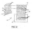
- the second portions 117b and 118bare shown in contact with structural elements 121, such as machine surfaces, hoistway metal frames, elevator rails and the like.
- structural elements 121such as machine surfaces, hoistway metal frames, elevator rails and the like.
- FIGS. 13A, 13B and 14A, 14Billustrate a second form of motor and drive combination 131, in which the motor 133 and drive 135 are integral.
- the advantage of an integrated motor and driveis that it provides a significant cost reduction and increase of machine reliability by eliminating the connecting power cables that are used in older elevator systems.
- heat pipes 117 and 118conduct heat from first portions 117a and 118a to second portions 117b and 118b to interact with heat exchanger 119 in FIGS. 13A and 13B and structural elements 121 in FIGS. 14A and 14B .
- FIG. 15illustrates an application of the present invention where part of the structure supporting the motor 143 and drive 145 (that are integrated in a manner similar to FIGS. 13A, 13B , 14A and 14B ) acts as a heat exchanger.
- Heat pipes 147 and 148have first portions 147a and 148a receiving heat from motor 143 and drive 145. These heat pipes 147 and 148 have a second portion 147b and 148b that transfer heat away and into contact with the bedplate 149 that supports the elevator drive system including motor 143 and drive 145.
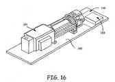
- FIG. 16illustrates the use of a heat spreader instead of a heat pipe system as shown in FIG. 15 .
- the motor 141 and drive 143are separately mounted on bedplate 149 and a heat spreader 146 is placed between the drive 143 and bedplate 149.
- a heat spreader 146is placed between the drive 143 and bedplate 149.
- some structuressuch as those made of thick aluminum, for example, could directly spread the high flux of heat generated by power electronics such as in drive 143
- an intermediate heat spreading structuresuch as heat spreader 146 spreads the heat flux over a larger area.
- inexpensive plate stockcan be used as spreader 146 to spread more of the heat onto bedplate 149.
- Heat spreadersare solid materials with high conductivity, usually made from aluminum or copper.
- a form of heat pipecan be used, where a flat surface has an internal liquid to vapor structure like that of heat pipe 147 in FIG. 11 .
- FIG. 17illustrates the mounting of the drive 145 on a heat spreader146 which in turn is mounted to elevator counterweight rail 151, or other structure, again to increase spreading of heat using a more heat conductive material such as aluminum or copper in heat spreader 146, rather than a typical material such as iron that elevator counterweight rails 151 require for added strength.
- FIGS. 18A and 18Billustrate a combination of a heat spreader 146 mounting drive 145 on bedplate 49 and heat pipes 147 which further pull heat from the drive 145 through the heat spreader 146 through hedplate149 and away from the portion of the heat pipe 147 closest to heat spreader 46 to the portion furthest away.
- FIG. 18Bshows the relationship of the drive 145 on heat spreader 146 on one side of elevator rail 151 with heat pipes 147 on the other side of elevator counterweight rail 151. Again, heat is conducted from the portion of the heat pipe closest to the spreader to a portion remote from the drive 145.
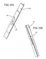
- FIGS. 19A and 19Billustrate a motor 143 and drive 145 with a pair of heat pipes 147, one of which is on each side of motor 143 and conducts heat from the motor 143 and drive 145 to a part 151 of motor 143 that is substantially cooler.
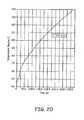
- FIG. 20is a graph illustrating the temperature of a hot spot as the motor 143 of FIG 19A is operated without the heat pipes 147. As can be seen, the temperature increases over time to a temperature well above the maximum allowable temperature of 125°C.
- FIG. 21is a graph illustrating the temperature of the same hot spot over time with heat pipes 147 conducting heat to part 151, and where the maximum allowable temperature of 125 °C is not reached, thus significantly improving operation of the elevator system.
Landscapes
- Engineering & Computer Science (AREA)
- Mechanical Engineering (AREA)
- Physics & Mathematics (AREA)
- General Engineering & Computer Science (AREA)
- Thermal Sciences (AREA)
- Power Engineering (AREA)
- Sustainable Development (AREA)
- Life Sciences & Earth Sciences (AREA)
- Civil Engineering (AREA)
- Structural Engineering (AREA)
- Microelectronics & Electronic Packaging (AREA)
- Geometry (AREA)
- Cage And Drive Apparatuses For Elevators (AREA)
- Motor Or Generator Cooling System (AREA)
Abstract
Description
- Elevator systems typically include an elevator car that is supported for movement within a hoistway. The elevator car travels between different levels of a building, for example, to transport passengers, cargo or both to desired destinations. An elevator machine causes the desired movement of the car.
- Many elevator machines include a motor that rotates a traction sheave to cause movement of a roping arrangement (e.g., round ropes or flat belts) from which the elevator car is suspended. The machine includes a drive that provides power and control signals to the motor to achieve the desired elevator car movement.
- Typical arrangements include separated motors and drives. Hardwired connections between them facilitate achieving the desired motor operation based upon the control signals provided by the drive. One issue with traditional arrangements is that the amount of wiring required between the drive and the motor introduces additional expense and complexity when installing or repairing an elevator machine. Another issue that is common to most drives is that some arrangement must be provided for cooling the electronics of the drive.
- One attempt at changing an elevator drive arrangement is shown in
WO 2005/040024 . That document describes a proposed separation of drive components with an inverter integrated with a motor. - The increasing market demand for lower cost, high space utilization, energy efficiency, and low noise environment of modern buildings translates into miniaturization and high power density, low noise and energy efficiency requirements for elevators, their motors and their electronic drives. One of the key factors determining acceptable power density in the motor and in the drive is the thermal management or cooling system.
- The cooling system of the motor is typically based on heat removal through the natural convection to surrounding air from the surface of the motor, which in many cases determines the motor size. Modem elevators usually employ permanent magnet motors with a brushless rotor so that only the stator has a winding. Resistive losses present the source of heat that needs to be removed. The typical brake in an elevator system also has at least one electromagnetic coil with associated resistive losses, and often represents the second largest heat source in the system. Additionally, the efficiency of bearings is limited by mechanical friction and aerodynamic and hydrodynamic drag, and thus the bearings contribute additional heat to the machine.
- Motor drive cooling systems usually include fans for forced air circulation and removal of the heat that results primarily from power dissipation of power electronic components. The heat sources are connected to a heat sink and fans are forced air circulation is used to move heat from the heat sink to the ambient environment. Typically heat sinks are costly and take up significant space. Fans contribute to noise, reduce drive reliability and increase maintenance costs. It is desirable, therefore, to eliminate fans or, at least, reduce the size or number of fans. An alternative to using fans has been to provide an extended surface inside or outside of the drive enclosure and use natural convection mechanisms.
- Liquid cooling, though not as common as direct forced air cooling, is also applied in some cases to power electronics. In such a system, the high heat flux of the power electronics components is absorbed by a moving liquid and carried to a remote liquid-to-air heat exchanger. While liquid cooling systems can provide for a more compact power electronics section, the size of a remote heat exchange must be similar or even larger than required by a forced air flow system.
- An exemplary elevator machine includes a motor having a case. A drive provides power and control signals to the motor. The drive is supported adjacent the motor case such that the drive and the motor are at the same location.
- The present invention is an apparatus and method for reducing heat in a drive system having a motor and a drive providing a source of power for the motor, and for other components in the system, without the use of fans and other devices that increase cost, consume energy, produce noise and reduce reliability.
- The apparatus includes at least one passive heat conducting element in heat exchanging contact with the motor or the drive. The heat conducting element includes at least one portion for receiving heat from the motor or the drive, and a second portion for each heat conducting element for receiving heat transferred from the first portion. A heat exchange device is used for withdrawing heat from the second portion to cool the motor and/or drive.
- The heat conducting element may be a heat pipe or a heat spreader, or a combination of both devices.
- The heat exchange device may be a conventional heat exchanger or it may be configured such that a portion of the structural elements of the elevator system are adapted to exchange heat from the heat conducting element second portion at a location spaced from the motor and the drive.
- The motor and drive may be separated from each other and connected in a conventional manner such that at least one of the motor and the drive have at least one heat pipe in heat exchanging contact therewith. Alternatively, the motor and the drive are integrated to provide a single external surface for contact with the at least one heat pipe.
FIG. 1 schematically shows selected portions of an elevator system including an exemplary elevator machine assembly.FIG. 2 is a perspective illustration diagrammatically illustrating one example embodiment of selected portions of an elevator machine assembly.FIG. 3 is an exploded, perspective illustration of the example ofFIG. 2 .FIG. 4 is a perspective illustration diagrammatically showing another example elevator motor and drive arrangement.FIG. 5 shows selected portions of the example ofFIG. 4 .FIG. 6 diagrammatically illustrates an elevator machine assembly including a motor and drive consistent with the example ofFIG. 4 .FIG. 7 shows another example configuration.FIG. 8 shows another example configuration.FIG. 9 shows another example configuration.FIG. 10 is a schematic view of one embodiment of the invention.FIG. 11 is a schematic view of a heat pipe.FIG. 12 is a schematic view of an alternative embodiment of the invention.FIG. 13A is a schematic view of another embodiment of the invention.FIG. 13B is a plan view of the embodiment shown inFIG. 13A .FIG. 14A is a schematic view of yet another embodiment of the invention.FIG. 14B is a plan view of the embodiment shown inFIG. 14A .FIG. 15 is a perspective view of another embodiment of the invention.FIG. 16 is a perspective view of yet another embodiment of the invention.FIG. 17 is a variation of the embodiment ofFIG. 16 .FIGS. 18A and 18B show another variation of the embodiment ofFIG. 16 .FIGS. 19A and 19B show yet another variation of the embodiment ofFIG. 16 .FIG. 20 is a graph showing the rise in temperature without the embodiment ofFIG. 10 .FIG. 21 is a graph showing the improvement in the rise in temperature with the embodiment ofFIG. 10 .FIG. 1 schematically shows selected portions of anelevator system 12. Anelevator car 14 is supported for movement along guide rails 15. Acounterweight 16 is coupled with thecar 14 using a roping arrangement (e.g., round ropes or flat belts) 17 in a known manner. Anelevator machine assembly 18 includes aframe 20 that supports a motor and driveportion 22, atraction sheave 24 and abrake portion 26. Theframe 20 is supported on astructural member 28, which in this example is connected with theguide rail 16.- One feature of the illustrated example is that the motor and drive
portion 22 includes amotor 30 and adrive 32 at the same location. Thedrive 32 provides power and control signals to themotor 30. Having themotor 30 and drive 32 at the same location is different than previous arrangements where the drive and motor were at separate locations. - Referring to
FIGS. 2 and3 , oneexample motor 30 includes amotor case 40 that houses components of themotor 30. In this example, at least onecapacitor component 44 is provided near one end of thecase 40. In one example thecapacitor component 44 comprises an electrode of the capacitor. The illustrated example allows for thecapacitor component 44 to be supported between themotor case 40 and a support plate of a machine frame, for example. - Example components within the
case 40 include arotor 50, a stator 52 and achoke 54. Incorporating thechoke 54 into the motor structure is different than previous motor designs. In this example, thechoke 54 comprises a line inductor that includes part of the motor core with wire to establish a line inductor. Incorporating the choke into the motor structure avoids having the choke as a stand alone component. This represents space savings and reduces installation time as the number of stand alone components of an elevator machine assembly has an impact on the complexity of the system and the time required for installation, for example. - In this example, the
drive 32 includes asupport structure 60 comprising a plurality ofboards 62. In one example, theboards 62 comprise printed circuit board substrate materials. The illustrated example includes anend cap board 64 from which each of theboards 62 extends. Each of theboards electronic components 66. Power control and control signal generation for operating themotor 30 are accomplished by theelectronic components 66. - In the illustrated example, the
drive support structure 60 is positioned adjacent themotor case 40. In this particular example, at least one of theboards motor case 40 such that thedrive 32 is supported by themotor case 40. This is one example arrangement that allows for locating themotor 30 and drive 32 at the same location. - Another feature of the illustrated example is a
cooling circuit 70 that provides cooling to at least thedrive 32. In this example, the coolingcircuit 70 includes an electroconductive fluid that follows a closed loop conduit path that is positioned relative to theelectronic components 66 of thedrive 32 to dissipate heat and provide cooling for thecomponent 66. The conduit for thecooling circuit 70 follows a path around and between at least some drive components in close enough proximity for the fluid to absorb some heat from the drive components. In this example, the electroconductive fluid effectively gets pumped through thecooling circuit 70 by the electric field of themotor 30. As the fluid flows, it carries heat away from the drive components to provide cooling. - One feature of such an arrangement is that the cooling for the
drive 32 operates responsive to operation of themotor 30. No separate source of power for cooling thedrive 32 is required. The illustrated example takes advantage of operation of themotor 30 to provide cooling to thedrive 32. - Referring to
FIGS. 4 and5 , another example arrangement is shown including a different drive support structure compared to that in the example ofFIGS. 2 and3 . In this example, a plurality ofboards 62 supportelectronic components 66 of thedrive 32. Each of theboards 62 in this example are received against an exterior surface of theexample motor case 40. As best appreciated fromFIG. 5 , the coolingcircuit 70 in this example includes some conduit that is positioned at least partially within a central portion of themotor 30 such that electroconductive fluid within thecooling circuit 70 is pumped by the electric field of themotor 30. Additionally, the presence of thecooling circuit 70 within themotor 30 provides cooling to themotor 30 during operation along with providing cooling to thedrive 32. This example includes an integrated cooling function for the motor and the drive from asingle cooling circuit 70. This further reduces the complexity of the installation and provides cost savings by reducing the number of separate components required for the machine assembly. Additionally, having a single cooling source for themotor 30 and drive 32 reduces required space, which has economic benefits. - One feature of the illustrated examples is that it reduces the amount of wiring connections required external of the location of the
motor 30 and drive 32. In the example ofFIG. 4 , asingle connector 80 allows for making a connection with the motor and driveportion 22 to provide power from a power source and to allow for signal communication between thedrive 32 and an elevator controller (not illustrated) that is responsible for determining the desired position and motion profile of theelevator car 14. Reducing the amount of wired connections that must be installed at the location of the elevator system further reduces the complexity and cost associated with installing an elevator system. FIG. 6 illustrates the example ofFIGS. 4 and5 associated with anexample machine frame 20. In this example, theframe 20 includes a plurality ofsupport plates 82 and connectingrods 86 extending between thesupport plates 82. In this example, theframe 20 supports the motor and driveportion 22,traction sheave 24 andbrake portion 26. Thesupport plates 82 facilitate mounting the machine assembly onto anappropriate support structure 28 within a hoistway or in a machine room as may be needed. One feature of the illustrated example is that it facilitates positioning the machine assembly within an elevator hoistway for elevator machine roomless installations. Theexample machine frame 20 is only one example and those skilled in the art who have the benefit of this description will realize what other frame configurations can be used with the other features of the disclosed examples.- The
example motor case 40 includes a mountingflange 88 that is secured to one of thesupport plates 82. The association between themotor case 40 and thesupport plate 82 and the position of thesupport plate 82 against the supportingstructural member 28, provides a thermally conductive path for dissipating heat from themotor 30 and drive 32. In the example ofFIG. 1 , thestructural member 28 and theguide rail 16 along with theframe 20 act as a heat sink for dissipating heat away from themotor 30 and drive 32. Accordingly, the illustrated examples provide a convenient way of maintaining a desired temperature of themotor 30 and drive 32 during operation. Additionally, thetraction sheave 24 comprises a metal that can dissipate heat for cooling thedrive 32 and themotor 30. Having thedrive 32 andmotor 30 at the same location allows for using the same components for cooling both of them rather than requiring separate cooling arrangements for each. - The
drive 32 may be located with themotor 30 by supporting portions of thedrive 32 on acase 40 of the motor as shown inFIG. 6 , for example. In an alternative example as shown inFIG. 7 , thedrive 32 is supported at the location of themotor 30 without having thedrive 32 supported by any portion of themotor 30. In the example ofFIG. 7 , the drive support structure is mounted to a portion of theframe 20 adjacent the traction sheave 24 (not visible inFIG. 7 ). In another example as shown inFIG. 8 , thedrive 32 is supported directly by astructural member 28 that also supports themachine frame 20. Another example is shown inFIG. 9 where thedrive 32 is supported directly by aguide rail 16. - Given this description, those skilled in the art will realize how best to situate the
motor 30 and drive 32 to realize the features of the disclosed examples such as integrating multiple components to avoid stand alone components that make up the elevator machine assembly, utilizing various structures associated with the machine assembly to provide cooling to the motor and drive (e.g.,. the machine frame, supporting structure or guide rails) and simplification of the installation process. - In
FIG. 10 , anelevator drive system 110 including amotor 111 and drive 113 is shown. In order to operate efficiently and reliably, the heat generated by operation ofmotor 111 and drive 113 must be dissipated with minimal energy cost and noise. Reliability should be maximized, and motor size should be minimized. - While any motor used in an elevator drive system is within the scope of this invention, many modern elevators use a permanent magnet brushless motor. Only the stator has a winding with resistive losses that generate heat to be removed.
- Drive 113 is the component of the elevator system that converts power from the power bus, not shown, to a frequency and voltage that is suitable to drive the
motor 111. It is within the scope of this invention to remove heat generated bymotor 111 or drive 113, or both, or by any one or more components of the elevator drive system. The elevator drive system of this invention is conventional, except for the cooling apparatus of this invention that eliminates fans and other expensive, noisy and inefficient elements. - Drive 113 is shown with an
aluminum mounting bracket 115 that supportsheat pipes 117, such that afirst portion 117a is in contact withdrive 113 to receive heat by contact and asecond portion 117b is used to dissipate heat intoheat exchanger 119.Heat pipes 117 are curved in a generally L-shape, but any configuration is suitable as long as thefirst portion 117a makes adequate heat transfer contact. Attached tomotor 111 areheat pipes 118 that include afirst portion 118a for receiving heat frommotor 111, by conduction as shown here, and moving the heat to asecond portion 118b that releases heat intoheat exchanger 119. - A heat pipe is a heat transfer mechanism that can transport large quantities of heat with a very small difference in temperature between the hotter and colder interfaces. In
FIG. 11 , inside aheat pipe 147, at thehot interface 147a, the fluid turns to vapor 147c shown flowing from left to right inFIG. 11 . The gas 147c naturally flows and condenses as liquid 147d on thecool interface 147b. The liquid falls or is moved by capillary action back to the hot interface from right to left inFIG. 11 to evaporate again and repeat the cycle. A typical heat pipe consists of a sealed hollow tube. A heat-conductive metal like copper or aluminum is used to make the tube. The pipe contains a relatively small quantity of a "working fluid" or coolant (such as water, ethanol or mercury) in liquid phase with the remainder of the pipe being filled with vapor phase of the working fluid, all other gases being excluded. - On the internal side of the tube's sidewalls, a wick structure exerts a capillary force on the liquid phase of the working fluid. This is typically a sintered metal powder or a series of grooves parallel to the tube axis, but it may in principle be any material capable of exerting capillary pressure on the condensed liquid to drive it back to the heated end. If the heat pipe has a continual slope with the heated end down, no inner lining is needed. The working fluid simply flows back down the pipe. This simple type of heat pipe is known as a thermosyphone. Any form of heat pipe can be used, including thermosyphones that only work in a vertical direction. The advantage of heat pipes is their great efficiency in transferring heat. For example, they are a better heat conductor than an equivalent cross-section of solid copper. In addition, heat pipes can transfer heat without the need for mechanical moving parts, motors or other sources of noise.
- Also, more advanced heat pipes may be used that are solid state devices such as those using nanoparticles. Examples of such a device are described in
U.S. Patent Application Serial Number 11/852,840, filed January 12, 2007 - In
FIG. 12 , thesecond portions structural elements 121, such as machine surfaces, hoistway metal frames, elevator rails and the like. The advantage of this design is that the cost of a heat exchanger (such as heat exchanger 19 inFIG. 10 ) is eliminated, and existing structure that needs to be present is used to carry away the heat, without noise and without any issues of reliability. FIGS. 13A, 13B and14A, 14B illustrate a second form of motor and drivecombination 131, in which the motor 133 and drive 135 are integral. The advantage of an integrated motor and drive is that it provides a significant cost reduction and increase of machine reliability by eliminating the connecting power cables that are used in older elevator systems. Again heatpipes first portions second portions heat exchanger 119 inFIGS. 13A and 13B andstructural elements 121 inFIGS. 14A and 14B .FIG. 15 illustrates an application of the present invention where part of the structure supporting themotor 143 and drive 145 (that are integrated in a manner similar toFIGS. 13A, 13B ,14A and 14B ) acts as a heat exchanger.Heat pipes first portions motor 143 and drive 145. Theseheat pipes second portion bedplate 149 that supports the elevator drivesystem including motor 143 and drive 145.FIG. 16 illustrates the use of a heat spreader instead of a heat pipe system as shown inFIG. 15 . InFIG. 16 , themotor 141 and drive 143 are separately mounted onbedplate 149 and aheat spreader 146 is placed between thedrive 143 andbedplate 149. While some structures such as those made of thick aluminum, for example, could directly spread the high flux of heat generated by power electronics such as indrive 143, it has been found that an intermediate heat spreading structure such asheat spreader 146 spreads the heat flux over a larger area. Unlike typical extruded fin heat sink materials in conventional cooling designs, inexpensive plate stock can be used asspreader 146 to spread more of the heat ontobedplate 149. Heat spreaders are solid materials with high conductivity, usually made from aluminum or copper. In addition to solid materials formingheat spreaders 146, a form of heat pipe can be used, where a flat surface has an internal liquid to vapor structure like that ofheat pipe 147 inFIG. 11 .FIG. 17 illustrates the mounting of thedrive 145 on a heat spreader146 which in turn is mounted toelevator counterweight rail 151, or other structure, again to increase spreading of heat using a more heat conductive material such as aluminum or copper inheat spreader 146, rather than a typical material such as iron that elevator counterweight rails 151 require for added strength.FIGS. 18A and 18B illustrate a combination of aheat spreader 146 mountingdrive 145 on bedplate 49 andheat pipes 147 which further pull heat from thedrive 145 through theheat spreader 146 through hedplate149 and away from the portion of theheat pipe 147 closest to heat spreader 46 to the portion furthest away.FIG. 18B shows the relationship of thedrive 145 onheat spreader 146 on one side ofelevator rail 151 withheat pipes 147 on the other side ofelevator counterweight rail 151. Again, heat is conducted from the portion of the heat pipe closest to the spreader to a portion remote from thedrive 145.FIGS. 19A and 19B illustrate amotor 143 and drive 145 with a pair ofheat pipes 147, one of which is on each side ofmotor 143 and conducts heat from themotor 143 and drive 145 to apart 151 ofmotor 143 that is substantially cooler.- When the heat distribution is not effective, such as, for example, without both
heat pipes FIG. 15 , or ifheat spreader 146 inFIG. 16 is not as large as shown, the device will experience hot spots.FIG. 20 is a graph illustrating the temperature of a hot spot as themotor 143 ofFIG 19A is operated without theheat pipes 147. As can be seen, the temperature increases over time to a temperature well above the maximum allowable temperature of 125°C. In contrast,FIG. 21 is a graph illustrating the temperature of the same hot spot over time withheat pipes 147 conducting heat topart 151, and where the maximum allowable temperature of 125 °C is not reached, thus significantly improving operation of the elevator system. - Although the present invention has been described with reference to preferred embodiments, workers skilled in the art will recognize that changes may be made in form and detail without departing from the spirit and scope of the invention.
Claims (13)
- Apparatus for reducing heat in a drive system including a motor and a drive for providing a source of power for the motor, the apparatus comprising:at least one heat conducting element in heat exchanging contact with at least one component of the drive system, the at least one heat conducting element having a first portion for receiving heat from the at least one component of the drive system;the at least one heat conducting element being adapted to transfer heat from the first portion to a second portion spaced from the first portion; anda heat exchange device proximate the second portion of the at least one heat conducting element for withdrawing heat from the second portion to cool the at least one component of the elevator drive system.
- The apparatus of claim 1, wherein the drive system is an elevator drive system.
- The apparatus of claim 1 or 2, wherein the heat exchange device comprises a heat exchanger adapted to exchange heat from the second portion of the at least one heat conducting element at a location spaced from the motor and drive.
- The apparatus of any preceding claim, wherein the elevator system further includes structural elements proximate the motor and the drive, and the heat exchange device comprises a portion of the structural elements adapted to exchange heat from the second portion of the at least one heat conducting element at a location spaced from the motor and the drive.
- The apparatus of any preceding claim, wherein the motor and the drive are separated from each other in space, and wherein each of the motor and the drive have at least one heat conducting element in heat exchanging contact therewith.
- The apparatus of any preceding claim, wherein the motor and the drive are integrated to provide a unitary device for contact with the at least one heat conducting element.
- The apparatus of any preceding claim, wherein the at least one heat conducting element is selected from at least one heat pipe and at least one heat spreader element.
- The apparatus of any of claims 1 to 6, wherein the at least one heat conducting element is selected from at least one of (a) a plurality of thermosyphones, (b) a plurality of heat pipes formed from hollow metal pipes having the first portion for receiving heat from the at least one component of the elevator drive system and the second portion for delivering heat to the heat exchanger device, the heat pipes having liquid-vapor with a two phase mixture and a capillary structure for liquid delivery from the first portion of the pipe to the second portion of the pipe, and (c) a plurality of pipes using nanoparticles to transfer heat from the first portion to the second portion proximate the heat exchange device.
- A method for reducing heat in a drive system including a motor and a drive for providing a source of power for the motor, the method comprising:providing at least one heat conducting element in heat exchanging contact with at least one component of the drive system, the at least one heat conducting element having a first portion for receiving heat from the one component;transferring heat in the at least one heat conducting element from the first portion to a second portion spaced from the first portion;and withdrawing heat from the second portion using a heat exchange device to cool the at least one component of the drive system.
- The method of claim 9, wherein the drive system is an elevator drive system.
- The method of claim 9 or 10, wherein the heat exchange device comprises a heat exchanger adapted to exchange heat from the second portion at a location spaced from the least one component of the elevator drive system, and wherein the elevator system further includes structural elements proximate the least one component of the elevator drive system, and the heat exchange device comprises a portion of the structural elements adapted to exchange heat from the second portion at a location spaced from the elevator drive system.
- The method of claim 9, 10 or 11, wherein the at least one heat conducting element comprises at least one of a heat pipe and a heat spreader element.
- The method of any of claims 9 to 11, wherein the at least one heat conducting element is selected from at least one of (a) a plurality of thermosyphones, (b) a plurality of heat pipes formed from hollow metal pipes having the first portion for receiving heat from the elevator drive system and a second portion for delivering heat to the heat exchanger device, the heat pipes having liquid-vapor with a two phase mixture and a capillary structure for liquid delivery from the first portion of the pipe to the second portion of the pipe, and (c) a plurality of pipes using nanoparticles to transfer heat from the first portion to the second portion proximate the heat exchange device.
Applications Claiming Priority (2)
| Application Number | Priority Date | Filing Date | Title |
|---|---|---|---|
| US13148308P | 2008-06-09 | 2008-06-09 | |
| EP08874643AEP2300348A1 (en) | 2008-06-09 | 2009-01-15 | Elevator machine motor and drive and cooling thereof |
Related Parent Applications (2)
| Application Number | Title | Priority Date | Filing Date |
|---|---|---|---|
| EP08874643.3Division | 2009-01-15 | ||
| EP08874643ADivisionEP2300348A1 (en) | 2008-06-09 | 2009-01-15 | Elevator machine motor and drive and cooling thereof |
Publications (2)
| Publication Number | Publication Date |
|---|---|
| EP2330067A1true EP2330067A1 (en) | 2011-06-08 |
| EP2330067B1 EP2330067B1 (en) | 2015-10-28 |
Family
ID=40405002
Family Applications (2)
| Application Number | Title | Priority Date | Filing Date |
|---|---|---|---|
| EP08874643AWithdrawnEP2300348A1 (en) | 2008-06-09 | 2009-01-15 | Elevator machine motor and drive and cooling thereof |
| EP11157098.2ANot-in-forceEP2330067B1 (en) | 2008-06-09 | 2009-01-15 | Elevator machine motor and drive and cooling therefor |
Family Applications Before (1)
| Application Number | Title | Priority Date | Filing Date |
|---|---|---|---|
| EP08874643AWithdrawnEP2300348A1 (en) | 2008-06-09 | 2009-01-15 | Elevator machine motor and drive and cooling thereof |
Country Status (6)
| Country | Link |
|---|---|
| US (1) | US8922074B2 (en) |
| EP (2) | EP2300348A1 (en) |
| JP (1) | JP5208269B2 (en) |
| CN (1) | CN102083730B (en) |
| ES (1) | ES2559952T3 (en) |
| WO (1) | WO2009151434A1 (en) |
Cited By (4)
| Publication number | Priority date | Publication date | Assignee | Title |
|---|---|---|---|---|
| US8893513B2 (en) | 2012-05-07 | 2014-11-25 | Phononic Device, Inc. | Thermoelectric heat exchanger component including protective heat spreading lid and optimal thermal interface resistance |
| US8991194B2 (en) | 2012-05-07 | 2015-03-31 | Phononic Devices, Inc. | Parallel thermoelectric heat exchange systems |
| US9593871B2 (en) | 2014-07-21 | 2017-03-14 | Phononic Devices, Inc. | Systems and methods for operating a thermoelectric module to increase efficiency |
| US10458683B2 (en) | 2014-07-21 | 2019-10-29 | Phononic, Inc. | Systems and methods for mitigating heat rejection limitations of a thermoelectric module |
Families Citing this family (18)
| Publication number | Priority date | Publication date | Assignee | Title |
|---|---|---|---|---|
| CN101687604B (en)* | 2007-01-11 | 2013-01-09 | 奥蒂斯电梯公司 | Thermoelectric temperature controller with convective airflow for cooling elevator components |
| JP5776163B2 (en)* | 2010-10-15 | 2015-09-09 | 株式会社明電舎 | Hoisting machine |
| FR2980057B1 (en)* | 2011-09-13 | 2013-10-04 | Renault Sa | COOLING OF ELECTRIC MOTOR BY CALODUCES |
| JP5912975B2 (en)* | 2012-08-01 | 2016-04-27 | キャタピラー エス エー アール エル | Magnetic device of work machine |
| CN103471436B (en)* | 2013-08-20 | 2015-10-28 | 吴江骏达电梯部件有限公司 | A kind of gravity assisted heat pipe heat exchange type lift car |
| JP6195025B2 (en)* | 2014-12-09 | 2017-09-13 | 三菱電機株式会社 | Elevator hoisting machine |
| EP3086627B1 (en)* | 2015-04-24 | 2020-10-21 | Kone Corporation | Elevator comprising a power unit |
| US10640332B2 (en) | 2015-08-07 | 2020-05-05 | Otis Elevator Company | Elevator linear propulsion system with cooling device |
| EP3408207A4 (en)* | 2016-01-25 | 2019-09-25 | Kone Corporation | ELEVATOR |
| US10384913B2 (en)* | 2016-06-13 | 2019-08-20 | Otis Elevatro Company | Thermal management of linear motor |
| EP3489185B1 (en)* | 2017-11-24 | 2020-07-29 | KONE Corporation | Cooling solution for hoisting machinery |
| ES2994312T3 (en) | 2019-11-05 | 2025-01-21 | TruBlue LLC | Carabiner |
| USD945252S1 (en) | 2019-12-18 | 2022-03-08 | TruBlue LLC | Carabiner |
| EP4241371A4 (en)* | 2020-11-03 | 2024-11-06 | H3X Technologies Inc. | ELECTRIC MOTOR WITH INTEGRATED INVERTER AND COMMON COOLING SYSTEM |
| CN112777448B (en)* | 2021-02-24 | 2024-01-02 | 杭州西奥电梯有限公司 | Traction machine system and elevator installation method |
| CN112830364B (en)* | 2021-02-24 | 2024-01-02 | 杭州西奥电梯有限公司 | Elevator system and elevator installation method |
| CN114834995A (en)* | 2022-05-05 | 2022-08-02 | 上海三菱电梯有限公司 | Integrated driving device and elevator |
| CN120027471B (en)* | 2025-04-22 | 2025-07-08 | 北京中矿赛力贝特节能科技有限公司 | A heat pipe air conditioning system for mines |
Citations (7)
| Publication number | Priority date | Publication date | Assignee | Title |
|---|---|---|---|---|
| WO2000038488A1 (en)* | 1998-12-22 | 2000-06-29 | Otis Elevator Company | Liquid cooled elevator machine drive |
| EP1057768A1 (en)* | 1998-12-25 | 2000-12-06 | Mitsubishi Denki Kabushiki Kaisha | Elevator control apparatus |
| US20040164625A1 (en)* | 2001-03-16 | 2004-08-26 | Gruendl Andreas | Fluid cooled electric machine |
| WO2005040024A2 (en) | 2003-10-29 | 2005-05-06 | Kone Corporation | Elevator and its control |
| EP1678814A1 (en)* | 2003-10-31 | 2006-07-12 | Telma | Electromagnetic retarders comprising heat dissipating elements |
| US20080067882A1 (en)* | 2006-09-15 | 2008-03-20 | Toyota Jidosha Kabushiki Kaisha | Motor |
| US7378766B2 (en)* | 2003-05-26 | 2008-05-27 | Valeo Equipement Electrique Moteur | Rotating electrical machine, such as an alternator, particularly for an automobile |
Family Cites Families (15)
| Publication number | Priority date | Publication date | Assignee | Title |
|---|---|---|---|---|
| GB410425A (en) | 1933-12-01 | 1934-05-17 | English Electric Co Ltd | Improvements in electric condensers for mounting on electric motors |
| GB900852A (en) | 1958-08-05 | 1962-07-11 | Hoover Ltd | Improvements relating to electric motors |
| US5642011A (en)* | 1992-02-18 | 1997-06-24 | General Electric Company | Double-stator electromagnetic pump having alignment ring and spine assembly |
| FI94123C (en)* | 1993-06-28 | 1995-07-25 | Kone Oy | Traction sheave elevator |
| US5763951A (en)* | 1996-07-22 | 1998-06-09 | Northrop Grumman Corporation | Non-mechanical magnetic pump for liquid cooling |
| DE19739899A1 (en)* | 1997-09-11 | 1999-03-18 | Alpha Getriebebau Gmbh | Drive for elevators |
| FR2773941B1 (en)* | 1998-01-19 | 2000-04-21 | Ferraz | DI-PHASIC EXCHANGER FOR AT LEAST ONE ELECTRONIC POWER COMPONENT |
| ES2280378T3 (en)* | 2001-05-18 | 2007-09-16 | Thyssenkrupp Aufzugswerke Gmbh | ELEVATOR OPERATION WITH PLASTIC SUPPORT PARTS. |
| WO2003043727A1 (en) | 2001-11-19 | 2003-05-30 | Casale Chemicals S.A. | Modular chemical reactor |
| US7117930B2 (en)* | 2002-06-14 | 2006-10-10 | Thermal Corp. | Heat pipe fin stack with extruded base |
| US6830098B1 (en)* | 2002-06-14 | 2004-12-14 | Thermal Corp. | Heat pipe fin stack with extruded base |
| JP2008528940A (en)* | 2005-02-02 | 2008-07-31 | キャリア コーポレイション | Heat exchanger with fluid expansion in header |
| CA2595844A1 (en)* | 2005-02-02 | 2006-08-10 | Carrier Corporation | Multi-channel flat-tube heat exchanger |
| US8104584B2 (en)* | 2005-12-20 | 2012-01-31 | Otis Elevator Company | Elevator drive control strategy |
| JP2007197094A (en)* | 2006-01-23 | 2007-08-09 | Mitsubishi Electric Corp | Heat dissipation device for elevator control |
- 2009
- 2009-01-15WOPCT/US2008/013525patent/WO2009151434A1/enactiveApplication Filing
- 2009-01-15EPEP08874643Apatent/EP2300348A1/ennot_activeWithdrawn
- 2009-01-15JPJP2011513467Apatent/JP5208269B2/ennot_activeExpired - Fee Related
- 2009-01-15CNCN200980121440.XApatent/CN102083730B/ennot_activeExpired - Fee Related
- 2009-01-15EPEP11157098.2Apatent/EP2330067B1/ennot_activeNot-in-force
- 2009-01-15ESES11157098.2Tpatent/ES2559952T3/enactiveActive
- 2010
- 2010-06-10USUS12/797,776patent/US8922074B2/enactiveActive
Patent Citations (7)
| Publication number | Priority date | Publication date | Assignee | Title |
|---|---|---|---|---|
| WO2000038488A1 (en)* | 1998-12-22 | 2000-06-29 | Otis Elevator Company | Liquid cooled elevator machine drive |
| EP1057768A1 (en)* | 1998-12-25 | 2000-12-06 | Mitsubishi Denki Kabushiki Kaisha | Elevator control apparatus |
| US20040164625A1 (en)* | 2001-03-16 | 2004-08-26 | Gruendl Andreas | Fluid cooled electric machine |
| US7378766B2 (en)* | 2003-05-26 | 2008-05-27 | Valeo Equipement Electrique Moteur | Rotating electrical machine, such as an alternator, particularly for an automobile |
| WO2005040024A2 (en) | 2003-10-29 | 2005-05-06 | Kone Corporation | Elevator and its control |
| EP1678814A1 (en)* | 2003-10-31 | 2006-07-12 | Telma | Electromagnetic retarders comprising heat dissipating elements |
| US20080067882A1 (en)* | 2006-09-15 | 2008-03-20 | Toyota Jidosha Kabushiki Kaisha | Motor |
Cited By (9)
| Publication number | Priority date | Publication date | Assignee | Title |
|---|---|---|---|---|
| US8893513B2 (en) | 2012-05-07 | 2014-11-25 | Phononic Device, Inc. | Thermoelectric heat exchanger component including protective heat spreading lid and optimal thermal interface resistance |
| US8991194B2 (en) | 2012-05-07 | 2015-03-31 | Phononic Devices, Inc. | Parallel thermoelectric heat exchange systems |
| US9103572B2 (en) | 2012-05-07 | 2015-08-11 | Phononic Devices, Inc. | Physically separated hot side and cold side heat sinks in a thermoelectric refrigeration system |
| US9234682B2 (en) | 2012-05-07 | 2016-01-12 | Phononic Devices, Inc. | Two-phase heat exchanger mounting |
| US9310111B2 (en) | 2012-05-07 | 2016-04-12 | Phononic Devices, Inc. | Systems and methods to mitigate heat leak back in a thermoelectric refrigeration system |
| US9341394B2 (en) | 2012-05-07 | 2016-05-17 | Phononic Devices, Inc. | Thermoelectric heat exchange system comprising cascaded cold side heat sinks |
| US10012417B2 (en) | 2012-05-07 | 2018-07-03 | Phononic, Inc. | Thermoelectric refrigeration system control scheme for high efficiency performance |
| US9593871B2 (en) | 2014-07-21 | 2017-03-14 | Phononic Devices, Inc. | Systems and methods for operating a thermoelectric module to increase efficiency |
| US10458683B2 (en) | 2014-07-21 | 2019-10-29 | Phononic, Inc. | Systems and methods for mitigating heat rejection limitations of a thermoelectric module |
Also Published As
| Publication number | Publication date |
|---|---|
| HK1158597A1 (en) | 2012-07-20 |
| JP2011524157A (en) | 2011-08-25 |
| JP5208269B2 (en) | 2013-06-12 |
| WO2009151434A1 (en) | 2009-12-17 |
| CN102083730B (en) | 2014-08-13 |
| EP2300348A1 (en) | 2011-03-30 |
| US20100288586A1 (en) | 2010-11-18 |
| EP2330067B1 (en) | 2015-10-28 |
| ES2559952T3 (en) | 2016-02-16 |
| CN102083730A (en) | 2011-06-01 |
| HK1158605A1 (en) | 2012-07-20 |
| US8922074B2 (en) | 2014-12-30 |
Similar Documents
| Publication | Publication Date | Title |
|---|---|---|
| EP2330067B1 (en) | Elevator machine motor and drive and cooling therefor | |
| CN107848759B (en) | elevator linear propulsion system with cooling device | |
| CN102782331B (en) | Turbo molecular pump device | |
| EP2487327A1 (en) | Subsea electronic system | |
| EP3468011A1 (en) | Motor apparatus | |
| US11001477B2 (en) | Elevator linear propulsion system with cooling device | |
| JP2007266527A (en) | Inverter device for vehicle | |
| EP1057768B1 (en) | Elevator control apparatus | |
| CN116367510A (en) | Converter heat dissipation device and control method thereof | |
| CN102403878B (en) | Electricity transforming device and elevator | |
| JP5972354B2 (en) | Cooling device for electronic components and / or electronic assemblies | |
| EP2736827B1 (en) | Electricity supply device and elevator system | |
| WO2009075672A1 (en) | Integrated elevator machine motor and drive | |
| HK1158605B (en) | Elevator machine motor and drive and cooling therefor | |
| HK1158597B (en) | Elevator machine motor and drive and cooling thereof | |
| CN219437410U (en) | Elevator control drive equipment and elevator equipment | |
| CN201115201Y (en) | Novel power cabinet based on thermal tube heat radiation system | |
| JP4610209B2 (en) | Elevator power converter | |
| CN217216403U (en) | Mud pump motor SCR drive flash chamber | |
| CN218102837U (en) | High-speed high-performance safety motor for continuous extrusion | |
| CN214314872U (en) | Installation surface area water-cooled no iron core linear electric motor | |
| CN222301590U (en) | High-speed linear motor with built-in heat radiation system | |
| JP2010027760A (en) | Electric device | |
| CN115530850A (en) | Brake resistor arrangement in a computer tomography gantry | |
| JP2005067846A (en) | Elevator control panel |
Legal Events
| Date | Code | Title | Description |
|---|---|---|---|
| PUAI | Public reference made under article 153(3) epc to a published international application that has entered the european phase | Free format text:ORIGINAL CODE: 0009012 | |
| AC | Divisional application: reference to earlier application | Ref document number:2300348 Country of ref document:EP Kind code of ref document:P | |
| AK | Designated contracting states | Kind code of ref document:A1 Designated state(s):AT BE BG CH CY CZ DE DK EE ES FI FR GB GR HR HU IE IS IT LI LT LU LV MC MK MT NL NO PL PT RO SE SI SK TR | |
| AX | Request for extension of the european patent | Extension state:AL BA RS | |
| 17P | Request for examination filed | Effective date:20111206 | |
| 17Q | First examination report despatched | Effective date:20120425 | |
| REG | Reference to a national code | Ref country code:HK Ref legal event code:DE Ref document number:1158605 Country of ref document:HK | |
| GRAP | Despatch of communication of intention to grant a patent | Free format text:ORIGINAL CODE: EPIDOSNIGR1 | |
| INTG | Intention to grant announced | Effective date:20150115 | |
| GRAP | Despatch of communication of intention to grant a patent | Free format text:ORIGINAL CODE: EPIDOSNIGR1 | |
| INTG | Intention to grant announced | Effective date:20150618 | |
| GRAS | Grant fee paid | Free format text:ORIGINAL CODE: EPIDOSNIGR3 | |
| GRAA | (expected) grant | Free format text:ORIGINAL CODE: 0009210 | |
| AC | Divisional application: reference to earlier application | Ref document number:2300348 Country of ref document:EP Kind code of ref document:P | |
| AK | Designated contracting states | Kind code of ref document:B1 Designated state(s):AT BE BG CH CY CZ DE DK EE ES FI FR GB GR HR HU IE IS IT LI LT LU LV MC MK MT NL NO PL PT RO SE SI SK TR | |
| REG | Reference to a national code | Ref country code:GB Ref legal event code:FG4D | |
| REG | Reference to a national code | Ref country code:CH Ref legal event code:EP | |
| REG | Reference to a national code | Ref country code:AT Ref legal event code:REF Ref document number:757816 Country of ref document:AT Kind code of ref document:T Effective date:20151115 | |
| REG | Reference to a national code | Ref country code:IE Ref legal event code:FG4D | |
| REG | Reference to a national code | Ref country code:DE Ref legal event code:R096 Ref document number:602009034562 Country of ref document:DE | |
| REG | Reference to a national code | Ref country code:FR Ref legal event code:PLFP Year of fee payment:8 | |
| REG | Reference to a national code | Ref country code:ES Ref legal event code:FG2A Ref document number:2559952 Country of ref document:ES Kind code of ref document:T3 Effective date:20160216 | |
| REG | Reference to a national code | Ref country code:LT Ref legal event code:MG4D | |
| REG | Reference to a national code | Ref country code:NL Ref legal event code:MP Effective date:20151028 | |
| REG | Reference to a national code | Ref country code:AT Ref legal event code:MK05 Ref document number:757816 Country of ref document:AT Kind code of ref document:T Effective date:20151028 | |
| PG25 | Lapsed in a contracting state [announced via postgrant information from national office to epo] | Ref country code:HR Free format text:LAPSE BECAUSE OF FAILURE TO SUBMIT A TRANSLATION OF THE DESCRIPTION OR TO PAY THE FEE WITHIN THE PRESCRIBED TIME-LIMIT Effective date:20151028 Ref country code:NL Free format text:LAPSE BECAUSE OF FAILURE TO SUBMIT A TRANSLATION OF THE DESCRIPTION OR TO PAY THE FEE WITHIN THE PRESCRIBED TIME-LIMIT Effective date:20151028 Ref country code:LT Free format text:LAPSE BECAUSE OF FAILURE TO SUBMIT A TRANSLATION OF THE DESCRIPTION OR TO PAY THE FEE WITHIN THE PRESCRIBED TIME-LIMIT Effective date:20151028 Ref country code:IT Free format text:LAPSE BECAUSE OF FAILURE TO SUBMIT A TRANSLATION OF THE DESCRIPTION OR TO PAY THE FEE WITHIN THE PRESCRIBED TIME-LIMIT Effective date:20151028 Ref country code:IS Free format text:LAPSE BECAUSE OF FAILURE TO SUBMIT A TRANSLATION OF THE DESCRIPTION OR TO PAY THE FEE WITHIN THE PRESCRIBED TIME-LIMIT Effective date:20160228 Ref country code:NO Free format text:LAPSE BECAUSE OF FAILURE TO SUBMIT A TRANSLATION OF THE DESCRIPTION OR TO PAY THE FEE WITHIN THE PRESCRIBED TIME-LIMIT Effective date:20160128 | |
| REG | Reference to a national code | Ref country code:HK Ref legal event code:GR Ref document number:1158605 Country of ref document:HK | |
| PG25 | Lapsed in a contracting state [announced via postgrant information from national office to epo] | Ref country code:PL Free format text:LAPSE BECAUSE OF FAILURE TO SUBMIT A TRANSLATION OF THE DESCRIPTION OR TO PAY THE FEE WITHIN THE PRESCRIBED TIME-LIMIT Effective date:20151028 Ref country code:LV Free format text:LAPSE BECAUSE OF FAILURE TO SUBMIT A TRANSLATION OF THE DESCRIPTION OR TO PAY THE FEE WITHIN THE PRESCRIBED TIME-LIMIT Effective date:20151028 Ref country code:PT Free format text:LAPSE BECAUSE OF FAILURE TO SUBMIT A TRANSLATION OF THE DESCRIPTION OR TO PAY THE FEE WITHIN THE PRESCRIBED TIME-LIMIT Effective date:20160229 Ref country code:BE Free format text:LAPSE BECAUSE OF NON-PAYMENT OF DUE FEES Effective date:20160131 Ref country code:FI Free format text:LAPSE BECAUSE OF FAILURE TO SUBMIT A TRANSLATION OF THE DESCRIPTION OR TO PAY THE FEE WITHIN THE PRESCRIBED TIME-LIMIT Effective date:20151028 Ref country code:AT Free format text:LAPSE BECAUSE OF FAILURE TO SUBMIT A TRANSLATION OF THE DESCRIPTION OR TO PAY THE FEE WITHIN THE PRESCRIBED TIME-LIMIT Effective date:20151028 Ref country code:SE Free format text:LAPSE BECAUSE OF FAILURE TO SUBMIT A TRANSLATION OF THE DESCRIPTION OR TO PAY THE FEE WITHIN THE PRESCRIBED TIME-LIMIT Effective date:20151028 Ref country code:GR Free format text:LAPSE BECAUSE OF FAILURE TO SUBMIT A TRANSLATION OF THE DESCRIPTION OR TO PAY THE FEE WITHIN THE PRESCRIBED TIME-LIMIT Effective date:20160129 | |
| PG25 | Lapsed in a contracting state [announced via postgrant information from national office to epo] | Ref country code:CZ Free format text:LAPSE BECAUSE OF FAILURE TO SUBMIT A TRANSLATION OF THE DESCRIPTION OR TO PAY THE FEE WITHIN THE PRESCRIBED TIME-LIMIT Effective date:20151028 | |
| REG | Reference to a national code | Ref country code:DE Ref legal event code:R097 Ref document number:602009034562 Country of ref document:DE | |
| PG25 | Lapsed in a contracting state [announced via postgrant information from national office to epo] | Ref country code:LU Free format text:LAPSE BECAUSE OF FAILURE TO SUBMIT A TRANSLATION OF THE DESCRIPTION OR TO PAY THE FEE WITHIN THE PRESCRIBED TIME-LIMIT Effective date:20160115 Ref country code:SK Free format text:LAPSE BECAUSE OF FAILURE TO SUBMIT A TRANSLATION OF THE DESCRIPTION OR TO PAY THE FEE WITHIN THE PRESCRIBED TIME-LIMIT Effective date:20151028 Ref country code:RO Free format text:LAPSE BECAUSE OF FAILURE TO SUBMIT A TRANSLATION OF THE DESCRIPTION OR TO PAY THE FEE WITHIN THE PRESCRIBED TIME-LIMIT Effective date:20151028 Ref country code:EE Free format text:LAPSE BECAUSE OF FAILURE TO SUBMIT A TRANSLATION OF THE DESCRIPTION OR TO PAY THE FEE WITHIN THE PRESCRIBED TIME-LIMIT Effective date:20151028 Ref country code:DK Free format text:LAPSE BECAUSE OF FAILURE TO SUBMIT A TRANSLATION OF THE DESCRIPTION OR TO PAY THE FEE WITHIN THE PRESCRIBED TIME-LIMIT Effective date:20151028 | |
| REG | Reference to a national code | Ref country code:CH Ref legal event code:PL | |
| PLBE | No opposition filed within time limit | Free format text:ORIGINAL CODE: 0009261 | |
| STAA | Information on the status of an ep patent application or granted ep patent | Free format text:STATUS: NO OPPOSITION FILED WITHIN TIME LIMIT | |
| GBPC | Gb: european patent ceased through non-payment of renewal fee | Effective date:20160128 | |
| PG25 | Lapsed in a contracting state [announced via postgrant information from national office to epo] | Ref country code:MC Free format text:LAPSE BECAUSE OF FAILURE TO SUBMIT A TRANSLATION OF THE DESCRIPTION OR TO PAY THE FEE WITHIN THE PRESCRIBED TIME-LIMIT Effective date:20151028 | |
| 26N | No opposition filed | Effective date:20160729 | |
| PG25 | Lapsed in a contracting state [announced via postgrant information from national office to epo] | Ref country code:GB Free format text:LAPSE BECAUSE OF NON-PAYMENT OF DUE FEES Effective date:20160128 Ref country code:LI Free format text:LAPSE BECAUSE OF NON-PAYMENT OF DUE FEES Effective date:20160131 Ref country code:CH Free format text:LAPSE BECAUSE OF NON-PAYMENT OF DUE FEES Effective date:20160131 | |
| REG | Reference to a national code | Ref country code:IE Ref legal event code:MM4A | |
| PG25 | Lapsed in a contracting state [announced via postgrant information from national office to epo] | Ref country code:SI Free format text:LAPSE BECAUSE OF FAILURE TO SUBMIT A TRANSLATION OF THE DESCRIPTION OR TO PAY THE FEE WITHIN THE PRESCRIBED TIME-LIMIT Effective date:20151028 | |
| REG | Reference to a national code | Ref country code:FR Ref legal event code:PLFP Year of fee payment:9 | |
| PG25 | Lapsed in a contracting state [announced via postgrant information from national office to epo] | Ref country code:BE Free format text:LAPSE BECAUSE OF FAILURE TO SUBMIT A TRANSLATION OF THE DESCRIPTION OR TO PAY THE FEE WITHIN THE PRESCRIBED TIME-LIMIT Effective date:20151028 | |
| PG25 | Lapsed in a contracting state [announced via postgrant information from national office to epo] | Ref country code:IE Free format text:LAPSE BECAUSE OF NON-PAYMENT OF DUE FEES Effective date:20160115 | |
| REG | Reference to a national code | Ref country code:DE Ref legal event code:R082 Ref document number:602009034562 Country of ref document:DE Representative=s name:SCHMITT-NILSON SCHRAUD WAIBEL WOHLFROM PATENTA, DE | |
| PG25 | Lapsed in a contracting state [announced via postgrant information from national office to epo] | Ref country code:MT Free format text:LAPSE BECAUSE OF FAILURE TO SUBMIT A TRANSLATION OF THE DESCRIPTION OR TO PAY THE FEE WITHIN THE PRESCRIBED TIME-LIMIT Effective date:20151028 | |
| REG | Reference to a national code | Ref country code:FR Ref legal event code:PLFP Year of fee payment:10 | |
| PGFP | Annual fee paid to national office [announced via postgrant information from national office to epo] | Ref country code:FR Payment date:20171221 Year of fee payment:10 | |
| PGFP | Annual fee paid to national office [announced via postgrant information from national office to epo] | Ref country code:DE Payment date:20171218 Year of fee payment:10 Ref country code:ES Payment date:20180201 Year of fee payment:10 | |
| PG25 | Lapsed in a contracting state [announced via postgrant information from national office to epo] | Ref country code:CY Free format text:LAPSE BECAUSE OF FAILURE TO SUBMIT A TRANSLATION OF THE DESCRIPTION OR TO PAY THE FEE WITHIN THE PRESCRIBED TIME-LIMIT Effective date:20151028 Ref country code:HU Free format text:LAPSE BECAUSE OF FAILURE TO SUBMIT A TRANSLATION OF THE DESCRIPTION OR TO PAY THE FEE WITHIN THE PRESCRIBED TIME-LIMIT; INVALID AB INITIO Effective date:20090115 | |
| PG25 | Lapsed in a contracting state [announced via postgrant information from national office to epo] | Ref country code:MT Free format text:LAPSE BECAUSE OF FAILURE TO SUBMIT A TRANSLATION OF THE DESCRIPTION OR TO PAY THE FEE WITHIN THE PRESCRIBED TIME-LIMIT Effective date:20160131 Ref country code:MK Free format text:LAPSE BECAUSE OF FAILURE TO SUBMIT A TRANSLATION OF THE DESCRIPTION OR TO PAY THE FEE WITHIN THE PRESCRIBED TIME-LIMIT Effective date:20151028 Ref country code:TR Free format text:LAPSE BECAUSE OF FAILURE TO SUBMIT A TRANSLATION OF THE DESCRIPTION OR TO PAY THE FEE WITHIN THE PRESCRIBED TIME-LIMIT Effective date:20151028 | |
| PG25 | Lapsed in a contracting state [announced via postgrant information from national office to epo] | Ref country code:BG Free format text:LAPSE BECAUSE OF FAILURE TO SUBMIT A TRANSLATION OF THE DESCRIPTION OR TO PAY THE FEE WITHIN THE PRESCRIBED TIME-LIMIT Effective date:20151028 | |
| REG | Reference to a national code | Ref country code:DE Ref legal event code:R119 Ref document number:602009034562 Country of ref document:DE | |
| PG25 | Lapsed in a contracting state [announced via postgrant information from national office to epo] | Ref country code:DE Free format text:LAPSE BECAUSE OF NON-PAYMENT OF DUE FEES Effective date:20190801 Ref country code:FR Free format text:LAPSE BECAUSE OF NON-PAYMENT OF DUE FEES Effective date:20190131 | |
| REG | Reference to a national code | Ref country code:ES Ref legal event code:FD2A Effective date:20200310 | |
| PG25 | Lapsed in a contracting state [announced via postgrant information from national office to epo] | Ref country code:ES Free format text:LAPSE BECAUSE OF NON-PAYMENT OF DUE FEES Effective date:20190116 |