EP2329797A1 - Improved distractor for lumbar insertion instrument - Google Patents
Improved distractor for lumbar insertion instrumentDownload PDFInfo
- Publication number
- EP2329797A1 EP2329797A1EP11154751AEP11154751AEP2329797A1EP 2329797 A1EP2329797 A1EP 2329797A1EP 11154751 AEP11154751 AEP 11154751AEP 11154751 AEP11154751 AEP 11154751AEP 2329797 A1EP2329797 A1EP 2329797A1
- Authority
- EP
- European Patent Office
- Prior art keywords
- arms
- distractor
- arm
- implant
- lower parts
- Prior art date
- Legal status (The legal status is an assumption and is not a legal conclusion. Google has not performed a legal analysis and makes no representation as to the accuracy of the status listed.)
- Granted
Links
Images


Classifications
- A—HUMAN NECESSITIES
- A61—MEDICAL OR VETERINARY SCIENCE; HYGIENE
- A61F—FILTERS IMPLANTABLE INTO BLOOD VESSELS; PROSTHESES; DEVICES PROVIDING PATENCY TO, OR PREVENTING COLLAPSING OF, TUBULAR STRUCTURES OF THE BODY, e.g. STENTS; ORTHOPAEDIC, NURSING OR CONTRACEPTIVE DEVICES; FOMENTATION; TREATMENT OR PROTECTION OF EYES OR EARS; BANDAGES, DRESSINGS OR ABSORBENT PADS; FIRST-AID KITS
- A61F2/00—Filters implantable into blood vessels; Prostheses, i.e. artificial substitutes or replacements for parts of the body; Appliances for connecting them with the body; Devices providing patency to, or preventing collapsing of, tubular structures of the body, e.g. stents
- A61F2/02—Prostheses implantable into the body
- A61F2/30—Joints
- A61F2/32—Joints for the hip
- A61F2/34—Acetabular cups
- A—HUMAN NECESSITIES
- A61—MEDICAL OR VETERINARY SCIENCE; HYGIENE
- A61F—FILTERS IMPLANTABLE INTO BLOOD VESSELS; PROSTHESES; DEVICES PROVIDING PATENCY TO, OR PREVENTING COLLAPSING OF, TUBULAR STRUCTURES OF THE BODY, e.g. STENTS; ORTHOPAEDIC, NURSING OR CONTRACEPTIVE DEVICES; FOMENTATION; TREATMENT OR PROTECTION OF EYES OR EARS; BANDAGES, DRESSINGS OR ABSORBENT PADS; FIRST-AID KITS
- A61F2/00—Filters implantable into blood vessels; Prostheses, i.e. artificial substitutes or replacements for parts of the body; Appliances for connecting them with the body; Devices providing patency to, or preventing collapsing of, tubular structures of the body, e.g. stents
- A61F2/02—Prostheses implantable into the body
- A61F2/30—Joints
- A61F2/46—Special tools for implanting artificial joints
- A61F2/4603—Special tools for implanting artificial joints for insertion or extraction of endoprosthetic joints or of accessories thereof
- A61F2/4611—Special tools for implanting artificial joints for insertion or extraction of endoprosthetic joints or of accessories thereof of spinal prostheses
- A—HUMAN NECESSITIES
- A61—MEDICAL OR VETERINARY SCIENCE; HYGIENE
- A61B—DIAGNOSIS; SURGERY; IDENTIFICATION
- A61B17/00—Surgical instruments, devices or methods
- A61B17/56—Surgical instruments or methods for treatment of bones or joints; Devices specially adapted therefor
- A—HUMAN NECESSITIES
- A61—MEDICAL OR VETERINARY SCIENCE; HYGIENE
- A61B—DIAGNOSIS; SURGERY; IDENTIFICATION
- A61B17/00—Surgical instruments, devices or methods
- A61B17/56—Surgical instruments or methods for treatment of bones or joints; Devices specially adapted therefor
- A61B17/58—Surgical instruments or methods for treatment of bones or joints; Devices specially adapted therefor for osteosynthesis, e.g. bone plates, screws or setting implements
- A61B17/68—Internal fixation devices, including fasteners and spinal fixators, even if a part thereof projects from the skin
- A61B17/72—Intramedullary devices, e.g. pins or nails
- A—HUMAN NECESSITIES
- A61—MEDICAL OR VETERINARY SCIENCE; HYGIENE
- A61B—DIAGNOSIS; SURGERY; IDENTIFICATION
- A61B17/00—Surgical instruments, devices or methods
- A61B17/56—Surgical instruments or methods for treatment of bones or joints; Devices specially adapted therefor
- A61B17/58—Surgical instruments or methods for treatment of bones or joints; Devices specially adapted therefor for osteosynthesis, e.g. bone plates, screws or setting implements
- A61B17/88—Osteosynthesis instruments; Methods or means for implanting or extracting internal or external fixation devices
- A—HUMAN NECESSITIES
- A61—MEDICAL OR VETERINARY SCIENCE; HYGIENE
- A61B—DIAGNOSIS; SURGERY; IDENTIFICATION
- A61B17/00—Surgical instruments, devices or methods
- A61B17/02—Surgical instruments, devices or methods for holding wounds open, e.g. retractors; Tractors
- A61B17/025—Joint distractors
- A61B2017/0256—Joint distractors for the spine
- A—HUMAN NECESSITIES
- A61—MEDICAL OR VETERINARY SCIENCE; HYGIENE
- A61F—FILTERS IMPLANTABLE INTO BLOOD VESSELS; PROSTHESES; DEVICES PROVIDING PATENCY TO, OR PREVENTING COLLAPSING OF, TUBULAR STRUCTURES OF THE BODY, e.g. STENTS; ORTHOPAEDIC, NURSING OR CONTRACEPTIVE DEVICES; FOMENTATION; TREATMENT OR PROTECTION OF EYES OR EARS; BANDAGES, DRESSINGS OR ABSORBENT PADS; FIRST-AID KITS
- A61F2/00—Filters implantable into blood vessels; Prostheses, i.e. artificial substitutes or replacements for parts of the body; Appliances for connecting them with the body; Devices providing patency to, or preventing collapsing of, tubular structures of the body, e.g. stents
- A61F2/02—Prostheses implantable into the body
- A61F2/30—Joints
- A61F2002/30001—Additional features of subject-matter classified in A61F2/28, A61F2/30 and subgroups thereof
- A61F2002/30316—The prosthesis having different structural features at different locations within the same prosthesis; Connections between prosthetic parts; Special structural features of bone or joint prostheses not otherwise provided for
- A61F2002/30329—Connections or couplings between prosthetic parts, e.g. between modular parts; Connecting elements
- A61F2002/30383—Connections or couplings between prosthetic parts, e.g. between modular parts; Connecting elements made by laterally inserting a protrusion, e.g. a rib into a complementarily-shaped groove
- A—HUMAN NECESSITIES
- A61—MEDICAL OR VETERINARY SCIENCE; HYGIENE
- A61F—FILTERS IMPLANTABLE INTO BLOOD VESSELS; PROSTHESES; DEVICES PROVIDING PATENCY TO, OR PREVENTING COLLAPSING OF, TUBULAR STRUCTURES OF THE BODY, e.g. STENTS; ORTHOPAEDIC, NURSING OR CONTRACEPTIVE DEVICES; FOMENTATION; TREATMENT OR PROTECTION OF EYES OR EARS; BANDAGES, DRESSINGS OR ABSORBENT PADS; FIRST-AID KITS
- A61F2/00—Filters implantable into blood vessels; Prostheses, i.e. artificial substitutes or replacements for parts of the body; Appliances for connecting them with the body; Devices providing patency to, or preventing collapsing of, tubular structures of the body, e.g. stents
- A61F2/02—Prostheses implantable into the body
- A61F2/30—Joints
- A61F2/30767—Special external or bone-contacting surface, e.g. coating for improving bone ingrowth
- A61F2/30771—Special external or bone-contacting surface, e.g. coating for improving bone ingrowth applied in original prostheses, e.g. holes or grooves
- A61F2002/30878—Special external or bone-contacting surface, e.g. coating for improving bone ingrowth applied in original prostheses, e.g. holes or grooves with non-sharp protrusions, for instance contacting the bone for anchoring, e.g. keels, pegs, pins, posts, shanks, stems, struts
- A61F2002/30884—Fins or wings, e.g. longitudinal wings for preventing rotation within the bone cavity
- A—HUMAN NECESSITIES
- A61—MEDICAL OR VETERINARY SCIENCE; HYGIENE
- A61F—FILTERS IMPLANTABLE INTO BLOOD VESSELS; PROSTHESES; DEVICES PROVIDING PATENCY TO, OR PREVENTING COLLAPSING OF, TUBULAR STRUCTURES OF THE BODY, e.g. STENTS; ORTHOPAEDIC, NURSING OR CONTRACEPTIVE DEVICES; FOMENTATION; TREATMENT OR PROTECTION OF EYES OR EARS; BANDAGES, DRESSINGS OR ABSORBENT PADS; FIRST-AID KITS
- A61F2/00—Filters implantable into blood vessels; Prostheses, i.e. artificial substitutes or replacements for parts of the body; Appliances for connecting them with the body; Devices providing patency to, or preventing collapsing of, tubular structures of the body, e.g. stents
- A61F2/02—Prostheses implantable into the body
- A61F2/30—Joints
- A61F2/44—Joints for the spine, e.g. vertebrae, spinal discs
- A61F2/442—Intervertebral or spinal discs, e.g. resilient
- A61F2/4425—Intervertebral or spinal discs, e.g. resilient made of articulated components
- A61F2002/443—Intervertebral or spinal discs, e.g. resilient made of articulated components having two transversal endplates and at least one intermediate component
- A—HUMAN NECESSITIES
- A61—MEDICAL OR VETERINARY SCIENCE; HYGIENE
- A61F—FILTERS IMPLANTABLE INTO BLOOD VESSELS; PROSTHESES; DEVICES PROVIDING PATENCY TO, OR PREVENTING COLLAPSING OF, TUBULAR STRUCTURES OF THE BODY, e.g. STENTS; ORTHOPAEDIC, NURSING OR CONTRACEPTIVE DEVICES; FOMENTATION; TREATMENT OR PROTECTION OF EYES OR EARS; BANDAGES, DRESSINGS OR ABSORBENT PADS; FIRST-AID KITS
- A61F2/00—Filters implantable into blood vessels; Prostheses, i.e. artificial substitutes or replacements for parts of the body; Appliances for connecting them with the body; Devices providing patency to, or preventing collapsing of, tubular structures of the body, e.g. stents
- A61F2/02—Prostheses implantable into the body
- A61F2/30—Joints
- A61F2/46—Special tools for implanting artificial joints
- A61F2/4603—Special tools for implanting artificial joints for insertion or extraction of endoprosthetic joints or of accessories thereof
- A61F2002/4625—Special tools for implanting artificial joints for insertion or extraction of endoprosthetic joints or of accessories thereof with relative movement between parts of the instrument during use
- A61F2002/4627—Special tools for implanting artificial joints for insertion or extraction of endoprosthetic joints or of accessories thereof with relative movement between parts of the instrument during use with linear motion along or rotating motion about the instrument axis or the implantation direction, e.g. telescopic, along a guiding rod, screwing inside the instrument
- A—HUMAN NECESSITIES
- A61—MEDICAL OR VETERINARY SCIENCE; HYGIENE
- A61F—FILTERS IMPLANTABLE INTO BLOOD VESSELS; PROSTHESES; DEVICES PROVIDING PATENCY TO, OR PREVENTING COLLAPSING OF, TUBULAR STRUCTURES OF THE BODY, e.g. STENTS; ORTHOPAEDIC, NURSING OR CONTRACEPTIVE DEVICES; FOMENTATION; TREATMENT OR PROTECTION OF EYES OR EARS; BANDAGES, DRESSINGS OR ABSORBENT PADS; FIRST-AID KITS
- A61F2/00—Filters implantable into blood vessels; Prostheses, i.e. artificial substitutes or replacements for parts of the body; Appliances for connecting them with the body; Devices providing patency to, or preventing collapsing of, tubular structures of the body, e.g. stents
- A61F2/02—Prostheses implantable into the body
- A61F2/30—Joints
- A61F2/46—Special tools for implanting artificial joints
- A61F2/4603—Special tools for implanting artificial joints for insertion or extraction of endoprosthetic joints or of accessories thereof
- A61F2002/4625—Special tools for implanting artificial joints for insertion or extraction of endoprosthetic joints or of accessories thereof with relative movement between parts of the instrument during use
- A61F2002/4628—Special tools for implanting artificial joints for insertion or extraction of endoprosthetic joints or of accessories thereof with relative movement between parts of the instrument during use with linear motion along or rotating motion about an axis transverse to the instrument axis or to the implantation direction, e.g. clamping
- A—HUMAN NECESSITIES
- A61—MEDICAL OR VETERINARY SCIENCE; HYGIENE
- A61F—FILTERS IMPLANTABLE INTO BLOOD VESSELS; PROSTHESES; DEVICES PROVIDING PATENCY TO, OR PREVENTING COLLAPSING OF, TUBULAR STRUCTURES OF THE BODY, e.g. STENTS; ORTHOPAEDIC, NURSING OR CONTRACEPTIVE DEVICES; FOMENTATION; TREATMENT OR PROTECTION OF EYES OR EARS; BANDAGES, DRESSINGS OR ABSORBENT PADS; FIRST-AID KITS
- A61F2220/00—Fixations or connections for prostheses classified in groups A61F2/00 - A61F2/26 or A61F2/82 or A61F9/00 or A61F11/00 or subgroups thereof
- A61F2220/0025—Connections or couplings between prosthetic parts, e.g. between modular parts; Connecting elements
Definitions
- This inventionrelates to instruments for inserting intervertebral implants, and more specifically to new and improved instruments and methods for inserting an artificial intervertebral disc implant into an intervertebral space.
- disc replacementnamely disc arthoplasty, which involves the insertion of an artificial intervertebral disc implant into the intervertebral space between adjacent vertebrae, and which allows limited universal movement of the adjacent vertebrae with respect to each other.
- total disc replacementis to remove pain generation (disc), restore anatomy (disc height), and maintain mobility in the functional spinal unit so that the spine remains in an adapted sagittal balance.
- Sagittal balanceis be defined as the equilibrium of the trunk with the legs and pelvis to maintain harmonious sagittal curves.
- total disc replacementpreserves mobility in the motion segment and mimics physiologic conditions.
- One such intervertebral implantincludes an upper part, or upper plate, that can communicate with a vertebrae, a lower part, or lower plate that can communicate with the adjacent vertebrae, and a pivot element inserted between these two parts.
- An example of an instrument for this type of implantis disclosed in U.S. Patent No. 5,314,477 . More specifically, tongs are disclosed that can be used, after the insertion of the pivot element between the upper and lower parts of the implant, to move the two vertebrae apart to a distance sufficient for introducing the assembled implant into that space.
- instrumentsexist for inserting intervertebral implants that move the implant along a longitudinal guide as far as the implant point, and then feed the implant out of the guide and into the intervertebral space. See U.S. Patent No. 5,571,109 . However, both of these instruments are suitable only for inserting complete implants.
- the instrument shown in Published Application No. WO 01/19295includes: a) an upper arm for engaging an upper part of the implant, b) a lower arm for engaging a lower part of the implant, c) a separate distractor for separating the upper. and lower parts from each other after they have been inserted into the intervertebral space, and d) a pusher element for pushing the pivot element along the length of the instrument between the two lower arms and directly into the lower part. After location of the pivot element, the distractor is retracted, allowing the two adjacent vertebrae to come together which urges the upper and lower parts together against the pivot element.
- a purpose of the present inventionis to provide a new and improved instrument and method for inserting an intervertebral disc implant.
- the instruments and methods of the present inventionare used to insert various sized artificial intervertebral disc implants at any location along the spine, including especially the lumbar and cervical spine.
- An intervertebral implantis normally inserted anteriorly, i.e., from the patient's anterior moving towards the patient's posterior.
- the implant, the instruments and a methodcan also be designed and arranged to insert the implant laterally, i.e., from the side or obliquely, from the side-front.
- the inventionwill be described herein with respect to more simple terminology which relates to instruments and methods themselves.
- the terms “front” or “forward”mean the part of the instrument which faces toward the vertebrae or is moving in the direction of movement toward the vertebrae, and the words “back”, “rear”, or “rearward” refer to the end of the instrument furthest from the vertebrae or moving away from the vertebrae.
- the words “upper”, “lower”, “uppermost” or “lowermost” or any other words describing orientation of the intervertebral implant or the instruments or methods associated therewithare used only for convenience and are not intended to convey any limitation. More specifically, the parts of the implant, the instrument and/or the methods described in this application with reference to the upper part or plate can in fact be positioned as the superior or inferior part within the patient's vertebrae, with the other of the two parts being the opposite part.
- the instrument and the method of the present inventionare particularly adapted for use with an artificial intervertebral disc implant having upper and lower parts which undergo limited universal movement with respect to each other, with the upper and lower surfaces of the upper and lower parts engaging the adjacent vertebral surfaces.
- the instrument and method of the present inventionare used in connection with implant devices that have an upper part or plate and a lower part or plate, and a pivot element therebetween.
- the present inventionimproves upon the previous instrument by providing a new and improved distractor element which is constructed and arranged such that as it is moving the upper and lower parts apart, and hence the adjacent vertebrae, apart.
- This distractorhas a new forward end which engages and at least supports the upper part along at least the posterior portion thereof, by extending into the space between the upper and lower parts and engaging the interior lower surface of the upper part.
- this forward end of the distractorcomprises a pair of fork arms which extend along the bottom of the upper part, offset to one side or the other so as not to interfere with a central portion of the upper part which forms a surface for receiving the pivot element. It will be appreciated that the upper part is always finally engaged at least at the posterior portion thereof by a respective head of each fork arm.
- Figure 1is a perspective view of one prior art type of intervertebral implant for use with the instruments and method of the present invention.
- Figure 2is an exploded perspective view of an upper plate, a pivot element and-a lower plate of the intervertebral implant depicted in Figure 1 .
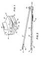
- Figure 3is a perspective view of a partially assembled insertion instrument of the present invention.
- Figure 4is a perspective view of a fork distractor of the present invention.
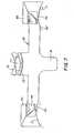
- Figure 5is a perspective view of the lower arms engaging the lower part of an intervertebral disc implant.
- Figure 6is a perspective view of the upper arm engaging the upper part of the intervertebral disc implant.
- Figure 7is an enlarged front view of the body of the fork distractor of the present invention.
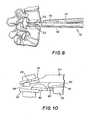
- Figure 8is a side elevational view of an insertion instrument of the present invention engaged with the upper and lower parts of an intervertebral disc implant after insertion of the implant into an intervertebral space.
- Figure 9is a front, top and side perspective view of an insertion instrument of the present invention creating an introduction space for the pivot element of an intervertebral disc implant.
- Figure 10is a side elevational view of the introduction space created by the insertion instrument.
- Figure 11a bottom view of the upper part and associated fork arms in the position depicted in Figure 10 .
- Figure 12is a side elevational view of a fork distractor of the present invention supporting the upper part of an intervertebral disc implant as the pivot element is being inserted into the space between the upper and lower parts.
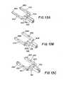
- Figures 13A , 12B, and 12Care perspective views of the forked arms of three variations of distractors in accordance with the present invention.
- Figure 14is a side elevational view of an alternative fork distractor of the present invention from that of Figure 13 where the fork arms are supporting both the upper part and lower part as the pivot element is being inserted therebetween.
- embodiments of the present inventionare directed to instruments and methods for inserting artificial intervertebral disc implants 21 or the like.
- the intervertebral spacePrior to inserting of an intervertebral disc implant 21, the intervertebral space must be cleaned out with instruments such as elevators and/or chisels.
- the next stepis to determine the precise size of an inlay protrusion 44 of a pivot element 42 (which is located between an upper part 22 and a lower part 32 of implant 21) which provides a correct overall height for disc implant 21 for that particular (height) intervertebral space. This determination is accomplished by providing a set of trial implants of different sizes. The operator thus selects by experience the trial implant that the operator believes would be the most appropriate for that particular intervertebral space and disc implant 21 selected.
- the next stepis to form the cutouts in the adjacent vertebrae using the trial implant.
- These cutoutsare designed to receive raised keels of the upper and lower plates.
- a chiselis used to form the require cutouts in the opposed vertebrae.
- an insertion instrument 50 disclosed hereafteris then used to insert intervertebral implant 21 into the intervertebral space defined by the two vertebrae as explained in detail below.
- intervertebral disc implants 21used in connection with the present invention will include those similar to disc implant 21 depicted in detail in Figures 1-2.
- Figures 1-2show disc implant 21 having upper part 22 with a raised keel 23 protruding therefrom, and lower part 32 with a raised keel 33 protruding therefrom.
- upper insertion apertures 24 and one of two lower apertures 34are shown in place between upper part 22 and lower part 32 in Figures 1 and 2 , and in a position to be inserted into the holding space of the lower part 32 in Figure 2 .
- Upper part 22(as shown in Figures 10 and 11 ) has a domed-shaped concave bearing face 26 which receives a mating convex inlay protrusion 44 of pivot element 42.
- Pivot element 42shown best in Figure 2 , will typically have a substantially rectangular base 43 which is to be captured in a recess 35 of lower part 32 and protrusion 44 which is to be received in concave domed-shaped bearing face 26 of upper part 22.
- Lower part 32shown best in Figure 2 , comprises a recess 35 to snugly receive rectangular base 43 of pivot element 42.
- Pivot element 42can be inserted into recess 35 from the open side as shown in Figure 2 , allowing opposite edges 45 of base 43 to engage lateral grooves 37 in lower part 32 so that pivot element 42 can be inserted and then moved forwardly along grooves 37 into a fully inserted/captured position in recess 35.
- Other details of implant 21are disclosed in WO 01/01893 as noted above and thus need not be discussed here further.
- inlay protrusion 44engages concave bearing face 26 of upper part 22, so that upper part 22 and lower part 32 are braced on one another via pivot element 42 and have a pivotal relationship one to the other.
- Both upper part 22 and lower part 32 on a front or anterior face thereofhave insertion apertures 24, 34 which are designed to receive mounting pins 51 of the insertion instrument of the present invention as described below.
- Figure 1clearly shows upper part 22 and lower part 32 with pivot element 42 positioned therebetween so that relative pivoting of upper part 22 and lower part 32 is permitted.
- insertion instrument 50 of the present inventionhas an elongated upper arm 57 and substantially parallel elongated lower arms 52, 53.
- Upper arm 57 and lower arms 52, 53engage a mounting structure 54, which holds the adjacent ends of arms 52, 53 and 57 as noted below.
- the second or free ends of lower arms 52, 53are each engageable in lower part 32 of disc implant 21 while the second or free end of upper arm 57 is engageable in upper part 22. Referring to Figure 3 , these engagements are accomplished by retaining pins 51 on the associated ends of each arm 52, 53, 57.
- a holder 56is used to attach pins 51 to upper arm 57 as broadly described in WO 01/19295 , by which upper part 22 is engaged with upper arm 57 at a predetermined slight angle to vertical as shown.
- Mounting structure 54includes an opening 54A with a spring-loaded ball catch (not shown) therein which receives mounting portion 66A of a part of the casing 66 (see Figure 4 ) to secure the distractor, as discussed in detail below.
- lower arms 52, 53are rotatable about their central, longitudinal axes in order to lock lower arms 52, 53 to lower part 32 as shown and described in WO 01/19295 and as described below with respect to Figure 5 .
- upper arm 57has pins 51 of holder 56 slidably received in apertures 24 of upper part 22 as shown in Figure 6 .
- holder 56is rigid with upper arm 57 and hence does not pivot relative to upper arm 57 as does the holder disclosed in WO 01/19295 .
- mounting structure 54holds arms 52, 53, 57 in pivotable relationship with one another, with lower arms 52, 53 parallel to one another and with upper arm 57 at a small angle to the plane of lower arms 52, 53.
- mounting structure 54is spaced apart from the plane defined by the two lower arms 52 and 53.
- Upper arm 57is vertically disposed approximately midway between the two lower arms 52 and 53, so that the free or forward end of upper arm 57 can, in its lowered position, enter the space between the two parallel lower arms 52 and 53.
- upper arm 57is circular in cross section and on its free end carries U-shaped holder 56 which receives the free end of upper arm 57. Holder 56 and upper arm 57 are immovably joined together as noted above..
- Instrument 50 of the present inventionfurther comprises a distractor 60, as shown best in Figure 4 , which comprises an elongated arm 61 with a body 62 securely attached thereto. At a forward end of body 62 there are a pair of fork-shaped arms 63 that extend forward beyond body 62 substantially parallel to the longitudinal axis of arm 61. As shown in Figures 4 and 7 , body 62 has a solid wedge portion 70 which matingly seats with and engages upper arm 57 as wedge portion 70 approaches the free end of upper arm 57. In addition, as best shown in Figure 7 , fork arms 63 also have rounded lower seats 71 which similarly engage the adjacent portions of lower arms 52 and 53. It will be appreciated that distractor 60 is usable with instruments 50 having differently spaced lower arms 53.
- seats 71are designed to mate against lower arms 53 (only one of which is partially shown in phantom) where instrument 50 has widely spaced lower arms 53 (for larger sized implants 21); while the inside portion of seats 71 are similarly designed to mate against lower arms 53' (only one of which is partially shown in phantom) where instrument 50 has more closely spaced lower arms 53' (for smaller sized implants 21). If only one spacing of lower arms 50 is usable, then seats 71 can be designed to mate over the entire surface thereof with the associated lower arm 53.
- wedge portion 70forces upper arm 57 slowly away from lower arms 52, 53, creating a small starting space between upper part 22 and lower part 32.
- body 62includes a protrusion 74 which also serves a function similar to protrusion 44 disclosed in WO 01/19295 .
- protrusion 74is used to initially push rectangular base 43 of pivot element 42 - whose edges 45 engage longitudinal grooves 55 provided along opposing (facing) inner sides of lower arms 52, 53 - forward to a position immediately adjacent implant 21 and then partially into recess 35. The final forward movement of pivot element 42 is then accomplished using a pushing element 80 (see Figure 10 ) similar to that described in WO 01/19295 , which also engages rectangular base 43 so that no potentially damaging contact is made with inlay protrusion 44.
- distractor 60 of the present inventionmay further include a leaf spring 73 provided behind wedge portion 70 which resiliently mounts a seat 72.
- a leaf spring 73provided behind wedge portion 70 which resiliently mounts a seat 72.
- seat 72This movement of seat 72 is made against the mild force of leaf spring 73, so that only a minor reactive force is exerted on arms 52, 53 and 57 which is insufficient to force upper part 22 and lower part 32 of disc implant 21 apart (so that no significant separating forces are conveyed to upper part 22 and lower part 32). It will be appreciated that seat 72 does not actually contact arm 61 during this movement, since wedge portion 70 is slightly higher than the thickness of seat 72 so that wedge portion 70 takes over the holding function of seat 72 when fork arms 63 approach implant 21 - and turns this holding function additionally to a separating function as noted below.
- Distractor 60engages upper arm 57 and lower arms 52, 53 in such a way that as distractor 60 slides forward along between lower arms 52, 53 it rides along the top of lower arms 52, 53 and first seat 72 of leaf spring 73 engages upper arm 57 and then wedge portion 70 engages upper arm 57.
- Figure 8shows the position of the upper and lower parts 22, 32 nested together (as described in WO 01/19295 ) in their closed or initial position before wedge portion 70 (not shown in this Figure) engages upper arm 57 and lower arms 52, 53.
- distractor 60With the parts in this position, distractor 60, as it moves further forward along upper arm 57 and lower arms 52, 53 towards disc implant 21, will slightly separate upper and lower parts 22, 32 from each other (and hence slightly enlarge the intervertebral space), as wedge portion 70 of distractor 60 urges upper arm 57 upwardly slightly, creating a starting space.
- This starting spaceis relatively easy to create, as the intervertebral forces holding upper part 22 and lower part 32 adjacent one another are initially small.
- pivot element 42has caused pivot element 42 to be located immediately adjacent recess 35 and thus ready to be pushed forward into recess 35 as fork arms 63 move forward between upper part 22 and lower part 32 and wedge portion 70 and/or fork arms 63 open a space sufficient for receiving pivot element 42 to pass into (as discussed below).
- wedge portion 70may be sufficient by itself to perform all or most of the needed distracting movement.
- heads 64 of fork arms 63may provide no or only a minor effective distracting force. It will be appreciated that where fork arms 63 provide essentially no distracting force, heads 64 of fork arms 63 nonetheless will engage along upper part 22 and provide a holding or supporting force along upper part 22 to maintain upper part 22 in the proper orientation with lower part 32 (and hence to prevent falling or pivoting of upper part 32).
- heads 64 of fork arms 63provide only a minor distracting force (which distracting force also serves to support or hold), this distracting force of heads 64 of fork arms 63 will primarily be exerted as heads 64 of fork arms 63 engage along upper part 22 as wedge portion 70 does not provide the complete distracting force necessary.
- heads 64 of fork arms 63only begin to contact upper part 22 after passing some of the anterior portion thereof; but this supporting/holding/forcing could occur starting at the anterior portion, but more likely will occur starting near the posterior portion of upper part 22 at the end of the forward movement of distractor 60.
- heads 64 of fork arms 63can begin providing only a supporting/holding force and then provide some distracting force, or vice versa or alternately, as forward movement of distractor 60 occurs.
- heads 64 of fork arms 63may perform all or most of the distracting movement after the initial starting space at the anterior end of upper part 22 is created by wedge portion 70.
- wedge portion 70may provide no or only a minor additional effective distracting force. It will. be appreciated that where wedge portion 70 provides essentially no additional distracting force, wedge portion 70 may or will nonetheless provide a holding or supporting force at the anterior part of upper part 22 to help maintain upper part 22 in the proper orientation with lower part 32 (and hence to prevent falling or pivoting of upper part 22).
- wedge portion 70provides only a minor additional distracting force (which distracting force also serves to support or hold), this distracting force of wedge portion 70 will primarily be exerted at the anterior portion of upper part 22 to which upper arm 57 is directly attached.
- wedge portion 70only effects a supporting/holding and/or distracting force on the anterior part of upper part 22 as heads 64 of fork arms 63 travel further along the posterior half thereof; but this supporting/holding/forcing could occur starting at the beginning of the forward engaging movement of heads 64, but more likely will occur starting near the end of the forward movement of heads 64 (the end of the forward movement of distractor 60).
- wedge portion 70can begin providing only a supporting/holding force and then provide some distracting force, or vice versa or alternately, as the forward movement of distractor 60 occurs.
- wedge portion 70 and heads 64will be designed so that in many or even most situations it will be some, possibly changing, combination of the distracting forces of both heads 64 of fork arms 63 and wedge portion 70 which will effect the distracting movement of upper part 22 away from lower part 32.
- wedge portion 70will do more of the separating while heads 64 act more as a support; while where the separation space is less easily produced (a larger separating force is needed), heads 64 will do more of the separating (and supporting) while wedge portion 70 does less.
- heads 64 of fork arms 63acts between lower arms 52, 53 on which body 62 rests and the engaging portions of heads 64 of fork arms 63 on the lower/inner surface of upper part 22 as shown in Figures 10-12 .
- the reactive force of heads 64 of the fork arms 63is on the surface of upper part 22, this force acts directly to hold/force upper part 22 away from lower part 32.
- the reactive force of heads 64 of fork arms 63does begin at the anterior end of the facing/inner surface of upper part 22, this force moves forward along this surface with only a small distracting force until heads 64 are moved substantially inward (forward) to the posterior portion as shown in Figures 10 and 12 .
- the distracting force of heads 64begin at about the midway point between the anterior and posterior ends of the surfaces. In this way, there is a more forceful pivoting torque exerted by heads 64 of fork arms 63 on the surface of upper part 22 as fork arms 63 advance further (as the moment arm length increases, as the moment arm length is measured from the forward end of U-shaped holder 56). This is advantageous since generally it is desired to have more separating torque or force at the posterior end of upper part 22 where a greater resistance to separation is expected.
- arm 61 of distractor 60has a stop pin 75 ( Figure 4 ) which engages a casing 66 to signify when distractor 61 is fully inserted.
- pin 75is thus specifically positioned on arm 61 to engage casing 66 at the point where heads 64 of fork arms 63 have advanced fully or forwards sufficiently into the space between upper part 22 and lower part 32 to provide the needed spacing for the completion of the insertion of pivot element 42 (and clearance for inlay protrusion 44) by the action of pushing element 80 ( Figure 10 ).
- heads 64 of fork arms 63are at a maximum distance from the anterior end of upper part 22 so that a maximum pivoting torque can be exerted by heads 64 (as noted above, where the moment arm is greatest) in case the forces resisting distraction are at their highest (at the maximum displacement of upper part 22 and lower part 32, which is the maximum vertebral spacing).
- Figure 11clearly shows the relationship between distractor 60 and, as shown in the drawing, the lower/inner surface of upper part 22, wherein fork arms 63 flank domed-shaped bearing face 26.
- This positioningallows pivot element 42 (not shown in Figure 11 ) to be pushed partially into position in recess 35 as heads 64 of fork arms 63 are moved forward to support upper part 22 in the raised position (where pusher element 80, without interference with distractor 60, then completes pushing pivot element 42 into recess 35 as previously noted).
- Figures 13A, 13B, and 13Cshow different fork arms 63A, 63B and 63C that may be used in connection with distractor 60 of the present invention.
- the different vertical thicknesses or heights of heads 64A, 64B and 64C of respective fork arms 63A-Cprovide for the creation of different height insertion spaces between upper part 22 and lower part 32, which would correspond to the different available heights of protrusions 44 ( Figure 2 ) typically provided in a set of pivot elements 42.
- wedge portions 70A-Care respectively vertically thicker or higher in correspondence with the increased thickness of heads 64A-C of fork arms 63A-C.
- This corresponding thicknessis needed to maintain the proper orientation of upper part 22 to lower part 32 during use of distractor 60.
- the heights of heads 64A-Ccould be lowered or raised to effect lesser or greater holding/distracting forces by heads 64A-C relative to wedge portions 70A-C; and similarly but probably less preferably, the heights of wedge portions 70A-C could be lowered or raised to effect lesser or greater holding/distracting forces by wedge portions 70A-C relative to heads 64A-C.
- distractor 60further comprises a hex end 67 which extends rotatably through casing 66 and beyond mounting portion 66A and which is designed to be engaged by a suitable wrench having a mating hex socket or the like (not shown) if desired.
- a suitable wrenchhaving a mating hex socket or the like (not shown) if desired.
- the opposite end from hex end 67is provided with a square end or the like (not shown) to which is securely mounted a thumbscrew 69.
- thumbscrew 69 or hex end 67results in the turning of a gear wheel (not shown, but inside casing 66) which engages a tooth rack 65 on elongated arm 61.
- This systemmay be used to carefully and precisely advance distractor 60 longitudinally forward towards the second ends of arms 52, 53 and 57 as noted above and in much the same manner as the distractor is advanced in WO 01/19295 ⁇ except that a more positive and forceful insertion force can be exerted on tooth rack 65 by the use of the wrench if such insertion force is needed.
- the insertion instrument described hereincomprises a biocompatible metal, such as titanium or a titanium alloy or a stainless steel composite; and may be the same or different material as the upper and lower parts.
- Pivot element 42is also made from a biocompatible material, and is preferably a biocompatible plastic material such as polyethylene.
- distractor 60may comprise a biocompatible coating that assists sliding relative to the arms, or distractor 60 may comprise a plastic material for the same reason.
- upper part 22 and lower part 32are engaged with upper arm 57 and lower arms 52, 53 as shown in Figures 5 and 6 .
- Lower part 32is locked to lower arms 52, 53 by rotation thereof , which causes locking bar protrusions 58 to engage recesses 36 of lower part 32.
- Upper and lower parts 22, 32are then brought to their closest proximity, preferably nested together (as no pivot element is yet present), and inserted into the intervertebral space as shown in Figure 8 .
- pivot element 42After insertion of upper and lower parts 22, 32 forwardly into the intervertebral space, pivot element 42 is inserted between lower arms 52 adjacent the rear thereof. After mounting of distractor 60, pivot element 42 is then moved forward towards the intervertebral space by distractor 60 with edges 45 thereof engaging grooves 55 formed in lower arms 52, 53 as described in WO 01/19295 . As shown in Figures 9 , 10 and 12 , once the starting space is created, further forward advancement of wedge portion 70 causes heads 64 of fork arms 63 to engage the bottom/inner surface of upper part 22 as noted in detail above, pushing and/or holding upper part 22 away from lower part 32 which is held in place by lower arms 52, 53.
- heads 64 of fork arms 63have been described above as only engaging the lower/inner surface of upper part 22 as fork arms 63 advance into the intervertebral space provided between upper part 22 and lower part 32, it will be appreciated that engagement of the upper surface of lower part 32 would be possible as shown in Figure 14 .
- a more positive separation of upper part 22 from lower part 32 using heads 64would be achieved as the separating force would be directly exerted between the facing surfaces of lower part 32 and upper part 22 by heads 64 of fork arms 63 once heads 64 of fork arms 63 completely entered the space provided between upper part 22 and lower part 32.
- the holding forces of arms 52, 53 and 57 on upper part 22 and lower part 32 in this embodimentwould thus not need to be as secure.
Landscapes
- Health & Medical Sciences (AREA)
- Orthopedic Medicine & Surgery (AREA)
- Life Sciences & Earth Sciences (AREA)
- Engineering & Computer Science (AREA)
- Biomedical Technology (AREA)
- Animal Behavior & Ethology (AREA)
- Surgery (AREA)
- Veterinary Medicine (AREA)
- Public Health (AREA)
- General Health & Medical Sciences (AREA)
- Heart & Thoracic Surgery (AREA)
- Transplantation (AREA)
- Vascular Medicine (AREA)
- Oral & Maxillofacial Surgery (AREA)
- Cardiology (AREA)
- Nuclear Medicine, Radiotherapy & Molecular Imaging (AREA)
- Neurology (AREA)
- Medical Informatics (AREA)
- Molecular Biology (AREA)
- Physical Education & Sports Medicine (AREA)
- Prostheses (AREA)
Abstract
Description
- This invention relates to instruments for inserting intervertebral implants, and more specifically to new and improved instruments and methods for inserting an artificial intervertebral disc implant into an intervertebral space.
- Currently, when it is necessary to completely remove a disc from between adjacent vertebrae, the conventional procedure is to fuse the adjacent vertebrae together. This "spinal fusion" procedure is a widely accepted surgical treatment for symptomatic lumbar degenerative disc disease. However, reported clinical results vary considerably, and complication rates are considered by some to be unacceptably high.
- More recently, there have been important developments in the field of disc replacement, namely disc arthoplasty, which involves the insertion of an artificial intervertebral disc implant into the intervertebral space between adjacent vertebrae, and which allows limited universal movement of the adjacent vertebrae with respect to each other.
- The aim of total disc replacement is to remove pain generation (disc), restore anatomy (disc height), and maintain mobility in the functional spinal unit so that the spine remains in an adapted sagittal balance. Sagittal balance is be defined as the equilibrium of the trunk with the legs and pelvis to maintain harmonious sagittal curves. In contrast with fusion techniques, total disc replacement preserves mobility in the motion segment and mimics physiologic conditions.
- One such intervertebral implant includes an upper part, or upper plate, that can communicate with a vertebrae, a lower part, or lower plate that can communicate with the adjacent vertebrae, and a pivot element inserted between these two parts. An example of an instrument for this type of implant is disclosed in
U.S. Patent No. 5,314,477 . More specifically, tongs are disclosed that can be used, after the insertion of the pivot element between the upper and lower parts of the implant, to move the two vertebrae apart to a distance sufficient for introducing the assembled implant into that space. Additionally, instruments exist for inserting intervertebral implants that move the implant along a longitudinal guide as far as the implant point, and then feed the implant out of the guide and into the intervertebral space. SeeU.S. Patent No. 5,571,109 . However, both of these instruments are suitable only for inserting complete implants. - An improved instrument is shown in Published Application No.
WO 01/01893, published January 11, 2001 WO 01/19295, published March 22, 2001 - In particular, the instrument shown in Published Application No.
WO 01/19295 - While these and other known instruments and methods represent improvements in the art of artificial intervertebral implant insertion, there exists a continuing need in the art for improvements in the field of instruments and methods for inserting intervertebral implants.
- A purpose of the present invention is to provide a new and improved instrument and method for inserting an intervertebral disc implant.
- The instruments and methods of the present invention are used to insert various sized artificial intervertebral disc implants at any location along the spine, including especially the lumbar and cervical spine.
- An intervertebral implant is normally inserted anteriorly, i.e., from the patient's anterior moving towards the patient's posterior. However, it is to be understood that the implant, the instruments and a method can also be designed and arranged to insert the implant laterally, i.e., from the side or obliquely, from the side-front. To avoid confusion with respect to the patient's anatomy, the invention will be described herein with respect to more simple terminology which relates to instruments and methods themselves. For example, in describing the invention, the terms "front" or "forward" mean the part of the instrument which faces toward the vertebrae or is moving in the direction of movement toward the vertebrae, and the words "back", "rear", or "rearward" refer to the end of the instrument furthest from the vertebrae or moving away from the vertebrae. Also, in this application, the words "upper", "lower", "uppermost" or "lowermost" or any other words describing orientation of the intervertebral implant or the instruments or methods associated therewith are used only for convenience and are not intended to convey any limitation. More specifically, the parts of the implant, the instrument and/or the methods described in this application with reference to the upper part or plate can in fact be positioned as the superior or inferior part within the patient's vertebrae, with the other of the two parts being the opposite part.
- The instrument and the method of the present invention are particularly adapted for use with an artificial intervertebral disc implant having upper and lower parts which undergo limited universal movement with respect to each other, with the upper and lower surfaces of the upper and lower parts engaging the adjacent vertebral surfaces.
- For example, the instrument and method of the present invention are used in connection with implant devices that have an upper part or plate and a lower part or plate, and a pivot element therebetween.
- In the prior arrangement of
WO 01/19295 - The present invention improves upon the previous instrument by providing a new and improved distractor element which is constructed and arranged such that as it is moving the upper and lower parts apart, and hence the adjacent vertebrae, apart. This distractor has a new forward end which engages and at least supports the upper part along at least the posterior portion thereof, by extending into the space between the upper and lower parts and engaging the interior lower surface of the upper part.
- In a preferred arrangement, this forward end of the distractor comprises a pair of fork arms which extend along the bottom of the upper part, offset to one side or the other so as not to interfere with a central portion of the upper part which forms a surface for receiving the pivot element. It will be appreciated that the upper part is always finally engaged at least at the posterior portion thereof by a respective head of each fork arm.
- Thus, it is an object of the present invention to provide a new and improved instrument for distracting upper and lower parts of an intervertebral disc implant.
- It is another object of the present invention to provide a new and improved method for separating the upper and lower parts of an intervertebral disc implant.
- These and other objects of the present invention will become apparent from the detailed description to follow, together with the accompanying drawings.
- Embodiments of the present invention will now be discussed by way of example with reference to the drawings. It is emphasized that these drawings are exemplary in nature and are not to be construed as limiting the present invention.
Figure 1 is a perspective view of one prior art type of intervertebral implant for use with the instruments and method of the present invention.Figure 2 is an exploded perspective view of an upper plate, a pivot element and-a lower plate of the intervertebral implant depicted inFigure 1 .Figure 3 is a perspective view of a partially assembled insertion instrument of the present invention.Figure 4 is a perspective view of a fork distractor of the present invention.Figure 5 is a perspective view of the lower arms engaging the lower part of an intervertebral disc implant.Figure 6 is a perspective view of the upper arm engaging the upper part of the intervertebral disc implant.Figure 7 is an enlarged front view of the body of the fork distractor of the present invention.Figure 8 is a side elevational view of an insertion instrument of the present invention engaged with the upper and lower parts of an intervertebral disc implant after insertion of the implant into an intervertebral space.Figure 9 is a front, top and side perspective view of an insertion instrument of the present invention creating an introduction space for the pivot element of an intervertebral disc implant.Figure 10 is a side elevational view of the introduction space created by the insertion instrument.Figure 11 a bottom view of the upper part and associated fork arms in the position depicted inFigure 10 .Figure 12 is a side elevational view of a fork distractor of the present invention supporting the upper part of an intervertebral disc implant as the pivot element is being inserted into the space between the upper and lower parts.Figures 13A , 12B, and 12C are perspective views of the forked arms of three variations of distractors in accordance with the present invention.Figure 14 is a side elevational view of an alternative fork distractor of the present invention from that ofFigure 13 where the fork arms are supporting both the upper part and lower part as the pivot element is being inserted therebetween.- Referring now to the drawings, like elements are represented by like numerals throughout the several views. As stated above, embodiments of the present invention are directed to instruments and methods for inserting artificial
intervertebral disc implants 21 or the like. As known in the art, prior to inserting of anintervertebral disc implant 21, the intervertebral space must be cleaned out with instruments such as elevators and/or chisels. After the intervertebral space has been cleaned out in preparation for receivingintervertebral disc implant 21, the next step is to determine the precise size of aninlay protrusion 44 of a pivot element 42 (which is located between anupper part 22 and alower part 32 of implant 21) which provides a correct overall height fordisc implant 21 for that particular (height) intervertebral space. This determination is accomplished by providing a set of trial implants of different sizes. The operator thus selects by experience the trial implant that the operator believes would be the most appropriate for that particular intervertebral space anddisc implant 21 selected. - Once the correct trial implant has been selected, the next step is to form the cutouts in the adjacent vertebrae using the trial implant. These cutouts are designed to receive raised keels of the upper and lower plates. Typically, a chisel is used to form the require cutouts in the opposed vertebrae. In accordance with the present invention, an
insertion instrument 50 disclosed hereafter is then used to insertintervertebral implant 21 into the intervertebral space defined by the two vertebrae as explained in detail below. - Typically, examples of
intervertebral disc implants 21 used in connection with the present invention will include those similar todisc implant 21 depicted in detail inFigures 1-2. Figures 1-2 show disc implant 21 havingupper part 22 with a raisedkeel 23 protruding therefrom, andlower part 32 with a raisedkeel 33 protruding therefrom. Also shown areupper insertion apertures 24 and one of twolower apertures 34.Pivot element 42 is shown in place betweenupper part 22 andlower part 32 inFigures 1 and2 , and in a position to be inserted into the holding space of thelower part 32 inFigure 2 . Upper part 22 (as shown inFigures 10 and11 ) has a domed-shaped concave bearing face 26 which receives a matingconvex inlay protrusion 44 ofpivot element 42. Pivot element 42, shown best inFigure 2 , will typically have a substantiallyrectangular base 43 which is to be captured in arecess 35 oflower part 32 andprotrusion 44 which is to be received in concave domed-shaped bearing face 26 ofupper part 22.Lower part 32, shown best inFigure 2 , comprises arecess 35 to snugly receiverectangular base 43 ofpivot element 42.Pivot element 42 can be inserted intorecess 35 from the open side as shown inFigure 2 , allowing oppositeedges 45 ofbase 43 to engagelateral grooves 37 inlower part 32 so thatpivot element 42 can be inserted and then moved forwardly alonggrooves 37 into a fully inserted/captured position inrecess 35. Other details ofimplant 21 are disclosed inWO 01/01893 - When implanted, as also fully disclosed in
WO 01/01893 inlay protrusion 44 engages concave bearing face 26 ofupper part 22, so thatupper part 22 andlower part 32 are braced on one another viapivot element 42 and have a pivotal relationship one to the other. Bothupper part 22 andlower part 32 on a front or anterior face thereof haveinsertion apertures pins 51 of the insertion instrument of the present invention as described below.Figure 1 clearly showsupper part 22 andlower part 32 withpivot element 42 positioned therebetween so that relative pivoting ofupper part 22 andlower part 32 is permitted. - As shown in
Figure 3 and similar to the instrument disclosed inWO 01/01893 insertion instrument 50 of the present invention has an elongatedupper arm 57 and substantially parallel elongatedlower arms Upper arm 57 andlower arms structure 54, which holds the adjacent ends ofarms lower arms lower part 32 ofdisc implant 21 while the second or free end ofupper arm 57 is engageable inupper part 22. Referring toFigure 3 , these engagements are accomplished by retainingpins 51 on the associated ends of eacharm holder 56 is used to attachpins 51 toupper arm 57 as broadly described inWO 01/19295 upper part 22 is engaged withupper arm 57 at a predetermined slight angle to vertical as shown. Mountingstructure 54 includes an opening 54A with a spring-loaded ball catch (not shown) therein which receives mountingportion 66A of a part of the casing 66 (seeFigure 4 ) to secure the distractor, as discussed in detail below. - In the embodiments of the present invention,
lower arms lower arms lower part 32 as shown and described inWO 01/19295 Figure 5 . As also described inWO 01/19295 upper arm 57 haspins 51 ofholder 56 slidably received inapertures 24 ofupper part 22 as shown inFigure 6 . However, in this embodiment it will be appreciated thatholder 56 is rigid withupper arm 57 and hence does not pivot relative toupper arm 57 as does the holder disclosed inWO 01/19295 - As stated above, mounting
structure 54 holdsarms lower arms upper arm 57 at a small angle to the plane oflower arms structure 54 is spaced apart from the plane defined by the twolower arms Upper arm 57 is vertically disposed approximately midway between the twolower arms upper arm 57 can, in its lowered position, enter the space between the two parallellower arms - As shown in
Figure 6 ,upper arm 57 is circular in cross section and on its free end carriesU-shaped holder 56 which receives the free end ofupper arm 57.Holder 56 andupper arm 57 are immovably joined together as noted above.. Instrument 50 of the present invention further comprises adistractor 60, as shown best inFigure 4 , which comprises anelongated arm 61 with abody 62 securely attached thereto. At a forward end ofbody 62 there are a pair of fork-shapedarms 63 that extend forward beyondbody 62 substantially parallel to the longitudinal axis ofarm 61. As shown inFigures 4 and7 ,body 62 has asolid wedge portion 70 which matingly seats with and engagesupper arm 57 aswedge portion 70 approaches the free end ofupper arm 57. In addition, as best shown inFigure 7 , forkarms 63 also have roundedlower seats 71 which similarly engage the adjacent portions oflower arms distractor 60 is usable withinstruments 50 having differently spacedlower arms 53. Thus, as shown inFigure 7 , the outside portion ofseats 71 are designed to mate against lower arms 53 (only one of which is partially shown in phantom) whereinstrument 50 has widely spaced lower arms 53 (for larger sized implants 21); while the inside portion ofseats 71 are similarly designed to mate against lower arms 53' (only one of which is partially shown in phantom) whereinstrument 50 has more closely spaced lower arms 53' (for smaller sized implants 21). If only one spacing oflower arms 50 is usable, then seats 71 can be designed to mate over the entire surface thereof with the associatedlower arm 53.- As
wedge portion 70 moves forward alongarms disc implant 21,wedge portion 70 forcesupper arm 57 slowly away fromlower arms upper part 22 andlower part 32. It will thus be appreciated thatwedge portion 70 serves a function similar to the spreader element (43) disclosed inWO 01/19295 body 62 includes aprotrusion 74 which also serves a function similar toprotrusion 44 disclosed inWO 01/19295 protrusion 74 is used to initially pushrectangular base 43 of pivot element 42 - whoseedges 45 engagelongitudinal grooves 55 provided along opposing (facing) inner sides oflower arms 52, 53 - forward to a position immediatelyadjacent implant 21 and then partially intorecess 35. The final forward movement ofpivot element 42 is then accomplished using a pushing element 80 (seeFigure 10 ) similar to that described inWO 01/19295 rectangular base 43 so that no potentially damaging contact is made withinlay protrusion 44. - It will also be appreciated that
distractor 60 of the present invention may further include aleaf spring 73 provided behindwedge portion 70 which resiliently mounts aseat 72. Whendistractor 60 is first located betweenarms body 62 is rearward or near mountingstructure 54,seats 71 rest loosely onarms wedge portion 70 is too far away fromupper arm 57 to have contact therewith (due to the angle ofarm 57 to the plane oflower arms 52, 53). Thus, at this position it isseat 72 that resiliently engagesarm 57 to gently holdbody 62 in position betweenarms structure 54 as explained below) to assure thatprotrusion 74 is in position to engage and hence movepivot element 42 forward alonglower arms body 62 is moved towardimplant 21. Then, asdistractor 60 moves alongupper arm 57 andlower arms adjacent mounting structure 54 towarddisc implant 21 at the forward end ofarms upper arm 57 relative to lowerarms seat 72 down towardarm 61. This movement ofseat 72 is made against the mild force ofleaf spring 73, so that only a minor reactive force is exerted onarms upper part 22 andlower part 32 ofdisc implant 21 apart (so that no significant separating forces are conveyed toupper part 22 and lower part 32). It will be appreciated thatseat 72 does not actually contactarm 61 during this movement, sincewedge portion 70 is slightly higher than the thickness ofseat 72 so thatwedge portion 70 takes over the holding function ofseat 72 whenfork arms 63 approach implant 21 - and turns this holding function additionally to a separating function as noted below. Distractor 60 engagesupper arm 57 andlower arms distractor 60 slides forward along betweenlower arms lower arms first seat 72 ofleaf spring 73 engagesupper arm 57 and then wedgeportion 70 engagesupper arm 57.Figure 8 shows the position of the upper andlower parts WO 01/19295 upper arm 57 andlower arms distractor 60, as it moves further forward alongupper arm 57 andlower arms disc implant 21, will slightly separate upper andlower parts wedge portion 70 ofdistractor 60 urgesupper arm 57 upwardly slightly, creating a starting space. This starting space is relatively easy to create, as the intervertebral forces holdingupper part 22 andlower part 32 adjacent one another are initially small. When this starting space is created, it will be appreciated thatprotrusion 74 has causedpivot element 42 to be located immediatelyadjacent recess 35 and thus ready to be pushed forward intorecess 35 asfork arms 63 move forward betweenupper part 22 andlower part 32 andwedge portion 70 and/or forkarms 63 open a space sufficient for receivingpivot element 42 to pass into (as discussed below).- In the prior art
WO 01/19295 pivot element 42 could be easily inserted partially ontolower part 32 using the protrusion without interference fromupper part 22. However, as the force required to separate theupper part 22 from the lower part increased with the increased separation distance (the resistance of the forces trying to close the intervertebral space increased), it would not always be easy to achieve the required spacing and/or the desired orientation ofupper part 22 relative tolower part 32 was not easily maintained. - In order to make this separation easier, in accordance with the present invention, after the starting space is provided by
wedge portion 70, further advancement ofdistractor 60 causes forkarms 63 to enter the already created starting space. Entry ofheads 64 offork arms 63 into the staring space is facilitated by the tapered front end of eachhead 64. As theheads 64 offork arms 63 enter the starting space betweenupper part 22 andlower part 32 and further forward movement ofdistractor 60 occurs, one or both of two reactive forces are exerted to positively forceupper part 22 further away fromlower part 32 in order to provide the needed spacing therebetween. The first force is that ofwedge portion 70 acting onupper part 22, while the second force is that ofheads 64 offork arms 63. These forces act in concert in the following manners, which obviously depend on the relative sizes ofwedge portion 70 and heads 64 of fork arms 63 (as discussed below with respect tofigures 13A-C ) as well as the amount of pivoting into the separation space which the posterior end ofupper part 22 experiences asdistractor 60 moves forward. - Typically where there is only some resistance to the distracting movement of
upper part 22 away fromlower part 32, as where the intervertebralspace receiving implant 21 is large so not much widening is needed,wedge portion 70 may be sufficient by itself to perform all or most of the needed distracting movement. In this case, heads 64 offork arms 63 may provide no or only a minor effective distracting force. It will be appreciated that where forkarms 63 provide essentially no distracting force, heads 64 offork arms 63 nonetheless will engage alongupper part 22 and provide a holding or supporting force alongupper part 22 to maintainupper part 22 in the proper orientation with lower part 32 (and hence to prevent falling or pivoting of upper part 32). Similarly, where heads 64 offork arms 63 provide only a minor distracting force (which distracting force also serves to support or hold), this distracting force ofheads 64 offork arms 63 will primarily be exerted asheads 64 offork arms 63 engage alongupper part 22 aswedge portion 70 does not provide the complete distracting force necessary. Typically when either no distractor force (with supporting/holding occurring) or some distracting force is exerted byheads 64 offork arms 63, heads 64 offork arms 63 only begin to contactupper part 22 after passing some of the anterior portion thereof; but this supporting/holding/forcing could occur starting at the anterior portion, but more likely will occur starting near the posterior portion ofupper part 22 at the end of the forward movement ofdistractor 60. In addition, heads 64 offork arms 63 can begin providing only a supporting/holding force and then provide some distracting force, or vice versa or alternately, as forward movement ofdistractor 60 occurs. - Typically where there is significant resistance to the distracting movement of
upper part 22 away fromlower part 32, as where the intervertebralspace receiving implant 21 is small so a more forceful widening may be needed, heads 64 offork arms 63 may perform all or most of the distracting movement after the initial starting space at the anterior end ofupper part 22 is created bywedge portion 70. In this case,wedge portion 70 may provide no or only a minor additional effective distracting force. It will. be appreciated that wherewedge portion 70 provides essentially no additional distracting force,wedge portion 70 may or will nonetheless provide a holding or supporting force at the anterior part ofupper part 22 to help maintainupper part 22 in the proper orientation with lower part 32 (and hence to prevent falling or pivoting of upper part 22). Similarly, wherewedge portion 70 provides only a minor additional distracting force (which distracting force also serves to support or hold), this distracting force ofwedge portion 70 will primarily be exerted at the anterior portion ofupper part 22 to whichupper arm 57 is directly attached. Typically when either no distracting force (with supporting/holding occurring) or some additional distracting force is exerted bywedge portion 70,wedge portion 70 only effects a supporting/holding and/or distracting force on the anterior part ofupper part 22 asheads 64 offork arms 63 travel further along the posterior half thereof; but this supporting/holding/forcing could occur starting at the beginning of the forward engaging movement ofheads 64, but more likely will occur starting near the end of the forward movement of heads 64 (the end of the forward movement of distractor 60). In addition,wedge portion 70 can begin providing only a supporting/holding force and then provide some distracting force, or vice versa or alternately, as the forward movement ofdistractor 60 occurs. - While two relative extremes of the two distracting forces of
heads 64 offork arms 63 and ofwedge portion 70 have been described above, inpractice wedge portion 70 and heads 64 will be designed so that in many or even most situations it will be some, possibly changing, combination of the distracting forces of bothheads 64 offork arms 63 andwedge portion 70 which will effect the distracting movement ofupper part 22 away fromlower part 32. In general, however, as noted above, it is anticipated that where the separation space is more easily produced (a small separating force is needed),wedge portion 70 will do more of the separating whileheads 64 act more as a support; while where the separation space is less easily produced (a larger separating force is needed), heads 64 will do more of the separating (and supporting) whilewedge portion 70 does less. - It will be appreciated that the force of
heads 64 offork arms 63 acts betweenlower arms body 62 rests and the engaging portions ofheads 64 offork arms 63 on the lower/inner surface ofupper part 22 as shown inFigures 10-12 . As the attachment oflower part 32 tolower arms 52 is strong (relative to the attachment ofupper part 22 to upper arm 57), there is no problem withlower part 32 moving relative to lowerarms 52. And as the reactive force ofheads 64 of thefork arms 63 is on the surface ofupper part 22, this force acts directly to hold/forceupper part 22 away fromlower part 32. - Where the reactive force of
heads 64 offork arms 63 does begin at the anterior end of the facing/inner surface ofupper part 22, this force moves forward along this surface with only a small distracting force untilheads 64 are moved substantially inward (forward) to the posterior portion as shown inFigures 10 and12 . Preferably, the distracting force ofheads 64 begin at about the midway point between the anterior and posterior ends of the surfaces. In this way, there is a more forceful pivoting torque exerted byheads 64 offork arms 63 on the surface ofupper part 22 asfork arms 63 advance further (as the moment arm length increases, as the moment arm length is measured from the forward end of U-shaped holder 56). This is advantageous since generally it is desired to have more separating torque or force at the posterior end ofupper part 22 where a greater resistance to separation is expected. - In addition, it will be appreciated that
arm 61 ofdistractor 60 has a stop pin 75 (Figure 4 ) which engages acasing 66 to signify whendistractor 61 is fully inserted. In particular,pin 75 is thus specifically positioned onarm 61 to engagecasing 66 at the point where heads 64 offork arms 63 have advanced fully or forwards sufficiently into the space betweenupper part 22 andlower part 32 to provide the needed spacing for the completion of the insertion of pivot element 42 (and clearance for inlay protrusion 44) by the action of pushing element 80 (Figure 10 ). At this fully inserted position, heads 64 offork arms 63 are at a maximum distance from the anterior end ofupper part 22 so that a maximum pivoting torque can be exerted by heads 64 (as noted above, where the moment arm is greatest) in case the forces resisting distraction are at their highest (at the maximum displacement ofupper part 22 andlower part 32, which is the maximum vertebral spacing). Figure 11 clearly shows the relationship betweendistractor 60 and, as shown in the drawing, the lower/inner surface ofupper part 22, wherein forkarms 63 flank domed-shapedbearing face 26. This positioning allows pivot element 42 (not shown inFigure 11 ) to be pushed partially into position inrecess 35 asheads 64 offork arms 63 are moved forward to supportupper part 22 in the raised position (wherepusher element 80, without interference withdistractor 60, then completes pushingpivot element 42 intorecess 35 as previously noted).Figures 13A, 13B, and 13C showdifferent fork arms distractor 60 of the present invention. Obviously, the different vertical thicknesses or heights ofheads respective fork arms 63A-C provide for the creation of different height insertion spaces betweenupper part 22 andlower part 32, which would correspond to the different available heights of protrusions 44 (Figure 2 ) typically provided in a set ofpivot elements 42. In addition, it will be noted thatwedge portions 70A-C are respectively vertically thicker or higher in correspondence with the increased thickness ofheads 64A-C offork arms 63A-C. This corresponding thickness is needed to maintain the proper orientation ofupper part 22 tolower part 32 during use ofdistractor 60. However, if desired or needed, the heights ofheads 64A-C could be lowered or raised to effect lesser or greater holding/distracting forces byheads 64A-C relative to wedgeportions 70A-C; and similarly but probably less preferably, the heights ofwedge portions 70A-C could be lowered or raised to effect lesser or greater holding/distracting forces bywedge portions 70A-C relative toheads 64A-C.- As noted above,
portion 66A securesdistractor 60 to mountingstructure 54 via opening 54A and the ball catch therein in the much the same manner as the distractor is attached inWO 01/19295 Figure 4 ,distractor 60 further comprises ahex end 67 which extends rotatably throughcasing 66 and beyond mountingportion 66A and which is designed to be engaged by a suitable wrench having a mating hex socket or the like (not shown) if desired. However, in this preferred embodiment, the opposite end fromhex end 67 is provided with a square end or the like (not shown) to which is securely mounted athumbscrew 69. Turning of eitherthumbscrew 69 orhex end 67 results in the turning of a gear wheel (not shown, but inside casing 66) which engages atooth rack 65 onelongated arm 61. This system may be used to carefully and precisely advancedistractor 60 longitudinally forward towards the second ends ofarms WO 01/19295 tooth rack 65 by the use of the wrench if such insertion force is needed. - The insertion instrument described herein comprises a biocompatible metal, such as titanium or a titanium alloy or a stainless steel composite; and may be the same or different material as the upper and lower parts.
Pivot element 42 is also made from a biocompatible material, and is preferably a biocompatible plastic material such as polyethylene. Furthermore,distractor 60 may comprise a biocompatible coating that assists sliding relative to the arms, ordistractor 60 may comprise a plastic material for the same reason. - Thus, in operation and after suitable preparation as described above and as known in the art,
upper part 22 andlower part 32 are engaged withupper arm 57 andlower arms Figures 5 and 6 .Lower part 32 is locked to lowerarms bar protrusions 58 to engagerecesses 36 oflower part 32. Upper andlower parts Figure 8 . - After insertion of upper and
lower parts pivot element 42 is inserted betweenlower arms 52 adjacent the rear thereof. After mounting ofdistractor 60,pivot element 42 is then moved forward towards the intervertebral space bydistractor 60 withedges 45 thereof engaginggrooves 55 formed inlower arms WO 01/19295 Figures 9 ,10 and12 , once the starting space is created, further forward advancement ofwedge portion 70 causes heads 64 offork arms 63 to engage the bottom/inner surface ofupper part 22 as noted in detail above, pushing and/or holdingupper part 22 away fromlower part 32 which is held in place bylower arms arm 61, the space betweenupper part 22 andlower part 32 is made large enough to accommodate the similar advancement ofpivot element 42 intolower part 32. In the final step,pusher element 80 is used to complete the insertion ofpivot element 42 into locked engagement withrecess 35 oflower part 32 as described inWO 01/19295 - Following insertion of
pivot element 42,pusher element 80 anddistractor 60 are retracted andupper part 22 andlower part 32 are permitted to come together under the force of the adjacent vertebrae which have been displaced, until all parts ofintervertebral disc implant 21 engage one another and attain their final position (as shown inFigure 1 ). Finally, by rotation oflower arms bar protrusions 58 is undone andinsertion instrument 50 can be pulled rearwardly off the now properly inserted and completedintervertebral implant 21. - While
heads 64 offork arms 63 have been described above as only engaging the lower/inner surface ofupper part 22 asfork arms 63 advance into the intervertebral space provided betweenupper part 22 andlower part 32, it will be appreciated that engagement of the upper surface oflower part 32 would be possible as shown inFigure 14 . Thus, a more positive separation ofupper part 22 fromlower part 32 usingheads 64 would be achieved as the separating force would be directly exerted between the facing surfaces oflower part 32 andupper part 22 byheads 64 offork arms 63 onceheads 64 offork arms 63 completely entered the space provided betweenupper part 22 andlower part 32. The holding forces ofarms upper part 22 andlower part 32 in this embodiment would thus not need to be as secure. - Although the invention has been described in considerable detail with respect to preferred embodiments, it will be apparent that the invention is capable of numerous modifications and variations, apparent to those skilled in the art, without departing from the spirit and scope of the claims.
- Preferred embodiments of the invention are defined in the following paragraphs
- 1. An insertion instrument for inserting an intervertebral implant of the type having an upper part and a lower part with facing surfaces, comprising:
- an upper arm and a lower arm disposed adjacent each other and pivotally supported relative to one another at respective held ends thereof, each upper and lower arm having a free end which is engageable with an associated one of the upper and lower parts of the implant; and
- a distractor which engages the arms, moves along the arms, and separates the free ends of the upper and lower arms and hence the upper and lower parts from each other, the distractor including a body and a forward end, wherein the forward end engages one of the facing surfaces of the upper and lower parts as the upper and lower parts are forced apart.
- 2. The insertion instrument as claimed in para 1, wherein the lower arm comprises a pair of elongated arms disposed substantially parallel to each other, and the distractor is positioned for guided movement along the elongated arms and the upper arm.
- 3. The insertion instrument as claimed in para 1, wherein the body comprises a groove-shaped wedge portion shaped to slidably engage the upper arm as the wedge portion approaches the implant.
- 4. The insertion instrument as claimed in para 3, wherein the lower arms form between them a receiving chamber, the body of the distractor rests on the two arms and has a protrusion that extends down between the lower arms into the receiving chamber, and the body further includes a resilient element which engages the upper arm when the body is adjacent the held ends of the upper and lower arms to maintain the body resting on the lower arms as the body is advanced toward the implant.
- 5. The insertion instrument as claimed in para 4, wherein the resilient element is a leaf spring attached to the body and having a seat which slidingly engages the upper arm.
- 6. The insertion instrument as claimed in para 1, wherein the forward end of the distractor comprises a pair of fork arms.
- 7. The insertion instrument as claimed in
para 6, wherein each forked arm includes a tapered head. - 8. The insertion instrument as claimed in para 7, wherein each head includes a surface which engages and slides along the upper part.
- 9. The insertion instrument as claimed in para 7, wherein each head includes opposed surfaces which engage and slide respectively along both the upper part and the lower part.
- 10. The insertion instrument as claimed in para 1, wherein at least one of the upper and lower arms has a structure for mounting the distractor, and the distractor includes an elongated distractor arm connected to the body and movable relative to the structure to positively move the body toward the implant.
- 11. The insertion instrument as claimed in para 10, wherein the distractor arm
includes a stop which is engaged to prevent further movement of the body toward the implant when the distractor separates the upper and lower parts a predetermined
distance. - 12. The insertion instrument as claimed in para 1, wherein the forward end comprises a platform for engaging one of the upper or lower parts.
- 13. The insertion instrument as claimed in para 2,
wherein the body comprises a groove-shaped wedge portion shaped to slidably engage the upper arm as the wedge portion approaches the implant; and
wherein the forward end of the distractor comprises a pair of fork arms, each fork arm having a respective head which slidably engages the one of the facing surfaces. - 14. The insertion instrument as claimed in para 13, wherein the wedge portion effects a majority of a distracting force which separates the upper and lower parts as the wedge portion moves along the arms, and wherein the heads effect at least a supporting force on the one of the facing surfaces as the distracting force is effected.
- 15. The insertion instrument as claimed in para 13, wherein the heads effect a majority of a distracting force which separates the upper and lower parts as the heads move along the one of the facing surfaces, and wherein the wedge portion effects at least a supporting force on the upper and lower parts as the distracting force is effected.
- 16. In combination, an instrument for inserting an intervertebral implant into an intervertebral space, the combination comprising:
- an implant comprising an upper part and a lower part having facing surfaces; and
- an implant insertion instrument comprising an upper arm for engaging the upper part, lower arms pivotally connectable to the upper arm and engaging the lower part, and a distractor between the upper and lower arms which is moved toward the upper and lower parts for separating the upper arm from the lower arm and hence for separating the upper part and the lower part;
- 17. The combination of para 16, wherein the distractor comprises a body with a wedge portion to slidably receive the upper arm to create the starting space.
- 18. The combination of para 17, wherein the forward end of the distractor is a plurality of parallel fork arms.
- 19. The combination of para 18:
- further comprising a pivot element disposable between the upper and lower parts;
wherein the body of the distractor further includes a protrusion which engages the pivot element as the fork arms are moved toward the upper and lower parts to move the pivot element into position between the separated upper and lower parts. - 20. The combination of para 18, wherein the body further includes a resilient seat which engages and moves along the upper arm to maintain the body in position between the lower arms.
- 21. The combination of para 20, wherein each fork arm has a leading head.
- 22. The combination as claimed in
para 21, wherein each head includes opposed surfaces which engage and slide respectively along both the upper part and the lower part. - 23. The combination of
para 21, further including a structure which mounts the lower arms pivotally to the upper arm; and wherein the distractor includes an elongated distractor arm connected to the body and actuatable relative to the structure to positively move the body toward the implant. - 24. The combination of
para 23, wherein the distractor arm includes a stop which is engaged by the implant to prevent further movement of the body toward the implant when the forward end has further separated the upper and lower parts a predetermined distance. - 25. The combination of para 16, wherein the distractor comprises a body with a surface for engaging the lower arms and a wedge portion for engaging the upper arm.
- 26. The combination as claimed in para 17, wherein the wedge portion effects a majority of a distracting force which separates the upper and lower parts as the wedge
portion moves along the arms, and wherein the forward end effects at least a supporting force on the one of the facing surfaces as the distracting force is effected. - 27. The combination as claimed in para 17, wherein the forward end effects a majority of a distracting force which separates the upper and lower parts as the forward end moves along the one of the facing surfaces, and wherein the wedge portion effects at least a supporting force on the upper and lower parts as the distracting force is effected.
- 28. A method for inserting an intervertebral implant into an intervertebral space, comprising:
- assembling upper and lower parts of the intervertebral implant together on an elongated inserting instrument;
- inserting the upper and lower parts into an intervertebral space such that an upper surface of the upper part and a lower surface of the lower part engage adjacent vertebrae; and
- after the upper part and lower part are located in the intervertebral space, separating the upper and lower parts from each other with the elongated inserting instrument, wherein the separating step includes engaging a portion of the elongated inserting instrument with one of the facing surfaces of the upper and lower parts as the upper and lower parts separate.
- 29. The method for inserting of para 28, further comprising the step of, when the upper and lower parts are separated, inserting a third part of the implant into a space between the upper and lower parts created by the separating step while the portion of the elongated inserting instrument engages and supports the one of the facing surfaces.
- 30. The method for inserting of para 29, wherein the separating step further includes, to initially separate the upper and lower parts apart, moving of a distractor along upper and lower arms which respectively engage the upper and lower parts toward the upper and lower parts such that the distractor movement initially moves one of the upper and lower parts in the intervertebral space away from the other.
- 31. The method for inserting of para 30, wherein said engaging step includes the providing of a pair of fork arms at the portion of the inserting instrument which engages the one of the facing surfaces.
- 32. The method for inserting of para 31, wherein said engaging step includes the providing of a tapered head on each fork arm.
- 33. The method for inserting of para 31, wherein said engaging step includes the engaging of each fork arm with both facing surfaces of the upper and lower parts.
- 34. The method for inserting of para 31, wherein said inserting step includes the moving of the third part with the distractor.
- 35. The method for inserting of
para 34, wherein the distractor includes a body which moves along an upper arm and a pair of lower arms of the instrument, the body including a protrusion which engages the third part which is also mounted for movement along the lower arms; and wherein said inserting step includes the moving of the third part with the protrusion. - 36. The method for inserting of
para 35, wherein said separating step includes providing the body with a wedge portion which forces the upper arm away from the lower arm as the body moves, and providing the body with a resilient mounting to the upper arm to keep the body in position on the lower arms. - 37. The method for inserting of
para 36, wherein said engaging step includes moving the body by a force exerted on an elongated member until a stop on the member engages an associated part of the instrument. - 38. The method for inserting of para 30, wherein the distractor movement effects a majority of a distracting force which separates the upper and lower parts as the distractor moves along the arms, and wherein the portion of the inserting instrument effects at least a supporting force on the one of the facing surfaces as the distracting force is effected.
- 39. The method for inserting of para 30, wherein the portion of the inserting instrument effects a majority of a distracting force which separates the upper and lower parts as the portion of the inserting instrument moves along the one of the facing surfaces, and wherein the distractor movement effects at least a supporting force on the upper and lower parts as the distracting force is effected.
Claims (15)
- An insertion instrument for inserting an intervertebral implant of the type having an upper part and a lower part with facing surfaces, comprising:an upper arm and a lower arm disposed adjacent each other and pivotally supported relative to one another at respective held ends thereof, each upper and lower arm having a free end which is engageable with an associated one of the upper and lower parts of the implant; anda distractor which engages the arms, movable along the arms, and separates the free ends of the upper and lower arms and hence the upper and lower parts from each other, the distractor including a body and a forward end, wherein the forward end engages one of the facing surfaces of the upper and lower parts as the upper and lower parts are forced apart.
- The insertion instrument as claimed in claim 1, wherein the body comprises a groove-shaped wedge portion shaped to slidably engage the upper arm as the wedge portion approaches the implant.
- The insertion instrument as claimed in claim 2, wherein the lower arms form between them a receiving chamber, the body of the distractor rests on the two arms and has a protrusion that extends down between the lower arms into the receiving chamber, and the body further includes a resilient element which engages the upper arm when the body is adjacent the held ends of the upper and lower arms to maintain the body resting on the lower arms as the body is advanced toward the implant.
- In combination, an instrument for inserting an intervertebral implant into an intervertebral space, the combination comprising:an implant comprising an upper part and a lower part having facing surfaces;
andan implant insertion instrument comprising an upper arm for engaging the upper part, lower arms pivotally connectable to the upper arm and engaging the lower part, and a distractor between the upper and lower arms which is moved toward the upper and lower parts for separating the upper arm from the lower arm and hence for separating the upper part and the lower part;wherein the distractor creates a starting space between the upper part and the lower part and the distractor has a forward end constructed and positioned to enter the starting space and to engage and move along one of the facing surfaces of the upper and lower parts for at least maintaining a separation of the upper and lower parts. - The combination of claim 4, wherein the distractor comprises a body with a wedge portion to slidably receive the upper arm to create the starting space.
- The combination of claim 5, wherein the forward end of the distractor is a plurality of parallel fork arms.
- The combination of claim 6:further comprising a pivot element disposable between the upper and lower parts;wherein the lower arms each have a corresponding longitudinal guide structure to engage the pivot element for sliding movement therealong toward and into the implant; and
wherein the body of the distractor further includes a protrusion which engages the pivot element as the fork arms are moved toward the upper and lower parts to move the pivot element into position between the separated upper and lower parts. - The combination of claim 6, wherein the body further includes a resilient seat which engages and moves along the upper arm to maintain the body in position between the lower arms.
- The combination of claim 8, wherein each fork arm has a leading head.
- The combination as claimed in claim 9, wherein each head includes opposed surfaces which engage and slide respectively along both the upper part and the lower part.
- The combination of claim 9, further including a structure which mounts the lower arms pivotally to the upper arm; and wherein the distractor includes an elongated distractor arm connected to the body and actuatable relative to the structure to positively move the body toward the implant.
- The combination of claim 11, wherein the distractor arm includes a stop which is engaged by the implant to prevent further movement of the body toward the implant when the forward end has further separated the upper and lower parts a predetermined distance.
- The combination of claim 4, wherein the distractor comprises a body with a surface for engaging the lower arms and a wedge portion for engaging the upper arm.
- The combination as claimed in claim 5, wherein the wedge portion effects a majority of a distracting force which separates the upper and lower parts as the wedge portion moves along the arms, and wherein the forward end effects at least a supporting force on the one of the facing surfaces as the distracting force is effected.
- The combination as claimed in claim 5, wherein the forward end effects a majority of a distracting force which separates the upper and lower parts as the forward end moves along the one of the facing surfaces, and wherein the wedge portion effects at least a supporting force on the upper and lower parts as the distracting force is effected.
Applications Claiming Priority (2)
| Application Number | Priority Date | Filing Date | Title |
|---|---|---|---|
| US10/947,660US7547309B2 (en) | 2004-09-23 | 2004-09-23 | Distractor for lumbar insertion instrument |
| EP05797540AEP1793768B1 (en) | 2004-09-23 | 2005-09-16 | Improved distractor for lumbar insertion instrument |
Related Parent Applications (1)
| Application Number | Title | Priority Date | Filing Date |
|---|---|---|---|
| EP05797540.1Division | 2005-09-16 |
Publications (2)
| Publication Number | Publication Date |
|---|---|
| EP2329797A1true EP2329797A1 (en) | 2011-06-08 |
| EP2329797B1 EP2329797B1 (en) | 2013-04-24 |
Family
ID=36075058
Family Applications (2)
| Application Number | Title | Priority Date | Filing Date |
|---|---|---|---|
| EP05797540AExpired - LifetimeEP1793768B1 (en) | 2004-09-23 | 2005-09-16 | Improved distractor for lumbar insertion instrument |
| EP11154751.9AExpired - LifetimeEP2329797B1 (en) | 2004-09-23 | 2005-09-16 | Improved distractor for lumbar insertion instrument |
Family Applications Before (1)
| Application Number | Title | Priority Date | Filing Date |
|---|---|---|---|
| EP05797540AExpired - LifetimeEP1793768B1 (en) | 2004-09-23 | 2005-09-16 | Improved distractor for lumbar insertion instrument |
Country Status (11)
| Country | Link |
|---|---|
| US (1) | US7547309B2 (en) |
| EP (2) | EP1793768B1 (en) |
| JP (1) | JP2008513122A (en) |
| KR (1) | KR20070089126A (en) |
| CN (1) | CN101035490A (en) |
| AT (1) | ATE532483T1 (en) |
| AU (1) | AU2005289892A1 (en) |
| BR (1) | BRPI0515895A (en) |
| CA (1) | CA2581825A1 (en) |
| TW (1) | TW200621210A (en) |
| WO (1) | WO2006036579A2 (en) |
Families Citing this family (72)
| Publication number | Priority date | Publication date | Assignee | Title |
|---|---|---|---|---|
| US6936071B1 (en) | 1999-07-02 | 2005-08-30 | Spine Solutions, Inc. | Intervertebral implant |
| EP1792586B1 (en) | 1999-09-14 | 2012-12-26 | Spine Solutions Inc. | Insert instrument for an implant between vertebrae |
| US7169182B2 (en) | 2001-07-16 | 2007-01-30 | Spinecore, Inc. | Implanting an artificial intervertebral disc |
| US7223291B2 (en)* | 2001-07-16 | 2007-05-29 | Spinecore, Inc. | Intervertebral spacer device having engagement hole pairs for manipulation using a surgical tool |
| US6989032B2 (en)* | 2001-07-16 | 2006-01-24 | Spinecore, Inc. | Artificial intervertebral disc |
| US8858564B2 (en)* | 2001-02-15 | 2014-10-14 | Spinecore, Inc. | Wedge plate inserter/impactor and related methods for use in implanting an artificial intervertebral disc |
| US6673113B2 (en) | 2001-10-18 | 2004-01-06 | Spinecore, Inc. | Intervertebral spacer device having arch shaped spring elements |
| US8940047B2 (en) | 2001-02-15 | 2015-01-27 | Spinecore, Inc. | Intervertebral spacer device having recessed notch pairs for manipulation using a surgical tool |
| US7771477B2 (en) | 2001-10-01 | 2010-08-10 | Spinecore, Inc. | Intervertebral spacer device utilizing a belleville washer having radially spaced concentric grooves |
| US7713302B2 (en)* | 2001-10-01 | 2010-05-11 | Spinecore, Inc. | Intervertebral spacer device utilizing a spirally slotted belleville washer having radially spaced concentric grooves |
| US7204852B2 (en) | 2002-12-13 | 2007-04-17 | Spine Solutions, Inc. | Intervertebral implant, insertion tool and method of inserting same |
| US7491204B2 (en)* | 2003-04-28 | 2009-02-17 | Spine Solutions, Inc. | Instruments and method for preparing an intervertebral space for receiving an artificial disc implant |
| US7803162B2 (en) | 2003-07-21 | 2010-09-28 | Spine Solutions, Inc. | Instruments and method for inserting an intervertebral implant |
| US7153325B2 (en)* | 2003-08-01 | 2006-12-26 | Ultra-Kinetics, Inc. | Prosthetic intervertebral disc and methods for using the same |
| US7753958B2 (en)* | 2003-08-05 | 2010-07-13 | Gordon Charles R | Expandable intervertebral implant |
| US7909869B2 (en) | 2003-08-05 | 2011-03-22 | Flexuspine, Inc. | Artificial spinal unit assemblies |
| US7799082B2 (en) | 2003-08-05 | 2010-09-21 | Flexuspine, Inc. | Artificial functional spinal unit system and method for use |
| DE102004043995A1 (en)* | 2004-09-08 | 2006-03-30 | Aesculap Ag & Co. Kg | Surgical instrument |
| EP1647244A1 (en)* | 2004-10-15 | 2006-04-19 | Zimmer GmbH | System of instruments for the insertion of intervertebral disc implants |
| US8128662B2 (en) | 2004-10-20 | 2012-03-06 | Vertiflex, Inc. | Minimally invasive tooling for delivery of interspinous spacer |
| US8152837B2 (en) | 2004-10-20 | 2012-04-10 | The Board Of Trustees Of The Leland Stanford Junior University | Systems and methods for posterior dynamic stabilization of the spine |
| US8167944B2 (en) | 2004-10-20 | 2012-05-01 | The Board Of Trustees Of The Leland Stanford Junior University | Systems and methods for posterior dynamic stabilization of the spine |
| US8317864B2 (en) | 2004-10-20 | 2012-11-27 | The Board Of Trustees Of The Leland Stanford Junior University | Systems and methods for posterior dynamic stabilization of the spine |
| US8273108B2 (en) | 2004-10-20 | 2012-09-25 | Vertiflex, Inc. | Interspinous spacer |
| US9119680B2 (en) | 2004-10-20 | 2015-09-01 | Vertiflex, Inc. | Interspinous spacer |
| US7618459B2 (en)* | 2005-09-26 | 2009-11-17 | Infinity Orthopedics Ltd. | Universal spinal disc implant system |
| US8034113B2 (en)* | 2005-09-27 | 2011-10-11 | Randall Lane Acker | Joint prosthesis and method of implanting same |
| US8118869B2 (en) | 2006-03-08 | 2012-02-21 | Flexuspine, Inc. | Dynamic interbody device |
| CN101442962A (en)* | 2006-05-11 | 2009-05-27 | 康隆有限公司 | Implanting a tissue prosthesis |
| EP3628244A1 (en) | 2006-07-24 | 2020-04-01 | Centinel Spine Schweiz GmbH | Intervertebral implant with keel |
| BRPI0714955A2 (en) | 2006-07-31 | 2013-07-23 | Systhes Gmbh | instrument system and method for preparing an intervertebral space to receive an implant, and milling guide for use with an instrument system |
| US9381098B2 (en)* | 2006-09-28 | 2016-07-05 | Spinal Kinetics, Inc. | Tool systems for implanting prosthetic intervertebral discs |
| FR2908978B1 (en)* | 2006-11-28 | 2012-08-03 | Spineart Sa | PROSTHESES HOLDER AND THEIR APPLICATIONS. |
| US7959677B2 (en) | 2007-01-19 | 2011-06-14 | Flexuspine, Inc. | Artificial functional spinal unit system and method for use |
| US8016831B2 (en)* | 2007-02-08 | 2011-09-13 | Warsaw Orthopedic, Inc. | Instruments and techniques for guiding instruments to a spinal column |
| AU2008241447B2 (en) | 2007-04-16 | 2014-03-27 | Vertiflex, Inc. | Interspinous spacer |
| US20080262494A1 (en)* | 2007-04-17 | 2008-10-23 | Warsaw Orthopedic, Inc. | Spinal tool |
| US8579910B2 (en) | 2007-05-18 | 2013-11-12 | DePuy Synthes Products, LLC | Insertion blade assembly and method of use |
| US8480715B2 (en)* | 2007-05-22 | 2013-07-09 | Zimmer Spine, Inc. | Spinal implant system and method |
| US8182514B2 (en) | 2007-10-22 | 2012-05-22 | Flexuspine, Inc. | Dampener system for a posterior stabilization system with a fixed length elongated member |
| US8157844B2 (en) | 2007-10-22 | 2012-04-17 | Flexuspine, Inc. | Dampener system for a posterior stabilization system with a variable length elongated member |
| US8267965B2 (en) | 2007-10-22 | 2012-09-18 | Flexuspine, Inc. | Spinal stabilization systems with dynamic interbody devices |
| US8162994B2 (en) | 2007-10-22 | 2012-04-24 | Flexuspine, Inc. | Posterior stabilization system with isolated, dual dampener systems |
| US8187330B2 (en) | 2007-10-22 | 2012-05-29 | Flexuspine, Inc. | Dampener system for a posterior stabilization system with a variable length elongated member |
| US8523912B2 (en) | 2007-10-22 | 2013-09-03 | Flexuspine, Inc. | Posterior stabilization systems with shared, dual dampener systems |
| US8142441B2 (en)* | 2008-10-16 | 2012-03-27 | Aesculap Implant Systems, Llc | Surgical instrument and method of use for inserting an implant between two bones |
| US8591587B2 (en) | 2007-10-30 | 2013-11-26 | Aesculap Implant Systems, Llc | Vertebral body replacement device and method for use to maintain a space between two vertebral bodies within a spine |
| AU2009206098B2 (en) | 2008-01-15 | 2014-10-30 | Vertiflex, Inc. | Interspinous spacer |
| US8449554B2 (en) | 2008-03-07 | 2013-05-28 | K2M, Inc. | Intervertebral implant and instrument with removable section |
| DE102008050233A1 (en)* | 2008-10-02 | 2010-04-08 | Copf jun., Franz, Dr. | Instrument for measuring the distraction pressure between vertebral bodies |
| WO2010075195A1 (en)* | 2008-12-22 | 2010-07-01 | Synthes Usa, Llc | Orthopedic implant with flexible keel |
| CN101991457B (en)* | 2009-08-27 | 2012-12-19 | 邹德威 | Interfacial distracting device of cervical vertebra facet joint |
| US8382840B2 (en)* | 2009-09-03 | 2013-02-26 | Zimmer Spine, Inc. | Spinal implant delivery methods and devices |
| US9180017B2 (en)* | 2009-10-13 | 2015-11-10 | Nicholas Poulos | Lumbar implant |
| US8277509B2 (en)* | 2009-12-07 | 2012-10-02 | Globus Medical, Inc. | Transforaminal prosthetic spinal disc apparatus |
| US9358122B2 (en) | 2011-01-07 | 2016-06-07 | K2M, Inc. | Interbody spacer |
| US9265620B2 (en) | 2011-03-18 | 2016-02-23 | Raed M. Ali, M.D., Inc. | Devices and methods for transpedicular stabilization of the spine |
| EP2685921B1 (en) | 2011-03-18 | 2019-03-13 | Raed M. Ali, M.D., Inc. | Transpedicular access to intervertebral spaces and related spinal fusion systems and methods |
| US8388687B2 (en) | 2011-03-25 | 2013-03-05 | Flexuspine, Inc. | Interbody device insertion systems and methods |
| US8500749B2 (en)* | 2011-04-19 | 2013-08-06 | Prescient Surgical Designs, Llc | Apparatus and method for inserting intervertebral implants |
| US9526627B2 (en) | 2011-11-17 | 2016-12-27 | Exactech, Inc. | Expandable interbody device system and method |
| US9492288B2 (en) | 2013-02-20 | 2016-11-15 | Flexuspine, Inc. | Expandable fusion device for positioning between adjacent vertebral bodies |
| US10687962B2 (en) | 2013-03-14 | 2020-06-23 | Raed M. Ali, M.D., Inc. | Interbody fusion devices, systems and methods |
| US9861495B2 (en) | 2013-03-14 | 2018-01-09 | Raed M. Ali, M.D., Inc. | Lateral interbody fusion devices, systems and methods |
| US10398565B2 (en) | 2014-04-24 | 2019-09-03 | Choice Spine, Llc | Limited profile intervertebral implant with incorporated fastening and locking mechanism |
| US9517144B2 (en) | 2014-04-24 | 2016-12-13 | Exactech, Inc. | Limited profile intervertebral implant with incorporated fastening mechanism |
| US11219536B2 (en)* | 2019-05-01 | 2022-01-11 | Simplify Medical Pty Ltd | Intervertebral prosethetic disc placement and removal systems |
| GB201910640D0 (en) | 2019-07-25 | 2019-09-11 | Axis Spine Tech Ltd | Insertions instruments |
| WO2023285675A1 (en) | 2021-07-16 | 2023-01-19 | Blue Ocean Spine Gmbh | Adjustable intervertebral cage, associated instrument and manufacturing process therefor |
| WO2023158581A1 (en) | 2022-02-15 | 2023-08-24 | Boston Scientific Neuromodulation Corporation | Interspinous spacer and systems utilizing the interspinous spacer |
| US12433646B2 (en) | 2023-02-21 | 2025-10-07 | Boston Scientific Neuromodulation Corporation | Interspinous spacer with actuator locking arrangements and methods and systems |
| US12390340B2 (en) | 2023-03-15 | 2025-08-19 | Boston Scientific Neuromodulation Corporation | Interspinous spacer with a range of deployment positions and methods and systems |
Citations (7)
| Publication number | Priority date | Publication date | Assignee | Title |
|---|---|---|---|---|
| US5314477A (en) | 1990-03-07 | 1994-05-24 | J.B.S. Limited Company | Prosthesis for intervertebral discs and instruments for implanting it |
| US5571109A (en) | 1993-08-26 | 1996-11-05 | Man Ceramics Gmbh | System for the immobilization of vertebrae |
| WO2001001893A1 (en) | 1999-07-02 | 2001-01-11 | Spine Solutions Inc. | Intervertebral implant |
| WO2001019295A1 (en) | 1999-09-14 | 2001-03-22 | Spine Solutions Inc. | Instrument for inserting intervertebral implants |
| US20020116009A1 (en)* | 2000-05-08 | 2002-08-22 | Fraser Robert D. | Medical installation tool |
| US20040030387A1 (en)* | 2002-03-11 | 2004-02-12 | Landry Michael E. | Instrumentation and procedure for implanting spinal implant devices |
| US20040143332A1 (en)* | 2002-10-31 | 2004-07-22 | Krueger David J. | Movable disc implant |
Family Cites Families (14)
| Publication number | Priority date | Publication date | Assignee | Title |
|---|---|---|---|---|
| US5431658A (en)* | 1994-02-14 | 1995-07-11 | Moskovich; Ronald | Facilitator for vertebrae grafts and prostheses |
| US6159215A (en)* | 1997-12-19 | 2000-12-12 | Depuy Acromed, Inc. | Insertion instruments and method for delivering a vertebral body spacer |
| US6174311B1 (en)* | 1998-10-28 | 2001-01-16 | Sdgi Holdings, Inc. | Interbody fusion grafts and instrumentation |
| ATE464847T1 (en)* | 1999-01-25 | 2010-05-15 | Warsaw Orthopedic Inc | INSTRUMENT FOR CREATION OF AN INTERVERBEL SPACE FOR ACCOMMODATION OF AN IMPLANT |
| DE19903762C1 (en)* | 1999-01-30 | 2000-11-16 | Aesculap Ag & Co Kg | Surgical instrument for inserting intervertebral implants |
| US6224599B1 (en)* | 1999-05-19 | 2001-05-01 | Matthew G. Baynham | Viewable wedge distractor device |
| US7169182B2 (en)* | 2001-07-16 | 2007-01-30 | Spinecore, Inc. | Implanting an artificial intervertebral disc |
| US7575576B2 (en)* | 2001-07-16 | 2009-08-18 | Spinecore, Inc. | Wedge ramp distractor and related methods for use in implanting artificial intervertebral discs |
| US6652533B2 (en)* | 2001-09-20 | 2003-11-25 | Depuy Acromed, Inc. | Medical inserter tool with slaphammer |
| US7153325B2 (en)* | 2003-08-01 | 2006-12-26 | Ultra-Kinetics, Inc. | Prosthetic intervertebral disc and methods for using the same |
| US7625380B2 (en)* | 2004-07-21 | 2009-12-01 | Warsaw Orthopedic, Inc. | Dual distractor inserter |
| US20060089656A1 (en)* | 2004-10-22 | 2006-04-27 | Sdgi Holdings, Inc. | Revision instruments |
| AU2005314224B2 (en)* | 2004-12-06 | 2009-10-08 | Axiomed Spine Corporation | Method for replacing a spinal disc |
| US20060241641A1 (en)* | 2005-04-22 | 2006-10-26 | Sdgi Holdings, Inc. | Methods and instrumentation for distraction and insertion of implants in a spinal disc space |
- 2004
- 2004-09-23USUS10/947,660patent/US7547309B2/enactiveActive
- 2005
- 2005-09-16EPEP05797540Apatent/EP1793768B1/ennot_activeExpired - Lifetime
- 2005-09-16CNCNA200580032295XApatent/CN101035490A/enactivePending
- 2005-09-16WOPCT/US2005/033006patent/WO2006036579A2/enactiveApplication Filing
- 2005-09-16BRBRPI0515895-8Apatent/BRPI0515895A/ennot_activeApplication Discontinuation
- 2005-09-16ATAT05797540Tpatent/ATE532483T1/enactive
- 2005-09-16KRKR1020077008530Apatent/KR20070089126A/ennot_activeWithdrawn
- 2005-09-16AUAU2005289892Apatent/AU2005289892A1/ennot_activeAbandoned
- 2005-09-16JPJP2007532471Apatent/JP2008513122A/ennot_activeWithdrawn
- 2005-09-16EPEP11154751.9Apatent/EP2329797B1/ennot_activeExpired - Lifetime
- 2005-09-16TWTW094131945Apatent/TW200621210A/enunknown
- 2005-09-16CACA002581825Apatent/CA2581825A1/ennot_activeAbandoned
Patent Citations (7)
| Publication number | Priority date | Publication date | Assignee | Title |
|---|---|---|---|---|
| US5314477A (en) | 1990-03-07 | 1994-05-24 | J.B.S. Limited Company | Prosthesis for intervertebral discs and instruments for implanting it |
| US5571109A (en) | 1993-08-26 | 1996-11-05 | Man Ceramics Gmbh | System for the immobilization of vertebrae |
| WO2001001893A1 (en) | 1999-07-02 | 2001-01-11 | Spine Solutions Inc. | Intervertebral implant |
| WO2001019295A1 (en) | 1999-09-14 | 2001-03-22 | Spine Solutions Inc. | Instrument for inserting intervertebral implants |
| US20020116009A1 (en)* | 2000-05-08 | 2002-08-22 | Fraser Robert D. | Medical installation tool |
| US20040030387A1 (en)* | 2002-03-11 | 2004-02-12 | Landry Michael E. | Instrumentation and procedure for implanting spinal implant devices |
| US20040143332A1 (en)* | 2002-10-31 | 2004-07-22 | Krueger David J. | Movable disc implant |
Also Published As
| Publication number | Publication date |
|---|---|
| US7547309B2 (en) | 2009-06-16 |
| WO2006036579A2 (en) | 2006-04-06 |
| KR20070089126A (en) | 2007-08-30 |
| WO2006036579A3 (en) | 2007-02-01 |
| EP1793768A4 (en) | 2008-12-10 |
| EP2329797B1 (en) | 2013-04-24 |
| JP2008513122A (en) | 2008-05-01 |
| EP1793768B1 (en) | 2011-11-09 |
| US20060064107A1 (en) | 2006-03-23 |
| ATE532483T1 (en) | 2011-11-15 |
| CN101035490A (en) | 2007-09-12 |
| EP1793768A2 (en) | 2007-06-13 |
| TW200621210A (en) | 2006-07-01 |
| AU2005289892A1 (en) | 2006-04-06 |
| BRPI0515895A (en) | 2008-08-12 |
| CA2581825A1 (en) | 2006-04-06 |
Similar Documents
| Publication | Publication Date | Title |
|---|---|---|
| EP1793768B1 (en) | Improved distractor for lumbar insertion instrument | |
| US11696837B2 (en) | Intervertebral implant with fixation geometry | |
| US10806594B2 (en) | Inter-body implant | |
| EP2931184B1 (en) | Expandable vertebral implant | |
| US7625380B2 (en) | Dual distractor inserter | |
| US8016829B2 (en) | Systems and methods for spinal surgery | |
| US8840622B1 (en) | Implant installation assembly and related methods | |
| EP1454589A1 (en) | Portal apparatus for use in spinal distraction | |
| US20100160985A1 (en) | Spinal implant apparatus, method and system | |
| US20030074064A1 (en) | Adjustable bone fusion implant and method | |
| WO2006033067A2 (en) | System and method for an intervertebral implant | |
| AU2008224898A1 (en) | Intervertebral implant component with three points of contact | |
| EP3410967A1 (en) | Expandable spinal fixation system | |
| WO2002069811A1 (en) | Vertebral distractor |
Legal Events
| Date | Code | Title | Description |
|---|---|---|---|
| PUAI | Public reference made under article 153(3) epc to a published international application that has entered the european phase | Free format text:ORIGINAL CODE: 0009012 | |
| AC | Divisional application: reference to earlier application | Ref document number:1793768 Country of ref document:EP Kind code of ref document:P | |
| AK | Designated contracting states | Kind code of ref document:A1 Designated state(s):AT BE BG CH CY CZ DE DK EE ES FI FR GB GR HU IE IS IT LI LT LU LV MC NL PL PT RO SE SI SK TR | |
| 17P | Request for examination filed | Effective date:20111118 | |
| REG | Reference to a national code | Ref country code:DE Ref legal event code:R079 Ref document number:602005039328 Country of ref document:DE Free format text:PREVIOUS MAIN CLASS: A61F0002340000 Ipc:A61F0002460000 | |
| GRAP | Despatch of communication of intention to grant a patent | Free format text:ORIGINAL CODE: EPIDOSNIGR1 | |
| RIC1 | Information provided on ipc code assigned before grant | Ipc:A61F 2/46 20060101AFI20121106BHEP | |
| GRAS | Grant fee paid | Free format text:ORIGINAL CODE: EPIDOSNIGR3 | |
| GRAA | (expected) grant | Free format text:ORIGINAL CODE: 0009210 | |
| AC | Divisional application: reference to earlier application | Ref document number:1793768 Country of ref document:EP Kind code of ref document:P | |
| AK | Designated contracting states | Kind code of ref document:B1 Designated state(s):AT BE BG CH CY CZ DE DK EE ES FI FR GB GR HU IE IS IT LI LT LU LV MC NL PL PT RO SE SI SK TR | |
| REG | Reference to a national code | Ref country code:GB Ref legal event code:FG4D | |
| REG | Reference to a national code | Ref country code:CH Ref legal event code:EP Ref country code:CH Ref legal event code:NV Representative=s name:E. BLUM AND CO. AG PATENT- UND MARKENANWAELTE , CH | |
| REG | Reference to a national code | Ref country code:AT Ref legal event code:REF Ref document number:608111 Country of ref document:AT Kind code of ref document:T Effective date:20130515 | |
| REG | Reference to a national code | Ref country code:IE Ref legal event code:FG4D | |
| REG | Reference to a national code | Ref country code:DE Ref legal event code:R096 Ref document number:602005039328 Country of ref document:DE Effective date:20130627 | |
| REG | Reference to a national code | Ref country code:AT Ref legal event code:MK05 Ref document number:608111 Country of ref document:AT Kind code of ref document:T Effective date:20130424 | |
| REG | Reference to a national code | Ref country code:LT Ref legal event code:MG4D | |
| REG | Reference to a national code | Ref country code:NL Ref legal event code:VDEP Effective date:20130424 | |
| PG25 | Lapsed in a contracting state [announced via postgrant information from national office to epo] | Ref country code:ES Free format text:LAPSE BECAUSE OF FAILURE TO SUBMIT A TRANSLATION OF THE DESCRIPTION OR TO PAY THE FEE WITHIN THE PRESCRIBED TIME-LIMIT Effective date:20130804 Ref country code:SI Free format text:LAPSE BECAUSE OF FAILURE TO SUBMIT A TRANSLATION OF THE DESCRIPTION OR TO PAY THE FEE WITHIN THE PRESCRIBED TIME-LIMIT Effective date:20130424 Ref country code:FI Free format text:LAPSE BECAUSE OF FAILURE TO SUBMIT A TRANSLATION OF THE DESCRIPTION OR TO PAY THE FEE WITHIN THE PRESCRIBED TIME-LIMIT Effective date:20130424 Ref country code:SE Free format text:LAPSE BECAUSE OF FAILURE TO SUBMIT A TRANSLATION OF THE DESCRIPTION OR TO PAY THE FEE WITHIN THE PRESCRIBED TIME-LIMIT Effective date:20130424 Ref country code:GR Free format text:LAPSE BECAUSE OF FAILURE TO SUBMIT A TRANSLATION OF THE DESCRIPTION OR TO PAY THE FEE WITHIN THE PRESCRIBED TIME-LIMIT Effective date:20130725 Ref country code:LT Free format text:LAPSE BECAUSE OF FAILURE TO SUBMIT A TRANSLATION OF THE DESCRIPTION OR TO PAY THE FEE WITHIN THE PRESCRIBED TIME-LIMIT Effective date:20130424 Ref country code:IS Free format text:LAPSE BECAUSE OF FAILURE TO SUBMIT A TRANSLATION OF THE DESCRIPTION OR TO PAY THE FEE WITHIN THE PRESCRIBED TIME-LIMIT Effective date:20130824 Ref country code:PT Free format text:LAPSE BECAUSE OF FAILURE TO SUBMIT A TRANSLATION OF THE DESCRIPTION OR TO PAY THE FEE WITHIN THE PRESCRIBED TIME-LIMIT Effective date:20130826 Ref country code:AT Free format text:LAPSE BECAUSE OF FAILURE TO SUBMIT A TRANSLATION OF THE DESCRIPTION OR TO PAY THE FEE WITHIN THE PRESCRIBED TIME-LIMIT Effective date:20130424 Ref country code:BE Free format text:LAPSE BECAUSE OF FAILURE TO SUBMIT A TRANSLATION OF THE DESCRIPTION OR TO PAY THE FEE WITHIN THE PRESCRIBED TIME-LIMIT Effective date:20130424 | |
| PG25 | Lapsed in a contracting state [announced via postgrant information from national office to epo] | Ref country code:LV Free format text:LAPSE BECAUSE OF FAILURE TO SUBMIT A TRANSLATION OF THE DESCRIPTION OR TO PAY THE FEE WITHIN THE PRESCRIBED TIME-LIMIT Effective date:20130424 Ref country code:CY Free format text:LAPSE BECAUSE OF FAILURE TO SUBMIT A TRANSLATION OF THE DESCRIPTION OR TO PAY THE FEE WITHIN THE PRESCRIBED TIME-LIMIT Effective date:20130424 Ref country code:PL Free format text:LAPSE BECAUSE OF FAILURE TO SUBMIT A TRANSLATION OF THE DESCRIPTION OR TO PAY THE FEE WITHIN THE PRESCRIBED TIME-LIMIT Effective date:20130424 Ref country code:BG Free format text:LAPSE BECAUSE OF FAILURE TO SUBMIT A TRANSLATION OF THE DESCRIPTION OR TO PAY THE FEE WITHIN THE PRESCRIBED TIME-LIMIT Effective date:20130724 | |
| PG25 | Lapsed in a contracting state [announced via postgrant information from national office to epo] | Ref country code:EE Free format text:LAPSE BECAUSE OF FAILURE TO SUBMIT A TRANSLATION OF THE DESCRIPTION OR TO PAY THE FEE WITHIN THE PRESCRIBED TIME-LIMIT Effective date:20130424 Ref country code:SK Free format text:LAPSE BECAUSE OF FAILURE TO SUBMIT A TRANSLATION OF THE DESCRIPTION OR TO PAY THE FEE WITHIN THE PRESCRIBED TIME-LIMIT Effective date:20130424 Ref country code:DK Free format text:LAPSE BECAUSE OF FAILURE TO SUBMIT A TRANSLATION OF THE DESCRIPTION OR TO PAY THE FEE WITHIN THE PRESCRIBED TIME-LIMIT Effective date:20130424 Ref country code:CZ Free format text:LAPSE BECAUSE OF FAILURE TO SUBMIT A TRANSLATION OF THE DESCRIPTION OR TO PAY THE FEE WITHIN THE PRESCRIBED TIME-LIMIT Effective date:20130424 | |
| PG25 | Lapsed in a contracting state [announced via postgrant information from national office to epo] | Ref country code:RO Free format text:LAPSE BECAUSE OF FAILURE TO SUBMIT A TRANSLATION OF THE DESCRIPTION OR TO PAY THE FEE WITHIN THE PRESCRIBED TIME-LIMIT Effective date:20130424 Ref country code:NL Free format text:LAPSE BECAUSE OF FAILURE TO SUBMIT A TRANSLATION OF THE DESCRIPTION OR TO PAY THE FEE WITHIN THE PRESCRIBED TIME-LIMIT Effective date:20130424 | |
| PLBE | No opposition filed within time limit | Free format text:ORIGINAL CODE: 0009261 | |
| STAA | Information on the status of an ep patent application or granted ep patent | Free format text:STATUS: NO OPPOSITION FILED WITHIN TIME LIMIT | |
| 26N | No opposition filed | Effective date:20140127 | |
| PG25 | Lapsed in a contracting state [announced via postgrant information from national office to epo] | Ref country code:MC Free format text:LAPSE BECAUSE OF FAILURE TO SUBMIT A TRANSLATION OF THE DESCRIPTION OR TO PAY THE FEE WITHIN THE PRESCRIBED TIME-LIMIT Effective date:20130424 | |
| REG | Reference to a national code | Ref country code:DE Ref legal event code:R097 Ref document number:602005039328 Country of ref document:DE Effective date:20140127 | |
| REG | Reference to a national code | Ref country code:IE Ref legal event code:MM4A | |
| PG25 | Lapsed in a contracting state [announced via postgrant information from national office to epo] | Ref country code:IE Free format text:LAPSE BECAUSE OF NON-PAYMENT OF DUE FEES Effective date:20130916 | |
| REG | Reference to a national code | Ref country code:FR Ref legal event code:PLFP Year of fee payment:11 | |
| PG25 | Lapsed in a contracting state [announced via postgrant information from national office to epo] | Ref country code:TR Free format text:LAPSE BECAUSE OF FAILURE TO SUBMIT A TRANSLATION OF THE DESCRIPTION OR TO PAY THE FEE WITHIN THE PRESCRIBED TIME-LIMIT Effective date:20130424 | |
| PG25 | Lapsed in a contracting state [announced via postgrant information from national office to epo] | Ref country code:HU Free format text:LAPSE BECAUSE OF FAILURE TO SUBMIT A TRANSLATION OF THE DESCRIPTION OR TO PAY THE FEE WITHIN THE PRESCRIBED TIME-LIMIT; INVALID AB INITIO Effective date:20050916 Ref country code:LU Free format text:LAPSE BECAUSE OF NON-PAYMENT OF DUE FEES Effective date:20130916 | |
| REG | Reference to a national code | Ref country code:FR Ref legal event code:PLFP Year of fee payment:12 | |
| REG | Reference to a national code | Ref country code:DE Ref legal event code:R082 Ref document number:602005039328 Country of ref document:DE Representative=s name:KLUNKER IP PATENTANWAELTE PARTG MBB, DE Ref country code:DE Ref legal event code:R082 Ref document number:602005039328 Country of ref document:DE Representative=s name:DF-MP DOERRIES FRANK-MOLNIA & POHLMAN PATENTAN, DE | |
| REG | Reference to a national code | Ref country code:FR Ref legal event code:PLFP Year of fee payment:13 | |
| PGFP | Annual fee paid to national office [announced via postgrant information from national office to epo] | Ref country code:DE Payment date:20170912 Year of fee payment:13 | |
| REG | Reference to a national code | Ref country code:DE Ref legal event code:R082 Ref document number:602005039328 Country of ref document:DE Representative=s name:DF-MP DOERRIES FRANK-MOLNIA & POHLMAN PATENTAN, DE Ref country code:DE Ref legal event code:R081 Ref document number:602005039328 Country of ref document:DE Owner name:CENTINEL SPINE SCHWEIZ GMBH, CH Free format text:FORMER OWNER: SPINE SOLUTIONS INC., WEST CHESTER, PA., US | |
| REG | Reference to a national code | Ref country code:CH Ref legal event code:PFUS Owner name:DEPUY ACQUISITION LLC, US Free format text:FORMER OWNER: SPINE SOLUTIONS, INC, US Ref country code:CH Ref legal event code:PFUS Owner name:DEPUY SPINE, LLC, US Free format text:FORMER OWNER: DEPUY ACQUISITION LLC, US Ref country code:CH Ref legal event code:PUE Owner name:CENTINEL SPINE SCHWEIZ GMBH, CH Free format text:FORMER OWNER: DEPUY SPINE, LLC, US Ref country code:CH Ref legal event code:PVP | |
| REG | Reference to a national code | Ref country code:GB Ref legal event code:732E Free format text:REGISTERED BETWEEN 20180906 AND 20180912 | |
| REG | Reference to a national code | Ref country code:GB Ref legal event code:732E Free format text:REGISTERED BETWEEN 20180913 AND 20180919 | |
| REG | Reference to a national code | Ref country code:DE Ref legal event code:R119 Ref document number:602005039328 Country of ref document:DE | |
| PG25 | Lapsed in a contracting state [announced via postgrant information from national office to epo] | Ref country code:DE Free format text:LAPSE BECAUSE OF NON-PAYMENT OF DUE FEES Effective date:20190402 | |
| PGFP | Annual fee paid to national office [announced via postgrant information from national office to epo] | Ref country code:FR Payment date:20210927 Year of fee payment:17 Ref country code:IT Payment date:20210922 Year of fee payment:17 | |
| PGFP | Annual fee paid to national office [announced via postgrant information from national office to epo] | Ref country code:GB Payment date:20210927 Year of fee payment:17 | |
| PGFP | Annual fee paid to national office [announced via postgrant information from national office to epo] | Ref country code:CH Payment date:20211004 Year of fee payment:17 | |
| REG | Reference to a national code | Ref country code:CH Ref legal event code:PL | |
| GBPC | Gb: european patent ceased through non-payment of renewal fee | Effective date:20220916 | |
| P01 | Opt-out of the competence of the unified patent court (upc) registered | Effective date:20230601 | |
| PG25 | Lapsed in a contracting state [announced via postgrant information from national office to epo] | Ref country code:LI Free format text:LAPSE BECAUSE OF NON-PAYMENT OF DUE FEES Effective date:20220930 Ref country code:FR Free format text:LAPSE BECAUSE OF NON-PAYMENT OF DUE FEES Effective date:20220930 Ref country code:CH Free format text:LAPSE BECAUSE OF NON-PAYMENT OF DUE FEES Effective date:20220930 | |
| PG25 | Lapsed in a contracting state [announced via postgrant information from national office to epo] | Ref country code:IT Free format text:LAPSE BECAUSE OF NON-PAYMENT OF DUE FEES Effective date:20220916 Ref country code:GB Free format text:LAPSE BECAUSE OF NON-PAYMENT OF DUE FEES Effective date:20220916 |