EP2328501B1 - Medical work station and operating device for manually moving a robot arm of a medical work station - Google Patents
Medical work station and operating device for manually moving a robot arm of a medical work stationDownload PDFInfo
- Publication number
- EP2328501B1 EP2328501B1EP09777975.5AEP09777975AEP2328501B1EP 2328501 B1EP2328501 B1EP 2328501B1EP 09777975 AEP09777975 AEP 09777975AEP 2328501 B1EP2328501 B1EP 2328501B1
- Authority
- EP
- European Patent Office
- Prior art keywords
- robot arm
- input device
- operating device
- control device
- living
- Prior art date
- Legal status (The legal status is an assumption and is not a legal conclusion. Google has not performed a legal analysis and makes no representation as to the accuracy of the status listed.)
- Active
Links
- 230000003213activating effectEffects0.000claimsdescription3
- 238000003384imaging methodMethods0.000claimsdescription3
- 230000004913activationEffects0.000claims1
- 238000004590computer programMethods0.000description2
- 238000002604ultrasonographyMethods0.000description2
- 208000012260Accidental injuryDiseases0.000description1
- 210000003484anatomyAnatomy0.000description1
- 230000003190augmentative effectEffects0.000description1
- 210000004204blood vesselAnatomy0.000description1
- 238000001914filtrationMethods0.000description1
- 208000014674injuryDiseases0.000description1
- 238000000034methodMethods0.000description1
- 238000002324minimally invasive surgeryMethods0.000description1
- 230000000007visual effectEffects0.000description1
Images

Classifications
- A—HUMAN NECESSITIES
- A61—MEDICAL OR VETERINARY SCIENCE; HYGIENE
- A61B—DIAGNOSIS; SURGERY; IDENTIFICATION
- A61B34/00—Computer-aided surgery; Manipulators or robots specially adapted for use in surgery
- A61B34/30—Surgical robots
- A—HUMAN NECESSITIES
- A61—MEDICAL OR VETERINARY SCIENCE; HYGIENE
- A61B—DIAGNOSIS; SURGERY; IDENTIFICATION
- A61B34/00—Computer-aided surgery; Manipulators or robots specially adapted for use in surgery
- A61B34/30—Surgical robots
- A61B34/37—Leader-follower robots
- A—HUMAN NECESSITIES
- A61—MEDICAL OR VETERINARY SCIENCE; HYGIENE
- A61B—DIAGNOSIS; SURGERY; IDENTIFICATION
- A61B34/00—Computer-aided surgery; Manipulators or robots specially adapted for use in surgery
- A61B34/70—Manipulators specially adapted for use in surgery
- A61B34/74—Manipulators with manual electric input means
- A—HUMAN NECESSITIES
- A61—MEDICAL OR VETERINARY SCIENCE; HYGIENE
- A61B—DIAGNOSIS; SURGERY; IDENTIFICATION
- A61B34/00—Computer-aided surgery; Manipulators or robots specially adapted for use in surgery
- A61B34/25—User interfaces for surgical systems
- A61B2034/256—User interfaces for surgical systems having a database of accessory information, e.g. including context sensitive help or scientific articles
Definitions
- the inventionrelates to a medical work station and an operating device for manually moving a robot arm of a medical work station.
- the EP 0 883 376 B1discloses a medical work station with a plurality of robot arms provided for treating a patient, which can be moved manually by means of an operating device of the medical work station.
- the operating devicecomprises a control device and manually movable first and second input devices coupled to it. If the input devices are moved, the control device generates a signal to move the robot arms accordingly.
- the US 2006/0087746 A1discloses an operating device with an input device for manually moving a robot arm with which a patient can be treated.
- the operating deviceis set up in such a way that data associated with the patient can be transmitted to it. This data is transmitted to a network and the operating device comprises an interface via which the operating device can be connected to the network.
- the US 6,911,916 B1discloses a medical work station with a robot arm which is connected to a master controller via a slave controller.
- the master controllerrepresents a user interface.
- the user interfacehas a voice input.
- One of the slave controllerscan be connected to a hospital data network, so that by means of the master controller from data assigned to the patient to be treated are available.
- the US 2006/0142657 A1discloses a medical work station with a robotic arm connected to a computer system.
- the computer of the computer systemis set up to transmit commands to the control computer for the robot arm which can be entered by means of input means.
- the object of the inventionis to specify requirements for a more flexible operating device for such a medical work station.
- an operating device for manually moving a robot arm of a medical work stationcomprising a control device which is set up to generate a first signal intended for controlling a movement of a first robot arm intended for treating a living being, a control device coupled to the control device a manual first input device, the control device generating the first signal based on a manual movement of the first input device so that the first robot arm performs a movement corresponding to the manual movement, and a screen, the control device having an interface that is provided with a hospital data network to be connected and the control device is set up, assigned to the living being, created before treatment of the living being with the first robot arm via the interface and the hospital data network to call up and display information content associated with the data on the screen, and set up the control device and its first input device are to change the information content displayed on the screen by means of the first input device.
- a further aspect of the inventionrelates to a medical work station which has the operating device according to the invention and at least one medical robot arm provided for treating the living being, the movement of which can be controlled manually by means of the operating device.
- the operating device according to the invention or the medical workstation according to the inventionare provided for the fact that e.g. a doctor treats the living being using one or more robotic arms.
- the robot arm or the robot armscan, for example, be provided with a medical instrument, in particular with a minimally invasive medical instrument, the doctor moving the robot arm or the robot arms and thus the medical instrument by means of the manual input device.
- the robot armcan be moved in six degrees of freedom.
- the input devicecan e.g. have the same number of degrees of freedom as or more degrees of freedom than the robot arm to be moved.
- the manual movement of the robot arm by means of the input deviceresults in a relatively simple manual movement of the robot arm or the instrument tip.
- the medical instrumentparticularly when used in minimally invasive surgery, can also be actuated, i.e. own drives with motors, gears, etc.
- the operating devicehas the control device coupled to it. Due to the movement of the first input device, the control device generates the first signal, by means of which the movement of the first robot arm is controlled in accordance with the movement of the first input device becomes.
- the control devicecan, for example, directly control the first robot arm or can be connected to a further control device that controls drives for moving the first robot arm.
- the first signalcan also be processed, for example filtering and / or scaling.
- the operating device according to the inventioncan also have a manual second input device, by means of which the movement of a second robot arm of the medical work station can be controlled manually. This allows the doctor treating the living being to manually control the movement of two robot arms at the same time.
- the second input devicecan in particular have as many degrees of freedom as or more degrees of freedom than the second robot arm.
- the operating devicefurther comprises the screen, which is provided in particular to represent a movement of the first robot arm and / or possibly the second robot arm and / or the instruments assigned to the robot arms.
- the screenis provided for displaying images taken with this camera.
- the control device of the control device according to the inventionalso has the interface via which the control device according to the invention or its control device can be connected to the hospital data network.
- the hospital data networkis connected, for example, to a so-called PACS, so that the physician treating the living being can associate the living being and, for example, data in DICOM format via the interface by means of the operating device according to the invention, so that the data assigned information content can be displayed on the screen of the operating device according to the invention.
- the data that was created before treatment of the living being with the first robot armare assigned, for example, to the living being's medical file and / or the information content includes, for example, images, in particular images of the living being taken with an imaging medical device, such as X-ray, ultrasound, or magnetic resonance images. This enables the doctor in a relatively simple manner to retrieve information associated with the living being and to display it on the screen in a relatively simple manner during the treatment of the living being with the robot arm.
- the control device and the first input deviceare set up to change the information content displayed on the screen by means of the first input device and / or to call up the data via the interface by actuating the first input device.
- the operating device according to the inventioncomprises the first input device, which, similar to input devices of conventional operating devices, is provided for moving the first robot arm. Since, in accordance with this variant of the operating device according to the invention, the first input device is additionally designed to change the information content shown on the screen or to call up the data via the interface, no further input means for such a change or such a call, such as a computer mouse, are required . In particular, no further workstation is required to call up and view the data assigned to the patient.
- the control device according to the invention or the medical workstation according to the inventioncan have a manual second input device coupled to the control device, the control device being set up to generate a second signal on the basis of a manual movement of the second input device, on the basis of which a medical second robot arm provided for treating the living being is generated carries out a movement corresponding to the manual movement of the second input device, the control device and the second input device being set up to change the information content displayed on the screen by means of the second input device.
- the doctor treating the living beingcan be able to change the information content shown with both input devices.
- the control devicecan, for example, directly control the robot arms or can be connected to a further control device that controls drives for moving the robot arms. in the second case, if a plurality of robot arms are used, a single control device can directly control all or more of the robot arms together directly, or each individual robot arm can be assigned an individual control device which is controlled by the control device of the operating device according to the invention.
- thishas a switchover device coupled to the control device, the control device either generating the first signal due to manual movement of the first input device or changing the information content displayed on the screen due to actuation of the first input device due to actuation of the switchover device.
- the switching deviceenables the doctor to switch the operating device according to the invention from a first operating mode, in which the first input device for manually moving the first robot arm, into a second operating mode, in which the first input device for changing the am Information displayed on the screen is usable.
- the switching deviceis e.g. designed as a foot switch, which allows the doctor a relatively simple operation of the operating device according to the invention.
- the switching devicecan also be voice-controlled.
- the control devicecan be designed in such a way that it generates a third signal when the switching device is actuated, so that a robot arm of the medical workstation provided for treating the living being carries out a movement corresponding to the manual movement.
- the doctoris able to use the first input device for moving the first or the second robot arm as well as for changing the am Information displayed on the screen can be used by relatively simple switching.
- its first input deviceis designed to be force-controlled or force-fed back.
- the first information deviceresults in an improved and / or more convenient change of the information content, since relevant information can be displayed haptically.
- the force controlled or force feedback embodimentcan e.g. facilitate navigation or display of stored haptic information.
- the Fig. 1shows a medical work station which has a patient bed L, a plurality of robot arms M1-M3 and an operating device 1 for manually moving the robot arms M1-M3.
- Each of the robot arms M1-M3has a plurality of axes which can be moved by means of drives and a fastening device F1-F3 and can be moved, for example, with respect to six degrees of freedom.
- a person Plies on the patient couch L, who can be treated by means of the robot arms M1-M3 or by means of instruments attached to the fastening devices F1-F3 of the robot arms M1-M3.
- the fastening devices F1, F2 of the robot arms M1, M2are e.g. medical instruments W1, W2 in each case and, for example, a camera W3 is fastened to the fastening device F3 of the robot arm M3.
- the drives of the robot arms M-M3, the medical instruments W1, W2 and the camera W3are connected to a first control computer 3 in a manner not shown.
- a computer programruns on the first control computer 3, by means of which the control computer 3 can control the drives of the robot arms M1-M3 in such a way that the axes of the robot arms M1-M3 move in the desired manner in such a way that the fastening devices F1-F3 or Tool center points of the medical instruments W1, W2 and the camera W3 assume a desired position (position and orientation).
- the medical work stationalso includes the operating device 1.
- thishas a second control computer 5, two manual input devices E1, E2 arranged on a table 4 and connected in a manner not shown to the second control computer 5, one in a way not shown with the second control computer 5 connected screen 6 and a foot switch 7 connected to the second control computer 5 by means of a line L1.
- the two control computers 3, 5can also communicate with one another via a data line L2.
- the two manual input devices E1, E2each have a handle H1, H2 and multiple axes.
- a doctorcan manually move the manual input devices E1, E2 by means of the handles H1, H2 with respect to at least six degrees of freedom.
- the manual input devices E1, E2have, for example, angle sensors assigned to the respective axes of the manual input devices E1, E2 and not shown in the figures, the signals of which are transmitted to the second control computer 5.
- a computer programruns on the second control computer 5, which recognizes movements of the manual input devices E1, E2 on the basis of the signals coming from the manual input devices E1, E2.
- the two manual input devices E1, E2can also have more than six degrees of freedom.
- the manual input device E1is provided for moving the robot arm M1.
- the angle sensors of the manual input device E1detect changes in the angle of the relevant axes.
- the second control computer 5determines corresponding movements of the manual input device E1 and transmits corresponding information to the first control computer 3 via the line L2, which then controls the drives of the robot arm M1 such that its fastening device F1 or its Tool Center Point performs a movement corresponding to the manual movement of the manual input device E1.
- the signalscan also be pre-processed, e.g. be filtered.
- the manual input device E2is provided for moving the two other robot arms M2, M3.
- the doctorcan actuate the foot switch device 7.
- Thishas three foot switches 7a, 7b, 7c.
- the doctoractivates the foot switch 7a with his foot, similar to how he can move the robot arm M1 with the manual input device E1, he can move the robot arm M2 with the manual input device E2.
- the doctoractivates the foot switch 7b, similar to how he can move the robot arm M1 with the manual input device E1, he can move the robot arm M3 with the manual input device E2.
- the camera W3is attached to the robot arm M3 and can be used to take pictures of the surgical site, so that the doctor e.g. receives visual feedback on the positions of the robot arms M1, M2 and / or the instruments W1 and / or W2 assigned to the robots.
- the image data sets associated with the images recorded with the camera W3are transmitted via line L2 from the first control computer 3 to the second control computer 5, so that the second control computer 5 can display these images, if necessary, on the screen 6 after processing.
- the second control computer 5 of the operating device 1has an interface 8, via which the second control computer 5 can communicate with a hospital data network 9.
- the interface 8is connected to the hospital data network 9 via a data line L3.
- the hospital data networkis in turn connected to a database 10 via a data line L4.
- data associated with the living being Pe.g. whose patient record 11 is stored in electronic form.
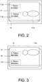
- the operating device 1is also set up such that data about the hospital data network 9 and in particular from the database 10 can be called up via the interface 8, so that, for example, the patient file 11 of the living being P can be displayed on the screen 6 of the operating device 1, as shown in FIGS Figures 2 and 3 is shown.
- the operating device 1is set up in such a way that, by actuating the foot switch device 7 and in particular by activating the foot switch 7c, the doctor can use the manual input device E2 instead of moving the robot arms M2, M3 to call up data from the database 10.
- the manual input device E2 or the second control computer 5are set up in such a way that the second control computer 5 recognizes a predetermined movement of the manual input device E2 as an instruction for calling up data from the database 10.
- the second control computer 5is set up in such a way that as soon as information content associated with the retrieved data is displayed on the screen 6, such as that shown in FIGS Figures 2 and 3 shown patient file 11, for example a change of the displayed information content, for example in the form of navigation within the patient file 11 is possible due to a manual movement of the manual input device E2.
- the patient file 11comprises 1. patient data 11a, 2. patient data 11b, 3. patient data 11c and an image 11d of the living being P recorded by means of an imaging medical device, for example an X-ray image, a CT or an MR image or is an ultrasound image.
- an imaging medical devicefor example an X-ray image, a CT or an MR image or is an ultrasound image.
- the doctoris able to move the one shown on the screen 6 and into FIG Figures 2 and 3 scroll the patient record 11 shown up and down, in particular to read the text of the patient record 11 can.
- the second control computer 5interprets the signals of the angle sensors generated due to the manual movement of the manual input device E2 and controls the screen 6 accordingly in order to scroll the above-mentioned ones Figures 2 and 3 to enable illustrated patient record 11. Additionally or alternatively, it is also possible to change the representation of the image 11d due to a manual movement of the manual input device E2.
- the second control computer 5is set up, for example, to rotate the displayed image 11d due to a movement of the manual input device E2 in order to display it in different views or to show different sections. In particular, superimposition with the images recorded by the camera W3 is possible.
- the two manual input devices E1, E2are additionally force-controlled and include, for example, Electric drives, not shown in the figures, coupled to the axes of the manual input devices E1, E2, e.g. to balance a weight force of the manual input devices E1, E2 or to enable the physician to provide haptic feedback when moving the robot arms M1-M3 and / or navigating and / or changing the patient file 11.
- Electric drivesnot shown in the figures, coupled to the axes of the manual input devices E1, E2, e.g. to balance a weight force of the manual input devices E1, E2 or to enable the physician to provide haptic feedback when moving the robot arms M1-M3 and / or navigating and / or changing the patient file 11.
Landscapes
- Health & Medical Sciences (AREA)
- Engineering & Computer Science (AREA)
- Life Sciences & Earth Sciences (AREA)
- Surgery (AREA)
- Robotics (AREA)
- Biomedical Technology (AREA)
- Nuclear Medicine, Radiotherapy & Molecular Imaging (AREA)
- Heart & Thoracic Surgery (AREA)
- Medical Informatics (AREA)
- Molecular Biology (AREA)
- Animal Behavior & Ethology (AREA)
- General Health & Medical Sciences (AREA)
- Public Health (AREA)
- Veterinary Medicine (AREA)
- Manipulator (AREA)
Description
Translated fromGermanDie Erfindung betrifft einen medizinischen Arbeitsplatz und eine Bedienvorrichtung zum manuellen Bewegen eines Roboterarms eines medizinischen Arbeitsplatzes.The invention relates to a medical work station and an operating device for manually moving a robot arm of a medical work station.
Die
Die
Die
Die
Die Aufgabe der Erfindung ist es, Voraussetzungen für eine flexiblere Bedienvorrichtung für einen solchen medizinischen Arbeitsplatzes anzugeben.The object of the invention is to specify requirements for a more flexible operating device for such a medical work station.
Die Aufgabe der Erfindung wird gelöst durch eine Bedienvorrichtung zum manuellen Bewegen eines Roboterarms eines medizinischen Arbeitsplatzes, aufweisend eine Steuerungsvorrichtung, die eingerichtet ist, ein zum Steuern einer Bewegung eines zum Behandeln eines Lebewesens vorgesehenen ersten Roboterarms vorgesehenes erstes Signal zu erzeugen, eine mit der Steuerungsvorrichtung gekoppelte manuelle erste Eingabevorrichtung, wobei die Steuerungsvorrichtung das erste Signal aufgrund eines manuellen Bewegens der ersten Eingabevorrichtung erzeugt, so dass der erste Roboterarm eine des manuellen Bewegens entsprechende Bewegung durchführt, und einen Bildschirm, wobei die Steuerungsvorrichtung eine Schnittstelle aufweist, die vorgesehen ist, mit einem Krankenhausdatennetz verbunden zu werden und die Steuerungsvorrichtung eingerichtet ist, dem Lebewesen zugeordnete, vor einer Behandlung des Lebewesens mit dem ersten Roboterarm erstellte Daten über die Schnittstelle und dem Krankenhausdatennetz abzurufen und den Daten zugeordnete Informationsinhalte am Bildschirm darzustellen, und die Steuerungsvorrichtung und deren erste Eingabevorrichtung eingerichtet sind, die am Bildschirm dargestellten Informationsinhalte mittels der ersten Eingabevorrichtung zu ändern.The object of the invention is achieved by an operating device for manually moving a robot arm of a medical work station, comprising a control device which is set up to generate a first signal intended for controlling a movement of a first robot arm intended for treating a living being, a control device coupled to the control device a manual first input device, the control device generating the first signal based on a manual movement of the first input device so that the first robot arm performs a movement corresponding to the manual movement, and a screen, the control device having an interface that is provided with a hospital data network to be connected and the control device is set up, assigned to the living being, created before treatment of the living being with the first robot arm via the interface and the hospital data network to call up and display information content associated with the data on the screen, and set up the control device and its first input device are to change the information content displayed on the screen by means of the first input device.
Ein weiterer Aspekt der Erfindung betrifft einen medizinischen Arbeitsplatz, der die erfindungsgemäße Bedienvorrichtung und wenigstes einen zum Behandeln des Lebewesens vorgesehenen medizinischen Roboterarm aufweist, dessen Bewegung mittels der Bedienvorrichtung manuell steuerbar ist.A further aspect of the invention relates to a medical work station which has the operating device according to the invention and at least one medical robot arm provided for treating the living being, the movement of which can be controlled manually by means of the operating device.
Die erfindungsgemäße Bedienvorrichtung bzw. der erfindungsgemäße medizinische Arbeitsplatz sind dafür vorgesehen, dass z.B. ein Arzt das Lebewesen mittels eines oder mehrere Roboterarme behandelt. Der Roboterarm kann bzw. die Roboterarme können beispielsweise mit einem medizinischen Instrument, insbesondere mit einem minimalinvasiven medizinischen Instrument versehen sein, wobei der Arzt den Roboterarm bzw. die Roboterarme und somit das medizinische Instrument mittels der manuellen Eingabevorrichtung bewegt. Der Roboterarm kann beispielsweise in sechs Freiheitsgraden bewegt werden. Die Eingabevorrichtung kann z.B. dieselbe Anzahl von Freiheitsgraden wie oder mehr Freiheitsgrade als der zu bewegenden Roboterarm aufweisen. Aufgrund des manuellen Bewegens des Roboterarms mittels der Eingabevorrichtung ergibt sich ein relativ einfaches manuelles Bewegen des Roboterarms bzw. der Instrumentenspitze. Das medizinische Instrument, insbesondere wenn in der minimal invasiven Chirurgie eingesetzt, kann ebenfalls aktuiert sein, d.h. über eigene, mit Motoren, Getriebe, etc. versehene Antriebe umfassen.The operating device according to the invention or the medical workstation according to the invention are provided for the fact that e.g. a doctor treats the living being using one or more robotic arms. The robot arm or the robot arms can, for example, be provided with a medical instrument, in particular with a minimally invasive medical instrument, the doctor moving the robot arm or the robot arms and thus the medical instrument by means of the manual input device. For example, the robot arm can be moved in six degrees of freedom. The input device can e.g. have the same number of degrees of freedom as or more degrees of freedom than the robot arm to be moved. The manual movement of the robot arm by means of the input device results in a relatively simple manual movement of the robot arm or the instrument tip. The medical instrument, particularly when used in minimally invasive surgery, can also be actuated, i.e. own drives with motors, gears, etc.
Die erfindungsgemäße Bedienvorrichtung weist neben der ersten Eingabevorrichtung die mit dieser gekoppelten Steuerungsvorrichtung auf. Aufgrund des Bewegens der ersten Eingabevorrichtung erzeugt die Steuerungsvorrichtung das erste Signal, mittels dessen die Bewegung des ersten Roboterarms entsprechend des Bewegens der ersten Eingabevorrichtung gesteuert wird. Die Steuerungsvorrichtung kann z.B. direkt den ersten Roboterarm ansteuern oder mit einer weiteren Steuerungsvorrichtung verbunden sein, die Antriebe zum Bewegen des ersten Roboterarms ansteuert. Es kann auch eine Verarbeitung des ersten Signals, zum Beispiel eine Filterung und/ oder Skalierung, vorgenommen werden.In addition to the first input device, the operating device according to the invention has the control device coupled to it. Due to the movement of the first input device, the control device generates the first signal, by means of which the movement of the first robot arm is controlled in accordance with the movement of the first input device becomes. The control device can, for example, directly control the first robot arm or can be connected to a further control device that controls drives for moving the first robot arm. The first signal can also be processed, for example filtering and / or scaling.
Die erfindungsgemäße Bedienvorrichtung kann aber auch eine manuelle zweite Eingabevorrichtung aufweisen, mittels derer die Bewegung eines zweiten Roboterarms des medizinischen Arbeitsplatzes manuell gesteuert werden kann. Somit wird es dem das Lebewesen behandelnden Arzt erlaubt, die Bewegung zweier Roboterarme gleichzeitig manuell zu steuern. Die zweite Eingabevorrichtung kann insbesondere genauso viele Freiheitsgrade wie oder mehr Freiheitsgrade als der zweite Roboterarm aufweisen.However, the operating device according to the invention can also have a manual second input device, by means of which the movement of a second robot arm of the medical work station can be controlled manually. This allows the doctor treating the living being to manually control the movement of two robot arms at the same time. The second input device can in particular have as many degrees of freedom as or more degrees of freedom than the second robot arm.
Die erfindungsgemäße Bedienvorrichtung umfasst ferner den Bildschirm, der insbesondere vorgesehen ist, eine Bewegung des ersten Roboterarm und/oder gegebenenfalls des zweiten Roboterarms und/ oder der den Roboterarmen zugeordneten Instrumente darzustellen. Ist z.B. am Roboterarm eine Kamera befestigt oder umfasst das am Roboterarm befestigte medizinische Instrument eine Kamera, dann ist der Bildschirm vorgesehen, mit dieser Kamera aufgenommene Bilder darzustellen.The operating device according to the invention further comprises the screen, which is provided in particular to represent a movement of the first robot arm and / or possibly the second robot arm and / or the instruments assigned to the robot arms. Is e.g. If a camera is attached to the robot arm or if the medical instrument attached to the robot arm comprises a camera, then the screen is provided for displaying images taken with this camera.
Die Steuerungsvorrichtung der erfindungsgemäßen Bedienvorrichtung weist ferner die Schnittstelle auf, über die die erfindungsgemäße Bedienvorrichtung bzw. deren Steuerungsvorrichtung mit dem Krankenhausdatennetz verbunden werden kann. Das Krankenhausdatennetz ist z.B. mit einem so genannten PACS verbunden, so dass der das Lebewesen behandelnde Arzt dem Lebewesen zugeordnete und z.B. im DICOM-Format vorliegende Daten über die Schnittstelle mittels der erfindungsgemäßen Bedienvorrichtung abrufen kann, so dass die den Daten zugeordneten Informationsinhalte mit dem Bildschirm der erfindungsgemäßen Bedienvorrichtung dargestellt werden. Die Daten, die vor einer Behandlung des Lebewesens mit dem ersten Roboterarm erstellt wurden, sind z.B. der Krankenakte des Lebewesens zugeordnet und/oder die Informationsinhalte umfassen beispielsweise Bilder, insbesondere mit einem bildgebenden medizinischen Gerät aufgenommene Bilder des Lebewesens, wie z.B. Röntgen-, Ultraschall- oder Magnetresonazbilder. Somit wird es dem Arzt in relativ einfacher Weise ermöglicht, während der Behandlung des Lebewesens mit dem Roboterarm dem Lebewesen zugeordnete Informationen in relativ einfacher abzurufen und am Bildschirm darzustellen.The control device of the control device according to the invention also has the interface via which the control device according to the invention or its control device can be connected to the hospital data network. The hospital data network is connected, for example, to a so-called PACS, so that the physician treating the living being can associate the living being and, for example, data in DICOM format via the interface by means of the operating device according to the invention, so that the data assigned information content can be displayed on the screen of the operating device according to the invention. The data that was created before treatment of the living being with the first robot arm are assigned, for example, to the living being's medical file and / or the information content includes, for example, images, in particular images of the living being taken with an imaging medical device, such as X-ray, ultrasound, or magnetic resonance images. This enables the doctor in a relatively simple manner to retrieve information associated with the living being and to display it on the screen in a relatively simple manner during the treatment of the living being with the robot arm.
Die Steuerungsvorrichtung und die erste Eingabevorrichtung eingerichtet, die am Bildschirm dargestellten Informationsinhalte mittels der ersten Eingabevorrichtung zu ändern und/oder mittels eines Betätigens der ersten Eingabevorrichtung die Daten über die Schnittstelle abzurufen. Die erfindungsgemäße Bedienvorrichtung umfasst die erste Eingabevorrichtung, die ähnlich Eingabevorrichtungen konventioneller Bedienvorrichtungen zum Bewegen des ersten Roboterarms vorgesehen ist. Da gemäß dieser Variante der erfindungsgemäßen Bedienvorrichtung zusätzlich die erste Eingabevorrichtung ausgeführt ist, die am Bildschirm dargestellten Informationsinhalte zu ändern bzw. die Daten über die Schnittstelle abzurufen, werden keine weiteren Eingabemittel für eine solche Änderung bzw. ein solches Abrufen, wie z.B. eine Rechnermaus, benötigt. Insbesondere ist kein weiterer Arbeitsplatz zum Abrufen und Betrachten der dem Patienten zugeordneten Daten notwendig. Dies stellt für den Operateur eine erhebliche Erleichterung des Operierens dar, da er den Arbeitsplatz zum Betrachten der Daten nicht verlassen und die Operation nicht unterbrechen muss. Des Weiteren geht eine Reduktion der Kosten einher. Unter einer Änderung der dargestellten Informationsinhalte wird u.A. eine Änderung deren Darstellung, z.B. ein Navigieren innerhalb der Informationsinhalte, und/oder eine Änderung der den Informationsinhalten zugeordneten Daten verstanden. Insbesondere handelt es sich auch um eine Überlagerung der Patientendaten mit den Daten der Kamera um spezielle anatomische Strukturen geeignet darzustellen. Diese Technik ist unter dem Begriff "Augmented Reality" dem Fachmann bekannt. Spezielle Strukturen können zum Beispiel im Kamerabild verdeckte, nur auf den dem Patienten zugeordneten Daten sichtbare Blutgefäße sein, deren versehentliche Verletzung zu vermeiden ist.The control device and the first input device are set up to change the information content displayed on the screen by means of the first input device and / or to call up the data via the interface by actuating the first input device. The operating device according to the invention comprises the first input device, which, similar to input devices of conventional operating devices, is provided for moving the first robot arm. Since, in accordance with this variant of the operating device according to the invention, the first input device is additionally designed to change the information content shown on the screen or to call up the data via the interface, no further input means for such a change or such a call, such as a computer mouse, are required . In particular, no further workstation is required to call up and view the data assigned to the patient. This represents a considerable relief for the operator because he does not have to leave the workplace to view the data and does not have to interrupt the operation. There is also a reduction in costs. If the information content is changed, this will change Representation, eg navigating within the information content, and / or a change in the data associated with the information content. In particular, it is also a matter of superimposing the patient data with the data from the camera in order to suitably represent special anatomical structures. This technique is known to the person skilled in the art under the term "augmented reality". Special structures can, for example, be hidden blood vessels in the camera image that are only visible on the data assigned to the patient, and their accidental injury must be avoided.
Die erfindungsgemäße Bedienvorrichtung bzw. der erfindungsgemäße medizinische Arbeitsplatz kann eine mit der Steuerungsvorrichtung gekoppelte manuelle zweite Eingabevorrichtung aufweisen, wobei die Steuerungsvorrichtung eingerichtet ist, aufgrund eines manuellen Bewegens der zweiten Eingabevorrichtung ein zweites Signal zu erzeugen, aufgrund dessen ein zur Behandlung des Lebewesens vorgesehener medizinischer zweiter Roboterarm eine des manuellen Bewegens der zweiten Eingabevorrichtung entsprechenden Bewegung durchführt, wobei die Steuerungsvorrichtung und die zweite Eingabevorrichtung eingerichtet sind, die am Bildschirm dargestellten Informationsinhalte mittels der zweiten Eingabevorrichtung zu ändern. Aufgrund dieser Variante ist es möglich, dass der das Lebewesen behandelnde Arzt mit beiden Eingabeeinrichtungen die dargestellten Informationsinhalte ändern kann. Die Steuerungsvorrichtung kann z.B. direkt die Roboterarme ansteuern oder mit einer weiteren Steuerungsvorrichtung verbunden sein, die Antriebe zum Bewegen der Roboterarme ansteuert. Im zweiten Fall kann, wenn mehrere Roboterarme verwendet werden, eine einzige Steuerungsvorrichtung alle oder mehrere der Roboterarme gemeinsam direkt ansteuern oder es kann jedem einzelnen Roboterarm eine individuelle Steuerungsvorrichtung zugeordnet sein, die von der Steuervorrichtung der erfindungsgemäßen Bedienvorrichtung angesteuert werden.The control device according to the invention or the medical workstation according to the invention can have a manual second input device coupled to the control device, the control device being set up to generate a second signal on the basis of a manual movement of the second input device, on the basis of which a medical second robot arm provided for treating the living being is generated carries out a movement corresponding to the manual movement of the second input device, the control device and the second input device being set up to change the information content displayed on the screen by means of the second input device. On the basis of this variant, it is possible for the doctor treating the living being to be able to change the information content shown with both input devices. The control device can, for example, directly control the robot arms or can be connected to a further control device that controls drives for moving the robot arms. in the second case, if a plurality of robot arms are used, a single control device can directly control all or more of the robot arms together directly, or each individual robot arm can be assigned an individual control device which is controlled by the control device of the operating device according to the invention.
Nach einer Variante der erfindungsgemäßen Bedienvorrichtung weist diese eine mit der Steuerungsvorrichtung gekoppelte Umschaltvorrichtung auf, wobei die Steuerungsvorrichtung aufgrund eines Betätigen der Umschaltvorrichtung entweder das erste Signal aufgrund des manuellen Bewegens der ersten Eingabevorrichtung erzeugt oder die am Bildschirm dargestellten Informationsinhalte aufgrund eines Betätigens der ersten Eingabevorrichtung ändert. Mittels der Umschaltvorrichtung wird es dem Arzt ermöglicht, in relativ einfacher Weise die erfindungsgemäße Bedienvorrichtung von einem ersten Betriebsmodus, in dem die erste Eingabevorrichtung zum manuellen Bewegen des ersten Roboterarms, in einen zweiten Betriebsmodus zu schalten, in dem die erste Eingabevorrichtung für das Ändern der am Bildschirm dargestellten Informationsinhalte verwendbar ist. Die Umschaltvorrichtung ist z.B. als Fußschalter ausgeführt, was dem Arzt eine relativ einfache Bedienung der erfindungsgemäßen Bedienvorrichtung erlaubt. Die Umschaltvorrichtung kann auch sprachgesteuert ausgeführt sein.According to a variant of the operating device according to the invention, this has a switchover device coupled to the control device, the control device either generating the first signal due to manual movement of the first input device or changing the information content displayed on the screen due to actuation of the first input device due to actuation of the switchover device. The switching device enables the doctor to switch the operating device according to the invention from a first operating mode, in which the first input device for manually moving the first robot arm, into a second operating mode, in which the first input device for changing the am Information displayed on the screen is usable. The switching device is e.g. designed as a foot switch, which allows the doctor a relatively simple operation of the operating device according to the invention. The switching device can also be voice-controlled.
Die Steuerungsvorrichtung kann derart ausgeführt sein, dass sie aufgrund eines Betätigens der Umschaltvorrichtung ein drittes Signal erzeugt, so dass ein zum Behandeln des Lebewesens vorgesehner Roboterarm des medizinischen Arbeitsplatzes eine des manuellen Bewegens entsprechende Bewegung durchführt. Gemäß dieser Variante wird es dem Arzt ermöglicht, die erste Eingabevorrichtung zum Bewegen des ersten oder des zweiten Roboterarms als auch zum Ändern der am Bildschirm dargestellten Informationsinhalte durch relativ einfaches Umschalten zu verwenden.The control device can be designed in such a way that it generates a third signal when the switching device is actuated, so that a robot arm of the medical workstation provided for treating the living being carries out a movement corresponding to the manual movement. According to this variant, the doctor is able to use the first input device for moving the first or the second robot arm as well as for changing the am Information displayed on the screen can be used by relatively simple switching.
Nach einer Variante der erfindungsgemäßen Bedienvorrichtung ist deren erste Eingabevorrichtung kraftgeregelt oder kraftrückgekoppelt ausgeführt. In Verbindung mit der Variante, gemäß derer die erste Eingabevorrichtung zum Ändern der am Bildschirm dargestellten Informationsinhalte verwendet wird, ergibt sich ein verbessertes und/oder bequemeres Ändern der dargestellten Informationsinhalte mittels der ersten Eingabevorrichtung, da relevante Information haptisch dargestellt werden kann. Die kraftgeregelte oder kraftrückgekoppelte Ausführungsform kann z.B. ein Navigieren oder ein Darstellen hinterlegter haptischer Information erleichtern.According to a variant of the operating device according to the invention, its first input device is designed to be force-controlled or force-fed back. In connection with the variant according to which the first input device is used to change the information content displayed on the screen, the first information device results in an improved and / or more convenient change of the information content, since relevant information can be displayed haptically. The force controlled or force feedback embodiment can e.g. facilitate navigation or display of stored haptic information.
Ein Ausführungsbeispiel der Erfindung ist exemplarisch in den beigefügten schematischen Zeichnungen dargestellt. Es zeigen:
- Fig. 1
- einen medizinischen Arbeitsplatz mit mehreren Roboterarmen und einer Bedienvorrichtung zum manuellen Bewegen der Roboterarme und
- Fig. 2 und 3
- mit einem Bildschirm der Bedienvorrichtung dargestellte Informationsinhalte.
- Fig. 1
- a medical workstation with several robot arms and an operating device for manually moving the robot arms and
- 2 and 3
- information displayed with a screen of the operating device.
Die
Im Falle des vorliegenden Ausführungsbeispiels liegt auf der Patientenliege L eine Person P, die mittels der Roboterarme M1-M3 bzw. mittels an den Befestigungsvorrichtungen F1-F3 der Roboterarme M1-M3 befestigten Instrumenten behandelt werden kann. An den Befestigungsvorrichtungen F1, F2 der Roboterarme M1, M2 sind z.B. jeweils medizinische Instrumente W1, W2 und an der Befestigungsvorrichtung F3 des Roboterarms M3 ist beispielsweise eine Kamera W3 befestigt.In the case of the present exemplary embodiment, a person P lies on the patient couch L, who can be treated by means of the robot arms M1-M3 or by means of instruments attached to the fastening devices F1-F3 of the robot arms M1-M3. On the fastening devices F1, F2 of the robot arms M1, M2 are e.g. medical instruments W1, W2 in each case and, for example, a camera W3 is fastened to the fastening device F3 of the robot arm M3.
Im Falle des vorliegenden Ausführungsbeispiels sind die Antriebe der Roboterarme M-M3, die medizinischen Instrumente W1, W2 und die Kamera W3 in nicht dargestellter Weise mit einem ersten Steuerrechner 3 verbunden. Auf dem ersten Steuerrechner 3 läuft ein Rechnerprogramm, mittels dem der Steuerrechner 3 die Antriebe der Roboterarme M1-M3 derart ansteuern kann, so dass sich die Achsen der Roboterarme M1-M3 in gewünschter Weise derart bewegen, damit die Befestigungsvorrichtungen F1-F3 bzw. die Tool Center Points der medizinischen Instrumente W1, W2 und der Kamera W3 eine gewünschte Lage (Position und Orientierung) einnehmen.In the case of the present exemplary embodiment, the drives of the robot arms M-M3, the medical instruments W1, W2 and the camera W3 are connected to a
Der medizinische Arbeitsplatz umfasst ferner die Bedienvorrichtung 1. Diese weist im Falle des vorliegenden Ausführungsbeispiels einen zweiten Steuerrechner 5, zwei an einem Tisch 4 angeordnete und in nicht dargestellter Weise mit dem zweiten Steuerrechner 5 verbundene Handeingabevorrichtungen E1, E2, einen in nicht dargestellter Weise mit dem zweiten Steuerrechner 5 verbundenen Bildschirm 6 und eine mittels einer Leitung L1 mit dem zweiten Steuerrechner 5 verbundene Fußumschalteinrichtung 7 auf. Die beiden Steuerrechner 3, 5 können ferner über eine Datenleitung L2 miteinander kommunizieren.The medical work station also includes the
Im Falle des vorliegenden Ausführungsbeispiels weisen die beiden Handeingabevorrichtungen E1, E2 jeweils einen Handgriff H1, H2 und mehrere Achsen auf. Ein in den Figuren nicht näher dargestellter Arzt kann die Handeingabevorrichtungen E1, E2 mittels der Handgriffe H1, H2 manuell bezüglich wenigstens sechs Freiheitsgraden bewegen. Die Handeingabevorrichtungen E1, E2 weisen z.B. den jeweiligen Achsen der Handeingabevorrichtungen E1, E2 zugeordnete und in den Figuren nicht näher dargestellte Winkelsensoren auf, deren Signale dem zweiten Steuerrechner 5 übermittelt werden. Auf dem zweiten Steuerrechner 5 läuft wiederum ein Rechnerprogramm, das aufgrund der von den Handeingabevorrichtungen E1, E2 stammenden Signalen Bewegungen der Handeingabevorrichtungen E1, E2 erkennt. Die beiden Handeingabevorrichtungen E1, E2 können auch mehr als sechs Freiheitsgrade aufweisen.In the case of the present exemplary embodiment, the two manual input devices E1, E2 each have a handle H1, H2 and multiple axes. A doctor, not shown in the figures, can manually move the manual input devices E1, E2 by means of the handles H1, H2 with respect to at least six degrees of freedom. The manual input devices E1, E2 have, for example, angle sensors assigned to the respective axes of the manual input devices E1, E2 and not shown in the figures, the signals of which are transmitted to the
Im Falle des vorliegenden Ausführungsbeispiels ist die Handeingabevorrichtung E1 dafür vorgesehen, den Roboterarm M1 zu bewegen. Bei einem manuellen Bewegen der Handeingabevorrichtung E1 mittels ihres Handgriffs H1 detektieren die Winkelsensoren der Handeingabevorrichtung E1 Winkeländerungen der relevanten Achsen. Aus den von den Winkelsensoren erzeugten Signalen ermittelt der zweite Steuerrechner 5 entsprechende Bewegungen der Handeingabevorrichtung E1 und übermittelt über die Leitung L2 eine entsprechende Information an den ersten Steuerrechner 3, der daraufhin die Antriebe des Roboterarms M1 derart ansteuert, so dass dessen Befestigungsvorrichtung F1 bzw. dessen Tool Center Point eine der manuellen Bewegung der Handeingabevorrichtung E1 entsprechenden Bewegung durchführt. Die Signale könne auch vor verarbeitet, z.B. gefiltert werden.In the case of the present exemplary embodiment, the manual input device E1 is provided for moving the robot arm M1. When the manual input device E1 is moved manually by means of its handle H1, the angle sensors of the manual input device E1 detect changes in the angle of the relevant axes. From the signals generated by the angle sensors, the
Im Falle des vorliegenden Ausführungsbeispiels ist die Handeingabevorrichtung E2 dafür vorgesehen, die beiden anderen Roboterarme M2, M3 zu bewegen. Um einen der beiden Roboterarme M2, M3 für das Bewegen auszuwählen, kann der Arzt die Fußumschalteinrichtung 7 betätigen. Diese weist drei Fußschalter 7a, 7b, 7c auf. Aktiviert der Arzt z.B. mit seinem Fuß den Fußschalter 7a, so kann, ähnlich wie er mit der Handeingabevorrichtung E1 den Roboterarm M1 bewegen kann, mit der Handeingabevorrichtung E2 den Roboterarm M2 bewegen. Aktiviert der Arzt dagegen den Fußschalter 7b, so kann, ähnlich wie er mit der Handeingabevorrichtung E1 den Roboterarm M1 bewegen kann, mit der Handeingabevorrichtung E2 den Roboterarm M3 bewegen.In the case of the present exemplary embodiment, the manual input device E2 is provided for moving the two other robot arms M2, M3. In order to select one of the two robot arms M2, M3 for moving, the doctor can actuate the
Im Falle des vorliegenden Ausführungsbeispiels ist am Roboterarm M3 die Kamera W3 befestigt, mit der Bilder vom Operationssitus aufgenommen werden können, so dass der Arzt z.B. eine optische Rückmeldung über die Lagen der Roboterarme M1, M2 und/ oder der den Robotern zugeordneten Instrumente W1 und/ oder W2 erhält. Die den mit der Kamera W3 aufgenommenen Bildern zugeordneten Bilddatensätze werden über die Leitung L2 vom ersten Steuerrechner 3 zum zweiten Steuerrechner 5 übermittelt, damit der zweite Steuerrechner 5 diese Bilder ggf. nach Verarbeitung am Bildschirm 6 darstellten kann.In the case of the present exemplary embodiment, the camera W3 is attached to the robot arm M3 and can be used to take pictures of the surgical site, so that the doctor e.g. receives visual feedback on the positions of the robot arms M1, M2 and / or the instruments W1 and / or W2 assigned to the robots. The image data sets associated with the images recorded with the camera W3 are transmitted via line L2 from the
Im Falle des vorliegenden Ausführungsbeispiels weist der zweite Steuerrechner 5 der Bedienvorrichtung 1 eine Schnittstelle 8 auf, über die der zweite Steuerrechner 5 mit einem Krankenhausdatennetz 9 kommunizieren kann. Dazu ist die Schnittstelle 8 mit dem Krankenhausdatennetz 9 über eine Datenleitung L3 verbunden. Das Krankenhausdatennetz ist wiederum mit einer Datenbank 10 über eine Datenleitung L4 verbunden. In der Datenbank 10 sind u.A. dem Lebewesen P zugeordnete Daten, wie z.B. dessen Patientenakte 11 in elektronischer Form gespeichert.In the case of the present exemplary embodiment, the
Im Falle des vorliegenden Ausführungsbeispiels ist die Bedienvorrichtung 1 ferner derart eingerichtet, so dass über die Schnittstelle 8 Daten über das Krankenhausdatennetz 9 und insbesondere von der Datenbank 10 abgerufen werden können, so dass z.B. die Patientenakte 11 des Lebewesens P auf dem Bildschirm 6 der Bedienvorrichtung 1 dargestellt werden kann, wie dies in den
Des Weiteren ist die Bedienvorrichtung 1 derart eingerichtet, so dass durch Betätigen der Fußumschalteinrichtung 7 und insbesondere durch Aktivieren des Fußschalters 7c der Arzt mit der Handeingabevorrichtung E2 anstelle die Roboterarme M2, M3 zu bewegen, Daten von der Datenbank 10 abrufen kann. Dazu sind im Falle des vorliegenden Ausführungsbeispiels die Handeingabevorrichtung E2 bzw. der zweite Steuerrechner 5 derart eingerichtet, so dass der zweite Steuerrechner 5 eine vorgegebene Bewegung der Handeingabevorrichtung E2 als Anweisung zum Abrufen von Daten von der Datenbank 10 erkennt. Ferner ist der zweite Steuerrechner 5 derart eingerichtet, dass, sobald den abgerufenen Daten zugeordnete Informationsinhalte am Bildschirm 6 angezeigt sind, wie z.B. die in den
Im Falle des vorliegenden Ausführungsbeispiels umfasst die Patientenakte 11 1. Patientendaten 11a, 2. Patientendaten 11b, 3. Patientendaten 11c und ein mittels eines bildgebenden medizinischen Gerätes aufgenommenes Bild 11d des Lebewesens P, das beispielsweise ein Röntgenbild, ein CT- oder ein MR-Bild oder ein Ultraschallbild ist.In the case of the present exemplary embodiment, the
Durch ein Bewegen der Handeingabevorrichtung E2 wird es im Falle des vorliegenden Ausführungsbeispiels dem Arzt ermöglicht, die am Bildschirm 6 dargestellte und in den
Im Falle des vorliegenden Ausführungsbeispiels sind die beiden Handeingabevorrichtungnen E1, E2 zusätzlich kraftgeregelt und umfassen dazu z.B. in den Figuren nicht dargestellte mit den Achsen der Handeingabevorrichtungen E1, E2 gekoppelte elektrische Antriebe, um z.B. eine Gewichtskraft der Handeingabevorrichtungen E1, E2 auszugleichen oder um dem Arzt eine haptisch Rückmeldung beim Bewegen der Roboterarme M1-M3 und/ oder Navigieren und/oder Verändern der Patientenakte 11 zu ermöglichen.In the case of the present exemplary embodiment, the two manual input devices E1, E2 are additionally force-controlled and include, for example, Electric drives, not shown in the figures, coupled to the axes of the manual input devices E1, E2, e.g. to balance a weight force of the manual input devices E1, E2 or to enable the physician to provide haptic feedback when moving the robot arms M1-M3 and / or navigating and / or changing the
Zusätzlich oder alternativ ist es auch möglich, auch die Handeingabevorrichtung E1 umzuschalten, so dass mit dieser Daten von der Datenbank 10 über die Schnittstelle 8 des zweiten Steuerrechners 5 abgerufen werden können und/oder um die Eingabevorrichtung E1 zum Ändern der am Bildschirm 6 dargestellten Informationsinhalte, wie die Patientenakte 11, zu verwenden.Additionally or alternatively, it is also possible to also switch over the manual input device E1 so that it can be used to retrieve data from the
Claims (13)
- Operating device for manually moving a robot arm of a medical workstation, comprising- a control device (5) which is set up to generate a first signal intended for controlling a movement of a first robot arm (M2) provided for treating a living being (P), and which has an interface (8) which is provided to be connected to a hospital data network (9),- a manual first input device (E2) coupled to the control device (5), wherein the control device (5) generates the first signal on the basis of a manual movement of the first input device (E2), so that the first robot arm (M2) executes a movement corresponding to the manual movement, and- a screen (6),
characterised in that the control device (5) is configured to retrieve data via the interface (8) and the hospital data network (9) assigned to the living being (P) and created before a treatment of the living being (P) with the first robot arm (M2) and to represent informational content (11) assigned to the data on the screen (6), and the control device (5) and its first input device (E2) are configured to change the informational content (11) shown on the screen (6) by means of the first input device (E2). - Operating device according to claim 1, wherein the informational content comprises images (11d) which have been captured in particular by an imaging medical device.
- Operating device according to claim 1 or 2, wherein the change of informational content represented on the screen (6) comprises overlayering with images captured by a camera (W3), wherein the camera (W3) is secured to the first robot arm or to a second robot arm, or wherein the first or the second robot arm is provided with a medical instrument which comprises the camera.
- Operating device according to any of claims 1 to 3, wherein a change to the shown informational content comprises a change to its presentation, in particular navigation within the informational content and/or a change of the data assigned to the informational content.
- Operating device according to any of claims 1 to 4, the first input device (E2) of which has more degrees of freedom than the first robot arm (M2).
- Operating device according to any of claims 1 to 5, having a manual second input device (E1) coupled to the control device (5), the control device (5) being set up to generate a second signal on the basis of a manual movement of the second input device (E1), on the basis of which a second robot arm (M1) provided for treating the living being (P) executes a movement corresponding to the manual movement of the second input device (E1), wherein the control device (5) and the second input device (E1) are set up to change the informational content (11) displayed on the screen (6) by means of the second input device (E1).
- Operating device according to any of claims 1 to 6, having a switching device (7) coupled to the control device (5), wherein the control device (5) on the basis of activating the switching device (7) either generates the first signal on the basis of the manual movement of the first input device (E2) or retrieves and/or changes via the interface (8) the informational content (11) displayed on the screen (6) on the basis of an activation of the first input device.
- Operating device according to claim 7, the control device (5) of which is designed such that it generates a third signal on the basis of activating the switching device (7), so that a third robot arm (M3) provided for treating the living being (8) executes a movement corresponding to the manual movement.
- Operating device according to any of claims 1 to 8, the first input device (E2) of which is designed to be controlled by force or feedback coupled by force.
- Operating device according to any of claims 1 to 9, wherein the data assigned to the living being (P) are stored in a database (10) of the hospital data network (9) and the control device (5) is set up to retrieve said data from the database (10) via the interface (8).
- Operating device according to any of claims 1 to 10, wherein the data are assigned to a clinical record (11) of the living being (P).
- Operating device according to any of claims 1 to 11, wherein the data have been created prior to a treatment of the living being (P) with the first robot arm (M2).
- Medical workstation, having an operating device (1) according to any of claims 1 to 12 and at least one medical robot arm (M1-M3) provided for treating the living being (P), the movement of which robot arm can be controlled manually by means of the operating device (1).
Applications Claiming Priority (2)
| Application Number | Priority Date | Filing Date | Title |
|---|---|---|---|
| DE102008041709ADE102008041709A1 (en) | 2008-08-29 | 2008-08-29 | Medical workstation and operating device for manually moving a robotic arm of a medical workstation |
| PCT/EP2009/006010WO2010022884A1 (en) | 2008-08-29 | 2009-08-19 | Medical work station and operating device for manually moving a robot arm of a medical work station |
Publications (2)
| Publication Number | Publication Date |
|---|---|
| EP2328501A1 EP2328501A1 (en) | 2011-06-08 |
| EP2328501B1true EP2328501B1 (en) | 2020-03-25 |
Family
ID=41226891
Family Applications (1)
| Application Number | Title | Priority Date | Filing Date |
|---|---|---|---|
| EP09777975.5AActiveEP2328501B1 (en) | 2008-08-29 | 2009-08-19 | Medical work station and operating device for manually moving a robot arm of a medical work station |
Country Status (4)
| Country | Link |
|---|---|
| US (1) | US20110190937A1 (en) |
| EP (1) | EP2328501B1 (en) |
| DE (1) | DE102008041709A1 (en) |
| WO (1) | WO2010022884A1 (en) |
Families Citing this family (16)
| Publication number | Priority date | Publication date | Assignee | Title |
|---|---|---|---|---|
| DE102010039540C5 (en)* | 2010-08-19 | 2020-01-02 | Kuka Deutschland Gmbh | Manual control device for moving a robot arm manually |
| WO2012074564A1 (en) | 2010-12-02 | 2012-06-07 | Freehand Endoscopic Devices, Inc. | Surgical tool |
| WO2013123310A1 (en) | 2012-02-15 | 2013-08-22 | Intuitive Surgical Operations, Inc. | User selection of robotic system operating modes using mode distinguishing operator actions |
| WO2014028563A1 (en) | 2012-08-15 | 2014-02-20 | Intuitive Surgical Operations, Inc. | Phantom degrees of freedom in joint estimation and control |
| EP2885114B1 (en) | 2012-08-15 | 2021-06-30 | Intuitive Surgical Operations, Inc. | Phantom degrees of freedom for manipulating the movement of mechanical bodies |
| KR102184960B1 (en) | 2012-08-15 | 2020-12-01 | 인튜어티브 서지컬 오퍼레이션즈 인코포레이티드 | Movable surgical mounting platform controlled by manual motion of robotic arms |
| EP2884936A4 (en) | 2012-08-15 | 2016-04-27 | Intuitive Surgical Operations | Phantom degrees of freedom for manipulating the movement of surgical systems |
| CN106456257B (en) | 2014-05-13 | 2019-11-05 | 柯惠Lp公司 | Robot arm for operation support system and application method |
| US10500015B2 (en) | 2014-05-13 | 2019-12-10 | Covidien Lp | Surgical robotic arm support systems and methods of use |
| WO2016014385A2 (en)* | 2014-07-25 | 2016-01-28 | Covidien Lp | An augmented surgical reality environment for a robotic surgical system |
| EP3200718A4 (en)* | 2014-09-30 | 2018-04-25 | Auris Surgical Robotics, Inc | Configurable robotic surgical system with virtual rail and flexible endoscope |
| WO2017205481A1 (en) | 2016-05-26 | 2017-11-30 | Covidien Lp | Robotic surgical assemblies and instrument drive units thereof |
| EP3463159B1 (en) | 2016-05-26 | 2024-01-03 | Covidien LP | Instrument drive units |
| US11272992B2 (en) | 2016-06-03 | 2022-03-15 | Covidien Lp | Robotic surgical assemblies and instrument drive units thereof |
| JP2023533919A (en) | 2020-08-19 | 2023-08-07 | 北京術鋭機器人股▲ふん▼有限公司 | Robot system and control method |
| DE102021113575A1 (en) | 2021-05-25 | 2022-12-01 | Olympus Winter & Ibe Gmbh | surgical robot |
Family Cites Families (9)
| Publication number | Priority date | Publication date | Assignee | Title |
|---|---|---|---|---|
| US5855583A (en) | 1996-02-20 | 1999-01-05 | Computer Motion, Inc. | Method and apparatus for performing minimally invasive cardiac procedures |
| US6911916B1 (en) | 1996-06-24 | 2005-06-28 | The Cleveland Clinic Foundation | Method and apparatus for accessing medical data over a network |
| US5924074A (en)* | 1996-09-27 | 1999-07-13 | Azron Incorporated | Electronic medical records system |
| US6522906B1 (en)* | 1998-12-08 | 2003-02-18 | Intuitive Surgical, Inc. | Devices and methods for presenting and regulating auxiliary information on an image display of a telesurgical system to assist an operator in performing a surgical procedure |
| US7607440B2 (en)* | 2001-06-07 | 2009-10-27 | Intuitive Surgical, Inc. | Methods and apparatus for surgical planning |
| US6728599B2 (en)* | 2001-09-07 | 2004-04-27 | Computer Motion, Inc. | Modularity system for computer assisted surgery |
| US8010180B2 (en)* | 2002-03-06 | 2011-08-30 | Mako Surgical Corp. | Haptic guidance system and method |
| US9002518B2 (en)* | 2003-06-30 | 2015-04-07 | Intuitive Surgical Operations, Inc. | Maximum torque driving of robotic surgical tools in robotic surgical systems |
| US20060087746A1 (en)* | 2004-10-22 | 2006-04-27 | Kenneth Lipow | Remote augmented motor-sensory interface for surgery |
- 2008
- 2008-08-29DEDE102008041709Apatent/DE102008041709A1/ennot_activeWithdrawn
- 2009
- 2009-08-19WOPCT/EP2009/006010patent/WO2010022884A1/enactiveApplication Filing
- 2009-08-19USUS13/061,361patent/US20110190937A1/ennot_activeAbandoned
- 2009-08-19EPEP09777975.5Apatent/EP2328501B1/enactiveActive
Non-Patent Citations (1)
| Title |
|---|
| None* |
Also Published As
| Publication number | Publication date |
|---|---|
| WO2010022884A1 (en) | 2010-03-04 |
| EP2328501A1 (en) | 2011-06-08 |
| US20110190937A1 (en) | 2011-08-04 |
| DE102008041709A1 (en) | 2010-03-04 |
Similar Documents
| Publication | Publication Date | Title |
|---|---|---|
| EP2328501B1 (en) | Medical work station and operating device for manually moving a robot arm of a medical work station | |
| EP2449997B1 (en) | Medical workstation | |
| DE102007045075B4 (en) | Interventional medical diagnosis and / or therapy system | |
| DE102012110190B4 (en) | Manually operated robot control and method for controlling a robot system | |
| EP2326275B1 (en) | Medical workstation and operating device for the manual movement of a robot arm | |
| DE19958443C2 (en) | operating device | |
| EP3443908B1 (en) | Method for operating an x-ray device comprising an articulated arm and x-ray device with an articulated arm | |
| DE10210622A1 (en) | Remote control of a medical device using voice recognition control and foot control | |
| DE102013109677A1 (en) | Assistance device for the imaging support of an operator during a surgical procedure | |
| DE112013004898T5 (en) | A medical imaging system and method for providing an improved x-ray image | |
| DE102013226244A1 (en) | Medical control | |
| DE112020001408T5 (en) | SYSTEMS AND METHODS FOR MAINTAINING THE STERILITY OF A COMPONENT BY USING A MOVABLE, STERILE VOLUME | |
| EP3639782A1 (en) | Control arrangement for controlling a movement of a robot arm and treatment device comprising a control arrangement | |
| DE4341324A1 (en) | Medical equipment for diagnosis and/or therapy | |
| DE112022003770T5 (en) | TECHNIQUES FOR ADJUSTING A FIELD OF VIEW OF AN IMAGING DEVICE BASED ON HEAD MOVEMENTS OF AN OPERATOR | |
| DE102009009549A1 (en) | Method for positioning medical device on carrier device, involves providing target position of medical device, where relative position of medical device, is determined for target position, and positioning support signal is optical signal | |
| DE10335369B4 (en) | A method of providing non-contact device function control and apparatus for performing the method | |
| DE102022111495A1 (en) | Robotic telemanipulation system with adaptable degree of autonomy, use of a robotic telemanipulation system, autonomous medical robotic system | |
| DE102019118752A1 (en) | Method for adaptive function reassignment of control elements of an image recording system and the associated image recording system | |
| DE10149795B4 (en) | Semiautomatic registration for overlaying two medical image data sets | |
| WO2024023019A1 (en) | Medical remote control, medical robot with intuitive control, and control method | |
| WO2015014952A1 (en) | Aid for providing imaging support to an operator during a surgical intervention | |
| DE4341291A1 (en) | Medical equipment for therapy and/or diagnosis | |
| WO2023062231A1 (en) | Surgical system comprising haptics | |
| DE112021006323T5 (en) | METHOD FOR ADJUSTING A DISPLAY UNIT OF A VIEWING SYSTEM |
Legal Events
| Date | Code | Title | Description |
|---|---|---|---|
| PUAI | Public reference made under article 153(3) epc to a published international application that has entered the european phase | Free format text:ORIGINAL CODE: 0009012 | |
| 17P | Request for examination filed | Effective date:20110224 | |
| AK | Designated contracting states | Kind code of ref document:A1 Designated state(s):AT BE BG CH CY CZ DE DK EE ES FI FR GB GR HR HU IE IS IT LI LT LU LV MC MK MT NL NO PL PT RO SE SI SK SM TR | |
| AX | Request for extension of the european patent | Extension state:AL BA RS | |
| DAX | Request for extension of the european patent (deleted) | ||
| 17Q | First examination report despatched | Effective date:20150311 | |
| RAP1 | Party data changed (applicant data changed or rights of an application transferred) | Owner name:KUKA ROBOTER GMBH | |
| RAP1 | Party data changed (applicant data changed or rights of an application transferred) | Owner name:KUKA DEUTSCHLAND GMBH | |
| REG | Reference to a national code | Ref country code:DE Ref legal event code:R079 Ref document number:502009016147 Country of ref document:DE Free format text:PREVIOUS MAIN CLASS: A61B0019000000 Ipc:A61B0034300000 | |
| RIC1 | Information provided on ipc code assigned before grant | Ipc:A61B 34/00 20160101ALI20190826BHEP Ipc:A61B 34/37 20160101ALI20190826BHEP Ipc:A61B 34/30 20160101AFI20190826BHEP | |
| GRAP | Despatch of communication of intention to grant a patent | Free format text:ORIGINAL CODE: EPIDOSNIGR1 | |
| STAA | Information on the status of an ep patent application or granted ep patent | Free format text:STATUS: GRANT OF PATENT IS INTENDED | |
| INTG | Intention to grant announced | Effective date:20191025 | |
| GRAS | Grant fee paid | Free format text:ORIGINAL CODE: EPIDOSNIGR3 | |
| GRAA | (expected) grant | Free format text:ORIGINAL CODE: 0009210 | |
| STAA | Information on the status of an ep patent application or granted ep patent | Free format text:STATUS: THE PATENT HAS BEEN GRANTED | |
| AK | Designated contracting states | Kind code of ref document:B1 Designated state(s):AT BE BG CH CY CZ DE DK EE ES FI FR GB GR HR HU IE IS IT LI LT LU LV MC MK MT NL NO PL PT RO SE SI SK SM TR | |
| REG | Reference to a national code | Ref country code:GB Ref legal event code:FG4D Free format text:NOT ENGLISH | |
| REG | Reference to a national code | Ref country code:AT Ref legal event code:REF Ref document number:1247677 Country of ref document:AT Kind code of ref document:T Effective date:20200415 Ref country code:IE Ref legal event code:FG4D Free format text:LANGUAGE OF EP DOCUMENT: GERMAN | |
| REG | Reference to a national code | Ref country code:DE Ref legal event code:R096 Ref document number:502009016147 Country of ref document:DE | |
| PG25 | Lapsed in a contracting state [announced via postgrant information from national office to epo] | Ref country code:FI Free format text:LAPSE BECAUSE OF FAILURE TO SUBMIT A TRANSLATION OF THE DESCRIPTION OR TO PAY THE FEE WITHIN THE PRESCRIBED TIME-LIMIT Effective date:20200325 Ref country code:NO Free format text:LAPSE BECAUSE OF FAILURE TO SUBMIT A TRANSLATION OF THE DESCRIPTION OR TO PAY THE FEE WITHIN THE PRESCRIBED TIME-LIMIT Effective date:20200625 | |
| PG25 | Lapsed in a contracting state [announced via postgrant information from national office to epo] | Ref country code:BG Free format text:LAPSE BECAUSE OF FAILURE TO SUBMIT A TRANSLATION OF THE DESCRIPTION OR TO PAY THE FEE WITHIN THE PRESCRIBED TIME-LIMIT Effective date:20200625 Ref country code:LV Free format text:LAPSE BECAUSE OF FAILURE TO SUBMIT A TRANSLATION OF THE DESCRIPTION OR TO PAY THE FEE WITHIN THE PRESCRIBED TIME-LIMIT Effective date:20200325 Ref country code:SE Free format text:LAPSE BECAUSE OF FAILURE TO SUBMIT A TRANSLATION OF THE DESCRIPTION OR TO PAY THE FEE WITHIN THE PRESCRIBED TIME-LIMIT Effective date:20200325 Ref country code:GR Free format text:LAPSE BECAUSE OF FAILURE TO SUBMIT A TRANSLATION OF THE DESCRIPTION OR TO PAY THE FEE WITHIN THE PRESCRIBED TIME-LIMIT Effective date:20200626 Ref country code:HR Free format text:LAPSE BECAUSE OF FAILURE TO SUBMIT A TRANSLATION OF THE DESCRIPTION OR TO PAY THE FEE WITHIN THE PRESCRIBED TIME-LIMIT Effective date:20200325 | |
| REG | Reference to a national code | Ref country code:NL Ref legal event code:MP Effective date:20200325 | |
| REG | Reference to a national code | Ref country code:LT Ref legal event code:MG4D | |
| PG25 | Lapsed in a contracting state [announced via postgrant information from national office to epo] | Ref country code:NL Free format text:LAPSE BECAUSE OF FAILURE TO SUBMIT A TRANSLATION OF THE DESCRIPTION OR TO PAY THE FEE WITHIN THE PRESCRIBED TIME-LIMIT Effective date:20200325 | |
| PG25 | Lapsed in a contracting state [announced via postgrant information from national office to epo] | Ref country code:PT Free format text:LAPSE BECAUSE OF FAILURE TO SUBMIT A TRANSLATION OF THE DESCRIPTION OR TO PAY THE FEE WITHIN THE PRESCRIBED TIME-LIMIT Effective date:20200818 Ref country code:EE Free format text:LAPSE BECAUSE OF FAILURE TO SUBMIT A TRANSLATION OF THE DESCRIPTION OR TO PAY THE FEE WITHIN THE PRESCRIBED TIME-LIMIT Effective date:20200325 Ref country code:SM Free format text:LAPSE BECAUSE OF FAILURE TO SUBMIT A TRANSLATION OF THE DESCRIPTION OR TO PAY THE FEE WITHIN THE PRESCRIBED TIME-LIMIT Effective date:20200325 Ref country code:RO Free format text:LAPSE BECAUSE OF FAILURE TO SUBMIT A TRANSLATION OF THE DESCRIPTION OR TO PAY THE FEE WITHIN THE PRESCRIBED TIME-LIMIT Effective date:20200325 Ref country code:IS Free format text:LAPSE BECAUSE OF FAILURE TO SUBMIT A TRANSLATION OF THE DESCRIPTION OR TO PAY THE FEE WITHIN THE PRESCRIBED TIME-LIMIT Effective date:20200725 Ref country code:SK Free format text:LAPSE BECAUSE OF FAILURE TO SUBMIT A TRANSLATION OF THE DESCRIPTION OR TO PAY THE FEE WITHIN THE PRESCRIBED TIME-LIMIT Effective date:20200325 Ref country code:LT Free format text:LAPSE BECAUSE OF FAILURE TO SUBMIT A TRANSLATION OF THE DESCRIPTION OR TO PAY THE FEE WITHIN THE PRESCRIBED TIME-LIMIT Effective date:20200325 Ref country code:CZ Free format text:LAPSE BECAUSE OF FAILURE TO SUBMIT A TRANSLATION OF THE DESCRIPTION OR TO PAY THE FEE WITHIN THE PRESCRIBED TIME-LIMIT Effective date:20200325 | |
| REG | Reference to a national code | Ref country code:DE Ref legal event code:R097 Ref document number:502009016147 Country of ref document:DE | |
| PG25 | Lapsed in a contracting state [announced via postgrant information from national office to epo] | Ref country code:IT Free format text:LAPSE BECAUSE OF FAILURE TO SUBMIT A TRANSLATION OF THE DESCRIPTION OR TO PAY THE FEE WITHIN THE PRESCRIBED TIME-LIMIT Effective date:20200325 Ref country code:DK Free format text:LAPSE BECAUSE OF FAILURE TO SUBMIT A TRANSLATION OF THE DESCRIPTION OR TO PAY THE FEE WITHIN THE PRESCRIBED TIME-LIMIT Effective date:20200325 Ref country code:ES Free format text:LAPSE BECAUSE OF FAILURE TO SUBMIT A TRANSLATION OF THE DESCRIPTION OR TO PAY THE FEE WITHIN THE PRESCRIBED TIME-LIMIT Effective date:20200325 | |
| PLBE | No opposition filed within time limit | Free format text:ORIGINAL CODE: 0009261 | |
| STAA | Information on the status of an ep patent application or granted ep patent | Free format text:STATUS: NO OPPOSITION FILED WITHIN TIME LIMIT | |
| PG25 | Lapsed in a contracting state [announced via postgrant information from national office to epo] | Ref country code:PL Free format text:LAPSE BECAUSE OF FAILURE TO SUBMIT A TRANSLATION OF THE DESCRIPTION OR TO PAY THE FEE WITHIN THE PRESCRIBED TIME-LIMIT Effective date:20200325 | |
| 26N | No opposition filed | Effective date:20210112 | |
| PG25 | Lapsed in a contracting state [announced via postgrant information from national office to epo] | Ref country code:MC Free format text:LAPSE BECAUSE OF FAILURE TO SUBMIT A TRANSLATION OF THE DESCRIPTION OR TO PAY THE FEE WITHIN THE PRESCRIBED TIME-LIMIT Effective date:20200325 | |
| PG25 | Lapsed in a contracting state [announced via postgrant information from national office to epo] | Ref country code:LU Free format text:LAPSE BECAUSE OF NON-PAYMENT OF DUE FEES Effective date:20200819 | |
| REG | Reference to a national code | Ref country code:BE Ref legal event code:MM Effective date:20200831 | |
| PG25 | Lapsed in a contracting state [announced via postgrant information from national office to epo] | Ref country code:SI Free format text:LAPSE BECAUSE OF FAILURE TO SUBMIT A TRANSLATION OF THE DESCRIPTION OR TO PAY THE FEE WITHIN THE PRESCRIBED TIME-LIMIT Effective date:20200325 | |
| PG25 | Lapsed in a contracting state [announced via postgrant information from national office to epo] | Ref country code:IE Free format text:LAPSE BECAUSE OF NON-PAYMENT OF DUE FEES Effective date:20200819 Ref country code:BE Free format text:LAPSE BECAUSE OF NON-PAYMENT OF DUE FEES Effective date:20200831 | |
| REG | Reference to a national code | Ref country code:AT Ref legal event code:MM01 Ref document number:1247677 Country of ref document:AT Kind code of ref document:T Effective date:20200819 | |
| PG25 | Lapsed in a contracting state [announced via postgrant information from national office to epo] | Ref country code:AT Free format text:LAPSE BECAUSE OF NON-PAYMENT OF DUE FEES Effective date:20200819 | |
| PG25 | Lapsed in a contracting state [announced via postgrant information from national office to epo] | Ref country code:TR Free format text:LAPSE BECAUSE OF FAILURE TO SUBMIT A TRANSLATION OF THE DESCRIPTION OR TO PAY THE FEE WITHIN THE PRESCRIBED TIME-LIMIT Effective date:20200325 Ref country code:MT Free format text:LAPSE BECAUSE OF FAILURE TO SUBMIT A TRANSLATION OF THE DESCRIPTION OR TO PAY THE FEE WITHIN THE PRESCRIBED TIME-LIMIT Effective date:20200325 Ref country code:CY Free format text:LAPSE BECAUSE OF FAILURE TO SUBMIT A TRANSLATION OF THE DESCRIPTION OR TO PAY THE FEE WITHIN THE PRESCRIBED TIME-LIMIT Effective date:20200325 | |
| PG25 | Lapsed in a contracting state [announced via postgrant information from national office to epo] | Ref country code:MK Free format text:LAPSE BECAUSE OF FAILURE TO SUBMIT A TRANSLATION OF THE DESCRIPTION OR TO PAY THE FEE WITHIN THE PRESCRIBED TIME-LIMIT Effective date:20200325 | |
| P01 | Opt-out of the competence of the unified patent court (upc) registered | Effective date:20230528 | |
| PGFP | Annual fee paid to national office [announced via postgrant information from national office to epo] | Ref country code:GB Payment date:20240627 Year of fee payment:16 | |
| PGFP | Annual fee paid to national office [announced via postgrant information from national office to epo] | Ref country code:FR Payment date:20240611 Year of fee payment:16 | |
| PGFP | Annual fee paid to national office [announced via postgrant information from national office to epo] | Ref country code:DE Payment date:20240625 Year of fee payment:16 | |
| PGFP | Annual fee paid to national office [announced via postgrant information from national office to epo] | Ref country code:CH Payment date:20240901 Year of fee payment:16 |