EP2328487B1 - First-entry trocar system - Google Patents
First-entry trocar systemDownload PDFInfo
- Publication number
- EP2328487B1 EP2328487B1EP09737239.5AEP09737239AEP2328487B1EP 2328487 B1EP2328487 B1EP 2328487B1EP 09737239 AEP09737239 AEP 09737239AEP 2328487 B1EP2328487 B1EP 2328487B1
- Authority
- EP
- European Patent Office
- Prior art keywords
- obturator
- tip
- access system
- laparoscope
- surgical access
- Prior art date
- Legal status (The legal status is an assumption and is not a legal conclusion. Google has not performed a legal analysis and makes no representation as to the accuracy of the status listed.)
- Active
Links
- 239000012530fluidSubstances0.000claimsdescription14
- 239000012780transparent materialSubstances0.000claimsdescription3
- CURLTUGMZLYLDI-UHFFFAOYSA-NCarbon dioxideChemical compoundO=C=OCURLTUGMZLYLDI-UHFFFAOYSA-N0.000description38
- 230000003287optical effectEffects0.000description23
- 210000001519tissueAnatomy0.000description22
- 229910002092carbon dioxideInorganic materials0.000description19
- 239000001569carbon dioxideSubstances0.000description19
- 239000000463materialSubstances0.000description13
- 230000001965increasing effectEffects0.000description11
- 230000000007visual effectEffects0.000description10
- 210000003815abdominal wallAnatomy0.000description7
- 239000003550markerSubstances0.000description6
- 229920000515polycarbonatePolymers0.000description6
- 239000004417polycarbonateSubstances0.000description6
- 208000005646PneumoperitoneumDiseases0.000description5
- 238000003780insertionMethods0.000description5
- 230000037431insertionEffects0.000description5
- 239000002184metalSubstances0.000description5
- 238000000034methodMethods0.000description5
- 229920000642polymerPolymers0.000description5
- 229920002614Polyether block amidePolymers0.000description4
- 239000003814drugSubstances0.000description4
- 208000014674injuryDiseases0.000description4
- 210000001835visceraAnatomy0.000description4
- 238000012800visualizationMethods0.000description4
- 210000001015abdomenAnatomy0.000description3
- 230000006378damageEffects0.000description3
- 239000000835fiberSubstances0.000description3
- 210000000056organAnatomy0.000description3
- 229920001634CopolyesterPolymers0.000description2
- 239000004696Poly ether ether ketoneSubstances0.000description2
- 208000027418Wounds and injuryDiseases0.000description2
- 238000010521absorption reactionMethods0.000description2
- NIXOWILDQLNWCW-UHFFFAOYSA-Nacrylic acid groupChemical groupC(C=C)(=O)ONIXOWILDQLNWCW-UHFFFAOYSA-N0.000description2
- JUPQTSLXMOCDHR-UHFFFAOYSA-Nbenzene-1,4-diol;bis(4-fluorophenyl)methanoneChemical compoundOC1=CC=C(O)C=C1.C1=CC(F)=CC=C1C(=O)C1=CC=C(F)C=C1JUPQTSLXMOCDHR-UHFFFAOYSA-N0.000description2
- 239000002131composite materialSubstances0.000description2
- 238000003384imaging methodMethods0.000description2
- 238000001746injection mouldingMethods0.000description2
- 238000002357laparoscopic surgeryMethods0.000description2
- 238000004519manufacturing processMethods0.000description2
- 230000013011matingEffects0.000description2
- 230000035515penetrationEffects0.000description2
- 229920002492poly(sulfone)Polymers0.000description2
- 229920000728polyesterPolymers0.000description2
- 229920002530polyetherether ketonePolymers0.000description2
- 210000004872soft tissueAnatomy0.000description2
- 238000002834transmittanceMethods0.000description2
- 230000008733traumaEffects0.000description2
- 229920002430Fibre-reinforced plasticPolymers0.000description1
- 229920006362Teflon®Polymers0.000description1
- 210000000577adipose tissueAnatomy0.000description1
- 230000002411adverseEffects0.000description1
- 239000003831antifriction materialSubstances0.000description1
- 210000001124body fluidAnatomy0.000description1
- 239000010839body fluidSubstances0.000description1
- 239000000919ceramicSubstances0.000description1
- 238000005660chlorination reactionMethods0.000description1
- 238000000576coating methodMethods0.000description1
- 239000003086colorantSubstances0.000description1
- 230000000052comparative effectEffects0.000description1
- 230000007423decreaseEffects0.000description1
- 230000001419dependent effectEffects0.000description1
- 230000000916dilatatory effectEffects0.000description1
- 238000012377drug deliveryMethods0.000description1
- 239000000839emulsionSubstances0.000description1
- 230000002708enhancing effectEffects0.000description1
- 239000011151fibre-reinforced plasticSubstances0.000description1
- 238000002347injectionMethods0.000description1
- 239000007924injectionSubstances0.000description1
- 238000002324minimally invasive surgeryMethods0.000description1
- 238000012544monitoring processMethods0.000description1
- 210000001087myotubuleAnatomy0.000description1
- 230000007170pathologyEffects0.000description1
- 230000000149penetrating effectEffects0.000description1
- 238000001020plasma etchingMethods0.000description1
- 229920000052poly(p-xylylene)Polymers0.000description1
- 229920001296polysiloxanePolymers0.000description1
- -1polytetrafluoroethylenePolymers0.000description1
- 229920001343polytetrafluoroethylenePolymers0.000description1
- 239000004810polytetrafluoroethyleneSubstances0.000description1
- 229920002545silicone oilPolymers0.000description1
- 229910001220stainless steelInorganic materials0.000description1
- 239000010935stainless steelSubstances0.000description1
Images


Classifications
- A—HUMAN NECESSITIES
- A61—MEDICAL OR VETERINARY SCIENCE; HYGIENE
- A61B—DIAGNOSIS; SURGERY; IDENTIFICATION
- A61B17/00—Surgical instruments, devices or methods
- A61B17/34—Trocars; Puncturing needles
- A61B17/3474—Insufflating needles, e.g. Veress needles
- A—HUMAN NECESSITIES
- A61—MEDICAL OR VETERINARY SCIENCE; HYGIENE
- A61B—DIAGNOSIS; SURGERY; IDENTIFICATION
- A61B1/00—Instruments for performing medical examinations of the interior of cavities or tubes of the body by visual or photographical inspection, e.g. endoscopes; Illuminating arrangements therefor
- A61B1/00147—Holding or positioning arrangements
- A61B1/00154—Holding or positioning arrangements using guiding arrangements for insertion
- A—HUMAN NECESSITIES
- A61—MEDICAL OR VETERINARY SCIENCE; HYGIENE
- A61B—DIAGNOSIS; SURGERY; IDENTIFICATION
- A61B1/00—Instruments for performing medical examinations of the interior of cavities or tubes of the body by visual or photographical inspection, e.g. endoscopes; Illuminating arrangements therefor
- A61B1/313—Instruments for performing medical examinations of the interior of cavities or tubes of the body by visual or photographical inspection, e.g. endoscopes; Illuminating arrangements therefor for introducing through surgical openings, e.g. laparoscopes
- A61B1/3132—Instruments for performing medical examinations of the interior of cavities or tubes of the body by visual or photographical inspection, e.g. endoscopes; Illuminating arrangements therefor for introducing through surgical openings, e.g. laparoscopes for laparoscopy
- A—HUMAN NECESSITIES
- A61—MEDICAL OR VETERINARY SCIENCE; HYGIENE
- A61B—DIAGNOSIS; SURGERY; IDENTIFICATION
- A61B17/00—Surgical instruments, devices or methods
- A61B17/02—Surgical instruments, devices or methods for holding wounds open, e.g. retractors; Tractors
- A61B17/0218—Surgical instruments, devices or methods for holding wounds open, e.g. retractors; Tractors for minimally invasive surgery
- A—HUMAN NECESSITIES
- A61—MEDICAL OR VETERINARY SCIENCE; HYGIENE
- A61B—DIAGNOSIS; SURGERY; IDENTIFICATION
- A61B17/00—Surgical instruments, devices or methods
- A61B17/34—Trocars; Puncturing needles
- A61B17/3417—Details of tips or shafts, e.g. grooves, expandable, bendable; Multiple coaxial sliding cannulas, e.g. for dilating
- A61B17/3421—Cannulas
- A61B17/3423—Access ports, e.g. toroid shape introducers for instruments or hands
- A—HUMAN NECESSITIES
- A61—MEDICAL OR VETERINARY SCIENCE; HYGIENE
- A61B—DIAGNOSIS; SURGERY; IDENTIFICATION
- A61B17/00—Surgical instruments, devices or methods
- A61B17/34—Trocars; Puncturing needles
- A61B17/3494—Trocars; Puncturing needles with safety means for protection against accidental cutting or pricking, e.g. limiting insertion depth, pressure sensors
- A61B17/3496—Protecting sleeves or inner probes; Retractable tips
- A—HUMAN NECESSITIES
- A61—MEDICAL OR VETERINARY SCIENCE; HYGIENE
- A61B—DIAGNOSIS; SURGERY; IDENTIFICATION
- A61B1/00—Instruments for performing medical examinations of the interior of cavities or tubes of the body by visual or photographical inspection, e.g. endoscopes; Illuminating arrangements therefor
- A61B1/313—Instruments for performing medical examinations of the interior of cavities or tubes of the body by visual or photographical inspection, e.g. endoscopes; Illuminating arrangements therefor for introducing through surgical openings, e.g. laparoscopes
- A—HUMAN NECESSITIES
- A61—MEDICAL OR VETERINARY SCIENCE; HYGIENE
- A61B—DIAGNOSIS; SURGERY; IDENTIFICATION
- A61B17/00—Surgical instruments, devices or methods
- A61B17/00234—Surgical instruments, devices or methods for minimally invasive surgery
- A—HUMAN NECESSITIES
- A61—MEDICAL OR VETERINARY SCIENCE; HYGIENE
- A61B—DIAGNOSIS; SURGERY; IDENTIFICATION
- A61B17/00—Surgical instruments, devices or methods
- A61B2017/00831—Material properties
- A61B2017/00902—Material properties transparent or translucent
- A—HUMAN NECESSITIES
- A61—MEDICAL OR VETERINARY SCIENCE; HYGIENE
- A61B—DIAGNOSIS; SURGERY; IDENTIFICATION
- A61B17/00—Surgical instruments, devices or methods
- A61B2017/00831—Material properties
- A61B2017/00902—Material properties transparent or translucent
- A61B2017/00907—Material properties transparent or translucent for light
- A—HUMAN NECESSITIES
- A61—MEDICAL OR VETERINARY SCIENCE; HYGIENE
- A61B—DIAGNOSIS; SURGERY; IDENTIFICATION
- A61B17/00—Surgical instruments, devices or methods
- A61B17/34—Trocars; Puncturing needles
- A61B17/3417—Details of tips or shafts, e.g. grooves, expandable, bendable; Multiple coaxial sliding cannulas, e.g. for dilating
- A61B2017/3419—Sealing means between cannula and body
- A—HUMAN NECESSITIES
- A61—MEDICAL OR VETERINARY SCIENCE; HYGIENE
- A61B—DIAGNOSIS; SURGERY; IDENTIFICATION
- A61B17/00—Surgical instruments, devices or methods
- A61B17/34—Trocars; Puncturing needles
- A61B17/3417—Details of tips or shafts, e.g. grooves, expandable, bendable; Multiple coaxial sliding cannulas, e.g. for dilating
- A61B2017/3454—Details of tips
- A—HUMAN NECESSITIES
- A61—MEDICAL OR VETERINARY SCIENCE; HYGIENE
- A61B—DIAGNOSIS; SURGERY; IDENTIFICATION
- A61B90/00—Instruments, implements or accessories specially adapted for surgery or diagnosis and not covered by any of the groups A61B1/00 - A61B50/00, e.g. for luxation treatment or for protecting wound edges
- A61B90/36—Image-producing devices or illumination devices not otherwise provided for
- A61B90/361—Image-producing devices, e.g. surgical cameras
Definitions
- This disclosureis generally directed to surgical access devices, and more particularly, to a first-entry surgical access system.
- Trocarsare used for instrument access to body cavities in minimally invasive surgery, for example, laparoscopic surgery.
- an insufflation gasfor example, carbon dioxide
- the abdomenis typically inflated or insufflated with an insufflation gas, for example, carbon dioxide, which lifts the abdominal wall away from the internal organs, thereby facilitating access to the organs, a condition referred to as pneumoperitoneum.
- Inserting trocars into an abdomen under pneumoperitoneumis relatively easy. Because the abdominal wall is distended away from the internal organs by the pressure of the insufflation gas, inadvertent damage to the organs during insertion is reduced.
- first entryBefore pneumoperitoneum is established, however, the abdominal wall through which the trocar is to be inserted contacts the internal organs directly. Consequently, inserting the first trocar, referred to as first entry, carries an increased risk of damaging the internal organs directly beneath the entry point.
- a surgical access systemaccording to claim 1.
- Preferred embodimentsare define in the dependent claims. Improved optical characteristics of the trocar system permit precise and accurate visual placement thereof into a body cavity. Accordingly the access system is suitable as a first entry surgical access system. Embodiments of the trocar access are also useful for drug delivery, and/or for fluid and/or tissue aspiration.
- Some embodimentsprovide a bladeless trocar that permits visualization of body tissue fibers as they are being separated, thereby permitting a controlled traversal across a body wall. Some embodiments provide a bladeless trocar that accommodates a conventional laparoscope.
- the seal assemblycomprises a septum seal and a duckbill valve.
- the fluid inletis disposed on the proximal end of the trocar.
- the obturator tipis bladeless. In some embodiments, the wall of the obturator tip is not greater than about 0.65 mm thick. In some embodiments, the obturator tip has a substantially uniform wall thickness. In some embodiments, the obturator shaft and tip are unitary. In some embodiments, the obturator tip comprises at least one of polymer, polycarbonate, polysulfone, PEEK, polyether block amide (PEBAX®), polyester, copolyester, and acrylic.
- PEBAX®polyether block amide
- the obturator tipcomprises a single vent hole.
- the at least one vent holeis at least one of circular, oval, elliptical, tear-drop shaped, slot shaped, slit shaped, chevron shaped, triangular, rectangular, rhomboid, and polygonal.
- Some embodimentsfurther comprise a depth indicator on the obturator tip.
- the depth indicatorcomprises at least one of indicia disposed in a bore of the at least one vent hole, and indicia disposed proximate to the at least one vent hole.
- the obturatorfurther comprises at least one laparoscope stop disposed on at least one of the interior surface of the obturator tip and the interior surface of the obturator shaft.
- the interior surface of the obturator tipcomprises a non-circular transverse cross section.
- the obturatoraccommodates laparoscopes with varying diameters. In some embodiments, at least one opening perforates the obturator shaft.
- a cross-sectional area of the insufflation gas flow channelis at least about 1.6 mm 2 . In some embodiments, a flow rate through the access system is at least about 3.5 L/min at an insufflator setting of about 1.6-2 KPa.
- Some embodimentsfurther comprise at least one of a gas flow indicator, an audible gas flow indicator, and a visual gas flow indicator.
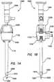
- FIGS. 1A and 1Bare front and side views of an embodiment of a surgical access or trocar system 1000, which is suitable, for example, as a first entry trocar system.
- the illustrated embodimentis suitable, for example, as a 5-mm trocar system, as well as for trocar systems of other sizes.
- the illustrated access system 1000comprises a trocar 1100, an obturator 1200, and a laparoscope 1300.
- the trocar 1100comprises a longitudinal axis, a proximal end, and a distal end.
- the proximal endis disposed proximal to a user, for example, a surgeon, during use.
- the distal endis disposed away from the user during use.
- the obturator 1100comprises a tubular cannula 1110 and a trocar seal assembly 1120 disposed at the proximal end of the cannula 1110.
- the seal assembly 1120comprises a fluid inlet comprising a Luer fitting 1122 and a stopcock 1124.
- the fluid inlethas a different configuration and/or is disposed on another component, for example, on the obturator 1100.
- the obturator 1200is an insufflating optical obturator, as will be described in greater detail below.
- the obturator 1200comprises a longitudinal axis, a proximal end, and a distal end.
- the obturator 1200comprises an elongate shaft 1210, which is dimensioned for slidable insertion into and removal from the tubular cannula 1110 of the trocar, a tip 1220 disposed at the distal end of the shaft 1210, and a handle 1230 disposed at the proximal end of the shaft 1210.
- the obturator tip 1220is a bladeless tip.
- the tip 1220has another configuration useful for traversing and/or penetrating body tissue, for example, a sharp tip, a pointed tip, a pyramidal tip, a bladed tip, a conical tip, and/or a tip comprising one or more sharp edges or sharpened edges.
- the tip 1220is a radiused blunt tip, which is advantageous for traversing an existing body orifice, and/or relatively soft or fatty tissue.
- the trocar 1100 and obturator 1200independently comprise any suitable material. Those skilled in the art will understand that different components of the trocar 1100 and/or obturator 1200 comprise different materials in some embodiments. Suitable materials include, for example, at least one of a polymer, metal, ceramic, and the like. Suitable polymers include engineering polymers, polycarbonate, polysulfone, PEEK, polyether block amide (PEBAX®), polyester, copolyester, acrylic, and the like. Some embodiments of the trocar 1100 and/or obturator 1100 further comprise a composite, for example, a fiber-reinforced polymer.
- a stronger materialpermits reducing a wall thickness of a component without reducing the strength thereof.
- some embodiments of a metal or composite obturator shaft 1210are thinner than a corresponding polymer version, thereby increasing the diameter of a lumen thereof without increasing the outer diameter. As discussed in detail below, increasing lumen diameter improves gas flow through the device.
- obturator shaft 1210comprises a metal tube, for example, a stainless steel tube, with a polycarbonate tip 1220 insert molded onto the tube.
- the metal tubehas a wall thickness as thin as about 0.003" (about 0.076 mm).
- An metal obturator shaft 1210 with an inside diameter of about 0.235" (about 6 mm) and an outside diameter of about 0.241" (about 6 mm)provides an acceptable insufflation gas flow rate. The relationship between gas flow rate and component dimensions and configurations is discussed in detail below.
- Embodiments of the cannula 1110typically comprise a rigid material. Some embodiments of the obturator shaft 1210 comprise a rigid material and/or a flexible material because the obturator shaft 1210 is largely supported by the cannula 1110 during use in some embodiments.
- the laparoscope 1300comprises a proximal end and a distal end 1304 ( FIGS. 1C and 1D ).
- the laparoscope 1300is of any suitable type, for example, comprising an eyepiece at a proximal end and an objective at a distal end thereof.
- the distal end 1304 of the laparoscope 1300is dimensioned for slidable insertion into and removal from the obturator shaft 1210.
- FIG. 1Cis a front cross-sectional view and FIG. 1D is a side cross-sectional view of the distal end of the insufflating obturator 1200 with a laparoscope 1300 inserted therein.
- the illustrated embodimentdepicts a bladeless obturator 1200 suitable for visualization and insufflation therewith.
- the deviceinclude a pair of vent holes 1222 at the distal tip 1220 of the bladeless obturator, through which an insufflating gas, such as carbon dioxide, flows into a body cavity, as discussed in greater detail below.
- Other embodimentscomprise more or fewer vent holes 1222.
- some embodiments of the tip 1220 of the obturatorcomprise a single vent hole 1222.
- vent holes 1222are generally circular. In other embodiments, the vent holes 1222 have another shape, for example, oval, elliptical, tear-drop shaped, slot shaped, slit shaped, chevron-shaped, triangular, rectangular, rhomboid, polygonal, and the like. In some embodiments, at least one vent hole 1222 has a different shape from another vent hole 1222.
- the obturator 1200is an optical obturator in which at least a portion of a distal end of the tip 1220 of the bladeless obturator comprises a generally transparent or translucent material, through which tissue is visualized during the insertion of the obturator 1200 through a body wall.
- Embodiments of the bladeless obturator 1200are dimensioned and configured to receive therein any suitable laparoscope 1300, which typically includes an imaging element and fiber optic light fibers (not illustrated).
- the illustrated embodiment of the tip 1220comprises at least one laparoscope stop 1224, which assists in positioning the laparoscope 1300 within the obturator 1200.
- one or more laparoscope stopsare disposed within the obturator shaft 1210 and/or at the intersection of the shaft 1210 and tip 1220. Other embodiments do not comprise a laparoscope stop.
- the illustrated embodiment of the bladeless optical insufflating obturator 1200includes a tip 1220 configuration comprising one or more features that enhance the visualization and clarity through the tip of the obturator.
- the illustrated transparent tip 1220 of the obturator through which tissue is observedcomprises a wall 1225, at least a portion of which has a substantially uniform thickness.
- the uniform wall thicknessreduces distortion of an image observed through the obturator tip 1220.
- the entire obturator tip 1220comprises a substantially uniform wall thickness.
- Embodiments of bladeless optical obturators comprising non-uniform wall thicknessestypically exhibit less clear imaging through the obturator tip because the varying wall thickness distorts the image transmitted therethrough, for example, in bladeless optical obturators comprising a generally circular inner contour and a generally rectangular outer contour.
- FIG. 1Eis a top view of a transverse cross section of the obturator tip 1220 illustrated in FIGS. 1A-1D .
- an inner contour 1226 of the obturator tip 1220has a generally rectangular transverse cross section, which substantially matches an outer contour 1228 of the obturator tip, which also has a generally rectangular transverse cross section.
- the inner and outer transverse cross-sectional contours 1226 and 1228 of the obturator tip 1220have another shape, for example, generally elliptical, hexagonal, S-shaped, or another suitable shape.
- a portion of an interior surface the tip 1220 at which the distal end laparoscope 1300 contactshas a contour different from a shape or contour of the distal end of the laparoscope.
- the portion of the tip 1220 at which the distal end of the laparoscope 1300 contactsis not circular, thereby defining a gas flow channel therebetween, as discussed in greater detail below.
- the wall 1225 of the obturator tip 1220comprises a thin-wall configuration.
- the thin-wall configurationenables light to travel through the material with reduced loss in intensity, thereby enhancing the visibility of tissue through the obturator tip 1220 as the obturator is advanced and placed into the targeted body cavity.
- the thin-wall configurationalso reduces distortion of the image viewed through the obturator tip 1220 and maintains the color accuracy of the viewed tissue.
- Some embodiments of the obturators 1200have tip wall thicknesses of from about 0.02" (about 0.5 mm) to about 0.025" (about 0.65 mm) for about 5-mm to 12-mm obturators. In some embodiments, the tip wall is thicker, for example, to provide additional strength.
- All transparent materialshave a light transmittance value of less than 100%. That is, less than 100% of the light incident on the material is transmitted directly through the material. For a given transparent material, as the wall thickness of the material increases, the amount of light that travels through the material decreases. Moreover, because the illuminating light is directed from within the obturator 1200, the light must travel through the obturator tip 1220 twice, thereby doubling the loss of light due to the transmittance characteristics or absorption of the obturator tip 1220.
- Embodiments of an obturator tip 1220 with a reduced wall thicknessreduce the loss of light or absorption thereby, thereby improving the image of the tissue through which the obturator 1200 is advanced, and maintaining the color accuracy and fidelity of the observed tissue.
- the obturator shaft 1210 and tip 1220are injection molded as a unitary or single, integral component, which, in combination with the thin-wall tip 1220, allows positioning or placing a distal end 1304 of the laparoscope ( FIGS. 1C and 1D ) in close proximity to and/or within the tip 1220 of the obturator.
- a distal end 1304 of the laparoscopeFIGS. 1C and 1D
- an image produced through the laparoscope 1300is magnified compared with an image produced by a distal end 1304 of the laparoscope 1300 positioned at a greater distance from the obturator tip 1220.
- the distal end of the laparoscopeis positionable as close as about 0.442" (about 11 mm) from the distal end of the obturator 1200.
- Some embodiments of a 12-mm bladeless optical obturator designed to accommodate about 10-mm diameter laparoscopespermit positioning the distal end of the laparoscope as close as about 0.79" (about 20 mm) from the distal end of the obturator 1200 or less than about 0.83" (about 21 mm) from the distal end of the obturator 1200.
- the magnification through the 5-mm optical obturatoris greater than that for the 12-mm optical obturator.
- the vent holes 1222are useful as markers for indicating the penetration depth of the obturator tip 1220.
- the surgeonadvances the trocar system 1000 through tissue, the surgeon can view the vent holes 1222 through the laparoscope 1300, thereby observing when the vent holes 1222 have traversed a body wall, such as the abdominal wall. Once the vent holes 1222 have traversed a body wall and entered a body cavity, the trocar system 1000 need not be advanced further.
- the enhanced visibility of the obturator tip 1220permits precise placement of the access system 1000, and consequently, the trocar 1100 into a body cavity, thereby preventing the trocar 1100 from being advanced too far into the body cavity. Because the surgeon is able to precisely place the trocar system 1000 across a body wall until just the portion of the obturator tip 1200 comprising the vent holes 1222 is positioned within the body cavity, the risk of injury to internal body structures is reduced.
- one or more indiciaare provided on at least one vent hole 1222, thereby increasing the utility, visibility, and/or prominence of the vent holes 1222 as depth indicators.
- one or more contrasting and/or fluorescent colorsare printed in the vent hole 1222 bores.
- one or more marker bands or indiciaare disposed proximate to or near at least one vent hole 1222, for example, by printing one or more contrasting or fluorescent marker bands.
- the enhanced visibility through the tip 1220 of the obturatorpermits using the marker bands for monitoring the penetration depth of the obturator 1200.
- the marker bandis highly visible through the laparoscope 1300 as a rectangular band positioned just proximal to the vent holes 1222.
- the marker bandshave another shape, for example, dots. As a surgeon advances the access system 1000 through the tissue, the surgeon can view the position of the marker band to determine when the vent holes 1222 have traversed a body wall.
- the enhanced visualization through the obturator tip 1220enables precise placement of the trocar 1100 into a body cavity, thereby preventing the trocar 1100 from being advanced too far into the body cavity. Precisely placing the access system 1000 across a body wall until just the portion of the obturator tip 1220 with the vent holes 1222 is in the body cavity reduces the risk of injury to internal body structures.
- some embodimentsprovide a device comprising an insufflation flow path or channel 1400 defined by an inner wall of the obturator shaft 1210 and the laparoscope 1300.
- a 5-mm bladeless optical trocar with a 5-mm obturatorare dimensioned and configured to accommodate laparoscopes with diameters of from about 5 mm to about 5.5 mm (from about 0.197" to about 0.217") with an insufflation flow channel 1400 extending longitudinally through the inside of the obturator between the outside wall of the laparoscope 1300 and the inside wall of the obturator shaft 1210.
- the insufflation flow channel 1400is dimensioned to accommodate a suitable flow of an insufflating gas, for example, carbon dioxide.
- a cross-sectional area of the insufflation flow channelis at least about 0.0025 in 2 (about 1.6 mm 2 ).
- an inside diameter of the obturator shaft 1210is larger compared with the inside diameter of the obturator shaft of a typical 5-mm optical obturator. Increasing the inside diameter of the obturator shaft 1210 defines a generally cylindrical flow channel 1400 sufficient for insufflation when either a 5-mm or 5.5-mm laparoscope 1300 is inserted into the obturator 1200.
- an outer diameter of the obturator shaft 1210is also increased.
- the inner diameter and outer diameter of the trocar cannula 1110are also increased compared with typical a 5-mm trocar cannula.
- a polycarbonate insufflating obturatorwas manufactured in which the inner diameter of the 5-mm insufflating obturator shaft was 0.235" (6 mm), the outer diameter was 0.272" (6.9 mm), and the wall thickness was 0.018" (0.46 mm).
- the inner diameter of the mating 5-mm cannulawas 0.277" (7 mm), the outer diameter was 0.343" (8.7 mm), and the wall thickness of the cannula was 0.033" (0.84 mm).
- the cross-sectional area of the obturator flow channel with a 5.5 mm laparoscope inserted thereinwas 0.0064 in 2 (4.1 mm 2 ), which provides a carbon dioxide flow rate of about 6 L/min at an insufflator pressure setting of about 1.6-2 KPa (about 12-15 Torr).
- a polycarbonate 5-mm bladeless optical trocar designed to accommodate 5-mm to 5.5-mm laparoscopesincluded an obturator with an inner diameter of 0.219" (5.6 mm), an outer diameter of 0.225" (5.7 mm), and a wall thickness of 0.003" (0.076 mm).
- the mating cannula for this obturatorhad an inner diameter of 0.227" (5.8 mm), an outer diameter of 0.287" (7.3 mm), and a wall thickness of 0.03" (0.76 mm).
- the cross-sectional area of the obturator flow channel with a 5.5-mm laparoscope inserted in the obturatorwas 0.00068 in 2 (0.44 mm 2 ), which provides an insufficient flow of carbon dioxide through the device.
- a 5-mm obturatoris molded from polycarbonate with an inside diameter of 0.230" (5.8 mm) and a wall thickness of 0.021" (0.53 mm).
- the carbon dioxide flow rate through this obturator with a 5.5-mm laparoscope inserted thereinis about 3.5 L/minute at an insufflator pressure setting of about 1.6-2 KPa (about 12-15 Torr).
- the increased wall thicknessimproves the injection molding process for manufacturing the obturator shaft.
- the tip 1220 of a bladeless insufflating obturatoris designed to separate and dilate tissue and muscle fibers during traversal of a body wall. Because of the dilating and separating properties of a 5-mm insufflating trocar, increasing the outer diameters of the obturator shaft 1210 and the cannula 1110, as compared with typically sized 5-mm bladeless trocars, does not adversely affect the insertion force of the trocar in the illustrated embodiment.
- the wall thickness of the obturator shaft 1210is also sufficient to permit injection molding the shaft 1210 and tip 1220 as a single piece, thereby reducing the overall device cost and increasing production capacity.
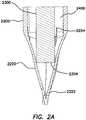
- FIG. 2Ais a side cross-sectional view and FIG. 2B is a front cross-sectional view of a distal end of another embodiment of an insufflating optical obturator 2200 with a laparoscope 2300 inserted therein.
- FIG. 2Cis a top view of a transverse cross section of a tip 2220 of the insufflating optical obturator 2200 and laparoscope 2300 illustrated in FIGS. 2A and 2B .
- the following descriptionrefers to a 12-mm obturator sized to accommodate 10-mm laparoscopes, which defines an insufflation flow channel sufficient for generating pneumoperitoneum.
- the illustrated embodimentis also scalable to other size trocar systems.
- the illustrated 12-mm obturatoralso accommodates smaller laparoscopes 2300 such as 5-mm and/or 5.5-mm diameter laparoscopes.
- the tip 2220 of the obturatoris configured such that a distal end 2304 a 5-mm to 5.5-mm laparoscope is insertable deep into a tapered portion of the obturator tip 2220, while still defining an insufflation flow channel 2400 with a sufficient minimum area for a suitable flow of carbon dioxide around the laparoscope 2300.
- a shorter dimension or width of a generally rectangular internal surface 2226 of the tip of the obturatordefines a stop for a 5-mm and/or 5.5-mm laparoscope 2300.
- the insufflation flow channel 2400is defined by the area between the internal longer dimension or internal length of the internal surface 2226 of the tip and the outside wall of the laparoscope 2300, as best viewed in FIGS. 2A and 2C .
- the insufflation flow channel 2400is fluidly connected to one or more vent holes 2222 disposed on the tip.
- the embodiment illustrated in FIG. 2Aalso comprises an optional stop 2224 for a 10-mm laparoscope.
- distal end of the 5-mm or 5.5 mm laparoscope 2300 and the portion of the inner surface 2226 of the tip that acts as a stop thereforhave similar shapes do not provide an insufflation flow channel 2400 with an sufficiently large minimum area to provide a desired insufflation gas flow.
- inserting a round laparoscope 2300 into an obturator 2200 in which the stop portion of the inner surface 2226 has a circular transverse cross sectionprovides only a small or even no flow channel 2400, thereby effectively isolating the vent holes 2222 from the lumen of the shaft 2210 and preventing gas flow therethrough.
- the illustrated trocar systemexhibits improved flexibility, versatility, and/or performance, while reducing cost and inventory requirements. Pairing a 5-mm and/or 5.5-mm laparoscope with a 12-mm obturator improves the flow rate of carbon dioxide through the obturator 2200 with the laparoscope inserted therein compared with the flow rate through the obturator 2200 with a 10-mm laparoscope inserted therein. Also, a hospital or clinic may not have any 10-mm zero-degree laparoscopes readily available, whereas many facilities have 5mm and/or 5.5mm zero-degree laparoscopes readily available.
- the distal end of a 5mm or 5.5mm laparoscopeis closer to the distal end of the obturator tip 2200 compared with a 10-mm laparoscope, thereby providing a magnified image.
- the distal end of a 5-mm or 5.5-mm laparoscopeis positioned at about 0.430" (about 11 mm) from the distal end of the tip 2200 of the obturator, while the distal end of a 10-mm laparoscope is positioned at about 0.790" (about 20 mm) from the distal end of the tip 3220 of the obturator.
- FIG. 3Ais a longitudinal cross-section of another embodiment of an insufflating obturator 3200 and FIG. 3B is a detailed longitudinal cross section of a proximal end thereof.
- the insufflating obturator 3200comprises a shaft 3210, a tip 3220, and a handle 3230.
- the handle 3230comprises a funneled entry 3232 disposed at a proximal end thereof.
- a seal assembly 3240is disposed distally thereof. Accordingly, the seal assembly 3240 is spaced from and/or recessed from the proximal end of the obturator 3200, thereby encasing the seal assembly 3240 within the handle 3230.
- the seal assembly 3240is protected from direct user contact and/or manipulation.
- a seal assembly 3240is disposed at the proximal end of the obturator 3200 and externally accessible, one or more components of the seal assembly 3240 are vulnerable to inadvertent deformation, for example, during placement of the trocar system, which can cause loss of pneumoperitoneum.
- the seal assembly 3240is vulnerable to deliberate and/or inadvertent removal and/or loss.
- the illustrated seal assembly 3240seals with instruments of varying diameters as well as providing a zero seal in the absence of an instrument.
- the seal assembly 3240seals with any of 5-mm laparoscopes, 5.5-mm laparoscopes, and/or 10-mm laparoscopes, thereby preventing leakage of carbon dioxide from the proximal end of the obturator 3200.
- At least one opening 3206perforates the shaft 3210, fluidly connecting the interior or lumen with the exterior thereof.
- the at least one opening 3206fluidly connects the interior or lumen of the obturator 3200 to the fluid inlet 1122, thereby permitting fluid flow from the fluid inlet 1122, through the openings 3210, and out the vent holes 3222.
- Some embodiments of the obturator 3200comprise a single opening perforating the shaft.
- the opening or openings 3206independently have another shape, for example, circular, oval, elliptical, tear-drop shaped, slot shaped, slit shaped, chevron-shaped, triangular, rectangular, rhomboid, polygonal, and the like.
- the illustrated seal assembly 3240comprises an internal septum seal 3242 and an internal duckbill valve 3244 disposed at the proximal end of the obturator shaft 3210.
- the septum seal 3242prevents carbon dioxide from leaking from the obturator 3200 when a laparoscope 3300 is inserted therein.
- the duckbill valve 3244prevents carbon dioxide from leaking in the absence of a laparoscope 3300, for example, when the laparoscope 3300 is withdrawn from the obturator 3200 or not used at all.
- the illustrated embodimentalso comprises a sleeve 3246 disposed proximally of the septum seal 3242, which prevents and/or reduces inversion of the septum seal 3242 on withdrawal of the laparoscope 3300 therefrom.
- the septum seal 3242 and the duckbill valve 3444are disposed between the obturator shaft 3210 and the obturator handle 3230 in the illustrated embodiment.
- the obturator handle 3230comprises a funneled entry 3232 at its proximal end leading into a guide channel 3234, which guides or directs the laparoscope 3300 into the obturator 3200.
- the obturator handle 3230comprise a space in the guide channel 3234 sufficient to permit at least some septum seal 3234 inversion during laparoscope 3300 withdrawal without binding the laparoscope 3300.
- the diameter of the cap guide channel 3234is larger than the diameter of the laparoscope plus the thickness of the inverted septum seal, which is sufficient to prevent binding or lock-up of the laparoscope 3300 during withdrawal from the obturator 3200.
- At least one of the septum seal 3242 and duckbill valve 3244is treated by a chlorination process, which reduces friction when inserting, rotating, and/or withdrawing the laparoscope 3300, which typically has a polished surface that generates high friction with septum seals 3242 and duckbill valves 3244.
- at least one of the septum seal 3242 and duckbill valve 3244is coated or treated with one or more other anti-friction materials and/or coatings, such as silicone oil, silicone emulsion, parylene, polytetrafluoroethylene (Teflon®), and/or treated by plasma etching.
- a method for using the surgical access or trocar systemrefers to the embodiment 1000 illustrated in FIGS. 1A-1E , although the method is applicable to any of the embodiments discussed herein.
- the bladeless obturator 1200is first inserted through the trocar seal 1120 and cannula 1110 of the trocar.
- a laparoscope 1300is then inserted into the proximal end of the bladeless obturator 1200 and advanced to the stop 1224 or tip 1220 of the obturator.
- An endoscopic video camera(not illustrated) is attached to the proximal end of the laparoscope 1300 and the access system 1000 is then axially advanced by a surgeon through a body wall.
- the surgeonvisualizes the tissue as it is being separated, for example, using a video monitor connected to the endoscopic video camera.
- the surgeoncan also readily determine when the body wall has been traversed by observing the distal end of the obturator 1200 entering the body cavity.
- the distal end of the obturator 1200includes insufflation vent holes 1222 through which an insufflation gas may flow from the obturator 1200 and into a body cavity.
- the optical access system 1000accesses a targeted body area or region under laparoscopic guidance as discussed above, then is used to administer a medicament under vision.
- the medicamentmay be delivered through the stopcock 1124 and Luer fitting 1122, through the obturator 1200, and out through the vent holes 1222 disposed at the tip 1220 of the obturator.
- vent holeis used here for consistency. Those skilled in the art will understand that in some embodiments, gas need not be delivered through the vent holes. Instead, the vent holes are used for another purpose, for example, for delivering a fluid, aspirating a fluid, withdrawing tissue, and/or as a gauge for placing the device, as discussed above.
- the trocar 1100in this embodiment, is rigid, semi-rigid, or flexible.
- Some embodiments of the obturator 1200comprise a single vent hole 1222.
- the vent hole 1222is disposed at the distal end of the tip 1220, generally along the longitudinal axis of the obturator 1200, which permits a more precise delivery of the medicament.
- the access system 1000is suitable, for example, for rapidly accessing a trauma site and for rapidly delivering a medicament through the obturator under vision to the trauma site.
- the obturator 1200is usable in this application either with or without a trocar 1100.
- the obturator 1200comprises a fluid inlet, for example, a Luer fitting, disposed at or near the proximal end of the obturator 1200, for example, at the handle 1230.
- the fluid inletis fluidly connected to the vent hole 1222 through the lumen of the obturator shaft 1210.
- These embodiments of the trocar system 1100are also useful for accessing a targeted body area under vision using an inserted laparoscope, then withdrawing a body fluid sample and/or a soft tissue sample through the vent or aspiration hole 1222 of the obturator, for example, for pathology analysis, without a cannula.
- the access system 1000further comprises an insufflator comprising a gas flow alarm (not illustrated).
- a source of insufflation gasfor example, an insufflator
- the insufflation gas flowactivated, for example, a carbon dioxide flow.
- the gas flow obstruction alarmwill continue as the trocar is advanced through the tissue until the vent holes 1222 in the tip of the obturator are positioned within a hollow body cavity, at which point, carbon dioxide automatically starts flowing into the cavity and the gas flow obstruction alarm on the insufflator deactivates, thereby serving as an audible indicator that the distal tip 1222 of the obturator is properly positioned within the body cavity.
- the access system 1000further comprise an integral audible indicator (not illustrated), which indicates gas flow, for example, carbon dioxide, through the device.
- the audible indicatorproduces a sound, for example, a high-pitched tone, for example, by mechanically modulating the gas flow through the device.
- the audible indicatoris disposed in the trocar 1100.
- the audible indicatoris integral to the trocar seal 1120, the audible indicator is positioned within and/or integrated with the stopcock Luer fitting 1122.
- the audible indicatoris disposed in the obturator 1200.
- the audible indicatoris a detachable component, for example, disposed between and fluidly connecting the stopcock Luer fitting 1122 and the insufflation tubing.
- the access system 1000 comprising the audible indicatoris connected to an insufflator and the carbon dioxide gas flow activated.
- tissuesuch as the abdominal wall
- the tissueblocks gas flow through the device.
- the gas flowremains blocked until the vent holes 1222 in the tip of the obturator reach the targeted body cavity.
- the vent holes 1222are positioned within the body cavity, the carbon dioxide automatically starts flowing into the cavity.
- the gas flowactivates the audible indicator, thereby creating a high-pitched tone, which signals that the distal tip 1220 of the obturator is properly positioned within the body cavity.
- the access system 1000further comprise a visual indicator (not illustrated), for example, a flow sight that indicates carbon dioxide flow through the device.
- Suitable visual indicatorsinclude a flapper, a rotor, and/or an oscillating ball.
- the visual indicatoris integral to the trocar seal 1120, for example, positioned within and/or integrated with the stopcock Luer fitting 1122.
- the visual indicatoris disposed within the proximal portion of the obturator 1200.
- the visual indicatoris a detachable component disposed between the Luer fitting 1122 and the insufflation tubing.
- the trocar systemis connected to an insufflator and the carbon dioxide gas flow activated.
- tissuesuch as the abdominal wall
- the gas flowis blocked.
- the vent holes 1222 in the tip of the obturatorenter the targeted body cavity.
- the carbon dioxideautomatically flows into the body cavity.
- the gas flowcauses movement of the visual flow indicator, thereby indicating that the distal tip of the obturator is properly positioned within the body cavity.
- Some embodiments of the access system 1000comprise an electronic gas flow indicator.
- An output of the gas flow indicatoris, for example, audible and/or visible.
Landscapes
- Health & Medical Sciences (AREA)
- Life Sciences & Earth Sciences (AREA)
- Surgery (AREA)
- General Health & Medical Sciences (AREA)
- Public Health (AREA)
- Veterinary Medicine (AREA)
- Nuclear Medicine, Radiotherapy & Molecular Imaging (AREA)
- Animal Behavior & Ethology (AREA)
- Molecular Biology (AREA)
- Engineering & Computer Science (AREA)
- Biomedical Technology (AREA)
- Heart & Thoracic Surgery (AREA)
- Medical Informatics (AREA)
- Pathology (AREA)
- Biophysics (AREA)
- Radiology & Medical Imaging (AREA)
- Physics & Mathematics (AREA)
- Optics & Photonics (AREA)
- Endoscopes (AREA)
- Surgical Instruments (AREA)
- Magnetic Resonance Imaging Apparatus (AREA)
Description
- This disclosure is generally directed to surgical access devices, and more particularly, to a first-entry surgical access system.
- Trocars are used for instrument access to body cavities in minimally invasive surgery, for example, laparoscopic surgery. In laparoscopic surgery of the organs of the abdomen, the abdomen is typically inflated or insufflated with an insufflation gas, for example, carbon dioxide, which lifts the abdominal wall away from the internal organs, thereby facilitating access to the organs, a condition referred to as pneumoperitoneum. Inserting trocars into an abdomen under pneumoperitoneum is relatively easy. Because the abdominal wall is distended away from the internal organs by the pressure of the insufflation gas, inadvertent damage to the organs during insertion is reduced. Before pneumoperitoneum is established, however, the abdominal wall through which the trocar is to be inserted contacts the internal organs directly. Consequently, inserting the first trocar, referred to as first entry, carries an increased risk of damaging the internal organs directly beneath the entry point.
- US patent application, publication number
US 2008/0086074 A1 discloses a visual obturator which may also permit insufflation. The preamble of claim 1 is based on this document. - In accordance with the present invention there is provided a surgical access system according to claim 1. Preferred embodiments are define in the dependent claims. Improved optical characteristics of the trocar system permit precise and accurate visual placement thereof into a body cavity. Accordingly the access system is suitable as a first entry surgical access system. Embodiments of the trocar access are also useful for drug delivery, and/or for fluid and/or tissue aspiration.
- Some embodiments provide a bladeless trocar that permits visualization of body tissue fibers as they are being separated, thereby permitting a controlled traversal across a body wall. Some embodiments provide a bladeless trocar that accommodates a conventional laparoscope.
- In some embodiments, the seal assembly comprises a septum seal and a duckbill valve.
- In some embodiments, the fluid inlet is disposed on the proximal end of the trocar.
- In some embodiments, the obturator tip is bladeless. In some embodiments, the wall of the obturator tip is not greater than about 0.65 mm thick. In some embodiments, the obturator tip has a substantially uniform wall thickness. In some embodiments, the obturator shaft and tip are unitary. In some embodiments, the obturator tip comprises at least one of polymer, polycarbonate, polysulfone, PEEK, polyether block amide (PEBAX®), polyester, copolyester, and acrylic.
- In some embodiments, the obturator tip comprises a single vent hole. In some embodiments, the at least one vent hole is at least one of circular, oval, elliptical, tear-drop shaped, slot shaped, slit shaped, chevron shaped, triangular, rectangular, rhomboid, and polygonal.
- Some embodiments further comprise a depth indicator on the obturator tip. In some embodiments, the depth indicator comprises at least one of indicia disposed in a bore of the at least one vent hole, and indicia disposed proximate to the at least one vent hole.
- In some embodiments, the obturator further comprises at least one laparoscope stop disposed on at least one of the interior surface of the obturator tip and the interior surface of the obturator shaft. In some embodiments, the interior surface of the obturator tip comprises a non-circular transverse cross section.
- In some embodiments, the obturator accommodates laparoscopes with varying diameters. In some embodiments, at least one opening perforates the obturator shaft.
- In some embodiments, a cross-sectional area of the insufflation gas flow channel is at least about 1.6 mm2. In some embodiments, a flow rate through the access system is at least about 3.5 L/min at an insufflator setting of about 1.6-2 KPa.
- Some embodiments further comprise at least one of a gas flow indicator, an audible gas flow indicator, and a visual gas flow indicator.
FIG.1A is a front view andFIG.1B is a side view of a surgical access system comprising a trocar, an insufflating optical obturator, and a laparoscope.FIG.1C is a front cross-sectional view andFIG.1D is a side cross-sectional view a distal end of the insufflating optical obturator illustrated inFIGS.1A and1B with a laparoscope inserted therein.FIG.1E is a top view of a transverse cross section of a tip of the insufflating optical obturator illustrated inFIGS.1A-1D .FIG.2A is a side cross-sectional view andFIG.2B is a front cross-sectional view of a distal end of an embodiment of an insufflating optical obturator with a laparoscope inserted therein in accordance with the present invention.FIG.2C is a top view of a transverse cross-section of a tip of the insufflating optical obturator and laparoscope illustrated inFIGS.2A and2B .FIG3A is a longitudinal cross-section of another embodiment of an insufflating optical obturator.FIG.3B is a detailed cross section of a handle of the insufflating optical obturator illustrated inFIG.3A .Fig. 1A-1C disclose exemplary embodiments not forming part of the claimed invention although they illustrate features that can be used in combination with the invention as claimed.Fig. 2A-3B disclose embodiments of the invention.FIGS.1A and1B are front and side views of an embodiment of a surgical access ortrocar system 1000, which is suitable, for example, as a first entry trocar system. The illustrated embodiment is suitable, for example, as a 5-mm trocar system, as well as for trocar systems of other sizes. The illustratedaccess system 1000 comprises atrocar 1100, anobturator 1200, and alaparoscope 1300.- The
trocar 1100 comprises a longitudinal axis, a proximal end, and a distal end. The proximal end is disposed proximal to a user, for example, a surgeon, during use. Conversely, the distal end is disposed away from the user during use. Theobturator 1100 comprises atubular cannula 1110 and atrocar seal assembly 1120 disposed at the proximal end of thecannula 1110. In the illustrated embodiment, theseal assembly 1120 comprises a fluid inlet comprising a Luer fitting1122 and astopcock 1124. In other embodiments, the fluid inlet has a different configuration and/or is disposed on another component, for example, on theobturator 1100. - In the illustrated embodiment, the
obturator 1200 is an insufflating optical obturator, as will be described in greater detail below. Theobturator 1200 comprises a longitudinal axis, a proximal end, and a distal end. Theobturator 1200 comprises anelongate shaft 1210, which is dimensioned for slidable insertion into and removal from thetubular cannula 1110 of the trocar, atip 1220 disposed at the distal end of theshaft 1210, and ahandle 1230 disposed at the proximal end of theshaft 1210. In some embodiments, theobturator tip 1220 is a bladeless tip. In other embodiments, thetip 1220 has another configuration useful for traversing and/or penetrating body tissue, for example, a sharp tip, a pointed tip, a pyramidal tip, a bladed tip, a conical tip, and/or a tip comprising one or more sharp edges or sharpened edges. In other embodiments, thetip 1220 is a radiused blunt tip, which is advantageous for traversing an existing body orifice, and/or relatively soft or fatty tissue. - The
trocar 1100 andobturator 1200 independently comprise any suitable material. Those skilled in the art will understand that different components of thetrocar 1100 and/orobturator 1200 comprise different materials in some embodiments. Suitable materials include, for example, at least one of a polymer, metal, ceramic, and the like. Suitable polymers include engineering polymers, polycarbonate, polysulfone, PEEK, polyether block amide (PEBAX®), polyester, copolyester, acrylic, and the like. Some embodiments of thetrocar 1100 and/orobturator 1100 further comprise a composite, for example, a fiber-reinforced polymer. In some embodiments, a stronger material permits reducing a wall thickness of a component without reducing the strength thereof. For example, some embodiments of a metal orcomposite obturator shaft 1210 are thinner than a corresponding polymer version, thereby increasing the diameter of a lumen thereof without increasing the outer diameter. As discussed in detail below, increasing lumen diameter improves gas flow through the device. - For example, in some embodiments,
obturator shaft 1210 comprises a metal tube, for example, a stainless steel tube, with apolycarbonate tip 1220 insert molded onto the tube. In some embodiments, the metal tube has a wall thickness as thin as about 0.003" (about 0.076 mm). Anmetal obturator shaft 1210 with an inside diameter of about 0.235" (about 6 mm) and an outside diameter of about 0.241" (about 6 mm) provides an acceptable insufflation gas flow rate. The relationship between gas flow rate and component dimensions and configurations is discussed in detail below. - Embodiments of the
cannula 1110 typically comprise a rigid material. Some embodiments of theobturator shaft 1210 comprise a rigid material and/or a flexible material because theobturator shaft 1210 is largely supported by thecannula 1110 during use in some embodiments. - The
laparoscope 1300 comprises a proximal end and a distal end1304 (FIGS.1C and1D ). Thelaparoscope 1300 is of any suitable type, for example, comprising an eyepiece at a proximal end and an objective at a distal end thereof. Thedistal end 1304 of thelaparoscope 1300 is dimensioned for slidable insertion into and removal from theobturator shaft 1210. FIG.1C is a front cross-sectional view andFIG.1D is a side cross-sectional view of the distal end of the insufflatingobturator 1200 with alaparoscope 1300 inserted therein. The illustrated embodiment depicts abladeless obturator 1200 suitable for visualization and insufflation therewith. The device include a pair ofvent holes 1222 at thedistal tip 1220 of the bladeless obturator, through which an insufflating gas, such as carbon dioxide, flows into a body cavity, as discussed in greater detail below. Other embodiments comprise more or fewer vent holes1222. For example, some embodiments of thetip 1220 of the obturator comprise asingle vent hole 1222. In the illustrated embodiment, the vent holes1222 are generally circular. In other embodiments, the vent holes1222 have another shape, for example, oval, elliptical, tear-drop shaped, slot shaped, slit shaped, chevron-shaped, triangular, rectangular, rhomboid, polygonal, and the like. In some embodiments, at least onevent hole 1222 has a different shape from anothervent hole 1222.- In some embodiments, the
obturator 1200 is an optical obturator in which at least a portion of a distal end of thetip 1220 of the bladeless obturator comprises a generally transparent or translucent material, through which tissue is visualized during the insertion of theobturator 1200 through a body wall. Embodiments of thebladeless obturator 1200 are dimensioned and configured to receive therein anysuitable laparoscope 1300, which typically includes an imaging element and fiber optic light fibers (not illustrated). The illustrated embodiment of thetip 1220 comprises at least onelaparoscope stop 1224, which assists in positioning thelaparoscope 1300 within theobturator 1200. In other embodiments one or more laparoscope stops are disposed within theobturator shaft 1210 and/or at the intersection of theshaft 1210 andtip 1220. Other embodiments do not comprise a laparoscope stop. - The illustrated embodiment of the bladeless
optical insufflating obturator 1200 includes atip 1220 configuration comprising one or more features that enhance the visualization and clarity through the tip of the obturator. The illustratedtransparent tip 1220 of the obturator through which tissue is observed comprises awall 1225, at least a portion of which has a substantially uniform thickness. The uniform wall thickness reduces distortion of an image observed through theobturator tip 1220. In some embodiments, theentire obturator tip 1220 comprises a substantially uniform wall thickness. Embodiments of bladeless optical obturators comprising non-uniform wall thicknesses typically exhibit less clear imaging through the obturator tip because the varying wall thickness distorts the image transmitted therethrough, for example, in bladeless optical obturators comprising a generally circular inner contour and a generally rectangular outer contour. FIG.1E is a top view of a transverse cross section of theobturator tip 1220 illustrated inFIGS.1A-1D . In the illustrated embodiment, aninner contour 1226 of theobturator tip 1220 has a generally rectangular transverse cross section, which substantially matches anouter contour 1228 of the obturator tip, which also has a generally rectangular transverse cross section. In other embodiments, the inner and outer transversecross-sectional contours obturator tip 1220 have another shape, for example, generally elliptical, hexagonal, S-shaped, or another suitable shape. In some embodiments, a portion of an interior surface thetip 1220 at which thedistal end laparoscope 1300 contacts has a contour different from a shape or contour of the distal end of the laparoscope. For example, in embodiments in which the distal end of thelaparoscope 1300 is circular, the portion of thetip 1220 at which the distal end of thelaparoscope 1300 contacts is not circular, thereby defining a gas flow channel therebetween, as discussed in greater detail below.- In some embodiments, at least a portion of the
wall 1225 of theobturator tip 1220 comprises a thin-wall configuration. The thin-wall configuration enables light to travel through the material with reduced loss in intensity, thereby enhancing the visibility of tissue through theobturator tip 1220 as the obturator is advanced and placed into the targeted body cavity. The thin-wall configuration also reduces distortion of the image viewed through theobturator tip 1220 and maintains the color accuracy of the viewed tissue. Some embodiments of theobturators 1200 have tip wall thicknesses of from about 0.02" (about 0.5 mm) to about 0.025" (about 0.65 mm) for about 5-mm to 12-mm obturators. In some embodiments, the tip wall is thicker, for example, to provide additional strength. - All transparent materials have a light transmittance value of less than 100%. That is, less than 100% of the light incident on the material is transmitted directly through the material. For a given transparent material, as the wall thickness of the material increases, the amount of light that travels through the material decreases. Moreover, because the illuminating light is directed from within the
obturator 1200, the light must travel through theobturator tip 1220 twice, thereby doubling the loss of light due to the transmittance characteristics or absorption of theobturator tip 1220. Embodiments of anobturator tip 1220 with a reduced wall thickness reduce the loss of light or absorption thereby, thereby improving the image of the tissue through which theobturator 1200 is advanced, and maintaining the color accuracy and fidelity of the observed tissue. - In some embodiments, the
obturator shaft 1210 andtip 1220 are injection molded as a unitary or single, integral component, which, in combination with the thin-wall tip 1220, allows positioning or placing adistal end 1304 of the laparoscope (FIGS.1C and1D ) in close proximity to and/or within thetip 1220 of the obturator. By placing thedistal end 1304 of the laparoscope in close proximity to and/or within thetip 1220 of the obturator, an image produced through thelaparoscope 1300 is magnified compared with an image produced by adistal end 1304 of thelaparoscope 1300 positioned at a greater distance from theobturator tip 1220. For example, in some embodiments of a 5-mm bladeless optical obturator designed to accommodate laparoscopes with diameters of from about 5 mm to about 5.5 mm, the distal end of the laparoscope is positionable as close as about 0.442" (about 11 mm) from the distal end of theobturator 1200. Some embodiments of a 12-mm bladeless optical obturator designed to accommodate about 10-mm diameter laparoscopes, permit positioning the distal end of the laparoscope as close as about 0.79" (about 20 mm) from the distal end of theobturator 1200 or less than about 0.83" (about 21 mm) from the distal end of theobturator 1200. In these embodiments, the magnification through the 5-mm optical obturator is greater than that for the 12-mm optical obturator. - The enhanced visibility through the
tip 1220 of the obturator also enhances the visibility of the vent holes1222 in the tip of the obturator. Consequently, in some embodiments, the vent holes1222 are useful as markers for indicating the penetration depth of theobturator tip 1220. As the surgeon advances thetrocar system 1000 through tissue, the surgeon can view the vent holes1222 through thelaparoscope 1300, thereby observing when the vent holes1222 have traversed a body wall, such as the abdominal wall. Once the vent holes1222 have traversed a body wall and entered a body cavity, thetrocar system 1000 need not be advanced further. Accordingly, the enhanced visibility of theobturator tip 1220 permits precise placement of theaccess system 1000, and consequently, thetrocar 1100 into a body cavity, thereby preventing thetrocar 1100 from being advanced too far into the body cavity. Because the surgeon is able to precisely place thetrocar system 1000 across a body wall until just the portion of theobturator tip 1200 comprising the vent holes1222 is positioned within the body cavity, the risk of injury to internal body structures is reduced. - In some embodiments, one or more indicia are provided on at least one
vent hole 1222, thereby increasing the utility, visibility, and/or prominence of the vent holes1222 as depth indicators. For example, in some embodiments, one or more contrasting and/or fluorescent colors are printed in thevent hole 1222 bores. - In some embodiments, one or more marker bands or indicia are disposed proximate to or near at least one
vent hole 1222, for example, by printing one or more contrasting or fluorescent marker bands. The enhanced visibility through thetip 1220 of the obturator permits using the marker bands for monitoring the penetration depth of theobturator 1200. For example, in some embodiments, the marker band is highly visible through thelaparoscope 1300 as a rectangular band positioned just proximal to the vent holes1222. In other embodiments, the marker bands have another shape, for example, dots. As a surgeon advances theaccess system 1000 through the tissue, the surgeon can view the position of the marker band to determine when the vent holes1222 have traversed a body wall. The enhanced visualization through theobturator tip 1220 enables precise placement of thetrocar 1100 into a body cavity, thereby preventing thetrocar 1100 from being advanced too far into the body cavity. Precisely placing theaccess system 1000 across a body wall until just the portion of theobturator tip 1220 with the vent holes1222 is in the body cavity reduces the risk of injury to internal body structures. - Referring to
FIGS.1C and1D , some embodiments provide a device comprising an insufflation flow path orchannel 1400 defined by an inner wall of theobturator shaft 1210 and thelaparoscope 1300. For example, embodiments of a 5-mm bladeless optical trocar with a 5-mm obturator are dimensioned and configured to accommodate laparoscopes with diameters of from about 5 mm to about 5.5 mm (from about 0.197" to about 0.217") with aninsufflation flow channel 1400 extending longitudinally through the inside of the obturator between the outside wall of thelaparoscope 1300 and the inside wall of theobturator shaft 1210. Theinsufflation flow channel 1400 is dimensioned to accommodate a suitable flow of an insufflating gas, for example, carbon dioxide. In some embodiments, a cross-sectional area of the insufflation flow channel is at least about 0.0025 in2 (about 1.6 mm2). In the illustrated embodiment, an inside diameter of theobturator shaft 1210 is larger compared with the inside diameter of the obturator shaft of a typical 5-mm optical obturator. Increasing the inside diameter of theobturator shaft 1210 defines a generallycylindrical flow channel 1400 sufficient for insufflation when either a 5-mm or 5.5-mm laparoscope 1300 is inserted into theobturator 1200. In the illustrated embodiment, an outer diameter of theobturator shaft 1210 is also increased. To accommodate the slightlylarger obturator shaft 1210, in some embodiments, the inner diameter and outer diameter of thetrocar cannula 1110 are also increased compared with typical a 5-mm trocar cannula. - A polycarbonate insufflating obturator was manufactured in which the inner diameter of the 5-mm insufflating obturator shaft was 0.235" (6 mm), the outer diameter was 0.272" (6.9 mm), and the wall thickness was 0.018" (0.46 mm). The inner diameter of the mating 5-mm cannula was 0.277" (7 mm), the outer diameter was 0.343" (8.7 mm), and the wall thickness of the cannula was 0.033" (0.84 mm). Based on these dimensions, the cross-sectional area of the obturator flow channel with a 5.5 mm laparoscope inserted therein was 0.0064 in2 (4.1 mm2), which provides a carbon dioxide flow rate of about 6 L/min at an insufflator pressure setting of about 1.6-2 KPa (about 12-15 Torr).
- For comparison, a polycarbonate 5-mm bladeless optical trocar designed to accommodate 5-mm to 5.5-mm laparoscopes included an obturator with an inner diameter of 0.219" (5.6 mm), an outer diameter of 0.225" (5.7 mm), and a wall thickness of 0.003" (0.076 mm). The mating cannula for this obturator had an inner diameter of 0.227" (5.8 mm), an outer diameter of 0.287" (7.3 mm), and a wall thickness of 0.03" (0.76 mm). For comparison, the cross-sectional area of the obturator flow channel with a 5.5-mm laparoscope inserted in the obturator was 0.00068 in2 (0.44 mm2), which provides an insufficient flow of carbon dioxide through the device.
- A 5-mm obturator is molded from polycarbonate with an inside diameter of 0.230" (5.8 mm) and a wall thickness of 0.021" (0.53 mm). The carbon dioxide flow rate through this obturator with a 5.5-mm laparoscope inserted therein is about 3.5 L/minute at an insufflator pressure setting of about 1.6-2 KPa (about 12-15 Torr). The increased wall thickness improves the injection molding process for manufacturing the obturator shaft.
- The
tip 1220 of a bladeless insufflating obturator is designed to separate and dilate tissue and muscle fibers during traversal of a body wall. Because of the dilating and separating properties of a 5-mm insufflating trocar, increasing the outer diameters of theobturator shaft 1210 and thecannula 1110, as compared with typically sized 5-mm bladeless trocars, does not adversely affect the insertion force of the trocar in the illustrated embodiment. The wall thickness of theobturator shaft 1210 is also sufficient to permit injection molding theshaft 1210 andtip 1220 as a single piece, thereby reducing the overall device cost and increasing production capacity. FIG.2A is a side cross-sectional view andFIG.2B is a front cross-sectional view of a distal end of another embodiment of an insufflatingoptical obturator 2200 with alaparoscope 2300 inserted therein.FIG.2C is a top view of a transverse cross section of atip 2220 of the insufflatingoptical obturator 2200 andlaparoscope 2300 illustrated inFIGS.2A and2B . The following description refers to a 12-mm obturator sized to accommodate 10-mm laparoscopes, which defines an insufflation flow channel sufficient for generating pneumoperitoneum. Those skilled in the art will understand that the illustrated embodiment is also scalable to other size trocar systems.- The illustrated 12-mm obturator also accommodates
smaller laparoscopes 2300 such as 5-mm and/or 5.5-mm diameter laparoscopes. In accordance with the present invention thetip 2220 of the obturator is configured such that a distal end2304 a 5-mm to 5.5-mm laparoscope is insertable deep into a tapered portion of theobturator tip 2220, while still defining aninsufflation flow channel 2400 with a sufficient minimum area for a suitable flow of carbon dioxide around thelaparoscope 2300. In the illustrated embodiment, a shorter dimension or width of a generally rectangularinternal surface 2226 of the tip of the obturator defines a stop for a 5-mm and/or 5.5-mm laparoscope 2300. Theinsufflation flow channel 2400 is defined by the area between the internal longer dimension or internal length of theinternal surface 2226 of the tip and the outside wall of thelaparoscope 2300, as best viewed inFIGS.2A and2C . Theinsufflation flow channel 2400 is fluidly connected to one ormore vent holes 2222 disposed on the tip. The embodiment illustrated inFIG.2A also comprises anoptional stop 2224 for a 10-mm laparoscope. - Some embodiments in which distal end of the 5-mm or 5.5
mm laparoscope 2300 and the portion of theinner surface 2226 of the tip that acts as a stop therefor have similar shapes do not provide aninsufflation flow channel 2400 with an sufficiently large minimum area to provide a desired insufflation gas flow. For example, inserting around laparoscope 2300 into anobturator 2200 in which the stop portion of theinner surface 2226 has a circular transverse cross section provides only a small or even noflow channel 2400, thereby effectively isolating the vent holes2222 from the lumen of the shaft2210 and preventing gas flow therethrough. - The illustrated trocar system exhibits improved flexibility, versatility, and/or performance, while reducing cost and inventory requirements. Pairing a 5-mm and/or 5.5-mm laparoscope with a 12-mm obturator improves the flow rate of carbon dioxide through the
obturator 2200 with the laparoscope inserted therein compared with the flow rate through theobturator 2200 with a 10-mm laparoscope inserted therein. Also, a hospital or clinic may not have any 10-mm zero-degree laparoscopes readily available, whereas many facilities have 5mm and/or 5.5mm zero-degree laparoscopes readily available. Another advantage is that the distal end of a 5mm or 5.5mm laparoscope is closer to the distal end of theobturator tip 2200 compared with a 10-mm laparoscope, thereby providing a magnified image. For example, in the illustrated embodiment, the distal end of a 5-mm or 5.5-mm laparoscope is positioned at about 0.430" (about 11 mm) from the distal end of thetip 2200 of the obturator, while the distal end of a 10-mm laparoscope is positioned at about 0.790" (about 20 mm) from the distal end of thetip 3220 of the obturator. FIG.3A is a longitudinal cross-section of another embodiment of aninsufflating obturator 3200 andFIG.3B is a detailed longitudinal cross section of a proximal end thereof. The insufflatingobturator 3200 comprises ashaft 3210, atip 3220, and ahandle 3230. Thehandle 3230 comprises a funneledentry 3232 disposed at a proximal end thereof. Aseal assembly 3240 is disposed distally thereof. Accordingly, theseal assembly 3240 is spaced from and/or recessed from the proximal end of theobturator 3200, thereby encasing theseal assembly 3240 within thehandle 3230. Thus, in the illustrated embodiment, theseal assembly 3240 is protected from direct user contact and/or manipulation. In some embodiments in which aseal assembly 3240 is disposed at the proximal end of theobturator 3200 and externally accessible, one or more components of theseal assembly 3240 are vulnerable to inadvertent deformation, for example, during placement of the trocar system, which can cause loss of pneumoperitoneum. Furthermore, in some embodiments, theseal assembly 3240 is vulnerable to deliberate and/or inadvertent removal and/or loss. The illustratedseal assembly 3240 seals with instruments of varying diameters as well as providing a zero seal in the absence of an instrument. Again, using a 12-mm obturator as an illustrative example, theseal assembly 3240 seals with any of 5-mm laparoscopes, 5.5-mm laparoscopes, and/or 10-mm laparoscopes, thereby preventing leakage of carbon dioxide from the proximal end of theobturator 3200.- In the illustrated embodiment of the
obturator 3200, at least oneopening 3206 perforates theshaft 3210, fluidly connecting the interior or lumen with the exterior thereof. When inserted into a suitable trocar, for example, embodiments of thetrocar 1110 illustrated inFIGS.1A and1B , the at least oneopening 3206 fluidly connects the interior or lumen of theobturator 3200 to thefluid inlet 1122, thereby permitting fluid flow from thefluid inlet 1122, through theopenings 3210, and out the vent holes3222. Some embodiments of theobturator 3200 comprise a single opening perforating the shaft. In some embodiments, the opening oropenings 3206 independently have another shape, for example, circular, oval, elliptical, tear-drop shaped, slot shaped, slit shaped, chevron-shaped, triangular, rectangular, rhomboid, polygonal, and the like. - Referring to
FIG.3B , which is a detailed longitudinal cross section of the proximal end of theobturator 3200 illustrated inFIG.3A , the illustratedseal assembly 3240 comprises aninternal septum seal 3242 and aninternal duckbill valve 3244 disposed at the proximal end of theobturator shaft 3210. Theseptum seal 3242 prevents carbon dioxide from leaking from theobturator 3200 when alaparoscope 3300 is inserted therein. Theduckbill valve 3244 prevents carbon dioxide from leaking in the absence of alaparoscope 3300, for example, when thelaparoscope 3300 is withdrawn from theobturator 3200 or not used at all. The illustrated embodiment also comprises asleeve 3246 disposed proximally of theseptum seal 3242, which prevents and/or reduces inversion of theseptum seal 3242 on withdrawal of thelaparoscope 3300 therefrom. Theseptum seal 3242 and the duckbill valve3444 are disposed between theobturator shaft 3210 and theobturator handle 3230 in the illustrated embodiment. Theobturator handle 3230 comprises a funneledentry 3232 at its proximal end leading into aguide channel 3234, which guides or directs thelaparoscope 3300 into theobturator 3200. Some embodiments of theobturator handle 3230 comprise a space in theguide channel 3234 sufficient to permit at least someseptum seal 3234 inversion duringlaparoscope 3300 withdrawal without binding thelaparoscope 3300. For example, in some embodiments, the diameter of thecap guide channel 3234 is larger than the diameter of the laparoscope plus the thickness of the inverted septum seal, which is sufficient to prevent binding or lock-up of thelaparoscope 3300 during withdrawal from theobturator 3200. - In some embodiments, at least one of the
septum seal 3242 andduckbill valve 3244 is treated by a chlorination process, which reduces friction when inserting, rotating, and/or withdrawing thelaparoscope 3300, which typically has a polished surface that generates high friction withseptum seals 3242 andduckbill valves 3244. In some embodiments, at least one of theseptum seal 3242 andduckbill valve 3244 is coated or treated with one or more other anti-friction materials and/or coatings, such as silicone oil, silicone emulsion, parylene, polytetrafluoroethylene (Teflon®), and/or treated by plasma etching. - A method is now described for using the surgical access or trocar system refers to the
embodiment 1000 illustrated inFIGS.1A-1E , although the method is applicable to any of the embodiments discussed herein. In the method, thebladeless obturator 1200 is first inserted through thetrocar seal 1120 andcannula 1110 of the trocar. Alaparoscope 1300 is then inserted into the proximal end of thebladeless obturator 1200 and advanced to thestop 1224 ortip 1220 of the obturator. An endoscopic video camera (not illustrated) is attached to the proximal end of thelaparoscope 1300 and theaccess system 1000 is then axially advanced by a surgeon through a body wall. As the surgeon advances theaccess system 1000 through the body wall, the surgeon visualizes the tissue as it is being separated, for example, using a video monitor connected to the endoscopic video camera. The surgeon can also readily determine when the body wall has been traversed by observing the distal end of theobturator 1200 entering the body cavity. As discussed above, the distal end of theobturator 1200 includes insufflation vent holes1222 through which an insufflation gas may flow from theobturator 1200 and into a body cavity. - Alternatively the
optical access system 1000 accesses a targeted body area or region under laparoscopic guidance as discussed above, then is used to administer a medicament under vision. The medicament may be delivered through thestopcock 1124 and Luer fitting1122, through theobturator 1200, and out through the vent holes1222 disposed at thetip 1220 of the obturator. The term "vent hole" is used here for consistency. Those skilled in the art will understand that in some embodiments, gas need not be delivered through the vent holes. Instead, the vent holes are used for another purpose, for example, for delivering a fluid, aspirating a fluid, withdrawing tissue, and/or as a gauge for placing the device, as discussed above. Thetrocar 1100, in this embodiment, is rigid, semi-rigid, or flexible. Some embodiments of theobturator 1200 comprise asingle vent hole 1222. In some embodiments, thevent hole 1222 is disposed at the distal end of thetip 1220, generally along the longitudinal axis of theobturator 1200, which permits a more precise delivery of the medicament. Theaccess system 1000 is suitable, for example, for rapidly accessing a trauma site and for rapidly delivering a medicament through the obturator under vision to the trauma site. In some embodiments, theobturator 1200 is usable in this application either with or without atrocar 1100. In embodiments that do not include a trocar,
theobturator 1200 comprises a fluid inlet, for example, a Luer fitting, disposed at or near the proximal end of theobturator 1200, for example, at thehandle 1230. The fluid inlet is fluidly connected to thevent hole 1222 through the lumen of theobturator shaft 1210. These embodiments of thetrocar system 1100 are also useful for accessing a targeted body area under vision using an inserted laparoscope, then withdrawing a body fluid sample and/or a soft tissue sample through the vent oraspiration hole 1222 of the obturator, for example, for pathology analysis, without a cannula. - In some embodiments, the
access system 1000 further comprises an insufflator comprising a gas flow alarm (not illustrated). In some embodiments, a source of insufflation gas, for example, an insufflator, is connected to the Luer fitting1122, thestopcock valve 1124 opened, and the insufflation gas flow activated, for example, a carbon dioxide flow. When thetip 1220 of the obturator is placed in tissue such as the abdominal wall, the gas flow is blocked by the tissue, which in turn activates a gas flow obstruction alarm of the insufflator. The gas flow obstruction alarm will continue as the trocar is advanced through the tissue until the vent holes1222 in the tip of the obturator are positioned within a hollow body cavity, at which point, carbon dioxide automatically starts flowing into the cavity and the gas flow obstruction alarm on the insufflator deactivates, thereby serving as an audible indicator that thedistal tip 1222 of the obturator is properly positioned within the body cavity. - Some embodiments of the
access system 1000 further comprise an integral audible indicator (not illustrated), which indicates gas flow, for example, carbon dioxide, through the device. The audible indicator produces a sound, for example, a high-pitched tone, for example, by mechanically modulating the gas flow through the device. In some embodiments, the audible indicator is disposed in thetrocar 1100. In some embodiments in which the audible indicator is integral to thetrocar seal 1120, the audible indicator is positioned within and/or integrated with the stopcock Luer fitting1122. In other embodiments, the audible indicator is disposed in theobturator 1200. In yet other embodiments, the audible indicator is a detachable component, for example, disposed between and fluidly connecting the stopcock Luer fitting1122 and the insufflation tubing. - In some embodiments, the
access system 1000 comprising the audible indicator is connected to an insufflator and the carbon dioxide gas flow activated. When thetip 1220 of the obturator is placed in tissue, such as the abdominal wall, the tissue blocks gas flow through the device. As thetip 1220 is advanced though the tissue, the gas flow remains blocked until the vent holes1222 in the tip of the obturator reach the targeted body cavity. When the vent holes1222 are positioned within the body cavity, the carbon dioxide automatically starts flowing into the cavity. The gas flow activates the audible indicator, thereby creating a high-pitched tone, which signals that thedistal tip 1220 of the obturator is properly positioned within the body cavity. - Some embodiments of the
access system 1000 further comprise a visual indicator (not illustrated), for example, a flow sight that indicates carbon dioxide flow through the device. Suitable visual indicators include a flapper, a rotor, and/or an oscillating ball. In some embodiments, the visual indicator is integral to thetrocar seal 1120, for example, positioned within and/or integrated with the stopcock Luer fitting1122. In other embodiments, the visual indicator is disposed within the proximal portion of theobturator 1200. In other embodiments, the visual indicator is a detachable component disposed between the Luer fitting1122 and the insufflation tubing. - In a method for using the trocar system comprising the integral visual indicator, the trocar system is connected to an insufflator and the carbon dioxide gas flow activated. When the
tip 1220 of the obturator is placed in tissue, such as the abdominal wall, the gas flow is blocked. As thetip 1220 is advanced though tissue, the gas flow remains blocked until the vent holes1222 in the tip of the obturator enter the targeted body cavity. When the vent holes1222 are positioned within the body cavity, the carbon dioxide automatically flows into the body cavity. The gas flow causes movement of the visual flow indicator, thereby indicating that the distal tip of the obturator is properly positioned within the body cavity. - Some embodiments of the
access system 1000 comprise an electronic gas flow indicator. An output of the gas flow indicator is, for example, audible and/or visible. - While certain embodiments have been particularly shown and described with reference to exemplary embodiments thereof, it will be understood by those of ordinary skill in the art that various changes in form and details may be made therein without departing from the scope of the following claims.
Claims (15)
- A surgical access system comprising:a tubular trocar comprising a longitudinal axis, a proximal end, a distal end, an elongate cannula, and a seal assembly disposed at a proximal end of the cannula;an insufflating obturator (2200) slidably insertable into the trocar, the obturator (2200) comprising a longitudinal axis, a proximal end, a distal end, a tubular shaft (1210), a tip (2220) having an inner surface (2226) and being disposed at the distal end of the shaft (1210), the tip comprising a tapered portion, at least one vent hole (2222) disposed on the tapered portion of the tip (2220), and a handle disposed at the proximal end of the shaft (1210);a fluid inlet disposed at a proximal end of the access system; anda laparoscope (2300); whereinat least a portion of the obturator tip (2220) comprises a wall comprising a transparent material with a substantially uniform thickness,the obturator (2200) slidably receives the laparoscope into the obturator (2200) shaft (1210), andan interior surface of the obturator shaft (1210) and tip (2220), and an outer surface of an inserted laparoscope together define a insufflation gas flow channel (2400) fluidly connecting the at least one vent hole (2222) to the fluid inlet;characterized by the obturator being configured to slidably receive the inserted laparoscope into the tubular shaft (1210) of the obturator and extending into the tapered portion of the tip (2220) such that the inner surface (2226) of the tip (2220) abuts the outer surface of the inserted laparoscope while still defining an insufflation gas flow channel (2400) between the inner surface (2226) of the tip (2220) and an outer surface of the inserted laparoscope.
- The surgical access system of Claim 1, wherein the seal assembly comprises a septum seal and a duckbill valve.
- The surgical access system of Claim 1, wherein the fluid inlet is disposed on the proximal end of the trocar.
- The surgical access system of Claim 1, wherein the obturator tip (2220) is bladeless.
- The surgical access system of Claim 1, wherein the wall of the obturator tip (2220) is not greater than about 0.65 mm thick.
- The surgical access system of Claim 1, wherein the obturator tip (2220) comprises a single vent hole (2222).
- The surgical access system of Claim 1, wherein the at least one vent hole (2222) is at least one of circular, oval, elliptical, tear-drop shaped, slot shaped, slit shaped, chevron shaped, triangular, rectangular, rhomboid, and polygonal.
- The surgical access system of Claim 1, further comprising a depth indicator on the obturator tip (2220).
- The surgical access system of Claim 8, wherein the depth indicator comprises at least one of indicia disposed in a bore of the at least one vent hole (2222), and indicia disposed proximate to the at least one vent hole (2222).
- The surgical access system of Claim 1, wherein the obturator (2200) further comprises at least one laparoscope stop (2224) disposed on at least one of the inner surface (2226) of the obturator tip (2220) and the interior surface of the obturator (2200) shaft (1210).
- The surgical access system of Claim 1, wherein the inner surface (2226) of the obturator tip (2220) comprises a non-circular transverse cross section.
- The surgical access system of Claimll, wherein the interior surface (2226) of the obturator tip (2220) is generally rectangular with the shorter dimension of width defining a stop.
- The surgical access system of Claim 1, wherein at least one opening perforates the obturator (2200) shaft (1210).
- The surgical access system of Claim 1, wherein a cross-sectional area of the insufflation gas flow channel (2400) is at least about 1.6 mm2.
- The surgical access system of Claim 1, wherein a flow rate through the access system is at least about 3.5 L/min at an insufflator pressure of about 1.6-2 KPa.
Priority Applications (3)
| Application Number | Priority Date | Filing Date | Title |
|---|---|---|---|
| EP20208082.6AEP3799811B1 (en) | 2008-09-29 | 2009-09-29 | First-entry trocar system |
| EP18155145.8AEP3335651B1 (en) | 2008-09-29 | 2009-09-29 | First-entry trocar system |
| EP19175227.8AEP3545883B1 (en) | 2008-09-29 | 2009-09-29 | First-entry trocar system |
Applications Claiming Priority (2)
| Application Number | Priority Date | Filing Date | Title |
|---|---|---|---|
| US10106108P | 2008-09-29 | 2008-09-29 | |
| PCT/US2009/058792WO2010037099A1 (en) | 2008-09-29 | 2009-09-29 | First-entry trocar system |
Related Child Applications (4)
| Application Number | Title | Priority Date | Filing Date |
|---|---|---|---|
| EP18155145.8ADivision-IntoEP3335651B1 (en) | 2008-09-29 | 2009-09-29 | First-entry trocar system |
| EP18155145.8ADivisionEP3335651B1 (en) | 2008-09-29 | 2009-09-29 | First-entry trocar system |
| EP19175227.8ADivisionEP3545883B1 (en) | 2008-09-29 | 2009-09-29 | First-entry trocar system |
| EP20208082.6ADivisionEP3799811B1 (en) | 2008-09-29 | 2009-09-29 | First-entry trocar system |
Publications (2)
| Publication Number | Publication Date |
|---|---|
| EP2328487A1 EP2328487A1 (en) | 2011-06-08 |
| EP2328487B1true EP2328487B1 (en) | 2018-04-18 |
Family
ID=41401667
Family Applications (4)
| Application Number | Title | Priority Date | Filing Date |
|---|---|---|---|
| EP09737239.5AActiveEP2328487B1 (en) | 2008-09-29 | 2009-09-29 | First-entry trocar system |
| EP18155145.8AActiveEP3335651B1 (en) | 2008-09-29 | 2009-09-29 | First-entry trocar system |
| EP20208082.6AActiveEP3799811B1 (en) | 2008-09-29 | 2009-09-29 | First-entry trocar system |
| EP19175227.8AActiveEP3545883B1 (en) | 2008-09-29 | 2009-09-29 | First-entry trocar system |
Family Applications After (3)
| Application Number | Title | Priority Date | Filing Date |
|---|---|---|---|
| EP18155145.8AActiveEP3335651B1 (en) | 2008-09-29 | 2009-09-29 | First-entry trocar system |
| EP20208082.6AActiveEP3799811B1 (en) | 2008-09-29 | 2009-09-29 | First-entry trocar system |
| EP19175227.8AActiveEP3545883B1 (en) | 2008-09-29 | 2009-09-29 | First-entry trocar system |
Country Status (7)
| Country | Link |
|---|---|
| US (6) | US8506520B2 (en) |
| EP (4) | EP2328487B1 (en) |
| JP (1) | JP5518873B2 (en) |
| AU (1) | AU2009296212B2 (en) |
| CA (1) | CA2734538C (en) |
| ES (3) | ES2748523T3 (en) |
| WO (1) | WO2010037099A1 (en) |
Families Citing this family (48)
| Publication number | Priority date | Publication date | Assignee | Title |
|---|---|---|---|---|
| EP1731087A3 (en) | 2000-07-14 | 2008-08-06 | Novadaq Technologies Inc. | Compact fluorescent endoscopy video system |
| US20060241496A1 (en) | 2002-01-15 | 2006-10-26 | Xillix Technologies Corp. | Filter for use with imaging endoscopes |
| EP2545870B1 (en) | 2004-06-29 | 2015-11-04 | Applied Medical Resources Corporation | Insufflating optical surgical instrument |
| WO2007106624A2 (en) | 2006-02-07 | 2007-09-20 | Novadaq Technologies Inc. | Near infrared imaging |
| EP2328487B1 (en) | 2008-09-29 | 2018-04-18 | Applied Medical Resources Corporation | First-entry trocar system |
| US20130324803A1 (en)* | 2009-01-23 | 2013-12-05 | Reza S. Mohajer | Veress needle with illuminated guidance and suturing capability |
| US8821526B2 (en) | 2010-11-11 | 2014-09-02 | Specialtycare, Inc. | Trocar |
| US9101315B2 (en) | 2010-11-11 | 2015-08-11 | Specialty Care, Inc. | Cannula system |
| ES2769810T3 (en)* | 2011-10-18 | 2020-06-29 | Covidien Lp | Optical trocar system |
| CN102553023B (en)* | 2012-01-19 | 2013-07-10 | 山东新华安得医疗用品有限公司 | Trocar |
| US20130253266A1 (en) | 2012-03-22 | 2013-09-26 | Codman & Shurtleff, Inc. | Fluid management catheter and methods of using same |
| US9186173B2 (en)* | 2012-04-27 | 2015-11-17 | Specialty Care, Inc. | Optical obturator system |
| US9693802B2 (en) | 2012-06-06 | 2017-07-04 | Covidien Lp | Obturator tip with insufflation pathway |
| US9402532B2 (en)* | 2012-06-26 | 2016-08-02 | Covidien Lp | Optical obturator |
| GB2503668B (en)* | 2012-07-03 | 2018-02-07 | Univ Hospitals Of Leicester Nhs Trust | Delivery apparatus |
| EP3323388B1 (en) | 2012-08-24 | 2019-09-18 | Cook Medical Technologies LLC | Medical device for the medialization of a vocal cord |
| WO2014108730A2 (en)* | 2012-12-24 | 2014-07-17 | Novadaq Technologies Inc. | Endoluminal introducer |
| DE102013101336A1 (en) | 2013-02-11 | 2014-08-14 | Pajunk GmbH Medizintechnologie | trocar |
| BR112015022987A2 (en)* | 2013-03-15 | 2017-07-18 | Olive Medical Corp | integrated prism trocar visualization for use with angled endoscope |
| US20140309620A1 (en)* | 2013-04-11 | 2014-10-16 | University Of Iowa Research Foundation | Transilluminating obturator |
| US9433499B2 (en) | 2013-05-07 | 2016-09-06 | Cook Medical Technologies Llc | Vocal cord medialization |
| US20140336634A1 (en)* | 2013-05-13 | 2014-11-13 | New Wave Surgical Corp. | Multifunctional attachment for electrocautery surgical device |
| US20180042459A1 (en)* | 2015-02-23 | 2018-02-15 | Soundcore Technology, Llc. | Medical tool with image enhancing features |
| TWI579566B (en)* | 2015-08-10 | 2017-04-21 | 創意電子股份有限公司 | Circuit probing system and its circuit probing device |
| US10172525B2 (en) | 2015-08-17 | 2019-01-08 | Rebound Therapeutics Corporation | Cannula with proximally mounted camera |
| CN105534576B (en)* | 2016-02-23 | 2017-10-24 | 常州威克医疗器械有限公司 | Disposable puncture device |
| US10293122B2 (en) | 2016-03-17 | 2019-05-21 | Novadaq Technologies ULC | Endoluminal introducer with contamination avoidance |
| JP6871279B2 (en)* | 2016-07-11 | 2021-05-12 | コンメッド コーポレーション | Cannula assembly for robot-assisted pressure-controlled laparoscopic surgery |
| GB2553045B (en)* | 2016-08-17 | 2019-02-13 | Rebound Therapeutics Corp | Cannula with proximally mounted camera |
| KR102486092B1 (en) | 2016-08-17 | 2023-01-06 | 리바운드 세라퓨틱스 코포레이션 | Cannula with Proximally Mounted Camera |
| US10105042B2 (en) | 2016-08-17 | 2018-10-23 | Rebound Therapeutics Corporation | Cannula with proximally mounted camera |
| GB201614658D0 (en)* | 2016-08-30 | 2016-10-12 | Carewill Lda | Laparoscopy Trocar |
| US10201396B2 (en) | 2017-03-07 | 2019-02-12 | Carefusion 2200, Inc. | Trocar assembly with a cleaning element for use during a laparoscopic procedure |
| US10368905B2 (en) | 2017-03-07 | 2019-08-06 | Carefusion 2200, Inc. | Trocar assembly with a cleaning element for use during a laparoscopic procedure |
| US10398296B2 (en) | 2017-03-07 | 2019-09-03 | Carefusion 2200, Inc. | Trocar assembly with a cleaning element for use during a laparoscopic procedure |
| US10806490B2 (en) | 2017-03-08 | 2020-10-20 | Conmed Corporation | Single lumen gas sealed access port for use during endoscopic surgical procedures |
| WO2018222754A1 (en) | 2017-05-31 | 2018-12-06 | Carefusion 2200, Inc. | Trocar assembly with a movable cleaning element |
| US10828065B2 (en)* | 2017-08-28 | 2020-11-10 | Covidien Lp | Surgical access system |
| US11576816B2 (en)* | 2017-10-18 | 2023-02-14 | Jesus Moreno | Opthalmic microsurgical instrument |
| US11039856B2 (en)* | 2018-05-10 | 2021-06-22 | Verily Life Sciences Llc | Surgical laparoscopic ports for implanting medical systems |
| WO2019227018A1 (en)* | 2018-05-25 | 2019-11-28 | Flash Surgical, Inc. | Optical entry trocar camera |
| WO2020121475A1 (en) | 2018-12-13 | 2020-06-18 | オリンパス株式会社 | Gas supply tube connection unit |
| CN116687529A (en) | 2019-03-26 | 2023-09-05 | 康美公司 | Gas circulation system with gas-tight access cover and valve-tight access cover for robotic-assisted surgery |
| WO2021161228A1 (en)* | 2020-02-14 | 2021-08-19 | Fisher & Paykel Healthcare Limited | Obturator for cannula with internal features |
| USD956219S1 (en) | 2020-07-10 | 2022-06-28 | Covidien Lp | Port apparatus |
| USD963851S1 (en) | 2020-07-10 | 2022-09-13 | Covidien Lp | Port apparatus |
| EP4376736A4 (en)* | 2021-07-30 | 2025-05-14 | CONMED Corporation | GAS-SEALED ACCESS CAP FOR ROBOTIC CANNULA AND METHOD FOR PERFORMING ROBOT-ASSISTED SURGERY |
| CN115736784B (en)* | 2022-10-18 | 2024-09-13 | 济南科众医疗科技有限公司 | Integrated visual system and working method |
Family Cites Families (359)
| Publication number | Priority date | Publication date | Assignee | Title |
|---|---|---|---|---|
| DE365049C (en) | 1922-12-07 | Albrecht Meyenberg Dr | Tube speculum for women | |
| US322320A (en)* | 1885-07-14 | Machine for turning crank-pins | ||
| US396754A (en) | 1889-01-29 | Catheter | ||
| US184573A (en) | 1876-11-21 | Improvement in gas-cocks | ||
| US682A (en) | 1838-04-07 | Improvement in carriage-springs | ||
| US207932A (en) | 1878-09-10 | Improvement in surgical dilators | ||
| US224513A (en) | 1880-02-10 | btjrdon | ||
| US1727495A (en) | 1929-09-10 | Beinhold h | ||
| US764322A (en) | 1903-08-17 | 1904-07-05 | Eimer & Amend | Stop-cock. |
| US1147408A (en) | 1915-02-08 | 1915-07-20 | Charles Edmund Kells | Trocar. |
| GB186005A (en) | 1922-01-26 | 1922-09-21 | Louis Marie Clement Charnaux | Improvements in medical catheters, bougies, and the like |
| US1672258A (en) | 1926-10-23 | 1928-06-05 | Creamery Package Mfg Co | Valve |
| US1845727A (en) | 1930-10-04 | 1932-02-16 | George H Slaughter | Trocar |
| US2024069A (en) | 1931-05-04 | 1935-12-10 | John H Sharp | Bolt |
| US2102274A (en) | 1934-06-29 | 1937-12-14 | Louise D Larimore | Microscope for pathological research |
| US2189343A (en) | 1939-02-21 | 1940-02-06 | William A Fritz | Closure for collapsible tubes |
| US2301338A (en) | 1941-02-04 | 1942-11-10 | Us Rubber Co | Apparatus for making tubing |
| US2434594A (en) | 1944-10-06 | 1948-01-13 | Western Electric Co | Molding apparatus |
| US2441143A (en) | 1946-02-28 | 1948-05-11 | James H Gracey | Broach |
| US2646701A (en) | 1949-12-27 | 1953-07-28 | Peter A Letien | Stepped edge cutting tool |
| US2764148A (en) | 1950-07-11 | 1956-09-25 | Sheldon Edward Emannel | Endoscope means for the internal examination of the human body |
| DE1616107U (en) | 1950-09-27 | 1950-11-16 | Andreas Amon | SPINDLE WINCH ASSEMBLY LIFT. |
| US2699770A (en) | 1951-05-11 | 1955-01-18 | Centre Nat Rech Scient | Endoscope |
| US2764149A (en) | 1951-05-23 | 1956-09-25 | Sheldon Edward Emanuel | Electrical device for the examination of the interior of the human body |
| BE524021A (en) | 1951-10-12 | |||
| US3021834A (en) | 1954-03-11 | 1962-02-20 | Sheldon Edward Emanuel | Endoscopes |
| US2877368A (en) | 1954-03-11 | 1959-03-10 | Sheldon Edward Emanuel | Device for conducting images |
| US2932294A (en) | 1954-10-13 | 1960-04-12 | Centre Nat Rech Scient | Lighting devices for endoscopes |
| US3033226A (en) | 1957-08-26 | 1962-05-08 | Valentine E Macy Jr | Valve |
| US3005468A (en) | 1958-08-13 | 1961-10-24 | Hulsey | Rotary sleeve valves |
| NL250623A (en) | 1959-05-05 | |||
| US3042022A (en) | 1959-05-25 | 1962-07-03 | Bausch & Lomb | Illumination means for diagnostic instrument |
| US3385553A (en) | 1961-07-29 | 1968-05-28 | Bernhard Braun | Mold for producing plastic cannulae for continuous intravenous infusion |
| FR84847E (en) | 1962-12-04 | 1965-07-26 | ||
| US3417745A (en) | 1963-08-23 | 1968-12-24 | Sheldon Edward Emanuel | Fiber endoscope provided with focusing means and electroluminescent means |
| US3437747A (en) | 1964-03-24 | 1969-04-08 | Sheldon Edward E | Devices for inspection using fiberoptic members |
| US3277922A (en) | 1964-05-19 | 1966-10-11 | North American Aviation Inc | Flow control device |
| US3459189A (en) | 1965-07-28 | 1969-08-05 | Brunswick Corp | Trocar catheter |
| US3556085A (en) | 1968-02-26 | 1971-01-19 | Olympus Optical Co | Optical viewing instrument |
| DE1616107B1 (en) | 1968-02-26 | 1971-04-08 | Olympus Optical Co | Microscope for introducing and observing body cavities and an optical instrument with such a microscope |
| US3613684A (en) | 1969-09-19 | 1971-10-19 | David S Sheridan | Trocar catheters |
| US3653338A (en) | 1970-09-17 | 1972-04-04 | Flambeau Plastics Corp | Hollow polyethylene rolling pin |
| DE7107645U (en) | 1971-03-02 | 1971-05-27 | Storz K | ENDOSCOPE IN PARTICULAR CYSTOSCOPE |
| DE2218901C3 (en) | 1972-04-19 | 1981-06-11 | Karl 7200 Tuttlingen Storz | Trocar for introducing surgical instruments into body cavities |
| US3870036A (en) | 1972-05-01 | 1975-03-11 | Bio Analytical Labor Inc | Improved speculum barrel member |
| US3817251A (en) | 1972-10-04 | 1974-06-18 | H Hasson | Laparoscope cannula |
| AU475406B2 (en) | 1973-07-18 | 1976-01-08 | W. A. Deutsher Proprietary Limited | Self drilling screws |
| US3821956A (en) | 1973-08-14 | 1974-07-02 | D Gordhamer | Bovine teat dilator and medicament dispenser |
| DK131542C (en) | 1974-02-06 | 1976-02-09 | Akad Tekn Videnskaber | SURGICAL INSTRUMENT FOR SAMPLING BIOLOGICAL SAMPLES |
| US3994287A (en) | 1974-07-01 | 1976-11-30 | Centre De Recherche Industrielle Du Quebec | Trocar |
| US3971385A (en) | 1974-09-09 | 1976-07-27 | Sherwood Medical Industries Inc. | Medical tube with cuff |
| US4126291A (en) | 1974-10-18 | 1978-11-21 | California Injection Molding Co., Inc. | Injection mold for elongated, hollow articles |
| US3994301A (en) | 1975-04-14 | 1976-11-30 | S & S Medical Products Co., Inc. | Submammary dissector |
| US4168882A (en) | 1975-04-30 | 1979-09-25 | The Secretary Of State For Social Services In Her Britannic Majesty's Government Of The United Kingdom Of Great Britain And Northern Ireland | Optical systems |
| DE2538758C3 (en) | 1975-08-30 | 1979-09-13 | Eberhard Dr.Med. 4500 Osnabrueck Regenbogen | Obturator for a rectosigmoidoscope |
| US4112932A (en) | 1977-02-24 | 1978-09-12 | Chiulli Robert D | Laparoscopic cannula |
| US4150929A (en) | 1977-06-22 | 1979-04-24 | B & H Tool Company, Inc. | Ribbon cable extrusion apparatus |
| US4269192A (en) | 1977-12-02 | 1981-05-26 | Olympus Optical Co., Ltd. | Stabbing apparatus for diagnosis of living body |
| US4319563A (en) | 1977-12-02 | 1982-03-16 | Olympus Optical Co., Ltd. | Endoscope with a smoothly curved distal end face |
| US4191191A (en) | 1978-02-13 | 1980-03-04 | Auburn Robert M | Laproscopic trocar |
| US4222375A (en) | 1978-03-10 | 1980-09-16 | Miguel Martinez | In vivo illumination system utilizing a cannula with a conical opening allowing a snap-fit with a conical lens and an aperture for flow of fluids and utilizing a housing with a spherical lens for focusing light onto fiber optics |
| US4180068A (en) | 1978-04-13 | 1979-12-25 | Motion Control, Incorporated | Bi-directional flow catheter with retractable trocar/valve structure |
| ES482265A1 (en) | 1978-07-19 | 1980-02-16 | Medtronic Inc | Body tissue tunnel formation instrument - has oblong pointed shank with grip in tube of low friction material |
| US4299230A (en) | 1979-05-09 | 1981-11-10 | Olympus Optical Co., Ltd. | Stabbing apparatus for diagnosis of living body |
| US4356826A (en) | 1979-05-09 | 1982-11-02 | Olympus Optical Co., Ltd. | Stabbing apparatus for diagnosis of living body |
| US4248214A (en) | 1979-05-22 | 1981-02-03 | Robert S. Kish | Illuminated urethral catheter |
| DE2922239C2 (en) | 1979-05-31 | 1982-03-25 | Olympus Optical Co., Ltd., Tokyo | Puncture instrument for diagnosis on the living body |
| US4274771A (en) | 1979-06-28 | 1981-06-23 | G. N. Tool Inc. | Boring reamer with end mill cutters |
| US4285618A (en) | 1979-10-12 | 1981-08-25 | Shanley Stephen E Jr | Rotary milling cutter |
| US4254762A (en) | 1979-10-23 | 1981-03-10 | Inbae Yoon | Safety endoscope system |
| US4311138A (en) | 1980-03-10 | 1982-01-19 | Sugarman Edward D | Illuminated hypodermic needle |
| US4386179A (en) | 1980-05-07 | 1983-05-31 | Medical Research Associates, Ltd. | Hydrocarbon block copolymer with dispersed polysiloxane |
| SU942730A1 (en) | 1980-07-11 | 1982-07-15 | Московский научно-исследовательский институт туберкулеза | Trochar |
| DE3174393D1 (en) | 1980-08-04 | 1986-05-22 | Bon F Del | Self-closing valve-and-lid assembly |
| US4414966A (en) | 1981-04-09 | 1983-11-15 | Ace Orthopedic Manufacturing, Inc. | Fixation pin |
| US4436519A (en) | 1981-05-28 | 1984-03-13 | Argon Medical Corp. | Removable hemostasis valve |
| US4956143A (en) | 1981-09-16 | 1990-09-11 | Taut, Inc. | Method and apparatus for the multi-unit production of thin-walled tubular products utilizing an injection molding technique |
| US4803999A (en) | 1981-11-16 | 1989-02-14 | Liegner Kenneth B | Catheter system |
| US4429856A (en) | 1981-12-18 | 1984-02-07 | Mallinckrodt, Inc. | Inflation valve |
| US4535773A (en) | 1982-03-26 | 1985-08-20 | Inbae Yoon | Safety puncturing instrument and method |
| GB2124970B (en) | 1982-08-03 | 1985-11-27 | Chloride Group Plc | Injection mould assembly |
| US4498902A (en) | 1982-11-13 | 1985-02-12 | Purdue Research Foundation | Catheter guide |
| US4567882A (en) | 1982-12-06 | 1986-02-04 | Vanderbilt University | Method for locating the illuminated tip of an endotracheal tube |
| US4750877A (en) | 1983-05-23 | 1988-06-14 | Taut, Inc. | Injection molding of a thin-walled elongated tubular product such as a catheter |
| US4537593A (en) | 1983-06-06 | 1985-08-27 | Becton, Dickinson And Co. | Self-venting, non-coring needle assembly |
| US4535808A (en) | 1983-07-08 | 1985-08-20 | Dicken Manufacturing Company | Check valve |
| US4524805A (en) | 1983-07-08 | 1985-06-25 | Hoffman Allan C | Normally closed duckbill valve and method of manufacture |
| US4601710B1 (en) | 1983-08-24 | 1998-05-05 | United States Surgical Corp | Trocar assembly |
| US4959067A (en) | 1983-11-21 | 1990-09-25 | Joseph J. Berke | Manual surgical separator structure and method |
| JPS60179033A (en) | 1984-02-28 | 1985-09-12 | 雪印乳業株式会社 | Laparoscope |
| US5554336A (en) | 1984-08-08 | 1996-09-10 | 3D Systems, Inc. | Method and apparatus for production of three-dimensional objects by stereolithography |
| SU1329769A1 (en) | 1985-02-13 | 1987-08-15 | Львовский государственный медицинский институт | Rectoscope |
| CH671150A5 (en) | 1986-10-13 | 1989-08-15 | Jaquet Orthopedie | |
| SU1328658A1 (en) | 1986-02-04 | 1987-08-07 | Ленинградское Отделение Всесоюзного Государственного Научно-Исследовательского И Проектно-Изыскательского Института "Атомтеплоэлектропроект" | Centrifugal nozzle |
| US4779613A (en) | 1986-03-13 | 1988-10-25 | Olympus Optical Co., Ltd. | Endoscope with means for preventing an observing optical system from being fogged |
| US4813400A (en) | 1986-08-08 | 1989-03-21 | Olympus Optical Co., Ltd. | Optical fiber assembly for an endoscope |
| US4895431A (en) | 1986-11-13 | 1990-01-23 | Olympus Optical Co., Ltd. | Method of processing endoscopic images |
| US4762130A (en) | 1987-01-15 | 1988-08-09 | Thomas J. Fogarty | Catheter with corkscrew-like balloon |
| JPH0698120B2 (en) | 1987-03-23 | 1994-12-07 | オリンパス光学工業株式会社 | Video scope system |
| DE8714069U1 (en) | 1987-10-21 | 1987-12-03 | Richard Wolf Gmbh, 7134 Knittlingen | Endoscopic instrument set |
| US5030210A (en) | 1988-02-08 | 1991-07-09 | Becton, Dickinson And Company | Catheter valve assembly |
| US4869717A (en) | 1988-04-25 | 1989-09-26 | Adair Edwin Lloyd | Gas insufflation needle with instrument port |
| US4846154A (en) | 1988-06-13 | 1989-07-11 | Macanally Richard B | Dual view endoscope |
| GB8816033D0 (en) | 1988-07-06 | 1988-08-10 | Ethicon Inc | Improved safety trocar |
| US4850393A (en) | 1988-08-01 | 1989-07-25 | Rockland Form-A-Plastic, Inc. | All-plastic check valve |
| US5221163A (en) | 1988-10-31 | 1993-06-22 | Gn Tool Co., Ltd. | Nicked cutting tool |
| US5057082A (en) | 1988-11-04 | 1991-10-15 | Plastic Injectors, Inc. | Trocar assembly |
| DE8814573U1 (en) | 1988-11-18 | 1990-01-11 | BIOMET Deutschland GmbH, 14167 Berlin | endoscope |
| DE58905458D1 (en) | 1988-11-18 | 1993-10-07 | Effner Biomet Gmbh | Endoscope, especially arthroscope. |
| US4972827A (en) | 1989-02-06 | 1990-11-27 | Fuji Photo Optical Co., Ltd. | Guide device for percutaneous insertion of endoscope |
| US5041100A (en) | 1989-04-28 | 1991-08-20 | Cordis Corporation | Catheter and hydrophilic, friction-reducing coating thereon |
| ES1010964Y (en) | 1989-06-30 | 1990-08-01 | Fernandez-Blanco Jaraiz Ricardo | RAPID PUNCTURE NEEDLE. |
| JPH0362828A (en) | 1989-07-30 | 1991-03-18 | Victor Co Of Japan Ltd | Coloring method for polycarbonate resin molded products for optical components |
| US5217441A (en) | 1989-08-15 | 1993-06-08 | United States Surgical Corporation | Trocar guide tube positioning device |
| US5017057A (en) | 1989-09-05 | 1991-05-21 | Ronald J. Harms | Apparatus for drilling a circularly curved bore |
| US5098379A (en) | 1990-01-10 | 1992-03-24 | Rochester Medical Corporation | Catheter having lubricated outer sleeve and methods for making and using same |
| US5207656A (en) | 1990-04-19 | 1993-05-04 | Cordis Corporation | Medical instrument valve having foam partition member |
| US5104316A (en) | 1990-04-19 | 1992-04-14 | Mcspadden John T | Endodontic instrument |
| IT1240639B (en) | 1990-05-04 | 1993-12-17 | Francesco Pianetti | TREQUARTI NEEDLE FOR THREADED-CONICAL POINTED LAPAROSCOPY |
| US5104388A (en) | 1990-05-08 | 1992-04-14 | Fbk International Corporation | Membrane splittable tubing |
| US5884639A (en) | 1996-03-08 | 1999-03-23 | Applied Elastomerics, Inc. | Crystal gels with improved properties |
| US5159920A (en) | 1990-06-18 | 1992-11-03 | Mentor Corporation | Scope and stent system |
| US5114407A (en) | 1990-08-30 | 1992-05-19 | Ethicon, Inc. | Safety mechanism for trocar |
| DE4133073A1 (en) | 1990-10-11 | 1992-04-16 | Effner Gmbh | Trocar for producing access for surgery under endoscopic control - has pointed tip at one end of shaft and optical system with objective in vicinity to tip |
| US5160790A (en) | 1990-11-01 | 1992-11-03 | C. R. Bard, Inc. | Lubricious hydrogel coatings |
| US5685820A (en) | 1990-11-06 | 1997-11-11 | Partomed Medizintechnik Gmbh | Instrument for the penetration of body tissue |
| DE4035146A1 (en) | 1990-11-06 | 1992-05-07 | Riek Siegfried | INSTRUMENT FOR PENETRATING BODY TISSUE |
| US5250068A (en) | 1990-11-30 | 1993-10-05 | Yakuouji Shinkiyu Chiryouin | Optical transmission type acupuncture needle |
| AU648135B2 (en) | 1991-01-15 | 1994-04-14 | Ethicon Inc. | Knife for surgical trocar |
| US5178186A (en) | 1991-03-14 | 1993-01-12 | Levasseur Joseph E | Axial two-way valve-stopcock combination |
| US5144942A (en) | 1991-03-21 | 1992-09-08 | United States Surgical Corporation | Endoscopic instrumentation kit and package therefor |
| US5922351A (en) | 1991-03-27 | 1999-07-13 | Bayer Corporation | Lubricants for use in tabletting |
| US5098388A (en) | 1991-05-02 | 1992-03-24 | Richard Kulkashi | Veress needle assembly |
| US5163941A (en) | 1991-05-07 | 1992-11-17 | California Medical Products | Intubation device |
| US5591186A (en) | 1991-05-22 | 1997-01-07 | Wurster; Helmut | Self-cutting trocar |
| DE4116648A1 (en) | 1991-05-22 | 1992-11-26 | Helmut Dipl Ing Wurster | Self-cutting trocar insertable in sleeve for penetrating abdominal wall - has manual or motor driven cutting tool so hat power which is normally not used for inserting trocar is considerably reduced and insertion can be controlled |
| US5186972A (en) | 1991-06-06 | 1993-02-16 | Becton, Dickinson And Company | Method for lubricating articles |
| US5104389A (en) | 1991-06-27 | 1992-04-14 | Cordis Corporation | Medical instrument valve with foam partition member having vapor permeable skin |
| DE4211889A1 (en) | 1991-08-16 | 1993-07-15 | Hans Henning Spitalny | Surgical extraction and transplant instrument |
| US5288290A (en) | 1991-09-25 | 1994-02-22 | Alcon Surgical, Inc. | Multi-ported valve assembly |
| US5240397A (en) | 1991-10-01 | 1993-08-31 | Biomedical Polymers, Inc. | Injection molding mechanism for forming a monolithic tubular pipette |
| US5197955A (en) | 1991-10-18 | 1993-03-30 | Ethicon, Inc. | Universal seal for trocar assembly |
| DE69228257T2 (en) | 1991-11-06 | 1999-07-08 | Inbae M.D. Phoenix Yoon, Md. | HOLDER FOR SURGICAL INSTRUMENTS |
| EP0548612A1 (en) | 1991-12-20 | 1993-06-30 | Becton, Dickinson and Company | One-piece injection molded needle bore occlusion device |
| US5290276A (en) | 1992-02-06 | 1994-03-01 | Sewell Jr Frank | Rotatable laparoscopic puncturing instrument |
| US5256149A (en) | 1992-02-14 | 1993-10-26 | Ethicon, Inc. | Trocar having transparent cannula and method of using |
| MX9301163A (en) | 1992-03-05 | 1994-07-29 | Brain Archibald Ian Jeremy | LARINGEA MASK AND METHOD FOR ITS MANUFACTURE. |
| US5707362A (en) | 1992-04-15 | 1998-01-13 | Yoon; Inbae | Penetrating instrument having an expandable anchoring portion for triggering protrusion of a safety member and/or retraction of a penetrating member |
| US5258003A (en) | 1992-06-01 | 1993-11-02 | Conmed Corporation | Method and apparatus for induction of pneumoperitoneum |
| US5540711A (en) | 1992-06-02 | 1996-07-30 | General Surgical Innovations, Inc. | Apparatus and method for developing an anatomic space for laparoscopic procedures with laparoscopic visualization |
| US5443484A (en) | 1992-06-16 | 1995-08-22 | Loma Linda University Medical Center | Trocar and method for endoscopic surgery |
| US5407427A (en) | 1992-06-16 | 1995-04-18 | Loma Linda University Medical Center | Trocar facilitator for endoscopic surgery |
| US5405328A (en) | 1992-06-17 | 1995-04-11 | Minnesota Mining And Manufacturing Company | Trocar with replaceable obturator |
| US5279567A (en) | 1992-07-02 | 1994-01-18 | Conmed Corporation | Trocar and tube with pressure signal |
| US5300033A (en) | 1992-07-09 | 1994-04-05 | Unisurge, Inc. | Introducer assembly and valve construction for use therein |
| US5246425A (en) | 1992-09-21 | 1993-09-21 | Daniel Hunsberger | Trocar and cannula assembly |
| US5382260A (en) | 1992-10-30 | 1995-01-17 | Interventional Therapeutics Corp. | Embolization device and apparatus including an introducer cartridge and method for delivering the same |
| US5562696A (en) | 1992-11-12 | 1996-10-08 | Cordis Innovasive Systems, Inc. | Visualization trocar |
| US5334150A (en) | 1992-11-17 | 1994-08-02 | Kaali Steven G | Visually directed trocar for laparoscopic surgical procedures and method of using same |
| US5372588A (en) | 1992-11-24 | 1994-12-13 | Farley; Kevin | Trocar having blunt tip |
| US5881909A (en) | 1993-02-01 | 1999-03-16 | Maytag Corporation | Plastic washing machine basket |
| US5407433A (en) | 1993-02-10 | 1995-04-18 | Origin Medsystems, Inc. | Gas-tight seal accommodating surgical instruments with a wide range of diameters |
| US6346074B1 (en) | 1993-02-22 | 2002-02-12 | Heartport, Inc. | Devices for less invasive intracardiac interventions |
| US5387197A (en) | 1993-02-25 | 1995-02-07 | Ethicon, Inc. | Trocar safety shield locking mechanism |
| US5389077A (en) | 1993-03-03 | 1995-02-14 | Uresil Corporation | Minimally invasive body cavity penetrating instruments |
| BE1006811A6 (en) | 1993-03-31 | 1994-12-13 | Hourlay Pierre | Atraumatic dissector with a stationary distal tip and foam (spoon shaped)for videoscopic and endoscopic surgery |
| US5391153A (en) | 1993-04-09 | 1995-02-21 | Habley Medical Technology Corporation | Trocar with linear movement seal |
| US5531715A (en) | 1993-05-12 | 1996-07-02 | Target Therapeutics, Inc. | Lubricious catheters |
| US5573545A (en) | 1993-06-24 | 1996-11-12 | Yoon; Inbae | Safety penetrating instrument with safety member and cannula moving during penetration and triggered cannula and/or safety member protrusion |
| WO1995007053A1 (en) | 1993-09-07 | 1995-03-16 | Invamed, Inc. | Safety shielded, reusable trocar |
| US5454791A (en) | 1993-09-07 | 1995-10-03 | United States Surgical Corporation | Trocar with tissue penetration pressure indicator |
| US5441041A (en) | 1993-09-13 | 1995-08-15 | United States Surgical Corporation | Optical trocar |
| US5467762A (en) | 1993-09-13 | 1995-11-21 | United States Surgical Corporation | Optical trocar |
| US5370624A (en) | 1993-09-14 | 1994-12-06 | Becton Dickinson And Company | Catheter with deactivatable side port |
| US5392766A (en) | 1993-10-06 | 1995-02-28 | Innerdyne Medical, Inc. | System and method for cleaning viewing scope lenses |
| US5957832A (en) | 1993-10-08 | 1999-09-28 | Heartport, Inc. | Stereoscopic percutaneous visualization system |
| US5374253A (en) | 1993-10-12 | 1994-12-20 | Burns, Sr.; Charles N. | Medical instrument with automatic shut-off valve |
| US5720761A (en) | 1993-11-16 | 1998-02-24 | Worldwide Optical Trocar Licensing Corp. | Visually directed trocar and method |
| US5609562A (en) | 1993-11-16 | 1997-03-11 | Worldwide Optical Trocar Licensing Corporation | Visually directed trocar and method |
| US5366446A (en) | 1993-11-17 | 1994-11-22 | Unisurge, Inc. | Introducer assembly |
| US5785693A (en) | 1993-11-26 | 1998-07-28 | Haining; Michael L. | Medical connector |
| DE4402467A1 (en)* | 1994-01-28 | 1995-08-03 | Wolf Gmbh Richard | Insufflation device |
| US5538509A (en) | 1994-01-31 | 1996-07-23 | Richard-Allan Medical Industries, Inc. | Trocar assembly |
| US5480410A (en) | 1994-03-14 | 1996-01-02 | Advanced Surgical, Inc. | Extracorporeal pneumoperitoneum access bubble |
| AU2471295A (en) | 1994-05-06 | 1995-11-29 | Lon J. Wardell | End mill having high and low helical flutes |
| US5478329A (en) | 1994-05-06 | 1995-12-26 | Ternamian; Artin M. | Trocarless rotational entry cannula |
| US6168355B1 (en) | 1994-05-06 | 2001-01-02 | Lon J. Wardell | End-mill tool with multiple cutting edges |
| CA2149290C (en) | 1994-05-26 | 2006-07-18 | Carl T. Urban | Optical trocar |
| JPH07331051A (en) | 1994-05-31 | 1995-12-19 | Nippon G Ii Plast Kk | Flame-retardant polycarbonate-based resin composition |
| US5658306A (en) | 1994-07-01 | 1997-08-19 | Archimedes Surgical, Inc. | Method for making additional incisions in laparoscopic surgery |
| WO1996001132A1 (en) | 1994-07-01 | 1996-01-18 | Northgate Technologies Incorporated | High flow insufflation instrument for laparoscopic surgery |
| US5542845A (en) | 1994-08-11 | 1996-08-06 | A.C. Hoffman Engineering, Inc. | Dental syringe safety sheath with modified duckbill valve |
| AU701424B2 (en) | 1994-10-24 | 1999-01-28 | Smith & Nephew, Inc. | Hollow surgical cutter with apertured flutes |
| JP3463705B2 (en) | 1994-10-27 | 2003-11-05 | 三菱瓦斯化学株式会社 | Production method of colored polycarbonate resin molding material |
| US5593402A (en) | 1994-11-14 | 1997-01-14 | Biosearch Medical Products Inc. | Laparoscopic device having a detachable distal tip |
| US5613954A (en) | 1994-11-21 | 1997-03-25 | Stryker Corporation | Laparoscopic surgical Y-tube cannula |
| US5836957A (en) | 1994-12-22 | 1998-11-17 | Devices For Vascular Intervention, Inc. | Large volume atherectomy device |
| US5603720A (en) | 1995-01-27 | 1997-02-18 | Kieturakis; Maciej J. | Surgical method for use with transluminal dilation catheter |
| US5569291A (en) | 1995-02-01 | 1996-10-29 | Ethicon Endo-Surgery, Inc. | Surgical penetration and dissection instrument |
| US5591192A (en) | 1995-02-01 | 1997-01-07 | Ethicon Endo-Surgery, Inc. | Surgical penetration instrument including an imaging element |
| US5569292A (en) | 1995-02-01 | 1996-10-29 | Ethicon Endo-Surgery, Inc. | Surgical penetration instrument with transparent blades and tip cover |
| AU4763296A (en) | 1995-02-03 | 1996-08-21 | Inbae Yoon | Cannula with distal end valve |
| US5814044A (en) | 1995-02-10 | 1998-09-29 | Enable Medical Corporation | Apparatus and method for morselating and removing tissue from a patient |
| DE29503750U1 (en) | 1995-03-04 | 1995-04-27 | B. Braun Melsungen Ag, 34212 Melsungen | Fixing device |
| US5738628A (en) | 1995-03-24 | 1998-04-14 | Ethicon Endo-Surgery, Inc. | Surgical dissector and method for its use |
| US5662673A (en) | 1995-04-05 | 1997-09-02 | Kieturakis; Maciej J. | Surgical trocar and method for placing a trocar sleeve in a body wall |
| US5622462A (en) | 1995-04-11 | 1997-04-22 | Credo Tool Company | Twist drill bit |
| US5980549A (en) | 1995-07-13 | 1999-11-09 | Origin Medsystems, Inc. | Tissue separation cannula with dissection probe and method |
| US5634911A (en) | 1995-05-19 | 1997-06-03 | General Surgical Innovations, Inc. | Screw-type skin seal with inflatable membrane |
| AT824U1 (en) | 1995-08-23 | 1996-06-25 | Golser Karl Dr | WORKING CANNULAS FOR ARTHROSCOPY |
| US5720730A (en) | 1995-09-01 | 1998-02-24 | Blake, Iii; Joseph W. | Lubricated trocar valve |
| US5662615A (en) | 1995-09-01 | 1997-09-02 | Blake, Iii; Joseph W. | Valve and valve cartridge for trocar |
| US6068637A (en) | 1995-10-03 | 2000-05-30 | Cedar Sinai Medical Center | Method and devices for performing vascular anastomosis |
| US5957888A (en) | 1995-10-10 | 1999-09-28 | United States Surgical Corporation | Surgical cannula having a variable length |
| US5609604A (en) | 1995-10-16 | 1997-03-11 | Ethicon Endo-Surgery, Inc. | Trocar with improved blade attachment |
| US5792112A (en) | 1995-10-20 | 1998-08-11 | Applied Medical Resources Corporation | Trocar with electrical discharge path |
| US5743881A (en) | 1995-11-03 | 1998-04-28 | Aptec Medical Corporation | Laparoscopic surgical instrument and method of using same |
| DE19541041A1 (en) | 1995-11-03 | 1997-05-07 | Guenter Schaller | Operating instrument for introduction of medical instruments into human body |
| DE19547246C1 (en) | 1995-12-18 | 1997-03-20 | Riek Siegfried | Medicinal needle containing spring-loaded guard |
| DE29521431U1 (en) | 1995-12-18 | 1997-04-30 | Bachmann, Karl-Heinz, 78667 Villingendorf | Medical needle |
| DE19547772A1 (en) | 1995-12-20 | 1997-06-26 | Fraunhofer Ges Forschung | Abdominal wall lifting device for performing endoscopic examinations and surgical operations |
| US5695462A (en) | 1996-01-18 | 1997-12-09 | Conmed Corporation | Gas insufflation needle apparatus and method of use |
| US5891013A (en) | 1996-02-07 | 1999-04-06 | Pinotage, Llc | System for single-puncture endoscopic surgery |
| CA2170841C (en) | 1996-03-01 | 2005-10-25 | Lubomyr I. Kuzmak | Finger-like laparoscopic blunt dissector device |
| US5817062A (en) | 1996-03-12 | 1998-10-06 | Heartport, Inc. | Trocar |
| US5814026A (en) | 1996-03-19 | 1998-09-29 | Yoon; Inbae | Endoscopic portal having a universal seal and methods for introducing instruments therethrough |
| EP0895460B1 (en) | 1996-04-25 | 2002-01-09 | Karl Storz GmbH & Co. KG | Trocar spike with a point |
| GB9610460D0 (en) | 1996-05-18 | 1996-07-24 | Redmond Anthony D | Surgical devices for use in installation of thoracic drainage |
| EP0906135B1 (en) | 1996-05-20 | 2004-12-29 | Medtronic Percusurge, Inc. | Low profile catheter valve |
| US5842971A (en) | 1996-05-22 | 1998-12-01 | Yoon; Inbae | Optical endoscopic portals and methods of using the same to establish passages through cavity walls |
| US6007544A (en) | 1996-06-14 | 1999-12-28 | Beth Israel Deaconess Medical Center | Catheter apparatus having an improved shape-memory alloy cuff and inflatable on-demand balloon for creating a bypass graft in-vivo |
| US6468228B1 (en) | 1996-06-18 | 2002-10-22 | Vance Products Incorporated | Surgical tissue morcellator |
| US5741234A (en) | 1996-07-16 | 1998-04-21 | Aboul-Hosn; Walid Nagib | Anatomical cavity access sealing condit |
| DE19631963C2 (en) | 1996-08-08 | 2000-03-09 | Mann & Hummel Filter | Injection mold |
| TW375522B (en) | 1996-10-24 | 1999-12-01 | Danek Medical Inc | Devices for percutaneous surgery under direct visualization and through an elongated cannula |
| US5676611A (en) | 1996-11-18 | 1997-10-14 | Elliot A. Rudell | Foraminous shell foam football |
| US5882348A (en) | 1997-02-03 | 1999-03-16 | Sorenson Critical Care, Inc. | Valved manifold |
| US5984941A (en) | 1997-02-13 | 1999-11-16 | Endoscopic Concepts, Inc. | Trocar |
| US5968060A (en) | 1997-02-28 | 1999-10-19 | Ethicon Endo-Surgery, Inc. | Ultrasonic interlock and method of using the same |
| JP3413355B2 (en) | 1997-03-31 | 2003-06-03 | 日本たばこ産業株式会社 | Automatic analysis system |
| US5865809A (en) | 1997-04-29 | 1999-02-02 | Stephen P. Moenning | Apparatus and method for securing a cannula of a trocar assembly to a body of a patient |
| DE19718086C2 (en) | 1997-04-29 | 2001-07-05 | Florian Krug | Trocar as an access instrument for minimally invasive surgery |
| US6656160B1 (en) | 1997-04-29 | 2003-12-02 | Applied Medical Resources Corporation | Insufflation needle apparatus |
| CH692484A5 (en) | 1997-05-15 | 2002-07-15 | Jean Claude Rouiller | rotary drilling tool. |
| US5817061A (en) | 1997-05-16 | 1998-10-06 | Ethicon Endo-Surgery, Inc. | Trocar assembly |
| US5779697A (en) | 1997-05-28 | 1998-07-14 | Linvatec Corporation | Arthroscopic cannula with fluid seals |
| US5913818A (en) | 1997-06-02 | 1999-06-22 | General Surgical Innovations, Inc. | Vascular retractor |
| JPH119722A (en) | 1997-06-27 | 1999-01-19 | Bridgestone Sports Co Ltd | Golf ball injection mold |
| DE69824728T2 (en) | 1997-07-14 | 2005-08-04 | Applied Medical Resources Corp., Rancho Santa Margarita | PNEUMATIC TISSUE SECTOR WITH PRESSURE RELIEF SYSTEM |
| US6092551A (en) | 1998-05-19 | 2000-07-25 | Chesebrough-Pond's Usa Co., Division Of Conopco, Inc. | Duckbill valve |
| US5924452A (en) | 1997-09-08 | 1999-07-20 | Baxter International Inc. | Valve assembly |
| US5904699A (en) | 1997-09-19 | 1999-05-18 | Ethicon Endo-Surgery, Inc. | Trocar for penetration and skin incision |
| US6096026A (en) | 1997-09-22 | 2000-08-01 | Jlj Medical Devices, International, Llc | Surgical instruments for minimally invasive surgical procedures |
| US5893865A (en) | 1997-09-23 | 1999-04-13 | Baxter Research Medical, Inc. | Apparatus and method for improved aortic incision |
| US6019776A (en) | 1997-10-14 | 2000-02-01 | Parallax Medical, Inc. | Precision depth guided instruments for use in vertebroplasty |
| DE19819432C2 (en) | 1998-04-30 | 2000-10-12 | Storz Karl Gmbh & Co Kg | Handpiece for a medical device for suction and rinsing |
| EP1079724A1 (en) | 1998-05-13 | 2001-03-07 | Inbae Yoon | Penetrating endoscope and endoscopic surgical instrument with cmos image sensor and display |
| US6030406A (en) | 1998-10-05 | 2000-02-29 | Origin Medsystems, Inc. | Method and apparatus for tissue dissection |
| US6270484B1 (en) | 1999-02-17 | 2001-08-07 | Inbae Yoon | Safety penetrating instrument with expandible portion and method of penetrating anatomical cavity |
| IL128989A0 (en) | 1999-03-15 | 2000-02-17 | Popov Sergey | Safety trocar assembly |
| AU4910800A (en) | 1999-05-28 | 2000-12-18 | Novo Nordisk A/S | Method and system for the production of a plastic needle |
| US6228059B1 (en) | 1999-06-16 | 2001-05-08 | Denis C. Astarita | Endoscopic instrument locks |
| US20040230155A1 (en) | 1999-06-22 | 2004-11-18 | Erblan Surgical Inc. | Insufflator and method of use |
| US6450992B1 (en) | 1999-07-02 | 2002-09-17 | Smith & Nephew, Inc. | Cannula interface |
| WO2001001847A1 (en) | 1999-07-06 | 2001-01-11 | Inbae Yoon | Penetrating endoscope and endoscopic surgical instrument with cmos image sensor and display |
| IES990659A2 (en) | 1999-07-30 | 2001-02-21 | Gaya Ltd | A surgical device |
| US6206823B1 (en) | 1999-08-02 | 2001-03-27 | Ethicon Endo-Surgery, Inc. | Surgical instrument and method for endoscopic tissue dissection |
| US6053194A (en) | 1999-09-10 | 2000-04-25 | S. C. Johnson & Son, Inc. | Duckbilled check valves and methods of making and using same |
| JP2001137253A (en) | 1999-11-12 | 2001-05-22 | Olympus Optical Co Ltd | Trocar |
| DE10006651A1 (en) | 2000-02-15 | 2001-08-16 | Bayer Ag | Thermoplastic composition for pearly-lustre products, e.g. decorative panelling or glazing, contains pigment with a transparent core coated with three layers of metal oxide with high, low and high refractive indices respectively |
| US6328720B1 (en) | 2000-02-18 | 2001-12-11 | Zevex, Inc. | Low-profile enterostomy device |
| US6302873B1 (en) | 2000-02-23 | 2001-10-16 | Stephen P. Moenning | Minimally invasive medical apparatus for dispensing a biologically active compound and an associated medical procedure for dispensing a biologically active compound |
| US6579298B1 (en) | 2000-02-29 | 2003-06-17 | Scimed Life Systems, Inc. | Method and apparatus for treating vein graft lesions |
| US6319266B1 (en) | 2000-03-16 | 2001-11-20 | United States Surgical Corporation | Trocar system and method of use |
| US20050283122A1 (en) | 2000-04-03 | 2005-12-22 | Greg Nordgren | Slit valves bridging between the tip and distal side wall of catheter tubes and methods |
| US7056294B2 (en) | 2000-04-13 | 2006-06-06 | Ev3 Sunnyvale, Inc | Method and apparatus for accessing the left atrial appendage |
| US6478806B2 (en) | 2000-05-16 | 2002-11-12 | Taut, Inc. | Penetrating tip for trocar assembly |
| US6884253B1 (en) | 2000-05-16 | 2005-04-26 | Taut, Inc. | Penetrating tip for trocar assembly |
| AUPQ941000A0 (en) | 2000-08-14 | 2000-09-07 | Cooper, Michael | An endoscopic surgical device |
| JP5190169B2 (en) | 2000-10-19 | 2013-04-24 | アプライド メディカル リソーシーズ コーポレイション | Surgical access instruments and methods |
| BR0115087B1 (en) | 2000-11-01 | 2011-12-27 | Method of making a radioactive limb for use in brachytherapy. | |
| US6942671B1 (en) | 2000-11-06 | 2005-09-13 | Tyco Healthcare Group Lp | Surgical sealing apparatus |
| US6520939B2 (en) | 2001-02-13 | 2003-02-18 | Scimed Life Systems, Inc. | Hemostasis valve |
| US6835201B2 (en) | 2001-03-15 | 2004-12-28 | Neosurg Technologies, Inc. | Trocar |
| JP4113781B2 (en) | 2001-03-26 | 2008-07-09 | バイエル アクチェンゲゼルシャフト | Melt polymerized polycarbonate with outstanding "shear fluidization characteristics" |
| US6905489B2 (en) | 2001-04-24 | 2005-06-14 | Northgate Technologies, Inc. | Laparoscopic insertion device |
| US6814713B2 (en) | 2001-04-25 | 2004-11-09 | A-Med Systems, Inc. | Systems for performing minimally invasive cardiac medical procedures |
| US6656198B2 (en) | 2001-06-01 | 2003-12-02 | Ethicon-Endo Surgery, Inc. | Trocar with reinforced obturator shaft |
| US7037303B2 (en) | 2001-07-06 | 2006-05-02 | Opticon Medical, Inc. | Urinary flow control valve |
| EP2422829B1 (en) | 2001-08-14 | 2013-03-06 | Applied Medical Resources Corporation | Surgical access sealing apparatus |
| US7344519B2 (en) | 2001-08-31 | 2008-03-18 | Conmed Corporation | Trocar system |
| JP4287273B2 (en) | 2001-09-24 | 2009-07-01 | アプライド メディカル リソーシーズ コーポレイション | Bladeless obturator |
| TW494812U (en) | 2001-09-27 | 2002-07-11 | Zen Wu Zheng Sun Tool Co Ltd | Structure of carver |
| JP2005505371A (en) | 2001-10-17 | 2005-02-24 | アプライド メディカル リソーシーズ コーポレイション | Laparoscopic illumination apparatus and method |
| US6939296B2 (en) | 2001-10-17 | 2005-09-06 | Applied Medical Resources Corp. | Laparoscopic illumination apparatus and method |
| US6830578B2 (en) | 2001-11-26 | 2004-12-14 | Neosurg Technologies, Inc. | Trocar |
| US6462111B1 (en) | 2001-12-10 | 2002-10-08 | General Electric Company | Translucent flame retardant polycarbonate compositions |
| US7008979B2 (en) | 2002-04-30 | 2006-03-07 | Hydromer, Inc. | Coating composition for multiple hydrophilic applications |
| US6764107B1 (en) | 2002-05-08 | 2004-07-20 | Hassan Obahi | Self-sealing pre-assembled endfitting/coupling for corrugated tubing |
| WO2003096879A2 (en) | 2002-05-16 | 2003-11-27 | Applied Medical Resources Corporation | Cone tip obturator |
| US7105009B2 (en) | 2002-10-16 | 2006-09-12 | Applied Medical Resources Corporation | Access device maintenance apparatus and method |
| US7056329B2 (en) | 2002-10-23 | 2006-06-06 | Intellimed Surgical Solutions, Llc | Laparoscopic direct vision dissecting port |
| US20040093000A1 (en) | 2002-10-23 | 2004-05-13 | Stephen Kerr | Direct vision port site dissector |
| DE60325879D1 (en) | 2002-11-08 | 2009-03-05 | Tyco Healthcare | SELF-CLOSING CANNULA |
| US7390317B2 (en) | 2002-12-02 | 2008-06-24 | Applied Medical Resources Corporation | Universal access seal |
| AU2003295672B2 (en) | 2002-12-10 | 2008-05-22 | Johnson Polymer, Llc | High flow engineering theremoplastic compositions and products made therefrom |
| US7070586B2 (en) | 2003-01-17 | 2006-07-04 | Applied Medical Resources Corporation | Surgical access apparatus and method |
| US6887194B2 (en) | 2003-01-17 | 2005-05-03 | Applied Medical Resources Corporation | Surgical access apparatus and method |
| AU2004213006B2 (en) | 2003-02-18 | 2010-11-04 | Hampar Karageozian | Methods and devices for draining fluids and lowering intraocular pressure |
| US9486241B2 (en) | 2003-03-21 | 2016-11-08 | Ethicon Endo-Surgery, Llc | Trocar seal assembly |
| US7182752B2 (en) | 2003-04-08 | 2007-02-27 | Surgiquest, Incorporated | Continuous gas flow trocar assembly |
| WO2004093699A1 (en) | 2003-04-22 | 2004-11-04 | Patrick Leahy | A device for use in surgery |
| US20040230217A1 (en) | 2003-05-15 | 2004-11-18 | O'heeron Peter T. | Offset trocar piercing tip |
| CA2533204A1 (en) | 2003-08-06 | 2005-02-17 | Applied Medical Resources Corporation | Surgical device with tack-free gel and method of manufacture |
| US20050033237A1 (en) | 2003-08-08 | 2005-02-10 | James Fentress | Catheter assemblies and injection molding processes and equipment for making the same |
| DE602004018342D1 (en) | 2003-08-26 | 2009-01-22 | Zimmer Spine Inc | ACCESS SYSTEMS FOR MINIMALLY INVASIVE SURGERY |
| US7163510B2 (en) | 2003-09-17 | 2007-01-16 | Applied Medical Resources Corporation | Surgical instrument access device |
| JP2007506527A (en) | 2003-09-24 | 2007-03-22 | アプライド メディカル リソーシーズ コーポレイション | Anti-inversion trocar seal |
| US8034032B2 (en)* | 2003-09-30 | 2011-10-11 | Ethicon Endo-Surgery, Inc. | Multi-angled duckbill seal assembly |
| EP2545862B1 (en) | 2003-10-03 | 2015-09-30 | Applied Medical Resources Corporation | Bladeless optical obturator with a lock for an optical instrument |
| US20050149094A1 (en) | 2003-10-31 | 2005-07-07 | Olympus Corporation | Trocar |
| US7125411B2 (en) | 2003-11-14 | 2006-10-24 | Guanche Carlos A | Cannula delivery and support system |
| US20050113533A1 (en) | 2003-11-25 | 2005-05-26 | General Electric Company | High flow misible polycarbonate polyester composition |
| US20050149096A1 (en) | 2003-12-23 | 2005-07-07 | Hilal Said S. | Catheter with conduit traversing tip |
| US7585290B2 (en) | 2004-01-20 | 2009-09-08 | Ethicon Endo-Surgery, Inc. | Medical device for providing access |
| US8007477B2 (en) | 2004-03-22 | 2011-08-30 | Applied Medical Resources Corporation | Surgical access port and method of using same |
| US8292853B2 (en) | 2004-03-24 | 2012-10-23 | Applied Medical Resources Corporation | Self-sealing cannula having integrated seals |
| US7357709B2 (en) | 2004-04-12 | 2008-04-15 | Gore Enterprise Holdings | Metal vent |
| US20060041270A1 (en) | 2004-05-07 | 2006-02-23 | Jay Lenker | Medical access sheath |
| EP2545870B1 (en)* | 2004-06-29 | 2015-11-04 | Applied Medical Resources Corporation | Insufflating optical surgical instrument |
| JP4922164B2 (en) | 2004-07-21 | 2012-04-25 | タイコ ヘルスケア グループ リミテッド パートナーシップ | Introducer assembly with pendant seal |
| US7419496B2 (en) | 2004-08-03 | 2008-09-02 | Staudner Rupert A | Trocar with retractable cutting surface |
| US8241251B2 (en) | 2004-08-25 | 2012-08-14 | Tyco Healthcare Group Lp | Gel seal for a surgical trocar apparatus |
| US7370709B2 (en) | 2004-09-02 | 2008-05-13 | Halliburton Energy Services, Inc. | Subterranean magnetic field protective shield |
| US7329233B2 (en) | 2004-10-05 | 2008-02-12 | Tyco Healthcare Group Lp | Surgical system for laparoscopic surgery |
| US7921874B2 (en) | 2004-11-12 | 2011-04-12 | Cook Medical Technologies Llc | Flow variation valve assembly |
| US7811253B2 (en) | 2004-12-09 | 2010-10-12 | Applied Medical Resources Corporation | Insufflation gas warmer and humidifier |
| US7470230B2 (en) | 2005-03-31 | 2008-12-30 | Tyco Healthcare Group Lp | Optical obturator |
| US7591802B2 (en) | 2005-04-29 | 2009-09-22 | Applied Medical Resources Corporation | Seal housing having anti-inversion features |
| US7794644B2 (en) | 2005-10-05 | 2010-09-14 | Applied Medical Resources Corporation | Thin-walled optical obturator |
| EP1933733A2 (en) | 2005-10-14 | 2008-06-25 | Applied Medical Resources Corporation | Surgical access port |
| WO2007053798A2 (en) | 2005-10-14 | 2007-05-10 | Applied Medical Resources Corporation | Surgical devices, systems and methods thereof having gel materials, gel coatings, or gel lubricants |
| WO2007093957A2 (en) | 2006-02-17 | 2007-08-23 | Roesch Theodor Gerhard | A cannula with a deployable external thread |
| US8147453B2 (en) | 2006-03-13 | 2012-04-03 | Applied Medical Resources Corporation | Balloon trocar |
| US20090281500A1 (en) | 2006-04-19 | 2009-11-12 | Acosta Pablo G | Devices, system and methods for minimally invasive abdominal surgical procedures |
| GB2441501A (en) | 2006-09-07 | 2008-03-12 | Gyrus Medical Ltd | Surgical instrument with sealing mechanism to retain pressurised gas |
| US20080086093A1 (en) | 2006-09-18 | 2008-04-10 | Steppe Dennis L | Automatic stop cock valve |
| AU2007303069B2 (en) | 2006-10-06 | 2013-03-21 | Applied Medical Resources Corporation | Visual insufflation port |
| WO2008045316A2 (en) | 2006-10-06 | 2008-04-17 | Surgiquest, Incorporated | Visualization trocar |
| US8028395B2 (en) | 2006-10-06 | 2011-10-04 | Applied Medical Resources Corporation | Method for manufacturing high flow insufflation needle stylet |
| EP2101662B1 (en) | 2006-12-18 | 2018-07-11 | SurgiQuest, Incorporated | System for surgical insufflation and gas recirculation |
| US7967791B2 (en) | 2007-07-23 | 2011-06-28 | Ethicon Endo-Surgery, Inc. | Surgical access device |
| US8282663B2 (en) | 2007-10-05 | 2012-10-09 | Tyco Healthcare Group Lp | Bladeless obturator for use in a surgical trocar assembly |
| CA2711116C (en) | 2008-01-22 | 2017-08-29 | Applied Medical Resources Corporation | Surgical instrument access device |
| US8075530B2 (en) | 2008-03-20 | 2011-12-13 | Applied Medical Resources Corporation | Instrument seal with inverting shroud |
| US7967074B2 (en) | 2008-07-29 | 2011-06-28 | Baker Hughes Incorporated | Electric wireline insert safety valve |
| EP2328487B1 (en) | 2008-09-29 | 2018-04-18 | Applied Medical Resources Corporation | First-entry trocar system |
| US9078697B2 (en) | 2009-03-18 | 2015-07-14 | Covidien Lp | Surgical portal apparatus including movable housing |
| US8206357B2 (en) | 2009-03-26 | 2012-06-26 | Tyco Healthcare Group Lp | Articulating surgical portal apparatus with spring |
- 2009
- 2009-09-29EPEP09737239.5Apatent/EP2328487B1/enactiveActive
- 2009-09-29ESES18155145Tpatent/ES2748523T3/enactiveActive
- 2009-09-29USUS12/569,652patent/US8506520B2/enactiveActive
- 2009-09-29WOPCT/US2009/058792patent/WO2010037099A1/enactiveApplication Filing
- 2009-09-29JPJP2011529352Apatent/JP5518873B2/enactiveActive
- 2009-09-29EPEP18155145.8Apatent/EP3335651B1/enactiveActive
- 2009-09-29EPEP20208082.6Apatent/EP3799811B1/enactiveActive
- 2009-09-29ESES20208082Tpatent/ES2917876T3/enactiveActive
- 2009-09-29EPEP19175227.8Apatent/EP3545883B1/enactiveActive
- 2009-09-29AUAU2009296212Apatent/AU2009296212B2/enactiveActive
- 2009-09-29ESES19175227Tpatent/ES2863967T3/enactiveActive
- 2009-09-29CACA2734538Apatent/CA2734538C/enactiveActive
- 2013
- 2013-07-12USUS13/940,707patent/US9358040B2/enactiveActive
- 2013-08-08USUS13/962,557patent/US9314266B2/enactiveActive
- 2016
- 2016-03-08USUS15/064,049patent/US10022150B2/enactiveActive
- 2018
- 2018-07-06USUS16/028,701patent/US10856906B2/enactiveActive
- 2020
- 2020-12-07USUS17/113,412patent/US11723689B2/enactiveActive
Non-Patent Citations (1)
| Title |
|---|
| None* |
Also Published As
| Publication number | Publication date |
|---|---|
| ES2917876T3 (en) | 2022-07-12 |
| EP2328487A1 (en) | 2011-06-08 |
| AU2009296212A1 (en) | 2010-04-01 |
| ES2748523T3 (en) | 2020-03-17 |
| AU2009296212B2 (en) | 2015-02-05 |
| EP3799811B1 (en) | 2022-03-30 |
| US9314266B2 (en) | 2016-04-19 |
| US20130324912A1 (en) | 2013-12-05 |
| EP3799811A1 (en) | 2021-04-07 |
| US8506520B2 (en) | 2013-08-13 |
| CA2734538A1 (en) | 2010-04-01 |
| US11723689B2 (en) | 2023-08-15 |
| US20210085366A1 (en) | 2021-03-25 |
| JP5518873B2 (en) | 2014-06-11 |
| US9358040B2 (en) | 2016-06-07 |
| EP3335651A1 (en) | 2018-06-20 |
| US20160183975A1 (en) | 2016-06-30 |
| US20180310959A1 (en) | 2018-11-01 |
| US10856906B2 (en) | 2020-12-08 |
| US20100081988A1 (en) | 2010-04-01 |
| ES2863967T3 (en) | 2021-10-13 |
| EP3335651B1 (en) | 2019-07-17 |
| US20130303848A1 (en) | 2013-11-14 |
| US10022150B2 (en) | 2018-07-17 |
| CA2734538C (en) | 2016-08-02 |
| JP2012504030A (en) | 2012-02-16 |
| WO2010037099A1 (en) | 2010-04-01 |
| EP3545883A1 (en) | 2019-10-02 |
| EP3545883B1 (en) | 2021-01-13 |
Similar Documents
| Publication | Publication Date | Title |
|---|---|---|
| US11723689B2 (en) | First-entry trocar system | |
| US8475486B2 (en) | Optical penetrating adapter for surgical portal | |
| US8317815B2 (en) | Visualization trocar | |
| EP3744271B1 (en) | Insufflating optical surgical instrument | |
| AU2006202604B2 (en) | Beveled access apparatus with locking ribs elements | |
| AU2015201956B2 (en) | First-entry trocar system |
Legal Events
| Date | Code | Title | Description |
|---|---|---|---|
| PUAI | Public reference made under article 153(3) epc to a published international application that has entered the european phase | Free format text:ORIGINAL CODE: 0009012 | |
| 17P | Request for examination filed | Effective date:20110209 | |
| AK | Designated contracting states | Kind code of ref document:A1 Designated state(s):AT BE BG CH CY CZ DE DK EE ES FI FR GB GR HR HU IE IS IT LI LT LU LV MC MK MT NL NO PL PT RO SE SI SK SM TR | |
| AX | Request for extension of the european patent | Extension state:AL BA RS | |
| DAX | Request for extension of the european patent (deleted) | ||
| 17Q | First examination report despatched | Effective date:20151015 | |
| RIC1 | Information provided on ipc code assigned before grant | Ipc:A61B 17/34 20060101AFI20171005BHEP Ipc:A61B 1/00 20060101ALI20171005BHEP Ipc:A61B 17/00 20060101ALI20171005BHEP Ipc:A61B 1/313 20060101ALI20171005BHEP | |
| GRAP | Despatch of communication of intention to grant a patent | Free format text:ORIGINAL CODE: EPIDOSNIGR1 | |
| STAA | Information on the status of an ep patent application or granted ep patent | Free format text:STATUS: GRANT OF PATENT IS INTENDED | |
| INTG | Intention to grant announced | Effective date:20171201 | |
| GRAS | Grant fee paid | Free format text:ORIGINAL CODE: EPIDOSNIGR3 | |
| GRAA | (expected) grant | Free format text:ORIGINAL CODE: 0009210 | |
| STAA | Information on the status of an ep patent application or granted ep patent | Free format text:STATUS: THE PATENT HAS BEEN GRANTED | |
| AK | Designated contracting states | Kind code of ref document:B1 Designated state(s):AT BE BG CH CY CZ DE DK EE ES FI FR GB GR HR HU IE IS IT LI LT LU LV MC MK MT NL NO PL PT RO SE SI SK SM TR | |
| REG | Reference to a national code | Ref country code:GB Ref legal event code:FG4D | |
| REG | Reference to a national code | Ref country code:CH Ref legal event code:EP | |
| REG | Reference to a national code | Ref country code:AT Ref legal event code:REF Ref document number:989579 Country of ref document:AT Kind code of ref document:T Effective date:20180515 | |
| REG | Reference to a national code | Ref country code:IE Ref legal event code:FG4D | |
| REG | Reference to a national code | Ref country code:DE Ref legal event code:R096 Ref document number:602009051841 Country of ref document:DE | |
| REG | Reference to a national code | Ref country code:NL Ref legal event code:MP Effective date:20180418 | |
| REG | Reference to a national code | Ref country code:LT Ref legal event code:MG4D | |
| REG | Reference to a national code | Ref country code:FR Ref legal event code:PLFP Year of fee payment:10 | |
| PG25 | Lapsed in a contracting state [announced via postgrant information from national office to epo] | Ref country code:NL Free format text:LAPSE BECAUSE OF FAILURE TO SUBMIT A TRANSLATION OF THE DESCRIPTION OR TO PAY THE FEE WITHIN THE PRESCRIBED TIME-LIMIT Effective date:20180418 | |
| PG25 | Lapsed in a contracting state [announced via postgrant information from national office to epo] | Ref country code:ES Free format text:LAPSE BECAUSE OF FAILURE TO SUBMIT A TRANSLATION OF THE DESCRIPTION OR TO PAY THE FEE WITHIN THE PRESCRIBED TIME-LIMIT Effective date:20180418 Ref country code:LT Free format text:LAPSE BECAUSE OF FAILURE TO SUBMIT A TRANSLATION OF THE DESCRIPTION OR TO PAY THE FEE WITHIN THE PRESCRIBED TIME-LIMIT Effective date:20180418 Ref country code:PL Free format text:LAPSE BECAUSE OF FAILURE TO SUBMIT A TRANSLATION OF THE DESCRIPTION OR TO PAY THE FEE WITHIN THE PRESCRIBED TIME-LIMIT Effective date:20180418 Ref country code:SE Free format text:LAPSE BECAUSE OF FAILURE TO SUBMIT A TRANSLATION OF THE DESCRIPTION OR TO PAY THE FEE WITHIN THE PRESCRIBED TIME-LIMIT Effective date:20180418 Ref country code:FI Free format text:LAPSE BECAUSE OF FAILURE TO SUBMIT A TRANSLATION OF THE DESCRIPTION OR TO PAY THE FEE WITHIN THE PRESCRIBED TIME-LIMIT Effective date:20180418 Ref country code:BG Free format text:LAPSE BECAUSE OF FAILURE TO SUBMIT A TRANSLATION OF THE DESCRIPTION OR TO PAY THE FEE WITHIN THE PRESCRIBED TIME-LIMIT Effective date:20180718 Ref country code:NO Free format text:LAPSE BECAUSE OF FAILURE TO SUBMIT A TRANSLATION OF THE DESCRIPTION OR TO PAY THE FEE WITHIN THE PRESCRIBED TIME-LIMIT Effective date:20180718 | |
| PG25 | Lapsed in a contracting state [announced via postgrant information from national office to epo] | Ref country code:HR Free format text:LAPSE BECAUSE OF FAILURE TO SUBMIT A TRANSLATION OF THE DESCRIPTION OR TO PAY THE FEE WITHIN THE PRESCRIBED TIME-LIMIT Effective date:20180418 Ref country code:GR Free format text:LAPSE BECAUSE OF FAILURE TO SUBMIT A TRANSLATION OF THE DESCRIPTION OR TO PAY THE FEE WITHIN THE PRESCRIBED TIME-LIMIT Effective date:20180719 Ref country code:LV Free format text:LAPSE BECAUSE OF FAILURE TO SUBMIT A TRANSLATION OF THE DESCRIPTION OR TO PAY THE FEE WITHIN THE PRESCRIBED TIME-LIMIT Effective date:20180418 | |
| REG | Reference to a national code | Ref country code:AT Ref legal event code:MK05 Ref document number:989579 Country of ref document:AT Kind code of ref document:T Effective date:20180418 | |
| PG25 | Lapsed in a contracting state [announced via postgrant information from national office to epo] | Ref country code:PT Free format text:LAPSE BECAUSE OF FAILURE TO SUBMIT A TRANSLATION OF THE DESCRIPTION OR TO PAY THE FEE WITHIN THE PRESCRIBED TIME-LIMIT Effective date:20180820 | |
| REG | Reference to a national code | Ref country code:DE Ref legal event code:R097 Ref document number:602009051841 Country of ref document:DE | |
| PG25 | Lapsed in a contracting state [announced via postgrant information from national office to epo] | Ref country code:SK Free format text:LAPSE BECAUSE OF FAILURE TO SUBMIT A TRANSLATION OF THE DESCRIPTION OR TO PAY THE FEE WITHIN THE PRESCRIBED TIME-LIMIT Effective date:20180418 Ref country code:DK Free format text:LAPSE BECAUSE OF FAILURE TO SUBMIT A TRANSLATION OF THE DESCRIPTION OR TO PAY THE FEE WITHIN THE PRESCRIBED TIME-LIMIT Effective date:20180418 Ref country code:CZ Free format text:LAPSE BECAUSE OF FAILURE TO SUBMIT A TRANSLATION OF THE DESCRIPTION OR TO PAY THE FEE WITHIN THE PRESCRIBED TIME-LIMIT Effective date:20180418 Ref country code:EE Free format text:LAPSE BECAUSE OF FAILURE TO SUBMIT A TRANSLATION OF THE DESCRIPTION OR TO PAY THE FEE WITHIN THE PRESCRIBED TIME-LIMIT Effective date:20180418 Ref country code:AT Free format text:LAPSE BECAUSE OF FAILURE TO SUBMIT A TRANSLATION OF THE DESCRIPTION OR TO PAY THE FEE WITHIN THE PRESCRIBED TIME-LIMIT Effective date:20180418 Ref country code:RO Free format text:LAPSE BECAUSE OF FAILURE TO SUBMIT A TRANSLATION OF THE DESCRIPTION OR TO PAY THE FEE WITHIN THE PRESCRIBED TIME-LIMIT Effective date:20180418 | |
| PLBE | No opposition filed within time limit | Free format text:ORIGINAL CODE: 0009261 | |
| STAA | Information on the status of an ep patent application or granted ep patent | Free format text:STATUS: NO OPPOSITION FILED WITHIN TIME LIMIT | |
| PG25 | Lapsed in a contracting state [announced via postgrant information from national office to epo] | Ref country code:SM Free format text:LAPSE BECAUSE OF FAILURE TO SUBMIT A TRANSLATION OF THE DESCRIPTION OR TO PAY THE FEE WITHIN THE PRESCRIBED TIME-LIMIT Effective date:20180418 Ref country code:IT Free format text:LAPSE BECAUSE OF FAILURE TO SUBMIT A TRANSLATION OF THE DESCRIPTION OR TO PAY THE FEE WITHIN THE PRESCRIBED TIME-LIMIT Effective date:20180418 | |
| 26N | No opposition filed | Effective date:20190121 | |
| PG25 | Lapsed in a contracting state [announced via postgrant information from national office to epo] | Ref country code:MC Free format text:LAPSE BECAUSE OF FAILURE TO SUBMIT A TRANSLATION OF THE DESCRIPTION OR TO PAY THE FEE WITHIN THE PRESCRIBED TIME-LIMIT Effective date:20180418 | |
| REG | Reference to a national code | Ref country code:CH Ref legal event code:PL | |
| PG25 | Lapsed in a contracting state [announced via postgrant information from national office to epo] | Ref country code:SI Free format text:LAPSE BECAUSE OF FAILURE TO SUBMIT A TRANSLATION OF THE DESCRIPTION OR TO PAY THE FEE WITHIN THE PRESCRIBED TIME-LIMIT Effective date:20180418 | |
| REG | Reference to a national code | Ref country code:BE Ref legal event code:MM Effective date:20180930 | |
| REG | Reference to a national code | Ref country code:IE Ref legal event code:MM4A | |
| PG25 | Lapsed in a contracting state [announced via postgrant information from national office to epo] | Ref country code:LU Free format text:LAPSE BECAUSE OF NON-PAYMENT OF DUE FEES Effective date:20180929 | |
| PG25 | Lapsed in a contracting state [announced via postgrant information from national office to epo] | Ref country code:IE Free format text:LAPSE BECAUSE OF NON-PAYMENT OF DUE FEES Effective date:20180929 | |
| PG25 | Lapsed in a contracting state [announced via postgrant information from national office to epo] | Ref country code:LI Free format text:LAPSE BECAUSE OF NON-PAYMENT OF DUE FEES Effective date:20180930 Ref country code:CH Free format text:LAPSE BECAUSE OF NON-PAYMENT OF DUE FEES Effective date:20180930 Ref country code:BE Free format text:LAPSE BECAUSE OF NON-PAYMENT OF DUE FEES Effective date:20180930 | |
| PG25 | Lapsed in a contracting state [announced via postgrant information from national office to epo] | Ref country code:MT Free format text:LAPSE BECAUSE OF NON-PAYMENT OF DUE FEES Effective date:20180929 | |
| PG25 | Lapsed in a contracting state [announced via postgrant information from national office to epo] | Ref country code:TR Free format text:LAPSE BECAUSE OF FAILURE TO SUBMIT A TRANSLATION OF THE DESCRIPTION OR TO PAY THE FEE WITHIN THE PRESCRIBED TIME-LIMIT Effective date:20180418 | |
| PG25 | Lapsed in a contracting state [announced via postgrant information from national office to epo] | Ref country code:HU Free format text:LAPSE BECAUSE OF FAILURE TO SUBMIT A TRANSLATION OF THE DESCRIPTION OR TO PAY THE FEE WITHIN THE PRESCRIBED TIME-LIMIT; INVALID AB INITIO Effective date:20090929 | |
| PG25 | Lapsed in a contracting state [announced via postgrant information from national office to epo] | Ref country code:MK Free format text:LAPSE BECAUSE OF NON-PAYMENT OF DUE FEES Effective date:20180418 Ref country code:CY Free format text:LAPSE BECAUSE OF FAILURE TO SUBMIT A TRANSLATION OF THE DESCRIPTION OR TO PAY THE FEE WITHIN THE PRESCRIBED TIME-LIMIT Effective date:20180418 | |
| PG25 | Lapsed in a contracting state [announced via postgrant information from national office to epo] | Ref country code:IS Free format text:LAPSE BECAUSE OF FAILURE TO SUBMIT A TRANSLATION OF THE DESCRIPTION OR TO PAY THE FEE WITHIN THE PRESCRIBED TIME-LIMIT Effective date:20180818 | |
| P01 | Opt-out of the competence of the unified patent court (upc) registered | Effective date:20230521 | |
| PGFP | Annual fee paid to national office [announced via postgrant information from national office to epo] | Ref country code:DE Payment date:20240927 Year of fee payment:16 | |
| PGFP | Annual fee paid to national office [announced via postgrant information from national office to epo] | Ref country code:GB Payment date:20240927 Year of fee payment:16 | |
| PGFP | Annual fee paid to national office [announced via postgrant information from national office to epo] | Ref country code:FR Payment date:20240925 Year of fee payment:16 |