EP2328353B1 - 3D display - Google Patents
3D displayDownload PDFInfo
- Publication number
- EP2328353B1 EP2328353B1EP09177512.2AEP09177512AEP2328353B1EP 2328353 B1EP2328353 B1EP 2328353B1EP 09177512 AEP09177512 AEP 09177512AEP 2328353 B1EP2328353 B1EP 2328353B1
- Authority
- EP
- European Patent Office
- Prior art keywords
- sub
- field
- common
- image
- display
- Prior art date
- Legal status (The legal status is an assumption and is not a legal conclusion. Google has not performed a legal analysis and makes no representation as to the accuracy of the status listed.)
- Active
Links
- 238000000034methodMethods0.000claimsdescription9
- 238000004590computer programMethods0.000claimsdescription2
- 239000011521glassSubstances0.000description22
- 238000010586diagramMethods0.000description11
- 238000005286illuminationMethods0.000description11
- 238000013459approachMethods0.000description8
- 230000003287optical effectEffects0.000description8
- 230000005540biological transmissionEffects0.000description5
- 238000013461designMethods0.000description5
- 230000004048modificationEffects0.000description5
- 238000012986modificationMethods0.000description5
- 230000004044responseEffects0.000description5
- 230000001276controlling effectEffects0.000description4
- 230000010287polarizationEffects0.000description3
- 238000000926separation methodMethods0.000description3
- 230000003044adaptive effectEffects0.000description2
- 230000008901benefitEffects0.000description2
- 238000009125cardiac resynchronization therapyMethods0.000description2
- 230000000875corresponding effectEffects0.000description2
- 238000005516engineering processMethods0.000description2
- 239000000463materialSubstances0.000description2
- 230000008569processEffects0.000description2
- 230000003068static effectEffects0.000description2
- 230000001360synchronised effectEffects0.000description2
- 230000007704transitionEffects0.000description2
- 230000004913activationEffects0.000description1
- 238000003491arrayMethods0.000description1
- 230000004888barrier functionEffects0.000description1
- 230000000903blocking effectEffects0.000description1
- 230000008859changeEffects0.000description1
- 230000001010compromised effectEffects0.000description1
- 239000012141concentrateSubstances0.000description1
- 238000012937correctionMethods0.000description1
- 230000002596correlated effectEffects0.000description1
- 230000000694effectsEffects0.000description1
- 238000001914filtrationMethods0.000description1
- 238000003384imaging methodMethods0.000description1
- 238000012800visualizationMethods0.000description1
Images


Classifications
- H—ELECTRICITY
- H04—ELECTRIC COMMUNICATION TECHNIQUE
- H04N—PICTORIAL COMMUNICATION, e.g. TELEVISION
- H04N13/00—Stereoscopic video systems; Multi-view video systems; Details thereof
- H04N13/30—Image reproducers
- H04N13/398—Synchronisation thereof; Control thereof
- G—PHYSICS
- G09—EDUCATION; CRYPTOGRAPHY; DISPLAY; ADVERTISING; SEALS
- G09G—ARRANGEMENTS OR CIRCUITS FOR CONTROL OF INDICATING DEVICES USING STATIC MEANS TO PRESENT VARIABLE INFORMATION
- G09G3/00—Control arrangements or circuits, of interest only in connection with visual indicators other than cathode-ray tubes
- G09G3/001—Control arrangements or circuits, of interest only in connection with visual indicators other than cathode-ray tubes using specific devices not provided for in groups G09G3/02 - G09G3/36, e.g. using an intermediate record carrier such as a film slide; Projection systems; Display of non-alphanumerical information, solely or in combination with alphanumerical information, e.g. digital display on projected diapositive as background
- G09G3/003—Control arrangements or circuits, of interest only in connection with visual indicators other than cathode-ray tubes using specific devices not provided for in groups G09G3/02 - G09G3/36, e.g. using an intermediate record carrier such as a film slide; Projection systems; Display of non-alphanumerical information, solely or in combination with alphanumerical information, e.g. digital display on projected diapositive as background to produce spatial visual effects
- G—PHYSICS
- G09—EDUCATION; CRYPTOGRAPHY; DISPLAY; ADVERTISING; SEALS
- G09G—ARRANGEMENTS OR CIRCUITS FOR CONTROL OF INDICATING DEVICES USING STATIC MEANS TO PRESENT VARIABLE INFORMATION
- G09G3/00—Control arrangements or circuits, of interest only in connection with visual indicators other than cathode-ray tubes
- G09G3/20—Control arrangements or circuits, of interest only in connection with visual indicators other than cathode-ray tubes for presentation of an assembly of a number of characters, e.g. a page, by composing the assembly by combination of individual elements arranged in a matrix no fixed position being assigned to or needed to be assigned to the individual characters or partial characters
- G09G3/34—Control arrangements or circuits, of interest only in connection with visual indicators other than cathode-ray tubes for presentation of an assembly of a number of characters, e.g. a page, by composing the assembly by combination of individual elements arranged in a matrix no fixed position being assigned to or needed to be assigned to the individual characters or partial characters by control of light from an independent source
- G09G3/3406—Control of illumination source
- G09G3/342—Control of illumination source using several illumination sources separately controlled corresponding to different display panel areas, e.g. along one dimension such as lines
- H—ELECTRICITY
- H04—ELECTRIC COMMUNICATION TECHNIQUE
- H04N—PICTORIAL COMMUNICATION, e.g. TELEVISION
- H04N13/00—Stereoscopic video systems; Multi-view video systems; Details thereof
- H04N13/30—Image reproducers
- H04N13/332—Displays for viewing with the aid of special glasses or head-mounted displays [HMD]
- H04N13/341—Displays for viewing with the aid of special glasses or head-mounted displays [HMD] using temporal multiplexing
- G—PHYSICS
- G09—EDUCATION; CRYPTOGRAPHY; DISPLAY; ADVERTISING; SEALS
- G09G—ARRANGEMENTS OR CIRCUITS FOR CONTROL OF INDICATING DEVICES USING STATIC MEANS TO PRESENT VARIABLE INFORMATION
- G09G2310/00—Command of the display device
- G09G2310/02—Addressing, scanning or driving the display screen or processing steps related thereto
- G09G2310/024—Scrolling of light from the illumination source over the display in combination with the scanning of the display screen
Definitions
- This inventionrelates to 3D displays, and in particular to displays in which the user wears active glasses which serve to select the image for presentation to the left and right eyes.
- 3D display systemsThere a number of different designs of 3D display systems. These generally fall into two categories; those that require the user to wear special glasses and those that do not.
- 3D display technologieswhich avoid the need for glasses include displays with switchable barrier arrangements, and displays with lenticular arrays. These generate different views in different directions. However, the resolution of the views is greatly reduced if there are many different images projected in different directions, and the position of the viewer is critical in achieving the desired 3D effect.
- a viewercan be positioned anywhere within the field of view, and a full resolution image can be presented to each eye in a time sequential manner or else two views can be presented simultaneously with reduced resolution (for example with different polarizations).
- the so-called active shutter glasses optionhas great advantages, as in 2D viewing mode the display system is not compromised in quality, power efficiency and cost.
- the displaydoes not need to provide special polarizations as in a polarization based system, and full colour 3D can be achieved, unlike systems using colour filtering. Any fast LCD display panel can be used, with only an adapted control method required.
- the active shutter designprovides sequential images to the left and right eye, and the glasses provide a shutter over one eye to block the wrong image.
- the shutter glassescan be used to block the light towards both the left and right eyes.
- the backlightcan be turned off during this period.
- low brightnessis a problem with this design, as the stereoscopic viewing method blocks more then 50% of the light.
- the implementationrequires a relatively small time window when an eye is receiving an image, so that the efficiency of the actual implementation also has losses of about 50%. This reduces light output from the desired 500Cd/m 2 down to 125 Cd/m 2 .
- the inventionaims to improve the light transmission of the overall stereoscopic display system.
- the obvious solutionis to provide a brighter backlight, but this results again in high power consumption and low efficiency. There is therefore a need for improved efficiency and brightness by redesigning the optical system.
- a LCD display systemcomprising a LC panel, a backlight unit for illuminating the LC panel or a portion thereof, a controller for: controlling the LC panel to display a first image and a second image forming a stereoscopic pair, controlling the backlight unit to only illuminate the LC panel or the portion thereof during a first period in time after the pixels of the LC panel or the portion thereof have a stable optical state according to the first image, and during a second period in time after the pixels of the LC panel or the portion thereof have a stable optical state according to the second image, and generating a control signal for controlling a first one of a pair of 3D shutter glasses to be in a transmissive state for enabling viewing of the pixels of the LC panel or the portion thereof at least during part of the first period in time and a second one of the pair of3D shutter glasses to be in a transmissive state for enabling viewing of the pixels of the LC panel
- a stereo display devicea method of of operating a stereo display device, and a computer program according claims 1 to 3.
- a TVsequentially displays images, typically at 50 (PAL) or 60 (NTSC) images per second.
- An imageis divided into one or more sub-fields, which together reproduce an image as perceived by the viewer.
- the process of displaying a sub-fieldcan be divided in 2 stages: writing image-data to the display elements (addressing) and light generation by these elements.
- each imagecomprises slightly different information to be viewed by either the left or the right eye. These images may have been captured by a stereo camera or rendered by a graphics engine.
- active shutter glassesare used to differentiate the left images from the right images. By shutting the optical transmission of either the left or right glass of the glasses, the sequentially displayed sub-fields are captured by either the left or the right eye.
- Each of the two glassesmay comprise a single LC-cell, controlled by a circuit synchronous with the display panel, which can block light transmission.
- a light burst(e.g. 10% duty cycle) creates an image of all pixels on either the left or right eye, selected by the shutter glasses.
- a faster addressing periodenables the duty cycle to be increased to create more brightness, but this is insufficient to compensate for the brightness difference between 2D and 3D viewing modes.
- the inventionprovides a solution for improved stereoscopic (3D) image reproduction on fast display systems in combination with shutter glasses.
- One approachis to make sure of a scanning backlight, and another is to add one or more common sub-fields, enabling a more transparent optical system, with the common image exposed to both the left and right eye.
- Thisrequires a method of calculating the content of the common sub-fields and modified left and right sub-fields, such that the common and left sub-fields provide an optimal 3D image for the left eye and the common and right sub-fields provide an optimal 3D image for the right eye.
- Figure 1shows a first known way of operating a stereoscopic display system with shutter glasses:
- the top plotshows the line-by-line addressing of the two sequential images. The lines are addressed in turn (hence the sloping edge 10), and remain addressed for a period 12.
- the middle plotshows the backlight activation during the vertical blanking intervals VBI. These are the time periods during which an image is fully addressed and static on the display. Vertical blanking originates from the transmission standards and initially corresponds to the fly-back time of CRT tubes, for LCD panels this period can be modified.
- the backlightis illuminated when the full image has been addressed into the display.
- the bottom plotshows the relative brightness perceived by the viewer during the period of illumination (100% representing light provided to both eyes and 50% representing light provided to one eye only). As shown, there is a short duration period of 50% brightness (to one eye) and subsequent short duration period of 50% brightness (to the other eye). These take place during the vertical blanking periods (VBI).
- the basic sequential stereoscopic displayruns at twice the image rate of the 3D video source, which is typically 50 or 60 Hz. Thus, a 120Hz display is used. This corresponds to a panel addressing and vertical blanking period (VBI) of respectively 10 ms or 8.3 ms. The vertical blanking is often about 10% of this period and these cycles are used for the exposure of the left respectively the right eye. This leads to a luminance efficiency of only 5%.
- VBIvertical blanking period
- the display systemproduces no light.
- the glassesalso act as light blocks during this period.
- the maximum luminancehas reduced to only 5%. 90% of the time images cannot be reproduced, as the left as well as the right image are both partially imaged on the display panel during addressing.
- the ambient lightis also modulated by the shutter glasses
- flickeris visible at the toggle frequency (of the individual shutters), which is typically 50 or 60 Hz.
- the applicanthas proposed that the shutter glasses can be opened one or more extra periods per input image, when the display is not reproducing images. In this way the flicker-frequency of the ambient light can be tuned to e.g. a 2 or 3 times higher frequency, where is human eye is not sensitive for flicker anymore. This also reduces the interference with flickering light sources like incandescent or fluorescent lamps.
- Figure 3shows a second known way of operating a stereoscopic display system with shutter glasses.
- Such a displaymay run at four times the image rate of the 3D video source, which is typically 50 or 60 Hz.
- Figure 3shows the same plots as in Figure 1 . As shown, each image is addressed twice in succession. During the second addressing cycle, the image content does not change, so the image can be exposed to the user during this second addressing period.
- This frequencycorresponds to a panel addressing and vertical blanking period (VBI) of respectively 5 or 4.2 ms.
- VBIvertical blanking period
- the vertical blankingof often about 10% of this period and is now used as settling time for the lines recently addressed at the bottom of the image.
- a repeated addressing of the image dataimproves the picture quality.
- the backlightcan expose the panel, shown as period 30.
- the display systemproduces no light (and the shutters are blocking)
- a first approach of the inventionis use a scanning backlight (otherwise known as a scrolling backlight), in which rows of pixels are illuminated in sequence. A horizontal band of illumination is provided by the backlight, which scrolls vertically.
- a scanning backlightotherwise known as a scrolling backlight
- Figure 4shows an example of 120Hz display with scanning backlight.
- Figure 4shows the same plots as in Figure 1 .
- the imageis addressed in the same manner as in Figure 1 .
- the sequential stereoscopic displayruns at twice the image rate of the 3D video source, which is typically 50 or 60 Hz. This corresponds to a panel addressing and vertical blanking interval (VBI) of respectively 10 or 8.3 ms.
- VBIvertical blanking interval
- the exposure period of the left and the right eyecan be extended by scanning the backlight synchronously to the addressing of the display panel (for transmissive displays). Each position on the display panel can now be exposed for a longer time.
- the scanning backlightruns twice as fast as the addressing (i.e. the slope 40 is twice the slope 41).
- the area 42represents the time when the backlight is illuminated for the left image.
- the parts of the image which are illuminatedare static during this time, whereas the non-illuminated parts of the image may be in the process of being addressed with new data.
- the time periodhas been extended (to period 44), but each line is only exposed for half of that time period.
- the relative brightnessis 25% (one eye only and only illumination of each part of the image for half of the time).
- the maximum luminancehas reduced to 25%.
- a vertical separation between the addressed image and the previous/next backlight exposureis required to prevent crosstalk between the left and right sub-fields, and this is shown as 46.
- Figure 5shows an example of 240Hz display with scanning backlight.
- Figure 5shows the same plots as in Figure 4 .
- the imageis addressed in the same manner as in Figure 3 .
- the higher speedenables a longer time for image exposure.
- the repeated addressing of the image data as explained with reference to Figure 3improves the picture quality, but also enables the backlight to expose the panel both during the repeated imaging as well as during part of the addressing period.
- the area 50 of illumination of the left imageis increased to approximately 75% (compared to constant illumination of the full panel during time period 54).
- Each lineis addressed for 3/4 of this time period 54.
- the panelDuring the initial and final parts of the addressing, the panel has about 25% efficiency, the remaining time 50%. Compared to the 2D viewing mode the maximum luminance has reduced to 37%. Again, a vertical separation between the addressed image and the previous/next backlight exposure is required to prevent significant left/right crosstalk between sub-fields.
- a second approach of the inventionis to use an extra sub-field to improve the exposure time.
- This extra sub-fieldmust expose both eyes, hence it should share only the common luminance of the left and right images. In the following, this is termed a common sub-field.
- the backlight for this sub-fieldcan reach both eyes, and it enables a longer time for image exposure for each eye.
- the displaytypically runs at 180 Hz or 240 Hz.
- the spare 5 or 4.2 ms vertical blanking intervalcan be distributed over the 3 sub-fields to adaptively stretch the period for image reproduction and hence boost luminance over the full field period.
- the top imageshows a 2D image of a light grey block on a dark grey background (left and right eye see the same view).
- the second row of imagesshow left and right views of a 3D image with depth; again a light grey block on a dark grey background.
- the blocksare in a different position relative to the outer boundary of the image as a result of the different perspective views.
- the third and fourth rows of imagesshow examples of sub-fields named "delta_left” 60 (the left image content which is not common with the common image), "common” 62 and “delta_right” 64 (the left image content which is not common with the common image).
- the middle partis common to both left and right images. This middle part has the right boundary of the left image and the left boundary of the right image.
- the combined imagescan be formed in a number of ways.
- the bottom rowrepresents the same images for an LCD module with a local dimming backlight.
- the adjacent pixels of this sub-fieldsare also driven to brighter levels, combined with dimmer levels for the related of pixels in the common sub-field, saving energy.
- Figure 7shows a first example of this approach for a 180Hz display.
- the addressing sequenceprovides the delta_left image, then the common image, then the delta_right image.
- the backlight scanningis carried out faster as the addressing of the image.
- the exposure of the panel by the backlightcan be flashing or scanning, synchronous to the addressing of the display panel.
- the backlightcan expose the panel with twice the power efficiency as both eyes are exposed by the displayed common image.
- the relative brightnesshas profiles that correspond to those shown in Figure 5 for the left and right delta images, but with an additional central common image with double the relative brightness.
- the maximum luminancehas only reduced to 42%.
- the vertical separation between the addressed image and the previous/next backlight exposureis again required to prevent significant left/right crosstalk between the sub-fields, but this is less needed for the common sub-field. This allows the exposure period to be stretched without introducing significant left/right crosstalk.
- Figure 8shows a modification to the 180Hz design of Figure 7 in which an adaptive common sub-field is employed (explained below).
- the time period allocated to the delta_left, common and delta_right imagescan be varied depending on image content.
- the maximum luminancehas only reduced to about 50% as the image reproduction weight of the Delta_left, Delta_right and common sub-fields has be modulated to lengthen the common sub-field, depending on the image content.
- the extra common sub-fieldhas the advantage also of reducing 50/60 Hz image flicker.
- Figure 8The design of Figure 8 can be modified to use two common sub-fields 62a,62b, in a 240Hz system. Four sub-fields are then used to improve the exposure time as shown in Figure 9 .
- the extra sub-fieldsmust expose both eyes, hence share only the common luminance of the left and right sub-field.
- the schemeis particularly suitable for 50Hz 3D sources on a 240Hz display, as it changes visible 50 Hz image flicker into flicker-free 100Hz.
- the maximum luminancehas reduced to about 50%.
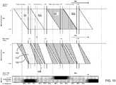
- Figure 10shows a modification to Figure 9 in which the backlight provides additional luminance during the addressing cycle.
- the backlight outputhas time profile 100. Part of this 102 is at full brightness, and as in previous examples, the timing is such that a part of only one image is ever illuminated at a given time, and a guard time is provided between illumination of one line and illumination of a nearby line with a new image.
- Another part 104is at reduced brightness. There is illumination during addressing to boost the luminance which has a smooth transition from 0 luminance towards the luminance level of part 102. This can lead to some optical cross talk. For example at time t1, the lower part of the display is displaying the delta_left image, but the top part is being addressed with the common image, and this is visible to the viewer. This error can be partially compensated in the video domain.
- an adaptive local luminance dimming algorithmcan be applied reducing the required backlight brightness about 50% on average, hence the need for stretching the image reproduction period of the sub-fields to create extra luminance in part 102 will not occur frequently and related artefacts will not often occur.
- Boosting the backlight luminancecan further enhance the brightness of left, right and common sub-fields, depending on the luminance distribution across the sub-fields.
- the smooth transition period of switching shutter glassesdepends on the amount of boosting.
- a further example in Figure 11is a 250Hz system using one common sub-field. This system uses five sub-fields to improve the exposure time. A duplicated delta-left and delta-right sub-field 60a,60b and 64a,64b are provided and a single extra common sub-field 62. The scheme is particularly suitable for 50Hz 3D sources on a 250Hz addressable display.
- the double-addressing of the delta_left and delta_right sub-fieldsenables a long illumination time in the same way as explained with reference to Figure 5 .
- the common sub-fieldfurther increases the exposure in the same way as explained above.
- the maximum luminancehas reduced to almost 50%.
- the amount of luminance which the delta left and delta_right sub-field can generateis larger than the amount luminance which the common sub-field can generate, yet the common sub-field can be used to image part of the required luminance of the common image.
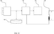
- Figure 13shows the basic elements of a 3D display system which can be used to implement the invention.
- a stereo camera 130is used to collect left and right images.
- the systemhas storage 132 and a display processor 134 which provides the data to the field sequential stereo display panel 136 (including backlight, not shown separately) as well as controlling the shutter timing of the glasses 138.
- the left and right sub-fields of a stereoscopic imageare highly correlated, hence there will be a lot of bright pixels in the common sub-field.
- the shared image content of the common sub-fieldis typically much brighter, a two times longer exposure of the common sub-field can help to create sufficient brightness.
- thiswill increase the dynamic switching of the LC material when using the L-C-R-C- driving scheme.
- the brightness of the common sub-fieldscan be re-distributed over all sub-fields, with the intent to reduce the dynamics of the LC switching, and optimising the LC response hence reducing crosstalk between the sub-fields. This will enable a longer exposure time, which has a positive impact of the brightness.
- Adjusted Backlight Dimminghas been mentioned above.
- local dimmingimproves the power efficiency of a normal LCD-TV
- local dimmingcan reduce the power consumed by a stereoscopic display system when in a 2D view mode as well as in 3D view mode.
- these imagestypically comprise a limited amount of light, concentrated in small bright contours. These contours demand the local backlight to be very bright. As the optical path has large losses and there is limited time for exposure, this locally generated light should be used in an optimal way by driving the pixels in the adjacent areas more transparent, without demanding more luminance from the backlight. This extra light generated by the images of the left and right sub-field can be subtracted from the image of the common sub-fields, reducing the local brightness and backlight luminance in these sub-fields, saving even more power.
- the inventioncan be used in combination with RGBW LCD panel technology to save power in 2D as well as 3D viewing mode, providing power efficiency in the 3D mode close to state-of-the-art LCD-TV.
- the inventioncan also be applied to projection displays, like DLP and some aspects can also be applied to sub-field sequential emissive displays, like PDP.
- the inventioncan also be applied to emissive displays, like CRTs as well as OLED displays (of course in this case the display output is scanned rather than the backlight output as OLED displays are emissive displays with sample and hold properties).
- the efficiency of the methodis very important, as these displays typically have severe brightness and lifetime constraints.
- the ability to create extra brightness without consuming extra energyis valuable.
- the delta_left and delta_right sub-fieldsshould be able to provide a lot of light on the depth-contouring image-data, yet the average power on these sub-fields is always very low, reducing panel stress.
- the required algorithmscan be implemented on existing video processors, which are already used for driving 200 and 240Hz display panels, to render various 3D input formats to stereoscopic display formats and local dimming and boosting.
- the inventionprovides improved brightness, specifically of image-data without depth and large bright areas. Improved power efficiency is provided during the common sub-fields.
Landscapes
- Engineering & Computer Science (AREA)
- Physics & Mathematics (AREA)
- Computer Hardware Design (AREA)
- General Physics & Mathematics (AREA)
- Theoretical Computer Science (AREA)
- Multimedia (AREA)
- Signal Processing (AREA)
- Liquid Crystal Display Device Control (AREA)
- Testing, Inspecting, Measuring Of Stereoscopic Televisions And Televisions (AREA)
- Control Of Indicators Other Than Cathode Ray Tubes (AREA)
Description
- This invention relates to 3D displays, and in particular to displays in which the user wears active glasses which serve to select the image for presentation to the left and right eyes.
- There a number of different designs of 3D display systems. These generally fall into two categories; those that require the user to wear special glasses and those that do not.
- 3D display technologies which avoid the need for glasses include displays with switchable barrier arrangements, and displays with lenticular arrays. These generate different views in different directions. However, the resolution of the views is greatly reduced if there are many different images projected in different directions, and the position of the viewer is critical in achieving the desired 3D effect.
- Systems which require the use of glasses overcome these problems. A viewer can be positioned anywhere within the field of view, and a full resolution image can be presented to each eye in a time sequential manner or else two views can be presented simultaneously with reduced resolution (for example with different polarizations).
- For 3D LCD TV applications, the so-called active shutter glasses option has great advantages, as in 2D viewing mode the display system is not compromised in quality, power efficiency and cost. The display does not need to provide special polarizations as in a polarization based system, and full colour 3D can be achieved, unlike systems using colour filtering. Any fast LCD display panel can be used, with only an adapted control method required.
- The active shutter design provides sequential images to the left and right eye, and the glasses provide a shutter over one eye to block the wrong image. During addressing of a new field, the shutter glasses can be used to block the light towards both the left and right eyes. To reduce energy wastage, the backlight can be turned off during this period.
- In the 3D viewing mode, low brightness is a problem with this design, as the stereoscopic viewing method blocks more then 50% of the light. The implementation requires a relatively small time window when an eye is receiving an image, so that the efficiency of the actual implementation also has losses of about 50%. This reduces light output from the desired 500Cd/m2 down to 125 Cd/m2.
- The invention aims to improve the light transmission of the overall stereoscopic display system. The obvious solution is to provide a brighter backlight, but this results again in high power consumption and low efficiency. There is therefore a need for improved efficiency and brightness by redesigning the optical system.
- 3D visualization is known from
WO 2009/069026A2 . Therein is disclosed a LCD display system comprising a LC panel, a backlight unit for illuminating the LC panel or a portion thereof, a controller for: controlling the LC panel to display a first image and a second image forming a stereoscopic pair, controlling the backlight unit to only illuminate the LC panel or the portion thereof during a first period in time after the pixels of the LC panel or the portion thereof have a stable optical state according to the first image, and during a second period in time after the pixels of the LC panel or the portion thereof have a stable optical state according to the second image, and generating a control signal for controlling a first one of a pair of 3D shutter glasses to be in a transmissive state for enabling viewing of the pixels of the LC panel or the portion thereof at least during part of the first period in time and a second one of the pair of3D shutter glasses to be in a transmissive state for enabling viewing of the pixels of the LC panel. - According to the invention, there is provided a stereo display device, a method of of operating a stereo display device, and a computer
program according claims 1 to 3. - The present invention will now be described, by way of example, with reference to the accompanying drawings, wherein:
Figure 1 shows a timing diagram for a first known shutter 3D display;Figure 2 shows a new way to reduce flicker in the scheme ofFigure 1 ;Figure 3 shows a timing diagram for a second known shutter 3D display;Figure 4 shows a timing diagram for a first example of shutter 3D display of the invention;Figure 5 shows a timing diagram for a second example of shutter 3D display of the invention;Figure 6 is used to explain the concept of common images used in further examples of shutter 3D display of the invention;Figure 7 shows a timing diagram for a third example of shutter 3D display of the invention;Figure 8 shows a timing diagram for a fourth example of shutter 3D display of the invention;Figure 9 shows a timing diagram for a fifth example of shutter 3D display of the invention;Figure 10 shows a timing diagram for a sixth example of shutter 3D display of the invention;Figure 11 shows a timing diagram for a seventh example of shutter 3D display of the invention;Figure 12 shows a timing diagram for a eighth example of shutter 3D display of the invention; andFigure 13 shows an example of the apparatus of a shutter 3D display of the invention.- In the drawings the same reference numerals have been used to indicate corresponding features.
- A TV sequentially displays images, typically at 50 (PAL) or 60 (NTSC) images per second. An image is divided into one or more sub-fields, which together reproduce an image as perceived by the viewer. The process of displaying a sub-field can be divided in 2 stages: writing image-data to the display elements (addressing) and light generation by these elements. For the stereoscopic viewing experience, each image comprises slightly different information to be viewed by either the left or the right eye. These images may have been captured by a stereo camera or rendered by a graphics engine.
- In a stereo sequential display system, active shutter glasses are used to differentiate the left images from the right images. By shutting the optical transmission of either the left or right glass of the glasses, the sequentially displayed sub-fields are captured by either the left or the right eye. Each of the two glasses may comprise a single LC-cell, controlled by a circuit synchronous with the display panel, which can block light transmission.
- After a complete image (one sub-field) has been addressed, a light burst (e.g. 10% duty cycle) creates an image of all pixels on either the left or right eye, selected by the shutter glasses. A faster addressing period enables the duty cycle to be increased to create more brightness, but this is insufficient to compensate for the brightness difference between 2D and 3D viewing modes.
- Increasing the light capacity of the backlight would enable more brightness, but this is an expensive solution and one which is power inefficient.
- The invention provides a solution for improved stereoscopic (3D) image reproduction on fast display systems in combination with shutter glasses. One approach is to make sure of a scanning backlight, and another is to add one or more common sub-fields, enabling a more transparent optical system, with the common image exposed to both the left and right eye. This requires a method of calculating the content of the common sub-fields and modified left and right sub-fields, such that the common and left sub-fields provide an optimal 3D image for the left eye and the common and right sub-fields provide an optimal 3D image for the right eye. These two approaches can be combined or used independently.
Figure 1 shows a first known way of operating a stereoscopic display system with shutter glasses:
The top plot shows the line-by-line addressing of the two sequential images. The lines are addressed in turn (hence the sloping edge 10), and remain addressed for aperiod 12. The middle plot shows the backlight activation during the vertical blanking intervals VBI. These are the time periods during which an image is fully addressed and static on the display. Vertical blanking originates from the transmission standards and initially corresponds to the fly-back time of CRT tubes, for LCD panels this period can be modified. The backlight is illuminated when the full image has been addressed into the display. The bottom plot shows the relative brightness perceived by the viewer during the period of illumination (100% representing light provided to both eyes and 50% representing light provided to one eye only). As shown, there is a short duration period of 50% brightness (to one eye) and subsequent short duration period of 50% brightness (to the other eye). These take place during the vertical blanking periods (VBI).- The basic sequential stereoscopic display runs at twice the image rate of the 3D video source, which is typically 50 or 60 Hz. Thus, a 120Hz display is used. This corresponds to a panel addressing and vertical blanking period (VBI) of respectively 10 ms or 8.3 ms. The vertical blanking is often about 10% of this period and these cycles are used for the exposure of the left respectively the right eye. This leads to a luminance efficiency of only 5%.
- During the addressing, the display system produces no light. The glasses also act as light blocks during this period.
- Compared to the 2D viewing mode the maximum luminance has reduced to only 5%. 90% of the time images cannot be reproduced, as the left as well as the right image are both partially imaged on the display panel during addressing.
- As the ambient light is also modulated by the shutter glasses, flicker is visible at the toggle frequency (of the individual shutters), which is typically 50 or 60 Hz. The applicant has proposed that the shutter glasses can be opened one or more extra periods per input image, when the display is not reproducing images. In this way the flicker-frequency of the ambient light can be tuned to e.g. a 2 or 3 times higher frequency, where is human eye is not sensitive for flicker anymore. This also reduces the interference with flickering light sources like incandescent or fluorescent lamps.
- Thus approach is shown in
Figure 2 . The backlight is only illuminated for the 50% brightness periods (shown dotted). The other open shutter periods allow only ambient light to reach the viewer as the backlight is off. Figure 3 shows a second known way of operating a stereoscopic display system with shutter glasses.- This is for a more advanced sequential 240Hz stereoscopic display, which addresses as fast as possible, enabling a longer time for image exposure. Such a display may run at four times the image rate of the 3D video source, which is typically 50 or 60 Hz.
Figure 3 shows the same plots as inFigure 1 . As shown, each image is addressed twice in succession. During the second addressing cycle, the image content does not change, so the image can be exposed to the user during this second addressing period.- This frequency corresponds to a panel addressing and vertical blanking period (VBI) of respectively 5 or 4.2 ms. The vertical blanking of often about 10% of this period and is now used as settling time for the lines recently addressed at the bottom of the image. For LCD display systems, a repeated addressing of the image data improves the picture quality. During the complete repeated addressing period the backlight can expose the panel, shown as
period 30. - During the addressing from left to right and right to left (i.e. the first of the two sequential addressing operations), the display system produces no light (and the shutters are blocking)
- Compared to the 2D viewing mode the maximum luminance has reduced to 25%. 50% of the time, images cannot be reproduced, because the left as well as the right image are both partially imaged on the display panel during the first addressing, and a small settling time is introduced to hide the slow LC response of pixels which where recently addressed.
- A first approach of the invention is use a scanning backlight (otherwise known as a scrolling backlight), in which rows of pixels are illuminated in sequence. A horizontal band of illumination is provided by the backlight, which scrolls vertically.
Figure 4 shows an example of 120Hz display with scanning backlight.Figure 4 shows the same plots as inFigure 1 . The image is addressed in the same manner as inFigure 1 . Thus, the sequential stereoscopic display runs at twice the image rate of the 3D video source, which is typically 50 or 60 Hz. This corresponds to a panel addressing and vertical blanking interval (VBI) of respectively 10 or 8.3 ms.- The exposure period of the left and the right eye can be extended by scanning the backlight synchronously to the addressing of the display panel (for transmissive displays). Each position on the display panel can now be exposed for a longer time. To limit the optical vertical crosstalk, the scanning backlight runs twice as fast as the addressing (i.e. the
slope 40 is twice the slope 41). - The
area 42 represents the time when the backlight is illuminated for the left image. The parts of the image which are illuminated are static during this time, whereas the non-illuminated parts of the image may be in the process of being addressed with new data. The same applies to theillumination 44 for the right image - Taking the
illumination window 42 for example, the time period has been extended (to period 44), but each line is only exposed for half of that time period. Hence, the relative brightness is 25% (one eye only and only illumination of each part of the image for half of the time). - Compared to the 2D viewing mode, the maximum luminance has reduced to 25%. A vertical separation between the addressed image and the previous/next backlight exposure is required to prevent crosstalk between the left and right sub-fields, and this is shown as 46.
Figure 5 shows an example of 240Hz display with scanning backlight.Figure 5 shows the same plots as inFigure 4 . The image is addressed in the same manner as inFigure 3 .- As explained in connection with
Figure 3 , the higher speed enables a longer time for image exposure. The repeated addressing of the image data as explained with reference toFigure 3 improves the picture quality, but also enables the backlight to expose the panel both during the repeated imaging as well as during part of the addressing period. - In this case, the
area 50 of illumination of the left image is increased to approximately 75% (compared to constant illumination of the full panel during time period 54). Each line is addressed for 3/4 of thistime period 54. - During the initial and final parts of the addressing, the panel has about 25% efficiency, the remaining
time 50%. Compared to the 2D viewing mode the maximum luminance has reduced to 37%. Again, a vertical separation between the addressed image and the previous/next backlight exposure is required to prevent significant left/right crosstalk between sub-fields. - A second approach of the invention is to use an extra sub-field to improve the exposure time. This extra sub-field must expose both eyes, hence it should share only the common luminance of the left and right images. In the following, this is termed a common sub-field. The backlight for this sub-field can reach both eyes, and it enables a longer time for image exposure for each eye.
- To implement this method, the display typically runs at 180 Hz or 240 Hz. The spare 5 or 4.2 ms vertical blanking interval can be distributed over the 3 sub-fields to adaptively stretch the period for image reproduction and hence boost luminance over the full field period.
- The concept of a common sub-field is explained with reference to
Figure 6 . - The top image shows a 2D image of a light grey block on a dark grey background (left and right eye see the same view).
- The second row of images show left and right views of a 3D image with depth; again a light grey block on a dark grey background. The blocks are in a different position relative to the outer boundary of the image as a result of the different perspective views.
- The third and fourth rows of images show examples of sub-fields named "delta_left" 60 (the left image content which is not common with the common image), "common" 62 and "delta_right" 64 (the left image content which is not common with the common image). In the case of a rectangle, the middle part is common to both left and right images. This middle part has the right boundary of the left image and the left boundary of the right image. As can be seen, the combined images can be formed in a number of ways.
- The bottom row represents the same images for an LCD module with a local dimming backlight. When the 3D contours of the delta_left and delta_right sub-fields require a bright backlight exposure, the adjacent pixels of this sub-fields are also driven to brighter levels, combined with dimmer levels for the related of pixels in the common sub-field, saving energy.
Figure 7 shows a first example of this approach for a 180Hz display.- The addressing sequence provides the delta_left image, then the common image, then the delta_right image. As with all examples above, the backlight scanning is carried out faster as the addressing of the image.
- The exposure of the panel by the backlight can be flashing or scanning, synchronous to the addressing of the display panel. During the common sub-field, the backlight can expose the panel with twice the power efficiency as both eyes are exposed by the displayed common image.
- The relative brightness has profiles that correspond to those shown in
Figure 5 for the left and right delta images, but with an additional central common image with double the relative brightness. - Compared to the 2D viewing mode the maximum luminance has only reduced to 42%. The vertical separation between the addressed image and the previous/next backlight exposure is again required to prevent significant left/right crosstalk between the sub-fields, but this is less needed for the common sub-field. This allows the exposure period to be stretched without introducing significant left/right crosstalk.
Figure 8 shows a modification to the 180Hz design ofFigure 7 in which an adaptive common sub-field is employed (explained below).- In this modification, the time period allocated to the delta_left, common and delta_right images can be varied depending on image content.
- In
Figure 8 , the common sub-field has been lengthened and the delta_right image has been shortened. - In this case, compared to the 2D viewing mode, the maximum luminance has only reduced to about 50% as the image reproduction weight of the Delta_left, Delta_right and common sub-fields has be modulated to lengthen the common sub-field, depending on the image content.
- In both examples, in the case of image disparity, required to create the 3D stereoscopic experience, bright pixels must be able to appear only in the delta_left and delta_right view, as the common sub-field might not create any luminance. In this condition, extra local brightness due to a boosting backlight will help to create an appropriate brightness on the left and right eye.
- In order to obtain this 50% of 2D viewing mode brightness a factor 2 luminance gain for the bright image-data of the delta_left and delta_right sub-fields is required to compensate for the missing luminance due to the extra addressing period. Furthermore:
- Local gain of the video-data can be employed (some clipping can be tolerated)
- Local control of the gain of the of backlight output can be employed by increasing the power (boost)
- The duty cycle can be stretched towards the common sub-field.
- It is also possible to locally attenuate the backlight output where light is not required, to save power and reduce temperature. The extra common sub-field has the advantage also of reducing 50/60 Hz image flicker.
- The design of
Figure 8 can be modified to use twocommon sub-fields Figure 9 . - The extra sub-fields must expose both eyes, hence share only the common luminance of the left and right sub-field. The scheme is particularly suitable for 50Hz 3D sources on a 240Hz display, as it changes visible 50 Hz image flicker into flicker-free 100Hz.
- This implementation is comparable to the example of
Figure 8 , but with the common sub-field stretched to twice the length of the delta sub-fields, but with the common sub-field split into two sections, interleaved with the left and right delta sub-fields. - Compared to the 2D viewing mode the maximum luminance has reduced to about 50%.
Figure 10 shows a modification toFigure 9 in which the backlight provides additional luminance during the addressing cycle. Taking the delta_left image as an example, the backlight output hastime profile 100. Part of this 102 is at full brightness, and as in previous examples, the timing is such that a part of only one image is ever illuminated at a given time, and a guard time is provided between illumination of one line and illumination of a nearby line with a new image.- Another
part 104 is at reduced brightness. There is illumination during addressing to boost the luminance which has a smooth transition from 0 luminance towards the luminance level ofpart 102. This can lead to some optical cross talk. For example at time t1, the lower part of the display is displaying the delta_left image, but the top part is being addressed with the common image, and this is visible to the viewer. This error can be partially compensated in the video domain. - Compared to the 2D viewing mode the maximum luminance has reduced only to about 75%. For average video-content, an adaptive local luminance dimming algorithm can be applied reducing the required backlight brightness about 50% on average, hence the need for stretching the image reproduction period of the sub-fields to create extra luminance in
part 102 will not occur frequently and related artefacts will not often occur. - Boosting the backlight luminance can further enhance the brightness of left, right and common sub-fields, depending on the luminance distribution across the sub-fields. The smooth transition period of switching shutter glasses depends on the amount of boosting.
- A further example in
Figure 11 is a 250Hz system using one common sub-field. This system uses five sub-fields to improve the exposure time. A duplicated delta-left and delta-right sub-field common sub-field 62. The scheme is particularly suitable for 50Hz 3D sources on a 250Hz addressable display. - The double-addressing of the delta_left and delta_right sub-fields enables a long illumination time in the same way as explained with reference to
Figure 5 . The common sub-field further increases the exposure in the same way as explained above. - In this case, compared to the 2D viewing mode the maximum luminance has reduced to almost 50%. The amount of luminance which the delta left and delta_right sub-field can generate is larger than the amount luminance which the common sub-field can generate, yet the common sub-field can be used to image part of the required luminance of the common image.
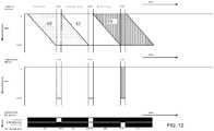
- The examples above all use a scanning or scrolling backlight. However, the idea of providing a common image can be used with a normal backlight. The timing diagrams for this approach are shown in
Figure 12 . - Compared to
Figure 1 , there is a third image in the field period, and during the corresponding vertical blanking interval, both shutters can be opened. This represents a doubling of light output compared toFigure 1 , but this is nonetheless much less significant than the increases in brightness that can be achieved with the additional use of a scrolling backlight as explained in the examples above. - The invention can be implemented with modification to the control of a segmented backlight (if provided) and the addressing scheme. Thus, minor modification to existing systems is required. By way of example,
Figure 13 shows the basic elements of a 3D display system which can be used to implement the invention. - A
stereo camera 130 is used to collect left and right images. The system hasstorage 132 and adisplay processor 134 which provides the data to the field sequential stereo display panel 136 (including backlight, not shown separately) as well as controlling the shutter timing of theglasses 138. - When driving the display with a repeated left and right sub-field, there is plenty of time for settling the response of LC material to the desired transmission level. The repeated addressing improves the actual LC response, as overdrive schemes can be executed more accurately and the variations over the varying cell capacitance are compensated for.
- The left and right sub-fields of a stereoscopic image are highly correlated, hence there will be a lot of bright pixels in the common sub-field. As the shared image content of the common sub-field is typically much brighter, a two times longer exposure of the common sub-field can help to create sufficient brightness. On the other hand this will increase the dynamic switching of the LC material when using the L-C-R-C- driving scheme. There is however no real need to concentrate the shared brightness in the common sub-fields. The brightness of the common sub-fields can be re-distributed over all sub-fields, with the intent to reduce the dynamics of the LC switching, and optimising the LC response hence reducing crosstalk between the sub-fields. This will enable a longer exposure time, which has a positive impact of the brightness.
- When LC response and overdrive correction are combined with the stereoscopic driving scheme, the overall control over light generated by the left, right and common sub-fields can be optimized. This is possible as the shared brightness of the image-date can be freely distributed over the sub-fields.
- Adjusted Backlight Dimming has been mentioned above. In the same way that local dimming improves the power efficiency of a normal LCD-TV, local dimming can reduce the power consumed by a stereoscopic display system when in a 2D view mode as well as in 3D view mode.
- After the left and right sub-fields have been compensated for the image provided by the common sub-fields, these images typically comprise a limited amount of light, concentrated in small bright contours. These contours demand the local backlight to be very bright. As the optical path has large losses and there is limited time for exposure, this locally generated light should be used in an optimal way by driving the pixels in the adjacent areas more transparent, without demanding more luminance from the backlight. This extra light generated by the images of the left and right sub-field can be subtracted from the image of the common sub-fields, reducing the local brightness and backlight luminance in these sub-fields, saving even more power.
- The invention can be used in combination with RGBW LCD panel technology to save power in 2D as well as 3D viewing mode, providing power efficiency in the 3D mode close to state-of-the-art LCD-TV. The invention can also be applied to projection displays, like DLP and some aspects can also be applied to sub-field sequential emissive displays, like PDP. The invention can also be applied to emissive displays, like CRTs as well as OLED displays (of course in this case the display output is scanned rather than the backlight output as OLED displays are emissive displays with sample and hold properties).
- The efficiency of the method, specifically when applied to OLED displays panels is very important, as these displays typically have severe brightness and lifetime constraints. The ability to create extra brightness without consuming extra energy is valuable. Specifically in the 4-sub-field addressing mode the delta_left and delta_right sub-fields should be able to provide a lot of light on the depth-contouring image-data, yet the average power on these sub-fields is always very low, reducing panel stress.
- The additional opening of shutters to reduce flicker as explained with reference to
Figure 2 as proposed by the applicant can be employed in combination with the other approaches of the invention. - The required algorithms can be implemented on existing video processors, which are already used for driving 200 and 240Hz display panels, to render various 3D input formats to stereoscopic display formats and local dimming and boosting.
- The invention provides improved brightness, specifically of image-data without depth and large bright areas. Improved power efficiency is provided during the common sub-fields.
- In the present specification and claims the word "a" or "an" preceding an element does not exclude the presence of a plurality of such elements. Further, the word "comprising" does not exclude the presence of other elements or steps than those listed.
- The use of any reference signs placed between parentheses in the claims shall not be construed as limiting the scope of the claims.
Claims (3)
- A stereo display device comprising:a display panel (136);a backlight having independently addressable portions; anda shutter arrangement (138) for a viewer, having independently controllable shutters for the two eyes of the viewer;a controller (134) for controlling the addressing of the display such that a stereo image is addressed in one field period, and for controlling the timing of operation of a shutter arrangement;wherein the controller is adapted to address the display to present left and right eye images in sequence, and to control the backlight, wherein the images are addressed line by line and the backlight is operated in line-by-line manner with a different addressing rate to the addressing rate of the images, wherein the backlight is addressed at a faster speed (40) than the image addressing (41);wherein each field comprises one left sub-field (60), one right sub-field (64) and a common sub-field (62);wherein the common sub-field shares only the common content of left and right images, the left sub-field represents the left image content which is not in common with the common image and the right sub-field represents the right image content which is not in common with the common image, wherein the common sub-field is central to the left and right sub-fields, and the shutters are controlled to allow light to both eyes during the display of the common image;wherein the controller is adapted to control the fractions of the frame period allocated to the left sub-field, the right sub-field, and the common sub-field; andwherein the fractions of the frame period allocated to the left, common and right sub-fields are varied depending on the image content.
- A method of operating a stereo display device, comprising:addressing a display (136) such that a stereo image is addressed in one field period by presenting left and right eye images in sequence with line-by-line addressing;controlling a shutter arrangement (138) for a viewer by opening a shutter associated with one eye of the viewer when the respective image for that eye is displayed;controlling a backlight in line-by-line manner with a different addressing rate (40) to the addressing rate (41) of the images, wherein the backlight is addressed at a faster speed than the image addressing;providing, within each field one left sub-field (60), one right sub-field (64) and a common sub-field (62), wherein the common sub-field shares only the common content of left and right images, the left sub-field represents the left image content which is not in common with the common image and the right sub-field represents the right image content which is not in common with the common image, wherein the common sub-field is central to the left and right sub-fields, and the shutters are controlled to allow light to both eyes during the display of the common image;controlling the fractions of the frame period allocated to the left sub-field, the right sub-field, and the common sub-field; andwherein the fractions of the frame period allocated to the left, common and right sub-fields are varied depending on the image content.
- A computer program product which is adapted to perform all of the steps of claim 2 when said program is run on a computer.
Priority Applications (2)
| Application Number | Priority Date | Filing Date | Title |
|---|---|---|---|
| EP09177512.2AEP2328353B1 (en) | 2009-11-30 | 2009-11-30 | 3D display |
| US12/956,958US8836770B2 (en) | 2009-11-30 | 2010-11-30 | 3D display |
Applications Claiming Priority (1)
| Application Number | Priority Date | Filing Date | Title |
|---|---|---|---|
| EP09177512.2AEP2328353B1 (en) | 2009-11-30 | 2009-11-30 | 3D display |
Publications (2)
| Publication Number | Publication Date |
|---|---|
| EP2328353A1 EP2328353A1 (en) | 2011-06-01 |
| EP2328353B1true EP2328353B1 (en) | 2020-10-28 |
Family
ID=42079120
Family Applications (1)
| Application Number | Title | Priority Date | Filing Date |
|---|---|---|---|
| EP09177512.2AActiveEP2328353B1 (en) | 2009-11-30 | 2009-11-30 | 3D display |
Country Status (2)
| Country | Link |
|---|---|
| US (1) | US8836770B2 (en) |
| EP (1) | EP2328353B1 (en) |
Families Citing this family (20)
| Publication number | Priority date | Publication date | Assignee | Title |
|---|---|---|---|---|
| JP5299300B2 (en)* | 2010-01-29 | 2013-09-25 | 株式会社Jvcケンウッド | Display device and display method |
| US9210414B2 (en)* | 2010-06-30 | 2015-12-08 | Tp Vision Holding B.V. | Multi-view display system and method therefor |
| JP5100916B2 (en)* | 2010-09-30 | 2012-12-19 | パナソニック株式会社 | Signal processing apparatus and video display apparatus using the same |
| KR20120035825A (en)* | 2010-10-06 | 2012-04-16 | 삼성전자주식회사 | 3d display panel, 3d display apparatus for using it, and driving methods thereof |
| KR101232086B1 (en)* | 2010-10-08 | 2013-02-08 | 엘지디스플레이 주식회사 | Liquid crystal display and local dimming control method of thereof |
| US20120113153A1 (en)* | 2010-11-04 | 2012-05-10 | 3M Innovative Properties Company | Methods of zero-d dimming and reducing perceived image crosstalk in a multiview display |
| TW201230767A (en)* | 2011-01-14 | 2012-07-16 | Acer Inc | Image display method and image display system |
| TWI441151B (en)* | 2011-02-15 | 2014-06-11 | Novatek Microelectronics Corp | 3-dimentional video processing device, 3-dimentional video displaying system, and control circuit capable of avoiding crosstalk |
| TWI446326B (en)* | 2011-08-22 | 2014-07-21 | Chunghwa Picture Tubes Ltd | Control circuit for generating a backlight driving current and method thereof |
| KR101950204B1 (en) | 2011-09-30 | 2019-02-25 | 삼성디스플레이 주식회사 | Method of driving display panel and display apparatus for performing the same |
| CN102510509B (en)* | 2011-10-18 | 2014-04-23 | 深圳市华星光电技术有限公司 | Liquid crystal panel and shutter glasses for three-dimensional television |
| CN102497561B (en) | 2011-11-16 | 2013-11-13 | 深圳市华星光电技术有限公司 | Working method of shutter glasses type 3D (three dimensional) display |
| CN102395038B (en) | 2011-11-16 | 2013-09-04 | 深圳市华星光电技术有限公司 | Working method of shutter glass type 3D display |
| KR101937710B1 (en)* | 2011-12-14 | 2019-04-11 | 엘지디스플레이 주식회사 | Display Apparatus For Displaying Three Dimensional Picture And Method For Driving The Same |
| TWI474048B (en)* | 2011-12-21 | 2015-02-21 | Au Optronics Corp | Display device |
| JP2014216920A (en)* | 2013-04-26 | 2014-11-17 | 株式会社ジャパンディスプレイ | Display device |
| JP2019154008A (en)* | 2018-03-06 | 2019-09-12 | シャープ株式会社 | Stereoscopic image display device, method for displaying liquid crystal display, and program for liquid crystal display |
| CN109377950B (en)* | 2018-10-31 | 2020-12-29 | 惠科股份有限公司 | Driving method of display panel and display panel thereof |
| CN109767732B (en)* | 2019-03-22 | 2021-09-10 | 明基智能科技(上海)有限公司 | Display method and display system for reducing image delay |
| TWI783683B (en)* | 2021-09-15 | 2022-11-11 | 友達光電股份有限公司 | Display device |
Citations (4)
| Publication number | Priority date | Publication date | Assignee | Title |
|---|---|---|---|---|
| US20040252097A1 (en)* | 2003-06-10 | 2004-12-16 | Takeshi Kaneki | Liquid crystal display device and driving method thereof |
| US20060072006A1 (en)* | 2004-10-05 | 2006-04-06 | Lin Lin | 3D stereo display method and a device thereof |
| WO2008126904A1 (en)* | 2007-04-11 | 2008-10-23 | Taiyo Yuden Co., Ltd. | Video display device |
| US20090237495A1 (en)* | 2008-03-24 | 2009-09-24 | Kabushiki Kaisha Toshiba | Stereoscopic Image Display Apparatus, Image Display System and Method for Displaying Stereoscopic Image |
Family Cites Families (10)
| Publication number | Priority date | Publication date | Assignee | Title |
|---|---|---|---|---|
| DE60139598D1 (en)* | 2001-02-10 | 2009-10-01 | Thomson Licensing | Stereoscopic plasma display |
| EP1271965A1 (en)* | 2001-06-23 | 2003-01-02 | Deutsche Thomson-Brandt Gmbh | Method and device for processing video frames for stereoscopic display |
| JP3774715B2 (en)* | 2002-10-21 | 2006-05-17 | キヤノン株式会社 | Projection display |
| GB2404991A (en)* | 2003-08-09 | 2005-02-16 | Sharp Kk | LCD device having at least one viewing window |
| CN101142612A (en)* | 2005-03-29 | 2008-03-12 | 富士通株式会社 | Liquid crystal display device having a plurality of pixel electrodes |
| US20100134402A1 (en)* | 2005-04-01 | 2010-06-03 | Koninklijke Philips Electronics, N.V. | Scanning backlight lcd panel with optimized lamp segmentation and timing |
| US20070206280A1 (en)* | 2006-03-06 | 2007-09-06 | Hewlett-Packard Development Company Lp | Light source and screen |
| KR101311557B1 (en)* | 2006-06-30 | 2013-09-26 | 엘지디스플레이 주식회사 | Driving method of liquid crystal display device |
| CN101878654B (en)* | 2007-11-28 | 2013-02-13 | 皇家飞利浦电子股份有限公司 | 3d visualization |
| US8339441B2 (en)* | 2008-12-26 | 2012-12-25 | Kabushiki Kaisha Toshiba | Frame processing device, television receiving apparatus and frame processing method |
- 2009
- 2009-11-30EPEP09177512.2Apatent/EP2328353B1/enactiveActive
- 2010
- 2010-11-30USUS12/956,958patent/US8836770B2/ennot_activeExpired - Fee Related
Patent Citations (4)
| Publication number | Priority date | Publication date | Assignee | Title |
|---|---|---|---|---|
| US20040252097A1 (en)* | 2003-06-10 | 2004-12-16 | Takeshi Kaneki | Liquid crystal display device and driving method thereof |
| US20060072006A1 (en)* | 2004-10-05 | 2006-04-06 | Lin Lin | 3D stereo display method and a device thereof |
| WO2008126904A1 (en)* | 2007-04-11 | 2008-10-23 | Taiyo Yuden Co., Ltd. | Video display device |
| US20090237495A1 (en)* | 2008-03-24 | 2009-09-24 | Kabushiki Kaisha Toshiba | Stereoscopic Image Display Apparatus, Image Display System and Method for Displaying Stereoscopic Image |
Non-Patent Citations (2)
| Title |
|---|
| DE GREEF P ET AL: "ADAPTIVE DIMMING AND BOOSTING BACKLIGHT FOR LCD-TV SYSTEMS", 22 May 2007, 2007 SID INTERNATIONAL SYMPOSIUM DIGEST OFTECHNICAL PAPERS BOOK I, SID, PAGE(S) 1332 - 1335, XP002565813* |
| HENDRIEK GROOT HULZE ET AL: "51.3: Driving an Adaptive Local Dimming Backlight for LCD-TV Systems", SID 2008, 2008 SID INTERNATIONAL SYMPOSIUM, SOCIETY FOR INFORMATION DISPLAY, LOS ANGELES, USA, vol. XXXIX, 18 May 2008 (2008-05-18), pages 772 - 775, XP007016627, ISSN: 0008-966X* |
Also Published As
| Publication number | Publication date |
|---|---|
| US20110292184A1 (en) | 2011-12-01 |
| EP2328353A1 (en) | 2011-06-01 |
| US8836770B2 (en) | 2014-09-16 |
Similar Documents
| Publication | Publication Date | Title |
|---|---|---|
| EP2328353B1 (en) | 3D display | |
| US9618758B2 (en) | Stereoscopic image display and method of controlling backlight thereof | |
| US10621934B2 (en) | Display and display method | |
| US9355488B2 (en) | 3D visualization | |
| US8115728B2 (en) | Image display device with reduced flickering and blur | |
| JP5619863B2 (en) | Non-glasses stereoscopic image display apparatus and control method thereof | |
| US7898519B2 (en) | Method for overdriving a backlit display | |
| US20080316303A1 (en) | Display Device | |
| US9088792B2 (en) | Stereoscopic flat panel display with synchronized backlight, polarization control panel, and liquid crystal display | |
| US8482605B2 (en) | Image processing device, image display device, and image processing and display method and program | |
| WO2007072598A1 (en) | Display device, receiver, and method of driving display device | |
| JP2010286555A (en) | Image display device and image display system | |
| US9210414B2 (en) | Multi-view display system and method therefor | |
| CN102725675B (en) | Display device and method of display | |
| Kim et al. | 18.1: Distinguished Paper: Novel TFT‐LCD Technology for Motion Blur Reduction Using 120Hz Driving with McFi | |
| WO2013047230A1 (en) | Liquid crystal display device | |
| US20110242094A1 (en) | Stereoscopic image display apparatus and stereoscopic image display method | |
| US20120306937A1 (en) | Backlight module, display system, and driving method of backlight module | |
| CN101137071B (en) | Stereoscopic image display device and method for reducing stereoscopic image interference | |
| JP2007108484A (en) | Liquid crystal display | |
| WO2013072453A2 (en) | Apparatus and method for driving a display | |
| KR101941956B1 (en) | Stereoscopic image display and control method thereof | |
| JP2011217370A (en) | Image display device and image display method | |
| WO2012086495A1 (en) | Liquid crystal display device for stereoscopic display |
Legal Events
| Date | Code | Title | Description |
|---|---|---|---|
| PUAI | Public reference made under article 153(3) epc to a published international application that has entered the european phase | Free format text:ORIGINAL CODE: 0009012 | |
| AK | Designated contracting states | Kind code of ref document:A1 Designated state(s):AT BE BG CH CY CZ DE DK EE ES FI FR GB GR HR HU IE IS IT LI LT LU LV MC MK MT NL NO PL PT RO SE SI SK SM TR | |
| AX | Request for extension of the european patent | Extension state:AL BA RS | |
| 17P | Request for examination filed | Effective date:20111201 | |
| 17Q | First examination report despatched | Effective date:20120809 | |
| RAP1 | Party data changed (applicant data changed or rights of an application transferred) | Owner name:III HOLDINGS 6, LLC | |
| STAA | Information on the status of an ep patent application or granted ep patent | Free format text:STATUS: EXAMINATION IS IN PROGRESS | |
| REG | Reference to a national code | Ref country code:DE Ref legal event code:R079 Ref document number:602009062973 Country of ref document:DE Free format text:PREVIOUS MAIN CLASS: H04N0013000000 Ipc:H04N0013341000 | |
| GRAJ | Information related to disapproval of communication of intention to grant by the applicant or resumption of examination proceedings by the epo deleted | Free format text:ORIGINAL CODE: EPIDOSDIGR1 | |
| GRAP | Despatch of communication of intention to grant a patent | Free format text:ORIGINAL CODE: EPIDOSNIGR1 | |
| RIC1 | Information provided on ipc code assigned before grant | Ipc:H04N 13/398 20180101ALI20200519BHEP Ipc:G09G 3/00 20060101ALI20200519BHEP Ipc:G09G 3/34 20060101ALI20200519BHEP Ipc:H04N 13/341 20180101AFI20200519BHEP | |
| GRAP | Despatch of communication of intention to grant a patent | Free format text:ORIGINAL CODE: EPIDOSNIGR1 | |
| STAA | Information on the status of an ep patent application or granted ep patent | Free format text:STATUS: GRANT OF PATENT IS INTENDED | |
| INTG | Intention to grant announced | Effective date:20200709 | |
| GRAS | Grant fee paid | Free format text:ORIGINAL CODE: EPIDOSNIGR3 | |
| GRAA | (expected) grant | Free format text:ORIGINAL CODE: 0009210 | |
| STAA | Information on the status of an ep patent application or granted ep patent | Free format text:STATUS: THE PATENT HAS BEEN GRANTED | |
| AK | Designated contracting states | Kind code of ref document:B1 Designated state(s):AT BE BG CH CY CZ DE DK EE ES FI FR GB GR HR HU IE IS IT LI LT LU LV MC MK MT NL NO PL PT RO SE SI SK SM TR | |
| REG | Reference to a national code | Ref country code:GB Ref legal event code:FG4D | |
| REG | Reference to a national code | Ref country code:CH Ref legal event code:EP | |
| REG | Reference to a national code | Ref country code:AT Ref legal event code:REF Ref document number:1329439 Country of ref document:AT Kind code of ref document:T Effective date:20201115 | |
| REG | Reference to a national code | Ref country code:DE Ref legal event code:R096 Ref document number:602009062973 Country of ref document:DE | |
| REG | Reference to a national code | Ref country code:IE Ref legal event code:FG4D | |
| REG | Reference to a national code | Ref country code:AT Ref legal event code:MK05 Ref document number:1329439 Country of ref document:AT Kind code of ref document:T Effective date:20201028 | |
| REG | Reference to a national code | Ref country code:NL Ref legal event code:MP Effective date:20201028 | |
| PG25 | Lapsed in a contracting state [announced via postgrant information from national office to epo] | Ref country code:GR Free format text:LAPSE BECAUSE OF FAILURE TO SUBMIT A TRANSLATION OF THE DESCRIPTION OR TO PAY THE FEE WITHIN THE PRESCRIBED TIME-LIMIT Effective date:20210129 Ref country code:PT Free format text:LAPSE BECAUSE OF FAILURE TO SUBMIT A TRANSLATION OF THE DESCRIPTION OR TO PAY THE FEE WITHIN THE PRESCRIBED TIME-LIMIT Effective date:20210301 Ref country code:NL Free format text:LAPSE BECAUSE OF FAILURE TO SUBMIT A TRANSLATION OF THE DESCRIPTION OR TO PAY THE FEE WITHIN THE PRESCRIBED TIME-LIMIT Effective date:20201028 Ref country code:NO Free format text:LAPSE BECAUSE OF FAILURE TO SUBMIT A TRANSLATION OF THE DESCRIPTION OR TO PAY THE FEE WITHIN THE PRESCRIBED TIME-LIMIT Effective date:20210128 Ref country code:FI Free format text:LAPSE BECAUSE OF FAILURE TO SUBMIT A TRANSLATION OF THE DESCRIPTION OR TO PAY THE FEE WITHIN THE PRESCRIBED TIME-LIMIT Effective date:20201028 | |
| REG | Reference to a national code | Ref country code:LT Ref legal event code:MG4D | |
| PG25 | Lapsed in a contracting state [announced via postgrant information from national office to epo] | Ref country code:LV Free format text:LAPSE BECAUSE OF FAILURE TO SUBMIT A TRANSLATION OF THE DESCRIPTION OR TO PAY THE FEE WITHIN THE PRESCRIBED TIME-LIMIT Effective date:20201028 Ref country code:PL Free format text:LAPSE BECAUSE OF FAILURE TO SUBMIT A TRANSLATION OF THE DESCRIPTION OR TO PAY THE FEE WITHIN THE PRESCRIBED TIME-LIMIT Effective date:20201028 Ref country code:SE Free format text:LAPSE BECAUSE OF FAILURE TO SUBMIT A TRANSLATION OF THE DESCRIPTION OR TO PAY THE FEE WITHIN THE PRESCRIBED TIME-LIMIT Effective date:20201028 Ref country code:BG Free format text:LAPSE BECAUSE OF FAILURE TO SUBMIT A TRANSLATION OF THE DESCRIPTION OR TO PAY THE FEE WITHIN THE PRESCRIBED TIME-LIMIT Effective date:20210128 Ref country code:AT Free format text:LAPSE BECAUSE OF FAILURE TO SUBMIT A TRANSLATION OF THE DESCRIPTION OR TO PAY THE FEE WITHIN THE PRESCRIBED TIME-LIMIT Effective date:20201028 Ref country code:IS Free format text:LAPSE BECAUSE OF FAILURE TO SUBMIT A TRANSLATION OF THE DESCRIPTION OR TO PAY THE FEE WITHIN THE PRESCRIBED TIME-LIMIT Effective date:20210228 Ref country code:ES Free format text:LAPSE BECAUSE OF FAILURE TO SUBMIT A TRANSLATION OF THE DESCRIPTION OR TO PAY THE FEE WITHIN THE PRESCRIBED TIME-LIMIT Effective date:20201028 | |
| PG25 | Lapsed in a contracting state [announced via postgrant information from national office to epo] | Ref country code:HR Free format text:LAPSE BECAUSE OF FAILURE TO SUBMIT A TRANSLATION OF THE DESCRIPTION OR TO PAY THE FEE WITHIN THE PRESCRIBED TIME-LIMIT Effective date:20201028 | |
| REG | Reference to a national code | Ref country code:CH Ref legal event code:PL | |
| REG | Reference to a national code | Ref country code:DE Ref legal event code:R097 Ref document number:602009062973 Country of ref document:DE | |
| PG25 | Lapsed in a contracting state [announced via postgrant information from national office to epo] | Ref country code:LU Free format text:LAPSE BECAUSE OF NON-PAYMENT OF DUE FEES Effective date:20201130 Ref country code:LT Free format text:LAPSE BECAUSE OF FAILURE TO SUBMIT A TRANSLATION OF THE DESCRIPTION OR TO PAY THE FEE WITHIN THE PRESCRIBED TIME-LIMIT Effective date:20201028 Ref country code:MC Free format text:LAPSE BECAUSE OF FAILURE TO SUBMIT A TRANSLATION OF THE DESCRIPTION OR TO PAY THE FEE WITHIN THE PRESCRIBED TIME-LIMIT Effective date:20201028 Ref country code:CZ Free format text:LAPSE BECAUSE OF FAILURE TO SUBMIT A TRANSLATION OF THE DESCRIPTION OR TO PAY THE FEE WITHIN THE PRESCRIBED TIME-LIMIT Effective date:20201028 Ref country code:EE Free format text:LAPSE BECAUSE OF FAILURE TO SUBMIT A TRANSLATION OF THE DESCRIPTION OR TO PAY THE FEE WITHIN THE PRESCRIBED TIME-LIMIT Effective date:20201028 Ref country code:SK Free format text:LAPSE BECAUSE OF FAILURE TO SUBMIT A TRANSLATION OF THE DESCRIPTION OR TO PAY THE FEE WITHIN THE PRESCRIBED TIME-LIMIT Effective date:20201028 Ref country code:RO Free format text:LAPSE BECAUSE OF FAILURE TO SUBMIT A TRANSLATION OF THE DESCRIPTION OR TO PAY THE FEE WITHIN THE PRESCRIBED TIME-LIMIT Effective date:20201028 Ref country code:SM Free format text:LAPSE BECAUSE OF FAILURE TO SUBMIT A TRANSLATION OF THE DESCRIPTION OR TO PAY THE FEE WITHIN THE PRESCRIBED TIME-LIMIT Effective date:20201028 | |
| REG | Reference to a national code | Ref country code:BE Ref legal event code:MM Effective date:20201130 | |
| PG25 | Lapsed in a contracting state [announced via postgrant information from national office to epo] | Ref country code:LI Free format text:LAPSE BECAUSE OF NON-PAYMENT OF DUE FEES Effective date:20201130 Ref country code:DK Free format text:LAPSE BECAUSE OF FAILURE TO SUBMIT A TRANSLATION OF THE DESCRIPTION OR TO PAY THE FEE WITHIN THE PRESCRIBED TIME-LIMIT Effective date:20201028 Ref country code:CH Free format text:LAPSE BECAUSE OF NON-PAYMENT OF DUE FEES Effective date:20201130 | |
| PLBE | No opposition filed within time limit | Free format text:ORIGINAL CODE: 0009261 | |
| STAA | Information on the status of an ep patent application or granted ep patent | Free format text:STATUS: NO OPPOSITION FILED WITHIN TIME LIMIT | |
| 26N | No opposition filed | Effective date:20210729 | |
| PG25 | Lapsed in a contracting state [announced via postgrant information from national office to epo] | Ref country code:IE Free format text:LAPSE BECAUSE OF NON-PAYMENT OF DUE FEES Effective date:20201130 Ref country code:IT Free format text:LAPSE BECAUSE OF FAILURE TO SUBMIT A TRANSLATION OF THE DESCRIPTION OR TO PAY THE FEE WITHIN THE PRESCRIBED TIME-LIMIT Effective date:20201028 | |
| PG25 | Lapsed in a contracting state [announced via postgrant information from national office to epo] | Ref country code:SI Free format text:LAPSE BECAUSE OF FAILURE TO SUBMIT A TRANSLATION OF THE DESCRIPTION OR TO PAY THE FEE WITHIN THE PRESCRIBED TIME-LIMIT Effective date:20201028 | |
| PGFP | Annual fee paid to national office [announced via postgrant information from national office to epo] | Ref country code:DE Payment date:20211129 Year of fee payment:13 Ref country code:FR Payment date:20211126 Year of fee payment:13 Ref country code:GB Payment date:20211123 Year of fee payment:13 | |
| PG25 | Lapsed in a contracting state [announced via postgrant information from national office to epo] | Ref country code:IS Free format text:LAPSE BECAUSE OF FAILURE TO SUBMIT A TRANSLATION OF THE DESCRIPTION OR TO PAY THE FEE WITHIN THE PRESCRIBED TIME-LIMIT Effective date:20210228 Ref country code:TR Free format text:LAPSE BECAUSE OF FAILURE TO SUBMIT A TRANSLATION OF THE DESCRIPTION OR TO PAY THE FEE WITHIN THE PRESCRIBED TIME-LIMIT Effective date:20201028 Ref country code:MT Free format text:LAPSE BECAUSE OF FAILURE TO SUBMIT A TRANSLATION OF THE DESCRIPTION OR TO PAY THE FEE WITHIN THE PRESCRIBED TIME-LIMIT Effective date:20201028 Ref country code:CY Free format text:LAPSE BECAUSE OF FAILURE TO SUBMIT A TRANSLATION OF THE DESCRIPTION OR TO PAY THE FEE WITHIN THE PRESCRIBED TIME-LIMIT Effective date:20201028 | |
| PG25 | Lapsed in a contracting state [announced via postgrant information from national office to epo] | Ref country code:MK Free format text:LAPSE BECAUSE OF FAILURE TO SUBMIT A TRANSLATION OF THE DESCRIPTION OR TO PAY THE FEE WITHIN THE PRESCRIBED TIME-LIMIT Effective date:20201028 | |
| PG25 | Lapsed in a contracting state [announced via postgrant information from national office to epo] | Ref country code:BE Free format text:LAPSE BECAUSE OF NON-PAYMENT OF DUE FEES Effective date:20201130 | |
| REG | Reference to a national code | Ref country code:DE Ref legal event code:R119 Ref document number:602009062973 Country of ref document:DE | |
| GBPC | Gb: european patent ceased through non-payment of renewal fee | Effective date:20221130 | |
| PG25 | Lapsed in a contracting state [announced via postgrant information from national office to epo] | Ref country code:GB Free format text:LAPSE BECAUSE OF NON-PAYMENT OF DUE FEES Effective date:20221130 Ref country code:DE Free format text:LAPSE BECAUSE OF NON-PAYMENT OF DUE FEES Effective date:20230601 | |
| PG25 | Lapsed in a contracting state [announced via postgrant information from national office to epo] | Ref country code:FR Free format text:LAPSE BECAUSE OF NON-PAYMENT OF DUE FEES Effective date:20221130 |