EP2328222A1 - Thin film electrochemical cell for lithium polymer batteries and manufacturing method therefor - Google Patents
Thin film electrochemical cell for lithium polymer batteries and manufacturing method thereforDownload PDFInfo
- Publication number
- EP2328222A1 EP2328222A1EP10191570AEP10191570AEP2328222A1EP 2328222 A1EP2328222 A1EP 2328222A1EP 10191570 AEP10191570 AEP 10191570AEP 10191570 AEP10191570 AEP 10191570AEP 2328222 A1EP2328222 A1EP 2328222A1
- Authority
- EP
- European Patent Office
- Prior art keywords
- current collector
- polymer electrolyte
- layers
- electrochemical cell
- collector sheet
- Prior art date
- Legal status (The legal status is an assumption and is not a legal conclusion. Google has not performed a legal analysis and makes no representation as to the accuracy of the status listed.)
- Granted
Links
Images


Classifications
- H—ELECTRICITY
- H01—ELECTRIC ELEMENTS
- H01M—PROCESSES OR MEANS, e.g. BATTERIES, FOR THE DIRECT CONVERSION OF CHEMICAL ENERGY INTO ELECTRICAL ENERGY
- H01M10/00—Secondary cells; Manufacture thereof
- H01M10/04—Construction or manufacture in general
- H01M10/0436—Small-sized flat cells or batteries for portable equipment
- B—PERFORMING OPERATIONS; TRANSPORTING
- B29—WORKING OF PLASTICS; WORKING OF SUBSTANCES IN A PLASTIC STATE IN GENERAL
- B29C—SHAPING OR JOINING OF PLASTICS; SHAPING OF MATERIAL IN A PLASTIC STATE, NOT OTHERWISE PROVIDED FOR; AFTER-TREATMENT OF THE SHAPED PRODUCTS, e.g. REPAIRING
- B29C48/00—Extrusion moulding, i.e. expressing the moulding material through a die or nozzle which imparts the desired form; Apparatus therefor
- B29C48/03—Extrusion moulding, i.e. expressing the moulding material through a die or nozzle which imparts the desired form; Apparatus therefor characterised by the shape of the extruded material at extrusion
- B29C48/07—Flat, e.g. panels
- B29C48/08—Flat, e.g. panels flexible, e.g. films
- B—PERFORMING OPERATIONS; TRANSPORTING
- B29—WORKING OF PLASTICS; WORKING OF SUBSTANCES IN A PLASTIC STATE IN GENERAL
- B29C—SHAPING OR JOINING OF PLASTICS; SHAPING OF MATERIAL IN A PLASTIC STATE, NOT OTHERWISE PROVIDED FOR; AFTER-TREATMENT OF THE SHAPED PRODUCTS, e.g. REPAIRING
- B29C48/00—Extrusion moulding, i.e. expressing the moulding material through a die or nozzle which imparts the desired form; Apparatus therefor
- B29C48/15—Extrusion moulding, i.e. expressing the moulding material through a die or nozzle which imparts the desired form; Apparatus therefor incorporating preformed parts or layers, e.g. extrusion moulding around inserts
- B29C48/154—Coating solid articles, i.e. non-hollow articles
- B—PERFORMING OPERATIONS; TRANSPORTING
- B29—WORKING OF PLASTICS; WORKING OF SUBSTANCES IN A PLASTIC STATE IN GENERAL
- B29C—SHAPING OR JOINING OF PLASTICS; SHAPING OF MATERIAL IN A PLASTIC STATE, NOT OTHERWISE PROVIDED FOR; AFTER-TREATMENT OF THE SHAPED PRODUCTS, e.g. REPAIRING
- B29C48/00—Extrusion moulding, i.e. expressing the moulding material through a die or nozzle which imparts the desired form; Apparatus therefor
- B29C48/16—Articles comprising two or more components, e.g. co-extruded layers
- B29C48/18—Articles comprising two or more components, e.g. co-extruded layers the components being layers
- B29C48/21—Articles comprising two or more components, e.g. co-extruded layers the components being layers the layers being joined at their surfaces
- B—PERFORMING OPERATIONS; TRANSPORTING
- B29—WORKING OF PLASTICS; WORKING OF SUBSTANCES IN A PLASTIC STATE IN GENERAL
- B29C—SHAPING OR JOINING OF PLASTICS; SHAPING OF MATERIAL IN A PLASTIC STATE, NOT OTHERWISE PROVIDED FOR; AFTER-TREATMENT OF THE SHAPED PRODUCTS, e.g. REPAIRING
- B29C48/00—Extrusion moulding, i.e. expressing the moulding material through a die or nozzle which imparts the desired form; Apparatus therefor
- B29C48/25—Component parts, details or accessories; Auxiliary operations
- B29C48/30—Extrusion nozzles or dies
- B29C48/32—Extrusion nozzles or dies with annular openings, e.g. for forming tubular articles
- B29C48/34—Cross-head annular extrusion nozzles, i.e. for simultaneously receiving moulding material and the preform to be coated
- B—PERFORMING OPERATIONS; TRANSPORTING
- B29—WORKING OF PLASTICS; WORKING OF SUBSTANCES IN A PLASTIC STATE IN GENERAL
- B29C—SHAPING OR JOINING OF PLASTICS; SHAPING OF MATERIAL IN A PLASTIC STATE, NOT OTHERWISE PROVIDED FOR; AFTER-TREATMENT OF THE SHAPED PRODUCTS, e.g. REPAIRING
- B29C63/00—Lining or sheathing, i.e. applying preformed layers or sheathings of plastics; Apparatus therefor
- B29C63/0004—Component parts, details or accessories; Auxiliary operations
- B29C63/0013—Removing old coatings
- B—PERFORMING OPERATIONS; TRANSPORTING
- B32—LAYERED PRODUCTS
- B32B—LAYERED PRODUCTS, i.e. PRODUCTS BUILT-UP OF STRATA OF FLAT OR NON-FLAT, e.g. CELLULAR OR HONEYCOMB, FORM
- B32B37/00—Methods or apparatus for laminating, e.g. by curing or by ultrasonic bonding
- B32B37/14—Methods or apparatus for laminating, e.g. by curing or by ultrasonic bonding characterised by the properties of the layers
- B32B37/15—Methods or apparatus for laminating, e.g. by curing or by ultrasonic bonding characterised by the properties of the layers with at least one layer being manufactured and immediately laminated before reaching its stable state, e.g. in which a layer is extruded and laminated while in semi-molten state
- B32B37/153—Methods or apparatus for laminating, e.g. by curing or by ultrasonic bonding characterised by the properties of the layers with at least one layer being manufactured and immediately laminated before reaching its stable state, e.g. in which a layer is extruded and laminated while in semi-molten state at least one layer is extruded and immediately laminated while in semi-molten state
- B—PERFORMING OPERATIONS; TRANSPORTING
- B32—LAYERED PRODUCTS
- B32B—LAYERED PRODUCTS, i.e. PRODUCTS BUILT-UP OF STRATA OF FLAT OR NON-FLAT, e.g. CELLULAR OR HONEYCOMB, FORM
- B32B37/00—Methods or apparatus for laminating, e.g. by curing or by ultrasonic bonding
- B32B37/14—Methods or apparatus for laminating, e.g. by curing or by ultrasonic bonding characterised by the properties of the layers
- B32B37/16—Methods or apparatus for laminating, e.g. by curing or by ultrasonic bonding characterised by the properties of the layers with all layers existing as coherent layers before laminating
- B32B37/20—Methods or apparatus for laminating, e.g. by curing or by ultrasonic bonding characterised by the properties of the layers with all layers existing as coherent layers before laminating involving the assembly of continuous webs only
- B32B37/203—One or more of the layers being plastic
- B32B37/206—Laminating a continuous layer between two continuous plastic layers
- H—ELECTRICITY
- H01—ELECTRIC ELEMENTS
- H01M—PROCESSES OR MEANS, e.g. BATTERIES, FOR THE DIRECT CONVERSION OF CHEMICAL ENERGY INTO ELECTRICAL ENERGY
- H01M10/00—Secondary cells; Manufacture thereof
- H01M10/05—Accumulators with non-aqueous electrolyte
- H01M10/052—Li-accumulators
- H—ELECTRICITY
- H01—ELECTRIC ELEMENTS
- H01M—PROCESSES OR MEANS, e.g. BATTERIES, FOR THE DIRECT CONVERSION OF CHEMICAL ENERGY INTO ELECTRICAL ENERGY
- H01M10/00—Secondary cells; Manufacture thereof
- H01M10/05—Accumulators with non-aqueous electrolyte
- H01M10/056—Accumulators with non-aqueous electrolyte characterised by the materials used as electrolytes, e.g. mixed inorganic/organic electrolytes
- H01M10/0564—Accumulators with non-aqueous electrolyte characterised by the materials used as electrolytes, e.g. mixed inorganic/organic electrolytes the electrolyte being constituted of organic materials only
- H01M10/0565—Polymeric materials, e.g. gel-type or solid-type
- H—ELECTRICITY
- H01—ELECTRIC ELEMENTS
- H01M—PROCESSES OR MEANS, e.g. BATTERIES, FOR THE DIRECT CONVERSION OF CHEMICAL ENERGY INTO ELECTRICAL ENERGY
- H01M10/00—Secondary cells; Manufacture thereof
- H01M10/05—Accumulators with non-aqueous electrolyte
- H01M10/058—Construction or manufacture
- H01M10/0585—Construction or manufacture of accumulators having only flat construction elements, i.e. flat positive electrodes, flat negative electrodes and flat separators
- B—PERFORMING OPERATIONS; TRANSPORTING
- B29—WORKING OF PLASTICS; WORKING OF SUBSTANCES IN A PLASTIC STATE IN GENERAL
- B29L—INDEXING SCHEME ASSOCIATED WITH SUBCLASS B29C, RELATING TO PARTICULAR ARTICLES
- B29L2009/00—Layered products
- B—PERFORMING OPERATIONS; TRANSPORTING
- B29—WORKING OF PLASTICS; WORKING OF SUBSTANCES IN A PLASTIC STATE IN GENERAL
- B29L—INDEXING SCHEME ASSOCIATED WITH SUBCLASS B29C, RELATING TO PARTICULAR ARTICLES
- B29L2031/00—Other particular articles
- B29L2031/34—Electrical apparatus, e.g. sparking plugs or parts thereof
- B29L2031/3468—Batteries, accumulators or fuel cells
- B—PERFORMING OPERATIONS; TRANSPORTING
- B32—LAYERED PRODUCTS
- B32B—LAYERED PRODUCTS, i.e. PRODUCTS BUILT-UP OF STRATA OF FLAT OR NON-FLAT, e.g. CELLULAR OR HONEYCOMB, FORM
- B32B2309/00—Parameters for the laminating or treatment process; Apparatus details
- B32B2309/02—Temperature
- B—PERFORMING OPERATIONS; TRANSPORTING
- B32—LAYERED PRODUCTS
- B32B—LAYERED PRODUCTS, i.e. PRODUCTS BUILT-UP OF STRATA OF FLAT OR NON-FLAT, e.g. CELLULAR OR HONEYCOMB, FORM
- B32B2311/00—Metals, their alloys or their compounds
- B—PERFORMING OPERATIONS; TRANSPORTING
- B32—LAYERED PRODUCTS
- B32B—LAYERED PRODUCTS, i.e. PRODUCTS BUILT-UP OF STRATA OF FLAT OR NON-FLAT, e.g. CELLULAR OR HONEYCOMB, FORM
- B32B2457/00—Electrical equipment
- B32B2457/10—Batteries
- H—ELECTRICITY
- H01—ELECTRIC ELEMENTS
- H01M—PROCESSES OR MEANS, e.g. BATTERIES, FOR THE DIRECT CONVERSION OF CHEMICAL ENERGY INTO ELECTRICAL ENERGY
- H01M10/00—Secondary cells; Manufacture thereof
- H01M10/04—Construction or manufacture in general
- H01M2010/0495—Nanobatteries
- H—ELECTRICITY
- H01—ELECTRIC ELEMENTS
- H01M—PROCESSES OR MEANS, e.g. BATTERIES, FOR THE DIRECT CONVERSION OF CHEMICAL ENERGY INTO ELECTRICAL ENERGY
- H01M6/00—Primary cells; Manufacture thereof
- H01M6/40—Printed batteries, e.g. thin film batteries
- Y—GENERAL TAGGING OF NEW TECHNOLOGICAL DEVELOPMENTS; GENERAL TAGGING OF CROSS-SECTIONAL TECHNOLOGIES SPANNING OVER SEVERAL SECTIONS OF THE IPC; TECHNICAL SUBJECTS COVERED BY FORMER USPC CROSS-REFERENCE ART COLLECTIONS [XRACs] AND DIGESTS
- Y02—TECHNOLOGIES OR APPLICATIONS FOR MITIGATION OR ADAPTATION AGAINST CLIMATE CHANGE
- Y02E—REDUCTION OF GREENHOUSE GAS [GHG] EMISSIONS, RELATED TO ENERGY GENERATION, TRANSMISSION OR DISTRIBUTION
- Y02E60/00—Enabling technologies; Technologies with a potential or indirect contribution to GHG emissions mitigation
- Y02E60/10—Energy storage using batteries
- Y—GENERAL TAGGING OF NEW TECHNOLOGICAL DEVELOPMENTS; GENERAL TAGGING OF CROSS-SECTIONAL TECHNOLOGIES SPANNING OVER SEVERAL SECTIONS OF THE IPC; TECHNICAL SUBJECTS COVERED BY FORMER USPC CROSS-REFERENCE ART COLLECTIONS [XRACs] AND DIGESTS
- Y02—TECHNOLOGIES OR APPLICATIONS FOR MITIGATION OR ADAPTATION AGAINST CLIMATE CHANGE
- Y02P—CLIMATE CHANGE MITIGATION TECHNOLOGIES IN THE PRODUCTION OR PROCESSING OF GOODS
- Y02P70/00—Climate change mitigation technologies in the production process for final industrial or consumer products
- Y02P70/50—Manufacturing or production processes characterised by the final manufactured product
- Y—GENERAL TAGGING OF NEW TECHNOLOGICAL DEVELOPMENTS; GENERAL TAGGING OF CROSS-SECTIONAL TECHNOLOGIES SPANNING OVER SEVERAL SECTIONS OF THE IPC; TECHNICAL SUBJECTS COVERED BY FORMER USPC CROSS-REFERENCE ART COLLECTIONS [XRACs] AND DIGESTS
- Y10—TECHNICAL SUBJECTS COVERED BY FORMER USPC
- Y10T—TECHNICAL SUBJECTS COVERED BY FORMER US CLASSIFICATION
- Y10T29/00—Metal working
- Y10T29/49—Method of mechanical manufacture
- Y10T29/49002—Electrical device making
- Y10T29/49108—Electric battery cell making
- Y10T29/49115—Electric battery cell making including coating or impregnating
- Y—GENERAL TAGGING OF NEW TECHNOLOGICAL DEVELOPMENTS; GENERAL TAGGING OF CROSS-SECTIONAL TECHNOLOGIES SPANNING OVER SEVERAL SECTIONS OF THE IPC; TECHNICAL SUBJECTS COVERED BY FORMER USPC CROSS-REFERENCE ART COLLECTIONS [XRACs] AND DIGESTS
- Y10—TECHNICAL SUBJECTS COVERED BY FORMER USPC
- Y10T—TECHNICAL SUBJECTS COVERED BY FORMER US CLASSIFICATION
- Y10T29/00—Metal working
- Y10T29/53—Means to assemble or disassemble
- Y10T29/5313—Means to assemble electrical device
- Y10T29/53135—Storage cell or battery
Definitions
- the present inventionrelates generally to lithium polymer batteries and more specifically to the design and method of manufacturing of the electrochemical cells making up a lithium polymer battery.
- Rechargeable batteries manufactured from laminates of solid polymer electrolytes and sheet-like anodes and cathodesdisplay many advantages over conventional liquid electrolyte batteries. These advantages include having a lower overall battery weight, a high power density, a high specific energy and a Longer service life, as well as being environmentally friendly since the danger of spilling toxic liquid into the environment is eliminated.
- the components of a solid polymer electrochemical cellinclude positive electrodes, negative electrodes and separators capable of permitting ionic conductivity, such as solid polymer electrolytes, sandwiched between each anode and cathode.
- the anodes (or negative electrodes) and cathodes (or positive electrodes)are made of material capable of reversible insertion of alkali metal ions.
- the polymer electrolyte separatorselectrically isolate the anode from the cathode to prevent short circuits therebetween, which would render the electrochemical cell useless.
- the cathodesare typically formed of a mixture of active material capable of occluding and releasing lithium, such as transitional metal oxides or phosphates, an electronically conductive filter, usually carbon or graphite or combinations thereof, and an ionically conductive polymer binder.
- Cathode materialsare usually paste-like and require a current collector, usually a thin sheet of electrically conductive material such as aluminum foil.
- the anodesare typically made of light-weight metal foils, such as alkali metals and alloys, typical lithium metal, lithium oxide, lithium-aluminum alloys and the like.
- the anodesmay also be composite paste-like material comprising, for example, carbon-based intercalation compounds in a polymer binder, in which case the anode also requires a current collector support, preferably a thin sheet of copper.
- Composite cathode thin filmsare usually obtained by solvent coating onto a current collector or by melt extrusion.
- the polymer electrolyte separator layeris typically produced by solvent coating or by melt extrusion.
- Solid lithium polymer electrochemical cellsare typically manufactured by successive layering of the positive electrode, the electrolyte separator and the negative electrode.
- the positive electrode materialis initially coated or extruded onto a metallic foil (for example aluminum) or onto a metallized plastic film, which serves as a current collector.
- the polymer electrolyte separatoris thereafter preferably coated or extruded directly onto the previously coated cathode material and the negative electrode is finally laminated onto the electrolyte to form an electrochemical cell.
- a bi-face designis preferred wherein positive electrode material is laminated, coated or extruded onto both sides of the current collector.
- Electrochemal cells as previously describedare assembled in an offset pattern: Electrochemical cells as previously described are assembled in an offset pattern: the metallic anode or negative current collector extends from one side of the electrochemical cell, while the cathode current collector extends from the other side of the electrochemical cell.
- the electrolyte separator(or separators in the case of bi-face designs) is positioned in between the anode and the cathode but does not extend the entire width of the electrochemical cell because a portion of the metallic anode or negative current collector on one side and a portion of the cathode current collector on the other side must remain exposed for lateral collection of current (i.e.
- the exposed anodes and cathodesmay in some circumstances touch each other when the electrochemical cells are assembled and pressed together, resulting in a short circuit which renders the cells useless. Short circuits may also occur through misplacement or misalignment of the various layers of the electrochemical cells or through misplacement or misalignment of a stack of electrochemical cells.
- US Patent No. 5,360,684disclosed the addition of an insulating band of polypropylene or other plastic material between the exposed ends of the anode and the cathode current collector, for the sole purpose of eliminating potential short circuit.
- US patent application No. 09/876,567discloses a variant of the same concept, in which an insulating edge material is coated or extruded at the end of the cathode material to prevent a potential short circuit between the exposed ends of the anode and the cathode layer.
- 5,670,273discloses a method of fabricating electrochemical cells, wherein the successive anode and cathode layers are separated by a polymeric electrolyte layer having a protruding polymer edge that reduces the likelihood of inadvertent contact between the anode and cathode current collectors.
- the present inventionprovides a method for manufacturing an electrochemical cell sub-assembty for a lithium polymer battery, the method including:
- the present inventionalso provides an electrochemical cell including:
- the present inventionalso provides a system for manufacturing an electrochemical cell sub-assembly, the system including:
- the present inventionalso provides a method for manufacturing an electrochemical cell sub-assembly for a lithium polymer battery, said method comprising:
- the present inventionalso provides a system for manufacturing an electrochemical cell sub-assembly for a lithium polymer battery, said system comprising:
- the electrochemical cell sub-assembly 10includes a central current collector element 12, a layer of electrode material 14 coated on each surface of the central current collector element 12 and a polymer electrolyte 16.
- the polymer electrolyte 16completely envelopes the layers of electrode material 14 coated on the surfaces of the central current collector element 12, as well as one edge 13 of the current collector element 12.
- the layer of electrode material 14consists of a cathode or positive electrode material.
- the polymer electrolyte envelope 16is ionically conductive but electrically non-conductive, as is well known in the art, in order to allow ionic exchanges between the positive and negative electrodes but inhibit the formation of electrical current pathway between the positive and negative electrodes of the electrochemical cell.
- the electrode layers 14 and one edge 13 of the central current collector 12are completely enclosed within the polymer electrolyte envelope 16 and therefore are completely isolated electrically. Only edge 15 of the central current collector 12 remains exposed for the purpose of electrical connection to other electrochemical cells or to the electrical post of the generator having at least one electrochemical cell.
- FIG. 2illustrates a complete electrochemical cell 20, in accordance with an embodiment of the present invention.
- the electrochemical cell 20is formed of the sub-assembly 10, which includes the central current collector element 12, the layers of electrode material 14 coated on each surface of the central current collector element 12 and the polymer electrolyte envelope 16, which completely envelopes the layers of electrode material 14.
- a negative electrode 18is disposed on each side of the polymer electrolyte envelope 16 facing the layers of positive electrode material 14, thereby sandwiching the polymer electrolyte envelope 16 and completing the electrochemical cell 20.
- the layers of positive electrode material 14 and edge 13 of the central current collector element 12are completely isolated electrically from the negative electrodes 18, thereby reducing the risks of short circuits between the negative electrodes 18 and either the positive electrode material 14 or the edge 13 of the central current collector element 12.
- the positive and negative electrical contact pointsare offset. More specifically, the current collector element 12 of the positive electrode extends to one side of the electrochemical cell 20, while the negative electrodes 18 extend to the other side of the electrochemical cell 20, such that the electrical contact points are on opposite sides of the electrochemical cell 20.
- a plurality of electrochemical cellsmay be stacked together, their positive electrodes connected together in parallel and their negative electrodes also connected in parallel, to increase their overall capacity (Amp/hr).
- the electrochemical cells described hereinare typically formed of extremely thin constituents. For example:
- FIGS 3 and 4illustrate an example implementation of an apparatus and method for overlaying a central current collector element having layers of electrode material on both its surfaces with a polymer electrolyte envelope, in order to form the electrochemical cell sub-assembly 10 illustrated in Figure 1 , in accordance with an embodiment of the present invention.
- a single screw or twin screw extruder 31feeds polymer electrolyte material to the dual extrusion die 30.
- the pre-assembly 22travels through dual extrusion die 30, where a thin layer of polymer electrolyte 24 is applied simultaneously to both sides of the pre-assembly 22.
- the layers of polymer electrolyte 24are, wider than the layers of electrode material 14, such that the two layers of polymer electrolyte 24 completely encapsulate the layers of electrode material 14 and also circumvent one edge 13 of the current collector 12.
- the pre-assembly 22 with its polymer electrolyte envelope 16is then redirected by a series of cylindrical rollers 32A and 32B, which are preferably maintained at a cool temperature in order to accelerate the solidification of the polymer electrolyte envelope 16 and to prevent unwanted adhesion of the polymer to the rollers.
- the complete electrochemical cell sub-assembly 10( Figure 1 ) is then routed towards other stations for further processing or storage.
- Figure 5illustrates schematically a cross-sectional view of the dual extrusion die 30 of Figures 3 and 4 , when the pre-assembly 22 travels directly therethrough.
- Extrusion die 30incudes two discharge nozzles 35 and 37, illustrated in dotted lines, which determine the path that the polymer electrolyte follows inside the extrusion die 30 before being discharged as a thin sheet onto both sides of the pre-assembly 22.
- the polymer electrolyte materialis fed to the extrusion die 30 under pressure from the extruder 31 ( Figures 3 and 4 ) through a cylindrical channel 39.
- the polymer electrolyte materialis divided by a flow divider 44 into two separate internal channels 41 and 43, leading to the discharge nozzles 35 and 37, respectively.
- the polymer electrolyte materialWhen entering the discharge nozzles 35 and 37, the polymer electrolyte material is shaped into a wide but thin film. This film is discharged over an area that covers the layers of electrode material 14, the entire edge 13 of the current collector element 12 and a portion of the other end 15 of the current collector element 12. Accordingly, the two layers of electrode material 14 are enveloped and electrically isolated.
- Figure 6illustrates schematically a cross sectional view of the electrochemical cell sub-assembly 10 exiting the dual extrusion die 30, where it can be seen that the two layers of polymer electrolyte 24 merge together at a meeting point 45 beyond the end of the edge 13 of current collector 12, thereby forming the polymer electrolyte envelope 16.
- Figure 7illustrates another example of implementation of an apparatus and method for overlaying a central current collector element having layers of electrode material on both its surfaces with a polymer electrolyte envelope, in order to form the electrochemical cell sub-assembly 10 illustrated in Figure 1 .
- a pre-assembly 22 formed of a current collector element 12 that was previously coated on both its surfaces with layers of electrode material 14is delivered via a series of cylindrical rollers 48 (only one shown) to a pair of extrusion dies 50 and 60, where thin layers of polymer electrolyte 52 and 62 are overlaid simultaneously onto respective sides of the pre-assembly 22.
- both layers 52 and 62 of polymer electrolyteare wider than the layers of electrode material 14, they completely encapsulate the layers of electrode material, 14.
- the pre-assembly 22 with its layers 52 and 62 of polymer electrolyteis next guided by cylindrical roller 55, which is preferably maintained at a cool temperature in order to accelerate the solidification of the polymer electrolyte layers and prevent any unwanted adhesion thereof.
- the complete electrochemical cell sub-assembly 10is routed towards other stations for further processing or storage.
- Figure 8illustrates schematically a top cross sectional view of the pair of opposing extrusion dies 50 and 60 of Figure 7 , when the pre-assembly 22 including its layers of electrode material 14 travels directly in front of the discharge ends of extrusion dies 50 and 60.
- the internal channels 54 and 64 of extrusion dies 50 and 60, respectively,are illustrated in dotted lines and determine the path that the polymer electrolyze follows inside each extrusion die 50 and 60 before being discharged as thin sheets onto the surfaces of the pre-assembly 22.
- the polymer electrolyte sheets 52 and 62are spread over an area covering the layers of electrode material 14 and extending marginally beyond edge 13 of the current collector element 12, in order to envelop and electrically isolate the end of edge 13.
- the polymer electrolyte sheets 52 and 62also extend over a portion of the other end 15 of the current collector element 12, thereby enveloping and electrically isolating the two layers of electrode material 14.
- Figure 9illustrates the electrochemical cell sub-assembly 10 resulting from the apparatus and method of extrusion shown in and described with regard to Figures 7 and 8 .
- the polymer electrolyte sheets 52 and 62are discharged over an area that extends marginally beyond edge 13 of the current collector element 12, such that the polymer electrolyte sheets 52 and 62 merge beyond the edge 13 thereby enclosing the edge 13 and forming the polymer electrolyte envelope 16.
- Figure 7illustrates extrusion dies 50 and 60 directly opposed to each other, they may be offset relative to one another.
- Figure 10illustrates a variant example of implementation of the apparatus and method for overlaying a central current collector element having layers of electrode material on both its surfaces with a polymer electrolyte envelope, in order to form the electrochemical cell sub-assembly 10 illustrated in Figures 1 .
- the extrusion dies 70 and 80are offset relative to each other.
- the pre-assembty sheet 22is preferably supported by cylindrical rollers 74 and 84 when the layers of polymer electrolyte 72 and 82 are applied onto the traveling pre-assembly sheet 22.
- the polymer electrolyte layers or sheets 72 and 82are discharged over an area that extends marginally beyond the edge 13 of the current collector element 12. Accordingly the polymer electrolyte sheets 72 and 82 completely overlay the layers of electrode material 14 and merge beyond the edge 13, thereby enclosing the edge 13 and forming the polymer electrolyte envelope 16, as illustrated with more detail in Figure 15 .
- Figure 11illustrates another variant example of implementation of the apparatus and method for overlaying a central current collector element having layers of electrode material on both its surfaces with a polymer electrolyte envelope, in order to form the electrochemical cell sub-assembty 10 illustrated in Figure 1 .
- the extrusion dies 90 and 100are disposed in a marginally different configuration than that illustrated in Figure 10 , although the extrusion dies 90 and 100 are still offset relative to each other.
- the pre-assembly sheet 22is supported by cylindrical rollers 94 and 104 when the layers of polymer electrolyte 92 and 102 are applied onto the traveling pre-assembly sheet 22.
- the polymer electrolyte layers or sheets 92 and 102are discharged over an area that extends marginally beyond the edge 13 of the current collector element 12. Accordingly, the polymer electrolyte sheets 92 and 102 completely overlay the layers of electrode material 14 and merge beyond the edge 13, thereby enclosing the edge 13 and forming the polymer electrolyte envelope 16, as illustrated with more detail in Figure 15 .
- Figure 12illustrates yet another variant example of implementation of the apparatus and method for overlaying a central current collector element having layers of electrode material on both its surfaces with a polymer electrolyte envelope, in order to form the electrochemical cell sub-assembty 10 illustrated in Figure 1 .
- the pre-assembly 22is delivered via a series of cylindrical rollers 112 (only one shown) to a first extrusion die 110, where a thin layer of polymer electrolyte 24 is overlaid onto a first side of the pre-assembly 22.
- the layer of polymer electrolyte 24is wider than the layer of electrode material, such that it completely encapsulates the layer of electrode material.
- the pre-assembly 22 with the added layer of polymer electrolyte 24 on one of its surfacesis then redirected by a cylindrical roller 114, which is preferably maintained at a cool temperature in order to accelerate the solidification of the polymer electrolyte layer 24.
- the pre-assembly 22 with the added layer of polymer electrolyte 24is then delivered via another series of cylindrical rollers 116 (only one shown) to a second extrusion die 120, where another thin layer of polymer electrolyte 24 is overlaid onto the second side of the pre-assembly 22.
- the layer of polymer electrolyte 24 being applied on the second side of the pre-assembly 22is wider than the layer of electrode material, such that it completely encapsulates the layer of electrode material.
- the pre-assembly 22 with both layers of polymer electrolyte 24 forming an envelope 16is supported by cylindrical roller 118, which is also preferably maintained at a cool temperature in order to accelerate the solidification of the second polymer electrolyte layer 24 and to prevent unwanted adhesion of the first layer of polymer electrolyte 24.
- the complete electrochemical cell sub-assembly 10is routed towards other stations via another series of cylindrical rollers 122 (only one shown) for further processing or storage.
- Figure 13illustrates schematically a cross sectional view of each of the first extrusion dies 70, 90 and 110 of Figures 10, 11 and 12 , respectively, when the pre-assembly 22 travels directly in front of the discharge end of the extrusion die.
- the internal channel 125 of the extrusion die 70, 90, 110is illustrated in dotted lines and determines the path that the polymer electrolyte follows inside the extrusion die 70, 90, 110 before being discharged as a thin film onto a first side of the pre-assembly 22.
- the polymer electrolyte sheet 24is spread over an area that covers the first layer of electrode material 14, the entire edge 13 of the current collector element 12 and a portion of the other edge 15 of the current collector element 12, thereby enveloping and electrically isolating the first layer of electrode material 14.
- Figure 14illustrates schematically a cross sectional view of each of the second extrusion dies 80, 100 and 120 of Figures 10, 11 and 12 , respectively, when the pre-assembly 22 including the first added polymer electrolyte layer 24 travels directly in front of the discharge end of the extrusion die with the second side or surface of the pre-assembly 22 facing the extrusion die.
- the internal channel 127 of the extrusion die 80, 100, 120is illustrated in dotted lines and determines the path that the polymer electrolyte follows inside the extrusion die 80, 100, 120 before being discharged as a thin film onto the second side or surface of the pre-assembly 22.
- the polymer electrolyte sheet 26is spread over an area that covers the second layer of electrode material 14 and extends marginally beyond edge 13 of the current collector element 12, in order to envelop and electrically isolate the end of edge 13.
- the polymer electrolyte sheet 26also extends over a portion of the other end 15 of the current collector element 12, thereby enveloping and electrically isolating the second layer of electrode material 14.
- Figure 15illustrates the electrochemical cell sub-assembly 10 resulting from the apparatuses and methods of extrusion shown in and described with regard to Figures 10 to 14 .
- the polymer electrolyte sheet 26is discharged over an area that extends marginally beyond edge 13 of the current collector element 12. As such, it folds over the edge 13 by capillarity to enclose the edge 13 and adhere to previously applied polymer electrolyte layer 24, for forming the polymer electrolyte envelope 16.
- Figure 16illustrates another variant example of implementation of the apparatus and method for overlaying a central current collector element having layers of electrode material on both its surfaces with a polymer electrolyte envelope, in order to form the electrochemical cell sub-assembly 10 illustrated in Figure 1 .
- the polymer electrolyte envelope 16is formed by laminating polymer electrolyte films 24 onto the electrode layers 14 of each surface of the central current collector 12.
- a pre-assembly 22, including a current collector element 12 that was previously coated on both its surfaces with layers of electrode material 14is delivered via any conveyor system to a first pair of rollers 200, where thin films of polymer electrolyte 24 are overlaid onto each side of the pre-assembly 22.
- the polymer electrolyte films 24may be overlaid onto the respective sides of the pre-assembly 22 at different locations and in successive steps, as opposed to the simultaneous application illustrated in Figure 16 .
- each thin film of polymer electrolyte 24has been previously laid onto a plastic support film 202, covered by another protective plastic film 204 and wound into a roll 201, 203 for storage.
- the protective plastic films 204A and 204Bare peeled off of the thin films of polymer electrolyte 24, routed away from the rollers 200 and wound onto recuperation rolls 205 and 207, in order to expose the polymer electrolyte films 24 to the layers of electrode material 14 prior to lamination.
- the polymer electrolyte films 24are then brought into contact with the layers of electrode material 14 such that they are offset to one side of the pre-assembly 22, as seen in Figure 17 .
- both polymer electrolyte films 24extend over one edge 206 of the pre-assembly 22, and thus over one edge of the central current collector 12 of the pre-assembly 22, such that the extensions 210 of the polymer electrolyte layers 24 may be brought into contact with each other when the entire assembly is pressed together.
- the ends 208 of the polymer electrolyte films 24also extend past the ends of the layers of electrode material 14, in order to encapsulate them when the entire assembly is pressed together.
- the two layers of polymer electrolyte 24are heated to a temperature sufficient to promote adhesion of the polymer electrolyte layers 24 onto the electrode layers 14, as well as adhesion of the extensions 210 of the polymer electrolyte layers 24 to each other.
- the heatmay be generated by any means known to those skilled in the art.
- the laminate 212is routed through a series of cooling rollers 217 and 219.
- the cooling rollers 217 and 219are maintained at a temperature below room temperature (10° to 15°C).
- the laminate 212is maintained in contact with the cooling rollers 217, 219 as it travels over an arc of the circumference of each roller 217, 219, this being sufficiently long for the laminate 212 to dissipate its residual heat via the cooling rollers 217, 219.
- the laminate 212is then routed to a peeling station 220, where the plastic support films 202 are removed from the laminate 212 and wound onto recuperation rolls 221 and 223.
- a suitable solventis introduced at each peeling point 222 and 224. This solvent reduces the adhesion forces between the polymer electrolyte layers 24 and the plastic support films 202, thus preventing any ripping of portions or segments of the polymer electrolyte films 24.
- the peeling anglesare less than 90°. In this manner, each pair of plastic support film 202 and polymer electrolyte film 24, once separated, forms a small pool where the solvent can remain and act on the interface between the plastic support film 202 and polymer electrolyte film 24.
- each polymer electrolyte film 24is next passed through a drying station 226, where the excess or remaining solvent is evaporated.
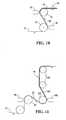
- FIG 19illustrates a variant embodiment of the present invention, in which a large current collector element 150 is coated on each of its surfaces with two separate layers of electrode material. More specifically, layers 152 and 153 coat the first surface of the current collector element 150, while layers 154 and 155 coat the second surface of the current collector element 150. The layers of electrode material 152, 153 and 154, 155 are then encapsulated by two distinct polymer electrolyte envelopes 158 and 159, which also circumvent the edges 160 and 161, respectively, of the current collector element 150 to form a dual sub-assembly 175.
- the electrode layers 152, 153 and 154, 155, as well as the two edges 160 and 161 of the current collector element 150,are completely enclosed and thus electrically isolated within the two polymer electrolyte envelopes 158 and 159. Only the intermediate portion 165 of the current collector element 150 remains exposed.
- the current collector element 150is slit along the axis A-A at the midpoint of the intermediate portion 165, in order to form two separate electrochemical cell sub-assemblies 10 as illustrated in Figure 1 .
- the exposed edges of the previously slit current collector element 150allows for electrical connection to other electrochemical cells or to the electrical post of the generator formed of a series of stacked electrochemical cells.
- any of the apparatuses previously described and shown in Figures 3 , 7 , 10, 11 , 12 and 16are suitable, to produce the dual sub-assembly 175 shown in Figure 19 .
- the apparatuses which extrude polymer electrolyte layerswill include extrusion dies having two separate internal channels, one for each polymer electrolyte layer, such that the layers of polymer electrolyte can be extruded to form the polymer electrolyte envelopes 158 and 159 shown in Figure 19 .
- Figure 20illustrates a large current collector element 250 coated with a large layer of electrode material 252 on each of its surfaces, leaving both edges 253 and 254 of the large current collector element 250 exposed.
- the pre-assembly formed of current collector element 250 and electrode layers 252is slit or cut along the axis A-A at the midpoint, in order to form the two separate pre-assemblies 255 shown in Figure 21 .
- the ends of the current collector element 250 and of the electrode layers 252 on the cut sides 256 of the pre-assemblies 255are therefore even, while the edges 253 and 254 remain exposed.
- polymer electrolyte layers 258 and 259are coated onto pre-assemblies 255 by any method previously described, such that the polymer electrolyte layers 258 and 259 encapsulate the entire electrode layers 252, as well as the ends 256, with a polymer electrolyte envelope 260.
- the ends 256are electrically insulated to prevent any potential short circuit, while the edges 253 and 254 of the current collector element 250 remain exposed to allow for electrical connection to other electrochemical cells or to the electrical post of a generator formed of a series of stacked electrochemical cells,
Landscapes
- Engineering & Computer Science (AREA)
- Manufacturing & Machinery (AREA)
- Chemical & Material Sciences (AREA)
- Chemical Kinetics & Catalysis (AREA)
- Electrochemistry (AREA)
- General Chemical & Material Sciences (AREA)
- Mechanical Engineering (AREA)
- Condensed Matter Physics & Semiconductors (AREA)
- Physics & Mathematics (AREA)
- Dispersion Chemistry (AREA)
- General Physics & Mathematics (AREA)
- Inorganic Chemistry (AREA)
- Secondary Cells (AREA)
- Battery Electrode And Active Subsutance (AREA)
- Cell Electrode Carriers And Collectors (AREA)
- Primary Cells (AREA)
Abstract
Description
- The present invention relates generally to lithium polymer batteries and more specifically to the design and method of manufacturing of the electrochemical cells making up a lithium polymer battery.
- Rechargeable batteries manufactured from laminates of solid polymer electrolytes and sheet-like anodes and cathodes display many advantages over conventional liquid electrolyte batteries. These advantages include having a lower overall battery weight, a high power density, a high specific energy and a Longer service life, as well as being environmentally friendly since the danger of spilling toxic liquid into the environment is eliminated.
- The components of a solid polymer electrochemical cell include positive electrodes, negative electrodes and separators capable of permitting ionic conductivity, such as solid polymer electrolytes, sandwiched between each anode and cathode. The anodes (or negative electrodes) and cathodes (or positive electrodes) are made of material capable of reversible insertion of alkali metal ions. The polymer electrolyte separators electrically isolate the anode from the cathode to prevent short circuits therebetween, which would render the electrochemical cell useless.
- The cathodes are typically formed of a mixture of active material capable of occluding and releasing lithium, such as transitional metal oxides or phosphates, an electronically conductive filter, usually carbon or graphite or combinations thereof, and an ionically conductive polymer binder. Cathode materials are usually paste-like and require a current collector, usually a thin sheet of electrically conductive material such as aluminum foil. The anodes are typically made of light-weight metal foils, such as alkali metals and alloys, typical lithium metal, lithium oxide, lithium-aluminum alloys and the like. The anodes may also be composite paste-like material comprising, for example, carbon-based intercalation compounds in a polymer binder, in which case the anode also requires a current collector support, preferably a thin sheet of copper.
- Composite cathode thin films are usually obtained by solvent coating onto a current collector or by melt extrusion. Similarly, the polymer electrolyte separator layer is typically produced by solvent coating or by melt extrusion.
- Solid lithium polymer electrochemical cells are typically manufactured by successive layering of the positive electrode, the electrolyte separator and the negative electrode. The positive electrode material is initially coated or extruded onto a metallic foil (for example aluminum) or onto a metallized plastic film, which serves as a current collector. The polymer electrolyte separator is thereafter preferably coated or extruded directly onto the previously coated cathode material and the negative electrode is finally laminated onto the electrolyte to form an electrochemical cell. To increase the energy density of an electrochemical cell, a bi-face design is preferred wherein positive electrode material is laminated, coated or extruded onto both sides of the current collector.
- Electrochemal cells as previously described are assembled in an offset pattern: Electrochemical cells as previously described are assembled in an offset pattern: the metallic anode or negative current collector extends from one side of the electrochemical cell, while the cathode current collector extends from the other side of the electrochemical cell. The electrolyte separator (or separators in the case of bi-face designs) is positioned in between the anode and the cathode but does not extend the entire width of the electrochemical cell because a portion of the metallic anode or negative current collector on one side and a portion of the cathode current collector on the other side must remain exposed for lateral collection of current (i.e. to allow for connection in parallel to other electrochemical cells and to the positive and negative terminals of the electrochemical generator of which it is a constituent of). The exposed anodes and cathodes may in some circumstances touch each other when the electrochemical cells are assembled and pressed together, resulting in a short circuit which renders the cells useless. Short circuits may also occur through misplacement or misalignment of the various layers of the electrochemical cells or through misplacement or misalignment of a stack of electrochemical cells.
- To alleviate this potential problem,
US Patent No. 5,360,684 disclosed the addition of an insulating band of polypropylene or other plastic material between the exposed ends of the anode and the cathode current collector, for the sole purpose of eliminating potential short circuit.US patent application No. 09/876,567 US2002/0197535A1 ) discloses a variant of the same concept, in which an insulating edge material is coated or extruded at the end of the cathode material to prevent a potential short circuit between the exposed ends of the anode and the cathode layer.US Patent No. 5,670,273 discloses a method of fabricating electrochemical cells, wherein the successive anode and cathode layers are separated by a polymeric electrolyte layer having a protruding polymer edge that reduces the likelihood of inadvertent contact between the anode and cathode current collectors. - The above described solutions all fulfill their purpose, however at the cost of either adding steps to the manufacturing process of the electrochemical cells or having protruding separators that hinder proper parallel connections of the current collectors and may cause potential weight penalties.
- Thus, there is a need for an electrochemical cell configuration that prevents inadvertent short circuits between the anode and cathode, as well as for a reliable method and apparatus for the production of electrochemical cell sub-assemblies for lithium polymer batteries.
- It is therefore an object of the present invention to provide an electrochemical cell configuration that prevents inadvertent short circuits between the anode and cathode.
- It is another object of the present invention to provide a method of manufacturing sub-assembly components for a thin film electrochemical cell.
- It is a further object of the present invention to provide an electrochemical generator comprising a plurality of electrochemical cells configured to prevent inadvertent short circuits between the anodes and cathodes.
- As embodied and broadly described, the present invention provides a method for manufacturing an electrochemical cell sub-assembty for a lithium polymer battery, the method including:
- (a) providing a current collector sheet having a pair of opposite surfaces and a pair of opposite edges, where each surface is coated with a respective layer of electrode material;
- (b) extruding a layer of polymer electrolyte over the current collector sheet such that the layer of polymer electrolyte envelopes both layers of electrodes material and one of the pair of edges of the current collector sheet, thereby encapsulating the one edge of the current collector sheet while leaving exposed the other edge of the current collector sheet.
- As embodied and broadly described, the present invention also provides an electrochemical cell including:
- (a) a positive electrode including:
- a current collector sheet having a pair of opposite surfaces and a pair of opposite edges;
- a layer of positive electrode material disposed on each surface of the current collector sheet;
- (b) a polymer electrolyte separator encapsulating both layers of positive electrode material and one of the pair of edges of the current collector sheet, thereby leaving the other edge of the current collector sheet exposed; and
- (c) at least one negative electrode disposed over said polymer electrolyte separator.
- As embodied and broadly described, the present invention further provides an electrochemical cell sub-assembly including:
- (a) a current collector sheet having a pair of opposite surfaces and a pair of opposite edges, each surface being coated with a respective layer of electrode material;
- (b) a layer of polymer electrolyte enveloping both layers of electrode material and one of the pair of edges of the current collector sheet, thereby encapsulating the one edge of the current collector sheet while leaving exposed the other edge of the current collector sheet.
- As embodied and broadly described, the present invention also provides a system for manufacturing an electrochemical cell sub-assembly, the system including:
- (a) a conveyor mechanism transporting a current collector sheet having a pair of opposite surfaces and a pair of opposite edges, each surface of the current collector sheet being coated with a respective layer of electrode material;
- (b) an extrusion die having a pair of distinct discharge nozzles and a passageway disposed generally in between the distinct discharge nozzles, the passageway operative to receive the current collector sheet from the conveyor mechanism, each discharge nozzles operative to discharge a film of polymer electrolyte onto a respective surface of the current collector sheet when the current collector sheet travels through the passageway, thereby encapsulating both layers of electrode material and one of the pair of edges of the current collector sheet, while leaving exposed the other edge of the current collector sheet.
- As embodied and broadly described, the present invention also provides a method for manufacturing an electrochemical cell sub-assembly for a lithium polymer battery, said method comprising:
- (a) providing a current collector sheet having a pair of opposite surfaces and a pair of opposite edges, where each surface is coated with a respective tayer of electrode material;
- (b) laminating a layer of polymer electrolyte over each surface of the current collector sheet such that the layers of polymer electrolyte envelope both layers of electrode material and one of the pair of edges of the current collector sheet, thereby encapsulating the one edge of the current collector sheet white leaving exposed the other edge of the current collector sheet.
- As embodied and broadly described, the present invention also provides a system for manufacturing an electrochemical cell sub-assembly for a lithium polymer battery, said system comprising:
- (a) a conveyor mechanism transporting a current collector sheet having a pair of opposite surfaces and a pair of opposite edges, each surface of said current collector sheet being coated with a respective layer of electrode material;
- (b) a lamination apparatus having a pair of pressure rollers, said pressure rollers defining a passageway therebetween for receiving said current collector sheet from said conveyor mechanism, each pressure roller operative to laminate a polymer electrolyte layer onto a respective surface of said current collector sheet when said current collector sheet travels through said passageway, thereby encapsulating both said layers of electrode material and one of the pair of edges of said current collector sheet, white leaving exposed the other edge of said current collector sheet.
- The invention will be better understood and other advantages will appear by means of the following description and the following drawings in which:
Figure 1 is a schematic cross-sectional view of a electrochemical cell sub-assembty, in accordance with an embodiment of the present invention;Figure 2 is a schematic cross-sectional view of an electrochemical cell, in accordance with an embodiment of the present invention;Figure 3 is a schematic side elevational view of an extrusion process for encapsulating the electrode layers previously deposited on a current collector with a polymer electrolyte, in accordance with an example of implementation of the present invention;Figure 4 is a schematic top plan view of the extrusion process illustrated inFigure 3 , showing a current collector and etectrode assembly traveling through the extrusion die;Figure 5 is a schematic cross-sectional view of the extrusion die ofFigure 3 applying an electrolyte layer on both sides of a current collector and electrode assembly;Figure 6 is a schematic cross-sectional view of an electrochemical cell sub-assembly resulting from the process illustrated inFigure 3 ;Figure 7 is a schematic cross-sectional view of an extrusion process for encapsulating the electrode layers previously deposited on a current collector, in accordance with another example of implementation of the present invention;Figure 8 is a schematic top cross sectional view of the opposing extrusion dies ofFigure 7 applying an electrolyte layer on a both sides of a current collector and electrode assembly;Figure 9 is a schematic cross-sectional view of an electrochemical cell sub-assembly resulting from the process illustrated inFigure 7 ;Figure 10 is a schematic side elevational view of an extrusion process for encapsulating the electrode layers previously deposited on a current collector, in accordance with yet another example of implementation of the present invention;Figure 11 is a schematic side elevational view of an extrusion process for encapsulating the electrode layers previously deposited on a current collector, in accordance with another example of implementation of the present invention;Figure 12 is a schematic side elevational view of an extrusion process for encapsulating the electrode layers previously deposited on a current collector, in accordance with another example of implementation of the present invention;Figure 13 is a schematic cross sectional view of the first extrusion dies ofFigures 10, 11 and12 depositing a first layer of polymer electrolyte onto a first side of a current collector and electrode assembly;Figure 14 is a schematic cross sectional view of the second extrusion dies ofFigures 10, 11 and12 depositing a second layer of polymer electrolyte onto a second side of a current collector and electrode assembly;Figure 15 is a schematic cross-sectional view of an electrochemical cell sub-assembly resulting from the process illustrated in each ofFigures 10, 11 and12 ;Figure 16 is a schematic side elevational view of a lamination process for encapsulating the electrode layers previously deposited on a current collector, in accordance with yet another example of implementation of the present invention;Figure 17 is a schematic cross-sectional view taken at line 17-17 ofFigure 16 ;Figure 18 is a schematic cross-sectional view taken at line 18-18 ofFigure 16 ;Figure 19 is a schematic cross-sectional view of a dual electrochemical cell sub-assembly, in accordance with a variant embodiment of the present invention;Figure 20 is a schematic cross-sectional view of a pre-assembly of a large current collector previously coated with layers of electrode material, in accordance with another variant embodiment of the present invention;Figure 21 is a schematic cross-sectional view of the pre-assembly illustrated inFigure 20 after being cut; andFigure 22 is a schematic cross-sectional view of the pre-assemblies illustrated inFigure 21 , encapsulated with polymer electrolyte envelopes.- With reference to
Figure 1 , there is shown a cross-section of anelectrochemical cell sub-assembly 10, in accordance with an embodiment of the present invention. Theelectrochemical cell sub-assembly 10 includes a centralcurrent collector element 12, a layer ofelectrode material 14 coated on each surface of the centralcurrent collector element 12 and apolymer electrolyte 16. Thepolymer electrolyte 16 completely envelopes the layers ofelectrode material 14 coated on the surfaces of the centralcurrent collector element 12, as well as oneedge 13 of thecurrent collector element 12. In this example, the layer ofelectrode material 14 consists of a cathode or positive electrode material. Thepolymer electrolyte envelope 16 is ionically conductive but electrically non-conductive, as is well known in the art, in order to allow ionic exchanges between the positive and negative electrodes but inhibit the formation of electrical current pathway between the positive and negative electrodes of the electrochemical cell. As shown inFigure 1 , the electrode layers 14 and oneedge 13 of the centralcurrent collector 12 are completely enclosed within thepolymer electrolyte envelope 16 and therefore are completely isolated electrically. Only edge 15 of the centralcurrent collector 12 remains exposed for the purpose of electrical connection to other electrochemical cells or to the electrical post of the generator having at least one electrochemical cell. Figure 2 illustrates a completeelectrochemical cell 20, in accordance with an embodiment of the present invention. Theelectrochemical cell 20 is formed of the sub-assembly 10, which includes the centralcurrent collector element 12, the layers ofelectrode material 14 coated on each surface of the centralcurrent collector element 12 and thepolymer electrolyte envelope 16, which completely envelopes the layers ofelectrode material 14. Anegative electrode 18 is disposed on each side of thepolymer electrolyte envelope 16 facing the layers ofpositive electrode material 14, thereby sandwiching thepolymer electrolyte envelope 16 and completing theelectrochemical cell 20. As illustrated, the layers ofpositive electrode material 14 and edge 13 of the centralcurrent collector element 12 are completely isolated electrically from thenegative electrodes 18, thereby reducing the risks of short circuits between thenegative electrodes 18 and either thepositive electrode material 14 or theedge 13 of the centralcurrent collector element 12. In this particular configuration, the positive and negative electrical contact points are offset. More specifically, thecurrent collector element 12 of the positive electrode extends to one side of theelectrochemical cell 20, while thenegative electrodes 18 extend to the other side of theelectrochemical cell 20, such that the electrical contact points are on opposite sides of theelectrochemical cell 20. As is well known in the art, a plurality of electrochemical cells may be stacked together, their positive electrodes connected together in parallel and their negative electrodes also connected in parallel, to increase their overall capacity (Amp/hr).- The electrochemical cells described herein are typically formed of extremely thin constituents. For example:
- the thickness of the central
current collector element 12 may range from 12 µm to 50 µm; - the thickness of one layer of
positive electrode material 14 may range from 15 pm to 100 µm; - the thickness of one side of the
polymer electrolyte envelope 16 may range from 15 µm to 50 µm; and - the thickness of the
negative electrode 18 may range from 20 µm to 80 µm. - The above thickness ranges are given only as an example, in order to illustrate the difficulty of producing such an assembly. Other thickness ranges for each of the central
current collector element 12, thepositive electrode material 14, thepolymer electrolyte envelope 16 and thenegative electrode 18 are also possible and included within the scope of the present invention. Figures 3 and 4 illustrate an example implementation of an apparatus and method for overlaying a central current collector element having layers of electrode material on both its surfaces with a polymer electrolyte envelope, in order to form theelectrochemical cell sub-assembly 10 illustrated inFigure 1 , in accordance with an embodiment of the present invention. A pre-assembly 22, including acurrent collector element 12 that was previously coated on both its surfaces with layers ofelectrode material 14, is delivered via a conveyor mechanism, in this example a series ofcylindrical rollers 34, to a dual extrusion die 30, where thin layers ofpolymer electrolyte 24 are overlaid onto each side of the pre-assembly 22. A single screw ortwin screw extruder 31 feeds polymer electrolyte material to the dual extrusion die 30.- As illustrated in
Figures 3 and 4 , the pre-assembly 22 travels through dual extrusion die 30, where a thin layer ofpolymer electrolyte 24 is applied simultaneously to both sides of the pre-assembly 22. As seen more clearly inFigure 4 , the layers ofpolymer electrolyte 24 are, wider than the layers ofelectrode material 14, such that the two layers ofpolymer electrolyte 24 completely encapsulate the layers ofelectrode material 14 and also circumvent oneedge 13 of thecurrent collector 12. The pre-assembly 22 with itspolymer electrolyte envelope 16 is then redirected by a series ofcylindrical rollers polymer electrolyte envelope 16 and to prevent unwanted adhesion of the polymer to the rollers. The complete electrochemical cell sub-assembly 10 (Figure 1 ) is then routed towards other stations for further processing or storage. Figure 5 illustrates schematically a cross-sectional view of the dual extrusion die 30 ofFigures 3 and 4 , when the pre-assembly 22 travels directly therethrough.- Extrusion die 30 incudes two
discharge nozzles Figures 3 and 4 ) through acylindrical channel 39. Upon entering the extrusion die 30, the polymer electrolyte material is divided by aflow divider 44 into two separateinternal channels discharge nozzles discharge nozzles electrode material 14, theentire edge 13 of thecurrent collector element 12 and a portion of theother end 15 of thecurrent collector element 12. Accordingly, the two layers ofelectrode material 14 are enveloped and electrically isolated. Figure 6 illustrates schematically a cross sectional view of theelectrochemical cell sub-assembly 10 exiting the dual extrusion die 30, where it can be seen that the two layers ofpolymer electrolyte 24 merge together at ameeting point 45 beyond the end of theedge 13 ofcurrent collector 12, thereby forming thepolymer electrolyte envelope 16.Figure 7 illustrates another example of implementation of an apparatus and method for overlaying a central current collector element having layers of electrode material on both its surfaces with a polymer electrolyte envelope, in order to form theelectrochemical cell sub-assembly 10 illustrated inFigure 1 . A pre-assembly 22 formed of acurrent collector element 12 that was previously coated on both its surfaces with layers ofelectrode material 14 is delivered via a series of cylindrical rollers 48 (only one shown) to a pair of extrusion dies 50 and 60, where thin layers ofpolymer electrolyte layers electrode material 14, they completely encapsulate the layers of electrode material, 14. The pre-assembly 22 with itslayers cylindrical roller 55, which is preferably maintained at a cool temperature in order to accelerate the solidification of the polymer electrolyte layers and prevent any unwanted adhesion thereof. The completeelectrochemical cell sub-assembly 10 is routed towards other stations for further processing or storage.Figure 8 illustrates schematically a top cross sectional view of the pair of opposing extrusion dies 50 and 60 ofFigure 7 , when the pre-assembly 22 including its layers ofelectrode material 14 travels directly in front of the discharge ends of extrusion dies 50 and 60. Theinternal channels polymer electrolyte sheets electrode material 14 and extending marginally beyondedge 13 of thecurrent collector element 12, in order to envelop and electrically isolate the end ofedge 13. Thepolymer electrolyte sheets other end 15 of thecurrent collector element 12, thereby enveloping and electrically isolating the two layers ofelectrode material 14.Figure 9 illustrates theelectrochemical cell sub-assembly 10 resulting from the apparatus and method of extrusion shown in and described with regard toFigures 7 and 8 . As previously mentioned, thepolymer electrolyte sheets edge 13 of thecurrent collector element 12, such that thepolymer electrolyte sheets edge 13 thereby enclosing theedge 13 and forming thepolymer electrolyte envelope 16.- Although
Figure 7 illustrates extrusion dies 50 and 60 directly opposed to each other, they may be offset relative to one another. Figure 10 illustrates a variant example of implementation of the apparatus and method for overlaying a central current collector element having layers of electrode material on both its surfaces with a polymer electrolyte envelope, in order to form theelectrochemical cell sub-assembly 10 illustrated inFigures 1 . In this example, the extrusion dies 70 and 80 are offset relative to each other. Thepre-assembty sheet 22 is preferably supported bycylindrical rollers polymer electrolyte pre-assembly sheet 22. The polymer electrolyte layers orsheets edge 13 of thecurrent collector element 12. Accordingly thepolymer electrolyte sheets electrode material 14 and merge beyond theedge 13, thereby enclosing theedge 13 and forming thepolymer electrolyte envelope 16, as illustrated with more detail inFigure 15 .Figure 11 illustrates another variant example of implementation of the apparatus and method for overlaying a central current collector element having layers of electrode material on both its surfaces with a polymer electrolyte envelope, in order to form theelectrochemical cell sub-assembty 10 illustrated inFigure 1 . In this example, the extrusion dies 90 and 100 are disposed in a marginally different configuration than that illustrated inFigure 10 , although the extrusion dies 90 and 100 are still offset relative to each other. Thepre-assembly sheet 22 is supported bycylindrical rollers polymer electrolyte pre-assembly sheet 22. As previously described with reference toFigure 8 , the polymer electrolyte layers orsheets edge 13 of thecurrent collector element 12. Accordingly, thepolymer electrolyte sheets electrode material 14 and merge beyond theedge 13, thereby enclosing theedge 13 and forming thepolymer electrolyte envelope 16, as illustrated with more detail inFigure 15 .Figure 12 illustrates yet another variant example of implementation of the apparatus and method for overlaying a central current collector element having layers of electrode material on both its surfaces with a polymer electrolyte envelope, in order to form theelectrochemical cell sub-assembty 10 illustrated inFigure 1 . In this example, the pre-assembly 22 is delivered via a series of cylindrical rollers 112 (only one shown) to a first extrusion die 110, where a thin layer ofpolymer electrolyte 24 is overlaid onto a first side of the pre-assembly 22.- As previously described, the layer of
polymer electrolyte 24 is wider than the layer of electrode material, such that it completely encapsulates the layer of electrode material. The pre-assembly 22 with the added layer ofpolymer electrolyte 24 on one of its surfaces is then redirected by acylindrical roller 114, which is preferably maintained at a cool temperature in order to accelerate the solidification of thepolymer electrolyte layer 24. The pre-assembly 22 with the added layer ofpolymer electrolyte 24 is then delivered via another series of cylindrical rollers 116 (only one shown) to a second extrusion die 120, where another thin layer ofpolymer electrolyte 24 is overlaid onto the second side of the pre-assembly 22. Again, the layer ofpolymer electrolyte 24 being applied on the second side of the pre-assembly 22 is wider than the layer of electrode material, such that it completely encapsulates the layer of electrode material. The pre-assembly 22 with both layers ofpolymer electrolyte 24 forming anenvelope 16 is supported bycylindrical roller 118, which is also preferably maintained at a cool temperature in order to accelerate the solidification of the secondpolymer electrolyte layer 24 and to prevent unwanted adhesion of the first layer ofpolymer electrolyte 24. The completeelectrochemical cell sub-assembly 10 is routed towards other stations via another series of cylindrical rollers 122 (only one shown) for further processing or storage. Figure 13 illustrates schematically a cross sectional view of each of the first extrusion dies 70, 90 and 110 ofFigures 10, 11 and12 , respectively, when the pre-assembly 22 travels directly in front of the discharge end of the extrusion die. Theinternal channel 125 of the extrusion die 70, 90, 110 is illustrated in dotted lines and determines the path that the polymer electrolyte follows inside the extrusion die 70, 90, 110 before being discharged as a thin film onto a first side of the pre-assembly 22. Thepolymer electrolyte sheet 24 is spread over an area that covers the first layer ofelectrode material 14, theentire edge 13 of thecurrent collector element 12 and a portion of theother edge 15 of thecurrent collector element 12, thereby enveloping and electrically isolating the first layer ofelectrode material 14.Figure 14 illustrates schematically a cross sectional view of each of the second extrusion dies 80, 100 and 120 ofFigures 10, 11 and12 , respectively, when the pre-assembly 22 including the first addedpolymer electrolyte layer 24 travels directly in front of the discharge end of the extrusion die with the second side or surface of the pre-assembly 22 facing the extrusion die. Theinternal channel 127 of the extrusion die 80, 100, 120 is illustrated in dotted lines and determines the path that the polymer electrolyte follows inside the extrusion die 80, 100, 120 before being discharged as a thin film onto the second side or surface of the pre-assembly 22. Thepolymer electrolyte sheet 26 is spread over an area that covers the second layer ofelectrode material 14 and extends marginally beyondedge 13 of thecurrent collector element 12, in order to envelop and electrically isolate the end ofedge 13. Thepolymer electrolyte sheet 26 also extends over a portion of theother end 15 of thecurrent collector element 12, thereby enveloping and electrically isolating the second layer ofelectrode material 14.Figure 15 illustrates theelectrochemical cell sub-assembly 10 resulting from the apparatuses and methods of extrusion shown in and described with regard toFigures 10 to 14 . As previously described, thepolymer electrolyte sheet 26 is discharged over an area that extends marginally beyondedge 13 of thecurrent collector element 12. As such, it folds over theedge 13 by capillarity to enclose theedge 13 and adhere to previously appliedpolymer electrolyte layer 24, for forming thepolymer electrolyte envelope 16.Figure 16 illustrates another variant example of implementation of the apparatus and method for overlaying a central current collector element having layers of electrode material on both its surfaces with a polymer electrolyte envelope, in order to form theelectrochemical cell sub-assembly 10 illustrated inFigure 1 . In this example, thepolymer electrolyte envelope 16 is formed by laminatingpolymer electrolyte films 24 onto the electrode layers 14 of each surface of the centralcurrent collector 12. As illustrated inFigure 16 , a pre-assembly 22, including acurrent collector element 12 that was previously coated on both its surfaces with layers ofelectrode material 14, is delivered via any conveyor system to a first pair ofrollers 200, where thin films ofpolymer electrolyte 24 are overlaid onto each side of the pre-assembly 22. Alternatively, thepolymer electrolyte films 24 may be overlaid onto the respective sides of the pre-assembly 22 at different locations and in successive steps, as opposed to the simultaneous application illustrated inFigure 16 .- in a specific example, each thin film of
polymer electrolyte 24 has been previously laid onto aplastic support film 202, covered by another protective plastic film 204 and wound into aroll Figure 16 , the protectiveplastic films 204A and 204B are peeled off of the thin films ofpolymer electrolyte 24, routed away from therollers 200 and wound onto recuperation rolls 205 and 207, in order to expose thepolymer electrolyte films 24 to the layers ofelectrode material 14 prior to lamination. Thepolymer electrolyte films 24 are then brought into contact with the layers ofelectrode material 14 such that they are offset to one side of the pre-assembly 22, as seen inFigure 17 . More specifically, bothpolymer electrolyte films 24 extend over oneedge 206 of the pre-assembly 22, and thus over one edge of the centralcurrent collector 12 of the pre-assembly 22, such that theextensions 210 of the polymer electrolyte layers 24 may be brought into contact with each other when the entire assembly is pressed together. The ends 208 of thepolymer electrolyte films 24 also extend past the ends of the layers ofelectrode material 14, in order to encapsulate them when the entire assembly is pressed together. - The laminate 212 formed of a central
current collector 12, two layers ofelectrode material 14, as well as a layer ofpolymer electrolyte 24 and aplastic support film 202 on each side thereof, next enters aheating zone 215. In thisheating zone 215, the two layers ofpolymer electrolyte 24 are heated to a temperature sufficient to promote adhesion of the polymer electrolyte layers 24 onto the electrode layers 14, as well as adhesion of theextensions 210 of the polymer electrolyte layers 24 to each other. The heat may be generated by any means known to those skilled in the art. - The
heated laminate 212 then passes through a pair oflamination rollers 216, at least one of which is covered with a layer of rubber or other flexible material in order to conform to the profile of the laminate 212 and exert a pressure P onto the entire surface of the respectivepolymer electrolyte film 24. Accordingly, theextensions 210 of the polymer electrolyte layers 24 adhere to each other and envelope the edge of the centralcurrent collector 12, while theends 208 of the polymer electrolyte layers 24 enclose the ends of the electrode material layers 14. As a result, the polymer electrolyte layers 24 encapsulate the entire electrode layers 14 and one edge of the centralcurrent collector 12, as illustrated inFigure 18 . - Thereafter, the laminate 212 is routed through a series of cooling
rollers rollers rollers roller rollers - The laminate 212 is then routed to a peeling station 220, where the
plastic support films 202 are removed from the laminate 212 and wound onto recuperation rolls 221 and 223. To prevent any damage to thepolymer electrolyte film 24 encapsulating the electrode layers 14 while theplastic support films 202 are being removed, a suitable solvent is introduced at eachpeeling point plastic support films 202, thus preventing any ripping of portions or segments of thepolymer electrolyte films 24. As illustrated inFigure 16 , the peeling angles are less than 90°. In this manner, each pair ofplastic support film 202 andpolymer electrolyte film 24, once separated, forms a small pool where the solvent can remain and act on the interface between theplastic support film 202 andpolymer electrolyte film 24. - Note that a small quantity of solvent may remain on the surface of each
polymer electrolyte film 24. As such, the laminate 10 is next passed through a dryingstation 226, where the excess or remaining solvent is evaporated. - In order to store the encapsulated
laminate 10, a newprotective film 230 having a weak adherence to the polymer electrolyte is applied thereto in order to prevent adhesion of adjacent layers ofpolymer electrolyte 24 when the laminate 10 is wound onto aroll 229, as well as to ease peeling when the laminate 10 is brought for final assembly with the anode portions of the electrochemical cell Of course, the laminate 10 may alternatively be brought directly to a further processing station for assembly into a complete electrochemical cell. Figure 19 illustrates a variant embodiment of the present invention, in which a largecurrent collector element 150 is coated on each of its surfaces with two separate layers of electrode material. More specifically, layers 152 and 153 coat the first surface of thecurrent collector element 150, whilelayers current collector element 150. The layers ofelectrode material polymer electrolyte envelopes edges current collector element 150 to form adual sub-assembly 175. As shown inFigure 19 , the electrode layers 152, 153 and 154, 155, as well as the twoedges current collector element 150, are completely enclosed and thus electrically isolated within the twopolymer electrolyte envelopes intermediate portion 165 of thecurrent collector element 150 remains exposed. In a subsequent step in the manufacturing process, thecurrent collector element 150 is slit along the axis A-A at the midpoint of theintermediate portion 165, in order to form two separateelectrochemical cell sub-assemblies 10 as illustrated inFigure 1 . The exposed edges of the previously slitcurrent collector element 150 allows for electrical connection to other electrochemical cells or to the electrical post of the generator formed of a series of stacked electrochemical cells.- Any of the apparatuses previously described and shown in
Figures 3 ,7 ,10, 11 ,12 and16 are suitable, to produce thedual sub-assembly 175 shown inFigure 19 . However, the apparatuses which extrude polymer electrolyte layers will include extrusion dies having two separate internal channels, one for each polymer electrolyte layer, such that the layers of polymer electrolyte can be extruded to form thepolymer electrolyte envelopes Figure 19 . Furthermore, the apparatuses which laminate the polymer electrolyte layers onto the pre-assembly 22 will be fed with two pairs of parallel polymer electrolyte films, in order to cover both electrode layers and both edges of the centralcurrent collector 150 prior to slitting. The slitting of the sub-assembly 175 may be done by any conventional method. - In another variant embodiment of the present invention,
Figure 20 illustrates a largecurrent collector element 250 coated with a large layer ofelectrode material 252 on each of its surfaces, leaving bothedges current collector element 250 exposed. In a subsequent step of the manufacturing process, the pre-assembly formed ofcurrent collector element 250 andelectrode layers 252 is slit or cut along the axis A-A at the midpoint, in order to form the twoseparate pre-assemblies 255 shown inFigure 21 . The ends of thecurrent collector element 250 and of the electrode layers 252 on the cut sides 256 of the pre-assemblies 255 are therefore even, while theedges - In a final step of the manufacturing, process illustrated in
Figure 22 , polymer electrolyte layers 258 and 259 are coated ontopre-assemblies 255 by any method previously described, such that the polymer electrolyte layers 258 and 259 encapsulate the entire electrode layers 252, as well as theends 256, with apolymer electrolyte envelope 260. Thus, theends 256 are electrically insulated to prevent any potential short circuit, while theedges current collector element 250 remain exposed to allow for electrical connection to other electrochemical cells or to the electrical post of a generator formed of a series of stacked electrochemical cells, - Although the present invention has been described in relation to particular variations thereof, other variation and modifications are contemplated and are within the scope of the present invention. Therefore the present invention is not to be limited by the above description but is defined by the appended claims.
Claims (5)
- an electrochemical cell comprising:a. a positive electrode including:i. a current collector sheet having a pair of opposite surfaces and a pair of opposite edges;ii. a layer of positive electrode material disposed on each surface of the current collector sheet;b. a polymer electrolyte separator encapsulating both layers of positive electrode material and one of the pair of edges of said current collector sheet, thereby leaving the other edge of said current collector sheet exposed;andc. at least one negative electrode disposed over said polymer electrolyte separator.
- An electrochemical cell as defined in claim 1, wherein said at least one negative electrode extends outwardly from said encapsulated edge of said current collector sheet, such that said negative electrodes is spaced apart from said exposed edge of said current collector sheet.
- An electrochemical cell as defined in claim 1, comprising a pair of negative electrodes, each negative electrode being disposed adjacent a respective surface of said current collector sheet, over said polymer electrolyte separator, thereby forming a bi-face electrochemical cell.
- An electrochemical cell as defined in claim 3, wherein each of said negative electrodes extends outwardly from said encapsulated edge of said current collector sheet, such that each of said negative electrodes is spaced apart from said exposed edge of said current collector sheet.
- an electrochemical cell sub-assembly comprising:a. a current collector sheet having a pair of opposite surfaces and a pair of opposite edges, each surface being coated with a respective layer of electrode material;b. a layer of polymer electrolyte enveloping both said layers of electrodes material and one of said pair of opposite edges of said current collector sheet, thereby encapsulating the one edge of said current collector sheet while leaving exposed the other edge of said current collector sheet.
Applications Claiming Priority (2)
| Application Number | Priority Date | Filing Date | Title |
|---|---|---|---|
| US10/968,933US7531012B2 (en) | 2004-10-21 | 2004-10-21 | Thin film electrochemical cell for lithium polymer batteries and manufacturing method therefor |
| EP05799219AEP1825555B1 (en) | 2004-10-21 | 2005-10-20 | Thin film electrochemical cell for lithium polymer batteries and manufacturing method therefor |
Related Parent Applications (1)
| Application Number | Title | Priority Date | Filing Date |
|---|---|---|---|
| EP05799219.0Division | 2005-10-20 |
Publications (2)
| Publication Number | Publication Date |
|---|---|
| EP2328222A1true EP2328222A1 (en) | 2011-06-01 |
| EP2328222B1 EP2328222B1 (en) | 2012-07-04 |
Family
ID=36202653
Family Applications (2)
| Application Number | Title | Priority Date | Filing Date |
|---|---|---|---|
| EP10191570ANot-in-forceEP2328222B1 (en) | 2004-10-21 | 2005-10-20 | Thin film electrochemical cell for lithium polymer batteries and manufacturing method therefor |
| EP05799219ANot-in-forceEP1825555B1 (en) | 2004-10-21 | 2005-10-20 | Thin film electrochemical cell for lithium polymer batteries and manufacturing method therefor |
Family Applications After (1)
| Application Number | Title | Priority Date | Filing Date |
|---|---|---|---|
| EP05799219ANot-in-forceEP1825555B1 (en) | 2004-10-21 | 2005-10-20 | Thin film electrochemical cell for lithium polymer batteries and manufacturing method therefor |
Country Status (5)
| Country | Link |
|---|---|
| US (2) | US7531012B2 (en) |
| EP (2) | EP2328222B1 (en) |
| JP (3) | JP5414176B2 (en) |
| CA (2) | CA2585440C (en) |
| WO (1) | WO2006042416A1 (en) |
Families Citing this family (30)
| Publication number | Priority date | Publication date | Assignee | Title |
|---|---|---|---|---|
| US20080126442A1 (en)* | 2006-08-04 | 2008-05-29 | Pavel Cisler | Architecture for back up and/or recovery of electronic data |
| US7527894B2 (en) | 2006-09-19 | 2009-05-05 | Caleb Technology Corporation | Identifying defective electrodes in lithium-ion polymer batteries |
| US20080070108A1 (en)* | 2006-09-19 | 2008-03-20 | Caleb Technology Corporation | Directly Coating Solid Polymer Composite Having Edge Extensions on Lithium-Ion Polymer Battery Electrode Surface |
| WO2008035707A1 (en)* | 2006-09-19 | 2008-03-27 | Sony Corporation | Electrode, method for manufacturing the electrode, and battery |
| US20080070103A1 (en)* | 2006-09-19 | 2008-03-20 | Caleb Technology Corporation | Activation of Anode and Cathode in Lithium-Ion Polymer Battery |
| US20080070104A1 (en)* | 2006-09-19 | 2008-03-20 | Caleb Technology Corporation | Forming Polymer Electrolyte Coating on Lithium-Ion Polymer Battery Electrode |
| KR101107075B1 (en)* | 2009-10-28 | 2012-01-20 | 삼성에스디아이 주식회사 | Secondary battery |
| US8557417B2 (en) | 2009-12-07 | 2013-10-15 | Samsung Sdi Co., Ltd. | Secondary battery |
| KR101355834B1 (en)* | 2010-12-02 | 2014-01-28 | 주식회사 엘지화학 | Device for Laminating Electrode Assembly Used in Manufacturing Secondary Battery |
| ITTV20120054A1 (en) | 2012-04-06 | 2013-10-07 | Biesse Tecnosystem Srl | SEMIAUTOMATIC SYSTEM OF REMOVAL FILM CARRIER AND APPLICATION OF PELABILE LAYER FOR CONTINUOUS OR COMPOSED FINAL COIL |
| KR102163733B1 (en) | 2013-11-29 | 2020-10-12 | 삼성전자주식회사 | Polymer electrolyte for lithium battery and lithium battery employing the same |
| JP6149792B2 (en)* | 2014-04-24 | 2017-06-21 | トヨタ自動車株式会社 | Method for manufacturing electrolyte membrane structure |
| EP2991153B1 (en) | 2014-08-28 | 2023-08-23 | Samsung Electronics Co., Ltd. | Composite electrolyte and lithium battery including the same |
| CN105390744B (en) | 2014-08-29 | 2021-10-22 | 三星电子株式会社 | Composite, preparation method thereof, electrolyte including same, and lithium secondary battery |
| EP3001494B1 (en) | 2014-09-19 | 2018-08-15 | Samsung Electronics Co., Ltd. | Electrolyte, method of preparing the electrolyte, and lithium secondary battery comprising the electrolyte |
| US10361456B2 (en) | 2014-09-26 | 2019-07-23 | Samsung Electronics Co., Ltd. | Electrolyte, method of preparing the electrolyte, and secondary battery including the electrolyte |
| EP3076470B1 (en) | 2015-04-03 | 2019-10-16 | Samsung Electronics Co., Ltd. | Lithium secondary battery |
| EP3240087B1 (en) | 2016-04-29 | 2019-06-19 | Samsung Electronics Co., Ltd | Negative electrode for lithium metal battery and lithium metal battery comprising the same |
| US10741846B2 (en) | 2016-05-09 | 2020-08-11 | Samsung Electronics Co., Ltd. | Negative electrode for lithium metal battery and lithium metal battery comprising the same |
| EP3316361B1 (en) | 2016-10-25 | 2020-04-29 | Samsung Electronics Co., Ltd. | Polymer electrolyte, method of preparing the polymer electrolyte, and lithium metal battery including the same |
| KR102682126B1 (en) | 2017-08-04 | 2024-07-08 | 삼성전자주식회사 | Solid electrolyte, preparing method thereof, and lithium battery comprising the solid electrolyte |
| DE102018216315A1 (en)* | 2018-09-25 | 2020-03-26 | Robert Bosch Gmbh | Method of manufacturing an electrode unit for a battery cell and battery cell |
| JP2021061113A (en)* | 2019-10-03 | 2021-04-15 | イビデン株式会社 | Electrode for power storage device, power storage device, secondary battery, lithium ion capacitor, air battery and all-solid battery |
| JP7442912B2 (en)* | 2019-10-09 | 2024-03-05 | エルジー エナジー ソリューション リミテッド | Method for manufacturing battery components, battery components, and secondary batteries |
| WO2021070296A1 (en)* | 2019-10-09 | 2021-04-15 | 昭和電工マテリアルズ株式会社 | Battery member, secondary battery, and method for manufacturing battery member |
| WO2021194282A1 (en)* | 2020-03-25 | 2021-09-30 | 주식회사 엘지에너지솔루션 | Apparatus and method for manufacturing unit cell |
| CN113394375B (en)* | 2021-06-15 | 2023-02-17 | 宁德新能源科技有限公司 | Electrochemical device and electronic device |
| US20220399599A1 (en)* | 2021-06-15 | 2022-12-15 | Lionrock Batteries Limited | Flexible lithium-ion battery and method of manufacturing thereof |
| CN113644310B (en)* | 2021-08-12 | 2023-11-14 | 远景动力技术(江苏)有限公司 | Preparation method of multi-core stack and battery core |
| DE102022203933A1 (en) | 2022-04-22 | 2023-10-26 | Volkswagen Aktiengesellschaft | Impregnation process, impregnation device, solid cell and motor vehicle |
Citations (10)
| Publication number | Priority date | Publication date | Assignee | Title |
|---|---|---|---|---|
| US5376210A (en)* | 1994-03-23 | 1994-12-27 | Hydro-Quebec | Peeling aids for LPB electrolytes and method of use |
| US5456000A (en)* | 1993-03-05 | 1995-10-10 | Bell Communications Research, Inc. | Method of making an electrolyte activatable lithium-ion rechargeable battery cell |
| US5498489A (en)* | 1995-04-14 | 1996-03-12 | Dasgupta; Sankar | Rechargeable non-aqueous lithium battery having stacked electrochemical cells |
| US5593462A (en)* | 1993-11-16 | 1997-01-14 | Bollore Technologies | Method of manufacturing a multilayer electrochemical assembly comprising an electrolyte between two electrodes, and an assembly made thereby |
| WO1997008769A1 (en)* | 1995-08-25 | 1997-03-06 | Valence Technology, Inc. | Current collector having electrode material on two sides for use in a laminate battery and method of making a battery |
| WO1998012765A1 (en)* | 1996-09-18 | 1998-03-26 | Bell Communications Research, Inc. | Apparatus and method for making laminated rechargeable battery cells |
| US6134773A (en)* | 1998-02-20 | 2000-10-24 | Lithium Technology Corporation | Method for automatic mass production of electrochemical cells |
| JP2002042880A (en)* | 2000-07-27 | 2002-02-08 | Mitsubishi Cable Ind Ltd | Electrode laminated body and sheet-like polymer battery using the same |
| US6617074B1 (en)* | 1999-06-30 | 2003-09-09 | Mitsubishi Materials Corporation | Lithium ion polymer secondary battery and gelatinous polymer electrolyte for sheet battery |
| WO2004051769A2 (en)* | 2002-12-02 | 2004-06-17 | Avestor Limited Partnership | Co-extrusion manufacturing process of thin film electrochemical cell for lithium polymer batteries and apparatus therefor |
Family Cites Families (23)
| Publication number | Priority date | Publication date | Assignee | Title |
|---|---|---|---|---|
| JPH01319268A (en)* | 1988-06-21 | 1989-12-25 | Ricoh Co Ltd | secondary battery |
| US5348824A (en)* | 1993-10-25 | 1994-09-20 | Hydro-Quebec | Process of coating by melt extrusion a solid polymer electrolyte on positive electrode of lithium battery |
| US5360684A (en) | 1993-10-25 | 1994-11-01 | Hydro-Quebec | Electrochemical cell for polymer electrolyte-lithium batteries (ACEP) |
| US5670273A (en) | 1996-02-22 | 1997-09-23 | Valence Technology, Inc. | Method of preparing electrochemical cells |
| US5746781A (en)* | 1996-02-22 | 1998-05-05 | Valence Technology, Inc. | Method and apparatus for preparing electrochemical cells |
| JP4010521B2 (en)* | 1997-11-28 | 2007-11-21 | 日立マクセル株式会社 | Stacked battery |
| JP4193267B2 (en)* | 1999-02-23 | 2008-12-10 | ソニー株式会社 | Solid electrolyte battery |
| JP3864621B2 (en)* | 1999-06-30 | 2007-01-10 | 三菱マテリアル株式会社 | Lithium ion polymer secondary battery |
| JP3709495B2 (en)* | 1999-07-15 | 2005-10-26 | 三菱マテリアル株式会社 | Lithium ion polymer secondary battery |
| CN1277330C (en) | 1999-08-10 | 2006-09-27 | 三洋电机株式会社 | Non-aqueous electrolyte secondary battery and its mfg. method |
| GB0021466D0 (en)* | 2000-09-01 | 2000-10-18 | Univ Leeds Innovations Ltd | Extruded battery components |
| JP2002352850A (en)* | 2001-05-24 | 2002-12-06 | Matsushita Electric Ind Co Ltd | Chip battery and its manufacturing method |
| US7097673B2 (en) | 2001-06-07 | 2006-08-29 | 3M Innovative Properties Company | Coating edge control |
| JP2003109666A (en)* | 2001-07-27 | 2003-04-11 | Nissan Motor Co Ltd | Structure for all solid polymer battery, all solid polymer battery and method for manufacturing the same |
| JP2003109668A (en)* | 2001-09-28 | 2003-04-11 | Mitsubishi Materials Corp | Lithium ion polymer secondary battery |
| US6830846B2 (en) | 2001-11-29 | 2004-12-14 | 3M Innovative Properties Company | Discontinuous cathode sheet halfcell web |
| JP2003197264A (en)* | 2001-12-28 | 2003-07-11 | Tdk Corp | Polymer electrolyte battery and method of manufacturing the same |
| JP4092620B2 (en)* | 2002-02-22 | 2008-05-28 | 株式会社ジーエス・ユアサコーポレーション | Polymer electrolyte battery |
| JP3680809B2 (en)* | 2002-03-29 | 2005-08-10 | 三菱マテリアル株式会社 | Lithium ion polymer secondary battery and manufacturing method thereof |
| JP2004047369A (en)* | 2002-07-15 | 2004-02-12 | Irie Trading Corporation Kk | Non-aqueous electrolyte secondary battery and method of manufacturing the same |
| JP2004079217A (en)* | 2002-08-09 | 2004-03-11 | Mitsubishi Materials Corp | Battery module and its charging method |
| JP2004179091A (en)* | 2002-11-28 | 2004-06-24 | Kyocera Corp | Stacked battery |
| JP2004311351A (en)* | 2003-04-10 | 2004-11-04 | Ngk Spark Plug Co Ltd | Plate type battery and method of manufacturing the same |
- 2004
- 2004-10-21USUS10/968,933patent/US7531012B2/enactiveActive
- 2005
- 2005-10-20CACA2585440Apatent/CA2585440C/enactiveActive
- 2005-10-20EPEP10191570Apatent/EP2328222B1/ennot_activeNot-in-force
- 2005-10-20CACA2819736Apatent/CA2819736C/enactiveActive
- 2005-10-20WOPCT/CA2005/001621patent/WO2006042416A1/enactiveApplication Filing
- 2005-10-20EPEP05799219Apatent/EP1825555B1/ennot_activeNot-in-force
- 2005-10-20JPJP2007537091Apatent/JP5414176B2/ennot_activeExpired - Fee Related
- 2009
- 2009-04-17USUS12/425,700patent/US7968224B2/ennot_activeExpired - Lifetime
- 2013
- 2013-03-15JPJP2013052986Apatent/JP6174342B2/ennot_activeExpired - Fee Related
- 2015
- 2015-06-16JPJP2015121184Apatent/JP2015165517A/enactivePending
Patent Citations (10)
| Publication number | Priority date | Publication date | Assignee | Title |
|---|---|---|---|---|
| US5456000A (en)* | 1993-03-05 | 1995-10-10 | Bell Communications Research, Inc. | Method of making an electrolyte activatable lithium-ion rechargeable battery cell |
| US5593462A (en)* | 1993-11-16 | 1997-01-14 | Bollore Technologies | Method of manufacturing a multilayer electrochemical assembly comprising an electrolyte between two electrodes, and an assembly made thereby |
| US5376210A (en)* | 1994-03-23 | 1994-12-27 | Hydro-Quebec | Peeling aids for LPB electrolytes and method of use |
| US5498489A (en)* | 1995-04-14 | 1996-03-12 | Dasgupta; Sankar | Rechargeable non-aqueous lithium battery having stacked electrochemical cells |
| WO1997008769A1 (en)* | 1995-08-25 | 1997-03-06 | Valence Technology, Inc. | Current collector having electrode material on two sides for use in a laminate battery and method of making a battery |
| WO1998012765A1 (en)* | 1996-09-18 | 1998-03-26 | Bell Communications Research, Inc. | Apparatus and method for making laminated rechargeable battery cells |
| US6134773A (en)* | 1998-02-20 | 2000-10-24 | Lithium Technology Corporation | Method for automatic mass production of electrochemical cells |
| US6617074B1 (en)* | 1999-06-30 | 2003-09-09 | Mitsubishi Materials Corporation | Lithium ion polymer secondary battery and gelatinous polymer electrolyte for sheet battery |
| JP2002042880A (en)* | 2000-07-27 | 2002-02-08 | Mitsubishi Cable Ind Ltd | Electrode laminated body and sheet-like polymer battery using the same |
| WO2004051769A2 (en)* | 2002-12-02 | 2004-06-17 | Avestor Limited Partnership | Co-extrusion manufacturing process of thin film electrochemical cell for lithium polymer batteries and apparatus therefor |
Also Published As
| Publication number | Publication date |
|---|---|
| CA2585440C (en) | 2013-09-24 |
| CA2819736A1 (en) | 2013-09-10 |
| CA2585440A1 (en) | 2006-04-27 |
| JP5414176B2 (en) | 2014-02-12 |
| JP2008517433A (en) | 2008-05-22 |
| US7531012B2 (en) | 2009-05-12 |
| US7968224B2 (en) | 2011-06-28 |
| US20060085972A1 (en) | 2006-04-27 |
| JP2013127986A (en) | 2013-06-27 |
| WO2006042416A1 (en) | 2006-04-27 |
| CA2819736C (en) | 2015-02-24 |
| EP1825555A1 (en) | 2007-08-29 |
| JP6174342B2 (en) | 2017-08-02 |
| EP2328222B1 (en) | 2012-07-04 |
| US20090208833A1 (en) | 2009-08-20 |
| JP2015165517A (en) | 2015-09-17 |
| EP1825555B1 (en) | 2012-06-06 |
| EP1825555A4 (en) | 2008-08-13 |
Similar Documents
| Publication | Publication Date | Title |
|---|---|---|
| US7968224B2 (en) | Thin film electrochemical cell for lithium polymer batteries and manufacturing method therefor | |
| JP3580871B2 (en) | Method of manufacturing an electrochemical multilayer assembly | |
| US9246185B2 (en) | Electrochemical cell having a folded electrode and separator, battery including the same, and method of forming same | |
| KR20150067238A (en) | Solid-state battery separators and methods of fabrication | |
| US20040126654A1 (en) | Electrochemical cell laminate for alkali metal polymer batteries and method for making same | |
| US20180076474A1 (en) | Electrode including an increased active material content | |
| JP2002157997A (en) | Method of manufacturing collapsible lithium battery | |
| CN115207365A (en) | Anode fabrication by pattern lamination, anodes fabricated thereby, and electrochemical devices incorporating such anodes | |
| JPH11154534A (en) | Lithium ion secondary battery element | |
| EP0994522A2 (en) | Lithium polymer battery | |
| KR100439350B1 (en) | Method for Continuously Making Band Type Lithium Metal Anode, Rechargeable Lithium Polymer Battery and Method for Making the Same Using the Lithium Metal Anode | |
| CA2575291C (en) | Process and apparatus for laminating components of an electrochemical cell | |
| US20180309134A1 (en) | Battery and battery manufacturing method | |
| CN113964369A (en) | Battery cell and battery | |
| JP2011233346A (en) | Outer package for electrochemical device and electrochemical device | |
| CN112640184A (en) | Method of making a battery with a separator material on a current collector substrate | |
| US20250309373A1 (en) | Systems and methods for minimizing and preventing dendrite formation in electrochemical cells | |
| JP2023003069A (en) | Battery electrode manufacturing device and method for manufacturing battery electrode | |
| JP2023096326A (en) | Battery electrode manufacturing device and battery electrode manufacturing method | |
| KR20230166950A (en) | Galvanic monocell and method for producing the same | |
| JP2023003068A (en) | Battery electrode manufacturing device and method for manufacturing battery electrode | |
| KR19990030555A (en) | Manufacturing Method of Lithium Polymer Secondary Battery Cell |
Legal Events
| Date | Code | Title | Description |
|---|---|---|---|
| PUAI | Public reference made under article 153(3) epc to a published international application that has entered the european phase | Free format text:ORIGINAL CODE: 0009012 | |
| 17P | Request for examination filed | Effective date:20101117 | |
| AC | Divisional application: reference to earlier application | Ref document number:1825555 Country of ref document:EP Kind code of ref document:P | |
| AK | Designated contracting states | Kind code of ref document:A1 Designated state(s):AT BE BG CH CY CZ DE DK EE ES FI FR GB GR HU IE IS IT LI LT LU LV MC NL PL PT RO SE SI SK TR | |
| REG | Reference to a national code | Ref country code:DE Ref legal event code:R079 Ref document number:602005035067 Country of ref document:DE Free format text:PREVIOUS MAIN CLASS: H01M0010280000 Ipc:H01M0010040000 | |
| GRAP | Despatch of communication of intention to grant a patent | Free format text:ORIGINAL CODE: EPIDOSNIGR1 | |
| RIC1 | Information provided on ipc code assigned before grant | Ipc:H01M 10/052 20100101ALI20111123BHEP Ipc:B32B 37/15 20060101ALI20111123BHEP Ipc:H01M 10/04 20060101AFI20111123BHEP Ipc:B32B 37/20 20060101ALI20111123BHEP Ipc:H01M 6/40 20060101ALN20111123BHEP Ipc:H01M 10/0585 20100101ALI20111123BHEP Ipc:H01M 10/0565 20100101ALI20111123BHEP Ipc:B32B 43/00 20060101ALI20111123BHEP Ipc:B29C 63/00 20060101ALI20111123BHEP Ipc:B29C 47/06 20060101ALI20111123BHEP Ipc:B29C 47/02 20060101ALI20111123BHEP Ipc:B29C 47/28 20060101ALI20111123BHEP | |
| RTI1 | Title (correction) | Free format text:THIN FILM ELECTROCHEMICAL CELL FOR LITHIUM POLYMER BATTERIES AND MANUFACTURING METHOD THEREFOR | |
| RIC1 | Information provided on ipc code assigned before grant | Ipc:B32B 37/20 20060101ALI20111214BHEP Ipc:H01M 6/40 20060101ALN20111214BHEP Ipc:B29C 47/02 20060101ALI20111214BHEP Ipc:H01M 10/052 20100101ALI20111214BHEP Ipc:H01M 10/0565 20100101ALI20111214BHEP Ipc:B29C 47/28 20060101ALI20111214BHEP Ipc:B32B 37/15 20060101ALI20111214BHEP Ipc:H01M 10/04 20060101AFI20111214BHEP Ipc:H01M 10/0585 20100101ALI20111214BHEP Ipc:B29C 63/00 20060101ALI20111214BHEP | |
| GRAS | Grant fee paid | Free format text:ORIGINAL CODE: EPIDOSNIGR3 | |
| GRAA | (expected) grant | Free format text:ORIGINAL CODE: 0009210 | |
| AC | Divisional application: reference to earlier application | Ref document number:1825555 Country of ref document:EP Kind code of ref document:P | |
| AK | Designated contracting states | Kind code of ref document:B1 Designated state(s):AT BE BG CH CY CZ DE DK EE ES FI FR GB GR HU IE IS IT LI LT LU LV MC NL PL PT RO SE SI SK TR | |
| REG | Reference to a national code | Ref country code:GB Ref legal event code:FG4D | |
| REG | Reference to a national code | Ref country code:CH Ref legal event code:EP | |
| REG | Reference to a national code | Ref country code:AT Ref legal event code:REF Ref document number:565455 Country of ref document:AT Kind code of ref document:T Effective date:20120715 | |
| REG | Reference to a national code | Ref country code:IE Ref legal event code:FG4D | |
| REG | Reference to a national code | Ref country code:DE Ref legal event code:R096 Ref document number:602005035067 Country of ref document:DE Effective date:20120830 | |
| REG | Reference to a national code | Ref country code:AT Ref legal event code:MK05 Ref document number:565455 Country of ref document:AT Kind code of ref document:T Effective date:20120704 | |
| REG | Reference to a national code | Ref country code:NL Ref legal event code:VDEP Effective date:20120704 | |
| PG25 | Lapsed in a contracting state [announced via postgrant information from national office to epo] | Ref country code:SI Free format text:LAPSE BECAUSE OF FAILURE TO SUBMIT A TRANSLATION OF THE DESCRIPTION OR TO PAY THE FEE WITHIN THE PRESCRIBED TIME-LIMIT Effective date:20120704 | |
| REG | Reference to a national code | Ref country code:LT Ref legal event code:MG4D Effective date:20120704 | |
| PG25 | Lapsed in a contracting state [announced via postgrant information from national office to epo] | Ref country code:CY Free format text:LAPSE BECAUSE OF FAILURE TO SUBMIT A TRANSLATION OF THE DESCRIPTION OR TO PAY THE FEE WITHIN THE PRESCRIBED TIME-LIMIT Effective date:20120704 Ref country code:FI Free format text:LAPSE BECAUSE OF FAILURE TO SUBMIT A TRANSLATION OF THE DESCRIPTION OR TO PAY THE FEE WITHIN THE PRESCRIBED TIME-LIMIT Effective date:20120704 Ref country code:IS Free format text:LAPSE BECAUSE OF FAILURE TO SUBMIT A TRANSLATION OF THE DESCRIPTION OR TO PAY THE FEE WITHIN THE PRESCRIBED TIME-LIMIT Effective date:20121104 Ref country code:AT Free format text:LAPSE BECAUSE OF FAILURE TO SUBMIT A TRANSLATION OF THE DESCRIPTION OR TO PAY THE FEE WITHIN THE PRESCRIBED TIME-LIMIT Effective date:20120704 Ref country code:LT Free format text:LAPSE BECAUSE OF FAILURE TO SUBMIT A TRANSLATION OF THE DESCRIPTION OR TO PAY THE FEE WITHIN THE PRESCRIBED TIME-LIMIT Effective date:20120704 Ref country code:BE Free format text:LAPSE BECAUSE OF FAILURE TO SUBMIT A TRANSLATION OF THE DESCRIPTION OR TO PAY THE FEE WITHIN THE PRESCRIBED TIME-LIMIT Effective date:20120704 | |
| PG25 | Lapsed in a contracting state [announced via postgrant information from national office to epo] | Ref country code:SE Free format text:LAPSE BECAUSE OF FAILURE TO SUBMIT A TRANSLATION OF THE DESCRIPTION OR TO PAY THE FEE WITHIN THE PRESCRIBED TIME-LIMIT Effective date:20120704 Ref country code:LV Free format text:LAPSE BECAUSE OF FAILURE TO SUBMIT A TRANSLATION OF THE DESCRIPTION OR TO PAY THE FEE WITHIN THE PRESCRIBED TIME-LIMIT Effective date:20120704 Ref country code:GR Free format text:LAPSE BECAUSE OF FAILURE TO SUBMIT A TRANSLATION OF THE DESCRIPTION OR TO PAY THE FEE WITHIN THE PRESCRIBED TIME-LIMIT Effective date:20121005 Ref country code:PT Free format text:LAPSE BECAUSE OF FAILURE TO SUBMIT A TRANSLATION OF THE DESCRIPTION OR TO PAY THE FEE WITHIN THE PRESCRIBED TIME-LIMIT Effective date:20121105 Ref country code:PL Free format text:LAPSE BECAUSE OF FAILURE TO SUBMIT A TRANSLATION OF THE DESCRIPTION OR TO PAY THE FEE WITHIN THE PRESCRIBED TIME-LIMIT Effective date:20120704 | |
| PG25 | Lapsed in a contracting state [announced via postgrant information from national office to epo] | Ref country code:NL Free format text:LAPSE BECAUSE OF FAILURE TO SUBMIT A TRANSLATION OF THE DESCRIPTION OR TO PAY THE FEE WITHIN THE PRESCRIBED TIME-LIMIT Effective date:20120704 | |
| PG25 | Lapsed in a contracting state [announced via postgrant information from national office to epo] | Ref country code:RO Free format text:LAPSE BECAUSE OF FAILURE TO SUBMIT A TRANSLATION OF THE DESCRIPTION OR TO PAY THE FEE WITHIN THE PRESCRIBED TIME-LIMIT Effective date:20120704 Ref country code:CZ Free format text:LAPSE BECAUSE OF FAILURE TO SUBMIT A TRANSLATION OF THE DESCRIPTION OR TO PAY THE FEE WITHIN THE PRESCRIBED TIME-LIMIT Effective date:20120704 Ref country code:EE Free format text:LAPSE BECAUSE OF FAILURE TO SUBMIT A TRANSLATION OF THE DESCRIPTION OR TO PAY THE FEE WITHIN THE PRESCRIBED TIME-LIMIT Effective date:20120704 Ref country code:DK Free format text:LAPSE BECAUSE OF FAILURE TO SUBMIT A TRANSLATION OF THE DESCRIPTION OR TO PAY THE FEE WITHIN THE PRESCRIBED TIME-LIMIT Effective date:20120704 Ref country code:ES Free format text:LAPSE BECAUSE OF FAILURE TO SUBMIT A TRANSLATION OF THE DESCRIPTION OR TO PAY THE FEE WITHIN THE PRESCRIBED TIME-LIMIT Effective date:20121015 | |
| PLBE | No opposition filed within time limit | Free format text:ORIGINAL CODE: 0009261 | |
| STAA | Information on the status of an ep patent application or granted ep patent | Free format text:STATUS: NO OPPOSITION FILED WITHIN TIME LIMIT | |
| PG25 | Lapsed in a contracting state [announced via postgrant information from national office to epo] | Ref country code:SK Free format text:LAPSE BECAUSE OF FAILURE TO SUBMIT A TRANSLATION OF THE DESCRIPTION OR TO PAY THE FEE WITHIN THE PRESCRIBED TIME-LIMIT Effective date:20120704 Ref country code:MC Free format text:LAPSE BECAUSE OF NON-PAYMENT OF DUE FEES Effective date:20121031 | |
| REG | Reference to a national code | Ref country code:CH Ref legal event code:PL | |
| 26N | No opposition filed | Effective date:20130405 | |
| REG | Reference to a national code | Ref country code:IE Ref legal event code:MM4A | |
| PG25 | Lapsed in a contracting state [announced via postgrant information from national office to epo] | Ref country code:IE Free format text:LAPSE BECAUSE OF NON-PAYMENT OF DUE FEES Effective date:20121020 Ref country code:BG Free format text:LAPSE BECAUSE OF FAILURE TO SUBMIT A TRANSLATION OF THE DESCRIPTION OR TO PAY THE FEE WITHIN THE PRESCRIBED TIME-LIMIT Effective date:20121004 Ref country code:LI Free format text:LAPSE BECAUSE OF NON-PAYMENT OF DUE FEES Effective date:20121031 Ref country code:CH Free format text:LAPSE BECAUSE OF NON-PAYMENT OF DUE FEES Effective date:20121031 | |
| REG | Reference to a national code | Ref country code:DE Ref legal event code:R097 Ref document number:602005035067 Country of ref document:DE Effective date:20130405 | |
| PG25 | Lapsed in a contracting state [announced via postgrant information from national office to epo] | Ref country code:TR Free format text:LAPSE BECAUSE OF FAILURE TO SUBMIT A TRANSLATION OF THE DESCRIPTION OR TO PAY THE FEE WITHIN THE PRESCRIBED TIME-LIMIT Effective date:20120704 | |
| PG25 | Lapsed in a contracting state [announced via postgrant information from national office to epo] | Ref country code:LU Free format text:LAPSE BECAUSE OF NON-PAYMENT OF DUE FEES Effective date:20121020 | |
| PG25 | Lapsed in a contracting state [announced via postgrant information from national office to epo] | Ref country code:HU Free format text:LAPSE BECAUSE OF FAILURE TO SUBMIT A TRANSLATION OF THE DESCRIPTION OR TO PAY THE FEE WITHIN THE PRESCRIBED TIME-LIMIT Effective date:20051020 | |
| REG | Reference to a national code | Ref country code:FR Ref legal event code:PLFP Year of fee payment:12 | |
| REG | Reference to a national code | Ref country code:FR Ref legal event code:PLFP Year of fee payment:13 | |
| REG | Reference to a national code | Ref country code:FR Ref legal event code:PLFP Year of fee payment:14 | |
| PGFP | Annual fee paid to national office [announced via postgrant information from national office to epo] | Ref country code:IT Payment date:20220920 Year of fee payment:18 | |
| PGFP | Annual fee paid to national office [announced via postgrant information from national office to epo] | Ref country code:GB Payment date:20230920 Year of fee payment:19 | |
| PGFP | Annual fee paid to national office [announced via postgrant information from national office to epo] | Ref country code:FR Payment date:20230920 Year of fee payment:19 | |
| PGFP | Annual fee paid to national office [announced via postgrant information from national office to epo] | Ref country code:DE Payment date:20230920 Year of fee payment:19 | |
| PG25 | Lapsed in a contracting state [announced via postgrant information from national office to epo] | Ref country code:IT Free format text:LAPSE BECAUSE OF NON-PAYMENT OF DUE FEES Effective date:20231020 | |
| PG25 | Lapsed in a contracting state [announced via postgrant information from national office to epo] | Ref country code:IT Free format text:LAPSE BECAUSE OF NON-PAYMENT OF DUE FEES Effective date:20231020 | |
| REG | Reference to a national code | Ref country code:DE Ref legal event code:R119 Ref document number:602005035067 Country of ref document:DE | |
| GBPC | Gb: european patent ceased through non-payment of renewal fee | Effective date:20241020 | |
| PG25 | Lapsed in a contracting state [announced via postgrant information from national office to epo] | Ref country code:DE Free format text:LAPSE BECAUSE OF NON-PAYMENT OF DUE FEES Effective date:20250501 | |
| PG25 | Lapsed in a contracting state [announced via postgrant information from national office to epo] | Ref country code:GB Free format text:LAPSE BECAUSE OF NON-PAYMENT OF DUE FEES Effective date:20241020 | |
| PG25 | Lapsed in a contracting state [announced via postgrant information from national office to epo] | Ref country code:FR Free format text:LAPSE BECAUSE OF NON-PAYMENT OF DUE FEES Effective date:20241031 |