EP2327003B1 - User interface for augmented reality - Google Patents
User interface for augmented realityDownload PDFInfo
- Publication number
- EP2327003B1 EP2327003B1EP08875791.9AEP08875791AEP2327003B1EP 2327003 B1EP2327003 B1EP 2327003B1EP 08875791 AEP08875791 AEP 08875791AEP 2327003 B1EP2327003 B1EP 2327003B1
- Authority
- EP
- European Patent Office
- Prior art keywords
- objects
- display
- interest
- image
- additional information
- Prior art date
- Legal status (The legal status is an assumption and is not a legal conclusion. Google has not performed a legal analysis and makes no representation as to the accuracy of the status listed.)
- Active
Links
Images


Classifications
- G—PHYSICS
- G06—COMPUTING OR CALCULATING; COUNTING
- G06F—ELECTRIC DIGITAL DATA PROCESSING
- G06F3/00—Input arrangements for transferring data to be processed into a form capable of being handled by the computer; Output arrangements for transferring data from processing unit to output unit, e.g. interface arrangements
- G06F3/01—Input arrangements or combined input and output arrangements for interaction between user and computer
- G06F3/048—Interaction techniques based on graphical user interfaces [GUI]
- G06F3/0481—Interaction techniques based on graphical user interfaces [GUI] based on specific properties of the displayed interaction object or a metaphor-based environment, e.g. interaction with desktop elements like windows or icons, or assisted by a cursor's changing behaviour or appearance
- G—PHYSICS
- G06—COMPUTING OR CALCULATING; COUNTING
- G06F—ELECTRIC DIGITAL DATA PROCESSING
- G06F3/00—Input arrangements for transferring data to be processed into a form capable of being handled by the computer; Output arrangements for transferring data from processing unit to output unit, e.g. interface arrangements
- G06F3/01—Input arrangements or combined input and output arrangements for interaction between user and computer
- G06F3/017—Gesture based interaction, e.g. based on a set of recognized hand gestures
Definitions
- the disclosed embodimentsgenerally relate to user interfaces and, more particularly, to an augmented reality user interface.
- Augmented reality systemsgenerally present a real-world view and additional data in a combined display. Augmented reality systems may enhance real-world images with computer-generated elements that may identify or provide additional information about items in the images. As an example, an augmented reality system may display an image of a building with superimposed text identifying the address and the names of businesses within the building.
- Portable devicesare already capable of determining position and orientation to within a few meters and degrees.
- portable devicestend to have relatively small displays.
- Traditional overlaysmay partially or totally obscure the objects in view and may also obscure other parts of the surrounding area.
- the additional informationmay produce a large amount of visual clutter.
- a crowded viewmay make it difficult to match the additional information with what the user actually sees.
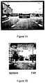
- Figures 1A and 1Bshow earlier display examples that rely on overlaying text on or near the objects for which additional information is available.
- Non-portable devicesmay also exhibit similar problems related to obscuring objects in view, visual clutter, and difficulties matching additional information with real world objects.
- Document US 2007/0244634 A1describes a virtual tour.
- a virtual tourFor a virtual tour, one or more maps are presented to show to a user the geographic location of the tour.
- the virtual tourcomprises images in the form of pictures and/or videos that show what the user might see if they were to actually go to the locations indicated in the map.
- the imagesare animated in the form of a slide show.
- the mapsshow the location of the images that are currently being displayed in the slide show.
- the locations of the imagesare shown by both markers on a map and pointers to those markers.
- the virtual tourmay contain icons or images superimposed on the map, which represent points of interest (POI). If the user selects one of the POI icons it may bring up additional information or another virtual tour.
- POIpoints of interest
- the disclosed embodimentsare directed to a method including acquiring an image, identifying one or more objects of interest in the image, and providing an indication that additional information is available for the one or more of the objects of interest without obscuring the one or more objects of interest.
- the disclosed embodimentsare also directed to an apparatus including an image capture device configured for acquiring an image, location circuitry configured for identifying one or more objects of interest in the image, and a display configured for providing an indication that additional information is available for the one or more of the objects of interest without obscuring the one or more objects of interest.
- the disclosed embodimentsare further directed to a user interface having an image capture device configured for acquiring an image, and a display configured for displaying one or more objects of interest identified in the image, and for providing an indication that additional information is available for the identified objects of interest in the image without obscuring the identified objects of interest.
- Figure 2illustrates one embodiment of an exemplary device 100 in which aspects of the disclosed embodiments may be applied.
- the disclosed embodimentsmay generally incorporate a portion of an augmented reality display that provides an indication of additional information for real world objects and also avoids obscuring the real world objects.
- the disclosed embodimentsalso include an ability to highlight a real world object and provide the additional information on the display again while avoiding obscuring the highlighted real world object.
- the disclosed embodimentsfurther include an ability to select display modes for acquiring and providing the additional information by changing the orientation of the augmented reality display device, or by gesturing.
- Figure 2shows an exemplary augmented reality display device 100 for practicing the disclosed embodiments.
- Device 100may be a portable device, for example, a mobile terminal, or may be a fixed device, for example, an outdoor telescope at a tourist attraction.
- Device 100may be any suitable device, provided it is capable of supplying an augmented reality display.
- Device 100may include a user interface 102, a processor 122 and a storage device 182.
- Device 100may also include a communications function 170, and a location function 172.
- the user interface 102 of the disclosed embodimentsmay include input and output devices for interaction with one or more users, and with the environment of the augmented reality display device.
- User interface 102may include both touch and non-touch devices.
- Touch devicesmay include a touch screen or proximity screen device 112 which may be responsive to user input and may also include a display.
- the aspects of the user interface 102 disclosed hereinmay be embodied on any suitable device that will display information and allow the selection and activation of applications, system content, and the functions of the embodiments described herein.
- the terms "select” and “touch”are generally described with respect to a touch screen-display. However, in alternate embodiments, the terms are also intended to encompass required user action with respect to other input devices. For example, with respect to the touch/proximity screen device 112, it may not be necessary for a user to make direct contact with the touch/proximity screen device 112 in order to select an object, other information, or to initiate an application.
- touch/proximity screen device 112does not necessarily require direct contact, but may include near or close contact that activates the touch/proximity screen device 112.
- touch/proximity screen device 112does not necessarily require direct contact, but may include near or close contact that activates the touch/proximity screen device 112.
- the scope of the intended devicesis not limited to single touch or contact devices. Multi-touch devices, where contact by one or more fingers or other pointing devices can navigate on and about the screen are also intended to be encompassed by the disclosed embodiments.
- Non-touch devices 117are also intended to be encompassed by the disclosed embodiments.
- Non-touch devicesmay include, but are not limited to, brain computer interfaces (BCI) and devices without touch or proximity screens.
- BCIbrain computer interfaces
- a usermay use thoughts to control the devices described herein (i.e. through neuro-physiological signals detected from the brain or from other suitable nervous tissue).
- the user interface 102may also include keys 110, for example, hard keys, soft keys, a keyboard, etc. for receiving user input, and a microphone 113 for receiving voice commands.
- keys 110for example, hard keys, soft keys, a keyboard, etc. for receiving user input
- a microphone 113for receiving voice commands.
- the user interface 102may also include an image capture device 115, for example, a camera, for implementing the embodiments described herein.
- an image capture device 115for example, a camera
- the user interface 102may also include one or more displays 114 which, as mentioned above, may be part of touch/proximity screen 112, or may be separate devices.
- the one or more displaysgenerally provide information to a user including menus for selecting functions of the augmented reality display device 100.
- the processor 122operates to control the functions of the augmented reality display device 100.
- the processormay receive inputs, for example, signals, transmissions, instructions or commands related to the functions of the device 100 from user interface 102, storage device 182, and communications function 170.
- the processor 122interprets the inputs and controls the functions of the augmented reality display device 100 accordingly.
- Storage device 182generally includes instructions or commands for the processor 122 related to the functions of the device 100.
- Storage device 182includes computer readable media encoded with computer executable components, software, programs, instructions, commands, etc. for implementing the embodiments disclosed herein.
- Storage device 182may utilize optical, magnetic, chemical, electrical, or any other suitable properties for receiving, storing, or delivering instructions and commands.
- Storage device 182may include magnetic media, such as a diskette, disk, memory stick or computer hard drive, which is readable and executable by a computer.
- storage device 182may include optical disks, read-only-memory (“ROM”) floppy disks and semiconductor materials and chips.
- Storage device 182may generally utilize any suitable technology for implementing the embodiments disclosed herein.
- Storage device 182may also include applications 180 and application settings 184 for other functions, for example, data acquisition (e.g. image, video and sound), data processing (spread sheets, word processor, contact lists, currency converters, etc.), multimedia players (e.g. video and music players), various web services, and any other suitable applications.
- Storage device 182may also include one or more databases 186 that include maps of any geographic location as well as information related to objects that may be present in the vicinity of the augmented reality display device 100.
- Communications function 170may include circuitry and programs for providing any suitable communications tasks for implementing the disclosed embodiments.
- Communications functionmay include facilities for any type of satellite, mobile, wireless, wide area network, local area network, or public switched telephone network communications, or any other suitable communication facilities.
- Location function 172may generally include circuitry and programs for determining the location, orientation, and forces being applied to the augmented reality display device 100, and for determining the location of and identifying objects captured by the image capture device 115.
- location function 172may include a global positioning system processor 174, a compass, one or more accelerometers, and any other suitable sensors referred to collectively as sensors 176.
- augmented reality display device 100may use the global positioning system processor 174 to determine its own location.
- location function 172may include circuitry and programs for determining the location and orientation of the augmented reality display device 100 using computer or machine vision.
- the location functionmay communicate with the image capture device and may perform among other things, image acquisition, detection, segmentation, feature extraction, etc. alone or in combination with the other functions, circuitry and programs of the augmented reality display device 100 to determine the location and the orientation of the device 100.
- Figures 3A-3Cshow examples of different orientations for the augmented reality display device 100.
- the augmented reality display device 100may determine its own orientation, for example, horizontal, as shown in Figure 3A , vertical landscape, as shown in Figure 3B , or vertical portrait, as shown in Figure 3C .
- Other orientations of the augmented reality display device 100may also be determined. Moving the augmented reality display device 100 from one orientation to another, from one position to another, or from one position returning to the same position, may be referred to as a gesture, or gesturing.
- the augmented reality display device 100may also use the one or more of the sensors, and optionally the applications 180 and application settings 184 to determine the locations of objects in its vicinity.
- the augmented reality display device 100may also determine the locations of objects in its vicinity by processing images captured by the image capture device 115.
- the augmented reality display device 100may utilize computer or machine vision as described above to determine the location of objects in its vicinity.
- the augmented reality display device 100may also utilize computer or machine vision to identify the objects.
- the augmented reality display device 100may use the location of the object to identify the object.
- discovery of objectsmay be aided by using a map view provided by the augmented reality display device 100.
- Figure 3Ashows an example of such a view 350.
- the map view 350may be invoked in various ways, for example, from a menu selection on the user interface, by changing the orientation of the augmented reality display device 100 to a horizontal position as shown in Figure 3A , or by any other suitable method.
- a map 355 of an areamay be displayed.
- Mapsmay be retrieved from the one or more databases 186 ( Figure 2 ), from a remote device or service using communications function 170, or any combination of the two.
- Objects of interestmay be highlighted on the map.
- the map viewmay be used to guide a user, that is, aid a user in finding objects of interest.
- the usermay use the image capture device 115 to view objects. In some embodiments this may be accomplished by manipulating the augmented reality display device 100 to a vertical landscape orientation ( Figure 3B ). Upon sensing the orientation, the augmented reality display device 100 may provide a heads up view as observed by the image capture device 115.
- Figure 3Dshows an example of such a heads up view 300 that may be provided by display 114.
- Objects in the viewmay then be identified using the location function 172.
- An indication that additional information is available for one or more of the objectsmay then be provided.
- objects in the view 300 for which additional information is availablemay be indicated by icons 310, 315, 320, 323 portrayed in a portion 325 of the display.
- the icons 310, 315, 320, 323may be diagrammatic, schematic, pictorial, or any other type of representation of objects in the view 300.
- the portion 325 of the displaymay reside along the top as shown, or may reside along one of the sides or the bottom of the display.
- the portion 325 of the displaymay also reside in any suitable location of the display that avoids obscuring the objects in the view.
- the icons 310, 315, 320, 323may resemble or otherwise represent objects in the view and may be tethered, or otherwise located on the display to correspond to the real world positions of the objects.
- the icons 310, 315, 320, 323may extend over a wider field than the view 300 but may be positioned in the same order as the real world positions so that a correspondence may be made between an icon and the object it represents.
- the icons 310, 315, 320, 323may be sized or placed in the view to indicate the distance from the corresponding object to the augmented reality display device 100.
- the icons 310, 315, 320, 323may overlap or be interleaved, for example when objects in the view are close to each other or overlap. See for example, icons 320 and 323.
- one or more of the icons 310, 315, 320, 323may be selected, for example, icon 320.
- the object corresponding to the iconmay alternately be selected.
- object 330may be highlighted in a non-obscuring manner.
- a dark transparent layermay be rendered over the view 300 except in an area 345 surrounding the object 330.
- the area 345may be sized according to the size of the object 330 in the view 300 and may also be sized to compensate for any uncertainty in determining the position of object 330.
- the selected iconmight be enlarged or replicated elsewhere on the display 114, for example, to allow a user to more easily recognize the corresponding object, or for example, to compensate for inaccuracies in the location of the icon or object.
- additional information 335 related to the objectmay be shown in another portion 340 of the display 114.
- the additional information 335may include identification information, links to other information related to the object 330, actions that may be performed related to the display and the object 330, or any other suitable information, actions, links, etc.
- the other informationmay be displayed.
- the additional information 335may be obtained from the one or more databases 186 ( Figure 2 ).
- the augmented reality display device 100may obtain at least a part of the additional information 335 from a remote device or service using communications function 170.
- one or more of the links in the additional informationmay link to a remote device or service by utilizing communications function 170.
- the further informationmay include at least a portion of the additional information 335, further details related to the object 330, further links to other information, further actions that may be performed related to the display and the object 330, or any other suitable information, actions, links, etc.
- the further informationmay be displayed for example, by manipulating one or more of keys 110, touch screen or proximity screen device 112, non-touch devices 117, or any other suitable component of user interface 102.
- the further informationmay be displayed for example, by changing the orientation of the augmented reality display device 100, for example, to a vertical-portrait orientation as shown in Figure 3C , or by a gesture as described above.
- Figure 4illustrates a flow diagram of a process in accordance with the disclosed embodiments.
- a map viewmay be optionally used to aid in object discovery.
- one or more objects of interestmay be captured using the image capture device 115.
- one or more of the objectsmay be identified and in block 420 an indication may be provided signifying that additional information for one or more of the objects is available. The indication may be provided without obscuring the objects.
- one of the indicatorsmay be selected, and in block 430 the corresponding object is highlighted without obscuring the highlighted object.
- additional information related to the objectmay be shown, again without obscuring the selected object.
- the objects of interestare not obscured when displaying additional information.
- the additional informationmay include identification information, links to other information related to the object 330, actions that may be performed related to the display and the object 330, or any other suitable information, actions, links, etc. As shown in block 440, optionally, even further information may displayed related to the corresponding object.
- objectsmay be annotated without being obscured, user interaction is streamlined, and the highlighting may be sized to correspond with the size of an object and may also be sized to compensate for any uncertainty in an object's position.
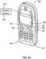
- a terminal or mobile communications device 500may incorporate all the functions of an augmented reality display device as described above.
- the terminal or mobile communications device 500have a keypad 510 and a display 520.
- the keypad 510may include any suitable user input devices such as, for example, a multi-function/scroll key 530, soft keys 531, 532, a call key 533, an end call key 534 and alphanumeric keys 535.
- the display 520may be any suitable display, such as for example, a touch screen display or graphical user interface.
- the displaymay be integral to the device 500 or the display may be a peripheral display connected to the device 500.
- a pointing devicesuch as for example, a stylus, pen or simply the user's finger may be used with the display 520.
- any suitable pointing devicemay be used.
- the displaymay be for example a flat display that is typically made of an liquid crystal display (LCD) with optional back lighting, such as a thin film transistor (TFT) matrix capable of displaying color images.
- TFTthin film transistor
- the displaymay be any suitable conventional display.
- the device 500may also include other suitable features such as, for example, a camera, loud speaker, connectivity port or tactile feedback features.
- the mobile communications devicemay have a processor 518 connected to the display for processing user inputs, displaying information on the display 520, and for controlling the terminal or mobile communications device 500 according to the augmented reality display embodiments described herein.
- a memory 502may be connected to the processor 518 for storing any suitable information and/or applications associated with the mobile communications device 500 such as phone book entries, calendar entries, instructions or commands related to the functions of displaying augmented reality disclosed herein, etc.
- Memory 502may include computer readable media encoded with computer executable components software, programs, instructions, commands, etc. for implementing the embodiments disclosed herein.
- the device 500comprises a mobile communications device
- the devicecan be adapted for communication in a telecommunication system, such as that shown in Figure 6 .
- various telecommunications servicessuch as cellular voice calls, worldwide web/wireless application protocol (www/wap) browsing, cellular video calls, data calls, facsimile transmissions, data transmissions, music transmissions, still image transmission, video transmissions, electronic message transmissions and electronic commerce may be performed between a mobile terminal 600 and other devices, such as another mobile terminal 606, a line telephone 632, a personal computer 626 and/or an internet server 622.
- the mobile terminal 600generally includes all the features of terminal or mobile communications device 500 and augmented reality display device 100. It is to be noted that for different embodiments of the mobile terminal 600 and in different situations, some of the telecommunications services indicated above may or may not be available. The aspects of the disclosed embodiments are not limited to any particular set of services in this respect.
- the mobile terminals 600, 606may be connected to a mobile telecommunications network 610 through radio frequency (RF) links 602, 608 via base stations 604, 609.
- the mobile telecommunications network 610may be in compliance with any commercially available mobile telecommunications standard such as for example global system for mobile communications (GSM), universal mobile telecommunication system (UMTS), digital advanced mobile phone service (D-AMPS), code division multiple access 2000 (CDMA2000), wideband code division multiple access (WCDMA), wireless local area network (WLAN), freedom of mobile multimedia access (FOMA) and time division-synchronous code division multiple access (TD-SCDMA).
- GSMglobal system for mobile communications
- UMTSuniversal mobile telecommunication system
- D-AMPSdigital advanced mobile phone service
- CDMA2000code division multiple access 2000
- WCDMAwideband code division multiple access
- WLANwireless local area network
- FOMAfreedom of mobile multimedia access
- TD-SCDMAtime division-synchronous code division multiple access
- the mobile telecommunications network 610may be operatively connected to a wide area network 620, which may be the Internet or a part thereof.
- An Internet server 622has data storage 624 and is connected to the wide area network 620, as is an Internet client computer 626.
- data storage 624may include at least a portion of maps 355 ( Figure 3A ), additional information 335 ( Figure 3E ), and further information 345 ( Figure 3C ).
- One or more of the links in the additional information 335may link to data or invoke one or more programs stored in data storage 624.
- the server 622may host a worldwide web/wireless application protocol server capable of serving worldwide web/wireless application protocol content to the mobile terminal 600.
- a public switched telephone network (PSTN) 630may be connected to the mobile telecommunications network 610 in a familiar manner.
- Various telephone terminals, including the stationary telephone 632,may be connected to the public switched telephone network 630.
- the mobile terminal 600is also capable of communicating locally via a local link 601 to one or more local devices 603.
- the local link 601may be any suitable type of link with a limited range, such as for example Bluetooth, a Universal Serial Bus (USB) link, a wireless Universal Serial Bus (WUSB) link, an IEEE 802.11 wireless local area network (WLAN) link, an RS-232 serial link, etc.
- the above examplesare not intended to be limiting, and any suitable type of link may be utilized.
- the local devices 603may be antennas and supporting equipment forming a wireless local area network implementing Worldwide Interoperability for Microwave Access (WiMAX, IEEE 802.16), WiFi (IEEE 802.11x) or other communication protocols.
- the wireless local area networkmay be connected to the Internet.
- the mobile terminal 600may thus have multi-radio capability for connecting wirelessly using mobile communications network 610, wireless local area network or both. Communication with the mobile telecommunications network 610 may also be implemented using WiFi, Worldwide Interoperability for Microwave Access, or any other suitable protocols, and such communication may utilize unlicensed portions of the radio spectrum (e.g. unlicensed mobile access (UMA)).
- the processor 122 of Figure 2can include a communications module that is configured to interact with the system described with respect to Figure 6 .
- the augmented reality display device 100 of Figure 2may be implemented in, for example, a personal digital assistant (PDA) style device 590 illustrated in Figure 5B .
- the personal digital assistant 590may have a keypad 591, a touch screen display 592 and a pointing device 595 for use on the touch screen display 592.
- the devicemay be a personal computer, a tablet computer, touch pad device, Internet tablet, a laptop or desktop computer, a mobile terminal, a cellular/mobile phone, a multimedia device, a personal communicator, or any other suitable device capable of containing, for example, a display 114 shown in Figure 2 , and supported electronics such as the processor 122 and memory 182.
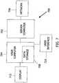
- FIG. 7is a block diagram of one embodiment of a typical apparatus 700 incorporating features that may be used to practice aspects of the disclosed embodiments.
- the apparatus 700can include a computer readable media with computer executable components or program code embodied therein for implementing the disclosed embodiments.
- a computer system 702may be linked to another computer system 704, such that the computers 702 and 704 are capable of sending information to each other and receiving information from each other.
- Computer 704generally includes all the features of augmented reality display device 100.
- computer system 702could include a server computer adapted to communicate with a network 706.
- Computer systems 702 and 704can be linked together in any conventional manner including, for example, a modem, wireless, hard wire connection, or fiber optic link. Generally, information can be made available to both computer systems 702 and 704 using a communication protocol typically sent over a communication channel or through a dial-up connection on an integrated services digital network (ISDN) line.
- ISDNintegrated services digital network
- Computers 702 and 704are generally adapted to utilize program storage devices with computer readable media embodying computer executable components, for example, machine-readable program source code, which is adapted to cause the computers 702 and 704 to implement the embodiments disclosed herein.
- the program storage devices incorporating aspects of the disclosed embodimentsmay be devised, made and used as a component of a machine utilizing optics, magnetic properties and/or electronics to perform the procedures and methods disclosed herein.
- the program storage devicesmay include magnetic media such as a diskette or computer hard drive, which is readable and executable by a computer.
- the program storage devicescould include optical disks, read-only-memory ("ROM”) floppy disks and semiconductor materials and chips.
- Computer systems 702 and 704may also include a microprocessor for executing stored programs.
- Computer 704may include a data storage device 708 on its program storage device for the storage of information and data.
- the computer program or software implementing the disclosed embodimentsmay be stored in one or more computers 702 and 704 on an otherwise conventional program storage device.
- computers 702 and 704may include a user interface 710, and a display interface 712 from which aspects of the disclosed embodiments may be accessed.
- the user interface 710 and the display interface 712may be adapted to allow the input of queries and commands to the system, as well as present the results of the commands and queries.
- the exemplary embodiments described hereinare provided as nonlimiting examples of providing an augmented reality display with one or more indications that additional information for objects in view is available.
- the indicationsare provided in a manner that avoids obscuring the objects.
- the embodimentsalso provide an ability to highlight an object and provide the additional information, also in a manner that avoids obscuring the highlighted object.
- the embodimentsfurther provide for selecting display modes for acquiring and providing the additional information by changing the orientation of the augmented reality display device, or gesturing. Thus, objects may be annotated and highlighted without being obscured image clutter is avoided
Landscapes
- Engineering & Computer Science (AREA)
- General Engineering & Computer Science (AREA)
- Theoretical Computer Science (AREA)
- Human Computer Interaction (AREA)
- Physics & Mathematics (AREA)
- General Physics & Mathematics (AREA)
- User Interface Of Digital Computer (AREA)
- Processing Or Creating Images (AREA)
Description
- The disclosed embodiments generally relate to user interfaces and, more particularly, to an augmented reality user interface.
- Augmented reality systems generally present a real-world view and additional data in a combined display. Augmented reality systems may enhance real-world images with computer-generated elements that may identify or provide additional information about items in the images. As an example, an augmented reality system may display an image of a building with superimposed text identifying the address and the names of businesses within the building.
- Advances in computer vision, more powerful and smaller computers, and advances in position and orientation sensors are making portable, hand held augmented reality devices increasingly feasible. Portable devices are already capable of determining position and orientation to within a few meters and degrees. However, portable devices tend to have relatively small displays. Traditional overlays may partially or totally obscure the objects in view and may also obscure other parts of the surrounding area. When there are many objects in an area, the additional information may produce a large amount of visual clutter. In addition, a crowded view may make it difficult to match the additional information with what the user actually sees.
Figures 1A and 1B show earlier display examples that rely on overlaying text on or near the objects for which additional information is available. Non-portable devices may also exhibit similar problems related to obscuring objects in view, visual clutter, and difficulties matching additional information with real world objects. - It would be advantageous to provide a scheme for presenting additional information on an augmented reality display that avoids the limitations of previous implementations.
- Document
US 2007/0244634 A1 describes a virtual tour. For a virtual tour, one or more maps are presented to show to a user the geographic location of the tour. The virtual tour comprises images in the form of pictures and/or videos that show what the user might see if they were to actually go to the locations indicated in the map. The images are animated in the form of a slide show. The maps show the location of the images that are currently being displayed in the slide show. The locations of the images are shown by both markers on a map and pointers to those markers. The virtual tour may contain icons or images superimposed on the map, which represent points of interest (POI). If the user selects one of the POI icons it may bring up additional information or another virtual tour. - Document
US 2005/0206654 A1 discloses a method as specified in the preamble of the independent claims. - The invention is defined by the appended claims.
- The following summary is intended to exemplary only and non- limiting.
- The disclosed embodiments are directed to a method including acquiring an image, identifying one or more objects of interest in the image, and providing an indication that additional information is available for the one or more of the objects of interest without obscuring the one or more objects of interest.
- The disclosed embodiments are also directed to an apparatus including an image capture device configured for acquiring an image, location circuitry configured for identifying one or more objects of interest in the image, and a display configured for providing an indication that additional information is available for the one or more of the objects of interest without obscuring the one or more objects of interest.
- The disclosed embodiments are further directed to a user interface having an image capture device configured for acquiring an image, and a display configured for displaying one or more objects of interest identified in the image, and for providing an indication that additional information is available for the identified objects of interest in the image without obscuring the identified objects of interest.
- The foregoing aspects and other features of the embodiments are explained in the following description, taken in connection with the accompanying drawings, wherein:
Figures 1 A and 1 B show earlier augmented reality display examples;Figure 2 shows an exemplary device 100 for practicing the disclosed embodiments;Figures 3A-3C show examples of different orientations for the augmented reality display device 100;Figures 3D and3E show examples of heads up views used in implementing the disclosed embodiments;Figure 4 illustrates a flow diagram of a process in accordance with the disclosed embodiments;Figures 5A and5B are illustrations of examples of devices that may be used to practice aspects of the disclosed embodiments;Figure 6 illustrates a block diagram of an exemplary system incorporating features that may be used to practice the disclosed embodiments; andFigure 7 shows a block diagram illustrating the general architecture of an exemplary system in which the exemplary devices ofFIGS. 5A and5B may be used.Figure 2 illustrates one embodiment of an exemplary device 100 in which aspects of the disclosed embodiments may be applied. Although aspects of the disclosed embodiments will be described with reference to the embodiments shown in the drawings and described below, it should be understood that these aspects could be embodied in many alternate forms and in any possible combination of elements. In addition, any suitable size, shape or type of elements or materials could be used.- The disclosed embodiments may generally incorporate a portion of an augmented reality display that provides an indication of additional information for real world objects and also avoids obscuring the real world objects. The disclosed embodiments also include an ability to highlight a real world object and provide the additional information on the display again while avoiding obscuring the highlighted real world object. The disclosed embodiments further include an ability to select display modes for acquiring and providing the additional information by changing the orientation of the augmented reality display device, or by gesturing.
Figure 2 shows an exemplary augmented reality display device 100 for practicing the disclosed embodiments. Device 100 may be a portable device, for example, a mobile terminal, or may be a fixed device, for example, an outdoor telescope at a tourist attraction. Device 100 may be any suitable device, provided it is capable of supplying an augmented reality display. Device 100 may include auser interface 102, aprocessor 122 and astorage device 182. Device 100 may also include acommunications function 170, and alocation function 172.- The
user interface 102 of the disclosed embodiments may include input and output devices for interaction with one or more users, and with the environment of the augmented reality display device.User interface 102 may include both touch and non-touch devices. Touch devices may include a touch screen orproximity screen device 112 which may be responsive to user input and may also include a display. In alternate embodiments, the aspects of theuser interface 102 disclosed herein may be embodied on any suitable device that will display information and allow the selection and activation of applications, system content, and the functions of the embodiments described herein. The terms "select" and "touch" are generally described with respect to a touch screen-display. However, in alternate embodiments, the terms are also intended to encompass required user action with respect to other input devices. For example, with respect to the touch/proximity screen device 112, it may not be necessary for a user to make direct contact with the touch/proximity screen device 112 in order to select an object, other information, or to initiate an application. - Thus, the above noted terms are intended to encompass that a user only needs to be within the proximity of touch/
proximity screen device 112 to carry out the desired function. For example, the term "touch" in the context of the touch/proximity screen device 112, does not necessarily require direct contact, but may include near or close contact that activates the touch/proximity screen device 112. Similarly, the scope of the intended devices is not limited to single touch or contact devices. Multi-touch devices, where contact by one or more fingers or other pointing devices can navigate on and about the screen are also intended to be encompassed by the disclosed embodiments. Non-touch devices 117 are also intended to be encompassed by the disclosed embodiments. Non-touch devices may include, but are not limited to, brain computer interfaces (BCI) and devices without touch or proximity screens. In one embodiment, with non-touch devices such as BCI a user may use thoughts to control the devices described herein (i.e. through neuro-physiological signals detected from the brain or from other suitable nervous tissue).- The
user interface 102 may also include keys 110, for example, hard keys, soft keys, a keyboard, etc. for receiving user input, and amicrophone 113 for receiving voice commands. - The
user interface 102 may also include animage capture device 115, for example, a camera, for implementing the embodiments described herein. - The
user interface 102 may also include one ormore displays 114 which, as mentioned above, may be part of touch/proximity screen 112, or may be separate devices. The one or more displays generally provide information to a user including menus for selecting functions of the augmented reality display device 100. - Still referring to
Figure 2 , theprocessor 122 operates to control the functions of the augmented reality display device 100. The processor may receive inputs, for example, signals, transmissions, instructions or commands related to the functions of the device 100 fromuser interface 102,storage device 182, and communications function 170. Theprocessor 122 interprets the inputs and controls the functions of the augmented reality display device 100 accordingly. Storage device 182 generally includes instructions or commands for theprocessor 122 related to the functions of the device 100.Storage device 182 includes computer readable media encoded with computer executable components, software, programs, instructions, commands, etc. for implementing the embodiments disclosed herein.Storage device 182 may utilize optical, magnetic, chemical, electrical, or any other suitable properties for receiving, storing, or delivering instructions and commands.Storage device 182 may include magnetic media, such as a diskette, disk, memory stick or computer hard drive, which is readable and executable by a computer. In other embodiments,storage device 182 may include optical disks, read-only-memory ("ROM") floppy disks and semiconductor materials and chips.Storage device 182 may generally utilize any suitable technology for implementing the embodiments disclosed herein.Storage device 182 may also includeapplications 180 andapplication settings 184 for other functions, for example, data acquisition (e.g. image, video and sound), data processing (spread sheets, word processor, contact lists, currency converters, etc.), multimedia players (e.g. video and music players), various web services, and any other suitable applications.Storage device 182 may also include one ormore databases 186 that include maps of any geographic location as well as information related to objects that may be present in the vicinity of the augmented reality display device 100.- Communications function 170 may include circuitry and programs for providing any suitable communications tasks for implementing the disclosed embodiments. Communications function may include facilities for any type of satellite, mobile, wireless, wide area network, local area network, or public switched telephone network communications, or any other suitable communication facilities.
Location function 172 may generally include circuitry and programs for determining the location, orientation, and forces being applied to the augmented reality display device 100, and for determining the location of and identifying objects captured by theimage capture device 115. For example,location function 172 may include a globalpositioning system processor 174, a compass, one or more accelerometers, and any other suitable sensors referred to collectively assensors 176. As a further example, augmented reality display device 100 may use the globalpositioning system processor 174 to determine its own location. In some embodiments,location function 172 may include circuitry and programs for determining the location and orientation of the augmented reality display device 100 using computer or machine vision. For example, the location function may communicate with the image capture device and may perform among other things, image acquisition, detection, segmentation, feature extraction, etc. alone or in combination with the other functions, circuitry and programs of the augmented reality display device 100 to determine the location and the orientation of the device 100.Figures 3A-3C show examples of different orientations for the augmented reality display device 100. By utilizing the sensors, andoptionally applications 180 andapplication settings 184, the augmented reality display device 100 may determine its own orientation, for example, horizontal, as shown inFigure 3A , vertical landscape, as shown inFigure 3B , or vertical portrait, as shown inFigure 3C . Other orientations of the augmented reality display device 100 may also be determined. Moving the augmented reality display device 100 from one orientation to another, from one position to another, or from one position returning to the same position, may be referred to as a gesture, or gesturing.- The augmented reality display device 100 may also use the one or more of the sensors, and optionally the
applications 180 andapplication settings 184 to determine the locations of objects in its vicinity. The augmented reality display device 100 may also determine the locations of objects in its vicinity by processing images captured by theimage capture device 115. In some embodiments, the augmented reality display device 100 may utilize computer or machine vision as described above to determine the location of objects in its vicinity. The augmented reality display device 100 may also utilize computer or machine vision to identify the objects. In some embodiments the augmented reality display device 100 may use the location of the object to identify the object. - The disclosed embodiments may be utilized as described in the following examples.
- In some embodiments, discovery of objects may be aided by using a map view provided by the augmented reality display device 100.
Figure 3A shows an example of such aview 350. Themap view 350 may be invoked in various ways, for example, from a menu selection on the user interface, by changing the orientation of the augmented reality display device 100 to a horizontal position as shown inFigure 3A , or by any other suitable method. Upon invoking themap view 350, amap 355 of an area may be displayed. Maps may be retrieved from the one or more databases 186 (Figure 2 ), from a remote device or service usingcommunications function 170, or any combination of the two. Objects of interest may be highlighted on the map. The map view may be used to guide a user, that is, aid a user in finding objects of interest. - The user may use the
image capture device 115 to view objects. In some embodiments this may be accomplished by manipulating the augmented reality display device 100 to a vertical landscape orientation (Figure 3B ). Upon sensing the orientation, the augmented reality display device 100 may provide a heads up view as observed by theimage capture device 115. Figure 3D shows an example of such a heads upview 300 that may be provided bydisplay 114. Objects in the view may then be identified using thelocation function 172. An indication that additional information is available for one or more of the objects may then be provided. For example, objects in theview 300 for which additional information is available may be indicated byicons portion 325 of the display. Theicons view 300. Theportion 325 of the display may reside along the top as shown, or may reside along one of the sides or the bottom of the display. Theportion 325 of the display may also reside in any suitable location of the display that avoids obscuring the objects in the view. In some embodiments, theicons icons view 300 but may be positioned in the same order as the real world positions so that a correspondence may be made between an icon and the object it represents. In some embodiments, theicons icons icons 320 and 323.- Turning to
Figure 3E , one or more of theicons icon 320. In other embodiments, the object corresponding to the icon may alternately be selected. Upon selection ofexemplary icon 320 orcorresponding object 330,object 330 may be highlighted in a non-obscuring manner. For example, a dark transparent layer may be rendered over theview 300 except in anarea 345 surrounding theobject 330. Thearea 345 may be sized according to the size of theobject 330 in theview 300 and may also be sized to compensate for any uncertainty in determining the position ofobject 330. In some embodiments, the selected icon might be enlarged or replicated elsewhere on thedisplay 114, for example, to allow a user to more easily recognize the corresponding object, or for example, to compensate for inaccuracies in the location of the icon or object. - As a result of the selection,
additional information 335 related to the object may be shown in anotherportion 340 of thedisplay 114. Thus, the objects in theview 300 are not obscured by the additional information. Theadditional information 335 may include identification information, links to other information related to theobject 330, actions that may be performed related to the display and theobject 330, or any other suitable information, actions, links, etc. Upon selection of a link to other information, the other information may be displayed. - In some embodiments, the
additional information 335 may be obtained from the one or more databases 186 (Figure 2 ). In some embodiments, the augmented reality display device 100 may obtain at least a part of theadditional information 335 from a remote device or service usingcommunications function 170. Similarly, one or more of the links in the additional information may link to a remote device or service by utilizingcommunications function 170. - In some embodiments, once the
additional information 335 is displayed, even further information 345 (Figure 3C ) may be displayed upon demand. The further information may include at least a portion of theadditional information 335, further details related to theobject 330, further links to other information, further actions that may be performed related to the display and theobject 330, or any other suitable information, actions, links, etc. The further information may be displayed for example, by manipulating one or more of keys 110, touch screen orproximity screen device 112,non-touch devices 117, or any other suitable component ofuser interface 102. In some embodiments, the further information may be displayed for example, by changing the orientation of the augmented reality display device 100, for example, to a vertical-portrait orientation as shown inFigure 3C , or by a gesture as described above. Figure 4 illustrates a flow diagram of a process in accordance with the disclosed embodiments. In block 400 a map view may be optionally used to aid in object discovery. Inblock 410 one or more objects of interest may be captured using theimage capture device 115. Inblock 415 one or more of the objects may be identified and inblock 420 an indication may be provided signifying that additional information for one or more of the objects is available. The indication may be provided without obscuring the objects. Inblock 425, one of the indicators may be selected, and inblock 430 the corresponding object is highlighted without obscuring the highlighted object. Inblock 435 additional information related to the object may be shown, again without obscuring the selected object. Thus, the objects of interest are not obscured when displaying additional information. As mentioned above, the additional information may include identification information, links to other information related to theobject 330, actions that may be performed related to the display and theobject 330, or any other suitable information, actions, links, etc. As shown inblock 440, optionally, even further information may displayed related to the corresponding object.- As a result of the exemplary embodiments, objects may be annotated without being obscured, user interaction is streamlined, and the highlighting may be sized to correspond with the size of an object and may also be sized to compensate for any uncertainty in an object's position.
- Examples of devices on which aspects of the disclosed embodiments can be practiced are illustrated with respect to
Figures 5A and5B . A terminal ormobile communications device 500 may incorporate all the functions of an augmented reality display device as described above. The terminal ormobile communications device 500 have akeypad 510 and adisplay 520. Thekeypad 510 may include any suitable user input devices such as, for example, a multi-function/scroll key 530,soft keys call key 533, anend call key 534 andalphanumeric keys 535. Thedisplay 520 may be any suitable display, such as for example, a touch screen display or graphical user interface. The display may be integral to thedevice 500 or the display may be a peripheral display connected to thedevice 500. A pointing device, such as for example, a stylus, pen or simply the user's finger may be used with thedisplay 520. In alternate embodiments any suitable pointing device may be used. In other alternate embodiments, the display may be for example a flat display that is typically made of an liquid crystal display (LCD) with optional back lighting, such as a thin film transistor (TFT) matrix capable of displaying color images. In still other alternate embodiments, the display may be any suitable conventional display. - The
device 500 may also include other suitable features such as, for example, a camera, loud speaker, connectivity port or tactile feedback features. The mobile communications device may have aprocessor 518 connected to the display for processing user inputs, displaying information on thedisplay 520, and for controlling the terminal ormobile communications device 500 according to the augmented reality display embodiments described herein. Amemory 502 may be connected to theprocessor 518 for storing any suitable information and/or applications associated with themobile communications device 500 such as phone book entries, calendar entries, instructions or commands related to the functions of displaying augmented reality disclosed herein, etc.Memory 502 may include computer readable media encoded with computer executable components software, programs, instructions, commands, etc. for implementing the embodiments disclosed herein. - In the embodiment where the
device 500 comprises a mobile communications device, the device can be adapted for communication in a telecommunication system, such as that shown inFigure 6 . In such a system, various telecommunications services such as cellular voice calls, worldwide web/wireless application protocol (www/wap) browsing, cellular video calls, data calls, facsimile transmissions, data transmissions, music transmissions, still image transmission, video transmissions, electronic message transmissions and electronic commerce may be performed between amobile terminal 600 and other devices, such as anothermobile terminal 606, aline telephone 632, apersonal computer 626 and/or aninternet server 622. - The
mobile terminal 600 generally includes all the features of terminal ormobile communications device 500 and augmented reality display device 100. It is to be noted that for different embodiments of themobile terminal 600 and in different situations, some of the telecommunications services indicated above may or may not be available. The aspects of the disclosed embodiments are not limited to any particular set of services in this respect. - The
mobile terminals mobile telecommunications network 610 through radio frequency (RF) links 602, 608 viabase stations mobile telecommunications network 610 may be in compliance with any commercially available mobile telecommunications standard such as for example global system for mobile communications (GSM), universal mobile telecommunication system (UMTS), digital advanced mobile phone service (D-AMPS), code division multiple access 2000 (CDMA2000), wideband code division multiple access (WCDMA), wireless local area network (WLAN), freedom of mobile multimedia access (FOMA) and time division-synchronous code division multiple access (TD-SCDMA). - The
mobile telecommunications network 610 may be operatively connected to awide area network 620, which may be the Internet or a part thereof. AnInternet server 622 hasdata storage 624 and is connected to thewide area network 620, as is anInternet client computer 626. In some embodiments,data storage 624 may include at least a portion of maps 355 (Figure 3A ), additional information 335 (Figure 3E ), and further information 345 (Figure 3C ). One or more of the links in theadditional information 335 may link to data or invoke one or more programs stored indata storage 624. Theserver 622 may host a worldwide web/wireless application protocol server capable of serving worldwide web/wireless application protocol content to themobile terminal 600. - A public switched telephone network (PSTN) 630 may be connected to the
mobile telecommunications network 610 in a familiar manner. Various telephone terminals, including thestationary telephone 632, may be connected to the public switchedtelephone network 630. - The
mobile terminal 600 is also capable of communicating locally via alocal link 601 to one or morelocal devices 603. Thelocal link 601 may be any suitable type of link with a limited range, such as for example Bluetooth, a Universal Serial Bus (USB) link, a wireless Universal Serial Bus (WUSB) link, an IEEE 802.11 wireless local area network (WLAN) link, an RS-232 serial link, etc. The above examples are not intended to be limiting, and any suitable type of link may be utilized. Thelocal devices 603 may be antennas and supporting equipment forming a wireless local area network implementing Worldwide Interoperability for Microwave Access (WiMAX, IEEE 802.16), WiFi (IEEE 802.11x) or other communication protocols. The wireless local area network may be connected to the Internet. Themobile terminal 600 may thus have multi-radio capability for connecting wirelessly usingmobile communications network 610, wireless local area network or both. Communication with themobile telecommunications network 610 may also be implemented using WiFi, Worldwide Interoperability for Microwave Access, or any other suitable protocols, and such communication may utilize unlicensed portions of the radio spectrum (e.g. unlicensed mobile access (UMA)). In one embodiment, theprocessor 122 ofFigure 2 can include a communications module that is configured to interact with the system described with respect toFigure 6 . - Although the above embodiments are described as being implemented on and with a mobile communication device, it will be understood that the disclosed embodiments can be practiced on any suitable device incorporating a display, processor, memory and supporting software or hardware. In one embodiment, the augmented reality display device 100 of
Figure 2 may be implemented in, for example, a personal digital assistant (PDA)style device 590 illustrated inFigure 5B . The personaldigital assistant 590 may have akeypad 591, atouch screen display 592 and apointing device 595 for use on thetouch screen display 592. In still other alternate embodiments, the device may be a personal computer, a tablet computer, touch pad device, Internet tablet, a laptop or desktop computer, a mobile terminal, a cellular/mobile phone, a multimedia device, a personal communicator, or any other suitable device capable of containing, for example, adisplay 114 shown inFigure 2 , and supported electronics such as theprocessor 122 andmemory 182. - The disclosed embodiments may also include software and computer programs incorporating the process steps and instructions described above that are executed in different computers.
Figure 7 is a block diagram of one embodiment of atypical apparatus 700 incorporating features that may be used to practice aspects of the disclosed embodiments. Theapparatus 700 can include a computer readable media with computer executable components or program code embodied therein for implementing the disclosed embodiments. As shown, acomputer system 702 may be linked to anothercomputer system 704, such that thecomputers Computer 704 generally includes all the features of augmented reality display device 100. - In one embodiment,
computer system 702 could include a server computer adapted to communicate with anetwork 706.Computer systems computer systems Computers computers Computer systems Computer 704 may include adata storage device 708 on its program storage device for the storage of information and data. The computer program or software implementing the disclosed embodiments may be stored in one ormore computers computers user interface 710, and adisplay interface 712 from which aspects of the disclosed embodiments may be accessed. Theuser interface 710 and thedisplay interface 712 may be adapted to allow the input of queries and commands to the system, as well as present the results of the commands and queries.- The exemplary embodiments described herein are provided as nonlimiting examples of providing an augmented reality display with one or more indications that additional information for objects in view is available. The indications are provided in a manner that avoids obscuring the objects. The embodiments also provide an ability to highlight an object and provide the additional information, also in a manner that avoids obscuring the highlighted object. The embodiments further provide for selecting display modes for acquiring and providing the additional information by changing the orientation of the augmented reality display device, or gesturing. Thus, objects may be annotated and highlighted without being obscured image clutter is avoided
- It is noted that the embodiments described herein may be used individually or in any combination thereof. It should be understood that the foregoing description is only illustrative of the embodiments. Various alternatives and modifications may be devised by those skilled in the art without departing from the embodiments. Accordingly, the present embodiments are intended to embrace all such alternatives, modifications and variances that fall within the scope of the invention as claimed.
Claims (15)
- A method comprising:acquiring an image captured by an image capture device (115) of an apparatus (100);presenting the image in a first portion (300) of a display (114) of the apparatus (100);identifying one or more objects (330) of interest in the image; the method beingcharacterized by the step of providing an indication (310, 315, 320, 323) that additional information is available for the one or more of the objects (330) of interest without obscuring the one or more objects (330) of interest by displaying the indication (310, 315, 320, 323) in a portion (325) of the display (114) other than the first portion (300) of the display (114).
- The method of claim 1, further comprising acquiring the image upon sensing a gesture.
- The method of claim 1, further comprising presenting a map view (350) in response to a predetermined gesture for aiding with a discovery of one or more objects of interest.
- The method of claim 1, further comprising upon selection of an object of interest (330) for which additional information is available: displaying the additional information (335) without obscuring the selected object in a portion (340) of the display (114) other than the first portion (300) of the display (114).
- The method of claim 4, further comprising causing further information (335) about the selected object of interest (330) to be displayed upon sensing a gesture.
- The method of claim 1, wherein the indication comprises at least one icon (310, 315, 320, 323), each icon (320) representing a respective one of the one or more objects (330), the method further comprising upon a selection of one of the at least one icon (320):highlighting the object (330) represented by the icon (320) in non-obscuring manner in the presented image, and/orpresenting the additional information (335) in a third portion (340) of the display (114) other than the first portion (300) of the display (114).
- The method of claim 1, wherein identifying one or more objects of interest (330) in the image comprises utilizing computer or machine vision.
- A computer program product (182) comprising computer readable code stored on a computer readable medium, the computer readable code configured to execute the method according to any of claims 1 to 7.
- An apparatus (100) comprising:an image capture device (115) configured for acquiring an image;location circuitry (172) configured for identifying one or more objects of interest (330) in the image; the apparatus beingcharacterized by a display (114) configured for presenting the image in a first portion (300) and for providing an indication (310, 315, 320, 323) that additional information is available for the one or more of the objects of interest (330) without obscuring the one or more objects of interest (330) by displaying the indication (310, 315, 320, 323) in a portion (325) other than the first portion (300).
- The apparatus (100) of claim 9, further comprising circuitry (122, 182, 115, 176) configured to acquire the image upon sensing a gesture.
- The apparatus (100) of claim 9, further comprising circuitry configured to invoke a map view (350) upon sensing a gesture for aiding with a discovery of one or more objects of interest.
- The apparatus (100) of claim 9, further comprising circuitry (112) configured for selecting an object of interest (330) for which additional information (335) is available, wherein the display (114) is configured for displaying the additional information (355) without obscuring the selected object (330) in a portion (340) other than the first portion (300).
- The apparatus (100) of claim 12, further comprising circuitry (176, 114) configured to cause further information for the selected object of interest (330) to be displayed upon sensing a gesture.
- The apparatus (100) of claim 9, wherein the indication comprises at least one icon (310, 315, 320, 323), each icon (320) representing a respective one of the one or more objects (330), the display configured for, upon a selection of one of the at least one icon (320):highlighting the object (330) represented by the icon (320) in non-obscuring manner in the presented image, and/orpresenting the additional information (335) in a third portion (340) of the display (114) other than the first portion (300) of the display (114).
- The apparatus (100) of claim 9, wherein identifying one or more objects of interest (330) in the image comprises utilizing computer or machine vision.
Applications Claiming Priority (2)
| Application Number | Priority Date | Filing Date | Title |
|---|---|---|---|
| US9780408P | 2008-09-17 | 2008-09-17 | |
| PCT/IB2008/003629WO2010032079A2 (en) | 2008-09-17 | 2008-12-24 | User interface for augmented reality |
Publications (2)
| Publication Number | Publication Date |
|---|---|
| EP2327003A2 EP2327003A2 (en) | 2011-06-01 |
| EP2327003B1true EP2327003B1 (en) | 2017-03-29 |
Family
ID=42039952
Family Applications (1)
| Application Number | Title | Priority Date | Filing Date |
|---|---|---|---|
| EP08875791.9AActiveEP2327003B1 (en) | 2008-09-17 | 2008-12-24 | User interface for augmented reality |
Country Status (4)
| Country | Link |
|---|---|
| US (1) | US10133438B2 (en) |
| EP (1) | EP2327003B1 (en) |
| JP (1) | JP5372157B2 (en) |
| WO (1) | WO2010032079A2 (en) |
Cited By (1)
| Publication number | Priority date | Publication date | Assignee | Title |
|---|---|---|---|---|
| US11087134B2 (en) | 2017-05-30 | 2021-08-10 | Artglass Usa, Llc | Augmented reality smartglasses for use at cultural sites |
Families Citing this family (63)
| Publication number | Priority date | Publication date | Assignee | Title |
|---|---|---|---|---|
| US11010841B2 (en) | 2008-10-02 | 2021-05-18 | Ecoatm, Llc | Kiosk for recycling electronic devices |
| EP2335337B1 (en) | 2008-10-02 | 2020-03-11 | ecoATM, LLC | Secondary market and vending system for devices |
| US7881965B2 (en) | 2008-10-02 | 2011-02-01 | ecoATM, Inc. | Secondary market and vending system for devices |
| US9420251B2 (en)* | 2010-02-08 | 2016-08-16 | Nikon Corporation | Imaging device and information acquisition system in which an acquired image and associated information are held on a display |
| JP5444115B2 (en)* | 2010-05-14 | 2014-03-19 | 株式会社Nttドコモ | Data search apparatus, data search method and program |
| US20120019557A1 (en)* | 2010-07-22 | 2012-01-26 | Sony Ericsson Mobile Communications Ab | Displaying augmented reality information |
| KR101347518B1 (en)* | 2010-08-12 | 2014-01-07 | 주식회사 팬택 | Apparatus, Method and Server for Selecting Filter |
| KR101708303B1 (en)* | 2010-08-18 | 2017-02-20 | 엘지전자 주식회사 | Method for transmitting information and mobile terminal using this method |
| US20120038668A1 (en)* | 2010-08-16 | 2012-02-16 | Lg Electronics Inc. | Method for display information and mobile terminal using the same |
| KR101315399B1 (en) | 2010-08-20 | 2013-10-07 | 주식회사 팬택 | Terminal device and method for providing object information |
| US9069760B2 (en)* | 2010-08-24 | 2015-06-30 | Lg Electronics Inc. | Mobile terminal and controlling method thereof |
| EP2625685B1 (en) | 2010-10-05 | 2020-04-22 | Citrix Systems, Inc. | Display management for native user experiences |
| JP5792473B2 (en)* | 2011-01-26 | 2015-10-14 | 株式会社メガチップス | Sensor network system, information providing method and program |
| JP5377537B2 (en)* | 2011-02-10 | 2013-12-25 | 株式会社エヌ・ティ・ティ・ドコモ | Object display device, object display method, and object display program |
| JP5812272B2 (en)* | 2011-09-22 | 2015-11-11 | 日本電気株式会社 | Information display method, information processing apparatus, and program |
| US9685000B1 (en)* | 2011-09-28 | 2017-06-20 | EMC IP Holding Company LLC | Using augmented reality in data storage management |
| US8832593B2 (en)* | 2011-12-16 | 2014-09-09 | Harris Corporation | Systems and methods for efficient spatial feature analysis |
| US8855427B2 (en) | 2011-12-16 | 2014-10-07 | Harris Corporation | Systems and methods for efficiently and accurately detecting changes in spatial feature data |
| US8755606B2 (en) | 2011-12-16 | 2014-06-17 | Harris Corporation | Systems and methods for efficient feature extraction accuracy using imperfect extractors |
| JP5942422B2 (en)* | 2011-12-26 | 2016-06-29 | キヤノンマーケティングジャパン株式会社 | Information processing apparatus, control method thereof, and program |
| CN103257703B (en)* | 2012-02-20 | 2016-03-30 | 联想(北京)有限公司 | A kind of augmented reality device and method |
| EP2820576A4 (en) | 2012-02-29 | 2015-11-18 | Nokia Technologies Oy | Method and apparatus for rendering items in a user interface |
| CN103309895B (en)* | 2012-03-15 | 2018-04-10 | 中兴通讯股份有限公司 | Mobile augmented reality searching method, client, server and search system |
| US20130260360A1 (en)* | 2012-03-27 | 2013-10-03 | Sony Corporation | Method and system of providing interactive information |
| US20130297460A1 (en)* | 2012-05-01 | 2013-11-07 | Zambala Lllp | System and method for facilitating transactions of a physical product or real life service via an augmented reality environment |
| US20130342568A1 (en)* | 2012-06-20 | 2013-12-26 | Tony Ambrus | Low light scene augmentation |
| US9395875B2 (en)* | 2012-06-27 | 2016-07-19 | Ebay, Inc. | Systems, methods, and computer program products for navigating through a virtual/augmented reality |
| US20140071163A1 (en)* | 2012-09-11 | 2014-03-13 | Peter Tobias Kinnebrew | Augmented reality information detail |
| JP5831764B2 (en)* | 2012-10-26 | 2015-12-09 | カシオ計算機株式会社 | Image display apparatus and program |
| US20140168264A1 (en) | 2012-12-19 | 2014-06-19 | Lockheed Martin Corporation | System, method and computer program product for real-time alignment of an augmented reality device |
| KR20140127527A (en)* | 2013-04-25 | 2014-11-04 | 삼성전자주식회사 | Display apparatus and providing recommendation information using the display apparatus |
| US9329752B2 (en)* | 2013-05-03 | 2016-05-03 | Tencent Technology (Shenzhen) Company Limited | Method and device for displaying detailed map information |
| US9354702B2 (en) | 2013-06-03 | 2016-05-31 | Daqri, Llc | Manipulation of virtual object in augmented reality via thought |
| US9383819B2 (en) | 2013-06-03 | 2016-07-05 | Daqri, Llc | Manipulation of virtual object in augmented reality via intent |
| US10380799B2 (en)* | 2013-07-31 | 2019-08-13 | Splunk Inc. | Dockable billboards for labeling objects in a display having a three-dimensional perspective of a virtual or real environment |
| US20150035823A1 (en) | 2013-07-31 | 2015-02-05 | Splunk Inc. | Systems and Methods for Using a Three-Dimensional, First Person Display to Convey Data to a User |
| US9429754B2 (en) | 2013-08-08 | 2016-08-30 | Nissan North America, Inc. | Wearable assembly aid |
| DE102013013698B4 (en)* | 2013-08-16 | 2024-10-02 | Audi Ag | Method for operating electronic data glasses |
| US9113293B1 (en)* | 2013-11-19 | 2015-08-18 | Sprint Communications Company L.P. | Displaying location uncertainty of a mobile device |
| US10056054B2 (en) | 2014-07-03 | 2018-08-21 | Federico Fraccaroli | Method, system, and apparatus for optimising the augmentation of radio emissions |
| US9477852B1 (en) | 2014-07-24 | 2016-10-25 | Wells Fargo Bank, N.A. | Augmented reality numberless transaction card |
| US9679152B1 (en) | 2014-07-24 | 2017-06-13 | Wells Fargo Bank, N.A. | Augmented reality security access |
| EP4446968A3 (en) | 2014-10-02 | 2024-12-25 | ecoATM, LLC | Wireless-enabled kiosk for recycling consumer devices |
| US10445708B2 (en) | 2014-10-03 | 2019-10-15 | Ecoatm, Llc | System for electrically testing mobile devices at a consumer-operated kiosk, and associated devices and methods |
| CA3056457A1 (en) | 2014-10-31 | 2016-05-06 | Mark Vincent Bowles | Systems and methods for recycling consumer electronic devices |
| US11080672B2 (en) | 2014-12-12 | 2021-08-03 | Ecoatm, Llc | Systems and methods for recycling consumer electronic devices |
| WO2016121808A1 (en) | 2015-01-27 | 2016-08-04 | 大日本印刷株式会社 | Server device, image printing device, and moving-image data delivery system |
| JP6428404B2 (en)* | 2015-03-17 | 2018-11-28 | 大日本印刷株式会社 | Server apparatus, moving image data reproduction method, and program |
| US20180012506A1 (en)* | 2016-07-06 | 2018-01-11 | Kadho Inc. | System and method for training cognitive skills utilizing data addition to videos |
| US10477602B2 (en) | 2017-02-04 | 2019-11-12 | Federico Fraccaroli | Method, system, and apparatus for providing content, functionalities and services in connection with the reception of an electromagnetic signal |
| US10880716B2 (en) | 2017-02-04 | 2020-12-29 | Federico Fraccaroli | Method, system, and apparatus for providing content, functionalities, and services in connection with the reception of an electromagnetic signal |
| CN109931923B (en) | 2017-12-15 | 2023-07-07 | 阿里巴巴集团控股有限公司 | Navigation guidance diagram generation method and device |
| US10726732B2 (en)* | 2018-01-16 | 2020-07-28 | SmartNoter Inc. | System and method of producing and providing user specific educational digital media modules augmented with electronic educational testing content |
| CN109145141A (en)* | 2018-09-06 | 2019-01-04 | 百度在线网络技术(北京)有限公司 | Information displaying method and device |
| EP3884475A1 (en) | 2018-12-19 | 2021-09-29 | ecoATM, LLC | Systems and methods for vending and/or purchasing mobile phones and other electronic devices |
| US12322259B2 (en) | 2018-12-19 | 2025-06-03 | Ecoatm, Llc | Systems and methods for vending and/or purchasing mobile phones and other electronic devices |
| EP3924918A1 (en) | 2019-02-12 | 2021-12-22 | ecoATM, LLC | Kiosk for evaluating and purchasing used electronic devices |
| CN111738402A (en) | 2019-02-18 | 2020-10-02 | 埃科亚特姆公司 | Neural network-based physical condition assessment of electronic equipment and related systems and methods |
| WO2021127291A2 (en) | 2019-12-18 | 2021-06-24 | Ecoatm, Llc | Systems and methods for vending and/or purchasing mobile phones and other electronic devices |
| WO2022040668A1 (en) | 2020-08-17 | 2022-02-24 | Ecoatm, Llc | Evaluating an electronic device using optical character recognition |
| US12271929B2 (en) | 2020-08-17 | 2025-04-08 | Ecoatm Llc | Evaluating an electronic device using a wireless charger |
| US11922467B2 (en)* | 2020-08-17 | 2024-03-05 | ecoATM, Inc. | Evaluating an electronic device using optical character recognition |
| WO2022047473A1 (en) | 2020-08-25 | 2022-03-03 | Ecoatm, Llc | Evaluating and recycling electronic devices |
Family Cites Families (17)
| Publication number | Priority date | Publication date | Assignee | Title |
|---|---|---|---|---|
| JP2002140159A (en)* | 2000-10-30 | 2002-05-17 | Motoaki Fujimoto | Portable information apparatus equipped with sensor |
| US6798429B2 (en)* | 2001-03-29 | 2004-09-28 | Intel Corporation | Intuitive mobile device interface to virtual spaces |
| JP4300767B2 (en)* | 2002-08-05 | 2009-07-22 | ソニー株式会社 | Guide system, content server, portable device, information processing method, information processing program, and storage medium |
| JP2004085476A (en) | 2002-08-28 | 2004-03-18 | Sony Corp | Head tracking method and device |
| JP4298407B2 (en) | 2002-09-30 | 2009-07-22 | キヤノン株式会社 | Video composition apparatus and video composition method |
| FI115943B (en)* | 2003-12-12 | 2005-08-15 | Nokia Corp | Arrangement for presenting information on a monitor |
| JP2005309600A (en)* | 2004-04-19 | 2005-11-04 | ▼しょう▲達科技股▼ふん▲有限公司 | Method for tap control and its control module |
| US7228227B2 (en) | 2004-07-07 | 2007-06-05 | The Boeing Company | Bezier curve flightpath guidance using moving waypoints |
| US7761814B2 (en)* | 2004-09-13 | 2010-07-20 | Microsoft Corporation | Flick gesture |
| JP4696248B2 (en) | 2004-09-28 | 2011-06-08 | 国立大学法人 熊本大学 | MOBILE NAVIGATION INFORMATION DISPLAY METHOD AND MOBILE NAVIGATION INFORMATION DISPLAY DEVICE |
| DE602005016311D1 (en)* | 2005-06-06 | 2009-10-08 | Tomtom Int Bv | NAVIGATION DEVICE WITH CAMERA INFO |
| JP2009500662A (en) | 2005-06-29 | 2009-01-08 | リフレキサイト・コーポレーション | Collimating microlens array |
| AT502228B1 (en)* | 2005-08-11 | 2007-07-15 | Ftw Forschungszentrum Telekomm | PORTABLE NAVIGATION APPARATUS AND METHOD FOR FUNNA NAVIGATION |
| US7617246B2 (en)* | 2006-02-21 | 2009-11-10 | Geopeg, Inc. | System and method for geo-coding user generated content |
| KR101309176B1 (en) | 2006-01-18 | 2013-09-23 | 삼성전자주식회사 | Apparatus and method for augmented reality |
| US7791594B2 (en)* | 2006-08-30 | 2010-09-07 | Sony Ericsson Mobile Communications Ab | Orientation based multiple mode mechanically vibrated touch screen display |
| US8031170B2 (en)* | 2007-05-09 | 2011-10-04 | Research In Motion Limited | User interface for selecting a photo tag |
- 2008
- 2008-12-24EPEP08875791.9Apatent/EP2327003B1/enactiveActive
- 2008-12-24JPJP2011526578Apatent/JP5372157B2/ennot_activeExpired - Fee Related
- 2008-12-24WOPCT/IB2008/003629patent/WO2010032079A2/enactiveApplication Filing
- 2008-12-24USUS13/119,609patent/US10133438B2/enactiveActive
Non-Patent Citations (1)
| Title |
|---|
| None* |
Cited By (3)
| Publication number | Priority date | Publication date | Assignee | Title |
|---|---|---|---|---|
| US11087134B2 (en) | 2017-05-30 | 2021-08-10 | Artglass Usa, Llc | Augmented reality smartglasses for use at cultural sites |
| US12001974B2 (en) | 2017-05-30 | 2024-06-04 | Artglass Usa Llc | Augmented reality smartglasses for use at cultural sites |
| US12400150B2 (en) | 2017-05-30 | 2025-08-26 | Artglass Usa Llc | Graphical user interface to create palimpsests |
Also Published As
| Publication number | Publication date |
|---|---|
| EP2327003A2 (en) | 2011-06-01 |
| US10133438B2 (en) | 2018-11-20 |
| JP2012503228A (en) | 2012-02-02 |
| US20110173576A1 (en) | 2011-07-14 |
| WO2010032079A3 (en) | 2010-09-30 |
| JP5372157B2 (en) | 2013-12-18 |
| WO2010032079A2 (en) | 2010-03-25 |
Similar Documents
| Publication | Publication Date | Title |
|---|---|---|
| EP2327003B1 (en) | User interface for augmented reality | |
| US10521111B2 (en) | Electronic apparatus and method for displaying a plurality of images in a plurality of areas of a display | |
| US10031656B1 (en) | Zoom-region indicator for zooming in an electronic interface | |
| US9817232B2 (en) | Head movement controlled navigation among multiple boards for display in a headset computer | |
| EP3070586B1 (en) | Mobile terminal and user interface of mobile terminal | |
| US8949734B2 (en) | Mobile device color-based content mapping and navigation | |
| US9772762B2 (en) | Variable scale scrolling and resizing of displayed images based upon gesture speed | |
| TWI590146B (en) | Multi display device and method of providing tool therefor | |
| US9262867B2 (en) | Mobile terminal and method of operation | |
| EP2282259B1 (en) | User interface method used in web browsing, electronic device for performing the same and computer readable recording medium thereof | |
| US20100138782A1 (en) | Item and view specific options | |
| US20090254855A1 (en) | Communication terminals with superimposed user interface | |
| US20110316888A1 (en) | Mobile device user interface combining input from motion sensors and other controls | |
| US10613744B2 (en) | Mobile terminal and method for controlling the same | |
| KR20030097820A (en) | Coordinating images displayed on devices with two or more displays | |
| CN102334132A (en) | Image Object Detection Browser | |
| EP3521987A1 (en) | Method and device for displaying page, graphical user interface, and mobile terminal | |
| WO2010060502A1 (en) | Item and view specific options | |
| CN112214138A (en) | Method for displaying graphical user interface based on gestures and electronic equipment | |
| CN114546545B (en) | Image-text display method, device, terminal and storage medium | |
| US9383815B2 (en) | Mobile terminal and method of controlling the mobile terminal | |
| US20100138765A1 (en) | Indicator Pop-Up | |
| EP3557396B1 (en) | Interactive imaging for cellular phones | |
| CN119987908A (en) | Interface display method, electronic device and storage medium |
Legal Events
| Date | Code | Title | Description |
|---|---|---|---|
| PUAI | Public reference made under article 153(3) epc to a published international application that has entered the european phase | Free format text:ORIGINAL CODE: 0009012 | |
| 17P | Request for examination filed | Effective date:20110318 | |
| AK | Designated contracting states | Kind code of ref document:A2 Designated state(s):AT BE BG CH CY CZ DE DK EE ES FI FR GB GR HR HU IE IS IT LI LT LU LV MC MT NL NO PL PT RO SE SI SK TR | |
| AX | Request for extension of the european patent | Extension state:AL BA MK RS | |
| DAX | Request for extension of the european patent (deleted) | ||
| RAP1 | Party data changed (applicant data changed or rights of an application transferred) | Owner name:NOKIA CORPORATION | |
| RAP1 | Party data changed (applicant data changed or rights of an application transferred) | Owner name:NOKIA TECHNOLOGIES OY | |
| 17Q | First examination report despatched | Effective date:20160415 | |
| REG | Reference to a national code | Ref country code:DE Ref legal event code:R079 Ref document number:602008049533 Country of ref document:DE Free format text:PREVIOUS MAIN CLASS: G06F0003010000 Ipc:G06F0003048100 | |
| GRAP | Despatch of communication of intention to grant a patent | Free format text:ORIGINAL CODE: EPIDOSNIGR1 | |
| RIC1 | Information provided on ipc code assigned before grant | Ipc:G06F 3/01 20060101ALI20160906BHEP Ipc:G06F 3/0481 20130101AFI20160906BHEP | |
| INTG | Intention to grant announced | Effective date:20161010 | |
| GRAS | Grant fee paid | Free format text:ORIGINAL CODE: EPIDOSNIGR3 | |
| GRAA | (expected) grant | Free format text:ORIGINAL CODE: 0009210 | |
| AK | Designated contracting states | Kind code of ref document:B1 Designated state(s):AT BE BG CH CY CZ DE DK EE ES FI FR GB GR HR HU IE IS IT LI LT LU LV MC MT NL NO PL PT RO SE SI SK TR | |
| REG | Reference to a national code | Ref country code:GB Ref legal event code:FG4D | |
| REG | Reference to a national code | Ref country code:CH Ref legal event code:EP | |
| REG | Reference to a national code | Ref country code:AT Ref legal event code:REF Ref document number:880330 Country of ref document:AT Kind code of ref document:T Effective date:20170415 | |
| REG | Reference to a national code | Ref country code:IE Ref legal event code:FG4D | |
| REG | Reference to a national code | Ref country code:DE Ref legal event code:R096 Ref document number:602008049533 Country of ref document:DE | |
| REG | Reference to a national code | Ref country code:NL Ref legal event code:FP | |
| PG25 | Lapsed in a contracting state [announced via postgrant information from national office to epo] | Ref country code:FI Free format text:LAPSE BECAUSE OF FAILURE TO SUBMIT A TRANSLATION OF THE DESCRIPTION OR TO PAY THE FEE WITHIN THE PRESCRIBED TIME-LIMIT Effective date:20170329 Ref country code:HR Free format text:LAPSE BECAUSE OF FAILURE TO SUBMIT A TRANSLATION OF THE DESCRIPTION OR TO PAY THE FEE WITHIN THE PRESCRIBED TIME-LIMIT Effective date:20170329 Ref country code:NO Free format text:LAPSE BECAUSE OF FAILURE TO SUBMIT A TRANSLATION OF THE DESCRIPTION OR TO PAY THE FEE WITHIN THE PRESCRIBED TIME-LIMIT Effective date:20170629 Ref country code:GR Free format text:LAPSE BECAUSE OF FAILURE TO SUBMIT A TRANSLATION OF THE DESCRIPTION OR TO PAY THE FEE WITHIN THE PRESCRIBED TIME-LIMIT Effective date:20170630 Ref country code:LT Free format text:LAPSE BECAUSE OF FAILURE TO SUBMIT A TRANSLATION OF THE DESCRIPTION OR TO PAY THE FEE WITHIN THE PRESCRIBED TIME-LIMIT Effective date:20170329 | |
| REG | Reference to a national code | Ref country code:AT Ref legal event code:MK05 Ref document number:880330 Country of ref document:AT Kind code of ref document:T Effective date:20170329 | |
| PG25 | Lapsed in a contracting state [announced via postgrant information from national office to epo] | Ref country code:LV Free format text:LAPSE BECAUSE OF FAILURE TO SUBMIT A TRANSLATION OF THE DESCRIPTION OR TO PAY THE FEE WITHIN THE PRESCRIBED TIME-LIMIT Effective date:20170329 Ref country code:SE Free format text:LAPSE BECAUSE OF FAILURE TO SUBMIT A TRANSLATION OF THE DESCRIPTION OR TO PAY THE FEE WITHIN THE PRESCRIBED TIME-LIMIT Effective date:20170329 Ref country code:BG Free format text:LAPSE BECAUSE OF FAILURE TO SUBMIT A TRANSLATION OF THE DESCRIPTION OR TO PAY THE FEE WITHIN THE PRESCRIBED TIME-LIMIT Effective date:20170629 | |
| PG25 | Lapsed in a contracting state [announced via postgrant information from national office to epo] | Ref country code:IT Free format text:LAPSE BECAUSE OF FAILURE TO SUBMIT A TRANSLATION OF THE DESCRIPTION OR TO PAY THE FEE WITHIN THE PRESCRIBED TIME-LIMIT Effective date:20170329 Ref country code:EE Free format text:LAPSE BECAUSE OF FAILURE TO SUBMIT A TRANSLATION OF THE DESCRIPTION OR TO PAY THE FEE WITHIN THE PRESCRIBED TIME-LIMIT Effective date:20170329 Ref country code:CZ Free format text:LAPSE BECAUSE OF FAILURE TO SUBMIT A TRANSLATION OF THE DESCRIPTION OR TO PAY THE FEE WITHIN THE PRESCRIBED TIME-LIMIT Effective date:20170329 Ref country code:RO Free format text:LAPSE BECAUSE OF FAILURE TO SUBMIT A TRANSLATION OF THE DESCRIPTION OR TO PAY THE FEE WITHIN THE PRESCRIBED TIME-LIMIT Effective date:20170329 Ref country code:AT Free format text:LAPSE BECAUSE OF FAILURE TO SUBMIT A TRANSLATION OF THE DESCRIPTION OR TO PAY THE FEE WITHIN THE PRESCRIBED TIME-LIMIT Effective date:20170329 Ref country code:SK Free format text:LAPSE BECAUSE OF FAILURE TO SUBMIT A TRANSLATION OF THE DESCRIPTION OR TO PAY THE FEE WITHIN THE PRESCRIBED TIME-LIMIT Effective date:20170329 Ref country code:ES Free format text:LAPSE BECAUSE OF FAILURE TO SUBMIT A TRANSLATION OF THE DESCRIPTION OR TO PAY THE FEE WITHIN THE PRESCRIBED TIME-LIMIT Effective date:20170329 | |
| REG | Reference to a national code | Ref country code:FR Ref legal event code:PLFP Year of fee payment:10 | |
| PG25 | Lapsed in a contracting state [announced via postgrant information from national office to epo] | Ref country code:PL Free format text:LAPSE BECAUSE OF FAILURE TO SUBMIT A TRANSLATION OF THE DESCRIPTION OR TO PAY THE FEE WITHIN THE PRESCRIBED TIME-LIMIT Effective date:20170329 Ref country code:IS Free format text:LAPSE BECAUSE OF FAILURE TO SUBMIT A TRANSLATION OF THE DESCRIPTION OR TO PAY THE FEE WITHIN THE PRESCRIBED TIME-LIMIT Effective date:20170729 Ref country code:PT Free format text:LAPSE BECAUSE OF FAILURE TO SUBMIT A TRANSLATION OF THE DESCRIPTION OR TO PAY THE FEE WITHIN THE PRESCRIBED TIME-LIMIT Effective date:20170731 | |
| REG | Reference to a national code | Ref country code:DE Ref legal event code:R097 Ref document number:602008049533 Country of ref document:DE | |
| PG25 | Lapsed in a contracting state [announced via postgrant information from national office to epo] | Ref country code:DK Free format text:LAPSE BECAUSE OF FAILURE TO SUBMIT A TRANSLATION OF THE DESCRIPTION OR TO PAY THE FEE WITHIN THE PRESCRIBED TIME-LIMIT Effective date:20170329 | |
| PLBE | No opposition filed within time limit | Free format text:ORIGINAL CODE: 0009261 | |
| STAA | Information on the status of an ep patent application or granted ep patent | Free format text:STATUS: NO OPPOSITION FILED WITHIN TIME LIMIT | |
| 26N | No opposition filed | Effective date:20180103 | |
| PG25 | Lapsed in a contracting state [announced via postgrant information from national office to epo] | Ref country code:SI Free format text:LAPSE BECAUSE OF FAILURE TO SUBMIT A TRANSLATION OF THE DESCRIPTION OR TO PAY THE FEE WITHIN THE PRESCRIBED TIME-LIMIT Effective date:20170329 | |
| REG | Reference to a national code | Ref country code:CH Ref legal event code:PL | |
| PG25 | Lapsed in a contracting state [announced via postgrant information from national office to epo] | Ref country code:LU Free format text:LAPSE BECAUSE OF NON-PAYMENT OF DUE FEES Effective date:20171224 Ref country code:MT Free format text:LAPSE BECAUSE OF NON-PAYMENT OF DUE FEES Effective date:20171224 | |
| PG25 | Lapsed in a contracting state [announced via postgrant information from national office to epo] | Ref country code:LI Free format text:LAPSE BECAUSE OF NON-PAYMENT OF DUE FEES Effective date:20171231 Ref country code:CH Free format text:LAPSE BECAUSE OF NON-PAYMENT OF DUE FEES Effective date:20171231 | |
| PGFP | Annual fee paid to national office [announced via postgrant information from national office to epo] | Ref country code:PT Payment date:20181121 Year of fee payment:9 | |
| PG25 | Lapsed in a contracting state [announced via postgrant information from national office to epo] | Ref country code:MC Free format text:LAPSE BECAUSE OF FAILURE TO SUBMIT A TRANSLATION OF THE DESCRIPTION OR TO PAY THE FEE WITHIN THE PRESCRIBED TIME-LIMIT Effective date:20170329 Ref country code:HU Free format text:LAPSE BECAUSE OF FAILURE TO SUBMIT A TRANSLATION OF THE DESCRIPTION OR TO PAY THE FEE WITHIN THE PRESCRIBED TIME-LIMIT; INVALID AB INITIO Effective date:20081224 | |
| PG25 | Lapsed in a contracting state [announced via postgrant information from national office to epo] | Ref country code:CY Free format text:LAPSE BECAUSE OF NON-PAYMENT OF DUE FEES Effective date:20170329 | |
| PG25 | Lapsed in a contracting state [announced via postgrant information from national office to epo] | Ref country code:TR Free format text:LAPSE BECAUSE OF FAILURE TO SUBMIT A TRANSLATION OF THE DESCRIPTION OR TO PAY THE FEE WITHIN THE PRESCRIBED TIME-LIMIT Effective date:20170329 | |
| REG | Reference to a national code | Ref country code:BE Ref legal event code:MM Effective date:20191231 | |
| PG25 | Lapsed in a contracting state [announced via postgrant information from national office to epo] | Ref country code:IE Free format text:LAPSE BECAUSE OF NON-PAYMENT OF DUE FEES Effective date:20191224 | |
| PG25 | Lapsed in a contracting state [announced via postgrant information from national office to epo] | Ref country code:BE Free format text:LAPSE BECAUSE OF NON-PAYMENT OF DUE FEES Effective date:20191231 | |
| P01 | Opt-out of the competence of the unified patent court (upc) registered | Effective date:20230527 | |
| PGFP | Annual fee paid to national office [announced via postgrant information from national office to epo] | Ref country code:NL Payment date:20241120 Year of fee payment:17 | |
| PGFP | Annual fee paid to national office [announced via postgrant information from national office to epo] | Ref country code:DE Payment date:20241029 Year of fee payment:17 | |
| PGFP | Annual fee paid to national office [announced via postgrant information from national office to epo] | Ref country code:GB Payment date:20241031 Year of fee payment:17 | |
| PGFP | Annual fee paid to national office [announced via postgrant information from national office to epo] | Ref country code:FR Payment date:20241111 Year of fee payment:17 |