EP2326970B1 - An acoustic transducer for swath beams - Google Patents
An acoustic transducer for swath beamsDownload PDFInfo
- Publication number
- EP2326970B1 EP2326970B1EP09808446.0AEP09808446AEP2326970B1EP 2326970 B1EP2326970 B1EP 2326970B1EP 09808446 AEP09808446 AEP 09808446AEP 2326970 B1EP2326970 B1EP 2326970B1
- Authority
- EP
- European Patent Office
- Prior art keywords
- acoustic
- transducer
- swath
- radiation surface
- active
- Prior art date
- Legal status (The legal status is an assumption and is not a legal conclusion. Google has not performed a legal analysis and makes no representation as to the accuracy of the status listed.)
- Active
Links
Images


Classifications
- G—PHYSICS
- G10—MUSICAL INSTRUMENTS; ACOUSTICS
- G10K—SOUND-PRODUCING DEVICES; METHODS OR DEVICES FOR PROTECTING AGAINST, OR FOR DAMPING, NOISE OR OTHER ACOUSTIC WAVES IN GENERAL; ACOUSTICS NOT OTHERWISE PROVIDED FOR
- G10K11/00—Methods or devices for transmitting, conducting or directing sound in general; Methods or devices for protecting against, or for damping, noise or other acoustic waves in general
- G10K11/004—Mounting transducers, e.g. provided with mechanical moving or orienting device
- G10K11/006—Transducer mounting in underwater equipment, e.g. sonobuoys
- B—PERFORMING OPERATIONS; TRANSPORTING
- B06—GENERATING OR TRANSMITTING MECHANICAL VIBRATIONS IN GENERAL
- B06B—METHODS OR APPARATUS FOR GENERATING OR TRANSMITTING MECHANICAL VIBRATIONS OF INFRASONIC, SONIC, OR ULTRASONIC FREQUENCY, e.g. FOR PERFORMING MECHANICAL WORK IN GENERAL
- B06B1/00—Methods or apparatus for generating mechanical vibrations of infrasonic, sonic, or ultrasonic frequency
- B06B1/02—Methods or apparatus for generating mechanical vibrations of infrasonic, sonic, or ultrasonic frequency making use of electrical energy
- B06B1/06—Methods or apparatus for generating mechanical vibrations of infrasonic, sonic, or ultrasonic frequency making use of electrical energy operating with piezoelectric effect or with electrostriction
- B06B1/0607—Methods or apparatus for generating mechanical vibrations of infrasonic, sonic, or ultrasonic frequency making use of electrical energy operating with piezoelectric effect or with electrostriction using multiple elements
- B06B1/0622—Methods or apparatus for generating mechanical vibrations of infrasonic, sonic, or ultrasonic frequency making use of electrical energy operating with piezoelectric effect or with electrostriction using multiple elements on one surface
- G—PHYSICS
- G01—MEASURING; TESTING
- G01S—RADIO DIRECTION-FINDING; RADIO NAVIGATION; DETERMINING DISTANCE OR VELOCITY BY USE OF RADIO WAVES; LOCATING OR PRESENCE-DETECTING BY USE OF THE REFLECTION OR RERADIATION OF RADIO WAVES; ANALOGOUS ARRANGEMENTS USING OTHER WAVES
- G01S1/00—Beacons or beacon systems transmitting signals having a characteristic or characteristics capable of being detected by non-directional receivers and defining directions, positions, or position lines fixed relatively to the beacon transmitters; Receivers co-operating therewith
- G01S1/72—Beacons or beacon systems transmitting signals having a characteristic or characteristics capable of being detected by non-directional receivers and defining directions, positions, or position lines fixed relatively to the beacon transmitters; Receivers co-operating therewith using ultrasonic, sonic or infrasonic waves
Definitions
- the disclosurerelates to an acoustic transducer for projecting and/or receiving acoustic swath beams.
- Acoustic beamsare used in many applications, including sonar and other underwater acoustic devices, audio transducers, and acoustic control of space, for example architectural acoustics.
- the objectivecan be to map the ocean floor or to detect stationary or moving objects within the water. Additional uses for underwater acoustic devices includes fish finding and fish population estimation, inspection of underwater objects such as boat hulls, piers, and navigation. In many of these applications, it is desirable to utilise an acoustic transducer that is capable of projecting far-field acoustic swath beams. Swath beams are generally considered to be beams that cover a wide angle in one direction and a narrow width in the perpendicular direction.
- acoustic transducers for projecting swath beamsgenerally comprise an array of active transducer elements that are arranged as either line arrays or alternatively convex cylindrical arrays. Both of these types of acoustic transducers have limitations. For example, the line array acoustic transducers typically have beam power limitations due to their limited width.
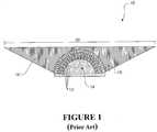
- FIG. 1shows a cross-sectional end view of an example of a known structure for a convex cylindrical array transducer 10 for producing swath beams.
- the convex cylindrical transducer 10comprises an array of active transducer elements 12 that are fixed in a convex cylindrical arrangement within a support structure 14.
- the transducer elements 12are driven to project an overall wide-angle swath beam via acoustic aperture 16.
- the acoustic aperture 16has a width defined by arrows 20.
- the transducer elements 12have a thickness of about a half wave-length relative to the operating frequency, and this requires a substantial spacing 18 between the front surfaces of the elements. Therefore, the convex cylindrical transducer 10 generally needs to be at least several wavelengths in diameter to operate effectively. This is because arranging the elements 12 into a convex cylinder having a smaller diameter increases the spacing 18 between the elements and this tends to result in prohibitively large response variations within the angle of interest of the swath beam.
- US patent 6,014,898describes an ultrasonic transducer array formed of multiple concave transducer elements that are arranged to provide a transducer having an overall convex array axis shape.
- US patent 4,156,863describes a conical beam transducer array formed from a spherically curved array of transducer elements.
- An underwater swath beam acoustic transducer according to claim 1 and a method of projecting and receiving far-field acoustic swath beams through water according to claim 15are disclosed.
- the radiation surfacemay be a concave cylindrical radiation surface in that the radiation surface conforms substantially to the peripheral external surface of a semicylinder.
- the active acoustic elementsmay be arranged about the concave semicylindrical radiation surface with each element being equally spaced by a radii from the cylinder axis.
- the array of active acoustic elementsmay be arranged to provide a substantially continuous radiation surface.
- each active acoustic elementmay be an acoustic transducer element comprising active acoustic material coupled between electrodes that are electrically excitable. More preferably, each acoustic element may be provided with one or more matching layers coupled directly or indirectly to the active acoustic material, the matching layer(s) being arranged to provide an impedance matching between the transducer and acoustic medium through which the acoustic beams propagate.
- each active acoustic elementmay comprise a matching layer situated between the radiation surface and the active acoustic material.
- the active acoustic elementsmay be acoustically isolated from each other within a support structure.
- each active acoustic element in the arraymay be straight and elongate. More preferably, the length of each active acoustic element may extend substantially the entire length of the radiation surface.
- the transducermay be arranged to produce a swath beam having a substantially fixed width in the direction of the longitudinal axis of the radiation surface.
- each straight and elongate active acoustic elementis collectively formed from a line of multiple individual active acoustic elements that are acoustically and electrically isolated from each other along the length of the transducer.
- the lines of individual active acoustic elementsmay be aligned with respect to each other along the length of the transducer to thereby provide a series of selectively operable concave array segments of active acoustic elements along the length of the transducer.
- control systemmay be operable to activate or deactivate any one or more of the concave array segments of active acoustic elements to thereby control the effective length of the radiation surface and consequently the width of the propagated swath beam in the direction of the longitudinal axis of the radiation surface. Additionally or alternatively, the control system may be operable to apply differently phased driving signals to the concave array segments of active acoustic elements to thereby steer the propagated swath beam in the desired direction about an axis transverse to the longitudinal axis of the radiation surface.
- the array of active acoustic elementsis operable to project acoustic swath beams having a wide field of view in the plane that is perpendicular to the longitudinal axis of the transducer and wherein the far-field acoustic intensity is substantially uniform within the field of view.
- the active acoustic elementsare activated at a predetermined operating frequency and the array of active acoustic elements are arranged such that the centre-to-centre distance between adjacent acoustic elements about the radiation surface is not greater than approximately one half of the wavelength of the operating frequency.
- the radiation surfacemay be indirectly exposed via one or more protection layers to the acoustic medium through which the projected or received acoustic swath beams propagate. More preferably, the radiation surface forms an acoustic aperture through which acoustic swath beams are projected or received, the one or more protection layers being arranged to at least partially fill the acoustic aperture.
- the protection layer(s)may be formed from rubber that is formulated to be acoustically transparent in the water to enable the transducer to operate underwater.
- an acoustic transducer for projecting and/or receiving acoustic swath beamscomprising: a concave cylindrical arrangement of operable acoustic transducer elements.
- radiation surfaceas used in this specification and claims is intended to mean the collective or effective surface associated with the acoustic aperture that is formed from the array of active acoustic elements and which is the surface from which acoustic beams are projected and/or received, whether the surface is directly exposed to the acoustic medium or indirectly exposed via one or more other layers.
- swath beamsas used in this specification and claims is intended to mean far-field acoustic beams that cover a wide angle in one direction and which have a narrower or alternatively controllable width or focus in the perpendicular direction.
- the disclosurerelates to an acoustic transducer for producing and/or receiving acoustic swath beams.
- swath beamsare typically far-field acoustic beams that cover a wide angle in one direction and which have a narrow or alternatively controllable width or focus in the perpendicular direction.
- Far-field in this contextis generally considered to be a distance that is much greater than the size of the transducer and the wavelength of its operating frequency.
- the acoustic transducercan be configured to generate and receive acoustic waves at any desired operating frequency, including audible and ultrasonic frequencies for example.
- the acoustic transducer 100comprises an elongate support structure 102 that is arranged to support an array of active acoustic elements 104.
- the active acoustic elements 104are arranged in a substantially concave pattern relative to each other to thereby provide a substantially concave elongate radiation surface 106 from which acoustic beams are projected and received by the transducer 100. More particularly, the active acoustic elements 104 are arranged to collectively provide a substantially continuous concave and elongate radiation surface 106 for the acoustic swath beams.
- each of the active acoustic elements 104may be driven to generate an acoustic beam and that the overall far-field swath beam 108 is the superposition of all the individual acoustic beams.
- the swath beam 108has a wide-angle or wide field of view (FOV) in the plane that is perpendicular to the longitudinal axis of the transducer.
- the FOV of the transducer 100is dependent on the size of opening of the acoustic aperture 110 formed by the acoustic active elements 104.
- the acoustic transduceris capable of projecting a swath beam having a far-field acoustic intensity that is substantially uniform within the FOV.
- the width of the swath beam 108 in the perpendicular direction to the FOV(or into the page along the longitudinal axis of the transducer 100), this is dependent on the length of the acoustic active elements 104 arid radiation surface 106. It will be appreciated that a longer transducer 100 will produce a narrower swath beam in the direction of the longitudinal axis of the transducer 100, and vice versa in that a shorter transducer will produce a wider swath beam.
- the acoustic transducer 100comprises a substantially concave elongate radiation surface 106 that is provided by a concave arrangement of active acoustic elements 104.
- the radiation surface 106conforms substantially to a portion or segment of the peripheral external surface of a cylinder with an associated diameter, and this will be referred to as a "concave cylindrical radiation surface".
- the radiation surfacecan in some forms be considered as being semicylindrical in that the active acoustic elements conform to the external surface of a semicylinder.
- the active acoustic elements 104can be said to be arranged to extend radially outwardly relative to a segment of a virtual cylindrical surface with each element being equally spaced by a radii from the cylinder axis.
- the concave cylindrical radiation surfacewill extend not more than half the full circumference of the cylinder.
- the elongate concave radiation surface 106need not necessarily conform to a semicylinder and may alternatively simply be an accurate radiation surface that is curved inward and non-cylindrical in nature.
- the concave cylindrical transducer 100is capable of producing the same wide-angle swath beam as the known conventional convex cylindrical transducer 10 shown in Figure 1 , but with a smaller number of active acoustic elements 104 and a smaller acoustic aperture 110, having a width indicated by arrows 112.
- the known conventional convex cylindrical transducer of Figure 1would require a minimum size of 10-12 wavelengths of the operating frequency in diameter and a much wider aperture 20 relative to the concave cylindrical transducer 100 of Figure 2 that can generate a swath beam having the same FOV with a concave cylindrical radiation surface size of approximately 2.5 wavelengths in diameter.
- the smaller acoustic aperture 110allows the application of shading for side-lobe suppression and electronic beam-steering along the longitudinal or cylindrical axis of the transducer using phased-array techniques.
- the acoustic transducer 200comprises a support structure 202 that supports an array of multiple active acoustic elements 204 that are arranged to provide an elongate concave radiation surface 206 for protecting and/or receiving acoustic swath beams.
- the active acoustic elements 204are in a concave cylindrical arrangement so as to provide a concave cylindrical radiation surface of a predetermined diameter for a predetermined operating frequency or range of operating frequencies.
- the support structuremay be any form of suitable known transducer array support material or mechanical system for supporting the array of active acoustic elements in place.
- the support structureis provided in and around the active acoustic elements 204 so as to acoustically isolate them from each other.
- the support structuremay comprise any acoustically insulating material as will be appreciated by those skilled in the art.
- the support structuremay be formed from rigid porous polymer materials.
- the radiation surface 206may either be directly exposed to the acoustic medium or indirectly exposed via one or more protection layers. It will be appreciated that the acoustic medium through which the acoustic beams propagate when being projected from the transducer or received by the transducer. If protection layer(s) are employed, these may be fixed, secured or formed across the radiation surface in various ways, depending on design requirements. It will be appreciated that mechanical or other securing methods can be used to secure the protection layer(s) to the radiation surface 206, including, but not limited to, adhesives or moulding techniques. By way of example, the cavity or acoustic aperture 210 provided by the concave elongate radiation surface 206 may optionally be at least partially filled with a protection layer 212.
- the protection layer 212may be formed from rubber that is formulated to be acoustically transparent in water.
- the thickness of the protection layer 212may be varied according to the operating power of the transducer 200 so as to avoid caviation in the high intensity zone of the acoustic beams. It will be appreciated that a protection layer 212 is not necessarily essential, but may enhance the performance of the transducer for particular operating conditions.
- the width and opening of the acoustic aperture 210defines the FOV or angle of coverage of the far-field swath beam projected by the acoustic transducer 200, in the plane perpendicular to the longitudinal axis of the transducer ( Figure 3A ). It will be appreciated that the number of active acoustic elements 204 in the array may be varied according to the diameter of the concave cylindrical radiation surface required for any particular application and operating frequencies.
- the width or focus of the far-field swath beam or sonic beam projected by the acoustic transducer 200, in the plane comprising the longitudinal axis of the transducer ( Figure 3B ),is dependent on the overall length of the radiation surface 206 provided by the elongate active acoustic elements 204 as generally indicated by arrows 214.
- a longer transducerproduces a narrower width swath beam in the direction perpendicular to the FOV, and vice versa for a smaller length transducer.
- the length of the active acoustic elements 204 and dimension of the acoustic aperture associated with the radiation surface 206can be modified or configured to project a specific far-field swath beam having a predetermined FOV and width for a particular operating frequency.
- each active acoustic element 204 in the arraymay be any form of operable acoustic transducer element.
- the active acoustic elements 204are preferably identical in shape and size, although this is not necessary in alternative forms of the transducer.
- each active acoustic element 204may be in the form of an elongate continuous structure extending substantially the entire length of the transducer.
- Each elongate structuremay comprise a piece or layer of actively acoustic material, such as an elongate piezoelectric ceramic plate 204a.
- Each piezoelectric ceramic plate 204ahas a front surface 216a directed toward the radiation surface 206 and an opposite rear surface 216b directed toward the bottom of the transducer as shown in Figure 3A .
- each structure of the active acoustic element 204may further comprise a matching layer or element 204b provided on the front surface 216a of the piezoelectric ceramic plate 204a to form the effective radiation surface 206.
- the active acoustic material of the elements 204may directly and collectively form the radiation surface 206 with or without one or more matching layers or extensions in alternative forms of the transducer.
- the matching layer 204b of the elements 204can be formed from any material having a suitable specific acoustic impedance including, by way of example only, polymers, metals, oxides, and composite materials.
- each active acoustic element 204also comprises front and rear electrodes that sandwich the active acoustic material 204a between its front 216a and rear 216b surfaces. Further, electrical connections to the electrodes of each active acoustic element 204 are provided to enable the elements to be driven in an active mode to generate acoustic waves or beams, or alternatively for receiving electrical signals in response to excitation of the active acoustic material by received acoustic waves or beams incident on the radiation surface 206 in a passive mode.
- the centre-to-centre distance between adjacent active acoustic elements 204should preferably not exceed about one half of the wavelength of the operating frequency.
- the acoustic transducer 200may further comprise a control system that is electrically connected to the electrodes of each of the active acoustic elements 204.
- the control systemhas electronic circuits that are operable to generate drive signals for applying to the electrodes of the active acoustic elements 204 to thereby cause each element to generate and project an acoustic wave or beam at the desired operating frequency for known acoustic applications.
- the control systemcan be arranged to receive electrical signals generated by the active acoustic elements 204 in response to receiving acoustic beams on the radiation surface 206 and these can be processed in accordance with the known acoustic transducer techniques for various acoustic applications.
- the active acoustic elementsmay be magnetostrictive elements or any other type of operable acoustic transducer element for generating and/or receiving acoustic beams.
- the concave array of elongate active acoustic elements 204are driven by the control system, via driving signals that are applied to the electrodes of the elements, to generate individual acoustic beams and which produce a swath beam that is a superposition of all of the individual acoustic beams. More specifically, the active acoustic elements 204 that conform to the concave cylindrical radiation surface are excited to produce a sonic wave within the cavity 210 by the driving signals.
- the sonic field produced as a result of the electrical excitation and acoustical interaction between the piezoelectric elements 204forms a converging cylindrical acoustic wave front.
- the wave frontpropagates through the focal zone (at or about the cylinder axis) and then becomes diverging.
- the acoustic intensity of the acoustic waveis substantially uniform within a wide angle (or FOV), the width of which depends on cylinder opening as previously mentioned.
- the concave array of active acoustic elements 204 of the transducer 200provides a small aperture for generating high power swath beams that have a wide FOV and a substantially uniform response over the FOV.
- a second preferred form acoustic transducer 300will be described.
- the second preferred from acoustic transducer 300is substantially similar in construction to the first preferred form acoustic transducer 200 and like components have been numbered with like reference numerals.
- the primary differenceis that acoustic transducer 300 is a multi-channel transducer having electronic beam control functionality in the form of beam-steering and variable swath beam width control as will be explained in more detail.
- the acoustic transducer 300comprises an array of operable active acoustic elements 304 extending radially outward from the concave cylindrical elongate radiation surface 206 as before. However, the acoustic transducer 300 does not employ continuous elongate active acoustic elements 304 that extend substantially the length of the transducer like the single-channel acoustic transducer 200.
- a line of multiple (N) active acoustic elements 304 0-Nare provided for each array element orientation about the cylindrical axis of the radiation surface 206.
- Each line of active acoustic element 304 0-Nare electrically and acoustically isolated from each other along the length of the transducer.
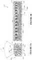
- each line of active acoustic elements 304 0-N extending along the length of the transducercan be considered to be a radial column of elements ( Figure 4A ), and the active elements of each radial column are arranged in N circumferential rows ( Figure 4B ) about the concave cylindrical radiation surface 210.
- Each circumferential row of active acoustic elements 304 0-Ncan be considered as a concave array segment.
- a control system for operating and driving the active acoustic elements 304 0-Nis preferably provided.
- the control system of the acoustic transducer 300can be operated to activate or deactivate any of the N concave array segments to thereby control the effective length of the radiation surface 206 and thereby the width of the swath beam in the direction of the longitudinal axis on the transducer ( Figure 4B ).
- the control systemcan be arranged or configured to deactivate one or more of the N concave array segments at one or both ends to thereby reduce the effective length of radiation surface 206 and thereby widen the width of the swath beam projected.
- control systemcan be arranged to employ phased-array techniques to apply differently phased driving signals across the concave array segments in order to beam-steer the swath beam or enlarge beam width in the direction of the transducer longitudinal axis.
- phased-array techniquesto apply differently phased driving signals across the concave array segments in order to beam-steer the swath beam or enlarge beam width in the direction of the transducer longitudinal axis.
- the far-field swath beampropagates from the radiation surface 206 at an angle substantially perpendicular to the central longitudinal axis of the transducer 300 as shown by the arrow nominated with 0°.
- differential phase driving signalscan be applied across the activate concave array segments along the length of the transducer to thereby alter the angle (D) of propagation of the swath beam about an axis that is transverse to the transducer longitudinal axis or enlarge beam width in the direction of the transducer longitudinal axis.
- the multi-channel acoustic transducer 300provides for the generation of steerable and variable width acoustic swath beams.
- the directivity patternsrepresent the acoustic response of the swath beam in a plane comprising the longitudinal or cylindrical axis of the transducer ( Figure 4B ).
- Figure 5Bshows the far-field directivity pattern of a swath beam projected by acoustic transducer 300 at an operating frequency of 160 kHz in the plane perpendicular to the longitudinal or cylindrical axis of the transducer, or more particularly shows the FOV with reference to Figure 4A .
- the swath beamhas a substantially uniform response for a wide-angle of approximately 100° in this example. It will be appreciated that the wide-angle uniform response or FOV may be narrowed or widened according to requirements.
- the concave elongate radiation surface of the acoustic transducer of the inventionmay alternatively be formed by other array arrangements and configurations of active acoustic elements that conform to a concave or preferably cylindrical concave radiation surface. It will be appreciated that the active acoustic elements should preferably collectively form a continuous or substantially continuous radiation surface. However, the acoustic transducer may still operate with spacings between the front surfaces of the array of active elements that form the collective radiation surface, although this may not be the optimum design for certain applications.
- the acoustic transducer of the disclosureis preferably arranged to generate and/or receive high power swath beams via a small aperture.
- This type of acoustic transducercan be employed in sonar or any other underwater acoustic devices or applications.
- the acoustic transducercan also operate in any acoustic medium including water or, in an example not forming part of the claimed invention, air.
- the acoustic transducercan be employed as a wide-angle acoustic transducer for air acoustics in audio applications.
- two or more transducersmay be coupled together in a side-by-side linear or curved arrangement with each producing its own swath beam and thereby providing an overall wider field of view with an omni-directional transducer being the extreme example.
- multiple coupled transducersmay be useful for underwater side scanning applications.
Landscapes
- Engineering & Computer Science (AREA)
- Physics & Mathematics (AREA)
- Acoustics & Sound (AREA)
- Multimedia (AREA)
- Mechanical Engineering (AREA)
- General Physics & Mathematics (AREA)
- Computer Networks & Wireless Communication (AREA)
- Radar, Positioning & Navigation (AREA)
- Remote Sensing (AREA)
- Transducers For Ultrasonic Waves (AREA)
- Measurement Of Velocity Or Position Using Acoustic Or Ultrasonic Waves (AREA)
- Investigating Or Analyzing Materials By The Use Of Ultrasonic Waves (AREA)
- Ultra Sonic Daignosis Equipment (AREA)
Description
- The disclosure relates to an acoustic transducer for projecting and/or receiving acoustic swath beams.
- Acoustic beams are used in many applications, including sonar and other underwater acoustic devices, audio transducers, and acoustic control of space, for example architectural acoustics.
- In sonar and underwater acoustic devices, the objective can be to map the ocean floor or to detect stationary or moving objects within the water. Additional uses for underwater acoustic devices includes fish finding and fish population estimation, inspection of underwater objects such as boat hulls, piers, and navigation. In many of these applications, it is desirable to utilise an acoustic transducer that is capable of projecting far-field acoustic swath beams. Swath beams are generally considered to be beams that cover a wide angle in one direction and a narrow width in the perpendicular direction.
- Known acoustic transducers for projecting swath beams generally comprise an array of active transducer elements that are arranged as either line arrays or alternatively convex cylindrical arrays. Both of these types of acoustic transducers have limitations. For example, the line array acoustic transducers typically have beam power limitations due to their limited width.
- As to the convex cylindrical array transducers, these have size constraints in that they cannot generally be made smaller than several wavelengths in diameter relative to the operating frequency due to structural requirements. For example,
Figure 1 shows a cross-sectional end view of an example of a known structure for a convexcylindrical array transducer 10 for producing swath beams. Briefly, the convexcylindrical transducer 10 comprises an array ofactive transducer elements 12 that are fixed in a convex cylindrical arrangement within asupport structure 14. In operation, thetransducer elements 12 are driven to project an overall wide-angle swath beam viaacoustic aperture 16. Theacoustic aperture 16 has a width defined byarrows 20. Typically, thetransducer elements 12 have a thickness of about a half wave-length relative to the operating frequency, and this requires asubstantial spacing 18 between the front surfaces of the elements. Therefore, the convexcylindrical transducer 10 generally needs to be at least several wavelengths in diameter to operate effectively. This is because arranging theelements 12 into a convex cylinder having a smaller diameter increases thespacing 18 between the elements and this tends to result in prohibitively large response variations within the angle of interest of the swath beam. US patent 6,014,898 describes an ultrasonic transducer array formed of multiple concave transducer elements that are arranged to provide a transducer having an overall convex array axis shape.US patent 4,156,863 describes a conical beam transducer array formed from a spherically curved array of transducer elements.- In this specification where reference has been made to patent specifications, other external documents, or other sources of information, this is generally for the purpose of providing a context for discussing the features of the invention. Unless specifically stated otherwise, reference to such external documents is not to be construed as an admission that such documents, or such sources of information, in any jurisdiction, are prior art, or form part of the common general knowledge in the art.
- It is an object of the disclosure to provide an improved acoustic transducer for projecting and/or receiving swath beams, or to at least provide the public with a useful choice.
- The present invention is as defined in and by the appended claims. An underwater swath beam acoustic transducer according to
claim 1 and a method of projecting and receiving far-field acoustic swath beams through water according to claim 15 are disclosed. - Preferably, the radiation surface may be a concave cylindrical radiation surface in that the radiation surface conforms substantially to the peripheral external surface of a semicylinder.
- Preferably, the active acoustic elements may be arranged about the concave semicylindrical radiation surface with each element being equally spaced by a radii from the cylinder axis.
- Preferably, the array of active acoustic elements may be arranged to provide a substantially continuous radiation surface.
- Preferably, each active acoustic element may be an acoustic transducer element comprising active acoustic material coupled between electrodes that are electrically excitable. More preferably, each acoustic element may be provided with one or more matching layers coupled directly or indirectly to the active acoustic material, the matching layer(s) being arranged to provide an impedance matching between the transducer and acoustic medium through which the acoustic beams propagate. By way of example, each active acoustic element may comprise a matching layer situated between the radiation surface and the active acoustic material.
- Preferably, the active acoustic elements may be acoustically isolated from each other within a support structure.
- Preferably, each active acoustic element in the array may be straight and elongate. More preferably, the length of each active acoustic element may extend substantially the entire length of the radiation surface.
- In one form, the transducer may be arranged to produce a swath beam having a substantially fixed width in the direction of the longitudinal axis of the radiation surface.
- In another form, each straight and elongate active acoustic element is collectively formed from a line of multiple individual active acoustic elements that are acoustically and electrically isolated from each other along the length of the transducer. Preferably, the lines of individual active acoustic elements may be aligned with respect to each other along the length of the transducer to thereby provide a series of selectively operable concave array segments of active acoustic elements along the length of the transducer. More preferably, the control system may be operable to activate or deactivate any one or more of the concave array segments of active acoustic elements to thereby control the effective length of the radiation surface and consequently the width of the propagated swath beam in the direction of the longitudinal axis of the radiation surface. Additionally or alternatively, the control system may be operable to apply differently phased driving signals to the concave array segments of active acoustic elements to thereby steer the propagated swath beam in the desired direction about an axis transverse to the longitudinal axis of the radiation surface.
- The array of active acoustic elements is operable to project acoustic swath beams having a wide field of view in the plane that is perpendicular to the longitudinal axis of the transducer and wherein the far-field acoustic intensity is substantially uniform within the field of view.
- Preferably, the active acoustic elements are activated at a predetermined operating frequency and the array of active acoustic elements are arranged such that the centre-to-centre distance between adjacent acoustic elements about the radiation surface is not greater than approximately one half of the wavelength of the operating frequency.
- Preferably, the radiation surface may be indirectly exposed via one or more protection layers to the acoustic medium through which the projected or received acoustic swath beams propagate. More preferably, the radiation surface forms an acoustic aperture through which acoustic swath beams are projected or received, the one or more protection layers being arranged to at least partially fill the acoustic aperture. By way of example only, the protection layer(s) may be formed from rubber that is formulated to be acoustically transparent in the water to enable the transducer to operate underwater.
- Also described is an acoustic transducer for projecting and/or receiving acoustic swath beams comprising: a concave cylindrical arrangement of operable acoustic transducer elements.
- The phrase "radiation surface" as used in this specification and claims is intended to mean the collective or effective surface associated with the acoustic aperture that is formed from the array of active acoustic elements and which is the surface from which acoustic beams are projected and/or received, whether the surface is directly exposed to the acoustic medium or indirectly exposed via one or more other layers.
- The phrase "swath beams" as used in this specification and claims is intended to mean far-field acoustic beams that cover a wide angle in one direction and which have a narrower or alternatively controllable width or focus in the perpendicular direction.
- The term "comprising" as used in this specification and claims means "consisting at least in part of. When interpreting each statement in this specification and claims that includes the term "comprising", features other than that or those prefaced by the term may also be present. Related terms such as "comprise" and "comprises" are to be interpreted in the same manner.
- As used herein the term "and/or" means "and" or "or", or both.
- As used herein "(s)" following a noun means the plural and/or singular forms of the noun.
- The invention consists in the foregoing and also envisages constructions of which the following gives examples only.
- Preferred embodiments of the invention will be described by way of example only and with reference to the drawings, in which:
Figure 1 shows a cross-sectional end view of an example of a conventional convex cylindrical acoustic transducer array for generating swath beams;Figure 2 shows a cross-sectional end view of an acoustic transducer in accordance with a preferred embodiment of the invention;Figure 3A shows a cross-sectional end view of a first preferred form acoustic transducer of the invention;Figure 3B shows a cross-sectional side view of the first preferred form acoustic transducer viewed through line AA ofFigure 3A ;Figure 4A shows a cross-sectional end view of a second preferred form acoustic transducer of the invention;Figure 4B shows a cross-sectional side view of the second preferred form acoustic transducer viewed through line BB ofFigure 4A ;Figure 5A is a graph of the far-field directivity pattern of an acoustic swath beam projected from the second preferred form acoustic transducer ofFigures 4A and 4B operating at a frequency of 160 kHz for various beam steering angles in a plane comprising the longitudinal axis of the transducer; andFigure 5B is a graph of the far-field directivity pattern of an acoustic swath beam projected from the second preferred form acoustic transducer ofFigures 4A and 4B operating at a frequency of 160 kHz in the plane perpendicular to the longitudinal axis of the transducer.- The disclosure relates to an acoustic transducer for producing and/or receiving acoustic swath beams. As referred to in this description, swath beams are typically far-field acoustic beams that cover a wide angle in one direction and which have a narrow or alternatively controllable width or focus in the perpendicular direction. Far-field in this context is generally considered to be a distance that is much greater than the size of the transducer and the wavelength of its operating frequency. The acoustic transducer can be configured to generate and receive acoustic waves at any desired operating frequency, including audible and ultrasonic frequencies for example.
- Referring to
Figure 2 , a cross-sectional end view of the structure of theacoustic transducer 100 of the invention is shown. The view ofFigure 2 is in a plane that is perpendicular to the longitudinal axis of thetransducer 100. In brief, theacoustic transducer 100 comprises anelongate support structure 102 that is arranged to support an array of activeacoustic elements 104. The activeacoustic elements 104 are arranged in a substantially concave pattern relative to each other to thereby provide a substantially concaveelongate radiation surface 106 from which acoustic beams are projected and received by thetransducer 100. More particularly, the activeacoustic elements 104 are arranged to collectively provide a substantially continuous concave andelongate radiation surface 106 for the acoustic swath beams. - It will be appreciated that each of the active
acoustic elements 104 may be driven to generate an acoustic beam and that the overall far-field swath beam 108 is the superposition of all the individual acoustic beams. As shown, theswath beam 108 has a wide-angle or wide field of view (FOV) in the plane that is perpendicular to the longitudinal axis of the transducer. The FOV of thetransducer 100 is dependent on the size of opening of theacoustic aperture 110 formed by the acousticactive elements 104. In the preferred form, the acoustic transducer is capable of projecting a swath beam having a far-field acoustic intensity that is substantially uniform within the FOV. - As to the width of the
swath beam 108 in the perpendicular direction to the FOV (or into the page along the longitudinal axis of the transducer 100), this is dependent on the length of the acousticactive elements 104arid radiation surface 106. It will be appreciated that alonger transducer 100 will produce a narrower swath beam in the direction of the longitudinal axis of thetransducer 100, and vice versa in that a shorter transducer will produce a wider swath beam. - As mentioned, the
acoustic transducer 100 comprises a substantially concaveelongate radiation surface 106 that is provided by a concave arrangement of activeacoustic elements 104. In the preferred form, theradiation surface 106 conforms substantially to a portion or segment of the peripheral external surface of a cylinder with an associated diameter, and this will be referred to as a "concave cylindrical radiation surface". In other words, the radiation surface can in some forms be considered as being semicylindrical in that the active acoustic elements conform to the external surface of a semicylinder. For example, the activeacoustic elements 104 can be said to be arranged to extend radially outwardly relative to a segment of a virtual cylindrical surface with each element being equally spaced by a radii from the cylinder axis. Typically, the concave cylindrical radiation surface will extend not more than half the full circumference of the cylinder. However, it will be appreciated that the elongateconcave radiation surface 106 need not necessarily conform to a semicylinder and may alternatively simply be an accurate radiation surface that is curved inward and non-cylindrical in nature. - The concave
cylindrical transducer 100 is capable of producing the same wide-angle swath beam as the known conventional convexcylindrical transducer 10 shown inFigure 1 , but with a smaller number of activeacoustic elements 104 and a smalleracoustic aperture 110, having a width indicated byarrows 112. By way of example only, the known conventional convex cylindrical transducer ofFigure 1 would require a minimum size of 10-12 wavelengths of the operating frequency in diameter and a muchwider aperture 20 relative to the concavecylindrical transducer 100 ofFigure 2 that can generate a swath beam having the same FOV with a concave cylindrical radiation surface size of approximately 2.5 wavelengths in diameter. Along with the general benefits of being a smaller transducer, the smalleracoustic aperture 110 allows the application of shading for side-lobe suppression and electronic beam-steering along the longitudinal or cylindrical axis of the transducer using phased-array techniques. - More preferred forms of the acoustic transducer of the invention will now be described in greater detail, by way of example only.
- Referring to
Figures 3A and 3B , a first preferred form single-channelacoustic transducer 200 will now be described. In the first preferred form, theacoustic transducer 200 comprises asupport structure 202 that supports an array of multiple activeacoustic elements 204 that are arranged to provide an elongateconcave radiation surface 206 for protecting and/or receiving acoustic swath beams. Preferably, the activeacoustic elements 204 are in a concave cylindrical arrangement so as to provide a concave cylindrical radiation surface of a predetermined diameter for a predetermined operating frequency or range of operating frequencies. The support structure may be any form of suitable known transducer array support material or mechanical system for supporting the array of active acoustic elements in place. In the first preferred form, the support structure is provided in and around the activeacoustic elements 204 so as to acoustically isolate them from each other. The support structure may comprise any acoustically insulating material as will be appreciated by those skilled in the art. By way of example only, the support structure may be formed from rigid porous polymer materials. - The
radiation surface 206 may either be directly exposed to the acoustic medium or indirectly exposed via one or more protection layers. It will be appreciated that the acoustic medium through which the acoustic beams propagate when being projected from the transducer or received by the transducer. If protection layer(s) are employed, these may be fixed, secured or formed across the radiation surface in various ways, depending on design requirements. It will be appreciated that mechanical or other securing methods can be used to secure the protection layer(s) to theradiation surface 206, including, but not limited to, adhesives or moulding techniques. By way of example, the cavity oracoustic aperture 210 provided by the concaveelongate radiation surface 206 may optionally be at least partially filled with aprotection layer 212. For example, if thetransducer 200 is employed as an underwater transducer, theprotection layer 212 may be formed from rubber that is formulated to be acoustically transparent in water. For underwater transmit transducers, the thickness of theprotection layer 212 may be varied according to the operating power of thetransducer 200 so as to avoid caviation in the high intensity zone of the acoustic beams. It will be appreciated that aprotection layer 212 is not necessarily essential, but may enhance the performance of the transducer for particular operating conditions. - As mentioned, the width and opening of the
acoustic aperture 210 defines the FOV or angle of coverage of the far-field swath beam projected by theacoustic transducer 200, in the plane perpendicular to the longitudinal axis of the transducer (Figure 3A ). It will be appreciated that the number of activeacoustic elements 204 in the array may be varied according to the diameter of the concave cylindrical radiation surface required for any particular application and operating frequencies. - The width or focus of the far-field swath beam or sonic beam projected by the
acoustic transducer 200, in the plane comprising the longitudinal axis of the transducer (Figure 3B ), is dependent on the overall length of theradiation surface 206 provided by the elongate activeacoustic elements 204 as generally indicated byarrows 214. In particular, a longer transducer produces a narrower width swath beam in the direction perpendicular to the FOV, and vice versa for a smaller length transducer. - In summary, it will be appreciated that the length of the active
acoustic elements 204 and dimension of the acoustic aperture associated with theradiation surface 206 can be modified or configured to project a specific far-field swath beam having a predetermined FOV and width for a particular operating frequency. - In the first preferred form, each active
acoustic element 204 in the array may be any form of operable acoustic transducer element. The activeacoustic elements 204 are preferably identical in shape and size, although this is not necessary in alternative forms of the transducer. By way of example, each activeacoustic element 204 may be in the form of an elongate continuous structure extending substantially the entire length of the transducer. Each elongate structure may comprise a piece or layer of actively acoustic material, such as an elongate piezoelectricceramic plate 204a. Each piezoelectricceramic plate 204a has afront surface 216a directed toward theradiation surface 206 and an oppositerear surface 216b directed toward the bottom of the transducer as shown inFigure 3A . Optionally, each structure of the activeacoustic element 204 may further comprise a matching layer orelement 204b provided on thefront surface 216a of the piezoelectricceramic plate 204a to form theeffective radiation surface 206. However, it will be appreciated that the active acoustic material of theelements 204 may directly and collectively form theradiation surface 206 with or without one or more matching layers or extensions in alternative forms of the transducer. It will be appreciated that thematching layer 204b of theelements 204 can be formed from any material having a suitable specific acoustic impedance including, by way of example only, polymers, metals, oxides, and composite materials. - Although not shown, each active
acoustic element 204 also comprises front and rear electrodes that sandwich the activeacoustic material 204a between its front 216a and rear 216b surfaces. Further, electrical connections to the electrodes of each activeacoustic element 204 are provided to enable the elements to be driven in an active mode to generate acoustic waves or beams, or alternatively for receiving electrical signals in response to excitation of the active acoustic material by received acoustic waves or beams incident on theradiation surface 206 in a passive mode. In the first preferred form, the centre-to-centre distance between adjacent activeacoustic elements 204 should preferably not exceed about one half of the wavelength of the operating frequency. - As will be appreciated, the
acoustic transducer 200 may further comprise a control system that is electrically connected to the electrodes of each of the activeacoustic elements 204. The control system has electronic circuits that are operable to generate drive signals for applying to the electrodes of the activeacoustic elements 204 to thereby cause each element to generate and project an acoustic wave or beam at the desired operating frequency for known acoustic applications. Additionally or alternatively, the control system can be arranged to receive electrical signals generated by the activeacoustic elements 204 in response to receiving acoustic beams on theradiation surface 206 and these can be processed in accordance with the known acoustic transducer techniques for various acoustic applications. - In an alternative form, it will be appreciated that the active acoustic elements may be magnetostrictive elements or any other type of operable acoustic transducer element for generating and/or receiving acoustic beams.
- In operation of the first
preferred form transducer 200, the concave array of elongate activeacoustic elements 204 are driven by the control system, via driving signals that are applied to the electrodes of the elements, to generate individual acoustic beams and which produce a swath beam that is a superposition of all of the individual acoustic beams. More specifically, the activeacoustic elements 204 that conform to the concave cylindrical radiation surface are excited to produce a sonic wave within thecavity 210 by the driving signals. The sonic field produced as a result of the electrical excitation and acoustical interaction between thepiezoelectric elements 204 forms a converging cylindrical acoustic wave front. The wave front propagates through the focal zone (at or about the cylinder axis) and then becomes diverging. At a distance much greater than the wavelength and size of the transducer, i.e. in the far-field, the acoustic intensity of the acoustic wave (swath beam) is substantially uniform within a wide angle (or FOV), the width of which depends on cylinder opening as previously mentioned. - In summary, the concave array of active
acoustic elements 204 of thetransducer 200 provides a small aperture for generating high power swath beams that have a wide FOV and a substantially uniform response over the FOV. - Referring to
Figures 4A and 4B , a second preferred formacoustic transducer 300 will be described. The second preferred fromacoustic transducer 300 is substantially similar in construction to the first preferred formacoustic transducer 200 and like components have been numbered with like reference numerals. The primary difference is thatacoustic transducer 300 is a multi-channel transducer having electronic beam control functionality in the form of beam-steering and variable swath beam width control as will be explained in more detail. - Referring to
Figure 4A , theacoustic transducer 300 comprises an array of operable activeacoustic elements 304 extending radially outward from the concave cylindricalelongate radiation surface 206 as before. However, theacoustic transducer 300 does not employ continuous elongate activeacoustic elements 304 that extend substantially the length of the transducer like the single-channelacoustic transducer 200. In the multi-channelacoustic transducer 300, a line of multiple (N) activeacoustic elements 3040-N are provided for each array element orientation about the cylindrical axis of theradiation surface 206. Each line of activeacoustic element 3040-N are electrically and acoustically isolated from each other along the length of the transducer. - The number of individual
acoustic elements 3040-N in each line is preferably identical and the lines of individual active acoustic elements are preferably aligned with respect to each other along the length of the transducer to thereby provide a series of concave array segments of active acoustic elements along the length of the transducer. In other words, each line of activeacoustic elements 3040-N extending along the length of the transducer can be considered to be a radial column of elements (Figure 4A ), and the active elements of each radial column are arranged in N circumferential rows (Figure 4B ) about the concavecylindrical radiation surface 210. Each circumferential row of activeacoustic elements 3040-N can be considered as a concave array segment. - In the second preferred form, a control system for operating and driving the active
acoustic elements 3040-N is preferably provided. The control system of theacoustic transducer 300 can be operated to activate or deactivate any of the N concave array segments to thereby control the effective length of theradiation surface 206 and thereby the width of the swath beam in the direction of the longitudinal axis on the transducer (Figure 4B ). For example, the control system can be arranged or configured to deactivate one or more of the N concave array segments at one or both ends to thereby reduce the effective length ofradiation surface 206 and thereby widen the width of the swath beam projected. - Additionally or alternatively, the control system can be arranged to employ phased-array techniques to apply differently phased driving signals across the concave array segments in order to beam-steer the swath beam or enlarge beam width in the direction of the transducer longitudinal axis. For example, when uniform phase is applied across all the active concave array segments, the far-field swath beam propagates from the
radiation surface 206 at an angle substantially perpendicular to the central longitudinal axis of thetransducer 300 as shown by the arrow nominated with 0°. However, differential phase driving signals can be applied across the activate concave array segments along the length of the transducer to thereby alter the angle (D) of propagation of the swath beam about an axis that is transverse to the transducer longitudinal axis or enlarge beam width in the direction of the transducer longitudinal axis. - In summary, the multi-channel
acoustic transducer 300 provides for the generation of steerable and variable width acoustic swath beams. Figure 5A shows a far-field directivity pattern of a swath beam projected by anacoustic transducer 300 at an operating frequency of 160 kHz for steering angles D = 0°, 7.7°, 15.5°, and 23.7°. The directivity patterns represent the acoustic response of the swath beam in a plane comprising the longitudinal or cylindrical axis of the transducer (Figure 4B ).Figure 5B shows the far-field directivity pattern of a swath beam projected byacoustic transducer 300 at an operating frequency of 160 kHz in the plane perpendicular to the longitudinal or cylindrical axis of the transducer, or more particularly shows the FOV with reference toFigure 4A . As shown inFigure 5B , the swath beam has a substantially uniform response for a wide-angle of approximately 100° in this example. It will be appreciated that the wide-angle uniform response or FOV may be narrowed or widened according to requirements.- It will be appreciated that the concave elongate radiation surface of the acoustic transducer of the invention may alternatively be formed by other array arrangements and configurations of active acoustic elements that conform to a concave or preferably cylindrical concave radiation surface. It will be appreciated that the active acoustic elements should preferably collectively form a continuous or substantially continuous radiation surface. However, the acoustic transducer may still operate with spacings between the front surfaces of the array of active elements that form the collective radiation surface, although this may not be the optimum design for certain applications.
- The acoustic transducer of the disclosure is preferably arranged to generate and/or receive high power swath beams via a small aperture. This type of acoustic transducer can be employed in sonar or any other underwater acoustic devices or applications. In addition, the acoustic transducer can also operate in any acoustic medium including water or, in an example not forming part of the claimed invention, air. In an example not forming part of the claimed invention, the acoustic transducer can be employed as a wide-angle acoustic transducer for air acoustics in audio applications.
- It will be appreciated that two or more transducers may be coupled together in a side-by-side linear or curved arrangement with each producing its own swath beam and thereby providing an overall wider field of view with an omni-directional transducer being the extreme example. For example, multiple coupled transducers may be useful for underwater side scanning applications.
- The foregoing description of the invention includes preferred forms thereof. Modifications may be made thereto without departing from the scope of the invention as defined by the accompanying claims.
Claims (18)
- An underwater swath beam acoustic transducer (100) for projecting and receiving far-field acoustic swath beams (108) through water, comprising:an array of active acoustic elements (104) that are arranged to collectively provide an elongate concave radiation surface (106) with an associated acoustic aperture (110), each active acoustic element (104) being operable to project an individual acoustic beam from the radiation surface toward a focal zone of the transducer (100); anda control system that is electrically connected to the active acoustic elements (104) and which is configured to generate electrical driving signals to drive each of the active acoustic elements (104) so as to project far-field acoustic swath beams (108) through water from the transducer (100), the far-field acoustic swath beams (108) being a superposition of all of the individual acoustic beams such that in the far-field, beyond the focal zone and acoustic aperture (110), the acoustic swath beams (108) have a wide field view in a plane that is transverse to a longitudinal direction of the radiation surface (106), a narrower width in a direction perpendicular to the wide field of view, and an acoustic intensity that is uniform across the field of view, and wherein the control system is further configured to receive and process electrical signals from the active acoustic elements that are generated in response to swath beams received by the radiation surface (106) that are reflected back from the far-field.
- An underwater swath beam acoustic transducer according to claim 1 wherein the radiation surface (106) is a concave cylindrical radiation surface in that the radiation surface conforms to the peripheral external surface of a semicylinder, and wherein the active acoustic elements (104) are arranged about the concave semicylindrical radiation surface with each element being equally spaced relative to each other about the radiation surface (106).
- An underwater swath beam acoustic transducer according to claim 1 or claim 2 wherein the array of active acoustic elements (104) is arranged to provide a continuous radiation surface (106).
- An underwater swath beam acoustic transducer according to any one of the preceding claims wherein each active acoustic element (204) is an acoustic transducer element comprising active acoustic material (204a) coupled between electrodes that are electrically excitable, and wherein each acoustic element (204) is provided with one or more matching layers (204b) coupled directly or indirectly to the active acoustic material (204a), the one or more matching layers being arranged to provide an impedance matching between the transducer (200) and the water through which the acoustic beams propagate.
- An underwater swath beam acoustic transducer according to claim 4 wherein each active acoustic element (204) comprises a matching layer (204b) situated between the radiation surface (206) and the active acoustic material (204a).
- An underwater swath beam acoustic transducer according to any one of the preceding claims wherein the active acoustic elements (204) are acoustically isolated from each other within a support structure (202) that supports the array of active acoustic elements.
- An underwater swath beam acoustic transducer according to any one of the preceding claims wherein each active acoustic element (204) in the array is straight and elongate, and wherein the length of each active acoustic element extends the entire length of the radiation surface (206).
- An underwater swath beam acoustic transducer according to claim 7 wherein the transducer is arranged to produce a swath beam having a fixed width in the direction of a longitudinal axis (214) of the radiation surface (206).
- An underwater swath beam acoustic transducer according to claim 7 wherein each straight and elongate active acoustic element (304) is collectively formed from a line of multiple individual active acoustic elements that are acoustically and electrically isolated from each other along the length of the transducer (300), and wherein the lines of individual active acoustic elements are aligned with respect to each other along the length of the transducer (300) to thereby provide a series of selectively operable concave array segments of active acoustic elements along the length of the transducer (300).
- An underwater swath beam acoustic transducer according to claim 9 wherein the control system is operable to activate or deactivate any one or more of the concave array segments of active acoustic elements (304) to thereby control the effective length of the radiation surface (206) and consequently the width of the propagated swath beam in the direction of a longitudinal axis (214) of the radiation surface (206).
- An underwater swath beam acoustic transducer according to claim 9 or claim 10 wherein the control system is operable to apply differently phased driving signals to the concave array segments of active acoustic elements (304) to thereby steer the propagated swath beam in the desired direction (D) about an axis transverse to a longitudinal axis (214) of the radiation surface (206).
- An underwater swath beam acoustic transducer according to any one of the preceding claims wherein the active acoustic elements (204) are driven by the control system at a predetermined operating frequency and the array of active acoustic elements (204) are arranged such that the centre-to-centre distance between adjacent acoustic elements about the radiation surface (206) is not greater than one half of the wavelength of the operating frequency.
- An underwater swath beam acoustic transducer according to any one of the preceding claims wherein the radiation surface (206) forms the acoustic aperture (210) through which acoustic swath beams are projected and received and the transducer further comprises one or more protection layers (212) that are arranged to at least partially fill the acoustic aperture (210) such that the radiation surface (206) is indirectly exposed via the one or more protection layers (212) to the water through which the projected and received acoustic swath beams propagate.
- An underwater swath beam acoustic transducer according to claim 13 wherein at least one of the protection layers (212) is formed from rubber that is formulated to be acoustically transparent in the water to enable the transducer (200) to operate underwater.
- A method of projecting and receiving far-field acoustic swath beams through water comprising:exposing an underwater swath beam acoustic transducer (100, 200, 300) to the water, the transducer comprising:an array of active acoustic elements (104) that are arranged to collectively provide an elongate concave radiation surface (106) with an associated acoustic aperture (110), each active acoustic element (104) being operable to project an individual acoustic beam from the radiation surface toward a focal zone of the transducer (100); anda control system that is electrically connected to the active acoustic elements (104) and which is configured to generate electrical driving signals to drive each of the active acoustic elements (104) so as to project far-field acoustic swath beams (108) through water from the transducer (100), the far-field acoustic swath beams (108) being a superposition of all of the individual acoustic beams such that in the far-field, beyond the focal zone and acoustic aperture (110), the acoustic swath beams (108) have a wide field view in a plane that is transverse to a longitudinal direction of the radiation surface (106), a narrower width in a direction perpendicular to the wide field of view, and an acoustic intensity that is uniform across the field of view, and wherein the control system is further configured to receive and process electrical signals from the active acoustic elements that are generated in response to swath beams received by the radiation surface (106) that are reflected back from the far-field;driving, using the control system, the array of active acoustic elements (104, 204, 304) of the transducer to project a far-field swath beam through the water, the swath beam having a wide field of view in a plane that is transverse to a longitudinal direction of the radiation surface (106, 206) of the transducer and wherein a far-field acoustic intensity of the swath beam is uniform across the field of view; andreceiving and processing electrical signals from the active acoustic elements that are generated in response to swath beams received by the radiation surface (106) that are reflected back from the far-field.
- A method of projecting and receiving far-field acoustic swath beams through water according to claim 15 wherein the transducer is formed by a series of selectively operable concave array segments of active acoustic elements (304) along the length of the transducer (300).
- A method of projecting and receiving far-field acoustic swath beams through water according to claim 16 further comprising the step of driving, using the control system, a selected number of adjacent concave array segments to thereby control the effective length of the radiation surface (206) and consequently the width of the propagated swath beam in the direction of a longitudinal axis (214) of the radiation surface (206).
- A method of projecting and receiving far-field acoustic swath beams through water according to claim 16 or claim 17 further comprising the step of steering, using the control system, the propagated swath beam in the desired direction about an axis transverse to a longitudinal axis (214) of the radiation surface (206) by applying differently phased driving signals to the concave array segments.
Applications Claiming Priority (2)
| Application Number | Priority Date | Filing Date | Title |
|---|---|---|---|
| NZ57072508 | 2008-08-21 | ||
| PCT/NZ2009/000119WO2010021554A1 (en) | 2008-08-21 | 2009-06-23 | An acoustic transducer for swath beams |
Publications (3)
| Publication Number | Publication Date |
|---|---|
| EP2326970A1 EP2326970A1 (en) | 2011-06-01 |
| EP2326970A4 EP2326970A4 (en) | 2017-03-01 |
| EP2326970B1true EP2326970B1 (en) | 2020-10-28 |
Family
ID=41707323
Family Applications (1)
| Application Number | Title | Priority Date | Filing Date |
|---|---|---|---|
| EP09808446.0AActiveEP2326970B1 (en) | 2008-08-21 | 2009-06-23 | An acoustic transducer for swath beams |
Country Status (8)
| Country | Link |
|---|---|
| US (1) | US9218799B2 (en) |
| EP (1) | EP2326970B1 (en) |
| JP (1) | JP5600678B2 (en) |
| CN (1) | CN102177443B (en) |
| AU (1) | AU2009283312B8 (en) |
| DK (1) | DK2326970T3 (en) |
| ES (1) | ES2844275T3 (en) |
| WO (1) | WO2010021554A1 (en) |
Cited By (6)
| Publication number | Priority date | Publication date | Assignee | Title |
|---|---|---|---|---|
| US11921200B1 (en) | 2022-08-19 | 2024-03-05 | Navico, Inc. | Live down sonar view |
| USD1026679S1 (en) | 2022-08-19 | 2024-05-14 | Navico, Inc. | Multi-orientation sonar transducer array system |
| USD1072648S1 (en) | 2022-08-19 | 2025-04-29 | Navico, Inc. | Bracket for multiple sonar transducer array housings |
| US12287416B2 (en) | 2018-05-17 | 2025-04-29 | Navico, Inc. | Live sonar systems and methods |
| US12287402B2 (en) | 2022-06-10 | 2025-04-29 | Navico, Inc. | Sonar ping synchronization and associated methods |
| US12306353B2 (en) | 2023-04-28 | 2025-05-20 | Navico, Inc. | Beamforming sonar systems for 360-degree live sonar, and associated methods |
Families Citing this family (2)
| Publication number | Priority date | Publication date | Assignee | Title |
|---|---|---|---|---|
| CN106597450B (en)* | 2016-12-09 | 2019-07-30 | 中国科学院电子学研究所 | A kind of acoustic detection and positioning system |
| CN115235521A (en)* | 2021-04-23 | 2022-10-25 | 苏州佳世达电通有限公司 | underwater ultrasonic device |
Family Cites Families (23)
| Publication number | Priority date | Publication date | Assignee | Title |
|---|---|---|---|---|
| US3736555A (en) | 1971-08-20 | 1973-05-29 | Dynamics Corp Massa Div | Electroacoustic transducers |
| US4183249A (en) | 1975-03-07 | 1980-01-15 | Varian Associates, Inc. | Lens system for acoustical imaging |
| US4156863A (en) | 1978-04-28 | 1979-05-29 | The United States Of America As Represented By The Secretary Of The Navy | Conical beam transducer array |
| JPS589063A (en) | 1981-07-08 | 1983-01-19 | Noritoshi Nakabachi | Ultrasonic microscope |
| US4766575A (en)* | 1986-02-05 | 1988-08-23 | Raytheon Company | Cylindrical sonar array |
| JPH0714392B2 (en)* | 1987-02-26 | 1995-02-22 | 株式会社東芝 | Ultrasonic probe |
| JPS63305848A (en)* | 1987-06-05 | 1988-12-13 | Hitachi Medical Corp | Ultrasonic probe |
| JPH02234600A (en)* | 1989-03-07 | 1990-09-17 | Mitsubishi Mining & Cement Co Ltd | Piezoelectric conversion element |
| US5423220A (en) | 1993-01-29 | 1995-06-13 | Parallel Design | Ultrasonic transducer array and manufacturing method thereof |
| US5546356A (en)* | 1993-06-30 | 1996-08-13 | The United States Of America As Represented By The Secretary Of The Navy | Wide beam acoustic projector with sharp cutoff and low side lobes |
| NO308264B1 (en) | 1994-03-22 | 2000-08-21 | Western Atlas Int Inc | Well log probe with approximately cylindrical arrangement of piezoelectric acoustic transducers for electronic control and focusing of acoustic signals |
| US5511550A (en)* | 1994-10-14 | 1996-04-30 | Parallel Design, Inc. | Ultrasonic transducer array with apodized elevation focus |
| US5526325A (en)* | 1995-09-21 | 1996-06-11 | The United States Of America As Represented By The Secretary Of The Navy | Steerable beamformer |
| JP3673035B2 (en)* | 1996-10-25 | 2005-07-20 | 株式会社東芝 | Ultrasonic transducer |
| JPH11128225A (en) | 1997-10-28 | 1999-05-18 | Olympus Optical Co Ltd | Convex array type ultrasonic probe |
| WO2001045550A2 (en) | 1999-12-23 | 2001-06-28 | Therus Corporation | Ultrasound transducers for imaging and therapy |
| US6645162B2 (en) | 2000-12-27 | 2003-11-11 | Insightec - Txsonics Ltd. | Systems and methods for ultrasound assisted lipolysis |
| US6537220B1 (en) | 2001-08-31 | 2003-03-25 | Siemens Medical Solutions Usa, Inc. | Ultrasound imaging with acquisition of imaging data in perpendicular scan planes |
| US6784600B2 (en)* | 2002-05-01 | 2004-08-31 | Koninklijke Philips Electronics N.V. | Ultrasonic membrane transducer for an ultrasonic diagnostic probe |
| US6961025B1 (en)* | 2003-08-18 | 2005-11-01 | Lockheed Martin Corporation | High-gain conformal array antenna |
| JP2005351718A (en)* | 2004-06-09 | 2005-12-22 | Mitsubishi Heavy Ind Ltd | Omnidirectional flaw detection probe |
| US8323201B2 (en)* | 2007-08-06 | 2012-12-04 | Orison Corporation | System and method for three-dimensional ultrasound imaging |
| US8331197B2 (en)* | 2007-08-07 | 2012-12-11 | Industrial Research Limited | Beam forming system and method |
- 2009
- 2009-06-23EPEP09808446.0Apatent/EP2326970B1/enactiveActive
- 2009-06-23AUAU2009283312Apatent/AU2009283312B8/enactiveActive
- 2009-06-23CNCN2009801403261Apatent/CN102177443B/enactiveActive
- 2009-06-23JPJP2011523763Apatent/JP5600678B2/enactiveActive
- 2009-06-23WOPCT/NZ2009/000119patent/WO2010021554A1/enactiveApplication Filing
- 2009-06-23ESES09808446Tpatent/ES2844275T3/enactiveActive
- 2009-06-23DKDK09808446.0Tpatent/DK2326970T3/enactive
- 2009-06-23USUS13/060,067patent/US9218799B2/enactiveActive
Non-Patent Citations (1)
| Title |
|---|
| None* |
Cited By (6)
| Publication number | Priority date | Publication date | Assignee | Title |
|---|---|---|---|---|
| US12287416B2 (en) | 2018-05-17 | 2025-04-29 | Navico, Inc. | Live sonar systems and methods |
| US12287402B2 (en) | 2022-06-10 | 2025-04-29 | Navico, Inc. | Sonar ping synchronization and associated methods |
| US11921200B1 (en) | 2022-08-19 | 2024-03-05 | Navico, Inc. | Live down sonar view |
| USD1026679S1 (en) | 2022-08-19 | 2024-05-14 | Navico, Inc. | Multi-orientation sonar transducer array system |
| USD1072648S1 (en) | 2022-08-19 | 2025-04-29 | Navico, Inc. | Bracket for multiple sonar transducer array housings |
| US12306353B2 (en) | 2023-04-28 | 2025-05-20 | Navico, Inc. | Beamforming sonar systems for 360-degree live sonar, and associated methods |
Also Published As
| Publication number | Publication date |
|---|---|
| DK2326970T3 (en) | 2021-01-25 |
| AU2009283312A1 (en) | 2010-02-25 |
| CN102177443B (en) | 2013-09-25 |
| US20110211424A1 (en) | 2011-09-01 |
| EP2326970A4 (en) | 2017-03-01 |
| EP2326970A1 (en) | 2011-06-01 |
| WO2010021554A1 (en) | 2010-02-25 |
| US9218799B2 (en) | 2015-12-22 |
| AU2009283312A8 (en) | 2015-06-25 |
| CN102177443A (en) | 2011-09-07 |
| ES2844275T3 (en) | 2021-07-21 |
| JP5600678B2 (en) | 2014-10-01 |
| AU2009283312B8 (en) | 2015-06-25 |
| WO2010021554A8 (en) | 2011-04-07 |
| AU2009283312B2 (en) | 2015-06-11 |
| JP2012500555A (en) | 2012-01-05 |
Similar Documents
| Publication | Publication Date | Title |
|---|---|---|
| EP2326970B1 (en) | An acoustic transducer for swath beams | |
| US5530683A (en) | Steerable acoustic transducer | |
| JPH0715799A (en) | Ultrasonic transducer with reduced side lobes and method of manufacturing the same | |
| JP2010521650A (en) | Transducer array placement and operation for soda applications | |
| US6614143B2 (en) | Class V flextensional transducer with directional beam patterns | |
| US20190257930A1 (en) | Multi frequency piston transducer | |
| AU2019364655B2 (en) | Acoustic transmitting antenna | |
| US8599648B1 (en) | Doubly steered acoustic array | |
| Butler et al. | A low-frequency directional flextensional transducer and line array | |
| RU2440586C2 (en) | High-frequency multichannel hydroacoustic antenna | |
| JPH0854458A (en) | Array plate for craft | |
| US8331197B2 (en) | Beam forming system and method | |
| US5511043A (en) | Multiple frequency steerable acoustic transducer | |
| US9286418B1 (en) | Method for designing an acoustic array | |
| US8033997B2 (en) | Interdigitated geometry transducer for optimizing the irradiated acoustic beam | |
| US6661739B1 (en) | Filigree electrode pattern apparatus for steering parametric mode acoustic beams | |
| Naify et al. | Acoustic leaky wave antennas: Direction-finding via dispersion | |
| US8817575B1 (en) | Transducer for high pressure environment | |
| Emadi et al. | Capacitive micromachined ultrasonic transducer array with pencil beam shape and wide range beam steering | |
| Hao et al. | Design of an underwater acoustic array for full ocean depth multi-beam echo sounder | |
| US6856579B1 (en) | Broadband towed line array with spatial discrimination capabilities | |
| NZ583154A (en) | Beam forming system and method | |
| CN120178220A (en) | Ultrasonic sensor, parking assistance system and motor vehicle | |
| Hughes et al. | Spatially-phased transducer to form steered beams | |
| CN110619863A (en) | Low-frequency narrow-beam underwater acoustic transducer |
Legal Events
| Date | Code | Title | Description |
|---|---|---|---|
| PUAI | Public reference made under article 153(3) epc to a published international application that has entered the european phase | Free format text:ORIGINAL CODE: 0009012 | |
| 17P | Request for examination filed | Effective date:20110307 | |
| AK | Designated contracting states | Kind code of ref document:A1 Designated state(s):AT BE BG CH CY CZ DE DK EE ES FI FR GB GR HR HU IE IS IT LI LT LU LV MC MK MT NL NO PL PT RO SE SI SK TR | |
| AX | Request for extension of the european patent | Extension state:AL BA RS | |
| DAX | Request for extension of the european patent (deleted) | ||
| RAP1 | Party data changed (applicant data changed or rights of an application transferred) | Owner name:WASSP LIMITED | |
| RA4 | Supplementary search report drawn up and despatched (corrected) | Effective date:20170130 | |
| RIC1 | Information provided on ipc code assigned before grant | Ipc:G10K 11/00 20060101ALI20170124BHEP Ipc:B06B 1/06 20060101ALI20170124BHEP Ipc:G01S 15/88 20060101AFI20170124BHEP | |
| STAA | Information on the status of an ep patent application or granted ep patent | Free format text:STATUS: EXAMINATION IS IN PROGRESS | |
| 17Q | First examination report despatched | Effective date:20190401 | |
| GRAP | Despatch of communication of intention to grant a patent | Free format text:ORIGINAL CODE: EPIDOSNIGR1 | |
| STAA | Information on the status of an ep patent application or granted ep patent | Free format text:STATUS: GRANT OF PATENT IS INTENDED | |
| INTG | Intention to grant announced | Effective date:20200623 | |
| GRAS | Grant fee paid | Free format text:ORIGINAL CODE: EPIDOSNIGR3 | |
| GRAA | (expected) grant | Free format text:ORIGINAL CODE: 0009210 | |
| STAA | Information on the status of an ep patent application or granted ep patent | Free format text:STATUS: THE PATENT HAS BEEN GRANTED | |
| AK | Designated contracting states | Kind code of ref document:B1 Designated state(s):AT BE BG CH CY CZ DE DK EE ES FI FR GB GR HR HU IE IS IT LI LT LU LV MC MK MT NL NO PL PT RO SE SI SK TR | |
| REG | Reference to a national code | Ref country code:GB Ref legal event code:FG4D | |
| REG | Reference to a national code | Ref country code:CH Ref legal event code:EP | |
| REG | Reference to a national code | Ref country code:DE Ref legal event code:R096 Ref document number:602009062987 Country of ref document:DE | |
| REG | Reference to a national code | Ref country code:AT Ref legal event code:REF Ref document number:1328764 Country of ref document:AT Kind code of ref document:T Effective date:20201115 | |
| REG | Reference to a national code | Ref country code:NL Ref legal event code:FP Ref country code:IE Ref legal event code:FG4D | |
| REG | Reference to a national code | Ref country code:DK Ref legal event code:T3 Effective date:20210120 | |
| REG | Reference to a national code | Ref country code:NO Ref legal event code:T2 Effective date:20201028 | |
| REG | Reference to a national code | Ref country code:AT Ref legal event code:MK05 Ref document number:1328764 Country of ref document:AT Kind code of ref document:T Effective date:20201028 | |
| PG25 | Lapsed in a contracting state [announced via postgrant information from national office to epo] | Ref country code:PT Free format text:LAPSE BECAUSE OF FAILURE TO SUBMIT A TRANSLATION OF THE DESCRIPTION OR TO PAY THE FEE WITHIN THE PRESCRIBED TIME-LIMIT Effective date:20210301 Ref country code:FI Free format text:LAPSE BECAUSE OF FAILURE TO SUBMIT A TRANSLATION OF THE DESCRIPTION OR TO PAY THE FEE WITHIN THE PRESCRIBED TIME-LIMIT Effective date:20201028 Ref country code:GR Free format text:LAPSE BECAUSE OF FAILURE TO SUBMIT A TRANSLATION OF THE DESCRIPTION OR TO PAY THE FEE WITHIN THE PRESCRIBED TIME-LIMIT Effective date:20210129 | |
| REG | Reference to a national code | Ref country code:LT Ref legal event code:MG4D | |
| PG25 | Lapsed in a contracting state [announced via postgrant information from national office to epo] | Ref country code:BG Free format text:LAPSE BECAUSE OF FAILURE TO SUBMIT A TRANSLATION OF THE DESCRIPTION OR TO PAY THE FEE WITHIN THE PRESCRIBED TIME-LIMIT Effective date:20210128 Ref country code:AT Free format text:LAPSE BECAUSE OF FAILURE TO SUBMIT A TRANSLATION OF THE DESCRIPTION OR TO PAY THE FEE WITHIN THE PRESCRIBED TIME-LIMIT Effective date:20201028 Ref country code:IS Free format text:LAPSE BECAUSE OF FAILURE TO SUBMIT A TRANSLATION OF THE DESCRIPTION OR TO PAY THE FEE WITHIN THE PRESCRIBED TIME-LIMIT Effective date:20210228 Ref country code:SE Free format text:LAPSE BECAUSE OF FAILURE TO SUBMIT A TRANSLATION OF THE DESCRIPTION OR TO PAY THE FEE WITHIN THE PRESCRIBED TIME-LIMIT Effective date:20201028 Ref country code:LV Free format text:LAPSE BECAUSE OF FAILURE TO SUBMIT A TRANSLATION OF THE DESCRIPTION OR TO PAY THE FEE WITHIN THE PRESCRIBED TIME-LIMIT Effective date:20201028 Ref country code:PL Free format text:LAPSE BECAUSE OF FAILURE TO SUBMIT A TRANSLATION OF THE DESCRIPTION OR TO PAY THE FEE WITHIN THE PRESCRIBED TIME-LIMIT Effective date:20201028 | |
| PG25 | Lapsed in a contracting state [announced via postgrant information from national office to epo] | Ref country code:HR Free format text:LAPSE BECAUSE OF FAILURE TO SUBMIT A TRANSLATION OF THE DESCRIPTION OR TO PAY THE FEE WITHIN THE PRESCRIBED TIME-LIMIT Effective date:20201028 | |
| REG | Reference to a national code | Ref country code:ES Ref legal event code:FG2A Ref document number:2844275 Country of ref document:ES Kind code of ref document:T3 Effective date:20210721 | |
| REG | Reference to a national code | Ref country code:DE Ref legal event code:R097 Ref document number:602009062987 Country of ref document:DE | |
| PG25 | Lapsed in a contracting state [announced via postgrant information from national office to epo] | Ref country code:LT Free format text:LAPSE BECAUSE OF FAILURE TO SUBMIT A TRANSLATION OF THE DESCRIPTION OR TO PAY THE FEE WITHIN THE PRESCRIBED TIME-LIMIT Effective date:20201028 Ref country code:EE Free format text:LAPSE BECAUSE OF FAILURE TO SUBMIT A TRANSLATION OF THE DESCRIPTION OR TO PAY THE FEE WITHIN THE PRESCRIBED TIME-LIMIT Effective date:20201028 Ref country code:CZ Free format text:LAPSE BECAUSE OF FAILURE TO SUBMIT A TRANSLATION OF THE DESCRIPTION OR TO PAY THE FEE WITHIN THE PRESCRIBED TIME-LIMIT Effective date:20201028 Ref country code:RO Free format text:LAPSE BECAUSE OF FAILURE TO SUBMIT A TRANSLATION OF THE DESCRIPTION OR TO PAY THE FEE WITHIN THE PRESCRIBED TIME-LIMIT Effective date:20201028 Ref country code:SK Free format text:LAPSE BECAUSE OF FAILURE TO SUBMIT A TRANSLATION OF THE DESCRIPTION OR TO PAY THE FEE WITHIN THE PRESCRIBED TIME-LIMIT Effective date:20201028 | |
| PLBE | No opposition filed within time limit | Free format text:ORIGINAL CODE: 0009261 | |
| STAA | Information on the status of an ep patent application or granted ep patent | Free format text:STATUS: NO OPPOSITION FILED WITHIN TIME LIMIT | |
| 26N | No opposition filed | Effective date:20210729 | |
| PG25 | Lapsed in a contracting state [announced via postgrant information from national office to epo] | Ref country code:IT Free format text:LAPSE BECAUSE OF FAILURE TO SUBMIT A TRANSLATION OF THE DESCRIPTION OR TO PAY THE FEE WITHIN THE PRESCRIBED TIME-LIMIT Effective date:20201028 | |
| PG25 | Lapsed in a contracting state [announced via postgrant information from national office to epo] | Ref country code:SI Free format text:LAPSE BECAUSE OF FAILURE TO SUBMIT A TRANSLATION OF THE DESCRIPTION OR TO PAY THE FEE WITHIN THE PRESCRIBED TIME-LIMIT Effective date:20201028 | |
| REG | Reference to a national code | Ref country code:DE Ref legal event code:R119 Ref document number:602009062987 Country of ref document:DE | |
| PG25 | Lapsed in a contracting state [announced via postgrant information from national office to epo] | Ref country code:MC Free format text:LAPSE BECAUSE OF FAILURE TO SUBMIT A TRANSLATION OF THE DESCRIPTION OR TO PAY THE FEE WITHIN THE PRESCRIBED TIME-LIMIT Effective date:20201028 | |
| REG | Reference to a national code | Ref country code:CH Ref legal event code:PL | |
| REG | Reference to a national code | Ref country code:BE Ref legal event code:MM Effective date:20210630 | |
| PG25 | Lapsed in a contracting state [announced via postgrant information from national office to epo] | Ref country code:LU Free format text:LAPSE BECAUSE OF NON-PAYMENT OF DUE FEES Effective date:20210623 | |
| PG25 | Lapsed in a contracting state [announced via postgrant information from national office to epo] | Ref country code:LI Free format text:LAPSE BECAUSE OF NON-PAYMENT OF DUE FEES Effective date:20210630 Ref country code:IE Free format text:LAPSE BECAUSE OF NON-PAYMENT OF DUE FEES Effective date:20210623 Ref country code:DE Free format text:LAPSE BECAUSE OF NON-PAYMENT OF DUE FEES Effective date:20220101 Ref country code:CH Free format text:LAPSE BECAUSE OF NON-PAYMENT OF DUE FEES Effective date:20210630 | |
| PG25 | Lapsed in a contracting state [announced via postgrant information from national office to epo] | Ref country code:IS Free format text:LAPSE BECAUSE OF FAILURE TO SUBMIT A TRANSLATION OF THE DESCRIPTION OR TO PAY THE FEE WITHIN THE PRESCRIBED TIME-LIMIT Effective date:20210228 Ref country code:FR Free format text:LAPSE BECAUSE OF NON-PAYMENT OF DUE FEES Effective date:20210630 | |
| PG25 | Lapsed in a contracting state [announced via postgrant information from national office to epo] | Ref country code:BE Free format text:LAPSE BECAUSE OF NON-PAYMENT OF DUE FEES Effective date:20210630 | |
| PG25 | Lapsed in a contracting state [announced via postgrant information from national office to epo] | Ref country code:HU Free format text:LAPSE BECAUSE OF FAILURE TO SUBMIT A TRANSLATION OF THE DESCRIPTION OR TO PAY THE FEE WITHIN THE PRESCRIBED TIME-LIMIT; INVALID AB INITIO Effective date:20090623 Ref country code:CY Free format text:LAPSE BECAUSE OF FAILURE TO SUBMIT A TRANSLATION OF THE DESCRIPTION OR TO PAY THE FEE WITHIN THE PRESCRIBED TIME-LIMIT Effective date:20201028 | |
| P01 | Opt-out of the competence of the unified patent court (upc) registered | Effective date:20230602 | |
| PG25 | Lapsed in a contracting state [announced via postgrant information from national office to epo] | Ref country code:MK Free format text:LAPSE BECAUSE OF FAILURE TO SUBMIT A TRANSLATION OF THE DESCRIPTION OR TO PAY THE FEE WITHIN THE PRESCRIBED TIME-LIMIT Effective date:20201028 | |
| PG25 | Lapsed in a contracting state [announced via postgrant information from national office to epo] | Ref country code:TR Free format text:LAPSE BECAUSE OF FAILURE TO SUBMIT A TRANSLATION OF THE DESCRIPTION OR TO PAY THE FEE WITHIN THE PRESCRIBED TIME-LIMIT Effective date:20201028 | |
| PG25 | Lapsed in a contracting state [announced via postgrant information from national office to epo] | Ref country code:MT Free format text:LAPSE BECAUSE OF FAILURE TO SUBMIT A TRANSLATION OF THE DESCRIPTION OR TO PAY THE FEE WITHIN THE PRESCRIBED TIME-LIMIT Effective date:20201028 | |
| PGFP | Annual fee paid to national office [announced via postgrant information from national office to epo] | Ref country code:GB Payment date:20250512 Year of fee payment:17 Ref country code:DK Payment date:20250618 Year of fee payment:17 | |
| PGFP | Annual fee paid to national office [announced via postgrant information from national office to epo] | Ref country code:NO Payment date:20250618 Year of fee payment:17 | |
| PGFP | Annual fee paid to national office [announced via postgrant information from national office to epo] | Ref country code:NL Payment date:20250618 Year of fee payment:17 | |
| PGFP | Annual fee paid to national office [announced via postgrant information from national office to epo] | Ref country code:ES Payment date:20250707 Year of fee payment:17 |