EP2323924B1 - Double-walled container and method of manufacture - Google Patents
Double-walled container and method of manufactureDownload PDFInfo
- Publication number
- EP2323924B1 EP2323924B1EP09771197.2AEP09771197AEP2323924B1EP 2323924 B1EP2323924 B1EP 2323924B1EP 09771197 AEP09771197 AEP 09771197AEP 2323924 B1EP2323924 B1EP 2323924B1
- Authority
- EP
- European Patent Office
- Prior art keywords
- container
- metal container
- diameter
- double
- walled
- Prior art date
- Legal status (The legal status is an assumption and is not a legal conclusion. Google has not performed a legal analysis and makes no representation as to the accuracy of the status listed.)
- Not-in-force
Links
Images


Classifications
- B—PERFORMING OPERATIONS; TRANSPORTING
- B65—CONVEYING; PACKING; STORING; HANDLING THIN OR FILAMENTARY MATERIAL
- B65D—CONTAINERS FOR STORAGE OR TRANSPORT OF ARTICLES OR MATERIALS, e.g. BAGS, BARRELS, BOTTLES, BOXES, CANS, CARTONS, CRATES, DRUMS, JARS, TANKS, HOPPERS, FORWARDING CONTAINERS; ACCESSORIES, CLOSURES, OR FITTINGS THEREFOR; PACKAGING ELEMENTS; PACKAGES
- B65D81/00—Containers, packaging elements, or packages, for contents presenting particular transport or storage problems, or adapted to be used for non-packaging purposes after removal of contents
- B65D81/38—Containers, packaging elements, or packages, for contents presenting particular transport or storage problems, or adapted to be used for non-packaging purposes after removal of contents with thermal insulation
- B65D81/3865—Containers, packaging elements, or packages, for contents presenting particular transport or storage problems, or adapted to be used for non-packaging purposes after removal of contents with thermal insulation drinking cups or like containers
- B65D81/3869—Containers, packaging elements, or packages, for contents presenting particular transport or storage problems, or adapted to be used for non-packaging purposes after removal of contents with thermal insulation drinking cups or like containers formed with double walls, i.e. hollow
- B—PERFORMING OPERATIONS; TRANSPORTING
- B65—CONVEYING; PACKING; STORING; HANDLING THIN OR FILAMENTARY MATERIAL
- B65D—CONTAINERS FOR STORAGE OR TRANSPORT OF ARTICLES OR MATERIALS, e.g. BAGS, BARRELS, BOTTLES, BOXES, CANS, CARTONS, CRATES, DRUMS, JARS, TANKS, HOPPERS, FORWARDING CONTAINERS; ACCESSORIES, CLOSURES, OR FITTINGS THEREFOR; PACKAGING ELEMENTS; PACKAGES
- B65D81/00—Containers, packaging elements, or packages, for contents presenting particular transport or storage problems, or adapted to be used for non-packaging purposes after removal of contents
- B65D81/38—Containers, packaging elements, or packages, for contents presenting particular transport or storage problems, or adapted to be used for non-packaging purposes after removal of contents with thermal insulation
- B65D81/3837—Containers, packaging elements, or packages, for contents presenting particular transport or storage problems, or adapted to be used for non-packaging purposes after removal of contents with thermal insulation rigid container in the form of a bottle, jar or like container
- B65D81/3841—Containers, packaging elements, or packages, for contents presenting particular transport or storage problems, or adapted to be used for non-packaging purposes after removal of contents with thermal insulation rigid container in the form of a bottle, jar or like container formed with double walls, i.e. hollow
- B—PERFORMING OPERATIONS; TRANSPORTING
- B65—CONVEYING; PACKING; STORING; HANDLING THIN OR FILAMENTARY MATERIAL
- B65D—CONTAINERS FOR STORAGE OR TRANSPORT OF ARTICLES OR MATERIALS, e.g. BAGS, BARRELS, BOTTLES, BOXES, CANS, CARTONS, CRATES, DRUMS, JARS, TANKS, HOPPERS, FORWARDING CONTAINERS; ACCESSORIES, CLOSURES, OR FITTINGS THEREFOR; PACKAGING ELEMENTS; PACKAGES
- B65D83/00—Containers or packages with special means for dispensing contents
- B65D83/14—Containers for dispensing liquid or semi-liquid contents by internal gaseous pressure, i.e. aerosol containers comprising propellant
- B65D83/38—Details of the container body
- Y—GENERAL TAGGING OF NEW TECHNOLOGICAL DEVELOPMENTS; GENERAL TAGGING OF CROSS-SECTIONAL TECHNOLOGIES SPANNING OVER SEVERAL SECTIONS OF THE IPC; TECHNICAL SUBJECTS COVERED BY FORMER USPC CROSS-REFERENCE ART COLLECTIONS [XRACs] AND DIGESTS
- Y10—TECHNICAL SUBJECTS COVERED BY FORMER USPC
- Y10S—TECHNICAL SUBJECTS COVERED BY FORMER USPC CROSS-REFERENCE ART COLLECTIONS [XRACs] AND DIGESTS
- Y10S220/00—Receptacles
- Y10S220/906—Beverage can, i.e. beer, soda
- Y—GENERAL TAGGING OF NEW TECHNOLOGICAL DEVELOPMENTS; GENERAL TAGGING OF CROSS-SECTIONAL TECHNOLOGIES SPANNING OVER SEVERAL SECTIONS OF THE IPC; TECHNICAL SUBJECTS COVERED BY FORMER USPC CROSS-REFERENCE ART COLLECTIONS [XRACs] AND DIGESTS
- Y10—TECHNICAL SUBJECTS COVERED BY FORMER USPC
- Y10T—TECHNICAL SUBJECTS COVERED BY FORMER US CLASSIFICATION
- Y10T29/00—Metal working
- Y10T29/49—Method of mechanical manufacture
- Y10T29/49826—Assembling or joining
- Y10T29/49908—Joining by deforming
- Y10T29/49938—Radially expanding part in cavity, aperture, or hollow body
- Y10T29/4994—Radially expanding internal tube
- Y—GENERAL TAGGING OF NEW TECHNOLOGICAL DEVELOPMENTS; GENERAL TAGGING OF CROSS-SECTIONAL TECHNOLOGIES SPANNING OVER SEVERAL SECTIONS OF THE IPC; TECHNICAL SUBJECTS COVERED BY FORMER USPC CROSS-REFERENCE ART COLLECTIONS [XRACs] AND DIGESTS
- Y10—TECHNICAL SUBJECTS COVERED BY FORMER USPC
- Y10T—TECHNICAL SUBJECTS COVERED BY FORMER US CLASSIFICATION
- Y10T29/00—Metal working
- Y10T29/49—Method of mechanical manufacture
- Y10T29/49826—Assembling or joining
- Y10T29/49908—Joining by deforming
- Y10T29/49938—Radially expanding part in cavity, aperture, or hollow body
- Y10T29/49941—Peripheral edge joining of abutting plates
Definitions
- Metal containersare commonly comprised of metal.
- Metal containersmay take several forms such as a drinking cup, can, bottle, or aerosol.
- Metal containersmay be manufactured by several methods including: drawing, drawing and ironing, draw reverse draw, drawing and stretching, deep drawing, 3-piece seaming, and impact extrusion.
- Metal containersmay be finished in many different ways including curling, flanging, threading, seaming, etc.
- JP 2007 181863discloses a method of manufacturing a double-walled container.
- the present inventionconcerns a method of manufacturing a metal double-walled container according to claim 1. Preferred embodiments are set out in the dependent claims 2-10.
- a method of manufacturing a double-walled containercomprises providing a first container having a diameter X; providing a second container having a diameter Y, wherein the diameter Y is larger than the diameter X; inserting the first container into the second container; and interlocking the first container and the second container so that the first and second containers form a single double-walled container.
- Interlocking the first container and the second containermeans securing the first container at least partially inside of the second container to prevent axial movement of the first container relative to the second container.
- interlocking the first container and the second containermay comprise expanding the diameter X of a portion of the first container and narrowing a portion of the second container along with an expanded portion of the first container.
- the portion of the second and/or first container that is narrowedis a smaller portion than the portion that had been expanded.
- interlocking the first container and the second containermay comprise expanding the diameter X of a portion of the first container and curling or seaming the top edges of both containers or of the first container. Any other appropriate methods of finishing the edges or forming the opening of the double-walled container to accept a closure may be used.
- interlocking the first container and the second containercomprises narrowing the diameter Y of a portion of the second container and curling or seaming the top edges of both containers or of the first container. In some embodiments, interlocking the first container and the second container comprises narrowing the diameter Y of a portion of the second container and narrowing the diameter X of a portion of the first container.
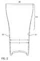
- Figures 1-3each show a double-walled container 10, 20, and 30, respectively, wherein the top portions 13, 23, and 33, respectively, of both the first container 11, 21, and 31, respectively, and the second container 12,22, and 32 respectively, have been expanded.
- the top edges of containers 11, 12, 21, 22, 31 and 32are curled.
- First container 11is interlocked with second container 12.
- First container 21is interlocked with second container 22.
- first container 31is interlocked with second container 32.
- Figures 4 and 5show containers after certain example manufacturing steps according to some embodiments of the invention.
- the first container 40 in step Astarted with a 53mm diameter.
- step Ba top portion 41 of the first container 40 had been expanded to a 57.4mm diameter.
- the expansionwas accomplished by using a the expansion die shown in Figure 7 .
- step Ca second container 42, having a 59mm diameter was provided.
- step Dthe first container 40 was placed inside the second container 42. A small clearance between the two containers prevented air from being trapped and compressed. Then, both containers were expanded together using a larger diameter expansion die shown in Figure 8 , by inserting the die into the partially expanded first container.
- the expansion die shown in Figure 8expanded the top portion of the partially expanded can an additional 0.059" (1.5mm) per side to a diameter of 60.4mm.
- the die travelwas adjusted to produce the desired length of expanded surface.
- a top portion 44 of both containerswas narrowed, via die necking without a knockout, to a diameter of 59mm.
- Step Fanother top portion of both containers was expanded.
- step Gtop edges of both containers were double seamed.
- step Aa first container 50, having a 53mm diameter, was provided.
- step Ba top portion 52 of the first container 50 was expanded.
- step Ca second container 51 having a 59mm diameter was provided.
- step Dthe first container 50 was placed inside the second container 51 and top portions of the first container 50 and the second container 51 were expanded together.
- step Etop portions of the first container 50 and the second container 51 were narrowed, via die necking without a knockout, to a diameter of 59mm.
- step Ftop edges of both containers 50 and 51 were curled outward.
- a lower or middle portion of the first and/or second containersmay be expanded and/or narrowed.
- a method of manufacturing a double-walled containercomprises providing a first container having a diameter X; providing a second container having a diameter Y, wherein the diameter Y is larger than the diameter X; inserting the first container into the second container; and narrowing a top portion of the second container.
- a knockoutis used in the narrowing process.
- the second containermay be necked, using a knockout, to a diameter just slightly larger than the first container, the first container is then placed inside the second container and then a knockout is placed inside the first container and both the first and second containers are necked together.
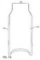
- Figure 16shows double-walled container 164 wherein the first container 165 and the second container 166 have been interlocked by narrowing both the first container and the second container.
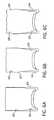
- Figures 6A-6Cshow the effects of steps in an interlocking process according to one embodiment of the invention.
- Figure 6Ashows a first container 63 resting inside a second container 64.
- a portion 65 of the first container 63has been expanded so that there is little clearance between the first container and the second container 64.
- a second portion 66 of the first container 63has been expanded along with a portion 67 of the second container 64.
- a second portion 69 of the second container 64has been narrowed along w/a third portion 68 of the first container 63. Through the expansion and narrowing processes, the first container 63 has been interlocked to the second container 64.
- the step of providing a second container having a diameter Ycomprises providing a second container having a diameter having a diameter Z and expanding the second container to the diameter Y.
- the diameter Zmay equal the diameter X, or Z may be a different diameter than X.
- the step of providing the first container having a diameter Xcomprises providing a first container having a diameter W and narrowing the first container to a diameter X.
- the diameter Wmay equal to the diameter Y or W may be a different diameter than Y.
- the sidewalls of the first and second containersare straight, i.e. have a substantially uniform diameter at the beginning of the process, as shown, for example, in Figures 4A, 4C , 5A and 5C .
- the sidewalls of the first and second containersare curved or tapered.
- the double-walled container shown in Figure 3could be manufactured with first and second containers having curved sidewalls.
- the dome 14 of the first container 11is not of a substantially similar size and/or shape of the dome 15 of the second container 12 so that the dome of the first container does not nest into the dome of the second container. This enhances the thermal insulating properties of the double-walled container 10.
- the non-nesting dome configurationcan be observed in Figures 1-3 .
- a gap 16lies between a portion of the first container and a portion of the second container.
- the width of the gap 16is about 0.080" to about 0.085" in some areas.
- the width of the gap 16is about 0.020" to about 0.040" is some areas, about 0.060" to about 0.080" in some areas, or about 0.020" to about 0.125" in some areas.
- the width of the gapis 0.080"
- the width of the gapis not uniform in some embodiments.
- this gap 16may be filled partially or completely with air or another insulating material. Any appropriate insulating material may be used.
- expanding the diameter X of a portion of the first containercomprises inserting an expansion die, examples of which are shown in Figures 7 and 8 , at least partially into the first container.
- the expansion diewhen the expansion die is inserted into the first container, the diameter Y of a portion of the second container is expanded also.
- at least one expansion dieis inserted into an open end of the first container to expand the diameter of the double-walled container.
- Another expansion diecan be inserted into the open end of the container to further expand the diameter of the container. This process can be repeated until the desired shape of the double-walled container is achieved. Examples of possible stages of expansion of the double-walled container can be seen in Figures 4 and 5 .
- the number of expansion dies used to expand the double-walled container to a desired diameter without significantly damaging the containeris dependent on the degree of expansion desired, the material of the container, the hardness of the material of the container, and the sidewall thickness of the container. For example, the higher the degree of expansion desired, the larger the number of expansion dies required. Similarly, if the metal comprising the container has a hard temper, a larger number of expansion dies will be required as compared to expanding a container comprised of a softer metal the same degree. Also, the thinner the sidewall, the greater number of expansion dies will be required. Further, when expanding a coated container, a gradual expansion will help to maintain the integrity of the coating. Alternatively, a container may be expanded before coating.
- the die 60 or 70is comprised of A2 tool steel, 58-60 Rc harden, 32 finish, although any suitable die material may be used.
- Initial portions 61 and 71 of the work surfaces 62 and 72 in the Figures 7 and 8respectively, have a geometry for gradually transitioning the diameter of the container sidewall.
- the work surfaces 62 and 72 of dies 60 and 70have dimensions and geometries that when inserted into the open end of a container work the container's sidewall to radially expand the container's diameter in a progressive manner as the container travels along the work surface.
- the expansion dieincludes a work surface, having a progressively expanding portion, a land portion, and a tapered portion transitioning to an undercut portion.
- the land portionhas dimensions and a geometry for setting the final diameter of the container being formed by that expansion die.
- the tapered portiontransitions from the land portion to the undercut portion.
- the diameter of the undercut portionis less than the diameter of the land portion.
- the undercut portionextends at least the length of the portion of the container being expanded minus the length of the land portion and the initial portion of the die. The undercut portion allows for springback and reduces the total contact area between the can and the die minimizing total forming loads.
- an expansion die not having a land or undercut portionis used.
- a container having the profile shown in Figure 1was expanded using a die not having a land portion or an undercut portion.
- a top edge of the first containeris curled.
- the curlingmay be done after first inserting an expansion die at least partially into the first container and expanding a top portion of the first container, and possibly the top portion of the second container also.
- the top edge of the second containeris curled also.
- the top edge of the second containeris curled over top of, or along with, the top edge of the first container.
- the top edge of the first containeris curled over top of, or along with, the top edge of the second container.
- the top edges of the first container and the second containerare flanged and seamed along with a closure or just the top edge of the first container is flanged and seamed along with a closure. Any appropriate flanging and seaming method may be used.
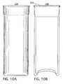
- An example of a double-walled container 100 having a flanged and seamed top edge 101 and closure 102can be seen in Figure 10 .
- the narrowingcan be accomplished via die necking, spin necking or any suitable method.
- the diameter of the narrowed portion of the double-walled containermay be less than, equal to, or greater than diameter X.
- the distance from the top edge of the double-walled container where it is narrowedis less than the distance from the top edge of the container where it is expanded.
- the double-walled containeris necked in several steps with several different necking dies. In other embodiments, the double-walled container is necked with only one necking die. Any appropriate necking die(s) known in the art may be used.
- the double-walled containermay be necked so that it takes the shape of a bottle or a beverage can.
- a portion of the containeris expanded until a desired shape is attained.
- the double-walled containercan be repeatedly necked and expanded until a desired shape is achieved.
- a double-walled container wherein the top portions of the first and second containers were interlocked by narrowing top portions of the first and second containersis shown in Figure 11 .
- the double-walled container 130 in Figure 11was narrowed using a necking die.
- the double-walled container 130has two expanded portions 131 and 132 separated by a necked in portion 133.
- the first containerhas a different height than the second container.
- the first container 134is taller than the second container 135.
- Figures 12A and 12Bshow another example of a double-walled container 120 wherein the first container 121 is taller than the second container 122. After the first container 121 was placed inside of the second container 122, both the first container and the second container were expanded then narrowed to interlock the first container and the second container. The top edge 123 of the second container 122 lies on the narrowed portion of the containers.
- the double-walled container 120 of Figure 12can be further processed to accept a closure or the top edge of the first container may be curled, for example.
- Figure 13shows yet another example of a double-walled container 136 wherein the first container 137 is taller than the second container 138. After the first container 137 was placed inside of the second container 138, both the first container and the second container were expanded then narrowed to interlock the first container and the second container. The top edge 139 of the second container can be seen in Figure 13 .
- the double-walled container 136 of Figure 13can be further processed to accept a closure or the top edge of the first container may be curled, for example.
- Necking an expanded double-walled container formed in accordance with some embodiments of the invention to a diameter greater than or equal to the first container's original diameter Xdoes not require the use of a knockout because the first container's sidewall is in a state of tension following expansion.
- a knockoutcan be used when necking the container.
- the open end of the double-walled containeris formed to accept a closure.
- Any appropriate method of forming to accept a closuremay be used including forming a flange, curl, thread, lug, attach an outsert and hem, or combinations thereof. Any appropriate method of threading or forming a lug may be used.
- Any suitable closuremay be used, including but not limited to, standard double-seamed end, full-panel easy-open food end, crown closure, plastic threaded closure, roll-on pilfer proof closure, lug cap, aerosol valve, or crimp closure.
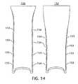
- the first container, the second container or both containersare ribbed, as shown in Figures 14 and 15 .
- Figure 14shows two exampled of double-walled containers 150 and 152 wherein the second or outside container has ribs 153.
- Figure 15shows two examples of double-walled containers 160 and 162 wherein the inside container has ribs 163.
- the containersmay be ribbed to establish points of contact 154 between the first container and the second container for rigidity and/or thermal transfer.
- a thin, hard metal in the inner containerfor example, a H19 or H39 temper, and a sidewall metal thickness of about 0.0038" to about 0.015
- ribs on the inner containerhelp to maintain the shape of the inner container..
- Figure 17shows the heat-up rate of a container outer sidewall starting from room temperature of a single walled container versus a double-walled container containing a fluid having a starting temperature of 166°F.
- Container F shown in Figure 4was the double-walled container used to measure thermal/insulating properties.
- Figure 18shows the warming rate of a fluid having an initial temperature of 39°F inside a single walled container versus a double-walled container at room temperature. After 45 minutes the fluid inside the single walled container warmed to 55°F. The fluid inside the double-walled container took 90 minutes to warm to 55°F.
- Container F shown in Figure 4was the double-walled container used to measure thermal/insulating properties.
- Embodiments of the inventionmay be used in conjunction with any container capable of being expanded and/or narrowed including but not limited to beverage, aerosol, and food containers.
- the first and second containers providedmay be manufactured via any suitable means, including, but not limited to, drawing, draw reverse draw, drawing and ironing, drawing and stretching, deep drawing, 3-piece seamed and impact extrusion.
- the containeris comprised of aluminum or steel.
- the aluminumcomprises an alloy, such as Aluminum Association 3104, 3004, 5042, 1060, 1070, steel alloys may also be used.
- the alloyhas a hard temper, such as H19 or H39. In other embodiments, a softer temper metal is used.
- a double-walled container manufactured in accordance with embodiments of the inventioncan take many shapes, such as pilsner or other drinking container, a beverage can, or a bottle.
Landscapes
- Engineering & Computer Science (AREA)
- Mechanical Engineering (AREA)
- Chemical & Material Sciences (AREA)
- Dispersion Chemistry (AREA)
- Rigid Containers With Two Or More Constituent Elements (AREA)
- Containers Having Bodies Formed In One Piece (AREA)
- Packages (AREA)
- Thermally Insulated Containers For Foods (AREA)
Description
- Beverage, food and aerosol containers are commonly comprised of metal. Metal containers may take several forms such as a drinking cup, can, bottle, or aerosol. Metal containers may be manufactured by several methods including: drawing, drawing and ironing, draw reverse draw, drawing and stretching, deep drawing, 3-piece seaming, and impact extrusion. Metal containers may be finished in many different ways including curling, flanging, threading, seaming, etc.
JP 2007 181863 - The present invention concerns a method of manufacturing a metal double-walled container according to
claim 1. Preferred embodiments are set out in the dependent claims 2-10. Figure 1 shows a cross-section of a double-walled container according to one embodiment.Figure 2 shows a cross-section of a double-walled container according to another embodiment.Figure 3 shows a cross-section of a double-walled container according to yet another embodiment.Figure 4 shows a series of containers after undergoing process steps in a series of process steps according to an embodiment of the invention.Figure 5 shows a series of containers after undergoing process steps in a series of process steps according to another embodiment of the invention.Figure 6A shows a partial cross-section of a first container inside a second container.Figure 6B shows a partial cross-section of a double-walled container according to one embodiment of the invention.Figure 6C shows a partial cross-section of a double-walled container according to another embodiment of the invention.Figure 7A shows a top view of an expansion die used to manufacture the double-walled container ofFigure 4B .Figure 7B shows a cross-section along line A-A view of the expansion die ofFigure 7A .- Figure SA shows a top view of an expansion die used to manufacture the double-walled container of
Figure 4D . - Figure SB shows a cross-section along line A-A of the expansion die of
Figure 8A . Figure 9A illustrates a top view of a double-walled container according to yet another embodiment.Figure 9B illustrates a cross-section along line A-A of the double-walled container ofFigure 9A .Figure 9C illustrates a partial cross-section along line A-A of the double-walled container of Figure of 9A.Figure 10A shows a side view of a double-walled container according to a further embodiment.Figure 10B depicts a cross-section along line A-A of the double-walled container ofFigure 10A .Figure 10C shows a partial cross-section along line A-A of the double-walled container ofFigure 10A .Figure 10D illustrates a partial side view of the double-walled container ofFigure 10A .Figure 11A shows a side view of a double-walled container according to yet a further embodiment of the invention.Figure 11B depicts a cross-section along line A-A of the double-walled container ofFigure 11A .Figure 11C shows a partial side view of the double-walled container ofFigure 11A .Figure 11D illustrates a partial cross-section along line A-A of the double-walled container ofFigure 11A .Figure 12A depicts a double-walled container according to another embodiment of the invention.Figure 12B shows a partial close up view of the double-walled container ofFigure 12A .Figure 13 illustrates a partial cross-section view of a double-walled container according to yet a further embodiment of the invention.Figure 14 depicts two examples of double-walled containers according to embodiments wherein the outside wall of each of the double-walled containers is ribbed.Figure 15 depicts two examples of double-walled-containers according to embodiments wherein the inside wall of each of the double-walled containers is ribbed.Figure 16 shows a partial cross-section view of yet a further embodimentFigure 17 is a graph showing the heat up rate of the side-wall of a double-walled container vs. the side-wall of a single-walled container.Figure 18 is a graph showing the heat up rate of water in a double-walled container vs. water in a single-walled container.- In the following detailed description of the preferred embodiments, reference is made to the accompanying drawings which form a part hereof, and in which are shown by way of illustration specific embodiments in which the invention may be practiced. It is to be understood that other embodiments may be utilized and structural changes may be made without departing from the scope of the present invention.
- In one embodiment of the invention, a method of manufacturing a double-walled container comprises providing a first container having a diameter X; providing a second container having a diameter Y, wherein the diameter Y is larger than the diameter X; inserting the first container into the second container; and interlocking the first container and the second container so that the first and second containers form a single double-walled container. Interlocking the first container and the second container means securing the first container at least partially inside of the second container to prevent axial movement of the first container relative to the second container. When the containers are interlocked, they still may rotate relative to one another. The first container does not need to be completely encompassed by the second container as will be shown in certain examples herein.
- In some embodiments, interlocking the first container and the second container may comprise expanding the diameter X of a portion of the first container and narrowing a portion of the second container along with an expanded portion of the first container. In some embodiments, the portion of the second and/or first container that is narrowed is a smaller portion than the portion that had been expanded. In some embodiments interlocking the first container and the second container may comprise expanding the diameter X of a portion of the first container and curling or seaming the top edges of both containers or of the first container. Any other appropriate methods of finishing the edges or forming the opening of the double-walled container to accept a closure may be used.
- In some embodiments, interlocking the first container and the second container comprises narrowing the diameter Y of a portion of the second container and curling or seaming the top edges of both containers or of the first container. In some embodiments, interlocking the first container and the second container comprises narrowing the diameter Y of a portion of the second container and narrowing the diameter X of a portion of the first container.
- Three examples of double-walled containers are shown in
Figures 1-3. Figures 1-3 each show a double-walled container top portions first container second container containers First container 11 is interlocked withsecond container 12.First container 21 is interlocked withsecond container 22. And,first container 31 is interlocked withsecond container 32. Figures 4 and5 show containers after certain example manufacturing steps according to some embodiments of the invention. Referring toFigure 4 , thefirst container 40 in step A started with a 53mm diameter. In step B, atop portion 41 of thefirst container 40 had been expanded to a 57.4mm diameter. The expansion was accomplished by using a the expansion die shown inFigure 7 . In step C, asecond container 42, having a 59mm diameter was provided. In step D, thefirst container 40 was placed inside thesecond container 42. A small clearance between the two containers prevented air from being trapped and compressed. Then, both containers were expanded together using a larger diameter expansion die shown inFigure 8 , by inserting the die into the partially expanded first container. The expansion die shown inFigure 8 expanded the top portion of the partially expanded can an additional 0.059" (1.5mm) per side to a diameter of 60.4mm. The die travel was adjusted to produce the desired length of expanded surface. In step E, atop portion 44 of both containers was narrowed, via die necking without a knockout, to a diameter of 59mm. In Step F, another top portion of both containers was expanded. In step G, top edges of both containers were double seamed.- Referring now to
Figure 5 , in step A, afirst container 50, having a 53mm diameter, was provided. In step B, atop portion 52 of thefirst container 50 was expanded. In step C, asecond container 51 having a 59mm diameter was provided. In step D, thefirst container 50 was placed inside thesecond container 51 and top portions of thefirst container 50 and thesecond container 51 were expanded together. In step E, top portions of thefirst container 50 and thesecond container 51 were narrowed, via die necking without a knockout, to a diameter of 59mm. In step F, top edges of bothcontainers - In other embodiments, a lower or middle portion of the first and/or second containers may be expanded and/or narrowed.
- In another embodiment, a method of manufacturing a double-walled container comprises providing a first container having a diameter X; providing a second container having a diameter Y, wherein the diameter Y is larger than the diameter X; inserting the first container into the second container; and narrowing a top portion of the second container. In some embodiments in which the second container is narrowed a knockout is used in the narrowing process. In some embodiments, the second container may be necked, using a knockout, to a diameter just slightly larger than the first container, the first container is then placed inside the second container and then a knockout is placed inside the first container and both the first and second containers are necked together.
Figure 16 shows double-walled container 164 wherein thefirst container 165 and thesecond container 166 have been interlocked by narrowing both the first container and the second container. Figures 6A-6C show the effects of steps in an interlocking process according to one embodiment of the invention.Figure 6A shows afirst container 63 resting inside asecond container 64. Aportion 65 of thefirst container 63 has been expanded so that there is little clearance between the first container and thesecond container 64. InFigure 6B , asecond portion 66 of thefirst container 63 has been expanded along with aportion 67 of thesecond container 64. InFigure 6C , asecond portion 69 of thesecond container 64 has been narrowed along w/athird portion 68 of thefirst container 63. Through the expansion and narrowing processes, thefirst container 63 has been interlocked to thesecond container 64.- In some embodiments, the step of providing a second container having a diameter Y comprises providing a second container having a diameter having a diameter Z and expanding the second container to the diameter Y. The diameter Z may equal the diameter X, or Z may be a different diameter than X. In some embodiments the step of providing the first container having a diameter X comprises providing a first container having a diameter W and narrowing the first container to a diameter X. The diameter W may equal to the diameter Y or W may be a different diameter than Y.
- In some embodiments, the sidewalls of the first and second containers are straight, i.e. have a substantially uniform diameter at the beginning of the process, as shown, for example, in
Figures 4A, 4C ,5A and 5C . In some embodiments, the sidewalls of the first and second containers are curved or tapered. For example, the double-walled container shown inFigure 3 could be manufactured with first and second containers having curved sidewalls. - Referring now to
Figure 1 , in some embodiments, thedome 14 of thefirst container 11 is not of a substantially similar size and/or shape of thedome 15 of thesecond container 12 so that the dome of the first container does not nest into the dome of the second container. This enhances the thermal insulating properties of the double-walled container 10. The non-nesting dome configuration can be observed inFigures 1-3 . - As can be seen in
Figure 1 , agap 16 lies between a portion of the first container and a portion of the second container. In some embodiments, the width of thegap 16 is about 0.080" to about 0.085" in some areas. In other embodiments, the width of thegap 16 is about 0.020" to about 0.040" is some areas, about 0.060" to about 0.080" in some areas, or about 0.020" to about 0.125" in some areas. When the width of the gap is 0.080", there is a 0.160" difference in diameter between the first (inner) container and the second (outer) container. As can be observed in the figures, the width of the gap is not uniform in some embodiments. In some embodiments, thisgap 16 may be filled partially or completely with air or another insulating material. Any appropriate insulating material may be used. - In some embodiments, expanding the diameter X of a portion of the first container comprises inserting an expansion die, examples of which are shown in
Figures 7 and8 , at least partially into the first container. In some embodiments, when the expansion die is inserted into the first container, the diameter Y of a portion of the second container is expanded also. In some embodiments, at least one expansion die is inserted into an open end of the first container to expand the diameter of the double-walled container. Another expansion die can be inserted into the open end of the container to further expand the diameter of the container. This process can be repeated until the desired shape of the double-walled container is achieved. Examples of possible stages of expansion of the double-walled container can be seen inFigures 4 and5 . - The number of expansion dies used to expand the double-walled container to a desired diameter without significantly damaging the container is dependent on the degree of expansion desired, the material of the container, the hardness of the material of the container, and the sidewall thickness of the container. For example, the higher the degree of expansion desired, the larger the number of expansion dies required. Similarly, if the metal comprising the container has a hard temper, a larger number of expansion dies will be required as compared to expanding a container comprised of a softer metal the same degree. Also, the thinner the sidewall, the greater number of expansion dies will be required. Further, when expanding a coated container, a gradual expansion will help to maintain the integrity of the coating. Alternatively, a container may be expanded before coating.
- Referring again to expansion dies 60 and 70 of
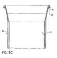
Figures 7 and8 , respectively, in some embodiments, the die 60 or 70 is comprised of A2 tool steel, 58-60 Rc harden, 32 finish, although any suitable die material may be used.Initial portions Figures 7 and8 , respectively, have a geometry for gradually transitioning the diameter of the container sidewall. The work surfaces 62 and 72 of dies 60 and 70 have dimensions and geometries that when inserted into the open end of a container work the container's sidewall to radially expand the container's diameter in a progressive manner as the container travels along the work surface. In some embodiments, the expansion die includes a work surface, having a progressively expanding portion, a land portion, and a tapered portion transitioning to an undercut portion. In some embodiments, the land portion has dimensions and a geometry for setting the final diameter of the container being formed by that expansion die. In some embodiments, the tapered portion transitions from the land portion to the undercut portion. In some embodiments, the diameter of the undercut portion is less than the diameter of the land portion. In some embodiments, the undercut portion extends at least the length of the portion of the container being expanded minus the length of the land portion and the initial portion of the die. The undercut portion allows for springback and reduces the total contact area between the can and the die minimizing total forming loads. In some embodiments, when only a small top portion of a container is being expanded, an expansion die not having a land or undercut portion is used. For example, a container having the profile shown inFigure 1 was expanded using a die not having a land portion or an undercut portion. - In some embodiments, a top edge of the first container is curled. In some embodiments, the curling may be done after first inserting an expansion die at least partially into the first container and expanding a top portion of the first container, and possibly the top portion of the second container also. In some embodiments the top edge of the second container is curled also. In some embodiments, when the curl is toward the inside of the double-walled container, the top edge of the second container is curled over top of, or along with, the top edge of the first container. In some embodiments, when the curl is toward the outside of the double-walled container, the top edge of the first container is curled over top of, or along with, the top edge of the second container. An example of a curl on the double-walled container can be seen in
Figures 9A-9C . InFigure 9C ,top edges first container 81 and thesecond container 82 are curled outward. - In some embodiments, the top edges of the first container and the second container are flanged and seamed along with a closure or just the top edge of the first container is flanged and seamed along with a closure. Any appropriate flanging and seaming method may be used. An example of a double-
walled container 100 having a flanged and seamedtop edge 101 andclosure 102 can be seen inFigure 10 . - In some embodiments, wherein a portion of the first and/or second containers is narrowed the narrowing can be accomplished via die necking, spin necking or any suitable method. The diameter of the narrowed portion of the double-walled container may be less than, equal to, or greater than diameter X. In some embodiments, the distance from the top edge of the double-walled container where it is narrowed is less than the distance from the top edge of the container where it is expanded. In some embodiments, the double-walled container is necked in several steps with several different necking dies. In other embodiments, the double-walled container is necked with only one necking die. Any appropriate necking die(s) known in the art may be used. In some embodiments the double-walled container may be necked so that it takes the shape of a bottle or a beverage can. In some embodiments, after the double-walled container is narrowed, a portion of the container is expanded until a desired shape is attained. The double-walled container can be repeatedly necked and expanded until a desired shape is achieved. A double-walled container wherein the top portions of the first and second containers were interlocked by narrowing top portions of the first and second containers is shown in
Figure 11 . The double-walled container 130 inFigure 11 was narrowed using a necking die. The double-walled container 130 has two expandedportions portion 133. - In some embodiments the first container has a different height than the second container. In
Figure 11 , thefirst container 134 is taller than thesecond container 135. Figures 12A and 12B show another example of a double-walled container 120 wherein thefirst container 121 is taller than thesecond container 122. After thefirst container 121 was placed inside of thesecond container 122, both the first container and the second container were expanded then narrowed to interlock the first container and the second container. Thetop edge 123 of thesecond container 122 lies on the narrowed portion of the containers. The double-walled container 120 ofFigure 12 can be further processed to accept a closure or the top edge of the first container may be curled, for example.Figure 13 shows yet another example of a double-walled container 136 wherein thefirst container 137 is taller than thesecond container 138. After thefirst container 137 was placed inside of thesecond container 138, both the first container and the second container were expanded then narrowed to interlock the first container and the second container. Thetop edge 139 of the second container can be seen inFigure 13 . The double-walled container 136 ofFigure 13 can be further processed to accept a closure or the top edge of the first container may be curled, for example.- Necking an expanded double-walled container formed in accordance with some embodiments of the invention to a diameter greater than or equal to the first container's original diameter X does not require the use of a knockout because the first container's sidewall is in a state of tension following expansion. In some embodiments, a knockout can be used when necking the container.
- In some embodiments, following the final expansion or necking step, the open end of the double-walled container is formed to accept a closure. Any appropriate method of forming to accept a closure may be used including forming a flange, curl, thread, lug, attach an outsert and hem, or combinations thereof. Any appropriate method of threading or forming a lug may be used. Any suitable closure may be used, including but not limited to, standard double-seamed end, full-panel easy-open food end, crown closure, plastic threaded closure, roll-on pilfer proof closure, lug cap, aerosol valve, or crimp closure.
- In some embodiments, the first container, the second container or both containers are ribbed, as shown in
Figures 14 and15 .Figure 14 shows two exampled of double-walled containers ribs 153.Figure 15 shows two examples of double-walled containers ribs 163. The containers may be ribbed to establish points ofcontact 154 between the first container and the second container for rigidity and/or thermal transfer. In one embodiment, when using a thin, hard metal in the inner container, for example, a H19 or H39 temper, and a sidewall metal thickness of about 0.0038" to about 0.015", ribs on the inner container help to maintain the shape of the inner container.. Figure 17 shows the heat-up rate of a container outer sidewall starting from room temperature of a single walled container versus a double-walled container containing a fluid having a starting temperature of 166°F. Container F shown inFigure 4 was the double-walled container used to measure thermal/insulating properties.Figure 18 shows the warming rate of a fluid having an initial temperature of 39°F inside a single walled container versus a double-walled container at room temperature. After 45 minutes the fluid inside the single walled container warmed to 55°F. The fluid inside the double-walled container took 90 minutes to warm to 55°F. Container F shown inFigure 4 was the double-walled container used to measure thermal/insulating properties.- Embodiments of the invention may be used in conjunction with any container capable of being expanded and/or narrowed including but not limited to beverage, aerosol, and food containers. The first and second containers provided may be manufactured via any suitable means, including, but not limited to, drawing, draw reverse draw, drawing and ironing, drawing and stretching, deep drawing, 3-piece seamed and impact extrusion. In some embodiments, the container is comprised of aluminum or steel. In some embodiments, the aluminum comprises an alloy, such as Aluminum Association 3104, 3004, 5042, 1060, 1070, steel alloys may also be used. In some embodiments, the alloy has a hard temper, such as H19 or H39. In other embodiments, a softer temper metal is used.
- A double-walled container manufactured in accordance with embodiments of the invention can take many shapes, such as pilsner or other drinking container, a beverage can, or a bottle.
Claims (10)
- A method of manufacturing a metal double-walled container (10) comprising:providing a first metal container (11, 21, 31, 40, 50, 63, 81, 121, 134, 137) having a diameter X;providing a second metal container (12, 22, 32, 42, 51, 64, 82, 122, 135, 138) having a diameter Y, wherein the diameter Y is larger than the diameter X;inserting the first metal container (11 ... 137) into the second metal container (12 ... 138); andinterlocking the first metal container (11 ... 137) and the second metal container (12 ... 138) so that a gap (16) lies between a first portion of the first metal container (11 ... 137) and a first portion of the second metal container (12 ... 138);wherein interlocking the first metal container (11 ... 137) and the second metal container (12 ... 138) comprises inserting an expansion die into the first metal container in order to expand the diameter X of a second portion (66) of the first metal container (11 ... 137) along with a portion (67) of the second metal container (12 ... 138) and narrowing the diameter Y of a second portion (69) of the second metal container (12 ... 138) along with a third portion (68) of the first metal container (11 ... 137) so as to interlock the first metal container (11 ... 137) and the second metal container (12 ... 138).
- The method of Claim 1 wherein the diameter X of the second portion of the first metal container (11 ... 137) is expanded prior to narrowing the diameter Y of the second portion of the second metal container (12 ... 138).
- The method of Claim 1 or 2 wherein, as the diameter X of the second portion of the first metal container (11... 137) is expanded, a portion of the second metal container (12... 138) is also expanded.
- The method of any of the preceding Claims wherein, as the diameter Y of the second portion of the second metal container (12 ... 138) is narrowed, a second portion of the first metal container (11 ... 137) is also narrowed.
- The method of Claim 1 further comprising the step of narrowing an opening of the double-walled container (10) to accept a closure.
- The method of Claim 1 wherein the first metal container (11 ... 137) and/or the second metal container (12 ... 138) have ribs (153, 163); or
wherein the first and the second metal containers each have a height and the height of the first metal container (11 ... 137) is taller than the height of the second metal container (12 ... 138). - The method of Claim 1 wherein the diameters of the second portion of the first metal container (11 ... 137) and the diameter of the second portion of the second metal container (12 ... 138) are expanded together prior to narrowing the diameter Y of the second portion of the second metal container (12 ... 138); and
wherein the method further comprises the step of finishing a top edge of the first container so as to interlock the first metal container (11 ... 137) and the second metal container (12 ... 138) so that a gap (16) lies between a first portion of the first metal container (11 ... 137) and a first portion of the second metal container (12 ... 138). - The method of Claim 1 wherein the diameter Y of a second portion of the second metal container (12 ... 138) is necked until at least the second portion of the second metal container (12 ... 138) makes contact with a second portion of the first metal container (11 ... 137); and
wherein the method further comprises the step of necking the diameters of the second portion of the first metal container (11 ... 137) and the diameter of the second portion of the second metal container (12 ... 138) together, and the step of finishing a top edge of the first container so as to interlock the first metal container (11 ... 137) and the second metal container (12 ... 138) so that a gap (16) lies between a first portion of the first metal container (11 ... 137) and a first portion of the second metal container (12 ... 138). - The method of Claim 7 or 8 wherein finishing a top edge includes one of curling or double seaming.
- The method of Claim 1 wherein the diameter Y of a second portion of the second metal container (12 ... 138) is narrowed until at least the second portion of the second metal container (12 ... 138) makes contact with a second portion of the first metal container (11 ... 137).
Priority Applications (1)
| Application Number | Priority Date | Filing Date | Title |
|---|---|---|---|
| PL09771197TPL2323924T3 (en) | 2008-06-26 | 2009-06-26 | Double-walled container and method of manufacture |
Applications Claiming Priority (2)
| Application Number | Priority Date | Filing Date | Title |
|---|---|---|---|
| US7597708P | 2008-06-26 | 2008-06-26 | |
| PCT/US2009/048941WO2009158666A1 (en) | 2008-06-26 | 2009-06-26 | Double-walled container and method of manufacture |
Publications (2)
| Publication Number | Publication Date |
|---|---|
| EP2323924A1 EP2323924A1 (en) | 2011-05-25 |
| EP2323924B1true EP2323924B1 (en) | 2016-01-13 |
Family
ID=41228454
Family Applications (1)
| Application Number | Title | Priority Date | Filing Date |
|---|---|---|---|
| EP09771197.2ANot-in-forceEP2323924B1 (en) | 2008-06-26 | 2009-06-26 | Double-walled container and method of manufacture |
Country Status (15)
| Country | Link |
|---|---|
| US (1) | US8132687B2 (en) |
| EP (1) | EP2323924B1 (en) |
| JP (1) | JP5296203B2 (en) |
| KR (1) | KR101693897B1 (en) |
| CN (1) | CN102076575B (en) |
| AU (1) | AU2009261974B2 (en) |
| BR (1) | BRPI0914592A2 (en) |
| CA (2) | CA2933974A1 (en) |
| DK (1) | DK2323924T3 (en) |
| ES (1) | ES2566345T3 (en) |
| MX (1) | MX2010013556A (en) |
| PL (1) | PL2323924T3 (en) |
| RU (1) | RU2509701C2 (en) |
| WO (1) | WO2009158666A1 (en) |
| ZA (1) | ZA201100555B (en) |
Families Citing this family (34)
| Publication number | Priority date | Publication date | Assignee | Title |
|---|---|---|---|---|
| TR200400866T4 (en) | 2001-01-30 | 2004-06-21 | Seda S.P.A | Cardboard beverage container and method for producing it |
| BRPI0601188B1 (en) | 2005-04-15 | 2018-06-26 | Seda S.P.A. | ISOLATED CONTAINER; METHOD OF MANUFACTURING THE SAME AND APPARATUS FOR MANUFACTURING |
| DE202005014177U1 (en) | 2005-09-08 | 2005-11-17 | Seda S.P.A., Arzano | Double-walled beaker comprises an inner wall formed by an inner beaker which is made of a fluid-tight plastic material, and is releasably inserted into an outer beaker forming the outer wall |
| DE202005014738U1 (en) | 2005-09-19 | 2007-02-08 | Seda S.P.A., Arzano | Container and cut |
| PT1785370E (en) | 2005-11-11 | 2008-06-06 | Seda Spa | Insulated cup |
| EP1785265A1 (en) | 2005-11-14 | 2007-05-16 | SEDA S.p.A. | Device for producing a stacking projection on a container wall and container with same |
| DE202006018406U1 (en) | 2006-12-05 | 2008-04-10 | Seda S.P.A. | packaging |
| US8448810B2 (en)* | 2007-01-12 | 2013-05-28 | Millercoors, Llc | Double walled beverage container and method of making same |
| US8464891B2 (en) | 2009-04-30 | 2013-06-18 | Merissa Beth Pico | Hot/cold container and lid |
| EA025944B1 (en)* | 2010-08-20 | 2017-02-28 | Алкоа Инк. | Shaped metal container and method for making same |
| US8757404B1 (en)* | 2011-01-14 | 2014-06-24 | William Fleckenstein | Combination beverage container and golf ball warmer |
| US9663846B2 (en) | 2011-09-16 | 2017-05-30 | Ball Corporation | Impact extruded containers from recycled aluminum scrap |
| CA2990040C (en) | 2013-04-09 | 2021-07-20 | Ball Corporation | Aluminum impact extruded bottle with threaded neck made from recycled aluminum and enhanced alloys |
| US9290312B2 (en) | 2013-08-14 | 2016-03-22 | Dart Container Corporation | Double-walled container |
| JP6177752B2 (en)* | 2014-11-14 | 2017-08-09 | 象印マホービン株式会社 | Beverage container |
| US10695897B2 (en) | 2015-12-18 | 2020-06-30 | Dyln Inc. | Fluid container diffuser system and related method of use |
| US20180044155A1 (en) | 2016-08-12 | 2018-02-15 | Ball Corporation | Apparatus and Methods of Capping Metallic Bottles |
| US11375852B2 (en) | 2016-10-25 | 2022-07-05 | Alan Mark Crawley | Method and apparatus for producing double-walled containers |
| AU2016433840B2 (en) | 2016-12-30 | 2020-10-15 | Ball Corporation | Aluminum alloy for impact extruded containers and method of making the same |
| EP3583043A4 (en) | 2017-02-16 | 2021-04-14 | Ball Corporation | Apparatus and methods of forming and applying roll-on pilfer proof closures on the threaded neck of metal containers |
| USD817000S1 (en) | 2017-03-08 | 2018-05-08 | Filip Sedic | Toothbrush |
| DE102017120822B4 (en)* | 2017-09-08 | 2023-03-16 | Jochen Schomber | Beverage cup with insulating container |
| MX2020002563A (en) | 2017-09-15 | 2020-07-13 | Ball Corp | System and method of forming a metallic closure for a threaded container. |
| KR101828944B1 (en)* | 2017-10-23 | 2018-03-29 | 주식회사 한일케미텍 | Chemicals Storage Tank |
| KR102025629B1 (en) | 2017-12-20 | 2019-09-26 | 주식회사 포스코 | Inspection apparatus for fluorine of sample and inspection method using the same |
| USD891184S1 (en) | 2018-10-09 | 2020-07-28 | Dyln Inc. | Water bottle |
| US20200107667A1 (en)* | 2018-10-09 | 2020-04-09 | Dyln Lifestyle, LLC | Contoured double walled fluid container with internal compartment |
| DE102019108838B4 (en)* | 2019-04-04 | 2021-01-28 | MATO Interpraesent GmbH | Insulating mug |
| US11779156B2 (en)* | 2021-02-12 | 2023-10-10 | Sprogo Llc | Reusable beverage container assembly |
| JP2022137003A (en)* | 2021-03-08 | 2022-09-21 | アルテミラ製缶株式会社 | METHOD OF MANUFACTURING A METAL CUP |
| MX2023011782A (en)* | 2021-04-08 | 2023-10-11 | Novelis Inc | Primary beverage container with temperature control. |
| JP2023064975A (en)* | 2021-10-27 | 2023-05-12 | アルテミラ製缶株式会社 | Metallic cup manufacturing method |
| USD1025715S1 (en) | 2022-02-02 | 2024-05-07 | Dyln Inc. | Water bottle |
| US12291371B2 (en) | 2022-02-04 | 2025-05-06 | Ball Corporation | Method for forming a curl and a threaded metallic container including the same |
Citations (1)
| Publication number | Priority date | Publication date | Assignee | Title |
|---|---|---|---|---|
| JP2007181863A (en)* | 2006-01-06 | 2007-07-19 | Toyo Seikan Kaisha Ltd | Method for manufacturing duplex structure formed body, and duplex structure formed body |
Family Cites Families (22)
| Publication number | Priority date | Publication date | Assignee | Title |
|---|---|---|---|---|
| US2186338A (en)* | 1936-11-04 | 1940-01-09 | Clark Mfg Co J L | Metallic container |
| US2863585A (en)* | 1956-02-06 | 1958-12-09 | Meshberg Philip | Insulated tumbler |
| US3065875A (en)* | 1960-02-19 | 1962-11-27 | Continental Can Co | Plastic snap-on reclosure cover |
| US3456860A (en)* | 1968-01-09 | 1969-07-22 | Illinois Tool Works | Double wall cup |
| US4333581A (en)* | 1980-08-19 | 1982-06-08 | Henry H. Howard | Multi-compartment container with pop-top and communicating door |
| US5497900A (en)* | 1982-12-27 | 1996-03-12 | American National Can Company | Necked container body |
| US4548348A (en)* | 1984-02-27 | 1985-10-22 | Solo Cup Company | Disposable cup assembly |
| EP0196327A4 (en)* | 1984-10-03 | 1988-06-27 | Nat Can Corp | Domer assembly for forming container end wall. |
| JPH03254322A (en)* | 1990-03-02 | 1991-11-13 | Furukawa Alum Co Ltd | Manufacture of multiple can for drink |
| US5335813A (en)* | 1992-12-02 | 1994-08-09 | Hao Qi | Double-vessel can |
| JP2832702B2 (en)* | 1996-08-08 | 1998-12-09 | 株式会社三五 | Double pipe manufacturing method |
| JP3441317B2 (en)* | 1996-10-21 | 2003-09-02 | 大和製罐株式会社 | Method for producing deformed metal can having irregular pattern on body |
| JP3049220B2 (en)* | 1997-05-07 | 2000-06-05 | 日本酸素株式会社 | Method for producing synthetic resin double-walled thermal insulation |
| NL1008077C2 (en)* | 1998-01-21 | 1999-07-22 | Hoogovens Staal Bv | Method for the manufacture of a metal can with insert for packaging, for example, a foodstuff and such a can. |
| JP2001025441A (en)* | 1999-07-13 | 2001-01-30 | Tiger Vacuum Bottle Co Ltd | Metal vacuum double container and method of manufacturing the same |
| JP2001123431A (en) | 1999-10-29 | 2001-05-08 | Shinichiro Hayashi | Water channel provided with overflow preventing function |
| NL1019586C2 (en)* | 2001-12-17 | 2003-06-18 | Rpc Packaging Holdings B V | Double-walled cup and method for the manufacture thereof. |
| JP2004276921A (en)* | 2003-03-12 | 2004-10-07 | Guritto:Kk | Heat insulating cup with lid |
| JP2005096794A (en)* | 2003-09-24 | 2005-04-14 | Hosokawa Yoko Co Ltd | Container for liquid, and double can |
| DE602004026642D1 (en)* | 2004-02-10 | 2010-05-27 | Fuji Seal Int Inc | heat insulation vessel |
| JP4962699B2 (en)* | 2006-01-06 | 2012-06-27 | 東洋製罐株式会社 | Equipment for manufacturing double structure molded bodies |
| US7934410B2 (en)* | 2006-06-26 | 2011-05-03 | Alcoa Inc. | Expanding die and method of shaping containers |
- 2009
- 2009-06-26KRKR1020117001917Apatent/KR101693897B1/ennot_activeExpired - Fee Related
- 2009-06-26BRBRPI0914592Apatent/BRPI0914592A2/ennot_activeApplication Discontinuation
- 2009-06-26CACA2933974Apatent/CA2933974A1/ennot_activeAbandoned
- 2009-06-26AUAU2009261974Apatent/AU2009261974B2/ennot_activeCeased
- 2009-06-26DKDK09771197.2Tpatent/DK2323924T3/enactive
- 2009-06-26PLPL09771197Tpatent/PL2323924T3/enunknown
- 2009-06-26MXMX2010013556Apatent/MX2010013556A/enactiveIP Right Grant
- 2009-06-26WOPCT/US2009/048941patent/WO2009158666A1/enactiveApplication Filing
- 2009-06-26USUS12/492,963patent/US8132687B2/enactiveActive
- 2009-06-26EPEP09771197.2Apatent/EP2323924B1/ennot_activeNot-in-force
- 2009-06-26CACA2728678Apatent/CA2728678C/ennot_activeExpired - Fee Related
- 2009-06-26ESES09771197.2Tpatent/ES2566345T3/enactiveActive
- 2009-06-26RURU2011102771/12Apatent/RU2509701C2/ennot_activeIP Right Cessation
- 2009-06-26JPJP2011516732Apatent/JP5296203B2/ennot_activeExpired - Fee Related
- 2009-06-26CNCN200980123831.5Apatent/CN102076575B/ennot_activeExpired - Fee Related
- 2011
- 2011-01-21ZAZA2011/00555Apatent/ZA201100555B/enunknown
Patent Citations (1)
| Publication number | Priority date | Publication date | Assignee | Title |
|---|---|---|---|---|
| JP2007181863A (en)* | 2006-01-06 | 2007-07-19 | Toyo Seikan Kaisha Ltd | Method for manufacturing duplex structure formed body, and duplex structure formed body |
Also Published As
| Publication number | Publication date |
|---|---|
| AU2009261974A2 (en) | 2011-01-20 |
| AU2009261974B2 (en) | 2015-09-24 |
| KR20110031480A (en) | 2011-03-28 |
| RU2509701C2 (en) | 2014-03-20 |
| CA2933974A1 (en) | 2009-12-30 |
| CN102076575B (en) | 2014-07-30 |
| EP2323924A1 (en) | 2011-05-25 |
| MX2010013556A (en) | 2011-02-15 |
| AU2009261974A1 (en) | 2009-12-30 |
| US8132687B2 (en) | 2012-03-13 |
| DK2323924T3 (en) | 2016-04-18 |
| KR101693897B1 (en) | 2017-01-06 |
| CA2728678C (en) | 2016-10-11 |
| JP2011526232A (en) | 2011-10-06 |
| CA2728678A1 (en) | 2009-12-30 |
| CN102076575A (en) | 2011-05-25 |
| PL2323924T3 (en) | 2016-08-31 |
| BRPI0914592A2 (en) | 2015-12-22 |
| ZA201100555B (en) | 2014-04-30 |
| RU2011102771A (en) | 2012-08-10 |
| US20090321440A1 (en) | 2009-12-31 |
| ES2566345T3 (en) | 2016-04-12 |
| JP5296203B2 (en) | 2013-09-25 |
| WO2009158666A1 (en) | 2009-12-30 |
Similar Documents
| Publication | Publication Date | Title |
|---|---|---|
| EP2323924B1 (en) | Double-walled container and method of manufacture | |
| AU2007265132B2 (en) | Method of manufacturing containers | |
| US10464707B2 (en) | Shaped metal container and method for making same | |
| CA2858094C (en) | Method for expanding the diameter of a metal container | |
| US20100107718A1 (en) | Necking die with redraw surface and method of die necking | |
| US20230302517A1 (en) | Tapered cup and method of forming the same | |
| CN116634908A (en) | Conical cup and method of forming same | |
| NZ625920B2 (en) | Method for expanding the diameter of a metal container |
Legal Events
| Date | Code | Title | Description |
|---|---|---|---|
| PUAI | Public reference made under article 153(3) epc to a published international application that has entered the european phase | Free format text:ORIGINAL CODE: 0009012 | |
| 17P | Request for examination filed | Effective date:20110124 | |
| AK | Designated contracting states | Kind code of ref document:A1 Designated state(s):AT BE BG CH CY CZ DE DK EE ES FI FR GB GR HR HU IE IS IT LI LT LU LV MC MK MT NL NO PL PT RO SE SI SK TR | |
| AX | Request for extension of the european patent | Extension state:AL BA RS | |
| DAX | Request for extension of the european patent (deleted) | ||
| 17Q | First examination report despatched | Effective date:20120430 | |
| GRAP | Despatch of communication of intention to grant a patent | Free format text:ORIGINAL CODE: EPIDOSNIGR1 | |
| INTG | Intention to grant announced | Effective date:20150716 | |
| RIN1 | Information on inventor provided before grant (corrected) | Inventor name:DICK, ROBERT, E. Inventor name:FEDUSA, ANTHONY, J. Inventor name:BOYSEL, DARL, G. | |
| GRAS | Grant fee paid | Free format text:ORIGINAL CODE: EPIDOSNIGR3 | |
| GRAA | (expected) grant | Free format text:ORIGINAL CODE: 0009210 | |
| AK | Designated contracting states | Kind code of ref document:B1 Designated state(s):AT BE BG CH CY CZ DE DK EE ES FI FR GB GR HR HU IE IS IT LI LT LU LV MC MK MT NL NO PL PT RO SE SI SK TR | |
| REG | Reference to a national code | Ref country code:GB Ref legal event code:FG4D | |
| REG | Reference to a national code | Ref country code:CH Ref legal event code:EP | |
| REG | Reference to a national code | Ref country code:IE Ref legal event code:FG4D | |
| REG | Reference to a national code | Ref country code:AT Ref legal event code:REF Ref document number:770344 Country of ref document:AT Kind code of ref document:T Effective date:20160215 | |
| REG | Reference to a national code | Ref country code:DE Ref legal event code:R096 Ref document number:602009035859 Country of ref document:DE | |
| REG | Reference to a national code | Ref country code:ES Ref legal event code:FG2A Ref document number:2566345 Country of ref document:ES Kind code of ref document:T3 Effective date:20160412 | |
| REG | Reference to a national code | Ref country code:DK Ref legal event code:T3 Effective date:20160414 | |
| REG | Reference to a national code | Ref country code:NL Ref legal event code:FP | |
| REG | Reference to a national code | Ref country code:SE Ref legal event code:TRGR | |
| REG | Reference to a national code | Ref country code:LT Ref legal event code:MG4D | |
| REG | Reference to a national code | Ref country code:FR Ref legal event code:PLFP Year of fee payment:8 | |
| PG25 | Lapsed in a contracting state [announced via postgrant information from national office to epo] | Ref country code:HR Free format text:LAPSE BECAUSE OF FAILURE TO SUBMIT A TRANSLATION OF THE DESCRIPTION OR TO PAY THE FEE WITHIN THE PRESCRIBED TIME-LIMIT Effective date:20160113 Ref country code:GR Free format text:LAPSE BECAUSE OF FAILURE TO SUBMIT A TRANSLATION OF THE DESCRIPTION OR TO PAY THE FEE WITHIN THE PRESCRIBED TIME-LIMIT Effective date:20160414 Ref country code:NO Free format text:LAPSE BECAUSE OF FAILURE TO SUBMIT A TRANSLATION OF THE DESCRIPTION OR TO PAY THE FEE WITHIN THE PRESCRIBED TIME-LIMIT Effective date:20160413 | |
| PG25 | Lapsed in a contracting state [announced via postgrant information from national office to epo] | Ref country code:LV Free format text:LAPSE BECAUSE OF FAILURE TO SUBMIT A TRANSLATION OF THE DESCRIPTION OR TO PAY THE FEE WITHIN THE PRESCRIBED TIME-LIMIT Effective date:20160113 Ref country code:LT Free format text:LAPSE BECAUSE OF FAILURE TO SUBMIT A TRANSLATION OF THE DESCRIPTION OR TO PAY THE FEE WITHIN THE PRESCRIBED TIME-LIMIT Effective date:20160113 Ref country code:IS Free format text:LAPSE BECAUSE OF FAILURE TO SUBMIT A TRANSLATION OF THE DESCRIPTION OR TO PAY THE FEE WITHIN THE PRESCRIBED TIME-LIMIT Effective date:20160513 Ref country code:PT Free format text:LAPSE BECAUSE OF FAILURE TO SUBMIT A TRANSLATION OF THE DESCRIPTION OR TO PAY THE FEE WITHIN THE PRESCRIBED TIME-LIMIT Effective date:20160513 | |
| REG | Reference to a national code | Ref country code:SK Ref legal event code:T3 Ref document number:E 20912 Country of ref document:SK | |
| REG | Reference to a national code | Ref country code:DE Ref legal event code:R097 Ref document number:602009035859 Country of ref document:DE | |
| PG25 | Lapsed in a contracting state [announced via postgrant information from national office to epo] | Ref country code:EE Free format text:LAPSE BECAUSE OF FAILURE TO SUBMIT A TRANSLATION OF THE DESCRIPTION OR TO PAY THE FEE WITHIN THE PRESCRIBED TIME-LIMIT Effective date:20160113 | |
| PLBE | No opposition filed within time limit | Free format text:ORIGINAL CODE: 0009261 | |
| STAA | Information on the status of an ep patent application or granted ep patent | Free format text:STATUS: NO OPPOSITION FILED WITHIN TIME LIMIT | |
| PG25 | Lapsed in a contracting state [announced via postgrant information from national office to epo] | Ref country code:RO Free format text:LAPSE BECAUSE OF FAILURE TO SUBMIT A TRANSLATION OF THE DESCRIPTION OR TO PAY THE FEE WITHIN THE PRESCRIBED TIME-LIMIT Effective date:20160113 | |
| 26N | No opposition filed | Effective date:20161014 | |
| PG25 | Lapsed in a contracting state [announced via postgrant information from national office to epo] | Ref country code:BE Free format text:LAPSE BECAUSE OF FAILURE TO SUBMIT A TRANSLATION OF THE DESCRIPTION OR TO PAY THE FEE WITHIN THE PRESCRIBED TIME-LIMIT Effective date:20160113 | |
| PG25 | Lapsed in a contracting state [announced via postgrant information from national office to epo] | Ref country code:MC Free format text:LAPSE BECAUSE OF FAILURE TO SUBMIT A TRANSLATION OF THE DESCRIPTION OR TO PAY THE FEE WITHIN THE PRESCRIBED TIME-LIMIT Effective date:20160113 | |
| REG | Reference to a national code | Ref country code:CH Ref legal event code:PL | |
| PG25 | Lapsed in a contracting state [announced via postgrant information from national office to epo] | Ref country code:BG Free format text:LAPSE BECAUSE OF FAILURE TO SUBMIT A TRANSLATION OF THE DESCRIPTION OR TO PAY THE FEE WITHIN THE PRESCRIBED TIME-LIMIT Effective date:20160413 Ref country code:SI Free format text:LAPSE BECAUSE OF FAILURE TO SUBMIT A TRANSLATION OF THE DESCRIPTION OR TO PAY THE FEE WITHIN THE PRESCRIBED TIME-LIMIT Effective date:20160113 | |
| REG | Reference to a national code | Ref country code:DE Ref legal event code:R082 Ref document number:602009035859 Country of ref document:DE Representative=s name:MEISSNER BOLTE PATENTANWAELTE RECHTSANWAELTE P, DE Ref country code:DE Ref legal event code:R081 Ref document number:602009035859 Country of ref document:DE Owner name:ALCOA USA CORP., PITTSBURGH, US Free format text:FORMER OWNER: ALCOA INC., PITTSBURGH, PA., US | |
| REG | Reference to a national code | Ref country code:IE Ref legal event code:MM4A | |
| PG25 | Lapsed in a contracting state [announced via postgrant information from national office to epo] | Ref country code:LI Free format text:LAPSE BECAUSE OF NON-PAYMENT OF DUE FEES Effective date:20160630 Ref country code:CH Free format text:LAPSE BECAUSE OF NON-PAYMENT OF DUE FEES Effective date:20160630 | |
| PG25 | Lapsed in a contracting state [announced via postgrant information from national office to epo] | Ref country code:IE Free format text:LAPSE BECAUSE OF NON-PAYMENT OF DUE FEES Effective date:20160626 | |
| REG | Reference to a national code | Ref country code:FR Ref legal event code:PLFP Year of fee payment:9 | |
| REG | Reference to a national code | Ref country code:GB Ref legal event code:732E Free format text:REGISTERED BETWEEN 20170824 AND 20170830 | |
| PGFP | Annual fee paid to national office [announced via postgrant information from national office to epo] | Ref country code:TR Payment date:20170615 Year of fee payment:9 | |
| REG | Reference to a national code | Ref country code:NL Ref legal event code:PD Owner name:ALCOA USA CORP.; US Free format text:DETAILS ASSIGNMENT: CHANGE OF OWNER(S), ASSIGNMENT; FORMER OWNER NAME: ALCOA INC. Effective date:20170818 | |
| PG25 | Lapsed in a contracting state [announced via postgrant information from national office to epo] | Ref country code:HU Free format text:LAPSE BECAUSE OF FAILURE TO SUBMIT A TRANSLATION OF THE DESCRIPTION OR TO PAY THE FEE WITHIN THE PRESCRIBED TIME-LIMIT; INVALID AB INITIO Effective date:20090626 Ref country code:CY Free format text:LAPSE BECAUSE OF FAILURE TO SUBMIT A TRANSLATION OF THE DESCRIPTION OR TO PAY THE FEE WITHIN THE PRESCRIBED TIME-LIMIT Effective date:20160113 | |
| REG | Reference to a national code | Ref country code:FR Ref legal event code:PLFP Year of fee payment:10 | |
| PG25 | Lapsed in a contracting state [announced via postgrant information from national office to epo] | Ref country code:MT Free format text:LAPSE BECAUSE OF NON-PAYMENT OF DUE FEES Effective date:20160630 Ref country code:MK Free format text:LAPSE BECAUSE OF FAILURE TO SUBMIT A TRANSLATION OF THE DESCRIPTION OR TO PAY THE FEE WITHIN THE PRESCRIBED TIME-LIMIT Effective date:20160113 Ref country code:LU Free format text:LAPSE BECAUSE OF NON-PAYMENT OF DUE FEES Effective date:20160626 | |
| PGFP | Annual fee paid to national office [announced via postgrant information from national office to epo] | Ref country code:CZ Payment date:20180625 Year of fee payment:10 Ref country code:NL Payment date:20180620 Year of fee payment:10 Ref country code:DE Payment date:20180625 Year of fee payment:10 Ref country code:FI Payment date:20180621 Year of fee payment:10 Ref country code:SK Payment date:20180521 Year of fee payment:10 | |
| PGFP | Annual fee paid to national office [announced via postgrant information from national office to epo] | Ref country code:PL Payment date:20180521 Year of fee payment:10 Ref country code:AT Payment date:20180621 Year of fee payment:10 Ref country code:FR Payment date:20180620 Year of fee payment:10 | |
| PGFP | Annual fee paid to national office [announced via postgrant information from national office to epo] | Ref country code:SE Payment date:20180620 Year of fee payment:10 | |
| REG | Reference to a national code | Ref country code:AT Ref legal event code:PC Ref document number:770344 Country of ref document:AT Kind code of ref document:T Owner name:ALCOA USA CORP., US Effective date:20180820 | |
| PGFP | Annual fee paid to national office [announced via postgrant information from national office to epo] | Ref country code:IT Payment date:20180627 Year of fee payment:10 Ref country code:GB Payment date:20180620 Year of fee payment:10 Ref country code:ES Payment date:20180724 Year of fee payment:10 | |
| PGFP | Annual fee paid to national office [announced via postgrant information from national office to epo] | Ref country code:DK Payment date:20180620 Year of fee payment:10 | |
| REG | Reference to a national code | Ref country code:ES Ref legal event code:PC2A Owner name:ALCOA USA CORP. Effective date:20190618 | |
| REG | Reference to a national code | Ref country code:AT Ref legal event code:UEP Ref document number:770344 Country of ref document:AT Kind code of ref document:T Effective date:20160113 | |
| REG | Reference to a national code | Ref country code:DE Ref legal event code:R082 Ref document number:602009035859 Country of ref document:DE Representative=s name:MEISSNER BOLTE PATENTANWAELTE RECHTSANWAELTE P, DE | |
| REG | Reference to a national code | Ref country code:DE Ref legal event code:R119 Ref document number:602009035859 Country of ref document:DE | |
| REG | Reference to a national code | Ref country code:FI Ref legal event code:MAE | |
| REG | Reference to a national code | Ref country code:DK Ref legal event code:EBP Effective date:20190630 | |
| REG | Reference to a national code | Ref country code:SE Ref legal event code:EUG | |
| PG25 | Lapsed in a contracting state [announced via postgrant information from national office to epo] | Ref country code:FI Free format text:LAPSE BECAUSE OF NON-PAYMENT OF DUE FEES Effective date:20190626 Ref country code:SE Free format text:LAPSE BECAUSE OF NON-PAYMENT OF DUE FEES Effective date:20190627 Ref country code:CZ Free format text:LAPSE BECAUSE OF NON-PAYMENT OF DUE FEES Effective date:20190626 | |
| REG | Reference to a national code | Ref country code:NL Ref legal event code:MM Effective date:20190701 | |
| REG | Reference to a national code | Ref country code:AT Ref legal event code:MM01 Ref document number:770344 Country of ref document:AT Kind code of ref document:T Effective date:20190626 | |
| GBPC | Gb: european patent ceased through non-payment of renewal fee | Effective date:20190626 | |
| REG | Reference to a national code | Ref country code:SK Ref legal event code:MM4A Ref document number:E 20912 Country of ref document:SK Effective date:20190626 | |
| PG25 | Lapsed in a contracting state [announced via postgrant information from national office to epo] | Ref country code:IT Free format text:LAPSE BECAUSE OF NON-PAYMENT OF DUE FEES Effective date:20190626 Ref country code:GB Free format text:LAPSE BECAUSE OF NON-PAYMENT OF DUE FEES Effective date:20190626 Ref country code:DE Free format text:LAPSE BECAUSE OF NON-PAYMENT OF DUE FEES Effective date:20200101 Ref country code:NL Free format text:LAPSE BECAUSE OF NON-PAYMENT OF DUE FEES Effective date:20190701 Ref country code:AT Free format text:LAPSE BECAUSE OF NON-PAYMENT OF DUE FEES Effective date:20190626 | |
| PG25 | Lapsed in a contracting state [announced via postgrant information from national office to epo] | Ref country code:SK Free format text:LAPSE BECAUSE OF NON-PAYMENT OF DUE FEES Effective date:20190626 | |
| PG25 | Lapsed in a contracting state [announced via postgrant information from national office to epo] | Ref country code:FR Free format text:LAPSE BECAUSE OF NON-PAYMENT OF DUE FEES Effective date:20190630 | |
| PG25 | Lapsed in a contracting state [announced via postgrant information from national office to epo] | Ref country code:DK Free format text:LAPSE BECAUSE OF NON-PAYMENT OF DUE FEES Effective date:20190630 | |
| REG | Reference to a national code | Ref country code:ES Ref legal event code:FD2A Effective date:20201030 | |
| PG25 | Lapsed in a contracting state [announced via postgrant information from national office to epo] | Ref country code:ES Free format text:LAPSE BECAUSE OF NON-PAYMENT OF DUE FEES Effective date:20190627 | |
| PG25 | Lapsed in a contracting state [announced via postgrant information from national office to epo] | Ref country code:PL Free format text:LAPSE BECAUSE OF NON-PAYMENT OF DUE FEES Effective date:20190626 | |
| PG25 | Lapsed in a contracting state [announced via postgrant information from national office to epo] | Ref country code:TR Free format text:LAPSE BECAUSE OF NON-PAYMENT OF DUE FEES Effective date:20190626 |