EP2323712B2 - System for controlling inflammatory response - Google Patents
System for controlling inflammatory responseDownload PDFInfo
- Publication number
- EP2323712B2 EP2323712B2EP09789691.4AEP09789691AEP2323712B2EP 2323712 B2EP2323712 B2EP 2323712B2EP 09789691 AEP09789691 AEP 09789691AEP 2323712 B2EP2323712 B2EP 2323712B2
- Authority
- EP
- European Patent Office
- Prior art keywords
- reduced
- pressure
- treatment device
- leg
- manifold
- Prior art date
- Legal status (The legal status is an assumption and is not a legal conclusion. Google has not performed a legal analysis and makes no representation as to the accuracy of the status listed.)
- Active
Links
Images


Classifications
- A—HUMAN NECESSITIES
- A61—MEDICAL OR VETERINARY SCIENCE; HYGIENE
- A61M—DEVICES FOR INTRODUCING MEDIA INTO, OR ONTO, THE BODY; DEVICES FOR TRANSDUCING BODY MEDIA OR FOR TAKING MEDIA FROM THE BODY; DEVICES FOR PRODUCING OR ENDING SLEEP OR STUPOR
- A61M1/00—Suction or pumping devices for medical purposes; Devices for carrying-off, for treatment of, or for carrying-over, body-liquids; Drainage systems
- A61M1/90—Negative pressure wound therapy devices, i.e. devices for applying suction to a wound to promote healing, e.g. including a vacuum dressing
- A61M1/91—Suction aspects of the dressing
- A61M1/915—Constructional details of the pressure distribution manifold
- A—HUMAN NECESSITIES
- A61—MEDICAL OR VETERINARY SCIENCE; HYGIENE
- A61F—FILTERS IMPLANTABLE INTO BLOOD VESSELS; PROSTHESES; DEVICES PROVIDING PATENCY TO, OR PREVENTING COLLAPSING OF, TUBULAR STRUCTURES OF THE BODY, e.g. STENTS; ORTHOPAEDIC, NURSING OR CONTRACEPTIVE DEVICES; FOMENTATION; TREATMENT OR PROTECTION OF EYES OR EARS; BANDAGES, DRESSINGS OR ABSORBENT PADS; FIRST-AID KITS
- A61F13/00—Bandages or dressings; Absorbent pads
- A61F13/02—Adhesive bandages or dressings
- A61F13/0203—Adhesive bandages or dressings with fluid retention members
- A—HUMAN NECESSITIES
- A61—MEDICAL OR VETERINARY SCIENCE; HYGIENE
- A61F—FILTERS IMPLANTABLE INTO BLOOD VESSELS; PROSTHESES; DEVICES PROVIDING PATENCY TO, OR PREVENTING COLLAPSING OF, TUBULAR STRUCTURES OF THE BODY, e.g. STENTS; ORTHOPAEDIC, NURSING OR CONTRACEPTIVE DEVICES; FOMENTATION; TREATMENT OR PROTECTION OF EYES OR EARS; BANDAGES, DRESSINGS OR ABSORBENT PADS; FIRST-AID KITS
- A61F13/00—Bandages or dressings; Absorbent pads
- A61F13/05—Bandages or dressings; Absorbent pads specially adapted for use with sub-pressure or over-pressure therapy, wound drainage or wound irrigation, e.g. for use with negative-pressure wound therapy [NPWT]
- A—HUMAN NECESSITIES
- A61—MEDICAL OR VETERINARY SCIENCE; HYGIENE
- A61F—FILTERS IMPLANTABLE INTO BLOOD VESSELS; PROSTHESES; DEVICES PROVIDING PATENCY TO, OR PREVENTING COLLAPSING OF, TUBULAR STRUCTURES OF THE BODY, e.g. STENTS; ORTHOPAEDIC, NURSING OR CONTRACEPTIVE DEVICES; FOMENTATION; TREATMENT OR PROTECTION OF EYES OR EARS; BANDAGES, DRESSINGS OR ABSORBENT PADS; FIRST-AID KITS
- A61F13/00—Bandages or dressings; Absorbent pads
- A61F13/14—Bandages or dressings; Absorbent pads specially adapted for the breast or abdomen
- A61F13/148—Abdomen bandages or bandaging garments
- A—HUMAN NECESSITIES
- A61—MEDICAL OR VETERINARY SCIENCE; HYGIENE
- A61M—DEVICES FOR INTRODUCING MEDIA INTO, OR ONTO, THE BODY; DEVICES FOR TRANSDUCING BODY MEDIA OR FOR TAKING MEDIA FROM THE BODY; DEVICES FOR PRODUCING OR ENDING SLEEP OR STUPOR
- A61M1/00—Suction or pumping devices for medical purposes; Devices for carrying-off, for treatment of, or for carrying-over, body-liquids; Drainage systems
- A61M1/71—Suction drainage systems
- A61M1/73—Suction drainage systems comprising sensors or indicators for physical values
- A—HUMAN NECESSITIES
- A61—MEDICAL OR VETERINARY SCIENCE; HYGIENE
- A61M—DEVICES FOR INTRODUCING MEDIA INTO, OR ONTO, THE BODY; DEVICES FOR TRANSDUCING BODY MEDIA OR FOR TAKING MEDIA FROM THE BODY; DEVICES FOR PRODUCING OR ENDING SLEEP OR STUPOR
- A61M1/00—Suction or pumping devices for medical purposes; Devices for carrying-off, for treatment of, or for carrying-over, body-liquids; Drainage systems
- A61M1/90—Negative pressure wound therapy devices, i.e. devices for applying suction to a wound to promote healing, e.g. including a vacuum dressing
- A61M1/91—Suction aspects of the dressing
- A61M1/916—Suction aspects of the dressing specially adapted for deep wounds
- A—HUMAN NECESSITIES
- A61—MEDICAL OR VETERINARY SCIENCE; HYGIENE
- A61M—DEVICES FOR INTRODUCING MEDIA INTO, OR ONTO, THE BODY; DEVICES FOR TRANSDUCING BODY MEDIA OR FOR TAKING MEDIA FROM THE BODY; DEVICES FOR PRODUCING OR ENDING SLEEP OR STUPOR
- A61M1/00—Suction or pumping devices for medical purposes; Devices for carrying-off, for treatment of, or for carrying-over, body-liquids; Drainage systems
- A61M1/90—Negative pressure wound therapy devices, i.e. devices for applying suction to a wound to promote healing, e.g. including a vacuum dressing
- A61M1/96—Suction control thereof
- A61M1/966—Suction control thereof having a pressure sensor on or near the dressing
- A—HUMAN NECESSITIES
- A61—MEDICAL OR VETERINARY SCIENCE; HYGIENE
- A61M—DEVICES FOR INTRODUCING MEDIA INTO, OR ONTO, THE BODY; DEVICES FOR TRANSDUCING BODY MEDIA OR FOR TAKING MEDIA FROM THE BODY; DEVICES FOR PRODUCING OR ENDING SLEEP OR STUPOR
- A61M27/00—Drainage appliance for wounds or the like, i.e. wound drains, implanted drains
- A61M27/002—Implant devices for drainage of body fluids from one part of the body to another
- G—PHYSICS
- G05—CONTROLLING; REGULATING
- G05B—CONTROL OR REGULATING SYSTEMS IN GENERAL; FUNCTIONAL ELEMENTS OF SUCH SYSTEMS; MONITORING OR TESTING ARRANGEMENTS FOR SUCH SYSTEMS OR ELEMENTS
- G05B13/00—Adaptive control systems, i.e. systems automatically adjusting themselves to have a performance which is optimum according to some preassigned criterion
- A—HUMAN NECESSITIES
- A61—MEDICAL OR VETERINARY SCIENCE; HYGIENE
- A61F—FILTERS IMPLANTABLE INTO BLOOD VESSELS; PROSTHESES; DEVICES PROVIDING PATENCY TO, OR PREVENTING COLLAPSING OF, TUBULAR STRUCTURES OF THE BODY, e.g. STENTS; ORTHOPAEDIC, NURSING OR CONTRACEPTIVE DEVICES; FOMENTATION; TREATMENT OR PROTECTION OF EYES OR EARS; BANDAGES, DRESSINGS OR ABSORBENT PADS; FIRST-AID KITS
- A61F13/00—Bandages or dressings; Absorbent pads
- A61F2013/00361—Plasters
- A61F2013/00365—Plasters use
- A61F2013/00536—Plasters use for draining or irrigating wounds
- A—HUMAN NECESSITIES
- A61—MEDICAL OR VETERINARY SCIENCE; HYGIENE
- A61M—DEVICES FOR INTRODUCING MEDIA INTO, OR ONTO, THE BODY; DEVICES FOR TRANSDUCING BODY MEDIA OR FOR TAKING MEDIA FROM THE BODY; DEVICES FOR PRODUCING OR ENDING SLEEP OR STUPOR
- A61M1/00—Suction or pumping devices for medical purposes; Devices for carrying-off, for treatment of, or for carrying-over, body-liquids; Drainage systems
- A61M1/14—Dialysis systems; Artificial kidneys; Blood oxygenators ; Reciprocating systems for treatment of body fluids, e.g. single needle systems for hemofiltration or pheresis
- A61M1/28—Peritoneal dialysis ; Other peritoneal treatment, e.g. oxygenation
- A61M1/285—Catheters therefor
- A—HUMAN NECESSITIES
- A61—MEDICAL OR VETERINARY SCIENCE; HYGIENE
- A61M—DEVICES FOR INTRODUCING MEDIA INTO, OR ONTO, THE BODY; DEVICES FOR TRANSDUCING BODY MEDIA OR FOR TAKING MEDIA FROM THE BODY; DEVICES FOR PRODUCING OR ENDING SLEEP OR STUPOR
- A61M2210/00—Anatomical parts of the body
- A61M2210/10—Trunk
- A61M2210/1021—Abdominal cavity
- Y—GENERAL TAGGING OF NEW TECHNOLOGICAL DEVELOPMENTS; GENERAL TAGGING OF CROSS-SECTIONAL TECHNOLOGIES SPANNING OVER SEVERAL SECTIONS OF THE IPC; TECHNICAL SUBJECTS COVERED BY FORMER USPC CROSS-REFERENCE ART COLLECTIONS [XRACs] AND DIGESTS
- Y10—TECHNICAL SUBJECTS COVERED BY FORMER USPC
- Y10T—TECHNICAL SUBJECTS COVERED BY FORMER US CLASSIFICATION
- Y10T29/00—Metal working
- Y10T29/49—Method of mechanical manufacture
- Y10T29/49826—Assembling or joining
Definitions
- US 2008/167593 A1discloses a wound treatment device comprising a wound surface contacting plug and a cover for covering the wound surface.
- the present inventionrelates generally to medical treatment systems and, more particularly, to systems and methods for controlling inflammatory response in a patient.
- SIRSsystemic inflammatory response syndrome
- SIRSSystemic inflammatory response syndrome
- Sepsisis a subcategory of SIRS that may be defined as the presence of SIRS in addition to a documented or presumed infection.
- SIRStypically has the same pathophysio logic properties, with minor differences, in inciting inflammation or inflammatory cascade.
- the inflammatory cascadeis a complex process that may involve humoral and cellular responses, complement, and cytokine cascades. It is believed that pro-inflammatory stimuli can interact directly with tissue to promote SIRS. Unchecked SIRS may lead to abdominal compartment syndrome (ACS), organ dysfunction, multiple organ dysfunction syndrome (MODS), multiple organ failure (MOF), and death.
- ACSabdominal compartment syndrome
- MODSmultiple organ dysfunction syndrome
- MOFmultiple organ failure
- SIRSis severe enough, intervention becomes necessary.
- surgical decompressioninvolves a laparotomy in which a surgeon forms an anterior, midline incision from the patient's sternum to near the pubic bone. The abdominal contents are then freed to expand beyond the abdominal cavity.
- This type of interventionis costly given the long hospital stay associated with such a procedure, the increased morbidity and mortality, and as a result the decision to intervene with a laparotomy is often delayed as long as possible because of the severity of the intervention.
- SIRSSIRS
- other types of inflammatory responseIt is desirable to control SIRS and other types of inflammatory response. Moreover, it is generally desirable to control inflammatory response as soon as possible and as cost effectively as possible.
- the present inventionprovides a system according to claim 1.
- Illustrative systems and devices hereinallow for the control of inflammatory response including systemic inflammatory response and local inflammatory response at an internal tissue site.
- Control of inflammatory responseincludes preventing or moderating the inflammatory response. Controlling the inflammatory response may be accomplished in a number ofways that involve treating the inflammatory milieu. Treating the inflammatory milieu may include removing or moderating pro-inflammatory stimuli, e.g., fluids, enhancing perfusion of the tissue at or near the internal tissue site, or providing reduced-pressure therapy. Unless otherwise indicated, as used herein, "or" does not require mutual exclusivity.
- controlling the inflammatory responsemay be accomplished by removing cytokines, chemokines, and other stimulants from proximate the internal tissue site. This approach involves increasing the rate of clearance.
- controlling the inflammatory responsemay be accomplished by improving the health of the local tissue, such as by increased perfusion, to decrease pro-inflammatory signaling thereby cutting off the source of the cascade and preventing a physiological response. This approach involves decreasing the rate of appearance.
- controlling the inflammatory responsemay be accomplished by increasing the production of anti-inflammatory signals and cytokines to act as agonists or antagonists or generally to block receptor sites for pro-inflammatory cytokines. This example will help to restore homeostasis and blunt the inflammatory physiologic responses and involves neutralizing the response.
- the illustrative systems and devicesmay be used to treat an internal tissue site that may be the bodily tissue of any human, animal, or other organism.
- the internal tissue sitemay be a tissue space, e.g., a body cavity, such as an abdominal cavity.
- the internal tissue sitemay also be located in other tissue spaces such as a patient's arm, leg, skull, or other site. With respect to the tissue space, a number of approaches to deploying and removing the illustrative systems and devices may be used.
- the illustrative systems and devicesmay be (1) deployed and removed through an open wound, see, e.g., FIGURE 1 ; (2) deployed through an open wound and removed through one or more device incisions, see, e.g., FIGURES 3A-5B ; or (3) deployed and removed through one or more device incisions, see, e.g., FIGURES 3A-5B .
- FIGURES 1A-1Dan illustrative embodiment of a system 100 for controlling inflammatory response, e.g., systemic inflammatory response, at an internal tissue site 104, such as in a patient's abdominal cavity 103, is presented.
- the system 100includes a treatment device 102.
- the system 100 for controlling inflammatory response in a patient's abdominal cavity 103delivers a treatment that controls inflammatory response, including systemic inflammatory response syndrome, and may help avoid abdominal compartment syndrome.
- controlling inflammatory responsemay involve avoiding a pressure rise in the abdominal cavity 103 altogether or at least maintaining the intra-abdominal pressure below 15 mm Hg and preferably below 13 mm Hg and even more preferably below 10 mm Hg.
- Normal intra-abdominal pressureis said to be in the range of about 0 - 5 mm Hg.
- the intra-abdominal pressuremay be monitored by directly inserting a catheter into the abdominal compartment or indirectly by monitoring pressure in the bladder, stomach, or other cavities.
- the system 100controls the inflammation by treating an inflammatory milieu associated with the internal tissue site 104 of a patient. Treating the inflammatory milieu may include the approaches previously mentioned, including removing pro-inflammatory stimuli, enhancing perfusion of the tissue at or near the internal tissue site 104, or providing reduced-pressure therapy.
- the system 100is operable to remove substantially all the inflammatory stimuli, which may include removing the majority of the fluids in the abdominal cavity 103 so as to disrupt the inflammatory environment or improve local tissue health.
- the system 100is operable to moderate the inflammatory stimuli to disrupt the inflammatory environment or improve local tissue health.
- Using the treatment device 102 deployed in the abdominal cavity 103 to provide treatmentmay reduce the level of inflammatory stimuli, or mediators, such as interluekin-6 (IL-6) and TNF- ⁇ as measured in a peritoneal catheter fluid.
- the treatment device 102may be used with a system and method to remove fluids that are pro-inflammatory stimuli from proximate the internal tissue site 104 over a time duration (T).
- Ttime duration
- the time that the treatment may be conductedmay range from half an hour to 50 hours or more.
- the treatment device 102provides for the removal of abdominal fluids or pro-inflammatory stimuli with great reliability.
- the system 100does not typically clog or otherwise have effectiveness diminish with use.
- the reduced-pressure therapy provided by the treatment device 102may provide better perfusion of tissue within the abdominal cavity 103 and this may account for an additional measure of control of the inflammatory response.
- the treatment device 102helps, among other things, to manage fluids, reduce edema, and reduces the risk of developing multiple organ dysfunction (MODS) secondary to inflammatory response.
- the treatment device 102may be used in applications within the abdominal cavity 103 and to treat bowel edema.
- the treatment device 102may also be used when a partial laparotomy is performed.
- the internal tissue site 104 treatedmay be the bodily tissue of any human, animal, or other organism.
- the internal tissue site 104includes tissue in a body cavity, and in particular the abdominal cavity 103, and includes the abdominal contents or tissue that is proximate the abdominal cavity.
- the internal tissue sitemay be located in a tissue space, or compartment, of a patient's arm, leg, skull, or other site.
- the treatment device 102is disposed within the abdominal cavity 103 of the patient to help control the inflammatory response-local or systemic.
- the treatment device 102is for deployment and removal through an open abdomen.
- the treatment device 102includes a plurality of encapsulated leg members 106 that are supported by the abdominal contents, which make up a surface on which the plurality of encapsulated leg members 106 are placed.
- One or more of the plurality of encapsulated leg members 106may be placed in or proximate to a first paracolic gutter 108, and one or more of the plurality of encapsulated leg members 106 may be placed in or proximate to a second paracolic gutter 110.
- the plurality of encapsulated leg members 106is coupled to a central connection member 112, and there is fluid communication between the plurality of encapsulated leg members 106 and the central connection member 112.
- Both the plurality of encapsulated leg members 106 and the central connection member 112may be formed with fenestrations 114, 116, 118, 120 that allow fluids in the abdominal cavity 103 to pass through.
- the fenestrations 114, 116, 118, 120may take any shape, e.g., circular apertures, rectangular openings, polygons, etc., but are presented in this illustrative embodiment as slits, or linear cuts.
- One or more fenestrations 114, 116, 118, 120might be omitted in alternative embodiments.
- a manifold 122or manifold pad, distributes reduced pressure to the treatment device 102.
- a connecting interfacee.g., connecting interface 220 in FIG. 3A
- a sealing member 124provides a pneumatic seal over the abdominal cavity 103 or a body-cavity opening 126.
- One or more skin closure devicesmay be placed on a patient's epidermis 134 or abdominal wall (not shown).
- Reduced pressureis delivered to the manifold 122 through a reduced-pressure interface 128, which is coupled to a reduced-pressure delivery conduit 130.
- An external reduced-pressure source 132delivers reduced pressure to the reduced-pressure delivery conduit 130.
- Coupledincludes coupling via a separate object and includes direct coupling.
- the term “coupled”also encompasses two or more components that are continuous with one another by virtue of each of the components being formed from the same piece of material.
- the term “coupled”may include chemical, such as via a chemical bond, mechanical, thermal, or electrical coupling.
- Fluid couplingmeans that fluid is in communication between the designated parts or locations.
- Reduced pressuremay be applied to the internal tissue site 104 to help promote removal of pro-inflammatory stimuli, which may include ascites, cytokines, exudates, blood (in the case of trauma), or other fluids from the internal tissue site 104.
- pro-inflammatory stimulimay include ascites, cytokines, exudates, blood (in the case of trauma), or other fluids from the internal tissue site 104.
- reduced pressuregenerally refers to a pressure less than the ambient pressure at a tissue site that is being subjected to treatment. In most cases, this reduced pressure will be less than the atmospheric pressure at which the patient is located. Alternatively, the reduced pressure may be less than a hydrostatic pressure at the tissue site. Unless otherwise indicated, values of pressure stated herein are gauge pressures.
- the manifold 122is positioned proximate the central connection member 112.
- the manifold 122may take many forms.
- the term "manifold” as used hereingenerally refers to a substance or structure that is provided to assist in applying reduced pressure to, delivering fluids to, or removing fluids from the internal tissue site 104.
- the manifold 122typically includes a plurality of flow channels or pathways that are interconnected to improve distribution of fluids provided to and removed from the internal tissue site 104 around the manifold 122 and through the central connection member 112.
- the manifold 122may be a biocompatible material that is capable of being placed in contact with the internal tissue site 104 and distributing reduced pressure to the internal tissue site 104.
- manifold 122may include, without limitation, devices that have structural elements arranged to form flow channels, cellular foam, such as open-cell foam, porous tissue collections, liquids, gels and foams that include or cure to include flow channels.
- the manifold 122may be porous and may be made from foam, gauze, felted mat, or any other material suited to a particular biological application.
- the manifold 122is a porous foam and includes a plurality of interconnected cells or pores that act as flow channels.
- the porous foammay be a polyurethane, open-cell, reticulated foam, such as a GranuFoam® material manufactured by Kinetic Concepts, Incorporated of San Antonio, Texas.
- the manifold 122may also be used to distribute fluids, such as medications, antibacterials, growth factors, and various solutions to the internal tissue site 104.
- fluidssuch as medications, antibacterials, growth factors, and various solutions to the internal tissue site 104.
- Other layersmay be included in or on the manifold 122, such as absorptive materials, wicking materials, hydrophobic materials, and hydrophilic materials.
- the sealing member 124is placed over the body-cavity opening 126, e.g., abdominal cavity 103, and provides a pneumatic seal adequate for the open-cavity, reduced-pressure system 100 to hold reduced pressure at the internal tissue site 104.
- the sealing member 124may be a cover that is used to secure the manifold 122 on the central connection member 112.
- the sealing member 124may be impermeable or semi-permeable.
- the sealing member 124is capable of maintaining reduced pressure at the internal tissue site 104 after installation of the sealing member 124 over the body-cavity opening 126.
- the sealing member 124may be a flexible over-drape or film formed from a silicone-based compound, acrylic, hydrogel or hydrogel-forming material, or any other biocompatible material that includes the impermeability or permeability characteristics as desired for applying reduced pressure to the internal tissue site 104.
- the sealing member 124may further include an attachment device 131 to secure the sealing member 124 to the patient's epidermis 134.
- the attachment device 131may take many forms; for example, an adhesive layer 136 may be positioned along a perimeter of the sealing member 124 or any portion of the sealing member 124 to provide, directly or indirectly, the pneumatic seal with the patient's epidermis 134.
- the adhesive layer 136might also be pre-applied to the sealing member 124 and covered with a releasable backing, or member (not shown), that is removed at the time of application.
- the reduced-pressure interface 128may be, as one example, a port or connector 138, which permits the passage of fluid from the manifold 122 to the reduced-pressure delivery conduit 130 and vice versa.
- fluid collected from the internal tissue site 104 using the manifold 122 and the treatment device 102may enter the reduced-pressure delivery conduit 130 via the connector 138.
- the open-cavity, reduced-pressure system 100may omit the connector 138 and the reduced-pressure delivery conduit 130 may be inserted directly into the sealing member 124 and into the manifold 122.
- the reduced-pressure delivery conduit 130may be a medical conduit or tubing or any other means for transporting a reduced pressure and fluid.
- the reduced-pressure delivery conduit 130may be a multi-lumen member for readily delivering reduced pressure and removing fluids.
- the reduced-pressure delivery conduit 130is a two-lumen conduit with one lumen for reduced pressure and liquid transport and one lumen for communicating pressure to a pressure sensor.
- Reduced pressureis supplied to the reduced-pressure delivery conduit 130 by the external reduced-pressure source 132.
- a wide range of reduced pressuresmay be generated or supplied by the external reduced-pressure source 132.
- the rangemay include the range -50 to -300 mm Hg and in another embodiment, the range may include -100 mm Hg to -200 mm Hg.
- the external reduced-pressure source 132includes preset selectors for -100 mm Hg, -125 mm Hg, and -150 mm Hg.
- the external reduced-pressure source 132may also include a number of alarms, such as a blockage alarm, a leakage alarm, or a battery-low alarm.
- the external reduced-pressure source 132may be a portable source, wall source, or other unit for abdominal cavities.
- the external reduced-pressure source 132may selectively deliver a constant pressure, intermittent pressure, or pressure with a dynamic or set pattern.
- the fluid removed from the cavity through the reduced-pressure delivery conduit 130could be as much as 5L or more per day.
- a representative device 140may be added to a medial portion 142 of the reduced-pressure delivery conduit 130.
- the representative device 140might be a fluid reservoir, or canister collection member, a pressure-feedback device, a volume detection system, a blood detection system, an infection detection system, a filter, a port with a filter, a flow monitoring system, a temperature monitoring system, etc.
- Multiple representative devices 140might be included. Some of these devices, e.g., the fluid collection member, may be formed integral to the external reduced-pressure source 132.
- a reduced-pressure port 144 on the external reduced-pressure source 132may include a filter member (not shown) that includes one or more filters and may include a hydrophobic filter that prevents liquid from entering an interior space of the external reduced-pressure source 132.
- the treatment device 102includes a non-adherent drape 148.
- the non-adherent drape 148may be formed of any non-adherent film material that helps prevent tissue from adhering to the non-adherent drape 148.
- the non-adherent drape 148is formed from a breathable polyurethane film.
- the non-adherent drape 148is formed with a plurality of fenestrations 150.
- the plurality of fenestrations 150may take any shape, such as circular openings, rectangular openings, polygon-shaped openings, etc., but are shown in FIGURE 2 as slits, or linear cuts.
- the treatment device 102includes the central connection member 112 to which the plurality of encapsulated leg members 106 are coupled.
- the central connection member 112is encapsulated by a first connection encapsulation member 186 and a second connection encapsulation member 192, except at leg coupling areas 152, which allow fluid communication between the central connection member 112 and the plurality of encapsulated leg members 106.
- the central connection member 112has fenestrations 118 that allow fluid communication between a connection manifold member 154 and the manifold 122.
- Each of the plurality of encapsulated leg members 106may be formed with or without a plurality of defined leg modules, such as leg modules 156.
- the adjacent leg modules 156are fluidly coupled to each other and have a manipulation zone 158 between them.
- each of the plurality of encapsulated leg members 106has a leg manifold member 160, which may be a single manifold member that runs between the leg modules 156 or may be discrete components of a manifold material that make up the leg manifold member 160.
- the leg manifold member 160is disposed within an interior portion 162 of each of the encapsulated leg members 106.
- Each leg manifold member 160has a first side 164 and a second, tissue-facing side 166.
- a first leg encapsulating member 168which is formed with fenestrations 114, is disposed on the first side 164 of the leg manifold member 160.
- a second leg encapsulating member 170which has fenestrations 116, is disposed on the second, tissue-facing side 166 of the leg manifold member 160.
- the second leg encapsulating member 170may be a portion of the non-adherent drape 148.
- fluidflows between the adjacent leg modules 156 towards the central connection member 112.
- the fluidis able to enter fenestrations 114 and 116 and flow into the leg manifold member 160 and then flow toward the central connection member 112 as represented by arrows 172.
- a lateral cross section of a portion of the encapsulated leg member 106is presented.
- the first side 164 of the leg manifold member 160is covered with the first leg encapsulating member 168
- the second, tissue-facing side 166 of the leg manifold member 160is covered by the second leg encapsulating member 170, which in this instance is a portion of the non-adherent drape 148.
- the fenestrations 116may be some of the plurality of fenestrations 150 in the non-adherent drape 148.
- peripheral edges 176 of the leg manifold member 160are also covered by a portion of the first leg encapsulating member 168.
- the peripheral edges 176include a first lateral edge 177 and a second lateral edge 179.
- the first leg encapsulating member 168covers the first side 164 and the peripheral edges 176 and extends onto a first surface 178 of the non-adherent drape 148 and forms extensions 180.
- the extensions 180have been coupled to the second leg encapsulating member 170 by welds 182.
- the first leg encapsulating member 168may, however, be coupled to the second leg encapsulating member 170 using any known technique, including welding (e.g., ultrasonic or RF welding), bonding, adhesives, cements, etc.
- the central connection member 112includes the connection manifold member 154 that is encapsulated within the first connection encapsulation member 186, which has fenestrations 118.
- the first connection encapsulation member 186is disposed on a first side 188 of the connection manifold member 154.
- the second connection encapsulation member 192is disposed on a second, tissue-facing side 190 of the connection manifold member 154.
- the second connection encapsulation member 192is formed with fenestrations 120.
- the first connection encapsulation member 186has a peripheral zone or edge 194 as shown in FIGURE 2 .
- the second connection encapsulation member 192has a peripheral zone or edge (not explicitly shown) that lines up with the peripheral edge 194.
- the peripheral edge 194 of the first connection encapsulation member 186is coupled to peripheral edge of the second connection encapsulation member 192, except at the leg coupling areas 152 in order to allow fluid within the plurality of encapsulated leg members 106 to flow into the connection manifold member 154 as suggested by arrows 196 in FIGURE 1D . Fluid may also enter directly into the connection manifold member 154 by flowing through fenestrations 120 as suggested by arrows 198.
- the manifold 122is disposed proximate to the first connection encapsulation member 186, and when reduced pressure is applied to the manifold 122, reduced pressure causes fluid to flow from the connection manifold member 154 through fenestrations 118 and into the manifold 122 as suggested by arrows 199. The fluid continues to flow in the direction of the reduced-pressure interface 128 through which the fluid is removed to the reduced-pressure delivery conduit 130.
- the illustrative system 100may be used by first sizing the treatment device 102 by cutting to size.
- the non-adherent drape 148 with the plurality of encapsulated leg members 106is disposed within the abdominal cavity through the body-cavity opening 126 and is distributed against the abdominal contents; this may include placing at least one encapsulated leg member 106 in or proximate the first paracolic gutter 108 or the second paracolic gutter 110.
- the manifold 122is placed adjacent a first side 184 of the first connection encapsulation member 186.
- the sealing member 124may then be applied over the body-cavity opening 126 to provide a pneumatic seal over the body-cavity opening 126, e.g., abdominal cavity 103.
- the body-cavity opening 126may be further closed or reinforced using mechanical closing means, e.g., staples, or using a reduced-pressure closure system.
- the sealing member 124may be applied in a number of ways, but according to one illustrative embodiment, the releasable backing member that is on the adhesive layer 136 of the sealing member 124 is removed and then the sealing member 124 is placed against the patient's epidermis 134 about the body-cavity opening 126.
- the reduced-pressure interface 128, such as connector 138is then attached to the sealing member 124 such that reduced pressure can be delivered by the reduced-pressure interface 128, through the sealing member 124, and to the manifold 122.
- the reduced-pressure delivery conduit 130is fluidly coupled to the reduced-pressure interface 128 and to the reduced-pressure port 144 on the external reduced-pressure source 132.
- the external reduced-pressure source 132is activated and thereby provides reduced pressure into the reduced-pressure delivery conduit 130, which delivers reduced pressure to the reduced-pressure interface 128 and into the manifold 122.
- the manifold 122distributes reduced pressure and draws fluid through fenestrations 118 from the connection manifold member 154.
- the connection manifold member 154draws fluid, including pro-inflammatory stimuli, from the abdominal cavity 103 through fenestrations 120 and pulls fluid from the plurality of encapsulated leg members 106 as suggested by arrows 196.
- Fluid from the abdominal cavity 103flows into the plurality of encapsulated leg members 106 through fenestrations 114 on the first leg encapsulating member 168 and through fenestrations 116 on the second leg encapsulating member 170 and then flows through the plurality of encapsulated leg members 106 as suggested by arrows 172 towards the connection manifold member 154.
- the fluidthen flows through the manifold 122, the reduced-pressure interface 128, and into the reduced-pressure delivery conduit 130.
- the treatment device 200is a minimally-invasive treatment device in that the treatment device 200 is sized and configured to be introduced through a device incision, e.g., in the range of 0.3 centimeters to 4.0 centimeters in length. In some instances, the device incision may be larger e.g., 4.0 to 8.0 centimeters in length or more.
- the treatment device 200may be formed as a one-piece design to facilitate placement and removal of the treatment device 200 from the abdominal cavity.
- the treatment device 200is formed as an encapsulated leg member 205 and has a first end 202 and a second end 204.
- the first end 202 and the second end 204 of the encapsulated leg member 205are particularly well suited for placement in tight portions of the abdominal cavity, such as the paracolic gutters.
- the treatment device 200is formed with a leg manifold member 206, which is enveloped in an encapsulating envelope 208.
- the leg manifold member 206may be any manifold material, such as those referenced above for manifold 122 and leg manifold member 160.
- the leg manifold member 206may have adequate stiffness to help facilitate placement of the encapsulated leg member 205.
- the encapsulating envelope 208may be formed by a first leg encapsulating member 210 and a second leg encapsulating member 212.
- Each leg encapsulating member 210, 212has a peripheral edge 214.
- the peripheral edges 214 of the first leg encapsulating member 210 and the second leg encapsulating member 212are coupled using any technique, including without limitation welding (e.g., ultrasonic or RF welding), bonding, adhesives, cements, etc.
- the peripheral edges 214 in this illustrative embodimentare shown coupled by a weld 216.
- the leg encapsulating members 210 and 212may be formed from a fenestrated film or cover or any material referenced for the sealing member 124 above.
- a plurality of fenestrations 218are formed on the first leg encapsulating member 210 and the second leg encapsulating member 212, and thus fenestrations 218 are formed on the encapsulating envelope 208.
- a connecting interface 220or reduced-pressure interface, is coupled to the encapsulating envelope 208 and is in fluid communication with the leg manifold member 206.
- a reduced-pressure delivery conduit 222may be coupled to the connecting interface 220.
- the reduced-pressure delivery conduit 222has a first end 224 and a second end 226.
- a fitting 228may be placed on the second end 226 for a quick connection to an external reduced-pressure source (e.g., external reduced-pressure source 132 in FIG. 1A ).
- the first end 224 of the reduced-pressure delivery conduit 222is fluidly coupled to the connecting interface 220.
- a conduit clamp 230may be placed on the reduced-pressure delivery conduit 222.
- the encapsulated leg member 205has a length (L) 232 and a width (W) 234.
- the aspect ratio (L/W)may, in an illustrative embodiment, range from 1.5 to 6.0.
- the aspect ratio of a shapeis the ratio of the shape's longer dimension to its shorter dimension. It may be applied to two characteristic dimensions of a three-dimensional shape, such as the ratio of the longest and shortest axis, or for symmetrical objects that are described by just two measurements, such as the length and diameter of a rod.
- the aspect ratio of a torusis the ratio of the major axis R to the minor axis r.
- the aspect ratiois the ratio L/W.
- a pressure transducer 238may be included within or alternatively attached to the treatment device 200.
- a transducer lead 240may be coupled to the pressure transducer 238 and may run within or along the leg manifold member 206 to the connecting interface 220 and may run inside or along the reduced-pressure delivery conduit 222 to a point external to the patient where the transducer lead 240 may be coupled to equipment to provide an indication of the pressure within the abdominal cavity as experienced by the pressure transducer 238.
- the treatment device 200may be deployed either through an open abdomen (see FIGURE 1A ) or percutaneously through a patient's epidermis (see epidermis 134 in FIGURE 1A ).
- the use of treatment device 200is similar to other devices described herein. Whether through a device incision using a trocar or through an open abdomen application, the healthcare provider places the treatment device 200 within the abdominal cavity and preferably the first end 202 is placed on the abdominal contents and may be placed proximate a paracolic gutter and similarly the second end 204 is positioned on the abdominal contents and preferably at a paracolic gutter.
- the reduced-pressure delivery conduit 222is run from within the abdominal cavity to a point external the abdominal cavity and is coupled to an external reduced-pressure source, e.g., external reduced-pressure source 132 in FIG. 1A .
- the device incisionmay be sealed (e.g., by a sealing member, such as the sealing member 124 in FIG. 1A ). Reduced pressure is delivered via the reduced-pressure delivery conduit 222 to the connecting interface 220.
- the connecting interface 220is fluidly coupled to the leg manifold member 206 and delivers reduced pressure thereto. As such, fluids are pulled into the leg manifold member 206, delivered to the connecting interface 220, and delivered on to the reduced-pressure delivery conduit 222.
- the reduced-pressure delivery conduit 222delivers the fluids to a location external the abdominal cavity for storage, disposal, or treatment.
- the removed fluidscontain ascites, cytokines, and other fluids from the abdominal cavity that include pro-inflammatory stimuli. As the fluids are moved from the abdominal cavity, the inflammatory response is controlled.
- the pressure transducer 238, which is associated with the treatment device 200,may be coupled using the transducer lead 240 to a device for determining the pressure within the abdominal cavity.
- the pressure within the abdominal cavitymay be monitored to determine if additional treatment devices 200 should be deployed or if other intervention may be necessary.
- the removal of pro-inflammatory stimuli and reduced-pressure therapy within the abdominal cavity using treatment device 200may continue for a period of time (T) ranging from 0.5 hours to more than 40 hours.
- the treatment device 200which is a minimally-invasive treatment device, may be removed through the device incision.
- the treatment device 200is removed through the device incision by administering a force on the reduced-pressure delivery conduit 222.
- the device incisionmay be closed by any technique known, such as suture, bonding, bandage, staples, etc., or allowed to heal spontaneously.
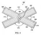
- the use of treatment device 300 in FIGURE 4is analogous to the use of the treatment device 200, but provides for a greater area of treatment with a single device.
- the treatment device 300is also a minimally-invasive treatment device in that the treatment device 300 may be deployed and removed through a device incision, e.g., in the range of 0.3 centimeters to 4.0 centimeters in length.
- the treatment device 300is formed with a first leg manifold member 302 and a second leg manifold member 304.
- the first leg manifold member 302 and the second leg manifold member 304intersect to form a central connection site 305.
- the first leg manifold member 302 and the second leg manifold member 304may be formed from an integral piece of manifold member material (see, e.g., manifold materials mentioned in connection with manifold 122 above) or two pieces of manifold material may be coupled by any technique, e.g., glue.
- the treatment device 300may be of a one-piece design to facilitate its deployment and removal.
- the first and second leg manifold members 302 and 304may be encapsulated in an encapsulating envelope 306, which may be formed with fenestrations 308.
- the encapsulating envelope 306may be formed with a film or covering, such as the material mentioned in connection with the sealing member 124 in FIG. 1A .
- the first leg manifold member 302 and second leg manifold member 304may intersect to form angles, which may take any of a variety of sizes.
- the treatment device 300may, in other words, form an "X" shape. In the embodiment shown, the angles include two obtuse angles 310 and two acute angles 312.
- the ends of the first leg manifold member 302 and second leg manifold member 304 within encapsulating envelope 306facilitate fluid collection in multiple locations within the abdominal cavity.
- a connecting interface 314may be coupled to the central connection site 305 and is fluidly coupled to the first leg manifold member 302 and the second leg manifold member 304.
- the coupling of the connecting interface 314 to the central connection site 305 and a reduced-pressure delivery conduit 320 to the connecting interface 314allows the treatment device 300 to be removed through a device incision, e.g., in the range of 0.3 centimeters to 4.0 centimeters in length, by providing a force initially on the reduced-pressure delivery conduit 320.
- the encapsulating envelope 306may be formed with a first encapsulating member 316 and a second encapsulating member (opposite side of the first and second leg manifold members 302, 304).
- the first encapsulating member 316 and second encapsulating memberform an exterior layer that surrounds and covers the first leg manifold member 302 and the second leg manifold member 304.
- the first encapsulating member 316 and the second encapsulating membermay be coupled at a peripheral portion 318, or peripheral edge, using any known technique, such as those previously mentioned.
- an RF weld 322is used to couple the peripheral portion 318 of the first encapsulating member 316 and the second encapsulating member.
- a reduced-pressure delivery conduit 320may be fluidly coupled to the connecting interface 314 and to an external, reduced-pressure source (e.g., external reduced-pressure source 132 in FIG. 1A ).
- the treatment device 400includes a plurality of encapsulated leg members 402. Each encapsulated leg member 402 has a first end 404 and a second end 406. Each encapsulated leg member 402 may be placed at different locations within the abdominal cavity, such as in or near a paracolic gutter, behind the liver, etc. Each encapsulated leg member 402 has an exterior layer 408 formed with fenestrations 410. The exterior layer 408 forms an encapsulating envelope 412 that defines an interior space 414, which includes a leg manifold member 416. The exterior layer 408 may be formed from a film or covering, such as those mentioned in connection with the sealing member 124.
- each connecting conduit 420On the first end 404 of each encapsulated leg member 402 is a connecting interface 418.
- a plurality of connecting conduits 420are coupled to the connecting interfaces 418 in a one-to-one fashion.
- Each connecting conduit 420has a first end 422 and a second end 424.
- the second end 424 of the connecting conduit 420is coupled to the connecting interface 418 of an associated encapsulated leg member 402.
- the first end 422 of the first connecting conduit 420is coupled to an interface conduit 426.
- the interface conduit 426has a first end 428 and a second end 430.
- the second end 430 of each interface conduit 426couples to the first end 422 of one of the connecting conduits 420.
- a connector 438may be used to couple the first end 422 of each of the connecting conduits 420 to the second end 430 of the interface conduit 426.
- the first end 428 of the interface conduit 426may be coupled to a reduced-pressure delivery conduit (not shown) or directly to an external reduced-pressure source.
- the plurality of encapsulated leg members 402includes a first encapsulated leg member 432 and a second encapsulated leg member 434. It should be understood that any number of additional encapsulated leg members might be added as is appropriate for a particular need.
- the treatment device 400may be installed through an open abdomen or percutaneously using a trocar.
- the surgeonmay make a device incision and insert a single encapsulated leg member 402, such as the first encapsulated leg member 432 along with its connecting conduit 420, into the patient's abdominal cavity.
- the surgeonmay make other device incisions and insert other encapsulated leg members 402 with their associated connecting conduits 420 as deemed appropriate.
- the first ends 422 of the connecting conduits 420may be coupled to a connector 438.
- the connector 438is connected to the interface conduit 426.
- the interface conduit 426may be coupled to an external reduced-pressure source, e.g., external reduced-pressure source 132 in FIGURE 1A .
- the treatment using one or more treatment devices 400may then begin.
- the treatment using the treatment device 400may be carried out for a desired period of time (T).
- Ta desired period of time
- the connector 438is removed so that a plurality of connecting conduits 420 remains initially extending from the patient.
- Each connecting conduit 420may then be pulled to remove the associated encapsulated leg member 402 from its corresponding device incision. It should be recognized that with the treatment device 400, any number of encapsulated leg members 402 may be used without requiring an open abdomen for installation or removal.
- interventionmay occur sooner as compared to a laparotomy. This may occur in practice because surgeons may be more likely to implement use of a minimally-invasive treatment device at a much earlier stage of management than a laparotomy since use of the minimally-invasive treatment device does not involve an incision of 30 centimeters or longer as is the case with many laparotomies.
Landscapes
- Health & Medical Sciences (AREA)
- Heart & Thoracic Surgery (AREA)
- Engineering & Computer Science (AREA)
- Biomedical Technology (AREA)
- Life Sciences & Earth Sciences (AREA)
- Animal Behavior & Ethology (AREA)
- General Health & Medical Sciences (AREA)
- Public Health (AREA)
- Veterinary Medicine (AREA)
- Vascular Medicine (AREA)
- Anesthesiology (AREA)
- Hematology (AREA)
- Otolaryngology (AREA)
- Ophthalmology & Optometry (AREA)
- Medical Informatics (AREA)
- Computer Vision & Pattern Recognition (AREA)
- Evolutionary Computation (AREA)
- Artificial Intelligence (AREA)
- Software Systems (AREA)
- Physics & Mathematics (AREA)
- General Physics & Mathematics (AREA)
- Automation & Control Theory (AREA)
- External Artificial Organs (AREA)
- Surgical Instruments (AREA)
- Media Introduction/Drainage Providing Device (AREA)
Description
- The present invention claims the benefit, under 35 USC § 119(e), of the filing of
U.S. Provisional Patent Application Ser. No. 61/098,030 US 2008/167593 A1 discloses a wound treatment device comprising a wound surface contacting plug and a cover for covering the wound surface.- The present invention relates generally to medical treatment systems and, more particularly, to systems and methods for controlling inflammatory response in a patient.
- One type of inflammatory response is systemic inflammatory response syndrome (SIRS). SIRS has been defined as a severe systemic response to a condition (trauma, infection, burn, etc.) that provokes an acute inflammatory reaction indicated by the presence of two or more of a group of symptoms including abnormally increased or decreased body temperature, heart rate greater than 90 beats per minute, respiratory rate greater than 20 breaths per minute or a reduced concentration of carbon dioxide in the arterial blood, and the white blood cell count greatly decreased or increased or consisting of more than ten percent immature neutrophils.Merriam-Webster's Medical Dictionary (Springfield, Mo.: Merriam-Webster, Inc., 2006), q.v., "Systemic inflammatory response syndrome." SIRS is nonspecific and can be caused by ischemia, inflammation, trauma, infection, or a combination of several insults. Sepsis is a subcategory of SIRS that may be defined as the presence of SIRS in addition to a documented or presumed infection.
- Irrespective of etiology, SIRS typically has the same pathophysio logic properties, with minor differences, in inciting inflammation or inflammatory cascade. The inflammatory cascade is a complex process that may involve humoral and cellular responses, complement, and cytokine cascades. It is believed that pro-inflammatory stimuli can interact directly with tissue to promote SIRS. Unchecked SIRS may lead to abdominal compartment syndrome (ACS), organ dysfunction, multiple organ dysfunction syndrome (MODS), multiple organ failure (MOF), and death.
- In many instances, if SIRS is severe enough, intervention becomes necessary. For example, if SIRS leads or begins to lead to ACS, surgical decompression may be utilized. Surgical decompression involves a laparotomy in which a surgeon forms an anterior, midline incision from the patient's sternum to near the pubic bone. The abdominal contents are then freed to expand beyond the abdominal cavity. This type of intervention is costly given the long hospital stay associated with such a procedure, the increased morbidity and mortality, and as a result the decision to intervene with a laparotomy is often delayed as long as possible because of the severity of the intervention.
- It is desirable to control SIRS and other types of inflammatory response. Moreover, it is generally desirable to control inflammatory response as soon as possible and as cost effectively as possible.
- The present invention provides a system according to claim 1.
- Other objects, features, and advantages of the illustrative embodiments will become apparent with reference to the drawings and detailed description that follow.
FIGURE 1A is a schematic, cross sectional view, with a portion shown as a block diagram, of an illustrative embodiment of a system for controlling systemic inflammatory response in a patient's abdominal cavity;FIGURE 1B is a detail of an encapsulated leg member of the system for controlling systemic inflammatory response in a patient's abdominal cavity ofFIGURE 1A ;FIGURE 1C is a lateral, cross-sectional view of an encapsulated leg member taken alongline 1C- 1C inFIGURE 1A ;FIGURE 1D is a cross sectional view of a portion of the system for controlling systemic inflammatory response in a patient's abdominal cavity ofFIGURE 1A ;FIGURE 2 is a schematic, perspective view of a portion of the system for controlling systemic inflammatory response in a patient's abdominal cavity ofFIGURE 1A ;FIGURE 3A is a schematic plan view of an illustrative embodiment of a reduced-pressure treatment device for use in system for controlling systemic inflammatory response;FIGURE 3B is a schematic, cross-sectional view of the illustrative embodiment of a reduced-pressure treatment device ofFIGURE 3A taken alongline 3B-3B;FIGURE 4 is a schematic, plan view of an illustrative embodiment of a reduced-pressure treatment device;FIGURE 5A is a schematic, perspective view of an illustrative embodiment of a reduced-pressure treatment device; andFIGURE 5B is a schematic, cross sectional view of the illustrative embodiment of a reduced-pressure treatment device ofFIGURE 5A taken alongplane 5B-5B.- In the following detailed description of the illustrative embodiments, reference is made to the accompanying drawings that form a part hereof. These embodiments are described in sufficient detail to enable those skilled in the art to practice the invention, and it is understood that other embodiments may be utilized and that logical structural, mechanical, electrical, and chemical changes may be made without departing from the scope of the invention. To avoid detail not necessary to enable those skilled in the art to practice the embodiments described herein, the description may omit certain information known to those skilled in the art. The following detailed description is, therefore, not to be taken in a limiting sense, and the scope of the illustrative embodiments are defined only by the appended claims.
- Illustrative systems and devices herein allow for the control of inflammatory response including systemic inflammatory response and local inflammatory response at an internal tissue site. "Control of inflammatory response" as used herein includes preventing or moderating the inflammatory response. Controlling the inflammatory response may be accomplished in a number ofways that involve treating the inflammatory milieu. Treating the inflammatory milieu may include removing or moderating pro-inflammatory stimuli, e.g., fluids, enhancing perfusion of the tissue at or near the internal tissue site, or providing reduced-pressure therapy. Unless otherwise indicated, as used herein, "or" does not require mutual exclusivity. As a more specific, illustrative example, controlling the inflammatory response may be accomplished by removing cytokines, chemokines, and other stimulants from proximate the internal tissue site. This approach involves increasing the rate of clearance. As another more specific, illustrative example, controlling the inflammatory response may be accomplished by improving the health of the local tissue, such as by increased perfusion, to decrease pro-inflammatory signaling thereby cutting off the source of the cascade and preventing a physiological response. This approach involves decreasing the rate of appearance. As another more specific, illustrative example, controlling the inflammatory response may be accomplished by increasing the production of anti-inflammatory signals and cytokines to act as agonists or antagonists or generally to block receptor sites for pro-inflammatory cytokines. This example will help to restore homeostasis and blunt the inflammatory physiologic responses and involves neutralizing the response.
- The illustrative systems and devices may be used to treat an internal tissue site that may be the bodily tissue of any human, animal, or other organism. The internal tissue site may be a tissue space, e.g., a body cavity, such as an abdominal cavity. The internal tissue site may also be located in other tissue spaces such as a patient's arm, leg, skull, or other site. With respect to the tissue space, a number of approaches to deploying and removing the illustrative systems and devices may be used. For example, the illustrative systems and devices may be (1) deployed and removed through an open wound, see, e.g.,
FIGURE 1 ; (2) deployed through an open wound and removed through one or more device incisions, see, e.g.,FIGURES 3A-5B ; or (3) deployed and removed through one or more device incisions, see, e.g.,FIGURES 3A-5B . - Referring now to
FIGURES 1A-1D , an illustrative embodiment of asystem 100 for controlling inflammatory response, e.g., systemic inflammatory response, at aninternal tissue site 104, such as in a patient'sabdominal cavity 103, is presented. Thesystem 100 includes atreatment device 102. Thesystem 100 for controlling inflammatory response in a patient'sabdominal cavity 103 delivers a treatment that controls inflammatory response, including systemic inflammatory response syndrome, and may help avoid abdominal compartment syndrome. While inflammatory response may occur without a rise in intra-abdominal pressure, in one particular, non-limiting example, controlling inflammatory response may involve avoiding a pressure rise in theabdominal cavity 103 altogether or at least maintaining the intra-abdominal pressure below 15 mm Hg and preferably below 13 mm Hg and even more preferably below 10 mm Hg. Normal intra-abdominal pressure is said to be in the range of about 0 - 5 mm Hg. The intra-abdominal pressure may be monitored by directly inserting a catheter into the abdominal compartment or indirectly by monitoring pressure in the bladder, stomach, or other cavities. - The
system 100 controls the inflammation by treating an inflammatory milieu associated with theinternal tissue site 104 of a patient. Treating the inflammatory milieu may include the approaches previously mentioned, including removing pro-inflammatory stimuli, enhancing perfusion of the tissue at or near theinternal tissue site 104, or providing reduced-pressure therapy. In one embodiment, thesystem 100 is operable to remove substantially all the inflammatory stimuli, which may include removing the majority of the fluids in theabdominal cavity 103 so as to disrupt the inflammatory environment or improve local tissue health. In another illustrative embodiment, thesystem 100 is operable to moderate the inflammatory stimuli to disrupt the inflammatory environment or improve local tissue health. Using thetreatment device 102 deployed in theabdominal cavity 103 to provide treatment may reduce the level of inflammatory stimuli, or mediators, such as interluekin-6 (IL-6) and TNF-α as measured in a peritoneal catheter fluid. Thetreatment device 102 may be used with a system and method to remove fluids that are pro-inflammatory stimuli from proximate theinternal tissue site 104 over a time duration (T). The time that the treatment may be conducted may range from half an hour to 50 hours or more. By treating the inflammatory milieu, e.g., moderating the pro-inflammatory stimuli, the onset of an inflammatory response is controlled, e.g., avoided or delayed, and the severity may be reduced. - The
treatment device 102 provides for the removal of abdominal fluids or pro-inflammatory stimuli with great reliability. Thesystem 100 does not typically clog or otherwise have effectiveness diminish with use. The reduced-pressure therapy provided by thetreatment device 102 may provide better perfusion of tissue within theabdominal cavity 103 and this may account for an additional measure of control of the inflammatory response. Thetreatment device 102 helps, among other things, to manage fluids, reduce edema, and reduces the risk of developing multiple organ dysfunction (MODS) secondary to inflammatory response. Thetreatment device 102 may be used in applications within theabdominal cavity 103 and to treat bowel edema. Thetreatment device 102 may also be used when a partial laparotomy is performed. - The
internal tissue site 104 treated may be the bodily tissue of any human, animal, or other organism. In this illustrative embodiment, theinternal tissue site 104 includes tissue in a body cavity, and in particular theabdominal cavity 103, and includes the abdominal contents or tissue that is proximate the abdominal cavity. In other illustrative applications, the internal tissue site may be located in a tissue space, or compartment, of a patient's arm, leg, skull, or other site. - As shown, the
treatment device 102 is disposed within theabdominal cavity 103 of the patient to help control the inflammatory response-local or systemic. In this embodiment, thetreatment device 102 is for deployment and removal through an open abdomen. Thetreatment device 102 includes a plurality of encapsulatedleg members 106 that are supported by the abdominal contents, which make up a surface on which the plurality of encapsulatedleg members 106 are placed. One or more of the plurality of encapsulatedleg members 106 may be placed in or proximate to a firstparacolic gutter 108, and one or more of the plurality of encapsulatedleg members 106 may be placed in or proximate to a secondparacolic gutter 110. The plurality of encapsulatedleg members 106 is coupled to acentral connection member 112, and there is fluid communication between the plurality of encapsulatedleg members 106 and thecentral connection member 112. Both the plurality of encapsulatedleg members 106 and thecentral connection member 112 may be formed withfenestrations abdominal cavity 103 to pass through. Thefenestrations - A manifold 122, or manifold pad, distributes reduced pressure to the
treatment device 102. Alternatively, a connecting interface (e.g., connectinginterface 220 inFIG. 3A ) may be coupled to thetreatment device 102 to supply reduced pressure (and remove fluids). A sealingmember 124 provides a pneumatic seal over theabdominal cavity 103 or a body-cavity opening 126. One or more skin closure devices may be placed on a patient'sepidermis 134 or abdominal wall (not shown). Reduced pressure is delivered to the manifold 122 through a reduced-pressure interface 128, which is coupled to a reduced-pressure delivery conduit 130. An external reduced-pressure source 132 delivers reduced pressure to the reduced-pressure delivery conduit 130. As used herein, the term "coupled" includes coupling via a separate object and includes direct coupling. The term "coupled" also encompasses two or more components that are continuous with one another by virtue of each of the components being formed from the same piece of material. Also, the term "coupled" may include chemical, such as via a chemical bond, mechanical, thermal, or electrical coupling. Fluid coupling means that fluid is in communication between the designated parts or locations. - Reduced pressure may be applied to the
internal tissue site 104 to help promote removal of pro-inflammatory stimuli, which may include ascites, cytokines, exudates, blood (in the case of trauma), or other fluids from theinternal tissue site 104. As used herein, "reduced pressure" generally refers to a pressure less than the ambient pressure at a tissue site that is being subjected to treatment. In most cases, this reduced pressure will be less than the atmospheric pressure at which the patient is located. Alternatively, the reduced pressure may be less than a hydrostatic pressure at the tissue site. Unless otherwise indicated, values of pressure stated herein are gauge pressures. - The manifold 122 is positioned proximate the
central connection member 112. The manifold 122 may take many forms. The term "manifold" as used herein generally refers to a substance or structure that is provided to assist in applying reduced pressure to, delivering fluids to, or removing fluids from theinternal tissue site 104. The manifold 122 typically includes a plurality of flow channels or pathways that are interconnected to improve distribution of fluids provided to and removed from theinternal tissue site 104 around themanifold 122 and through thecentral connection member 112. The manifold 122 may be a biocompatible material that is capable of being placed in contact with theinternal tissue site 104 and distributing reduced pressure to theinternal tissue site 104. Examples of the manifold 122 may include, without limitation, devices that have structural elements arranged to form flow channels, cellular foam, such as open-cell foam, porous tissue collections, liquids, gels and foams that include or cure to include flow channels. The manifold 122 may be porous and may be made from foam, gauze, felted mat, or any other material suited to a particular biological application. In one embodiment, the manifold 122 is a porous foam and includes a plurality of interconnected cells or pores that act as flow channels. The porous foam may be a polyurethane, open-cell, reticulated foam, such as a GranuFoam® material manufactured by Kinetic Concepts, Incorporated of San Antonio, Texas. Other embodiments might include "closed cells." In some situations, the manifold 122 may also be used to distribute fluids, such as medications, antibacterials, growth factors, and various solutions to theinternal tissue site 104. Other layers may be included in or on the manifold 122, such as absorptive materials, wicking materials, hydrophobic materials, and hydrophilic materials. - The sealing
member 124 is placed over the body-cavity opening 126, e.g.,abdominal cavity 103, and provides a pneumatic seal adequate for the open-cavity, reduced-pressure system 100 to hold reduced pressure at theinternal tissue site 104. The sealingmember 124 may be a cover that is used to secure the manifold 122 on thecentral connection member 112. The sealingmember 124 may be impermeable or semi-permeable. The sealingmember 124 is capable of maintaining reduced pressure at theinternal tissue site 104 after installation of the sealingmember 124 over the body-cavity opening 126. The sealingmember 124 may be a flexible over-drape or film formed from a silicone-based compound, acrylic, hydrogel or hydrogel-forming material, or any other biocompatible material that includes the impermeability or permeability characteristics as desired for applying reduced pressure to theinternal tissue site 104. - The sealing
member 124 may further include anattachment device 131 to secure the sealingmember 124 to the patient'sepidermis 134. Theattachment device 131 may take many forms; for example, anadhesive layer 136 may be positioned along a perimeter of the sealingmember 124 or any portion of the sealingmember 124 to provide, directly or indirectly, the pneumatic seal with the patient'sepidermis 134. Theadhesive layer 136 might also be pre-applied to the sealingmember 124 and covered with a releasable backing, or member (not shown), that is removed at the time of application. - The reduced-
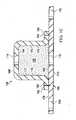
pressure interface 128 may be, as one example, a port orconnector 138, which permits the passage of fluid from the manifold 122 to the reduced-pressure delivery conduit 130 and vice versa. For example, fluid collected from theinternal tissue site 104 using themanifold 122 and thetreatment device 102 may enter the reduced-pressure delivery conduit 130 via theconnector 138. In another embodiment, the open-cavity, reduced-pressure system 100 may omit theconnector 138 and the reduced-pressure delivery conduit 130 may be inserted directly into the sealingmember 124 and into themanifold 122. The reduced-pressure delivery conduit 130 may be a medical conduit or tubing or any other means for transporting a reduced pressure and fluid. The reduced-pressure delivery conduit 130 may be a multi-lumen member for readily delivering reduced pressure and removing fluids. In one embodiment, the reduced-pressure delivery conduit 130 is a two-lumen conduit with one lumen for reduced pressure and liquid transport and one lumen for communicating pressure to a pressure sensor. - Reduced pressure is supplied to the reduced-
pressure delivery conduit 130 by the external reduced-pressure source 132. A wide range of reduced pressures may be generated or supplied by the external reduced-pressure source 132. In one embodiment, the range may include the range -50 to -300 mm Hg and in another embodiment, the range may include -100 mm Hg to -200 mm Hg. In one illustrative embodiment, the external reduced-pressure source 132 includes preset selectors for -100 mm Hg, -125 mm Hg, and -150 mm Hg. The external reduced-pressure source 132 may also include a number of alarms, such as a blockage alarm, a leakage alarm, or a battery-low alarm. The external reduced-pressure source 132 may be a portable source, wall source, or other unit for abdominal cavities. The external reduced-pressure source 132 may selectively deliver a constant pressure, intermittent pressure, or pressure with a dynamic or set pattern. The fluid removed from the cavity through the reduced-pressure delivery conduit 130 could be as much as 5L or more per day. - A number of different devices, e.g., a
representative device 140, may be added to amedial portion 142 of the reduced-pressure delivery conduit 130. For example, therepresentative device 140 might be a fluid reservoir, or canister collection member, a pressure-feedback device, a volume detection system, a blood detection system, an infection detection system, a filter, a port with a filter, a flow monitoring system, a temperature monitoring system, etc. Multiplerepresentative devices 140 might be included. Some of these devices, e.g., the fluid collection member, may be formed integral to the external reduced-pressure source 132. For example, a reduced-pressure port 144 on the external reduced-pressure source 132 may include a filter member (not shown) that includes one or more filters and may include a hydrophobic filter that prevents liquid from entering an interior space of the external reduced-pressure source 132. - Referring now to
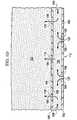
FIGURE 1D andFIGURE 2 , thetreatment device 102 includes anon-adherent drape 148. Thenon-adherent drape 148 may be formed of any non-adherent film material that helps prevent tissue from adhering to thenon-adherent drape 148. In one embodiment, thenon-adherent drape 148 is formed from a breathable polyurethane film. Thenon-adherent drape 148 is formed with a plurality offenestrations 150. The plurality offenestrations 150 may take any shape, such as circular openings, rectangular openings, polygon-shaped openings, etc., but are shown inFIGURE 2 as slits, or linear cuts. - The
treatment device 102 includes thecentral connection member 112 to which the plurality of encapsulatedleg members 106 are coupled. Thecentral connection member 112 is encapsulated by a firstconnection encapsulation member 186 and a secondconnection encapsulation member 192, except atleg coupling areas 152, which allow fluid communication between thecentral connection member 112 and the plurality of encapsulatedleg members 106. Thecentral connection member 112 hasfenestrations 118 that allow fluid communication between aconnection manifold member 154 and themanifold 122. Each of the plurality of encapsulatedleg members 106 may be formed with or without a plurality of defined leg modules, such asleg modules 156. Theadjacent leg modules 156 are fluidly coupled to each other and have amanipulation zone 158 between them. - Referring again to
FIGURES 1A-1D , each of the plurality of encapsulatedleg members 106 has aleg manifold member 160, which may be a single manifold member that runs between theleg modules 156 or may be discrete components of a manifold material that make up theleg manifold member 160. Theleg manifold member 160 is disposed within aninterior portion 162 of each of the encapsulatedleg members 106. Eachleg manifold member 160 has afirst side 164 and a second, tissue-facingside 166. A firstleg encapsulating member 168, which is formed withfenestrations 114, is disposed on thefirst side 164 of theleg manifold member 160. Similarly, a secondleg encapsulating member 170, which has fenestrations 116, is disposed on the second, tissue-facingside 166 of theleg manifold member 160. The secondleg encapsulating member 170 may be a portion of thenon-adherent drape 148. As shown in the longitudinal cross section ofFIGURE 1B byarrows 172, fluid flows between theadjacent leg modules 156 towards thecentral connection member 112. As shown byarrows 174, the fluid is able to enterfenestrations leg manifold member 160 and then flow toward thecentral connection member 112 as represented byarrows 172. - Referring to
FIGURE 1C , a lateral cross section of a portion of the encapsulatedleg member 106 is presented. As before, it can be seen that thefirst side 164 of theleg manifold member 160 is covered with the firstleg encapsulating member 168, and that the second, tissue-facingside 166 of theleg manifold member 160 is covered by the secondleg encapsulating member 170, which in this instance is a portion of thenon-adherent drape 148. Thus, in this illustrative embodiment, thefenestrations 116 may be some of the plurality offenestrations 150 in thenon-adherent drape 148. In this illustrative embodiment,peripheral edges 176 of theleg manifold member 160 are also covered by a portion of the firstleg encapsulating member 168. Theperipheral edges 176 include a firstlateral edge 177 and a secondlateral edge 179. The firstleg encapsulating member 168 covers thefirst side 164 and theperipheral edges 176 and extends onto afirst surface 178 of thenon-adherent drape 148 andforms extensions 180. Theextensions 180 have been coupled to the secondleg encapsulating member 170 bywelds 182. The firstleg encapsulating member 168 may, however, be coupled to the secondleg encapsulating member 170 using any known technique, including welding (e.g., ultrasonic or RF welding), bonding, adhesives, cements, etc. - Referring again to
FIGURE 1D andFIGURE 2 , thecentral connection member 112 includes theconnection manifold member 154 that is encapsulated within the firstconnection encapsulation member 186, which hasfenestrations 118. The firstconnection encapsulation member 186 is disposed on afirst side 188 of theconnection manifold member 154. The secondconnection encapsulation member 192 is disposed on a second, tissue-facingside 190 of theconnection manifold member 154. The secondconnection encapsulation member 192 is formed withfenestrations 120. The firstconnection encapsulation member 186 has a peripheral zone or edge 194 as shown inFIGURE 2 . In a similar fashion, the secondconnection encapsulation member 192 has a peripheral zone or edge (not explicitly shown) that lines up with theperipheral edge 194. Theperipheral edge 194 of the firstconnection encapsulation member 186 is coupled to peripheral edge of the secondconnection encapsulation member 192, except at theleg coupling areas 152 in order to allow fluid within the plurality of encapsulatedleg members 106 to flow into theconnection manifold member 154 as suggested byarrows 196 inFIGURE 1D . Fluid may also enter directly into theconnection manifold member 154 by flowing throughfenestrations 120 as suggested byarrows 198. The manifold 122 is disposed proximate to the firstconnection encapsulation member 186, and when reduced pressure is applied to the manifold 122, reduced pressure causes fluid to flow from theconnection manifold member 154 throughfenestrations 118 and into the manifold 122 as suggested byarrows 199. The fluid continues to flow in the direction of the reduced-pressure interface 128 through which the fluid is removed to the reduced-pressure delivery conduit 130. - Referring to
FIGURES 1A-1D and2 , in operation, theillustrative system 100 may be used by first sizing thetreatment device 102 by cutting to size. Thenon-adherent drape 148 with the plurality of encapsulatedleg members 106 is disposed within the abdominal cavity through the body-cavity opening 126 and is distributed against the abdominal contents; this may include placing at least one encapsulatedleg member 106 in or proximate the firstparacolic gutter 108 or the secondparacolic gutter 110. Once thetreatment device 102 has been distributed, the manifold 122 is placed adjacent afirst side 184 of the firstconnection encapsulation member 186. The sealingmember 124 may then be applied over the body-cavity opening 126 to provide a pneumatic seal over the body-cavity opening 126, e.g.,abdominal cavity 103. - In addition to the sealing
member 124, the body-cavity opening 126 may be further closed or reinforced using mechanical closing means, e.g., staples, or using a reduced-pressure closure system. The sealingmember 124 may be applied in a number of ways, but according to one illustrative embodiment, the releasable backing member that is on theadhesive layer 136 of the sealingmember 124 is removed and then the sealingmember 124 is placed against the patient'sepidermis 134 about the body-cavity opening 126. The reduced-pressure interface 128, such asconnector 138, is then attached to the sealingmember 124 such that reduced pressure can be delivered by the reduced-pressure interface 128, through the sealingmember 124, and to themanifold 122. The reduced-pressure delivery conduit 130 is fluidly coupled to the reduced-pressure interface 128 and to the reduced-pressure port 144 on the external reduced-pressure source 132. - The external reduced-
pressure source 132 is activated and thereby provides reduced pressure into the reduced-pressure delivery conduit 130, which delivers reduced pressure to the reduced-pressure interface 128 and into themanifold 122. The manifold 122 distributes reduced pressure and draws fluid throughfenestrations 118 from theconnection manifold member 154. Theconnection manifold member 154 draws fluid, including pro-inflammatory stimuli, from theabdominal cavity 103 throughfenestrations 120 and pulls fluid from the plurality of encapsulatedleg members 106 as suggested byarrows 196. Fluid from theabdominal cavity 103 flows into the plurality of encapsulatedleg members 106 throughfenestrations 114 on the firstleg encapsulating member 168 and throughfenestrations 116 on the secondleg encapsulating member 170 and then flows through the plurality of encapsulatedleg members 106 as suggested byarrows 172 towards theconnection manifold member 154. The fluid then flows through the manifold 122, the reduced-pressure interface 128, and into the reduced-pressure delivery conduit 130. - Referring to
FIGURES 3A and 3B , another illustrative embodiment of atreatment device 200 is presented. Thetreatment device 200 is a minimally-invasive treatment device in that thetreatment device 200 is sized and configured to be introduced through a device incision, e.g., in the range of 0.3 centimeters to 4.0 centimeters in length. In some instances, the device incision may be larger e.g., 4.0 to 8.0 centimeters in length or more. Thetreatment device 200 may be formed as a one-piece design to facilitate placement and removal of thetreatment device 200 from the abdominal cavity. - The
treatment device 200 is formed as an encapsulatedleg member 205 and has afirst end 202 and asecond end 204. Thefirst end 202 and thesecond end 204 of the encapsulatedleg member 205 are particularly well suited for placement in tight portions of the abdominal cavity, such as the paracolic gutters. Thetreatment device 200 is formed with aleg manifold member 206, which is enveloped in an encapsulatingenvelope 208. Theleg manifold member 206 may be any manifold material, such as those referenced above formanifold 122 andleg manifold member 160. Theleg manifold member 206 may have adequate stiffness to help facilitate placement of the encapsulatedleg member 205. - The encapsulating
envelope 208 may be formed by a firstleg encapsulating member 210 and a secondleg encapsulating member 212. Eachleg encapsulating member peripheral edge 214. Theperipheral edges 214 of the firstleg encapsulating member 210 and the secondleg encapsulating member 212 are coupled using any technique, including without limitation welding (e.g., ultrasonic or RF welding), bonding, adhesives, cements, etc. Theperipheral edges 214 in this illustrative embodiment are shown coupled by aweld 216. Theleg encapsulating members member 124 above. - A plurality of
fenestrations 218 are formed on the firstleg encapsulating member 210 and the secondleg encapsulating member 212, and thus fenestrations 218 are formed on the encapsulatingenvelope 208. A connectinginterface 220, or reduced-pressure interface, is coupled to the encapsulatingenvelope 208 and is in fluid communication with theleg manifold member 206. A reduced-pressure delivery conduit 222 may be coupled to the connectinginterface 220. The reduced-pressure delivery conduit 222 has afirst end 224 and asecond end 226. A fitting 228 may be placed on thesecond end 226 for a quick connection to an external reduced-pressure source (e.g., external reduced-pressure source 132 inFIG. 1A ). Thefirst end 224 of the reduced-pressure delivery conduit 222 is fluidly coupled to the connectinginterface 220. Aconduit clamp 230 may be placed on the reduced-pressure delivery conduit 222. - The encapsulated
leg member 205 has a length (L) 232 and a width (W) 234. For thetreatment device 200 shown inFIGURE 3A , the aspect ratio (L/W) may, in an illustrative embodiment, range from 1.5 to 6.0. The aspect ratio of a shape is the ratio of the shape's longer dimension to its shorter dimension. It may be applied to two characteristic dimensions of a three-dimensional shape, such as the ratio of the longest and shortest axis, or for symmetrical objects that are described by just two measurements, such as the length and diameter of a rod. The aspect ratio of a torus is the ratio of the major axis R to the minor axis r. For a substantially flat leg member, such astreatment device 200 shown inFIGURE 3A , the aspect ratio is the ratio L/W. - A
pressure transducer 238 may be included within or alternatively attached to thetreatment device 200. Atransducer lead 240 may be coupled to thepressure transducer 238 and may run within or along theleg manifold member 206 to the connectinginterface 220 and may run inside or along the reduced-pressure delivery conduit 222 to a point external to the patient where thetransducer lead 240 may be coupled to equipment to provide an indication of the pressure within the abdominal cavity as experienced by thepressure transducer 238. - The use of
treatment device 200 will now be described. Thetreatment device 200 may be deployed either through an open abdomen (seeFIGURE 1A ) or percutaneously through a patient's epidermis (seeepidermis 134 inFIGURE 1A ). The use oftreatment device 200 is similar to other devices described herein. Whether through a device incision using a trocar or through an open abdomen application, the healthcare provider places thetreatment device 200 within the abdominal cavity and preferably thefirst end 202 is placed on the abdominal contents and may be placed proximate a paracolic gutter and similarly thesecond end 204 is positioned on the abdominal contents and preferably at a paracolic gutter. The reduced-pressure delivery conduit 222 is run from within the abdominal cavity to a point external the abdominal cavity and is coupled to an external reduced-pressure source, e.g., external reduced-pressure source 132 inFIG. 1A . The device incision may be sealed (e.g., by a sealing member, such as the sealingmember 124 inFIG. 1A ). Reduced pressure is delivered via the reduced-pressure delivery conduit 222 to the connectinginterface 220. - The connecting
interface 220 is fluidly coupled to theleg manifold member 206 and delivers reduced pressure thereto. As such, fluids are pulled into theleg manifold member 206, delivered to the connectinginterface 220, and delivered on to the reduced-pressure delivery conduit 222. The reduced-pressure delivery conduit 222 delivers the fluids to a location external the abdominal cavity for storage, disposal, or treatment. The removed fluids contain ascites, cytokines, and other fluids from the abdominal cavity that include pro-inflammatory stimuli. As the fluids are moved from the abdominal cavity, the inflammatory response is controlled. - The
pressure transducer 238, which is associated with thetreatment device 200, may be coupled using thetransducer lead 240 to a device for determining the pressure within the abdominal cavity. The pressure within the abdominal cavity may be monitored to determine ifadditional treatment devices 200 should be deployed or if other intervention may be necessary. The removal of pro-inflammatory stimuli and reduced-pressure therapy within the abdominal cavity usingtreatment device 200 may continue for a period of time (T) ranging from 0.5 hours to more than 40 hours. - Once the healthcare provider decides that the need for treatment with the
treatment device 200 has ended, thetreatment device 200, which is a minimally-invasive treatment device, may be removed through the device incision. Thetreatment device 200 is removed through the device incision by administering a force on the reduced-pressure delivery conduit 222. Once thetreatment device 200 is removed from the device incision, the device incision may be closed by any technique known, such as suture, bonding, bandage, staples, etc., or allowed to heal spontaneously. The use oftreatment device 300 inFIGURE 4 is analogous to the use of thetreatment device 200, but provides for a greater area of treatment with a single device. - Referring now to
FIGURE 4 , another illustrative embodiment of atreatment device 300 is presented. Thetreatment device 300 is also a minimally-invasive treatment device in that thetreatment device 300 may be deployed and removed through a device incision, e.g., in the range of 0.3 centimeters to 4.0 centimeters in length. Thetreatment device 300 is formed with a firstleg manifold member 302 and a secondleg manifold member 304. The firstleg manifold member 302 and the secondleg manifold member 304 intersect to form acentral connection site 305. The firstleg manifold member 302 and the secondleg manifold member 304 may be formed from an integral piece of manifold member material (see, e.g., manifold materials mentioned in connection withmanifold 122 above) or two pieces of manifold material may be coupled by any technique, e.g., glue. Again, thetreatment device 300 may be of a one-piece design to facilitate its deployment and removal. - The first and second
leg manifold members envelope 306, which may be formed withfenestrations 308. The encapsulatingenvelope 306 may be formed with a film or covering, such as the material mentioned in connection with the sealingmember 124 inFIG. 1A . The firstleg manifold member 302 and secondleg manifold member 304 may intersect to form angles, which may take any of a variety of sizes. Thetreatment device 300 may, in other words, form an "X" shape. In the embodiment shown, the angles include twoobtuse angles 310 and twoacute angles 312. The ends of the firstleg manifold member 302 and secondleg manifold member 304 within encapsulatingenvelope 306 facilitate fluid collection in multiple locations within the abdominal cavity. - A connecting
interface 314 may be coupled to thecentral connection site 305 and is fluidly coupled to the firstleg manifold member 302 and the secondleg manifold member 304. The coupling of the connectinginterface 314 to thecentral connection site 305 and a reduced-pressure delivery conduit 320 to the connectinginterface 314 allows thetreatment device 300 to be removed through a device incision, e.g., in the range of 0.3 centimeters to 4.0 centimeters in length, by providing a force initially on the reduced-pressure delivery conduit 320. - The encapsulating
envelope 306 may be formed with afirst encapsulating member 316 and a second encapsulating member (opposite side of the first and secondleg manifold members 302, 304). Thefirst encapsulating member 316 and second encapsulating member form an exterior layer that surrounds and covers the firstleg manifold member 302 and the secondleg manifold member 304. Thefirst encapsulating member 316 and the second encapsulating member may be coupled at aperipheral portion 318, or peripheral edge, using any known technique, such as those previously mentioned. In the embodiment shown, anRF weld 322 is used to couple theperipheral portion 318 of the first encapsulatingmember 316 and the second encapsulating member. A reduced-pressure delivery conduit 320 may be fluidly coupled to the connectinginterface 314 and to an external, reduced-pressure source (e.g., external reduced-pressure source 132 inFIG. 1A ). - Referring to
FIGURES 5A and 5B , another illustrative embodiment of atreatment device 400 is presented. Thetreatment device 400 includes a plurality of encapsulatedleg members 402. Each encapsulatedleg member 402 has afirst end 404 and asecond end 406. Each encapsulatedleg member 402 may be placed at different locations within the abdominal cavity, such as in or near a paracolic gutter, behind the liver, etc. Each encapsulatedleg member 402 has anexterior layer 408 formed withfenestrations 410. Theexterior layer 408 forms an encapsulatingenvelope 412 that defines aninterior space 414, which includes aleg manifold member 416. Theexterior layer 408 may be formed from a film or covering, such as those mentioned in connection with the sealingmember 124. - On the
first end 404 of each encapsulatedleg member 402 is a connectinginterface 418. A plurality of connectingconduits 420 are coupled to the connectinginterfaces 418 in a one-to-one fashion. Each connectingconduit 420 has afirst end 422 and asecond end 424. Thesecond end 424 of the connectingconduit 420 is coupled to the connectinginterface 418 of an associated encapsulatedleg member 402. Thefirst end 422 of the first connectingconduit 420 is coupled to aninterface conduit 426. Theinterface conduit 426 has afirst end 428 and asecond end 430. Thesecond end 430 of eachinterface conduit 426 couples to thefirst end 422 of one of the connectingconduits 420. Aconnector 438 may be used to couple thefirst end 422 of each of the connectingconduits 420 to thesecond end 430 of theinterface conduit 426. Thefirst end 428 of theinterface conduit 426 may be coupled to a reduced-pressure delivery conduit (not shown) or directly to an external reduced-pressure source. In the embodiment shown inFIGURE 5A , the plurality of encapsulatedleg members 402 includes a first encapsulatedleg member 432 and a second encapsulatedleg member 434. It should be understood that any number of additional encapsulated leg members might be added as is appropriate for a particular need. - The use of the
treatment device 400 will now be described. Thetreatment device 400 may be installed through an open abdomen or percutaneously using a trocar. The surgeon may make a device incision and insert a single encapsulatedleg member 402, such as the first encapsulatedleg member 432 along with its connectingconduit 420, into the patient's abdominal cavity. The surgeon may make other device incisions and insert other encapsulatedleg members 402 with their associated connectingconduits 420 as deemed appropriate. - When a desired number of encapsulated
leg members 402 has been placed within the abdominal cavity with their connectingconduits 420 extending through the device incisions, the first ends 422 of the connectingconduits 420 may be coupled to aconnector 438. Theconnector 438 is connected to theinterface conduit 426. Theinterface conduit 426 may be coupled to an external reduced-pressure source, e.g., external reduced-pressure source 132 inFIGURE 1A . The treatment using one ormore treatment devices 400 may then begin. - The treatment using the
treatment device 400 may be carried out for a desired period of time (T). When treatment is terminated and removal of thetreatment device 400 is desired, theconnector 438 is removed so that a plurality of connectingconduits 420 remains initially extending from the patient. Each connectingconduit 420 may then be pulled to remove the associated encapsulatedleg member 402 from its corresponding device incision. It should be recognized that with thetreatment device 400, any number of encapsulatedleg members 402 may be used without requiring an open abdomen for installation or removal. - With respect to the illustrative systems and devices that may be deployed using minimally invasive techniques on the context of an abdominal cavity, intervention may occur sooner as compared to a laparotomy. This may occur in practice because surgeons may be more likely to implement use of a minimally-invasive treatment device at a much earlier stage of management than a laparotomy since use of the minimally-invasive treatment device does not involve an incision of 30 centimeters or longer as is the case with many laparotomies. By offering the surgeon the opportunity to intervene with one or more minimally-invasive devices at an earlier stage post-injury, the time in which the abdominal viscera are exposed to the progressively harmful effects of allowing the inflammatory stimuli to persist until decompression could be substantially decreased and thus reducing in effect the severity and extent of disease.
- Although the illustrative embodiments and methods advantages have been disclosed in the context of certain illustrative, non-limiting embodiments, it should be understood that various changes, substitutions, permutations, and alterations can be made without departing from the scope of the invention as defined by the appended claims. It will be appreciated that any feature that is described in a connection to any one embodiment may also be applicable to any other embodiment.
Claims (1)
- A system for controlling inflammatory response at an internal tissue site of a patient, the system comprising:a reduced-pressure treatment device for deploying proximate the internal tissue site, the reduced-pressure treatment device comprising a minimally-invasive treatment device;a sealing member for disposing on a portion of a patient's epidermis and operable to form a pneumatic seal over the internal tissue site;an external reduced-pressure source for supplying reduced pressure;a reduced-pressure delivery conduit for fluidly coupling the reduced-pressure source and a connecting interface;wherein the reduced-pressure treatment device comprises:a plurality of encapsulated leg members, each having an interior portion with a leg manifold member, and an encapsulating envelope formed with fenestrations operable to allow fluid flow into the interior portion and enveloping the leg manifold member, and wherein each of the plurality of encapsulated leg members has a first end and a second end;a plurality of connecting conduits, each having a first end and a second end;each encapsulated leg member having a connecting interface on the first end of the encapsulated leg member and fluidly coupled to the leg manifold member of the encapsulated leg member which it is on; andan interface conduit having a first end and second end,wherein the first end of each of the plurality of connecting conduits is coupled to the second end of the interface conduit; and wherein the second end of each of the plurality of connecting conduits is coupled to one of the connecting interfaces, andwherein the reduced-pressure source, reduced-pressure delivery conduit, and reduced-pressure treatment device are operable to provide reduced pressure from the external reduced-pressure source to the reduced-pressure treatment device, and to moderate pro-inflammatory stimuli.
Priority Applications (2)
| Application Number | Priority Date | Filing Date | Title |
|---|---|---|---|
| EP14157544.9AEP2740501B1 (en) | 2008-09-18 | 2009-05-15 | System for controlling inflammatory response |
| EP19170668.8AEP3536358A1 (en) | 2008-09-18 | 2009-05-15 | Systems and methods for controlling inflammatory response |
Applications Claiming Priority (2)
| Application Number | Priority Date | Filing Date | Title |
|---|---|---|---|
| US9803008P | 2008-09-18 | 2008-09-18 | |
| PCT/US2009/044235WO2010033271A1 (en) | 2008-09-18 | 2009-05-15 | Systems and methods for controlling inflammatory response |
Related Child Applications (4)
| Application Number | Title | Priority Date | Filing Date |
|---|---|---|---|
| EP19170668.8ADivisionEP3536358A1 (en) | 2008-09-18 | 2009-05-15 | Systems and methods for controlling inflammatory response |
| EP19170668.8ADivision-IntoEP3536358A1 (en) | 2008-09-18 | 2009-05-15 | Systems and methods for controlling inflammatory response |
| EP14157544.9ADivisionEP2740501B1 (en) | 2008-09-18 | 2009-05-15 | System for controlling inflammatory response |
| EP14157544.9ADivision-IntoEP2740501B1 (en) | 2008-09-18 | 2009-05-15 | System for controlling inflammatory response |
Publications (3)
| Publication Number | Publication Date |
|---|---|
| EP2323712A1 EP2323712A1 (en) | 2011-05-25 |
| EP2323712B1 EP2323712B1 (en) | 2014-04-02 |
| EP2323712B2true EP2323712B2 (en) | 2021-08-11 |
Family
ID=40999942
Family Applications (4)
| Application Number | Title | Priority Date | Filing Date |
|---|---|---|---|
| EP19170668.8AWithdrawnEP3536358A1 (en) | 2008-09-18 | 2009-05-15 | Systems and methods for controlling inflammatory response |
| EP09789692.2ANot-in-forceEP2323711B1 (en) | 2008-09-18 | 2009-05-15 | Therapy delivery systems and methods |
| EP14157544.9AActiveEP2740501B1 (en) | 2008-09-18 | 2009-05-15 | System for controlling inflammatory response |
| EP09789691.4AActiveEP2323712B2 (en) | 2008-09-18 | 2009-05-15 | System for controlling inflammatory response |
Family Applications Before (3)
| Application Number | Title | Priority Date | Filing Date |
|---|---|---|---|
| EP19170668.8AWithdrawnEP3536358A1 (en) | 2008-09-18 | 2009-05-15 | Systems and methods for controlling inflammatory response |
| EP09789692.2ANot-in-forceEP2323711B1 (en) | 2008-09-18 | 2009-05-15 | Therapy delivery systems and methods |
| EP14157544.9AActiveEP2740501B1 (en) | 2008-09-18 | 2009-05-15 | System for controlling inflammatory response |
Country Status (12)
| Country | Link |
|---|---|
| US (7) | US8246606B2 (en) |
| EP (4) | EP3536358A1 (en) |
| JP (2) | JP5337248B2 (en) |
| KR (2) | KR20110058872A (en) |
| CN (4) | CN102143772B (en) |
| AU (2) | AU2009293592B8 (en) |
| BR (2) | BRPI0913550A2 (en) |
| CA (2) | CA2734961C (en) |
| MX (2) | MX2011002861A (en) |
| RU (2) | RU2011107112A (en) |
| TW (2) | TW201019976A (en) |
| WO (2) | WO2010033271A1 (en) |
Cited By (1)
| Publication number | Priority date | Publication date | Assignee | Title |
|---|---|---|---|---|
| US12111309B2 (en) | 2019-12-23 | 2024-10-08 | Convatec Limited | Point of care devices and methods for detecting infection status of a wound |
Families Citing this family (137)
| Publication number | Priority date | Publication date | Assignee | Title |
|---|---|---|---|---|
| GB0224986D0 (en) | 2002-10-28 | 2002-12-04 | Smith & Nephew | Apparatus |
| GB0325126D0 (en) | 2003-10-28 | 2003-12-03 | Smith & Nephew | Apparatus with heat |
| GB0325120D0 (en)* | 2003-10-28 | 2003-12-03 | Smith & Nephew | Apparatus with actives |
| US11298453B2 (en) | 2003-10-28 | 2022-04-12 | Smith & Nephew Plc | Apparatus and method for wound cleansing with actives |
| US8758313B2 (en)* | 2003-10-28 | 2014-06-24 | Smith & Nephew Plc | Apparatus and method for wound cleansing with actives |
| US7909805B2 (en) | 2004-04-05 | 2011-03-22 | Bluesky Medical Group Incorporated | Flexible reduced pressure treatment appliance |
| US10058642B2 (en) | 2004-04-05 | 2018-08-28 | Bluesky Medical Group Incorporated | Reduced pressure treatment system |
| GB0409446D0 (en) | 2004-04-28 | 2004-06-02 | Smith & Nephew | Apparatus |
| EP2214612B1 (en) | 2007-11-21 | 2019-05-01 | Smith & Nephew PLC | Wound dressing |
| ES2715605T3 (en) | 2007-11-21 | 2019-06-05 | Smith & Nephew | Wound dressing |
| WO2009067711A2 (en) | 2007-11-21 | 2009-05-28 | T.J. Smith & Nephew, Limited | Suction device and dressing |
| GB0722820D0 (en) | 2007-11-21 | 2008-01-02 | Smith & Nephew | Vacuum assisted wound dressing |
| GB0723875D0 (en) | 2007-12-06 | 2008-01-16 | Smith & Nephew | Wound management |
| US20130096518A1 (en) | 2007-12-06 | 2013-04-18 | Smith & Nephew Plc | Wound filling apparatuses and methods |
| US11253399B2 (en) | 2007-12-06 | 2022-02-22 | Smith & Nephew Plc | Wound filling apparatuses and methods |
| GB0723872D0 (en) | 2007-12-06 | 2008-01-16 | Smith & Nephew | Apparatus for topical negative pressure therapy |
| US8298200B2 (en) | 2009-06-01 | 2012-10-30 | Tyco Healthcare Group Lp | System for providing continual drainage in negative pressure wound therapy |
| US9033942B2 (en) | 2008-03-07 | 2015-05-19 | Smith & Nephew, Inc. | Wound dressing port and associated wound dressing |
| GB0804654D0 (en) | 2008-03-13 | 2008-04-16 | Smith & Nephew | Vacuum closure device |
| ES2658263T3 (en) | 2008-08-08 | 2018-03-09 | Smith & Nephew, Inc. | Continuous fiber wound dressing |
| AU2016277595B2 (en)* | 2008-10-29 | 2018-10-18 | Solventum Intellectual Properties Company | Open-cavity, reduced-pressure treatment devices and systems |
| WO2010051071A1 (en) | 2008-10-29 | 2010-05-06 | Kci Licensing, Inc. | Reduced-pressure, wound-closure and treatment systems and methods |
| TW201021867A (en)* | 2008-12-12 | 2010-06-16 | Ind Tech Res Inst | Fluid processing system and collecting device thereof |
| US8162907B2 (en) | 2009-01-20 | 2012-04-24 | Tyco Healthcare Group Lp | Method and apparatus for bridging from a dressing in negative pressure wound therapy |
| GB0902368D0 (en) | 2009-02-13 | 2009-04-01 | Smith & Nephew | Wound packing |
| US20100324516A1 (en) | 2009-06-18 | 2010-12-23 | Tyco Healthcare Group Lp | Apparatus for Vacuum Bridging and/or Exudate Collection |
| US20110054420A1 (en)* | 2009-08-27 | 2011-03-03 | Christopher Brian Locke | Reduced-pressure wound dressings and systems for re-epithelialization and granulation |
| AU2010341491B2 (en) | 2009-12-22 | 2015-05-14 | Smith & Nephew, Inc. | Apparatuses and methods for negative pressure wound therapy |
| JP6013921B2 (en) | 2010-02-23 | 2016-10-25 | エル−ヴイエイディー テクノロジー インコーポレイティッドL−Vad Technology,Inc. | Vacuum-assisted transcutaneous device |
| US8791315B2 (en) | 2010-02-26 | 2014-07-29 | Smith & Nephew, Inc. | Systems and methods for using negative pressure wound therapy to manage open abdominal wounds |
| US8469935B2 (en) | 2010-03-11 | 2013-06-25 | Kci Licensing, Inc. | Abdominal treatment systems, delivery devices, and methods |
| US8721606B2 (en) | 2010-03-11 | 2014-05-13 | Kci Licensing, Inc. | Dressings, systems, and methods for treating a tissue site |
| US20110257611A1 (en)* | 2010-04-16 | 2011-10-20 | Kci Licensing, Inc. | Systems, apparatuses, and methods for sizing a subcutaneous, reduced-pressure treatment device |
| USRE48117E1 (en) | 2010-05-07 | 2020-07-28 | Smith & Nephew, Inc. | Apparatuses and methods for negative pressure wound therapy |
| USD692565S1 (en) | 2010-06-03 | 2013-10-29 | Smith & Nephew, Inc. | Organ protection layer |
| US9526920B2 (en) | 2010-10-12 | 2016-12-27 | Smith & Nephew, Inc. | Medical device |
| CA140189S (en) | 2010-10-15 | 2011-11-07 | Smith & Nephew | Medical dressing |
| CA140188S (en) | 2010-10-15 | 2011-11-07 | Smith & Nephew | Medical dressing |
| DE102010052336A1 (en) | 2010-11-25 | 2012-05-31 | Paul Hartmann Ag | Wound dressing for the negative pressure therapy |
| USD714433S1 (en) | 2010-12-22 | 2014-09-30 | Smith & Nephew, Inc. | Suction adapter |
| RU2016111981A (en) | 2010-12-22 | 2018-11-27 | Смит Энд Нефью, Инк. | DEVICE AND METHOD FOR TREATING RAS WITH NEGATIVE PRESSURE |
| US9421132B2 (en) | 2011-02-04 | 2016-08-23 | University Of Massachusetts | Negative pressure wound closure device |
| ES2571402T3 (en)* | 2011-04-18 | 2016-05-25 | Rigshospitalet Copenhagen Univ Hospital | Enhanced wound care product |
| CN107252383A (en) | 2011-07-14 | 2017-10-17 | 史密夫及内修公开有限公司 | Wound dressing and treatment method |
| DE102011082347A1 (en) | 2011-09-08 | 2013-03-14 | Paul Hartmann Ag | Wound dressing for use in the vacuum treatment of wounds |
| EP2626049B1 (en) | 2012-02-11 | 2018-07-25 | Paul Hartmann AG | Wound treatment device |
| JP6250571B2 (en) | 2012-03-12 | 2017-12-20 | スミス アンド ネフュー ピーエルシーSmith & Nephew Public Limited Company | Pressure reducing apparatus and method |
| AU346291S (en) | 2012-05-15 | 2013-01-09 | Smith & Nephew | Medical dressing |
| EP2852333B1 (en) | 2012-05-22 | 2021-12-15 | Smith & Nephew plc | Apparatuses for wound therapy |
| EP2852419B1 (en) | 2012-05-22 | 2019-11-20 | Smith & Nephew plc | Wound closure device |
| JP6400570B2 (en) | 2012-05-23 | 2018-10-10 | スミス アンド ネフュー ピーエルシーSmith & Nephew Public Limited Company | Apparatus and method for local negative pressure closure therapy |
| AU2013264937B2 (en) | 2012-05-24 | 2018-04-19 | Smith & Nephew Inc. | Devices and methods for treating and closing wounds with negative pressure |
| MX369689B (en) | 2012-07-16 | 2019-11-19 | Smith & Nephew Inc | Negative pressure wound closure device. |
| CN108186200B (en) | 2012-08-01 | 2021-08-10 | 史密夫及内修公开有限公司 | Wound dressing |
| WO2014020440A1 (en) | 2012-08-01 | 2014-02-06 | Smith & Nephew Plc | Wound dressing |
| US9623159B2 (en) | 2012-08-03 | 2017-04-18 | Kci Licensing, Inc. | Interfaces, systems, and methods for use in reduced pressure tissue treatment |
| US9662427B2 (en)* | 2012-08-13 | 2017-05-30 | Kci Licensing, Inc. | Intelligent therapy system with evaporation management |
| EP2928515B1 (en)* | 2012-12-06 | 2018-07-18 | IC Surgical, Inc. | Adaptable wound drainage system |
| US10124098B2 (en) | 2013-03-13 | 2018-11-13 | Smith & Nephew, Inc. | Negative pressure wound closure device and systems and methods of use in treating wounds with negative pressure |
| US9737649B2 (en) | 2013-03-14 | 2017-08-22 | Smith & Nephew, Inc. | Systems and methods for applying reduced pressure therapy |
| JP2016517318A (en) | 2013-03-14 | 2016-06-16 | スミス アンド ネフュー インコーポレーテッド | System and method for administering decompression therapy |
| BR112015021123A2 (en) | 2013-03-14 | 2017-07-18 | Smith & Nephew | compressible wound fillers and systems and methods for use in treating negative pressure injuries |
| US10010658B2 (en) | 2013-05-10 | 2018-07-03 | Smith & Nephew Plc | Fluidic connector for irrigation and aspiration of wounds |
| CA2920766A1 (en)* | 2013-08-07 | 2015-02-12 | Plurogen Therapeutics, Inc. | Delivery of medicants under continuous negative pressure dressing |
| WO2015023515A1 (en) | 2013-08-13 | 2015-02-19 | Smith & Nephew, Inc. | Systems and methods for applying reduced pressure therapy |
| CN106170275B (en) | 2013-10-21 | 2021-05-07 | 史密夫和内修有限公司 | Negative pressure wound closure device |
| CA3179001A1 (en) | 2014-07-31 | 2016-02-04 | Smith & Nephew, Inc. | Systems and methods for applying reduced pressure therapy |
| US12133789B2 (en) | 2014-07-31 | 2024-11-05 | Smith & Nephew, Inc. | Reduced pressure therapy apparatus construction and control |
| CA2972701A1 (en) | 2014-12-30 | 2016-07-07 | Smith & Nephew, Inc. | Systems and methods for applying reduced pressure therapy |
| EP3240587B1 (en) | 2014-12-30 | 2020-05-27 | Smith & Nephew, Inc | Systems for applying reduced pressure therapy |
| EP3441051B1 (en)* | 2015-01-14 | 2021-07-21 | 3M Innovative Properties Company | Closed abdominal manifold dressing |
| EP3744359A1 (en)* | 2015-02-02 | 2020-12-02 | 3M Innovative Properties Company | Customizable closed tissue site dressing for improved postoperative removal |
| DK3288508T3 (en) | 2015-04-27 | 2020-03-09 | Smith & Nephew | REDUCED PRESSURE DEVICES |
| AU2016254119A1 (en) | 2015-04-29 | 2017-10-05 | Smith & Nephew Inc. | Negative pressure wound closure device |
| US10076594B2 (en) | 2015-05-18 | 2018-09-18 | Smith & Nephew Plc | Fluidic connector for negative pressure wound therapy |
| CA2995686C (en)* | 2015-07-27 | 2022-12-13 | Noleus Technologies Inc. | Apparatuses and methods for improving post-operative recovery from surgery |
| US11315681B2 (en) | 2015-10-07 | 2022-04-26 | Smith & Nephew, Inc. | Reduced pressure therapy device operation and authorization monitoring |
| US11471586B2 (en) | 2015-12-15 | 2022-10-18 | University Of Massachusetts | Negative pressure wound closure devices and methods |
| WO2017132144A1 (en)* | 2016-01-28 | 2017-08-03 | Kci Licensing, Inc. | Sequential collapse waveform dressing |
| EP3426206B1 (en) | 2016-03-07 | 2023-05-10 | Smith & Nephew plc | Wound treatment apparatuses and methods with negative pressure source integrated into wound dressing |
| AU2017243601A1 (en) | 2016-03-30 | 2018-11-22 | Acib Gmbh | Detecting microbial infection in wounds |
| CA3022184A1 (en) | 2016-04-26 | 2017-11-02 | Smith & Nephew Plc | Wound dressings and methods of use with integrated negative pressure source having a fluid ingress inhibition component |
| CA3038206A1 (en) | 2016-05-03 | 2017-11-09 | Smith & Nephew Plc | Optimizing power transfer to negative pressure sources in negative pressure therapy systems |
| US11096831B2 (en) | 2016-05-03 | 2021-08-24 | Smith & Nephew Plc | Negative pressure wound therapy device activation and control |
| WO2017191158A1 (en) | 2016-05-03 | 2017-11-09 | Smith & Nephew Plc | Systems and methods for driving negative pressure sources in negative pressure therapy systems |
| CN109069713A (en) | 2016-05-13 | 2018-12-21 | 史密夫和内修有限公司 | Automatic wound in negative pressure wound treating system couples detection |
| WO2018037075A1 (en) | 2016-08-25 | 2018-03-01 | Smith & Nephew Plc | Absorbent negative pressure wound therapy dressing |
| JP7038701B2 (en) | 2016-08-30 | 2022-03-18 | スミス アンド ネフュー ピーエルシー | System for applying decompression therapy |
| US12263294B2 (en) | 2016-09-28 | 2025-04-01 | T.J.Smith And Nephew, Limited | Systems and methods for operating negative pressure wound therapy devices |
| WO2018064077A2 (en) | 2016-09-29 | 2018-04-05 | Smith & Nephew, Inc. | Construction and protection of components in negative pressure wound therapy systems |
| EP3519001B1 (en) | 2016-09-30 | 2025-05-21 | Smith & Nephew plc | Negative pressure wound treatment apparatuses and methods with integrated electronics |
| GB2555584B (en) | 2016-10-28 | 2020-05-27 | Smith & Nephew | Multi-layered wound dressing and method of manufacture |
| CN110167495B (en) | 2016-11-02 | 2022-06-14 | 史密夫和内修有限公司 | Wound closure device |
| EP3551244A1 (en) | 2016-12-12 | 2019-10-16 | Smith & Nephew PLC | Pressure wound therapy status indication via external device |
| CA3046127A1 (en) | 2017-01-10 | 2018-07-19 | Medela Holding Ag | Appliance and method for wound therapy by means of negative pressure and delivery of a substance |
| WO2018140386A2 (en)* | 2017-01-27 | 2018-08-02 | Kci Licensing, Inc. | Multi-layer abdominal closure dressing with instillation capabilities |
| WO2018165049A1 (en) | 2017-03-07 | 2018-09-13 | Smith & Nephew, Inc. | Reduced pressure therapy systems and methods including an antenna |
| EP3592312B1 (en) | 2017-03-08 | 2024-01-10 | Smith & Nephew plc | Negative pressure wound therapy device control in presence of fault condition |
| JP7121050B2 (en) | 2017-05-09 | 2022-08-17 | スミス アンド ネフュー ピーエルシー | Redundant control of negative pressure wound therapy systems |
| JP7204685B2 (en) | 2017-06-07 | 2023-01-16 | スリーエム イノベイティブ プロパティズ カンパニー | A composite dressing that promotes granulation formation and reduces maceration in negative pressure therapy |
| AU2018282159A1 (en) | 2017-06-07 | 2019-12-19 | 3M Innovative Properties Company | Composite dressings for improved granulation and reduced maceration with negative-pressure treatment |
| WO2018226707A1 (en) | 2017-06-07 | 2018-12-13 | Kci Licensing, Inc. | Composite dressings for improved granulation reduced maceration with negative-pressure treatment |
| WO2018226744A1 (en) | 2017-06-07 | 2018-12-13 | Kci Licensing, Inc. | Peel and place dressing for negative -pressure treatment |
| AU2018282188A1 (en) | 2017-06-07 | 2019-12-19 | 3M Innovative Properties Company | Tissue contact interface |
| WO2018226650A1 (en)* | 2017-06-07 | 2018-12-13 | Kci Licensing, Inc. | Systems, apparatuses, and methods for negative-pressure treatment with reduced tissue in-growth |
| WO2018226691A1 (en) | 2017-06-07 | 2018-12-13 | Kci Licensing, Inc. | Methods for manufacturing and assembling dual material tissue interface for negative-pressure therapy |
| US11123476B2 (en) | 2017-06-14 | 2021-09-21 | Smith & Nephew, Inc. | Fluid removal management and control of wound closure in wound therapy |
| WO2018229011A1 (en) | 2017-06-14 | 2018-12-20 | Smith & Nephew Plc | Collapsible structure for wound closure and method of use |
| WO2018231874A1 (en)* | 2017-06-14 | 2018-12-20 | Smith & Nephew, Inc. | Control of wound closure and fluid removal management in wound therapy |
| WO2019014141A1 (en) | 2017-07-10 | 2019-01-17 | Smith & Nephew, Inc. | Systems and methods for directly interacting with communications module of wound therapy apparatus |
| WO2019020544A1 (en) | 2017-07-27 | 2019-01-31 | Smith & Nephew Plc | Customizable wound closure device and method of use |
| US11590030B2 (en) | 2017-08-07 | 2023-02-28 | Smith & Nephew Plc | Wound closure device with protective layer and method of use |
| EP3675925A1 (en) | 2017-08-29 | 2020-07-08 | Smith & Nephew PLC | Systems and methods for monitoring wound closure |
| GB201718070D0 (en) | 2017-11-01 | 2017-12-13 | Smith & Nephew | Negative pressure wound treatment apparatuses and methods with integrated electronics |
| CA3074780A1 (en) | 2017-09-13 | 2019-03-21 | Smith & Nephew Plc | Negative pressure wound treatment apparatuses and methods with integrated electronics |
| GB201718054D0 (en) | 2017-11-01 | 2017-12-13 | Smith & Nephew | Sterilization of integrated negative pressure wound treatment apparatuses and sterilization methods |
| US11497653B2 (en) | 2017-11-01 | 2022-11-15 | Smith & Nephew Plc | Negative pressure wound treatment apparatuses and methods with integrated electronics |
| GB201718014D0 (en) | 2017-11-01 | 2017-12-13 | Smith & Nephew | Dressing for negative pressure wound therapy with filter |
| GB201718072D0 (en) | 2017-11-01 | 2017-12-13 | Smith & Nephew | Negative pressure wound treatment apparatuses and methods with integrated electronics |
| US11000813B2 (en)* | 2017-11-21 | 2021-05-11 | Rocco Giardullo | Beverage aerator, beverage decanter, and related methods |
| EP3773385B1 (en) | 2018-03-26 | 2025-02-12 | DeRoyal Industries, Inc. | Multi-lumen bridge for negative pressure wound therapy system |
| US20210008259A1 (en)* | 2018-04-04 | 2021-01-14 | Kci Licensing, Inc. | Systems and methods for controlling negative pressure therapy with fluid instillation therapy and cleansing |
| GB201811449D0 (en) | 2018-07-12 | 2018-08-29 | Smith & Nephew | Apparatuses and methods for negative pressure wound therapy |
| WO2020056182A1 (en)* | 2018-09-12 | 2020-03-19 | Kci Licensing, Inc. | Systems, apparatuses, and methods for negative-pressure treatment with reduced tissue in-growth |
| USD898925S1 (en) | 2018-09-13 | 2020-10-13 | Smith & Nephew Plc | Medical dressing |
| GB201820668D0 (en) | 2018-12-19 | 2019-01-30 | Smith & Nephew Inc | Systems and methods for delivering prescribed wound therapy |
| EP3917476A1 (en)* | 2019-02-01 | 2021-12-08 | KCI Licensing, Inc. | Abdominal negative pressure therapy dressing with remote wound sensing capability |
| AU2019428716B2 (en)* | 2019-02-06 | 2025-03-20 | Solventum Intellectual Properties Company | Wound therapy system with internal alternating orifice |
| EP3923878A4 (en)* | 2019-02-13 | 2022-11-09 | Brian H. Silver | Forward osmosis medical and wound care devices |
| GB201903774D0 (en) | 2019-03-20 | 2019-05-01 | Smith & Nephew | Negative pressure wound treatment apparatuses and methods with integrated electronics |
| US20220202620A1 (en)* | 2019-05-08 | 2022-06-30 | Kci Licensing, Inc. | Manifold With Biological Actives For Negative-Pressure Therapy |
| GB201907716D0 (en) | 2019-05-31 | 2019-07-17 | Smith & Nephew | Systems and methods for extending operational time of negative pressure wound treatment apparatuses |
| WO2020256837A1 (en)* | 2019-06-17 | 2020-12-24 | Kci Licensing, Inc. | Abdominal negative-pressure therapy dressing with closed-loop force management control |
| GB201911693D0 (en) | 2019-08-15 | 2019-10-02 | Smith & Nephew | Systems and methods for monitoring essential performance of wound therapy |
| GB202000574D0 (en) | 2020-01-15 | 2020-02-26 | Smith & Nephew | Fluidic connectors for negative pressure wound therapy |
| US11160917B2 (en) | 2020-01-22 | 2021-11-02 | J&M Shuler Medical Inc. | Negative pressure wound therapy barrier |
| US20210322737A1 (en)* | 2020-04-14 | 2021-10-21 | The Regents Of The University Of California | Compositions and methods for reducing traumatic edema from severe spinal cord injury |
Family Cites Families (256)
| Publication number | Priority date | Publication date | Assignee | Title |
|---|---|---|---|---|
| US496988A (en)* | 1893-05-09 | Process of thickening drying-oils | ||
| US878901A (en)* | 1906-02-28 | 1908-02-11 | John W Shelbourn | Threshing mechanism. |
| US1355846A (en) | 1920-02-06 | 1920-10-19 | David A Rannells | Medical appliance |
| US2547758A (en) | 1949-01-05 | 1951-04-03 | Wilmer B Keeling | Instrument for treating the male urethra |
| US2632443A (en) | 1949-04-18 | 1953-03-24 | Eleanor P Lesher | Surgical dressing |
| GB692578A (en) | 1949-09-13 | 1953-06-10 | Minnesota Mining & Mfg | Improvements in or relating to drape sheets for surgical use |
| US2682873A (en)* | 1952-07-30 | 1954-07-06 | Johnson & Johnson | General purpose protective dressing |
| NL189176B (en) | 1956-07-13 | 1900-01-01 | Hisamitsu Pharmaceutical Co | PLASTER BASED ON A SYNTHETIC RUBBER. |
| US2969057A (en)* | 1957-11-04 | 1961-01-24 | Brady Co W H | Nematodic swab |
| US3066672A (en) | 1960-09-27 | 1962-12-04 | Jr William H Crosby | Method and apparatus for serial sampling of intestinal juice |
| US3367332A (en) | 1965-08-27 | 1968-02-06 | Gen Electric | Product and process for establishing a sterile area of skin |
| US3520300A (en) | 1967-03-15 | 1970-07-14 | Amp Inc | Surgical sponge and suction device |
| US3568675A (en)* | 1968-08-30 | 1971-03-09 | Clyde B Harvey | Fistula and penetrating wound dressing |
| US3556101A (en)* | 1969-02-07 | 1971-01-19 | Hollister Inc | Surgical suction assembly |
| US3682180A (en) | 1970-06-08 | 1972-08-08 | Coilform Co Inc | Drain clip for surgical drain |
| BE789293Q (en)* | 1970-12-07 | 1973-01-15 | Parke Davis & Co | MEDICO-SURGICAL DRESSING FOR BURNS AND SIMILAR LESIONS |
| US3823720A (en)* | 1972-06-21 | 1974-07-16 | D Tribble | Surgical drain |
| US3830238A (en) | 1972-11-07 | 1974-08-20 | Deknatel Inc | Surgical drainage system with pressure measuring device |
| US3826254A (en)* | 1973-02-26 | 1974-07-30 | Verco Ind | Needle or catheter retaining appliance |
| DE2527706A1 (en) | 1975-06-21 | 1976-12-30 | Hanfried Dr Med Weigand | DEVICE FOR THE INTRODUCTION OF CONTRAST AGENTS INTO AN ARTIFICIAL INTESTINAL OUTLET |
| US4075224A (en)* | 1976-01-22 | 1978-02-21 | Sterling Drug Inc. | 3,5-Bis (indolyl)-5-(indolyl)-2(5H)-furanones |
| DE2640413C3 (en) | 1976-09-08 | 1980-03-27 | Richard Wolf Gmbh, 7134 Knittlingen | Catheter monitor |
| NL7710909A (en) | 1976-10-08 | 1978-04-11 | Smith & Nephew | COMPOSITE STRAPS. |
| GB1562244A (en) | 1976-11-11 | 1980-03-05 | Lock P M | Wound dressing materials |
| US4080970A (en)* | 1976-11-17 | 1978-03-28 | Miller Thomas J | Post-operative combination dressing and internal drain tube with external shield and tube connector |
| US4139004A (en) | 1977-02-17 | 1979-02-13 | Gonzalez Jr Harry | Bandage apparatus for treating burns |
| US4184510A (en) | 1977-03-15 | 1980-01-22 | Fibra-Sonics, Inc. | Valued device for controlling vacuum in surgery |
| US4294240A (en) | 1977-07-14 | 1981-10-13 | Minnesota Mining And Manufacturing Company | Perforated closed cell padding material |
| US4165748A (en) | 1977-11-07 | 1979-08-28 | Johnson Melissa C | Catheter tube holder |
| DE2754775C3 (en)* | 1977-12-08 | 1981-12-17 | Hilber, Contz, Dr.med., 8000 München | Abdominal cavity irrigation device |
| US4245637A (en)* | 1978-07-10 | 1981-01-20 | Nichols Robert L | Shutoff valve sleeve |
| SE414994B (en) | 1978-11-28 | 1980-09-01 | Landstingens Inkopscentral | VENKATETERFORBAND |
| GB2047543B (en) | 1978-12-06 | 1983-04-20 | Svedman Paul | Device for treating tissues for example skin |
| US4250882A (en)* | 1979-01-26 | 1981-02-17 | Medical Dynamics, Inc. | Wound drainage device |
| US4266545A (en) | 1979-04-06 | 1981-05-12 | Moss James P | Portable suction device for collecting fluids from a closed wound |
| US4284079A (en) | 1979-06-28 | 1981-08-18 | Adair Edwin Lloyd | Method for applying a male incontinence device |
| GB2058227B (en) | 1979-07-19 | 1983-07-06 | Matburn Holdings Ltd | Bung assemblies for use with vacuum apparatus |
| EP0026572B1 (en) | 1979-09-07 | 1983-10-19 | Kingsdown Medical Consultants Limited | Wound dressing |
| US4261363A (en)* | 1979-11-09 | 1981-04-14 | C. R. Bard, Inc. | Retention clips for body fluid drains |
| US4430084A (en)* | 1980-01-21 | 1984-02-07 | American Hospital Supply Corp. | Method for pre-use storage of a medical receptacle |
| US4569348A (en) | 1980-02-22 | 1986-02-11 | Velcro Usa Inc. | Catheter tube holder strap |
| WO1981002516A1 (en) | 1980-03-11 | 1981-09-17 | E Schmid | Cushion for holding an element of grafted skin |
| US4297995A (en) | 1980-06-03 | 1981-11-03 | Key Pharmaceuticals, Inc. | Bandage containing attachment post |
| US4333468A (en) | 1980-08-18 | 1982-06-08 | Geist Robert W | Mesentery tube holder apparatus |
| US4346711A (en) | 1981-01-16 | 1982-08-31 | Sherwood Medical Industries Inc. | Body fluid collection device with disposable liner |
| US4465485A (en) | 1981-03-06 | 1984-08-14 | Becton, Dickinson And Company | Suction canister with unitary shut-off valve and filter features |
| US4392853A (en)* | 1981-03-16 | 1983-07-12 | Rudolph Muto | Sterile assembly for protecting and fastening an indwelling device |
| US4373519A (en) | 1981-06-26 | 1983-02-15 | Minnesota Mining And Manufacturing Company | Composite wound dressing |
| US4392858A (en)* | 1981-07-16 | 1983-07-12 | Sherwood Medical Company | Wound drainage device |
| US4419097A (en) | 1981-07-31 | 1983-12-06 | Rexar Industries, Inc. | Attachment for catheter tube |
| AU550575B2 (en) | 1981-08-07 | 1986-03-27 | Richard Christian Wright | Wound drainage device |
| SE429197B (en) | 1981-10-14 | 1983-08-22 | Frese Nielsen | SAR TREATMENT DEVICE |
| DE3146266A1 (en) | 1981-11-21 | 1983-06-01 | B. Braun Melsungen Ag, 3508 Melsungen | COMBINED DEVICE FOR A MEDICAL SUCTION DRAINAGE |
| US4551139A (en) | 1982-02-08 | 1985-11-05 | Marion Laboratories, Inc. | Method and apparatus for burn wound treatment |
| US4728642A (en) | 1982-04-22 | 1988-03-01 | E. R. Squibb & Sons, Inc. | Method of treating wounds with granules and dressing |
| US4475909A (en) | 1982-05-06 | 1984-10-09 | Eisenberg Melvin I | Male urinary device and method for applying the device |
| EP0100148B1 (en) | 1982-07-06 | 1986-01-08 | Dow Corning Limited | Medical-surgical dressing and a process for the production thereof |
| NZ206837A (en) | 1983-01-27 | 1986-08-08 | Johnson & Johnson Prod Inc | Thin film adhesive dressing:backing material in three sections |
| US4548202A (en) | 1983-06-20 | 1985-10-22 | Ethicon, Inc. | Mesh tissue fasteners |
| US4540412A (en) | 1983-07-14 | 1985-09-10 | The Kendall Company | Device for moist heat therapy |
| US4553966A (en)* | 1983-09-19 | 1985-11-19 | Americal Corporation | Device for draining body fluids and irrigating solutions |
| US4543100A (en) | 1983-11-01 | 1985-09-24 | Brodsky Stuart A | Catheter and drain tube retainer |
| US4525374A (en)* | 1984-02-27 | 1985-06-25 | Manresa, Inc. | Treating hydrophobic filters to render them hydrophilic |
| CA1286177C (en) | 1984-05-03 | 1991-07-16 | Smith And Nephew Associated Companies Plc | Adhesive wound dressing |
| US4897081A (en) | 1984-05-25 | 1990-01-30 | Thermedics Inc. | Percutaneous access device |
| US4633865A (en)* | 1984-07-19 | 1987-01-06 | Rewoplan Medizin-Technische Einrichtungsgesellschaft Mbh | Device for performing examinations and interventions in the abdominal cavity of a patient |
| US5215522A (en) | 1984-07-23 | 1993-06-01 | Ballard Medical Products | Single use medical aspirating device and method |
| GB8419745D0 (en) | 1984-08-02 | 1984-09-05 | Smith & Nephew Ass | Wound dressing |
| US4872450A (en) | 1984-08-17 | 1989-10-10 | Austad Eric D | Wound dressing and method of forming same |
| US4826494A (en) | 1984-11-09 | 1989-05-02 | Stryker Corporation | Vacuum wound drainage system |
| US4655754A (en) | 1984-11-09 | 1987-04-07 | Stryker Corporation | Vacuum wound drainage system and lipids baffle therefor |
| US4605399A (en) | 1984-12-04 | 1986-08-12 | Complex, Inc. | Transdermal infusion device |
| US5037397A (en) | 1985-05-03 | 1991-08-06 | Medical Distributors, Inc. | Universal clamp |
| GB8520999D0 (en) | 1985-08-22 | 1985-09-25 | Clinical Product Dev Ltd | Wound closure device |
| US4640688A (en)* | 1985-08-23 | 1987-02-03 | Mentor Corporation | Urine collection catheter |
| US4710165A (en) | 1985-09-16 | 1987-12-01 | Mcneil Charles B | Wearable, variable rate suction/collection device |
| US4758220A (en) | 1985-09-26 | 1988-07-19 | Alcon Laboratories, Inc. | Surgical cassette proximity sensing and latching apparatus |
| US4908350A (en) | 1985-10-31 | 1990-03-13 | The Regents Of The University Of California | Hyperosmotic/hyperoncotic solutions for resuscitation of hypodynamic shock |
| US4844072A (en) | 1985-12-27 | 1989-07-04 | Seabrook Medical Systems, Inc. | Liquid-circulating thermal therapy system |
| US4733659A (en) | 1986-01-17 | 1988-03-29 | Seton Company | Foam bandage |
| EP0256060A1 (en) | 1986-01-31 | 1988-02-24 | OSMOND, Roger L. W. | Suction system for wound and gastro-intestinal drainage |
| US4838883A (en) | 1986-03-07 | 1989-06-13 | Nissho Corporation | Urine-collecting device |
| JPS62281965A (en)* | 1986-05-29 | 1987-12-07 | テルモ株式会社 | Catheter and catheter fixing member |
| GB8621884D0 (en) | 1986-09-11 | 1986-10-15 | Bard Ltd | Catheter applicator |
| GB2195255B (en) | 1986-09-30 | 1991-05-01 | Vacutec Uk Limited | Apparatus for vacuum treatment of an epidermal surface |
| US4743232A (en)* | 1986-10-06 | 1988-05-10 | The Clinipad Corporation | Package assembly for plastic film bandage |
| DE3634569A1 (en) | 1986-10-10 | 1988-04-21 | Sachse Hans E | CONDOM CATHETER, A URINE TUBE CATHETER FOR PREVENTING RISING INFECTIONS |
| JPS63135179A (en) | 1986-11-26 | 1988-06-07 | 立花 俊郎 | Subcataneous drug administration set |
| GB8628564D0 (en) | 1986-11-28 | 1987-01-07 | Smiths Industries Plc | Anti-foaming agent suction apparatus |
| US4815468A (en) | 1987-01-09 | 1989-03-28 | Annand David S | Sutureless closure |
| GB8706116D0 (en) | 1987-03-14 | 1987-04-15 | Smith & Nephew Ass | Adhesive dressings |
| US4787888A (en) | 1987-06-01 | 1988-11-29 | University Of Connecticut | Disposable piezoelectric polymer bandage for percutaneous delivery of drugs and method for such percutaneous delivery (a) |
| US4863449A (en) | 1987-07-06 | 1989-09-05 | Hollister Incorporated | Adhesive-lined elastic condom cathether |
| US4825866A (en) | 1987-08-27 | 1989-05-02 | Robert Pierce | Wound closure device |
| US5176663A (en) | 1987-12-02 | 1993-01-05 | Pal Svedman | Dressing having pad with compressibility limiting elements |
| US4906240A (en)* | 1988-02-01 | 1990-03-06 | Matrix Medica, Inc. | Adhesive-faced porous absorbent sheet and method of making same |
| JPH0733021Y2 (en)* | 1988-02-16 | 1995-07-31 | 臼井国際産業株式会社 | Centralized fixing structure for piping by clamp body |
| US4985019A (en)* | 1988-03-11 | 1991-01-15 | Michelson Gary K | X-ray marker |
| FR2628797B1 (en)* | 1988-03-17 | 1990-08-24 | Rockwell Cim | SUPPORT FOR ATTACHING OBJECTS TO COMPONENTS OF THE AUTOMOBILE, IN PARTICULAR FOR ATTACHING ICE TO A SUN VISOR IN FOAMED PLASTIC MATERIAL |
| GB8812803D0 (en) | 1988-05-28 | 1988-06-29 | Smiths Industries Plc | Medico-surgical containers |
| US4919654A (en) | 1988-08-03 | 1990-04-24 | Kalt Medical Corporation | IV clamp with membrane |
| US5000741A (en) | 1988-08-22 | 1991-03-19 | Kalt Medical Corporation | Transparent tracheostomy tube dressing |
| US4962768A (en)* | 1988-09-12 | 1990-10-16 | Lawrence Thompson Stromgren | Stirrup-lock ankle support |
| US5059596A (en)* | 1989-01-16 | 1991-10-22 | Roussel Uclaf | Azabicyclo compounds |
| GB8906100D0 (en) | 1989-03-16 | 1989-04-26 | Smith & Nephew | Laminates |
| US5261893A (en) | 1989-04-03 | 1993-11-16 | Zamierowski David S | Fastening system and method |
| US4969880A (en) | 1989-04-03 | 1990-11-13 | Zamierowski David S | Wound dressing and treatment method |
| US5527293A (en) | 1989-04-03 | 1996-06-18 | Kinetic Concepts, Inc. | Fastening system and method |
| US5100396A (en)* | 1989-04-03 | 1992-03-31 | Zamierowski David S | Fluidic connection system and method |
| JP2719671B2 (en) | 1989-07-11 | 1998-02-25 | 日本ゼオン株式会社 | Wound dressing |
| US5358494A (en)* | 1989-07-11 | 1994-10-25 | Svedman Paul | Irrigation dressing |
| US5232453A (en) | 1989-07-14 | 1993-08-03 | E. R. Squibb & Sons, Inc. | Catheter holder |
| GB2235877A (en) | 1989-09-18 | 1991-03-20 | Antonio Talluri | Closed wound suction apparatus |
| US5014389A (en)* | 1989-11-15 | 1991-05-14 | Concept Inc. | Foot manipulated suction head and method for employing same |
| US5100393A (en)* | 1989-12-18 | 1992-03-31 | Johnson Melissa C | Holder for elongated members |
| US5134994A (en) | 1990-02-12 | 1992-08-04 | Say Sam L | Field aspirator in a soft pack with externally mounted container |
| DD292373A (en) | 1990-03-07 | 1991-08-01 | ||
| WO1991013600A1 (en)* | 1990-03-16 | 1991-09-19 | Mayn Alice M | Contoured cooling pack |
| US5151094A (en)* | 1990-03-20 | 1992-09-29 | Sage Products, Inc. | Suction swab |
| US5092858A (en) | 1990-03-20 | 1992-03-03 | Becton, Dickinson And Company | Liquid gelling agent distributor device |
| JP2941918B2 (en) | 1990-09-19 | 1999-08-30 | テルモ株式会社 | Weighing device |
| DE4034705A1 (en) | 1990-10-31 | 1992-05-07 | Martin Neumann | WOUND CLOSURE |
| US5149331A (en) | 1991-05-03 | 1992-09-22 | Ariel Ferdman | Method and device for wound closure |
| US5248507A (en) | 1991-05-31 | 1993-09-28 | Board Of Regents, The University Of Texas System | Hypertonic isochloremic formulation for circulatory shock |
| US5278100A (en)* | 1991-11-08 | 1994-01-11 | Micron Technology, Inc. | Chemical vapor deposition technique for depositing titanium silicide on semiconductor wafers |
| US5645081A (en) | 1991-11-14 | 1997-07-08 | Wake Forest University | Method of treating tissue damage and apparatus for same |
| US5636643A (en) | 1991-11-14 | 1997-06-10 | Wake Forest University | Wound treatment employing reduced pressure |
| US5279550A (en)* | 1991-12-19 | 1994-01-18 | Gish Biomedical, Inc. | Orthopedic autotransfusion system |
| US5192266A (en)* | 1992-02-18 | 1993-03-09 | Wilk Peter J | Device and related method for reducing swelling of hemorrhoidal tissues |
| US5484399A (en) | 1992-02-27 | 1996-01-16 | Sloan-Kettering Institute For Cancer Research | Process and device to reduce interstitial fluid pressure in tissue |
| US5167613A (en) | 1992-03-23 | 1992-12-01 | The Kendall Company | Composite vented wound dressing |
| EP0632731B1 (en)* | 1992-03-23 | 1999-02-24 | C.R. Bard, Inc. | Fluid collection container |
| FR2690617B1 (en) | 1992-04-29 | 1994-06-24 | Cbh Textile | TRANSPARENT ADHESIVE DRESSING. |
| US5947914A (en) | 1995-02-21 | 1999-09-07 | Augustine Medical, Inc. | Wound covering |
| US5324286A (en)* | 1993-01-21 | 1994-06-28 | Arthur A. Fowle, Inc. | Entrained cryogenic droplet transfer method and cryosurgical instrument |
| DE4306478A1 (en) | 1993-03-02 | 1994-09-08 | Wolfgang Dr Wagner | Drainage device, in particular pleural drainage device, and drainage method |
| US5637103A (en) | 1993-03-17 | 1997-06-10 | Kerwin; Michael J. | Fluid collection and disposal system |
| US5676641A (en)* | 1993-04-15 | 1997-10-14 | Arensdorf; Stephen C. | Stabilized ankle support |
| US5342376A (en) | 1993-05-03 | 1994-08-30 | Dermagraphics, Inc. | Inserting device for a barbed tissue connector |
| US6241747B1 (en) | 1993-05-03 | 2001-06-05 | Quill Medical, Inc. | Barbed Bodily tissue connector |
| US5344415A (en) | 1993-06-15 | 1994-09-06 | Deroyal Industries, Inc. | Sterile system for dressing vascular access site |
| US5437651A (en) | 1993-09-01 | 1995-08-01 | Research Medical, Inc. | Medical suction apparatus |
| US5466231A (en) | 1993-11-04 | 1995-11-14 | Merocel Corporation | Laminated sponge device |
| US5549584A (en) | 1994-02-14 | 1996-08-27 | The Kendall Company | Apparatus for removing fluid from a wound |
| US5701917A (en) | 1994-03-30 | 1997-12-30 | Khouri Biomedical Research, Inc. | Method and apparatus for promoting soft tissue enlargement and wound healing |
| GB9409281D0 (en) | 1994-05-10 | 1994-06-29 | Svedman Paul | Transdermal device |
| US5441481A (en)* | 1994-05-27 | 1995-08-15 | Mishra; Pravin | Microdialysis probes and methods of use |
| US5607388A (en)* | 1994-06-16 | 1997-03-04 | Hercules Incorporated | Multi-purpose wound dressing |
| US5556375A (en) | 1994-06-16 | 1996-09-17 | Hercules Incorporated | Wound dressing having a fenestrated base layer |
| US5664270A (en) | 1994-07-19 | 1997-09-09 | Kinetic Concepts, Inc. | Patient interface system |
| DE69505545T2 (en) | 1994-08-22 | 1999-03-11 | Kinetic Concepts Inc | WOUND DRAINAGE DEVICE |
| DE29504378U1 (en) | 1995-03-15 | 1995-09-14 | MTG Medizinisch, technische Gerätebau GmbH, 66299 Friedrichsthal | Electronically controlled low-vacuum pump for chest and wound drainage |
| DE19517699C2 (en)* | 1995-05-13 | 1999-11-04 | Wilhelm Fleischmann | Device for vacuum sealing a wound |
| US5792173A (en) | 1995-07-10 | 1998-08-11 | Stuart D. Edwards | Wound closure hemostasis device |
| US8801681B2 (en) | 1995-09-05 | 2014-08-12 | Argentum Medical, Llc | Medical device |
| GB9523253D0 (en) | 1995-11-14 | 1996-01-17 | Mediscus Prod Ltd | Portable wound treatment apparatus |
| SE505000C2 (en)* | 1996-05-14 | 1997-06-09 | Moelnlycke Ab | Wound dressing and manufacturing process therefore |
| US5893368A (en)* | 1996-05-15 | 1999-04-13 | Virginia Commonwealth University | Method for lowering abdominal pressure |
| US5662598A (en) | 1996-06-27 | 1997-09-02 | Tobin; Joshua M. | Silicone occlusive dressing for penetrating thoracic trauma |
| US5902260A (en) | 1997-03-14 | 1999-05-11 | Hollister Incorporated | Thin film wound dressing with stretchable foraminous backing layer |
| AU748103B2 (en) | 1997-05-02 | 2002-05-30 | Systagenix Wound Management Ip Co. B.V. | Absorbent wound dressings |
| DE19722075C1 (en)* | 1997-05-27 | 1998-10-01 | Wilhelm Dr Med Fleischmann | Medication supply to open wounds |
| NL1006457C2 (en) | 1997-07-03 | 1999-01-05 | Polymedics N V | Drainage system to be used with an open wound, element used for applying a drainage pipe or hose and method for applying the drainage system. |
| US6135116A (en) | 1997-07-28 | 2000-10-24 | Kci Licensing, Inc. | Therapeutic method for treating ulcers |
| US6420622B1 (en) | 1997-08-01 | 2002-07-16 | 3M Innovative Properties Company | Medical article having fluid control film |
| US6030358A (en)* | 1997-08-08 | 2000-02-29 | Odland; Rick Matthew | Microcatheter and method for site specific therapy |
| GB9719520D0 (en) | 1997-09-12 | 1997-11-19 | Kci Medical Ltd | Surgical drape and suction heads for wound treatment |
| AU755496B2 (en) | 1997-09-12 | 2002-12-12 | Kci Licensing, Inc. | Surgical drape and suction head for wound treatment |
| US6071267A (en) | 1998-02-06 | 2000-06-06 | Kinetic Concepts, Inc. | Medical patient fluid management interface system and method |
| US5938626A (en) | 1998-07-24 | 1999-08-17 | Virginia Commonwealth University | Apparatus for lowering intra-abdominal pressure |
| JP3056429U (en) | 1998-08-03 | 1999-02-16 | 城北工業株式会社 | Roll-shaped moisture-proof film with an adhesive layer for walls |
| US6458109B1 (en)* | 1998-08-07 | 2002-10-01 | Hill-Rom Services, Inc. | Wound treatment apparatus |
| US6488643B1 (en) | 1998-10-08 | 2002-12-03 | Kci Licensing, Inc. | Wound healing foot wrap |
| GB9822341D0 (en) | 1998-10-13 | 1998-12-09 | Kci Medical Ltd | Negative pressure therapy using wall suction |
| US6254567B1 (en)* | 1999-02-26 | 2001-07-03 | Nxstage Medical, Inc. | Flow-through peritoneal dialysis systems and methods with on-line dialysis solution regeneration |
| US6042539A (en)* | 1999-03-26 | 2000-03-28 | Ethicon Endo-Surgery, Inc. | Vacuum-actuated tissue-lifting device and method |
| US6287316B1 (en) | 1999-03-26 | 2001-09-11 | Ethicon, Inc. | Knitted surgical mesh |
| US7534240B1 (en) | 1999-04-02 | 2009-05-19 | Kci Licensing, Inc. | Negative pressure wound therapy system with provision for introduction of an agent |
| PT1164986E (en) | 1999-04-02 | 2007-01-31 | Kci Licensing Inc | Vacuum assisted closure system with heating and cooling provision |
| US7799004B2 (en) | 2001-03-05 | 2010-09-21 | Kci Licensing, Inc. | Negative pressure wound treatment apparatus and infection identification system and method |
| US6856821B2 (en) | 2000-05-26 | 2005-02-15 | Kci Licensing, Inc. | System for combined transcutaneous blood gas monitoring and vacuum assisted wound closure |
| US6695823B1 (en) | 1999-04-09 | 2004-02-24 | Kci Licensing, Inc. | Wound therapy device |
| US6991643B2 (en) | 2000-12-20 | 2006-01-31 | Usgi Medical Inc. | Multi-barbed device for retaining tissue in apposition and methods of use |
| GB9926538D0 (en) | 1999-11-09 | 2000-01-12 | Kci Medical Ltd | Multi-lumen connector |
| US6383162B1 (en) | 1999-11-12 | 2002-05-07 | Paul H. Sugarbaker | Apparatus and method for abdomino-pelvic chemotherapy perfusion and lavage |
| JP4681185B2 (en) | 1999-11-29 | 2011-05-11 | ケーシーアイ メディカル リソーシーズ | Trauma treatment device |
| US6794554B2 (en) | 2000-02-01 | 2004-09-21 | Ferris Pharmaceuticals, Inc. | Wound packing material |
| ES2220734T3 (en) | 2000-02-24 | 2004-12-16 | Venetec International, Inc. | UNIVERSAL FIXING SYSTEM FOR CATETER. |
| WO2001071231A1 (en) | 2000-03-20 | 2001-09-27 | Unicoil International Pty Ltd | Hose bending clamp |
| GB0011202D0 (en)* | 2000-05-09 | 2000-06-28 | Kci Licensing Inc | Abdominal wound dressing |
| US20010043943A1 (en) | 2000-05-22 | 2001-11-22 | Coffey Arthur C. | Combination SIS and vacuum bandage and method |
| US6803495B2 (en)* | 2000-06-28 | 2004-10-12 | World Properties, Inc. | Polyurethane foam composition and method of manufacture thereof |
| US6869412B2 (en)* | 2000-11-13 | 2005-03-22 | Edward Allan Ross | Method and device for intravascular plasma fluid removal |
| US6855135B2 (en)* | 2000-11-29 | 2005-02-15 | Hill-Rom Services, Inc. | Vacuum therapy and cleansing dressing for wounds |
| US6685681B2 (en)* | 2000-11-29 | 2004-02-03 | Hill-Rom Services, Inc. | Vacuum therapy and cleansing dressing for wounds |
| US7700819B2 (en) | 2001-02-16 | 2010-04-20 | Kci Licensing, Inc. | Biocompatible wound dressing |
| US7763769B2 (en) | 2001-02-16 | 2010-07-27 | Kci Licensing, Inc. | Biocompatible wound dressing |
| US6540705B2 (en) | 2001-02-22 | 2003-04-01 | Core Products International, Inc. | Ankle brace providing upper and lower ankle adjustment |
| US6695824B2 (en) | 2001-04-16 | 2004-02-24 | The United States Of America As Represented By The Secretary Of The Army | Wound dressing system |
| US7658749B2 (en) | 2001-09-05 | 2010-02-09 | Wittmann Dietmar H | Method for creating a temporary hypobaric wound space in an intentionally left open surgical wound to diagnose substrate losses and prevent exogenous contamination with microorganisms |
| DE20115990U1 (en) | 2001-09-28 | 2001-12-13 | Atmos Medizintechnik GmbH & Co., 79853 Lenzkirch | Suction device with medical suction pump |
| EP1461113A4 (en) | 2001-12-26 | 2009-05-06 | Hill Rom Services Inc | Wound vacuum therapy dressing kit |
| AU2002359828A1 (en) | 2001-12-26 | 2003-07-24 | Hill-Rom Services Inc. | Vented vacuum bandage and method |
| EP1487389B1 (en)* | 2002-02-28 | 2011-10-05 | KCI Medical Resources | External catheter access to vacuum bandage |
| JP2005536275A (en) | 2002-08-21 | 2005-12-02 | ヒル−ロム サービシズ,インコーポレイテッド | Wound packing to prevent wound closure |
| US7846141B2 (en) | 2002-09-03 | 2010-12-07 | Bluesky Medical Group Incorporated | Reduced pressure treatment system |
| US6979324B2 (en) | 2002-09-13 | 2005-12-27 | Neogen Technologies, Inc. | Closed wound drainage system |
| GB0224986D0 (en)* | 2002-10-28 | 2002-12-04 | Smith & Nephew | Apparatus |
| US7976519B2 (en) | 2002-12-31 | 2011-07-12 | Kci Licensing, Inc. | Externally-applied patient interface system and method |
| US6951553B2 (en) | 2002-12-31 | 2005-10-04 | Kci Licensing, Inc | Tissue closure treatment system and method with externally-applied patient interface |
| US7322971B2 (en)* | 2003-02-07 | 2008-01-29 | Alfred E. Mann Institute For Biomedical Engineering At The University Of Southern California | Surgical drain with sensors for monitoring internal tissue condition by transmittance |
| ITMO20030079A1 (en)* | 2003-03-21 | 2004-09-22 | Gambro Lundia Ab | DEVICE TO PROTECT MEDICAL EQUIPMENT |
| US7284730B2 (en) | 2003-04-09 | 2007-10-23 | Dale Medical Products, Inc. | Transducer holder |
| US7105001B2 (en) | 2003-05-21 | 2006-09-12 | Mandelbaum Jon A | Surgical method and composition utilizing submucosal tissue to prevent incisional hernias |
| GB0325120D0 (en) | 2003-10-28 | 2003-12-03 | Smith & Nephew | Apparatus with actives |
| GB0325126D0 (en) | 2003-10-28 | 2003-12-03 | Smith & Nephew | Apparatus with heat |
| GB0518826D0 (en)* | 2005-09-15 | 2005-10-26 | Smith & Nephew | Apparatus with actives from tissue - exudialysis |
| US20050101922A1 (en) | 2003-11-07 | 2005-05-12 | Bemis Manufacturing Company | Suction canister and drainage of same |
| US7128735B2 (en) | 2004-01-02 | 2006-10-31 | Richard Scott Weston | Reduced pressure wound treatment appliance |
| GB0407502D0 (en) | 2004-04-02 | 2004-05-05 | Inotec Amd Ltd | Hyperbaric dressing |
| US8062272B2 (en) | 2004-05-21 | 2011-11-22 | Bluesky Medical Group Incorporated | Flexible reduced pressure treatment appliance |
| US7909805B2 (en) | 2004-04-05 | 2011-03-22 | Bluesky Medical Group Incorporated | Flexible reduced pressure treatment appliance |
| US7790945B1 (en) | 2004-04-05 | 2010-09-07 | Kci Licensing, Inc. | Wound dressing with absorption and suction capabilities |
| US8529548B2 (en) | 2004-04-27 | 2013-09-10 | Smith & Nephew Plc | Wound treatment apparatus and method |
| GB0508528D0 (en) | 2005-04-27 | 2005-06-01 | Smith & Nephew | SAI with macrostress |
| GB0424046D0 (en) | 2004-10-29 | 2004-12-01 | Smith & Nephew | Apparatus |
| US8202248B2 (en)* | 2004-08-18 | 2012-06-19 | Sequana Medical Ag | Dialysis implant and methods of use |
| DE202004017052U1 (en) | 2004-11-02 | 2005-06-09 | Riesinger, Birgit | Device for wound treatment using negative pressure |
| DE102005007016A1 (en)* | 2005-02-15 | 2006-08-24 | Fleischmann, Wilhelm, Dr.med. | Device for the treatment of wounds |
| DE102005015878A1 (en)* | 2005-04-06 | 2006-10-12 | Inmeditec Medizintechnik Gmbh | Hose connection for vacuum therapy device |
| DE102005026771B4 (en)* | 2005-06-10 | 2007-04-19 | Erdmann, Alfons, Dr. med. | Device for treating patients suffering from skin lesions distributed on the skin surface as well as body coverage |
| US7622629B2 (en) | 2005-12-15 | 2009-11-24 | Aalnex, Inc. | Wound shield for exudate management |
| WO2007109209A2 (en) | 2006-03-17 | 2007-09-27 | Blue Band, Llc | Specimen handling device |
| US7845944B2 (en)* | 2006-05-03 | 2010-12-07 | Trademark Medical, Llc | Oral suction swab |
| US7779625B2 (en) | 2006-05-11 | 2010-08-24 | Kalypto Medical, Inc. | Device and method for wound therapy |
| WO2007142688A1 (en)* | 2006-06-02 | 2007-12-13 | Bengtson Bradley P | Assemblies, systems, and methods for vacuum assisted internal drainage during wound healing |
| DE102006032870A1 (en) | 2006-07-14 | 2008-01-17 | Rehau Ag + Co. | Installation and attachment fitting for central heating plastic pipe has bent upper section and ratchet holder |
| GB0712735D0 (en) | 2006-07-26 | 2007-08-08 | Smith & Nephew | Dressing |
| US9539373B2 (en)* | 2006-08-30 | 2017-01-10 | Southeastern Medical Technologies, Llc | Methods, compositions and apparatuses to treat wounds with pressures altered from atmospheric |
| US8206279B2 (en)* | 2006-09-04 | 2012-06-26 | Shieldheart Medtech Ab | Surgical method |
| DE102006042732B3 (en) | 2006-09-12 | 2008-04-10 | Gerlach, Jörg, Dr.med. | Artificial capillary membrane system for wound treatment, comprises a capillary hollow fiber membrane system having a common inlet and outlet connected with a pumping device and a fluid media feed pump arranged in the capillary system |
| US20100030132A1 (en)* | 2006-09-28 | 2010-02-04 | Jeffrey Niezgoda | Apparatus and method for wound, cavity, and bone treatment |
| SE0602064L (en) | 2006-10-03 | 2008-04-04 | Moelnlycke Health Care Ab | Wound dressing with pressure distributing hose inlet |
| US20080103462A1 (en) | 2006-10-30 | 2008-05-01 | Stuart Wenzel | Wound healing patch with integral passive vacuum and electrostimulation |
| WO2008060475A2 (en)* | 2006-11-09 | 2008-05-22 | Kci Licensing Inc. | Porous bioresorbable linked dressing comprising microspheres and methods of making same |
| US8030534B2 (en)* | 2006-11-28 | 2011-10-04 | Boehringer Technologies, L.P. | Tunnel dressing for use with negative pressure wound therapy system |
| US20080215020A1 (en)* | 2007-01-22 | 2008-09-04 | Reeves William H | Apparatuses and methods for healing wounds |
| JP5193233B2 (en) | 2007-02-21 | 2013-05-08 | シー・アール・バード・インコーポレーテッド | ACS treatment system |
| US7783348B2 (en)* | 2007-05-03 | 2010-08-24 | Orthocor Medical, Inc. | Stimulation device for treating osteoarthritis |
| US8012116B2 (en)* | 2007-08-17 | 2011-09-06 | Marc Ronald Del Bigio | Device to reduce brain edema by surface dialysis and cooling |
| US20090099519A1 (en) | 2007-09-07 | 2009-04-16 | Albert Einstein Healthcare Network | Advanced abdominal dressing for the treatment of the postoperative hypothermic patients with an open abdomen |
| US8021347B2 (en) | 2008-07-21 | 2011-09-20 | Tyco Healthcare Group Lp | Thin film wound dressing |
| US8007481B2 (en) | 2008-07-17 | 2011-08-30 | Tyco Healthcare Group Lp | Subatmospheric pressure mechanism for wound therapy system |
| US8251979B2 (en) | 2009-05-11 | 2012-08-28 | Tyco Healthcare Group Lp | Orientation independent canister for a negative pressure wound therapy device |
| US8216198B2 (en) | 2009-01-09 | 2012-07-10 | Tyco Healthcare Group Lp | Canister for receiving wound exudate in a negative pressure therapy system |
| WO2010051071A1 (en) | 2008-10-29 | 2010-05-06 | Kci Licensing, Inc. | Reduced-pressure, wound-closure and treatment systems and methods |
- 2009
- 2009-05-15MXMX2011002861Apatent/MX2011002861A/ennot_activeApplication Discontinuation
- 2009-05-15RURU2011107112/14Apatent/RU2011107112A/ennot_activeApplication Discontinuation
- 2009-05-15USUS12/466,844patent/US8246606B2/enactiveActive
- 2009-05-15JPJP2011527843Apatent/JP5337248B2/enactiveActive
- 2009-05-15AUAU2009293592Apatent/AU2009293592B8/enactiveActive
- 2009-05-15RURU2011107119/14Apatent/RU2011107119A/ennot_activeApplication Discontinuation
- 2009-05-15CNCN200980134928.6Apatent/CN102143772B/enactiveActive
- 2009-05-15CNCN201711370883.5Apatent/CN107865985B/enactiveActive
- 2009-05-15CACA2734961Apatent/CA2734961C/ennot_activeExpired - Fee Related
- 2009-05-15EPEP19170668.8Apatent/EP3536358A1/ennot_activeWithdrawn
- 2009-05-15BRBRPI0913550Apatent/BRPI0913550A2/ennot_activeIP Right Cessation
- 2009-05-15KRKR1020117007965Apatent/KR20110058872A/ennot_activeCeased
- 2009-05-15CNCN201410471394.9Apatent/CN104248780B/enactiveActive
- 2009-05-15EPEP09789692.2Apatent/EP2323711B1/ennot_activeNot-in-force
- 2009-05-15EPEP14157544.9Apatent/EP2740501B1/enactiveActive
- 2009-05-15KRKR1020117008474Apatent/KR20110058885A/ennot_activeCeased
- 2009-05-15JPJP2011527844Apatent/JP5318957B2/ennot_activeExpired - Fee Related
- 2009-05-15CACA2735103Apatent/CA2735103C/enactiveActive
- 2009-05-15MXMX2011002863Apatent/MX2011002863A/ennot_activeApplication Discontinuation
- 2009-05-15USUS12/466,973patent/US8216175B2/ennot_activeExpired - Fee Related
- 2009-05-15WOPCT/US2009/044235patent/WO2010033271A1/enactiveApplication Filing
- 2009-05-15EPEP09789691.4Apatent/EP2323712B2/enactiveActive
- 2009-05-15AUAU2009293593Apatent/AU2009293593C1/ennot_activeCeased
- 2009-05-15BRBRPI0913458Apatent/BRPI0913458B8/enactiveIP Right Grant
- 2009-05-15CNCN200980133938.8Apatent/CN102137688B/ennot_activeExpired - Fee Related
- 2009-05-15WOPCT/US2009/044240patent/WO2010033272A1/enactiveApplication Filing
- 2009-05-18TWTW098116478Apatent/TW201019976A/enunknown
- 2009-05-18TWTW098116470Apatent/TW201012494A/enunknown
- 2012
- 2012-06-01USUS13/486,493patent/US8945041B2/ennot_activeExpired - Fee Related
- 2012-07-17USUS13/550,787patent/US9314555B2/enactiveActive
- 2014
- 2014-12-17USUS14/574,014patent/US9849038B2/enactiveActive
- 2016
- 2016-03-14USUS15/069,703patent/US10080690B2/enactiveActive
- 2018
- 2018-08-22USUS16/108,855patent/US20190054219A1/ennot_activeAbandoned
Cited By (1)
| Publication number | Priority date | Publication date | Assignee | Title |
|---|---|---|---|---|
| US12111309B2 (en) | 2019-12-23 | 2024-10-08 | Convatec Limited | Point of care devices and methods for detecting infection status of a wound |
Also Published As
Similar Documents
| Publication | Publication Date | Title |
|---|---|---|
| EP2323712B2 (en) | System for controlling inflammatory response | |
| US11246758B2 (en) | Open-cavity, reduced-pressure treatment devices and systems | |
| EP3253425B1 (en) | Customizable closed tissue site dressing for improved postoperative removal | |
| AU2015268695B2 (en) | Systems and methods for controlling inflammatory response | |
| AU2013263847B2 (en) | Systems and methods for controlling inflammatory response | |
| AU2016277595B2 (en) | Open-cavity, reduced-pressure treatment devices and systems | |
| AU2015258308B2 (en) | Open-cavity, reduced-pressure treatment devices and systems | |
| HK1154816B (en) | Systems and methods for controlling inflammatory response |
Legal Events
| Date | Code | Title | Description |
|---|---|---|---|
| PUAI | Public reference made under article 153(3) epc to a published international application that has entered the european phase | Free format text:ORIGINAL CODE: 0009012 | |
| 17P | Request for examination filed | Effective date:20110309 | |
| AK | Designated contracting states | Kind code of ref document:A1 Designated state(s):AT BE BG CH CY CZ DE DK EE ES FI FR GB GR HR HU IE IS IT LI LT LU LV MC MK MT NL NO PL PT RO SE SI SK TR | |
| AX | Request for extension of the european patent | Extension state:AL BA RS | |
| DAX | Request for extension of the european patent (deleted) | ||
| 17Q | First examination report despatched | Effective date:20130611 | |
| TPAC | Observations filed by third parties | Free format text:ORIGINAL CODE: EPIDOSNTIPA | |
| GRAP | Despatch of communication of intention to grant a patent | Free format text:ORIGINAL CODE: EPIDOSNIGR1 | |
| INTG | Intention to grant announced | Effective date:20131210 | |
| GRAS | Grant fee paid | Free format text:ORIGINAL CODE: EPIDOSNIGR3 | |
| GRAA | (expected) grant | Free format text:ORIGINAL CODE: 0009210 | |
| AK | Designated contracting states | Kind code of ref document:B1 Designated state(s):AT BE BG CH CY CZ DE DK EE ES FI FR GB GR HR HU IE IS IT LI LT LU LV MC MK MT NL NO PL PT RO SE SI SK TR | |
| REG | Reference to a national code | Ref country code:GB Ref legal event code:FG4D | |
| REG | Reference to a national code | Ref country code:AT Ref legal event code:REF Ref document number:659688 Country of ref document:AT Kind code of ref document:T Effective date:20140415 Ref country code:CH Ref legal event code:EP | |
| REG | Reference to a national code | Ref country code:IE Ref legal event code:FG4D | |
| REG | Reference to a national code | Ref country code:DE Ref legal event code:R096 Ref document number:602009022993 Country of ref document:DE Effective date:20140515 | |
| REG | Reference to a national code | Ref country code:AT Ref legal event code:MK05 Ref document number:659688 Country of ref document:AT Kind code of ref document:T Effective date:20140402 | |
| REG | Reference to a national code | Ref country code:NL Ref legal event code:VDEP Effective date:20140402 | |
| REG | Reference to a national code | Ref country code:LT Ref legal event code:MG4D | |
| PG25 | Lapsed in a contracting state [announced via postgrant information from national office to epo] | Ref country code:GR Free format text:LAPSE BECAUSE OF FAILURE TO SUBMIT A TRANSLATION OF THE DESCRIPTION OR TO PAY THE FEE WITHIN THE PRESCRIBED TIME-LIMIT Effective date:20140703 Ref country code:NL Free format text:LAPSE BECAUSE OF FAILURE TO SUBMIT A TRANSLATION OF THE DESCRIPTION OR TO PAY THE FEE WITHIN THE PRESCRIBED TIME-LIMIT Effective date:20140402 Ref country code:CY Free format text:LAPSE BECAUSE OF FAILURE TO SUBMIT A TRANSLATION OF THE DESCRIPTION OR TO PAY THE FEE WITHIN THE PRESCRIBED TIME-LIMIT Effective date:20140402 Ref country code:LT Free format text:LAPSE BECAUSE OF FAILURE TO SUBMIT A TRANSLATION OF THE DESCRIPTION OR TO PAY THE FEE WITHIN THE PRESCRIBED TIME-LIMIT Effective date:20140402 Ref country code:IS Free format text:LAPSE BECAUSE OF FAILURE TO SUBMIT A TRANSLATION OF THE DESCRIPTION OR TO PAY THE FEE WITHIN THE PRESCRIBED TIME-LIMIT Effective date:20140802 Ref country code:CZ Free format text:LAPSE BECAUSE OF FAILURE TO SUBMIT A TRANSLATION OF THE DESCRIPTION OR TO PAY THE FEE WITHIN THE PRESCRIBED TIME-LIMIT Effective date:20140402 Ref country code:BG Free format text:LAPSE BECAUSE OF FAILURE TO SUBMIT A TRANSLATION OF THE DESCRIPTION OR TO PAY THE FEE WITHIN THE PRESCRIBED TIME-LIMIT Effective date:20140702 Ref country code:NO Free format text:LAPSE BECAUSE OF FAILURE TO SUBMIT A TRANSLATION OF THE DESCRIPTION OR TO PAY THE FEE WITHIN THE PRESCRIBED TIME-LIMIT Effective date:20140702 Ref country code:FI Free format text:LAPSE BECAUSE OF FAILURE TO SUBMIT A TRANSLATION OF THE DESCRIPTION OR TO PAY THE FEE WITHIN THE PRESCRIBED TIME-LIMIT Effective date:20140402 | |
| PG25 | Lapsed in a contracting state [announced via postgrant information from national office to epo] | Ref country code:SE Free format text:LAPSE BECAUSE OF FAILURE TO SUBMIT A TRANSLATION OF THE DESCRIPTION OR TO PAY THE FEE WITHIN THE PRESCRIBED TIME-LIMIT Effective date:20140402 Ref country code:LV Free format text:LAPSE BECAUSE OF FAILURE TO SUBMIT A TRANSLATION OF THE DESCRIPTION OR TO PAY THE FEE WITHIN THE PRESCRIBED TIME-LIMIT Effective date:20140402 Ref country code:HR Free format text:LAPSE BECAUSE OF FAILURE TO SUBMIT A TRANSLATION OF THE DESCRIPTION OR TO PAY THE FEE WITHIN THE PRESCRIBED TIME-LIMIT Effective date:20140402 Ref country code:ES Free format text:LAPSE BECAUSE OF FAILURE TO SUBMIT A TRANSLATION OF THE DESCRIPTION OR TO PAY THE FEE WITHIN THE PRESCRIBED TIME-LIMIT Effective date:20140402 Ref country code:PL Free format text:LAPSE BECAUSE OF FAILURE TO SUBMIT A TRANSLATION OF THE DESCRIPTION OR TO PAY THE FEE WITHIN THE PRESCRIBED TIME-LIMIT Effective date:20140402 Ref country code:AT Free format text:LAPSE BECAUSE OF FAILURE TO SUBMIT A TRANSLATION OF THE DESCRIPTION OR TO PAY THE FEE WITHIN THE PRESCRIBED TIME-LIMIT Effective date:20140402 | |
| REG | Reference to a national code | Ref country code:DE Ref legal event code:R026 Ref document number:602009022993 Country of ref document:DE | |
| PG25 | Lapsed in a contracting state [announced via postgrant information from national office to epo] | Ref country code:PT Free format text:LAPSE BECAUSE OF FAILURE TO SUBMIT A TRANSLATION OF THE DESCRIPTION OR TO PAY THE FEE WITHIN THE PRESCRIBED TIME-LIMIT Effective date:20140804 | |
| REG | Reference to a national code | Ref country code:CH Ref legal event code:PL | |
| PLBI | Opposition filed | Free format text:ORIGINAL CODE: 0009260 | |
| PG25 | Lapsed in a contracting state [announced via postgrant information from national office to epo] | Ref country code:DK Free format text:LAPSE BECAUSE OF FAILURE TO SUBMIT A TRANSLATION OF THE DESCRIPTION OR TO PAY THE FEE WITHIN THE PRESCRIBED TIME-LIMIT Effective date:20140402 Ref country code:BE Free format text:LAPSE BECAUSE OF FAILURE TO SUBMIT A TRANSLATION OF THE DESCRIPTION OR TO PAY THE FEE WITHIN THE PRESCRIBED TIME-LIMIT Effective date:20140402 Ref country code:EE Free format text:LAPSE BECAUSE OF FAILURE TO SUBMIT A TRANSLATION OF THE DESCRIPTION OR TO PAY THE FEE WITHIN THE PRESCRIBED TIME-LIMIT Effective date:20140402 Ref country code:RO Free format text:LAPSE BECAUSE OF FAILURE TO SUBMIT A TRANSLATION OF THE DESCRIPTION OR TO PAY THE FEE WITHIN THE PRESCRIBED TIME-LIMIT Effective date:20140402 Ref country code:SK Free format text:LAPSE BECAUSE OF FAILURE TO SUBMIT A TRANSLATION OF THE DESCRIPTION OR TO PAY THE FEE WITHIN THE PRESCRIBED TIME-LIMIT Effective date:20140402 Ref country code:CH Free format text:LAPSE BECAUSE OF NON-PAYMENT OF DUE FEES Effective date:20140531 Ref country code:MC Free format text:LAPSE BECAUSE OF FAILURE TO SUBMIT A TRANSLATION OF THE DESCRIPTION OR TO PAY THE FEE WITHIN THE PRESCRIBED TIME-LIMIT Effective date:20140402 Ref country code:LI Free format text:LAPSE BECAUSE OF NON-PAYMENT OF DUE FEES Effective date:20140531 | |
| PLAX | Notice of opposition and request to file observation + time limit sent | Free format text:ORIGINAL CODE: EPIDOSNOBS2 | |
| 26 | Opposition filed | Opponent name:SMITH AND NEPHEW, INC. Effective date:20141229 | |
| REG | Reference to a national code | Ref country code:IE Ref legal event code:MM4A | |
| REG | Reference to a national code | Ref country code:DE Ref legal event code:R026 Ref document number:602009022993 Country of ref document:DE Effective date:20141229 | |
| PG25 | Lapsed in a contracting state [announced via postgrant information from national office to epo] | Ref country code:IE Free format text:LAPSE BECAUSE OF NON-PAYMENT OF DUE FEES Effective date:20140515 | |
| PLAF | Information modified related to communication of a notice of opposition and request to file observations + time limit | Free format text:ORIGINAL CODE: EPIDOSCOBS2 | |
| PG25 | Lapsed in a contracting state [announced via postgrant information from national office to epo] | Ref country code:SI Free format text:LAPSE BECAUSE OF FAILURE TO SUBMIT A TRANSLATION OF THE DESCRIPTION OR TO PAY THE FEE WITHIN THE PRESCRIBED TIME-LIMIT Effective date:20140402 | |
| PLBB | Reply of patent proprietor to notice(s) of opposition received | Free format text:ORIGINAL CODE: EPIDOSNOBS3 | |
| PG25 | Lapsed in a contracting state [announced via postgrant information from national office to epo] | Ref country code:MT Free format text:LAPSE BECAUSE OF FAILURE TO SUBMIT A TRANSLATION OF THE DESCRIPTION OR TO PAY THE FEE WITHIN THE PRESCRIBED TIME-LIMIT Effective date:20140402 | |
| REG | Reference to a national code | Ref country code:FR Ref legal event code:PLFP Year of fee payment:8 | |
| PG25 | Lapsed in a contracting state [announced via postgrant information from national office to epo] | Ref country code:HU Free format text:LAPSE BECAUSE OF FAILURE TO SUBMIT A TRANSLATION OF THE DESCRIPTION OR TO PAY THE FEE WITHIN THE PRESCRIBED TIME-LIMIT; INVALID AB INITIO Effective date:20090515 Ref country code:LU Free format text:LAPSE BECAUSE OF NON-PAYMENT OF DUE FEES Effective date:20140515 | |
| RIC2 | Information provided on ipc code assigned after grant | Ipc:A61F 13/02 20060101ALI20161118BHEP Ipc:A61F 13/00 20060101ALI20161118BHEP Ipc:A61M 1/00 20060101AFI20161118BHEP Ipc:A61M 27/00 20060101ALI20161118BHEP | |
| RAP2 | Party data changed (patent owner data changed or rights of a patent transferred) | Owner name:KCI LICENSING, INC. | |
| RAP2 | Party data changed (patent owner data changed or rights of a patent transferred) | Owner name:KCI LICENSING, INC. | |
| APBM | Appeal reference recorded | Free format text:ORIGINAL CODE: EPIDOSNREFNO | |
| APBP | Date of receipt of notice of appeal recorded | Free format text:ORIGINAL CODE: EPIDOSNNOA2O | |
| APAH | Appeal reference modified | Free format text:ORIGINAL CODE: EPIDOSCREFNO | |
| REG | Reference to a national code | Ref country code:FR Ref legal event code:PLFP Year of fee payment:9 | |
| APBQ | Date of receipt of statement of grounds of appeal recorded | Free format text:ORIGINAL CODE: EPIDOSNNOA3O | |
| RAP2 | Party data changed (patent owner data changed or rights of a patent transferred) | Owner name:KCI LICENSING, INC. | |
| REG | Reference to a national code | Ref country code:FR Ref legal event code:PLFP Year of fee payment:10 | |
| PG25 | Lapsed in a contracting state [announced via postgrant information from national office to epo] | Ref country code:MK Free format text:LAPSE BECAUSE OF FAILURE TO SUBMIT A TRANSLATION OF THE DESCRIPTION OR TO PAY THE FEE WITHIN THE PRESCRIBED TIME-LIMIT Effective date:20140402 | |
| REG | Reference to a national code | Ref country code:DE Ref legal event code:R082 Ref document number:602009022993 Country of ref document:DE Representative=s name:SIMMONS & SIMMONS LLP, DE | |
| REG | Reference to a national code | Ref country code:GB Ref legal event code:732E Free format text:REGISTERED BETWEEN 20201203 AND 20201209 | |
| REG | Reference to a national code | Ref country code:DE Ref legal event code:R081 Ref document number:602009022993 Country of ref document:DE Owner name:SOLVENTUM INTELLECTUAL PROPERTIES CO. (N.D.GES, US Free format text:FORMER OWNER: KCI LICENSING, INC., SAN ANTONIO, TEX., US Ref country code:DE Ref legal event code:R082 Ref document number:602009022993 Country of ref document:DE Representative=s name:SIMMONS & SIMMONS LLP, DE Ref country code:DE Ref legal event code:R081 Ref document number:602009022993 Country of ref document:DE Owner name:3M INNOVATIVE PROPERTIES COMPANY, ST. PAUL, US Free format text:FORMER OWNER: KCI LICENSING, INC., SAN ANTONIO, TEX., US | |
| APBU | Appeal procedure closed | Free format text:ORIGINAL CODE: EPIDOSNNOA9O | |
| PUAH | Patent maintained in amended form | Free format text:ORIGINAL CODE: 0009272 | |
| STAA | Information on the status of an ep patent application or granted ep patent | Free format text:STATUS: PATENT MAINTAINED AS AMENDED | |
| 27A | Patent maintained in amended form | Effective date:20210811 | |
| AK | Designated contracting states | Kind code of ref document:B2 Designated state(s):AT BE BG CH CY CZ DE DK EE ES FI FR GB GR HR HU IE IS IT LI LT LU LV MC MK MT NL NO PL PT RO SE SI SK TR | |
| REG | Reference to a national code | Ref country code:DE Ref legal event code:R102 Ref document number:602009022993 Country of ref document:DE | |
| REG | Reference to a national code | Ref country code:GB Ref legal event code:732E Free format text:REGISTERED BETWEEN 20240208 AND 20240214 | |
| REG | Reference to a national code | Ref country code:DE Ref legal event code:R081 Ref document number:602009022993 Country of ref document:DE Owner name:SOLVENTUM INTELLECTUAL PROPERTIES CO. (N.D.GES, US Free format text:FORMER OWNER: 3M INNOVATIVE PROPERTIES COMPANY, ST. PAUL, MN, US | |
| PGFP | Annual fee paid to national office [announced via postgrant information from national office to epo] | Ref country code:DE Payment date:20250423 Year of fee payment:17 | |
| PGFP | Annual fee paid to national office [announced via postgrant information from national office to epo] | Ref country code:GB Payment date:20250423 Year of fee payment:17 | |
| PGFP | Annual fee paid to national office [announced via postgrant information from national office to epo] | Ref country code:IT Payment date:20250423 Year of fee payment:17 | |
| PGFP | Annual fee paid to national office [announced via postgrant information from national office to epo] | Ref country code:FR Payment date:20250423 Year of fee payment:17 | |
| PGFP | Annual fee paid to national office [announced via postgrant information from national office to epo] | Ref country code:TR Payment date:20250428 Year of fee payment:17 |