EP2322305A1 - Electrical discharge cutting with thick wire electrode - Google Patents
Electrical discharge cutting with thick wire electrodeDownload PDFInfo
- Publication number
- EP2322305A1 EP2322305A1EP09014187AEP09014187AEP2322305A1EP 2322305 A1EP2322305 A1EP 2322305A1EP 09014187 AEP09014187 AEP 09014187AEP 09014187 AEP09014187 AEP 09014187AEP 2322305 A1EP2322305 A1EP 2322305A1
- Authority
- EP
- European Patent Office
- Prior art keywords
- wire electrode
- blade
- component
- electrical discharge
- thick wire
- Prior art date
- Legal status (The legal status is an assumption and is not a legal conclusion. Google has not performed a legal analysis and makes no representation as to the accuracy of the status listed.)
- Withdrawn
Links
- 238000005520cutting processMethods0.000titleclaimsdescription3
- 238000000034methodMethods0.000claimsdescription9
- 238000003754machiningMethods0.000claimsdescription4
- 230000003628erosive effectEffects0.000claimsdescription3
- 238000004381surface treatmentMethods0.000abstract1
- 239000010410layerSubstances0.000description11
- PXHVJJICTQNCMI-UHFFFAOYSA-NNickelChemical compound[Ni]PXHVJJICTQNCMI-UHFFFAOYSA-N0.000description5
- 239000013078crystalSubstances0.000description5
- 238000004519manufacturing processMethods0.000description5
- 238000000576coating methodMethods0.000description4
- 229910000601superalloyInorganic materials0.000description4
- 239000012720thermal barrier coatingSubstances0.000description4
- 238000005266castingMethods0.000description3
- 230000008569processEffects0.000description3
- 238000007711solidificationMethods0.000description3
- 230000008023solidificationEffects0.000description3
- 229910017052cobaltInorganic materials0.000description2
- 239000010941cobaltSubstances0.000description2
- GUTLYIVDDKVIGB-UHFFFAOYSA-Ncobalt atomChemical compound[Co]GUTLYIVDDKVIGB-UHFFFAOYSA-N0.000description2
- 230000007797corrosionEffects0.000description2
- 238000005260corrosionMethods0.000description2
- 238000000227grindingMethods0.000description2
- 229910052759nickelInorganic materials0.000description2
- 230000003647oxidationEffects0.000description2
- 238000007254oxidation reactionMethods0.000description2
- 230000009467reductionEffects0.000description2
- 239000007787solidSubstances0.000description2
- 241000191291Abies albaSpecies0.000description1
- XEEYBQQBJWHFJM-UHFFFAOYSA-NIronChemical compound[Fe]XEEYBQQBJWHFJM-UHFFFAOYSA-N0.000description1
- 229910045601alloyInorganic materials0.000description1
- 239000000956alloySubstances0.000description1
- BRPQOXSCLDDYGP-UHFFFAOYSA-Ncalcium oxideChemical compound[O-2].[Ca+2]BRPQOXSCLDDYGP-UHFFFAOYSA-N0.000description1
- 239000000292calcium oxideSubstances0.000description1
- ODINCKMPIJJUCX-UHFFFAOYSA-Ncalcium oxideInorganic materials[Ca]=OODINCKMPIJJUCX-UHFFFAOYSA-N0.000description1
- 239000011248coating agentSubstances0.000description1
- 238000001816coolingMethods0.000description1
- 230000001419dependent effectEffects0.000description1
- 238000005566electron beam evaporationMethods0.000description1
- 230000004907fluxEffects0.000description1
- 238000005242forgingMethods0.000description1
- 229910052735hafniumInorganic materials0.000description1
- VBJZVLUMGGDVMO-UHFFFAOYSA-Nhafnium atomChemical compound[Hf]VBJZVLUMGGDVMO-UHFFFAOYSA-N0.000description1
- 238000009413insulationMethods0.000description1
- 239000007788liquidSubstances0.000description1
- 239000000395magnesium oxideSubstances0.000description1
- CPLXHLVBOLITMK-UHFFFAOYSA-Nmagnesium oxideInorganic materials[Mg]=OCPLXHLVBOLITMK-UHFFFAOYSA-N0.000description1
- AXZKOIWUVFPNLO-UHFFFAOYSA-Nmagnesium;oxygen(2-)Chemical compound[O-2].[Mg+2]AXZKOIWUVFPNLO-UHFFFAOYSA-N0.000description1
- 239000000155meltSubstances0.000description1
- 229910001092metal group alloyInorganic materials0.000description1
- 239000007769metal materialSubstances0.000description1
- 238000003801millingMethods0.000description1
- 239000000203mixtureSubstances0.000description1
- TWNQGVIAIRXVLR-UHFFFAOYSA-Noxo(oxoalumanyloxy)alumaneChemical compoundO=[Al]O[Al]=OTWNQGVIAIRXVLR-UHFFFAOYSA-N0.000description1
- 238000007750plasma sprayingMethods0.000description1
- 238000010248power generationMethods0.000description1
- 239000011253protective coatingSubstances0.000description1
- 230000001681protective effectEffects0.000description1
- 239000011241protective layerSubstances0.000description1
- 238000009419refurbishmentMethods0.000description1
- 238000005488sandblastingMethods0.000description1
- 230000035939shockEffects0.000description1
- 229910052710siliconInorganic materials0.000description1
- 239000010703siliconSubstances0.000description1
- 239000000126substanceSubstances0.000description1
- 230000003746surface roughnessEffects0.000description1
- 230000007704transitionEffects0.000description1
- 229910052727yttriumInorganic materials0.000description1
- VWQVUPCCIRVNHF-UHFFFAOYSA-Nyttrium atomChemical compound[Y]VWQVUPCCIRVNHF-UHFFFAOYSA-N0.000description1
- RUDFQVOCFDJEEF-UHFFFAOYSA-Nyttrium(III) oxideInorganic materials[O-2].[O-2].[O-2].[Y+3].[Y+3]RUDFQVOCFDJEEF-UHFFFAOYSA-N0.000description1
Images


Classifications
- B—PERFORMING OPERATIONS; TRANSPORTING
- B23—MACHINE TOOLS; METAL-WORKING NOT OTHERWISE PROVIDED FOR
- B23H—WORKING OF METAL BY THE ACTION OF A HIGH CONCENTRATION OF ELECTRIC CURRENT ON A WORKPIECE USING AN ELECTRODE WHICH TAKES THE PLACE OF A TOOL; SUCH WORKING COMBINED WITH OTHER FORMS OF WORKING OF METAL
- B23H7/00—Processes or apparatus applicable to both electrical discharge machining and electrochemical machining
- B23H7/02—Wire-cutting
- B23H7/08—Wire electrodes
- B—PERFORMING OPERATIONS; TRANSPORTING
- B23—MACHINE TOOLS; METAL-WORKING NOT OTHERWISE PROVIDED FOR
- B23H—WORKING OF METAL BY THE ACTION OF A HIGH CONCENTRATION OF ELECTRIC CURRENT ON A WORKPIECE USING AN ELECTRODE WHICH TAKES THE PLACE OF A TOOL; SUCH WORKING COMBINED WITH OTHER FORMS OF WORKING OF METAL
- B23H7/00—Processes or apparatus applicable to both electrical discharge machining and electrochemical machining
- B23H7/02—Wire-cutting
- B23H7/04—Apparatus for supplying current to working gap; Electric circuits specially adapted therefor
- B—PERFORMING OPERATIONS; TRANSPORTING
- B23—MACHINE TOOLS; METAL-WORKING NOT OTHERWISE PROVIDED FOR
- B23H—WORKING OF METAL BY THE ACTION OF A HIGH CONCENTRATION OF ELECTRIC CURRENT ON A WORKPIECE USING AN ELECTRODE WHICH TAKES THE PLACE OF A TOOL; SUCH WORKING COMBINED WITH OTHER FORMS OF WORKING OF METAL
- B23H9/00—Machining specially adapted for treating particular metal objects or for obtaining special effects or results on metal objects
- B23H9/10—Working turbine blades or nozzles
- B—PERFORMING OPERATIONS; TRANSPORTING
- B23—MACHINE TOOLS; METAL-WORKING NOT OTHERWISE PROVIDED FOR
- B23H—WORKING OF METAL BY THE ACTION OF A HIGH CONCENTRATION OF ELECTRIC CURRENT ON A WORKPIECE USING AN ELECTRODE WHICH TAKES THE PLACE OF A TOOL; SUCH WORKING COMBINED WITH OTHER FORMS OF WORKING OF METAL
- B23H2600/00—Machining conditions
- B23H2600/10—Switching of machining conditions during machining
- B23H2600/12—Switching from rough cutting to finish machining
Definitions
- the inventionrelates to a spark erosive cutting method with running wire electrode.
- Cast componentsare often reworked after casting, e.g. the fir-tree profiles of shovel feet.
- the object of the inventionis therefore to show an improved manufacturing process.
- the objectis achieved by a method according to claim 1.
- FIG. 1schematically a part of a component 1, in particular a turbine blade 120, 130 is shown, which is processed by means of a running wire electrode 4 and has a surface 13.
- the turbine blades 120, 130preferably comprise a superalloy FIG. 4 on.
- the wire electrode 4has a diameter of at least 0.5 mm and preferably up to 4 mm, preferably depending on the radius to be machined.
- the production of the surface 13 '' of the component 1, 120, 130takes place in at least two steps ( Fig. 2 ).
- a rough contour 13 'is generated in the main section, starting from the surface 13 through the wire electrode 4, a rough contour 13 'is generated. Underneath the rough contour 13 'is a heat-affected zone 10 (which is the area between the surface 13' and the dotted line).
- the heat-affected zone 10 of the preceding processingis processed.
- the final contour 13 "is in FIG. 2 shown and the former course of the surface 13 'as a dashed line.
- the gapshows that zone 10 has been removed.
- Wire erosionis a zero-force process and does not require costly force-bearing chucking systems, allowing it to flexibly manufacture a variety of blade types.
- FIG. 3shows a perspective view of a blade 120 or guide vane 130 of a turbomachine, which extends along a longitudinal axis 121.
- the turbomachinemay be a gas turbine of an aircraft or a power plant for power generation, a steam turbine or a compressor.
- the blade 120, 130has along the longitudinal axis 121 consecutively a fastening region 400, a blade platform 403 adjacent thereto and an airfoil 406 and a blade tip 415.
- the blade 130may have at its blade tip 415 another platform (not shown).
- a blade root 183is formed, which serves for attachment of the blades 120, 130 to a shaft or a disc (not shown).
- the blade root 183is designed, for example, as a hammer head. Other designs as Christmas tree or Schwalbenschwanzfuß are possible.
- the blade 120, 130has a leading edge 409 and a trailing edge 412 for a medium flowing past the airfoil 406.
- Such superalloysare for example from EP 1 204 776 B1 .
- EP 1 306 454.
- the blade 120, 130can be made by a casting process, also by directional solidification, by a forging process, by a milling process or combinations thereof.
- Workpieces with a monocrystalline structure or structuresare used as components for machines which are exposed to high mechanical, thermal and / or chemical stresses during operation.
- Such monocrystalline workpiecestakes place e.g. by directed solidification from the melt.
- Theseare casting processes in which the liquid metallic alloy is transformed into a monocrystalline structure, i. to the single-crystal workpiece, or directionally solidified.
- dendritic crystalsare aligned along the heat flux and form either a columnar grain structure (columnar, i.e., grains that run the full length of the workpiece and here, in common usage, are referred to as directionally solidified) or a monocrystalline structure, i. the whole workpiece consists of a single crystal.
- a columnar grain structurecolumnar, i.e., grains that run the full length of the workpiece and here, in common usage, are referred to as directionally solidified
- a monocrystalline structurei. the whole workpiece consists of a single crystal.
- directionally solidified microstructureswhich means both single crystals that have no grain boundaries or at most small angle grain boundaries, and stem crystal structures that have probably longitudinal grain boundaries but no transverse grain boundaries. These second-mentioned crystalline structures are also known as directionally solidified structures.
- the blades 120, 130may have coatings against corrosion or oxidation, e.g. M is at least one element of the group iron (Fe), cobalt (Co), nickel (Ni), X is an active element and stands for yttrium (Y) and / or silicon and / or at least one element of the rare ones Earth, or hafnium (Hf)).
- Mis at least one element of the group iron (Fe), cobalt (Co), nickel (Ni)
- Xis an active element and stands for yttrium (Y) and / or silicon and / or at least one element of the rare ones Earth, or hafnium (Hf)).
- Such alloysare known from the EP 0 486 489 B1 .
- EP 0 412 397 B1 or EP 1 306 454 A1are known from the EP 0 486 489 B1 .
- the densityis preferably 95% of the theoretical density.
- the layer compositioncomprises Co-30Ni-28Cr-8Al-O, 6Y-0, 7Si or Co-28Ni-24Cr-10Al-0.6Y.
- nickel-based protective layerssuch as Ni-10Cr-12Al-0.6Y-3Re or Ni-12Co-21Cr-11Al-O, 4Y-2Re or Ni-25Co-17Cr-10Al-0.4Y-1 are also preferably used , 5RE.
- thermal barrier coatingwhich is preferably the outermost layer, and consists for example of ZrO 2, Y 2 O 3 -ZrO 2 , ie it is not, partially or completely stabilized by yttria and / or calcium oxide and / or magnesium oxide.
- the thermal barrier coatingcovers the entire MCrAlX layer.
- suitable coating methodse.g. Electron beam evaporation (EB-PVD) produces stalk-shaped grains in the thermal barrier coating.
- the thermal barrier coatingmay have porous, micro- or macro-cracked grains for better thermal shock resistance.
- the Thermal insulation layeris therefore preferably more porous than the MCrAlX layer.
- Refurbishmentmeans that components 120, 130 may need to be deprotected after use (e.g., by sandblasting). This is followed by removal of the corrosion and / or oxidation layers or products. Optionally, even cracks in the component 120, 130 are repaired. This is followed by a re-coating of the component 120, 130 and a renewed use of the component 120, 130.
- the blade 120, 130may be hollow or solid. If the blade 120, 130 is to be cooled, it is hollow and may still film cooling holes 418 (indicated by dashed lines) on.
Landscapes
- Engineering & Computer Science (AREA)
- Mechanical Engineering (AREA)
- Chemical & Material Sciences (AREA)
- Chemical Kinetics & Catalysis (AREA)
- Electrochemistry (AREA)
- Physics & Mathematics (AREA)
- Thermal Sciences (AREA)
- Electrical Discharge Machining, Electrochemical Machining, And Combined Machining (AREA)
- Turbine Rotor Nozzle Sealing (AREA)
Abstract
Translated fromGerman
Description
Translated fromGermanDie Erfindung betrifft ein funkenerosives Schneideverfahren mit ablaufender Drahtelektrode.The invention relates to a spark erosive cutting method with running wire electrode.
Gussbauteile werden oft nach dem Gießen noch nachgearbeitet, wie z.B. die Tannenbaumprofile von Schaufelfüßen.Cast components are often reworked after casting, e.g. the fir-tree profiles of shovel feet.
Bisher erfolgte das mittels Schleifung.So far, this has been done by means of grinding.
Aufgabe der Erfindung ist es daher ein verbessertes Fertigungsverfahren aufzuzeigen.The object of the invention is therefore to show an improved manufacturing process.
Die Aufgabe wird gelöst durch ein Verfahren gemäß Anspruch 1.The object is achieved by a method according to claim 1.
In den Unteransprüchen sind weitere vorteilhafte Maßnahmen aufgelistet, die beliebig miteinander kombiniert werden können, um weitere Vorteile zu erzielen.In the dependent claims further advantageous measures are listed, which can be combined with each other in order to achieve further advantages.
Es zeigen:
Figur 1, 2Figur 3 eine Turbinenschaufel undFigur 4
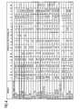
FIG. 1, 2 schematically the arrangement of a component and a wire electrode,FIG. 3 a turbine blade andFIG. 4 a list of superalloys.
Die Figuren und die Beschreibung stellen nur Ausführungsbeispiele der Erfindung dar.The figures and the description represent only embodiments of the invention.
In
Die Turbinenschaufeln 120, 130 weisen vorzugsweise eine Superlegierung gemäß
Die Drahtelektrode 4 weist einen Durchmesser von mindestens 0,5mm und vorzugsweise bis 4mm, vorzugsweise je nach zu bearbeitenden Radius auf.The
Dadurch wird eine bisher nicht erreichte Bearbeitungsgeschwindigkeit und Genauigkeit erreicht.As a result, a previously unachieved machining speed and accuracy is achieved.
Die Herstellung der Oberfläche 13'' des Bauteils 1, 120, 130 erfolgt in zumindest zwei Schritten (
Im Hauptschnitt wird ausgehend von der Oberfläche 13 durch die Drahtelektrode 4 eine Grobkontur 13' erzeugt. Unterhalb der Grobkontur 13' ist eine wärmebeeinflusste Zone 10 (ist der Bereich zwischen Oberfläche 13' und gepunkteter Linie) ausgebildet.In the main section, starting from the
In zumindest einem, insbesondere in mehreren aufeinanderfolgenden Nachschnitten mit einer vorzugsweise sukzessiv reduzierten Entladeenergie wird die wärmebeeinflusste Zone 10 der vorausgegangenen Bearbeitung abgearbeitet.In at least one, in particular in several successive re-cuts with a preferably successively reduced discharge energy, the heat-affected
Durch die Reduzierung wird eine wärmebeeinflusste Zone 10, die durch die Bearbeitung im Bauteil erzeugt wird, immer kleiner bzw. verschwindet zum Schluss.As a result of the reduction, a heat-affected
Die Endkontur 13" ist in
Hierbei wird neben der Erzielung einer bestimmten Oberflächenrauhigkeit, Form- und Maßgenauigkeit eine Verringerung der Dicke der thermisch beeinflussten Randzone 10 angestrebt.Here, in addition to the achievement of a certain surface roughness, dimensional and dimensional accuracy, a reduction in the thickness of the thermally influenced
Durch die Nutzung eines CNC-Programms erfolgt eine Bewegung des Bauteils 120, 130 relativ zur Drahtelektrode 4 (
Die Drahterosion stellt ein kräftefreies Verfahren dar und benötigt keine kostenintensive Kräfte aufnehmenden Spannsysteme und ist dadurch in der Lage, flexibel verschiedene Laufschaufeltypen zu fertigen.Wire erosion is a zero-force process and does not require costly force-bearing chucking systems, allowing it to flexibly manufacture a variety of blade types.
Die
Die Strömungsmaschine kann eine Gasturbine eines Flugzeugs oder eines Kraftwerks zur Elektrizitätserzeugung, eine Dampfturbine oder ein Kompressor sein.The turbomachine may be a gas turbine of an aircraft or a power plant for power generation, a steam turbine or a compressor.
Die Schaufel 120, 130 weist entlang der Längsachse 121 aufeinander folgend einen Befestigungsbereich 400, eine daran angrenzende Schaufelplattform 403 sowie ein Schaufelblatt 406 und eine Schaufelspitze 415 auf.The blade 120, 130 has along the
Als Leitschaufel 130 kann die Schaufel 130 an ihrer Schaufelspitze 415 eine weitere Plattform aufweisen (nicht dargestellt).As a guide blade 130, the blade 130 may have at its
Im Befestigungsbereich 400 ist ein Schaufelfuß 183 gebildet, der zur Befestigung der Laufschaufeln 120, 130 an einer Welle oder einer Scheibe dient (nicht dargestellt).In the
Der Schaufelfuß 183 ist beispielsweise als Hammerkopf ausgestaltet. Andere Ausgestaltungen als Tannenbaum- oder Schwalbenschwanzfuß sind möglich.The
Die Schaufel 120, 130 weist für ein Medium, das an dem Schaufelblatt 406 vorbeiströmt, eine Anströmkante 409 und eine Abströmkante 412 auf.The blade 120, 130 has a leading
Bei herkömmlichen Schaufeln 120, 130 werden in allen Bereichen 400, 403, 406 der Schaufel 120, 130 beispielsweise massive metallische Werkstoffe, insbesondere Superlegierungen verwendet.In conventional blades 120, 130, for example, solid metallic materials, in particular superalloys, are used in all
Solche Superlegierungen sind beispielsweise aus der
Die Schaufel 120, 130 kann hierbei durch ein Gussverfahren, auch mittels gerichteter Erstarrung, durch ein Schmiedeverfahren, durch ein Fräsverfahren oder Kombinationen daraus gefertigt sein.The blade 120, 130 can be made by a casting process, also by directional solidification, by a forging process, by a milling process or combinations thereof.
Werkstücke mit einkristalliner Struktur oder Strukturen werden als Bauteile für Maschinen eingesetzt, die im Betrieb hohen mechanischen, thermischen und/oder chemischen Belastungen ausgesetzt sind.Workpieces with a monocrystalline structure or structures are used as components for machines which are exposed to high mechanical, thermal and / or chemical stresses during operation.
Die Fertigung von derartigen einkristallinen Werkstücken erfolgt z.B. durch gerichtetes Erstarren aus der Schmelze. Es handelt sich dabei um Gießverfahren, bei denen die flüssige metallische Legierung zur einkristallinen Struktur, d.h. zum einkristallinen Werkstück, oder gerichtet erstarrt.The production of such monocrystalline workpieces takes place e.g. by directed solidification from the melt. These are casting processes in which the liquid metallic alloy is transformed into a monocrystalline structure, i. to the single-crystal workpiece, or directionally solidified.
Dabei werden dendritische Kristalle entlang dem Wärmefluss ausgerichtet und bilden entweder eine stängelkristalline Kornstruktur (kolumnar, d.h. Körner, die über die ganze Länge des Werkstückes verlaufen und hier, dem allgemeinen Sprachgebrauch nach, als gerichtet erstarrt bezeichnet werden) oder eine einkristalline Struktur, d.h. das ganze Werkstück besteht aus einem einzigen Kristall. In diesen Verfahren muss man den Übergang zur globulitischen (polykristallinen) Erstarrung meiden, da sich durch ungerichtetes Wachstum notwendigerweise transversale und longitudinale Korngrenzen ausbilden, welche die guten Eigenschaften des gerichtet erstarrten oder einkristallinen Bauteiles zunichte machen.Here, dendritic crystals are aligned along the heat flux and form either a columnar grain structure (columnar, i.e., grains that run the full length of the workpiece and here, in common usage, are referred to as directionally solidified) or a monocrystalline structure, i. the whole workpiece consists of a single crystal. In these processes, it is necessary to avoid the transition to globulitic (polycrystalline) solidification, since non-directional growth necessarily forms transverse and longitudinal grain boundaries which negate the good properties of the directionally solidified or monocrystalline component.
Ist allgemein von gerichtet erstarrten Gefügen die Rede, so sind damit sowohl Einkristalle gemeint, die keine Korngrenzen oder höchstens Kleinwinkelkorngrenzen aufweisen, als auch Stängelkristallstrukturen, die wohl in longitudinaler Richtung verlaufende Korngrenzen, aber keine transversalen Korngrenzen aufweisen. Bei diesen zweitgenannten kristallinen Strukturen spricht man auch von gerichtet erstarrten Gefügen (directionally solidified structures).The term generally refers to directionally solidified microstructures, which means both single crystals that have no grain boundaries or at most small angle grain boundaries, and stem crystal structures that have probably longitudinal grain boundaries but no transverse grain boundaries. These second-mentioned crystalline structures are also known as directionally solidified structures.
Solche Verfahren sind aus der
Ebenso können die Schaufeln 120, 130 Beschichtungen gegen Korrosion oder Oxidation aufweisen, z. B. (MCrAlX; M ist zumindest ein Element der Gruppe Eisen (Fe), Kobalt (Co), Nickel (Ni), X ist ein Aktivelement und steht für Yttrium (Y) und/oder Silizium und/oder zumindest ein Element der Seltenen Erden, bzw. Hafnium (Hf)). Solche Legierungen sind bekannt aus der
Die Dichte liegt vorzugsweise bei 95% der theoretischen Dichte.The density is preferably 95% of the theoretical density.
Auf der MCrAlX-Schicht (als Zwischenschicht oder als äußerste Schicht) bildet sich eine schützende Aluminiumoxidschicht (TGO = thermal grown oxide layer).A protective aluminum oxide layer (TGO = thermal grown oxide layer) is formed on the MCrAlX layer (as an intermediate layer or as the outermost layer).
Vorzugsweise weist die Schichtzusammensetzung Co-30Ni-28Cr-8Al-0, 6Y-0, 7Si oder Co-28Ni-24Cr-10Al-0,6Y auf. Neben diesen kobaltbasierten Schutzbeschichtungen werden auch vorzugsweise nickelbasierte Schutzschichten verwendet wie Ni-10Cr-12Al-0,6Y-3Re oder Ni-12Co-21Cr-11Al-0, 4Y-2Re oder Ni-25Co-17Cr-10Al-0,4Y-1,5Re.Preferably, the layer composition comprises Co-30Ni-28Cr-8Al-O, 6Y-0, 7Si or Co-28Ni-24Cr-10Al-0.6Y. In addition to these cobalt-based protective coatings, nickel-based protective layers such as Ni-10Cr-12Al-0.6Y-3Re or Ni-12Co-21Cr-11Al-O, 4Y-2Re or Ni-25Co-17Cr-10Al-0.4Y-1 are also preferably used , 5RE.
Auf der MCrAlX kann noch eine Wärmedämmschicht vorhanden sein, die vorzugsweise die äußerste Schicht ist, und besteht beispielsweise aus ZrO2, Y2O3-ZrO2, d.h. sie ist nicht, teilweise oder vollständig stabilisiert durch Yttriumoxid und/oder Kalziumoxid und/oder Magnesiumoxid.On the MCrAlX may still be present a thermal barrier coating, which is preferably the outermost layer, and consists for example of ZrO2, Y2 O3 -ZrO2 , ie it is not, partially or completely stabilized by yttria and / or calcium oxide and / or magnesium oxide.
Die Wärmedämmschicht bedeckt die gesamte MCrAlX-Schicht. Durch geeignete Beschichtungsverfahren wie z.B. Elektronenstrahlverdampfen (EB-PVD) werden stängelförmige Körner in der Wärmedämmschicht erzeugt.The thermal barrier coating covers the entire MCrAlX layer. By suitable coating methods, e.g. Electron beam evaporation (EB-PVD) produces stalk-shaped grains in the thermal barrier coating.
Andere Beschichtungsverfahren sind denkbar, z.B. atmosphärisches Plasmaspritzen (APS), LPPS, VPS oder CVD. Die Wärmedämmschicht kann poröse, mikro- oder makrorissbehaftete Körner zur besseren Thermoschockbeständigkeit aufweisen. Die Wärmedämmschicht ist also vorzugsweise poröser als die MCrAlX-Schicht.Other coating methods are conceivable, for example atmospheric plasma spraying (APS), LPPS, VPS or CVD. The thermal barrier coating may have porous, micro- or macro-cracked grains for better thermal shock resistance. The Thermal insulation layer is therefore preferably more porous than the MCrAlX layer.
Wiederaufarbeitung (Refurbishment) bedeutet, dass Bauteile 120, 130 nach ihrem Einsatz gegebenenfalls von Schutzschichten befreit werden müssen (z.B. durch Sandstrahlen). Danach erfolgt eine Entfernung der Korrosions- und/oder Oxidationsschichten bzw. -produkte. Gegebenenfalls werden auch noch Risse im Bauteil 120, 130 repariert. Danach erfolgt eine Wiederbeschichtung des Bauteils 120, 130 und ein erneuter Einsatz des Bauteils 120, 130.Refurbishment means that components 120, 130 may need to be deprotected after use (e.g., by sandblasting). This is followed by removal of the corrosion and / or oxidation layers or products. Optionally, even cracks in the component 120, 130 are repaired. This is followed by a re-coating of the component 120, 130 and a renewed use of the component 120, 130.
Die Schaufel 120, 130 kann hohl oder massiv ausgeführt sein. Wenn die Schaufel 120, 130 gekühlt werden soll, ist sie hohl und weist ggf. noch Filmkühllöcher 418 (gestrichelt angedeutet) auf.The blade 120, 130 may be hollow or solid. If the blade 120, 130 is to be cooled, it is hollow and may still film cooling holes 418 (indicated by dashed lines) on.
Claims (4)
Translated fromGermanbei dem die Drahtelektrode (4) einen Durchmesser von mindestens 0,5mm,
insbesondere mindestens 1mm aufweist.Spark erosive cutting by means of an outgoing wire electrode (4) for machining a surface (13, 13 ') of a component (1, 120, 130),
in which the wire electrode (4) has a diameter of at least 0.5 mm,
in particular at least 1mm.
bei dem in einem Hauptschnitt als einen ersten Schritt zur Bearbeitung der Oberfläche (13) eine Grobkontur (13') an dem Bauteil (1, 120, 130) erzeugt wird und
in zumindest einem,
insbesondere mehreren Nachschnitten die Randschicht (10) der Grobkontur (13') nachgearbeitet wird.Method according to claim 1,
in which a rough contour (13 ') is produced on the component (1, 120, 130) in a main section as a first step for machining the surface (13), and
in at least one,
in particular, several aftercuts, the edge layer (10) of the rough contour (13 ') is refinished.
wobei in dem folgenden Nachschnitt oder den aufeinanderfolgenden Nachschnitten die Entladeenergie gegenüber der Entladeenergie des Hauptschnitts (13') reduziert wird,
insbesondere sukzessiv reduziert wird.Method according to claim 2,
wherein in the subsequent post-cut or successive post-cuts the discharge energy is reduced compared to the discharge energy of the main section (13 '),
in particular, is successively reduced.
bei dem der Durchmesser der Drahtelektrode (4) maximal 3mm beträgt,
insbesondere maximal 2mm,
ganz insbesondere maximal 1mm.Method according to claim 1, 2 or 3,
in which the diameter of the wire electrode (4) is at most 3 mm,
in particular maximum 2mm,
in particular, a maximum of 1mm.
Priority Applications (5)
| Application Number | Priority Date | Filing Date | Title |
|---|---|---|---|
| EP09014187AEP2322305A1 (en) | 2009-11-12 | 2009-11-12 | Electrical discharge cutting with thick wire electrode |
| PCT/EP2010/067180WO2011058040A1 (en) | 2009-11-12 | 2010-11-10 | Electrical discharge machining with thick wire electrode |
| EP10779752.4AEP2498941B1 (en) | 2009-11-12 | 2010-11-10 | Electrical discharge cutting with thick wire electrode |
| US13/508,612US20120228269A1 (en) | 2009-11-12 | 2010-11-10 | Electrical discharge machining with thick wire electrode |
| CN2010800515277ACN102686349A (en) | 2009-11-12 | 2010-11-10 | Electrical discharge cutting with thick running wire electrode |
Applications Claiming Priority (1)
| Application Number | Priority Date | Filing Date | Title |
|---|---|---|---|
| EP09014187AEP2322305A1 (en) | 2009-11-12 | 2009-11-12 | Electrical discharge cutting with thick wire electrode |
Publications (1)
| Publication Number | Publication Date |
|---|---|
| EP2322305A1true EP2322305A1 (en) | 2011-05-18 |
Family
ID=42105894
Family Applications (2)
| Application Number | Title | Priority Date | Filing Date |
|---|---|---|---|
| EP09014187AWithdrawnEP2322305A1 (en) | 2009-11-12 | 2009-11-12 | Electrical discharge cutting with thick wire electrode |
| EP10779752.4ANot-in-forceEP2498941B1 (en) | 2009-11-12 | 2010-11-10 | Electrical discharge cutting with thick wire electrode |
Family Applications After (1)
| Application Number | Title | Priority Date | Filing Date |
|---|---|---|---|
| EP10779752.4ANot-in-forceEP2498941B1 (en) | 2009-11-12 | 2010-11-10 | Electrical discharge cutting with thick wire electrode |
Country Status (4)
| Country | Link |
|---|---|
| US (1) | US20120228269A1 (en) |
| EP (2) | EP2322305A1 (en) |
| CN (1) | CN102686349A (en) |
| WO (1) | WO2011058040A1 (en) |
Citations (15)
| Publication number | Priority date | Publication date | Assignee | Title |
|---|---|---|---|---|
| EP0028926A1 (en)* | 1979-11-09 | 1981-05-20 | Fanuc Ltd. | Method of wire-cut electric discharge machining |
| US4448655A (en)* | 1981-11-17 | 1984-05-15 | Inoue-Japax Research Incorporated | Traveling-wire electroerosion machining electrode and method |
| JPS6099426A (en)* | 1983-11-04 | 1985-06-03 | Kobe Steel Ltd | Manufacture of composite wire for electric discharge machining |
| DE3415055A1 (en)* | 1984-04-21 | 1985-10-24 | Berkenhoff GmbH, 6301 Heuchelheim | QUICK CUTTING ELECTRODE FOR EDM CUTTING |
| EP0446368A1 (en)* | 1989-10-04 | 1991-09-18 | Fanuc Ltd. | Machining condition setting method for wire cut discharge machine |
| EP0486489B1 (en) | 1989-08-10 | 1994-11-02 | Siemens Aktiengesellschaft | High-temperature-resistant, corrosion-resistant coating, in particular for components of gas turbines |
| EP0412397B1 (en) | 1989-08-10 | 1998-03-25 | Siemens Aktiengesellschaft | Rhenium-containing protective coating with high corrosion and oxidation resistance |
| EP0892090A1 (en) | 1997-02-24 | 1999-01-20 | Sulzer Innotec Ag | Method for manufacturing single crystal structures |
| EP0786017B1 (en) | 1994-10-14 | 1999-03-24 | Siemens Aktiengesellschaft | Protective layer for protecting parts against corrosion, oxidation and excessive thermal stresses, as well as process for producing the same |
| WO1999067435A1 (en) | 1998-06-23 | 1999-12-29 | Siemens Aktiengesellschaft | Directionally solidified casting with improved transverse stress rupture strength |
| US6024792A (en) | 1997-02-24 | 2000-02-15 | Sulzer Innotec Ag | Method for producing monocrystalline structures |
| WO2000044949A1 (en) | 1999-01-28 | 2000-08-03 | Siemens Aktiengesellschaft | Nickel base superalloy with good machinability |
| EP1306454A1 (en) | 2001-10-24 | 2003-05-02 | Siemens Aktiengesellschaft | Rhenium containing protective coating protecting a product against corrosion and oxidation at high temperatures |
| EP1319729A1 (en) | 2001-12-13 | 2003-06-18 | Siemens Aktiengesellschaft | High temperature resistant part, made of single-crystal or polycrystalline nickel-base superalloy |
| EP1204776B1 (en) | 1999-07-29 | 2004-06-02 | Siemens Aktiengesellschaft | High-temperature part and method for producing the same |
Family Cites Families (6)
| Publication number | Priority date | Publication date | Assignee | Title |
|---|---|---|---|---|
| US3642601A (en)* | 1968-12-03 | 1972-02-15 | Iwao Kondo | Machine for processing a piece of work by electric current |
| CN2044526U (en)* | 1988-05-24 | 1989-09-20 | 西北工业大学1008教研室 | Gds-type high-speed electric spark apparatus for processing deep hole |
| US6130395A (en)* | 1998-06-17 | 2000-10-10 | Sodick Co., Ltd. | Method and apparatus for achieving a fine surface finish in wire-cut EDM |
| KR100528850B1 (en)* | 2004-02-05 | 2005-11-21 | 주식회사 풍국통상 | Multi purpose multilayer coated electrode wire for electric discharge machining and production method thereof |
| CN100457346C (en)* | 2006-03-15 | 2009-02-04 | 太原理工大学 | Electric spark composite machining process in magnetic field |
| CN101367145A (en)* | 2007-08-15 | 2009-02-18 | 朱红兵 | High speed pinhole knife handle type punched hole electrode |
- 2009
- 2009-11-12EPEP09014187Apatent/EP2322305A1/ennot_activeWithdrawn
- 2010
- 2010-11-10USUS13/508,612patent/US20120228269A1/ennot_activeAbandoned
- 2010-11-10CNCN2010800515277Apatent/CN102686349A/enactivePending
- 2010-11-10EPEP10779752.4Apatent/EP2498941B1/ennot_activeNot-in-force
- 2010-11-10WOPCT/EP2010/067180patent/WO2011058040A1/enactiveApplication Filing
Patent Citations (15)
| Publication number | Priority date | Publication date | Assignee | Title |
|---|---|---|---|---|
| EP0028926A1 (en)* | 1979-11-09 | 1981-05-20 | Fanuc Ltd. | Method of wire-cut electric discharge machining |
| US4448655A (en)* | 1981-11-17 | 1984-05-15 | Inoue-Japax Research Incorporated | Traveling-wire electroerosion machining electrode and method |
| JPS6099426A (en)* | 1983-11-04 | 1985-06-03 | Kobe Steel Ltd | Manufacture of composite wire for electric discharge machining |
| DE3415055A1 (en)* | 1984-04-21 | 1985-10-24 | Berkenhoff GmbH, 6301 Heuchelheim | QUICK CUTTING ELECTRODE FOR EDM CUTTING |
| EP0412397B1 (en) | 1989-08-10 | 1998-03-25 | Siemens Aktiengesellschaft | Rhenium-containing protective coating with high corrosion and oxidation resistance |
| EP0486489B1 (en) | 1989-08-10 | 1994-11-02 | Siemens Aktiengesellschaft | High-temperature-resistant, corrosion-resistant coating, in particular for components of gas turbines |
| EP0446368A1 (en)* | 1989-10-04 | 1991-09-18 | Fanuc Ltd. | Machining condition setting method for wire cut discharge machine |
| EP0786017B1 (en) | 1994-10-14 | 1999-03-24 | Siemens Aktiengesellschaft | Protective layer for protecting parts against corrosion, oxidation and excessive thermal stresses, as well as process for producing the same |
| EP0892090A1 (en) | 1997-02-24 | 1999-01-20 | Sulzer Innotec Ag | Method for manufacturing single crystal structures |
| US6024792A (en) | 1997-02-24 | 2000-02-15 | Sulzer Innotec Ag | Method for producing monocrystalline structures |
| WO1999067435A1 (en) | 1998-06-23 | 1999-12-29 | Siemens Aktiengesellschaft | Directionally solidified casting with improved transverse stress rupture strength |
| WO2000044949A1 (en) | 1999-01-28 | 2000-08-03 | Siemens Aktiengesellschaft | Nickel base superalloy with good machinability |
| EP1204776B1 (en) | 1999-07-29 | 2004-06-02 | Siemens Aktiengesellschaft | High-temperature part and method for producing the same |
| EP1306454A1 (en) | 2001-10-24 | 2003-05-02 | Siemens Aktiengesellschaft | Rhenium containing protective coating protecting a product against corrosion and oxidation at high temperatures |
| EP1319729A1 (en) | 2001-12-13 | 2003-06-18 | Siemens Aktiengesellschaft | High temperature resistant part, made of single-crystal or polycrystalline nickel-base superalloy |
Also Published As
| Publication number | Publication date |
|---|---|
| EP2498941B1 (en) | 2015-03-18 |
| US20120228269A1 (en) | 2012-09-13 |
| WO2011058040A1 (en) | 2011-05-19 |
| CN102686349A (en) | 2012-09-19 |
| EP2498941A1 (en) | 2012-09-19 |
Similar Documents
| Publication | Publication Date | Title |
|---|---|---|
| EP2591872A1 (en) | Remelting method and subsequent filling and resulting component | |
| EP2444590B1 (en) | Method for coating cooling holes | |
| EP2865781A1 (en) | Two layer ceramic layer having different microstructures | |
| EP3500395B1 (en) | 3-step method of producing air cooling holes using a nanosecond and millisecond laser and workpiece | |
| EP2712700A1 (en) | Laser drills without burr formation | |
| EP2725235A1 (en) | Differentially rough airfoil and corresponding manufacturing method | |
| EP2308628A1 (en) | Method of removal of a soldered component with local heating of the soldered place | |
| WO2014053327A1 (en) | Repairing component edges by means of psp elements and component | |
| EP2878697A1 (en) | Method for producing a chamfer, component with chamfer and device | |
| EP2604377B1 (en) | Method for laser processing a laminated piece with ceramic coating | |
| EP2583784A1 (en) | Preparation of a welding point before welding and component | |
| EP2774710A1 (en) | Surface and crack repair by means of different soldering materials | |
| EP2591877A1 (en) | Remelting method under reactive gas atmosphere | |
| EP2591876A1 (en) | Process for build-up welding a single or directionally solidified metallic article | |
| EP2730364A1 (en) | Weld pool backing at the edge area | |
| WO2015071011A1 (en) | Geometrically adapted spraying in coating methods | |
| EP2733236A1 (en) | Two-layer ceramic coating system having an outer porous layer and depressions therein | |
| EP2604378B1 (en) | Reopening of cooling holes with nanosecond laser in the microsecond range | |
| EP2498941B1 (en) | Electrical discharge cutting with thick wire electrode | |
| EP2402096A1 (en) | Porous beam structure | |
| EP2340909A1 (en) | Sealing of circular and oval openings in crown bases of turbine rotor blades using conical plugs | |
| WO2015078615A1 (en) | Device for masking based on a tungsten alloy and a tungsten alloy | |
| EP2754528A1 (en) | Method of build up welding a substrate through laser remelting of a prefabricated mold | |
| EP2322681A1 (en) | Method to avoid recrystallisation through alitization | |
| EP2756907A1 (en) | Built-up welding with an external thicker outline contour |
Legal Events
| Date | Code | Title | Description |
|---|---|---|---|
| PUAI | Public reference made under article 153(3) epc to a published international application that has entered the european phase | Free format text:ORIGINAL CODE: 0009012 | |
| AK | Designated contracting states | Kind code of ref document:A1 Designated state(s):AT BE BG CH CY CZ DE DK EE ES FI FR GB GR HR HU IE IS IT LI LT LU LV MC MK MT NL NO PL PT RO SE SI SK SM TR | |
| AX | Request for extension of the european patent | Extension state:AL BA RS | |
| STAA | Information on the status of an ep patent application or granted ep patent | Free format text:STATUS: THE APPLICATION IS DEEMED TO BE WITHDRAWN | |
| 18D | Application deemed to be withdrawn | Effective date:20111119 |