EP2321558B1 - Motorized gear and coupling system - Google Patents
Motorized gear and coupling systemDownload PDFInfo
- Publication number
- EP2321558B1 EP2321558B1EP08754534.9AEP08754534AEP2321558B1EP 2321558 B1EP2321558 B1EP 2321558B1EP 08754534 AEP08754534 AEP 08754534AEP 2321558 B1EP2321558 B1EP 2321558B1
- Authority
- EP
- European Patent Office
- Prior art keywords
- motor
- gear
- shaft
- coupling
- worm
- Prior art date
- Legal status (The legal status is an assumption and is not a legal conclusion. Google has not performed a legal analysis and makes no representation as to the accuracy of the status listed.)
- Not-in-force
Links
- 230000008878couplingEffects0.000titleclaimsdescription102
- 238000010168coupling processMethods0.000titleclaimsdescription102
- 238000005859coupling reactionMethods0.000titleclaimsdescription102
- 230000004044responseEffects0.000claimsdescription4
- 230000001276controlling effectEffects0.000description6
- 239000000463materialSubstances0.000description5
- 238000004891communicationMethods0.000description4
- 239000002184metalSubstances0.000description4
- 230000000295complement effectEffects0.000description3
- 239000004020conductorSubstances0.000description2
- 239000004033plasticSubstances0.000description2
- 238000005476solderingMethods0.000description2
- DHKHKXVYLBGOIT-UHFFFAOYSA-N1,1-DiethoxyethaneChemical compoundCCOC(C)OCCDHKHKXVYLBGOIT-UHFFFAOYSA-N0.000description1
- 239000004677NylonSubstances0.000description1
- 239000011354acetal resinSubstances0.000description1
- 230000003213activating effectEffects0.000description1
- 238000004378air conditioningMethods0.000description1
- 238000005266castingMethods0.000description1
- 238000010586diagramMethods0.000description1
- 238000005553drillingMethods0.000description1
- 238000010438heat treatmentMethods0.000description1
- 238000000034methodMethods0.000description1
- 238000003801millingMethods0.000description1
- 238000000465mouldingMethods0.000description1
- 229920001778nylonPolymers0.000description1
- 229920006324polyoxymethylenePolymers0.000description1
- 238000004080punchingMethods0.000description1
- 230000001105regulatory effectEffects0.000description1
- 238000010008shearingMethods0.000description1
- 238000009423ventilationMethods0.000description1
- 238000003466weldingMethods0.000description1
Images


Classifications
- F—MECHANICAL ENGINEERING; LIGHTING; HEATING; WEAPONS; BLASTING
- F24—HEATING; RANGES; VENTILATING
- F24F—AIR-CONDITIONING; AIR-HUMIDIFICATION; VENTILATION; USE OF AIR CURRENTS FOR SCREENING
- F24F13/00—Details common to, or for air-conditioning, air-humidification, ventilation or use of air currents for screening
- F24F13/08—Air-flow control members, e.g. louvres, grilles, flaps or guide plates
- F24F13/10—Air-flow control members, e.g. louvres, grilles, flaps or guide plates movable, e.g. dampers
- F24F13/14—Air-flow control members, e.g. louvres, grilles, flaps or guide plates movable, e.g. dampers built up of tilting members, e.g. louvre
- F24F13/1426—Air-flow control members, e.g. louvres, grilles, flaps or guide plates movable, e.g. dampers built up of tilting members, e.g. louvre characterised by actuating means
- F—MECHANICAL ENGINEERING; LIGHTING; HEATING; WEAPONS; BLASTING
- F24—HEATING; RANGES; VENTILATING
- F24F—AIR-CONDITIONING; AIR-HUMIDIFICATION; VENTILATION; USE OF AIR CURRENTS FOR SCREENING
- F24F11/00—Control or safety arrangements
- F24F11/30—Control or safety arrangements for purposes related to the operation of the system, e.g. for safety or monitoring
- F—MECHANICAL ENGINEERING; LIGHTING; HEATING; WEAPONS; BLASTING
- F24—HEATING; RANGES; VENTILATING
- F24F—AIR-CONDITIONING; AIR-HUMIDIFICATION; VENTILATION; USE OF AIR CURRENTS FOR SCREENING
- F24F11/00—Control or safety arrangements
- F24F11/62—Control or safety arrangements characterised by the type of control or by internal processing, e.g. using fuzzy logic, adaptive control or estimation of values
- F—MECHANICAL ENGINEERING; LIGHTING; HEATING; WEAPONS; BLASTING
- F24—HEATING; RANGES; VENTILATING
- F24F—AIR-CONDITIONING; AIR-HUMIDIFICATION; VENTILATION; USE OF AIR CURRENTS FOR SCREENING
- F24F11/00—Control or safety arrangements
- F24F11/70—Control systems characterised by their outputs; Constructional details thereof
- F24F11/72—Control systems characterised by their outputs; Constructional details thereof for controlling the supply of treated air, e.g. its pressure
- F24F11/74—Control systems characterised by their outputs; Constructional details thereof for controlling the supply of treated air, e.g. its pressure for controlling air flow rate or air velocity
- G—PHYSICS
- G05—CONTROLLING; REGULATING
- G05D—SYSTEMS FOR CONTROLLING OR REGULATING NON-ELECTRIC VARIABLES
- G05D7/00—Control of flow
- G05D7/06—Control of flow characterised by the use of electric means
- G05D7/0617—Control of flow characterised by the use of electric means specially adapted for fluid materials
- G05D7/0629—Control of flow characterised by the use of electric means specially adapted for fluid materials characterised by the type of regulator means
- G05D7/0635—Control of flow characterised by the use of electric means specially adapted for fluid materials characterised by the type of regulator means by action on throttling means
- F—MECHANICAL ENGINEERING; LIGHTING; HEATING; WEAPONS; BLASTING
- F16—ENGINEERING ELEMENTS AND UNITS; GENERAL MEASURES FOR PRODUCING AND MAINTAINING EFFECTIVE FUNCTIONING OF MACHINES OR INSTALLATIONS; THERMAL INSULATION IN GENERAL
- F16H—GEARING
- F16H1/00—Toothed gearings for conveying rotary motion
- F16H1/02—Toothed gearings for conveying rotary motion without gears having orbital motion
- F16H1/04—Toothed gearings for conveying rotary motion without gears having orbital motion involving only two intermeshing members
- F16H1/12—Toothed gearings for conveying rotary motion without gears having orbital motion involving only two intermeshing members with non-parallel axes
- F16H1/16—Toothed gearings for conveying rotary motion without gears having orbital motion involving only two intermeshing members with non-parallel axes comprising worm and worm-wheel
- F—MECHANICAL ENGINEERING; LIGHTING; HEATING; WEAPONS; BLASTING
- F24—HEATING; RANGES; VENTILATING
- F24F—AIR-CONDITIONING; AIR-HUMIDIFICATION; VENTILATION; USE OF AIR CURRENTS FOR SCREENING
- F24F13/00—Details common to, or for air-conditioning, air-humidification, ventilation or use of air currents for screening
- F24F13/08—Air-flow control members, e.g. louvres, grilles, flaps or guide plates
- F24F13/10—Air-flow control members, e.g. louvres, grilles, flaps or guide plates movable, e.g. dampers
- F24F13/14—Air-flow control members, e.g. louvres, grilles, flaps or guide plates movable, e.g. dampers built up of tilting members, e.g. louvre
- F24F13/1426—Air-flow control members, e.g. louvres, grilles, flaps or guide plates movable, e.g. dampers built up of tilting members, e.g. louvre characterised by actuating means
- F24F2013/1446—Air-flow control members, e.g. louvres, grilles, flaps or guide plates movable, e.g. dampers built up of tilting members, e.g. louvre characterised by actuating means with gearings
- Y—GENERAL TAGGING OF NEW TECHNOLOGICAL DEVELOPMENTS; GENERAL TAGGING OF CROSS-SECTIONAL TECHNOLOGIES SPANNING OVER SEVERAL SECTIONS OF THE IPC; TECHNICAL SUBJECTS COVERED BY FORMER USPC CROSS-REFERENCE ART COLLECTIONS [XRACs] AND DIGESTS
- Y10—TECHNICAL SUBJECTS COVERED BY FORMER USPC
- Y10T—TECHNICAL SUBJECTS COVERED BY FORMER US CLASSIFICATION
- Y10T74/00—Machine element or mechanism
- Y10T74/19—Gearing
- Y10T74/19642—Directly cooperating gears
- Y10T74/19698—Spiral
- Y10T74/19828—Worm
- Y—GENERAL TAGGING OF NEW TECHNOLOGICAL DEVELOPMENTS; GENERAL TAGGING OF CROSS-SECTIONAL TECHNOLOGIES SPANNING OVER SEVERAL SECTIONS OF THE IPC; TECHNICAL SUBJECTS COVERED BY FORMER USPC CROSS-REFERENCE ART COLLECTIONS [XRACs] AND DIGESTS
- Y10—TECHNICAL SUBJECTS COVERED BY FORMER USPC
- Y10T—TECHNICAL SUBJECTS COVERED BY FORMER US CLASSIFICATION
- Y10T74/00—Machine element or mechanism
- Y10T74/21—Elements
- Y10T74/2186—Gear casings
Definitions
- the inventionrelates to a system for controlling an airflow through a plenum according to claim 1.
- Worm and planetary gearswork together to transfer rotational movement in one plane to another plane.
- the worm gear and planetary gear(also commonly referred to as a worm and worm gear, respectively) are placed in rotational engagement with each other so that the threads of the worm gear mesh with the teeth of the planetary gear.
- the longitudinal axis of the worm gear and that of the planetary gearare at right angles with each other so that rotational movement of one gear along its longitudinal axis is transferred to the other gear along its longitudinal axis.
- the worm gear/planetary gear combinationmay be used to transfer the rotational movement of one shaft or other body to that of another shaft or body. This may be accomplished by coupling one of the shafts to the worm gear and the other to the planetary gear. Couplings are used to couple the shafts to the gears. In general, the couplings are separate elements, such as a nut or bearing, which must be separately attached to both the shaft and the gear. For example, the shaft may be inserted into the axle of the gear and held in place with a bearing.
- the worm couplingincludes a head and an elongated portion.
- the elongated portionmay be inserted into and fixedly attached to the worm gear. In this manner, the elongated portion serves as the axle of the worm gear.
- the head of the worm couplingincludes an opening into which the worm shaft is inserted and to which it is removably attached.
- the headmay include one or more bores into which set screws may be inserted so that they contact the worm shaft.
- the cross-sectional shape of the coupling and the worm shaftare generally complementary.
- the planetary couplingcouples a shaft (the "planetary shaft") with the planetary gear.
- the planetary couplingincludes a bore into which the planetary shaft may be inserted and to which it is removably attached.
- the planetary couplingmay include one or more bores into which set screws may be inserted so that they contact the planetary shaft.
- the planetary couplingmay accommodate planetary shafts with cross-sections significantly different and/or smaller than that of the planetary coupling.
- the cross-sectional shape of the planetary coupling and the planetary shaftmay be complementary, however, this is not necessary.
- the worm shaftis coaxially connected with a motor or gear-motor that rotates the worm shaft and, consequently, the worm gear.
- the motoris in electromechanical communication with the controller when the controller is connected to a modular interface.
- the motormay be direct current, low voltage, low torque, and low rpm.
- the controllerregulates the motor, particularly by activating and deactivating the motor as well as controlling the direction and distance the motor rotates the worm shaft.
- the controlleralso powers the motor, for instance, by battery.
- the controllermay contain a processor and/or memory.
- the processormay be coupled to a sensor that deactivates the motor once the motor draws a certain level of current, indicating that the mechanism has reached the end of its range of motion.
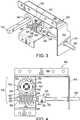
- the system 100generally includes a worm gear coupling 200, worm gear 300, planetary gear 400 and planetary gear coupling 500. As shown in FIGS. 1 and 2 , the system 100 may be mounted on a bracket 800.
- the bracket 800may include configurations that maintain the functional relationship among the elements of the system 100.
- the worm gear 300 and the planetary gear 400are mounted at right angles to each other so that the threads 302 of the worm gear 300 intermesh with the teeth 402 of the planetary gear 400. In this arrangement, rotation of the worm gear 300 around its longitudinal axis will cause the planetary gear 400 to rotate around its longitudinal axis.
- the worm gear coupling 200includes a head 202 and an elongated portion 204.
- the worm gear 300is coaxially attached around the elongated portion 204 along the longitudinal axis of the elongated portion 204.
- the elongated portion 204serves as the axle of the worm gear 300 in one integrated element.
- the head 202includes a bore 210 for receiving a set screw 206. Although one bore 210 and one set screw 206 are shown, a variety and number of bores 210 and set screws 206 may be included.
- the headalso includes an opening 208.
- the planetary gear coupling 500is fixedly and coaxially attached to the planetary gear 400.
- planetary gear 400 and planetary gear coupling 500are formed integrally as a single element.
- the planetary gear coupling 500may include a number of bores 506 for receiving a number of set screws 502. Although four bores 506 and set screws 502 are shown in FIGS. 1 and 2 , a variety and number of bores 506 and set screws 502 may be included.
- Worm gear coupling 200, worm gear 300, planetary gear 400 and planetary gear coupling 500may be formed of various materials that are known in the art, including metal and plastic.
- worm gear coupling 200 and worm gear 300 (and/or planetary gear 400 and planetary gear coupling 500)are integral and formed as a single element.
- Worm gear coupling 200, worm gear 300, planetary gear 400 and/or planetary gear coupling 500may be made of various materials that are known in the art, including metal, nylon or acetal resin, and may be formed by milling, casting, molding or other methods known in the art that are appropriate to the material.
- the gear and coupling system 100may be used to translate the rotational motion of one body to another body along a different axis.
- the system 100may be used to translate the rotational movement of one shaft (a worm shaft 600) around the longitudinal axis of the worm gear 300 to another shaft (a planetary shaft 700) around the longitudinal axis of the planetary gear 400.
- the worm shaft 600may serve as the drive shaft for the system 100.
- the worm shaft 600 and the planetary shaft 700may be a rigid or flexible body, such as a flexible cable.
- the worm shaft 600may be removably coupled to the worm gear 300 via the worm coupling 200. As shown in FIGS. 5 and 6 , the elongated portion 204 of the worm coupling 200 is inserted into the bore 304 in the worm gear 300. For example, the elongated portion 204 of the worm coupling 200 may be knurled and slightly larger in diameter than the bore 304. The elongated portion 204 is press fit into the worm gear 300. To couple the worm shaft 600 with the worm gear 300, the worm shaft 600 is inserted into the opening 208 in the head 202 of the worm coupling 200 and secured therein by one or more set screws 206.
- the worm coupling 200In addition to coupling the worm shaft 600 with the worm gear 300, the worm coupling 200, particularly the elongated portion 204, serves as the axle of the worm gear 300. Thus, rotation of the worm shaft 600 will cause the worm gear 300 to rotate along its longitudinal axis.
- the planetary shaft 700may be removably coupled with the planetary gear 400 via the planetary coupling 500.
- the planetary shaft 700is inserted into the bore 504 in the planetary coupling 500 and secured therein by the set screws 502.
- the planetary coupling 500includes four bores 504 and four set screws 502.
- the opening 208 in the worm coupling 200may have a variety of cross-sectional shapes, which are generally complementary to the shape of the cross-section of the worm shaft 600.
- the opening 208 and the cross-section of the worm shaft 600 proximate to the worm coupling 200has a square shape.
- the opening 208 and the cross-section of the worm shaft 600may have other shapes for example, circular or hexagonal.
- the bore 504 in the planetary coupling 500may have a circular cross-section, which may receive planetary shafts 700 of various cross-sectional shapes, such as circular, square (which is shown in FIGS. 3 and 4 ) and hexagonal.
- the planetary coupling 500may accommodate planetary shafts 700 with cross-sections significantly smaller than that of the planetary coupling 500.
- the systemmay be supported by a bracket 800.
- a bracket 800One example of such a bracket 800 is shown in FIGS. 1-4 .
- the bracketmay include a lower support 802, a side support 808 and an end support 810.
- the worm gear 300 and the planetary gear 400are supported by the lower support 802.
- the planetary gear 400is secured to the lower support 802 so that its longitudinal axis is about perpendicular with the lower support 802.
- the planetary gear 400may go through a bore 504 in the lower support 802 and be attached to the bore 504 via a snap ring or retaining ring (not shown) located on the side of the lower support 802 opposite the planetary coupling 500.
- the lower support 802includes a pair of protrusions 806 and 807 that support the worm gear 300.
- the protrusions 806 and 807each include a bore 811 and 809, respectively, through which the axle of the worm gear 300 (the elongated portion 204 of the worm coupling 200) is inserted.
- the elongated portion 204may be knurled and press fit into one protrusion 806, the worm gear 300 and the other protrusion 807, respectively.
- the worm gear 300 and the planetary gear 400are located on the lower support 802 of the bracket 800 in such proximity with each other so that the threads 302 of the worm gear 300 mesh with the teeth 402 of the planetary gear 400.
- the side support 808 of the bracket 800attaches the lower support 802 to the end support 810 so that the end support 810 faces the lower support 802.
- the end support 810may include a bore 812 through which the worm shaft 600 may protrude. This arrangement provides support to the worm shaft 600 and aligns the longitudinal axis of the worm shaft 600 with that of the worm coupling 200.
- the bracket 800may be manufactured from a material such as metal or engineered plastic.
- the bracket 800may be made from a single piece of material (for example, stamped in one piece from a single sheet of metal) and folded to obtain the desired shape.
- the components of the bracket 800may be manufactured separately and secured together via, for example, welding, screwing and/or soldering.
- protrusions 806 and 807may be formed as yokes having an opening on the side toward the planetary gear.
- a gear and coupling systemis shown having a worm gear 350 and a planetary gear 450 that are mounted on a bracket 850.
- Bracket 850is provided with yokes 856 and 857 having openings 858 and 859, respectively, on the side toward planetary gear 450.
- Axle 352 of worm gear 350is inserted in openings 858 and 859 and supported on yokes 856 and 857.
- Axle 352is further provided with a collar 354 and radial flange 356 that are positioned outside of yokes 856 and 857, respectively. Both collar 354 and radial flange 356 have diameters that are larger than openings 858 and 859, to prevent worm gear 350 from slipping laterally within yokes yokes 856 and 857.
- the assembly of planetary gear 450 on bracket 850prevents worm gear 350 from inadvertently lifting out of yokes 856 and 857 and further secures worm gear 300 in place.
- planetary shafts 700 of different sizes and shapesmay be accommodated.
- the aperture 504 and set screws 502may accommodate a 0.25 or 0.375 inch square shaft.
- the aperture 504 and set screws 502may accommodate 0.25 or 0.5 inch round shaft 700.
- Such plenums 900may be located in areas that are not conveniently or easily accessible.
- the plenum 900may be located in a ceiling, wall or floor. Therefore, some type of device is needed to enable the dampers 904 to be remotely controlled.
- This devicemay include a worm shaft 600.
- the worm shaft 600may include, for example, a flexible or non-flexible cable. If the plenum 900 is installed in a ceiling, the worm shaft 600, which is in communication with the worm coupling 200, may protrude from the ceiling. Thus, the dampers 904 may be controlled by rotating the protruding worm shaft 600.
- a motorized gear and coupling system 1000is shown, which generally includes a worm gear coupling 1200, worm gear 1300, planetary gear 1400 and a planetary gear coupling 500, that are mounted on a bracket 1800.
- a worm shaft 1600is coupled with worm gear 1300 through worm coupling 1200.
- a motor 1100is mounted on end support 1810 of bracket 1800, that is connected with and configured to rotate worm shaft 1600.
- the motor 1100may have an output shaft that serves as a drive shaft and is inserted directly into the worm coupling 1200, thus eliminating the need for a separate worm shaft.
- Motor 1100may be removably mounted on bracket 1800 using bolts, screws or other fasteners (not shown) that are well known in the art.
- Motor 1100is operated by a controller 1102, which is in electromechanical communication with the motor via a cable 1104.
- Motor 1100is preferably a direct current, low voltage motor (e.g., a 9 V, 12 V or 18 V motor) having low rpm and low torque.
- motor 1100may be a gear-motor that includes a gear set 1101 to gear down the speed of the motor to accommodate the requirements of a particular application.
- motorized gear and coupling system 1000it is presently preferred that motor 1100 be geared down such that it takes approximately 10-15 seconds for the dampers to move from a position of maximum airflow to a position of minimum airflow (or vice versa).
- a motor and gear set that rotates worm shaft 1600 in a range of about 30 rpm to about 35 rpmis particularly useful for controlling dampers when the gear and coupling system includes a worm gear and planetary gear.
- the gear ratio of the worm gear and planetary gearmay also be a factor in determining the optimal motor speed.
- controller 1102includes a switch 1106, a control module 1108, a user interface 1110 and a power supply 1112.
- Control module 1108includes a microprocessor 1114 and a sensor 1116.
- User interfaceincludes an input 1120 and a display 1122.
- controller 1102is a portable handheld device having a housing 1103 that contains switch 1106, control module 1108, user interface 1110 and power supply 1112.
- Housing 1103may be ergonomically designed and may be provided with a textured grip 1105. Housing 1103 may be provided with other features to enhance its portability, such as a belt clip and/or retractable reel (not shown).
- Motorized gear and coupling system 1000is operated by actuating switch 1106, which provides a signal to microprocessor 1114 via input 1120.
- Microprocessor 1114provides a current from power supply 1112 through cable 1104 to motor 1100, to drive worm shaft 1600 and operate gear and coupling system 1000.
- Sensor 1116monitors the operation of motor 1100 and provides a signal to microprocessor 1114. Based on the signals from switch 1106 and/or from sensor 1116, microprocessor 1114 directs display 1122 to provide an indicia that reflects the operational condition of gear and coupling system 1000 and/or controls the current provided to motor 1100 from power supply 1112.
- switch 1106is a 3-position rocker switch having a rest position, a first position 1106a and a second position 1106b. Actuating switch 1106 at the first position 1106a sends a first signal to microprocessor 1114 to provide a current from power supply 1112 and operate motor 1100 to rotate worm shaft 1600 in a first, forward direction. Actuating switch 1106 at the second position 1106b sends a second signal to microprocessor 1114 to reverse the polarity of the current from power supply 1112 and operate motor 1100 to rotate worm shaft 1600 in a second, reverse direction. When neither position 1106a nor 1106b are actuated, switch 1106 returns to the rest position and no current is provided to motor 1100. Those of skill in the art will appreciate that other type of switches may be used, such as separate buttons 2106a and 2106b for forward and reverse, rather than a rocker switch, as shown in FIG. 11 .
- sensor 1116detects the level of current draw by motor 1100. In a first operating condition, motor 1100 rotates freely and sensor 1116 detects a first level of current draw and sends a first signal to microprocessor 1114. In a second operating condition, motor 1100 experiences resistance to rotation which increases the current draw by the motor. Sensor 1116 detects the increased current draw and sends a second signal to microprocessor 1114 to shut off the current from power supply 1112 to motor 1100.
- Display 1122is controlled by microprocessor 1114 in response to signals from rocker switch 1106 and/or sensor 1116.
- display 1122comprises LEDs 1124a and 1124b that provide indicia of the operating condition of motor 1100.
- LEDs 1124a and 1124bpositioned to correspond to first and second positions 1106a and 1106b of a rocker switch 1106. The actuation of rocker switch 1006 at first position 1106a sends a first signal to microprocessor 1114 which, in turn, directs first LED 1124a to provide a first indicia that motor 1100 is rotating in a first direction.
- sensor 1116When motor 1100 experiences resistance to rotation, such as when worm shaft 1600 is prevented from rotating, sensor 1116 sends a second signal to microprocessor 1114 which, in turn, directs first LED 1124a to provide a second indicia that motor 1100 has experienced a change in operating condition.
- LED 1124bsimilarly provides indicia that motor 1100 is operating in a second, reverse direction, and whether motor 1100 has experienced a change in operating condition.
- rocker switch 1106when motorized gear and coupling system 1000 is used to control the motion of a damper, actuating rocker switch 1106 at position 1106a causes the motor to rotate in a first direction and causes LED 1124a to turn green, indicating that the dampers are moving toward an open position to allow maximum airflow.
- worm shaft 1600Once the dampers are in the fully open position and have reached the end of their range of motion, worm shaft 1600 is prevented from further rotation, the current to motor 1100 is shut off, and LED 1124a turns red to indicate that the dampers have stopped moving and are fully open.
- rocker switch 1106when rocker switch 1106 is actuated at position 1106b, motor 1100 operates in reverse and LED 1124b turns green, indicating that the dampers are moving toward a closed position to restrict airflow.
- Power supply 1112may be of any type sufficient to operate motor 1100.
- power supply 1112is a low voltage power supply that is small enough for a portable device and is easily replaced, such as a 9 V battery.
- Controller 1102may include a shutoff switch 1126 to turn off the controller and prevent the battery from being drained by the continuing draw from microprocessor 1114 or by the inadvertent actuation of switch 1106.
- Controller 1102is connected to motor 1100 by a cable 1104.
- Cable 1104may be of any type suitable for the application.
- cable 1104is preferably a two conductor, plenum rated cable or similar fire rated cable.
- the connections between cable 1104 and motor 1100 and/or between cable 1104 and controller 1102may be soldered or may use any of a variety of electrical connectors that are known in the art.
- cable 1104is detachably connected to controller 1102, to create a modular system where a single controller may be used with multiple different motorized gear and coupling systems 1000. As shown in FIG.
- Motorized gear and coupling system 2000generally comprises a worm gear/coupling 2200, planetary gear/coupling 1400 and motor 2100 that are mounted on a bracket 2800, a cable 2104 and a controller 2102.
- Bracket 2800is mounted at a plenum 2010, such as a ceiling plenum for use in an HVAC system.
- motorized gear and coupling system 2000is mounted on plenum 2010, but may also be mounted on a nearby structure.
- a damper(not shown) is mounted within plenum 2010 to regulate airflow, and is operated by motorized gear and coupling system 2000.
- Cable 2104extends from motor 2100 at plenum 2010 to a remote location and terminates in a detachable electrical connection 2128.
- electrical connection 2128is mounted in a wall 2004 at a location that is conveniently accessible to the user. This configuration permits the gear and coupling system, including the motor, to be installed on a plenum, leaving the controller as the only external part of the system.
- Controller 2102includes a cable 2132 that has a first end 2132a that is connected to the controller and a second end 2132b that terminates in a detachable electrical connection 2134 which corresponds to detachable electrical connection 2128 of cable 2104.
- detachable electrical connections 2134 and 2128are a mini power plug and jack, respectively.
- End 2132a of cable 2132may be connected to controller 2102 by soldering or may use any of a variety of electrical connectors that are known in the art.
- end 2132a of cable 2132is also connected to controller 2102 by a detachable electrical connection, such as a mini power plug/jack.
- a modular systemmay include a wall plate 2138 for mounting multiple electrical connections 2128 corresponding to different motorized gear and coupling systems.
- Wall plate 2138is installed at a convenient location, such that multiple motorized gear and coupling systems at different locations may be easily controlled by alternately connecting the plug 2134 of a controller 2102 into the various electrical connectors 2128.
- Indicia 2140may be provided on wall plate 2138 to identify the different motorized gear and coupling system associated with each electrical connection 2128.
- the controllermay provide the user with additional information, such as battery life, identification of the damper being controlled, the position of the dampers relative to the fully open/closed position, and other information.
- the controllermay be provided with an alphanumeric display 2136, rather than simple LEDs.
- the controllermay also include a memory 1118 to store data.
- cables 2104 and 2132may be four conductor cables with appropriate electrical connectors 2128, 2134.
- motorized gear and coupling system described hereinis not limited to a worm gear and planetary gear, but may be adapted for use with other gearing systems, such as miter gears or a friction drive.
- operation of a dampermay not require the translation of rotational movement, but may be directly driven by the motor through a drive shaft.
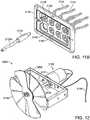
- FIGS. 12 and 13an alternative embodiment of a system for controlling airflow through a plenum is shown.
- a rotary damper 3000 and a motor 3100are mounted on a bracket 3800.
- Motor 3100is directly connected to rotary damper 3000 by a drive shaft 3600, without intervening gearing.
- Rotary damper 3000may be removably coupled to drive shaft 3600 by a coupling (not shown) in the same manner as previously described couplings 200 and 500.
- a controller(not shown) is connected to motor 3100 by cable 3104.
- motor 3100causes drive shaft 3600 to rotate damper blades 3136 and either open or close damper 3000, depending on the direction of rotation of the motor.
- motor 3100is a gear-motor that contains an appropriate gear set 3101 to gear down the motor and ensure that it takes approximately 10 to 15 seconds for damper blades 3136 to move between open and closed positions. It has been found that a gear motor capable of rotating drive shaft 3600 at a speed of about 2.5 rpm is particularly useful.
- rotary damper 3000 and motor 3100are shown mounted in a plenum 3900 to control the airflow through the plenum.
- motor 3100is positioned in the airstream when used in an HVAC system or other regulated airflow system.
- Cable 3104may extend from motor 3100 through plenum 3900 to a remotely located diffuser 3902 or other opening in the plenum system.
- diffuser 3902is located in a ceiling 3004 or other structure where the end 3104a of cable 3104 is conveniently accessible for connection to a controller.
- End 3104a of cable 3104is provided with a detachable electrical connector 3128 (e.g., a mini power jack) for connection to the corresponding detachable electrical connector 3134 (e.g., a mini power plug) of a controller.
- end 3104amay be secured to plenum 3900 at or near diffuser 3902, using a clamp 3132 or by other means known in the art.
- cable 3104may exit the plenum through a hole in the wall of the plenum (not shown) that is made by drilling, punching or other means known in the art.
- the holemay be provided with a grommet (not shown) to protect cable 3104 from fraying or shearing caused by the edges of the hole.
- Cable 3104extends from motor 3100 at plenum 3900 to a remote location and terminates in a detachable electrical connection, such as previously described wall plate 2138.
Landscapes
- Engineering & Computer Science (AREA)
- Combustion & Propulsion (AREA)
- General Engineering & Computer Science (AREA)
- Mechanical Engineering (AREA)
- Chemical & Material Sciences (AREA)
- Physics & Mathematics (AREA)
- Mathematical Physics (AREA)
- Signal Processing (AREA)
- Fuzzy Systems (AREA)
- Fluid Mechanics (AREA)
- General Physics & Mathematics (AREA)
- Automation & Control Theory (AREA)
- Gear Transmission (AREA)
Description
- This application is a continuation-in-part of
U.S. Patent Application Number 11/974,302 filed on October 12, 2007 - The invention relates to a system for controlling an airflow through a plenum according to
claim 1. Worm and planetary gears work together to transfer rotational movement in one plane to another plane. The worm gear and planetary gear (also commonly referred to as a worm and worm gear, respectively) are placed in rotational engagement with each other so that the threads of the worm gear mesh with the teeth of the planetary gear. Thus, the longitudinal axis of the worm gear and that of the planetary gear are at right angles with each other so that rotational movement of one gear along its longitudinal axis is transferred to the other gear along its longitudinal axis. - The worm gear/planetary gear combination may be used to transfer the rotational movement of one shaft or other body to that of another shaft or body. This may be accomplished by coupling one of the shafts to the worm gear and the other to the planetary gear. Couplings are used to couple the shafts to the gears. In general, the couplings are separate elements, such as a nut or bearing, which must be separately attached to both the shaft and the gear. For example, the shaft may be inserted into the axle of the gear and held in place with a bearing.
- The shafts coupled to the worm and planetary gears may by rotated manually. However, the gears can also be rotated by a motor. Thus, either the manual or motorized motion of one shaft is translated via the worm gear/planetary gear combination to another shaft or body.
U.S. Patent No. 5,744,923 (issued April 28, 1998 ), which is regarded as closest prior art, discloses an actuator motor coupled to an air damper. The actuator includes control electronics for operating the motor. - A gear system comprising a gear and coupling portion including a shaft, a worm gear, a planetary gear, a motor, and a means for controlling the motor is presented. The system may be supported by a bracket. The worm gear includes a coupler (a "worm coupling") integrated with the worm gear's axle. Thus, the axle and the coupler form one integrated element. To attach a shaft (the "worm shaft") to the worm coupling and a shaft (the "planetary shaft") to the planetary gear, the worm shaft and the planetary shaft are inserted into the worm coupling and the planetary coupling, respectively. Both couplings include bores through which set screws are inserted so that they engage the shafts. Thus, the shafts are held in place. Shafts of different sizes and shapes may be accommodated by the distance by which the set screws are inserted into the couplings.
- The worm coupling includes a head and an elongated portion. The elongated portion may be inserted into and fixedly attached to the worm gear. In this manner, the elongated portion serves as the axle of the worm gear. The head of the worm coupling includes an opening into which the worm shaft is inserted and to which it is removably attached. To attach the worm shaft to the worm coupling, the head may include one or more bores into which set screws may be inserted so that they contact the worm shaft. The cross-sectional shape of the coupling and the worm shaft are generally complementary.
- The planetary coupling couples a shaft (the "planetary shaft") with the planetary gear. The planetary coupling includes a bore into which the planetary shaft may be inserted and to which it is removably attached. To attach the planetary shaft to the planetary coupling, the planetary coupling may include one or more bores into which set screws may be inserted so that they contact the planetary shaft. By using a multiple of bores and set screws, such as four, the planetary coupling may accommodate planetary shafts with cross-sections significantly different and/or smaller than that of the planetary coupling. The cross-sectional shape of the planetary coupling and the planetary shaft may be complementary, however, this is not necessary.
- The worm shaft is coaxially connected with a motor or gear-motor that rotates the worm shaft and, consequently, the worm gear. The motor is in electromechanical communication with the controller when the controller is connected to a modular interface. For example, the motor may be direct current, low voltage, low torque, and low rpm. The controller regulates the motor, particularly by activating and deactivating the motor as well as controlling the direction and distance the motor rotates the worm shaft. The controller also powers the motor, for instance, by battery. The controller may contain a processor and/or memory. The processor may be coupled to a sensor that deactivates the motor once the motor draws a certain level of current, indicating that the mechanism has reached the end of its range of motion.
- The invention can be better understood with reference to the following drawings and description. The components in the figures are not necessarily to scale, emphasis instead being placed upon illustrating the principles of the invention. In the drawings:
FIG. 1 . is a front isometric view of a gear and coupling system mounted on a bracket;FIG. 2 is a front elevation view of the gear and coupling system mounted on a bracket shown inFIG. 1 ;FIG. 3 is front isometric view of a the gear and coupling system mounted on a bracket shown inFIG. 1 receiving a first and second shaft;FIG. 4 is a front elevation view of a the gear and coupling system mounted on a bracket shown inFIG. 1 receiving a first and second shaft;FIG. 5 is an exploded isometric view of the coupling, first shaft and worm gear shown inFIG. 3 ;FIG. 6 is an isometric view of the coupling, first shaft and worm gear shown inFIG. 3 ;FIG. 7 is an isometric view of the gear and coupling system shown inFIG. 3 in operative communication with plenums in a duct;FIG. 8 is an alternative embodiment of a gear and coupling system.FIG. 9 is an isometric view of a motorized gear and coupling system;FIG. 10 is a functional block diagram of the controller ofFIG. 9 ; andFIG. 11 a is a side elevation view of the motorized gear and coupling system shown inFIG. 9 adapted to operate a damper.FIG. 11b is an isometric view of a wall plate for mounting multiple electrical connectors corresponding to multiple different motorized gear and coupling systems at different locations.FIG. 12 is an isometric view of an alternative embodiment of a system for controlling airflow through a plenum.FIG. 13 is a side elevation view of the system ofFIG. 12 , mounted in a plenum.- A gear and coupling system is shown in
FIGS. 1 and 2 . Thesystem 100 generally includes aworm gear coupling 200,worm gear 300,planetary gear 400 andplanetary gear coupling 500. As shown inFIGS. 1 and 2 , thesystem 100 may be mounted on abracket 800. Thebracket 800 may include configurations that maintain the functional relationship among the elements of thesystem 100. Theworm gear 300 and theplanetary gear 400 are mounted at right angles to each other so that thethreads 302 of theworm gear 300 intermesh with theteeth 402 of theplanetary gear 400. In this arrangement, rotation of theworm gear 300 around its longitudinal axis will cause theplanetary gear 400 to rotate around its longitudinal axis. - The
worm gear coupling 200 includes ahead 202 and anelongated portion 204. Theworm gear 300 is coaxially attached around theelongated portion 204 along the longitudinal axis of theelongated portion 204. Thus, theelongated portion 204 serves as the axle of theworm gear 300 in one integrated element. Thehead 202 includes abore 210 for receiving aset screw 206. Although onebore 210 and oneset screw 206 are shown, a variety and number ofbores 210 and setscrews 206 may be included. The head also includes anopening 208. - The
planetary gear coupling 500 is fixedly and coaxially attached to theplanetary gear 400. In a preferred embodiment,planetary gear 400 andplanetary gear coupling 500 are formed integrally as a single element. Theplanetary gear coupling 500 may include a number ofbores 506 for receiving a number ofset screws 502. Although fourbores 506 and setscrews 502 are shown inFIGS. 1 and 2 , a variety and number ofbores 506 and setscrews 502 may be included. Worm gear coupling 200,worm gear 300,planetary gear 400 andplanetary gear coupling 500 may be formed of various materials that are known in the art, including metal and plastic. In a preferred embodiment,worm gear coupling 200 and worm gear 300 (and/orplanetary gear 400 and planetary gear coupling 500) are integral and formed as a single element.Worm gear coupling 200,worm gear 300,planetary gear 400 and/orplanetary gear coupling 500 may be made of various materials that are known in the art, including metal, nylon or acetal resin, and may be formed by milling, casting, molding or other methods known in the art that are appropriate to the material.- The gear and
coupling system 100 may be used to translate the rotational motion of one body to another body along a different axis. For example, as shown inFIGS. 3 and 4 , thesystem 100 may be used to translate the rotational movement of one shaft (a worm shaft 600) around the longitudinal axis of theworm gear 300 to another shaft (a planetary shaft 700) around the longitudinal axis of theplanetary gear 400. Theworm shaft 600 may serve as the drive shaft for thesystem 100. Theworm shaft 600 and theplanetary shaft 700 may be a rigid or flexible body, such as a flexible cable. - The
worm shaft 600 may be removably coupled to theworm gear 300 via theworm coupling 200. As shown inFIGS. 5 and 6 , theelongated portion 204 of theworm coupling 200 is inserted into thebore 304 in theworm gear 300. For example, theelongated portion 204 of theworm coupling 200 may be knurled and slightly larger in diameter than thebore 304. Theelongated portion 204 is press fit into theworm gear 300. To couple theworm shaft 600 with theworm gear 300, theworm shaft 600 is inserted into theopening 208 in thehead 202 of theworm coupling 200 and secured therein by one ormore set screws 206. In addition to coupling theworm shaft 600 with theworm gear 300, theworm coupling 200, particularly theelongated portion 204, serves as the axle of theworm gear 300. Thus, rotation of theworm shaft 600 will cause theworm gear 300 to rotate along its longitudinal axis. - Referring again to
FIGS. 3 and 4 , theplanetary shaft 700 may be removably coupled with theplanetary gear 400 via theplanetary coupling 500. Theplanetary shaft 700 is inserted into thebore 504 in theplanetary coupling 500 and secured therein by the set screws 502. As shown inFIGS. 3 and 4 , theplanetary coupling 500 includes fourbores 504 and four setscrews 502. - The
opening 208 in theworm coupling 200 may have a variety of cross-sectional shapes, which are generally complementary to the shape of the cross-section of theworm shaft 600. For example, as shown inFIG. 5 , theopening 208 and the cross-section of theworm shaft 600 proximate to theworm coupling 200 has a square shape. Alternately, theopening 208 and the cross-section of theworm shaft 600 may have other shapes for example, circular or hexagonal. Thebore 504 in theplanetary coupling 500 may have a circular cross-section, which may receiveplanetary shafts 700 of various cross-sectional shapes, such as circular, square (which is shown inFIGS. 3 and 4 ) and hexagonal. By using a multiple ofbores 504 and setscrews 502, such as four, theplanetary coupling 500 may accommodateplanetary shafts 700 with cross-sections significantly smaller than that of theplanetary coupling 500. - The system may be supported by a
bracket 800. One example of such abracket 800 is shown inFIGS. 1-4 . As shown inFIGS. 3 and 4 , the bracket may include alower support 802, aside support 808 and anend support 810. Theworm gear 300 and theplanetary gear 400 are supported by thelower support 802. Theplanetary gear 400 is secured to thelower support 802 so that its longitudinal axis is about perpendicular with thelower support 802. Theplanetary gear 400 may go through abore 504 in thelower support 802 and be attached to thebore 504 via a snap ring or retaining ring (not shown) located on the side of thelower support 802 opposite theplanetary coupling 500. Thelower support 802 includes a pair ofprotrusions worm gear 300. Theprotrusions bore 811 and 809, respectively, through which the axle of the worm gear 300 (theelongated portion 204 of the worm coupling 200) is inserted. To secure theworm gear 300 to thebracket 800, theelongated portion 204 may be knurled and press fit into oneprotrusion 806, theworm gear 300 and theother protrusion 807, respectively. Theworm gear 300 and theplanetary gear 400 are located on thelower support 802 of thebracket 800 in such proximity with each other so that thethreads 302 of theworm gear 300 mesh with theteeth 402 of theplanetary gear 400. - The
side support 808 of thebracket 800 attaches thelower support 802 to theend support 810 so that theend support 810 faces thelower support 802. Theend support 810 may include abore 812 through which theworm shaft 600 may protrude. This arrangement provides support to theworm shaft 600 and aligns the longitudinal axis of theworm shaft 600 with that of theworm coupling 200. - The
bracket 800 may be manufactured from a material such as metal or engineered plastic. Thebracket 800 may be made from a single piece of material (for example, stamped in one piece from a single sheet of metal) and folded to obtain the desired shape. Alternately, the components of thebracket 800 may be manufactured separately and secured together via, for example, welding, screwing and/or soldering. - In an alternative embodiment, instead of having
bores 811 and 809,protrusions FIG. 8 , a gear and coupling system is shown having aworm gear 350 and aplanetary gear 450 that are mounted on abracket 850.Bracket 850 is provided withyokes openings planetary gear 450.Axle 352 ofworm gear 350 is inserted inopenings yokes Axle 352 is further provided with acollar 354 andradial flange 356 that are positioned outside ofyokes collar 354 andradial flange 356 have diameters that are larger thanopenings worm gear 350 from slipping laterally within yokes yokes 856 and 857. The assembly ofplanetary gear 450 onbracket 850 preventsworm gear 350 from inadvertently lifting out ofyokes worm gear 300 in place. - One application for which a gear and coupling system may be used is shown in
FIG. 7 . In this example, the gear andcoupling system 100 is used to control the motion of adamper 904 within aplenum 900, such as a heating, ventilation and air conditioning (HVAC) duct. In theplenum 900, airflow is controlled by the position of thedampers 904. If thedampers 904 are positioned so that they are parallel with the top 902 of the plenum, the maximum amount of air is permitted to flow. In contrast, if thedampers 904 are positioned so that they are perpendicular with the top 902 of the plenum, air is restricted from flowing through theplenum 900. Movement of thedampers 904 is controlled by the rotation of theplanetary shaft 700. - Due to the size and the shape of the
aperture 504 and set screws 502 (seeFIG. 3 ) in theplanetary coupling 500,planetary shafts 700 of different sizes and shapes may be accommodated. For example, theaperture 504 and set screws 502 (seeFIG. 3 ) may accommodate a 0.25 or 0.375 inch square shaft. Alternately, theaperture 504 and set screws 502 (seeFIG. 3 ) may accommodate 0.25 or 0.5 inchround shaft 700. Such plenums 900 may be located in areas that are not conveniently or easily accessible. For example, theplenum 900 may be located in a ceiling, wall or floor. Therefore, some type of device is needed to enable thedampers 904 to be remotely controlled. This device may include aworm shaft 600. Theworm shaft 600 may include, for example, a flexible or non-flexible cable. If theplenum 900 is installed in a ceiling, theworm shaft 600, which is in communication with theworm coupling 200, may protrude from the ceiling. Thus, thedampers 904 may be controlled by rotating the protrudingworm shaft 600.- In an alternative embodiment, the rotation of the worm shaft may be driven by a motor. Referring to
FIGS. 9 and10 , a motorized gear andcoupling system 1000 is shown, which generally includes aworm gear coupling 1200,worm gear 1300,planetary gear 1400 and aplanetary gear coupling 500, that are mounted on abracket 1800. Aworm shaft 1600 is coupled withworm gear 1300 throughworm coupling 1200. Amotor 1100 is mounted on end support 1810 ofbracket 1800, that is connected with and configured to rotateworm shaft 1600. Themotor 1100 may have an output shaft that serves as a drive shaft and is inserted directly into theworm coupling 1200, thus eliminating the need for a separate worm shaft.Motor 1100 may be removably mounted onbracket 1800 using bolts, screws or other fasteners (not shown) that are well known in the art.Motor 1100 is operated by acontroller 1102, which is in electromechanical communication with the motor via acable 1104. Motor 1100 is preferably a direct current, low voltage motor (e.g., a 9 V, 12 V or 18 V motor) having low rpm and low torque. As is well known in the art,motor 1100 may be a gear-motor that includes agear set 1101 to gear down the speed of the motor to accommodate the requirements of a particular application. When motorized gear andcoupling system 1000 is used to control the motion of a damper, it is presently preferred thatmotor 1100 be geared down such that it takes approximately 10-15 seconds for the dampers to move from a position of maximum airflow to a position of minimum airflow (or vice versa). It has been found that a motor and gear set that rotatesworm shaft 1600 in a range of about 30 rpm to about 35 rpm is particularly useful for controlling dampers when the gear and coupling system includes a worm gear and planetary gear. However, those of skill in the art will appreciate that the gear ratio of the worm gear and planetary gear (or other intervening gearing between the motor and the damper) may also be a factor in determining the optimal motor speed.- As best shown in
FIGS. 9 and10 ,controller 1102 includes aswitch 1106, acontrol module 1108, auser interface 1110 and apower supply 1112.Control module 1108 includes amicroprocessor 1114 and asensor 1116. User interface includes aninput 1120 and adisplay 1122. In a preferred embodiment,controller 1102 is a portable handheld device having ahousing 1103 that containsswitch 1106,control module 1108,user interface 1110 andpower supply 1112.Housing 1103 may be ergonomically designed and may be provided with atextured grip 1105.Housing 1103 may be provided with other features to enhance its portability, such as a belt clip and/or retractable reel (not shown). - Motorized gear and
coupling system 1000 is operated by actuatingswitch 1106, which provides a signal tomicroprocessor 1114 viainput 1120.Microprocessor 1114, in turn, provides a current frompower supply 1112 throughcable 1104 tomotor 1100, to driveworm shaft 1600 and operate gear andcoupling system 1000.Sensor 1116 monitors the operation ofmotor 1100 and provides a signal tomicroprocessor 1114. Based on the signals fromswitch 1106 and/or fromsensor 1116,microprocessor 1114 directsdisplay 1122 to provide an indicia that reflects the operational condition of gear andcoupling system 1000 and/or controls the current provided tomotor 1100 frompower supply 1112. - In a preferred embodiment,
switch 1106 is a 3-position rocker switch having a rest position, afirst position 1106a and asecond position 1106b.Actuating switch 1106 at thefirst position 1106a sends a first signal tomicroprocessor 1114 to provide a current frompower supply 1112 and operatemotor 1100 to rotateworm shaft 1600 in a first, forward direction.Actuating switch 1106 at thesecond position 1106b sends a second signal tomicroprocessor 1114 to reverse the polarity of the current frompower supply 1112 and operatemotor 1100 to rotateworm shaft 1600 in a second, reverse direction. When neitherposition 1106a nor 1106b are actuated,switch 1106 returns to the rest position and no current is provided tomotor 1100. Those of skill in the art will appreciate that other type of switches may be used, such asseparate buttons FIG. 11 . - In a further preferred embodiment,
sensor 1116 detects the level of current draw bymotor 1100. In a first operating condition,motor 1100 rotates freely andsensor 1116 detects a first level of current draw and sends a first signal tomicroprocessor 1114. In a second operating condition,motor 1100 experiences resistance to rotation which increases the current draw by the motor.Sensor 1116 detects the increased current draw and sends a second signal tomicroprocessor 1114 to shut off the current frompower supply 1112 tomotor 1100. Display 1122 is controlled bymicroprocessor 1114 in response to signals fromrocker switch 1106 and/orsensor 1116. In a preferred embodiment,display 1122 comprisesLEDs motor 1100. As best shown inFIG. 9 ,LEDs second positions rocker switch 1106. The actuation of rocker switch 1006 atfirst position 1106a sends a first signal tomicroprocessor 1114 which, in turn, directsfirst LED 1124a to provide a first indicia that motor 1100 is rotating in a first direction. Whenmotor 1100 experiences resistance to rotation, such as whenworm shaft 1600 is prevented from rotating,sensor 1116 sends a second signal tomicroprocessor 1114 which, in turn, directsfirst LED 1124a to provide a second indicia that motor 1100 has experienced a change in operating condition.LED 1124b similarly provides indicia that motor 1100 is operating in a second, reverse direction, and whethermotor 1100 has experienced a change in operating condition.- For example, when motorized gear and
coupling system 1000 is used to control the motion of a damper, actuatingrocker switch 1106 atposition 1106a causes the motor to rotate in a first direction and causesLED 1124a to turn green, indicating that the dampers are moving toward an open position to allow maximum airflow. Once the dampers are in the fully open position and have reached the end of their range of motion,worm shaft 1600 is prevented from further rotation, the current tomotor 1100 is shut off, andLED 1124a turns red to indicate that the dampers have stopped moving and are fully open. Conversely, whenrocker switch 1106 is actuated atposition 1106b,motor 1100 operates in reverse andLED 1124b turns green, indicating that the dampers are moving toward a closed position to restrict airflow. Once the dampers are in the fully closed position and have reached the end of their range of motion in the opposition direction,worm shaft 1600 is once again prevented from further rotation, the current tomotor 1100 is shut off, andLED 1124b turns red to indicate that the dampers have stopped moving and are fully closed, resulting in a minimum of airflow. Power supply 1112 may be of any type sufficient to operatemotor 1100. In a preferred embodiment,power supply 1112 is a low voltage power supply that is small enough for a portable device and is easily replaced, such as a 9 V battery.Controller 1102 may include ashutoff switch 1126 to turn off the controller and prevent the battery from being drained by the continuing draw frommicroprocessor 1114 or by the inadvertent actuation ofswitch 1106.Controller 1102 is connected tomotor 1100 by acable 1104.Cable 1104 may be of any type suitable for the application. For example, when motorized gear andcoupling system 1000 is used to control a damper,cable 1104 is preferably a two conductor, plenum rated cable or similar fire rated cable. The connections betweencable 1104 andmotor 1100 and/or betweencable 1104 andcontroller 1102 may be soldered or may use any of a variety of electrical connectors that are known in the art. In a preferred embodiment,cable 1104 is detachably connected tocontroller 1102, to create a modular system where a single controller may be used with multiple different motorized gear andcoupling systems 1000. As shown inFIG. 9 ,cable 1104 has anend 1104a that terminates in a standard 2.1 mm connectormini power plug 1128.Controller 1102 is provided with a correspondingmini power jack 1130 for receivingplug 1128. Those of skill in the art will appreciate that other types of detachable electrical connectors may be used, depending on the voltage of the power source and the type of information that is transmitted betweenmotor 1100 andcontroller 1102.- Referring to
FIGS. 11a and11b , an alternative embodiment of a motorized gear and coupling system is shown that is adapted to operate a damper. Motorized gear andcoupling system 2000 generally comprises a worm gear/coupling 2200, planetary gear/coupling 1400 andmotor 2100 that are mounted on abracket 2800, acable 2104 and acontroller 2102.Bracket 2800 is mounted at aplenum 2010, such as a ceiling plenum for use in an HVAC system. Preferably, motorized gear andcoupling system 2000 is mounted onplenum 2010, but may also be mounted on a nearby structure. A damper (not shown) is mounted withinplenum 2010 to regulate airflow, and is operated by motorized gear andcoupling system 2000. Cable 2104 extends frommotor 2100 atplenum 2010 to a remote location and terminates in a detachableelectrical connection 2128. In a preferred embodiment,electrical connection 2128 is mounted in awall 2004 at a location that is conveniently accessible to the user. This configuration permits the gear and coupling system, including the motor, to be installed on a plenum, leaving the controller as the only external part of the system.Controller 2102 includes acable 2132 that has afirst end 2132a that is connected to the controller and asecond end 2132b that terminates in a detachableelectrical connection 2134 which corresponds to detachableelectrical connection 2128 ofcable 2104. In a preferred embodiment, detachableelectrical connections End 2132a ofcable 2132 may be connected tocontroller 2102 by soldering or may use any of a variety of electrical connectors that are known in the art. In a preferred embodiment,end 2132a ofcable 2132 is also connected tocontroller 2102 by a detachable electrical connection, such as a mini power plug/jack.- As best shown in
FIG. 11b , a modular system may include awall plate 2138 for mounting multipleelectrical connections 2128 corresponding to different motorized gear and coupling systems.Wall plate 2138 is installed at a convenient location, such that multiple motorized gear and coupling systems at different locations may be easily controlled by alternately connecting theplug 2134 of acontroller 2102 into the variouselectrical connectors 2128.Indicia 2140 may be provided onwall plate 2138 to identify the different motorized gear and coupling system associated with eachelectrical connection 2128. - In a further alternative embodiment, the controller may provide the user with additional information, such as battery life, identification of the damper being controlled, the position of the dampers relative to the fully open/closed position, and other information. To accommodate these additional features, the controller may be provided with an
alphanumeric display 2136, rather than simple LEDs. The controller may also include amemory 1118 to store data. In addition,cables electrical connectors - Those of skill in the art will appreciate that the motorized gear and coupling system described herein is not limited to a worm gear and planetary gear, but may be adapted for use with other gearing systems, such as miter gears or a friction drive. Furthermore, in some cases, the operation of a damper may not require the translation of rotational movement, but may be directly driven by the motor through a drive shaft.
- Referring to
FIGS. 12 and13 , an alternative embodiment of a system for controlling airflow through a plenum is shown. Arotary damper 3000 and amotor 3100 are mounted on abracket 3800.Motor 3100 is directly connected torotary damper 3000 by adrive shaft 3600, without intervening gearing.Rotary damper 3000 may be removably coupled to driveshaft 3600 by a coupling (not shown) in the same manner as previously describedcouplings motor 3100 bycable 3104. - The movement of
rotary damper 3000 between open (maximum airflow) and closed (restricted airflow) positions is controlled by the rotation ofdrive shaft 3600. The operation ofmotor 3100 causes driveshaft 3600 to rotatedamper blades 3136 and either open orclose damper 3000, depending on the direction of rotation of the motor. Those of skill in the art will appreciate that it requires less than a single revolution ofdrive shaft 3600 to rotatedamper blades 3136 from a fully open to a fully closed position (or vice versa). Thus, in a preferred embodiment,motor 3100 is a gear-motor that contains an appropriate gear set 3101 to gear down the motor and ensure that it takes approximately 10 to 15 seconds fordamper blades 3136 to move between open and closed positions. It has been found that a gear motor capable of rotatingdrive shaft 3600 at a speed of about 2.5 rpm is particularly useful. - Referring to
FIG. 13 ,rotary damper 3000 andmotor 3100 are shown mounted in aplenum 3900 to control the airflow through the plenum. Thus,motor 3100 is positioned in the airstream when used in an HVAC system or other regulated airflow system.Cable 3104 may extend frommotor 3100 throughplenum 3900 to a remotely located diffuser 3902 or other opening in the plenum system. In a preferred embodiment,diffuser 3902 is located in aceiling 3004 or other structure where theend 3104a ofcable 3104 is conveniently accessible for connection to a controller.End 3104a ofcable 3104 is provided with a detachable electrical connector 3128 (e.g., a mini power jack) for connection to the corresponding detachable electrical connector 3134 (e.g., a mini power plug) of a controller. In addition,end 3104a may be secured toplenum 3900 at or neardiffuser 3902, using aclamp 3132 or by other means known in the art. - In an alternative embodiment,
cable 3104 may exit the plenum through a hole in the wall of the plenum (not shown) that is made by drilling, punching or other means known in the art. The hole may be provided with a grommet (not shown) to protectcable 3104 from fraying or shearing caused by the edges of the hole.Cable 3104 extends frommotor 3100 atplenum 3900 to a remote location and terminates in a detachable electrical connection, such as previously describedwall plate 2138.
Claims (12)
- A system for controlling airflow through a plenum having a damper within the plenum, the damper having a first position permitting maximum airflow and a second position restricting airflow through the plenum, and a motor (1100) positioned at the plenum for moving the damper between the first and second positions;
a power supply (1112);
a display (1122);
a microprocessor (1114) for controlling the display (1122) and the current provided by the power supply (1112);
a sensor (1116) for detecting an operating condition of the motor (1100) and sending a signal to the microprocessor (1114); and
switch (1106) for sending a signal to the microprocessor (1114);
wherein the microprocessor (1114) provides a current from the power supply (1112) to the motor (1100) in response to the signal from the switch (1106), and directs the display (1122) to provide an indicia in response to a signal from the sensor (1116),characterized in that the system further comprises a handheld controller (1102) connected to the motor (1100) at a remote location, including said power supply for providing a current which powers the motor (1100), andin that said display (1122), said microprocessor (1114), said sensor (1116) and said switch (1106) are provided in the handheld controller. - The system of claim 1, further comprising a cable (1104) having a first end connected to the motor (1100), and a second end removably connected to the controller (1102) at a remote location.
- The system of claim 2, wherein the cable (2104) is connected to the controller (2102) by a detachable electrical connection (2128, 2134).
- The system of claim 3, wherein the detachable electrical connection comprises a mini power plug (3134) and a mini power jack (3128).
- The system of any preceding claim, further comprising a gear and coupling system for translating the movement of the motor to the movement of the damper, the gear and coupling system comprising:a worm gear (300) in rotational engagement with a worm wheel (400);a first shaft (600) removably coupled to the worm gear (300); anda second shaft (700) removably coupled to the worm wheel (400) and operatively coupled with the damper.
- The system of claim 5, further comprising:a first coupling (200) integral with the worm gear (300) and having a first bore (208) configured to receive the first shaft (600); anda second coupling (500) integral with the worm wheel (400) and having a second bore (504) configured to receive the second shaft (700), the second shaft (700) having a cross-section that is smaller and has a different shape than the second bore (504).
- The system of claim 6, wherein the second coupling (500) is configured to receive a set screw (502) for removably securing the second shaft (700) within the second bore (504).
- The system of claim 7, wherein the first shaft (600) has a cross-section that is smaller and has a different shape than the first bore (208).
- The system of claim 8, wherein the first coupling (200) is configured to receive a set screw (206) for removably securing the first shaft (600) within the first bore (208).
- The system of claim 5, wherein the motor (1100) is configured to rotate the first shaft (600).
- The system of claim 1, wherein the plenum is a plenum system having a plurality of dampers within the plenum system, each damper having a motor for moving the damper between a first position permitting maximum airflow and a second position restricting airflow through the plenum system, and wherein the handheld controller further comprises:a detachable electrical connector (3128, 3134) for connecting the handheld controller (1102) to the motor (1100) of any of the plurality of dampers at a remote location;wherein the microprocessor (1114) further directs the display (1122) to provide an indicia in response to the operating condition of the motor (1100).
- The system of claim 11, wherein the display (1122) provides an indicia of the direction of rotation of the motor (1100).
Applications Claiming Priority (3)
| Application Number | Priority Date | Filing Date | Title |
|---|---|---|---|
| US11/974,302US20090095105A1 (en) | 2007-10-12 | 2007-10-12 | Gear and coupling system |
| US12/080,007US20090095106A1 (en) | 2007-10-12 | 2008-03-31 | Motorized gear and coupling system |
| PCT/US2008/006391WO2009048491A1 (en) | 2007-10-12 | 2008-05-19 | Motorized gear and coupling system |
Publications (3)
| Publication Number | Publication Date |
|---|---|
| EP2321558A1 EP2321558A1 (en) | 2011-05-18 |
| EP2321558A4 EP2321558A4 (en) | 2013-03-27 |
| EP2321558B1true EP2321558B1 (en) | 2017-09-06 |
Family
ID=40532876
Family Applications (1)
| Application Number | Title | Priority Date | Filing Date |
|---|---|---|---|
| EP08754534.9ANot-in-forceEP2321558B1 (en) | 2007-10-12 | 2008-05-19 | Motorized gear and coupling system |
Country Status (3)
| Country | Link |
|---|---|
| US (1) | US20090095106A1 (en) |
| EP (1) | EP2321558B1 (en) |
| WO (1) | WO2009048491A1 (en) |
Families Citing this family (12)
| Publication number | Priority date | Publication date | Assignee | Title |
|---|---|---|---|---|
| US9003816B2 (en)* | 2010-11-19 | 2015-04-14 | Google Inc. | HVAC controller with user-friendly installation features facilitating both do-it-yourself and professional installation scenarios |
| US9092039B2 (en) | 2010-11-19 | 2015-07-28 | Google Inc. | HVAC controller with user-friendly installation features with wire insertion detection |
| CN105020874B (en)* | 2011-08-16 | 2018-10-19 | 珠海格力电器股份有限公司 | Air conditioner indoor unit |
| CN103259365B (en)* | 2012-02-17 | 2018-01-16 | 德昌电机(深圳)有限公司 | drive device |
| US9114949B2 (en)* | 2013-06-18 | 2015-08-25 | Hewlett-Packard Development Company, L.P. | Monitoring a media roll mounted in a printing apparatus |
| WO2015171751A1 (en)* | 2014-05-06 | 2015-11-12 | Trico Products Corporation | Motor assembly and method of biasing the same |
| US20160268669A1 (en)* | 2014-10-31 | 2016-09-15 | Eastern Metal Supply Inc. | Articulating marine antenna mount with self-locking worm drive |
| US10260566B2 (en)* | 2015-05-13 | 2019-04-16 | Mark H. Salerno | Marine antenna actuator |
| US20180208049A1 (en)* | 2017-01-24 | 2018-07-26 | Ford Global Technologies, Llc | Flush-mounted active grille shutter system |
| FR3084431B1 (en)* | 2018-07-24 | 2020-07-17 | Aldes Aeraulique | ADJUSTABLE ADJUSTMENT DEVICE FROM A FIRST END AND A SECOND END OF THE ADJUSTMENT DEVICE |
| US20210372656A1 (en)* | 2020-02-10 | 2021-12-02 | Capital Hardware Supply, Llc | Standoff for ductwork damper assembly, ductwork damper assembly incorporating same and method of assembling ductwork damper assembly |
| KR102761180B1 (en)* | 2020-06-11 | 2025-01-31 | 삼성중공업 주식회사 | Air volume control system |
Family Cites Families (26)
| Publication number | Priority date | Publication date | Assignee | Title |
|---|---|---|---|---|
| US3986765A (en)* | 1975-02-07 | 1976-10-19 | Amp Incorporated | Power cord connector |
| US4646964A (en)* | 1982-03-26 | 1987-03-03 | Parker Electronics, Inc. | Temperature control system |
| US4545363A (en)* | 1984-07-05 | 1985-10-08 | Safe-Air Inc. | Ventilation damper control system |
| US5034671A (en)* | 1990-01-25 | 1991-07-23 | Honeywell Inc. | Manual damper motor control |
| US4969508A (en)* | 1990-01-25 | 1990-11-13 | United Enertech Corporation | Wireless thermostat and room environment control system |
| US5413278A (en)* | 1994-06-30 | 1995-05-09 | Erikson; Evans W. | Remotely activated opposing pressure air flow control register |
| US5603451A (en)* | 1995-03-31 | 1997-02-18 | John W. Helander | Aesthetic thermostat |
| US5702298A (en)* | 1995-09-29 | 1997-12-30 | Conkling; Stephen J. | Unsheathed cable activated damper control system |
| US5744923A (en)* | 1996-11-22 | 1998-04-28 | National Environmental Products, Ltd., Inc. | Microprocessor-based controller for actuator motors with capacitive power backup and method therefor |
| US6064177A (en)* | 1999-01-05 | 2000-05-16 | Dixon; Steven C. | Two-part battery charger/power cable article with multiple device capability |
| US6435211B2 (en)* | 1999-07-13 | 2002-08-20 | William L. Stone | HVAC damper |
| US6364211B1 (en)* | 2000-08-30 | 2002-04-02 | Saleh A. Saleh | Wireless damper and duct fan system |
| US6712727B2 (en)* | 2001-02-13 | 2004-03-30 | Asmo Co., Ltd. | Motor actuator |
| US7106019B2 (en)* | 2001-02-27 | 2006-09-12 | Regal-Beloit Corporation | Digital communication link |
| US6717299B2 (en)* | 2001-10-30 | 2004-04-06 | Robert Bosch Corporation | Isolation system for a motor |
| US6702148B1 (en)* | 2002-04-04 | 2004-03-09 | Addmaster Corporation | Paper feed assembly |
| US20060151165A1 (en)* | 2002-08-16 | 2006-07-13 | Bertrand Poirier | Proportional control system for a motor |
| US20040176022A1 (en)* | 2002-12-10 | 2004-09-09 | Steven Thrasher | Systems, methods and devices for controlling ventilation registers |
| US7344089B1 (en)* | 2003-03-24 | 2008-03-18 | Sutterfield Bill R | Wireless air-volume damper control system |
| US7033268B2 (en)* | 2003-04-17 | 2006-04-25 | Siemens Building Technologies, Inc. | Multi-mode damper actuator |
| US8038075B1 (en)* | 2004-06-08 | 2011-10-18 | Walsh Emmet M | Air damper balancing system and method |
| US7156316B2 (en)* | 2004-10-06 | 2007-01-02 | Lawrence Kates | Zone thermostat for zone heating and cooling |
| US7168627B2 (en)* | 2004-10-06 | 2007-01-30 | Lawrence Kates | Electronically-controlled register vent for zone heating and cooling |
| US7265512B2 (en)* | 2005-08-30 | 2007-09-04 | Honeywell International Inc. | Actuator with feedback for end stop positioning |
| US7789317B2 (en)* | 2005-09-14 | 2010-09-07 | Arzel Zoning Technology, Inc. | System and method for heat pump oriented zone control |
| US20070298706A1 (en)* | 2006-06-22 | 2007-12-27 | Springfield Precision Instruments, Inc. | Programmable energy saving register vent |
- 2008
- 2008-03-31USUS12/080,007patent/US20090095106A1/ennot_activeAbandoned
- 2008-05-19WOPCT/US2008/006391patent/WO2009048491A1/enactiveApplication Filing
- 2008-05-19EPEP08754534.9Apatent/EP2321558B1/ennot_activeNot-in-force
Non-Patent Citations (1)
| Title |
|---|
| None* |
Also Published As
| Publication number | Publication date |
|---|---|
| EP2321558A4 (en) | 2013-03-27 |
| EP2321558A1 (en) | 2011-05-18 |
| US20090095106A1 (en) | 2009-04-16 |
| WO2009048491A1 (en) | 2009-04-16 |
Similar Documents
| Publication | Publication Date | Title |
|---|---|---|
| EP2321558B1 (en) | Motorized gear and coupling system | |
| US11428436B2 (en) | Motorized gear and coupling system | |
| US20090111373A1 (en) | Motorized gear and coupling system | |
| AU2016203208B2 (en) | A fan assembly | |
| US9423143B2 (en) | HVAC actuator with light indicator | |
| US10295215B2 (en) | HVAC actuator with range adjustment | |
| US20070268701A1 (en) | Motorized lamp axis assembly | |
| EP2578889A1 (en) | Device for blowing air by means of narrow slit nozzle assembly | |
| US10184681B2 (en) | HVAC actuator | |
| US9568207B2 (en) | HVAC actuator with removable wire blocking tab | |
| US10941960B2 (en) | HVAC actuator with position indicator | |
| US10208804B2 (en) | Control device | |
| WO2009048484A1 (en) | Gear and coupling system | |
| US6854579B2 (en) | Rotation angle-adjustable rotating device | |
| WO2017017849A1 (en) | Indoor unit of air conditioners | |
| JPH10119540A5 (en) | ||
| JP7206233B2 (en) | Shoji door opening/closing device and fittings |
Legal Events
| Date | Code | Title | Description |
|---|---|---|---|
| PUAI | Public reference made under article 153(3) epc to a published international application that has entered the european phase | Free format text:ORIGINAL CODE: 0009012 | |
| 17P | Request for examination filed | Effective date:20100923 | |
| AK | Designated contracting states | Kind code of ref document:A1 Designated state(s):AT BE BG CH CY CZ DE DK EE ES FI FR GB GR HR HU IE IS IT LI LT LU LV MC MT NL NO PL PT RO SE SI SK TR | |
| AX | Request for extension of the european patent | Extension state:AL BA MK RS | |
| DAX | Request for extension of the european patent (deleted) | ||
| A4 | Supplementary search report drawn up and despatched | Effective date:20130221 | |
| RIC1 | Information provided on ipc code assigned before grant | Ipc:G05D 23/19 20060101ALI20130215BHEP Ipc:G05B 9/02 20060101ALI20130215BHEP Ipc:F24F 13/14 20060101ALI20130215BHEP Ipc:F16K 31/04 20060101ALI20130215BHEP Ipc:F16H 57/08 20060101AFI20130215BHEP Ipc:F24F 11/00 20060101ALI20130215BHEP Ipc:F24F 11/04 20060101ALI20130215BHEP | |
| 17Q | First examination report despatched | Effective date:20160309 | |
| GRAP | Despatch of communication of intention to grant a patent | Free format text:ORIGINAL CODE: EPIDOSNIGR1 | |
| INTG | Intention to grant announced | Effective date:20170313 | |
| GRAS | Grant fee paid | Free format text:ORIGINAL CODE: EPIDOSNIGR3 | |
| GRAA | (expected) grant | Free format text:ORIGINAL CODE: 0009210 | |
| AK | Designated contracting states | Kind code of ref document:B1 Designated state(s):AT BE BG CH CY CZ DE DK EE ES FI FR GB GR HR HU IE IS IT LI LT LU LV MC MT NL NO PL PT RO SE SI SK TR | |
| REG | Reference to a national code | Ref country code:GB Ref legal event code:FG4D | |
| REG | Reference to a national code | Ref country code:CH Ref legal event code:EP Ref country code:AT Ref legal event code:REF Ref document number:926245 Country of ref document:AT Kind code of ref document:T Effective date:20170915 | |
| REG | Reference to a national code | Ref country code:IE Ref legal event code:FG4D | |
| REG | Reference to a national code | Ref country code:DE Ref legal event code:R096 Ref document number:602008052016 Country of ref document:DE | |
| REG | Reference to a national code | Ref country code:NL Ref legal event code:MP Effective date:20170906 | |
| REG | Reference to a national code | Ref country code:LT Ref legal event code:MG4D | |
| PG25 | Lapsed in a contracting state [announced via postgrant information from national office to epo] | Ref country code:NO Free format text:LAPSE BECAUSE OF FAILURE TO SUBMIT A TRANSLATION OF THE DESCRIPTION OR TO PAY THE FEE WITHIN THE PRESCRIBED TIME-LIMIT Effective date:20171206 Ref country code:HR Free format text:LAPSE BECAUSE OF FAILURE TO SUBMIT A TRANSLATION OF THE DESCRIPTION OR TO PAY THE FEE WITHIN THE PRESCRIBED TIME-LIMIT Effective date:20170906 Ref country code:SE Free format text:LAPSE BECAUSE OF FAILURE TO SUBMIT A TRANSLATION OF THE DESCRIPTION OR TO PAY THE FEE WITHIN THE PRESCRIBED TIME-LIMIT Effective date:20170906 Ref country code:LT Free format text:LAPSE BECAUSE OF FAILURE TO SUBMIT A TRANSLATION OF THE DESCRIPTION OR TO PAY THE FEE WITHIN THE PRESCRIBED TIME-LIMIT Effective date:20170906 Ref country code:FI Free format text:LAPSE BECAUSE OF FAILURE TO SUBMIT A TRANSLATION OF THE DESCRIPTION OR TO PAY THE FEE WITHIN THE PRESCRIBED TIME-LIMIT Effective date:20170906 | |
| REG | Reference to a national code | Ref country code:AT Ref legal event code:MK05 Ref document number:926245 Country of ref document:AT Kind code of ref document:T Effective date:20170906 | |
| PG25 | Lapsed in a contracting state [announced via postgrant information from national office to epo] | Ref country code:LV Free format text:LAPSE BECAUSE OF FAILURE TO SUBMIT A TRANSLATION OF THE DESCRIPTION OR TO PAY THE FEE WITHIN THE PRESCRIBED TIME-LIMIT Effective date:20170906 Ref country code:ES Free format text:LAPSE BECAUSE OF FAILURE TO SUBMIT A TRANSLATION OF THE DESCRIPTION OR TO PAY THE FEE WITHIN THE PRESCRIBED TIME-LIMIT Effective date:20170906 Ref country code:BG Free format text:LAPSE BECAUSE OF FAILURE TO SUBMIT A TRANSLATION OF THE DESCRIPTION OR TO PAY THE FEE WITHIN THE PRESCRIBED TIME-LIMIT Effective date:20171206 Ref country code:GR Free format text:LAPSE BECAUSE OF FAILURE TO SUBMIT A TRANSLATION OF THE DESCRIPTION OR TO PAY THE FEE WITHIN THE PRESCRIBED TIME-LIMIT Effective date:20171207 | |
| PG25 | Lapsed in a contracting state [announced via postgrant information from national office to epo] | Ref country code:NL Free format text:LAPSE BECAUSE OF FAILURE TO SUBMIT A TRANSLATION OF THE DESCRIPTION OR TO PAY THE FEE WITHIN THE PRESCRIBED TIME-LIMIT Effective date:20170906 | |
| PG25 | Lapsed in a contracting state [announced via postgrant information from national office to epo] | Ref country code:PL Free format text:LAPSE BECAUSE OF FAILURE TO SUBMIT A TRANSLATION OF THE DESCRIPTION OR TO PAY THE FEE WITHIN THE PRESCRIBED TIME-LIMIT Effective date:20170906 Ref country code:RO Free format text:LAPSE BECAUSE OF FAILURE TO SUBMIT A TRANSLATION OF THE DESCRIPTION OR TO PAY THE FEE WITHIN THE PRESCRIBED TIME-LIMIT Effective date:20170906 Ref country code:CZ Free format text:LAPSE BECAUSE OF FAILURE TO SUBMIT A TRANSLATION OF THE DESCRIPTION OR TO PAY THE FEE WITHIN THE PRESCRIBED TIME-LIMIT Effective date:20170906 | |
| PG25 | Lapsed in a contracting state [announced via postgrant information from national office to epo] | Ref country code:AT Free format text:LAPSE BECAUSE OF FAILURE TO SUBMIT A TRANSLATION OF THE DESCRIPTION OR TO PAY THE FEE WITHIN THE PRESCRIBED TIME-LIMIT Effective date:20170906 Ref country code:IS Free format text:LAPSE BECAUSE OF FAILURE TO SUBMIT A TRANSLATION OF THE DESCRIPTION OR TO PAY THE FEE WITHIN THE PRESCRIBED TIME-LIMIT Effective date:20180106 Ref country code:IT Free format text:LAPSE BECAUSE OF FAILURE TO SUBMIT A TRANSLATION OF THE DESCRIPTION OR TO PAY THE FEE WITHIN THE PRESCRIBED TIME-LIMIT Effective date:20170906 Ref country code:EE Free format text:LAPSE BECAUSE OF FAILURE TO SUBMIT A TRANSLATION OF THE DESCRIPTION OR TO PAY THE FEE WITHIN THE PRESCRIBED TIME-LIMIT Effective date:20170906 Ref country code:SK Free format text:LAPSE BECAUSE OF FAILURE TO SUBMIT A TRANSLATION OF THE DESCRIPTION OR TO PAY THE FEE WITHIN THE PRESCRIBED TIME-LIMIT Effective date:20170906 | |
| REG | Reference to a national code | Ref country code:DE Ref legal event code:R097 Ref document number:602008052016 Country of ref document:DE | |
| PLBE | No opposition filed within time limit | Free format text:ORIGINAL CODE: 0009261 | |
| STAA | Information on the status of an ep patent application or granted ep patent | Free format text:STATUS: NO OPPOSITION FILED WITHIN TIME LIMIT | |
| PG25 | Lapsed in a contracting state [announced via postgrant information from national office to epo] | Ref country code:DK Free format text:LAPSE BECAUSE OF FAILURE TO SUBMIT A TRANSLATION OF THE DESCRIPTION OR TO PAY THE FEE WITHIN THE PRESCRIBED TIME-LIMIT Effective date:20170906 | |
| 26N | No opposition filed | Effective date:20180607 | |
| PG25 | Lapsed in a contracting state [announced via postgrant information from national office to epo] | Ref country code:SI Free format text:LAPSE BECAUSE OF FAILURE TO SUBMIT A TRANSLATION OF THE DESCRIPTION OR TO PAY THE FEE WITHIN THE PRESCRIBED TIME-LIMIT Effective date:20170906 | |
| REG | Reference to a national code | Ref country code:CH Ref legal event code:PL | |
| REG | Reference to a national code | Ref country code:BE Ref legal event code:MM Effective date:20180531 | |
| PG25 | Lapsed in a contracting state [announced via postgrant information from national office to epo] | Ref country code:MC Free format text:LAPSE BECAUSE OF FAILURE TO SUBMIT A TRANSLATION OF THE DESCRIPTION OR TO PAY THE FEE WITHIN THE PRESCRIBED TIME-LIMIT Effective date:20170906 | |
| REG | Reference to a national code | Ref country code:IE Ref legal event code:MM4A | |
| PG25 | Lapsed in a contracting state [announced via postgrant information from national office to epo] | Ref country code:LI Free format text:LAPSE BECAUSE OF NON-PAYMENT OF DUE FEES Effective date:20180531 Ref country code:CH Free format text:LAPSE BECAUSE OF NON-PAYMENT OF DUE FEES Effective date:20180531 | |
| PG25 | Lapsed in a contracting state [announced via postgrant information from national office to epo] | Ref country code:LU Free format text:LAPSE BECAUSE OF NON-PAYMENT OF DUE FEES Effective date:20180519 | |
| PG25 | Lapsed in a contracting state [announced via postgrant information from national office to epo] | Ref country code:IE Free format text:LAPSE BECAUSE OF NON-PAYMENT OF DUE FEES Effective date:20180519 Ref country code:FR Free format text:LAPSE BECAUSE OF NON-PAYMENT OF DUE FEES Effective date:20180531 | |
| PG25 | Lapsed in a contracting state [announced via postgrant information from national office to epo] | Ref country code:BE Free format text:LAPSE BECAUSE OF NON-PAYMENT OF DUE FEES Effective date:20180531 | |
| PGFP | Annual fee paid to national office [announced via postgrant information from national office to epo] | Ref country code:DE Payment date:20190513 Year of fee payment:12 | |
| PGFP | Annual fee paid to national office [announced via postgrant information from national office to epo] | Ref country code:GB Payment date:20190528 Year of fee payment:12 | |
| PG25 | Lapsed in a contracting state [announced via postgrant information from national office to epo] | Ref country code:MT Free format text:LAPSE BECAUSE OF NON-PAYMENT OF DUE FEES Effective date:20180519 | |
| PG25 | Lapsed in a contracting state [announced via postgrant information from national office to epo] | Ref country code:TR Free format text:LAPSE BECAUSE OF FAILURE TO SUBMIT A TRANSLATION OF THE DESCRIPTION OR TO PAY THE FEE WITHIN THE PRESCRIBED TIME-LIMIT Effective date:20170906 | |
| PG25 | Lapsed in a contracting state [announced via postgrant information from national office to epo] | Ref country code:PT Free format text:LAPSE BECAUSE OF FAILURE TO SUBMIT A TRANSLATION OF THE DESCRIPTION OR TO PAY THE FEE WITHIN THE PRESCRIBED TIME-LIMIT Effective date:20170906 Ref country code:HU Free format text:LAPSE BECAUSE OF FAILURE TO SUBMIT A TRANSLATION OF THE DESCRIPTION OR TO PAY THE FEE WITHIN THE PRESCRIBED TIME-LIMIT; INVALID AB INITIO Effective date:20080519 | |
| PG25 | Lapsed in a contracting state [announced via postgrant information from national office to epo] | Ref country code:CY Free format text:LAPSE BECAUSE OF FAILURE TO SUBMIT A TRANSLATION OF THE DESCRIPTION OR TO PAY THE FEE WITHIN THE PRESCRIBED TIME-LIMIT Effective date:20170906 | |
| REG | Reference to a national code | Ref country code:DE Ref legal event code:R119 Ref document number:602008052016 Country of ref document:DE | |
| GBPC | Gb: european patent ceased through non-payment of renewal fee | Effective date:20200519 | |
| PG25 | Lapsed in a contracting state [announced via postgrant information from national office to epo] | Ref country code:GB Free format text:LAPSE BECAUSE OF NON-PAYMENT OF DUE FEES Effective date:20200519 | |
| PG25 | Lapsed in a contracting state [announced via postgrant information from national office to epo] | Ref country code:DE Free format text:LAPSE BECAUSE OF NON-PAYMENT OF DUE FEES Effective date:20201201 |