EP2320990B2 - Catheter control system and graphical user interface - Google Patents
Catheter control system and graphical user interfaceDownload PDFInfo
- Publication number
- EP2320990B2 EP2320990B2EP09810642.0AEP09810642AEP2320990B2EP 2320990 B2EP2320990 B2EP 2320990B2EP 09810642 AEP09810642 AEP 09810642AEP 2320990 B2EP2320990 B2EP 2320990B2
- Authority
- EP
- European Patent Office
- Prior art keywords
- guide wire
- control
- catheter
- patient
- workstation
- Prior art date
- Legal status (The legal status is an assumption and is not a legal conclusion. Google has not performed a legal analysis and makes no representation as to the accuracy of the status listed.)
- Active
Links
Images


Classifications
- A—HUMAN NECESSITIES
- A61—MEDICAL OR VETERINARY SCIENCE; HYGIENE
- A61B—DIAGNOSIS; SURGERY; IDENTIFICATION
- A61B34/00—Computer-aided surgery; Manipulators or robots specially adapted for use in surgery
- A61B34/25—User interfaces for surgical systems
- A—HUMAN NECESSITIES
- A61—MEDICAL OR VETERINARY SCIENCE; HYGIENE
- A61B—DIAGNOSIS; SURGERY; IDENTIFICATION
- A61B34/00—Computer-aided surgery; Manipulators or robots specially adapted for use in surgery
- A61B34/20—Surgical navigation systems; Devices for tracking or guiding surgical instruments, e.g. for frameless stereotaxis
- A—HUMAN NECESSITIES
- A61—MEDICAL OR VETERINARY SCIENCE; HYGIENE
- A61B—DIAGNOSIS; SURGERY; IDENTIFICATION
- A61B34/00—Computer-aided surgery; Manipulators or robots specially adapted for use in surgery
- A61B34/30—Surgical robots
- A—HUMAN NECESSITIES
- A61—MEDICAL OR VETERINARY SCIENCE; HYGIENE
- A61B—DIAGNOSIS; SURGERY; IDENTIFICATION
- A61B34/00—Computer-aided surgery; Manipulators or robots specially adapted for use in surgery
- A61B34/30—Surgical robots
- A61B34/37—Leader-follower robots
- A—HUMAN NECESSITIES
- A61—MEDICAL OR VETERINARY SCIENCE; HYGIENE
- A61B—DIAGNOSIS; SURGERY; IDENTIFICATION
- A61B34/00—Computer-aided surgery; Manipulators or robots specially adapted for use in surgery
- A61B34/70—Manipulators specially adapted for use in surgery
- A61B34/76—Manipulators having means for providing feel, e.g. force or tactile feedback
- A—HUMAN NECESSITIES
- A61—MEDICAL OR VETERINARY SCIENCE; HYGIENE
- A61B—DIAGNOSIS; SURGERY; IDENTIFICATION
- A61B5/00—Measuring for diagnostic purposes; Identification of persons
- A61B5/103—Measuring devices for testing the shape, pattern, colour, size or movement of the body or parts thereof, for diagnostic purposes
- A61B5/107—Measuring physical dimensions, e.g. size of the entire body or parts thereof
- A61B5/1076—Measuring physical dimensions, e.g. size of the entire body or parts thereof for measuring dimensions inside body cavities, e.g. using catheters
- A—HUMAN NECESSITIES
- A61—MEDICAL OR VETERINARY SCIENCE; HYGIENE
- A61B—DIAGNOSIS; SURGERY; IDENTIFICATION
- A61B5/00—Measuring for diagnostic purposes; Identification of persons
- A61B5/74—Details of notification to user or communication with user or patient; User input means
- A61B5/742—Details of notification to user or communication with user or patient; User input means using visual displays
- A—HUMAN NECESSITIES
- A61—MEDICAL OR VETERINARY SCIENCE; HYGIENE
- A61B—DIAGNOSIS; SURGERY; IDENTIFICATION
- A61B5/00—Measuring for diagnostic purposes; Identification of persons
- A61B5/74—Details of notification to user or communication with user or patient; User input means
- A61B5/7475—User input or interface means, e.g. keyboard, pointing device, joystick
- A—HUMAN NECESSITIES
- A61—MEDICAL OR VETERINARY SCIENCE; HYGIENE
- A61B—DIAGNOSIS; SURGERY; IDENTIFICATION
- A61B90/00—Instruments, implements or accessories specially adapted for surgery or diagnosis and not covered by any of the groups A61B1/00 - A61B50/00, e.g. for luxation treatment or for protecting wound edges
- A61B90/90—Identification means for patients or instruments, e.g. tags
- A61B90/98—Identification means for patients or instruments, e.g. tags using electromagnetic means, e.g. transponders
- A—HUMAN NECESSITIES
- A61—MEDICAL OR VETERINARY SCIENCE; HYGIENE
- A61F—FILTERS IMPLANTABLE INTO BLOOD VESSELS; PROSTHESES; DEVICES PROVIDING PATENCY TO, OR PREVENTING COLLAPSING OF, TUBULAR STRUCTURES OF THE BODY, e.g. STENTS; ORTHOPAEDIC, NURSING OR CONTRACEPTIVE DEVICES; FOMENTATION; TREATMENT OR PROTECTION OF EYES OR EARS; BANDAGES, DRESSINGS OR ABSORBENT PADS; FIRST-AID KITS
- A61F2/00—Filters implantable into blood vessels; Prostheses, i.e. artificial substitutes or replacements for parts of the body; Appliances for connecting them with the body; Devices providing patency to, or preventing collapsing of, tubular structures of the body, e.g. stents
- A61F2/95—Instruments specially adapted for placement or removal of stents or stent-grafts
- A—HUMAN NECESSITIES
- A61—MEDICAL OR VETERINARY SCIENCE; HYGIENE
- A61M—DEVICES FOR INTRODUCING MEDIA INTO, OR ONTO, THE BODY; DEVICES FOR TRANSDUCING BODY MEDIA OR FOR TAKING MEDIA FROM THE BODY; DEVICES FOR PRODUCING OR ENDING SLEEP OR STUPOR
- A61M25/00—Catheters; Hollow probes
- A61M25/01—Introducing, guiding, advancing, emplacing or holding catheters
- A61M25/0105—Steering means as part of the catheter or advancing means; Markers for positioning
- A—HUMAN NECESSITIES
- A61—MEDICAL OR VETERINARY SCIENCE; HYGIENE
- A61B—DIAGNOSIS; SURGERY; IDENTIFICATION
- A61B17/00—Surgical instruments, devices or methods
- A61B2017/00017—Electrical control of surgical instruments
- A61B2017/00199—Electrical control of surgical instruments with a console, e.g. a control panel with a display
- A—HUMAN NECESSITIES
- A61—MEDICAL OR VETERINARY SCIENCE; HYGIENE
- A61B—DIAGNOSIS; SURGERY; IDENTIFICATION
- A61B34/00—Computer-aided surgery; Manipulators or robots specially adapted for use in surgery
- A61B34/30—Surgical robots
- A61B2034/302—Surgical robots specifically adapted for manipulations within body cavities, e.g. within abdominal or thoracic cavities
- A—HUMAN NECESSITIES
- A61—MEDICAL OR VETERINARY SCIENCE; HYGIENE
- A61B—DIAGNOSIS; SURGERY; IDENTIFICATION
- A61B5/00—Measuring for diagnostic purposes; Identification of persons
- A61B5/02—Detecting, measuring or recording for evaluating the cardiovascular system, e.g. pulse, heart rate, blood pressure or blood flow
- A61B5/0205—Simultaneously evaluating both cardiovascular conditions and different types of body conditions, e.g. heart and respiratory condition
- A—HUMAN NECESSITIES
- A61—MEDICAL OR VETERINARY SCIENCE; HYGIENE
- A61B—DIAGNOSIS; SURGERY; IDENTIFICATION
- A61B5/00—Measuring for diagnostic purposes; Identification of persons
- A61B5/74—Details of notification to user or communication with user or patient; User input means
- A61B5/742—Details of notification to user or communication with user or patient; User input means using visual displays
- A61B5/7435—Displaying user selection data, e.g. icons in a graphical user interface
- A—HUMAN NECESSITIES
- A61—MEDICAL OR VETERINARY SCIENCE; HYGIENE
- A61M—DEVICES FOR INTRODUCING MEDIA INTO, OR ONTO, THE BODY; DEVICES FOR TRANSDUCING BODY MEDIA OR FOR TAKING MEDIA FROM THE BODY; DEVICES FOR PRODUCING OR ENDING SLEEP OR STUPOR
- A61M25/00—Catheters; Hollow probes
- A61M25/10—Balloon catheters
- A61M25/104—Balloon catheters used for angioplasty
Definitions
- the present inventionrelates generally to the field of catheter systems for performing diagnostic and/or therapeutic procedures.
- the present inventionrelates specifically to catheter systems including a user interface and/or workstation for controlling a robotic catheter system.
- vascular diseasemay be treated in a variety of ways.
- Surgerysuch as cardiac bypass surgery, is one method for treating cardiovascular disease.
- vascular diseasemay be treated with a catheter based therapeutic procedure, such as angioplasty.
- Catheter based therapeutic proceduresare generally considered less invasive than surgery.
- an image of the patient's heartmay be taken to aid in the diagnosis of the patient's disease and to determine an appropriate course of treatment.
- the image of the patient's heartmay show a lesion that is blocking one or more coronary arteries.
- the patientmay undergo a catheter based therapeutic procedure.
- a catheteris inserted into the patient's femoral artery and moved through the patient's arterial system until the catheter reaches the site of the lesion.
- the catheteris equipped with a balloon or a stent that when deployed at the site of a lesion allows for increased blood flow through the portion of the coronary artery that is affected by the lesion.
- other diseasemay be treated with catheterization procedures.
- US patent number 6, 726, 675describes a remote control catheterization system including a propelling device, which controllably inserts a flexible, elongate probe into the body of a patient.
- a control consolein communication with the propelling device, includes user controls which are operated by a user of the system remote from the patient to control insertion of the probe into the body by the propelling device.
- US6428512B1is generally directed to improved devices for measuring of distances within a patient's body such as the length of a stenosis with a patient's coronary arteries.
- Catheter procedure system 10may be used to perform catheter based medical procedures (e.g., percutaneous intervention procedures).
- Percutaneous intervention proceduresmay include diagnostic catheterization procedures during which one or more catheters are used to aid in the diagnosis of a patient's disease. For example, during one embodiment of a catheter based diagnostic procedure, a contrast medium is injected into one or more coronary arteries through a catheter and an image of the patient's heart is taken.
- Percutaneous intervention proceduresmay also include catheter based therapeutic procedures (e.g., angioplasty, stent placement, treatment of peripheral vascular disease, etc.) during which a catheter is used to treat a disease.
- catheter procedure system 10is capable of performing any number of catheter based medical procedures with minor adjustments to accommodate the specific percutaneous intervention devices to be used in the procedure.
- catheter procedure system 10may be used to diagnose and/or treat any type of disease or condition amenable to diagnosis and/or treatment via a catheter based procedure.
- Catheter procedure system 10includes lab unit 11 and workstation 14.
- Catheter procedure system 10includes a robotic catheter system, shown as bedside system 12, located within lab unit 11 adjacent patient 21.
- bedside system 12may be equipped with the appropriate percutaneous intervention devices or components (e.g., guide wires, guide catheters, working catheters, catheter balloons, stents, contrast media, medicine, diagnostic catheters, etc.) to allow the user to perform a catheter based medical procedure.
- a robotic catheter system, such as bedside system 12may be any system configured to allow a user to perform a catheter-based medical procedure via a robotic system by operating various controls such as the controls located at workstation 14.
- Bedside system 12may include any number and/or combination of components to provide bedside system 12 with the functionality described herein.
- bedside system 12Various embodiments of bedside system 12 are described in detail in U.S. Provisional Application No. 61/050,933, filed May 6, 2008 . Other embodiments of bedside system 12 are described in detail in International Application No. PCT/US2009/042720, filed May 4,2009 .
- bedside system 12may be equipped to perform a catheter based diagnostic procedure.
- bedside system 12may be equipped with a variety of catheters for the delivery of contrast media to the coronary arteries.
- bedside system 12may be equipped with a first catheter shaped to deliver contrast media to the coronary arteries on the left side of the heart, a second catheter shaped to deliver contrast media to the coronary arteries on the right side of the heart, and a third catheter shaped to deliver contrast media into the chambers of the heart.
- bedside system 12may be equipped to perform a catheter based therapeutic procedure.
- bedside system 12may be equipped with a guide catheter, a guide wire, and a working catheter (e.g., a balloon catheter, a stent delivery catheter, etc.).
- bedside system 12may be equipped with an intravascular ultrasound (IVUS) catheter.
- IVUSintravascular ultrasound
- any of the percutaneous intervention devices of bedside system 12may be equipped with positional sensors that indicate the position of the component within the body.
- Bedside system 12is in communication with workstation 14, allowing signals generated by the user inputs of workstation 14 to be transmitted to bedside system 12 to control the various functions of beside system 12. Bedside system 12 also may provide feedback signals (e.g., operating conditions, warning signals, error codes, etc.) to workstation 14. Bedside system 12 may be connected to workstation 14 via a communication link 38 that may be a wireless connection, cable connectors, or any other means capable of allowing communication to occur between workstation 14 and beside system 12.
- a communication link 38may be a wireless connection, cable connectors, or any other means capable of allowing communication to occur between workstation 14 and beside system 12.
- Workstation 14includes a user interface 30.
- User interface 30includes controls 16.
- Controls 16allow the user to control bedside system 12 to perform a catheter based medical procedure.
- Controls 16may be configured to control movement of the percutaneous intervention devices along at least two degrees of freedom.
- controls 16may be configured to cause bedside system 12 to perform various tasks using the various percutaneous intervention devices with which bedside system 12 may be equipped (e.g., to advance, retract, or rotate a guide wire, advance, retract, or rotate a working catheter, advance, retract, or rotate a guide catheter, inflate or deflate a balloon located on a catheter, position and/or deploy a stent, inject contrast media into a catheter, inject medicine into a catheter, or to perform any other function that may be performed as part of a catheter based medical procedure).
- workstation 14includes a single set of controls 16 that are configured to control all of the percutaneous intervention devices (e.g., guide wires, catheters, catheter balloons, stents, diagnostic catheters, contrast medium, medicine, etc.) that may be used with bedside system 12.
- controls 16will include a switch or toggle that allows the user to select which task bedside system 12 will currently perform.
- controls 16may include one or more dedicated sets of controls configured to control bedside system 12 only during the performance of a particular task.
- workstation 14may include a guide wire control 23, a working catheter control 25, and a guide catheter control 29.
- guide wire control 23is configured to advance, retract, or rotate a guide wire
- working catheter control 25is configured to advance, retract, or rotate a working catheter
- guide catheter control 29is configured to advance, retract, or rotate a guide catheter.
- Controls 16may also include a balloon control that is configured to inflate or deflate a balloon and/or a stent.
- Each of the dedicated controlsmay include one or more buttons, joysticks, touch screens, etc. that may be desirable to control the particular component to which the control is dedicated.
- controls 16are configured to allow the user to operate more than one component via bedside system 12 at the same time.
- the usermay operate guide wire control 23, working catheter control 25, and/or guide catheter control 29 at the same time to advance, retract, and/or rotate a guide wire, a working catheter, and/or a guide catheter at the same time.
- controls 16include a touch screen 18, a pair of joysticks 20 having variable speed control, a first jog button 22 for 1 mm jogs, and a second jog button 24 for 5 mm jogs.
- First jog button 22 and second jog button 24have continuous jog capability.
- Operation of jog buttons 22 and 24may be configured to cause bedside system 12 to move a guide wire or a catheter. In one embodiment, depression of one or more of the jog buttons will move a guide wire or catheter a set distance forward as noted above. However, jog buttons 22 and 24 may be configured to move a guide wire or a catheter any distance that may be desired.
- controls 16may be configured to allow the user to set the distance that a component moves in response to operation of jog buttons 22 and 24 (e.g., 2mm jogs, 3 mm jogs, 4 mm jogs, 6 mm jogs, 7 mm jogs, etc.).
- the usermay set the distance that a component moves in response to operation of jog buttons 22 and 24 via a separate control, such as a dial, entry of the desired distance via a keyboard or touch screen, entry of the desired distance via selection of desired distance from a menu displayed on one of the displays of workstation 14, etc.
- controls 16may include a rotational jog button configured to rotate a guide wire or a catheter a pre-set number of degrees when pressed. Another button may be used to accelerate the speed of a guide wire or a catheter or to provide a multiplier so that the variable speed control reacts in a heightened manner. For example, if movement of a joystick a set distance results in the movement of the guide wire at a set speed in normal operation, the guide wire would move at a multiple of the set speed by depressing the button to accelerate the speed.
- the various controlse.g., jog buttons 22 and 24, joysticks 20, etc.
- controls 16includes a touch screen 18, a guide catheter control 29, a guide wire control 23, and a working catheter control 25.
- guide catheter control 29, guide wire control 23, and working catheter control 25are joysticks that allow the user to advance, retract, and rotate the component associated with the control.
- guide catheter control 29is positioned on the far left
- guide wire control 23is positioned in the middle
- working catheter control 25is positioned to the far right below touch screen 18.
- each of the joysticks shown in FIG. 4may be assigned to control a particular component based upon the preference of the user.
- the left most joystick shownmay be assigned to control the working catheter and the right most joystick may be assigned to control the guide catheter.
- one or more portions of controls 16are configured to provide haptic feedback (i.e., feedback through sense of touch) to the user.
- the joysticks of controls 23, 25, and 29may vibrate when the user is advancing the associated component or may apply a force to indicate resistance experienced by the associated component as the user attempts to move the component via manipulation of the control.
- Controls 16may include an emergency stop button 31 and a multiplier button 33.
- emergency stop button 31When emergency stop button 31 is pushed a relay is triggered to cut the power supply to bedside system 12.
- Multiplier button 33acts to increase or decrease the speed at which the associated component is moved in response to a manipulation of guide catheter control 29, guide wire control 23, and working catheter control 25. For example, if operation of guide wire control 23 advances the guide wire at a rate of 1 mm/sec, pushing multiplier button 33 may cause operation of guide wire control 23 to advance the guide wire at a rate of 2 mm/sec.
- Multiplier button 33may be a toggle allowing the multiplier effect to be toggled on and off. In another embodiment, multiplier button 33 must be held down by the user to increase the speed of a component during operation of controls 16.
- Controls 16may include one or more ergonomic hand supports to support the user's hand while operating controls 16.
- controls 16may include a keyboard and/or a mouse. The keyboard and/or mouse may be separate input devices coupled via a communication link 38 to controller 40, and/or the keyboard and/or mouse may be integrated with one or more components of workstation 14.
- workstation 14 and/or controls 16include one or more devices and/or systems to control access to and/or use of various component.
- controls 16may be password protected, may include a fingerprint reader, a badge reader, etc.
- controls 16may not operate bedside system 12 unless a correct password is entered, an authorized finger print or badge is read, etc.
- User interface 30may include a first monitor 26 and a second monitor 28.
- First monitor 26 and second monitor 28may be configured to display information or patient specific data to the user located at workstation 14.
- first monitor 26 and second monitor 28may be configured to display image data (e.g., x-ray images, MRI images, CT images, ultrasound images, etc.), hemodynamic data (e.g., blood pressure, heart rate, etc.), patient record information (e.g., medical history, age, weight, etc.).
- first monitor 26 and second monitor 28may be configured to display procedure specific information (e.g., duration of procedure, catheter or guide wire position, volume of medicine or contrast agent delivered, etc.).
- first monitor 26is configured to display a real-time image of a patient's heart during a catheterization procedure
- second monitor 28is configured to display graphical user interface 160 as discussed below.
- user interface 30includes a third monitor configured to display hemodynamic data.
- user interface 30includes a single screen of sufficient size to display one or more of the displays and/or touch screen components discussed herein.
- Catheter procedure system 10also includes an imaging system 32 located within lab unit 11.
- Imaging system 32may be any medical imaging system that may be used in conjunction with a catheter based medical procedure (e.g., non-digital x-ray, digital x-ray, CT, MRI, ultrasound, etc.).
- imaging system 32is a digital x-ray imaging device including a C-arm that allows imaging system 32 to partially or completely rotate around patient 21 in order to obtain images at different angular positions relative to the patient (e.g., sagital views, caudal views, cranio-caudal views, etc.).
- Imaging system 32is configured to take x-ray images of the appropriate area of patient 21 during a particular procedure.
- imaging system 32may be configured to take one or more x-ray images of the heart to diagnose a heart condition.
- Imaging system 32may also be configured to take one or more x-ray images during a catheter based medical procedure (e.g., real-time images) to assist the user of workstation 14 to properly position a guide wire, catheter, stent, etc. during the procedure.
- the image or imagesmay be displayed on first monitor 26 and/or second monitor 28.
- controls 16may also be configured to allow the user positioned at workstation 14 to control various functions of imaging system 32 (e.g., image capture, magnification, collimation, c-arm positioning, etc.).
- Workstation 14is capable of being remotely located, for example, in either a procedure room or a separate control room. Workstation 14 may be located at any place within a hospital. Workstation 14 may also be in at any location outside of the hospital, such as in a physician's offsite office, mobile workstation trailer, etc. If workstation 14 is located such that the user is not able to directly view patient 21 within lab unit 11, lab unit 11 may be equipped with a camera to allow the user located at workstation 14 to see the patient within lab unit 11. If imaging system 32 is a radiation based imaging device, remotely locating workstation 14 enables users to perform procedures outside the radiation zone created by imaging system 32. This may eliminate the need to wear heavy lead garments.
- a second benefit of remotely locating workstation 14is that the dangers associated with radiation exposure are reduced.
- a third benefit of remotely locating workstation 14is that it allows users to multitask outside the procedure room during downtime.
- a single workstation 14may be in communication with multiple lab units 11. Each lab unit 11 may be equipped as discussed above regarding FIGS. 1 and 2 .
- the single workstation 14may be configured to operate a bedside system, an imaging system, and/or a communication system that are located within each of the lab units.
- controls 16include a switch or other suitable selection device that allows the user located at workstation 14 to select which lab unit 11 workstation 14 is currently controlling. This configuration may increase the productivity and efficiency of workstation 14.
- this configurationmay allow the user positioned at workstation 14 to perform a catheter based medical procedure on a first patient using a first bedside system located in the first lab unit while another patient is being prepared (e.g., anesthetized, connected to monitoring devices, etc.) for a procedure to be preformed in the second lab unit.
- the single workstation 14may be located at a different site than one or more of the lab units that it is controlling.
- each lab unit 11may be equipped with a camera to allow the user located at workstation 14 to see each of the patients within each lab unit 11.
- multiple workstations 14may control a single lab unit 11.
- catheter procedure system 10may include a communication system that allows the user positioned at workstation 14 to communicate with patient 21 positioned within lab unit 11.
- the communication systemmay include a first voice output unit, shown as lab unit speaker 13, a first voice input unit, shown as lab unit microphone 15, a second voice output unit, shown as workstation speaker 17, and a second voice input unit, shown as workstation microphone 19.
- Workstation microphone 19is configured to transmit the voice of the user of workstation 14 to lab unit speaker 13.
- Lab unit microphone 15is configured to transmit the voice of patient 21 to workstation speaker 17.
- the communication systemmay include one or more switches (e.g., on/off switch, mute switch, etc.) to turn off workstation microphone 19 and/or lab unit microphone 15.
- Speaker 13 and/or speaker 17may also include on/off switches and/or volume control switches.
- controller 40is configured to operate the communication system.
- lab unit speaker 13 and/or workstation speaker 17may be a set of headphones or earphones that patient 21 and/or the user of workstation 14, respectively, may wear.
- lab unit speaker 13, lab unit microphone 15, workstation speaker 17, and workstation microphone 19comprise a wireless remote communication system.
- workstation speaker 17 and workstation microphone 19may be part of a wireless headset that the user of workstation 14 can wear while performing a catheter based procedure. Use of a wireless headset may allow the user to move more freely about workstation 14 and remain in communication with patient 21 and it may also eliminate problems that may associated with cords under certain circumstances (e.g., tangling, tripping, etc.).
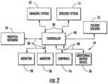
- Catheter procedure system 10may include a control system, shown as controller 40.
- controller 40may be part of workstation 14.
- Controller 40is in communication with one or more bedside systems 12, controls 16, monitors 26 and 28, imaging system 32, and patient sensors 35 (e.g., electrocardiogram ("ECG”) devices, electroencephalogram (“EEG”) devices, blood pressure monitors, temperature monitors, heart rate monitors, respiratory monitors, etc.).
- ECGelectrocardiogram
- EEGelectroencephalogram
- controller 40may be in communication with a hospital data management system or hospital network 34 and one or more additional output devices 36 (e.g., printer, disk drive, cd/dvd writer, etc.).
- Communication between the various components of catheter procedure system 10may be accomplished via communication links 38.
- Communication links 38may be dedicated wires or wireless connections.
- Communication links 38may also represent communication over a network.
- Catheter procedure system 10may be connected or configured to include any other systems and/or devices not explicitly shown.
- catheter procedure system 10may include IVUS systems, image processing engines, data storage and archive systems, automatic balloon and/or stent inflation systems, contrast media and/or medicine injection systems, medicine tracking and/or logging systems, user logs, encryption systems, systems to restrict access or use of catheter procedure system 10, robotic catheter systems of the past, present, or future, etc.
- Controller 40may generally be an electronic control unit suitable to provide catheter procedure system 10 with the various functionalities described herein.
- controller 40may be an embedded system, a dedicated circuit, a general purpose system programmed with the functionality described herein, etc.
- Controller 40includes a processing circuit 42, memory 44, communication module or subsystem 46, communication interface 48, procedure control module or subsystem 50, simulation module or subsystem 52, GUI module or subsystem 56, data storage module or subsystem 58, safety lock module or subsystem 62, maintenance module or subsystem 64, and measurement module 66.
- Processing circuit 42may be a general purpose processor, an application specific processor (ASIC), a circuit containing one or more processing components, a group of distributed processing components, a group of distributed computers configured for processing, etc. configured provide the functionality of module components 46, 50-66.
- Memory 44e.g., memory unit, memory device, storage device, etc.
- Memory 44may be one or more devices for storing data and/or computer code for completing and/or facilitating the various processes described in the present disclosure.
- Memory 44may include volatile memory and/or non-volatile memory.
- Memory 44may include database components, object code components, script components, and/or any other type of information structure for supporting the various activities described in the present disclosure.
- any distributed and/or local memory device of the past, present, or futuremay be utilized with the systems and methods of this disclosure.
- memory 44is communicably connected to processing circuit 42 (e.g., via a circuit or any other wired, wireless, or network connection) and includes computer code for executing one or more processes described herein.
- a single memory unitmay include a variety of individual memory devices, chips, disks, and/or other storage structures or systems.
- Module or subsystems 46, 50-66may be computer code (e.g., object code, program code, compiled code, script code, executable code, or any combination thereof) for conducting each module's respective functions.
- Module components 46, 50-66may be stored in memory 44, or in one or more local, distributed, and/or remote memory units configured to be in communication with processing circuit 42 or another suitable processing system.
- Communication interface 48includes one or more component for communicably coupling controller 40 to the other components of catheter procedure system 10 via communication links 38.
- Communication interface 48may include one or more jacks or other hardware for physically coupling communication links 38 to controller 40, an analog to digital converter, a digital to analog converter, signal processing circuitry, and/or other suitable components.
- Communication interface 48may include hardware configured to connect controller 40 with the other components of catheter procedure system 10 via wireless connections.
- Communication module 46is configured to support the communication activities of controller 40 (e.g., negotiating connections, communication via standard or proprietary protocols, etc.). In one embodiment, communication module 46 may also be configured to support communication between lab unit speaker 13, lab unit microphone 15, workstation speaker 17, and workstation microphone 19. In another embodiment, communication interface 48 may be configured to communicably couple controller 40 to multiple bedside systems and/or multiple imaging systems located in multiple lab units. In this embodiment, communication module 46 may also be configured to allow workstation 14 to control multiple lab units.
- Data storage module 58is configured to support the storage and retrieval of information by controller 40.
- data storage module 58is a database for storing patient specific data, including image data.
- data storage module 58may be located on hospital network 34.
- Data storage module 58 and/or communication module 46may also be configured to import and/or export patient specific data from hospital network 34 for use by controller 40.
- Controller 40also includes a procedure control module 50 configured to support the control of bedside system 12 during a catheter based medical procedure.
- Procedure control module 50allows the manipulation of controls 16 by the user to operate bedside system 12.
- Procedure control module 50may also cause data appropriate for a particular procedure to be displayed on monitors 26 and 28.
- Procedure control module 50may include sets of instructions specific to various types of catheter based procedures that may be performed using bedside system 12. For example, procedure control module 50 may include one set of instructions that will be executed by processing circuit 42 if bedside system 12 is being used to perform a diagnostic catheterization procedure and another set of instructions that will be executed by processing circuit 42 if bedside system 12 is being used to perform an therapeutic catheter procedure.
- procedure control module 50may also be configured to allow a user located at workstation 14 to operate imaging system 32.
- procedure control module 50 located at workstation 14may be configured to control multiple bedside systems, control balloon and/or stent inflation, control contrast media and/or medicine injection, and control multiple imaging systems located in multiple lab units 11.
- an exemplary catheterization procedureis shown.
- an incisionis made, usually in the groin.
- a guide catheter 148is inserted through the incision into the femoral artery.
- Bedside system 12is operated to feed guide catheter 148 through the patient's arterial system until guide catheter 148 is positioned near either the left or right ostium.
- Bedside system 12is then operated to feed guide wire 142 through guide catheter 148 until guide wire 142 extends across lesion 140.
- bedside system 12is operated to advance working catheter 144 over guide wire 142 to position balloon 146 across lesion 140.
- balloon 146is inflated to compress lesion 140 and to stretch the artery open thereby increasing blood flow to the heart. Balloon 146 is then deflated, guide wire 142 and working catheter 144 are removed, and the incision is closed.
- the catheter used during a catheterization proceduremay be any type of catheter useful during the performance of any percutaneous procedure.
- the cathetermay include a stent that is expanded and left at the site of the lesion.
- the cathetermay include structures adapted to cut or grind away the plaque forming the lesion.
- Controller 40also includes simulation module 52.
- Simulation module 52is configured to run a simulated catheterization procedure based upon stored patient specific data (e.g., image data representing a patient's heart) and also based upon a user's manipulation of controls 16.
- patient specific datae.g., image data representing a patient's heart
- simulation module 52is configured to allow a user to manipulate controls 16 during the simulated procedure, to determine how bedside system 12 would respond to the manipulation of these controls if the procedure were not simulated, and, based upon this, to provide feedback to the user regarding the user's performance during the simulated procedure.
- simulation module 52may display an image of a heart on monitor 26 or 28 and display an image of a virtual catheterization component on top of the displayed image. The image of the virtual catheterization component moves relative to the displayed image in response to manipulation of controls 16.
- various information from or portions of the simulated procedureis recorded.
- Controller 40also includes graphical user interface (“GUI”) module 56.
- GUI module 56is configured to support the display of information on monitors 26 and 28 and/or on touch screen 18.
- GUI module 56is configured to display x-ray images of a patient's heart generated by imaging system 32 on first monitor 26, to display hemodynamic data on second monitor 28, and to display graphical user interface ("GUI") 160 on touch screen 18.
- GUI module 56is configured to display images captured during a previous catheter based medical procedure.
- the image datais downloaded in advance into data storage subsystem in advance of the next procedure to be performed.
- GUI module 56may include a two dimensional graphics engine, a three dimensional graphics engine, and/or any other suitable logic or programming code for generating a GUI having the features described in the present application.
- GUI module 56is configured to generate a GUI 160 having an icon representing the operational status of each of the percutaneous intervention devices or components that may be used with bedside system 12.
- GUI 160includes a guide wire icon 162, a guide catheter icon 164, and a working catheter icon 166.
- GUI module 56is configured to display icons 162-166 in a manner that illustrates which component bedside system 12 is currently controlling.
- GUI module 56may be configured to alter the display of guide wire icon 162 when the user is controlling guide wire 142, to alter the display of guide catheter icon 164 when the user is controlling guide catheter 148, and to alter the display of working catheter icon 166 when the user is controlling working catheter 144.
- GUI module 56is configured to color code the icons of GUI 160 based upon whether the corresponding component is currently in use. For example, if controls 16 are currently controlling guide wire 142, guide wire icon 162 may be colored green to indicate that the user is currently controlling the guide wire. In addition, when controls 16 are currently controlling guide wire 142, guide catheter icon 164 and working catheter icon 166 may be colored yellow or grey to indicate that the user is not currently controlling guide catheter 148 or working catheter 144.
- GUI module 56may change the size, change the shape, change the type of graphic, create movement, etc. of the icons of GUI 160 to clearly indicate which component is in currently in use.
- GUI module 56is configured to display icons 162-166 as a moving graphic of the component currently in use.
- the movement of the graphicmay match the movement experienced by the component.
- guide wire icon 162may be an advancing, retracting, or rotating graphic of a guide wire when guide wire 142, is being advanced, retracted, or rotated.
- GUI module 56is configured to color code icons 162-166 based upon whether the corresponding component has been rendered inoperative by safety lock module 62. For example, if the controls for guide wire 142 have been locked, GUI module 56 may be configured to color guide wire icon 162 red. In addition, GUI module 56 may be configured to color code the image of a particular component shown in the x-ray image of the patient's heart to correspond to the color of the corresponding icon. For example, if guide wire icon 162 is colored green indicating that guide wire 142 is in use, the image of guide wire 142 shown in the x-ray image may also be colored green.
- GUI module 56may be configured to display icons 162-166 in a manner that clearly indicates which controls are configured to operate which component of beside system 12.
- GUI module 56is configured to display icons 162-166 on touch screen 18 such that each icon is positioned above the corresponding control.
- the usermay assign each of the joysticks shown in FIG. 4 to control a particular component by positioning icons 162-166 over the joysticks. For example, if a user wanted the left most joystick to control the working catheter, the user would touch working catheter icon 166 on touch screen 18 and drag working catheter icon 166 to the portion of touch screen 18 above the left most joystick.
- GUI module 56may be configured to display guide wire icon 162 to have the same shape and/or color as guide wire control 23. In another embodiment, GUI module 56 is configured to display GUI 160 during a simulated catheterization procedure is performed using catheter procedure system 10.
- GUI module 56may be configured to allow the user to alter the display of image data by interacting with touch screen 18.
- GUI 160may be displayed on touch screen 18 and GUI 160 may include an icon representing the patient's heart. By touching portions of the icon representing the patient's heart, the user may alter the display of real-time images during the performance of a real catheterization procedure or may alter the display of a stored image during the performance of a simulation procedure. For example the user may touch to coronary artery portion of the heart icon to cause the display of the real-time images of the patient's heart to zoom in on (e.g., magnify, increase the screen resolution, etc.) the coronary arteries displayed in the real-time image.
- GUI module 56is configured to display GUI 160 including icons that represent various information about the procedure currently being preformed.
- GUI module 56displays an icon that shows the distance moved by the various percutaneous intervention devices during the procedure. This distance information may be obtained from encoders in bedside system 12, from the real-time image data, and/or from one or more positional sensors located on the percutaneous intervention devices.
- GUI module 56may display an icon that shows a force that is acting on the percutaneous intervention devices. This force may be generated by bedside system 12 or by a source within the patient (e.g., contraction of the heart, etc.).
- GUI module 56is configured to display an icon showing the amount of contrast media that has been delivered to the patient during the procedure. In one embodiment, this icon may also indicate the maximum amount of contrast agent that can safely be delivered to the patient. This icon may also indicate the amount of contrast agent that still may be delivered to the patient during the procedure. In one embodiment, this icon may be a meter that has a bar that increases as the amount of contrast media delivered increases. In another embodiment, GUI module 56 is configured to display an icon showing the amount of radiation that has been delivered to a patient during a particular procedure. This icon may also show the maximum amount of radiation that may be delivered during the procedure and may also show the current amount of radiation delivered as a percentage of the total that may be delivered.
- GUI module 56is configured to display an icon providing information regarding the state of contraction of the heart. Providing this information to the user may allow the user to time operation of various percutaneous intervention devices to a particular stage of the heart beat. For example, the user may want to inject contrast media into the coronary arteries during diastole to prevent dilution of the contrast media that may occur when the heart contracts moving blood through the coronary arteries.
- GUI module 56displays an icon indicating when contrast media should be introduced.
- controller 40automatically injects contrast agent during the appropriate state of contraction of the heart.
- GUI module 56displays an icon of a beating heart that matches the beating of the patient's heart. In another embodiment, GUI module 56 displays an electrocardiogram graph.
- GUI module 56is configured to display icons indicating various physiological data of the patient.
- GUI module 56displays one or more icons indicating the patient's heart rate, respiratory rate, blood pressure, body temperature, etc.
- GUI module 56may be configured to display icons to indicate that the patient is experiencing a medical problem.
- GUI module 56may be configured to display an icon indicating that patient 21 is experiencing cardiac arrest or a seizure, that the patient's breathing has stopped, etc. Display of icons indicating a problem with the patient may be based upon the various measurements taken by patient sensors 35 (e.g., heart rate, blood pressure, etc.) during the catheterization procedure or based upon an automated analysis of the real time images of the patient's heart taken during the procedure.
- GUI module 56is configured to display GUI 160 including icons that represent various aspects of catheter procedure system 10.
- GUI module 56is configured display a graphical display of the motors, actuators, encoders, etc. that are currently in use or in motion within bedside system 12.
- GUI module 56is configured to display one or more icons (e.g., on/off icons, mute icon, volume icon, etc.) to allow the user located at workstation 14 to control various aspects of the communication system.
- GUI module 56is configured to a display a graphic that indicates that patient 21 located within lab unit 11 is trying to communicate using lab unit mic 15.
- GUI module 56may be configured to display an icon indicating various information regarding a particular component that is being used with bedside system 12. For example, if a guide wire of a certain size made by a certain manufacturer is being used with bedside system 12, the icon displayed by GUI module 56 will indicate the size and manufacturer of the guide wire.
- specific percutaneous intervention devicesmay include radio frequency identification tags (RFID tags) that include information which identifies the particular component, and catheter procedure system 10 may include an RFID reader to read the RFID tags.
- RFID tagsradio frequency identification tags
- catheter procedure system 10may include an RFID reader to read the RFID tags.
- the icon identifying the component displayed by GUI module 56is based upon the information read from the RFID tag associated with the component.
- GUI module 56will display a menu listing all of the specific percutaneous intervention devices that may be used with bedside system 12. The user then may select from the menu which component will be used with bedside system 12.
- Various modules of controller 40may utilize information about specific percutaneous intervention devices to provide the functionalities of the modules. For example, procedure module 50 may utilize this information to ensure that proper display of information during a catheterization procedure.
- GUI module 56is configured to display an icon that represents the angioplasty balloon and/or stent that the working catheter is equipped with. In one embodiment, GUI module 56 is configured to display a graphical representation of the balloon and/or stent that expands as the real balloon or catheter expands allowing the user to conveniently see the current state of expansion. In another embodiment, GUI module may be configured to display a bar graph indicating the percentage of the balloon or stent expansion.
- GUI module 56is configured to display icons representing various information based upon interaction with bedside system 12.
- GUI module 56may display an icon prompting the user at workstation 14 to load or access the records and/or patient history of the next patient to undergo a procedure within lab unit 11.
- One event that may trigger the display of this iconis the loading of new percutaneous intervention devices (e.g., a new cassette, etc.) into bedside system 12.
- controller 40may record a summary or produce a summary report of every display generated by GUI module 56 during a catheter based procedure.
- the summary reportincludes all of the details of a catheter based medical procedure (e.g., time, movement of devices, types of devices used, etc.).
- Controller 40also includes a safety lock module 62.
- Safety lock module 62is configured to lock, render inoperative, inactivate, etc., one or more portions of controls 16 when the component of bedside system 12 (e.g., guide wires, catheters, catheter balloons, stents, contrast media, medicine, etc.) that corresponds to the inactive portion of control 16 is not currently in use. This may prevent accidental or inadvertent operation of the inactive control or controls. For example, in the embodiment shown in FIG.
- Controls 16may include a switch, toggle or other means that is configured to allow the user to switch various controls between active and inactive states (e.g., controls 210 and 220 discussed below).
- safety lock module 62inactivates one or more of the controls by preventing the inactive control from generating a control signal (e.g., the inactive control may be disconnected from a power source). In another embodiment, safety lock module 62 inactivates one or more of the controls by preventing the transmission of a control signal from the inactive control. This may be accomplished by introducing a reversible break in one of the communication links 38 that connect the inactive control to bedside system 12. In another embodiment, safety lock module 62 inactivates one or more of the controls by causing bedside system 12 or one of the intermediate subsystems of controller 40 (e.g., procedure control module 50) to ignore the control signal generated by the inactive control.
- the intermediate subsystems of controller 40e.g., procedure control module 50
- Controller 40also includes maintenance module 64.
- Maintenance module 64is configured to allow a technician to perform various maintenance tasks on catheter procedure system 10.
- Maintenance module 64may allow a technician to calibrate various components of catheter procedure system 10 (e.g., motors within bedside system 12, controls 16, etc.).
- Maintenance module 64may also be configured to allow the technician to reinstall, update, upgrade, etc. any of the software components of catheter procedure system 10.
- Maintenance module 64may also be configured to allow the technician to perform diagnostic tests to aid in the isolation and repair of a malfunction.
- maintenance module 64is configured to allow the technician to switch between a maintenance mode, and/or procedure mode.
- Controller 40also includes measurement module 66.
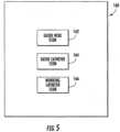
- Measurement module 66is configured to measure the length of a structure utilizing catheter procedure system 10 by measuring the distanced moved by a guide wire as the guide wire traverses the length of the structure.
- catheter procedure system 10includes one or more devices or components for measuring the distance moved by the guide wire 142.
- bedside system 12may be equipped with one or more encoders that measure movement of rollers that impart movement to the guide wire. In other embodiments, however, other measurement devices for determining the amount of guide wire movement may be used.
- lesion 140includes a distal end 152 and a proximal end 154
- guide wire 142includes a distal tip 150.
- the useroperates controls 16 to cause bedside system 12 to move guide wire 142 so that distal tip 150 of guide wire 142 is aligned with distal end 152 of lesion 140.
- the userthen activates measurement module 66 by, for example, selecting a measurement mode icon displayed on touch screen 18.
- measurement module 66With measurement module 66 activated, at step 172, the user operates controls 16 to cause guide wire 142 to retract. At step 174, the user continues to operate controls 16 to retract guide wire 142 until distal tip 150 of guide wire 142 is aligned with proximal end 154 of lesion 140. Next the user indicates that distal tip 150 of guide wire 142 is aligned with proximal end 154 of lesion 140 by, for example, selecting a measurement complete icon displayed on touch screen 18. At step 176, measurement module 66 calculates the distance that guide wire 142 was retracted between distal end 152 and proximal end 154 of lesion 140.
- the distance that guide wire 142 was retractedis determined from a device, such as an encoder, that measures (directly or indirectly) the distance that guide wire 142 travels as discussed above.
- the distance that guide wire 142 was retractedis approximately the same length of lesion 140.
- measurement module 66then causes the display of the lesion length to the user.
- the length of the lesionmay then be used to select the appropriate size device (e.g., stent, angioplasty balloon, etc.) for treatment of the lesion.
- the userperforms measurement of the lesion by watching the positioning of the guide wire relative to the lesion on the live, real-time angiographic images of the patient displayed on monitor 26 and/or 28.
- lesion lengthmay be measured by measuring the length of the 2D angiographic image of the lesion.
- the 2D image of the lesionmay distort the 3-dimensional length of the lesion, indirect measurement of lesion length by measuring guide wire movement, as discussed above, often results in a more accurate measurement of lesion length than measurement from a 2D image.
- distal tip 150 of guide wire 142is configured to facilitate location by the user.
- distal tip 150may be configured to be easily seen on an x-ray based image of the patient.
- distal tip 150 of guide wire 142may be made more radio-opaque than the rest of guide wire 142.
- distal tip 150 of guide wire 142emits radiation that is detected by imaging system 32.
- measurement module 66may be integrated with other devices or systems to provide additional and/or different measurements of various lesion characteristics.
- measurement module 66may be configured to utilize an intravascular ultrasound (IVUS) catheter system and/or an optical coherence tomography (OCT) system to measure various characteristics of a lesion and to cause a display of information related to the measured characteristic on one or more of the display devices of workstation 14.
- IVUSintravascular ultrasound
- OCToptical coherence tomography
- measurement module 66may be configured to utilize one or more measurement systems to measure and display information related to characteristics of a lesion in addition to lesion length (e.g., amount of vascular occlusion, degree of calcification, etc.).
- GUI module 56may be configured to cause the display of a graphical user interface (GUI) 200.
- GUI 200includes a guide wire panel 202, a working catheter panel, shown as balloon/stent panel 204, system panel 206, and a device engagement panel 208.
- GUI 200is displayed on touch screen 18 allowing the user to interact with the various icons by touching the touch screen generating inputs to be processed by the appropriate modules or subsystems of controller 40.
- GUI 200may be displayed on a non-touch screen display with the user interacting with the icons via one or more input device (e.g., mouse, keyboard, etc.).
- GUI 200in combination with the other control elements of control 16 (e.g., guide wire control 23, working catheter control 25, etc.), allows a user to control bedside system 12 to move a guide wire and/or a working catheter equipped with a balloon and/or stent to perform a procedure.
- control 16e.g., guide wire control 23, working catheter control 25, etc.
- GUI 200may be modified for the display and control of any device (e.g., guide catheter, imaging catheter, etc.) that may be operated via workstation 14.
- guide wire panel 202includes various GUI elements related to the control and position of the guide wire.
- Guide wire panel 202includes an activation control 210, a guide wire speed indicator 212, a guide wire measurement control 214, a guide wire axial step control 216, and a guide wire rotational step control 218.
- Balloon/stent panel 204includes various GUI elements related to the control and position of the balloon and/or stent. Balloon/stent panel 204 includes an activation control 220, balloon/stent speed indicator 222, a balloon/stent measurement control 224, and a balloon/stent axial step control 226.
- controls 210 and 220allow the user to implement the functionality of safety lock module 62 discussed above.
- Guide wire activation control 210allows a user to toggle the guide wire related controls between active and inactive states.
- Activation control 210includes a status icon 228 and a toggle button 230 which is pressed by the user to toggle between the active and inactive states.
- button 230includes an icon representative of the guide wire control 23 (a joystick in the embodiment shown).
- status icon 228 and button 230are displayed in a first color (e.g., grey, red, etc.) to indicate to the user that the guide wire control elements are inactive.
- the guide wire control elementse.g., control 23, controls of guide wire panel 202
- the guide wire controlsare active, status icon 228 and button 230 are displayed in a second color (e.g., green, blue, etc.) to indicate to the user that the guide wire control elements are active.
- Balloon/stent activation control 220allows a user to toggle the working catheter related controls between active and inactive states.
- Activation control 220includes a status icon 232 and a toggle button 234 which is pressed by the user to toggle between the active and inactive states.
- button 234includes an icon representative of working catheter control 25 (a joystick in the embodiment shown).
- the working catheter control elementse.g., control 25, controls of balloon/stent panel 204 are disabled such that if a user interacts with one of the control elements there will be no corresponding movement of the working catheter caused by bedside system 12.
- status icon 232 and button 234are displayed in a first color (e.g., grey, red, etc.) to indicate to the user that the working catheter control elements are inactive.
- the working catheter control elementse.g., control 25, controls of balloon/stent panel 204
- the working catheter control elementsare enabled such that if a user manipulates one of the control elements bedside system 12 will cause the working catheter (and any balloon/stent that the working catheter is equipped with) to move based on the manipulation of the control.
- status icon 232 and button 234are displayed in a second color (e.g., green, blue, etc.) to indicate to the user that the working catheter control elements are active.
- safety lock module 62may be configured to allow both the guide wire controls and the working catheter controls to be active at the same time if both control 210 and 220 are toggled to the active state by the user. In another embodiment, safety lock module 62 may be configured to prevent both the guide wire controls and the working catheter controls to be active at the same time requiring the user to inactivate one set of controls before activating the other set of controls.
- safety lock module 62is configured to cause bedside system 12 to hold the position of the device fixed until the controls for the device are reactivated (i.e., the device does not move relative to the drive mechanisms of bedside system 12 and/or relative to the patient).
- the drive mechanisms of bedside system 12may be configured to engage the inactive device with enough force to prevent unwanted movement of the device relative to the bedside system and/or to the patient.
- Guide wire speed indicator 212provides information to the user regarding the current movement of the guide wire.
- guide wire speed indicator 212includes a linear or axial speed indicator 236 to display information related to the linear speed of the guide wire and a rotational speed indicator 238 to display information related to the rotational speed of the guide wire.
- Linear speed indicator 236includes a vertically displayed bar 240 extending between a maximum forward icon 242 indicating the maximum forward speed, a maximum reverse icon 244 indicating the maximum reverse speed of the guide wire, and an origin 246 indicating zero linear movement.
- bar 240 between origin 246 and either icon 242 or icon 244changes color in proportion to the speed of the guide wire. For example, if the guide wire is currently being advanced at half of the maximum speed, the first half of vertical bar 240 extending above origin 246 changes color.
- Rotational speed indicator 238includes a curved horizontally displayed bar 248 extending between a left (i.e., counterclockwise) rotation icon 250 indicating the maximum left rotational speed and a right (i.e., clockwise) rotation icon 252 indicating the maximum right rotational speed.
- bar 248 between origin 246 and either icon 250 or icon 252changes color in proportion to the rotational speed of the guide wire. For example, if the guide wire is currently being rotated at half the maximum speed to the right, the first half of horizontal bar 248 extending from origin 246 toward right rotation icon 252 changes color.
- Balloon/stent speed indicator 222provides information to the user regarding the current movement of the balloon/stent that the working catheter is equipped with.
- indicator 222provides information related to the linear speed of the working catheter.
- Indicator 222includes a vertical bar 256 extending between a maximum forward icon 258 indicating the maximum forward speed, a maximum reverse icon 260 indicating the maximum reverse speed, and an origin 262 indicating zero linear movement.
- bar 256 between origin 262 and either icon 258 or icon 260changes color in proportion to the speed of the balloon/stent. For example, if the balloon/stent is currently being advanced at half of the maximum speed, the first half of vertical bar 256 extending above origin 262 changes color.
- Guide wire measurement control 214includes a reset button 264, a save button 266, distance indicator 268, and a stored distance indicator 270.
- reset button 264resets the value displayed by distance indicator 268 causing distance indicator 268 to display 000.0.
- distance indicator 268displays the net distance that the guide wire has moved since the last time reset button 264 was pushed (in mm in the embodiment shown). In this manner, distance indicator 268 displays the length of the path that the guide wire traveled from the point when the reset button was pushed to its current position. Thus, distance indicator 268 provides information regarding the current position of the guide wire relative to the position when reset button 264 was last pushed.
- save button 266is pushed, the current value displayed in distance indicator 268 is saved and displayed in stored distance indicator 270.
- the functionality of measurement module 66is provided via guide wire measurement control 214.
- the userwill press reset button 264 when the tip of the guide wire is aligned with the distal tip of the lesion. The user will then retract the guide wire until the distal tip of the guide wire is aligned with the proximal tip of the lesion.
- the userwill press save button 266.
- the number displayed in stored distance indicator 270will be the distance that the guide wire traveled from the distal to proximal ends of the lesion. The distance traveled using this procedure provides a measurement of the length of the lesion.
- Balloon/stent measurement control 224includes a reset button 272, a save button 274, a distance indicator 276, and a stored distance indicator 278.
- reset button 272When pushed, reset button 272 resets the value displayed by distance indicator 276 causing distance indicator 276 to display 000.0.
- distance indicator 276displays the net distance that the working catheter has moved since the last time reset button 272 was pushed. In this manner, distance indicator 276 displays the length of the path that the working catheter traveled from the point when the reset button was pushed to its current position (in mm in the embodiment shown).
- save button 274is pushed, the current value displayed in distance indicator 276 is saved and displayed in stored distance indicator 278.
- the positional information displayed in distance indicators 268, 270, 276, and/or 278may be used by the user to help in positioning the guide wire or stent/balloon, respectively.
- the usermay know the distance that the guide wire must travel to reach a particular point within the patient.
- the positional information displayed in the various indicatorshelps the user determine if the device has been moved too far, not far enough etc.
- knowing the remaining distance to a particular pointmay allow a user to plan upcoming movements of the device. For example, the user may begin to rotate the guide wire some distance before a branch in the patient's vascular system so that the guide wire is properly aligned when the tip of the guide wire reaches the branch.
- Guide wire panel 202includes a guide wire axial step control 216 and a guide wire rotational step control 218.
- Axial step control 216includes an advance button 280 and a retract button 282 that, when pushed, cause bedside system 12 to advance or retract, respectively, the guide wire by the step distance associated with button 280 and/or 282.
- the step distance for both button 280 and 282is 1 mm.
- Rotational step control 218includes a left rotation button 286 and a right rotation button 288 that, when pushed, cause bedside system 12 to rotate the guide wire to left or right, respectively, by the angular step associated with button 286 and/or 288.
- the angular step distance for both button 286 and 288is 30 degrees.
- other step distancesare associated with the step controls (e.g., 1 mm, 2 mm, 3 mm, etc. axial steps, and 10 degree, 15 degree, 20 degree, 40 degree, etc. rotational steps).
- Balloon/stent panel 204includes a balloon/stent axial step control 226.
- Balloon/stent axial step control 226includes an advance button 290 and a retract button 292 that, when pushed, cause bedside system 12 to advance or retract, respectively, the balloon/stent equipped working catheter by the step distance associated with button 290 and/or 292.
- the step distance for both button 290 and 292is 1 mm.
- the steps associated with the various buttonsneed not be the same.
- the retract stepmay be 2 mm and the advance step may be 1 mm.
- System panel 206includes a bedside system status indicator 294, a control indicator 296, a menu button 298, and volume buttons 300.
- Bedside system status indicator 294displays information related to the current operating status of bedside system 12. In the embodiment shown, indicator 294 indicates that the drive elements of bedside system 12 that impart movement to the guide wire and working catheter are engaged. Indicator 294 may indicate other states of bedside system 12 (e.g., disengaged, covers open, no power, various error messages, etc.).
- Control indicator 296displays information related which controls are active. As shown, control indicator 296 indicates that the guide wire joystick control (i.e., an embodiment of guide wire control 23) is active. Volume buttons 300 allow the user to increase or decrease the volume of various auditory alerts and signals generated by workstation 14.
- menu button 298When pushed, menu button 298 causes a drop down menu with various options to be displayed.
- the drop down menu displayed by pushing menu button 298includes a cancel/return button that closes the drop down menu, a restart application button that restarts the software of workstation 14, an exit/shut down option that powers down controls 16 and/or workstation 14, and an "about software" button that displays information related to the version of the software installed on workstation 14.
- GUI 200includes a device engagement panel 208.
- Device engagement panel 208includes an engage/disengage control 302 and a bedside system indicator 304.
- Engage/disengage control 302when pushed by the user, causes bedside system 12 to move between a loading position and a use position. If bedside system 12 is currently in the loading position, pressing control 302 will cause bedside system 12 to move to the engaged, use position. If bedside system 12 is currently in the use position, pressing control 302 will cause bedside system to move to the disengaged, loading position. In the loading position, the various drive mechanisms of bedside system 12 are disengaged from the percutaneous devices (e.g., guide wire, working catheter, etc.) of bedside system 12 and the covers are unlocked and opened.
- percutaneous devicese.g., guide wire, working catheter, etc.
- bedside system 12In the loading position, new percutaneous devices may be loaded into bedside system 12 and the current percutaneous devices may be removed. In the use position, the various drive mechanisms of bedside system 12 are engaged with the percutaneous devices of bedside system 12 such that bedside system 12 is able to impart movement to the devices and the covers are closed and locked.
- engage/disengage control 302includes a lock icon 310.
- Lock icon 310provides an indication to the user regarding whether pushing control 302 will results in engagement or disengagement of bedside system 12 from the percutaneous devices. For example, if lock icon 310 is shown unlocked, as in FIG. 9 , pushing control 302 will cause bedside system 12 to move from the engaged, use position to the disengaged, loading position. If lock icon 310 is shown locked (not shown), pushing control 302 will cause bedside system 12 to move from the disengaged, loading position to the engaged, use position.
- Bedside system indicator 304provides information related to the current position (e.g., loading, use) of bedside system 12. For example, indicator 304 indicates whether bedside system 12 is in the disengaged, loading position or the engaged, use position. In one embodiment, indicator 304 is displayed in one color (e.g., green, blue, etc.) if bedside system 12 is in the engaged, use position and in a second color (e.g., yellow, red, etc.) if bedside system 12 is in the disengaged, loading position. In the embodiment shown, indicator 304 may also include a lock icon 306. If lock icon 306 is shown locked, as in FIG. 9 , bedside system 12 is currently in the engaged, use position. If lock icon 306 is shown unlocked, bedside system 12 is currently in the disengaged, loading position.
- lock icon 306If lock icon 306 is shown locked, as in FIG. 9 , bedside system 12 is currently in the engaged, use position. If lock icon 306 is shown unlocked, bedside system 12 is currently in the dis
- Indicator 304also includes a percutaneous devices icon 308 that provides an indication of the types of percutaneous devices that bedside system is equipped with.
- devices icon 308indicates that bedside system 12 is equipped with a guide wire and a stent-equipped working catheter.
- devices icon 308may show different and/or more detailed information (e.g., make, model, size, type, etc.) of the devices that bedside system 12 is equipped with.
- any process or method stepsmay be varied or re-sequenced according to alternative embodiments. Also two or more steps may be performed concurrently or with partial concurrence. Such variation will depend on the software and hardware systems chosen and on designer choice. All such variations are within the scope of the disclosure. Likewise, software implementations could be accomplished with standard programming techniques with rule based logic and other logic to accomplish the various connection steps, processing steps, comparison steps and decision steps.
Landscapes
- Health & Medical Sciences (AREA)
- Life Sciences & Earth Sciences (AREA)
- Engineering & Computer Science (AREA)
- Surgery (AREA)
- Biomedical Technology (AREA)
- General Health & Medical Sciences (AREA)
- Animal Behavior & Ethology (AREA)
- Veterinary Medicine (AREA)
- Public Health (AREA)
- Heart & Thoracic Surgery (AREA)
- Molecular Biology (AREA)
- Medical Informatics (AREA)
- Robotics (AREA)
- Nuclear Medicine, Radiotherapy & Molecular Imaging (AREA)
- Biophysics (AREA)
- Physics & Mathematics (AREA)
- Pathology (AREA)
- Oral & Maxillofacial Surgery (AREA)
- Human Computer Interaction (AREA)
- Pulmonology (AREA)
- Anesthesiology (AREA)
- Hematology (AREA)
- Electromagnetism (AREA)
- Dentistry (AREA)
- Cardiology (AREA)
- Transplantation (AREA)
- Vascular Medicine (AREA)
- Apparatus For Radiation Diagnosis (AREA)
Description
- The present invention relates generally to the field of catheter systems for performing diagnostic and/or therapeutic procedures. The present invention relates specifically to catheter systems including a user interface and/or workstation for controlling a robotic catheter system.
- Vascular disease, and in particular cardiovascular disease, may be treated in a variety of ways. Surgery, such as cardiac bypass surgery, is one method for treating cardiovascular disease. However, under certain circumstances, vascular disease may be treated with a catheter based therapeutic procedure, such as angioplasty. Catheter based therapeutic procedures are generally considered less invasive than surgery. If a patient shows symptoms indicative of cardiovascular disease, an image of the patient's heart may be taken to aid in the diagnosis of the patient's disease and to determine an appropriate course of treatment. For certain disease types, such as atherosclerosis, the image of the patient's heart may show a lesion that is blocking one or more coronary arteries. Following the diagnostic procedure, the patient may undergo a catheter based therapeutic procedure. During one type of therapeutic procedure, a catheter is inserted into the patient's femoral artery and moved through the patient's arterial system until the catheter reaches the site of the lesion. In some procedures, the catheter is equipped with a balloon or a stent that when deployed at the site of a lesion allows for increased blood flow through the portion of the coronary artery that is affected by the lesion. In addition to cardiovascular disease, other disease may be treated with catheterization procedures.
US patent number 6, 726, 675 describes a remote control catheterization system including a propelling device, which controllably inserts a flexible, elongate probe into the body of a patient. A control console, in communication with the propelling device, includes user controls which are operated by a user of the system remote from the patient to control insertion of the probe into the body by the propelling device.US6428512B1 is generally directed to improved devices for measuring of distances within a patient's body such as the length of a stenosis with a patient's coronary arteries.- Aspects and embodiments of the invention are set out according to the appended claims.
- This application will become more fully understood from the following detailed description, taken in conjunction with the accompanying figures, wherein like reference numerals refer to like elements in which:
FIG. 1 is a perspective view of the robotic catheter system according to an exemplary embodiment;FIG. 2 is block diagram of a robotic catheter system according to an exemplary embodiment;FIG. 3 is a block diagram of a control system according to an exemplary embodiment;FIG. 4 is perspective view of controls for a robotic catheter system according to an exemplary embodiment;FIG. 5 is a diagram of a graphical user interface according to an exemplary embodiment;FIG. 6 is a diagram of a robotic catheter system including multiple lab units according the invention;FIG. 7 is an image of coronary arteries shown during a real catheter based therapeutic procedure according to an exemplary embodiment;FIG. 8 is a flow diagram showing measurement of a length according to an exemplary embodiment; andFIG. 9 is a graphical user interface according to an exemplary embodiment.- Referring to
FIG. 1 , acatheter procedure system 10 is shown.Catheter procedure system 10 may be used to perform catheter based medical procedures (e.g., percutaneous intervention procedures). Percutaneous intervention procedures may include diagnostic catheterization procedures during which one or more catheters are used to aid in the diagnosis of a patient's disease. For example, during one embodiment of a catheter based diagnostic procedure, a contrast medium is injected into one or more coronary arteries through a catheter and an image of the patient's heart is taken. Percutaneous intervention procedures may also include catheter based therapeutic procedures (e.g., angioplasty, stent placement, treatment of peripheral vascular disease, etc.) during which a catheter is used to treat a disease. It should be noted, however, that one skilled in the art would recognize that, certain specific percutaneous intervention devices or components (e.g., type of guide wire, type of catheter, etc.) will be selected based on the type of procedure that is to be performed.Catheter procedure system 10 is capable of performing any number of catheter based medical procedures with minor adjustments to accommodate the specific percutaneous intervention devices to be used in the procedure. In particular, while the embodiments ofcatheter procedure system 10 described herein are explained primarily in relation to the diagnosis and/or treatment of coronary disease,catheter procedure system 10 may be used to diagnose and/or treat any type of disease or condition amenable to diagnosis and/or treatment via a catheter based procedure. Catheter procedure system 10 includeslab unit 11 andworkstation 14.Catheter procedure system 10 includes a robotic catheter system, shown asbedside system 12, located withinlab unit 11adjacent patient 21. Generally,bedside system 12 may be equipped with the appropriate percutaneous intervention devices or components (e.g., guide wires, guide catheters, working catheters, catheter balloons, stents, contrast media, medicine, diagnostic catheters, etc.) to allow the user to perform a catheter based medical procedure. A robotic catheter system, such asbedside system 12, may be any system configured to allow a user to perform a catheter-based medical procedure via a robotic system by operating various controls such as the controls located atworkstation 14.Bedside system 12 may include any number and/or combination of components to providebedside system 12 with the functionality described herein. Various embodiments ofbedside system 12 are described in detail inU.S. Provisional Application No. 61/050,933, filed May 6, 2008 bedside system 12 are described in detail in International Application No.PCT/US2009/042720, filed May 4,2009 .- In one embodiment,
bedside system 12 may be equipped to perform a catheter based diagnostic procedure. In this embodiment,bedside system 12 may be equipped with a variety of catheters for the delivery of contrast media to the coronary arteries. In one embodiment,bedside system 12 may be equipped with a first catheter shaped to deliver contrast media to the coronary arteries on the left side of the heart, a second catheter shaped to deliver contrast media to the coronary arteries on the right side of the heart, and a third catheter shaped to deliver contrast media into the chambers of the heart. - In another embodiment,
bedside system 12 may be equipped to perform a catheter based therapeutic procedure. In this embodiment,bedside system 12 may be equipped with a guide catheter, a guide wire, and a working catheter (e.g., a balloon catheter, a stent delivery catheter, etc.). In another embodiment,bedside system 12 may be equipped with an intravascular ultrasound (IVUS) catheter. In another embodiment, any of the percutaneous intervention devices ofbedside system 12 may be equipped with positional sensors that indicate the position of the component within the body. Bedside system 12 is in communication withworkstation 14, allowing signals generated by the user inputs ofworkstation 14 to be transmitted tobedside system 12 to control the various functions of besidesystem 12.Bedside system 12 also may provide feedback signals (e.g., operating conditions, warning signals, error codes, etc.) toworkstation 14.Bedside system 12 may be connected toworkstation 14 via acommunication link 38 that may be a wireless connection, cable connectors, or any other means capable of allowing communication to occur betweenworkstation 14 and besidesystem 12.Workstation 14 includes auser interface 30.User interface 30 includescontrols 16.Controls 16 allow the user to controlbedside system 12 to perform a catheter based medical procedure.Controls 16 may be configured to control movement of the percutaneous intervention devices along at least two degrees of freedom. For example,controls 16 may be configured to causebedside system 12 to perform various tasks using the various percutaneous intervention devices with whichbedside system 12 may be equipped (e.g., to advance, retract, or rotate a guide wire, advance, retract, or rotate a working catheter, advance, retract, or rotate a guide catheter, inflate or deflate a balloon located on a catheter, position and/or deploy a stent, inject contrast media into a catheter, inject medicine into a catheter, or to perform any other function that may be performed as part of a catheter based medical procedure).- In one embodiment,
workstation 14 includes a single set ofcontrols 16 that are configured to control all of the percutaneous intervention devices (e.g., guide wires, catheters, catheter balloons, stents, diagnostic catheters, contrast medium, medicine, etc.) that may be used withbedside system 12. In this embodiment,controls 16 will include a switch or toggle that allows the user to select whichtask bedside system 12 will currently perform. In another embodiment,controls 16 may include one or more dedicated sets of controls configured to controlbedside system 12 only during the performance of a particular task. For example, as shown inFIG. 4 ,workstation 14 may include aguide wire control 23, a workingcatheter control 25, and aguide catheter control 29. In this embodiment,guide wire control 23 is configured to advance, retract, or rotate a guide wire, workingcatheter control 25 is configured to advance, retract, or rotate a working catheter, and guidecatheter control 29 is configured to advance, retract, or rotate a guide catheter.Controls 16 may also include a balloon control that is configured to inflate or deflate a balloon and/or a stent. Each of the dedicated controls may include one or more buttons, joysticks, touch screens, etc. that may be desirable to control the particular component to which the control is dedicated. In one embodiment, controls 16 are configured to allow the user to operate more than one component viabedside system 12 at the same time. For example, in this embodiment, the user may operateguide wire control 23, workingcatheter control 25, and/or guidecatheter control 29 at the same time to advance, retract, and/or rotate a guide wire, a working catheter, and/or a guide catheter at the same time. - In an exemplary embodiment of
FIG. 1 , controls 16 include atouch screen 18, a pair ofjoysticks 20 having variable speed control, afirst jog button 22 for 1 mm jogs, and asecond jog button 24 for 5 mm jogs.First jog button 22 andsecond jog button 24 have continuous jog capability. Operation ofjog buttons bedside system 12 to move a guide wire or a catheter. In one embodiment, depression of one or more of the jog buttons will move a guide wire or catheter a set distance forward as noted above. However,jog buttons jog buttons 22 and 24 (e.g., 2mm jogs, 3 mm jogs, 4 mm jogs, 6 mm jogs, 7 mm jogs, etc.). The user may set the distance that a component moves in response to operation ofjog buttons workstation 14, etc. In addition, controls 16 may include a rotational jog button configured to rotate a guide wire or a catheter a pre-set number of degrees when pressed. Another button may be used to accelerate the speed of a guide wire or a catheter or to provide a multiplier so that the variable speed control reacts in a heightened manner. For example, if movement of a joystick a set distance results in the movement of the guide wire at a set speed in normal operation, the guide wire would move at a multiple of the set speed by depressing the button to accelerate the speed. In another embodiment, the various controls (e.g.,jog buttons joysticks 20, etc.) may be graphic touch screen controls. - Referring to
FIG. 4 , an exemplary embodiment ofcontrols 16 is shown. In this embodiment, controls 16 includes atouch screen 18, aguide catheter control 29, aguide wire control 23, and a workingcatheter control 25. In this embodiment, guidecatheter control 29,guide wire control 23, and workingcatheter control 25 are joysticks that allow the user to advance, retract, and rotate the component associated with the control. As shown inFIG. 4 , in an exemplary embodiment, guidecatheter control 29 is positioned on the far left,guide wire control 23 is positioned in the middle, and workingcatheter control 25 is positioned to the far right belowtouch screen 18. In another embodiment, each of the joysticks shown inFIG. 4 may be assigned to control a particular component based upon the preference of the user. For example, the left most joystick shown may be assigned to control the working catheter and the right most joystick may be assigned to control the guide catheter. In another embodiment, one or more portions ofcontrols 16 are configured to provide haptic feedback (i.e., feedback through sense of touch) to the user. For example, the joysticks ofcontrols Controls 16 may include anemergency stop button 31 and a multiplier button 33. Whenemergency stop button 31 is pushed a relay is triggered to cut the power supply tobedside system 12. Multiplier button 33 acts to increase or decrease the speed at which the associated component is moved in response to a manipulation ofguide catheter control 29,guide wire control 23, and workingcatheter control 25. For example, if operation ofguide wire control 23 advances the guide wire at a rate of 1 mm/sec, pushing multiplier button 33 may cause operation ofguide wire control 23 to advance the guide wire at a rate of 2 mm/sec. Multiplier button 33 may be a toggle allowing the multiplier effect to be toggled on and off. In another embodiment, multiplier button 33 must be held down by the user to increase the speed of a component during operation ofcontrols 16.- In the embodiment shown in
FIG. 4 , thecontrols touch screen 18. In other embodiments, controls 23, 25, and 29 are not aligned beneathtouch screen 18 but are staggered. In another embodiment, the space between workingcatheter control 25 and guidewire control 23 is greater than the distance betweenguide wire control 23 and guidecatheter control 29.Controls 16 may include one or more ergonomic hand supports to support the user's hand while operating controls 16. In another embodiment, controls 16 may include a keyboard and/or a mouse. The keyboard and/or mouse may be separate input devices coupled via acommunication link 38 tocontroller 40, and/or the keyboard and/or mouse may be integrated with one or more components ofworkstation 14. - In one embodiment,
workstation 14 and/or controls 16 include one or more devices and/or systems to control access to and/or use of various component. For example, controls 16 may be password protected, may include a fingerprint reader, a badge reader, etc. In these embodiments, controls 16 may not operatebedside system 12 unless a correct password is entered, an authorized finger print or badge is read, etc. User interface 30 may include afirst monitor 26 and asecond monitor 28. First monitor 26 andsecond monitor 28 may be configured to display information or patient specific data to the user located atworkstation 14. For example,first monitor 26 andsecond monitor 28 may be configured to display image data (e.g., x-ray images, MRI images, CT images, ultrasound images, etc.), hemodynamic data (e.g., blood pressure, heart rate, etc.), patient record information (e.g., medical history, age, weight, etc.). In addition,first monitor 26 andsecond monitor 28 may be configured to display procedure specific information (e.g., duration of procedure, catheter or guide wire position, volume of medicine or contrast agent delivered, etc.). In one embodiment,first monitor 26 is configured to display a real-time image of a patient's heart during a catheterization procedure, andsecond monitor 28 is configured to displaygraphical user interface 160 as discussed below. In another embodiment,user interface 30 includes a third monitor configured to display hemodynamic data. In another embodiment,user interface 30 includes a single screen of sufficient size to display one or more of the displays and/or touch screen components discussed herein.Catheter procedure system 10 also includes animaging system 32 located withinlab unit 11.Imaging system 32 may be any medical imaging system that may be used in conjunction with a catheter based medical procedure (e.g., non-digital x-ray, digital x-ray, CT, MRI, ultrasound, etc.). In an exemplary embodiment,imaging system 32 is a digital x-ray imaging device including a C-arm that allowsimaging system 32 to partially or completely rotate aroundpatient 21 in order to obtain images at different angular positions relative to the patient (e.g., sagital views, caudal views, cranio-caudal views, etc.).Imaging system 32 is configured to take x-ray images of the appropriate area ofpatient 21 during a particular procedure. For example,imaging system 32 may be configured to take one or more x-ray images of the heart to diagnose a heart condition.Imaging system 32 may also be configured to take one or more x-ray images during a catheter based medical procedure (e.g., real-time images) to assist the user ofworkstation 14 to properly position a guide wire, catheter, stent, etc. during the procedure. The image or images may be displayed onfirst monitor 26 and/orsecond monitor 28. In addition, controls 16 may also be configured to allow the user positioned atworkstation 14 to control various functions of imaging system 32 (e.g., image capture, magnification, collimation, c-arm positioning, etc.).Workstation 14 is capable of being remotely located, for example, in either a procedure room or a separate control room.Workstation 14 may be located at any place within a hospital.Workstation 14 may also be in at any location outside of the hospital, such as in a physician's offsite office, mobile workstation trailer, etc. Ifworkstation 14 is located such that the user is not able to directly viewpatient 21 withinlab unit 11,lab unit 11 may be equipped with a camera to allow the user located atworkstation 14 to see the patient withinlab unit 11. Ifimaging system 32 is a radiation based imaging device, remotely locatingworkstation 14 enables users to perform procedures outside the radiation zone created byimaging system 32. This may eliminate the need to wear heavy lead garments. This reduces orthopedic occupational hazards, including, but not limited to, spinal injuries and general strain on the body of the operator. A second benefit of remotely locatingworkstation 14 is that the dangers associated with radiation exposure are reduced. A third benefit of remotely locatingworkstation 14 is that it allows users to multitask outside the procedure room during downtime.- According to the invention, as shown in
FIG. 6 , asingle workstation 14 may be in communication withmultiple lab units 11. Eachlab unit 11 may be equipped as discussed above regardingFIGS. 1 and2 . Thesingle workstation 14 may be configured to operate a bedside system, an imaging system, and/or a communication system that are located within each of the lab units. In this embodiment, controls 16 include a switch or other suitable selection device that allows the user located atworkstation 14 to select whichlab unit 11workstation 14 is currently controlling. This configuration may increase the productivity and efficiency ofworkstation 14. For instance, this configuration may allow the user positioned atworkstation 14 to perform a catheter based medical procedure on a first patient using a first bedside system located in the first lab unit while another patient is being prepared (e.g., anesthetized, connected to monitoring devices, etc.) for a procedure to be preformed in the second lab unit. In one embodiment, thesingle workstation 14 may be located at a different site than one or more of the lab units that it is controlling. In this embodiment, eachlab unit 11 may be equipped with a camera to allow the user located atworkstation 14 to see each of the patients within eachlab unit 11. In another embodiment,multiple workstations 14 may control asingle lab unit 11. In one embodiment, there is a master-slave relationship between the multiple workstations. - Referring to
FIG. 1 ,catheter procedure system 10 may include a communication system that allows the user positioned atworkstation 14 to communicate withpatient 21 positioned withinlab unit 11. The communication system, may include a first voice output unit, shown aslab unit speaker 13, a first voice input unit, shown aslab unit microphone 15, a second voice output unit, shown asworkstation speaker 17, and a second voice input unit, shown asworkstation microphone 19.Workstation microphone 19 is configured to transmit the voice of the user ofworkstation 14 tolab unit speaker 13.Lab unit microphone 15 is configured to transmit the voice ofpatient 21 toworkstation speaker 17. The communication system may include one or more switches (e.g., on/off switch, mute switch, etc.) to turn offworkstation microphone 19 and/orlab unit microphone 15.Speaker 13 and/orspeaker 17 may also include on/off switches and/or volume control switches. In one embodiment,controller 40 is configured to operate the communication system. - In one embodiment,
lab unit speaker 13 and/orworkstation speaker 17 may be a set of headphones or earphones thatpatient 21 and/or the user ofworkstation 14, respectively, may wear. In another embodiment,lab unit speaker 13,lab unit microphone 15,workstation speaker 17, andworkstation microphone 19 comprise a wireless remote communication system. In this embodiment,workstation speaker 17 andworkstation microphone 19 may be part of a wireless headset that the user ofworkstation 14 can wear while performing a catheter based procedure. Use of a wireless headset may allow the user to move more freely aboutworkstation 14 and remain in communication withpatient 21 and it may also eliminate problems that may associated with cords under certain circumstances (e.g., tangling, tripping, etc.). - Referring to
FIG. 2 , a block diagram ofcatheter procedure system 10 is shown according to an exemplary embodiment.Catheter procedure system 10 may include a control system, shown ascontroller 40. As shown inFIG. 2 ,controller 40 may be part ofworkstation 14.Controller 40 is in communication with one ormore bedside systems 12, controls 16, monitors 26 and 28,imaging system 32, and patient sensors 35 (e.g., electrocardiogram ("ECG") devices, electroencephalogram ("EEG") devices, blood pressure monitors, temperature monitors, heart rate monitors, respiratory monitors, etc.). In addition,controller 40 may be in communication with a hospital data management system orhospital network 34 and one or more additional output devices 36 (e.g., printer, disk drive, cd/dvd writer, etc.). Communication between the various components ofcatheter procedure system 10 may be accomplished via communication links 38. Communication links 38 may be dedicated wires or wireless connections. Communication links 38 may also represent communication over a network.Catheter procedure system 10 may be connected or configured to include any other systems and/or devices not explicitly shown. For example,catheter procedure system 10 may include IVUS systems, image processing engines, data storage and archive systems, automatic balloon and/or stent inflation systems, contrast media and/or medicine injection systems, medicine tracking and/or logging systems, user logs, encryption systems, systems to restrict access or use ofcatheter procedure system 10, robotic catheter systems of the past, present, or future, etc. - Referring to
FIG. 3 , a block diagram ofcontroller 40 is shown according to an exemplary embodiment.Controller 40 may generally be an electronic control unit suitable to providecatheter procedure system 10 with the various functionalities described herein. For example,controller 40 may be an embedded system, a dedicated circuit, a general purpose system programmed with the functionality described herein, etc.Controller 40 includes aprocessing circuit 42,memory 44, communication module orsubsystem 46,communication interface 48, procedure control module orsubsystem 50, simulation module orsubsystem 52, GUI module orsubsystem 56, data storage module orsubsystem 58, safety lock module orsubsystem 62, maintenance module orsubsystem 64, andmeasurement module 66. - Processing
circuit 42 may be a general purpose processor, an application specific processor (ASIC), a circuit containing one or more processing components, a group of distributed processing components, a group of distributed computers configured for processing, etc. configured provide the functionality ofmodule components 46, 50-66. Memory 44 (e.g., memory unit, memory device, storage device, etc.) may be one or more devices for storing data and/or computer code for completing and/or facilitating the various processes described in the present disclosure.Memory 44 may include volatile memory and/or non-volatile memory.Memory 44 may include database components, object code components, script components, and/or any other type of information structure for supporting the various activities described in the present disclosure. - According to an exemplary embodiment, any distributed and/or local memory device of the past, present, or future may be utilized with the systems and methods of this disclosure. According to an exemplary embodiment,
memory 44 is communicably connected to processing circuit 42 (e.g., via a circuit or any other wired, wireless, or network connection) and includes computer code for executing one or more processes described herein. A single memory unit may include a variety of individual memory devices, chips, disks, and/or other storage structures or systems. - Module or
subsystems 46, 50-66 may be computer code (e.g., object code, program code, compiled code, script code, executable code, or any combination thereof) for conducting each module's respective functions.Module components 46, 50-66 may be stored inmemory 44, or in one or more local, distributed, and/or remote memory units configured to be in communication withprocessing circuit 42 or another suitable processing system. Communication interface 48 includes one or more component forcommunicably coupling controller 40 to the other components ofcatheter procedure system 10 via communication links 38.Communication interface 48 may include one or more jacks or other hardware for physically couplingcommunication links 38 tocontroller 40, an analog to digital converter, a digital to analog converter, signal processing circuitry, and/or other suitable components.Communication interface 48 may include hardware configured to connectcontroller 40 with the other components ofcatheter procedure system 10 via wireless connections.Communication module 46 is configured to support the communication activities of controller 40 (e.g., negotiating connections, communication via standard or proprietary protocols, etc.). In one embodiment,communication module 46 may also be configured to support communication betweenlab unit speaker 13,lab unit microphone 15,workstation speaker 17, andworkstation microphone 19. In another embodiment,communication interface 48 may be configured to communicablycouple controller 40 to multiple bedside systems and/or multiple imaging systems located in multiple lab units. In this embodiment,communication module 46 may also be configured to allowworkstation 14 to control multiple lab units.Data storage module 58 is configured to support the storage and retrieval of information bycontroller 40. In one embodiment,data storage module 58 is a database for storing patient specific data, including image data. In another embodiment,data storage module 58 may be located onhospital network 34.Data storage module 58 and/orcommunication module 46 may also be configured to import and/or export patient specific data fromhospital network 34 for use bycontroller 40.Controller 40 also includes aprocedure control module 50 configured to support the control ofbedside system 12 during a catheter based medical procedure.Procedure control module 50 allows the manipulation ofcontrols 16 by the user to operatebedside system 12.Procedure control module 50 may also cause data appropriate for a particular procedure to be displayed onmonitors Procedure control module 50 may include sets of instructions specific to various types of catheter based procedures that may be performed usingbedside system 12. For example,procedure control module 50 may include one set of instructions that will be executed by processingcircuit 42 ifbedside system 12 is being used to perform a diagnostic catheterization procedure and another set of instructions that will be executed by processingcircuit 42 ifbedside system 12 is being used to perform an therapeutic catheter procedure. In addition,procedure control module 50 may also be configured to allow a user located atworkstation 14 to operateimaging system 32. In the exemplary embodiment shown inFIG. 6 ,procedure control module 50 located atworkstation 14 may be configured to control multiple bedside systems, control balloon and/or stent inflation, control contrast media and/or medicine injection, and control multiple imaging systems located inmultiple lab units 11.- Referring to
FIG. 7 , an exemplary catheterization procedure is shown. During the exemplary balloon angioplasty therapeutic procedure ofFIG. 7 , an incision is made, usually in the groin. Aguide catheter 148 is inserted through the incision into the femoral artery.Bedside system 12 is operated to feedguide catheter 148 through the patient's arterial system untilguide catheter 148 is positioned near either the left or right ostium.Bedside system 12 is then operated to feedguide wire 142 throughguide catheter 148 untilguide wire 142 extends acrosslesion 140. Next,bedside system 12 is operated to advance workingcatheter 144 overguide wire 142 to positionballoon 146 acrosslesion 140. Once workingcatheter 144 andballoon 146 is in place,balloon 146 is inflated to compresslesion 140 and to stretch the artery open thereby increasing blood flow to the heart.Balloon 146 is then deflated,guide wire 142 and workingcatheter 144 are removed, and the incision is closed. - While the catheter based therapeutic procedure discussed above relates to a balloon angioplasty, it should be understood that the catheter used during a catheterization procedure may be any type of catheter useful during the performance of any percutaneous procedure. For example, the catheter may include a stent that is expanded and left at the site of the lesion. Alternatively, the catheter may include structures adapted to cut or grind away the plaque forming the lesion.
Controller 40 also includessimulation module 52.Simulation module 52 is configured to run a simulated catheterization procedure based upon stored patient specific data (e.g., image data representing a patient's heart) and also based upon a user's manipulation ofcontrols 16. Generally,simulation module 52 is configured to allow a user to manipulatecontrols 16 during the simulated procedure, to determine howbedside system 12 would respond to the manipulation of these controls if the procedure were not simulated, and, based upon this, to provide feedback to the user regarding the user's performance during the simulated procedure. In one embodiment,simulation module 52 may display an image of a heart onmonitor controls 16. In one embodiment various information from or portions of the simulated procedure is recorded.Controller 40 also includes graphical user interface ("GUI")module 56.GUI module 56 is configured to support the display of information onmonitors touch screen 18. In one embodiment, during a catheterization procedure,GUI module 56 is configured to display x-ray images of a patient's heart generated byimaging system 32 onfirst monitor 26, to display hemodynamic data onsecond monitor 28, and to display graphical user interface ("GUI") 160 ontouch screen 18. In another embodiment,GUI module 56 is configured to display images captured during a previous catheter based medical procedure. In one embodiment, the image data is downloaded in advance into data storage subsystem in advance of the next procedure to be performed.GUI module 56 may include a two dimensional graphics engine, a three dimensional graphics engine, and/or any other suitable logic or programming code for generating a GUI having the features described in the present application.- Referring to
FIG. 5 , in oneembodiment GUI module 56 is configured to generate aGUI 160 having an icon representing the operational status of each of the percutaneous intervention devices or components that may be used withbedside system 12.GUI 160 includes aguide wire icon 162, aguide catheter icon 164, and a workingcatheter icon 166. In one embodiment,GUI module 56 is configured to display icons 162-166 in a manner that illustrates whichcomponent bedside system 12 is currently controlling. - In one embodiment,
GUI module 56 may be configured to alter the display ofguide wire icon 162 when the user is controllingguide wire 142, to alter the display ofguide catheter icon 164 when the user is controllingguide catheter 148, and to alter the display of workingcatheter icon 166 when the user is controlling workingcatheter 144. In one embodiment,GUI module 56 is configured to color code the icons ofGUI 160 based upon whether the corresponding component is currently in use. For example, ifcontrols 16 are currently controllingguide wire 142,guide wire icon 162 may be colored green to indicate that the user is currently controlling the guide wire. In addition, when controls 16 are currently controllingguide wire 142, guidecatheter icon 164 and workingcatheter icon 166 may be colored yellow or grey to indicate that the user is not currently controllingguide catheter 148 or workingcatheter 144. In other embodiments,GUI module 56 may change the size, change the shape, change the type of graphic, create movement, etc. of the icons ofGUI 160 to clearly indicate which component is in currently in use. In one embodiment,GUI module 56 is configured to display icons 162-166 as a moving graphic of the component currently in use. In this embodiment, the movement of the graphic may match the movement experienced by the component. For example,guide wire icon 162 may be an advancing, retracting, or rotating graphic of a guide wire whenguide wire 142, is being advanced, retracted, or rotated. - In another embodiment,
GUI module 56 is configured to color code icons 162-166 based upon whether the corresponding component has been rendered inoperative bysafety lock module 62. For example, if the controls forguide wire 142 have been locked,GUI module 56 may be configured to colorguide wire icon 162 red. In addition,GUI module 56 may be configured to color code the image of a particular component shown in the x-ray image of the patient's heart to correspond to the color of the corresponding icon. For example, ifguide wire icon 162 is colored green indicating thatguide wire 142 is in use, the image ofguide wire 142 shown in the x-ray image may also be colored green. - In another embodiment,
GUI module 56 may be configured to display icons 162-166 in a manner that clearly indicates which controls are configured to operate which component of besidesystem 12. In the exemplary embodiment ofFIG. 4 ,GUI module 56 is configured to display icons 162-166 ontouch screen 18 such that each icon is positioned above the corresponding control. In one embodiment, the user may assign each of the joysticks shown inFIG. 4 to control a particular component by positioning icons 162-166 over the joysticks. For example, if a user wanted the left most joystick to control the working catheter, the user would touch workingcatheter icon 166 ontouch screen 18 and drag workingcatheter icon 166 to the portion oftouch screen 18 above the left most joystick. In another exemplary embodiment, ifguide wire control 23 has a particular shape and/or color,GUI module 56 may be configured to displayguide wire icon 162 to have the same shape and/or color asguide wire control 23. In another embodiment,GUI module 56 is configured to displayGUI 160 during a simulated catheterization procedure is performed usingcatheter procedure system 10. - In another embodiment,
GUI module 56 may be configured to allow the user to alter the display of image data by interacting withtouch screen 18. In one embodiment,GUI 160 may be displayed ontouch screen 18 andGUI 160 may include an icon representing the patient's heart. By touching portions of the icon representing the patient's heart, the user may alter the display of real-time images during the performance of a real catheterization procedure or may alter the display of a stored image during the performance of a simulation procedure. For example the user may touch to coronary artery portion of the heart icon to cause the display of the real-time images of the patient's heart to zoom in on (e.g., magnify, increase the screen resolution, etc.) the coronary arteries displayed in the real-time image. - In another embodiment,
GUI module 56 is configured to displayGUI 160 including icons that represent various information about the procedure currently being preformed. In one embodiment,GUI module 56 displays an icon that shows the distance moved by the various percutaneous intervention devices during the procedure. This distance information may be obtained from encoders inbedside system 12, from the real-time image data, and/or from one or more positional sensors located on the percutaneous intervention devices. In another embodiment,GUI module 56 may display an icon that shows a force that is acting on the percutaneous intervention devices. This force may be generated bybedside system 12 or by a source within the patient (e.g., contraction of the heart, etc.). - In another embodiment,
GUI module 56 is configured to display an icon showing the amount of contrast media that has been delivered to the patient during the procedure. In one embodiment, this icon may also indicate the maximum amount of contrast agent that can safely be delivered to the patient. This icon may also indicate the amount of contrast agent that still may be delivered to the patient during the procedure. In one embodiment, this icon may be a meter that has a bar that increases as the amount of contrast media delivered increases. In another embodiment,GUI module 56 is configured to display an icon showing the amount of radiation that has been delivered to a patient during a particular procedure. This icon may also show the maximum amount of radiation that may be delivered during the procedure and may also show the current amount of radiation delivered as a percentage of the total that may be delivered. - In another embodiment,
GUI module 56 is configured to display an icon providing information regarding the state of contraction of the heart. Providing this information to the user may allow the user to time operation of various percutaneous intervention devices to a particular stage of the heart beat. For example, the user may want to inject contrast media into the coronary arteries during diastole to prevent dilution of the contrast media that may occur when the heart contracts moving blood through the coronary arteries. In one embodiment,GUI module 56 displays an icon indicating when contrast media should be introduced. In another embodiment,controller 40 automatically injects contrast agent during the appropriate state of contraction of the heart. As another example, the user may time movement of the guide wire so that the guide wire is moved during diastole because the amount of contact (and consequently the resulting frictional force) between the guide wire and the interior wall of the blood vessel tends to be lower during diastole. In one embodiment,GUI module 56 displays an icon of a beating heart that matches the beating of the patient's heart. In another embodiment,GUI module 56 displays an electrocardiogram graph. - In other embodiments,
GUI module 56 is configured to display icons indicating various physiological data of the patient. In one embodiment,GUI module 56 displays one or more icons indicating the patient's heart rate, respiratory rate, blood pressure, body temperature, etc. In another embodiment,GUI module 56 may be configured to display icons to indicate that the patient is experiencing a medical problem. For example,GUI module 56 may be configured to display an icon indicating thatpatient 21 is experiencing cardiac arrest or a seizure, that the patient's breathing has stopped, etc. Display of icons indicating a problem with the patient may be based upon the various measurements taken by patient sensors 35 (e.g., heart rate, blood pressure, etc.) during the catheterization procedure or based upon an automated analysis of the real time images of the patient's heart taken during the procedure. - In other embodiments,
GUI module 56 is configured to displayGUI 160 including icons that represent various aspects ofcatheter procedure system 10. In one embodiment,GUI module 56 is configured display a graphical display of the motors, actuators, encoders, etc. that are currently in use or in motion withinbedside system 12. In one embodiment,GUI module 56 is configured to display one or more icons (e.g., on/off icons, mute icon, volume icon, etc.) to allow the user located atworkstation 14 to control various aspects of the communication system. In another embodiment,GUI module 56 is configured to a display a graphic that indicates thatpatient 21 located withinlab unit 11 is trying to communicate usinglab unit mic 15. - In another embodiment,
GUI module 56 may be configured to display an icon indicating various information regarding a particular component that is being used withbedside system 12. For example, if a guide wire of a certain size made by a certain manufacturer is being used withbedside system 12, the icon displayed byGUI module 56 will indicate the size and manufacturer of the guide wire. In one embodiment, specific percutaneous intervention devices may include radio frequency identification tags (RFID tags) that include information which identifies the particular component, andcatheter procedure system 10 may include an RFID reader to read the RFID tags. In this embodiment, the icon identifying the component displayed byGUI module 56 is based upon the information read from the RFID tag associated with the component. - In another embodiment,
GUI module 56 will display a menu listing all of the specific percutaneous intervention devices that may be used withbedside system 12. The user then may select from the menu which component will be used withbedside system 12. Various modules ofcontroller 40 may utilize information about specific percutaneous intervention devices to provide the functionalities of the modules. For example,procedure module 50 may utilize this information to ensure that proper display of information during a catheterization procedure. - In another embodiment,
GUI module 56 is configured to display an icon that represents the angioplasty balloon and/or stent that the working catheter is equipped with. In one embodiment,GUI module 56 is configured to display a graphical representation of the balloon and/or stent that expands as the real balloon or catheter expands allowing the user to conveniently see the current state of expansion. In another embodiment, GUI module may be configured to display a bar graph indicating the percentage of the balloon or stent expansion. - In another embodiment,
GUI module 56 is configured to display icons representing various information based upon interaction withbedside system 12. In one embodiment, if a physician, nurse, technician, etc. working withinlab unit 11 performs an action indicating that a new patient will be operated on inlab unit 11,GUI module 56 may display an icon prompting the user atworkstation 14 to load or access the records and/or patient history of the next patient to undergo a procedure withinlab unit 11. One event that may trigger the display of this icon is the loading of new percutaneous intervention devices (e.g., a new cassette, etc.) intobedside system 12. In one embodiment,controller 40 may record a summary or produce a summary report of every display generated byGUI module 56 during a catheter based procedure. In one embodiment, the summary report includes all of the details of a catheter based medical procedure (e.g., time, movement of devices, types of devices used, etc.). Controller 40 also includes asafety lock module 62.Safety lock module 62 is configured to lock, render inoperative, inactivate, etc., one or more portions ofcontrols 16 when the component of bedside system 12 (e.g., guide wires, catheters, catheter balloons, stents, contrast media, medicine, etc.) that corresponds to the inactive portion ofcontrol 16 is not currently in use. This may prevent accidental or inadvertent operation of the inactive control or controls. For example, in the embodiment shown inFIG. 4 , when the operator is moving a guide wire via operation ofguide wire control 23, workingcatheter control 25 and guidecatheter control 29 may be rendered inoperative such that if the user accidentally operates (e.g., inadvertently touches, bumps, etc.) either control, there will be no corresponding movement of the working catheter or the guide catheter.Controls 16 may include a switch, toggle or other means that is configured to allow the user to switch various controls between active and inactive states (e.g., controls 210 and 220 discussed below).- In one embodiment,
safety lock module 62 inactivates one or more of the controls by preventing the inactive control from generating a control signal (e.g., the inactive control may be disconnected from a power source). In another embodiment,safety lock module 62 inactivates one or more of the controls by preventing the transmission of a control signal from the inactive control. This may be accomplished by introducing a reversible break in one of the communication links 38 that connect the inactive control tobedside system 12. In another embodiment,safety lock module 62 inactivates one or more of the controls by causingbedside system 12 or one of the intermediate subsystems of controller 40 (e.g., procedure control module 50) to ignore the control signal generated by the inactive control. Controller 40 also includesmaintenance module 64.Maintenance module 64 is configured to allow a technician to perform various maintenance tasks oncatheter procedure system 10.Maintenance module 64 may allow a technician to calibrate various components of catheter procedure system 10 (e.g., motors withinbedside system 12, controls 16, etc.).Maintenance module 64 may also be configured to allow the technician to reinstall, update, upgrade, etc. any of the software components ofcatheter procedure system 10.Maintenance module 64 may also be configured to allow the technician to perform diagnostic tests to aid in the isolation and repair of a malfunction. In one embodiment,maintenance module 64 is configured to allow the technician to switch between a maintenance mode, and/or procedure mode.Controller 40 also includesmeasurement module 66.Measurement module 66 is configured to measure the length of a structure utilizingcatheter procedure system 10 by measuring the distanced moved by a guide wire as the guide wire traverses the length of the structure. In this embodiment,catheter procedure system 10 includes one or more devices or components for measuring the distance moved by theguide wire 142. For example,bedside system 12 may be equipped with one or more encoders that measure movement of rollers that impart movement to the guide wire. In other embodiments, however, other measurement devices for determining the amount of guide wire movement may be used.- Referring to
FIGS. 7 and8 , an exemplary embodiment according to the invention ofmeasurement module 66 is described for measuring the length of a vascular lesion. As shown inFIG. 7 ,lesion 140 includes adistal end 152 and aproximal end 154, and guidewire 142 includes adistal tip 150. Referring toFIG. 8 , to measure the length oflesion 140, atstep 170 the user operatescontrols 16 to causebedside system 12 to moveguide wire 142 so thatdistal tip 150 ofguide wire 142 is aligned withdistal end 152 oflesion 140. The user then activatesmeasurement module 66 by, for example, selecting a measurement mode icon displayed ontouch screen 18. Withmeasurement module 66 activated, atstep 172, the user operatescontrols 16 to causeguide wire 142 to retract. Atstep 174, the user continues to operatecontrols 16 to retractguide wire 142 untildistal tip 150 ofguide wire 142 is aligned withproximal end 154 oflesion 140. Next the user indicates thatdistal tip 150 ofguide wire 142 is aligned withproximal end 154 oflesion 140 by, for example, selecting a measurement complete icon displayed ontouch screen 18. Atstep 176,measurement module 66 calculates the distance that guidewire 142 was retracted betweendistal end 152 andproximal end 154 oflesion 140. In one embodiment, the distance that guidewire 142 was retracted is determined from a device, such as an encoder, that measures (directly or indirectly) the distance that guidewire 142 travels as discussed above. The distance that guidewire 142 was retracted is approximately the same length oflesion 140. Atstep 178,measurement module 66 then causes the display of the lesion length to the user. - The length of the lesion may then be used to select the appropriate size device (e.g., stent, angioplasty balloon, etc.) for treatment of the lesion. In one embodiment, the user performs measurement of the lesion by watching the positioning of the guide wire relative to the lesion on the live, real-time angiographic images of the patient displayed on
monitor 26 and/or 28. In another embodiment, lesion length may be measured by measuring the length of the 2D angiographic image of the lesion. However, because the 2D image of the lesion may distort the 3-dimensional length of the lesion, indirect measurement of lesion length by measuring guide wire movement, as discussed above, often results in a more accurate measurement of lesion length than measurement from a 2D image. - In various embodiments,
distal tip 150 ofguide wire 142 is configured to facilitate location by the user. In one embodiment,distal tip 150 may be configured to be easily seen on an x-ray based image of the patient. For example,distal tip 150 ofguide wire 142 may be made more radio-opaque than the rest ofguide wire 142. In another embodiment,distal tip 150 ofguide wire 142 emits radiation that is detected by imagingsystem 32. - In various embodiments,
measurement module 66 may be integrated with other devices or systems to provide additional and/or different measurements of various lesion characteristics. For example,measurement module 66 may be configured to utilize an intravascular ultrasound (IVUS) catheter system and/or an optical coherence tomography (OCT) system to measure various characteristics of a lesion and to cause a display of information related to the measured characteristic on one or more of the display devices ofworkstation 14. In addition to lesion length,measurement module 66 may be configured to utilize one or more measurement systems to measure and display information related to characteristics of a lesion in addition to lesion length (e.g., amount of vascular occlusion, degree of calcification, etc.). - Referring to
FIG. 9 , in one exemplary embodiment,GUI module 56 may be configured to cause the display of a graphical user interface (GUI) 200. In the embodiment shown,GUI 200 includes aguide wire panel 202, a working catheter panel, shown as balloon/stent panel 204,system panel 206, and adevice engagement panel 208. In the embodiment shown,GUI 200 is displayed ontouch screen 18 allowing the user to interact with the various icons by touching the touch screen generating inputs to be processed by the appropriate modules or subsystems ofcontroller 40. In other embodiments,GUI 200 may be displayed on a non-touch screen display with the user interacting with the icons via one or more input device (e.g., mouse, keyboard, etc.). In the embodiment shown,GUI 200, in combination with the other control elements of control 16 (e.g.,guide wire control 23, workingcatheter control 25, etc.), allows a user to controlbedside system 12 to move a guide wire and/or a working catheter equipped with a balloon and/or stent to perform a procedure. It should be understood that, while the embodiment ofGUI 200 shown relates primarily to the control of a guide wire and a working catheter equipped with a balloon and/or stent,GUI 200 may be modified for the display and control of any device (e.g., guide catheter, imaging catheter, etc.) that may be operated viaworkstation 14. - In the embodiment shown,
guide wire panel 202 includes various GUI elements related to the control and position of the guide wire.Guide wire panel 202 includes anactivation control 210, a guidewire speed indicator 212, a guidewire measurement control 214, a guide wireaxial step control 216, and a guide wirerotational step control 218. Balloon/stent panel 204 includes various GUI elements related to the control and position of the balloon and/or stent. Balloon/stent panel 204 includes anactivation control 220, balloon/stent speed indicator 222, a balloon/stent measurement control 224, and a balloon/stentaxial step control 226. - In the embodiment of
FIG. 9 , controls 210 and 220 allow the user to implement the functionality ofsafety lock module 62 discussed above. Guidewire activation control 210 allows a user to toggle the guide wire related controls between active and inactive states.Activation control 210 includes astatus icon 228 and atoggle button 230 which is pressed by the user to toggle between the active and inactive states. In the embodiment shown,button 230 includes an icon representative of the guide wire control 23 (a joystick in the embodiment shown). Whencontrol 210 is toggled to the inactive state, the guide wire control elements (e.g.,control 23, controls of guide wire panel 202) are disabled such that if a user interacts with one of the control elements there will be no corresponding movement of the guide wire caused bybedside system 12. When the guide wire controls are inactive,status icon 228 andbutton 230 are displayed in a first color (e.g., grey, red, etc.) to indicate to the user that the guide wire control elements are inactive. Whencontrol 210 is toggled to the active state, the guide wire control elements (e.g.,control 23, controls of guide wire panel 202) are enabled such that if a user manipulates one of the controlelements bedside system 12 will cause the guide wire to move based on the manipulation of the control. When the guide wire controls are active,status icon 228 andbutton 230 are displayed in a second color (e.g., green, blue, etc.) to indicate to the user that the guide wire control elements are active. - Balloon/
stent activation control 220 allows a user to toggle the working catheter related controls between active and inactive states.Activation control 220 includes astatus icon 232 and atoggle button 234 which is pressed by the user to toggle between the active and inactive states. In the embodiment shown,button 234 includes an icon representative of working catheter control 25 (a joystick in the embodiment shown). Whencontrol 220 is toggled to the inactive state, the working catheter control elements (e.g.,control 25, controls of balloon/stent panel 204) are disabled such that if a user interacts with one of the control elements there will be no corresponding movement of the working catheter caused bybedside system 12. When the working catheter controls are inactive,status icon 232 andbutton 234 are displayed in a first color (e.g., grey, red, etc.) to indicate to the user that the working catheter control elements are inactive. Whencontrol 220 is toggled to the active state, the working catheter control elements (e.g.,control 25, controls of balloon/stent panel 204) are enabled such that if a user manipulates one of the controlelements bedside system 12 will cause the working catheter (and any balloon/stent that the working catheter is equipped with) to move based on the manipulation of the control. When the working catheter controls are active,status icon 232 andbutton 234 are displayed in a second color (e.g., green, blue, etc.) to indicate to the user that the working catheter control elements are active. - In use the user may toggle the currently active set of controls to the inactive state before toggling the other set of controls to the active state. However, in one embodiment,
safety lock module 62 may be configured to allow both the guide wire controls and the working catheter controls to be active at the same time if both control 210 and 220 are toggled to the active state by the user. In another embodiment,safety lock module 62 may be configured to prevent both the guide wire controls and the working catheter controls to be active at the same time requiring the user to inactivate one set of controls before activating the other set of controls. In one embodiment, when the controls for the device are inactivated,safety lock module 62 is configured to causebedside system 12 to hold the position of the device fixed until the controls for the device are reactivated (i.e., the device does not move relative to the drive mechanisms ofbedside system 12 and/or relative to the patient). For example, the drive mechanisms ofbedside system 12 may be configured to engage the inactive device with enough force to prevent unwanted movement of the device relative to the bedside system and/or to the patient. - Guide
wire speed indicator 212 provides information to the user regarding the current movement of the guide wire. As shown, guidewire speed indicator 212 includes a linear oraxial speed indicator 236 to display information related to the linear speed of the guide wire and arotational speed indicator 238 to display information related to the rotational speed of the guide wire.Linear speed indicator 236 includes a vertically displayedbar 240 extending between a maximumforward icon 242 indicating the maximum forward speed, amaximum reverse icon 244 indicating the maximum reverse speed of the guide wire, and anorigin 246 indicating zero linear movement. As the user manipulates the guide wire controls to advance or retract the guide wire,bar 240 betweenorigin 246 and eithericon 242 oricon 244 changes color in proportion to the speed of the guide wire. For example, if the guide wire is currently being advanced at half of the maximum speed, the first half ofvertical bar 240 extending aboveorigin 246 changes color. Rotational speed indicator 238 includes a curved horizontally displayedbar 248 extending between a left (i.e., counterclockwise) rotation icon 250 indicating the maximum left rotational speed and a right (i.e., clockwise)rotation icon 252 indicating the maximum right rotational speed. As the user manipulates the guide wire controls to rotate the guide wire,bar 248 betweenorigin 246 and either icon 250 oricon 252 changes color in proportion to the rotational speed of the guide wire. For example, if the guide wire is currently being rotated at half the maximum speed to the right, the first half ofhorizontal bar 248 extending fromorigin 246 towardright rotation icon 252 changes color.- Balloon/
stent speed indicator 222 provides information to the user regarding the current movement of the balloon/stent that the working catheter is equipped with. In the embodiment shown,indicator 222 provides information related to the linear speed of the working catheter.Indicator 222 includes avertical bar 256 extending between a maximumforward icon 258 indicating the maximum forward speed, amaximum reverse icon 260 indicating the maximum reverse speed, and anorigin 262 indicating zero linear movement. As the user manipulates the working catheter controls to advance or retract the balloon/stent,bar 256 betweenorigin 262 and eithericon 258 oricon 260 changes color in proportion to the speed of the balloon/stent. For example, if the balloon/stent is currently being advanced at half of the maximum speed, the first half ofvertical bar 256 extending aboveorigin 262 changes color. - Guide
wire measurement control 214 includes areset button 264, asave button 266,distance indicator 268, and a storeddistance indicator 270. When pushed,reset button 264 resets the value displayed bydistance indicator 268 causingdistance indicator 268 to display 000.0. As the guide wire is advanced and retracted,distance indicator 268 displays the net distance that the guide wire has moved since the lasttime reset button 264 was pushed (in mm in the embodiment shown). In this manner,distance indicator 268 displays the length of the path that the guide wire traveled from the point when the reset button was pushed to its current position. Thus,distance indicator 268 provides information regarding the current position of the guide wire relative to the position whenreset button 264 was last pushed. When savebutton 266 is pushed, the current value displayed indistance indicator 268 is saved and displayed in storeddistance indicator 270. - In the embodiment of
FIG. 9 , the functionality ofmeasurement module 66 is provided via guidewire measurement control 214. To measure the length of a lesion using guidewire measurement control 214, the user will press resetbutton 264 when the tip of the guide wire is aligned with the distal tip of the lesion. The user will then retract the guide wire until the distal tip of the guide wire is aligned with the proximal tip of the lesion. When aligned, the user will press savebutton 266. The number displayed in storeddistance indicator 270 will be the distance that the guide wire traveled from the distal to proximal ends of the lesion. The distance traveled using this procedure provides a measurement of the length of the lesion. - Balloon/
stent measurement control 224 includes areset button 272, asave button 274, adistance indicator 276, and a storeddistance indicator 278. When pushed,reset button 272 resets the value displayed bydistance indicator 276 causingdistance indicator 276 to display 000.0. As the working catheter is advanced and retracted,distance indicator 276 displays the net distance that the working catheter has moved since the lasttime reset button 272 was pushed. In this manner,distance indicator 276 displays the length of the path that the working catheter traveled from the point when the reset button was pushed to its current position (in mm in the embodiment shown). When savebutton 274 is pushed, the current value displayed indistance indicator 276 is saved and displayed in storeddistance indicator 278. - The positional information displayed in
distance indicators Guide wire panel 202 includes a guide wireaxial step control 216 and a guide wirerotational step control 218.Axial step control 216 includes anadvance button 280 and a retractbutton 282 that, when pushed, causebedside system 12 to advance or retract, respectively, the guide wire by the step distance associated withbutton 280 and/or 282. In the embodiment shown, the step distance for bothbutton Rotational step control 218 includes aleft rotation button 286 and aright rotation button 288 that, when pushed, causebedside system 12 to rotate the guide wire to left or right, respectively, by the angular step associated withbutton 286 and/or 288. In the embodiment shown, the angular step distance for bothbutton - Balloon/
stent panel 204 includes a balloon/stentaxial step control 226. Balloon/stentaxial step control 226 includes anadvance button 290 and a retractbutton 292 that, when pushed, causebedside system 12 to advance or retract, respectively, the balloon/stent equipped working catheter by the step distance associated withbutton 290 and/or 292. In the embodiment shown, the step distance for bothbutton System panel 206 includes a bedsidesystem status indicator 294, acontrol indicator 296, amenu button 298, andvolume buttons 300. Bedsidesystem status indicator 294 displays information related to the current operating status ofbedside system 12. In the embodiment shown,indicator 294 indicates that the drive elements ofbedside system 12 that impart movement to the guide wire and working catheter are engaged.Indicator 294 may indicate other states of bedside system 12 (e.g., disengaged, covers open, no power, various error messages, etc.).Control indicator 296 displays information related which controls are active. As shown,control indicator 296 indicates that the guide wire joystick control (i.e., an embodiment of guide wire control 23) is active.Volume buttons 300 allow the user to increase or decrease the volume of various auditory alerts and signals generated byworkstation 14. When pushed,menu button 298 causes a drop down menu with various options to be displayed. In one embodiment, the drop down menu displayed by pushingmenu button 298 includes a cancel/return button that closes the drop down menu, a restart application button that restarts the software ofworkstation 14, an exit/shut down option that powers downcontrols 16 and/orworkstation 14, and an "about software" button that displays information related to the version of the software installed onworkstation 14.GUI 200 includes adevice engagement panel 208.Device engagement panel 208 includes an engage/disengage control 302 and abedside system indicator 304. Engage/disengage control 302, when pushed by the user, causesbedside system 12 to move between a loading position and a use position. Ifbedside system 12 is currently in the loading position, pressingcontrol 302 will causebedside system 12 to move to the engaged, use position. Ifbedside system 12 is currently in the use position, pressingcontrol 302 will cause bedside system to move to the disengaged, loading position. In the loading position, the various drive mechanisms ofbedside system 12 are disengaged from the percutaneous devices (e.g., guide wire, working catheter, etc.) ofbedside system 12 and the covers are unlocked and opened. In the loading position, new percutaneous devices may be loaded intobedside system 12 and the current percutaneous devices may be removed. In the use position, the various drive mechanisms ofbedside system 12 are engaged with the percutaneous devices ofbedside system 12 such thatbedside system 12 is able to impart movement to the devices and the covers are closed and locked.- In the embodiment shown, engage/
disengage control 302 includes alock icon 310.Lock icon 310 provides an indication to the user regarding whether pushingcontrol 302 will results in engagement or disengagement ofbedside system 12 from the percutaneous devices. For example, iflock icon 310 is shown unlocked, as inFIG. 9 , pushingcontrol 302 will causebedside system 12 to move from the engaged, use position to the disengaged, loading position. Iflock icon 310 is shown locked (not shown), pushingcontrol 302 will causebedside system 12 to move from the disengaged, loading position to the engaged, use position. Bedside system indicator 304 provides information related to the current position (e.g., loading, use) ofbedside system 12. For example,indicator 304 indicates whetherbedside system 12 is in the disengaged, loading position or the engaged, use position. In one embodiment,indicator 304 is displayed in one color (e.g., green, blue, etc.) ifbedside system 12 is in the engaged, use position and in a second color (e.g., yellow, red, etc.) ifbedside system 12 is in the disengaged, loading position. In the embodiment shown,indicator 304 may also include alock icon 306. Iflock icon 306 is shown locked, as inFIG. 9 ,bedside system 12 is currently in the engaged, use position. Iflock icon 306 is shown unlocked,bedside system 12 is currently in the disengaged, loading position.Indicator 304 also includes apercutaneous devices icon 308 that provides an indication of the types of percutaneous devices that bedside system is equipped with. For example, as shown,devices icon 308 indicates thatbedside system 12 is equipped with a guide wire and a stent-equipped working catheter. In other embodiments,devices icon 308 may show different and/or more detailed information (e.g., make, model, size, type, etc.) of the devices thatbedside system 12 is equipped with.- The exemplary embodiments illustrated in the figures and described herein are offered by way of example only. Accordingly, the present application is not limited to a particular embodiment, but extends to various modifications that nevertheless fall within the scope of the appended claims and also extends to any combination of the features or elements described herein or set forth in the claims.
- The construction and arrangement of the systems and methods as shown in the various exemplary embodiments are illustrative only. Although only a few embodiments have been described in detail in this disclosure, many modifications are possible (e.g., variations in sizes, dimensions, structures, shapes and proportions of the various elements, values of parameters, mounting arrangements, use of materials, colors, orientations, etc.). For example, the position of elements may be reversed or otherwise varied and the nature or number of discrete elements or positions may be altered or varied. All such modifications are intended to be included within the scope of the present disclosure.
- The order or sequence of any process or method steps may be varied or re-sequenced according to alternative embodiments. Also two or more steps may be performed concurrently or with partial concurrence. Such variation will depend on the software and hardware systems chosen and on designer choice. All such variations are within the scope of the disclosure. Likewise, software implementations could be accomplished with standard programming techniques with rule based logic and other logic to accomplish the various connection steps, processing steps, comparison steps and decision steps.
Claims (15)
- A remote workstation (14) for the control of percutaneous intervention devices provided at multiple remote lab units, the remote workstation comprising:a control system (16) configured to remotely and independently control at least two percutaneous intervention devices of a selected lab unit (11) of the multiple remote lab units, the at least two percutaneous intervention devices including a guide wire, the control system including at least one input device (18, 23, 25, 29, 31) to control the percutaneous intervention devices, wherein the control system controls movement of at least one of the percutaneous intervention devices along at least two degrees of freedom;a graphical user interface (200) configured to display a first set of icons representative of the operational status of the two percutaneous intervention devices; anda measurement module (66) configured to allow a user to measure the length of a structure by aligning the tip of the guide wirecontrolled by the control system (16) with the distal end of the structure, withdrawing the tip until it is aligned with the proximal end of the structure and measuring the distance moved by the guide wire as the guide wire traverses the length of the structure, wherein the measurement module is configured to cause the display of the measured length on a display device, and whereinthe measurement module (66) is operable to be activated by a user when the distal tip of the guide wire is aligned with the distal end of the structure and the measurement module enables the user to indicate when the tip is aligned with the proximal end of the structure, and the measurement module (66) is configured to calculate the distance that the guide wire was withdrawn as the measured length on the display device; andthe workstation includes a selection device to enable the user located at the workstation to select which lab unit the workstation is currently controlling.
- The remote workstation of claim 1 wherein the at least two degrees of freedom include axial movement and rotation.
- The remote workstation of claim 2 wherein the first set of icons comprises dynamically displayed icons representative of the operational status of each of the percutaneous intervention devices including an indication of the current movement speed of the percutaneous device, the first set of icons including a vertical bar member (240) displaying the speed of the axial movement of a guide wire and a second bar member (248) intersecting the vertical bar member displaying the speed of the rotational movement of the guide wire.
- The remote workstation of claim 3, further comprising a second set of icons representative of physiological information of a patient received from patient sensors (35) measuring patient physiological information from at least one of an electrocardiogram device, an electroencephalogram device, a blood pressure monitor, a temperature monitor, a heart rate monitor, and a respiratory monitor.
- The remote workstation of claim 1 further comprising a safety lock module (62) configured to look and render a percutaneous device inactive such that operation of a control device dedicated to move the percutaneous device will not move the percutaneous device until the safety lock module (62) is unlocked.
- The remote workstation of claim 1 wherein the first set of icons provide at least one of a visual indication of movement of the percutaneous devices and a visual indication of the physical position of the at least one input device (18, 23, 25, 29, 31).
- The remote workstation of claim 1 wherein the graphical user (200) interface displays an additional icon representative of an amount of contrast agent delivered to a patient during a medical procedure from information received from a contrast mediainjection system.
- The remote workstation of claim 1 wherein the graphical user interface displays an additional icon that provides information received from a bedside system (12) regarding at least one of the type, manufacturer, size, and material of one of the percutaneous intervention devices being controlled.
- The remote workstation of claim 4 wherein the graphical user interface (200) displays an additional icon representative of the state of contraction of the patient's heart from information received from patient sensors (35), wherein the additional icon is an animated image of a beating heart that moves to match the state of contraction of the patient's heart.
- The remote workstation of claim 1 further comprising a touch screen, wherein the graphical user interface displays an additional icon on the touch screen that is a graphical representation of a heart, wherein the additional icon is touched to change a display of a real-time image of the patient's heart from information received from an imaging system (32).
- The remote workstation of claim 10 wherein the display receives real-time image of the patient's heart zooms in on a portion of the patient's heart corresponding to a portion of the additional icon that is touched.
- The remote workstation of claim 1, wherein the at least one input device comprises a first input device, wherein the first input device is configured to control either of the at least two percutaneous intervention devices.
- The remote workstation of claim 3, wherein the fore and aft direction of the axial translation falls on either side of the intersection of the two bars, and that the clockwise and counterclockwise direction of the rotation falls on either side of the intersection of the two bars (240,248).
- The remote workstation of claim 1, wherein the graphical user interface (200) has icons (290, 292, 286, 288, 280, 282) that provide for incremental positioning of the percutaneous device.
- The remote workstation of claim 1, wherein the measurement module (66) further comprises a distance indicator (268, 276).
Applications Claiming Priority (2)
| Application Number | Priority Date | Filing Date | Title |
|---|---|---|---|
| US9324208P | 2008-08-29 | 2008-08-29 | |
| PCT/US2009/055320WO2010025338A1 (en) | 2008-08-29 | 2009-08-28 | Catheter control system and graphical user interface |
Publications (4)
| Publication Number | Publication Date |
|---|---|
| EP2320990A1 EP2320990A1 (en) | 2011-05-18 |
| EP2320990A4 EP2320990A4 (en) | 2011-11-09 |
| EP2320990B1 EP2320990B1 (en) | 2016-03-30 |
| EP2320990B2true EP2320990B2 (en) | 2023-05-31 |
Family
ID=41721948
Family Applications (1)
| Application Number | Title | Priority Date | Filing Date |
|---|---|---|---|
| EP09810642.0AActiveEP2320990B2 (en) | 2008-08-29 | 2009-08-28 | Catheter control system and graphical user interface |
Country Status (3)
| Country | Link |
|---|---|
| US (6) | US8694157B2 (en) |
| EP (1) | EP2320990B2 (en) |
| WO (1) | WO2010025338A1 (en) |
Families Citing this family (104)
| Publication number | Priority date | Publication date | Assignee | Title |
|---|---|---|---|---|
| EP4197447A1 (en) | 2004-08-16 | 2023-06-21 | Corindus, Inc. | Image-guided navigation for catheter-based interventions |
| US8257302B2 (en) | 2005-05-10 | 2012-09-04 | Corindus, Inc. | User interface for remote control catheterization |
| WO2007036925A1 (en)* | 2005-09-29 | 2007-04-05 | Corindus Ltd. | Methods and apparatuses for treatment of hollow organs |
| US8641664B2 (en) | 2008-03-27 | 2014-02-04 | St. Jude Medical, Atrial Fibrillation Division, Inc. | Robotic catheter system with dynamic response |
| US8684962B2 (en) | 2008-03-27 | 2014-04-01 | St. Jude Medical, Atrial Fibrillation Division, Inc. | Robotic catheter device cartridge |
| US8343096B2 (en) | 2008-03-27 | 2013-01-01 | St. Jude Medical, Atrial Fibrillation Division, Inc. | Robotic catheter system |
| US9161817B2 (en) | 2008-03-27 | 2015-10-20 | St. Jude Medical, Atrial Fibrillation Division, Inc. | Robotic catheter system |
| US8641663B2 (en) | 2008-03-27 | 2014-02-04 | St. Jude Medical, Atrial Fibrillation Division, Inc. | Robotic catheter system input device |
| US8317744B2 (en) | 2008-03-27 | 2012-11-27 | St. Jude Medical, Atrial Fibrillation Division, Inc. | Robotic catheter manipulator assembly |
| US9241768B2 (en) | 2008-03-27 | 2016-01-26 | St. Jude Medical, Atrial Fibrillation Division, Inc. | Intelligent input device controller for a robotic catheter system |
| WO2009137410A1 (en) | 2008-05-06 | 2009-11-12 | Corindus Ltd. | Catheter system |
| WO2010025336A1 (en)* | 2008-08-29 | 2010-03-04 | Corindus Ltd. | Catheter simulation and assistance system |
| EP2320990B2 (en)* | 2008-08-29 | 2023-05-31 | Corindus, Inc. | Catheter control system and graphical user interface |
| WO2010068783A1 (en) | 2008-12-12 | 2010-06-17 | Corindus Inc. | Remote catheter procedure system |
| EP2408509B1 (en) | 2009-03-18 | 2023-08-09 | Corindus, Inc. | Remote catheter system with steerable catheter |
| US9330497B2 (en) | 2011-08-12 | 2016-05-03 | St. Jude Medical, Atrial Fibrillation Division, Inc. | User interface devices for electrophysiology lab diagnostic and therapeutic equipment |
| US9439736B2 (en) | 2009-07-22 | 2016-09-13 | St. Jude Medical, Atrial Fibrillation Division, Inc. | System and method for controlling a remote medical device guidance system in three-dimensions using gestures |
| EP2488245B1 (en) | 2009-10-12 | 2019-02-20 | Corindus, Inc. | Catheter system with percutaneous device movement algorithm |
| US9962229B2 (en) | 2009-10-12 | 2018-05-08 | Corindus, Inc. | System and method for navigating a guide wire |
| JP5775881B2 (en)* | 2010-01-15 | 2015-09-09 | イマージョン コーポレーションImmersion Corporation | System and method for minimally invasive surgical tools with tactile feedback |
| US9888973B2 (en)* | 2010-03-31 | 2018-02-13 | St. Jude Medical, Atrial Fibrillation Division, Inc. | Intuitive user interface control for remote catheter navigation and 3D mapping and visualization systems |
| US9763587B2 (en)* | 2010-06-10 | 2017-09-19 | Biosense Webster (Israel), Ltd. | Operator-controlled map point density |
| US9833293B2 (en) | 2010-09-17 | 2017-12-05 | Corindus, Inc. | Robotic catheter system |
| US20120071752A1 (en) | 2010-09-17 | 2012-03-22 | Sewell Christopher M | User interface and method for operating a robotic medical system |
| US10238456B2 (en) | 2010-10-14 | 2019-03-26 | Corindus, Inc. | Occlusion traversal robotic catheter system |
| WO2012050877A1 (en)* | 2010-10-14 | 2012-04-19 | Corindus Inc. | Occlusion traversal robotic catheter system |
| EP2688632B1 (en) | 2011-03-22 | 2016-05-18 | Corindus Inc. | Robotic catheter system including imaging system control |
| KR102109615B1 (en)* | 2011-05-31 | 2020-05-12 | 인튜어티브 서지컬 오퍼레이션즈 인코포레이티드 | Positive control of robotic surgical instrument end effector |
| JP6433293B2 (en)* | 2011-06-02 | 2018-12-05 | メドロボティクス コーポレイション | Robot system |
| ITRM20110479A1 (en)* | 2011-09-09 | 2013-03-10 | O P A Medical S R L | GROUP FOR CIFOPLASTIC INTERVENTIONS |
| WO2013059643A1 (en) | 2011-10-21 | 2013-04-25 | Intuitive Surgical Operations, Inc. | Grip force control for robotic surgical instrument end effector |
| US20140051049A1 (en) | 2012-08-17 | 2014-02-20 | Intuitive Surgical Operations, Inc. | Anatomical model and method for surgical training |
| WO2014062890A1 (en)* | 2012-10-17 | 2014-04-24 | Worcester Polytechnic Institute | System and method for underactuated control of insertion path for asymmetric tip needles |
| EP2737845B1 (en) | 2012-12-03 | 2020-08-05 | Samsung Electronics Co., Ltd | Control apparatus operatively coupled with medical imaging apparatus and medical imaging apparatus having the same |
| JP6072256B2 (en)* | 2013-03-05 | 2017-02-01 | オリンパス株式会社 | Operation input device and master-slave system |
| WO2014153091A2 (en)* | 2013-03-14 | 2014-09-25 | Medivu, Inc. | Medical information display systems and methods |
| US9549783B2 (en)* | 2013-03-15 | 2017-01-24 | Corindus, Inc. | Catheter system with magnetic coupling |
| US9179051B1 (en)* | 2013-06-13 | 2015-11-03 | Clara Stoudt | Voice-activated hands-free camera holder systems |
| WO2015095715A1 (en)* | 2013-12-20 | 2015-06-25 | Intuitive Surgical Operations, Inc. | Simulator system for medical procedure training |
| US10130382B2 (en)* | 2014-03-27 | 2018-11-20 | Medtronic Xomed, Inc. | Powered surgical handpiece having a surgical tool with an RFID tag |
| US20170202624A1 (en)* | 2014-06-08 | 2017-07-20 | M.S.T. Medical Surgery Technologies Ltd | Device and method for assisting laparoscopic surgery utilizing a touch screen |
| US9480448B2 (en) | 2014-07-23 | 2016-11-01 | General Electric Company | System and method for use in mapping a radiation dose applied in an angiography imaging procedure of a patient |
| USD771089S1 (en)* | 2014-07-23 | 2016-11-08 | General Electric Company | Display screen or portion thereof with graphical user interface for a radiation dose mapping system |
| KR102652836B1 (en) | 2014-08-12 | 2024-04-01 | 인튜어티브 서지컬 오퍼레이션즈 인코포레이티드 | Detecting uncontrolled movement |
| WO2016090270A1 (en)* | 2014-12-05 | 2016-06-09 | Corindus, Inc. | System and method for navigating a guide wire |
| JP2016107379A (en)* | 2014-12-08 | 2016-06-20 | ファナック株式会社 | Robot system including augmented reality corresponding display |
| US10342997B2 (en)* | 2014-12-17 | 2019-07-09 | Varian Medical Systems, Inc. | Dynamic beam's eye view of proton therapy irradiation shown in anatomical context |
| KR20160097671A (en)* | 2015-02-09 | 2016-08-18 | 삼성전자주식회사 | Mobile device for controlling medical apparatus and method for controlling medical apparatus thereof |
| US10679758B2 (en)* | 2015-08-07 | 2020-06-09 | Abbott Cardiovascular Systems Inc. | System and method for supporting decisions during a catheterization procedure |
| WO2017197294A1 (en)* | 2016-05-12 | 2017-11-16 | Affera, Inc. | Three-dimensional cardiac representation |
| US10245112B2 (en) | 2016-06-27 | 2019-04-02 | Corindus, Inc. | Interlocking system and method for joysticks in a catheter procedure system |
| DE102016211902A1 (en)* | 2016-06-30 | 2018-01-04 | Siemens Healthcare Gmbh | Method and system for contrast-based medical imaging |
| US10737070B2 (en)* | 2016-10-11 | 2020-08-11 | St. Jude Medical, Cardiology Division, Inc. | Apparatus and method for navigating a medical device |
| EP3417901A1 (en)* | 2017-06-20 | 2018-12-26 | Siemens Healthcare GmbH | Autonomous catheterization assembly |
| USD905104S1 (en) | 2017-07-06 | 2020-12-15 | Biosense Webster (Israel) Ltd. | Display screen or portion thereof with icon |
| US10512515B2 (en) | 2017-07-31 | 2019-12-24 | Intuitive Surgical Operations, Inc. | Systems and methods for steerable elongate device |
| US11723579B2 (en) | 2017-09-19 | 2023-08-15 | Neuroenhancement Lab, LLC | Method and apparatus for neuroenhancement |
| US11717686B2 (en) | 2017-12-04 | 2023-08-08 | Neuroenhancement Lab, LLC | Method and apparatus for neuroenhancement to facilitate learning and performance |
| US12280219B2 (en) | 2017-12-31 | 2025-04-22 | NeuroLight, Inc. | Method and apparatus for neuroenhancement to enhance emotional response |
| US11273283B2 (en) | 2017-12-31 | 2022-03-15 | Neuroenhancement Lab, LLC | Method and apparatus for neuroenhancement to enhance emotional response |
| US11364361B2 (en) | 2018-04-20 | 2022-06-21 | Neuroenhancement Lab, LLC | System and method for inducing sleep by transplanting mental states |
| US11471582B2 (en) | 2018-07-06 | 2022-10-18 | Incept, Llc | Vacuum transfer tool for extendable catheter |
| EP3849410A4 (en) | 2018-09-14 | 2022-11-02 | Neuroenhancement Lab, LLC | SLEEP ENHANCEMENT SYSTEM AND METHOD |
| CN112996445B (en)* | 2018-10-26 | 2025-01-07 | 皇家飞利浦有限公司 | Velocity determination for intraluminal ultrasound imaging and associated devices, systems and methods |
| US10832392B2 (en)* | 2018-12-19 | 2020-11-10 | Siemens Healthcare Gmbh | Method, learning apparatus, and medical imaging apparatus for registration of images |
| US11701190B2 (en)* | 2019-03-15 | 2023-07-18 | Cilag Gmbh International | Selectable variable response of shaft motion of surgical robotic systems |
| US11992282B2 (en) | 2019-03-15 | 2024-05-28 | Cilag Gmbh International | Motion capture controls for robotic surgery |
| US11690690B2 (en) | 2019-03-15 | 2023-07-04 | Cilag Gmbh International | Segmented control inputs for surgical robotic systems |
| US11490981B2 (en) | 2019-03-15 | 2022-11-08 | Cilag Gmbh International | Robotic surgical controls having feedback capabilities |
| US11583350B2 (en) | 2019-03-15 | 2023-02-21 | Cilag Gmbh International | Jaw coordination of robotic surgical controls |
| US11666401B2 (en) | 2019-03-15 | 2023-06-06 | Cilag Gmbh International | Input controls for robotic surgery |
| US11998287B1 (en) | 2019-03-18 | 2024-06-04 | Dopl Technologies Inc. | Platform for facilitating remote robotic medical procedures |
| WO2020196884A1 (en) | 2019-03-28 | 2020-10-01 | テルモ株式会社 | Diagnostic imaging device and method of operation |
| US11737819B2 (en)* | 2019-05-20 | 2023-08-29 | Avent, Inc. | System and method for a graphical user interface that provides improved control and visualization for an ablation procedure |
| US11786694B2 (en) | 2019-05-24 | 2023-10-17 | NeuroLight, Inc. | Device, method, and app for facilitating sleep |
| EP4245239A3 (en) | 2019-07-15 | 2023-11-15 | Corindus, Inc. | Systems and methods for a control station for robotic interventional procedures using a plurality of elongated medical devices |
| US11272995B2 (en) | 2019-08-15 | 2022-03-15 | Auris Health, Inc. | Axial motion drive devices, systems, and methods for a robotic medical system |
| US11134859B2 (en) | 2019-10-15 | 2021-10-05 | Imperative Care, Inc. | Systems and methods for multivariate stroke detection |
| US11488700B2 (en)* | 2019-12-13 | 2022-11-01 | Medtronic Minimed, Inc. | Medical device configuration procedure guidance responsive to detected gestures |
| US20210178063A1 (en) | 2019-12-13 | 2021-06-17 | Medtronic Minimed, Inc. | Controlling medication delivery system operation and features based on automatically detected user stress level |
| CN112155735A (en)* | 2020-10-10 | 2021-01-01 | 北京唯迈医疗设备有限公司 | Interventional operation control box |
| US12042121B2 (en) | 2020-12-29 | 2024-07-23 | Canon U.S.A., Inc. | Medical system with medical device overlay display |
| US12059170B2 (en) | 2020-12-30 | 2024-08-13 | Cilag Gmbh International | Surgical tool with tool-based translation and lock for the same |
| US12239404B2 (en) | 2020-12-30 | 2025-03-04 | Cilag Gmbh International | Torque-based transition between operating gears |
| US12070287B2 (en) | 2020-12-30 | 2024-08-27 | Cilag Gmbh International | Robotic surgical tools having dual articulation drives |
| US11813746B2 (en) | 2020-12-30 | 2023-11-14 | Cilag Gmbh International | Dual driving pinion crosscheck |
| WO2022169778A1 (en) | 2021-02-04 | 2022-08-11 | Amplitude Vascular Systems, Inc. | Pulsatile balloon catheter systems and methods of using the same |
| CN113729961B (en)* | 2021-06-10 | 2024-03-29 | 深圳爱博合创医疗机器人有限公司 | Main end operating handle of interventional operation robot |
| CN113729960B (en)* | 2021-06-10 | 2024-03-29 | 深圳爱博合创医疗机器人有限公司 | Main end control module of interventional operation robot |
| CN113288437A (en)* | 2021-06-18 | 2021-08-24 | 北京唯迈医疗设备有限公司 | Main end control device of interventional operation robot |
| US12035989B2 (en)* | 2021-08-02 | 2024-07-16 | Corindus, Inc. | Systems and methods for a control station for robotic interventional procedures using a plurality of elongated medical devices |
| US20230052862A1 (en)* | 2021-08-12 | 2023-02-16 | Imperative Care, Inc. | Sterile packaging assembly for robotic interventional device |
| US12419703B2 (en) | 2022-08-01 | 2025-09-23 | Imperative Care, Inc. | Robotic drive system for achieving supra-aortic access |
| CN113598959B (en)* | 2021-08-25 | 2023-11-24 | 知脉(上海)机器人有限公司 | Interventional robot system, operation method, master device, and readable storage medium |
| USD1077996S1 (en) | 2021-10-18 | 2025-06-03 | Imperative Care, Inc. | Inline fluid filter |
| WO2023095128A1 (en)* | 2021-11-29 | 2023-06-01 | Microbot Medical Ltd. | Remote control for a surgical robotic device |
| JP2025520103A (en)* | 2022-05-27 | 2025-07-01 | アンプリチュード バスキュラー システムズ インコーポレイテッド | Systems and methods relating to catheter-based procedures - Patents.com |
| US12137904B2 (en) | 2022-06-15 | 2024-11-12 | Cilag Gmbh International | Impact mechanism for grasp clamp fire |
| CN115227408A (en)* | 2022-07-27 | 2022-10-25 | 深圳市爱博医疗机器人有限公司 | A linkage control system, method and storage medium for interventional robot |
| US20240041480A1 (en) | 2022-08-02 | 2024-02-08 | Imperative Care, Inc. | Multi catheter system with integrated fluidics management |
| USD1069809S1 (en) | 2022-08-25 | 2025-04-08 | Kandu Health, Inc. | Display screen or portion thereof with graphical user interface |
| US20240181213A1 (en) | 2022-12-01 | 2024-06-06 | Imperative Care, Inc. | Drive table with shuttle |
| US12377206B2 (en) | 2023-05-17 | 2025-08-05 | Imperative Care, Inc. | Fluidics control system for multi catheter stack |
| CN116616906B (en)* | 2023-07-18 | 2023-12-01 | 深圳市爱博医疗机器人有限公司 | A master-slave interventional surgery robot and interventional surgery system |
Citations (11)
| Publication number | Priority date | Publication date | Assignee | Title |
|---|---|---|---|---|
| WO1992021287A1 (en)† | 1991-06-07 | 1992-12-10 | Baxter International Inc. | Catheter depth gauge |
| WO2000030548A1 (en)† | 1998-11-20 | 2000-06-02 | Intuitive Surgical, Inc. | Cooperative minimally invasive telesurgical system |
| WO2002047549A1 (en)† | 2000-07-13 | 2002-06-20 | Wilson Cook Medical, Inc. | System of indicia for a medical device |
| US6428512B1 (en)† | 2000-10-10 | 2002-08-06 | Advanced Cardiovascular Systems, Inc. | Guidewire with improved lesion measurement |
| WO2003053232A1 (en)† | 2001-12-20 | 2003-07-03 | Ghc Global Health Care Gmbh | Telemedicine system, use thereof and telemedicine patient care |
| US6726675B1 (en)† | 1998-03-11 | 2004-04-27 | Navicath Ltd. | Remote control catheterization |
| WO2005000105A2 (en)† | 2003-06-27 | 2005-01-06 | Telecath | Computer-assisted manipulation of catheters and guide wires |
| WO2007133818A2 (en)† | 2006-01-13 | 2007-11-22 | Boston Scientific Limited, | Control panel for a medical imaging system |
| US20080004530A1 (en)† | 2006-03-01 | 2008-01-03 | Brigham And Women's Hospital, Inc. | Artery imaging system |
| WO2008067325A2 (en)† | 2006-11-28 | 2008-06-05 | Infusion Systems, Llc. | Remote controls and ambulatory medical systems including the same |
| WO2009120666A1 (en)† | 2008-03-24 | 2009-10-01 | Qualcomm Incorporated | Dynamic home network assignment |
Family Cites Families (214)
| Publication number | Priority date | Publication date | Assignee | Title |
|---|---|---|---|---|
| US2718598A (en)* | 1952-04-12 | 1955-09-20 | Graf Herbert | Diagnostic x-ray apparatus |
| US3147953A (en)* | 1961-09-15 | 1964-09-08 | Raymond Products Company | Desk lift |
| US3308297A (en)* | 1964-02-12 | 1967-03-07 | Joseph S Mansker | X-ray protective shield having an aperture for the passage of instruments manipulated by the operator |
| DE2838519A1 (en)* | 1978-09-04 | 1980-03-20 | Marianne Dr Med Herr | RADIATION PROTECTION DEVICE, IN PARTICULAR FOR X-RENGENOLOGY, RADIATION THERAPY AND DIAGNOSTICS |
| US4382184A (en)* | 1978-11-24 | 1983-05-03 | Cardiac Imaging Limited Partnership | Apparatus and method for simultaneously displaying relative displacements of a fluctuating biological object |
| US4581538A (en)* | 1983-09-30 | 1986-04-08 | Colonial X-Ray Corporation | Radiation shield |
| EP0590268B1 (en) | 1985-03-22 | 1998-07-01 | Massachusetts Institute Of Technology | Fiber Optic Probe System for Spectrally Diagnosing Tissue |
| US4887605A (en) | 1988-02-18 | 1989-12-19 | Angelsen Bjorn A J | Laser catheter delivery system for controlled atheroma ablation combining laser angioplasty and intra-arterial ultrasonic imagining |
| US4856354A (en) | 1988-03-07 | 1989-08-15 | Combustion Engineering, Inc. | Inspection probe manipulator |
| DE8807462U1 (en)* | 1988-06-08 | 1989-10-05 | Siemens AG, 1000 Berlin und 8000 München | Radiation protection device |
| MY103860A (en) | 1988-06-13 | 1993-09-30 | Bard Inc C R | Guidewire extension with self-latching detachable connector |
| NL8900638A (en) | 1989-03-16 | 1990-10-16 | Philips Nv | ROENTGEN RESEARCH DEVICE. |
| IL89874A0 (en)* | 1989-04-06 | 1989-12-15 | Nissim Nejat Danon | Apparatus for computerized laser surgery |
| US5015864A (en) | 1989-09-21 | 1991-05-14 | Maleki Massoud M | Mobile radiation shield |
| DE3932523A1 (en) | 1989-09-29 | 1991-04-11 | Basf Ag | USE OF AZO DYES FOR THERMAL TRANSFER PRINTING |
| JPH03141934A (en)* | 1989-10-30 | 1991-06-17 | Toshiba Corp | Armrest with cover to prevent scattered X-ray exposure |
| US5092834A (en)* | 1990-10-12 | 1992-03-03 | Omnitron International, Inc. | Apparatus and method for the remote handling of highly radioactive sources in the treatment of cancer |
| US5217474A (en) | 1991-07-15 | 1993-06-08 | Zacca Nadim M | Expandable tip atherectomy method and apparatus |
| CA2078295C (en) | 1991-08-05 | 1995-11-21 | John Michael Putman | Endoscope stabilizer |
| US5185778A (en)* | 1991-08-13 | 1993-02-09 | Magram Martin Y | X-ray shielding apparatus |
| EP0531081A1 (en)* | 1991-09-03 | 1993-03-10 | General Electric Company | Tracking system to follow the position and orientation of a device with radiofrequency fields |
| US5741271A (en) | 1991-11-05 | 1998-04-21 | Nakao; Naomi L. | Surgical retrieval assembly and associated method |
| US5276279A (en) | 1992-02-03 | 1994-01-04 | The Whitaker Corporation | Surface mount outlet |
| US5396880A (en) | 1992-04-08 | 1995-03-14 | Danek Medical, Inc. | Endoscope for direct visualization of the spine and epidural space |
| IL101720A (en) | 1992-04-29 | 1998-09-24 | Mali Tech Ltd | Needle for syringe or the like |
| US6770066B1 (en)* | 1992-05-11 | 2004-08-03 | Ballard Medical Products | Multi-lumen endoscopic catheter |
| AT399647B (en) | 1992-07-31 | 1995-06-26 | Truppe Michael | ARRANGEMENT FOR DISPLAYING THE INTERIOR OF BODIES |
| US5524180A (en) | 1992-08-10 | 1996-06-04 | Computer Motion, Inc. | Automated endoscope system for optimal positioning |
| US5623943A (en)* | 1992-08-12 | 1997-04-29 | Scimed Life Systems, Inc. | Magnetic medical shaft movement control device and method |
| US5832448A (en) | 1996-10-16 | 1998-11-03 | Health Hero Network | Multiple patient monitoring system for proactive health management |
| DE4244990C2 (en) | 1992-12-15 | 2002-03-14 | Stm Medtech Starnberg | Device for moving an endoscope shaft along a channel-like cavity |
| US5423321A (en) | 1993-02-11 | 1995-06-13 | Fontenot; Mark G. | Detection of anatomic passages using infrared emitting catheter |
| US5318541A (en) | 1993-03-02 | 1994-06-07 | Cordis Corporation | Apparatus for catheter exchange in vascular dilitation |
| DE4320962C2 (en) | 1993-06-24 | 1997-04-17 | Osypka Peter | Catheter made of a flexible plastic tube |
| US6285898B1 (en)* | 1993-07-20 | 2001-09-04 | Biosense, Inc. | Cardiac electromechanics |
| US5425382A (en)* | 1993-09-14 | 1995-06-20 | University Of Washington | Apparatus and method for locating a medical tube in the body of a patient |
| US5779623A (en) | 1993-10-08 | 1998-07-14 | Leonard Medical, Inc. | Positioner for medical instruments |
| US5540649A (en) | 1993-10-08 | 1996-07-30 | Leonard Medical, Inc. | Positioner for medical instruments |
| US5876325A (en)* | 1993-11-02 | 1999-03-02 | Olympus Optical Co., Ltd. | Surgical manipulation system |
| US5434775A (en)* | 1993-11-04 | 1995-07-18 | The General Hospital Corporation | Managing an inventory of devices |
| JPH07184923A (en) | 1993-12-28 | 1995-07-25 | Hitachi Ltd | Remote microsurgery support device |
| US5464023A (en) | 1994-01-31 | 1995-11-07 | Cordis Corporation | Magnetic exchange device for catheters |
| US5882333A (en)* | 1994-05-13 | 1999-03-16 | Cardima, Inc. | Catheter with deflectable distal section |
| US5821920A (en)* | 1994-07-14 | 1998-10-13 | Immersion Human Interface Corporation | Control input device for interfacing an elongated flexible object with a computer system |
| US5654864A (en) | 1994-07-25 | 1997-08-05 | University Of Virginia Patent Foundation | Control method for magnetic stereotaxis system |
| US5492131A (en)* | 1994-09-06 | 1996-02-20 | Guided Medical Systems, Inc. | Servo-catheter |
| US5706827A (en)* | 1994-09-21 | 1998-01-13 | Scimed Life Systems, Inc. | Magnetic lumen catheter |
| US5584078A (en) | 1994-11-16 | 1996-12-17 | Saboory; Majid | Detachable/disposable face shield for surgical mask |
| US5487734A (en)* | 1995-01-10 | 1996-01-30 | Specialized Health Products, Inc. | Self retracting catheter needle apparatus and methods |
| CA2210094A1 (en)* | 1995-01-10 | 1996-07-18 | Baxter International Inc. | Magnetic guidewire anchoring apparatus and method for facilitating exchange of an over-the-wire catheter |
| EP0723786A1 (en)* | 1995-01-30 | 1996-07-31 | Cardiovascular Concepts, Inc. | Lesion measurement catheter and method |
| US5728044A (en) | 1995-03-10 | 1998-03-17 | Shan; Yansong | Sensor device for spacial imaging of endoscopes |
| NL1000685C2 (en) | 1995-06-28 | 1996-12-31 | Cordis Europ | Device for controlled displacement of a catheter. |
| US5644613A (en) | 1995-08-11 | 1997-07-01 | Cmt-Medical Technologies Ltd. | Road-mapping |
| US5697377A (en) | 1995-11-22 | 1997-12-16 | Medtronic, Inc. | Catheter mapping system and method |
| US5855583A (en)* | 1996-02-20 | 1999-01-05 | Computer Motion, Inc. | Method and apparatus for performing minimally invasive cardiac procedures |
| WO1997044089A1 (en)* | 1996-05-17 | 1997-11-27 | Biosense Inc. | Self-aligning catheter |
| WO1997048438A2 (en) | 1996-06-17 | 1997-12-24 | Lucent Medical Systems, Inc. | Medical tube for insertion and detection within the body of a patient |
| SE9602574D0 (en)* | 1996-06-28 | 1996-06-28 | Siemens Elema Ab | Method and arrangement for locating a measurement and / or treatment catheter in a vessel or organ of a patient |
| US5851182A (en) | 1996-09-11 | 1998-12-22 | Sahadevan; Velayudhan | Megavoltage radiation therapy machine combined to diagnostic imaging devices for cost efficient conventional and 3D conformal radiation therapy with on-line Isodose port and diagnostic radiology |
| US5957941A (en)* | 1996-09-27 | 1999-09-28 | Boston Scientific Corporation | Catheter system and drive assembly thereof |
| US6290675B1 (en) | 1997-01-09 | 2001-09-18 | Endosonics Corporation | Device for withdrawing a catheter |
| US6004276A (en) | 1997-03-03 | 1999-12-21 | Quinton Instrument Company | Open architecture cardiology information system |
| US5842987A (en) | 1997-05-20 | 1998-12-01 | Sahadevan; Velayudhan | Simulated patient setup for medical imaging with increased patient throughput |
| DE19725137C2 (en) | 1997-06-13 | 2003-01-23 | Siemens Ag | Medical examination device with means for recording patient and / or device movements |
| US6048300A (en)* | 1997-07-03 | 2000-04-11 | Guidant Corporation | Compact cartridge for afterloader |
| US6024749A (en) | 1997-10-27 | 2000-02-15 | Shturman Cardiology Systems, Inc. | Rotational atherectomy device with improved exchangeable drive shaft cartridge |
| US6183432B1 (en) | 1997-11-13 | 2001-02-06 | Lumend, Inc. | Guidewire and catheter with rotating and reciprocating symmetrical or asymmetrical distal tip |
| US5981964A (en) | 1997-12-22 | 1999-11-09 | Bruce J. McAuley | Adjustable X-ray shield and on-line dosimetry system using same |
| US6470302B1 (en)* | 1998-01-28 | 2002-10-22 | Immersion Medical, Inc. | Interface device and method for interfacing instruments to vascular access simulation systems |
| US20030129750A1 (en) | 1998-02-05 | 2003-07-10 | Yitzhack Schwartz | Homing of donor cells to a target zone in tissue using active therapeutics or substances |
| US7090683B2 (en) | 1998-02-24 | 2006-08-15 | Hansen Medical, Inc. | Flexible instrument |
| US20060074442A1 (en) | 2000-04-06 | 2006-04-06 | Revascular Therapeutics, Inc. | Guidewire for crossing occlusions or stenoses |
| US20050119615A1 (en) | 2000-04-06 | 2005-06-02 | Norborn Medical, Inc. | Guidewire for crossing occlusions or stenoses |
| DE29808180U1 (en) | 1998-05-06 | 1998-07-23 | STM Medizintechnik Starnberg GmbH, 86947 Weil | Drive device for slip hose system |
| US7806829B2 (en)* | 1998-06-30 | 2010-10-05 | St. Jude Medical, Atrial Fibrillation Division, Inc. | System and method for navigating an ultrasound catheter to image a beating heart |
| US6447504B1 (en)* | 1998-07-02 | 2002-09-10 | Biosense, Inc. | System for treatment of heart tissue using viability map |
| US6096004A (en)* | 1998-07-10 | 2000-08-01 | Mitsubishi Electric Information Technology Center America, Inc. (Ita) | Master/slave system for the manipulation of tubular medical tools |
| US6375471B1 (en)* | 1998-07-10 | 2002-04-23 | Mitsubishi Electric Research Laboratories, Inc. | Actuator for independent axial and rotational actuation of a catheter or similar elongated object |
| EP1115327A4 (en) | 1998-08-07 | 2007-06-20 | Stereotaxis Inc | Method and apparatus for magnetically controlling catheters in body lumens and cavities |
| US6171234B1 (en)* | 1998-09-25 | 2001-01-09 | Scimed Life Systems, Inc. | Imaging gore loading tool |
| AU6279299A (en)* | 1998-10-02 | 2000-04-26 | Stereotaxis, Inc. | Magnetically navigable and/or controllable device for removing material from body lumens and cavities |
| US6398755B1 (en) | 1998-10-06 | 2002-06-04 | Scimed Life Systems, Inc. | Driveable catheter system |
| DE19859811C2 (en)* | 1998-12-23 | 2001-05-10 | Hilekes Guido | Contrast agent injection system |
| WO2000038571A1 (en) | 1998-12-31 | 2000-07-06 | Ball Semiconductor, Inc. | Position sensing system |
| DE19906191A1 (en)* | 1999-02-15 | 2000-08-17 | Ingo F Herrmann | Mouldable endoscope for transmitting light and images with supplementary device has non-round cross section along longitudinal section for inserting in human or animal body opening |
| US6540670B1 (en) | 1999-03-19 | 2003-04-01 | Olympus Optical Co., Ltd. | Endoscope system |
| US7848788B2 (en) | 1999-04-15 | 2010-12-07 | The Johns Hopkins University | Magnetic resonance imaging probe |
| US20020168618A1 (en) | 2001-03-06 | 2002-11-14 | Johns Hopkins University School Of Medicine | Simulation system for image-guided medical procedures |
| US6126647A (en)* | 1999-05-17 | 2000-10-03 | Hermetic Switch, Inc. | Magnetically guided catheter with sensor |
| US6233476B1 (en) | 1999-05-18 | 2001-05-15 | Mediguide Ltd. | Medical positioning system |
| US7343195B2 (en)* | 1999-05-18 | 2008-03-11 | Mediguide Ltd. | Method and apparatus for real time quantitative three-dimensional image reconstruction of a moving organ and intra-body navigation |
| US6582417B1 (en)* | 1999-09-22 | 2003-06-24 | Advanced Cardiovascular Systems, Inc. | Methods and apparatuses for radiation treatment |
| US6474341B1 (en)* | 1999-10-28 | 2002-11-05 | Surgical Navigation Technologies, Inc. | Surgical communication and power system |
| US6540734B1 (en)* | 2000-02-16 | 2003-04-01 | Advanced Cardiovascular Systems, Inc. | Multi-lumen extrusion tubing |
| US6817973B2 (en)* | 2000-03-16 | 2004-11-16 | Immersion Medical, Inc. | Apparatus for controlling force for manipulation of medical instruments |
| JP4723156B2 (en) | 2000-03-31 | 2011-07-13 | アンジオ ダイナミクス インコーポレイテッド | Tissue biopsy and treatment equipment |
| US6610007B2 (en) | 2000-04-03 | 2003-08-26 | Neoguide Systems, Inc. | Steerable segmented endoscope and method of insertion |
| US7321677B2 (en) | 2000-05-09 | 2008-01-22 | Paieon Inc. | System and method for three-dimensional reconstruction of an artery |
| US6351513B1 (en)* | 2000-06-30 | 2002-02-26 | Siemens Corporate Research, Inc. | Fluoroscopy based 3-D neural navigation based on co-registration of other modalities with 3-D angiography reconstruction data |
| US6705990B1 (en) | 2000-07-25 | 2004-03-16 | Tensys Medical, Inc. | Method and apparatus for monitoring physiologic parameters of a living subject |
| WO2002009571A2 (en) | 2000-07-31 | 2002-02-07 | Galil Medical Ltd. | Planning and facilitation systems and methods for cryosurgery |
| US6448571B1 (en) | 2000-08-15 | 2002-09-10 | James A. Goldstein | Radiation protection system |
| US20030060808A1 (en) | 2000-10-04 | 2003-03-27 | Wilk Peter J. | Telemedical method and system |
| US6620114B2 (en)* | 2000-10-05 | 2003-09-16 | Scimed Life Systems, Inc. | Guidewire having a marker segment for length assessment |
| US6926669B1 (en) | 2000-10-10 | 2005-08-09 | Medtronic, Inc. | Heart wall ablation/mapping catheter and method |
| US6499163B1 (en) | 2000-11-08 | 2002-12-31 | Harold Stensby | Apparatus convertible to a chair or treatment table |
| US7766894B2 (en) | 2001-02-15 | 2010-08-03 | Hansen Medical, Inc. | Coaxial catheter system |
| US20020115931A1 (en) | 2001-02-21 | 2002-08-22 | Strauss H. William | Localizing intravascular lesions on anatomic images |
| US20040152974A1 (en) | 2001-04-06 | 2004-08-05 | Stephen Solomon | Cardiology mapping and navigation system |
| DK1389958T3 (en)* | 2001-05-06 | 2009-01-12 | Stereotaxis Inc | Catheter delivery system |
| US7635342B2 (en) | 2001-05-06 | 2009-12-22 | Stereotaxis, Inc. | System and methods for medical device advancement and rotation |
| US20030036712A1 (en) | 2001-08-15 | 2003-02-20 | Heh Kok Boon | Roller wheel assisted guidewire advancer |
| US6835173B2 (en) | 2001-10-05 | 2004-12-28 | Scimed Life Systems, Inc. | Robotic endoscope |
| US6497444B1 (en) | 2001-10-10 | 2002-12-24 | Alan Simon | Radiation shield for occupants of golf carts |
| US20030210259A1 (en) | 2001-11-14 | 2003-11-13 | Liu Alan V. | Multi-tactile display haptic interface device |
| US6554472B1 (en)* | 2001-11-15 | 2003-04-29 | Ge Medical Systems Global Technology | X-ray positioner with lead shield protection device |
| US7409354B2 (en)* | 2001-11-29 | 2008-08-05 | Medison Online Inc. | Method and apparatus for operative event documentation and related data management |
| US7500949B2 (en)* | 2002-03-01 | 2009-03-10 | Medtronic Minimed, Inc. | Multilumen catheter |
| US7058950B2 (en) | 2002-03-21 | 2006-06-06 | Sun Microsystems, Inc. | Callback event listener mechanism for resource adapter work executions performed by an application server thread |
| FR2838862B1 (en)* | 2002-04-17 | 2004-09-10 | Lemer Pax | PROTECTIVE SCREEN AGAINST IONIZING RADIATION EMISSIONS |
| US7894877B2 (en)* | 2002-05-17 | 2011-02-22 | Case Western Reserve University | System and method for adjusting image parameters based on device tracking |
| US6679836B2 (en) | 2002-06-21 | 2004-01-20 | Scimed Life Systems, Inc. | Universal programmable guide catheter |
| US7547320B2 (en)* | 2002-07-11 | 2009-06-16 | Life Recovery System Hd, Llc | Apparatus for altering the body temperature of a patient |
| US7769427B2 (en) | 2002-07-16 | 2010-08-03 | Magnetics, Inc. | Apparatus and method for catheter guidance control and imaging |
| US7630752B2 (en)* | 2002-08-06 | 2009-12-08 | Stereotaxis, Inc. | Remote control of medical devices using a virtual device interface |
| AU2003257309A1 (en)* | 2002-08-13 | 2004-02-25 | Microbotics Corporation | Microsurgical robot system |
| US20040176751A1 (en)* | 2002-08-14 | 2004-09-09 | Endovia Medical, Inc. | Robotic medical instrument system |
| EP1416359A1 (en) | 2002-10-31 | 2004-05-06 | Sony International (Europe) GmbH | Method for operating a haptic interface unit |
| US7697972B2 (en)* | 2002-11-19 | 2010-04-13 | Medtronic Navigation, Inc. | Navigation system for cardiac therapies |
| US20040113498A1 (en)* | 2002-12-12 | 2004-06-17 | Thomas Kroenke | Electrical isolation interface for medical instrumentation |
| JP2006512950A (en) | 2003-01-07 | 2006-04-20 | コーニンクレッカ フィリップス エレクトロニクス エヌ ヴィ | Method and apparatus for tracking medical instruments |
| US7505809B2 (en)* | 2003-01-13 | 2009-03-17 | Mediguide Ltd. | Method and system for registering a first image with a second image relative to the body of a patient |
| EP1442720A1 (en) | 2003-01-31 | 2004-08-04 | Tre Esse Progettazione Biomedica S.r.l | Apparatus for the maneuvering of flexible catheters in the human cardiovascular system |
| US7294135B2 (en) | 2003-03-20 | 2007-11-13 | Medtronic Vascular, Inc | Control handle for intraluminal devices |
| KR100507554B1 (en) | 2003-05-21 | 2005-08-17 | 한국과학기술연구원 | Parallel haptic joystick system |
| DE202004021953U1 (en) | 2003-09-12 | 2013-06-19 | Vessix Vascular, Inc. | Selectable eccentric remodeling and / or ablation of atherosclerotic material |
| US7280863B2 (en)* | 2003-10-20 | 2007-10-09 | Magnetecs, Inc. | System and method for radar-assisted catheter guidance and control |
| WO2005039391A2 (en) | 2003-10-21 | 2005-05-06 | The Board Of Trustees Of The Leland Stanford Junior University | Systems and methods for intraoperative targetting |
| CA2543613A1 (en)* | 2003-10-28 | 2005-05-12 | Uab Research Foundation | Electrosurgical control system |
| RS49856B (en)* | 2004-01-16 | 2008-08-07 | Boško Bojović | METHOD AND DEVICE FOR VISUAL THREE-DIMENSIONAL PRESENTATlON OF ECG DATA |
| US8046049B2 (en) | 2004-02-23 | 2011-10-25 | Biosense Webster, Inc. | Robotically guided catheter |
| WO2005084542A1 (en)* | 2004-03-04 | 2005-09-15 | Agency For Science, Technology And Research | Apparatus for medical and/or simulation procedures |
| WO2005087128A1 (en)* | 2004-03-05 | 2005-09-22 | Hansen Medical, Inc. | Robotic catheter system |
| US8052636B2 (en)* | 2004-03-05 | 2011-11-08 | Hansen Medical, Inc. | Robotic catheter system and methods |
| US7811294B2 (en) | 2004-03-08 | 2010-10-12 | Mediguide Ltd. | Automatic guidewire maneuvering system and method |
| US7615032B2 (en) | 2004-03-24 | 2009-11-10 | Windcrest Llc | Vascular guidewire control apparatus |
| US20050245846A1 (en) | 2004-05-03 | 2005-11-03 | Casey Don E | Vibrating, magnetically guidable catheter with magnetic powder commingled with resin, extruded as an integral part the catheter |
| US7758564B2 (en) | 2004-05-14 | 2010-07-20 | Ethicon Endo-Surgery, Inc. | Medical instrument having a catheter and a medical guidewire |
| US9782130B2 (en)* | 2004-05-28 | 2017-10-10 | St. Jude Medical, Atrial Fibrillation Division, Inc. | Robotic surgical system |
| US7632265B2 (en) | 2004-05-28 | 2009-12-15 | St. Jude Medical, Atrial Fibrillation Division, Inc. | Radio frequency ablation servo catheter and method |
| JP3946711B2 (en)* | 2004-06-02 | 2007-07-18 | ファナック株式会社 | Robot system |
| IL162318A (en) | 2004-06-03 | 2011-07-31 | Tal Wenderow | Transmission for a remote catheterization system |
| US20060025679A1 (en)* | 2004-06-04 | 2006-02-02 | Viswanathan Raju R | User interface for remote control of medical devices |
| US8021300B2 (en)* | 2004-06-16 | 2011-09-20 | Siemens Medical Solutions Usa, Inc. | Three-dimensional fly-through systems and methods using ultrasound data |
| EP4197447A1 (en) | 2004-08-16 | 2023-06-21 | Corindus, Inc. | Image-guided navigation for catheter-based interventions |
| US7720520B2 (en) | 2004-12-01 | 2010-05-18 | Boston Scientific Scimed, Inc. | Method and system for registering an image with a navigation reference catheter |
| US8257302B2 (en)* | 2005-05-10 | 2012-09-04 | Corindus, Inc. | User interface for remote control catheterization |
| US20060258935A1 (en) | 2005-05-12 | 2006-11-16 | John Pile-Spellman | System for autonomous robotic navigation |
| US7383639B2 (en)* | 2005-07-12 | 2008-06-10 | Medtronic Spine Llc | Measurement instrument for percutaneous surgery |
| US7569015B2 (en)* | 2005-07-15 | 2009-08-04 | General Electric Company | Integrated physiology and imaging workstation |
| US20070016029A1 (en)* | 2005-07-15 | 2007-01-18 | General Electric Company | Physiology workstation with real-time fluoroscopy and ultrasound imaging |
| US8657814B2 (en)* | 2005-08-22 | 2014-02-25 | Medtronic Ablation Frontiers Llc | User interface for tissue ablation system |
| WO2007036925A1 (en)* | 2005-09-29 | 2007-04-05 | Corindus Ltd. | Methods and apparatuses for treatment of hollow organs |
| US20070093697A1 (en)* | 2005-10-21 | 2007-04-26 | Theranova, Llc | Method and apparatus for detection of right to left shunting in the cardiopulmonary vasculature |
| US20070103437A1 (en)* | 2005-10-26 | 2007-05-10 | Outland Research, Llc | Haptic metering for minimally invasive medical procedures |
| US20070118079A1 (en)* | 2005-11-21 | 2007-05-24 | Moberg John R | Medical devices and related systems and methods |
| EP1954194B1 (en)* | 2005-11-23 | 2013-05-15 | Koninklijke Philips Electronics N.V. | Radiation shielding for tomographic scanners |
| FR2893851B1 (en) | 2005-11-30 | 2008-02-08 | Philippe Bencteux | CATHETER ROLLER / DEROULER AND ARTERIOGRAPHY SYSTEM EQUIPPED WITH SUCH ROLLER / DEROULEUR |
| US8303505B2 (en)* | 2005-12-02 | 2012-11-06 | Abbott Cardiovascular Systems Inc. | Methods and apparatuses for image guided medical procedures |
| US8190238B2 (en)* | 2005-12-09 | 2012-05-29 | Hansen Medical, Inc. | Robotic catheter system and methods |
| US7608847B2 (en) | 2005-12-16 | 2009-10-27 | Rees Chet R | System and method for implementing a suspended personal radiation protection system |
| EP1815950A1 (en)* | 2006-02-03 | 2007-08-08 | The European Atomic Energy Community (EURATOM), represented by the European Commission | Robotic surgical system for performing minimally invasive medical procedures |
| JP4878513B2 (en) | 2006-03-27 | 2012-02-15 | 国立大学法人 名古屋工業大学 | Apparatus and method for measuring compressive force of flexible linear body |
| US20080051707A1 (en) | 2006-08-25 | 2008-02-28 | Phan Christopher U | Apparatus and methods for use of expandable members in surgical applications |
| US8244824B2 (en)* | 2006-09-06 | 2012-08-14 | Stereotaxis, Inc. | Coordinated control for multiple computer-controlled medical systems |
| US8660635B2 (en)* | 2006-09-29 | 2014-02-25 | Medtronic, Inc. | Method and apparatus for optimizing a computer assisted surgical procedure |
| US20080097224A1 (en) | 2006-10-20 | 2008-04-24 | Infraredx, Inc. | Manual and Motor Driven Optical Pullback and Rotation System and Method |
| US20080146922A1 (en)* | 2006-10-24 | 2008-06-19 | Zonare Medical Systems, Inc. | Control of user interfaces and displays for portable ultrasound unit and docking station |
| US8108069B2 (en)* | 2007-01-10 | 2012-01-31 | Hansen Medical, Inc. | Robotic catheter system and methods |
| US20080249536A1 (en)* | 2007-02-15 | 2008-10-09 | Hansen Medical, Inc. | Interface assembly for controlling orientation of robotically controlled medical instrument |
| US10489794B2 (en) | 2007-03-05 | 2019-11-26 | Electronic Credit Systems Corporation | Business to business marketing system |
| US8399871B2 (en)* | 2007-03-09 | 2013-03-19 | Corindus Inc. | Protected control console apparatuses |
| WO2008133956A2 (en)* | 2007-04-23 | 2008-11-06 | Hansen Medical, Inc. | Robotic instrument control system |
| US20090138025A1 (en)* | 2007-05-04 | 2009-05-28 | Hansen Medical, Inc. | Apparatus systems and methods for forming a working platform of a robotic instrument system by manipulation of components having controllably rigidity |
| JP5275340B2 (en)* | 2007-05-08 | 2013-08-28 | シー・アール・バード・インコーポレーテッド | Rapid 3D mapping using multi-electrode position data |
| US8313432B2 (en)* | 2007-06-20 | 2012-11-20 | Surgmatix, Inc. | Surgical data monitoring and display system |
| JP5660890B2 (en)* | 2007-06-26 | 2015-01-28 | バソノバ・インコーポレイテッドVasonova, Inc. | Vascular access and guidance system |
| EP2626030A3 (en)* | 2007-08-14 | 2017-03-08 | Koninklijke Philips N.V. | Robotic instrument systems and methods utilizing optical fiber sensors |
| US7663128B2 (en) | 2007-08-18 | 2010-02-16 | Charles Arterson | Radiation shield securing and covering system |
| US7905853B2 (en) | 2007-10-30 | 2011-03-15 | Baxter International Inc. | Dialysis system having integrated pneumatic manifold |
| US8641663B2 (en)* | 2008-03-27 | 2014-02-04 | St. Jude Medical, Atrial Fibrillation Division, Inc. | Robotic catheter system input device |
| US8343096B2 (en) | 2008-03-27 | 2013-01-01 | St. Jude Medical, Atrial Fibrillation Division, Inc. | Robotic catheter system |
| US8317745B2 (en) | 2008-03-27 | 2012-11-27 | St. Jude Medical, Atrial Fibrillation Division, Inc. | Robotic catheter rotatable device cartridge |
| WO2009137410A1 (en)* | 2008-05-06 | 2009-11-12 | Corindus Ltd. | Catheter system |
| US20110109283A1 (en) | 2008-06-06 | 2011-05-12 | Infineon Technologies Austria Ag | System and method for controlling a converter |
| US20100056958A1 (en)* | 2008-06-18 | 2010-03-04 | Kumar Lava Ravi | Device for measuring blockage length in a blood vessel |
| US8143607B2 (en) | 2008-07-15 | 2012-03-27 | Horia Mihail Teodorescu | Reconfigurable radiation shield |
| EP2320990B2 (en) | 2008-08-29 | 2023-05-31 | Corindus, Inc. | Catheter control system and graphical user interface |
| WO2010025336A1 (en)* | 2008-08-29 | 2010-03-04 | Corindus Ltd. | Catheter simulation and assistance system |
| US8390438B2 (en)* | 2008-09-24 | 2013-03-05 | St. Jude Medical, Atrial Fibrillation Division, Inc. | Robotic catheter system including haptic feedback |
| WO2010068783A1 (en) | 2008-12-12 | 2010-06-17 | Corindus Inc. | Remote catheter procedure system |
| US8602031B2 (en) | 2009-01-12 | 2013-12-10 | Hansen Medical, Inc. | Modular interfaces and drive actuation through barrier |
| EP2408509B1 (en) | 2009-03-18 | 2023-08-09 | Corindus, Inc. | Remote catheter system with steerable catheter |
| EP2488245B1 (en) | 2009-10-12 | 2019-02-20 | Corindus, Inc. | Catheter system with percutaneous device movement algorithm |
| US7967773B2 (en) | 2009-10-13 | 2011-06-28 | Smiths Medical Asd, Inc. | Two piece medication cassette closure apparatus and method |
| EP3583978A1 (en)* | 2010-03-02 | 2019-12-25 | Corindus Inc. | Robotic catheter system with variable speed control |
| USD626250S1 (en) | 2010-03-19 | 2010-10-26 | Corindus Inc. | Medical radiation protected workstation |
| US8965482B2 (en)* | 2010-09-30 | 2015-02-24 | Nevro Corporation | Systems and methods for positioning implanted devices in a patient |
| US8805519B2 (en)* | 2010-09-30 | 2014-08-12 | Nevro Corporation | Systems and methods for detecting intrathecal penetration |
| EP2688632B1 (en)* | 2011-03-22 | 2016-05-18 | Corindus Inc. | Robotic catheter system including imaging system control |
| WO2016038493A1 (en)* | 2014-09-11 | 2016-03-17 | Koninklijke Philips N.V. | Bedside controller for assessment of vessels and associated devices, systems, and methods |
| WO2016090270A1 (en)* | 2014-12-05 | 2016-06-09 | Corindus, Inc. | System and method for navigating a guide wire |
| WO2016092422A1 (en)* | 2014-12-08 | 2016-06-16 | Koninklijke Philips N.V. | Bedside interface for percutaneous coronary intervention planning |
- 2009
- 2009-08-28EPEP09810642.0Apatent/EP2320990B2/enactiveActive
- 2009-08-28WOPCT/US2009/055320patent/WO2010025338A1/enactiveApplication Filing
- 2011
- 2011-02-24USUS13/034,630patent/US8694157B2/enactiveActive
- 2014
- 2014-02-19USUS14/184,118patent/US9314311B2/enactiveActive
- 2015
- 2015-12-22USUS14/978,308patent/US9814534B2/enactiveActive
- 2017
- 2017-10-16USUS15/785,063patent/US10779895B2/enactiveActive
- 2020
- 2020-08-19USUS16/997,334patent/US11819295B2/enactiveActive
- 2023
- 2023-10-17USUS18/488,154patent/US20240041539A1/enactivePending
Patent Citations (11)
| Publication number | Priority date | Publication date | Assignee | Title |
|---|---|---|---|---|
| WO1992021287A1 (en)† | 1991-06-07 | 1992-12-10 | Baxter International Inc. | Catheter depth gauge |
| US6726675B1 (en)† | 1998-03-11 | 2004-04-27 | Navicath Ltd. | Remote control catheterization |
| WO2000030548A1 (en)† | 1998-11-20 | 2000-06-02 | Intuitive Surgical, Inc. | Cooperative minimally invasive telesurgical system |
| WO2002047549A1 (en)† | 2000-07-13 | 2002-06-20 | Wilson Cook Medical, Inc. | System of indicia for a medical device |
| US6428512B1 (en)† | 2000-10-10 | 2002-08-06 | Advanced Cardiovascular Systems, Inc. | Guidewire with improved lesion measurement |
| WO2003053232A1 (en)† | 2001-12-20 | 2003-07-03 | Ghc Global Health Care Gmbh | Telemedicine system, use thereof and telemedicine patient care |
| WO2005000105A2 (en)† | 2003-06-27 | 2005-01-06 | Telecath | Computer-assisted manipulation of catheters and guide wires |
| WO2007133818A2 (en)† | 2006-01-13 | 2007-11-22 | Boston Scientific Limited, | Control panel for a medical imaging system |
| US20080004530A1 (en)† | 2006-03-01 | 2008-01-03 | Brigham And Women's Hospital, Inc. | Artery imaging system |
| WO2008067325A2 (en)† | 2006-11-28 | 2008-06-05 | Infusion Systems, Llc. | Remote controls and ambulatory medical systems including the same |
| WO2009120666A1 (en)† | 2008-03-24 | 2009-10-01 | Qualcomm Incorporated | Dynamic home network assignment |
Also Published As
| Publication number | Publication date |
|---|---|
| US20240041539A1 (en) | 2024-02-08 |
| US20140343566A1 (en) | 2014-11-20 |
| US9314311B2 (en) | 2016-04-19 |
| US10779895B2 (en) | 2020-09-22 |
| EP2320990B1 (en) | 2016-03-30 |
| EP2320990A1 (en) | 2011-05-18 |
| EP2320990A4 (en) | 2011-11-09 |
| US8694157B2 (en) | 2014-04-08 |
| WO2010025338A1 (en) | 2010-03-04 |
| US11819295B2 (en) | 2023-11-21 |
| US9814534B2 (en) | 2017-11-14 |
| US20110152882A1 (en) | 2011-06-23 |
| US20180206922A1 (en) | 2018-07-26 |
| US20200375671A1 (en) | 2020-12-03 |
| US20160175058A1 (en) | 2016-06-23 |
Similar Documents
| Publication | Publication Date | Title |
|---|---|---|
| US11819295B2 (en) | Catheter control system and graphical user interface | |
| US20230310100A1 (en) | Robotic catheter system including imaging system control | |
| US12186498B2 (en) | Robotic catheter system with variable speed control | |
| EP2488245B1 (en) | Catheter system with percutaneous device movement algorithm | |
| EP3659661B1 (en) | Robotic catheter system with variable drive mechanism | |
| EP2408509B1 (en) | Remote catheter system with steerable catheter | |
| US20110144658A1 (en) | Catheter simulation and assistance system |
Legal Events
| Date | Code | Title | Description |
|---|---|---|---|
| PUAI | Public reference made under article 153(3) epc to a published international application that has entered the european phase | Free format text:ORIGINAL CODE: 0009012 | |
| 17P | Request for examination filed | Effective date:20110325 | |
| AK | Designated contracting states | Kind code of ref document:A1 Designated state(s):AT BE BG CH CY CZ DE DK EE ES FI FR GB GR HR HU IE IS IT LI LT LU LV MC MK MT NL NO PL PT RO SE SI SK SM TR | |
| AX | Request for extension of the european patent | Extension state:AL BA RS | |
| A4 | Supplementary search report drawn up and despatched | Effective date:20111010 | |
| RIC1 | Information provided on ipc code assigned before grant | Ipc:A61M 25/01 20060101ALI20111004BHEP Ipc:A61M 31/00 20060101AFI20111004BHEP | |
| DAX | Request for extension of the european patent (deleted) | ||
| 17Q | First examination report despatched | Effective date:20120608 | |
| GRAP | Despatch of communication of intention to grant a patent | Free format text:ORIGINAL CODE: EPIDOSNIGR1 | |
| INTG | Intention to grant announced | Effective date:20151007 | |
| GRAS | Grant fee paid | Free format text:ORIGINAL CODE: EPIDOSNIGR3 | |
| GRAA | (expected) grant | Free format text:ORIGINAL CODE: 0009210 | |
| AK | Designated contracting states | Kind code of ref document:B1 Designated state(s):AT BE BG CH CY CZ DE DK EE ES FI FR GB GR HR HU IE IS IT LI LT LU LV MC MK MT NL NO PL PT RO SE SI SK SM TR | |
| REG | Reference to a national code | Ref country code:GB Ref legal event code:FG4D | |
| REG | Reference to a national code | Ref country code:CH Ref legal event code:EP | |
| REG | Reference to a national code | Ref country code:AT Ref legal event code:REF Ref document number:784691 Country of ref document:AT Kind code of ref document:T Effective date:20160415 | |
| REG | Reference to a national code | Ref country code:IE Ref legal event code:FG4D | |
| REG | Reference to a national code | Ref country code:DE Ref legal event code:R096 Ref document number:602009037386 Country of ref document:DE | |
| REG | Reference to a national code | Ref country code:NL Ref legal event code:FP | |
| REG | Reference to a national code | Ref country code:LT Ref legal event code:MG4D | |
| PG25 | Lapsed in a contracting state [announced via postgrant information from national office to epo] | Ref country code:GR Free format text:LAPSE BECAUSE OF FAILURE TO SUBMIT A TRANSLATION OF THE DESCRIPTION OR TO PAY THE FEE WITHIN THE PRESCRIBED TIME-LIMIT Effective date:20160701 Ref country code:NO Free format text:LAPSE BECAUSE OF FAILURE TO SUBMIT A TRANSLATION OF THE DESCRIPTION OR TO PAY THE FEE WITHIN THE PRESCRIBED TIME-LIMIT Effective date:20160630 Ref country code:FI Free format text:LAPSE BECAUSE OF FAILURE TO SUBMIT A TRANSLATION OF THE DESCRIPTION OR TO PAY THE FEE WITHIN THE PRESCRIBED TIME-LIMIT Effective date:20160330 Ref country code:HR Free format text:LAPSE BECAUSE OF FAILURE TO SUBMIT A TRANSLATION OF THE DESCRIPTION OR TO PAY THE FEE WITHIN THE PRESCRIBED TIME-LIMIT Effective date:20160330 | |
| REG | Reference to a national code | Ref country code:AT Ref legal event code:MK05 Ref document number:784691 Country of ref document:AT Kind code of ref document:T Effective date:20160330 | |
| REG | Reference to a national code | Ref country code:FR Ref legal event code:PLFP Year of fee payment:8 | |
| PG25 | Lapsed in a contracting state [announced via postgrant information from national office to epo] | Ref country code:LV Free format text:LAPSE BECAUSE OF FAILURE TO SUBMIT A TRANSLATION OF THE DESCRIPTION OR TO PAY THE FEE WITHIN THE PRESCRIBED TIME-LIMIT Effective date:20160330 Ref country code:SE Free format text:LAPSE BECAUSE OF FAILURE TO SUBMIT A TRANSLATION OF THE DESCRIPTION OR TO PAY THE FEE WITHIN THE PRESCRIBED TIME-LIMIT Effective date:20160330 Ref country code:LT Free format text:LAPSE BECAUSE OF FAILURE TO SUBMIT A TRANSLATION OF THE DESCRIPTION OR TO PAY THE FEE WITHIN THE PRESCRIBED TIME-LIMIT Effective date:20160330 | |
| PG25 | Lapsed in a contracting state [announced via postgrant information from national office to epo] | Ref country code:EE Free format text:LAPSE BECAUSE OF FAILURE TO SUBMIT A TRANSLATION OF THE DESCRIPTION OR TO PAY THE FEE WITHIN THE PRESCRIBED TIME-LIMIT Effective date:20160330 Ref country code:IS Free format text:LAPSE BECAUSE OF FAILURE TO SUBMIT A TRANSLATION OF THE DESCRIPTION OR TO PAY THE FEE WITHIN THE PRESCRIBED TIME-LIMIT Effective date:20160730 Ref country code:PL Free format text:LAPSE BECAUSE OF FAILURE TO SUBMIT A TRANSLATION OF THE DESCRIPTION OR TO PAY THE FEE WITHIN THE PRESCRIBED TIME-LIMIT Effective date:20160330 | |
| PG25 | Lapsed in a contracting state [announced via postgrant information from national office to epo] | Ref country code:PT Free format text:LAPSE BECAUSE OF FAILURE TO SUBMIT A TRANSLATION OF THE DESCRIPTION OR TO PAY THE FEE WITHIN THE PRESCRIBED TIME-LIMIT Effective date:20160801 Ref country code:SK Free format text:LAPSE BECAUSE OF FAILURE TO SUBMIT A TRANSLATION OF THE DESCRIPTION OR TO PAY THE FEE WITHIN THE PRESCRIBED TIME-LIMIT Effective date:20160330 Ref country code:AT Free format text:LAPSE BECAUSE OF FAILURE TO SUBMIT A TRANSLATION OF THE DESCRIPTION OR TO PAY THE FEE WITHIN THE PRESCRIBED TIME-LIMIT Effective date:20160330 Ref country code:RO Free format text:LAPSE BECAUSE OF FAILURE TO SUBMIT A TRANSLATION OF THE DESCRIPTION OR TO PAY THE FEE WITHIN THE PRESCRIBED TIME-LIMIT Effective date:20160330 Ref country code:ES Free format text:LAPSE BECAUSE OF FAILURE TO SUBMIT A TRANSLATION OF THE DESCRIPTION OR TO PAY THE FEE WITHIN THE PRESCRIBED TIME-LIMIT Effective date:20160330 Ref country code:SM Free format text:LAPSE BECAUSE OF FAILURE TO SUBMIT A TRANSLATION OF THE DESCRIPTION OR TO PAY THE FEE WITHIN THE PRESCRIBED TIME-LIMIT Effective date:20160330 Ref country code:CZ Free format text:LAPSE BECAUSE OF FAILURE TO SUBMIT A TRANSLATION OF THE DESCRIPTION OR TO PAY THE FEE WITHIN THE PRESCRIBED TIME-LIMIT Effective date:20160330 | |
| REG | Reference to a national code | Ref country code:DE Ref legal event code:R026 Ref document number:602009037386 Country of ref document:DE | |
| PG25 | Lapsed in a contracting state [announced via postgrant information from national office to epo] | Ref country code:BE Free format text:LAPSE BECAUSE OF FAILURE TO SUBMIT A TRANSLATION OF THE DESCRIPTION OR TO PAY THE FEE WITHIN THE PRESCRIBED TIME-LIMIT Effective date:20160330 | |
| PLBI | Opposition filed | Free format text:ORIGINAL CODE: 0009260 | |
| PG25 | Lapsed in a contracting state [announced via postgrant information from national office to epo] | Ref country code:DK Free format text:LAPSE BECAUSE OF FAILURE TO SUBMIT A TRANSLATION OF THE DESCRIPTION OR TO PAY THE FEE WITHIN THE PRESCRIBED TIME-LIMIT Effective date:20160330 | |
| PLAX | Notice of opposition and request to file observation + time limit sent | Free format text:ORIGINAL CODE: EPIDOSNOBS2 | |
| 26 | Opposition filed | Opponent name:SPREEPATENT SCHUTZRECHTSVERWERTUNG UND INNOVATIONS Effective date:20161228 | |
| PG25 | Lapsed in a contracting state [announced via postgrant information from national office to epo] | Ref country code:MC Free format text:LAPSE BECAUSE OF FAILURE TO SUBMIT A TRANSLATION OF THE DESCRIPTION OR TO PAY THE FEE WITHIN THE PRESCRIBED TIME-LIMIT Effective date:20160330 | |
| REG | Reference to a national code | Ref country code:CH Ref legal event code:PL | |
| PG25 | Lapsed in a contracting state [announced via postgrant information from national office to epo] | Ref country code:LI Free format text:LAPSE BECAUSE OF NON-PAYMENT OF DUE FEES Effective date:20160831 Ref country code:CH Free format text:LAPSE BECAUSE OF NON-PAYMENT OF DUE FEES Effective date:20160831 | |
| PG25 | Lapsed in a contracting state [announced via postgrant information from national office to epo] | Ref country code:SI Free format text:LAPSE BECAUSE OF FAILURE TO SUBMIT A TRANSLATION OF THE DESCRIPTION OR TO PAY THE FEE WITHIN THE PRESCRIBED TIME-LIMIT Effective date:20160330 | |
| PLBB | Reply of patent proprietor to notice(s) of opposition received | Free format text:ORIGINAL CODE: EPIDOSNOBS3 | |
| REG | Reference to a national code | Ref country code:FR Ref legal event code:PLFP Year of fee payment:9 | |
| PG25 | Lapsed in a contracting state [announced via postgrant information from national office to epo] | Ref country code:LU Free format text:LAPSE BECAUSE OF NON-PAYMENT OF DUE FEES Effective date:20160828 | |
| PG25 | Lapsed in a contracting state [announced via postgrant information from national office to epo] | Ref country code:CY Free format text:LAPSE BECAUSE OF FAILURE TO SUBMIT A TRANSLATION OF THE DESCRIPTION OR TO PAY THE FEE WITHIN THE PRESCRIBED TIME-LIMIT Effective date:20160330 Ref country code:HU Free format text:LAPSE BECAUSE OF FAILURE TO SUBMIT A TRANSLATION OF THE DESCRIPTION OR TO PAY THE FEE WITHIN THE PRESCRIBED TIME-LIMIT; INVALID AB INITIO Effective date:20090828 | |
| PG25 | Lapsed in a contracting state [announced via postgrant information from national office to epo] | Ref country code:MT Free format text:LAPSE BECAUSE OF NON-PAYMENT OF DUE FEES Effective date:20160831 Ref country code:MK Free format text:LAPSE BECAUSE OF FAILURE TO SUBMIT A TRANSLATION OF THE DESCRIPTION OR TO PAY THE FEE WITHIN THE PRESCRIBED TIME-LIMIT Effective date:20160330 Ref country code:TR Free format text:LAPSE BECAUSE OF FAILURE TO SUBMIT A TRANSLATION OF THE DESCRIPTION OR TO PAY THE FEE WITHIN THE PRESCRIBED TIME-LIMIT Effective date:20160330 | |
| PG25 | Lapsed in a contracting state [announced via postgrant information from national office to epo] | Ref country code:BG Free format text:LAPSE BECAUSE OF FAILURE TO SUBMIT A TRANSLATION OF THE DESCRIPTION OR TO PAY THE FEE WITHIN THE PRESCRIBED TIME-LIMIT Effective date:20160330 | |
| REG | Reference to a national code | Ref country code:FR Ref legal event code:PLFP Year of fee payment:10 | |
| APBM | Appeal reference recorded | Free format text:ORIGINAL CODE: EPIDOSNREFNO | |
| APBP | Date of receipt of notice of appeal recorded | Free format text:ORIGINAL CODE: EPIDOSNNOA2O | |
| APAH | Appeal reference modified | Free format text:ORIGINAL CODE: EPIDOSCREFNO | |
| APBQ | Date of receipt of statement of grounds of appeal recorded | Free format text:ORIGINAL CODE: EPIDOSNNOA3O | |
| REG | Reference to a national code | Ref country code:DE Ref legal event code:R082 Ref document number:602009037386 Country of ref document:DE Representative=s name:MAIER, DANIEL OLIVER, DIPL.-ING. UNIV., DE Ref country code:DE Ref legal event code:R082 Ref document number:602009037386 Country of ref document:DE Representative=s name:PATENTANWAELTE CANZLER & BERGMEIER PARTNERSCHA, DE Ref country code:DE Ref legal event code:R081 Ref document number:602009037386 Country of ref document:DE Owner name:CORINDUS, INC., WALTHAM, US Free format text:FORMER OWNER: CORINDUS INC., NATICK, MASS., US Ref country code:DE Ref legal event code:R081 Ref document number:602009037386 Country of ref document:DE Owner name:CORINDUS, INC., NATICK, US Free format text:FORMER OWNER: CORINDUS INC., NATICK, MASS., US | |
| RAP2 | Party data changed (patent owner data changed or rights of a patent transferred) | Owner name:CORINDUS, INC. | |
| REG | Reference to a national code | Ref country code:DE Ref legal event code:R081 Ref document number:602009037386 Country of ref document:DE Owner name:SIEMENS HEALTHINEERS ENDOVASCULAR ROBOTICS, IN, US Free format text:FORMER OWNER: CORINDUS, INC., NATICK, MA, US Ref country code:DE Ref legal event code:R081 Ref document number:602009037386 Country of ref document:DE Owner name:CORINDUS, INC., WALTHAM, US Free format text:FORMER OWNER: CORINDUS, INC., NATICK, MA, US Ref country code:DE Ref legal event code:R082 Ref document number:602009037386 Country of ref document:DE Representative=s name:MAIER, DANIEL OLIVER, DIPL.-ING. UNIV., DE | |
| REG | Reference to a national code | Ref country code:DE Ref legal event code:R082 Ref document number:602009037386 Country of ref document:DE Representative=s name:MAIER, DANIEL OLIVER, DIPL.-ING. UNIV., DE | |
| APBU | Appeal procedure closed | Free format text:ORIGINAL CODE: EPIDOSNNOA9O | |
| PUAH | Patent maintained in amended form | Free format text:ORIGINAL CODE: 0009272 | |
| STAA | Information on the status of an ep patent application or granted ep patent | Free format text:STATUS: PATENT MAINTAINED AS AMENDED | |
| 27A | Patent maintained in amended form | Effective date:20230531 | |
| AK | Designated contracting states | Kind code of ref document:B2 Designated state(s):AT BE BG CH CY CZ DE DK EE ES FI FR GB GR HR HU IE IS IT LI LT LU LV MC MK MT NL NO PL PT RO SE SI SK SM TR | |
| REG | Reference to a national code | Ref country code:DE Ref legal event code:R102 Ref document number:602009037386 Country of ref document:DE | |
| REG | Reference to a national code | Ref country code:NL Ref legal event code:FP | |
| PGFP | Annual fee paid to national office [announced via postgrant information from national office to epo] | Ref country code:NL Payment date:20230807 Year of fee payment:15 | |
| PGFP | Annual fee paid to national office [announced via postgrant information from national office to epo] | Ref country code:IT Payment date:20230828 Year of fee payment:15 Ref country code:IE Payment date:20230822 Year of fee payment:15 | |
| PGFP | Annual fee paid to national office [announced via postgrant information from national office to epo] | Ref country code:GB Payment date:20240910 Year of fee payment:16 | |
| PGFP | Annual fee paid to national office [announced via postgrant information from national office to epo] | Ref country code:FR Payment date:20240819 Year of fee payment:16 | |
| PGFP | Annual fee paid to national office [announced via postgrant information from national office to epo] | Ref country code:DE Payment date:20241018 Year of fee payment:16 | |
| REG | Reference to a national code | Ref country code:DE Ref legal event code:R081 Ref document number:602009037386 Country of ref document:DE Owner name:SIEMENS HEALTHINEERS ENDOVASCULAR ROBOTICS, IN, US Free format text:FORMER OWNER: CORINDUS, INC., WALTHAM, MA, US | |
| REG | Reference to a national code | Ref country code:NL Ref legal event code:MM Effective date:20240901 | |
| PG25 | Lapsed in a contracting state [announced via postgrant information from national office to epo] | Ref country code:NL Free format text:LAPSE BECAUSE OF NON-PAYMENT OF DUE FEES Effective date:20240901 | |
| PG25 | Lapsed in a contracting state [announced via postgrant information from national office to epo] | Ref country code:IT Free format text:LAPSE BECAUSE OF NON-PAYMENT OF DUE FEES Effective date:20240828 | |
| PG25 | Lapsed in a contracting state [announced via postgrant information from national office to epo] | Ref country code:IE Free format text:LAPSE BECAUSE OF NON-PAYMENT OF DUE FEES Effective date:20240828 | |
| REG | Reference to a national code | Ref country code:DE Ref legal event code:R082 Ref document number:602009037386 Country of ref document:DE |