EP2320816B1 - Short pin for taking care of epiphysis fractures - Google Patents
Short pin for taking care of epiphysis fracturesDownload PDFInfo
- Publication number
- EP2320816B1 EP2320816B1EP09777876.5AEP09777876AEP2320816B1EP 2320816 B1EP2320816 B1EP 2320816B1EP 09777876 AEP09777876 AEP 09777876AEP 2320816 B1EP2320816 B1EP 2320816B1
- Authority
- EP
- European Patent Office
- Prior art keywords
- diaphysis
- stub
- nail
- flat
- short nail
- Prior art date
- Legal status (The legal status is an assumption and is not a legal conclusion. Google has not performed a legal analysis and makes no representation as to the accuracy of the status listed.)
- Not-in-force
Links
- 210000002745epiphysisAnatomy0.000titleclaimsdescription16
- 210000003275diaphysisAnatomy0.000claimsdescription37
- 238000004873anchoringMethods0.000claimsdescription31
- 206010017076FractureDiseases0.000claimsdescription21
- 210000000988bone and boneAnatomy0.000claimsdescription21
- 210000002758humerusAnatomy0.000claimsdescription9
- 239000007943implantSubstances0.000claimsdescription8
- 206010053962Epiphyseal fractureDiseases0.000claims1
- 208000010392Bone FracturesDiseases0.000description10
- 239000012634fragmentSubstances0.000description9
- 238000001356surgical procedureMethods0.000description6
- 230000006641stabilisationEffects0.000description5
- 238000011105stabilizationMethods0.000description5
- 210000004095humeral headAnatomy0.000description4
- 208000007981Humeral FracturesDiseases0.000description2
- 206010020462Humerus fractureDiseases0.000description2
- 210000002683footAnatomy0.000description2
- 239000007787solidSubstances0.000description2
- 208000002103Shoulder FracturesDiseases0.000description1
- 208000031294Upper limb fracturesDiseases0.000description1
- 210000000459calcaneusAnatomy0.000description1
- 239000000969carrierSubstances0.000description1
- 239000003795chemical substances by applicationSubstances0.000description1
- 150000001875compoundsChemical class0.000description1
- 230000006835compressionEffects0.000description1
- 238000007906compressionMethods0.000description1
- 238000006073displacement reactionMethods0.000description1
- 238000005553drillingMethods0.000description1
- 230000002349favourable effectEffects0.000description1
- 210000002082fibulaAnatomy0.000description1
- 208000014674injuryDiseases0.000description1
- 238000003780insertionMethods0.000description1
- 230000037431insertionEffects0.000description1
- 210000003041ligamentAnatomy0.000description1
- 239000000463materialSubstances0.000description1
- 238000000465mouldingMethods0.000description1
- 238000004321preservationMethods0.000description1
- 210000002320radiusAnatomy0.000description1
- 238000010079rubber tappingMethods0.000description1
- 238000004513sizingMethods0.000description1
- 230000000087stabilizing effectEffects0.000description1
- 238000005728strengtheningMethods0.000description1
- 239000006228supernatantSubstances0.000description1
- 230000008685targetingEffects0.000description1
- 210000002435tendonAnatomy0.000description1
- 210000002303tibiaAnatomy0.000description1
- 210000001519tissueAnatomy0.000description1
- 230000007704transitionEffects0.000description1
- 230000008733traumaEffects0.000description1
- 230000003144traumatizing effectEffects0.000description1
- 210000000623ulnaAnatomy0.000description1
- 210000000689upper legAnatomy0.000description1
Images

Classifications
- A—HUMAN NECESSITIES
- A61—MEDICAL OR VETERINARY SCIENCE; HYGIENE
- A61B—DIAGNOSIS; SURGERY; IDENTIFICATION
- A61B17/00—Surgical instruments, devices or methods
- A61B17/56—Surgical instruments or methods for treatment of bones or joints; Devices specially adapted therefor
- A61B17/58—Surgical instruments or methods for treatment of bones or joints; Devices specially adapted therefor for osteosynthesis, e.g. bone plates, screws or setting implements
- A61B17/68—Internal fixation devices, including fasteners and spinal fixators, even if a part thereof projects from the skin
- A61B17/72—Intramedullary devices, e.g. pins or nails
- A61B17/7233—Intramedullary devices, e.g. pins or nails with special means of locking the nail to the bone
- A—HUMAN NECESSITIES
- A61—MEDICAL OR VETERINARY SCIENCE; HYGIENE
- A61B—DIAGNOSIS; SURGERY; IDENTIFICATION
- A61B17/00—Surgical instruments, devices or methods
- A61B17/56—Surgical instruments or methods for treatment of bones or joints; Devices specially adapted therefor
- A61B17/58—Surgical instruments or methods for treatment of bones or joints; Devices specially adapted therefor for osteosynthesis, e.g. bone plates, screws or setting implements
- A61B17/68—Internal fixation devices, including fasteners and spinal fixators, even if a part thereof projects from the skin
- A61B17/72—Intramedullary devices, e.g. pins or nails
- A—HUMAN NECESSITIES
- A61—MEDICAL OR VETERINARY SCIENCE; HYGIENE
- A61B—DIAGNOSIS; SURGERY; IDENTIFICATION
- A61B17/00—Surgical instruments, devices or methods
- A61B17/56—Surgical instruments or methods for treatment of bones or joints; Devices specially adapted therefor
- A61B17/58—Surgical instruments or methods for treatment of bones or joints; Devices specially adapted therefor for osteosynthesis, e.g. bone plates, screws or setting implements
- A61B17/68—Internal fixation devices, including fasteners and spinal fixators, even if a part thereof projects from the skin
- A61B17/80—Cortical plates, i.e. bone plates; Instruments for holding or positioning cortical plates, or for compressing bones attached to cortical plates
- A61B17/8061—Cortical plates, i.e. bone plates; Instruments for holding or positioning cortical plates, or for compressing bones attached to cortical plates specially adapted for particular bones
Definitions
- the inventionrelates to a short nail for the treatment of joint near Epihysefrakturen an epiphyseal and diaphyseal tubular bone, comprising adapted to the dimension of Frakturepiphyse, provided for insertion with lateral, joint remote access path to be implanted nail support and, in the state of fracture supply, at least one nail support body with this in a crossed arrangement by transverse through hole passing through the fixing pin, which is provided with angle fixed attachment to the nail support body and secured against movement along the pin axis, wherein the nail support body is dimensioned and arranged so that it comes to rest in the Frakturepiphyse in an inclined position and be on the lateral Insert side has a Diaphysschräge lying close to the outer periphery of the diaphysis in a Diaphyse Colour at least almost flush, which is connected to the between the Frakturepiphyse and Di aphyse extending metaphysis connects.
- the short nailprovides an intramedullary implant that supports and maintains the existing bone structure.
- the antegradintroduced close to the joint and anchored in the medullary cavity of the diaphysis (see, for example US 5,472,444 )
- the short nailallows a less invasive surgical technique that supports and preserves the existing bone structure of the epiphysis, even in problematic fractures.
- the jointwill not open.
- the access route percutaneously from lateralreduces tissue trauma.
- Such a systemis particularly suitable for subcapital and pertubercular humeral fractures.
- the surgical technique with short nailis also to be distinguished from surgical techniques with plate systems.
- itis off US 5,693,055 a disc assembly with a compression-stressed bone screw known.
- the bone screwis introduced obliquely laterally through the diaphysis.
- the screwis a clamping screw, as such no support body for locking / Be-strengthening pins by being tensioned against a plate to be attached in the area of diaphysis and metaphysis for pulling bone fragments together.
- a part of the plateis to be introduced into a special boring of the diaphysis.
- the compression screwcan not detect and stabilize multi-fragment fractures.
- a generic short nail for providing head fractures of a boneis disclosed in US Pat WO-A2-2004039271 disclosed.
- the short nail described theresignificantly improves the surgical technique and the treatment of especially problematic multi-fragment fractures, it has been found that fasteners in the region of the surgical neck are in some applications insufficient for a satisfactory stabilization of the short nail.
- the inventionto remedy the situation.
- the inventionis therefore based on the objective to improve the stabilization of the short nail and to expand the surgical indications.
- the nail support bodyis formed in two parts with a at least one transverse holes for the mounting pin having the main body and a Diaphyseschräge stub body, provided with the main body corresponding support cross-section and is an integral part of a Diaphyseankers, which is releasably attachable to the main body by means of the stub body and a connecting the main body and the stub body connecting means and which is formed with a connecting flat web which terminates in oblique alignment with the Diaphyseschräge with this laterally flat, of the fracture epiphysis is seminal flat on the diaphysis to the plant and is provided with an anchoring means by which the flat web is fixed in flat contact with the diaphysis.
- the implanted short nailis stabilized particularly effectively and reliably.
- the supporting body of the short nailis designed and set up with the Diaphyseanker that ensures the stable support function without affecting the nail length and thus without affecting the inclination in the fracture epiphysis and a breaking out to the bone shaft is reliably prevented.
- the stub or attachment body of the support body with the Diaphyseschrägeis part of Diaphyseankers, so that the support body terminates flush with the Diaphyseschräge on Diaphyseanker or at its connection flat bar. With the connecting flat bar, it is achieved that the Diaphysschräge on the outer circumference of the Diaphyse at least almost flush.
- a fastening part of the connecting flat webis determined by a flat-shaped approach or extension piece in the manner of a flat flag or tongue.
- the connecting flat bar on Diaphyseflowerdoes not contribute.
- the stablereaching only in the area of the metaphysis or the surgical neck oblique position of the short nail is reached in the Fracturepiphyse, succeeds anchoring in the joint area of the diaphysis and there with easily attachable, traumatizing reducing anchoring agent, useful with a diaphysis screwed connection screw produce.
- Force ratios for supporting and stabilizing attachment of the support bodyare particularly favorable since the connecting flat web of Diaphyseankers merges laterally outside at a flat obtuse angle in the stub body of the support body.
- the connecting flat barremains particularly flat and relatively small area while ensuring support and attachment function with the laid in the diaphysis under the oblique of the support body anchoring.
- the connecting flat baris kept so short that the anchor comes to lie in the vicinity of the support body Schrägendes below it. Due to the design according to the invention a special engagement of Diaphyseankers is avoided in the diaphysis.
- a short-nail implantis obtained, the support body of which serves as an intramedullary force carrier being particularly stabilized.
- the stable fracture supplyespecially in multi-fragment fractures, is achieved both for vital and for porotic bone structures.
- Advantages of minimally invasive surgical techniquein particular preservation of the bone head, protection of ligaments and tendons as a prerequisite for good repositioning results as well as avoidance of traumatization during treatment are brought to bear.
- the anchoring according to the inventionis particularly advantageously provided in combination with a male thread formed on the bone engaging end of the supporting body. It is achieved that the support body is fixed at both outer ends.
- the connecting meansconnecting the main body and the stub body of the support body in a screw connection.
- the connectionis stiff in the sense that the main body and the stub body are secured together in abutment against relative displacement and rotation.
- the connecting means connecting the main body and the stub body of the support bodymay be arranged with a rotation lock, which positively and / or non-positively locks a relative axial rotation between the two bodies in an adjustable rotational position.
- An advantageous embodimentalso consists in that the anchoring means of Diaphyseankers is set up with a locking means which forms at least two each an altitude of Diaphyseankers at the Diaphyse determining detent positions, which are selectable and the Diaphyseanker in the fixed state against the epiphysis along the diaphysis away secure directed movement.
- the stub bodyis formed with open on the Diaphysschräge, a passage forming cavity, and the Diaphyseanker rigidly connected to the main body of the support body screw comprises a laterally settable connecting screw with a head portion which in the Cavity comes at least substantially sunk to lie.
- the anchoring meanscomprises a slot corresponding to the diaphysis and formed on its connecting flat bar, and an anchoring screw which can be passed through it.
- the slotis formed as a locking template for height-adjustable locking receptacle of the head of the anchoring screw.
- the stub body of the support body and the connecting flat barmay be dimensioned and designed so that the connecting flat bar is flush with the stub body, where it also terminates at least almost borderless to the side of the metaphysis with the stub body.
- a special feature of the support body according to the inventionis that the lateral end of the support body is designed in the form of the stub body as the base or foot of Diaphyseankers.
- the stub bodyis an integral part of Diaphyseankers and molded together with this.
- the two-piece, the Diaphyseanker having support bodycan be assembled as a unit for the implant and offer.
- the short nail according to the inventionis expediently offered in the form of an aggregate, which forms a sales unit.
- the general assembly for producing a short nail implant, in particular for proximal humeral fracturescomprises the parts of the short nail or support body according to the invention, namely at least in singular the main body, the Diaphyseanker with stub body, but the connecting means and the anchoring means and at least one set of attachment pins.
- the short nail 1 shown in the embodimentis designed as an implant for subcapital and pertubercular fractures of the humerus 7.
- the short nail 1is particularly suitable for the mentioned humeral fractures.
- the short nail of the present inventionwith appropriate sizing and layout, is particularly suited to treat multiple fragment fractures of the epiphyses of long bones, such as the femur, tibia, fibula, radius, and ulna.
- the inventively designed short nailcan also be used for other bones with joint-near fractures, for example for fractures of the calcaneus.
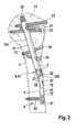
- Fig. 2The location, structure and placement of the implanted in the humerus 7 short nail 1 out. Fracture lines are not shown in detail in the humeral head (epiphysis of the humerus) 71. Individual components of the short nail 1 are made Fig. 1 seen.
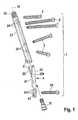
- the short nail 1has a support body 2, fastening pins 3, a Diaphyseanker 4 and a connecting means 5 and an anchoring means 6.
- the support body 2is formed in two parts. In the form of a rod or nail with a smooth shaft, it has the function of a power carrier in conjunction with the fixing pins 3 passing through it. It is composed of an elongate straight main body 21 and a stub or foot body 22 which is in short length. In the exemplary embodiment, the two bodies 21, 22 have matching and constant circular cross-section, and they are designed as a hollow cylinder. through of the connecting means 5, the two bodies 21, 22 in a straight alignment in the impact seat at facing ends with the straight nail axis 10 vertical abutment surfaces firmly and rigidly joined together. The connection is such that the two bodies 21, 22 relatively non-rotatably and axially immovable fit together.
- the stub body 22has the shape of an obliquely cut hollow circular cylinder piece.
- the oblique section or the inclined surfaceare at obtuse wide angle 26 to the longitudinal axis 10 of the short nail 1.
- the inclined surfaceforms a flush with the Diaphyseober
- Diaphyseschräge 23at the support body end, which comes to rest on the lateral introduction side of the short nail 1.
- the Diaphyseanker 4is designed or worked as a one-piece or one-piece, in any case a solid body unit forming component. Components are a connecting flat bar 41 and the stub body 22.
- the flat bar 41comprises a flat elongated flat piece in the manner of a fastening lug or tongue, which protrudes on the stub body 22 exclusively distally, so directed away from the humeral head (Frakturepiphyse) 71 away.
- the Diaphyseanker 4is designed such that the Diaphyseschräge 23 merges into the lateral flat surface of the flat web 41 and coincides with it.
- the Diaphyseschräge 23is open at the circumference of the Diaphyse 72 oblong extending flat surface of Diaphyseankers 4.
- the stub body 23goes borderless flush in the flat surface and thus in the flat bar 41 via. This transition is proximal flush and borderless, so that the Diaphyseanker 4 comes with the flat bar 41 only distal to the positive flat system to the substantially straight wall of the diaphysis 72.
- the stub body 22is formed so short that the flat web 41 or the Diaphyseschräge 23 corresponding oblique opening proximally, ie on the side of the fracture metaphysis 73 with the stub body 22 terminates supernatant. In other words, the abutting interface of the stub body 22 closes proximally with the flat surface of the diaphyseal anchor 4 and does not protrude proximally above it.
- the connecting means 5is designed as a screw 51 with a connecting screw 52. This engages an internal thread inside the distal end of the main body 21 and comes to lie with its head in the passage or cavity 220 of the stub body 22 in a recessed arrangement.
- the abutting against each other by means of the screw 51 connection ends of the two bodies 21, 22form in the frictional connection a rotation lock, the relative axial rotation between the two bodies 21, 22 locks in an adjustable position.
- the fine adjustment of the relative rotational position of the bodies 21, 22 to each otheris important in order to produce a largely large, flat contact of the flat web 41 on the diaphysis 72.
- the adjustable rotational positionfor example, od by a fine-adjusting locking connection with interlocking locking discs. Like. Be set up.
- the main body 21 of the support body 2has on its lateral end side a groove 27 for connecting a conventional adapter for target device and rotary tool for aligning and introducing the nail main body 21.
- the Diaphyseanker 4is fixed by means of the connecting flat bar 41 distally below the end slope 23 of the short nail 2 in the vicinity of this nail end on the diaphysis 72.
- This anchoring compoundcomprises anchoring means 6 as a fully threaded anchoring screw 62 and a long hole 61 extending in the flat web 41 with the diaphysis 72.
- the anchoringcomes to lie in a relatively fixed area of the humerus 1 on the diaphysis 72 and it bears on the circumference the diaphysis 72 with the particularly flat and small area formed flat web 41 of Diaphyseankers 4 not particularly on.
- the fastening part of the flat web 41can be made so elastic and therefore so thin that it conforms to the Diaphysewandung after attachment of the connecting means 5 and the anchoring means 6.
- the connection of the distal end of the support body with the anchoring screw 62 or another suitable connection means, also via the elastic web 41 which is elastic for elastic molding,proves to be sufficiently effective for the stabilization according to the invention.
- the slot 61is formed on the inner edge with three locking holes 611, each with the screwed connection record the head of the anchoring screw 62 in fixed locking seat, while not tightened screw over the length of the slot 61, a passage for the shaft of the anchoring screw 62 is formed ,
- the Diaphyseanker 4can be fixed in three his high position on the diaphysis 72 determining detent positions.
- each locking seatsecures the fixed Diaphyseanker 4 in a simple manner against the epiphysis 71 along the diaphysis 72 directed movement.
- a particularly effective supportis obtained in the direction transverse to the shaft of the anchoring screw 62.
- Other suitable latching connectionswhich can be adjusted in height or the like can be set up.
- the connecting / anchoring elementsare designed and dimensioned such that the device remains diagrammatically particularly flat on the diaphysis 72 corresponding to the flat dimension of the flat web 41.
- the mounting pins 3, as out Fig. 1 to 4 can be seen,are designed as screws with over their length continuous thread (full thread), expediently as cannulated screw holes. These are set by each having an internal thread transverse bores 24 which are attached only to the main body 21 of the support body 2, in such a way that the screws 3 come to lie in crossing arrangement.
- Each screw (each fixing pin) 3is attached by means of the screwed connection to the supporting body 2 in a fixed angle and secured against movement along the axis of the screw.
- Fig. 2how out Fig. 2 can be seen, the short nail 1 and the support body 2 in a special oblique arrangement substantially in the humeral head (fracture epiphysis) 71 to lie.
- the support body 2is dimensioned and arranged to extend from its distal end in the area of the surgical neck of the bone into the medial region of the humeral head 71.
- the proximal end of the support body 2is provided with an external thread 25.
- This thread 25is self-tapping and anchors the support body 2 at its bone-side engagement end. This anchoring interacts particularly well with the distal lateral anchoring by means of the Diaphyseanker 4 according to the invention.
- the implantis made by implanting the short nail 1 using conventional instruments and tools such as, in particular, targeting device, drilling tools, guide spikes and sleeves.
- the main body 21is placed on a lateral, articulated access path 70 with a snug fit in a previously prepared wellbore 701, which serves to receive the support body 2 and is uniform over its entire length with the same cross section.
- the screw 31 for fixing the tubercle minuscan be introduced. So then the screws 32 and 33 are introduced to fix the greater tuberosity.
- These screwswhich are carried by the support body 2, respectively connect fragments after reduction. They each enforce a (not shown) terminal fracture surface and hold the fragments by screwing together.
- the Diaphyseanker 4is added to the Stütz restructuringfuß 22 by means of the connecting means 5.
- the anchoring with the means 6is distal, far away from the at the epiphysis 71 deepest Bruchaus devisr.
- the short nail 1still fastening screws (fixing pins) 34, 35 which are screwed in the region of the surgical neck or in the metaphysis and serve the short nail 2 instead of anchoring with proximal thread 25 or additionally in its longitudinal region in to stabilize a firmer bone area. Also important to this extent remains the sunken attachment of Diaphyseankers invention 4 at the extreme distal end of the support nail 2 with anchoring remote from the fracture area in solid bone material of the straight diaphysis 72nd
Landscapes
- Health & Medical Sciences (AREA)
- Orthopedic Medicine & Surgery (AREA)
- Surgery (AREA)
- Life Sciences & Earth Sciences (AREA)
- Heart & Thoracic Surgery (AREA)
- Nuclear Medicine, Radiotherapy & Molecular Imaging (AREA)
- Engineering & Computer Science (AREA)
- Biomedical Technology (AREA)
- Neurology (AREA)
- Medical Informatics (AREA)
- Molecular Biology (AREA)
- Animal Behavior & Ethology (AREA)
- General Health & Medical Sciences (AREA)
- Public Health (AREA)
- Veterinary Medicine (AREA)
- Surgical Instruments (AREA)
Description
Translated fromGermanDie Erfindung betrifft einen Kurznagel zum Versorgen von gelenknahen Epihysefrakturen eines Epiphyse und Diaphyse aufweisenden Röhrenknochens, umfassend einen an die Dimension der Frakturepiphyse angepassten, zum Einbringen mit lateralem, gelenkfernem Zugangsweg eingerichteten zu implantierenden Nagelstützkörper und, im Zustand der Frakturversorgung, wenigstens einen den Nagelstützkörper mit diesem in gekreuzter Anordnung durch Querdurchbohrung durchsetzenden Befestigungsstift, der mit winkelfester Anbringung an dem Nagelstützkörper und mit Sicherung gegen Bewegung längs der Stiftachse vorgesehen ist, wobei der Nagelstützkörper so dimensioniert und eingerichtet ist, dass er in der Frakturepiphyse in Schräglage zu liegen kommt und sein an der lateralen Einbringungsseite zu liegen kommendes Ende eine Diaphyseschräge aufweist, die am Außenumfang der Diaphyse in einem Diaphysebereich wenigstens nahezu bündig abschließt, der an die sich zwischen der Frakturepiphyse und der Diaphyse erstreckende Metaphyse anschließt.The invention relates to a short nail for the treatment of joint near Epihysefrakturen an epiphyseal and diaphyseal tubular bone, comprising adapted to the dimension of Frakturepiphyse, provided for insertion with lateral, joint remote access path to be implanted nail support and, in the state of fracture supply, at least one nail support body with this in a crossed arrangement by transverse through hole passing through the fixing pin, which is provided with angle fixed attachment to the nail support body and secured against movement along the pin axis, wherein the nail support body is dimensioned and arranged so that it comes to rest in the Frakturepiphyse in an inclined position and be on the lateral Insert side has a Diaphysschräge lying close to the outer periphery of the diaphysis in a Diaphysebereich at least almost flush, which is connected to the between the Frakturepiphyse and Di aphyse extending metaphysis connects.
Mit dem Kurznagel wird ein intramedulläres Implantat zur Verfügung gestellt, das die vorhandene Knochenstruktur stützt und erhält. Im wesentlichen Unterschied zu sich lang erstreckenden Knochennägeln, zum Beispiel zum Versorgen von Oberarmfrakturen, die antegrad gelenknah eingebracht und in der Markhöhle der Diaphyse verankert werden (vgl. zum Beispiel
Die Operationstechnik mit Kurznagel ist auch von Operationstechniken mit Plattensystemen zu unterscheiden. Zum Beispiel ist aus
Ein gattungsgemäßer Kurznagel zum Versorgen von Kopffrakturen eines Knochens wird in
Danach liegt der Erfindung die Zielsetzung zugrunde, die Stabilisierung des Kurznagels zu verbessern und die Operationsindikationen zu erweitern.The invention is therefore based on the objective to improve the stabilization of the short nail and to expand the surgical indications.
Das Ziel wird in Verbindung mit den Merkmalen des Knochen-Kurznagels der eingangsgenannten Art dadurch erreicht, dass der Nagelstützkörper zweiteilig mit einem die wenigstens eine Querdurchbohrungen für den Befestigungsstift aufweisenden Hauptkörper und einem die Diaphyseschräge aufweisenden Stummelkörper ausgebildet ist, der mit dem Hauptkörper entsprechendem Stützquerschnitt versehen und fester Bestandteil eines Diaphyseankers ist, der mittels des Stummelkörpers und eines den Hauptkörper und den Stummelkörper steif verbindenden Verbindungsmittels an den Hauptkörper lösbar ansetzbar ist und der mit einem Verbindungs-Flachsteg ausgebildet ist, der in schräger Ausrichtung mit der Diaphyseschräge mit dieser lateral flächig abschließt, von der Frakturepiphyse wegweisend flach an der Diaphyse zur Anlage kommt und mit einem Verankerungsmittel ausgestattet ist, durch das der Flachsteg in flacher Anlage an der Diaphyse festsetzbar ist.The object is achieved in conjunction with the features of the bone short nail of the type mentioned in that the nail support body is formed in two parts with a at least one transverse holes for the mounting pin having the main body and a Diaphyseschräge stub body, provided with the main body corresponding support cross-section and is an integral part of a Diaphyseankers, which is releasably attachable to the main body by means of the stub body and a connecting the main body and the stub body connecting means and which is formed with a connecting flat web which terminates in oblique alignment with the Diaphyseschräge with this laterally flat, of the fracture epiphysis is seminal flat on the diaphysis to the plant and is provided with an anchoring means by which the flat web is fixed in flat contact with the diaphysis.
Erfindungsgemäß erreicht man, dass der implantierte Kurznagel besonders wirksam und zuverlässig stabilisiert ist. Der Stützkörper des Kurznagels ist mit dem Diaphyseanker derart ausgebildet und eingerichtet, dass ohne Auswirkung auf die Nagellänge und damit ohne Beeinträchtigung der Schräglage in der Frakturepiphyse die stabile Stützfunktion gewährleistet und ein Ausbrechen zum Knochenschaft hin zuverlässig vermieden wird. Wesentlich ist, dass der Stummel- oder Ansatzkörper des Stützkörpers mit der Diaphyseschräge Bestandteil des Diaphyseankers ist, so dass der Stützkörper mit der Diaphyseschräge an dem Diaphyseanker bzw. an dessem Verbindungs-Flachsteg bündig abschließt. Mit dem Verbindungs-Flachsteg erreicht man, dass die Diaphyseschräge am Außenumfang der Diaphyse wenigstens nahezu bündig abschließt.According to the invention, it is achieved that the implanted short nail is stabilized particularly effectively and reliably. The supporting body of the short nail is designed and set up with the Diaphyseanker that ensures the stable support function without affecting the nail length and thus without affecting the inclination in the fracture epiphysis and a breaking out to the bone shaft is reliably prevented. It is essential that the stub or attachment body of the support body with the Diaphyseschräge is part of Diaphyseankers, so that the support body terminates flush with the Diaphyseschräge on Diaphyseanker or at its connection flat bar. With the connecting flat bar, it is achieved that the Diaphysschräge on the outer circumference of the Diaphyse at least almost flush.
Ein Befestigungsteil des Verbindungs-Flachstegs ist durch ein flachförmiges Ansatz- oder Verlängerungsstück nach Art einer flachen Fahne oder Zunge bestimmt. Damit trägt der Verbindungs-Flachsteg am Diaphyseumfang nicht auf. Obwohl die stabile, nur in den Bereich der Metaphyse oder des chirurgischen Halses hineinreichende Schräglage des Kurznagels in der Frakturepiphyse erreicht wird, gelingt es, die Verankerung in gelenkfernem Bereich der Diaphyse und dort mit einfach anbringbarem, Traumatisierung reduzierendem Verankerungsmittel, zweckmäßig mit einer in die Diaphyse eingeschraubten Verbindungsschraube herzustellen. Kraftverhältnisse zur stützenden und stabilisierenden Befestigung des Stützkörpers sind besonders günstig, da der Verbindungs-Flachsteg des Diaphyseankers lateral außen unter flachem stumpfem Winkel in den Stummelkörper des Stützkörpers übergeht. Der Verbindungs-Flachsteg bleibt unter Gewährleistung von Stütz- und Befestigungsfunktion mit der in der Diaphyse unter das Schrägende des Stützkörpers verlegten Verankerung besonders flach und relativ kleinflächig. Vorzugsweise wird der Verbindungs-Flachsteg so kurz gehalten, dass die Verankerung in der Nähe des Stützkörper-Schrägendes unter diesem zu liegen kommt. Aufgrund der erfindungsgemäßen Gestaltung wird ein besonderer Eingriff des Diaphyseankers in die Diaphyse vermieden.A fastening part of the connecting flat web is determined by a flat-shaped approach or extension piece in the manner of a flat flag or tongue. Thus, the connecting flat bar on Diaphyseumfang does not contribute. Although the stable, reaching only in the area of the metaphysis or the surgical neck oblique position of the short nail is reached in the Fracturepiphyse, succeeds anchoring in the joint area of the diaphysis and there with easily attachable, traumatizing reducing anchoring agent, useful with a diaphysis screwed connection screw produce. Force ratios for supporting and stabilizing attachment of the support body are particularly favorable since the connecting flat web of Diaphyseankers merges laterally outside at a flat obtuse angle in the stub body of the support body. The connecting flat bar remains particularly flat and relatively small area while ensuring support and attachment function with the laid in the diaphysis under the oblique of the support body anchoring. Preferably, the connecting flat bar is kept so short that the anchor comes to lie in the vicinity of the support body Schrägendes below it. Due to the design according to the invention a special engagement of Diaphyseankers is avoided in the diaphysis.
Im Ganzen erzielt man ein Kurznagel-Implantat, dessen als intramedullärer Kraftträger dienender Stützkörper in besonderem Maße stabilisiert ist. Es resultiert eine optimale Stabilisierung der Kopffragmente mittels der Befestigungsstifte. Die stabile Frakturversorgung, insbesondere auch bei Mehrfragmentfrakturen, erreicht man sowohl für vitale, als auch für porotische Knochenstrukturen. Vorteile gering invasiver Operationstechnik, damit insbesondere Erhaltung des Knochenkopfes, Schonung von Bändern und Sehnen als Voraussetzung für gute Repositionsergebnisse sowie Vermeiden von Traumatisierung während der Versorgung kommen zur Geltung.On the whole, a short-nail implant is obtained, the support body of which serves as an intramedullary force carrier being particularly stabilized. This results in optimum stabilization of the head fragments by means of the fixing pins. The stable fracture supply, especially in multi-fragment fractures, is achieved both for vital and for porotic bone structures. Advantages of minimally invasive surgical technique, in particular preservation of the bone head, protection of ligaments and tendons as a prerequisite for good repositioning results as well as avoidance of traumatization during treatment are brought to bear.
Die erfindungsgemäße Verankerung wird besonders vorteilhaft in Kombination mit einem am Knocheneingriffsende des Stützkörpers ausgebildeten Außengewinde vorgesehen. Man erreicht, dass der Stützkörper an beiden äußeren Enden fixiert ist.The anchoring according to the invention is particularly advantageously provided in combination with a male thread formed on the bone engaging end of the supporting body. It is achieved that the support body is fixed at both outer ends.
Zweckmäßig besteht das den Hauptkörper und den Stummelkörper des Stützkörpers verbindende Verbindungsmittel in einer Schraubverbindung. Die Verbindung ist steif in dem Sinne, dass der Hauptkörper und der Stummelkörper auf Stoß und gegen relatives Verschieben und Drehen zueinander gesichert aneinandergezogen sind.Suitably, the connecting means connecting the main body and the stub body of the support body in a screw connection. The connection is stiff in the sense that the main body and the stub body are secured together in abutment against relative displacement and rotation.
Das den Hauptkörper und den Stummelkörper des Stützkörpers verbindende Verbindungsmittel kann mit einer Drehsicherung eingerichtet sein, die eine relative axiale Drehung zwischen den beiden Körpern in einstellbarer Drehposition form- und/oder kraftschlüssig sperrt.The connecting means connecting the main body and the stub body of the support body may be arranged with a rotation lock, which positively and / or non-positively locks a relative axial rotation between the two bodies in an adjustable rotational position.
Eine vorteilhafte Ausgestaltung besteht auch darin, dass das Verankerungsmittel des Diaphyseankers mit einem Rastmittel eingerichtet ist, das wenigstens zwei jeweils eine Höhenlage des Diaphyseankers an der Diaphyse bestimmende Rastpositionen ausbildet, die wählbar sind und den Diaphyseanker in festgesetztem Zustand gegen von der Epiphyse längs der Diaphyse weg gerichtete Bewegung sichern.An advantageous embodiment also consists in that the anchoring means of Diaphyseankers is set up with a locking means which forms at least two each an altitude of Diaphyseankers at the Diaphyse determining detent positions, which are selectable and the Diaphyseanker in the fixed state against the epiphysis along the diaphysis away secure directed movement.
In vorteilhafter Gestaltung wird der Stummelkörper mit an der Diaphyseschräge offenem, einen Durchgang bildendem Hohlraum ausgebildet, und die den Diaphyseanker steif mit dem Hauptkörper des Stützkörpers verbindende Schraubverbindung umfasst eine von lateral setzbare Verbindungsschraube mit einem Kopfbereich, der in dem Hohlraum zumindest im Wesentlichen versenkt zu liegen kommt. Eine besonders einfache Verankerung des Diaphyseankers erreicht man dadurch, dass das Verankerungsmittel ein entsprechend der Diaphyse sich erstreckendes, an seinem Verbindungs-Flachsteg ausgebildetes Langloch und eine durch dieses hindurchsetzbare Verankerungsschraube umfasst. Zweckmäßig besteht eine Gestaltung des genannten Rastmittels darin, dass das Langloch als Rastschablone zur höhenveränderlichen Rastaufnahme des Kopfes der Verankerungsschraube ausgebildet wird.In an advantageous embodiment, the stub body is formed with open on the Diaphysschräge, a passage forming cavity, and the Diaphyseanker rigidly connected to the main body of the support body screw comprises a laterally settable connecting screw with a head portion which in the Cavity comes at least substantially sunk to lie. A particularly simple anchorage of the diaphysis anchor is achieved in that the anchoring means comprises a slot corresponding to the diaphysis and formed on its connecting flat bar, and an anchoring screw which can be passed through it. Appropriately, there is a design of said locking means is that the slot is formed as a locking template for height-adjustable locking receptacle of the head of the anchoring screw.
Zweckmäßig werden der Stummelkörper des Stützkörpers und der Verbindungs-Flachsteg kleinbauend so dimensioniert und ausgebildet, dass der Verbindungs-Flachsteg bündig an den Stummelkörper anschließt, wobei er auch zur Seite der Metaphyse mit dem Stummelkörper wenigstens nahezu randlos abschließt.Appropriately, the stub body of the support body and the connecting flat bar kleinbauend be dimensioned and designed so that the connecting flat bar is flush with the stub body, where it also terminates at least almost borderless to the side of the metaphysis with the stub body.
Eine Besonderheit des erfindungsgemäßen Stützkörpers besteht darin, dass das laterale Ende des Stützkörpers in Form des Stummelkörpers als Basis oder Fuß des Diaphyseankers ausgebildet ist. Zweckmäßig ist der Stummelkörper einstückiger Bestandteil des Diaphyseankers und zusammen mit diesem geformt. Der zweiteilig bauende, den Diaphyseanker aufweisende Stützkörper lässt sich als Einheit für das Implantat konfektionieren und anbieten.A special feature of the support body according to the invention is that the lateral end of the support body is designed in the form of the stub body as the base or foot of Diaphyseankers. Suitably, the stub body is an integral part of Diaphyseankers and molded together with this. The two-piece, the Diaphyseanker having support body can be assembled as a unit for the implant and offer.
Der erfindungsgemäße Kurznagel wird zweckmäßig in Form einer Sachgesamtheit, die eine Verkaufseinheit bildet, angeboten. Die Sachgesamtheit zum Herstellen eines Kurznagel-Implantates, insbesondere für proximale Humerusfrakturen, umfasst die Teile des erfindungsgemäßen Kurznagels bzw. Stützkörpers, nämlich wenigstens in Einzahl jeweils den Hauptkörper, den Diaphyseanker mit Stummelkörper, dafür das Verbindungsmittel und das Verankerungsmittel sowie wenigstens einen Satz von Befestigungsstiftten.The short nail according to the invention is expediently offered in the form of an aggregate, which forms a sales unit. The general assembly for producing a short nail implant, in particular for proximal humeral fractures, comprises the parts of the short nail or support body according to the invention, namely at least in singular the main body, the Diaphyseanker with stub body, but the connecting means and the anchoring means and at least one set of attachment pins.
Unteransprüche sind auf die genannten und noch andere zweckmäßige und vorteilhafte Ausgestaltungen gerichtet. Besonders zweckmäßig und vorteilhafte Ausbildungsformen oder -möglichkeiten der Erfindung werden anhand der folgenden Beschreibung der in der schematischen Zeichnung dargestellten Ausführungsbeispiele näher beschrieben. Es zeigen
- Fig. 1
- in Explosionsdarstellung und seitlicher Vorderansicht einen erfindungsgemäßen Kurznagel zum Versorgen einer Mehrfragmentfraktion des Humerus,
- Fig. 2
- in Ansicht von dorsal den aus den Teilen der
Fig. 1 zusammengefügten erfindungsgemäßen Kurznagel als Implantat im Humerus und - Fig. 3 und 4
- den Knochennagel gemäß
Fig. 1 und2 in Ansicht von dorsal bzw. lateral.
- Fig. 1
- in exploded view and lateral front view of a short nail according to the invention for supplying a multi-fragment fraction of the humerus,
- Fig. 2
- in dorsal view from the parts of the
Fig. 1 assembled short nail according to the invention as an implant in the humerus and - 3 and 4
- according to the bone nail
Fig. 1 and2 in view of the dorsal or lateral.
Der im Ausführungsbeispiel dargestellte Kurznagel 1 ist als Implantat für subkapitale und pertuberkuläre Frakturen des Humerus 7 eingerichtet. Der Kurznagel 1 ist für die genannten Humerusfrakturen besonders geeignet. Allgemein ist der erfindungsgemäße Kurznagel mit angepasster Dimensionierung und Auslegung insbesondere zum Versorgen von Mehrfragmentfrakturen der Epiphysen von Röhrenknochen geeignet, wie zum Beispiel auch von Femur, Tibia, Fibula, Radius und Ulna. Der erfindungsgemäß gestaltete Kurznagel kann aber auch für andere Knochen mit gelenknahen Frakturen, zum Beispiel für Frakturen des Calcaneus verwendet werden..The short nail 1 shown in the embodiment is designed as an implant for subcapital and pertubercular fractures of the
Aus
Der Stützkörper 2 ist zweiteilig ausgebildet. In Form eines Stabes oder Nagels mit glattem Schaft hat er die Funktion eines Kraftträgers in Verbindung mit den ihn durchsetzenden Befestigungsstiften 3. Er setzt sich aus einem langgestreckten geraden Hauptkörper 21 und einem demgegenüber kurzstückigen Stummel- oder Fußkörper 22 zusammen. Im Ausführungsbeispiel weisen die beiden Körper 21, 22 übereinstimmenden und gleichbleibenden Kreisquerschnitt auf, und sie sind als Hohlzylinder ausgeführt. Mittels des Verbindungsmittels 5 sind die beiden Körper 21, 22 in gerader Ausrichtung im Stoßsitz an zugewandten Enden mit zur geraden Nagelachse 10 senkrechten Stoßflächen fest und steif aneinandergefügt. Die Verbindung ist derart, dass die beiden Körper 21, 22 relativ zueinander drehfest und axial unverschieblich aneinandersitzen.The
Genauer betrachtet, weist der Stummelkörper 22 die Form eines schräg abgeschnittenen hohlen Kreiszylinderstücks auf. Der Schrägschnitt bzw. die Schrägfläche liegen unter stumpfem weitem Winkel 26 zur Längsachse 10 des Kurznagels 1. Die Schrägfläche bildet eine bündig mit der Diaphyseoberfläche abschließende Diaphyseschräge 23 an dem Stützkörper-Ende, das an der lateralen Einbringungsseite des Kurznagels 1 zu liegen kommt.More specifically, the
Der Diaphyseanker 4 ist als einstückiges oder einteiliges, jedenfalls eine feste Körpereinheit bildendes Bauteil gestaltet bzw. gearbeitet. Bestandteile sind ein Verbindungs-Flachsteg 41 und der Stummelkörper 22. Der Flachsteg 41 umfasst ein flaches längliches Flachstück nach Art einer Befestigungsfahne oder -zunge, das an dem Stummelkörper 22 ausschließlich nach distal, also von dem Humeruskopf (Frakturepiphyse) 71 weg gerichtet absteht. Der Diaphyseanker 4 ist derart gestaltet, dass die Diaphyseschräge 23 in die laterale Flachfläche des Flachstegs 41 übergeht bzw. damit zusammenfällt. Die Diaphyseschräge 23 ist an der am Umfang der Diaphyse 72 sich länglich erstreckenden Flachfläche des Diaphyseankers 4 offen. Der Stummelkörper 23 geht randlos bündig in die Flachfläche und damit in den Flachsteg 41 über. Dieser Übergang ist proximal bündig und randlos, so dass der Diaphyseanker 4 mit dem Flachsteg 41 ausschließlich distal zur formschlüssigen Flachanlage an die im Wesentlichen gerade Wandung der Diaphyse 72 kommt. Zudem ist der Stummelkörper 22 so kurzstückig ausgebildet, dass der Flachsteg 41 bzw. die der Diaphyseschräge 23 entsprechende Schrägöffnung proximal, also zur Seite der Frakturmetaphyse 73 mit dem Stummelkörper 22 überstandsfrei abschließt. Anders ausgedrückt, schließt die den Stoßsitz herstellende Anschlussfläche des Stummelkörpers 22 proximal mit der Flachfläche des Diaphyseankers 4 ab und steht darüber proximal nicht hervor.The
Mit dem beschriebenen kurzen Stummelkörper 22 des Diaphyseankers 4 wird in besonderem Maß erreicht, dass der Anschluss des Diaphyseankers 4 an den Hauptkörper 21 des Stützkörpers 2 so weit wie möglich nach lateral, jedoch in der Diaphyse 72 versenkt, gelegt ist.With the described
Das Verbindungsmittel 5 ist als Schraubverbindung 51 mit einer Verbindungsschraube 52 ausgebildet. Diese greift in ein Innengewinde innen am distalen Ende des Hauptkörpers 21 ein und kommt mit ihrem Kopf in dem Durchgang oder Hohlraum 220 des Stummelkörpers 22 in versenkter Anordnung zu liegen. Die mittels der Schraubverbindung 51 auf Stoß gegeneinandergezogenen Anschlussenden der beiden Körper 21, 22 bilden im Kraftschluss eine Drehsicherung, die in einstellbarer Position die relative axiale Drehung zwischen den beiden Körpern 21, 22 sperrt. Die Feinjustierung der relativen Drehposition der Körper 21, 22 zueinander ist von Bedeutung, um eine weitgehend großflächige, flache Anlage des Flachstegs 41 an der Diaphyse 72 herzustellen. Die einstellbare Drehposition kann zum Beispiel auch durch eine feinjustierende Rastverbindung mit ineinandergreifenden Rastscheiben od. dgl. eingerichtet werden.The connecting means 5 is designed as a
Der Hauptkörper 21 des Stützkörpers 2 weist an seiner lateralen Stirnseite eine Nut 27 zum Anschluss eines herkömmlichen Adapters für Zielgerät und Drehwerkzeug zum Ausrichten und Einbringen des Nagel-Hauptkörpers 21 auf.The
Der Diaphyseanker 4 wird mittels des Verbindungs-Flachstegs 41 distal unterhalb der Endschräge 23 des Kurznagels 2 in der Nähe dieses Nagelendes an der Diaphyse 72 befestigt. Diese Verankerungsverbindung umfasst als Verankerungsmittel 6 eine Verankerungsschraube 62 mit Vollgewinde sowie ein mit der Diaphyse 72 sich lang erstreckendes Langloch 61 in dem Flachsteg 41. Die Verankerung kommt in einem relativ festen Bereich des Humerus 1 an der Diaphyse 72 zu liegen, und sie trägt am Umfang der Diaphyse 72 mit dem besonders flach und kleinflächig ausgebildeten Flachsteg 41 des Diaphyseankers 4 nicht besonders auf. Vorteilhaft kann der Befestigungsteil des Flachstegs 41 derart elastisch und damit so dünn ausgebildet werden, dass er sich nach Anbringen des Verbindungsmittels 5 und des Verankerungsmittels 6 an die Diaphysewandung anschmiegt. Die Verbindung des distalen Stützkörperendes mit der Verankerungsschraube 62 oder einem anderen geeigneten Verbindungsmittel auch über den zur elastischen Anformung elastischen Steg 41 erweist sich für die erfindungsgemäße Stabilisierung als ausreichend wirksam.The
Wie insbesondere aus
Im Ausführungsbeispiel der
Die Befestigungsstifte 3, wie aus
Wie aus
Das Implantat wird dadurch hergestellt, dass der Kurznagel 1 unter Verwendung von üblichen Instrumenten und Werkzeugen wie insbesondere Zielgerät, Bohrwerkzeugen, Führungsspießen und - hülsen implantiert wird. Zunächst wird der Hauptkörper 21 auf lateralem, gelenkfernem Zugangsweg 70 mit sattem Sitz in ein zuvor gefertigtes Bohrloch 701 eingebracht, das zur Aufnahme des Stützkörpers 2 dient und über dessen Gesamtlänge mit gleichem Querschnitt einheitlich ist. Dann kann zum Beispiel die Schraube 31 zur Fixierung des Tuberculum minus eingebracht werden. So dann werden die Schrauben 32 und 33 zum Fixieren des Tuberculum majus eingebracht. Diese Schrauben, die von dem Stützkörper 2 getragen werden, verbinden jeweils Fragmente nach Reposition. Sie durchsetzen jeweils eine (nicht dargestellte) Endstellen-Bruchfläche und halten die Fragmente durch Schraubverbindung aneinander. Schließlich wird der Diaphyseanker 4 mit dem Stützkörperfuß 22 mittels des Verbindungsmittels 5 angefügt. Die Verankerung mit dem Mittel 6 erfolgt distal, fern von dem an der Epiphyse 71 tiefsten Bruchausläufer.The implant is made by implanting the short nail 1 using conventional instruments and tools such as, in particular, targeting device, drilling tools, guide spikes and sleeves. First, the
Im Ausführungsbeispiel weist der Kurznagel 1 noch Befestigungsschrauben (Befestigungsstifte) 34, 35 auf, die im Bereich des chirurgischen Halses bzw. im Bereich der Metaphyse eingeschraubt werden und dazu dienen, den Kurznagel 2 statt der Verankerung mit proximalem Gewinde 25 oder zusätzlich in seinem Längsbereich in einem festeren Knochenbereich zu stabilisieren. Von wesentlicher Bedeutung bleibt auch insoweit das versenkte Anbringen des erfindungsgemäßen Diaphyseankers 4 am äußersten distalen Ende des Stütznagels 2 mit Verankerung fern von dem Frakturbereich in festem Knochenmaterial der geraden Diaphyse 72.In the exemplary embodiment, the short nail 1 still fastening screws (fixing pins) 34, 35 which are screwed in the region of the surgical neck or in the metaphysis and serve the
Claims (10)
- Short nail (1) for the treatment of epiphyseal fractures close to the joint in a long bone (7) having epiphysis (71) and diaphysis (72), comprising a nail supporting body (2) to be implanted, adapted to the dimensions of the fractured epiphysis (71) and designed to be introduced with a lateral access path (70) remote from the joint, and, in the state of treatment of the fracture, at least one fixation pin (3) which passes through the nail supporting body (2) in a crossed arrangement with the latter through a transverse through-bore (24) and which is provided with mounting at a fixed angle on the nail supporting body (2) and with protection against movement along the axis of the pin, wherein the nail supporting body (2) is dimensioned and designed in such a way that it comes to lie in an oblique position in the fractured epiphysis (71), and its end which comes to lie on the lateral side of introduction has a diaphyseal slant (23) which ends at least almost flush at the outer circumference of the diaphysis (72) in a region of the diaphysis which adjoins the metaphysis (73) extending between the fractured epiphysis (71) and the diaphysis (72),characterised in that the nail supporting body (2) is constructed in two parts with a main body (21) having the at least one transverse through-bore for the fixation pin (3) and a stub body (22) which has the diaphyseal slant (23) and which is provided with a supporting cross-section corresponding to the main body (21) and forms a fixed part of a diaphyseal anchor (4) which can be releasably attached to the main body (21) by means of the stub body (22) and a connecting means (5) rigidly connecting the main body (21) and the stub body (22) and which is designed with a flat connecting web (41) which in oblique orientation ends laterally in a plane with the diaphyseal slant (23), comes to abut flat against the diaphysis (72), pointing away from the fractured epiphysis (71), and is provided with an anchoring means (6) by which the flat web (41) can be fixed in flat abutment against the diaphysis (72).
- Short nail according to claim 1,characterised in that the nail supporting body (2) at its end facing away from the stub body (22) is provided with an external thread (25).
- Short nail according to claim 1 or 2,characterised in that the connecting means (5) which connects the main body (21) and the stub body (22) of the supporting body (2) consists of a screw connection (51).
- Short nail according to claim 3,characterised in that the stub body (22) is provided with a cavity (220) and the screw connection (5) comprises a laterally insertable connecting screw (52) with a head region which comes to lie at least substantially countersunk in the stub body cavity (220).
- Short nail according to any one of claims 1 to 4,characterised in that the connecting means (5) which connects the main body (21) and the stub body (22) of the supporting body (2) is designed with means (53) for protection against rotation, which blocks relative axial rotation between the two bodies (21, 22) in an adjustable rotational position.
- Short nail according to any one of claims 1 to 5,characterised in that the anchoring means (6) of the diaphyseal anchor (4) comprises an elongated hole (61) extending according to the diaphysis (72) and formed in the flat connecting web (41), and an anchoring screw (62) which can be passed through the elongated hole.
- Short nail according to any one of claims 1 to 6,characterised in that the anchoring means (6) of the diaphyseal anchor (4) is designed with a catch means (63) which forms at least two catch positions which in each case determine a height of the diaphyseal anchor (4) on the diaphysis (72) and which can be selected and in the selected catch position protect the diaphyseal anchor (4) in the fixed state against movement directed away from the epiphysis (71) along the diaphysis (72).
- Short nail according to any one of claims 1 to 7,characterised in that the stub body (22) of the supporting body (21) and the flat connecting web (41) are dimensioned and shaped in such a way that the flat connecting web (41) ends at least substantially without overhang with the stub body (22) on the side of the metaphysis (73).
- Supporting body (2) of a short nail (1) according to any one of claims 1 to 8, wherein the supporting body (2) is constructed in two parts with the main body (21) and the stub body (22) which forms part of the diaphyseal anchor (4).
- Entity of items for producing a short nail implant, in particular for proximal fractures of the humerus, comprising the parts of the short nail (1) or supporting body (2), according to any one of claims 1 to 9, namely at least in the singular in each case the main body (21), the diaphyseal anchor (4) with stub body (22), the connecting means (5) and the anchoring means (6) therefor, and also at least one set of fixation pins (3).
Applications Claiming Priority (2)
| Application Number | Priority Date | Filing Date | Title |
|---|---|---|---|
| DE202008010922UDE202008010922U1 (en) | 2008-08-12 | 2008-08-12 | Short nail to treat epiphyseal fractures |
| PCT/EP2009/005895WO2010017990A1 (en) | 2008-08-12 | 2009-08-07 | Short pin for taking care of epiphysis fractures |
Publications (2)
| Publication Number | Publication Date |
|---|---|
| EP2320816A1 EP2320816A1 (en) | 2011-05-18 |
| EP2320816B1true EP2320816B1 (en) | 2014-02-12 |
Family
ID=41278439
Family Applications (1)
| Application Number | Title | Priority Date | Filing Date |
|---|---|---|---|
| EP09777876.5ANot-in-forceEP2320816B1 (en) | 2008-08-12 | 2009-08-07 | Short pin for taking care of epiphysis fractures |
Country Status (6)
| Country | Link |
|---|---|
| US (1) | US8486071B2 (en) |
| EP (1) | EP2320816B1 (en) |
| CN (1) | CN102149343B (en) |
| DE (1) | DE202008010922U1 (en) |
| ES (1) | ES2457192T3 (en) |
| WO (1) | WO2010017990A1 (en) |
Families Citing this family (35)
| Publication number | Priority date | Publication date | Assignee | Title |
|---|---|---|---|---|
| CA2781407A1 (en) | 2008-01-14 | 2009-07-23 | Michael P. Brenzel | Apparatus and methods for fracture repair |
| US20110046625A1 (en)* | 2008-05-07 | 2011-02-24 | Tornier | Surgical technique and apparatus for proximal humeral fracture repair |
| US9044282B2 (en) | 2008-06-24 | 2015-06-02 | Extremity Medical Llc | Intraosseous intramedullary fixation assembly and method of use |
| US8303589B2 (en) | 2008-06-24 | 2012-11-06 | Extremity Medical Llc | Fixation system, an intramedullary fixation assembly and method of use |
| US8313487B2 (en)* | 2008-06-24 | 2012-11-20 | Extremity Medical Llc | Fixation system, an intramedullary fixation assembly and method of use |
| US9017329B2 (en) | 2008-06-24 | 2015-04-28 | Extremity Medical, Llc | Intramedullary fixation assembly and method of use |
| US9289220B2 (en) | 2008-06-24 | 2016-03-22 | Extremity Medical Llc | Intramedullary fixation assembly and method of use |
| US20110230884A1 (en)* | 2008-06-24 | 2011-09-22 | Adam Mantzaris | Hybrid intramedullary fixation assembly and method of use |
| US8328806B2 (en) | 2008-06-24 | 2012-12-11 | Extremity Medical, Llc | Fixation system, an intramedullary fixation assembly and method of use |
| US20110178520A1 (en) | 2010-01-15 | 2011-07-21 | Kyle Taylor | Rotary-rigid orthopaedic rod |
| WO2011091052A1 (en) | 2010-01-20 | 2011-07-28 | Kyle Taylor | Apparatus and methods for bone access and cavity preparation |
| WO2011112615A1 (en) | 2010-03-08 | 2011-09-15 | Krinke Todd A | Apparatus and methods for securing a bone implant |
| EP2455014B1 (en)* | 2010-11-17 | 2015-08-12 | Hyprevention | Implantable device for preventive or interventive treatment of femur fractures, associated ancillary device |
| PT2667808E (en)* | 2011-01-26 | 2015-12-09 | Del Palma Orthopedics Llc | Lower extremity fusion devices |
| EP2811927B1 (en) | 2012-02-07 | 2017-05-10 | MNR Device Corporation | Apparatus for treating a bone fracture |
| KR20140119797A (en) | 2012-03-01 | 2014-10-10 | 솔라나 서지컬, 엘엘씨 | Surgical staple for insertion into bones |
| CN105939677A (en) | 2013-12-12 | 2016-09-14 | 康文图斯整形外科公司 | Tissue displacement tools and methods |
| DE102014009774B4 (en)* | 2014-07-02 | 2018-06-14 | Ehrhardt Weiß | Orthopedic trauma implant |
| CN104173098A (en)* | 2014-08-07 | 2014-12-03 | 上海市第一人民医院 | Intramedullary nail used for implanting in humerus bone marrow cavity |
| US10682168B2 (en) | 2016-09-15 | 2020-06-16 | Wright Medical Technology, Inc. | Intramedullary implant with proximal plate and method for its use |
| US11033303B2 (en)* | 2017-03-13 | 2021-06-15 | Extremity Medical, Llc | Calcaneal cross medullary plate |
| WO2018187770A1 (en) | 2017-04-06 | 2018-10-11 | Extremity Medical, Llc | Orthopedic plate with modular peg and compression screw |
| WO2019010252A2 (en) | 2017-07-04 | 2019-01-10 | Conventus Orthopaedics, Inc. | APPARATUS AND METHODS FOR TREATING BONES |
| MX2020003481A (en) | 2017-10-11 | 2020-12-07 | Howmedica Osteonics Corp | Humeral fixation plate guides. |
| US10881436B2 (en) | 2017-10-27 | 2021-01-05 | Wright Medical Technology, Inc. | Implant with intramedullary portion and offset extramedullary portion |
| US11660201B2 (en) | 2018-10-25 | 2023-05-30 | Wright Medical Technology, Inc. | Systems, apparatuses, and methods for correcting a bone defect |
| US10987146B2 (en) | 2019-03-05 | 2021-04-27 | Nextremity Solutions, Inc. | Bone defect repair apparatus and method |
| EP3968872A4 (en) | 2019-05-13 | 2023-04-19 | Wright Medical Technology, Inc. | Surgical tools and methods of use |
| WO2021176272A1 (en) | 2020-03-06 | 2021-09-10 | Stryker European Operations Limited | Set screw for femoral nail |
| US12207849B2 (en) | 2020-03-06 | 2025-01-28 | Stryker European Operations Limited | Set screw for femoral nail |
| CN112294412A (en)* | 2020-10-29 | 2021-02-02 | 江苏安格尔医疗器械有限公司 | Humerus multidimensional locking intramedullary nail |
| US12256969B2 (en) | 2021-06-17 | 2025-03-25 | Wright Medical Technology, Inc. | Minimally invasive surgery osteotomy fragment shifter, stabilizer, and targeter |
| US12343050B2 (en)* | 2021-08-17 | 2025-07-01 | Ps Ortho Llc | Bone fixation devices, systems, and methods |
| EP4460249A1 (en) | 2022-01-04 | 2024-11-13 | Extremity Medical, LLC | Orthopedic plate with locking compression slot |
| DE102022000228A1 (en) | 2022-01-22 | 2023-07-27 | Trauma-Stiftung gemeinnützige Gesellschaft für Klinik - Forschung - Lehre mbH | Rotationally adaptive bone marrow nail |
Family Cites Families (14)
| Publication number | Priority date | Publication date | Assignee | Title |
|---|---|---|---|---|
| US4776330A (en)* | 1986-06-23 | 1988-10-11 | Pfizer Hospital Products Group, Inc. | Modular femoral fixation system |
| US5041116A (en)* | 1990-05-21 | 1991-08-20 | Wilson James T | Compression hip screw system |
| DE9106152U1 (en)* | 1991-05-17 | 1991-10-10 | Oswald Leibinger GmbH, 7202 Mühlheim | Device for osteosynthesis |
| US5472444A (en) | 1994-05-13 | 1995-12-05 | Acumed, Inc. | Humeral nail for fixation of proximal humeral fractures |
| US5693055A (en) | 1995-01-03 | 1997-12-02 | Zahiri; Christopher A. | Odd angle internal bone fixation device |
| US6645209B2 (en) | 2000-04-04 | 2003-11-11 | Synthes (Usa) | Device for rotational stabilization of bone segments |
| US6572620B1 (en)* | 2001-11-16 | 2003-06-03 | Lew C. Schon | Modular, blade-rod, intramedullary fixation device |
| WO2004039271A2 (en) | 2002-10-29 | 2004-05-13 | Tantum Ag | Fracture pin |
| US7118572B2 (en)* | 2003-02-03 | 2006-10-10 | Orthopedic Designs, Inc. | Femoral neck compression screw system with ortho-biologic material delivery capability |
| DE10326643A1 (en)* | 2003-06-11 | 2004-12-30 | Mückter, Helmut, Dr. med. Dipl.-Ing. | Osteosynthesis plate or comparable implant with ball sleeve |
| FR2881340B1 (en)* | 2005-02-01 | 2008-01-11 | Tornier Sas | HUMERAL NUTS |
| US20070083202A1 (en)* | 2005-09-20 | 2007-04-12 | Donald Eli Running | Intramedullary bone plate with sheath |
| JP4978906B2 (en)* | 2006-10-17 | 2012-07-18 | 周 中村 | Fracture fixation device for femoral trochanteric fracture |
| US8182484B2 (en)* | 2008-04-21 | 2012-05-22 | Depuy Products, Inc. | Orthopaedic trauma hip screw assembly |
- 2008
- 2008-08-12DEDE202008010922Upatent/DE202008010922U1/ennot_activeExpired - Lifetime
- 2009
- 2009-08-07ESES09777876.5Tpatent/ES2457192T3/enactiveActive
- 2009-08-07WOPCT/EP2009/005895patent/WO2010017990A1/enactiveApplication Filing
- 2009-08-07EPEP09777876.5Apatent/EP2320816B1/ennot_activeNot-in-force
- 2009-08-07CNCN2009801324630Apatent/CN102149343B/ennot_activeExpired - Fee Related
- 2009-08-07USUS13/058,710patent/US8486071B2/ennot_activeExpired - Fee Related
Also Published As
| Publication number | Publication date |
|---|---|
| ES2457192T3 (en) | 2014-04-25 |
| US8486071B2 (en) | 2013-07-16 |
| US20110137313A1 (en) | 2011-06-09 |
| EP2320816A1 (en) | 2011-05-18 |
| WO2010017990A1 (en) | 2010-02-18 |
| CN102149343B (en) | 2013-10-16 |
| DE202008010922U1 (en) | 2010-01-07 |
| CN102149343A (en) | 2011-08-10 |
Similar Documents
| Publication | Publication Date | Title |
|---|---|---|
| EP2320816B1 (en) | Short pin for taking care of epiphysis fractures | |
| DE60213800T2 (en) | Nail and screw for surgical fixation system | |
| DE60119890T2 (en) | HAND FIXING DEVICE | |
| EP1024762B1 (en) | Bone fixation device | |
| DE10348932B4 (en) | System for the minimally invasive treatment of a proximal humeral or femoral fracture | |
| EP2152173B1 (en) | Locking intramedullary nail | |
| EP2190369B1 (en) | Bone anchoring device for the operative repair of fractures | |
| EP0468192B1 (en) | Osteosynthetic plate | |
| DE60112921T2 (en) | SPIRAL BLADES FOR A HUMERUS IMPLANT | |
| EP1202675B1 (en) | Surgical guide body | |
| CH682300A5 (en) | ||
| EP1330988B1 (en) | Intramedullary implant for osteosynthesis | |
| DE10335388A1 (en) | Surgical reference device, comprising bone plate attached to femur for safe joining of rigid body | |
| DE20200705U1 (en) | Intramedullary osteosynthesis implant | |
| EP1286623B1 (en) | Osteosynthesis implant from a plastic material | |
| DE29506036U1 (en) | Modular femoral prosthesis system with a shaft or prosthesis nail on which various modules can be placed | |
| EP2029037B1 (en) | Femoral head implant | |
| DE102005043281A1 (en) | Bone plate for maintaining proximal humerus fracture, has heading section whose region overlapping shank part in dorsal direction is larger than region of section overlapping shank part in ventral direction | |
| DE102007029090A1 (en) | Device for osteosynthesis, particularly bone fracture near joint, has pin for implantation into abarticular bone, and proximal longitudinal ring element provided for implantation into bone fragment near joint | |
| DE60036553T2 (en) | FEMORAL INTERMEDULLARY STABS SYSTEM | |
| EP2092904A1 (en) | Trochanter plate | |
| EP1439801B1 (en) | Femoral prosthesis | |
| EP2750616B1 (en) | Device for fixing a bone fractured in the femoral neck region | |
| AT413639B (en) | osteosynthesis | |
| DE102004019196A1 (en) | Implant for fixing two bone fragments, has guide bushing having shank that is anchored into opening of one bone fragment, and pin that is fixed in opening of another bone fragment |
Legal Events
| Date | Code | Title | Description |
|---|---|---|---|
| PUAI | Public reference made under article 153(3) epc to a published international application that has entered the european phase | Free format text:ORIGINAL CODE: 0009012 | |
| 17P | Request for examination filed | Effective date:20110309 | |
| AK | Designated contracting states | Kind code of ref document:A1 Designated state(s):AT BE BG CH CY CZ DE DK EE ES FI FR GB GR HR HU IE IS IT LI LT LU LV MC MK MT NL NO PL PT RO SE SI SK SM TR | |
| AX | Request for extension of the european patent | Extension state:AL BA RS | |
| DAX | Request for extension of the european patent (deleted) | ||
| GRAP | Despatch of communication of intention to grant a patent | Free format text:ORIGINAL CODE: EPIDOSNIGR1 | |
| RIC1 | Information provided on ipc code assigned before grant | Ipc:A61B 17/80 20060101ALI20130722BHEP Ipc:A61B 17/72 20060101AFI20130722BHEP | |
| INTG | Intention to grant announced | Effective date:20130821 | |
| GRAS | Grant fee paid | Free format text:ORIGINAL CODE: EPIDOSNIGR3 | |
| GRAA | (expected) grant | Free format text:ORIGINAL CODE: 0009210 | |
| AK | Designated contracting states | Kind code of ref document:B1 Designated state(s):AT BE BG CH CY CZ DE DK EE ES FI FR GB GR HR HU IE IS IT LI LT LU LV MC MK MT NL NO PL PT RO SE SI SK SM TR | |
| REG | Reference to a national code | Ref country code:GB Ref legal event code:FG4D Free format text:NOT ENGLISH | |
| REG | Reference to a national code | Ref country code:CH Ref legal event code:EP | |
| REG | Reference to a national code | Ref country code:AT Ref legal event code:REF Ref document number:651798 Country of ref document:AT Kind code of ref document:T Effective date:20140215 | |
| REG | Reference to a national code | Ref country code:CH Ref legal event code:NV Representative=s name:E. BLUM AND CO. AG PATENT- UND MARKENANWAELTE , CH | |
| REG | Reference to a national code | Ref country code:IE Ref legal event code:FG4D Free format text:LANGUAGE OF EP DOCUMENT: GERMAN | |
| REG | Reference to a national code | Ref country code:DE Ref legal event code:R096 Ref document number:502009008796 Country of ref document:DE Effective date:20140327 | |
| REG | Reference to a national code | Ref country code:ES Ref legal event code:FG2A Ref document number:2457192 Country of ref document:ES Kind code of ref document:T3 Effective date:20140425 | |
| REG | Reference to a national code | Ref country code:SE Ref legal event code:TRGR | |
| REG | Reference to a national code | Ref country code:NL Ref legal event code:VDEP Effective date:20140212 | |
| REG | Reference to a national code | Ref country code:LT Ref legal event code:MG4D | |
| PG25 | Lapsed in a contracting state [announced via postgrant information from national office to epo] | Ref country code:IS Free format text:LAPSE BECAUSE OF FAILURE TO SUBMIT A TRANSLATION OF THE DESCRIPTION OR TO PAY THE FEE WITHIN THE PRESCRIBED TIME-LIMIT Effective date:20140612 Ref country code:LT Free format text:LAPSE BECAUSE OF FAILURE TO SUBMIT A TRANSLATION OF THE DESCRIPTION OR TO PAY THE FEE WITHIN THE PRESCRIBED TIME-LIMIT Effective date:20140212 Ref country code:NO Free format text:LAPSE BECAUSE OF FAILURE TO SUBMIT A TRANSLATION OF THE DESCRIPTION OR TO PAY THE FEE WITHIN THE PRESCRIBED TIME-LIMIT Effective date:20140512 | |
| PG25 | Lapsed in a contracting state [announced via postgrant information from national office to epo] | Ref country code:CY Free format text:LAPSE BECAUSE OF FAILURE TO SUBMIT A TRANSLATION OF THE DESCRIPTION OR TO PAY THE FEE WITHIN THE PRESCRIBED TIME-LIMIT Effective date:20140212 Ref country code:NL Free format text:LAPSE BECAUSE OF FAILURE TO SUBMIT A TRANSLATION OF THE DESCRIPTION OR TO PAY THE FEE WITHIN THE PRESCRIBED TIME-LIMIT Effective date:20140212 Ref country code:PT Free format text:LAPSE BECAUSE OF FAILURE TO SUBMIT A TRANSLATION OF THE DESCRIPTION OR TO PAY THE FEE WITHIN THE PRESCRIBED TIME-LIMIT Effective date:20140612 Ref country code:FI Free format text:LAPSE BECAUSE OF FAILURE TO SUBMIT A TRANSLATION OF THE DESCRIPTION OR TO PAY THE FEE WITHIN THE PRESCRIBED TIME-LIMIT Effective date:20140212 | |
| PG25 | Lapsed in a contracting state [announced via postgrant information from national office to epo] | Ref country code:LV Free format text:LAPSE BECAUSE OF FAILURE TO SUBMIT A TRANSLATION OF THE DESCRIPTION OR TO PAY THE FEE WITHIN THE PRESCRIBED TIME-LIMIT Effective date:20140212 Ref country code:HR Free format text:LAPSE BECAUSE OF FAILURE TO SUBMIT A TRANSLATION OF THE DESCRIPTION OR TO PAY THE FEE WITHIN THE PRESCRIBED TIME-LIMIT Effective date:20140212 | |
| PG25 | Lapsed in a contracting state [announced via postgrant information from national office to epo] | Ref country code:CZ Free format text:LAPSE BECAUSE OF FAILURE TO SUBMIT A TRANSLATION OF THE DESCRIPTION OR TO PAY THE FEE WITHIN THE PRESCRIBED TIME-LIMIT Effective date:20140212 Ref country code:RO Free format text:LAPSE BECAUSE OF FAILURE TO SUBMIT A TRANSLATION OF THE DESCRIPTION OR TO PAY THE FEE WITHIN THE PRESCRIBED TIME-LIMIT Effective date:20140212 Ref country code:EE Free format text:LAPSE BECAUSE OF FAILURE TO SUBMIT A TRANSLATION OF THE DESCRIPTION OR TO PAY THE FEE WITHIN THE PRESCRIBED TIME-LIMIT Effective date:20140212 Ref country code:DK Free format text:LAPSE BECAUSE OF FAILURE TO SUBMIT A TRANSLATION OF THE DESCRIPTION OR TO PAY THE FEE WITHIN THE PRESCRIBED TIME-LIMIT Effective date:20140212 | |
| REG | Reference to a national code | Ref country code:DE Ref legal event code:R097 Ref document number:502009008796 Country of ref document:DE | |
| PG25 | Lapsed in a contracting state [announced via postgrant information from national office to epo] | Ref country code:PL Free format text:LAPSE BECAUSE OF FAILURE TO SUBMIT A TRANSLATION OF THE DESCRIPTION OR TO PAY THE FEE WITHIN THE PRESCRIBED TIME-LIMIT Effective date:20140212 Ref country code:SK Free format text:LAPSE BECAUSE OF FAILURE TO SUBMIT A TRANSLATION OF THE DESCRIPTION OR TO PAY THE FEE WITHIN THE PRESCRIBED TIME-LIMIT Effective date:20140212 | |
| PLBE | No opposition filed within time limit | Free format text:ORIGINAL CODE: 0009261 | |
| STAA | Information on the status of an ep patent application or granted ep patent | Free format text:STATUS: NO OPPOSITION FILED WITHIN TIME LIMIT | |
| 26N | No opposition filed | Effective date:20141113 | |
| REG | Reference to a national code | Ref country code:DE Ref legal event code:R097 Ref document number:502009008796 Country of ref document:DE Effective date:20141113 | |
| PG25 | Lapsed in a contracting state [announced via postgrant information from national office to epo] | Ref country code:LU Free format text:LAPSE BECAUSE OF FAILURE TO SUBMIT A TRANSLATION OF THE DESCRIPTION OR TO PAY THE FEE WITHIN THE PRESCRIBED TIME-LIMIT Effective date:20140807 Ref country code:MC Free format text:LAPSE BECAUSE OF FAILURE TO SUBMIT A TRANSLATION OF THE DESCRIPTION OR TO PAY THE FEE WITHIN THE PRESCRIBED TIME-LIMIT Effective date:20140212 | |
| PG25 | Lapsed in a contracting state [announced via postgrant information from national office to epo] | Ref country code:BE Free format text:LAPSE BECAUSE OF NON-PAYMENT OF DUE FEES Effective date:20140831 | |
| REG | Reference to a national code | Ref country code:IE Ref legal event code:MM4A | |
| PG25 | Lapsed in a contracting state [announced via postgrant information from national office to epo] | Ref country code:SI Free format text:LAPSE BECAUSE OF FAILURE TO SUBMIT A TRANSLATION OF THE DESCRIPTION OR TO PAY THE FEE WITHIN THE PRESCRIBED TIME-LIMIT Effective date:20140212 | |
| REG | Reference to a national code | Ref country code:FR Ref legal event code:PLFP Year of fee payment:7 | |
| PG25 | Lapsed in a contracting state [announced via postgrant information from national office to epo] | Ref country code:IE Free format text:LAPSE BECAUSE OF NON-PAYMENT OF DUE FEES Effective date:20140807 | |
| PG25 | Lapsed in a contracting state [announced via postgrant information from national office to epo] | Ref country code:SM Free format text:LAPSE BECAUSE OF FAILURE TO SUBMIT A TRANSLATION OF THE DESCRIPTION OR TO PAY THE FEE WITHIN THE PRESCRIBED TIME-LIMIT Effective date:20140212 | |
| PG25 | Lapsed in a contracting state [announced via postgrant information from national office to epo] | Ref country code:BG Free format text:LAPSE BECAUSE OF FAILURE TO SUBMIT A TRANSLATION OF THE DESCRIPTION OR TO PAY THE FEE WITHIN THE PRESCRIBED TIME-LIMIT Effective date:20140212 Ref country code:MT Free format text:LAPSE BECAUSE OF FAILURE TO SUBMIT A TRANSLATION OF THE DESCRIPTION OR TO PAY THE FEE WITHIN THE PRESCRIBED TIME-LIMIT Effective date:20140212 Ref country code:GR Free format text:LAPSE BECAUSE OF FAILURE TO SUBMIT A TRANSLATION OF THE DESCRIPTION OR TO PAY THE FEE WITHIN THE PRESCRIBED TIME-LIMIT Effective date:20140513 | |
| PG25 | Lapsed in a contracting state [announced via postgrant information from national office to epo] | Ref country code:HU Free format text:LAPSE BECAUSE OF FAILURE TO SUBMIT A TRANSLATION OF THE DESCRIPTION OR TO PAY THE FEE WITHIN THE PRESCRIBED TIME-LIMIT; INVALID AB INITIO Effective date:20090807 | |
| REG | Reference to a national code | Ref country code:FR Ref legal event code:PLFP Year of fee payment:8 | |
| REG | Reference to a national code | Ref country code:FR Ref legal event code:PLFP Year of fee payment:9 | |
| PG25 | Lapsed in a contracting state [announced via postgrant information from national office to epo] | Ref country code:MK Free format text:LAPSE BECAUSE OF FAILURE TO SUBMIT A TRANSLATION OF THE DESCRIPTION OR TO PAY THE FEE WITHIN THE PRESCRIBED TIME-LIMIT Effective date:20140212 | |
| REG | Reference to a national code | Ref country code:FR Ref legal event code:PLFP Year of fee payment:10 | |
| PGFP | Annual fee paid to national office [announced via postgrant information from national office to epo] | Ref country code:FR Payment date:20200827 Year of fee payment:12 Ref country code:ES Payment date:20200917 Year of fee payment:12 Ref country code:GB Payment date:20200828 Year of fee payment:12 Ref country code:TR Payment date:20200805 Year of fee payment:12 Ref country code:DE Payment date:20200826 Year of fee payment:12 | |
| PGFP | Annual fee paid to national office [announced via postgrant information from national office to epo] | Ref country code:CH Payment date:20200828 Year of fee payment:12 Ref country code:IT Payment date:20200826 Year of fee payment:12 Ref country code:AT Payment date:20200826 Year of fee payment:12 Ref country code:SE Payment date:20200828 Year of fee payment:12 | |
| REG | Reference to a national code | Ref country code:DE Ref legal event code:R119 Ref document number:502009008796 Country of ref document:DE | |
| REG | Reference to a national code | Ref country code:SE Ref legal event code:EUG | |
| REG | Reference to a national code | Ref country code:CH Ref legal event code:PL | |
| REG | Reference to a national code | Ref country code:AT Ref legal event code:MM01 Ref document number:651798 Country of ref document:AT Kind code of ref document:T Effective date:20210807 | |
| GBPC | Gb: european patent ceased through non-payment of renewal fee | Effective date:20210807 | |
| PG25 | Lapsed in a contracting state [announced via postgrant information from national office to epo] | Ref country code:LI Free format text:LAPSE BECAUSE OF NON-PAYMENT OF DUE FEES Effective date:20210831 Ref country code:CH Free format text:LAPSE BECAUSE OF NON-PAYMENT OF DUE FEES Effective date:20210831 Ref country code:AT Free format text:LAPSE BECAUSE OF NON-PAYMENT OF DUE FEES Effective date:20210807 | |
| PG25 | Lapsed in a contracting state [announced via postgrant information from national office to epo] | Ref country code:SE Free format text:LAPSE BECAUSE OF NON-PAYMENT OF DUE FEES Effective date:20210808 | |
| PG25 | Lapsed in a contracting state [announced via postgrant information from national office to epo] | Ref country code:TR Free format text:LAPSE BECAUSE OF NON-PAYMENT OF DUE FEES Effective date:20210807 | |
| PG25 | Lapsed in a contracting state [announced via postgrant information from national office to epo] | Ref country code:IT Free format text:LAPSE BECAUSE OF NON-PAYMENT OF DUE FEES Effective date:20210807 Ref country code:GB Free format text:LAPSE BECAUSE OF NON-PAYMENT OF DUE FEES Effective date:20210807 Ref country code:FR Free format text:LAPSE BECAUSE OF NON-PAYMENT OF DUE FEES Effective date:20210831 Ref country code:DE Free format text:LAPSE BECAUSE OF NON-PAYMENT OF DUE FEES Effective date:20220301 | |
| REG | Reference to a national code | Ref country code:ES Ref legal event code:FD2A Effective date:20221102 | |
| PG25 | Lapsed in a contracting state [announced via postgrant information from national office to epo] | Ref country code:ES Free format text:LAPSE BECAUSE OF NON-PAYMENT OF DUE FEES Effective date:20210808 |