EP2320533B1 - Wire harness routing structure - Google Patents
Wire harness routing structureDownload PDFInfo
- Publication number
- EP2320533B1 EP2320533B1EP09809742.1AEP09809742AEP2320533B1EP 2320533 B1EP2320533 B1EP 2320533B1EP 09809742 AEP09809742 AEP 09809742AEP 2320533 B1EP2320533 B1EP 2320533B1
- Authority
- EP
- European Patent Office
- Prior art keywords
- wire harness
- fixing
- extending portion
- wire
- protector
- Prior art date
- Legal status (The legal status is an assumption and is not a legal conclusion. Google has not performed a legal analysis and makes no representation as to the accuracy of the status listed.)
- Active
Links
Images


Classifications
- H—ELECTRICITY
- H02—GENERATION; CONVERSION OR DISTRIBUTION OF ELECTRIC POWER
- H02G—INSTALLATION OF ELECTRIC CABLES OR LINES, OR OF COMBINED OPTICAL AND ELECTRIC CABLES OR LINES
- H02G3/00—Installations of electric cables or lines or protective tubing therefor in or on buildings, equivalent structures or vehicles
- H02G3/02—Details
- H02G3/04—Protective tubing or conduits, e.g. cable ladders or cable troughs
- H02G3/0462—Tubings, i.e. having a closed section
- B—PERFORMING OPERATIONS; TRANSPORTING
- B60—VEHICLES IN GENERAL
- B60R—VEHICLES, VEHICLE FITTINGS, OR VEHICLE PARTS, NOT OTHERWISE PROVIDED FOR
- B60R16/00—Electric or fluid circuits specially adapted for vehicles and not otherwise provided for; Arrangement of elements of electric or fluid circuits specially adapted for vehicles and not otherwise provided for
- B60R16/02—Electric or fluid circuits specially adapted for vehicles and not otherwise provided for; Arrangement of elements of electric or fluid circuits specially adapted for vehicles and not otherwise provided for electric constitutive elements
- B60R16/0207—Wire harnesses
- B60R16/0215—Protecting, fastening and routing means therefor
- B—PERFORMING OPERATIONS; TRANSPORTING
- B60—VEHICLES IN GENERAL
- B60R—VEHICLES, VEHICLE FITTINGS, OR VEHICLE PARTS, NOT OTHERWISE PROVIDED FOR
- B60R16/00—Electric or fluid circuits specially adapted for vehicles and not otherwise provided for; Arrangement of elements of electric or fluid circuits specially adapted for vehicles and not otherwise provided for
- B60R16/02—Electric or fluid circuits specially adapted for vehicles and not otherwise provided for; Arrangement of elements of electric or fluid circuits specially adapted for vehicles and not otherwise provided for electric constitutive elements
- B60R16/023—Electric or fluid circuits specially adapted for vehicles and not otherwise provided for; Arrangement of elements of electric or fluid circuits specially adapted for vehicles and not otherwise provided for electric constitutive elements for transmission of signals between vehicle parts or subsystems
- B60R16/027—Electric or fluid circuits specially adapted for vehicles and not otherwise provided for; Arrangement of elements of electric or fluid circuits specially adapted for vehicles and not otherwise provided for electric constitutive elements for transmission of signals between vehicle parts or subsystems between relatively movable parts of the vehicle, e.g. between steering wheel and column
Definitions
- the present inventionrelates to a wire harness installation structure which is installed over a stationary structure (on which a movable structure is movably mounted) and the movable structure in order to supply electric power to an electrical part, etc., on the movable structure, for example a sliding door and a hatch-back door of an automobile.
- a wire harness installation structureis known from EP 1 108 621 A2 which corresponds to the preamble of claim 1.
- a wire harness for supplying electric power to an electrical part, etc., on a movable structure such as a sliding door and a hatch-back dooris installed over a stationary structure such as a vehicle body frame (on which the movable structure is movably mounted) and the movable structure.
- FIG. 20 and Fig. 21show conventional examples of such wire harness installation structures.
- the installation structure shown in Fig. 20is disclosed in the Patent Literature 1.
- a wire harness 101 to be installedis constructed such that an extending portion 107 between a fixing-side connecting portion 103 to be fixed onto a stationary structure, such for example as a vehicle body panel and a vehicle body frame, and a moving-side connecting portion 105 to be fixed onto a movable structure such as a sliding door is provided with an excess length for allowing movement of the movable structure.
- the extending portion 107while bent into a generally U-shaped condition, is received in a harness receiving space 113 provided at a lower portion of a guide rail 111, and by doing so, an extraordinary displacement of the extending portion 107 in accordance with the movement of the movable structure is restrained, and at the same time the extending portion 107 is prevented from interfering with surrounding structural objects, etc.
- the above guide rail 111has a slider 115 which slidingly moves along a direction of movement of the movable structure (not shown) (direction of arrow A in Fig. 20 ).
- the extending portion 107 received in the harness receiving space 113is connected to the slider 115 at near side of the moving-side connecting portion 105.
- the slider 115is connected to the movable structure, and moves on the guide rail 111 in accordance with the movement of the movable structure.
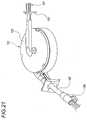
- an extending portion 107 provided between a fixing-side connecting portion 103 and a moving-side connecting portion 105 of a wire harness 101is withdrawably wound and received in a harness receiving box 121, and by doing so, an extraordinary displacement of the extending portion 107 in accordance with the movement of the movable structure is restrained, and at the same time the extending portion 107 is prevented from interfering with surrounding structural objects, etc.
- the harness receiving box 121includes a reel rotatably mounted within a box body 123 so as to wind up the extending portion 107, and urging means such as a spring for urging this reel in a winding direction, and the reel rotates according to an amount of movement of the movable structure, so that the length of withdrawal of the extending portion 107 from the box body 123 is adjusted.
- Fig. 22 and Fig. 23also show other conventional example of wire harness installation structure, and this is disclosed in the Patent Literature 2.
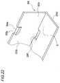
- Fig. 22is a perspective view of a protector 200 configuring the wire harness installation structure, and the protector 200 having a resin material is formed into an L-shaped cross-section, and has such a bent portion.
- the bent portion of the protector 200has a horizontal disposition portion 200a extending along the wire harness-installing direction, and a vertical disposition portion 200b bent right-angularly downwardly at one end of the horizontal disposition portion 200a.
- the protector 200includes a side wall 200c to be disposed along a vehicle body surface, and a bottom wall 200d, and a wire harness W/H is adapted to be passed through a space S surrounded by this bottom wall 200d and this side wall 200c.
- a notch 200e for band clamp-attaching purposesis formed at an upper end of the side wall 200c of the protector 200.
- a band passage hole 200fis formed in that portion of the side wall 200d disposed beneath this notch 200e.
- a clamp rest 200g having a surface coplanar with a surface of the notch 200eis formed in such a shape that it projects from an inner surface of the side wall 200c.
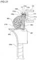
- a band clamp 211includes a body portion 211 a of a generally box-shape, and a band portion 211 b extending from the body portion 211 a. And, a band retaining hole 211c is formed through a lower portion of the body portion 211a, and also a retaining tubular portion 211d for vehicle body fixing purposes is provided at an upper portion thereof.
- the retaining tubular portion 211 d of the body portion 211 ais projected toward the vehicle body 212 so as to form a gap C between the lower portion and the vehicle body 212 so that the band portion 211 b can be drawn out.
- a retaining piece for retaining on a toothed portion formed on the band portion 211bis provided within the band retaining hole 211 c. The band portion 211b is retained against withdrawal by the meshing engagement of the toothed portion with the retaining piece.
- a retaining piece 211 eis formed in a projecting manner on an inner peripheral surface of the retaining tubular portion 211d, and is adapted to retain a stud bolt 213, projecting from the vehicle body 212, inserted therein.
- the band portion 211 bis passed through the passage hole 200f from the outside of the side wall 200c, and is wound half on the wire harness W/H, and thereafter the band portion 211b is passed through the band retaining hole 211c, and is retained, and the protector 200 and the wire harness W/H are fastened together by the band portion 211 b.
- the conventional installation structures shown in Fig. 20 and Fig. 21have the guide rail 111 and the harness receiving box 121, respectively, for receiving the extending portion 107. Therefore, the number of the component parts greatly increases, and besides the guide rail 111 and the harness receiving box 121 have the complicated constructions, and therefore there was a problem that the cost of an apparatus employing such installation structure increased. Furthermore, the installation space increases because of the structures of the guide rail 111 and harness receiving box 121 covering the periphery of the extending portion 107, and there arose a problem that a space-saving design was difficult.
- a protectorconstructed such that it is bendably formed by many short protector members interconnected in a longitudinal direction of a wire harness and protects the wire harness in such a manner that the wire harness can be flexibly deformed, and a corrugated tube constructed so as to be formed into a bellows-shape and protects a wire harness in such a manner that the wire harness can be flexibly deformed.
- the wire harness W/H and the protectorare fastened together and are fixed to the vehicle body panel 212, and for example, and in the case where one end of the wire harness W/H is to be fixed to the vehicle body which is a stationary structure, while the other end is to be installed, for example, on a door or the like which is a movable structure, this structure is not used since the wire harness W/H can not be flexibly deformed.
- a first object of the present inventionis to solve the above problems, and to provide a wire harness installation structure in which an extraordinary deformation of a wire harness installed over a stationary structure and a movable structure is prevented, and by reducing the number of parts used in the installation of the wire harness and by simplifying the structures of the used parts, the cost of an apparatus employing this installation structure can be reduced, and also a space-saving design can be achieved by suppressing the increase of an installation space by the used parts, and furthermore water will not reside in the vicinity of the wire harness, so that there is no risk of freezing.
- a second object of the present inventionis to solve the above problems, and to provide a wire harness installation structure constructed such that an extraordinary deformation of a wire harness installed over a stationary structure and a movable structure is prevented, that by reducing the number of parts used in the installation of the wire harness and by simplifying the structures of the used parts, the cost of an apparatus employing this installation structure can be reduced, that also a space-saving design can be achieved by suppressing the increase of an installation space by the used parts, that the installed wire harness can be flexibly deformed, and that the shifting of the wire harness out of position can be prevented.
- wire harness installation structureas set forth in any one of above (1) to (4), wherein a fixing-side protector which is fixed to the stationary structure is connected to the fixing-side connecting portion, wherein a moving-side protector which is fixed to the movable structure is connected to the moving-side connecting portion, wherein the fixing-side protector has a groove directed toward the movable structure, and the extending portion of the wire resides in the groove.
- an extraordinary displacement, such as a waving movement, of the extending portion of the wire harness in accordance with the movement of the movable structureis restrained by the rigidity and effect of an elastic force of the strip-like plate spring set along the extending portion. Also, even when rain water, wash water or the like splashes on the extending portion, the water will not reside in the protective member, and therefore the freezing and cutting due to the residing of the water in the extending portion of the wire can be prevented from occurring.
- the protective memberhas the wear resistance and besides has the flexibility, and therefore the arcuately-bending and movement of the extending portion are smoothly effected. Further, the protective member has the mesh-like shape, and therefore draining is effected satisfactorily with the simple construction, and the residing of water in the extending portion of the wire as well as the freezing and cutting due to the residing of the water can be prevented.
- the protective memberhas the wear resistance and besides has the flexibility, and therefore the arcuately-bending and movement of the extending portion are smoothly effected. Further, the protective member is obtained by forming the metallic filament into the mesh-like shape, and therefore draining is effected satisfactorily with the simple construction, and the prevention of the residing of water in the extending portion of the wire as well as the freezing and cutting due to the residing of the water can be prevented. Further, an electromagnetic shielding effect is obtained, and therefore there are advantages such as one that the wire harness can be used for many purposes.
- drainingcan be effected by the hole or the slit formed in the protective member, and therefore the residing of water in the extending portion of the wire as well as the freezing and cutting due to the residing of the water can be prevented.
- the residing of watercan be prevented.
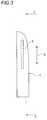
- An automobile 1 shown in Fig. 1is provided with a back door 3 which is pivotally moved upwardly to be opened.
- a window glass 5which is raised and lowered in an upward-downward direction (direction of arrow D in Fig. 3 ) is provided at the back door 3.
- An electrical part 7such as a heating wire for defogging purposes is provided at this window glass 5.
- the wire harness installation structure 1is such that in order to supply electric power to the electrical part 7, etc., on the window glass 5, a wire harness assembly 13 is installed over a door panel 3a of the back door 3, corresponding to a stationary structure, and the window glass 5 which is movably mounted on the door panel 3a and corresponds to a movable structure.
- the window glass 5is mounted on the door panel 3a by a raising and lowering mechanism (not shown) so as to be able to be raised and lowered in a direction indicated by arrow E in Fig. 5 .
- reference numeral 5Adesignates the window glass moved to an upper limit position
- reference numeral 5Bdesignates the window glass moved to an intermediate position so that a window is in a half-open condition
- reference numeral 5Cdesignates the window glass 5 moved to a lower limit position so that the window is in a full open condition.
- a curved portion of an extending portion 13c of the wire harness assembly 13 installed over the door panel 3a and the window glass 5is moved in accordance with the ascending and descending movement of the window glass 5.
- a fixing-side protector 21is fixedly provided at the inner surface side of the door panel 3a and is disposed near to the side of the window glass 5 along the upward-downward direction.
- This fixing-side protector 21, together with the door panel 3a,corresponds to the stationary structure.
- the fixing-side protector 21is, for example, one using a die-cut material of the channel type, and is mounted with its groove directed toward the window glass 5, and receives the wire harness assembly 13 hanging down from the door panel 3a when the window glass 5 is lowered, thereby regulating the position of the wire harness assembly 13.
- the wire harness assembly 13 used in the wire harness installation structure 11 of this one embodimentis such that the extending portion 13c between a fixing-side connecting portion 13a, fixed onto the fixing-side protector 21 on the door panel 3a which is the stationary structure, and a moving-side connecting portion 13b fixed onto the window glass 5 which is the movable structure is provided with an excess length for allowing the ascending and descending movement of the window glass 5.
- the fixing-side connecting portion 13a of the wire harness assembly 13is secured by binding bands 23a, 23b to the fixing-side protector 21 which is to be fixed to the door panel 3a.
- the fixing-side protector 21is fixed onto the door panel 3a by screws or the like. The construction of the fixing-side protector 21 will be described later in detail with reference to Fig. 11 to Fig. 13 .
- a moving-side protector 25which is a connecting member for fixing the moving-side connecting portion to the window glass 5 is secured to the moving-side connecting portion 13b by binding bands 23a, 23b.
- the moving-side protector 25is fixed to the window glass 5 by screws or the like. The construction of the moving-side protector 25 will be described later in detail with reference to Fig. 14 to Fig. 16 .
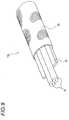
- the extending portion 13c between the fixing-side connecting portion 13a and the moving-side connecting portion 13bis such that a strip-like plate spring 27 is set longitudinally along wires 31 forming the extending portion 13c as shown in Fig. 8 and Fig. 9 , and the extending portion 13c and the wires 31 are bound together by a tape wound on an outer periphery thereof or by tubular outer members 29 fitted on the outer periphery, and a protective member 33 is fitted on the periphery thereof, thereby protecting the bundle.
- the protective member 33a tubular one obtained by forming synthetic resin into a mesh-like shape is used. With this construction, even when water splashes on the extending portion 13c, it immediately flows through the interstices, and therefore the water will not reside in the extending portion 13c within the protective member 33, and an accident such as the freezing of the residing water can be prevented from happening.
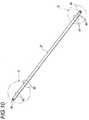
- the strip-like plate spring 27is obtained by forming a thin sheet of stainless steel having a rust preventive effect or the like into a strip shape, and an end portion F is connected to the fixing-side protector 21.
- a retaining hole 41 for retaining on the fixing-side protector 21 and notch portions 42, 43are formed in the end portion F.
- an end portion Gis connected to the moving-side protector 25.
- a retaining hole 45 for retaining on the moving-side protector 25 and notch portions 46, 47are also formed in the end portion G.
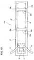
- the fixing-side protector 21is integrally molded, using synthetic resin, and serves to connect the fixing-side connecting portion 13a of the wire harness assembly 13 to the door panel 3a.
- a retaining projection 51 for retaining the retaining hole 41 formed in the strip-like plate spring 27, binding member through holes 53a, 53b for the passage of the binding bands 23a, 23b therethrough, a cover portion 54 which is closed after the connection, fixing portions 55 for fixing to the back door 3, etc.,are formed integrally with the fixing-side protector 21.
- the fixing-side connecting portion 13aFor connecting the fixing-side connecting portion 13a to the fixing-side protector 21, the fixing-side connecting portion 13a is located in the vicinity of the cover portion 54, and the retaining hole 41 formed in the end portion F of the strip-like plate spring 27 is retained on the retaining projection 51 as shown in Fig. 13 . Then, the fixing-side connecting portion 13a is fastened and fixed to the fixing-side protector 21, using the binding bands 23a, 23b passed through the binding member through holes 53a, 53b.
- the moving-side protector 25is integrally molded, using synthetic resin, and serves to connect the moving-side connecting portion 13b of the wire harness assembly 13 to the window glass 5.
- the moving-side connecting portion 13bFor connecting the moving-side connecting portion 13b to the moving-side protector 25, the retaining hole 45 formed in the end portion G is retained on the retaining projection 61. As a result, the moving-side connecting portion 13b is positioned relative to the moving-side protector 25 as shown in Fig. 16 , and in this condition the binding is effected using the binding bands 23a, 23b, so that the moving-side connecting portion 13b is connected to the moving-side protector 25 as described with reference to Fig. 7 .
- the connection of the moving-side connecting portion 13bis effected in the same manner as in the fixing-side protector 21, and the shifting and withdrawal of the strip-like plate spring 27 in the longitudinal direction and the withdrawal of the wires 31, etc., can be prevented.
- the wire harness installation structure 11 of the one embodimentis of such a construction that the displacement of the extending portion 13c of the wire harness in accordance with the movement of the window glass 5 is restrained by the strip-like plate spring 27 set longitudinally along this extending portion 13c, and as compared with the conventional installation structures in which the guide rail or the harness receiving box is used for restraining the displacement of the extending portion, the number of the parts to be used can be greatly reduced, and at the same time the structures of the used parts can be simplified. Therefore, the cost of an apparatus employing this installation structure can be reduced.
- the whole of the extending portion 13cis covered with the protective member 33 of the mesh structure which discharges water, and therefore even if water such as rain water slashes on it during the travel of the automobile, the water immediately flows out from the extending portion 13c, and therefore the water will not reside in the extending portion 13c. Therefore, the freezing of water will not occur, and an accident such as the cutting of the wire group 31 due to the freezing can be prevented from happening, and the reliability of the automobile is enhanced.
- Fig. 13 to Fig. 15schematically show the fixing-side protector, etc., for illustration purposes, and reference will be suitably made to Fig. 11 when giving a description.
- the positions of the retaining hole 41 and notch portions 43a, 43b formed in the strip-like plate spring 27correspond respectively to the positions of the retaining projection 51 and binding band through holes 53a, 53b formed at the fixing-side protector 21. Therefore, in the case of locating the strip-like plate spring 27 in the predetermined position at the fixing-side protector 21, the retaining hole 41 is retained on the retaining projection 51, and the strip-like plate spring 27 is set along the fixing-side protector 21 as indicated in imaginary lines in Fig. 12 , and by doing so, the positions of formation of the binding band through holes 52a, 53b conform respectively to the positions of formation of the notches 43a, 43b.
- the connecting portion 13ais to be connected to the fixing-side protector 21, the wires 31 is bound onto the strip-like plate spring 27 as shown in Fig. 8 prior to this connection, and then it is covered with the protective member 33, and then the connecting portion 13a is positioned relative to the fixing protector 21 as shown in Fig. 13 .
- the notch portions 43a, 43bare located respectively at the positions of formation of the binding band through holes 53a, 53b without effecting any positioning operation.
- the strip-like plate spring 27, etc.Although tension acts on the strip-like plate spring 27, etc., during the time when the extending portion 13c of the wire harness assembly 13 moves upward and downward as described above, the strip-like plate spring will not be shifted in the longitudinal direction and will not drop, since the end portion of the strip-like plate spring 27 is retained on the retaining projection 51 as shown on an enlarged scale in Fig. 19 . And, the strip-like plate spring 27, the wires 31, etc., are integrally combined with the fixing-side protector 21 by the binding bands 23a, 23b as described above, and therefore the withdrawal of the wires 31, etc., will not occur, and the fixing-side end portion of the extending portion 13c is stably fixed to the door panel 3a.
- the notch portions 43a, 43b, 47a, 47b corresponding respectively to the binding band through holes 53a, 53b, 62a, 62b of the fixing-side protector 21 and moving-side protector 25are formed in the strip-like plate spring 27, and therefore at the time when the strip-like plate spring 27 and the wires 31 are fastened together to the fixing-side protector 21 and the moving-side protector 25 by the binding bands 23, the binding bands 23 are engaged also in the notch portions 43a, 43b, 47a, 47b. Therefore, the strip-like plate spring 27 and the wires 31 will not be shifted in the longitudinal direction, and the movement of the wires 31 can be properly regulated.
- the protective memberone obtained by forming the synthetic resin (chemical fibers) into the mesh-like shape is used, it may be one obtained by forming a metallic filament into a mesh-like shape instead of using the chemical fibers.
- holes or slitsmay be formed in a conventional protector or a corrugated tube, and in this case, water, such as rain water, splashing on the extending portion can be drained, and the freezing of the water and the cutting of the wires due to the freezing can be positively prevented. Furthermore, without the freezing of the water, there are obtained advantages such as the smooth movement of the extending portion.
- the present inventionis based on Japanese Patent Application (Patent Application No. 2008-221511 ) filed on August 29, 2008 and Japanese Patent Application (Patent Application No. 2008-221811 ) filed on August 29, 2008.
- the part for restraining the extraordinary displacement of the extending portionis the strip-like plate spring set along the extending portion, and therefore as compared with the conventional installation structures in which the guide rail or the harness receiving box is used for restraining the extraordinary displacement of the extending portion, the number of the parts to be used can be greatly reduced, and at the same time the structures of the used parts can be simplified, and the cost of the apparatus employing this installation structure can be reduced. Furthermore, the extending portion of the wire harness is covered with the protective member in which water will not reside, and therefore even when rain water or the like splashes on the wire harness, it is immediately drained. Therefore, water such as rain water will not reside in the extending portion of the wires, and the cutting of the wires due to the freezing of the residing water can be prevented from occurring.
- the part for restraining the extraordinary displacement of the extending portionis the strip-like plate spring set along the extending portion, and therefore as compared with the conventional installation structures in which the guide rail or the harness receiving box is used for restraining the extraordinary displacement of the extending portion, the number of the parts to be used can be greatly reduced, and at the same time the structures of the used parts can be simplified, and the cost of the apparatus employing this installation structure can be reduced.
- the strip-like plate springhas the notch portions corresponding to the binding band through holes of the fixing-side protector and moving-side protector, and therefore when the wires and the strip-like plate spring are fastened together to the fixing-side protector and the moving-side protector by the binding bands, the binding bands are engaged also in the notch portions, and therefore the binding is effected in such a manner that the strip-like plate spring will not be shifted in the longitudinal direction.
Landscapes
- Engineering & Computer Science (AREA)
- Mechanical Engineering (AREA)
- Architecture (AREA)
- Civil Engineering (AREA)
- Structural Engineering (AREA)
- Details Of Indoor Wiring (AREA)
- Installation Of Indoor Wiring (AREA)
- Electric Cable Arrangement Between Relatively Moving Parts (AREA)
Description
- The present invention relates to a wire harness installation structure which is installed over a stationary structure (on which a movable structure is movably mounted) and the movable structure in order to supply electric power to an electrical part, etc., on the movable structure, for example a sliding door and a hatch-back door of an automobile. Such a wire harness installation structure is known from
EP 1 108 621 A2claim 1. - For example, among wire harnesses installed in an automobile, a wire harness for supplying electric power to an electrical part, etc., on a movable structure such as a sliding door and a hatch-back door is installed over a stationary structure such as a vehicle body frame (on which the movable structure is movably mounted) and the movable structure.
Fig. 20 andFig. 21 show conventional examples of such wire harness installation structures.
The installation structure shown inFig. 20 is disclosed in thePatent Literature 1. Awire harness 101 to be installed is constructed such that an extendingportion 107 between a fixing-side connecting portion 103 to be fixed onto a stationary structure, such for example as a vehicle body panel and a vehicle body frame, and a moving-side connecting portion 105 to be fixed onto a movable structure such as a sliding door is provided with an excess length for allowing movement of the movable structure. The extendingportion 107, while bent into a generally U-shaped condition, is received in aharness receiving space 113 provided at a lower portion of aguide rail 111, and by doing so, an extraordinary displacement of the extendingportion 107 in accordance with the movement of the movable structure is restrained, and at the same time the extendingportion 107 is prevented from interfering with surrounding structural objects, etc.- The
above guide rail 111 has aslider 115 which slidingly moves along a direction of movement of the movable structure (not shown) (direction of arrow A inFig. 20 ). The extendingportion 107 received in theharness receiving space 113 is connected to theslider 115 at near side of the moving-side connecting portion 105.
Theslider 115 is connected to the movable structure, and moves on theguide rail 111 in accordance with the movement of the movable structure. - In the case of the installation structure shown in
Fig. 21 , an extendingportion 107 provided between a fixing-side connecting portion 103 and a moving-side connecting portion 105 of awire harness 101 is withdrawably wound and received in aharness receiving box 121, and by doing so, an extraordinary displacement of the extendingportion 107 in accordance with the movement of the movable structure is restrained, and at the same time the extendingportion 107 is prevented from interfering with surrounding structural objects, etc. - The
harness receiving box 121 includes a reel rotatably mounted within abox body 123 so as to wind up the extendingportion 107, and urging means such as a spring for urging this reel in a winding direction, and the reel rotates according to an amount of movement of the movable structure, so that the length of withdrawal of the extendingportion 107 from thebox body 123 is adjusted. Fig. 22 andFig. 23 also show other conventional example of wire harness installation structure, and this is disclosed in the Patent Literature 2.Fig. 22 is a perspective view of aprotector 200 configuring the wire harness installation structure, and theprotector 200 having a resin material is formed into an L-shaped cross-section, and has such a bent portion. The bent portion of theprotector 200 has ahorizontal disposition portion 200a extending along the wire harness-installing direction, and avertical disposition portion 200b bent right-angularly downwardly at one end of thehorizontal disposition portion 200a.- The
protector 200 includes aside wall 200c to be disposed along a vehicle body surface, and abottom wall 200d, and a wire harness W/H is adapted to be passed through a space S surrounded by thisbottom wall 200d and thisside wall 200c. - A
notch 200e for band clamp-attaching purposes is formed at an upper end of theside wall 200c of theprotector 200. Aband passage hole 200f is formed in that portion of theside wall 200d disposed beneath thisnotch 200e. Further, a clamp rest 200g having a surface coplanar with a surface of thenotch 200e is formed in such a shape that it projects from an inner surface of theside wall 200c. - As shown in
Fig. 23 , aband clamp 211 includes abody portion 211 a of a generally box-shape, and aband portion 211 b extending from thebody portion 211 a. And, aband retaining hole 211c is formed through a lower portion of thebody portion 211a, and also a retainingtubular portion 211d for vehicle body fixing purposes is provided at an upper portion thereof. - For fixing the
band clamp 211 to avehicle body 212, the retainingtubular portion 211 d of thebody portion 211 a is projected toward thevehicle body 212 so as to form a gap C between the lower portion and thevehicle body 212 so that theband portion 211 b can be drawn out. A retaining piece for retaining on a toothed portion formed on theband portion 211b is provided within theband retaining hole 211 c. Theband portion 211b is retained against withdrawal by the meshing engagement of the toothed portion with the retaining piece. - A
retaining piece 211 e is formed in a projecting manner on an inner peripheral surface of the retainingtubular portion 211d, and is adapted to retain astud bolt 213, projecting from thevehicle body 212, inserted therein. - In the installation structure employing the
protector 200 andband clamp 211 of the above construction, as shown inFig. 22 , theband portion 211 b is passed through thepassage hole 200f from the outside of theside wall 200c, and is wound half on the wire harness W/H, and thereafter theband portion 211b is passed through theband retaining hole 211c, and is retained, and theprotector 200 and the wire harness W/H are fastened together by theband portion 211 b. - With this construction, the W/H will not be turned in a clockwise direction or in a counterclockwise direction in
Fig. 22 , and the illustrated condition is maintained. - Patent Literature 1:
JP-A-2006-74980 - Patent Literature 2:
JP-A-2000-134763 - However, the conventional installation structures shown in
Fig. 20 andFig. 21 have theguide rail 111 and theharness receiving box 121, respectively, for receiving the extendingportion 107. Therefore, the number of the component parts greatly increases, and besides theguide rail 111 and the harness receivingbox 121 have the complicated constructions, and therefore there was a problem that the cost of an apparatus employing such installation structure increased.
Furthermore, the installation space increases because of the structures of theguide rail 111 andharness receiving box 121 covering the periphery of the extendingportion 107, and there arose a problem that a space-saving design was difficult. - Further, there are known a protector constructed such that it is bendably formed by many short protector members interconnected in a longitudinal direction of a wire harness and protects the wire harness in such a manner that the wire harness can be flexibly deformed, and a corrugated tube constructed so as to be formed into a bellows-shape and protects a wire harness in such a manner that the wire harness can be flexibly deformed.
- However, such conventional installation structures are not designed on the assumption that rain water, wash water, etc., splash on them. Therefore, when water splashes on the protector or the corrugated tube and intrudes into the interior thereof with the result that the water is kept collected in the protector or the corrugated tube, the water is frozen in the winter or in cold districts, so that the shape of the wire harness is fixed. And, it was feared that wires might be severed when both ends of the wire harness whose shape is fixed were moved relative to each other.
- Furthermore, in the conventional installation structure shown in
Fig. 22 andFig. 23 , the wire harness W/H and the protector are fastened together and are fixed to thevehicle body panel 212, and for example, and in the case where one end of the wire harness W/H is to be fixed to the vehicle body which is a stationary structure, while the other end is to be installed, for example, on a door or the like which is a movable structure, this structure is not used since the wire harness W/H can not be flexibly deformed. - A first object of the present invention is to solve the above problems, and to provide a wire harness installation structure in which an extraordinary deformation of a wire harness installed over a stationary structure and a movable structure is prevented, and by reducing the number of parts used in the installation of the wire harness and by simplifying the structures of the used parts, the cost of an apparatus employing this installation structure can be reduced, and also a space-saving design can be achieved by suppressing the increase of an installation space by the used parts, and furthermore water will not reside in the vicinity of the wire harness, so that there is no risk of freezing.
- A second object of the present invention is to solve the above problems, and to provide a wire harness installation structure constructed such that an extraordinary deformation of a wire harness installed over a stationary structure and a movable structure is prevented, that by reducing the number of parts used in the installation of the wire harness and by simplifying the structures of the used parts, the cost of an apparatus employing this installation structure can be reduced, that also a space-saving design can be achieved by suppressing the increase of an installation space by the used parts, that the installed wire harness can be flexibly deformed, and that the shifting of the wire harness out of position can be prevented.
- The above first object of the present invention is achieved by the following configuration.
- (1) A wire harness installation structure, comprising a wire in which a fixing-side connecting portion to be fixed to a stationary structure is provided at one end side of the wire in a wire extending direction thereof and a moving-side connecting portion to be fixed to a movable structure is provided at the other end side of the wire in the wire extending direction, the movable structure being provided so as to be movable relative to the stationary structure, an extending portion of the wire between the fixing-side connecting portion and the moving-side connecting portion being provided with an excess length for allowing a movement of the movable structure,
wherein a strip-like plate spring is provided along the extending portion in an extending direction of the extending portion, and the extending portion is installed in a state that the extending portion is bent into a generally U-shape or curved shape,
the wire harness installation structure further comprising a protective member which covers both of the extending portion and the strip-like plate spring so that water will not reside, wherein the protective member is configured to discharge water, wherein retaining holes formed on each end portions of the strip-like spring are retained on retaining projections , the retaining projections being formed integrally with the fixing-side protector and at the moving-side protector. - (2) The wire harness installation structure as set forth in the above (1), wherein the protective member is comprised of synthetic fiber forming into a mesh shape.
- (3) The wire harness installation structure as set forth in the above (1), wherein the protective member is comprised of metallic filament forming into a mesh shape.
- (4) The wire harness installation structure as set forth in the above (1), wherein the protective member has a hole or a slit for draining water.
- The wire harness installation structure as set forth in any one of above (1) to (4), wherein a fixing-side protector which is fixed to the stationary structure is connected to the fixing-side connecting portion, wherein a moving-side protector which is fixed to the movable structure is connected to the moving-side connecting portion, wherein the fixing-side protector has a groove directed toward the movable structure, and the extending portion of the wire resides in the groove.
- In the configuration of the above (1), an extraordinary displacement, such as a waving movement, of the extending portion of the wire harness in accordance with the movement of the movable structure is restrained by the rigidity and effect of an elastic force of the strip-like plate spring set along the extending portion. Also, even when rain water, wash water or the like splashes on the extending portion, the water will not reside in the protective member, and therefore the freezing and cutting due to the residing of the water in the extending portion of the wire can be prevented from occurring.
- In the configuration of the above (2), the protective member has the wear resistance and besides has the flexibility, and therefore the arcuately-bending and movement of the extending portion are smoothly effected. Further, the protective member has the mesh-like shape, and therefore draining is effected satisfactorily with the simple construction, and the residing of water in the extending portion of the wire as well as the freezing and cutting due to the residing of the water can be prevented.
- In the configuration of the above (3), the protective member has the wear resistance and besides has the flexibility, and therefore the arcuately-bending and movement of the extending portion are smoothly effected. Further, the protective member is obtained by forming the metallic filament into the mesh-like shape, and therefore draining is effected satisfactorily with the simple construction, and the prevention of the residing of water in the extending portion of the wire as well as the freezing and cutting due to the residing of the water can be prevented. Further, an electromagnetic shielding effect is obtained, and therefore there are advantages such as one that the wire harness can be used for many purposes.
- In the configuration of the above (4), draining can be effected by the hole or the slit formed in the protective member, and therefore the residing of water in the extending portion of the wire as well as the freezing and cutting due to the residing of the water can be prevented. In this case, by forming a hole or a slit in a conventional protector or a corrugated tube, the residing of water can be prevented.
- [
Fig. 1] Fig.1 is a side-elevational view of an automobile in which one embodiment of a wire harness installation structure of the present invention is employed. - [
Fig. 2] Fig.2 is a front-elevational view of a back door of the automobile shown inFig. 1 . - [
Fig. 3] Fig.3 is a cross-sectional view taken along the line B-B ofFig. 2 . - [
Fig. 4] Fig.4 is a cross-sectional view taken along the line C-C ofFig. 3 . - [
Fig. 5] Fig.5 is an explanatory view showing a situation in which in the wire harness installation structure shown inFig. 4 , a curved portion of an extending portion of a wire harness moves in accordance with the ascending and descending movement of a window glass which is a movable structure. - [
Fig. 6] Fig.6 is a plan view showing the construction of a fixing-side protector. - [
Fig. 7] Fig.7 is a plan view showing the construction of a moving-side protector. - [
Fig. 8] Fig.8 is a plan view showing the fixing of wires to a strip-like plate spring. - [
Fig. 9] Fig.9 is a partly-broken perspective view of the extending portion, showing a covering structure provided by a protective member. - [
Fig. 10] Fig.10 is a perspective view showing the construction of the strip-like plate spring. - [
Fig. 11] Fig.11 is a perspective view showing the construction of the fixing-side protector. - [
Fig. 12] Fig.12 is a plan view showing the construction of the fixing-side protector. - [
Fig. 13] Fig.13 is a plan view showing the positioning of the wire harness relative to the fixing-side protector. - [
Fig. 14] Fig.14 is a perspective view showing the construction of the moving-side protector. - [
Fig. 15] Fig.15 is a plan view showing the construction of the moving-side protector. - [
Fig. 16] Fig.16 is a plan view showing the positioning of the wire harness relative to the moving-side protector. - [
Fig. 17] Fig.17 is a perspective view showing a condition in which the wire harness is fastened to the fixing-side protector. - [
Fig. 18] Fig.18 is a plan view showing the condition in which the wire harness is fastened to the fixing-side protector. - [
Fig. 19] Fig.19 is a cross-sectional view showing a condition in which a retaining projection and a retaining hole are retained relative to each other, - [
Fig. 20] Fig.20 is a perspective view showing an example of conventional wire harness installation structure. - [
Fig. 21] Fig.21 is a perspective view showing another example of conventional wire harness installation structure. - [
Fig. 22] Fig.22 is a perspective view showing other conventional wire harness installation structure. - [
Fig. 23] Fig.23 is a cross-sectional view showing the other conventional wire harness installation structure. - A preferred embodiment of a wire harness installation structure of the present invention will be described below in detail with reference to the drawings.
- An
automobile 1 shown inFig. 1 is provided with aback door 3 which is pivotally moved upwardly to be opened. Awindow glass 5 which is raised and lowered in an upward-downward direction (direction of arrow D inFig. 3 ) is provided at theback door 3. Anelectrical part 7 such as a heating wire for defogging purposes is provided at thiswindow glass 5. - The wire
harness installation structure 1 according to the one embodiment of the present invention is such that in order to supply electric power to theelectrical part 7, etc., on thewindow glass 5, awire harness assembly 13 is installed over adoor panel 3a of theback door 3, corresponding to a stationary structure, and thewindow glass 5 which is movably mounted on thedoor panel 3a and corresponds to a movable structure. - The
window glass 5 is mounted on thedoor panel 3a by a raising and lowering mechanism (not shown) so as to be able to be raised and lowered in a direction indicated by arrow E inFig. 5 . InFig. 5 ,reference numeral 5A designates the window glass moved to an upper limit position,reference numeral 5B designates the window glass moved to an intermediate position so that a window is in a half-open condition, andreference numeral 5C designates thewindow glass 5 moved to a lower limit position so that the window is in a full open condition.
As shown inFig. 5 , a curved portion of an extendingportion 13c of thewire harness assembly 13 installed over thedoor panel 3a and thewindow glass 5 is moved in accordance with the ascending and descending movement of thewindow glass 5. - In the case of this embodiment, a fixing-
side protector 21 is fixedly provided at the inner surface side of thedoor panel 3a and is disposed near to the side of thewindow glass 5 along the upward-downward direction. This fixing-side protector 21, together with thedoor panel 3a, corresponds to the stationary structure. - The fixing-
side protector 21 is, for example, one using a die-cut material of the channel type, and is mounted with its groove directed toward thewindow glass 5, and receives thewire harness assembly 13 hanging down from thedoor panel 3a when thewindow glass 5 is lowered, thereby regulating the position of thewire harness assembly 13. - The
wire harness assembly 13 used in the wire harness installation structure 11 of this one embodiment is such that the extendingportion 13c between a fixing-side connecting portion 13a, fixed onto the fixing-side protector 21 on thedoor panel 3a which is the stationary structure, and a moving-side connecting portion 13b fixed onto thewindow glass 5 which is the movable structure is provided with an excess length for allowing the ascending and descending movement of thewindow glass 5. - As shown in
Fig. 6 , the fixing-side connecting portion 13a of thewire harness assembly 13 is secured by bindingbands side protector 21 which is to be fixed to thedoor panel 3a. The fixing-side protector 21 is fixed onto thedoor panel 3a by screws or the like. The construction of the fixing-side protector 21 will be described later in detail with reference toFig. 11 to Fig. 13 . - As shown in
Fig. 7 , a moving-side protector 25 which is a connecting member for fixing the moving-side connecting portion to thewindow glass 5 is secured to the moving-side connecting portion 13b by bindingbands side protector 25 is fixed to thewindow glass 5 by screws or the like. The construction of the moving-side protector 25 will be described later in detail with reference toFig. 14 to Fig. 16 . - In the
wire harness assembly 13, the extendingportion 13c between the fixing-side connecting portion 13a and the moving-side connecting portion 13b is such that a strip-like plate spring 27 is set longitudinally alongwires 31 forming the extendingportion 13c as shown inFig. 8 andFig. 9 , and the extendingportion 13c and thewires 31 are bound together by a tape wound on an outer periphery thereof or by tubularouter members 29 fitted on the outer periphery, and aprotective member 33 is fitted on the periphery thereof, thereby protecting the bundle. - In this embodiment, as the
protective member 33, a tubular one obtained by forming synthetic resin into a mesh-like shape is used. With this construction, even when water splashes on the extendingportion 13c, it immediately flows through the interstices, and therefore the water will not reside in the extendingportion 13c within theprotective member 33, and an accident such as the freezing of the residing water can be prevented from happening. - As shown in
Fig. 10 , the strip-like plate spring 27 is obtained by forming a thin sheet of stainless steel having a rust preventive effect or the like into a strip shape, and an end portion F is connected to the fixing-side protector 21. A retaininghole 41 for retaining on the fixing-side protector 21 andnotch portions
On the other hand, an end portion G is connected to the moving-side protector 25. A retaininghole 45 for retaining on the moving-side protector 25 andnotch portions - Next, the fixing-
side protector 21 will be described with reference toFigs. 11 to 13 .
The fixing-side protector 21 is integrally molded, using synthetic resin, and serves to connect the fixing-side connecting portion 13a of thewire harness assembly 13 to thedoor panel 3a. A retainingprojection 51 for retaining the retaininghole 41 formed in the strip-like plate spring 27, binding member throughholes bands cover portion 54 which is closed after the connection, fixingportions 55 for fixing to theback door 3, etc., are formed integrally with the fixing-side protector 21. - For connecting the fixing-
side connecting portion 13a to the fixing-side protector 21, the fixing-side connecting portion 13a is located in the vicinity of thecover portion 54, and the retaininghole 41 formed in the end portion F of the strip-like plate spring 27 is retained on the retainingprojection 51 as shown inFig. 13 . Then, the fixing-side connecting portion 13a is fastened and fixed to the fixing-side protector 21, using the bindingbands holes - Then, if other wires need to be installed as shown in
Fig. 6 , they are installed, and after an end processing is effected, thecover portion 54 is closed, thus completing the connection of the fixing-side connecting portion 13a to the fixing-side protector 21. In the case where this fixing-side protector 21 is fixed to thedoor panel 3a as described above, the extendingportion 13a hangs down along a flat plate-like guide portion 56, and makes the upward and downward movement as described with reference toFig. 5 . - Next, the moving-
side protector 25 will be described with reference toFig. 14 to Fig. 16 .
The moving-side protector 25 is integrally molded, using synthetic resin, and serves to connect the moving-side connecting portion 13b of thewire harness assembly 13 to thewindow glass 5. A retainingprojection 61 for retaining the retaininghole 45 formed in the strip-like plate spring 27, binding member throughholes bands side protector 25. - For connecting the moving-
side connecting portion 13b to the moving-side protector 25, the retaininghole 45 formed in the end portion G is retained on the retainingprojection 61. As a result, the moving-side connecting portion 13b is positioned relative to the moving-side protector 25 as shown inFig. 16 , and in this condition the binding is effected using the bindingbands side connecting portion 13b is connected to the moving-side protector 25 as described with reference toFig. 7 . - Namely, in the moving-
side protector 25, also, the connection of the moving-side connecting portion 13b is effected in the same manner as in the fixing-side protector 21, and the shifting and withdrawal of the strip-like plate spring 27 in the longitudinal direction and the withdrawal of thewires 31, etc., can be prevented. - Therefore, the upward and downward movement of the extending
portion 13c, etc., as described with reference toFig. 5 can be effect smoothly and besides accurately without causing the shifting. - The wire harness installation structure 11 of the one embodiment is of such a construction that the displacement of the extending
portion 13c of the wire harness in accordance with the movement of thewindow glass 5 is restrained by the strip-like plate spring 27 set longitudinally along this extendingportion 13c, and as compared with the conventional installation structures in which the guide rail or the harness receiving box is used for restraining the displacement of the extending portion, the number of the parts to be used can be greatly reduced, and at the same time the structures of the used parts can be simplified. Therefore, the cost of an apparatus employing this installation structure can be reduced. - Furthermore, the whole of the extending
portion 13c is covered with theprotective member 33 of the mesh structure which discharges water, and therefore even if water such as rain water slashes on it during the travel of the automobile, the water immediately flows out from the extendingportion 13c, and therefore the water will not reside in the extendingportion 13c.
Therefore, the freezing of water will not occur, and an accident such as the cutting of thewire group 31 due to the freezing can be prevented from happening, and the reliability of the automobile is enhanced. - Here, the relation between the retaining
projection 51 formed on the fixing-side protector 21 and the retaininghole 41 formed in the strip-like plate spring 27 will be described with reference toFig. 13 to Fig. 15. Fig. 13 to Fig. 15 schematically show the fixing-side protector, etc., for illustration purposes, and reference will be suitably made toFig. 11 when giving a description. - Namely, the positions of the retaining
hole 41 andnotch portions like plate spring 27 correspond respectively to the positions of the retainingprojection 51 and binding band throughholes side protector 21. Therefore, in the case of locating the strip-like plate spring 27 in the predetermined position at the fixing-side protector 21, the retaininghole 41 is retained on the retainingprojection 51, and the strip-like plate spring 27 is set along the fixing-side protector 21 as indicated in imaginary lines inFig. 12 , and by doing so, the positions of formation of the binding band throughholes 52a, 53b conform respectively to the positions of formation of thenotches - As described earlier, when the connecting
portion 13a is to be connected to the fixing-side protector 21, thewires 31 is bound onto the strip-like plate spring 27 as shown inFig. 8 prior to this connection, and then it is covered with theprotective member 33, and then the connectingportion 13a is positioned relative to the fixingprotector 21 as shown inFig. 13 . - When the retaining
hole 41 is retained on the retainingprojection 51 as described above at the time of effecting this positioning, thenotch portions holes bands side protector 21 and the strip-like plate spring 27 andwires 31 which are covered with theprotective member 33 are integrally combined together. - Although tension acts on the strip-
like plate spring 27, etc., during the time when the extendingportion 13c of thewire harness assembly 13 moves upward and downward as described above, the strip-like plate spring will not be shifted in the longitudinal direction and will not drop, since the end portion of the strip-like plate spring 27 is retained on the retainingprojection 51 as shown on an enlarged scale inFig. 19 . And, the strip-like plate spring 27, thewires 31, etc., are integrally combined with the fixing-side protector 21 by the bindingbands wires 31, etc., will not occur, and the fixing-side end portion of the extendingportion 13c is stably fixed to thedoor panel 3a. - Furthermore, the
notch portions holes side protector 21 and moving-side protector 25 are formed in the strip-like plate spring 27, and therefore at the time when the strip-like plate spring 27 and thewires 31 are fastened together to the fixing-side protector 21 and the moving-side protector 25 by the binding bands 23, the binding bands 23 are engaged also in thenotch portions like plate spring 27 and thewires 31 will not be shifted in the longitudinal direction, and the movement of thewires 31 can be properly regulated. - Furthermore, although as the protective member, one obtained by forming the synthetic resin (chemical fibers) into the mesh-like shape is used, it may be one obtained by forming a metallic filament into a mesh-like shape instead of using the chemical fibers.
- In this case, similar effects as described above in the above embodiment can be obtained, and besides a shielding effect is obtained, and therefore the wire harness can be used, for example, in a signal circuit or the like.
- Furthermore, for providing a protective member, holes or slits may be formed in a conventional protector or a corrugated tube, and in this case, water, such as rain water, splashing on the extending portion can be drained, and the freezing of the water and the cutting of the wires due to the freezing can be positively prevented. Furthermore, without the freezing of the water, there are obtained advantages such as the smooth movement of the extending portion.
- The present invention is based on Japanese Patent Application (Patent Application No.
2008-221511 2008-221811 - In the wire harness installation structure of the present invention, the part for restraining the extraordinary displacement of the extending portion is the strip-like plate spring set along the extending portion, and therefore as compared with the conventional installation structures in which the guide rail or the harness receiving box is used for restraining the extraordinary displacement of the extending portion, the number of the parts to be used can be greatly reduced, and at the same time the structures of the used parts can be simplified, and the cost of the apparatus employing this installation structure can be reduced. Furthermore, the extending portion of the wire harness is covered with the protective member in which water will not reside, and therefore even when rain water or the like splashes on the wire harness, it is immediately drained. Therefore, water such as rain water will not reside in the extending portion of the wires, and the cutting of the wires due to the freezing of the residing water can be prevented from occurring.
- In the wire harness installation structure of the present invention, the part for restraining the extraordinary displacement of the extending portion is the strip-like plate spring set along the extending portion, and therefore as compared with the conventional installation structures in which the guide rail or the harness receiving box is used for restraining the extraordinary displacement of the extending portion, the number of the parts to be used can be greatly reduced, and at the same time the structures of the used parts can be simplified, and the cost of the apparatus employing this installation structure can be reduced.
- Furthermore, the strip-like plate spring has the notch portions corresponding to the binding band through holes of the fixing-side protector and moving-side protector, and therefore when the wires and the strip-like plate spring are fastened together to the fixing-side protector and the moving-side protector by the binding bands, the binding bands are engaged also in the notch portions, and therefore the binding is effected in such a manner that the strip-like plate spring will not be shifted in the longitudinal direction.
- 1
- automobile
- 3
- back door
- 3a
- door panel (stationary structure)
- 5
- window glass (movable structure)
- 7
- electrical part
- 11
- wire harness installation structure
- 13
- wire harness assembly
- 13a
- fixing-side connecting portion
- 13b
- moving-side connecting portion
- 13c
- extending portion
- 21
- fixing-side protector (second interconnecting member)
- 23a, 23b
- binding band
- 25
- moving-side protector (first interconnecting member)
- 27
- strip-like plate spring
- 31
- wire
- 33
- protective member
- 41, 45
- retaining hole
- 51, 61
- retaining projection
- 53a, 53b
- binding member passage hole
- 62a, 62b
- binding member passage hole
Claims (5)
- A wire harness installation structure (11), comprising a wire (31) in which a fixing-side connecting portion (13a) to be fixed to a stationary structure (3a) is provided at one end side of the wire (31) in a wire extending direction thereof and a moving-side connecting portion (13b) to be fixed to a movable structure (5) is provided at the other end side of the wire (31) in the wire extending direction,
wherein the movable structure (5) being provided so as to be movable relative to the stationary structure (3a),
an extending portion (13c) of the wire (31) between the fixing-side connecting portion (13a) and the moving-side connecting portion (13b) being provided with an excess length for allowing a movement of the movable structure (5), wherein a strip-like plate spring (27) is provided along the extending portion (13c) in an extending direction of the extending portion (13c), and the extending portion (13c) is installed in a state that the extending portion (13c) is bent into a generally U-shape or curved shape,
the wire harness installation structure (11) further comprising a protective member (33) which covers both of the extending portion (13c) and the strip-like plate spring (27),
characterised in that
the protective member (33) is configured to discharge water,
wherein retaining holes (41, 45) formed on each end portions (F, G) of the strip-like spring (27) are retained on retaining projections (51, 61), the retaining projections (51, 61) being formed integrally with the fixing-side protector (21) and at the moving-side protector (25). - The wire harness installation structure (11) according to claim 1, wherein the protective member (33) is comprised of synthetic fiber forming into a mesh shape.
- The wire harness installation structure (11) according to claim 1, wherein the protective member (33) is comprised of metallic filament forming into a mesh shape.
- The wire harness installation structure (11) according to claim 1, wherein the protective member (33) has a hole or a slit for draining water.
- The wire harness installation structure (11) according to any one of claims 1 to 4, wherein a fixing-side protector (21) which is fixed to the stationary structure (3a) is connected to
the fixing-side connecting portion (13a);
wherein a moving-side protector (25) which is fixed to the movable structure (5) is connected to the moving-side connecting portion (13b);
wherein the fixing-side protector (21) has a groove directed toward the movable structure (5), and the extending portion (13c) of the wire (31) resides in the groove.
Applications Claiming Priority (3)
| Application Number | Priority Date | Filing Date | Title |
|---|---|---|---|
| JP2008221511AJP5149106B2 (en) | 2008-08-29 | 2008-08-29 | Wiring harness wiring structure |
| JP2008221811AJP5322539B2 (en) | 2008-08-29 | 2008-08-29 | Wiring harness wiring structure |
| PCT/JP2009/063608WO2010024088A1 (en) | 2008-08-29 | 2009-07-30 | Wire harness routing structure |
Publications (3)
| Publication Number | Publication Date |
|---|---|
| EP2320533A1 EP2320533A1 (en) | 2011-05-11 |
| EP2320533A4 EP2320533A4 (en) | 2012-10-17 |
| EP2320533B1true EP2320533B1 (en) | 2013-12-04 |
Family
ID=41721260
Family Applications (1)
| Application Number | Title | Priority Date | Filing Date |
|---|---|---|---|
| EP09809742.1AActiveEP2320533B1 (en) | 2008-08-29 | 2009-07-30 | Wire harness routing structure |
Country Status (4)
| Country | Link |
|---|---|
| US (1) | US10038314B2 (en) |
| EP (1) | EP2320533B1 (en) |
| CN (1) | CN102138262B (en) |
| WO (1) | WO2010024088A1 (en) |
Families Citing this family (28)
| Publication number | Priority date | Publication date | Assignee | Title |
|---|---|---|---|---|
| CA2616030A1 (en) | 2005-07-20 | 2007-01-25 | Lab Partners Associates, Inc. | Wireless photographic communication system and method |
| EP2162792A4 (en) | 2007-05-29 | 2011-08-24 | Lab Partners Associates Inc | System and method for maintaining hot shoe communications between a camera and a wireless device |
| JP5769388B2 (en)* | 2010-07-22 | 2015-08-26 | 矢崎総業株式会社 | Wire harness wiring structure |
| JP5710233B2 (en)* | 2010-12-10 | 2015-04-30 | 矢崎総業株式会社 | Manufacturing method of wire harness |
| JP5798360B2 (en)* | 2011-04-20 | 2015-10-21 | 矢崎総業株式会社 | Binding band assembly structure of the wire insertion part |
| JP6145771B2 (en)* | 2013-06-20 | 2017-06-14 | 矢崎総業株式会社 | Wire harness |
| CN104149718A (en)* | 2014-08-14 | 2014-11-19 | 张家港市汇琨电子制造有限公司 | Vehicle harness installation support |
| JP6177816B2 (en)* | 2015-01-23 | 2017-08-09 | 矢崎総業株式会社 | Bending restriction member and power feeding device |
| JP6272491B2 (en)* | 2015-02-27 | 2018-01-31 | 大作商事株式会社 | Mouth washing device |
| JP2017079555A (en)* | 2015-10-21 | 2017-04-27 | 株式会社オートネットワーク技術研究所 | Wiring harness |
| JP6901914B2 (en)* | 2017-06-26 | 2021-07-14 | 日本発條株式会社 | Power supply and vehicle seats |
| JP6645487B2 (en) | 2017-10-30 | 2020-02-14 | セイコーエプソン株式会社 | Printed circuit board |
| JP6881263B2 (en)* | 2017-11-30 | 2021-06-02 | 住友電装株式会社 | Wire harness |
| JP6806735B2 (en)* | 2018-05-30 | 2021-01-06 | 矢崎総業株式会社 | Vehicle circuit body and manufacturing method of vehicle circuit body |
| CN110733438A (en)* | 2018-07-19 | 2020-01-31 | 法雷奥照明湖北技术中心有限公司 | Circuit board, lighting and/or signalling device and motor vehicle |
| US11864900B2 (en) | 2018-08-21 | 2024-01-09 | The Cleveland Clinic Foundation | Advanced cardiac waveform analytics |
| US10522990B1 (en)* | 2018-08-29 | 2019-12-31 | The Boeing Company | System and method for an under floor seat-to-seat wiring trough to facilitate flat floors in aircraft passenger cabin |
| JP6811218B2 (en)* | 2018-09-05 | 2021-01-13 | 矢崎総業株式会社 | Wire harness |
| JP6781224B2 (en)* | 2018-09-25 | 2020-11-04 | 矢崎総業株式会社 | Wire harness |
| JP2020078169A (en)* | 2018-11-07 | 2020-05-21 | 矢崎総業株式会社 | Routing structure |
| JP6846401B2 (en)* | 2018-11-30 | 2021-03-24 | 矢崎総業株式会社 | Arrangement structure |
| US11318818B2 (en)* | 2019-02-15 | 2022-05-03 | Hi-Lex Controls, Inc. | Window regulator with power supply connection for electrical device on movable glass |
| JP7230605B2 (en)* | 2019-03-18 | 2023-03-01 | 富士フイルムビジネスイノベーション株式会社 | Harness connection structure and electronic equipment |
| CN113320363B (en) | 2020-02-28 | 2022-12-16 | 伟巴斯特车顶供暖系统(上海)有限公司 | Vehicle skylight with electrified skylight glass and vehicle |
| US11505321B2 (en) | 2020-06-15 | 2022-11-22 | The Boeing Company | Underfloor wire routing system for passenger cabin |
| US12158035B2 (en) | 2022-01-27 | 2024-12-03 | Honda Motor Co., Ltd. | Pinch sensor coupler assembly, vehicle door having same and manufacturing method thereof |
| FR3132469A1 (en)* | 2022-02-04 | 2023-08-11 | Saint-Gobain Glass France | ELECTRICAL LINK FOR SLIDING vehicle glazing, GLAZING AND vehicle COMPRISING THIS ELECTRICAL LINK |
| JP2023119682A (en)* | 2022-02-17 | 2023-08-29 | 矢崎総業株式会社 | wire harness |
Family Cites Families (59)
| Publication number | Priority date | Publication date | Assignee | Title |
|---|---|---|---|---|
| IT1070632B (en)* | 1976-07-27 | 1985-04-02 | Riv Officine Di Villar Perosa | WINDOW REGULATOR WITH ELECTRIC CONTROL..PARTICULARLY FOR VEHICLES |
| JPS5761062U (en)* | 1980-09-29 | 1982-04-10 | ||
| CA1297928C (en)* | 1987-03-18 | 1992-03-24 | Nebojsa Djordjevic | Cable window regulator |
| JP2782710B2 (en)* | 1987-09-30 | 1998-08-06 | アイシン精機株式会社 | Power window regulator device |
| US4908988A (en)* | 1988-04-25 | 1990-03-20 | Asmo Co., Ltd. | Self-driving closure device |
| US4939867A (en)* | 1989-07-31 | 1990-07-10 | Amso Co., Ltd. | Power supplying system for self-driving closure device |
| JPH0451018U (en) | 1990-09-05 | 1992-04-30 | ||
| DE4033949C1 (en)* | 1990-10-25 | 1992-01-02 | Vegla Vereinigte Glaswerke Gmbh, 5100 Aachen, De | |
| JPH0716522U (en) | 1993-08-26 | 1995-03-17 | 住友電装株式会社 | Corrugated tube for wire harness |
| DE4340013A1 (en)* | 1993-11-24 | 1995-06-01 | Brose Fahrzeugteile | Electrically-driven adjuster for car window or sun-roof |
| GB2288288A (en)* | 1994-03-30 | 1995-10-11 | Ford Motor Co | A vehicle door |
| JPH08149654A (en)* | 1994-11-17 | 1996-06-07 | Toyota Motor Corp | Cable protection structure |
| US6073395A (en)* | 1996-12-09 | 2000-06-13 | Fenelon; Paul J. | Window lift mechanism |
| JP2000134763A (en) | 1998-10-22 | 2000-05-12 | Sumitomo Wiring Syst Ltd | Structure for mounting clamp on wire harness protector |
| JP3931453B2 (en)* | 1998-11-06 | 2007-06-13 | アイシン精機株式会社 | Window door opening and closing device for vehicle sliding door |
| US6161894A (en)* | 1999-05-28 | 2000-12-19 | Delphi Technologies, Inc. | Flexible electric cable for sliding vehicle door |
| JP3570317B2 (en)* | 1999-12-14 | 2004-09-29 | 住友電装株式会社 | Wiring harness wiring structure for sliding doors for automobiles |
| JP2001239900A (en)* | 2000-02-29 | 2001-09-04 | Sumitomo Wiring Syst Ltd | Wire harness installation structure between car body and movable body |
| JP3954802B2 (en)* | 2000-04-11 | 2007-08-08 | 矢崎総業株式会社 | Power supply device for automotive sliding door |
| EP1241054B1 (en)* | 2001-03-16 | 2005-09-14 | Yazaki Corporation | Wiring harness arrangement assembly for sliding door of car |
| JP2002315168A (en) | 2001-04-04 | 2002-10-25 | Aisin Seiki Co Ltd | Vehicle door power supply |
| US6685253B1 (en)* | 2001-10-31 | 2004-02-03 | Lear Corporation | Power sliding door wire housing |
| JP3814520B2 (en)* | 2001-11-15 | 2006-08-30 | アイシン精機株式会社 | Sliding door device for vehicle |
| JP3940308B2 (en)* | 2002-03-27 | 2007-07-04 | 矢崎総業株式会社 | Harness fixture |
| JP4098615B2 (en)* | 2002-05-20 | 2008-06-11 | 矢崎総業株式会社 | Power supply device for slide structure |
| US7082720B2 (en)* | 2002-06-25 | 2006-08-01 | Sumitomo Wiring Systems, Ltd. | Cable guide and power supply apparatus for a vehicle slide door |
| JP2004176417A (en)* | 2002-11-27 | 2004-06-24 | Aisin Seiki Co Ltd | Opening / closing body pinch detection device |
| US6781058B1 (en)* | 2003-02-20 | 2004-08-24 | Stoneridge Inc., Alphabet Division | Cable guide assembly for a vehicle sliding door |
| US7730669B2 (en)* | 2003-09-22 | 2010-06-08 | Sumitomo Wiring Systems, Ltd. | Device for guiding a conductor path for slide door |
| KR20050037697A (en)* | 2003-10-20 | 2005-04-25 | 기아자동차주식회사 | A sliding type door's window glass interlock in vehicle |
| JP4256764B2 (en)* | 2003-12-05 | 2009-04-22 | 矢崎総業株式会社 | Harness guide protector, wire surplus length absorption structure including the same, and harness guide protector fixing method |
| JP4256826B2 (en)* | 2004-07-30 | 2009-04-22 | 矢崎総業株式会社 | Power supply device |
| JP4263684B2 (en)* | 2004-08-06 | 2009-05-13 | 矢崎総業株式会社 | Power supply device for slide |
| US7213370B2 (en)* | 2004-09-01 | 2007-05-08 | Dura Global Technologies, Inc. | Window regulator |
| GB2417937B (en)* | 2004-09-10 | 2009-08-12 | Ultra Electronics Ltd | An aircraft wing coupling arrangement |
| JP2006180621A (en)* | 2004-12-22 | 2006-07-06 | Yazaki Corp | Constant power supply device |
| JP4403091B2 (en)* | 2005-03-03 | 2010-01-20 | 矢崎総業株式会社 | Power supply device |
| JP2006257764A (en)* | 2005-03-17 | 2006-09-28 | Asmo Co Ltd | Self-traveling opening-closing device |
| CA2540456C (en)* | 2005-03-29 | 2009-07-21 | Fujikura Ltd. | Power supply apparatus for sliding door |
| JP2006327328A (en)* | 2005-05-24 | 2006-12-07 | Honda Motor Co Ltd | Harness wiring structure |
| JP2007116781A (en)* | 2005-10-18 | 2007-05-10 | Yazaki Corp | Routing device |
| JP4531675B2 (en)* | 2005-10-18 | 2010-08-25 | 矢崎総業株式会社 | Routing device |
| JP4746965B2 (en)* | 2005-11-17 | 2011-08-10 | 矢崎総業株式会社 | Power feeding device for slide structure |
| DE502006000952D1 (en)* | 2006-02-13 | 2008-07-31 | Delphi Tech Inc | wiring harness |
| JP4758850B2 (en)* | 2006-08-14 | 2011-08-31 | 矢崎総業株式会社 | Wiring harness wiring structure to link |
| JP5074757B2 (en) | 2006-12-19 | 2012-11-14 | 矢崎総業株式会社 | Power feeding device and harness wiring structure using the same |
| JP5185536B2 (en)* | 2007-01-17 | 2013-04-17 | 矢崎総業株式会社 | Power supply device |
| JP2008178266A (en) | 2007-01-22 | 2008-07-31 | Yazaki Corp | Power supply device |
| JP2008221511A (en) | 2007-03-09 | 2008-09-25 | Toyota Motor Corp | Fiber bundle, bonding method thereof, and method of manufacturing FRP molded body |
| JP5003222B2 (en) | 2007-03-16 | 2012-08-15 | 大日本印刷株式会社 | Heat-sealable film having barrier properties |
| JP2008252993A (en)* | 2007-03-29 | 2008-10-16 | Yazaki Corp | Feeding box |
| DE102007017286A1 (en)* | 2007-04-12 | 2008-10-16 | Leoni Bordnetz-Systeme Gmbh | Cable guide |
| JP5125234B2 (en)* | 2007-06-05 | 2013-01-23 | アイシン精機株式会社 | Sliding door device for vehicle |
| JP4913690B2 (en)* | 2007-07-27 | 2012-04-11 | 古河電気工業株式会社 | Power supply device for sliding door |
| JP5103196B2 (en)* | 2008-01-10 | 2012-12-19 | 株式会社オートネットワーク技術研究所 | Tube for wire harness exterior protection and wire harness |
| US8039744B2 (en)* | 2008-07-25 | 2011-10-18 | Lear Corporation | Structure for protectively supporting an element that extends between relatively movable components |
| JP5417922B2 (en)* | 2009-03-19 | 2014-02-19 | 住友電装株式会社 | Wire harness |
| ES2456354T3 (en)* | 2009-08-05 | 2014-04-22 | Prysmian S.P.A. | Flat power cable |
| EP2463974B1 (en)* | 2010-05-17 | 2015-02-25 | Yazaki Corporation | Wiring structure of wires |
- 2009
- 2009-07-30EPEP09809742.1Apatent/EP2320533B1/enactiveActive
- 2009-07-30WOPCT/JP2009/063608patent/WO2010024088A1/enactiveApplication Filing
- 2009-07-30CNCN200980133897.2Apatent/CN102138262B/enactiveActive
- 2009-07-30USUS13/060,508patent/US10038314B2/enactiveActive
Also Published As
| Publication number | Publication date |
|---|---|
| EP2320533A1 (en) | 2011-05-11 |
| US20110147078A1 (en) | 2011-06-23 |
| EP2320533A4 (en) | 2012-10-17 |
| CN102138262A (en) | 2011-07-27 |
| WO2010024088A1 (en) | 2010-03-04 |
| CN102138262B (en) | 2014-12-10 |
| US10038314B2 (en) | 2018-07-31 |
Similar Documents
| Publication | Publication Date | Title |
|---|---|---|
| EP2320533B1 (en) | Wire harness routing structure | |
| JP5149106B2 (en) | Wiring harness wiring structure | |
| US6515229B2 (en) | Structure of installing wire harness for sliding door | |
| EP1544046B1 (en) | Structure for installing a door harness | |
| US4635964A (en) | Seatbelt assembly | |
| JP5322539B2 (en) | Wiring harness wiring structure | |
| US7375281B2 (en) | Power-supplying apparatus for sliding structure | |
| EP1707443B1 (en) | Power supply apparatus for sliding door | |
| JP5517282B2 (en) | Wiring harness wiring structure | |
| KR20190060403A (en) | Door regulator for vehicle | |
| EP2275308B1 (en) | Wire Harness Assembly with ROD Member | |
| JP2008312376A (en) | Wire harness | |
| JP2008308070A (en) | Protector | |
| CN107521312B (en) | Drive device for a sun protection device | |
| JP2011057034A (en) | Routing structure of operating cable of vehicle comprising power slide door | |
| JP2008308068A (en) | Power supply device for sliding door | |
| JP5294390B2 (en) | Wiring harness wiring structure | |
| JP2013031300A (en) | Protector for wire harness | |
| JP6172985B2 (en) | Opening and closing device for vehicle | |
| JP2008312375A (en) | Wire routing structure | |
| JP2008312374A (en) | Power feeding device for slide structure | |
| JP5489376B2 (en) | Wiring harness wiring structure | |
| JP2001103639A (en) | Arrangement structure of wire harness | |
| JP2006027320A (en) | Mounting structure of sliding door wire harness | |
| HK1091788B (en) | Power supply apparatus for sliding door |
Legal Events
| Date | Code | Title | Description |
|---|---|---|---|
| PUAI | Public reference made under article 153(3) epc to a published international application that has entered the european phase | Free format text:ORIGINAL CODE: 0009012 | |
| 17P | Request for examination filed | Effective date:20110223 | |
| AK | Designated contracting states | Kind code of ref document:A1 Designated state(s):AT BE BG CH CY CZ DE DK EE ES FI FR GB GR HR HU IE IS IT LI LT LU LV MC MK MT NL NO PL PT RO SE SI SK SM TR | |
| AX | Request for extension of the european patent | Extension state:AL BA RS | |
| DAX | Request for extension of the european patent (deleted) | ||
| A4 | Supplementary search report drawn up and despatched | Effective date:20120919 | |
| RIC1 | Information provided on ipc code assigned before grant | Ipc:H02G 11/00 20060101AFI20120912BHEP Ipc:H02G 3/04 20060101ALI20120912BHEP Ipc:B60R 16/02 20060101ALI20120912BHEP | |
| REG | Reference to a national code | Ref country code:DE Ref legal event code:R079 Ref document number:602009020564 Country of ref document:DE Free format text:PREVIOUS MAIN CLASS: H02G0011000000 Ipc:B60R0016027000 | |
| GRAP | Despatch of communication of intention to grant a patent | Free format text:ORIGINAL CODE: EPIDOSNIGR1 | |
| RIC1 | Information provided on ipc code assigned before grant | Ipc:B60R 16/027 20060101AFI20130513BHEP Ipc:H02G 3/04 20060101ALI20130513BHEP Ipc:B60R 16/02 20060101ALI20130513BHEP | |
| INTG | Intention to grant announced | Effective date:20130619 | |
| GRAS | Grant fee paid | Free format text:ORIGINAL CODE: EPIDOSNIGR3 | |
| GRAA | (expected) grant | Free format text:ORIGINAL CODE: 0009210 | |
| AK | Designated contracting states | Kind code of ref document:B1 Designated state(s):AT BE BG CH CY CZ DE DK EE ES FI FR GB GR HR HU IE IS IT LI LT LU LV MC MK MT NL NO PL PT RO SE SI SK SM TR | |
| REG | Reference to a national code | Ref country code:GB Ref legal event code:FG4D | |
| REG | Reference to a national code | Ref country code:CH Ref legal event code:EP | |
| REG | Reference to a national code | Ref country code:AT Ref legal event code:REF Ref document number:643407 Country of ref document:AT Kind code of ref document:T Effective date:20140115 Ref country code:IE Ref legal event code:FG4D | |
| REG | Reference to a national code | Ref country code:DE Ref legal event code:R096 Ref document number:602009020564 Country of ref document:DE Effective date:20140130 | |
| REG | Reference to a national code | Ref country code:NL Ref legal event code:VDEP Effective date:20131204 | |
| REG | Reference to a national code | Ref country code:AT Ref legal event code:MK05 Ref document number:643407 Country of ref document:AT Kind code of ref document:T Effective date:20131204 | |
| PG25 | Lapsed in a contracting state [announced via postgrant information from national office to epo] | Ref country code:NO Free format text:LAPSE BECAUSE OF FAILURE TO SUBMIT A TRANSLATION OF THE DESCRIPTION OR TO PAY THE FEE WITHIN THE PRESCRIBED TIME-LIMIT Effective date:20140304 Ref country code:HR Free format text:LAPSE BECAUSE OF FAILURE TO SUBMIT A TRANSLATION OF THE DESCRIPTION OR TO PAY THE FEE WITHIN THE PRESCRIBED TIME-LIMIT Effective date:20131204 Ref country code:FI Free format text:LAPSE BECAUSE OF FAILURE TO SUBMIT A TRANSLATION OF THE DESCRIPTION OR TO PAY THE FEE WITHIN THE PRESCRIBED TIME-LIMIT Effective date:20131204 Ref country code:LT Free format text:LAPSE BECAUSE OF FAILURE TO SUBMIT A TRANSLATION OF THE DESCRIPTION OR TO PAY THE FEE WITHIN THE PRESCRIBED TIME-LIMIT Effective date:20131204 Ref country code:SE Free format text:LAPSE BECAUSE OF FAILURE TO SUBMIT A TRANSLATION OF THE DESCRIPTION OR TO PAY THE FEE WITHIN THE PRESCRIBED TIME-LIMIT Effective date:20131204 Ref country code:NL Free format text:LAPSE BECAUSE OF FAILURE TO SUBMIT A TRANSLATION OF THE DESCRIPTION OR TO PAY THE FEE WITHIN THE PRESCRIBED TIME-LIMIT Effective date:20131204 | |
| REG | Reference to a national code | Ref country code:LT Ref legal event code:MG4D | |
| PG25 | Lapsed in a contracting state [announced via postgrant information from national office to epo] | Ref country code:AT Free format text:LAPSE BECAUSE OF FAILURE TO SUBMIT A TRANSLATION OF THE DESCRIPTION OR TO PAY THE FEE WITHIN THE PRESCRIBED TIME-LIMIT Effective date:20131204 Ref country code:CY Free format text:LAPSE BECAUSE OF FAILURE TO SUBMIT A TRANSLATION OF THE DESCRIPTION OR TO PAY THE FEE WITHIN THE PRESCRIBED TIME-LIMIT Effective date:20131204 Ref country code:LV Free format text:LAPSE BECAUSE OF FAILURE TO SUBMIT A TRANSLATION OF THE DESCRIPTION OR TO PAY THE FEE WITHIN THE PRESCRIBED TIME-LIMIT Effective date:20131204 | |
| PG25 | Lapsed in a contracting state [announced via postgrant information from national office to epo] | Ref country code:IS Free format text:LAPSE BECAUSE OF FAILURE TO SUBMIT A TRANSLATION OF THE DESCRIPTION OR TO PAY THE FEE WITHIN THE PRESCRIBED TIME-LIMIT Effective date:20140404 Ref country code:BE Free format text:LAPSE BECAUSE OF FAILURE TO SUBMIT A TRANSLATION OF THE DESCRIPTION OR TO PAY THE FEE WITHIN THE PRESCRIBED TIME-LIMIT Effective date:20131204 Ref country code:EE Free format text:LAPSE BECAUSE OF FAILURE TO SUBMIT A TRANSLATION OF THE DESCRIPTION OR TO PAY THE FEE WITHIN THE PRESCRIBED TIME-LIMIT Effective date:20131204 | |
| PG25 | Lapsed in a contracting state [announced via postgrant information from national office to epo] | Ref country code:SK Free format text:LAPSE BECAUSE OF FAILURE TO SUBMIT A TRANSLATION OF THE DESCRIPTION OR TO PAY THE FEE WITHIN THE PRESCRIBED TIME-LIMIT Effective date:20131204 Ref country code:PL Free format text:LAPSE BECAUSE OF FAILURE TO SUBMIT A TRANSLATION OF THE DESCRIPTION OR TO PAY THE FEE WITHIN THE PRESCRIBED TIME-LIMIT Effective date:20131204 Ref country code:ES Free format text:LAPSE BECAUSE OF FAILURE TO SUBMIT A TRANSLATION OF THE DESCRIPTION OR TO PAY THE FEE WITHIN THE PRESCRIBED TIME-LIMIT Effective date:20131204 Ref country code:CZ Free format text:LAPSE BECAUSE OF FAILURE TO SUBMIT A TRANSLATION OF THE DESCRIPTION OR TO PAY THE FEE WITHIN THE PRESCRIBED TIME-LIMIT Effective date:20131204 Ref country code:RO Free format text:LAPSE BECAUSE OF FAILURE TO SUBMIT A TRANSLATION OF THE DESCRIPTION OR TO PAY THE FEE WITHIN THE PRESCRIBED TIME-LIMIT Effective date:20131204 Ref country code:PT Free format text:LAPSE BECAUSE OF FAILURE TO SUBMIT A TRANSLATION OF THE DESCRIPTION OR TO PAY THE FEE WITHIN THE PRESCRIBED TIME-LIMIT Effective date:20140404 | |
| REG | Reference to a national code | Ref country code:DE Ref legal event code:R097 Ref document number:602009020564 Country of ref document:DE | |
| PLBE | No opposition filed within time limit | Free format text:ORIGINAL CODE: 0009261 | |
| STAA | Information on the status of an ep patent application or granted ep patent | Free format text:STATUS: NO OPPOSITION FILED WITHIN TIME LIMIT | |
| PG25 | Lapsed in a contracting state [announced via postgrant information from national office to epo] | Ref country code:DK Free format text:LAPSE BECAUSE OF FAILURE TO SUBMIT A TRANSLATION OF THE DESCRIPTION OR TO PAY THE FEE WITHIN THE PRESCRIBED TIME-LIMIT Effective date:20131204 | |
| 26N | No opposition filed | Effective date:20140905 | |
| REG | Reference to a national code | Ref country code:DE Ref legal event code:R097 Ref document number:602009020564 Country of ref document:DE Effective date:20140905 | |
| PG25 | Lapsed in a contracting state [announced via postgrant information from national office to epo] | Ref country code:SI Free format text:LAPSE BECAUSE OF FAILURE TO SUBMIT A TRANSLATION OF THE DESCRIPTION OR TO PAY THE FEE WITHIN THE PRESCRIBED TIME-LIMIT Effective date:20131204 Ref country code:LU Free format text:LAPSE BECAUSE OF FAILURE TO SUBMIT A TRANSLATION OF THE DESCRIPTION OR TO PAY THE FEE WITHIN THE PRESCRIBED TIME-LIMIT Effective date:20140730 | |
| REG | Reference to a national code | Ref country code:CH Ref legal event code:PL | |
| GBPC | Gb: european patent ceased through non-payment of renewal fee | Effective date:20140730 | |
| REG | Reference to a national code | Ref country code:IE Ref legal event code:MM4A | |
| PG25 | Lapsed in a contracting state [announced via postgrant information from national office to epo] | Ref country code:CH Free format text:LAPSE BECAUSE OF NON-PAYMENT OF DUE FEES Effective date:20140731 Ref country code:LI Free format text:LAPSE BECAUSE OF NON-PAYMENT OF DUE FEES Effective date:20140731 | |
| PG25 | Lapsed in a contracting state [announced via postgrant information from national office to epo] | Ref country code:GB Free format text:LAPSE BECAUSE OF NON-PAYMENT OF DUE FEES Effective date:20140730 | |
| PG25 | Lapsed in a contracting state [announced via postgrant information from national office to epo] | Ref country code:IE Free format text:LAPSE BECAUSE OF NON-PAYMENT OF DUE FEES Effective date:20140730 | |
| PG25 | Lapsed in a contracting state [announced via postgrant information from national office to epo] | Ref country code:SM Free format text:LAPSE BECAUSE OF FAILURE TO SUBMIT A TRANSLATION OF THE DESCRIPTION OR TO PAY THE FEE WITHIN THE PRESCRIBED TIME-LIMIT Effective date:20131204 Ref country code:MC Free format text:LAPSE BECAUSE OF FAILURE TO SUBMIT A TRANSLATION OF THE DESCRIPTION OR TO PAY THE FEE WITHIN THE PRESCRIBED TIME-LIMIT Effective date:20131204 | |
| REG | Reference to a national code | Ref country code:FR Ref legal event code:PLFP Year of fee payment:8 | |
| PG25 | Lapsed in a contracting state [announced via postgrant information from national office to epo] | Ref country code:GR Free format text:LAPSE BECAUSE OF FAILURE TO SUBMIT A TRANSLATION OF THE DESCRIPTION OR TO PAY THE FEE WITHIN THE PRESCRIBED TIME-LIMIT Effective date:20140305 Ref country code:BG Free format text:LAPSE BECAUSE OF FAILURE TO SUBMIT A TRANSLATION OF THE DESCRIPTION OR TO PAY THE FEE WITHIN THE PRESCRIBED TIME-LIMIT Effective date:20131204 Ref country code:MT Free format text:LAPSE BECAUSE OF FAILURE TO SUBMIT A TRANSLATION OF THE DESCRIPTION OR TO PAY THE FEE WITHIN THE PRESCRIBED TIME-LIMIT Effective date:20131204 | |
| PG25 | Lapsed in a contracting state [announced via postgrant information from national office to epo] | Ref country code:TR Free format text:LAPSE BECAUSE OF FAILURE TO SUBMIT A TRANSLATION OF THE DESCRIPTION OR TO PAY THE FEE WITHIN THE PRESCRIBED TIME-LIMIT Effective date:20131204 Ref country code:HU Free format text:LAPSE BECAUSE OF FAILURE TO SUBMIT A TRANSLATION OF THE DESCRIPTION OR TO PAY THE FEE WITHIN THE PRESCRIBED TIME-LIMIT; INVALID AB INITIO Effective date:20090730 | |
| REG | Reference to a national code | Ref country code:FR Ref legal event code:PLFP Year of fee payment:9 | |
| REG | Reference to a national code | Ref country code:FR Ref legal event code:PLFP Year of fee payment:10 | |
| PG25 | Lapsed in a contracting state [announced via postgrant information from national office to epo] | Ref country code:MK Free format text:LAPSE BECAUSE OF FAILURE TO SUBMIT A TRANSLATION OF THE DESCRIPTION OR TO PAY THE FEE WITHIN THE PRESCRIBED TIME-LIMIT Effective date:20131204 | |
| PGFP | Annual fee paid to national office [announced via postgrant information from national office to epo] | Ref country code:IT Payment date:20240612 Year of fee payment:16 | |
| PGFP | Annual fee paid to national office [announced via postgrant information from national office to epo] | Ref country code:DE Payment date:20240604 Year of fee payment:16 | |
| PGFP | Annual fee paid to national office [announced via postgrant information from national office to epo] | Ref country code:FR Payment date:20250610 Year of fee payment:17 |