EP2319437B1 - Polyaxial bushing for locking plate - Google Patents
Polyaxial bushing for locking plateDownload PDFInfo
- Publication number
- EP2319437B1 EP2319437B1EP10190394AEP10190394AEP2319437B1EP 2319437 B1EP2319437 B1EP 2319437B1EP 10190394 AEP10190394 AEP 10190394AEP 10190394 AEP10190394 AEP 10190394AEP 2319437 B1EP2319437 B1EP 2319437B1
- Authority
- EP
- European Patent Office
- Prior art keywords
- bushing
- hole
- flat
- plate
- assembly
- Prior art date
- Legal status (The legal status is an assumption and is not a legal conclusion. Google has not performed a legal analysis and makes no representation as to the accuracy of the status listed.)
- Active
Links
- 210000000988bone and boneAnatomy0.000claimsdescription34
- 230000000295complement effectEffects0.000claims1
- 238000003780insertionMethods0.000description9
- 230000037431insertionEffects0.000description9
- 238000000034methodMethods0.000description5
- RTAQQCXQSZGOHL-UHFFFAOYSA-NTitaniumChemical compound[Ti]RTAQQCXQSZGOHL-UHFFFAOYSA-N0.000description1
- 229910052751metalInorganic materials0.000description1
- 239000002184metalSubstances0.000description1
- 238000012986modificationMethods0.000description1
- 230000004048modificationEffects0.000description1
- 238000010079rubber tappingMethods0.000description1
- 238000001356surgical procedureMethods0.000description1
- 239000010936titaniumSubstances0.000description1
- 229910052719titaniumInorganic materials0.000description1
Images


Classifications
- A—HUMAN NECESSITIES
- A61—MEDICAL OR VETERINARY SCIENCE; HYGIENE
- A61B—DIAGNOSIS; SURGERY; IDENTIFICATION
- A61B17/00—Surgical instruments, devices or methods
- A61B17/56—Surgical instruments or methods for treatment of bones or joints; Devices specially adapted therefor
- A61B17/58—Surgical instruments or methods for treatment of bones or joints; Devices specially adapted therefor for osteosynthesis, e.g. bone plates, screws or setting implements
- A61B17/68—Internal fixation devices, including fasteners and spinal fixators, even if a part thereof projects from the skin
- A61B17/80—Cortical plates, i.e. bone plates; Instruments for holding or positioning cortical plates, or for compressing bones attached to cortical plates
- A61B17/8033—Cortical plates, i.e. bone plates; Instruments for holding or positioning cortical plates, or for compressing bones attached to cortical plates having indirect contact with screw heads, or having contact with screw heads maintained with the aid of additional components, e.g. nuts, wedges or head covers
- A61B17/8047—Cortical plates, i.e. bone plates; Instruments for holding or positioning cortical plates, or for compressing bones attached to cortical plates having indirect contact with screw heads, or having contact with screw heads maintained with the aid of additional components, e.g. nuts, wedges or head covers wherein the additional element surrounds the screw head in the plate hole
Definitions
- the present inventionrelates to bone plates having looking bushings.
- Bone plates known in the artare typically provided with self-tapping bone plate screws that allow the bone plate to be secured to a surface of the bone.
- the screwsare inserted through holes, which are formed into the bone plate and which contain washers or bushings that are rotatable in the holes.
- the head of the screwtypically spreads the bushing (for example, a split-sleeve bushing) as the screw advances and ultimately locks the bushing to the bone plate.
- the bushingsmay provide for variable angles of insertion for the screws. During insertion of the screws into the bone plate, the bushings may inadvertently rotate within the screw hole or even dislodge from the through-hole of the bone plate, causing a delay in the surgical procedure.
- a locking plate assembly according to the preamble of claim 1is disclosed in US 2009/192 549 .
- a bone plateprovided with a new design that prevents the bushing from rotating and/or dislodging from the screw hole during screw insertion. Also needed is a bushing design that allows the screw to be locked at variable angles.
- the present inventionprovides a plate assembly according to claim 1 comprising a bone plate, preferably a humeral plate, with a new design that prevents the bushing from rotating and/or dislodging from the screw hole during screw insertion.
- the bushing design of the present inventionalso allows the screw to be locked at variable angles.
- the plate of the present inventionis provided with through-holes having internal walls with at least one flat that is configured to align with a corresponding flat provided on the outer wall of the bushing.
- the bushingis inserted by orienting the bushing in a direction perpendicular to the through-hole of the plate (screw hole) so that the center of the bushing is aligned with the center of the through-hole and the flat on the bushing is aligned with the flat on the through-hole of the bone plate.
- the bushingis introduced into the through- hole until the centers are aligned, and then the bushing is rotated about 90 degrees so that the bushing is captured within the through-hole of the plate.
- the bushingcannot rotate, dislodge from, or come out of the plate unless the bushing is turned 90 degrees.
- the flat on the bushingmates with the flat on the internal wall of the hole (screw hole) to prevent it from rotating within the screw hole. This important aspect avoids the need for a bushing guide during screw insertion.
- the bushingmay be provided with an optional post in addition to the flat to prevent the bushing from rotating.
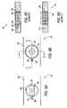
- FIG. 1Aillustrates a partial top view of a bone plate of the present invention with a through-hole (screw hole) according to a first embodiment of the present invention
- FIG.It illustrates a cross-sectional view of bone plate of FIG. 1A taken along line A-A;
- FIG. 2Aillustrates a top view of a bushing of the present invention for use with the bone plate of FIG. 1A , and according to a first embodiment.
- FIG. 2Billustrates a left-side lateral view of the bushing of FIG, 2A .
- FIG. 2Cillustrates a perspective view of the bushing of FIG. 2A .
- FIG. 3Aillustrate the step of inserting the bushing of FIGS. 2A-2C within the through-hole (screw hole) of the plate of FIGS. 1A-2B , and according to an exemplary method of the present invention of assembling the bushing with the plate to form a plate/bushing assembly (illustrating the bushing oriented about 90 degrees relative to the plate, with the flat of the bushing aligned with the flat of the plate, and with the center of the bushing coinciding with the center of the plate).
- FIG. 3Billustrate a step of assembling the bushing to the plate subsequent to that shown in FIG. 3A (illustrating the rotation of the bushing within the through-hole (screw hole) of the plate, for about 90 degrees, to constrain and lock the bushing within the through-hole of the plate).
- FIG. 3Cillustrate a cross-sectional view of the plate/bushing assembly of FIG. 3B , taken along line B-B.
- FIG. 3Dillustrate a cross-sectional view of the plate/bushing assembly of FIG. 3B , taken along line C-C.
- FIG. 4Aillustrates a partial top view of a bone plate of the present invention with a through-hole (screw hole) and a pin slot, according to a second embodiment of the present invention
- FIG. 4Billustrates across-sectional view of bone plate of FIG. 1A taken along line A-A;
- FIG. 5Aillustrates a top view of a bushing of the present invention provided with a pin and for use with the bone plate of FIG. 1A , and according to a second embodiment.
- FIG. 5Billustrates a left-side lateral view of the bushing of FIG. 5A .
- FIG. 5Cillustrates a perspective view of the bushing of FIG. 5A .
- FIG. 6Aillustrate the step of inserting the bushing of FIGS. 5A-2C within the through-hole (screw hole) of the plate of FIGS. 4A-2B , and according to an exemplary method of the present invention of assembling the bushing with the plate to form a plate/bushing/pin assembly (illustrating the bushing oriented about 90 degrees relative to the plate, with the pin of the bushing aligned with and positioned within the pin slot of the plate, and with the center of the bushing coinciding with the center of the plate).
- FIG. 6Billustrate a step of assembling the bushing to the plate subsequent to that shown in FIG. 6A (illustrating the rotation of the bushing within the through-hole (screw hole) of the plate, for about 90 degrees, to constrain and lock the bushing within the through-hole of the plate).
- FIG. 6Cillustrate a cross-sectional view of the plate/bushing assembly of FIG. 6B , taken along line B-B.
- FIG. 6Dillustrate a cross-sectional view of the plate/bushing assembly of FIG. 6B , taken along line C-C.
- the present inventionprovides a bone plate with a locking design that prevents the bushing from rotating and/or dislodging from the screw hole during screw insertion.
- the design of the plate and bushing of the present inventionalso allows the screw to lock at variable angles.
- FIG. 1-6illustrate a bone plate 100, 200 of the present invention provided with bushings 50, 150 that are designed to engage and lock within through-holes 20 of the plate, to form plate/bushing assembly 101, 201.
- the bushing 50, 150is first inserted into the plate 100, 200 in a direction about perpendicular to the plate 100, 200, i.e., with the axis of the bushing oriented about perpendicularly to the axis of through-hole 20 of the plate, so that the center of the bushing is aligned with the center of the through-hole, and a flat on a lateral side of the bushing is aligned with corresponding flat on an inner wall of the through-hole.
- the bushingis in an unlocked position.
- the bushingis then rotated within the through-hole 20 of the plate so that the top surface of the bushing is about parallel to the top surface of the plate, preferably in the same plane, to lock and constrain the bushing within the through-hole of the plate.
- the bushingis in a locked position. Unlocking of the bushing from the plate requires a manual step of physically rotating the bushing within the through-hole, so that the axis of the bushing is again oriented about perpendicularly to the axis of through-hole 20 of the plate, to allow the bushing to be pulled from the through-hole.
- bone plate 100has a body 10 provided with at least one through-hole (screw hole) 20, Body 10 may be formed of a metal, preferably titanium.
- bone plate 100has through-hole (screw hole) 20 with a generally spherical cross-section provided with a flat 22 on the inner wall of the through-hole.
- Flat 22may have a square or rectangular configuration (surface area) and is configured to be aligned with a corresponding flat 55 on the bushing, as described below.
- FIGS 2A-Cillustrate various views of bushing 50 of the present invention that is configured to engage the through-hole (screw hole) 20 of the plate 100 of Figure 1 , and to further allow a screw to lock at variable angles relative to body 10 of the plate.
- Bushing 50may have a general donut-shape configuration, with upper and lower surfaces preferably planar, and sized so that it is inserted into the through-hole 20 and locked therein, as detailed below.
- Bushing 50is provided with a generally spherical outer shape having at least one flat 55 (preferably, with two flats 55 as shown in Figure 2 ) and a small cut (split) 59.
- Flat 55may have a square or rectangular configuration (surface area) and is configured to be aligned with flat 22 on the plate.
- flat 22has a geometry similar to that of flat 55, and surface area about equal to the surface area of the flat 55.
- the bushing 50is first inserted by introducing the bushing in a direction about perpendicular to the through-hole of the plate, so that a longitudinal axis of the bushing is about perpendicular to the longitudinal axis of the through hole; aligning the center of the bushing with the center of the through-hole; and aligning the flat 55 of the bushing with the flat 22 of the plate, to place the bushing in the proper orientation for assembly.
- the bushing 50cannot rotate, or dislodge from, or otherwise come out of, the plate 100 unless the bushing 50 is turned again about 90 degrees relative to the plate.
- the flat 55 on the bushing 50mates with the flat 22 on the internal wall of the hole (screw hole) 20 to prevent it from rotating within the screw hole 20. This aspect is important to avoid the need for a bushing guide during insertion of the screw. As the screw is inserted through the bushing, the head of the screw expands the bushing against the plate, locking the bushing to the plate.
- the bushingis prevented from rotating and/or dislodging from the screw hole.
- the bushing designalso allows the screw to be locked at variable angles.
- the bushingis provided with internal threads corresponding to external threads on the body of the screw, to facilitate advancement of the screw through the passageway of the bushing.
- bushing 150may be provided with an optional post 180 to prevent the bushing 150 from rotating.
- post 180extends about perpendicular to flat 155.
- bone plate 210 of the present inventionmay have a modified through-hole 220 to accommodate the bushing 150 with post 180.
- bone plate 210has a through-hole 220 having a generally spherical shape with a slot 280 sized to fit the post 180 of bushing 150.
- the slot 280captures the post 180 of the bushing 150 and prevents rotation of the bushing during screw insertion.
- Figures 6A-Dillustrate exemplary steps of assembling the bushing 150 to the bone plate 210 to form assembly 201.
- the bushing 150is first inserted by introducing the bushing in a direction about perpendicular to the through-hole 220 of the plate, so that a longitudinal axis of the bushing is about perpendicular to the longitudinal axis of the through hole; aligning the center of the bushing with the center of the through-hole; and aligning the post 180 of the bushing with the slot 280 of the plate, placing the bushing in the proper orientation for assembly.
- rotating the bushing about 90 degreesallows the bushing to be constrained within the through-hole of the plate.
- the alignment of the post 180 of the bushing 150 and the slot 280 of the bone plate 10prevents rotation of the bushing within the through-hole 220.
- the bushing 150is constrained within bone plate 210 due to the diameter of the bushing being larger than the diameter of the through-hole as shown in Figure 6D .
- the present inventioncan be used in a method of providing a bushing/plate assembly by inter alia : (i) providing a bushing with an alignment/locking mechanism configured to mate with a corresponding alignment/locking mechanism of an inner wall of a through-hole of a bone plate, when the bushing is inserted into the plate; (ii) introducing the bushing in a direction about perpendicular to the through-hole of the plate, so that the bushing is about perpendicular to the through hole, and the center of the bushing is aligned with the center of the through-hole; and (iii) rotating the bushing about 90 degrees so that the bushing is captured within the through-hole of the plate, and the alignment/locking mechanism of the bushing is aligned with the alignment/locking mechanism of the plate.
- the alignment/locking mechanism of the bushingmay be a flat, a pin, or a combination of a flat and a pin.
- the alignment/locking mechanism of the wall of the through-hole of the platemay be a flat, a pin slot, or a combination of a flat and a pin slot.
- the present inventioncan also be used in a method of assembling a bushing to a bone plate by inter alia : (i) providing a bushing with a first flat on the outer wall of the bushing, and providing a second flat on an inner wall of a through-hole of bone plate, the second flat being configured to align with the first flat when the bushing is inserted into the plate; (ii) introducing the bushing in a direction about perpendicular to the through-hole of the plate, so that a longitudinal axis of the bushing is about perpendicular to a longitudinal axis of the through hole, and the center of the bushing is aligned with the center of the through-hole; and (iii) rotating the bushing about 90 degrees so that the bushing is captured within the through-hole of the plate (with the first flat aligned with the second flat).
Landscapes
- Health & Medical Sciences (AREA)
- Orthopedic Medicine & Surgery (AREA)
- Surgery (AREA)
- Life Sciences & Earth Sciences (AREA)
- Heart & Thoracic Surgery (AREA)
- Nuclear Medicine, Radiotherapy & Molecular Imaging (AREA)
- Engineering & Computer Science (AREA)
- Biomedical Technology (AREA)
- Neurology (AREA)
- Medical Informatics (AREA)
- Molecular Biology (AREA)
- Animal Behavior & Ethology (AREA)
- General Health & Medical Sciences (AREA)
- Public Health (AREA)
- Veterinary Medicine (AREA)
- Surgical Instruments (AREA)
Description
- The present invention relates to bone plates having looking bushings.
- Bone plates known in the art are typically provided with self-tapping bone plate screws that allow the bone plate to be secured to a surface of the bone. The screws are inserted through holes, which are formed into the bone plate and which contain washers or bushings that are rotatable in the holes. When the screw is inserted, the head of the screw typically spreads the bushing (for example, a split-sleeve bushing) as the screw advances and ultimately locks the bushing to the bone plate. The bushings may provide for variable angles of insertion for the screws. During insertion of the screws into the bone plate, the bushings may inadvertently rotate within the screw hole or even dislodge from the through-hole of the bone plate, causing a delay in the surgical procedure.
- A locking plate assembly according to the preamble of claim 1 is disclosed in
US 2009/192 549 . - Accordingly, there is a need for a bone plate provided with a new design that prevents the bushing from rotating and/or dislodging from the screw hole during screw insertion. Also needed is a bushing design that allows the screw to be locked at variable angles.
- The present invention provides a plate assembly according to claim 1 comprising a bone plate, preferably a humeral plate, with a new design that prevents the bushing from rotating and/or dislodging from the screw hole during screw insertion. The bushing design of the present invention also allows the screw to be locked at variable angles.
- The plate of the present invention is provided with through-holes having internal walls with at least one flat that is configured to align with a corresponding flat provided on the outer wall of the bushing. The bushing is inserted by orienting the bushing in a direction perpendicular to the through-hole of the plate (screw hole) so that the center of the bushing is aligned with the center of the through-hole and the flat on the bushing is aligned with the flat on the through-hole of the bone plate. The bushing is introduced into the through- hole until the centers are aligned, and then the bushing is rotated about 90 degrees so that the bushing is captured within the through-hole of the plate. Once captured, the bushing cannot rotate, dislodge from, or come out of the plate unless the bushing is turned 90 degrees. The flat on the bushing mates with the flat on the internal wall of the hole (screw hole) to prevent it from rotating within the screw hole. This important aspect avoids the need for a bushing guide during screw insertion.
- In an alternate embodiment, the bushing may be provided with an optional post in addition to the flat to prevent the bushing from rotating.
- These and other features and advantages of the invention Will be more apparent from the following detailed description that is provided in connection with the accompanying drawings and illustrated exemplary embodiments of the invention.
FIG. 1A illustrates a partial top view of a bone plate of the present invention with a through-hole (screw hole) according to a first embodiment of the present invention;- FIG. It illustrates a cross-sectional view of bone plate of
FIG. 1A taken along line A-A; FIG. 2A illustrates a top view of a bushing of the present invention for use with the bone plate ofFIG. 1A , and according to a first embodiment.FIG. 2B illustrates a left-side lateral view of the bushing ofFIG, 2A .FIG. 2C illustrates a perspective view of the bushing ofFIG. 2A .FIG. 3A illustrate the step of inserting the bushing ofFIGS. 2A-2C within the through-hole (screw hole) of the plate ofFIGS. 1A-2B , and according to an exemplary method of the present invention of assembling the bushing with the plate to form a plate/bushing assembly (illustrating the bushing oriented about 90 degrees relative to the plate, with the flat of the bushing aligned with the flat of the plate, and with the center of the bushing coinciding with the center of the plate).FIG. 3B illustrate a step of assembling the bushing to the plate subsequent to that shown inFIG. 3A (illustrating the rotation of the bushing within the through-hole (screw hole) of the plate, for about 90 degrees, to constrain and lock the bushing within the through-hole of the plate).FIG. 3C illustrate a cross-sectional view of the plate/bushing assembly ofFIG. 3B , taken along line B-B.FIG. 3D illustrate a cross-sectional view of the plate/bushing assembly ofFIG. 3B , taken along line C-C.FIG. 4A illustrates a partial top view of a bone plate of the present invention with a through-hole (screw hole) and a pin slot, according to a second embodiment of the present invention;FIG. 4B illustrates across-sectional view of bone plate ofFIG. 1A taken along line A-A;FIG. 5A illustrates a top view of a bushing of the present invention provided with a pin and for use with the bone plate ofFIG. 1A , and according to a second embodiment.FIG. 5B illustrates a left-side lateral view of the bushing ofFIG. 5A .FIG. 5C illustrates a perspective view of the bushing ofFIG. 5A .FIG. 6A illustrate the step of inserting the bushing ofFIGS. 5A-2C within the through-hole (screw hole) of the plate ofFIGS. 4A-2B , and according to an exemplary method of the present invention of assembling the bushing with the plate to form a plate/bushing/pin assembly (illustrating the bushing oriented about 90 degrees relative to the plate, with the pin of the bushing aligned with and positioned within the pin slot of the plate, and with the center of the bushing coinciding with the center of the plate).FIG. 6B illustrate a step of assembling the bushing to the plate subsequent to that shown inFIG. 6A (illustrating the rotation of the bushing within the through-hole (screw hole) of the plate, for about 90 degrees, to constrain and lock the bushing within the through-hole of the plate).FIG. 6C illustrate a cross-sectional view of the plate/bushing assembly ofFIG. 6B , taken along line B-B.FIG. 6D illustrate a cross-sectional view of the plate/bushing assembly ofFIG. 6B , taken along line C-C.- The present invention provides a bone plate with a locking design that prevents the bushing from rotating and/or dislodging from the screw hole during screw insertion. The design of the plate and bushing of the present invention also allows the screw to lock at variable angles.
- Referring now to the drawings, where like elements are designated by like reference numeral
Figures 1-6 illustrate abone plate bushings holes 20 of the plate, to form plate/bushing assembly bushing plate plate hole 20 of the plate, so that the center of the bushing is aligned with the center of the through-hole, and a flat on a lateral side of the bushing is aligned with corresponding flat on an inner wall of the through-hole. At this step, the bushing is in an unlocked position. The bushing is then rotated within the through-hole 20 of the plate so that the top surface of the bushing is about parallel to the top surface of the plate, preferably in the same plane, to lock and constrain the bushing within the through-hole of the plate. At this step, the bushing is in a locked position. Unlocking of the bushing from the plate requires a manual step of physically rotating the bushing within the through-hole, so that the axis of the bushing is again oriented about perpendicularly to the axis of through-hole 20 of the plate, to allow the bushing to be pulled from the through-hole. - As shown in
Figure 1A ,bone plate 100 has abody 10 provided with at least one through-hole (screw hole) 20,Body 10 may be formed of a metal, preferably titanium. As shown inFigures 1A-B ,bone plate 100 has through-hole (screw hole) 20 with a generally spherical cross-section provided with a flat 22 on the inner wall of the through-hole.Flat 22 may have a square or rectangular configuration (surface area) and is configured to be aligned with a corresponding flat 55 on the bushing, as described below. Figures 2A-C illustrate various views of bushing 50 of the present invention that is configured to engage the through-hole (screw hole) 20 of theplate 100 ofFigure 1 , and to further allow a screw to lock at variable angles relative tobody 10 of the plate.Bushing 50 may have a general donut-shape configuration, with upper and lower surfaces preferably planar, and sized so that it is inserted into the through-hole 20 and locked therein, as detailed below.Bushing 50 is provided with a generally spherical outer shape having at least one flat 55 (preferably, with twoflats 55 as shown inFigure 2 ) and a small cut (split) 59.Flat 55 may have a square or rectangular configuration (surface area) and is configured to be aligned with flat 22 on the plate. Preferably, flat 22 has a geometry similar to that of flat 55, and surface area about equal to the surface area of the flat 55.- During assembly with the plate to form
assembly 101, as illustrated inFigure 3A , thebushing 50 is first inserted by introducing the bushing in a direction about perpendicular to the through-hole of the plate, so that a longitudinal axis of the bushing is about perpendicular to the longitudinal axis of the through hole; aligning the center of the bushing with the center of the through-hole; and aligning the flat 55 of the bushing with the flat 22 of the plate, to place the bushing in the proper orientation for assembly. - As shown in
Figure 3B , rotating the bushing about 90 degrees allows the bushing to be constrained within the through-hole of the plate. The alignment of the flat 55 of thebushing 50 and the flat 22 of thebone plate 10 prevents rotation of the bushing within the through-hole 20. Thebushing 50 is constrained withinbone plate 10 due to the diameter of the bushing being larger than the diameter of the through-hole as shown inFigure 3D . In this orientation, atop surface 51 of thebushing 50 is about parallel to atop surface 11 of theplate 100, preferably in the same plane, to lock and constrain thebushing 50 within the through-hole 20 of the plate 100 (as shown inFigures 3B-3D ). - Once positioned within the through
hole 20, thebushing 50 cannot rotate, or dislodge from, or otherwise come out of, theplate 100 unless thebushing 50 is turned again about 90 degrees relative to the plate. The flat 55 on thebushing 50 mates with the flat 22 on the internal wall of the hole (screw hole) 20 to prevent it from rotating within thescrew hole 20. This aspect is important to avoid the need for a bushing guide during insertion of the screw. As the screw is inserted through the bushing, the head of the screw expands the bushing against the plate, locking the bushing to the plate. As the screw is advanced, the outward taper of the screw head spreads the split (small cut) 59 of the bushing, causing the bushing to become locked due to the frictional interference between the outer surface of the bushing and an inner surface (the walls) of the through-hole 20 of theplate 100, The process is repeated for a plurality of bushings and screws, and for each bushing individually, until the plate is secured to the bone. - During the screw insertion, as a result of the alignment/locking design of the bushing and through-hole, the bushing is prevented from rotating and/or dislodging from the screw hole. The bushing design also allows the screw to be locked at variable angles. If desired, the bushing is provided with internal threads corresponding to external threads on the body of the screw, to facilitate advancement of the screw through the passageway of the bushing.
- Referring now to
Figures 5A-C , bushing 150 according to a second exemplary embodiment of the present invention may be provided with anoptional post 180 to prevent thebushing 150 from rotating. In an exemplary embodiment, post 180 extends about perpendicular to flat 155. Referring now toFigures 4A-B ,bone plate 210 of the present invention may have a modified through-hole 220 to accommodate thebushing 150 withpost 180. As shown,bone plate 210 has a through-hole 220 having a generally spherical shape with aslot 280 sized to fit thepost 180 ofbushing 150. Theslot 280 captures thepost 180 of thebushing 150 and prevents rotation of the bushing during screw insertion. Figures 6A-D illustrate exemplary steps of assembling thebushing 150 to thebone plate 210 to formassembly 201. During assembly with the plate, and as illustrated inFigure 6A , thebushing 150 is first inserted by introducing the bushing in a direction about perpendicular to the through-hole 220 of the plate, so that a longitudinal axis of the bushing is about perpendicular to the longitudinal axis of the through hole; aligning the center of the bushing with the center of the through-hole; and aligning thepost 180 of the bushing with theslot 280 of the plate, placing the bushing in the proper orientation for assembly. As shown inFigure 6B , rotating the bushing about 90 degrees allows the bushing to be constrained within the through-hole of the plate. The alignment of thepost 180 of thebushing 150 and theslot 280 of thebone plate 10 prevents rotation of the bushing within the through-hole 220. Thebushing 150 is constrained withinbone plate 210 due to the diameter of the bushing being larger than the diameter of the through-hole as shown inFigure 6D .- The present invention can be used in a method of providing a bushing/plate assembly byinter alia: (i) providing a bushing with an alignment/locking mechanism configured to mate with a corresponding alignment/locking mechanism of an inner wall of a through-hole of a bone plate, when the bushing is inserted into the plate; (ii) introducing the bushing in a direction about perpendicular to the through-hole of the plate, so that the bushing is about perpendicular to the through hole, and the center of the bushing is aligned with the center of the through-hole; and (iii) rotating the bushing about 90 degrees so that the bushing is captured within the through-hole of the plate, and the alignment/locking mechanism of the bushing is aligned with the alignment/locking mechanism of the plate. The alignment/locking mechanism of the bushing may be a flat, a pin, or a combination of a flat and a pin. The alignment/locking mechanism of the wall of the through-hole of the plate may be a flat, a pin slot, or a combination of a flat and a pin slot.
- The present invention can also be used in a method of assembling a bushing to a bone plate byinter alia: (i) providing a bushing with a first flat on the outer wall of the bushing, and providing a second flat on an inner wall of a through-hole of bone plate, the second flat being configured to align with the first flat when the bushing is inserted into the plate; (ii) introducing the bushing in a direction about perpendicular to the through-hole of the plate, so that a longitudinal axis of the bushing is about perpendicular to a longitudinal axis of the through hole, and the center of the bushing is aligned with the center of the through-hole; and (iii) rotating the bushing about 90 degrees so that the bushing is captured within the through-hole of the plate (with the first flat aligned with the second flat).
- Although the present invention has been described in relation to particular embodiments thereof, many other variations and modifications and other uses will become apparent to those skilled in the art. Therefore, the present invention is to be limited not by the specific disclosure herein, but only by the appended claims.
Claims (8)
- A locking plate assembly (101; 201) for engagement with a bone, comprising:a plate (100; 200) comprising a body (10; 210) and at least one through-hole (20; 220), the at least one through-hole (20; 220) having an inner wall with one flat (22); anda bushing (50; 150) comprising an exterior surface with two bushing flats (55; 155) and a passageway comprising an interior surface, the bushing flats (55; 155) engaging the flat (22) of the through-hole (20; 220) to prevent rotation of the bushing (50; 150) relative to the through-hole (20; 220),characterised in that the exterior surface of the bushing (50; 150) and the inner wall of the at least one through-hole (20; 220) are substantially spherical in a complementary manner, except where the flats are located, andin that the bushing (50; 150) is arranged to be secured within the through-hole (20; 220) by first inserting the bushing (50; 150) within the through-hole (20; 220) in a direction about perpendicular to the through-hole (20; 220) with the longitudinal axis of the bushing oriented about prependicularly to the longitudinal axis of the through-hole, so that the cennter of the bushing (50; 150) is aligned with the center of the through-hole (20; 220) and the flat (55; 155) on the bushing is aligned with the flat (22) on the through-hole (20; 220), and then rotating the bushing (50; 150) for about 90 degrees, so that the bushing flat (55; 155) engages the flat of the through-hole (20; 220).
- The assembly (101) of claim 1, wherein the two bushing flats (55) are diametrically and symmetrically located relative to a center of the bushing (50).
- The assembly (101) of claim 1, wherein the flat (22) of the through-hole (20) of the plate (100) has a surface area about equal to a surface area of the bushing flat (55).
- The assembly (101; 201) of claim 1, wherein at least one of the flat (22) of the through-hole (20; 220) and the bushing flat (55; 155) has one of a rectangular, square or trapezoidal configuration.
- The assembly (101; 201) of claim 1, wherein the bushing (50; 150) is expandable and is provided with a slit (59; 159) extending completely through a wall of the bushing (50; 150).
- The assembly (201) of claim 1, wherein the plate (200) further comprises a pin slot (280) extending from the flat of the through-hole (220) and into the body (210).
- The assembly (201) of claim 6, wherein the pin slot (280) of the plate (200) engages a corresponding pin (180) of the bushing (150), the pin (180) of the bushing (150) extending about perpendicular to the bushing flat (155).
- The assembly (101; 201) of claim 1, wherein the bushing (50; 150) is arranged to be removed from the through-hole (20; 220) by first rotating the bushing (50; 150) for about 90 degrees so that the bushing (50; 150) is about perpendicular to the through-hole (20; 220), and the bushing flat (55; 155) is not in alignment with the flat in the through-hole (20; 220), and then pulling the bushing (50; 150) from the through-hole (20; 220).
Applications Claiming Priority (1)
| Application Number | Priority Date | Filing Date | Title |
|---|---|---|---|
| US25950009P | 2009-11-09 | 2009-11-09 |
Publications (2)
| Publication Number | Publication Date |
|---|---|
| EP2319437A1 EP2319437A1 (en) | 2011-05-11 |
| EP2319437B1true EP2319437B1 (en) | 2013-04-03 |
Family
ID=43531167
Family Applications (1)
| Application Number | Title | Priority Date | Filing Date |
|---|---|---|---|
| EP10190394AActiveEP2319437B1 (en) | 2009-11-09 | 2010-11-08 | Polyaxial bushing for locking plate |
Country Status (2)
| Country | Link |
|---|---|
| US (1) | US8444680B2 (en) |
| EP (1) | EP2319437B1 (en) |
Families Citing this family (41)
| Publication number | Priority date | Publication date | Assignee | Title |
|---|---|---|---|---|
| US6610067B2 (en) | 2000-05-01 | 2003-08-26 | Arthrosurface, Incorporated | System and method for joint resurface repair |
| US7163541B2 (en) | 2002-12-03 | 2007-01-16 | Arthrosurface Incorporated | Tibial resurfacing system |
| US6520964B2 (en) | 2000-05-01 | 2003-02-18 | Std Manufacturing, Inc. | System and method for joint resurface repair |
| US8177841B2 (en) | 2000-05-01 | 2012-05-15 | Arthrosurface Inc. | System and method for joint resurface repair |
| US7678151B2 (en) | 2000-05-01 | 2010-03-16 | Ek Steven W | System and method for joint resurface repair |
| US7901408B2 (en) | 2002-12-03 | 2011-03-08 | Arthrosurface, Inc. | System and method for retrograde procedure |
| US7914545B2 (en) | 2002-12-03 | 2011-03-29 | Arthrosurface, Inc | System and method for retrograde procedure |
| US8388624B2 (en) | 2003-02-24 | 2013-03-05 | Arthrosurface Incorporated | Trochlear resurfacing system and method |
| AU2004293042A1 (en) | 2003-11-20 | 2005-06-09 | Arthrosurface, Inc. | Retrograde delivery of resurfacing devices |
| WO2006004885A2 (en) | 2004-06-28 | 2006-01-12 | Arthrosurface, Inc. | System for articular surface replacement |
| US7828853B2 (en) | 2004-11-22 | 2010-11-09 | Arthrosurface, Inc. | Articular surface implant and delivery system |
| US9358029B2 (en) | 2006-12-11 | 2016-06-07 | Arthrosurface Incorporated | Retrograde resection apparatus and method |
| EP2262448A4 (en) | 2008-03-03 | 2014-03-26 | Arthrosurface Inc | Bone resurfacing system and method |
| US10945743B2 (en) | 2009-04-17 | 2021-03-16 | Arthrosurface Incorporated | Glenoid repair system and methods of use thereof |
| WO2010121250A1 (en) | 2009-04-17 | 2010-10-21 | Arthrosurface Incorporated | Glenoid resurfacing system and method |
| AU2010236182A1 (en) | 2009-04-17 | 2011-11-24 | Arthrosurface Incorporated | Glenoid resurfacing system and method |
| FR2955247B1 (en) | 2010-01-21 | 2013-04-26 | Tornier Sa | GLENOIDAL COMPONENT OF SHOULDER PROSTHESIS |
| EP2542165A4 (en) | 2010-03-05 | 2015-10-07 | Arthrosurface Inc | Tibial resurfacing system and method |
| FR2971144A1 (en) | 2011-02-08 | 2012-08-10 | Tornier Sa | GLENOIDAL IMPLANT FOR SHOULDER PROSTHESIS AND SURGICAL KIT |
| US9066716B2 (en) | 2011-03-30 | 2015-06-30 | Arthrosurface Incorporated | Suture coil and suture sheath for tissue repair |
| EP2804565B1 (en) | 2011-12-22 | 2018-03-07 | Arthrosurface Incorporated | System for bone fixation |
| US20130317554A1 (en)* | 2012-05-23 | 2013-11-28 | Thomas Purcell | Locking mechanism for an implantable medical device |
| WO2014008126A1 (en) | 2012-07-03 | 2014-01-09 | Arthrosurface Incorporated | System and method for joint resurfacing and repair |
| US9492200B2 (en) | 2013-04-16 | 2016-11-15 | Arthrosurface Incorporated | Suture system and method |
| US9468479B2 (en) | 2013-09-06 | 2016-10-18 | Cardinal Health 247, Inc. | Bone plate |
| WO2015103090A1 (en) | 2014-01-03 | 2015-07-09 | Tornier, Inc. | Reverse shoulder systems |
| US10624748B2 (en) | 2014-03-07 | 2020-04-21 | Arthrosurface Incorporated | System and method for repairing articular surfaces |
| US9931219B2 (en) | 2014-03-07 | 2018-04-03 | Arthrosurface Incorporated | Implant and anchor assembly |
| US11607319B2 (en) | 2014-03-07 | 2023-03-21 | Arthrosurface Incorporated | System and method for repairing articular surfaces |
| US10213237B2 (en) | 2014-10-03 | 2019-02-26 | Stryker European Holdings I, Llc | Periprosthetic extension plate |
| US10722374B2 (en) | 2015-05-05 | 2020-07-28 | Tornier, Inc. | Convertible glenoid implant |
| IL244461A (en)* | 2016-03-06 | 2017-06-29 | Jacobsen Hagay | Adaptor for adjustably mounting a structure onto a biological base |
| US10251685B2 (en) | 2016-03-17 | 2019-04-09 | Stryker European Holdings I, Llc | Floating locking insert |
| US11160663B2 (en) | 2017-08-04 | 2021-11-02 | Arthrosurface Incorporated | Multicomponent articular surface implant |
| WO2019079104A2 (en) | 2017-10-16 | 2019-04-25 | Imascap Sas | Shoulder implants and methods of use and assembly |
| EP4108194A1 (en) | 2018-03-02 | 2022-12-28 | Stryker European Holdings I, LLC | Bone plates and associated screws |
| WO2020186099A1 (en) | 2019-03-12 | 2020-09-17 | Arthrosurface Incorporated | Humeral and glenoid articular surface implant systems and methods |
| DE102019108777A1 (en)* | 2019-04-03 | 2020-10-08 | Osteobionix SL | Device for fixing bones |
| JP7257546B2 (en) | 2019-05-13 | 2023-04-13 | ハウメディカ オステオニクス コーポレイション | Glenoid baseplate and implant assembly |
| EP3982848A1 (en) | 2019-08-09 | 2022-04-20 | Howmedica Osteonics Corp. | Apparatuses and methods for implanting glenoid prostheses |
| US20220313308A1 (en)* | 2021-04-01 | 2022-10-06 | Medtronic Vascular, Inc. | Tissue-removing catheter with coupled inner liner |
Family Cites Families (21)
| Publication number | Priority date | Publication date | Assignee | Title |
|---|---|---|---|---|
| US5151103A (en) | 1987-11-03 | 1992-09-29 | Synthes (U.S.A.) | Point contact bone compression plate |
| SE9402130D0 (en) | 1994-06-17 | 1994-06-17 | Sven Olerud | Device and method for plate fixation of legs |
| US6017345A (en) | 1997-05-09 | 2000-01-25 | Spinal Innovations, L.L.C. | Spinal fixation plate |
| US5954722A (en) | 1997-07-29 | 1999-09-21 | Depuy Acromed, Inc. | Polyaxial locking plate |
| DE19832513A1 (en) | 1998-07-20 | 2000-02-17 | Impag Gmbh Medizintechnik | Fastening arrangement |
| DE20122742U1 (en) | 2001-05-28 | 2007-06-14 | Synthes Ag Chur, Chur | Bone plate for fixing proximal humerus fracture, has screw holes with partial internal threads or partial rotating taper grooves, where pitch of internal threads or taper grooves lies within range of specific millimeter |
| US6890335B2 (en) | 2001-08-24 | 2005-05-10 | Zimmer Spine, Inc. | Bone fixation device |
| CA2471843C (en)* | 2001-12-24 | 2011-04-12 | Synthes (U.S.A.) | Device for osteosynthesis |
| US7179260B2 (en) | 2003-09-29 | 2007-02-20 | Smith & Nephew, Inc. | Bone plates and bone plate assemblies |
| US7758620B2 (en) | 2002-09-24 | 2010-07-20 | Stryker Trauma Sa | Device for connecting a screw to a support plate |
| US8172885B2 (en)* | 2003-02-05 | 2012-05-08 | Pioneer Surgical Technology, Inc. | Bone plate system |
| EP1464295A3 (en) | 2003-04-01 | 2006-04-26 | Zimmer GmbH | Implant |
| US7195633B2 (en) | 2004-01-08 | 2007-03-27 | Robert J. Medoff | Fracture fixation system |
| US7604657B2 (en) | 2005-09-19 | 2009-10-20 | Depuy Products, Inc. | Bone fixation plate with complex suture anchor locations |
| US7931681B2 (en)* | 2005-04-14 | 2011-04-26 | Warsaw Orthopedic, Inc. | Anti-backout mechanism for an implant fastener |
| US7883531B2 (en)* | 2005-07-06 | 2011-02-08 | Stryker Spine | Multi-axial bone plate system |
| KR101246113B1 (en) | 2005-10-25 | 2013-03-20 | 앤썸 오르소패딕스, 엘엘씨 | Bone fastening assembly and bushing and screw for use therewith |
| US8287575B2 (en) | 2006-11-09 | 2012-10-16 | Stryker Trauma Gmbh | Polyaxial locking mechanism |
| FR2908627B1 (en) | 2006-11-20 | 2009-07-03 | Tornier Sas | PROTHETIC OR OSTEOSYNTHESIS DEVICE WITH A SLICED OLIVE |
| US8388666B2 (en) | 2007-09-27 | 2013-03-05 | Biomet C.V. | Locking screw system with relatively hard spiked polyaxial bushing |
| US20090192549A1 (en)* | 2008-01-30 | 2009-07-30 | Ebi, Llc | Bone plating system |
- 2010
- 2010-11-08USUS12/941,516patent/US8444680B2/enactiveActive
- 2010-11-08EPEP10190394Apatent/EP2319437B1/enactiveActive
Also Published As
| Publication number | Publication date |
|---|---|
| EP2319437A1 (en) | 2011-05-11 |
| US8444680B2 (en) | 2013-05-21 |
| US20110112536A1 (en) | 2011-05-12 |
Similar Documents
| Publication | Publication Date | Title |
|---|---|---|
| EP2319437B1 (en) | Polyaxial bushing for locking plate | |
| EP2720629B1 (en) | Modular bone plate and connector piece for a modular bone plate | |
| US6890334B2 (en) | Bone fixation assembly | |
| EP3366243B1 (en) | Surgical screw and fusion device using same | |
| JP5410269B2 (en) | Bone plate for fixation that can variably displace the lock type fixing screw | |
| US9730734B2 (en) | Locking assembly for a polyaxial bone anchoring device | |
| EP1935359B1 (en) | Orthopaedic screw lock system | |
| US7758620B2 (en) | Device for connecting a screw to a support plate | |
| EP2826432B1 (en) | Bone plate | |
| US20100298884A1 (en) | Polyaxial Auxiliary Connector | |
| EP2421455B1 (en) | Fastening apparatus for surgical retaining systems | |
| DE102016202450B4 (en) | Fasteners and methods for connecting two components | |
| US9039745B2 (en) | One-piece variable angle locking washer | |
| US20140303674A1 (en) | Parallel rod connector | |
| US9103141B2 (en) | Connection means and lock mounting device with such connection means | |
| KR101868694B1 (en) | Apparatus of bone fixation screw and fastening method thereof | |
| US7316715B2 (en) | Polyaxial screw for acetabular cup | |
| US20100042161A1 (en) | Surgical apparatus for osteosynthesis | |
| CN111316006A (en) | Active locking fastener | |
| KR101934391B1 (en) | Sleeve pin assembly for fixing bone pieces | |
| JP2000346035A (en) | Bolt with locking | |
| WO2007093855A1 (en) | Orthopedic devices and method for manufacturing the same | |
| DE102005005657A1 (en) | Femoral nail with self-tapping femoral neck screw, has compression adjustment screw in threaded hole and extending to contact sleeve to displace support part when rotated | |
| EP3502363A1 (en) | Assembly for fastening a wall mounted flange for a water tap on a wall | |
| KR101199334B1 (en) | Arrange pin of connecting holes |
Legal Events
| Date | Code | Title | Description |
|---|---|---|---|
| PUAI | Public reference made under article 153(3) epc to a published international application that has entered the european phase | Free format text:ORIGINAL CODE: 0009012 | |
| AK | Designated contracting states | Kind code of ref document:A1 Designated state(s):AL AT BE BG CH CY CZ DE DK EE ES FI FR GB GR HR HU IE IS IT LI LT LU LV MC MK MT NL NO PL PT RO RS SE SI SK SM TR | |
| AX | Request for extension of the european patent | Extension state:BA ME | |
| 17P | Request for examination filed | Effective date:20111103 | |
| 17Q | First examination report despatched | Effective date:20111128 | |
| GRAP | Despatch of communication of intention to grant a patent | Free format text:ORIGINAL CODE: EPIDOSNIGR1 | |
| GRAS | Grant fee paid | Free format text:ORIGINAL CODE: EPIDOSNIGR3 | |
| GRAA | (expected) grant | Free format text:ORIGINAL CODE: 0009210 | |
| AK | Designated contracting states | Kind code of ref document:B1 Designated state(s):AL AT BE BG CH CY CZ DE DK EE ES FI FR GB GR HR HU IE IS IT LI LT LU LV MC MK MT NL NO PL PT RO RS SE SI SK SM TR | |
| REG | Reference to a national code | Ref country code:GB Ref legal event code:FG4D | |
| REG | Reference to a national code | Ref country code:CH Ref legal event code:EP Ref country code:AT Ref legal event code:REF Ref document number:604210 Country of ref document:AT Kind code of ref document:T Effective date:20130415 | |
| REG | Reference to a national code | Ref country code:IE Ref legal event code:FG4D | |
| REG | Reference to a national code | Ref country code:DE Ref legal event code:R096 Ref document number:602010005883 Country of ref document:DE Effective date:20130529 | |
| PG25 | Lapsed in a contracting state [announced via postgrant information from national office to epo] | Ref country code:SI Free format text:LAPSE BECAUSE OF FAILURE TO SUBMIT A TRANSLATION OF THE DESCRIPTION OR TO PAY THE FEE WITHIN THE PRESCRIBED TIME-LIMIT Effective date:20130403 | |
| REG | Reference to a national code | Ref country code:NL Ref legal event code:VDEP Effective date:20130403 | |
| REG | Reference to a national code | Ref country code:LT Ref legal event code:MG4D | |
| PG25 | Lapsed in a contracting state [announced via postgrant information from national office to epo] | Ref country code:SE Free format text:LAPSE BECAUSE OF FAILURE TO SUBMIT A TRANSLATION OF THE DESCRIPTION OR TO PAY THE FEE WITHIN THE PRESCRIBED TIME-LIMIT Effective date:20130403 Ref country code:NL Free format text:LAPSE BECAUSE OF FAILURE TO SUBMIT A TRANSLATION OF THE DESCRIPTION OR TO PAY THE FEE WITHIN THE PRESCRIBED TIME-LIMIT Effective date:20130403 Ref country code:IS Free format text:LAPSE BECAUSE OF FAILURE TO SUBMIT A TRANSLATION OF THE DESCRIPTION OR TO PAY THE FEE WITHIN THE PRESCRIBED TIME-LIMIT Effective date:20130803 Ref country code:ES Free format text:LAPSE BECAUSE OF FAILURE TO SUBMIT A TRANSLATION OF THE DESCRIPTION OR TO PAY THE FEE WITHIN THE PRESCRIBED TIME-LIMIT Effective date:20130714 Ref country code:NO Free format text:LAPSE BECAUSE OF FAILURE TO SUBMIT A TRANSLATION OF THE DESCRIPTION OR TO PAY THE FEE WITHIN THE PRESCRIBED TIME-LIMIT Effective date:20130703 Ref country code:PT Free format text:LAPSE BECAUSE OF FAILURE TO SUBMIT A TRANSLATION OF THE DESCRIPTION OR TO PAY THE FEE WITHIN THE PRESCRIBED TIME-LIMIT Effective date:20130805 Ref country code:LT Free format text:LAPSE BECAUSE OF FAILURE TO SUBMIT A TRANSLATION OF THE DESCRIPTION OR TO PAY THE FEE WITHIN THE PRESCRIBED TIME-LIMIT Effective date:20130403 Ref country code:FI Free format text:LAPSE BECAUSE OF FAILURE TO SUBMIT A TRANSLATION OF THE DESCRIPTION OR TO PAY THE FEE WITHIN THE PRESCRIBED TIME-LIMIT Effective date:20130403 Ref country code:GR Free format text:LAPSE BECAUSE OF FAILURE TO SUBMIT A TRANSLATION OF THE DESCRIPTION OR TO PAY THE FEE WITHIN THE PRESCRIBED TIME-LIMIT Effective date:20130704 | |
| PG25 | Lapsed in a contracting state [announced via postgrant information from national office to epo] | Ref country code:LV Free format text:LAPSE BECAUSE OF FAILURE TO SUBMIT A TRANSLATION OF THE DESCRIPTION OR TO PAY THE FEE WITHIN THE PRESCRIBED TIME-LIMIT Effective date:20130403 Ref country code:BG Free format text:LAPSE BECAUSE OF FAILURE TO SUBMIT A TRANSLATION OF THE DESCRIPTION OR TO PAY THE FEE WITHIN THE PRESCRIBED TIME-LIMIT Effective date:20130703 Ref country code:CY Free format text:LAPSE BECAUSE OF FAILURE TO SUBMIT A TRANSLATION OF THE DESCRIPTION OR TO PAY THE FEE WITHIN THE PRESCRIBED TIME-LIMIT Effective date:20130403 Ref country code:HR Free format text:LAPSE BECAUSE OF FAILURE TO SUBMIT A TRANSLATION OF THE DESCRIPTION OR TO PAY THE FEE WITHIN THE PRESCRIBED TIME-LIMIT Effective date:20130403 Ref country code:PL Free format text:LAPSE BECAUSE OF FAILURE TO SUBMIT A TRANSLATION OF THE DESCRIPTION OR TO PAY THE FEE WITHIN THE PRESCRIBED TIME-LIMIT Effective date:20130403 Ref country code:RS Free format text:LAPSE BECAUSE OF FAILURE TO SUBMIT A TRANSLATION OF THE DESCRIPTION OR TO PAY THE FEE WITHIN THE PRESCRIBED TIME-LIMIT Effective date:20130403 | |
| PG25 | Lapsed in a contracting state [announced via postgrant information from national office to epo] | Ref country code:SK Free format text:LAPSE BECAUSE OF FAILURE TO SUBMIT A TRANSLATION OF THE DESCRIPTION OR TO PAY THE FEE WITHIN THE PRESCRIBED TIME-LIMIT Effective date:20130403 Ref country code:DK Free format text:LAPSE BECAUSE OF FAILURE TO SUBMIT A TRANSLATION OF THE DESCRIPTION OR TO PAY THE FEE WITHIN THE PRESCRIBED TIME-LIMIT Effective date:20130403 Ref country code:EE Free format text:LAPSE BECAUSE OF FAILURE TO SUBMIT A TRANSLATION OF THE DESCRIPTION OR TO PAY THE FEE WITHIN THE PRESCRIBED TIME-LIMIT Effective date:20130403 Ref country code:CZ Free format text:LAPSE BECAUSE OF FAILURE TO SUBMIT A TRANSLATION OF THE DESCRIPTION OR TO PAY THE FEE WITHIN THE PRESCRIBED TIME-LIMIT Effective date:20130403 | |
| PLBE | No opposition filed within time limit | Free format text:ORIGINAL CODE: 0009261 | |
| STAA | Information on the status of an ep patent application or granted ep patent | Free format text:STATUS: NO OPPOSITION FILED WITHIN TIME LIMIT | |
| PG25 | Lapsed in a contracting state [announced via postgrant information from national office to epo] | Ref country code:RO Free format text:LAPSE BECAUSE OF FAILURE TO SUBMIT A TRANSLATION OF THE DESCRIPTION OR TO PAY THE FEE WITHIN THE PRESCRIBED TIME-LIMIT Effective date:20130403 | |
| 26N | No opposition filed | Effective date:20140106 | |
| REG | Reference to a national code | Ref country code:DE Ref legal event code:R097 Ref document number:602010005883 Country of ref document:DE Effective date:20140106 | |
| PG25 | Lapsed in a contracting state [announced via postgrant information from national office to epo] | Ref country code:MC Free format text:LAPSE BECAUSE OF FAILURE TO SUBMIT A TRANSLATION OF THE DESCRIPTION OR TO PAY THE FEE WITHIN THE PRESCRIBED TIME-LIMIT Effective date:20130403 | |
| REG | Reference to a national code | Ref country code:IE Ref legal event code:MM4A | |
| PG25 | Lapsed in a contracting state [announced via postgrant information from national office to epo] | Ref country code:IE Free format text:LAPSE BECAUSE OF NON-PAYMENT OF DUE FEES Effective date:20131108 | |
| PG25 | Lapsed in a contracting state [announced via postgrant information from national office to epo] | Ref country code:SM Free format text:LAPSE BECAUSE OF FAILURE TO SUBMIT A TRANSLATION OF THE DESCRIPTION OR TO PAY THE FEE WITHIN THE PRESCRIBED TIME-LIMIT Effective date:20130403 | |
| PG25 | Lapsed in a contracting state [announced via postgrant information from national office to epo] | Ref country code:TR Free format text:LAPSE BECAUSE OF FAILURE TO SUBMIT A TRANSLATION OF THE DESCRIPTION OR TO PAY THE FEE WITHIN THE PRESCRIBED TIME-LIMIT Effective date:20130403 | |
| REG | Reference to a national code | Ref country code:CH Ref legal event code:PL | |
| PG25 | Lapsed in a contracting state [announced via postgrant information from national office to epo] | Ref country code:MK Free format text:LAPSE BECAUSE OF FAILURE TO SUBMIT A TRANSLATION OF THE DESCRIPTION OR TO PAY THE FEE WITHIN THE PRESCRIBED TIME-LIMIT Effective date:20130403 Ref country code:HU Free format text:LAPSE BECAUSE OF FAILURE TO SUBMIT A TRANSLATION OF THE DESCRIPTION OR TO PAY THE FEE WITHIN THE PRESCRIBED TIME-LIMIT; INVALID AB INITIO Effective date:20101108 Ref country code:LI Free format text:LAPSE BECAUSE OF NON-PAYMENT OF DUE FEES Effective date:20141130 Ref country code:LU Free format text:LAPSE BECAUSE OF NON-PAYMENT OF DUE FEES Effective date:20131108 Ref country code:CH Free format text:LAPSE BECAUSE OF NON-PAYMENT OF DUE FEES Effective date:20141130 | |
| PG25 | Lapsed in a contracting state [announced via postgrant information from national office to epo] | Ref country code:MT Free format text:LAPSE BECAUSE OF FAILURE TO SUBMIT A TRANSLATION OF THE DESCRIPTION OR TO PAY THE FEE WITHIN THE PRESCRIBED TIME-LIMIT Effective date:20130403 | |
| REG | Reference to a national code | Ref country code:FR Ref legal event code:PLFP Year of fee payment:6 | |
| REG | Reference to a national code | Ref country code:FR Ref legal event code:PLFP Year of fee payment:7 | |
| REG | Reference to a national code | Ref country code:FR Ref legal event code:PLFP Year of fee payment:8 | |
| REG | Reference to a national code | Ref country code:FR Ref legal event code:PLFP Year of fee payment:9 | |
| PG25 | Lapsed in a contracting state [announced via postgrant information from national office to epo] | Ref country code:AL Free format text:LAPSE BECAUSE OF FAILURE TO SUBMIT A TRANSLATION OF THE DESCRIPTION OR TO PAY THE FEE WITHIN THE PRESCRIBED TIME-LIMIT Effective date:20130403 | |
| PGFP | Annual fee paid to national office [announced via postgrant information from national office to epo] | Ref country code:GB Payment date:20240919 Year of fee payment:15 | |
| PGFP | Annual fee paid to national office [announced via postgrant information from national office to epo] | Ref country code:FR Payment date:20240909 Year of fee payment:15 | |
| PGFP | Annual fee paid to national office [announced via postgrant information from national office to epo] | Ref country code:DE Payment date:20240910 Year of fee payment:15 | |
| PGFP | Annual fee paid to national office [announced via postgrant information from national office to epo] | Ref country code:BE Payment date:20241007 Year of fee payment:15 | |
| PGFP | Annual fee paid to national office [announced via postgrant information from national office to epo] | Ref country code:AT Payment date:20241025 Year of fee payment:15 | |
| PGFP | Annual fee paid to national office [announced via postgrant information from national office to epo] | Ref country code:IT Payment date:20241010 Year of fee payment:15 |