EP2317075B1 - Method for repairing a gas turbine component - Google Patents
Method for repairing a gas turbine componentDownload PDFInfo
- Publication number
- EP2317075B1 EP2317075B1EP10186347AEP10186347AEP2317075B1EP 2317075 B1EP2317075 B1EP 2317075B1EP 10186347 AEP10186347 AEP 10186347AEP 10186347 AEP10186347 AEP 10186347AEP 2317075 B1EP2317075 B1EP 2317075B1
- Authority
- EP
- European Patent Office
- Prior art keywords
- article
- gas turbine
- turbine component
- cut
- out piece
- Prior art date
- Legal status (The legal status is an assumption and is not a legal conclusion. Google has not performed a legal analysis and makes no representation as to the accuracy of the status listed.)
- Active
Links
Images


Classifications
- F—MECHANICAL ENGINEERING; LIGHTING; HEATING; WEAPONS; BLASTING
- F01—MACHINES OR ENGINES IN GENERAL; ENGINE PLANTS IN GENERAL; STEAM ENGINES
- F01D—NON-POSITIVE DISPLACEMENT MACHINES OR ENGINES, e.g. STEAM TURBINES
- F01D5/00—Blades; Blade-carrying members; Heating, heat-insulating, cooling or antivibration means on the blades or the members
- F01D5/005—Repairing methods or devices
- B—PERFORMING OPERATIONS; TRANSPORTING
- B22—CASTING; POWDER METALLURGY
- B22F—WORKING METALLIC POWDER; MANUFACTURE OF ARTICLES FROM METALLIC POWDER; MAKING METALLIC POWDER; APPARATUS OR DEVICES SPECIALLY ADAPTED FOR METALLIC POWDER
- B22F7/00—Manufacture of composite layers, workpieces, or articles, comprising metallic powder, by sintering the powder, with or without compacting wherein at least one part is obtained by sintering or compression
- B22F7/06—Manufacture of composite layers, workpieces, or articles, comprising metallic powder, by sintering the powder, with or without compacting wherein at least one part is obtained by sintering or compression of composite workpieces or articles from parts, e.g. to form tipped tools
- B22F7/062—Manufacture of composite layers, workpieces, or articles, comprising metallic powder, by sintering the powder, with or without compacting wherein at least one part is obtained by sintering or compression of composite workpieces or articles from parts, e.g. to form tipped tools involving the connection or repairing of preformed parts
- B—PERFORMING OPERATIONS; TRANSPORTING
- B23—MACHINE TOOLS; METAL-WORKING NOT OTHERWISE PROVIDED FOR
- B23P—METAL-WORKING NOT OTHERWISE PROVIDED FOR; COMBINED OPERATIONS; UNIVERSAL MACHINE TOOLS
- B23P6/00—Restoring or reconditioning objects
- B23P6/002—Repairing turbine components, e.g. moving or stationary blades, rotors
- B23P6/005—Repairing turbine components, e.g. moving or stationary blades, rotors using only replacement pieces of a particular form
- B—PERFORMING OPERATIONS; TRANSPORTING
- B22—CASTING; POWDER METALLURGY
- B22F—WORKING METALLIC POWDER; MANUFACTURE OF ARTICLES FROM METALLIC POWDER; MAKING METALLIC POWDER; APPARATUS OR DEVICES SPECIALLY ADAPTED FOR METALLIC POWDER
- B22F2999/00—Aspects linked to processes or compositions used in powder metallurgy
- B—PERFORMING OPERATIONS; TRANSPORTING
- B23—MACHINE TOOLS; METAL-WORKING NOT OTHERWISE PROVIDED FOR
- B23K—SOLDERING OR UNSOLDERING; WELDING; CLADDING OR PLATING BY SOLDERING OR WELDING; CUTTING BY APPLYING HEAT LOCALLY, e.g. FLAME CUTTING; WORKING BY LASER BEAM
- B23K2101/00—Articles made by soldering, welding or cutting
- B23K2101/001—Turbines
- F—MECHANICAL ENGINEERING; LIGHTING; HEATING; WEAPONS; BLASTING
- F05—INDEXING SCHEMES RELATING TO ENGINES OR PUMPS IN VARIOUS SUBCLASSES OF CLASSES F01-F04
- F05D—INDEXING SCHEME FOR ASPECTS RELATING TO NON-POSITIVE-DISPLACEMENT MACHINES OR ENGINES, GAS-TURBINES OR JET-PROPULSION PLANTS
- F05D2230/00—Manufacture
- F05D2230/10—Manufacture by removing material
- F05D2230/13—Manufacture by removing material using lasers
- F—MECHANICAL ENGINEERING; LIGHTING; HEATING; WEAPONS; BLASTING
- F05—INDEXING SCHEMES RELATING TO ENGINES OR PUMPS IN VARIOUS SUBCLASSES OF CLASSES F01-F04
- F05D—INDEXING SCHEME FOR ASPECTS RELATING TO NON-POSITIVE-DISPLACEMENT MACHINES OR ENGINES, GAS-TURBINES OR JET-PROPULSION PLANTS
- F05D2230/00—Manufacture
- F05D2230/80—Repairing, retrofitting or upgrading methods
- F—MECHANICAL ENGINEERING; LIGHTING; HEATING; WEAPONS; BLASTING
- F05—INDEXING SCHEMES RELATING TO ENGINES OR PUMPS IN VARIOUS SUBCLASSES OF CLASSES F01-F04
- F05D—INDEXING SCHEME FOR ASPECTS RELATING TO NON-POSITIVE-DISPLACEMENT MACHINES OR ENGINES, GAS-TURBINES OR JET-PROPULSION PLANTS
- F05D2250/00—Geometry
- F05D2250/20—Three-dimensional
- Y—GENERAL TAGGING OF NEW TECHNOLOGICAL DEVELOPMENTS; GENERAL TAGGING OF CROSS-SECTIONAL TECHNOLOGIES SPANNING OVER SEVERAL SECTIONS OF THE IPC; TECHNICAL SUBJECTS COVERED BY FORMER USPC CROSS-REFERENCE ART COLLECTIONS [XRACs] AND DIGESTS
- Y02—TECHNOLOGIES OR APPLICATIONS FOR MITIGATION OR ADAPTATION AGAINST CLIMATE CHANGE
- Y02P—CLIMATE CHANGE MITIGATION TECHNOLOGIES IN THE PRODUCTION OR PROCESSING OF GOODS
- Y02P10/00—Technologies related to metal processing
- Y02P10/25—Process efficiency
- Y—GENERAL TAGGING OF NEW TECHNOLOGICAL DEVELOPMENTS; GENERAL TAGGING OF CROSS-SECTIONAL TECHNOLOGIES SPANNING OVER SEVERAL SECTIONS OF THE IPC; TECHNICAL SUBJECTS COVERED BY FORMER USPC CROSS-REFERENCE ART COLLECTIONS [XRACs] AND DIGESTS
- Y10—TECHNICAL SUBJECTS COVERED BY FORMER USPC
- Y10T—TECHNICAL SUBJECTS COVERED BY FORMER US CLASSIFICATION
- Y10T29/00—Metal working
- Y10T29/49—Method of mechanical manufacture
- Y10T29/49229—Prime mover or fluid pump making
Definitions
- the present inventionrelates to the technology of gas turbines. It refers to a method for repairing a gas turbine component according to the preamble of claim 1.
- gas turbineshave turbine inlet temperatures of more than 1400°C. Accordingly, the components of those gas turbines such as blades, vanes or liners are exposed to a high thermal load and mechanical stress. As those components are usually made of expensive high-temperature resistant materials, it is desirable to repair those components, when damaged, instead of replacing them. However, the repair of damaged gas turbine components is of limited quality, when the damaged section is removed and an insert is manufactured to fit into the removed region, as the insert has to be manufactured with high precision to avoid a loss in mechanical stability and change in the flow characteristics of the machine.
- Document EP 1 620 225 B1discloses a method for repairing and/or modifying components of a gas turbine according to the preamble of claim 1. Initially, at least one particularly damaged section of the component, which is to be repaired is extracted from the component. A CAD model is then produced for the replacement part by building the difference between nominal parametric CAD model and measured geometry data set of the damaged component. The replacement part is subsequently produced with the aid of an additive manufacturing process. Finally, the produced replacement part is integrated into the component, which is to be repaired.
- Document US 6,355,086 B2discloses a method and apparatus for fabricating a component by a direct laser process.
- a componentis a gas turbine engine blade having an abrasive tip formed directly thereon.
- Document WO 2008/046386 A1teaches a method for producing a gas turbine component with at least one closed outer wall and an inner structure bounded by the or each closed outer wall and defining hollow spaces, comprising the following steps: a) providing a three-dimensional CAD model of the gas turbine component to be produced; b) breaking down the three-dimensional CAD model into horizontal, substantially two-dimensional layers; c) building up layer by layer the gas turbine component to be produced with the aid of a additive manufacturing process using the layers generated from the CAD model in such a way that the or each outer wall is built up together with the inner structure and is accordingly connected to the inner structure with a material bond.
- the document EP 1 231 010 A1discloses a method of repairing gas turbine engine components.
- the methodincludes removing the damaged portion and fabricating an insert to match the removed portion.
- the insertis precision machined and crystallographically matched to the original component, and then bonded to this component using transient liquid phase bonding techniques and suitable heat treatment.
- transient liquid phase bonding techniques and suitable heat treatmentAlthough the document contains a wealth of information on the bonding process, no details of the precision machining of the insert are given.
- Document US 5,269,057teaches a method for replacing airfoil components includes the steps of identifying a portion of the airfoil to be replaced, removing the portion by a nonconventional machining process, such as continuous wire electrical discharge machining, and forming a replacement member utilizing a similar cutting process.
- a cutting path utilized to remove the portion to be replaced and to form the replacement memberincludes interlocking projections and sockets and may include one or more tapers along the cutting path so that the portion may be removed only by lifting in one direction.
- an electrical discharge cutting wiremoves along the outside of a CNC programmed cutting path.
- the US 2003/0105538 A1discloses a method for the rapid manufacturing of complete aerospace replacement parts, including removing an in-service aerospace part from an aerospace system.
- the in-service aerospace partis placed into a three-dimensional scanning device.
- the methodthen scans the in-service aerospace part utilizing the three-dimensional scanning device to develop a three-dimensional scan.
- a computer-aided-design modelis then developed based on the three-dimensional scan.
- the methodthen direct metal fabricates a replacement aerospace part from the computer-aided-design model utilizing a layer-build technology device. Finally the replacement aerospace part is installed back into the aerospace system.
- the inventive methodis characterised in that the damaged section is removed in form of a cut-out section along a split line as one single cut-out piece, that the cut-out piece is measured to obtain the actual non-parametric geometry data set of the cut-out piece, and that said 3-D article is manufactured based on said geometry data set of the cut-out piece.
- an additional material surchargeis added around at least part of the split line to the geometry data set of the cut-out piece to allow for a compensation of the material loss due to cutting and/or the preparation of a split line surface and/or a final or individual adaptation of a standard 3-D article geometry to the individual ex-service gas turbine component to be repaired.
- a "geometry data set”is meant to be a set of measured points representing a physical part
- a "CAD model”is meant to be a, by means of a computer software created, virtual representation of a physical part, whereby in a “parametric” CAD model the geometry of the virtual representation is described by mathematical functions (e.g. NURBS), and in a “non-parametric” CAD model the geometry of the virtual representation is described by primitives such as points, triangles, rectangles, etc..
- a virtual 3-D article in form of a CAD modelis created from said measured geometry data.
- damaged or missing areas of the cut-out pieceare virtually rebuild to create and/or modify and/or extend said CAD model.
- the CAD modelincludes information about the inner surface, potential distortions, local wall thickness modifications and positions of cooling air holes of the ex-service gas turbine component.
- the 3-D articleis manufactured by an additive manufacturing technology such as selective laser melting (SLM), selective laser sintering (SLS) or electron beam melting (EBM).
- SLMselective laser melting
- SLSselective laser sintering
- EBMelectron beam melting
- a method for making metallic or non-metallic products by a free-form laser sintering from a powder materialis for example known from document DE 102 19 983 B4 .
- Another method for manufacturing a moulded body, particularly a prototype of a product or component part, a tool prototype or spare part, in accordance with three-dimensional CAD data of a model of a moulded body, by depositing layers of a metallic material in powder form,is disclosed in document EP 946 325 B1 .
- document US 6,811,744 B2teaches device and arrangement for producing a three-dimensional object by means of a ray gun for controlled fusion of a thin layer of powder on the work table.
- the 3-D articleis manufactured by investment casting or milling.
- the manufactured 3-D articlebefore joining the manufactured 3-D article into the ex-service gas turbine component, is recontoured into a recontoured 3-D article to reach optimum conditions of the split line surface and/or gap width for the final joining process.
- the recontouringis done by removal of a fixed thickness of material.
- the recontouringmay be done by individual adaptive machining.
- the adaptive machiningis based on the individually scanned ex-service gas turbine component, which is compared with the 3-D article geometry.
- the adaptive machiningmay use a geometry data set based on the evaluation of a limited number of scanned gas turbine components of the same kind.
- the recontouring processis done by a subtractive machining process, such as milling, grinding or electro chemical machining (ECM).
- a subtractive machining processsuch as milling, grinding or electro chemical machining (ECM).
- the pre-joining processesinclude a heat treatment and/or chemical cleaning of the surfaces.
- the joining of said gas turbine component and said 3-D articleis done by brazing or welding or a combination thereof.
- the present inventioncomprises a method for repairing an ex-service gas turbine component by removing a damaged location, which method allows aright gap control, followed by replacing the respective location by a precisely fitting 3-D article.
- This 3-D articlecan be manufactured by additive manufacturing processes, such as selective laser melting (SLM), selective laser sintering (SLS), electron beam melting (EBM) or by standard methods, such as investment casting or machining process such as milling.
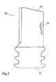
- the methodstarts with the damaged gas turbine component an example of which is shown in Fig. 1 .
- the gas turbine component 10 in this figurehas the form of a turbine blade with an airfoil 11 and a root 12. This gas turbine component 10 is damaged as it shows a damaged area 13 at one of the edges of the airfoil 11.
- machining processessuch as electrical discharge machining (EDM), water jet, laser or plasma cutting are preferentially applied.
- EDMelectrical discharge machining
- the machining processhas preferably a marginal influence on the cutting area (no oxidation, small heat affected zone and low roughness).
- Fig. 3shows the respective optical or tactile measuring system 16, wherein an optical scanning head 17 and/or tactile scanning head 18, which are controlled in their movement by a control 19, are used to pickup the non-parametric geometry data set of the cut-out piece 15.
- the damaged/missing areasare virtually re-build and potentially modified (e.g. by Reverse Engineering) allowing to create and/or modify and/or extend a final CAD model of the cut-out piece 15, also called 3D article 20 ( Fig. 4 ).
- the resulting CAD model of this 3D article 20includes the information about the inner surface, potential distortions, local wall thickness modifications and position of cooling air holes of the ex-service component.
- An additional material surcharge 21is added around at least part of the split line to the geometry data set of the cut-out piece 15. This allows a compensation of the material loss due to cutting, preparation of split line surface and, if needed, also a final or individual adaptation of a standard 3D article geometry to the individual ex-service gas turbine component 10 to be repaired.
- Fig. 8shows in a process scheme various alternative routes of processing within the method of the invention. The scheme begins with the start S that is the measurement of the cut-out piece 15.
- Variant Ais favoured, when the gas turbine component 10 to be repaired has only low distortion and damages.
- a standard material surcharge on the standard cut-out pieceis provided for compensation of cutting process and for surface preparation for joining. No 3-D model or measurement of the gas turbine component are necessary; a layer of fixed thickness is removed (A1).
- Variant Bis favoured, when the gas turbine component 10 to be repaired has medium distortion and damages.
- a standard material surcharge on the cut-out pieceis provided plus additional oversize for adaptive machining and for surface preparation for joining.
- B1a statistical evaluation of damages of components is used for the generation of a model and material removal with fixed thickness (B1).
- B2adaptive machining is applied
- Variant Cis favoured, when the gas turbine component 10 has a high distortion and worn out locations.
- C1a layer of fixed thickness
- C2a statistical evaluation of damages of components is used for the generation of a model and material removal with fixed thickness
- C3adaptive machining
- the 3D article 22can be manufactured by an additive manufacturing technology, such as selective laser melting (SLM), selective laser sintering (SLS) or electron beam melting
- SLMselective laser melting
- SLSselective laser sintering
- electron beam meltingelectron beam melting
- each 3-D article 22needs to be recontoured to reach optimum conditions of the split line surface (e.g. roughness, gap geometry/tolerance) for the final joining process.
- the recontouring stepcan be done by removal of a fixed value (thickness) or by individual adaptive machining.
- a standard processis used, such as milling, grinding or electro chemical machining (ECM);
- Fig. 5shows an exemplary machining system 23 for recontouring the manufactured 3-D article 22 into a recontoured 3-D article 22', with a rotating machining tool 24 and a respective control 25.
- pre-joining processesand chemical cleaning of the surfaces to be joined
- pre-heat treatments for improved weldabilitye.g. pre-heat treatments for improved weldability, stress relief heat treatments for 3D articles made by additive manufacturing technologies, etc.
- the joining of the manufactured 3D article into the ex-service gas turbine component 10can be realized with a standard and specifically adapted joining process, such as brazing or welding or a combination thereof.
- a final heat treatment and post machining(see Fig. 7 ) is carried out at the end of the reconditioning chain.
Landscapes
- Engineering & Computer Science (AREA)
- Mechanical Engineering (AREA)
- General Engineering & Computer Science (AREA)
- Chemical & Material Sciences (AREA)
- Composite Materials (AREA)
- Manufacturing & Machinery (AREA)
- Materials Engineering (AREA)
- Turbine Rotor Nozzle Sealing (AREA)
- Laser Beam Processing (AREA)
Description
- The present invention relates to the technology of gas turbines. It refers to a method for repairing a gas turbine component according to the preamble of
claim 1. - Today, gas turbines have turbine inlet temperatures of more than 1400°C. Accordingly, the components of those gas turbines such as blades, vanes or liners are exposed to a high thermal load and mechanical stress. As those components are usually made of expensive high-temperature resistant materials, it is desirable to repair those components, when damaged, instead of replacing them. However, the repair of damaged gas turbine components is of limited quality, when the damaged section is removed and an insert is manufactured to fit into the removed region, as the insert has to be manufactured with high precision to avoid a loss in mechanical stability and change in the flow characteristics of the machine.
Document EP 1 620 225 B1 (WO 2004/096487 A1 ), which is considered being the closest prior art, discloses a method for repairing and/or modifying components of a gas turbine according to the preamble ofclaim 1. Initially, at least one particularly damaged section of the component, which is to be repaired is extracted from the component. A CAD model is then produced for the replacement part by building the difference between nominal parametric CAD model and measured geometry data set of the damaged component. The replacement part is subsequently produced with the aid of an additive manufacturing process. Finally, the produced replacement part is integrated into the component, which is to be repaired.- Document
US 6,355,086 B2 discloses a method and apparatus for fabricating a component by a direct laser process. One example of such a component is a gas turbine engine blade having an abrasive tip formed directly thereon. - Document
WO 2008/046386 A1 teaches a method for producing a gas turbine component with at least one closed outer wall and an inner structure bounded by the or each closed outer wall and defining hollow spaces, comprising the following steps: a) providing a three-dimensional CAD model of the gas turbine component to be produced; b) breaking down the three-dimensional CAD model into horizontal, substantially two-dimensional layers; c) building up layer by layer the gas turbine component to be produced with the aid of a additive manufacturing process using the layers generated from the CAD model in such a way that the or each outer wall is built up together with the inner structure and is accordingly connected to the inner structure with a material bond. - The
document EP 1 231 010 A1 discloses a method of repairing gas turbine engine components. The method includes removing the damaged portion and fabricating an insert to match the removed portion. The insert is precision machined and crystallographically matched to the original component, and then bonded to this component using transient liquid phase bonding techniques and suitable heat treatment. Although the document contains a wealth of information on the bonding process, no details of the precision machining of the insert are given. - Document
US 5,269,057 teaches a method for replacing airfoil components includes the steps of identifying a portion of the airfoil to be replaced, removing the portion by a nonconventional machining process, such as continuous wire electrical discharge machining, and forming a replacement member utilizing a similar cutting process. A cutting path utilized to remove the portion to be replaced and to form the replacement member includes interlocking projections and sockets and may include one or more tapers along the cutting path so that the portion may be removed only by lifting in one direction. For the cutting, an electrical discharge cutting wire moves along the outside of a CNC programmed cutting path. - All the known methods for repairing gas turbine components are costly, have a low flexibility and productivity, and are difficult to put into practice. Furthermore, bad tolerances lead to a bad quality, the dependence on a 3D model makes the repair expensive and elaborate, and these methods are limited to the repair of components with damages of low degradation and distortion.
- The
US 2003/0105538 A1 discloses a method for the rapid manufacturing of complete aerospace replacement parts, including removing an in-service aerospace part from an aerospace system. The in-service aerospace part is placed into a three-dimensional scanning device. The method then scans the in-service aerospace part utilizing the three-dimensional scanning device to develop a three-dimensional scan. A computer-aided-design model is then developed based on the three-dimensional scan. The method then direct metal fabricates a replacement aerospace part from the computer-aided-design model utilizing a layer-build technology device. Finally the replacement aerospace part is installed back into the aerospace system. - It is therefore an object of the present invention to disclose an improved method for repairing a partly damaged gas turbine component, which does not require a parametric CAD model of the cut-out piece of the component, which can be applied with reduced cost, resulting in improved flexibility and productivity, and has the advantage of high quality.
- This object is obtained by a method with the limitations of
claim 1. The inventive method is characterised in that the damaged section is removed in form of a cut-out section along a split line as one single cut-out piece, that the cut-out piece is measured to obtain the actual non-parametric geometry data set of the cut-out piece, and that said 3-D article is manufactured based on said geometry data set of the cut-out piece. - According to the invention an additional material surcharge is added around at least part of the split line to the geometry data set of the cut-out piece to allow for a compensation of the material loss due to cutting and/or the preparation of a split line surface and/or a final or individual adaptation of a standard 3-D article geometry to the individual ex-service gas turbine component to be repaired.
- Throughout the following description, a "geometry data set" is meant to be a set of measured points representing a physical part; a "CAD model" is meant to be a, by means of a computer software created, virtual representation of a physical part, whereby in a "parametric" CAD model the geometry of the virtual representation is described by mathematical functions (e.g. NURBS), and in a "non-parametric" CAD model the geometry of the virtual representation is described by primitives such as points, triangles, rectangles, etc..
- According to one embodiment of the inventive method a virtual 3-D article in form of a CAD model is created from said measured geometry data.
- According to another embodiment of the invention damaged or missing areas of the cut-out piece are virtually rebuild to create and/or modify and/or extend said CAD model.
- According to another embodiment of the invention the CAD model includes information about the inner surface, potential distortions, local wall thickness modifications and positions of cooling air holes of the ex-service gas turbine component.
- According to another embodiment of the invention the 3-D article is manufactured by an additive manufacturing technology such as selective laser melting (SLM), selective laser sintering (SLS) or electron beam melting (EBM).
- A method for making metallic or non-metallic products by a free-form laser sintering from a powder material is for example known from document
DE 102 19 983 B4 . Another method for manufacturing a moulded body, particularly a prototype of a product or component part, a tool prototype or spare part, in accordance with three-dimensional CAD data of a model of a moulded body, by depositing layers of a metallic material in powder form, is disclosed in documentEP 946 325 B1 US 6,811,744 B2 teaches device and arrangement for producing a three-dimensional object by means of a ray gun for controlled fusion of a thin layer of powder on the work table. - According to another embodiment of the invention the 3-D article is manufactured by investment casting or milling.
- According to a further embodiment of the invention before joining the manufactured 3-D article into the ex-service gas turbine component, the manufactured 3-D article is recontoured into a recontoured 3-D article to reach optimum conditions of the split line surface and/or gap width for the final joining process.
- Especially, the recontouring is done by removal of a fixed thickness of material.
- As an alternative the recontouring may be done by individual adaptive machining.
- According to another embodiment of the invention the adaptive machining is based on the individually scanned ex-service gas turbine component, which is compared with the 3-D article geometry.
- Alternatively, the adaptive machining may use a geometry data set based on the evaluation of a limited number of scanned gas turbine components of the same kind.
- According to another embodiment of the invention the recontouring process is done by a subtractive machining process, such as milling, grinding or electro chemical machining (ECM).
- According to just another embodiment of the invention, further to the recontouring, other pre-joining processes are applied to the 3-D article to make the 3-D article ready for insertion.
- Preferably, the pre-joining processes include a heat treatment and/or chemical cleaning of the surfaces.
- According to another embodiment of the invention the joining of said gas turbine component and said 3-D article is done by brazing or welding or a combination thereof.
- The present invention is now to be explained more closely by means of different embodiments and with reference to the attached drawings.
- Fig. 1
- shows, in a side view, a damaged gas turbine component in form of a blade, which may be a starting point of the method according to the invention;
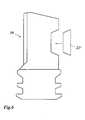
- Fig. 2
- shows the blade of
Fig.1 and the split line around the damaged region, where a single piece of a blade will be cut-out; - Fig. 3
- shows an arrangement for measuring the geometry of the cut-out piece of
Fig. 2 ; - Fig. 4
- is a representation of the CAD model of the 3-D article to be manufactured for replacing the cut-out piece;
- Fig. 5
- shows the principles of the recontouring process of the manufactured 3-D article, whereby additional information from the gas turbine component itself may be used;
- Fig. 6
- shows how the manufactured and recontoured 3-D article is inserted into the gas turbine component to be repaired;
- Fig. 7
- shows the post machining process after the 3-D article into component have been joined; and
- Fig.8
- shows in a process scheme various alternative routes of processing within the method of the invention.
- In general, the present invention comprises a method for repairing an ex-service gas turbine component by removing a damaged location, which method allows aright gap control, followed by replacing the respective location by a precisely fitting 3-D article. This 3-D article can be manufactured by additive manufacturing processes, such as selective laser melting (SLM), selective laser sintering (SLS), electron beam melting (EBM) or by standard methods, such as investment casting or machining process such as milling.
- The method starts with the damaged gas turbine component an example of which is shown in
Fig. 1 . Thegas turbine component 10 in this figure has the form of a turbine blade with anairfoil 11 and aroot 12. Thisgas turbine component 10 is damaged as it shows a damagedarea 13 at one of the edges of theairfoil 11. - As shown in
Fig. 2 the heavily damaged section orarea 13 on the ex-servicegas turbine component 10 is removed using a machining process, where the cut-out section will be available as one, single cut-out piece 15. Therefore, machining processes, such as electrical discharge machining (EDM), water jet, laser or plasma cutting are preferentially applied. With such machining processes the loss of material in thesplit line 14 between the cut-out piece 15 and thegas turbine component 10 can be reduced to a minimum. A milling or grinding process cannot be used, as no cut-out piece would be available. The machining process has preferably a marginal influence on the cutting area (no oxidation, small heat affected zone and low roughness). - After the machining process the cut-
out piece 15 including the damaged section (outer and inner contour) is measured using tactile or optical methods in order to obtain the actual, non-parametric geometry data set of this piece.Fig. 3 shows the respective optical ortactile measuring system 16, wherein anoptical scanning head 17 and/ortactile scanning head 18, which are controlled in their movement by acontrol 19, are used to pickup the non-parametric geometry data set of the cut-out piece 15. - Next, the damaged/missing areas are virtually re-build and potentially modified (e.g. by Reverse Engineering) allowing to create and/or modify and/or extend a final CAD model of the cut-
out piece 15, also called 3D article 20 (Fig. 4 ). The resulting CAD model of this3D article 20 includes the information about the inner surface, potential distortions, local wall thickness modifications and position of cooling air holes of the ex-service component. Anadditional material surcharge 21 is added around at least part of the split line to the geometry data set of the cut-out piece 15. This allows a compensation of the material loss due to cutting, preparation of split line surface and, if needed, also a final or individual adaptation of a standard 3D article geometry to the individual ex-servicegas turbine component 10 to be repaired. - Based on the CAD model of the 3-
D article 20 the reconditioning procedure continuous with the manufacturing of a real 3-D article (22 inFig. 5 ) For the related subsequent reconditioning chain three different approaches are generally possible: - The first variant generally allows the manufacturing of the 3-
D article 22 in form of a component of standard size without any additional information or measurement of the individual ex-servicegas turbine component 10 to be repaired. There is a standard material surcharge on the standard cut-out piece for compensation of the cutting process and for surface preparation for joining. Accordingly, no 3-D model or measurement of thegas turbine component 10 is used. The fixed thickness of material is removed during recontouring (see upper half ofFig. 5 , where amachining system 23 with amachining tool 24 intorespective control 25 are used for recontouring). - The second option would include a post machining (adaptive machining) of a standardized replacement article or "coupon" based on the individually scanned ex-service gas turbine component with aperture (see lower half of
Fig. 5 ), which is compared with the 3-D article geometry. In this case the gas turbine component orblade 10 to be repaired has to be individually scanned, or alternatively, a geometry data set based on the evaluation of a limited number of scanned blades is used. - The third alternative would ask for an individual scanning of each gas turbine component or
blade 10 to be repaired after removal of the damaged area in order to generate individual machine data sets for the additive manufacturing of respective 3-D articles. - The selection of the best suited variant strongly depends on the degree of deformation to be expected on the individual parts of a set of blades to be repaired.
Fig. 8 shows in a process scheme various alternative routes of processing within the method of the invention. The scheme begins with the start S that is the measurement of the cut-out piece 15. - Variant A is favoured, when the
gas turbine component 10 to be repaired has only low distortion and damages. In this case, a standard material surcharge on the standard cut-out piece is provided for compensation of cutting process and for surface preparation for joining. No 3-D model or measurement of the gas turbine component are necessary; a layer of fixed thickness is removed (A1). - Variant B is favoured, when the
gas turbine component 10 to be repaired has medium distortion and damages. In this case, a standard material surcharge on the cut-out piece is provided plus additional oversize for adaptive machining and for surface preparation for joining. When the joining process requires only a medium/low gap precision, a statistical evaluation of damages of components is used for the generation of a model and material removal with fixed thickness (B1). When the joining process requires a high gap precision, each component is measured and adaptive machining is applied (B2). - Variant C is favoured, when the
gas turbine component 10 has a high distortion and worn out locations. In this case, there is an individual manufacturing of the inserts with a material surcharge on the cut-out piece for compensation of the cutting process and for the surface preparation for joining. When the joining process requires only a low gap precision, either no 3-D model or measurement of the gas turbine component are necessary and a layer of fixed thickness is removed (C1), or a statistical evaluation of damages of components is used for the generation of a model and material removal with fixed thickness (C2). When the joining process requires a high gap precision, each component is measured and adaptive machining is applied (C3). - Based on the generated geometry data set of the cut-out piece, the
3D article 22 can be manufactured by an additive manufacturing technology, such as selective laser melting (SLM), selective laser sintering (SLS) or electron beam melting - (EBM). Also conventional methods, such as investment casting or milling can be used. The decision of the manufacturing technology also depends on the degree of deformation to be expected on the individual parts of a set of blades to be repaired.
- Before joining the manufactured 3-
D article 22 into the ex-servicegas turbine component 10, each 3-D article 22 needs to be recontoured to reach optimum conditions of the split line surface (e.g. roughness, gap geometry/tolerance) for the final joining process. Depending on the selected approach, the recontouring step can be done by removal of a fixed value (thickness) or by individual adaptive machining. For the recontouring a standard process is used, such as milling, grinding or electro chemical machining (ECM);Fig. 5 shows anexemplary machining system 23 for recontouring the manufactured 3-D article 22 into a recontoured 3-D article 22', with arotating machining tool 24 and arespective control 25. Besides the recontouring, other pre-joining processes (and chemical cleaning of the surfaces to be joined) may be needed depending on the manufacturing process, e.g. pre-heat treatments for improved weldability, stress relief heat treatments for 3D articles made by additive manufacturing technologies, etc.. - The joining of the manufactured 3D article into the ex-service
gas turbine component 10 can be realized with a standard and specifically adapted joining process, such as brazing or welding or a combination thereof. A final heat treatment and post machining (seeFig. 7 ) is carried out at the end of the reconditioning chain. - The advantages of the invention over the known technologies are:
- No measurement of the whole component to get the information about the ex-service influence such as distortion, depending on approach.
- No CAD model of the whole component is required.
- No parametric CAD model of the 3D article (cut-out piece) is required.
- Characteristic issues/information of the cut-out piece due to service and new manufacturing are covered with the scan of the cut-out piece.
- Cost and scrap rate reduction.
- Flexibility and productivity are improved.
- Extended repair to highly loaded areas.
- 10
- gas turbine component (e.g. turbine blade)
- 11
- airfoil
- 12
- root
- 13
- damaged section
- 14
- split line
- 15
- cut-out piece
- 16
- measuring system (optical or tactile)
- 17
- optical scanning head
- 18
- tactile scanning head
- 19
- control
- 20
- 3-D article (data set)
- 21
- material surcharge
- 22
- 3-D article (manufactured)
- 22'
- 3-D article (recontoured)
- 23
- machining system
- 24
- machining tool
- 25
- control
- S
- start
- A,B,C
- repair process requirement
- A1,B1,B2
- repair process requirement
- C1,C2,C3
- repair process requirement
Claims (15)
- A method for repairing an ex-service gas turbine component (10) comprising the steps of: removing a damaged section (13) from said gas turbine component (10), manufacturing a 3-D article (22), which fits in said gas turbine component (10) to replace the removed damaged section (13), and joining said gas turbine component (10) and said 3-D article (22) inserted therein,characterised in that the damaged section (13) is removed in form of a cut-out section along a split line (14) as one single cut-out piece (15), that the cut-out piece (15) is measured to obtain the actual non-parametric geometry data set of the cut-out piece (15), that an additional material surcharge (21) is added around at least part of the split line (14) to the geometry data set of the cut-out piece (15) to allow for a compensation of the material loss due to cutting and/or the preparation of a split line surface and/or a final or individual adaptation of a standard 3-D article geometry to the individual ex-service gas turbine component (10) to be repaired, and that said 3-D article (22) is manufactured based on said geometry data set of the cut-out piece (15).
- A method according to claim 1,characterised in that a virtual 3-D article (20) in form of a CAD model is created from said measured geometry data.
- A method according to claim 2,characterised in that damaged or missing areas of the cut-out piece (15) are virtually rebuild to create and/or modify and/or extend said CAD model.
- A method according to claim 2 or 3,characterised in that the CAD model includes information about the inner surface, potential distortions, local wall thickness modifications and positions of cooling air holes of the ex-service gas turbine component (10).
- A method according to one of the claims 1 to 4,characterised in that the 3-D article (22) is manufactured by an additive manufacturing technology such as selective laser melting (SLM), selective laser sintering (SLS) or electron beam melting (EBM).
- A method according to one of the claims 1 to 4,characterised in that the 3-D article (22) is manufactured by investment casting or milling.
- A method according to one of the claims 1 to 6,characterised in that before joining the manufactured 3-D article (22) into the ex-service gas turbine component (10), the manufactured 3-D article (22) is recontoured into a recontoured 3-D article (22') to reach optimum conditions of the split line surface and/or gap width for the final joining process.
- A method according to claim 7,characterised in that the recontouring is done by removal of a fixed thickness of material.
- A method according to claim 7,characterised in that the recontouring is done by individual adaptive machining.
- A method according to claim 9,characterised in that the adaptive machining is based on the individually scanned ex-service gas turbine component (10), which is compared with the 3-D article geometry.
- A method according to claim 9,characterised in that the adaptive machining uses a geometry data set based on the evaluation of a limited number of scanned gas turbine components of the same kind.
- A method according to one of the claims 7 to 11,characterised in that the recontouring process is done by a subtractive machining process, such as milling, grinding or electro chemical machining (ECM).
- A method according to one of the claims 7 to 12,characterised in that, further to the recontouring, other pre-joining processes are applied to the 3-D article (22, 22') to make the 3-D article (22, 22') ready for insertion.
- A method according to claim 13,characterised in that the pre-joining processes include a heat treatment and/or chemical cleaning of the surfaces.
- A method according to one of the claims 1 to 14,characterised in that the joining of said gas turbine component (10) and said 3-D article (22) is done by brazing or welding or a combination thereof.
Applications Claiming Priority (1)
| Application Number | Priority Date | Filing Date | Title |
|---|---|---|---|
| US25639909P | 2009-10-30 | 2009-10-30 |
Publications (3)
| Publication Number | Publication Date |
|---|---|
| EP2317075A2 EP2317075A2 (en) | 2011-05-04 |
| EP2317075A3 EP2317075A3 (en) | 2011-08-24 |
| EP2317075B1true EP2317075B1 (en) | 2013-01-02 |
Family
ID=43530819
Family Applications (1)
| Application Number | Title | Priority Date | Filing Date |
|---|---|---|---|
| EP10186347AActiveEP2317075B1 (en) | 2009-10-30 | 2010-10-04 | Method for repairing a gas turbine component |
Country Status (4)
| Country | Link |
|---|---|
| US (1) | US20110099810A1 (en) |
| EP (1) | EP2317075B1 (en) |
| CA (1) | CA2717830C (en) |
| ES (1) | ES2402257T3 (en) |
Cited By (3)
| Publication number | Priority date | Publication date | Assignee | Title |
|---|---|---|---|---|
| US10583490B2 (en) | 2017-07-20 | 2020-03-10 | General Electric Company | Methods for preparing a hybrid article |
| DE102020212006A1 (en) | 2020-09-24 | 2022-03-24 | Siemens Energy Global GmbH & Co. KG | Method of repairing a damaged leading or trailing edge area of a metallic turbine blade |
| WO2024094458A1 (en)* | 2022-11-04 | 2024-05-10 | Gkn Aerospace Sweden Ab | Blade repair method of an integrally bladed rotor |
Families Citing this family (48)
| Publication number | Priority date | Publication date | Assignee | Title |
|---|---|---|---|---|
| EP2319641B1 (en)* | 2009-10-30 | 2017-07-19 | Ansaldo Energia IP UK Limited | Method to apply multiple materials with selective laser melting on a 3D article |
| US8651393B2 (en)* | 2010-03-26 | 2014-02-18 | Holland, L.P. | Repair insert for repairing metallic structure |
| US9508047B2 (en)* | 2010-12-06 | 2016-11-29 | The Boeing Company | Rapid rework analysis system |
| CH704448A1 (en)* | 2011-02-03 | 2012-08-15 | Alstom Technology Ltd | A method of repairing or reconditioning of heavily damaged component, in particular from the hot gas area of a gas turbine. |
| US8438915B2 (en)* | 2011-08-29 | 2013-05-14 | United Technologies Corporation | Insert assembly and method for fluid flow reverse engineering |
| US9145792B2 (en) | 2012-01-31 | 2015-09-29 | General Electric Company | Fixture assembly for repairing a shroud tile of a gas turbine |
| US9206702B2 (en) | 2012-01-31 | 2015-12-08 | General Electric Company | Method for repairing a shroud tile of a gas turbine |
| US20140003923A1 (en) | 2012-07-02 | 2014-01-02 | Peter Finnigan | Functionally graded composite fan containment case |
| US11110648B2 (en) | 2012-07-31 | 2021-09-07 | Makerbot Industries, Llc | Build material switching |
| US9399322B2 (en) | 2012-08-08 | 2016-07-26 | Makerbot Industries, Llc | Three dimensional printer with removable, replaceable print nozzle |
| US9700941B2 (en)* | 2012-10-03 | 2017-07-11 | Siemens Energy, Inc. | Method for repairing a component for use in a turbine engine |
| US9863249B2 (en)* | 2012-12-04 | 2018-01-09 | Siemens Energy, Inc. | Pre-sintered preform repair of turbine blades |
| US9174312B2 (en) | 2013-03-12 | 2015-11-03 | Honeywell International Inc. | Methods for the repair of gas turbine engine components using additive manufacturing techniques |
| EP2781691A1 (en)* | 2013-03-19 | 2014-09-24 | Alstom Technology Ltd | Method for reconditioning a hot gas path part of a gas turbine |
| US9346145B2 (en)* | 2013-03-27 | 2016-05-24 | Av & R Vision And Robotics Inc | Apparatus and method for blending added material with base material on a manufactured component |
| EP2823952A1 (en)* | 2013-07-09 | 2015-01-14 | Siemens Aktiengesellschaft | Adaptation method and production method for components produced by means of SLM |
| US20150047168A1 (en)* | 2013-08-13 | 2015-02-19 | Allister William James | Repair chain for turbomachinery components using additive manufacturing technology |
| US9574447B2 (en) | 2013-09-11 | 2017-02-21 | General Electric Company | Modification process and modified article |
| EP3058175B1 (en)* | 2013-09-26 | 2019-06-19 | United Technologies Corporation | Balanced rotating component for a gas turbine engine |
| US9798839B2 (en) | 2013-11-11 | 2017-10-24 | General Electric Company | System and methods of generating a computer model of a component |
| CN106413943A (en)* | 2013-11-22 | 2017-02-15 | 霍加纳斯股份有限公司 | Preforms for brazing |
| EP2881205A1 (en)* | 2013-12-04 | 2015-06-10 | Alstom Technology Ltd | Method for manufacturing a braze joint gap and method for brazing or soldering |
| GB2541575B (en)* | 2014-06-04 | 2021-06-09 | Mitsubishi Power Ltd | Additive manufacturing system, modeling-data providing apparatus and providing method |
| US11047398B2 (en) | 2014-08-05 | 2021-06-29 | Energy Recovery, Inc. | Systems and methods for repairing fluid handling equipment |
| US10252380B2 (en) | 2014-09-10 | 2019-04-09 | Mechanical Dynamics & Analysis Llc | Repair or remanufacture of blade platform for a gas turbine engine |
| US9828857B2 (en) | 2014-09-10 | 2017-11-28 | Pw Power Systems, Inc. | Repaired or remanufactured blade platform for a gas turbine engine |
| DE102014224410A1 (en)* | 2014-11-28 | 2016-06-02 | Siemens Aktiengesellschaft | SX repair via AM coupon |
| DE102014226055A1 (en)* | 2014-12-16 | 2016-06-16 | Siemens Aktiengesellschaft | Method for repairing damage to a turbine blade |
| DE102015105999B4 (en)* | 2015-04-20 | 2016-11-10 | Walter Maschinenbau Gmbh | Method and device for material-removing machining of a tool |
| ITUA20161718A1 (en)* | 2016-03-16 | 2017-09-16 | Nuovo Pignone Tecnologie Srl | Repair part for a blade assembly of a gas turbine and method for repairing a damaged blade of a blade assembly of a gas turbine |
| GB201607462D0 (en)* | 2016-04-29 | 2016-06-15 | Rolls Royce Plc | Adaptive repair method for aerofoil blades |
| EP3458210A1 (en) | 2016-05-18 | 2019-03-27 | General Electric Company | Component and method of forming a component |
| US10260349B2 (en)* | 2016-10-12 | 2019-04-16 | General Electric Company | Tubine blade and related method of forming |
| ES2870479T3 (en) | 2016-11-11 | 2021-10-27 | Airbus Operations Gmbh | Method for reconditioning a damaged part of a component and insert for it |
| CN109963685B (en)* | 2016-11-16 | 2022-04-29 | 康明斯有限公司 | System and method for adding material to castings |
| US20180147655A1 (en)* | 2016-11-30 | 2018-05-31 | Arcam Ab | Additive manufacturing of three-dimensional articles |
| US20180187564A1 (en)* | 2017-01-04 | 2018-07-05 | General Electric Company | Structure braze of hard-to-weld superalloy components using diffusion alloy insert |
| US20180216464A1 (en)* | 2017-01-31 | 2018-08-02 | General Electric Company | Method of repairing a blisk |
| US11224915B2 (en)* | 2017-06-05 | 2022-01-18 | General Electric Company | Method of repairing a component using an additive manufacture replacement coupon, and alloy for additive manufacturing |
| DE102018102903A1 (en) | 2018-02-09 | 2019-08-14 | Otto Fuchs - Kommanditgesellschaft - | Method for producing a structural component from a high-strength alloy material |
| EP3594446B1 (en) | 2018-07-13 | 2021-10-20 | ANSALDO ENERGIA S.p.A. | Method of restoring a blade or vane platform |
| WO2021021232A1 (en) | 2019-07-30 | 2021-02-04 | Siemens Energy, Inc. | System and method for repairing high-temperature gas turbine blades |
| CN112372247A (en)* | 2020-11-03 | 2021-02-19 | 哈动国家水力发电设备工程技术研究中心有限公司 | Transformation method of impulse turbine runner |
| FR3119647B1 (en)* | 2021-02-11 | 2023-01-13 | Safran Aircraft Engines | Turbomachine rotor flange repair process |
| DE102021118371A1 (en)* | 2021-07-15 | 2023-01-19 | Lufthansa Technik Aktiengesellschaft | Method for supporting the processing of damage to a blading of a turbomachine, in particular a jet engine, computer program product and system |
| CN116274969A (en)* | 2023-01-09 | 2023-06-23 | 国铭铸管股份有限公司 | As-cast defect repair process and application thereof in ductile iron casting repair |
| US20250020062A1 (en)* | 2023-07-14 | 2025-01-16 | Raytheon Technologies Corporation | Localized rework using directed energy deposition |
| WO2025094388A1 (en)* | 2023-11-02 | 2025-05-08 | 株式会社ニコン | Information processing method and blade repair method |
Family Cites Families (47)
| Publication number | Priority date | Publication date | Assignee | Title |
|---|---|---|---|---|
| US3970319A (en)* | 1972-11-17 | 1976-07-20 | General Motors Corporation | Seal structure |
| US4323756A (en)* | 1979-10-29 | 1982-04-06 | United Technologies Corporation | Method for fabricating articles by sequential layer deposition |
| US4595637A (en)* | 1981-11-17 | 1986-06-17 | United Technologies Corporation | Plasma coatings comprised of sprayed fibers |
| JPS60238489A (en)* | 1984-05-12 | 1985-11-27 | Daiki Gomme Kogyo Kk | Formatin of metallic coating layer on surface |
| US4968383A (en)* | 1985-06-18 | 1990-11-06 | The Dow Chemical Company | Method for molding over a preform |
| DE3832351A1 (en)* | 1988-09-23 | 1990-04-05 | Schock & Co Gmbh | COMPONENT, IN PARTICULAR BUILT-IN COIL AND METHOD FOR THE PRODUCTION THEREOF |
| US5876550A (en)* | 1988-10-05 | 1999-03-02 | Helisys, Inc. | Laminated object manufacturing apparatus and method |
| US5038014A (en)* | 1989-02-08 | 1991-08-06 | General Electric Company | Fabrication of components by layered deposition |
| US5047966A (en)* | 1989-05-22 | 1991-09-10 | Airfoil Textron Inc. | Airfoil measurement method |
| US5121329A (en)* | 1989-10-30 | 1992-06-09 | Stratasys, Inc. | Apparatus and method for creating three-dimensional objects |
| US5269057A (en) | 1991-12-24 | 1993-12-14 | Freedom Forge Corporation | Method of making replacement airfoil components |
| DE4432685C1 (en)* | 1994-09-14 | 1995-11-23 | Mtu Muenchen Gmbh | Starting cover for turbo=machine casing |
| US5900170A (en)* | 1995-05-01 | 1999-05-04 | United Technologies Corporation | Containerless method of producing crack free metallic articles by energy beam deposition with reduced power density |
| DE19642980C1 (en)* | 1996-10-18 | 1998-08-13 | Mtu Muenchen Gmbh | Procedure for repairing worn blade tips of compressor and turbine blades |
| US6144008A (en)* | 1996-11-22 | 2000-11-07 | Rabinovich; Joshua E. | Rapid manufacturing system for metal, metal matrix composite materials and ceramics |
| DE19649865C1 (en) | 1996-12-02 | 1998-02-12 | Fraunhofer Ges Forschung | Shaped body especially prototype or replacement part production |
| US6355086B2 (en) | 1997-08-12 | 2002-03-12 | Rolls-Royce Corporation | Method and apparatus for making components by direct laser processing |
| US6057047A (en)* | 1997-11-18 | 2000-05-02 | United Technologies Corporation | Ceramic coatings containing layered porosity |
| US6203861B1 (en)* | 1998-01-12 | 2001-03-20 | University Of Central Florida | One-step rapid manufacturing of metal and composite parts |
| US6064031A (en)* | 1998-03-20 | 2000-05-16 | Mcdonnell Douglas Corporation | Selective metal matrix composite reinforcement by laser deposition |
| US6733907B2 (en)* | 1998-03-27 | 2004-05-11 | Siemens Westinghouse Power Corporation | Hybrid ceramic material composed of insulating and structural ceramic layers |
| US6583381B1 (en)* | 1999-05-24 | 2003-06-24 | Potomac Photonics, Inc. | Apparatus for fabrication of miniature structures |
| DE19928245B4 (en)* | 1999-06-21 | 2006-02-09 | Eos Gmbh Electro Optical Systems | Device for supplying powder for a laser sintering device |
| US6811744B2 (en) | 1999-07-07 | 2004-11-02 | Optomec Design Company | Forming structures from CAD solid models |
| DE19935274C1 (en)* | 1999-07-27 | 2001-01-25 | Fraunhofer Ges Forschung | Apparatus for producing components made of a material combination has a suction and blowing device for removing material from the processing surface, and a feed device for a further material |
| ATE420272T1 (en)* | 1999-12-20 | 2009-01-15 | Sulzer Metco Ag | PROFILED SURFACE USED AS A SCRUB COATING IN FLOW MACHINES |
| US6365222B1 (en)* | 2000-10-27 | 2002-04-02 | Siemens Westinghouse Power Corporation | Abradable coating applied with cold spray technique |
| US6508000B2 (en)* | 2001-02-08 | 2003-01-21 | Siemens Westinghouse Power Corporation | Transient liquid phase bonding repair for advanced turbine blades and vanes |
| US6575702B2 (en)* | 2001-10-22 | 2003-06-10 | General Electric Company | Airfoils with improved strength and manufacture and repair thereof |
| US20030082297A1 (en)* | 2001-10-26 | 2003-05-01 | Siemens Westinghouse Power Corporation | Combustion turbine blade tip restoration by metal build-up using thermal spray techniques |
| DE10219983B4 (en) | 2002-05-03 | 2004-03-18 | Bego Medical Ag | Process for manufacturing products using free-form laser sintering |
| US6838157B2 (en)* | 2002-09-23 | 2005-01-04 | Siemens Westinghouse Power Corporation | Method and apparatus for instrumenting a gas turbine component having a barrier coating |
| US6912446B2 (en)* | 2002-10-23 | 2005-06-28 | General Electric Company | Systems and methods for automated sensing and machining for repairing airfoils of blades |
| US6887528B2 (en)* | 2002-12-17 | 2005-05-03 | General Electric Company | High temperature abradable coatings |
| US6839607B2 (en)* | 2003-01-09 | 2005-01-04 | The Boeing Company | System for rapid manufacturing of replacement aerospace parts |
| US6916529B2 (en)* | 2003-01-09 | 2005-07-12 | General Electric Company | High temperature, oxidation-resistant abradable coatings containing microballoons and method for applying same |
| DE10319494A1 (en)* | 2003-04-30 | 2004-11-18 | Mtu Aero Engines Gmbh | Process for repairing and / or modifying components of a gas turbine |
| DE10334698A1 (en)* | 2003-07-25 | 2005-02-10 | Rolls-Royce Deutschland Ltd & Co Kg | Shroud segment for a turbomachine |
| US20050123785A1 (en)* | 2003-12-04 | 2005-06-09 | Purusottam Sahoo | High temperature clearance coating |
| US20070141375A1 (en)* | 2005-12-20 | 2007-06-21 | Budinger David E | Braze cladding for direct metal laser sintered materials |
| JP2007278995A (en)* | 2006-04-12 | 2007-10-25 | Toshiba Corp | 3D shape measuring method and 3D shape measuring apparatus |
| US7686570B2 (en)* | 2006-08-01 | 2010-03-30 | Siemens Energy, Inc. | Abradable coating system |
| DE102006049218A1 (en) | 2006-10-18 | 2008-04-30 | Mtu Aero Engines Gmbh | Method for producing a gas turbine component |
| US8691329B2 (en)* | 2007-01-31 | 2014-04-08 | General Electric Company | Laser net shape manufacturing using an adaptive toolpath deposition method |
| US20080182017A1 (en)* | 2007-01-31 | 2008-07-31 | General Electric Company | Laser net shape manufacturing and repair using a medial axis toolpath deposition method |
| US8578579B2 (en)* | 2007-12-11 | 2013-11-12 | General Electric Company | System and method for adaptive machining |
| US8309197B2 (en)* | 2008-12-17 | 2012-11-13 | Teledyne Scientific & Imaging, Llc | Integral abradable seals |
- 2010
- 2010-10-04EPEP10186347Apatent/EP2317075B1/enactiveActive
- 2010-10-04ESES10186347Tpatent/ES2402257T3/enactiveActive
- 2010-10-15CACA2717830Apatent/CA2717830C/ennot_activeExpired - Fee Related
- 2010-10-29USUS12/916,032patent/US20110099810A1/ennot_activeAbandoned
Cited By (5)
| Publication number | Priority date | Publication date | Assignee | Title |
|---|---|---|---|---|
| US10583490B2 (en) | 2017-07-20 | 2020-03-10 | General Electric Company | Methods for preparing a hybrid article |
| DE102020212006A1 (en) | 2020-09-24 | 2022-03-24 | Siemens Energy Global GmbH & Co. KG | Method of repairing a damaged leading or trailing edge area of a metallic turbine blade |
| WO2022063475A1 (en) | 2020-09-24 | 2022-03-31 | Siemens Energy Global GmbH & Co. KG | Method for repairing a damaged leading or trailing edge region of a metallic turbine blade |
| US11958150B2 (en) | 2020-09-24 | 2024-04-16 | Siemens Energy Global GmbH & Co. KG | Method for repairing a damaged leading or trailing edge region of a metallic turbine blade |
| WO2024094458A1 (en)* | 2022-11-04 | 2024-05-10 | Gkn Aerospace Sweden Ab | Blade repair method of an integrally bladed rotor |
Also Published As
| Publication number | Publication date |
|---|---|
| US20110099810A1 (en) | 2011-05-05 |
| EP2317075A2 (en) | 2011-05-04 |
| CA2717830C (en) | 2016-03-29 |
| ES2402257T3 (en) | 2013-04-30 |
| CA2717830A1 (en) | 2011-04-30 |
| EP2317075A3 (en) | 2011-08-24 |
Similar Documents
| Publication | Publication Date | Title |
|---|---|---|
| EP2317075B1 (en) | Method for repairing a gas turbine component | |
| EP2317076B1 (en) | A method for repairing a gas turbine component | |
| Jiménez et al. | Powder-based laser hybrid additive manufacturing of metals: a review | |
| CA2766423C (en) | Method for repairing or reconditioning a badly damaged component, in particular from the hot gas region of a gas turbine | |
| US10583490B2 (en) | Methods for preparing a hybrid article | |
| US9879535B2 (en) | Laser net shape manufactured component using an adaptive toolpath deposition method | |
| US9670782B2 (en) | Method for creating a blade for a flow engine and blade for a flow force engine | |
| EP2495397B1 (en) | Methods for repairing turbine components | |
| JP7208346B2 (en) | Additive manufacturing system and method for generating a CAD model for additive printing on a workpiece | |
| US20080182017A1 (en) | Laser net shape manufacturing and repair using a medial axis toolpath deposition method | |
| EP3585534A1 (en) | Method of manufacturing turbine airfoil with open tip casting and tip component thereof | |
| EP2949418B1 (en) | Method for repairing a turbine blade tip | |
| JP2006524579A (en) | Method for repairing and / or modifying gas turbine components | |
| CA2731756A1 (en) | Method for repairing and/or upgrading a component, especially of a gas turbine | |
| US20180371922A1 (en) | Composite turbomachine component and related methods of manufacture and repair | |
| EP1952917A2 (en) | A method of manufacturing a component by consolidating powder material | |
| EP4335566A1 (en) | Additively manufacturing using ct scan data | |
| EP3663878A1 (en) | Method of designing an intermediate product, computer pro-gram product, method of additive manufacturing, method of manufacturing a component and a corresponding component | |
| EP4527544A2 (en) | Methods for joining components at narrow, uniform braze joints | |
| KR20190143797A (en) | Turbomachine component with coating-capturing feature for thermal insulation |
Legal Events
| Date | Code | Title | Description |
|---|---|---|---|
| PUAI | Public reference made under article 153(3) epc to a published international application that has entered the european phase | Free format text:ORIGINAL CODE: 0009012 | |
| AK | Designated contracting states | Kind code of ref document:A2 Designated state(s):AL AT BE BG CH CY CZ DE DK EE ES FI FR GB GR HR HU IE IS IT LI LT LU LV MC MK MT NL NO PL PT RO RS SE SI SK SM TR | |
| AX | Request for extension of the european patent | Extension state:BA ME | |
| PUAL | Search report despatched | Free format text:ORIGINAL CODE: 0009013 | |
| AK | Designated contracting states | Kind code of ref document:A3 Designated state(s):AL AT BE BG CH CY CZ DE DK EE ES FI FR GB GR HR HU IE IS IT LI LT LU LV MC MK MT NL NO PL PT RO RS SE SI SK SM TR | |
| AX | Request for extension of the european patent | Extension state:BA ME | |
| RIC1 | Information provided on ipc code assigned before grant | Ipc:B23P 6/00 20060101ALI20110720BHEP Ipc:B22F 5/04 20060101ALI20110720BHEP Ipc:B23K 26/34 20060101ALI20110720BHEP Ipc:F01D 5/00 20060101AFI20110720BHEP | |
| 17P | Request for examination filed | Effective date:20120214 | |
| GRAP | Despatch of communication of intention to grant a patent | Free format text:ORIGINAL CODE: EPIDOSNIGR1 | |
| GRAS | Grant fee paid | Free format text:ORIGINAL CODE: EPIDOSNIGR3 | |
| GRAA | (expected) grant | Free format text:ORIGINAL CODE: 0009210 | |
| AK | Designated contracting states | Kind code of ref document:B1 Designated state(s):AL AT BE BG CH CY CZ DE DK EE ES FI FR GB GR HR HU IE IS IT LI LT LU LV MC MK MT NL NO PL PT RO RS SE SI SK SM TR | |
| REG | Reference to a national code | Ref country code:GB Ref legal event code:FG4D | |
| REG | Reference to a national code | Ref country code:AT Ref legal event code:REF Ref document number:591743 Country of ref document:AT Kind code of ref document:T Effective date:20130115 Ref country code:CH Ref legal event code:EP | |
| REG | Reference to a national code | Ref country code:IE Ref legal event code:FG4D | |
| REG | Reference to a national code | Ref country code:DE Ref legal event code:R096 Ref document number:602010004407 Country of ref document:DE Effective date:20130228 | |
| REG | Reference to a national code | Ref country code:ES Ref legal event code:FG2A Ref document number:2402257 Country of ref document:ES Kind code of ref document:T3 Effective date:20130430 | |
| REG | Reference to a national code | Ref country code:AT Ref legal event code:MK05 Ref document number:591743 Country of ref document:AT Kind code of ref document:T Effective date:20130102 Ref country code:NL Ref legal event code:T3 | |
| PG25 | Lapsed in a contracting state [announced via postgrant information from national office to epo] | Ref country code:SI Free format text:LAPSE BECAUSE OF FAILURE TO SUBMIT A TRANSLATION OF THE DESCRIPTION OR TO PAY THE FEE WITHIN THE PRESCRIBED TIME-LIMIT Effective date:20130102 | |
| REG | Reference to a national code | Ref country code:LT Ref legal event code:MG4D | |
| PG25 | Lapsed in a contracting state [announced via postgrant information from national office to epo] | Ref country code:LT Free format text:LAPSE BECAUSE OF FAILURE TO SUBMIT A TRANSLATION OF THE DESCRIPTION OR TO PAY THE FEE WITHIN THE PRESCRIBED TIME-LIMIT Effective date:20130102 Ref country code:CZ Free format text:LAPSE BECAUSE OF FAILURE TO SUBMIT A TRANSLATION OF THE DESCRIPTION OR TO PAY THE FEE WITHIN THE PRESCRIBED TIME-LIMIT Effective date:20130102 Ref country code:SE Free format text:LAPSE BECAUSE OF FAILURE TO SUBMIT A TRANSLATION OF THE DESCRIPTION OR TO PAY THE FEE WITHIN THE PRESCRIBED TIME-LIMIT Effective date:20130102 Ref country code:IS Free format text:LAPSE BECAUSE OF FAILURE TO SUBMIT A TRANSLATION OF THE DESCRIPTION OR TO PAY THE FEE WITHIN THE PRESCRIBED TIME-LIMIT Effective date:20130502 Ref country code:BG Free format text:LAPSE BECAUSE OF FAILURE TO SUBMIT A TRANSLATION OF THE DESCRIPTION OR TO PAY THE FEE WITHIN THE PRESCRIBED TIME-LIMIT Effective date:20130402 Ref country code:AT Free format text:LAPSE BECAUSE OF FAILURE TO SUBMIT A TRANSLATION OF THE DESCRIPTION OR TO PAY THE FEE WITHIN THE PRESCRIBED TIME-LIMIT Effective date:20130102 Ref country code:NO Free format text:LAPSE BECAUSE OF FAILURE TO SUBMIT A TRANSLATION OF THE DESCRIPTION OR TO PAY THE FEE WITHIN THE PRESCRIBED TIME-LIMIT Effective date:20130402 | |
| PG25 | Lapsed in a contracting state [announced via postgrant information from national office to epo] | Ref country code:LV Free format text:LAPSE BECAUSE OF FAILURE TO SUBMIT A TRANSLATION OF THE DESCRIPTION OR TO PAY THE FEE WITHIN THE PRESCRIBED TIME-LIMIT Effective date:20130102 Ref country code:PL Free format text:LAPSE BECAUSE OF FAILURE TO SUBMIT A TRANSLATION OF THE DESCRIPTION OR TO PAY THE FEE WITHIN THE PRESCRIBED TIME-LIMIT Effective date:20130102 Ref country code:FI Free format text:LAPSE BECAUSE OF FAILURE TO SUBMIT A TRANSLATION OF THE DESCRIPTION OR TO PAY THE FEE WITHIN THE PRESCRIBED TIME-LIMIT Effective date:20130102 Ref country code:GR Free format text:LAPSE BECAUSE OF FAILURE TO SUBMIT A TRANSLATION OF THE DESCRIPTION OR TO PAY THE FEE WITHIN THE PRESCRIBED TIME-LIMIT Effective date:20130403 Ref country code:PT Free format text:LAPSE BECAUSE OF FAILURE TO SUBMIT A TRANSLATION OF THE DESCRIPTION OR TO PAY THE FEE WITHIN THE PRESCRIBED TIME-LIMIT Effective date:20130502 | |
| PG25 | Lapsed in a contracting state [announced via postgrant information from national office to epo] | Ref country code:HR Free format text:LAPSE BECAUSE OF FAILURE TO SUBMIT A TRANSLATION OF THE DESCRIPTION OR TO PAY THE FEE WITHIN THE PRESCRIBED TIME-LIMIT Effective date:20130102 Ref country code:RS Free format text:LAPSE BECAUSE OF FAILURE TO SUBMIT A TRANSLATION OF THE DESCRIPTION OR TO PAY THE FEE WITHIN THE PRESCRIBED TIME-LIMIT Effective date:20130102 | |
| PG25 | Lapsed in a contracting state [announced via postgrant information from national office to epo] | Ref country code:DK Free format text:LAPSE BECAUSE OF FAILURE TO SUBMIT A TRANSLATION OF THE DESCRIPTION OR TO PAY THE FEE WITHIN THE PRESCRIBED TIME-LIMIT Effective date:20130102 Ref country code:RO Free format text:LAPSE BECAUSE OF FAILURE TO SUBMIT A TRANSLATION OF THE DESCRIPTION OR TO PAY THE FEE WITHIN THE PRESCRIBED TIME-LIMIT Effective date:20130102 Ref country code:EE Free format text:LAPSE BECAUSE OF FAILURE TO SUBMIT A TRANSLATION OF THE DESCRIPTION OR TO PAY THE FEE WITHIN THE PRESCRIBED TIME-LIMIT Effective date:20130102 Ref country code:SK Free format text:LAPSE BECAUSE OF FAILURE TO SUBMIT A TRANSLATION OF THE DESCRIPTION OR TO PAY THE FEE WITHIN THE PRESCRIBED TIME-LIMIT Effective date:20130102 | |
| PLBE | No opposition filed within time limit | Free format text:ORIGINAL CODE: 0009261 | |
| STAA | Information on the status of an ep patent application or granted ep patent | Free format text:STATUS: NO OPPOSITION FILED WITHIN TIME LIMIT | |
| PG25 | Lapsed in a contracting state [announced via postgrant information from national office to epo] | Ref country code:CY Free format text:LAPSE BECAUSE OF FAILURE TO SUBMIT A TRANSLATION OF THE DESCRIPTION OR TO PAY THE FEE WITHIN THE PRESCRIBED TIME-LIMIT Effective date:20130102 | |
| 26N | No opposition filed | Effective date:20131003 | |
| REG | Reference to a national code | Ref country code:DE Ref legal event code:R097 Ref document number:602010004407 Country of ref document:DE Effective date:20131003 | |
| PG25 | Lapsed in a contracting state [announced via postgrant information from national office to epo] | Ref country code:MC Free format text:LAPSE BECAUSE OF FAILURE TO SUBMIT A TRANSLATION OF THE DESCRIPTION OR TO PAY THE FEE WITHIN THE PRESCRIBED TIME-LIMIT Effective date:20130102 | |
| PG25 | Lapsed in a contracting state [announced via postgrant information from national office to epo] | Ref country code:SM Free format text:LAPSE BECAUSE OF FAILURE TO SUBMIT A TRANSLATION OF THE DESCRIPTION OR TO PAY THE FEE WITHIN THE PRESCRIBED TIME-LIMIT Effective date:20130102 | |
| PG25 | Lapsed in a contracting state [announced via postgrant information from national office to epo] | Ref country code:TR Free format text:LAPSE BECAUSE OF FAILURE TO SUBMIT A TRANSLATION OF THE DESCRIPTION OR TO PAY THE FEE WITHIN THE PRESCRIBED TIME-LIMIT Effective date:20130102 | |
| PG25 | Lapsed in a contracting state [announced via postgrant information from national office to epo] | Ref country code:HU Free format text:LAPSE BECAUSE OF FAILURE TO SUBMIT A TRANSLATION OF THE DESCRIPTION OR TO PAY THE FEE WITHIN THE PRESCRIBED TIME-LIMIT; INVALID AB INITIO Effective date:20101004 Ref country code:MK Free format text:LAPSE BECAUSE OF FAILURE TO SUBMIT A TRANSLATION OF THE DESCRIPTION OR TO PAY THE FEE WITHIN THE PRESCRIBED TIME-LIMIT Effective date:20130102 Ref country code:LU Free format text:LAPSE BECAUSE OF NON-PAYMENT OF DUE FEES Effective date:20131004 | |
| PG25 | Lapsed in a contracting state [announced via postgrant information from national office to epo] | Ref country code:MT Free format text:LAPSE BECAUSE OF FAILURE TO SUBMIT A TRANSLATION OF THE DESCRIPTION OR TO PAY THE FEE WITHIN THE PRESCRIBED TIME-LIMIT Effective date:20130102 | |
| REG | Reference to a national code | Ref country code:FR Ref legal event code:PLFP Year of fee payment:6 | |
| REG | Reference to a national code | Ref country code:CH Ref legal event code:PFA Owner name:GENERAL ELECTRIC TECHNOLOGY GMBH, CH Free format text:FORMER OWNER: ALSTOM TECHNOLOGY LTD, CH | |
| REG | Reference to a national code | Ref country code:DE Ref legal event code:R081 Ref document number:602010004407 Country of ref document:DE Owner name:GENERAL ELECTRIC TECHNOLOGY GMBH, CH Free format text:FORMER OWNER: ALSTOM TECHNOLOGY LTD., BADEN, CH Ref country code:DE Ref legal event code:R081 Ref document number:602010004407 Country of ref document:DE Owner name:ANSALDO ENERGIA IP UK LIMITED, GB Free format text:FORMER OWNER: ALSTOM TECHNOLOGY LTD., BADEN, CH | |
| REG | Reference to a national code | Ref country code:FR Ref legal event code:PLFP Year of fee payment:7 | |
| REG | Reference to a national code | Ref country code:ES Ref legal event code:PC2A Owner name:GENERAL ELECTRIC TECHNOLOGY GMBH Effective date:20161021 | |
| REG | Reference to a national code | Ref country code:NL Ref legal event code:HC Owner name:GENERAL ELECTRIC TECHNOLOGY GMBH; CH Free format text:DETAILS ASSIGNMENT: VERANDERING VAN EIGENAAR(S), VERANDERING VAN NAAM VAN DE EIGENAAR(S); FORMER OWNER NAME: ALSTOM TECHNOLOGY LTD Effective date:20161006 | |
| REG | Reference to a national code | Ref country code:FR Ref legal event code:CD Owner name:ALSTOM TECHNOLOGY LTD, CH Effective date:20161110 | |
| PGFP | Annual fee paid to national office [announced via postgrant information from national office to epo] | Ref country code:CH Payment date:20161020 Year of fee payment:7 Ref country code:IE Payment date:20161021 Year of fee payment:7 | |
| PGFP | Annual fee paid to national office [announced via postgrant information from national office to epo] | Ref country code:BE Payment date:20161019 Year of fee payment:7 | |
| REG | Reference to a national code | Ref country code:CH Ref legal event code:PUE Owner name:ANSALDO ENERGIA IP UK LIMITED, GB Free format text:FORMER OWNER: GENERAL ELECTRIC TECHNOLOGY GMBH, CH | |
| REG | Reference to a national code | Ref country code:NL Ref legal event code:PD Owner name:ANSALDO ENERGIA IP UK LIMITED; GB Free format text:DETAILS ASSIGNMENT: CHANGE OF OWNER(S), ASSIGNMENT; FORMER OWNER NAME: GENERAL ELECTRIC TECHNOLOGY GMBH Effective date:20170301 | |
| REG | Reference to a national code | Ref country code:DE Ref legal event code:R081 Ref document number:602010004407 Country of ref document:DE Owner name:ANSALDO ENERGIA IP UK LIMITED, GB Free format text:FORMER OWNER: GENERAL ELECTRIC TECHNOLOGY GMBH, BADEN, CH | |
| REG | Reference to a national code | Ref country code:GB Ref legal event code:732E Free format text:REGISTERED BETWEEN 20170824 AND 20170830 | |
| REG | Reference to a national code | Ref country code:ES Ref legal event code:PC2A Owner name:ANSALDO ENERGIA IP UK LIMITED Effective date:20170927 | |
| REG | Reference to a national code | Ref country code:FR Ref legal event code:PLFP Year of fee payment:8 | |
| REG | Reference to a national code | Ref country code:FR Ref legal event code:TP Owner name:ANSALDO ENERGIA IP UK LIMITED, GB Effective date:20171221 | |
| PGFP | Annual fee paid to national office [announced via postgrant information from national office to epo] | Ref country code:FR Payment date:20171024 Year of fee payment:8 | |
| PGFP | Annual fee paid to national office [announced via postgrant information from national office to epo] | Ref country code:ES Payment date:20171121 Year of fee payment:8 Ref country code:GB Payment date:20171019 Year of fee payment:8 Ref country code:NL Payment date:20171019 Year of fee payment:8 | |
| REG | Reference to a national code | Ref country code:CH Ref legal event code:PL | |
| REG | Reference to a national code | Ref country code:IE Ref legal event code:MM4A | |
| PG25 | Lapsed in a contracting state [announced via postgrant information from national office to epo] | Ref country code:CH Free format text:LAPSE BECAUSE OF NON-PAYMENT OF DUE FEES Effective date:20171031 Ref country code:LI Free format text:LAPSE BECAUSE OF NON-PAYMENT OF DUE FEES Effective date:20171031 | |
| REG | Reference to a national code | Ref country code:BE Ref legal event code:HC Owner name:GENERAL ELECTRIC TECHNOLOGY GMBH; CH Free format text:DETAILS ASSIGNMENT: CHANGE OF OWNER(S), CHANGEMENT DE NOM DU PROPRIETAIRE Effective date:20180524 Ref country code:BE Ref legal event code:MM Effective date:20171031 Ref country code:BE Ref legal event code:PD Owner name:ANSALDO ENERGIA IP UK LIMITED; GB Free format text:DETAILS ASSIGNMENT: CHANGE OF OWNER(S), CESSION Effective date:20180524 | |
| PG25 | Lapsed in a contracting state [announced via postgrant information from national office to epo] | Ref country code:BE Free format text:LAPSE BECAUSE OF NON-PAYMENT OF DUE FEES Effective date:20171031 | |
| PG25 | Lapsed in a contracting state [announced via postgrant information from national office to epo] | Ref country code:IE Free format text:LAPSE BECAUSE OF NON-PAYMENT OF DUE FEES Effective date:20171004 Ref country code:AL Free format text:LAPSE BECAUSE OF FAILURE TO SUBMIT A TRANSLATION OF THE DESCRIPTION OR TO PAY THE FEE WITHIN THE PRESCRIBED TIME-LIMIT Effective date:20130102 | |
| REG | Reference to a national code | Ref country code:NL Ref legal event code:MM Effective date:20181101 | |
| GBPC | Gb: european patent ceased through non-payment of renewal fee | Effective date:20181004 | |
| PG25 | Lapsed in a contracting state [announced via postgrant information from national office to epo] | Ref country code:NL Free format text:LAPSE BECAUSE OF NON-PAYMENT OF DUE FEES Effective date:20181101 | |
| PG25 | Lapsed in a contracting state [announced via postgrant information from national office to epo] | Ref country code:FR Free format text:LAPSE BECAUSE OF NON-PAYMENT OF DUE FEES Effective date:20181031 | |
| PG25 | Lapsed in a contracting state [announced via postgrant information from national office to epo] | Ref country code:GB Free format text:LAPSE BECAUSE OF NON-PAYMENT OF DUE FEES Effective date:20181004 | |
| REG | Reference to a national code | Ref country code:ES Ref legal event code:FD2A Effective date:20191129 | |
| PG25 | Lapsed in a contracting state [announced via postgrant information from national office to epo] | Ref country code:ES Free format text:LAPSE BECAUSE OF NON-PAYMENT OF DUE FEES Effective date:20181005 | |
| P01 | Opt-out of the competence of the unified patent court (upc) registered | Effective date:20240430 | |
| PGFP | Annual fee paid to national office [announced via postgrant information from national office to epo] | Ref country code:DE Payment date:20241022 Year of fee payment:15 | |
| PGFP | Annual fee paid to national office [announced via postgrant information from national office to epo] | Ref country code:IT Payment date:20241031 Year of fee payment:15 |