EP2316572B1 - Automated diagnostic analyzer and method - Google Patents
Automated diagnostic analyzer and methodDownload PDFInfo
- Publication number
- EP2316572B1 EP2316572B1EP10011555.9AEP10011555AEP2316572B1EP 2316572 B1EP2316572 B1EP 2316572B1EP 10011555 AEP10011555 AEP 10011555AEP 2316572 B1EP2316572 B1EP 2316572B1
- Authority
- EP
- European Patent Office
- Prior art keywords
- receptacle
- mtu
- magnet
- reaction
- housing
- Prior art date
- Legal status (The legal status is an assumption and is not a legal conclusion. Google has not performed a legal analysis and makes no representation as to the accuracy of the status listed.)
- Expired - Lifetime
Links
- 238000000034methodMethods0.000titleclaimsabstractdescription70
- 238000006243chemical reactionMethods0.000claimsabstractdescription156
- 239000012530fluidSubstances0.000claimsabstractdescription130
- 230000007723transport mechanismEffects0.000claimsdescription84
- 150000007523nucleic acidsChemical class0.000claimsdescription71
- 102000039446nucleic acidsHuman genes0.000claimsdescription65
- 108020004707nucleic acidsProteins0.000claimsdescription65
- 230000007246mechanismEffects0.000claimsdescription49
- 238000007885magnetic separationMethods0.000claimsdescription42
- 230000033001locomotionEffects0.000claimsdescription41
- 238000012546transferMethods0.000claimsdescription30
- 239000002245particleSubstances0.000claimsdescription18
- 238000011068loading methodMethods0.000claimsdescription12
- 238000000746purificationMethods0.000claimsdescription7
- 238000011109contaminationMethods0.000claimsdescription5
- 125000004122cyclic groupChemical group0.000claimsdescription5
- 230000000670limiting effectEffects0.000claimsdescription5
- 239000012488sample solutionSubstances0.000claims3
- 238000003556assayMethods0.000abstractdescription119
- 239000003153chemical reaction reagentSubstances0.000abstractdescription107
- 239000000463materialSubstances0.000abstractdescription34
- 230000008569processEffects0.000abstractdescription12
- 239000012491analyteSubstances0.000abstractdescription11
- 239000007787solidSubstances0.000abstractdescription10
- 239000000725suspensionSubstances0.000abstractdescription6
- 238000002955isolationMethods0.000abstractdescription3
- 239000000523sampleSubstances0.000description142
- 230000003287optical effectEffects0.000description55
- 230000003321amplificationEffects0.000description47
- 238000003199nucleic acid amplification methodMethods0.000description47
- 238000011534incubationMethods0.000description44
- 239000002699waste materialSubstances0.000description38
- 238000012545processingMethods0.000description37
- 238000005516engineering processMethods0.000description31
- 230000032258transportEffects0.000description31
- 238000001816coolingMethods0.000description29
- 238000009396hybridizationMethods0.000description26
- 238000012360testing methodMethods0.000description24
- 230000009849deactivationEffects0.000description23
- 238000001514detection methodMethods0.000description23
- 239000011534wash bufferSubstances0.000description20
- 238000002156mixingMethods0.000description18
- 238000002360preparation methodMethods0.000description15
- 108091093088AmpliconProteins0.000description14
- 239000000243solutionSubstances0.000description14
- 238000000137annealingMethods0.000description12
- 230000036961partial effectEffects0.000description12
- RXNXLAHQOVLMIE-UHFFFAOYSA-Nphenyl 10-methylacridin-10-ium-9-carboxylateChemical compoundC12=CC=CC=C2[N+](C)=C2C=CC=CC2=C1C(=O)OC1=CC=CC=C1RXNXLAHQOVLMIE-UHFFFAOYSA-N0.000description12
- XLYOFNOQVPJJNP-UHFFFAOYSA-NwaterChemical compoundOXLYOFNOQVPJJNP-UHFFFAOYSA-N0.000description12
- 229910052782aluminiumInorganic materials0.000description10
- XAGFODPZIPBFFR-UHFFFAOYSA-NaluminiumChemical compound[Al]XAGFODPZIPBFFR-UHFFFAOYSA-N0.000description10
- 238000010438heat treatmentMethods0.000description10
- 108091033319polynucleotideProteins0.000description10
- 102000040430polynucleotideHuman genes0.000description10
- 239000002157polynucleotideSubstances0.000description10
- 239000003990capacitorSubstances0.000description9
- 239000012153distilled waterSubstances0.000description9
- 239000000203mixtureSubstances0.000description9
- 238000012544monitoring processMethods0.000description9
- 230000002093peripheral effectEffects0.000description9
- 241000700605VirusesSpecies0.000description8
- 239000011888foilSubstances0.000description8
- 238000009413insulationMethods0.000description7
- 239000006249magnetic particleSubstances0.000description7
- 108020004418ribosomal RNAProteins0.000description7
- 102000004190EnzymesHuman genes0.000description6
- 108090000790EnzymesProteins0.000description6
- 230000008859changeEffects0.000description6
- 238000004891communicationMethods0.000description6
- 238000010276constructionMethods0.000description6
- 230000000694effectsEffects0.000description6
- 239000003921oilSubstances0.000description6
- 238000000926separation methodMethods0.000description6
- 108020004414DNAProteins0.000description5
- 102000053602DNAHuman genes0.000description5
- MHAJPDPJQMAIIY-UHFFFAOYSA-NHydrogen peroxideChemical compoundOOMHAJPDPJQMAIIY-UHFFFAOYSA-N0.000description5
- 239000007844bleaching agentSubstances0.000description5
- 210000004027cellAnatomy0.000description5
- 239000003795chemical substances by applicationSubstances0.000description5
- 150000001875compoundsChemical class0.000description5
- 238000002405diagnostic procedureMethods0.000description5
- 239000010808liquid wasteSubstances0.000description5
- 239000002773nucleotideSubstances0.000description5
- 125000003729nucleotide groupChemical group0.000description5
- -1polypropylenePolymers0.000description5
- 230000003068static effectEffects0.000description5
- 238000005406washingMethods0.000description5
- 229920002799BoPETPolymers0.000description4
- 239000005041Mylar™Substances0.000description4
- 108091028043Nucleic acid sequenceProteins0.000description4
- 239000004743PolypropyleneSubstances0.000description4
- 201000010099diseaseDiseases0.000description4
- 208000037265diseases, disorders, signs and symptomsDiseases0.000description4
- 238000003780insertionMethods0.000description4
- 230000037431insertionEffects0.000description4
- 239000007788liquidSubstances0.000description4
- 239000004033plasticSubstances0.000description4
- 229920003023plasticPolymers0.000description4
- 229920001155polypropylenePolymers0.000description4
- 238000011002quantificationMethods0.000description4
- 230000004044responseEffects0.000description4
- 229920002477rna polymerPolymers0.000description4
- 239000002910solid wasteSubstances0.000description4
- 239000000126substanceSubstances0.000description4
- 238000007514turningMethods0.000description4
- XUIMIQQOPSSXEZ-UHFFFAOYSA-NSiliconChemical compound[Si]XUIMIQQOPSSXEZ-UHFFFAOYSA-N0.000description3
- HEMHJVSKTPXQMS-UHFFFAOYSA-MSodium hydroxideChemical compound[OH-].[Na+]HEMHJVSKTPXQMS-UHFFFAOYSA-M0.000description3
- 239000004809TeflonSubstances0.000description3
- 229920006362Teflon®Polymers0.000description3
- 239000000427antigenSubstances0.000description3
- 102000036639antigensHuman genes0.000description3
- 108091007433antigensProteins0.000description3
- 230000000295complement effectEffects0.000description3
- 238000012864cross contaminationMethods0.000description3
- 238000003018immunoassayMethods0.000description3
- 238000002347injectionMethods0.000description3
- 239000007924injectionSubstances0.000description3
- 238000007834ligase chain reactionMethods0.000description3
- 244000052769pathogenSpecies0.000description3
- 108090000623proteins and genesProteins0.000description3
- 239000011541reaction mixtureSubstances0.000description3
- 230000035945sensitivityEffects0.000description3
- 239000010703siliconSubstances0.000description3
- 229910052710siliconInorganic materials0.000description3
- 238000012795verificationMethods0.000description3
- YBJHBAHKTGYVGT-ZKWXMUAHSA-N(+)-BiotinChemical compoundN1C(=O)N[C@@H]2[C@H](CCCCC(=O)O)SC[C@@H]21YBJHBAHKTGYVGT-ZKWXMUAHSA-N0.000description2
- OAKJQQAXSVQMHS-UHFFFAOYSA-NHydrazineChemical compoundNNOAKJQQAXSVQMHS-UHFFFAOYSA-N0.000description2
- 229910000639Spring steelInorganic materials0.000description2
- 229910000831SteelInorganic materials0.000description2
- 230000005856abnormalityEffects0.000description2
- 239000000443aerosolSubstances0.000description2
- 230000000712assemblyEffects0.000description2
- 238000000429assemblyMethods0.000description2
- 239000011324beadSubstances0.000description2
- 230000008901benefitEffects0.000description2
- 230000015572biosynthetic processEffects0.000description2
- 210000004369bloodAnatomy0.000description2
- 239000008280bloodSubstances0.000description2
- 238000012790confirmationMethods0.000description2
- 230000008878couplingEffects0.000description2
- 238000010168coupling processMethods0.000description2
- 238000005859coupling reactionMethods0.000description2
- 230000009089cytolysisEffects0.000description2
- 230000003247decreasing effectEffects0.000description2
- 238000013461designMethods0.000description2
- 238000009826distributionMethods0.000description2
- 210000003743erythrocyteAnatomy0.000description2
- 230000002068genetic effectEffects0.000description2
- 229920001519homopolymerPolymers0.000description2
- 230000003100immobilizing effectEffects0.000description2
- 208000015181infectious diseaseDiseases0.000description2
- 230000003993interactionEffects0.000description2
- 230000002452interceptive effectEffects0.000description2
- 210000000265leukocyteAnatomy0.000description2
- 230000013011matingEffects0.000description2
- 238000005259measurementMethods0.000description2
- 108020004999messenger RNAProteins0.000description2
- BDAGIHXWWSANSR-UHFFFAOYSA-Nmethanoic acidNatural productsOC=OBDAGIHXWWSANSR-UHFFFAOYSA-N0.000description2
- 238000012986modificationMethods0.000description2
- 230000004048modificationEffects0.000description2
- 229910001172neodymium magnetInorganic materials0.000description2
- 238000003752polymerase chain reactionMethods0.000description2
- 230000009467reductionEffects0.000description2
- 238000011160researchMethods0.000description2
- 229910001220stainless steelInorganic materials0.000description2
- 239000010935stainless steelSubstances0.000description2
- 239000010959steelSubstances0.000description2
- 238000003860storageMethods0.000description2
- 239000000758substrateSubstances0.000description2
- 238000013518transcriptionMethods0.000description2
- 230000035897transcriptionEffects0.000description2
- OSWFIVFLDKOXQC-UHFFFAOYSA-N4-(3-methoxyphenyl)anilineChemical compoundCOC1=CC=CC(C=2C=CC(N)=CC=2)=C1OSWFIVFLDKOXQC-UHFFFAOYSA-N0.000description1
- 208000032791BCR-ABL1 positive chronic myelogenous leukemiaDiseases0.000description1
- 241000894006BacteriaSpecies0.000description1
- 208000010833Chronic myeloid leukaemiaDiseases0.000description1
- 206010053567CoagulopathiesDiseases0.000description1
- 239000003155DNA primerSubstances0.000description1
- 229920004943Delrin®Polymers0.000description1
- VTLYFUHAOXGGBS-UHFFFAOYSA-NFe3+Chemical compound[Fe+3]VTLYFUHAOXGGBS-UHFFFAOYSA-N0.000description1
- 241000233866FungiSpecies0.000description1
- 230000005355Hall effectEffects0.000description1
- 208000033761Myelogenous Chronic BCR-ABL Positive LeukemiaDiseases0.000description1
- 101710163270NucleaseProteins0.000description1
- 108091034117OligonucleotideProteins0.000description1
- 238000012408PCR amplificationMethods0.000description1
- 101100502536Phaeodactylum tricornutum FCPC geneProteins0.000description1
- 239000004698PolyethyleneSubstances0.000description1
- 206010036790Productive coughDiseases0.000description1
- 241000220010RhodeSpecies0.000description1
- 239000005708Sodium hypochloriteSubstances0.000description1
- 208000027418Wounds and injuryDiseases0.000description1
- VCORFLZFSPUNDN-UAGCYRGNSA-N[(2r,3s,5r)-5-(6-aminopurin-9-yl)-3-[[(2r,3s,5r)-5-(6-aminopurin-9-yl)-3-hydroxyoxolan-2-yl]methoxy-hydroxyphosphoryl]oxyoxolan-2-yl]methyl [(2r,3s,5r)-5-(6-aminopurin-9-yl)-2-(phosphonooxymethyl)oxolan-3-yl] hydrogen phosphatePolymersC1=NC2=C(N)N=CN=C2N1[C@H](O[C@@H]1COP(O)(=O)O[C@@H]2[C@H](O[C@H](C2)N2C3=NC=NC(N)=C3N=C2)COP(O)(O)=O)C[C@@H]1OP(O)(=O)OC[C@@H](O1)[C@@H](O)C[C@@H]1N1C(N=CN=C2N)=C2N=C1VCORFLZFSPUNDN-UAGCYRGNSA-N0.000description1
- QJVKUMXDEUEQLH-UHFFFAOYSA-N[B].[Fe].[Nd]Chemical compound[B].[Fe].[Nd]QJVKUMXDEUEQLH-UHFFFAOYSA-N0.000description1
- 230000002159abnormal effectEffects0.000description1
- 239000002253acidSubstances0.000description1
- 150000007513acidsChemical class0.000description1
- DZBUGLKDJFMEHC-UHFFFAOYSA-NacridineChemical classC1=CC=CC2=CC3=CC=CC=C3N=C21DZBUGLKDJFMEHC-UHFFFAOYSA-N0.000description1
- 238000013019agitationMethods0.000description1
- 238000013459approachMethods0.000description1
- 238000003491arrayMethods0.000description1
- 230000009286beneficial effectEffects0.000description1
- 238000004166bioassayMethods0.000description1
- 239000013060biological fluidSubstances0.000description1
- 239000011616biotinSubstances0.000description1
- 229960002685biotinDrugs0.000description1
- 235000020958biotinNutrition0.000description1
- 239000000969carrierSubstances0.000description1
- 230000006037cell lysisEffects0.000description1
- 230000001413cellular effectEffects0.000description1
- 239000013043chemical agentSubstances0.000description1
- 239000003638chemical reducing agentSubstances0.000description1
- 238000003759clinical diagnosisMethods0.000description1
- 230000035602clottingEffects0.000description1
- 239000008139complexing agentSubstances0.000description1
- 239000004020conductorSubstances0.000description1
- 230000006378damageEffects0.000description1
- 239000008367deionised waterSubstances0.000description1
- 229910021641deionized waterInorganic materials0.000description1
- VAYGXNSJCAHWJZ-UHFFFAOYSA-Ndimethyl sulfateChemical compoundCOS(=O)(=O)OCVAYGXNSJCAHWJZ-UHFFFAOYSA-N0.000description1
- 238000006073displacement reactionMethods0.000description1
- 238000010494dissociation reactionMethods0.000description1
- 230000005593dissociationsEffects0.000description1
- 229920001971elastomerPolymers0.000description1
- 238000005485electric heatingMethods0.000description1
- 230000002255enzymatic effectEffects0.000description1
- 238000001704evaporationMethods0.000description1
- 230000008020evaporationEffects0.000description1
- 229910001447ferric ionInorganic materials0.000description1
- 238000007667floatingMethods0.000description1
- 239000007850fluorescent dyeSubstances0.000description1
- 235000019253formic acidNutrition0.000description1
- 150000003278haemChemical class0.000description1
- 230000036541healthEffects0.000description1
- 230000007062hydrolysisEffects0.000description1
- 238000006460hydrolysis reactionMethods0.000description1
- 230000001900immune effectEffects0.000description1
- 239000003112inhibitorSubstances0.000description1
- 230000002401inhibitory effectEffects0.000description1
- 208000014674injuryDiseases0.000description1
- 238000009434installationMethods0.000description1
- 238000002372labellingMethods0.000description1
- 230000002934lysing effectEffects0.000description1
- 238000003754machiningMethods0.000description1
- 230000005389magnetismEffects0.000description1
- 230000001404mediated effectEffects0.000description1
- 229910052751metalInorganic materials0.000description1
- 239000002184metalSubstances0.000description1
- HYIMSNHJOBLJNT-UHFFFAOYSA-NnifedipineChemical compoundCOC(=O)C1=C(C)NC(C)=C(C(=O)OC)C1C1=CC=CC=C1[N+]([O-])=OHYIMSNHJOBLJNT-UHFFFAOYSA-N0.000description1
- 238000007899nucleic acid hybridizationMethods0.000description1
- 210000004940nucleusAnatomy0.000description1
- 239000007800oxidant agentSubstances0.000description1
- 244000045947parasiteSpecies0.000description1
- 230000001717pathogenic effectEffects0.000description1
- 230000002572peristaltic effectEffects0.000description1
- 210000004214philadelphia chromosomeAnatomy0.000description1
- 229920000768polyaminePolymers0.000description1
- 229920000573polyethylenePolymers0.000description1
- 229920000098polyolefinPolymers0.000description1
- 229920002635polyurethanePolymers0.000description1
- 239000004814polyurethaneSubstances0.000description1
- 239000012286potassium permanganateSubstances0.000description1
- 239000000843powderSubstances0.000description1
- 230000001681protective effectEffects0.000description1
- 238000001243protein synthesisMethods0.000description1
- 102000004169proteins and genesHuman genes0.000description1
- 238000005086pumpingMethods0.000description1
- 238000010926purgeMethods0.000description1
- 230000002829reductive effectEffects0.000description1
- 238000009877renderingMethods0.000description1
- 239000011347resinSubstances0.000description1
- 229920005989resinPolymers0.000description1
- 230000002441reversible effectEffects0.000description1
- SUKJFIGYRHOWBL-UHFFFAOYSA-Nsodium hypochloriteChemical compound[Na+].Cl[O-]SUKJFIGYRHOWBL-UHFFFAOYSA-N0.000description1
- 239000007779soft materialSubstances0.000description1
- 238000011895specific detectionMethods0.000description1
- 210000003802sputumAnatomy0.000description1
- 208000024794sputumDiseases0.000description1
- 238000003786synthesis reactionMethods0.000description1
- 239000013076target substanceSubstances0.000description1
- 230000008685targetingEffects0.000description1
- 239000002470thermal conductorSubstances0.000description1
- 238000012549trainingMethods0.000description1
- 230000007704transitionEffects0.000description1
- 230000014616translationEffects0.000description1
- 238000010977unit operationMethods0.000description1
- 210000002700urineAnatomy0.000description1
- 229940057466vexaDrugs0.000description1
Images


Classifications
- G—PHYSICS
- G01—MEASURING; TESTING
- G01N—INVESTIGATING OR ANALYSING MATERIALS BY DETERMINING THEIR CHEMICAL OR PHYSICAL PROPERTIES
- G01N33/00—Investigating or analysing materials by specific methods not covered by groups G01N1/00 - G01N31/00
- G01N33/48—Biological material, e.g. blood, urine; Haemocytometers
- G01N33/50—Chemical analysis of biological material, e.g. blood, urine; Testing involving biospecific ligand binding methods; Immunological testing
- C—CHEMISTRY; METALLURGY
- C12—BIOCHEMISTRY; BEER; SPIRITS; WINE; VINEGAR; MICROBIOLOGY; ENZYMOLOGY; MUTATION OR GENETIC ENGINEERING
- C12Q—MEASURING OR TESTING PROCESSES INVOLVING ENZYMES, NUCLEIC ACIDS OR MICROORGANISMS; COMPOSITIONS OR TEST PAPERS THEREFOR; PROCESSES OF PREPARING SUCH COMPOSITIONS; CONDITION-RESPONSIVE CONTROL IN MICROBIOLOGICAL OR ENZYMOLOGICAL PROCESSES
- C12Q1/00—Measuring or testing processes involving enzymes, nucleic acids or microorganisms; Compositions therefor; Processes of preparing such compositions
- C12Q1/68—Measuring or testing processes involving enzymes, nucleic acids or microorganisms; Compositions therefor; Processes of preparing such compositions involving nucleic acids
- C12Q1/6813—Hybridisation assays
- C12Q1/6834—Enzymatic or biochemical coupling of nucleic acids to a solid phase
- B—PERFORMING OPERATIONS; TRANSPORTING
- B01—PHYSICAL OR CHEMICAL PROCESSES OR APPARATUS IN GENERAL
- B01F—MIXING, e.g. DISSOLVING, EMULSIFYING OR DISPERSING
- B01F29/00—Mixers with rotating receptacles
- B01F29/10—Mixers with rotating receptacles with receptacles rotated about two different axes, e.g. receptacles having planetary motion
- B—PERFORMING OPERATIONS; TRANSPORTING
- B01—PHYSICAL OR CHEMICAL PROCESSES OR APPARATUS IN GENERAL
- B01F—MIXING, e.g. DISSOLVING, EMULSIFYING OR DISPERSING
- B01F29/00—Mixers with rotating receptacles
- B01F29/30—Mixing the contents of individual packages or containers, e.g. by rotating tins or bottles
- B01F29/32—Containers specially adapted for coupling to rotating frames or the like; Coupling means therefor
- B01F29/322—Containers specially adapted for coupling to rotating frames or the like; Coupling means therefor of two or more containers supported for simultaneous mixing, e.g. for bottles in crates
- B—PERFORMING OPERATIONS; TRANSPORTING
- B01—PHYSICAL OR CHEMICAL PROCESSES OR APPARATUS IN GENERAL
- B01F—MIXING, e.g. DISSOLVING, EMULSIFYING OR DISPERSING
- B01F29/00—Mixers with rotating receptacles
- B01F29/40—Parts or components, e.g. receptacles, feeding or discharging means
- B01F29/403—Disposition of the rotor axis
- B01F29/4035—Disposition of the rotor axis with a receptacle rotating around two or more axes
- B01F29/40354—Disposition of the rotor axis with a receptacle rotating around two or more axes arranged for planetary motion
- B—PERFORMING OPERATIONS; TRANSPORTING
- B01—PHYSICAL OR CHEMICAL PROCESSES OR APPARATUS IN GENERAL
- B01L—CHEMICAL OR PHYSICAL LABORATORY APPARATUS FOR GENERAL USE
- B01L7/00—Heating or cooling apparatus; Heat insulating devices
- B01L7/52—Heating or cooling apparatus; Heat insulating devices with provision for submitting samples to a predetermined sequence of different temperatures, e.g. for treating nucleic acid samples
- B01L7/525—Heating or cooling apparatus; Heat insulating devices with provision for submitting samples to a predetermined sequence of different temperatures, e.g. for treating nucleic acid samples with physical movement of samples between temperature zones
- B01L7/5255—Heating or cooling apparatus; Heat insulating devices with provision for submitting samples to a predetermined sequence of different temperatures, e.g. for treating nucleic acid samples with physical movement of samples between temperature zones by moving sample containers
- B—PERFORMING OPERATIONS; TRANSPORTING
- B03—SEPARATION OF SOLID MATERIALS USING LIQUIDS OR USING PNEUMATIC TABLES OR JIGS; MAGNETIC OR ELECTROSTATIC SEPARATION OF SOLID MATERIALS FROM SOLID MATERIALS OR FLUIDS; SEPARATION BY HIGH-VOLTAGE ELECTRIC FIELDS
- B03C—MAGNETIC OR ELECTROSTATIC SEPARATION OF SOLID MATERIALS FROM SOLID MATERIALS OR FLUIDS; SEPARATION BY HIGH-VOLTAGE ELECTRIC FIELDS
- B03C1/00—Magnetic separation
- B03C1/02—Magnetic separation acting directly on the substance being separated
- B03C1/28—Magnetic plugs and dipsticks
- B03C1/282—Magnetic plugs and dipsticks with associated accumulation indicator, e.g. Hall sensor
- B—PERFORMING OPERATIONS; TRANSPORTING
- B03—SEPARATION OF SOLID MATERIALS USING LIQUIDS OR USING PNEUMATIC TABLES OR JIGS; MAGNETIC OR ELECTROSTATIC SEPARATION OF SOLID MATERIALS FROM SOLID MATERIALS OR FLUIDS; SEPARATION BY HIGH-VOLTAGE ELECTRIC FIELDS
- B03C—MAGNETIC OR ELECTROSTATIC SEPARATION OF SOLID MATERIALS FROM SOLID MATERIALS OR FLUIDS; SEPARATION BY HIGH-VOLTAGE ELECTRIC FIELDS
- B03C1/00—Magnetic separation
- B03C1/02—Magnetic separation acting directly on the substance being separated
- B03C1/28—Magnetic plugs and dipsticks
- B03C1/288—Magnetic plugs and dipsticks disposed at the outer circumference of a recipient
- B—PERFORMING OPERATIONS; TRANSPORTING
- B03—SEPARATION OF SOLID MATERIALS USING LIQUIDS OR USING PNEUMATIC TABLES OR JIGS; MAGNETIC OR ELECTROSTATIC SEPARATION OF SOLID MATERIALS FROM SOLID MATERIALS OR FLUIDS; SEPARATION BY HIGH-VOLTAGE ELECTRIC FIELDS
- B03C—MAGNETIC OR ELECTROSTATIC SEPARATION OF SOLID MATERIALS FROM SOLID MATERIALS OR FLUIDS; SEPARATION BY HIGH-VOLTAGE ELECTRIC FIELDS
- B03C1/00—Magnetic separation
- B03C1/02—Magnetic separation acting directly on the substance being separated
- B03C1/30—Combinations with other devices, not otherwise provided for
- C—CHEMISTRY; METALLURGY
- C12—BIOCHEMISTRY; BEER; SPIRITS; WINE; VINEGAR; MICROBIOLOGY; ENZYMOLOGY; MUTATION OR GENETIC ENGINEERING
- C12Q—MEASURING OR TESTING PROCESSES INVOLVING ENZYMES, NUCLEIC ACIDS OR MICROORGANISMS; COMPOSITIONS OR TEST PAPERS THEREFOR; PROCESSES OF PREPARING SUCH COMPOSITIONS; CONDITION-RESPONSIVE CONTROL IN MICROBIOLOGICAL OR ENZYMOLOGICAL PROCESSES
- C12Q1/00—Measuring or testing processes involving enzymes, nucleic acids or microorganisms; Compositions therefor; Processes of preparing such compositions
- C12Q1/68—Measuring or testing processes involving enzymes, nucleic acids or microorganisms; Compositions therefor; Processes of preparing such compositions involving nucleic acids
- C12Q1/6813—Hybridisation assays
- C12Q1/6832—Enhancement of hybridisation reaction
- G—PHYSICS
- G01—MEASURING; TESTING
- G01N—INVESTIGATING OR ANALYSING MATERIALS BY DETERMINING THEIR CHEMICAL OR PHYSICAL PROPERTIES
- G01N35/00—Automatic analysis not limited to methods or materials provided for in any single one of groups G01N1/00 - G01N33/00; Handling materials therefor
- G01N35/02—Automatic analysis not limited to methods or materials provided for in any single one of groups G01N1/00 - G01N33/00; Handling materials therefor using a plurality of sample containers moved by a conveyor system past one or more treatment or analysis stations
- G01N35/025—Automatic analysis not limited to methods or materials provided for in any single one of groups G01N1/00 - G01N33/00; Handling materials therefor using a plurality of sample containers moved by a conveyor system past one or more treatment or analysis stations having a carousel or turntable for reaction cells or cuvettes
- B—PERFORMING OPERATIONS; TRANSPORTING
- B01—PHYSICAL OR CHEMICAL PROCESSES OR APPARATUS IN GENERAL
- B01L—CHEMICAL OR PHYSICAL LABORATORY APPARATUS FOR GENERAL USE
- B01L2200/00—Solutions for specific problems relating to chemical or physical laboratory apparatus
- B01L2200/14—Process control and prevention of errors
- B01L2200/143—Quality control, feedback systems
- B01L2200/147—Employing temperature sensors
- B—PERFORMING OPERATIONS; TRANSPORTING
- B01—PHYSICAL OR CHEMICAL PROCESSES OR APPARATUS IN GENERAL
- B01L—CHEMICAL OR PHYSICAL LABORATORY APPARATUS FOR GENERAL USE
- B01L2300/00—Additional constructional details
- B01L2300/18—Means for temperature control
- B01L2300/1805—Conductive heating, heat from thermostatted solids is conducted to receptacles, e.g. heating plates, blocks
- B01L2300/1822—Conductive heating, heat from thermostatted solids is conducted to receptacles, e.g. heating plates, blocks using Peltier elements
- B—PERFORMING OPERATIONS; TRANSPORTING
- B01—PHYSICAL OR CHEMICAL PROCESSES OR APPARATUS IN GENERAL
- B01L—CHEMICAL OR PHYSICAL LABORATORY APPARATUS FOR GENERAL USE
- B01L2300/00—Additional constructional details
- B01L2300/18—Means for temperature control
- B01L2300/1805—Conductive heating, heat from thermostatted solids is conducted to receptacles, e.g. heating plates, blocks
- B01L2300/1827—Conductive heating, heat from thermostatted solids is conducted to receptacles, e.g. heating plates, blocks using resistive heater
- B—PERFORMING OPERATIONS; TRANSPORTING
- B01—PHYSICAL OR CHEMICAL PROCESSES OR APPARATUS IN GENERAL
- B01L—CHEMICAL OR PHYSICAL LABORATORY APPARATUS FOR GENERAL USE
- B01L9/00—Supporting devices; Holding devices
- B01L9/06—Test-tube stands; Test-tube holders
- B—PERFORMING OPERATIONS; TRANSPORTING
- B03—SEPARATION OF SOLID MATERIALS USING LIQUIDS OR USING PNEUMATIC TABLES OR JIGS; MAGNETIC OR ELECTROSTATIC SEPARATION OF SOLID MATERIALS FROM SOLID MATERIALS OR FLUIDS; SEPARATION BY HIGH-VOLTAGE ELECTRIC FIELDS
- B03C—MAGNETIC OR ELECTROSTATIC SEPARATION OF SOLID MATERIALS FROM SOLID MATERIALS OR FLUIDS; SEPARATION BY HIGH-VOLTAGE ELECTRIC FIELDS
- B03C2201/00—Details of magnetic or electrostatic separation
- B03C2201/26—Details of magnetic or electrostatic separation for use in medical or biological applications
- C—CHEMISTRY; METALLURGY
- C12—BIOCHEMISTRY; BEER; SPIRITS; WINE; VINEGAR; MICROBIOLOGY; ENZYMOLOGY; MUTATION OR GENETIC ENGINEERING
- C12Q—MEASURING OR TESTING PROCESSES INVOLVING ENZYMES, NUCLEIC ACIDS OR MICROORGANISMS; COMPOSITIONS OR TEST PAPERS THEREFOR; PROCESSES OF PREPARING SUCH COMPOSITIONS; CONDITION-RESPONSIVE CONTROL IN MICROBIOLOGICAL OR ENZYMOLOGICAL PROCESSES
- C12Q2537/00—Reactions characterised by the reaction format or use of a specific feature
- C12Q2537/10—Reactions characterised by the reaction format or use of a specific feature the purpose or use of
- G—PHYSICS
- G01—MEASURING; TESTING
- G01N—INVESTIGATING OR ANALYSING MATERIALS BY DETERMINING THEIR CHEMICAL OR PHYSICAL PROPERTIES
- G01N35/00—Automatic analysis not limited to methods or materials provided for in any single one of groups G01N1/00 - G01N33/00; Handling materials therefor
- G01N2035/00346—Heating or cooling arrangements
- G01N2035/00356—Holding samples at elevated temperature (incubation)
- G—PHYSICS
- G01—MEASURING; TESTING
- G01N—INVESTIGATING OR ANALYSING MATERIALS BY DETERMINING THEIR CHEMICAL OR PHYSICAL PROPERTIES
- G01N35/00—Automatic analysis not limited to methods or materials provided for in any single one of groups G01N1/00 - G01N33/00; Handling materials therefor
- G01N2035/00465—Separating and mixing arrangements
- G01N2035/00524—Mixing by agitating sample carrier
- G—PHYSICS
- G01—MEASURING; TESTING
- G01N—INVESTIGATING OR ANALYSING MATERIALS BY DETERMINING THEIR CHEMICAL OR PHYSICAL PROPERTIES
- G01N35/00—Automatic analysis not limited to methods or materials provided for in any single one of groups G01N1/00 - G01N33/00; Handling materials therefor
- G01N35/02—Automatic analysis not limited to methods or materials provided for in any single one of groups G01N1/00 - G01N33/00; Handling materials therefor using a plurality of sample containers moved by a conveyor system past one or more treatment or analysis stations
- G01N35/04—Details of the conveyor system
- G01N2035/0401—Sample carriers, cuvettes or reaction vessels
- G01N2035/0437—Cleaning cuvettes or reaction vessels
- G—PHYSICS
- G01—MEASURING; TESTING
- G01N—INVESTIGATING OR ANALYSING MATERIALS BY DETERMINING THEIR CHEMICAL OR PHYSICAL PROPERTIES
- G01N35/00—Automatic analysis not limited to methods or materials provided for in any single one of groups G01N1/00 - G01N33/00; Handling materials therefor
- G01N35/02—Automatic analysis not limited to methods or materials provided for in any single one of groups G01N1/00 - G01N33/00; Handling materials therefor using a plurality of sample containers moved by a conveyor system past one or more treatment or analysis stations
- G01N35/04—Details of the conveyor system
- G01N2035/0439—Rotary sample carriers, i.e. carousels
- G01N2035/0453—Multiple carousels working in parallel
- G01N2035/0455—Coaxial carousels
- G—PHYSICS
- G01—MEASURING; TESTING
- G01N—INVESTIGATING OR ANALYSING MATERIALS BY DETERMINING THEIR CHEMICAL OR PHYSICAL PROPERTIES
- G01N35/00—Automatic analysis not limited to methods or materials provided for in any single one of groups G01N1/00 - G01N33/00; Handling materials therefor
- G01N35/10—Devices for transferring samples or any liquids to, in, or from, the analysis apparatus, e.g. suction devices, injection devices
- G01N2035/1027—General features of the devices
- G01N2035/103—General features of the devices using disposable tips
- G—PHYSICS
- G01—MEASURING; TESTING
- G01N—INVESTIGATING OR ANALYSING MATERIALS BY DETERMINING THEIR CHEMICAL OR PHYSICAL PROPERTIES
- G01N35/00—Automatic analysis not limited to methods or materials provided for in any single one of groups G01N1/00 - G01N33/00; Handling materials therefor
- G01N35/0098—Automatic analysis not limited to methods or materials provided for in any single one of groups G01N1/00 - G01N33/00; Handling materials therefor involving analyte bound to insoluble magnetic carrier, e.g. using magnetic separation
- G—PHYSICS
- G01—MEASURING; TESTING
- G01N—INVESTIGATING OR ANALYSING MATERIALS BY DETERMINING THEIR CHEMICAL OR PHYSICAL PROPERTIES
- G01N35/00—Automatic analysis not limited to methods or materials provided for in any single one of groups G01N1/00 - G01N33/00; Handling materials therefor
- G01N35/0099—Automatic analysis not limited to methods or materials provided for in any single one of groups G01N1/00 - G01N33/00; Handling materials therefor comprising robots or similar manipulators
- G—PHYSICS
- G01—MEASURING; TESTING
- G01N—INVESTIGATING OR ANALYSING MATERIALS BY DETERMINING THEIR CHEMICAL OR PHYSICAL PROPERTIES
- G01N35/00—Automatic analysis not limited to methods or materials provided for in any single one of groups G01N1/00 - G01N33/00; Handling materials therefor
- G01N35/10—Devices for transferring samples or any liquids to, in, or from, the analysis apparatus, e.g. suction devices, injection devices
- G01N35/1065—Multiple transfer devices
- Y—GENERAL TAGGING OF NEW TECHNOLOGICAL DEVELOPMENTS; GENERAL TAGGING OF CROSS-SECTIONAL TECHNOLOGIES SPANNING OVER SEVERAL SECTIONS OF THE IPC; TECHNICAL SUBJECTS COVERED BY FORMER USPC CROSS-REFERENCE ART COLLECTIONS [XRACs] AND DIGESTS
- Y10—TECHNICAL SUBJECTS COVERED BY FORMER USPC
- Y10T—TECHNICAL SUBJECTS COVERED BY FORMER US CLASSIFICATION
- Y10T156/00—Adhesive bonding and miscellaneous chemical manufacture
- Y10T156/11—Methods of delaminating, per se; i.e., separating at bonding face
- Y10T156/1105—Delaminating process responsive to feed or shape at delamination
- Y—GENERAL TAGGING OF NEW TECHNOLOGICAL DEVELOPMENTS; GENERAL TAGGING OF CROSS-SECTIONAL TECHNOLOGIES SPANNING OVER SEVERAL SECTIONS OF THE IPC; TECHNICAL SUBJECTS COVERED BY FORMER USPC CROSS-REFERENCE ART COLLECTIONS [XRACs] AND DIGESTS
- Y10—TECHNICAL SUBJECTS COVERED BY FORMER USPC
- Y10T—TECHNICAL SUBJECTS COVERED BY FORMER US CLASSIFICATION
- Y10T156/00—Adhesive bonding and miscellaneous chemical manufacture
- Y10T156/19—Delaminating means
- Y10T156/1906—Delaminating means responsive to feed or shape at delamination
- Y—GENERAL TAGGING OF NEW TECHNOLOGICAL DEVELOPMENTS; GENERAL TAGGING OF CROSS-SECTIONAL TECHNOLOGIES SPANNING OVER SEVERAL SECTIONS OF THE IPC; TECHNICAL SUBJECTS COVERED BY FORMER USPC CROSS-REFERENCE ART COLLECTIONS [XRACs] AND DIGESTS
- Y10—TECHNICAL SUBJECTS COVERED BY FORMER USPC
- Y10T—TECHNICAL SUBJECTS COVERED BY FORMER US CLASSIFICATION
- Y10T29/00—Metal working
- Y10T29/53—Means to assemble or disassemble
- Y10T29/53657—Means to assemble or disassemble to apply or remove a resilient article [e.g., tube, sleeve, etc.]
- Y—GENERAL TAGGING OF NEW TECHNOLOGICAL DEVELOPMENTS; GENERAL TAGGING OF CROSS-SECTIONAL TECHNOLOGIES SPANNING OVER SEVERAL SECTIONS OF THE IPC; TECHNICAL SUBJECTS COVERED BY FORMER USPC CROSS-REFERENCE ART COLLECTIONS [XRACs] AND DIGESTS
- Y10—TECHNICAL SUBJECTS COVERED BY FORMER USPC
- Y10T—TECHNICAL SUBJECTS COVERED BY FORMER US CLASSIFICATION
- Y10T29/00—Metal working
- Y10T29/53—Means to assemble or disassemble
- Y10T29/53683—Spreading parts apart or separating them from face to face engagement
- Y—GENERAL TAGGING OF NEW TECHNOLOGICAL DEVELOPMENTS; GENERAL TAGGING OF CROSS-SECTIONAL TECHNOLOGIES SPANNING OVER SEVERAL SECTIONS OF THE IPC; TECHNICAL SUBJECTS COVERED BY FORMER USPC CROSS-REFERENCE ART COLLECTIONS [XRACs] AND DIGESTS
- Y10—TECHNICAL SUBJECTS COVERED BY FORMER USPC
- Y10T—TECHNICAL SUBJECTS COVERED BY FORMER US CLASSIFICATION
- Y10T29/00—Metal working
- Y10T29/53—Means to assemble or disassemble
- Y10T29/53796—Puller or pusher means, contained force multiplying operator
- Y10T29/53839—Puller or pusher means, contained force multiplying operator having percussion or explosive operator
- Y10T29/53843—Tube, sleeve, or ferrule inserting or removing
- Y—GENERAL TAGGING OF NEW TECHNOLOGICAL DEVELOPMENTS; GENERAL TAGGING OF CROSS-SECTIONAL TECHNOLOGIES SPANNING OVER SEVERAL SECTIONS OF THE IPC; TECHNICAL SUBJECTS COVERED BY FORMER USPC CROSS-REFERENCE ART COLLECTIONS [XRACs] AND DIGESTS
- Y10—TECHNICAL SUBJECTS COVERED BY FORMER USPC
- Y10T—TECHNICAL SUBJECTS COVERED BY FORMER US CLASSIFICATION
- Y10T436/00—Chemistry: analytical and immunological testing
- Y10T436/11—Automated chemical analysis
- Y10T436/111666—Utilizing a centrifuge or compartmented rotor
- Y—GENERAL TAGGING OF NEW TECHNOLOGICAL DEVELOPMENTS; GENERAL TAGGING OF CROSS-SECTIONAL TECHNOLOGIES SPANNING OVER SEVERAL SECTIONS OF THE IPC; TECHNICAL SUBJECTS COVERED BY FORMER USPC CROSS-REFERENCE ART COLLECTIONS [XRACs] AND DIGESTS
- Y10—TECHNICAL SUBJECTS COVERED BY FORMER USPC
- Y10T—TECHNICAL SUBJECTS COVERED BY FORMER US CLASSIFICATION
- Y10T436/00—Chemistry: analytical and immunological testing
- Y10T436/11—Automated chemical analysis
- Y10T436/113332—Automated chemical analysis with conveyance of sample along a test line in a container or rack
- Y10T436/114998—Automated chemical analysis with conveyance of sample along a test line in a container or rack with treatment or replacement of aspirator element [e.g., cleaning, etc.]
- Y—GENERAL TAGGING OF NEW TECHNOLOGICAL DEVELOPMENTS; GENERAL TAGGING OF CROSS-SECTIONAL TECHNOLOGIES SPANNING OVER SEVERAL SECTIONS OF THE IPC; TECHNICAL SUBJECTS COVERED BY FORMER USPC CROSS-REFERENCE ART COLLECTIONS [XRACs] AND DIGESTS
- Y10—TECHNICAL SUBJECTS COVERED BY FORMER USPC
- Y10T—TECHNICAL SUBJECTS COVERED BY FORMER US CLASSIFICATION
- Y10T436/00—Chemistry: analytical and immunological testing
- Y10T436/11—Automated chemical analysis
- Y10T436/119163—Automated chemical analysis with aspirator of claimed structure
- Y—GENERAL TAGGING OF NEW TECHNOLOGICAL DEVELOPMENTS; GENERAL TAGGING OF CROSS-SECTIONAL TECHNOLOGIES SPANNING OVER SEVERAL SECTIONS OF THE IPC; TECHNICAL SUBJECTS COVERED BY FORMER USPC CROSS-REFERENCE ART COLLECTIONS [XRACs] AND DIGESTS
- Y10—TECHNICAL SUBJECTS COVERED BY FORMER USPC
- Y10T—TECHNICAL SUBJECTS COVERED BY FORMER US CLASSIFICATION
- Y10T436/00—Chemistry: analytical and immunological testing
- Y10T436/25—Chemistry: analytical and immunological testing including sample preparation
- Y10T436/2575—Volumetric liquid transfer
Definitions
- the present inventionrelates to an automated analyzer for performing multiple diagnostic assays simultaneously.
- Diagnostic assaysare widely used in clinical diagnosis and health science research to detect or quantify the presence or amount of biological antigens, cell abnormalities, disease states, and disease-associated pathogens, including parasites, fungi, bacteria and viruses present in a host organism or sample. Where a diagnostic assay permits quantification, practitioners may be better able to calculate the extent of infection or disease and to determine the state of a disease over time. In general, diagnostic assays are based either on the detection of antigens (immunoassays) or nuclei acids (nucleic acid-based assays) belonging to an organism or virus of interest.
- Nucleic acid-based assaysgenerally include several steps leading to the detection or quantification of one or more target nucleic acid sequences in a sample which are specific to the organism or virus of interest.
- the targeted nucleic acid sequencescan also be specific to an identifiable group of organisms or viruses, where the group is defined by at least one shared sequence of nucleic acid that is common to all members of the group and is specific to that group in the sample being assayed.
- the detection of individual and groups of organisms and viruses using nucleic acid-based methodsis fully described by Kohne, U.S. Patent No. 4,851,330 ,and Hogan, U.S. Patent No. 5,541,551 .
- the first step in a nucleic acid-based assayis designing a probe which exhibits specificity, under stringent hybridization conditions, for a nucleic acid sequence belonging to the organism or virus of interest. While nucleic acid-based assays can be designed to detect either deoxyribonucleic acid (DNA) or ribonucleic acid (RNA), ribosomal RNA (rRNA), or the gene encoding rRNA (rDNA), is typically the preferred nucleic acid for detection of a prokaryotic or eukaryotic organism in a sample. Ribosomal RNA target sequences are preferred because of their relative abundance in cells, and because rRNA contains regions of sequence variability that can be exploited to design probes capable of distinguishing between even closely related organisms.
- RNARibosomal RNA is the major structural component of the ribosome, which is the situs of protein synthesis in a cell.
- Viruseswhich do not contain rRNA, and cellular changes are often best detected by targeting DNA, RNA, or a messenger RNA (mRNA) sequence, which is a nucleic acid intermediate used to synthesize a protein.
- mRNAmessenger RNA
- the probesare usually designed to detect identifiable changes in the genetic code, such as the abnormal Philadelphia chromosome associated with chronic myelocytic leukemia. See, e.g., Stepheason et al., U.S. Patent No. 4,681,840 .
- sample preparationWhen performing a nucleic acid-based assay, preparation of the sample is necessary to release and stabilize target nucleic acids which may be present in the sample. Sample preparation can also serve to eliminate nuclease activity and remove or inactivate potential inhibitors of nucleic acid amplification (discussed below) or detection of the target nucleic acids. See, e.g., Ryder et al., U.S. Patent No. 5,639,599 .which discloses methods for preparing nucleic acid for amplification, including the use of complexing agents able to complex with ferric ions contributed by lysed red blood cells. The method of sample preparation can vary and will depend in part on the nature of the sample being processed (e.g, blood, urine, stool, pus or sputum).
- sample preparationcan vary and will depend in part on the nature of the sample being processed (e.g, blood, urine, stool, pus or sputum).
- a differential lysis procedureis generally followed. See, e.g..Ryder et al., European Patent Application No. 93304542.9 and European Patent Publication No. 0547267 .
- Differential lysis proceduresare well known in the art and are designed to specifically isolate nucleic acids from white blood cells, while limiting or eliminating the presence or activity of red blood cell products, such as heme, which can interfere with nucleic acid amplification or detection.
- the target nucleic acidBefore or after exposing the extracted nucleic acid to a probe, the target nucleic acid can be immobilized by target-capture means, either directly or indirectly, using a "capture probe" bound to a substrate, such as a magnetic bead.
- target-capture methodologiesare described by Ranki et al., U.S. Patent No. 4,486,539 ,and Stabinsky, U.S. Patent No. 4,751,177 .
- Target capture probesare generally short sequences of nucleic acid (i.e.,oligonucleotide) capable of hybridizing, under stringent hybridization conditions, with a sequence of nucleic acid which also contains the target sequence.
- Magnets in close proximity to the reaction vesselare used to draw and hold the magnetic beads to the side of the vessel.
- the hybridized nucleic acidcan be separated from non-hybridized nucleic acid by aspirating fluid from the reaction vessel and optionally performing one or more wash steps.
- nucleic acid amplificationis the enzymatic synthesis of nucleic acid amplicons (copies) which contain a sequence that is complementary to a nucleic acid sequence being amplified.
- nucleic acid amplification proceduresinclude the polymerase chain reaction (PCR), strand displacement amplification (SDA), ligase chain reaction (LCR), and transcription-associated amplification (TAA).
- PCRpolymerase chain reaction
- SDAstrand displacement amplification
- LCRligase chain reaction
- TAAtranscription-associated amplification
- Nucleic acid amplificationis especially beneficial when the amount of target sequence present in a sample is very low.
- the sensitivity of an assaycan be vastly improved, since fewer target sequences are needed at the beginning of the assay to better ensure detection of nucleic acid in the sample belonging to the organism or virus of interest.
- PCR amplificationfor instance, is described by Mullis et al. in U.S. Patent Nos. 4,683,195 , 4,683,202 and 4,800,159 ,and in Methods in Enzymology, 155:335-350 (1987 ).
- SDAcan be found in Walker, PCR Methods and Applications, 3:25-30 (1993 ), Walker et al. in Nucleic Acids Res., 20:1691-1996 (1992 ) and Proc. Natl. Acad. Sci., 89:392-396 (1991 ).
- LCRis described in U.S. Patent Nos. 5,427,930 and 5,686,272 .
- TAA formatsare provided in publications such as Burg et al. in U.S. Patent No. 5,437,990 ; Kacian et al. in U.S. Patent Nos. 5,399,491 and 5,554,516 ;and Gingeras et al. in International Application No. PCT/US87/01966 and International Publication No. WO 88/01302 , and International Application No. PCT/US88/02108 and International Publication No. WO 88/10315 .
- Probesmay include a label capable of detection, where the label is, for example, a radiolabel, fluorescent dye, biotin, enzyme or chemiluminescent compound.
- Chemiluminescent compoundsinclude acridinium esters which can be used in a hybridization protection assay (HPA) and then detected with a luminometer. Examples of chemiluminescent compounds and methods of labeling probes with chemiluminescent compounds can be found in Arnold et al. U.S. Patent Nos. 4,950,613 , 5,185,439 and 5,585,481 .and Campbell et al., U.S. Patent No. 4,946,958 .
- HPAis a detection method based on differential hydrolysis which permits specific detection of the acridinium ester-labeled probe hybridized to the target sequence or amplicon thereof.
- HPAis described in detail by Arnold et al. in U.S. Patent Nos. 5,283,174 and 5,639,599 .
- This detection formatpermits hybridized probe to be distinguished from non-hybridized probe in solution and includes both a hybridization step and a selection step. In the hybridization step, an excess of acridinium ester-labeled probe is added to the reaction vessel and permitted to anneal to the target sequence or its amplicon.
- label associated with unhybridized probeis rendered non-chemiluminescent in the selection step by the addition of an alkaline reagent.
- the alkaline reagentspecifically hydrolyzes only that acridinium ester label associated with unhybridized probe, leaving the acridinium ester of the probe:target hybrid intact and detectable. Chemiluminescence from the acridinium ester of the hybridized probe can then be measured using a luminometer and signal is expressed in relative light units (RLU).
- RLUrelative light units
- the reaction mixturecan be treated with a deactivating reagent which destroys nucleic acids and related amplification products in the reaction vessel.
- reagentscan include oxidants, reductants and reactive chemicals which modify the primary chemical structure of a nucleic acid. These reagents operate by rendering nucleic acids inert towards an amplification reaction, whether the nucleic acid is RNA or DNA. Examples of such chemical agents include solutions of sodium hypochlorite (bleach), solutions of potassium permanganate, formic acid, hydrazine, dimethyl sulfate and similar compounds. More details of a deactivation protocol can be found in Dattagupta et al., U.S. Patent No. 5,612,200 .
- the complexity and shear number of processing steps associated with a nucleic acid-based assayintroduce opportunities for practitioner-error, exposure to pathogens, and cross-contamination between assays.
- the practitionermust safely and conveniently juxtapose the test samples, reagents, waste containers, assay receptacles, pipette tips, aspirator device, dispenser device, and magnetic rack for performing target-capture, while being especially careful not to confuse racks, test samples, assay receptacles, and associated tips, or to knock over any tubes, tips, containers, or instruments.
- the practitionermust carefully perform aspirating and dispensing steps with hand-held, non-fixed instruments in a manner requiring precise execution to avoid undesirable contact between assay receptacles, aerosol formation, or aspiration of magnetic particles or other substrates used in a target-capture assay.
- the magnetic field in a manually performed target-capture assayis often applied to only one side of the assay receptacle so that fluids can be aspirated through a pipette tip inserted along the opposite side of the assay receptacle.
- significant advantagescan be realized by automating the various process steps of a nucleic acid-based assay, including greatly reducing the risk of user-error, pathogen exposure, contamination, and spillage, while significantly increasing through-put volume.
- Automating the steps of a nucleic acid-based assaywill also reduce the amount training required for practitioners and virtually eliminate sources of physical injury attributable to high-volume manual applications.
- CA 1 282 692describes an automated analytical instrument for measuring antigens or antibodies in biological fluids.
- WO98/18008describes an automated immunological analyzer.
- US 5 232 665describes an automatic apparatus for processing immunoassays.
- US 5 128 103describes an automatic chemistry system for performing immunoassays.
- WO93/25913describes an apparatus for performing unit operations involving the handling of liquid samples.
- JP 9 329602describes a carrier holding micro-substances that can be used to execute assays for various target substances.
- US 5 443 791describes a liquid handling instrument for automating chemistry protocols such as gene detection and DNA sample purification.
- US 5 147 529describes an automated method and apparatus for separating and concentrating analyte in small amounts of complex liquid mixtures.
- EP 0 328 829describes methods and instruments for use in capturing target molecules.
- the automated clinical analyzerintegrates and coordinates the operation of various automated stations, or modules, involved in performing one or more assays on a plurality of reaction mixtures contained in reaction receptacles.
- the analyzeris preferably a self-contained, stand alone unit.
- Assay specimen materials and reaction receptacles, as well as the various solutions, reagents, and other materials used in performing the assaysare preferably stored within the analyzer, as are the waste products generated when assays are performed.
- the analyzerincludes a computer controller which runs analyzer-controlling and assay-scheduling software to coordinate operation of the stations of the analyzer and movement of each reaction receptacle through the analyzer.
- Reaction receptaclescan be loaded in an input queue which sequentially presents each receptacle at a pick-up position to be retrieved by a transport mechanism, which automatically transports the reaction receptacles between the stations of the analyzer.
- Specimen containersare carried on a first ring assembly, and disposable pipette tips are carried on a second ring assembly.
- Containers of target capture reagentincluding a suspension of solid support material, are carried on an inner rotatable assembly constructed and arranged to selectively agitate the containers or present the containers for access by the probe of an automatic robotic pipette system.
- Reaction mixturesincluding fluid specimen material and target capture reagent, are prepared by the pipette system within each reaction receptacle.
- the analyzerfurther includes receptacle mixers for mixing the contents of a receptacle placed therein.
- the mixermay be in fluid communication with fluid containers and may include dispensers for dispensing one or more fluids into the receptacle.
- One or more incubatorscarry multiple receptacles in a temperature-controlled chamber and permit individual receptacles to be automatically placed into and removed from the chamber.
- Magnetic separation wash stationsautomatically perform a magnetic separation wash procedure on the contents of a receptacle placed in the station.
- assay resultsmay be ascertained by the amount of light, emitted from a receptacle at the conclusion of the appropriate preparation steps.
- the analyzerincludes a luminometer for detecting and/or quantifying the amount of light emitted by the contents of the reaction receptacle.
- a deactivation queuemay be provided to deactivate the contents of a reaction receptacle placed therein at the conclusion of the assay.
- Reaction receptaclescan be independently transported between stations by the transport mechanism, and the stations can be operated in parallel to perform different assay procedures simultaneously on different reaction receptacles, thereby facilitating efficient, high through-put operation of the analyzer.
- the present disclosurefacilitates arranging the various stations associated with a nucleic acid-based assay onto a single, contained platform, thereby achieving efficient space utilization.
- Analyzer 50includes a housing 60 built over an internal frame structure 62, preferably made of steel.
- the analyzer 50is preferably supported on caster wheels 64 structurally mounted to the frame structure 62 so as to make the analyzer movable.
- housing 60The various stations involved in performing an automated assay and the assay specimens are housed within housing 60.
- the various solutions, reagents, and other materials used in performing the assaysare preferably stored within the housing 60, as are the waste products generated when assays are performed with the analyzer 50.
- Housing 60includes a test receptacle loading opening 68, which is shown in FIGURE 1 to be disposed in a forwardly facing panel of the housing 60, but could as well be located in other panels of the housing 60.
- a pipette door 70 having a view window 72 and a carousel door 74 having a view window 76are disposed above a generally horizontal work surface 66.
- a forwardly protruding arcuate panel 78accommodates a specimen carousel, which will be described below.
- a flip-up arcuate specimen door 80is pivotally attached to the housing so as to be vertically pivotal with respect to arcuate panel 78 so as to provide access to a forward portion of the specimen carousel behind the panel 78.
- the locking mechanism for each doorpreferably consists of a hook attached to a DC rotary solenoid (rated for continuous duty) with a spring return.
- Preferred rotary solenoidsare available from Lucas Control Systems, of Vandalia, Ohio, model numbers L-2670-034 and L-1094-034.
- An extension portion 102preferably made of a transparent or translucent material, extends above the top portion of housing 60 so as to provide vertical clearance for moving components within the housing 60.
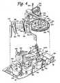
- the assaysare performed primarily on a processing deck 200, which is the general location of the various assay stations of the analyzer 50 described below.
- the processing deck 200is shown in FIGURE 2 without any of the assay stations mounted thereon.
- the processing deck 200comprises a datum plate 82 to which the various stations are directly or indirectly mounted.
- Datum plate 82preferably comprises a machined aluminum plate.
- the processing deck 200also known as the chemistry deck, separates the interior of the housing into the chemistry area, or upper chassis, above the datum plate 82 and the storage areas, or lower chassis 1100, located below the datum plate 82.
- a number of fans and louversare preferably provided in the upper chassis portion of the housing 60 to create air circulation throughout the upper chassis to avoid excessive temperatures in the upper chassis.
- the analyzer 50includes a computer controller, schematically represented as box 1000 in FIGURE 2 , which runs high-level analyzer-controlling software known as the "assay manager program".
- the assay manager programincludes a scheduler routine which monitors and controls test specimen movement through the chemistry deck 200.
- the computer system 1000 which controls the analyzer 50may include a stand-alone computer system including a CPU, keyboard, monitor, and may optionally include a printer device.
- a portable cartmay also be provided for storing and supporting the various computer components.
- the computer hardware for running the analyzer-controlling softwaremay be integrally housed within the housing 60 of the analyzer 50.
- Low level analyzer controlsuch as control of electric motors and heaters used throughout the analyzer 50 and monitoring of fluid levels within bulk fluid and waste fluid containers, is performed by an embedded controller, preferably comprising a Motorola 68332 microprocessor. Stepper motors used throughout the analyzer are also preferably controlled by preprogrammed, off-the-shelf, microprocessor chips available from E-M Technologies, Bala Cynwyd, Pennsylvania.
- FIGURE 3represents a schematic plan view of a poriton of the processing deck 200
- FIGURE 4represents a schematic perspective view of the processing deck.
- the datum plate 82forms the foundation of the processing deck 200 on which all stations are directly or indirectly attached.
- Processing deck 200includes a reaction receptacle input queue 150 which extends from opening 68 in front of housing 60.
- a plurality of reaction receptaclesare loaded in a stacked fashion in the input queue 150.
- the purpose of the input queueis to hold a prescribed number of reaction receptacles and to sequentially present them at a pick-up position to be retrieved by a transport mechanism (described below).
- a reflective sensor at the pick-up positionverifies the presence of a receptacle at that position.
- the input queuealso includes a device for counting the number of receptacles resident therein at any given time.
- a reaction receptacle shuttle assemblywithin the queue moves the receptacles along a receptacle advance path toward the pick-up position.
- Optical sensorsindicate when the shuttle assembly is in its home and fully extended positions.
- the queueincludes a drawer which may be pulled out for loading the receptacles therein. Before the drawer is opened, however, it must be unlocked and the shuttle must disengage from the receptacle advance path. When the drawer is again closed, it is locked and the shuttle engages the receptacles and moves them toward the pick-up position.
- Optical sensorsindicate when the drawer is closed and when the shuttle has engaged a receptacle. As each receptacle is removed from the pick-up position by the transport mechanism, the receptacle shuttle advances the receptacles one receptacle-width, so that the next receptacle is in the pick-up position.
- reaction receptaclesare preferably integrally formed linear arrays of test tubes and known as multi-tube units, or MTUs.
- MTUsmulti-tube units
- a first ring assemblywhich in the preferred embodiment comprises a specimen ring 250, is mounted on a pivoting jig plate 130 at a distance above the datum plate 82.
- Specimen ring 250is generally circular and preferably holds up to nine specimen trays 300 in an annular fluid container carrier portion thereof, and each of the specimen trays preferably holds 20 specimen-containing containers, or test tubes 320.
- the specimen ring 250is constructed and arranged to be rotatable about a first generally vertical axis of rotation and delivers the specimen tubes 320 to a specimen pipette assembly 450, preferably an automated robotic pipette system.
- specimen ring 250is accessible through the flip-up carousel door 80 provided in housing 60 so that trays 300 of test tubes 320 can be easily loaded onto the specimen ring 250 and unloaded from the specimen ring.
- Specimen ring 250is driven by a motor, as will be described in more detail below.
- a second ring assemblywhich in the preferred embodiment comprises a pipette tip wheel 350, is located in an interior portion of the specimen ring 250, so that at least a portion of the outer perimeter of the pipette tip wheel 350 is disposed radially inwardly of the inner periphery of the ring 250.
- Pipette tip wheel 350carries thereon a plurality of commercially available packages of pipette tips.
- Pipette tip wheel 350is motor driven to rotate independently of specimen ring 250 about a second axis of rotation that is generally parallel to the first axis of rotation of the specimen ring 250.
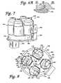
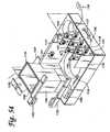
- the inner rotatable assemblyconstructed and arranged to carry a plurality of fluid containers is provided at an interior portion of the pipette tip wheel 350.
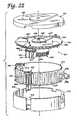
- the inner rotatable assemblycomprises a multi-axis mixer 400 located radially inside the pipette tip wheel 350 (i.e., the second ring assembly) and specimen ring 250 (i.e., the first ring assembly).
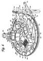
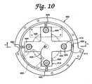
- the multi-axis mixer 400includes a rotating turntable 414 that is rotatable about a third axis of rotation that is generally parallel to the first and second axes of rotation and on which are mounted four independently and eccentrically rotating container holders 406.
- Each of the container holders 406receives a container, preferably in the form of a plastic bottle, containing a fluid suspension of magnetic particles with immobilized polynucleotides and polynucleotide capture probes.
- Each container holder 406is generally cylindrical in shape and includes an axis of symmetry, or axis of rotation.
- the multi-axis mixer 400rotates each of the containers eccentrically with respect to the center of the holder 406, while simultaneously rotating the turntable 414 about its center so as to provide substantially constant agitation of the containers to maintain the magnetic particles in suspension within the fluid.
- the specimen pipette assembly, or robot, 450is mounted to the frame structure 62 (see FIGURE 2 ) in a position above the specimen ring 250 and pipette tip wheel 350.
- the specimen pipette assembly 450includes a pipette unit 456 having a tubular probe 457 mounted on a gantry assembly to provide X, Y, Z motion.
- the pipette unit 456is linearly movable in the Y-direction along a track 458 formed in a lateral rail 454, and the lateral rail 454 is longitudinally movable in the X-direction along a longitudinal track 452.
- the pipette unit 456provides vertical, or Z-axis motion of the probe 457.
- Each axis of the specimen pipette assembly 450is driven by a stepper motor in a known and conventional manner.
- the pipette assemblyis preferably an off-the-shelf product.
- Presently preferredis the Robotic Sample Processor, model number RSP9000, available from Cavro Inc. of Sunnyvale, California. This model includes a single gantry arm.
- the specimen pipette assembly 450is preferably coupled to a syringe pump (not shown) (the Cavro XP 3000 has been used) and a DC driven diaphragm system fluid wash pump (not shown).
- the syringe pump of the specimen pipette assembly 450is preferably mounted to the internal frame structure 62 within the housing 60 of the analyzer 50 at a position above the left-hand side of the chemistry deck 200 and is connected to pipette unit 456 by suitable tubing (not shown) or other conduit structures.
- a specimen preparation opening 252is provided in the jig plate 130, so that the specimen pipette assembly 450 can access a reaction receptacle 160 in the input queue 150 located below the jig plate 130.
- the specimen pipette assembly 450 of the analyzer 50engages specimen tubes 320 carried on the specimen ring 250 through openings 140, 142 of an elevated cover plate 138 and engages pipette tips carried on the pipette tip wheel 350 near the back portions of the specimen ring 250 and pipette tip wheel 350, respectively. Accordingly, an operator can have access to the forward portions of specimen ring 250 and pipette tip wheel 350 through the carousel door opening 80 during operation of the analyzer without interfering with pipetting procedures.
- a tip wash/disposal station 340is disposed adjacent to the specimen ring 250 on the jig plate 130.
- Station 340includes a tip disposal tube 342 and a wash station basin 346.
- the pipette unit 456 of the specimen pipette assembly 450can move into position above the wash station basin 346 where the tubular probe 457 can be washed by pumping distilled water through the probe 457, the basin of the wash station 346 being connected, preferably by a flexible hose (not shown), to a liquid waste container in the lower chassis 1100.
- the tip disposal tube 342comprises an upstanding tubular member.
- an elongated pipette tipis frictionally secured onto the end of the tubular probe 457 of the pipette unit 456, so that specimen material does not come into contact with the tubular probe 457 of the pipette unit 456 when material is drawn from a specimen tube 320 and into the elongated pipette tip.
- the pipette unit 456moves to a position above the tip disposal tube 342 and ejects the used, disposable pipette tip into the tip disposal tube 342 which is connected to one of the solid waste containers carried in the lower chassis 1100.
- An elongated pipette tipis preferably also frictionally secured to the probe 457 for transferring target capture reagent from containers carried on the multi-axis mixer 400 to a reaction receptacle 160. Following reagent transfer, the pipette tip is discarded.
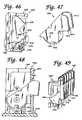
- the specimen ring 250, the pipette tip wheel 350, and the multi-axis mixer 400are preferably mounted on a hinged jig plate 130 (see FIGURES 5 and 6 ) supported above the datum plate 82.
- the jig plate 130is hinged at a back end 132 thereof (see FIGURE 6 ) so that the plate, and the ring 250, the wheel 350, and the mixer 400 mounted thereon, can be pivoted upwardly to permit access to the area of the chemistry deck below the jig plate.
- a first, or right-side, transport mechanism 500is mounted on the datum plate 82 below the jig plate 130 and specimen ring 250 on generally the same plane as the input queue 150.
- Transport mechanism 500includes a rotating main body portion 504 defining a receptacle carrier assembly and an extendible manipulating hook 506 mounted within the main body 504 and extendible and retractable with respect thereto by means of a powered hook member drive assembly.
- Each of the reaction receptacles 160preferably includes manipulating structure that can be engaged by the extendible manipulating hook 506, so that the transport mechanism 500 can engage and manipulate a reaction receptacle 160 and move it from one location on the processing deck 200 to another as the reaction receptacle is sequentially moved from one station to another during the performance of an assay within the reaction receptacle 160.
- a second, or left-side, transport mechanism 502, of substantially identical construction as first distribution arm 500,is also included on the processing deck 200.
- a plurality of receptacle parking stations 210are also located below the jig plate 130.
- the parking stations 210are structures for holding specimen-containing reaction receptacles until the assay performing stations of the processing deck 200 of the analyzer 50 are ready to accept the reaction receptacles.
- the reaction receptaclesare retrieved from and inserted into the parking stations 210 as necessary by the transport mechanism 500.
- a right-side orbital mixer 550is attached to the datum plate 82 and receives reaction receptacles 160 inserted therein by the right-side transport mechanism 500.
- the orbital mixeris provided to mix the contents of the reaction receptacle 160.
- the right-side transport mechanism 500removes the reaction receptacle from the right-side orbital mixer 550 and moves it to another location in the processing deck.
- incubators 600, 602, 604, 606, of substantially identical constructionare provided.
- Incubators 600, 602, 604, and 606are preferably rotary incubators. Although the particular assay to be performed and the desired throughput will determine the desired number of necessary incubators, four incubators are preferably provided in the analyzer 50.
- each incubator(600, 602. 604, 606) has a first, and may also have a second, receptacle access opening through which a transport mechanism 500 or 502 can insert a reaction receptacle 160 into the incubator or retrieve a reaction receptacle 160 from the incubator.
- a rotating receptacle carrier carouselwhich holds a plurality of reaction receptacles 160 within individual receptacle stations while the receptacles are being incubated.
- first rotary incubator 600is a target capture and annealing incubator
- second rotary incubator 602is an active temperature and pre-read cool-down incubator (also known as an "AT incubator")
- third rotary incubator 604is an amplification incubator
- fourth rotary incubator 606is a hybridization protection assay incubator.
- the construction, function, and role of the incubators in the overall performance of the assaywill be described in more detail below.
- the processing deck 200preferably also includes a plurality of temperature ramping stations 700. Two such stations 700 are shown attached to the datum plate 82 between incubators 602 and 604 in FIGURE 3 . Additional ramping stations may be disposed at other locations on the processing deck 200 where they will be accessible by one of the transport mechanisms 500, 502.
- a reaction receptacle 160may be placed into or removed from a temperature ramping station 700 by either transport mechanism 500 or 502. Each ramping station 700 either raises or lowers the temperature of the reaction receptacle and its contents to a desired temperature before the receptacle is placed into an incubator or another temperature sensitive station. By bringing the reaction receptacle and its contents to a desired temperature before inserting it into one of the incubators (600, 602, 604, 606), temperature fluctuations within the incubator are minimized.
- the processing deck 200also includes magnetic separation wash stations 800 for performing a magnetic separation wash procedure.
- Each magnetic separation wash station 800can accommodate and perform a wash procedure on one reaction receptacle 160 at a time. Therefore, to achieve the desired throughput, five magnetic separation wash stations 800 working in parallel are preferred.
- Receptacles 160are inserted into and removed from the magnetic separation wash stations 800 by the left-side transport mechanism 502.
- a reagent cooling bay 900is attached to the datum plate 82 roughly between the incubators 604 and 606.
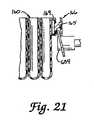
- Reagent cooling bay 900comprises a carousel structure having a plurality of container receptacles for holding bottles of temperature sensitive reagents.
- the carouselresides within a cooled housing structure having a lid with pipette-access holes formed therein.
- the left-side orbital mixer 552includes dispenser nozzles and lines for dispensing fluids into the reaction receptacle resident within the left-side orbital mixer 552.
- a reagent pipette assembly, or robot, 470includes a double gantry structure attached to the frame structure 62 (see FIGURE 2 ) and is disposed generally above the incubators 604 and 606 on the left-hand side of the processing deck 200.
- reagent pipette assembly 470includes pipette units 480 and 482.
- Pipette unit 480includes a tubular probe 481 and is mounted for linear movement, generally in the X-direction, along track 474 of lateral rail 476, and pipette unit 482, including a tubular probe 483, is also mounted for linear motion, generally in the X-direction, along track 484 of lateral rail 478.
- Each pipette unit 480, 482provides independent vertical, or Z-axis, motion of the respective probe 481, 483.
- Drive mechanisms within the assembly 470position the pipette units 480, 482 to the correct X, Y , Z coordinates within the analyzer 50 to pipette fluids, to wash the tubular probes 481.
- Each axis of the pipette assembly 470is driven by a stepper motor.
- the reagent pipette assembly 470is preferably an off-the-shelf product.
- the presently preferred unitis the Cavro Robotic Sample Processor, model RSP9000, with two gantry arms.
- the pipette units 480, 482 of the reagent pipette assembly 470are each preferably coupled to a respective syringe pump (not shown) (the Cavro XP 3000 has been used) and a DC driven diaphragm system fluid wash pump.
- the syringe pumps of the reagent pipette assembly 470are preferably mounted to the internal frame structure 62 within the housing 60 of the analyzer 50 at a position above the left-hand side of the chemistry deck 200 and are connected to the respective pipette units 480, 482 by suitable tubing (not shown) or other conduit structures.
- Each pipette unit 480, 482preferably includes capacitive level sensing capability.
- Capacitive level sensingwhich is generally known in the medical instrumentation arts, employs capacitance changes when the dielectric of a capacitor, formed by the pipette unit as one plate of the capacitor and the structure and hardware surrounding a container engaged by the pipette unit as the opposite plate, changes from air to fluid to sense when the probe of the pipette unit has penetrated fluid within a container.
- the vertical position of the probe of the pipette unitwhich may be known by monitoring the stepper motor which drives vertical movement of the pipette unit, the level of the fluid within the container engaged by the pipette unit may be determined.
- Pipette unit 480transfers reagents from the reagent cooling bay 900 into reaction receptacles disposed within the incubator 606 or the orbital mixer 552, and pipette unit 482 transfers reagent materials from the reagent cooling bay 900 into reaction receptacles disposed within the amplification incubator 604 or the orbital mixer 552.
- the pipette units 480, 482use capacitive level sensing to ascertain fluid level within a container and submerge only a small portion of the end of the probe of the pipette unit to pipette fluid from the container.
- Pipette units 480, 482preferably descend as fluid is pipetted into the respective tubular probes 481, 483 to keep the end of the probes submerged to a constant depth.
- the pipette unitscreate a minimum travel air gap of 10 ⁇ l in the end of the respective probe 481 or 483 to ensure no drips from the end of the probe as the pipette unit is moved to another location above the chemistry deck 200.
- the processing deck 200includes a luminometer 950 for detecting and/or quantifying the amount of light emitted by the contents of the reaction receptacle.
- the luminometer 950comprises a housing through which a reaction receptacle travels under the influence of a transport mechanism, a photomultiplier tube, and associated electronics. Various luminometer embodiments will be described in detail below.
- the processing deck 200also preferably includes a deactivation queue 750.
- the assay performed in the analyzer 50involves the isolation and amplification of nucleic acids belonging to at least one organism or cell of interest. Therefore, it is desirable to deactivate the contents of the reaction receptacle 160, typically by dispensing a bleach-based reagent into the reaction receptacle 160 at the conclusion of the assay. This deactivation occurs within the deactivation queue 750.
- reaction receptacle 160Following deactivation, the deactivated contents of the reaction receptacle 160 are stored in one of the liquid waste containers of the lower chassis 1100 and the used reaction receptacle is discarded into a dedicated solid waste container within the lower chassis 1100.
- the reaction receptacleis preferably not reused.
- the analyzer 50is initially configured for an assay run by loading bulk fluids into the bulk fluid storage bay of the lower chassis 1100 and connecting the bulk fluid containers to the appropriate hoses (not shown).
- the analyzeris preferably powered up in a sequential process, initially powering the stations, or modules, that will be needed early in the process, and subsequently powering the stations that will not be needed until later in the process. This serves to conserve energy and also avoids large power surges that would accompany full analyzer power-up and which could trip circuit breakers.
- the analyzeralso employs a "sleep" mode during periods of nonuse. During sleep mode, a minimal amount of power is supplied to the analyzer, again to avoid large surges necessary to power-up an analyzer from complete shut-down.
- reaction receptacles 160preferably in the form of plastic, integrally formed multiple-tube units (MTUs), which are described in more detail below, are loaded through opening 68 into the input queue 150.
- MTUsmultiple-tube units
- the reaction receptacle shuttle assembly(not shown) within the input queue 150 moves the MTUs 160 from the loading opening 68 to the pick-up position at the end of the queue 150.
- the right-side transport mechanism 500takes an MTU 160 from the end of the queue 150 and moves it to a bar code reader 253 to read the unique bar code label on that MTU which identifies that MTU. From the bar code reader 253, the MTU is moved to an available specimen transfer station 255 below opening 252.
- an MTU 160comprises a plurality of individual receptacle vessels 162, preferably five.
- the receptacle vessels 162, preferably in the form of cylindrical tubes with open top ends and closed bottom ends,are connected to one another by a connecting rib structure 164 which defines a downwardly facing shoulder extending longitudinally along either side of the MTU 160.
- the MTU 160is preferably formed from injection molded polypropylene.
- the most preferred polypropyleneis sold by Montell Polyolefins, of Wilmington, Delaware, product number PD701NW.
- the Montell materialis used because it is readily moldable, chemically compatible with the preferred mode of operation of the analyzer 50, and has a limited number of static discharge events which can interfere with accurate detection or quantification of chemiluminescence.
- An arcuate shield structure 169is provided at one end of the MTU 160.
- An MTU manipulating structure 166 to be engaged by one of the transport mechanisms 500, 502extends from the shield structure 169.
- MTU manipulating structure 166comprises a laterally extending plate 168 extending from shield structure 169 with a vertically extending piece 167 on the opposite end of the plate 168.
- a gusset wall 165extends downwardly from lateral plate 168 between shield structure 169 and vertical piece 167.
- the shield structure 169 and vertical piece 167have mutually facing convex surfaces.
- the MTU 160is engaged by the transport mechanisms 500,502 and other components, as will be described below, by moving an engaging member laterally (in the direction "A") into the space between the shield structure 169 and the vertical piece 167.
- the convex surfaces of the shield structure 169 and vertical piece 167provide for wider points of entry for an engaging member undergoing a lateral relative motion into the space.
- the convex surfaces of the vertical piece 167 and shield structure 169include raised portions 171, 172, respectively, formed at central portions thereof. The purpose of portions 171, 172 will be described below.
- a label-receiving structure 174 having a flat label-receiving surface 175is provided on an end of the MTU 160 opposite the shield structure 169 and MTU manipulating structure 166. Labels, such as scannable bar codes, can be placed on the surface 175 to provide identifying and instructional information on the MTU 160.
- the MTU. 160preferably includes tiplet holding structures 176 adjacent the open mouth of each respective receptacle vessel 162.
- Each tiplet holding structure 176provides a cylindrical orifice within which is received a contact-limiting tiplet 170.
- the construction and function of the tiplet 170will be described below.
- Each holding structure 176is constructed and arranged to frictionally receive a tiplet 170 in a manner that prevents the tiplet 170 from fatting out of the holding structure 176 when the MTU 160 is inverted, but permits the tiplet 170 to be removed from the holding structure 176 when engaged by a pipette.
- the tiplet 170comprises a generally cylindrical structure having a peripheral rim flange 177 and an upper collar 178 of generally larger diameter than a lower portion 179 of the tiplet 170.
- the tiplet 170is preferably formed from conductive polypropylene.
- Hole 180includes an outwardly flared end 181 at the top of the tiplet 170 which facilitates insertion of a pipette tubular probe (not shown) into the tiplet 170.
- Two annular ridges 183line the inner wall of hole 180. Ridges 183 provide an interference friction fit between the tiplet 170 and a tubular probe inserted into the tiplet 170.
- the bottom end of the tiplet 170preferably includes a beveled portion 182.
- a reaction receptaclesuch as a receptacle vessel 162 of an MTU 160
- the beveled portion 182prevents a vacuum from forming between the end of the tiplet 170 and the bottom of the reaction receptacle vessel.
- the lower chassis 1100includes a steel frame 1101 with a black polyurethane powder coat, a pull-out drip tray 1102 disposed below the chassis, a right-side drawer 1104, and a left-side drawer 1106.
- the left-side drawer 1106is actually centrally disposed within the lower chassis 1100.
- the far left-side of the lower chassis 1100houses various power supply system components and other analyzer mechanisms such as, for example, seven syringe pumps 1152 mounted on a mounting platform 1154, a vacuum pump 1162 preferably mounted on the floor of the lower chassis 1100 on vibration isolators (not shown), a power supply unit 1156, a power filter 1158, and fans 1160.
- a different syringe pump 1152is designated for each of the five magnetic separation wash stations 800, one is designated for the left-side orbital mixer 552, and one is designated for the deactivation queue 750. Although syringe pumps are preferred, peristaltic pumps may be used as an alternative.
- the vacuum pump 1162services each of the magnetic separation wash stations 800 and the deactivation queue 750.
- the preferred rating of the vacuum pumpis 5.3-6.5cfm at 0" Hg and 4.2-5.2cfm at 5" Hg.
- a preferred vacuum pumpis available from Thomas Industries, Inc. of Sheboygan, Wisconsin, as model number 2750CGHI60.
- a capacitor 1172is sold in conjunction with the pump 1162.
- the power supply unit 1156is preferably an ASTEC, model number VSI-B5-B7-03, available from ASTEC America, Inc., of Carlsbad, California. Power supply unit 1156 accepts 220 volts ranging from 50-60 Hz, i.e.,power from a typical 220 volt wall outlet. Power filter 1158 is preferably a Corcom model 20MV1 filter, available from Corcom, Inc. of Libertyville, Illinois. Fans 1160 are preferably Whisper XLDC fans available from Comair Rotron, of San Ysidro, California. Each fan is powered by a 24VDC motor and has a 75 cfm output.
- the fans 1160are preferably disposed proximate a left-side outer wall of the lower chassis 1100.
- the fans 1160are preferably directed outwardly to draw air through the lower chassis from the right-side thereof to the left-side thereof, and thus, to draw excess heat out of the lower chassis.
- a power switch 1174preferably an Eaton circuit breaker switch 2-pole, series JA/S. available from the Cutler-Hammer Division of Eaton Corporation of Cleveland, Ohio, and a power inlet module 1176 at which a power cord (not shown) for connecting the analyzer 50 to an external power source is connected.
- a power switch 1174preferably an Eaton circuit breaker switch 2-pole, series JA/S. available from the Cutler-Hammer Division of Eaton Corporation of Cleveland, Ohio
- a power inlet module 1176at which a power cord (not shown) for connecting the analyzer 50 to an external power source is connected.
- the power supply system of the analyzer 50also includes a terminal block (not shown), for attaching thereto a plurality of electrical terminals, a solid state switch (not shown), which is preferably a Crydom Series 1, model number D2425, available from Cal Switch, Carson City, California, for switching between different circuits, and an RS232 9-pin connector port for connecting the analyzer 50 to the external computer controller 1000.
- a terminal blockfor attaching thereto a plurality of electrical terminals
- a solid state switch(not shown), which is preferably a Crydom Series 1, model number D2425, available from Cal Switch, Carson City, California, for switching between different circuits
- an RS232 9-pin connector portfor connecting the analyzer 50 to the external computer controller 1000.
- the right-side drawer and left-side drawer baysare preferably closed behind one or two doors (not shown) in front of the analyzer, which is/are preferably locked by the assay manager program during operation of the analyzer. Microswitches are preferably provided to verify door-closed status.
- the far left bayis covered by a front panel. End panels are provided on opposite ends of the lower chassis to enclose the chassis.
- leveler feet 1180extend down from the four corners of the chassis 1100.
- the leveler feet 1180include threaded shafts with pads at the lower ends thereof. When the analyzer is in a desired location, the feet 1180 can be lowered until the pads engage the floor to level and stabilize the analyzer. The feet can also be raised to permit the analyzer to be moved on its casters.
- Bulk fluids typically contained in the containers of the lower chassis 1100may include wash buffer (for washing immobilized target), distilled water (for washing fixed pipette tips), diagnostic testing reagents, silicon oil (used as a floating fluid for layering over test reagents and specimen), and a bleach-based reagent (used for sample deactivation).
- wash bufferfor washing immobilized target
- distilled waterfor washing fixed pipette tips
- diagnostic testing reagentsfor washing fixed pipette tips
- silicon oilused as a floating fluid for layering over test reagents and specimen
- a bleach-based reagentused for sample deactivation
- the right-side drawer 1104is shown in detail in FIGURE 53 .
- the right-side drawer 1104includes a box-like drawer structure with a front drawer handle 1105.
- drawer handle 1105is shown as a conventional pull-type drawer handle, in the preferred embodiment of the analyzer 50, handle 1105 is a T-handle latch, such as those available from Southco, Inc. of Concordville, Pennsylvania.
- the drawer 1104is mounted in the lower chassis on slide brackets (not shown) so that the drawer 1104 can be pulled into and out of the lower chassis.
- a sensor(not shown) is preferably provided for verifying that the drawer 1104 is closed.
- the front portion of the drawerincludes bottle receptacles 1122 for holding bottle 1128 (shown in FIGURE 52 ), which is a dedicated pipette wash waste-containing bottle, and bottle 1130 (also shown in FIGURE 52 ), which is a dedicated waste bottle for containing waste from a magnetic wash, target-capture procedure.
- Bottle 1130is preferably evacuated.
- Bottle receptacles 1122preferably include bottle-present sensors (not shown) to verify the presence of a bottle in each receptacle 1122.
- the bottle-present sensorsare preferably diffuse reflective type optical sensors available from SUNX/Ramco Electric, Inc., of West Des Moines, Iowa, model EX-14A.
- Right-side drawer 1104further includes a waste bin 1108 for holding therein spent MTUs and specimen tips.
- Waste bin 1108is an open box structure with a sensor mount 1112 at a top portion thereof for mounting thereon a sensor, preferably a 24VDC Opto-diffuse reflector switch (not shown), for detecting whether the waste bin 1108 is full.
- Another diffuse reflector type optical sensor(not shown) is positioned within right-side drawer 1104 to verify that the waste bin 1108 is in place.
- diffuse reflective type optical sensorsavailable from SUNX/Ramco Electric, Inc., of West Des Moines, Iowa, model EX-14A. are preferred.
- a deflector 1110extends obliquely from a side of the waste bin 1108.
- Deflector 1110is disposed directly below a chute through which spent MTUs are dropped into the waste bin 1108 and deflects the dropped MTUs toward the middle of the waste bin 1108 to avoid MTU pile-ups in a corner of the waste bin 1108.
- Deflector 1110is preferably pivotally mounted so that it can pivot upwardly to a substantially vertical position so that when a waste bag, which lines the waste bin 1108 and covers the deflector 1110, is removed from the waste bin 1108, the deflector 1110 will pivot upwardly with the bag as it is pulled out and therefore will not rip the bag.
- a printed circuit board (not shown) and cover 1114can be mounted to the front of the waste bin 1108.
- Sensor mounts 1116 and 1117are also mounted to the front of waste bin 1108.
- Sensors 1118 and 1119are mounted on sensor mount 1116, and sensors 1120 and 1121 mounted on sensor mount 1117.
- Sensors 1118, 1119, 1120, and 1121are preferably DC capacitive proximity sensors.
- the upper sensors 1118, 1119indicate when the bottles 1128 and 1130 are full, and the bottom sensors 1120, 1121 indicate when the bottles are empty.
- Sensors 1118-1121are preferably those available from Stedham Electronics Corporation of Reno, Nevada, model number C2D45AN1-P, which were chosen because their relatively flat physical profile requires less space within the tight confines of the lower chassis 1100 and because the Stedham sensors provide the desired sensing distance range of 3-20 mm.
- the analyzer 50will preferably not begin performing any assays if the assay manager program detects that any of the waste fluid containers in the right-side drawer 1104 are not initially empty.
- the capacitive proximity sensors 1118-1121 and the bottle-present, waste-bin-present, and waste-bin-full optical sensors of the right-side drawer 1104are connected to the printed circuit board (not shown) behind cover 1114, and the printed circuit board is connected to the embedded controller of the analyzer 50.
- a handle 1126is mounted to the front of the waste bin 1108 and teflon strips 1124 are disposed on the bottom floor of the right-side drawer 1104 to facilitate forward and backward sliding of the waste bin 1108 in the drawer 1104 when bottles 1128 and 1130 are removed.
- Left-side drawer 1106includes a box-like structure with a front mounted handle 1107 and is mounted within the lower chassis 1100 on slide brackets (not shown).
- handle 1107is shown as a conventional pull-type drawer handle, in the preferred embodiment of the analyzer 50, handle 1107 is a T-handle latch, such as those available from Southco, Inc. of Concordville, Pennsylvania.
- a sensoris provided for verifying that the left-side drawer 1106 is closed.
- Left-side drawer 1106includes a tiplet waste bin 1134 with a mounting structure 1135 for mounting thereon a tiplet-waste-bin-full sensor (not shown).
- a tiplet-waste-bin-present sensoris preferably provided in the left-side drawer 1106 to verify that the tiplet waste bin 1134 is properly installed.
- Diffuse reflective type optical sensorsavailable from SUNX/Ramco Electric, Inc., of West Des Moines, lowa, model EX-14A, are preferred for both the tiplet-waste-bin-full sensor and the tiplet-waste-bin-present sensor.
- Bundling structures 1132are provided for securing and bundling various tubing and/or wires (not shown) within the lower chassis 1100.
- the bundling structures preferably usedare Energy Chain Systems manufactured and sold by Igus, Inc. of East Buffalo. Rhode Island.
- a printed circuit board 1182is mounted behind a panel 1184 which is located behind the tiplet waste bin 1134.
- a solenoid valve mounting panel 1186is located below the tiplet waste bin 1134.
- Left-side drawer 1106includes a forward container-holding structure for holding therein six similarly sized bottles.
- the container structureincludes divider walls 1153, 1155, 1157, and 1159 and container blocks 1151 having a curved bottle-conforming front edge, which together define six container-holding areas.
- Lower sensors 1148 and upper sensors 1150(six of each) are mounted on the divider walls 1155, 1157, and 1159.
- the upper and lower sensors 1148, 1150are preferably DC capacitive proximity sensors (preferably sensors available from Stedham Electronics Corporation of Reno, Nevada, model number C2D45AN1-P, chosen for their flat profile and sensing range).
- the upper sensors 1150indicate when the bottles held in the container structure are full, and the lower sensors 1148 indicate when the bottles are empty.
- the left two bottles 1146contain a detecting agent ("Detect I")
- the middle two bottles 1168contain silicon oil
- the right two bottles 1170contain another detecting agent
- Bottle-present sensorsare preferably provided in each of the container-holding areas defined by the container blocks 1151 and the dividing walls 1153, 1155, 1157, and 1159 to verify the presence of bottles in each container-holding area.
- the bottle-present sensorsare preferably diffuse reflective type optical sensors available from SUNX/Ramco Electric, Inc., of West Des Moines, lowa, model EX-14A.
- a large centrally located container receptacle 1164holds a bottle 1140 (shown in FIGURE 52 ), preferably containing deionized water.
- Container receptacles 1166(only one is visible in FIGURE 54 ) hold bottles 1142 and 1144 (also shown in FIGURE 52 ) preferably containing a wash buffer solution.
- a dividing wall 1143 between the receptacle 1164 and 1166has mounted thereon sensors, such as sensor 1141, for monitoring the fluid level in the bottles 1140, 1142, and 1144.
- the sensors, such as sensor 1141are preferably DC capacitive proximity sensors (preferably sensors available from Stedham Electronics Corporation of Reno, Nevada, model number C2D45ANI-P).
- Container receptacles 1164 and 1166preferably include bottle-present sensors (not shown) for verifying that bottles are properly positioned in their respective receptacles.
- the bottle-present sensorsare preferably diffuse reflective type optical sensors available from SUNX/Ramco Electric, Inc., of West Des Moines, Iowa, model EX-14A.
- the analyzer 50will not begin performing any assays if the assay manager program determines that any of the bulk-fluid containers in the left-side drawer 1106 are initially empty.
- the capacitive proximity fluid level sensors, the various bottle-present sensors, the tiplet-waste-bin-full sensor, and the tiplet-waste-bin-present sensorsare all connected to the printed circuit board 1182, and the printed circuit board 1182 is connected to the embedded controller of the analyzer 50.
- solenoid valves(not shown) are mounted below the solenoid valve mounting panel 1186.
- the solenoid valvesconnect bulk fluid bottles where fluids are stored in pairs of bottles, i.e.,the bottles 1140, 1142 containing wash buffer solution, the two bottles 1146 containing the "Detect I” agent, the two bottles 1168 containing oil, and the two bottles 1170 containing the "Detect II” agent.
- the solenoid valvesin response to signals from the respective capacitive proximity sensors, switch bottles from which fluid is being drawing when one of the two bottles containing the same fluid is empty.
- the solenoid valvesmay switch bottles after a prescribed number of tests are performed.
- the preferred solenoid valvesare teflon solenoid valves available from Beco Manufacturing Co., Inc. of Madison Hills, California, model numbers S313W2DFRT and M223W2DFRLT. The two different model numbers correspond to solenoid valves adapted for use with two different tube sizes. Teflon solenoid valves are preferred because they are less likely to contaminate fluids flowing through the valves and the valves are not damaged by corrosive fluids flowing through them.
- Bottle 1136(see FIGURE 52 ) is a vacuum trap held in a vacuum trap bracket 1137, and bottle 1138 contains a deactivating agent, such as bleach-containing reagent.
- a deactivating agentsuch as bleach-containing reagent.
- bottle-present sensorsare preferably provided to verify the presence of bottles 1136 and 1138.
- a hand-held bar code scanner 1190may be provided in the lower chassis 1100 for scanning information provided on scannable container labels into the assay manager program.
- Scanner 1190is connected by a cord to printed circuit board 1182 of the left-side drawer 1106 and is preferably stowed on a bracket (not show) mounted on dividing wall 1143.
- Scannersavailable from Symbol Technologies, Inc., of Holtsville, New York, series LS2100, are preferred.
- Specimensare contained in the specimen tubes 320, and the tubes 320 are loaded into the tube trays 300 outside the analyzer 50.
- the trays 300 carrying the specimen tubes 320are placed onto the specimen ring 250 through the access opening provided by opening the flip-up carousel door 80.
- the first ring assembly, or specimen ring, 250is formed of milled, unhardened aluminum and includes a raised ring structure defining an annular trough 251 about the outer periphery of ring 250 with a plurality of raised, radially extending dividers 254 extending through trough 251.
- nine dividers 254divide the trough 251 into nine arcuate specimen tube tray-receiving wells 256.
- the trough 251 and wells 256define an annular fluid container carrier portion constructed and arranged to carry a plurality of containers as will be described below.
- Specimen ring 250is preferably rotationally supported by three 120°-spaced V-groove rollers 257, 258, 260 which engage a continuous V-ridge 262 formed on the inner periphery of ring 250, as shown in FIGURES 5 and 6 , so that the ring 250 is rotatable about a first central axis of rotation.
- the rollersare preferably made by Bishop-Wisecarver Corp. of Pittsburg, California, model number W1SSX.
- Rollers 257 and 260are rotationally mounted on fixed shafts, and roller 258 is mounted on a bracket which pivots about a vertical axis and is spring biased so as to urge roller 258 radially outward against the inner periphery of ring 250.
- ring 250can be easily installed and removed by merely pushing pivoting roller 258 radially inwardly to allow the specimen ring 250 to move laterally to disengage continuous V-ridge 262 from the fixed V-groove rollers 257, 260.
- Specimen ring 250is driven by stepper motor 264 (VEXTA stepper motors available from Oriental Motor Co., Ltd. of Tokyo, Japan as model number PK266-01A are preferred) via continuous belt 270 (preferably available from SDP/SI of New Hyde Park, New York, as model number A6R3M444080) which extends over guide rollers 266, 268 and around the outer periphery of ring 250.
- a home sensor and a sector sensor(not shown), preferably slotted optical sensors, are provided adjacent the ring 250 at a rotational home position and at a position corresponding to one of the specimen tube tray receiving wells 256.
- the ring 250includes a home flag (not shown) located at a home position on the wheel and nine equally-spaced sector flags (not shown) corresponding to the positions of each of the nine specimen tube tray receiving wells 256.
- the home flag and sector flagscooperate with the home sensor and sector sensors to provide ring position information to the assay manager program and to control the ring 250 to stop at nine discrete positions corresponding to established coordinates for user re-load and access by pipette unit 450.
- Preferred sensors for the home sensor and sector sensorare Optek slotted optical sensors, model number OPB857, available from Optek of Carrollton, Texas.
- a specimen coveris disposed over a portion of the annular fluid container carrier portion, or trough 251, and comprises an arcuate cover plate 138 fixed in an elevated position with respect to the wheel 250 on three mounting posts 136.
- Plate 138has an arcuate shape generally conforming to the curve of the trough 251.
- a first opening 142is formed in the plate 138, and a second opening 140 is formed in the plate 138 at a greater radial distance from the axis of rotation of ring 250 than opening 142 and at a circumferentially-spaced position from opening 142.
- each specimen tube tray 300comprises a test tube rack structure that is curved to conform to the curvature of the ring 250.
- Each tray 300comprises a central wall structure 304 with lateral end walls 303 and 305 disposed on either end of wall 304.
- a floor 312extends across the bottom of the tray 300.
- the principle purposes of specimen tube tray 300are to hold specimen tubes on the specimen ring 250 for access by the specimen pipette assembly 450 and to facilitate loading and unloading of multiple specimen tubes into and from the analyzer.
- a plurality of Y-shaped dividers 302are equidistantly spaced along opposite edges of the tray 300. Each two adjacent dividers 302 define a test-tube receiving area 330.
- End wall 303includes inwardly bent flanges 316 and 318, and end wall 305 includes inwardly bent flanges 326 and 328.
- the respective inwardly bent flanges of end walls 303 and 305 along with the end-most of the dividers 302define the end-most tube receiving areas 332.
- the receiving areas 330. 332are arcuately aligned along two arcuate rows on opposite sides of central wall structure 304
- a leaf spring element 310is attached to central wall 304.
- Leaf spring element 310preferably formed of stainless spring steel, elastically deflects when a test tube 320 is inserted into the tube-receiving area 330 or 332 and urges the tube 320 outwardly against the dividers 302.
- the tube 320is secured in an upright orientation.
- the shape of the dividers 302 and the elasticity of the leaf spring elements 310allow the tray 300 to accommodate specimen tubes of various shapes and sizes, such as tubes 320 and 324.
- Each tray 300preferably includes nine dividers 302 along each edge to form, along with end walls 303 and 305, ten tube-receiving areas 330, 332 on each side of central wall structure 304 for a total of twenty tube-receiving areas per tray.
- Indicia for designating tube-receiving areas 330 and 332, such as raised numerals 306,may be provided on the tray, such as on central wall 304.
- Each tray 300may also include boss structures 308, shown in the illustrated embodiment to be integrally formed with the end-most dividers 302.
- An upright inverted U-shaped handle(not shown) may be attached to the tray at boss structures 308 or some other suitable location. Upright handles can facilitate handling of the tray 300 when loading and unloading the tray 300 through the arcuate carousel door 80, but are not necessarily preferred.
- a gapis provided between adjacent dividers 302 so that bar-code labels 334, or other readable or scannable information, on the tubes 320 is accessible when the tube is placed in the tray 320.
- a tray 300 carried on wheel 250passes beneath the plate 138 of the specimen cover, one tube 320 in a curved row at a radially-inward position with respect to wall structure 304 will be aligned with first opening . 142 and another tube 320 in a curved row at a radially-outward position with respect to wall 304 will be aligned with second opening 140.
- the ring 250is indexed to sequentially move each tube 320 beneath the openings 140, 142 to permit access to the tubes.
- bar code scanners 272 and 274are disposed adjacent the ring 250.
- Scanner 272is located outside ring 250, and scanner 274 is disposed inside ring 250.
- Scanners 272 and 274are positioned to scan bar code data labels on each specimen tube 320 carried in the specimen tube tray 300 as the ring 250 rotates a tray 300 of specimen tubes 320 past the scanners 272, 274.
- the scanners 272, 274scan the bar code label 337 (see FIGURE 55 ) on the outer portion of bent flanges 316 and 318 of end wall 303 of each tray 300 as the tray 300 is brought into the specimen preparation area.
- Various informationsuch as specimen and assay identification, can be placed on the tubes and/or each tray 300, and this information can be scanned by the scanners 272, 274 and stored in the central processing computer. If no specimen tube is present, the tray 300 presents a special code 335 (see FIGURE 55 ) to be read by the scanners 272, 274.
- a second ring assembly of the preferred embodimentis a pipette tip wheel 350 and comprises a circular ring 352 at a bottom portion thereof, a top panel 374 defining a circular inner periphery and five circumferentially-spaced, radially-protruding sections 370, and a plurality of generally rectangular risers 354 separating the top panel 374 from the ring 352 and preferably held in place by mechanical fasteners 356 extending through the top panel 374 and ring 352 into the risers 354.
- Top panel 374proximate each of the sections 370, and a rectangular box 376 is disposed beneath panel 374, one at each opening 358.
- Top panel 374, ring 352, and risers 354are preferably made from machined aluminum, and boxes 376 are preferably formed from stainless steel sheet stock.
- the openings 358 and associated boxes 376are constructed and arranged to receive trays 372 holding a plurality of disposable pipette tips.
- the pipette tip trays 372are preferably those manufactured and sold by TECAN (TECAN U.S. Inc., Research Triangle Park, North Carolina) under the trade name "Disposable Tips for GENESIS Series". Each tip has a 1000 ⁇ l capacity and is conductive. Each tray holds ninety-six elongated disposable tips.
- Lateral slots 378 and longitudinal slots 380are formed in the top panel 374 along the lateral and longitudinal edges, respectively, of each opening 358.
- the slots 378, 380receive downwardly-extending flanges (not shown) disposed along the lateral and longitudinal edges of the trays 372.
- the slots 378, 380 and associated flanges of the trays 372serve to properly register the trays 372 with respect to openings 358 and to hold the trays 372 in place on the panel 374.
- Pipette tip wheel 350is preferably rotationally supported by three 120°-spaced V-groove rollers 357. 360, 361 which engage a continuous V-ridge 362 formed on the inner periphery of ring 352, as shown in FIGURES 5 , 6 , and 6A , so that the pipette tip wheel 350 is rotatable about a second central axis of rotation that is generally parallel to the first axis of rotation of the specimen ring 250.
- the rollersare preferably made by Bishop-Wisecarver Corp. of Pittsburg, California, model number WISSX.
- Rollers 357 and 360are rotationally mounted on fixed shafts, and roller 361 is mounted on a bracket which pivots about a vertical axis and is spring biased so as to urge roller 361 radially outwardly against the inner periphery of ring 352. Having two fixed rollers and one radially movable roller allows the three rollers to accommodate an out-of round inner periphery of ring 352.
- the wheel 350can be easily installed and removed by merely pushing pivoting roller 361 radially inwardly to allow the ring 352 to move laterally to disengage continuous V-ridge 362 from the fixed V-groove rollers 357, 360.
- Pipette tip wheel 350is driven by a motor 364 having a shaft-mounted spur gear which meshes with mating gear teeth formed on an outer perimeter of ring 352.
- Motor 364is preferably a VEXTA gear head stepper motor, model number PK243-A 1-SG7.2, having a 7.2:1 gear reduction and available from Oriental Motor Co., Ltd. of Tokyo, Japan.
- a gear head stepper motor with a 7.2:1 gear reductionis preferred because it provides smooth motion of the pipette tip wheel 350, where the spur gear of the motor 364 is directly engaged with the ring 352.
- a home sensor and a sector sensorare provided adjacent the pipette tip wheel 350 at a rotational home position and at a position of one of the boxes 376.
- the pipette tip wheel 350includes a home flag (not shown) located at a home position on the wheel and five equally-spaced sector flags (not shown) corresponding to the positions of each of the five boxes 376.
- the home flag and sector flagscooperate with the home sensor and sector sensors to provide wheel position information to the assay manager program and to control the pipette tip wheel 350 to stop at five discrete positions corresponding to established coordinates for user re-load and access by pipette unit 450.
- Preferred sensors for the home sensor and sector sensorare Optek Technology, Inc. slotted optical sensors, model number OPB980, available from Optek Technology, Inc. of Carrollton, Texas.
- the multi-axis mixer 400includes a rotating turntable structure 414 (see FIGURE 10 ) rotatably mounted on a center shaft 428 supported in center bearings 430 to a fixed base 402 mounted to the jig plate 130 by means of mechanical fasteners (not shown) extending through apertures 419 formed about the outer periphery of the fixed base 402.
- a cover member 404is attached to and rotates with turntable 414.
- Turntable 414is preferably in the form of a right angle cross comprising three 90°-spaced rectangular arms 444 of equal length extending radially outwardly from the center of the turntable 414 and a fourth arm 445 having an extension 417 making arm 445 slightly longer than arms 444. As shown in FIGURES 10-12 , the center portion of turntable 414 is connected to center shaft 428 by a screw 429.
- Each container holder 406is disposed on the ends of the arms 444 and 445 of turntable frame 414. Each container holder 406 is attached to one of four vertical shafts 423, which are rotatably supported in container holder bearings 415. Container holder bearings 415 are pressed into the arms 444, 445 of the turntable 414 and are disposed at equal radial distances from shaft 428.
- the cover member 404includes four circular openings with upwardly-turned peripheral flanges 401 through which shafts 423 extend. Upward flanges 401 can advantageously prevent spilled liquids from flowing into the openings.
- the container holders 406comprise generally cylindrical members having an open bottom and an open top for receiving and holding a container 440, preferably a plastic bottle, of target capture reagent.
- the target capture reagent used with the preferred assayincludes magnetically responsive particles with immobilized polynucleotides, polynucleotide capture probes, and reagents sufficient to lyse cells containing the targeted nucleic acids.
- targeted nucleic acidsare available for hybridization under a first set of predetermined hybridization conditions with one or more capture probes, with each capture probe having a nucleotide base sequence region which is capable of hybridizing to a nucleotide base sequence region contained on at least one of the targeted nucleic acids.
- a homopolymer tail(e.g., oligo(dT)) of the immobilized polynucleotides is capable of hybridizing with a complementary homopolymer tail (e.g., oligo(dA)) contained on the capture probe, thereby immobilizing targeted nucleic acids.
- a complementary homopolymer taile.g., oligo(dA)
- a container retainer spring 408spans a lateral slot formed in the wall of each container holder 406 and helps to hold the container 440 within the container holder 406 by urging the container 440 toward a portion of the inner peripheral wall of the holder 406 opposite the spring 408.
- Each container holder 406is secured to an associated vertical shaft 423 by a shaft block structure 432.
- Shaft block structure 432includes curved end portions which conform to the inside of the cylindrical container holder 406, and the container holder 406 is secured to the block 432 by fasteners 434.
- a generally circular aperture 449receives the shaft 423.
- a slot 438extends from aperture 449 to an end of the block 432 which does not extend all the way to the inside of the container holder 406, and a second slot 436 extends from an edge of the block 432 generally perpendicularly to slot 438 so as to define a cantilevered arm 435.
- a machine screw 437extends through a through-hole 441 formed laterally through block 432 and into a threaded hole 447 formed laterally through arm 435. As screw 437 is tightened, arm 435 deflects, thus tightening aperture 449 around shaft 423.
- the shaft block structure 432, the shaft 423, and the container holder bearings 415 associated with each container holder 406define a preferred container holder mounting structure associated with each container holder 406 that is constructed and arranged to mount the container holder 406 to the turntable 414 and permit the container holder 406 to rotate about an axis of rotation 412 of the shaft 423.
- Container holder planetary gears 422are attached to the opposite ends of shafts 423.
- the planetary gears 422operatively engage a stationary sun gear 416.
- a drive pulley 418is attached to center shaft 428 and is coupled to a drive motor 420 by a drive belt (not shown).
- Drive motor 420is preferably mounted so as to extend through an opening (not shown) in the jig plate 130 below the base 402.
- Drive motor 420is preferably a stepper motor, and most preferably a VEXTA stepper motor, model number PK264-OIA, available from Oriental Motor Co., Ltd. of Tokyo, Japan.
- the drive motor 420via the drive belt and drive pulley 418, rotates the center shaft 428 and the turntable 414 attached thereto.
- each container holder 406is preferably mounted such that the axis of rotation 410 thereof is offset from the axis of rotation 412 of the associated shaft 423. Thus, each container holder 406 rotates eccentrically about axis 412 of the associated shaft 423.
- the planetary gears 422 and the sun gear 416constitute rotational motion coupling elements constructed and arranged to cause the container holders 406 to rotate about the respective axes of rotation of the shafts 423 as the turntable 414 rotates about the axis of rotation of the shaft 428.
- a bar code scanner device 405is preferably mounted on a bracket 403 and reads bar code information of the containers 440 through a scanner slot 407 formed in each container holder 406.
- the preferred scanneris a model number NFT1125/002RL scanner, available from Opticon, Inc. of Orangeburg, New York.
- the multi-axis mixer 400usually rotates during operation of the analyzer 50 to agitate the fluid contents of the containers 440 to thereby keep the target capture reagent in suspension, stopping only briefly to permit pipette unit 456 to withdraw an amount of mixture from one of the containers.
- Pipette unit 456draws mixture from a bottle at the same location each time. Therefore, it is desirable to monitor the positions of the bottles so that the bottle from which mixture is withdrawn each time can be specified.
- optical slotted sensors 426each comprising an optical emitter and detector, are stationed around the periphery of fixed base 402, spaced at 90° intervals.
- Optical sensorsavailable from Optek Technology, Inc. of Carrollton, Texas, model number OPB490P11, are preferred.
- a sensor tab 424extends down from extension 417 at the end of arm 445 of the turntable 414. When sensor tab 424 passes through a sensor 426, the communication between the emitter and detector is broken thus giving a "container present" signal.
- the tab 424is only provided at one location, e.g.,the first container location. By knowing the position of the first container, the positions of the remaining containers, which are fixed relative to the first container, are also known.
- Power and control signalsare provided to the multi-axis mixer 400 via a power and data connector. While the multi-axis mixer 400 provides mixing by rotation and eccentric revolution, other mixing techniques, such as vibration, inversion, etc. may be used.
- the pipette unit 456moves to transfer target capture reagent, preferably mag-oligo reagent, from a container 440 carried on the multi-axis mixer 400 into each of the receptacle vessels 162 of the MTU 160.
- the target capture reagentincludes a support material able to bind to and immobilize a target analyte.
- the support materialpreferably comprises magnetically responsive particles.
- the tip trays 372are carried on the pipette tip wheel 350 so as to be precisely positioned to achieve proper registration between the pipette tips and the tubular probe 457 of the pipette unit 456.
- the pipette unit 456moves down to insert the free end of the tubular probe 457 into the open end of a pipette tip and frictionally engage the pipette tip.
- the Cavro processors preferably used for pipette unit 456includes a collar (not shown), which is unique to Cavro processors. This collar is moved slightly upwardly when a pipette tip is frictionally engaged onto the end of the tubular probe 457, and the displaced collar trips an electrical switch on the pipette unit 456 to verify that a pipette tip is present.
- tip pick-upis not successful (e.g., due to missing tips in the trays 372 or a misalignment)
- a missing tip signalis generated and the pipette unit 456 can move to re-try tip engagement at a different tip location.
- the assay manager programcauses the multi-axis mixer 400 to briefly stop rotating so that the pipette unit 456 can be moved to a position with the tubular probe 457 and attached pipette tip of the pipette unit 456 aligned over one of the stationary containers 440.
- the pipette unit 456lowers the pipette tip attached to the tubular probe 457 into the container 440 and draws a desired amount of target capture reagent into the pipette tip.
- the pipette unit 456then moves the probe 457 out of the container 440, the multi-axis mixer 400 resumes rotating, and the pipette unit 456 moves to a position above opening 252 and the specimen transfer station 255.
- the pipette unit 456descends, moving the pipette tip and the tubular probe 457 through the opening 252, and dispenses a required amount of target capture (typically 100-500 ⁇ l) into one or more of the receptacle vessels 162 of the MTU 160. It is preferred that the target capture reagent is drawn only into the pipette tip and not into the probe 457 itself. Furthermore, it is preferred that the pipette tip be of sufficient volumetric capacity to hold enough reagent for all five vessels 162 of the MTU 160.
- the pipette unit 456After target capture reagent transfer, the pipette unit 456 then moves to a "tip discard" position above tip disposal tube 342, where the disposable pipette tip is pushed or ejected off of the end of the tubular probe 457 of the pipette unit 456, and falls through tube 342 toward a solid waste container.
- An optical sensor(not shown) is disposed adjacent to tube 342, and before tip discard, the specimen pipette assembly 450 moves the pipette unit 456 into a sensing position of the sensor. The sensor detects whether a tip is engaged with the end of the tubular probe 457 to verify that the tip is still held on the tubular probe 457 of the pipette unit 456, thereby confirming that the tip was on the tubular probe 457 throughout specimen preparation.
- a preferred sensoris a wide-gap slotted optic sensor, model OPB900W, available from Optek Technology, Inc. of Carrollton, Texas.
- the pipette tipis ejected by the collar (not shown) on the tubular probe 457 of pipette unit 456.
- the collarengages a hard stop when the tubular probe 457 is raised, so that as the probe 457 continues to ascend, the collar remains fixed and engages an upper end of the pipette tip, thereby forcing it off the tubular probe 457.
- the probe 457 of the pipette unit 456can be washed by running distilled water through the tubular probe 457 at the tip wash station basin 346.
- the tip wash wateris collected and drains down into a liquid waste container.
- the pipette unit 456 on the right pipette assembly 450moves laterally and longitudinally to a position in which the tubular probe 457 of the pipette unit 456 is centered over a new pipette tip on one of the tip trays 372.
- the pipette unit 456moves back over the specimen ring 250, adjacent to the specimen preparation opening 252 and withdraws a test specimen (about 25-900 ⁇ l) from a specimen tube 320 that is aligned with one of the openings 140, 142 of the cover plate 138.
- both openings 140, 142include upwardly extending peripheral flanges to prevent any fluids spilled onto the plate 138 from running into the openings 140, 142.
- the pipette unit 456then moves over the MTU 160 in the specimen transfer station 255, moves down through opening 252, and dispenses test specimen into one of the receptacle vessels 162 of the MTU 160 containing target capture reagent. Pipette unit 456 then moves to the "tip discard" position above the tip disposal tube 342, and the disposable pipette tip is ejected into the tube 342.
- Pipette unit 456then picks up a new disposable pipette tip from the pipette tip wheel 350, the specimen ring 250 indexes so that a new specimen tube is accessible by the pipette unit 456, unit 456 moves to and draws specimen fluid from the specimen tube into the disposable pipette tip, the pipette unit 456 then moves to a position above the specimen transfer station 255, and dispenses specimen fluid into a different receptacle vessel 162 containing target capture reagent. This process is preferably repeated until all five receptacle vessels 162 contain a combination of fluid specimen sample and target capture reagent.
- the pipette unit 456may dispense the same test specimen material into two or more of the receptacle vessels 162 and the analyzer can perform the same or different assays on each of those aliquots.
- pipette unit 456also includes capacitive level sensing capability.
- the pipette tips used on the end of the tubular probe 457are preferably made from a conductive material, so that capacitive level sensing can be performed with the pipette unit 456, even when a tip is carried on the end of the tubular probe 457.
- the pipette unit 456moves the tubular probe 457 back down into the receptacle vessel 162 until the top of the fluid level is detected by the change in capacitance.
- the vertical position of the tubular probe 457is noted to determine whether the proper amount of fluid material is contained in the receptacle vessel 162. Lack of sufficient material in a receptacle vessel 162 can be caused by clotting in the test specimen, which can clot the tip at the end of the tubular probe 457 and prevent proper aspiration of test specimen material into the tip and/or can prevent proper dispensing of test specimen from the tip.
- the pipette tipis discarded into the tip disposal tube 342 as described above.
- the tubular probe 457 of the pipette of unitcan be washed with distilled water if desired, but washing of the probe is typically not necessary because, in the preferred method of operation, specimen material only comes into contact with the disposable pipette tip.
- the assay manager programincludes pipette unit control logic which controls movements of the pipette units 456, 480, 482, and preferably causes pipette unit 456 to move in such a manner that it never passes over a specimen tube 320 on the specimen ring 250, except when the pipette unit 456 positions the tubular probe 457 over a specimen tube 320 to withdraw a test specimen or when the specimen tube 320 is below the plate 138 of the specimen cover. In this way, inadvertent fluid drips from the tubular probe 457 of the pipette unit 450 into another specimen tube, which might result in cross-contamination, are avoided.
- the MTU 160is moved by the right-side transport mechanism 500 from the specimen transfer station to the right orbital mixer 550 in which the specimen/reagent mixtures are mixed.
- the structure and operation of the orbital mixers 550, 552will be described in further detail below.
- the reaction receptacle shuttle assembly within the input queue 150advances the next MTU into a position to be retrieved by the right-side transport mechanism 500 which moves the next MTU to the specimen transfer station. Specimen preparation procedures are then repeated for this next MTU.
- the right-side transport mechanism 500(as well as the left-side transport mechanism 502) has a manipulating hook member that, in the illustrated embodiment, includes an extendible distributor hook 506 extending from a hook mounting structure 508 that is radially and slidably displaceable in a slot 510 on a plate 512.
- a housing 504 on top of the plate 512has an opening 505 configured to receive the upper portion of an MTU 160.
- a stepper motor 514 mounted on the plate 512turns a threaded shaft 516, which, in cooperation with a lead screw mechanism, moves the distributor hook 506 from the extended position shown in FIGURES 13 and 15 , to the retracted position shown in FIGURE 14 , the motor 514 and threaded shaft 516 constituting elements of a preferred hook member drive assembly.
- Stepper motor 514is preferably a modified HSI, series 46000. HSI stepper motors are available from Haydon Switch and Instrument, Inc. of Waterbury, Connecticut. The HSI motor is modified by machining the threads off one end of the threaded shaft 516, so that the shaft 516 can receive the hook mounting structure 508.
- the housing 504, motor 514, and the plate 512are preferably covered by a conforming shroud 507.
- a stepper motor 518turns a pulley 520 via a belt 519.
- VEXTA stepper motorsmodel number PK264-01A. available from Oriental Motor Co., Ltd. of Tokyo, Japan, and SDP timing belts, model number A6RS1M200060, available from SDP/SI of New Hyde Park, New York, are preferred.
- Pulley 520is preferably a custom-made pulley with one hundred sixty-two (162) axial grooves disposed around its perimeter.
- Base 524is mounted to the datum plate 82 by means of mechanical fasteners extending through apertures 525 formed about the outer periphery of the base 524.
- a flex circuit 526provides power and control signals to the hook mounting structure 508 and motor 514, while allowing the plate. 512 (and the components carried on the plate) to pivot sufficiently so as to rotate as much as 340° with respect to the base 524.
- the transport mechanism 500, 502, assemblypreferably includes hard stops (not shown) at either end of the unit's rotational path of travel.
- An arm position encoder 531is preferably mounted on an end of the main shaft 522.
- the arm position encoderis preferably an absolute encoder.
- the assay manager programprovides control signals to the motors 518 and 514, and to the hook mounting structure 508, to command the distributor hook 506 to engage the MTU manipulating structure 166 on MTU 160.
- the motor 514can be energized to rotate the shaft 516 and thereby withdraw the hook 506, and the MTU 160, back into the housing 504.
- the MTU 160is securely held by the transport mechanism 500, 502 via the sliding engagement of the connecting rib structure 164 of the MTU 160 with opposed edges 511 of plate 512 adjacent slot 510.
- the plate 512thereby constitutes an element of a preferred receptacle carrier assembly that is constructed and arranged to be rotatable about an axis of rotation (e.g., the axis of shaft 522) and to receive and carry a reaction receptacle (e.g..MTU 160).
- the motor 518can rotate the pulley 520 and shaft 522 via the belt 519 to thereby rotate the plate 512 and housing 504 with respect to the base 524. Rotation of the housing 504 thus changes the orientation of the engaged MTU, thereby bringing that MTU into alignment with a different station on the processing deck.
- Sensors 528, 532are provided in opposite sides of the housing 504 to indicate the position of the distributor hook 506 within the housing 504.
- Sensor 528is an end-of-travel sensor
- sensor 532is a home sensor.
- Sensors 528, 532are preferably optical slotted sensors available from Optek Technology, Inc. of Carrollton, Texas, model number OPB980T11.
- the sensor beamis broken by a home flag 536 extending from the hook mounting structure 508 when the hook 506 is in its fully retracted position.
- the beam of the end-of-travel sensor 528is broken by an end-of-travel flag 534 extending from the opposite side of the hook mounting structure 508 when the hook 506 is fully extended.
- An MTU-present sensor 530 mounted in the side of the housing 504senses the presence of an MTU 160 in the housing 504.
- Sensor 530is preferably a SUNX, infra-red sensor, available from SUNX/Ramco Electric, Inc., of West Des Moines, Iowa.
- One or more temperature ramping stations 700are preferably disposed below the jig plate 130 and specimen ring 250 (no temperature ramping stations located below the specimen ring 250 are shown in the figures). After mixing the contents of the MTU 160 within the orbital mixer 550, the right-side transport mechanism 500 may move the MTU 160 from the right orbital mixer 550 to a temperature ramping station 700, depending on the assay protocol.
- each ramping station 700is to adjust the temperature of an MTU 160 and its contents up or down as desired.
- the temperature of the MTU and its contentsmay be adjusted to approximate an incubator temperature before inserting the MTU into the incubator to avoid large temperature fluctuations within the incubator.
- a temperature ramping station 700includes a housing 702 in which an MTU 160 can be inserted.
- the housing 702includes mounting flanges 712, 714 for mounting the ramping station 700 to the datum plate 82.
- a thermoelectric module 704also known as a Peltier device
- Preferred thermoelectric modulesare those available from Melcor, Inc. of Trenton, New Jersey, model number CP1.4-127-06L. Although one thermoelectric module 704 is shown in FIGURE 17 , the ramping station 700 preferably includes two such thermoelectric modules.
- the outer surface of the housing 702could be covered with a mylar film resistive heating foil material (not shown) for heating the ramping station.
- Suitable mylar film heating foilsare etched foils available from Minco Products, Inc. of Minneapolis, Minnesota and from Heatron, Inc. of Leavenworth, Kansas.
- resistive heating elementsare preferably used, and for ramp-down stations (i.e., chillers), thermoelectric modules 704 are preferably used.
- the housing 702is preferably covered with a thermal insulating jacket structure (not shown).
- the heat sink structure used in conjunction with the thermoelectric module 704preferably comprises an aluminum block with heat dissipating fins 708 extending therefrom.
- Two thermal sensorsare preferably provided at a location on or within the housing 702 to monitor the temperature.
- YSI 44036 series thermistorsavailable from YSI, Inc. of Yellow Springs, Ohio are preferred.
- YSI thermistorsare preferred because of their high accuracy and the ⁇ 0.1°C interchangeability provided by YSI thermistors from one thermistor to another.
- One of the thermal sensorsis for primary temperature control, that is, it sends signals to the embedded controller for controlling temperature within the ramping station, and the other thermal sensor is for monitoring ramping station temperature as a back-up check of the primary temperature control thermal sensor.
- the embedded controllermonitors the thermal sensors and controls the heating foils or the thermoelectric module of the ramping station to maintain a generally uniform, desired temperature within the ramping station 700.
- An MTU 160can be inserted into the housing, supported on the MTU support flanges 718 which engage the connecting rib structure 164 of the MTU 160.
- a cut-out 720is formed in a front edge of a side panel of the housing 702. The cut-out 720 permits a distributor hook 506 of a transport mechanism 500 or 502 to engage or disengage the MTU manipulating structure 166 of an MTU 160 inserted all the way into a temperature ramping station 700 by lateral movement with respect thereto.
- the right-side transport mechanism 500retrieves the MTU from the ramping station 700 and places the MTU 160 into the target capture and annealing incubator 600.
- the target capture and annealing incubator 600incubates the contents of the MTU 160 at about 60°C.
- the annealing incubation temperaturenot vary more than ⁇ 0.5°C and that amplification incubation (described below) temperature not vary more than ⁇ 0.1°C. Consequently, the incubators are designed to provide a consistent uniform temperature.
- each of the incubatorshas housing with a generally cylindrical portion 610, suitably mounted to the datum plate 82, within an insulating jacket 612 and an insulated cover 611.
- the cylindrical portion 610is preferably constructed of nickel-plated cast aluminum and the metal portion of the cover 611 is preferably machined aluminum.
- the cylindrical portion 610is preferably mounted to the datum plate 82 atop three or more resin "feet" 609.
- the feet 609are preferably formed of Ultem ⁇ -1000 supplied by General Electric Plastics. The material is a poor thermal conductor, and therefore the feet 609 function to thermally isolate the incubator from the datum plate.
- the insulation 612 and the insulation for the cover 611are preferably comprised of 1/2 inch thick polyethylene supplied by the Boyd Corporation of Pleasantown, California.
- Receptacle access openings 614, 616are formed in the cylindrical portion 610, and cooperating receptacle access openings 618, 620 are formed in the jacket 612.
- one of set of access openingsis positioned to be accessible by the right-side transport mechanism 500 and the other set of access opening is positioned to be accessible by the left-side transport mechanism 502.
- Incubators 604 and 606need to be accessible only by the left-side transport mechanism 502 and therefore only have a single receptacle access opening.
- Closure mechanismscomprising revolving doors 622, 624 are rotatably positioned within the openings 614 and 616.
- Each revolving door 622, 624has a MTU slot 626 extending through a solid cylindrical body.
- the MTU slot 626is configured to closely match the profile of the MTU 160, having a wider upper portion compared to the lower portion.
- a door roller 628, 630is attached on top of each of the doors 622, 624, respectively.
- the revolving doors 622. 624are actuated by solenoids (not shown) which are controlled by commands from the assay manager program to open and close the doors 622, 624 at the proper times.
- a door 622 or 624is opened by turning the door 622.
- the cylindrical portion 610, cover 611, doors 622. 624, and a floor panelconstitute an enclosure which defines the incubation chamber.
- the doors 622, 624are opened to permit insertion or retrieval of an MTU into or from an incubator and are closed at all other times to minimize heat loss from the incubator through the access openings 614, 616.
- a centrally positioned radial fan 632is driven by an internal fan motor (not shown).
- a Papst, model number RER 100-25/14 centrifugal fan, available from ebm/Papst of Farmington. Connecticut, having a 24VDC motor and rated at 32 cfmis preferred because its shape is well-suited to application within the incubator.
- an MTU carousel assembly 671is a preferred receptacle carrier which carries a plurality of radially oriented, circumferentially-arranged MTUs 160 within the incubator.
- the MTU carousel assembly 671is carried by a top plate 642, which is supported by the cylindrical portion 610 of the housing, and is preferably actuated by a rotation motor 640, preferably a stepper motor, supported at a peripheral edge of on the top plate 642.
- Rotation motor 640is preferably a VEXTA stepper motor, model number PK246-01A. available from Oriental Motor Co., Ltd. of Tokyo, Japan.
- the MTU carousel 671includes a hub 646 disposed below the top plate 642 and coupled, via a shaft 649 extending through the top plate 642, to a pulley 644.
- Pulley 644is preferably a custom-made pulley with one hundred sixty-two (162) axial grooves disposed around its perimeter and is coupled to motor 640 through a belt 643, so that motor 640 can rotate the hub 646.
- Belt 643is preferably a GT ® series timing belt available from SDP/SI of New Hyde Park, New York.
- a 9:1 ratiois preferably provided between the pulley 644 and the motor 640.
- the hub 646has a plurality of equally spaced-apart internal air flow slots 645 optionally separated by radially-oriented, circumferentially arranged divider walls 647. In the illustration, only three divider walls 647 are shown, although it will be understood that divider walls may be provided about the entire circumference of the hub 646. In the preferred embodiment, divider walls 647 are omitted.
- a support disk 670is attached to hub 646 and disposed below top plate 642 in generally parallel relation therewith.
- a plurality of radially extending, circumferentially-arranged MTU holding members 672are attached to the bottom of the support disk 670 (only three MTU holding members 672 are shown for clarity).
- the MTU holding members 672have support ridges 674 extending along opposite sides thereof.
- Radially oriented MTUsare carried on the MTU carousel assembly 671 within stations 676 defined by circumferentially adjacent MTU holding members 672, with the support ridges 674 supporting the connecting rib structures 164 of each MTU 160 carried by the MTU carousel assembly 671.
- the MTU carousel assemblyrotates on a carousel drive shaft to which the drive pulley (644 in the illustrated embodiment) is attached.
- a carousel position encoderis preferably mounted on an exterior end of the carousel drive shaft.
- the carousel position encoderpreferably comprises a slotted wheel and an optical slot switch combination (not shown).
- the slotted wheelcan be coupled to the carousel assembly 671 to rotate therewith, and the optical slot switch can be fixed to the cylindrical portion 610 of the housing or top plate 642 so as to be stationary.
- the slotted wheel/slot switch combinationcan be employed to indicate a rotational position of the carousel assembly 671 and can indicate a "home' position (e.g., a position in which an MTU station 676 designated the #1 station is in front of the access opening 614).
- A2 series encoders from U.S. Digital in Seattle, WA, model number A2-S-K-315-H,are preferred.
- a heat sourceis provided in thermal communication with the incubator chamber defined within the incubator housing comprising the cylindrical portion 610 and cover 611.
- Mylar film-encased electrically-resistive heating foils 660surround the housing 610 and may be attached to the cover 611 as well.
- Preferred mylar film heating foilsare etched foils available from Minco Products, Inc. of Minneapolis, Minnesota and Heatron, Inc. of Leavenworth, Kansas.
- Alternative heat sourcesmay include internally mounted resistive heating elements, thermal-electric heating chips (Peltiers), or a remote heat-generating mechanism thermally connected to the housing by a conduit or the like.
- a pipette slot 662extends through the incubator cover 611, radially-aligned pipette holes 663 extend through the top plate 642, and pipettes slots 664 are formed in the support disk 670 over each MTU station 676, to allow pipetting of reagents into MTUs disposed within the incubators.
- the analyzer 50for the preferred mode of operation, only two of the incubators, the amplification incubator 604 and the hybridization protection assay incubator 606, include the pipette holes 663 and pipette slots 662 and 664, because, in the preferred mode of operation, it is only in these two incubators where fluids are dispensed into MTUs 160 while they are in the incubator.
- Two temperature sensors 666are positioned in the top plate 642.
- YSI 44036 series thermistorsavailable from YSI, Inc. of Yellow Springs, Ohio are preferred.
- YSI thermistorsare preferred because of their high accuracy and the ⁇ 0.1°C interchangeability provided by YSI thermistors from one thermistor to another.
- One of the sensors 666is for primary temperature control, that is, it sends singles to the embedded controller for controlling temperature within the incubator, and the other sensor is for monitoring temperature of the incubator as a back-up check of the primary temperature control sensor.
- the embedded controllermonitors the sensors 666 and controls the heating foils 660 and fan 632 to maintain a uniform, desired temperature within the incubator housing 610.
- a transport mechanism 500. 502prepares to load an MTU 160 into an incubator 600, 602, 604, or 606, the motor 640 turns the hub 646 to bring an empty MTU station 676 into alignment with the receptacle access opening 614 (or 616). As this occurs, the door-actuating solenoid correspondingly turns the revolving door 622 (or 624) one-quarter turn to align the MTU slot 626 of the door with the MTU station 676. The access opening 614 is thus exposed to allow placement or removal of an MTU 160. The transport mechanism 500 or 502 then advances the distributor hook 506 from the retracted position to the extended position, pushing the MTU 160 out of the housing 504, through the access opening 614, and into an MTU station 676 in the incubator.
- the motor 640turns the hub 646, shifting the previously inserted MTU 160 away from the access opening 614, and the revolving door 622 closes once again. This sequence is repeated for subsequent MTUs inserted into the rotary incubator. Incubation of each loaded MTU continues as that MTU advances around the incubator (counter-clockwise) towards the exit slot 618.
- An MTU sensorin each of the MTU stations 676 detects the presence of an MTU 160 within the station.
- Optek Technology, Inc. sensors, model number OPB770T, available from Optek Technology, Inc. of Carrollton, Texasare preferred because of the ability of these sensors to withstand the high temperature environment of the incubators and because of the ability of these sensors to read bar code data fixed to the label-receiving surfaces 175 of the label-receiving structures 174 of the MTUs 160.
- each door assemblypreferably includes slotted optical sensors (not shown) to indicate door open and door closed positions. Sensors available from Optek Technology, Inc.
- a skewed disk linear mixer(also known as a wobbler plate) 634 is provided within housing 610 adjacent MTU carousel assembly 671 and operates as a receptacle mixing mechanism.
- the mixer 634comprises a disk mounted in a skewed manner to the shaft of a motor 636 which extends through opening 635 into the housing 610.
- the motoris preferably a VEXTA stepper motor, model number PK264-01A. available from Oriental Motors Ltd. of Tokyo, Japan, which is the same motor preferably used for the MTU carousel assembly 671.
- a viscous harmonic damper 638is preferably attached to motor 636 to damp out harmonic frequencies of the motor which can cause the motor to stall.
- Preferred harmonic dampersare VEXTA harmonic dampers, available from Oriental Motors Ltd. The operation of the skewed disk linear mixer 634 will be described below.
- the amplification incubator 604 and the hybridization protection assay incubator 606include a skewed disk linear mixer 634, because, in the preferred mode of operation, it is only in these two incubators where fluids are dispensed into the MTUs 160 while they are in the incubator. Thus, it is only necessary to provide linear mixing of the MTU 160 by the skewed disk linear mixer 634 in the amplification incubator 604 and the hybridization protection assay incubator 606.
- the MTU carousel assembly 671moves the MTU 160 into alignment with the skewed disk linear mixer 634, and the skewed disk of the skewed disk linear mixer 634 engages the MTU manipulating structure 166 of the MTU 160.
- the motor 636spins the skewed disk of the skewed disk linear mixer 634, the portion of the skewed disk structure engaged with the MTU 160 moves radially in and out with respect to the wall of the housing 610, thus alternately engaging the vertical piece 167 of the MTU manipulating structure 166 and the shield structure 169.
- the MTU 160 engaged with the skewed disk linear mixer 634is moved radially in and out, preferably at high frequency, providing linear mixing of the contents of the MTU 160.
- a mixing frequency of 10 Hzis preferred.
- a mixing frequency of 14 Hzis preferred.
- a mixing frequency of 13 Hzis preferred.
- the raised arcuate portions 171, 172may be provided in the middle of the convex surfaces of the vertical piece 167 and the shield structure 169 of the MTU 160, respectively, (see FIGURE 47 ) to minimize the surface contact between the skewed disk linear mixer 634 and the MTU 160 so as to minimize friction between the MTU 160 and the skewed disk linear mixer 634.
- a sensoris provided at the skewed disk linear mixer 634 to ensure that the skewed disk linear mixer 634 stops rotating in the "home" position shown in FIGURE 21 , so that MTU manipulating structure 166 can engage and disengage from the skewed disk linear mixer 634 as the MTU carousel assembly 671 rotates.
- the preferred "home' sensoris a pin extending laterally from the skewed disk linear mixer structure and a slotted optical switch which verifies orientation of the skewed disk linear mixer assembly when the pin interrupts the optical switch beam. Hall effect sensors based on magnetism may also be used.
- the alternate incubatorincludes a housing assembly 1650 generally comprising a cylindrical portion 1610 constructed of nickel-plated cast aluminum, a cover 1676 preferably formed of machined aluminum, insulation 1678 for the cover 1676, and an insulation jacket 1651 surrounding the cylindrical portion 1610.
- the incubatormay include a linear mixer mechanism including a linear mixer motor 636 with a harmonic damper 638.
- a closure mechanism 1600(described below) operates to close off or permit access through a receptacle access opening 1614.
- the incubatormay include one or two access openings 1614 depending on the location of the incubator and its function within the analyzer 50.
- a centrifugal fan 632is mounted at a bottom portion of the housing 1650 and is driven by a motor (not shown).
- a fan cover 652is disposed over the fan and includes sufficient openings to permit air flow generated by the fan 632.
- a carousel support shaft 1654includes a lower shaft 1692 and an upper shaft 1690 divided by a support disk 1694. The support shaft 1654 is supported by means of the lower shaft 1692 extending down into the fan cover 1652 where it is rotatably supported and secured by bearings (not shown).
- An MTU carousel 1656includes an upper disk 1658 having a central portion 1696.
- a top surface of the support disk 1694engages and is attached to a bottom surface of the central portion 1696 of the upper disk 1658 so that the weight of the carousel 1656 is supported from below.
- a plurality of radially extending, circumferentially spaced station dividers 1660are attached beneath the upper disk 1658.
- a lower disk 1662includes a plurality of radial flanges 1682 emanating from an annular inner portion 1688.
- the radial flanges 1682correspond in number and spacing to the carousel station dividers 1660, and the lower disk 1662 is secured to the bottom surfaces of the carousel station dividers 1660, with each flange 1682 being secured to an associated one of the dividers 1660.
- the radial flanges 1682define a plurality of radial slots 1680 between adjacent pairs of flanges 1682.
- the width in the circumferential direction of each flange 1682 at an inner end 1686 thereofis less than the width in the circumferential direction of the flange 1682 at the outer end 1684 thereof.
- the tapered shape of the flanges 1682ensures that the opposite sides of the slots 1680 are generally parallel to one another.
- the widths of the flanges along at least a portion of their respective lengthsare greater than the widths of the respective dividers 1660, which may also be tapered from an outer end thereof toward an inner end thereof.
- the flanges 1684define lateral shelves along the sides of adjacent pairs of dividers 1660 for supporting the connecting rib structure 164 of an MTU 160 inserted into each MTU station 1663 defined between adjacent pairs of dividers 1660.
- a pulley 1664is secured to the top of the central portion 1696 of the top disk 1658 and a motor 1672 is carried by a mounting bracket 1670 which spans the diameter of the housing 1650 and is secured to the cylindrical portion 1610 of the housing at opposite ends thereof.
- the motoris preferably a Vexa PK264-01A stepper motor, and it is coupled to the pulley (having a 9:1 ratio with respect to the motor) by a belt 1666, preferably one supplied by the Gates Rubber Company.
- a position encoder 1674is secured to a top central portion of the mounting bracket 1672 and is coupled with the upper shaft 1690 of the carousel support shaft 1654.
- the encoder 1674(preferably an absolute encoder of the A2 series by U.S. Digital Corporation of Vancouver, Washington) indicates the rotational position of the carousel 1656.
- An incubator coveris defined by an incubator plate 1676, preferably formed of machined aluminum, and a conforming cover insulation element 1678.
- Cover plate 1676 and insulation element 1678include appropriate openings to accommodate the encoder 1674 and the motor 1672 and may also include radial slots formed therein for dispensing fluids into MTUs carried within the incubator as described with regard to the above embodiment.
- FIGURE 23BAn alternate, and preferred, closure mechanism 1600 is shown in FIGURE 23B .
- the cylindrical portion 1610 of the incubator housingincludes at least one receptacle access opening 1614 with outwardly projecting wall portions 1616, 1618 extending integrally from the cylindrical portion 1610 along opposite sides of the access opening 1614.
- a rotating door 1620is operatively mounted with respect to the access opening 1614 by means of a door mounting bracket 1636 attached to the cylindrical portion 1610 of the housing above the access opening 1614.
- Door 1620includes an arcuate closure panel 1622 and a transversely extending hinge plate portion 1628 having a hole 1034 for receiving a mounting post (not shown) of the door mounting bracket 1636.
- the door 1622is rotatable about the opening 1634 with respect to the access opening 1614 between a first position in which the arcuate closure panel 1622 cooperates with the projecting wall portions 1616, 1618 to close off the access opening 1614 and a second position rotated outwardly with respect to the access opening 1614 to permit movement of a receptacle through the access opening 1614.
- An inner arcuate surface of the arcuate panel 1622conforms with an arcuate surface 1638 of the door mounting bracket 1636 and an arcuate surface 1619 disposed below the receptacle access opening 1614 to permit movement of the arcuate panel 1622 with respect to the surfaces 1638 and 1619 while providing a minimum gap between the respective surfaces so as to minimize heat loss therethrough.
- the door 1620is actuated by a motor 1642 mounted to the incubator housing by means of a motor mounting bracket 1640 secured to the cylindrical portion 1610 of the housing beneath the receptacle access opening 1614.
- the motor shaft 1644is coupled to a lower actuating plate 1626 of the rotating door 1620 so that rotation of the shaft 1644 is transmitted into rotation of the rotating door 1620.
- Motor 1642is most preferably an HSI 7.5° per step motor available from Haydon Switch and Instrument, Inc. of Waterbury, Connecticut.
- the HSI motoris chosen because of its relatively low cost and because the closure assembly 1600 does not require a high torque, robust motor.
- Door position sensors 1646 and 1648are operatively mounted on opposite sides of the door mounting bracket 1636.
- the sensor 1646 and 1648cooperate with sensor tabs 1632 and 1630 on the hinge plate 1628 of the door 1620 for indicating the relative position of the rotating door 1620 and can be configured so as to indicate, for example, a door open and a door closed status.
- a door cover element 1612is secured to the outside of the cylindrical portion 1610 of the housing so as to cover the door mounting bracket 1636 and a portion of the rotating door 1620.
- the cover element 1612includes an access opening 1613 aligned with the access opening 1614 of the incubator housing and further includes a receptacle bridge 1615 extending laterally from a bottom edge of the access opening 1613.
- the receptacle bridge 1615facilitates the insertion of a receptacle (e.g., an MTU 160) into and withdrawal of the receptacle from the incubator.
- the MTU 160 and test specimensare preferably kept at a temperature of about 60°C ⁇ 0.5°C for a period of time sufficient to permit hybridization between capture probes and target nucleic acids. Under these conditions, the capture probes will preferably not hybridize with those polynucleotides directly immobilized by the magnetic particles.
- the MTU 160is rotated by the incubator carousel to the entrance door 622, also known as the right-side or number one distributor door.
- the MTU 160is retrieved from its MTU station 676 within incubator 600 and is then transferred by the right-side transport mechanism 500 to a temperature ramp-down station (not shown) below the specimen ring 250.
- a temperature ramp-down station(not shown) below the specimen ring 250.
- the MTU temperatureis brought down to the level of the next incubator.
- This ramp-down station that precedes the active temperature and pre-read cool-down incubator 602is technically a heater, as opposed to a chiller, because the temperature to which the MTU is decreased, about 40°C, is still greater than the ambient analyzer temperature, about 30°C. Accordingly, this ramp-down station preferably uses resistive heating elements, as opposed to a thermoelectric module.
- the MTU 160is transferred by the right-side transfer mechanism 500 into the active temperature and pre-read cool-down incubator 602.
- the design and operation of the active temperature and pre-read cool-down 602is similar to that of the target capture and annealing incubator 600, as described above, except that the active temperature and pre-read cool-down incubator 602 incubates at 40 ⁇ 1.0°C.
- the hybridization conditionsare such that the polythymidine tail of the immobilized polynucleotide can hybridize to the polyamine tail of the capture probe.
- a hybridization complexcan be formed between the immobilized polynucleotide, the capture probe and the target nucleic acid in the AT incubator 602, thus immobilizing the target nucleic acid.
- the carousel assembly 1656 (or 671) of the active temperature and pre-read cool-down incubator 602rotates the MTU to the exit door 624, also known as the number two, or left-side, distributor door, from which the MTU 160 can be removed by the left-side transport mechanism 502.
- the left-side transport mechanism 502removes the MTU 160 from the active temperature and pre-read cool-down incubator 602 and places it into an available magnetic separation wash station 800.
- Temperature ramping stations 700can be a bottle neck in the processing of at number of MTUs through the chemistry deck 200. It may be possible to use underutilized MTU stations 676 in one or more of the incubators in which temperature sensitivity is of less concern. For example, the active temperature binding process which occurs within the active temperature and pre-read cool-down incubator 602 at about 60°C is not as temperature sensitive as the other incubators, and up to fifteen (15) of the incubator's thirty (30) MTU stations 676 may be unused at any given time. As presently contemplated, the chemistry deck has only about eight ramp-up stations, or heaters.
- MTUscan be preheated within the unused slots of the active temperature and pre-read cool-down incubator 602 than within the ramp-up stations 700.
- using unused incubator slots instead of heatersallows the omission of some or all of the heaters, thus freeing up space on the chemistry deck.
- each magnetic separation wash station 800includes a module housing 802 having an upper section 801 and a lower section 803.
- Mounting flanges 805, 806extend from the lower section 803 for mounting the magnetic separation wash station 800 to the datum plate 82 by means of suitable mechanical fasteners.
- Locator pins 807 and 811extend from the bottom of lower section 803 of housing 802. Pins 807 and 811 register with apertures (not shown) formed in the datum plate 82 to help to locate the magnetic separation wash station 800 on the datum plate 82 before the housing 802 is secured by fasteners.
- a loading slot 804extends through the front wall of the lower section 803 to allow a transport mechanism (e.g. 502) to place an MTU 160 into and remove an MTU 160 from the magnetic separation station 800.
- a tapered slot extension 821surrounds a portion of the loading slot 804 to facilitate MTU insertion through the slot 804.
- a divider 808separates the upper section 801 from the lower section 803.
- a pivoting magnet moving structure 810is attached inside the lower section 803 at a pivot 812 so as to be pivotable about point 812.
- the magnet moving structure 810carries permanent magnets 814, which are positioned on either side of an MTU slot 815 formed in the magnet moving structure 810.
- the magnetsare preferably made of neodymium-iron-boron (NdFeB), minimum grade n-35 and have preferred dimensions of 0.5 inch width, 0.3 inch height, and 0.3 inch depth.
- actuator 816pivots the magnet moving structure 810 up and down, thereby moving the magnets 814.
- actuator 816preferably comprises a rotary stepper motor 819 which rotates a drive screw mechanism coupled to the magnet moving structure 810 to selectively raise and lower the magnet moving structure 810.
- Motor 819is preferably an HSI linear stepper actuator, model number 26841-05, available from Haydon Switch and Instrument, Inc. of Waterbury, Connecticut.
- a sensor 818preferably an optical slotted sensor, is positioned inside the lower section 803 of the housing for indicating the down, or "home", position of the magnet moving structure 810.
- Sensor 818is preferably an Optek Technology, Inc., model number OPB980T11. available from Optek Technology, Inc. of Carrollton, Texas.
- Another sensor(not shown), also preferably an Optek Technology, Inc., model number OPB980T11, optical slotted sensor, is preferably provided to indicate the up, or engaged, position of the magnet moving structure 810.
- An MTU carrier unit 820is disposed adjacent the loading slot 804, below the divider 808, for operatively supporting an MTU 160 disposed within the magnetic separation wash station 800.
- the MTU carrier unit 820has a slot 822 for receiving the upper end of an MTU 160.
- a lower fork plate 824attaches to the bottom of the carrier unit 820 and supports the underside of the connecting rib structure 164 of the MTU 160 when slid into the carrier unit 820 (see FIGURES 28 and 29 ).
- a spring clip 826is attached to the carrier unit 820 with its opposed prongs 831, 833 extending into the slot 822 to releasably hold the MTU within the carrier unit 820.
- An orbital mixer assembly 828is coupled to the carrier unit 820 for orbitally mixing the contents of an MTU held by the MTU carrier unit 820.
- the orbital mixer assembly 828includes a stepper motor 830. mounted on a motor mounting plate 832, a drive pulley 834 having an eccentric pin 836, an idler pulley 838 having an eccentric pin 840, and a belt 835 connecting drive pulley 834 with idler pulley 838.
- Stepper motor 830is preferably a VEXTA, model number PK245-02A, available from Oriental Motors Ltd. of Tokyo, Japan
- belt 835is preferably a timing belt, model number A 6G16-170012. available from SDP/SI of New Hyde Park, New York.
- eccentric pin 836fits within a slot 842 formed longitudinally in the MTU carrier unit 820.
- Eccentric pin 840fits within a circular aperture 844 formed in the opposite end of MTU carrier unit 820.
- the rotation shaft 839 of the idler pulley 838preferably extends upwardly and has a transverse slot 841 formed therethrough.
- An optical slotted sensor 843is disposed at the same level as the slot 841 and measures the frequency of the idler pulley 838 via the sensor beam intermittently directed through slot 841 as the shaft 839 rotates.
- Sensor 839is preferably an Optek Technology, Inc., model number OPB980T11, sensor, available from Optek Technology, Inc. of Carrollton, Texas.
- Locator plate 846passes through slotted optical sensors 847, 848 mounted to a sensor mounting bracket 845 extending from motor mounting plate 832.
- Sensors 847, 848are preferably Optek Technology, Inc., model number OPB980T11, sensors, available from Optek Technology, Inc. of Carrollton, Texas.
- Locator plate 846has a plurality of circumferentially spaced axial openings formed therein which register with one or both sensors 847, 848 to indicate a position of the orbital mixer assembly 828, and thus a position of the MTU carrier unit 820.
- wash buffer solution delivery tubes 854connect to fittings 856 and extend through a top surface of the module housing 802. Wash buffer delivery tubes 854 extend through the divider 808 via fittings 856, to form a wash buffer delivery network.
- wash buffer dispenser nozzles 858extending from the fittings 856 are disposed within the divider 808.
- Each nozzleis located above a respective receptacle vessel 162 of the MTU 160 at a laterally off-center position with respect to the receptacle vessel 162.
- Each nozzleincludes a laterally-directed lower portion 859 for directing the wash buffer into the respective receptacle vessel from the off-center position. Dispensing fluids into the receptacle vessels 162 in a direction having a lateral component can limit splashing as the fluid runs down the sides of the respective receptacle vessels 162. In addition, the laterally directed fluid can rinse away materials clinging to the sides of the respective receptacle vessels 162.
- aspirator tubes 860extend through a tube holder 862, to which the tubes 860 are fixedly secured, and extend through openings 861 in the divider 808.
- a tube guide yoke 809(see FIGURE 26 ) is attached by mechanical fasteners to the side of divider 808, below openings 861.
- Aspirator hoses 864 connected to the aspirator tubes 860extend to the vacuum pump 1162 (see FIGURE 52 ) within the analyzer 50, with aspirated fluid drawn off into a fluid waste container carried in the lower chassis 1100.
- Each of the aspirator tubes 860has a preferred length of 12 inches with an inside diameter of 0.041 inches.
- the tube holder 862is attached to a drive screw 866 actuated by a lift motor 868.
- Lift motor 868is preferably a VEXTA, model number PK245-02A, available from Oriental Motors Ltd. of Tokyo, Japan
- the drive screw 866is preferably a ZBX series threaded anti-backlash lead screw, available from Kerk Motion Products, Inc. of Hollis, New Hampshire.
- the tube holder 862is attached to a threaded sleeve 863 of the drive screw 866.
- Rod 865 and slide rail 867function as a guide for the tube holder 862.
- Z-axis sensors 829, 827(slotted optical sensors) cooperate with a tab extending from threaded sleeve 863 to indicate top and bottom of stroke positions of the aspirator tubes 860.
- the Z-axis sensorsare preferably Optek Technology, Inc., model number OPB980T11, sensors, available from Optek Technology, Inc. of Carrollton, Texas.
- Cablesbring power and control signals to the magnetic separation wash station 800, via a connector 870.
- the magnet moving structure 810is initially in a down position (shown in phantom in FIGURE 25 ), as verified by the sensor 818, when the MTU 160 is inserted into the magnetic separation wash station 800 through the insert opening 804 and into the MTU carrier unit 820.
- the magnet moving structure 810is in the down position, the magnetic fields of the magnets 814 will have no substantial effect on the magnetically responsive particles contained in the MTU 160. in the present context, "no substantial effect" means that the magnetically responsive particles are not drawn out of suspension by the attraction of the magnetic fields of the magnets 814.
- the orbital mixer assembly 828moves the MTU carrier unit 820 a portion of a complete orbit so as to move the carrier unit 820 and MTU 160 laterally, so that each of the tiplets 170 carried by the tiplet holding structures 176 of the MTU 160 is aligned with each of the aspiration tubes 860, as shown in FIGURE 28 .
- the position of the MTU carrier unit 820can be verified by the locator plate 846 and one of the sensors 847, 848.
- the stepper motor 830can be moved a known number of steps to place the MTU carrier unit 820 in the desired position, and one of the sensors 847, 848 can be omitted.
- the tube holder 862 and aspirator tubes 860are lowered by the lift motor 868 and drive screw 866 until each of the aspirator tubes 860 frictionally engages a tiplet 170 held in an associated carrying structure 176 on the MTU 160.
- each aspirator tube 860is characterized by a tapering, step construction, whereby the tube 860 has a first portion 851 along most of the extent of the tube, a second portion 853 having a diameter smaller than that of the first portion 851, and a third portion 855 having a diameter smaller than that of the second portion 853.
- the diameter of the third portion 855is such as to permit the end of the tube 860 to be inserted into the flared portion 181 of the through hole 180 of the tiplet 170 and to create an interference friction fit between the outer surface of third portion 855 and the two annular ridges 183 (see FIGURE 46 ) that line the inner wall of hole 180 of tiplet 170.
- An annular shoulder 857is defined at the transition between second portion 853 and third portion 855.
- the shoulder 857limits the extent to which the tube 860 can be inserted into the tiplet 170, so that the tiplet can be stripped off after use, as will be described below.
- the tiplets 170are at least partially electrically conductive, so that the presence of a tiplet 170 on an aspirator tube 860 can be verified by the capacitance of a capacitor comprising the aspirator tubes 860 as one half of the capacitor and the surrounding hardware of the magnetic separation wash station 800 as the other half of the capacitor. The capacitance will change when the tiplets 170 are engaged with the ends of the aspirator tubes 860.
- five optical slotted sensorscan be strategically positioned above the divider 808 to verify the presence of a tiplet 170 on the end of each aspirator tube 860.
- Preferred "tiplet-present" sensorsare Optek Technology, Inc., model number OPB930W51. sensors, available from Optek Technology, Inc. of Carrollton, Texas.
- a tiplet 170 on the end of an aspirator tube 860will break the beam of an associated sensor to verify presence of the tiplet 170. If, following a tiplet pick-up move, tiplet engagement is not verified by the tiplet present sensors for all five aspirator tubes 860, the MTU 160 must be aborted. The aborted MTU is retrieved from the magnetic separation wash station 800 and sent to the deactivation queue 750 and ultimately discarded.
- the orbital mixer assembly 828moves the MTU carrier unit 820 back to a fluid transfer position shown in FIGURE 27 as verified by the locator plate 846 and one or both of the sensors 847, 848.
- the magnet moving structure 810is then raised to the up position shown in FIGURE 24 so that the magnets 814 are disposed adjacent opposite sides of the MTU 160. With the contents of the MTU subjected to the magnetic fields of the magnets 814, the magnetically responsive particles bound indirectly to the target nucleic acids will be drawn to the sides of the individual receptacle vessels 162 adjacent the magnets 814. The remaining material within the receptacle vessels 162 should be substantially unaffected, thereby isolating the target nucleic acids. The magnet moving structure 810 will remain in the raised position for an appropriate dwell time, as defined by the assay protocol and controlled by the assay manager program, to cause the magnetic particles to adhere to the sides of the respective receptacle vessels 162.
- the aspirator tubesare then lowered into the receptacle vessels 162 of the MTU 160 to aspirate the fluid contents of the individual receptacle vessels 162, while the magnetic particles remain in the receptacle vessels 162, adhering to the sides thereof, adjacent the magnets 814.
- the tiplets 170 at the ends of the aspirator tubes 860ensure that the contents of each receptacle vessel 162 do not come into contact with the sides of the aspirator tubes 860 during the aspirating procedure. Because the tiplets 170 will be discarded before a subsequent MTU is processed in the magnetic separation wash station 800, the chance of cross-contamination by the aspirator tubes 860 is minimized.
- the electrically conductive tiplets 170can be used in a known manner for capacitive fluid level sensing within the receptacle vessels 162 of the MTUs.
- the aspirator tubes 860 and the conductive tiplets 170comprise one half of a capacitor, the surrounding conductive structure within the magnetic separation wash station comprises the second half of the capacitor, and the fluid medium between the two halves of the capacitor constitutes the dielectric. Capacitance changes due to a change in the nature of the dielectric can be detected.
- the capacitive circuitry of the aspirator tubes 860can be arranged so that all five aspirator tubes 860 operate as a single gang level-sensing mechanism. As a gang level-sensing mechanism, the circuitry will only determine if the fluid level in any of the receptacle vessels 162 is high, but cannot determine if the fluid level in one of the receptacle vessels is low. In other words, when any of the aspirator tubes 860 and its associated tiplet 170 contacts fluid material within a receptacle vessel, capacitance of the system changes due to the change in the dielectric.
- the circuitrycannot differentiate between aspirator tubes, and, therefore, if one or more of the other tubes has not yet contacted the top of the fluid, due to a low fluid level, the low fluid level will go undetected.
- the aspirator tube capacitive circuitrycan be arranged so that each of the five aspirator tubes 860 operates as an individual level sensing mechanism.
- the capacitive level sensing circuitrycan detect failed fluid aspiration in one or more of the receptacle vessels 162 if the fluid level in one or more of the receptacle vessels is high. Individual capacitive level sensing circuitry can detect failed fluid dispensing into one or more of the receptacle vessels 162 if the fluid level in one or more of the receptacle vessels is low. Furthermore, the capacitive level sensing circuitry can be used for volume verification to determine if the volume in each receptacle vessel 162 is within a prescribed range. Volume verification can be performed by stopping the descent of the aspirator tubes 860 at a position above expected fluid levels, e.g.
- the aspirator tubes 860are raised, the magnet moving structure 810 is lowered, and a prescribed volume of wash buffer is dispensed into each receptacle vessel 162 of the MTU 160 through the wash buffer dispenser nozzles 858.
- a brief, post-dispensing air aspirationis preferred.
- the orbital mixer assembly 828then moves the MTU carriers 820 in a horizontal orbital path at high frequency to mix the contents of the MTU 160. Mixing by moving, or agitating, the MTU in a horizontal plane is preferred so as to avoid splashing the fluid contents of the MTU and to avoid the creation of aerosols. Following mixing, the orbital mixer assembly 828 stops the MTU carrier unit 820 at the fluid transfer position.
- the magnet moving structure 810is again raised and maintained in the raised position for a prescribed dwell period.
- the aspirator tubes 860 with the engaged tiplets 170are lowered to the bottoms of the receptacle vessels 162 of the MTU 160 to aspirate the test specimen fluid and wash buffer in an aspiration procedure essentially the same as that described above.
- One or more additional wash cyclesmay be performed as defined by the assay protocol.
- Those skilled in the art of nucleic acid-based diagnostic testingwill be able to determine the appropriate magnetic dwell times, number of wash cycles, wash buffers, etc. for a desired target capture procedure.
- analyzer 50preferably includes five magnetic separation wash stations 800, so that a magnetic separation wash procedure can be performed on five different MTUs in parallel.
- the magnet moving structure 810is moved to the down position and the MTU 160 is removed from the magnetic separation wash station 800 by the left-side transport mechanism 502 and is then placed into the left orbital mixer 552.
- the tiplets 170are stripped from the aspirations tubes 860 by a stripper plate 872 located at the bottom of the lower section 803 of the housing 802.
- the stripper plate 872has a number of aligned stripping holes 871 corresponding in number to the number of aspiration tubes 860, which is five in the preferred embodiment. As shown in FIGURES 29A to 29D , each stripping hole 871 includes a first portion 873, a second portion 875 smaller than first portion 873, and a bevel 877 surrounding portions 873 and 875.
- the stripper plate 872is oriented in the bottom of the housing 802 so that the small portion 875 of each stripping hole 871 is generally aligned with each associated aspiration tube 860, as shown in FIGURE 29A .
- the aspiration tubes 860are lowered so that the tiplet 170 at the end of each aspirator tube 860 engages the stripping hole 871.
- the aspirator tubes 860are made of an elastically flexible material, preferably stainless steel, so that, as the aspirator tubes 860 continue to descend, the bevelled portion 877 causes each of aspirator tubes 860 to deflect laterally.
- the small portion 875 of the stripping hole 871can accommodate the diameter of the aspirator tube 860, so that after the rim 177 of the tiplet 170 clears the bottom of stripping hole 871, each of the aspirator tubes 860 snaps, due to its own resilience, into the small portion 875 of the stripping hole 871 as shown in FIGURE 29C .
- the aspirator tubes 860are then raised, and the rim 177 of each tiplet 170 engages the bottom peripheral edge of the small portion 875 of stripping hole 871.
- the tiplets 170are pulled off the aspirator tubes 860 by the stripping holes 871 (see FIGURE 29D ).
- the stripped tiplets 170are directed by a chute into a solid waste container, such as the tiplet waste bin 1134.
- the capacitance of the aspiration tubes 860is sampled to verify that all tiplets 170 have been stripped and discarded.
- the stripping stepcan be repeated if necessary.
- Stripper plate 882includes a number of stripping holes 881 corresponding to the number of aspirator tubes 860, which is five in the preferred embodiment.
- Each stripping hole 881includes a through-hole 883 surrounded by a bevelled countersink 887.
- a pair of tangs 885extend laterally from diametrically opposed positions below the through-hole 883. Tangs 885 are preferably made from a spring steel and include a v-notch 886 at their ends.
- bevelled portion 887ensures that any misaligned tubes are directed into the through-hole 883.
- the spacing between the ends of the opposed tangs 885is less than the diameter of the tiplet 170, so as the aspirator tube 860 and tiplet 170 are lowered, the tiplet engages the tangs 885, causing them to deflect downwardly as the tiplet 170 is forced between tangs 885.
- the notches 886 of the tangs 885grip the relatively soft material of the tiplet 170, thus preventing upward relative movement of the tiplet 170 with respect to the tangs 885.
- the tangs 885pull the tiplet 170 off the tube 860.
- the tiplet held between the tangs from the previous strippingis pushed through the tangs by the next tiplet and is directed toward waste bin 1134 (see FIGURE 52 ) located in the lower chassis 1100 generally below the five magnetic separation wash stations 800.
- stripper plate 1400includes five stripper cavities 1402, each including an initial frusto-conical portion 1404.
- the frusto-conical portion 1404tapers down to a neck portion 1406 which connects to an enlarged straight section 1408.
- Straight section 1408is offset with respect to the center of neck portion 1406, so that one side of the straight section 1408 is flush with a side of the neck portion 1406, and an opposite side of the straight section 1408 is offset from and undercuts the side of the neck portion 1406, thereby forming a ledge 1414.
- a sloped portion 1410is provided on a side of the stripper cavity 1402 opposite the ledge 1414. Sloped portion 1410 tapers inwardly toward a bottom opening 1412.
- the frusta-conical portion 1404directs the tiplet 170 and tube 860 toward the neck portion 1406.
- the aspirator tube 860continues to descend, and the tiplet 170 enters the straight section 1408 as the rim 177 of the tiplet 170 clears the bottom of the frusto-conical portion 1404 and passes through the neck portion 1406.
- the tiplet 170engages the lower slopped portion 1410 as the aspirator tube 860 descends further to urge the aspirator tube laterally to direct the tiplet 170 below the ledge 1414.
- the annular shoulder 857 (see FIGURE 25A ) formed at the bottom of the aspirator tube 860ensures that the tube 860 is not forced further into the through hole 180 of the tiplet 170 as the tube 860 is lowered into the stripper cavity 1402.
- the aspirator tube 860then ascends, and the ledge 1414 catches the rim 177 and strips the tiplet 170 off the tube 860.
- the stripped tiplet 170falls through bottom opening 1412 and into the waist bin 1134 in the lower chassis 1100 (see FIGURE 52 ).
- the position of the tiplet-stripping elementsare not all the same.
- the ledges 1414 of the stripper cavities 1402 of the stripper plate 1400are not at the same height throughout all the cavities.
- three tiplet-stripping elementsare at one height, and two tiplet-stripping elements are at a slightly different height above or below the other three elements.
- the result of the offset tiplet-stripping elementsis that the static friction of the tiplet 170 on the end of the aspirator tube 860 need not be overcome, or broken, for all five tubes 860 at once.
- the left orbital mixer 552(and the right orbital mixer 550), as shown in FIGURES 32-34 , are constructed and operate in the same manner as the lower housing section 803 and the orbital mixer assembly 828 of the magnetic separation wash stations 800 described above.
- the orbital mixer 550(552) includes a housing 554, including a front plate 551, a back plate, and mounting flanges 555, 556, for mounting the orbital mixer 550 (552) to the datum plate 82.
- An insert opening 557is formed in a front edge of the housing 554.
- An MTU carrier 558has a fork plate 560 attached to the bottom thereof and an MTU-retaining clip 562 attached to a back portion of the carrier 558 with opposed prongs of the clip 562 extending into an inner cavity of the carrier 558 that accommodates the MTU.
- An orbital mixer assembly 564includes a drive motor 566 mounted to a motor mounting plate 567, a drive wheel 568 having an eccentric pin 570, an idler wheel 572 having an eccentric pin 573, and a belt 574.
- Drive motor 566is preferably a stepper motor, and most preferably a VEXTA, model number PK245-02A, available from Oriental Motors Ltd. of Tokyo, Japan.
- Belt 574is preferably a timing belt, model number A 6G16-170012.
- the orbital mixer assembly 564is coupled to the MTU carrier 558 through the eccentric pins 570, 573 to move the MTU carrier 558 in an orbital path to agitate the contents of the MTU.
- the drive wheel 568includes a locator plate 576, which, in conjunction with sensor 578 attached to sensor mounting bracket 579, verifies the proper positioning of the MTU carrier 558 for inserting an MTU 160 into the orbital mixer 552 (550) and retrieving an MTU 160 from the orbital mixer.
- Sensor 578is preferably an Optek Technology, Inc., model number OPB980T11, sensor, available from Optek Technology, Inc. of Carrollton, Texas.
- Top plate 580is attached atop housing 554.
- Top plate 580 of the left orbital mixer 552includes a number of tube fittings 582, preferably five, to which are coupled a like number of flexible delivery tubes (not shown) for delivering a fluid from a bulk fluid container to an MTU 160 located within the mixer via dispenser nozzles 583.
- Top plate 580also includes a plurality of pipette openings 581, corresponding in number to the number of individual receptacle vessels 162 comprising a single MTU 160, which is preferably five.
- pipette unit 480 of the left pipette assembly 470transfers a prescribed volume of amplification reagent from a container within the reagent cooling bay 900 into each receptacle vessel 162 of the MTU 160 through the pipette openings 581.
- the amplification reagent usedwill depend upon the amplification procedure being followed. Various amplification procedures are well known to those skilled in the art of nucleic acid-based diagnostic testing, a number of which are discussed in the background section above.
- the contents of the MTUare mixed by the orbital mixer assembly 564 of the orbital mixer 552 to ensure proper exposure of the target nucleic acid to amplification reagent.
- the orbital mixer assembly 564 of the orbital mixer 552For a desired amplification procedure, those skilled in the art of nucleic acid-based diagnostic testing will be able to determine the appropriate components and amounts of an amplification reagent, as well as mix frequencies and durations.
- the pipette unit 480After pipetting amplification reagent into the MTU 160, the pipette unit 480 is moved to a rinse basin (described below) on the processing deck 200, and pipette unit 480 is washed by running distilled water through probe 481. The distilled water is pumped from bottle 1140 in the lower chassis 1100, and the purge water is collected in a liquid waste container 1128 in the lower chassis 1100.
- a layer of silicon oilis dispensed into each receptacle vessel through the dispenser nozzles 583.
- the layer of oilpumped from bottles 1148 in the lower chassis 1100, helps prevent evaporation and splashing of the fluid contents of the MTU 160 during subsequent manipulation and incubation of the MTU 160 and its contents.
- the reagent cooling bay 900will now be described.
- the reagent cooling bay 900includes an insulating jacket 902 fitted around a cylindrical housing 904, preferably made from aluminum.
- An optical sensormay be provided proximate to or within slot 907 for verifying that tab 905 is seated within slot 907.
- an optical sensor assembly 909can be secured to an edge of an upper rim of the housing 904 for verifying cover placement. The optical sensor assembly 909 cooperates with a sensor-tripping structure (not shown) on the cover 906 to verify that the cover is in place.
- Optical sensor assembly 909preferably includes an Optek Technology, Inc. slotted optical sensor, model number OPB980T11, available from Optek Technology, Inc. of Carrollton, Texas.
- the cover 906also includes pipette openings 908 through which pipette units 480, 482 can access reagent containers within the cooling bay 900.
- the housing 904is attached to a floor plate 910, and the floor plate 910 is attached to the datum plate 82 by means of suitable mechanical fasteners extending through openings formed in mounting flanges 911 spaced about the periphery of the floor plate 910.
- Cooling units 912preferably two, are attached to floor plate 910.
- Each cooling unit 912comprises a thermoelectric module 914 attached cool-side-up to the bottom surface of floor plate 910.
- Thermoelectric modulesavailable from Melcor, Inc. of Trenton, New Jersey, model number CP1.4-127-06L, provide the desired cooling capacity.
- a heat sink 916including a plurality of heat-dissipating fins 915, is attached to, or may be integral with, the bottom surface of floor plate 910, directly below the thermoelectric module 914.
- a fan unit 918is attached in a position to drain heat away from heat sink 916. Fan units 918 are preferably Orix fans, model number MD825B-24, available from Oriental Motors Ltd. of Tokyo, Japan. Together, the cooling units 912 cool the interior of the housing 904 to a prescribed temperature for the benefit of temperature-sensitive reagents (e.g.,eozymes) stored within the bay 900.
- temperature-sensitive reagentse.g.,eozymes
- the temperature sensorsare disposed within the cooling bay 900 housing 904 for monitoring and controlling the interior temperature thereof.
- the temperature sensorsare preferably thermistors (10 KOhm at 25°C), and YSI 44036 series thermistors available from YSI, Inc. of Yellow Springs, Ohio are most preferred. YSI thermistors are preferred because of their high accuracy and the ⁇ 0.1°C interchangeability provided by YSI thermistors from one thermistor to another.
- One of the sensorsis a primary temperature control sensor, and the other is a temperature monitoring sensor.
- the embedded controlleradjusts power to the thermoelectric modules 914 and/or power to the fan units 918 to control cooling bay temperature.
- the temperature monitoring sensorprovides a verification check of the primary temperature control sensor.
- container tray 922is a one-piece turntable structure with bottle-holding cavities 924 sized and shaped to receive and hold specific reagent bottles 925.
- a drive system for container tray 922includes a motor 926, a small pulley 931 on the shaft of motor 926, a belt 928, a pulley 930, and a shaft 932.
- motor 926 and cooling units 912extend through openings (not shown) formed in the datum plate 82 and extend below the floor plate 910.
- Container tray 922may include a central, upstanding handle 923 to facilitate installation of the tray 922 into and removal of the tray 922 from the housing 904.
- a top portion 933 of shaft 932extends through floor plate 910 and is received by a mating aperture (not shown) formed in the bottom of the tray 922.
- a sensor 940 extending up through the floor plate 910 and into the housing 904verifies that tray 922 is in place within the housing 904.
- Sensor 940is preferably a capacitive proximity sensor available from Advanced Controls, Inc., of Bradenton, Florida, model number FCP2.
- a position encoder 934(preferably a slotted disk) in conjunction with an optical sensor 935 may be used to detect the position of the container tray 922, so that a specific reagent bottle 925 may be aligned under the pipette openings 908 in the cover 906.
- a preferred alternative to the position encoder 934 and optical sensor 935includes four slotted optical sensors 937 (only two sensors are visible in FIGURE 36 ) provided inside the housing 904 along with a flag pin (not shown) extending from the bottom of container tray 922.
- One sensoris provided for each quadrant of the container tray 922, and the flag trips one of the four sensors to indicate which quadrant of the container tray 922 is aligned with the pipette openings 908.
- Sensors 937are preferably Optek Technology, Inc. sensors, model number OPB980T11, available from Optek Technology, Inc. of Carrollton, Texas.
- a preferred alternative to the one-piece container tray 922 shown in FIGURE 37is a modular tray 1922 shown in FIGURES 35 and 39 .
- Tray 1922includes a circular base plate 1926 and an upstanding handle post 1923 attached to a central portion thereof.
- Modular pieces 1930 having bottle-holding cavities 1924are preferably connected to one another and to the base plate 1926 by pins 1928 and screws (not shown) to form the circular tray 1922.
- Other means of securing the modular pieces 1930may be employed in the alternative to pins 1928 and screws.
- the modular pieces 1930 shown in the figuresare quadrants of a circle, and thus, of course, four such pieces 1930 would be required to complete the tray 1922. Although quadrants are preferred, the modular pieces may however be sectors of various sizes, such as, for example, 1/2 of a circle or 1/8 of a circle.
- Alphanumeric bottle location labels 1940are preferably provided on the base plate 1926 to identify positions within the tray 1922 for reagent containers.
- the preferred label schemeincludes an encircled letter-number pair comprising a leading letter A, E, P, or S with a trailing number 1, 2, 3, or 4,
- the letters A, E, P, and Sdesignate amplification reagent, enzyme reagent, probe reagent, and select reagent, respectively, corresponding to the preferred mode of use of the analyzer 50, and the numbers 1-4 designate a quadrant of the tray 1922.
- Each modular piece 1930includes a circular hole 1934 at the bottom of each bottle-holding cavity 1924. The holes 1934 align with the bottle location labels 1940, so that the labels 1940 can be seen when the modular pieces 1930 are in place on the base plate 1926.
- the modular pieces 1930 of the container tray 1922are configured to accommodate reagent containers of different sizes corresponding to reagent quantities sufficient for performing two hundred fifty (250) assays or reagent quantities sufficient for performing five hundred (500) assays.
- Four 250-assay modular quadrantspermit the reagent cooling bay to be stocked for 1000 assays, and four 500-assay modular quadrants permit the reagent cooling bay to be stocked for 2000 assays.
- Modular quadrants for 250 or 500 assay reagent kitscan be mixed and matched to configure the container tray for accommodating various numbers of a single assay type or various numbers of multiple different assay types.
- An insulation pad 938is disposed between the container tray 922 and the floor plate 910. Power, control, temperature, and position signals are provided to and from the reagent cooling bay 900 by a connector 936 and a cable (not shown) linked to the embedded controller of the analyzer 50.
- a bar code scanner 941is mounted to an upstanding scanner mounting plate 939 attached to floor plate 910 in front of an opening 942 formed in a side-wall of the cooling bay 900.
- the bar code scanner 941is able to scan bar code information from each of the reagent containers carried on the container tray 922.
- longitudinal slots 1932are formed along the bottle-holding cavities 1924, and bar code information disposed on the sides of the reagent container held in the bottle-holding cavities 1924 can be align with the slots 1932 to permit the bar code scanner 941 to scan the bar code information.
- a preferred bar code scanneris available from Microscan of Newbury Park, California under model number FTS-0710-0001:
- Pipette rinse basins 1942, 1944are attached to the side of the housing 904.
- Each rinse basin 1942, 1944provides an enclosure structure with a probe-receiving opening 1941, 1945, respectively, formed in a top panel thereof and a waste drain tube 1946, 1948, respectively, connected to a bottom portion thereof.
- a probe of a pipette unitcan be inserted into the rinse basin 1942, 1944 through the probe-receiving opening 1941, 1945, and a wash and/or rinse fluid can be passed through the probe and into the basin. Fluid in the rinse basin 1942, 1944 is conducted by the respective waste drain tube 1946, 1948 to the appropriate waste fluid container in the lower chassis 1100.
- probe 481 of pipette unit 480is rinsed in rinse basin 1942
- probe 483 of pipette unit 482is rinsed in rinse basin 1944.
- the left-side transport mechanism 502retrieves the MTU 160 from the left orbital mixer 552 and moves the MTU 160 to an available temperature ramp-up station 700 that is accessible to the left-side transport mechanism 502, i.e. on the left side of the chemistry deck 200, to increase the temperature of the MTU 160 and its contents to about 60°C.
- the left-side transport mechanism 502then moves the MTU 160 to the target capture and annealing incubator 600.
- the left-side distributor door of the target capture and annealing incubator 600opens, and the MTU carousel assembly 671 within the incubator 600 presents an empty MTU station 676 to permit the left-side transport mechanism to insert the MTU into the incubator 600.
- the MTU 160 and its contentsare then incubated at about 60°C for a prescribed incubation period. During incubation, the MTU carousel assembly 671 may continually rotate within the incubator 600 as other MTUs 600 are removed from and inserted into the incubator 600.
- oligonucleotide primers introduced from the reagent cooling bay 900can hybridize to the target nucleic acid and subsequently facilitate amplification of the target nucleotide base sequence.
- the MTU carousel assembly 671 within incubator 600rotates the MTU 160 to the left-side distributor door 624, the left side distributor door 624 opens, and the left-side transport mechanism 502 retrieves the MTU 160 from the MTU carousel assembly 671 of the target capture and annealing incubator 600.
- the left-side transport mechanism 502then moves the MTU 160 to, and inserts the MTU 160 into, an available temperature ramp-down station 700 that is accessible to the left-side transport mechanism 502.
- the temperature of the MTU 160 and its contentsis decreased to about 40°C in the ramp-down station.
- the MTU 160is then retrieved from the ramp-down station by the left-side transport mechanism 502 and is moved to the active temperature and pre-read cool-down incubator 602.
- the left-side distributor door of the AT incubator 602opens, and the MTU carousel assembly 671 within incubator 602 presents an empty MTU station 676, so that the left-side transport mechanism 502 can insert the MTU into the incubator 602.
- the MTUis incubated at about 41°C for a period of time necessary to stabilize the temperature of the MTU.
- the MTUis moved by transport mechanism 502 to the amplification incubator 604 in which the temperature of the MTU is stabilized at 41.5°C.
- the MTU carousel assembly 671 within the amplification incubator 604rotates to place the MTU at the pipetting station below the pipette openings 662 formed in the cover 611 (see, e.g., FIGURE 19 ).
- the container tray 922 within the reagent cooling bay 900rotates to place the enzyme reagent container below a pipette opening 908, and pipette unit 482 of pipette assembly 470 transfers enzyme reagent from the reagent cooling bay 900 to each of the receptacle vessels 162 of the MTU 160.
- pipette units 480, 482use capacitive level sensing to ascertain fluid level within a container and submerge only a small portion of the end of the probe 481, 483 of the pipette unit 480, 482 to pipette fluid from the container.
- Pipette units 480, 482preferably descend as fluid is drawn into the respective probe 481, 483 to keep the end of the probe submerged to a constant depth.
- the pipette unitcreate a minimum travel air gap of 10 ⁇ l in the end of the respective probe 481 or 483 to ensure no drips fall from the end of the probe.
- the MTU carousel assembly 671 of amplification incubator 604rotates MTU 160 to the skewed disk linear mixer 634 within amplification incubator 604 and the MTU 160 and its contents are mixed as described above at about 10 Hz to facilitate exposure of the target nucleic acid to the added enzyme reagent.
- the pipette unit 482is moved to rinse basin 1942, and the probe 483 is rinsed by passing distilled water through it.
- the MTU 160is then incubated within amplification incubator 604 at about 41.5°C for a prescribed incubation period.
- the incubation periodshould be sufficiently long to permit adequate amplification of at least one target nucleotide base sequence contained on one or more target nucleic acids which may be present in the receptacle tubes 162.
- TMAtranscription-mediated amplification
- an internal control sequenceis preferably added at the beginning of the assay to provide confirmation that the amplification conditions and reagents were appropriate for amplification. Internal controls are well known in the art and require no further discussion here.
- the MTU 160is moved by the left-side transport mechanism 502 from the amplification incubator 604 to an available ramp-up station 700 that is accessible to the left-side transport mechanism 502 to bring the temperature of the MTU 160 and its contents to about 60°C.
- the MTU 160is then moved by the left-side transport mechanism 502 into the hybridization incubator 606.
- the MTU 160is rotated to a pipetting station in the hybridization incubator 606, and a probe reagent from the reagent cooling bay 900 is pipetted into each receptacle vessel, through openings 662 in the cover 611 of the hybridization incubator 606, by the pipette unit 480.
- the probe reagentincludes chemiluminescent detection probes, and preferably acridinium ester (AE)-labeled probes which can be detected using a hybridization protection assay (HPA).
- AEacridinium ester
- HPAhybridization protection assay
- Acridinium ester-labeled probes and the HPA assayare well known in the art and are described more fully in the background section supra . While AE-labeled probes and the HPA assay are preferred, the analyzer 50 can be conveniently adapted to accommodate a variety of detection methods and associated probes, both labeled and unlabeled.
- Confirmation that detection probe has been added to the receptacle vessels 162can be accomplished using an internal control that is able (or its amplicon is able) to hybridize to a probe in the probe reagent, other than the detection probe, under the HPA assay conditions extant in the receptacle vessels 162 in the hybridization incubator 606.
- the label of this probemust be distinguishable from the label of the detection probe.
- the pipette unit 480moves to the pipette rinse basin 1944, and the probe 481 of the pipette unit is rinsed with distilled water.
- the MTU carousel assembly 671rotates the MTU 160 to the skewed disk linear mixer 634 where the MTU 160 and its contents are mixed, as described above, at about 14 Hz to facilitate exposure of the target amplicon to the added detection probes.
- the MTU 160is then incubated for a period of time sufficient to permit hybridization of the detection probes to the target amplicon.
- the MTU 160is again rotated within incubator 606 by the MTU carousel assembly 671 to the pipetting position below the pipette openings 662.
- a selection reagent stored in a container in the reagent cooling bay 900is pipetted into each receptacle vessel 162 by the pipette unit 480.
- a selection reagentis used with the HPA assay and includes an alkaline reagent that specifically hydrolyzes acridinium ester label which is associated with unhybridized probe, destroying or inhibiting its ability to chemiluminesce, while acridinium ester label associated with probe hybridized to target amplicon (or amplicon of the internal standard) is not hydrolyzed and can chemiluminesce in a detectable manner under appropriate detection conditions.
- the pipette probe 481 of the pipette unit 480is rinsed with distilled water at the pipette rinse basin 1944.
- the MTU 160is rotated by the MTU carousel assembly 671 within the incubator 606 to the skewed disk linear mixer 634 and mixed, as described above, at about 13 Hz to facilitate exposure of the target amplicon to the added selection reagent.
- the MTUis then incubated in the incubator 606 for a period of time sufficient to complete the selection process.
- the left-side transport mechanism 502transfers the MTU 160 into an available ramp-down station 700 that is accessible to the left-side transport mechanism 502 to cool the MTU 160. After the MTU 160 is cooled, it is retrieved from the ramp-down station by the left-side transport mechanism 502 and is moved by the transport mechanism 502 into the active temperature and pre-read cool-down incubator 602 to stabilize the temperature of the MTU 160 at about 40°C.
- the MTU carousel assembly 671 within active temperature and pre-read cool-down incubator 602rotates to present the MTU 160 at the right-side distributor door of the incubator 602.
- the right-side distributor dooris opened and the MTU 160 is removed from active temperature and pre-read cool-down incubator 602 by right-side transport mechanism 500.
- the right-side transport mechanism 500moves the MTU to a bar code scanner (not shown) which scans MTU bar code information posted on the label-receiving surface 175 of the label-receiving structure 174 of the MTU 160.
- the bar code scanneris preferably attached to an outer wall of the housing of the luminometer 950.
- a preferred bar code scanneris available from Opticon, Inc., of Orangeburg, New York, as part number LHA1127RR1S-032.
- the scannerverifies the total time of assay prior to-entering the luminometer 950 by confirming the correct MTU at the correct assay time. From the bar code reader, the right-side transport mechanism 500 moves the MTU 160 to the luminometer 950.
- the MTU 160is placed by the right-side transport mechanism 500 into an available MTU ramp-down station, or chiller, to decrease the temperature of the MTU 160 to 24 ⁇ 3°C. It has been determined that the MTU contents exhibit a more consistent chemiluminescent "light-off" at this cooler temperature.
- a first embodiment of the luminometer 950includes an electronics unit 952 within a housing 954.
- a photomultiplier tube (PMT) 956 linked to the electronics unit 952extends from within the housing 954 through a PMT plate 955, with the front end of the PMT 956 aligned with an aperture 953.
- PMTphotomultiplier tube
- a preferred PMTis available from Hamamatsu Corp. of Bridgewater, New Jersey as model number HC 135. Signal measurements using the preferred PMT are based on the well known photon counter system.
- the aperture 953is centered in an aperture box 958 in front of the PMT plate 955.
- the aperture 953 and aperture box 958are entirely enclosed by a housing, defined by a floor plate 964, a top plate 966, the PMT plate 955, and a back frame 965 and back plate 967, which prevents stray light from entering the aperture 953 and which is attached to the datum plate 82.
- An MTU transport pathextends through the housing in front of the aperture 953, generally transversely to an optical axis of the aperture. MTUs 160 pass through the luminometer 950 via the MTU transport path.
- a back rail 991 and a front rail 995are disposed on opposite sides of the MTU transport path and provide parallel horizontal flanges which support the connecting rib structure 164 of an MTU 160 disposed within the luminometer 950.
- Revolving doors 960are supported for rotation within associated door housings 961 disposed on opposite ends of the MTU transport path and are turned by door motors 962, which may comprise stepper motors or DC gear motors.
- the door housings 961provide openings through which MTUs 160 can enter and exit the luminometer 950.
- An MTU 160enters the luminometer 950 by means of the right-side transport mechanism 500 inserting the MTU 160 through one of the door housings 961.
- the MTU 160exits the luminometer under the influence of an MTU transport assembly, various embodiments of which are described below, which moves MTUs through the MTU transport path and eventually out of the luminometer through the other door housing 961.
- Revolving doors 960are generally cylindrical and include a cut-out portion 963. Each revolving door 960 can be rotated between an open position, in which the cut-out portion 963 is generally aligned with the opening of the associated door housing 961, so that an MTU 160 can pass through the opening, and a closed position, in which a side of the revolving door opposite the cut-out portion 963 extends across the opening of the associated door housing 961 so that neither an MTU 160 nor light can pass through the opening. Except when an MTU 160 is entering or exiting the luminometer 950, the revolving doors 960 are preferably in their respective closed positions to prevent stray light from entering the luminometer. Because test results are ascertained by the amount of light detected by the PMT 956, stray light from sources other than the receptacle 160 being sampled can cause erroneous results.
- the MTU transport assemblymay include an MTU advance motor 972 which drives a lead screw 974 through a timing belt (not shown) or bevel gears 975.
- a screw follower 976 engaged to the lead screw 974is coupled to an MTU bracket 977 extending away from lead screw 974 to engage the MTU 160.
- the MTU bracket 977has a guide flange 978 with an elongated, slightly arcuate guide hole 979 formed therein.
- a guide rod 980extends through the luminometer 95.0 adjacent and parallel to the lead screw 974. Guide rod 980 extends through guide hole 979.
- the lead screw 974turns counter-clockwise, as viewed in FIGURE 42B . Due to system friction, the screw follower 976 and the MTU bracket 977 will also turn counter-clockwise with the lead screw 974 until the guide rod 980 contacts the left-side of the guide hole 979. When guide rod 980 contacts the side of guide hole 979, MTU bracket 974 and screw follower 976 can no longer rotate with lead screw 974, and further rotation of the lead screw 974 will cause the MTU bracket 974 and screw follower 976 to advance along the lead screw 974. Arms 981 extending from the MTU bracket 977 will also rotate counter-clockwise over a limited arc to engage the MTU 160 and advance it through the luminometer 950, as the lead screw 974 rotates.
- blinder 982As shown in FIGURE 39 , a blinder 982, driven by a blinder actuator 993, moves vertically up and down, in alignment with the aperture 953.
- Blinder 982includes a front panel 983 which is mounted for sliding movement with respect to the aperture block 958 and which includes a generally rectangular opening (not shown) formed therein which can be aligned with the aperture 953.
- a top portion of the front panel 983blocks the aperture 953 when the opening formed in panel 983 is not aligned with the aperture 953 and thus operates as a shutter for the aperture 953.
- the blinder 982includes two side-walls 987, arranged in parallel on opposite sides of the opening and generally perpendicular to the front panel 983, and a back wall 988 spanning the back edges of the sidewalls 987 opposite the front wall 983 and generally parallel to the front wall 983.
- the side-walls 987 and the back wall 988define a partial rectangular enclosure sized to accommodate one receptacle vessel 162 of the MTU 160 when the blinder 982 is moved up beneath one of the receptacle vessels 162 of an MTU 160 by the blinder actuator 993.
- Blinder actuator 993may be a linear stepper actuator including a stepper motor 992 and a lead screw 994. HSI linear stepper actuators, available from Haydon Switch and Instrument, Inc. of Waterbury, Connecticut have been used.
- the motor 972is energized to pull the first receptacle vessel of the MTU into alignment with the aperture 953.
- the blinder 982which is normally stowed out of the MTU transport path, is raised by the blinder actuator 993 until the side walls 987 and back wall 988 of the blinder 982 surround the receptacle vessel 162 and the opening formed in the front panel 983 of the blinder 982 is aligned with the aperture 953.
- the blinder 982substantially prevents light from sources other than the receptacle vessel 162 in front of the aperture 953 from reaching the aperture 953, so that the PMT 556 detects only light emissions from the receptacle vessel directly in front of the aperture 953.
- detecting reagentsWith the PMT shutter open, different detecting reagents (Detect I and Detect II), drawn from containers 1148, 1170 of the lower chassis 1100, are sequentially delivered into the aligned receptacle vessel 162 through dedicated delivery lines (not shown) extending to a reagent port 984 at the top of the luminometer 950.
- the Detect 1 and Detect II reagentsare hydrogen peroxide-containing and sodium hydroxide-containing reagents, respectively, and combine to form a basic hydrogen peroxide solution which enhances the chemiluminescence of acridinium ester label which has not been hydrolyzed. Because basic hydrogen peroxide is unstable, the Detect I and Detect II reagents are preferably combined in the receptacle tube 162 just prior to detection in the luminometer 950.
- the light emitted from the contents of the receptacle vessel 162is detected using the PMT 956 and the PMT shutter is then closed.
- the PMT 956converts light emitted by chemiluminescent labels into electrical signals processed by the electronics unit 952 and thereafter sent to the controller 1000 or other peripheral unit via cables (not shown) linked to a connector 986.
- an optical sensorin place of a photomultiplier tube.
- a diodeis an example of an acceptable optical sensor which can be used with the luminometer 950.
- An optical sensormay also be appropriate when the material of the MTU 160 is relatively transparent, rather than the translucent appearance of the preferred polypropylene material.
- the motor 972advances to move the MTU 160 through the exit door 961 and out of the luminometer 950 and into the amplicon deactivation station 750.
- Luminometer 1360includes a housing 1372 having a bottom wall 1370, door assemblies 1200 on opposite sides of the bottom wall 1370 which define end portions of the housing 1372, an optical sensor shutter assembly 1250 which defines a front wall of the housing 1370, a top wall (not shown), and a back wall (not shown), which complete the housing 1370 and define an enclosure therein.
- the right-side door assembly 1200defines a receptacle entrance opening 1374
- the left-side door assembly 1200defines a receptacle exit opening 1376 through which a MTU 160 can be passed into and out of the housing 1370.
- Each door assembly 1200controls access through the respective opening 1374 or 1376 and comprises an end wall 1202. a cover plate 1232, and a rotating door 1220 rotatably disposed between the end wall 1202 and the cover plate 1232.
- the optical sensor aperture shutter assembly 1250controls light entering an optical sensor (not shown in FIGURE 43 ), for example a photomultiplier tube.
- Assembly 1250includes a light receiver mounting wall 1250 and a cover plate 1290 having an aperture 1292 formed therein.
- a bar code scanner 1368is attached to a front portion of the housing 1372 for scanning MTUs prior to their entry to the luminometer 1360.
- a receptacle transport assembly 1332moves a receptacle (e.g., a MTU 160) through the luminometer 1360 from the entrance opening 1374 to the exit opening 1376.
- the assembly 1332includes a transport 1342 movably carried on a threaded lead screw 1340 that is rotated by a motor 1336 coupled to the lead screw 1340 by a belt (not shown).
- a dispensing nozzle 1362is attached in the top wall (not shown) and is connected by conduit tubes 1362 and 1364 to a pump and ultimately to bottles 1146 and 1170 in the lower chassis 1100. Nozzle 1362 dispenses the "Detect I” and the “Detect II” regents into the receptacles 162 of the MTU 160 within the housing 1372.
- a receptacle vessel positioner assembly 1300is disposed within the housing 1372 and is constructed and arranged to position each tube 162 of the MTU 160 in front of the aperture 1292 and to optically isolate each tube being positioned from adjacent tubes, so that only light from one tube at a time enters the aperture 1292.
- the positioner assembly 1300comprises a receptacle positioner 1304 rotatably mounted within a positioner frame 1302 that is secured to the floor 1370 of the housing 1372.
- Door assembly 1200 for the MTU entrance opening 1374 and exit opening 1376 of the luminometer 1360is shown in FIGURE 44 .
- Door assembly 1200includes a luminometer end-wall 1202 which forms an end wall of the luminometer housing 1372.
- End-wall 1202includes a first recessed area 1206 with a second, circular recessed area 1208 superimposed on the first recessed area 1206.
- a circular groove 1207extends about the periphery of the circular recessed area 1208.
- a slot 1204, having a shape generally conforming to a longitudinal profile of an MTU 160,is formed in the circular recessed area 1208 to one side of the center thereof.
- a short center post 1209extends from the center of the circular recessed area 1208.
- the rotating door 1220is circular in shape and includes an axial wall 1222 extending about the periphery of the rotating door 1220.
- the axial wall 1222is disposed a short radial distance from the outer peripheral edge of the rotating door 1220. thus defining an annular shoulder 1230 about the outermost peripheral edge outside the axial wall 1222.
- a slot 1226, having a shape generally conforming to the longitudinal profile of an MTUis formed in the rotating door 1220 at an off-center position.
- the rotating door 1220is installed into the circular recessed area 1208 of the end-wall 1202.
- a central aperture 1224receives the center post 1209 of the end-wall 1202, and circular groove 1207 receives axial wall 1222.
- the annular shoulder 1230rests on the flat surface of the recessed area 1206 surrounding the circular recessed area 1208.
- End-wall 1202includes a drive gear recess 1210 which receives therein a drive gear 1212 attached to the drive shaft of a motor 1213 (See FIGURE 43 in which only the motor 1213 for the right side door assembly 1200 is shown).
- Motor 1213is preferably a DC gear motor.
- a preferred DC gear motoris available from Micro Mo Electronics, Inc. of Clearwater, Florida, under model number 1524TO24SR 16/7 66:1.
- the outer circumference of the axial wall 1222 of the rotating door 1220has gear teeth formed thereon which mesh with the drive gear 1212 when the shutter is installed into the circular recess 1208.
- the cover plate 1232is generally rectangular in shape and includes a raised area 1234 having a size and shape generally conforming to the recessed area 1206 of the end-wall 1202.
- Cover plate 1232has formed therein an opening 1236 having a shape generally conforming to the longitudinal profile of an MTU, and, when the cover plate 1232 is installed onto the end-wall 1202, the raised rectangular area 1234 is received within the rectangular recessed area 1206 and opening 1236 is in general alignment with opening 1204.
- the rotating door 1220is sandwiched between the cover plate 1232 and the end-wall 1202, and the openings 1236 and 1204 together define the entrance opening 1374 and exit opening 1376.
- the rotating door 1220When the drive gear 1212 is rotated by the motor 1213, the rotating door 1220, enmeshed with the drive gear 1212, is caused to rotate about the center post 1209.
- MTUs 160can be passed through the opening 1374 (1376) of the door assembly 1200.
- the rotating door 1220With the rotating door 1220 disposed within the circular recessed area 1208 and the raised area 1234 of the cover plate 1232 disposed within the recessed area 1206 of the end-wall 1202, a substantially light-tight structure is achieved, whereby little or no light enters through the door, when the opening 1226 is not aligned with openings 1204 and 1236.
- Optical slotted sensorsare disposed within slots 1214 and 1216 disposed on the outer edge of the circular recessed area 1208 at diametrically opposed positions.
- Preferred sensorsare available from Optek Technology, Inc. of Carrollton, Texas, model number OPB857.
- the slotted sensors disposed within slots 1214 and 1216detect the presence of a notch 1228 formed in the axial wall 1222 to signal door open and door closed status.
- the optical sensor aperture shutter assembly 1250is shown in FIGURE 45 .
- a light receiversuch as a photomultiplier tube 956, is coupled with a light receiver opening 1254 formed in a light receiver mounting wall 1252.
- the light receiver mounting wall 1252includes a generally rectangular, two-tiered raised area 1256, which defines a generally rectangular shoulder 1257 and a circular recessed area 1258 superimposed on the rectangular raised area 1256.
- a circular groove 1261extends about the periphery of circular recessed area 1258.
- a center post 1259is positioned at the center of the circular recessed area 1258.
- Light receiver opening 1254is formed in the circular recessed area 1258. In the illustrated embodiment, the light receiver opening 1254 is disposed below the center post 1259, but the light receiver opening 1254 could be placed at any position within the circular recessed area 1258.
- the aperture shutter assembly 1250includes a rotating shutter 1270 having an axial wall 1274 with gear teeth formed on the outer periphery thereof.
- Axial wall 1274is formed near, but not at, the outer periphery of the shutter 1270, thereby defining annular shoulder 1276.
- Rotating shutter 1270is installed in the circular recessed area 1258 with center post 1259 received within a central aperture 1272 formed in the rotating shutter 1270 and with axial wall 1274 received within circular groove 1261.
- a drive gear 1262 disposed within a gear recess 1260 and coupled to a drive motor 1263meshes with the outer gear teeth formed on the axial wall 1274 of the rotating shutter 1270 to rotate the rotating shutter 1270 about the center post 1259.
- a preferred drive motor 1263is a DC gear motor available from Micro Mo Electronics, Inc. of Clearwater, Florida, as model number 1524TO24SR 16/7 66:1. Micro Mo gear motors are preferred because they provide a high quality, low backlash motor.
- An opening 1280is formed in the rotating shutter 1270 which can be moved into and out of alignment with light receiver opening 1254 as the rotating shutter 1270 is rotated.
- sensor aperture wall 1290includes a generally rectangular, two-tiered recessed area 1296 which defines a generally rectangular shoulder 1297 and which is sized and shaped to receive therein the rectangular raised area 1256 of the sensor mount 1252.
- a sensor aperture 1292is formed through the aperture wall 1290 and is generally aligned with the light receiver opening 1254 formed in the sensor mount 1252.
- the sensor aperture 1292is generally in the shape of an elongated oval having a width generally corresponding to the width of an individual receptacle vessel 162 of an MTU 160 and a height corresponding to the height of the intended viewing area.
- opening 1280 of shutter 1270is shown in the illustrated embodiment to be circular, opening 1280 can have other shapes, such as rectangular, with a width corresponding to the width of a receptacle vessel 162 or an elongated oval similar to sensor aperture 1292.
- Rotation of the rotating shutter 1270 to a position in which the opening 1280 is aligned with the light receiver opening 1254 and the sensor aperture 1292permits light to reach the sensor 956, and rotation of the rotating shutter 1270 to a position in which the opening 1280 is not aligned with light receiver opening 1254 and sensor aperture 1292 prevents light from reaching the sensor 956.
- Slotted optical sensorsare disposed in slots 1264 and 1266 and detect a notch 1278 formed in the axial wall 1274 of the shutter 1270 to detect opened and closed positions of the shutter 1270.
- Preferred slotted optical sensorsare available from Optek Technology, Inc., of Carrollton, Texas, as model number OPB857.
- the aperture wall 1290includes an upwardly facing shoulder 1294 extending across the width thereof.
- a downwardly facing shoulder of the MTU 160defined by the connecting rib structure 164 of the MTU 160 (see FIGURE 45 ), is supported by the shoulder 1294 as the MTU 160 slides through the luminometer.
- the receptacle vessel positioner assembly 1300is shown in FIGURES 46 and 48-49 .
- the receptacle vessel positioner 1304is operatively disposed within the receptacle vessel positioner frame 1302.
- the receptacle vessel positioner 1304is mounted in the receptacle vessel positioner frame 1302 for rotation about a shaft 1308.
- Shaft 1308is operatively coupled to a rotary solenoid, or, more preferably, a gear motor 1306, to selectively rotate the receptacle vessel positioner 1304 between the retracted position shown in FIGURE 46 and the fully extended position shown in FIGURE 48 .
- a preferred gear motor driveis available from Micro Mo Electronics, Inc. of Clearwater. Florida, as model number 1724TO24S+16/7 134:1+X0520.
- the receptacle vessel positioner 1304includes a V-block structure 1310 defining two parallel walls 1312. Receptacle vessel positioner 1304 further includes an area at the lower end thereof where a portion of the thickness of the receptacle vessel positioner 1304 is removed, thus defining a relatively thin arcuate flange 1314.
- the receptacle vessel positioner 1304When an MTU 160 is inserted into the luminometer 1360, the receptacle vessel positioner 1304 is in the retracted position shown in FIGURE 46 . When an individual receptacle vessel 162 is disposed in front of the sensor aperture 1292 (see FIGURE 45A ), so that a sensor reading of the chemiluminescence of the contents of the receptacle vessel 162 can be taken, the receptacle vessel positioner 1304 rotates forwardly to the engaged position shown in FIGURE 49 . In the engaged position shown in FIGURE 49 , the V-block 1310 engages the receptacle vessel 162, thus holding the receptacle vessel in the proper position in alignment with the light receiver aperture 1292 of the luminometer.
- aperture wall 1290includes a protrusion 1298 extending from the back of wall 1290 into the MTU passage of the luminometer.
- the protrusion 1298is aligned with the aperture 1292 so that when the receptacle vessel positioner 1304 engages a receptacle vessel 162, the receptacle vessel is pushed laterally and encounters protrusion 1298 as a hard stop, thus preventing the receptacle vessel positioner 1304 from significantly tilting the receptacle vessel 162 within the MTU passage.
- the parallel sidewalls 1312 of the V-block 1310prevent stray light from adjacent receptacle vessels 162 of the MTU 160 from reaching the light receiver while a reading is being taken of the receptacle vessel 162 disposed directly in front of the aperture 1292.
- a slotted optical sensor 1318is mounted to a lower portion of the frame 1302, with the arcuate flange 1314 operatively positioned with respect to the sensor 1318.
- a preferred slotted optical sensoris available from Optek Technology, Inc., of Carrollton, Texas, as model number OPB930W51.
- An opening 1316is formed in the flange 1314. Opening 1316 is properly aligned with the sensor 1318 when the receptacle vessel positioner 1304 engages a receptacle vessel 162 and the receptacle vessel 162 and protrusion 1298 prevent further rotation of the receptacle vessel positioner 1304.
- receptacle vessel 162If a receptacle vessel 162 is not properly positioned in front of the receptacle vessel positioner 1304, the receptacle vessel positioner 1304 will rotate forwardly to the position shown at FIGURE 48 , in which case opening 1316 will not be aligned with the sensor 1318 and an error signal will be generated.
- a gear motor 1306is employed for rotating the receptacle vessel positioner 1304, it is necessary to provide a second sensor (not shown) to generate a positioner-retracted, i.e., "home", signal to shut off the gear motor when the receptacle vessel positioner 1304 is fully retracted, as shown in FIGURE 46 .
- a preferred sensoris available from Optek Technology, Inc. of Carrollton, Texas as model number OPB900W.
- the MTU transport assembly 1332is shown in FIGURE 50 .
- the MTU transport assembly 1332is operatively positioned adjacent a top edge of an intermediate wall 1330 (not shown in FIGURE 43 ) of the luminometer 1360.
- Intermediate wall 1330which defines one side of the MTU transport path through the luminometer housing 1372, includes a rectangular opening 1334.
- the receptacle vessel positioner frame 1302(see, e.g., FIGURE 57 ) is mounted to the intermediate wall 1330 proximate the opening 1334, and the receptacle vessel positioner 1304 rotates into engagement with an MTU 160 through the opening 1334.
- the MTU transport 1342is carried on the threaded lead screw 1340 and includes a screw follower 1344 having threads which mesh with the threads of the lead screw 1340 and an MTU yoke 1346 formed integrally with the screw follower 1344.
- the MTU yoke 1346includes a longitudinally-extending portion 1356 and two laterally-extending arms 1348 and 1350, with a longitudinal extension 1352 extending from the arm 1350.
- the lead screw 1340is driven, via a drive belt 1338, by a stepper motor 1336.
- a preferred stepper motoris a VEXTA motor, available from Oriental Motors Ltd. of Tokyo, Japan, model PK266-01A, and a preferred drive belt is available from SDP/SI of New Hyde Park, New York.
- the first receptacle vessel 162 of the MTU 160is preferably disposed directly in front of the sensor aperture 1292 and is thus properly positioned for the first reading.
- the width of the yoke 1346 between the lateral arms 1348 and 1350corresponds to the length of a single MTU 160.
- the transport 1342is moved between a first position shown in phantom in FIGURE 50 and a second position by rotation of the lead screw 1340. Slotted optical sensors 1341 and 1343 respectively indicate that the transport 1342 is in the either the first or second position.
- Rotation of the MTU transport 1342 with the lead screw 1340is preferably limited, however, to 12 degrees by engagement of a lower portion of the yoke 1346 with the top of the intermediate wall 1330 and engagement of an upper stop 1354 with the top cover (not shown) of the luminometer housing 1372.
- the lead screw 1340rotates in a first direction, and friction within the threads of the screw follower 1344 and the lead screw 1340 causes the transport 1342 to rotate with lead screw 1340 upwardly until the upper stop 1354 encounters the top cover (not shown) of the luminometer 1360. At that point, continued rotation of the lead screw 1340 causes the transport 1342 to move backward to the position shown in phantom in FIGURE 50 .
- the lateral arms 1348, 1350pass over the top of the MTU as the transport 1342 moves backward.
- Reverse rotation of the lead screw 1340first causes the transport 1342 to rotate downwardly with the lead screw 1340 until a bottom portion of the yoke 1346 encounters the top edge of the wall 1330, at which point the lateral arms 1348 and 1350 of the yoke 1346 straddle the MTU 160 disposed within the luminometer 1360.
- the MTU transport mechanism 1332is then used to incrementally move the MTU 160 forward to position each of the individual receptacle vessels 162 of the MTU 160 in front of the optical sensor aperture 1292.
- the transport 1342moves the MTU 160 to a position adjacent the exit door, at which point the lead screw 1340 reverses direction, thus retracting the transport 1342 back, as described above, to an initial position, now behind the MTU 160.
- Rotation of the lead screw 1340is again reversed and the transport 1342 is then advanced, as described above.
- the exit door assembly 1200is opened and the longitudinal extension 1352 of the yoke 1346 engages the MTU manipulating structure 166 of the MTU 160 to push the MTU 160 out of the luminometer exit door and into the deactivation queue 750.
- dedicated delivery linesadd a deactivating solution, such as buffered bleach, into the receptacle vessels 162 of the MTU 160 to deactivate the remaining fluid in the MTU 160.
- a deactivating solutionsuch as buffered bleach
- the fluid contents of the receptacle vesselsare aspirated by tubular elements (not shown) connected to dedicated aspiration lines and collected in a dedicated liquid waste container in the lower chassis 1100.
- the tubular elementspreferably have a length of 4.7 inches and an inside diameter of 0.041 inches.
- An MTU shuttle(not shown) moves the MTUs 160 incrementally (to the right in FIGURE 3 ) with the delivery of each subsequent MTU 160 into the deactivation station 750 from the luminometer 950.
- the MTU shuttleBefore an MTU can be delivered to the deactivation queue 750 by the luminometer 950, the MTU shuttle must be retracted to a home position, as sensed by a strategically positioned optical slot switch. After receiving an MTU 160 from the luminometer, the shuttle moves the MTU 160 to a deactivation station where the dedicated delivery lines connected to dedicated injectors dispense the deactivating solution into each receptacle vessel 162 of the MTU 160.
- Previous MTUs in the deactivation queueif any, will be pushed forward by the distance moved by the MTU shuttle.
- Sensors at the deactivation stationverify the presence of both the MTU and the MTU shuttle, thus preventing the occurrence of a deactivating fluid injection into a non-existent MTU or double injection into the same MTU.
- An aspiration station(not shown) includes five, mechanically coupled aspirator tubes mounted for vertical movement on an aspirator tube rack and coupled to an actuator for raising and lowering the aspirator tubes.
- the aspiration stationis at the last position along the deactivation queue before the MTUs are dropped through a hole in the datum plate 82 and into the waste bin 1108.
- the aspirator tubescycle up and down one time, whether an MTU is present in the aspiration station or not. If an MTU is present, the aspirator tubes aspirate the fluid contents from the MTU.
- the last-aspirated MTUis pushed off the end of the deactivation queue and falls into the waste bin 1108.
- the analyzer 50can run about 500 preferred assays in an 8 hour period, or about 1,000 preferred assays in a 12 hour period. Once the analyzer 50 is set-up and initialized, it ordinarily requires little or no operator assistance or intervention. Each sample is handled identically for a given assay, although the analyzer is capable of simultaneously performing multiple assay types in which different MTUs may or may not be handled identically. Consequently, manual pipetting, incubation timing, temperature control, and other limitations associated with manually performing multiple assays are avoided, thereby increasing reliability, efficiency, and throughput. And because an operator's exposure to samples is generally limited to the loading of samples, risks of possible infection are greatly reduced.
Landscapes
- Chemical & Material Sciences (AREA)
- Health & Medical Sciences (AREA)
- Life Sciences & Earth Sciences (AREA)
- Chemical Kinetics & Catalysis (AREA)
- General Health & Medical Sciences (AREA)
- Biochemistry (AREA)
- Organic Chemistry (AREA)
- Engineering & Computer Science (AREA)
- Molecular Biology (AREA)
- Analytical Chemistry (AREA)
- Immunology (AREA)
- Proteomics, Peptides & Aminoacids (AREA)
- Wood Science & Technology (AREA)
- Zoology (AREA)
- Physics & Mathematics (AREA)
- Microbiology (AREA)
- Biotechnology (AREA)
- Clinical Laboratory Science (AREA)
- Biophysics (AREA)
- Bioinformatics & Cheminformatics (AREA)
- General Engineering & Computer Science (AREA)
- Genetics & Genomics (AREA)
- General Physics & Mathematics (AREA)
- Pathology (AREA)
- Biomedical Technology (AREA)
- Hematology (AREA)
- Urology & Nephrology (AREA)
- Food Science & Technology (AREA)
- Medicinal Chemistry (AREA)
- Cell Biology (AREA)
- Automatic Analysis And Handling Materials Therefor (AREA)
- Apparatus Associated With Microorganisms And Enzymes (AREA)
- Measuring Or Testing Involving Enzymes Or Micro-Organisms (AREA)
- Investigating Or Analysing Materials By The Use Of Chemical Reactions (AREA)
- Mixers Of The Rotary Stirring Type (AREA)
- Saccharide Compounds (AREA)
- Investigating Or Analysing Biological Materials (AREA)
- Mixers With Rotating Receptacles And Mixers With Vibration Mechanisms (AREA)
- Spectrometry And Color Measurement (AREA)
- Ultra Sonic Daignosis Equipment (AREA)
Abstract
Description
- The present invention relates to an automated analyzer for performing multiple diagnostic assays simultaneously.
- None of the references described or referred to herein are admitted to be prior an to the claimed invention.
- Diagnostic assays are widely used in clinical diagnosis and health science research to detect or quantify the presence or amount of biological antigens, cell abnormalities, disease states, and disease-associated pathogens, including parasites, fungi, bacteria and viruses present in a host organism or sample. Where a diagnostic assay permits quantification, practitioners may be better able to calculate the extent of infection or disease and to determine the state of a disease over time. In general, diagnostic assays are based either on the detection of antigens (immunoassays) or nuclei acids (nucleic acid-based assays) belonging to an organism or virus of interest.
- Nucleic acid-based assays generally include several steps leading to the detection or quantification of one or more target nucleic acid sequences in a sample which are specific to the organism or virus of interest. The targeted nucleic acid sequences can also be specific to an identifiable group of organisms or viruses, where the group is defined by at least one shared sequence of nucleic acid that is common to all members of the group and is specific to that group in the sample being assayed. The detection of individual and groups of organisms and viruses using nucleic acid-based methods is fully described by
Kohne, U.S. Patent No. 4,851,330 ,andHogan, U.S. Patent No. 5,541,551 . - The first step in a nucleic acid-based assay is designing a probe which exhibits specificity, under stringent hybridization conditions, for a nucleic acid sequence belonging to the organism or virus of interest. While nucleic acid-based assays can be designed to detect either deoxyribonucleic acid (DNA) or ribonucleic acid (RNA), ribosomal RNA (rRNA), or the gene encoding rRNA (rDNA), is typically the preferred nucleic acid for detection of a prokaryotic or eukaryotic organism in a sample. Ribosomal RNA target sequences are preferred because of their relative abundance in cells, and because rRNA contains regions of sequence variability that can be exploited to design probes capable of distinguishing between even closely related organisms. (Ribosomal RNA is the major structural component of the ribosome, which is the situs of protein synthesis in a cell.) Viruses, which do not contain rRNA, and cellular changes are often best detected by targeting DNA, RNA, or a messenger RNA (mRNA) sequence, which is a nucleic acid intermediate used to synthesize a protein. When the focus of a nucleic acid-based assay is the detection of a genetic abnormality, then the probes are usually designed to detect identifiable changes in the genetic code, such as the abnormal Philadelphia chromosome associated with chronic myelocytic leukemia. See, e.g.,
Stepheason et al., U.S. Patent No. 4,681,840 . - When performing a nucleic acid-based assay, preparation of the sample is necessary to release and stabilize target nucleic acids which may be present in the sample. Sample preparation can also serve to eliminate nuclease activity and remove or inactivate potential inhibitors of nucleic acid amplification (discussed below) or detection of the target nucleic acids. See,e.g.,
Ryder et al., U.S. Patent No. 5,639,599 .which discloses methods for preparing nucleic acid for amplification, including the use of complexing agents able to complex with ferric ions contributed by lysed red blood cells. The method of sample preparation can vary and will depend in part on the nature of the sample being processed (e.g, blood, urine, stool, pus or sputum). When target nucleic acids are being extracted from a white blood cell population present in a diluted or undiluted whole blood sample, a differential lysis procedure is generally followed.See, e.g..Ryderet al., European Patent Application No.93304542.9 0547267 . Differential lysis procedures are well known in the art and are designed to specifically isolate nucleic acids from white blood cells, while limiting or eliminating the presence or activity of red blood cell products, such as heme, which can interfere with nucleic acid amplification or detection. - Before or after exposing the extracted nucleic acid to a probe, the target nucleic acid can be immobilized by target-capture means, either directly or indirectly, using a "capture probe" bound to a substrate, such as a magnetic bead. Examples of target-capture methodologies are described by
Ranki et al., U.S. Patent No. 4,486,539 ,andStabinsky, U.S. Patent No. 4,751,177 . Target capture probes are generally short sequences of nucleic acid (i.e.,oligonucleotide) capable of hybridizing, under stringent hybridization conditions, with a sequence of nucleic acid which also contains the target sequence. Magnets in close proximity to the reaction vessel are used to draw and hold the magnetic beads to the side of the vessel. Once the target nucleic acid is thus immobilized, the hybridized nucleic acid can be separated from non-hybridized nucleic acid by aspirating fluid from the reaction vessel and optionally performing one or more wash steps. - In most instances, it is desirable to amplify the target sequence using any of several nucleic acid amplification procedures which are well known in the art. Specifically, nucleic acid amplification is the enzymatic synthesis of nucleic acid amplicons (copies) which contain a sequence that is complementary to a nucleic acid sequence being amplified. Examples of nucleic acid amplification procedures practiced in the art include the polymerase chain reaction (PCR), strand displacement amplification (SDA), ligase chain reaction (LCR), and transcription-associated amplification (TAA). Nucleic acid amplification is especially beneficial when the amount of target sequence present in a sample is very low. By amplifying the target sequences and detecting the amplicon synthesized, the sensitivity of an assay can be vastly improved, since fewer target sequences are needed at the beginning of the assay to better ensure detection of nucleic acid in the sample belonging to the organism or virus of interest.
- Methods of nucleic acid amplification are thoroughly described in the literature. PCR amplification, for instance, is described by
Mullis et al. in U.S. Patent Nos. 4,683,195 ,4,683,202 and4,800,159 ,and inMethods in Enzymology, 155:335-350 (1987). Examples of SDA can be found inWalker, PCR Methods and Applications, 3:25-30 (1993),Walker et al. in Nucleic Acids Res., 20:1691-1996 (1992) andProc. Natl. Acad. Sci., 89:392-396 (1991). LCR is described inU.S. Patent Nos. 5,427,930 and5,686,272 . And different TAA formats are provided in publications such asBurg et al. in U.S. Patent No. 5,437,990 ;Kacian et al. in U.S. Patent Nos. 5,399,491 and5,554,516 ;andGingeras et al. in International Application No. PCT/US87/01966 and International Publication No.WO 88/01302PCT/US88/02108 and International Publication No.WO 88/10315 - Detection of a targeted nucleic acid sequence requires the use of a probe having a nucleotide base sequence which is substantially complementary to the targeted sequence or, alternatively, its amplicon. Under selective assay conditions, the probe will hybridize to the targeted sequence or its amplicon in a manner permitting a practitioner to detect the presence of the targeted sequence in a sample. Effective probes are designed to prevent non-specific hybridization with any nucleic acid sequence which will interfere with detecting the presence of the targeted sequence. Probes may include a label capable of detection, where the label is, for example, a radiolabel, fluorescent dye, biotin, enzyme or chemiluminescent compound. Chemiluminescent compounds include acridinium esters which can be used in a hybridization protection assay (HPA) and then detected with a luminometer. Examples of chemiluminescent compounds and methods of labeling probes with chemiluminescent compounds can be found in
Arnold et al. U.S. Patent Nos. 4,950,613 ,5,185,439 and5,585,481 .andCampbell et al., U.S. Patent No. 4,946,958 . - HPA is a detection method based on differential hydrolysis which permits specific detection of the acridinium ester-labeled probe hybridized to the target sequence or amplicon thereof. HPA is described in detail by
Arnold et al. in U.S. Patent Nos. 5,283,174 and5,639,599 . This detection format permits hybridized probe to be distinguished from non-hybridized probe in solution and includes both a hybridization step and a selection step. In the hybridization step, an excess of acridinium ester-labeled probe is added to the reaction vessel and permitted to anneal to the target sequence or its amplicon. Following the hybridization step, label associated with unhybridized probe is rendered non-chemiluminescent in the selection step by the addition of an alkaline reagent. The alkaline reagent specifically hydrolyzes only that acridinium ester label associated with unhybridized probe, leaving the acridinium ester of the probe:target hybrid intact and detectable. Chemiluminescence from the acridinium ester of the hybridized probe can then be measured using a luminometer and signal is expressed in relative light units (RLU). - After the nucleic acid-based assay is run, and to avoid possible contamination of subsequent amplification reactions, the reaction mixture can be treated with a deactivating reagent which destroys nucleic acids and related amplification products in the reaction vessel. Such reagents can include oxidants, reductants and reactive chemicals which modify the primary chemical structure of a nucleic acid. These reagents operate by rendering nucleic acids inert towards an amplification reaction, whether the nucleic acid is RNA or DNA. Examples of such chemical agents include solutions of sodium hypochlorite (bleach), solutions of potassium permanganate, formic acid, hydrazine, dimethyl sulfate and similar compounds. More details of a deactivation protocol can be found in
Dattagupta et al., U.S. Patent No. 5,612,200 . - When performed manually, the complexity and shear number of processing steps associated with a nucleic acid-based assay introduce opportunities for practitioner-error, exposure to pathogens, and cross-contamination between assays. Following a manual format, the practitioner must safely and conveniently juxtapose the test samples, reagents, waste containers, assay receptacles, pipette tips, aspirator device, dispenser device, and magnetic rack for performing target-capture, while being especially careful not to confuse racks, test samples, assay receptacles, and associated tips, or to knock over any tubes, tips, containers, or instruments. In addition, the practitioner must carefully perform aspirating and dispensing steps with hand-held, non-fixed instruments in a manner requiring precise execution to avoid undesirable contact between assay receptacles, aerosol formation, or aspiration of magnetic particles or other substrates used in a target-capture assay. As a further precaution, the magnetic field in a manually performed target-capture assay is often applied to only one side of the assay receptacle so that fluids can be aspirated through a pipette tip inserted along the opposite side of the assay receptacle. Although applying a magnetic field to only one side of the assay receptacle is a less efficient means for performing a target capture assay, it is designed to prevent magnetic particles from being unnecessarily aspirated as a result of practitioner inaccuracies.
- A need exists for an automated diagnostic analyzer which addresses many of the concerns associated with manual approaches to performing nucleic acid-based assays. In particular, significant advantages can be realized by automating the various process steps of a nucleic acid-based assay, including greatly reducing the risk of user-error, pathogen exposure, contamination, and spillage, while significantly increasing through-put volume. Automating the steps of a nucleic acid-based assay will also reduce the amount training required for practitioners and virtually eliminate sources of physical injury attributable to high-volume manual applications.
DE 195 12 368 describes an instrument for the isolation of nucleic acids.CA 1 282 692WO98/18008 US 5 232 665US 5 128 103WO93/25913 JP 9 329602US 5 443 791US 5 147 529EP 0 328 829 describes methods and instruments for use in capturing target molecules.- The aspects and embodiments of the present invention are set forth in the accompanying claims.
- The above-described needs are addressed by an automated clinical analyzer constructed and operated in accordance with aspects of the present disclosure. In general, the automated clinical analyzer integrates and coordinates the operation of various automated stations, or modules, involved in performing one or more assays on a plurality of reaction mixtures contained in reaction receptacles. The analyzer is preferably a self-contained, stand alone unit. Assay specimen materials and reaction receptacles, as well as the various solutions, reagents, and other materials used in performing the assays are preferably stored within the analyzer, as are the waste products generated when assays are performed.
- The analyzer includes a computer controller which runs analyzer-controlling and assay-scheduling software to coordinate operation of the stations of the analyzer and movement of each reaction receptacle through the analyzer.
- Reaction receptacles can be loaded in an input queue which sequentially presents each receptacle at a pick-up position to be retrieved by a transport mechanism, which automatically transports the reaction receptacles between the stations of the analyzer.
- Specimen containers are carried on a first ring assembly, and disposable pipette tips are carried on a second ring assembly. Containers of target capture reagent, including a suspension of solid support material, are carried on an inner rotatable assembly constructed and arranged to selectively agitate the containers or present the containers for access by the probe of an automatic robotic pipette system. Reaction mixtures, including fluid specimen material and target capture reagent, are prepared by the pipette system within each reaction receptacle.
- The analyzer further includes receptacle mixers for mixing the contents of a receptacle placed therein. The mixer may be in fluid communication with fluid containers and may include dispensers for dispensing one or more fluids into the receptacle. One or more incubators carry multiple receptacles in a temperature-controlled chamber and permit individual receptacles to be automatically placed into and removed from the chamber. Magnetic separation wash stations automatically perform a magnetic separation wash procedure on the contents of a receptacle placed in the station.
- In the preferred method of operation, assay results may be ascertained by the amount of light, emitted from a receptacle at the conclusion of the appropriate preparation steps. Accordingly, the analyzer includes a luminometer for detecting and/or quantifying the amount of light emitted by the contents of the reaction receptacle. A deactivation queue may be provided to deactivate the contents of a reaction receptacle placed therein at the conclusion of the assay.
- Reaction receptacles can be independently transported between stations by the transport mechanism, and the stations can be operated in parallel to perform different assay procedures simultaneously on different reaction receptacles, thereby facilitating efficient, high through-put operation of the analyzer. Moreover, the present disclosure facilitates arranging the various stations associated with a nucleic acid-based assay onto a single, contained platform, thereby achieving efficient space utilization.
- Other objects, features, and characteristics of the present invention, including the methods of operation and the function and interrelation of the elements of structure, will become more apparent upon consideration of the following description and the appended claims, with reference to the accompanying drawings, all of which form a part of this disclosure, wherein like reference numerals designate corresponding parts in the various figures.
FIGURE 1 is a perspective view of an automated nucleic acid-based diagnostic analyzer;FIGURE 2 is a perspective view of the structural frame of the analyzer;FIGURE 3 is a plan view of a portion of the assay processing deck of the analyzer;FIGURE 4 is an exploded perspective view of the assay processing deck;FIGURE 5 is a plan view of a specimen ring and a pipette tip wheel of the assay processing deck of the analyzer;FIGURE 6 is a perspective view showing the specimen ring and the pipette tip wheel;FIGURE 6A is a partial cross-sectional view along the line 6A-6A inFIGURE 5 ;FIGURE 7 is a perspective view of a multi-axis mixer of the processing deck of the analyzer;FIGURE 8 is a plan view of the multi-axis mixer;FIGURE 9 is a side elevation of the multi-axis mixer;FIGURE 10 is a plan view of the multi-axis mixer with container holders and a turntable cover removed therefrom;FIGURE 11 is a cross-sectional view of the multi-axis mixer taken in the direction 11-11 inFIGURE 10 ;FIGURE 12 is a perspective view of a drive assembly of the multi-axis mixer;FIGURE 13 is a perspective view of a transport mechanism of the processing deck of the analyzer;FIGURE 14 is a perspective view of a manipulating hook mounting plate and a manipulating hook actuating mechanism of the transport mechanism, with the manipulating hook member engaged with a reaction receptacle and in a retracted position;FIGURE 15 is the same asFIGURE 14 , except with the manipulating hook member in the extended position;FIGURE 16 is an exploded perspective view of the transport mechanism;FIGURE 17 is a side-elevation of a temperature ramping station of the processing deck of the analyzer;FIGURE 18 is a front-elevation of the temperature ramping station;FIGURE 19 is a perspective view of a rotary incubator of the processing deck of the analyzer;FIGURE 20 is an exploded view of a portion of a housing and access opening closure mechanisms of the rotary incubator;FIGURE 21 is a partial view of a skewed disk linear mixer of the rotary incubator, shown engaged with a reaction receptacle employed in a preferred mode of operation of the analyzer;FIGURE 22 is an exploded perspective view of the first embodiment of the rotary incubator;FIGURE 23 is a perspective view of the rotary incubator;FIGURE 23A is an exploded perspective view of the second rotary incubator;FIGURE 23B is a partial exploded perspective view of an access opening closure mechanism of the rotary incubator;FIGURE 23C is an exploded view of a receptacle carrier carousel of the rotary incubator;FIGURE 24 is a perspective view of a magnetic separation wash station of the processing deck with a side plate thereof removed;FIGURE 25 is a partial transvers cross-section of the magnetic separation wash station;FIGURE 25A is a partial transverse cross-section of a tip of an aspirating tube of the magnetic separation wash station with a contamination-limiting tiplet carried on the end thereof:FIGURE 26 is an exploded perspective view of a receptacle carrier unit, an orbital mixer assembly, and a divider plate of the magnetic separation wash station;FIGURE 27 is a partial cross-sectional view of a wash buffer dispenser nozzle, an aspirator tube with a contamination-limiting tiplet engaged with an end thereof, and a receptacle carrier unit of the magnetic separation wash station, showing a multi-tube unit reaction receptacle employed in a preferred mode of operation of the analyzer carried in the receptacle carrier unit and the aspirator tube and contamination-limiting tiplet inserted into a receptacle vessel of the multi-tube unit;FIGURE 28 is a partial cross-sectional view of the wash buffer dispenser nozzle, the aspirator tube, and the receptacle carrier unit of the magnetic separation wash station, showing the multi-tube unit carried in the receptacle carrier unit and the aspirator tube engaging the contamination-limiting tiplet held in a contamination-limiting element holding structure of the multi-tube unit;FIGURES 29A-29D show a cross-section of a tiplet stripping hole of a tiplet stripping plate of the magnetic separation wash station and a tiplet stripping operation using the tiplet stripping hole;FIGURES 30A-30D show a cross-section of a tiplet stripping hole and a tiplet stripping operation using the tiplet stripping hole;FIGURE 31A is a plan view of a tiplet stripping hole of a tiplet stripping plate of the magnetic separation wash station;FIGURES 31B-31C show a cross-section of the tiplet stripping hole and a tiplet stripping operation using the tiplet stripping hole;FIGURE 32 is a perspective view of an orbital mixer with a front plate thereof removed;FIGURE 33 is an exploded view of the orbital mixer of the processing deck of the analyzer;FIGURE 34 is a top-plan view of the orbital mixer;FIGURE 35 is a top perspective view of a reagent cooling bay of the processing deck of the analyzer;FIGURE 36 is a top perspective view of a reagent cooling bay with the container tray removed therefrom;FIGURE 37 is a bottom plan view of the reagent cooling bay;FIGURE 38 is an exploded view of the reagent cooling bay;FIGURE 39 is a top perspective view of a modular container tray of the reagent cooling bay;FIGURE 40 is a perspective view of a first embodiment of a luminometer of the processing deck of the analyzer;FIGURE 41 is a partial exploded perspective view of the luminometer;FIGURE 42A is a partial perspective view of a receptacle transport mechanism of the luminometer;FIGURE 42B is an end view of the receptacle transport mechanism of the luminometer;FIGURE 42C is a top view of the receptacle transport mechanism of the luminometer;FIGURE 43 is a break away perspective view of the luminometer;FIGURE 44 is an exploded perspective view of a multi-tube unit door assembly for the luminometer;FIGURE 45 is an exploded perspective view of a shutter assembly for a photosensor aperture for the luminometer ;FIGURE 45A is a perspective view of an aperture plate of the shutter assembly of the luminometer;FIGURE 46 is a perspective view of a receptacle vessel positioner assembly of the luminometer including a receptacle vessel positioner disposed within a receptacle vessel positioner frame;FIGURE 47 is a perspective view of the receptacle vessel positioner;FIGURE 48 is a side elevation of the receptacle vessel positioner assembly;FIGURE 49 is a perspective view showing the receptacle vessel positioner of the receptacle vessel positioner assembly operatively engaging a multi-tube unit employed in a preferred mode of operation of the analyzer;FIGURE 50 is a perspective view of a multi-tube unit transport mechanism of the luminometer;FIGURE 51 is a partial perspective view showing a multi-tube unit transport and drive screw of the multi-tube unit transport mechanism of the luminometer;FIGURE 52 is a perspective view of a lower chassis of the analyzer ;FIGURE 53 is a perspective view of a right-side drawer of the lower chassis;FIGURE 54 is a perspective view of a left-side drawer of the lower chassis;FIGURE 55 is a perspective view of a specimen tube tray employed in a preferred mode of operation of the analyzer;FIGURE 56 is a top plan view of the specimen tube tray;FIGURE 57 is a partial cross-section of the specimen tube tray through line "57-57"inFIGURE 55 ;FIGURE 58 is a perspective view of a multi-tube unit employed in a preferred mode of operation of the analyzer;FIGURE 59 is a side elevation of a contact-limiting pipette tiplet employed in a preferred mode of operation of the analyzer and carried on the multi-tube unit shown inFIGURE 58 ; andFIGURE 60 is an enlarged bottom view of a portion of the multi-tube unit, viewed in the direction of arrow "60" inFIGURE 58 .- An automated diagnostic analyzer is designated generally by
reference number 50 inFIGURES 1 and2 .Analyzer 50 includes ahousing 60 built over aninternal frame structure 62, preferably made of steel. Theanalyzer 50 is preferably supported oncaster wheels 64 structurally mounted to theframe structure 62 so as to make the analyzer movable. - The various stations involved in performing an automated assay and the assay specimens are housed within
housing 60. in addition, the various solutions, reagents, and other materials used in performing the assays are preferably stored within thehousing 60, as are the waste products generated when assays are performed with theanalyzer 50. Housing 60 includes a testreceptacle loading opening 68, which is shown inFIGURE 1 to be disposed in a forwardly facing panel of thehousing 60, but could as well be located in other panels of thehousing 60. Apipette door 70 having aview window 72 and acarousel door 74 having aview window 76 are disposed above a generallyhorizontal work surface 66. A forwardly protrudingarcuate panel 78 accommodates a specimen carousel, which will be described below. A flip-uparcuate specimen door 80 is pivotally attached to the housing so as to be vertically pivotal with respect toarcuate panel 78 so as to provide access to a forward portion of the specimen carousel behind thepanel 78. Sensors indicate when the doors are closed, and thespecimen door 80, thecarousel door 74, and thepipette door 70 are locked during analyzer operation. The locking mechanism for each door preferably consists of a hook attached to a DC rotary solenoid (rated for continuous duty) with a spring return. Preferred rotary solenoids are available from Lucas Control Systems, of Vandalia, Ohio, model numbers L-2670-034 and L-1094-034.- An
extension portion 102, preferably made of a transparent or translucent material, extends above the top portion ofhousing 60 so as to provide vertical clearance for moving components within thehousing 60. - The assays are performed primarily on a
processing deck 200, which is the general location of the various assay stations of theanalyzer 50 described below. For simplicity of the illustration, theprocessing deck 200 is shown inFIGURE 2 without any of the assay stations mounted thereon. Theprocessing deck 200 comprises adatum plate 82 to which the various stations are directly or indirectly mounted.Datum plate 82 preferably comprises a machined aluminum plate. Theprocessing deck 200, also known as the chemistry deck, separates the interior of the housing into the chemistry area, or upper chassis, above thedatum plate 82 and the storage areas, orlower chassis 1100, located below thedatum plate 82. - A number of fans and louvers are preferably provided in the upper chassis portion of the
housing 60 to create air circulation throughout the upper chassis to avoid excessive temperatures in the upper chassis. - As the
analyzer 50 is computer controlled, theanalyzer 50 includes a computer controller, schematically represented asbox 1000 inFIGURE 2 , which runs high-level analyzer-controlling software known as the "assay manager program". The assay manager program includes a scheduler routine which monitors and controls test specimen movement through thechemistry deck 200. - The
computer system 1000 which controls theanalyzer 50 may include a stand-alone computer system including a CPU, keyboard, monitor, and may optionally include a printer device. A portable cart may also be provided for storing and supporting the various computer components. Alternately, the computer hardware for running the analyzer-controlling software may be integrally housed within thehousing 60 of theanalyzer 50. - Low level analyzer control, such as control of electric motors and heaters used throughout the
analyzer 50 and monitoring of fluid levels within bulk fluid and waste fluid containers, is performed by an embedded controller, preferably comprising a Motorola 68332 microprocessor. Stepper motors used throughout the analyzer are also preferably controlled by preprogrammed, off-the-shelf, microprocessor chips available from E-M Technologies, Bala Cynwyd, Pennsylvania. - The
processing deck 200 is shown schematically inFIGURES 3 and4 .FIGURE 3 represents a schematic plan view of a poriton of theprocessing deck 200, andFIGURE 4 represents a schematic perspective view of the processing deck. Thedatum plate 82 forms the foundation of theprocessing deck 200 on which all stations are directly or indirectly attached. Processing deck 200 includes a reactionreceptacle input queue 150 which extends from opening 68 in front ofhousing 60. A plurality of reaction receptacles are loaded in a stacked fashion in theinput queue 150. The purpose of the input queue is to hold a prescribed number of reaction receptacles and to sequentially present them at a pick-up position to be retrieved by a transport mechanism (described below). A reflective sensor at the pick-up position verifies the presence of a receptacle at that position. The input queue also includes a device for counting the number of receptacles resident therein at any given time.- A reaction receptacle shuttle assembly (not shown) within the queue moves the receptacles along a receptacle advance path toward the pick-up position. Optical sensors indicate when the shuttle assembly is in its home and fully extended positions. The queue includes a drawer which may be pulled out for loading the receptacles therein. Before the drawer is opened, however, it must be unlocked and the shuttle must disengage from the receptacle advance path. When the drawer is again closed, it is locked and the shuttle engages the receptacles and moves them toward the pick-up position. Optical sensors indicate when the drawer is closed and when the shuttle has engaged a receptacle. As each receptacle is removed from the pick-up position by the transport mechanism, the receptacle shuttle advances the receptacles one receptacle-width, so that the next receptacle is in the pick-up position.
- The reaction receptacles are preferably integrally formed linear arrays of test tubes and known as multi-tube units, or MTUs. The preferred reaction receptacles (MTUs) will be described in more detail below.
- A first ring assembly, which in the preferred embodiment comprises a
specimen ring 250, is mounted on a pivotingjig plate 130 at a distance above thedatum plate 82.Specimen ring 250 is generally circular and preferably holds up to ninespecimen trays 300 in an annular fluid container carrier portion thereof, and each of the specimen trays preferably holds 20 specimen-containing containers, ortest tubes 320. Thespecimen ring 250 is constructed and arranged to be rotatable about a first generally vertical axis of rotation and delivers thespecimen tubes 320 to aspecimen pipette assembly 450, preferably an automated robotic pipette system. The forward portion ofspecimen ring 250 is accessible through the flip-upcarousel door 80 provided inhousing 60 so thattrays 300 oftest tubes 320 can be easily loaded onto thespecimen ring 250 and unloaded from the specimen ring.Specimen ring 250 is driven by a motor, as will be described in more detail below. - A second ring assembly, which in the preferred embodiment comprises a
pipette tip wheel 350, is located in an interior portion of thespecimen ring 250, so that at least a portion of the outer perimeter of thepipette tip wheel 350 is disposed radially inwardly of the inner periphery of thering 250.Pipette tip wheel 350 carries thereon a plurality of commercially available packages of pipette tips.Pipette tip wheel 350 is motor driven to rotate independently ofspecimen ring 250 about a second axis of rotation that is generally parallel to the first axis of rotation of thespecimen ring 250. - An inner rotatable assembly constructed and arranged to carry a plurality of fluid containers is provided at an interior portion of the
pipette tip wheel 350. In the preferred embodiment, the inner rotatable assembly comprises amulti-axis mixer 400 located radially inside the pipette tip wheel 350 (i.e., the second ring assembly) and specimen ring 250 (i.e., the first ring assembly). Themulti-axis mixer 400 includes arotating turntable 414 that is rotatable about a third axis of rotation that is generally parallel to the first and second axes of rotation and on which are mounted four independently and eccentricallyrotating container holders 406. Each of thecontainer holders 406 receives a container, preferably in the form of a plastic bottle, containing a fluid suspension of magnetic particles with immobilized polynucleotides and polynucleotide capture probes. Eachcontainer holder 406 is generally cylindrical in shape and includes an axis of symmetry, or axis of rotation. Themulti-axis mixer 400 rotates each of the containers eccentrically with respect to the center of theholder 406, while simultaneously rotating theturntable 414 about its center so as to provide substantially constant agitation of the containers to maintain the magnetic particles in suspension within the fluid. - The specimen pipette assembly, or robot, 450 is mounted to the frame structure 62 (see
FIGURE 2 ) in a position above thespecimen ring 250 andpipette tip wheel 350. Thespecimen pipette assembly 450 includes apipette unit 456 having a tubular probe 457 mounted on a gantry assembly to provide X, Y, Z motion. Specifically, thepipette unit 456 is linearly movable in the Y-direction along atrack 458 formed in a lateral rail 454, and the lateral rail 454 is longitudinally movable in the X-direction along alongitudinal track 452. Thepipette unit 456 provides vertical, or Z-axis motion of the probe 457. Drive mechanisms within thespecimen pipette assembly 450 position thepipette unit 456 to the correct X, Y, Z coordinates within theanalyzer 50 to pipette fluids, to wash the probe 457 of thepipette unit 456, to discard a protective tip from an end of the probe 457 of thepipette unit 456, or to stow thepipette unit 456 during periods of nonuse, e.g., in a "home" position. Each axis of thespecimen pipette assembly 450 is driven by a stepper motor in a known and conventional manner. - The pipette assembly is preferably an off-the-shelf product. Presently preferred is the Robotic Sample Processor, model number RSP9000, available from Cavro Inc. of Sunnyvale, California. This model includes a single gantry arm.
- The
specimen pipette assembly 450 is preferably coupled to a syringe pump (not shown) (the Cavro XP 3000 has been used) and a DC driven diaphragm system fluid wash pump (not shown). The syringe pump of thespecimen pipette assembly 450 is preferably mounted to theinternal frame structure 62 within thehousing 60 of theanalyzer 50 at a position above the left-hand side of thechemistry deck 200 and is connected topipette unit 456 by suitable tubing (not shown) or other conduit structures. - A
specimen preparation opening 252 is provided in thejig plate 130, so that thespecimen pipette assembly 450 can access areaction receptacle 160 in theinput queue 150 located below thejig plate 130. - The
specimen pipette assembly 450 of theanalyzer 50 engagesspecimen tubes 320 carried on thespecimen ring 250 throughopenings elevated cover plate 138 and engages pipette tips carried on thepipette tip wheel 350 near the back portions of thespecimen ring 250 andpipette tip wheel 350, respectively. Accordingly, an operator can have access to the forward portions ofspecimen ring 250 andpipette tip wheel 350 through the carousel door opening 80 during operation of the analyzer without interfering with pipetting procedures. - A tip wash/
disposal station 340 is disposed adjacent to thespecimen ring 250 on thejig plate 130.Station 340 includes atip disposal tube 342 and awash station basin 346. During specimen preparation, thepipette unit 456 of thespecimen pipette assembly 450 can move into position above thewash station basin 346 where the tubular probe 457 can be washed by pumping distilled water through the probe 457, the basin of thewash station 346 being connected, preferably by a flexible hose (not shown), to a liquid waste container in thelower chassis 1100. - The
tip disposal tube 342 comprises an upstanding tubular member. During specimen transfer from aspecimen tube 320 to areaction receptacle 160, an elongated pipette tip is frictionally secured onto the end of the tubular probe 457 of thepipette unit 456, so that specimen material does not come into contact with the tubular probe 457 of thepipette unit 456 when material is drawn from aspecimen tube 320 and into the elongated pipette tip. After a specimen has been transferred from aspecimen tube 320, it is critical that the pipette tip used in transferring that specimen not be used again for another unrelated specimen. Therefore, after specimen transfer, thepipette unit 456 moves to a position above thetip disposal tube 342 and ejects the used, disposable pipette tip into thetip disposal tube 342 which is connected to one of the solid waste containers carried in thelower chassis 1100. - An elongated pipette tip is preferably also frictionally secured to the probe 457 for transferring target capture reagent from containers carried on the
multi-axis mixer 400 to areaction receptacle 160. Following reagent transfer, the pipette tip is discarded. - As noted, the
specimen ring 250, thepipette tip wheel 350, and themulti-axis mixer 400 are preferably mounted on a hinged jig plate 130 (seeFIGURES 5 and6 ) supported above thedatum plate 82. Thejig plate 130 is hinged at aback end 132 thereof (seeFIGURE 6 ) so that the plate, and thering 250, thewheel 350, and themixer 400 mounted thereon, can be pivoted upwardly to permit access to the area of the chemistry deck below the jig plate. - A first, or right-side,
transport mechanism 500 is mounted on thedatum plate 82 below thejig plate 130 andspecimen ring 250 on generally the same plane as theinput queue 150.Transport mechanism 500 includes a rotatingmain body portion 504 defining a receptacle carrier assembly and an extendible manipulatinghook 506 mounted within themain body 504 and extendible and retractable with respect thereto by means of a powered hook member drive assembly. Each of thereaction receptacles 160 preferably includes manipulating structure that can be engaged by theextendible manipulating hook 506, so that thetransport mechanism 500 can engage and manipulate areaction receptacle 160 and move it from one location on theprocessing deck 200 to another as the reaction receptacle is sequentially moved from one station to another during the performance of an assay within thereaction receptacle 160. - A second, or left-side,
transport mechanism 502, of substantially identical construction asfirst distribution arm 500, is also included on theprocessing deck 200. - A plurality of
receptacle parking stations 210 are also located below thejig plate 130. Theparking stations 210, as their name implies, are structures for holding specimen-containing reaction receptacles until the assay performing stations of theprocessing deck 200 of theanalyzer 50 are ready to accept the reaction receptacles. The reaction receptacles are retrieved from and inserted into theparking stations 210 as necessary by thetransport mechanism 500. - A right-side
orbital mixer 550 is attached to thedatum plate 82 and receivesreaction receptacles 160 inserted therein by the right-side transport mechanism 500. The orbital mixer is provided to mix the contents of thereaction receptacle 160. After mixing is complete, the right-side transport mechanism 500 removes the reaction receptacle from the right-sideorbital mixer 550 and moves it to another location in the processing deck. - A number of
incubators Incubators analyzer 50. - As will be described in more detail below, each incubator (600, 602. 604, 606) has a first, and may also have a second, receptacle access opening through which a
transport mechanism reaction receptacle 160 into the incubator or retrieve areaction receptacle 160 from the incubator. Within each incubator (600, 602, 604, 606) is a rotating receptacle carrier carousel which holds a plurality ofreaction receptacles 160 within individual receptacle stations while the receptacles are being incubated. For the nucleic acid-based diagnostic assay preferably performed on theanalyzer 50, firstrotary incubator 600 is a target capture and annealing incubator, secondrotary incubator 602 is an active temperature and pre-read cool-down incubator (also known as an "AT incubator"), thirdrotary incubator 604 is an amplification incubator, and fourthrotary incubator 606 is a hybridization protection assay incubator. The construction, function, and role of the incubators in the overall performance of the assay will be described in more detail below. - The
processing deck 200 preferably also includes a plurality oftemperature ramping stations 700. Twosuch stations 700 are shown attached to thedatum plate 82 betweenincubators FIGURE 3 . Additional ramping stations may be disposed at other locations on theprocessing deck 200 where they will be accessible by one of thetransport mechanisms - A
reaction receptacle 160 may be placed into or removed from atemperature ramping station 700 by eithertransport mechanism station 700 either raises or lowers the temperature of the reaction receptacle and its contents to a desired temperature before the receptacle is placed into an incubator or another temperature sensitive station. By bringing the reaction receptacle and its contents to a desired temperature before inserting it into one of the incubators (600, 602, 604, 606), temperature fluctuations within the incubator are minimized. - The
processing deck 200 also includes magneticseparation wash stations 800 for performing a magnetic separation wash procedure. Each magneticseparation wash station 800 can accommodate and perform a wash procedure on onereaction receptacle 160 at a time. Therefore, to achieve the desired throughput, five magneticseparation wash stations 800 working in parallel are preferred.Receptacles 160 are inserted into and removed from the magneticseparation wash stations 800 by the left-side transport mechanism 502. - A
reagent cooling bay 900 is attached to thedatum plate 82 roughly between theincubators Reagent cooling bay 900 comprises a carousel structure having a plurality of container receptacles for holding bottles of temperature sensitive reagents. The carousel resides within a cooled housing structure having a lid with pipette-access holes formed therein. - A second, or left-side,
orbital mixer 552, substantially identical to right-sideorbital mixer 550, is disposed betweenincubators orbital mixer 552 includes dispenser nozzles and lines for dispensing fluids into the reaction receptacle resident within the left-sideorbital mixer 552. - A reagent pipette assembly, or robot, 470 includes a double gantry structure attached to the frame structure 62 (see
FIGURE 2 ) and is disposed generally above theincubators processing deck 200. Specifically,reagent pipette assembly 470 includespipette units Pipette unit 480 includes atubular probe 481 and is mounted for linear movement, generally in the X-direction, alongtrack 474 oflateral rail 476, andpipette unit 482, including atubular probe 483, is also mounted for linear motion, generally in the X-direction, alongtrack 484 oflateral rail 478.Lateral rails longitudinal track 472. Eachpipette unit respective probe assembly 470 position thepipette units analyzer 50 to pipette fluids, to wash the tubular probes 481. 483 of therespective pipette units pipette units pipette assembly 470 is driven by a stepper motor. - The
reagent pipette assembly 470 is preferably an off-the-shelf product. The presently preferred unit is the Cavro Robotic Sample Processor, model RSP9000, with two gantry arms. - The
pipette units reagent pipette assembly 470 are each preferably coupled to a respective syringe pump (not shown) (the Cavro XP 3000 has been used) and a DC driven diaphragm system fluid wash pump. The syringe pumps of thereagent pipette assembly 470 are preferably mounted to theinternal frame structure 62 within thehousing 60 of theanalyzer 50 at a position above the left-hand side of thechemistry deck 200 and are connected to therespective pipette units - Each
pipette unit Pipette unit 480 transfers reagents from thereagent cooling bay 900 into reaction receptacles disposed within theincubator 606 or theorbital mixer 552, andpipette unit 482 transfers reagent materials from thereagent cooling bay 900 into reaction receptacles disposed within theamplification incubator 604 or theorbital mixer 552.- The
pipette units Pipette units tubular probes pipette unit respective probe chemistry deck 200. - The results of the assay preferably performed in the
analyzer 50 are ascertained by the amount of chemiluminescence, or light, emitted from areceptacle vessel 162 at the conclusion of the appropriate preparation steps. Specifically, the results of the assay are determined from the amount of light emitted by label associated with hybridized polynucleotide probe at the conclusion of the assay. Accordingly, theprocessing deck 200 includes aluminometer 950 for detecting and/or quantifying the amount of light emitted by the contents of the reaction receptacle. Briefly, theluminometer 950 comprises a housing through which a reaction receptacle travels under the influence of a transport mechanism, a photomultiplier tube, and associated electronics. Various luminometer embodiments will be described in detail below. - The
processing deck 200 also preferably includes adeactivation queue 750. The assay performed in theanalyzer 50 involves the isolation and amplification of nucleic acids belonging to at least one organism or cell of interest. Therefore, it is desirable to deactivate the contents of thereaction receptacle 160, typically by dispensing a bleach-based reagent into thereaction receptacle 160 at the conclusion of the assay. This deactivation occurs within thedeactivation queue 750. - Following deactivation, the deactivated contents of the
reaction receptacle 160 are stored in one of the liquid waste containers of thelower chassis 1100 and the used reaction receptacle is discarded into a dedicated solid waste container within thelower chassis 1100. The reaction receptacle is preferably not reused. - The operation of the
analyzer 50, and the construction, cooperation, and interaction of the stations, components, and modules described above will be explained by describing the operation of theanalyzer 50 on a single test specimen in the performance of one type of assay which may be performed withanalyzer 50. Other diagnostic assays, which require the use of one or more of the stations, components, and modules described herein, may also be performed with theanalyzer 50. The description herein of a particular assay procedure is merely for the purpose of illustrating the operation and interaction of the various stations, components, and modules of theanalyzer 50 and is not intended to be limiting. Those skilled in the art of diagnostic testing will appreciate that a variety of chemical and biological assays can be performed in an automated fashion with theanalyzer 50. - The
analyzer 50 is initially configured for an assay run by loading bulk fluids into the bulk fluid storage bay of thelower chassis 1100 and connecting the bulk fluid containers to the appropriate hoses (not shown). - The analyzer is preferably powered up in a sequential process, initially powering the stations, or modules, that will be needed early in the process, and subsequently powering the stations that will not be needed until later in the process. This serves to conserve energy and also avoids large power surges that would accompany full analyzer power-up and which could trip circuit breakers. The analyzer also employs a "sleep" mode during periods of nonuse. During sleep mode, a minimal amount of power is supplied to the analyzer, again to avoid large surges necessary to power-up an analyzer from complete shut-down.
- A number of
reaction receptacles 160, preferably in the form of plastic, integrally formed multiple-tube units (MTUs), which are described in more detail below, are loaded throughopening 68 into theinput queue 150. Henceforth, thereaction receptacles 160 will be referred to as MTUs, consistent with the preferred manner of using theanalyzer 50. - The reaction receptacle shuttle assembly (not shown) within the
input queue 150 moves theMTUs 160 from theloading opening 68 to the pick-up position at the end of thequeue 150. The right-side transport mechanism 500 takes anMTU 160 from the end of thequeue 150 and moves it to a bar code reader 253 to read the unique bar code label on that MTU which identifies that MTU. From the bar code reader 253, the MTU is moved to an availablespecimen transfer station 255 belowopening 252. - As shown in
FIGURE 58 , anMTU 160 comprises a plurality ofindividual receptacle vessels 162, preferably five. Thereceptacle vessels 162, preferably in the form of cylindrical tubes with open top ends and closed bottom ends, are connected to one another by a connectingrib structure 164 which defines a downwardly facing shoulder extending longitudinally along either side of theMTU 160. - The
MTU 160 is preferably formed from injection molded polypropylene. The most preferred polypropylene is sold by Montell Polyolefins, of Wilmington, Delaware, product number PD701NW. The Montell material is used because it is readily moldable, chemically compatible with the preferred mode of operation of theanalyzer 50, and has a limited number of static discharge events which can interfere with accurate detection or quantification of chemiluminescence. - An
arcuate shield structure 169 is provided at one end of theMTU 160. AnMTU manipulating structure 166 to be engaged by one of thetransport mechanisms shield structure 169.MTU manipulating structure 166 comprises a laterally extendingplate 168 extending fromshield structure 169 with a vertically extendingpiece 167 on the opposite end of theplate 168. Agusset wall 165 extends downwardly fromlateral plate 168 betweenshield structure 169 andvertical piece 167. - As shown in
FIGURE 60 theshield structure 169 andvertical piece 167 have mutually facing convex surfaces. TheMTU 160 is engaged by the transport mechanisms 500,502 and other components, as will be described below, by moving an engaging member laterally (in the direction "A") into the space between theshield structure 169 and thevertical piece 167. The convex surfaces of theshield structure 169 andvertical piece 167 provide for wider points of entry for an engaging member undergoing a lateral relative motion into the space. The convex surfaces of thevertical piece 167 andshield structure 169 include raisedportions portions - A label-receiving
structure 174 having a flat label-receivingsurface 175 is provided on an end of theMTU 160 opposite theshield structure 169 andMTU manipulating structure 166. Labels, such as scannable bar codes, can be placed on thesurface 175 to provide identifying and instructional information on theMTU 160. - The MTU. 160 preferably includes
tiplet holding structures 176 adjacent the open mouth of eachrespective receptacle vessel 162. Eachtiplet holding structure 176 provides a cylindrical orifice within which is received a contact-limitingtiplet 170. The construction and function of thetiplet 170 will be described below. Each holdingstructure 176 is constructed and arranged to frictionally receive atiplet 170 in a manner that prevents the tiplet 170 from fatting out of the holdingstructure 176 when theMTU 160 is inverted, but permits thetiplet 170 to be removed from the holdingstructure 176 when engaged by a pipette. - As shown in
Figure 59 , thetiplet 170 comprises a generally cylindrical structure having aperipheral rim flange 177 and anupper collar 178 of generally larger diameter than alower portion 179 of thetiplet 170. Thetiplet 170 is preferably formed from conductive polypropylene. When thetiplet 170 is inserted into an orifice of a holdingstructure 176, theflange 177 contacts the top ofstructure 176 and thecollar 178 provides a snug but releasable interference fit between thetiplet 170 and the holdingstructure 176. - An axially extending through-
hole 180 passes through the tiplet.Hole 180 includes an outwardly flaredend 181 at the top of thetiplet 170 which facilitates insertion of a pipette tubular probe (not shown) into thetiplet 170. Twoannular ridges 183 line the inner wall ofhole 180.Ridges 183 provide an interference friction fit between thetiplet 170 and a tubular probe inserted into thetiplet 170. - The bottom end of the
tiplet 170 preferably includes abeveled portion 182. When tiplet 170 is used on the end of an aspirator that is inserted to the bottom of a reaction receptacle, such as areceptacle vessel 162 of anMTU 160, thebeveled portion 182 prevents a vacuum from forming between the end of thetiplet 170 and the bottom of the reaction receptacle vessel. - An embodiment of the lower chassis is shown in
FIGURES 52-54 . Thelower chassis 1100 includes asteel frame 1101 with a black polyurethane powder coat, a pull-outdrip tray 1102 disposed below the chassis, a right-side drawer 1104, and a left-side drawer 1106. The left-side drawer 1106 is actually centrally disposed within thelower chassis 1100. The far left-side of thelower chassis 1100 houses various power supply system components and other analyzer mechanisms such as, for example, sevensyringe pumps 1152 mounted on amounting platform 1154, avacuum pump 1162 preferably mounted on the floor of thelower chassis 1100 on vibration isolators (not shown), apower supply unit 1156, apower filter 1158, andfans 1160. - A
different syringe pump 1152 is designated for each of the five magneticseparation wash stations 800, one is designated for the left-sideorbital mixer 552, and one is designated for thedeactivation queue 750. Although syringe pumps are preferred, peristaltic pumps may be used as an alternative. - The
vacuum pump 1162 services each of the magneticseparation wash stations 800 and thedeactivation queue 750. The preferred rating of the vacuum pump is 5.3-6.5cfm at 0" Hg and 4.2-5.2cfm at 5" Hg. A preferred vacuum pump is available from Thomas Industries, Inc. of Sheboygan, Wisconsin, as model number 2750CGHI60. Acapacitor 1172 is sold in conjunction with thepump 1162. - The
power supply unit 1156 is preferably an ASTEC, model number VSI-B5-B7-03, available from ASTEC America, Inc., of Carlsbad, California.Power supply unit 1156 accepts 220 volts ranging from 50-60 Hz, i.e.,power from a typical 220 volt wall outlet.Power filter 1158 is preferably a Corcom model 20MV1 filter, available from Corcom, Inc. of Libertyville, Illinois.Fans 1160 are preferably Whisper XLDC fans available from Comair Rotron, of San Ysidro, California. Each fan is powered by a 24VDC motor and has a 75 cfm output. As shown inFIGURE 52 , thefans 1160 are preferably disposed proximate a left-side outer wall of thelower chassis 1100. Thefans 1160 are preferably directed outwardly to draw air through the lower chassis from the right-side thereof to the left-side thereof, and thus, to draw excess heat out of the lower chassis. - Other power supply system components are housed in the back left-hand side of the
lower chassis 1100, including apower switch 1174, preferably an Eaton circuit breaker switch 2-pole, series JA/S. available from the Cutler-Hammer Division of Eaton Corporation of Cleveland, Ohio, and apower inlet module 1176 at which a power cord (not shown) for connecting theanalyzer 50 to an external power source is connected. The power supply system of theanalyzer 50 also includes a terminal block (not shown), for attaching thereto a plurality of electrical terminals, a solid state switch (not shown), which is preferably aCrydom Series 1, model number D2425, available from Cal Switch, Carson City, California, for switching between different circuits, and an RS232 9-pin connector port for connecting theanalyzer 50 to theexternal computer controller 1000. - The right-side drawer and left-side drawer bays are preferably closed behind one or two doors (not shown) in front of the analyzer, which is/are preferably locked by the assay manager program during operation of the analyzer. Microswitches are preferably provided to verify door-closed status. The far left bay is covered by a front panel. End panels are provided on opposite ends of the lower chassis to enclose the chassis.
- Four
leveler feet 1180 extend down from the four corners of thechassis 1100. Theleveler feet 1180 include threaded shafts with pads at the lower ends thereof. When the analyzer is in a desired location, thefeet 1180 can be lowered until the pads engage the floor to level and stabilize the analyzer. The feet can also be raised to permit the analyzer to be moved on its casters. - Bulk fluids typically contained in the containers of the
lower chassis 1100 may include wash buffer (for washing immobilized target), distilled water (for washing fixed pipette tips), diagnostic testing reagents, silicon oil (used as a floating fluid for layering over test reagents and specimen), and a bleach-based reagent (used for sample deactivation). - The right-
side drawer 1104 is shown in detail inFIGURE 53 . The right-side drawer 1104 includes a box-like drawer structure with afront drawer handle 1105. Although drawer handle 1105 is shown as a conventional pull-type drawer handle, in the preferred embodiment of theanalyzer 50, handle 1105 is a T-handle latch, such as those available from Southco, Inc. of Concordville, Pennsylvania. Thedrawer 1104 is mounted in the lower chassis on slide brackets (not shown) so that thedrawer 1104 can be pulled into and out of the lower chassis. A sensor (not shown) is preferably provided for verifying that thedrawer 1104 is closed. The front portion of the drawer includesbottle receptacles 1122 for holding bottle 1128 (shown inFIGURE 52 ), which is a dedicated pipette wash waste-containing bottle, and bottle 1130 (also shown inFIGURE 52 ), which is a dedicated waste bottle for containing waste from a magnetic wash, target-capture procedure.Bottle 1130 is preferably evacuated. - The
analyzer 50 will not begin processing assays if any of the bottles required in thelower chassis 1100 are missing.Bottle receptacles 1122 preferably include bottle-present sensors (not shown) to verify the presence of a bottle in eachreceptacle 1122. The bottle-present sensors are preferably diffuse reflective type optical sensors available from SUNX/Ramco Electric, Inc., of West Des Moines, Iowa, model EX-14A. - Right-
side drawer 1104 further includes awaste bin 1108 for holding therein spent MTUs and specimen tips.Waste bin 1108 is an open box structure with asensor mount 1112 at a top portion thereof for mounting thereon a sensor, preferably a 24VDC Opto-diffuse reflector switch (not shown), for detecting whether thewaste bin 1108 is full. Another diffuse reflector type optical sensor (not shown) is positioned within right-side drawer 1104 to verify that thewaste bin 1108 is in place. Again, diffuse reflective type optical sensors available from SUNX/Ramco Electric, Inc., of West Des Moines, Iowa, model EX-14A. are preferred. - A
deflector 1110 extends obliquely from a side of thewaste bin 1108.Deflector 1110 is disposed directly below a chute through which spent MTUs are dropped into thewaste bin 1108 and deflects the dropped MTUs toward the middle of thewaste bin 1108 to avoid MTU pile-ups in a corner of thewaste bin 1108.Deflector 1110 is preferably pivotally mounted so that it can pivot upwardly to a substantially vertical position so that when a waste bag, which lines thewaste bin 1108 and covers thedeflector 1110, is removed from thewaste bin 1108, thedeflector 1110 will pivot upwardly with the bag as it is pulled out and therefore will not rip the bag. - A printed circuit board (not shown) and
cover 1114 can be mounted to the front of thewaste bin 1108. Sensor mounts 1116 and 1117 are also mounted to the front ofwaste bin 1108.Sensors sensor mount 1116, andsensors sensor mount 1117.Sensors upper sensors bottles bottom sensors lower chassis 1100 and because the Stedham sensors provide the desired sensing distance range of 3-20 mm. - The
analyzer 50 will preferably not begin performing any assays if the assay manager program detects that any of the waste fluid containers in the right-side drawer 1104 are not initially empty. - The capacitive proximity sensors 1118-1121 and the bottle-present, waste-bin-present, and waste-bin-full optical sensors of the right-
side drawer 1104 are connected to the printed circuit board (not shown) behindcover 1114, and the printed circuit board is connected to the embedded controller of theanalyzer 50. - Because the right-
side drawer 1104 cannot be pulled completely out of thelower chassis 1100, it is necessary to be able to pull thewaste bin 1108 forward so as to permit access to the waste bin for installing and removing a waste bag liner. For this purpose, ahandle 1126 is mounted to the front of thewaste bin 1108 andteflon strips 1124 are disposed on the bottom floor of the right-side drawer 1104 to facilitate forward and backward sliding of thewaste bin 1108 in thedrawer 1104 whenbottles - Details of the left-
side drawer 1106 are shown inFIGURE 54 . Left-side drawer 1106 includes a box-like structure with a front mountedhandle 1107 and is mounted within thelower chassis 1100 on slide brackets (not shown). Althoughhandle 1107 is shown as a conventional pull-type drawer handle, in the preferred embodiment of theanalyzer 50, handle 1107 is a T-handle latch, such as those available from Southco, Inc. of Concordville, Pennsylvania. A sensor is provided for verifying that the left-side drawer 1106 is closed. - Left-
side drawer 1106 includes atiplet waste bin 1134 with a mountingstructure 1135 for mounting thereon a tiplet-waste-bin-full sensor (not shown). A tiplet-waste-bin-present sensor is preferably provided in the left-side drawer 1106 to verify that thetiplet waste bin 1134 is properly installed. Diffuse reflective type optical sensors available from SUNX/Ramco Electric, Inc., of West Des Moines, lowa, model EX-14A, are preferred for both the tiplet-waste-bin-full sensor and the tiplet-waste-bin-present sensor. - Bundling
structures 1132 are provided for securing and bundling various tubing and/or wires (not shown) within thelower chassis 1100. The bundling structures preferably used are Energy Chain Systems manufactured and sold by Igus, Inc. of East Providence. Rhode Island. - A printed
circuit board 1182 is mounted behind apanel 1184 which is located behind thetiplet waste bin 1134. A solenoidvalve mounting panel 1186 is located below thetiplet waste bin 1134. - Left-
side drawer 1106 includes a forward container-holding structure for holding therein six similarly sized bottles. The container structure includesdivider walls container blocks 1151 having a curved bottle-conforming front edge, which together define six container-holding areas.Lower sensors 1148 and upper sensors 1150 (six of each) are mounted on thedivider walls lower sensors upper sensors 1150 indicate when the bottles held in the container structure are full, and thelower sensors 1148 indicate when the bottles are empty. In the preferred arrangement, the left twobottles 1146 contain a detecting agent ("Detect I"), the middle twobottles 1168 contain silicon oil, and the right twobottles 1170 contain another detecting agent ("Detect II"). - Bottle-present sensors (not shown) are preferably provided in each of the container-holding areas defined by the container blocks 1151 and the dividing
walls - A large centrally located
container receptacle 1164 holds a bottle 1140 (shown inFIGURE 52 ), preferably containing deionized water. Container receptacles 1166 (only one is visible inFIGURE 54 ) hold bottles 1142 and 1144 (also shown inFIGURE 52 ) preferably containing a wash buffer solution. A dividingwall 1143 between thereceptacle sensor 1141, for monitoring the fluid level in thebottles sensor 1141, are preferably DC capacitive proximity sensors (preferably sensors available from Stedham Electronics Corporation of Reno, Nevada, model number C2D45ANI-P). Container receptacles - The
analyzer 50 will not begin performing any assays if the assay manager program determines that any of the bulk-fluid containers in the left-side drawer 1106 are initially empty. - The capacitive proximity fluid level sensors, the various bottle-present sensors, the tiplet-waste-bin-full sensor, and the tiplet-waste-bin-present sensors are all connected to the printed
circuit board 1182, and the printedcircuit board 1182 is connected to the embedded controller of theanalyzer 50. - Four solenoid valves (not shown) are mounted below the solenoid
valve mounting panel 1186. The solenoid valves connect bulk fluid bottles where fluids are stored in pairs of bottles, i.e.,thebottles 1140, 1142 containing wash buffer solution, the twobottles 1146 containing the "Detect I" agent, the twobottles 1168 containing oil, and the twobottles 1170 containing the "Detect II" agent. The solenoid valves, in response to signals from the respective capacitive proximity sensors, switch bottles from which fluid is being drawing when one of the two bottles containing the same fluid is empty. In addition, the solenoid valves may switch bottles after a prescribed number of tests are performed. The preferred solenoid valves are teflon solenoid valves available from Beco Manufacturing Co., Inc. of Laguna Hills, California, model numbers S313W2DFRT and M223W2DFRLT. The two different model numbers correspond to solenoid valves adapted for use with two different tube sizes. Teflon solenoid valves are preferred because they are less likely to contaminate fluids flowing through the valves and the valves are not damaged by corrosive fluids flowing through them. - Bottle 1136 (see
FIGURE 52 ) is a vacuum trap held in avacuum trap bracket 1137, andbottle 1138 contains a deactivating agent, such as bleach-containing reagent. Again, bottle-present sensors are preferably provided to verify the presence ofbottles - A hand-held
bar code scanner 1190 may be provided in thelower chassis 1100 for scanning information provided on scannable container labels into the assay manager program.Scanner 1190 is connected by a cord to printedcircuit board 1182 of the left-side drawer 1106 and is preferably stowed on a bracket (not show) mounted on dividingwall 1143. Scanners available from Symbol Technologies, Inc., of Holtsville, New York, series LS2100, are preferred. - Specimens are contained in the
specimen tubes 320, and thetubes 320 are loaded into thetube trays 300 outside theanalyzer 50. Thetrays 300 carrying thespecimen tubes 320 are placed onto thespecimen ring 250 through the access opening provided by opening the flip-upcarousel door 80. - Referring to
FIGURES 5 and6 , the first ring assembly, or specimen ring, 250 is formed of milled, unhardened aluminum and includes a raised ring structure defining anannular trough 251 about the outer periphery ofring 250 with a plurality of raised, radially extendingdividers 254 extending throughtrough 251. Preferably, ninedividers 254 divide thetrough 251 into nine arcuate specimen tube tray-receivingwells 256. Thetrough 251 andwells 256 define an annular fluid container carrier portion constructed and arranged to carry a plurality of containers as will be described below. Specimen ring 250 is preferably rotationally supported by three 120°-spaced V-groove rollers ridge 262 formed on the inner periphery ofring 250, as shown inFIGURES 5 and6 , so that thering 250 is rotatable about a first central axis of rotation. The rollers are preferably made by Bishop-Wisecarver Corp. of Pittsburg, California, model number W1SSX.Rollers roller 258 is mounted on a bracket which pivots about a vertical axis and is spring biased so as to urgeroller 258 radially outward against the inner periphery ofring 250. Having two fixed rollers and one radially movable roller allows the three rollers to accommodate an out-of-round inner periphery of thering 250. In addition, thering 250 can be easily installed and removed by merely pushing pivotingroller 258 radially inwardly to allow thespecimen ring 250 to move laterally to disengage continuous V-ridge 262 from the fixed V-groove rollers Specimen ring 250 is driven by stepper motor 264 (VEXTA stepper motors available from Oriental Motor Co., Ltd. of Tokyo, Japan as model number PK266-01A are preferred) via continuous belt 270 (preferably available from SDP/SI of New Hyde Park, New York, as model number A6R3M444080) which extends overguide rollers ring 250. A home sensor and a sector sensor (not shown), preferably slotted optical sensors, are provided adjacent thering 250 at a rotational home position and at a position corresponding to one of the specimen tubetray receiving wells 256. Thering 250 includes a home flag (not shown) located at a home position on the wheel and nine equally-spaced sector flags (not shown) corresponding to the positions of each of the nine specimen tubetray receiving wells 256. The home flag and sector flags cooperate with the home sensor and sector sensors to provide ring position information to the assay manager program and to control thering 250 to stop at nine discrete positions corresponding to established coordinates for user re-load and access bypipette unit 450. Preferred sensors for the home sensor and sector sensor are Optek slotted optical sensors, model number OPB857, available from Optek of Carrollton, Texas.- A specimen cover is disposed over a portion of the annular fluid container carrier portion, or
trough 251, and comprises anarcuate cover plate 138 fixed in an elevated position with respect to thewheel 250 on three mountingposts 136.Plate 138 has an arcuate shape generally conforming to the curve of thetrough 251. Afirst opening 142 is formed in theplate 138, and asecond opening 140 is formed in theplate 138 at a greater radial distance from the axis of rotation ofring 250 than opening 142 and at a circumferentially-spaced position from opening 142. - Referring to
FIGURES 55-57 , eachspecimen tube tray 300 comprises a test tube rack structure that is curved to conform to the curvature of thering 250. Eachtray 300 comprises acentral wall structure 304 withlateral end walls wall 304. Afloor 312 extends across the bottom of thetray 300. The principle purposes ofspecimen tube tray 300 are to hold specimen tubes on thespecimen ring 250 for access by thespecimen pipette assembly 450 and to facilitate loading and unloading of multiple specimen tubes into and from the analyzer. - A plurality of Y-shaped
dividers 302 are equidistantly spaced along opposite edges of thetray 300. Each twoadjacent dividers 302 define a test-tube receiving area 330.End wall 303 includes inwardlybent flanges wall 305 includes inwardlybent flanges end walls dividers 302 define the end-mosttube receiving areas 332. The receivingareas 330. 332 are arcuately aligned along two arcuate rows on opposite sides ofcentral wall structure 304 - Referring to
FIGURE 57 , within eachtube receiving area leaf spring element 310 is attached tocentral wall 304.Leaf spring element 310, preferably formed of stainless spring steel, elastically deflects when atest tube 320 is inserted into the tube-receivingarea tube 320 outwardly against thedividers 302. Thus, thetube 320 is secured in an upright orientation. The shape of thedividers 302 and the elasticity of theleaf spring elements 310 allow thetray 300 to accommodate specimen tubes of various shapes and sizes, such astubes tray 300 preferably includes ninedividers 302 along each edge to form, along withend walls areas central wall structure 304 for a total of twenty tube-receiving areas per tray. Indicia for designating tube-receivingareas numerals 306, may be provided on the tray, such as oncentral wall 304. - Each
tray 300 may also includeboss structures 308, shown in the illustrated embodiment to be integrally formed with theend-most dividers 302. An upright inverted U-shaped handle (not shown) may be attached to the tray atboss structures 308 or some other suitable location. Upright handles can facilitate handling of thetray 300 when loading and unloading thetray 300 through thearcuate carousel door 80, but are not necessarily preferred. - A gap is provided between
adjacent dividers 302 so that bar-code labels 334, or other readable or scannable information, on thetubes 320 is accessible when the tube is placed in thetray 320. When atray 300 carried onwheel 250 passes beneath theplate 138 of the specimen cover, onetube 320 in a curved row at a radially-inward position with respect towall structure 304 will be aligned with first opening . 142 and anothertube 320 in a curved row at a radially-outward position with respect towall 304 will be aligned withsecond opening 140. Thering 250 is indexed to sequentially move eachtube 320 beneath theopenings - Referring again to
FIGURE 5 ,bar code scanners ring 250. Opticon, Inc. scanners, model number LHA2126RRIS-032, available from Opticon, Inc. of Orangeburg, New York, are preferred.Scanner 272 is located outsidering 250, andscanner 274 is disposed insidering 250.Scanners specimen tube 320 carried in thespecimen tube tray 300 as thering 250 rotates atray 300 ofspecimen tubes 320 past thescanners scanners FIGURE 55 ) on the outer portion ofbent flanges end wall 303 of eachtray 300 as thetray 300 is brought into the specimen preparation area. Various information, such as specimen and assay identification, can be placed on the tubes and/or eachtray 300, and this information can be scanned by thescanners tray 300 presents a special code 335 (seeFIGURE 55 ) to be read by thescanners - As shown primarily in
FIGURES 5 and6 , a second ring assembly of the preferred embodiment is apipette tip wheel 350 and comprises acircular ring 352 at a bottom portion thereof, atop panel 374 defining a circular inner periphery and five circumferentially-spaced, radially-protrudingsections 370, and a plurality of generallyrectangular risers 354 separating thetop panel 374 from thering 352 and preferably held in place bymechanical fasteners 356 extending through thetop panel 374 andring 352 into therisers 354. Fiverectangular openings 358 are formed in thetop panel 374 proximate each of thesections 370, and arectangular box 376 is disposed beneathpanel 374, one at eachopening 358.Top panel 374,ring 352, andrisers 354 are preferably made from machined aluminum, andboxes 376 are preferably formed from stainless steel sheet stock. - The
openings 358 and associatedboxes 376 are constructed and arranged to receivetrays 372 holding a plurality of disposable pipette tips. Thepipette tip trays 372 are preferably those manufactured and sold by TECAN (TECAN U.S. Inc., Research Triangle Park, North Carolina) under the trade name "Disposable Tips for GENESIS Series". Each tip has a 1000 µl capacity and is conductive. Each tray holds ninety-six elongated disposable tips. Lateral slots 378 andlongitudinal slots 380 are formed in thetop panel 374 along the lateral and longitudinal edges, respectively, of eachopening 358. Theslots trays 372. Theslots trays 372 serve to properly register thetrays 372 with respect toopenings 358 and to hold thetrays 372 in place on thepanel 374.Pipette tip wheel 350 is preferably rotationally supported by three 120°-spaced V-groove rollers 357. 360, 361 which engage a continuous V-ridge 362 formed on the inner periphery ofring 352, as shown inFIGURES 5 ,6 , and6A , so that thepipette tip wheel 350 is rotatable about a second central axis of rotation that is generally parallel to the first axis of rotation of thespecimen ring 250. The rollers are preferably made by Bishop-Wisecarver Corp. of Pittsburg, California, model number WISSX.Rollers roller 361 is mounted on a bracket which pivots about a vertical axis and is spring biased so as to urgeroller 361 radially outwardly against the inner periphery ofring 352. Having two fixed rollers and one radially movable roller allows the three rollers to accommodate an out-of round inner periphery ofring 352. In addition, thewheel 350 can be easily installed and removed by merely pushing pivotingroller 361 radially inwardly to allow thering 352 to move laterally to disengage continuous V-ridge 362 from the fixed V-groove rollers Pipette tip wheel 350 is driven by amotor 364 having a shaft-mounted spur gear which meshes with mating gear teeth formed on an outer perimeter ofring 352.Motor 364 is preferably a VEXTA gear head stepper motor, model number PK243-A 1-SG7.2, having a 7.2:1 gear reduction and available from Oriental Motor Co., Ltd. of Tokyo, Japan. A gear head stepper motor with a 7.2:1 gear reduction is preferred because it provides smooth motion of thepipette tip wheel 350, where the spur gear of themotor 364 is directly engaged with thering 352.- A home sensor and a sector sensor (not shown), preferably slotted optical sensors, are provided adjacent the
pipette tip wheel 350 at a rotational home position and at a position of one of theboxes 376. Thepipette tip wheel 350 includes a home flag (not shown) located at a home position on the wheel and five equally-spaced sector flags (not shown) corresponding to the positions of each of the fiveboxes 376. The home flag and sector flags cooperate with the home sensor and sector sensors to provide wheel position information to the assay manager program and to control thepipette tip wheel 350 to stop at five discrete positions corresponding to established coordinates for user re-load and access bypipette unit 450. Preferred sensors for the home sensor and sector sensor are Optek Technology, Inc. slotted optical sensors, model number OPB980, available from Optek Technology, Inc. of Carrollton, Texas. - Referring to
FIGURES 7-12 , themulti-axis mixer 400 includes a rotating turntable structure 414 (seeFIGURE 10 ) rotatably mounted on acenter shaft 428 supported incenter bearings 430 to a fixedbase 402 mounted to thejig plate 130 by means of mechanical fasteners (not shown) extending throughapertures 419 formed about the outer periphery of the fixedbase 402. Acover member 404 is attached to and rotates withturntable 414. Turntable 414 is preferably in the form of a right angle cross comprising three 90°-spacedrectangular arms 444 of equal length extending radially outwardly from the center of theturntable 414 and afourth arm 445 having anextension 417 makingarm 445 slightly longer thanarms 444. As shown inFIGURES 10-12 , the center portion ofturntable 414 is connected to centershaft 428 by ascrew 429.- Four
container holders 406 are disposed on the ends of thearms turntable frame 414. Eachcontainer holder 406 is attached to one of fourvertical shafts 423, which are rotatably supported incontainer holder bearings 415.Container holder bearings 415 are pressed into thearms turntable 414 and are disposed at equal radial distances fromshaft 428. - The
cover member 404 includes four circular openings with upwardly-turnedperipheral flanges 401 through whichshafts 423 extend.Upward flanges 401 can advantageously prevent spilled liquids from flowing into the openings. - The
container holders 406 comprise generally cylindrical members having an open bottom and an open top for receiving and holding acontainer 440, preferably a plastic bottle, of target capture reagent. - The target capture reagent used with the preferred assay includes magnetically responsive particles with immobilized polynucleotides, polynucleotide capture probes, and reagents sufficient to lyse cells containing the targeted nucleic acids. After cell lysis, targeted nucleic acids are available for hybridization under a first set of predetermined hybridization conditions with one or more capture probes, with each capture probe having a nucleotide base sequence region which is capable of hybridizing to a nucleotide base sequence region contained on at least one of the targeted nucleic acids. Under a second set of predetermined hybridization conditions, a homopolymer tail (e.g., oligo(dT)) of the immobilized polynucleotides is capable of hybridizing with a complementary homopolymer tail (e.g., oligo(dA)) contained on the capture probe, thereby immobilizing targeted nucleic acids. Target-capture methods and lysing procedures are well known in the art and are described more fully in the background sectionsupra.
- A
container retainer spring 408 spans a lateral slot formed in the wall of eachcontainer holder 406 and helps to hold thecontainer 440 within thecontainer holder 406 by urging thecontainer 440 toward a portion of the inner peripheral wall of theholder 406 opposite thespring 408. - Each
container holder 406 is secured to an associatedvertical shaft 423 by ashaft block structure 432.Shaft block structure 432 includes curved end portions which conform to the inside of thecylindrical container holder 406, and thecontainer holder 406 is secured to theblock 432 byfasteners 434. A generallycircular aperture 449 receives theshaft 423. Aslot 438 extends fromaperture 449 to an end of theblock 432 which does not extend all the way to the inside of thecontainer holder 406, and asecond slot 436 extends from an edge of theblock 432 generally perpendicularly to slot 438 so as to define acantilevered arm 435. Amachine screw 437 extends through a through-hole 441 formed laterally throughblock 432 and into a threadedhole 447 formed laterally througharm 435. Asscrew 437 is tightened,arm 435 deflects, thus tighteningaperture 449 aroundshaft 423. - The
shaft block structure 432, theshaft 423, and thecontainer holder bearings 415 associated with eachcontainer holder 406 define a preferred container holder mounting structure associated with eachcontainer holder 406 that is constructed and arranged to mount thecontainer holder 406 to theturntable 414 and permit thecontainer holder 406 to rotate about an axis ofrotation 412 of theshaft 423. - Container holder
planetary gears 422 are attached to the opposite ends ofshafts 423. Theplanetary gears 422 operatively engage astationary sun gear 416. Adrive pulley 418 is attached to centershaft 428 and is coupled to adrive motor 420 by a drive belt (not shown).Drive motor 420 is preferably mounted so as to extend through an opening (not shown) in thejig plate 130 below thebase 402.Drive motor 420 is preferably a stepper motor, and most preferably a VEXTA stepper motor, model number PK264-OIA, available from Oriental Motor Co., Ltd. of Tokyo, Japan. Thedrive motor 420, via the drive belt and drivepulley 418, rotates thecenter shaft 428 and theturntable 414 attached thereto. As theturntable frame 414 rotates about the center line ofcenter shaft 428, theplanetary gears 422 engaged withsun gear 416 cause theshafts 423 andcontainer holders 406 attached thereto to rotate at the ends of thearms 444 of theturntable frame 414. Eachcontainer holder 406 is preferably mounted such that the axis ofrotation 410 thereof is offset from the axis ofrotation 412 of the associatedshaft 423. Thus, eachcontainer holder 406 rotates eccentrically aboutaxis 412 of the associatedshaft 423. Accordingly, theplanetary gears 422 and thesun gear 416 constitute rotational motion coupling elements constructed and arranged to cause thecontainer holders 406 to rotate about the respective axes of rotation of theshafts 423 as theturntable 414 rotates about the axis of rotation of theshaft 428. - A bar
code scanner device 405 is preferably mounted on abracket 403 and reads bar code information of thecontainers 440 through ascanner slot 407 formed in eachcontainer holder 406. The preferred scanner is a model number NFT1125/002RL scanner, available from Opticon, Inc. of Orangeburg, New York. - The
multi-axis mixer 400 usually rotates during operation of theanalyzer 50 to agitate the fluid contents of thecontainers 440 to thereby keep the target capture reagent in suspension, stopping only briefly to permitpipette unit 456 to withdraw an amount of mixture from one of the containers.Pipette unit 456 draws mixture from a bottle at the same location each time. Therefore, it is desirable to monitor the positions of the bottles so that the bottle from which mixture is withdrawn each time can be specified. - Four optical slotted
sensors 426, each comprising an optical emitter and detector, are stationed around the periphery of fixedbase 402, spaced at 90° intervals. Optical sensors available from Optek Technology, Inc. of Carrollton, Texas, model number OPB490P11, are preferred. Asensor tab 424 extends down fromextension 417 at the end ofarm 445 of theturntable 414. Whensensor tab 424 passes through asensor 426, the communication between the emitter and detector is broken thus giving a "container present" signal. Thetab 424 is only provided at one location, e.g.,the first container location. By knowing the position of the first container, the positions of the remaining containers, which are fixed relative to the first container, are also known. - Power and control signals are provided to the
multi-axis mixer 400 via a power and data connector. While themulti-axis mixer 400 provides mixing by rotation and eccentric revolution, other mixing techniques, such as vibration, inversion, etc. may be used. - To begin specimen preparation, the
pipette unit 456 moves to transfer target capture reagent, preferably mag-oligo reagent, from acontainer 440 carried on themulti-axis mixer 400 into each of thereceptacle vessels 162 of theMTU 160. The target capture reagent includes a support material able to bind to and immobilize a target analyte. The support material preferably comprises magnetically responsive particles. At the beginning of the specimen preparation procedure, thepipette unit 456 of the right-side pipette assembly 450 moves laterally and longitudinally to a position in which the probe 457 is operatively positioned over a pipette tip in one of thetrays 372. - The
tip trays 372 are carried on thepipette tip wheel 350 so as to be precisely positioned to achieve proper registration between the pipette tips and the tubular probe 457 of thepipette unit 456. Thepipette unit 456 moves down to insert the free end of the tubular probe 457 into the open end of a pipette tip and frictionally engage the pipette tip. The Cavro processors preferably used forpipette unit 456 includes a collar (not shown), which is unique to Cavro processors. This collar is moved slightly upwardly when a pipette tip is frictionally engaged onto the end of the tubular probe 457, and the displaced collar trips an electrical switch on thepipette unit 456 to verify that a pipette tip is present. If tip pick-up is not successful (e.g., due to missing tips in thetrays 372 or a misalignment), a missing tip signal is generated and thepipette unit 456 can move to re-try tip engagement at a different tip location. - The assay manager program causes the
multi-axis mixer 400 to briefly stop rotating so that thepipette unit 456 can be moved to a position with the tubular probe 457 and attached pipette tip of thepipette unit 456 aligned over one of thestationary containers 440. Thepipette unit 456 lowers the pipette tip attached to the tubular probe 457 into thecontainer 440 and draws a desired amount of target capture reagent into the pipette tip. Thepipette unit 456 then moves the probe 457 out of thecontainer 440, themulti-axis mixer 400 resumes rotating, and thepipette unit 456 moves to a position above opening 252 and thespecimen transfer station 255. Next, thepipette unit 456 descends, moving the pipette tip and the tubular probe 457 through theopening 252, and dispenses a required amount of target capture (typically 100-500 µl) into one or more of thereceptacle vessels 162 of theMTU 160. It is preferred that the target capture reagent is drawn only into the pipette tip and not into the probe 457 itself. Furthermore, it is preferred that the pipette tip be of sufficient volumetric capacity to hold enough reagent for all fivevessels 162 of theMTU 160. - After target capture reagent transfer, the
pipette unit 456 then moves to a "tip discard" position abovetip disposal tube 342, where the disposable pipette tip is pushed or ejected off of the end of the tubular probe 457 of thepipette unit 456, and falls throughtube 342 toward a solid waste container. An optical sensor (not shown) is disposed adjacent totube 342, and before tip discard, thespecimen pipette assembly 450 moves thepipette unit 456 into a sensing position of the sensor. The sensor detects whether a tip is engaged with the end of the tubular probe 457 to verify that the tip is still held on the tubular probe 457 of thepipette unit 456, thereby confirming that the tip was on the tubular probe 457 throughout specimen preparation. A preferred sensor is a wide-gap slotted optic sensor, model OPB900W, available from Optek Technology, Inc. of Carrollton, Texas. - Preferably, the pipette tip is ejected by the collar (not shown) on the tubular probe 457 of
pipette unit 456. The collar engages a hard stop when the tubular probe 457 is raised, so that as the probe 457 continues to ascend, the collar remains fixed and engages an upper end of the pipette tip, thereby forcing it off the tubular probe 457. - After pipetting the target capture and discarding the pipette tip, the probe 457 of the
pipette unit 456 can be washed by running distilled water through the tubular probe 457 at the tipwash station basin 346. The tip wash water is collected and drains down into a liquid waste container. - Following the reagent dispensing procedure, the
pipette unit 456 on theright pipette assembly 450 moves laterally and longitudinally to a position in which the tubular probe 457 of thepipette unit 456 is centered over a new pipette tip on one of thetip trays 372. After successful tip engagement, thepipette unit 456 moves back over thespecimen ring 250, adjacent to thespecimen preparation opening 252 and withdraws a test specimen (about 25-900 µl) from aspecimen tube 320 that is aligned with one of theopenings cover plate 138. Note that bothopenings plate 138 from running into theopenings pipette unit 456 then moves over theMTU 160 in thespecimen transfer station 255, moves down throughopening 252, and dispenses test specimen into one of thereceptacle vessels 162 of theMTU 160 containing target capture reagent.Pipette unit 456 then moves to the "tip discard" position above thetip disposal tube 342, and the disposable pipette tip is ejected into thetube 342.Pipette unit 456 then picks up a new disposable pipette tip from thepipette tip wheel 350, thespecimen ring 250 indexes so that a new specimen tube is accessible by thepipette unit 456,unit 456 moves to and draws specimen fluid from the specimen tube into the disposable pipette tip, thepipette unit 456 then moves to a position above thespecimen transfer station 255, and dispenses specimen fluid into adifferent receptacle vessel 162 containing target capture reagent. This process is preferably repeated until all fivereceptacle vessels 162 contain a combination of fluid specimen sample and target capture reagent. - Alternatively, depending on the assay protocol or protocols to be run by the
analyzer 50, thepipette unit 456 may dispense the same test specimen material into two or more of thereceptacle vessels 162 and the analyzer can perform the same or different assays on each of those aliquots. - As described above with respect to
pipette units pipette unit 456 also includes capacitive level sensing capability. The pipette tips used on the end of the tubular probe 457 are preferably made from a conductive material, so that capacitive level sensing can be performed with thepipette unit 456, even when a tip is carried on the end of the tubular probe 457. After the pipette unit has completed a test specimen dispensing procedure, thepipette unit 456 moves the tubular probe 457 back down into thereceptacle vessel 162 until the top of the fluid level is detected by the change in capacitance. The vertical position of the tubular probe 457 is noted to determine whether the proper amount of fluid material is contained in thereceptacle vessel 162. Lack of sufficient material in areceptacle vessel 162 can be caused by clotting in the test specimen, which can clot the tip at the end of the tubular probe 457 and prevent proper aspiration of test specimen material into the tip and/or can prevent proper dispensing of test specimen from the tip. - After specimen transfer, the pipette tip is discarded into the
tip disposal tube 342 as described above. Again, the tubular probe 457 of the pipette of unit can be washed with distilled water if desired, but washing of the probe is typically not necessary because, in the preferred method of operation, specimen material only comes into contact with the disposable pipette tip. - The assay manager program includes pipette unit control logic which controls movements of the
pipette units pipette unit 456 to move in such a manner that it never passes over aspecimen tube 320 on thespecimen ring 250, except when thepipette unit 456 positions the tubular probe 457 over aspecimen tube 320 to withdraw a test specimen or when thespecimen tube 320 is below theplate 138 of the specimen cover. In this way, inadvertent fluid drips from the tubular probe 457 of thepipette unit 450 into another specimen tube, which might result in cross-contamination, are avoided. - Following specimen preparation, the
MTU 160 is moved by the right-side transport mechanism 500 from the specimen transfer station to the rightorbital mixer 550 in which the specimen/reagent mixtures are mixed. The structure and operation of theorbital mixers - After the
MTU 160 is withdrawn from the specimen transfer station by the right-side transport mechanism 500, the reaction receptacle shuttle assembly within theinput queue 150 advances the next MTU into a position to be retrieved by the right-side transport mechanism 500 which moves the next MTU to the specimen transfer station. Specimen preparation procedures are then repeated for this next MTU. - The right-side and left-
side transport mechanisms FIGURES 13-16 , the right-side transport mechanism 500 (as well as the left-side transport mechanism 502) has a manipulating hook member that, in the illustrated embodiment, includes anextendible distributor hook 506 extending from ahook mounting structure 508 that is radially and slidably displaceable in aslot 510 on aplate 512. Ahousing 504 on top of theplate 512 has anopening 505 configured to receive the upper portion of anMTU 160. Astepper motor 514 mounted on theplate 512 turns a threadedshaft 516, which, in cooperation with a lead screw mechanism, moves thedistributor hook 506 from the extended position shown inFIGURES 13 and 15 , to the retracted position shown inFIGURE 14 , themotor 514 and threadedshaft 516 constituting elements of a preferred hook member drive assembly.Stepper motor 514 is preferably a modified HSI, series 46000. HSI stepper motors are available from Haydon Switch and Instrument, Inc. of Waterbury, Connecticut. The HSI motor is modified by machining the threads off one end of the threadedshaft 516, so that theshaft 516 can receive thehook mounting structure 508. - The
housing 504,motor 514, and theplate 512 are preferably covered by a conformingshroud 507. - As shown in
FIGURE 16 , astepper motor 518 turns apulley 520 via abelt 519. (VEXTA stepper motors, model number PK264-01A. available from Oriental Motor Co., Ltd. of Tokyo, Japan, and SDP timing belts, model number A6RS1M200060, available from SDP/SI of New Hyde Park, New York, are preferred).Pulley 520 is preferably a custom-made pulley with one hundred sixty-two (162) axial grooves disposed around its perimeter. Amain shaft 522 fixedly attached to theplate 512, by means of a uniquely-shapedmounting block 523, extends down through abase 524 and is fixed to thepulley 520.Base 524 is mounted to thedatum plate 82 by means of mechanical fasteners extending throughapertures 525 formed about the outer periphery of thebase 524. Aflex circuit 526 provides power and control signals to thehook mounting structure 508 andmotor 514, while allowing the plate. 512 (and the components carried on the plate) to pivot sufficiently so as to rotate as much as 340° with respect to thebase 524. Thetransport mechanism - An
arm position encoder 531 is preferably mounted on an end of themain shaft 522. The arm position encoder is preferably an absolute encoder. A2 series encoders from U.S. Digital in Seattle, Washington, model number A2-S-K-315-H, are preferred. - The assay manager program provides control signals to the
motors hook mounting structure 508, to command thedistributor hook 506 to engage theMTU manipulating structure 166 onMTU 160. With thehook 506 engaged, themotor 514 can be energized to rotate theshaft 516 and thereby withdraw thehook 506, and theMTU 160, back into thehousing 504. TheMTU 160 is securely held by thetransport mechanism rib structure 164 of theMTU 160 with opposededges 511 ofplate 512adjacent slot 510. Theplate 512 thereby constitutes an element of a preferred receptacle carrier assembly that is constructed and arranged to be rotatable about an axis of rotation (e.g., the axis of shaft 522) and to receive and carry a reaction receptacle (e.g..MTU 160). Themotor 518 can rotate thepulley 520 andshaft 522 via thebelt 519 to thereby rotate theplate 512 andhousing 504 with respect to thebase 524. Rotation of thehousing 504 thus changes the orientation of the engaged MTU, thereby bringing that MTU into alignment with a different station on the processing deck. Sensors housing 504 to indicate the position of thedistributor hook 506 within thehousing 504.Sensor 528 is an end-of-travel sensor, andsensor 532 is a home sensor.Sensors home sensor 532, the sensor beam is broken by ahome flag 536 extending from thehook mounting structure 508 when thehook 506 is in its fully retracted position. The beam of the end-of-travel sensor 528 is broken by an end-of-travel flag 534 extending from the opposite side of thehook mounting structure 508 when thehook 506 is fully extended.- An MTU-
present sensor 530 mounted in the side of thehousing 504 senses the presence of anMTU 160 in thehousing 504.Sensor 530 is preferably a SUNX, infra-red sensor, available from SUNX/Ramco Electric, Inc., of West Des Moines, Iowa. - One or more
temperature ramping stations 700 are preferably disposed below thejig plate 130 and specimen ring 250 (no temperature ramping stations located below thespecimen ring 250 are shown in the figures). After mixing the contents of theMTU 160 within theorbital mixer 550, the right-side transport mechanism 500 may move theMTU 160 from the rightorbital mixer 550 to atemperature ramping station 700, depending on the assay protocol. - The purpose of each ramping
station 700 is to adjust the temperature of anMTU 160 and its contents up or down as desired. The temperature of the MTU and its contents may be adjusted to approximate an incubator temperature before inserting the MTU into the incubator to avoid large temperature fluctuations within the incubator. - As shown in
FIGURES 17-18 , atemperature ramping station 700 includes ahousing 702 in which anMTU 160 can be inserted. Thehousing 702 includes mountingflanges station 700 to thedatum plate 82. A thermoelectric module 704 (also known as a Peltier device) in thermal contact with aheat sink structure 706 is attached to thehousing 702, preferably at the bottom 710. Preferred thermoelectric modules are those available from Melcor, Inc. of Trenton, New Jersey, model number CP1.4-127-06L. Although onethermoelectric module 704 is shown inFIGURE 17 , the rampingstation 700 preferably includes two such thermoelectric modules. Alternatively, the outer surface of thehousing 702 could be covered with a mylar film resistive heating foil material (not shown) for heating the ramping station. Suitable mylar film heating foils are etched foils available from Minco Products, Inc. of Minneapolis, Minnesota and from Heatron, Inc. of Leavenworth, Kansas. For ramp-up stations (i.e., heaters), resistive heating elements are preferably used, and for ramp-down stations (i.e., chillers),thermoelectric modules 704 are preferably used. Thehousing 702 is preferably covered with a thermal insulating jacket structure (not shown). - The heat sink structure used in conjunction with the
thermoelectric module 704 preferably comprises an aluminum block withheat dissipating fins 708 extending therefrom. - Two thermal sensors (not shown) (preferably thermistors rated 10 KOhm at 25°C) are preferably provided at a location on or within the
housing 702 to monitor the temperature. YSI 44036 series thermistors available from YSI, Inc. of Yellow Springs, Ohio are preferred. YSI thermistors are preferred because of their high accuracy and the ±0.1°C interchangeability provided by YSI thermistors from one thermistor to another. One of the thermal sensors is for primary temperature control, that is, it sends signals to the embedded controller for controlling temperature within the ramping station, and the other thermal sensor is for monitoring ramping station temperature as a back-up check of the primary temperature control thermal sensor. The embedded controller monitors the thermal sensors and controls the heating foils or the thermoelectric module of the ramping station to maintain a generally uniform, desired temperature within the rampingstation 700. - An
MTU 160 can be inserted into the housing, supported on theMTU support flanges 718 which engage the connectingrib structure 164 of theMTU 160. A cut-out 720 is formed in a front edge of a side panel of thehousing 702. The cut-out 720 permits adistributor hook 506 of atransport mechanism MTU manipulating structure 166 of anMTU 160 inserted all the way into atemperature ramping station 700 by lateral movement with respect thereto. - Continuing with the general description of the assay procedure, following sufficient temperature ramp-up in a ramping
station 700, the right-side transport mechanism 500 retrieves the MTU from the rampingstation 700 and places theMTU 160 into the target capture andannealing incubator 600. In a preferred mode of operation of theanalyzer 50, the target capture andannealing incubator 600 incubates the contents of theMTU 160 at about 60°C. For certain tests, it is important that the annealing incubation temperature not vary more than ± 0.5°C and that amplification incubation (described below) temperature not vary more than ± 0.1°C. Consequently, the incubators are designed to provide a consistent uniform temperature. - The details of the structure and operation of the two embodiments of the
rotary incubators FIGURES 19-23 , each of the incubators has housing with a generallycylindrical portion 610, suitably mounted to thedatum plate 82, within an insulatingjacket 612 and aninsulated cover 611. - The
cylindrical portion 610 is preferably constructed of nickel-plated cast aluminum and the metal portion of thecover 611 is preferably machined aluminum. Thecylindrical portion 610 is preferably mounted to thedatum plate 82 atop three or more resin "feet" 609. Thefeet 609 are preferably formed of UltemÛ-1000 supplied by General Electric Plastics. The material is a poor thermal conductor, and therefore thefeet 609 function to thermally isolate the incubator from the datum plate. Theinsulation 612 and the insulation for thecover 611 are preferably comprised of 1/2 inch thick polyethylene supplied by the Boyd Corporation of Pleasantown, California. Receptacle access openings cylindrical portion 610, and cooperatingreceptacle access openings jacket 612. Forincubators side transport mechanism 500 and the other set of access opening is positioned to be accessible by the left-side transport mechanism 502.Incubators side transport mechanism 502 and therefore only have a single receptacle access opening.- Closure mechanisms comprising revolving
doors openings door MTU slot 626 extending through a solid cylindrical body. TheMTU slot 626 is configured to closely match the profile of theMTU 160, having a wider upper portion compared to the lower portion. Adoor roller doors doors 622. 624 are actuated by solenoids (not shown) which are controlled by commands from the assay manager program to open and close thedoors door door 622. 624 so that the 626 thereof is aligned with the respective receptacle access opening 614, 616 and is closed by turning thedoor MTU slot 626 thereof extends transversely to the respective access opening 614, 616. Thecylindrical portion 610,cover 611,doors 622. 624, and a floor panel (not shown) constitute an enclosure which defines the incubation chamber. - The
doors access openings - A centrally positioned
radial fan 632 is driven by an internal fan motor (not shown). A Papst, model number RER 100-25/14 centrifugal fan, available from ebm/Papst of Farmington. Connecticut, having a 24VDC motor and rated at 32 cfm is preferred because its shape is well-suited to application within the incubator. - Referring now to
FIGURE 22 , anMTU carousel assembly 671 is a preferred receptacle carrier which carries a plurality of radially oriented, circumferentially-arrangedMTUs 160 within the incubator. TheMTU carousel assembly 671 is carried by atop plate 642, which is supported by thecylindrical portion 610 of the housing, and is preferably actuated by arotation motor 640, preferably a stepper motor, supported at a peripheral edge of on thetop plate 642.Rotation motor 640 is preferably a VEXTA stepper motor, model number PK246-01A. available from Oriental Motor Co., Ltd. of Tokyo, Japan. - The
MTU carousel 671 includes ahub 646 disposed below thetop plate 642 and coupled, via ashaft 649 extending through thetop plate 642, to apulley 644.Pulley 644 is preferably a custom-made pulley with one hundred sixty-two (162) axial grooves disposed around its perimeter and is coupled tomotor 640 through abelt 643, so thatmotor 640 can rotate thehub 646.Belt 643 is preferably a GT® series timing belt available from SDP/SI of New Hyde Park, New York. A 9:1 ratio is preferably provided between thepulley 644 and themotor 640. Thehub 646 has a plurality of equally spaced-apart internalair flow slots 645 optionally separated by radially-oriented, circumferentially arrangeddivider walls 647. In the illustration, only threedivider walls 647 are shown, although it will be understood that divider walls may be provided about the entire circumference of thehub 646. In the preferred embodiment,divider walls 647 are omitted. A support disk 670 is attached tohub 646 and disposed belowtop plate 642 in generally parallel relation therewith. A plurality of radially extending, circumferentially-arrangedMTU holding members 672 are attached to the bottom of the support disk 670 (only threeMTU holding members 672 are shown for clarity). TheMTU holding members 672 havesupport ridges 674 extending along opposite sides thereof. Radially oriented MTUs are carried on theMTU carousel assembly 671 withinstations 676 defined by circumferentially adjacentMTU holding members 672, with thesupport ridges 674 supporting the connectingrib structures 164 of eachMTU 160 carried by theMTU carousel assembly 671. - The MTU carousel assembly rotates on a carousel drive shaft to which the drive pulley (644 in the illustrated embodiment) is attached. A carousel position encoder is preferably mounted on an exterior end of the carousel drive shaft. The carousel position encoder preferably comprises a slotted wheel and an optical slot switch combination (not shown). The slotted wheel can be coupled to the
carousel assembly 671 to rotate therewith, and the optical slot switch can be fixed to thecylindrical portion 610 of the housing ortop plate 642 so as to be stationary. The slotted wheel/slot switch combination can be employed to indicate a rotational position of thecarousel assembly 671 and can indicate a "home' position (e.g.,a position in which anMTU station 676 designated the #1 station is in front of the access opening 614). A2 series encoders from U.S. Digital in Seattle, WA, model number A2-S-K-315-H, are preferred. - A heat source is provided in thermal communication with the incubator chamber defined within the incubator housing comprising the
cylindrical portion 610 andcover 611. In the preferred embodiment, Mylar film-encased electrically-resistive heating foils 660 surround thehousing 610 and may be attached to thecover 611 as well. Preferred mylar film heating foils are etched foils available from Minco Products, Inc. of Minneapolis, Minnesota and Heatron, Inc. of Leavenworth, Kansas. Alternative heat sources may include internally mounted resistive heating elements, thermal-electric heating chips (Peltiers), or a remote heat-generating mechanism thermally connected to the housing by a conduit or the like. - As shown in
FIGURES 19 and22 , apipette slot 662 extends through theincubator cover 611, radially-aligned pipette holes 663 extend through thetop plate 642, and pipettes slots 664 are formed in the support disk 670 over eachMTU station 676, to allow pipetting of reagents into MTUs disposed within the incubators. In the preferred embodiment of theanalyzer 50 for the preferred mode of operation, only two of the incubators, theamplification incubator 604 and the hybridizationprotection assay incubator 606, include the pipette holes 663 andpipette slots 662 and 664, because, in the preferred mode of operation, it is only in these two incubators where fluids are dispensed intoMTUs 160 while they are in the incubator. - Two
temperature sensors 666, preferably thermistors (10 KOhm at 25 °C), are positioned in thetop plate 642. YSI 44036 series thermistors available from YSI, Inc. of Yellow Springs, Ohio are preferred. YSI thermistors are preferred because of their high accuracy and the ±0.1°C interchangeability provided by YSI thermistors from one thermistor to another. One of thesensors 666 is for primary temperature control, that is, it sends singles to the embedded controller for controlling temperature within the incubator, and the other sensor is for monitoring temperature of the incubator as a back-up check of the primary temperature control sensor. The embedded controller monitors thesensors 666 and controls the heating foils 660 andfan 632 to maintain a uniform, desired temperature within theincubator housing 610. - As a
transport mechanism 500. 502 prepares to load anMTU 160 into anincubator motor 640 turns thehub 646 to bring anempty MTU station 676 into alignment with the receptacle access opening 614 (or 616). As this occurs, the door-actuating solenoid correspondingly turns the revolving door 622 (or 624) one-quarter turn to align theMTU slot 626 of the door with theMTU station 676. Theaccess opening 614 is thus exposed to allow placement or removal of anMTU 160. Thetransport mechanism distributor hook 506 from the retracted position to the extended position, pushing theMTU 160 out of thehousing 504, through the access opening 614, and into anMTU station 676 in the incubator. After thedistributor hook 506 is withdrawn, themotor 640 turns thehub 646, shifting the previously insertedMTU 160 away from the access opening 614, and the revolvingdoor 622 closes once again. This sequence is repeated for subsequent MTUs inserted into the rotary incubator. Incubation of each loaded MTU continues as that MTU advances around the incubator (counter-clockwise) towards theexit slot 618. - An MTU sensor (preferably an infrared optical reflective sensor) in each of the
MTU stations 676 detects the presence of anMTU 160 within the station. Optek Technology, Inc. sensors, model number OPB770T, available from Optek Technology, Inc. of Carrollton, Texas are preferred because of the ability of these sensors to withstand the high temperature environment of the incubators and because of the ability of these sensors to read bar code data fixed to the label-receivingsurfaces 175 of the label-receivingstructures 174 of theMTUs 160. In addition, each door assembly (revolvingdoors housing 610 adjacentMTU carousel assembly 671 and operates as a receptacle mixing mechanism. Themixer 634 comprises a disk mounted in a skewed manner to the shaft of amotor 636 which extends throughopening 635 into thehousing 610. The motor is preferably a VEXTA stepper motor, model number PK264-01A. available from Oriental Motors Ltd. of Tokyo, Japan, which is the same motor preferably used for theMTU carousel assembly 671. A viscousharmonic damper 638 is preferably attached tomotor 636 to damp out harmonic frequencies of the motor which can cause the motor to stall. Preferred harmonic dampers are VEXTA harmonic dampers, available from Oriental Motors Ltd. The operation of the skewed disklinear mixer 634 will be described below. - Only two of the incubators, the
amplification incubator 604 and the hybridizationprotection assay incubator 606, include a skewed disklinear mixer 634, because, in the preferred mode of operation, it is only in these two incubators where fluids are dispensed into theMTUs 160 while they are in the incubator. Thus, it is only necessary to provide linear mixing of theMTU 160 by the skewed disklinear mixer 634 in theamplification incubator 604 and the hybridizationprotection assay incubator 606. - To effect linear mixing of an
MTU 160 in the incubator bylinear mixer 634, theMTU carousel assembly 671 moves theMTU 160 into alignment with the skewed disklinear mixer 634, and the skewed disk of the skewed disklinear mixer 634 engages theMTU manipulating structure 166 of theMTU 160. As themotor 636 spins the skewed disk of the skewed disklinear mixer 634, the portion of the skewed disk structure engaged with theMTU 160 moves radially in and out with respect to the wall of thehousing 610, thus alternately engaging thevertical piece 167 of theMTU manipulating structure 166 and theshield structure 169. Accordingly, theMTU 160 engaged with the skewed disklinear mixer 634 is moved radially in and out, preferably at high frequency, providing linear mixing of the contents of theMTU 160. For the amplification incubation step of the preferred mode of operation, which occurs within theamplification incubator 604, a mixing frequency of 10 Hz is preferred. For the probe incubation step of the preferred mode of operation, which occurs within the hybridizationprotection assay incubator 606, a mixing frequency of 14 Hz is preferred. Finally, for the select incubation step of the preferred mode of operation, which also occurs within the hybridizationprotection assay incubator 606, a mixing frequency of 13 Hz is preferred. - The raised
arcuate portions vertical piece 167 and theshield structure 169 of theMTU 160, respectively, (seeFIGURE 47 ) to minimize the surface contact between the skewed disklinear mixer 634 and theMTU 160 so as to minimize friction between theMTU 160 and the skewed disklinear mixer 634. - In the preferred embodiment, a sensor is provided at the skewed disk
linear mixer 634 to ensure that the skewed disklinear mixer 634 stops rotating in the "home" position shown inFIGURE 21 , so thatMTU manipulating structure 166 can engage and disengage from the skewed disklinear mixer 634 as theMTU carousel assembly 671 rotates. The preferred "home' sensor is a pin extending laterally from the skewed disk linear mixer structure and a slotted optical switch which verifies orientation of the skewed disk linear mixer assembly when the pin interrupts the optical switch beam. Hall effect sensors based on magnetism may also be used. - An alternate MTU carousel assembly and carousel drive mechanism are shown in
FIGURES 23A and23C . As shown inFIGURE 23A , the alternate incubator includes ahousing assembly 1650 generally comprising acylindrical portion 1610 constructed of nickel-plated cast aluminum, acover 1676 preferably formed of machined aluminum,insulation 1678 for thecover 1676, and aninsulation jacket 1651 surrounding thecylindrical portion 1610. As with the previously described incubator embodiment, the incubator may include a linear mixer mechanism including alinear mixer motor 636 with aharmonic damper 638. A closure mechanism 1600 (described below) operates to close off or permit access through areceptacle access opening 1614. As with the previously described embodiment, the incubator may include one or twoaccess openings 1614 depending on the location of the incubator and its function within theanalyzer 50. - A
centrifugal fan 632 is mounted at a bottom portion of thehousing 1650 and is driven by a motor (not shown). A fan cover 652 is disposed over the fan and includes sufficient openings to permit air flow generated by thefan 632. Acarousel support shaft 1654 includes alower shaft 1692 and an upper shaft 1690 divided by asupport disk 1694. Thesupport shaft 1654 is supported by means of thelower shaft 1692 extending down into thefan cover 1652 where it is rotatably supported and secured by bearings (not shown). - An
MTU carousel 1656 includes anupper disk 1658 having acentral portion 1696. A top surface of thesupport disk 1694 engages and is attached to a bottom surface of thecentral portion 1696 of theupper disk 1658 so that the weight of thecarousel 1656 is supported from below. As shown inFIGURE 23C , a plurality of radially extending, circumferentially spacedstation dividers 1660 are attached beneath theupper disk 1658. Alower disk 1662 includes a plurality ofradial flanges 1682 emanating from an annularinner portion 1688. Theradial flanges 1682 correspond in number and spacing to thecarousel station dividers 1660, and thelower disk 1662 is secured to the bottom surfaces of thecarousel station dividers 1660, with eachflange 1682 being secured to an associated one of thedividers 1660. - The
radial flanges 1682 define a plurality ofradial slots 1680 between adjacent pairs offlanges 1682. As can be appreciated fromFIGURE 23C , the width in the circumferential direction of eachflange 1682 at aninner end 1686 thereof is less than the width in the circumferential direction of theflange 1682 at theouter end 1684 thereof. The tapered shape of theflanges 1682 ensures that the opposite sides of theslots 1680 are generally parallel to one another. - When the
lower disk 1662 is attached beneath thecarousel station dividers 1660, the widths of the flanges along at least a portion of their respective lengths are greater than the widths of therespective dividers 1660, which may also be tapered from an outer end thereof toward an inner end thereof. Theflanges 1684 define lateral shelves along the sides of adjacent pairs ofdividers 1660 for supporting the connectingrib structure 164 of anMTU 160 inserted into eachMTU station 1663 defined between adjacent pairs ofdividers 1660. - A
pulley 1664 is secured to the top of thecentral portion 1696 of thetop disk 1658 and amotor 1672 is carried by a mountingbracket 1670 which spans the diameter of thehousing 1650 and is secured to thecylindrical portion 1610 of the housing at opposite ends thereof. The motor is preferably a Vexa PK264-01A stepper motor, and it is coupled to the pulley (having a 9:1 ratio with respect to the motor) by abelt 1666, preferably one supplied by the Gates Rubber Company. Aposition encoder 1674 is secured to a top central portion of the mountingbracket 1672 and is coupled with the upper shaft 1690 of thecarousel support shaft 1654. The encoder 1674 (preferably an absolute encoder of the A2 series by U.S. Digital Corporation of Vancouver, Washington) indicates the rotational position of thecarousel 1656. - An incubator cover is defined by an
incubator plate 1676, preferably formed of machined aluminum, and a conformingcover insulation element 1678.Cover plate 1676 andinsulation element 1678 include appropriate openings to accommodate theencoder 1674 and themotor 1672 and may also include radial slots formed therein for dispensing fluids into MTUs carried within the incubator as described with regard to the above embodiment. - An alternate, and preferred,
closure mechanism 1600 is shown inFIGURE 23B . Thecylindrical portion 1610 of the incubator housing includes at least one receptacle access opening 1614 with outwardly projectingwall portions cylindrical portion 1610 along opposite sides of theaccess opening 1614. - A
rotating door 1620 is operatively mounted with respect to theaccess opening 1614 by means of adoor mounting bracket 1636 attached to thecylindrical portion 1610 of the housing above theaccess opening 1614.Door 1620 includes anarcuate closure panel 1622 and a transversely extendinghinge plate portion 1628 having a hole 1034 for receiving a mounting post (not shown) of thedoor mounting bracket 1636. Thedoor 1622 is rotatable about theopening 1634 with respect to theaccess opening 1614 between a first position in which thearcuate closure panel 1622 cooperates with the projectingwall portions access opening 1614 and a second position rotated outwardly with respect to theaccess opening 1614 to permit movement of a receptacle through theaccess opening 1614. An inner arcuate surface of thearcuate panel 1622 conforms with anarcuate surface 1638 of thedoor mounting bracket 1636 and anarcuate surface 1619 disposed below the receptacle access opening 1614 to permit movement of thearcuate panel 1622 with respect to thesurfaces - The
door 1620 is actuated by amotor 1642 mounted to the incubator housing by means of amotor mounting bracket 1640 secured to thecylindrical portion 1610 of the housing beneath thereceptacle access opening 1614. Themotor shaft 1644 is coupled to alower actuating plate 1626 of therotating door 1620 so that rotation of theshaft 1644 is transmitted into rotation of therotating door 1620.Motor 1642 is most preferably an HSI 7.5° per step motor available from Haydon Switch and Instrument, Inc. of Waterbury, Connecticut. The HSI motor is chosen because of its relatively low cost and because theclosure assembly 1600 does not require a high torque, robust motor. Door position sensors 1646 and 1648 (preferably slotted optical sensors) are operatively mounted on opposite sides of thedoor mounting bracket 1636. Thesensor sensor tabs hinge plate 1628 of thedoor 1620 for indicating the relative position of therotating door 1620 and can be configured so as to indicate, for example, a door open and a door closed status.- A
door cover element 1612 is secured to the outside of thecylindrical portion 1610 of the housing so as to cover thedoor mounting bracket 1636 and a portion of therotating door 1620. Thecover element 1612 includes anaccess opening 1613 aligned with the access opening 1614 of the incubator housing and further includes areceptacle bridge 1615 extending laterally from a bottom edge of theaccess opening 1613. Thereceptacle bridge 1615 facilitates the insertion of a receptacle (e.g., an MTU 160) into and withdrawal of the receptacle from the incubator. - While in the target capture and
annealing incubator 600, theMTU 160 and test specimens are preferably kept at a temperature of about 60°C ± 0.5°C for a period of time sufficient to permit hybridization between capture probes and target nucleic acids. Under these conditions, the capture probes will preferably not hybridize with those polynucleotides directly immobilized by the magnetic particles. - Following target capture incubation in the target capture and
annealing incubator 600, theMTU 160 is rotated by the incubator carousel to theentrance door 622, also known as the right-side or number one distributor door. TheMTU 160 is retrieved from itsMTU station 676 withinincubator 600 and is then transferred by the right-side transport mechanism 500 to a temperature ramp-down station (not shown) below thespecimen ring 250. In the ramp-down station, the MTU temperature is brought down to the level of the next incubator. This ramp-down station that precedes the active temperature and pre-read cool-downincubator 602 is technically a heater, as opposed to a chiller, because the temperature to which the MTU is decreased, about 40°C, is still greater than the ambient analyzer temperature, about 30°C. Accordingly, this ramp-down station preferably uses resistive heating elements, as opposed to a thermoelectric module. - From the ramp-down station, the
MTU 160 is transferred by the right-side transfer mechanism 500 into the active temperature and pre-read cool-downincubator 602. The design and operation of the active temperature and pre-read cool-down 602 is similar to that of the target capture andannealing incubator 600, as described above, except that the active temperature and pre-read cool-downincubator 602 incubates at 40 ± 1.0°C. - In the
AT incubator 602, the hybridization conditions are such that the polythymidine tail of the immobilized polynucleotide can hybridize to the polyamine tail of the capture probe. Provided target nucleic acid has hybridized with the capture probe in theannealing incubator 600, a hybridization complex can be formed between the immobilized polynucleotide, the capture probe and the target nucleic acid in theAT incubator 602, thus immobilizing the target nucleic acid. - During active temperature binding incubation, the carousel assembly 1656 (or 671) of the active temperature and pre-read cool-down
incubator 602 rotates the MTU to theexit door 624, also known as the number two, or left-side, distributor door, from which theMTU 160 can be removed by the left-side transport mechanism 502. The left-side transport mechanism 502 removes theMTU 160 from the active temperature and pre-read cool-downincubator 602 and places it into an available magneticseparation wash station 800. Temperature ramping stations 700 can be a bottle neck in the processing of at number of MTUs through thechemistry deck 200. It may be possible to useunderutilized MTU stations 676 in one or more of the incubators in which temperature sensitivity is of less concern. For example, the active temperature binding process which occurs within the active temperature and pre-read cool-downincubator 602 at about 60°C is not as temperature sensitive as the other incubators, and up to fifteen (15) of the incubator's thirty (30)MTU stations 676 may be unused at any given time. As presently contemplated, the chemistry deck has only about eight ramp-up stations, or heaters. Accordingly, significantly more MTUs can be preheated within the unused slots of the active temperature and pre-read cool-downincubator 602 than within the ramp-upstations 700. Moreover, using unused incubator slots instead of heaters allows the omission of some or all of the heaters, thus freeing up space on the chemistry deck.- Turning to
FIGURES 24-25 , each magneticseparation wash station 800 includes amodule housing 802 having anupper section 801 and alower section 803. Mountingflanges lower section 803 for mounting the magneticseparation wash station 800 to thedatum plate 82 by means of suitable mechanical fasteners. Locator pins 807 and 811 extend from the bottom oflower section 803 ofhousing 802.Pins datum plate 82 to help to locate the magneticseparation wash station 800 on thedatum plate 82 before thehousing 802 is secured by fasteners. - A
loading slot 804 extends through the front wall of thelower section 803 to allow a transport mechanism (e.g. 502) to place anMTU 160 into and remove anMTU 160 from themagnetic separation station 800. A taperedslot extension 821 surrounds a portion of theloading slot 804 to facilitate MTU insertion through theslot 804. Adivider 808 separates theupper section 801 from thelower section 803. - A pivoting
magnet moving structure 810 is attached inside thelower section 803 at apivot 812 so as to be pivotable aboutpoint 812. Themagnet moving structure 810 carriespermanent magnets 814, which are positioned on either side of anMTU slot 815 formed in themagnet moving structure 810. Preferably five magnets, one corresponding to eachindividual receptacle vessel 162 of theMTU 160, are held in an aligned arrangement on each side of themagnet moving structure 810. The magnets are preferably made of neodymium-iron-boron (NdFeB), minimum grade n-35 and have preferred dimensions of 0.5 inch width, 0.3 inch height, and 0.3 inch depth. An electric actuator, generally represented at 816, pivots themagnet moving structure 810 up and down, thereby moving themagnets 814. As shown inFIGURE 25 ,actuator 816 preferably comprises arotary stepper motor 819 which rotates a drive screw mechanism coupled to themagnet moving structure 810 to selectively raise and lower themagnet moving structure 810.Motor 819 is preferably an HSI linear stepper actuator, model number 26841-05, available from Haydon Switch and Instrument, Inc. of Waterbury, Connecticut. - A sensor 818, preferably an optical slotted sensor, is positioned inside the
lower section 803 of the housing for indicating the down, or "home", position of themagnet moving structure 810. Sensor 818 is preferably an Optek Technology, Inc., model number OPB980T11. available from Optek Technology, Inc. of Carrollton, Texas. Another sensor (not shown), also preferably an Optek Technology, Inc., model number OPB980T11, optical slotted sensor, is preferably provided to indicate the up, or engaged, position of themagnet moving structure 810. - An
MTU carrier unit 820 is disposed adjacent theloading slot 804, below thedivider 808, for operatively supporting anMTU 160 disposed within the magneticseparation wash station 800. Turning toFIGURE 26 , theMTU carrier unit 820 has aslot 822 for receiving the upper end of anMTU 160. Alower fork plate 824 attaches to the bottom of thecarrier unit 820 and supports the underside of the connectingrib structure 164 of theMTU 160 when slid into the carrier unit 820 (seeFIGURES 28 and29 ). Aspring clip 826 is attached to thecarrier unit 820 with itsopposed prongs slot 822 to releasably hold the MTU within thecarrier unit 820. - An
orbital mixer assembly 828 is coupled to thecarrier unit 820 for orbitally mixing the contents of an MTU held by theMTU carrier unit 820. Theorbital mixer assembly 828 includes astepper motor 830. mounted on amotor mounting plate 832, adrive pulley 834 having aneccentric pin 836, anidler pulley 838 having aneccentric pin 840, and abelt 835 connectingdrive pulley 834 withidler pulley 838.Stepper motor 830 is preferably a VEXTA, model number PK245-02A, available from Oriental Motors Ltd. of Tokyo, Japan, andbelt 835 is preferably a timing belt, model number A 6G16-170012. available from SDP/SI of New Hyde Park, New York. As shown inFIGURES 25 and26 ,eccentric pin 836 fits within aslot 842 formed longitudinally in theMTU carrier unit 820.Eccentric pin 840 fits within acircular aperture 844 formed in the opposite end ofMTU carrier unit 820. As themotor 830 turns thedrive pulley 834,idler pulley 838 also rotates viabelt 835 and theMTU carrier unit 820 is moved in a horizontal orbital path by theeccentric pins apertures carrier unit 820. Therotation shaft 839 of theidler pulley 838 preferably extends upwardly and has a transverse slot 841 formed therethrough. An optical slotted sensor 843 is disposed at the same level as the slot 841 and measures the frequency of theidler pulley 838 via the sensor beam intermittently directed through slot 841 as theshaft 839 rotates.Sensor 839 is preferably an Optek Technology, Inc., model number OPB980T11, sensor, available from Optek Technology, Inc. of Carrollton, Texas. - Drive
pulley 834 also includes alocator plate 846.Locator plate 846 passes through slottedoptical sensors sensor mounting bracket 845 extending frommotor mounting plate 832.Sensors Locator plate 846 has a plurality of circumferentially spaced axial openings formed therein which register with one or bothsensors orbital mixer assembly 828, and thus a position of theMTU carrier unit 820. - Returning to
FIGURES 24 and25 , wash buffersolution delivery tubes 854 connect tofittings 856 and extend through a top surface of themodule housing 802. Washbuffer delivery tubes 854 extend through thedivider 808 viafittings 856, to form a wash buffer delivery network. - As shown in
FIGURES 28 and29 , washbuffer dispenser nozzles 858 extending from thefittings 856 are disposed within thedivider 808. Each nozzle is located above arespective receptacle vessel 162 of theMTU 160 at a laterally off-center position with respect to thereceptacle vessel 162. Each nozzle includes a laterally-directedlower portion 859 for directing the wash buffer into the respective receptacle vessel from the off-center position. Dispensing fluids into thereceptacle vessels 162 in a direction having a lateral component can limit splashing as the fluid runs down the sides of therespective receptacle vessels 162. In addition, the laterally directed fluid can rinse away materials clinging to the sides of therespective receptacle vessels 162. - As shown in
FIGURES 24 and25 ,aspirator tubes 860 extend through atube holder 862, to which thetubes 860 are fixedly secured, and extend throughopenings 861 in thedivider 808. A tube guide yoke 809 (seeFIGURE 26 ) is attached by mechanical fasteners to the side ofdivider 808, belowopenings 861.Aspirator hoses 864 connected to theaspirator tubes 860 extend to the vacuum pump 1162 (seeFIGURE 52 ) within theanalyzer 50, with aspirated fluid drawn off into a fluid waste container carried in thelower chassis 1100. Each of theaspirator tubes 860 has a preferred length of 12 inches with an inside diameter of 0.041 inches. - The
tube holder 862 is attached to adrive screw 866 actuated by alift motor 868.Lift motor 868 is preferably a VEXTA, model number PK245-02A, available from Oriental Motors Ltd. of Tokyo, Japan, and thedrive screw 866 is preferably a ZBX series threaded anti-backlash lead screw, available from Kerk Motion Products, Inc. of Hollis, New Hampshire. Thetube holder 862 is attached to a threadedsleeve 863 of thedrive screw 866.Rod 865 and slide rail 867 function as a guide for thetube holder 862. Z-axis sensors 829, 827 (slotted optical sensors) cooperate with a tab extending from threadedsleeve 863 to indicate top and bottom of stroke positions of theaspirator tubes 860. The Z-axis sensors are preferably Optek Technology, Inc., model number OPB980T11, sensors, available from Optek Technology, Inc. of Carrollton, Texas. - Cables bring power and control signals to the magnetic
separation wash station 800, via a connector 870. - The
magnet moving structure 810 is initially in a down position (shown in phantom inFIGURE 25 ), as verified by the sensor 818, when theMTU 160 is inserted into the magneticseparation wash station 800 through theinsert opening 804 and into theMTU carrier unit 820. When themagnet moving structure 810 is in the down position, the magnetic fields of themagnets 814 will have no substantial effect on the magnetically responsive particles contained in theMTU 160. in the present context, "no substantial effect" means that the magnetically responsive particles are not drawn out of suspension by the attraction of the magnetic fields of themagnets 814. Theorbital mixer assembly 828 moves the MTU carrier unit 820 a portion of a complete orbit so as to move thecarrier unit 820 andMTU 160 laterally, so that each of thetiplets 170 carried by thetiplet holding structures 176 of theMTU 160 is aligned with each of theaspiration tubes 860, as shown inFIGURE 28 . The position of theMTU carrier unit 820 can be verified by thelocator plate 846 and one of thesensors stepper motor 830 can be moved a known number of steps to place theMTU carrier unit 820 in the desired position, and one of thesensors - The
tube holder 862 andaspirator tubes 860 are lowered by thelift motor 868 and drivescrew 866 until each of theaspirator tubes 860 frictionally engages atiplet 170 held in an associated carryingstructure 176 on theMTU 160. - As shown in
FIGURE 25A , the lower end of eachaspirator tube 860 is characterized by a tapering, step construction, whereby thetube 860 has afirst portion 851 along most of the extent of the tube, asecond portion 853 having a diameter smaller than that of thefirst portion 851, and athird portion 855 having a diameter smaller than that of thesecond portion 853. The diameter of thethird portion 855 is such as to permit the end of thetube 860 to be inserted into the flaredportion 181 of the throughhole 180 of thetiplet 170 and to create an interference friction fit between the outer surface ofthird portion 855 and the two annular ridges 183 (seeFIGURE 46 ) that line the inner wall ofhole 180 oftiplet 170. Anannular shoulder 857 is defined at the transition betweensecond portion 853 andthird portion 855. Theshoulder 857 limits the extent to which thetube 860 can be inserted into thetiplet 170, so that the tiplet can be stripped off after use, as will be described below. - The
tiplets 170 are at least partially electrically conductive, so that the presence of atiplet 170 on anaspirator tube 860 can be verified by the capacitance of a capacitor comprising theaspirator tubes 860 as one half of the capacitor and the surrounding hardware of the magneticseparation wash station 800 as the other half of the capacitor. The capacitance will change when thetiplets 170 are engaged with the ends of theaspirator tubes 860. - In addition, five optical slotted sensors (not shown) can be strategically positioned above the
divider 808 to verify the presence of atiplet 170 on the end of eachaspirator tube 860. Preferred "tiplet-present" sensors are Optek Technology, Inc., model number OPB930W51. sensors, available from Optek Technology, Inc. of Carrollton, Texas. Atiplet 170 on the end of anaspirator tube 860 will break the beam of an associated sensor to verify presence of thetiplet 170. If, following a tiplet pick-up move, tiplet engagement is not verified by the tiplet present sensors for all fiveaspirator tubes 860, theMTU 160 must be aborted. The aborted MTU is retrieved from the magneticseparation wash station 800 and sent to thedeactivation queue 750 and ultimately discarded. - After successful tiplet engagement, the
orbital mixer assembly 828 moves theMTU carrier unit 820 back to a fluid transfer position shown inFIGURE 27 as verified by thelocator plate 846 and one or both of thesensors - The
magnet moving structure 810 is then raised to the up position shown inFIGURE 24 so that themagnets 814 are disposed adjacent opposite sides of theMTU 160. With the contents of the MTU subjected to the magnetic fields of themagnets 814, the magnetically responsive particles bound indirectly to the target nucleic acids will be drawn to the sides of theindividual receptacle vessels 162 adjacent themagnets 814. The remaining material within thereceptacle vessels 162 should be substantially unaffected, thereby isolating the target nucleic acids. Themagnet moving structure 810 will remain in the raised position for an appropriate dwell time, as defined by the assay protocol and controlled by the assay manager program, to cause the magnetic particles to adhere to the sides of therespective receptacle vessels 162. - The aspirator tubes are then lowered into the
receptacle vessels 162 of theMTU 160 to aspirate the fluid contents of theindividual receptacle vessels 162, while the magnetic particles remain in thereceptacle vessels 162, adhering to the sides thereof, adjacent themagnets 814. Thetiplets 170 at the ends of theaspirator tubes 860 ensure that the contents of eachreceptacle vessel 162 do not come into contact with the sides of theaspirator tubes 860 during the aspirating procedure. Because thetiplets 170 will be discarded before a subsequent MTU is processed in the magneticseparation wash station 800, the chance of cross-contamination by theaspirator tubes 860 is minimized. - The electrically
conductive tiplets 170 can be used in a known manner for capacitive fluid level sensing within thereceptacle vessels 162 of the MTUs. Theaspirator tubes 860 and theconductive tiplets 170 comprise one half of a capacitor, the surrounding conductive structure within the magnetic separation wash station comprises the second half of the capacitor, and the fluid medium between the two halves of the capacitor constitutes the dielectric. Capacitance changes due to a change in the nature of the dielectric can be detected. - The capacitive circuitry of the
aspirator tubes 860 can be arranged so that all fiveaspirator tubes 860 operate as a single gang level-sensing mechanism. As a gang level-sensing mechanism, the circuitry will only determine if the fluid level in any of thereceptacle vessels 162 is high, but cannot determine if the fluid level in one of the receptacle vessels is low. In other words, when any of theaspirator tubes 860 and its associatedtiplet 170 contacts fluid material within a receptacle vessel, capacitance of the system changes due to the change in the dielectric. If the Z-position of theaspirator tubes 860 at which the capacitance change occurs is too high, then a high fluid level in at least one receptacle vessel is indicated, thus implying an aspiration failure. On the other hand, if the Z-position of the aspirator tubes at which the capacitance change occurs is correct, the circuitry cannot differentiate between aspirator tubes, and, therefore, if one or more of the other tubes has not yet contacted the top of the fluid, due to a low fluid level, the low fluid level will go undetected. - Alternatively, the aspirator tube capacitive circuitry can be arranged so that each of the five
aspirator tubes 860 operates as an individual level sensing mechanism. - With five individual level sensing mechanism, the capacitive level sensing circuitry can detect failed fluid aspiration in one or more of the
receptacle vessels 162 if the fluid level in one or more of the receptacle vessels is high. Individual capacitive level sensing circuitry can detect failed fluid dispensing into one or more of thereceptacle vessels 162 if the fluid level in one or more of the receptacle vessels is low. Furthermore, the capacitive level sensing circuitry can be used for volume verification to determine if the volume in eachreceptacle vessel 162 is within a prescribed range. Volume verification can be performed by stopping the descent of theaspirator tubes 860 at a position above expected fluid levels, e.g. 110% of expected fluid levels, to make sure none of the receptacle vessels has a level that high, and then stopping the descent of theaspirator tubes 860 at a position below the expected fluid levels, e.g. 90% of expected fluid levels, to make sure that each of the receptacle vessels has a fluid level at least that high. - Following aspiration, the
aspirator tubes 860 are raised, themagnet moving structure 810 is lowered, and a prescribed volume of wash buffer is dispensed into eachreceptacle vessel 162 of theMTU 160 through the washbuffer dispenser nozzles 858. To prevent hanging drops of wash buffer on the washbuffer dispenser nozzles 858, a brief, post-dispensing air aspiration is preferred. - The
orbital mixer assembly 828 then moves theMTU carriers 820 in a horizontal orbital path at high frequency to mix the contents of theMTU 160. Mixing by moving, or agitating, the MTU in a horizontal plane is preferred so as to avoid splashing the fluid contents of the MTU and to avoid the creation of aerosols. Following mixing, theorbital mixer assembly 828 stops theMTU carrier unit 820 at the fluid transfer position. - To further purify the targeted nucleic acids, the
magnet moving structure 810 is again raised and maintained in the raised position for a prescribed dwell period. After magnetic dwell, theaspirator tubes 860 with the engaged tiplets 170 are lowered to the bottoms of thereceptacle vessels 162 of theMTU 160 to aspirate the test specimen fluid and wash buffer in an aspiration procedure essentially the same as that described above. - One or more additional wash cycles, each comprising a dispense, mix, magnetic dwell, and aspirate sequence, may be performed as defined by the assay protocol. Those skilled in the art of nucleic acid-based diagnostic testing will be able to determine the appropriate magnetic dwell times, number of wash cycles, wash buffers, etc. for a desired target capture procedure.
- While the number of magnetic
separation wash stations 800 can vary, depending on the desired throughput,analyzer 50 preferably includes five magneticseparation wash stations 800, so that a magnetic separation wash procedure can be performed on five different MTUs in parallel. - After the final wash step, the
magnet moving structure 810 is moved to the down position and theMTU 160 is removed from the magneticseparation wash station 800 by the left-side transport mechanism 502 and is then placed into the leftorbital mixer 552. - After the
MTU 160 is removed from the wash station, thetiplets 170 are stripped from theaspirations tubes 860 by astripper plate 872 located at the bottom of thelower section 803 of thehousing 802. - The
stripper plate 872 has a number of aligned strippingholes 871 corresponding in number to the number ofaspiration tubes 860, which is five in the preferred embodiment. As shown inFIGURES 29A to 29D , each strippinghole 871 includes afirst portion 873, asecond portion 875 smaller thanfirst portion 873, and abevel 877 surroundingportions stripper plate 872 is oriented in the bottom of thehousing 802 so that thesmall portion 875 of each strippinghole 871 is generally aligned with each associatedaspiration tube 860, as shown inFIGURE 29A . Theaspiration tubes 860 are lowered so that thetiplet 170 at the end of eachaspirator tube 860 engages the strippinghole 871.Small portion 875 is too small to accommodate the diameter of atiplet 170, so thebevel 877 directs thetiplet 170 and theaspirator tube 860 toward thelarger portion 873; as shown inFIGURE 29B . Theaspirator tubes 860 are made of an elastically flexible material, preferably stainless steel, so that, as theaspirator tubes 860 continue to descend, the bevelledportion 877 causes each ofaspirator tubes 860 to deflect laterally. Thesmall portion 875 of the strippinghole 871 can accommodate the diameter of theaspirator tube 860, so that after therim 177 of thetiplet 170 clears the bottom of strippinghole 871, each of theaspirator tubes 860 snaps, due to its own resilience, into thesmall portion 875 of the strippinghole 871 as shown inFIGURE 29C . Theaspirator tubes 860 are then raised, and therim 177 of eachtiplet 170 engages the bottom peripheral edge of thesmall portion 875 of strippinghole 871. As theaspirator tubes 860 ascend further, thetiplets 170 are pulled off theaspirator tubes 860 by the stripping holes 871 (seeFIGURE 29D ). The stripped tiplets 170 are directed by a chute into a solid waste container, such as thetiplet waste bin 1134. - The capacitance of the
aspiration tubes 860 is sampled to verify that alltiplets 170 have been stripped and discarded. The stripping step can be repeated if necessary. - An
alternate stripper plate 882 is shown inFIGURES 31A to 31C .Stripper plate 882 includes a number of strippingholes 881 corresponding to the number ofaspirator tubes 860, which is five in the preferred embodiment. Each strippinghole 881 includes a through-hole 883 surrounded by abevelled countersink 887. A pair oftangs 885 extend laterally from diametrically opposed positions below the through-hole 883.Tangs 885 are preferably made from a spring steel and include a v-notch 886 at their ends. - As an
aspirator tube 860 with atiplet 170 disposed on its end is lowered toward strippinghole 881,bevelled portion 887 ensures that any misaligned tubes are directed into the through-hole 883. The spacing between the ends of theopposed tangs 885 is less than the diameter of thetiplet 170, so as theaspirator tube 860 andtiplet 170 are lowered, the tiplet engages thetangs 885, causing them to deflect downwardly as thetiplet 170 is forced betweentangs 885. When theaspirator tubes 860 are raised, thenotches 886 of thetangs 885 grip the relatively soft material of thetiplet 170, thus preventing upward relative movement of thetiplet 170 with respect to thetangs 885. As the tubes continue to ascend, thetangs 885 pull thetiplet 170 off thetube 860. When theaspirator tubes 860 are subsequently lowered to strip a subsequent set of tiplets, the tiplet held between the tangs from the previous stripping is pushed through the tangs by the next tiplet and is directed toward waste bin 1134 (seeFIGURE 52 ) located in thelower chassis 1100 generally below the five magneticseparation wash stations 800. - Still another alternate, and the presently preferred,
stripper plate 1400 is shown inFIGURES 30A-30D .Stripper plate 1400 includes fivestripper cavities 1402, each including an initial frusto-conical portion 1404. The frusto-conical portion 1404 tapers down to aneck portion 1406 which connects to an enlargedstraight section 1408.Straight section 1408 is offset with respect to the center ofneck portion 1406, so that one side of thestraight section 1408 is flush with a side of theneck portion 1406, and an opposite side of thestraight section 1408 is offset from and undercuts the side of theneck portion 1406, thereby forming aledge 1414. Following thestraight section 1408, a slopedportion 1410 is provided on a side of thestripper cavity 1402 opposite theledge 1414.Sloped portion 1410 tapers inwardly toward abottom opening 1412. - As an
aspirator tube 860 with atiplet 170 on its end is moved toward thestripper cavity 1402, the frusta-conical portion 1404 directs thetiplet 170 andtube 860 toward theneck portion 1406. Theaspirator tube 860 continues to descend, and thetiplet 170 enters thestraight section 1408 as therim 177 of thetiplet 170 clears the bottom of the frusto-conical portion 1404 and passes through theneck portion 1406. - If the
aspirator tube 860 and thestripper cavity 1402 are in proper, preferred alignment, a portion of therim 177 of thetiplet 170 will be disposed below theledge 1414 of thestripper cavity 1402 when thetiplet 170 has moved through theneck portion 1406 and into thestraight section 1408. To ensure that a portion of therim 177 will be disposed beneath theledge 1414, thetiplet 170 engages thelower slopped portion 1410 as theaspirator tube 860 descends further to urge the aspirator tube laterally to direct thetiplet 170 below theledge 1414. - The annular shoulder 857 (see
FIGURE 25A ) formed at the bottom of theaspirator tube 860 ensures that thetube 860 is not forced further into the throughhole 180 of thetiplet 170 as thetube 860 is lowered into thestripper cavity 1402. Theaspirator tube 860 then ascends, and theledge 1414 catches therim 177 and strips thetiplet 170 off thetube 860. The stripped tiplet 170 falls throughbottom opening 1412 and into thewaist bin 1134 in the lower chassis 1100 (seeFIGURE 52 ). - With each of the stripper plates described above, the position of the tiplet-stripping elements are not all the same. For example, the
ledges 1414 of thestripper cavities 1402 of thestripper plate 1400 are not at the same height throughout all the cavities. Preferably, three tiplet-stripping elements are at one height, and two tiplet-stripping elements are at a slightly different height above or below the other three elements. The result of the offset tiplet-stripping elements is that the static friction of thetiplet 170 on the end of theaspirator tube 860 need not be overcome, or broken, for all fivetubes 860 at once. As theaspirator tubes 860 begin to ascend, static friction of thetiplets 170 is broken for one set (two or three) ofaspirator tubes 860 first, and then, as thetubes 860 continue to ascend, static friction of thetiplets 170 is broken for the remainingtubes 860. By not breaking static friction of thetiplets 170 for all fiveaspirator tubes 860 at once, the loads to which thetube holder 862,drive screw 866, threadedsleeve 863, and liftmotor 868 are subjected are kept to a lower level. - The left orbital mixer 552 (and the right orbital mixer 550), as shown in
FIGURES 32-34 , are constructed and operate in the same manner as thelower housing section 803 and theorbital mixer assembly 828 of the magneticseparation wash stations 800 described above. Specifically, the orbital mixer 550 (552) includes ahousing 554, including afront plate 551, a back plate, and mountingflanges datum plate 82. Aninsert opening 557 is formed in a front edge of thehousing 554. AnMTU carrier 558 has afork plate 560 attached to the bottom thereof and an MTU-retainingclip 562 attached to a back portion of thecarrier 558 with opposed prongs of theclip 562 extending into an inner cavity of thecarrier 558 that accommodates the MTU. Anorbital mixer assembly 564 includes adrive motor 566 mounted to amotor mounting plate 567, adrive wheel 568 having aneccentric pin 570, anidler wheel 572 having an eccentric pin 573, and abelt 574.Drive motor 566 is preferably a stepper motor, and most preferably a VEXTA, model number PK245-02A, available from Oriental Motors Ltd. of Tokyo, Japan.Belt 574 is preferably a timing belt, model number A 6G16-170012. available from SDP/SI of New Hyde Park, New York. Theorbital mixer assembly 564 is coupled to theMTU carrier 558 through theeccentric pins 570, 573 to move theMTU carrier 558 in an orbital path to agitate the contents of the MTU. Thedrive wheel 568 includes alocator plate 576, which, in conjunction withsensor 578 attached to sensor mounting bracket 579, verifies the proper positioning of theMTU carrier 558 for inserting anMTU 160 into the orbital mixer 552 (550) and retrieving anMTU 160 from the orbital mixer.Sensor 578 is preferably an Optek Technology, Inc., model number OPB980T11, sensor, available from Optek Technology, Inc. of Carrollton, Texas. - A
top plate 580 is attached atophousing 554.Top plate 580 of the leftorbital mixer 552 includes a number oftube fittings 582, preferably five, to which are coupled a like number of flexible delivery tubes (not shown) for delivering a fluid from a bulk fluid container to anMTU 160 located within the mixer viadispenser nozzles 583.Top plate 580 also includes a plurality ofpipette openings 581, corresponding in number to the number ofindividual receptacle vessels 162 comprising asingle MTU 160, which is preferably five. - With the
MTU 160 held stationary in the leftorbital mixer 552,pipette unit 480 of theleft pipette assembly 470 transfers a prescribed volume of amplification reagent from a container within thereagent cooling bay 900 into eachreceptacle vessel 162 of theMTU 160 through thepipette openings 581. The amplification reagent used will depend upon the amplification procedure being followed. Various amplification procedures are well known to those skilled in the art of nucleic acid-based diagnostic testing, a number of which are discussed in the background section above. - Next, the contents of the MTU are mixed by the
orbital mixer assembly 564 of theorbital mixer 552 to ensure proper exposure of the target nucleic acid to amplification reagent. For a desired amplification procedure, those skilled in the art of nucleic acid-based diagnostic testing will be able to determine the appropriate components and amounts of an amplification reagent, as well as mix frequencies and durations. - After pipetting amplification reagent into the
MTU 160, thepipette unit 480 is moved to a rinse basin (described below) on theprocessing deck 200, andpipette unit 480 is washed by running distilled water throughprobe 481. The distilled water is pumped frombottle 1140 in thelower chassis 1100, and the purge water is collected in aliquid waste container 1128 in thelower chassis 1100. - After mixing the contents of the
MTU 160, a layer of silicon oil is dispensed into each receptacle vessel through thedispenser nozzles 583. The layer of oil, pumped frombottles 1148 in thelower chassis 1100, helps prevent evaporation and splashing of the fluid contents of theMTU 160 during subsequent manipulation and incubation of theMTU 160 and its contents. - The
reagent cooling bay 900 will now be described. - Referring to
FIGURES 35-39 , thereagent cooling bay 900 includes an insulatingjacket 902 fitted around acylindrical housing 904, preferably made from aluminum. Acover 906, preferably made of Delrin, sits atophousing 904 with aregistration tab 905 ofcover 906 fitting withinslot 907 inhousing 904 to ensure proper orientation of thecover 906 An optical sensor may be provided proximate to or withinslot 907 for verifying thattab 905 is seated withinslot 907. Alternatively, anoptical sensor assembly 909 can be secured to an edge of an upper rim of thehousing 904 for verifying cover placement. Theoptical sensor assembly 909 cooperates with a sensor-tripping structure (not shown) on thecover 906 to verify that the cover is in place.Optical sensor assembly 909 preferably includes an Optek Technology, Inc. slotted optical sensor, model number OPB980T11, available from Optek Technology, Inc. of Carrollton, Texas. Thecover 906 also includespipette openings 908 through whichpipette units cooling bay 900. - The
housing 904 is attached to afloor plate 910, and thefloor plate 910 is attached to thedatum plate 82 by means of suitable mechanical fasteners extending through openings formed in mountingflanges 911 spaced about the periphery of thefloor plate 910. Coolingunits 912, preferably two, are attached tofloor plate 910. Eachcooling unit 912 comprises athermoelectric module 914 attached cool-side-up to the bottom surface offloor plate 910. Thermoelectric modules available from Melcor, Inc. of Trenton, New Jersey, model number CP1.4-127-06L, provide the desired cooling capacity. Aheat sink 916, including a plurality of heat-dissipatingfins 915, is attached to, or may be integral with, the bottom surface offloor plate 910, directly below thethermoelectric module 914. Afan unit 918 is attached in a position to drain heat away fromheat sink 916.Fan units 918 are preferably Orix fans, model number MD825B-24, available from Oriental Motors Ltd. of Tokyo, Japan. Together, the coolingunits 912 cool the interior of thehousing 904 to a prescribed temperature for the benefit of temperature-sensitive reagents (e.g.,eozymes) stored within thebay 900. - Two temperature sensors (not shown) are disposed within the
cooling bay 900housing 904 for monitoring and controlling the interior temperature thereof. The temperature sensors are preferably thermistors (10 KOhm at 25°C), and YSI 44036 series thermistors available from YSI, Inc. of Yellow Springs, Ohio are most preferred. YSI thermistors are preferred because of their high accuracy and the ±0.1°C interchangeability provided by YSI thermistors from one thermistor to another. One of the sensors is a primary temperature control sensor, and the other is a temperature monitoring sensor. On the basis of the temperature indications from the primary control sensor, the embedded controller adjusts power to thethermoelectric modules 914 and/or power to thefan units 918 to control cooling bay temperature. The temperature monitoring sensor provides a verification check of the primary temperature control sensor. - As shown in
FIGURE 37 ,container tray 922 is a one-piece turntable structure with bottle-holdingcavities 924 sized and shaped to receive and holdspecific reagent bottles 925. A drive system forcontainer tray 922 includes amotor 926, asmall pulley 931 on the shaft ofmotor 926, abelt 928, apulley 930, and ashaft 932.
(a VEXTA stepper motor, model number PK265-02A, available from Oriental Motor Co., Ltd, of Tokyo, Japan, and an SDP timing belt, GT® Series, available from SDP/SI of New Hyde Park. New York, are preferred).Motor 926 and coolingunits 912 extend through openings (not shown) formed in thedatum plate 82 and extend below thefloor plate 910. Container tray 922 may include a central,upstanding handle 923 to facilitate installation of thetray 922 into and removal of thetray 922 from thehousing 904. Atop portion 933 ofshaft 932 extends throughfloor plate 910 and is received by a mating aperture (not shown) formed in the bottom of thetray 922. Asensor 940 extending up through thefloor plate 910 and into thehousing 904 verifies thattray 922 is in place within thehousing 904.Sensor 940 is preferably a capacitive proximity sensor available from Advanced Controls, Inc., of Bradenton, Florida, model number FCP2.- A position encoder 934 (preferably a slotted disk) in conjunction with an
optical sensor 935 may be used to detect the position of thecontainer tray 922, so that aspecific reagent bottle 925 may be aligned under thepipette openings 908 in thecover 906. - As shown in
FIGURE 36 , a preferred alternative to theposition encoder 934 andoptical sensor 935 includes four slotted optical sensors 937 (only two sensors are visible inFIGURE 36 ) provided inside thehousing 904 along with a flag pin (not shown) extending from the bottom ofcontainer tray 922. One sensor is provided for each quadrant of thecontainer tray 922, and the flag trips one of the four sensors to indicate which quadrant of thecontainer tray 922 is aligned with thepipette openings 908.Sensors 937 are preferably Optek Technology, Inc. sensors, model number OPB980T11, available from Optek Technology, Inc. of Carrollton, Texas. - A preferred alternative to the one-
piece container tray 922 shown inFIGURE 37 is amodular tray 1922 shown inFIGURES 35 and39 .Tray 1922 includes acircular base plate 1926 and anupstanding handle post 1923 attached to a central portion thereof.Modular pieces 1930 having bottle-holdingcavities 1924 are preferably connected to one another and to thebase plate 1926 bypins 1928 and screws (not shown) to form thecircular tray 1922. Other means of securing themodular pieces 1930 may be employed in the alternative topins 1928 and screws. Themodular pieces 1930 shown in the figures are quadrants of a circle, and thus, of course, foursuch pieces 1930 would be required to complete thetray 1922. Although quadrants are preferred, the modular pieces may however be sectors of various sizes, such as, for example, 1/2 of a circle or 1/8 of a circle. - Alphanumeric
bottle location labels 1940 are preferably provided on thebase plate 1926 to identify positions within thetray 1922 for reagent containers. The preferred label scheme includes an encircled letter-number pair comprising a leading letter A, E, P, or S with a trailingnumber analyzer 50, and the numbers 1-4 designate a quadrant of thetray 1922. Eachmodular piece 1930 includes acircular hole 1934 at the bottom of each bottle-holdingcavity 1924. Theholes 1934 align with thebottle location labels 1940, so that thelabels 1940 can be seen when themodular pieces 1930 are in place on thebase plate 1926. - The
modular pieces 1930 of thecontainer tray 1922 are configured to accommodate reagent containers of different sizes corresponding to reagent quantities sufficient for performing two hundred fifty (250) assays or reagent quantities sufficient for performing five hundred (500) assays. Four 250-assay modular quadrants permit the reagent cooling bay to be stocked for 1000 assays, and four 500-assay modular quadrants permit the reagent cooling bay to be stocked for 2000 assays. Modular quadrants for 250 or 500 assay reagent kits can be mixed and matched to configure the container tray for accommodating various numbers of a single assay type or various numbers of multiple different assay types. - An
insulation pad 938 is disposed between thecontainer tray 922 and thefloor plate 910. Power, control, temperature, and position signals are provided to and from thereagent cooling bay 900 by aconnector 936 and a cable (not shown) linked to the embedded controller of theanalyzer 50. - A
bar code scanner 941 is mounted to an upstandingscanner mounting plate 939 attached tofloor plate 910 in front of anopening 942 formed in a side-wall of thecooling bay 900. Thebar code scanner 941 is able to scan bar code information from each of the reagent containers carried on thecontainer tray 922. As shown inFIGURE 39 ,longitudinal slots 1932 are formed along the bottle-holdingcavities 1924, and bar code information disposed on the sides of the reagent container held in the bottle-holdingcavities 1924 can be align with theslots 1932 to permit thebar code scanner 941 to scan the bar code information. A preferred bar code scanner is available from Microscan of Newbury Park, California under model number FTS-0710-0001: - Pipette rinse
basins housing 904. Each rinsebasin opening waste drain tube basin opening basin waste drain tube lower chassis 1100. In the preferred arrangement and mode of operation of theanalyzer 50,probe 481 ofpipette unit 480 is rinsed in rinsebasin 1942, and probe 483 ofpipette unit 482 is rinsed in rinsebasin 1944. - After the amplification reagent and oil are added to the
receptacle vessels 162 ofMTU 160 in the leftorbital mixer 552, the left-side transport mechanism 502 retrieves theMTU 160 from the leftorbital mixer 552 and moves theMTU 160 to an available temperature ramp-up station 700 that is accessible to the left-side transport mechanism 502, i.e. on the left side of thechemistry deck 200, to increase the temperature of theMTU 160 and its contents to about 60°C. - After sufficient ramp-up time in the ramp-
up station 700, the left-side transport mechanism 502 then moves theMTU 160 to the target capture andannealing incubator 600. The left-side distributor door of the target capture andannealing incubator 600 opens, and theMTU carousel assembly 671 within theincubator 600 presents anempty MTU station 676 to permit the left-side transport mechanism to insert the MTU into theincubator 600. TheMTU 160 and its contents are then incubated at about 60°C for a prescribed incubation period. During incubation, theMTU carousel assembly 671 may continually rotate within theincubator 600 asother MTUs 600 are removed from and inserted into theincubator 600. - Incubating at 60°C in the
annealing incubator 600 permits dissociation of the capture probe/target nucleic acid hybridization complex from the immobilized polynucleotide present in the assay solution. At this temperature, oligonucleotide primers introduced from thereagent cooling bay 900 can hybridize to the target nucleic acid and subsequently facilitate amplification of the target nucleotide base sequence. - Following incubation, the
MTU carousel assembly 671 withinincubator 600 rotates theMTU 160 to the left-side distributor door 624, the leftside distributor door 624 opens, and the left-side transport mechanism 502 retrieves theMTU 160 from theMTU carousel assembly 671 of the target capture andannealing incubator 600. The left-side transport mechanism 502 then moves theMTU 160 to, and inserts theMTU 160 into, an available temperature ramp-down station 700 that is accessible to the left-side transport mechanism 502. The temperature of theMTU 160 and its contents is decreased to about 40°C in the ramp-down station. TheMTU 160 is then retrieved from the ramp-down station by the left-side transport mechanism 502 and is moved to the active temperature and pre-read cool-downincubator 602. The left-side distributor door of theAT incubator 602 opens, and theMTU carousel assembly 671 withinincubator 602 presents anempty MTU station 676, so that the left-side transport mechanism 502 can insert the MTU into theincubator 602. Within the active temperature and pre-read cool-downincubator 602, the MTU is incubated at about 41°C for a period of time necessary to stabilize the temperature of the MTU. - From the active temperature and pre-read cool-down
incubator 602, the MTU is moved bytransport mechanism 502 to theamplification incubator 604 in which the temperature of the MTU is stabilized at 41.5°C. TheMTU carousel assembly 671 within theamplification incubator 604 rotates to place the MTU at the pipetting station below thepipette openings 662 formed in the cover 611 (see, e.g.,FIGURE 19 ). Thecontainer tray 922 within thereagent cooling bay 900 rotates to place the enzyme reagent container below apipette opening 908, andpipette unit 482 ofpipette assembly 470 transfers enzyme reagent from thereagent cooling bay 900 to each of thereceptacle vessels 162 of theMTU 160. - As explained above,
pipette units probe pipette unit Pipette units respective probe pipette unit respective probe - After enzyme reagent is added to each
receptacle vessel 162, theMTU carousel assembly 671 ofamplification incubator 604 rotatesMTU 160 to the skewed disklinear mixer 634 withinamplification incubator 604 and theMTU 160 and its contents are mixed as described above at about 10 Hz to facilitate exposure of the target nucleic acid to the added enzyme reagent. Thepipette unit 482 is moved to rinsebasin 1942, and theprobe 483 is rinsed by passing distilled water through it. - The
MTU 160 is then incubated withinamplification incubator 604 at about 41.5°C for a prescribed incubation period. The incubation period should be sufficiently long to permit adequate amplification of at least one target nucleotide base sequence contained on one or more target nucleic acids which may be present in thereceptacle tubes 162. Although the preferred embodiment is designed to facilitate amplification using a transcription-mediated amplification (TMA) procedure, which is discussed in the background sectionsupra, practitioners will easily appreciate those modifications necessary to perform other amplification procedures using theanalyzer 50. In addition, an internal control sequence is preferably added at the beginning of the assay to provide confirmation that the amplification conditions and reagents were appropriate for amplification. Internal controls are well known in the art and require no further discussion here. - Following amplification incubation, the
MTU 160 is moved by the left-side transport mechanism 502 from theamplification incubator 604 to an available ramp-up station 700 that is accessible to the left-side transport mechanism 502 to bring the temperature of theMTU 160 and its contents to about 60°C. TheMTU 160 is then moved by the left-side transport mechanism 502 into thehybridization incubator 606. TheMTU 160 is rotated to a pipetting station in thehybridization incubator 606, and a probe reagent from thereagent cooling bay 900 is pipetted into each receptacle vessel, throughopenings 662 in thecover 611 of thehybridization incubator 606, by thepipette unit 480. The probe reagent includes chemiluminescent detection probes, and preferably acridinium ester (AE)-labeled probes which can be detected using a hybridization protection assay (HPA). Acridinium ester-labeled probes and the HPA assay are well known in the art and are described more fully in the background sectionsupra. While AE-labeled probes and the HPA assay are preferred, theanalyzer 50 can be conveniently adapted to accommodate a variety of detection methods and associated probes, both labeled and unlabeled. Confirmation that detection probe has been added to thereceptacle vessels 162 can be accomplished using an internal control that is able (or its amplicon is able) to hybridize to a probe in the probe reagent, other than the detection probe, under the HPA assay conditions extant in thereceptacle vessels 162 in thehybridization incubator 606. The label of this probe must be distinguishable from the label of the detection probe. - After dispensing probe reagent into each of the
receptacle vessels 162 of theMTU 160. thepipette unit 480 moves to the pipette rinsebasin 1944, and theprobe 481 of the pipette unit is rinsed with distilled water. - The
MTU carousel assembly 671 rotates theMTU 160 to the skewed disklinear mixer 634 where theMTU 160 and its contents are mixed, as described above, at about 14 Hz to facilitate exposure of the target amplicon to the added detection probes. TheMTU 160 is then incubated for a period of time sufficient to permit hybridization of the detection probes to the target amplicon. - After hybridization incubation, the
MTU 160 is again rotated withinincubator 606 by theMTU carousel assembly 671 to the pipetting position below thepipette openings 662. A selection reagent stored in a container in thereagent cooling bay 900 is pipetted into eachreceptacle vessel 162 by thepipette unit 480. A selection reagent is used with the HPA assay and includes an alkaline reagent that specifically hydrolyzes acridinium ester label which is associated with unhybridized probe, destroying or inhibiting its ability to chemiluminesce, while acridinium ester label associated with probe hybridized to target amplicon (or amplicon of the internal standard) is not hydrolyzed and can chemiluminesce in a detectable manner under appropriate detection conditions. - Following addition of the selection probe to each of the
receptacle vessels 162 of theMTU 160, thepipette probe 481 of thepipette unit 480 is rinsed with distilled water at the pipette rinsebasin 1944. TheMTU 160 is rotated by theMTU carousel assembly 671 within theincubator 606 to the skewed disklinear mixer 634 and mixed, as described above, at about 13 Hz to facilitate exposure of the target amplicon to the added selection reagent. The MTU is then incubated in theincubator 606 for a period of time sufficient to complete the selection process. - After selection incubation is complete, the left-
side transport mechanism 502 transfers theMTU 160 into an available ramp-down station 700 that is accessible to the left-side transport mechanism 502 to cool theMTU 160. After theMTU 160 is cooled, it is retrieved from the ramp-down station by the left-side transport mechanism 502 and is moved by thetransport mechanism 502 into the active temperature and pre-read cool-downincubator 602 to stabilize the temperature of theMTU 160 at about 40°C. - When a period sufficient to stabilize the temperature of the
MTU 160 has passed, theMTU carousel assembly 671 within active temperature and pre-read cool-downincubator 602 rotates to present theMTU 160 at the right-side distributor door of theincubator 602. The right-side distributor door is opened and theMTU 160 is removed from active temperature and pre-read cool-downincubator 602 by right-side transport mechanism 500. - The right-
side transport mechanism 500 moves the MTU to a bar code scanner (not shown) which scans MTU bar code information posted on the label-receivingsurface 175 of the label-receivingstructure 174 of theMTU 160. The bar code scanner is preferably attached to an outer wall of the housing of theluminometer 950. A preferred bar code scanner is available from Opticon, Inc., of Orangeburg, New York, as part number LHA1127RR1S-032. The scanner verifies the total time of assay prior to-entering theluminometer 950 by confirming the correct MTU at the correct assay time. From the bar code reader, the right-side transport mechanism 500 moves theMTU 160 to theluminometer 950. - In a preferred mode of operation, before the right-
side transport mechanism 500 moves theMTU 160 into theluminometer 950, theMTU 160 is placed by the right-side transport mechanism 500 into an available MTU ramp-down station, or chiller, to decrease the temperature of theMTU 160 to 24±3°C. It has been determined that the MTU contents exhibit a more consistent chemiluminescent "light-off" at this cooler temperature. - Referring to
FIGURES 40-42C , a first embodiment of theluminometer 950 includes an electronics unit 952 within ahousing 954. A photomultiplier tube (PMT) 956 linked to the electronics unit 952 extends from within thehousing 954 through aPMT plate 955, with the front end of thePMT 956 aligned with anaperture 953. A preferred PMT is available from Hamamatsu Corp. of Bridgewater, New Jersey as model number HC 135. Signal measurements using the preferred PMT are based on the well known photon counter system. - The
aperture 953 is centered in anaperture box 958 in front of thePMT plate 955. Theaperture 953 andaperture box 958 are entirely enclosed by a housing, defined by afloor plate 964, atop plate 966, thePMT plate 955, and aback frame 965 andback plate 967, which prevents stray light from entering theaperture 953 and which is attached to thedatum plate 82. An MTU transport path extends through the housing in front of theaperture 953, generally transversely to an optical axis of the aperture.MTUs 160 pass through theluminometer 950 via the MTU transport path. Aback rail 991 and afront rail 995 are disposed on opposite sides of the MTU transport path and provide parallel horizontal flanges which support the connectingrib structure 164 of anMTU 160 disposed within theluminometer 950. Revolvingdoors 960 are supported for rotation within associateddoor housings 961 disposed on opposite ends of the MTU transport path and are turned bydoor motors 962, which may comprise stepper motors or DC gear motors. - The
door housings 961 provide openings through whichMTUs 160 can enter and exit theluminometer 950. AnMTU 160 enters theluminometer 950 by means of the right-side transport mechanism 500 inserting theMTU 160 through one of thedoor housings 961. TheMTU 160 exits the luminometer under the influence of an MTU transport assembly, various embodiments of which are described below, which moves MTUs through the MTU transport path and eventually out of the luminometer through theother door housing 961. - Revolving
doors 960 are generally cylindrical and include a cut-outportion 963. Each revolvingdoor 960 can be rotated between an open position, in which the cut-outportion 963 is generally aligned with the opening of the associateddoor housing 961, so that anMTU 160 can pass through the opening, and a closed position, in which a side of the revolving door opposite the cut-outportion 963 extends across the opening of the associateddoor housing 961 so that neither anMTU 160 nor light can pass through the opening. Except when anMTU 160 is entering or exiting theluminometer 950, the revolvingdoors 960 are preferably in their respective closed positions to prevent stray light from entering the luminometer. Because test results are ascertained by the amount of light detected by thePMT 956, stray light from sources other than thereceptacle 160 being sampled can cause erroneous results. - As shown in
FIGURES 39-41 , the MTU transport assembly may include anMTU advance motor 972 which drives alead screw 974 through a timing belt (not shown) or bevel gears 975. Ascrew follower 976 engaged to thelead screw 974 is coupled to anMTU bracket 977 extending away fromlead screw 974 to engage theMTU 160. TheMTU bracket 977 has aguide flange 978 with an elongated, slightlyarcuate guide hole 979 formed therein. Aguide rod 980 extends through the luminometer 95.0 adjacent and parallel to thelead screw 974.Guide rod 980 extends throughguide hole 979. - To advance the MTU bracket 977 (from bottom to top in
FIGURE 40C ), thelead screw 974 turns counter-clockwise, as viewed inFIGURE 42B . Due to system friction, thescrew follower 976 and theMTU bracket 977 will also turn counter-clockwise with thelead screw 974 until theguide rod 980 contacts the left-side of theguide hole 979. Whenguide rod 980 contacts the side ofguide hole 979,MTU bracket 974 andscrew follower 976 can no longer rotate withlead screw 974, and further rotation of thelead screw 974 will cause theMTU bracket 974 andscrew follower 976 to advance along thelead screw 974.Arms 981 extending from theMTU bracket 977 will also rotate counter-clockwise over a limited arc to engage theMTU 160 and advance it through theluminometer 950, as thelead screw 974 rotates. - After the
MTU 160 has passed thePMT 956, that MTU is ejected from theluminometer 950 and the next MTU can be pulled through theluminometer 950. TheMTU bracket 977 moves toward the MTU entrance end of the MTU transport path by clockwise rotation of thelead screw 974. System friction will cause thescrew follower 976 andMTU bracket 977 to rotate clockwise until theguide rod 980 contacts the right-side ofguide opening 979, after which, continued rotation of thelead screw 974 will cause thescrew follower 976 and theMTU bracket 977 to retreat along thelead screw 974. This clockwise movement of theMTU bracket 977 will cause thearms 981 to rotate clockwise over a limited arc to disengage from the MTU, so theMTU bracket 977 can retreat without contacting the MTU. That is, thearms 981 will pass over the top of the MTU as theMTU bracket 977 retreats - As shown in
FIGURE 39 , ablinder 982, driven by ablinder actuator 993, moves vertically up and down, in alignment with theaperture 953.Blinder 982 includes afront panel 983 which is mounted for sliding movement with respect to theaperture block 958 and which includes a generally rectangular opening (not shown) formed therein which can be aligned with theaperture 953. A top portion of thefront panel 983 blocks theaperture 953 when the opening formed inpanel 983 is not aligned with theaperture 953 and thus operates as a shutter for theaperture 953. Theblinder 982 includes two side-walls 987, arranged in parallel on opposite sides of the opening and generally perpendicular to thefront panel 983, and aback wall 988 spanning the back edges of thesidewalls 987 opposite thefront wall 983 and generally parallel to thefront wall 983. The side-walls 987 and theback wall 988 define a partial rectangular enclosure sized to accommodate onereceptacle vessel 162 of theMTU 160 when theblinder 982 is moved up beneath one of thereceptacle vessels 162 of anMTU 160 by theblinder actuator 993. Blinder actuator 993 may be a linear stepper actuator including astepper motor 992 and alead screw 994. HSI linear stepper actuators, available from Haydon Switch and Instrument, Inc. of Waterbury, Connecticut have been used. - After the
MTU 160 is placed into theluminometer 950 by the right-side transport mechanism 500, themotor 972 is energized to pull the first receptacle vessel of the MTU into alignment with theaperture 953. Theblinder 982, which is normally stowed out of the MTU transport path, is raised by theblinder actuator 993 until theside walls 987 andback wall 988 of theblinder 982 surround thereceptacle vessel 162 and the opening formed in thefront panel 983 of theblinder 982 is aligned with theaperture 953. Theblinder 982 substantially prevents light from sources other than thereceptacle vessel 162 in front of theaperture 953 from reaching theaperture 953, so that thePMT 556 detects only light emissions from the receptacle vessel directly in front of theaperture 953. - With the PMT shutter open, different detecting reagents (Detect I and Detect II), drawn from
containers lower chassis 1100, are sequentially delivered into the alignedreceptacle vessel 162 through dedicated delivery lines (not shown) extending to a reagent port 984 at the top of theluminometer 950. The Detect 1 and Detect II reagents are hydrogen peroxide-containing and sodium hydroxide-containing reagents, respectively, and combine to form a basic hydrogen peroxide solution which enhances the chemiluminescence of acridinium ester label which has not been hydrolyzed. Because basic hydrogen peroxide is unstable, the Detect I and Detect II reagents are preferably combined in thereceptacle tube 162 just prior to detection in theluminometer 950. - After the addition of Detect II, the light emitted from the contents of the
receptacle vessel 162 is detected using thePMT 956 and the PMT shutter is then closed. ThePMT 956 converts light emitted by chemiluminescent labels into electrical signals processed by the electronics unit 952 and thereafter sent to thecontroller 1000 or other peripheral unit via cables (not shown) linked to aconnector 986. - In cases where less sensitivity is required, it may be possible to use an optical sensor in place of a photomultiplier tube. A diode is an example of an acceptable optical sensor which can be used with the
luminometer 950. An optical sensor may also be appropriate when the material of theMTU 160 is relatively transparent, rather than the translucent appearance of the preferred polypropylene material. When selecting a material for theMTU 160, care should be taken to avoid materials that naturally luminesce or are predisposed to electrostatic buildup, either of which can increase the chances of a false positive or interfering with quantification measurements. - The above-described process is repeated for each
receptacle vessel 162 of theMTU 160. After the chemiluminescent signal from eachreceptacle vessel 162 of theMTU 160 has been measured, themotor 972 advances to move theMTU 160 through theexit door 961 and out of theluminometer 950 and into theamplicon deactivation station 750. - An alternate, and presently preferred, luminometer is generally designated by reference number 1360 in
FIGURE 43 . Luminometer 1360 includes a housing 1372 having abottom wall 1370,door assemblies 1200 on opposite sides of thebottom wall 1370 which define end portions of the housing 1372, an opticalsensor shutter assembly 1250 which defines a front wall of thehousing 1370, a top wall (not shown), and a back wall (not shown), which complete thehousing 1370 and define an enclosure therein. The right-side door assembly 1200 defines areceptacle entrance opening 1374, and the left-side door assembly 1200 defines areceptacle exit opening 1376 through which aMTU 160 can be passed into and out of thehousing 1370. Eachdoor assembly 1200 controls access through therespective opening end wall 1202. acover plate 1232, and arotating door 1220 rotatably disposed between theend wall 1202 and thecover plate 1232. The optical sensoraperture shutter assembly 1250 controls light entering an optical sensor (not shown inFIGURE 43 ), for example a photomultiplier tube.Assembly 1250 includes a lightreceiver mounting wall 1250 and acover plate 1290 having anaperture 1292 formed therein. - A
bar code scanner 1368 is attached to a front portion of the housing 1372 for scanning MTUs prior to their entry to the luminometer 1360. - A
receptacle transport assembly 1332 moves a receptacle (e.g., a MTU 160) through the luminometer 1360 from theentrance opening 1374 to theexit opening 1376. Theassembly 1332 includes atransport 1342 movably carried on a threadedlead screw 1340 that is rotated by amotor 1336 coupled to thelead screw 1340 by a belt (not shown). - A dispensing
nozzle 1362 is attached in the top wall (not shown) and is connected byconduit tubes bottles lower chassis 1100.Nozzle 1362 dispenses the "Detect I" and the "Detect II" regents into thereceptacles 162 of theMTU 160 within the housing 1372. - A receptacle
vessel positioner assembly 1300 is disposed within the housing 1372 and is constructed and arranged to position eachtube 162 of theMTU 160 in front of theaperture 1292 and to optically isolate each tube being positioned from adjacent tubes, so that only light from one tube at a time enters theaperture 1292. Thepositioner assembly 1300 comprises areceptacle positioner 1304 rotatably mounted within apositioner frame 1302 that is secured to thefloor 1370 of the housing 1372. - The
door assembly 1200 for theMTU entrance opening 1374 andexit opening 1376 of the luminometer 1360 is shown inFIGURE 44 .Door assembly 1200 includes a luminometer end-wall 1202 which forms an end wall of the luminometer housing 1372. End-wall 1202 includes a first recessedarea 1206 with a second, circular recessedarea 1208 superimposed on the first recessedarea 1206. Acircular groove 1207 extends about the periphery of the circular recessedarea 1208. Aslot 1204, having a shape generally conforming to a longitudinal profile of anMTU 160, is formed in the circular recessedarea 1208 to one side of the center thereof. Ashort center post 1209 extends from the center of the circular recessedarea 1208. - The
rotating door 1220 is circular in shape and includes anaxial wall 1222 extending about the periphery of therotating door 1220. Theaxial wall 1222 is disposed a short radial distance from the outer peripheral edge of therotating door 1220. thus defining anannular shoulder 1230 about the outermost peripheral edge outside theaxial wall 1222. Aslot 1226, having a shape generally conforming to the longitudinal profile of an MTU is formed in therotating door 1220 at an off-center position. - The
rotating door 1220 is installed into the circular recessedarea 1208 of the end-wall 1202. Acentral aperture 1224 receives thecenter post 1209 of the end-wall 1202, andcircular groove 1207 receivesaxial wall 1222. Theannular shoulder 1230 rests on the flat surface of the recessedarea 1206 surrounding the circular recessedarea 1208. - End-
wall 1202 includes adrive gear recess 1210 which receives therein adrive gear 1212 attached to the drive shaft of a motor 1213 (SeeFIGURE 43 in which only themotor 1213 for the rightside door assembly 1200 is shown).Motor 1213 is preferably a DC gear motor. A preferred DC gear motor is available from Micro Mo Electronics, Inc. of Clearwater, Florida, undermodel number 1524TO24SR 16/7 66:1. The outer circumference of theaxial wall 1222 of therotating door 1220 has gear teeth formed thereon which mesh with thedrive gear 1212 when the shutter is installed into thecircular recess 1208. - The
cover plate 1232 is generally rectangular in shape and includes a raisedarea 1234 having a size and shape generally conforming to the recessedarea 1206 of the end-wall 1202.Cover plate 1232 has formed therein anopening 1236 having a shape generally conforming to the longitudinal profile of an MTU, and, when thecover plate 1232 is installed onto the end-wall 1202, the raisedrectangular area 1234 is received within the rectangular recessedarea 1206 andopening 1236 is in general alignment withopening 1204. Thus, therotating door 1220 is sandwiched between thecover plate 1232 and the end-wall 1202, and theopenings entrance opening 1374 andexit opening 1376. - When the
drive gear 1212 is rotated by themotor 1213, therotating door 1220, enmeshed with thedrive gear 1212, is caused to rotate about thecenter post 1209. When theopening 1226 is aligned withopenings MTUs 160 can be passed through the opening 1374 (1376) of thedoor assembly 1200. With therotating door 1220 disposed within the circular recessedarea 1208 and the raisedarea 1234 of thecover plate 1232 disposed within the recessedarea 1206 of the end-wall 1202, a substantially light-tight structure is achieved, whereby little or no light enters through the door, when theopening 1226 is not aligned withopenings - Optical slotted sensors are disposed within
slots area 1208 at diametrically opposed positions. Preferred sensors are available from Optek Technology, Inc. of Carrollton, Texas, model number OPB857. The slotted sensors disposed withinslots notch 1228 formed in theaxial wall 1222 to signal door open and door closed status. - The optical sensor
aperture shutter assembly 1250 is shown inFIGURE 45 . A light receiver, such as aphotomultiplier tube 956, is coupled with alight receiver opening 1254 formed in a lightreceiver mounting wall 1252. The lightreceiver mounting wall 1252 includes a generally rectangular, two-tiered raisedarea 1256, which defines a generallyrectangular shoulder 1257 and a circular recessedarea 1258 superimposed on the rectangular raisedarea 1256. Acircular groove 1261 extends about the periphery of circular recessedarea 1258. Acenter post 1259 is positioned at the center of the circular recessedarea 1258.Light receiver opening 1254 is formed in the circular recessedarea 1258. In the illustrated embodiment, thelight receiver opening 1254 is disposed below thecenter post 1259, but thelight receiver opening 1254 could be placed at any position within the circular recessedarea 1258. - The
aperture shutter assembly 1250 includes arotating shutter 1270 having anaxial wall 1274 with gear teeth formed on the outer periphery thereof.Axial wall 1274 is formed near, but not at, the outer periphery of theshutter 1270, thereby definingannular shoulder 1276. Rotatingshutter 1270 is installed in the circular recessedarea 1258 withcenter post 1259 received within acentral aperture 1272 formed in therotating shutter 1270 and withaxial wall 1274 received withincircular groove 1261. Adrive gear 1262 disposed within agear recess 1260 and coupled to adrive motor 1263 meshes with the outer gear teeth formed on theaxial wall 1274 of therotating shutter 1270 to rotate therotating shutter 1270 about thecenter post 1259. Apreferred drive motor 1263 is a DC gear motor available from Micro Mo Electronics, Inc. of Clearwater, Florida, asmodel number 1524TO24SR 16/7 66:1. Micro Mo gear motors are preferred because they provide a high quality, low backlash motor. Anopening 1280 is formed in therotating shutter 1270 which can be moved into and out of alignment withlight receiver opening 1254 as therotating shutter 1270 is rotated. - With the
shutter 1270 installed in the circular recessedarea 1258, a cover plate, or sensor aperture wall, 1290 is installed onto thesensor mount 1252. As shown inFIGURE 45A ,sensor aperture wall 1290 includes a generally rectangular, two-tiered recessedarea 1296 which defines a generallyrectangular shoulder 1297 and which is sized and shaped to receive therein the rectangular raisedarea 1256 of thesensor mount 1252. Asensor aperture 1292 is formed through theaperture wall 1290 and is generally aligned with thelight receiver opening 1254 formed in thesensor mount 1252. Thesensor aperture 1292 is generally in the shape of an elongated oval having a width generally corresponding to the width of anindividual receptacle vessel 162 of anMTU 160 and a height corresponding to the height of the intended viewing area. Although opening 1280 ofshutter 1270 is shown in the illustrated embodiment to be circular, opening 1280 can have other shapes, such as rectangular, with a width corresponding to the width of areceptacle vessel 162 or an elongated oval similar tosensor aperture 1292. Rotation of therotating shutter 1270 to a position in which theopening 1280 is aligned with thelight receiver opening 1254 and thesensor aperture 1292 permits light to reach thesensor 956, and rotation of therotating shutter 1270 to a position in which theopening 1280 is not aligned withlight receiver opening 1254 andsensor aperture 1292 prevents light from reaching thesensor 956. - Slotted optical sensors are disposed in
slots notch 1278 formed in theaxial wall 1274 of theshutter 1270 to detect opened and closed positions of theshutter 1270. Preferred slotted optical sensors are available from Optek Technology, Inc., of Carrollton, Texas, as model number OPB857. - The
aperture wall 1290 includes an upwardly facingshoulder 1294 extending across the width thereof. A downwardly facing shoulder of theMTU 160, defined by the connectingrib structure 164 of the MTU 160 (seeFIGURE 45 ), is supported by theshoulder 1294 as theMTU 160 slides through the luminometer. - The receptacle
vessel positioner assembly 1300 is shown inFIGURES 46 and 48-49 . Thereceptacle vessel positioner 1304 is operatively disposed within the receptaclevessel positioner frame 1302. Thereceptacle vessel positioner 1304 is mounted in the receptaclevessel positioner frame 1302 for rotation about ashaft 1308.Shaft 1308 is operatively coupled to a rotary solenoid, or, more preferably, agear motor 1306, to selectively rotate thereceptacle vessel positioner 1304 between the retracted position shown inFIGURE 46 and the fully extended position shown inFIGURE 48 . A preferred gear motor drive is available from Micro Mo Electronics, Inc. of Clearwater. Florida, as model number 1724TO24S+16/7 134:1+X0520. - As shown in
FIGURE 47 , thereceptacle vessel positioner 1304 includes a V-block structure 1310 defining twoparallel walls 1312.Receptacle vessel positioner 1304 further includes an area at the lower end thereof where a portion of the thickness of thereceptacle vessel positioner 1304 is removed, thus defining a relatively thinarcuate flange 1314. - When an
MTU 160 is inserted into the luminometer 1360, thereceptacle vessel positioner 1304 is in the retracted position shown inFIGURE 46 . When anindividual receptacle vessel 162 is disposed in front of the sensor aperture 1292 (seeFIGURE 45A ), so that a sensor reading of the chemiluminescence of the contents of thereceptacle vessel 162 can be taken, thereceptacle vessel positioner 1304 rotates forwardly to the engaged position shown inFIGURE 49 . In the engaged position shown inFIGURE 49 , the V-block 1310 engages thereceptacle vessel 162, thus holding the receptacle vessel in the proper position in alignment with thelight receiver aperture 1292 of the luminometer. As shown inFIGURE 45 ,aperture wall 1290 includes aprotrusion 1298 extending from the back ofwall 1290 into the MTU passage of the luminometer. Theprotrusion 1298 is aligned with theaperture 1292 so that when thereceptacle vessel positioner 1304 engages areceptacle vessel 162, the receptacle vessel is pushed laterally and encountersprotrusion 1298 as a hard stop, thus preventing thereceptacle vessel positioner 1304 from significantly tilting thereceptacle vessel 162 within the MTU passage. The parallel sidewalls 1312 of the V-block 1310 prevent stray light fromadjacent receptacle vessels 162 of theMTU 160 from reaching the light receiver while a reading is being taken of thereceptacle vessel 162 disposed directly in front of theaperture 1292. - A slotted
optical sensor 1318 is mounted to a lower portion of theframe 1302, with thearcuate flange 1314 operatively positioned with respect to thesensor 1318. A preferred slotted optical sensor is available from Optek Technology, Inc., of Carrollton, Texas, as model number OPB930W51. Anopening 1316 is formed in theflange 1314.Opening 1316 is properly aligned with thesensor 1318 when thereceptacle vessel positioner 1304 engages areceptacle vessel 162 and thereceptacle vessel 162 andprotrusion 1298 prevent further rotation of thereceptacle vessel positioner 1304. If areceptacle vessel 162 is not properly positioned in front of thereceptacle vessel positioner 1304, thereceptacle vessel positioner 1304 will rotate forwardly to the position shown atFIGURE 48 , in whichcase opening 1316 will not be aligned with thesensor 1318 and an error signal will be generated. - If a
gear motor 1306 is employed for rotating thereceptacle vessel positioner 1304, it is necessary to provide a second sensor (not shown) to generate a positioner-retracted, i.e., "home", signal to shut off the gear motor when thereceptacle vessel positioner 1304 is fully retracted, as shown inFIGURE 46 . A preferred sensor is available from Optek Technology, Inc. of Carrollton, Texas as model number OPB900W. - The
MTU transport assembly 1332 is shown inFIGURE 50 . TheMTU transport assembly 1332 is operatively positioned adjacent a top edge of an intermediate wall 1330 (not shown inFIGURE 43 ) of the luminometer 1360.Intermediate wall 1330, which defines one side of the MTU transport path through the luminometer housing 1372, includes arectangular opening 1334. The receptacle vessel positioner frame 1302 (see, e.g.,FIGURE 57 ) is mounted to theintermediate wall 1330 proximate theopening 1334, and thereceptacle vessel positioner 1304 rotates into engagement with anMTU 160 through theopening 1334. - The
MTU transport 1342 is carried on the threadedlead screw 1340 and includes ascrew follower 1344 having threads which mesh with the threads of thelead screw 1340 and anMTU yoke 1346 formed integrally with thescrew follower 1344. As shown inFIGURE 51 , theMTU yoke 1346 includes a longitudinally-extendingportion 1356 and two laterally-extendingarms longitudinal extension 1352 extending from thearm 1350. Thelead screw 1340 is driven, via adrive belt 1338, by astepper motor 1336. A preferred stepper motor is a VEXTA motor, available from Oriental Motors Ltd. of Tokyo, Japan, model PK266-01A, and a preferred drive belt is available from SDP/SI of New Hyde Park, New York. - When an
MTU 160 is inserted into the MTU transport path of theluminometer 950 by the right-side transport mechanism 500, thefirst receptacle vessel 162 of theMTU 160 is preferably disposed directly in front of thesensor aperture 1292 and is thus properly positioned for the first reading. The width of theyoke 1346 between thelateral arms single MTU 160. Thetransport 1342 is moved between a first position shown in phantom inFIGURE 50 and a second position by rotation of thelead screw 1340. Slottedoptical sensors 1341 and 1343 respectively indicate that thetransport 1342 is in the either the first or second position. Due to friction between thelead screw 1340 and thescrew follower 1344, theMTU transport 1342 will have a tendency to rotate with thelead screw 1340. Rotation of theMTU transport 1342 with thelead screw 1340 is preferably limited, however, to 12 degrees by engagement of a lower portion of theyoke 1346 with the top of theintermediate wall 1330 and engagement of anupper stop 1354 with the top cover (not shown) of the luminometer housing 1372. - To engage the MTU that has been inserted into the luminometer 1360, the
lead screw 1340 rotates in a first direction, and friction within the threads of thescrew follower 1344 and thelead screw 1340 causes thetransport 1342 to rotate withlead screw 1340 upwardly until theupper stop 1354 encounters the top cover (not shown) of the luminometer 1360. At that point, continued rotation of thelead screw 1340 causes thetransport 1342 to move backward to the position shown in phantom inFIGURE 50 . Thelateral arms transport 1342 moves backward. Reverse rotation of thelead screw 1340 first causes thetransport 1342 to rotate downwardly with thelead screw 1340 until a bottom portion of theyoke 1346 encounters the top edge of thewall 1330, at which point thelateral arms yoke 1346 straddle theMTU 160 disposed within the luminometer 1360. - The
MTU transport mechanism 1332 is then used to incrementally move theMTU 160 forward to position each of theindividual receptacle vessels 162 of theMTU 160 in front of theoptical sensor aperture 1292. After thelast receptacle vessel 162 has been measured by the light receiver within the luminometer, thetransport 1342 moves theMTU 160 to a position adjacent the exit door, at which point thelead screw 1340 reverses direction, thus retracting thetransport 1342 back, as described above, to an initial position, now behind theMTU 160. Rotation of thelead screw 1340 is again reversed and thetransport 1342 is then advanced, as described above. Theexit door assembly 1200 is opened and thelongitudinal extension 1352 of theyoke 1346 engages theMTU manipulating structure 166 of theMTU 160 to push theMTU 160 out of the luminometer exit door and into thedeactivation queue 750. - In the
amplicon deactivation station 750, dedicated delivery lines (not shown) add a deactivating solution, such as buffered bleach, into thereceptacle vessels 162 of theMTU 160 to deactivate the remaining fluid in theMTU 160. The fluid contents of the receptacle vessels are aspirated by tubular elements (not shown) connected to dedicated aspiration lines and collected in a dedicated liquid waste container in thelower chassis 1100. The tubular elements preferably have a length of 4.7 inches and an inside diameter of 0.041 inches. - An MTU shuttle (not shown) moves the
MTUs 160 incrementally (to the right inFIGURE 3 ) with the delivery of eachsubsequent MTU 160 into thedeactivation station 750 from theluminometer 950. Before an MTU can be delivered to thedeactivation queue 750 by theluminometer 950, the MTU shuttle must be retracted to a home position, as sensed by a strategically positioned optical slot switch. After receiving anMTU 160 from the luminometer, the shuttle moves theMTU 160 to a deactivation station where the dedicated delivery lines connected to dedicated injectors dispense the deactivating solution into eachreceptacle vessel 162 of theMTU 160. Previous MTUs in the deactivation queue, if any, will be pushed forward by the distance moved by the MTU shuttle. Sensors at the deactivation station verify the presence of both the MTU and the MTU shuttle, thus preventing the occurrence of a deactivating fluid injection into a non-existent MTU or double injection into the same MTU. - An aspiration station (not shown) includes five, mechanically coupled aspirator tubes mounted for vertical movement on an aspirator tube rack and coupled to an actuator for raising and lowering the aspirator tubes. The aspiration station is at the last position along the deactivation queue before the MTUs are dropped through a hole in the
datum plate 82 and into thewaste bin 1108. Each time an MTU moves into the deactivation station, the aspirator tubes cycle up and down one time, whether an MTU is present in the aspiration station or not. If an MTU is present, the aspirator tubes aspirate the fluid contents from the MTU. When the next MTU is moved into the deactivation station by the MTU shuttle, the last-aspirated MTU is pushed off the end of the deactivation queue and falls into thewaste bin 1108. - The steps and sequence of the above-described assay procedure performed on the
analyzer 50 in the preferred mode of operation are graphically and succinctly described in the documentGen-Probe TIGRIS Storyboard v.1.0,June 23, 1997, a copy of which was filed with the provisional disclosure upon which priority is claimed for the present specification and the contents of which are hereby incorporated by reference. - Ideally, the
analyzer 50 can run about 500 preferred assays in an 8 hour period, or about 1,000 preferred assays in a 12 hour period. Once theanalyzer 50 is set-up and initialized, it ordinarily requires little or no operator assistance or intervention. Each sample is handled identically for a given assay, although the analyzer is capable of simultaneously performing multiple assay types in which different MTUs may or may not be handled identically. Consequently, manual pipetting, incubation timing, temperature control, and other limitations associated with manually performing multiple assays are avoided, thereby increasing reliability, efficiency, and throughput. And because an operator's exposure to samples is generally limited to the loading of samples, risks of possible infection are greatly reduced. - While the invention has been described in connection with what are presently considered to be the most practical and preferred embodiments, it is to be understood that the invention is not to be limited to the disclosed embodiments, but, on the contrary, is intended to cover various modifications and equivalent arrangements included within the scope of the appended claims.
- 1. An automated process for isolating and amplifying a target analyte that may be present in a fluid sample contained in each of a plurality of reaction receptacles, said process being performed at a plurality of stations between which each reaction receptacle is transported by automated receptacle transporting system including one or more automated receptacle transport mechanisms, each said automated receptacle transport mechanism being constructed and arranged to retrieve at least one of said reaction receptacles from one of said stations and transport said reaction receptacle to another of said stations, said plurality of reaction receptacles being initially held in a holding station for holding said plurality of reaction receptacles prior to commencement of said process, said process comprising the following steps performed on each of said reaction receptacles:
- retrieving one of said reaction receptacles from said holding station with said automated receptacle transporting system, wherein each said reaction receptacle retrieved from said holding station further contains a solid support material;
- transporting said reaction receptacle to a first incubation station with said automated receptacle transporting system, said first incubation station comprising one or more incubators, each defining an enclosed temperature-controlled incubation chamber;
- permitting said reaction receptacle to dwell within said incubation chamber of said first incubation station for a period of time and under conditions sufficient to permit said target analyte to be immobilized by said solid support material;
- retrieving said reaction receptacle from said first incubation station with said automated receptacle transferring system;
- transporting said reaction receptacle to a separation station with said automated receptacle transporting system;
- performing a target analyte separation procedure at said separation station, wherein said target analyte separation procedure includes isolating said solid support material within said reaction receptacle from said fluid sample and removing said fluid sample from said reaction receptacle;
- retrieving said reaction receptacle containing said solid support material from said separation station with said automated receptacle transferring system;
- transporting said reaction receptacle to a second incubation station with said automated receptacle transporting system, said second incubation station comprising one or more incubators, each defining an enclosed temperature-controlled incubation chamber, wherein said first and second incubation stations are independent of one another or share at least one incubator in common;
- dispensing an amplification reagent into said reaction receptacle prior to or after transporting said reaction receptacle to said second incubation station; and
- permitting said reaction receptacle to dwell within said incubation chamber of said second incubation station for a period of time and under conditions sufficient to permit said target analyte to be amplified.
- 2. The method of
paragraph 1, wherein said target analyte separation procedure further comprises:- dispensing a wash buffer into said reaction receptacle after removing said fluid sample from said reaction receptacle;
- agitating said reaction receptacle to mix said wash buffer and said solid support material;
- isolating said solid support material within said reaction receptacle from said wash buffer; and
- removing said wash buffer from said reaction receptacle.
- 3. A transport mechanism for transporting a reaction receptacle between stations of an automated analyzer, the reaction receptacle including a manipulating structure, said transport mechanism comprising:
- a receptacle carrier assembly constructed and arranged to be rotatable about an axis of rotation and to receive a reaction receptacle and carry the reaction receptacle while said receptacle carrier assembly rotates about said axis of rotation;
- a manipulating hook member interrelated with said receptacle carrier assembly so as to be moveable with respect thereto, said manipulating hook member being constructed and arranged to be engageable with the manipulating structure of the reaction receptacle; and
- a hook member drive assembly including a hook motor having fixed structure carried by said receptacle carrier assembly in a fixed position with respect thereto and a lead screw mechanism including a threaded shaft oriented in a generally radial direction with respect to said axis of rotation and having an end coupled to said manipulating hook member, said lead screw mechanism being operatively coupled with said hook motor and being constructed and arranged to convert powered motion of said hook motor into movement of said threaded shaft with respect to said fixed structure of said hook motor in either axial direction of said threaded shaft to thereby cause corresponding movement of said manipulating hook member with respect to said receptacle carrier assembly so that a reaction receptacle engaged by said manipulating hook member can be moved with respect to said receptacle carrier assembly.
- 4. An incubator for receiving a plurality of reaction receptacles containing reaction fluids and maintaining the reaction fluids in a temperature controlled environment, said incubator comprising:
- a housing including a receptacle access opening formed therein for allowing movement of a reaction receptacle into or out of said housing through said receptacle access opening;
- a command-responsive closure mechanism connected to said housing in proximal relation to said receptacle access opening, said command-responsive closure mechanism being constructed and arranged to be movable between a closed position and an open position with respect to said receptacle access opening in response to corresponding closure movement commands to prevent or permit access to said housing through said access opening,
- said housing and said command-responsive closure mechanism constituting an enclosure defining an incubation chamber therein;
- a heat source in thermal communication with said incubation chamber;
- a powered fan mechanism disposed within said incubation chamber and constructed and arranged to generate air movement within said incubation chamber to promote a generally uniform temperature distribution internal to said incubation chamber;
- a receptacle carrier disposed within said incubation chamber and including a plurality of receptacle stations, each of said receptacle stations being constructed and arranged to carry a single reaction receptacle, said receptacle carrier being constructed and arranged to present any of said plurality of receptacle stations in a receptacle transfer position with respect to said access opening.
- 5. An incubator for receiving a plurality of reaction receptacles containing reaction fluids and maintaining the reaction fluids in a temperature controlled environment, said incubator comprising:
- a housing including a receptacle access opening formed therein for allowing movement of a reaction receptacle into or out of said housing through said receptacle access opening;
- a command-responsive closure mechanism connected to said housing in proximal relation to said receptacle access opening, said command-responsive closure mechanism being constructed and arranged to be movable between a closed position and an open position with respect to said receptacle access opening in response to corresponding closure movement commands to prevent or permit access to said housing through said access opening,
- said housing and said command-responsive closure mechanism constituting an enclosue defining an incubation chamber therein;
- a heat source in thermal communication with said incubation chamber;
- a receptacle carrier disposed within said incubation chamber and including a plurality of receptacle stations, each of said receptacle stations being constructed and arranged to carry a single reaction receptacle, said receptacle carrier being constructed and arranged to present any of said plurality of receptacle stations in a receptacle transfer position with respect to said access opening; and
- a receptacle mixing mechanism mounted on said housing and constructed and arranged to agitate a reaction receptacle carried in a receptacle station disposed in an operative position with respect to said mixing mechanism to thereby mix the reaction fluids contained in the reaction receptacle.
- 6. Modules for an automated analyzer comprising:
- (A) a transport mechanism for transporting a reaction receptacle from one of said modules to another of said modules, the reaction receptacle including a manipulating structure, said transport mechanism comprising:
- (1) a receptacle carrier assembly constructed and arranged to be rotatable about an axis of rotation and to receive a reaction receptacle and carry the reaction receptacle while said receptacle carrier assembly is rotating about said axis of rotation;
- (2) a manipulating hook member interrelated with said receptacle carrier assembly so as to be moveable with respect thereto, said manipulating hook member being constructed and arranged to be engageable with the manipulating structure of the reaction receptacle; and
- (3) a hook member drive assembly including a hook motor having fixed structure carried by said receptacle carrier assembly in a fixed position with respect thereto and a lead screw mechanism including a threaded shaft oriented in a generally radial direction with respect to said axis of rotation and having an end coupled to said manipulating hook member said lead screw mechanism being operatively coupled with said hook motor and being constructed and arranged to convert powered motion of said hook motor into movement of said threaded shaft with respect to said fixed structure of said hook motor in either axial direction of said threaded shaft to thereby cause corresponding movement of said manipulating hook member with respect to said receptacle carrier assembly so that a reaction receptacle engaged by said manipulating hook member can be moved with respect to said receptacle carrier assembly; and
- (B) an incubator for receiving a plurality of the reaction receptacles containing reaction fluids and maintaining the reaction fluids in a temperature controlled environment, said incubator comprising:
- (1) a housing including a receptacle access opening formed therein for allowing movement of a reaction receptacle into or out of said housing through said receptacle access opening;
- (2) a command-responsive closure mechanism connected to said housing in proximal relation to said receptacle access opening, said command-responsive closure mechanism being constructed and arranged to be movable between a closed position and an open position with respect to said receptacle access opening in response to corresponding closure movement commands to prevent or permit access to said housing through said access opening,
said housing and said command-responsive closure mechanism constituting an enclosure defining an incubation chamber therein: - (3) a heat source in thermal communication with said incubation chamber;
- (4) a receptacle carrier disposed within said incubation chamber and including a plurality of receptacle stations, each of said receptacle stations being constructed and arranged to carry a single reaction receptacle, said receptacle carrier being constructed and arranged to present any of said plurality of receptacle stations in a receptacle transfer position with respect to said access opening, said incubator being positioned radially outside an arc swung by said receptacle carrier assembly of said transport mechanism to permit said receptacle carrier assembly to rotate without interference from said incubator and said incubator being oriented so that said access opening is positioned adjacent the arc swung by said receptacle carrier assembly of said transport mechanism to permit said transport mechanism:
- (a) to insert a reaction receptacle carried thereby through said access opening and into an empty one of said plurality of receptacle stations by rotating said receptacle carrier assembly into cooperative alignment with said receptacle access opening and moving said manipulating hook member in a first direction with respect to said receptacle carrier assembly when said command-responsive closure mechanism is in said open position to move the reaction receptacle from said receptacle carrier assembly, through said receptacle access opening, and into supported engagement within the empty receptacle station, and
- (b) remove a reaction receptacle from a receptacle station of said receptacle carrier by rotating said receptacle carrier assembly into cooperative alignment with said receptacle access opening and moving said manipulating hook member in said first direction when said command- responsive closure mechanism is in said open position to insert at least a portion of said manipulating hook member through said receptacle access opening to engage the manipulating structure of the reaction receptacle carried in said receptacle station and subsequently moving said manipulating hook member in a second direction with respect to said reaction receptacle carrier assembly to draw the reaction receptacle from said receptacle station, through said receptacle access opening, and into supported engagement within said receptacle carrier assembly.
- (A) a transport mechanism for transporting a reaction receptacle from one of said modules to another of said modules, the reaction receptacle including a manipulating structure, said transport mechanism comprising:
- 7. A device for performing a magnetic separation purification procedure on a solution which includes magnetically responsive particles and is contained in a reaction receptacle, said device comprising:
- a receptacle carrier unit constructed and arranged to receive a reaction receptacle containing a solution which includes magnetically responsive particles and to carry the reaction receptacle throughout the magnetic separation purification procedure;
- a magnet moving structure including at least one magnet generating a magnetic field, said magnet moving structure being constructed and arranged to move said at least one magnet between first and second positions with resect to the reaction receptacle carried in said receptacle carrier unit,
wherein said magnetic field of said at least one magnet draws the magnetically responsive particles to an inner surface of the reaction receptacle adjacent to said at least one magnet when said at least one magnet is in said first position, and wherein the effect of said magnetic field on said magnetically responsive particles is less when said at least one magnet is in said second position than when said at least one magnet is in said first position; - a fluid transfer mechanism constructed and arranged to selectively dispense fluid into the reaction receptacle carried in said receptacle carrier unit and withdraw fluid from the reaction receptacle; and
- a carrier agitator mechanism operatively coupled to said receptacle carrier unit and constructed and arranged to impart a cyclic motion to said receptacle carrier unit to agitate and mix the solution contained in the reaction receptacle carried in said receptacle carrier unit.
- 8. An assembly comprising:
- a first ring assembly constructed and arranged to be rotatable about a first axis of rotation, and said first ring assembly including an annular fluid container carrier portion having an inner periphery and an outer periphery between which said fluid container carrier portion is defined, said fluid container carrier portion being constructed and arranged to carry a plurality of fluid containers; and
- a second ring assembly constructed and arranged to be rotatable independent of said first ring assembly about a second axis of rotation that is generally parallel to said first axis of rotation, said second ring assembly being positioned with respect to said first ring assembly so that at least a portion of an outer perimeter of said second ring assembly is disposed radially inwardly of said inner periphery of said fluid container carrier portion of said first ring assembly, said second ring assembly being constructed and arranged to carry a plurality of pipette tips thereon.
- 9. The assembly of
paragraph 8, wherein said second ring assembly includes a pipette tip carrier portion having an inner periphery and an outer periphery between which said pipette tip carrier portion is defined, and wherein said assembly further comprises an inner rotatable assembly constructed and arranged to be rotatable independent of said first and second ring assemblies about a third axis of rotation that is generally parallel to said first and second axes of rotation, said inner rotatable assembly being positioned with respect to said second ring assembly so that at least a portion of an outer perimeter of said inner rotatable assembly is disposed radially inwardly of said inner periphery of said pipette tip carrier portion of said second ring assembly, said inner rotatable assembly being constructed and arranged to carry a plurality of fluid containers thereon. - 10. A device for agitating the fluid contents of at least one container, said device comprising:
- a turntable structure constructed and arranged to be rotatable about a first axis of rotation;
- one or more container holders, each having an axis of rotation and being constructed and arranged to hold a container therein, said container holders being mounted on said turntable structure so as to be rotatable therewith and so that said axis of rotation of each container holder is generally parallel to said first axis of rotation;
- a container holder mounting assembly associated with each one container holder, said container holder mounting assembly being constructed and arranged to mount said associated container holder to said turntable structure and to permit said associated container holder to rotate about a second axis of rotation that is generally parallel to and spaced from both said first axis of rotation and said axis of rotation of said container holder; and
- rotational motion coupling elements operatively associated with said turntable structure and said container holder mounting structure and constructed and arranged to cause each container holder to rotate about said second axis of rotation as said turntable structure rotates about said first axis of rotation.
Claims (16)
- An automated device for performing a magnetic separation purification procedure on a solution which includes magnetically responsive particles and is contained in a reaction receptacle (160), said device comprising:a receptacle carrier unit (820) constructed and arranged to releasably hold the reaction receptacle (160) comprising a plurality of receptacle vessels (162) containing a solution which includes magnetically responsive particles and to carry the reaction receptacle (160) throughout the magnetic separation purification procedure;a magnet moving structure (810) which includes at least one magnet (814), said magnet moving structure (810) being constructed and arranged to move said at least one magnet (814) between a first position and a second position with respect to the reaction receptacle (160) held in the receptacle carrier unit (820), wherein said at least one magnet (814) attracts the magnetically responsive particles to an inner surface of the reaction receptacle (160) adjacent to said at least one magnet (814) when said at least one magnet (814) is in the second position, and wherein the attraction of the magnetically responsive particles to said at least one magnet (814) is greater when said at least one magnet (814) is in the second position than when said at least one magnet (8 14) is in the first position;a fluid transfer mechanism constructed and arranged to dispense fluid into and withdraw fluid from the reaction receptacle (160), said fluid transfer mechanism comprising fluid dispense nozzles (858) constructed and arranged to dispense fluid into the receptacle vessels (162) of the reaction receptacle (160) held by said receptacle carrier unit (820) and aspirator tubes (860) constructed and arranged to aspirate fluid from the receptacle vessels (162) of the reaction receptacle (160) held by said receptacle carrier unit (820);a carrier agitator mechanism (828) operatively coupled to said receptacle carrier unit (820) and constructed and arranged to impart a cyclic motion to said receptacle carrier unit (820) to agitate and mix the solution contained in the reaction receptacle (160);a housing (802) containing said receptacle carrier unit (820), said magnet moving structure (810), said carrier agitator mechanism (828), and at least a portion of said fluid transfer mechanism; anda transport mechanism (502) configured to move the reaction receptacle (160) into the housing (802) through a loading slot (804) formed in a wall of the housing (802).
- The automated device according to claim 1, wherein said magnet moving structure (810) is constructed and arranged to pivot about a pivot point (812) and between the first and second positions.
- The automated device according to claim 1 or claim 2, wherein said magnet moving structure (810) carrier permanent magnets (814) positioned on either side of a slot (815) formed in the magnet moving structure (810).
- The automated device of claim 1, further comprising a vertically translatable tube holder (862) constructed and arranged to carry said aspirator tubes (860) so as to permit downward movement of said aspirator tubes (860) into the receptacle vessels (162) of a reaction receptacle (160) held by said receptacle carrier unit (820) to aspirate the fluid contents from the receptacle vessels (162) and to permit upward movement of said aspirator tubes (860) out of the receptacle vessels (162).
- The automated device of claim 4, wherein: said receptacle carrier unit (820) is constructed and arranged to selectively position a reaction receptacle (160) held thereby into a position with respect to said aspirator tubes (860) and said tube holder (862), so as to permit said tube holder (862) to lower said aspirator tubes (860) into operative engagement with contamination limiting elements (170) carried on the reaction receptacle (160), and each of said aspirator tubes (860) is constructed and arranged to releasably hold a contamination limiting element (170) onto an end thereof so as to limit contact between the fluid contents being aspirated by said aspirator tube (860) and an outer portion of said aspirator tube (860).
- The automated device according to any one of claims 1 to 5, wherein the receptacle vessels (162) are cylindrical tubes with an open top end and a closed bottom end.
- The automated device according to any one of claims 1 to 6, wherein the fluid transfer mechanism comprises a fluid dispense nozzle (858) located above a respective receptacle vessel (162) and disposed at a laterally off-center position with respect to the receptacle vessel (162), wherein the fluid dispense nozzle (858) includes a laterally-directed portion (859) for directing fluid into the respective receptacle vessel (162) from the off-center position.
- The automated device according to any one of claims 1 to 7, wherein said carrier agitator mechanism (828) is constructed and arranged to move said receptacle carrier unit (820) in a cyclic motion comprising a generally horizontal, orbital path.
- The automated device according to any of claims 1 to 8, wherein the magnetically responsive particles have target nucleic acid immobilised thereon.
- An automated method for performing a magnetic separation purification procedure on a sample solution which includes magnetically responsive particles and is contained in a receptacle carrier unit (820) constructed and arranged to releasably hold a reaction receptacle (160) comprising a plurality of receptacle vessels (162), said method comprising:A. moving the reaction receptacle (160) comprising the receptacle vessels (162) into a housing (802) through a loading slot (804) formed in a wall of the housing (802) so that the receptacle carrier unit (820), which is comprised within the housing (802), releasably holds the reaction receptacle (160);B. moving at least one magnet (814) within said housing (802) from a first position to a second position with respect to the reaction receptacle (160), wherein the at least one magnet (814) attracts the magnetically responsive particles to an inner surface of each receptacle vessel (162) of the reaction receptacle (160) adjacent to the at least one magnet (814) when the at least one magnet (814) is in the second position, and wherein the attraction of the magnetically responsive particles to the at least one magnet (814) is greater when the at least one magnet (814) is in the second position than when the at least one magnet (814) is in the first position;C. aspirating the sample solution from each receptacle vessel (162) of the reaction receptacle (160) while the at least one magnet (814) is in the second position, wherein the aspirating step is performed within said housing (802) with a fluid transfer mechanism comprising aspirator tubes (860), each aspirator tube (860) being constructed and arranged to be selectively moved into one receptacle vessel (162) of the reaction receptacle (160) to aspirate the sample solution therefrom;D. dispensing a wash solution into each receptacle vessel (162) of the reaction receptacle (160) within said housing (802) ;E. agitating the wash solution by imparting a cyclic motion to the receptacle carrier unit (820) while the at least one magnet (814) is in the first position, wherein the receptacle carrier unit (820) is maintained in a substantially fixed location within said housing (802) throughout the magnetic separation purification procedure including steps B - E.
- The automated method of claim 10, wherein said aspirating step further comprises placing a contamination limiting element (170) onto a distal end of each of the aspirator tubes (860) prior to moving each of the aspirator tubes (860) into one of the receptacle vessels (162) of the reaction receptacle (160).
- The automated method according to any one of claims 10 to 12, wherein moving at least one magnet (814) comprises pivoting a magnet moving structure (810), on which the at least one magnet (814) is mounted, about a pivot point (812) to move the at least one magnet (814) between the first and second positions.
- The automated method according to any one of claims 10 to 13, wherein said agitating step comprises imparting a cyclic generally horizontal, orbital path of motion to the reaction receptacle (160).
- The automated method according to any one of claims 10 to 14, wherein the receptacle vessels (162) are cylindrical tubes with an open top end and a closed bottom end.
- The automated method according to any one of claims 10 to 15, wherein the dispensing step comprises directing the wash solution in a direction having a lateral component into the receptacle vessels (162) from an off-center position with respect to the receptacle vessels (162).
- The automated method according to any of claims 10 to 16, wherein the magnetically responsive particles have target nucleic acid immobilised thereon.
Priority Applications (1)
| Application Number | Priority Date | Filing Date | Title |
|---|---|---|---|
| DE10011555TDE10011555T1 (en) | 1998-05-01 | 1999-04-30 | Automatic diagnostic analyzer and method |
Applications Claiming Priority (5)
| Application Number | Priority Date | Filing Date | Title |
|---|---|---|---|
| US8392798P | 1998-05-01 | 1998-05-01 | |
| EP99920156AEP1075328B1 (en) | 1998-05-01 | 1999-04-30 | Automated diagnostic analyzing method |
| EP05019226AEP1614472B1 (en) | 1998-05-01 | 1999-04-30 | Luminometer for automatic analyser |
| EP08152612AEP1925367A1 (en) | 1998-05-01 | 1999-04-30 | System for agitating the contents of a container |
| EP09010368AEP2156891A3 (en) | 1998-05-01 | 1999-04-30 | System and method for incubating the contents of a reaction receptacle |
Related Parent Applications (8)
| Application Number | Title | Priority Date | Filing Date |
|---|---|---|---|
| EP08152612ADivisionEP1925367A1 (en) | 1998-05-01 | 1999-04-30 | System for agitating the contents of a container |
| EP09010368ADivisionEP2156891A3 (en) | 1998-05-01 | 1999-04-30 | System and method for incubating the contents of a reaction receptacle |
| EP99920156.9Division | 1999-04-30 | ||
| EP99920156ADivisionEP1075328B1 (en) | 1998-05-01 | 1999-04-30 | Automated diagnostic analyzing method |
| EP05019226ADivisionEP1614472B1 (en) | 1998-05-01 | 1999-04-30 | Luminometer for automatic analyser |
| EP05019226.9Division | 2005-09-05 | ||
| EP08152612.1Division | 2008-03-11 | ||
| EP09010368.0Division | 2009-08-12 |
Publications (3)
| Publication Number | Publication Date |
|---|---|
| EP2316572A2 EP2316572A2 (en) | 2011-05-04 |
| EP2316572A3 EP2316572A3 (en) | 2011-07-06 |
| EP2316572B1true EP2316572B1 (en) | 2016-01-13 |
Family
ID=22181564
Family Applications (16)
| Application Number | Title | Priority Date | Filing Date |
|---|---|---|---|
| EP10011555.9AExpired - LifetimeEP2316572B1 (en) | 1998-05-01 | 1999-04-30 | Automated diagnostic analyzer and method |
| EP99920156AExpired - LifetimeEP1075328B1 (en) | 1998-05-01 | 1999-04-30 | Automated diagnostic analyzing method |
| EP10011529AWithdrawnEP2316571A3 (en) | 1998-05-01 | 1999-04-30 | Automated diagnostic analyzer and method |
| EP05015156ARevokedEP1614470B1 (en) | 1998-05-01 | 1999-04-30 | Automated diagnostic analyzer |
| EP05019228AExpired - LifetimeEP1614474B1 (en) | 1998-05-01 | 1999-04-30 | Incubator for automatic analyser |
| EP05019227AWithdrawnEP1614473A3 (en) | 1998-05-01 | 1999-04-30 | Multiple ring assembly for providing specimen to reaction receptacles within an automated analyzer |
| EP09004018AWithdrawnEP2082806A3 (en) | 1998-05-01 | 1999-04-30 | Automated diagnostic analyzer and method |
| EP08152605AWithdrawnEP1930078A1 (en) | 1998-05-01 | 1999-04-30 | Method for agitating the contents of a container |
| EP10012007ACeasedEP2316570A3 (en) | 1998-05-01 | 1999-04-30 | Automated diagnostic analyzer and method |
| EP05019226AExpired - LifetimeEP1614472B1 (en) | 1998-05-01 | 1999-04-30 | Luminometer for automatic analyser |
| EP08152612AWithdrawnEP1925367A1 (en) | 1998-05-01 | 1999-04-30 | System for agitating the contents of a container |
| EP10011547AWithdrawnEP2295144A3 (en) | 1998-05-01 | 1999-04-30 | System and method for incubating the contents of a reaction receptacle |
| EP09010368AWithdrawnEP2156891A3 (en) | 1998-05-01 | 1999-04-30 | System and method for incubating the contents of a reaction receptacle |
| EP05019225AExpired - LifetimeEP1614471B1 (en) | 1998-05-01 | 1999-04-30 | Transport mechanism for automatic analyser |
| EP05019229AExpired - LifetimeEP1614475B1 (en) | 1998-05-01 | 1999-04-30 | Device for agitating the fluid contents of a container |
| EP05077602ARevokedEP1623764B1 (en) | 1998-05-01 | 1999-04-30 | Automated process for isolating and amplifying a target nucleic acid sequence |
Family Applications After (15)
| Application Number | Title | Priority Date | Filing Date |
|---|---|---|---|
| EP99920156AExpired - LifetimeEP1075328B1 (en) | 1998-05-01 | 1999-04-30 | Automated diagnostic analyzing method |
| EP10011529AWithdrawnEP2316571A3 (en) | 1998-05-01 | 1999-04-30 | Automated diagnostic analyzer and method |
| EP05015156ARevokedEP1614470B1 (en) | 1998-05-01 | 1999-04-30 | Automated diagnostic analyzer |
| EP05019228AExpired - LifetimeEP1614474B1 (en) | 1998-05-01 | 1999-04-30 | Incubator for automatic analyser |
| EP05019227AWithdrawnEP1614473A3 (en) | 1998-05-01 | 1999-04-30 | Multiple ring assembly for providing specimen to reaction receptacles within an automated analyzer |
| EP09004018AWithdrawnEP2082806A3 (en) | 1998-05-01 | 1999-04-30 | Automated diagnostic analyzer and method |
| EP08152605AWithdrawnEP1930078A1 (en) | 1998-05-01 | 1999-04-30 | Method for agitating the contents of a container |
| EP10012007ACeasedEP2316570A3 (en) | 1998-05-01 | 1999-04-30 | Automated diagnostic analyzer and method |
| EP05019226AExpired - LifetimeEP1614472B1 (en) | 1998-05-01 | 1999-04-30 | Luminometer for automatic analyser |
| EP08152612AWithdrawnEP1925367A1 (en) | 1998-05-01 | 1999-04-30 | System for agitating the contents of a container |
| EP10011547AWithdrawnEP2295144A3 (en) | 1998-05-01 | 1999-04-30 | System and method for incubating the contents of a reaction receptacle |
| EP09010368AWithdrawnEP2156891A3 (en) | 1998-05-01 | 1999-04-30 | System and method for incubating the contents of a reaction receptacle |
| EP05019225AExpired - LifetimeEP1614471B1 (en) | 1998-05-01 | 1999-04-30 | Transport mechanism for automatic analyser |
| EP05019229AExpired - LifetimeEP1614475B1 (en) | 1998-05-01 | 1999-04-30 | Device for agitating the fluid contents of a container |
| EP05077602ARevokedEP1623764B1 (en) | 1998-05-01 | 1999-04-30 | Automated process for isolating and amplifying a target nucleic acid sequence |
Country Status (11)
| Country | Link |
|---|---|
| US (31) | US6335166B1 (en) |
| EP (16) | EP2316572B1 (en) |
| JP (12) | JP4511034B2 (en) |
| KR (1) | KR100704324B1 (en) |
| AT (7) | ATE426456T1 (en) |
| AU (2) | AU765623B2 (en) |
| CA (7) | CA2738140C (en) |
| DE (14) | DE10011547T1 (en) |
| DK (4) | DK1614470T3 (en) |
| ES (5) | ES2322859T3 (en) |
| WO (1) | WO1999057561A2 (en) |
Families Citing this family (552)
| Publication number | Priority date | Publication date | Assignee | Title |
|---|---|---|---|---|
| US6048734A (en) | 1995-09-15 | 2000-04-11 | The Regents Of The University Of Michigan | Thermal microvalves in a fluid flow method |
| DE69827678T2 (en) | 1997-05-02 | 2005-10-06 | Gen-Probe Inc., San Diego | Reaction vessel apparatus |
| US8337753B2 (en) | 1998-05-01 | 2012-12-25 | Gen-Probe Incorporated | Temperature-controlled incubator having a receptacle mixing mechanism |
| KR100704324B1 (en)* | 1998-05-01 | 2007-04-09 | 젠-프로브 인코포레이티드 | Automated Analytical Instruments and Automated Analytical Methods |
| US6908770B1 (en)* | 1998-07-16 | 2005-06-21 | Board Of Regents, The University Of Texas System | Fluid based analysis of multiple analytes by a sensor array |
| DE69942220D1 (en)* | 1998-07-27 | 2010-05-20 | Hitachi Ltd | Method for handling body fluid samples and analyzer. which uses these |
| JP2000121511A (en)* | 1998-10-13 | 2000-04-28 | Hitachi Koki Co Ltd | Automatic separation and extraction apparatus and control method thereof |
| US20040047765A1 (en)* | 1998-10-16 | 2004-03-11 | Gordon Steven J. | Automated robotic workstation and methods of operation thereof |
| US6942771B1 (en)* | 1999-04-21 | 2005-09-13 | Clinical Micro Sensors, Inc. | Microfluidic systems in the electrochemical detection of target analytes |
| AU777180B2 (en)* | 1999-07-19 | 2004-10-07 | Organon Teknika B.V. | Device and method for mixing magnetic particles with a fluid |
| JP4141608B2 (en)* | 2000-01-17 | 2008-08-27 | プレシジョン・システム・サイエンス株式会社 | Container transfer processing system |
| AU2001268481A1 (en)* | 2000-06-15 | 2001-12-24 | Board Of Regents, The University Of Texas System | Regulatable, catalytically active nucleic acids |
| US20020090321A1 (en)* | 2001-01-11 | 2002-07-11 | Fuji Photo Film Co., Ltd. | Incubator |
| US6692700B2 (en) | 2001-02-14 | 2004-02-17 | Handylab, Inc. | Heat-reduction methods and systems related to microfluidic devices |
| WO2002072265A1 (en) | 2001-03-09 | 2002-09-19 | Gen-Probe Incorporated | Penetrable cap |
| US7323140B2 (en) | 2001-03-28 | 2008-01-29 | Handylab, Inc. | Moving microdroplets in a microfluidic device |
| US8895311B1 (en) | 2001-03-28 | 2014-11-25 | Handylab, Inc. | Methods and systems for control of general purpose microfluidic devices |
| US6852287B2 (en) | 2001-09-12 | 2005-02-08 | Handylab, Inc. | Microfluidic devices having a reduced number of input and output connections |
| US7829025B2 (en) | 2001-03-28 | 2010-11-09 | Venture Lending & Leasing Iv, Inc. | Systems and methods for thermal actuation of microfluidic devices |
| US7010391B2 (en) | 2001-03-28 | 2006-03-07 | Handylab, Inc. | Methods and systems for control of microfluidic devices |
| US20020145589A1 (en)* | 2001-04-06 | 2002-10-10 | Sony Corporation Of Japan | User interface for an e-marker |
| US6588625B2 (en)* | 2001-04-24 | 2003-07-08 | Abbott Laboratories | Sample handling system |
| US7458483B2 (en)* | 2001-04-24 | 2008-12-02 | Abbott Laboratories, Inc. | Assay testing diagnostic analyzer |
| US20020164807A1 (en)* | 2001-05-03 | 2002-11-07 | Hideki Itaya | Diagnostic instrument having overlapping carousels |
| US6698213B2 (en)* | 2001-05-22 | 2004-03-02 | Integrated Biosystems, Inc. | Systems and methods for freezing and storing biopharmaceutical material |
| GB0117715D0 (en)* | 2001-07-19 | 2001-09-12 | Mrbp Res Ltd | Microwave biochemical analysis |
| DE60237522D1 (en) | 2001-07-20 | 2010-10-14 | Gen Probe Inc | SAMPLE CARRIER AND DRYING DEVICE AND METHOD THEREFOR |
| US7250303B2 (en)* | 2001-07-20 | 2007-07-31 | Ortho-Clinical Diagnostics, Inc. | Chemistry system for a clinical analyzer |
| US20030034956A1 (en)* | 2001-08-17 | 2003-02-20 | Yuichiro Deguchi | Virtual e-marker |
| EP1293782B1 (en)* | 2001-09-12 | 2008-05-07 | Olympus Corporation | Automatic analyzing apparatus |
| JP4558995B2 (en)* | 2001-09-12 | 2010-10-06 | ベックマン コールター, インコーポレイテッド | Transfer unit and automatic analyzer equipped with the transfer unit |
| JP5193408B2 (en) | 2001-09-13 | 2013-05-08 | ベックマン コールター, インコーポレイテッド | Automatic analyzer |
| WO2003034038A2 (en)* | 2001-10-19 | 2003-04-24 | Monogen, Inc. | Flow control metering system and method for controlling filtration of liquid-based specimens |
| US20030110133A1 (en)* | 2001-12-07 | 2003-06-12 | Maritzen L. Michael | Automated digital rights management and payment system with embedded content |
| US6902704B2 (en)* | 2002-02-28 | 2005-06-07 | Equistar Chemicals, L.P | Injection pump assembly for a combinatorial reactor and related method |
| US7514270B2 (en)* | 2002-04-12 | 2009-04-07 | Instrumentation Laboratory Company | Immunoassay probe |
| CA2523626A1 (en)* | 2002-04-26 | 2003-11-06 | Board Of Regents, The University Of Texas System | Method and system for the detection of cardiac risk factors |
| CA2483445C (en) | 2002-04-26 | 2011-04-19 | Abbott Laboratories | Structure and method for handling magnetic particles in biological assays |
| ES2270046T3 (en)* | 2002-05-17 | 2007-04-01 | Gen-Probe Incorporated | SAMPLE SUPPORT WITH MEDIUM SAMPLE TUBE BLOCKER AND DRIP PROTECTOR USED WITH THE SAME. |
| AU2003234594B2 (en)* | 2002-05-17 | 2009-04-02 | Gen-Probe Incorporated | sample carrier having releasable locking mechanism |
| BRPI0310060B8 (en)* | 2002-05-17 | 2021-07-27 | Becton Dickinson Co | automated system for isolating, amplifying and detecting a target nucleic acid sequence or protein |
| JP4272850B2 (en)* | 2002-06-17 | 2009-06-03 | 学校法人慈恵大学 | Human cell / tissue culture system |
| US7125722B2 (en)* | 2002-07-03 | 2006-10-24 | Abbott Laboratories | Apparatus and method for handling fluids for analysis |
| US20040021055A1 (en)* | 2002-07-31 | 2004-02-05 | Corson John F. | Extended life biopolymer array scanner system |
| EP1420240B1 (en)* | 2002-11-14 | 2008-07-16 | Ortho-Clinical Diagnostics, Inc. | Wash process for removing undesired components in samples being analyzed |
| US20040096983A1 (en)* | 2002-11-14 | 2004-05-20 | Jacobs Merrit N. | Wash process for a sample being analyzed |
| KR100452403B1 (en)* | 2002-11-19 | 2004-10-12 | 한국과학기술연구원 | Hybrid bioreactor for cell culture |
| US7648678B2 (en) | 2002-12-20 | 2010-01-19 | Dako Denmark A/S | Method and system for pretreatment of tissue slides |
| JP2004236514A (en)* | 2003-02-04 | 2004-08-26 | Hitachi Ltd | Culture device |
| WO2004081554A1 (en)* | 2003-03-14 | 2004-09-23 | Nec Corporation | Diagnosis supporting system |
| DE10312197A1 (en)* | 2003-03-19 | 2004-09-30 | Roche Diagnostics Gmbh | Sample treatment device, in particular automatic analysis device |
| MXPA05010429A (en) | 2003-03-31 | 2005-11-04 | Hoffmann La Roche | Compositions and methods for detecting certain flaviviruses, including members of the japanese encephalitis virus serogroup. |
| US6958234B2 (en)* | 2003-04-03 | 2005-10-25 | Hospira, Inc. | Automatic microbial air sampling system and method |
| TWI375796B (en) | 2003-04-18 | 2012-11-01 | Becton Dickinson Co | Immuno-amplification |
| US8262991B2 (en) | 2003-05-19 | 2012-09-11 | Lattec I/S | Apparatus for analysing fluid taken from a body |
| CA2525413C (en) | 2003-05-19 | 2010-08-17 | Gen-Probe Incorporated | Compositions, methods and kits for determining the presence of trichomonas vaginalis in a test sample |
| US8409528B2 (en) | 2003-06-19 | 2013-04-02 | Abbott Laboratories | Apparatus and method for handling fluids for analysis |
| EP1681570B1 (en) | 2003-06-19 | 2008-11-05 | Abbott Laboratories | Apparatus and method for handling fluids for analysis |
| US7393638B2 (en)* | 2003-07-01 | 2008-07-01 | Asiagen Corporation | Assay system and methods for detecting SARS-CV |
| EP1648286B1 (en) | 2003-07-12 | 2017-12-20 | Accelerate Diagnostics, Inc. | Sensitive and rapid biodetection |
| CA2949524C (en)* | 2003-07-18 | 2017-07-04 | Bio-Rad Laboratories, Inc. | System and method for multi-analyte detection |
| US7169356B2 (en)* | 2003-07-18 | 2007-01-30 | Dade Behring Inc. | Random access reagent delivery system for use in an automatic clinical analyzer |
| FR2858057B1 (en)* | 2003-07-21 | 2006-05-26 | Abx Sa | QUALITY CONTROL DEVICE FOR BLOOD ANALYZER OPERATING IN WHOLE BLOOD |
| EP2407243B1 (en) | 2003-07-31 | 2020-04-22 | Handylab, Inc. | Multilayered microfluidic device |
| US7767152B2 (en)* | 2003-08-11 | 2010-08-03 | Sakura Finetek U.S.A., Inc. | Reagent container and slide reaction retaining tray, and method of operation |
| US9518899B2 (en)* | 2003-08-11 | 2016-12-13 | Sakura Finetek U.S.A., Inc. | Automated reagent dispensing system and method of operation |
| US7501283B2 (en)* | 2003-08-11 | 2009-03-10 | Sakura Finetek U.S.A., Inc. | Fluid dispensing apparatus |
| US7744817B2 (en)* | 2003-08-11 | 2010-06-29 | Sakura Finetek U.S.A., Inc. | Manifold assembly |
| US20050042138A1 (en)* | 2003-08-20 | 2005-02-24 | Sysmex Corporation | Sample analyzer, nucleic acid detector and nucleic acid detection method |
| GB0319671D0 (en)* | 2003-08-21 | 2003-09-24 | Secr Defence | Apparatus for processing a fluid sample |
| WO2005031322A1 (en)* | 2003-09-26 | 2005-04-07 | Nikon Corporation | Environment holding apparatus and environment control type analyzer |
| US7575862B2 (en)* | 2003-12-09 | 2009-08-18 | Asiagen Corporation | Assay systems, kits and methods for detecting microorganisms |
| CA2549190A1 (en)* | 2003-12-11 | 2005-06-30 | Board Of Regents, The University Of Texas System | Method and system for the analysis of saliva using a sensor array |
| WO2005058471A2 (en)* | 2003-12-15 | 2005-06-30 | Applera Corporation | Automated oligomer synthesis |
| WO2005065267A2 (en)* | 2003-12-24 | 2005-07-21 | Massachusetts Institute Of Technology | Magnetophoretic cell clarification |
| US20080280349A1 (en)* | 2004-01-14 | 2008-11-13 | Daikin Industries, Ltd | Temperature Control Device |
| JP4542345B2 (en)* | 2004-01-15 | 2010-09-15 | シスメックス株式会社 | Analysis equipment |
| US8293471B2 (en)* | 2004-01-28 | 2012-10-23 | Marshall University Research Corporation | Apparatus and method for a continuous rapid thermal cycle system |
| US8105849B2 (en)* | 2004-02-27 | 2012-01-31 | Board Of Regents, The University Of Texas System | Integration of fluids and reagents into self-contained cartridges containing sensor elements |
| US8101431B2 (en) | 2004-02-27 | 2012-01-24 | Board Of Regents, The University Of Texas System | Integration of fluids and reagents into self-contained cartridges containing sensor elements and reagent delivery systems |
| US7951329B2 (en)* | 2004-03-31 | 2011-05-31 | Siemens Healthcare Diagnostics Inc. | Rotary luminometer |
| WO2005098463A2 (en)* | 2004-04-01 | 2005-10-20 | Liposcience, Inc. | Nmr clinical analyzers and related methods, systems, modules and computer program products for clinical evaluation of biosamples |
| JP2005304439A (en)* | 2004-04-26 | 2005-11-04 | Sanyo Electric Co Ltd | Centralized management system for specimen storage equipment |
| JP4652717B2 (en)* | 2004-04-26 | 2011-03-16 | 株式会社ミツトヨ | Image processing apparatus and method, and program |
| US8852862B2 (en) | 2004-05-03 | 2014-10-07 | Handylab, Inc. | Method for processing polynucleotide-containing samples |
| CA2994321C (en) | 2004-05-03 | 2023-08-08 | Handylab, Inc. | A microfluidic device and methods for processing polynucleotide-containing samples |
| US7939251B2 (en) | 2004-05-06 | 2011-05-10 | Roche Molecular Systems, Inc. | SENP1 as a marker for cancer |
| US20060030036A1 (en) | 2004-05-28 | 2006-02-09 | Victor Joseph | Chips for multiplex analyses |
| EP1771250B1 (en)* | 2004-06-04 | 2011-01-26 | Abacus Diagnostica OY | Temperature control of reaction vessel, system with reaction vessel and use of system |
| DE602004006508T2 (en)* | 2004-06-07 | 2008-01-31 | The Automation Partnership (Cambridge) Ltd., Royston | Stirring system for cell culture |
| US8211386B2 (en) | 2004-06-08 | 2012-07-03 | Biokit, S.A. | Tapered cuvette and method of collecting magnetic particles |
| CA2895994A1 (en) | 2004-06-23 | 2006-01-05 | Zyzeba Testing Limited | Improvements in and relating to micro-organism test apparatus and methods of using the same |
| US20060018802A1 (en)* | 2004-07-09 | 2006-01-26 | Greenway Roger B Jr | Method and apparatus for reconfiguring a labware storage system |
| US20060024212A1 (en)* | 2004-08-02 | 2006-02-02 | Hwang David S | Analytical equipment cart |
| DE102004043399A1 (en)* | 2004-09-03 | 2006-03-09 | Bioplan Consulting Gmbh | Plant for the treatment of microbiological samples |
| US20060104861A1 (en)* | 2004-09-30 | 2006-05-18 | Windus-Smith Bryan K | Test sensor transport mechanisms and methods |
| WO2006038643A1 (en) | 2004-10-06 | 2006-04-13 | Universal Bio Research Co., Ltd. | Reaction container and reaction controller |
| US9132398B2 (en) | 2007-10-12 | 2015-09-15 | Rheonix, Inc. | Integrated microfluidic device and methods |
| FI118192B (en)* | 2004-11-03 | 2007-08-15 | Medicel Oy | reactor device |
| DE102004054551B4 (en)* | 2004-11-11 | 2021-07-22 | Orgentec Diagnostika Gmbh | Device for the fully automatic implementation of a single immunoassay |
| EP1657552A1 (en)* | 2004-11-12 | 2006-05-17 | The Automation Partnership (Cambridge) Limited | Vessel loading/unloading |
| WO2006062236A1 (en) | 2004-12-10 | 2006-06-15 | Universal Bio Research Co., Ltd. | Chip having biosubstance immobilization region hermetically sealed therein, biosubstance immobilization region treating apparatus and method of treatment |
| EP2620778A3 (en) | 2004-12-10 | 2014-08-20 | Universal Bio Research Co., Ltd. | Biological material fixed carrier enclosing tip, biological material fixed carrier treatment apparatus, and treatment method thereof |
| US7296923B1 (en)* | 2004-12-16 | 2007-11-20 | Stovall Life Science, Inc. | Drive mechanism for mixing device |
| US20060154372A1 (en)* | 2004-12-21 | 2006-07-13 | Arter Thomas C | Providing additional motion in assays |
| USD601712S1 (en) | 2005-01-07 | 2009-10-06 | Universal Bio Research Co., Ltd. | Carrier enclosing tip |
| EP1835020A4 (en) | 2005-01-07 | 2011-06-15 | Universal Bio Research Co Ltd | Carrier enclosing chip, carrier treating apparatus and method of carrier treatment |
| JP4519667B2 (en)* | 2005-01-31 | 2010-08-04 | シスメックス株式会社 | Sample rack transport device |
| AU2006218794A1 (en)* | 2005-02-28 | 2006-09-08 | Gen-Probe Incorporated | Compositions and methods of detecting an analyte by using a nucleic acid hybridization switch probe |
| AU2012202876B2 (en)* | 2005-03-10 | 2012-09-20 | Gen-Probe Incorporated | Systems and methods to perform assays for detecting or quantifying analytes within samples |
| CA2967430C (en)* | 2005-03-10 | 2018-05-08 | Gen-Probe Incorporated | Systems and methods to perform assays for detecting or quantifying analytes within samples |
| EP2348320B1 (en)* | 2005-03-10 | 2024-05-01 | Gen-Probe Incorporated | Methods and systems for detecting multiple fluorescent emission signals |
| CA2501122A1 (en)* | 2005-03-17 | 2006-09-17 | David John Moore | Collapsible multi-use cart and tree stand |
| WO2006102416A2 (en)* | 2005-03-22 | 2006-09-28 | Irm Llc | Compound profiling devices, systems, and related methods |
| US7670553B2 (en)* | 2005-03-24 | 2010-03-02 | Siemens Healthcare Diagnostics Inc. | Carousel system for automated chemical or biological analyzers employing linear racks |
| CN103941027B (en)* | 2005-03-29 | 2016-09-07 | 希森美康株式会社 | Sample analyzing method and specimen analyzing device |
| JP4562768B2 (en)* | 2005-03-30 | 2010-10-13 | 株式会社島津製作所 | Nonvolatile liquid dispensing method and reaction vessel processing apparatus in reaction vessel |
| US7910067B2 (en)* | 2005-04-19 | 2011-03-22 | Gen-Probe Incorporated | Sample tube holder |
| USD532524S1 (en) | 2005-05-04 | 2006-11-21 | Abbott Laboratories | Reagent carrier for use in an automated analyzer |
| USD531736S1 (en) | 2005-05-04 | 2006-11-07 | Abbott Laboratories | Reagent carrier for use in an automated analyzer |
| USD534280S1 (en) | 2005-05-04 | 2006-12-26 | Abbott Laboratories | Reagent carrier for use in an automated analyzer |
| USD533947S1 (en) | 2005-05-04 | 2006-12-19 | Abbott Laboratories | Reagent carrier for use in an automated analyzer |
| US7628954B2 (en)* | 2005-05-04 | 2009-12-08 | Abbott Laboratories, Inc. | Reagent and sample handling device for automatic testing system |
| EP2471805A3 (en) | 2005-05-06 | 2013-01-16 | Gen-Probe Incorporated | Compositions and assays to specifically detect nucleic acid of influenza virus A or B |
| AU2006309284B2 (en) | 2005-05-31 | 2012-08-02 | Board Of Regents, The University Of Texas System | Methods and compositions related to determination and use of white blood cell counts |
| AU2006261953B2 (en)* | 2005-06-24 | 2012-02-23 | Board Of Regents, The University Of Texas System | Systems and methods including self-contained cartridges with detection systems and fluid delivery systems |
| US20070137062A1 (en)* | 2005-07-05 | 2007-06-21 | Eck Gary A | Increased Negative Static Pressure Drying |
| JP2009505095A (en)* | 2005-08-19 | 2009-02-05 | コーニンクレッカ フィリップス エレクトロニクス エヌ ヴィ | System for automated processing of biological samples |
| KR101354764B1 (en) | 2005-09-05 | 2014-01-22 | 유니바사루 바이오 리사치 가부시키가이샤 | Various substances supporter, various substances supporter processing apparatus, and method of mentioned processing |
| EP1767950B1 (en)* | 2005-09-21 | 2008-08-20 | F.Hoffmann-La Roche Ag | Method and apparatus for accurate positioning of a pipetting device |
| JP4328787B2 (en)* | 2005-10-04 | 2009-09-09 | キヤノン株式会社 | Nucleic acid sample testing equipment |
| JP4630786B2 (en)* | 2005-10-04 | 2011-02-09 | キヤノン株式会社 | Biochemical treatment apparatus, DNA amplification and purification apparatus, and DNA testing apparatus including the apparatus |
| JP4981295B2 (en)* | 2005-10-04 | 2012-07-18 | キヤノン株式会社 | DNA processing method and DNA processing apparatus |
| JP4328788B2 (en)* | 2005-10-04 | 2009-09-09 | キヤノン株式会社 | Nucleic acid sample testing equipment |
| US20070122872A1 (en)* | 2005-10-14 | 2007-05-31 | Cumbo Thomas A | Method for storage of clinical samples prior to culture |
| US7754148B2 (en) | 2006-12-27 | 2010-07-13 | Progentech Limited | Instrument for cassette for sample preparation |
| US7727473B2 (en)* | 2005-10-19 | 2010-06-01 | Progentech Limited | Cassette for sample preparation |
| US20070092403A1 (en)* | 2005-10-21 | 2007-04-26 | Alan Wirbisky | Compact apparatus, compositions and methods for purifying nucleic acids |
| WO2008018904A2 (en) | 2006-01-18 | 2008-02-14 | Argos Therapeutics, Inc. | Systems and methods for processing samples in a closed container, and related devices |
| US20070172390A1 (en)* | 2006-01-23 | 2007-07-26 | Sysmex Corporation | Analyzing apparatus, solid-liquid separation device and solid-liquid separation method |
| DK2682189T3 (en)* | 2006-01-23 | 2015-06-01 | Nexus Biosystems Inc | Automated system for storage, retrieval and administration of samples |
| US10697987B2 (en) | 2006-01-23 | 2020-06-30 | Brooks Automation, Inc. | Automated system for storing, retrieving and managing samples |
| US7763467B2 (en)* | 2006-02-13 | 2010-07-27 | Gen-Probe Incorporated | Drip shield |
| US7678330B2 (en)* | 2006-03-01 | 2010-03-16 | Aleksandr Ostrovsky | System, method and apparatus for use in blood testing through luminescence |
| US8883490B2 (en) | 2006-03-24 | 2014-11-11 | Handylab, Inc. | Fluorescence detector for microfluidic diagnostic system |
| US10900066B2 (en) | 2006-03-24 | 2021-01-26 | Handylab, Inc. | Microfluidic system for amplifying and detecting polynucleotides in parallel |
| WO2007112114A2 (en) | 2006-03-24 | 2007-10-04 | Handylab, Inc. | Integrated system for processing microfluidic samples, and method of using same |
| US11806718B2 (en) | 2006-03-24 | 2023-11-07 | Handylab, Inc. | Fluorescence detector for microfluidic diagnostic system |
| US8088616B2 (en) | 2006-03-24 | 2012-01-03 | Handylab, Inc. | Heater unit for microfluidic diagnostic system |
| US7998708B2 (en) | 2006-03-24 | 2011-08-16 | Handylab, Inc. | Microfluidic system for amplifying and detecting polynucleotides in parallel |
| JP4857882B2 (en)* | 2006-04-14 | 2012-01-18 | 東レ株式会社 | Sample solution agitation method |
| USD560131S1 (en)* | 2006-04-21 | 2008-01-22 | Shenzhen Mindray Bio-Medical Electronics Co., Ltd. | Biochemical analyzer |
| US8900828B2 (en)* | 2006-05-01 | 2014-12-02 | Cepheid | Methods and apparatus for sequential amplification reactions |
| EP2025478B1 (en)* | 2006-05-16 | 2011-09-14 | Murata Kikai Kabushiki Kaisha | Robot |
| US10741034B2 (en) | 2006-05-19 | 2020-08-11 | Apdn (B.V.I.) Inc. | Security system and method of marking an inventory item and/or person in the vicinity |
| US8459509B2 (en)* | 2006-05-25 | 2013-06-11 | Sakura Finetek U.S.A., Inc. | Fluid dispensing apparatus |
| US8240112B2 (en)* | 2006-05-31 | 2012-08-14 | The Glad Products Company | Evacuation device |
| US20070292889A1 (en)* | 2006-06-16 | 2007-12-20 | The Regents Of The University Of California | Immunoassay magnetic trapping device |
| EP1882948A2 (en)* | 2006-07-28 | 2008-01-30 | Qiagen GmbH | Sample processing device |
| WO2008012104A2 (en)* | 2006-07-28 | 2008-01-31 | Qiagen Gmbh | Device for processing samples |
| FR2904872B1 (en)* | 2006-08-09 | 2008-10-10 | Neuroservice Sarl | APPARATUS FOR MEASURING EXTRACELLULAR MEMBRANE POTENTIAL VARIATIONS USING MICROELECTRODES |
| WO2008024778A1 (en)* | 2006-08-21 | 2008-02-28 | Anp Technologies, Inc. | Automated self-contained liquid handling and detection system device |
| JP2008054647A (en)* | 2006-09-04 | 2008-03-13 | Hitachi Ltd | Incubator |
| EP1898218A3 (en)* | 2006-09-05 | 2009-10-07 | FUJIFILM Corporation | Cold insulation unit and measurement apparatus |
| USD560815S1 (en) | 2006-09-13 | 2008-01-29 | Universal Bio Research Co., Ltd. | Pipette with particulate carriers therein |
| USD561906S1 (en) | 2006-09-13 | 2008-02-12 | Universal Bio Research Co., Ltd. | Pipette with particulate carriers therein |
| USD565192S1 (en) | 2006-09-13 | 2008-03-25 | Universal Bio Research Co., Ltd. | Pipette with particulate carriers therein |
| USD561347S1 (en) | 2006-09-13 | 2008-02-05 | Universal Bio Research Co., Ltd. | Pipette with particulate carriers therein |
| USD569989S1 (en) | 2006-09-13 | 2008-05-27 | Universal Bio Research Co., Ltd. | Pipette with particulate carriers therein |
| WO2008043463A1 (en)* | 2006-10-10 | 2008-04-17 | Hte Ag The High Throughput Experimentation Company | Device and method for producing substance formulations - formulation station |
| DE102006049347A1 (en)* | 2006-10-19 | 2008-04-30 | Hte Ag The High Throughput Experimentation Company | Formulation station for dosing and mixing of substances, comprises a platform having a module with a supply container for different substances and another module with a sample container for reception of substances, and a dosing station |
| CN200960457Y (en)* | 2006-10-26 | 2007-10-17 | 深圳迈瑞生物医疗电子股份有限公司 | Solid directly-heated reacting disc structure |
| WO2008061165A2 (en) | 2006-11-14 | 2008-05-22 | Handylab, Inc. | Microfluidic cartridge and method of making same |
| US7953438B2 (en)* | 2006-12-05 | 2011-05-31 | Motorola Mobility, Inc. | Common circuits and user interfaces for shutters and electro-optical components |
| JP2010516281A (en) | 2007-01-22 | 2010-05-20 | ウェハージェン,インコーポレイテッド | High-throughput chemical reaction equipment |
| US8315817B2 (en) | 2007-01-26 | 2012-11-20 | Illumina, Inc. | Independently removable nucleic acid sequencing system and method |
| US8725425B2 (en)* | 2007-01-26 | 2014-05-13 | Illumina, Inc. | Image data efficient genetic sequencing method and system |
| US20230076823A1 (en) | 2007-01-26 | 2023-03-09 | Illumina, Inc. | Independently removable nucleic acid sequencing system and method |
| WO2008096776A1 (en)* | 2007-02-07 | 2008-08-14 | Universal Bio Research Co., Ltd. | Magnetic particle parallel processing apparatus permitting repeated use of container and method of magnetic particle parallel processing permitting repeated use of container |
| US20090137047A1 (en)* | 2007-03-02 | 2009-05-28 | John Frederick Regan | Automated Diagnostic Kiosk for Diagnosing Diseases |
| GB0704035D0 (en) | 2007-03-02 | 2007-04-11 | Smiths Detection Watford Ltd | Sample preparation apparatus |
| DE102007010616A1 (en)* | 2007-03-02 | 2008-09-04 | Eppendorf Ag | Mixer with a number of positions, for mixing the contents of laboratory vessels, has adapters to hold the vessels for rotary oscillation against each other on a horizontal plane |
| US8877507B2 (en)* | 2007-04-06 | 2014-11-04 | Qiagen Gaithersburg, Inc. | Ensuring sample adequacy using turbidity light scattering techniques |
| US8357538B2 (en) | 2007-04-06 | 2013-01-22 | Qiagen Gaithersburg, Inc. | Automated assay and system |
| EP2145949A4 (en)* | 2007-04-06 | 2013-07-03 | Universal Bio Research Co Ltd | Temperature control device, and temperature control method |
| US8703492B2 (en)* | 2007-04-06 | 2014-04-22 | Qiagen Gaithersburg, Inc. | Open platform hybrid manual-automated sample processing system |
| US8355132B2 (en)* | 2007-04-06 | 2013-01-15 | Qiagen Gaithersburg, Inc. | Sample adequacy measurement system having a plurality of sample tubes and using turbidity light scattering techniques |
| US7985375B2 (en)* | 2007-04-06 | 2011-07-26 | Qiagen Gaithersburg, Inc. | Sample preparation system and method for processing clinical specimens |
| WO2008140742A1 (en)* | 2007-05-08 | 2008-11-20 | Idexx Laboratories, Inc. | Chemical analyzer |
| US8028591B2 (en)* | 2007-05-11 | 2011-10-04 | Applied Biosystems Llc | System and method for selective retrieval of support beads |
| US20090136385A1 (en) | 2007-07-13 | 2009-05-28 | Handylab, Inc. | Reagent Tube |
| US8105783B2 (en) | 2007-07-13 | 2012-01-31 | Handylab, Inc. | Microfluidic cartridge |
| US8182763B2 (en) | 2007-07-13 | 2012-05-22 | Handylab, Inc. | Rack for sample tubes and reagent holders |
| US8133671B2 (en) | 2007-07-13 | 2012-03-13 | Handylab, Inc. | Integrated apparatus for performing nucleic acid extraction and diagnostic testing on multiple biological samples |
| US9186677B2 (en) | 2007-07-13 | 2015-11-17 | Handylab, Inc. | Integrated apparatus for performing nucleic acid extraction and diagnostic testing on multiple biological samples |
| US8287820B2 (en) | 2007-07-13 | 2012-10-16 | Handylab, Inc. | Automated pipetting apparatus having a combined liquid pump and pipette head system |
| EP3222733B1 (en) | 2007-07-13 | 2021-04-07 | Handylab, Inc. | Polynucleotide capture materials, and methods of using same |
| US9618139B2 (en) | 2007-07-13 | 2017-04-11 | Handylab, Inc. | Integrated heater and magnetic separator |
| USD621060S1 (en) | 2008-07-14 | 2010-08-03 | Handylab, Inc. | Microfluidic cartridge |
| AU2008291699B2 (en)* | 2007-08-28 | 2012-04-26 | Qiagen Instruments Ag | Thermal cycling device with selectively openable sample port |
| GB0717461D0 (en)* | 2007-09-07 | 2007-10-17 | Mole Genetics As | Separation apparatus |
| US8088593B2 (en) | 2007-10-02 | 2012-01-03 | Theranos, Inc. | Modular point-of-care devices, systems, and uses thereof |
| EP3192876A1 (en) | 2007-10-10 | 2017-07-19 | Pocared Diagnostics Ltd. | System for conducting the identification of bacteria in urine |
| US10125388B2 (en) | 2007-10-31 | 2018-11-13 | Akonni Biosystems, Inc. | Integrated sample processing system |
| USD598479S1 (en)* | 2007-11-01 | 2009-08-18 | Maschinenfabrik Gustav Eirich Gmbh & Co. Kg | Mixing machine |
| US9047545B2 (en) | 2007-11-13 | 2015-06-02 | Medica Corporation | Modular chemistry analyzer |
| US8685322B2 (en)* | 2007-11-13 | 2014-04-01 | Stratec Biomedical Ag | Apparatus and method for the purification of biomolecules |
| US8485387B2 (en)* | 2008-05-13 | 2013-07-16 | Tokitae Llc | Storage container including multi-layer insulation composite material having bandgap material |
| US8069680B2 (en) | 2007-12-11 | 2011-12-06 | Tokitae Llc | Methods of manufacturing temperature-stabilized storage containers |
| US9174791B2 (en) | 2007-12-11 | 2015-11-03 | Tokitae Llc | Temperature-stabilized storage systems |
| US8211516B2 (en) | 2008-05-13 | 2012-07-03 | Tokitae Llc | Multi-layer insulation composite material including bandgap material, storage container using same, and related methods |
| US8887944B2 (en) | 2007-12-11 | 2014-11-18 | Tokitae Llc | Temperature-stabilized storage systems configured for storage and stabilization of modular units |
| US20090145912A1 (en)* | 2007-12-11 | 2009-06-11 | Searete Llc, A Limited Liability Corporation Of The State Of Delaware | Temperature-stabilized storage containers |
| US20110127273A1 (en)* | 2007-12-11 | 2011-06-02 | TOKITAE LLC, a limited liability company of the State of Delaware | Temperature-stabilized storage systems including storage structures configured for interchangeable storage of modular units |
| US8215835B2 (en) | 2007-12-11 | 2012-07-10 | Tokitae Llc | Temperature-stabilized medicinal storage systems |
| US9205969B2 (en)* | 2007-12-11 | 2015-12-08 | Tokitae Llc | Temperature-stabilized storage systems |
| US9140476B2 (en) | 2007-12-11 | 2015-09-22 | Tokitae Llc | Temperature-controlled storage systems |
| US8215518B2 (en)* | 2007-12-11 | 2012-07-10 | Tokitae Llc | Temperature-stabilized storage containers with directed access |
| US8603598B2 (en)* | 2008-07-23 | 2013-12-10 | Tokitae Llc | Multi-layer insulation composite material having at least one thermally-reflective layer with through openings, storage container using the same, and related methods |
| US8377030B2 (en) | 2007-12-11 | 2013-02-19 | Tokitae Llc | Temperature-stabilized storage containers for medicinals |
| CN104251911B (en) | 2008-02-05 | 2017-05-31 | 普凯尔德诊断技术有限公司 | System for identifying bacterium in biological sample |
| DE102008009920A1 (en)* | 2008-02-15 | 2009-08-20 | Aj Innuscreen Gmbh | Mobile device for nucleic acid isolation |
| JP5166996B2 (en)* | 2008-06-30 | 2013-03-21 | シスメックス株式会社 | Analysis equipment |
| USD598128S1 (en) | 2008-03-12 | 2009-08-11 | Cellectricon Ab | Multiwell plate |
| JP2011516075A (en)* | 2008-04-09 | 2011-05-26 | バイオニア コーポレーション | Automatic purification apparatus, multiwell plate kit, and method for extracting hexane from biological sample |
| CA2719925C (en)* | 2008-04-11 | 2017-01-03 | Biotix Inc. | Pipette tip handling devices and methods |
| DK3567363T3 (en)* | 2008-04-11 | 2022-04-25 | Meso Scale Technologies Llc | TEST FACILITIES, PROCEDURES AND REAGENTS |
| USD618820S1 (en) | 2008-07-11 | 2010-06-29 | Handylab, Inc. | Reagent holder |
| USD787087S1 (en) | 2008-07-14 | 2017-05-16 | Handylab, Inc. | Housing |
| US8148163B2 (en)* | 2008-09-16 | 2012-04-03 | Ibis Biosciences, Inc. | Sample processing units, systems, and related methods |
| US9284523B2 (en)* | 2008-10-27 | 2016-03-15 | Terumo Bct, Inc. | Premounted fluid conveyance assembly for cell expansion system and method of use associated therewith |
| JP4762294B2 (en) | 2008-11-07 | 2011-08-31 | 株式会社椿本チエイン | Silent chain with bush |
| DE102008058062A1 (en)* | 2008-11-18 | 2010-05-20 | Diasys Diagnostic Systems Gmbh | Automated analyzer with a revolving carousel for various liquid containers |
| WO2010059569A2 (en)* | 2008-11-21 | 2010-05-27 | Monsanto Technology Llc | Analyzers and methods related thereto |
| US8284386B2 (en)* | 2008-11-26 | 2012-10-09 | Parata Systems, Llc | System and method for verifying the contents of a filled, capped pharmaceutical prescription |
| EP2192186B1 (en)* | 2008-11-28 | 2016-03-09 | F. Hoffmann-La Roche AG | System and method for the automated extraction of nucleic acids |
| EP2191900B1 (en)* | 2008-11-28 | 2016-03-30 | F. Hoffmann-La Roche AG | System and method for nucleic acids containing fluid processing |
| JP5279481B2 (en) | 2008-12-25 | 2013-09-04 | 株式会社日立ハイテクノロジーズ | Nucleic acid analyzer |
| FR2941385B1 (en) | 2009-01-23 | 2011-04-01 | Millipore Corp | METHOD FOR PROVIDING A CIRCUIT FOR BIOLOGICAL LIQUID AND CIRCUIT OBTAINED |
| US8309897B2 (en)* | 2009-02-06 | 2012-11-13 | Pocared Diagnostics Ltd. | Optical measurement arrangement |
| WO2010089138A1 (en)* | 2009-02-09 | 2010-08-12 | Caprotec Bioanalytics Gmbh | Devices, systems and methods for separating magnetic particles |
| CN101487845B (en)* | 2009-02-19 | 2013-01-02 | 苏州海路生物技术有限公司 | Automatic detection instrument for excrement sample |
| JP2010202269A (en)* | 2009-03-05 | 2010-09-16 | Beckman Coulter Inc | Reaction card manufacturing device |
| US8590736B2 (en)* | 2009-04-11 | 2013-11-26 | Biotix, Inc. | Automated pipette tip loading devices and methods |
| USD673294S1 (en) | 2009-04-11 | 2012-12-25 | Biotix, Inc. | Pipette tip handling device component |
| USD673295S1 (en)* | 2009-04-11 | 2012-12-25 | Biotix, Inc. | Automated pipette tip loading device set |
| USD697227S1 (en) | 2009-04-11 | 2014-01-07 | Biotix, Inc. | Pipette tip handling device set |
| USD699859S1 (en) | 2009-04-11 | 2014-02-18 | Biotix, Inc. | Pipette tip handling device assembly |
| WO2010132885A2 (en)* | 2009-05-15 | 2010-11-18 | Gen-Probe Incorporated | Method and apparatus for effecting transfer of reaction receptacles in an instrument for multi-step analytical procedures |
| CN102427885B (en)* | 2009-05-15 | 2016-10-19 | 简·探针公司 | Method and apparatus for automatic movement of magnets in an apparatus for performing magnetic separation procedures |
| WO2010144859A2 (en)* | 2009-06-12 | 2010-12-16 | Life Technologies Corporation | Devices and methods for automated sample preparation, assay, and analysis |
| CA2769501C (en)* | 2009-07-29 | 2015-07-07 | F. Hoffmann-La Roche Ag | Automatic analyzer |
| JP5496581B2 (en)* | 2009-08-31 | 2014-05-21 | シスメックス株式会社 | Sample processing equipment |
| US10288632B2 (en)* | 2009-09-21 | 2019-05-14 | Pocared Diagnostics Ltd. | System for conducting the identification of bacteria in biological samples |
| KR101718344B1 (en) | 2009-10-16 | 2017-03-21 | 프로메가 코포레이션 | Heating, shaking, and magnetizing apparatus and method of operating the same |
| KR101122124B1 (en)* | 2009-11-17 | 2012-03-16 | 주식회사 아모그린텍 | Methods and systems for detecting analytes |
| WO2011063139A1 (en) | 2009-11-18 | 2011-05-26 | Qiagen | Laboratory central control unit method and system |
| US9107652B2 (en)* | 2009-11-19 | 2015-08-18 | Qiagen Gaithersburg, Inc. | Sampling devices and methods |
| AU2010323212B2 (en)* | 2009-11-27 | 2015-03-26 | Bayer Intellectual Property Gmbh | Fluid management system |
| JP5623888B2 (en)* | 2009-12-10 | 2014-11-12 | エフ.ホフマン−ラ ロシュアーゲーF.Hoffmann−La Roche Aktiengesellschaft | Method for separating and detecting analytes |
| JP5933918B2 (en)* | 2009-12-10 | 2016-06-15 | エフ.ホフマン−ラ ロシュ アーゲーF. Hoffmann−La Roche Aktiengesellschaft | Mold-shaped locking system |
| JP5872765B2 (en) | 2009-12-10 | 2016-03-01 | エフ.ホフマン−ラ ロシュ アーゲーF. Hoffmann−La Roche Aktiengesellschaft | Amplification system with spatial separation |
| US9289768B2 (en)* | 2010-01-11 | 2016-03-22 | Waters Technologies Corporation | Apparatus for reducing variation in sample temperatures in a liquid chromatography system |
| FR2955119B1 (en) | 2010-01-13 | 2012-12-28 | Millipore Corp | CIRCUIT FOR BIOLOGICAL LIQUID |
| WO2011089966A1 (en)* | 2010-01-21 | 2011-07-28 | シスメックス株式会社 | Sample analysis device |
| US8759084B2 (en) | 2010-01-22 | 2014-06-24 | Michael J. Nichols | Self-sterilizing automated incubator |
| WO2011091330A1 (en) | 2010-01-22 | 2011-07-28 | Gen-Probe Incorporated | Probes for detecting the presence of trichomonas vaginalis in a sample |
| DE102010005722A1 (en) | 2010-01-26 | 2011-07-28 | Eppendorf AG, 22339 | Positioning device for a sample distribution device, sample distribution device with positioning device and method for positioning |
| CN101769858B (en)* | 2010-02-05 | 2011-09-07 | 深圳市新产业生物医学工程有限公司 | Automatic detection device and detection method thereof |
| US9447995B2 (en) | 2010-02-08 | 2016-09-20 | Tokitac LLC | Temperature-stabilized storage systems with integral regulated cooling |
| US9372016B2 (en) | 2013-05-31 | 2016-06-21 | Tokitae Llc | Temperature-stabilized storage systems with regulated cooling |
| ES2390333B1 (en)* | 2010-02-10 | 2013-10-03 | Universidad Autónoma de Madrid | PORTAMUESTRAS FOR MULTI-COAT COATING BY EMPTY EVAPORATION AND DEVICE FOR MULTI-COAT COATING BY VACUUM EVAPORATION THAT INCLUDES SUCH PORTAMUESTRAS. |
| JP6058399B2 (en) | 2010-02-23 | 2017-01-11 | レオニックス,インコーポレイテッド | Self-contained biological assay device, method and application |
| KR102004319B1 (en) | 2010-02-23 | 2019-07-26 | 루미넥스 코포레이션 | Apparatus and methods for integrated sample preparation, reaction and detection |
| JP5694813B2 (en)* | 2010-03-04 | 2015-04-01 | エフ.ホフマン−ラ ロシュ アーゲーF. Hoffmann−La Roche Aktiengesellschaft | Method and system for isolating and analyzing an analyte in an automated analyzer |
| EP2363713B1 (en) | 2010-03-04 | 2015-06-03 | F.Hoffmann-La Roche Ag | Hardware architecture of analyzers |
| DE102010003365A1 (en)* | 2010-03-26 | 2011-09-29 | Micropelt Gmbh | Apparatus for carrying out the PCR and PCR methods |
| JP5481250B2 (en)* | 2010-03-26 | 2014-04-23 | 富士フイルム株式会社 | Article with birefringence pattern |
| WO2011126650A1 (en) | 2010-04-09 | 2011-10-13 | Caridianbct, Inc. | Air removal chamber for a cell expansion system and method of use associated therewith |
| JP5351823B2 (en)* | 2010-04-28 | 2013-11-27 | 株式会社日立ハイテクノロジーズ | Automatic analyzer |
| US10760042B2 (en)* | 2010-05-14 | 2020-09-01 | Biomerieux, Inc. | Automated transfer mechanism for microbial detection apparatus |
| JP5662055B2 (en)* | 2010-05-14 | 2015-01-28 | 株式会社日立ハイテクノロジーズ | Nucleic acid amplification apparatus and nucleic acid amplification method |
| FR2960796B1 (en) | 2010-06-08 | 2014-01-24 | Millipore Corp | DEVICE FOR A PLANT FOR TREATING BIOLOGICAL LIQUID |
| FR2960794B1 (en)* | 2010-06-08 | 2012-07-27 | Millipore Corp | DEVICE FOR A PLANT FOR TREATING BIOLOGICAL LIQUID |
| FR2960795B1 (en)* | 2010-06-08 | 2012-07-27 | Millipore Corp | DEVICE FOR A PLANT FOR TREATING BIOLOGICAL LIQUID |
| ES2569220T3 (en) | 2010-06-22 | 2016-05-09 | F. Hoffmann-La Roche Ag | Suspension container for binding particles for the isolation of biological material |
| FR2961711B1 (en) | 2010-06-23 | 2012-08-17 | Millipore Corp | POCKET FOR CIRCUIT OF A BIOLOGICAL LIQUID TREATMENT FACILITY |
| FR2961713B1 (en) | 2010-06-23 | 2012-08-10 | Millipore Corp | POCKET FOR CIRCUIT OF A BIOLOGICAL LIQUID TREATMENT FACILITY |
| JP5846773B2 (en) | 2010-06-29 | 2016-01-20 | エフ.ホフマン−ラ ロシュ アーゲーF. Hoffmann−La Roche Aktiengesellschaft | Sample distribution |
| CN103675303B (en) | 2010-07-23 | 2016-02-03 | 贝克曼考尔特公司 | Sensing system |
| US9046507B2 (en) | 2010-07-29 | 2015-06-02 | Gen-Probe Incorporated | Method, system and apparatus for incorporating capacitive proximity sensing in an automated fluid transfer procedure |
| FR2963573B1 (en) | 2010-08-03 | 2012-08-31 | Millipore Corp | PUMPING TROLLEY FOR A BIOLOGICAL LIQUID TREATMENT FACILITY |
| US9144801B2 (en) | 2010-08-31 | 2015-09-29 | Abbott Laboratories | Sample tube racks having retention bars |
| AU2011313320B2 (en) | 2010-10-07 | 2015-04-23 | Takazono Technology Incorporated | Liquid medication dispensing machine |
| EP2625263B1 (en) | 2010-10-08 | 2020-03-11 | Terumo BCT, Inc. | Configurable methods and systems of growing and harvesting cells in a hollow fiber bioreactor system |
| AU2015261711B2 (en)* | 2010-10-29 | 2017-11-09 | Thermo Fisher Scientific Oy | Automated system for sample preparation and analysis |
| HUE055674T2 (en) | 2010-10-29 | 2021-12-28 | Thermo Fisher Scientific Oy | System layout for an automated system for sample preparation and analysis |
| US8804114B2 (en) | 2010-11-03 | 2014-08-12 | Pocared Diagnostics Ltd. | Optical cup |
| JP5581985B2 (en)* | 2010-11-12 | 2014-09-03 | 株式会社島津製作所 | TOC meter |
| JP5497620B2 (en) | 2010-12-14 | 2014-05-21 | シスメックス株式会社 | Analysis equipment |
| JP5945282B2 (en) | 2011-01-21 | 2016-07-05 | セラノス, インコーポレイテッド | System and method for maximizing sample usage |
| US8752732B2 (en) | 2011-02-01 | 2014-06-17 | Sakura Finetek U.S.A., Inc. | Fluid dispensing system |
| US8703653B2 (en) | 2011-02-18 | 2014-04-22 | NVS Technologies, Inc. | Quantitative, highly multiplexed detection of nucleic acids |
| SG192720A1 (en)* | 2011-02-18 | 2013-09-30 | Nvs Technologies Inc | Quantitative, highly multiplexed detection of nucleic acids |
| AU2012222178B2 (en) | 2011-02-24 | 2014-12-18 | Gen-Probe Incorporated | Systems and methods for distinguishing optical signals of different modulation frequencies in an optical signal detector |
| US9446411B2 (en)* | 2011-02-24 | 2016-09-20 | Reametrix, Inc. | Sample assembly for a measurement device |
| EP2683831B1 (en) | 2011-03-07 | 2015-09-23 | Accelerate Diagnostics, Inc. | Rapid cell purification systems |
| US10254204B2 (en) | 2011-03-07 | 2019-04-09 | Accelerate Diagnostics, Inc. | Membrane-assisted purification |
| WO2012130107A1 (en)* | 2011-03-25 | 2012-10-04 | 深圳迈瑞生物医疗电子股份有限公司 | Apparatus for automatic analysis and sample analysis method thereof |
| FR2973396B1 (en) | 2011-03-28 | 2013-05-10 | Millipore Corp | FACILITY FOR TREATING BIOLOGICAL LIQUID |
| ES2698901T3 (en) | 2011-04-13 | 2019-02-06 | Akonni Biosystems Inc | Sample detection system based on microarrays |
| JP2014510930A (en)* | 2011-04-13 | 2014-05-01 | マクミラン,ノーマン | Optical equipment |
| CN106190806B (en) | 2011-04-15 | 2018-11-06 | 贝克顿·迪金森公司 | Scan real-time microfluid thermal cycler and the method for synchronous thermal cycle and scanning optical detection |
| US9012205B2 (en) | 2011-04-18 | 2015-04-21 | Empire Technology Development Llc | Revolving cell culture cartridge and methods of use |
| USD681233S1 (en)* | 2011-04-22 | 2013-04-30 | Life Technologies Corporation | Biological sample analysis system |
| EP2705130B1 (en) | 2011-05-04 | 2016-07-06 | Luminex Corporation | Apparatus and methods for integrated sample preparation, reaction and detection |
| UA24051S (en)* | 2011-06-16 | 2012-12-10 | Машіненфабрік Г& | MACHINE FOR MIXING DIFFERENT ENVIRONMENTS |
| WO2013003795A1 (en)* | 2011-06-29 | 2013-01-03 | The Regents Of The University Of California | Multinozzle emitter arrays for ultrahigh-throughput nanoelectrospray mass spectrometry |
| USD695324S1 (en)* | 2011-07-07 | 2013-12-10 | Maschinenfabrik Gustav Eirich Gmbh & Co. Kg | Mixing machine |
| WO2013009654A1 (en)* | 2011-07-08 | 2013-01-17 | Life Technologies Corporation | Method and apparatus for automated sample manipulation |
| DE102011108537B4 (en) | 2011-07-26 | 2023-10-12 | Eppendorf Se | Positioning device for a laboratory device for distributing fluid samples and laboratory device with positioning device |
| ES2983246T3 (en) | 2011-07-27 | 2024-10-22 | Curetis Gmbh | Apparatus and method for lysis of a sample, in particular for automated and/or controlled lysis of a sample |
| DE102011109332A1 (en) | 2011-08-03 | 2013-02-07 | Eppendorf Ag | Laboratory apparatus and method for treating laboratory samples |
| AU2012297028B2 (en)* | 2011-08-17 | 2016-06-30 | Société des Produits Nestlé S.A. | Linear peristaltic pump |
| JP6097297B2 (en)* | 2011-09-09 | 2017-03-15 | ジェン−プローブ・インコーポレーテッド | Automatic sample manipulation instrument, system, process, and method |
| US9632102B2 (en) | 2011-09-25 | 2017-04-25 | Theranos, Inc. | Systems and methods for multi-purpose analysis |
| US8475739B2 (en) | 2011-09-25 | 2013-07-02 | Theranos, Inc. | Systems and methods for fluid handling |
| US8840838B2 (en) | 2011-09-25 | 2014-09-23 | Theranos, Inc. | Centrifuge configurations |
| US20140170735A1 (en) | 2011-09-25 | 2014-06-19 | Elizabeth A. Holmes | Systems and methods for multi-analysis |
| US9619627B2 (en) | 2011-09-25 | 2017-04-11 | Theranos, Inc. | Systems and methods for collecting and transmitting assay results |
| US9268915B2 (en) | 2011-09-25 | 2016-02-23 | Theranos, Inc. | Systems and methods for diagnosis or treatment |
| US9664702B2 (en) | 2011-09-25 | 2017-05-30 | Theranos, Inc. | Fluid handling apparatus and configurations |
| US8435738B2 (en) | 2011-09-25 | 2013-05-07 | Theranos, Inc. | Systems and methods for multi-analysis |
| US20130071946A1 (en) | 2011-09-21 | 2013-03-21 | Roche Molecular Systems, Inc. | Suspension Container For Binding Particles For The Isolation Of Biological Material |
| US8932543B2 (en) | 2011-09-21 | 2015-01-13 | Sakura Finetek U.S.A., Inc. | Automated staining system and reaction chamber |
| US8580568B2 (en) | 2011-09-21 | 2013-11-12 | Sakura Finetek U.S.A., Inc. | Traceability for automated staining system |
| US10012664B2 (en) | 2011-09-25 | 2018-07-03 | Theranos Ip Company, Llc | Systems and methods for fluid and component handling |
| US9250229B2 (en) | 2011-09-25 | 2016-02-02 | Theranos, Inc. | Systems and methods for multi-analysis |
| US9810704B2 (en) | 2013-02-18 | 2017-11-07 | Theranos, Inc. | Systems and methods for multi-analysis |
| JP5979838B2 (en)* | 2011-09-27 | 2016-08-31 | エフ.ホフマン−ラ ロシュ アーゲーF. Hoffmann−La Roche Aktiengesellschaft | Suspension container for binding particles for the isolation of biological materials |
| CA2849917C (en) | 2011-09-30 | 2020-03-31 | Becton, Dickinson And Company | Unitized reagent strip |
| USD692162S1 (en) | 2011-09-30 | 2013-10-22 | Becton, Dickinson And Company | Single piece reagent holder |
| JP5923270B2 (en)* | 2011-10-07 | 2016-05-24 | 株式会社日立ハイテクノロジーズ | Sample processing system |
| USD753311S1 (en) | 2011-10-12 | 2016-04-05 | Alere Switzerland Gmbh | Isothermal nucleic acid amplification meter |
| WO2013067202A1 (en) | 2011-11-04 | 2013-05-10 | Handylab, Inc. | Polynucleotide sample preparation device |
| WO2013070754A1 (en) | 2011-11-07 | 2013-05-16 | Beckman Coulter, Inc. | Robotic arm |
| BR112014010955A2 (en) | 2011-11-07 | 2017-06-06 | Beckman Coulter Inc | system and method for processing samples |
| CN104040357B (en) | 2011-11-07 | 2016-11-23 | 贝克曼考尔特公司 | Halver system and workflow |
| BR112014011043A2 (en) | 2011-11-07 | 2017-06-13 | Beckman Coulter Inc | specimen container detection |
| KR20140091032A (en) | 2011-11-07 | 2014-07-18 | 베크만 컬터, 인코포레이티드 | Magnetic damping for specimen transport system |
| CN104105969B (en) | 2011-11-07 | 2016-10-12 | 贝克曼考尔特公司 | Centrifuge system and workflow |
| EP2618157A1 (en) | 2012-01-17 | 2013-07-24 | Eppendorf Ag | Laboratory apparatus for treating a sample reception section with a magnetic tool device, magnetic tool device, sample reception device for use with the magnetic tool device and method for performing a work step on at least one fluid sample using a magnetic field |
| US20130195734A1 (en)* | 2012-01-31 | 2013-08-01 | Thermo Shandon Limited | Reagent bottle |
| WO2013116661A1 (en)* | 2012-02-03 | 2013-08-08 | Siemens Healthcare Diagnostics Inc. | Barcode reading test tube holder |
| EP3231861B1 (en)* | 2012-02-03 | 2020-01-08 | Axxin Pty Ltd | Nucleic acid amplification with mathematical calculation of the assay result |
| AU2015275310B2 (en)* | 2012-02-03 | 2018-10-18 | Axxin Pty Ltd | Nucleic acid amplification and detection apparatus and method |
| EP2810080B1 (en) | 2012-02-03 | 2024-03-27 | Becton, Dickinson and Company | External files for distribution of molecular diagnostic tests and determination of compatibility between tests |
| WO2013123035A1 (en) | 2012-02-13 | 2013-08-22 | Molecular Systems Corporation | System and method for processing and detecting nucleic acids |
| US9604213B2 (en) | 2012-02-13 | 2017-03-28 | Neumodx Molecular, Inc. | System and method for processing and detecting nucleic acids |
| US9637775B2 (en) | 2012-02-13 | 2017-05-02 | Neumodx Molecular, Inc. | System and method for processing biological samples |
| US11485968B2 (en) | 2012-02-13 | 2022-11-01 | Neumodx Molecular, Inc. | Microfluidic cartridge for processing and detecting nucleic acids |
| US11931740B2 (en) | 2012-02-13 | 2024-03-19 | Neumodx Molecular, Inc. | System and method for processing and detecting nucleic acids |
| FR2987896B1 (en) | 2012-03-08 | 2014-04-25 | Noviloire | MEDICAL ANALYSIS AUTOMATE AND CORRESPONDING METHOD |
| MX2012003252A (en)* | 2012-03-16 | 2013-09-16 | Diana Elizabeth Calva Mendez | Hybrid pipetting system with disposable tip insertion. |
| ES2805025T3 (en)* | 2012-04-12 | 2021-02-10 | Becton Dickinson Co | Methods, systems and devices to detect and identify microorganisms in microbiological culture samples |
| JP2013217882A (en)* | 2012-04-12 | 2013-10-24 | Hitachi High-Technologies Corp | Reagent stirring mechanism and autoanalyzer |
| DE102012206239A1 (en) | 2012-04-17 | 2013-10-17 | Hamilton Bonaduz Ag | Dosing device, in particular automatic pipetting with disposal container |
| CN103376333B (en)* | 2012-04-17 | 2015-09-16 | 深圳迈瑞生物医疗电子股份有限公司 | Automatic clinical chemistry analyzer |
| AU2013202804A1 (en) | 2012-06-14 | 2014-01-16 | Gen-Probe Incorporated | Use of a fluorescent material to detect failure or deteriorated performance of a fluorometer |
| EP2677321A1 (en) | 2012-06-20 | 2013-12-25 | Innogenetics N.V. | Integrated device for nucleic acid hybridizations and immuno-assays |
| WO2014000037A1 (en) | 2012-06-26 | 2014-01-03 | Axxin Pty Ltd | Nucleic acid amplification and detection kit |
| FR2993572B1 (en) | 2012-07-23 | 2016-04-15 | Emd Millipore Corp | CIRCUIT FOR BIOLOGICAL LIQUID COMPRISING A PINCH VALVE |
| AU2013202793B2 (en) | 2012-07-31 | 2014-09-18 | Gen-Probe Incorporated | System, method and apparatus for automated incubation |
| AU2013202808B2 (en) | 2012-07-31 | 2014-11-13 | Gen-Probe Incorporated | System and method for performing multiplex thermal melt analysis |
| JP6205122B2 (en) | 2012-09-21 | 2017-09-27 | あおい精機株式会社 | Sample processing equipment |
| WO2014066376A1 (en) | 2012-10-25 | 2014-05-01 | Neumodx Molecular, Inc. | Method and materials for isolation of nucleic acid materials |
| KR101415001B1 (en) | 2012-10-30 | 2014-07-04 | 한국해양과학기술원 | Portable DNA analysis bench |
| CA2892950C (en) | 2012-12-11 | 2019-04-23 | Pocared Diagnostics Ltd. | Optics cup with curved bottom |
| CA2897133C (en)* | 2013-01-07 | 2018-10-09 | Anpac Bio-Medical Science (Lishui) Co., Ltd. | Apparatus for improved disease detection |
| EP2755035A1 (en)* | 2013-01-09 | 2014-07-16 | Siemens Healthcare Diagnostics Products GmbH | Device for transporting reaction vessels |
| KR101437261B1 (en)* | 2013-01-17 | 2014-11-03 | 한국과학기술원 | Sample treatment chip for rotary pcr processing, rotary pcr apparatus with the same and rotary pcr method using the same |
| US9963740B2 (en) | 2013-03-07 | 2018-05-08 | APDN (B.V.I.), Inc. | Method and device for marking articles |
| AU2013202805B2 (en) | 2013-03-14 | 2015-07-16 | Gen-Probe Incorporated | System and method for extending the capabilities of a diagnostic analyzer |
| AU2013202788B2 (en) | 2013-03-14 | 2015-10-01 | Gen-Probe Incorporated | Indexing signal detection module |
| AU2013202782B2 (en) | 2013-03-14 | 2015-05-14 | Gen-Probe Incorporated | Apparatus for indexing and agitating fluid containers |
| CN107831324B (en) | 2013-03-15 | 2021-11-19 | 雅培制药有限公司 | Automated diagnostic analyzer with rear accessible track system and related methods |
| US9677109B2 (en) | 2013-03-15 | 2017-06-13 | Accelerate Diagnostics, Inc. | Rapid determination of microbial growth and antimicrobial susceptibility |
| WO2014144640A1 (en) | 2013-03-15 | 2014-09-18 | Abbott Laboratories | Automated diagnostic analyzers having vertically arranged carousels and related methods |
| JP6165961B2 (en) | 2013-03-15 | 2017-07-19 | アボット・ラボラトリーズAbbott Laboratories | Diagnostic analyzer with pre-process carousel and associated method |
| US9513303B2 (en) | 2013-03-15 | 2016-12-06 | Abbott Laboratories | Light-blocking system for a diagnostic analyzer |
| US9632103B2 (en) | 2013-03-15 | 2017-04-25 | Abbott Laboraties | Linear track diagnostic analyzer |
| US9993820B2 (en) | 2013-03-15 | 2018-06-12 | Abbott Laboratories | Automated reagent manager of a diagnostic analyzer system |
| USD707823S1 (en) | 2013-03-28 | 2014-06-24 | Miller Manufacturing Company | Incubator housing |
| JP5805136B2 (en)* | 2013-05-16 | 2015-11-04 | 株式会社堀場製作所 | Whole blood blood cell immunoassay device |
| JP5771236B2 (en)* | 2013-05-17 | 2015-08-26 | 株式会社堀場製作所 | Blood analyzer |
| US9904734B2 (en) | 2013-10-07 | 2018-02-27 | Apdn (B.V.I.) Inc. | Multimode image and spectral reader |
| WO2015072941A1 (en)* | 2013-11-15 | 2015-05-21 | Anatolia Tani Ve Biyoteknoloji Urunleri Arastirma Gelistirme Sanayi Ve Ticaret Anonim Sirketi | Laboratory automation system |
| US9410904B2 (en) | 2013-12-23 | 2016-08-09 | Rosmount Tank Radar Ab | System and method for determining density of a medium in a tank |
| WO2015106008A1 (en)* | 2014-01-10 | 2015-07-16 | Idexx Laboratories, Inc. | Chemical analyzer |
| US10260111B1 (en) | 2014-01-20 | 2019-04-16 | Brett Eric Etchebarne | Method of detecting sepsis-related microorganisms and detecting antibiotic-resistant sepsis-related microorganisms in a fluid sample |
| EP3105139A4 (en)* | 2014-02-10 | 2017-03-22 | Big Belly Solar, Inc. | Security technologies for electrically-powered trash compactors and receptacles |
| US10745825B2 (en) | 2014-03-18 | 2020-08-18 | Apdn (B.V.I.) Inc. | Encrypted optical markers for security applications |
| EP3119610B1 (en) | 2014-03-18 | 2024-05-22 | APDN (B.V.I.) Inc. | Encrypted optical markers for security applications |
| EP3120154B1 (en)* | 2014-03-20 | 2022-08-03 | Beckman Coulter Inc. | Instrument interface with presentation unit display |
| US10613106B2 (en) | 2014-04-18 | 2020-04-07 | Siemens Healthcare Diagnostics Inc. | Reaction vessel handling apparatus, testing apparatus, and methods using same |
| USD815754S1 (en)* | 2014-05-16 | 2018-04-17 | Cytonome/St, Llc | Droplet sorter |
| WO2015191702A1 (en)* | 2014-06-10 | 2015-12-17 | Siemens Healthcare Diagnostics Inc. | Drawer vision system |
| KR101651337B1 (en)* | 2014-06-18 | 2016-08-25 | 한국과학기술원 | Micro-chip for diagnosis and integrated rotary method for identification of biological pathogens using the same |
| US10512888B2 (en) | 2014-06-24 | 2019-12-24 | Parker-Hannifin Corporation | Multiple identification point automated parameter assurance method |
| AU2015280223B2 (en)* | 2014-06-24 | 2018-11-22 | Parker-Hannifin Corporation | Multiple identification point automated parameter assurance method |
| US10031085B2 (en) | 2014-07-24 | 2018-07-24 | Ortho-Clinical Diagnostics, Inc. | Point of care analytical processing system |
| CN104190344B (en)* | 2014-07-25 | 2016-01-13 | 北京泊菲莱科技有限公司 | Light irradiation multi-sample parallel reaction device |
| KR102323205B1 (en)* | 2014-08-22 | 2021-11-08 | 삼성전자주식회사 | Apparatus for separating target matter and Method for separating target matter |
| JP5771731B2 (en)* | 2014-09-19 | 2015-09-02 | 株式会社日立ハイテクノロジーズ | Reaction vessel used for sample processing apparatus and sample processing method |
| US9663780B2 (en) | 2014-10-15 | 2017-05-30 | Alpaqua Engineering, LLC | Solid-core ring-magnet |
| US10094842B2 (en) | 2014-10-17 | 2018-10-09 | Shenzhen Mindray Bio-Medical Electronics Co., Ltd. | Automatic biochemical analyzer |
| EP3206035B1 (en)* | 2014-11-11 | 2025-02-26 | Shimadzu Corporation | Automatic analysis system |
| US10463290B2 (en) | 2014-11-14 | 2019-11-05 | Axxin Pty Ltd. | Biological sample collection and storage assembly |
| EP3034617A1 (en) | 2014-12-16 | 2016-06-22 | Marcos Isamat Riviere | Method for the simultaneous identification of multiple same-genome fragments or multiple fragments from different genomes using a PCR-technique |
| US9943092B1 (en)* | 2014-12-22 | 2018-04-17 | Roy Lee Garrison | Liquid processing system and method |
| TWI543290B (en)* | 2015-01-06 | 2016-07-21 | All Ring Tech Co Ltd | Classification and collection method and device for electronic component sorting equipment |
| WO2016130964A1 (en) | 2015-02-13 | 2016-08-18 | Abbott Laboratories | Decapping and capping apparatus, systems and methods for use in diagnostic analyzers |
| EP3259602B9 (en) | 2015-02-20 | 2021-05-19 | Takara Bio USA, Inc. | Method for rapid accurate dispensing, visualization and analysis of single cells |
| GB2553907B (en) | 2015-02-23 | 2021-06-02 | Hitachi High Tech Corp | Nucleic acid analyzer |
| EP3262397B1 (en)* | 2015-02-27 | 2022-06-08 | Hycor Biomedical, LLC | Apparatuses for suspending and washing the contents of a plurality of cuvettes |
| US10253355B2 (en) | 2015-03-30 | 2019-04-09 | Accelerate Diagnostics, Inc. | Instrument and system for rapid microorganism identification and antimicrobial agent susceptibility testing |
| US10023895B2 (en)* | 2015-03-30 | 2018-07-17 | Accelerate Diagnostics, Inc. | Instrument and system for rapid microogranism identification and antimicrobial agent susceptibility testing |
| JP6008013B1 (en)* | 2015-04-27 | 2016-10-19 | 東洋製罐グループホールディングス株式会社 | Cell culture equipment |
| US10799871B1 (en) | 2015-04-29 | 2020-10-13 | John L. Sternick | Aspiration adapter and system |
| US10105708B1 (en) | 2015-04-29 | 2018-10-23 | John L. Sternick | Aspiration adapter and system |
| CN118976549A (en)* | 2015-05-01 | 2024-11-19 | 雅培制药有限公司 | Device for removing liquid contents from containers |
| EP3097978B1 (en)* | 2015-05-27 | 2018-03-28 | Siemens Healthcare Diagnostics Products GmbH | Container for liquid with a splash prevention device |
| EP4582813A3 (en) | 2015-06-26 | 2025-08-27 | Abbott Laboratories | Rotating device in a diagnostic analyzer |
| US11198122B2 (en) | 2015-07-17 | 2021-12-14 | Axxin Pty Ltd | Diagnostic test assembly, apparatus, method |
| US10351893B2 (en) | 2015-10-05 | 2019-07-16 | GeneWeave Biosciences, Inc. | Reagent cartridge for detection of cells |
| EP3374772B1 (en)* | 2015-11-12 | 2020-06-17 | Roche Diagnostics GmbH | Sample handling device and method for sample handling |
| JP6995369B2 (en)* | 2015-11-18 | 2022-01-14 | スライブ バイオサイエンス, インコーポレイテッド | Instrument resource scheduling |
| EP3384042A4 (en)* | 2015-12-01 | 2019-05-08 | Akonni Biosystems, Inc. | Integrated sample processing system |
| JP7120922B2 (en) | 2016-02-17 | 2022-08-17 | ベクトン・ディキンソン・アンド・カンパニー | Automated sample preparation system for diagnostic testing of samples |
| EP3417298B1 (en) | 2016-02-19 | 2023-12-27 | Gen-Probe Incorporated | Laboratory automated instruments, systems, and methods |
| CN105758848B (en)* | 2016-02-24 | 2018-06-19 | 南京诺尔曼生物技术有限公司 | A kind of incubation magnetic separating device applied to chemical luminescent detecting |
| CA3016445A1 (en)* | 2016-03-02 | 2017-09-08 | Robert R. Wilt | Sample cup feeding system |
| CN109070130B (en) | 2016-04-11 | 2022-03-22 | 亚普蒂恩(B V I)公司 | Method for marking cellulose products |
| PL3442485T3 (en) | 2016-04-13 | 2022-02-21 | Avery Dennison Corporation | Adhesive tape assemblies |
| ES2972583T3 (en) | 2016-04-22 | 2024-06-13 | Becton Dickinson Co | Automated diagnostic analyzer and method for its operation |
| CN207067156U (en) | 2016-04-22 | 2018-03-02 | 贝克顿·迪金森公司 | automated diagnostic analyzer |
| US10739245B2 (en)* | 2016-04-26 | 2020-08-11 | Cytek Biosciences, Inc. | Compact multi-color flow cytometer |
| DE202017002012U1 (en)* | 2016-05-17 | 2017-08-21 | Brand Gmbh + Co Kg | Housing for a laboratory device |
| US10955396B1 (en)* | 2016-05-20 | 2021-03-23 | Center For Pharmaceutical Cleaning Innovation Corp | Automated coupon lifting device |
| US10008074B2 (en)* | 2016-05-25 | 2018-06-26 | Scientific Games International, Inc. | Method and system for linking web-based secondary features to a lottery ticket validation file by an encrypted registration code |
| US9997026B2 (en)* | 2016-05-25 | 2018-06-12 | Scientific Games International, Inc. | Method and system for validating a lottery ticket using an encrypted registration code |
| CN106053198B (en)* | 2016-06-28 | 2019-06-25 | 深圳市亚辉龙生物科技股份有限公司 | Agent liquid vortex oscillator and automatic analyzer |
| CN105938143B (en)* | 2016-06-30 | 2017-11-14 | 嘉兴凯实生物科技有限公司 | A kind of reaction cup storehouse and full-automatic illumination immunity analysis instrument |
| CN105929184B (en)* | 2016-06-30 | 2018-05-15 | 嘉兴凯实生物科技有限公司 | A kind of full-automatic illumination immunity analysis instrument |
| EP3481462B1 (en) | 2016-07-06 | 2021-03-24 | Bayer Healthcare LLC | Contrast heating system with in-line contrast warmer |
| DE102016212608B3 (en)* | 2016-07-11 | 2018-01-11 | B Medical Systems S.à r.l. | Agitator unit for use with a blood product storage system and blood product storage system |
| US11209447B2 (en)* | 2016-07-14 | 2021-12-28 | Siemens Healthcare Diagnostics Inc. | Methods, systems, and apparatus for dynamic pick and place selection sequence based on sample rack imaging data |
| JP6901209B2 (en)* | 2016-07-21 | 2021-07-14 | シーメンス・ヘルスケア・ダイアグノスティックス・インコーポレーテッドSiemens Healthcare Diagnostics Inc. | Managing sample exposure to air on an automated system that performs laboratory in vitro diagnostics |
| CN109716048B (en)* | 2016-07-21 | 2021-05-28 | 西门子医疗保健诊断公司 | Mechanisms for storing refrigerated calibration and quality control materials |
| US11460405B2 (en) | 2016-07-21 | 2022-10-04 | Takara Bio Usa, Inc. | Multi-Z imaging and dispensing with multi-well devices |
| CN109716140A (en)* | 2016-07-21 | 2019-05-03 | 西门子医疗保健诊断公司 | The single-point chain of monitoring in distributed automatization platform |
| US11408817B2 (en)* | 2016-07-28 | 2022-08-09 | Otsuka Pharmaceutical Co., Ltd. | Detection chip, detection system, and detection method |
| JP6686800B2 (en)* | 2016-08-31 | 2020-04-22 | ウシオ電機株式会社 | Optical measuring device |
| EP3290926A1 (en)* | 2016-09-01 | 2018-03-07 | Roche Diagnostics GmbH | Housing for a laboratory instrument, laboratory instrument and method for assembling a laboratory instrument |
| EP3516082A4 (en)* | 2016-09-23 | 2020-07-01 | Archerdx, Inc. | System for nucleic acid preparation |
| US10995371B2 (en) | 2016-10-13 | 2021-05-04 | Apdn (B.V.I.) Inc. | Composition and method of DNA marking elastomeric material |
| US20190352594A1 (en)* | 2016-11-10 | 2019-11-21 | Kataoka Corporation | Culture vessel housing apparatus |
| JP7022880B2 (en)* | 2016-11-18 | 2022-02-21 | モラレー リサーチ インク. | Biological sample preparation system and related methods |
| EP4296683A3 (en) | 2016-12-02 | 2024-03-06 | Gen-Probe Incorporated | Laboratory automated instruments, systems, and methods for transporting sample receptacle carriers |
| US10427162B2 (en) | 2016-12-21 | 2019-10-01 | Quandx Inc. | Systems and methods for molecular diagnostics |
| EP3574111A4 (en)* | 2017-01-26 | 2020-12-16 | Bio-Rad Laboratories, Inc. | TESTING SYSTEMS WITH STABILIZATION OF Aqueous SAMPLES |
| US10920274B2 (en) | 2017-02-21 | 2021-02-16 | Apdn (B.V.I.) Inc. | Nucleic acid coated submicron particles for authentication |
| EP3589408A1 (en) | 2017-03-03 | 2020-01-08 | Gen-Probe Incorporated | Evaporation-limiting inserts for reagent containers and related methods of use |
| AU2018237575B2 (en) | 2017-03-24 | 2023-08-31 | Gen-Probe Incorporated | System for mixing contents of containers and related methods of use |
| CA3057325C (en)* | 2017-03-24 | 2024-03-12 | Gen-Probe Incorporated | Cover assembly and related methods of use |
| CA3055284A1 (en)* | 2017-03-31 | 2018-10-04 | X-Zell Inc. | Automatic slide staining and cooling systems |
| US12320818B2 (en) | 2017-03-31 | 2025-06-03 | Gen-Probe Incorporated | Method of processing a sample |
| EP3651894A1 (en) | 2017-07-10 | 2020-05-20 | Gen-Probe Incorporated | Receptacle holders, systems, and methods for capacitive fluid level detection |
| CA3155871A1 (en) | 2017-07-10 | 2019-01-17 | Gen-Probe Incorporated | Analytical systems and methods for nucleic acid amplification using sample assigning parameters |
| US11433402B2 (en) | 2017-07-19 | 2022-09-06 | Amgen Inc. | Magnetic assisted separation apparatuses and related methods |
| CN111051891B (en)* | 2017-09-01 | 2023-08-25 | 株式会社日立高新技术 | Connection module and interference avoidance method |
| CA3076836A1 (en) | 2017-09-27 | 2019-04-04 | Axxin Pty Ltd | Diagnostic test system and method |
| CN118033164A (en) | 2017-11-30 | 2024-05-14 | 徕卡生物系统成像股份有限公司 | Safety light curtain for disabling rotation of turntable |
| CN111279200B (en) | 2017-12-01 | 2023-11-14 | 徕卡生物系统成像股份有限公司 | Slide holder turntable |
| EP3720608B1 (en) | 2017-12-05 | 2023-07-12 | Siemens Healthcare Diagnostics Inc. | Probe tip waste chutes and methods thereof for automated diagnostic analysis apparatus |
| GB201720405D0 (en)* | 2017-12-07 | 2018-01-24 | Biosafe Sa | A bioprocessing system |
| AU2018353924A1 (en) | 2017-12-29 | 2019-07-18 | Clear Labs, Inc. | Automated priming and library loading device |
| CN111902213B (en) | 2018-01-29 | 2022-12-06 | 简·探针公司 | Analysis system and method |
| US12066449B2 (en) | 2018-05-18 | 2024-08-20 | Meso Scale Technologies, Llc. | High throughput system for performing assays using electrochemiluminescence including a consumable shaking apparatus |
| IT201800006169A1 (en)* | 2018-06-08 | 2019-12-08 | Headspace sampling apparatus and procedure equipped with one or more sensors | |
| EP3820616A1 (en) | 2018-07-10 | 2021-05-19 | Gen-Probe Incorporated | Methods and systems for detecting and quantifying nucleic acids |
| EP3841223A1 (en) | 2018-08-08 | 2021-06-30 | Gen-Probe Incorporated | Compositions, methods and kits for detecting mycoplasma genitalium |
| US11242519B2 (en) | 2018-08-23 | 2022-02-08 | Alpaqua Engineering, LLC | Discontinuous wall hollow core magnet |
| JP3220518U (en)* | 2018-11-14 | 2019-03-14 | 株式会社島津製作所 | Magnetic particle manipulation device |
| CN112752962B (en)* | 2018-12-14 | 2025-01-03 | 莱卡生物系统墨尔本私人有限公司 | Reagent test kit |
| MX2021007501A (en) | 2018-12-19 | 2021-10-13 | Nuclein Llc | APPARATUS AND METHODS FOR MOLECULAR DIAGNOSIS. |
| RU2694114C1 (en)* | 2018-12-28 | 2019-07-09 | Российская Федерация, от имени которой выступает Министерство здравоохранения Российской Федерации | Automatic analyzer of biopathogens in air |
| CN109557328A (en)* | 2019-01-02 | 2019-04-02 | 江苏普正医疗科技有限公司 | A kind of automated loading mechanism of automatic coagulation analyzer |
| CN109799336B (en)* | 2019-02-20 | 2023-11-03 | 重庆科斯迈生物科技有限公司 | Dark box detection system of magnetic particle chemiluminescence immunoassay analyzer |
| JP7528111B2 (en) | 2019-03-07 | 2024-08-05 | ジェン-プローブ・インコーポレーテッド | Systems and methods for transporting and retaining consumables in processing equipment - Patents.com |
| CN118164173A (en) | 2019-05-03 | 2024-06-11 | 简·探针公司 | Container transport system for an analysis system |
| US20220219167A1 (en)* | 2019-05-15 | 2022-07-14 | Hitachi High-Tech Corporation | Automatic analyzer |
| US12313643B2 (en)* | 2019-05-28 | 2025-05-27 | Roche Diagnostics Operations, Inc. | Reagent drawer and associated detector mounted to a slider capable of extending from an automatic analyzer housing |
| CN114364987A (en)* | 2019-07-03 | 2022-04-15 | 贝克曼库尔特有限公司 | Configurable wash process for sample analyzer |
| US11259431B2 (en) | 2019-08-15 | 2022-02-22 | Dell Products L.P. | Rotational hook mechanism for drop prevention and protection during module removal |
| CA3152309A1 (en) | 2019-08-23 | 2021-03-04 | Gen-Probe Incorporated | Compositions, methods and kits for detecting treponema pallidum |
| US10620227B1 (en)* | 2019-09-26 | 2020-04-14 | Process Instruments, Inc. | Automatic liquid sampling system and method of use thereof |
| JP6954336B2 (en)* | 2019-10-08 | 2021-10-27 | 栗田工業株式会社 | Water sampling device for water quality measurement |
| US10883873B1 (en) | 2019-10-17 | 2021-01-05 | King Fahd University Of Petroleum And Minerals | Rotating sample platform for SERS analysis |
| JP6791517B1 (en)* | 2019-11-12 | 2020-11-25 | 株式会社セルシステム | Light irradiation device |
| CA3163473A1 (en) | 2019-12-02 | 2021-06-10 | Gen-Probe Incorporated | System and methods for lab automation data sharing |
| US20210162398A1 (en)* | 2019-12-03 | 2021-06-03 | RPI Consulting, LLC | Medical testing device |
| US12169207B2 (en)* | 2019-12-18 | 2024-12-17 | Elemental Scientific, Inc. | Temperature-controlled sample introduction system for analysis of viscous samples |
| EP4159315A3 (en)* | 2020-02-27 | 2023-06-21 | Molarray Research Inc. | System and apparatus for automated sample extracting of biological specimens |
| GB202003403D0 (en)* | 2020-03-09 | 2020-04-22 | Oribiotech Ltd | A system for cell processing |
| US20210348099A1 (en)* | 2020-05-07 | 2021-11-11 | Rongrong Wu | Devices for incubating and washing biological samples and methods using thereof |
| JP7414134B2 (en)* | 2020-06-02 | 2024-01-16 | 東洋紡株式会社 | Genetic analysis device |
| WO2021243450A1 (en)* | 2020-06-04 | 2021-12-09 | Australian Laboratory Services Pty. Ltd. | Automated liquid dispensing systems |
| CA3185353A1 (en) | 2020-07-10 | 2022-01-13 | Jonathan W. LAWRENCE | Point-of-care medical diagnostic analyzer and devices, systems, and methods for medical diagnostic analysis of samples |
| CN114062067B (en)* | 2020-07-30 | 2024-04-19 | 深圳市帝迈生物技术有限公司 | Sample incubation device and sample analyzer |
| WO2022032194A1 (en) | 2020-08-06 | 2022-02-10 | Singular Genomics Systems, Inc. | Methods for in situ transcriptomics and proteomics |
| CN112345322B (en)* | 2020-10-26 | 2022-03-22 | 安徽九陆生物科技有限公司 | Full-automatic liquid-based thin-layer cell film-making dyeing machine is with film-making mechanism |
| DE102020134836B3 (en) | 2020-12-23 | 2022-03-24 | LCTech GmbH | Extraction system for extracting analytes from a sample |
| CN112592827B (en)* | 2021-01-07 | 2021-09-28 | 广东创晟控股集团有限公司 | Transgenic culture dish for biological health research |
| CN112708548B (en)* | 2021-01-25 | 2021-11-09 | 西康软件股份有限公司 | Intelligent tumor mutation load detection system and method based on 5G and block chain |
| CN112924703A (en)* | 2021-01-26 | 2021-06-08 | 英华达(上海)科技有限公司 | Pipetting system and pipetting operation method thereof |
| CN112935980B (en)* | 2021-02-05 | 2022-10-28 | 重庆大江国立精密机械制造有限公司 | Stamping workpiece burr grinding device |
| CN112964537B (en)* | 2021-02-23 | 2022-07-08 | 青岛中科恒维智能科技有限公司 | Extremely high temperature preprocessing device for helmet test of safety helmet |
| WO2022232601A1 (en) | 2021-04-29 | 2022-11-03 | Abbott Laboratories | High throughput nucleic acid testing of biological samples |
| CN113145319B (en)* | 2021-04-30 | 2022-03-08 | 江苏汉典生物科技股份有限公司 | Preparation process of probiotic powder |
| EP4334706A4 (en)* | 2021-05-05 | 2025-08-06 | Singular Genomics Systems Inc | Multiomic analysis device and methods of use thereof |
| CN113244871A (en)* | 2021-07-02 | 2021-08-13 | 山东彩客东奥化学有限公司 | Environment-friendly nitration reactor |
| US12372497B2 (en) | 2021-08-18 | 2025-07-29 | Alpaqua Engineering, LLC | Plate cushion device having a compression gap lock |
| US20250003524A1 (en)* | 2021-10-25 | 2025-01-02 | Beckman Coulter, Inc. | Solenoid valve monitor using hall effect sensors |
| CN116078451B (en)* | 2021-11-08 | 2025-06-24 | 上海思路迪生物医学科技有限公司 | Nucleic acid processing closed type card box and method |
| TWI797820B (en)* | 2021-11-08 | 2023-04-01 | 財團法人工業技術研究院 | Pcr rapid detection device and method thereof |
| CN114096097B (en)* | 2021-11-24 | 2025-01-24 | 西安邮电大学 | A big data remote monitoring mechanism for conveniently adjusting display |
| CN114505109B (en)* | 2022-01-17 | 2023-06-30 | 南京市蓝业科技有限公司 | Endocrine sample batched dropping device |
| CN114113620B (en)* | 2022-01-26 | 2022-03-29 | 山东康华生物医疗科技股份有限公司 | Card feeding and discharging mechanism for fluorescence immunoassay quantitative analyzer core |
| WO2023144686A1 (en)* | 2022-01-28 | 2023-08-03 | Mylab Discovery Solutions Private Limited | A deck assembly for a diagnostic system |
| WO2023190216A1 (en)* | 2022-03-31 | 2023-10-05 | 株式会社日立ハイテク | Automated analyzer |
| WO2024030890A1 (en)* | 2022-08-02 | 2024-02-08 | NTL Biotech, Inc. | Systems and methods for automated nucleic acid extraction |
| CN116741025B (en)* | 2022-09-01 | 2025-06-10 | 山东建筑大学 | Electrician electronic experiment table convenient for module replacement and application method thereof |
| LU103022B1 (en)* | 2022-09-27 | 2024-03-27 | Stratec Se | Sample purification device |
| WO2024073659A1 (en) | 2022-09-30 | 2024-04-04 | Biotheranostics, Inc. | Biomarker assay to select breast cancer therapy |
| WO2024233375A1 (en) | 2023-05-05 | 2024-11-14 | Gen-Probe Incorporated | Method and system for improving specificity of analyte detection using real-time nucleic acid amplification |
| WO2024249961A1 (en) | 2023-06-01 | 2024-12-05 | Singular Genomics Systems, Inc. | Methods and probes for detecting polynucleotide sequences in cells and tissues |
| DE102023117218B3 (en)* | 2023-06-29 | 2024-08-08 | Leica Biosystems Nussloch Gmbh | Coverslipper for automatically covering slides held in a slide holder and method for handling slides |
| CN116899267B (en)* | 2023-09-14 | 2023-12-01 | 山西省三水实验测试中心有限公司 | Soil component extraction device |
| USD1091653S1 (en)* | 2023-11-03 | 2025-09-02 | Zhengzhou Sanhua Technology & Industry Co., Ltd. | Color mixing and blending machine |
| CN118455958A (en)* | 2024-06-07 | 2024-08-09 | 深圳市弘测精密科技有限公司 | A vertical probe module assembly device |
| CN118837181B (en)* | 2024-09-24 | 2024-11-26 | 常州金麦格生物技术有限公司 | Flow type fluorescence detection pretreatment equipment |
Citations (2)
| Publication number | Priority date | Publication date | Assignee | Title |
|---|---|---|---|---|
| EP0328829A2 (en)* | 1987-12-21 | 1989-08-23 | Amoco Corporation | Method for affinity assays using target amplification |
| EP0806665A1 (en)* | 1996-05-10 | 1997-11-12 | Chiron Diagnostics Corporation | Method and apparatus for wash, resuspension, recollection and localization of magnetizable particles in assays using magnetic separation technology |
Family Cites Families (574)
| Publication number | Priority date | Publication date | Assignee | Title |
|---|---|---|---|---|
| US31108A (en)* | 1861-01-15 | Improvement in subsoil plows | ||
| US31150A (en)* | 1861-01-22 | Louis auguste boisson | ||
| US749104A (en) | 1904-01-05 | Concentrator | ||
| US1010016A (en) | 1911-03-27 | 1911-11-28 | Merle G Campau | Cream and milk testing device. |
| US1010018A (en) | 1911-04-08 | 1911-11-28 | Emil Christensen | Snatch-block. |
| US1179720A (en)* | 1915-10-20 | 1916-04-18 | William H Hart Jr | Toy money-box or savings-bank. |
| US2075079A (en)* | 1935-01-29 | 1937-03-30 | Raytheon Production Corp | Induction heating coil |
| US2313045A (en)* | 1941-11-25 | 1943-03-09 | Edward A Brown | Mixer |
| US2774803A (en)* | 1952-09-20 | 1956-12-18 | Asea Ab | Inductive stirring device for metallurgical furnace |
| US3190483A (en)* | 1963-10-01 | 1965-06-22 | Gilro Machine & Stamping Co | Waste container |
| US3626190A (en) | 1966-04-11 | 1971-12-07 | Beckman Instruments Inc | Sample changing elevator and light sealing mechanism for scintillation counting |
| US3663816A (en) | 1966-05-20 | 1972-05-16 | Beckman Instruments Inc | Sample-conveying mechanism for scintillation counting |
| US3504376A (en) | 1966-12-15 | 1970-03-31 | Xerox Corp | Automated chemical analyzer |
| US3565582A (en) | 1967-11-30 | 1971-02-23 | Robert R Young | Methods and means for handling blood test specimens |
| US3644095A (en) | 1967-12-20 | 1972-02-22 | Eppendorf Geractebau Netheler | Apparatus for performing chemical analyses |
| FR1599134A (en)* | 1967-12-22 | 1970-07-15 | ||
| US3622279A (en)* | 1968-06-14 | 1971-11-23 | Hycel Inc | Automatic chemical testing apparatus |
| US3614434A (en)* | 1968-07-17 | 1971-10-19 | Lofstrom James E | Automatic agitating and sample device |
| US3562962A (en) | 1969-02-26 | 1971-02-16 | Ietatsu Ohno | Grinding apparatus |
| US3662962A (en)* | 1969-03-13 | 1972-05-16 | Imco Inc | Machine for treating refuse |
| US3665582A (en)* | 1969-10-01 | 1972-05-30 | Albert G Bodine | Sonic drive for press fitting system |
| US3676078A (en) | 1970-03-19 | 1972-07-11 | Int Salt Co | Salt solution mining and geothermal heat utilization system |
| US3648727A (en)* | 1970-05-07 | 1972-03-14 | Roberts Appliance Corp Gordon | Gas pressure regulator |
| US3754444A (en) | 1970-09-14 | 1973-08-28 | Bio Logics Products | Medical sampling and reading |
| US3676076A (en) | 1970-09-24 | 1972-07-11 | Gradko Glass Lab Inc | Disposable container |
| US3740026A (en)* | 1972-01-27 | 1973-06-19 | Graco Inc | Liquid agitator and dispensing system |
| JPS5141249Y2 (en)* | 1972-03-14 | 1976-10-07 | ||
| GB1417852A (en) | 1972-03-21 | 1975-12-17 | Coulter Electronics | Automatic chemical analysis apparatus |
| US3850368A (en)* | 1973-02-12 | 1974-11-26 | Kennametal Inc | Apparatus for centrifugal compaction |
| US3881869A (en)* | 1973-07-02 | 1975-05-06 | Beckman Instruments Inc | Chemiluminescent detection of ozone |
| US3881992A (en) | 1973-07-02 | 1975-05-06 | Wilson Ralston | Optical rate measurement method |
| US3876078A (en)* | 1973-08-21 | 1975-04-08 | Manuel A Gomes | Portable gun rack |
| JPS5344752Y2 (en)* | 1973-08-28 | 1978-10-26 | ||
| US4052161A (en)* | 1974-08-22 | 1977-10-04 | The Perkin-Elmer Corporation | Kinetic analyzer |
| US3985649A (en) | 1974-11-25 | 1976-10-12 | Eddelman Roy T | Ferromagnetic separation process and material |
| US4054415A (en) | 1975-10-28 | 1977-10-18 | Yale University | Body fluid and blood electrolyte analyzer |
| GB1561061A (en) | 1976-03-17 | 1980-02-13 | Hycel Inc | Reaction conveyor assembly in an automatic chemical testing apparatus |
| JPS5368158A (en) | 1976-11-30 | 1978-06-17 | Toshiba Corp | Thyristor converter |
| US4066407A (en)* | 1976-12-16 | 1978-01-03 | Vincent Lupica | Body fluid testing system and process |
| US4298571A (en) | 1976-12-17 | 1981-11-03 | Eastman Kodak Company | Incubator including cover means for an analysis slide |
| US4119381A (en)* | 1976-12-17 | 1978-10-10 | Eastman Kodak Company | Incubator and radiometric scanner |
| US4125335A (en)* | 1977-02-03 | 1978-11-14 | Blume Horst K | Agitator system |
| JPS5629466Y2 (en) | 1977-04-11 | 1981-07-14 | ||
| JPS5631358Y2 (en) | 1977-04-14 | 1981-07-25 | ||
| US4169125A (en) | 1977-04-14 | 1979-09-25 | Baxter Travenol Laboratories, Inc. | Modular chemical analysis system |
| USRE31150E (en) | 1977-06-20 | 1983-02-15 | Coulter Electronics, Inc. | Apparatus for monitoring chemical reactions and employing moving photometer means |
| US4234539A (en) | 1979-08-23 | 1980-11-18 | Coulter Electronics, Inc. | Apparatus for monitoring chemical reactions and employing moving photometer means |
| USRE31108E (en) | 1977-06-20 | 1982-12-21 | Coulter Electronics, Inc. | Apparatus for monitoring chemical reactions and employing moving photometer means |
| US4170625A (en) | 1978-05-24 | 1979-10-09 | Welch Henry H | Automatic analyzer device for carrying out chemical-clinical and kinetic-enzymatic analyses on fluids, particularly biological fluids |
| DE2826275A1 (en) | 1978-06-15 | 1979-12-20 | Bna Augustin Gmbh & Co | DEVICE FOR SAMPLE DISTRIBUTION FOR LIQUID EXAMINATION MATERIAL FOR ANALYSIS |
| JPS5819344B2 (en)* | 1979-02-26 | 1983-04-18 | テルモ株式会社 | fluid centrifuge |
| US4291230A (en) | 1979-03-07 | 1981-09-22 | Baxter Travenol Laboratories, Inc. | Fluorometric analyzer including shutter means for simultaneously shielding sample and photodetector during sample change |
| JPS55136958A (en) | 1979-04-14 | 1980-10-25 | Olympus Optical Co Ltd | Automatic analyzer |
| JPS55144550A (en) | 1979-04-28 | 1980-11-11 | Olympus Optical Co Ltd | Automatic analyzer |
| US4235840A (en) | 1979-05-10 | 1980-11-25 | Baxter Travenol Laboratories, Inc. | Sample transfer arm assembly |
| JPS5629466A (en) | 1979-08-10 | 1981-03-24 | Seiko Epson Corp | Dc power source device |
| DE2932952A1 (en) | 1979-08-14 | 1981-03-26 | Siemens AG, 1000 Berlin und 8000 München | METHOD FOR PRODUCING SHORT CIRCUIT CABLES |
| JPS6135972Y2 (en)* | 1979-08-15 | 1986-10-18 | ||
| JPS5631358U (en)* | 1979-08-17 | 1981-03-26 | ||
| US4346056A (en) | 1979-08-15 | 1982-08-24 | Olympus Optical Company Limited | Automatic analyzing apparatus |
| JPS5630650A (en) | 1979-08-22 | 1981-03-27 | Hitachi Ltd | Automatic chemical analyzer |
| US4271123A (en) | 1979-10-22 | 1981-06-02 | Bio-Rad Laboratories, Inc. | Automated system for performing fluorescent immunoassays |
| US4250266A (en)* | 1979-12-19 | 1981-02-10 | Honeywell Inc. | Automated micro-organism culture growth and detection instrument |
| US4276051A (en) | 1980-01-28 | 1981-06-30 | Coulter Electronics, Inc. | System and program for chemical reaction observation with a moving photometer |
| SE8001912L (en)* | 1980-03-11 | 1981-09-12 | Clinicon Ab | PROVROR VIBRATION DEVICE |
| JPS56132567A (en) | 1980-03-20 | 1981-10-16 | Toshiba Corp | Automatic chemical analyzer |
| US4305668A (en) | 1980-04-08 | 1981-12-15 | Scientific Manufacturing Industries, Inc. | Vortexer |
| JPS56147072A (en) | 1980-04-18 | 1981-11-14 | Olympus Optical Co Ltd | Automaic analyzing system |
| US4340390A (en) | 1980-06-16 | 1982-07-20 | Eastman Kodak Company | Method and apparatus for metering biological fluids |
| JPS6244663Y2 (en) | 1980-06-20 | 1987-11-26 | ||
| SE8004687L (en) | 1980-06-25 | 1981-12-26 | Clinicon Ab | AUTOMATIC ANALYSIS |
| GB2081118B (en)* | 1980-08-04 | 1983-09-07 | Technicon Instr | Non-invasive mixing |
| JPS5742325U (en)* | 1980-08-21 | 1982-03-08 | ||
| US4323735A (en)* | 1980-09-26 | 1982-04-06 | Bell Telephone Laboratories, Inc. | Key telephone line shunt detector circuit |
| US4590814A (en)* | 1980-10-14 | 1986-05-27 | Wadensten Theodore S | Vibration dampening apparatus for motor actuated eccentric forces |
| JPS5782769A (en) | 1980-11-10 | 1982-05-24 | Hitachi Ltd | Automatic analyzing device |
| JPS5782753A (en) | 1980-11-10 | 1982-05-24 | Hitachi Ltd | Method and device for analysis with automatic setting of reaction limit |
| US4478095A (en) | 1981-03-09 | 1984-10-23 | Spectra-Physics, Inc. | Autosampler mechanism |
| US4344768A (en) | 1981-03-27 | 1982-08-17 | Baker Instruments Corp. | Automatic pipettor |
| JPS57164350A (en) | 1981-04-03 | 1982-10-08 | Nec Corp | Status career storage device |
| JPS57171266A (en)* | 1981-04-14 | 1982-10-21 | Sunstar Kinzoku Kk | Apparatus for examining mixed reagent |
| JPS57171266U (en) | 1981-04-22 | 1982-10-28 | ||
| US4497774A (en) | 1981-06-19 | 1985-02-05 | Medical Laboratory Automation, Inc. | Coagulation instrument for performing clotting tests |
| US4595562A (en) | 1981-07-20 | 1986-06-17 | American Hospital Supply Corporation | Loading and transfer assembly for chemical analyzer |
| JPS58501142A (en) | 1981-07-20 | 1983-07-14 | バツクスター トラベノル ラボラトリーズ インコーポレーテツド | Cell chamber system used in automated chemical analyzer |
| JPS5841358A (en) | 1981-09-04 | 1983-03-10 | Hitachi Ltd | Automatic analyzer |
| JPS5861469A (en) | 1981-10-08 | 1983-04-12 | Mochida Pharmaceut Co Ltd | Inclined rotating device for reactor |
| FI63596C (en) | 1981-10-16 | 1983-07-11 | Orion Yhtymae Oy | MICROBIA DIAGNOSIS FOERFARANDE SOM GRUNDAR SIG PAO SKIKTSHYBRIDISERING AV NUCLEINSYROR OCH VID FOERFARANDET ANVAENDA KOMBINATIONER AV REAGENSER |
| GB2112779B (en) | 1981-12-11 | 1986-10-15 | Welsh Nat School Med | Aryl acridinium esters as luminescent labelling materials |
| US4699767A (en) | 1982-02-24 | 1987-10-13 | Olympus Optical Company, Ltd. | Liquid transfer apparatus for automatic analyzers |
| JPS58164674U (en) | 1982-04-24 | 1983-11-02 | 明勢建設株式会社 | rock drilling only |
| US5482834A (en) | 1982-05-17 | 1996-01-09 | Hahnemann University | Evaluation of nucleic acids in a biological sample hybridization in a solution of chaotrophic salt solubilized cells |
| GB2125961B (en) | 1982-08-20 | 1985-10-09 | Philips Electronic Associated | Automatic sampling arrangement turntable |
| JPS5985959A (en) | 1982-11-09 | 1984-05-18 | Nippon Tectron Co Ltd | Automatic analyzing apparatus |
| JPS5984961U (en) | 1982-11-25 | 1984-06-08 | シャープ株式会社 | Video camera |
| US4647432A (en) | 1982-11-30 | 1987-03-03 | Japan Tectron Instruments Corporation Tokuyama Soda Kabushiki Kaisha | Automatic analysis apparatus |
| JPS59100878A (en) | 1982-12-01 | 1984-06-11 | Advantest Corp | Testing apparatus for image pickup device |
| JPS59100850A (en) | 1982-12-02 | 1984-06-11 | Seiko Instr & Electronics Ltd | Dna analyzing apparatus |
| AU2490284A (en) | 1983-01-10 | 1984-08-02 | Gen-Probe Incorporated | Method for detecting, identitifying, and quantitating organisms and viruses |
| US4478094A (en)* | 1983-01-21 | 1984-10-23 | Cetus Corporation | Liquid sample handling system |
| JPS59196134A (en) | 1983-04-18 | 1984-11-07 | Matsushita Electric Ind Co Ltd | screw tightening device |
| DE3314961A1 (en)* | 1983-04-25 | 1984-10-25 | Boehringer Mannheim Gmbh, 6800 Mannheim | ANALYZER FOR PHOTOMETRICALLY DETERMINING A PARAMETER OF A LIQUID |
| US4673657A (en) | 1983-08-26 | 1987-06-16 | The Regents Of The University Of California | Multiple assay card and system |
| CA1220168A (en) | 1983-09-09 | 1987-04-07 | Henry J. Rahn | Magnetic separator for solid phase immunoassays |
| US4555957A (en)* | 1983-10-14 | 1985-12-03 | Cetus Corporation | Bi-directional liquid sample handling system |
| US5675941A (en)* | 1983-12-09 | 1997-10-14 | Dykmans; Maximiliaan J. | Method and apparatus for constructing prestressed structures utilizing a membrane and floating dome assembly |
| US4681840A (en) | 1984-01-18 | 1987-07-21 | The United States Of America As Represented By The Secretary Of Commerce | Deoxyribonucleic acid molecules useful as probes for detecting oncogenes incorporated into chromosomal DNA |
| US4483695A (en)* | 1984-04-02 | 1984-11-20 | Covey Jr Walter R | Apparatus for vibration separation of oil and water |
| US4761268A (en) | 1984-04-12 | 1988-08-02 | Fisher Scientific Company | Liquid handling |
| US4961906A (en) | 1984-04-12 | 1990-10-09 | Fisher Scientific Company | Liquid handling |
| US4908433A (en)* | 1984-04-25 | 1990-03-13 | Sloan-Kettering Institute For Cancer Research | Uses of interleukin-2 |
| JPS60241884A (en) | 1984-05-15 | 1985-11-30 | Tokyo Daigaku | Automatic cycling reaction device and automatic analysis device using the same |
| WO1986000704A1 (en) | 1984-07-17 | 1986-01-30 | International Health Services | Method and apparatus for filtering particulate matter from fluids of biomedical interest and examining same |
| US4647199A (en) | 1984-09-14 | 1987-03-03 | The Perkin-Elmer Corporation | Automatic shutter system |
| US4764342A (en) | 1985-02-27 | 1988-08-16 | Fisher Scientific Company | Reagent handling |
| US4683195A (en) | 1986-01-30 | 1987-07-28 | Cetus Corporation | Process for amplifying, detecting, and/or-cloning nucleic acid sequences |
| US4683202A (en) | 1985-03-28 | 1987-07-28 | Cetus Corporation | Process for amplifying nucleic acid sequences |
| US5656493A (en)* | 1985-03-28 | 1997-08-12 | The Perkin-Elmer Corporation | System for automated performance of the polymerase chain reaction |
| ZA862335B (en)* | 1985-03-28 | 1987-11-25 | Cetus Corp | Process for amplifying nucleic acid sequences |
| JPS61274268A (en) | 1985-05-30 | 1986-12-04 | Toshiba Corp | automatic chemical analyzer |
| US4751177A (en) | 1985-06-13 | 1988-06-14 | Amgen | Methods and kits for performing nucleic acid hybridization assays |
| JPH0786509B2 (en) | 1985-06-18 | 1995-09-20 | 株式会社東芝 | Automatic chemical analyzer |
| EP0216026B1 (en) | 1985-06-26 | 1992-01-22 | Japan Tectron Instruments Corporation | Automatic analysis apparatus |
| AU596987B2 (en) | 1985-08-30 | 1990-05-24 | Tosoh Corporation | Automated immunoassay analyser |
| JPH07119765B2 (en) | 1985-08-30 | 1995-12-20 | 東ソー株式会社 | Automatic immunoassay device |
| JPH0692975B2 (en) | 1985-09-11 | 1994-11-16 | 株式会社東芝 | Automatic chemical analyzer |
| US4695430A (en) | 1985-10-31 | 1987-09-22 | Bio/Data Corporation | Analytical apparatus |
| US4678752A (en) | 1985-11-18 | 1987-07-07 | Becton, Dickinson And Company | Automatic random access analyzer |
| US4908166A (en)* | 1985-11-22 | 1990-03-13 | University Of Dayton | Method for preparing polyolefin composites containing a phase change material |
| GB8529889D0 (en) | 1985-12-04 | 1986-01-15 | Cardiff Energy & Resources | Luminometer construction |
| US4669274A (en)* | 1986-01-27 | 1987-06-02 | Huang Cheng F | Slush and ice cream maker |
| DE3680317D1 (en) | 1986-01-31 | 1991-08-22 | Nittec Koganei Kk | AUTOMATIC ANALYZER. |
| US4800159A (en) | 1986-02-07 | 1989-01-24 | Cetus Corporation | Process for amplifying, detecting, and/or cloning nucleic acid sequences |
| JPS62148858U (en) | 1986-03-10 | 1987-09-19 | ||
| US5104621A (en) | 1986-03-26 | 1992-04-14 | Beckman Instruments, Inc. | Automated multi-purpose analytical chemistry processing center and laboratory work station |
| US5206568A (en)* | 1986-03-26 | 1993-04-27 | Beckman Instruments, Inc. | Coordinated control of stepper motors |
| JPS62278460A (en) | 1986-05-28 | 1987-12-03 | Olympus Optical Co Ltd | Automatic analyzer |
| JPH0754326B2 (en) | 1986-06-24 | 1995-06-07 | 株式会社東芝 | Automatic chemical analyzer |
| JPH07107999B2 (en) | 1986-07-04 | 1995-11-15 | 富士通株式会社 | 4-phase demodulator |
| US4965049A (en) | 1986-07-11 | 1990-10-23 | Beckman Instruments, Inc. | Modular analyzer system |
| EP0274519B1 (en) | 1986-07-11 | 1993-01-13 | Beckman Instruments, Inc. | Analyzer operating method |
| DE3623601C2 (en)* | 1986-07-12 | 1997-01-16 | Berthold Lab Prof Dr | Measuring device for bio- and chemiluminescence |
| US5154889A (en)* | 1986-08-07 | 1992-10-13 | Fuji Photo Film Co., Ltd. | Chemical analysis apparatus |
| JP2641880B2 (en) | 1986-08-11 | 1997-08-20 | シスカ・ダイアグノスティックス・インコーポレーテッド | Nucleic acid probe assays and compositions |
| US5561058A (en) | 1986-08-22 | 1996-10-01 | Hoffmann-La Roche Inc. | Methods for coupled high temperatures reverse transcription and polymerase chain reactions |
| US5693517A (en) | 1987-06-17 | 1997-12-02 | Roche Molecular Systems, Inc. | Reagents and methods for coupled high temperature reverse transcription and polymerase chain reactions |
| CN1014551B (en) | 1986-09-16 | 1991-10-30 | 尼泰库株式会社 | Automatic analyser |
| CH669266A5 (en)* | 1986-10-14 | 1989-02-28 | Serono Diagnostics Ltd | Automatic analysis apparatus for the determination of antibody or antigens in a biological liquid. |
| US5698450A (en)* | 1986-10-14 | 1997-12-16 | Ringrose; Anthony | Method for measuring antigens or antibodies in biological fluids |
| US5750338A (en) | 1986-10-23 | 1998-05-12 | Amoco Corporation | Target and background capture methods with amplification for affinity assays |
| US5714380A (en) | 1986-10-23 | 1998-02-03 | Amoco Corporation | Closed vessel for isolating target molecules and for performing amplification |
| US4747693A (en) | 1986-11-20 | 1988-05-31 | Murray Kahl | Laboratory mixer |
| US5541308A (en) | 1986-11-24 | 1996-07-30 | Gen-Probe Incorporated | Nucleic acid probes for detection and/or quantitation of non-viral organisms |
| GB8630136D0 (en)* | 1986-12-17 | 1987-01-28 | Grand Metropolitan Innovation | Luminometer apparatus |
| DE3886081T2 (en) | 1987-04-09 | 1994-04-14 | Meidensha Tokio Tokyo Kk | Quantitative analysis tool. |
| US5039615A (en) | 1987-04-11 | 1991-08-13 | Kabushiki Kaisha Kyoto Daiichi Kagaku | Method for chemically analyzing a test piece |
| US4863695A (en) | 1987-04-28 | 1989-09-05 | Hewlett-Packard Company | Pipette assembly |
| US4855110A (en) | 1987-05-06 | 1989-08-08 | Abbott Laboratories | Sample ring for clinical analyzer network |
| US4826660A (en) | 1987-05-07 | 1989-05-02 | Becton, Dickinson And Company | Detector assembly for analyzer instrument |
| US5293174A (en)* | 1987-05-21 | 1994-03-08 | Kropielnicki Jerzy J | Vehicle antenna |
| US4871676A (en) | 1987-05-28 | 1989-10-03 | Sumitomo Electric Industries, Ltd. | Cell culture incubator |
| US4735055A (en)* | 1987-06-15 | 1988-04-05 | Thermo King Corporation | Method of operating a transport refrigeration system having a six cylinder compressor |
| IL86724A (en) | 1987-06-19 | 1995-01-24 | Siska Diagnostics Inc | Method and kits for the amplification and detection of nucleic acid sequences |
| DE3853700T2 (en) | 1987-07-15 | 1995-09-07 | Fuji Photo Film Co Ltd | Device for biochemical studies. |
| IE72468B1 (en) | 1987-07-31 | 1997-04-09 | Univ Leland Stanford Junior | Selective amplification of target polynucleotide sequences |
| JPH06103315B2 (en) | 1987-08-14 | 1994-12-14 | 株式会社東芝 | Dispensing nozzle device of automatic chemical analyzer |
| US5639604A (en) | 1987-09-21 | 1997-06-17 | Gen-Probe Incorporated | Homogeneous protection assay |
| US5283174A (en) | 1987-09-21 | 1994-02-01 | Gen-Probe, Incorporated | Homogenous protection assay |
| KR960002561B1 (en) | 1987-09-21 | 1996-02-22 | 젠-프로우브 인코퍼레이티드 | Homogeneous protection assays |
| US5585481A (en) | 1987-09-21 | 1996-12-17 | Gen-Probe Incorporated | Linking reagents for nucleotide probes |
| US5139743A (en) | 1987-09-24 | 1992-08-18 | Fuji Photo Film Co., Ltd. | Biochemical analysis apparatus |
| US5185439A (en) | 1987-10-05 | 1993-02-09 | Gen-Probe Incorporated | Acridinium ester labelling and purification of nucleotide probes |
| GB2211607A (en) | 1987-10-29 | 1989-07-05 | Cardiff Energy & Resources | Injection systems for luminometers |
| US5272092A (en) | 1987-11-12 | 1993-12-21 | Hitachi, Ltd. | Method for analyzing a reaction solution |
| JP2585740B2 (en)* | 1987-11-12 | 1997-02-26 | 株式会社日立製作所 | Automatic analyzers and reaction vessels |
| JP2708437B2 (en) | 1987-11-13 | 1998-02-04 | 株式会社日立製作所 | Automatic analyzer |
| US5051238A (en) | 1987-11-20 | 1991-09-24 | Hitachi, Ltd. | Automatic analyzing system |
| US5403711A (en) | 1987-11-30 | 1995-04-04 | University Of Iowa Research Foundation | Nucleic acid hybridization and amplification method for detection of specific sequences in which a complementary labeled nucleic acid probe is cleaved |
| US4883644A (en) | 1987-12-09 | 1989-11-28 | Brandeis University | Microtube vortexer adapter and method of its use |
| US5449602A (en) | 1988-01-13 | 1995-09-12 | Amoco Corporation | Template-directed photoligation |
| US5306510A (en)* | 1988-01-14 | 1994-04-26 | Cyberlab, Inc. | Automated pipetting system |
| US5104807A (en) | 1988-02-19 | 1992-04-14 | Hitachi, Ltd. | Analyzing apparatus in which liquid can be stirred and analyzing method thereof |
| US5260028A (en) | 1988-02-22 | 1993-11-09 | Astle Thomas W | Method and apparatus for effecting solid phase extraction |
| US4895650A (en) | 1988-02-25 | 1990-01-23 | Gen-Probe Incorporated | Magnetic separation rack for diagnostic assays |
| US4950613A (en) | 1988-02-26 | 1990-08-21 | Gen-Probe Incorporated | Proteted chemiluminescent labels |
| IE64511B1 (en)* | 1988-03-11 | 1995-08-09 | Takeda Chemical Industries Ltd | Automated synthesizing apparatus |
| IT1219517B (en) | 1988-03-31 | 1990-05-18 | Welch Henry H | RANDOM OR SEQUENTIAL ACCESS ANALYZER FOR CHEMICAL-CLINICAL AND IMMUNOLOGICAL TESTS |
| US5215714A (en) | 1988-04-08 | 1993-06-01 | Toa Medical Electronics Co., Ltd. | Immunoagglutination measurement apparatus |
| JPH0225754A (en) | 1988-07-15 | 1990-01-29 | Corona Denki Kk | Automatic analyzing device |
| US5597733A (en) | 1988-07-25 | 1997-01-28 | Precision Systems, Inc. | Automatic multiple-sample multiple-reagent dispensing method in chemical analyzer |
| US5147529A (en)* | 1988-08-10 | 1992-09-15 | E. I. Du Pont De Nemours And Company | Method for automatically processing magnetic solid phase reagents |
| US5104808A (en) | 1988-08-26 | 1992-04-14 | Laska Paul F | Method and apparatus for effecting a plurality of assays on a plurality of samples in an automatic analytical device |
| US4848917A (en) | 1988-08-26 | 1989-07-18 | E. I. Du Pont De Nemours And Company | Automatic vortex mixer |
| JPH0623769B2 (en) | 1988-08-31 | 1994-03-30 | 株式会社島津製作所 | Automatic analyzer |
| US4865986A (en) | 1988-10-06 | 1989-09-12 | Coy Corporation | Temperature control apparatus |
| US5536475A (en) | 1988-10-11 | 1996-07-16 | Baxter International Inc. | Apparatus for magnetic cell separation |
| JPH0266461U (en) | 1988-11-08 | 1990-05-18 | ||
| GB8827160D0 (en) | 1988-11-21 | 1988-12-29 | Apothekernes Lab | Detection & quantitative determination of rna & dna |
| US4986817A (en)* | 1988-11-22 | 1991-01-22 | International Development Systems, Inc. | Hypodermic syringe sheath holder and needle guide |
| JPH02180941A (en) | 1989-01-05 | 1990-07-13 | Chisso Corp | Thermoplastic resin composition for washing |
| JPH0297664U (en)* | 1989-01-24 | 1990-08-03 | ||
| US5229297A (en) | 1989-02-03 | 1993-07-20 | Eastman Kodak Company | Containment cuvette for PCR and method of use |
| JPH0638758B2 (en)* | 1989-02-03 | 1994-05-25 | イーストマン コダック カンパニー | Nucleic acid test strip and its use for detecting a given nucleic acid |
| US5514550A (en) | 1989-02-03 | 1996-05-07 | Johnson & Johnson Clinical Diagnostics, Inc. | Nucleic acid test article and its use to detect a predetermined nucleic acid |
| CA1338505C (en)* | 1989-02-03 | 1996-08-06 | John Bruce Findlay | Containment cuvette for pcr and method of use |
| JPH02210266A (en) | 1989-02-10 | 1990-08-21 | Jeol Ltd | Stirring mechanism in chemical analyzer |
| US5213761A (en) | 1989-04-12 | 1993-05-25 | Olympus Optical Co., Ltd. | Automatic chemical analyzer having an improved delivery mechanism |
| JP2731229B2 (en) | 1989-04-25 | 1998-03-25 | オリンパス光学工業株式会社 | Automatic analyzer |
| JPH0510957Y2 (en) | 1989-05-24 | 1993-03-17 | ||
| US5089233A (en) | 1989-06-12 | 1992-02-18 | Eastman Kodak Company | Processing apparatus for a chemical reaction pack |
| CA1329698C (en) | 1989-06-12 | 1994-05-24 | Mark Joseph Devaney, Jr. | Temperature control device |
| US5055393A (en) | 1989-06-13 | 1991-10-08 | Salk Institute Biotechnology/Industrial Associates, Inc. | Prenatal sex determination of bovine cells using male-specific oligonucleotides |
| DE8907335U1 (en)* | 1989-06-15 | 1990-10-18 | Espe Stiftung & Co Produktions- und Vertriebs KG, 8031 Seefeld | Mixing device for pastes |
| CA2020958C (en) | 1989-07-11 | 2005-01-11 | Daniel L. Kacian | Nucleic acid sequence amplification methods |
| ATE282716T1 (en)* | 1989-07-11 | 2004-12-15 | Gen Probe Inc | METHOD FOR AMPLIFICATION OF NUCLEIC ACID SEQUENCES |
| US4943415A (en)* | 1989-07-14 | 1990-07-24 | Eastman Kodak Company | Grooved cover for test elements |
| JP2539512B2 (en) | 1989-07-17 | 1996-10-02 | 株式会社日立製作所 | Multi-item analyzer and method for operating the analyzer |
| IL94212A0 (en)* | 1989-07-24 | 1991-01-31 | Tri Tech Partners And Triton B | Automated analytical apparatus and method |
| EP0411515B1 (en)* | 1989-07-31 | 1993-09-08 | Mitsubishi Jukogyo Kabushiki Kaisha | High strength heat-resistant low alloy steels |
| JP2834200B2 (en) | 1989-08-02 | 1998-12-09 | 株式会社日立製作所 | Liquid sample analyzer and analysis method |
| JPH0394828A (en)* | 1989-09-05 | 1991-04-19 | Mochida Pharmaceut Co Ltd | Reaction container attachment/detachment equipment and solid phase/liquid phase reaction equipment |
| US5082628A (en) | 1989-09-19 | 1992-01-21 | Park Pharmaceuticals, Inc. | Luminometer |
| JPH03105251A (en)* | 1989-09-20 | 1991-05-02 | Hitachi Ltd | Sample preparation device |
| US5277871A (en) | 1989-10-20 | 1994-01-11 | Hitachi, Ltd. | Liquid chromatographic analyzer, sample feeder and prelabeling reaction treating method |
| JPH0725217Y2 (en)* | 1990-03-16 | 1995-06-07 | 三井製薬工業株式会社 | Stirrer |
| US5183638A (en)* | 1989-12-04 | 1993-02-02 | Kabushiki Kaisha Nittec | Automatic immunity analysis apparatus with magnetic particle separation |
| AU635008B2 (en) | 1989-12-13 | 1993-03-11 | Genelabs Diagnostics Pte Ltd | Analytical apparatus and method for automated blot assay |
| CA2031912A1 (en)* | 1989-12-22 | 1991-06-23 | Robert Fred Pfost | Heated cover device |
| JPH0642936B2 (en)* | 1989-12-22 | 1994-06-08 | 株式会社クボタ | Mixer |
| DE69031334T2 (en)* | 1989-12-22 | 1998-01-29 | Alfa Biotech S.P.A., Pomezia, Rom/Roma | Device for the selective stirring of reaction components |
| GB9020352D0 (en)* | 1990-09-18 | 1990-10-31 | Anagen Ltd | Assay or reaction apparatus |
| US5427930A (en) | 1990-01-26 | 1995-06-27 | Abbott Laboratories | Amplification of target nucleic acids using gap filling ligase chain reaction |
| AU653712B2 (en)* | 1990-02-16 | 1994-10-13 | F. Hoffmann-La Roche Ag | Improvements in the specificity and convenience of the polymerase chain reaction |
| US5585068A (en) | 1990-02-20 | 1996-12-17 | Biochemical Diagnostics, Inc. | Apparatus for automatically separating a compound from a plurality of discrete liquid specimens |
| US5595707A (en) | 1990-03-02 | 1997-01-21 | Ventana Medical Systems, Inc. | Automated biological reaction apparatus |
| US5126239A (en) | 1990-03-14 | 1992-06-30 | E. I. Du Pont De Nemours And Company | Process for detecting polymorphisms on the basis of nucleotide differences |
| TW199858B (en) | 1990-03-30 | 1993-02-11 | Fujirebio Kk | |
| US5139745A (en) | 1990-03-30 | 1992-08-18 | Block Medical, Inc. | Luminometer |
| EP0523171A1 (en)* | 1990-04-06 | 1993-01-20 | Syngene, Inc. | Process and composition for performing dna assays |
| EP0478753B1 (en)* | 1990-04-06 | 1997-07-02 | The Perkin-Elmer Corporation | Automated molecular biology laboratory |
| AU639575B2 (en)* | 1990-05-01 | 1993-07-29 | Enprotech Corporation | Integral biomolecule preparation device |
| US5141871A (en) | 1990-05-10 | 1992-08-25 | Pb Diagnostic Systems, Inc. | Fluid dispensing system with optical locator |
| US5207987A (en)* | 1990-05-21 | 1993-05-04 | Pb Diagnostic Systems Inc. | Temperature controlled chamber for diagnostic analyzer |
| US5075079A (en) | 1990-05-21 | 1991-12-24 | Technicon Instruments Corporation | Slide analysis system |
| US5200151A (en) | 1990-05-21 | 1993-04-06 | P B Diagnostic Systems, Inc. | Fluid dispensing system having a pipette assembly with preset tip locator |
| JPH0678978B2 (en) | 1990-05-25 | 1994-10-05 | スズキ株式会社 | Aggregation pattern detector |
| US5380662A (en)* | 1990-06-01 | 1995-01-10 | Robbins Scientific Corporation | Hybridization incubator with rotisserie mechanism |
| US7273749B1 (en) | 1990-06-04 | 2007-09-25 | University Of Utah Research Foundation | Container for carrying out and monitoring biological processes |
| US6569620B1 (en) | 1990-06-11 | 2003-05-27 | Somalogic, Inc. | Method for the automated generation of nucleic acid ligands |
| JPH0448267A (en) | 1990-06-15 | 1992-02-18 | Hitachi Ltd | automatic analyzer |
| US5114858A (en)* | 1990-06-26 | 1992-05-19 | E. I. Du Pont De Nemours And Company | Cellular component extraction process in a disposable filtration vessel |
| DE4023165A1 (en) | 1990-07-20 | 1992-01-23 | Kodak Ag | DEVICE FOR SCANING AND CENTERING CONTAINERS WITH A LIQUID |
| DE4023184A1 (en)* | 1990-07-20 | 1992-01-23 | Kodak Ag | DEVICE FOR TRANSPORTING CONTAINERS WITH A LIQUID |
| EP0479448A3 (en) | 1990-10-02 | 1992-12-23 | Beckman Instruments, Inc. | Magnetic separation device |
| CA2046813A1 (en) | 1990-10-02 | 1992-04-03 | Ueli Stettler | Apparatus for introducing pipetting inserts through sample cup closures |
| US5154888A (en) | 1990-10-25 | 1992-10-13 | Eastman Kodak Company | Automatic sealing closure means for closing off a passage in a flexible cuvette |
| EP0488247B1 (en) | 1990-11-28 | 1997-04-23 | Hitachi, Ltd. | Analyzing method and apparatus for liquid sample |
| US5128103A (en)* | 1990-12-14 | 1992-07-07 | E. I. Du Pont De Nemours And Company | Apparatus for automatically processing magnetic solid phase reagents |
| US5086233A (en) | 1991-01-22 | 1992-02-04 | Dynatech Corporation | Luminometers with sample container displacement controlled by ramped abutment |
| US5525302A (en)* | 1991-02-01 | 1996-06-11 | Astle; Thomas W. | Method and device for simultaneously transferring plural samples |
| US5138868A (en) | 1991-02-13 | 1992-08-18 | Pb Diagnostic Systems, Inc. | Calibration method for automated assay instrument |
| US6436349B1 (en) | 1991-03-04 | 2002-08-20 | Bayer Corporation | Fluid handling apparatus for an automated analyzer |
| US5192506A (en)* | 1991-02-14 | 1993-03-09 | P B Diagnostic Systems, Inc. | Incubator port closure for automated assay system |
| US20060013729A1 (en)* | 1991-02-14 | 2006-01-19 | Glen Carey | Fluid handling apparatus for an automated analyzer |
| US5269827A (en)* | 1991-03-01 | 1993-12-14 | Leco Corporation | Analytical sample preparation system |
| CA2384523C (en)* | 1991-03-04 | 2007-01-09 | Bayer Corporation | Automated analyzer |
| US6498037B1 (en) | 1991-03-04 | 2002-12-24 | Bayer Corporation | Method of handling reagents in a random access protocol |
| US5466574A (en) | 1991-03-25 | 1995-11-14 | Immunivest Corporation | Apparatus and methods for magnetic separation featuring external magnetic means |
| US5186827A (en) | 1991-03-25 | 1993-02-16 | Immunicon Corporation | Apparatus for magnetic separation featuring external magnetic means |
| DE4113330A1 (en)* | 1991-04-24 | 1992-10-29 | Amelung Gmbh Heinrich | DEVICE FOR PHOTOMETRICALLY DETERMINING THE COAGENING BEHAVIOR OF BLOOD, BLOOD PLASMA OR THE LIKE |
| US5994056A (en) | 1991-05-02 | 1999-11-30 | Roche Molecular Systems, Inc. | Homogeneous methods for nucleic acid amplification and detection |
| IT1247883B (en)* | 1991-05-03 | 1995-01-05 | Devi Spa | PROCEDURE AND MACHINE FOR THE MOLDING OF COUPLED PLASTIC MATERIAL |
| US5213764A (en) | 1991-05-15 | 1993-05-25 | Miles Inc. | Metering device for slide analysis system |
| CA2069530A1 (en) | 1991-06-03 | 1992-12-04 | Cass J. Grandone | Reagent pack for immunoassays |
| US5320809A (en) | 1991-06-03 | 1994-06-14 | Abbott Laboratories | Retrofit kit for changing single immunoassay instrument to flexible multiple immunoassay instrument |
| US5246665A (en) | 1991-06-03 | 1993-09-21 | Abbott Laboratories | Heat and air flow control for assay carrier |
| US5576215A (en) | 1991-06-03 | 1996-11-19 | Abbott Laboratories | Adaptive scheduling system and method for operating a biological sample analyzer with variable interval periods |
| US5324481A (en) | 1991-06-03 | 1994-06-28 | Abbott Laboratories | Carousel for assay specimen carrier |
| JP3091261B2 (en) | 1991-06-05 | 2000-09-25 | オリンパス光学工業株式会社 | Automatic analyzer |
| DE4121089A1 (en) | 1991-06-26 | 1993-01-07 | Boehringer Mannheim Gmbh | ANALYSIS SYSTEM FOR THE AUTOMATIC ANALYSIS OF BODY LIQUIDS |
| US7087234B1 (en) | 1991-07-09 | 2006-08-08 | Cornell Research Foundation, Inc. | Recombinant multivalent viral vaccine |
| DE4123817C2 (en)* | 1991-07-18 | 1994-06-09 | Berthold Lab Prof Dr | Radiation measuring device, in particular for measuring luminescence |
| FR2679660B1 (en) | 1991-07-22 | 1993-11-12 | Pasteur Diagnostics | METHOD AND MAGNETIC DEVICE FOR IMMUNOLOGICAL ANALYSIS ON A SOLID PHASE. |
| US5104231A (en) | 1991-07-26 | 1992-04-14 | E. I. Du Pont De Nemours And Company | Vortex mixer drive |
| US5232665A (en)* | 1991-07-26 | 1993-08-03 | E. I. Du Pont De Nemours And Company | Multi-linear automatic apparatus for processing immunoassays |
| EP0596883A4 (en)* | 1991-07-26 | 1994-12-07 | Cirrus Diagnostics Inc | Automated immunoassay analyzer. |
| US5254315A (en) | 1991-07-26 | 1993-10-19 | E. I. Du Pont De Nemours And Company | Carrier device |
| DE4128698A1 (en) | 1991-08-29 | 1993-03-04 | Boehringer Mannheim Gmbh | Immunological analysis system for a specific combination reaction - contains extractors for specimen and reaction vessels on single rotor with washing and pipette stations on circumference |
| JPH0557163A (en)* | 1991-08-30 | 1993-03-09 | Maikuronikusu Kk | Eccentric rotary mixing machine for cleaning |
| JPH0560770A (en) | 1991-09-04 | 1993-03-12 | Kyowa Medetsukusu Kk | Method and apparatus for sampling specimen in automatic analyzer |
| JP2549325B2 (en)* | 1991-09-04 | 1996-10-30 | 協和メデックス株式会社 | Specimen sampling method for automatic analyzer and its apparatus |
| US20040018489A1 (en)* | 1991-09-09 | 2004-01-29 | Ma Wupo | Detection of RNA |
| JPH0572216A (en) | 1991-09-18 | 1993-03-23 | Hitachi Ltd | Automatic analytical apparatus for clinical inspection |
| IL102486A (en) | 1991-10-04 | 1997-11-20 | Orgenics Ltd | Method and apparatus for detection of nucleic acid sequences with a nucleic acid probe |
| SE469198B (en) | 1991-10-29 | 1993-05-24 | Perstorp Analytical Ab | LUMINOMETERANORDNING |
| US5232669A (en)* | 1991-11-08 | 1993-08-03 | Abbott Laboratories | Pipette tip with self-aligning and self-sealing features |
| EP0542422A1 (en) | 1991-11-12 | 1993-05-19 | General Atomics | Multi-well microtiter plate |
| EP0547267A1 (en) | 1991-12-19 | 1993-06-23 | Lombardi E Simoncelli Snc | Device connectable to liquid aspiration units for cleaning flat surfaces |
| US5196168A (en) | 1991-12-19 | 1993-03-23 | Eastman Kodak Company | Incubator with positioning device for slide elements |
| ZA929876B (en)* | 1991-12-23 | 1994-03-22 | Duphar Int Res | Serpulina hyodysenteriae vaccine |
| US5589333A (en) | 1992-02-03 | 1996-12-31 | Thomas Jefferson University | In situ polymerase chain reaction |
| JPH05219933A (en) | 1992-02-12 | 1993-08-31 | Shimadzu Corp | Dna detector |
| US5888723A (en)* | 1992-02-18 | 1999-03-30 | Johnson & Johnson Clinical Diagnostics, Inc. | Method for nucleic acid amplification and detection using adhered probes |
| WO1993018182A1 (en) | 1992-03-09 | 1993-09-16 | Difco Laboratories | Diagnostic microbiological testing apparatus and method |
| US5646049A (en)* | 1992-03-27 | 1997-07-08 | Abbott Laboratories | Scheduling operation of an automated analytical system |
| US5610069A (en) | 1992-03-27 | 1997-03-11 | Abbott Laboratories | Apparatus and method for washing clinical apparatus |
| US5605665A (en) | 1992-03-27 | 1997-02-25 | Abbott Laboratories | Reaction vessel |
| US5376313A (en) | 1992-03-27 | 1994-12-27 | Abbott Laboratories | Injection molding a plastic assay cuvette having low birefringence |
| US5635364A (en) | 1992-03-27 | 1997-06-03 | Abbott Laboratories | Assay verification control for an automated analytical system |
| US5536471A (en)* | 1992-03-27 | 1996-07-16 | Abbott Laboratories | Syringe with bubble flushing |
| DE69331067T2 (en) | 1992-04-06 | 2002-07-11 | Abbott Laboratories, Abbott Park | METHOD AND DEVICE FOR DETECTING NUCLEIC ACID OR ANALYZES USING INTERNAL TOTAL REFLECTION |
| EP0564907B1 (en) | 1992-04-06 | 1997-05-28 | F. Hoffmann-La Roche Ag | Analyser |
| FI921765A0 (en) | 1992-04-21 | 1992-04-21 | Labsystems Oy | MED EN SPETSAVLAEGSNARE FOERSEDD PIPETT. |
| JP3193443B2 (en) | 1992-04-24 | 2001-07-30 | オリンパス光学工業株式会社 | Automatic analyzer |
| CA2093481A1 (en) | 1992-04-30 | 1993-10-31 | Gottlieb Schacher | Processing station for carrying out fluorescence polarization measurements in an analyzer |
| US5587128A (en) | 1992-05-01 | 1996-12-24 | The Trustees Of The University Of Pennsylvania | Mesoscale polynucleotide amplification devices |
| FI922003A7 (en)* | 1992-05-04 | 1993-11-19 | Wallac Oy | Shaker/incubator |
| US5401465A (en) | 1992-05-05 | 1995-03-28 | Chiron Corporation | Luminometer with reduced sample crosstalk |
| US5380487A (en) | 1992-05-05 | 1995-01-10 | Pasteur Sanofi Diagnostics | Device for automatic chemical analysis |
| JP4137996B2 (en) | 1992-05-06 | 2008-08-20 | ジェン−プローブ・インコーポレイテッド | Nucleic acid sequence amplification method, composition and kit |
| JP3099513B2 (en)* | 1992-05-21 | 2000-10-16 | 株式会社日立製作所 | Biochemical reactor using microchamber |
| US5244633A (en)* | 1992-05-22 | 1993-09-14 | Eastman Kodak Company | Analyzer incubator with plural independently driven rings supporting cuvettes |
| US5360597A (en)* | 1993-03-22 | 1994-11-01 | Eastman Kodak Company | Ribbed mechanism for mixing sample by vibration |
| US5250261A (en) | 1992-05-22 | 1993-10-05 | Eastman Kodak Company | Cam-operated doors for an incubator |
| CA2136764A1 (en) | 1992-05-29 | 1993-12-09 | Ronald L. Marshall | Ligase chain reaction starting with rna sequences |
| DK74692D0 (en)* | 1992-06-03 | 1992-06-03 | Foss Electric As | APPARATUS |
| WO1993025710A1 (en) | 1992-06-08 | 1993-12-23 | Gen-Probe Incorporated | Preparation of nucleic acid from mononuclear cells |
| GB9212164D0 (en)* | 1992-06-09 | 1992-07-22 | Medical Res Council | Preparation of nucleic acids |
| CA2137690A1 (en) | 1992-06-12 | 1993-12-23 | Thomas B. Ryder | Preparation of nucleic acid from blood |
| US5280028A (en)* | 1992-06-24 | 1994-01-18 | G. D. Searle & Co. | Benzimidazole compounds |
| US5612200A (en) | 1992-06-24 | 1997-03-18 | Gen-Probe Incorporated | Method and kit for destroying ability of nucleic acid to be amplified |
| JP2578292B2 (en) | 1992-06-30 | 1997-02-05 | アロカ株式会社 | Pipetting tip removal device for pipetting device |
| US5332549A (en) | 1992-07-01 | 1994-07-26 | Pb Diagnostic Systems, Inc. | Assay module transport apparatus for use in an automated analytical instrument |
| US5314825A (en) | 1992-07-16 | 1994-05-24 | Schiapparelli Biosystems, Inc. | Chemical analyzer |
| US5270210A (en) | 1992-07-16 | 1993-12-14 | Schiapparelli Biosystems, Inc. | Capacitive sensing system and wash/alignment station for a chemical analyzer |
| JP3315439B2 (en) | 1992-07-21 | 2002-08-19 | 住友電気工業株式会社 | Cell specific cDNA isolation method and library preparation method |
| JP2711964B2 (en)* | 1992-08-27 | 1998-02-10 | 株式会社アイ・ケイ・エス | Method and apparatus for stirring and defoaming liquid |
| GB9219825D0 (en) | 1992-09-18 | 1992-10-28 | Philips Electronics Uk Ltd | Power amplifier and a transmitter including the power amplifier |
| US5897783A (en) | 1992-09-24 | 1999-04-27 | Amersham International Plc | Magnetic separation method |
| US5360741A (en) | 1992-09-29 | 1994-11-01 | Triangle Biomedical Sciences, Inc. | DNA hybridization incubator |
| JP2616360B2 (en) | 1992-09-30 | 1997-06-04 | 株式会社島津製作所 | Blood coagulation analyzer |
| US5714127A (en)* | 1992-10-08 | 1998-02-03 | Warner-Lambert Company | System for multiple simultaneous synthesis |
| JP2812625B2 (en) | 1992-10-19 | 1998-10-22 | 株式会社日立製作所 | Liquid sample automatic analyzer |
| TW313588B (en)* | 1992-10-23 | 1997-08-21 | Eastman Kodak Co | |
| US5422271A (en) | 1992-11-20 | 1995-06-06 | Eastman Kodak Company | Nucleic acid material amplification and detection without washing |
| US5288463A (en) | 1992-10-23 | 1994-02-22 | Eastman Kodak Company | Positive flow control in an unvented container |
| US6372424B1 (en) | 1995-08-30 | 2002-04-16 | Third Wave Technologies, Inc | Rapid detection and identification of pathogens |
| KR970011065B1 (en) | 1992-12-21 | 1997-07-05 | 다이닛뽕 스크린 세이조오 가부시키가이샤 | Board changing apparatus and method in board handling system |
| CA2152353C (en) | 1992-12-23 | 2005-05-03 | Rodney S. Markin | Method for automatic testing of laboratory specimens |
| US5538849A (en) | 1992-12-29 | 1996-07-23 | Toyo Boseki Kabushiki Kaisha | Apparatus for automated assay of DNA probe and method for assaying nucleic acid in sample |
| AU687363B2 (en) | 1993-03-19 | 1998-02-26 | Ciba Corning Diagnostics Corp. | Luminometer |
| US5601783A (en) | 1993-05-04 | 1997-02-11 | Pasteur Sanofi Diagnostics | Vessel transport device for automatic chemical analysis |
| JP2842758B2 (en) | 1993-05-10 | 1999-01-06 | 株式会社日立製作所 | Automatic analyzer |
| CA2122203C (en) | 1993-05-11 | 2001-12-18 | Melinda S. Fraiser | Decontamination of nucleic acid amplification reactions |
| US5466416A (en)* | 1993-05-14 | 1995-11-14 | Ghaed; Ali | Apparatus and methods for carrying out electrochemiluminescence test measurements |
| JPH06327476A (en)* | 1993-05-21 | 1994-11-29 | Hitachi Ltd | Analyzer for gene |
| US5363885A (en) | 1993-06-02 | 1994-11-15 | R. J. Reynolds Tobacco Company | Robotic sample preparation system and method |
| US5681530A (en)* | 1993-06-11 | 1997-10-28 | Ortho Diagnostic Systems Inc. | Transport system for fluid analysis instrument |
| US5578269A (en) | 1993-06-11 | 1996-11-26 | Ortho Diagnostic Systems Inc. | Automated blood analysis system with an integral centrifuge |
| JPH0723769A (en)* | 1993-07-09 | 1995-01-27 | Hitachi Ltd | Sample preparation device |
| CA2143428A1 (en)* | 1993-07-09 | 1995-01-19 | Takanori Oka | Method of nucleic acid-differentiation and assay kit for nucleic acid-differentiation |
| ATE208658T1 (en) | 1993-07-28 | 2001-11-15 | Pe Corp Ny | APPARATUS AND METHOD FOR NUCLEIC ACID DUPLICATION |
| GB9316437D0 (en)* | 1993-08-06 | 1993-09-22 | Harcros Chemicals Uk Limited | Zinc oxide and a process for making it |
| JP2541464B2 (en) | 1993-08-18 | 1996-10-09 | 日本電気株式会社 | How to describe and present multimedia documents |
| US5397709A (en) | 1993-08-27 | 1995-03-14 | Becton Dickinson And Company | System for detecting bacterial growth in a plurality of culture vials |
| CA2129787A1 (en) | 1993-08-27 | 1995-02-28 | Russell G. Higuchi | Monitoring multiple amplification reactions simultaneously and analyzing same |
| CA2130013C (en) | 1993-09-10 | 1999-03-30 | Rolf Moser | Apparatus for automatic performance of temperature cycles |
| DE59410037D1 (en)* | 1993-09-17 | 2002-03-14 | Hoffmann La Roche | Analysis device with a device for separating magnetic microparticles |
| US5827653A (en) | 1993-09-23 | 1998-10-27 | Zeneca Limited | Nucleic acid detection with energy transfer |
| CA2650258C (en) | 1993-09-24 | 2010-03-30 | Abbott Laboratories | Automated continuous and random access analytical system |
| JPH07107999A (en)* | 1993-10-12 | 1995-04-25 | Hitachi Ltd | Gene analysis method and device |
| JPH07107975A (en)* | 1993-10-12 | 1995-04-25 | Hitachi Ltd | Nucleic acid purification method and device |
| US5374395A (en)* | 1993-10-14 | 1994-12-20 | Amoco Corporation | Diagnostics instrument |
| AU7802594A (en) | 1993-10-18 | 1995-05-08 | Anthos Labtec Instruments Ges.M.B.H. | Luminometer |
| JPH07115080A (en)* | 1993-10-19 | 1995-05-02 | Dan Kagaku:Kk | Cleaning tank |
| US5525300A (en) | 1993-10-20 | 1996-06-11 | Stratagene | Thermal cycler including a temperature gradient block |
| US5415839A (en)* | 1993-10-21 | 1995-05-16 | Abbott Laboratories | Apparatus and method for amplifying and detecting target nucleic acids |
| US5645801A (en) | 1993-10-21 | 1997-07-08 | Abbott Laboratories | Device and method for amplifying and detecting target nucleic acids |
| ATE236400T1 (en)* | 1993-10-21 | 2003-04-15 | Abbott Lab | DEVICE AND METHOD FOR DETECTING TARGET LIGANDS |
| AU8073294A (en) | 1993-10-21 | 1995-05-08 | Abbott Laboratories | Apparatus and method for transfer of a fluid sample |
| US6165778A (en) | 1993-11-02 | 2000-12-26 | Affymax Technologies N.V. | Reaction vessel agitation apparatus |
| US5925517A (en) | 1993-11-12 | 1999-07-20 | The Public Health Research Institute Of The City Of New York, Inc. | Detectably labeled dual conformation oligonucleotide probes, assays and kits |
| US5538848A (en) | 1994-11-16 | 1996-07-23 | Applied Biosystems Division, Perkin-Elmer Corp. | Method for detecting nucleic acid amplification using self-quenching fluorescence probe |
| CA2182513A1 (en)* | 1994-02-01 | 1995-08-10 | Robert E. Fields | Molecular analyzer and method of use |
| US5882918A (en) | 1995-08-08 | 1999-03-16 | Genespan Corporation | Cell culture incubator |
| JP2996860B2 (en) | 1994-03-18 | 2000-01-11 | 株式会社日立製作所 | Automatic analyzer |
| DE9405224U1 (en)* | 1994-03-28 | 1994-05-26 | Kodak Ag, 70327 Stuttgart | Automatic analyzer |
| US5469964A (en)* | 1994-03-29 | 1995-11-28 | Bailey; Eddy R. | Multiple syringe unsheathing and resheathing device |
| DE4412286A1 (en) | 1994-04-09 | 1995-10-12 | Boehringer Mannheim Gmbh | System for contamination-free processing of reaction processes |
| US5470744A (en) | 1994-04-14 | 1995-11-28 | Astle; Thomas W. | Bioassay incubator for use with robotic arms |
| US5602042A (en) | 1994-04-14 | 1997-02-11 | Cytyc Corporation | Method and apparatus for magnetically separating biological particles from a mixture |
| CA2148140C (en) | 1994-04-29 | 2010-08-10 | John W. Sutherland | Homogeneous method for assay of double-stranded nucleic acids using fluorescent dyes and kit useful therein |
| US5490972A (en)* | 1994-04-29 | 1996-02-13 | Johnson & Johnson Clinical Diagnostics, Inc. | Raising mechanism for incubator cover |
| AU698953B2 (en) | 1994-04-29 | 1998-11-12 | Applied Biosystems, Llc | System for real time detection of nucleic acid amplification products |
| US5419871A (en) | 1994-04-29 | 1995-05-30 | Muszak; Martin F. | Analyzer elevator assembly |
| JPH07333230A (en) | 1994-06-06 | 1995-12-22 | Hitachi Ltd | Liquid dispensing device and automatic analyzer using the same |
| GB9411572D0 (en) | 1994-06-09 | 1994-08-03 | Amersham Int Plc | Magnetic bead precipitation method |
| JP3115501B2 (en) | 1994-06-15 | 2000-12-11 | プレシジョン・システム・サイエンス株式会社 | Method for controlling desorption of magnetic material using dispenser and various devices processed by this method |
| DE4420732A1 (en)* | 1994-06-15 | 1995-12-21 | Boehringer Mannheim Gmbh | Device for the treatment of nucleic acids from a sample |
| EP0717782A1 (en) | 1994-06-22 | 1996-06-26 | Mount Sinai School Of Medicine Of The City University Of New York | Ligation-dependent amplification for the detection of infectious pathogens and abnormal genes |
| US5826129A (en) | 1994-06-30 | 1998-10-20 | Tokyo Electron Limited | Substrate processing system |
| SE9402518D0 (en)* | 1994-07-18 | 1994-07-18 | Pharmacia Biotech Ab | Processing system |
| JPH0835971A (en) | 1994-07-25 | 1996-02-06 | Hitachi Ltd | pipette |
| GB9415232D0 (en)* | 1994-07-28 | 1994-09-21 | Anagen Uk Ltd | Rotating incubator |
| US5641658A (en) | 1994-08-03 | 1997-06-24 | Mosaic Technologies, Inc. | Method for performing amplification of nucleic acid with two primers bound to a single solid support |
| JP3580864B2 (en)* | 1994-08-11 | 2004-10-27 | 倉敷紡績株式会社 | Stirrer |
| DE4429155A1 (en) | 1994-08-17 | 1996-02-22 | Hans Schiesl | Measuring arrangement and method for carrying out luminometric series analyzes as well as multiple cuvette for taking liquid samples therefor |
| ZA956776B (en) | 1994-08-25 | 1996-03-20 | Akzo Nobel Nv | A process for making the product of a nucleic acid amplification reaction incapable of being a target for further amplification a diagnostic assay employing said process a kit and a container suitable for carrying out said process for assay |
| AUPM798094A0 (en)* | 1994-09-09 | 1994-09-29 | Henott Pty. Ltd. | A scalpel blade remover |
| SE505060C2 (en)* | 1994-09-15 | 1997-06-16 | Lennart Silverstolpe | Centrifuge device with rotatable cross arm |
| US5639425A (en) | 1994-09-21 | 1997-06-17 | Hitachi, Ltd. | Analyzing apparatus having pipetting device |
| JP3228645B2 (en)* | 1994-09-21 | 2001-11-12 | 株式会社日立製作所 | Immune analyzer |
| JP3229498B2 (en) | 1994-09-21 | 2001-11-19 | シスメックス株式会社 | Automatic sample analysis method and apparatus |
| JP3251441B2 (en) | 1994-09-30 | 2002-01-28 | シスメックス株式会社 | Cuvette and cuvette transporter |
| JP3652424B2 (en) | 1994-10-27 | 2005-05-25 | 日本政策投資銀行 | Automatic analyzer and method |
| WO1996014582A1 (en) | 1994-11-07 | 1996-05-17 | Laboratoires Merck-Clevenot | Automatic immunoassay apparatus |
| US5773268A (en)* | 1994-11-09 | 1998-06-30 | Cedars-Sinai Medical Center | Chromosome 21 gene marker, compositions and methods using same |
| US5599501A (en) | 1994-11-10 | 1997-02-04 | Ciba Corning Diagnostics Corp. | Incubation chamber |
| DE4440294A1 (en) | 1994-11-11 | 1996-05-15 | Boehringer Mannheim Gmbh | System for the incubation of sample liquids |
| US5541551A (en) | 1994-12-23 | 1996-07-30 | Advinced Micro Devices, Inc. | Analog voltage reference generator system |
| JP3229915B2 (en) | 1995-01-19 | 2001-11-19 | 日本電子株式会社 | Biochemical automatic analyzer |
| JPH08196299A (en)* | 1995-01-26 | 1996-08-06 | Tosoh Corp | Thermal cycling reactor and reaction vessel used therefor |
| US5735587A (en)* | 1995-02-06 | 1998-04-07 | Liconic Ag | Climatic cabinet, turntable and use of the turntable |
| US5571481A (en) | 1995-02-17 | 1996-11-05 | Vicam, L.P. | Magnetic capture rack with slidable magnetic member |
| DE69600924T2 (en) | 1995-02-21 | 1999-06-10 | Iqbal W. Dr. Brea Calif. Siddiqi | APPARATUS AND METHOD FOR MIXING AND SEPARATING THROUGH MAGNETIC PARTICLES |
| JPH08229414A (en) | 1995-02-28 | 1996-09-10 | Suzuki Motor Corp | Electromotive pipette holding and selecting apparatus |
| US5670114A (en) | 1995-03-08 | 1997-09-23 | Hitachi, Ltd. | Apparatus of handling reagent for suppressing decrease in effect of reagent |
| JP3063564B2 (en) | 1995-03-17 | 2000-07-12 | 株式会社日立製作所 | Automatic analyzer |
| CA2183638C (en) | 1995-03-20 | 2001-03-20 | Tajima Hideji | Liquid processing method making use of pipette device and apparatus for same |
| US5578270A (en) | 1995-03-24 | 1996-11-26 | Becton Dickinson And Company | System for nucleic acid based diagnostic assay |
| US6919175B1 (en) | 1995-04-01 | 2005-07-19 | Roche Diagnostics Gmbh | System for releasing and isolating nucleic acids |
| DE19512368A1 (en)* | 1995-04-01 | 1996-10-02 | Boehringer Mannheim Gmbh | Nucleic acid release and isolation system |
| JP2945848B2 (en) | 1995-04-12 | 1999-09-06 | アロカ株式会社 | Dispensing device |
| DE19518505A1 (en)* | 1995-05-19 | 1996-11-21 | Max Planck Gesellschaft | Procedure for gene expression analysis |
| US5741461A (en) | 1995-05-19 | 1998-04-21 | Hitachi, Ltd. | Automatic analyzer having cuvette cleaning control device |
| JPH08309173A (en)* | 1995-05-22 | 1996-11-26 | Suzuka Fuji Xerox Kk | Paste stirring device equipped with temperature control function |
| US5604130A (en) | 1995-05-31 | 1997-02-18 | Chiron Corporation | Releasable multiwell plate cover |
| AU709292B2 (en)* | 1995-06-07 | 1999-08-26 | Gen-Probe Incorporated | Methods and kits for determining pre-amplification levels of a nucleic acid target sequence from post-amplification levels of product |
| US5856174A (en) | 1995-06-29 | 1999-01-05 | Affymetrix, Inc. | Integrated nucleic acid diagnostic device |
| WO1997002361A1 (en)* | 1995-07-03 | 1997-01-23 | Akzo Nobel N.V. | A method for determining the integrity of nucleic acid |
| JP2965131B2 (en) | 1995-07-07 | 1999-10-18 | 東洋紡績株式会社 | Magnetic carrier for nucleic acid binding and nucleic acid isolation method using the same |
| US5955351A (en) | 1995-07-13 | 1999-09-21 | Gerdes; John C. | Self-contained device integrating nucleic acid extraction amplification and detection |
| US5686046A (en) | 1995-07-13 | 1997-11-11 | Chiron Diagnostics Corporation | Luminometer |
| US5720377A (en) | 1995-07-14 | 1998-02-24 | Chiron Diagnostics Corporation | Magnetic conveyor system |
| AU722335B2 (en) | 1995-07-31 | 2000-07-27 | Precision System Science Co., Ltd. | Container |
| US6395887B1 (en) | 1995-08-01 | 2002-05-28 | Yale University | Analysis of gene expression by display of 3'-end fragments of CDNAS |
| US5730938A (en) | 1995-08-09 | 1998-03-24 | Bio-Chem Laboratory Systems, Inc. | Chemistry analyzer |
| US5738827A (en) | 1995-08-23 | 1998-04-14 | Ljl Biosystems, Inc. | Apparatus for holding reagent and sample vessels |
| FR2738344B1 (en) | 1995-09-04 | 1997-11-21 | Rech Investissements Sfri Soc | LUMINOMETER ESPECIALLY FOR MEDICAL ANALYSIS |
| JP3063584B2 (en) | 1995-09-05 | 2000-07-12 | 株式会社日立製作所 | Automatic analyzer |
| JPH10509330A (en) | 1995-09-12 | 1998-09-14 | ベクトン・ディッキンソン・アンド・カンパニー | Apparatus and methods for DNA amplification and assays |
| US5605685A (en)* | 1995-09-13 | 1997-02-25 | Isp Investments Inc. | Non-irritating skin and hair rejuvenating compostion having a pH between 1 and 6.5 |
| DE19534632A1 (en) | 1995-09-19 | 1997-03-20 | Boehringer Mannheim Gmbh | System for temperature change treatment of sample liquids |
| JP3001087B2 (en) | 1995-10-18 | 2000-01-17 | 株式会社日立製作所 | Automatic analyzer and method |
| US5972693A (en)* | 1995-10-24 | 1999-10-26 | Curagen Corporation | Apparatus for identifying, classifying, or quantifying DNA sequences in a sample without sequencing |
| US5648727A (en)* | 1995-10-24 | 1997-07-15 | Dpc Cirrus Inc. | Capacitive level sensing pipette probe |
| CA2236451A1 (en)* | 1995-11-03 | 1997-05-09 | Zygmunt M. Andrevski | Assay system and method for conducting assays |
| US5611994A (en)* | 1995-11-22 | 1997-03-18 | Dynatech Laboratories, Inc. | Luminometer |
| JP3559879B2 (en) | 1995-12-13 | 2004-09-02 | 東ソー株式会社 | Reactor for automatic analyzer |
| US5679309A (en) | 1995-12-14 | 1997-10-21 | Beckman Instruments, Inc. | Automated random access analyzer |
| US5779985A (en)* | 1995-12-18 | 1998-07-14 | Solid Phase Sciences Corporation | Reaction plenum |
| GB9525794D0 (en) | 1995-12-18 | 1996-02-21 | Hale Alan | Biotechnological process |
| US6277332B1 (en)* | 1995-12-18 | 2001-08-21 | Solid Phase Sciences Corporation | Reaction plenum with magnetic separation and/or ultrasonic agitation |
| EP0876510B1 (en) | 1995-12-22 | 2008-05-07 | Dade Behring Marburg GmbH | Homogeneous amplification and detection of nucleic acids |
| JPH09187270A (en)* | 1996-01-11 | 1997-07-22 | Nishi Nippon Shinku Tank Kk | Analysis of bacteria and device for analyzing the same |
| JPH09196925A (en) | 1996-01-19 | 1997-07-31 | Hitachi Ltd | Automatic analyzer |
| US5792427A (en) | 1996-02-09 | 1998-08-11 | Forma Scientific, Inc. | Controlled atmosphere incubator |
| US5670375A (en) | 1996-02-21 | 1997-09-23 | Biomerieux Vitek, Inc. | Sample card transport method for biological sample testing machine |
| US5762873A (en) | 1996-02-21 | 1998-06-09 | Biomerieux Vitek, Inc. | Automatic sample testing machine |
| US6156565A (en) | 1996-02-21 | 2000-12-05 | Biomerieux, Inc. | Incubation station for test sample cards |
| JP3813655B2 (en)* | 1996-02-22 | 2006-08-23 | 大日本印刷株式会社 | PCR equipment |
| US6100079A (en)* | 1996-02-25 | 2000-08-08 | Precision System Science Co., Ltd. | Method for treating biopolymers, microorganisms or materials by using more than one type of magnetic particles |
| DE19610354C1 (en)* | 1996-03-15 | 1997-11-20 | Innova Gmbh | Device, method and device for isolating nucleic acids |
| AU2324997A (en) | 1996-03-15 | 1997-10-01 | Penn State Research Foundation, The | Detection of extracellular tumor-associated nucleic acid in blood plasma or ser um using nucleic acid amplification assays |
| US20020031446A1 (en) | 1996-03-29 | 2002-03-14 | Uri Friedlander | Automatic diagnostic apparatus |
| JP3031237B2 (en) | 1996-04-10 | 2000-04-10 | 株式会社日立製作所 | Method of transporting sample rack and automatic analyzer for transporting sample rack |
| AU713667B2 (en) | 1996-04-12 | 1999-12-09 | Phri Properties, Inc. | Detection probes, kits and assays |
| EP0835452B1 (en) | 1996-04-26 | 2005-08-10 | Dade Behring Inc. | Method and apparatus for pre-treating samples in an automatic chemical analyzer |
| EP0899572A4 (en) | 1996-05-01 | 2005-02-02 | Sanko Junyaku Kk | Automatic immunoassay method and apparatus |
| US6143578A (en) | 1996-05-10 | 2000-11-07 | Bayer Corporation | Method and apparatus for wash, resuspension, recollection and localization of magnetizable particles in assays using magnetic separation technology |
| US5748978A (en) | 1996-05-17 | 1998-05-05 | Advanced Micro Devices, Inc. | Byte queue divided into multiple subqueues for optimizing instruction selection logic |
| US5994075A (en) | 1996-05-17 | 1999-11-30 | Hexagen Technology Limited | Methods for identifying a mutation in a gene of interest without a phenotypic guide |
| ES2304573T3 (en) | 1996-06-04 | 2008-10-16 | University Of Utah Research Foundation | CONTAINER TO CARRY OUT AND CONTROL BIOLOGICAL PROCESSES. |
| DE19622885A1 (en) | 1996-06-07 | 1997-12-11 | Boehringer Mannheim Gmbh | Reagent preparation containing magnetic particles in the form of a tablet |
| JP3825501B2 (en)* | 1996-06-10 | 2006-09-27 | 吉郎 岡見 | Fine substance holding carrier, suspension system thereof, fine substance operation device, and fine substance position control method |
| JP3582240B2 (en) | 1996-06-14 | 2004-10-27 | 東ソー株式会社 | Automatic sample pretreatment device and automatic sample pretreatment method |
| US5885353A (en) | 1996-06-21 | 1999-03-23 | Micron Technology, Inc. | Thermal conditioning apparatus |
| US5885529A (en) | 1996-06-28 | 1999-03-23 | Dpc Cirrus, Inc. | Automated immunoassay analyzer |
| AU3582797A (en)* | 1996-06-28 | 1998-01-21 | Dpc Cirrus, Inc. | Automated immunoassay analyzer |
| US5807523A (en) | 1996-07-03 | 1998-09-15 | Beckman Instruments, Inc. | Automatic chemistry analyzer |
| US5866336A (en) | 1996-07-16 | 1999-02-02 | Oncor, Inc. | Nucleic acid amplification oligonucleotides with molecular energy transfer labels and methods based thereon |
| JP2969084B2 (en)* | 1996-07-29 | 1999-11-02 | アロカ株式会社 | Nozzle tip disposal device |
| US5788927A (en) | 1996-07-30 | 1998-08-04 | Bayer Corporation | Unified fluid circuit assembly for a clinical hematology instrument |
| EP0853657B1 (en) | 1996-08-05 | 2007-12-26 | Thermo Electron LED GmbH | Storage device for objects, storage station, and air-conditioned cabinet |
| GB9620934D0 (en) | 1996-10-08 | 1996-11-27 | Molecular Drives Limited | Multi-well containers |
| JP3419430B2 (en) | 1996-08-21 | 2003-06-23 | 日本電子株式会社 | Reagent injection mixer for biochemical automatic analyzer |
| JP3493910B2 (en) | 1996-08-23 | 2004-02-03 | 株式会社日立製作所 | Automated processing system |
| US5798263A (en) | 1996-09-05 | 1998-08-25 | Promega Corporation | Apparatus for quantifying dual-luminescent reporter assays |
| US5795784A (en) | 1996-09-19 | 1998-08-18 | Abbott Laboratories | Method of performing a process for determining an item of interest in a sample |
| US5817507A (en)* | 1996-09-27 | 1998-10-06 | Becton Dickinson And Company | Blood culture apparatus having a bell-shaped drum |
| JPH10123136A (en)* | 1996-10-24 | 1998-05-15 | Nippon Tectron Co Ltd | Automatic immunoanalysis device |
| US5882903A (en)* | 1996-11-01 | 1999-03-16 | Sarnoff Corporation | Assay system and method for conducting assays |
| US5863506A (en) | 1996-11-12 | 1999-01-26 | Beckman Instruments, Inc. | Automatic chemistry analyzer with improved heated reaction cup assembly |
| US5795726A (en) | 1996-11-12 | 1998-08-18 | Millennium Pharmaceuticals, Inc. | Methods for identifying compounds useful in treating type II diabetes |
| US6110676A (en) | 1996-12-04 | 2000-08-29 | Boston Probes, Inc. | Methods for suppressing the binding of detectable probes to non-target sequences in hybridization assays |
| JP3336894B2 (en) | 1997-01-29 | 2002-10-21 | 株式会社日立製作所 | Automatic analyzer |
| DE19704732A1 (en)* | 1997-02-07 | 1998-08-13 | Stratec Elektronik Gmbh | Luminescence measurement device |
| US6306588B1 (en)* | 1997-02-07 | 2001-10-23 | Invitrogen Corporation | Polymerases for analyzing or typing polymorphic nucleic acid fragments and uses thereof |
| US5939271A (en) | 1997-02-19 | 1999-08-17 | The Regents Of The University Of California | Netrin receptor |
| DE19708151C2 (en) | 1997-02-28 | 1999-05-27 | Eppendorf Geraetebau Netheler | Pipetting device |
| JP3693783B2 (en) | 1997-03-21 | 2005-09-07 | 大日本スクリーン製造株式会社 | Substrate processing equipment |
| US5989499A (en)* | 1997-05-02 | 1999-11-23 | Biomerieux, Inc. | Dual chamber disposable reaction vessel for amplification reactions |
| DE69827678T2 (en)* | 1997-05-02 | 2005-10-06 | Gen-Probe Inc., San Diego | Reaction vessel apparatus |
| US5786182A (en) | 1997-05-02 | 1998-07-28 | Biomerieux Vitek, Inc. | Dual chamber disposable reaction vessel for amplification reactions, reaction processing station therefor, and methods of use |
| US6558901B1 (en) | 1997-05-02 | 2003-05-06 | Biomerieux Vitek | Nucleic acid assays |
| US6429007B1 (en) | 1997-05-02 | 2002-08-06 | BIOMéRIEUX, INC. | Nucleic acid amplification reaction station for disposable test devices |
| DK0975807T3 (en) | 1997-05-02 | 2007-01-29 | Gen Probe Inc | Two-step hybridization and capture of a polynucleotide |
| US5846726A (en) | 1997-05-13 | 1998-12-08 | Becton, Dickinson And Company | Detection of nucleic acids by fluorescence quenching |
| EP0983499B1 (en) | 1997-05-23 | 2005-10-26 | Becton, Dickinson and Company | Automated microbiological testing apparatus and methods therefor |
| US6056923A (en) | 1997-06-25 | 2000-05-02 | Clmp, Inc. | Dual injector for chemiluminescence immunoanalyzing system |
| US5885783A (en)* | 1997-07-02 | 1999-03-23 | Yoo; Tai-June | Autoimmune inner ear disease antigen and diagnostic assay |
| US6300138B1 (en) | 1997-08-01 | 2001-10-09 | Qualigen, Inc. | Methods for conducting tests |
| US6597450B1 (en) | 1997-09-15 | 2003-07-22 | Becton, Dickinson And Company | Automated Optical Reader for Nucleic Acid Assays |
| US6043880A (en)* | 1997-09-15 | 2000-03-28 | Becton Dickinson And Company | Automated optical reader for nucleic acid assays |
| US6284113B1 (en)* | 1997-09-19 | 2001-09-04 | Aclara Biosciences, Inc. | Apparatus and method for transferring liquids |
| US6825921B1 (en) | 1999-11-10 | 2004-11-30 | Molecular Devices Corporation | Multi-mode light detection system |
| US6077669A (en) | 1997-11-04 | 2000-06-20 | Becton Dickinson And Company | Kit and method for fluorescence based detection assay |
| DK1030736T3 (en)* | 1997-11-14 | 2004-01-26 | Gen Probe Inc | Workstation for assays |
| US6033861A (en)* | 1997-11-19 | 2000-03-07 | Incyte Genetics, Inc. | Methods for obtaining nucleic acid containing a mutation |
| DE29720432U1 (en) | 1997-11-19 | 1999-03-25 | Heimberg, Wolfgang, Dr., 85560 Ebersberg | robot |
| US6121054A (en)* | 1997-11-19 | 2000-09-19 | Trega Biosciences, Inc. | Method for separation of liquid and solid phases for solid phase organic syntheses |
| US5897102A (en)* | 1998-01-15 | 1999-04-27 | Sorkin; Felix L. | Pocketformer apparatus for a post-tension anchor system |
| JP3758847B2 (en)* | 1998-03-02 | 2006-03-22 | アロカ株式会社 | Dispensing device |
| US5948691A (en) | 1998-04-10 | 1999-09-07 | Abbott Laboratories | Carrier and method of use |
| US8337753B2 (en)* | 1998-05-01 | 2012-12-25 | Gen-Probe Incorporated | Temperature-controlled incubator having a receptacle mixing mechanism |
| KR100704324B1 (en) | 1998-05-01 | 2007-04-09 | 젠-프로브 인코포레이티드 | Automated Analytical Instruments and Automated Analytical Methods |
| US6780617B2 (en) | 2000-12-29 | 2004-08-24 | Chen & Chen, Llc | Sample processing device and method |
| US6627446B1 (en)* | 1998-07-02 | 2003-09-30 | Amersham Biosciences (Sv) Corp | Robotic microchannel bioanalytical instrument |
| US5988869A (en)* | 1998-07-29 | 1999-11-23 | Pharmacopeia, Inc. | Agitator for orbital agitation |
| ATE330031T1 (en) | 1998-07-31 | 2006-07-15 | Gen Probe Inc | REVERSIBLE INHIBITING PROBE |
| JP3855517B2 (en) | 1999-01-27 | 2006-12-13 | 東ソー株式会社 | Scanner type fluorescence detector for multiple samples |
| US6399952B1 (en) | 1999-05-12 | 2002-06-04 | Aclara Biosciences, Inc. | Multiplexed fluorescent detection in microfluidic devices |
| US6423536B1 (en) | 1999-08-02 | 2002-07-23 | Molecular Dynamics, Inc. | Low volume chemical and biochemical reaction system |
| EP1242633B1 (en) | 1999-12-17 | 2011-01-12 | Gen-Probe Incorporated | Nucleic acid amplification and detection of mycobacterium species |
| JP2001281259A (en) | 2000-03-29 | 2001-10-10 | Sysmex Corp | Liquid sampling apparatus |
| DE10045521A1 (en) | 2000-03-31 | 2001-10-04 | Roche Diagnostics Gmbh | Determining amplification efficiency of a target nucleic acid comprises measuring real-time amplification of diluted series, setting signal threshold value, and determining cycle number at which threshold is exceeded |
| US6783934B1 (en) | 2000-05-01 | 2004-08-31 | Cepheid, Inc. | Methods for quantitative analysis of nucleic acid amplification reaction |
| DE10022693C1 (en) | 2000-05-05 | 2001-10-11 | Cybio Instr Gmbh | Automatic pipetting system for filling microtiter plates has single row, multichannel head with mechanism for stripping nozzles from pipettes |
| US6300158B1 (en) | 2000-08-28 | 2001-10-09 | Iowa Thin Films | Integrated solar power module |
| GB0029617D0 (en) | 2000-12-05 | 2001-01-17 | Norchip As | Ligand detection method |
| US6421898B1 (en)* | 2001-04-12 | 2002-07-23 | David Tsai | Device for separating a needle from a used syringe |
| WO2003033740A2 (en) | 2001-07-10 | 2003-04-24 | Massachusetts Institute Of Technology | Apparatus and method for isolating a nucleic acid |
| US7402282B2 (en)* | 2001-07-20 | 2008-07-22 | Ortho-Clinical Diagnostics, Inc. | Auxiliary sample supply for a clinical analyzer |
| US7250303B2 (en) | 2001-07-20 | 2007-07-31 | Ortho-Clinical Diagnostics, Inc. | Chemistry system for a clinical analyzer |
| US6919058B2 (en) | 2001-08-28 | 2005-07-19 | Gyros Ab | Retaining microfluidic microcavity and other microfluidic structures |
| US6835947B2 (en) | 2002-01-31 | 2004-12-28 | Hewlett-Packard Development Company, L.P. | Emitter and method of making |
| CA2483445C (en) | 2002-04-26 | 2011-04-19 | Abbott Laboratories | Structure and method for handling magnetic particles in biological assays |
| BRPI0310060B8 (en) | 2002-05-17 | 2021-07-27 | Becton Dickinson Co | automated system for isolating, amplifying and detecting a target nucleic acid sequence or protein |
| US7133145B2 (en)* | 2003-02-05 | 2006-11-07 | Hewlett-Packard Development Company, L.P. | Method and assembly for carriage locking |
| JP4542345B2 (en)* | 2004-01-15 | 2010-09-15 | シスメックス株式会社 | Analysis equipment |
| JP4359154B2 (en) | 2004-01-21 | 2009-11-04 | 富士通株式会社 | Project management apparatus, project management method, and program |
| US20050220670A1 (en) | 2004-03-31 | 2005-10-06 | Thomas Palmieri | Multipath access system for use in an automated immunoassay analyzer |
| US7951329B2 (en) | 2004-03-31 | 2011-05-31 | Siemens Healthcare Diagnostics Inc. | Rotary luminometer |
| EP1612561A1 (en)* | 2004-07-02 | 2006-01-04 | Roche Diagnostics GmbH | Instrument for efficient treatment of analytical devices |
| JP4861668B2 (en)* | 2005-09-27 | 2012-01-25 | キヤノン株式会社 | Biochemical reactor, stirring method |
| JP4548359B2 (en) | 2006-02-20 | 2010-09-22 | 株式会社島津製作所 | Reaction kit processing equipment |
| DE102006034245C5 (en)* | 2006-07-21 | 2014-05-28 | Stratec Biomedical Systems Ag | Positioning device for positioning pipettes |
| KR20090115936A (en) | 2007-02-13 | 2009-11-10 | 에스-바이오텍 홀딩 에이피에스 | Dietary Products Containing Alginic Acid |
| JP5038004B2 (en) | 2007-04-12 | 2012-10-03 | キヤノン株式会社 | Analysis equipment |
| US8603628B2 (en) | 2007-04-30 | 2013-12-10 | Saint-Gobain Performance Plastics Corporation | Turbine blade protective barrier |
| US8691149B2 (en) | 2007-11-06 | 2014-04-08 | Abbott Laboratories | System for automatically loading immunoassay analyzer |
| US9156010B2 (en) | 2008-09-23 | 2015-10-13 | Bio-Rad Laboratories, Inc. | Droplet-based assay system |
| JP5184397B2 (en) | 2009-02-06 | 2013-04-17 | ヤンマー株式会社 | HST gear shifting pedal assembly |
| US8701966B2 (en) | 2012-01-24 | 2014-04-22 | Apple Inc. | Induction bonding |
- 1999
- 1999-04-30KRKR1020007012142Apatent/KR100704324B1/ennot_activeExpired - Fee Related
- 1999-04-30DEDE10011547Tpatent/DE10011547T1/enactivePending
- 1999-04-30DEDE69936897Tpatent/DE69936897T2/ennot_activeExpired - Lifetime
- 1999-04-30DKDK05015156Tpatent/DK1614470T3/enactive
- 1999-04-30ATAT05015156Tpatent/ATE426456T1/enactive
- 1999-04-30CACA2738140Apatent/CA2738140C/ennot_activeExpired - Fee Related
- 1999-04-30DEDE09004018Tpatent/DE09004018T1/enactivePending
- 1999-04-30DEDE10011555Tpatent/DE10011555T1/enactivePending
- 1999-04-30USUS09/303,030patent/US6335166B1/ennot_activeExpired - Lifetime
- 1999-04-30EPEP10011555.9Apatent/EP2316572B1/ennot_activeExpired - Lifetime
- 1999-04-30EPEP99920156Apatent/EP1075328B1/ennot_activeExpired - Lifetime
- 1999-04-30EPEP10011529Apatent/EP2316571A3/ennot_activeWithdrawn
- 1999-04-30EPEP05015156Apatent/EP1614470B1/ennot_activeRevoked
- 1999-04-30ATAT05077602Tpatent/ATE423622T1/enactive
- 1999-04-30DEDE69939347Tpatent/DE69939347D1/ennot_activeExpired - Lifetime
- 1999-04-30CACA2737980Apatent/CA2737980C/ennot_activeExpired - Fee Related
- 1999-04-30CACA2328069Apatent/CA2328069C/ennot_activeExpired - Lifetime
- 1999-04-30DEDE69940647Tpatent/DE69940647D1/ennot_activeExpired - Lifetime
- 1999-04-30ESES05015156Tpatent/ES2322859T3/ennot_activeExpired - Lifetime
- 1999-04-30DKDK05077602Tpatent/DK1623764T3/enactive
- 1999-04-30EPEP05019228Apatent/EP1614474B1/ennot_activeExpired - Lifetime
- 1999-04-30DEDE69928390Tpatent/DE69928390T2/ennot_activeExpired - Lifetime
- 1999-04-30ATAT05019228Tpatent/ATE369915T1/ennot_activeIP Right Cessation
- 1999-04-30ESES99920156Tpatent/ES2253889T3/ennot_activeExpired - Lifetime
- 1999-04-30DEDE10012007Tpatent/DE10012007T1/enactivePending
- 1999-04-30EPEP05019227Apatent/EP1614473A3/ennot_activeWithdrawn
- 1999-04-30AUAU37722/99Apatent/AU765623B2/ennot_activeExpired
- 1999-04-30ATAT05019226Tpatent/ATE404287T1/ennot_activeIP Right Cessation
- 1999-04-30ESES05077602Tpatent/ES2322958T3/ennot_activeExpired - Lifetime
- 1999-04-30EPEP09004018Apatent/EP2082806A3/ennot_activeWithdrawn
- 1999-04-30CACA2754182Apatent/CA2754182A1/ennot_activeWithdrawn
- 1999-04-30ESES09004018Tpatent/ES2327381T1/enactivePending
- 1999-04-30EPEP08152605Apatent/EP1930078A1/ennot_activeWithdrawn
- 1999-04-30EPEP10012007Apatent/EP2316570A3/ennot_activeCeased
- 1999-04-30EPEP05019226Apatent/EP1614472B1/ennot_activeExpired - Lifetime
- 1999-04-30DKDK05019229Tpatent/DK1614475T3/enactive
- 1999-04-30EPEP08152612Apatent/EP1925367A1/ennot_activeWithdrawn
- 1999-04-30DEDE10011529Tpatent/DE10011529T1/enactivePending
- 1999-04-30DEDE29924635Upatent/DE29924635U1/ennot_activeExpired - Lifetime
- 1999-04-30ATAT05019229Tpatent/ATE363339T1/ennot_activeIP Right Cessation
- 1999-04-30JPJP2000547476Apatent/JP4511034B2/ennot_activeExpired - Lifetime
- 1999-04-30WOPCT/US1999/009343patent/WO1999057561A2/enactiveSearch and Examination
- 1999-04-30ESES05019229Tpatent/ES2286750T3/ennot_activeExpired - Lifetime
- 1999-04-30EPEP10011547Apatent/EP2295144A3/ennot_activeWithdrawn
- 1999-04-30EPEP09010368Apatent/EP2156891A3/ennot_activeWithdrawn
- 1999-04-30CACA2737959Apatent/CA2737959A1/ennot_activeWithdrawn
- 1999-04-30EPEP05019225Apatent/EP1614471B1/ennot_activeExpired - Lifetime
- 1999-04-30CACA2737955Apatent/CA2737955C/ennot_activeExpired - Lifetime
- 1999-04-30DEDE69936237Tpatent/DE69936237T2/ennot_activeExpired - Lifetime
- 1999-04-30DEDE69942654Tpatent/DE69942654D1/ennot_activeExpired - Lifetime
- 1999-04-30EPEP05019229Apatent/EP1614475B1/ennot_activeExpired - Lifetime
- 1999-04-30ATAT05019225Tpatent/ATE476255T1/ennot_activeIP Right Cessation
- 1999-04-30EPEP05077602Apatent/EP1623764B1/ennot_activeRevoked
- 1999-04-30ATAT99920156Tpatent/ATE309865T1/ennot_activeIP Right Cessation
- 1999-04-30DEDE1075328Tpatent/DE1075328T1/enactivePending
- 1999-04-30CACA2737963Apatent/CA2737963C/ennot_activeExpired - Lifetime
- 1999-04-30DEDE69940490Tpatent/DE69940490D1/ennot_activeExpired - Lifetime
- 1999-04-30DKDK99920156Tpatent/DK1075328T3/enactive
- 2000
- 2000-11-27USUS09/721,921patent/US6605213B1/ennot_activeExpired - Lifetime
- 2001
- 2001-04-04USUS09/825,067patent/US6764649B2/ennot_activeExpired - Lifetime
- 2001-10-11USUS09/973,862patent/US7033820B2/ennot_activeExpired - Lifetime
- 2001-11-01USUS09/985,064patent/US6890742B2/ennot_activeExpired - Lifetime
- 2002
- 2002-02-13USUS10/073,346patent/US7267795B2/ennot_activeExpired - Lifetime
- 2002-05-16USUS10/145,695patent/US7135145B2/ennot_activeExpired - Lifetime
- 2002-10-03USUS10/263,939patent/US7118892B2/ennot_activeExpired - Lifetime
- 2002-10-11USUS10/268,899patent/US7384600B2/ennot_activeExpired - Fee Related
- 2003
- 2003-11-26USUS10/721,216patent/US7396509B2/ennot_activeExpired - Fee Related
- 2004
- 2004-09-22USUS10/946,557patent/US7560255B2/ennot_activeExpired - Fee Related
- 2005
- 2005-05-23USUS11/134,323patent/US7666681B2/ennot_activeExpired - Lifetime
- 2005-06-29USUS11/168,592patent/US7524652B2/ennot_activeExpired - Fee Related
- 2005-06-29USUS11/169,112patent/US7482143B2/ennot_activeExpired - Fee Related
- 2005-06-29USUS11/168,374patent/US7560256B2/ennot_activeExpired - Fee Related
- 2007
- 2007-06-06JPJP2007151041Apatent/JP4662580B2/ennot_activeExpired - Fee Related
- 2007-07-02USUS11/772,453patent/US8012419B2/ennot_activeExpired - Fee Related
- 2007-10-09USUS11/869,300patent/US8137620B2/ennot_activeExpired - Fee Related
- 2007-10-17USUS11/873,818patent/US9598723B2/ennot_activeExpired - Fee Related
- 2007-10-19USUS11/875,306patent/US8318500B2/ennot_activeExpired - Fee Related
- 2007-10-25USUS11/924,037patent/US7666602B2/ennot_activeExpired - Fee Related
- 2007-10-30USUS11/927,856patent/US7638337B2/ennot_activeExpired - Fee Related
- 2007-10-31USUS11/931,722patent/US8569019B2/ennot_activeExpired - Fee Related
- 2008
- 2008-06-27JPJP2008169680Apatent/JP4526131B2/ennot_activeExpired - Lifetime
- 2008-06-27JPJP2008169683Apatent/JP4550131B2/ennot_activeExpired - Fee Related
- 2008-06-27JPJP2008169682Apatent/JP4550130B2/ennot_activeExpired - Fee Related
- 2008-06-27JPJP2008169681Apatent/JP4518570B2/ennot_activeExpired - Lifetime
- 2008-06-27JPJP2008169684Apatent/JP4942049B2/ennot_activeExpired - Fee Related
- 2008-09-30USUS12/241,350patent/US8569020B2/ennot_activeExpired - Fee Related
- 2008-09-30USUS12/241,349patent/US20090029877A1/ennot_activeAbandoned
- 2008-09-30USUS12/241,353patent/US8546110B2/ennot_activeExpired - Fee Related
- 2008-12-16USUS12/335,814patent/US7941904B2/ennot_activeExpired - Fee Related
- 2008-12-16USUS12/335,812patent/US8047086B2/ennot_activeExpired - Fee Related
- 2008-12-16USUS12/335,818patent/US8580574B2/ennot_activeExpired - Fee Related
- 2009
- 2009-05-27AUAU2009202093Apatent/AU2009202093B2/ennot_activeExpired
- 2011
- 2011-01-14JPJP2011006319Apatent/JP2011078433A/ennot_activeWithdrawn
- 2011-12-19JPJP2011277356Apatent/JP2012055323A/ennot_activeWithdrawn
- 2013
- 2013-09-11USUS14/024,261patent/US8883455B2/ennot_activeExpired - Fee Related
- 2013-10-16JPJP2013215244Apatent/JP2014014374A/enactivePending
- 2013-10-16JPJP2013215245Apatent/JP2014006267A/enactivePending
- 2014
- 2014-05-21USUS14/284,025patent/US9150908B2/ennot_activeExpired - Fee Related
- 2014-10-02JPJP2014203622Apatent/JP5936219B2/ennot_activeExpired - Lifetime
- 2015
- 2015-10-02USUS14/873,552patent/US20160122808A1/ennot_activeAbandoned
Patent Citations (2)
| Publication number | Priority date | Publication date | Assignee | Title |
|---|---|---|---|---|
| EP0328829A2 (en)* | 1987-12-21 | 1989-08-23 | Amoco Corporation | Method for affinity assays using target amplification |
| EP0806665A1 (en)* | 1996-05-10 | 1997-11-12 | Chiron Diagnostics Corporation | Method and apparatus for wash, resuspension, recollection and localization of magnetizable particles in assays using magnetic separation technology |
Non-Patent Citations (2)
| Title |
|---|
| B. M. GOOSEN ET AL: "Comparison of two automated systems using nucleic acid detection of human immunodeficiency virus (HIV-1) for infant diagnosis from dried blood spot (DBS) specimens", 6TH IAS CONFERENCE ON HIV PATHOGENESIS, TREATMENT AND PREVENTION, 17 July 2011 (2011-07-17), Rome, Italy, pages 1, XP055199309* |
| DIDOMENICO N ET AL: "COBAS AMPLICOR: FULLY AUTOMATED RNA AND DNA AMPLIFICATION AND DETECTION SYSTEM FOR ROUTINE DIAGNOSTIC PCR", CLINICAL CHEMISTRY, AMERICAN ASSOCIATION FOR CLINICAL CHEMISTRY, WASHINGTON, DC, vol. 42, no. 12, 1 December 1996 (1996-12-01), pages 1915 - 1923, XP001148846, ISSN: 0009-9147* |
Also Published As
Similar Documents
| Publication | Publication Date | Title |
|---|---|---|
| EP2316572B1 (en) | Automated diagnostic analyzer and method |
Legal Events
| Date | Code | Title | Description |
|---|---|---|---|
| PUAI | Public reference made under article 153(3) epc to a published international application that has entered the european phase | Free format text:ORIGINAL CODE: 0009012 | |
| AC | Divisional application: reference to earlier application | Ref document number:1614472 Country of ref document:EP Kind code of ref document:P Ref document number:2156891 Country of ref document:EP Kind code of ref document:P Ref document number:1925367 Country of ref document:EP Kind code of ref document:P Ref document number:1075328 Country of ref document:EP Kind code of ref document:P | |
| AK | Designated contracting states | Kind code of ref document:A2 Designated state(s):AT BE CH CY DE DK ES FI FR GB GR IE IT LI LU MC NL PT SE | |
| PUAL | Search report despatched | Free format text:ORIGINAL CODE: 0009013 | |
| EL | Fr: translation of claims filed | ||
| AK | Designated contracting states | Kind code of ref document:A3 Designated state(s):AT BE CH CY DE DK ES FI FR GB GR IE IT LI LU MC NL PT SE | |
| RIC1 | Information provided on ipc code assigned before grant | Ipc:G01N 35/00 20060101ALI20110601BHEP Ipc:B01L 7/00 20060101AFI20110325BHEP Ipc:B03C 1/28 20060101ALI20110601BHEP | |
| RIN1 | Information on inventor provided before grant (corrected) | Inventor name:SMITH, ROBERT J. Inventor name:SCHNEIDER, ROBERT E. | |
| REG | Reference to a national code | Ref document number:69945470 Country of ref document:DE Ref country code:DE Ref legal event code:R210 Effective date:20120202 | |
| 17P | Request for examination filed | Effective date:20120104 | |
| 17Q | First examination report despatched | Effective date:20120224 | |
| REG | Reference to a national code | Ref country code:DE Ref legal event code:R079 Ref document number:69945470 Country of ref document:DE Free format text:PREVIOUS MAIN CLASS: B01L0007000000 Ipc:B01F0009000000 | |
| GRAP | Despatch of communication of intention to grant a patent | Free format text:ORIGINAL CODE: EPIDOSNIGR1 | |
| RIC1 | Information provided on ipc code assigned before grant | Ipc:B01L 7/00 20060101ALI20150630BHEP Ipc:G01N 35/00 20060101ALI20150630BHEP Ipc:C12Q 1/68 20060101ALI20150630BHEP Ipc:G01N 35/04 20060101ALI20150630BHEP Ipc:B03C 1/30 20060101ALI20150630BHEP Ipc:B01L 9/06 20060101ALI20150630BHEP Ipc:B01F 9/00 20060101AFI20150630BHEP Ipc:B03C 1/28 20060101ALI20150630BHEP Ipc:G01N 35/02 20060101ALI20150630BHEP Ipc:G01N 35/10 20060101ALI20150630BHEP | |
| INTG | Intention to grant announced | Effective date:20150716 | |
| GRAS | Grant fee paid | Free format text:ORIGINAL CODE: EPIDOSNIGR3 | |
| GRAA | (expected) grant | Free format text:ORIGINAL CODE: 0009210 | |
| AC | Divisional application: reference to earlier application | Ref document number:1075328 Country of ref document:EP Kind code of ref document:P Ref document number:1925367 Country of ref document:EP Kind code of ref document:P Ref document number:2156891 Country of ref document:EP Kind code of ref document:P Ref document number:1614472 Country of ref document:EP Kind code of ref document:P | |
| AK | Designated contracting states | Kind code of ref document:B1 Designated state(s):AT BE CH CY DE DK ES FI FR GB GR IE IT LI LU MC NL PT SE | |
| REG | Reference to a national code | Ref country code:GB Ref legal event code:FG4D | |
| REG | Reference to a national code | Ref country code:CH Ref legal event code:EP | |
| REG | Reference to a national code | Ref country code:DE Ref legal event code:R082 Ref document number:69945470 Country of ref document:DE | |
| REG | Reference to a national code | Ref country code:IE Ref legal event code:FG4D | |
| REG | Reference to a national code | Ref country code:AT Ref legal event code:REF Ref document number:770138 Country of ref document:AT Kind code of ref document:T Effective date:20160215 | |
| REG | Reference to a national code | Ref country code:DE Ref legal event code:R096 Ref document number:69945470 Country of ref document:DE | |
| REG | Reference to a national code | Ref country code:FR Ref legal event code:PLFP Year of fee payment:18 | |
| REG | Reference to a national code | Ref country code:NL Ref legal event code:MP Effective date:20160113 | |
| REG | Reference to a national code | Ref country code:AT Ref legal event code:MK05 Ref document number:770138 Country of ref document:AT Kind code of ref document:T Effective date:20160113 | |
| PG25 | Lapsed in a contracting state [announced via postgrant information from national office to epo] | Ref country code:NL Free format text:LAPSE BECAUSE OF FAILURE TO SUBMIT A TRANSLATION OF THE DESCRIPTION OR TO PAY THE FEE WITHIN THE PRESCRIBED TIME-LIMIT Effective date:20160113 | |
| PG25 | Lapsed in a contracting state [announced via postgrant information from national office to epo] | Ref country code:IT Free format text:LAPSE BECAUSE OF FAILURE TO SUBMIT A TRANSLATION OF THE DESCRIPTION OR TO PAY THE FEE WITHIN THE PRESCRIBED TIME-LIMIT Effective date:20160113 Ref country code:GR Free format text:LAPSE BECAUSE OF FAILURE TO SUBMIT A TRANSLATION OF THE DESCRIPTION OR TO PAY THE FEE WITHIN THE PRESCRIBED TIME-LIMIT Effective date:20160414 Ref country code:ES Free format text:LAPSE BECAUSE OF FAILURE TO SUBMIT A TRANSLATION OF THE DESCRIPTION OR TO PAY THE FEE WITHIN THE PRESCRIBED TIME-LIMIT Effective date:20160113 Ref country code:FI Free format text:LAPSE BECAUSE OF FAILURE TO SUBMIT A TRANSLATION OF THE DESCRIPTION OR TO PAY THE FEE WITHIN THE PRESCRIBED TIME-LIMIT Effective date:20160113 | |
| PG25 | Lapsed in a contracting state [announced via postgrant information from national office to epo] | Ref country code:AT Free format text:LAPSE BECAUSE OF FAILURE TO SUBMIT A TRANSLATION OF THE DESCRIPTION OR TO PAY THE FEE WITHIN THE PRESCRIBED TIME-LIMIT Effective date:20160113 Ref country code:PT Free format text:LAPSE BECAUSE OF FAILURE TO SUBMIT A TRANSLATION OF THE DESCRIPTION OR TO PAY THE FEE WITHIN THE PRESCRIBED TIME-LIMIT Effective date:20160513 Ref country code:BE Free format text:LAPSE BECAUSE OF NON-PAYMENT OF DUE FEES Effective date:20160430 Ref country code:SE Free format text:LAPSE BECAUSE OF FAILURE TO SUBMIT A TRANSLATION OF THE DESCRIPTION OR TO PAY THE FEE WITHIN THE PRESCRIBED TIME-LIMIT Effective date:20160113 | |
| REG | Reference to a national code | Ref country code:DE Ref legal event code:R097 Ref document number:69945470 Country of ref document:DE | |
| PG25 | Lapsed in a contracting state [announced via postgrant information from national office to epo] | Ref country code:DK Free format text:LAPSE BECAUSE OF FAILURE TO SUBMIT A TRANSLATION OF THE DESCRIPTION OR TO PAY THE FEE WITHIN THE PRESCRIBED TIME-LIMIT Effective date:20160113 | |
| PLBE | No opposition filed within time limit | Free format text:ORIGINAL CODE: 0009261 | |
| STAA | Information on the status of an ep patent application or granted ep patent | Free format text:STATUS: NO OPPOSITION FILED WITHIN TIME LIMIT | |
| 26N | No opposition filed | Effective date:20161014 | |
| PG25 | Lapsed in a contracting state [announced via postgrant information from national office to epo] | Ref country code:BE Free format text:LAPSE BECAUSE OF FAILURE TO SUBMIT A TRANSLATION OF THE DESCRIPTION OR TO PAY THE FEE WITHIN THE PRESCRIBED TIME-LIMIT Effective date:20160113 Ref country code:LU Free format text:LAPSE BECAUSE OF FAILURE TO SUBMIT A TRANSLATION OF THE DESCRIPTION OR TO PAY THE FEE WITHIN THE PRESCRIBED TIME-LIMIT Effective date:20160430 | |
| REG | Reference to a national code | Ref country code:IE Ref legal event code:MM4A | |
| REG | Reference to a national code | Ref country code:FR Ref legal event code:PLFP Year of fee payment:19 | |
| PG25 | Lapsed in a contracting state [announced via postgrant information from national office to epo] | Ref country code:IE Free format text:LAPSE BECAUSE OF NON-PAYMENT OF DUE FEES Effective date:20160430 | |
| PGFP | Annual fee paid to national office [announced via postgrant information from national office to epo] | Ref country code:FR Payment date:20170426 Year of fee payment:19 Ref country code:DE Payment date:20170427 Year of fee payment:19 | |
| PG25 | Lapsed in a contracting state [announced via postgrant information from national office to epo] | Ref country code:CY Free format text:LAPSE BECAUSE OF FAILURE TO SUBMIT A TRANSLATION OF THE DESCRIPTION OR TO PAY THE FEE WITHIN THE PRESCRIBED TIME-LIMIT Effective date:20160113 | |
| PG25 | Lapsed in a contracting state [announced via postgrant information from national office to epo] | Ref country code:MC Free format text:LAPSE BECAUSE OF FAILURE TO SUBMIT A TRANSLATION OF THE DESCRIPTION OR TO PAY THE FEE WITHIN THE PRESCRIBED TIME-LIMIT Effective date:20160113 | |
| PGFP | Annual fee paid to national office [announced via postgrant information from national office to epo] | Ref country code:GB Payment date:20180427 Year of fee payment:20 | |
| REG | Reference to a national code | Ref country code:DE Ref legal event code:R119 Ref document number:69945470 Country of ref document:DE | |
| REG | Reference to a national code | Ref country code:CH Ref legal event code:PL | |
| PG25 | Lapsed in a contracting state [announced via postgrant information from national office to epo] | Ref country code:DE Free format text:LAPSE BECAUSE OF NON-PAYMENT OF DUE FEES Effective date:20181101 | |
| PG25 | Lapsed in a contracting state [announced via postgrant information from national office to epo] | Ref country code:LI Free format text:LAPSE BECAUSE OF NON-PAYMENT OF DUE FEES Effective date:20180430 Ref country code:CH Free format text:LAPSE BECAUSE OF NON-PAYMENT OF DUE FEES Effective date:20180430 | |
| PG25 | Lapsed in a contracting state [announced via postgrant information from national office to epo] | Ref country code:FR Free format text:LAPSE BECAUSE OF NON-PAYMENT OF DUE FEES Effective date:20180430 | |
| REG | Reference to a national code | Ref country code:GB Ref legal event code:PE20 Expiry date:20190429 | |
| PG25 | Lapsed in a contracting state [announced via postgrant information from national office to epo] | Ref country code:GB Free format text:LAPSE BECAUSE OF EXPIRATION OF PROTECTION Effective date:20190429 | |
| P01 | Opt-out of the competence of the unified patent court (upc) registered | Effective date:20230527 |