EP2314233B1 - A surgical tool system with an intermediate attachment located between the handpiece and an accessory or an implant, the attachment able to transmit energy from the handpiece to the accessory or the implant and the transmission of data signals from the accessory or implant to the handpiece - Google Patents
A surgical tool system with an intermediate attachment located between the handpiece and an accessory or an implant, the attachment able to transmit energy from the handpiece to the accessory or the implant and the transmission of data signals from the accessory or implant to the handpieceDownload PDFInfo
- Publication number
- EP2314233B1 EP2314233B1EP10014998.8AEP10014998AEP2314233B1EP 2314233 B1EP2314233 B1EP 2314233B1EP 10014998 AEP10014998 AEP 10014998AEP 2314233 B1EP2314233 B1EP 2314233B1
- Authority
- EP
- European Patent Office
- Prior art keywords
- handpiece
- coil
- attachment
- accessory
- data
- Prior art date
- Legal status (The legal status is an assumption and is not a legal conclusion. Google has not performed a legal analysis and makes no representation as to the accuracy of the status listed.)
- Expired - Lifetime
Links
- 239000007943implantSubstances0.000titleclaimsdescription73
- 230000005540biological transmissionEffects0.000title1
- 238000005520cutting processMethods0.000claimsabstractdescription239
- 230000015654memoryEffects0.000claimsdescription55
- 230000003287optical effectEffects0.000claimsdescription3
- 238000000034methodMethods0.000description26
- 238000001356surgical procedureMethods0.000description21
- 239000004033plasticSubstances0.000description13
- 229920003023plasticPolymers0.000description13
- 230000000295complement effectEffects0.000description11
- 239000004020conductorSubstances0.000description10
- 238000010586diagramMethods0.000description10
- 239000012530fluidSubstances0.000description8
- 230000001939inductive effectEffects0.000description8
- 238000003973irrigationMethods0.000description8
- 230000002262irrigationEffects0.000description8
- 239000000853adhesiveSubstances0.000description7
- 230000001070adhesive effectEffects0.000description7
- 239000000463materialSubstances0.000description7
- 238000012546transferMethods0.000description7
- 230000008859changeEffects0.000description6
- 230000006870functionEffects0.000description6
- 239000002184metalSubstances0.000description6
- 210000000988bone and boneAnatomy0.000description5
- 230000008569processEffects0.000description5
- 230000004044responseEffects0.000description5
- 239000003990capacitorSubstances0.000description4
- 230000008878couplingEffects0.000description4
- 238000010168coupling processMethods0.000description4
- 238000005859coupling reactionMethods0.000description4
- 230000001954sterilising effectEffects0.000description4
- 238000004659sterilization and disinfectionMethods0.000description4
- 239000000758substrateSubstances0.000description4
- 238000013475authorizationMethods0.000description3
- 230000008901benefitEffects0.000description3
- 238000003780insertionMethods0.000description3
- 230000037431insertionEffects0.000description3
- 210000001519tissueAnatomy0.000description3
- 206010002091AnaesthesiaDiseases0.000description2
- 239000004952PolyamideSubstances0.000description2
- 230000037005anaesthesiaEffects0.000description2
- 230000003466anti-cipated effectEffects0.000description2
- 230000001276controlling effectEffects0.000description2
- 230000000881depressing effectEffects0.000description2
- 238000013461designMethods0.000description2
- 238000006073displacement reactionMethods0.000description2
- 238000012544monitoring processMethods0.000description2
- 238000011022operating instructionMethods0.000description2
- 230000003534oscillatory effectEffects0.000description2
- 229920002647polyamidePolymers0.000description2
- 230000002829reductive effectEffects0.000description2
- 239000004065semiconductorSubstances0.000description2
- 239000007787solidSubstances0.000description2
- 238000012795verificationMethods0.000description2
- 239000004696Poly ether ether ketoneSubstances0.000description1
- 239000004697PolyetherimideSubstances0.000description1
- FAPWRFPIFSIZLT-UHFFFAOYSA-MSodium chlorideChemical compound[Na+].[Cl-]FAPWRFPIFSIZLT-UHFFFAOYSA-M0.000description1
- 229920004738ULTEM®Polymers0.000description1
- 230000004888barrier functionEffects0.000description1
- JUPQTSLXMOCDHR-UHFFFAOYSA-Nbenzene-1,4-diol;bis(4-fluorophenyl)methanoneChemical compoundOC1=CC=C(O)C=C1.C1=CC(F)=CC=C1C(=O)C1=CC=C(F)C=C1JUPQTSLXMOCDHR-UHFFFAOYSA-N0.000description1
- 238000004364calculation methodMethods0.000description1
- 238000010276constructionMethods0.000description1
- 230000001186cumulative effectEffects0.000description1
- 238000013500data storageMethods0.000description1
- 230000000994depressogenic effectEffects0.000description1
- 230000003292diminished effectEffects0.000description1
- 238000005553drillingMethods0.000description1
- 239000011521glassSubstances0.000description1
- 230000005484gravityEffects0.000description1
- 238000002675image-guided surgeryMethods0.000description1
- 230000002401inhibitory effectEffects0.000description1
- 238000009434installationMethods0.000description1
- 238000004519manufacturing processMethods0.000description1
- 238000005259measurementMethods0.000description1
- 230000007246mechanismEffects0.000description1
- 210000004379membraneAnatomy0.000description1
- 230000000737periodic effectEffects0.000description1
- 229920002530polyetherether ketonePolymers0.000description1
- 229920001601polyetherimidePolymers0.000description1
- 230000001105regulatory effectEffects0.000description1
- 230000002441reversible effectEffects0.000description1
- 238000012552reviewMethods0.000description1
- 239000013464silicone adhesiveSubstances0.000description1
- 229920002379silicone rubberPolymers0.000description1
- 239000011780sodium chlorideSubstances0.000description1
- 210000004872soft tissueAnatomy0.000description1
- 230000003068static effectEffects0.000description1
- 239000000126substanceSubstances0.000description1
- 239000010409thin filmSubstances0.000description1
- XLYOFNOQVPJJNP-UHFFFAOYSA-NwaterChemical classOXLYOFNOQVPJJNP-UHFFFAOYSA-N0.000description1
- 238000004804windingMethods0.000description1
Images


Classifications
- A—HUMAN NECESSITIES
- A61—MEDICAL OR VETERINARY SCIENCE; HYGIENE
- A61B—DIAGNOSIS; SURGERY; IDENTIFICATION
- A61B17/00—Surgical instruments, devices or methods
- A61B17/56—Surgical instruments or methods for treatment of bones or joints; Devices specially adapted therefor
- A61B17/58—Surgical instruments or methods for treatment of bones or joints; Devices specially adapted therefor for osteosynthesis, e.g. bone plates, screws or setting implements
- A61B17/88—Osteosynthesis instruments; Methods or means for implanting or extracting internal or external fixation devices
- A61B17/8875—Screwdrivers, spanners or wrenches
- A—HUMAN NECESSITIES
- A61—MEDICAL OR VETERINARY SCIENCE; HYGIENE
- A61B—DIAGNOSIS; SURGERY; IDENTIFICATION
- A61B17/00—Surgical instruments, devices or methods
- A61B17/16—Instruments for performing osteoclasis; Drills or chisels for bones; Trepans
- A61B17/1613—Component parts
- A61B17/1626—Control means; Display units
- A—HUMAN NECESSITIES
- A61—MEDICAL OR VETERINARY SCIENCE; HYGIENE
- A61B—DIAGNOSIS; SURGERY; IDENTIFICATION
- A61B17/00—Surgical instruments, devices or methods
- A61B17/16—Instruments for performing osteoclasis; Drills or chisels for bones; Trepans
- A61B17/1662—Instruments for performing osteoclasis; Drills or chisels for bones; Trepans for particular parts of the body
- A61B17/1688—Instruments for performing osteoclasis; Drills or chisels for bones; Trepans for particular parts of the body for the sinus or nose
- A—HUMAN NECESSITIES
- A61—MEDICAL OR VETERINARY SCIENCE; HYGIENE
- A61B—DIAGNOSIS; SURGERY; IDENTIFICATION
- A61B17/00—Surgical instruments, devices or methods
- A61B17/32—Surgical cutting instruments
- A61B17/320016—Endoscopic cutting instruments, e.g. arthroscopes, resectoscopes
- A61B17/32002—Endoscopic cutting instruments, e.g. arthroscopes, resectoscopes with continuously rotating, oscillating or reciprocating cutting instruments
- A—HUMAN NECESSITIES
- A61—MEDICAL OR VETERINARY SCIENCE; HYGIENE
- A61B—DIAGNOSIS; SURGERY; IDENTIFICATION
- A61B34/00—Computer-aided surgery; Manipulators or robots specially adapted for use in surgery
- A61B34/20—Surgical navigation systems; Devices for tracking or guiding surgical instruments, e.g. for frameless stereotaxis
- A—HUMAN NECESSITIES
- A61—MEDICAL OR VETERINARY SCIENCE; HYGIENE
- A61B—DIAGNOSIS; SURGERY; IDENTIFICATION
- A61B90/00—Instruments, implements or accessories specially adapted for surgery or diagnosis and not covered by any of the groups A61B1/00 - A61B50/00, e.g. for luxation treatment or for protecting wound edges
- A61B90/90—Identification means for patients or instruments, e.g. tags
- A61B90/98—Identification means for patients or instruments, e.g. tags using electromagnetic means, e.g. transponders
- A—HUMAN NECESSITIES
- A61—MEDICAL OR VETERINARY SCIENCE; HYGIENE
- A61B—DIAGNOSIS; SURGERY; IDENTIFICATION
- A61B17/00—Surgical instruments, devices or methods
- A61B17/16—Instruments for performing osteoclasis; Drills or chisels for bones; Trepans
- A61B17/1613—Component parts
- A61B17/162—Chucks or tool parts which are to be held in a chuck
- A—HUMAN NECESSITIES
- A61—MEDICAL OR VETERINARY SCIENCE; HYGIENE
- A61B—DIAGNOSIS; SURGERY; IDENTIFICATION
- A61B17/00—Surgical instruments, devices or methods
- A61B2017/00017—Electrical control of surgical instruments
- A—HUMAN NECESSITIES
- A61—MEDICAL OR VETERINARY SCIENCE; HYGIENE
- A61B—DIAGNOSIS; SURGERY; IDENTIFICATION
- A61B17/00—Surgical instruments, devices or methods
- A61B2017/00017—Electrical control of surgical instruments
- A61B2017/00221—Electrical control of surgical instruments with wireless transmission of data, e.g. by infrared radiation or radiowaves
- A—HUMAN NECESSITIES
- A61—MEDICAL OR VETERINARY SCIENCE; HYGIENE
- A61B—DIAGNOSIS; SURGERY; IDENTIFICATION
- A61B17/00—Surgical instruments, devices or methods
- A61B2017/0046—Surgical instruments, devices or methods with a releasable handle; with handle and operating part separable
- A61B2017/00464—Surgical instruments, devices or methods with a releasable handle; with handle and operating part separable for use with different instruments
- A—HUMAN NECESSITIES
- A61—MEDICAL OR VETERINARY SCIENCE; HYGIENE
- A61B—DIAGNOSIS; SURGERY; IDENTIFICATION
- A61B17/00—Surgical instruments, devices or methods
- A61B2017/00477—Coupling
- A—HUMAN NECESSITIES
- A61—MEDICAL OR VETERINARY SCIENCE; HYGIENE
- A61B—DIAGNOSIS; SURGERY; IDENTIFICATION
- A61B17/00—Surgical instruments, devices or methods
- A61B2017/00477—Coupling
- A61B2017/00482—Coupling with a code
- A—HUMAN NECESSITIES
- A61—MEDICAL OR VETERINARY SCIENCE; HYGIENE
- A61B—DIAGNOSIS; SURGERY; IDENTIFICATION
- A61B34/00—Computer-aided surgery; Manipulators or robots specially adapted for use in surgery
- A61B34/10—Computer-aided planning, simulation or modelling of surgical operations
- A61B2034/101—Computer-aided simulation of surgical operations
- A61B2034/102—Modelling of surgical devices, implants or prosthesis
- A—HUMAN NECESSITIES
- A61—MEDICAL OR VETERINARY SCIENCE; HYGIENE
- A61B—DIAGNOSIS; SURGERY; IDENTIFICATION
- A61B34/00—Computer-aided surgery; Manipulators or robots specially adapted for use in surgery
- A61B34/25—User interfaces for surgical systems
- A61B2034/256—User interfaces for surgical systems having a database of accessory information, e.g. including context sensitive help or scientific articles
- A—HUMAN NECESSITIES
- A61—MEDICAL OR VETERINARY SCIENCE; HYGIENE
- A61B—DIAGNOSIS; SURGERY; IDENTIFICATION
- A61B90/00—Instruments, implements or accessories specially adapted for surgery or diagnosis and not covered by any of the groups A61B1/00 - A61B50/00, e.g. for luxation treatment or for protecting wound edges
- A61B90/08—Accessories or related features not otherwise provided for
- A61B2090/0804—Counting number of instruments used; Instrument detectors
- A—HUMAN NECESSITIES
- A61—MEDICAL OR VETERINARY SCIENCE; HYGIENE
- A61B—DIAGNOSIS; SURGERY; IDENTIFICATION
- A61B2217/00—General characteristics of surgical instruments
- A61B2217/002—Auxiliary appliance
- A61B2217/005—Auxiliary appliance with suction drainage system
- A—HUMAN NECESSITIES
- A61—MEDICAL OR VETERINARY SCIENCE; HYGIENE
- A61B—DIAGNOSIS; SURGERY; IDENTIFICATION
- A61B2217/00—General characteristics of surgical instruments
- A61B2217/002—Auxiliary appliance
- A61B2217/007—Auxiliary appliance with irrigation system
- A—HUMAN NECESSITIES
- A61—MEDICAL OR VETERINARY SCIENCE; HYGIENE
- A61B—DIAGNOSIS; SURGERY; IDENTIFICATION
- A61B90/00—Instruments, implements or accessories specially adapted for surgery or diagnosis and not covered by any of the groups A61B1/00 - A61B50/00, e.g. for luxation treatment or for protecting wound edges
- A61B90/40—Apparatus fixed or close to patients specially adapted for providing an aseptic surgical environment
Definitions
- the Applicant's Assignee's U.S. Patent No. 6,017,354entitled INTEGRATED SYSTEM FOR POWERED SURGICAL TOOLS, issued 25 January 2000, describes a surgical tool system with a handpiece that is removably attached to a control console.
- a memoryInternal to the handpiece is a NOVRAM.
- the NOVRAMcontains data that describes the operating characteristics of the handpiece. For example, if the handpiece includes a motor, its NOVRAM includes data indicating the maximum speed at which the motor should run and, for given speeds, the maximum torque the motor is allowed to develop.
- the data in the handpiece NOVRAMis read by a complementary processor in the control console.
- the control consolebased on the handpiece NOVRAM data, then supplies the appropriate energizaton signal to the handpiece motor.
- An advantage of the foregoing systemis that it allows a single control console to be used to supply the energizaton signals that are applied to the handpiece that have different power consuming units, such as motors.
- a single control consolecan be used to operate a first handpiece with a motor that rotates at speeds under 3,000 RPM and requires 350 Watts or more of power, a second handpiece that has a motor that operates at speeds over 70,000 RPM and that requires approximately 150 Watts of power and a third handpiece that operates at speeds between 10,000 to 40,000 RPM and that requires only 40 Watts of power.
- the handpieceIn most surgical systems, the handpiece is not the actual component that is applied to the surgical site in order to accomplish a surgical task. These components are, what are referred to as cutting accessories. Typically, a single handpiece is used to actuate a number of different types of cutting accessories. For example, a handpiece designed to perform some forms of ear, nose and throat surgery is designed to actuate both burrs and cutters. Burrs are cutting accessories designed to selectively shape and remove hard tissue, bone. Cutters are cutting accessories that are employed to selectively shape and remove soft tissue such as sinus membrane tissue.
- a burris driven, rotated, in a single direction.
- a cutteris typically oscillated. In other words, when a cutter is actuated, it is typically rotated through an arc of X degrees in a first direction and then rotated in the opposite direction through the same arc. Once this first rotation cycle is complete, the motor driving the cutter repeats this rotational pattern.
- the surgeonwill want to apply two or more different cutting accessories to the surgical site in order to accomplish the procedure.
- the surgeonwill use a single handpiece to actuate these different cutting accessories.
- Each time the surgeon attaches a different type of cutting accessory to the handpieceit may be necessary for the surgeon or other operating room personnel to reconfigure the surgical system used to drive the cutting accessory to set it for the specific characteristics of that accessory.
- itcan increase the overall time it takes for the procedure to be performed. This is contrary to one of the goals of modern surgery which is that it is desirable to perform a surgical procedure as quickly as possible in order to hold the overall time a patient is kept under anesthesia to a minimum.
- the handpieces to which these accessories are attachedare provided with sensors. These sensors detect the presence/absence of the magnets and generate signals representative of what was sensed back to the control console.
- the processor in the control consolebased on the signals from the handpiece sensors, then configures the system.
- the above systemwhile of some utility, only provides a limited amount of data about the cutting accessory attached to the system handpiece. This is because, due to space considerations, only a limited number of indicators can be mounted to a cutting accessory and only a limited number of sensors can be fitted in the head end of the handpiece designed to actuate the accessory.
- known commercial systems of this designhave handpieces with two sensors. Each sensor is designed to detect the presence/absence of a separate cutting accessory-mounted magnet. Thus, these systems simply provide 2 bits of data. Even if it were possible for the number of magnets in the cutting accessories and the number of complementary handpiece sensors to be doubled, the resultant system would only be able to provide 4 bits of accessory specific data.
- the indicators mounted to a cutting accessoryare only employed to provide data that describes a basic operating characteristic of the accessory or that describes its type.
- the indicatormay be employed to describe basic speed and torque ranges of the cutting accessory or, for example, that the accessory is a burr.
- the control console processoruses the data to reference complementary control data in a look-up table or other circuitry internal to the control console. The actual regulation of the handpiece is controlled by reference to this previously stored characteristic-data.
- the actual control of the handpieceis based on operating parameters that have been previously loaded into the control console. If a new accessory is provided that has operating characteristics different than those that have been loaded into the control console, the console will not automatically configure itself to operate the handpiece in accordance with those parameters. In order for this control to be accomplished, the control console has to be loaded with the new operating characteristic data. Moreover, given the limited amount of data that can be read from the indicators of the current systems, these data may be insufficient to provide all the information a control console could use to regulate its operation based on the characteristics of the attached cutting accessory.
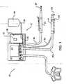
- FIG. 1depicts the basic system of this invention
- FIGS. 2 to 19illustrate the tool system but do not show the invention
- Figure 2is a cross-sectional diagram of a cutting accessory seated in the distal end of a handpiece
- Figure 3is a block diagram of the circuitry internal to the control console, the handpiece, and the cutting accessory that is used to store and read data from the accessory that describes the characteristics of the cutting accessory;
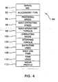
- Figure 4depicts the contents of the memory internal to the cutting accessory
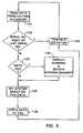
- Figure 5is a block diagram of how the control console periodically reads the contents of the memory of the cutting accessory and reconfigures the operation of the system based on the retrieved data;
- Figure 6depicts how the control console periodically determines whether or not a particular cutting accessory attached to the handpiece has been used for a time period equal to the useful lifetime of the handpiece;
- Figure 7is a cross-sectional view of an alternative handpiece and cutting accessory
- Figure 8is a cross-sectional view of locking collet of the handpiece of Figure 7 ;
- Figure 9is a plan view of the hub of the cutting accessory of Figure 7 ;
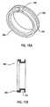
- Figure 10is a cross-sectional view of the coil seal of the cutting accessory of Figure 7 ;
- Figure 11is a perspective view of the coil seal of the cutting accessory of Figure 7 ;
- Figure 11Ais a perspective view of the cutting accessory tag assembly
- Figure 12is a perspective view of a partially assembled alternative handpiece in which a cutting accessory hub is shown coupled to the handpiece;
- Figure 13is a front view of the handpiece and cutting accessory hub of Figure 12 ;
- Figure 14is a cross sectional view of the handpiece and cutting accessory hub taken along line 14-14 of Figure 13 ;
- Figures 15A and 15Bare, respectively, perspective and cross sectional views of the handpiece coil housing
- Figure 16is a plan view of one coil assembly
- Figures 17is a plan view of the outer hub of Figure 12 ;
- Figure 18is a cross sectional view of the outer hub taken along line 18-18 of Figure 17 ;
- Figure 19is a perspective view of a chip-and-coil subassembly, a tag
- Figure 20is a block diagram view of this invention.
- Figure 21is a block diagram depiction of how this invention may be integrated in a surgical navigation system.
- Figure 22is a cross sectional view of a cutting accessory of the version of this invention depicted in Figure 21 ;
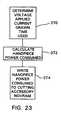
- Figure 23is a flow chart depicting how the control console determines the extent to which a particular cutting accessory is worn
- Figure 24is a block diagram of the inside of the control console depicting how separate controllers regulate the actuating of handpieces and the reading of data from the NOVRAMs integral with the cutting accessories attached to the handpieces;
- Figure 25is flow chart depicting an alternative process by which data in a cutting accessory NOVRAM are read
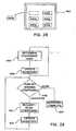
- Figure 26is a flow chart depicting an alternative process by which data in a cutting accessory NOVRAM are read and the control console configured to energize the handpiece to which the cutting accessory is attached;
- Figure 27is a flow chart depicting how the integrated cutting accessory and implant recognition system of this invention can be used to facilitate the performance of image guided surgery;
- Figure 28is a diagrammatic illustration of a case, such as a sterilization case or a trial case, in which components used to facilitate the performance of a surgical procedure are held;
- Figure 29is a flow chart depicting how the integrated cutting accessory and implant recognition system of this invention can be used to facilitate the inventory of components used during the performance of a surgical procedure.
- Figure 30is a block diagram of how the information generated by the integrated cutting accessory and implant recognition system of this invention are transferred to other components of a medical facility data information network.
- Figure 31is a block diagram of the circuitry internal to a cordless powered surgical tool and a cutting accessory that is used therewith.
- FIG 1depicts the surgical system 20.
- System 20includes a surgical handpiece 22 that is used to actuate a cutting accessory 24 that is removably attached to the handpiece.
- a motor 26( Figure 2 ) that is actuated to drive the cutting accessory 24.
- the handpiece 22is removably attached to a control console 28 by a flexible cable 30.
- the control console 28contains circuitry that is used to supply energization signals to the handpiece motor 26. The regulation of these energization signals is controlled by a microprocessor, controller 70 ( Figure 3 ), internal to the control console 28.
- controller 70Figure 3
- Internal to the handpiece 22 or the cable 30is a NOVRAM 32.
- the NOVRAM 32contains data that describes the operating characteristics of the handpiece 22. These data include: information that identifies the type of handpiece; information that describes the operating characteristics of the handpiece motor; the identification of the type of output signals provided by any sensors internal to the handpiece; and information useful for correcting the signals produced by the handpiece sensors to correct for their individual calibration characteristics. More information on the types of data contained in the handpiece NOVRAM 32 and how this information is used to regulate the operation of the handpiece 22 by the system 20 is found in U.S. Patent No. 6,017,354 .
- Figure 1further includes disposable tubing set 31.
- the tubing set 31includes tubing 33 and a cartridge 35. A portion of the tubing 33 extends through and is secured to the cartridge 35.
- the cartridgeincludes an identification chip 37.
- a first end of the tubing 33is secured to and receives irrigation fluid, such as saline from an IV bag 39.
- the cartridge 35is mounted onto the control console 28.
- a positive displacement pump (not shown) of the control consolepumps the solution to a second distal end of the tubing 33 to irrigate a surgical site.
- the tubing 33is adjacent an irrigation/cutting handpiece 41.
- a flexible cable 30aconnects the handpiece 41 to the control console 28.
- the tubing 33is positioned adjacent to the entire length of the cable 30a.
- a cutting saw 43is located at a distal end of the handpiece 41. Other cutting elements can be utilized in place of the saw 43.
- the cartridge 35can be any structure designed for securement to the control console.
- the tubing set 31comprises only tubing 31 and an identification chip 37.
- the tubing 33is secured to the control console 28 so that the pump can pump irrigation fluid to the distal end of the tubing.
- the user of the irrigation/cutting handpiece 41actuates the cutting saw 43.
- Poweris supplied to the cutting saw via cable 30a.
- tubing 33provides irrigation fluid to the surgical site.
- a coilmounted on the console adjacent the cartridge reads data from the identification chip 37.
- the dataprovides the diameter, size and any other relevant properties for the tubing 33.
- the control console 28then controls the positive displacement pump to provide a proper flow rate for the irrigation fluid being applied to the surgical site during cutting.
- a userneed not manually set specific control values for the pump.
- tubing set 31Since the tubing set 31 is disposable, typically only data is read from the identification chip 37. However, in some embodiments data is sent to the chip 37 indicating that the tubing set has been used and must be disposed of.
- no cartridge 35is present.
- the tubing 33is wrapped or otherwise configured to the pump, which is preferably mounted onto the control console 28.
- the identification chip 37is mounted directly to the tubing 33, which comprises of itself, the tubing set 31.
- the identification chip 37must be positioned adjacent a detector coil connected to the control console 28.
- Figure 2illustrates the distal end of the handpiece 22 and the proximal end of the cutting accessory 24.
- distalis used to refer to a portion of a component located away from a surgeon/towards a surgical site; “proximal” refers to a portion of a component located towards the surgeon/away from the surgical site.)
- the handpiece 22has a housing 34.
- Motor 26is disposed in the housing 34.
- the motor 26has a rotated-sleeve shaped shaft 36 to which a number of magnets 38 are attached.
- Motor 26also includes a set of windings 40 that are secured to the inner wall of housing 34 that surround magnets 38.
- the distal end of housing 34is open and dimensioned to receive the proximal end of cutting accessory 24.
- the cutting accessory 24includes an outer hub 44 formed of plastic. Outer hub 44 is formed with tabs 46. Tabs 46 seat in complementary notches 48 formed in handpiece housing 34 so as to hold the hub in one place in the housing.
- a locking mechanism integral with the handpiece(not illustrated) has members designed to engage the outer hub 44 so as to releasably secure the cutting accessory to the handpiece. For example, some handpieces are provided with a set of ball bearings that are releasesably pressed against an opposed outer surface of the outer hub.
- the Applicant's Assignee's U.S. Patent No. 6,312,441 , POWERED SURGICAL HANDPIECE FOR PERFORMING ENDOSCOPIC PROCEDURES, issued 6 November 2001discloses how one such locking assembly works.
- spring armsmay be releaseably held against the outer hub.
- the Applicant's Assignee's U.S. Patent No. 5,192,292 , SURGICAL APPARATUS FOR ARTHROSCOPIC SURGERY, issued 9 March 1993discloses one version of this type of locking assembly.
- the actual type of handpiece locking assembly that holds the cutting accessory to the 24 to the handpiece 22 and complementary outer hub geometrymay vary.
- An outer tube 50extends distally forward from the outer hub 44 away from the handpiece 22.
- the cutting accessory 24also includes an inner tube 52 that is disposed inside the outer tube 50.
- the distal head end of the inner tube 52(end not illustrated) is provided with some type of cutting member to selectively shape and/or remove the tissue to which it is applied.
- the inner tube 52extends through both the outer tube 52 and the outer hub 44.
- the proximal end of the inner tubeis attached to an inner hub 56, sometimes referred to as a drive coupling, that is located against the proximal facing face of the outer hub 44.
- inner hub 56is located inside a cavity located in the distal end of the handpiece housing 34.
- the proximal end of the inner tube 52 and inner hub 56is seated over the open distal end of handpiece shaft 36.
- Complementary teeth on the shaft 36 and the inner hub 56releasably hold the inner hub to the shaft so that the inner hub will rotate in unison with the shaft 36 (teeth not illustrated).
- An identification sleeve 60is fitted over the outer hub 44.
- Sleeve 60is formed of plastic and may provide some of the structural strength of the outer hub 44.
- Internal to sleeve 60is a small semiconductor that functions as an identification chip 62.
- Also disposed inside sleeve 44is a coil 64.
- coil 64extends annularly around sleeve 60. The ends of coil 64 are, as described below, connected to components internal to identification chip 62.
- the distal end, the head end, of handpiece housing 34is provided with a separate annular coil 66.
- the opposed ends of coil 66are connected by conductors 63 (one shown) and cable 30 to circuitry internal to the control console 28.
- the handpiece 22 and cutting accessory 24are shaped so that coils 64 and 66 are in such proximity to each other that they will collectively inductively transfer signals from/to the circuit internal to the control console to/from the circuit internal to the identification chip 62.
- the handpiece housing 34is formed of metal.
- coil 66is disposed in a ring 67 formed from a plastic that can be subjected to medical sterilization wherein the handpiece is autoclaved at 270 °F, subjected to saturated water vapor at 30 psi.
- a plastic from which ring 67 may be formedis a polyetherimide and glass filed plastic sold by the General Electric Company under the trademark ULTEM.
- Ring 67is fitted in a notch, not identified, formed in an interior wall of handpiece housing 34. The inner surface of ring 67 thus defines part of the cavity in which the proximal end of the cutting accessory 24 is seated.
- the fitting of handpiece coil 66 in ring 67facilitates the inductive signal transfer between the handpiece coil and the coil 64 integral with the cutting accessory.
- FIG. 3depicts, in block diagram, electrical components internal to control console 28 of system 20.
- the control console 28includes a controller (CNTRLR) 70 that controls the overall operation of the system 20.
- Memories, represented by a single memory 69,are also contained in the control console. These memories contain the permanent operating instructions that are executed by controller 70 to control the system and regulate the actuation of the handpiece 22 and the cutting accessory 24. The memories also temporarily store the data that is read from the handpiece NOVRAM 32.
- controller 70As part of its control of system 20, controller 70 generates energization control signals to a driver 72.
- the driver 72based in part on the energization control signals, generates energization signals that are applied to the handpiece motor 26.
- Controller 70is connected to the handpiece NOVRAM 32 to receive from the NOVRAM the data that describes the operating characteristics of the motor.
- the control console 28also includes a touch screen display 71. Controller 70 causes information regarding the state of the system 20 to be presented on the display 71. Controller 70 also causes images of buttons to be presented on the display 71. Operating room personnel regulate the operation of the system 20 by selectively depressing these buttons.
- Control console 28is also connected to a modulator (MOD) 74.
- MODulator 74modulates digital signals output by controller 70 so they can be inductively transferred to cutting accessory identification chip 62.
- modulator 74receives a fixed-frequency signal from an oscillator 76 internal to the control console 28.
- the signal produced by the oscillator 76is at a frequency of 125 Khz.
- the carrier signal produced by oscillator 76is at 13.56 MHz.
- Modulator 74based on the bit stream produced by the controller 70, engages in selective amplitude shift keying (ASK) of the carrier signal.
- ASKamplitude shift keying
- the modulator 74selectively transmits/stops transmitting the carrier signal so as to produce a set of variable length rectangular pulses.
- the amplitude shift keyed signal generated by modulator 74is amplified by an amplifier 78 internal to the control console 28.
- the output signal from amplifier 78is applied to one end of handpiece coil 66.
- Demodulator 80receives the signal that is coupled to handpiece coil 66, demodulates the signal, and applies the output bit stream to controller 70.
- a typical demodulatormay include a product detector to which the carrier signal is applied from oscillator 76.
- the output from the detectorwhich is a multiplication of the signal from the oscillator 76 and the coil 66, is applied to a low-pass filter, also part of the demodulator 80.
- the output signal from the low pass filteris a bit stream that is applied to the controller 70.
- oscillator 76is also shown as connected to controller 70. This is because the signal produced by the oscillator is also used to regulate the writing out of the bit stream that is applied to the modulator 74 and the reading in of the bit stream generated by the demodulator 80.
- the identification chip 62includes a small controller and an electronically programmable memory ( ⁇ C&MEM) 84.
- Controller/memory 84is capable of storing approximately 1 k bits of data.
- the controller integral with controller/memory 84is capable of controlling the writing of data into its complementary memory section and the writing out of the contents of the memory.
- Modulator/demodulator 86contains the components necessary to demodulate the ASK signal coupled to coil 64 and apply the resultant bit stream to controller/memory 84.
- Modulator/demodulator 86also accepts the bit stream output from the controller/memory 84 and produces an ASK modulated signal based on this bit stream.
- a clock 88 fabricated into chip 62produces a clock signal that the modulator/demodulator 86 uses as a basis for producing a carrier signal produced an ASK modulated signal.
- a capacitor 83is also fabricated integrally with chip 62. More particularly, chip 62 is designed so that coil 64 is connected across the opposed ends of capacitor 83. When a signal is applied to chip 62 through coil 64, the energy in the high portion of the signal is stored in capacitor 83. This energy is applied directly to a power regulator 89 to function as an energization signal. The power regulator 89 supplies this energization signal to the other sub-circuits internal to the chip 62. (Connections between power regulator 89 and other components of chip 62 not shown.)
- coil 64is shown as being integrally part of chip 62. This is one option for the invention. However, as discussed above, it is anticipated that in many arrangements, chip 62 and coil 64 will be separate components.
- Figure 4illustrates some of the different types of data stored in the tag controller/memory 84.
- These datainclude a serial number specific to the cutting accessory 24 with which tag 62 is integral, field 90. This number may also include a special authorization code, the purpose of which is described hereinafter.
- Field 94 within controller/memory 84contains data indicating a preferred speed at which the cutting accessory should be operated. Data indicating the maximum speed at which the cutting accessory should operate is contained in field 96. The maximum operating torque the cutting accessory should develop is indicated by data in field 98.
- Field 102contains data that indicates the preferred mode of operation of the cutting accessory. For example, if the cutting accessory 24 is a cutter, the most common mode of its operation is oscillatory. Alternatively, if the cutting accessory 24 is a burr, the preferred mode of operation is unidirectional. Stopping torque data is contained within a field 104. The stopping torque data is data used to regulate the deceleration of the handpiece motor 26.
- Controller/memory 84also contains data fields that are written to by the control console controller 70.
- One of these data fieldsis a date/time used field 106.
- Field 106is used to store data indicating if and when the cutting accessory 24 was previously used. Specifically, during loading of basic information into the controller/memory 84, field 106 is loaded with flag data indicating that it has not been previously used. As described below, once the cutting accessory 24 is used, the controller 70 writes into field 106 an indication of when the use occurs.
- a set of data indicating for how long the cutting accessory can be usedis loaded into a MAX USE TIME data field 108 in controller/memory 84.
- This particular datarepresents how long a surgeon can expect to use the cutting accessory 24 before the cutting surfaces become worn to the level at which they may not efficiently cut tissue.
- the length of time contained in field 108may be based on empirical studies indicating how long an accessory can be used before its cutting surfaces become excessively worn.
- the MAX USE TIME field 108is loaded with data specifying this time period when the other permanent accessory-describing data are loaded into controller/memory 84.
- the controller/memory 84also includes a TIME USED field 110. Data representative of the amount of time the cutting accessory has been used is stored in TIME USED field 110 by control console controller 70.
- a WEAR PROFILE field 112contains data indicating the extent to which the cutting accessory has been worn during its use.
- the system 20 of this inventionis initially configured for operation by connecting the handpiece 22 to the control console 28.
- Controller 70reads the data in the handpiece NOVRAM 32, stores these data in memory 69 and initially configures the system 20 to operate based on the data contained in the NOVRAM.
- Handpiece NOVRAM 32also contains a data field, (not illustrated), that indicates whether or not the cutting accessories attached to the handpiece 22 may contain an identification chip 62. If this data indicates no such chip may be present, system 20 controls the actuation of the handpiece 22 based on the configuration data contained in NOVRAM 32.
- controller 70executes a read request, step 120 in Figure 5 , in which it reads the data in the chip controller/memory 84.
- controller 70generates a read request to chip 62. This request is converted into an ASK signal by modulator 74 and applied to the chip through coils 64 and 66. If a chip 62 is attached to cutting accessory 24, the chip, in response to the read request, writes out the stored data in its controller/memory 84 through coils 64 and 69 and demodulator 80 to controller 70. Controller 70 stores this data in appropriate fields within control console memory 69.
- controller 70does not receive any data in response to its read request. If this event occurs, controller 70 regulates the operation of the handpiece based on the data contained in NOVRAM 32, step not shown.
- cutting accessory chip 62writes data to control console controller 70
- the first thing the controller doesis compare the serial number stored in chip 62 to the serial number stored from the last cutting accessory attached to the handpiece, step 122. If this is the first cutting accessory attached to the handpiece 22, the serial number the controller 70 has stored will be a set of flag data indicating that, previously, there was no attached cutting accessory with chip.
- step 122may also include the sub-step of, determining based on the identification number, if the appropriate authorization code is present. If this code is not present the control console 70 may prevent further operation of the system with the attached cutting accessory 24 and/or generate a message on display 71 indicating that an unauthorized accessory is attached. (The sub-steps of this code determination and the steps executed when the code is not present are not illustrated.)
- step 122If the comparison of step 122 indicates that this is the first cutting accessory attached to the handpiece or, as discussed below, there has been a change in the cutting accessory attached to the handpiece, controller 70 reads and reviews the data read from the tag data/time used field 106. Specifically, in step 123, this data is reviewed to determine whether or not the cutting accessory was previously used and, if so, did the use occur at a date and time significantly before the current data and time. The data in chip 62 may indicate that there was no previous use of the cutting accessory. Alternatively, if the data indicates that the use of the cutting accessory was relatively recent, within, for example, 24 hours, controller 70 interprets this data as indicating that the use was in association with the current surgical procedure. Controller 70 interprets either of these two states as being ones in which use of the cutting accessory can continue normally.
- controller 70may determine that the cutting accessory 26 was previously used at a time other than during the current surgical procedure. If this determination is made, controller 70 generates a warning message indicating this information on the console touch screen display 71, step 124. This provides the surgeon with an indication that the cutting accessory was used. In step 124, the controller presents a button on display 71 the surgeon must depress to acknowledge the used state of the cutting accessory before it allows the surgeon to actuate the handpiece 22.
- controller 70reconfigures the operation of the system, step 126.
- step 126based on the data read from the controller/memory 84 integral with the cutting accessory 24, controller 70 configures the system for operation with the cutting accessory. Specifically, the system 20 is set so that at least initially the handpiece motor will operate at the speed indicated by the data in preferred speed field 94. The forward/reverse/oscillate mode of the motor is set to that specified in operating mode field 102.
- the data from the cutting accessory chip 62is used to override data that supersedes the data in handpiece NOVRAM 32 that describes how the system should be configured.
- the memory integral with controller 70in which the data from chip 62 are stored and used as reference data to control the operation of the system 20.
- controller 70causes console display 71 to present an indication of the accessory's type. Controller 70 further configures the system to prevent the surgeon for generating commands that allow the handpiece motor to be actuated at a speed greater than that specified in the maximum speed field 96. (Alternatively, controller 70 may simply require the surgeon to acknowledge a warning before allowing the surgeon to operate the handpiece above the maximum speed for the associated accessory 24.) System 20 is further configured by controller 70 to prevent the generation of energization signals from being applied to the handpiece motor that would cause the cutting accessory 24 to develop more torque than it is allowed to develop according to the data in maximum torque field 98. The system is further configured so that during deceleration of the handpiece motor, the motor will not be subjected to torque in excess of the braking torque specified in stopping torque field 106.
- Controller 70also updates the data in the controller/memory 84 of the cutting accessory 24, step 128. More particularly, in step 126, the date and time the cutting accessory 24 was attached to the handpiece 22 are written into the date/time used field 106.
- steps 126 and 128are executed, the system is ready for operation.
- the control consolewill, based on commands entered by the surgeon, apply energization signals to the handpiece motor 26 so that it will run in the appropriate mode and in appropriate speed for that attached cutting accessory 24.
- This operation of the systemis represented by continued operation step 130 of Figure 4 .
- controller 70will periodically execute read request/data read and serial number comparison steps 120 and 122, respectively.
- steps 120 and 122are reexecuted once every 0.2 to 1.0 seconds during periods of time the handpiece is not being actuated. If the serial number comparison step 122 indicates that serial number associated with the cutting accessory 24 is unchanged, controller 70 recognizes this state as indicating that the same cutting accessory remains attached to the handpiece 22. If this condition is detected, controller continues to allow the system to operate in accordance with its current configuration; step 130 is continually executed.
- serial number comparison step 122may indicate that there has been a change in cutting accessory serial numbers since the step was previously executed. This condition is recognized by controller 70 as indicating that a different cutting accessory 24 is attached to the handpiece 22. If this is the detected system state, controller 70 reexecutes steps 123, 126 and 128, and, if necessary, step, 124, before reexecuting step continued operation step 128. When continuing operation step 128 is reexecuted, the system 20 has been reconfigured to actuate the handpiece in accordance with the characteristics of the newly attached cutting accessory 24.
- Controller 70also monitors the amount of time the cutting accessory 24 is actuated. Specifically, controller 70 maintains an internal timer in which a time count is maintained indicating how long the cutting accessory attached to the handpiece 22 is actuated. In some arrangements, after each time the motor is deactivated, step 138 of Figure 6 , the controller 70 performs this monitoring. Specifically, after the motor is deactivated, controller 70 performs a step 140 in which the controller writes into the TIME USED field 110 of the cutting accessory controller/memory 84 data indicating the total time the cutting accessory has been used. These data are determined based on the data read from the TIME USED field 110 when the cutting accessory was first attached to the handpiece as well as the elapsed time of use for the accessory stored by the controller 70.
- step 140may be integrated into the first reexecution of step 120 after the motor is deactivated. Alternatively, step 140 may be executed as a separate write data step after the motor is deactivated. As part of step 140, the elapsed time count held by the internal timer is zeroed out.
- Controller 70determines if the total time the cutting accessory has been used is less than the time period specified in the MAX USE TIME field 108 of the cutting accessory 24, step 142. In some versions of the invention, it is believed the useful lifetime for a cutting accessory will be between, for example, 30 and 120 minutes. If the total use time is less than the maximum recommended use time, controller 70 allows the system to operate as before, step 144. If, however, the total time of use is greater than the specified maximum recommended use time, controller 70 presents a warning notice and an acknowledgement button on the touch screen display, step 146. The surgeon must acknowledge that the cutting accessory 24 has been used for a time greater than its specified maximum use before the controller allows the system to continue to actuate the cutting accessory 24.
- Chip 64 of cutting accessory 24 of this inventioncontains a significant amount of data that describes the operating characteristics and state of the cutting accessory.
- the control console 28 of this systemautomatically both reads this data and periodically updates it.
- the control console 28, based on the data read from chip 64,configures the system so it will operate in an appropriate manner given the specific characteristics of the specific attached cutting accessory.
- the control console controller 70configures the system so that, at least initially the handpiece motor will run at the preferred speed and in the preferred mode for the cutting accessory.
- the systemis also configured to prevent the cutting accessory from being driven above its specific maximum operating speed, from developing torque beyond its design limit and from being subjected to excessive braking torque. This configuration of the system occurs without human intervention. Consequently, the possibility that human error could result in the incorrect configuration of the system 20 for the cutting accessory 24 attached to it is substantially eliminated.
- the systemprovides the surgeon with an indication of whether or not the cutting accessory attached to it was previously used. This provides the surgeon with an indication that the cutting accessory may be worn and, therefore, will not be able to satisfactorily perform the intended surgical procedure.
- System 20also, during the surgical procedure, provides the surgeon an indication that a cutting accessory has been used for a period equal to its intended lifetime. This information is supplied to the surgeon to inform him/her that the cutting accessory, even if new when installed, may be worn to the level of reduced efficiency. Thus, the surgeon, upon receiving this information, can decide whether or not to continue using the current accessory or replace it with a new one.
- the handpiece 22is constructed so that ring 67, which functions as the inner wall in which coil 66 is contained is plastic and the handpiece housing 34, which forms the outer containment wall for the coil, is formed of metal.
- the inductive field generated by coil 66is localized within the cavity in the distal end of the housing 34 in which cutting accessory 24 is seated.
- the inductive field generated by coil 66does not extend beyond the surface of housing 34. This substantially eliminates the possibility that if the handpiece was placed on a surface next to a cutting accessory that is provided with an identification chip 64, the handpiece coil 66 will not establish an inductively coupled circuit so as to provide the control console 28 with a false indication that the handpiece is actually connected to the adjacent cutting accessory.
- the coils integral with the cutting accessory and handpiecemay not extend circumferentially around the longitudinal axis of these components. Instead, these coils may be positioned to be aligned longitudinally with the longitudinal axes of the cutting accessory and handpiece.
- the handpiecemay be constructed so that the material in which coil 66 is encased is metal.
- the presence of coil 66does not require the handpiece to have a non-metallic component that is directly exposed to the rigors of sterilization.
- the data contained within the chip 62 of the handpiecemay vary from what has been described.
- the handpiece of the inventionmay not include a NOVRAM.
- chip 62contains all, or substantially all, of the handpiece characteristic data that was otherwise stored in the handpiece NOVRAM. This data is, however, specific to the operating characteristics of the cutting accessory 24 with which the chip 62 is integral.
- controller 70configures the system based on the data read from the chip 62.
- the cutting accessorymay not be possible for the cutting accessory to overwrite new data into any data field.
- the chip 62has empty data fields when it is installed in the cutting accessory 24. Then, during operation of the system 20, controller 70 writes the new data that needs to be written into chip 62 into the previously empty controller/memory data fields. During the read out of the contents of the controller/memory 84, step 120, all the data are read out.
- the controlleris configured to recognize the last data in a set of data fields, for example in a set of time used fields, as being the most current version of the data.
- Figure 7depicts an alternative handpiece 150 and cutting accessory 152 which does not form part of the invention.
- the handpiece 150has a metal body 154 to which a plastic locking collet 156 is attached. Internal to the body is a motor, not illustrated, from which a drive shaft 158 extends.
- the cutting accessory 152has a static hub 160 that is releasably held to the handpiece 150 by a locking assembly mounted in the locking collet 156.
- the locking assemblywhile not fully illustrated, includes a tongue 157 that is releasably seated in a recessed surface of hub 160.
- a tubular housing or outer tube 162extends from hub 160.
- Located proximal to hub 160 and within the handpiece 150is a drive coupler 164.
- Drive coupler 164has a proximal end designed to engage a coupling member integral with drive shaft 158 so that the shaft and coupler rotate in unison.
- a drive shaft, or inner tube 166is secured and extends distally from the drive coupler 164.
- the drive shaft 166extends through hub 160 and into housing 162.
- An RFID chip 170( Figure 11A ) is secured to hub 160.
- a coil 172is connected to chip 170.
- a coil 174is mounted to handpiece body 154 with chip 170 through coil 172.
- Handpiece body 154is generally elongated in shape and has elongated bore 177. Bore 177 is the space in which the handpiece motor as well as the proximal end of the cutting accessory 152 are seated. The distal end of body 154 is shaped to have a ring shaped head 178 that defines a counterbore 180 that opens into bore 177. Counterbore 180 opens into a main bore in the body in which the motor is housed. A suction bore 182 branches off of bore 177. Suction is drawn through the cutting accessory 152 through the suction bore 182. Partially seen in Figure 7 is a valve bore 184 that interests the suction bore. A valve (not illustrated,) is disposed in the valve bore 184, for regulating the suction flow through the cutting accessory 152 and the handpiece 150.
- a valve(not illustrated,) is disposed in the valve bore 184, for regulating the suction flow through the cutting accessory 152 and the handpiece 150.
- Handpiece body 154is further formed so that the distal end portion of the inner wall of head 178 has an inwardly directed step 186.
- Coil 174is disposed in the space defined by step 186.
- coil 174is in the helical wrap of wire.
- the wiremay be wrapped around a thin film of polyamide material that supports the wire.
- the coil 174is formed on flex circuit.
- the flex circuitis placed in the space adjacent step 186.
- Conductors 188 that connect coil 174 to downline components in the handpiece 150are seated in a separate bore 189 formed in the housing body 154.
- an impedance matching circuitthat establishes the impedance of the circuit internal to the handpiece to 50 Ohms to facilitate the exchange of the signals between control console 28 and coil 174 over a 50 Ohm impedance coaxial cable.
- Locking collet 156seen best by reference to Figure 8 , has a tubular base 190. Extending distally from base 190, collet 156 is shaped to have a head 192 that has a larger outer diameter to base 190. The moving components of the locking assembly that engage hub 160 are mounted in base 190.
- collet base 190When the handpiece 150 is assembled, collet base 190 is fitted in counterbore 180 so that the outer wall of the base abuts the inner wall of body proximal to step 186.
- An O-ring 194is located around the interface where the proximal end of collet base 190 abuts the handpiece body 154.
- the collet base 190is formed to define a groove 196 that extends circumferentially around the distal end of the outer perimeter of the proximal end of the base 190. In order to provide structural strength for the collet, it will be observed that the proximal end is located inwardly of the more distal sections of the base.
- the handpiece bodyis shaped to define an annular stepped surface 198.
- the stepped surfaceis the surface from which the body head 178 extends.
- Stepped surface 198is the surface against which the proximal facing end of collet base 190 extends.
- Housing body 154is further formed so that there is a small grooved surface 202 within stepped surface 198. Specifically, grooved surface 202 extends annularly around stepped surface 198 adjacent the outer perimeter of the stepped surface. The O-ring 194 is thus seated in the grooved surface 202 of the handpiece body 154 and groove 196 of collet 156.
- Locking collet 156is further formed to have a generally cylindrical outer ring 204 that extends proximally from head 192. Outer ring 204 thus extends circumferentially around and is spaced away from the distal end of locking collet base 190.
- coil 174is seated in the annular space between the outer wall of collet base 190 and the inner wall of outer ring 204.
- this annular spaceforms an enclosure for holding coil 174.
- the collet 156is fitted to body 154 so that the outer surface of collet outer ring 204 is disposed against the inner wall of the base head 178.
- an adhesivesuch as a silicone adhesive
- a silicone adhesiveis placed between the opposed surfaces of the body head 178 and collet outer ring 204.
- a fraction of this adhesivecollects in two annular channels 210 formed in the handpiece body head 178.
- the adhesiveforms two O-rings 211 between the body 154 and collet 156. These O-rings 211 thus prevent fluid flow from outside the handpiece 150 to coil 174.
- Hub 160which is formed of rigid plastic, is now described by reference to Figures 9, 10 and 11 .
- the hub 160is constructed to have a sleeve-shaped base 220.
- the base 220is formed with two diametrically opposed, generally rectangularly shaped openings 221.
- Extending forward from base 220 and formed integrally therewithis a substantially solid head 222. While head 222 is substantially solid, the hub 160 is formed so that a bore 224 extends axially through the head.
- Housing 162is mounted in bore 224 in any conventional manner to extend forward from head 222.
- a generally tube-shaped coil seal 226is disposed in hub base 220.
- Coil seal 226is formed from flexible sterilizable material.
- coil seal 226is formed from a silicon rubber that has 55 Shore A durometer hardness.
- the coil seal 226is shaped so as to have a first distal end section 228 that has a constant outer diameter and inner diameter. Extending proximally from the distal end section 228, the coil seal 226 has a main section 230.
- Main section 230has the same inner diameter as distal end section 228 and a smaller outer diameter.
- the coil sealis further formed so as to define a generally rectangular recess 232 in the outer surface of main section 230.
- the coil seal 226Located proximal to main section 230, the coil seal 226 has a locking section 234.
- the inner and outer diameters of locking section 234are the same as those of the distal end section 228.
- the locking section 234 of the coil sealis further formed to have two diametrically opposed lock tabs 236.
- Each lock tab 236extends radially outwardly from the outer surface of the locking section 234.
- the locking sectionalso has two diametrically opposed stop tabs 238 that extend inwardly from the inner wall of the lock section.
- each stop tab 238is radially aligned with a separate one of the lock tabs 236.
- Coil seal 226is further formed to have a tail section 240 that extends rearwardly from the locking section and that forms the proximal end of the seal.
- the tail section 240is formed to define two annular spaced apart ribs 242 and 244 that extend circumferentially around coil seal 226. Both ribs 242 and 244 extend beyond the outer diameter of the seal locking section 234. Here, the diameter of the circle subtended by the more proximal of the two ribs, rib 244, is less than the diameter subtended by the other rib, rib 242.
- Tail section 240is further formed to have an inner wall that is outwardly flared.
- the RFID chip 170When a cutting accessory 152 of this version of the invention is assembled, the RFID chip 170 is seated in seal recess 232. Coil 172 is wound over the reduced diameter outer surface of seal main section 230.
- the chip 170is mounted on a small flex circuit 171; the coil 172 is a conductive trace formed on the flex circuit 171. After manufacture of the flex circuit'171, the flex circuit, with the chip 170 mounted thereon, is wrapped in cylinder over seal main section 230.
- the RFID chip-coil-and-seal assemblyis fitted in hub base 220.
- both the RFID chip 170 and coil 172are disposed between the inner wall of the hub base and the outer surface of coil seal 226.
- the outer surfaces of the seal distal end and locking sections 228 and 234, respectively,press against the inner wall of the hub base 220. This contact forms a seal around chip 170 and coil 172.
- lock tabs 236are seated in hub base openings 221.
- the seating of the lock tabs 236 in openings 221serves to hold the coil seal 226 to the hub 160.
- tail section ribs 242 and 244are located proximal to the proximal end of the hub.
- ribs 242 and 244abut the inwardly flared surface of the handpiece collet base 190. The ribs thus function as a seal that prevents leakage from the suction channel to the coil cavity or the outside environment.
- driver coupler 164is formed with a head 245 that has a relatively large outer diameter.
- the driver coupler and rotating shaft subassemblyis moved past coil seal 226 in hub bore 224. Owing to.the dimensioning of the components, the drive coupler head 245 abuts the coil seal stop tabs 238. Owing to the compressibility of the material from which the coil seal is formed, a small amount of force will compress the stop tabs 238 to allow the complete insertion of the drive coupler and rotating shaft.
- the drive coupler head 245abuts the stop tabs 238.
- the stop tabsprevent gravity, without any additional force, from causing the driver coupler and rotating shaft to drop out of hub 160.
- FIGs 12, 13 and 14illustrate an alternative handpiece 250 and cutting accessory hub 252.
- the handpiece 250shown in cross-section in Figure 14 , includes an elongated body 254 that has an axially extending bore 256.
- the center and proximal end sections of bore 256serve as the space in which the motor and cable connecter integral with the handpiece 250 are housed, (motor and cable connector not shown).
- the distal end section of bore 256is the space internal to the handpiece in which the cutting accessory hub and drive coupler are received, (drive coupler not shown).
- This particular handpiecehas a motor with a cannulated rotor.
- suctionis drawn axially from the distal end of the rotating shaft of the attached cutting accessory, through the drive coupler and the motor rotor by the suction pump attached to the handpiece.
- Irrigation fluidis supplied to an opening in the hub 252.
- the irrigation fluidcan also be directed through the rotating shaft.
- a valve in the proximal end of body bore 256selectively connects the rotating shaft to either the suction pump or the source of irrigating fluid. This valve is set by a control tab, (not illustrated), that is positioned above a stepped surface 258 formed in the outside of body 254.
- the control tabdisplaces a linkage rod (not illustrated), that is seated in a rod bore 259 formed in the body 254.
- a linkage rod(not illustrated), that is seated in a rod bore 259 formed in the body 254.
- a coil 260is disposed in the distal end of body bore 256, immediately inside the distal end opening of bore 260.
- Coil 260shown in Figure 14 as a wrap of wires, is contained in a coil housing 262, now described by reference to Figures 15A and 15B .
- the coil housing 262is formed from a plastic cable to withstand sterilizaton such as PEEK plastic and is generally ringshaped.
- Coil housing 262is further formed to define a rectangular groove 264 that extends circumferentially around the outside of the housing. Groove 264 is the space in which coil 260 is seated.
- the proximal facing end of the coil housing 262is formed to have an annular lip 266 that extends substantially circumferentially around the housing. Lip 266 has an outer diameter substantially equal to the outer diameter of the more distal portions of the coil housing. The inner diameter of lip 266 is greater than that of the rest of the housing 262.
- Coil housing 262is further formed to have a slot 268 that is defined by opposed spaced apart ends of lip 266.
- the wires forming coil 260extend proximally into the handpiece body through slot 268.
- coil 260When handpiece 250 is assembled, coil 260 is seated in housing groove 264.
- the coil-and-housing assemblyis seated in the distal end of body bore 256.
- the coil housing 262is adhesively secured to a lock nut 270 disposed in body bore 256.
- coil housing 262may be provided with feet that press fit, snap fit or key-in-key hole slot fit into the lock nut. The coil housing 262 may even press fit into body bore 256.
- the conductors connected to coil 260are disposed in a bore, signal conduit 259, formed in the handpiece body 254.
- Signal conduit 259it is observed from Figure 14 , extends generally parallel to bore 256.
- the distal end of signal conduit 259extends diagonally into the section of bore 256 in which coil housing lip 266 is seated.
- Flex circuit 272is formed of polyamide or any other material that can serve as a structural substrate for conductors and electrical components. Generally, the depicted flex circuit 272 is L-shaped. Conductive traces 274, 276 and 278 are formed on the flex circuit 272. Two traces, traces 274 and 276 are parallel and are located on a vertical section 273 of the flex circuit in Figure 16 . An integrated circuit 280 is shown attached to trace 276. Circuit 280 is an impedance matching circuit to bring the impedance of the circuit on the trace to 50 Ohms. While not illustrated, it should be recognized that trace 274 is also attached to the integrated circuit 280. Trace 274 also terminates a short distance above integrated circuit 280.
- Trace 278extends from integrated circuit 280 and is the conductive trace formed on the generally horizontal portion 284 of flex circuit 272 in Figure 16 .
- the flex circuit 272is further formed to have a small branch section 286 that extends diagonally downward from the end of the horizontal section 284 opposite vertical section 273. The free end of trace 278 is formed over the branch section 286.
- section 284 of the flex circuitis wrapped in a circular pattern at least once in coil housing groove 264. More specifically, the flex circuit 272 is wound around the coil housing 262 so that flex circuit branch section 286 extends over section 273. Then, the free end of trace 278 is soldered or otherwise conductively connected to the free end of trace 274. Thus trace 278 forms the handpiece coil.
- the cutting accessory hub 252is formed from two plastic pieces, base 290 and head 292.
- Base 290is formed to have a proximal section 296 that has a multi-section axial bore 298. It should be understood that bore 298 is dimensioned to receive the drive coupler and proximal end of the rotating shaft of the cutting accessory with which hub 252 is integral.
- Base 290also has a distal section 302 integrally formed with and located forward of proximal section 296.
- Base distal section 302is formed to have a counterbore 304 that has a diameter that is larger than the diameter of the adjacent section of bore 298.
- the hub head 292is formed to have an axially extending through bore 308. Bore 308 is dimensioned to receive the associated rotating shaft.
- the hub headis shaped to have a generally cylindrical, proximally located stem section 310. Collectively the components forming hub 252 are shaped so that stem section 310 has an outer diameter that is appreciably less than the inner diameter of base distal end section 302.
- head stem section 310When hub 252 is assembled, head stem section 310 is seated in base counterbore 304. Owing to the relative dimensions of the base 290 and head 292, when these components are so assembled an annular coil space 312 is formed between stem section 310 and the adjacent end wall of base distal end section 302.
- An RFID chip 314 and coil 316now described by reference to Figure 19 are seated in this space. Specifically, the chip 314 and coil 316 are assembled as a single unit on a flexible substrate 318. Often this assembly is referred to as a tag.
- a chip from the Philips Semiconductor of Netherlands i.Code family of chipscan be employed as the chip 314. Conductive traces that form coil 316 are formed on substrate 318.
- substrate 318is wrapped into a cylindrical shape and inserted in base counterbore 304.
- the head stem section 310is then seated in counterbore 304. It will be understood that the base 290 and head 292 are dimensioned so that the proximal end of the head stem section abuts the step within base 290 that defines the base of counterbore 304.
- Adhesiveshold the base 290 and head 292 together.
- the adhesivesalso create a seal around coil space 312.
- base 290 and head 292may be provided with tongue-and-slot members to further facilitate the mechanical connection of these components.
- the inductive field established by the handpiece coildoes not extend more than 2 cm beyond the coil. Preferably, this inductive field extends a maximum of 1 cm beyond the coil.
- the inductive fieldis sufficient to engage in signal transfer with the coil 316 of the hub inserted in the handpiece 250, but not the coil integral with a cutting accessory that may be located next to the handpiece.
- the arrangementmay have power-consuming devices other than motors.
- the handpiece power-consuming devicemay be some sort of heat generating device, light generating device or sound/mechanical-vibration generating device.
- the energy generated by these power-consuming devicesare applied to surgical sites through removable accessories different from what has been described.
- the accessories of these versions of the system of this inventionare provided with tags that have memories in which data describing the individual operating characteristics of the accessories are stored.
- different dataare contained in cutting accessories that are actuated by devices other than motors.
- the chipmay be installed in accessories that are not actuated.
- One such deviceis a pointer that is attached to a tracker that is used to facilitate the performance of surgical navigation.
- the inventiondoes more than simply provide data or write data to a cutting accessory attached to a handpiece.
- the surgical tool system of the inventionincludes intermediate attachments 320, one shown diagrammatically in Figure 20 . These attachments 320 serve as mechanical, optical or electrical linkages between the power generating unit internal to the handpiece 22a and a cutting accessory 24a.
- an RFID chip 322is mounted in a non-metallic ring integral with the attachment (ring not illustrated).
- a coil 324 integral with the attachmentis in close enough proximity to the handpiece coil 66a that there is an inductive signal transfer between these components.
- the control console 28Based on the data read from the attachment, the control console 28 applies energization signals to the handpiece power generating unit so that it operates in a manner appropriate to the associated attachment and cutting accessories. For example, if the handpiece power generating unit is a motor, based on the data read from the attachment connected to the handpiece, the power generating unit can establish a maximum speed for the motor and/or determine the maximum torque the motor should be allowed to develop.
- the attachmentas depicted in Figure 20 , has its own coil 326 for inductive coupling to the RFID chip 62 integral with the associated cutting accessory 24a.
- the processor internal to the control consoleengages in the following data reading protocol.
- an interrogation signalis sent asking for data from an attachment RFID chip 322. Integral with this signal is data indicating the type of RFID chip, an attachment chip, that is supposed to respond to the interrogation. Based on these data, only the attachment chip 322 responds.
- the control consoleAfter the data in the attachment RFID chip 322 are read, the control console generates a second interrogation signal. Embedded in this signal are data indicating that an accessory chip 62 is supposed to respond to the interrogation. Based on this interrogation signal, only the accessory RFID chip 62 writes out data back to the processor.
- the energizaton of the handpiece power generating unitis based on data in the attachment and/or any overriding data in the cutting accessory.
- an RFID chipmay be placed in an implantable device 330 that is fitted into a patient, represented by bone section 332.
- implantable devicesinclude screws, reamers that are used to bore holes for implants, or implants themselves.
- the head of the device 330is provided with a plastic ring in which an RFID chip 336 and complementary coil 338 are seated.
- the data in chip 336include such information as the preferred and suggested maximum speeds for driving the implant into the patient. These data also describe the physical characteristics of the implant. For example, if the implant is a screw, the data describes: the implantable length of the screw; the diameter of the screw; and the size of the exposed head.
- the accessory 340 used to set the implantis provided with a coil 342.
- the accessory 340is a screw driving shaft.
- the accessoryhas a shaft 344 formed of metal.
- shaft 344is formed to have a circumferentially extending groove 346.
- Coil 342is disposed in a plastic or other non-metallic housing 347 seated in groove 346.
- Conductors, represented by a single conductor 348,extend through a conduit 349 that extends longitudinally through shaft 344.
- the conductors 348are connected to a coil 64b disposed in the distal end hub 44b of the accessory 340.
- Distal end hub 44bin addition to including coil 64b also includes an RFID chip 62b that contains data describing the characteristics of the accessory 340.
- control console 28is inductively coupled to both accessory chip 62b and implant chip 336. This coupling occurs immediately after the surgeon has depressed a control member associated with the system to actuate the handpiece 22b. This is because, at this time, the surgeon has typically already pressed the distal end head of the cutting accessory 340 against the adjacent head of the implant 330. Thus, at this time the data from the implant chip 336 can be read. The data in these chips are read by the control console 28. Based on these data, the control console regulates the application of energization signals to the handpiece 22b to ensure that the accessory 340 is driven at an appropriate speed for the complementary implant 330.
- the control console 28first verifies that the accessory 340 is an appropriate type of accessory for driving the implant. This verification may be performed by, first, determining the type of implant from the data read from the implant chip 336. Then, based on data contained in the memory internal to the control console 28, the control console determines if the accessory 340 can drive the implant. Alternatively, the data in the implant chip 336 contains a list of the types of accessories 340 that are appropriate for driving the implant. If initially, the control console 28, based on the determination of the type of accessory and the type of implant, determines that the accessory is inappropriate, the control console either provides a warning message that the surgeon must acknowledge this fact or prevents actuation of the handpiece 22b.
- control console 28configures the system so that energization signals are applied to the handpiece 22b that will cause the accessory to be driven at the preferred speed. If the surgeon attempts to drive the accessory above an appropriate maximum speed for the implant 330 or the accessory 340, at a minimum, the control console presents a warning the surgeon must acknowledge before the procedure is allowed to proceed.
- Control console 28also forwards the data regarding the characteristics of the implant 330 and the driving accessory 340 to a surgical navigation unit 350.
- the surgical navigation unitPrior to this part of the procedure, the surgical navigation unit was provided with data that describes the physical dimensions of the portion of the patient on which the procedure is being performed.
- a trackernot shown is attached to the handpiece 22b.
- the surgical navigation unit 350monitors the position of the tracker.
- the surgical navigation unithas the following data: position of the tracker; data regarding the physical characteristics of the handpiece 22a and accessory 340; and, from the implant chip 336, data regarding the physical characteristics of the implant 330. Based on these data and the stored image of the patient, the surgical navigation unit 350 is able to determine the position of the implant 330 as it is driven into the body of the patient 332. This information is presented on a monitor 352.
- the surgical navigation unit 350determines, based on the stored data regarding the implant 330 and patient 332, if it appears that there is a possibility that the implant is being inappropriately positioned in the patient. For example, if the implant is a screw that is supposed to only be driven into bone to a certain depth, the surgical navigation unit monitors the extent to which the implant is driven into the bone. If it appears that continued driving of the implant into the bone is inappropriate, the surgical navigation unit 350 causes a warning to be presented. The surgical navigation unit 350 also inhibits the control console 28 for supplying energization signals to the handpiece 22b until the warning is acknowledged.
- controller 70in addition to monitoring the amount of time a cutting accessory is actuated monitors the voltage applied to the handpiece that actuates the cutting accessory as well as the current drawn by the handpiece, step 370. When the handpiece motor is actuated, controller 70 performs step 372, a power consumed calculation for the handpiece. In step 372, based on the voltage applied to the handpiece, the current drawn and the time the handpiece was used, controller 70 determines the Watts minutes of power consumed by the handpiece.
- step 374data representative of the power consumed by the handpiece is then written by the controller 70 into the WEAR PROFILE data field 112 of controller memory 84.
- the data in the WEAR PROFILE data field 112are used in the same generally manner as the data in the TIME USED field 110 are used. Specifically, these data are read by controller 70. During the use of the cutting accessory, in a location within the memory integral with control console 28 data representative of the cumulative watt minutes of power consumed in actuating the cutting accessory are stored. These data are based on the data read from the WEAR PROFILE field 112 as well as the data generated as a result of the periodic execution of steps 370 and 372 when the handpiece motor is actuated. These data representative of total cutting accessory wear are compared to a reference value.
- This reference valuemay be from data read from chip 62, (data storage field not shown) from the handpiece or a set value in the control console memory 69. If this comparison indicates that the total amount of power employed to drive the cutting accessory exceeds the reference value, a warning message is generated on the console display 71. This provides the surgeon with an indication that the cutting accessory may be worn to a level that the efficiency of the accessory has appreciably diminished.
- Figure 24depicts in block diagram components internal to a control console to which plural handpieces may be simultaneously attached.
- the main controller 380is the processor that has primary responsibility for generating the command signals to the drivers internal to the control console that supply the energization signals to the individual handpieces 22a, 22b and 22c, (drivers not shown).
- the input signals into main controller 380include the characteristics of the individual handpieces as well as the surgeon-originating command signals that indicate the rate at which the handpieces are to be actuated.
- the input signals into main controller 380also include the data read from the identification chips 62 integral with the cutting accessories 24 attached to the individual handpiece 22a, 22b, and 22c. These data are retrieved by the accessory integrator 382. Once the accessory interrogator 382 retrieves these data, the interrogator forwards these data to the main controller 380. The main controller 380, in turn, generates command signals to the drivers to cause each handpiece 22a, 22b and 22c to be actuated appropriately for the attached cutting accessory 24.
- Figure 25depicts one protocol for retrieving data from the cutting accessory identification chips.
- the main controller 380determines that a handpiece 22a, 22b or 22c is connected to one of the control console 28 connections
- the main controllerinstructs the accessory interrogator 382, to initiate an interrogation sequence for that handpiece, (step not shown).
- the interrogation sequenceconsists of accessory interrogator 382 generating a request that any attached accessory write back one specific type of data.
- This requestrepresented by step 388, is performed so that the accessory interrogator 382 can determine whether or not an accessory is even attached to the handpiece 22a, 22b or 22c.
- the accessory interrogator 382performs this write request and waits for data step continually, as long as there is an attached handpiece.
- the specific data the accessory interrogator 382 requestsis the cutting accessory serial number.
- the identification chip in the accessoryUpon attachment of a cutting accessory 24 to a handpiece 22a, 22b or 22c, the identification chip in the accessory will, in response to the write request, read out the serial number. Upon receipt of these data, accessory interrogator requests that all the data in the accessory identification chip 64 be written back. This write request and the subsequent data write out, are represented by step 390. In step 392 the identification chip data used to control operation of the cutting accessory 24 are forwarded to the main controller 380. The main controller, as discussed previously with regard to step 126, configures the system so that energization signals will be supplied to the handpiece 22a, 22b or 22c that will cause the appropriate energization of the attached cutting accessory 24.
- the accessory interrogator 382After the data are read from the accessory identification chip 62, the accessory interrogator 382 continually generates a read request for the serial number of the accessory. This serial number is continuously compared to the serial number originally read for the cutting accessory.
- the read-request, data write and comparison stepscollectively represented as step 394. These steps are performed in order to ensure that the same cutting accessory 24 remains attached to the handpiece 22a, 22b or 22c. As long as the same cutting accessory is attached to the particular handpiece, there is no change in the overall operation of the system.
- the accessory interrogator 382interprets the response indicating the accessory was removed or switched. Accessory interrogator 382 then proceeds to step 396.
- the accessory interrogatorgenerates a message to the main controller 380 informing the main controller of the disconnect of the cutting accessory.
- the main controller 380in a step not shown, then regulates the energization of the associated handpiece as is appropriate for a cutting accessory not being attached. This particular regulation may, for example, consist of the inhibiting of the actuation of the handpiece.
- Step 388is again repetitively reexcuted until it receives a serial number indicating a cutting accessory 24 has again been attached to the handpiece.
- An advantage of the above arrangementis that, the majority of read requests generated by the accessory interrogator and subsequent data writes by the accessory NOVRAMs 32 are for relatively small amounts of data. This makes it possible for the accessory interrogator to, in a relatively short amount of time, monitor whether or not accessories 24 are attached to each of the handpieces 22a, 22b and 22c. Thus, in the event there is a removal or replacement of the cutting accessory attached to any one of the handpiece 22a, 22b or 22c, the accessory interrogator will detect this change, typically within 50 msec. or less of the event. Main controller 380 is then promptly informed of this state change so as to substantially eliminate the likelihood that a handpiece will be actuated even though there is no attached accessory, or actuated in an inappropriate manner for the attached handpiece.
- an accessory present read-request and receive written data step 402is performed as before whenever a handpiece 22a, 22b or 22c is connected to a control console 28.
- the main controllersets the control console to energize the handpiece 22a, 22b or 22c based on default setting for the handpiece. These settings are based on data in the handpiece NOVRAM.
- Accessory interrogator 382 and main controller 380repetitively reexcute steps 402 and 404, respectively, until data are returned by an accessory identification chip 62.
- step 406the accessory interrogator requests all the data in the chip, represented by step 406. These data are forwarded by the accessory interrogator 382 to the main controller 380, step not illustrated. Based on these data, in step 408, the main controller resets the data used to control the handpiece so that the handpiece 22a, 22b or 22c is energized appropriately for the attached cutting accessory 24. As before, even when the handpiece 22a, 22b or 22c is energized, the accessory interrogator 382 continues to request the serial number information from the accessory identification chip 62 to determine whether or not it has changed, step 410.
- step 410If, in step 410, it is determined that there has been a change in the cutting accessory 24 attached to the handpiece step 402 is again executed. Depending on the results of the inquiry performed in step 402 either step 404 or step 406 is again executed.
- An advantage of this method of operationis that there may be some handpieces that are used primarily with one particular type of cutting accessory.
- the cutting accessory with which the handpiece is most often usedis not provided with an identification chip.
- the handpiece NOVRAM 32contains data setting the handpiece to operate in accordance with the characteristics of this particular cutting accessory.
- the cost of providing the most often used cutting accessory with an identification chipis eliminated.
- this inventioncan be used to facilitate the placement of an implant in a patient.
- the surgical navigation unit 350is employed to measure the portion of the body of the patient to which the implant is to be fitted.
- the surgical navigation unitgenerates a message prompting the surgeon to select an implant, or a particular component of an implant, for fitting to the patient.
- the surgeonthen identifies the implant 330, as represented by step 424.
- the surgeonidentifies the specific implant by placing the handpiece 22 or cutting accessory 24 in close proximity to the implant so that the data in the implant chip 336 can be inductively written to the control console 28.
- a passive surgical instrumentlike a pointer with a built in coil, may be used to perform this data read-request and receive the written out data.
- the data identifying the implantare written to the surgical navigation unit 350.
- the surgical navigation unit 350determines whether or not the implant is appropriate for the procedure being performed, verify implant step 426. If, in step 426, the surgical navigation unit 350 determines that the implant might be inappropriate for the procedure, for example, the size appears inappropriate for the position in the body in which it is to be placed, the surgical navigation unit generates a warning to the surgeon, step not shown.
- the next step in the procedureis the prompting by the surgical navigation unit 350 of the accessory that is to be used to fit the implant, step 428.
- the surgical navigation unitin step 430, verifies that the accessory is the appropriate accessory for driving the implant. If an inappropriate accessory is selected, an appropriate warning is presented, warning step not shown.
- step 432the surgical navigation unit 350 determines whether or not the accessory and implant are ready for the fitting of the implant. This step is performed by determine whether or not the signal transferred to the accessory coil 342 indicates the implant 330 is fitted to the accessory. Once the accessory and implant are ready for implant installation, the surgical navigation unit, in step 434, presents on monitor 352 information about the exact surgical sub procedure that is performed to fit the implant. This information may include an image of the site where the implant is to be fitted. This information may also include textual commentary regarding aspects of the procedure.
- the integrated system of this inventionprovides guidance and prompts to the surgeon to facilitate the execution of the surgical procedure. This can minimize the time the patient is held under anesthesia which is one of the goals of modern surgery. Also, the implant and accessory verification steps serve to reduce the likelihood that an inadvertent oversight causes a surgeon to attempt to use a less than optimal component during a surgical procedure.
- the cutting accessory and implant recognition system of this inventionis also used to assist in the inventory of components used during a surgical procedure.
- components 440a, 440b, ... 440f used to perform the procedureare kept in a case 442.
- certain instrumentsmay be held in a sterilization case.
- trial implant componentsare held in a trial case.
- control console 28determines when a component is used. This determination occurs when an accessory is fitted to a handpiece or another device, for example an implant or an implant trial unit, is fitted in place with the handpiece or cutting accessory. As discussed above, the data in the chip integral with this instrument or implant is inductively read.
- a local inventory of used componentsis updated, step 446.
- a database in which these information is stored, a local inventory database 480,is connected to the control console as discussed below with respect to Figure 30 . Data are written to and read from this database 480 by a dedicated processor, not shown.
- step 448the processor associated with the local inventory database 480 identifies a component that needs for which accounting is required, step 448.
- the identity of this componentis sent to either the control console 28 or the surgical navigation unit 350.
- the device that receives this informationrequests the surgical personnel to locate this component.
- the personnelreturn the component 440a, 440b ... or 440f to the case 442 in which the component is stored and inductively read the stored identifying information for the component.
- step 452updates the inventory for the particular case 442.
- the local inventory database processorthen reexecutes step 448. If there are still missing components, step 450 is reexcuted and one of the remaining missing components is again identified. However, in step 448 it may be determined that all the components are accounted for. If the local inventory database processor makes this determination, this processor causes the control console 28 or navigation unit 350 to display a message indicating that the inventory is complete, step 454.
- the above aspect of this inventionfacilitates the checking of equipment used during surgery to ensure the whereabouts of this equipment is known.
- the information generated by the accessory and implant recognition system of this inventionmay be employed by components other than the control console that drive the handpieces used to actuate the accessories.
- the control console that reads the accessory and implant identify datamay be attached to a local area network to which other equipment both in the operating room and elsewhere in the medical facility are attached. In one version of a network it is contemplated that this data transfer be over a serial bus in accordance with the IEEE-1394 data transfer protocol.
- control console 28the surgical navigation unit 350 and the local inventory database 480.
- the facility's billing processorrepresented by node 482 is also attached to this network.
- the billing processorreceives data packets identifying the patient-chargeable components identified by the control console that are used during the procedure. This facilitates the accurate charging of the patient for the equipment used during the surgical procedure.
- the records of components usedare also forwarded to facility's primary inventory control database, node 484.
- Thisallows the processor that monitors inventory levels of the accessories and implants to determine when the additional equipment needs to be shipped, represented by supplier ship node 486. Also, some suppliers only bill the facility when the equipment is actually used.
- the inventory control databaseupon receiving an indication that some equipment has been used, through a supplier bill node 488 informs the supplier's processor of this event. This arrangement thus makes it possible to ensure that a facility is only billed for equipment when the equipment is used.
- the database in the facility that maintains patient recordsrepresented by node 490, receives an indication of the cutting accessories, trial components, and implants fitted during the surgical procedure.
- medical personneldo not, during the procedure have to spend time documenting what specific components where used during the procedure. Since the use of these components can readily be data stamped, the personnel likewise do not have to document when these components were used.
- tagsbe inductively coupled to the complementary handpieces in which their accessories are inserted.
- the cutting or operating end of the cordless surgical tool 522is provided with an annular coil 566.
- the cordless surgical tool 522 and cutting accessory 524are shaped so that coils 564 and 566 are in such proximity to each other that they will collectively inductively transfer signals from/to the circuit internal to the surgical tool 522 to/from the circuit internal to the identification chip 562.
- the housing of the surgical tool 522is formed of materials discussed in Applicant's above patent documents.
- the surgical tool 522includes a battery 590 that supplies power, as necessary, to the circuit elements therein (connections not shown).
- a controller 570controls the overall operation of the system.
- Memory 569 in the surgical tool 522contains the permanent operating instructions that are executed by controller 570 to control the system and regulate the actuation of the surgical tool 522 and the cutting accessory 524.
- Controller 570generates energization control signals to a driver 572.
- the energization control signalsare based on the cutting accessory 524 identified and the value selected by a manual actuator device 549.
- the manual actuator device 549can be a trigger type push button controlling the output from a variable resistor or any other type of device providing a variable signal output.
- the driver 572based on the value of the output from the manual actuator device 549 and the cutting accessory 524 identified, generates the energization signals that are applied to the surgical tool motor 526.
- the surgical tool 522can also include a touch screen display 571 or other type of indicator/input system.
- Controller 570causes information regarding the state of the system to be presented on the display 571.
- Controller 570can also cause images of buttons to be presented on the display 571.
- An operatorregulates the operation of the system by selectively depressing these buttons.
- no indicator or displayis present.
- the systemautomatically controls the cutting accessory 524 based on the accessory identified. For example, the maximum operating speed of the cutting accessory 524 can be varied depending of the accessory identified.
- the surgical tool 522also includes a modulator (MOD) 574 that modulates digital signals output by controller 570 so they can be inductively transferred to cutting accessory identification chip 562.
- modulator 574receives a fixed-frequency signal from an oscillator 576 internal to the surgical tool 522.
- Modulator 574produces an amplitude shift keyed signal generated by modulator 574 that is amplified by an amplifier 578.
- the output signal from amplifier 578is applied to one end of coil 566.
- Demodulator 580receives a signal that is coupled to coil 566, demodulates the signal, and applies the output bit stream to controller 570.
- the identification chip 562can include a small controller and an electronically programmable memory ( ⁇ C&MEM) 584.
- the controller integral with controller/memory 584controls the writing of data into its complementary memory section and the reading out of the contents of the memory.
- Modulator/demodulator (MOD DEM) 586, clock 588, capacitor 583 and power regulator 589function in substantially the same manner as described for the arrangement in Figure 3 .
- coil 564is shown as being integrally part of chip 562. This is one option for the invention. However, as discussed above, it is anticipated that in many versions of the invention, chip 62 and coil 564 will be separate components.
- Some of the different types of data stored in the tag controller/memory 584include a serial number specific to the cutting accessory 524 with which tag 562 is integral. This number may also include a special authorization code. There is also stored data that indicates the type of cutting accessory 524.
- the cutting accessory 524may be a drill, saw, burr, linkage assembly for converting rotary movement to a back-and-forth movement, or other types of elements.
- an identification tagmay be provided on the linkage assembly as well as a cutting element secured to the linkage assembly.
- the linkage assemblycan function as an intermediate attachment between the surgical tool 522 and the cutting accessory 524 in a manner similar to the arrangement shown in Figure 20 .
- the stored datacan include the size, diameter, physical materials, and type of cutting accessory 524.
- the datacan also include the preferred operating speed, maximum operating speed, maximum operating torque, stopping torque, or other type of information regarding operation of the cutting accessory 524.
- the mode of operation of the cutting accessory 524such as oscillatory or unidirectional can also be provided with the data.
- the cordless surgical tool 522 of Figure 31operates in a similar manner to the handpieces connected by cables 30 in embodiments discussed above.
- the accessory 524comprises an implant device, such as a screw or other element that is directly implanted into the body of a patient using the surgical tool 522.
- the characteristics of the accessory elementare provided to the surgical tool 522 regarding desired torque, operating speed, etc. for implanting the implant device.
Landscapes
- Health & Medical Sciences (AREA)
- Surgery (AREA)
- Life Sciences & Earth Sciences (AREA)
- Engineering & Computer Science (AREA)
- Medical Informatics (AREA)
- General Health & Medical Sciences (AREA)
- Veterinary Medicine (AREA)
- Public Health (AREA)
- Biomedical Technology (AREA)
- Heart & Thoracic Surgery (AREA)
- Nuclear Medicine, Radiotherapy & Molecular Imaging (AREA)
- Molecular Biology (AREA)
- Animal Behavior & Ethology (AREA)
- Orthopedic Medicine & Surgery (AREA)
- Oral & Maxillofacial Surgery (AREA)
- Dentistry (AREA)
- Otolaryngology (AREA)
- Robotics (AREA)
- Physics & Mathematics (AREA)
- Electromagnetism (AREA)
- Pathology (AREA)
- Surgical Instruments (AREA)
Abstract
Description
- The Applicant's Assignee's
U.S. Patent No. 6,017,354 , entitled INTEGRATED SYSTEM FOR POWERED SURGICAL TOOLS, issued 25 January 2000, describes a surgical tool system with a handpiece that is removably attached to a control console. Internal to the handpiece is a memory, a NOVRAM. The NOVRAM contains data that describes the operating characteristics of the handpiece. For example, if the handpiece includes a motor, its NOVRAM includes data indicating the maximum speed at which the motor should run and, for given speeds, the maximum torque the motor is allowed to develop. Each time a new handpiece is attached to the control console, the data in the handpiece NOVRAM is read by a complementary processor in the control console. The control console, based on the handpiece NOVRAM data, then supplies the appropriate energizaton signal to the handpiece motor. - An advantage of the foregoing system is that it allows a single control console to be used to supply the energizaton signals that are applied to the handpiece that have different power consuming units, such as motors. Thus, a single control console can be used to operate a first handpiece with a motor that rotates at speeds under 3,000 RPM and requires 350 Watts or more of power, a second handpiece that has a motor that operates at speeds over 70,000 RPM and that requires approximately 150 Watts of power and a third handpiece that operates at speeds between 10,000 to 40,000 RPM and that requires only 40 Watts of power.
- In most surgical systems, the handpiece is not the actual component that is applied to the surgical site in order to accomplish a surgical task. These components are, what are referred to as cutting accessories. Typically, a single handpiece is used to actuate a number of different types of cutting accessories. For example, a handpiece designed to perform some forms of ear, nose and throat surgery is designed to actuate both burrs and cutters. Burrs are cutting accessories designed to selectively shape and remove hard tissue, bone. Cutters are cutting accessories that are employed to selectively shape and remove soft tissue such as sinus membrane tissue.
- While a single handpiece is designed to actuate different types of cutting accessories, the accessories themselves often have different operating characteristics. For example, some burrs may have a preferred operating speed of 6,000 RPM and may be designed to operate at speeds of up to 10,000 RPM. In contrast, some cutters may have a preferred operating speed of 2,000 RPM and may be designed to operate at a maximum speed of 5,000 RPM. Moreover, some cutting accessories are operated in a different manner than other cutting accessories. For example, a burr is driven, rotated, in a single direction. A cutter is typically oscillated. In other words, when a cutter is actuated, it is typically rotated through an arc of X degrees in a first direction and then rotated in the opposite direction through the same arc. Once this first rotation cycle is complete, the motor driving the cutter repeats this rotational pattern.
- Often, during the course of a single surgical procedure, the surgeon will want to apply two or more different cutting accessories to the surgical site in order to accomplish the procedure. Typically, the surgeon will use a single handpiece to actuate these different cutting accessories. Each time the surgeon attaches a different type of cutting accessory to the handpiece, it may be necessary for the surgeon or other operating room personnel to reconfigure the surgical system used to drive the cutting accessory to set it for the specific characteristics of that accessory. When surgical personnel have to do this during the course of a surgical procedure, it can increase the overall time it takes for the procedure to be performed. This is contrary to one of the goals of modern surgery which is that it is desirable to perform a surgical procedure as quickly as possible in order to hold the overall time a patient is kept under anesthesia to a minimum.
- Moreover, having to have an individual in the operating room set the surgical system to the operating characteristics of the cutting accessory that the system is being used to operate introduces the possibility that, due to human error, these characteristics will be improperly entered.
- There have been some efforts at providing cutting accessories with type-identifying indicators, typically magnets. The handpieces to which these accessories are attached are provided with sensors. These sensors detect the presence/absence of the magnets and generate signals representative of what was sensed back to the control console. The processor in the control console, based on the signals from the handpiece sensors, then configures the system.
- The above system, while of some utility, only provides a limited amount of data about the cutting accessory attached to the system handpiece. This is because, due to space considerations, only a limited number of indicators can be mounted to a cutting accessory and only a limited number of sensors can be fitted in the head end of the handpiece designed to actuate the accessory. For example, known commercial systems of this design have handpieces with two sensors. Each sensor is designed to detect the presence/absence of a separate cutting accessory-mounted magnet. Thus, these systems simply provide 2 bits of data. Even if it were possible for the number of magnets in the cutting accessories and the number of complementary handpiece sensors to be doubled, the resultant system would only be able to provide 4 bits of accessory specific data.
- Thus, in the current systems, the indicators mounted to a cutting accessory are only employed to provide data that describes a basic operating characteristic of the accessory or that describes its type. For example, the indicator may be employed to describe basic speed and torque ranges of the cutting accessory or, for example, that the accessory is a burr. Regardless of the specific nature of this data, the control console processor, uses the data to reference complementary control data in a look-up table or other circuitry internal to the control console. The actual regulation of the handpiece is controlled by reference to this previously stored characteristic-data.
- Thus, in the foregoing cutting accessory recognition system, the actual control of the handpiece is based on operating parameters that have been previously loaded into the control console. If a new accessory is provided that has operating characteristics different than those that have been loaded into the control console, the console will not automatically configure itself to operate the handpiece in accordance with those parameters. In order for this control to be accomplished, the control console has to be loaded with the new operating characteristic data. Moreover, given the limited amount of data that can be read from the indicators of the current systems, these data may be insufficient to provide all the information a control console could use to regulate its operation based on the characteristics of the attached cutting accessory.
Figure 1 depicts the basic system of this invention;Figures 2 to 19 illustrate the tool system but do not show the invention;Figure 2 is a cross-sectional diagram of a cutting accessory seated in the distal end of a handpiece;Figure 3 is a block diagram of the circuitry internal to the control console, the handpiece, and the cutting accessory that is used to store and read data from the accessory that describes the characteristics of the cutting accessory;Figure 4 depicts the contents of the memory internal to the cutting accessory;Figure 5 is a block diagram of how the control console periodically reads the contents of the memory of the cutting accessory and reconfigures the operation of the system based on the retrieved data;Figure 6 depicts how the control console periodically determines whether or not a particular cutting accessory attached to the handpiece has been used for a time period equal to the useful lifetime of the handpiece;Figure 7 is a cross-sectional view of an alternative handpiece and cutting accessory;Figure 8 is a cross-sectional view of locking collet of the handpiece ofFigure 7 ;Figure 9 is a plan view of the hub of the cutting accessory ofFigure 7 ;Figure 10 is a cross-sectional view of the coil seal of the cutting accessory ofFigure 7 ;Figure 11 is a perspective view of the coil seal of the cutting accessory ofFigure 7 ;Figure 11A is a perspective view of the cutting accessory tag assembly;Figure 12 is a perspective view of a partially assembled alternative handpiece in which a cutting accessory hub is shown coupled to the handpiece;Figure 13 is a front view of the handpiece and cutting accessory hub ofFigure 12 ;Figure 14 is a cross sectional view of the handpiece and cutting accessory hub taken along line 14-14 ofFigure 13 ;Figures 15A and 15B are, respectively, perspective and cross sectional views of the handpiece coil housing;Figure 16 is a plan view of one coil assembly;Figures 17 is a plan view of the outer hub ofFigure 12 ;Figure 18 is a cross sectional view of the outer hub taken along line 18-18 ofFigure 17 ;Figure 19 is a perspective view of a chip-and-coil subassembly, a tag;Figure 20 is a block diagram view of this invention;Figure 21 is a block diagram depiction of how this invention may be integrated in a surgical navigation system; andFigure 22 is a cross sectional view of a cutting accessory of the version of this invention depicted inFigure 21 ;Figure 23 is a flow chart depicting how the control console determines the extent to which a particular cutting accessory is worn;Figure 24 is a block diagram of the inside of the control console depicting how separate controllers regulate the actuating of handpieces and the reading of data from the NOVRAMs integral with the cutting accessories attached to the handpieces;Figure 25 is flow chart depicting an alternative process by which data in a cutting accessory NOVRAM are read;Figure 26 is a flow chart depicting an alternative process by which data in a cutting accessory NOVRAM are read and the control console configured to energize the handpiece to which the cutting accessory is attached;Figure 27 is a flow chart depicting how the integrated cutting accessory and implant recognition system of this invention can be used to facilitate the performance of image guided surgery;Figure 28 is a diagrammatic illustration of a case, such as a sterilization case or a trial case, in which components used to facilitate the performance of a surgical procedure are held;Figure 29 is a flow chart depicting how the integrated cutting accessory and implant recognition system of this invention can be used to facilitate the inventory of components used during the performance of a surgical procedure; andFigure 30 is a block diagram of how the information generated by the integrated cutting accessory and implant recognition system of this invention are transferred to other components of a medical facility data information network.Figure 31 is a block diagram of the circuitry internal to a cordless powered surgical tool and a cutting accessory that is used therewith.Figure 1 depicts thesurgical system 20.System 20 includes asurgical handpiece 22 that is used to actuate a cuttingaccessory 24 that is removably attached to the handpiece. Internal to the handpiece is a motor 26 (Figure 2 ) that is actuated to drive the cuttingaccessory 24. Thehandpiece 22 is removably attached to acontrol console 28 by aflexible cable 30. Thecontrol console 28 contains circuitry that is used to supply energization signals to thehandpiece motor 26. The regulation of these energization signals is controlled by a microprocessor, controller 70 (Figure 3 ), internal to thecontrol console 28. Internal to thehandpiece 22 or thecable 30 is aNOVRAM 32. (When theNOVRAM 32 is in thecable 30, the cable is integrally attached to thehandpiece 22.) TheNOVRAM 32 contains data that describes the operating characteristics of thehandpiece 22. These data include: information that identifies the type of handpiece; information that describes the operating characteristics of the handpiece motor; the identification of the type of output signals provided by any sensors internal to the handpiece; and information useful for correcting the signals produced by the handpiece sensors to correct for their individual calibration characteristics. More information on the types of data contained in thehandpiece NOVRAM 32 and how this information is used to regulate the operation of thehandpiece 22 by thesystem 20 is found inU.S. Patent No. 6,017,354 .Figure 1 further includes disposable tubing set 31. The tubing set 31 includestubing 33 and acartridge 35. A portion of thetubing 33 extends through and is secured to thecartridge 35. The cartridge includes anidentification chip 37.- A first end of the
tubing 33 is secured to and receives irrigation fluid, such as saline from anIV bag 39. Thecartridge 35 is mounted onto thecontrol console 28. A positive displacement pump (not shown) of the control console pumps the solution to a second distal end of thetubing 33 to irrigate a surgical site. Thetubing 33 is adjacent an irrigation/cuttinghandpiece 41. Aflexible cable 30a connects thehandpiece 41 to thecontrol console 28. Thetubing 33 is positioned adjacent to the entire length of thecable 30a. A cutting saw 43 is located at a distal end of thehandpiece 41. Other cutting elements can be utilized in place of thesaw 43. - The
cartridge 35 can be any structure designed for securement to the control console. In some embodiments, the tubing set 31 comprises onlytubing 31 and anidentification chip 37. In this instance, thetubing 33 is secured to thecontrol console 28 so that the pump can pump irrigation fluid to the distal end of the tubing. - In operation, the user of the irrigation/cutting
handpiece 41 actuates the cutting saw 43. Power is supplied to the cutting saw viacable 30a. When the cutting saw 43 is actuated,tubing 33 provides irrigation fluid to the surgical site. - When the
cartridge 35 is installed onto theconsole 28, a coil (not shown) mounted on the console adjacent the cartridge reads data from theidentification chip 37. The data provides the diameter, size and any other relevant properties for thetubing 33. Thecontrol console 28 then controls the positive displacement pump to provide a proper flow rate for the irrigation fluid being applied to the surgical site during cutting. Thus, a user need not manually set specific control values for the pump. - Since the tubing set 31 is disposable, typically only data is read from the
identification chip 37. However, in some embodiments data is sent to thechip 37 indicating that the tubing set has been used and must be disposed of. - In some arrangements, no
cartridge 35 is present. Thetubing 33 is wrapped or otherwise configured to the pump, which is preferably mounted onto thecontrol console 28. In this instance theidentification chip 37 is mounted directly to thetubing 33, which comprises of itself, the tubing set 31. However, theidentification chip 37 must be positioned adjacent a detector coil connected to thecontrol console 28. Figure 2 illustrates the distal end of thehandpiece 22 and the proximal end of the cuttingaccessory 24. (In this application, "distal" is used to refer to a portion of a component located away from a surgeon/towards a surgical site; "proximal" refers to a portion of a component located towards the surgeon/away from the surgical site.)- The
handpiece 22 has ahousing 34.Motor 26 is disposed in thehousing 34. Themotor 26 has a rotated-sleeve shapedshaft 36 to which a number ofmagnets 38 are attached.Motor 26 also includes a set ofwindings 40 that are secured to the inner wall ofhousing 34 that surroundmagnets 38. The distal end ofhousing 34 is open and dimensioned to receive the proximal end of cuttingaccessory 24. - The cutting
accessory 24 includes anouter hub 44 formed of plastic.Outer hub 44 is formed withtabs 46.Tabs 46 seat incomplementary notches 48 formed inhandpiece housing 34 so as to hold the hub in one place in the housing. A locking mechanism integral with the handpiece, (not illustrated) has members designed to engage theouter hub 44 so as to releasably secure the cutting accessory to the handpiece. For example, some handpieces are provided with a set of ball bearings that are releasesably pressed against an opposed outer surface of the outer hub. The Applicant's Assignee'sU.S. Patent No. 6,312,441 , POWERED SURGICAL HANDPIECE FOR PERFORMING ENDOSCOPIC PROCEDURES, issued 6 November 2001 discloses how one such locking assembly works. Alternatively, spring arms may be releaseably held against the outer hub. The Applicant's Assignee'sU.S. Patent No. 5,192,292 , SURGICAL APPARATUS FOR ARTHROSCOPIC SURGERY, issued 9 March 1993 discloses one version of this type of locking assembly. Thus, the actual type of handpiece locking assembly that holds the cutting accessory to the 24 to thehandpiece 22 and complementary outer hub geometry may vary. - An
outer tube 50 extends distally forward from theouter hub 44 away from thehandpiece 22. The cuttingaccessory 24 also includes aninner tube 52 that is disposed inside theouter tube 50. The distal head end of theinner tube 52, (end not illustrated) is provided with some type of cutting member to selectively shape and/or remove the tissue to which it is applied. Theinner tube 52 extends through both theouter tube 52 and theouter hub 44. The proximal end of the inner tube is attached to aninner hub 56, sometimes referred to as a drive coupling, that is located against the proximal facing face of theouter hub 44. - When the cutting
accessory 24 is fitted in the handpiece,inner hub 56 is located inside a cavity located in the distal end of thehandpiece housing 34. The proximal end of theinner tube 52 andinner hub 56 is seated over the open distal end ofhandpiece shaft 36. Complementary teeth on theshaft 36 and theinner hub 56 releasably hold the inner hub to the shaft so that the inner hub will rotate in unison with the shaft 36 (teeth not illustrated). - An
identification sleeve 60 is fitted over theouter hub 44.Sleeve 60 is formed of plastic and may provide some of the structural strength of theouter hub 44. Internal tosleeve 60 is a small semiconductor that functions as anidentification chip 62. Also disposed insidesleeve 44 is acoil 64. In the depicted version of the invention,coil 64 extends annularly aroundsleeve 60. The ends ofcoil 64 are, as described below, connected to components internal toidentification chip 62. - The distal end, the head end, of
handpiece housing 34 is provided with a separateannular coil 66. The opposed ends ofcoil 66 are connected by conductors 63 (one shown) andcable 30 to circuitry internal to thecontrol console 28. Collectively, thehandpiece 22 and cuttingaccessory 24 are shaped so thatcoils identification chip 62. Typically, thehandpiece housing 34 is formed of metal. Accordingly,coil 66 is disposed in aring 67 formed from a plastic that can be subjected to medical sterilization wherein the handpiece is autoclaved at 270 °F, subjected to saturated water vapor at 30 psi. One suitable plastic from which ring 67 may be formed is a polyetherimide and glass filed plastic sold by the General Electric Company under the trademark ULTEM.Ring 67 is fitted in a notch, not identified, formed in an interior wall ofhandpiece housing 34. The inner surface ofring 67 thus defines part of the cavity in which the proximal end of the cuttingaccessory 24 is seated. The fitting ofhandpiece coil 66 inring 67 facilitates the inductive signal transfer between the handpiece coil and thecoil 64 integral with the cutting accessory. Figure 3 depicts, in block diagram, electrical components internal to controlconsole 28 ofsystem 20.. Thecontrol console 28 includes a controller (CNTRLR) 70 that controls the overall operation of thesystem 20. Memories, represented by asingle memory 69, are also contained in the control console. These memories contain the permanent operating instructions that are executed bycontroller 70 to control the system and regulate the actuation of thehandpiece 22 and the cuttingaccessory 24. The memories also temporarily store the data that is read from thehandpiece NOVRAM 32. As part of its control ofsystem 20,controller 70 generates energization control signals to adriver 72. Thedriver 72, based in part on the energization control signals, generates energization signals that are applied to thehandpiece motor 26.Controller 70 is connected to thehandpiece NOVRAM 32 to receive from the NOVRAM the data that describes the operating characteristics of the motor. Thecontrol console 28 also includes atouch screen display 71.Controller 70 causes information regarding the state of thesystem 20 to be presented on thedisplay 71.Controller 70 also causes images of buttons to be presented on thedisplay 71. Operating room personnel regulate the operation of thesystem 20 by selectively depressing these buttons.Control console 28 is also connected to a modulator (MOD) 74.Modulator 74 modulates digital signals output bycontroller 70 so they can be inductively transferred to cuttingaccessory identification chip 62. In one preferred version of the invention,modulator 74 receives a fixed-frequency signal from anoscillator 76 internal to thecontrol console 28. In one arrangement, the signal produced by theoscillator 76 is at a frequency of 125 Khz. In another arrangement, the carrier signal produced byoscillator 76 is at 13.56 MHz.Modulator 74, based on the bit stream produced by thecontroller 70, engages in selective amplitude shift keying (ASK) of the carrier signal. In one form of amplitude shift keying, based on the 1's and 0's pattern that forms the bit stream, themodulator 74 selectively transmits/stops transmitting the carrier signal so as to produce a set of variable length rectangular pulses. The amplitude shift keyed signal generated bymodulator 74 is amplified by anamplifier 78 internal to thecontrol console 28. The output signal fromamplifier 78 is applied to one end ofhandpiece coil 66.- The end of
handpiece coil 66 opposite the end to whichamplifier 78 is connected is tied to a demodulator (DEMOD) 80 internal to the control console.Demodulator 80 receives the signal that is coupled tohandpiece coil 66, demodulates the signal, and applies the output bit stream tocontroller 70. A typical demodulator may include a product detector to which the carrier signal is applied fromoscillator 76. The output from the detector, which is a multiplication of the signal from theoscillator 76 and thecoil 66, is applied to a low-pass filter, also part of thedemodulator 80. The output signal from the low pass filter is a bit stream that is applied to thecontroller 70. - In
Figure 3 oscillator 76 is also shown as connected tocontroller 70. This is because the signal produced by the oscillator is also used to regulate the writing out of the bit stream that is applied to themodulator 74 and the reading in of the bit stream generated by thedemodulator 80. - The
identification chip 62 includes a small controller and an electronically programmable memory (µC&MEM) 84. Controller/memory 84 is capable of storing approximately 1 k bits of data. The controller integral with controller/memory 84 is capable of controlling the writing of data into its complementary memory section and the writing out of the contents of the memory. There is also a modulator/demodulator (MOD DEM) 86 fabricated integrally intochip 62. Modulator/demodulator 86 contains the components necessary to demodulate the ASK signal coupled tocoil 64 and apply the resultant bit stream to controller/memory 84. Modulator/demodulator 86 also accepts the bit stream output from the controller/memory 84 and produces an ASK modulated signal based on this bit stream. Aclock 88 fabricated intochip 62 produces a clock signal that the modulator/demodulator 86 uses as a basis for producing a carrier signal produced an ASK modulated signal. - A
capacitor 83 is also fabricated integrally withchip 62. More particularly,chip 62 is designed so thatcoil 64 is connected across the opposed ends ofcapacitor 83. When a signal is applied to chip 62 throughcoil 64, the energy in the high portion of the signal is stored incapacitor 83. This energy is applied directly to apower regulator 89 to function as an energization signal. Thepower regulator 89 supplies this energization signal to the other sub-circuits internal to thechip 62. (Connections betweenpower regulator 89 and other components ofchip 62 not shown.) - In
Figure 3 ,coil 64 is shown as being integrally part ofchip 62. This is one option for the invention. However, as discussed above, it is anticipated that in many arrangements,chip 62 andcoil 64 will be separate components. Figure 4 illustrates some of the different types of data stored in the tag controller/memory 84. These data include a serial number specific to the cuttingaccessory 24 with which tag 62 is integral,field 90. This number may also include a special authorization code, the purpose of which is described hereinafter. There is also a field with data that indicates cutting accessory's 24 type,field 92. For example, the data infield 92 may indicate that the cutting accessory is a burr that has a head with a particular diameter.Field 94 within controller/memory 84 contains data indicating a preferred speed at which the cutting accessory should be operated. Data indicating the maximum speed at which the cutting accessory should operate is contained infield 96. The maximum operating torque the cutting accessory should develop is indicated by data infield 98.Field 102 contains data that indicates the preferred mode of operation of the cutting accessory. For example, if the cuttingaccessory 24 is a cutter, the most common mode of its operation is oscillatory. Alternatively, if the cuttingaccessory 24 is a burr, the preferred mode of operation is unidirectional. Stopping torque data is contained within afield 104. The stopping torque data is data used to regulate the deceleration of thehandpiece motor 26.- Controller/
memory 84 also contains data fields that are written to by thecontrol console controller 70. One of these data fields is a date/time usedfield 106.Field 106 is used to store data indicating if and when the cuttingaccessory 24 was previously used. Specifically, during loading of basic information into the controller/memory 84,field 106 is loaded with flag data indicating that it has not been previously used. As described below, once the cuttingaccessory 24 is used, thecontroller 70 writes intofield 106 an indication of when the use occurs. - A set of data indicating for how long the cutting accessory can be used is loaded into a MAX USE
TIME data field 108 in controller/memory 84. This particular data represents how long a surgeon can expect to use the cuttingaccessory 24 before the cutting surfaces become worn to the level at which they may not efficiently cut tissue. The length of time contained infield 108 may be based on empirical studies indicating how long an accessory can be used before its cutting surfaces become excessively worn. The MAXUSE TIME field 108 is loaded with data specifying this time period when the other permanent accessory-describing data are loaded into controller/memory 84. The controller/memory 84 also includes a TIME USEDfield 110. Data representative of the amount of time the cutting accessory has been used is stored in TIME USEDfield 110 bycontrol console controller 70. AWEAR PROFILE field 112 contains data indicating the extent to which the cutting accessory has been worn during its use. - The
system 20 of this invention is initially configured for operation by connecting thehandpiece 22 to thecontrol console 28.Controller 70 reads the data in thehandpiece NOVRAM 32, stores these data inmemory 69 and initially configures thesystem 20 to operate based on the data contained in the NOVRAM.Handpiece NOVRAM 32 also contains a data field, (not illustrated), that indicates whether or not the cutting accessories attached to thehandpiece 22 may contain anidentification chip 62. If this data indicates no such chip may be present,system 20 controls the actuation of thehandpiece 22 based on the configuration data contained inNOVRAM 32. - If, however,
NOVRAM 32 indicates that the cutting accessory may contain achip 62,controller 70 executes a read request,step 120 inFigure 5 , in which it reads the data in the chip controller/memory 84. Instep 120,controller 70 generates a read request tochip 62. This request is converted into an ASK signal bymodulator 74 and applied to the chip throughcoils chip 62 is attached to cuttingaccessory 24, the chip, in response to the read request, writes out the stored data in its controller/memory 84 throughcoils demodulator 80 tocontroller 70.Controller 70 stores this data in appropriate fields withincontrol console memory 69. - If the cutting
accessory 24 does not include achip 62,controller 70 does not receive any data in response to its read request. If this event occurs,controller 70 regulates the operation of the handpiece based on the data contained inNOVRAM 32, step not shown. - If cutting
accessory chip 62 writes data to controlconsole controller 70, the first thing the controller does is compare the serial number stored inchip 62 to the serial number stored from the last cutting accessory attached to the handpiece,step 122. If this is the first cutting accessory attached to thehandpiece 22, the serial number thecontroller 70 has stored will be a set of flag data indicating that, previously, there was no attached cutting accessory with chip. - Once it has been determined that a new cutting accessory has been attached to the
handpiece 22,step 122 may also include the sub-step of, determining based on the identification number, if the appropriate authorization code is present. If this code is not present thecontrol console 70 may prevent further operation of the system with the attached cuttingaccessory 24 and/or generate a message ondisplay 71 indicating that an unauthorized accessory is attached. (The sub-steps of this code determination and the steps executed when the code is not present are not illustrated.) - If the comparison of
step 122 indicates that this is the first cutting accessory attached to the handpiece or, as discussed below, there has been a change in the cutting accessory attached to the handpiece,controller 70 reads and reviews the data read from the tag data/time usedfield 106. Specifically, instep 123, this data is reviewed to determine whether or not the cutting accessory was previously used and, if so, did the use occur at a date and time significantly before the current data and time. The data inchip 62 may indicate that there was no previous use of the cutting accessory. Alternatively, if the data indicates that the use of the cutting accessory was relatively recent, within, for example, 24 hours,controller 70 interprets this data as indicating that the use was in association with the current surgical procedure.Controller 70 interprets either of these two states as being ones in which use of the cutting accessory can continue normally. - However, in
step 123,controller 70, based on the data read fromfield 108, may determine that the cuttingaccessory 26 was previously used at a time other than during the current surgical procedure. If this determination is made,controller 70 generates a warning message indicating this information on the consoletouch screen display 71,step 124. This provides the surgeon with an indication that the cutting accessory was used. Instep 124, the controller presents a button ondisplay 71 the surgeon must depress to acknowledge the used state of the cutting accessory before it allows the surgeon to actuate thehandpiece 22. - Once it is determined that the cutting
accessory 24 was not previously used, or the surgeon has acknowledged the previous use,controller 70 reconfigures the operation of the system,step 126. Instep 126, based on the data read from the controller/memory 84 integral with the cuttingaccessory 24,controller 70 configures the system for operation with the cutting accessory. Specifically, thesystem 20 is set so that at least initially the handpiece motor will operate at the speed indicated by the data inpreferred speed field 94. The forward/reverse/oscillate mode of the motor is set to that specified in operatingmode field 102. Thus, instep 126, the data from the cuttingaccessory chip 62 is used to override data that supersedes the data inhandpiece NOVRAM 32 that describes how the system should be configured. Not illustrated is the memory integral withcontroller 70 in which the data fromchip 62 are stored and used as reference data to control the operation of thesystem 20. - In
step 126, based on the data contained in theaccessory type field 92,controller 70causes console display 71 to present an indication of the accessory's type.Controller 70 further configures the system to prevent the surgeon for generating commands that allow the handpiece motor to be actuated at a speed greater than that specified in themaximum speed field 96. (Alternatively,controller 70 may simply require the surgeon to acknowledge a warning before allowing the surgeon to operate the handpiece above the maximum speed for the associatedaccessory 24.)System 20 is further configured bycontroller 70 to prevent the generation of energization signals from being applied to the handpiece motor that would cause the cuttingaccessory 24 to develop more torque than it is allowed to develop according to the data inmaximum torque field 98. The system is further configured so that during deceleration of the handpiece motor, the motor will not be subjected to torque in excess of the braking torque specified in stoppingtorque field 106. Controller 70 also updates the data in the controller/memory 84 of the cuttingaccessory 24,step 128. More particularly, instep 126, the date and time the cuttingaccessory 24 was attached to thehandpiece 22 are written into the date/time usedfield 106.- Once
steps handpiece motor 26 so that it will run in the appropriate mode and in appropriate speed for that attached cuttingaccessory 24. This operation of the system is represented by continuedoperation step 130 ofFigure 4 . - Throughout the operation of the
system 20,controller 70 will periodically execute read request/data read and serial number comparison steps 120 and 122, respectively. In some versions of the system, steps 120 and 122 are reexecuted once every 0.2 to 1.0 seconds during periods of time the handpiece is not being actuated. If the serialnumber comparison step 122 indicates that serial number associated with the cuttingaccessory 24 is unchanged,controller 70 recognizes this state as indicating that the same cutting accessory remains attached to thehandpiece 22. If this condition is detected, controller continues to allow the system to operate in accordance with its current configuration;step 130 is continually executed. - However, serial
number comparison step 122 may indicate that there has been a change in cutting accessory serial numbers since the step was previously executed. This condition is recognized bycontroller 70 as indicating that a different cuttingaccessory 24 is attached to thehandpiece 22. If this is the detected system state,controller 70reexecutes steps operation step 128. When continuingoperation step 128 is reexecuted, thesystem 20 has been reconfigured to actuate the handpiece in accordance with the characteristics of the newly attached cuttingaccessory 24. Controller 70 also monitors the amount of time the cuttingaccessory 24 is actuated. Specifically,controller 70 maintains an internal timer in which a time count is maintained indicating how long the cutting accessory attached to thehandpiece 22 is actuated. In some arrangements, after each time the motor is deactivated, step 138 ofFigure 6 , thecontroller 70 performs this monitoring. Specifically, after the motor is deactivated,controller 70 performs astep 140 in which the controller writes into the TIME USEDfield 110 of the cutting accessory controller/memory 84 data indicating the total time the cutting accessory has been used. These data are determined based on the data read from the TIME USEDfield 110 when the cutting accessory was first attached to the handpiece as well as the elapsed time of use for the accessory stored by thecontroller 70. Thisstep 140 may be integrated into the first reexecution ofstep 120 after the motor is deactivated. Alternatively, step 140 may be executed as a separate write data step after the motor is deactivated. As part ofstep 140, the elapsed time count held by the internal timer is zeroed out.Controller 70 then determines if the total time the cutting accessory has been used is less than the time period specified in the MAXUSE TIME field 108 of the cuttingaccessory 24,step 142. In some versions of the invention, it is believed the useful lifetime for a cutting accessory will be between, for example, 30 and 120 minutes. If the total use time is less than the maximum recommended use time,controller 70 allows the system to operate as before, step 144. If, however, the total time of use is greater than the specified maximum recommended use time,controller 70 presents a warning notice and an acknowledgement button on the touch screen display,step 146. The surgeon must acknowledge that the cuttingaccessory 24 has been used for a time greater than its specified maximum use before the controller allows the system to continue to actuate the cuttingaccessory 24.Chip 64 of cuttingaccessory 24 of this invention contains a significant amount of data that describes the operating characteristics and state of the cutting accessory. Thecontrol console 28 of this system automatically both reads this data and periodically updates it. Thecontrol console 28, based on the data read fromchip 64, configures the system so it will operate in an appropriate manner given the specific characteristics of the specific attached cutting accessory. Specifically, thecontrol console controller 70 configures the system so that, at least initially the handpiece motor will run at the preferred speed and in the preferred mode for the cutting accessory. The system is also configured to prevent the cutting accessory from being driven above its specific maximum operating speed, from developing torque beyond its design limit and from being subjected to excessive braking torque. This configuration of the system occurs without human intervention. Consequently, the possibility that human error could result in the incorrect configuration of thesystem 20 for the cuttingaccessory 24 attached to it is substantially eliminated.- The system provides the surgeon with an indication of whether or not the cutting accessory attached to it was previously used. This provides the surgeon with an indication that the cutting accessory may be worn and, therefore, will not be able to satisfactorily perform the intended surgical procedure.
System 20 also, during the surgical procedure, provides the surgeon an indication that a cutting accessory has been used for a period equal to its intended lifetime. This information is supplied to the surgeon to inform him/her that the cutting accessory, even if new when installed, may be worn to the level of reduced efficiency. Thus, the surgeon, upon receiving this information, can decide whether or not to continue using the current accessory or replace it with a new one.- Moreover, the
handpiece 22 is constructed so thatring 67, which functions as the inner wall in whichcoil 66 is contained is plastic and thehandpiece housing 34, which forms the outer containment wall for the coil, is formed of metal. As a result of this construction, the inductive field generated bycoil 66 is localized within the cavity in the distal end of thehousing 34 in which cuttingaccessory 24 is seated. The inductive field generated bycoil 66 does not extend beyond the surface ofhousing 34. This substantially eliminates the possibility that if the handpiece was placed on a surface next to a cutting accessory that is provided with anidentification chip 64, thehandpiece coil 66 will not establish an inductively coupled circuit so as to provide thecontrol console 28 with a false indication that the handpiece is actually connected to the adjacent cutting accessory. - In some arrangements, the coils integral with the cutting accessory and handpiece may not extend circumferentially around the longitudinal axis of these components. Instead, these coils may be positioned to be aligned longitudinally with the longitudinal axes of the cutting accessory and handpiece.
- Also, the handpiece may be constructed so that the material in which
coil 66 is encased is metal. Thus, the presence ofcoil 66 does not require the handpiece to have a non-metallic component that is directly exposed to the rigors of sterilization. - Moreover, the data contained within the
chip 62 of the handpiece may vary from what has been described. For instance, the handpiece of the invention may not include a NOVRAM. Here,chip 62 contains all, or substantially all, of the handpiece characteristic data that was otherwise stored in the handpiece NOVRAM. This data is, however, specific to the operating characteristics of the cuttingaccessory 24 with which thechip 62 is integral. Once the cuttingaccessory 24 is attached to thehandpiece 22,controller 70 configures the system based on the data read from thechip 62. - Also, it may not be possible for the cutting accessory to overwrite new data into any data field. Here, the
chip 62 has empty data fields when it is installed in the cuttingaccessory 24. Then, during operation of thesystem 20,controller 70 writes the new data that needs to be written intochip 62 into the previously empty controller/memory data fields. During the read out of the contents of the controller/memory 84,step 120, all the data are read out. The controller is configured to recognize the last data in a set of data fields, for example in a set of time used fields, as being the most current version of the data. Figure 7 depicts analternative handpiece 150 and cuttingaccessory 152 which does not form part of the invention. Specifically, thehandpiece 150 has ametal body 154 to which aplastic locking collet 156 is attached. Internal to the body is a motor, not illustrated, from which adrive shaft 158 extends. The cuttingaccessory 152 has astatic hub 160 that is releasably held to thehandpiece 150 by a locking assembly mounted in the lockingcollet 156. The locking assembly, while not fully illustrated, includes atongue 157 that is releasably seated in a recessed surface ofhub 160. A tubular housing orouter tube 162 extends fromhub 160. Located proximal tohub 160 and within thehandpiece 150 is adrive coupler 164.Drive coupler 164 has a proximal end designed to engage a coupling member integral withdrive shaft 158 so that the shaft and coupler rotate in unison. A drive shaft, orinner tube 166 is secured and extends distally from thedrive coupler 164. Thedrive shaft 166 extends throughhub 160 and intohousing 162.- An RFID chip 170 (
Figure 11A ) is secured tohub 160. Acoil 172 is connected to chip 170. Acoil 174 is mounted tohandpiece body 154 withchip 170 throughcoil 172. Handpiece body 154 is generally elongated in shape and has elongatedbore 177.Bore 177 is the space in which the handpiece motor as well as the proximal end of the cuttingaccessory 152 are seated. The distal end ofbody 154 is shaped to have a ring shapedhead 178 that defines acounterbore 180 that opens intobore 177.Counterbore 180 opens into a main bore in the body in which the motor is housed. A suction bore 182 branches off ofbore 177. Suction is drawn through the cuttingaccessory 152 through the suction bore 182. Partially seen inFigure 7 is avalve bore 184 that interests the suction bore. A valve (not illustrated,) is disposed in the valve bore 184, for regulating the suction flow through the cuttingaccessory 152 and thehandpiece 150.Handpiece body 154 is further formed so that the distal end portion of the inner wall ofhead 178 has an inwardly directedstep 186.Coil 174 is disposed in the space defined bystep 186. In some versions of the invention,coil 174 is in the helical wrap of wire. The wire may be wrapped around a thin film of polyamide material that supports the wire. Thecoil 174 is formed on flex circuit. The flex circuit is placed in the spaceadjacent step 186.Conductors 188 that connectcoil 174 to downline components in thehandpiece 150 are seated in aseparate bore 189 formed in thehousing body 154. Specifically, internal to the handpiece is an impedance matching circuit that establishes the impedance of the circuit internal to the handpiece to 50 Ohms to facilitate the exchange of the signals betweencontrol console 28 andcoil 174 over a 50 Ohm impedance coaxial cable.- Locking
collet 156, seen best by reference toFigure 8 , has atubular base 190. Extending distally frombase 190,collet 156 is shaped to have ahead 192 that has a larger outer diameter tobase 190. The moving components of the locking assembly that engagehub 160 are mounted inbase 190. - When the
handpiece 150 is assembled,collet base 190 is fitted incounterbore 180 so that the outer wall of the base abuts the inner wall of body proximal to step 186. An O-ring 194 is located around the interface where the proximal end ofcollet base 190 abuts thehandpiece body 154. Specifically, thecollet base 190 is formed to define agroove 196 that extends circumferentially around the distal end of the outer perimeter of the proximal end of thebase 190. In order to provide structural strength for the collet, it will be observed that the proximal end is located inwardly of the more distal sections of the base. The handpiece body is shaped to define an annular steppedsurface 198. The stepped surface is the surface from which thebody head 178 extends. Steppedsurface 198 is the surface against which the proximal facing end ofcollet base 190 extends.Housing body 154 is further formed so that there is a smallgrooved surface 202 within steppedsurface 198. Specifically, groovedsurface 202 extends annularly around steppedsurface 198 adjacent the outer perimeter of the stepped surface. The O-ring 194 is thus seated in thegrooved surface 202 of thehandpiece body 154 and groove 196 ofcollet 156. - Locking
collet 156 is further formed to have a generally cylindricalouter ring 204 that extends proximally fromhead 192.Outer ring 204 thus extends circumferentially around and is spaced away from the distal end of lockingcollet base 190. - When the
handpiece 150 is assembled,coil 174 is seated in the annular space between the outer wall ofcollet base 190 and the inner wall ofouter ring 204. In other words, this annular space forms an enclosure for holdingcoil 174. Thecollet 156 is fitted tobody 154 so that the outer surface of colletouter ring 204 is disposed against the inner wall of thebase head 178. - As part of the process of assembling the
handpiece 150, an adhesive, such as a silicone adhesive, is placed between the opposed surfaces of thebody head 178 and colletouter ring 204. A fraction of this adhesive collects in twoannular channels 210 formed in thehandpiece body head 178. Upon the curing of this adhesive in the channels, the adhesive forms two O-rings 211 between thebody 154 andcollet 156. These O-rings 211 thus prevent fluid flow from outside thehandpiece 150 tocoil 174. Hub 160, which is formed of rigid plastic, is now described by reference toFigures 9, 10 and 11 . Thehub 160 is constructed to have a sleeve-shapedbase 220. Thebase 220, it will be observed, is formed with two diametrically opposed, generally rectangularly shapedopenings 221. Extending forward frombase 220 and formed integrally therewith is a substantiallysolid head 222. Whilehead 222 is substantially solid, thehub 160 is formed so that abore 224 extends axially through the head.Housing 162 is mounted inbore 224 in any conventional manner to extend forward fromhead 222.- A generally tube-shaped
coil seal 226 is disposed inhub base 220.Coil seal 226 is formed from flexible sterilizable material. In one arrangement,coil seal 226 is formed from a silicon rubber that has 55 Shore A durometer hardness. Thecoil seal 226 is shaped so as to have a firstdistal end section 228 that has a constant outer diameter and inner diameter. Extending proximally from thedistal end section 228, thecoil seal 226 has amain section 230.Main section 230 has the same inner diameter asdistal end section 228 and a smaller outer diameter. The coil seal is further formed so as to define a generallyrectangular recess 232 in the outer surface ofmain section 230. Located proximal tomain section 230, thecoil seal 226 has alocking section 234. The inner and outer diameters of lockingsection 234 are the same as those of thedistal end section 228. - The
locking section 234 of the coil seal is further formed to have two diametricallyopposed lock tabs 236. Eachlock tab 236 extends radially outwardly from the outer surface of thelocking section 234. The locking section also has two diametricallyopposed stop tabs 238 that extend inwardly from the inner wall of the lock section. Here, eachstop tab 238 is radially aligned with a separate one of thelock tabs 236. Coil seal 226 is further formed to have atail section 240 that extends rearwardly from the locking section and that forms the proximal end of the seal. Thetail section 240 is formed to define two annular spaced apartribs coil seal 226. Bothribs seal locking section 234. Here, the diameter of the circle subtended by the more proximal of the two ribs,rib 244, is less than the diameter subtended by the other rib,rib 242.Tail section 240 is further formed to have an inner wall that is outwardly flared.- When a cutting
accessory 152 of this version of the invention is assembled, theRFID chip 170 is seated inseal recess 232.Coil 172 is wound over the reduced diameter outer surface of sealmain section 230. InFigure 11A , thechip 170 is mounted on asmall flex circuit 171; thecoil 172 is a conductive trace formed on theflex circuit 171. After manufacture of the flex circuit'171, the flex circuit, with thechip 170 mounted thereon, is wrapped in cylinder over sealmain section 230. - The RFID chip-coil-and-seal assembly is fitted in
hub base 220. Thus both theRFID chip 170 andcoil 172 are disposed between the inner wall of the hub base and the outer surface ofcoil seal 226. Owing to the relative dimensions ofhub 160 andcoil seal 226, the outer surfaces of the seal distal end and lockingsections hub base 220. This contact forms a seal aroundchip 170 andcoil 172. Thus, there is no need to employ an adhesive or other chemical to provide a moisture barrier around thechip 170 andcoil 172. - As part of the insertion of the
coil seal 226 into thehub 160,lock tabs 236 are seated inhub base openings 221. The seating of thelock tabs 236 inopenings 221 serves to hold thecoil seal 226 to thehub 160. - When the
coil seal 226 is so attached tohub 160,tail section ribs accessory 152 is fitted in thehandpiece 150,ribs handpiece collet base 190. The ribs thus function as a seal that prevents leakage from the suction channel to the coil cavity or the outside environment. - It will further be observed that the distal end of
driver coupler 164 is formed with ahead 245 that has a relatively large outer diameter. When cuttingaccessory 152 is assembled, the driver coupler and rotating shaft subassembly is movedpast coil seal 226 in hub bore 224. Owing to.the dimensioning of the components, thedrive coupler head 245 abuts the coilseal stop tabs 238. Owing to the compressibility of the material from which the coil seal is formed, a small amount of force will compress thestop tabs 238 to allow the complete insertion of the drive coupler and rotating shaft. After assembly, if the cuttingaccessory 152 is held vertically, thedrive coupler head 245 abuts thestop tabs 238. Thus, the stop tabs prevent gravity, without any additional force, from causing the driver coupler and rotating shaft to drop out ofhub 160. Figures 12, 13 and14 illustrate analternative handpiece 250 and cuttingaccessory hub 252. Thehandpiece 250, shown in cross-section inFigure 14 , includes anelongated body 254 that has anaxially extending bore 256. The center and proximal end sections ofbore 256 serve as the space in which the motor and cable connecter integral with thehandpiece 250 are housed, (motor and cable connector not shown). The distal end section ofbore 256 is the space internal to the handpiece in which the cutting accessory hub and drive coupler are received, (drive coupler not shown).- This particular handpiece has a motor with a cannulated rotor. Thus, suction is drawn axially from the distal end of the rotating shaft of the attached cutting accessory, through the drive coupler and the motor rotor by the suction pump attached to the handpiece. Irrigation fluid is supplied to an opening in the
hub 252. The irrigation fluid can also be directed through the rotating shaft. A valve in the proximal end of body bore 256 selectively connects the rotating shaft to either the suction pump or the source of irrigating fluid. This valve is set by a control tab, (not illustrated), that is positioned above a steppedsurface 258 formed in the outside ofbody 254. The control tab displaces a linkage rod (not illustrated), that is seated in arod bore 259 formed in thebody 254. The Applicant's Assignee's U.S. Patent Application, SYSTEM AND METHOD FOR PERFORMING IRRIGATED NOSE AND THROAT SURGERY Serial No.60/395 881, filed on 13 July 2002 - A
coil 260 is disposed in the distal end of body bore 256, immediately inside the distal end opening ofbore 260.Coil 260, shown inFigure 14 as a wrap of wires, is contained in acoil housing 262, now described by reference toFigures 15A and 15B . Thecoil housing 262 is formed from a plastic cable to withstand sterilizaton such as PEEK plastic and is generally ringshaped.Coil housing 262 is further formed to define arectangular groove 264 that extends circumferentially around the outside of the housing.Groove 264 is the space in whichcoil 260 is seated. The proximal facing end of thecoil housing 262 is formed to have anannular lip 266 that extends substantially circumferentially around the housing.Lip 266 has an outer diameter substantially equal to the outer diameter of the more distal portions of the coil housing. The inner diameter oflip 266 is greater than that of the rest of thehousing 262. Coil housing 262 is further formed to have aslot 268 that is defined by opposed spaced apart ends oflip 266. Thewires forming coil 260 extend proximally into the handpiece body throughslot 268.- When handpiece 250 is assembled,
coil 260 is seated inhousing groove 264. The coil-and-housing assembly is seated in the distal end of body bore 256. Thecoil housing 262 is adhesively secured to alock nut 270 disposed in body bore 256. Alternatively,coil housing 262 may be provided with feet that press fit, snap fit or key-in-key hole slot fit into the lock nut. Thecoil housing 262 may even press fit into body bore 256. - The conductors connected to
coil 260 are disposed in a bore,signal conduit 259, formed in thehandpiece body 254.Signal conduit 259, it is observed fromFigure 14 , extends generally parallel to bore 256. The distal end ofsignal conduit 259 extends diagonally into the section ofbore 256 in whichcoil housing lip 266 is seated. - In one arrangement, the conductors that extend to
coil 260, as well as the conductors that actually form the coil, are formed on aflex circuit 272 now described by reference toFigure 16 .Flex circuit 272 is formed of polyamide or any other material that can serve as a structural substrate for conductors and electrical components. Generally, the depictedflex circuit 272 is L-shaped. Conductive traces 274, 276 and 278 are formed on theflex circuit 272. Two traces, traces 274 and 276 are parallel and are located on avertical section 273 of the flex circuit inFigure 16 . Anintegrated circuit 280 is shown attached to trace 276.Circuit 280 is an impedance matching circuit to bring the impedance of the circuit on the trace to 50 Ohms. While not illustrated, it should be recognized thattrace 274 is also attached to theintegrated circuit 280.Trace 274 also terminates a short distance aboveintegrated circuit 280. Trace 278 extends fromintegrated circuit 280 and is the conductive trace formed on the generallyhorizontal portion 284 offlex circuit 272 inFigure 16 . Theflex circuit 272 is further formed to have asmall branch section 286 that extends diagonally downward from the end of thehorizontal section 284 oppositevertical section 273. The free end oftrace 278 is formed over thebranch section 286.- When an arrangement incorporating
flex circuit 272 is assembled,section 284 of the flex circuit is wrapped in a circular pattern at least once incoil housing groove 264. More specifically, theflex circuit 272 is wound around thecoil housing 262 so that flexcircuit branch section 286 extends oversection 273. Then, the free end oftrace 278 is soldered or otherwise conductively connected to the free end oftrace 274. Thus trace 278 forms the handpiece coil. - The cutting
accessory hub 252, now described by reference toFigures 17 and 18 , is formed from two plastic pieces,base 290 andhead 292.Base 290 is formed to have aproximal section 296 that has a multi-sectionaxial bore 298. It should be understood thatbore 298 is dimensioned to receive the drive coupler and proximal end of the rotating shaft of the cutting accessory with whichhub 252 is integral.Base 290 also has adistal section 302 integrally formed with and located forward ofproximal section 296. Basedistal section 302 is formed to have acounterbore 304 that has a diameter that is larger than the diameter of the adjacent section ofbore 298. - The
hub head 292 is formed to have an axially extending throughbore 308.Bore 308 is dimensioned to receive the associated rotating shaft. The hub head is shaped to have a generally cylindrical, proximally locatedstem section 310. Collectively thecomponents forming hub 252 are shaped so thatstem section 310 has an outer diameter that is appreciably less than the inner diameter of basedistal end section 302. - When
hub 252 is assembled,head stem section 310 is seated inbase counterbore 304. Owing to the relative dimensions of thebase 290 andhead 292, when these components are so assembled anannular coil space 312 is formed betweenstem section 310 and the adjacent end wall of basedistal end section 302. AnRFID chip 314 andcoil 316, now described by reference toFigure 19 are seated in this space. Specifically, thechip 314 andcoil 316 are assembled as a single unit on aflexible substrate 318. Often this assembly is referred to as a tag. A chip from the Philips Semiconductor of Netherlands i.Code family of chips can be employed as thechip 314. Conductive traces that formcoil 316 are formed onsubstrate 318. As part of the hub assembly process, prior to the insertion ofhead 292 overbase 290,substrate 318 is wrapped into a cylindrical shape and inserted inbase counterbore 304. Thehead stem section 310 is then seated incounterbore 304. It will be understood that thebase 290 andhead 292 are dimensioned so that the proximal end of the head stem section abuts the step withinbase 290 that defines the base ofcounterbore 304. - Adhesives hold the
base 290 andhead 292 together. The adhesives also create a seal aroundcoil space 312. In some versions of the invention,base 290 andhead 292 may be provided with tongue-and-slot members to further facilitate the mechanical connection of these components. - When
hub 252 is seated inhandpiece 250,coil 316 is aligned with thehandpiece coil 260. Consequently, signals are inductively transmitted between the coils. In preferred versions of the invention, the voltage across the handpiece coil is approximately 5 to 25 volts, the current through the handpiece coil is approximately 25 to 125 m Amps. Given this strength of signal, and the fact thathandpiece body 254 is metal, the inductive field established by the handpiece coil does not extend more than 2 cm beyond the coil. Preferably, this inductive field extends a maximum of 1 cm beyond the coil. Thus, the inductive field is sufficient to engage in signal transfer with thecoil 316 of the hub inserted in thehandpiece 250, but not the coil integral with a cutting accessory that may be located next to the handpiece. - It should likewise be understood that the arrangement may have power-consuming devices other than motors. For example, the handpiece power-consuming device may be some sort of heat generating device, light generating device or sound/mechanical-vibration generating device. The energy generated by these power-consuming devices are applied to surgical sites through removable accessories different from what has been described. The accessories of these versions of the system of this invention are provided with tags that have memories in which data describing the individual operating characteristics of the accessories are stored. Clearly, different data are contained in cutting accessories that are actuated by devices other than motors. Also, the chip may be installed in accessories that are not actuated. One such device is a pointer that is attached to a tracker that is used to facilitate the performance of surgical navigation.
- The invention does more than simply provide data or write data to a cutting accessory attached to a handpiece. The surgical tool system of the invention includes
intermediate attachments 320, one shown diagrammatically inFigure 20 . Theseattachments 320 serve as mechanical, optical or electrical linkages between the power generating unit internal to thehandpiece 22a and a cutting accessory 24a. In these versions of the invention, anRFID chip 322 is mounted in a non-metallic ring integral with the attachment (ring not illustrated). Upon connection of theattachment 320 to the handpiece, acoil 324 integral with the attachment is in close enough proximity to thehandpiece coil 66a that there is an inductive signal transfer between these components. Based on the data read from the attachment, thecontrol console 28 applies energization signals to the handpiece power generating unit so that it operates in a manner appropriate to the associated attachment and cutting accessories. For example, if the handpiece power generating unit is a motor, based on the data read from the attachment connected to the handpiece, the power generating unit can establish a maximum speed for the motor and/or determine the maximum torque the motor should be allowed to develop. - In the invention, the attachment as depicted in
Figure 20 , has itsown coil 326 for inductive coupling to theRFID chip 62 integral with the associated cutting accessory 24a. The processor internal to the control console engages in the following data reading protocol. First, an interrogation signal is sent asking for data from anattachment RFID chip 322. Integral with this signal is data indicating the type of RFID chip, an attachment chip, that is supposed to respond to the interrogation. Based on these data, only theattachment chip 322 responds. After the data in theattachment RFID chip 322 are read, the control console generates a second interrogation signal. Embedded in this signal are data indicating that anaccessory chip 62 is supposed to respond to the interrogation. Based on this interrogation signal, only theaccessory RFID chip 62 writes out data back to the processor. Thus, the energizaton of the handpiece power generating unit is based on data in the attachment and/or any overriding data in the cutting accessory. - Also, as depicted in
Figure, 21 , in some versions of the invention, an RFID chip may be placed in animplantable device 330 that is fitted into a patient, represented bybone section 332. Such devices include screws, reamers that are used to bore holes for implants, or implants themselves. Specifically the head of thedevice 330 is provided with a plastic ring in which anRFID chip 336 andcomplementary coil 338 are seated. The data inchip 336 include such information as the preferred and suggested maximum speeds for driving the implant into the patient. These data also describe the physical characteristics of the implant. For example, if the implant is a screw, the data describes: the implantable length of the screw; the diameter of the screw; and the size of the exposed head. - In this version of the invention, the
accessory 340 used to set the implant, as seen inFigure 22 , is provided with acoil 342. Here, theaccessory 340 is a screw driving shaft. The accessory has ashaft 344 formed of metal. Immediately proximal to the distal end,shaft 344 is formed to have acircumferentially extending groove 346.Coil 342 is disposed in a plastic or othernon-metallic housing 347 seated ingroove 346. Conductors, represented by asingle conductor 348, extend through aconduit 349 that extends longitudinally throughshaft 344. Theconductors 348 are connected to acoil 64b disposed in thedistal end hub 44b of theaccessory 340.Distal end hub 44b, in addition to includingcoil 64b also includes anRFID chip 62b that contains data describing the characteristics of theaccessory 340. - When the system of
Figure 21 is used,control console 28 is inductively coupled to bothaccessory chip 62b andimplant chip 336. This coupling occurs immediately after the surgeon has depressed a control member associated with the system to actuate thehandpiece 22b. This is because, at this time, the surgeon has typically already pressed the distal end head of the cuttingaccessory 340 against the adjacent head of theimplant 330. Thus, at this time the data from theimplant chip 336 can be read. The data in these chips are read by thecontrol console 28. Based on these data, the control console regulates the application of energization signals to thehandpiece 22b to ensure that theaccessory 340 is driven at an appropriate speed for thecomplementary implant 330. - As part of this process, the
control console 28 first verifies that theaccessory 340 is an appropriate type of accessory for driving the implant. This verification may be performed by, first, determining the type of implant from the data read from theimplant chip 336. Then, based on data contained in the memory internal to thecontrol console 28, the control console determines if theaccessory 340 can drive the implant. Alternatively, the data in theimplant chip 336 contains a list of the types ofaccessories 340 that are appropriate for driving the implant. If initially, thecontrol console 28, based on the determination of the type of accessory and the type of implant, determines that the accessory is inappropriate, the control console either provides a warning message that the surgeon must acknowledge this fact or prevents actuation of thehandpiece 22b. - If the
accessory 340 is an appropriate accessory for driving the implant,control console 28 configures the system so that energization signals are applied to thehandpiece 22b that will cause the accessory to be driven at the preferred speed. If the surgeon attempts to drive the accessory above an appropriate maximum speed for theimplant 330 or theaccessory 340, at a minimum, the control console presents a warning the surgeon must acknowledge before the procedure is allowed to proceed. Control console 28 also forwards the data regarding the characteristics of theimplant 330 and the drivingaccessory 340 to asurgical navigation unit 350. Prior to this part of the procedure, the surgical navigation unit was provided with data that describes the physical dimensions of the portion of the patient on which the procedure is being performed. A tracker, not shown is attached to thehandpiece 22b. Thesurgical navigation unit 350 monitors the position of the tracker. When the surgical procedure is being performed, the surgical navigation unit has the following data: position of the tracker; data regarding the physical characteristics of thehandpiece 22a andaccessory 340; and, from theimplant chip 336, data regarding the physical characteristics of theimplant 330. Based on these data and the stored image of the patient, thesurgical navigation unit 350 is able to determine the position of theimplant 330 as it is driven into the body of thepatient 332. This information is presented on amonitor 352.- Also, the
surgical navigation unit 350 determines, based on the stored data regarding theimplant 330 andpatient 332, if it appears that there is a possibility that the implant is being inappropriately positioned in the patient. For example, if the implant is a screw that is supposed to only be driven into bone to a certain depth, the surgical navigation unit monitors the extent to which the implant is driven into the bone. If it appears that continued driving of the implant into the bone is inappropriate, thesurgical navigation unit 350 causes a warning to be presented. Thesurgical navigation unit 350 also inhibits thecontrol console 28 for supplying energization signals to thehandpiece 22b until the warning is acknowledged. - Also, as mentioned above with respect to the data stored in chip controller/
memory 84, this component may contain data that indicates the extent to which the cutting accessory is worn. One means of determining cutting accessory wear is now described by reference toFigure 23 . Specifically,controller 70, in addition to monitoring the amount of time a cutting accessory is actuated monitors the voltage applied to the handpiece that actuates the cutting accessory as well as the current drawn by the handpiece,step 370. When the handpiece motor is actuated,controller 70 performsstep 372, a power consumed calculation for the handpiece. Instep 372, based on the voltage applied to the handpiece, the current drawn and the time the handpiece was used,controller 70 determines the Watts minutes of power consumed by the handpiece. - Then, once the handpiece motor is turned off, in
step 374, data representative of the power consumed by the handpiece is then written by thecontroller 70 into the WEAR PROFILE data field 112 ofcontroller memory 84. - It should be understood that the data in the WEAR
PROFILE data field 112 are used in the same generally manner as the data in the TIME USEDfield 110 are used. Specifically, these data are read bycontroller 70. During the use of the cutting accessory, in a location within the memory integral withcontrol console 28 data representative of the cumulative watt minutes of power consumed in actuating the cutting accessory are stored. These data are based on the data read from theWEAR PROFILE field 112 as well as the data generated as a result of the periodic execution ofsteps chip 62, (data storage field not shown) from the handpiece or a set value in thecontrol console memory 69. If this comparison indicates that the total amount of power employed to drive the cutting accessory exceeds the reference value, a warning message is generated on theconsole display 71. This provides the surgeon with an indication that the cutting accessory may be worn to a level that the efficiency of the accessory has appreciably diminished. Figure 24 depicts in block diagram components internal to a control console to which plural handpieces may be simultaneously attached. Specifically, there is a first processor,main controller 380, and a second processor,accessory interrogator 382. Themain controller 380 is the processor that has primary responsibility for generating the command signals to the drivers internal to the control console that supply the energization signals to theindividual handpieces main controller 380 include the characteristics of the individual handpieces as well as the surgeon-originating command signals that indicate the rate at which the handpieces are to be actuated.- The input signals into
main controller 380 also include the data read from the identification chips 62 integral with the cuttingaccessories 24 attached to theindividual handpiece accessory integrator 382. Once theaccessory interrogator 382 retrieves these data, the interrogator forwards these data to themain controller 380. Themain controller 380, in turn, generates command signals to the drivers to cause eachhandpiece accessory 24. Figure 25 depicts one protocol for retrieving data from the cutting accessory identification chips. Specifically, after themain controller 380 determines that ahandpiece control console 28 connections, the main controller instructs theaccessory interrogator 382, to initiate an interrogation sequence for that handpiece, (step not shown). Initially, the interrogation sequence consists ofaccessory interrogator 382 generating a request that any attached accessory write back one specific type of data. This request, represented bystep 388, is performed so that theaccessory interrogator 382 can determine whether or not an accessory is even attached to thehandpiece accessory interrogator 382 performs this write request and waits for data step continually, as long as there is an attached handpiece. In one version of the invention, the specific data theaccessory interrogator 382 requests is the cutting accessory serial number.- Upon attachment of a cutting
accessory 24 to ahandpiece accessory identification chip 64 be written back. This write request and the subsequent data write out, are represented bystep 390. Instep 392 the identification chip data used to control operation of the cuttingaccessory 24 are forwarded to themain controller 380. The main controller, as discussed previously with regard to step 126, configures the system so that energization signals will be supplied to thehandpiece accessory 24. - After the data are read from the
accessory identification chip 62, theaccessory interrogator 382 continually generates a read request for the serial number of the accessory. This serial number is continuously compared to the serial number originally read for the cutting accessory. The read-request, data write and comparison steps collectively represented asstep 394. These steps are performed in order to ensure that the same cuttingaccessory 24 remains attached to thehandpiece - If, however, the serial number is different, or no serial number is returned, the
accessory interrogator 382 interprets the response indicating the accessory was removed or switched.Accessory interrogator 382 then proceeds to step 396. Instep 396, the accessory interrogator generates a message to themain controller 380 informing the main controller of the disconnect of the cutting accessory. Themain controller 380, in a step not shown, then regulates the energization of the associated handpiece as is appropriate for a cutting accessory not being attached. This particular regulation may, for example, consist of the inhibiting of the actuation of the handpiece. - The
accessory interrogator 382 thenreexecutes step 388. Step 388 is again repetitively reexcuted until it receives a serial number indicating a cuttingaccessory 24 has again been attached to the handpiece. - An advantage of the above arrangement is that, the majority of read requests generated by the accessory interrogator and subsequent data writes by the
accessory NOVRAMs 32 are for relatively small amounts of data. This makes it possible for the accessory interrogator to, in a relatively short amount of time, monitor whether or notaccessories 24 are attached to each of thehandpieces handpiece Main controller 380 is then promptly informed of this state change so as to substantially eliminate the likelihood that a handpiece will be actuated even though there is no attached accessory, or actuated in an inappropriate manner for the attached handpiece. - An alternative protocol for reading data from a cutting
accessory identification chip 62 is now described by reference toFigure 26 . Here an accessory present read-request and receive writtendata step 402, identical to step 388, is performed as before whenever ahandpiece control console 28. However, if theaccessory interrogator 382 does not provide themain controller 380 with a data fromaccessory identification chip 62, instep 404, the main controller sets the control console to energize thehandpiece Accessory interrogator 382 andmain controller 380 repetitivelyreexcute steps accessory identification chip 62. - Once data, again typically a serial number, are returned by the
identification chip 62 of a newly installed cuttingaccessory 24, the accessory interrogator requests all the data in the chip, represented bystep 406. These data are forwarded by theaccessory interrogator 382 to themain controller 380, step not illustrated. Based on these data, instep 408, the main controller resets the data used to control the handpiece so that thehandpiece accessory 24. As before, even when thehandpiece accessory interrogator 382 continues to request the serial number information from theaccessory identification chip 62 to determine whether or not it has changed,step 410. - If, in
step 410, it is determined that there has been a change in the cuttingaccessory 24 attached to thehandpiece step 402 is again executed. Depending on the results of the inquiry performed instep 402 either step 404 or step 406 is again executed. - An advantage of this method of operation is that there may be some handpieces that are used primarily with one particular type of cutting accessory. The cutting accessory with which the handpiece is most often used is not provided with an identification chip. The
handpiece NOVRAM 32 contains data setting the handpiece to operate in accordance with the characteristics of this particular cutting accessory. Thus, in this version of the invention, the cost of providing the most often used cutting accessory with an identification chip is eliminated. - A more detailed explanation of how the cutting accessory and implant recognition system of this invention can be used in combination with a
surgical navigation unit 350 is now described by reference toFigure 27 . Specifically, this invention can be used to facilitate the placement of an implant in a patient. As represented bystep 420, initially thesurgical navigation unit 350 is employed to measure the portion of the body of the patient to which the implant is to be fitted. Then, as represented bystep 422, as part of the procedure, the surgical navigation unit generates a message prompting the surgeon to select an implant, or a particular component of an implant, for fitting to the patient. - The surgeon then identifies the
implant 330, as represented bystep 424. In this step, the surgeon identifies the specific implant by placing thehandpiece 22 or cuttingaccessory 24 in close proximity to the implant so that the data in theimplant chip 336 can be inductively written to thecontrol console 28. In some versions of the invention, a passive surgical instrument, like a pointer with a built in coil, may be used to perform this data read-request and receive the written out data. - The data identifying the implant are written to the
surgical navigation unit 350. Thesurgical navigation unit 350, in turn, based on input variables such as the dimensions of the implant and the measurements of the patient's body, determines whether or not the implant is appropriate for the procedure being performed, verifyimplant step 426. If, instep 426, thesurgical navigation unit 350 determines that the implant might be inappropriate for the procedure, for example, the size appears inappropriate for the position in the body in which it is to be placed, the surgical navigation unit generates a warning to the surgeon, step not shown. - The next step in the procedure is the prompting by the
surgical navigation unit 350 of the accessory that is to be used to fit the implant,step 428. The surgical navigation unit, instep 430, verifies that the accessory is the appropriate accessory for driving the implant. If an inappropriate accessory is selected, an appropriate warning is presented, warning step not shown. - In
step 432 thesurgical navigation unit 350 determines whether or not the accessory and implant are ready for the fitting of the implant. This step is performed by determine whether or not the signal transferred to theaccessory coil 342 indicates theimplant 330 is fitted to the accessory. Once the accessory and implant are ready for implant installation, the surgical navigation unit, instep 434, presents onmonitor 352 information about the exact surgical sub procedure that is performed to fit the implant. This information may include an image of the site where the implant is to be fitted. This information may also include textual commentary regarding aspects of the procedure. - Thus, the integrated system of this invention provides guidance and prompts to the surgeon to facilitate the execution of the surgical procedure. This can minimize the time the patient is held under anesthesia which is one of the goals of modern surgery. Also, the implant and accessory verification steps serve to reduce the likelihood that an inadvertent oversight causes a surgeon to attempt to use a less than optimal component during a surgical procedure.
- The cutting accessory and implant recognition system of this invention is also used to assist in the inventory of components used during a surgical procedure. As seen by reference to
Figure 28 ,components case 442. For example, certain instruments may be held in a sterilization case. Alternatively trial implant components are held in a trial case. - As part of the procedure, the
control console 28, instep 444, determines when a component is used. This determination occurs when an accessory is fitted to a handpiece or another device, for example an implant or an implant trial unit, is fitted in place with the handpiece or cutting accessory. As discussed above, the data in the chip integral with this instrument or implant is inductively read. - As a consequence of this component used determination, a local inventory of used components is updated,
step 446. A database in which these information is stored, alocal inventory database 480, is connected to the control console as discussed below with respect toFigure 30 . Data are written to and read from thisdatabase 480 by a dedicated processor, not shown. - Eventually, there is a point in the procedure in which it is time to inventory the used components to ensure that their whereabouts are known and they are properly stored. Typically this point is near the end of the procedure. At this time, the processor associated with the
local inventory database 480 identifies a component that needs for which accounting is required,step 448. The identity of this component is sent to either thecontrol console 28 or thesurgical navigation unit 350. The device that receives this information, instep 450, requests the surgical personnel to locate this component. In response to this request, also part ofstep 450 inFigure 29 , the personnel return thecomponent case 442 in which the component is stored and inductively read the stored identifying information for the component. - Data indicating that the component has been properly returned to the
case 442 are forwarded to the processor associated with thelocal inventory database 480. This processor, instep 452, updates the inventory for theparticular case 442. The local inventory database processor thenreexecutes step 448. If there are still missing components,step 450 is reexcuted and one of the remaining missing components is again identified. However, instep 448 it may be determined that all the components are accounted for. If the local inventory database processor makes this determination, this processor causes thecontrol console 28 ornavigation unit 350 to display a message indicating that the inventory is complete,step 454. - The above aspect of this invention facilitates the checking of equipment used during surgery to ensure the whereabouts of this equipment is known.
- As mentioned above, and now described by reference to
Figure 30 , the information generated by the accessory and implant recognition system of this invention may be employed by components other than the control console that drive the handpieces used to actuate the accessories. Specifically, as seen in this Figure, the control console that reads the accessory and implant identify data may be attached to a local area network to which other equipment both in the operating room and elsewhere in the medical facility are attached. In one version of a network it is contemplated that this data transfer be over a serial bus in accordance with the IEEE-1394 data transfer protocol. - Three devices attached this network are the
control console 28, thesurgical navigation unit 350 and thelocal inventory database 480. - The facility's billing processor, represented by
node 482 is also attached to this network. The billing processor receives data packets identifying the patient-chargeable components identified by the control console that are used during the procedure. This facilitates the accurate charging of the patient for the equipment used during the surgical procedure. - The records of components used are also forwarded to facility's primary inventory control database,
node 484. This allows the processor that monitors inventory levels of the accessories and implants to determine when the additional equipment needs to be shipped, represented bysupplier ship node 486. Also, some suppliers only bill the facility when the equipment is actually used. The inventory control database, upon receiving an indication that some equipment has been used, through asupplier bill node 488 informs the supplier's processor of this event. This arrangement thus makes it possible to ensure that a facility is only billed for equipment when the equipment is used. - Also the database in the facility that maintains patient records, represented by node 490, receives an indication of the cutting accessories, trial components, and implants fitted during the surgical procedure. Thus, medical personnel do not, during the procedure have to spend time documenting what specific components where used during the procedure. Since the use of these components can readily be data stamped, the personnel likewise do not have to document when these components were used.
- Also, there is no reason that in all versions of the invention the tags be inductively coupled to the complementary handpieces in which their accessories are inserted. In some versions of the invention, there may be physical connections between the exposed contacts that are part of the handpiece and accessory. These contacts, upon physical abutment, establish the connection between the accessory tag and the conductors in the handpiece that extend to the control console.
- Applicant's Assignee's
U.S. Patent No. 5,747,953 entitled CORDLESS, BATTERY OPERATED SURGICAL TOOL, issued 5 May 1998, describes a surgical tool that may be modified to include the circuit arrangement shown inFigure 31 . - As shown in
Figure 31 , the cutting or operating end of the cordlesssurgical tool 522 is provided with anannular coil 566. Collectively, the cordlesssurgical tool 522 and cuttingaccessory 524 are shaped so thatcoils surgical tool 522 to/from the circuit internal to theidentification chip 562. Typically, the housing of thesurgical tool 522 is formed of materials discussed in Applicant's above patent documents. - The
surgical tool 522 includes abattery 590 that supplies power, as necessary, to the circuit elements therein (connections not shown). Acontroller 570 controls the overall operation of the system.Memory 569 in thesurgical tool 522 contains the permanent operating instructions that are executed bycontroller 570 to control the system and regulate the actuation of thesurgical tool 522 and the cuttingaccessory 524.Controller 570 generates energization control signals to adriver 572. The energization control signals are based on the cuttingaccessory 524 identified and the value selected by amanual actuator device 549. Themanual actuator device 549 can be a trigger type push button controlling the output from a variable resistor or any other type of device providing a variable signal output. Thedriver 572, based on the value of the output from themanual actuator device 549 and the cuttingaccessory 524 identified, generates the energization signals that are applied to thesurgical tool motor 526. - The
surgical tool 522 can also include atouch screen display 571 or other type of indicator/input system.Controller 570 causes information regarding the state of the system to be presented on thedisplay 571.Controller 570 can also cause images of buttons to be presented on thedisplay 571. An operator regulates the operation of the system by selectively depressing these buttons. In other embodiments, no indicator or display is present. The system automatically controls the cuttingaccessory 524 based on the accessory identified. For example, the maximum operating speed of the cuttingaccessory 524 can be varied depending of the accessory identified. - The
surgical tool 522 also includes a modulator (MOD) 574 that modulates digital signals output bycontroller 570 so they can be inductively transferred to cuttingaccessory identification chip 562. In one preferred version of the invention,modulator 574 receives a fixed-frequency signal from anoscillator 576 internal to thesurgical tool 522. Modulator 574 produces an amplitude shift keyed signal generated bymodulator 574 that is amplified by anamplifier 578. The output signal fromamplifier 578 is applied to one end ofcoil 566.Demodulator 580 receives a signal that is coupled tocoil 566, demodulates the signal, and applies the output bit stream tocontroller 570.- The
identification chip 562 can include a small controller and an electronically programmable memory (µC&MEM) 584. The controller integral with controller/memory 584 controls the writing of data into its complementary memory section and the reading out of the contents of the memory. Modulator/demodulator (MOD DEM) 586,clock 588,capacitor 583 andpower regulator 589 function in substantially the same manner as described for the arrangement inFigure 3 . - In
Figure 31 ,coil 564 is shown as being integrally part ofchip 562. This is one option for the invention. However, as discussed above, it is anticipated that in many versions of the invention,chip 62 andcoil 564 will be separate components. - Some of the different types of data stored in the tag controller/
memory 584 include a serial number specific to the cuttingaccessory 524 with which tag 562 is integral. This number may also include a special authorization code. There is also stored data that indicates the type of cuttingaccessory 524. For example, the cuttingaccessory 524 may be a drill, saw, burr, linkage assembly for converting rotary movement to a back-and-forth movement, or other types of elements. In cases where a linkage assembly is utilized, an identification tag may be provided on the linkage assembly as well as a cutting element secured to the linkage assembly. The linkage assembly can function as an intermediate attachment between thesurgical tool 522 and the cuttingaccessory 524 in a manner similar to the arrangement shown inFigure 20 . - The stored data can include the size, diameter, physical materials, and type of cutting
accessory 524. The data can also include the preferred operating speed, maximum operating speed, maximum operating torque, stopping torque, or other type of information regarding operation of the cuttingaccessory 524. The mode of operation of the cuttingaccessory 524, such as oscillatory or unidirectional can also be provided with the data. - Data indicating if and when the cutting
accessory 524 was previously used, and for how long can be read and written to thechip 562. Data indicating how long a surgeon can expect to use the cuttingaccessory 524 before the cutting/drilling surfaces become worn to the level at which they may not efficiently cut tissue can be read/stored. - The cordless
surgical tool 522 ofFigure 31 operates in a similar manner to the handpieces connected bycables 30 in embodiments discussed above. - In another embodiment, the
accessory 524 comprises an implant device, such as a screw or other element that is directly implanted into the body of a patient using thesurgical tool 522. In this instance, the characteristics of the accessory element are provided to thesurgical tool 522 regarding desired torque, operating speed, etc. for implanting the implant device.
Claims (15)
- A surgical tool system, said system comprising:a handplece (22a) with a power generating unit (26) capable of driving a cutting accessory (24a) or an implantable device (330) that is fitted into a patient; andand an attachment (320, 340) connectable to the handpiece (22a), the attachment (320, 340) serving as a linkage between the power generating unit (26) and the cutting accessory (24a) or implantable device (330) for driving the cutting accessory or the implantable device;characterized in that:the handplece (22a) comprises a coil (66, 66a); andthe attachment (320, 340) comprises a first coil (326, 342) positioned so that when the cutting accessory (24a) or implantable device (330) is attached to the attachment (320, 340), the first coil (326, 342) Is able to receive signals from a coil (64, 338) internal to the cutting accessory (24a) or implantable device (330); and a second coil (324, 64b) connected to the first coil (326, 342) and positioned so that when the attachment (320, 340) is attached to the handpiece (22a), the second coil (324, 64b) is able to transmit signals received from the cutting accessory or Implantable device coil (64, 338) to the handpiece coil (66, 66a).
- The surgical tool system of claim 1, wherein the attachment (320, 340) further comprises a memory (322, 62b) containing data describing the operating characteristics of the attachment (320, 340), the memory (322, 62b) connected to said second coil (324, 64b).
- The surgical tool system of claim 1 or 2, wherein the power generating unit (26) is one selected from the group consisting of a motor, a heat generating device, a light generating device, a sound or mechanical-vibration generating device.
- The surgical tool system of any one of claims 1 to 3, wherein:a control console (28, 70) regulates operation of the handpiece power generating unit (26);the accessory (24a) or implantable device (330) comprises a memory (62, 336) with data that describe the characteristics of the accessory (24a) or the implantable device (330); andthe controle console (28) receives from the accessory coil (64), the attachment first coil (326), the attachment second coil (324) and the handpiece coil (66, 66a) said data in the accessory or implantable device memory (62, 336) and, based on said data, regulates operation of the handpiece power generating unit (26).
- The surgical tool system of claim 4, wherein the control console (28) is removably attached to the handpiece (22a) by a cable (30).
- The surgical tool system of claim 4, wherein the control console (28) comprises a controller (70).
- The surgical tool system of any one of claims 4 to 6, wherein:the attachment (320, 340) comprises a memory (322, 62b) that contains data describing the characteristics of the attachment;the control console (28, 70) reads through the attachemnt second coil (324) and the handpiece coil (66a) the data In said attachment memory (322); and,based on the read data, the control console (28) regulates operation of the handpiece power generating unit (26).
- The surgical tool system of any one of claims 4 to 6, wherein:the attachment (320, 340) comprises a memory (322, 62b) that contains data describing the characteristics of the attachment;the control console (28, 70) reads through the attachment second coil (324) and the handplece coil (66a) the data in said attachment memory (322); and,based on the data read from the implantable device memory (336) and the data contained in a memory internal to the control console (28), the control console (28) determines if the attachment (340) is appropriate for driving the implantable device (330).
- The surgical tool system of any one of claims 1 to 8, wherein the attachment (340) is configured to set an implantable screw, drive a reamer used to bore a hole for an implant or set an implant, (330).
- The surgical tool system of any one of claims 1 to 9, wherein the attachment (320, 340) serves as a mechanical, optical or electrical linkage between the accessory (24a) or implantable device (330).
- The surgical tool system of any one of claims 1 to 10, wherein:the handpiece power generating unit (26) is a motor; andthe attachment (340) is a screw driving shaft.
- An attachment (320, 340) for use with the surgical tool system of any one of claims 1 to 11, the attachment comprising a linkage for transmitting energy from the power generating unit (26) internal to the handpiece (22a) to which the attachment (320, 340) is attached, to the cutting accessory (24a) or implantable device (330) that is fitted into a patient,
characterized in that
the attachment (320, 340) comprises a first coil (326, 342) positioned so that when the cutting accessory (24a) or implantable device (330) is attached to the attachment (320, 340), the first coil (326, 342) is able to receive signals from a coil (64; 338) internal to the cutting accessory (24a) or implantable device (330); and a second coil (324, 64b) connected to the first coil (326, 342) and positioned so that
when the attachment (320, 340) is attached to the handplece (22a), the second coil (324, 64b) is able to transmit signals received from the cutting accessory or implantable device coil (64, 338) to the handplece coil (66, 66a). - The attachment of claim 12, further comprising a memory (322, 62b) containing data describing the operating characteristics of the attachment (320, 340), the memory (322, 62b) connected to said second coil (324, 64b).
- The attachment of claim 12 or 13, wherein the attachment (340) is configured to set an implantable screw, drive a reamer used to bore a hole for an implant or set an implant, (330).
- The attachment of claim 12 or 13, wherein the attachment (320, 340) serves as a mechanical, optical or electrical linkage between the accessory (24a) or implantable device (330).
Applications Claiming Priority (2)
| Application Number | Priority Date | Filing Date | Title |
|---|---|---|---|
| US31095701P | 2001-08-08 | 2001-08-08 | |
| EP02759297AEP1424944B1 (en) | 2001-08-08 | 2002-08-08 | Surgical tool system with components that perform inductive data transfer |
Related Parent Applications (1)
| Application Number | Title | Priority Date | Filing Date |
|---|---|---|---|
| EP02759297.1Division | 2002-08-08 |
Publications (2)
| Publication Number | Publication Date |
|---|---|
| EP2314233A1 EP2314233A1 (en) | 2011-04-27 |
| EP2314233B1true EP2314233B1 (en) | 2013-06-12 |
Family
ID=23204777
Family Applications (4)
| Application Number | Title | Priority Date | Filing Date |
|---|---|---|---|
| EP10014998.8AExpired - LifetimeEP2314233B1 (en) | 2001-08-08 | 2002-08-08 | A surgical tool system with an intermediate attachment located between the handpiece and an accessory or an implant, the attachment able to transmit energy from the handpiece to the accessory or the implant and the transmission of data signals from the accessory or implant to the handpiece |
| EP10014999.6AExpired - LifetimeEP2305143B1 (en) | 2001-08-08 | 2002-08-08 | Motorized surgical handpiece that drives a cutting accessory and that includes a coil for reading data from the accessory |
| EP02759297AExpired - LifetimeEP1424944B1 (en) | 2001-08-08 | 2002-08-08 | Surgical tool system with components that perform inductive data transfer |
| EP10015000AWithdrawnEP2308395A1 (en) | 2001-08-08 | 2002-08-08 | Surgical tool system including a navigation unit that receives information about the implant the system is to implant and that responds to the received information |
Family Applications After (3)
| Application Number | Title | Priority Date | Filing Date |
|---|---|---|---|
| EP10014999.6AExpired - LifetimeEP2305143B1 (en) | 2001-08-08 | 2002-08-08 | Motorized surgical handpiece that drives a cutting accessory and that includes a coil for reading data from the accessory |
| EP02759297AExpired - LifetimeEP1424944B1 (en) | 2001-08-08 | 2002-08-08 | Surgical tool system with components that perform inductive data transfer |
| EP10015000AWithdrawnEP2308395A1 (en) | 2001-08-08 | 2002-08-08 | Surgical tool system including a navigation unit that receives information about the implant the system is to implant and that responds to the received information |
Country Status (6)
| Country | Link |
|---|---|
| US (6) | US20030093103A1 (en) |
| EP (4) | EP2314233B1 (en) |
| JP (3) | JP4215162B2 (en) |
| CA (1) | CA2456424C (en) |
| DE (1) | DE60239812D1 (en) |
| WO (1) | WO2003013372A2 (en) |
Families Citing this family (1101)
| Publication number | Priority date | Publication date | Assignee | Title |
|---|---|---|---|---|
| US7086111B2 (en) | 2001-03-16 | 2006-08-08 | Braun Gmbh | Electric dental cleaning device |
| US6620157B1 (en) | 2000-12-28 | 2003-09-16 | Senorx, Inc. | High frequency power source |
| US20050004559A1 (en) | 2003-06-03 | 2005-01-06 | Senorx, Inc. | Universal medical device control console |
| US8133218B2 (en) | 2000-12-28 | 2012-03-13 | Senorx, Inc. | Electrosurgical medical system and method |
| EP1367958B1 (en)* | 2001-03-14 | 2007-11-07 | Braun GmbH | Device for cleaning teeth |
| DE10159395B4 (en)* | 2001-12-04 | 2010-11-11 | Braun Gmbh | Device for cleaning teeth |
| EP2314233B1 (en)* | 2001-08-08 | 2013-06-12 | Stryker Corporation | A surgical tool system with an intermediate attachment located between the handpiece and an accessory or an implant, the attachment able to transmit energy from the handpiece to the accessory or the implant and the transmission of data signals from the accessory or implant to the handpiece |
| US10285694B2 (en) | 2001-10-20 | 2019-05-14 | Covidien Lp | Surgical stapler with timer and feedback display |
| US8443476B2 (en) | 2001-12-04 | 2013-05-21 | Braun Gmbh | Dental cleaning device |
| US8216243B2 (en)* | 2001-12-04 | 2012-07-10 | Synthes Usa, Llc | Headless compression screw with integrated reduction-compression instrument |
| JP2003230536A (en) | 2002-02-07 | 2003-08-19 | Olympus Optical Co Ltd | Electric curving endoscope |
| TW200304608A (en) | 2002-03-06 | 2003-10-01 | Z Kat Inc | System and method for using a haptic device in combination with a computer-assisted surgery system |
| US8996169B2 (en) | 2011-12-29 | 2015-03-31 | Mako Surgical Corp. | Neural monitor-based dynamic haptics |
| US11202676B2 (en) | 2002-03-06 | 2021-12-21 | Mako Surgical Corp. | Neural monitor-based dynamic haptics |
| US8010180B2 (en) | 2002-03-06 | 2011-08-30 | Mako Surgical Corp. | Haptic guidance system and method |
| US9510740B2 (en)* | 2002-03-12 | 2016-12-06 | Karl Storz Endovision, Inc. | Auto recognition of a shaver blade for medical use |
| US8194122B2 (en)* | 2002-03-12 | 2012-06-05 | Karl Storz Imaging, Inc. | Universal scope reader |
| US8723936B2 (en) | 2002-03-12 | 2014-05-13 | Karl Storz Imaging, Inc. | Wireless camera coupling with rotatable coupling |
| US8599250B2 (en)* | 2002-03-12 | 2013-12-03 | Karl Storz Imaging, Inc. | Wireless camera coupling |
| EP1524940B1 (en) | 2002-03-19 | 2011-08-24 | Bard Dublin ITC Limited | Biopsy device and biopsy needle module that can be inserted into the biopsy device |
| US8109885B2 (en) | 2002-03-19 | 2012-02-07 | C. R. Bard, Inc. | Biopsy device for removing tissue specimens using a vacuum |
| US6641039B2 (en)* | 2002-03-21 | 2003-11-04 | Alcon, Inc. | Surgical procedure identification system |
| US20050131415A1 (en)* | 2002-04-24 | 2005-06-16 | Hearn Trevor C. | Adaptive apparatus for driving a threaded device into material such as a biological tissue |
| US6958071B2 (en)* | 2002-07-13 | 2005-10-25 | Stryker Corporation | Surgical tool system |
| JP2004041587A (en)* | 2002-07-15 | 2004-02-12 | Morita Mfg Co Ltd | Connected body having communication function, medical treatment device using the same |
| JP2005533607A (en) | 2002-07-25 | 2005-11-10 | シャーウッド・サービシーズ・アクチェンゲゼルシャフト | Electrosurgical pencil with drag detection |
| US7887559B2 (en)* | 2002-08-08 | 2011-02-15 | Stryker Corporation | Surgical cutting accessory with encapsulated RFID chip |
| US7237990B2 (en)* | 2002-08-08 | 2007-07-03 | Stryker Corporation | Surgical tool system with quick release coupling assembly |
| US20050187539A1 (en)* | 2002-10-23 | 2005-08-25 | Olympus Corporation | Electric operation system |
| US7244257B2 (en) | 2002-11-05 | 2007-07-17 | Sherwood Services Ag | Electrosurgical pencil having a single button variable control |
| JP2004208922A (en)* | 2002-12-27 | 2004-07-29 | Olympus Corp | Medical apparatus, medical manipulator and control process for medical apparatus |
| WO2004070577A2 (en)* | 2003-02-04 | 2004-08-19 | Z-Kat, Inc. | Interactive computer-assisted surgery system and method |
| AU2004212990B2 (en) | 2003-02-20 | 2009-12-10 | Covidien Ag | Motion detector for controlling electrosurgical output |
| WO2004098390A2 (en)* | 2003-04-30 | 2004-11-18 | Insulet Corporation | Rf medical device |
| US9060770B2 (en) | 2003-05-20 | 2015-06-23 | Ethicon Endo-Surgery, Inc. | Robotically-driven surgical instrument with E-beam driver |
| US20070084897A1 (en) | 2003-05-20 | 2007-04-19 | Shelton Frederick E Iv | Articulating surgical stapling instrument incorporating a two-piece e-beam firing mechanism |
| US7218232B2 (en)* | 2003-07-11 | 2007-05-15 | Depuy Products, Inc. | Orthopaedic components with data storage element |
| US20050085723A1 (en)* | 2003-10-04 | 2005-04-21 | Joel Huebner | Radiolucent medical devices with radiopaque markers |
| US9055943B2 (en) | 2007-09-21 | 2015-06-16 | Covidien Lp | Hand held surgical handle assembly, surgical adapters for use between surgical handle assembly and surgical end effectors, and methods of use |
| US11311291B2 (en) | 2003-10-17 | 2022-04-26 | Covidien Lp | Surgical adapter assemblies for use between surgical handle assembly and surgical end effectors |
| US10022123B2 (en) | 2012-07-09 | 2018-07-17 | Covidien Lp | Surgical adapter assemblies for use between surgical handle assembly and surgical end effectors |
| US10105140B2 (en) | 2009-11-20 | 2018-10-23 | Covidien Lp | Surgical console and hand-held surgical device |
| US20070094303A1 (en)* | 2003-11-05 | 2007-04-26 | Arthur Zwingenberger | System for management of processed instruments |
| US7241294B2 (en) | 2003-11-19 | 2007-07-10 | Sherwood Services Ag | Pistol grip electrosurgical pencil with manual aspirator/irrigator and methods of using the same |
| US7156842B2 (en) | 2003-11-20 | 2007-01-02 | Sherwood Services Ag | Electrosurgical pencil with improved controls |
| US7879033B2 (en) | 2003-11-20 | 2011-02-01 | Covidien Ag | Electrosurgical pencil with advanced ES controls |
| US7156844B2 (en) | 2003-11-20 | 2007-01-02 | Sherwood Services Ag | Electrosurgical pencil with improved controls |
| US7503917B2 (en) | 2003-11-20 | 2009-03-17 | Covidien Ag | Electrosurgical pencil with improved controls |
| US8548822B2 (en)* | 2003-12-19 | 2013-10-01 | Stryker Leibinger Gmbh & Co., Kg | Reactive workflow system and method |
| DE102004004626A1 (en)* | 2004-01-29 | 2005-08-25 | Siemens Ag | Apparatus and method for receiving a high energy image |
| US20050245909A1 (en)* | 2004-04-29 | 2005-11-03 | Mccary Brian D | Embedded data chip in a surgical handpiece |
| US20050267553A1 (en)* | 2004-05-05 | 2005-12-01 | Doug Staunton | System and method for controlling electrical stimulation and radiofrequency output for use in an electrosurgical procedure |
| JP4874970B2 (en)* | 2004-06-07 | 2012-02-15 | ジンテス ゲゼルシャフト ミット ベシュレンクテル ハフツング | Orthopedic implant with sensor |
| JP4814229B2 (en)* | 2004-07-09 | 2011-11-16 | バード ペリフェラル ヴァスキュラー インコーポレイテッド | Transport device for biopsy device |
| US7497860B2 (en) | 2004-07-09 | 2009-03-03 | Stryker Corporation | Surgical sagittal saw including a handpiece and a removable blade assembly, the blade assembly including a guide bar, a blade head capable of oscillatory movement and a drive rod for actuating the blade head |
| US11890012B2 (en) | 2004-07-28 | 2024-02-06 | Cilag Gmbh International | Staple cartridge comprising cartridge body and attached support |
| US9072535B2 (en) | 2011-05-27 | 2015-07-07 | Ethicon Endo-Surgery, Inc. | Surgical stapling instruments with rotatable staple deployment arrangements |
| US8215531B2 (en) | 2004-07-28 | 2012-07-10 | Ethicon Endo-Surgery, Inc. | Surgical stapling instrument having a medical substance dispenser |
| US11998198B2 (en) | 2004-07-28 | 2024-06-04 | Cilag Gmbh International | Surgical stapling instrument incorporating a two-piece E-beam firing mechanism |
| US7947034B2 (en) | 2004-07-30 | 2011-05-24 | Tyco Healthcare Group Lp | Flexible shaft extender and method of using same |
| US7644016B2 (en)* | 2004-08-25 | 2010-01-05 | Warsaw Orthopedic, Inc. | Automated pass-through surgical instrument tray reader |
| US7753880B2 (en)* | 2004-09-28 | 2010-07-13 | Stryker Corporation | Method of operating a surgical irrigation pump capable of performing a priming operation |
| US7422582B2 (en) | 2004-09-29 | 2008-09-09 | Stryker Corporation | Control console to which powered surgical handpieces are connected, the console configured to simultaneously energize more than one and less than all of the handpieces |
| JP2008514363A (en)* | 2004-09-30 | 2008-05-08 | ボストン サイエンティフィック リミテッド | Multifunctional endoscope system for use in electrosurgical applications |
| JP2006122654A (en)* | 2004-09-30 | 2006-05-18 | Nidek Co Ltd | Corneal surgical apparatus and blade unit attached to corneal surgical apparatus |
| AU2005302151B2 (en) | 2004-11-01 | 2010-11-11 | Stryker Corporation | Secure transmission of wireless control to central unit |
| US7492261B2 (en)* | 2004-11-22 | 2009-02-17 | Warsaw Orthopedic, Inc. | Control system for an RFID-based system for assembling and verifying outbound surgical equipment corresponding to a particular surgery |
| US7492257B2 (en)* | 2004-11-22 | 2009-02-17 | Warsaw Orthopedic, Inc. | Systems and methods for processing surgical instrument tray shipping totes |
| US7227469B2 (en)* | 2004-11-22 | 2007-06-05 | Sdgi Holdings, Inc. | Surgical instrument tray shipping tote identification system and methods of using same |
| US7268684B2 (en)* | 2004-12-08 | 2007-09-11 | Sdgi Holdings, Inc. | Workstation RFID reader for surgical instruments and surgical instrument trays and methods of using same |
| EP1833390B1 (en)* | 2004-12-09 | 2010-05-12 | Stryker Corporation | Wireless system for providing instrument and implant data to a surgical navigation unit |
| US7568619B2 (en)* | 2004-12-15 | 2009-08-04 | Alcon, Inc. | System and method for identifying and controlling ophthalmic surgical devices and components |
| DE102004062150A1 (en)* | 2004-12-23 | 2006-07-13 | Braun Gmbh | Interchangeable accessory for a small electrical appliance and method for determining the service life of the accessory |
| US7517321B2 (en) | 2005-01-31 | 2009-04-14 | C. R. Bard, Inc. | Quick cycle biopsy system |
| FR2881341B1 (en)* | 2005-02-02 | 2007-05-11 | Satelec Sa | DENTAL TREATMENT APPARATUS WITH AUTOMATIC INSERT RECOGNITION |
| US9514277B2 (en)* | 2005-03-08 | 2016-12-06 | Koninklijke Philips N.V. | Clinical monitoring network |
| WO2006104929A2 (en)* | 2005-03-25 | 2006-10-05 | Black & Decker Inc. | Power tool accessory identification system |
| US9838836B2 (en) | 2005-03-29 | 2017-12-05 | Stryker Corporation | Patient support apparatus communication systems |
| CA2803828C (en) | 2005-03-31 | 2015-11-24 | Alcon, Inc. | Footswitch operable to control a surgical system |
| JP4892546B2 (en) | 2005-04-16 | 2012-03-07 | アエスキュラップ アーゲー | Surgical machine and method for controlling and / or adjusting surgical machine |
| US7474223B2 (en)* | 2005-04-18 | 2009-01-06 | Warsaw Orthopedic, Inc. | Method and apparatus for implant identification |
| US7837694B2 (en)* | 2005-04-28 | 2010-11-23 | Warsaw Orthopedic, Inc. | Method and apparatus for surgical instrument identification |
| US7362228B2 (en)* | 2005-04-28 | 2008-04-22 | Warsaw Orthepedic, Inc. | Smart instrument tray RFID reader |
| DE102005025407A1 (en)* | 2005-06-02 | 2006-12-07 | Wavelight Laser Technologie Ag | Mikrokeratomsystem |
| US11291443B2 (en) | 2005-06-03 | 2022-04-05 | Covidien Lp | Surgical stapler with timer and feedback display |
| US7500974B2 (en) | 2005-06-28 | 2009-03-10 | Covidien Ag | Electrode with rotatably deployable sheath |
| EP2241270B1 (en) | 2005-06-28 | 2012-10-10 | Stryker Corporation | Control assembly for a motorized surgical tool that contains a sensor that monitors the state of the motor rotor |
| US8627993B2 (en) | 2007-02-12 | 2014-01-14 | Ethicon Endo-Surgery, Inc. | Active braking electrical surgical instrument and method for braking such an instrument |
| US8627995B2 (en)* | 2006-05-19 | 2014-01-14 | Ethicon Endo-Sugery, Inc. | Electrically self-powered surgical instrument with cryptographic identification of interchangeable part |
| US9662116B2 (en) | 2006-05-19 | 2017-05-30 | Ethicon, Llc | Electrically self-powered surgical instrument with cryptographic identification of interchangeable part |
| US8573462B2 (en) | 2006-05-19 | 2013-11-05 | Ethicon Endo-Surgery, Inc. | Electrical surgical instrument with optimized power supply and drive |
| US8579176B2 (en) | 2005-07-26 | 2013-11-12 | Ethicon Endo-Surgery, Inc. | Surgical stapling and cutting device and method for using the device |
| US7959050B2 (en)* | 2005-07-26 | 2011-06-14 | Ethicon Endo-Surgery, Inc | Electrically self-powered surgical instrument with manual release |
| US11751873B2 (en) | 2005-07-26 | 2023-09-12 | Cilag Gmbh International | Electrically powered surgical instrument with manual release |
| US7479608B2 (en) | 2006-05-19 | 2009-01-20 | Ethicon Endo-Surgery, Inc. | Force switch |
| US10314583B2 (en) | 2005-07-26 | 2019-06-11 | Ethicon Llc | Electrically self-powered surgical instrument with manual release |
| US9554803B2 (en) | 2005-07-26 | 2017-01-31 | Ethicon Endo-Surgery, Llc | Electrically self-powered surgical instrument with manual release |
| CN101495046B (en) | 2005-07-27 | 2012-12-12 | Tyco医疗健康集团 | e.g. shafts for electromechanical surgical equipment |
| KR20080045165A (en)* | 2005-07-29 | 2008-05-22 | 알콘, 인코퍼레이티드 | Method and system for configuring a surgical device and entering data |
| ES2539578T3 (en) | 2005-08-10 | 2015-07-02 | C.R. Bard, Inc. | Multi-sample biopsy device and single insert with various transport systems |
| EP1921998B8 (en) | 2005-08-10 | 2021-07-07 | C.R.Bard, Inc. | Single-insertion, multiple sampling biopsy device with linear drive |
| US7828794B2 (en) | 2005-08-25 | 2010-11-09 | Covidien Ag | Handheld electrosurgical apparatus for controlling operating room equipment |
| US11484312B2 (en) | 2005-08-31 | 2022-11-01 | Cilag Gmbh International | Staple cartridge comprising a staple driver arrangement |
| US9237891B2 (en) | 2005-08-31 | 2016-01-19 | Ethicon Endo-Surgery, Inc. | Robotically-controlled surgical stapling devices that produce formed staples having different lengths |
| US10159482B2 (en) | 2005-08-31 | 2018-12-25 | Ethicon Llc | Fastener cartridge assembly comprising a fixed anvil and different staple heights |
| US7673781B2 (en) | 2005-08-31 | 2010-03-09 | Ethicon Endo-Surgery, Inc. | Surgical stapling device with staple driver that supports multiple wire diameter staples |
| US11246590B2 (en) | 2005-08-31 | 2022-02-15 | Cilag Gmbh International | Staple cartridge including staple drivers having different unfired heights |
| US8800838B2 (en) | 2005-08-31 | 2014-08-12 | Ethicon Endo-Surgery, Inc. | Robotically-controlled cable-based surgical end effectors |
| US7669746B2 (en) | 2005-08-31 | 2010-03-02 | Ethicon Endo-Surgery, Inc. | Staple cartridges for forming staples having differing formed staple heights |
| US7934630B2 (en) | 2005-08-31 | 2011-05-03 | Ethicon Endo-Surgery, Inc. | Staple cartridges for forming staples having differing formed staple heights |
| US7704254B2 (en) | 2005-09-10 | 2010-04-27 | Stryker Corporation | Surgical sagittal saw with indexing head and toolless blade coupling assembly for actuating an oscillating tip saw blade |
| AU2013205322B2 (en)* | 2005-09-10 | 2015-11-26 | Stryker European Operations Holdings Llc | Surgical sagittal saw blade with a blade bar and a pivoting blade head, the blade bar having outwardly tapered sides |
| US7799039B2 (en) | 2005-11-09 | 2010-09-21 | Ethicon Endo-Surgery, Inc. | Surgical instrument having a hydraulically actuated end effector |
| US20070106317A1 (en) | 2005-11-09 | 2007-05-10 | Shelton Frederick E Iv | Hydraulically and electrically actuated articulation joints for surgical instruments |
| US8011905B2 (en) | 2005-11-17 | 2011-09-06 | Novartis Ag | Surgical cassette |
| WO2007059810A1 (en)* | 2005-11-26 | 2007-05-31 | Dräger Medical AG & Co. KG | System for enabling operating modes on a multi-part medical appliance |
| US11278279B2 (en) | 2006-01-31 | 2022-03-22 | Cilag Gmbh International | Surgical instrument assembly |
| US7753904B2 (en) | 2006-01-31 | 2010-07-13 | Ethicon Endo-Surgery, Inc. | Endoscopic surgical instrument with a handle that can articulate with respect to the shaft |
| US11224427B2 (en) | 2006-01-31 | 2022-01-18 | Cilag Gmbh International | Surgical stapling system including a console and retraction assembly |
| US7845537B2 (en) | 2006-01-31 | 2010-12-07 | Ethicon Endo-Surgery, Inc. | Surgical instrument having recording capabilities |
| US11793518B2 (en) | 2006-01-31 | 2023-10-24 | Cilag Gmbh International | Powered surgical instruments with firing system lockout arrangements |
| US20110024477A1 (en) | 2009-02-06 | 2011-02-03 | Hall Steven G | Driven Surgical Stapler Improvements |
| US8708213B2 (en) | 2006-01-31 | 2014-04-29 | Ethicon Endo-Surgery, Inc. | Surgical instrument having a feedback system |
| US8820603B2 (en) | 2006-01-31 | 2014-09-02 | Ethicon Endo-Surgery, Inc. | Accessing data stored in a memory of a surgical instrument |
| US20110295295A1 (en) | 2006-01-31 | 2011-12-01 | Ethicon Endo-Surgery, Inc. | Robotically-controlled surgical instrument having recording capabilities |
| US8161977B2 (en) | 2006-01-31 | 2012-04-24 | Ethicon Endo-Surgery, Inc. | Accessing data stored in a memory of a surgical instrument |
| US8763879B2 (en) | 2006-01-31 | 2014-07-01 | Ethicon Endo-Surgery, Inc. | Accessing data stored in a memory of surgical instrument |
| US8186555B2 (en) | 2006-01-31 | 2012-05-29 | Ethicon Endo-Surgery, Inc. | Motor-driven surgical cutting and fastening instrument with mechanical closure system |
| US9861359B2 (en) | 2006-01-31 | 2018-01-09 | Ethicon Llc | Powered surgical instruments with firing system lockout arrangements |
| US20120292367A1 (en) | 2006-01-31 | 2012-11-22 | Ethicon Endo-Surgery, Inc. | Robotically-controlled end effector |
| US7524284B2 (en)* | 2006-02-06 | 2009-04-28 | Olympus Medical Systems Corp. | Endoscopy system |
| US8236010B2 (en) | 2006-03-23 | 2012-08-07 | Ethicon Endo-Surgery, Inc. | Surgical fastener and cutter with mimicking end effector |
| US8992422B2 (en) | 2006-03-23 | 2015-03-31 | Ethicon Endo-Surgery, Inc. | Robotically-controlled endoscopic accessory channel |
| US20100174151A1 (en)* | 2006-03-27 | 2010-07-08 | Francesco Peluso | Modular expandable multifunction machine with automatic recognition of actuators for aesthetic and/or rehabilitative treatments |
| US20070260240A1 (en) | 2006-05-05 | 2007-11-08 | Sherwood Services Ag | Soft tissue RF transection and resection device |
| WO2007136769A2 (en) | 2006-05-19 | 2007-11-29 | Mako Surgical Corp. | Method and apparatus for controlling a haptic device |
| US8322455B2 (en) | 2006-06-27 | 2012-12-04 | Ethicon Endo-Surgery, Inc. | Manually driven surgical cutting and fastening instrument |
| US7443296B2 (en) | 2006-07-21 | 2008-10-28 | Alcon, Inc. | Smart connector system for surgical machine |
| EP3417792B1 (en) | 2006-08-21 | 2022-03-02 | C. R. Bard, Inc. | Self-contained handheld biopsy needle |
| US10130359B2 (en) | 2006-09-29 | 2018-11-20 | Ethicon Llc | Method for forming a staple |
| US10568652B2 (en) | 2006-09-29 | 2020-02-25 | Ethicon Llc | Surgical staples having attached drivers of different heights and stapling instruments for deploying the same |
| US7506791B2 (en) | 2006-09-29 | 2009-03-24 | Ethicon Endo-Surgery, Inc. | Surgical stapling instrument with mechanical mechanism for limiting maximum tissue compression |
| CN1931103A (en)* | 2006-09-30 | 2007-03-21 | 梁雄 | A multi-functional surgical device for orthopedics and its automatic control method |
| US11980366B2 (en) | 2006-10-03 | 2024-05-14 | Cilag Gmbh International | Surgical instrument |
| SI2086418T1 (en) | 2006-10-06 | 2011-05-31 | Bard Peripheral Vascular Inc | Tissue handling system with reduced operator exposure |
| FR2907241B1 (en)* | 2006-10-12 | 2020-11-27 | Erick Cloix | PROCEDURE AND SYSTEM FOR MONITORING MEDICAL PRODUCTS |
| US8262586B2 (en) | 2006-10-24 | 2012-09-11 | C. R. Bard, Inc. | Large sample low aspect ratio biopsy needle |
| WO2008061225A2 (en)* | 2006-11-16 | 2008-05-22 | Hu - Friedy Mfg. Co., Inc. | Tip - based computer controlled system for a hand-held dental delivery device |
| US20080132882A1 (en)* | 2006-11-30 | 2008-06-05 | Howmedica Osteonics Corp. | Orthopedic instruments with RFID |
| US7738971B2 (en)* | 2007-01-10 | 2010-06-15 | Ethicon Endo-Surgery, Inc. | Post-sterilization programming of surgical instruments |
| US11291441B2 (en)* | 2007-01-10 | 2022-04-05 | Cilag Gmbh International | Surgical instrument with wireless communication between control unit and remote sensor |
| US7721936B2 (en)* | 2007-01-10 | 2010-05-25 | Ethicon Endo-Surgery, Inc. | Interlock and surgical instrument including same |
| US8684253B2 (en) | 2007-01-10 | 2014-04-01 | Ethicon Endo-Surgery, Inc. | Surgical instrument with wireless communication between a control unit of a robotic system and remote sensor |
| US8459520B2 (en) | 2007-01-10 | 2013-06-11 | Ethicon Endo-Surgery, Inc. | Surgical instrument with wireless communication between control unit and remote sensor |
| US7900805B2 (en)* | 2007-01-10 | 2011-03-08 | Ethicon Endo-Surgery, Inc. | Surgical instrument with enhanced battery performance |
| US8632535B2 (en) | 2007-01-10 | 2014-01-21 | Ethicon Endo-Surgery, Inc. | Interlock and surgical instrument including same |
| US8652120B2 (en) | 2007-01-10 | 2014-02-18 | Ethicon Endo-Surgery, Inc. | Surgical instrument with wireless communication between control unit and sensor transponders |
| US7954682B2 (en)* | 2007-01-10 | 2011-06-07 | Ethicon Endo-Surgery, Inc. | Surgical instrument with elements to communicate between control unit and end effector |
| US7721931B2 (en) | 2007-01-10 | 2010-05-25 | Ethicon Endo-Surgery, Inc. | Prevention of cartridge reuse in a surgical instrument |
| US11039836B2 (en) | 2007-01-11 | 2021-06-22 | Cilag Gmbh International | Staple cartridge for use with a surgical stapling instrument |
| US20080169333A1 (en) | 2007-01-11 | 2008-07-17 | Shelton Frederick E | Surgical stapler end effector with tapered distal end |
| DE102007005330A1 (en)* | 2007-01-29 | 2008-07-31 | Schunk Gmbh & Co. Kg Spann- Und Greiftechnik | Electric motor system and kit for this |
| US9179984B2 (en)* | 2007-02-19 | 2015-11-10 | Medtronic Navigation, Inc. | Multi-configuration tracking array and related method |
| US8600478B2 (en)* | 2007-02-19 | 2013-12-03 | Medtronic Navigation, Inc. | Automatic identification of instruments used with a surgical navigation system |
| US8233963B2 (en)* | 2007-02-19 | 2012-07-31 | Medtronic Navigation, Inc. | Automatic identification of tracked surgical devices using an electromagnetic localization system |
| US7673782B2 (en)* | 2007-03-15 | 2010-03-09 | Ethicon Endo-Surgery, Inc. | Surgical stapling instrument having a releasable buttress material |
| US8465473B2 (en) | 2007-03-28 | 2013-06-18 | Novartis Ag | Surgical footswitch with movable shroud |
| US8893946B2 (en) | 2007-03-28 | 2014-11-25 | Ethicon Endo-Surgery, Inc. | Laparoscopic tissue thickness and clamp load measuring devices |
| DE102007022827A1 (en)* | 2007-05-15 | 2008-11-20 | Braun Gmbh | Toothbrush attachment and method for its production |
| US7832408B2 (en) | 2007-06-04 | 2010-11-16 | Ethicon Endo-Surgery, Inc. | Surgical instrument having a directional switching mechanism |
| US8534528B2 (en) | 2007-06-04 | 2013-09-17 | Ethicon Endo-Surgery, Inc. | Surgical instrument having a multiple rate directional switching mechanism |
| US8931682B2 (en) | 2007-06-04 | 2015-01-13 | Ethicon Endo-Surgery, Inc. | Robotically-controlled shaft based rotary drive systems for surgical instruments |
| US11564682B2 (en) | 2007-06-04 | 2023-01-31 | Cilag Gmbh International | Surgical stapler device |
| US7905380B2 (en) | 2007-06-04 | 2011-03-15 | Ethicon Endo-Surgery, Inc. | Surgical instrument having a multiple rate directional switching mechanism |
| US8408439B2 (en) | 2007-06-22 | 2013-04-02 | Ethicon Endo-Surgery, Inc. | Surgical stapling instrument with an articulatable end effector |
| US7753245B2 (en) | 2007-06-22 | 2010-07-13 | Ethicon Endo-Surgery, Inc. | Surgical stapling instruments |
| RU2501533C2 (en)* | 2007-06-25 | 2013-12-20 | Лазер Абразив Текноложес, Ллс | System and method used in dentistry comprising no optical connectors on panel, and also nozzle assembly for given system |
| US11849941B2 (en) | 2007-06-29 | 2023-12-26 | Cilag Gmbh International | Staple cartridge having staple cavities extending at a transverse angle relative to a longitudinal cartridge axis |
| JP5115088B2 (en) | 2007-08-10 | 2013-01-09 | セイコーエプソン株式会社 | Surgical tool |
| US8506565B2 (en) | 2007-08-23 | 2013-08-13 | Covidien Lp | Electrosurgical device with LED adapter |
| AU2008302043B2 (en) | 2007-09-21 | 2013-06-27 | Covidien Lp | Surgical device |
| US8638191B2 (en)* | 2007-09-28 | 2014-01-28 | Stryker Corporation | Wireless hand-control of device by means of wireless button |
| US8517241B2 (en) | 2010-04-16 | 2013-08-27 | Covidien Lp | Hand-held surgical devices |
| US10779818B2 (en) | 2007-10-05 | 2020-09-22 | Covidien Lp | Powered surgical stapling device |
| US10498269B2 (en) | 2007-10-05 | 2019-12-03 | Covidien Lp | Powered surgical stapling device |
| US8235987B2 (en) | 2007-12-05 | 2012-08-07 | Tyco Healthcare Group Lp | Thermal penetration and arc length controllable electrosurgical pencil |
| DE102008061418A1 (en)* | 2007-12-12 | 2009-06-18 | Erbe Elektromedizin Gmbh | Apparatus for contactless communication and use of a memory device |
| US8241225B2 (en) | 2007-12-20 | 2012-08-14 | C. R. Bard, Inc. | Biopsy device |
| US8561870B2 (en) | 2008-02-13 | 2013-10-22 | Ethicon Endo-Surgery, Inc. | Surgical stapling instrument |
| US8758391B2 (en) | 2008-02-14 | 2014-06-24 | Ethicon Endo-Surgery, Inc. | Interchangeable tools for surgical instruments |
| US9179912B2 (en) | 2008-02-14 | 2015-11-10 | Ethicon Endo-Surgery, Inc. | Robotically-controlled motorized surgical cutting and fastening instrument |
| US8657174B2 (en) | 2008-02-14 | 2014-02-25 | Ethicon Endo-Surgery, Inc. | Motorized surgical cutting and fastening instrument having handle based power source |
| US8459525B2 (en) | 2008-02-14 | 2013-06-11 | Ethicon Endo-Sugery, Inc. | Motorized surgical cutting and fastening instrument having a magnetic drive train torque limiting device |
| US8752749B2 (en) | 2008-02-14 | 2014-06-17 | Ethicon Endo-Surgery, Inc. | Robotically-controlled disposable motor-driven loading unit |
| US8584919B2 (en) | 2008-02-14 | 2013-11-19 | Ethicon Endo-Sugery, Inc. | Surgical stapling apparatus with load-sensitive firing mechanism |
| US7819298B2 (en) | 2008-02-14 | 2010-10-26 | Ethicon Endo-Surgery, Inc. | Surgical stapling apparatus with control features operable with one hand |
| US8636736B2 (en) | 2008-02-14 | 2014-01-28 | Ethicon Endo-Surgery, Inc. | Motorized surgical cutting and fastening instrument |
| US7793812B2 (en) | 2008-02-14 | 2010-09-14 | Ethicon Endo-Surgery, Inc. | Disposable motor-driven loading unit for use with a surgical cutting and stapling apparatus |
| US11986183B2 (en) | 2008-02-14 | 2024-05-21 | Cilag Gmbh International | Surgical cutting and fastening instrument comprising a plurality of sensors to measure an electrical parameter |
| JP5410110B2 (en) | 2008-02-14 | 2014-02-05 | エシコン・エンド−サージェリィ・インコーポレイテッド | Surgical cutting / fixing instrument with RF electrode |
| US8573465B2 (en) | 2008-02-14 | 2013-11-05 | Ethicon Endo-Surgery, Inc. | Robotically-controlled surgical end effector system with rotary actuated closure systems |
| US7866527B2 (en) | 2008-02-14 | 2011-01-11 | Ethicon Endo-Surgery, Inc. | Surgical stapling apparatus with interlockable firing system |
| US8622274B2 (en) | 2008-02-14 | 2014-01-07 | Ethicon Endo-Surgery, Inc. | Motorized cutting and fastening instrument having control circuit for optimizing battery usage |
| US9585657B2 (en) | 2008-02-15 | 2017-03-07 | Ethicon Endo-Surgery, Llc | Actuator for releasing a layer of material from a surgical end effector |
| US20090206131A1 (en) | 2008-02-15 | 2009-08-20 | Ethicon Endo-Surgery, Inc. | End effector coupling arrangements for a surgical cutting and stapling instrument |
| US11272927B2 (en) | 2008-02-15 | 2022-03-15 | Cilag Gmbh International | Layer arrangements for surgical staple cartridges |
| US8197501B2 (en) | 2008-03-20 | 2012-06-12 | Medtronic Xomed, Inc. | Control for a powered surgical instrument |
| US8663218B2 (en) | 2008-03-31 | 2014-03-04 | Covidien Lp | Electrosurgical pencil including improved controls |
| US8636733B2 (en) | 2008-03-31 | 2014-01-28 | Covidien Lp | Electrosurgical pencil including improved controls |
| US8597292B2 (en) | 2008-03-31 | 2013-12-03 | Covidien Lp | Electrosurgical pencil including improved controls |
| US8246614B2 (en) | 2008-04-17 | 2012-08-21 | Vivant Medical, Inc. | High-strength microwave antenna coupling |
| US20090267765A1 (en)* | 2008-04-29 | 2009-10-29 | Jack Greene | Rfid to prevent reprocessing |
| EP2502595B1 (en)* | 2008-05-05 | 2014-10-01 | Stryker Corporation | Control console for a surgical tool, the console capable of reading data from a memory integral with the tool from the console terminals over which power is sourced to the tool |
| DE102008024438A1 (en)* | 2008-05-14 | 2009-11-19 | Aesculap Ag | Surgical drive unit, surgical instrument and surgical drive system |
| US8162937B2 (en) | 2008-06-27 | 2012-04-24 | Tyco Healthcare Group Lp | High volume fluid seal for electrosurgical handpiece |
| US8269612B2 (en) | 2008-07-10 | 2012-09-18 | Black & Decker Inc. | Communication protocol for remotely controlled laser devices |
| PL3476312T3 (en) | 2008-09-19 | 2024-03-11 | Ethicon Llc | Surgical stapler with apparatus for adjusting staple height |
| US7954686B2 (en) | 2008-09-19 | 2011-06-07 | Ethicon Endo-Surgery, Inc. | Surgical stapler with apparatus for adjusting staple height |
| US9050083B2 (en) | 2008-09-23 | 2015-06-09 | Ethicon Endo-Surgery, Inc. | Motorized surgical instrument |
| US9005230B2 (en) | 2008-09-23 | 2015-04-14 | Ethicon Endo-Surgery, Inc. | Motorized surgical instrument |
| US9386983B2 (en) | 2008-09-23 | 2016-07-12 | Ethicon Endo-Surgery, Llc | Robotically-controlled motorized surgical instrument |
| US11648005B2 (en) | 2008-09-23 | 2023-05-16 | Cilag Gmbh International | Robotically-controlled motorized surgical instrument with an end effector |
| US8210411B2 (en) | 2008-09-23 | 2012-07-03 | Ethicon Endo-Surgery, Inc. | Motor-driven surgical cutting instrument |
| US8608045B2 (en) | 2008-10-10 | 2013-12-17 | Ethicon Endo-Sugery, Inc. | Powered surgical cutting and stapling apparatus with manually retractable firing system |
| US8269608B2 (en)* | 2008-11-13 | 2012-09-18 | Ncr Corporation | Device and method of coupling a processor to an RFID tag |
| US8414577B2 (en) | 2009-02-05 | 2013-04-09 | Ethicon Endo-Surgery, Inc. | Surgical instruments and components for use in sterile environments |
| US8517239B2 (en) | 2009-02-05 | 2013-08-27 | Ethicon Endo-Surgery, Inc. | Surgical stapling instrument comprising a magnetic element driver |
| US8397971B2 (en) | 2009-02-05 | 2013-03-19 | Ethicon Endo-Surgery, Inc. | Sterilizable surgical instrument |
| US8453907B2 (en) | 2009-02-06 | 2013-06-04 | Ethicon Endo-Surgery, Inc. | Motor driven surgical fastener device with cutting member reversing mechanism |
| RU2525225C2 (en) | 2009-02-06 | 2014-08-10 | Этикон Эндо-Серджери, Инк. | Improvement of drive surgical suturing instrument |
| US8444036B2 (en) | 2009-02-06 | 2013-05-21 | Ethicon Endo-Surgery, Inc. | Motor driven surgical fastener device with mechanisms for adjusting a tissue gap within the end effector |
| US8231620B2 (en) | 2009-02-10 | 2012-07-31 | Tyco Healthcare Group Lp | Extension cutting blade |
| US8672934B2 (en) | 2009-03-17 | 2014-03-18 | Stryker Corporation | Method for adjusting source impedance and maximizing output by RF generator |
| US8366719B2 (en) | 2009-03-18 | 2013-02-05 | Integrated Spinal Concepts, Inc. | Image-guided minimal-step placement of screw into bone |
| EP2233103B1 (en) | 2009-03-26 | 2017-11-15 | W & H Dentalwerk Bürmoos GmbH | Medical, in particular dental handpiece |
| DE102009018143A1 (en) | 2009-04-08 | 2010-10-14 | Aesculap Ag | A surgical motor control and / or regulation device, surgical drive system, and method for controlling and / or regulating a surgical drive unit |
| US10045819B2 (en) | 2009-04-14 | 2018-08-14 | Covidien Lp | Frequency identification for microwave ablation probes |
| AU2009344276B2 (en) | 2009-04-15 | 2014-06-05 | C.R. Bard, Inc. | Biopsy apparatus having integrated fluid management |
| US8308043B2 (en)* | 2009-05-19 | 2012-11-13 | Covidien Lp | Recognition of interchangeable component of a device |
| EP2282070B1 (en)* | 2009-08-06 | 2012-10-17 | ECP Entwicklungsgesellschaft mbH | Catheter device with a coupling device for a drive device |
| US9173641B2 (en) | 2009-08-12 | 2015-11-03 | C. R. Bard, Inc. | Biopsy apparatus having integrated thumbwheel mechanism for manual rotation of biopsy cannula |
| US8283890B2 (en) | 2009-09-25 | 2012-10-09 | Bard Peripheral Vascular, Inc. | Charging station for battery powered biopsy apparatus |
| US8430824B2 (en) | 2009-10-29 | 2013-04-30 | Bard Peripheral Vascular, Inc. | Biopsy driver assembly having a control circuit for conserving battery power |
| CH702200B1 (en)* | 2009-11-09 | 2014-12-15 | Jean-Pierre Py | surgical device to the rotary motor. |
| EP2327370A3 (en)* | 2009-11-25 | 2011-12-28 | W & H Dentalwerk Bürmoos GmbH | Coupling device for a medical, in particular dental, handpiece |
| US8220688B2 (en) | 2009-12-24 | 2012-07-17 | Ethicon Endo-Surgery, Inc. | Motor-driven surgical cutting instrument with electric actuator directional control assembly |
| US8851354B2 (en) | 2009-12-24 | 2014-10-07 | Ethicon Endo-Surgery, Inc. | Surgical cutting instrument that analyzes tissue thickness |
| US8608046B2 (en) | 2010-01-07 | 2013-12-17 | Ethicon Endo-Surgery, Inc. | Test device for a surgical tool |
| CH702650A1 (en) | 2010-02-11 | 2011-08-15 | Medela Holding Ag | Apparatus and method for detecting couplings between two system components. |
| EP2561239A4 (en)* | 2010-04-22 | 2014-08-06 | Blue Belt Tech Inc | Navigated freehand surgical tool and kit |
| US10455682B2 (en) | 2012-04-04 | 2019-10-22 | Hypertherm, Inc. | Optimization and control of material processing using a thermal processing torch |
| US10486260B2 (en) | 2012-04-04 | 2019-11-26 | Hypertherm, Inc. | Systems, methods, and devices for transmitting information to thermal processing systems |
| US8840609B2 (en) | 2010-07-23 | 2014-09-23 | Conmed Corporation | Tissue fusion system and method of performing a functional verification test |
| US8783543B2 (en) | 2010-07-30 | 2014-07-22 | Ethicon Endo-Surgery, Inc. | Tissue acquisition arrangements and methods for surgical stapling devices |
| EP2420203B1 (en) | 2010-08-19 | 2019-10-23 | Braun GmbH | Resonant motor unit and electric device with resonant motor unit |
| US8360296B2 (en) | 2010-09-09 | 2013-01-29 | Ethicon Endo-Surgery, Inc. | Surgical stapling head assembly with firing lockout for a surgical stapler |
| US9289212B2 (en) | 2010-09-17 | 2016-03-22 | Ethicon Endo-Surgery, Inc. | Surgical instruments and batteries for surgical instruments |
| US8632525B2 (en) | 2010-09-17 | 2014-01-21 | Ethicon Endo-Surgery, Inc. | Power control arrangements for surgical instruments and batteries |
| US20120078244A1 (en) | 2010-09-24 | 2012-03-29 | Worrell Barry C | Control features for articulating surgical device |
| US8733613B2 (en) | 2010-09-29 | 2014-05-27 | Ethicon Endo-Surgery, Inc. | Staple cartridge |
| US9307989B2 (en) | 2012-03-28 | 2016-04-12 | Ethicon Endo-Surgery, Llc | Tissue stapler having a thickness compensator incorportating a hydrophobic agent |
| US9301753B2 (en) | 2010-09-30 | 2016-04-05 | Ethicon Endo-Surgery, Llc | Expandable tissue thickness compensator |
| US9055941B2 (en) | 2011-09-23 | 2015-06-16 | Ethicon Endo-Surgery, Inc. | Staple cartridge including collapsible deck |
| US9232941B2 (en) | 2010-09-30 | 2016-01-12 | Ethicon Endo-Surgery, Inc. | Tissue thickness compensator comprising a reservoir |
| US12213666B2 (en) | 2010-09-30 | 2025-02-04 | Cilag Gmbh International | Tissue thickness compensator comprising layers |
| US9016542B2 (en) | 2010-09-30 | 2015-04-28 | Ethicon Endo-Surgery, Inc. | Staple cartridge comprising compressible distortion resistant components |
| US11812965B2 (en) | 2010-09-30 | 2023-11-14 | Cilag Gmbh International | Layer of material for a surgical end effector |
| US9220501B2 (en) | 2010-09-30 | 2015-12-29 | Ethicon Endo-Surgery, Inc. | Tissue thickness compensators |
| US8893949B2 (en) | 2010-09-30 | 2014-11-25 | Ethicon Endo-Surgery, Inc. | Surgical stapler with floating anvil |
| US9386988B2 (en) | 2010-09-30 | 2016-07-12 | Ethicon End-Surgery, LLC | Retainer assembly including a tissue thickness compensator |
| US9351730B2 (en) | 2011-04-29 | 2016-05-31 | Ethicon Endo-Surgery, Llc | Tissue thickness compensator comprising channels |
| US9314246B2 (en) | 2010-09-30 | 2016-04-19 | Ethicon Endo-Surgery, Llc | Tissue stapler having a thickness compensator incorporating an anti-inflammatory agent |
| US9301752B2 (en) | 2010-09-30 | 2016-04-05 | Ethicon Endo-Surgery, Llc | Tissue thickness compensator comprising a plurality of capsules |
| US9629814B2 (en) | 2010-09-30 | 2017-04-25 | Ethicon Endo-Surgery, Llc | Tissue thickness compensator configured to redistribute compressive forces |
| US11298125B2 (en) | 2010-09-30 | 2022-04-12 | Cilag Gmbh International | Tissue stapler having a thickness compensator |
| US9332974B2 (en) | 2010-09-30 | 2016-05-10 | Ethicon Endo-Surgery, Llc | Layered tissue thickness compensator |
| US11925354B2 (en) | 2010-09-30 | 2024-03-12 | Cilag Gmbh International | Staple cartridge comprising staples positioned within a compressible portion thereof |
| RU2013119928A (en) | 2010-09-30 | 2014-11-10 | Этикон Эндо-Серджери, Инк. | A STAPLING SYSTEM CONTAINING A RETAINING MATRIX AND A LEVELING MATRIX |
| US9788834B2 (en) | 2010-09-30 | 2017-10-17 | Ethicon Llc | Layer comprising deployable attachment members |
| US9364233B2 (en) | 2010-09-30 | 2016-06-14 | Ethicon Endo-Surgery, Llc | Tissue thickness compensators for circular surgical staplers |
| US9277919B2 (en) | 2010-09-30 | 2016-03-08 | Ethicon Endo-Surgery, Llc | Tissue thickness compensator comprising fibers to produce a resilient load |
| US10945731B2 (en) | 2010-09-30 | 2021-03-16 | Ethicon Llc | Tissue thickness compensator comprising controlled release and expansion |
| US8695866B2 (en) | 2010-10-01 | 2014-04-15 | Ethicon Endo-Surgery, Inc. | Surgical instrument having a power control circuit |
| USD650074S1 (en) | 2010-10-01 | 2011-12-06 | Ethicon Endo-Surgery, Inc. | Surgical instrument |
| US8292150B2 (en) | 2010-11-02 | 2012-10-23 | Tyco Healthcare Group Lp | Adapter for powered surgical devices |
| US20120116381A1 (en) | 2010-11-05 | 2012-05-10 | Houser Kevin L | Surgical instrument with charging station and wireless communication |
| US9782214B2 (en) | 2010-11-05 | 2017-10-10 | Ethicon Llc | Surgical instrument with sensor and powered control |
| US9017851B2 (en) | 2010-11-05 | 2015-04-28 | Ethicon Endo-Surgery, Inc. | Sterile housing for non-sterile medical device component |
| US9597143B2 (en) | 2010-11-05 | 2017-03-21 | Ethicon Endo-Surgery, Llc | Sterile medical instrument charging device |
| US9089338B2 (en) | 2010-11-05 | 2015-07-28 | Ethicon Endo-Surgery, Inc. | Medical device packaging with window for insertion of reusable component |
| US9375255B2 (en) | 2010-11-05 | 2016-06-28 | Ethicon Endo-Surgery, Llc | Surgical instrument handpiece with resiliently biased coupling to modular shaft and end effector |
| JP6328425B2 (en)* | 2010-11-05 | 2018-05-23 | エシコン・エンド−サージェリィ・インコーポレイテッドEthicon Endo−Surgery,Inc. | Surgical instrument with modular end effector and detection mechanism |
| US10959769B2 (en) | 2010-11-05 | 2021-03-30 | Ethicon Llc | Surgical instrument with slip ring assembly to power ultrasonic transducer |
| US9017849B2 (en) | 2010-11-05 | 2015-04-28 | Ethicon Endo-Surgery, Inc. | Power source management for medical device |
| US9510895B2 (en) | 2010-11-05 | 2016-12-06 | Ethicon Endo-Surgery, Llc | Surgical instrument with modular shaft and end effector |
| US9782215B2 (en) | 2010-11-05 | 2017-10-10 | Ethicon Endo-Surgery, Llc | Surgical instrument with ultrasonic transducer having integral switches |
| US9247986B2 (en) | 2010-11-05 | 2016-02-02 | Ethicon Endo-Surgery, Llc | Surgical instrument with ultrasonic transducer having integral switches |
| US9072523B2 (en) | 2010-11-05 | 2015-07-07 | Ethicon Endo-Surgery, Inc. | Medical device with feature for sterile acceptance of non-sterile reusable component |
| US9381058B2 (en) | 2010-11-05 | 2016-07-05 | Ethicon Endo-Surgery, Llc | Recharge system for medical devices |
| US10660695B2 (en) | 2010-11-05 | 2020-05-26 | Ethicon Llc | Sterile medical instrument charging device |
| US10085792B2 (en) | 2010-11-05 | 2018-10-02 | Ethicon Llc | Surgical instrument with motorized attachment feature |
| US10881448B2 (en) | 2010-11-05 | 2021-01-05 | Ethicon Llc | Cam driven coupling between ultrasonic transducer and waveguide in surgical instrument |
| US9161803B2 (en) | 2010-11-05 | 2015-10-20 | Ethicon Endo-Surgery, Inc. | Motor driven electrosurgical device with mechanical and electrical feedback |
| US20120116265A1 (en) | 2010-11-05 | 2012-05-10 | Houser Kevin L | Surgical instrument with charging devices |
| US9649150B2 (en) | 2010-11-05 | 2017-05-16 | Ethicon Endo-Surgery, Llc | Selective activation of electronic components in medical device |
| US9011471B2 (en) | 2010-11-05 | 2015-04-21 | Ethicon Endo-Surgery, Inc. | Surgical instrument with pivoting coupling to modular shaft and end effector |
| US9000720B2 (en) | 2010-11-05 | 2015-04-07 | Ethicon Endo-Surgery, Inc. | Medical device packaging with charging interface |
| US9421062B2 (en) | 2010-11-05 | 2016-08-23 | Ethicon Endo-Surgery, Llc | Surgical instrument shaft with resiliently biased coupling to handpiece |
| US9526921B2 (en) | 2010-11-05 | 2016-12-27 | Ethicon Endo-Surgery, Llc | User feedback through end effector of surgical instrument |
| US9039720B2 (en) | 2010-11-05 | 2015-05-26 | Ethicon Endo-Surgery, Inc. | Surgical instrument with ratcheting rotatable shaft |
| JP5734631B2 (en)* | 2010-12-02 | 2015-06-17 | オリンパス株式会社 | Surgery support system |
| CN106377294B (en)* | 2010-12-21 | 2020-02-18 | 史赛克公司 | Control module for powered surgical tool including active seal |
| US9119655B2 (en) | 2012-08-03 | 2015-09-01 | Stryker Corporation | Surgical manipulator capable of controlling a surgical instrument in multiple modes |
| US9730717B2 (en)* | 2011-02-03 | 2017-08-15 | Karl Storz Gmbh & Co. Kg | Medical manipulator system |
| WO2012112986A2 (en)* | 2011-02-18 | 2012-08-23 | Intrinsic Medical, Llc | Surgical fastener and associated systems and methods |
| US9211122B2 (en) | 2011-03-14 | 2015-12-15 | Ethicon Endo-Surgery, Inc. | Surgical access devices with anvil introduction and specimen retrieval structures |
| US9044229B2 (en) | 2011-03-15 | 2015-06-02 | Ethicon Endo-Surgery, Inc. | Surgical fastener instruments |
| US9549758B2 (en) | 2011-03-23 | 2017-01-24 | Covidien Lp | Surgical access assembly with adapter |
| AU2012250197B2 (en) | 2011-04-29 | 2017-08-10 | Ethicon Endo-Surgery, Inc. | Staple cartridge comprising staples positioned within a compressible portion thereof |
| US9326785B2 (en)* | 2011-05-12 | 2016-05-03 | Microline Surgical, Inc. | Connector for a laparoscopic surgical system |
| US11207064B2 (en) | 2011-05-27 | 2021-12-28 | Cilag Gmbh International | Automated end effector component reloading system for use with a robotic system |
| ITRM20110276A1 (en)* | 2011-06-03 | 2012-12-04 | Vilde Nardicchia | IDENTIFICATION SYSTEM OF OBJECTS AND CONTROL OF MEANS OF OPERATION OF THE SAME. |
| WO2013009252A2 (en) | 2011-07-11 | 2013-01-17 | Medical Vision Research & Development Ab | Status control for electrically powered surgical tool systems |
| DE102011051754A1 (en)* | 2011-07-12 | 2013-01-17 | Sycotec Gmbh & Co. Kg | drive unit |
| PL2550938T3 (en) | 2011-07-25 | 2015-06-30 | Braun Gmbh | Oral hygiene device |
| CN103703668B (en) | 2011-07-25 | 2016-12-07 | 博朗有限公司 | Linear electro-polymer motor and the device with described linear electro-polymer motor |
| ES2451021T3 (en) | 2011-07-25 | 2014-03-26 | Braun Gmbh | Magnetic connection between a toothbrush handle and a brush head |
| US8833632B2 (en) | 2011-09-06 | 2014-09-16 | Ethicon Endo-Surgery, Inc. | Firing member displacement system for a stapling instrument |
| US9050084B2 (en) | 2011-09-23 | 2015-06-09 | Ethicon Endo-Surgery, Inc. | Staple cartridge including collapsible deck arrangement |
| US9480492B2 (en) | 2011-10-25 | 2016-11-01 | Covidien Lp | Apparatus for endoscopic procedures |
| US9492146B2 (en) | 2011-10-25 | 2016-11-15 | Covidien Lp | Apparatus for endoscopic procedures |
| US11207089B2 (en) | 2011-10-25 | 2021-12-28 | Covidien Lp | Apparatus for endoscopic procedures |
| US9364231B2 (en) | 2011-10-27 | 2016-06-14 | Covidien Lp | System and method of using simulation reload to optimize staple formation |
| DE102011120067B4 (en)* | 2011-12-05 | 2023-11-16 | Ifm Electronic Gmbh | Sensor with an adjusting element |
| US9908182B2 (en) | 2012-01-30 | 2018-03-06 | Black & Decker Inc. | Remote programming of a power tool |
| WO2013116303A1 (en)* | 2012-01-30 | 2013-08-08 | Black & Decker Inc. | Power tool |
| US9044230B2 (en) | 2012-02-13 | 2015-06-02 | Ethicon Endo-Surgery, Inc. | Surgical cutting and fastening instrument with apparatus for determining cartridge and firing motion status |
| US9486271B2 (en) | 2012-03-05 | 2016-11-08 | Covidien Lp | Method and apparatus for identification using capacitive elements |
| US20130253552A1 (en)* | 2012-03-20 | 2013-09-26 | Cardiovascular Systems, Inc. | Controller for an atherectomy device |
| US9078653B2 (en) | 2012-03-26 | 2015-07-14 | Ethicon Endo-Surgery, Inc. | Surgical stapling device with lockout system for preventing actuation in the absence of an installed staple cartridge |
| JP6224070B2 (en) | 2012-03-28 | 2017-11-01 | エシコン・エンド−サージェリィ・インコーポレイテッドEthicon Endo−Surgery,Inc. | Retainer assembly including tissue thickness compensator |
| BR112014024098B1 (en) | 2012-03-28 | 2021-05-25 | Ethicon Endo-Surgery, Inc. | staple cartridge |
| MX358135B (en) | 2012-03-28 | 2018-08-06 | Ethicon Endo Surgery Inc | Tissue thickness compensator comprising a plurality of layers. |
| US9198662B2 (en) | 2012-03-28 | 2015-12-01 | Ethicon Endo-Surgery, Inc. | Tissue thickness compensator having improved visibility |
| US9737954B2 (en)* | 2012-04-04 | 2017-08-22 | Hypertherm, Inc. | Automatically sensing consumable components in thermal processing systems |
| US9672460B2 (en)* | 2012-04-04 | 2017-06-06 | Hypertherm, Inc. | Configuring signal devices in thermal processing systems |
| US11783138B2 (en) | 2012-04-04 | 2023-10-10 | Hypertherm, Inc. | Configuring signal devices in thermal processing systems |
| US20150332071A1 (en) | 2012-04-04 | 2015-11-19 | Hypertherm, Inc. | Configuring Signal Devices in Thermal Processing Systems |
| US9232958B2 (en)* | 2012-05-16 | 2016-01-12 | Smith & Nephew, Inc. | Reusable blade hub assembly |
| US11871901B2 (en) | 2012-05-20 | 2024-01-16 | Cilag Gmbh International | Method for situational awareness for surgical network or surgical network connected device capable of adjusting function based on a sensed situation or usage |
| US12226070B2 (en) | 2012-05-20 | 2025-02-18 | Cilag Gmbh International | System comprising control circuit to determine a property of a fluid at a surgical site |
| US10080563B2 (en) | 2012-06-01 | 2018-09-25 | Covidien Lp | Loading unit detection assembly and surgical device for use therewith |
| US9868198B2 (en) | 2012-06-01 | 2018-01-16 | Covidien Lp | Hand held surgical handle assembly, surgical adapters for use between surgical handle assembly and surgical loading units, and methods of use |
| US9597104B2 (en) | 2012-06-01 | 2017-03-21 | Covidien Lp | Handheld surgical handle assembly, surgical adapters for use between surgical handle assembly and surgical end effectors, and methods of use |
| US9101358B2 (en) | 2012-06-15 | 2015-08-11 | Ethicon Endo-Surgery, Inc. | Articulatable surgical instrument comprising a firing drive |
| US9072536B2 (en) | 2012-06-28 | 2015-07-07 | Ethicon Endo-Surgery, Inc. | Differential locking arrangements for rotary powered surgical instruments |
| US11278284B2 (en) | 2012-06-28 | 2022-03-22 | Cilag Gmbh International | Rotary drive arrangements for surgical instruments |
| US9289256B2 (en) | 2012-06-28 | 2016-03-22 | Ethicon Endo-Surgery, Llc | Surgical end effectors having angled tissue-contacting surfaces |
| US20140005718A1 (en) | 2012-06-28 | 2014-01-02 | Ethicon Endo-Surgery, Inc. | Multi-functional powered surgical device with external dissection features |
| US9561038B2 (en) | 2012-06-28 | 2017-02-07 | Ethicon Endo-Surgery, Llc | Interchangeable clip applier |
| US9101385B2 (en) | 2012-06-28 | 2015-08-11 | Ethicon Endo-Surgery, Inc. | Electrode connections for rotary driven surgical tools |
| US20140001231A1 (en) | 2012-06-28 | 2014-01-02 | Ethicon Endo-Surgery, Inc. | Firing system lockout arrangements for surgical instruments |
| US9282974B2 (en) | 2012-06-28 | 2016-03-15 | Ethicon Endo-Surgery, Llc | Empty clip cartridge lockout |
| US9408606B2 (en) | 2012-06-28 | 2016-08-09 | Ethicon Endo-Surgery, Llc | Robotically powered surgical device with manually-actuatable reversing system |
| JP6290201B2 (en) | 2012-06-28 | 2018-03-07 | エシコン・エンド−サージェリィ・インコーポレイテッドEthicon Endo−Surgery,Inc. | Lockout for empty clip cartridge |
| US12383267B2 (en) | 2012-06-28 | 2025-08-12 | Cilag Gmbh International | Robotically powered surgical device with manually-actuatable reversing system |
| US9125662B2 (en) | 2012-06-28 | 2015-09-08 | Ethicon Endo-Surgery, Inc. | Multi-axis articulating and rotating surgical tools |
| US9028494B2 (en) | 2012-06-28 | 2015-05-12 | Ethicon Endo-Surgery, Inc. | Interchangeable end effector coupling arrangement |
| BR112014032776B1 (en) | 2012-06-28 | 2021-09-08 | Ethicon Endo-Surgery, Inc | SURGICAL INSTRUMENT SYSTEM AND SURGICAL KIT FOR USE WITH A SURGICAL INSTRUMENT SYSTEM |
| US9119657B2 (en) | 2012-06-28 | 2015-09-01 | Ethicon Endo-Surgery, Inc. | Rotary actuatable closure arrangement for surgical end effector |
| US8747238B2 (en) | 2012-06-28 | 2014-06-10 | Ethicon Endo-Surgery, Inc. | Rotary drive shaft assemblies for surgical instruments with articulatable end effectors |
| US9839480B2 (en) | 2012-07-09 | 2017-12-12 | Covidien Lp | Surgical adapter assemblies for use between surgical handle assembly and surgical end effectors |
| US10492814B2 (en) | 2012-07-09 | 2019-12-03 | Covidien Lp | Apparatus for endoscopic procedures |
| DE102012106589A1 (en)* | 2012-07-20 | 2014-01-23 | Aesculap Ag | Drive control device and method for a surgical motor system |
| US9226796B2 (en) | 2012-08-03 | 2016-01-05 | Stryker Corporation | Method for detecting a disturbance as an energy applicator of a surgical instrument traverses a cutting path |
| CN107198567B (en) | 2012-08-03 | 2021-02-09 | 史赛克公司 | Systems and methods for robotic surgery |
| US9820818B2 (en)* | 2012-08-03 | 2017-11-21 | Stryker Corporation | System and method for controlling a surgical manipulator based on implant parameters |
| US9386985B2 (en) | 2012-10-15 | 2016-07-12 | Ethicon Endo-Surgery, Llc | Surgical cutting instrument |
| US9421014B2 (en) | 2012-10-18 | 2016-08-23 | Covidien Lp | Loading unit velocity and position feedback |
| US9546662B2 (en) | 2012-11-20 | 2017-01-17 | Smith & Nephew, Inc. | Medical pump |
| US8956355B2 (en) | 2012-11-30 | 2015-02-17 | Gyrus Acmi, Inc. | Integrated blade assembly and identification circuit |
| KR101435436B1 (en)* | 2012-12-11 | 2014-09-23 | 주식회사 루트로닉 | An optical treatment apparatus, a method to operate the apparatus and a method to treat using the apparatus |
| US9782187B2 (en) | 2013-01-18 | 2017-10-10 | Covidien Lp | Adapter load button lockout |
| EP2948077B1 (en)* | 2013-01-23 | 2020-04-29 | ECA Medical Instruments | Fortified plastic connector mount for disposable devices |
| WO2014116414A1 (en)* | 2013-01-23 | 2014-07-31 | Eca Medical Instruments | In-line disposable torque limiting device suitable for power drive |
| CA2899036C (en) | 2013-01-23 | 2021-02-16 | Eca Medical Instruments | Fortified plastic disposable torque devices |
| US10918364B2 (en) | 2013-01-24 | 2021-02-16 | Covidien Lp | Intelligent adapter assembly for use with an electromechanical surgical system |
| US9386984B2 (en) | 2013-02-08 | 2016-07-12 | Ethicon Endo-Surgery, Llc | Staple cartridge comprising a releasable cover |
| US9216013B2 (en) | 2013-02-18 | 2015-12-22 | Covidien Lp | Apparatus for endoscopic procedures |
| US10092292B2 (en) | 2013-02-28 | 2018-10-09 | Ethicon Llc | Staple forming features for surgical stapling instrument |
| US9468438B2 (en) | 2013-03-01 | 2016-10-18 | Eticon Endo-Surgery, LLC | Sensor straightened end effector during removal through trocar |
| RU2672520C2 (en) | 2013-03-01 | 2018-11-15 | Этикон Эндо-Серджери, Инк. | Hingedly turnable surgical instruments with conducting ways for signal transfer |
| BR112015021082B1 (en) | 2013-03-01 | 2022-05-10 | Ethicon Endo-Surgery, Inc | surgical instrument |
| US9345481B2 (en) | 2013-03-13 | 2016-05-24 | Ethicon Endo-Surgery, Llc | Staple cartridge tissue thickness sensor system |
| US9492189B2 (en) | 2013-03-13 | 2016-11-15 | Covidien Lp | Apparatus for endoscopic procedures |
| EP2996615B1 (en) | 2013-03-13 | 2019-01-30 | Stryker Corporation | System for arranging objects in an operating room in preparation for surgical procedures |
| US9629629B2 (en) | 2013-03-14 | 2017-04-25 | Ethicon Endo-Surgey, LLC | Control systems for surgical instruments |
| US9808244B2 (en) | 2013-03-14 | 2017-11-07 | Ethicon Llc | Sensor arrangements for absolute positioning system for surgical instruments |
| CA2902221A1 (en) | 2013-03-20 | 2014-09-25 | Bard Peripheral Vascular, Inc. | Biopsy device |
| US9332984B2 (en) | 2013-03-27 | 2016-05-10 | Ethicon Endo-Surgery, Llc | Fastener cartridge assemblies |
| US9795384B2 (en) | 2013-03-27 | 2017-10-24 | Ethicon Llc | Fastener cartridge comprising a tissue thickness compensator and a gap setting element |
| US9572577B2 (en) | 2013-03-27 | 2017-02-21 | Ethicon Endo-Surgery, Llc | Fastener cartridge comprising a tissue thickness compensator including openings therein |
| US9700318B2 (en) | 2013-04-09 | 2017-07-11 | Covidien Lp | Apparatus for endoscopic procedures |
| US9775610B2 (en) | 2013-04-09 | 2017-10-03 | Covidien Lp | Apparatus for endoscopic procedures |
| US9826976B2 (en) | 2013-04-16 | 2017-11-28 | Ethicon Llc | Motor driven surgical instruments with lockable dual drive shafts |
| BR112015026109B1 (en) | 2013-04-16 | 2022-02-22 | Ethicon Endo-Surgery, Inc | surgical instrument |
| US9801646B2 (en) | 2013-05-30 | 2017-10-31 | Covidien Lp | Adapter load button decoupled from loading unit sensor |
| US9574644B2 (en) | 2013-05-30 | 2017-02-21 | Ethicon Endo-Surgery, Llc | Power module for use with a surgical instrument |
| DE202013102373U1 (en)* | 2013-05-31 | 2014-09-03 | Somnomedics Gmbh | Medical diagnostic system with diagnostic signalers / receivers |
| US9797486B2 (en) | 2013-06-20 | 2017-10-24 | Covidien Lp | Adapter direct drive with manual retraction, lockout and connection mechanisms |
| US9629633B2 (en) | 2013-07-09 | 2017-04-25 | Covidien Lp | Surgical device, surgical adapters for use between surgical handle assembly and surgical loading units, and methods of use |
| US9265551B2 (en) | 2013-07-19 | 2016-02-23 | Pro-Dex, Inc. | Torque-limiting screwdrivers |
| US9750526B2 (en) | 2013-07-25 | 2017-09-05 | Cardiovascular Systems, Inc. | Rotational atherectomy device with exchangeable drive shaft and meshing gears |
| US9439674B2 (en) | 2013-07-25 | 2016-09-13 | Cardiovascular Systems, Inc. | Rotational atherectomy device with exchangeable drive shaft and meshing gears |
| US9907566B2 (en) | 2013-07-25 | 2018-03-06 | Cardiovascualar Systems, Inc. | Rotational atherectomy device with exchangeable drive shaft and meshing gears |
| US9724123B2 (en) | 2013-07-25 | 2017-08-08 | Cardiovascular Systems, Inc. | Rotational atherectomy device with exchangeable drive shaft and meshing gears |
| US9924964B2 (en) | 2013-07-25 | 2018-03-27 | Cardiovascular Systems, Inc. | Rotational atherectomy device with exchangeable drive shaft and meshing gears |
| US9883887B2 (en) | 2013-07-25 | 2018-02-06 | Cardiovascular Systems, Inc. | Rotational atherectomy device with exchangeable drive shaft and meshing gears |
| US9636112B2 (en)* | 2013-08-16 | 2017-05-02 | Covidien Lp | Chip assembly for reusable surgical instruments |
| MX369362B (en) | 2013-08-23 | 2019-11-06 | Ethicon Endo Surgery Llc | Firing member retraction devices for powered surgical instruments. |
| US9775609B2 (en)* | 2013-08-23 | 2017-10-03 | Ethicon Llc | Tamper proof circuit for surgical instrument battery pack |
| US9955966B2 (en) | 2013-09-17 | 2018-05-01 | Covidien Lp | Adapter direct drive with manual retraction, lockout, and connection mechanisms for improper use prevention |
| US9962157B2 (en) | 2013-09-18 | 2018-05-08 | Covidien Lp | Apparatus and method for differentiating between tissue and mechanical obstruction in a surgical instrument |
| US9643273B2 (en) | 2013-10-14 | 2017-05-09 | Hypertherm, Inc. | Systems and methods for configuring a cutting or welding delivery device |
| US9974540B2 (en) | 2013-10-18 | 2018-05-22 | Covidien Lp | Adapter direct drive twist-lock retention mechanism |
| US9655688B2 (en) | 2013-11-04 | 2017-05-23 | L & K Dental Instruments | Dental instrument |
| ES2726985T3 (en) | 2013-11-05 | 2019-10-11 | Bard Inc C R | Biopsy device that has integrated vacuum |
| US9295522B2 (en) | 2013-11-08 | 2016-03-29 | Covidien Lp | Medical device adapter with wrist mechanism |
| US12275082B2 (en) | 2013-11-13 | 2025-04-15 | Hypertherm, Inc. | Consumable cartridge for a plasma arc cutting system |
| US10236616B2 (en) | 2013-12-04 | 2019-03-19 | Covidien Lp | Adapter assembly for interconnecting surgical devices and surgical attachments, and surgical systems thereof |
| US9918713B2 (en) | 2013-12-09 | 2018-03-20 | Covidien Lp | Adapter assembly for interconnecting electromechanical surgical devices and surgical loading units, and surgical systems thereof |
| ES2755485T3 (en) | 2013-12-09 | 2020-04-22 | Covidien Lp | Adapter assembly for the interconnection of electromechanical surgical devices and surgical load units, and surgical systems thereof |
| CN105813582B (en) | 2013-12-11 | 2019-05-28 | 柯惠Lp公司 | Wrist and jaw assemblies for robotic surgical systems |
| CN110448377A (en) | 2013-12-12 | 2019-11-15 | 柯惠Lp公司 | Gear train for robotic surgical system |
| US9808245B2 (en) | 2013-12-13 | 2017-11-07 | Covidien Lp | Coupling assembly for interconnecting an adapter assembly and a surgical device, and surgical systems thereof |
| US9839428B2 (en) | 2013-12-23 | 2017-12-12 | Ethicon Llc | Surgical cutting and stapling instruments with independent jaw control features |
| US20150173756A1 (en) | 2013-12-23 | 2015-06-25 | Ethicon Endo-Surgery, Inc. | Surgical cutting and stapling methods |
| US9642620B2 (en) | 2013-12-23 | 2017-05-09 | Ethicon Endo-Surgery, Llc | Surgical cutting and stapling instruments with articulatable end effectors |
| US9681870B2 (en) | 2013-12-23 | 2017-06-20 | Ethicon Llc | Articulatable surgical instruments with separate and distinct closing and firing systems |
| US9724092B2 (en) | 2013-12-23 | 2017-08-08 | Ethicon Llc | Modular surgical instruments |
| US20150173749A1 (en) | 2013-12-23 | 2015-06-25 | Ethicon Endo-Surgery, Inc. | Surgical staples and staple cartridges |
| US9839424B2 (en) | 2014-01-17 | 2017-12-12 | Covidien Lp | Electromechanical surgical assembly |
| US9706674B2 (en)* | 2014-02-04 | 2017-07-11 | Covidien Lp | Authentication system for reusable surgical instruments |
| US9962161B2 (en) | 2014-02-12 | 2018-05-08 | Ethicon Llc | Deliverable surgical instrument |
| US10219869B2 (en) | 2014-02-12 | 2019-03-05 | Covidien Lp | Surgical end effectors and pulley assemblies thereof |
| US20140166724A1 (en) | 2014-02-24 | 2014-06-19 | Ethicon Endo-Surgery, Inc. | Staple cartridge including a barbed staple |
| JP6462004B2 (en) | 2014-02-24 | 2019-01-30 | エシコン エルエルシー | Fastening system with launcher lockout |
| US10786924B2 (en) | 2014-03-07 | 2020-09-29 | Hypertherm, Inc. | Waterjet cutting head temperature sensor |
| WO2015134966A1 (en) | 2014-03-07 | 2015-09-11 | Hypertherm, Inc. | Liquid pressurization pump and systems with data storage |
| KR102536576B1 (en) | 2014-03-17 | 2023-05-26 | 인튜어티브 서지컬 오퍼레이션즈 인코포레이티드 | Surgical cannulas and related systems and methods of identifying surgical cannulas |
| US20150265360A1 (en)* | 2014-03-18 | 2015-09-24 | Ricoh Company, Ltd. | Medical apparatus with ic chip, and medical apparatus management system |
| BR112016021943B1 (en) | 2014-03-26 | 2022-06-14 | Ethicon Endo-Surgery, Llc | SURGICAL INSTRUMENT FOR USE BY AN OPERATOR IN A SURGICAL PROCEDURE |
| US20150272580A1 (en) | 2014-03-26 | 2015-10-01 | Ethicon Endo-Surgery, Inc. | Verification of number of battery exchanges/procedure count |
| US12232723B2 (en) | 2014-03-26 | 2025-02-25 | Cilag Gmbh International | Systems and methods for controlling a segmented circuit |
| US10004497B2 (en) | 2014-03-26 | 2018-06-26 | Ethicon Llc | Interface systems for use with surgical instruments |
| US10013049B2 (en) | 2014-03-26 | 2018-07-03 | Ethicon Llc | Power management through sleep options of segmented circuit and wake up control |
| US9913642B2 (en) | 2014-03-26 | 2018-03-13 | Ethicon Llc | Surgical instrument comprising a sensor system |
| US10130382B2 (en)* | 2014-03-27 | 2018-11-20 | Medtronic Xomed, Inc. | Powered surgical handpiece having a surgical tool with an RFID tag |
| EP3125785B1 (en) | 2014-03-31 | 2020-03-04 | Covidien LP | Wrist and jaw assemblies for robotic surgical systems |
| US10327764B2 (en) | 2014-09-26 | 2019-06-25 | Ethicon Llc | Method for creating a flexible staple line |
| US10470768B2 (en) | 2014-04-16 | 2019-11-12 | Ethicon Llc | Fastener cartridge including a layer attached thereto |
| US20150297225A1 (en) | 2014-04-16 | 2015-10-22 | Ethicon Endo-Surgery, Inc. | Fastener cartridges including extensions having different configurations |
| CN106456159B (en) | 2014-04-16 | 2019-03-08 | 伊西康内外科有限责任公司 | Fastener Cartridge Assembly and Nail Retainer Cover Arrangement |
| BR112016023825B1 (en) | 2014-04-16 | 2022-08-02 | Ethicon Endo-Surgery, Llc | STAPLE CARTRIDGE FOR USE WITH A SURGICAL STAPLER AND STAPLE CARTRIDGE FOR USE WITH A SURGICAL INSTRUMENT |
| CN106456176B (en) | 2014-04-16 | 2019-06-28 | 伊西康内外科有限责任公司 | Fastener Cartridge Including Extensions With Different Configurations |
| US10164466B2 (en)* | 2014-04-17 | 2018-12-25 | Covidien Lp | Non-contact surgical adapter electrical interface |
| US10080552B2 (en) | 2014-04-21 | 2018-09-25 | Covidien Lp | Adapter assembly with gimbal for interconnecting electromechanical surgical devices and surgical loading units, and surgical systems thereof |
| US20150317899A1 (en) | 2014-05-01 | 2015-11-05 | Covidien Lp | System and method for using rfid tags to determine sterilization of devices |
| US9913643B2 (en) | 2014-05-09 | 2018-03-13 | Covidien Lp | Interlock assemblies for replaceable loading unit |
| US9713466B2 (en) | 2014-05-16 | 2017-07-25 | Covidien Lp | Adaptor for surgical instrument for converting rotary input to linear output |
| US9687257B2 (en) | 2014-06-04 | 2017-06-27 | Zimmer Surgical, Inc. | Pin wire driver device |
| US10045781B2 (en) | 2014-06-13 | 2018-08-14 | Ethicon Llc | Closure lockout systems for surgical instruments |
| JP6218681B2 (en)* | 2014-06-17 | 2017-10-25 | オリンパス株式会社 | How to set up a medical system |
| US9839425B2 (en) | 2014-06-26 | 2017-12-12 | Covidien Lp | Adapter assembly for interconnecting electromechanical surgical devices and surgical loading units, and surgical systems thereof |
| US9987095B2 (en) | 2014-06-26 | 2018-06-05 | Covidien Lp | Adapter assemblies for interconnecting electromechanical handle assemblies and surgical loading units |
| US10561418B2 (en) | 2014-06-26 | 2020-02-18 | Covidien Lp | Adapter assemblies for interconnecting surgical loading units and handle assemblies |
| US9763661B2 (en) | 2014-06-26 | 2017-09-19 | Covidien Lp | Adapter assembly for interconnecting electromechanical surgical devices and surgical loading units, and surgical systems thereof |
| US10163589B2 (en) | 2014-06-26 | 2018-12-25 | Covidien Lp | Adapter assemblies for interconnecting surgical loading units and handle assemblies |
| CN107072651B (en)* | 2014-09-04 | 2020-06-16 | 心血管系统股份有限公司 | Rotatable atherectomy device with replaceable drive shaft and meshing gears |
| BR112017004361B1 (en) | 2014-09-05 | 2023-04-11 | Ethicon Llc | ELECTRONIC SYSTEM FOR A SURGICAL INSTRUMENT |
| US11311294B2 (en) | 2014-09-05 | 2022-04-26 | Cilag Gmbh International | Powered medical device including measurement of closure state of jaws |
| US10135242B2 (en) | 2014-09-05 | 2018-11-20 | Ethicon Llc | Smart cartridge wake up operation and data retention |
| US10105142B2 (en) | 2014-09-18 | 2018-10-23 | Ethicon Llc | Surgical stapler with plurality of cutting elements |
| CN107427300B (en) | 2014-09-26 | 2020-12-04 | 伊西康有限责任公司 | Surgical suture buttresses and auxiliary materials |
| US11523821B2 (en) | 2014-09-26 | 2022-12-13 | Cilag Gmbh International | Method for creating a flexible staple line |
| US10603128B2 (en) | 2014-10-07 | 2020-03-31 | Covidien Lp | Handheld electromechanical surgical system |
| US10076325B2 (en) | 2014-10-13 | 2018-09-18 | Ethicon Llc | Surgical stapling apparatus comprising a tissue stop |
| US9924944B2 (en) | 2014-10-16 | 2018-03-27 | Ethicon Llc | Staple cartridge comprising an adjunct material |
| US10729443B2 (en) | 2014-10-21 | 2020-08-04 | Covidien Lp | Adapter, extension, and connector assemblies for surgical devices |
| US10226254B2 (en) | 2014-10-21 | 2019-03-12 | Covidien Lp | Adapter, extension, and connector assemblies for surgical devices |
| US10085750B2 (en) | 2014-10-22 | 2018-10-02 | Covidien Lp | Adapter with fire rod J-hook lockout |
| US9949737B2 (en) | 2014-10-22 | 2018-04-24 | Covidien Lp | Adapter assemblies for interconnecting surgical loading units and handle assemblies |
| US11141153B2 (en) | 2014-10-29 | 2021-10-12 | Cilag Gmbh International | Staple cartridges comprising driver arrangements |
| US10136938B2 (en) | 2014-10-29 | 2018-11-27 | Ethicon Llc | Electrosurgical instrument with sensor |
| US10517594B2 (en) | 2014-10-29 | 2019-12-31 | Ethicon Llc | Cartridge assemblies for surgical staplers |
| US11504192B2 (en) | 2014-10-30 | 2022-11-22 | Cilag Gmbh International | Method of hub communication with surgical instrument systems |
| US9844376B2 (en) | 2014-11-06 | 2017-12-19 | Ethicon Llc | Staple cartridge comprising a releasable adjunct material |
| US10403401B2 (en) | 2014-11-19 | 2019-09-03 | Stryker Corporation | Medical apparatus with selectively enabled features |
| US10736636B2 (en) | 2014-12-10 | 2020-08-11 | Ethicon Llc | Articulatable surgical instrument system |
| US10085748B2 (en) | 2014-12-18 | 2018-10-02 | Ethicon Llc | Locking arrangements for detachable shaft assemblies with articulatable surgical end effectors |
| US10188385B2 (en) | 2014-12-18 | 2019-01-29 | Ethicon Llc | Surgical instrument system comprising lockable systems |
| MX389118B (en) | 2014-12-18 | 2025-03-20 | Ethicon Llc | SURGICAL INSTRUMENT WITH AN ANVIL THAT CAN BE SELECTIVELY MOVED ON A DISCRETE, NON-MOBILE AXIS RELATIVE TO A STAPLE CARTRIDGE. |
| US9844375B2 (en) | 2014-12-18 | 2017-12-19 | Ethicon Llc | Drive arrangements for articulatable surgical instruments |
| US9844374B2 (en) | 2014-12-18 | 2017-12-19 | Ethicon Llc | Surgical instrument systems comprising an articulatable end effector and means for adjusting the firing stroke of a firing member |
| US9943309B2 (en) | 2014-12-18 | 2018-04-17 | Ethicon Llc | Surgical instruments with articulatable end effectors and movable firing beam support arrangements |
| US9987000B2 (en) | 2014-12-18 | 2018-06-05 | Ethicon Llc | Surgical instrument assembly comprising a flexible articulation system |
| US10117649B2 (en) | 2014-12-18 | 2018-11-06 | Ethicon Llc | Surgical instrument assembly comprising a lockable articulation system |
| US10111665B2 (en) | 2015-02-19 | 2018-10-30 | Covidien Lp | Electromechanical surgical systems |
| US9993258B2 (en) | 2015-02-27 | 2018-06-12 | Ethicon Llc | Adaptable surgical instrument handle |
| US11154301B2 (en) | 2015-02-27 | 2021-10-26 | Cilag Gmbh International | Modular stapling assembly |
| US10159483B2 (en) | 2015-02-27 | 2018-12-25 | Ethicon Llc | Surgical apparatus configured to track an end-of-life parameter |
| US10180463B2 (en) | 2015-02-27 | 2019-01-15 | Ethicon Llc | Surgical apparatus configured to assess whether a performance parameter of the surgical apparatus is within an acceptable performance band |
| GB201503499D0 (en)* | 2015-03-02 | 2015-04-15 | Rtf Europ Ltd | Security device |
| US10687806B2 (en) | 2015-03-06 | 2020-06-23 | Ethicon Llc | Adaptive tissue compression techniques to adjust closure rates for multiple tissue types |
| US10548504B2 (en) | 2015-03-06 | 2020-02-04 | Ethicon Llc | Overlaid multi sensor radio frequency (RF) electrode system to measure tissue compression |
| US10245033B2 (en) | 2015-03-06 | 2019-04-02 | Ethicon Llc | Surgical instrument comprising a lockable battery housing |
| US10045776B2 (en) | 2015-03-06 | 2018-08-14 | Ethicon Llc | Control techniques and sub-processor contained within modular shaft with select control processing from handle |
| US9993248B2 (en) | 2015-03-06 | 2018-06-12 | Ethicon Endo-Surgery, Llc | Smart sensors with local signal processing |
| US9808246B2 (en) | 2015-03-06 | 2017-11-07 | Ethicon Endo-Surgery, Llc | Method of operating a powered surgical instrument |
| US10441279B2 (en) | 2015-03-06 | 2019-10-15 | Ethicon Llc | Multiple level thresholds to modify operation of powered surgical instruments |
| US9901342B2 (en) | 2015-03-06 | 2018-02-27 | Ethicon Endo-Surgery, Llc | Signal and power communication system positioned on a rotatable shaft |
| US9895148B2 (en) | 2015-03-06 | 2018-02-20 | Ethicon Endo-Surgery, Llc | Monitoring speed control and precision incrementing of motor for powered surgical instruments |
| JP2020121162A (en) | 2015-03-06 | 2020-08-13 | エシコン エルエルシーEthicon LLC | Time dependent evaluation of sensor data to determine stability element, creep element and viscoelastic element of measurement |
| US9924961B2 (en) | 2015-03-06 | 2018-03-27 | Ethicon Endo-Surgery, Llc | Interactive feedback system for powered surgical instruments |
| US10617412B2 (en) | 2015-03-06 | 2020-04-14 | Ethicon Llc | System for detecting the mis-insertion of a staple cartridge into a surgical stapler |
| US10190888B2 (en) | 2015-03-11 | 2019-01-29 | Covidien Lp | Surgical stapling instruments with linear position assembly |
| US10433844B2 (en) | 2015-03-31 | 2019-10-08 | Ethicon Llc | Surgical instrument with selectively disengageable threaded drive systems |
| US10327779B2 (en) | 2015-04-10 | 2019-06-25 | Covidien Lp | Adapter, extension, and connector assemblies for surgical devices |
| US11432902B2 (en) | 2015-04-10 | 2022-09-06 | Covidien Lp | Surgical devices with moisture control |
| US10226239B2 (en) | 2015-04-10 | 2019-03-12 | Covidien Lp | Adapter assembly with gimbal for interconnecting electromechanical surgical devices and surgical loading units, and surgical systems thereof |
| US11278286B2 (en) | 2015-04-22 | 2022-03-22 | Covidien Lp | Handheld electromechanical surgical system |
| EP3741309A1 (en) | 2015-04-22 | 2020-11-25 | Covidien LP | Handheld electromechanical surgical system |
| WO2016178656A1 (en) | 2015-05-01 | 2016-11-10 | C. R. Bard, Inc. | Biopsy device |
| EP3846492A1 (en) | 2015-05-04 | 2021-07-07 | Milwaukee Electric Tool Corporation | Power tool and method for wireless communication |
| US10299789B2 (en) | 2015-05-05 | 2019-05-28 | Covidie LP | Adapter assembly for surgical stapling devices |
| US10117650B2 (en) | 2015-05-05 | 2018-11-06 | Covidien Lp | Adapter assembly and loading units for surgical stapling devices |
| JP6730323B2 (en) | 2015-05-12 | 2020-07-29 | ストライカー・ユーロピアン・ホールディングス・I,リミテッド・ライアビリティ・カンパニー | Surgical sagittal blade cartridge with reinforced guide bar |
| JP6819966B2 (en)* | 2015-06-15 | 2021-01-27 | ヒューマン エクステンションズ リミテッド | Adapters or adapter systems for functionally sterilizing medical devices |
| US10154841B2 (en) | 2015-06-18 | 2018-12-18 | Ethicon Llc | Surgical stapling instruments with lockout arrangements for preventing firing system actuation when a cartridge is spent or missing |
| US10751058B2 (en) | 2015-07-28 | 2020-08-25 | Covidien Lp | Adapter assemblies for surgical devices |
| US10835249B2 (en) | 2015-08-17 | 2020-11-17 | Ethicon Llc | Implantable layers for a surgical instrument |
| US10980538B2 (en) | 2015-08-26 | 2021-04-20 | Ethicon Llc | Surgical stapling configurations for curved and circular stapling instruments |
| MX2022009705A (en) | 2015-08-26 | 2022-11-07 | Ethicon Llc | Surgical staples comprising hardness variations for improved fastening of tissue. |
| RU2725081C2 (en) | 2015-08-26 | 2020-06-29 | ЭТИКОН ЭлЭлСи | Strips with surgical staples allowing the presence of staples with variable properties and providing simple loading of the cartridge |
| MX2018002392A (en) | 2015-08-26 | 2018-08-01 | Ethicon Llc | Staple cartridge assembly comprising various tissue compression gaps and staple forming gaps. |
| MX2022006189A (en) | 2015-09-02 | 2022-06-16 | Ethicon Llc | Surgical staple configurations with camming surfaces located between portions supporting surgical staples. |
| US10238390B2 (en) | 2015-09-02 | 2019-03-26 | Ethicon Llc | Surgical staple cartridges with driver arrangements for establishing herringbone staple patterns |
| US10327769B2 (en) | 2015-09-23 | 2019-06-25 | Ethicon Llc | Surgical stapler having motor control based on a drive system component |
| US10076326B2 (en) | 2015-09-23 | 2018-09-18 | Ethicon Llc | Surgical stapler having current mirror-based motor control |
| US10363036B2 (en) | 2015-09-23 | 2019-07-30 | Ethicon Llc | Surgical stapler having force-based motor control |
| US10238386B2 (en) | 2015-09-23 | 2019-03-26 | Ethicon Llc | Surgical stapler having motor control based on an electrical parameter related to a motor current |
| US10085751B2 (en) | 2015-09-23 | 2018-10-02 | Ethicon Llc | Surgical stapler having temperature-based motor control |
| US10105139B2 (en) | 2015-09-23 | 2018-10-23 | Ethicon Llc | Surgical stapler having downstream current-based motor control |
| US10299878B2 (en) | 2015-09-25 | 2019-05-28 | Ethicon Llc | Implantable adjunct systems for determining adjunct skew |
| AU2016326371B2 (en) | 2015-09-25 | 2020-07-23 | Covidien Lp | Robotic surgical assemblies and instrument drive connectors thereof |
| US10433846B2 (en) | 2015-09-30 | 2019-10-08 | Ethicon Llc | Compressible adjunct with crossing spacer fibers |
| US10980539B2 (en) | 2015-09-30 | 2021-04-20 | Ethicon Llc | Implantable adjunct comprising bonded layers |
| US11890015B2 (en) | 2015-09-30 | 2024-02-06 | Cilag Gmbh International | Compressible adjunct with crossing spacer fibers |
| US10478188B2 (en) | 2015-09-30 | 2019-11-19 | Ethicon Llc | Implantable layer comprising a constricted configuration |
| US10371238B2 (en) | 2015-10-09 | 2019-08-06 | Covidien Lp | Adapter assembly for surgical device |
| US10413298B2 (en) | 2015-10-14 | 2019-09-17 | Covidien Lp | Adapter assembly for surgical devices |
| US10729435B2 (en) | 2015-11-06 | 2020-08-04 | Covidien Lp | Adapter assemblies for interconnecting surgical loading units and handle assemblies |
| US10292705B2 (en) | 2015-11-06 | 2019-05-21 | Covidien Lp | Surgical apparatus |
| US10939952B2 (en) | 2015-11-06 | 2021-03-09 | Covidien Lp | Adapter, extension, and connector assemblies for surgical devices |
| US10617411B2 (en) | 2015-12-01 | 2020-04-14 | Covidien Lp | Adapter assembly for surgical device |
| US10433841B2 (en) | 2015-12-10 | 2019-10-08 | Covidien Lp | Adapter assembly for surgical device |
| US10338259B2 (en) | 2015-12-14 | 2019-07-02 | Covidien Lp | Surgical adapter assemblies and wireless detection of surgical loading units |
| US10420554B2 (en) | 2015-12-22 | 2019-09-24 | Covidien Lp | Personalization of powered surgical devices |
| US11020295B2 (en) | 2015-12-22 | 2021-06-01 | Stryker Corporation | Patient support systems and methods for assisting caregivers with patient care |
| US10253847B2 (en) | 2015-12-22 | 2019-04-09 | Covidien Lp | Electromechanical surgical devices with single motor drives and adapter assemblies therfor |
| US10368865B2 (en) | 2015-12-30 | 2019-08-06 | Ethicon Llc | Mechanisms for compensating for drivetrain failure in powered surgical instruments |
| US10265068B2 (en) | 2015-12-30 | 2019-04-23 | Ethicon Llc | Surgical instruments with separable motors and motor control circuits |
| US10292704B2 (en) | 2015-12-30 | 2019-05-21 | Ethicon Llc | Mechanisms for compensating for battery pack failure in powered surgical instruments |
| US10314579B2 (en) | 2016-01-07 | 2019-06-11 | Covidien Lp | Adapter assemblies for interconnecting surgical loading units and handle assemblies |
| CN105688336B (en)* | 2016-01-14 | 2018-03-16 | 北京爱看到美科技有限公司 | A kind of beauty apparatus and its work head, handle and hand tool |
| US10660623B2 (en) | 2016-01-15 | 2020-05-26 | Covidien Lp | Centering mechanism for articulation joint |
| US10508720B2 (en) | 2016-01-21 | 2019-12-17 | Covidien Lp | Adapter assembly with planetary gear drive for interconnecting electromechanical surgical devices and surgical loading units, and surgical systems thereof |
| US11213293B2 (en) | 2016-02-09 | 2022-01-04 | Cilag Gmbh International | Articulatable surgical instruments with single articulation link arrangements |
| US10413291B2 (en) | 2016-02-09 | 2019-09-17 | Ethicon Llc | Surgical instrument articulation mechanism with slotted secondary constraint |
| BR112018016098B1 (en) | 2016-02-09 | 2023-02-23 | Ethicon Llc | SURGICAL INSTRUMENT |
| US10448948B2 (en) | 2016-02-12 | 2019-10-22 | Ethicon Llc | Mechanisms for compensating for drivetrain failure in powered surgical instruments |
| US11224426B2 (en) | 2016-02-12 | 2022-01-18 | Cilag Gmbh International | Mechanisms for compensating for drivetrain failure in powered surgical instruments |
| US10258331B2 (en) | 2016-02-12 | 2019-04-16 | Ethicon Llc | Mechanisms for compensating for drivetrain failure in powered surgical instruments |
| US10420552B2 (en) | 2016-04-01 | 2019-09-24 | Ethicon Llc | Surgical stapling system configured to provide selective cutting of tissue |
| US10531874B2 (en) | 2016-04-01 | 2020-01-14 | Ethicon Llc | Surgical cutting and stapling end effector with anvil concentric drive member |
| JP7010838B2 (en) | 2016-04-01 | 2022-01-26 | エシコン エルエルシー | Surgical staple fasteners |
| US10617413B2 (en) | 2016-04-01 | 2020-04-14 | Ethicon Llc | Closure system arrangements for surgical cutting and stapling devices with separate and distinct firing shafts |
| US10413297B2 (en) | 2016-04-01 | 2019-09-17 | Ethicon Llc | Surgical stapling system configured to apply annular rows of staples having different heights |
| US11284890B2 (en) | 2016-04-01 | 2022-03-29 | Cilag Gmbh International | Circular stapling system comprising an incisable tissue support |
| US10357247B2 (en) | 2016-04-15 | 2019-07-23 | Ethicon Llc | Surgical instrument with multiple program responses during a firing motion |
| US11179150B2 (en) | 2016-04-15 | 2021-11-23 | Cilag Gmbh International | Systems and methods for controlling a surgical stapling and cutting instrument |
| US10828028B2 (en) | 2016-04-15 | 2020-11-10 | Ethicon Llc | Surgical instrument with multiple program responses during a firing motion |
| US10405859B2 (en) | 2016-04-15 | 2019-09-10 | Ethicon Llc | Surgical instrument with adjustable stop/start control during a firing motion |
| US10492783B2 (en) | 2016-04-15 | 2019-12-03 | Ethicon, Llc | Surgical instrument with improved stop/start control during a firing motion |
| US10426467B2 (en) | 2016-04-15 | 2019-10-01 | Ethicon Llc | Surgical instrument with detection sensors |
| US11607239B2 (en) | 2016-04-15 | 2023-03-21 | Cilag Gmbh International | Systems and methods for controlling a surgical stapling and cutting instrument |
| US10335145B2 (en) | 2016-04-15 | 2019-07-02 | Ethicon Llc | Modular surgical instrument with configurable operating mode |
| US10456137B2 (en) | 2016-04-15 | 2019-10-29 | Ethicon Llc | Staple formation detection mechanisms |
| US11317917B2 (en) | 2016-04-18 | 2022-05-03 | Cilag Gmbh International | Surgical stapling system comprising a lockable firing assembly |
| US20170296173A1 (en) | 2016-04-18 | 2017-10-19 | Ethicon Endo-Surgery, Llc | Method for operating a surgical instrument |
| US10363037B2 (en) | 2016-04-18 | 2019-07-30 | Ethicon Llc | Surgical instrument system comprising a magnetic lockout |
| EP3858277B1 (en)* | 2016-05-03 | 2023-02-22 | St. Jude Medical, Cardiology Division, Inc. | Irrigated high density electrode catheter |
| US10799239B2 (en) | 2016-05-09 | 2020-10-13 | Covidien Lp | Adapter assembly with pulley system and worm gear drive for interconnecting electromechanical surgical devices and surgical end effectors |
| US10736637B2 (en) | 2016-05-10 | 2020-08-11 | Covidien Lp | Brake for adapter assemblies for surgical devices |
| US10588610B2 (en) | 2016-05-10 | 2020-03-17 | Covidien Lp | Adapter assemblies for surgical devices |
| US10702302B2 (en) | 2016-05-17 | 2020-07-07 | Covidien Lp | Adapter assembly including a removable trocar assembly |
| US10463374B2 (en) | 2016-05-17 | 2019-11-05 | Covidien Lp | Adapter assembly for a flexible circular stapler |
| US10813806B2 (en) | 2016-05-24 | 2020-10-27 | Stryker Corporation | Medical support apparatus with stand assistance |
| EP3463143A4 (en) | 2016-05-26 | 2020-01-22 | Covidien LP | ROBOTIC SURGICAL ARRANGEMENTS |
| WO2017214194A1 (en) | 2016-06-07 | 2017-12-14 | Pro-Dex, Inc. | Torque-limiting screwdriver devices, systems, and methods |
| JP6980705B2 (en) | 2016-06-24 | 2021-12-15 | エシコン エルエルシーEthicon LLC | Stapling system for use with wire staples and punched staples |
| USD826405S1 (en) | 2016-06-24 | 2018-08-21 | Ethicon Llc | Surgical fastener |
| US10893863B2 (en) | 2016-06-24 | 2021-01-19 | Ethicon Llc | Staple cartridge comprising offset longitudinal staple rows |
| USD847989S1 (en) | 2016-06-24 | 2019-05-07 | Ethicon Llc | Surgical fastener cartridge |
| JP6957532B2 (en) | 2016-06-24 | 2021-11-02 | エシコン エルエルシーEthicon LLC | Staple cartridges including wire staples and punched staples |
| USD850617S1 (en) | 2016-06-24 | 2019-06-04 | Ethicon Llc | Surgical fastener cartridge |
| EP3636214B1 (en)* | 2016-07-04 | 2021-04-21 | W & H Dentalwerk Bürmoos GmbH | Medical or dental treatment device and tool for such a treatment device |
| US10653398B2 (en) | 2016-08-05 | 2020-05-19 | Covidien Lp | Adapter assemblies for surgical devices |
| US10434024B2 (en) | 2016-08-15 | 2019-10-08 | Kavo Dental Technologies, Llc | Modular dental tool and docking station |
| US10500000B2 (en) | 2016-08-16 | 2019-12-10 | Ethicon Llc | Surgical tool with manual control of end effector jaws |
| WO2018075935A1 (en) | 2016-10-21 | 2018-04-26 | Mako Surgical Corp. | Systems and tools for use with surgical robotic manipulators |
| US11116594B2 (en) | 2016-11-08 | 2021-09-14 | Covidien Lp | Surgical systems including adapter assemblies for interconnecting electromechanical surgical devices and end effectors |
| KR102429144B1 (en)* | 2016-11-11 | 2022-08-04 | 인튜어티브 서지컬 오퍼레이션즈 인코포레이티드 | Teleoperated Surgical System with Surgical Instrument Wear Tracking |
| GB2557339B (en)* | 2016-12-07 | 2022-06-08 | Kenwood Ltd | Communication assembly and component of a kitchen appliance |
| MX2019007295A (en) | 2016-12-21 | 2019-10-15 | Ethicon Llc | Surgical instrument system comprising an end effector lockout and a firing assembly lockout. |
| US11134942B2 (en) | 2016-12-21 | 2021-10-05 | Cilag Gmbh International | Surgical stapling instruments and staple-forming anvils |
| US20180168648A1 (en) | 2016-12-21 | 2018-06-21 | Ethicon Endo-Surgery, Llc | Durability features for end effectors and firing assemblies of surgical stapling instruments |
| US10973516B2 (en) | 2016-12-21 | 2021-04-13 | Ethicon Llc | Surgical end effectors and adaptable firing members therefor |
| JP6983893B2 (en) | 2016-12-21 | 2021-12-17 | エシコン エルエルシーEthicon LLC | Lockout configuration for surgical end effectors and replaceable tool assemblies |
| CN110087565A (en) | 2016-12-21 | 2019-08-02 | 爱惜康有限责任公司 | Surgical stapling system |
| US10568625B2 (en) | 2016-12-21 | 2020-02-25 | Ethicon Llc | Staple cartridges and arrangements of staples and staple cavities therein |
| US10993715B2 (en) | 2016-12-21 | 2021-05-04 | Ethicon Llc | Staple cartridge comprising staples with different clamping breadths |
| US20180168625A1 (en) | 2016-12-21 | 2018-06-21 | Ethicon Endo-Surgery, Llc | Surgical stapling instruments with smart staple cartridges |
| US11684367B2 (en) | 2016-12-21 | 2023-06-27 | Cilag Gmbh International | Stepped assembly having and end-of-life indicator |
| JP7010957B2 (en) | 2016-12-21 | 2022-01-26 | エシコン エルエルシー | Shaft assembly with lockout |
| JP2020501815A (en) | 2016-12-21 | 2020-01-23 | エシコン エルエルシーEthicon LLC | Surgical stapling system |
| US10945727B2 (en) | 2016-12-21 | 2021-03-16 | Ethicon Llc | Staple cartridge with deformable driver retention features |
| US10695055B2 (en) | 2016-12-21 | 2020-06-30 | Ethicon Llc | Firing assembly comprising a lockout |
| US20180168615A1 (en) | 2016-12-21 | 2018-06-21 | Ethicon Endo-Surgery, Llc | Method of deforming staples from two different types of staple cartridges with the same surgical stapling instrument |
| JP7010956B2 (en) | 2016-12-21 | 2022-01-26 | エシコン エルエルシー | How to staple tissue |
| US10898186B2 (en) | 2016-12-21 | 2021-01-26 | Ethicon Llc | Staple forming pocket arrangements comprising primary sidewalls and pocket sidewalls |
| US10813638B2 (en) | 2016-12-21 | 2020-10-27 | Ethicon Llc | Surgical end effectors with expandable tissue stop arrangements |
| US11419606B2 (en) | 2016-12-21 | 2022-08-23 | Cilag Gmbh International | Shaft assembly comprising a clutch configured to adapt the output of a rotary firing member to two different systems |
| US10758229B2 (en) | 2016-12-21 | 2020-09-01 | Ethicon Llc | Surgical instrument comprising improved jaw control |
| US10485543B2 (en) | 2016-12-21 | 2019-11-26 | Ethicon Llc | Anvil having a knife slot width |
| US11090048B2 (en) | 2016-12-21 | 2021-08-17 | Cilag Gmbh International | Method for resetting a fuse of a surgical instrument shaft |
| US10582928B2 (en) | 2016-12-21 | 2020-03-10 | Ethicon Llc | Articulation lock arrangements for locking an end effector in an articulated position in response to actuation of a jaw closure system |
| US10980536B2 (en) | 2016-12-21 | 2021-04-20 | Ethicon Llc | No-cartridge and spent cartridge lockout arrangements for surgical staplers |
| US10542982B2 (en) | 2016-12-21 | 2020-01-28 | Ethicon Llc | Shaft assembly comprising first and second articulation lockouts |
| US10687810B2 (en) | 2016-12-21 | 2020-06-23 | Ethicon Llc | Stepped staple cartridge with tissue retention and gap setting features |
| US10426471B2 (en) | 2016-12-21 | 2019-10-01 | Ethicon Llc | Surgical instrument with multiple failure response modes |
| EP3352106A1 (en)* | 2017-01-20 | 2018-07-25 | Stefan Leuthold | Method for monitoring the state of instruments and tools for surgical interventions and similar inserts |
| WO2018133983A1 (en)* | 2017-01-20 | 2018-07-26 | Stefan Leuthold | Method for monitoring the state of operating utensils for surgical interventions and similar applications |
| JP7221204B2 (en) | 2017-02-09 | 2023-02-13 | ハイパーサーム インコーポレイテッド | Cartridge frames and consumable cartridges for plasma arc torches |
| WO2018148539A1 (en) | 2017-02-10 | 2018-08-16 | Zimmer, Inc. | Systems for advancing a pin wire with a driver device |
| US10631945B2 (en) | 2017-02-28 | 2020-04-28 | Covidien Lp | Autoclavable load sensing device |
| US11272929B2 (en) | 2017-03-03 | 2022-03-15 | Covidien Lp | Dynamically matching input and output shaft speeds of articulating adapter assemblies for surgical instruments |
| US10299790B2 (en) | 2017-03-03 | 2019-05-28 | Covidien Lp | Adapter with centering mechanism for articulation joint |
| US10660641B2 (en) | 2017-03-16 | 2020-05-26 | Covidien Lp | Adapter with centering mechanism for articulation joint |
| US10537350B2 (en)* | 2017-03-28 | 2020-01-21 | Biosense Webster (Israel) Ltd. | Medical device having a reusable position sensor |
| KR20200003089A (en) | 2017-04-28 | 2020-01-08 | 스트리커 코포레이션 | Systems and methods for displaying mapping of console-based surgical systems |
| US10603035B2 (en) | 2017-05-02 | 2020-03-31 | Covidien Lp | Surgical loading unit including an articulating end effector |
| US11324502B2 (en) | 2017-05-02 | 2022-05-10 | Covidien Lp | Surgical loading unit including an articulating end effector |
| US10390858B2 (en) | 2017-05-02 | 2019-08-27 | Covidien Lp | Powered surgical device with speed and current derivative motor shut off |
| US11311295B2 (en) | 2017-05-15 | 2022-04-26 | Covidien Lp | Adaptive powered stapling algorithm with calibration factor |
| US10405776B2 (en)* | 2017-06-13 | 2019-09-10 | Biosense Webster (Israel) Ltd. | Positioning tool for an orthopedic implant |
| US10307170B2 (en) | 2017-06-20 | 2019-06-04 | Ethicon Llc | Method for closed loop control of motor velocity of a surgical stapling and cutting instrument |
| US11090046B2 (en) | 2017-06-20 | 2021-08-17 | Cilag Gmbh International | Systems and methods for controlling displacement member motion of a surgical stapling and cutting instrument |
| US11517325B2 (en) | 2017-06-20 | 2022-12-06 | Cilag Gmbh International | Closed loop feedback control of motor velocity of a surgical stapling and cutting instrument based on measured displacement distance traveled over a specified time interval |
| US11382638B2 (en) | 2017-06-20 | 2022-07-12 | Cilag Gmbh International | Closed loop feedback control of motor velocity of a surgical stapling and cutting instrument based on measured time over a specified displacement distance |
| USD879809S1 (en) | 2017-06-20 | 2020-03-31 | Ethicon Llc | Display panel with changeable graphical user interface |
| US10779820B2 (en) | 2017-06-20 | 2020-09-22 | Ethicon Llc | Systems and methods for controlling motor speed according to user input for a surgical instrument |
| US10813639B2 (en) | 2017-06-20 | 2020-10-27 | Ethicon Llc | Closed loop feedback control of motor velocity of a surgical stapling and cutting instrument based on system conditions |
| US10888321B2 (en) | 2017-06-20 | 2021-01-12 | Ethicon Llc | Systems and methods for controlling velocity of a displacement member of a surgical stapling and cutting instrument |
| US10980537B2 (en) | 2017-06-20 | 2021-04-20 | Ethicon Llc | Closed loop feedback control of motor velocity of a surgical stapling and cutting instrument based on measured time over a specified number of shaft rotations |
| US10646220B2 (en) | 2017-06-20 | 2020-05-12 | Ethicon Llc | Systems and methods for controlling displacement member velocity for a surgical instrument |
| US10881396B2 (en) | 2017-06-20 | 2021-01-05 | Ethicon Llc | Surgical instrument with variable duration trigger arrangement |
| US11071554B2 (en) | 2017-06-20 | 2021-07-27 | Cilag Gmbh International | Closed loop feedback control of motor velocity of a surgical stapling and cutting instrument based on magnitude of velocity error measurements |
| US10624633B2 (en) | 2017-06-20 | 2020-04-21 | Ethicon Llc | Systems and methods for controlling motor velocity of a surgical stapling and cutting instrument |
| US11653914B2 (en) | 2017-06-20 | 2023-05-23 | Cilag Gmbh International | Systems and methods for controlling motor velocity of a surgical stapling and cutting instrument according to articulation angle of end effector |
| USD890784S1 (en) | 2017-06-20 | 2020-07-21 | Ethicon Llc | Display panel with changeable graphical user interface |
| US10390841B2 (en) | 2017-06-20 | 2019-08-27 | Ethicon Llc | Control of motor velocity of a surgical stapling and cutting instrument based on angle of articulation |
| USD879808S1 (en) | 2017-06-20 | 2020-03-31 | Ethicon Llc | Display panel with graphical user interface |
| US10327767B2 (en) | 2017-06-20 | 2019-06-25 | Ethicon Llc | Control of motor velocity of a surgical stapling and cutting instrument based on angle of articulation |
| US10881399B2 (en) | 2017-06-20 | 2021-01-05 | Ethicon Llc | Techniques for adaptive control of motor velocity of a surgical stapling and cutting instrument |
| US10368864B2 (en) | 2017-06-20 | 2019-08-06 | Ethicon Llc | Systems and methods for controlling displaying motor velocity for a surgical instrument |
| US11324503B2 (en) | 2017-06-27 | 2022-05-10 | Cilag Gmbh International | Surgical firing member arrangements |
| US10772629B2 (en) | 2017-06-27 | 2020-09-15 | Ethicon Llc | Surgical anvil arrangements |
| US10856869B2 (en) | 2017-06-27 | 2020-12-08 | Ethicon Llc | Surgical anvil arrangements |
| US11266405B2 (en) | 2017-06-27 | 2022-03-08 | Cilag Gmbh International | Surgical anvil manufacturing methods |
| US10993716B2 (en) | 2017-06-27 | 2021-05-04 | Ethicon Llc | Surgical anvil arrangements |
| US11090049B2 (en) | 2017-06-27 | 2021-08-17 | Cilag Gmbh International | Staple forming pocket arrangements |
| US11484310B2 (en) | 2017-06-28 | 2022-11-01 | Cilag Gmbh International | Surgical instrument comprising a shaft including a closure tube profile |
| US10211586B2 (en) | 2017-06-28 | 2019-02-19 | Ethicon Llc | Surgical shaft assemblies with watertight housings |
| US10758232B2 (en) | 2017-06-28 | 2020-09-01 | Ethicon Llc | Surgical instrument with positive jaw opening features |
| US10903685B2 (en) | 2017-06-28 | 2021-01-26 | Ethicon Llc | Surgical shaft assemblies with slip ring assemblies forming capacitive channels |
| USD851762S1 (en) | 2017-06-28 | 2019-06-18 | Ethicon Llc | Anvil |
| US10716614B2 (en) | 2017-06-28 | 2020-07-21 | Ethicon Llc | Surgical shaft assemblies with slip ring assemblies with increased contact pressure |
| USD906355S1 (en) | 2017-06-28 | 2020-12-29 | Ethicon Llc | Display screen or portion thereof with a graphical user interface for a surgical instrument |
| USD854151S1 (en) | 2017-06-28 | 2019-07-16 | Ethicon Llc | Surgical instrument shaft |
| US11564686B2 (en) | 2017-06-28 | 2023-01-31 | Cilag Gmbh International | Surgical shaft assemblies with flexible interfaces |
| EP3420947B1 (en) | 2017-06-28 | 2022-05-25 | Cilag GmbH International | Surgical instrument comprising selectively actuatable rotatable couplers |
| USD869655S1 (en) | 2017-06-28 | 2019-12-10 | Ethicon Llc | Surgical fastener cartridge |
| US10765427B2 (en) | 2017-06-28 | 2020-09-08 | Ethicon Llc | Method for articulating a surgical instrument |
| US11259805B2 (en) | 2017-06-28 | 2022-03-01 | Cilag Gmbh International | Surgical instrument comprising firing member supports |
| US11246592B2 (en) | 2017-06-28 | 2022-02-15 | Cilag Gmbh International | Surgical instrument comprising an articulation system lockable to a frame |
| US10932772B2 (en) | 2017-06-29 | 2021-03-02 | Ethicon Llc | Methods for closed loop velocity control for robotic surgical instrument |
| US10258418B2 (en) | 2017-06-29 | 2019-04-16 | Ethicon Llc | System for controlling articulation forces |
| US10898183B2 (en) | 2017-06-29 | 2021-01-26 | Ethicon Llc | Robotic surgical instrument with closed loop feedback techniques for advancement of closure member during firing |
| US10398434B2 (en) | 2017-06-29 | 2019-09-03 | Ethicon Llc | Closed loop velocity control of closure member for robotic surgical instrument |
| US11007022B2 (en) | 2017-06-29 | 2021-05-18 | Ethicon Llc | Closed loop velocity control techniques based on sensed tissue parameters for robotic surgical instrument |
| US10603799B2 (en) | 2017-06-30 | 2020-03-31 | L'oreal | System for use with encoded end effectors and related methods of use |
| US11974742B2 (en) | 2017-08-03 | 2024-05-07 | Cilag Gmbh International | Surgical system comprising an articulation bailout |
| US11471155B2 (en) | 2017-08-03 | 2022-10-18 | Cilag Gmbh International | Surgical system bailout |
| US11304695B2 (en) | 2017-08-03 | 2022-04-19 | Cilag Gmbh International | Surgical system shaft interconnection |
| US11944300B2 (en) | 2017-08-03 | 2024-04-02 | Cilag Gmbh International | Method for operating a surgical system bailout |
| EP3664970A4 (en) | 2017-08-07 | 2021-08-04 | Milwaukee Electric Tool Corporation | POWER TOOL WITH IRREVERSIBLE LOCKING COMPARTMENT |
| US12029512B2 (en) | 2017-08-10 | 2024-07-09 | Intuitive Surgical Operations, Inc. | Increased usable instrument life in telesurgical systems |
| KR102607089B1 (en) | 2017-08-10 | 2023-11-29 | 인튜어티브 서지컬 오퍼레이션즈 인코포레이티드 | Increased usable instrument life in telesurgical systems |
| US11896239B2 (en) | 2017-08-17 | 2024-02-13 | Stryker Corporation | Surgical handpiece system for depth measurement and related accessories |
| US10772700B2 (en) | 2017-08-23 | 2020-09-15 | Covidien Lp | Contactless loading unit detection |
| US11583358B2 (en) | 2017-09-06 | 2023-02-21 | Covidien Lp | Boundary scaling of surgical robots |
| EP3678579A4 (en) | 2017-09-08 | 2021-06-16 | Covidien LP | Energy disconnect for robotic surgical assemblies |
| US10729501B2 (en) | 2017-09-29 | 2020-08-04 | Ethicon Llc | Systems and methods for language selection of a surgical instrument |
| US10765429B2 (en) | 2017-09-29 | 2020-09-08 | Ethicon Llc | Systems and methods for providing alerts according to the operational state of a surgical instrument |
| US10796471B2 (en) | 2017-09-29 | 2020-10-06 | Ethicon Llc | Systems and methods of displaying a knife position for a surgical instrument |
| USD907647S1 (en) | 2017-09-29 | 2021-01-12 | Ethicon Llc | Display screen or portion thereof with animated graphical user interface |
| USD917500S1 (en) | 2017-09-29 | 2021-04-27 | Ethicon Llc | Display screen or portion thereof with graphical user interface |
| US10743872B2 (en) | 2017-09-29 | 2020-08-18 | Ethicon Llc | System and methods for controlling a display of a surgical instrument |
| USD907648S1 (en) | 2017-09-29 | 2021-01-12 | Ethicon Llc | Display screen or portion thereof with animated graphical user interface |
| US11399829B2 (en) | 2017-09-29 | 2022-08-02 | Cilag Gmbh International | Systems and methods of initiating a power shutdown mode for a surgical instrument |
| US11179203B2 (en) | 2017-10-26 | 2021-11-23 | Biosense Webster (Israel) Ltd. | Position-tracking-enabling connector for an ear-nose-throat (ENT) tool |
| WO2019089305A1 (en)* | 2017-10-30 | 2019-05-09 | Ethicon Llc | Surgical suturing instrument configured to manipulate tissue using mechanical and electrical power |
| US11317919B2 (en) | 2017-10-30 | 2022-05-03 | Cilag Gmbh International | Clip applier comprising a clip crimping system |
| US11291510B2 (en) | 2017-10-30 | 2022-04-05 | Cilag Gmbh International | Method of hub communication with surgical instrument systems |
| US11229436B2 (en) | 2017-10-30 | 2022-01-25 | Cilag Gmbh International | Surgical system comprising a surgical tool and a surgical hub |
| US11090075B2 (en) | 2017-10-30 | 2021-08-17 | Cilag Gmbh International | Articulation features for surgical end effector |
| US11925373B2 (en) | 2017-10-30 | 2024-03-12 | Cilag Gmbh International | Surgical suturing instrument comprising a non-circular needle |
| US11311342B2 (en) | 2017-10-30 | 2022-04-26 | Cilag Gmbh International | Method for communicating with surgical instrument systems |
| US11564756B2 (en) | 2017-10-30 | 2023-01-31 | Cilag Gmbh International | Method of hub communication with surgical instrument systems |
| US11801098B2 (en) | 2017-10-30 | 2023-10-31 | Cilag Gmbh International | Method of hub communication with surgical instrument systems |
| US11510741B2 (en) | 2017-10-30 | 2022-11-29 | Cilag Gmbh International | Method for producing a surgical instrument comprising a smart electrical system |
| US11026687B2 (en) | 2017-10-30 | 2021-06-08 | Cilag Gmbh International | Clip applier comprising clip advancing systems |
| US11134944B2 (en) | 2017-10-30 | 2021-10-05 | Cilag Gmbh International | Surgical stapler knife motion controls |
| US11911045B2 (en) | 2017-10-30 | 2024-02-27 | Cllag GmbH International | Method for operating a powered articulating multi-clip applier |
| US10842490B2 (en) | 2017-10-31 | 2020-11-24 | Ethicon Llc | Cartridge body design with force reduction based on firing completion |
| US10779903B2 (en) | 2017-10-31 | 2020-09-22 | Ethicon Llc | Positive shaft rotation lock activated by jaw closure |
| US11576684B2 (en) | 2017-11-21 | 2023-02-14 | Mcginley Engineered Solutions, Llc | Drill bit data management for penetration-monitoring drill |
| WO2019108621A1 (en) | 2017-11-29 | 2019-06-06 | Milwaukee Electric Tool Corporation | Externally attachable tracking module for a power tool |
| US10966718B2 (en) | 2017-12-15 | 2021-04-06 | Ethicon Llc | Dynamic clamping assemblies with improved wear characteristics for use in connection with electromechanical surgical instruments |
| US10779826B2 (en) | 2017-12-15 | 2020-09-22 | Ethicon Llc | Methods of operating surgical end effectors |
| US10828033B2 (en) | 2017-12-15 | 2020-11-10 | Ethicon Llc | Handheld electromechanical surgical instruments with improved motor control arrangements for positioning components of an adapter coupled thereto |
| US10869666B2 (en) | 2017-12-15 | 2020-12-22 | Ethicon Llc | Adapters with control systems for controlling multiple motors of an electromechanical surgical instrument |
| US11197670B2 (en) | 2017-12-15 | 2021-12-14 | Cilag Gmbh International | Surgical end effectors with pivotal jaws configured to touch at their respective distal ends when fully closed |
| US11033267B2 (en) | 2017-12-15 | 2021-06-15 | Ethicon Llc | Systems and methods of controlling a clamping member firing rate of a surgical instrument |
| US10779825B2 (en) | 2017-12-15 | 2020-09-22 | Ethicon Llc | Adapters with end effector position sensing and control arrangements for use in connection with electromechanical surgical instruments |
| US11071543B2 (en) | 2017-12-15 | 2021-07-27 | Cilag Gmbh International | Surgical end effectors with clamping assemblies configured to increase jaw aperture ranges |
| US11006955B2 (en) | 2017-12-15 | 2021-05-18 | Ethicon Llc | End effectors with positive jaw opening features for use with adapters for electromechanical surgical instruments |
| US10743874B2 (en) | 2017-12-15 | 2020-08-18 | Ethicon Llc | Sealed adapters for use with electromechanical surgical instruments |
| US10687813B2 (en) | 2017-12-15 | 2020-06-23 | Ethicon Llc | Adapters with firing stroke sensing arrangements for use in connection with electromechanical surgical instruments |
| US10743875B2 (en) | 2017-12-15 | 2020-08-18 | Ethicon Llc | Surgical end effectors with jaw stiffener arrangements configured to permit monitoring of firing member |
| US11020112B2 (en) | 2017-12-19 | 2021-06-01 | Ethicon Llc | Surgical tools configured for interchangeable use with different controller interfaces |
| USD910847S1 (en) | 2017-12-19 | 2021-02-16 | Ethicon Llc | Surgical instrument assembly |
| US11045270B2 (en) | 2017-12-19 | 2021-06-29 | Cilag Gmbh International | Robotic attachment comprising exterior drive actuator |
| US10729509B2 (en) | 2017-12-19 | 2020-08-04 | Ethicon Llc | Surgical instrument comprising closure and firing locking mechanism |
| US10716565B2 (en) | 2017-12-19 | 2020-07-21 | Ethicon Llc | Surgical instruments with dual articulation drivers |
| US10835330B2 (en) | 2017-12-19 | 2020-11-17 | Ethicon Llc | Method for determining the position of a rotatable jaw of a surgical instrument attachment assembly |
| US11129680B2 (en) | 2017-12-21 | 2021-09-28 | Cilag Gmbh International | Surgical instrument comprising a projector |
| US12336705B2 (en) | 2017-12-21 | 2025-06-24 | Cilag Gmbh International | Continuous use self-propelled stapling instrument |
| US11179151B2 (en) | 2017-12-21 | 2021-11-23 | Cilag Gmbh International | Surgical instrument comprising a display |
| US11076853B2 (en) | 2017-12-21 | 2021-08-03 | Cilag Gmbh International | Systems and methods of displaying a knife position during transection for a surgical instrument |
| US11311290B2 (en) | 2017-12-21 | 2022-04-26 | Cilag Gmbh International | Surgical instrument comprising an end effector dampener |
| US11832899B2 (en) | 2017-12-28 | 2023-12-05 | Cilag Gmbh International | Surgical systems with autonomously adjustable control programs |
| US11202570B2 (en) | 2017-12-28 | 2021-12-21 | Cilag Gmbh International | Communication hub and storage device for storing parameters and status of a surgical device to be shared with cloud based analytics systems |
| US11317937B2 (en) | 2018-03-08 | 2022-05-03 | Cilag Gmbh International | Determining the state of an ultrasonic end effector |
| US20190201112A1 (en) | 2017-12-28 | 2019-07-04 | Ethicon Llc | Computer implemented interactive surgical systems |
| US11612444B2 (en) | 2017-12-28 | 2023-03-28 | Cilag Gmbh International | Adjustment of a surgical device function based on situational awareness |
| US11234756B2 (en) | 2017-12-28 | 2022-02-01 | Cilag Gmbh International | Powered surgical tool with predefined adjustable control algorithm for controlling end effector parameter |
| US11278281B2 (en) | 2017-12-28 | 2022-03-22 | Cilag Gmbh International | Interactive surgical system |
| US11857152B2 (en) | 2017-12-28 | 2024-01-02 | Cilag Gmbh International | Surgical hub spatial awareness to determine devices in operating theater |
| US10898622B2 (en) | 2017-12-28 | 2021-01-26 | Ethicon Llc | Surgical evacuation system with a communication circuit for communication between a filter and a smoke evacuation device |
| US20190201039A1 (en) | 2017-12-28 | 2019-07-04 | Ethicon Llc | Situational awareness of electrosurgical systems |
| US11056244B2 (en) | 2017-12-28 | 2021-07-06 | Cilag Gmbh International | Automated data scaling, alignment, and organizing based on predefined parameters within surgical networks |
| US11166772B2 (en) | 2017-12-28 | 2021-11-09 | Cilag Gmbh International | Surgical hub coordination of control and communication of operating room devices |
| US10918310B2 (en) | 2018-01-03 | 2021-02-16 | Biosense Webster (Israel) Ltd. | Fast anatomical mapping (FAM) using volume filling |
| US11744604B2 (en) | 2017-12-28 | 2023-09-05 | Cilag Gmbh International | Surgical instrument with a hardware-only control circuit |
| US11076921B2 (en) | 2017-12-28 | 2021-08-03 | Cilag Gmbh International | Adaptive control program updates for surgical hubs |
| US10966791B2 (en) | 2017-12-28 | 2021-04-06 | Ethicon Llc | Cloud-based medical analytics for medical facility segmented individualization of instrument function |
| US10944728B2 (en) | 2017-12-28 | 2021-03-09 | Ethicon Llc | Interactive surgical systems with encrypted communication capabilities |
| US11633237B2 (en) | 2017-12-28 | 2023-04-25 | Cilag Gmbh International | Usage and technique analysis of surgeon / staff performance against a baseline to optimize device utilization and performance for both current and future procedures |
| US20190205567A1 (en)* | 2017-12-28 | 2019-07-04 | Ethicon Llc | Data pairing to interconnect a device measured parameter with an outcome |
| US11659023B2 (en) | 2017-12-28 | 2023-05-23 | Cilag Gmbh International | Method of hub communication |
| US10755813B2 (en) | 2017-12-28 | 2020-08-25 | Ethicon Llc | Communication of smoke evacuation system parameters to hub or cloud in smoke evacuation module for interactive surgical platform |
| US10943454B2 (en) | 2017-12-28 | 2021-03-09 | Ethicon Llc | Detection and escalation of security responses of surgical instruments to increasing severity threats |
| US11419667B2 (en) | 2017-12-28 | 2022-08-23 | Cilag Gmbh International | Ultrasonic energy device which varies pressure applied by clamp arm to provide threshold control pressure at a cut progression location |
| US11678881B2 (en) | 2017-12-28 | 2023-06-20 | Cilag Gmbh International | Spatial awareness of surgical hubs in operating rooms |
| US20190201090A1 (en) | 2017-12-28 | 2019-07-04 | Ethicon Llc | Capacitive coupled return path pad with separable array elements |
| US11446052B2 (en) | 2017-12-28 | 2022-09-20 | Cilag Gmbh International | Variation of radio frequency and ultrasonic power level in cooperation with varying clamp arm pressure to achieve predefined heat flux or power applied to tissue |
| US11257589B2 (en) | 2017-12-28 | 2022-02-22 | Cilag Gmbh International | Real-time analysis of comprehensive cost of all instrumentation used in surgery utilizing data fluidity to track instruments through stocking and in-house processes |
| US11304720B2 (en) | 2017-12-28 | 2022-04-19 | Cilag Gmbh International | Activation of energy devices |
| US11571234B2 (en) | 2017-12-28 | 2023-02-07 | Cilag Gmbh International | Temperature control of ultrasonic end effector and control system therefor |
| US11589888B2 (en) | 2017-12-28 | 2023-02-28 | Cilag Gmbh International | Method for controlling smart energy devices |
| WO2019133144A1 (en) | 2017-12-28 | 2019-07-04 | Ethicon Llc | Detection and escalation of security responses of surgical instruments to increasing severity threats |
| US11109866B2 (en) | 2017-12-28 | 2021-09-07 | Cilag Gmbh International | Method for circular stapler control algorithm adjustment based on situational awareness |
| US11423007B2 (en) | 2017-12-28 | 2022-08-23 | Cilag Gmbh International | Adjustment of device control programs based on stratified contextual data in addition to the data |
| US11969142B2 (en) | 2017-12-28 | 2024-04-30 | Cilag Gmbh International | Method of compressing tissue within a stapling device and simultaneously displaying the location of the tissue within the jaws |
| US11364075B2 (en) | 2017-12-28 | 2022-06-21 | Cilag Gmbh International | Radio frequency energy device for delivering combined electrical signals |
| US11896443B2 (en) | 2017-12-28 | 2024-02-13 | Cilag Gmbh International | Control of a surgical system through a surgical barrier |
| US11389164B2 (en) | 2017-12-28 | 2022-07-19 | Cilag Gmbh International | Method of using reinforced flexible circuits with multiple sensors to optimize performance of radio frequency devices |
| US11291495B2 (en) | 2017-12-28 | 2022-04-05 | Cilag Gmbh International | Interruption of energy due to inadvertent capacitive coupling |
| US11432885B2 (en) | 2017-12-28 | 2022-09-06 | Cilag Gmbh International | Sensing arrangements for robot-assisted surgical platforms |
| US11311306B2 (en) | 2017-12-28 | 2022-04-26 | Cilag Gmbh International | Surgical systems for detecting end effector tissue distribution irregularities |
| US11100631B2 (en) | 2017-12-28 | 2021-08-24 | Cilag Gmbh International | Use of laser light and red-green-blue coloration to determine properties of back scattered light |
| US11324557B2 (en) | 2017-12-28 | 2022-05-10 | Cilag Gmbh International | Surgical instrument with a sensing array |
| US11786251B2 (en) | 2017-12-28 | 2023-10-17 | Cilag Gmbh International | Method for adaptive control schemes for surgical network control and interaction |
| US11096693B2 (en) | 2017-12-28 | 2021-08-24 | Cilag Gmbh International | Adjustment of staple height of at least one row of staples based on the sensed tissue thickness or force in closing |
| US11559308B2 (en) | 2017-12-28 | 2023-01-24 | Cilag Gmbh International | Method for smart energy device infrastructure |
| US11464535B2 (en) | 2017-12-28 | 2022-10-11 | Cilag Gmbh International | Detection of end effector emersion in liquid |
| US11576677B2 (en) | 2017-12-28 | 2023-02-14 | Cilag Gmbh International | Method of hub communication, processing, display, and cloud analytics |
| US10932872B2 (en) | 2017-12-28 | 2021-03-02 | Ethicon Llc | Cloud-based medical analytics for linking of local usage trends with the resource acquisition behaviors of larger data set |
| US11304699B2 (en) | 2017-12-28 | 2022-04-19 | Cilag Gmbh International | Method for adaptive control schemes for surgical network control and interaction |
| US11969216B2 (en) | 2017-12-28 | 2024-04-30 | Cilag Gmbh International | Surgical network recommendations from real time analysis of procedure variables against a baseline highlighting differences from the optimal solution |
| US11051876B2 (en) | 2017-12-28 | 2021-07-06 | Cilag Gmbh International | Surgical evacuation flow paths |
| US11464559B2 (en) | 2017-12-28 | 2022-10-11 | Cilag Gmbh International | Estimating state of ultrasonic end effector and control system therefor |
| US20190206569A1 (en) | 2017-12-28 | 2019-07-04 | Ethicon Llc | Method of cloud based data analytics for use with the hub |
| US11147607B2 (en) | 2017-12-28 | 2021-10-19 | Cilag Gmbh International | Bipolar combination device that automatically adjusts pressure based on energy modality |
| US11559307B2 (en) | 2017-12-28 | 2023-01-24 | Cilag Gmbh International | Method of robotic hub communication, detection, and control |
| US11903601B2 (en) | 2017-12-28 | 2024-02-20 | Cilag Gmbh International | Surgical instrument comprising a plurality of drive systems |
| US11529187B2 (en) | 2017-12-28 | 2022-12-20 | Cilag Gmbh International | Surgical evacuation sensor arrangements |
| US11160605B2 (en) | 2017-12-28 | 2021-11-02 | Cilag Gmbh International | Surgical evacuation sensing and motor control |
| US11410259B2 (en) | 2017-12-28 | 2022-08-09 | Cilag Gmbh International | Adaptive control program updates for surgical devices |
| US11026751B2 (en) | 2017-12-28 | 2021-06-08 | Cilag Gmbh International | Display of alignment of staple cartridge to prior linear staple line |
| US11179208B2 (en) | 2017-12-28 | 2021-11-23 | Cilag Gmbh International | Cloud-based medical analytics for security and authentication trends and reactive measures |
| US11602393B2 (en) | 2017-12-28 | 2023-03-14 | Cilag Gmbh International | Surgical evacuation sensing and generator control |
| US11013563B2 (en) | 2017-12-28 | 2021-05-25 | Ethicon Llc | Drive arrangements for robot-assisted surgical platforms |
| US11308075B2 (en) | 2017-12-28 | 2022-04-19 | Cilag Gmbh International | Surgical network, instrument, and cloud responses based on validation of received dataset and authentication of its source and integrity |
| US11818052B2 (en) | 2017-12-28 | 2023-11-14 | Cilag Gmbh International | Surgical network determination of prioritization of communication, interaction, or processing based on system or device needs |
| US11273001B2 (en) | 2017-12-28 | 2022-03-15 | Cilag Gmbh International | Surgical hub and modular device response adjustment based on situational awareness |
| US11998193B2 (en) | 2017-12-28 | 2024-06-04 | Cilag Gmbh International | Method for usage of the shroud as an aspect of sensing or controlling a powered surgical device, and a control algorithm to adjust its default operation |
| US11540855B2 (en) | 2017-12-28 | 2023-01-03 | Cilag Gmbh International | Controlling activation of an ultrasonic surgical instrument according to the presence of tissue |
| US10892899B2 (en) | 2017-12-28 | 2021-01-12 | Ethicon Llc | Self describing data packets generated at an issuing instrument |
| US11253315B2 (en) | 2017-12-28 | 2022-02-22 | Cilag Gmbh International | Increasing radio frequency to create pad-less monopolar loop |
| US12396806B2 (en) | 2017-12-28 | 2025-08-26 | Cilag Gmbh International | Adjustment of a surgical device function based on situational awareness |
| US11937769B2 (en) | 2017-12-28 | 2024-03-26 | Cilag Gmbh International | Method of hub communication, processing, storage and display |
| US10758310B2 (en) | 2017-12-28 | 2020-09-01 | Ethicon Llc | Wireless pairing of a surgical device with another device within a sterile surgical field based on the usage and situational awareness of devices |
| US10987178B2 (en) | 2017-12-28 | 2021-04-27 | Ethicon Llc | Surgical hub control arrangements |
| US11424027B2 (en) | 2017-12-28 | 2022-08-23 | Cilag Gmbh International | Method for operating surgical instrument systems |
| US11304745B2 (en) | 2017-12-28 | 2022-04-19 | Cilag Gmbh International | Surgical evacuation sensing and display |
| US11696760B2 (en) | 2017-12-28 | 2023-07-11 | Cilag Gmbh International | Safety systems for smart powered surgical stapling |
| US12096916B2 (en) | 2017-12-28 | 2024-09-24 | Cilag Gmbh International | Method of sensing particulate from smoke evacuated from a patient, adjusting the pump speed based on the sensed information, and communicating the functional parameters of the system to the hub |
| US11832840B2 (en) | 2017-12-28 | 2023-12-05 | Cilag Gmbh International | Surgical instrument having a flexible circuit |
| US10849697B2 (en) | 2017-12-28 | 2020-12-01 | Ethicon Llc | Cloud interface for coupled surgical devices |
| US10892995B2 (en) | 2017-12-28 | 2021-01-12 | Ethicon Llc | Surgical network determination of prioritization of communication, interaction, or processing based on system or device needs |
| US11376002B2 (en) | 2017-12-28 | 2022-07-05 | Cilag Gmbh International | Surgical instrument cartridge sensor assemblies |
| US11666331B2 (en) | 2017-12-28 | 2023-06-06 | Cilag Gmbh International | Systems for detecting proximity of surgical end effector to cancerous tissue |
| US11284936B2 (en) | 2017-12-28 | 2022-03-29 | Cilag Gmbh International | Surgical instrument having a flexible electrode |
| US11266468B2 (en) | 2017-12-28 | 2022-03-08 | Cilag Gmbh International | Cooperative utilization of data derived from secondary sources by intelligent surgical hubs |
| US20190201142A1 (en) | 2017-12-28 | 2019-07-04 | Ethicon Llc | Automatic tool adjustments for robot-assisted surgical platforms |
| US12376855B2 (en) | 2017-12-28 | 2025-08-05 | Cilag Gmbh International | Safety systems for smart powered surgical stapling |
| US11069012B2 (en) | 2017-12-28 | 2021-07-20 | Cilag Gmbh International | Interactive surgical systems with condition handling of devices and data capabilities |
| US11179175B2 (en) | 2017-12-28 | 2021-11-23 | Cilag Gmbh International | Controlling an ultrasonic surgical instrument according to tissue location |
| US11786245B2 (en) | 2017-12-28 | 2023-10-17 | Cilag Gmbh International | Surgical systems with prioritized data transmission capabilities |
| US11419630B2 (en) | 2017-12-28 | 2022-08-23 | Cilag Gmbh International | Surgical system distributed processing |
| US11304763B2 (en) | 2017-12-28 | 2022-04-19 | Cilag Gmbh International | Image capturing of the areas outside the abdomen to improve placement and control of a surgical device in use |
| US12127729B2 (en) | 2017-12-28 | 2024-10-29 | Cilag Gmbh International | Method for smoke evacuation for surgical hub |
| US11896322B2 (en) | 2017-12-28 | 2024-02-13 | Cilag Gmbh International | Sensing the patient position and contact utilizing the mono-polar return pad electrode to provide situational awareness to the hub |
| US11132462B2 (en) | 2017-12-28 | 2021-09-28 | Cilag Gmbh International | Data stripping method to interrogate patient records and create anonymized record |
| US11864728B2 (en) | 2017-12-28 | 2024-01-09 | Cilag Gmbh International | Characterization of tissue irregularities through the use of mono-chromatic light refractivity |
| US12062442B2 (en) | 2017-12-28 | 2024-08-13 | Cilag Gmbh International | Method for operating surgical instrument systems |
| EP3737328B1 (en) | 2018-01-09 | 2025-04-30 | Covidien LP | STERILE INTERFACE MODULE FOR ROBOTIC SURGICAL DEVICES |
| US11259830B2 (en) | 2018-03-08 | 2022-03-01 | Cilag Gmbh International | Methods for controlling temperature in ultrasonic device |
| US11986233B2 (en) | 2018-03-08 | 2024-05-21 | Cilag Gmbh International | Adjustment of complex impedance to compensate for lost power in an articulating ultrasonic device |
| US12303159B2 (en) | 2018-03-08 | 2025-05-20 | Cilag Gmbh International | Methods for estimating and controlling state of ultrasonic end effector |
| US11534196B2 (en) | 2018-03-08 | 2022-12-27 | Cilag Gmbh International | Using spectroscopy to determine device use state in combo instrument |
| US11589865B2 (en) | 2018-03-28 | 2023-02-28 | Cilag Gmbh International | Methods for controlling a powered surgical stapler that has separate rotary closure and firing systems |
| US10973520B2 (en) | 2018-03-28 | 2021-04-13 | Ethicon Llc | Surgical staple cartridge with firing member driven camming assembly that has an onboard tissue cutting feature |
| US11471156B2 (en) | 2018-03-28 | 2022-10-18 | Cilag Gmbh International | Surgical stapling devices with improved rotary driven closure systems |
| US11213294B2 (en) | 2018-03-28 | 2022-01-04 | Cilag Gmbh International | Surgical instrument comprising co-operating lockout features |
| US11096688B2 (en) | 2018-03-28 | 2021-08-24 | Cilag Gmbh International | Rotary driven firing members with different anvil and channel engagement features |
| US11278280B2 (en) | 2018-03-28 | 2022-03-22 | Cilag Gmbh International | Surgical instrument comprising a jaw closure lockout |
| US11219453B2 (en) | 2018-03-28 | 2022-01-11 | Cilag Gmbh International | Surgical stapling devices with cartridge compatible closure and firing lockout arrangements |
| US11090047B2 (en) | 2018-03-28 | 2021-08-17 | Cilag Gmbh International | Surgical instrument comprising an adaptive control system |
| US11207067B2 (en) | 2018-03-28 | 2021-12-28 | Cilag Gmbh International | Surgical stapling device with separate rotary driven closure and firing systems and firing member that engages both jaws while firing |
| WO2019191015A1 (en) | 2018-03-29 | 2019-10-03 | Covidien Lp | Robotic surgical systems and instrument drive assemblies |
| EP3593750A1 (en) | 2018-04-19 | 2020-01-15 | Stryker European Holdings I, LLC | Tracker for a surgical navigation system |
| US11160556B2 (en) | 2018-04-23 | 2021-11-02 | Covidien Lp | Threaded trocar for adapter assemblies |
| US11534172B2 (en) | 2018-05-07 | 2022-12-27 | Covidien Lp | Electromechanical surgical stapler including trocar assembly release mechanism |
| US11896230B2 (en) | 2018-05-07 | 2024-02-13 | Covidien Lp | Handheld electromechanical surgical device including load sensor having spherical ball pivots |
| US11399839B2 (en) | 2018-05-07 | 2022-08-02 | Covidien Lp | Surgical devices including trocar lock and trocar connection indicator |
| DE202018102658U1 (en) | 2018-05-11 | 2018-05-24 | Amann Girrbach Ag | Arrangement with a tool and a packaging |
| AU2019277665B2 (en) | 2018-06-01 | 2025-04-17 | Stryker Corporation | Surgical handpiece including a visible light emitter and a system and method for determining an identity of a surgical handpiece |
| US20190388091A1 (en) | 2018-06-21 | 2019-12-26 | Covidien Lp | Powered surgical devices including strain gauges incorporated into flex circuits |
| US11241233B2 (en) | 2018-07-10 | 2022-02-08 | Covidien Lp | Apparatus for ensuring strain gauge accuracy in medical reusable device |
| US12029507B2 (en) | 2018-07-26 | 2024-07-09 | Covidien Lp | Surgical robotic systems |
| US11013526B2 (en) | 2018-08-06 | 2021-05-25 | Medtronic Xomed, Inc. | System and method for connecting an instrument |
| US11241286B2 (en) | 2018-08-06 | 2022-02-08 | Medtronic Xomed, Inc. | System and method for navigating an instrument |
| US11389184B2 (en)* | 2018-08-06 | 2022-07-19 | Medtronic Xomed, Inc. | System and method for connecting an instrument |
| US11596496B2 (en) | 2018-08-13 | 2023-03-07 | Covidien Lp | Surgical devices with moisture control |
| US11076858B2 (en) | 2018-08-14 | 2021-08-03 | Covidien Lp | Single use electronics for surgical devices |
| USD914878S1 (en) | 2018-08-20 | 2021-03-30 | Ethicon Llc | Surgical instrument anvil |
| US11207065B2 (en) | 2018-08-20 | 2021-12-28 | Cilag Gmbh International | Method for fabricating surgical stapler anvils |
| US10842492B2 (en) | 2018-08-20 | 2020-11-24 | Ethicon Llc | Powered articulatable surgical instruments with clutching and locking arrangements for linking an articulation drive system to a firing drive system |
| US11083458B2 (en) | 2018-08-20 | 2021-08-10 | Cilag Gmbh International | Powered surgical instruments with clutching arrangements to convert linear drive motions to rotary drive motions |
| US20200054321A1 (en) | 2018-08-20 | 2020-02-20 | Ethicon Llc | Surgical instruments with progressive jaw closure arrangements |
| US10779821B2 (en) | 2018-08-20 | 2020-09-22 | Ethicon Llc | Surgical stapler anvils with tissue stop features configured to avoid tissue pinch |
| US10856870B2 (en) | 2018-08-20 | 2020-12-08 | Ethicon Llc | Switching arrangements for motor powered articulatable surgical instruments |
| US11324501B2 (en) | 2018-08-20 | 2022-05-10 | Cilag Gmbh International | Surgical stapling devices with improved closure members |
| US11045192B2 (en) | 2018-08-20 | 2021-06-29 | Cilag Gmbh International | Fabricating techniques for surgical stapler anvils |
| US11253256B2 (en) | 2018-08-20 | 2022-02-22 | Cilag Gmbh International | Articulatable motor powered surgical instruments with dedicated articulation motor arrangements |
| US11039834B2 (en) | 2018-08-20 | 2021-06-22 | Cilag Gmbh International | Surgical stapler anvils with staple directing protrusions and tissue stability features |
| CN112566754B (en) | 2018-08-20 | 2023-04-18 | 普罗德克斯有限公司 | Torque limiting device, system and method |
| US10912559B2 (en) | 2018-08-20 | 2021-02-09 | Ethicon Llc | Reinforced deformable anvil tip for surgical stapler anvil |
| US11291440B2 (en) | 2018-08-20 | 2022-04-05 | Cilag Gmbh International | Method for operating a powered articulatable surgical instrument |
| US11510720B2 (en) | 2018-09-07 | 2022-11-29 | Cilag Gmbh International | Managing simultaneous monopolar outputs using duty cycle and synchronization |
| US12144136B2 (en) | 2018-09-07 | 2024-11-12 | Cilag Gmbh International | Modular surgical energy system with module positional awareness with digital logic |
| US11510669B2 (en) | 2020-09-29 | 2022-11-29 | Covidien Lp | Hand-held surgical instruments |
| CN119791782A (en)* | 2018-09-24 | 2025-04-11 | 史赛克公司 | Ultrasonic surgical handpiece assembly |
| US11717276B2 (en) | 2018-10-30 | 2023-08-08 | Covidien Lp | Surgical devices including adapters and seals |
| CA3116618A1 (en) | 2018-12-03 | 2020-06-11 | Woodwelding Ag | Surgical apparatus, surgical system and method of setting up a surgical apparatus |
| US11665519B2 (en) | 2019-02-06 | 2023-05-30 | Milwaukee Electric Tool Corporation | Power tool with shared terminal block |
| US11464511B2 (en) | 2019-02-19 | 2022-10-11 | Cilag Gmbh International | Surgical staple cartridges with movable authentication key arrangements |
| US11317915B2 (en) | 2019-02-19 | 2022-05-03 | Cilag Gmbh International | Universal cartridge based key feature that unlocks multiple lockout arrangements in different surgical staplers |
| US11331100B2 (en) | 2019-02-19 | 2022-05-17 | Cilag Gmbh International | Staple cartridge retainer system with authentication keys |
| US11369377B2 (en) | 2019-02-19 | 2022-06-28 | Cilag Gmbh International | Surgical stapling assembly with cartridge based retainer configured to unlock a firing lockout |
| US11357503B2 (en) | 2019-02-19 | 2022-06-14 | Cilag Gmbh International | Staple cartridge retainers with frangible retention features and methods of using same |
| US11147553B2 (en) | 2019-03-25 | 2021-10-19 | Cilag Gmbh International | Firing drive arrangements for surgical systems |
| US11147551B2 (en) | 2019-03-25 | 2021-10-19 | Cilag Gmbh International | Firing drive arrangements for surgical systems |
| US11696761B2 (en) | 2019-03-25 | 2023-07-11 | Cilag Gmbh International | Firing drive arrangements for surgical systems |
| US11172929B2 (en) | 2019-03-25 | 2021-11-16 | Cilag Gmbh International | Articulation drive arrangements for surgical systems |
| US11241228B2 (en) | 2019-04-05 | 2022-02-08 | Covidien Lp | Surgical instrument including an adapter assembly and an articulating surgical loading unit |
| US11369378B2 (en) | 2019-04-18 | 2022-06-28 | Covidien Lp | Surgical instrument including an adapter assembly and an articulating surgical loading unit |
| US11648009B2 (en) | 2019-04-30 | 2023-05-16 | Cilag Gmbh International | Rotatable jaw tip for a surgical instrument |
| US11903581B2 (en) | 2019-04-30 | 2024-02-20 | Cilag Gmbh International | Methods for stapling tissue using a surgical instrument |
| US20200345359A1 (en) | 2019-04-30 | 2020-11-05 | Ethicon Llc | Tissue stop for a surgical instrument |
| US11426251B2 (en) | 2019-04-30 | 2022-08-30 | Cilag Gmbh International | Articulation directional lights on a surgical instrument |
| US11432816B2 (en) | 2019-04-30 | 2022-09-06 | Cilag Gmbh International | Articulation pin for a surgical instrument |
| US11452528B2 (en) | 2019-04-30 | 2022-09-27 | Cilag Gmbh International | Articulation actuators for a surgical instrument |
| US11253254B2 (en) | 2019-04-30 | 2022-02-22 | Cilag Gmbh International | Shaft rotation actuator on a surgical instrument |
| US11471157B2 (en) | 2019-04-30 | 2022-10-18 | Cilag Gmbh International | Articulation control mapping for a surgical instrument |
| JP7576047B2 (en) | 2019-05-15 | 2024-10-30 | ストライカー・コーポレイション | Electric surgical drilling device for identifying the rotating magnetic field of a bit |
| US11446035B2 (en) | 2019-06-24 | 2022-09-20 | Covidien Lp | Retaining mechanisms for trocar assemblies |
| US11426168B2 (en) | 2019-07-05 | 2022-08-30 | Covidien Lp | Trocar coupling assemblies for a surgical stapler |
| US11464541B2 (en) | 2019-06-24 | 2022-10-11 | Covidien Lp | Retaining mechanisms for trocar assembly |
| US11058429B2 (en) | 2019-06-24 | 2021-07-13 | Covidien Lp | Load sensing assemblies and methods of manufacturing load sensing assemblies |
| USD952144S1 (en) | 2019-06-25 | 2022-05-17 | Cilag Gmbh International | Surgical staple cartridge retainer with firing system authentication key |
| USD964564S1 (en) | 2019-06-25 | 2022-09-20 | Cilag Gmbh International | Surgical staple cartridge retainer with a closure system authentication key |
| USD950728S1 (en) | 2019-06-25 | 2022-05-03 | Cilag Gmbh International | Surgical staple cartridge |
| US11246678B2 (en) | 2019-06-28 | 2022-02-15 | Cilag Gmbh International | Surgical stapling system having a frangible RFID tag |
| US11298127B2 (en) | 2019-06-28 | 2022-04-12 | Cilag GmbH Interational | Surgical stapling system having a lockout mechanism for an incompatible cartridge |
| US11478241B2 (en) | 2019-06-28 | 2022-10-25 | Cilag Gmbh International | Staple cartridge including projections |
| US12004740B2 (en) | 2019-06-28 | 2024-06-11 | Cilag Gmbh International | Surgical stapling system having an information decryption protocol |
| US11523822B2 (en) | 2019-06-28 | 2022-12-13 | Cilag Gmbh International | Battery pack including a circuit interrupter |
| US11638587B2 (en) | 2019-06-28 | 2023-05-02 | Cilag Gmbh International | RFID identification systems for surgical instruments |
| US11376098B2 (en) | 2019-06-28 | 2022-07-05 | Cilag Gmbh International | Surgical instrument system comprising an RFID system |
| US11627959B2 (en) | 2019-06-28 | 2023-04-18 | Cilag Gmbh International | Surgical instruments including manual and powered system lockouts |
| US11259803B2 (en) | 2019-06-28 | 2022-03-01 | Cilag Gmbh International | Surgical stapling system having an information encryption protocol |
| US11051807B2 (en) | 2019-06-28 | 2021-07-06 | Cilag Gmbh International | Packaging assembly including a particulate trap |
| US11224497B2 (en) | 2019-06-28 | 2022-01-18 | Cilag Gmbh International | Surgical systems with multiple RFID tags |
| US11298132B2 (en) | 2019-06-28 | 2022-04-12 | Cilag GmbH Inlernational | Staple cartridge including a honeycomb extension |
| US11660163B2 (en) | 2019-06-28 | 2023-05-30 | Cilag Gmbh International | Surgical system with RFID tags for updating motor assembly parameters |
| US11219455B2 (en) | 2019-06-28 | 2022-01-11 | Cilag Gmbh International | Surgical instrument including a lockout key |
| US11684434B2 (en) | 2019-06-28 | 2023-06-27 | Cilag Gmbh International | Surgical RFID assemblies for instrument operational setting control |
| US11553971B2 (en) | 2019-06-28 | 2023-01-17 | Cilag Gmbh International | Surgical RFID assemblies for display and communication |
| US11426167B2 (en) | 2019-06-28 | 2022-08-30 | Cilag Gmbh International | Mechanisms for proper anvil attachment surgical stapling head assembly |
| US11497492B2 (en) | 2019-06-28 | 2022-11-15 | Cilag Gmbh International | Surgical instrument including an articulation lock |
| US11464601B2 (en) | 2019-06-28 | 2022-10-11 | Cilag Gmbh International | Surgical instrument comprising an RFID system for tracking a movable component |
| US11771419B2 (en) | 2019-06-28 | 2023-10-03 | Cilag Gmbh International | Packaging for a replaceable component of a surgical stapling system |
| US11241235B2 (en) | 2019-06-28 | 2022-02-08 | Cilag Gmbh International | Method of using multiple RFID chips with a surgical assembly |
| US11399837B2 (en) | 2019-06-28 | 2022-08-02 | Cilag Gmbh International | Mechanisms for motor control adjustments of a motorized surgical instrument |
| US11291451B2 (en) | 2019-06-28 | 2022-04-05 | Cilag Gmbh International | Surgical instrument with battery compatibility verification functionality |
| CN110584772B (en)* | 2019-09-18 | 2022-02-11 | 青岛市市立医院 | A minimally invasive scalpel for urology and its control method |
| WO2021102289A1 (en) | 2019-11-21 | 2021-05-27 | Milwaukee Electric Tool Corporation | Insertable wireless communication device for a power tool |
| US11076850B2 (en) | 2019-11-26 | 2021-08-03 | Covidien Lp | Surgical instrument including an adapter assembly and an articulating surgical loading unit |
| US11564732B2 (en) | 2019-12-05 | 2023-01-31 | Covidien Lp | Tensioning mechanism for bipolar pencil |
| US11376032B2 (en)* | 2019-12-05 | 2022-07-05 | Covidien Lp | Tissue resecting instrument |
| US11737747B2 (en) | 2019-12-17 | 2023-08-29 | Covidien Lp | Hand-held surgical instruments |
| US11291446B2 (en) | 2019-12-18 | 2022-04-05 | Covidien Lp | Surgical instrument including an adapter assembly and an articulating surgical loading unit |
| US11931033B2 (en) | 2019-12-19 | 2024-03-19 | Cilag Gmbh International | Staple cartridge comprising a latch lockout |
| US11304696B2 (en) | 2019-12-19 | 2022-04-19 | Cilag Gmbh International | Surgical instrument comprising a powered articulation system |
| US11576672B2 (en) | 2019-12-19 | 2023-02-14 | Cilag Gmbh International | Surgical instrument comprising a closure system including a closure member and an opening member driven by a drive screw |
| US11234698B2 (en) | 2019-12-19 | 2022-02-01 | Cilag Gmbh International | Stapling system comprising a clamp lockout and a firing lockout |
| US11607219B2 (en) | 2019-12-19 | 2023-03-21 | Cilag Gmbh International | Staple cartridge comprising a detachable tissue cutting knife |
| US11529139B2 (en) | 2019-12-19 | 2022-12-20 | Cilag Gmbh International | Motor driven surgical instrument |
| US11446029B2 (en) | 2019-12-19 | 2022-09-20 | Cilag Gmbh International | Staple cartridge comprising projections extending from a curved deck surface |
| US11291447B2 (en) | 2019-12-19 | 2022-04-05 | Cilag Gmbh International | Stapling instrument comprising independent jaw closing and staple firing systems |
| US11464512B2 (en) | 2019-12-19 | 2022-10-11 | Cilag Gmbh International | Staple cartridge comprising a curved deck surface |
| US11844520B2 (en) | 2019-12-19 | 2023-12-19 | Cilag Gmbh International | Staple cartridge comprising driver retention members |
| US12035913B2 (en) | 2019-12-19 | 2024-07-16 | Cilag Gmbh International | Staple cartridge comprising a deployable knife |
| US11504122B2 (en) | 2019-12-19 | 2022-11-22 | Cilag Gmbh International | Surgical instrument comprising a nested firing member |
| US11559304B2 (en) | 2019-12-19 | 2023-01-24 | Cilag Gmbh International | Surgical instrument comprising a rapid closure mechanism |
| US11701111B2 (en) | 2019-12-19 | 2023-07-18 | Cilag Gmbh International | Method for operating a surgical stapling instrument |
| US11911032B2 (en) | 2019-12-19 | 2024-02-27 | Cilag Gmbh International | Staple cartridge comprising a seating cam |
| US11529137B2 (en) | 2019-12-19 | 2022-12-20 | Cilag Gmbh International | Staple cartridge comprising driver retention members |
| US11583275B2 (en) | 2019-12-27 | 2023-02-21 | Covidien Lp | Surgical instruments including sensor assembly |
| US20210204951A1 (en)* | 2020-01-08 | 2021-07-08 | Covidien Lp | Surgical apparatus |
| US12102305B2 (en) | 2020-01-15 | 2024-10-01 | Covidien Lp | Adapter assemblies and surgical loading units |
| DE102020108275A1 (en)* | 2020-03-25 | 2021-09-30 | Aesculap Ag | Surgical instrument and tool for a surgical instrument |
| US11504117B2 (en) | 2020-04-02 | 2022-11-22 | Covidien Lp | Hand-held surgical instruments |
| DE102020110918A1 (en)* | 2020-04-22 | 2021-10-28 | Aesculap Ag | Medical tool with connection detection and medical tool with disconnection detection |
| USD975851S1 (en) | 2020-06-02 | 2023-01-17 | Cilag Gmbh International | Staple cartridge |
| USD966512S1 (en) | 2020-06-02 | 2022-10-11 | Cilag Gmbh International | Staple cartridge |
| USD975850S1 (en) | 2020-06-02 | 2023-01-17 | Cilag Gmbh International | Staple cartridge |
| USD975278S1 (en) | 2020-06-02 | 2023-01-10 | Cilag Gmbh International | Staple cartridge |
| SE543741C2 (en)* | 2020-06-02 | 2021-07-06 | Atlas Copco Ind Technique Ab | A power tool with wireless communication capability |
| USD974560S1 (en) | 2020-06-02 | 2023-01-03 | Cilag Gmbh International | Staple cartridge |
| USD967421S1 (en) | 2020-06-02 | 2022-10-18 | Cilag Gmbh International | Staple cartridge |
| USD976401S1 (en) | 2020-06-02 | 2023-01-24 | Cilag Gmbh International | Staple cartridge |
| US12016557B2 (en) | 2020-06-10 | 2024-06-25 | Covidien Lp | Sealed electrical connection between surgical loading unit and adapter |
| US11871925B2 (en) | 2020-07-28 | 2024-01-16 | Cilag Gmbh International | Surgical instruments with dual spherical articulation joint arrangements |
| US11660091B2 (en) | 2020-09-08 | 2023-05-30 | Covidien Lp | Surgical device with seal assembly |
| US11571192B2 (en) | 2020-09-25 | 2023-02-07 | Covidien Lp | Adapter assembly for surgical devices |
| US11617577B2 (en) | 2020-10-29 | 2023-04-04 | Cilag Gmbh International | Surgical instrument comprising a sensor configured to sense whether an articulation drive of the surgical instrument is actuatable |
| USD1013170S1 (en) | 2020-10-29 | 2024-01-30 | Cilag Gmbh International | Surgical instrument assembly |
| US11844518B2 (en) | 2020-10-29 | 2023-12-19 | Cilag Gmbh International | Method for operating a surgical instrument |
| US11452526B2 (en) | 2020-10-29 | 2022-09-27 | Cilag Gmbh International | Surgical instrument comprising a staged voltage regulation start-up system |
| US11931025B2 (en) | 2020-10-29 | 2024-03-19 | Cilag Gmbh International | Surgical instrument comprising a releasable closure drive lock |
| US11534259B2 (en) | 2020-10-29 | 2022-12-27 | Cilag Gmbh International | Surgical instrument comprising an articulation indicator |
| US12053175B2 (en) | 2020-10-29 | 2024-08-06 | Cilag Gmbh International | Surgical instrument comprising a stowed closure actuator stop |
| US11779330B2 (en) | 2020-10-29 | 2023-10-10 | Cilag Gmbh International | Surgical instrument comprising a jaw alignment system |
| US11896217B2 (en) | 2020-10-29 | 2024-02-13 | Cilag Gmbh International | Surgical instrument comprising an articulation lock |
| USD980425S1 (en) | 2020-10-29 | 2023-03-07 | Cilag Gmbh International | Surgical instrument assembly |
| US11517390B2 (en) | 2020-10-29 | 2022-12-06 | Cilag Gmbh International | Surgical instrument comprising a limited travel switch |
| US11717289B2 (en) | 2020-10-29 | 2023-08-08 | Cilag Gmbh International | Surgical instrument comprising an indicator which indicates that an articulation drive is actuatable |
| WO2022094228A1 (en) | 2020-10-30 | 2022-05-05 | Boston Scientific Scimed, Inc. | Atherectomy burrs with blood flow enhancements |
| US11627960B2 (en) | 2020-12-02 | 2023-04-18 | Cilag Gmbh International | Powered surgical instruments with smart reload with separately attachable exteriorly mounted wiring connections |
| US11653920B2 (en) | 2020-12-02 | 2023-05-23 | Cilag Gmbh International | Powered surgical instruments with communication interfaces through sterile barrier |
| US11890010B2 (en) | 2020-12-02 | 2024-02-06 | Cllag GmbH International | Dual-sided reinforced reload for surgical instruments |
| US11678882B2 (en) | 2020-12-02 | 2023-06-20 | Cilag Gmbh International | Surgical instruments with interactive features to remedy incidental sled movements |
| US11737751B2 (en) | 2020-12-02 | 2023-08-29 | Cilag Gmbh International | Devices and methods of managing energy dissipated within sterile barriers of surgical instrument housings |
| US11744581B2 (en) | 2020-12-02 | 2023-09-05 | Cilag Gmbh International | Powered surgical instruments with multi-phase tissue treatment |
| US11653915B2 (en) | 2020-12-02 | 2023-05-23 | Cilag Gmbh International | Surgical instruments with sled location detection and adjustment features |
| US11944296B2 (en) | 2020-12-02 | 2024-04-02 | Cilag Gmbh International | Powered surgical instruments with external connectors |
| US11849943B2 (en) | 2020-12-02 | 2023-12-26 | Cilag Gmbh International | Surgical instrument with cartridge release mechanisms |
| WO2022119609A1 (en)* | 2020-12-04 | 2022-06-09 | Avail Medsystems, Inc. | Systems and methods for automated communications |
| US11812964B2 (en) | 2021-02-26 | 2023-11-14 | Cilag Gmbh International | Staple cartridge comprising a power management circuit |
| US11950777B2 (en) | 2021-02-26 | 2024-04-09 | Cilag Gmbh International | Staple cartridge comprising an information access control system |
| US11723657B2 (en) | 2021-02-26 | 2023-08-15 | Cilag Gmbh International | Adjustable communication based on available bandwidth and power capacity |
| US11980362B2 (en) | 2021-02-26 | 2024-05-14 | Cilag Gmbh International | Surgical instrument system comprising a power transfer coil |
| US12108951B2 (en) | 2021-02-26 | 2024-10-08 | Cilag Gmbh International | Staple cartridge comprising a sensing array and a temperature control system |
| US12324580B2 (en) | 2021-02-26 | 2025-06-10 | Cilag Gmbh International | Method of powering and communicating with a staple cartridge |
| US11950779B2 (en) | 2021-02-26 | 2024-04-09 | Cilag Gmbh International | Method of powering and communicating with a staple cartridge |
| US11793514B2 (en) | 2021-02-26 | 2023-10-24 | Cilag Gmbh International | Staple cartridge comprising sensor array which may be embedded in cartridge body |
| US11925349B2 (en) | 2021-02-26 | 2024-03-12 | Cilag Gmbh International | Adjustment to transfer parameters to improve available power |
| US11701113B2 (en) | 2021-02-26 | 2023-07-18 | Cilag Gmbh International | Stapling instrument comprising a separate power antenna and a data transfer antenna |
| US11749877B2 (en) | 2021-02-26 | 2023-09-05 | Cilag Gmbh International | Stapling instrument comprising a signal antenna |
| US11730473B2 (en) | 2021-02-26 | 2023-08-22 | Cilag Gmbh International | Monitoring of manufacturing life-cycle |
| US11696757B2 (en) | 2021-02-26 | 2023-07-11 | Cilag Gmbh International | Monitoring of internal systems to detect and track cartridge motion status |
| US11751869B2 (en) | 2021-02-26 | 2023-09-12 | Cilag Gmbh International | Monitoring of multiple sensors over time to detect moving characteristics of tissue |
| US11744583B2 (en) | 2021-02-26 | 2023-09-05 | Cilag Gmbh International | Distal communication array to tune frequency of RF systems |
| US11826042B2 (en) | 2021-03-22 | 2023-11-28 | Cilag Gmbh International | Surgical instrument comprising a firing drive including a selectable leverage mechanism |
| US11759202B2 (en) | 2021-03-22 | 2023-09-19 | Cilag Gmbh International | Staple cartridge comprising an implantable layer |
| US11717291B2 (en) | 2021-03-22 | 2023-08-08 | Cilag Gmbh International | Staple cartridge comprising staples configured to apply different tissue compression |
| US11826012B2 (en) | 2021-03-22 | 2023-11-28 | Cilag Gmbh International | Stapling instrument comprising a pulsed motor-driven firing rack |
| US11737749B2 (en) | 2021-03-22 | 2023-08-29 | Cilag Gmbh International | Surgical stapling instrument comprising a retraction system |
| US11806011B2 (en) | 2021-03-22 | 2023-11-07 | Cilag Gmbh International | Stapling instrument comprising tissue compression systems |
| US11723658B2 (en) | 2021-03-22 | 2023-08-15 | Cilag Gmbh International | Staple cartridge comprising a firing lockout |
| US11849944B2 (en) | 2021-03-24 | 2023-12-26 | Cilag Gmbh International | Drivers for fastener cartridge assemblies having rotary drive screws |
| US11793516B2 (en) | 2021-03-24 | 2023-10-24 | Cilag Gmbh International | Surgical staple cartridge comprising longitudinal support beam |
| US11896219B2 (en) | 2021-03-24 | 2024-02-13 | Cilag Gmbh International | Mating features between drivers and underside of a cartridge deck |
| US11786243B2 (en) | 2021-03-24 | 2023-10-17 | Cilag Gmbh International | Firing members having flexible portions for adapting to a load during a surgical firing stroke |
| US12102323B2 (en) | 2021-03-24 | 2024-10-01 | Cilag Gmbh International | Rotary-driven surgical stapling assembly comprising a floatable component |
| US11849945B2 (en) | 2021-03-24 | 2023-12-26 | Cilag Gmbh International | Rotary-driven surgical stapling assembly comprising eccentrically driven firing member |
| US11744603B2 (en) | 2021-03-24 | 2023-09-05 | Cilag Gmbh International | Multi-axis pivot joints for surgical instruments and methods for manufacturing same |
| US11896218B2 (en) | 2021-03-24 | 2024-02-13 | Cilag Gmbh International | Method of using a powered stapling device |
| US11857183B2 (en) | 2021-03-24 | 2024-01-02 | Cilag Gmbh International | Stapling assembly components having metal substrates and plastic bodies |
| US11786239B2 (en) | 2021-03-24 | 2023-10-17 | Cilag Gmbh International | Surgical instrument articulation joint arrangements comprising multiple moving linkage features |
| US11944336B2 (en) | 2021-03-24 | 2024-04-02 | Cilag Gmbh International | Joint arrangements for multi-planar alignment and support of operational drive shafts in articulatable surgical instruments |
| US11832816B2 (en) | 2021-03-24 | 2023-12-05 | Cilag Gmbh International | Surgical stapling assembly comprising nonplanar staples and planar staples |
| US11903582B2 (en) | 2021-03-24 | 2024-02-20 | Cilag Gmbh International | Leveraging surfaces for cartridge installation |
| US12235697B2 (en) | 2021-03-30 | 2025-02-25 | Cilag Gmbh International | Backplane connector attachment mechanism for modular energy system |
| US11950860B2 (en) | 2021-03-30 | 2024-04-09 | Cilag Gmbh International | User interface mitigation techniques for modular energy systems |
| US12369994B2 (en) | 2021-03-30 | 2025-07-29 | Cilag Gmbh International | Modular energy system with multi-energy port splitter for multiple energy devices |
| US11978554B2 (en) | 2021-03-30 | 2024-05-07 | Cilag Gmbh International | Radio frequency identification token for wireless surgical instruments |
| US12228987B2 (en) | 2021-03-30 | 2025-02-18 | Cilag Gmbh International | Method for energy delivery for modular energy system |
| US12040749B2 (en) | 2021-03-30 | 2024-07-16 | Cilag Gmbh International | Modular energy system with dual amplifiers and techniques for updating parameters thereof |
| US11963727B2 (en) | 2021-03-30 | 2024-04-23 | Cilag Gmbh International | Method for system architecture for modular energy system |
| US11980411B2 (en) | 2021-03-30 | 2024-05-14 | Cilag Gmbh International | Header for modular energy system |
| US12364500B2 (en)* | 2021-05-26 | 2025-07-22 | Covidien Lp | Tissue resecting instrument |
| US11826047B2 (en) | 2021-05-28 | 2023-11-28 | Cilag Gmbh International | Stapling instrument comprising jaw mounts |
| US20220415473A1 (en)* | 2021-06-24 | 2022-12-29 | Medtech S.A. | Instrument identification for surgical robot |
| US11871951B2 (en) | 2021-06-25 | 2024-01-16 | Arthrex, Inc. | Surgical tool seal |
| US11786248B2 (en) | 2021-07-09 | 2023-10-17 | Covidien Lp | Surgical stapling device including a buttress retention assembly |
| KR102428041B1 (en)* | 2021-07-29 | 2022-08-01 | 최상섭 | Separable dental handpiece and management method thereof |
| US11819209B2 (en) | 2021-08-03 | 2023-11-21 | Covidien Lp | Hand-held surgical instruments |
| US11862884B2 (en) | 2021-08-16 | 2024-01-02 | Covidien Lp | Surgical instrument with electrical connection |
| US11980363B2 (en) | 2021-10-18 | 2024-05-14 | Cilag Gmbh International | Row-to-row staple array variations |
| US11877745B2 (en) | 2021-10-18 | 2024-01-23 | Cilag Gmbh International | Surgical stapling assembly having longitudinally-repeating staple leg clusters |
| US11957337B2 (en) | 2021-10-18 | 2024-04-16 | Cilag Gmbh International | Surgical stapling assembly with offset ramped drive surfaces |
| US12239317B2 (en) | 2021-10-18 | 2025-03-04 | Cilag Gmbh International | Anvil comprising an arrangement of forming pockets proximal to tissue stop |
| US12279845B2 (en) | 2021-10-18 | 2025-04-22 | Cilag Gmbh International | Cable-driven actuation system for robotic surgical tool attachment |
| US12251105B2 (en) | 2021-10-20 | 2025-03-18 | Cilag Gmbh International | Lockout arrangements for surgical instruments |
| US12089841B2 (en) | 2021-10-28 | 2024-09-17 | Cilag CmbH International | Staple cartridge identification systems |
| US11937816B2 (en) | 2021-10-28 | 2024-03-26 | Cilag Gmbh International | Electrical lead arrangements for surgical instruments |
| US12432790B2 (en) | 2021-10-28 | 2025-09-30 | Cilag Gmbh International | Method and device for transmitting UART communications over a security short range wireless communication |
| US12239498B2 (en) | 2021-12-07 | 2025-03-04 | Arthrex, Inc. | Apparatus and method for tool accessory identification |
| US11786647B1 (en) | 2022-01-31 | 2023-10-17 | Stryker Corporation | Medical waste collection systems, manifolds, and related methods |
| USD1084335S1 (en) | 2022-06-22 | 2025-07-15 | Stryker European Operations Limited | Surgical blade cartridge |
| USD1084334S1 (en) | 2022-06-22 | 2025-07-15 | Stryker European Operations Limited | Surgical blade cartridge |
| CN115054325B (en)* | 2022-06-23 | 2025-09-26 | 宁波海泰科迈医疗器械有限公司 | Ultrasonic surgical system |
| US20240115285A1 (en)* | 2022-10-06 | 2024-04-11 | Arthrex, Inc. | Automatic surgical shaver window lock system and method |
| US11896327B1 (en) | 2022-12-28 | 2024-02-13 | Cilag Gmbh International | Tissue sensing circuit for surgical instrument |
Family Cites Families (68)
| Publication number | Priority date | Publication date | Assignee | Title |
|---|---|---|---|---|
| US3266494A (en)* | 1963-08-26 | 1966-08-16 | Possis Machine Corp | Powered forceps |
| US4090802A (en)* | 1976-12-27 | 1978-05-23 | Otto Bilz Werkzeugfabrik | Radio detector for detecting dull and broken tools |
| JPS5656314U (en)* | 1979-10-08 | 1981-05-15 | ||
| US4296408A (en)* | 1980-04-14 | 1981-10-20 | Portronix Communications Inc. | Location transmitting system |
| DE3046485C2 (en) | 1980-12-10 | 1986-11-13 | Otto Bilz, Werkzeugfabrik, 7302 Ostfildern | Chuck for tools, in particular drilling tools |
| US4605348A (en)* | 1982-10-29 | 1986-08-12 | Textron Inc. | Quick release adapter |
| DE3213119C2 (en)* | 1982-04-07 | 1995-10-05 | Knapp Logistik Automation | Method for picking piece goods and device for carrying out the method |
| US4588335A (en)* | 1984-09-14 | 1986-05-13 | Pearson Jr Claude C | Quick change tool retention device for power operated mechanism |
| USRE34556E (en) | 1985-01-23 | 1994-03-01 | Smith & Nephew Dyonics Inc. | Surgical system for powered instruments |
| US4705038A (en)* | 1985-01-23 | 1987-11-10 | Dyonics, Inc. | Surgical system for powered instruments |
| US5211129A (en)* | 1986-02-25 | 1993-05-18 | Destron/Idi, Inc. | Syringe-implantable identification transponder |
| US5217478A (en)* | 1987-02-18 | 1993-06-08 | Linvatec Corporation | Arthroscopic surgical instrument drive system |
| US5144314A (en)* | 1987-10-23 | 1992-09-01 | Allen-Bradley Company, Inc. | Programmable object identification transponder system |
| US4887929A (en)* | 1988-04-25 | 1989-12-19 | Electric Eel Manufacturing Co., Inc. | Cable coupler |
| US5180363A (en)* | 1989-04-27 | 1993-01-19 | Sumitomo Bakelite Company Company Limited | Operation device |
| DE3917876A1 (en)* | 1989-06-01 | 1990-12-06 | Aesculap Ag | SYSTEM FOR LOADING A SURGICAL INSTRUMENT SET |
| US4961533A (en)* | 1989-09-27 | 1990-10-09 | Viac Inc. | Inventory control system |
| GB2242551B (en)* | 1990-03-30 | 1994-05-11 | Operating Theatre Systems Ltd | Controlling articles of equipment during surgery |
| US5192292A (en) | 1990-11-02 | 1993-03-09 | Stryker Corporation | Surgical apparatus useable for arthroscopic surgery |
| US5176143A (en)* | 1991-06-17 | 1993-01-05 | Colin Electronics Company, Ltd. | Tonometer transducer positioning system |
| WO1993005719A1 (en)* | 1991-09-23 | 1993-04-01 | Visionary Medical, Inc. | Microsurgical cutting device |
| US5383874A (en)* | 1991-11-08 | 1995-01-24 | Ep Technologies, Inc. | Systems for identifying catheters and monitoring their use |
| EP0565748A1 (en)* | 1992-04-14 | 1993-10-20 | OTTO BILZ Werkzeugfabrik GmbH & Co. | Tool chuck |
| US5400267A (en)* | 1992-12-08 | 1995-03-21 | Hemostatix Corporation | Local in-device memory feature for electrically powered medical equipment |
| US5403277A (en)* | 1993-01-12 | 1995-04-04 | Minnesota Mining And Manufacturing Company | Irrigation system with tubing cassette |
| US5912818A (en)* | 1993-01-25 | 1999-06-15 | Diebold, Incorporated | System for tracking and dispensing medical items |
| GB9309151D0 (en)* | 1993-05-04 | 1993-06-16 | Zeneca Ltd | Syringes and syringe pumps |
| CZ144294A3 (en)* | 1993-06-14 | 1994-12-15 | Stiefenhofer Gmbh C | Method of controlling movement of material during its treatment by sterilization and apparatus for making the same |
| JPH07178107A (en)* | 1993-12-22 | 1995-07-18 | Dainippon Printing Co Ltd | Surgical equipment |
| US5460490A (en)* | 1994-05-19 | 1995-10-24 | Linvatec Corporation | Multi-purpose irrigation/aspiration pump system |
| US5569256A (en)* | 1995-02-10 | 1996-10-29 | Midas Rex Pneumatic Tools, Inc. | Surgical resection tool with a double quick release |
| US5617857A (en)* | 1995-06-06 | 1997-04-08 | Image Guided Technologies, Inc. | Imaging system having interactive medical instruments and methods |
| NL1001018C2 (en)* | 1995-08-22 | 1997-02-25 | Wentzel Peetenbosch Holding B | Medical instrument with machine readable identification label |
| US5953234A (en)* | 1996-03-12 | 1999-09-14 | Woodson Incorporated | Automated storage facility including a storage and retrieval system and a floor inventory management system |
| US5732401A (en)* | 1996-03-29 | 1998-03-24 | Intellitecs International Ltd. | Activity based cost tracking systems |
| US5747953A (en)* | 1996-03-29 | 1998-05-05 | Stryker Corporation | Cordless, battery operated surical tool |
| DE19629646C2 (en)* | 1996-07-23 | 1998-09-10 | Wolf Gmbh Richard | Method and device for the automatic identification of components of medical device systems |
| US6017354A (en) | 1996-08-15 | 2000-01-25 | Stryker Corporation | Integrated system for powered surgical tools |
| US5810770A (en)* | 1996-12-13 | 1998-09-22 | Stryker Corporation | Fluid management pump system for surgical procedures |
| WO1998037926A1 (en)* | 1997-02-26 | 1998-09-03 | Alfred E. Mann Foundation For Scientific Research | Battery-powered patient implantable device |
| US5822652A (en)* | 1997-03-28 | 1998-10-13 | Xerox Corporation | Compact design for combination of an electrical circuit with a segmented electrode development roll |
| US5963134A (en)* | 1997-07-24 | 1999-10-05 | Checkpoint Systems, Inc. | Inventory system using articles with RFID tags |
| US5978696A (en)* | 1997-10-06 | 1999-11-02 | General Electric Company | Real-time image-guided placement of anchor devices |
| US5935171A (en)* | 1997-11-17 | 1999-08-10 | John E. Schneider | Apparatus for, and method of, detecting dislocations and material wear in hip replacements |
| US6068627A (en)* | 1997-12-10 | 2000-05-30 | Valleylab, Inc. | Smart recognition apparatus and method |
| US6688611B2 (en)* | 1997-12-12 | 2004-02-10 | Black & Decker Inc. | Removable chuck |
| US5939974A (en)* | 1998-02-27 | 1999-08-17 | Food Safety Solutions Corp. | System for monitoring food service requirements for compliance at a food service establishment |
| AU754594B2 (en)* | 1998-04-24 | 2002-11-21 | Indigo Medical, Incorporated | Energy application system with ancillary information exchange capability, energy applicator, and methods associated therewith |
| US6008727A (en)* | 1998-09-10 | 1999-12-28 | Xerox Corporation | Selectively enabled electronic tags |
| US6602227B1 (en)* | 1998-09-25 | 2003-08-05 | Sherwood Services Ag | Surgical system console |
| WO2000024318A1 (en)* | 1998-10-27 | 2000-05-04 | Boston Scientific Limited | Catheter parameter storage and transmission |
| US6126670A (en)* | 1998-12-16 | 2000-10-03 | Medtronic, Inc. | Cordless surgical handpiece with disposable battery; and method |
| US6312441B1 (en)* | 1999-03-04 | 2001-11-06 | Stryker Corporation | Powered handpiece for performing endoscopic surgical procedures |
| US6315060B1 (en)* | 1999-08-13 | 2001-11-13 | Wilton Tool Company, Llc | Collet assembly for power tools |
| US6235038B1 (en)* | 1999-10-28 | 2001-05-22 | Medtronic Surgical Navigation Technologies | System for translation of electromagnetic and optical localization systems |
| US6223633B1 (en)* | 1999-10-29 | 2001-05-01 | Chen Chien-Chich | Screwdriver with control portion for selectively retaining tips therein |
| US6356780B1 (en)* | 1999-12-22 | 2002-03-12 | General Electric Company | Method and apparatus for managing peripheral devices in a medical imaging system |
| US7086111B2 (en) | 2001-03-16 | 2006-08-08 | Braun Gmbh | Electric dental cleaning device |
| US6626862B1 (en)* | 2000-04-04 | 2003-09-30 | Acist Medical Systems, Inc. | Fluid management and component detection system |
| US6604744B2 (en)* | 2001-01-16 | 2003-08-12 | Newfrey Llc | Rapid load drill bit adapter |
| US20020193685A1 (en)* | 2001-06-08 | 2002-12-19 | Calypso Medical, Inc. | Guided Radiation Therapy System |
| EP2314233B1 (en)* | 2001-08-08 | 2013-06-12 | Stryker Corporation | A surgical tool system with an intermediate attachment located between the handpiece and an accessory or an implant, the attachment able to transmit energy from the handpiece to the accessory or the implant and the transmission of data signals from the accessory or implant to the handpiece |
| US6654629B2 (en)* | 2002-01-23 | 2003-11-25 | Valentino Montegrande | Implantable biomarker and method of use |
| US6958071B2 (en) | 2002-07-13 | 2005-10-25 | Stryker Corporation | Surgical tool system |
| CA2493356A1 (en) | 2002-07-13 | 2004-01-22 | Stryker Corporation | System and method for performing irrigated nose and throat surgery |
| US6960894B2 (en)* | 2002-08-01 | 2005-11-01 | Stryker Corporation | Cordless, powered surgical tool |
| US7237990B2 (en)* | 2002-08-08 | 2007-07-03 | Stryker Corporation | Surgical tool system with quick release coupling assembly |
| US7887559B2 (en)* | 2002-08-08 | 2011-02-15 | Stryker Corporation | Surgical cutting accessory with encapsulated RFID chip |
- 2002
- 2002-08-08EPEP10014998.8Apatent/EP2314233B1/ennot_activeExpired - Lifetime
- 2002-08-08USUS10/214,937patent/US20030093103A1/ennot_activeAbandoned
- 2002-08-08EPEP10014999.6Apatent/EP2305143B1/ennot_activeExpired - Lifetime
- 2002-08-08EPEP02759297Apatent/EP1424944B1/ennot_activeExpired - Lifetime
- 2002-08-08CACA2456424Apatent/CA2456424C/ennot_activeExpired - Lifetime
- 2002-08-08DEDE60239812Tpatent/DE60239812D1/ennot_activeExpired - Lifetime
- 2002-08-08WOPCT/US2002/025127patent/WO2003013372A2/enactiveApplication Filing
- 2002-08-08JPJP2003518390Apatent/JP4215162B2/ennot_activeExpired - Lifetime
- 2002-08-08EPEP10015000Apatent/EP2308395A1/ennot_activeWithdrawn
- 2004
- 2004-07-28USUS10/901,478patent/US8035487B2/ennot_activeExpired - Fee Related
- 2005
- 2005-08-08JPJP2005229562Apatent/JP4332141B2/ennot_activeExpired - Lifetime
- 2009
- 2009-04-03JPJP2009091601Apatent/JP4920713B2/ennot_activeExpired - Fee Related
- 2009-06-29USUS12/493,826patent/US8535342B2/ennot_activeExpired - Lifetime
- 2013
- 2013-08-30USUS14/014,807patent/US9707026B2/ennot_activeExpired - Fee Related
- 2017
- 2017-07-10USUS15/644,869patent/US20170303984A1/ennot_activeAbandoned
- 2019
- 2019-10-31USUS16/670,323patent/US20200060744A1/ennot_activeAbandoned
Also Published As
| Publication number | Publication date |
|---|---|
| EP1424944B1 (en) | 2011-04-20 |
| JP2004537367A (en) | 2004-12-16 |
| EP2314233A1 (en) | 2011-04-27 |
| EP2305143B1 (en) | 2016-11-09 |
| US8035487B2 (en) | 2011-10-11 |
| US9707026B2 (en) | 2017-07-18 |
| JP4332141B2 (en) | 2009-09-16 |
| CA2456424A1 (en) | 2003-02-20 |
| US20090292304A1 (en) | 2009-11-26 |
| WO2003013372A2 (en) | 2003-02-20 |
| US20030093103A1 (en) | 2003-05-15 |
| WO2003013372A3 (en) | 2003-09-25 |
| JP2005324060A (en) | 2005-11-24 |
| JP4920713B2 (en) | 2012-04-18 |
| CA2456424C (en) | 2011-09-27 |
| US8535342B2 (en) | 2013-09-17 |
| EP2308395A1 (en) | 2011-04-13 |
| JP4215162B2 (en) | 2009-01-28 |
| EP2305143A1 (en) | 2011-04-06 |
| US20200060744A1 (en) | 2020-02-27 |
| EP1424944A2 (en) | 2004-06-09 |
| DE60239812D1 (en) | 2011-06-01 |
| US20040267297A1 (en) | 2004-12-30 |
| JP2009153989A (en) | 2009-07-16 |
| US20140031831A1 (en) | 2014-01-30 |
| US20170303984A1 (en) | 2017-10-26 |
Similar Documents
| Publication | Publication Date | Title |
|---|---|---|
| US20200060744A1 (en) | Method of managing the inventory of equipment used during a surgical procedure by inductively reading data from the equipment used in the procedure | |
| JP4118339B2 (en) | Electric surgical instrument system comprising a handpiece having a detector and a memory containing data for correcting an output signal from the detector | |
| EP1833390B1 (en) | Wireless system for providing instrument and implant data to a surgical navigation unit | |
| EP1793746B1 (en) | Integrated system for controlling plural surgical tools | |
| CN112469345B (en) | Systems and methods for connecting devices | |
| CN112543621A (en) | System and method for connecting instruments |
Legal Events
| Date | Code | Title | Description |
|---|---|---|---|
| PUAI | Public reference made under article 153(3) epc to a published international application that has entered the european phase | Free format text:ORIGINAL CODE: 0009012 | |
| 17P | Request for examination filed | Effective date:20101125 | |
| AC | Divisional application: reference to earlier application | Ref document number:1424944 Country of ref document:EP Kind code of ref document:P | |
| AK | Designated contracting states | Kind code of ref document:A1 Designated state(s):DE FR GB | |
| GRAP | Despatch of communication of intention to grant a patent | Free format text:ORIGINAL CODE: EPIDOSNIGR1 | |
| RIC1 | Information provided on ipc code assigned before grant | Ipc:A61B 17/16 20060101AFI20121002BHEP | |
| GRAS | Grant fee paid | Free format text:ORIGINAL CODE: EPIDOSNIGR3 | |
| GRAP | Despatch of communication of intention to grant a patent | Free format text:ORIGINAL CODE: EPIDOSNIGR1 | |
| GRAA | (expected) grant | Free format text:ORIGINAL CODE: 0009210 | |
| AC | Divisional application: reference to earlier application | Ref document number:1424944 Country of ref document:EP Kind code of ref document:P | |
| AK | Designated contracting states | Kind code of ref document:B1 Designated state(s):DE FR GB | |
| REG | Reference to a national code | Ref country code:GB Ref legal event code:FG4D | |
| REG | Reference to a national code | Ref country code:DE Ref legal event code:R096 Ref document number:60245105 Country of ref document:DE Effective date:20130808 | |
| PLBE | No opposition filed within time limit | Free format text:ORIGINAL CODE: 0009261 | |
| STAA | Information on the status of an ep patent application or granted ep patent | Free format text:STATUS: NO OPPOSITION FILED WITHIN TIME LIMIT | |
| 26N | No opposition filed | Effective date:20140313 | |
| REG | Reference to a national code | Ref country code:DE Ref legal event code:R097 Ref document number:60245105 Country of ref document:DE Effective date:20140313 | |
| REG | Reference to a national code | Ref country code:FR Ref legal event code:PLFP Year of fee payment:15 | |
| REG | Reference to a national code | Ref country code:FR Ref legal event code:PLFP Year of fee payment:16 | |
| REG | Reference to a national code | Ref country code:FR Ref legal event code:PLFP Year of fee payment:17 | |
| PGFP | Annual fee paid to national office [announced via postgrant information from national office to epo] | Ref country code:FR Payment date:20210714 Year of fee payment:20 | |
| PGFP | Annual fee paid to national office [announced via postgrant information from national office to epo] | Ref country code:DE Payment date:20210630 Year of fee payment:20 Ref country code:GB Payment date:20210701 Year of fee payment:20 | |
| REG | Reference to a national code | Ref country code:DE Ref legal event code:R071 Ref document number:60245105 Country of ref document:DE | |
| REG | Reference to a national code | Ref country code:GB Ref legal event code:PE20 Expiry date:20220807 | |
| PG25 | Lapsed in a contracting state [announced via postgrant information from national office to epo] | Ref country code:GB Free format text:LAPSE BECAUSE OF EXPIRATION OF PROTECTION Effective date:20220807 | |
| P01 | Opt-out of the competence of the unified patent court (upc) registered | Effective date:20230522 |