EP2314179A2 - Combined tension and back stop function for seating unit - Google Patents
Combined tension and back stop function for seating unitDownload PDFInfo
- Publication number
- EP2314179A2 EP2314179A2EP20100075631EP10075631AEP2314179A2EP 2314179 A2EP2314179 A2EP 2314179A2EP 20100075631EP20100075631EP 20100075631EP 10075631 AEP10075631 AEP 10075631AEP 2314179 A2EP2314179 A2EP 2314179A2
- Authority
- EP
- European Patent Office
- Prior art keywords
- seat
- support
- recline
- seating unit
- sections
- Prior art date
- Legal status (The legal status is an assumption and is not a legal conclusion. Google has not performed a legal analysis and makes no representation as to the accuracy of the status listed.)
- Granted
Links
- 230000007246mechanismEffects0.000claimsabstractdescription103
- 230000033001locomotionEffects0.000claimsabstractdescription58
- 230000008093supporting effectEffects0.000claimsabstractdescription21
- 230000003213activating effectEffects0.000claimsabstractdescription5
- 230000000670limiting effectEffects0.000claimsdescription8
- 230000036961partial effectEffects0.000claimsdescription4
- 210000002414legAnatomy0.000description27
- 239000000463materialSubstances0.000description15
- 230000009471actionEffects0.000description10
- 230000008901benefitEffects0.000description10
- 238000013461designMethods0.000description10
- 210000003127kneeAnatomy0.000description10
- 239000004744fabricSubstances0.000description9
- 239000000969carrierSubstances0.000description8
- 230000008859changeEffects0.000description8
- 210000001624hipAnatomy0.000description8
- 230000006870functionEffects0.000description7
- 230000000694effectsEffects0.000description5
- 238000000034methodMethods0.000description5
- 239000005060rubberSubstances0.000description5
- 230000001360synchronised effectEffects0.000description5
- 230000002860competitive effectEffects0.000description4
- 238000010276constructionMethods0.000description4
- 239000004033plasticSubstances0.000description4
- 238000012360testing methodMethods0.000description4
- 210000000689upper legAnatomy0.000description4
- 229910000639Spring steelInorganic materials0.000description3
- 239000006260foamSubstances0.000description3
- 230000006872improvementEffects0.000description3
- 238000004519manufacturing processMethods0.000description3
- 210000004197pelvisAnatomy0.000description3
- 238000005096rolling processMethods0.000description3
- 238000003860storageMethods0.000description3
- 239000004677NylonSubstances0.000description2
- 229910000831SteelInorganic materials0.000description2
- 238000013459approachMethods0.000description2
- 238000005452bendingMethods0.000description2
- 230000009286beneficial effectEffects0.000description2
- 210000000988bone and boneAnatomy0.000description2
- 210000003205muscleAnatomy0.000description2
- 229920001778nylonPolymers0.000description2
- 238000005381potential energyMethods0.000description2
- 230000008439repair processEffects0.000description2
- 230000000284resting effectEffects0.000description2
- 230000000717retained effectEffects0.000description2
- 238000009958sewingMethods0.000description2
- 239000010959steelSubstances0.000description2
- 230000003319supportive effectEffects0.000description2
- 239000006269thermoset foamSubstances0.000description2
- 210000001519tissueAnatomy0.000description2
- 208000008454HyperhidrosisDiseases0.000description1
- 241000272168LaridaeSpecies0.000description1
- 240000000528Ricinus communisSpecies0.000description1
- 235000004443Ricinus communisNutrition0.000description1
- 244000061456Solanum tuberosumSpecies0.000description1
- 235000002595Solanum tuberosumNutrition0.000description1
- DHKHKXVYLBGOIT-UHFFFAOYSA-Nacetaldehyde Diethyl AcetalNatural productsCCOC(C)OCCDHKHKXVYLBGOIT-UHFFFAOYSA-N0.000description1
- 125000002777acetyl groupChemical class[H]C([H])([H])C(*)=O0.000description1
- 230000015572biosynthetic processEffects0.000description1
- 230000037237body shapeEffects0.000description1
- 239000011449brickSubstances0.000description1
- 230000000295complement effectEffects0.000description1
- 239000002131composite materialSubstances0.000description1
- 230000006835compressionEffects0.000description1
- 238000007906compressionMethods0.000description1
- 230000006837decompressionEffects0.000description1
- 239000003000extruded plasticSubstances0.000description1
- 239000000835fiberSubstances0.000description1
- 238000005755formation reactionMethods0.000description1
- 230000008821health effectEffects0.000description1
- 230000000977initiatory effectEffects0.000description1
- 230000002452interceptive effectEffects0.000description1
- 238000012986modificationMethods0.000description1
- 230000004048modificationEffects0.000description1
- 238000000465mouldingMethods0.000description1
- 229920006324polyoxymethylenePolymers0.000description1
- 230000036316preloadEffects0.000description1
- 230000008569processEffects0.000description1
- 230000001737promoting effectEffects0.000description1
- 238000004064recyclingMethods0.000description1
- 230000002829reductive effectEffects0.000description1
- 239000002990reinforced plasticSubstances0.000description1
- 230000002441reversible effectEffects0.000description1
- 230000000630rising effectEffects0.000description1
- 208000013460sweatyDiseases0.000description1
- 229920001169thermoplasticPolymers0.000description1
- 239000004416thermosoftening plasticSubstances0.000description1
- 230000007704transitionEffects0.000description1
- 238000013519translationMethods0.000description1
- 238000003466weldingMethods0.000description1
Images


Classifications
- A—HUMAN NECESSITIES
- A47—FURNITURE; DOMESTIC ARTICLES OR APPLIANCES; COFFEE MILLS; SPICE MILLS; SUCTION CLEANERS IN GENERAL
- A47C—CHAIRS; SOFAS; BEDS
- A47C1/00—Chairs adapted for special purposes
- A47C1/02—Reclining or easy chairs
- A47C1/022—Reclining or easy chairs having independently-adjustable supporting parts
- A47C1/024—Reclining or easy chairs having independently-adjustable supporting parts the parts, being the back-rest, or the back-rest and seat unit, having adjustable and lockable inclination
- A—HUMAN NECESSITIES
- A47—FURNITURE; DOMESTIC ARTICLES OR APPLIANCES; COFFEE MILLS; SPICE MILLS; SUCTION CLEANERS IN GENERAL
- A47C—CHAIRS; SOFAS; BEDS
- A47C1/00—Chairs adapted for special purposes
- A47C1/02—Reclining or easy chairs
- A47C1/031—Reclining or easy chairs having coupled concurrently adjustable supporting parts
- A47C1/032—Reclining or easy chairs having coupled concurrently adjustable supporting parts the parts being movably-coupled seat and back-rest
- A47C1/03255—Reclining or easy chairs having coupled concurrently adjustable supporting parts the parts being movably-coupled seat and back-rest with a central column, e.g. rocking office chairs
- A—HUMAN NECESSITIES
- A47—FURNITURE; DOMESTIC ARTICLES OR APPLIANCES; COFFEE MILLS; SPICE MILLS; SUCTION CLEANERS IN GENERAL
- A47C—CHAIRS; SOFAS; BEDS
- A47C1/00—Chairs adapted for special purposes
- A47C1/02—Reclining or easy chairs
- A—HUMAN NECESSITIES
- A47—FURNITURE; DOMESTIC ARTICLES OR APPLIANCES; COFFEE MILLS; SPICE MILLS; SUCTION CLEANERS IN GENERAL
- A47C—CHAIRS; SOFAS; BEDS
- A47C1/00—Chairs adapted for special purposes
- A47C1/02—Reclining or easy chairs
- A47C1/022—Reclining or easy chairs having independently-adjustable supporting parts
- A47C1/023—Reclining or easy chairs having independently-adjustable supporting parts the parts being horizontally-adjustable seats ; Expandable seats or the like, e.g. seats with horizontally adjustable parts
- A—HUMAN NECESSITIES
- A47—FURNITURE; DOMESTIC ARTICLES OR APPLIANCES; COFFEE MILLS; SPICE MILLS; SUCTION CLEANERS IN GENERAL
- A47C—CHAIRS; SOFAS; BEDS
- A47C1/00—Chairs adapted for special purposes
- A47C1/02—Reclining or easy chairs
- A47C1/031—Reclining or easy chairs having coupled concurrently adjustable supporting parts
- A47C1/032—Reclining or easy chairs having coupled concurrently adjustable supporting parts the parts being movably-coupled seat and back-rest
- A47C1/03205—Reclining or easy chairs having coupled concurrently adjustable supporting parts the parts being movably-coupled seat and back-rest having adjustable and lockable inclination
- A47C1/03238—Reclining or easy chairs having coupled concurrently adjustable supporting parts the parts being movably-coupled seat and back-rest having adjustable and lockable inclination by means of peg-and-notch or pawl-and-ratchet mechanism
- A—HUMAN NECESSITIES
- A47—FURNITURE; DOMESTIC ARTICLES OR APPLIANCES; COFFEE MILLS; SPICE MILLS; SUCTION CLEANERS IN GENERAL
- A47C—CHAIRS; SOFAS; BEDS
- A47C1/00—Chairs adapted for special purposes
- A47C1/02—Reclining or easy chairs
- A47C1/031—Reclining or easy chairs having coupled concurrently adjustable supporting parts
- A47C1/032—Reclining or easy chairs having coupled concurrently adjustable supporting parts the parts being movably-coupled seat and back-rest
- A47C1/03261—Reclining or easy chairs having coupled concurrently adjustable supporting parts the parts being movably-coupled seat and back-rest characterised by elastic means
- A47C1/03272—Reclining or easy chairs having coupled concurrently adjustable supporting parts the parts being movably-coupled seat and back-rest characterised by elastic means with coil springs
- A47C1/03274—Reclining or easy chairs having coupled concurrently adjustable supporting parts the parts being movably-coupled seat and back-rest characterised by elastic means with coil springs of torsion type
- A—HUMAN NECESSITIES
- A47—FURNITURE; DOMESTIC ARTICLES OR APPLIANCES; COFFEE MILLS; SPICE MILLS; SUCTION CLEANERS IN GENERAL
- A47C—CHAIRS; SOFAS; BEDS
- A47C1/00—Chairs adapted for special purposes
- A47C1/02—Reclining or easy chairs
- A47C1/031—Reclining or easy chairs having coupled concurrently adjustable supporting parts
- A47C1/032—Reclining or easy chairs having coupled concurrently adjustable supporting parts the parts being movably-coupled seat and back-rest
- A47C1/03294—Reclining or easy chairs having coupled concurrently adjustable supporting parts the parts being movably-coupled seat and back-rest slidingly movable in the base frame, e.g. by rollers
- A—HUMAN NECESSITIES
- A47—FURNITURE; DOMESTIC ARTICLES OR APPLIANCES; COFFEE MILLS; SPICE MILLS; SUCTION CLEANERS IN GENERAL
- A47C—CHAIRS; SOFAS; BEDS
- A47C31/00—Details or accessories for chairs, beds, or the like, not provided for in other groups of this subclass, e.g. upholstery fasteners, mattress protectors, stretching devices for mattress nets
- A47C31/02—Upholstery attaching means
- A47C31/04—Clamps for attaching flat elastic strips or flat meandering springs to frames
- A—HUMAN NECESSITIES
- A47—FURNITURE; DOMESTIC ARTICLES OR APPLIANCES; COFFEE MILLS; SPICE MILLS; SUCTION CLEANERS IN GENERAL
- A47C—CHAIRS; SOFAS; BEDS
- A47C7/00—Parts, details, or accessories of chairs or stools
- A47C7/02—Seat parts
- A47C7/14—Seat parts of adjustable shape; elastically mounted ; adaptable to a user contour or ergonomic seating positions
- A—HUMAN NECESSITIES
- A47—FURNITURE; DOMESTIC ARTICLES OR APPLIANCES; COFFEE MILLS; SPICE MILLS; SUCTION CLEANERS IN GENERAL
- A47C—CHAIRS; SOFAS; BEDS
- A47C7/00—Parts, details, or accessories of chairs or stools
- A47C7/02—Seat parts
- A47C7/28—Seat parts with tensioned springs, e.g. of flat type
- A—HUMAN NECESSITIES
- A47—FURNITURE; DOMESTIC ARTICLES OR APPLIANCES; COFFEE MILLS; SPICE MILLS; SUCTION CLEANERS IN GENERAL
- A47C—CHAIRS; SOFAS; BEDS
- A47C7/00—Parts, details, or accessories of chairs or stools
- A47C7/36—Supports for the head or the back
- A47C7/38—Supports for the head or the back for the head, e.g. detachable
- A—HUMAN NECESSITIES
- A47—FURNITURE; DOMESTIC ARTICLES OR APPLIANCES; COFFEE MILLS; SPICE MILLS; SUCTION CLEANERS IN GENERAL
- A47C—CHAIRS; SOFAS; BEDS
- A47C7/00—Parts, details, or accessories of chairs or stools
- A47C7/36—Supports for the head or the back
- A47C7/40—Supports for the head or the back for the back
- A47C7/46—Supports for the head or the back for the back with special, e.g. adjustable, lumbar region support profile; "Ackerblom" profile chairs
Definitions
- the present inventionrelates to a seating unit having an adjustable back tension function and an adjustable back stop function.
- Comfort, simplicity, and adjustabilitycontinue to be highly-demanded features in seating. Specifically, it is desirable to provide a control that is easy to operate, simple to manufacture and assemble, relatively low cost and relatively few components, and that has a modern thin sleek appearance. It is further desirable that the structure complement the ability to provide weight-activated support upon recline so that heavier seated users feel secure upon recline even without adjustment.
- adjustabilityit is desirable to provide adjusters that are easier to adjust and more intuitive to operate.
- many chairs having a reclineable backalso have an adjustable spring for varying the back support provided upon recline.
- many adjusterswork against the spring to compress the spring during adjustment. This takes considerable effort, even if a mechanical advantage is provided, since the springs are substantial and there is significant energy input required to compress the spring. Even adjustments that decompress the spring require effort to overcome frictional forces that prevent unexpected decompression.
- seated usersconstantly find themselves searching among several different controls trying to find the correct control for the adjustment that they desire. Still further, once the proper control is selected, the user still has to figure out which way to adjust the control to achieve the desired effect. It is desirable to find a single control mechanism that provides a logical and intuitive arrangement of back adjustments, where increasingly supportive adjustments cause an increasing level of back support, even though the increasing support is provided by different mechanisms.
- thermoset foam productsare usually classified as not recyclable, and further are generally considered to be unfriendly to the environment as compared to steel, remeltable thermoplastic, recyclable materials, and more natural materials. Eliminating thermoset foam would be a significant step toward making a chair 100% recyclable. However, the comfort and cost advantage must be maintained for competitive reasons.
- a seating unitin one aspect of the present invention, includes a base, a seat, a back, and a control operably supporting the seat and the back on the base for movement between upright and recline positions.
- the controlincludes a first mechanism providing a biasing supporting force to the back during recline, and further includes a booster spring mechanism capable of increasing the supporting force, and still further includes an on/off selector device for selectively activating and deactivating the booster spring mechanism.
- a seating unitin another aspect of the present invention, includes a base, a seat, a back, and a control operably supporting the seat and back on the base for movement between upright and recline positions.
- the controlincludes a link pivoted to the seat at one end and pivoted to the base at another end.
- the controlalso includes a first mechanism adapted to provide a biasing supporting force during recline and further includes a booster spring mechanism operably attached to the link.
- the booster mechanismcomprises a torsion spring and a stop selectively engageable with the torsion spring to activate the torsion spring to boost and increase the supporting force provided to a seated user during recline.
- a control adapted to adjustably support a movable structural component on a base of a seating unitincludes a pivot pin adapted to be rotatably supported on one of the base and the structural component.
- the pivot pinis rotatably coupled to the other of the base and the structural component for coordinated rotation therewith during recline.
- a torsion springhas an inner ring keyed to the pivot pin, an outer second ring having a protrusion extending from the outer second ring, and a resilient spring portion operably interconnecting the inner and outer rings.
- a booster stopis operably coupled to the one of the structural component and the base, the booster stop being movable between a disengaged position where the protrusion misses and passes by the booster stop when the pivot pin is rotated as the structural component is moved, and an engaged position where the protrusion engages the booster stop and prevents the outer second ring on the torsion spring from rotating.
- the booster stopactivates the torsion spring to provide a bias when the structural component is moved, whereby the torsion spring can be selectively engaged and disengaged to adjust a biasing force on the structural component.
- a seating unitin another aspect of the present invention, includes a base, a seat, and a back.
- a controlsupports the back on the base for movement between upright and reclined positions, the control including a plurality of mechanisms including first and second energy mechanisms for biasing the back toward the upright position, and a back stop mechanism for limiting movement of the back to a position short of the reclined position.
- a selector deviceis operably connected to said plurality of mechanisms for selectively activating said plurality of mechanisms.
- a seating unithaving a base, a seat, and a back adapted to pivot between upright and reclined positions, an energy mechanism for biasing the back toward the upright position, a tension adjustment mechanism for adjusting the force biasing the back toward the upright position, and a back stop mechanism for limiting the range of motion of the back to a position short of the reclined position.
- An improvementincludes a single actuator operably attached to both the tension adjustment mechanism and the back stop mechanism for operating said mechanisms.
- a seating unithaving a base, a back, and an underseat control operably coupled to and supporting the back for movement between upright and reclined positions.
- the controlincludes a housing, an energy adjustment mechanism and a back stop mechanism.
- An improvementincludes an actuator movable to a first operative position for selectively engaging the energy adjustment mechanism, and movable to a second operative position for selectively engaging the back stop mechanism.
- a chair 20( Fig. 1 ) embodying the present invention includes a base 21, a seat 22, and a back 23, with the seat 22 and back 23 being operably supported on the base 21 by an underseat control mechanism 24 for synchronous movement upon recline of the back 23.
- the control mechanism 24moves and lifts the seat 22 upwardly and forwardly, such that the back 23 (and the seated user) is automatically provided with a weight-activated back-supporting force upon recline.
- heavier-weight seated usersreceive greater back-supporting force, thus eliminating (or at least reducing) the need for them to adjust a tension device for back support when reclining in the chair.
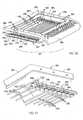
- the seat 22(and also the back 23) includes a highly comfortable support surface formed by a locally-compliant support structure (hereafter called "a comfort surface”) that adjusts to the changing shape and ergonomic support needs of the seated user, both when in an upright position and a reclined position.
- a comfort surfacechanges shape in a manner that retains the seated user comfortably in the chair during recline, yet that provides an optimal localized ergonomic support to the changing shape of the seated user as the user's pelvis rotate during recline.
- the chair 20avoids placing an uncomfortable lifting force under the seated user's knees and thighs, by well-distributing such forces at the knees and/or by flexing partially out of the way in the knee area.
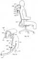
- comfort surfaces of the seat 22 and back 23create a changing bucket shape ( Figs. 2A and 2B ) that "grips" a seated user and also actively distributes stress around localized areas, such that the seated user feels comfortably retained in the seat 22, and does not feel as if they will slide down the angled/reclined back and forward off the seat during recline, as described below.
- the illustrated control mechanism 24also has several advantages and inventive aspects.
- the control mechanism 24includes a "booster" mechanism 25 ( Fig. 19 ) that can be engaged (with low effort) to provide an even greater back support upon recline, if the seated user desires the additional support upon recline.
- the control mechanism 24has a thin profile and is very cost-effective to manufacture and assemble, such that it can be well integrated into chair designs having a thin, side profile.
- the combination of the comfort surface on the back 22 and seat 23 ( Fig. 1 ) with the control mechanism 24provides a surprising and unexpected result in the form of a very comfortable and supportive "ride" in all positions of the chair, including upright and recline positions.
- the comfortable “ride”is at least partially due to the fact that, while the seat that lifts upon recline to provide a weight-activated back support force, with the seat 22 and back 23 surfaces dynamically changing shape to relieve pressure behind the seated user's knees. Also, the comfort surfaces of the seat 22 and back 23 also create a changing bucket (see Figs. 2A and 2B ) to support the pelvis as it "rolls” and changes shape during recline, which counteracts the gravitational forces causing the seated user's body to want to slide down the reclined/angled surface of the back 23 and slide forward off the seat 22.
- the booster mechanism 25 on the control mechanism 24is very easy to engage or disengage, (almost like a switch that flips on or off) making it more likely to be used. Also, this allows the booster mechanism 25 to be operated by automatic panel and/or remote devices, including electronic, mechanical, and other ways.
- all major components of the chair 20, including the control mechanism 24,are separable and recyclable, thus facilitating repair, and promoting components and processes that are friendly to the environment, while maintaining low cost, efficient assembly, relatively few complex parts, and other competitive advantages.
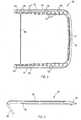
- the seat 22( Figs. 3-4 ) includes a molded perimeter frame 30 made of nylon or the like.
- the illustrated frame 30is semi-rigid, but is able to flex and twist a limited amount so that the frame 30 gives and moves with a seated user who is reaching and stretching for items while doing work tasks.
- the frame 30includes a U-shaped rear with horizontal side sections 31 connected by a transverse rear section 32, and further includes a U-shaped front 33 that connects a front of the side sections 31.
- the perimeter frame 30can be a single-piece molding, or a multi-piece assembly.
- the illustrated frame 30defines a continuous loop, but it is contemplated that the frame could also be U-shaped with an open front, for example.
- the U-shaped front 33includes side sections 34 that connect to an end of the side sections 31 and extend downward and rearward, and further includes a transverse section 35 that connects the side sections 34.
- the U-shaped front 33forms a "U" when viewed from a front, and angles downward and rearward, such that it leaves an upwardly open area in a front of the perimeter frame 30 at a location corresponding to the underside of a seated user's knees. This allows the perimeter frame 30 to avoid putting pressure on the bottom of a seated user's knees upon recline, even though the seat 22 is raised, as described below.
- the side sections 31include a series of notches 36 (six such notches are illustrated) at about 3 to 7 inches rearward of a front end of the side sections 31, or more preferably 4 to 6 inches.
- the notches 36create a flex point, which causes a front section 37 of the side sections 31 to flex downwardly when pressure is placed on the front end of the side sections 31.
- front section 37will flex when the front of the seat 22 is lifted against the knees of a seated user and the user is lifted, which occurs during recline of back 23.
- a pair of tracks 38are attached to the bottoms of the side sections 31 rearward of the notches 36.
- the pair of tracks 38are adapted to slidably engage a seat support structure for providing a depth-adjustable feature on the chair 20. Nonetheless, it is noted that the present inventive concepts can be used on chairs not having a depth-adjustment feature.
- the side sections 31 of perimeter frame 30each include longitudinally-extending recesses 40, respectively, in their top surfaces for receiving steel rods 42 ( Figs. 3 and 12 ).
- the side rods 42resiliently support and stiffen the side sections 31, particularly in the area of notches 36.
- the recesses 40are primarily located rearward of the notches 36, but also include a front portion that extends forward past the notches 36 to provide added resilient support for side sections 31 at the notches 36.
- the rods 42can be different shapes or sizes, or multiple rods can be used. Also, different materials can be used in the rods 42, if desired, such as plastic or composite materials.
- the illustrated rods 42are linear and made of a "hard-drawn spring steel" for optimal strength, low weight, long life, and competitive cost. Further, they are mechanically attached into position in their front and rear. It is contemplated that the rods 42 could also be insert-molded, snapped in, or otherwise secured in place.
- the comfort surface of the seat 22( FIG. 3 ) (and of the back) are formed by individual support members 45 with parallel long sections 51 and U-shaped ends 52 that slidably engage pockets 50 in the side sections 31.
- Each pocket 50includes inwardly facing pairs of apertures 51' ( Fig. 5 ) with an "up" protrusion 51'' formed between the apertures 51'.
- the ends 52 of the front eight support members 45are positioned in and directly slidably engage the front eight pockets 50 for limited inward and outward movement, while the ends 52 of the rear five support members 45 are carried by bearings 53 in the rear five pockets 50, as discussed below.
- the inboard surface of the pockets 50i.e. the "up" protrusion 51 " formed between the apertures 51') forms a stop for limiting inward sliding movement of the ends 52 of the support member 45. By doing this, it limits the downward flexing of the long sections 51 with a "sling"-type action when a person sits on the comfort surface of the seat 22. Notably, this results in a "soft" stopping action when a seated user reaches a maximum flexure of the long sections 51.
- Support members 45are hard-drawn spring steel rods ( Fig. 11 ) having a circular cross section.
- the rodsi.e. support members 45
- the illustrated end sections 52have relatively sharply bent corners, such that they form relatively square U-shaped configurations.
- one of the illustrated end sections 52has opposing ends of the wire that abut, but that are unattached. It is contemplated that the abutting ends in the one end section 52 could be welded together if needed, but this has not been found necessary in the present chair 20, particularly where bearings 53 are used, as discussed below.
- individual linear rodscould be used instead of the support member 45 being a rectangular loop shape with parallel long sections 51, if desired.
- the ends 52could be hook-shaped or L-shaped so that they engage the "up" protrusion in the pockets 50 for limited inwardly movement when a person sits on the seat 22.
- the interconnection of adjacent pairs of long sections 51 by end sections 52can provide an additional stability and "coordinated" cooperative movement in the pairs that is believed to have beneficial effects.
- the rear five support members 45 with bearings 53undergo considerable movement and flexure as a seated user reclines and/or moves around in the chair 20, such that bearings 53 with coupled wire sections 51 have been found to be desirable with those five support members 45.
- the rearmost five support members 45include bearing shoes 53 (also called “bearings” herein) ( Figs. 8-10 ) that are attached to the end sections 52.
- the bearing shoes 53are made of acetal polymer and are shaped to operably fit into the pockets 50 for oscillating (inward and outward) sliding movement in a transverse direction as a seated user moves around in the chair 20 and as the long sections 51 of the support member 45 flex.
- the bearing shoes 53include a U-shaped channel 54 shaped to mateably receive the U-shaped end sections 52.
- the bearing shoes 53can include a friction tab at locations 55 for snap-attachment to the U-shaped ends 52, if desired, though a friction tab is not required per se when a top cap is provided that captures the bearing shoes 53 in the pockets 50.
- the bearing shoes 53retain together the end sections 52 having the wire ends that touch each other even where the abutting ends of the wire are not attached directly together by welding.
- top caps 57are screw-attached, heat-staked, or otherwise attached to the side sections 31.
- the top caps 57( Fig. 7 ) include a body 58 shaped to cover the pockets 50 and operably hold the bearing shoes 53 in place.
- a rear of the body 58extends laterally and potentially includes a slot 59 to better cover a rearmost one of the pockets 50 while still allowing the rearmost wire section 51 to freely flex ( Fig. 7 ).
- the side sections 31 and top caps 57will both be made of nylon, and the bearing shoes 53 made of acetal, because these materials have a very low coefficient of friction when engaged with each other.
- the apertures 51 '( Fig. 7 ) are oversized to be larger than a diameter of the long sections 51 of the rod support members 45, such that there is no drag during flexure of the support members 45 and concurrent movement of the bearing shoes 53 in the pockets 50.
- the illustrated seat 22( Fig. 1 ) is covered with a fabric 60, and potentially includes a top thin foam or non-woven PET fiber cushion under the fabric 60 on both the seat 22 and the back 23.
- the seat 22 and/or back 23may not require a foam cushion because, based on testing, the present seat 22 is so comfortable that a cushion is not necessary.
- the space between the wire sections 51allows the construction to breathe, so that a seated user does not become sweaty while resting on the present chair 20, which can also be a competitive advantage.
- a thin topper cushion or webbingcould also be used under the fabric for aesthetics, if desired.
- each different pair of wire sectionscan be flexed different amounts, and further, each long section 51 in a given support member can be flexed more or less (and can be flexed in a different direction) than the other long section 51 in the pair.
- the pockets 50engage the bearing shoes 53 and limit their movement, such that they in turn limit flexure of the wire long sections 51 to a maximum amount so that the support surface cannot flex "too far". Based on testing, the maximum limit of flexure provided by the pockets 54 is a soft limit, such that a seated user does not feel an abrupt stop or "bump" as the maximum flexure is achieved.
- the present wire long sections 51/52are all the same diameter and shape, but they could be different diameters, stiffnesses, or shapes.
- the individual wire long sections 51travel to support a seated user's body along discrete and independent lines of support, with the wire long sections 51 moving in and out to meet the body and support the user. Specifically, as a seated user reclines, the wires move and flex to create a shifting new "support pocket" for the seated user.
- Fig. 2shows the comfort surface 60 of the seat 22 as being relatively flat (i.e. position P1, see solid lines) when there is no seated user resting on the seat 22. (I.e.
- the wire long sections 51 of the support members 45 of the seat 22are located in a generally horizontal common plane.)
- the comfort surface 60flexes to a new shape (i.e. position P2, see phantom lines), which includes an "upright position" support pocket 63 formed by (and which receives and supports) the protruding bone structure, muscle, and tissue of a seated user's hips.
- a new shapei.e. position P2
- the comfort surface 60flexes to a new shape (i.e.
- position P3which includes a newly formed "recline position" support pocket 65 formed by (and which receives and supports) the protruding portion, muscle, and tissue of a seated user's hips.
- the support pocket 65 formed in the seat 22 while in the recline position( Fig. 2B ) is located rearward of the support pocket 63 formed in the seat 22 when in the recline position (see Fig. 2B , where a shape of the seat in the upright and reclined positions is overlaid to better show the shape change).
- Thisis caused by a rolling motion of the hips during recline.
- the long sections 51 of rod support members 45are independent and provide a localized freedom and dynamic of movement able to comfortably accommodate the rolling activity of the hips of a seated user in a novel and unobvious way not previously seen in task chairs.
- the back 23( Fig. 2 ) also undergoes a shape change, as shown by the comfort surface 66 in the unstressed position P1 (unstressed, no seated user), the flexed comfort surface 66 in the upright stressed position P2 ("upright position” with seated user), and the flexed reclined comfort surface 66 in the reclined stressed position P3 ("recline position" with seated user) ( Fig. 2A ).
- the pairs of long wire sections 51act in a coordinated distributed dynamic fashion (primarily in a vertical direction) that provides an optimal comfort surface. This is a result of the constrained/limited movement of the bearing shoes 53 on adjacent pairs of the long sections 51 of the rod support members 45 and also is a result of the fabric 60 as it stretches across and covers the long sections 51. Nonetheless, it is noted that an extremely comfortable support can be achieved even without the fabric 60, because the long sections 51 flex in a manner that does not pinch or bind the seated user as the shape of the support pocket for their body changes.
- the long sections 51 in the seat 22flex and move to provide support primarily vertically, but that some of the long sections 51 may have a horizontal or angled component of movement and/or may provide a horizontal or angled component of force to a seated user.
- the long sections 51 located at a front of the "recline" support pocket 65tend to engage any depression in the flesh of a seated user at a front of the seated user's protruding hip area (i.e. behind the seated user's thighs and in front of the seated user's "main" hip area) which tends to securely hold the seated user in the seat 22.
- Figs. 2-2Bshow flexure of a center of the long sections 51 of the support member 45 between the unstressed state (i.e. no seated user, see solid lines P1), and a stressed state (i.e. with a seated user, see phantom lines P2) (both in an upright position of the chair 20).
- Fig. 2Ashows the chair 20 with a seated user in the chair 20 in the upright position (solid lines) and a reclined position (dashed lines).
- Fig. 2Bis a schematic view intended to show the change of shape in the comfort surface of the seat 22 between the upright position (see solid lines P2) and the reclined position (see dashed lines P3).
- the seat 22is compared as if it did not move forward upon recline, to better show the change in shape of the "pocket" in the seat 22 where the seated user's hips are located. Nonetheless, it is noted that the seat 22 does move forward during recline in the present chair 20.
- the Fig. 7shows some of the support members 45 with long sections 51 unstressed (i.e. that are located in an outboard position in their respective pocket 50), and shows some of the rod support members 45 with wires 51 flexed (i.e. see the bearing shoes 53 at location "B" that are located in an inboard position in their respective pocket 50).
- Fig. 7also shows some of the bearing shoes 53 exploded out of the pockets 50 and pre-attached to ends of the rod support members 45 (see location "C”).
- the bearing shoes 53are ready to drop downward into the pockets 50, which illustrates a first assembly technique.
- Fig. 7also shows one of the bearing shoes 53 positioned in a pocket 50, with the associated rod support member 45 being positioned above it and ready to be moved downward into engagement with the recess in the bearing shoe 53 (see location "D"), which illustrates a second assembly method.
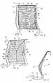
- the back 23( Figs. 15-17 ) is similar to the seat 22. Thus, a detailed description of the back 23 is not required for an understanding by a person skilled in this art, since it would be quite redundant. Nonetheless, a description follows that is sufficient for an understanding of the present invention as used on backs, in view of the discussion regarding seat 22 above.
- the back 23( Figs. 15-17 ) includes a back perimeter frame 70 composed of L-shaped side frame members 71. Top and bottom transverse frame members 72 and 73 are attached to the side frame members 71 to form a semi-rigid perimeter.
- the frame 70can be one-piece or multi-piece.
- An additional transverse frame member 72A( Fig. 1 ) can also be added, if needed for strength and stability.
- the side frame members 71include forwardly-extended lower sections 74 extending below the bottom transverse frame member 73.
- the lower sections 74are pivoted to a seat support 122 of the control mechanism 24, at location 75, and are pivoted to a flexible arm part of the control mechanism 24 at location 141, as described below.
- the back side frame members 71include pockets 77 (see seat frame pockets 50), covers 77' covering the pockets 77 (only a left cover 77' is shown), and support members 78 (similar to seat support members 45) are provided as hard-drawn spring steel wires with long sections 79 (similar to seat long sections 51).
- Several of the support members 78have ends that are operably supported by bearing shoes 80 (similar to bearing shoes 53).
- the illustrated back support members 78come in two different lengths because the back 23 has a smaller top width and a larger bottom width. (See Fig.
- the top half of the side frame members 71includes a plurality of U-shaped pockets 81 for receiving a wire 79 without a bearing shoe 80.
- a top edge of the top frame member 72is U-shaped and bent rearwardly for increased neck support and comfort to a seated user.
- Wire strips 83extend from the top corners of the back frame 70 to a center point located between a seated user's shoulders, and then extend downward into connection to a center of the bottom transverse member 73. When tensioned, the wire strips 83 cause the comfort surface of the back (i.e.
- An adjustable lumbar support 85( Figs. 15-17 ) is provided on the back that includes a pair of bodies 86 slidably connected to an inboard rib 87 on each of the side frame members 71.
- the bodies 86may (or may not) be connected by a cross member.
- the bodies 86are located behind the wires 79 adjacent the side frame members 71 and the wires 79.
- Handles 88extend from a rear of the bodies 86 for grasping by a seated user reaching behind the back 23.
- the bodies 86each include a flange 90 that engages a section of the wires 79 as the wire extends in an inboard direction out of the pockets 77.
- Fig. 17also shows a maximum of rearward flexure of the wires 79, as shown by the line 95.
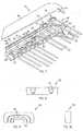
- the present control mechanism 24( Fig. 18 ) includes a stationary base support 121 forming a part of the base 21.
- the seat 22includes a seat support 122
- the back 23includes a back support 123.
- the seat and back supports 122 and 123are operably attached to the base support 121 as follows.
- the base support 121includes an upwardly-facing recess 115 covered in part by plate 115A.
- the recess 115forms a first pocket 116 for receiving the booster mechanism 25.
- the recess 115also forms a tapered second pocket 117 that extends vertically down through the base support 121 for receiving the tapered top section 118 of a height adjustable post 21A.
- the illustrated base 21( Fig.
- the post 21A( Fig. 18 ) includes a vertically-actuated release button 21B positioned at a top of the base support 121.
- the release button 21Bcan be actuated by a handle (not shown) operably attached to a top or side of the base support 121, with the handle being pivotally or rotationally movable to selectively cause the handle to depressingly engage the release button 21B and release the pneumatic spring for height adjustment of the chair.
- a handle(not shown) operably attached to a top or side of the base support 121, with the handle being pivotally or rotationally movable to selectively cause the handle to depressingly engage the release button 21B and release the pneumatic spring for height adjustment of the chair.
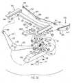
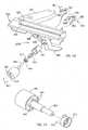
- the seat support 122( Fig. 36 ) is operably supported on the base support 121 by a front leaf spring 123' and by a pivot mechanism 124 spaced rearward of the leaf spring 123'.
- the front leaf spring 123'includes a center portion 125 supported on and attached to an angled front surface 126 (oriented at about 45 °) of the base support 121 by threaded fasteners, and includes arms 127 having barrel-shaped or spherically-shaped bearings 128 on each end that slidably and rotatably fit into cylindrical recesses 129 in side members 130 of the seat support 122.
- the bearings 128are barrel-shaped instead of cylindrically-shaped, so that the bearings 128 permit some non-axial rotation and axial sliding as the arms 127 flex, thus helping to reduce high stress areas and accommodating a wider range of movement during recline.
- different bearing arrangementsare possible that will still meet the needs of the present inventive concepts.
- the side members 130are rigidly interconnected by a cross beam 131 ( Fig. 36 ).
- the pivot mechanism 124includes one (or more) pivoted arms 132 that are pivotally supported at one end on the base support 121 by a pivot pin 133, and pivotally connected to a center of the cross beam 131 at its other end 134 by pivot pin 134" and pin bearings 134'. Pin bearings 134' are attached to cross piece 131, such as by screws.
- the pivot pin 133is keyed to the arm 132, so that the pivot pin 133 rotates upon movement of the seat (i.e. upon recline).
- the direction and orientation of movement of the seat support 122 (and seat 22)is directed by the linear movement of the bearing ends 128 as the arms 127 of leaf spring 123' flex (which is at a 45° angle forward and upward, see R1 in Fig. 38 ), and by the arcuate movement of the pivoted arm 132 on the pivot mechanism 124 as the pivot arm 132 rotates (which starts at a 45 ° angle and ends up near a 10° angle as the back 23 approaches a full recline position, see R2 in Fig. 38 ).
- the distance of travel of the front of the seat 22is preferably anywhere from about 1 ⁇ 2 to 2 inches, or more preferably is about 1 inch upward and 1 inch forward, but it can be made to be more or less, if desired.
- the vertical component of the distance of travel of the rear of the seatis anywhere from about 1 ⁇ 2 to 1 inch, but it also can be made to be more or less as desired.
- the vertical component of seat movementis the component that most directly affects the potential energy stored during recline in the chair 20. Restated, the greater the vertical component of the seat (i.e. the amount of vertical lift) during recline, the more weight-activated support will be received by the seated user during recline.
- the back-supporting upright 123( Fig. 36 ) includes side sections 135 pivoted to the side members 130 of the seat support 122 at pivot location 75, which is about halfway between the location of pivot 129 and the pivot 134.
- the illustrated pivot location 75is about equal in height of the bearings 128 (see Fig. 19 ), although it could be located higher or lower, as desired, for a particular chair design.
- a rear leaf spring 137( Fig. 36 ) includes a center portion 138 attached to a forwardly angled surface 139 on a rear of the base support 121, and includes arms 140 with barrel-shaped or spherically-shaped bearings 141 that pivotally and slidably engage a cylindrical recess 142 in the side sections 135 of the back upright 123.
- the rear surface 139is oriented at about a 30° forward angle relative to vertical, which is an angle opposite to the rearward angle of the front surface 126.
- the pivot 75drives the seat 22 forward along lines R1 and R2 upon recline, and in turn a reclining movement of the back 23 causes the seat support 122 to move forward and upward.
- the movement of the seat support 122is controlled in the front area by the flexure of the ends of the front spring 123, which moves the bearings 128 in a linear direction at a 45° angle (up and forward in direction "R1"), and is controlled in the rear area by the pivoting of the pivoted arm 132, which is arcuate (up and forward along path "R2").
- the pivot arm 132is at about a 45° angle when in the upright rest position ( Figs. 19 and 38 ), and is at about a 10° angle when in the full recline position ( Fig. 39 ), and moves arcuately between the two extreme positions upon recline.
- the movement of the seat support 122causes the pivot location 136 ( Fig.
- a rear of the seat support 122initially starts out its movement by lifting as fast as a front of the seat support 122.
- the rear of the seat support 122raises at a continuously slower rate (as arm 132 approaches the 10° angle) while the front of the seat support 122 continues to raise at a same rate.
- the back 23i.e. back upright 1273 moves angularly down and forward upon recline.
- the seat support 122moves synchronously with the back upright 123, but with a complex motion.
- a wide variety of motionsare possible by changing the angles and lengths of different components.
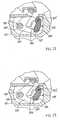
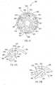
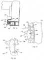
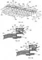
- the booster mechanism 25( Fig. 19 ) includes a torsion spring 150 mounted on the pivot pin 133 to seat support 121.
- the torsion spring 150includes an inner ring 151 ( Fig. 37 ) keyed to the pivot pin 133, a resilient rubber ring 152, and an outer ring 153 with an arm 154 extending radially outwardly.
- a stop member 155is pivoted to the base support 121 by a pivot pin 155' (and is keyed to pivot pin 155') and includes a stop surface 156 that can be moved to selectively engage or disengage the arm 154. When the stop member 155 is moved to disengage the stop surface 156 from the arm 154 ( Fig.
- the torsion spring 150freewheels, and does not add any bias to the control 120 upon recline.
- the stop member 155is moved to engage the stop surface 156 with the arm 154 ( Fig. 20 )
- the outer ring 153is prevented from movement upon recline. This causes the torsion spring 150 to be stressed and tensioned upon recline, since the pivot pin 133 does rotate upon recline, such that the torsion spring 150 "boosts" the amount of energy stored upon recline, thus adding to the amount of support received by a seated user upon recline.
- the torsion spring 150will be made to add about 15 % to 20 % of the biasing force upon recline, with the rest of the biasing force being supplied by the bending of the leaf springs 123 and 137 and by the energy stored by lifting the seat support and the seated user upon recline.
- the percentage of forcecan, of course, be changed by design to meet particular functional and aesthetic requirements of particular chair designs.
- the booster mechanism 25In operation, when the booster mechanism 25 is "off" ( Fig. 19 ), the arm 154 moves freely as a seated user reclines in the chair. Thus, during recline as the seat rises and lifts the seated user, the flexible arms 127 and 140 of leaf springs 123' and 137 flex and store energy. This results in the seated user receiving a first level of back support upon recline.
- the booster mechanism 25When additional support is needed (i.e. the equivalent of increased spring tension for back support in a traditional chair), the booster mechanism 25 is engaged by rotating stop 155 ( Fig. 20 ). This prevents the arm 154 from moving, yet pivot pin 133 is forced to rotate by the arm 132. Therefore, during recline, the rubber ring 152 of the torsion spring 150 is stretched, causing additional support to the seated user upon recline. In other words, the support provided to the back 23 during recline is "boosted” by engagement of the booster mechanism 25.
- torsion springs 150can be added to the axle of pivot 154', and that they can be sequentially engaged (such as by having their respective stops 155 engage at slightly different angles). This would result in increasing back support, as additional ones of the torsion springs were engaged. (See Fig. 25 .)
- a single long rubber ring 152could be used and anchored to the pivot pin 133 at a single location, and that several different outer rings 153 and arms 154 (positioned side-by-side on a common axle) could be used. As additional arms were engaged, the torsional force of the torsion spring would increase at a faster rate during recline.
- stop 155could have steps, much like the stop 205 ( Fig. 21 ), such that the "booster" torsion spring 150 engages and becomes active at different angular points in time during recline.
- a stop pin 290( Fig. 37 ) is provided on the arm 132, and an abutment 291 is provided on the outer ring 153 of torsion spring 150.
- the engagement of the components 290 and 291, and also the engagement of the arm 132 with the base support 121results in a positive location of the back 23 in the upright position.
- the rubber ring 152can be pre-tensioned by engagement of the pin 290 and abutment 291.
- this preload in rubber ring 152must be overcome prior to initiation of recline of the back 23. This results in the elevated pre-tension (see Fig. 24 ) whenever the stop member 155 is engaged (see Fig. 20 ).
- a stop pin 290'is located on the arm 132 and positioned to abut a surface on the chair control base support 121 as a way of setting the upright position of the back 23.
- a backstop 205( Fig. 21 ) is formed on the stop member 155.
- the backstop 205is keyed directly to the pivot pin 155' so that it moves with the pivot pin 155'. There is no torsion spring element on the illustrated backstop 205.
- the arm 132includes a lever 202 with an abutment surface 203.
- a backstop 205is pivoted to pivot pin 155' at a location adjacent to the booster stop member 155.
- the backstop 205includes a first abutment surface 206 and a second abutment surface 207.
- a manual control mechanism 220( Fig. 26 ) includes a selector device 227 mounted to base support 121 under the seat-supporting structure 122.
- the selector device 227is operably connected to pivot pin 155' as noted below for moving the booster stop 155 and backstop 205.
- the backstop 205does not engage the abutment surface 203 of lever 202 when the manual control mechanism 220 for booster mechanism 25 and backstop 205 is in a "home" disengaged position ( Figs. 19 and 21 ).
- the stop member 155 of booster mechanism 25engages and activates the torsion spring 150 when the selector device 227 is moved to a first adjusted position ( Fig. 20 ). In the first position, the abutment surface 203 is not yet engaged ( Fig. 20 ).
- the backstop abutment surface 206engages the abutment surface 203 of the lever 202, and the back 23 is limited to only 1/3 of its full angular recline. (The backstop 205 can of course have additional intermediate steps if desired.)
- the selector device 227is to a third adjusted position ( Fig. 23 )
- the backstop abutment surface 207engages the abutment surface 203 of the lever 202, and the back 23 is limited to zero recline.
- the effect of these multiple positions of selector device 227are illustrated by the lines labeled 211-214, respectively, on the graph of Fig. 24 .
- the devicecombines two functions in a totally new way - that being a single device that selectively provides (on a single member) a backstop function (i.e. the backstop mechanism 202/205) and also a back tension adjustment function (i.e. the booster mechanism 150/155).
- a backstop functioni.e. the backstop mechanism 202/205
- a back tension adjustment functioni.e. the booster mechanism 150/155
- pivot pin 155'can be extended to have an end located at an edge of the seat 22 under or integrated into the seat support 122. In such case, the end of the pivot pin 155' would include a handle for grasping and rotating the pivot pin 155'.
- the selector device 227 of the manual control mechanism 220( Figs. 26-27 ) can be positioned anywhere on the chair 20.
- a manual control mechanism 220( Fig. 26 ) includes a Bowden cable 251 having a sleeve 221 with a first end 221 ' attached to the base support 121, and an internal telescoping cable 222 ( Fig. 27 ) movable within the sleeve 221.
- a wheel section 223is keyed or otherwise attached to the pivot pin 155' of the back booster and backstop mechanism, and an end 224 of the cable 222 is attached tangentially to a perimeter of the wheel section 223.
- a spring 225can be used to bias the wheel section 223 in direction 225', pulling the cable in the first direction 225.
- spring 225is not required where the cable 222 is sufficient in strength to telescopingly push as well as pull.
- the cable sleeve 221includes a second end attached to the seat support 122, such as on the end of a fixed rod support 226 extending from the seat support 122.
- a selector device 227is attached near an end of the rod support 226 for operating the cable 222 to select different back supporting/stopping conditions.
- the selector device 227( Fig. 28 ) operates very much like a gearshift found on a bicycle handle bar for shifting gears on the bicycle.
- the selector device 227is also not unlike the lumbar force-adjusting device shown in patent 6,179,384 (minus the gears 56 and 56').
- a patent entitled “FORCE ADJUSTING DEVICE”issued January 30, 2001, Patent No. 6,179,384 , discloses a clutch device of interest, and the entire contents of patent 6,179,384 are incorporated herein by reference in its entirety for the purpose of disclosing and teaching the basic details of a sprag clutch and its operation.
- the illustrated selector device 227( Figs. 28-30 ) includes a housing 228 fixed to the rod support 226 with an inner ring section 229 attached to the rod, and an annular cover 230 rising from the ring and forming a laterally-open cavity 231 around the ring 229.
- Detent recesses 237are formed around an inside of the cover 230.
- a one-piece plastic molded rotatable clutch member 233 including a hub 242is positioned in the cavity 231 and includes a first section 234 attached to the cable end 221".
- the rotatable clutch member 233further includes a clutch portion 235 integrally formed with hub 242.
- a handle 236is rotatably mounted on an end of the support 226 and includes protrusions 238 that engage the clutch 235 to control engagement with the detent recesses 237 as follows.
- the clutch portion 235( Fig. 28 ) includes one or more side sections 240 (preferably at least two side sections 240, and most preferably a circumferentially symmetrical and uniform number of side sections, such as the illustrated six side sections) having a resilient first section 241 that extends at an angle from the hub 242 to an elbow 243 that is in contact with the detent recesses 237, and a second section 244 that extends in a reverse direction from the end of the first section 241 to a free end 245 located between the hub 242 and the detent recesses 237.
- Each free end 245includes a hole 248.
- the handle 236includes a clutch-adjacent section 246 that supports the protrusions 238 at a location where the protrusions 238 each engage the hole 248 in the associated free end 245 of every side section 240. Due to the angle of the first sections 241 ( Fig. 31A , see arrow 280) relative to the inner surface of the housing that defines detents 237, the first sections 241 interlockingly engage the detent recesses 237 against the bias of the spring 225 as communicated by the tension in cable 222 (see arrow 281), preventing movement of the clutch 235 when it is biased in direction 249 ( Fig. 31 ) by the hub 242.
- the clutch 235again locks up against the force 281 of spring 225 ( Fig. 27 ) as communicated by cable 222 to the clutch 235.
- the handle protrusions 238pull the second section 244 to thus pull the first and second sections 241 and 244 so that the rotatable member 230 (and the clutch 231) rotates.
- the handle 236is moved in a rotational direction 282 ( Fig.
- the handle protrusions 238push the second section(s) 244 at a low angle relative to the detent recesses 237, such that the second sections 244 (and first sections 241) slip out of and over the detent recesses 237 ( Fig. 31B ), allowing the rotatable member 230 (and clutch 231) to adjustingly move in direction 281.
- the present arrangementallows adjustment in either direction, but interlocks and prevents unwanted adjustment in a particular direction against a spring biasing force.
- actuation of the booster mechanism 25 and the backstop 205is particularly easily accomplished, since the actuation action does not require overcoming the strength of a spring nor of overcoming any friction force caused by the spring 150. Further, the actuation action does not require movement that results in storage of energy (i.e. does not require compressing or tensioning a spring). Thus, a simple battery-operated DC electric motor or switch-controlled solenoid would work to operate the booster mechanism 25 and/or the backstop 205.
- Fig. 26illustrates a housing 300 supporting a battery pack and electric rotary motivator (such as a DC motor), and includes an end-mounted switch.
- FIG. 27Aillustrates a linear motivator 301 operably connected to cable 222, and also illustrates a rotary motivator 302 connected to axle 155'. Since the movement of the booster mechanism 25 and the backstop 205 requires only a very small amount of energy with minimal frictional drag, it can be accomplished without a need for a large energy source. Thus, a small battery-operated device would work well for a long time before needing recharge of its battery.
- the illustrated control mechanism 24 abovehas front and rear leaf springs used as flexible weight bearing members to support a seat and back for a modified synchronous movement, and has a pivoted link/arm that assists in directing movement of a rear of the seat.
- the present arrangementcan also include stiff arms that are pivoted to the base support 121, or can include any of the support structures shown in U.S. Patent Application Publication No. 2004/0051362, published on March 18, 2004 , entitled “SEATING UNIT HAVING MOTION CONTROL", the entire contents of which are incorporated herein in their entirety.
- a "booster" mechanism 25provides added biasing support upon recline when a stop is engaged.
- a continuously adjustable biasing devicesuch as a threaded member for adjusting a spring tension or cam could be used instead of the booster mechanism 25.
- a modified chair or seating unit 20B( Figs. 40-42 ) includes changes and improvements from that of chair 20.
- Similar and identical components and features of the chair 20B to the chair 20will be identified using many of the same identification numbers, but with the addition of the letter "B".
- the chair 20B( Fig. 40 ) includes a base 21B, a seat 22B, and a back 23B, with the seat 22B and back 23B being operably supported on the base 21B by an underseat control mechanism 24B for synchronous movement upon recline of the back 23B.
- the control mechanism 24Bmoves and lifts the seat 22B upwardly and forwardly, such that the back 23B (and the seated user) is automatically provided with a weight-activated back-supporting force upon recline.
- the seat 22B(and also the back 23B) includes a highly comfortable support surface formed by a locally-compliant support structure (hereafter called "a comfort surface”) that adjusts to the changing shape and ergonomic support needs of the seated user, both when in an upright position and a reclined position.
- a comfort surfacechanges shape in a manner that retains the seated user comfortably in the chair during recline, yet that provides an optimal localized ergonomic support to the changing shape of the seated user as the user's pelvis bones rotate during recline.
- the chair 20Bavoids placing an uncomfortable lifting force under the seated user's knees and thighs, by well-distributing such forces at the knees and/or by flexing partially out of the way in the knee area.
- comfort surfaces of the seat 22B and back 23Bcreate a changing bucket shape (similar to that shown in Figs. 2A and 2B ) that "grips" a seated user and also actively distributes stress around localized areas, such that the seated user feels comfortably retained in the seat 22b, and does not feel as if they will slide down the angled/reclined back and forward off the seat during recline, as described below.
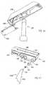
- the chair control mechanism 24B( Fig. 43 ) includes a booster/back stop selector device 227B with a handle 300 rotatable about a first axis 301 for selectively moving the backstop and booster mechanisms (see Figs. 19-23 ) (components 156 and 205) between the multiple positions illustrated in Figs. 19 , 20 , 22, and 23 .
- the control mechanism 24Bfurther includes a second control device 302 with a radially-extending lever handle 303 rotatable about a rod 304 forming a second axis 304' .
- the second axisextends parallel to but is spaced from the first axis 301.
- the handle 303is made to be positioned adjacent the handle 300, and includes a projection that engages the handle 300 to form a stop surface to limit back rotation of the handle 303.
- the base 21B( Fig: 45 ) includes a releasable self-locking pneumatic spring 307 having two fixed tabs 308 for engaging a sheath on a cable sleeve, and a side-activatable lever 309 that operably engages an internal release button in the spring 307.
- a side-activatable pneumatic springsuch as pneumatic spring 307 is commercially available in commerce and need not be described in detail in this application.
- a cable assembly( FIG. 48 ) includes a cable 310 connected at one end 311 to the finger 305 and at another end 312 (fit. 45) to the lever 309.
- the cable assemblyfurther includes a sleeve 313 ( Fig. 48 ) that is connected to the base support 121B near the handle 303, and that extends to and is connected to the tabs 308 ( Fig. 45 ) on the pneumatic spring 307.
- the base support 121Bis inverted from the base support 121.
- the base support 121B( Fig. 46 ) includes a similar cavity and internal surfaces and structure for supporting the levers, stops, and booster mechanisms within the base support 121B, similar to base support 121.
- the front portion 116B of the cavity in base support 121Bopens downwardly, and the cover 115B engages a bottom of the base support 121B.
- An upright arm 315( Fig. 45 ) is attached to the stop member 155B and extends up through a top aperture 155B' in the base support 121B.
- An end 316' of a cable 316is connected to the arm 315 and extends to a tangential connection on the booster/back stop selector device 227B ( Fig. 48 ), such that when the handle 300 is rotated, the cable 316 is pulled (and/or pushed) ... and hence the stop member 155B is moved to a selected position. (See Figs. 19 , 20 , 22 and 23 ).
- the laterally-extending arms 127B of the front spring 123B'include a tab 320 that non-removably snap-attaches into a spherical bearing 321.
- the seat support 122B( Fig. 45 ) includes a pair of side frame members 322 and a transverse cross piece 323 rigidly connecting the opposing side frame members 322.
- Each side frame member 322includes a bore 324, which, if desired, includes a bearing sleeve 325.
- the spherical bearings 321 on the ends of leaf springs 123B'each rotatably and telescopingly slidingly engage the sleeve 325/bore 324 to accommodate non-linear movement of the spherical bearing 321 during recline of the back 23B.
- Hole 75B( Fig. 47 ) receives a pivot pin that rotatably connects the respective side sections 135B of the back supporting upright 123B to the seat support 122B.
- a flange 327forms a slot 328 along a top of the side frame members 322.
- Each seat 22B( Fig. 43 ) includes a bracket 480 that forms a mounting socket 481 on seat side frame members 322 for receiving and fixedly supporting an "L-shaped" armrest support structure 482 ( Fig. 42 ) and T-shaped armrest 483.
- the seat 22Bis depth adjustable, and includes a pair of seat carriers 330 ( Fig. 45 ) attached to each side for sliding depth adjustment.
- the seat carriers 330each include a body 331 ( Fig. 65 ) adapted to slidably engage a top of the side frame members 322 of the seat support 122B, and further include a lateral flange 332 that fits into and slidably engages the slot 328 for providing fore/aft depth adjustment of the seat 22B.
- the seat 22Bis captured on the seat support 122B because flanges 332 on the right side and left side seat carriers 330 face in opposite directions.
- a series of notches 333 in the top inboard side of the seat carriers 330are engaged by a latch 334 mounted on the seat carriers 330, the latch 334 being movable downward into an engaged position to engage a selected notch 333 for holding the seat 22B at a selected depth position.
- the latch 334is movable upward to disengage the notches 333, thus permitting horizontal depth adjustment of the seat 22B.
- the latch 334can be a variety of different constructions, such as a blade mounted for vertical movement on the seat 22B, or a bent wire rod that when rotated has end sections that move into and out of engagement with the notches 333. It is contemplated that other latching and adjustment arrangements can also be constructed.
- the latch 334is two-sided ( Fig. 63 ) and is adapted to engage both sides of the seat 22B to prevent racking and unwanted angular twisting and rotation in the horizontal plane of the seat 22B.
- both seat carriers 330be fixed to their respective side frame members 322 when latched to provide a stable seat arrangement that does not torque and twist in an undesirable unbalanced manner when a seated user is attempting to recline.
- the illustrated latch 334( Fig. 63 ) is actuated by a U-shaped bent wire actuator 334' which includes a transverse handle section 470 forming a handle graspable under the seat front section 388, and includes a pair of legs 471 and 472.
- Each leg 471 (and 472)( Fig. 64 ) fits into a space between sidewall 365 and side section 359 (and between sidewall 366 and side section 359) of seat 22B.
- An annular groove 473( Fig. 64 ) fits mateably into a notch 474 in a rib 475 between walls 365 and 366 to form a pivot for leg 471 (and 472).
- the latch 334is pivoted on an axle 476, and includes a latching end 477 shaped to move into and out of engagement with notches 333, and includes a second end 478 operably connected to a rear tip 479 of leg 471 in direction "D".
- handle section 470When handle section 470 is moved up, side legs 471 and 472 pivot at rib 475, such that leg tip 479 moves down.
- latching member 334pivots about pivot 476 to lift latching end 477 out of notches 333.
- a depth of seat 22Bcan then be adjusted.
- One or more resilient springs 480located between transverse handle section 470 and seat front section 388 bias section 470 downwardly, causing latching tip 479 to again engage a selected notch 333 when handle section 470 is released.
- the chair control mechanism 24B( Fig. 43 ) includes a booster/back stop selector device 227B. with a handle 300 rotatable about a first axis 301 for selectively moving the backstop and booster mechanisms (see Figs. 19-23 ) (components 156 and 205) between the multiple positions illustrated in Figs. 19 , 20 , 22, and 23 .
- a tubular support 340( Fig. 48 ) is attached to the outboard side of the right side frame member 322.
- a bearing sleeve 341is positioned in the tubular support 340 along with a coiled compression spring 342, a crown-shaped detent ring 343 with pointed axial tips 344, and the handle 300.
- a rod 345extends from the handle 300 through the components 343, 342, and 340 to an inside of the side frame member 322.
- the handle 300includes teeth-like projections 346 ( Fig. 49 ) that engage the axial tips 344 of the detent ring 343, and the detent ring 343 is biased axially in an outboard direction so that the tips 344 continuously engage the projections 346. Further, the detent ring 343 is keyed to the tubular support 340 so that the detent ring 343 cannot rotate, but is able to telescope axially.
- the tips 344 and projections 346include angled surfaces so that upon rotation of the handle 300, the detent ring 343 will move axially inward against the bias of spring 342, and then snap back outwardly as the tips 344 fit between adjacent projections 346, thus permitting rotation of the handle 300 in directions 347.
- This arrangementcauses the handle 300 to move with a detented rotation.
- the illustrated arrangementincludes four projections 346 on the handle 300, and sixteen tips on the detent ring 343, but it is contemplated that more or less of each can be used. It is contemplated that the handle 300 can include markings 349 to identify its function, and that any of the handle shapes commonly used in the chair art can be incorporated into the illustrated design.
- a lever 351extends from an inner end of the rod 345, and is operably connected to one end 353 of the cable 316. Recall that the other end 316' ( Fig. 45 ) of the cable 316 is connected to the arm 315 of the stop member 155B of the booster and back stop engaging member 155B.
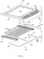
- the seat 22B( Fig. 50 ) includes a seat frame 357 comprising an upper frame component 358 and right and left seat lower frame components 359 and 360 attached to right and left sides of the upper frame component 358.
- the lower frame components 359 and 360are attached directly to the top of the seat carriers 330 mentioned earlier ( Fig. 45 ), or can be integrally formed to incorporate the features of the illustrated carriers 330.
- the support members 45B( Fig. 50 ) comprise single wires with down-hooks formed at each end, as described below.
- the lower frame components 359 and 360are mirror images of each other, and accordingly only the lower frame component 359 will be described.
- the lower frame component 359is a plastic molded component having a bottom wall 362, front and rear end walls 363 and 364, and three longitudinal walls 365-367.
- the outer wall 365formed an aesthetic and structural outer surface.
- the intermediate wall 366includes a plurality of apertures bosses 368 for receiving screws (not shown) to attach the upper and lower frame components 358 and 359/360 together.
- the inner wall 367includes a plurality of vertically open slots 369 that extend from its top surface to about halfway down into its height, and further includes parallel walls 370 and 371 that extend from wall 367 to wall 366 on each side of the slots 369.
- a recess or pocket 50Bis formed between each of the parallel walls 370 and 371 for receiving the end sections 52B, as described below.
- the inboard side of the intermediate wall 366forms a first stop surface 372 ( Fig. 52 ), and the outboard side of the inner wall 367 forms a second stop surface 373 with an angled ramp surface 374 extending inwardly and downwardly away from the second stop surface 373.
- Each support member 45B( Fig. 50 ) comprises a single wire of the same type wire as support member 45 described above.
- Each support member 45Bhas a long section 51B and has L-shaped down-formed end sections 52B forming hooks.
- the long section 51Bis linear and extends generally horizontally through a bottom of the slots 369 when in an installed position without a user setting on the seat 22B.
- the end sections 52Bare linear and extend downwardly into the pockets 50B.
- the end sections 52BWhen in an installed position without a user setting on the seat 22B (see solid lines in Fig. 52 ), the end sections 52B abut the outer (first) stop surface 372, causing the wire long section 51B to have a slight downward bow in its middle area at location 374'.
- the long section 51Bbends until the end sections 52B engage the inboard (second) stop surface 373. This limits further bowing or bending of the long section 51B.
- the angled ramp surface 374provides additional support to the end portions of the long section 51B, inboard from the end sections 52B, such that the effective length of the long section 51B is reduced. This results in the support member 45B having a preset maximum bend that is limited by the inner stop surface 373 (i.e. a sling type effect), and further is limited by a shorter effective length of the long wire section 51B (which feels stiffer).
- the wire support member 45Bcan bend at any location, more than only at their center point, such that the seated user receives a particularly comfortable and ergonomic support.
- the seat 22Balso includes a cushion assembly 375 ( Fig. 40 ) comprising a cushion and an upholstery or cloth covering. It is contemplated that the supports 45B are so flexible and comfortable that the cushion can be eliminated. Alternatively, a cushion assembly 375 can be used that is preferably anywhere from 1 ⁇ 4 inch to 1 inch in thickness.
- the upholstery coveringcan be any material, but preferably should allow some (though not too much) elastic stretch and give to accommodate the shape changes permitted by the individual movement of the support members 45B.
- the cushion assembly 375can include front and rear hook-like formations that permit it to be hook-attached to a front and a rear of the seat support structure (i.e. frame 30B). (See the discussion of Figs. 70-71 below.)
- Fig. 52Adiscloses seat having a modified lower frame component 359 made to include a strap 380 supported by a downwardly offset living hinge 381 at a bottom of where the second (inner) stop surface 373 would be.
- the strap 380has a groove shaped to receive a straight length of wire 382.
- the wire 382extends horizontally, and the living hinge 381 moves to allow the inner wall 367' to move to a normal raised position.
- the living hinge 381flexes, causing the wall 367' to tip inward and downward. (See dashed lines.) This results in an action and movement similar to that noted above in regard to seat 22B.
- the seat upper frame component 358( Fig. 50 ) includes a perimeter frame portion with side sections 385 and 386, rear section 387 and under-the-knee "waterfall" front section 388 defining a large opening 389 across which the support members 45B extend.
- the side sections 385 and 386screw-attach to the lower side frame components 359 and 360, and both stiffen the side frame components 359 and 360 and also capture the end sections 52B in the pockets 50B.
- the rear section 387forms a stiff rear area of the seat 22B.
- the front section 388extends forwardly 3 to 6 inches, and forms a front "waterfall" front surface that comfortably supports the thigh area of seated users of the chair 20B.
- Multiple slots 390 and/or stiffening ribsprovide an optimal stiffness so that the front section 388 will resiliently flex but provide adequate support and a good feel in both the upright and reclined positions of the chair 20B.
- Fore-aft leaf springs and transverse leaf springscan be added to optimize anyone of the sections 385-388. In particular, it is contemplated that fore/aft springs will be added to help support the transition area at ends of the front section 388 near a front of the side sections 385-386.
- the illustrated reinforced-plastic springs 490( Fig. 63 ) are pultruded flat leaf-springs made to flex without taking a permanent set. They fit snugly into a recess in the upper frame component 358, and are held thereagainst by the lower frame components 359. It is contemplated that they will have a flat horizontal cross-sectional shape, and that they will extend forward of the front end of the side sections 359, but other configurations and arrangements are possible, while still accomplishing the same function.
- back 23B( Figs. 53-54 ) is not dissimilar to the structure of the seat 22B. Hence a detailed repetitious description is not required. Nonetheless, it is noted that the back 23B includes a back perimeter frame 70B with upright side sections 400, 401, top transverse section 402 and bottom transverse section 403 defining a large open area 404. A bottom of the side sections 400 and 401 extend forwardly to form forwardly-extending side leg sections 135B, and are pivotally connected to the seat side sections at pivot 75B.
- the upright side sections 400 and 401include a bottom wall 405 ( Fig. 53 ), end walls 406 and 407, and inner and outer walls 408 and 410.
- Half-depth slots 411( Fig.
- a pocket 77Bis formed on the bottom wall 405 between the parallel walls 409-410.
- Bosses 409'are formed between the inner and outer walls 408 and 410, and are supported by a short intermediate wall 409 that extends between adjacent ones of the parallel walls 412 and 413 (at locations not interfering with the recesses or pockets 77B).
- Support members 78B(similar to support members 50B in the seat 22B) are positioned on the back 23B, and each include a long wire section 414 that extend into the slots 411, and L-shaped bent end sections 415 that extend down into the pockets 77B.
- end sections 415 within the pockets 77Bare similar to that described above in regard to the seat 22B.
- the end sections 415In the rest position, the end sections 415 abut outer surfaces 417 of the pockets 77B, thus holding the wires in a partially bent condition.
- the long wire sections 414flex, until the end sections 415 move abuttingly into the inboard stop surface 418, thus limiting any further flex of the wire support members 78B.
- Front covers 420 and 421( Fig. 53 ) are attached to a front of the back upright side sections 400 and 401. The covers 420 and 421 both stiffen the side sections 400 and 401, and also hold the end sections 415 within the pockets 77B.
- a cushion assembly 375'( Fig. 40 ) similar to that described above in regard to the seat 22B is attached to the back frame 70B. It can be attached in different manners. It is contemplated that one optimum method is to stretch and hook attach the cushion assembly to the top and bottom transverse frame sections 402 and 403. It is contemplated that a person skilled in the art will be able to use and adapt the attachment structure shown in Figs. 70-71 to the top and bottom of the back 23B for attaching the back cushion assembly 375', and to the front and rear of the seat 22B for attaching the seat cushion assembly 375. Thus, a detailed description of each is not required.
- the bottom frame section 403 of the back frame 400includes a pair of ridges 528 and 529 that define a downwardly-facing rectangularly-shaped pocket or channel 530 that extends continuously across a width of the back frame 400.
- a detent channel 531(or ridge if desired) is formed parallel the channel 530 along an outside front surface of the bottom frame section 403.
- the cushion assembly 375 'includes a U-shaped extruded plastic attachment clip 532, including a flat leg 533, a barbed leg 534, and a resilient section 535 connecting the legs 533 and 534.
- the legs 533 and 534are spaced apart to receive and matably engage the forward ridge 529.
- a detent protrusion 536is biased into engagement with the detent channel 531 by the resilient section 535.
- the cushion assembly 375'further includes a sheet of upholstery material 540 connected to the flat leg 533 by a strip of elastic sheet material 541.
- the elastic sheet material 541can be eliminated, and the upholstery material 540 attached directly to the flat leg 533, if testing shows that the added elastic stretch from the sheet material 541 is not required.
- one edge of the elastic sheet material 541is sewn to the flat leg 533 of clip 532 by stitching 542, and an opposite edge is sewn to the upholstery material 540 by stitching 543.
- the strip 541extends completely across a width of the back frame 400.
- the flat leg 533 of the extruded clip 532 of the cushion assembly 375'is pressed into the channel 530 of the bottom frame section 403 of the back frame 400, with the opposing leg 534 frictionally engaging an outer front surface of the bottom frame section 403.
- the sheets 540 and 541overlay onto the barbed leg 534 when the cushion assembly 375' is fully installed onto the back frame 400 (see the arrow 548 in Fig.
- the barbed leg 534has a thickened cross section, a tension in the sheets 540 and 541 further biases the detent protrusion 535 into engagement with the detent channel 531. Also, the thickened section of the barbed leg 534 can help hide the stitching, by providing a space to receive the stitched area and to receive the multiple thicknesses of pleats in the stitched area.
- a rail 424( Fig. 55 ) is formed on a front of an inwardly-directed flange 425 on the side sections 400 and 401.
- the rail 424extends vertically about half to two-thirds of a length of the side sections 400 and 401, and includes a top termination or end 426 that forms a access port for engaging the rail 424.
- Different accessoriescan be mounted on the rail 424. For example, a lumbar device 427 and a headrest support 428 ( Fig. 40 ) are illustrated.
- the illustrated lumbar device 427( Fig. 55 ) includes a plastic body 430 that extends around flange 425, a pair of hook-shaped retainer fingers 431 that slidably engage the rail 424, and a handle 432 that extends from body 430 opposite the retainer 431.
- a pair of detent bumps or recesses 433are formed on the body 430 adjacent the retainer fingers 431, and are adapted to detentingly engage successive wire support members 78B as the lumbar device 427 is moved up and down.
- the lumbar device 427can be adjusted downwardly to a non-use storage position (see Fig.
- the lumber device 427is so low that it is effectively disabled since it is no longer effective to provide lumbar support to a seated user.
- the area of body 430 adjacent the detent bumps 433supports the long wire sections 414 at locations inboard of the inner wall 408. (See Fig. 56 .)
- the effective bendable length of the long wire sections 414is foreshortened, as illustrated by Figs. 56-57 .
- the added lumbar supportcomes from less flexing of the long wire sections 414, and does not come from a forced shape change to the lumbar support area on the back 23B (although it could also be designed to create a shape change in the lumbar, if desired).
- This "flat" adjustmentis believed to have good ergonomic benefits, since a seated user receives the added lumbar support that they desire, yet their back and upper torso are not forced to take on a different body shape.
- Another important discoveryis the independent action of the right and left lumbar devices 427.
- a maximum lumbar support forcecan be achieved in a particular area (i.e. two wire long support sections 414 are supported).
- the lumbar support areais effectively enlarged (i.e. four wire long support sections 414 are supported).
- the lumber devices 427provide an exceptionally wide range of non-uniform adjustability, i.e. more to the right in one area and more to the left in another area. It is also conceived that different lumbar devices 427 can be provided, such that a user can select the lumbar support that they desire by choosing an appropriate lumber device 427.
- the present lumbar device 427can be designed to appreciably shift the lumbar support to one side (i.e. the long wire section 414 is supported only on one side, such that more lumber support is provided on one side of the chair and less support on the other side). This initially may seem to be undesirable since the lumbar support is unbalanced. However, testing has shown that some seated users want and even prefer an unbalanced lumbar support.
- the illustrated back frame 70B( Fig. 67 ) has a unique construction that facilitates assembly.
- the bottom 500 of side sections 400 and 401are hollow and each define an arcuate cavity 501.
- Side leg sections 135Binclude an arcuately-shaped body 502 configured to telescopingly slide into cavity 501. Once telescoped together, holes 503 and 504 on the bottoms 500 and side leg sections 135B align. Pivot pins are extended through holes 503 and 504 to form pivot 75B, and both secure the components (bottoms 500 and side leg sections 503 and 504) together, but also act as pivots for the back frame 70B on the seat 22B.
- the side frame members 322 of the seat 22Binclude a pair of arcuate recesses 510 ( Figs. 48 and 67 ) that extend partially circumferentially around the hole 75B.
- the recesses 510 and holes 75Bform a bow-tie-shaped feature.
- An inboard side of the side leg sections 135Binclude a pair of opposing protrusions 511 ( Fig. 67 ) that fit into recesses 510.
- the protrusions 511engage opposing ends of the recess 510 as the back frame 70B (i.e. back 23B) is rotated around pivot pins 505 between upright and fully-reclined positions, thus acting as a stop to set a maximum recline position of the back 23B.
- a headrest 440( Fig. 60 ) can be added to the chair 20B.
- the headrest 440includes a headrest support 441 and a vertically and angularly adjustable headrest assembly 442.
- the headrest support 441includes a center tube 443 and right and left arms 444 and 445 that extend to side sections 400 and 401 of the back frame 70B.
- the center tube 443is positioned rearward of the transverse upper frame section 402 and includes a tab 443' configured to securely engage and be attached to the top frame section 402 of the back frame 70B.
- the tube 443can be positioned under and in-line with an opening in the rearwardly flared top frame member 402 of the back 238.
- the arms 444 and 445each have an end 447 configured to engage the accessory rail 424 for stability.
- the headrest assembly 442includes a cushioned C-shaped head-engaging support 441.
- a pair of mounts 449are attached to a rear of a stiff sheet 448 under the C-shaped support 441.
- An upright support 450includes a vertical leg 451 that extends slidably through the opening in the center tube 443. Detents can be provided in the upright support 450 and tube 443 to retain the headrest in a selected position.
- a top of the upright support 450includes a transverse T-shaped hand 452 ( Fig. 61 ) that extends between the mounts 449.
- the hand 452( Fig. 61 ) includes a hollow tube member 453 with longitudinal serrations 454 around its inner surface.
- a bar 455extends between and is fixed to the mounts 449.
- the bar 455includes a pair of longitudinal channels 456, and a pair of detent rods 457 are positioned in the channels 456.
- Springs 458are positioned in transverse holes in the bar 455, and bias the detent rods 457 outwardly into engagement with the serrations 454.
- the C-shaped headrest support structure 448has a forward surface that, in cross section, is spiral in shape and is non-symmetrical about the bar 455. Due to the shape of the C-shaped headrest support structure 448, the effective area for supporting a seated user's head moves forward as the headrest support structure 448 is angularly rotatingly adjusted.
- the seat supports ( Fig. 50 ), back supports 78B ( Fig. 53 ), seat frame 30B ( Figs. 45 and 50 ), back frame 70B ( Figs. 53 and 69 ), springs 123B' and 137B and control mechanism 24 ( Fig. 45 )form a compliant chair assembly that results in a soft stop as the back 23B reaches a full upright position, and results in a soft stop as the back 23B reaches a full recline position.
- This avoidance of a hard "clunk” or jerky stop, in combination with the fluidity and smoothness of the ride during reclineis noticeable, and results in a surprising and unexpected level of support and comfort to a seated user.
- the compliant support arms 127B and back frame upright 123Bflex permitting the back 23B to move along a limited changed path to provide a compliant "soft stop".
- the forces on the back 23B along this limited changed pathcan be controlled by varying a strength and massiveness of the various structural elements of the chair, as will be understood by a person skilled in the art of manufacturing chairs and seating units.
- the present inventive conceptsare useful in other seating units other than office chairs. It is also contemplated that the present inventive concepts are useful in non-chair furniture and other applications where movement of a first structure relative to a second structure is desired, particularly where simultaneous coordinated or synchronized movement is desired and/or where a bias force is desired or adjustable stop is desired.
Landscapes
- Health & Medical Sciences (AREA)
- Dentistry (AREA)
- General Health & Medical Sciences (AREA)
- Chairs For Special Purposes, Such As Reclining Chairs (AREA)
- Chairs Characterized By Structure (AREA)
- Chair Legs, Seat Parts, And Backrests (AREA)
- Seats For Vehicles (AREA)
- Paper (AREA)
- Vehicle Body Suspensions (AREA)
- Hydraulic Control Valves For Brake Systems (AREA)
- Harvester Elements (AREA)
Abstract
Description
- This application is related to
U.S. Application Serial No. 10/455,487 filed on June 5, 2003 U.S. Patent Application Publication No. 2004/0051358, published on March 18, 2004 , entitled CONTROL MECHANISM FOR SEATING UNIT, the entire contents of both of which are incorporated herein by reference. - The present invention relates to a seating unit having an adjustable back tension function and an adjustable back stop function.
- Comfort, simplicity, and adjustability continue to be highly-demanded features in seating. Specifically, it is desirable to provide a control that is easy to operate, simple to manufacture and assemble, relatively low cost and relatively few components, and that has a modern thin sleek appearance. It is further desirable that the structure complement the ability to provide weight-activated support upon recline so that heavier seated users feel secure upon recline even without adjustment.
- In particular in regard to adjustability, it is desirable to provide adjusters that are easier to adjust and more intuitive to operate. For example, many chairs having a reclineable back also have an adjustable spring for varying the back support provided upon recline. However, many adjusters work against the spring to compress the spring during adjustment. This takes considerable effort, even if a mechanical advantage is provided, since the springs are substantial and there is significant energy input required to compress the spring. Even adjustments that decompress the spring require effort to overcome frictional forces that prevent unexpected decompression. Further, seated users constantly find themselves searching among several different controls trying to find the correct control for the adjustment that they desire. Still further, once the proper control is selected, the user still has to figure out which way to adjust the control to achieve the desired effect. It is desirable to find a single control mechanism that provides a logical and intuitive arrangement of back adjustments, where increasingly supportive adjustments cause an increasing level of back support, even though the increasing support is provided by different mechanisms.
- In addition to the above, it is desirable to provide a chair that is optimally designed to use recyclable parts, and that uses components that can be easily separated for recycling and/or repair. Expanded thermoset foam products are usually classified as not recyclable, and further are generally considered to be unfriendly to the environment as compared to steel, remeltable thermoplastic, recyclable materials, and more natural materials. Eliminating thermoset foam would be a significant step toward making a chair 100% recyclable. However, the comfort and cost advantage must be maintained for competitive reasons.
- Accordingly, an apparatus solving the aforementioned problems and having the aforementioned advantages is desired.
- Various aspects of the invention are set out in the independent claims. Various optional features are mentioned in the dependant claims. A number of aspects are now described.
- In one aspect of the present invention, a seating unit includes a base, a seat, a back, and a control operably supporting the seat and the back on the base for movement between upright and recline positions. The control includes a first mechanism providing a biasing supporting force to the back during recline, and further includes a booster spring mechanism capable of increasing the supporting force, and still further includes an on/off selector device for selectively activating and deactivating the booster spring mechanism.
- In another aspect of the present invention, a seating unit includes a base, a seat, a back, and a control operably supporting the seat and back on the base for movement between upright and recline positions. The control includes a link pivoted to the seat at one end and pivoted to the base at another end. The control also includes a first mechanism adapted to provide a biasing supporting force during recline and further includes a booster spring mechanism operably attached to the link. The booster mechanism comprises a torsion spring and a stop selectively engageable with the torsion spring to activate the torsion spring to boost and increase the supporting force provided to a seated user during recline.
- In another aspect of the present invention, a control adapted to adjustably support a movable structural component on a base of a seating unit includes a pivot pin adapted to be rotatably supported on one of the base and the structural component. The pivot pin is rotatably coupled to the other of the base and the structural component for coordinated rotation therewith during recline. A torsion spring has an inner ring keyed to the pivot pin, an outer second ring having a protrusion extending from the outer second ring, and a resilient spring portion operably interconnecting the inner and outer rings. A booster stop is operably coupled to the one of the structural component and the base, the booster stop being movable between a disengaged position where the protrusion misses and passes by the booster stop when the pivot pin is rotated as the structural component is moved, and an engaged position where the protrusion engages the booster stop and prevents the outer second ring on the torsion spring from rotating. By this arrangement, the booster stop activates the torsion spring to provide a bias when the structural component is moved, whereby the torsion spring can be selectively engaged and disengaged to adjust a biasing force on the structural component.
- In another aspect of the present invention, a seating unit includes a base, a seat, and a back. A control supports the back on the base for movement between upright and reclined positions, the control including a plurality of mechanisms including first and second energy mechanisms for biasing the back toward the upright position, and a back stop mechanism for limiting movement of the back to a position short of the reclined position. A selector device is operably connected to said plurality of mechanisms for selectively activating said plurality of mechanisms.
- In still another aspect of the present invention, a seating unit having a base, a seat, and a back adapted to pivot between upright and reclined positions, an energy mechanism for biasing the back toward the upright position, a tension adjustment mechanism for adjusting the force biasing the back toward the upright position, and a back stop mechanism for limiting the range of motion of the back to a position short of the reclined position. An improvement includes a single actuator operably attached to both the tension adjustment mechanism and the back stop mechanism for operating said mechanisms.
- In another aspect of the present invention, a seating unit having a base, a back, and an underseat control operably coupled to and supporting the back for movement between upright and reclined positions. The control includes a housing, an energy adjustment mechanism and a back stop mechanism. An improvement includes an actuator movable to a first operative position for selectively engaging the energy adjustment mechanism, and movable to a second operative position for selectively engaging the back stop mechanism.
- These and other aspects, objects, and features of the present invention will be understood and appreciated by those skilled in the art upon studying the following specification, claims, and appended drawings.
- The present invention may be carried out in a number of ways and various embodiments in accordance with the inventions will now be described, by way of example, with reference to the accompanying drawings, in which:
Fig. 1 is a perspective view of a seating unit embodying the present invention, the seating unit including transverse wires in a back and seat forming a comfortable support surface;Fig. 2 is a schematic cross-sectional view showing the position of the transverse wires in the seat and back ofFig. 1 , the wire support members being shown in solid lines without a seated user, the wire support members being shown in phantom lines with a seated user in an upright position;Fig. 2A is a view similar toFig. 2 , but showing the chair with seated user in the upright position in phantom lines and in a reclined position in dashed lines;Fig. 2B is a schematic view similar toFig. 2A , but with the change in shape of the seat being overlaid to eliminate confusion caused by a translation/rotational (up and forward) movement of the seat during recline;Figs. 3-4 are plan and side views of the seat ofFig. 1 ;Figs. 5-6 are plan and side views of the seat frame ofFig. 3 ;Fig. 7 is a partially exploded perspective view of a corner section of the seat inFig. 3 ;Figs. 8-10 are side, top, and end views of a bearing shoe used to slidably support an end of one of the wires shown inFig. 7 ;Figs. 11-12 are plan views of two different wires used in the seat shown inFig. 3 ;Figs. 13-14 are side and plan views of a cover for side sections of the seat frame shown inFig. 5-6 ;Figs. 15-16 are front and rear perspective views of the back shown inFig. 1 ;Fig. 17 is a side view of the back shown inFig. 15 ;Fig. 18 is a side view of the underseat control shown inFig. 1 ;Figs. 19-20 are cross-sectional views similar toFig. 18 , but showing cross-sectioned components,Fig. 19 being taken along line XIX inFig. 33 and showing the booster mechanism disengaged, andFig. 20 showing the booster mechanism engaged;Figs. 21-23 are cross-sectional views similar toFig. 18 , but showing cross-sectioned components,Fig. 21 being taken along line XXI inFig. 33 and showing the backstop mechanism disengaged, andFig. 22 showing the backstop mechanism engaged to a first level for partial back recline, andFig. 23 showing the backstop mechanism engaged to a second level for no back recline;Fig. 24 is a graph showing different lines of back support force versus deflection, depending upon whether the booster is disengaged or engaged, and whether the backstop is engaged for partial recline or to prevent any recline;Fig. 25 is a graph showing different strength booster mechanisms on a chair where they provide selectively increasing amounts of energy as each successive one is engaged;Fig. 26 is an exploded perspective view showing an underseat-located manual control for the booster and backstop mechanism;Figs. 26A and 27A are similar toFigs. 26 and 27 , but showing alternative embodiments;Fig. 27 is a cross-sectional view taken along the line XXVII inFig. 33 ;Fig. 28 is an exploded perspective view of the manual control ofFig. 26 ;Figs. 29-30 are cross-sectional views of the hand control ofFig. 28, Fig. 29 being fully assembled,Fig. 30 being exploded apart;Fig. 31 is an enlarged fragmentary view of the clutch and its engagement with the exterior housing, showing the clutch in a locking position;Figs. 31A and 31B are enlarged fragmentary views of a portion ofFig. 31, Fig. 31A showing a locked position andFig. 31B showing a released position;Figs. 32-33 are front and rear partial perspective views of the base and control ofFig. 18 ;Figs. 34-35 are front and plan fragmentary views of the control shown inFig. 33 ;Fig. 36 is an exploded perspective view ofFig. 33 ;Fig. 37 is an enlargement of the energy boost mechanism shown inFig. 36 ; andFigs. 38-39 are cross sections taken along the line XXXIX inFig. 33 , and are side views of the control, seat and back,Fig. 38 being in an upright position andFig. 39 being a recline position,Figs. 38-39 being similar toFig. 18 , but being simplified to show operation of the pivot link during recline.Figs. 40-42 are front perspective, rear perspective, and side views of a modified form of the present inventive chair;Fig. 43 is a perspective view of the underseat control for the chair inFig. 40 ;Fig. 44-46 are a top perspective, a second top perspective, and a bottom perspective exploded view of a portion of the underseat control and related base components ofFig. 43 ;Fig. 47-49 are exploded perspective views of the underseat control ofFig. 43 ,Figs. 48 and 49 showing a hand control for adjusting the booster and back stop mechanism shown inFig. 45 ;Fig. 50-51 are perspective and fragmentary perspective views of the seat shown inFig. 40 ;Fig. 52 is a cross section showing flexing of the wire, support member for the wire support members shown inFig. 50 , andFig. 52A is a similar view showing an alternative mounting structure;Figs. 53-54 are exploded perspective views of the back shown inFig. 40 ;Figs. 55-57 are perspective views of the lumbar devices and their effect on the wire support sections;Fig. 58 is a schematic showing the lumber device ofFig. 57 ;Fig. 59 is a perspective view of the chair ofFig. 40 with the lumber device ofFig. 55 in a disabled storage position;Fig. 60 is an exploded perspective view of the headrest assembly on the chair ofFig. 40 ;Figs. 61-62 are an exploded perspective and exploded cross section of the headrest assembly ofFig. 60 ;Fig. 63 is an exploded perspective view of the seat frame and wire support members ofFig. 50 , including the depth adjustment latch and release handle;Fig. 64 is an enlarged top perspective view similar toFig. 51 , but which focuses on a front corner of the seat subassembly ofFig. 50 ;Figs. 65 and 66 are cross sectional views taken perpendicularly through the latching area ofFig. 64, Fig. 65 showing a latched position andFig. 66 showing an unlatched position of the latching member;Figs. 67-69 are fragmentary views of the back frame ofFig. 53 and side frame members ofFig. 45 ;Figs. 67 and 68 showing assembly of upright members together,Fig. 69 showing the full assembly; andFigs. 70 and 71 are cross sectional views showing an attachment configuration for attaching a cushion assembly to the back frame ofFig. 53 .- A chair 20 (
Fig. 1 ) embodying the present invention includes abase 21, aseat 22, and a back 23, with theseat 22 and back 23 being operably supported on thebase 21 by anunderseat control mechanism 24 for synchronous movement upon recline of the back 23. Upon recline, thecontrol mechanism 24 moves and lifts theseat 22 upwardly and forwardly, such that the back 23 (and the seated user) is automatically provided with a weight-activated back-supporting force upon recline. Advantageously, heavier-weight seated users receive greater back-supporting force, thus eliminating (or at least reducing) the need for them to adjust a tension device for back support when reclining in the chair. The seat 22 (and also the back 23) includes a highly comfortable support surface formed by a locally-compliant support structure (hereafter called "a comfort surface") that adjusts to the changing shape and ergonomic support needs of the seated user, both when in an upright position and a reclined position. Specifically, the comfort surface changes shape in a manner that retains the seated user comfortably in the chair during recline, yet that provides an optimal localized ergonomic support to the changing shape of the seated user as the user's pelvis rotate during recline. In addition, thechair 20 avoids placing an uncomfortable lifting force under the seated user's knees and thighs, by well-distributing such forces at the knees and/or by flexing partially out of the way in the knee area. Further, comfort surfaces of theseat 22 and back 23 create a changing bucket shape (Figs. 2A and 2B ) that "grips" a seated user and also actively distributes stress around localized areas, such that the seated user feels comfortably retained in theseat 22, and does not feel as if they will slide down the angled/reclined back and forward off the seat during recline, as described below. - The illustrated
control mechanism 24 also has several advantages and inventive aspects. Thecontrol mechanism 24 includes a "booster" mechanism 25 (Fig. 19 ) that can be engaged (with low effort) to provide an even greater back support upon recline, if the seated user desires the additional support upon recline. Advantageously, thecontrol mechanism 24 has a thin profile and is very cost-effective to manufacture and assemble, such that it can be well integrated into chair designs having a thin, side profile. The combination of the comfort surface on the back 22 and seat 23 (Fig. 1 ) with thecontrol mechanism 24 provides a surprising and unexpected result in the form of a very comfortable and supportive "ride" in all positions of the chair, including upright and recline positions. The comfortable "ride" is at least partially due to the fact that, while the seat that lifts upon recline to provide a weight-activated back support force, with theseat 22 and back 23 surfaces dynamically changing shape to relieve pressure behind the seated user's knees. Also, the comfort surfaces of theseat 22 and back 23 also create a changing bucket (seeFigs. 2A and 2B ) to support the pelvis as it "rolls" and changes shape during recline, which counteracts the gravitational forces causing the seated user's body to want to slide down the reclined/angled surface of the back 23 and slide forward off theseat 22. Also, thebooster mechanism 25 on thecontrol mechanism 24 is very easy to engage or disengage, (almost like a switch that flips on or off) making it more likely to be used. Also, this allows thebooster mechanism 25 to be operated by automatic panel and/or remote devices, including electronic, mechanical, and other ways. Advantageously, all major components of thechair 20, including thecontrol mechanism 24, are separable and recyclable, thus facilitating repair, and promoting components and processes that are friendly to the environment, while maintaining low cost, efficient assembly, relatively few complex parts, and other competitive advantages. - The seat 22 (
Figs. 3-4 ) includes a moldedperimeter frame 30 made of nylon or the like. The illustratedframe 30 is semi-rigid, but is able to flex and twist a limited amount so that theframe 30 gives and moves with a seated user who is reaching and stretching for items while doing work tasks. Theframe 30 includes a U-shaped rear withhorizontal side sections 31 connected by a transverserear section 32, and further includes aU-shaped front 33 that connects a front of theside sections 31. It is contemplated that theperimeter frame 30 can be a single-piece molding, or a multi-piece assembly. The illustratedframe 30 defines a continuous loop, but it is contemplated that the frame could also be U-shaped with an open front, for example. TheU-shaped front 33 includesside sections 34 that connect to an end of theside sections 31 and extend downward and rearward, and further includes atransverse section 35 that connects theside sections 34. TheU-shaped front 33 forms a "U" when viewed from a front, and angles downward and rearward, such that it leaves an upwardly open area in a front of theperimeter frame 30 at a location corresponding to the underside of a seated user's knees. This allows theperimeter frame 30 to avoid putting pressure on the bottom of a seated user's knees upon recline, even though theseat 22 is raised, as described below. - The
side sections 31 include a series of notches 36 (six such notches are illustrated) at about 3 to 7 inches rearward of a front end of theside sections 31, or more preferably 4 to 6 inches. Thenotches 36 create a flex point, which causes afront section 37 of theside sections 31 to flex downwardly when pressure is placed on the front end of theside sections 31. For example,front section 37 will flex when the front of theseat 22 is lifted against the knees of a seated user and the user is lifted, which occurs during recline ofback 23. - A pair of
tracks 38 are attached to the bottoms of theside sections 31 rearward of thenotches 36. The pair oftracks 38 are adapted to slidably engage a seat support structure for providing a depth-adjustable feature on thechair 20. Nonetheless, it is noted that the present inventive concepts can be used on chairs not having a depth-adjustment feature. - The
side sections 31 of perimeter frame 30 (Fig. 5 ) each include longitudinally-extendingrecesses 40, respectively, in their top surfaces for receiving steel rods 42 (Figs. 3 and12 ). Theside rods 42 resiliently support and stiffen theside sections 31, particularly in the area ofnotches 36. As illustrated (inFigs. 3-4 ), therecesses 40 are primarily located rearward of thenotches 36, but also include a front portion that extends forward past thenotches 36 to provide added resilient support forside sections 31 at thenotches 36. It is noted that therods 42 can be different shapes or sizes, or multiple rods can be used. Also, different materials can be used in therods 42, if desired, such as plastic or composite materials. However, the illustratedrods 42 are linear and made of a "hard-drawn spring steel" for optimal strength, low weight, long life, and competitive cost. Further, they are mechanically attached into position in their front and rear. It is contemplated that therods 42 could also be insert-molded, snapped in, or otherwise secured in place. - The comfort surface of the seat 22 (
Fig. 3 ) (and of the back) are formed byindividual support members 45 with parallellong sections 51 and U-shaped ends 52 that slidably engagepockets 50 in theside sections 31. There are thirteenpockets 50 illustrated, but it is contemplated that more or less could be included depending on the chair design and functional requirements of the design. Further, themultiple pockets 50 could be replaced with continuous long channels formed longitudinally along theside sections 31, if desired. Eachpocket 50 includes inwardly facing pairs of apertures 51' (Fig. 5 ) with an "up" protrusion 51'' formed between the apertures 51'. The ends 52 of the front eightsupport members 45 are positioned in and directly slidably engage the front eightpockets 50 for limited inward and outward movement, while the ends 52 of the rear fivesupport members 45 are carried bybearings 53 in the rear fivepockets 50, as discussed below. The inboard surface of the pockets 50 (i.e. the "up"protrusion 51 " formed between the apertures 51') forms a stop for limiting inward sliding movement of theends 52 of thesupport member 45. By doing this, it limits the downward flexing of thelong sections 51 with a "sling"-type action when a person sits on the comfort surface of theseat 22. Notably, this results in a "soft" stopping action when a seated user reaches a maximum flexure of thelong sections 51. Part of the reason for the "soft" stopping action is the inward flexure of theside sections 31 as theends 52 bottom out in thepockets 50, but also part of the "soft" stopping action is due to the independent action of theindividual support members 45 and due to the paired arrangement of thelong sections 51 on thesupport members 45. By this arrangement, a seated user remains comfortable and does not feel a sharp and sudden stop that is uncomfortable, even though theseat 22 is held to a maximum depression. - Support members 45 (
Fig. 7 ) are hard-drawn spring steel rods (Fig. 11 ) having a circular cross section. The rods (i.e. support members 45) are bent into a rectangular loop shape with relatively sharply bent corners, and include parallel/linearlong sections 51 and flat/short end sections 52. Theillustrated end sections 52 have relatively sharply bent corners, such that they form relatively square U-shaped configurations. Also, one of theillustrated end sections 52 has opposing ends of the wire that abut, but that are unattached. It is contemplated that the abutting ends in the oneend section 52 could be welded together if needed, but this has not been found necessary in thepresent chair 20, particularly wherebearings 53 are used, as discussed below. It is also contemplated that individual linear rods could be used instead of thesupport member 45 being a rectangular loop shape with parallellong sections 51, if desired. In such event, the ends 52 could be hook-shaped or L-shaped so that they engage the "up" protrusion in thepockets 50 for limited inwardly movement when a person sits on theseat 22. However, the interconnection of adjacent pairs oflong sections 51 byend sections 52 can provide an additional stability and "coordinated" cooperative movement in the pairs that is believed to have beneficial effects. In particular, the rear fivesupport members 45 withbearings 53 undergo considerable movement and flexure as a seated user reclines and/or moves around in thechair 20, such thatbearings 53 with coupledwire sections 51 have been found to be desirable with those fivesupport members 45. - As noted above, the rearmost five support members 45 (
Fig. 7 ) include bearing shoes 53 (also called "bearings" herein) (Figs. 8-10 ) that are attached to theend sections 52. The bearing shoes 53 are made of acetal polymer and are shaped to operably fit into thepockets 50 for oscillating (inward and outward) sliding movement in a transverse direction as a seated user moves around in thechair 20 and as thelong sections 51 of thesupport member 45 flex. The bearing shoes 53 include aU-shaped channel 54 shaped to mateably receive theU-shaped end sections 52. The bearing shoes 53 can include a friction tab atlocations 55 for snap-attachment to the U-shaped ends 52, if desired, though a friction tab is not required per se when a top cap is provided that captures the bearingshoes 53 in thepockets 50. Notably, the bearingshoes 53 retain together theend sections 52 having the wire ends that touch each other even where the abutting ends of the wire are not attached directly together by welding. - Right and left top caps 57 (
Figs. 13-14 ) are screw-attached, heat-staked, or otherwise attached to theside sections 31. The top caps 57 (Fig. 7 ) include abody 58 shaped to cover thepockets 50 and operably hold the bearing shoes 53 in place. A rear of thebody 58 extends laterally and potentially includes aslot 59 to better cover a rearmost one of thepockets 50 while still allowing therearmost wire section 51 to freely flex (Fig. 7 ). It is contemplated that theside sections 31 andtop caps 57 will both be made of nylon, and the bearing shoes 53 made of acetal, because these materials have a very low coefficient of friction when engaged with each other. Further, the apertures 51 ' (Fig. 7 ) are oversized to be larger than a diameter of thelong sections 51 of therod support members 45, such that there is no drag during flexure of thesupport members 45 and concurrent movement of the bearing shoes 53 in thepockets 50. - The illustrated seat 22 (
Fig. 1 ) is covered with afabric 60, and potentially includes a top thin foam or non-woven PET fiber cushion under thefabric 60 on both theseat 22 and the back 23. However, it is contemplated that theseat 22 and/or back 23 may not require a foam cushion because, based on testing, thepresent seat 22 is so comfortable that a cushion is not necessary. Further, the space between thewire sections 51 allows the construction to breathe, so that a seated user does not become sweaty while resting on thepresent chair 20, which can also be a competitive advantage. A thin topper cushion or webbing could also be used under the fabric for aesthetics, if desired. - The present arrangement of
seat 22 offers several advantages. Assembly is easy, and it is difficult to incorrectly assemble the seat. By the present arrangement, each different pair of wire sections can be flexed different amounts, and further, eachlong section 51 in a given support member can be flexed more or less (and can be flexed in a different direction) than the otherlong section 51 in the pair. Thepockets 50 engage the bearing shoes 53 and limit their movement, such that they in turn limit flexure of the wirelong sections 51 to a maximum amount so that the support surface cannot flex "too far". Based on testing, the maximum limit of flexure provided by thepockets 54 is a soft limit, such that a seated user does not feel an abrupt stop or "bump" as the maximum flexure is achieved. It is noted that the present wirelong sections 51/52 are all the same diameter and shape, but they could be different diameters, stiffnesses, or shapes. The individual wirelong sections 51 travel to support a seated user's body along discrete and independent lines of support, with the wirelong sections 51 moving in and out to meet the body and support the user. Specifically, as a seated user reclines, the wires move and flex to create a shifting new "support pocket" for the seated user.Fig. 2 shows thecomfort surface 60 of theseat 22 as being relatively flat (i.e. position P1, see solid lines) when there is no seated user resting on theseat 22. (I.e. The wirelong sections 51 of thesupport members 45 of theseat 22 are located in a generally horizontal common plane.) When a seated user sits in thechair 20 in an upright position, thecomfort surface 60 flexes to a new shape (i.e. position P2, see phantom lines), which includes an "upright position"support pocket 63 formed by (and which receives and supports) the protruding bone structure, muscle, and tissue of a seated user's hips. As the seated user reclines the back 23 toward a fully reclined position (Fig. 2A ), thecomfort surface 60 flexes to a new shape (i.e. position P3, see dashed lines), which includes a newly formed "recline position"support pocket 65 formed by (and which receives and supports) the protruding portion, muscle, and tissue of a seated user's hips. Notably, thesupport pocket 65 formed in theseat 22 while in the recline position (Fig. 2B ) is located rearward of thesupport pocket 63 formed in theseat 22 when in the recline position (seeFig. 2B , where a shape of the seat in the upright and reclined positions is overlaid to better show the shape change). This is caused by a rolling motion of the hips during recline. Thelong sections 51 ofrod support members 45 are independent and provide a localized freedom and dynamic of movement able to comfortably accommodate the rolling activity of the hips of a seated user in a novel and unobvious way not previously seen in task chairs. - The back 23 (
Fig. 2 ) also undergoes a shape change, as shown by thecomfort surface 66 in the unstressed position P1 (unstressed, no seated user), the flexedcomfort surface 66 in the upright stressed position P2 ("upright position" with seated user), and the flexed reclinedcomfort surface 66 in the reclined stressed position P3 ("recline position" with seated user) (Fig. 2A ). - The pairs of
long wire sections 51 act in a coordinated distributed dynamic fashion (primarily in a vertical direction) that provides an optimal comfort surface. This is a result of the constrained/limited movement of the bearing shoes 53 on adjacent pairs of thelong sections 51 of therod support members 45 and also is a result of thefabric 60 as it stretches across and covers thelong sections 51. Nonetheless, it is noted that an extremely comfortable support can be achieved even without thefabric 60, because thelong sections 51 flex in a manner that does not pinch or bind the seated user as the shape of the support pocket for their body changes. - It is noted that the
long sections 51 in theseat 22 flex and move to provide support primarily vertically, but that some of thelong sections 51 may have a horizontal or angled component of movement and/or may provide a horizontal or angled component of force to a seated user. In particular, thelong sections 51 located at a front of the "recline" support pocket 65 (seewires 51A) tend to engage any depression in the flesh of a seated user at a front of the seated user's protruding hip area (i.e. behind the seated user's thighs and in front of the seated user's "main" hip area) which tends to securely hold the seated user in theseat 22. This occurs regardless of the location of the depression in the flesh of a particular seated user, due to the plurality of independently flexiblelong sections 51 in theseat 22. This added holding power appears to be important in preventing seated users from feeling like they will slide down an angled back (such as during recline) and forward and off the seat. The present inventors believe that this benefit, though subtle, is a very important and significant advantage of thechair 20. Notably, even with a fabric cover, there may be a horizontal component of force provided by thelong sections 51, limited only by the movement of thelong section 51 under the fabric, the stretchability of the fabric, the movement of bearingshoes 53, and the forces generated by the rolling action of the seated user's hips. - The operation of the
seat 22 is illustrated inFigs. 2-2B .Fig. 2 shows flexure of a center of thelong sections 51 of thesupport member 45 between the unstressed state (i.e. no seated user, see solid lines P1), and a stressed state (i.e. with a seated user, see phantom lines P2) (both in an upright position of the chair 20).Fig. 2A shows thechair 20 with a seated user in thechair 20 in the upright position (solid lines) and a reclined position (dashed lines).Fig. 2B is a schematic view intended to show the change of shape in the comfort surface of theseat 22 between the upright position (see solid lines P2) and the reclined position (see dashed lines P3). InFig. 2B , theseat 22 is compared as if it did not move forward upon recline, to better show the change in shape of the "pocket" in theseat 22 where the seated user's hips are located. Nonetheless, it is noted that theseat 22 does move forward during recline in thepresent chair 20. - The
Fig. 7 shows some of thesupport members 45 withlong sections 51 unstressed (i.e. that are located in an outboard position in their respective pocket 50), and shows some of therod support members 45 withwires 51 flexed (i.e. see the bearing shoes 53 at location "B" that are located in an inboard position in their respective pocket 50).Fig. 7 also shows some of the bearing shoes 53 exploded out of thepockets 50 and pre-attached to ends of the rod support members 45 (see location "C"). The bearing shoes 53 are ready to drop downward into thepockets 50, which illustrates a first assembly technique.Fig. 7 also shows one of the bearing shoes 53 positioned in apocket 50, with the associatedrod support member 45 being positioned above it and ready to be moved downward into engagement with the recess in the bearing shoe 53 (see location "D"), which illustrates a second assembly method. - The back 23 (
Figs. 15-17 ) is similar to theseat 22. Thus, a detailed description of the back 23 is not required for an understanding by a person skilled in this art, since it would be quite redundant. Nonetheless, a description follows that is sufficient for an understanding of the present invention as used on backs, in view of thediscussion regarding seat 22 above. - Briefly, the back 23 (
Figs. 15-17 ) includes aback perimeter frame 70 composed of L-shapedside frame members 71. Top and bottomtransverse frame members side frame members 71 to form a semi-rigid perimeter. Theframe 70 can be one-piece or multi-piece. An additionaltransverse frame member 72A (Fig. 1 ) can also be added, if needed for strength and stability. Theside frame members 71 include forwardly-extendedlower sections 74 extending below the bottomtransverse frame member 73. Thelower sections 74 are pivoted to aseat support 122 of thecontrol mechanism 24, atlocation 75, and are pivoted to a flexible arm part of thecontrol mechanism 24 atlocation 141, as described below. - Similar to the
seat 22, the backside frame members 71 include pockets 77 (see seat frame pockets 50), covers 77' covering the pockets 77 (only a left cover 77' is shown), and support members 78 (similar to seat support members 45) are provided as hard-drawn spring steel wires with long sections 79 (similar to seat long sections 51). Several of thesupport members 78 have ends that are operably supported by bearing shoes 80 (similar to bearing shoes 53). Notably, the illustrated backsupport members 78 come in two different lengths because the back 23 has a smaller top width and a larger bottom width. (SeeFig. 15 and notice the change in position of thepockets 77 at a middle area on theside frame members 71.) The top half of theside frame members 71 includes a plurality ofU-shaped pockets 81 for receiving awire 79 without a bearingshoe 80. A top edge of thetop frame member 72 is U-shaped and bent rearwardly for increased neck support and comfort to a seated user. Wire strips 83 extend from the top corners of theback frame 70 to a center point located between a seated user's shoulders, and then extend downward into connection to a center of the bottomtransverse member 73. When tensioned, the wire strips 83 cause the comfort surface of the back (i.e. support members 78) to take on an initial concave shape (sometimes referred to as a "PRINGLES potato chip shape"). This concave shape increases the comfort by providing a more friendly "pocket" in the back 23 for a seated user to nest into when they initially sit in thechair 20. - An adjustable lumbar support 85 (
Figs. 15-17 ) is provided on the back that includes a pair ofbodies 86 slidably connected to aninboard rib 87 on each of theside frame members 71. Thebodies 86 may (or may not) be connected by a cross member. Thebodies 86 are located behind thewires 79 adjacent theside frame members 71 and thewires 79.Handles 88 extend from a rear of thebodies 86 for grasping by a seated user reaching behind theback 23. Thebodies 86 each include aflange 90 that engages a section of thewires 79 as the wire extends in an inboard direction out of thepockets 77. By adjusting thebodies 86 vertically, theflanges 90 move behinddifferent wires 79, causing a different level of support (since an effective length of the supported wires are shortened). Alternatively, theflange 90 can physically engage and bend thewires 79 when vertically adjusted, if desired.Fig. 17 also shows a maximum of rearward flexure of thewires 79, as shown by theline 95. - The present control mechanism 24 (
Fig. 18 ) includes astationary base support 121 forming a part of thebase 21. Theseat 22 includes aseat support 122, and the back 23 includes aback support 123. The seat and back supports 122 and 123 are operably attached to thebase support 121 as follows. Thebase support 121 includes an upwardly-facingrecess 115 covered in part byplate 115A. Therecess 115 forms afirst pocket 116 for receiving thebooster mechanism 25. Therecess 115 also forms a taperedsecond pocket 117 that extends vertically down through thebase support 121 for receiving the taperedtop section 118 of a heightadjustable post 21A. The illustrated base 21 (Fig. 1 ) includes a hub at a bottom of thepost 21A, radially extending side sections extending from the hub, and castors at ends of the side sections for supporting thechair 20. A lockable pneumatic spring is incorporated into thepost 21A for providing counterbalancing support during height adjustment. Thepost 21A (Fig. 18 ) includes a vertically-actuatedrelease button 21B positioned at a top of thebase support 121. In this location, therelease button 21B can be actuated by a handle (not shown) operably attached to a top or side of thebase support 121, with the handle being pivotally or rotationally movable to selectively cause the handle to depressingly engage therelease button 21B and release the pneumatic spring for height adjustment of the chair. Though one particular base is illustrated, it is specifically contemplated that a variety of different chair bases can be used in combination with thepresent chair 20. - The seat support 122 (
Fig. 36 ) is operably supported on thebase support 121 by a front leaf spring 123' and by apivot mechanism 124 spaced rearward of the leaf spring 123'. Specifically, the front leaf spring 123' includes acenter portion 125 supported on and attached to an angled front surface 126 (oriented at about 45 °) of thebase support 121 by threaded fasteners, and includesarms 127 having barrel-shaped or spherically-shapedbearings 128 on each end that slidably and rotatably fit intocylindrical recesses 129 inside members 130 of theseat support 122. Thebearings 128 are barrel-shaped instead of cylindrically-shaped, so that thebearings 128 permit some non-axial rotation and axial sliding as thearms 127 flex, thus helping to reduce high stress areas and accommodating a wider range of movement during recline. However, it is contemplated that different bearing arrangements are possible that will still meet the needs of the present inventive concepts. - The
side members 130 are rigidly interconnected by a cross beam 131 (Fig. 36 ). Thepivot mechanism 124 includes one (or more) pivotedarms 132 that are pivotally supported at one end on thebase support 121 by apivot pin 133, and pivotally connected to a center of thecross beam 131 at itsother end 134 bypivot pin 134" and pin bearings 134'. Pin bearings 134' are attached to crosspiece 131, such as by screws. Thepivot pin 133 is keyed to thearm 132, so that thepivot pin 133 rotates upon movement of the seat (i.e. upon recline). Thus, the direction and orientation of movement of the seat support 122 (and seat 22) is directed by the linear movement of the bearing ends 128 as thearms 127 of leaf spring 123' flex (which is at a 45° angle forward and upward, see R1 inFig. 38 ), and by the arcuate movement of the pivotedarm 132 on thepivot mechanism 124 as thepivot arm 132 rotates (which starts at a 45 ° angle and ends up near a 10° angle as the back 23 approaches a full recline position, see R2 inFig. 38 ). The distance of travel of the front of theseat 22 is preferably anywhere from about ½ to 2 inches, or more preferably is about 1 inch upward and 1 inch forward, but it can be made to be more or less, if desired. Also, the vertical component of the distance of travel of the rear of the seat is anywhere from about ½ to 1 inch, but it also can be made to be more or less as desired. Notably, the vertical component of seat movement is the component that most directly affects the potential energy stored during recline in thechair 20. Restated, the greater the vertical component of the seat (i.e. the amount of vertical lift) during recline, the more weight-activated support will be received by the seated user during recline. - The back-supporting upright 123 (
Fig. 36 ) includesside sections 135 pivoted to theside members 130 of theseat support 122 atpivot location 75, which is about halfway between the location ofpivot 129 and thepivot 134. The illustratedpivot location 75 is about equal in height of the bearings 128 (seeFig. 19 ), although it could be located higher or lower, as desired, for a particular chair design. A rear leaf spring 137 (Fig. 36 ) includes acenter portion 138 attached to a forwardlyangled surface 139 on a rear of thebase support 121, and includesarms 140 with barrel-shaped or spherically-shapedbearings 141 that pivotally and slidably engage acylindrical recess 142 in theside sections 135 of theback upright 123. Therear surface 139 is oriented at about a 30° forward angle relative to vertical, which is an angle opposite to the rearward angle of thefront surface 126. As a result, as theside sections 135 of therear spring 137 are flexed during recline, therear bearings 141 are forced to move forward and downward in a direction perpendicular to the rear angled surface 139 (see directions R3 and R4,Fig. 38 ). Thus, thepivot 75 drives theseat 22 forward along lines R1 and R2 upon recline, and in turn a reclining movement of the back 23 causes theseat support 122 to move forward and upward. As noted above, the movement of theseat support 122 is controlled in the front area by the flexure of the ends of thefront spring 123, which moves thebearings 128 in a linear direction at a 45° angle (up and forward in direction "R1"), and is controlled in the rear area by the pivoting of the pivotedarm 132, which is arcuate (up and forward along path "R2"). Thepivot arm 132 is at about a 45° angle when in the upright rest position (Figs. 19 and38 ), and is at about a 10° angle when in the full recline position (Fig. 39 ), and moves arcuately between the two extreme positions upon recline. The movement of theseat support 122 causes the pivot location 136 (Fig. 38 ) to move forwardly along a curvilinear path. As a result, theback upright 123 rotates primarily rearward and downward upon recline (see line R3), but also thelower side section 74 moves forward with a coordinated synchronous movement with theseat 22, as shown by arrows R1-R2 (for the seat 22) and R3-R5 (for the back 23) (Fig. 38 ). - Specifically, during recline, a rear of the
seat support 122 initially starts out its movement by lifting as fast as a front of theseat support 122. Upon further recline, the rear of theseat support 122 raises at a continuously slower rate (asarm 132 approaches the 10° angle) while the front of theseat support 122 continues to raise at a same rate. The back 23 (i.e. back upright 123) moves angularly down and forward upon recline. Thus, theseat support 122 moves synchronously with theback upright 123, but with a complex motion. As will be understood by a person skilled in the art of chair design, a wide variety of motions are possible by changing the angles and lengths of different components. - The booster mechanism 25 (
Fig. 19 ) includes atorsion spring 150 mounted on thepivot pin 133 toseat support 121. Thetorsion spring 150 includes an inner ring 151 (Fig. 37 ) keyed to thepivot pin 133, aresilient rubber ring 152, and anouter ring 153 with anarm 154 extending radially outwardly. Astop member 155 is pivoted to thebase support 121 by a pivot pin 155' (and is keyed to pivot pin 155') and includes astop surface 156 that can be moved to selectively engage or disengage thearm 154. When thestop member 155 is moved to disengage thestop surface 156 from the arm 154 (Fig. 19 ), thetorsion spring 150 freewheels, and does not add any bias to thecontrol 120 upon recline. However, when thestop member 155 is moved to engage thestop surface 156 with the arm 154 (Fig. 20 ), theouter ring 153 is prevented from movement upon recline. This causes thetorsion spring 150 to be stressed and tensioned upon recline, since thepivot pin 133 does rotate upon recline, such that thetorsion spring 150 "boosts" the amount of energy stored upon recline, thus adding to the amount of support received by a seated user upon recline. It is contemplated that thetorsion spring 150 will be made to add about 15 % to 20 % of the biasing force upon recline, with the rest of the biasing force being supplied by the bending of theleaf springs - In operation, when the
booster mechanism 25 is "off" (Fig. 19 ), thearm 154 moves freely as a seated user reclines in the chair. Thus, during recline as the seat rises and lifts the seated user, theflexible arms leaf springs 123' and 137 flex and store energy. This results in the seated user receiving a first level of back support upon recline. When additional support is needed (i.e. the equivalent of increased spring tension for back support in a traditional chair), thebooster mechanism 25 is engaged by rotating stop 155 (Fig. 20 ). This prevents thearm 154 from moving, yetpivot pin 133 is forced to rotate by thearm 132. Therefore, during recline, therubber ring 152 of thetorsion spring 150 is stretched, causing additional support to the seated user upon recline. In other words, the support provided to the back 23 during recline is "boosted" by engagement of thebooster mechanism 25. - It is contemplated that several separate torsion springs 150 can be added to the axle of pivot 154', and that they can be sequentially engaged (such as by having their
respective stops 155 engage at slightly different angles). This would result in increasing back support, as additional ones of the torsion springs were engaged. (SeeFig. 25 .) In another alternative, it is contemplated that a singlelong rubber ring 152 could be used and anchored to thepivot pin 133 at a single location, and that several differentouter rings 153 and arms 154 (positioned side-by-side on a common axle) could be used. As additional arms were engaged, the torsional force of the torsion spring would increase at a faster rate during recline. It is also conceived that thestop 155 could have steps, much like the stop 205 (Fig. 21 ), such that the "booster"torsion spring 150 engages and becomes active at different angular points in time during recline. There are also several other arrangements and variations that a person of ordinary skill will understand and be able to make from the present disclosure. These additional concepts are intended to be covered by the present application. - A stop pin 290 (
Fig. 37 ) is provided on thearm 132, and anabutment 291 is provided on theouter ring 153 oftorsion spring 150. The engagement of thecomponents arm 132 with thebase support 121 results in a positive location of the back 23 in the upright position. Therubber ring 152 can be pre-tensioned by engagement of thepin 290 andabutment 291. Thus, when thestop member 156 is engaged, this preload inrubber ring 152 must be overcome prior to initiation of recline of the back 23. This results in the elevated pre-tension (seeFig. 24 ) whenever thestop member 155 is engaged (seeFig. 20 ). In an alternative construction, a stop pin 290' is located on thearm 132 and positioned to abut a surface on the chaircontrol base support 121 as a way of setting the upright position of the back 23. - A backstop 205 (
Fig. 21 ) is formed on thestop member 155. Thebackstop 205 is keyed directly to the pivot pin 155' so that it moves with the pivot pin 155'. There is no torsion spring element on the illustratedbackstop 205. Thearm 132 includes alever 202 with anabutment surface 203. Abackstop 205 is pivoted to pivot pin 155' at a location adjacent to thebooster stop member 155. Thebackstop 205 includes afirst abutment surface 206 and asecond abutment surface 207. - A manual control mechanism 220 (
Fig. 26 ) includes aselector device 227 mounted tobase support 121 under the seat-supportingstructure 122. Theselector device 227 is operably connected to pivot pin 155' as noted below for moving thebooster stop 155 andbackstop 205. Thebackstop 205 does not engage theabutment surface 203 oflever 202 when themanual control mechanism 220 forbooster mechanism 25 and backstop 205 is in a "home" disengaged position (Figs. 19 and21 ). Thestop member 155 ofbooster mechanism 25 engages and activates thetorsion spring 150 when theselector device 227 is moved to a first adjusted position (Fig. 20 ). In the first position, theabutment surface 203 is not yet engaged (Fig. 20 ). However, when thecontrol 220 is moved to a second adjusted position (Fig. 22 ), thebackstop abutment surface 206 engages theabutment surface 203 of thelever 202, and the back 23 is limited to only 1/3 of its full angular recline. (Thebackstop 205 can of course have additional intermediate steps if desired.) When theselector device 227 is to a third adjusted position (Fig. 23 ), thebackstop abutment surface 207 engages theabutment surface 203 of thelever 202, and the back 23 is limited to zero recline. The effect of these multiple positions ofselector device 227 are illustrated by the lines labeled 211-214, respectively, on the graph ofFig. 24 . - The combination of the
booster mechanism 25 and thebackstop 205 results in a unique adjustable control mechanism, as illustrated inFig. 24 . Literally, the device combines two functions in a totally new way - that being a single device that selectively provides (on a single member) a backstop function (i.e. thebackstop mechanism 202/205) and also a back tension adjustment function (i.e. thebooster mechanism 150/155). - It is contemplated that the pivot pin 155' can be extended to have an end located at an edge of the
seat 22 under or integrated into theseat support 122. In such case, the end of the pivot pin 155' would include a handle for grasping and rotating the pivot pin 155'. However, theselector device 227 of the manual control mechanism 220 (Figs. 26-27 ) can be positioned anywhere on thechair 20. - A manual control mechanism 220 (
Fig. 26 ) includes a Bowden cable 251 having asleeve 221 with a first end 221 ' attached to thebase support 121, and an internal telescoping cable 222 (Fig. 27 ) movable within thesleeve 221. Awheel section 223 is keyed or otherwise attached to the pivot pin 155' of the back booster and backstop mechanism, and anend 224 of thecable 222 is attached tangentially to a perimeter of thewheel section 223. (Alternatively, if the diameter of the pivot pin 155' is sufficiently large, thecable end 224 can be connected tangentially directly to the pivot pin 155'.) Optionally, aspring 225 can be used to bias thewheel section 223 in direction 225', pulling the cable in thefirst direction 225. However,spring 225 is not required where thecable 222 is sufficient in strength to telescopingly push as well as pull. Thecable sleeve 221 includes a second end attached to theseat support 122, such as on the end of a fixedrod support 226 extending from theseat support 122. Aselector device 227 is attached near an end of therod support 226 for operating thecable 222 to select different back supporting/stopping conditions. - The selector device 227 (
Fig. 28 ) operates very much like a gearshift found on a bicycle handle bar for shifting gears on the bicycle. Theselector device 227 is also not unlike the lumbar force-adjusting device shown in patent 6,179,384 (minus thegears 56 and 56'). It is noted that a patent entitled "FORCE ADJUSTING DEVICE", issuedJanuary 30, 2001, Patent No. 6,179,384 - The illustrated selector device 227 (
Figs. 28-30 ) includes ahousing 228 fixed to therod support 226 with aninner ring section 229 attached to the rod, and anannular cover 230 rising from the ring and forming a laterally-open cavity 231 around thering 229. Detent recesses 237 are formed around an inside of thecover 230. A one-piece plastic molded rotatableclutch member 233 including ahub 242 is positioned in thecavity 231 and includes afirst section 234 attached to thecable end 221". The rotatableclutch member 233 further includes aclutch portion 235 integrally formed withhub 242. Ahandle 236 is rotatably mounted on an end of thesupport 226 and includesprotrusions 238 that engage the clutch 235 to control engagement with the detent recesses 237 as follows. - The clutch portion 235 (
Fig. 28 ) includes one or more side sections 240 (preferably at least twoside sections 240, and most preferably a circumferentially symmetrical and uniform number of side sections, such as the illustrated six side sections) having a resilientfirst section 241 that extends at an angle from thehub 242 to anelbow 243 that is in contact with the detent recesses 237, and asecond section 244 that extends in a reverse direction from the end of thefirst section 241 to afree end 245 located between thehub 242 and the detent recesses 237. Eachfree end 245 includes ahole 248. Thehandle 236 includes a clutch-adjacent section 246 that supports theprotrusions 238 at a location where theprotrusions 238 each engage thehole 248 in the associatedfree end 245 of everyside section 240. Due to the angle of the first sections 241 (Fig. 31A , see arrow 280) relative to the inner surface of the housing that definesdetents 237, thefirst sections 241 interlockingly engage the detent recesses 237 against the bias of thespring 225 as communicated by the tension in cable 222 (see arrow 281), preventing movement of the clutch 235 when it is biased in direction 249 (Fig. 31 ) by thehub 242. Thus, whenhandle 236 is released, the clutch 235 again locks up against theforce 281 of spring 225 (Fig. 27 ) as communicated bycable 222 to the clutch 235. However, when thehandle 236 is grasped and moved in the rotational direction 283 (Fig. 31A ) relative tohousing 228, thehandle protrusions 238 pull thesecond section 244 to thus pull the first andsecond sections handle 236 is moved in a rotational direction 282 (Fig. 31A ), thehandle protrusions 238 push the second section(s) 244 at a low angle relative to the detent recesses 237, such that the second sections 244 (and first sections 241) slip out of and over the detent recesses 237 (Fig. 31B ), allowing the rotatable member 230 (and clutch 231) to adjustingly move indirection 281. Thus, the present arrangement allows adjustment in either direction, but interlocks and prevents unwanted adjustment in a particular direction against a spring biasing force. - It is noted that actuation of the
booster mechanism 25 and thebackstop 205 is particularly easily accomplished, since the actuation action does not require overcoming the strength of a spring nor of overcoming any friction force caused by thespring 150. Further, the actuation action does not require movement that results in storage of energy (i.e. does not require compressing or tensioning a spring). Thus, a simple battery-operated DC electric motor or switch-controlled solenoid would work to operate thebooster mechanism 25 and/or thebackstop 205.Fig. 26 illustrates ahousing 300 supporting a battery pack and electric rotary motivator (such as a DC motor), and includes an end-mounted switch.Fig. 27A illustrates alinear motivator 301 operably connected tocable 222, and also illustrates arotary motivator 302 connected to axle 155'. Since the movement of thebooster mechanism 25 and thebackstop 205 requires only a very small amount of energy with minimal frictional drag, it can be accomplished without a need for a large energy source. Thus, a small battery-operated device would work well for a long time before needing recharge of its battery. - The illustrated
control mechanism 24 above has front and rear leaf springs used as flexible weight bearing members to support a seat and back for a modified synchronous movement, and has a pivoted link/arm that assists in directing movement of a rear of the seat. However, the present arrangement can also include stiff arms that are pivoted to thebase support 121, or can include any of the support structures shown inU.S. Patent Application Publication No. 2004/0051362, published on March 18, 2004 , entitled "SEATING UNIT HAVING MOTION CONTROL", the entire contents of which are incorporated herein in their entirety. Also, a "booster"mechanism 25 provides added biasing support upon recline when a stop is engaged. However, it is contemplated that a continuously adjustable biasing device such as a threaded member for adjusting a spring tension or cam could be used instead of thebooster mechanism 25. - Since the
seat support 122 raises upon recline, potential energy is stored upon recline. Thus, a heavier seated user receives greater support upon recline than a lightweight seated user. Also, as a seated user moves from the recline position toward the upright position, this energy is recovered and hence assists in moving to the upright position. This provides a weight-activated movement seat, where the seat lifts upon recline and thus acts as a weight-activated motion control. (i.e. The greater the weight of the seated user, the greater the biasing support for supporting the user upon recline.) It is noted that a variety of different structures can provide a weight-activated control, and still be within a scope of the present invention. - A modified chair or
seating unit 20B (Figs. 40-42 ) includes changes and improvements from that ofchair 20. In order to minimize redundant discussion and facilitate comparison, similar and identical components and features of thechair 20B to thechair 20 will be identified using many of the same identification numbers, but with the addition of the letter "B". - The
chair 20B (Fig. 40 ) includes abase 21B, aseat 22B, and a back 23B, with theseat 22B and back 23B being operably supported on thebase 21B by anunderseat control mechanism 24B for synchronous movement upon recline of the back 23B. As withchair 20, upon recline ofchair 20B, thecontrol mechanism 24B moves and lifts theseat 22B upwardly and forwardly, such that the back 23B (and the seated user) is automatically provided with a weight-activated back-supporting force upon recline. Theseat 22B (and also the back 23B) includes a highly comfortable support surface formed by a locally-compliant support structure (hereafter called "a comfort surface") that adjusts to the changing shape and ergonomic support needs of the seated user, both when in an upright position and a reclined position. Specifically, the comfort surface changes shape in a manner that retains the seated user comfortably in the chair during recline, yet that provides an optimal localized ergonomic support to the changing shape of the seated user as the user's pelvis bones rotate during recline. In addition, thechair 20B avoids placing an uncomfortable lifting force under the seated user's knees and thighs, by well-distributing such forces at the knees and/or by flexing partially out of the way in the knee area. Further, comfort surfaces of theseat 22B and back 23B create a changing bucket shape (similar to that shown inFigs. 2A and 2B ) that "grips" a seated user and also actively distributes stress around localized areas, such that the seated user feels comfortably retained in the seat 22b, and does not feel as if they will slide down the angled/reclined back and forward off the seat during recline, as described below. - The
chair control mechanism 24B (Fig. 43 ) includes a booster/backstop selector device 227B with ahandle 300 rotatable about afirst axis 301 for selectively moving the backstop and booster mechanisms (seeFigs. 19-23 ) (components 156 and 205) between the multiple positions illustrated inFigs. 19 ,20 ,22, and 23 . Thecontrol mechanism 24B further includes asecond control device 302 with a radially-extending lever handle 303 rotatable about arod 304 forming a second axis 304' . The second axis extends parallel to but is spaced from thefirst axis 301. Thehandle 303 is made to be positioned adjacent thehandle 300, and includes a projection that engages thehandle 300 to form a stop surface to limit back rotation of thehandle 303. On an inner end of the rod 304 (Fig. 48 ) is aradially extending finger 305. Thebase 21B (Fig: 45 ) includes a releasable self-lockingpneumatic spring 307 having two fixedtabs 308 for engaging a sheath on a cable sleeve, and a side-activatable lever 309 that operably engages an internal release button in thespring 307. A side-activatable pneumatic spring such aspneumatic spring 307 is commercially available in commerce and need not be described in detail in this application. (See Cho patent 6,276,756.) A cable assembly (Fig. 48 ) includes acable 310 connected at oneend 311 to thefinger 305 and at another end 312 (fit. 45) to thelever 309. The cable assembly further includes a sleeve 313 (Fig. 48 ) that is connected to thebase support 121B near thehandle 303, and that extends to and is connected to the tabs 308 (Fig. 45 ) on thepneumatic spring 307. - As shown in
Figs. 44-46 , thebase support 121B is inverted from thebase support 121. Specifically, thebase support 121B (Fig. 46 ) includes a similar cavity and internal surfaces and structure for supporting the levers, stops, and booster mechanisms within thebase support 121B, similar tobase support 121. However, thefront portion 116B of the cavity inbase support 121B opens downwardly, and thecover 115B engages a bottom of thebase support 121B. An upright arm 315 (Fig. 45 ) is attached to thestop member 155B and extends up through atop aperture 155B' in thebase support 121B. An end 316' of acable 316 is connected to thearm 315 and extends to a tangential connection on the booster/backstop selector device 227B (Fig. 48 ), such that when thehandle 300 is rotated, thecable 316 is pulled (and/or pushed) ... and hence thestop member 155B is moved to a selected position. (SeeFigs. 19 ,20 ,22 and 23 ). - The laterally-extending
arms 127B of thefront spring 123B' (Fig. 47 ) include atab 320 that non-removably snap-attaches into aspherical bearing 321. Theseat support 122B (Fig. 45 ) includes a pair ofside frame members 322 and atransverse cross piece 323 rigidly connecting the opposingside frame members 322. Eachside frame member 322 includes abore 324, which, if desired, includes abearing sleeve 325. Thespherical bearings 321 on the ends ofleaf springs 123B' each rotatably and telescopingly slidingly engage thesleeve 325/bore 324 to accommodate non-linear movement of thespherical bearing 321 during recline of the back 23B.Hole 75B (Fig. 47 ) receives a pivot pin that rotatably connects therespective side sections 135B of the back supporting upright 123B to theseat support 122B. Aflange 327 forms aslot 328 along a top of theside frame members 322. - Each
seat 22B (Fig. 43 ) includes abracket 480 that forms a mountingsocket 481 on seatside frame members 322 for receiving and fixedly supporting an "L-shaped" armrest support structure 482 (Fig. 42 ) and T-shaped armrest 483. - The
seat 22B is depth adjustable, and includes a pair of seat carriers 330 (Fig. 45 ) attached to each side for sliding depth adjustment. Specifically, theseat carriers 330 each include a body 331 (Fig. 65 ) adapted to slidably engage a top of theside frame members 322 of theseat support 122B, and further include alateral flange 332 that fits into and slidably engages theslot 328 for providing fore/aft depth adjustment of theseat 22B. Theseat 22B is captured on theseat support 122B becauseflanges 332 on the right side and leftside seat carriers 330 face in opposite directions. A series ofnotches 333 in the top inboard side of theseat carriers 330 are engaged by alatch 334 mounted on theseat carriers 330, thelatch 334 being movable downward into an engaged position to engage a selectednotch 333 for holding theseat 22B at a selected depth position. Thelatch 334 is movable upward to disengage thenotches 333, thus permitting horizontal depth adjustment of theseat 22B. It is contemplated that thelatch 334 can be a variety of different constructions, such as a blade mounted for vertical movement on theseat 22B, or a bent wire rod that when rotated has end sections that move into and out of engagement with thenotches 333. It is contemplated that other latching and adjustment arrangements can also be constructed. - In the illustrated chair design, the
latch 334 is two-sided (Fig. 63 ) and is adapted to engage both sides of theseat 22B to prevent racking and unwanted angular twisting and rotation in the horizontal plane of theseat 22B. In other words, it is preferable that bothseat carriers 330 be fixed to their respectiveside frame members 322 when latched to provide a stable seat arrangement that does not torque and twist in an undesirable unbalanced manner when a seated user is attempting to recline. - The illustrated latch 334 (
Fig. 63 ) is actuated by a U-shaped bent wire actuator 334' which includes atransverse handle section 470 forming a handle graspable under theseat front section 388, and includes a pair oflegs Fig. 64 ) fits into a space betweensidewall 365 and side section 359 (and betweensidewall 366 and side section 359) ofseat 22B. An annular groove 473 (Fig. 64 ) fits mateably into anotch 474 in arib 475 betweenwalls latch 334 is pivoted on anaxle 476, and includes alatching end 477 shaped to move into and out of engagement withnotches 333, and includes asecond end 478 operably connected to arear tip 479 ofleg 471 in direction "D". Whenhandle section 470 is moved up,side legs rib 475, such thatleg tip 479 moves down. Whenleg tip 479 moves down, latchingmember 334 pivots aboutpivot 476 to lift latchingend 477 out ofnotches 333. A depth ofseat 22B can then be adjusted. One or more resilient springs 480 (Fig. 63 ) located betweentransverse handle section 470 andseat front section 388bias section 470 downwardly, causing latchingtip 479 to again engage a selectednotch 333 whenhandle section 470 is released. - As noted above, the
chair control mechanism 24B (Fig. 43 ) includes a booster/backstop selector device 227B. with ahandle 300 rotatable about afirst axis 301 for selectively moving the backstop and booster mechanisms (seeFigs. 19-23 ) (components 156 and 205) between the multiple positions illustrated inFigs. 19 ,20 ,22, and 23 . More particularly, a tubular support 340 (Fig. 48 ) is attached to the outboard side of the rightside frame member 322. Abearing sleeve 341 is positioned in thetubular support 340 along with acoiled compression spring 342, a crown-shapeddetent ring 343 with pointedaxial tips 344, and thehandle 300. Arod 345 extends from thehandle 300 through thecomponents side frame member 322. Thehandle 300 includes teeth-like projections 346 (Fig. 49 ) that engage theaxial tips 344 of thedetent ring 343, and thedetent ring 343 is biased axially in an outboard direction so that thetips 344 continuously engage theprojections 346. Further, thedetent ring 343 is keyed to thetubular support 340 so that thedetent ring 343 cannot rotate, but is able to telescope axially. Thetips 344 andprojections 346 include angled surfaces so that upon rotation of thehandle 300, thedetent ring 343 will move axially inward against the bias ofspring 342, and then snap back outwardly as thetips 344 fit betweenadjacent projections 346, thus permitting rotation of thehandle 300 indirections 347. This arrangement causes thehandle 300 to move with a detented rotation. The illustrated arrangement includes fourprojections 346 on thehandle 300, and sixteen tips on thedetent ring 343, but it is contemplated that more or less of each can be used. It is contemplated that thehandle 300 can includemarkings 349 to identify its function, and that any of the handle shapes commonly used in the chair art can be incorporated into the illustrated design. - A lever 351 (
Fig. 48 ) extends from an inner end of therod 345, and is operably connected to oneend 353 of thecable 316. Recall that the other end 316' (Fig. 45 ) of thecable 316 is connected to thearm 315 of thestop member 155B of the booster and back stop engagingmember 155B. - The
seat 22B (Fig. 50 ) includes aseat frame 357 comprising anupper frame component 358 and right and left seatlower frame components upper frame component 358. Thelower frame components seat carriers 330 mentioned earlier (Fig. 45 ), or can be integrally formed to incorporate the features of the illustratedcarriers 330. Thesupport members 45B (Fig. 50 ) comprise single wires with down-hooks formed at each end, as described below. - The
lower frame components 359 and 360 (Fig. 50 ) are mirror images of each other, and accordingly only thelower frame component 359 will be described. Thelower frame component 359 is a plastic molded component having abottom wall 362, front andrear end walls outer wall 365 formed an aesthetic and structural outer surface. Theintermediate wall 366 includes a plurality ofapertures bosses 368 for receiving screws (not shown) to attach the upper andlower frame components inner wall 367 includes a plurality of verticallyopen slots 369 that extend from its top surface to about halfway down into its height, and further includesparallel walls wall 367 to wall 366 on each side of theslots 369. A recess orpocket 50B is formed between each of theparallel walls end sections 52B, as described below. The inboard side of theintermediate wall 366 forms a first stop surface 372 (Fig. 52 ), and the outboard side of theinner wall 367 forms a second stop surface 373 with anangled ramp surface 374 extending inwardly and downwardly away from the second stop surface 373. - Each
support member 45B (Fig. 50 ) comprises a single wire of the same type wire assupport member 45 described above. Eachsupport member 45B has along section 51B and has L-shaped down-formedend sections 52B forming hooks. Thelong section 51B is linear and extends generally horizontally through a bottom of theslots 369 when in an installed position without a user setting on theseat 22B. Theend sections 52B are linear and extend downwardly into thepockets 50B. When in an installed position without a user setting on theseat 22B (see solid lines inFig. 52 ), theend sections 52B abut the outer (first)stop surface 372, causing the wirelong section 51B to have a slight downward bow in its middle area at location 374'. This provides a pretension and pre-form in thewire support member 45B. When a user sets on theseat 22B (see dashed lines inFig. 52 ), thelong section 51B bends until theend sections 52B engage the inboard (second) stop surface 373. This limits further bowing or bending of thelong section 51B. Further, theangled ramp surface 374 provides additional support to the end portions of thelong section 51B, inboard from theend sections 52B, such that the effective length of thelong section 51B is reduced. This results in thesupport member 45B having a preset maximum bend that is limited by the inner stop surface 373 (i.e. a sling type effect), and further is limited by a shorter effective length of thelong wire section 51B (which feels stiffer). Both of these circumstances cause a soft bottoming out as thewire support member 45B deflects to a maximum bend. At the same time, thewire support member 45B can bend at any location, more than only at their center point, such that the seated user receives a particularly comfortable and ergonomic support. - The
seat 22B also includes a cushion assembly 375 (Fig. 40 ) comprising a cushion and an upholstery or cloth covering. It is contemplated that thesupports 45B are so flexible and comfortable that the cushion can be eliminated. Alternatively, acushion assembly 375 can be used that is preferably anywhere from ¼ inch to 1 inch in thickness. The upholstery covering can be any material, but preferably should allow some (though not too much) elastic stretch and give to accommodate the shape changes permitted by the individual movement of thesupport members 45B. - Where the
cushion assembly 375 is sufficiently elastic and resilient, thecushion assembly 375 can include front and rear hook-like formations that permit it to be hook-attached to a front and a rear of the seat support structure (i.e. frame 30B). (See the discussion ofFigs. 70-71 below.) - It is contemplated that, instead of the
support members 45B comprising a single long wire with bent ends, that thesupport members 45B can be made to include long resilient wires or stiff members, supported at their ends by hinges to the side frame components, with the axis of rotation of the hinges extending forwardly and being at or slightly below the long resilient wires. For example,Fig. 52A discloses seat having a modifiedlower frame component 359 made to include astrap 380 supported by a downwardly offset livinghinge 381 at a bottom of where the second (inner) stop surface 373 would be. Thestrap 380 has a groove shaped to receive a straight length ofwire 382. When there is no seated user, thewire 382 extends horizontally, and theliving hinge 381 moves to allow the inner wall 367' to move to a normal raised position. When a person sits on the seat, the livinghinge 381 flexes, causing the wall 367' to tip inward and downward. (See dashed lines.) This results in an action and movement similar to that noted above in regard toseat 22B. - The seat upper frame component 358 (
Fig. 50 ) includes a perimeter frame portion withside sections rear section 387 and under-the-knee "waterfall"front section 388 defining alarge opening 389 across which thesupport members 45B extend. Theside sections side frame components side frame components end sections 52B in thepockets 50B. Therear section 387 forms a stiff rear area of theseat 22B. Thefront section 388 extends forwardly 3 to 6 inches, and forms a front "waterfall" front surface that comfortably supports the thigh area of seated users of thechair 20B.Multiple slots 390 and/or stiffening ribs provide an optimal stiffness so that thefront section 388 will resiliently flex but provide adequate support and a good feel in both the upright and reclined positions of thechair 20B. Fore-aft leaf springs and transverse leaf springs can be added to optimize anyone of the sections 385-388. In particular, it is contemplated that fore/aft springs will be added to help support the transition area at ends of thefront section 388 near a front of the side sections 385-386. - The illustrated reinforced-plastic springs 490 (
Fig. 63 ) are pultruded flat leaf-springs made to flex without taking a permanent set. They fit snugly into a recess in theupper frame component 358, and are held thereagainst by thelower frame components 359. It is contemplated that they will have a flat horizontal cross-sectional shape, and that they will extend forward of the front end of theside sections 359, but other configurations and arrangements are possible, while still accomplishing the same function. - The structure of back 23B (
Figs. 53-54 ) is not dissimilar to the structure of theseat 22B. Hence a detailed repetitious description is not required. Nonetheless, it is noted that the back 23B includes aback perimeter frame 70B withupright side sections transverse section 402 and bottomtransverse section 403 defining a largeopen area 404. A bottom of theside sections side leg sections 135B, and are pivotally connected to the seat side sections atpivot 75B. Theupright side sections Fig. 53 ),end walls outer walls Fig. 54 ) are formed ininner wall 408, andparallel walls outer walls slot 411. Apocket 77B is formed on thebottom wall 405 between the parallel walls 409-410. Bosses 409' are formed between the inner andouter walls intermediate wall 409 that extends between adjacent ones of theparallel walls 412 and 413 (at locations not interfering with the recesses or pockets 77B).Support members 78B (similar to supportmembers 50B in theseat 22B) are positioned on the back 23B, and each include along wire section 414 that extend into theslots 411, and L-shapedbent end sections 415 that extend down into thepockets 77B. The movement ofend sections 415 within thepockets 77B is similar to that described above in regard to theseat 22B. In the rest position, theend sections 415 abutouter surfaces 417 of thepockets 77B, thus holding the wires in a partially bent condition. When a seated user rests in the chair and leans on the back, thelong wire sections 414 flex, until theend sections 415 move abuttingly into theinboard stop surface 418, thus limiting any further flex of thewire support members 78B. Front covers 420 and 421 (Fig. 53 ) are attached to a front of the backupright side sections covers side sections end sections 415 within thepockets 77B. - A cushion assembly 375' (
Fig. 40 ) similar to that described above in regard to theseat 22B is attached to theback frame 70B. It can be attached in different manners. It is contemplated that one optimum method is to stretch and hook attach the cushion assembly to the top and bottomtransverse frame sections Figs. 70-71 to the top and bottom of the back 23B for attaching the back cushion assembly 375', and to the front and rear of theseat 22B for attaching theseat cushion assembly 375. Thus, a detailed description of each is not required. - As shown in
Fig. 71 , thebottom frame section 403 of theback frame 400 includes a pair ofridges back frame 400. A detent channel 531 (or ridge if desired) is formed parallel the channel 530 along an outside front surface of thebottom frame section 403. The cushion assembly 375 ' includes a U-shaped extrudedplastic attachment clip 532, including aflat leg 533, abarbed leg 534, and aresilient section 535 connecting thelegs legs forward ridge 529. A detent protrusion 536 is biased into engagement with thedetent channel 531 by theresilient section 535. - The cushion assembly 375' further includes a sheet of
upholstery material 540 connected to theflat leg 533 by a strip ofelastic sheet material 541. (Alternatively, theelastic sheet material 541 can be eliminated, and theupholstery material 540 attached directly to theflat leg 533, if testing shows that the added elastic stretch from thesheet material 541 is not required.) Specifically, one edge of theelastic sheet material 541 is sewn to theflat leg 533 ofclip 532 by stitching 542, and an opposite edge is sewn to theupholstery material 540 by stitching 543. Thestrip 541 extends completely across a width of theback frame 400. Different methods are known for attaching and sewing theupholstery material 540 to thestrip 541, and of for attaching and sewing thestrip 541 to theflat leg 533, such that only a single simple seam is illustrated. It is contemplated that in a preferred form, in addition to thesheet material 541, afoam layer 544 andstable backing sheet 545 will be attached to the cushion assembly 375', although this is not required. - To attach the cushion assembly 375' to the
back frame 400, theflat leg 533 of the extrudedclip 532 of the cushion assembly 375' is pressed into the channel 530 of thebottom frame section 403 of theback frame 400, with theopposing leg 534 frictionally engaging an outer front surface of thebottom frame section 403. The combined thickness of theelastic sheet material 541 and theflat leg 533 captured within the channel 530, along with thedetent protrusion 535 engaging thedetent channel 531, form a strong secure connection that retains and holds the cushion assembly 375' to theback frame 400. It is noted that thesheets barbed leg 534 when the cushion assembly 375' is fully installed onto the back frame 400 (see thearrow 548 inFig. 71 , and see the assembly ofFig. 70 ). Since thebarbed leg 534 has a thickened cross section, a tension in thesheets detent protrusion 535 into engagement with thedetent channel 531. Also, the thickened section of thebarbed leg 534 can help hide the stitching, by providing a space to receive the stitched area and to receive the multiple thicknesses of pleats in the stitched area. - A rail 424 (
Fig. 55 ) is formed on a front of an inwardly-directedflange 425 on theside sections rail 424 extends vertically about half to two-thirds of a length of theside sections rail 424. Different accessories can be mounted on therail 424. For example, alumbar device 427 and a headrest support 428 (Fig. 40 ) are illustrated. - The illustrated lumbar device 427 (
Fig. 55 ) includes aplastic body 430 that extends aroundflange 425, a pair of hook-shapedretainer fingers 431 that slidably engage therail 424, and ahandle 432 that extends frombody 430 opposite theretainer 431. A pair of detent bumps orrecesses 433 are formed on thebody 430 adjacent theretainer fingers 431, and are adapted to detentingly engage successivewire support members 78B as thelumbar device 427 is moved up and down. Interestingly, thelumbar device 427 can be adjusted downwardly to a non-use storage position (seeFig. 59 ), where thelumber device 427 is so low that it is effectively disabled since it is no longer effective to provide lumbar support to a seated user. As thelumbar device 427 is moved upwardly, the area ofbody 430 adjacent the detent bumps 433 supports thelong wire sections 414 at locations inboard of theinner wall 408. (SeeFig. 56 .) Thus the effective bendable length of thelong wire sections 414 is foreshortened, as illustrated byFigs. 56-57 . Thus, the added lumbar support comes from less flexing of thelong wire sections 414, and does not come from a forced shape change to the lumbar support area on the back 23B (although it could also be designed to create a shape change in the lumbar, if desired). This "flat" adjustment is believed to have good ergonomic benefits, since a seated user receives the added lumbar support that they desire, yet their back and upper torso are not forced to take on a different body shape. - Another important discovery is the independent action of the right and left
lumbar devices 427. By adjusting the right andlumber devices 427 to a same height, a maximum lumbar support force can be achieved in a particular area (i.e. two wirelong support sections 414 are supported). By adjusting the right and leftlumbar devices 427 to different heights, the lumbar support area is effectively enlarged (i.e. four wirelong support sections 414 are supported). Further, where onelumbar device 427 is adjusted high and the other is adjusted relatively low but still in an effective lumbar supporting area, thelumber devices 427 provide an exceptionally wide range of non-uniform adjustability, i.e. more to the right in one area and more to the left in another area. It is also conceived that differentlumbar devices 427 can be provided, such that a user can select the lumbar support that they desire by choosing anappropriate lumber device 427. - Even if a single one of the illustrated
lumbar devices 427 is used (e.g. if the other sidelumbar support device 427 is parked in the disabled position), the seated user does not feel an unbalanced lumber support from the back 23B. However, it is conceived that the presentlumbar device 427 can be designed to appreciably shift the lumbar support to one side (i.e. thelong wire section 414 is supported only on one side, such that more lumber support is provided on one side of the chair and less support on the other side). This initially may seem to be undesirable since the lumbar support is unbalanced. However, testing has shown that some seated users want and even prefer an unbalanced lumbar support. This may be particularly true for users having a curved spine, where non-uniform support has beneficial health effects. Also, users may want different lumbar support at different times as they sit and/or recline sideways in unsymmetrical positions, and as they turn and shift to different unbalanced positions in their chairs. - The illustrated back
frame 70B (Fig. 67 ) has a unique construction that facilitates assembly. Thebottom 500 ofside sections arcuate cavity 501.Side leg sections 135B include an arcuately-shapedbody 502 configured to telescopingly slide intocavity 501. Once telescoped together, holes 503 and 504 on thebottoms 500 andside leg sections 135B align. Pivot pins are extended throughholes pivot 75B, and both secure the components (bottoms 500 andside leg sections 503 and 504) together, but also act as pivots for theback frame 70B on theseat 22B. - The
side frame members 322 of theseat 22B include a pair of arcuate recesses 510 (Figs. 48 and67 ) that extend partially circumferentially around thehole 75B. Therecesses 510 andholes 75B form a bow-tie-shaped feature. An inboard side of theside leg sections 135B include a pair of opposing protrusions 511 (Fig. 67 ) that fit intorecesses 510. Theprotrusions 511 engage opposing ends of therecess 510 as theback frame 70B (i.e. back 23B) is rotated around pivot pins 505 between upright and fully-reclined positions, thus acting as a stop to set a maximum recline position of the back 23B. - A headrest 440 (
Fig. 60 ) can be added to thechair 20B. Theheadrest 440 includes aheadrest support 441 and a vertically and angularlyadjustable headrest assembly 442. Theheadrest support 441 includes acenter tube 443 and right and leftarms sections back frame 70B. Thecenter tube 443 is positioned rearward of the transverseupper frame section 402 and includes a tab 443' configured to securely engage and be attached to thetop frame section 402 of theback frame 70B. Alternatively, it is contemplated that thetube 443 can be positioned under and in-line with an opening in the rearwardly flaredtop frame member 402 of the back 238. Thearms end 447 configured to engage theaccessory rail 424 for stability. Theheadrest assembly 442 includes a cushioned C-shaped head-engagingsupport 441. A pair ofmounts 449 are attached to a rear of astiff sheet 448 under the C-shapedsupport 441. Anupright support 450 includes avertical leg 451 that extends slidably through the opening in thecenter tube 443. Detents can be provided in theupright support 450 andtube 443 to retain the headrest in a selected position. - A top of the
upright support 450 includes a transverse T-shaped hand 452 (Fig. 61 ) that extends between themounts 449. The hand 452 (Fig. 61 ) includes ahollow tube member 453 withlongitudinal serrations 454 around its inner surface. Abar 455 extends between and is fixed to themounts 449. Thebar 455 includes a pair oflongitudinal channels 456, and a pair ofdetent rods 457 are positioned in thechannels 456.Springs 458 are positioned in transverse holes in thebar 455, and bias thedetent rods 457 outwardly into engagement with theserrations 454. By this arrangement, theheadrest assembly 442 can be angularly adjusted on theheadrest support 441. The C-shapedheadrest support structure 448 has a forward surface that, in cross section, is spiral in shape and is non-symmetrical about thebar 455. Due to the shape of the C-shapedheadrest support structure 448, the effective area for supporting a seated user's head moves forward as theheadrest support structure 448 is angularly rotatingly adjusted. - The seat supports (
Fig. 50 ), back supports 78B (Fig. 53 ), seat frame 30B (Figs. 45 and50 ),back frame 70B (Figs. 53 and69 ), springs 123B' and 137B and control mechanism 24 (Fig. 45 ) form a compliant chair assembly that results in a soft stop as the back 23B reaches a full upright position, and results in a soft stop as the back 23B reaches a full recline position. This avoidance of a hard "clunk" or jerky stop, in combination with the fluidity and smoothness of the ride during recline is noticeable, and results in a surprising and unexpected level of support and comfort to a seated user. - It has been discovered that during recline of the
chair 20B (Fig. 40 ) (and similarly chair 20 ofFig. 1 ), the structure of thelink 132B and thearms 127B and the back frame upright 123B permit some compliant motion of the back 23B even when theback stop member 205B is engaged. Specifically, with the illustrated components, when the back 23B "bottoms out" against the back stop during recline, thesupport arms 127B and related components in the present chair control provide a compliancy internal to the control not previously seen in prior chair controls. Specifically, thearms 127B and related components allow the back 23B to give and comply a limited but noticeable amount. Thus, at the point of engaging the back stop, an increased back support force is provided to a seated user ... but the feel of a rigid "brick wall" stop is avoided. Instead, thecompliant support arms 127B and back frame upright 123B flex permitting the back 23B to move along a limited changed path to provide a compliant "soft stop". The forces on the back 23B along this limited changed path can be controlled by varying a strength and massiveness of the various structural elements of the chair, as will be understood by a person skilled in the art of manufacturing chairs and seating units. - It is noted that the present appearance and design of the illustrated chairs and individual components of the chairs, (such as the armrest, headrest, wires visible on a rear of the back, "gull wing" shape of the underseat control spring, and other items) are considered by the present inventors to be novel, ornamental, and non-obvious to a person of ordinary skill in this art, and hence are believed to be patentable.
- Although an office chair is illustrated, it is specifically contemplated that the present inventive concepts are useful in other seating units other than office chairs. It is also contemplated that the present inventive concepts are useful in non-chair furniture and other applications where movement of a first structure relative to a second structure is desired, particularly where simultaneous coordinated or synchronized movement is desired and/or where a bias force is desired or adjustable stop is desired.
- It is to be understood that variations and modifications can be made on the aforementioned structure without departing from the concepts of the present invention, and further it is to be understood that such concepts are intended to be covered by the following claims unless these claims by their language expressly state otherwise.
Claims (12)
- A seating unit comprising:a base (21; 21B), a seat (22; 22B), and a back (23; 23B), anda control (24; 24B) operably supporting the seat and the back on the base for movement between upright and recline positions, the control including a plurality of mechanisms including first and second energy mechanism for biasing the back toward the upright position and a back stop mechanism (203) being arranged for limiting movement of the back to a position short of the reclined position; anda single selector device operably connected to said plurality of mechanisms for selectively activating said plurality of mechanisms.
- The seating unit defined in claim 1, wherein the selector device is movable to at least one position where the first energy mechanism is simultaneously activated with at least one of the second energy mechanism and the back stop mechanism.
- The seating unit defined in claim 1, wherein the selector device is movable to at least one position where the first and second energy mechanisms and the back stop mechanism are all simultaneously activated.
- The seating unit defined in claim 1, wherein the selector device is movable through a plurality of positions, each position sequentially activating an additional one of the mechanisms.
- The seating unit defined in claim 1, wherein the selector device comprises an on/off selector moveable with a low effort that is separated from and independent from any friction generated by spring components of the first and second energy mechanisms.
- The seating unit defined in claim 5, wherein the booster spring mechanism includes a resilient torsion spring, and the on/off selector device comprises a stop engageable with the spring.
- The seating unit defined in claim 1, wherein the back stop mechanism further includes a stepped back stop member pivoted to the control.
- The seating unit defined in claim 7, wherein the stepped back stop member includes a first step limiting the back to a partial recline, and a second step limiting the back to a zero recline.
- The seating unit defined in claim 1, wherein the selector device includes a manually operated hand control with a single knob.
- The seating unit defined in claim 1, including a link operably coupled to the base and to one of the seat and the back, and wherein the back stop mechanism includes a back stop member movable between a disengaged position that permits full recline of the back, and an engaged position limiting recline of the back, and wherein the link includes an arm that engages the back stop member when the back stop mechanism is engaged.
- The seating unit defined in claim 1, including compliant arms extending from the base and supporting at least one of the seat and back for movement upon recline.
- The seat unit of claim 1 in which the selector device is operably attached to both a tension adjustment mechanism and the back stop mechanism for operating said mechanisms.
Applications Claiming Priority (6)
| Application Number | Priority Date | Filing Date | Title |
|---|---|---|---|
| US10/241,955US6869142B2 (en) | 2002-09-12 | 2002-09-12 | Seating unit having motion control |
| US10/455,076US6880886B2 (en) | 2002-09-12 | 2003-06-05 | Combined tension and back stop function for seating unit |
| US10/455,503US7165811B2 (en) | 2002-09-12 | 2003-06-05 | Control mechanism for seating unit |
| US10/455,487US7226130B2 (en) | 2002-09-12 | 2003-06-05 | Seating with comfort surface |
| EP04253350.5AEP1483986B1 (en) | 2002-09-12 | 2004-06-04 | Combined tension and back stop function for seating unit |
| DE102007002284ADE102007002284A1 (en) | 2002-09-12 | 2007-01-16 | chair |
Related Parent Applications (2)
| Application Number | Title | Priority Date | Filing Date |
|---|---|---|---|
| EP04253350.5Division | 2004-06-04 | ||
| EP04253350.5ADivision-IntoEP1483986B1 (en) | 2002-09-12 | 2004-06-04 | Combined tension and back stop function for seating unit |
Publications (3)
| Publication Number | Publication Date |
|---|---|
| EP2314179A2true EP2314179A2 (en) | 2011-04-27 |
| EP2314179A3 EP2314179A3 (en) | 2011-11-16 |
| EP2314179B1 EP2314179B1 (en) | 2013-02-20 |
Family
ID=53441578
Family Applications (7)
| Application Number | Title | Priority Date | Filing Date |
|---|---|---|---|
| EP03754456.6AExpired - LifetimeEP1578230B1 (en) | 2002-09-12 | 2003-09-08 | Seating unit |
| EP10075632.9AExpired - LifetimeEP2305072B1 (en) | 2002-09-12 | 2004-06-04 | Combined tension and back stop function for seating unit |
| EP20100075631Expired - LifetimeEP2314179B1 (en) | 2002-09-12 | 2004-06-04 | Combined tension and back stop function for seating unit |
| EP04253350.5AExpired - LifetimeEP1483986B1 (en) | 2002-09-12 | 2004-06-04 | Combined tension and back stop function for seating unit |
| EP20040754388WithdrawnEP1628554A2 (en) | 2002-09-12 | 2004-06-04 | Seating with comfort surface |
| EP20100075629WithdrawnEP2305071A3 (en) | 2002-09-12 | 2004-06-04 | Combined tension and back stop function for seating unit |
| EP07121220AActiveEP1946676B1 (en) | 2002-09-12 | 2007-11-21 | Chair |
Family Applications Before (2)
| Application Number | Title | Priority Date | Filing Date |
|---|---|---|---|
| EP03754456.6AExpired - LifetimeEP1578230B1 (en) | 2002-09-12 | 2003-09-08 | Seating unit |
| EP10075632.9AExpired - LifetimeEP2305072B1 (en) | 2002-09-12 | 2004-06-04 | Combined tension and back stop function for seating unit |
Family Applications After (4)
| Application Number | Title | Priority Date | Filing Date |
|---|---|---|---|
| EP04253350.5AExpired - LifetimeEP1483986B1 (en) | 2002-09-12 | 2004-06-04 | Combined tension and back stop function for seating unit |
| EP20040754388WithdrawnEP1628554A2 (en) | 2002-09-12 | 2004-06-04 | Seating with comfort surface |
| EP20100075629WithdrawnEP2305071A3 (en) | 2002-09-12 | 2004-06-04 | Combined tension and back stop function for seating unit |
| EP07121220AActiveEP1946676B1 (en) | 2002-09-12 | 2007-11-21 | Chair |
Country Status (15)
| Country | Link |
|---|---|
| US (8) | US6880886B2 (en) |
| EP (7) | EP1578230B1 (en) |
| JP (2) | JP4562532B2 (en) |
| KR (1) | KR100779809B1 (en) |
| CN (3) | CN102669972B (en) |
| AT (1) | ATE500767T1 (en) |
| AU (2) | AU2003272280B2 (en) |
| BR (2) | BRPI0314234B1 (en) |
| CA (2) | CA2498395C (en) |
| DE (3) | DE102007002284A1 (en) |
| ES (1) | ES2359169T3 (en) |
| MX (1) | MXPA05002605A (en) |
| PL (1) | PL1946676T3 (en) |
| TW (2) | TWI257294B (en) |
| WO (2) | WO2004023934A2 (en) |
Families Citing this family (229)
| Publication number | Priority date | Publication date | Assignee | Title |
|---|---|---|---|---|
| US6880886B2 (en)* | 2002-09-12 | 2005-04-19 | Steelcase Development Corporation | Combined tension and back stop function for seating unit |
| US7048335B2 (en)* | 2003-06-05 | 2006-05-23 | Steelcase Development Corporation | Seating unit with crossbar seat support |
| USD509969S1 (en)* | 2003-09-05 | 2005-09-27 | Steelcase Development Corporation | Seating unit |
| US6957862B2 (en)* | 2003-10-09 | 2005-10-25 | Su-Ming Chen | Chair with a seat-inclination adjusting device |
| US20050116526A1 (en) | 2003-10-23 | 2005-06-02 | Herman Miller, Inc. | Pixelated support structures and elements |
| USD536890S1 (en)* | 2004-03-03 | 2007-02-20 | Steelcase Development Corporation | Seating unit |
| US7987614B2 (en)* | 2004-04-12 | 2011-08-02 | Erickson Robert W | Restraining device for reducing warp in lumber during drying |
| USD552368S1 (en)* | 2004-06-07 | 2007-10-09 | Steelcase Development Corporation | Chair |
| DE102004032765C9 (en)* | 2004-07-06 | 2009-02-26 | Volker Wilhelm Eysing | Office chair with flexible backrest |
| NZ552467A (en)* | 2004-07-08 | 2010-10-29 | Knoll Inc | Office chair |
| USD557915S1 (en)* | 2004-09-15 | 2007-12-25 | Merryfair Chair System Sdn. Bhd. | Chair |
| CA2600002C (en)* | 2005-03-01 | 2014-02-18 | Haworth, Inc. | Tension adjustment mechanism for a chair |
| CA2600310C (en)* | 2005-03-01 | 2014-07-08 | Haworth, Inc. | Tilt control mechanism for a chair |
| ITMI20050116U1 (en)* | 2005-04-06 | 2006-10-07 | Donati Spa | SYNCHRONIZATION MECHANISM FOR CHAIRS OR ARMCHAIRS |
| ITMI20050751A1 (en) | 2005-04-27 | 2006-10-28 | Donati Spa | MECHANISM OF ADJUSTMENT OF THE INCLINATION OF BACKRESTS IN OFFICE CHAIRS AND POLTEONS |
| US7222868B2 (en)* | 2005-06-01 | 2007-05-29 | Steelcase Development Corporation | Seating unit with wheelchair base |
| EP2001338B1 (en)* | 2006-03-24 | 2016-10-26 | Herman Miller Inc. | Body support structure |
| US7543893B2 (en)* | 2006-04-14 | 2009-06-09 | La-Z-Boy Incorporated | Rocking reclining chair |
| WO2007127937A2 (en)* | 2006-04-28 | 2007-11-08 | Steelcase Development Corporation | Seat suspension and method of manufacture |
| US7740321B2 (en) | 2006-05-12 | 2010-06-22 | Herman Miller, Inc. | Suspended pixelated seating structure |
| US7410216B2 (en)* | 2006-06-08 | 2008-08-12 | Haworth, Inc. | Tension adjustment mechanism for a chair |
| CA2665176C (en) | 2006-10-04 | 2016-01-19 | Formway Furniture Limited | A back portion for a chair with a moveable upper section |
| USD610843S1 (en)* | 2006-10-23 | 2010-03-02 | Dauphin Entwicklungs-Und Beteiligungs Gmbh | Backrest of a chair |
| DE202006018268U1 (en)* | 2006-12-04 | 2007-02-08 | Sato Office Gmbh | Seat for office chair, has connecting device comprising rod units that are attached in pivotable and linearly movable manner at seat plate, where rod units are pivotably connected with bent extension of rear sided connecting lever |
| CN104305754A (en) | 2007-01-29 | 2015-01-28 | 赫尔曼米勒有限公司 | Seating structure and methods for the use thereof |
| US7695067B2 (en)* | 2007-03-02 | 2010-04-13 | Goetz Mark W | Ergonomic adjustable chair |
| CN101801241B (en) | 2007-03-13 | 2013-06-05 | Hni技术公司 | Dynamic chair back lumbar support system |
| ITMI20070718A1 (en)* | 2007-04-06 | 2008-10-07 | L & P Property Management Co | ADJUSTMENT DEVICE FOR ADJUSTABLE AND SIMILAR CHAIRS. |
| ITMI20070719A1 (en)* | 2007-04-06 | 2008-10-07 | L & P Property Management Co | TILTING DEVICE FOR A RECLINING SEAT. |
| US7857388B2 (en) | 2007-06-01 | 2010-12-28 | Steelcase Inc. | Seating unit with adjustable lumbar device |
| US7992937B2 (en)* | 2007-09-20 | 2011-08-09 | Herman Miller, Inc. | Body support structure |
| US8840186B2 (en)* | 2007-11-07 | 2014-09-23 | L&P Swiss Holding Ag | Support assembly and corresponding seat structure |
| US7841662B2 (en)* | 2007-11-07 | 2010-11-30 | L&P Swiss Holding Company | Support assembly and corresponding seat structure |
| DE102007059984B4 (en)* | 2007-12-11 | 2014-05-15 | Sedus Stoll Ag | Office chair with tilting backrest and means for tilting the backrest |
| JP5088123B2 (en)* | 2007-12-14 | 2012-12-05 | トヨタ紡織株式会社 | Cushion spring latch structure |
| USD587914S1 (en) | 2008-01-28 | 2009-03-10 | Herman Miller, Inc. | Chair |
| USD597771S1 (en) | 2008-01-28 | 2009-08-11 | Herman Miller, Inc. | Backrest |
| USD600051S1 (en) | 2008-04-09 | 2009-09-15 | Formway Furniture Limited | Chair back |
| USD604535S1 (en) | 2008-04-09 | 2009-11-24 | Formway Furniture Limited | Chair |
| TWM340761U (en)* | 2008-04-11 | 2008-09-21 | zheng-hong Lin | Mesh chair frame, and its assembly structure |
| CN102098945B (en) | 2008-05-02 | 2013-11-06 | 霍沃思公司 | Tension mechanism for a weight-responsive chair |
| JP5521206B2 (en)* | 2008-05-09 | 2014-06-11 | コクヨ株式会社 | Chair backrest |
| US20100133893A1 (en)* | 2008-05-23 | 2010-06-03 | William Raftery | Chair having elastic bands for support surfaces and device for securing the bands to the chair |
| AU2009258164A1 (en)* | 2008-05-26 | 2009-12-17 | Steelcase Inc. | Conforming back for a seating unit |
| WO2009149004A1 (en) | 2008-06-04 | 2009-12-10 | Herman Miller, Inc. | Suspension seating |
| US8172324B2 (en)* | 2008-06-06 | 2012-05-08 | Knoll, Inc. | Preference control mechanism |
| US7568768B1 (en)* | 2008-07-15 | 2009-08-04 | Chueng Shine Co., Ltd. | Chair having elastic cords |
| WO2010011633A1 (en)* | 2008-07-25 | 2010-01-28 | Herman Miller, Inc. | Multi-layered support structure |
| US7568769B1 (en)* | 2008-09-03 | 2009-08-04 | Teng-Fu Chuang | Elastic support assembly for chair |
| CA131020S (en) | 2008-12-12 | 2010-02-03 | Formway Furniture Ltd | Chair |
| NZ613957A (en) | 2008-12-12 | 2015-03-27 | Formway Furniture Ltd | A chair, a support, and components |
| USD601827S1 (en) | 2008-12-18 | 2009-10-13 | Formway Furniture Limited | Furniture base |
| DE202009009612U1 (en)* | 2009-07-14 | 2009-10-01 | Wilkhahn Wilkening + Hahne Gmbh & Co. Kg | chair |
| IT1395525B1 (en)* | 2009-09-03 | 2012-09-28 | Arper Spa | SEAT ELEMENT |
| EP2298132B1 (en)* | 2009-09-16 | 2018-06-13 | Haworth GmbH | Seating furniture, in particular rotating office chair |
| US8944507B2 (en)* | 2009-10-13 | 2015-02-03 | Herman Miller, Inc. | Ergonomic adjustable chair mechanisms |
| JP5514509B2 (en)* | 2009-10-26 | 2014-06-04 | 株式会社イトーキ | Rocking chair |
| US8505186B2 (en)* | 2009-11-03 | 2013-08-13 | Knoll, Inc. | Method of fabricating a chair |
| WO2011106774A2 (en)* | 2010-02-26 | 2011-09-01 | Zero1, Llc | Chair with collapsible seat back |
| AU2011250605B2 (en) | 2010-05-05 | 2016-06-16 | Allsteel Inc. | Moveable and demountable wall panel system for butt-glazed wall panels |
| US8632130B2 (en)* | 2010-05-13 | 2014-01-21 | L & P Property Management Company | Chair-specific adjustment device |
| USD659417S1 (en)* | 2010-06-04 | 2012-05-15 | Herman Miller, Inc. | Chair and components thereof |
| SG186286A1 (en) | 2010-06-15 | 2013-02-28 | Claudia Plikat | Chair |
| US8474909B2 (en) | 2010-09-21 | 2013-07-02 | La-Z-Boy Incorporated | Power lift lumbar support system |
| US8439441B2 (en) | 2010-09-29 | 2013-05-14 | Lear Corporation | Adjustable lumbar assembly for vehicle seats |
| US10543764B2 (en)* | 2010-10-01 | 2020-01-28 | Nissan Motor Co., Ltd. | Vehicle seat and stiffness setting method for vehicle seat |
| DE202010008739U1 (en) | 2010-10-06 | 2011-11-10 | Wilkhahn Wilkening + Hahne Gmbh + Co. Kg | seat |
| EP2630894A4 (en)* | 2010-10-19 | 2014-11-12 | Okamura Corp | Chair with armrest |
| DE102010042846A1 (en)* | 2010-10-25 | 2012-04-26 | Dauphin Entwicklungs- U. Beteiligungs-Gmbh | backrest |
| DE102011001811A1 (en)* | 2011-04-05 | 2012-10-11 | Wilkhahn Wilkening + Hahne Gmbh + Co. Kg | chair |
| AT12867U1 (en) | 2011-05-04 | 2013-01-15 | Eckhard Dipl Ing Hansen | seating |
| DE102011100708B4 (en) | 2011-05-06 | 2013-07-11 | Haworth, Inc. | Seating furniture, in particular office chair |
| DE102011104972B4 (en) | 2011-06-08 | 2015-03-05 | Haworth, Inc. | Seating furniture, in particular office chair |
| US8662585B2 (en)* | 2011-06-30 | 2014-03-04 | Industrial Smoke & Mirrors, Inc. | Motion seat |
| US8567864B2 (en) | 2011-08-12 | 2013-10-29 | Hni Corporation | Flexible back support member with integrated recline stop notches |
| CN102362741B (en)* | 2011-10-13 | 2014-03-26 | 陈育 | Structure for connecting backrest and headrest of chair |
| CN104039200B (en) | 2011-12-08 | 2017-09-22 | 赫尔曼米勒有限公司 | Compound body-support component and its method for manufacture |
| US9565946B1 (en)* | 2012-02-01 | 2017-02-14 | Jeffrey Watton | Park bench |
| JP2013183747A (en)* | 2012-03-05 | 2013-09-19 | Kokuyo Furniture Co Ltd | Chair |
| DK2822426T3 (en)* | 2012-03-08 | 2016-08-29 | Limbic Life Ag | BALANCE RENTAL |
| USD684783S1 (en)* | 2012-04-20 | 2013-06-25 | Fu-Chih Hsiao | Chair |
| US9198514B2 (en) | 2012-05-23 | 2015-12-01 | Hni Technologies Inc. | Chair with pivot function and method of making |
| USD707995S1 (en)* | 2012-05-23 | 2014-07-01 | Hni Technologies Inc. | Chair |
| DE102012107778B4 (en)* | 2012-08-23 | 2018-08-16 | Haworth Gmbh | Chair, especially office chair |
| US8820835B2 (en) | 2012-08-29 | 2014-09-02 | Hni Technologies Inc. | Resilient chair incorporating multiple flex zones |
| USD707477S1 (en) | 2012-08-29 | 2014-06-24 | Hni Technologies, Inc. | Chair |
| USD697730S1 (en) | 2012-09-20 | 2014-01-21 | Steelcase Inc. | Chair |
| USD781605S1 (en) | 2015-04-24 | 2017-03-21 | Steelcase Inc. | Chair |
| US20140077540A1 (en)* | 2012-09-20 | 2014-03-20 | Steelcase Inc. | Chair Assembly |
| USD697726S1 (en) | 2012-09-20 | 2014-01-21 | Steelcase Inc. | Chair |
| USD699959S1 (en) | 2012-09-20 | 2014-02-25 | Steelcase Inc. | Chair |
| USD699958S1 (en) | 2012-09-20 | 2014-02-25 | Steelcase Inc. | Chair |
| USD683151S1 (en) | 2012-09-20 | 2013-05-28 | Steelcase Inc. | Chair |
| US9458905B2 (en)* | 2012-09-20 | 2016-10-04 | Steelcase Inc. | Spring assembly and method |
| US11304528B2 (en) | 2012-09-20 | 2022-04-19 | Steelcase Inc. | Chair assembly with upholstery covering |
| USD707976S1 (en)* | 2013-06-07 | 2014-07-01 | Steelcase Inc. | Chair |
| USD698165S1 (en) | 2012-09-20 | 2014-01-28 | Steelcase Inc. | Chair |
| USD721529S1 (en) | 2013-06-07 | 2015-01-27 | Steelcase Inc. | Handle apparatus |
| US9661930B2 (en) | 2012-09-21 | 2017-05-30 | Steelcase Inc. | Chair construction |
| USD703987S1 (en)* | 2013-06-07 | 2014-05-06 | Steelcase Inc. | Chair |
| USD706547S1 (en)* | 2013-06-07 | 2014-06-10 | Steelcase Inc. | Chair |
| WO2014059553A1 (en) | 2012-10-18 | 2014-04-24 | Vitra Patente Ag | Seat with relative synchronous displacement between back incline and seat incline |
| JP5598557B2 (en)* | 2013-01-10 | 2014-10-01 | トヨタ自動車株式会社 | Vehicle seat device |
| CN103054366A (en)* | 2013-02-02 | 2013-04-24 | 谭干荣 | Seat |
| CN105101845B (en) | 2013-03-15 | 2018-11-09 | Hni技术公司 | Chair with curved backrest |
| USD743712S1 (en) | 2013-03-15 | 2015-11-24 | Herman Miller, Inc. | Chair |
| JP2016512738A (en) | 2013-03-15 | 2016-05-09 | ハワース、インク.Haworth Incorporated | Office chair |
| JP2016519603A (en)* | 2013-04-02 | 2016-07-07 | ビーイー・エアロスペース・インコーポレーテッドB/E Aerospace, Inc. | Method for determining optimal seat surface contour and seat with optimized seat surface contour |
| DE102013208178B4 (en) | 2013-05-03 | 2015-04-02 | Phoenix Design Gmbh + Co. Kg | Chair with seat mechanism |
| US9204726B2 (en)* | 2013-05-24 | 2015-12-08 | Chin Jwu Enterprise Co., Ltd. | Foldable chair |
| USD703457S1 (en) | 2013-06-07 | 2014-04-29 | Herman Miller, Inc. | Chair |
| USD703988S1 (en) | 2013-06-07 | 2014-05-06 | Steelcase Inc. | Chair |
| USD704487S1 (en)* | 2013-06-07 | 2014-05-13 | Steelcase Inc. | Chair |
| WO2014198255A1 (en)* | 2013-06-12 | 2014-12-18 | Stefan Brodbeck | Chair |
| USD696545S1 (en) | 2013-07-30 | 2013-12-31 | Steelcase, Inc. | Rear surface of a chair back |
| CN103462397B (en)* | 2013-08-23 | 2015-12-30 | 大康控股集团有限公司 | A kind of Portable swivel chair |
| JP6225650B2 (en)* | 2013-11-12 | 2017-11-08 | コクヨ株式会社 | Chair |
| TWM483731U (en)* | 2013-12-31 | 2014-08-11 | Yong-Hua Chen | Office chair |
| US9462889B2 (en)* | 2014-02-13 | 2016-10-11 | Pro-Cord S.P.A. | Chair with a seat and backrest movable in a synchronized way |
| US9380879B2 (en) | 2014-02-24 | 2016-07-05 | Knoll, Inc. | Chair back swivel mechanism |
| DE102014103780B3 (en) | 2014-03-19 | 2015-06-18 | Wilkhahn Wilkening + Hahne Gmbh + Co. | chair |
| US10064493B2 (en) | 2014-04-17 | 2018-09-04 | Hni Technologies Inc. | Flex lumbar support |
| CN106455821A (en) | 2014-04-17 | 2017-02-22 | Hni技术公司 | Chair and chair control assemblies, systems, and methods |
| USD731833S1 (en) | 2014-04-17 | 2015-06-16 | Allsteel Inc. | Chair |
| CA2946579C (en)* | 2014-04-24 | 2017-09-12 | Ashley Furniture Industries, Inc. | Drop in seat deck for furniture assemblies |
| US10016059B2 (en)* | 2014-05-08 | 2018-07-10 | James R. Leonard | Flexible substrate assembly and associated furniture using the same |
| CN106163335B (en)* | 2014-05-27 | 2020-09-22 | 约翰逊控制技术公司 | seat system |
| CN106659302B (en)* | 2014-06-05 | 2020-02-21 | 株式会社冈村制作所 | Chair backrest and chair |
| EP3169582B1 (en)* | 2014-06-06 | 2019-11-20 | Paul Francis Zwaan | A shock mitigation apparatus |
| JP6098576B2 (en)* | 2014-06-20 | 2017-03-22 | トヨタ自動車株式会社 | Vehicle seat |
| US9167902B1 (en)* | 2014-07-01 | 2015-10-27 | Yung-hua Chen | One-piece office chair in three dimensions |
| GB201412733D0 (en)* | 2014-07-17 | 2014-09-03 | Boss Design Ltd | Chair |
| USD743180S1 (en) | 2014-10-15 | 2015-11-17 | Hni Technologies Inc. | Chair |
| US9801470B2 (en) | 2014-10-15 | 2017-10-31 | Hni Technologies Inc. | Molded chair with integrated support and method of making same |
| US9560917B2 (en) | 2014-11-26 | 2017-02-07 | Steelcase Inc. | Recline adjustment system for chair |
| CN104433459A (en)* | 2014-12-09 | 2015-03-25 | 成都卓青科技有限公司 | a chair |
| SG11201703278WA (en)* | 2014-12-31 | 2017-05-30 | Singapore Tech Aerospace Ltd | Seat suspension installation method and passenger seat |
| US9861203B2 (en)* | 2015-03-05 | 2018-01-09 | A-Dec, Inc. | Seat assembly for task-oriented seating |
| US9398811B1 (en)* | 2015-03-18 | 2016-07-26 | Krueger International, Inc. | Lounge chair |
| US9629465B2 (en)* | 2015-03-18 | 2017-04-25 | Krueger International, Inc. | Lounge chair |
| USD804840S1 (en) | 2016-04-12 | 2017-12-12 | Steelcase Inc. | Chair |
| US11259637B2 (en) | 2015-04-13 | 2022-03-01 | Steelcase Inc. | Seating arrangement |
| USD802952S1 (en) | 2016-04-12 | 2017-11-21 | Steelcase Inc. | Chair |
| USD804841S1 (en) | 2016-04-12 | 2017-12-12 | Steelcase Inc. | Chair |
| EP3282899B1 (en) | 2015-04-13 | 2021-11-03 | Steelcase Inc. | Seating arrangement |
| US10194750B2 (en) | 2015-04-13 | 2019-02-05 | Steelcase Inc. | Seating arrangement |
| USD802951S1 (en) | 2016-04-12 | 2017-11-21 | Steelcase Inc. | Chair |
| USD804875S1 (en) | 2016-04-12 | 2017-12-12 | Steelcase Inc. | Chair |
| USD804876S1 (en) | 2016-04-12 | 2017-12-12 | Steelcase Inc. | Chair |
| USD804839S1 (en) | 2016-04-12 | 2017-12-12 | Steelcase Inc. | Chair |
| USD808187S1 (en) | 2016-04-12 | 2018-01-23 | Steelcase Inc. | Seating shell |
| US10966527B2 (en) | 2017-06-09 | 2021-04-06 | Steelcase Inc. | Seating arrangement and method of construction |
| USD821793S1 (en) | 2016-04-12 | 2018-07-03 | Steelcase Inc. | Seating shell |
| USD804209S1 (en) | 2016-04-12 | 2017-12-05 | Steelcase Inc. | Chair |
| USD758774S1 (en) | 2015-04-24 | 2016-06-14 | Steelcase Inc. | Headrest assembly |
| USD759415S1 (en) | 2015-04-24 | 2016-06-21 | Steelcase Inc. | Headrest |
| USD760526S1 (en) | 2015-04-24 | 2016-07-05 | Steelcase Inc. | Headrest assembly |
| USD781604S1 (en) | 2015-04-24 | 2017-03-21 | Steelcase Inc. | Chair |
| US9883748B2 (en) | 2015-05-15 | 2018-02-06 | Knoll, Inc. | Training device for a seating device and method of using the same |
| US9585485B2 (en) | 2015-05-15 | 2017-03-07 | Knoll, Inc. | Seating device having a tilt mechanism |
| USD777494S1 (en) | 2015-05-22 | 2017-01-31 | Davis Furniture Industries, Inc. | Chair frame |
| US9848709B2 (en)* | 2015-06-04 | 2017-12-26 | Donald J. Molenda | Multi layered modular support system for lounge and other applications |
| US9713381B2 (en) | 2015-06-11 | 2017-07-25 | Davis Furniture Industries, Inc. | Chair |
| KR101663969B1 (en)* | 2015-09-25 | 2016-10-11 | 주식회사 서연이화 | Vehicle Seat Equipped with Mesh-type String Elements |
| CN106880204A (en)* | 2015-12-16 | 2017-06-23 | 有限会社爱琳彩 | Radial type chair |
| CN106889799B (en)* | 2015-12-19 | 2023-08-11 | 永艺家具股份有限公司 | Swivel chair tray |
| USD779251S1 (en) | 2016-02-12 | 2017-02-21 | Haworth, Inc. | Lumbar support for a chair |
| USD782859S1 (en) | 2016-02-12 | 2017-04-04 | Haworth, Inc. | Back support for a chair |
| USD779254S1 (en) | 2016-02-12 | 2017-02-21 | Haworth, Inc. | Armrests for a chair |
| USD782241S1 (en) | 2016-02-12 | 2017-03-28 | Haworth, Inc. | Back support for a chair |
| US10182657B2 (en) | 2016-02-12 | 2019-01-22 | Haworth, Inc. | Back support for a chair |
| USD779248S1 (en) | 2016-02-12 | 2017-02-21 | Haworth, Inc. | Armrests for a chair |
| USD779255S1 (en) | 2016-02-12 | 2017-02-21 | Haworth, Inc. | Headrest for a chair |
| USD784749S1 (en) | 2016-02-12 | 2017-04-25 | Haworth, Inc. | Lumbar support for a chair |
| USD779253S1 (en) | 2016-02-12 | 2017-02-21 | Haworth, Inc. | Back support for a chair |
| USD793787S1 (en) | 2016-02-12 | 2017-08-08 | Haworth, Inc. | Portion of a back support for a chair |
| USD779252S1 (en) | 2016-02-12 | 2017-02-21 | Haworth, Inc. | Back support for a chair |
| USD779250S1 (en) | 2016-02-12 | 2017-02-21 | Haworth, Inc. | Portion of a back support for a chair |
| CN205457415U (en)* | 2016-03-11 | 2016-08-17 | 浙江永强集团股份有限公司 | Chair |
| DE102016104638A1 (en)* | 2016-03-14 | 2017-09-14 | Burkhard Schmitz | chair |
| USD932203S1 (en) | 2016-04-12 | 2021-10-05 | Steelcase Inc. | Seating arrangement |
| US10426267B2 (en) | 2016-09-09 | 2019-10-01 | Steelcase Inc. | Office systems with shape memory materials |
| USD804836S1 (en) | 2016-09-16 | 2017-12-12 | Francesco Lieberman | Canopy swing chair |
| USD854914S1 (en)* | 2017-03-16 | 2019-07-30 | Topstar Gmbh | Articulated joint for a chair |
| CN109788851B (en) | 2016-09-29 | 2022-05-27 | 斯迪尔科斯公司 | Compliant seat structure |
| WO2018116426A1 (en)* | 2016-12-21 | 2018-06-28 | コクヨ株式会社 | Chair |
| CN106724517A (en)* | 2017-01-16 | 2017-05-31 | 南京信息工程大学 | Lain on a kind of bed pillow |
| DE202017100480U1 (en) | 2017-01-30 | 2018-05-03 | Armin Sander | Seating furniture, in particular office chair |
| WO2018141968A1 (en)* | 2017-02-03 | 2018-08-09 | Oboyle Ruarc | Chair |
| USD827352S1 (en) | 2017-05-25 | 2018-09-04 | Steelcase Inc. | Seating arrangement |
| CA3072085A1 (en) | 2017-08-10 | 2019-02-14 | Hni Corporation | Chairs including flexible frames |
| CN107692625A (en)* | 2017-10-30 | 2018-02-16 | 安徽乐金健康科技股份有限公司 | Chair backrest structure and Saunas seat |
| CN107647980A (en)* | 2017-10-31 | 2018-02-02 | 依纳博(天津)智能科技发展有限公司 | A kind of ventilation mattress wheelchair |
| US11291305B2 (en) | 2017-12-05 | 2022-04-05 | Steelcase Inc. | Compliant backrest |
| US10813463B2 (en) | 2017-12-05 | 2020-10-27 | Steelcase Inc. | Compliant backrest |
| DE202018100450U1 (en)* | 2018-01-26 | 2019-04-29 | König + Neurath AG | Seating furniture, in particular office chair |
| US11006754B2 (en) | 2018-04-12 | 2021-05-18 | American Leather Operations, Llc | Motion chair |
| WO2019204714A1 (en)* | 2018-04-19 | 2019-10-24 | Cramer Llc | Chair having pliable backrest and methods for same |
| NL2021000B1 (en) | 2018-05-29 | 2019-12-04 | Hans Voorwinde Beheer B V | Device for supporting people |
| US10532675B2 (en) | 2018-05-31 | 2020-01-14 | GM Global Technology Operations LLC | Vehicle seat trim cover with integrally knitted attachment features |
| US10808336B2 (en) | 2018-05-31 | 2020-10-20 | GM Global Technology Operations LLC | Vehicle seat trim covers with knitted attachment structures formed with heat-activated yarns |
| US11083301B2 (en) | 2018-06-01 | 2021-08-10 | Steelcase Inc. | Seating arrangement |
| USD898496S1 (en)* | 2018-06-11 | 2020-10-13 | Exemplis Llc | Chair |
| CN108741857B (en)* | 2018-07-02 | 2023-09-19 | 佛山职业技术学院 | Fully-adjustable backrest chair |
| US10843600B2 (en) | 2018-07-12 | 2020-11-24 | GM Global Technology Operations LLC | Vehicle seat trim covers including integrally-knit backing materials and methods of manufacturing vehicle seat trim covers |
| US10820703B2 (en)* | 2018-09-17 | 2020-11-03 | Sedus Stoll Ag | Chair, particularly conference or office chair, and method for manufacturing a chair |
| DE112019005350T5 (en)* | 2018-10-25 | 2021-07-08 | Illinois Tool Works Inc. | SUSPENSION SUBSTANCE WITH COMPRESSION LIMITERS |
| JP7099933B2 (en)* | 2018-11-01 | 2022-07-12 | トヨタ自動車株式会社 | Vehicle seats |
| US11324324B2 (en) | 2018-11-05 | 2022-05-10 | La-Z-Boy Incorporated | Furniture member having lumbar adjustment mechanism |
| US10952535B2 (en)* | 2018-11-05 | 2021-03-23 | La-Z-Boy Incorporated | Furniture member having lumbar adjustment mechanism |
| US11672348B2 (en) | 2018-11-05 | 2023-06-13 | La-Z-Boy Incorporated | Furniture member having lumbar adjustment mechanism |
| CN113507865A (en) | 2019-02-21 | 2021-10-15 | 斯特尔凯斯公司 | Body support assembly and methods for use and assembly thereof |
| CN110584361B (en)* | 2019-08-27 | 2022-04-26 | 华中科技大学 | Device capable of collecting kinetic energy of human body and assisting human body to sit down |
| CN114502039B (en) | 2019-09-18 | 2025-05-16 | 斯迪尔科斯公司 | Body support member with lattice structure |
| US11357329B2 (en) | 2019-12-13 | 2022-06-14 | Steelcase Inc. | Body support assembly and methods for the use and assembly thereof |
| DE102020101033B4 (en) | 2020-01-17 | 2025-05-22 | Bock 1 Gmbh & Co. Kg | Support for a seating furniture |
| US11690457B2 (en)* | 2020-02-04 | 2023-07-04 | Hni Technologies Inc. | Chair with flexible internal support |
| US11051624B1 (en)* | 2020-02-27 | 2021-07-06 | Comfordy Co., Ltd. | Twistable chair backrest frame |
| US11617444B2 (en) | 2020-03-02 | 2023-04-04 | Steelcase Inc. | Body support assembly and methods for the use and assembly thereof |
| US20210298486A1 (en)* | 2020-03-25 | 2021-09-30 | L&P Property Management Company | Pocketed Spring Assembly |
| CN213605400U (en)* | 2020-08-07 | 2021-07-06 | 浙江圣奥家具制造有限公司 | Rocking structure of seat backrest |
| US11812870B2 (en) | 2021-02-10 | 2023-11-14 | Steelcase Inc. | Body support structure |
| DE102021104004A1 (en)* | 2021-02-19 | 2022-08-25 | Eb-Invent Gmbh | seating furniture |
| DE102021131277A1 (en)* | 2021-11-29 | 2023-06-01 | Bock 1 Gmbh & Co. Kg | Seat support kit for a chair |
| CN115336882A (en)* | 2022-02-10 | 2022-11-15 | 王建武 | Cushion supporting structure and cushion thereof |
| USD1063474S1 (en) | 2022-09-07 | 2025-02-25 | Steelcase Inc. | Chair |
| DE102022128794A1 (en) | 2022-10-29 | 2024-05-02 | Comfordy Co., Ltd. | Synchronization device of a chair backrest |
| USD1093978S1 (en) | 2023-09-29 | 2025-09-23 | Gasser Chair Co., Inc. | Chair |
| USD1064690S1 (en) | 2023-09-29 | 2025-03-04 | Gasser Chair Co., Inc. | Handle |
Citations (1)
| Publication number | Priority date | Publication date | Assignee | Title |
|---|---|---|---|---|
| US20040051362A1 (en) | 2002-09-12 | 2004-03-18 | Heidmann Kurt R. | Seating unit having motion control |
Family Cites Families (340)
| Publication number | Priority date | Publication date | Assignee | Title |
|---|---|---|---|---|
| US87644A (en)* | 1869-03-09 | Leo daft | ||
| US175161A (en)* | 1876-03-21 | Improvement in chair-bottoms | ||
| US609389A (en) | 1898-08-16 | Chair | ||
| US223385A (en) | 1880-01-06 | Bed-bottom | ||
| BE572539A (en) | ||||
| US312775A (en) | 1885-02-24 | Spring-seat | ||
| US144349A (en) | 1873-11-04 | Improvement in chairs | ||
| US83001A (en) | 1868-10-13 | Improved bed-bottom | ||
| US160809A (en)* | 1875-03-16 | Improvement in spring bed-bottoms | ||
| US198892A (en) | 1878-01-01 | Improvement in bed-bottoms | ||
| US54737A (en)* | 1866-05-15 | Improved bed-bottom | ||
| US398179A (en)* | 1889-02-19 | parry | ||
| US389292A (en) | 1888-09-11 | flohr | ||
| US84184A (en) | 1868-11-17 | Improvement in cultivators | ||
| USRE24964E (en) | 1961-04-11 | Furniture frame construction | ||
| FR5485E (en) | 1904-12-19 | 1906-04-24 | Georges Duvivier | Elastic bandage |
| US820864A (en)* | 1905-04-01 | 1906-05-15 | James E Hanger | Chair. |
| US995277A (en) | 1910-11-11 | 1911-06-13 | Fred Barrow | Springwork. |
| US1009417A (en) | 1911-06-10 | 1911-11-21 | Joseph R John | Barber's head-rest. |
| FR467099A (en) | 1914-01-08 | 1914-06-03 | Adolf Gerhauser | New vibratory massager |
| US1182854A (en) | 1915-05-10 | 1916-05-09 | Albert J Coe | Flexible back adjustment for chairs. |
| GB149246A (en) | 1917-09-13 | 1921-04-21 | Karl Koller | Improvements in or relating to bedsteads |
| FR487420A (en) | 1917-11-05 | 1918-07-03 | John Lassell | Device for propelling and steering ships by suction generated by means of steam ejectors |
| US1513726A (en) | 1923-11-13 | 1924-10-28 | Lamplugh Henry Arthur | Seat |
| CH142693A (en)* | 1929-05-31 | 1930-10-15 | Baerwinkel Moritz | Spring for upholstered seats. |
| DE515803C (en) | 1929-06-27 | 1931-01-12 | Holztechnische Unternehmung Mo | Spring base for beds |
| US1930867A (en) | 1931-12-01 | 1933-10-17 | West Robert | Chair head rest |
| US1974948A (en) | 1933-01-20 | 1934-09-25 | American Mfg Co | Chair |
| FR767099A (en) | 1933-01-31 | 1934-07-09 | Elastic bottom for furniture | |
| US1964424A (en) | 1933-10-03 | 1934-06-26 | Ralph A Borah | Automobile seat |
| US2087254A (en)* | 1935-05-16 | 1937-07-20 | Bassick Co | Tilting mechanism for chairs |
| GB483047A (en) | 1935-10-11 | 1938-04-07 | Victor Vanhaegenborgh | Improvements relating to resilient supporting-surfaces for the upholstery of chairs |
| GB487320A (en) | 1936-11-17 | 1938-06-17 | Max Bernhardt | Improvements in or relating to cartridge cases for ordnance, trench mortars and other guns |
| US2156664A (en)* | 1936-11-20 | 1939-05-02 | Jr Thomas J Litle | Resilient cushion for beds, chairs, or the like |
| GB487420A (en) | 1937-01-09 | 1938-06-21 | Humber Ltd | Seat backs |
| FR883637A (en) | 1939-11-09 | 1943-07-09 | Elastic wooden base | |
| US2316628A (en) | 1942-05-16 | 1943-04-13 | Kroehler Mfg Co | Laminated flexwood spring for chair seats |
| US2371777A (en)* | 1943-02-13 | 1945-03-20 | Retter Rudolf | Elastic bed bottom |
| FR54852E (en) | 1943-07-08 | 1950-12-07 | Flexibility double effect ash wood slat for chair or armchair seat | |
| US2586433A (en)* | 1946-03-26 | 1952-02-19 | Wingfoot Corp | Seat |
| US2471024A (en)* | 1946-10-04 | 1949-05-24 | Roy A Cramer | Chair with tilting back and automatically shiftable seat |
| GB640883A (en) | 1948-09-27 | 1950-08-02 | Len Ltd | Improvements in or relating to the construction of seats and the like |
| DE834587C (en) | 1950-05-05 | 1952-03-20 | Gustav Kuehn | Spring-loaded wooden slatted floor for seating and reclining furniture |
| US2731076A (en) | 1952-02-25 | 1956-01-17 | David L Rowland | Furniture seating |
| US2711211A (en) | 1952-04-16 | 1955-06-21 | Tan Sad Chair Co 1931 Ltd | Resiliently mounted back rest |
| US2803290A (en) | 1952-11-18 | 1957-08-20 | Gen Motors Corp | Seat mechanism |
| DE936817C (en) | 1953-03-02 | 1955-12-22 | Fritz Dr-Ing Drabert | Sick bed made of metal tube |
| US2701607A (en)* | 1953-03-04 | 1955-02-08 | Alexis D Andreef | Chair with corded seat and back |
| US2803293A (en) | 1953-10-12 | 1957-08-20 | David L Rowland | Spring assembly |
| US2818911A (en) | 1954-11-05 | 1958-01-07 | Trumbull Dev Corp | Tiltable office chair |
| US2936823A (en)* | 1957-12-16 | 1960-05-17 | Universal Inc | Seating construction |
| US3035828A (en) | 1958-08-04 | 1962-05-22 | Stubnitz Greene Corp | Spring element for seating structure |
| US3021176A (en) | 1958-11-26 | 1962-02-13 | Ames Company O | Furniture construction |
| US3039763A (en) | 1958-11-26 | 1962-06-19 | Saginaw Wire Products Inc | Spring structures, particularly for vehicle seats and backs |
| US2995182A (en) | 1959-05-05 | 1961-08-08 | Heywood Wakefield Co | Chair |
| US3046005A (en) | 1959-07-13 | 1962-07-24 | Solomon B Raduns | Aluminum tubular furniture and methods of making the backs and seats thereof |
| US3044831A (en) | 1959-10-29 | 1962-07-17 | Hoover Ball & Bearing Co | Wire spring structure |
| CH375501A (en) | 1960-02-17 | 1964-02-29 | Hasenfratz Geb | Daybed |
| CH379712A (en) | 1960-09-05 | 1964-07-15 | Felber Werner | Double sprung base mattress |
| US3117775A (en)* | 1961-07-26 | 1964-01-14 | Hamilton Cosco Inc | Slat for an article of furniture |
| US3107944A (en)* | 1961-09-14 | 1963-10-22 | Prestige Furniture Corp | Seat construction for articles of furniture |
| NL285858A (en) | 1961-12-01 | 1965-02-10 | Degen Hugo | |
| US3175269A (en)* | 1962-09-26 | 1965-03-30 | Scroll Inc | Strap end grip |
| US3114578A (en)* | 1962-09-27 | 1963-12-17 | Hamilton Cosco Inc | Back rest |
| US3175629A (en)* | 1962-11-01 | 1965-03-30 | Jersey Prod Res Co | Jet bit |
| US3175664A (en)* | 1962-11-02 | 1965-03-30 | Caterpillar Tractor Co | Separators for clutch discs |
| US3117774A (en)* | 1962-11-26 | 1964-01-14 | Flex O Lators | Spring deck for upholstered furniture |
| US3179469A (en)* | 1963-03-18 | 1965-04-20 | Acushnet Process Company | Elastomer furniture support |
| US3241879A (en) | 1963-06-10 | 1966-03-22 | Ford Motor Co | Spring seat structure |
| US3165308A (en)* | 1963-06-11 | 1965-01-12 | Alan E Rathbun | Spring seat suspension |
| US3156461A (en) | 1963-06-14 | 1964-11-10 | Stubuitz Greene Corp | Terminal connections for linear spring elements |
| US3189314A (en) | 1963-11-26 | 1965-06-15 | Ferro Stamping Co | Vehicle seat |
| CA784519A (en) | 1964-10-22 | 1968-05-07 | Platner Warren | Wire grid furniture frame |
| US3226159A (en) | 1965-03-10 | 1965-12-28 | Market Forge Company | Head and neck rest for automobile seat backs |
| US3271076A (en) | 1965-03-26 | 1966-09-06 | Heywood Wakefield Co | Seating construction |
| US3332719A (en) | 1965-04-26 | 1967-07-25 | Hyland C Flint | Spring seat |
| CA806983A (en) | 1965-07-23 | 1969-02-25 | Dufton Ronald | Chair tilting mechanism |
| US3307874A (en)* | 1966-02-23 | 1967-03-07 | American Motors Corp | Headrest |
| US3434756A (en) | 1967-04-17 | 1969-03-25 | Cramer Ind Inc | Chair with adjustable back and arm rests |
| US3497883A (en)* | 1967-12-27 | 1970-03-03 | Flex O Lators | Upholstery deck suspender |
| US3498672A (en)* | 1968-03-05 | 1970-03-03 | L F Grammes & Sons Inc | Vehicle headrest construction |
| US3511536A (en)* | 1968-08-28 | 1970-05-12 | Tenryu Industries | Bench |
| US3666840A (en) | 1968-09-19 | 1972-05-30 | Sumitomo Chemical Co | Polycarboxy-triphenyl phosphates |
| US3598444A (en) | 1968-12-09 | 1971-08-10 | Sarah H Seiter | Body supporter |
| US3586366A (en) | 1969-04-21 | 1971-06-22 | American Safety Equip | Inertia-responsive retractable head restraint device |
| US3610688A (en) | 1969-08-01 | 1971-10-05 | Flex O Lators | Encapsulated cushion and spring deck assembly for seating structures |
| DE7004114U (en)* | 1970-02-06 | 1970-05-21 | Kurz Gmbh | FOLDABLE FURNITURE, IN PARTICULAR CHAIR OR LUNCH BED. |
| US3720568A (en)* | 1971-03-22 | 1973-03-13 | D Rowland | Seating and sub-assembly for seats and backs |
| US3709559A (en)* | 1971-03-22 | 1973-01-09 | Rowland David L | Furniture for seating people |
| GB1382834A (en) | 1971-07-06 | 1975-02-05 | Arenson A Ltd | Chairs |
| US3744846A (en) | 1971-09-16 | 1973-07-10 | Flex O Lators | Seating construction |
| US3934932A (en) | 1971-10-28 | 1976-01-27 | J.E. Ekornes Fabrikker A/S | Adjustable chair |
| JPS5419866Y2 (en) | 1971-11-11 | 1979-07-20 | ||
| US3848926A (en) | 1972-03-03 | 1974-11-19 | Nhk Spring Co Ltd | Occupant seat |
| US3762770A (en) | 1972-09-05 | 1973-10-02 | Gulf & Western Metals Forming | Seat construction |
| US3888473A (en) | 1973-01-26 | 1975-06-10 | Hoover Ball & Bearing Co | Seat spring assembly |
| US3858937A (en) | 1973-05-18 | 1975-01-07 | Arnold S Auto Upholstery Inc | Dental chair and adjustable head support mechanism therefor |
| FR2253364A5 (en)* | 1973-11-29 | 1975-06-27 | Hurel Dubois Avions | Motor car passenger seat adjuster - gives height and lateral adjustments and varying tilt of backrest |
| JPS5419864Y2 (en) | 1974-09-20 | 1979-07-20 | ||
| FR2301204A1 (en) | 1975-02-21 | 1976-09-17 | Seaim | Flexible mattress support strip for bed frame - has thick longitudinal edges and central upwards curve from ends mounted in bed frame |
| CA1059892A (en)* | 1975-06-13 | 1979-08-07 | Emilio Ambasz | Chair |
| US4068888A (en)* | 1976-01-07 | 1978-01-17 | Homecrest Industries, Inc. | Recliner chair |
| SE393958B (en)* | 1976-02-19 | 1977-05-31 | G E Gustafsson | LOCKING DEVICE FOR LIMITABLY LOCKING TWO IN RELATION TO EACH OTHER MOVING PARTS AGAINST EACH OTHER, SPEC FOR LOCKING THE LENGTH MOVEMENT OF A CAR IN RELATION TO A CAR FLOOR |
| US4062590A (en) | 1976-05-24 | 1977-12-13 | Fixtures Manufacturing Corporation | Chair structure |
| US4099775A (en) | 1976-10-07 | 1978-07-11 | Hoover Ball And Bearing Company | Chair control with tilt lock |
| JPS5357620A (en) | 1976-11-01 | 1978-05-25 | Aisin Seiki Co Ltd | Lumber support adjusting apparatus |
| US4192547A (en)* | 1977-01-12 | 1980-03-11 | Geier James M | Rocking chair frame |
| DE2709919A1 (en) | 1977-03-08 | 1978-09-14 | Hanhardt Kg Wohnmoebelwerke | Timber framed bed or divan - has solid wooden slats suspended by short flat rubber belts to full length of frame |
| JPS53111867A (en) | 1977-03-09 | 1978-09-29 | Tenryu Industries | Reclining regulating mechanism |
| DE2733322C3 (en) | 1977-07-23 | 1980-08-07 | Protoned B.V., Amsterdam | Work chair |
| US4155592A (en)* | 1977-08-07 | 1979-05-22 | Nissan Motor Co., Ltd. | Seat back with adjustable lumbar supporter |
| US4126355A (en) | 1977-11-28 | 1978-11-21 | Thierry Rosenheck | Chair with multi-positionable supporting elements |
| GB2033738B (en) | 1978-09-22 | 1983-02-09 | Cox T Ltd | Vehicle seat slide mechanism |
| US4247089A (en)* | 1978-10-06 | 1981-01-27 | Morley Furniture Spring Construction | Spring construction |
| GB2045076B (en) | 1979-03-21 | 1983-02-23 | Uop Inc | Load supporting frame in particular for the back rest of a vehicle seat |
| US4318556A (en) | 1979-06-11 | 1982-03-09 | Rowland David L | Chair and seat-back unit therefor |
| DE2929428C2 (en) | 1979-07-20 | 1983-10-20 | Fa. Willibald Grammer, 8450 Amberg | Seat, especially office chair |
| US4244622A (en)* | 1979-09-20 | 1981-01-13 | Simpson Clifford G | Hanging chair |
| DE3010122C2 (en)* | 1980-03-15 | 1985-05-15 | Peter 8506 Langenzenn Forster | Support for a person lying or sitting |
| US4438898A (en) | 1980-05-01 | 1984-03-27 | Steelcase Inc. | Chain control locking assembly |
| DK275780A (en) | 1980-06-26 | 1981-12-27 | Labofa As | ADJUSTABLE CHAIR WITH POSITION INDICATOR |
| US4337931A (en) | 1980-08-25 | 1982-07-06 | Flex-O-Lators, Inc. | Spring base for upholstered seating |
| AU544651B2 (en) | 1980-11-17 | 1985-06-06 | Tor Arild | Universal mechanical linkage |
| US4586700A (en) | 1981-01-26 | 1986-05-06 | Morley Furniture Spring Corporation | Modular seat spring assembly |
| US4366985A (en)* | 1981-02-13 | 1983-01-04 | Pelton & Crane | Adjustable headrest for treatment chair |
| US4478454A (en) | 1981-06-08 | 1984-10-23 | Steelcase Inc. | Weight-actuated chair control |
| GB2100594B (en) | 1981-07-03 | 1985-01-09 | Tachikawa Spring Co | Seat frame with an integrally built-in slide rail mechanism |
| US4415147A (en) | 1981-10-09 | 1983-11-15 | Simmons Universal Corporation | Seating spring assembly and method |
| FI813496L (en) | 1981-11-06 | 1983-05-07 | Pauli Mikael Haapasalo | SPJAELBOTTEN PAO LINSKIVOR |
| US4498702A (en)* | 1982-06-11 | 1985-02-12 | Steelcase Inc. | Seating unit with front flex area |
| US4508383A (en)* | 1982-08-30 | 1985-04-02 | Gaskins Karl S | Resilient bladder type suspension system for a support structure such as a chair, bed, or the like |
| DE3361727D1 (en)* | 1982-10-22 | 1986-02-13 | Castelli Spa | Chair having a back comprising a plurality of articulated segments |
| US4815717A (en)* | 1982-12-30 | 1989-03-28 | Morley Furniture Spring Corporation | Spring assembly for upholstered furniture |
| CH668891A5 (en)* | 1983-01-13 | 1989-02-15 | Matra Ag | SPRING BAR ARRANGEMENT FOR A BED FRAME. |
| CH652290A5 (en)* | 1983-06-10 | 1985-11-15 | Youngflex Sa | SEAT. |
| DE3321187C2 (en) | 1983-06-11 | 1985-08-14 | Ford-Werke AG, 5000 Köln | Actuating device for Bowden cables, in particular for heating and ventilation flaps in motor vehicles |
| US4653603A (en)* | 1983-08-25 | 1987-03-31 | Gordon Rosenmeier | Rotary fluid devices |
| DE3334424A1 (en) | 1983-09-23 | 1985-04-11 | Girsberger AG, Bützberg | OPERATING MECHANISM FOR SEAT FURNITURE |
| US4545614A (en) | 1984-02-09 | 1985-10-08 | General Motors Corporation | Thin elastomeric seat |
| FR2562002B1 (en)* | 1984-03-27 | 1986-08-22 | Peugeot Cycles | DEVICE FOR LOCALLY ADJUSTING THE TENSION OF AN ELASTIC SHEET AND ELASTIC SHEET, PARTICULARLY FOR A SEAT BACKREST, PROVIDED WITH SUCH A DEVICE |
| JPS60207614A (en)* | 1984-03-29 | 1985-10-19 | 株式会社タチエス | Lamber support apparatus |
| US4595237A (en) | 1984-05-11 | 1986-06-17 | Haworth, Inc. | Actuating control for seat height adjustment mechanism |
| JPH0681603B2 (en) | 1984-06-22 | 1994-10-19 | アイシン精機株式会社 | Automotive seat cushion |
| US4971394A (en) | 1984-09-24 | 1990-11-20 | Telescope Casual Furniture Company | Swivel rocker chair |
| DE3537203A1 (en) | 1984-10-24 | 1986-04-24 | Klöber GmbH & Co, 7770 Überlingen | Work chair with inclination mechanism for seat and back |
| DE3439275C1 (en) | 1984-10-26 | 1985-11-07 | Hülsta Werke Hüls KG, 4424 Stadtlohn | Loungers or seating furniture |
| US4621864A (en) | 1984-12-13 | 1986-11-11 | Milsco Manufacturing Company | Tiltable arm rest assembly and mounting and operating means therefor |
| US4682817A (en) | 1985-01-24 | 1987-07-28 | Marquette Tool & Die Company | Adjustable head restraint for vehicular seats |
| US4660884A (en)* | 1985-01-30 | 1987-04-28 | Ikeda Bussan Co., Ltd. | Reclining chair |
| JPS61249844A (en)* | 1985-04-27 | 1986-11-07 | Ikeda Bussan Co Ltd | Seat for vehicles |
| US4674792A (en) | 1985-06-07 | 1987-06-23 | Ikeda Bussan Co, Ltd. | Position adjustable see-through headrest |
| FR2583361B1 (en)* | 1985-06-12 | 1987-09-04 | Faure Bertrand | IMPROVEMENTS ON ADJUSTABLE HEADRESTS AND IN SEATS EQUIPPED WITH SUCH HEADRESTS |
| EP0231251A1 (en) | 1985-07-30 | 1987-08-12 | PARK, Hyung, Sik | A chair adjustable to optimum standard height |
| DE3532419A1 (en) | 1985-09-11 | 1987-03-19 | Grammer Sitzsysteme Gmbh | SLIDE RAIL GUIDE WITH LOCKING DEVICE FOR VEHICLE SEATS |
| US4614377A (en) | 1985-10-02 | 1986-09-30 | Luo Wun Thong | Foldable lounge chair |
| US4858992A (en) | 1985-10-07 | 1989-08-22 | Lasota Larry | Conformable seat |
| US4854643A (en) | 1985-11-25 | 1989-08-08 | Wickes Manufacturing Company | Seat construction |
| CH668541A5 (en) | 1986-01-07 | 1989-01-13 | Provenda Marketing Ag | WORK CHAIR, ESPECIALLY FOR USE AS OFFICE CHAIR. |
| AT385406B (en) | 1986-02-28 | 1988-03-25 | Riedl Georg | Slatted base |
| US4715587A (en) | 1986-04-07 | 1987-12-29 | Morley Furniture Spring Corporation | Sinuous band and seat spring assembly |
| US5567012A (en)* | 1986-04-10 | 1996-10-22 | Steelcase, Inc. | Chair control |
| US4720142A (en)* | 1986-04-10 | 1988-01-19 | Steelcase Inc. | Variable back stop |
| US5050931A (en) | 1986-04-10 | 1991-09-24 | Steelcase Inc. | Controlled deflection front lip for seating |
| NO160896C (en) | 1986-05-09 | 1989-06-14 | Jurek Buchacz | ADJUSTABLE SEATING DEVICE. |
| FR2598988B1 (en) | 1986-05-22 | 1988-09-09 | Peugeot Cycles | ADJUSTABLE HEADREST FOR MOTOR VEHICLE SEAT OR THE LIKE. |
| DE3632131C2 (en)* | 1986-06-04 | 2001-12-13 | Hartmut S Engel | Functional seating |
| US4730871A (en)* | 1986-08-14 | 1988-03-15 | Nepsco, Inc. | Adjustable back rest |
| JPS6382602A (en) | 1986-09-24 | 1988-04-13 | ジロフレツクス エントヴイツクルンクス アクチエンゲゼルシヤフト | Stand for chair |
| US4991243A (en) | 1986-10-29 | 1991-02-12 | Rottermann Ag | Radiation-permeable body support |
| US4718716A (en) | 1986-12-03 | 1988-01-12 | Herman Miller, Inc. | Reclining chair |
| US4709963A (en) | 1986-12-12 | 1987-12-01 | Milsco Manufacturing Company | Adjustable office chair |
| US4818021A (en) | 1987-01-16 | 1989-04-04 | Martin Roysher | User variable chair |
| USD307526S (en)* | 1987-02-09 | 1990-05-01 | Mcintyre Jonothon M W | Adjustable neck support for attachment to an automobile headrest |
| JPH0414045Y2 (en) | 1987-06-30 | 1992-03-31 | ||
| FR2620607B1 (en) | 1987-09-22 | 1991-03-15 | Strafor Sa | ERGONOMIC SEAT |
| US4840426A (en) | 1987-09-30 | 1989-06-20 | Davis Furniture Industries, Inc. | Office chair |
| NO168985C (en)* | 1987-10-19 | 1992-04-29 | Ekornes Fabrikker As J E | DEVICE AT CHAIR. |
| WO1989003649A1 (en) | 1987-10-24 | 1989-05-05 | Kokuyo Co., Ltd. | Reclining chair |
| US5026117A (en)* | 1987-11-10 | 1991-06-25 | Steelcase Inc. | Controller for seating and the like |
| US4769864A (en) | 1987-11-13 | 1988-09-13 | Park Ki D | Therapeutic bed |
| US4796953A (en)* | 1987-11-16 | 1989-01-10 | Pereira Anthony S | Automotive adjustable head & neck rest |
| US4877291A (en) | 1987-12-14 | 1989-10-31 | Taylor William P | Reclining chair |
| DE3844102A1 (en) | 1988-12-28 | 1990-07-05 | Sondergeld Horst Dipl Designer | SEAT FOR AN OFFICE CHAIR OD. DGL. |
| US4935977A (en) | 1988-01-27 | 1990-06-26 | Yamada Co., Ltd. | Leaf spring |
| IT1219016B (en) | 1988-02-12 | 1990-04-24 | Tis Tecnologia Innovazione Sti | SPRING AND LATERAL CONTAINMENT ELEMENT FOR A SEAT AND OR BACK OF A SEAT AND SEAT IN CORPORATE SUCH ELEMENT |
| US5338094A (en) | 1988-04-25 | 1994-08-16 | Perry Charles O | Flexible reclining chair |
| IT1219314B (en) | 1988-05-18 | 1990-05-03 | Pro Cord Srl | CHAIR WITH OSCILLATING SEAT |
| US4889384A (en) | 1988-07-10 | 1989-12-26 | Leggett & Platt, Incorporated | Knee-action chair control |
| DE3900220A1 (en)* | 1989-01-05 | 1990-07-12 | Wilkhahn Wilkening & Hahne | CHAIR |
| US5106157A (en) | 1989-03-01 | 1992-04-21 | Herman Miller, Inc. | Chair height and tilt adjustment mechanisms |
| US4906045A (en) | 1989-03-20 | 1990-03-06 | The Shaw-Walker Company | Chair control for a pedestal chair having a knee-tilt seat |
| US5035466A (en) | 1989-04-03 | 1991-07-30 | Krueger International, Inc. | Ergonomic chair |
| US4911501A (en) | 1989-06-09 | 1990-03-27 | Harter Corporation | Suspension mechanism for connecting chair backs and seats to a pedestal |
| JPH03222907A (en) | 1989-11-30 | 1991-10-01 | Itoki Kosakusho Co Ltd | Elastic force regulator of desk |
| DK0461228T3 (en) | 1989-12-29 | 1994-12-19 | Wilkhahn Wilkening & Hahne | Synchronous setting device for office chairs and the like |
| US5029940A (en) | 1990-01-16 | 1991-07-09 | Westinghouse Electric Corporation | Chair tilt and chair height control apparatus |
| DE9003589U1 (en) | 1990-03-28 | 1991-07-25 | Fritz Hansens Eft. A/S, Alleroed | Seat mechanism |
| US5018787A (en) | 1990-06-20 | 1991-05-28 | Shepherd Products U.S. Inc. | Chair seat tilt control |
| FR2663829A1 (en) | 1990-06-27 | 1992-01-03 | De Gelis Alain | BEDDING SUMMER. |
| US5056862A (en) | 1990-07-03 | 1991-10-15 | Action Industries, Inc. | Recessed lever actuator for recliner mechanism |
| US5100201A (en)* | 1990-09-21 | 1992-03-31 | J.G. Furniture Systems Inc. | Passive ergonomic work chair |
| NO176384C (en) | 1990-10-12 | 1995-03-29 | Ekornes Fabrikker As J E | Device by a chair, especially a chair with adjustable back and headrest |
| US5058952A (en) | 1990-11-29 | 1991-10-22 | Lasota Laurence | Conformable seat with pivotal belt support |
| US5269497A (en) | 1990-12-17 | 1993-12-14 | Flexsteel Industries, Inc. | Seat spring structure |
| US5121969A (en) | 1991-03-21 | 1992-06-16 | Schroeder Clifford A | Adjustable head rest for lounges |
| US5172882A (en) | 1991-03-25 | 1992-12-22 | General Motors Corporation | Manual seat adjuster with dual locking means |
| US5209549A (en)* | 1991-05-28 | 1993-05-11 | Chang I Shan | Adjustable rotation chair |
| US5107720A (en) | 1991-07-24 | 1992-04-28 | Plastic Industries, Inc. | Device for actuating a remotely positioned latch |
| JP2919131B2 (en) | 1991-10-22 | 1999-07-12 | 株式会社イトーキクレビオ | Chair tilt control device |
| US5249839A (en) | 1991-11-12 | 1993-10-05 | Steelcase Inc. | Split back chair |
| US5267777A (en) | 1992-01-15 | 1993-12-07 | Lavaco Industries, Inc. | Resilient chair support |
| US5335972A (en) | 1992-01-30 | 1994-08-09 | Jensen Hans C | Reclining chair |
| US5328242A (en) | 1992-03-18 | 1994-07-12 | Steelcase Inc. | Chair with back lock |
| US6354577B1 (en) | 1995-06-07 | 2002-03-12 | Sealy Technology Llc | Composite material spring modules with integrally formed attachment fittings |
| US5282670A (en) | 1992-04-20 | 1994-02-01 | Steelcase Inc. | Cable actuated variable stop mechanism |
| FI90196C (en) | 1992-05-15 | 1994-01-10 | Samuel Sakarias Aittomaeki | Mattress |
| KR100334315B1 (en) | 1992-06-15 | 2002-10-11 | 헤르만밀러인코퍼레이티드 | Slope control device for office |
| CH690019A5 (en) | 1992-07-16 | 2000-03-31 | Giroflex Entwicklungs Ag | Supporting frame for a chair, in particular for an adjustable in height and tilt office chair. |
| US5238295A (en) | 1992-07-22 | 1993-08-24 | Lear Seating Corporation | Tilt-adjustable head rest having ratcheting mechanism |
| US5445436A (en)* | 1992-10-15 | 1995-08-29 | Sunbeam Corporation | Backing or seating for seating type furniture and means for securing backing or seating to a frame |
| US5316371A (en) | 1993-03-25 | 1994-05-31 | Mccord Winn Textron | Adjustable vehicle seat |
| US5427434A (en)* | 1993-07-30 | 1995-06-27 | Leggett & Platt, Incorporated | Chair tilt and height adjustment mechanism |
| DE9316299U1 (en) | 1993-10-26 | 1993-12-16 | Eisen- Und Drahtwerk Erlau Ag, 73431 Aalen | Seating |
| US5464274A (en) | 1994-01-13 | 1995-11-07 | Westinghouse Electric Corporation | Chair seat tilt adjustment and locking mechanism |
| US5425522A (en) | 1994-04-13 | 1995-06-20 | Atwood Industries, Inc. | Vehicle seat adjuster with conveniently accessible rotary actuator |
| CN2190438Y (en)* | 1994-04-29 | 1995-03-01 | 林文智 | Variable direction joint device |
| US5624161A (en) | 1994-05-31 | 1997-04-29 | Takashimaya Nippatsu Kogyo Co., Ltd. | Seat cushion pad supporting construction |
| US5577807A (en) | 1994-06-09 | 1996-11-26 | Steelcase Inc. | Adjustable chair actuator |
| US5486035A (en) | 1994-08-01 | 1996-01-23 | Koepke; Marcus C. | Occupant weight operated chair |
| US5556163A (en) | 1994-08-17 | 1996-09-17 | Eac Corporation | Automatically adjustable office and task chairs |
| CN2218482Y (en)* | 1994-09-10 | 1996-01-31 | 刘琪男 | The seat back tilts and swings |
| USD377431S (en)* | 1994-09-29 | 1997-01-21 | Herman Miller, Inc. | Seat and back unit for a chair |
| US5782536A (en)* | 1995-02-17 | 1998-07-21 | Steelcase Inc. | Modular chair construction and method of assembly |
| DE19505447A1 (en) | 1995-02-17 | 1996-08-22 | Schmidt Gmbh R | Device to adjust spinal pressure distribution on vehicle seat backrest |
| US5836655A (en) | 1995-03-27 | 1998-11-17 | Miami Metal Products, Inc. | Strap retainer assembly and method |
| US5607204A (en)* | 1995-06-07 | 1997-03-04 | Sears Manufacturing Company | Adjustable vehicle seat |
| US5658049A (en) | 1995-10-19 | 1997-08-19 | Flexsteel Industries, Inc. | Separable recliner chair assembly |
| DE19542132C2 (en) | 1995-11-11 | 1997-11-27 | Stoll Gmbh Martin | chair |
| FR2742061B1 (en)* | 1995-12-08 | 1998-02-06 | Look Fixations Sa | DEVICE FOR RETAINING A SHOE TO A SNOWBOARD SUCH AS A SKI OR THE LIKE |
| USD383319S (en) | 1995-12-15 | 1997-09-09 | Montes De Oca Levy | Rocking chair |
| DE29520526U1 (en) | 1995-12-23 | 1996-02-15 | R. Schmidt Gmbh, 57368 Lennestadt | headrest |
| DE29601479U1 (en)* | 1996-01-29 | 1996-05-30 | Trw Occupant Restraint Systems Gmbh, 73551 Alfdorf | Vehicle seat |
| US5769500A (en)* | 1996-02-01 | 1998-06-23 | Tropitone Furniture Co., Inc. | Furniture and method of assembly |
| JP3735935B2 (en)* | 1996-04-08 | 2006-01-18 | アイシン精機株式会社 | Headrest device |
| ES2110859T3 (en) | 1996-04-22 | 1998-02-16 | Steelcase Strafor Sa | IMPROVEMENT IN THE REGULATION AND CONTROL SYSTEMS OF THE VARIOUS MOBILE AND / OR DEFORMABLE ELEMENTS OF AN OFFICE CHAIR. |
| GB2316604B (en) | 1996-08-23 | 1998-10-14 | Youngflex Ag | Improved seat suspension arrangement and adjustment mechanism therefor |
| DE29614978U1 (en)* | 1996-08-28 | 1997-01-02 | Trw Occupant Restraint Systems Gmbh, 73551 Alfdorf | Vehicle seat with an adjustable headrest on the backrest |
| USD386023S (en) | 1996-09-13 | 1997-11-11 | Herman Miller, Inc. | Seat and back unit for a chair |
| JPH10151033A (en) | 1996-09-30 | 1998-06-09 | Mikio Fukunaga | Chair |
| US6149236A (en) | 1996-10-14 | 2000-11-21 | Vitra Patents Ag | Chair frame, control mechanism and upholstery |
| US5762399A (en) | 1996-11-13 | 1998-06-09 | Liu; Clement | Inclination positioning device for rocking type chairs |
| US5732923A (en)* | 1996-12-09 | 1998-03-31 | Atoma International, Inc. | Vehicle seat tract assembly with secondary system |
| US5918846A (en) | 1996-12-11 | 1999-07-06 | Meritor Automotive Canada, Inc. | Seat track with continuous engagement and memory easy entry mechanism |
| JP3644518B2 (en)* | 1996-12-24 | 2005-04-27 | 株式会社イトーキクレビオ | Chair |
| US5713632A (en)* | 1997-01-03 | 1998-02-03 | Su; Ching-Chuan | Swivel chair having a body-fit structure |
| DE19702328A1 (en) | 1997-01-23 | 1998-07-30 | Comforto Gmbh | Chair with synchronous mechanism |
| US5826942A (en) | 1997-01-23 | 1998-10-27 | Hoover Universal, Inc. | Vehicle seat assembly with adjustable headrest coupled to seat back latch |
| FR2758774B1 (en)* | 1997-01-28 | 1999-04-09 | Faure Bertrand Equipements Sa | ADJUSTMENT SLIDE FOR A MOTOR VEHICLE SEAT AND ADJUSTMENT SYSTEM COMPRISING TWO SUCH SLIDES |
| US5813726A (en) | 1997-02-18 | 1998-09-29 | Hoover Universal, Inc. | Inertia locking device for a vehicle seat adjustment mechanism |
| US5964442A (en) | 1997-03-03 | 1999-10-12 | Lear Corporation | Vehicle seat adjuster with self compensating cross wire length |
| US6139103A (en) | 1997-03-12 | 2000-10-31 | Leggett & Platt, Inc. | Synchronized chair seat and backrest tilt control mechanism |
| JPH10272031A (en) | 1997-03-31 | 1998-10-13 | Aiko Kk | Chair seat inclining method and chair provided with freely inclining seat |
| US5934758A (en) | 1997-04-30 | 1999-08-10 | Haworth, Inc. | Membrane chair |
| FR2766136B1 (en) | 1997-07-15 | 1999-09-17 | Irausa Ingeniera Sa | DEVICE FOR FIXING AND ADJUSTING THE LONGITUDINAL POSITION OF A REMOVABLE AND RETURNABLE SEAT FOR A VEHICLE |
| US5884977A (en) | 1997-08-26 | 1999-03-23 | General Motors Corporation | Vehicle seal cushion with passive unbalanced load compensation |
| TW414040U (en) | 1997-09-10 | 2000-12-01 | Takano Co Ltd | Device for tilting, swaying and fastening |
| US5913568A (en)* | 1997-09-30 | 1999-06-22 | Brightbill; Stephen T. | Two platform motion seat |
| US5909923A (en) | 1997-10-24 | 1999-06-08 | Steelcase Inc. | Chair with novel pivot mounts and method of assembly |
| DE19750116C2 (en) | 1997-11-13 | 2002-11-07 | Faurecia Autositze Gmbh & Co | Adjustment mechanism for the lateral support areas of a seat, in particular of its backrest |
| US5897167A (en)* | 1997-11-20 | 1999-04-27 | Keith; Lendon V. | Detachable adjustable height headrest for a folding chair |
| SE510961C2 (en) | 1997-11-20 | 1999-07-12 | Volvo Ab | Device for backrest to a vehicle seat |
| US6099075A (en) | 1997-12-19 | 2000-08-08 | Convaid Products, Inc. | Seating arrangement |
| US6250715B1 (en) | 1998-01-21 | 2001-06-26 | Herman Miller, Inc. | Chair |
| US6102477A (en) | 1998-03-11 | 2000-08-15 | Hon Technology Inc. | Chair with tilt limiter |
| US6368261B1 (en)* | 1998-03-14 | 2002-04-09 | Steven John Doehler | Desk chair for the prevention of repetitive stress injuries |
| EP0943484A3 (en) | 1998-03-17 | 2000-08-16 | Ohi Seisakusho Co., Ltd. | Seat slide unit |
| JPH11262427A (en)* | 1998-03-18 | 1999-09-28 | Ikeda Bussan Co Ltd | Movable headrest |
| DE29805913U1 (en) | 1998-04-01 | 1998-07-02 | Federnwerke Marienberg Gmbh, 09496 Marienberg | Seat upholstery |
| US5873632A (en) | 1998-04-06 | 1999-02-23 | Aur Hann Co., Ltd. | Pillow and backrest of chair |
| DE19817155A1 (en) | 1998-04-17 | 1999-10-21 | Lear Corp Gmbh & Co Kg | Headrest for motor vehicles |
| USD420523S (en)* | 1998-06-05 | 2000-02-15 | Herman Miller, Inc. | Chair |
| KR100351589B1 (en) | 1998-07-02 | 2002-12-18 | 주식회사 삼홍사 | Height adjustment member for chair |
| WO2000022959A1 (en) | 1998-10-20 | 2000-04-27 | Protoned B.V. | Chair mechanism |
| DE19849521A1 (en)* | 1998-10-21 | 2000-04-27 | Drabert Gmbh | Office chair with adjustable backrest |
| US6158815A (en) | 1998-12-24 | 2000-12-12 | Toyo Tire & Rubber Co., Ltd. | Seat having a seat cushion including a polyurethane foam pad onto a portion of which a stretchable, nonwoven fabric is laminated |
| US6022078A (en)* | 1999-01-13 | 2000-02-08 | Chang; Yung-Tsung | Headrest of a seat with adjustable positioning rods |
| US6116694A (en) | 1999-02-03 | 2000-09-12 | L&P Property Management Company | Seating product with sinuous spring assemblies |
| US6170915B1 (en) | 1999-02-18 | 2001-01-09 | L&P Property Management Company | Seat assembly |
| US6378943B1 (en) | 1999-03-26 | 2002-04-30 | Northfield Metal Products Ltd. | Chair tilt lock mechanisms |
| US6179384B1 (en) | 1999-04-21 | 2001-01-30 | Steelcase Development Inc. | Force adjusting device |
| US6056367A (en) | 1999-04-26 | 2000-05-02 | Hsiao; Yun-Chien | Chair structure |
| US6074013A (en) | 1999-04-27 | 2000-06-13 | Hsiao; Yun-Chien | Cross member of the seat and the backrest of a chair |
| DE29908599U1 (en)* | 1999-05-14 | 1999-08-05 | Frese, Walter, 82152 Planegg | Seat part storage with synchronous mechanism |
| US6412869B1 (en) | 1999-05-27 | 2002-07-02 | Steelcase Development Corporation | Nestable synchrotilt chair |
| US6109694A (en) | 1999-06-01 | 2000-08-29 | Hon Technololgy, Inc. | Chair with four-bar linkage for self-adjusting back tension |
| IT1308075B1 (en) | 1999-06-04 | 2001-11-29 | Pro Cord Srl | CHAIR WITH OSCILLATING SEAT |
| US6174031B1 (en) | 1999-06-07 | 2001-01-16 | Haworth, Inc. | Actuator handle for an office chair |
| CA2371901A1 (en) | 1999-06-17 | 2000-12-28 | Steelcase Inc. | Chair construction |
| US6264179B1 (en) | 1999-07-06 | 2001-07-24 | L&P Property Management Company | Seat assembly utilizing modular springs |
| NL1013253C2 (en)* | 1999-10-08 | 2001-04-10 | Ergodynamics Holding B V | Combination of frame-supported seat and backrest. |
| USD437132S1 (en)* | 1999-11-08 | 2001-02-06 | Okamura Corporation | Chair |
| DE29922592U1 (en)* | 1999-12-22 | 2000-04-20 | Breed Automotive Technology, Inc., Lakeland, Fla. | Device for adjusting a headrest on a backrest of a vehicle seat |
| US6357830B1 (en) | 2000-01-18 | 2002-03-19 | Attwood Corporation | Shock absorbing seat |
| JP2001275784A (en) | 2000-03-30 | 2001-10-09 | Aisin Seiki Co Ltd | Lumber support device |
| DE60108092D1 (en) | 2000-04-05 | 2005-02-03 | Brian Aaby Hansen | CHAIR |
| US6419318B1 (en) | 2000-04-11 | 2002-07-16 | United Chair Company, Inc. | Chair having an adjustable lumbar mechanism |
| CA2342266A1 (en)* | 2000-05-16 | 2001-11-16 | Art Design International Inc. | Articulated seat |
| EP1157640A2 (en) | 2000-05-26 | 2001-11-28 | GKD GEBR. KUFFERATH GMBH & CO. KG | Furniture |
| USD460300S1 (en)* | 2000-09-28 | 2002-07-16 | Formway Furniture Limited | Slotted seat panel for a chair |
| DE20019569U1 (en)* | 2000-11-17 | 2001-01-11 | Meyer, Stephan, 79100 Freiburg | Seating device for seating |
| US6669301B1 (en)* | 2000-11-28 | 2003-12-30 | Steelcase Development Corporation | Furniture article having panel and integral perimeter frame |
| US6450577B1 (en) | 2000-12-04 | 2002-09-17 | Haworth, Inc. | Multifunction tilt control with single actuator |
| US6394552B1 (en) | 2001-01-04 | 2002-05-28 | Tung-Hua Su | Chair backrest with an adjustable headrest |
| US6354662B1 (en)* | 2001-01-04 | 2002-03-12 | Tung-Hua Su | Waistrest assembly for a chair |
| ITMI20010073A1 (en) | 2001-01-16 | 2002-07-16 | Selle Italia Srl | STRUCTURE OF SELLA PERFECTED PARTICOLARMNETE STUDY FOR CYCLES AND MOTORCYCLES |
| USD451294S1 (en) | 2001-01-31 | 2001-12-04 | Steelcase Development Corporation | Chair |
| DE10106792A1 (en)* | 2001-02-12 | 2002-08-14 | Interstuhl Bueromoebel Gmbh | seating |
| DE20106173U1 (en)* | 2001-04-07 | 2001-08-02 | Pürner, Siegfried, 95615 Marktredwitz | Module for damping mass impacts |
| US6619740B2 (en)* | 2001-04-30 | 2003-09-16 | Leggett & Platt, Ltd. | Chair control mechanism |
| DE10126001A1 (en)* | 2001-05-18 | 2002-11-21 | Bock 1 Gmbh & Co | Preloaded spring arrangement, in particular for spring loading of synchronous mechanisms in office chairs |
| GB0114581D0 (en) | 2001-06-14 | 2001-08-08 | White Adam | Twister seat |
| US6598251B2 (en) | 2001-06-15 | 2003-07-29 | Hon Technology Inc. | Body support system |
| US6585320B2 (en) | 2001-06-15 | 2003-07-01 | Virco Mgmt. Corporation | Tilt control mechanism for a tilt back chair |
| US6616231B2 (en) | 2001-06-15 | 2003-09-09 | Hon Technology Inc. | Multi-position tilt-limiting mechanism |
| US6609755B2 (en) | 2001-06-15 | 2003-08-26 | Hon Technology Inc. | Ergonomic chair |
| US20030001424A1 (en) | 2001-06-27 | 2003-01-02 | David Mundell | Integral elastomeric suspension article and manufacturing process |
| KR200250589Y1 (en)* | 2001-07-09 | 2001-10-19 | 정구범 | A chair |
| US6890030B2 (en) | 2001-07-31 | 2005-05-10 | Haworth, Inc. | Chair having a seat with adjustable front edge |
| KR200254801Y1 (en)* | 2001-08-30 | 2001-11-26 | 이종환 | Seat back and seat's interlocking structure of swivel chair |
| US20030052526A1 (en) | 2001-09-19 | 2003-03-20 | Victor Deguchy | Furniture frame and construction |
| US6550866B1 (en)* | 2002-01-24 | 2003-04-22 | Tung-Hua Su | Chair backrest with ventilating function |
| RU2199258C1 (en)* | 2002-02-14 | 2003-02-27 | Быков Алексей Алексеевич | Seating device |
| US6779846B2 (en)* | 2002-08-06 | 2004-08-24 | Mity-Lite, Inc. | Chair with flexible, resilient back support |
| US6880886B2 (en)* | 2002-09-12 | 2005-04-19 | Steelcase Development Corporation | Combined tension and back stop function for seating unit |
| US7090301B2 (en)* | 2002-10-29 | 2006-08-15 | L&P Property Management Company | Apparatus and method for lumbar support structure |
| JP4596461B2 (en)* | 2005-02-14 | 2010-12-08 | 株式会社イトーキ | Chair |
| NO323205B1 (en)* | 2005-04-08 | 2007-01-22 | Opsvik Peter As | Chair |
| CA2526108A1 (en)* | 2005-11-04 | 2007-05-04 | Steven Pearse | Chair having movable thigh levers |
| DE102006023982A1 (en) | 2006-05-22 | 2007-12-06 | Wilkhahn Wilkening + Hahne Gmbh & Co. Kg | chair |
| DE102006023962A1 (en) | 2006-05-22 | 2007-11-29 | Ingelheim Consulting Gmbh | Planetary gearing with a positive fit for operating very precise adjusting gears has an eccentric wheel on a sun wheel and a curved disk to run along on roller bodies fixed firmly on a mount |
- 2003
- 2003-06-05USUS10/455,076patent/US6880886B2/ennot_activeExpired - Lifetime
- 2003-06-05USUS10/455,503patent/US7165811B2/ennot_activeExpired - Lifetime
- 2003-06-05USUS10/455,487patent/US7226130B2/ennot_activeExpired - Lifetime
- 2003-08-26TWTW92123408Apatent/TWI257294B/ennot_activeIP Right Cessation
- 2003-09-08BRBRPI0314234Apatent/BRPI0314234B1/ennot_activeIP Right Cessation
- 2003-09-08MXMXPA05002605Apatent/MXPA05002605A/enactiveIP Right Grant
- 2003-09-08WOPCT/US2003/027922patent/WO2004023934A2/enactiveSearch and Examination
- 2003-09-08EPEP03754456.6Apatent/EP1578230B1/ennot_activeExpired - Lifetime
- 2003-09-08CNCN201110341134.6Apatent/CN102669972B/ennot_activeExpired - Lifetime
- 2003-09-08AUAU2003272280Apatent/AU2003272280B2/ennot_activeExpired
- 2003-09-08JPJP2004571962Apatent/JP4562532B2/ennot_activeExpired - Fee Related
- 2003-09-08KRKR1020057004201Apatent/KR100779809B1/ennot_activeExpired - Fee Related
- 2003-09-08CACA 2498395patent/CA2498395C/ennot_activeExpired - Lifetime
- 2004
- 2004-03-03USUS10/792,309patent/US6932430B2/ennot_activeExpired - Lifetime
- 2004-06-04AUAU2004245072Apatent/AU2004245072B2/ennot_activeCeased
- 2004-06-04TWTW93116108Apatent/TWI300703B/ennot_activeIP Right Cessation
- 2004-06-04EPEP10075632.9Apatent/EP2305072B1/ennot_activeExpired - Lifetime
- 2004-06-04CACA 2528041patent/CA2528041C/ennot_activeExpired - Lifetime
- 2004-06-04JPJP2006515203Apatent/JP2006526484A/enactivePending
- 2004-06-04WOPCT/US2004/017777patent/WO2004107915A2/enactiveSearch and Examination
- 2004-06-04BRBRPI0411047patent/BRPI0411047A/ennot_activeIP Right Cessation
- 2004-06-04EPEP20100075631patent/EP2314179B1/ennot_activeExpired - Lifetime
- 2004-06-04CNCN2004800199166Apatent/CN1822781B/ennot_activeExpired - Fee Related
- 2004-06-04EPEP04253350.5Apatent/EP1483986B1/ennot_activeExpired - Lifetime
- 2004-06-04EPEP20040754388patent/EP1628554A2/ennot_activeWithdrawn
- 2004-06-04CNCN2004800198750Apatent/CN1822780B/ennot_activeExpired - Fee Related
- 2004-06-04EPEP20100075629patent/EP2305071A3/ennot_activeWithdrawn
- 2006
- 2006-03-21USUS11/385,565patent/US7264311B2/ennot_activeExpired - Lifetime
- 2007
- 2007-01-16DEDE102007002284Apatent/DE102007002284A1/ennot_activeWithdrawn
- 2007-01-22USUS11/625,544patent/US20070114827A1/ennot_activeAbandoned
- 2007-06-04USUS11/757,700patent/US7360835B2/ennot_activeExpired - Lifetime
- 2007-11-21PLPL07121220Tpatent/PL1946676T3/enunknown
- 2007-11-21DEDE202007018357Upatent/DE202007018357U1/ennot_activeExpired - Lifetime
- 2007-11-21DEDE502007006656Tpatent/DE502007006656D1/enactiveActive
- 2007-11-21EPEP07121220Apatent/EP1946676B1/enactiveActive
- 2007-11-21ATAT07121220Tpatent/ATE500767T1/enactive
- 2007-11-21ESES07121220Tpatent/ES2359169T3/enactiveActive
- 2008
- 2008-01-16USUS12/015,214patent/US7637570B2/enactiveActive
Patent Citations (1)
| Publication number | Priority date | Publication date | Assignee | Title |
|---|---|---|---|---|
| US20040051362A1 (en) | 2002-09-12 | 2004-03-18 | Heidmann Kurt R. | Seating unit having motion control |
Also Published As
Similar Documents
| Publication | Publication Date | Title |
|---|---|---|
| EP2305072B1 (en) | Combined tension and back stop function for seating unit | |
| CN101068488B (en) | Seat control mechanism | |
| US7213880B2 (en) | Control device for an adjustable seating structure | |
| US7568763B2 (en) | Control for seating unit with back stop | |
| US6394549B1 (en) | Seating unit with reclineable back and forwardly movable seat | |
| JP2006513807A5 (en) | ||
| HK1085632A (en) | Seating unit | |
| HK1085632B (en) | Seating unit |
Legal Events
| Date | Code | Title | Description |
|---|---|---|---|
| PUAI | Public reference made under article 153(3) epc to a published international application that has entered the european phase | Free format text:ORIGINAL CODE: 0009012 | |
| AC | Divisional application: reference to earlier application | Ref document number:1483986 Country of ref document:EP Kind code of ref document:P | |
| AK | Designated contracting states | Kind code of ref document:A2 Designated state(s):AT BE BG CH CY CZ DE DK EE ES FI FR GB GR HU IE IT LI LU MC NL PL PT RO SE SI SK TR | |
| PUAL | Search report despatched | Free format text:ORIGINAL CODE: 0009013 | |
| AK | Designated contracting states | Kind code of ref document:A3 Designated state(s):AT BE BG CH CY CZ DE DK EE ES FI FR GB GR HU IE IT LI LU MC NL PL PT RO SE SI SK TR | |
| RIC1 | Information provided on ipc code assigned before grant | Ipc:A47C 7/28 20060101ALI20111012BHEP Ipc:A47C 31/04 20060101ALI20111012BHEP Ipc:A47C 1/032 20060101AFI20111012BHEP Ipc:A47C 7/38 20060101ALI20111012BHEP Ipc:A47C 1/023 20060101ALI20111012BHEP Ipc:A47C 3/026 20060101ALI20111012BHEP Ipc:A47C 3/025 20060101ALI20111012BHEP Ipc:A47C 7/44 20060101ALI20111012BHEP | |
| 17P | Request for examination filed | Effective date:20120514 | |
| GRAP | Despatch of communication of intention to grant a patent | Free format text:ORIGINAL CODE: EPIDOSNIGR1 | |
| RIC1 | Information provided on ipc code assigned before grant | Ipc:A47C 3/026 20060101ALI20120823BHEP Ipc:A47C 7/28 20060101ALI20120823BHEP Ipc:A47C 7/44 20060101ALI20120823BHEP Ipc:A47C 1/023 20060101ALI20120823BHEP Ipc:A47C 31/04 20060101ALI20120823BHEP Ipc:A47C 1/032 20060101AFI20120823BHEP Ipc:A47C 7/46 20060101ALI20120823BHEP Ipc:A47C 3/025 20060101ALI20120823BHEP Ipc:A47C 7/38 20060101ALI20120823BHEP | |
| GRAS | Grant fee paid | Free format text:ORIGINAL CODE: EPIDOSNIGR3 | |
| GRAA | (expected) grant | Free format text:ORIGINAL CODE: 0009210 | |
| AC | Divisional application: reference to earlier application | Ref document number:1483986 Country of ref document:EP Kind code of ref document:P | |
| AK | Designated contracting states | Kind code of ref document:B1 Designated state(s):AT BE BG CH CY CZ DE DK EE ES FI FR GB GR HU IE IT LI LU MC NL PL PT RO SE SI SK TR | |
| REG | Reference to a national code | Ref country code:GB Ref legal event code:FG4D | |
| RIN1 | Information on inventor provided before grant (corrected) | Inventor name:BODNAR, DAVID, A. Inventor name:HEIDMANN, KURT, R. Inventor name:KARSTEN, GARY, L. Inventor name:BEDFORD, ADAM, C. | |
| REG | Reference to a national code | Ref country code:CH Ref legal event code:EP | |
| REG | Reference to a national code | Ref country code:AT Ref legal event code:REF Ref document number:597137 Country of ref document:AT Kind code of ref document:T Effective date:20130315 | |
| REG | Reference to a national code | Ref country code:IE Ref legal event code:FG4D | |
| REG | Reference to a national code | Ref country code:DE Ref legal event code:R096 Ref document number:602004041099 Country of ref document:DE Effective date:20130418 | |
| REG | Reference to a national code | Ref country code:AT Ref legal event code:MK05 Ref document number:597137 Country of ref document:AT Kind code of ref document:T Effective date:20130220 | |
| REG | Reference to a national code | Ref country code:NL Ref legal event code:VDEP Effective date:20130220 | |
| PG25 | Lapsed in a contracting state [announced via postgrant information from national office to epo] | Ref country code:AT Free format text:LAPSE BECAUSE OF FAILURE TO SUBMIT A TRANSLATION OF THE DESCRIPTION OR TO PAY THE FEE WITHIN THE PRESCRIBED TIME-LIMIT Effective date:20130220 Ref country code:ES Free format text:LAPSE BECAUSE OF FAILURE TO SUBMIT A TRANSLATION OF THE DESCRIPTION OR TO PAY THE FEE WITHIN THE PRESCRIBED TIME-LIMIT Effective date:20130531 Ref country code:SE Free format text:LAPSE BECAUSE OF FAILURE TO SUBMIT A TRANSLATION OF THE DESCRIPTION OR TO PAY THE FEE WITHIN THE PRESCRIBED TIME-LIMIT Effective date:20130220 Ref country code:BG Free format text:LAPSE BECAUSE OF FAILURE TO SUBMIT A TRANSLATION OF THE DESCRIPTION OR TO PAY THE FEE WITHIN THE PRESCRIBED TIME-LIMIT Effective date:20130520 | |
| PG25 | Lapsed in a contracting state [announced via postgrant information from national office to epo] | Ref country code:PL Free format text:LAPSE BECAUSE OF FAILURE TO SUBMIT A TRANSLATION OF THE DESCRIPTION OR TO PAY THE FEE WITHIN THE PRESCRIBED TIME-LIMIT Effective date:20130220 Ref country code:SI Free format text:LAPSE BECAUSE OF FAILURE TO SUBMIT A TRANSLATION OF THE DESCRIPTION OR TO PAY THE FEE WITHIN THE PRESCRIBED TIME-LIMIT Effective date:20130220 Ref country code:GR Free format text:LAPSE BECAUSE OF FAILURE TO SUBMIT A TRANSLATION OF THE DESCRIPTION OR TO PAY THE FEE WITHIN THE PRESCRIBED TIME-LIMIT Effective date:20130521 Ref country code:PT Free format text:LAPSE BECAUSE OF FAILURE TO SUBMIT A TRANSLATION OF THE DESCRIPTION OR TO PAY THE FEE WITHIN THE PRESCRIBED TIME-LIMIT Effective date:20130620 Ref country code:FI Free format text:LAPSE BECAUSE OF FAILURE TO SUBMIT A TRANSLATION OF THE DESCRIPTION OR TO PAY THE FEE WITHIN THE PRESCRIBED TIME-LIMIT Effective date:20130220 Ref country code:BE Free format text:LAPSE BECAUSE OF FAILURE TO SUBMIT A TRANSLATION OF THE DESCRIPTION OR TO PAY THE FEE WITHIN THE PRESCRIBED TIME-LIMIT Effective date:20130220 | |
| PG25 | Lapsed in a contracting state [announced via postgrant information from national office to epo] | Ref country code:EE Free format text:LAPSE BECAUSE OF FAILURE TO SUBMIT A TRANSLATION OF THE DESCRIPTION OR TO PAY THE FEE WITHIN THE PRESCRIBED TIME-LIMIT Effective date:20130220 Ref country code:DK Free format text:LAPSE BECAUSE OF FAILURE TO SUBMIT A TRANSLATION OF THE DESCRIPTION OR TO PAY THE FEE WITHIN THE PRESCRIBED TIME-LIMIT Effective date:20130220 Ref country code:RO Free format text:LAPSE BECAUSE OF FAILURE TO SUBMIT A TRANSLATION OF THE DESCRIPTION OR TO PAY THE FEE WITHIN THE PRESCRIBED TIME-LIMIT Effective date:20130220 Ref country code:SK Free format text:LAPSE BECAUSE OF FAILURE TO SUBMIT A TRANSLATION OF THE DESCRIPTION OR TO PAY THE FEE WITHIN THE PRESCRIBED TIME-LIMIT Effective date:20130220 Ref country code:CZ Free format text:LAPSE BECAUSE OF FAILURE TO SUBMIT A TRANSLATION OF THE DESCRIPTION OR TO PAY THE FEE WITHIN THE PRESCRIBED TIME-LIMIT Effective date:20130220 Ref country code:NL Free format text:LAPSE BECAUSE OF FAILURE TO SUBMIT A TRANSLATION OF THE DESCRIPTION OR TO PAY THE FEE WITHIN THE PRESCRIBED TIME-LIMIT Effective date:20130220 | |
| PLBE | No opposition filed within time limit | Free format text:ORIGINAL CODE: 0009261 | |
| STAA | Information on the status of an ep patent application or granted ep patent | Free format text:STATUS: NO OPPOSITION FILED WITHIN TIME LIMIT | |
| PG25 | Lapsed in a contracting state [announced via postgrant information from national office to epo] | Ref country code:IT Free format text:LAPSE BECAUSE OF FAILURE TO SUBMIT A TRANSLATION OF THE DESCRIPTION OR TO PAY THE FEE WITHIN THE PRESCRIBED TIME-LIMIT Effective date:20130220 | |
| 26N | No opposition filed | Effective date:20131121 | |
| PG25 | Lapsed in a contracting state [announced via postgrant information from national office to epo] | Ref country code:MC Free format text:LAPSE BECAUSE OF FAILURE TO SUBMIT A TRANSLATION OF THE DESCRIPTION OR TO PAY THE FEE WITHIN THE PRESCRIBED TIME-LIMIT Effective date:20130220 | |
| REG | Reference to a national code | Ref country code:CH Ref legal event code:PL | |
| REG | Reference to a national code | Ref country code:DE Ref legal event code:R097 Ref document number:602004041099 Country of ref document:DE Effective date:20131121 | |
| REG | Reference to a national code | Ref country code:IE Ref legal event code:MM4A | |
| PG25 | Lapsed in a contracting state [announced via postgrant information from national office to epo] | Ref country code:IE Free format text:LAPSE BECAUSE OF NON-PAYMENT OF DUE FEES Effective date:20130604 Ref country code:LI Free format text:LAPSE BECAUSE OF NON-PAYMENT OF DUE FEES Effective date:20130630 Ref country code:CH Free format text:LAPSE BECAUSE OF NON-PAYMENT OF DUE FEES Effective date:20130630 | |
| PG25 | Lapsed in a contracting state [announced via postgrant information from national office to epo] | Ref country code:CY Free format text:LAPSE BECAUSE OF FAILURE TO SUBMIT A TRANSLATION OF THE DESCRIPTION OR TO PAY THE FEE WITHIN THE PRESCRIBED TIME-LIMIT Effective date:20130220 Ref country code:TR Free format text:LAPSE BECAUSE OF FAILURE TO SUBMIT A TRANSLATION OF THE DESCRIPTION OR TO PAY THE FEE WITHIN THE PRESCRIBED TIME-LIMIT Effective date:20130220 | |
| PG25 | Lapsed in a contracting state [announced via postgrant information from national office to epo] | Ref country code:HU Free format text:LAPSE BECAUSE OF FAILURE TO SUBMIT A TRANSLATION OF THE DESCRIPTION OR TO PAY THE FEE WITHIN THE PRESCRIBED TIME-LIMIT; INVALID AB INITIO Effective date:20040604 Ref country code:LU Free format text:LAPSE BECAUSE OF NON-PAYMENT OF DUE FEES Effective date:20130604 | |
| REG | Reference to a national code | Ref country code:FR Ref legal event code:PLFP Year of fee payment:13 | |
| REG | Reference to a national code | Ref country code:FR Ref legal event code:PLFP Year of fee payment:14 | |
| REG | Reference to a national code | Ref country code:FR Ref legal event code:PLFP Year of fee payment:15 | |
| PGFP | Annual fee paid to national office [announced via postgrant information from national office to epo] | Ref country code:GB Payment date:20220628 Year of fee payment:19 | |
| PGFP | Annual fee paid to national office [announced via postgrant information from national office to epo] | Ref country code:FR Payment date:20220627 Year of fee payment:19 | |
| PGFP | Annual fee paid to national office [announced via postgrant information from national office to epo] | Ref country code:DE Payment date:20220629 Year of fee payment:19 | |
| REG | Reference to a national code | Ref country code:DE Ref legal event code:R119 Ref document number:602004041099 Country of ref document:DE | |
| GBPC | Gb: european patent ceased through non-payment of renewal fee | Effective date:20230604 | |
| PG25 | Lapsed in a contracting state [announced via postgrant information from national office to epo] | Ref country code:DE Free format text:LAPSE BECAUSE OF NON-PAYMENT OF DUE FEES Effective date:20240103 Ref country code:GB Free format text:LAPSE BECAUSE OF NON-PAYMENT OF DUE FEES Effective date:20230604 | |
| PG25 | Lapsed in a contracting state [announced via postgrant information from national office to epo] | Ref country code:FR Free format text:LAPSE BECAUSE OF NON-PAYMENT OF DUE FEES Effective date:20230630 |