EP2313767B1 - Cuvette-based apparatus for blood coagulation measurement and testing - Google Patents
Cuvette-based apparatus for blood coagulation measurement and testingDownload PDFInfo
- Publication number
- EP2313767B1 EP2313767B1EP09798718.4AEP09798718AEP2313767B1EP 2313767 B1EP2313767 B1EP 2313767B1EP 09798718 AEP09798718 AEP 09798718AEP 2313767 B1EP2313767 B1EP 2313767B1
- Authority
- EP
- European Patent Office
- Prior art keywords
- channel
- cuvette
- blood
- sampling
- hydrophilic
- Prior art date
- Legal status (The legal status is an assumption and is not a legal conclusion. Google has not performed a legal analysis and makes no representation as to the accuracy of the status listed.)
- Active
Links
Images


Classifications
- G—PHYSICS
- G01—MEASURING; TESTING
- G01N—INVESTIGATING OR ANALYSING MATERIALS BY DETERMINING THEIR CHEMICAL OR PHYSICAL PROPERTIES
- G01N33/00—Investigating or analysing materials by specific methods not covered by groups G01N1/00 - G01N31/00
- G01N33/48—Biological material, e.g. blood, urine; Haemocytometers
- G01N33/483—Physical analysis of biological material
- G01N33/487—Physical analysis of biological material of liquid biological material
- G01N33/49—Blood
- G01N33/4905—Determining clotting time of blood
- B—PERFORMING OPERATIONS; TRANSPORTING
- B01—PHYSICAL OR CHEMICAL PROCESSES OR APPARATUS IN GENERAL
- B01L—CHEMICAL OR PHYSICAL LABORATORY APPARATUS FOR GENERAL USE
- B01L3/00—Containers or dishes for laboratory use, e.g. laboratory glassware; Droppers
- B01L3/50—Containers for the purpose of retaining a material to be analysed, e.g. test tubes
- B01L3/502—Containers for the purpose of retaining a material to be analysed, e.g. test tubes with fluid transport, e.g. in multi-compartment structures
- B01L3/5027—Containers for the purpose of retaining a material to be analysed, e.g. test tubes with fluid transport, e.g. in multi-compartment structures by integrated microfluidic structures, i.e. dimensions of channels and chambers are such that surface tension forces are important, e.g. lab-on-a-chip
- B01L3/502715—Containers for the purpose of retaining a material to be analysed, e.g. test tubes with fluid transport, e.g. in multi-compartment structures by integrated microfluidic structures, i.e. dimensions of channels and chambers are such that surface tension forces are important, e.g. lab-on-a-chip characterised by interfacing components, e.g. fluidic, electrical, optical or mechanical interfaces
- B—PERFORMING OPERATIONS; TRANSPORTING
- B01—PHYSICAL OR CHEMICAL PROCESSES OR APPARATUS IN GENERAL
- B01L—CHEMICAL OR PHYSICAL LABORATORY APPARATUS FOR GENERAL USE
- B01L3/00—Containers or dishes for laboratory use, e.g. laboratory glassware; Droppers
- B01L3/50—Containers for the purpose of retaining a material to be analysed, e.g. test tubes
- B01L3/502—Containers for the purpose of retaining a material to be analysed, e.g. test tubes with fluid transport, e.g. in multi-compartment structures
- B01L3/5027—Containers for the purpose of retaining a material to be analysed, e.g. test tubes with fluid transport, e.g. in multi-compartment structures by integrated microfluidic structures, i.e. dimensions of channels and chambers are such that surface tension forces are important, e.g. lab-on-a-chip
- B01L3/502723—Containers for the purpose of retaining a material to be analysed, e.g. test tubes with fluid transport, e.g. in multi-compartment structures by integrated microfluidic structures, i.e. dimensions of channels and chambers are such that surface tension forces are important, e.g. lab-on-a-chip characterised by venting arrangements
- B—PERFORMING OPERATIONS; TRANSPORTING
- B01—PHYSICAL OR CHEMICAL PROCESSES OR APPARATUS IN GENERAL
- B01L—CHEMICAL OR PHYSICAL LABORATORY APPARATUS FOR GENERAL USE
- B01L3/00—Containers or dishes for laboratory use, e.g. laboratory glassware; Droppers
- B01L3/50—Containers for the purpose of retaining a material to be analysed, e.g. test tubes
- B01L3/502—Containers for the purpose of retaining a material to be analysed, e.g. test tubes with fluid transport, e.g. in multi-compartment structures
- B01L3/5027—Containers for the purpose of retaining a material to be analysed, e.g. test tubes with fluid transport, e.g. in multi-compartment structures by integrated microfluidic structures, i.e. dimensions of channels and chambers are such that surface tension forces are important, e.g. lab-on-a-chip
- B01L3/50273—Containers for the purpose of retaining a material to be analysed, e.g. test tubes with fluid transport, e.g. in multi-compartment structures by integrated microfluidic structures, i.e. dimensions of channels and chambers are such that surface tension forces are important, e.g. lab-on-a-chip characterised by the means or forces applied to move the fluids
- B—PERFORMING OPERATIONS; TRANSPORTING
- B01—PHYSICAL OR CHEMICAL PROCESSES OR APPARATUS IN GENERAL
- B01L—CHEMICAL OR PHYSICAL LABORATORY APPARATUS FOR GENERAL USE
- B01L2200/00—Solutions for specific problems relating to chemical or physical laboratory apparatus
- B01L2200/12—Specific details about manufacturing devices
- B—PERFORMING OPERATIONS; TRANSPORTING
- B01—PHYSICAL OR CHEMICAL PROCESSES OR APPARATUS IN GENERAL
- B01L—CHEMICAL OR PHYSICAL LABORATORY APPARATUS FOR GENERAL USE
- B01L2200/00—Solutions for specific problems relating to chemical or physical laboratory apparatus
- B01L2200/14—Process control and prevention of errors
- B01L2200/143—Quality control, feedback systems
- B01L2200/146—Employing pressure sensors
- B—PERFORMING OPERATIONS; TRANSPORTING
- B01—PHYSICAL OR CHEMICAL PROCESSES OR APPARATUS IN GENERAL
- B01L—CHEMICAL OR PHYSICAL LABORATORY APPARATUS FOR GENERAL USE
- B01L2200/00—Solutions for specific problems relating to chemical or physical laboratory apparatus
- B01L2200/16—Reagents, handling or storing thereof
- B—PERFORMING OPERATIONS; TRANSPORTING
- B01—PHYSICAL OR CHEMICAL PROCESSES OR APPARATUS IN GENERAL
- B01L—CHEMICAL OR PHYSICAL LABORATORY APPARATUS FOR GENERAL USE
- B01L2300/00—Additional constructional details
- B01L2300/02—Identification, exchange or storage of information
- B01L2300/025—Displaying results or values with integrated means
- B01L2300/027—Digital display, e.g. LCD, LED
- B—PERFORMING OPERATIONS; TRANSPORTING
- B01—PHYSICAL OR CHEMICAL PROCESSES OR APPARATUS IN GENERAL
- B01L—CHEMICAL OR PHYSICAL LABORATORY APPARATUS FOR GENERAL USE
- B01L2300/00—Additional constructional details
- B01L2300/06—Auxiliary integrated devices, integrated components
- B01L2300/0627—Sensor or part of a sensor is integrated
- B01L2300/0654—Lenses; Optical fibres
- B—PERFORMING OPERATIONS; TRANSPORTING
- B01—PHYSICAL OR CHEMICAL PROCESSES OR APPARATUS IN GENERAL
- B01L—CHEMICAL OR PHYSICAL LABORATORY APPARATUS FOR GENERAL USE
- B01L2300/00—Additional constructional details
- B01L2300/08—Geometry, shape and general structure
- B01L2300/0809—Geometry, shape and general structure rectangular shaped
- B01L2300/0816—Cards, e.g. flat sample carriers usually with flow in two horizontal directions
- B—PERFORMING OPERATIONS; TRANSPORTING
- B01—PHYSICAL OR CHEMICAL PROCESSES OR APPARATUS IN GENERAL
- B01L—CHEMICAL OR PHYSICAL LABORATORY APPARATUS FOR GENERAL USE
- B01L2300/00—Additional constructional details
- B01L2300/08—Geometry, shape and general structure
- B01L2300/0861—Configuration of multiple channels and/or chambers in a single devices
- B01L2300/0864—Configuration of multiple channels and/or chambers in a single devices comprising only one inlet and multiple receiving wells, e.g. for separation, splitting
- B—PERFORMING OPERATIONS; TRANSPORTING
- B01—PHYSICAL OR CHEMICAL PROCESSES OR APPARATUS IN GENERAL
- B01L—CHEMICAL OR PHYSICAL LABORATORY APPARATUS FOR GENERAL USE
- B01L2300/00—Additional constructional details
- B01L2300/16—Surface properties and coatings
- B01L2300/161—Control and use of surface tension forces, e.g. hydrophobic, hydrophilic
- B01L2300/165—Specific details about hydrophobic, oleophobic surfaces
- B—PERFORMING OPERATIONS; TRANSPORTING
- B01—PHYSICAL OR CHEMICAL PROCESSES OR APPARATUS IN GENERAL
- B01L—CHEMICAL OR PHYSICAL LABORATORY APPARATUS FOR GENERAL USE
- B01L2400/00—Moving or stopping fluids
- B01L2400/04—Moving fluids with specific forces or mechanical means
- B01L2400/0475—Moving fluids with specific forces or mechanical means specific mechanical means and fluid pressure
- B01L2400/0487—Moving fluids with specific forces or mechanical means specific mechanical means and fluid pressure fluid pressure, pneumatics
- B—PERFORMING OPERATIONS; TRANSPORTING
- B01—PHYSICAL OR CHEMICAL PROCESSES OR APPARATUS IN GENERAL
- B01L—CHEMICAL OR PHYSICAL LABORATORY APPARATUS FOR GENERAL USE
- B01L2400/00—Moving or stopping fluids
- B01L2400/08—Regulating or influencing the flow resistance
- B01L2400/084—Passive control of flow resistance
- B01L2400/086—Passive control of flow resistance using baffles or other fixed flow obstructions
- B—PERFORMING OPERATIONS; TRANSPORTING
- B01—PHYSICAL OR CHEMICAL PROCESSES OR APPARATUS IN GENERAL
- B01L—CHEMICAL OR PHYSICAL LABORATORY APPARATUS FOR GENERAL USE
- B01L3/00—Containers or dishes for laboratory use, e.g. laboratory glassware; Droppers
- B01L3/50—Containers for the purpose of retaining a material to be analysed, e.g. test tubes
- B01L3/502—Containers for the purpose of retaining a material to be analysed, e.g. test tubes with fluid transport, e.g. in multi-compartment structures
- B01L3/5027—Containers for the purpose of retaining a material to be analysed, e.g. test tubes with fluid transport, e.g. in multi-compartment structures by integrated microfluidic structures, i.e. dimensions of channels and chambers are such that surface tension forces are important, e.g. lab-on-a-chip
- B01L3/502746—Containers for the purpose of retaining a material to be analysed, e.g. test tubes with fluid transport, e.g. in multi-compartment structures by integrated microfluidic structures, i.e. dimensions of channels and chambers are such that surface tension forces are important, e.g. lab-on-a-chip characterised by the means for controlling flow resistance, e.g. flow controllers, baffles
- G—PHYSICS
- G01—MEASURING; TESTING
- G01N—INVESTIGATING OR ANALYSING MATERIALS BY DETERMINING THEIR CHEMICAL OR PHYSICAL PROPERTIES
- G01N33/00—Investigating or analysing materials by specific methods not covered by groups G01N1/00 - G01N31/00
- G01N33/48—Biological material, e.g. blood, urine; Haemocytometers
- G01N33/483—Physical analysis of biological material
- G01N33/487—Physical analysis of biological material of liquid biological material
- G01N33/49—Blood
- G01N33/4915—Blood using flow cells
Definitions
- the inventionrelates to a cuvette for use with a blood clot detection instrument.
- the peak anticoagulant effect of the anticoagulantmay be delayed by many hours and/or days, and the duration of the effect may persist after the peak for another four to five days. Accordingly, it is critical that the people who take anticoagulants closely monitor the coagulation time of their blood, so that they can monitor and adjust the amount of the anticoagulant they are taking.
- a common manner of determining the effective amount of anticoagulant in a person's bloodis to perform a prothrombin time (PT) test.
- PTprothrombin time
- a PT testmeasures how long a sample of blood takes to clot.
- the anticoagulation or hemostasis level in the bloodis directly proportional to the length of time required to form clots.
- a problem associated with such apparatusis that the volume of the blood sample drawn into the cuvette for measurement and testing is controlled by both the testing device and the sample cup removal techniques. Moreover, the cup-like supply reservoir can be messy to use.
- a cuvetteis described herein for use with a blood clot detection instrument.
- the cuvettecomprises a blood sample receptor-inlet and a channel arrangement comprising: at least one test channel for performing a blood clotting time measurement; a sampling channel communicating with the blood sample receptor-inlet and the at least one test channel; a waste channel communicating with the sampling channel; and a vent opening communicating with the sampling channel.
- At least the sampling channel and the waste channeleach has at least one surface portion, a coating, an insert or liner, and any combination thereof, that is hydrophilic.
- the sampling channel with its at least one surface portion that is hydrophilic, the vent opening and the waste channel with its at least one surface portion that is hydrophiliccoact to automatically draw a requisite volume of a blood sample deposited at the blood receptor-inlet, into the sampling channel. More specifically, air compressed within the blood clot detection instrument, the at least one test channel of the cuvette, and the section of the sampling channel extending beyond the vent opening of the cuvette, coacts with the waste channel to cause the a leading edge of the blood sample drawn into the sampling channel from the blood receptor-inlet, to pull back within the sampling channel and uncover an optical sensor of the blood clot detection instrument.
- the volume of the blood sample in the sampling channel at the time when the blood sample is pulled back to uncover the optical sensorequals the requisite volume.
- the uncovering of the optical sensoractivates a pump module of the blood clot detection instrument, which draws the requisite volume of the blood sample into the at least one test channel.
- the apparatuscomprises: a blood clot detection instrument and a cuvette according to claim 1 for use with the blood clot detection instrument.
- the blood clot detection instrumentcomprises: a pump module and at least one pressure sensor.
- the cuvettecomprises a blood sample receptor-inlet; a channel arrangement comprising: at least one test channel for performing a blood clotting time measurement; a sampling channel communicating with the blood sample receptor-inlet and the at least one test channel; and a waste channel communicating with the sampling channel; and a vent opening communicating with the sampling channel.
- At least the sampling channelhas at least one surface portion, a coating, an insert or liner, and any combination thereof, that is hydrophilic.
- the blood clot detection instrumentfor automatically measuring blood clotting time of a blood sample contained in a test channel of a cuvette according to claim 1.
- the blood clot detection instrumentcomprises a pump module for communicating with the test channel of the cuvette; a pressure sensor; and a central processing unit.
- the central processing unitexecutes instructions for operating the pump module in a pressure alternating mode that pumps the blood sample back and forth in a test channel of a cuvette.
- the viscosity of the blood sampleincreases and causes a pumping pressure of the pump module to increase over time.
- the central processing unitexecutes further instructions for obtaining a baseline pumping pressure from the pressure sensor upon initial operation of the pump module in the pressure alternating mode; obtaining additional pumping pressures over time from the pressure sensor; determining a pumping pressure difference value between each additional pumping pressure and the baseline pumping pressure; comparing each pumping pressure difference value to a predetermined threshold value; and indicating the blood clotting time of the blood sample when the pumping pressure difference value exceeds the predetermined threshold value, the indicated blood clotting time comprising a duration of time extending between the measurement of the additional pumping pressure used for determining the pumping pressure difference value that exceeded the predetermined threshold value and the measurement of the baseline pumping pressure.
- the apparatus 10generally comprises a disposable cuvette 100 and a blood clot detection instrument 200.
- the apparatus 10may be used for measuring blood coagulation time by depositing a sample of blood (whole blood or plasma) onto a specified location of the disposable cuvette 100 and operatively coupling the disposable cuvette 100 to the clot detection instrument 200.
- the cuvette 100automatically selects or fills itself with a requisite volume of the blood sample (to be tested) deposited at the specified location of the cuvette 100.
- the clot detection instrument 200facilitates automatic mixing of the blood sample with a clotting reagent within the cuvette 100 and automatically measures the clotting time of the selected volume of the blood sample mixed with the clotting reagent within the disposable cuvette 100, without contacting the blood sample. After completion of the measurement, the cuvette 100 may be uncoupled or removed from the clot detection instrument 200 and disposed of. Because the clot detection instrument 200 does not contact the blood sample, another cuvette 100 may be operatively coupled to the clot detection instrument 200 for measuring another blood sample without sterilization or other cleaning of the clot detection instrument 200.
- the clot detection instrument 200comprises a pneumatic pump module 210, a motor 220 for driving the pump module 210, a plurality of tubes 230 extending from the pump module 210 for pneumatically coupling with the cuvette 100, a pressure sensor 240 associated with each tube 230 for measuring the pneumatic pressure within the tube 230, and an optical sensor 250 for optically sensing a sampling channel in the cuvette 100.
- the optical sensor 250comprises, but is not limited, to a LED/photo sensor.
- the clot detection instrument 200also comprises, without limitation, a central processing unit 260 (CPU) executing instructions for controlling the operation of the motor 220 and thus the pump module 220 via signals received from the optical sensor 250, and determining clotting time based on the pressures sensed by the pressure sensors 240, a display (not shown) for displaying the measured clotting time or other data related to the measurement, a memory 270 for storing previously performed measurements, and buttons, knobs, and/or switches (not shown) for operating the clot detection instrument 200, controlling the display and/or accessing stored data from the memory 270.
- CPUcentral processing unit
- a displayfor displaying the measured clotting time or other data related to the measurement
- a memory 270for storing previously performed measurements
- buttons, knobs, and/or switchesnot shown
- the cuvette 100comprises a substantially planar main body 110 defining generally planar top and bottom surfaces 111, 112.
- the cuvette main body 110is typically made from a rigid, transparent hydrophobic or hydrophilic plastic material, using any suitable forming method, such as molding.
- the plastic hydrophobic materialsmay include, without, limitation polystyrene and polytetrafluoroethylene and the plastic hydrophilic materials may include, without limitation, styrene acrylonitrile, acrylonitrile styrene acrylate.
- the cuvette main body 110may also be made from other types of rigid, transparent hydrophobic or hydrophilic materials.
- the cuvette main body 110includes an arrangement of open channels formed in its bottom surface 112.
- the open channelsare covered and sealed by a thin, substrate 120 that is non-removably attached to the bottom surface 112 of the cuvette body 110
- the channels of the channel arrangementeach have at least one surface that is hydrophilic, and/or has a hydrophilic coating, and/or has a hydrophilic insert disposed therein (formed, for example, as a tube or liner, thereby fully or partially lining the channel(s)), that facilitates the automatic filling function of the cuvette 100.
- At least a top surface 121 of the thin substrate 120i.e., the surface in contact with the bottom surface 112 of the cuvette body 110, is hydrophilic or has hydrophilic properties.
- the hydrophilic properties of the top surface 121 of the substrate 120facilitates the requisite volumetric selection of the blood sample deposited on the cuvette 100, for coagulation time measurement by the clot detection instrument 200.
- requisite volumetric selection of the blood sampleis accomplished by forming the cuvette body 110 from a hydrophilic material.
- the thin substrate 120in one embodiment, is a transparent film 122 coated on one side with a layer 122a of clear pressure sensitive hydrophilic adhesive.
- the layer 122a of hydrophilic adhesiveforms the top surface 121 of the substrate 120 and non-removably attaches the substrate 120 to the bottom surface 112 of the cuvette body 110.
- the transparent film 122may comprise, in one embodiment, a transparent polyester material.
- the transparent film 122is made from a hydrophilic material.
- a substratemay be attached to the bottom surface 112 of the cuvette body 110 (with the top surface 121 of the substrate 120 mated with the bottom surface 112 of the cuvette body 110) with a layer of adhesive applied to the bottom surface 112 of cuvette body 110.
- a substratemay be attached to the bottom surface 112 of the cuvette body 110 using heat sealing methods.
- the channel arrangement formed in the bottom surface of the cuvette body 110generally comprises a sampling channel 130, one or more test channels 140 and at least one waste channel 150.
- a first end 131 of the sampling channel 130communicates with a sample depositing area 160 formed in a first or front end 113 of the cuvette body 110.
- the sample depositing area 160 in the front end 113 of the cuvette body 110 and the exposed underlying portion of the substrate 120form a blood sample receptor and inlet 161 (receptor-inlet 161) on which the entire blood sample is deposited.
- the sampling channel 130extends longitudinally in the bottom surface of the cuvette body 110, from the receptor-inlet 161, and merges at its second end with the one or more test channels 140 formed in the bottom surface of the cuvette body 110.
- the channel arrangement shown in FIGS. 2A-2Cfurther includes a jumper channel 170 that branches off from the sampling channel 130 just downstream of the receptor-inlet 161 and fluidly connects the waste channel 150 with the sampling channel 130.
- the terminal end of the waste channel 150communicates with a waste channel venting aperture 151 formed transversely through the cuvette body 110, which allows "dead” air displaced from within the waste and jumper channels 150, 170 by incoming blood, to be vented to the external environment.
- the waste channel venting aperture 151is open to the external environment at the top surface 111 of the cuvette body 110 and closed by the substrate 120 at the bottom surface of the cuvette body 110.
- the channel arrangement shown in FIGS. 2A-2Cfurther includes a vent channel 180 that branches off from the sampling channel 130 downstream of the jumper channel 170.
- the vent channel 180communicates with a vent opening 181 formed transversely through the cuvette body 110 which allows "dead” air displaced from within the sampling and vent channels 130, 180 by incoming blood to be vented to the external environment.
- the vent opening 181is open to the external environment at the top surface 111 of the cuvette body 110 and closed by the substrate 120 at the bottom surface of the cuvette body 110.
- the sampling channel 130 (and the jumper, waste and vent channels 170, 150, 180) formed in the bottom surface 112 of the cuvette main body 110has a smooth top T surface and smooth side surfaces S.
- the bottom surface B of the sampling channel 130 (and the jumper, waste and vent channels 170, 150, 180)is formed by the top surface 121 (e.g., hydrophilic adhesive layer 122a or the top surface of the hydrophilic film 122) of the substrate 120, which is also smooth.
- the cuvette main body 110in some embodiments, is made from a hydrophobic Material.
- the sampling, vent, jumper, and waste channels 130, 180, 170, and 150respectively, each includes at least one surface that is hydrophilic, and/or has a hydrophilic coating, and/or has a hydrophilic insert disposed therein, that facilitates the automatic sample sizing function of the cuvette 100.
- the cuvette main body 110is made from a hydrophilic material.
- the one or more test channels 140 in such embodimentseach includes at least one surface that is hydrophobic, and/or has a hydrophobic coating, and/or has a hydrophobic insert disposed therein, where no automatic filling or sample sizing function is required to be performed by the cuvette 100.
- the requisite volume of blood sample selected by the cuvette 100 for measurement by the clot detection instrument 200is obtained from the blood sample deposited on the receptor-inlet 161.
- the size of this volumeis determined by the effective volume of the sampling channel 130.
- the effective volume of the sampling channel 130is determined by the width of the sampling channel 130, the height of the sampling channel 130, and length of the sampling channel 130 as measured from point A, which is adjacent to the receptor-inlet 161, to point B, which is adjacent to the vent channel 180.
- the jumper channel 170connecting the sampling channel 130 to waste channel 150, delays the filling of the waste channel 150 until the sampling channel 130 is completely filled.
- the duration of the delayis controlled by an intersection I of the jumper channel 170 and the waste channel 150 and the length and cross-sectional area (CSA) of jumper channel 170 relative to the CSA of the waste channel 150, which insure that blood from the blood sample deposited on the receptor-inlet 161, is drawn into the sampling channel 130 prior to being drawn into the waste channel 150.
- the delay timeis determined by the cross section area and length of the jumper channel 70.
- the duration of the delaymay be increased by lengthening the jumper channel 170, and/or decreasing the cross-sectional area (width and height) of the jumper channel 170 relative to the CSA of the waste channel to increase flow resistant through the jumper channel 170.
- the intersection I of the jumper channel 170 and the waste channel 150acts like a resistor.
- the blood sampleOnce a blood sample is applied or deposited in the cuvette's receptor-inlet 161, the blood sample enters the sampling channel 130 and the jumper channel 170 substantially simultaneously. While the blood sample moves forward in the sampling channel 130, it also tills the jumper channel 170, then stops at the intersection I of the jumper channel 170 and the waste channel 150.
- the sampling channel 130continues to fill until an equilibrium state is reached.
- the remaining sample in the receptor-inlet 161then forces the blood sample into the waste channel 150 from the jumper channel 170.
- the hydrophilic force of the waste channel 150picks up and draws off the remaining blood sample in the receptor-inlet 161.
- the sampling channel 130has a width of about 0.055 inches, a height of about 0.014 inches, and a length of about 0.9 inches;
- the vent channels 180has a width of about 0.010 inches, a height of about 0.012 inches, and a length of about 0.140 inches;
- the jumper channel 170has a width of about 0.010 inches, a height of about 0.012 inches, and a length of about 0.25 inches;
- the waste channel 150has a width of about 0.066 inches, a height of about 0.014 inches, and length of about 2.24 inches.
- the three test channels 140 of such a cuvetteeach has a width of about 0.030 inches and a height of about 0.010 inches.
- the length of each of the outer two test channelsis about 1.69 inches and the inner test channel is about 1.634 inches.
- the sampling, jumper, waste, and test channel(s) in other embodiments of the cuvettemay have other suitable dimensions.
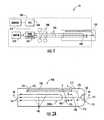
- FIG. 6Ashows an another embodiment of the cuvette, denoted by reference number 300.
- the cuvette 300is substantially identical to the cuvette 100 shown in FIG. 2A , except that the vent channel extending between the sampling channel and the vent opening is replaced by a vent opening 381 that directly opens into the sampling channel 130.
- FIG. 6Bshows a further embodiment of the cuvette, denoted by reference number 400.
- the cuvette 400is substantially identical to the cuvette 100 shown in FIG. 2A , except that the waste channel 450 communicates directly with the sampling channel 130 thereby omitting the jumper channel.
- the waste channel 450includes one or more restrictions 452 located just after the entrance to the waste channel 450 that function to delay filing of the waste channel 450.
- FIGS. 7A-7Ccollectively show a further embodiment of a cuvette, denoted by reference number 500.
- the cuvette 500is substantially identical to the cuvette 100 shown in FIG. 2A , except that the one or more open test channels 140 are formed in the top surface 111 of the main body 110 instead of in the bottom surface 112 of the main body 110 where the open sampling, vent, jumper, and waste channels 130, 180, 170, 150 are formed.
- the open one or more test channels 140 in the top surface 111 of the cuvette main body 110are covered and sealed by a thin substrate 530 with hydrophobic properties (e.g., the substrate 530 includes a hydrophobic adhesive coating or is a hydrophobic film) that is non-removably attached to the top surface 111 of the cuvette main body 110, and the open sampling, vent, jumper, and waste channels 130, 180, 170, 150 in the bottom surface 112 of the cuvette main body 110 are covered and sealed by a thin, substrate 520 with hydrophilic properties (e.g., the substrate 520 includes a hydrophilic adhesive coating or is a hydrophilic film) that is non-removably attached to the bottom surface 112 of the cuvette body 110.
- a thin substrate 530 with hydrophobic propertiese.g., the substrate 530 includes a hydrophobic adhesive coating or is a hydrophobic film
- a connecting channel 550 formed in the top surface 111 of the cuvette main body 110has a first end 550a that communicates with a terminal end of the sampling channel 103 and a second end 550b that communicates with an inlet 540 to the one or more test channels 140.
- the first end 550a of the connecting channel 550is covered and sealed by the hydrophilic substrate 520.
- the remainder of the connecting channel 550 including the second end 550b thereof,is covered and sealed by the hydrophobic substrate 530.
- the connecting channel 550transfers the volume of the blood sample precisely collected by the sampling channel 130, to the one or more test channels 140.
- the one or more test channels 140comprises a branched array of three test channels 140 in a menorah-shaped configuration 140 m (visible in FIGS. 2A , 3A , 4 , 6A and 6B ).
- the menorah-shaped array of test channels 140 mevenly divides the selected volume of blood into three separate blood samples, thereby allowing the cuvette 100 to be used for performing up to three different blood tests.
- the branched array in other embodiments of the cuvette 100may include two test channels 140 or more than three test channels 140.
- each test channel 140communicates with a drive aperture 141 formed through the cuvette body 110.
- the drive aperture 141is open to the external environment at the top surface 112 of the cuvette body 110 and closed by the substrate 120 at the bottom surface of the cuvette body 110.
- each of the test channels 140 formed in the bottom surface of the cuvette body 110includes end sections 142a with smooth top, side and bottom walls (the bottom wall of each test channel 140 being formed by the smooth top surface 121 of the substrate 120) similar to the top, side and bottom walls of the sampling, jumper and waste channels 130, 170, and 150, and an intermediate section 142b where the top wall T T and side walls S T are texture.
- the texturingmay comprise a flat knurl cross-hatch, In other embodiments, the texturing in the intermediate section 142b of one or more of test channels 140 may only be on the top wall or on one or both of the side walls.
- the length of the textured sectionis selected so that the blood sample BLD always remains within this section of the test channel 140 during testing.
- a dehydrated clot promoting reagent(not shown) for triggering and accelerating blood clotting, is disposed in each test channel 140 where the texturing is located.
- the reagent in each test channel 140may be the same or different. Therefore, in one embodiment, reagent A may be in each of the test channels. In another embodiment, reagent A may be in two of the test channels and reagent B may be in one of the test channels. In still another embodiment, reagent A may be in one of the test channels, reagent B may be in one of the test channels and reagent C may be in one of the test channels.
- each test channel 140improves reagent deposition thereon during manufacture of the cuvette, and increase clotting measurement sensitivity, as the blood sample is reciprocally moved or oscillated therein when measuring of the clotting time of the blood sample, as will be explained further on.
- the textured intermediate section of one or more the test channels 140may be replaced by a restricted area (not shown) where the test channel 140 is narrowed.
- the automatic volumetric filling function of the cuvette 100will now be described in greater detail with reference to FIG. 4 .
- the cuvette 100Prior to volumetric filling, the cuvette 100 must be operatively coupled to the clot detection instrument 200 such that the plurality of tubes 230 extending from the pump module 210 of the clot detection instrument 200 sealingly engage the one or more drive apertures 141 of the cuvette body 110, thereby creating a pneumatic system formed by the arrangement of channels of the cuvette 100 and the pneumatic pump module 210 of the clot detection instrument 200, as shown in FIG. 1 .
- the automatic volumetric filling functioncommences when a blood sample is deposited onto the receptor-inlet 161 of the cuvette 100.
- the blood samplemay be deposited on the receptor-inlet 161 by finger after a fingerstick, a needle, a dropper, a pipette, a capillary tube, or any other suitable depositing device. Since at least a portion of the sampling channel 130 is hydrophilic, a force F s is generated by the hydrophilicity of this portion, which initially draws the blood sample deposited on the receptor-inlet 161 into the sampling channel 130 until the entire vent channel 180 become filled.
- the dead air in the vent channel 180 and the section of the sampling channel 130 extending between the receptor-inlet 161 and the vent channel 180is vented through the vent opening 181 of the vent channel 180 as the blood BLD fills this section of the sampling channel 130, and the vent channel 180,
- the blood drawn into the vent channel 180seals the vent opening 181.
- the jumper channel hydrophilicity force F jdraws blood into the jumper channel.
- the force F scontinues to draw more blood from the blood sample deposited on the receptor-inlet 161 into the sampling channel 130 such that the blood BLD in the sampling channel 130 overshoots the vent channel 180 and covers the optical sensor 250 of the clot detection instrument 200, which lies under or over section or area 131 of the sampling channel 130.
- the leading edge E of the blood BLD in the sampling channel 130continues to be pulled back by force F w + F p and uncovers the optical sensor 250.
- the volume of the blood sample BLD disposed in the sampling channel 130 at the moment the optical sensor 250 is uncovered,is the requisite volume. Consequently, the pump module 210 of the clot detection instrument 200 is immediately activated by the uncovered optical sensor 250 and draws this requisite volume of blood sample BLD into the test channels 140 such that the blood sample BLD is disposed in the sections of the test channels 140 that are textured.
- the ratio of force F w to force F sdetermines the sample pull back speed. Generally, a wider waste channel 150 has stronger pull back.
- the ratio of force F w to force F sequals 1.2.
- the forces described abovemay be adjusted by the material properties of the cuvette body 110, substrate 120, size and/or geometry of the plurality of channels.
- the blood sample over shoot and pull back functions of the sampling channel 130may also be adjusted and controlled by the volume of dead air in the tubes 230 and pump module 210 of the clot detection instrument 200.
- the automatic blood clot testing function of the cuvette 100will now be described in greater detail with reference to FIGS. 3A and 5 .
- the pump module 210After the pump module 210 has drawn the blood sample into one or more test channels 140 of the cuvette 100, the pump module 210 automatically switches into a pumping mode where it alternately creates positive and negative pressures in the test channels 140 of the cuvette 100.
- the alternating positive and negative pressuresreciprocally moves the blood samples BLD back and forth across textured sections (or restricted areas) of the one or more test channels 140, thereby mixing the blood sample with dehydrated reagent, as shown in FIG. 3A .
- the reagentrehydrates and mixes with the blood sample BLD, it triggers and accelerates the blood clotting cascade.
- Fibrin formation within the blood sample BLDcauses the viscosity of the blood sample BLD to increase with time.
- the viscosity increasemay be detected, in one embodiment, by measuring the pumping pressure within each test channel 140 over time. As shown in the graph of FIG. 5 , the pumping pressure starts at an initial pumping pressure value (pumping pressure baseline ⁇ P baseline ) and increases with time, as the viscosity of the blood increases during clotting.
- the pressure sensors 240 of the blood clot detection instrument 200measure the pump pressure over time and the CPU 260 of the clot detection instrument 200 compares this data to the initial pressure baseline ⁇ P baseline .
- the clotting time of the blood samplemay be determined when pressure value is greater than or equal to a preset threshold. In one embodiment, the clotting time is, ⁇ ⁇ P end point - ⁇ ⁇ P baseline ⁇ threshold ,
- the preset thresholdmay be fixed or dynamic.
- a dynamic thresholdmay be, ⁇ ⁇ P baseline + 0.3 ⁇ ⁇ ⁇ P baseline .
- the hydrophilicity of the one or more test channels 140will aid the robust automatic volumetric blood sample filling function of the cuvette 100, while impeding the clotting performance of the cuvette 100.
- Appropriately balancing the test channel 140 dimensions, geometry, degree of texturing/restriction size, and the hydrophilic properties of the cuvette body 110 and substrate 120,will provide the cuvette 100 with requisite blood clotting performance.
- the pump profile of the pump module 210may also affect clotting performance. For example, a pump speed greater than 20 millisecond (ms) per pump step, equivalent to 20ul per sec in test channel or a pump stroke greater than 55 steps, equivalent to 0.044, may increase the chance of deforming a weak clot (International Normalized Ratio > 4.0), which may in turn, result in lower clot detection precision.
- the pump profileis 40ms per pump step and 36 steps per pump direction (generates positive and negative pressures).
Landscapes
- Health & Medical Sciences (AREA)
- Chemical & Material Sciences (AREA)
- Life Sciences & Earth Sciences (AREA)
- Hematology (AREA)
- Engineering & Computer Science (AREA)
- General Health & Medical Sciences (AREA)
- Analytical Chemistry (AREA)
- Biomedical Technology (AREA)
- Chemical Kinetics & Catalysis (AREA)
- Clinical Laboratory Science (AREA)
- Dispersion Chemistry (AREA)
- Physics & Mathematics (AREA)
- Biochemistry (AREA)
- Medicinal Chemistry (AREA)
- Food Science & Technology (AREA)
- Ecology (AREA)
- General Physics & Mathematics (AREA)
- Immunology (AREA)
- Pathology (AREA)
- Urology & Nephrology (AREA)
- Molecular Biology (AREA)
- Biophysics (AREA)
- Investigating Or Analysing Biological Materials (AREA)
Description
- The invention relates to a cuvette for use with a blood clot detection instrument.
- Many people take anticoagulants to maintain the theropedic coagulation time of their blood. Depending upon the person, the peak anticoagulant effect of the anticoagulant may be delayed by many hours and/or days, and the duration of the effect may persist after the peak for another four to five days. Accordingly, it is critical that the people who take anticoagulants closely monitor the coagulation time of their blood, so that they can monitor and adjust the amount of the anticoagulant they are taking.
- A common manner of determining the effective amount of anticoagulant in a person's blood is to perform a prothrombin time (PT) test. A PT test measures how long a sample of blood takes to clot. As a result, the anticoagulation or hemostasis level in the blood is directly proportional to the length of time required to form clots.
- Many devices and apparatus exist for performing coagulation time measurements and tests. Some of these apparatus are portable and simple enough to operate by a person in his or her home. An example of such an apparatus is describe in
U.S. Patent 5,534,226 , entitled PORTABLE TEST APPARATUS AND ASSOCIATED METHOD OF PERFORMING A BLOOD COAGULATION TEST, issued to Gavin et al. and assigned to International Technidyne Corporation, the assignee herein. The apparatus described in this patent includes a disposable cuvette and a testing device. In operation, a sample of blood is placed into a cup-like supply reservoir of the cuvette, the blood sample is drawn into the cuvette, and the coagulation time of the blood sample is measured.
A cuvette for conducting coagulation assays is also known fromUS 5628961 andWO97/24604 - A problem associated with such apparatus, is that the volume of the blood sample drawn into the cuvette for measurement and testing is controlled by both the testing device and the sample cup removal techniques. Moreover, the cup-like supply reservoir can be messy to use.
- Accordingly, a need exits for an improved apparatus for measuring and testing blood coagulation.
- A cuvette is described herein for use with a blood clot detection instrument. The cuvette comprises a blood sample receptor-inlet and a channel arrangement comprising: at least one test channel for performing a blood clotting time measurement; a sampling channel communicating with the blood sample receptor-inlet and the at least one test channel; a waste channel communicating with the sampling channel; and a vent opening communicating with the sampling channel. At least the sampling channel and the waste channel each has at least one surface portion, a coating, an insert or liner, and any combination thereof, that is hydrophilic. The sampling channel with its at least one surface portion that is hydrophilic, the vent opening and the waste channel with its at least one surface portion that is hydrophilic, coact to automatically draw a requisite volume of a blood sample deposited at the blood receptor-inlet, into the sampling channel. More specifically, air compressed within the blood clot detection instrument, the at least one test channel of the cuvette, and the section of the sampling channel extending beyond the vent opening of the cuvette, coacts with the waste channel to cause the a leading edge of the blood sample drawn into the sampling channel from the blood receptor-inlet, to pull back within the sampling channel and uncover an optical sensor of the blood clot detection instrument. The volume of the blood sample in the sampling channel at the time when the blood sample is pulled back to uncover the optical sensor, equals the requisite volume. The uncovering of the optical sensor activates a pump module of the blood clot detection instrument, which draws the requisite volume of the blood sample into the at least one test channel.
- An apparatus is described herein for measuring blood clotting time. The apparatus comprises: a blood clot detection instrument and a cuvette according to claim 1 for use with the blood clot detection instrument. The blood clot detection instrument comprises: a pump module and at least one pressure sensor. The cuvette comprises a blood sample receptor-inlet; a channel arrangement comprising: at least one test channel for performing a blood clotting time measurement; a sampling channel communicating with the blood sample receptor-inlet and the at least one test channel; and a waste channel communicating with the sampling channel; and a vent opening communicating with the sampling channel. At least the sampling channel has at least one surface portion, a coating, an insert or liner, and any combination thereof, that is hydrophilic. The sampling channel with its at least one surface portion that is hydrophilic, the vent opening and the waste channel coact to automatically draw a requisite volume of a blood sample deposited at the blood receptor-inlet, into the sampling channel, the requisite volume of blood sample being drawn into the at least one test channel when the pump module of the blood clot detection instrument is activated. The at least one test channel of the cuvette, and the pump module and the at least one pressure sensor of the clot detection instrument, coact to perform a blood clotting time measurement on the requisite volume of the blood sample.
- Also described herein is a blood clot detection instrument for automatically measuring blood clotting time of a blood sample contained in a test channel of a cuvette according to claim 1. The blood clot detection instrument comprises a pump module for communicating with the test channel of the cuvette; a pressure sensor; and a central processing unit. The central processing unit executes instructions for operating the pump module in a pressure alternating mode that pumps the blood sample back and forth in a test channel of a cuvette. During clot formation, the viscosity of the blood sample increases and causes a pumping pressure of the pump module to increase over time. The central processing unit executes further instructions for obtaining a baseline pumping pressure from the pressure sensor upon initial operation of the pump module in the pressure alternating mode; obtaining additional pumping pressures over time from the pressure sensor; determining a pumping pressure difference value between each additional pumping pressure and the baseline pumping pressure; comparing each pumping pressure difference value to a predetermined threshold value; and indicating the blood clotting time of the blood sample when the pumping pressure difference value exceeds the predetermined threshold value, the indicated blood clotting time comprising a duration of time extending between the measurement of the additional pumping pressure used for determining the pumping pressure difference value that exceeded the predetermined threshold value and the measurement of the baseline pumping pressure.
FIG. 1 is a schematic view of an embodiment of a cuvette-based apparatus for measuring blood coagulation or clotting time.FIG. 2A is a schematic plan view of an embodiment of the disposable cuvette.FIG. 2B is a sectional view through line 2B-2B ofFIG. 2A .FIG. 2C is a sectional view through line 2C-2C ofFiG. 2A .FIG. 3A is an enlarged view of a blood sample testing portion of the disposable cuvette shown inFIG. 2A .FIG. 3B is a section view throughline 3B-3B ofFIG. 3A .FIG. 4 is an enlarged view of a volumetric blood sampling portion of the disposable cuvette shown inFIG. 2A .FIG. 5 is a pressure profile and clot detection graph.FIG. 6A is a schematic plan view of another embodiment of the disposable cuvette.FIG. 6B is a schematic plan view of a further embodiment of the disposable cuvette.FIG. 7A is a perspective view of a further embodiment of the disposable cuvette.FIG. 7B is an enlarged view ofencircled area 7B inFIG. 7A .FIG. 7C is a sectional view through line 7C-7C inFIG. 7B .- Like reference numbers and designations in the various drawings indicate like elements.
- Referring to
FIG. 1 , there is shown a schematic view of an embodiment of a cuvette-basedapparatus 10 for measuring blood coagulation or clotting time. Theapparatus 10 generally comprises adisposable cuvette 100 and a bloodclot detection instrument 200. Theapparatus 10 may be used for measuring blood coagulation time by depositing a sample of blood (whole blood or plasma) onto a specified location of thedisposable cuvette 100 and operatively coupling thedisposable cuvette 100 to theclot detection instrument 200. Thecuvette 100 automatically selects or fills itself with a requisite volume of the blood sample (to be tested) deposited at the specified location of thecuvette 100. Theclot detection instrument 200 facilitates automatic mixing of the blood sample with a clotting reagent within thecuvette 100 and automatically measures the clotting time of the selected volume of the blood sample mixed with the clotting reagent within thedisposable cuvette 100, without contacting the blood sample. After completion of the measurement, thecuvette 100 may be uncoupled or removed from theclot detection instrument 200 and disposed of. Because theclot detection instrument 200 does not contact the blood sample, anothercuvette 100 may be operatively coupled to theclot detection instrument 200 for measuring another blood sample without sterilization or other cleaning of theclot detection instrument 200. - Referring still to
FIG. 1 , theclot detection instrument 200 comprises apneumatic pump module 210, amotor 220 for driving thepump module 210, a plurality oftubes 230 extending from thepump module 210 for pneumatically coupling with thecuvette 100, apressure sensor 240 associated with eachtube 230 for measuring the pneumatic pressure within thetube 230, and anoptical sensor 250 for optically sensing a sampling channel in thecuvette 100. In one embodiment, theoptical sensor 250 comprises, but is not limited, to a LED/photo sensor. Theclot detection instrument 200 also comprises, without limitation, a central processing unit 260 (CPU) executing instructions for controlling the operation of themotor 220 and thus thepump module 220 via signals received from theoptical sensor 250, and determining clotting time based on the pressures sensed by thepressure sensors 240, a display (not shown) for displaying the measured clotting time or other data related to the measurement, amemory 270 for storing previously performed measurements, and buttons, knobs, and/or switches (not shown) for operating theclot detection instrument 200, controlling the display and/or accessing stored data from thememory 270. - Referring now to
FIGS. 2A-2C , there is collectively shown a schematic plan view of an embodiment of thedisposable cuvette 100. Thecuvette 100 comprises a substantially planarmain body 110 defining generally planar top andbottom surfaces main body 110 is typically made from a rigid, transparent hydrophobic or hydrophilic plastic material, using any suitable forming method, such as molding. The plastic hydrophobic materials may include, without, limitation polystyrene and polytetrafluoroethylene and the plastic hydrophilic materials may include, without limitation, styrene acrylonitrile, acrylonitrile styrene acrylate. The cuvettemain body 110 may also be made from other types of rigid, transparent hydrophobic or hydrophilic materials. The cuvettemain body 110 includes an arrangement of open channels formed in itsbottom surface 112. The open channels are covered and sealed by a thin,substrate 120 that is non-removably attached to thebottom surface 112 of thecuvette body 110 When the cuvettemain body 110 is not made from a hydrophilic material or is made from a hydrophobic material, the channels of the channel arrangement each have at least one surface that is hydrophilic, and/or has a hydrophilic coating, and/or has a hydrophilic insert disposed therein (formed, for example, as a tube or liner, thereby fully or partially lining the channel(s)), that facilitates the automatic filling function of thecuvette 100. - In one embodiment, at least a
top surface 121 of thethin substrate 120, i.e., the surface in contact with thebottom surface 112 of thecuvette body 110, is hydrophilic or has hydrophilic properties. The hydrophilic properties of thetop surface 121 of thesubstrate 120, facilitates the requisite volumetric selection of the blood sample deposited on thecuvette 100, for coagulation time measurement by theclot detection instrument 200. In other embodiments, requisite volumetric selection of the blood sample is accomplished by forming thecuvette body 110 from a hydrophilic material. - The
thin substrate 120, in one embodiment, is atransparent film 122 coated on one side with alayer 122a of clear pressure sensitive hydrophilic adhesive. Thelayer 122a of hydrophilic adhesive forms thetop surface 121 of thesubstrate 120 and non-removably attaches thesubstrate 120 to thebottom surface 112 of thecuvette body 110. Thetransparent film 122 may comprise, in one embodiment, a transparent polyester material. - In an alternative embodiment the
transparent film 122 is made from a hydrophilic material. Such a substrate may be attached to thebottom surface 112 of the cuvette body 110 (with thetop surface 121 of thesubstrate 120 mated with thebottom surface 112 of the cuvette body 110) with a layer of adhesive applied to thebottom surface 112 ofcuvette body 110. Alternatively, such a substrate may be attached to thebottom surface 112 of thecuvette body 110 using heat sealing methods. - Referring still to
FIGS. 2A-2C , the channel arrangement formed in the bottom surface of thecuvette body 110 generally comprises asampling channel 130, one ormore test channels 140 and at least onewaste channel 150. Afirst end 131 of thesampling channel 130 communicates with asample depositing area 160 formed in a first orfront end 113 of thecuvette body 110. Thesample depositing area 160 in thefront end 113 of thecuvette body 110 and the exposed underlying portion of thesubstrate 120 form a blood sample receptor and inlet 161 (receptor-inlet 161) on which the entire blood sample is deposited. Thesampling channel 130 extends longitudinally in the bottom surface of thecuvette body 110, from the receptor-inlet 161, and merges at its second end with the one ormore test channels 140 formed in the bottom surface of thecuvette body 110. - The channel arrangement shown in
FIGS. 2A-2C further includes ajumper channel 170 that branches off from thesampling channel 130 just downstream of the receptor-inlet 161 and fluidly connects thewaste channel 150 with thesampling channel 130. The terminal end of thewaste channel 150 communicates with a wastechannel venting aperture 151 formed transversely through thecuvette body 110, which allows "dead" air displaced from within the waste andjumper channels channel venting aperture 151 is open to the external environment at thetop surface 111 of thecuvette body 110 and closed by thesubstrate 120 at the bottom surface of thecuvette body 110. - The channel arrangement shown in
FIGS. 2A-2C further includes avent channel 180 that branches off from thesampling channel 130 downstream of thejumper channel 170. Thevent channel 180 communicates with avent opening 181 formed transversely through thecuvette body 110 which allows "dead" air displaced from within the sampling and ventchannels vent opening 181 is open to the external environment at thetop surface 111 of thecuvette body 110 and closed by thesubstrate 120 at the bottom surface of thecuvette body 110. - As shown in
FIG. 2C , the sampling channel 130 (and the jumper, waste and ventchannels bottom surface 112 of the cuvettemain body 110 has a smooth top T surface and smooth side surfaces S. The bottom surface B of the sampling channel 130 (and the jumper, waste and ventchannels hydrophilic adhesive layer 122a or the top surface of the hydrophilic film 122) of thesubstrate 120, which is also smooth. - The cuvette
main body 110, in some embodiments, is made from a hydrophobic Material. In such embodiments, the sampling, vent, jumper, andwaste channels cuvette 100. - In other embodiments, the cuvette
main body 110 is made from a hydrophilic material. The one ormore test channels 140 in such embodiments, each includes at least one surface that is hydrophobic, and/or has a hydrophobic coating, and/or has a hydrophobic insert disposed therein, where no automatic filling or sample sizing function is required to be performed by thecuvette 100. - The requisite volume of blood sample selected by the
cuvette 100 for measurement by theclot detection instrument 200, is obtained from the blood sample deposited on the receptor-inlet 161. The size of this volume is determined by the effective volume of thesampling channel 130. The effective volume of thesampling channel 130 is determined by the width of thesampling channel 130, the height of thesampling channel 130, and length of thesampling channel 130 as measured from point A, which is adjacent to the receptor-inlet 161, to point B, which is adjacent to thevent channel 180. Thejumper channel 170, connecting thesampling channel 130 towaste channel 150, delays the filling of thewaste channel 150 until thesampling channel 130 is completely filled. The duration of the delay is controlled by an intersection I of thejumper channel 170 and thewaste channel 150 and the length and cross-sectional area (CSA) ofjumper channel 170 relative to the CSA of thewaste channel 150, which insure that blood from the blood sample deposited on the receptor-inlet 161, is drawn into thesampling channel 130 prior to being drawn into thewaste channel 150. The delay time is determined by the cross section area and length of thejumper channel 70. The duration of the delay may be increased by lengthening thejumper channel 170, and/or decreasing the cross-sectional area (width and height) of thejumper channel 170 relative to the CSA of the waste channel to increase flow resistant through thejumper channel 170. Thus, during automatic blood sample volume sizing, the intersection I of thejumper channel 170 and thewaste channel 150 acts like a resistor. Once a blood sample is applied or deposited in the cuvette's receptor-inlet 161, the blood sample enters thesampling channel 130 and thejumper channel 170 substantially simultaneously. While the blood sample moves forward in thesampling channel 130, it also tills thejumper channel 170, then stops at the intersection I of thejumper channel 170 and thewaste channel 150. Thesampling channel 130 continues to fill until an equilibrium state is reached. The remaining sample in the receptor-inlet 161 then forces the blood sample into thewaste channel 150 from thejumper channel 170. The hydrophilic force of thewaste channel 150 picks up and draws off the remaining blood sample in the receptor-inlet 161. - In one embodiment where the cuvette comprises three
test channels 140, thesampling channel 130 has a width of about 0.055 inches, a height of about 0.014 inches, and a length of about 0.9 inches; thevent channels 180 has a width of about 0.010 inches, a height of about 0.012 inches, and a length of about 0.140 inches; thejumper channel 170 has a width of about 0.010 inches, a height of about 0.012 inches, and a length of about 0.25 inches; and and thewaste channel 150 has a width of about 0.066 inches, a height of about 0.014 inches, and length of about 2.24 inches. The threetest channels 140 of such a cuvette each has a width of about 0.030 inches and a height of about 0.010 inches. The length of each of the outer two test channels is about 1.69 inches and the inner test channel is about 1.634 inches. The sampling, jumper, waste, and test channel(s) in other embodiments of the cuvette may have other suitable dimensions. FIG. 6A shows an another embodiment of the cuvette, denoted byreference number 300. Thecuvette 300 is substantially identical to thecuvette 100 shown inFIG. 2A , except that the vent channel extending between the sampling channel and the vent opening is replaced by avent opening 381 that directly opens into thesampling channel 130.FIG. 6B shows a further embodiment of the cuvette, denoted byreference number 400. Thecuvette 400 is substantially identical to thecuvette 100 shown inFIG. 2A , except that thewaste channel 450 communicates directly with thesampling channel 130 thereby omitting the jumper channel. In addition, thewaste channel 450 includes one ormore restrictions 452 located just after the entrance to thewaste channel 450 that function to delay filing of thewaste channel 450.FIGS. 7A-7C collectively show a further embodiment of a cuvette, denoted byreference number 500. Thecuvette 500 is substantially identical to thecuvette 100 shown inFIG. 2A , except that the one or moreopen test channels 140 are formed in thetop surface 111 of themain body 110 instead of in thebottom surface 112 of themain body 110 where the open sampling, vent, jumper, andwaste channels more test channels 140 in thetop surface 111 of the cuvettemain body 110 are covered and sealed by athin substrate 530 with hydrophobic properties (e.g., thesubstrate 530 includes a hydrophobic adhesive coating or is a hydrophobic film) that is non-removably attached to thetop surface 111 of the cuvettemain body 110, and the open sampling, vent, jumper, andwaste channels bottom surface 112 of the cuvettemain body 110 are covered and sealed by a thin,substrate 520 with hydrophilic properties (e.g., thesubstrate 520 includes a hydrophilic adhesive coating or is a hydrophilic film) that is non-removably attached to thebottom surface 112 of thecuvette body 110. As can be seen inFIGS. 7B and 7C , the sampling channel 103 and aninlet 540 to the one ormore test channels 140 are laterally offset from one another. A connectingchannel 550 formed in thetop surface 111 of the cuvettemain body 110, has a first end 550a that communicates with a terminal end of the sampling channel 103 and asecond end 550b that communicates with aninlet 540 to the one ormore test channels 140. The first end 550a of the connectingchannel 550 is covered and sealed by thehydrophilic substrate 520. The remainder of the connectingchannel 550 including thesecond end 550b thereof, is covered and sealed by thehydrophobic substrate 530. The connectingchannel 550 transfers the volume of the blood sample precisely collected by thesampling channel 130, to the one ormore test channels 140.- In one embodiment, the one or
more test channels 140 comprises a branched array of threetest channels 140 in a menorah-shaped configuration 140m (visible inFIGS. 2A ,3A ,4 ,6A and 6B ). The menorah-shaped array oftest channels 140m evenly divides the selected volume of blood into three separate blood samples, thereby allowing thecuvette 100 to be used for performing up to three different blood tests. For examples of the blood tests that may be performed in the cuvette, seeU.S. Patent 5,534,226 , entitled, PORTABLE TEST APPARATUS AND ASSOCIATED METHOD OF PERFORMING A BLOOD COAGULATION TEST, assigned to the International Technidyne Corporation, the assignee herein. The branched array in other embodiments of thecuvette 100 may include twotest channels 140 or more than threetest channels 140. - Referring still to
FIGS. 2A ,3A ,4 ,6A and 6B , the terminal or marginal terminal end of eachtest channel 140 communicates with adrive aperture 141 formed through thecuvette body 110. Thedrive aperture 141 is open to the external environment at thetop surface 112 of thecuvette body 110 and closed by thesubstrate 120 at the bottom surface of thecuvette body 110. When thecuvette 100 is operatively coupled to theclot detection instrument 200, as shown inFIG. 1 , the plurality oftubes 230 extending from thepump module 210 sealingly engage the one ormore drive apertures 141 of thecuvette body 110, so that the arrangement of channels and thepneumatic pump module 210 of theclot detection instrument 200 form a pneumatic system when thecuvette 100 is operatively coupled to theclot detection instrument 200. - Referring now to
FIGS. 3A and3B , each of thetest channels 140 formed in the bottom surface of thecuvette body 110 includesend sections 142a with smooth top, side and bottom walls (the bottom wall of eachtest channel 140 being formed by the smoothtop surface 121 of the substrate 120) similar to the top, side and bottom walls of the sampling, jumper andwaste channels intermediate section 142b where the top wall TT and side walls ST are texture. In one non-limiting embodiment, the texturing may comprise a flat knurl cross-hatch, In other embodiments, the texturing in theintermediate section 142b of one or more oftest channels 140 may only be on the top wall or on one or both of the side walls. The length of the textured section is selected so that the blood sample BLD always remains within this section of thetest channel 140 during testing. A dehydrated clot promoting reagent (not shown) for triggering and accelerating blood clotting, is disposed in eachtest channel 140 where the texturing is located. The reagent in eachtest channel 140 may be the same or different. Therefore, in one embodiment, reagent A may be in each of the test channels. In another embodiment, reagent A may be in two of the test channels and reagent B may be in one of the test channels. In still another embodiment, reagent A may be in one of the test channels, reagent B may be in one of the test channels and reagent C may be in one of the test channels. When the blood sample is drawn into thetest channels 140, the reagent rehydrates and mixes with the blood. The textured wall(s) of eachtest channel 140 improve reagent deposition thereon during manufacture of the cuvette, and increase clotting measurement sensitivity, as the blood sample is reciprocally moved or oscillated therein when measuring of the clotting time of the blood sample, as will be explained further on. In an alternate embodiment, the textured intermediate section of one or more thetest channels 140 may be replaced by a restricted area (not shown) where thetest channel 140 is narrowed. - The automatic volumetric filling function of the
cuvette 100 will now be described in greater detail with reference toFIG. 4 . Prior to volumetric filling, thecuvette 100 must be operatively coupled to theclot detection instrument 200 such that the plurality oftubes 230 extending from thepump module 210 of theclot detection instrument 200 sealingly engage the one ormore drive apertures 141 of thecuvette body 110, thereby creating a pneumatic system formed by the arrangement of channels of thecuvette 100 and thepneumatic pump module 210 of theclot detection instrument 200, as shown inFIG. 1 . The automatic volumetric filling function commences when a blood sample is deposited onto the receptor-inlet 161 of thecuvette 100. The blood sample may be deposited on the receptor-inlet 161 by finger after a fingerstick, a needle, a dropper, a pipette, a capillary tube, or any other suitable depositing device. Since at least a portion of thesampling channel 130 is hydrophilic, a forceFs is generated by the hydrophilicity of this portion, which initially draws the blood sample deposited on the receptor-inlet 161 into thesampling channel 130 until theentire vent channel 180 become filled. The dead air in thevent channel 180 and the section of thesampling channel 130 extending between the receptor-inlet 161 and thevent channel 180, is vented through the vent opening 181 of thevent channel 180 as the blood BLD fills this section of thesampling channel 130, and thevent channel 180, The blood drawn into thevent channel 180 seals thevent opening 181. At the same time the jumper channel hydrophilicity forceFj draws blood into the jumper channel. Once thevent channel 180 has been filled, the forceFs continues to draw more blood from the blood sample deposited on the receptor-inlet 161 into thesampling channel 130 such that the blood BLD in thesampling channel 130 overshoots thevent channel 180 and covers theoptical sensor 250 of theclot detection instrument 200, which lies under or over section orarea 131 of thesampling channel 130. The blood BLD which overshoots thevent channel 180 compresses the dead air volume contained within the section of thesampling channel 130 extending beyond thevent channel 180, thetest channels 140, and thetubes 230 of theclot detection instrument 200, and thepump module 210, becauseFs >Fp andFw <<Fs, whereFp is the pressure of the compressed dead air volume, andFw is the hydrophilicity force generated by at least a portion of thewaste channel 150 that is hydrophilic. Blood stops flowing in thesampling channel 130 towards thetest channels 140 when an equilibrium stateFs =Fp +Fw is achieved therein. - After the equilibrium state has been reached, blood that has been delayed by the jumper channel/waste channel intersection I and the
jumper channel 170, reaches thewaste channel 150. Thewaste channel 150 generates a forceFw, that increases to a value proportional to the line of contact between the blood and the hydrophilic surface, which first pulls additional blood remaining in the receptor-inlet 161 into thewaste channel 150. As thewaste channel 150 fills with excess blood sample BLD, dead air disposed therein and displaced by the incoming blood BLD is vented to the external environment through the wastechannel venting aperture 151. Once the remaining blood sample drawn off from the receptor-inlet 161, forceFw +Fp becomes greater than Fs, and therefore, the leading edge E of the blood BLD in thesampling channel 130 starts pulling back towards thevent channel 180. - The leading edge E of the blood BLD in the
sampling channel 130 continues to be pulled back by forceFw +Fp and uncovers theoptical sensor 250. The volume of the blood sample BLD disposed in thesampling channel 130 at the moment theoptical sensor 250 is uncovered, is the requisite volume. Consequently, thepump module 210 of theclot detection instrument 200 is immediately activated by the uncoveredoptical sensor 250 and draws this requisite volume of blood sample BLD into thetest channels 140 such that the blood sample BLD is disposed in the sections of thetest channels 140 that are textured. The ratio of forceFw to forceFs determines the sample pull back speed. Generally, awider waste channel 150 has stronger pull back. In one, non-limiting embodiment, the ratio of forceFw to forceFs equals 1.2. One of ordinary skill in the art will recognize that the forces described above may be adjusted by the material properties of thecuvette body 110,substrate 120, size and/or geometry of the plurality of channels. The blood sample over shoot and pull back functions of thesampling channel 130 may also be adjusted and controlled by the volume of dead air in thetubes 230 andpump module 210 of theclot detection instrument 200. - The automatic blood clot testing function of the
cuvette 100 will now be described in greater detail with reference toFIGS. 3A and5 . After thepump module 210 has drawn the blood sample into one ormore test channels 140 of thecuvette 100, thepump module 210 automatically switches into a pumping mode where it alternately creates positive and negative pressures in thetest channels 140 of thecuvette 100. The alternating positive and negative pressures (pumping pressure) reciprocally moves the blood samples BLD back and forth across textured sections (or restricted areas) of the one ormore test channels 140, thereby mixing the blood sample with dehydrated reagent, as shown inFIG. 3A . As the reagent rehydrates and mixes with the blood sample BLD, it triggers and accelerates the blood clotting cascade. Fibrin formation within the blood sample BLD causes the viscosity of the blood sample BLD to increase with time. The viscosity increase may be detected, in one embodiment, by measuring the pumping pressure within eachtest channel 140 over time. As shown in the graph ofFIG. 5 , the pumping pressure starts at an initial pumping pressure value (pumping pressure baselineΔPbaseline) and increases with time, as the viscosity of the blood increases during clotting. Thepressure sensors 240 of the bloodclot detection instrument 200, measure the pump pressure over time and theCPU 260 of theclot detection instrument 200 compares this data to the initial pressure baselineΔPbaseline. The clotting time of the blood sample may be determined when pressure value is greater than or equal to a preset threshold. In one embodiment, the clotting time is,
- whereΔPend point is the clotting end point peak to peak pressure.
- The preset threshold may be fixed or dynamic. In one embodiment, a dynamic threshold may be,

- In general, the hydrophilicity of the one or
more test channels 140 will aid the robust automatic volumetric blood sample filling function of thecuvette 100, while impeding the clotting performance of thecuvette 100. Appropriately balancing thetest channel 140 dimensions, geometry, degree of texturing/restriction size, and the hydrophilic properties of thecuvette body 110 andsubstrate 120, will provide thecuvette 100 with requisite blood clotting performance. - The pump profile of the
pump module 210, i.e., pumping speed and stroke, may also affect clotting performance. For example, a pump speed greater than 20 millisecond (ms) per pump step, equivalent to 20ul per sec in test channel or a pump stroke greater than 55 steps, equivalent to 0.044, may increase the chance of deforming a weak clot (International Normalized Ratio > 4.0), which may in turn, result in lower clot detection precision. In one embodiment, the pump profile is 40ms per pump step and 36 steps per pump direction (generates positive and negative pressures).


Claims (26)
- A cuvette (100) for use with a blood clot detection instrument (200), the cuvette comprising:a main body (110) including:a blood sample receptor-inlet (161);a channel arrangement comprising:at least one test channel (140) for performing a blood clotting time measurement;a sampling channel (130) communicating with the blood sample receptor-inlet and the at least one test channel, at least the sampling channel having at least one surface portion, a coating, an insert or liner, and any combination thereof, that is hydrophilic; anda waste channel (150) communicating with the sampling channel; anda vent opening (181) communicating with the sampling channel,wherein the sampling channel, the vent opening and the waste channel coact to automatically draw a requisite volume of a blood sample deposited at the blood receptor-inlet, into the sampling channel.
- The cuvette of claim 1, wherein the coaction between the sampling channel (130) and the vent opening (171) includes a force generated by the at least one surface portion of the sampling channel that is hydrophilic and which draws the blood from the blood sample deposited at the blood sample receptor-inlet into the sampling channel (130) and venting of air through the vent opening (181) (130) which is displaced from the sampling channel (130) by the incoming blood.
- The cuvette of claim 1, wherein the channel arrangement further comprises a member associated with the waste channel (150) for delaying the filling of the waste channel (150) until the sampling channel (130) is filled.
- The cuvette (100) of claim 1, wherein the channel arrangement is formed in a surface of the main body.
- The cuvette (100) of claim 4, further comprising a substrate (120) for closing and sealing at least a portion of the channel arrangement formed in the surface of the main body.
- The cuvette (100) of claim 5, wherein the substrate forms the at least one surface portion of the sampling channel (130) that is hydrophilic.
- The cuvette (100) of claim 5, wherein the substrate comprises a film with a hydrophilic surface, the hydrophilic surface of the substrate forming the at least one surface portion of the sampling channel that is hydrophilic, or wherein the substrate comprises a film and a layer of hydrophilic material disposed on the film, the hydrophilic material forming the at least one surface portion of the sampling channel (130) that is hydrophilic.
- The cuvette of claim 7, wherein the hydrophilic material is an adhesive which attaches the substrate to the main body.
- The cuvette (100) of claim 1, further comprising a blood clotting reagent disposed in the at least one test channel(140).
- The cuvette of claim 1, wherein the at least one test channel (140) includes a section having at least one textured surface, or includes a restriction.
- The cuvette of claim 1, wherein the main body (110) is made of one of a hydrophobic material, a hydrophilic material, or a combination of a hydrophobic material and a hydrophilic material.
- The cuvette of claim 1, wherein the channel arrangement further comprises a vent channel (180) connecting the vent opening (181) with the channel (130), at least one of group comprising the waste channel (150), and the vent channel (180) has at least one surface portion, a coating, an insert or liner, and any combination thereof, that is hydrophilic.
- The cuvette of claim 1, wherein the at least one test channel (140) has at least one surface portion, a coating, an insert or liner, and any combination thereof, that is hydrophilic or hydrophobic.
- The cuvette (100) of claim 3. wherein the member associated with the waste channel (150) comprises a jumper channel (170) or a restriction.
- The cuvette (100) of claim 14, wherein the jumper channel (170) or the restriction has at least one surface portion, a coating, an insert or liner, and any combination thereof, that is hydrophilic.
- The cuvette (100) of claim 1, wherein the channel arrangement further comprises a jumper (170) channel connecting the waste channel (150) with the samping channel (130), the jumper channel (170) for delaying the filling of the waste channel (150) until the sampling channel (130) is filled.
- The cuvette (100) of claim 1, wherein the waste channel (150) conmunicates with the sampling channel (130) through a restriction, the restriction having a smaller cross sectional area than the sample channel (130) and the waste channel (150).
- The cuvette (100) of claim 17, wherein the vent opening (181, 381) is located between the at least one test channel and the restriction.
- An apparatus for measuring blood clotting time, the apparatus comprising:A) a blood clot detection instrument (200), the blood clot detection instrument comprising:a pump module (210); andat least one pressure sensor (240); andB) a cuvette (100) of any one of claims 1 to 18
wherein the at least one test channel (140) of the cuvette (100), and the pump module (210) and the at least one pressure sensor (240) of the clot detection instrument, coact to perform a blood clotting time measurement on the requisite volume of the blood sample. - The cuvette (100) of claim 1, further comprising:a first substrate (520) with hydrophilic properties for closing and sealing the sampling channel (130) and the waste channel (150); anda second substrate (530) with hydrophobic properties for closing and sealing the at least one test channel (140).
- The cuvette (100) of claim 20, wherein the sampling channel (130) and the waste channel (150) are formed in a first surface of the cuvette (100) and the first substrate is affixed to the first surface, and the at least one test channel (140) is formed in second surface of the cuvette and the second substrate is affixed to the second surface.
- The cuvette (100) of claim 21, wherein the first and second surfaces are opposed to one another.
- The cuvette (100) of claim 20, wherein the channel arrangement further comprises:a vent channel (180) connecting the vent opening (181) with sampling channel (130); anda jumper channel (170) connecting the waste channel (150) to the sampling channel (130), for delaying the filling of the waste channel (150) until the sampling channel (130) is filled,wherein the first substrate closes and seals the vent channel (180) and the jumper channel (170).
- A system comprising the cuvette (100) of any of claims 1 to 16 and a blood clot detection instrument (200) for automatically measuring blood clotting time of a blood sample contained in a test channel of the cuvette, the blood clot detection instrument comprising:a pump module (210) for communicating with the test channel of the cuvette;a pressure sensor (240); anda central processing unit executing instructions for:operating the pump module in a pressure alternating mode that causes a viscosity of the blood sample to increase over time, the increase in viscosity of the blood causing a pumping pressure of the pump module to increase over time;obtaining a baseline pumping pressure from the pressure sensor upon initial operation of the pump module in the pressure alternating mode;obtaining additional pumping pressures over time from the pressure sensor; determining a pumping pressure difference value between each additional pumping pressure and the baseline pumping pressure;comparing the pumping pressure difference value to a predetermined threshold value; andindicating the blood clotting time of the blood sample when the pumping pressure difference value equals or exceeds the predetermined threshold value, the indicated blood clotting time comprising a duration of time extending between the measurement of the additional pumping pressure used for determining the pumping pressure difference value that exceeded the predetermined threshold value and the measurement of the baseline pumping pressure.
- The system of claim 24, wherein the pump module (210), in the pressure alternating (140) mode, creates positive and negative pressures in the test channel (140) of the cuvette (100).
- The system of claim 24, wherein the pump module (210), in the pressure alternating mode, reciprocally moves the blood sample back and forth across a textured section or restricted area of the test channel (140), thereby mixing the blood sample with a reagent disposed in the test channel (140) that triggers and accelerates clotting of the blood sample.
Applications Claiming Priority (2)
| Application Number | Priority Date | Filing Date | Title |
|---|---|---|---|
| US8129008P | 2008-07-16 | 2008-07-16 | |
| PCT/US2009/050747WO2010009267A1 (en) | 2008-07-16 | 2009-07-15 | Cuvette-based apparatus for blood coagulation measurement and testing |
Publications (3)
| Publication Number | Publication Date |
|---|---|
| EP2313767A1 EP2313767A1 (en) | 2011-04-27 |
| EP2313767A4 EP2313767A4 (en) | 2012-08-08 |
| EP2313767B1true EP2313767B1 (en) | 2014-02-26 |
Family
ID=41550706
Family Applications (1)
| Application Number | Title | Priority Date | Filing Date |
|---|---|---|---|
| EP09798718.4AActiveEP2313767B1 (en) | 2008-07-16 | 2009-07-15 | Cuvette-based apparatus for blood coagulation measurement and testing |
Country Status (6)
| Country | Link |
|---|---|
| US (5) | US20100028207A1 (en) |
| EP (1) | EP2313767B1 (en) |
| JP (1) | JP2011528439A (en) |
| CN (1) | CN102099676B (en) |
| ES (1) | ES2451541T3 (en) |
| WO (1) | WO2010009267A1 (en) |
Families Citing this family (37)
| Publication number | Priority date | Publication date | Assignee | Title |
|---|---|---|---|---|
| EP2040073A1 (en)* | 2007-09-20 | 2009-03-25 | Iline Microsystems, S.L. | Microfluidic device and method for fluid clotting time determination |
| US8088593B2 (en) | 2007-10-02 | 2012-01-03 | Theranos, Inc. | Modular point-of-care devices, systems, and uses thereof |
| EP2313767B1 (en) | 2008-07-16 | 2014-02-26 | International Technidyne Corporation | Cuvette-based apparatus for blood coagulation measurement and testing |
| CN102414550B (en)* | 2009-04-27 | 2014-07-16 | Ei频谱有限责任公司 | Pipette instrument |
| CN103140755B (en) | 2010-07-22 | 2016-03-16 | 哈希公司 | For the lab on A Chip of alkalinity analyzing |
| JP5945282B2 (en)* | 2011-01-21 | 2016-07-05 | セラノス, インコーポレイテッド | System and method for maximizing sample usage |
| KR101193566B1 (en) | 2011-08-10 | 2012-10-22 | 고려대학교 산학협력단 | Apparatus of platelet multi-function analysis based on micro-chip |
| US8475739B2 (en) | 2011-09-25 | 2013-07-02 | Theranos, Inc. | Systems and methods for fluid handling |
| US9632102B2 (en) | 2011-09-25 | 2017-04-25 | Theranos, Inc. | Systems and methods for multi-purpose analysis |
| US20140170735A1 (en) | 2011-09-25 | 2014-06-19 | Elizabeth A. Holmes | Systems and methods for multi-analysis |
| US9664702B2 (en) | 2011-09-25 | 2017-05-30 | Theranos, Inc. | Fluid handling apparatus and configurations |
| US9810704B2 (en) | 2013-02-18 | 2017-11-07 | Theranos, Inc. | Systems and methods for multi-analysis |
| US10012664B2 (en) | 2011-09-25 | 2018-07-03 | Theranos Ip Company, Llc | Systems and methods for fluid and component handling |
| CN103383391B (en)* | 2012-05-04 | 2015-07-08 | 北京尚位非凡医药科技有限公司 | Detection apparatus for blood clotting time |
| US9180449B2 (en) | 2012-06-12 | 2015-11-10 | Hach Company | Mobile water analysis |
| USD768872S1 (en) | 2012-12-12 | 2016-10-11 | Hach Company | Cuvette for a water analysis instrument |
| CN103063612B (en)* | 2012-12-28 | 2015-03-18 | 深圳市锦瑞电子有限公司 | Measurement and analysis method for coagulation analyzer, and coagulation analyzer |
| KR101497193B1 (en)* | 2012-12-31 | 2015-03-03 | 고려대학교 산학협력단 | Apparatus and method for monitoring platelet function and drug response using centrifugation-based microfluidics |
| WO2014169072A2 (en)* | 2013-04-11 | 2014-10-16 | Rarecyte, Inc. | Kits and methods for separating a target analyte from a suspension |
| EP2994233A2 (en)* | 2013-05-07 | 2016-03-16 | Gencell Biosystems Limited | Stabilisation features |
| CN104597228B (en)* | 2015-01-20 | 2016-06-15 | 重庆科技学院 | A kind of cell flow morphologic observation chip and using method |
| AU2015380619B2 (en)* | 2015-01-30 | 2020-05-21 | Hewlett-Packard Development Company, L.P. | Microfluidic chip for coagulation sensing |
| JP6941939B2 (en) | 2016-12-22 | 2021-09-29 | リンテック株式会社 | Inspection member and manufacturing method of inspection member |
| CN108627636B (en)* | 2017-03-23 | 2022-03-01 | 北京碧澄生物科技有限公司 | Device and method for detecting liquid solidification |
| US11543420B2 (en)* | 2018-01-16 | 2023-01-03 | Apel Co., Ltd | Blood clotting time measurement cartridge and blood clotting time measuring device |
| CN108872477B (en)* | 2018-03-20 | 2020-12-08 | 迈克医疗电子有限公司 | Clot detection method and device, terminal device and medium |
| CN108614306B (en)* | 2018-03-20 | 2020-03-27 | 迈克医疗电子有限公司 | Clot detection method and device, terminal device and medium |
| CN108872475A (en)* | 2018-03-20 | 2018-11-23 | 迈克医疗电子有限公司 | A kind of method, apparatus of clot detection, terminal device and medium |
| JP7216365B2 (en)* | 2018-10-01 | 2023-02-01 | 旭化成株式会社 | Photosensitive resin laminate for microchannel |
| AU2019385307A1 (en) | 2018-11-20 | 2021-05-06 | Xa Tek, Inc. | Portable dielectric spectroscopy device |
| WO2020197988A1 (en)* | 2019-03-26 | 2020-10-01 | Siemens Healthcare Diagnostics Inc. | System for delivering fluid samples through a fluidic device and methods therefor |
| TWI765205B (en)* | 2019-12-31 | 2022-05-21 | 台灣嘉碩科技股份有限公司 | Planar apparatus for volumetric body fluid collection and manufacturing method thereof |
| US20210354135A1 (en)* | 2020-05-13 | 2021-11-18 | The Texas A&M University System | Systems and methods for evaluating an ability of a blood sample to coagulate, clot, and/or occlude |
| IT202100021401A1 (en)* | 2021-08-20 | 2023-02-20 | Giuseppe Piccinni | IgG/IgM serological rapid test |
| CN114137196B (en)* | 2021-12-07 | 2024-08-13 | 世纪亿康(天津)医疗科技发展有限公司 | Reagent card for blood detection |
| CN115656489A (en)* | 2022-10-25 | 2023-01-31 | 深圳希克生物医疗科技有限公司 | A multiple coagulation time detection instrument and reagent card |
| WO2025124851A1 (en) | 2023-12-15 | 2025-06-19 | Roche Diagnostics International Ag | Highly efficient, patient- and eco-friendly method, fluid sensor system and computer program product for determining at least one additional property of a sample fluid and thereby reducing waste of consumables and/or sample fluids |
Family Cites Families (31)
| Publication number | Priority date | Publication date | Assignee | Title |
|---|---|---|---|---|
| US4497774A (en)* | 1981-06-19 | 1985-02-05 | Medical Laboratory Automation, Inc. | Coagulation instrument for performing clotting tests |
| US5164598A (en)* | 1985-08-05 | 1992-11-17 | Biotrack | Capillary flow device |
| US5236666A (en)* | 1989-12-01 | 1993-08-17 | Akzo N.V. | Temperature regulation in a sample handling system for an optical monitoring system |
| US5646046A (en)* | 1989-12-01 | 1997-07-08 | Akzo Nobel N.V. | Method and instrument for automatically performing analysis relating to thrombosis and hemostasis |
| FR2664982B1 (en)* | 1990-07-20 | 1994-04-29 | Serbio | APPARATUS FOR DETECTING CHANGE IN VISCOSITY, BY MEASURING RELATIVE SLIDING, PARTICULARLY FOR DETECTING BLOOD COAGULATION TIME. |
| US5230866A (en)* | 1991-03-01 | 1993-07-27 | Biotrack, Inc. | Capillary stop-flow junction having improved stability against accidental fluid flow |
| US5154082A (en)* | 1991-05-20 | 1992-10-13 | International Technidyne Corporation | Microprocessor-controlled apparatus and method for detecting the coagulation of blood |
| JPH04361150A (en)* | 1991-06-07 | 1992-12-14 | Sumitomo Chem Co Ltd | Mass detection device |
| JPH087132B2 (en)* | 1992-03-30 | 1996-01-29 | 株式会社ヤヨイ | Liquid viscosity measuring method and device |
| US5302348A (en)* | 1992-12-10 | 1994-04-12 | Itc Corporation | Blood coagulation time test apparatus and method |
| US5522255A (en)* | 1993-08-31 | 1996-06-04 | Boehringer Mannheim Corporation | Fluid dose, flow and coagulation sensor for medical instrument |
| US5447440A (en)* | 1993-10-28 | 1995-09-05 | I-Stat Corporation | Apparatus for assaying viscosity changes in fluid samples and method of conducting same |
| US5478751A (en)* | 1993-12-29 | 1995-12-26 | Abbott Laboratories | Self-venting immunodiagnositic devices and methods of performing assays |
| US5504011A (en)* | 1994-10-21 | 1996-04-02 | International Technidyne Corporation | Portable test apparatus and associated method of performing a blood coagulation test |
| US5736404A (en)* | 1995-12-27 | 1998-04-07 | Zia Yassinzadeh | Flow detection appartus and method |
| US5836360A (en)* | 1997-03-25 | 1998-11-17 | International Technidyne Corporation | Volume controlled receptacle |
| US6084660A (en)* | 1998-07-20 | 2000-07-04 | Lifescan, Inc. | Initiation of an analytical measurement in blood |
| US6521182B1 (en)* | 1998-07-20 | 2003-02-18 | Lifescan, Inc. | Fluidic device for medical diagnostics |
| US6451610B1 (en)* | 1999-04-14 | 2002-09-17 | International Technidyne Corporation | Method and apparatus for coagulation based assays |
| US6750053B1 (en)* | 1999-11-15 | 2004-06-15 | I-Stat Corporation | Apparatus and method for assaying coagulation in fluid samples |
| GB0030929D0 (en)* | 2000-12-19 | 2001-01-31 | Inverness Medical Ltd | Analyte measurement |
| WO2002052045A1 (en)* | 2000-12-26 | 2002-07-04 | Aviva Biosciences | Active and biocompatible platforms prepared by polymerization of surface coating films |
| DE10140699A1 (en)* | 2001-08-24 | 2003-03-13 | Roche Diagnostics Gmbh | Arrangement and method for examining the flowability of a physiological liquid sample |
| US6915919B2 (en)* | 2002-11-21 | 2005-07-12 | American Bio Medica Corporation | Container closure cap with self-sealing slot |
| CA2511389C (en)* | 2002-12-26 | 2016-10-18 | Meso Scale Technologies, Llc. | Assay cartridges and methods of using the same |
| DE10305050A1 (en) | 2003-02-07 | 2004-08-19 | Roche Diagnostics Gmbh | Analytical test element and method for blood tests |
| US7857761B2 (en) | 2003-04-16 | 2010-12-28 | Drexel University | Acoustic blood analyzer for assessing blood properties |
| US7439069B2 (en) | 2004-02-27 | 2008-10-21 | Nippoldt Douglas D | Blood coagulation test cartridge, system, and method |
| US7156117B2 (en)* | 2004-03-31 | 2007-01-02 | Lifescan Scotland Limited | Method of controlling the movement of fluid through a microfluidic circuit using an array of triggerable passive valves |
| US7059352B2 (en)* | 2004-03-31 | 2006-06-13 | Lifescan Scotland | Triggerable passive valve for use in controlling the flow of fluid |
| EP2313767B1 (en) | 2008-07-16 | 2014-02-26 | International Technidyne Corporation | Cuvette-based apparatus for blood coagulation measurement and testing |
- 2009
- 2009-07-15EPEP09798718.4Apatent/EP2313767B1/enactiveActive
- 2009-07-15JPJP2011518893Apatent/JP2011528439A/enactivePending
- 2009-07-15CNCN200980127374.7Apatent/CN102099676B/enactiveActive
- 2009-07-15WOPCT/US2009/050747patent/WO2010009267A1/enactiveApplication Filing
- 2009-07-15USUS12/503,665patent/US20100028207A1/ennot_activeAbandoned
- 2009-07-15ESES09798718.4Tpatent/ES2451541T3/enactiveActive
- 2012
- 2012-05-17USUS13/474,243patent/US20130017126A1/ennot_activeAbandoned
- 2013
- 2013-08-05USUS13/959,007patent/US10180419B2/enactiveActive
- 2018
- 2018-12-05USUS16/210,433patent/US10578605B2/enactiveActive
- 2020
- 2020-02-28USUS16/805,375patent/US11402369B2/enactiveActive
Also Published As
| Publication number | Publication date |
|---|---|
| EP2313767A4 (en) | 2012-08-08 |
| US20130017126A1 (en) | 2013-01-17 |
| JP2011528439A (en) | 2011-11-17 |
| US20200200731A1 (en) | 2020-06-25 |
| US20140161668A1 (en) | 2014-06-12 |
| US20100028207A1 (en) | 2010-02-04 |
| US20190107529A1 (en) | 2019-04-11 |
| US10578605B2 (en) | 2020-03-03 |
| CN102099676B (en) | 2016-01-20 |
| US10180419B2 (en) | 2019-01-15 |
| WO2010009267A1 (en) | 2010-01-21 |
| ES2451541T3 (en) | 2014-03-27 |
| CN102099676A (en) | 2011-06-15 |
| US11402369B2 (en) | 2022-08-02 |
| EP2313767A1 (en) | 2011-04-27 |
| WO2010009267A8 (en) | 2011-02-03 |
Similar Documents
| Publication | Publication Date | Title |
|---|---|---|
| US11402369B2 (en) | Cuvette-based apparatus for blood coagulation measurement and testing | |
| JP2937568B2 (en) | Self-measuring fluid analyzer | |
| US7008799B1 (en) | Analytical test element with a capillary channel | |
| AU2001280844B2 (en) | Strip holder for use in a test strip meter | |
| JP4362532B2 (en) | Disposable chamber for analyzing biological fluids | |
| US6261519B1 (en) | Medical diagnostic device with enough-sample indicator | |
| EP0974840B1 (en) | Fluidic device for medical diagnostics | |
| US6682933B2 (en) | Test strip qualification system | |
| EP2439530B1 (en) | Microfluidic system for coagulation tests or agglutination tests | |
| US9339815B2 (en) | Diagnostic cartridge and control method for diagnostic cartridge | |
| US9933348B2 (en) | Sequential aliqoting and determination of an indicator of sedimentation rate | |
| US11583851B2 (en) | Biologic fluid analysis cartridge with sample handling portion and analysis chamber portion | |
| US20110244581A1 (en) | Biologic fluid analysis system with sample motion | |
| CZ2003282A3 (en) | Process and apparatus for detection of presence of a liquid on a test strip | |
| WO1999041147A1 (en) | Capillary fill device with improved fluid delivery | |
| EP0865824A1 (en) | Micromechanical pipetting device | |
| EP3722000B1 (en) | Fluid delivery method and analysis device | |
| AU2021325375A1 (en) | System for analysis |
Legal Events
| Date | Code | Title | Description |
|---|---|---|---|
| PUAI | Public reference made under article 153(3) epc to a published international application that has entered the european phase | Free format text:ORIGINAL CODE: 0009012 | |
| 17P | Request for examination filed | Effective date:20101230 | |
| AK | Designated contracting states | Kind code of ref document:A1 Designated state(s):AT BE BG CH CY CZ DE DK EE ES FI FR GB GR HR HU IE IS IT LI LT LU LV MC MK MT NL NO PL PT RO SE SI SK SM TR | |
| AX | Request for extension of the european patent | Extension state:AL BA RS | |
| DAX | Request for extension of the european patent (deleted) | ||
| A4 | Supplementary search report drawn up and despatched | Effective date:20120705 | |
| RIC1 | Information provided on ipc code assigned before grant | Ipc:G01N 33/49 20060101AFI20120629BHEP | |
| REG | Reference to a national code | Ref country code:DE Ref legal event code:R079 Ref document number:602009022072 Country of ref document:DE Free format text:PREVIOUS MAIN CLASS: G01N0033000000 Ipc:G01N0033490000 | |
| GRAP | Despatch of communication of intention to grant a patent | Free format text:ORIGINAL CODE: EPIDOSNIGR1 | |
| RIC1 | Information provided on ipc code assigned before grant | Ipc:G01N 33/49 20060101AFI20130218BHEP | |
| GRAS | Grant fee paid | Free format text:ORIGINAL CODE: EPIDOSNIGR3 | |
| GRAA | (expected) grant | Free format text:ORIGINAL CODE: 0009210 | |
| AK | Designated contracting states | Kind code of ref document:B1 Designated state(s):AT BE BG CH CY CZ DE DK EE ES FI FR GB GR HR HU IE IS IT LI LT LU LV MC MK MT NL NO PL PT RO SE SI SK SM TR | |
| REG | Reference to a national code | Ref country code:GB Ref legal event code:FG4D | |
| REG | Reference to a national code | Ref country code:CH Ref legal event code:EP | |
| REG | Reference to a national code | Ref country code:AT Ref legal event code:REF Ref document number:653882 Country of ref document:AT Kind code of ref document:T Effective date:20140315 | |
| REG | Reference to a national code | Ref country code:ES Ref legal event code:FG2A Ref document number:2451541 Country of ref document:ES Kind code of ref document:T3 Effective date:20140327 | |
| REG | Reference to a national code | Ref country code:IE Ref legal event code:FG4D | |
| REG | Reference to a national code | Ref country code:DE Ref legal event code:R096 Ref document number:602009022072 Country of ref document:DE Effective date:20140410 | |
| REG | Reference to a national code | Ref country code:NL Ref legal event code:VDEP Effective date:20140226 | |
| REG | Reference to a national code | Ref country code:AT Ref legal event code:MK05 Ref document number:653882 Country of ref document:AT Kind code of ref document:T Effective date:20140226 | |
| REG | Reference to a national code | Ref country code:LT Ref legal event code:MG4D | |
| PG25 | Lapsed in a contracting state [announced via postgrant information from national office to epo] | Ref country code:LT Free format text:LAPSE BECAUSE OF FAILURE TO SUBMIT A TRANSLATION OF THE DESCRIPTION OR TO PAY THE FEE WITHIN THE PRESCRIBED TIME-LIMIT Effective date:20140226 Ref country code:NO Free format text:LAPSE BECAUSE OF FAILURE TO SUBMIT A TRANSLATION OF THE DESCRIPTION OR TO PAY THE FEE WITHIN THE PRESCRIBED TIME-LIMIT Effective date:20140526 Ref country code:IS Free format text:LAPSE BECAUSE OF FAILURE TO SUBMIT A TRANSLATION OF THE DESCRIPTION OR TO PAY THE FEE WITHIN THE PRESCRIBED TIME-LIMIT Effective date:20140626 | |
| PG25 | Lapsed in a contracting state [announced via postgrant information from national office to epo] | Ref country code:PT Free format text:LAPSE BECAUSE OF FAILURE TO SUBMIT A TRANSLATION OF THE DESCRIPTION OR TO PAY THE FEE WITHIN THE PRESCRIBED TIME-LIMIT Effective date:20140626 Ref country code:FI Free format text:LAPSE BECAUSE OF FAILURE TO SUBMIT A TRANSLATION OF THE DESCRIPTION OR TO PAY THE FEE WITHIN THE PRESCRIBED TIME-LIMIT Effective date:20140226 Ref country code:SE Free format text:LAPSE BECAUSE OF FAILURE TO SUBMIT A TRANSLATION OF THE DESCRIPTION OR TO PAY THE FEE WITHIN THE PRESCRIBED TIME-LIMIT Effective date:20140226 Ref country code:CY Free format text:LAPSE BECAUSE OF FAILURE TO SUBMIT A TRANSLATION OF THE DESCRIPTION OR TO PAY THE FEE WITHIN THE PRESCRIBED TIME-LIMIT Effective date:20140226 Ref country code:AT Free format text:LAPSE BECAUSE OF FAILURE TO SUBMIT A TRANSLATION OF THE DESCRIPTION OR TO PAY THE FEE WITHIN THE PRESCRIBED TIME-LIMIT Effective date:20140226 Ref country code:NL Free format text:LAPSE BECAUSE OF FAILURE TO SUBMIT A TRANSLATION OF THE DESCRIPTION OR TO PAY THE FEE WITHIN THE PRESCRIBED TIME-LIMIT Effective date:20140226 | |
| PG25 | Lapsed in a contracting state [announced via postgrant information from national office to epo] | Ref country code:BE Free format text:LAPSE BECAUSE OF FAILURE TO SUBMIT A TRANSLATION OF THE DESCRIPTION OR TO PAY THE FEE WITHIN THE PRESCRIBED TIME-LIMIT Effective date:20140226 Ref country code:HR Free format text:LAPSE BECAUSE OF FAILURE TO SUBMIT A TRANSLATION OF THE DESCRIPTION OR TO PAY THE FEE WITHIN THE PRESCRIBED TIME-LIMIT Effective date:20140226 Ref country code:LV Free format text:LAPSE BECAUSE OF FAILURE TO SUBMIT A TRANSLATION OF THE DESCRIPTION OR TO PAY THE FEE WITHIN THE PRESCRIBED TIME-LIMIT Effective date:20140226 | |
| PG25 | Lapsed in a contracting state [announced via postgrant information from national office to epo] | Ref country code:CZ Free format text:LAPSE BECAUSE OF FAILURE TO SUBMIT A TRANSLATION OF THE DESCRIPTION OR TO PAY THE FEE WITHIN THE PRESCRIBED TIME-LIMIT Effective date:20140226 Ref country code:RO Free format text:LAPSE BECAUSE OF FAILURE TO SUBMIT A TRANSLATION OF THE DESCRIPTION OR TO PAY THE FEE WITHIN THE PRESCRIBED TIME-LIMIT Effective date:20140226 Ref country code:DK Free format text:LAPSE BECAUSE OF FAILURE TO SUBMIT A TRANSLATION OF THE DESCRIPTION OR TO PAY THE FEE WITHIN THE PRESCRIBED TIME-LIMIT Effective date:20140226 Ref country code:EE Free format text:LAPSE BECAUSE OF FAILURE TO SUBMIT A TRANSLATION OF THE DESCRIPTION OR TO PAY THE FEE WITHIN THE PRESCRIBED TIME-LIMIT Effective date:20140226 | |
| PGFP | Annual fee paid to national office [announced via postgrant information from national office to epo] | Ref country code:IE Payment date:20140710 Year of fee payment:6 | |
| REG | Reference to a national code | Ref country code:DE Ref legal event code:R097 Ref document number:602009022072 Country of ref document:DE | |
| PG25 | Lapsed in a contracting state [announced via postgrant information from national office to epo] | Ref country code:PL Free format text:LAPSE BECAUSE OF FAILURE TO SUBMIT A TRANSLATION OF THE DESCRIPTION OR TO PAY THE FEE WITHIN THE PRESCRIBED TIME-LIMIT Effective date:20140226 Ref country code:SK Free format text:LAPSE BECAUSE OF FAILURE TO SUBMIT A TRANSLATION OF THE DESCRIPTION OR TO PAY THE FEE WITHIN THE PRESCRIBED TIME-LIMIT Effective date:20140226 | |
| PLBE | No opposition filed within time limit | Free format text:ORIGINAL CODE: 0009261 | |
| STAA | Information on the status of an ep patent application or granted ep patent | Free format text:STATUS: NO OPPOSITION FILED WITHIN TIME LIMIT | |
| 26N | No opposition filed | Effective date:20141127 | |
| PG25 | Lapsed in a contracting state [announced via postgrant information from national office to epo] | Ref country code:LU Free format text:LAPSE BECAUSE OF FAILURE TO SUBMIT A TRANSLATION OF THE DESCRIPTION OR TO PAY THE FEE WITHIN THE PRESCRIBED TIME-LIMIT Effective date:20140715 | |
| REG | Reference to a national code | Ref country code:CH Ref legal event code:PL | |
| REG | Reference to a national code | Ref country code:DE Ref legal event code:R097 Ref document number:602009022072 Country of ref document:DE Effective date:20141127 | |
| PG25 | Lapsed in a contracting state [announced via postgrant information from national office to epo] | Ref country code:LI Free format text:LAPSE BECAUSE OF NON-PAYMENT OF DUE FEES Effective date:20140731 Ref country code:CH Free format text:LAPSE BECAUSE OF NON-PAYMENT OF DUE FEES Effective date:20140731 | |
| PG25 | Lapsed in a contracting state [announced via postgrant information from national office to epo] | Ref country code:SI Free format text:LAPSE BECAUSE OF FAILURE TO SUBMIT A TRANSLATION OF THE DESCRIPTION OR TO PAY THE FEE WITHIN THE PRESCRIBED TIME-LIMIT Effective date:20140226 | |
| REG | Reference to a national code | Ref country code:IE Ref legal event code:MM4A | |
| PG25 | Lapsed in a contracting state [announced via postgrant information from national office to epo] | Ref country code:MC Free format text:LAPSE BECAUSE OF FAILURE TO SUBMIT A TRANSLATION OF THE DESCRIPTION OR TO PAY THE FEE WITHIN THE PRESCRIBED TIME-LIMIT Effective date:20140226 Ref country code:SM Free format text:LAPSE BECAUSE OF FAILURE TO SUBMIT A TRANSLATION OF THE DESCRIPTION OR TO PAY THE FEE WITHIN THE PRESCRIBED TIME-LIMIT Effective date:20140226 | |
| REG | Reference to a national code | Ref country code:FR Ref legal event code:PLFP Year of fee payment:8 | |
| PG25 | Lapsed in a contracting state [announced via postgrant information from national office to epo] | Ref country code:BG Free format text:LAPSE BECAUSE OF FAILURE TO SUBMIT A TRANSLATION OF THE DESCRIPTION OR TO PAY THE FEE WITHIN THE PRESCRIBED TIME-LIMIT Effective date:20140226 Ref country code:MT Free format text:LAPSE BECAUSE OF FAILURE TO SUBMIT A TRANSLATION OF THE DESCRIPTION OR TO PAY THE FEE WITHIN THE PRESCRIBED TIME-LIMIT Effective date:20140226 Ref country code:GR Free format text:LAPSE BECAUSE OF FAILURE TO SUBMIT A TRANSLATION OF THE DESCRIPTION OR TO PAY THE FEE WITHIN THE PRESCRIBED TIME-LIMIT Effective date:20140527 | |
| PG25 | Lapsed in a contracting state [announced via postgrant information from national office to epo] | Ref country code:HU Free format text:LAPSE BECAUSE OF FAILURE TO SUBMIT A TRANSLATION OF THE DESCRIPTION OR TO PAY THE FEE WITHIN THE PRESCRIBED TIME-LIMIT; INVALID AB INITIO Effective date:20090715 Ref country code:TR Free format text:LAPSE BECAUSE OF FAILURE TO SUBMIT A TRANSLATION OF THE DESCRIPTION OR TO PAY THE FEE WITHIN THE PRESCRIBED TIME-LIMIT Effective date:20140226 Ref country code:IE Free format text:LAPSE BECAUSE OF NON-PAYMENT OF DUE FEES Effective date:20150715 | |
| REG | Reference to a national code | Ref country code:FR Ref legal event code:PLFP Year of fee payment:9 | |
| PG25 | Lapsed in a contracting state [announced via postgrant information from national office to epo] | Ref country code:MK Free format text:LAPSE BECAUSE OF FAILURE TO SUBMIT A TRANSLATION OF THE DESCRIPTION OR TO PAY THE FEE WITHIN THE PRESCRIBED TIME-LIMIT Effective date:20140226 | |
| REG | Reference to a national code | Ref country code:FR Ref legal event code:PLFP Year of fee payment:10 | |
| P01 | Opt-out of the competence of the unified patent court (upc) registered | Effective date:20230524 | |
| PGFP | Annual fee paid to national office [announced via postgrant information from national office to epo] | Ref country code:DE Payment date:20240729 Year of fee payment:16 | |
| PGFP | Annual fee paid to national office [announced via postgrant information from national office to epo] | Ref country code:GB Payment date:20240729 Year of fee payment:16 | |
| PGFP | Annual fee paid to national office [announced via postgrant information from national office to epo] | Ref country code:FR Payment date:20240725 Year of fee payment:16 | |
| PGFP | Annual fee paid to national office [announced via postgrant information from national office to epo] | Ref country code:IT Payment date:20240719 Year of fee payment:16 | |
| PGFP | Annual fee paid to national office [announced via postgrant information from national office to epo] | Ref country code:ES Payment date:20250801 Year of fee payment:17 |