EP2313032B1 - Delivery device with a protective member - Google Patents
Delivery device with a protective memberDownload PDFInfo
- Publication number
- EP2313032B1 EP2313032B1EP09791142.4AEP09791142AEP2313032B1EP 2313032 B1EP2313032 B1EP 2313032B1EP 09791142 AEP09791142 AEP 09791142AEP 2313032 B1EP2313032 B1EP 2313032B1
- Authority
- EP
- European Patent Office
- Prior art keywords
- tubular member
- outer tubular
- delivery device
- actuator
- handle
- Prior art date
- Legal status (The legal status is an assumption and is not a legal conclusion. Google has not performed a legal analysis and makes no representation as to the accuracy of the status listed.)
- Active
Links
Images


Classifications
- A—HUMAN NECESSITIES
- A61—MEDICAL OR VETERINARY SCIENCE; HYGIENE
- A61F—FILTERS IMPLANTABLE INTO BLOOD VESSELS; PROSTHESES; DEVICES PROVIDING PATENCY TO, OR PREVENTING COLLAPSING OF, TUBULAR STRUCTURES OF THE BODY, e.g. STENTS; ORTHOPAEDIC, NURSING OR CONTRACEPTIVE DEVICES; FOMENTATION; TREATMENT OR PROTECTION OF EYES OR EARS; BANDAGES, DRESSINGS OR ABSORBENT PADS; FIRST-AID KITS
- A61F2/00—Filters implantable into blood vessels; Prostheses, i.e. artificial substitutes or replacements for parts of the body; Appliances for connecting them with the body; Devices providing patency to, or preventing collapsing of, tubular structures of the body, e.g. stents
- A61F2/95—Instruments specially adapted for placement or removal of stents or stent-grafts
- A61F2/962—Instruments specially adapted for placement or removal of stents or stent-grafts having an outer sleeve
- A61F2/966—Instruments specially adapted for placement or removal of stents or stent-grafts having an outer sleeve with relative longitudinal movement between outer sleeve and prosthesis, e.g. using a push rod
- A—HUMAN NECESSITIES
- A61—MEDICAL OR VETERINARY SCIENCE; HYGIENE
- A61F—FILTERS IMPLANTABLE INTO BLOOD VESSELS; PROSTHESES; DEVICES PROVIDING PATENCY TO, OR PREVENTING COLLAPSING OF, TUBULAR STRUCTURES OF THE BODY, e.g. STENTS; ORTHOPAEDIC, NURSING OR CONTRACEPTIVE DEVICES; FOMENTATION; TREATMENT OR PROTECTION OF EYES OR EARS; BANDAGES, DRESSINGS OR ABSORBENT PADS; FIRST-AID KITS
- A61F2/00—Filters implantable into blood vessels; Prostheses, i.e. artificial substitutes or replacements for parts of the body; Appliances for connecting them with the body; Devices providing patency to, or preventing collapsing of, tubular structures of the body, e.g. stents
- A61F2/95—Instruments specially adapted for placement or removal of stents or stent-grafts
- A61F2/9517—Instruments specially adapted for placement or removal of stents or stent-grafts handle assemblies therefor
- A—HUMAN NECESSITIES
- A61—MEDICAL OR VETERINARY SCIENCE; HYGIENE
- A61F—FILTERS IMPLANTABLE INTO BLOOD VESSELS; PROSTHESES; DEVICES PROVIDING PATENCY TO, OR PREVENTING COLLAPSING OF, TUBULAR STRUCTURES OF THE BODY, e.g. STENTS; ORTHOPAEDIC, NURSING OR CONTRACEPTIVE DEVICES; FOMENTATION; TREATMENT OR PROTECTION OF EYES OR EARS; BANDAGES, DRESSINGS OR ABSORBENT PADS; FIRST-AID KITS
- A61F2/00—Filters implantable into blood vessels; Prostheses, i.e. artificial substitutes or replacements for parts of the body; Appliances for connecting them with the body; Devices providing patency to, or preventing collapsing of, tubular structures of the body, e.g. stents
- A61F2/02—Prostheses implantable into the body
- A61F2/04—Hollow or tubular parts of organs, e.g. bladders, tracheae, bronchi or bile ducts
- A61F2002/047—Urethrae
Definitions
- the present inventionrelates to a delivery device and to a delivery device for positioning and deploying an implantable device within a lumen.
- Implantable medical devicesare valuable tools of modern medicine.
- an implantable deviceis a device or structure configured to be inserted or embedded into a patient for a variety of functions.
- Implantable devicesinclude stents, filters, markers, drug delivery devices, valves, and monitors.
- stentsare implantable devices that are inserted into body lumina such as vessels or passages to keep the lumen open and prevent closure due to a stricture, external compression, or internal obstruction.
- Stentsare commonly used to keep blood vessels open in the coronary arteries, and they are frequently inserted into the ureters to maintain drainage from the kidneys, the bile duct for pancreatic cancer or cholangiocarcinoma, or the esophagus or airways for strictures or cancer.
- Vascular as well as nonvascular stentinghas evolved significantly; unfortunately, there remain significant limitations with respect to effectively implanting the stents into a patient's lumen.
- the stent and most other implantable devicesIn order to serve its desired function, the stent and most other implantable devices must be delivered precisely and oriented correctly. Improper installation can lead to several adverse complications including tissue luminal inflammation and tissue granulation. In order to facilitate the delivery of implantable devices, delivery devices, such as endoscopes and catheters, have been utilized to deploy implantable devices more precisely.
- a delivery deviceincludes a handle and one or more movable tubular members extending from the handle.
- the delivery devicefurther includes a deployment mechanism for moving or operating the tubular members between positions.
- International Publication Number WO 2005/070095 to Mangiardi et al.discloses a delivery device having a handle, a deployment mechanism, and an inner tubular member disposed within an outer tubular member.
- the outer tubular memberis typically shorter than the inner tubular member and movable relative to the inner tubular member.
- a distal region of the outer tubular membersurrounds the implantable device, such as a stent, and maintains the stent in a crimped delivery configuration, while a distal region of the inner tubular member is surrounded by the stent, Once properly positioned at a targeted site, the outer tubular member is retracted to deploy the stent and allow the stent to radially expand.
- the implantable devicesuch as a stent
- the effective release of the stentdepends on the movement of the outer tubular member relative to the inner tubular member. Therefore, an impairment of the movement between the tubular members may adversely affect the accuracy of the stent release.
- the sources of such impairmentmay vary, one known source is the operator of the delivery device. More specifically, some operators have a tendency to grasp the outer tubular member during use of the delivery device, which may impair the movement between the tubular members. As another example, the tubular members may become pinched or otherwise interfered with due to the tortuous path that the delivery device may take within the patient's lumen or from the pressure of the walls of the patient's lumen.
- US2007/208350is an example of the prior art and provides the features of the preamble of claim 1.
- the inventionaddresses the above needs and achieves other advantages by providing a delivery device for deploying an Implantable device within a lumen.
- the Inventive delivery deviceis defined in the appended claims and includes a protective member for insulating at least a portion of the outer tube from external forces, such as an operator's hand or from the patient's lumen. Insulating any portion of the outer tube from external forces reduces the likelihood of the outer tube being pinched and Interfering with the movement between the inner and outer tubes and thus the accurate deployment of the implantable device.
- the delivery deviceincludes a first elongate member having a proximal end and a distal end and a second elongate member having a proximal end and a distal end.
- the first and second membersare configured to cooperatively retain an implantable device near the distal ends and to move relative to each other to release the implantable device into the lumen.
- the delivery devicefurther includes a protective member configured to extend over at least one portion of the elongate members wherein relative movement occurs and to Inhibit Impingement of external forces on the relative movement of the at least one portion of the elongate members.
- the first elongate memberincludes an outer tubular member and the second elongate member includes an inner tubular member.
- the inner tubular memberextends slidably within the outer tubular member.
- the inner and outer tubular memberdefine a space near and between their respective distal ends to retain the implantable device.
- the protective membermay include a protective tubular member extending over a proximal portion of the inner and outer tubular members where gripping is likely to occur.
- the delivery devicefurther includes a handle and a deployment mechanism.
- the handlemay be coupled to the inner tubular member, the outer tubular member, or both.
- the deployment mechanismmay also be coupled to the inner tubular member, the outer tubular member, or both. Furthermore, the deployment mechanism is operable to deploy the implantable device within the lumen.
- the protective memberextends along at least a portion of the outer tubular member from the handle toward the distal end of the outer tubular member.
- the handlemay be coupled to the proximal end of the inner tubular member and the deployment mechanism includes two actuators. At least one actuator is coupled to the proximal end of the outer tubular member. Also, each actuator has one or more flanges. For example, the delivery device has two actuators and each actuator may have two flanges. The second actuator may have two more connector arms for operatively coupling the second actuator to the first actuator.
- the protective memberincludes a proximal region and a distal region extending from approximately the handle to distally beyond the deployment mechanism and toward the distal end of the outer tubular member.
- the proximal regiondefines one or more grooves in which the flanges of the actuators are slidable within.
- the proximal regionmay have two grooves.
- the distal regionmay extend along and around at least a portion of the outer tubular member.
- the outer tubular membermay be slidable within the distal region.
- the distal regionmay define a sheath having a substantially solid tubular wall or define a tubular wall having one or more apertures.
- the protective membermay be formed from a variety of materials including polypropylene, poly-vinyl chloride, and polyethylene.
- the handle and the deployment mechanismare adapted to be operated by a first hand of an operator for moving the outer and inner outer tubular members between at least a first position and a second position
- the protective memberis adapted to be grasped by a second hand of the operator independently from the moving of the outer and inner tubular members between the at least first and second positions.
- Embodiments of the present inventionprovide a delivery device 10 capable of being deployed within a lumen proximate to a target area.
- “Target area,” as used herein,is not meant to be limiting, as the target area, could be a stricture, lesion, tumor, occlusion, fistulae, or other complication where the lumen passageway has been significantly reduced.
- the delivery device 10is typically utilized to deploy an implantable device (not illustrated) within a lumen.
- the delivery device 10is also capable of being used for surgical or endoscopic techniques to decrease the complexity of the procedure.
- the delivery device 10is also applicable to laparoscopy and arthrectomy.
- the delivery device 10is applicable to a wide range of intraluminal applications.
- the delivery device 10could be used for implanting an implantable device within lumina of the esophagus, trachea, arteries, or the biliary tract.
- the implantable devicecould be, for example, a stent, drug delivery device, or other medical device or drug known to those skilled in the art.
- any number of configurations of implantable devicescould be incorporated and still be within the present scope of the invention.
- An exemplary embodiment of the interstice geometry of a stent and methods of manufacturing the stentis disclosed in U.S. Patent Publication No. 20040127973 , entitled "Removable Biliary Stent,".
- the delivery device 10may include an inner tubular member 12 , an outer tubular member 14 , a handle 30 , and a deployment mechanism 20 .
- the inner tubular member and the outer tubular memberhave at least two positions. As illustrated in Figures 1 and 3 , in a first position, the tubular members 12 , 14 are configured to hold or contain at least a portion of the implantable device. And, as illustrated in Figures 7 and 9 , in a second position, the tubular members 12 , 14 are configured to release the implantable device. For example, in the first position, the implantable device may be configured to fit into the distal end of the outer tubular member.
- the implantable deviceis released by the outer tubular member either by the inner tubular member holding the implantable device in place as the outer tubular member is slid away or by the inner tubular member pushing the implantable device out of the outer tubular member as the inner tubular member is slid toward or further away from the distal end of the outer tubular member or a combination thereof.
- the handle 30 and deployment mechanism 20are adapted to allow an operator, such as a physician, to hold and operate the delivery device 10 , including moving the tubular members 12 , 14 between the first and second positions.
- either the inner tubular member 12 or outer tubular member 14extends from the handle 30 .
- Each of the tubular members 12 , 14extends from a proximal end 36 , 40 to a distal end 38 , 42 relative to the handle 30 .
- the inner tubular member 12is positioned within an outer tubular member 14 and at least one of the tubular members 12 , 14 is slidable relative to the other tubular member 12 , 14 .
- the inner tubular member 12extends from the handle 30 and the outer tubular member 14 is slidable along and around the inner tubular member 12 .
- the inner tubular membermay be slidable along and in the outer tubular member or yet in other embodiments both the inner tubular member and outer tubular member may both be slidable relative to each other.
- Both the inner tubular member 12 and outer tubular member 14are typically flexible for positioning and maneuvering the tubular members within a lumen.
- Each of the inner 12 and outer 14 tubular membersare also typically transparent or semi-transparent, such that the inner tubular member is visible through the outer tubular member.
- the inner tubular member 12may include markers for positioning and deploying the implantable device, although the inner and/or outer tubular members could include markers if desired.
- the distal end of the outer tubular member 14may include a marker to locate the distal end of the implantable device.
- the inner tubular member 12is slightly smaller in diameter than the outer tubular member 14 such that the inner tubular member may slide within the outer tubular member.
- the inner 12 and outer 14 tubular membersmay be various sizes and configurations to accommodate a desired implantable device.
- the inner 12 and outer 14 tubular memberscould be about 6 to 10 mm in diameter and about 250-500 mm in length.
- Each of the inner 12 and outer 14 tubular memberscould also be various diameters and wall thicknesses along the length of each tubular member for varying flexibility and/or aiding in securing or deploying the implantable device.
- the outer tubular member 14could have an incrementally larger diameter from near its respective side opening to the distal opening 18 , and could also have a greater wall thickness proximate to the side opening 18 .
- each of the inner 12 and outer tubular members 14may include an assembly of polymeric materials and a metal coil (not illustrated).
- the polymeric materialscould be a polytetrafluoroethylene (“PTFE”), such as Teflon® (E.I. DuPont de Nemours and Co. Corp.), and a polyether block amide (“PEBA”), such as Pebax® (Atofina Corp.).
- PTFEpolytetrafluoroethylene
- PEBApolyether block amide
- Pebax®Alignina Corp.
- the PEBA materialis configured as a tubular member and slid over the wound coil and the PTFE liner while the assembly is supported on the mandrel.
- the assemblyis then heated such that the PEBA outer sleeve and the PTFE liner are adhered together over the coil to form a tubular member assembly.
- the PTFE lineris typically etched so that the PEBA material attaches or fuses to the PTFE material. During the etching process, the PTFE liner is discolored from a clear color to a yellowish brown. Because the PTFE liner is slightly discolored, the side opening provides greater visibility where an optical instrument would be unable to clearly view through the liner itself.
- the remaining portions of the inner 12 and outer 14 tubular membersare typically a combination of PTFE and PEBA materials.
- the interior of the inner 12 and outer 14 tubular membersare a low-friction PTFE material, which allows various devices and instruments to slide therethrough and requires lower deployment forces when retracting the outer tubular member 14 during deployment of the implantable device.
- the inner tubular member 12may be fixedly attached at its proximal end adjacent to the handle 30.
- the proximal end of the inner tubular member 12may be molded or otherwise attached to a portion of the handle 30 , such as with an adhesive.
- the coilmay extend from the proximal end of the each of the inner 12 and outer 14 tubular members and within each of the inner and outer tubular members proximate to a respective side opening 18 .
- each coilmay be positioned proximal of a respective side opening.
- the coilsmaintain a desired flexibility for the inner 12 and outer 14 tubular members, but also preventing kinking or buckling when manipulating the inner and outer tubular members within the lumen.
- the inner tubular member 12may further include a pusher 26 that is configured to engage the implantable device by pushing the implantable device out of the distal end of the outer tubular member when the inner tubular member is moving toward the distal end of the outer tubular member.
- the inner tubular member 12may have a pusher 26 that is configured to hold the implantable device in place as the outer tubular member 14 moves away from the distal end of the inner tubular member 38 .
- the implantable deviceis deployed within a lumen and proximate to a target area using techniques known to those skilled in the art.
- the implantable devicemay be introduced orally with the delivery device 10 , through the lumen, and proximate to a target area.
- the implantable deviceis typically contracted to a smaller first diameter from a relaxed position. Once contracted, the implantable device is positioned within the outer tubular member 14 of the delivery device proximate to the distal end of the outer tubular member.
- the inner tubular member 12is positioned within the outer tubular member 14 such that the distal end of the inner tubular member is positioned proximate to the proximal end of the implantable device.
- at least a portion of the implantable device 16may be positioned on the distal end of the inner tubular member 12 to engage the pusher 26 .
- the pusher 26 shown and described aboveis only one embodiment of the present invention.
- the pusher 26could be integrally formed with the inner tubular member 12 such that pusher is not a separate component of the inner tubular member.
- the pusher 26does not always push the implantable device 16 .
- the inner tubular member 12 and pusher 26may remain stationary while the outer tubular member 14 is retracted.
- the pusher 26may be configured to advance the implantable device 16 such that the inner tubular member 12 may be moved distally while the outer tubular member 14 remains stationary or is moved concurrently in a proximal direction
- the handle 30may extend generally perpendicular from the length of the tubular members, similar to a "pistol grip."
- Other exemplary embodiments of the handle 130 , 330are illustrated in Figures 10 and 12 .
- the handlemay be made from a variety of materials.
- the handlemay be made from a polypropylene, a poly-vinyl chloride, or a high density polyethylene.
- the deployment mechanism 20may include one or more actuators 22 coupled to the outer tubular member 14 .
- the actuatorsmay be operatively connected such that the actuators cooperate to deploy the implantable device.
- the deployment mechanism 20may include a proximal actuator 23 and a distal actuator 22 .
- the distal actuator 22includes a base portion 44 that is slidable along the inner tubular member 12 and is affixed to the outer tubular member 14 such that the movement of the distal actuator 22 moves the outer tubular member 14 along the inner tubular member 12 .
- the distal actuator 22may include one or more flanges 46 that extend generally from the base portion 44 in a generally perpendicular direction from the tubular members 12 , 14 for providing a surface for an operator's fingers to grab.
- the proximal actuator 23is operatively connected to the distal actuator 22 . More specifically, the proximal actuator 23 may include a base portion 48 that is slidable along the inner tubular member 12 and one or more flanges 50 similar to the flanges 46 of the distal actuator 22 . The proximal actuator 23 may further include two or more connector arms 52 . Each arm 52 extends from the base portion 48 of the proximal actuator 23 in a direction generally parallel to the direction of the tubular members 12 , 14 to a distal end 54 of the connector arms.
- the distal ends 54 of the connector armsextend distally beyond the base portion of the distal actuator 22 such that the distal actuator 22 is between the distal ends 54 of the connector arms and the base portion 48 of the proximal actuator.
- the connector arms 52define an aperture 56 that extends from the distal end 54 of the connector arms to the base portion 48 of the proximal actuator.
- the distal actuator 22is slidable within the aperture 56 independently from the proximal actuator 23 .
- the distal ends 54 of the connector arms and the base portion 48 of the proximal actuatorinhibit the distal actuator 22 from escaping or moving beyond the aperture 56 .
- the connector armsare described as being an integral portion of the proximal actuator, it is understood that the connector arms and the proximal actuator may be separate components that are attached to each other.
- the connector armsmay be attached to the base portion of the proximal actuator by one or more fasteners or by an adhesive.
- the actuators and the connector armsmay be made from a variety of materials.
- the actuators and the connector armsmay be made from a polypropylene, a poly-vinyl chloride, or a high density polyethylene.
- the outer tubular member 14may be placed in an extended first position relative to the inner tubular member 12 .
- the proximal actuator 23may be positioned generally as far from the handle 30 as possible while still allowing an operator to grab the flanges of the proximal actuator 23 with his or her fingers while palming the handle 30 .
- the distal actuator 22is adjacent the distal ends 54 of the connector arms.
- actuators 22 , 23allows users of the delivery device 10 to deploy the implantable device 16 with one hand if desired.
- an operatormay palm the handle 30 of the delivery device 10 with one of his or her hands and extend his or her fingers of the same hand to pull proximally on the proximal actuator 22 , 23 .
- the distal ends 54 of the connector armswould also pull the distal actuator 22 back with the proximal actuator 23 .
- the operatormay extend his or her finder to pull directly on the distal actuator 22 rather than the proximal actuator 23 .
- the aperture 56 defined by the connector arms 52allows the distal actuator 22 , and thus the outer tubular member 14 to move proximally toward the handle 30 even after the proximally actuator 23 abuts the handle 30 (as shown in Figures 4-6 ) until the distal actuator 22 abuts the proximal actuator 23 (as shown in Figures 7-9 ).
- the two actuators abutting each other and the handle 30may be considered the second position, as described above, which is configured to release the implantable device from the distal end of the outer tubular member. In some applications, depending on the length of the implantable device, the implantable device may be released from the outer tubular member before the distal actuator abuts the proximal actuator.
- the deployment mechanism 20 as described aboveis an example according to an embodiment of the present invention.
- the deployment mechanism 20could be range of devices or actuators capable of deploying the implantable device 16 distally out of the outer tubular member 14 .
- the actuators 22could be configured to slide the inner tubular member 12 distally within the outer tubular member 14 such that the outer tubular member remains stationary relative to the inner tubular member.
- the actuators 22are T-shaped, the actuators could be configured as a trigger to grip the actuator.
- One or more of the actuators of the deployment mechanism 320may be opposite the handle 330 from the distal ends of the tubular members as illustrated in Figure 12 .
- the delivery device 10further includes a protective member 60 .
- a protective member 60may be configured for operation with one hand, a user may tend to use his or her other hand to grab the outer tubular member 14 during deployment. The second hand may pinch down on the outer tubular member 14 which may adversely affect the ability for the inner and outer tubular members 12 , 14 to slide relative to each other and thus affect the deployment accuracy of the delivery device 10. Also, due to the tortuous path often followed by tubular members 12 , 14 within the patient's lumen or from another device, such as an endoscope, the tubular members 12 , 14 may become pinched or otherwise interfered with such that the ability of the inner and outer tubular members 12 , 14 to slide relative to each other may be compromised.
- the protective member 60provides a degree of insulation to at least a portion of the outer tubular member 14 from external forces, such as an operator's hand. Insulating a portion of the outer tubular member 14 from external forces reduces the likelihood of the outer tubular member 14 being pinched and interfering with the movement between the inner and outer tubular members 12 , 14 .
- the shape and size of the protective member 60may vary.
- the protective member 60may extend from the handle 30 beyond the actuators 22 , 23 and toward the distal end 42 of the outer tubular member.
- the length of the protective member 60i.e. the extent of which the protective member 60 extends toward the distal end 42 of the outer tubular member, may vary.
- the protective member 60 in one embodimentis long enough to extend beyond the actuators 22 , 23 . This provides a large enough area for a user to grab with his or her hand.
- the protective member 60is not extended so far in this embodiment as to significantly interfere with the distal ends 38 , 42 of the inner and outer tubular members and the deployment of the implantable device.
- the protective member 60generally has a proximal region 62 and a distal region 64 .
- the proximal region 62extends distally from the handle 30 to the distal region 64 .
- the proximal region 64is configured to extend around the actuators 22 , 23 , including the connector arms 52 .
- the proximal region 64may include two extension arms 66 that are dimensioned to extend along and on the outside of the connector arms 52 .
- the two extension arms 66also define two grooves 68 for the flanges 46 , 50 of the actuators to extend through and slide within.
- the length of the proximal region 64is long enough to accommodate the full expected operational range of the actuators 22 , 23 .
- the grooves 68are long enough to accommodate the extended first position described above.
- the number of the groovesmay vary according to the number of flanges of the actuators, including an embodiment of just one groove.
- the proximal regionis coupled to the handle. However, in other embodiments, the proximal region, and thus the protective member, may be free to slide along the outer tubular member.
- the distal region 64extends from the proximal region 62 toward the distal end 42 of the outer tubular member.
- the distal region 64provides a surface or an area that insulates the outer tubular member 14 from external contact.
- the length of the distal region 64may vary.
- the distal region 64may be approximately 10 - 15 cm in length, which is large enough area for a hand to grab or may be approximately or may be approximately 50 - 60 cm depending on the length of the inner and outer tubular members 12 , 14 .
- the distal region 64may be a sheath that envelopes at least a portion of the outer tubular member 14 .
- the distal region 64is adapted to absorb at least some or all of an impact or pressure from a user grapping or grasping the distal region 64 with his or her hand or from the walls of the patient's lumen. In other words, the distal region 64 reduces the likelihood of the outer tubular member 14 being pinched when the user grabs the delivery device 10 outside of the handle 30 or deployment mechanism 20 or being pinched or by the walls of the patient's lumen.
- the distal region 64may be relatively rigid for absorbing and resisting the impact rather than deforming and potentially pinching the outer tubular member 14 .
- the distal region 64may be made from a variety of materials including, but not limited to, high density polypropylene or high density polyethylene or polyetheretherketone (PEEK).
- the material or coating of the protective member 60may be configured to have a low friction coefficient to facilitate the movement between the protective member 60 and the outer tubular member 14 or between the protective member 60 and the walls of the patient's lumen.
- distal region 64is illustrated in Figures 1 through 9 as a sheath having a solid tubular wall surrounding the outer tubular member, the distal region 64 may vary.
- the distal regionmay define a number of grooves and apertures or include a number of parallel arms extending along a portion of the outer tubular member and connected by a series of rings along and around the outer tubular member to form a cage-like structure.
- the protective member 260 of the delivery device 210includes a distal region 264 that defines at least one groove 270 corresponding to side openings 218 , 219 defined in each of the inner 212 and outer 214 tubular members.
- Each of the side openings 218 , 219 and at least one of grooves 270 of the distal regionmay be capable of aligning with one another such that an optical device (not illustrated) may view a target area within a lumen. Therefore the side openings 218 , 219 and the groove 270 of the distal region may provide increased visibility of the target area.
- Grooves defined within the distal regionmay also be used to allow the operator to view markers on one or both of the inner and outer tubular members.
- the structure of the proximal regionmay vary as well.
- the deployment mechanismmay be opposite the handle from the distal ends of the outer tubular member and the inner tubular member, as shown in Figure 12 .
- the protective member 360 of the delivery device 310may extend from the handle 330 toward the distal end 342 of the outer tubular member without separate proximal and distal regions.
- the protective membermay not include a proximal region and may extend from the deployment mechanism.
- the protective member 160may extend opposite of the deployment mechanism 120 from the handle 130 and toward the distal end 142 of the outer tubular member.
- the protective member 160may be configured to slide along the outer tubular member 114 .
- the protective member 160may be contained between stops 172 , 173 affixed along the outer tubular member 114 as shown such that the protective member 160 may be held in place by an operator as the outer tubular member 114 and the inner tubular member 112 are moving relative to each other.
- the delivery devicehas been illustrated and described primarily as having an outer tubular member and an inner tubular member, other embodiments of the delivery device include various other elongate members configured to move relative to each other and retain and release an implantable device.
- Other examplesmay include, but are not limited to, inner and outer elongate members having complementary cross-sections and elongate members positioned side by side each other, such as opposing C-shaped members that are moveable to each other and configured to retain and release an implantable device.
- the protective memberinsulates at least a portion of the outer tubular member from the tendency of some operators to grab the outer tubular member while operating the delivery device.
- the protective membermay also insulate at least a portion of the outer tubular member from the walls of the patient's lumen and reduce the likelihood of the inner and outer tubular members from be pinched due to the tortuous path the tubular members may have to follow in the patient's lumen.
- the delivery device 510may be delivered to the patient's lumen through the working channel of an endoscope 512 .
- the distal ends of the tubular members with the implantable deviceare inserted through an entry port 514 of the endoscope along the working channel (not visible in Figure 13 ) of the endoscope and out of the distal end of the endoscope into the patient's lumen (not illustrated).
- the protective member 516may be grabbed (as illustrated in Figure 13 ) at the entry port 514 of the endoscope 512 by the operator and thus immobilizing the protective member 516 and the rest of the delivery device during deployment of the implantable device except for the outer tubular member, which is moveable through the handles, which helps the operator to achieve a high placement accuracy of the implantable device in the patient's lumen.
- the protective memberreduces the likelihood of the outer tubular member being pinched or otherwise impinged by the operator or another external source and adversely affecting the deployment of the implantable device.
Landscapes
- Health & Medical Sciences (AREA)
- Engineering & Computer Science (AREA)
- Biomedical Technology (AREA)
- Cardiology (AREA)
- Oral & Maxillofacial Surgery (AREA)
- Transplantation (AREA)
- Heart & Thoracic Surgery (AREA)
- Vascular Medicine (AREA)
- Life Sciences & Earth Sciences (AREA)
- Animal Behavior & Ethology (AREA)
- General Health & Medical Sciences (AREA)
- Public Health (AREA)
- Veterinary Medicine (AREA)
- Media Introduction/Drainage Providing Device (AREA)
- Prostheses (AREA)
Description
- The present invention relates to a delivery device and to a delivery device for positioning and deploying an implantable device within a lumen.
- Implantable medical devices are valuable tools of modern medicine. In general, an implantable device is a device or structure configured to be inserted or embedded into a patient for a variety of functions. Implantable devices include stents, filters, markers, drug delivery devices, valves, and monitors.
- In particular, stents are implantable devices that are inserted into body lumina such as vessels or passages to keep the lumen open and prevent closure due to a stricture, external compression, or internal obstruction. Stents are commonly used to keep blood vessels open in the coronary arteries, and they are frequently inserted into the ureters to maintain drainage from the kidneys, the bile duct for pancreatic cancer or cholangiocarcinoma, or the esophagus or airways for strictures or cancer. Vascular as well as nonvascular stenting has evolved significantly; unfortunately, there remain significant limitations with respect to effectively implanting the stents into a patient's lumen.
- In order to serve its desired function, the stent and most other implantable devices must be delivered precisely and oriented correctly. Improper installation can lead to several adverse complications including tissue luminal inflammation and tissue granulation. In order to facilitate the delivery of implantable devices, delivery devices, such as endoscopes and catheters, have been utilized to deploy implantable devices more precisely.
- Delivery devices vary in shape and structure. However, in general, a delivery device includes a handle and one or more movable tubular members extending from the handle. The delivery device further includes a deployment mechanism for moving or operating the tubular members between positions. For example, International Publication Number
WO 2005/070095 to Mangiardi et al. , discloses a delivery device having a handle, a deployment mechanism, and an inner tubular member disposed within an outer tubular member. The outer tubular member is typically shorter than the inner tubular member and movable relative to the inner tubular member. A distal region of the outer tubular member surrounds the implantable device, such as a stent, and maintains the stent in a crimped delivery configuration, while a distal region of the inner tubular member is surrounded by the stent, Once properly positioned at a targeted site, the outer tubular member is retracted to deploy the stent and allow the stent to radially expand. - The effective release of the stent depends on the movement of the outer tubular member relative to the inner tubular member. Therefore, an impairment of the movement between the tubular members may adversely affect the accuracy of the stent release. Although the sources of such impairment may vary, one known source is the operator of the delivery device. More specifically, some operators have a tendency to grasp the outer tubular member during use of the delivery device, which may impair the movement between the tubular members. As another example, the tubular members may become pinched or otherwise interfered with due to the tortuous path that the delivery device may take within the patient's lumen or from the pressure of the walls of the patient's lumen.
US2007/208350 is an example of the prior art and provides the features of the preamble of claim 1.- in light of the foregoing, there is a need in the industry for a delivery device with enhanced protection for the tubular members.
- The invention addresses the above needs and achieves other advantages by providing a delivery device for deploying an Implantable device within a lumen. The Inventive delivery device is defined in the appended claims and includes a protective member for insulating at least a portion of the outer tube from external forces, such as an operator's hand or from the patient's lumen. Insulating any portion of the outer tube from external forces reduces the likelihood of the outer tube being pinched and Interfering with the movement between the inner and outer tubes and thus the accurate deployment of the implantable device.
- In particular, according to an embodiment of the present invention, the delivery device includes a first elongate member having a proximal end and a distal end and a second elongate member having a proximal end and a distal end. The first and second members are configured to cooperatively retain an implantable device near the distal ends and to move relative to each other to release the implantable device into the lumen. The delivery device further includes a protective member configured to extend over at least one portion of the elongate members wherein relative movement occurs and to Inhibit Impingement of external forces on the relative movement of the at least one portion of the elongate members.
- The first elongate member includes an outer tubular member and the second elongate member includes an inner tubular member. The inner tubular member extends slidably within the outer tubular member. And the inner and outer tubular member define a space near and between their respective distal ends to retain the implantable device.
- The protective member may include a protective tubular member extending over a proximal portion of the inner and outer tubular members where gripping is likely to occur.
- The delivery device further includes a handle and a deployment mechanism. The handle may be coupled to the inner tubular member, the outer tubular member, or both. The deployment mechanism may also be coupled to the inner tubular member, the outer tubular member, or both. Furthermore, the deployment mechanism is operable to deploy the implantable device within the lumen. The protective member extends along at least a portion of the outer tubular member from the handle toward the distal end of the outer tubular member.
- The handle may be coupled to the proximal end of the inner tubular member and the deployment mechanism includes two actuators. At least one actuator is coupled to the proximal end of the outer tubular member. Also, each actuator has one or more flanges. For example, the delivery device has two actuators and each actuator may have two flanges. The second actuator may have two more connector arms for operatively coupling the second actuator to the first actuator.
- The protective member includes a proximal region and a distal region extending from approximately the handle to distally beyond the deployment mechanism and toward the distal end of the outer tubular member. The proximal region defines one or more grooves in which the flanges of the actuators are slidable within. For example, the proximal region may have two grooves. The distal region may extend along and around at least a portion of the outer tubular member. And the outer tubular member may be slidable within the distal region. The distal region may define a sheath having a substantially solid tubular wall or define a tubular wall having one or more apertures. The protective member may be formed from a variety of materials including polypropylene, poly-vinyl chloride, and polyethylene.
- According to another embodiment of the present invention, the handle and the deployment mechanism are adapted to be operated by a first hand of an operator for moving the outer and inner outer tubular members between at least a first position and a second position, and the protective member is adapted to be grasped by a second hand of the operator independently from the moving of the outer and inner tubular members between the at least first and second positions.
- Having thus described the invention in general terms, reference will now be made to the accompanying drawings, which are not necessarily drawn to scale, and wherein:
Figure 1 is a perspective view of a delivery device in a hold position according to an embodiment of the present invention;Figure 2 is a top view of the delivery device ofFigure 1 ;Figure 3 is a side view of the delivery device ofFigure 1 ;Figure 4 is a perspective view of the delivery device ofFigure 1 in an intermediate position;Figure 5 is a top view of the delivery device ofFigure 4 ;Figure 6 is a side view of the delivery device ofFigure 4 ;Figure 7 is a perspective view of the delivery device ofFigure 1 in a release position;Figure 8 is a top view of the delivery device ofFigure 7 ;Figure 9 is a side view of the delivery device ofFigure 7 ;Figure 10 is a perspective view of a delivery device according to another embodiment of the present invention;Figure 11a is a perspective view of a delivery device according to yet another embodiment of the present invention;Figure 11b is an enlarged portion of the delivery device ofFigure 11a ;Figure 12 is a perspective view of a delivery device according to another embodiment of the present invention; andFigure 13 is an illustration of a delivery device being inserted into an endoscope in accordance with an embodiment of the present invention.- The present invention now will be described more fully hereinafter with reference to the accompanying drawings, in which some, but not all embodiments of the invention are shown. Indeed, this invention may be embodied in many different forms and should not be construed as limited to the embodiments set forth herein; rather, these embodiments are provided so that this disclosure will satisfy applicable legal requirements. Like numbers refer to like elements throughout.
- Embodiments of the present invention provide a
delivery device 10 capable of being deployed within a lumen proximate to a target area. "Target area," as used herein, is not meant to be limiting, as the target area, could be a stricture, lesion, tumor, occlusion, fistulae, or other complication where the lumen passageway has been significantly reduced. Thedelivery device 10 is typically utilized to deploy an implantable device (not illustrated) within a lumen. However, thedelivery device 10 is also capable of being used for surgical or endoscopic techniques to decrease the complexity of the procedure. For example, thedelivery device 10 is also applicable to laparoscopy and arthrectomy. - It is understood that the
delivery device 10 is applicable to a wide range of intraluminal applications. For example, thedelivery device 10 could be used for implanting an implantable device within lumina of the esophagus, trachea, arteries, or the biliary tract. The implantable device could be, for example, a stent, drug delivery device, or other medical device or drug known to those skilled in the art. Furthermore, any number of configurations of implantable devices could be incorporated and still be within the present scope of the invention. An exemplary embodiment of the interstice geometry of a stent and methods of manufacturing the stent is disclosed inU.S. Patent Publication No. 20040127973 , entitled "Removable Biliary Stent,". - With reference to
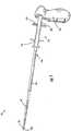
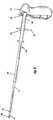
Figures 1 through 9 , adelivery device 10 according to an embodiment of the present invention is shown. Thedelivery device 10 may include aninner tubular member 12, anouter tubular member 14, ahandle 30, and adeployment mechanism 20. In general, the inner tubular member and the outer tubular member have at least two positions. As illustrated inFigures 1 and3 , in a first position, thetubular members Figures 7 and9 , in a second position, thetubular members handle 30 anddeployment mechanism 20 are adapted to allow an operator, such as a physician, to hold and operate thedelivery device 10, including moving thetubular members - In particular, either the
inner tubular member 12 or outertubular member 14 extends from thehandle 30. Each of thetubular members proximal end distal end handle 30. Theinner tubular member 12 is positioned within anouter tubular member 14 and at least one of thetubular members tubular member inner tubular member 12 extends from thehandle 30 and the outertubular member 14 is slidable along and around theinner tubular member 12. However, it is understood that according to other embodiments of the present invention the inner tubular member may be slidable along and in the outer tubular member or yet in other embodiments both the inner tubular member and outer tubular member may both be slidable relative to each other. - Both the
inner tubular member 12 and outertubular member 14 are typically flexible for positioning and maneuvering the tubular members within a lumen. Each of the inner12 and outer14 tubular members are also typically transparent or semi-transparent, such that the inner tubular member is visible through the outer tubular member. Moreover, theinner tubular member 12 may include markers for positioning and deploying the implantable device, although the inner and/or outer tubular members could include markers if desired. For instance, the distal end of the outertubular member 14 may include a marker to locate the distal end of the implantable device. Theinner tubular member 12 is slightly smaller in diameter than the outertubular member 14 such that the inner tubular member may slide within the outer tubular member. - However, the inner12 and outer14 tubular members may be various sizes and configurations to accommodate a desired implantable device. For example, the inner12 and outer14 tubular members could be about 6 to 10 mm in diameter and about 250-500 mm in length. Each of the inner12 and outer14 tubular members could also be various diameters and wall thicknesses along the length of each tubular member for varying flexibility and/or aiding in securing or deploying the implantable device. For example, the outer
tubular member 14 could have an incrementally larger diameter from near its respective side opening to the distal opening18, and could also have a greater wall thickness proximate to the side opening18. - A substantial portion of each of the inner12 and outer
tubular members 14 may include an assembly of polymeric materials and a metal coil (not illustrated). For instance, the polymeric materials could be a polytetrafluoroethylene ("PTFE"), such as Teflon® (E.I. DuPont de Nemours and Co. Corp.), and a polyether block amide ("PEBA"), such as Pebax® (Atofina Corp.). Generally, a PTFE liner is placed over a mandrel, and a coil is wound around the PTFE liner while positioned on the mandrel. The PEBA material is configured as a tubular member and slid over the wound coil and the PTFE liner while the assembly is supported on the mandrel. The assembly is then heated such that the PEBA outer sleeve and the PTFE liner are adhered together over the coil to form a tubular member assembly. The PTFE liner is typically etched so that the PEBA material attaches or fuses to the PTFE material. During the etching process, the PTFE liner is discolored from a clear color to a yellowish brown. Because the PTFE liner is slightly discolored, the side opening provides greater visibility where an optical instrument would be unable to clearly view through the liner itself. The remaining portions of the inner12 and outer14 tubular members (i.e., the distal portions of the tubular members where no coil is present) are typically a combination of PTFE and PEBA materials. The interior of the inner12 and outer14 tubular members, in one embodiment, are a low-friction PTFE material, which allows various devices and instruments to slide therethrough and requires lower deployment forces when retracting the outertubular member 14 during deployment of the implantable device. Theinner tubular member 12 may be fixedly attached at its proximal end adjacent to thehandle 30. Thus, the proximal end of theinner tubular member 12 may be molded or otherwise attached to a portion of thehandle 30, such as with an adhesive. - The coil may extend from the proximal end of the each of the inner12 and outer14 tubular members and within each of the inner and outer tubular members proximate to a respective side opening18. In particular, each coil may be positioned proximal of a respective side opening. The coils maintain a desired flexibility for the inner12 and outer14 tubular members, but also preventing kinking or buckling when manipulating the inner and outer tubular members within the lumen.
- The
inner tubular member 12 may further include apusher 26 that is configured to engage the implantable device by pushing the implantable device out of the distal end of the outer tubular member when the inner tubular member is moving toward the distal end of the outer tubular member. Another example and according to the illustrated embodiment, theinner tubular member 12 may have apusher 26 that is configured to hold the implantable device in place as the outertubular member 14 moves away from the distal end of theinner tubular member 38. - The implantable device is deployed within a lumen and proximate to a target area using techniques known to those skilled in the art. For instance, the implantable device may be introduced orally with the
delivery device 10, through the lumen, and proximate to a target area. The implantable device is typically contracted to a smaller first diameter from a relaxed position. Once contracted, the implantable device is positioned within the outertubular member 14 of the delivery device proximate to the distal end of the outer tubular member. Theinner tubular member 12 is positioned within the outertubular member 14 such that the distal end of the inner tubular member is positioned proximate to the proximal end of the implantable device. Or at least a portion of the implantable device16 may be positioned on the distal end of theinner tubular member 12 to engage thepusher 26. - It is understood that the
pusher 26 shown and described above is only one embodiment of the present invention. For instance, thepusher 26 could be integrally formed with theinner tubular member 12 such that pusher is not a separate component of the inner tubular member. It is noted that although the term "pusher" is used herein, thepusher 26 does not always push the implantable device16. Theinner tubular member 12 andpusher 26 may remain stationary while the outertubular member 14 is retracted. However, thepusher 26 may be configured to advance the implantable device16 such that theinner tubular member 12 may be moved distally while the outertubular member 14 remains stationary or is moved concurrently in a proximal direction - As shown in the illustrated embodiment of
Figures 1 through 9 , thehandle 30 may extend generally perpendicular from the length of the tubular members, similar to a "pistol grip." Other exemplary embodiments of thehandle Figures 10 and12 . The handle may be made from a variety of materials. For example, the handle may be made from a polypropylene, a poly-vinyl chloride, or a high density polyethylene. - The
deployment mechanism 20 may include one ormore actuators 22 coupled to the outertubular member 14. Depending on the length of the implantable device, there could be oneactuator 22 for shorter implantable devices (e.g., 20-60mm) (not illustrated) and two or more actuators for longer implantable devices (e.g., 80mm), as shown inFigure 1 through 9 . - When utilizing two or
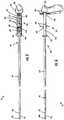
more actuators Figures 1 through 9 of the present invention, thedeployment mechanism 20 may include aproximal actuator 23 and adistal actuator 22. Thedistal actuator 22 includes abase portion 44 that is slidable along theinner tubular member 12 and is affixed to the outertubular member 14 such that the movement of thedistal actuator 22 moves the outertubular member 14 along theinner tubular member 12. Thedistal actuator 22 may include one ormore flanges 46 that extend generally from thebase portion 44 in a generally perpendicular direction from thetubular members - The
proximal actuator 23 is operatively connected to thedistal actuator 22. More specifically, theproximal actuator 23 may include abase portion 48 that is slidable along theinner tubular member 12 and one ormore flanges 50 similar to theflanges 46 of thedistal actuator 22. Theproximal actuator 23 may further include two ormore connector arms 52. Eacharm 52 extends from thebase portion 48 of theproximal actuator 23 in a direction generally parallel to the direction of thetubular members distal end 54 of the connector arms. The distal ends54 of the connector arms extend distally beyond the base portion of thedistal actuator 22 such that thedistal actuator 22 is between the distal ends54 of the connector arms and thebase portion 48 of the proximal actuator. Theconnector arms 52 define anaperture 56 that extends from thedistal end 54 of the connector arms to thebase portion 48 of the proximal actuator. Thedistal actuator 22 is slidable within theaperture 56 independently from theproximal actuator 23. And the distal ends54 of the connector arms and thebase portion 48 of the proximal actuator inhibit thedistal actuator 22 from escaping or moving beyond theaperture 56. Although the connector arms are described as being an integral portion of the proximal actuator, it is understood that the connector arms and the proximal actuator may be separate components that are attached to each other. For example, the connector arms may be attached to the base portion of the proximal actuator by one or more fasteners or by an adhesive. The actuators and the connector arms may be made from a variety of materials. For example, the actuators and the connector arms may be made from a polypropylene, a poly-vinyl chloride, or a high density polyethylene. - As shown in
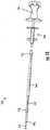
Figures 1 through 3 , the outertubular member 14 may be placed in an extended first position relative to theinner tubular member 12. In the extended first position, theproximal actuator 23 may be positioned generally as far from thehandle 30 as possible while still allowing an operator to grab the flanges of theproximal actuator 23 with his or her fingers while palming thehandle 30. In the extended first position, thedistal actuator 22 is adjacent the distal ends54 of the connector arms. - This arrangement of
actuators delivery device 10 to deploy the implantable device16 with one hand if desired. For example, an operator may palm thehandle 30 of thedelivery device 10 with one of his or her hands and extend his or her fingers of the same hand to pull proximally on theproximal actuator distal actuator 22 back with theproximal actuator 23. As thedistal actuator 22 moves closer to thehandle 30, the operator may extend his or her finder to pull directly on thedistal actuator 22 rather than theproximal actuator 23. Theaperture 56 defined by theconnector arms 52 allows thedistal actuator 22, and thus the outertubular member 14 to move proximally toward thehandle 30 even after theproximally actuator 23 abuts the handle30 (as shown inFigures 4-6 ) until thedistal actuator 22 abuts the proximal actuator23 (as shown inFigures 7-9 ). The two actuators abutting each other and thehandle 30 may be considered the second position, as described above, which is configured to release the implantable device from the distal end of the outer tubular member. In some applications, depending on the length of the implantable device, the implantable device may be released from the outer tubular member before the distal actuator abuts the proximal actuator. - The
deployment mechanism 20 as described above is an example according to an embodiment of the present invention. However, thedeployment mechanism 20 could be range of devices or actuators capable of deploying the implantable device16 distally out of the outertubular member 14. For example, theactuators 22 could be configured to slide theinner tubular member 12 distally within the outertubular member 14 such that the outer tubular member remains stationary relative to the inner tubular member. Also, although theactuators 22 are T-shaped, the actuators could be configured as a trigger to grip the actuator. One or more of the actuators of the deployment mechanism320 may be opposite thehandle 330 from the distal ends of the tubular members as illustrated inFigure 12 . - The
delivery device 10 further includes aprotective member 60. Although thehandle 30 and theactuators tubular member 14 during deployment. The second hand may pinch down on the outertubular member 14 which may adversely affect the ability for the inner and outertubular members delivery device 10. Also, due to the tortuous path often followed bytubular members tubular members tubular members protective member 60 provides a degree of insulation to at least a portion of the outertubular member 14 from external forces, such as an operator's hand. Insulating a portion of the outertubular member 14 from external forces reduces the likelihood of the outertubular member 14 being pinched and interfering with the movement between the inner and outertubular members - The shape and size of the
protective member 60 may vary. For example, theprotective member 60 may extend from thehandle 30 beyond theactuators distal end 42 of the outer tubular member. The length of theprotective member 60, i.e. the extent of which theprotective member 60 extends toward thedistal end 42 of the outer tubular member, may vary. In general, theprotective member 60 in one embodiment is long enough to extend beyond theactuators protective member 60 is not extended so far in this embodiment as to significantly interfere with the distal ends38,42 of the inner and outer tubular members and the deployment of the implantable device. - According to the embodiment of the present invention illustrated in
Figures 1 through 9 , theprotective member 60 generally has aproximal region 62 and adistal region 64. Theproximal region 62 extends distally from thehandle 30 to thedistal region 64. Theproximal region 64 is configured to extend around theactuators connector arms 52. For example and as illustrated, theproximal region 64 may include twoextension arms 66 that are dimensioned to extend along and on the outside of theconnector arms 52. The twoextension arms 66 also define twogrooves 68 for theflanges proximal region 64, including thegrooves 68 is long enough to accommodate the full expected operational range of theactuators grooves 68 are long enough to accommodate the extended first position described above. The number of the grooves may vary according to the number of flanges of the actuators, including an embodiment of just one groove. According to the illustrated embodiment, the proximal region is coupled to the handle. However, in other embodiments, the proximal region, and thus the protective member, may be free to slide along the outer tubular member. - The
distal region 64 extends from theproximal region 62 toward thedistal end 42 of the outer tubular member. Thedistal region 64 provides a surface or an area that insulates the outertubular member 14 from external contact. The length of thedistal region 64 may vary. For example, thedistal region 64 may be approximately 10 - 15 cm in length, which is large enough area for a hand to grab or may be approximately or may be approximately 50 - 60 cm depending on the length of the inner and outertubular members distal region 64 may be a sheath that envelopes at least a portion of the outertubular member 14. Moreover, thedistal region 64 is adapted to absorb at least some or all of an impact or pressure from a user grapping or grasping thedistal region 64 with his or her hand or from the walls of the patient's lumen. In other words, thedistal region 64 reduces the likelihood of the outertubular member 14 being pinched when the user grabs thedelivery device 10 outside of thehandle 30 ordeployment mechanism 20 or being pinched or by the walls of the patient's lumen. Thedistal region 64 may be relatively rigid for absorbing and resisting the impact rather than deforming and potentially pinching the outertubular member 14. Thedistal region 64, as well as theproximal region 62, may be made from a variety of materials including, but not limited to, high density polypropylene or high density polyethylene or polyetheretherketone (PEEK). The material or coating of theprotective member 60 may be configured to have a low friction coefficient to facilitate the movement between theprotective member 60 and the outertubular member 14 or between theprotective member 60 and the walls of the patient's lumen. - Although the
distal region 64 is illustrated inFigures 1 through 9 as a sheath having a solid tubular wall surrounding the outer tubular member, thedistal region 64 may vary. For example, instead of a solid tubular wall, the distal region may define a number of grooves and apertures or include a number of parallel arms extending along a portion of the outer tubular member and connected by a series of rings along and around the outer tubular member to form a cage-like structure. - For example, in the embodiment of the present invention illustrated in
Figures 11a and 11b , theprotective member 260 of the delivery device210 includes a distal region264 that defines at least onegroove 270 corresponding to sideopenings side openings grooves 270 of the distal region may be capable of aligning with one another such that an optical device (not illustrated) may view a target area within a lumen. Therefore theside openings groove 270 of the distal region may provide increased visibility of the target area. Grooves defined within the distal region may also be used to allow the operator to view markers on one or both of the inner and outer tubular members. - Moreover, the structure of the proximal region may vary as well. For example, according to some embodiments of the present invention, the deployment mechanism may be opposite the handle from the distal ends of the outer tubular member and the inner tubular member, as shown in
Figure 12 . In such embodiments, the protective member360 of thedelivery device 310 may extend from thehandle 330 toward thedistal end 342 of the outer tubular member without separate proximal and distal regions. - Also, in other embodiments, the protective member may not include a proximal region and may extend from the deployment mechanism. For example, according to another embodiment illustrated in
Figure 10 , theprotective member 160 may extend opposite of thedeployment mechanism 120 from thehandle 130 and toward thedistal end 142 of the outer tubular member. Theprotective member 160 may be configured to slide along the outertubular member 114. Theprotective member 160 may be contained betweenstops tubular member 114 as shown such that theprotective member 160 may be held in place by an operator as the outertubular member 114 and the innertubular member 112 are moving relative to each other. - Although the delivery device has been illustrated and described primarily as having an outer tubular member and an inner tubular member, other embodiments of the delivery device include various other elongate members configured to move relative to each other and retain and release an implantable device. Other examples may include, but are not limited to, inner and outer elongate members having complementary cross-sections and elongate members positioned side by side each other, such as opposing C-shaped members that are moveable to each other and configured to retain and release an implantable device.
- The present invention includes several advantages. For instance, the protective member insulates at least a portion of the outer tubular member from the tendency of some operators to grab the outer tubular member while operating the delivery device. The protective member may also insulate at least a portion of the outer tubular member from the walls of the patient's lumen and reduce the likelihood of the inner and outer tubular members from be pinched due to the tortuous path the tubular members may have to follow in the patient's lumen. In some instances and embodiments, as shown in
Figure 13 , thedelivery device 510 may be delivered to the patient's lumen through the working channel of anendoscope 512. More specifically, the distal ends of the tubular members with the implantable device are inserted through anentry port 514 of the endoscope along the working channel (not visible inFigure 13 ) of the endoscope and out of the distal end of the endoscope into the patient's lumen (not illustrated). Theprotective member 516 may be grabbed (as illustrated inFigure 13 ) at theentry port 514 of theendoscope 512 by the operator and thus immobilizing theprotective member 516 and the rest of the delivery device during deployment of the implantable device except for the outer tubular member, which is moveable through the handles, which helps the operator to achieve a high placement accuracy of the implantable device in the patient's lumen. In other words, the protective member reduces the likelihood of the outer tubular member being pinched or otherwise impinged by the operator or another external source and adversely affecting the deployment of the implantable device. - Many modifications and other embodiments of the invention set forth herein will come to mind to one skilled in the art to which this invention pertains having the benefit of the teachings presented in the foregoing descriptions and the associated drawings. Therefore, it is to be understood that the invention is not to be limited to the specific embodiments disclosed and that modifications and other embodiments are intended to be included within the scope of the appended claims. Although specific terms are employed herein, they are used in a generic and descriptive sense only and not for purposes of limitation.
Claims (9)
- A delivery device (10;210;310) for positioning and deploying an implantable device (16) within a lumen, said delivery device (10;210;310) comprising:a first elongate member having a proximal end (40) with a longitudinal axis extending to a distal end (42);a second elongate member having a proximal end (36) and a distal end (38),said first and second elongate members configured to cooperatively retain the implantable device (16) near the distal ends (38,42) and to move relative to each other to release the implantable device (16) into the lumen,wherein the first elongate member includes an outer tubular member (14;214) and the second elongate member includes an inner tubular member (12;212) extending slidably within the outer tubular member (14;214), and wherein a space is defined between the inner tubular member (12;212) and the outer tubular member (14;214) near the distal ends (38,42) to retain the implantable device (16);a handle (30;330) coupled to at least one of the inner and outer tubular members;a deployment mechanism (20) coupled to at least one of the inner (12;212) and outer (14;214) tubular members and operable to cause a relative motion of the first and second elongate members, wherein the deployment mechanism (20) comprises a first slidable actuator (23) positioned proximal to a second slidable actuator (22) and operably connected thereto, such that slidably retracting the first slidable actuator (23) moves the second slidable actuator (22) and the outer tubular member (14;214) proximally and longitudinally relative to the inner tubular member (12;212), and wherein the second actuator (22) comprises a base portion (44) that is slidable along the inner tubular member (12;212) and is coupled to the outer tubular member (14;414) such that movement of the second actuator (22) moves the outer tubular member (14;214) along the inner tubular member (12;212); anda protective member (60;260;360);characterized in that the protective member (60;260;360) is in engagement with the handle (30;33) and configured to extend from the handle (30;330) around and beyond the deployment mechanism (20) and over at least one portion of the elongate members wherein relative movement occurs, said protective member (60;260;360) configured to inhibit impingement of external forces on the relative movement of the elongate members (12,14) from the handle (30;330) around and beyond the deployment mechanism (20) and over at least one portion of the elongate members (12,14), wherein the protective member (60;260;360) extends from the handle (30;330) and over the deployment mechanism (20) toward the distal end (42) of the outer tubular member (14;214), such that a distal end of the protective member (60;260;360) terminates proximal to the distal end (42) of the outer tubular member (14;214),wherein at least a portion of the second elongate member is disposed within the first elongate member, such that at least a portion of the second elongate member is longitudinally and axially displaceable relative to the first elongate member, and wherein the first actuator (23) has a first flange (50) extending transverse to the longitudinal axis and greater than a diameter of the protective member (60;260;360), and the second actuator (22) has a second flange (46) extending transverse to the longitudinal axis and greater than the diameter of the protective member (60;260;360),wherein the protective member (60;260;360) includes a proximal region (62) and a distal region (64;264), and wherein the proximal region (62) defines one to a plurality of grooves (68) in which the flanges (46,50) of the actuators (22,23) are slidable within and the distal region (64;264) extends along and around at least a portion of the outer tubular member (14;214).
- A delivery device (10;210;310) of claim 1, wherein the protective member (60;260;360) includes a protective tubular member extending over a proximal portion of the inner (12;212) and outer (14;214) tubular members, the protective tubular member configured to inhibit impingement of external forces caused by a grip of an operator.
- A delivery device (10;210;310) of Claim 1, wherein the distal region (64;264) includes a substantially solid tubular wall.
- A delivery device (10;210;310) of Claim 1, wherein the distal region (64;264) defines at least one aperture (56).
- A delivery device (10;210;310) of Claim 1, wherein the protective member (60) is formed substantially from a material selected from the group consisting of a polypropylene, a poly-vinylchloride, and a polyethylene.
- A delivery device (10;210;310) of claim 1, wherein the outer tubular member (14;214) and an inner tubular member (12;212) are movable relative to each other between at least a first position and a second position,
wherein in the first position the outer (14;214) and inner tubular members (12;212) are configured to hold the implantable device (16) and in the second position the outer (14;214) and inner tubular members (12;212) are configured to release the implantable device(16),
wherein the handle (30;330) and the deployment mechanism (20) are adapted to be operated by a first hand of an operator for moving the outer (14;214) and inner (12;212) tubular members between the at least first and second positions, and
wherein the protective member (60;260;360) is adapted to be grasped by a second hand of the operator independently from the moving of the outer (14;214) and inner (12;212) tubular members between the at least first and second positions. - A delivery device (10;210;310) of Claim 6, wherein the distal region (64;264) of the protective member (60;260;360) defines a sheath that envelopes at least a portion of the outer tubular member (14;214) and wherein the outer tubular member (14;214) is slidable within the sheath.
- A delivery device (10;210;310) of Claim 7, wherein the deployment mechanism (20) is positioned between the handle (30;330) and the distal end (42) of the outer tubular member (14;214) and wherein the proximal region (62) of the protective member (60;260;360) extends distally from the handle (30;330) and beyond the deployment mechanism (20) to the distal region (64;264).
- A delivery device (10;210;310) of claim 1, wherein each actuator (22,23) includes two flanges (46,50).
Applications Claiming Priority (2)
| Application Number | Priority Date | Filing Date | Title |
|---|---|---|---|
| US9013908P | 2008-08-19 | 2008-08-19 | |
| PCT/US2009/052691WO2010021836A1 (en) | 2008-08-19 | 2009-08-04 | Delivery device with a protective member |
Publications (2)
| Publication Number | Publication Date |
|---|---|
| EP2313032A1 EP2313032A1 (en) | 2011-04-27 |
| EP2313032B1true EP2313032B1 (en) | 2020-12-23 |
Family
ID=41137355
Family Applications (1)
| Application Number | Title | Priority Date | Filing Date |
|---|---|---|---|
| EP09791142.4AActiveEP2313032B1 (en) | 2008-08-19 | 2009-08-04 | Delivery device with a protective member |
Country Status (4)
| Country | Link |
|---|---|
| US (1) | US8439934B2 (en) |
| EP (1) | EP2313032B1 (en) |
| DK (1) | DK2313032T3 (en) |
| WO (1) | WO2010021836A1 (en) |
Families Citing this family (21)
| Publication number | Priority date | Publication date | Assignee | Title |
|---|---|---|---|---|
| EP1701675B1 (en)* | 2004-01-08 | 2010-07-14 | Merit Medical Systems, Inc. | Implantable device delivery system handle and method of use |
| EP1895951A1 (en) | 2005-05-13 | 2008-03-12 | Alveolus Inc. | Delivery device allowing visual inspection of an intravascular site |
| EP2313032B1 (en) | 2008-08-19 | 2020-12-23 | Merit Medical Systems, Inc. | Delivery device with a protective member |
| EP2648654B1 (en)* | 2010-12-07 | 2024-02-14 | Merit Medical Systems, Inc. | Stent delivery systems |
| US9192496B2 (en) | 2011-10-31 | 2015-11-24 | Merit Medical Systems, Inc. | Systems and methods for sheathing an implantable device |
| US9883958B2 (en) | 2012-07-16 | 2018-02-06 | Boston Scientific Scimed, Inc. | Stent delivery device |
| CN103142336B (en)* | 2013-03-29 | 2014-12-10 | 孙思予 | One-piece stent inserter |
| US9375336B1 (en)* | 2015-01-29 | 2016-06-28 | Intact Vascular, Inc. | Delivery device and method of delivery |
| WO2016141295A1 (en) | 2015-03-05 | 2016-09-09 | Merit Medical Systems, Inc. | Vascular prosthesis deployment device and method of use |
| DE102015113678A1 (en)* | 2015-08-18 | 2017-03-09 | Novatech Sa | Bridge element and introducer for positioning a stent |
| US10470906B2 (en) | 2015-09-15 | 2019-11-12 | Merit Medical Systems, Inc. | Implantable device delivery system |
| AU2016355676B2 (en) | 2015-11-20 | 2018-12-13 | Cardiac Pacemakers, Inc. | Delivery devices and methods for leadless cardiac devices |
| WO2017087675A1 (en) | 2015-11-20 | 2017-05-26 | Cardiac Pacemakers, Inc. | Delivery devices and methods for leadless cardiac devices |
| CN115054413A (en) | 2016-09-29 | 2022-09-16 | 美国医疗设备有限公司 | Method of adjusting effective length of stent and prosthesis delivery catheter assembly |
| EP3531970B1 (en)* | 2016-10-31 | 2025-10-15 | The Johns Hopkins University | Tools for transurethral deployment and fixation of graft for the management and treatment of urethral strictures |
| US11628078B2 (en) | 2017-03-15 | 2023-04-18 | Merit Medical Systems, Inc. | Transluminal delivery devices and related kits and methods |
| EP4467111A3 (en) | 2017-03-15 | 2025-03-05 | Merit Medical Systems, Inc. | Transluminal stents |
| USD836194S1 (en) | 2017-03-21 | 2018-12-18 | Merit Medical Systems, Inc. | Stent deployment device |
| EP4185239A4 (en) | 2020-07-24 | 2024-08-07 | Merit Medical Systems, Inc. | ESOPHAGEAL STENT PROSTHESES AND RELATED METHODS |
| CA3194910A1 (en) | 2020-10-26 | 2022-05-05 | Tiffany ETHRIDGE | Esophageal stents with helical thread |
| US20250169974A1 (en)* | 2023-11-28 | 2025-05-29 | Boston Scientific Scimed, Inc. | Devices, systems and methods for access and delivery to challenging anatomy |
Family Cites Families (37)
| Publication number | Priority date | Publication date | Assignee | Title |
|---|---|---|---|---|
| SE8803444D0 (en) | 1988-09-28 | 1988-09-28 | Medinvent Sa | A DEVICE FOR TRANSLUMINAL IMPLANTATION OR EXTRACTION |
| US5591172A (en) | 1991-06-14 | 1997-01-07 | Ams Medinvent S.A. | Transluminal implantation device |
| US5201757A (en) | 1992-04-03 | 1993-04-13 | Schneider (Usa) Inc. | Medial region deployment of radially self-expanding stents |
| DE9209908U1 (en) | 1992-07-23 | 1992-09-17 | Neuss, Malte, Dipl.-Ing. (FH), 5300 Bonn | Stripping aid for spiral implants arranged on a guide wire |
| US5824041A (en) | 1994-06-08 | 1998-10-20 | Medtronic, Inc. | Apparatus and methods for placement and repositioning of intraluminal prostheses |
| US5571168A (en)* | 1995-04-05 | 1996-11-05 | Scimed Lifesystems Inc | Pull back stent delivery system |
| US6413269B1 (en) | 2000-07-06 | 2002-07-02 | Endocare, Inc. | Stent delivery system |
| US6702846B2 (en)* | 1996-04-09 | 2004-03-09 | Endocare, Inc. | Urological stent therapy system and method |
| US6254628B1 (en) | 1996-12-09 | 2001-07-03 | Micro Therapeutics, Inc. | Intracranial stent |
| US5968052A (en) | 1996-11-27 | 1999-10-19 | Scimed Life Systems Inc. | Pull back stent delivery system with pistol grip retraction handle |
| US5868755A (en) | 1997-01-16 | 1999-02-09 | Atrion Medical Products, Inc. | Sheath retractor mechanism and method |
| US5759189A (en)* | 1997-02-25 | 1998-06-02 | Smith & Nephew Inc. | Knot pusher |
| US6143016A (en) | 1997-04-21 | 2000-11-07 | Advanced Cardiovascular Systems, Inc. | Sheath and method of use for a stent delivery system |
| US6143021A (en) | 1998-07-10 | 2000-11-07 | American Medical Systems, Inc. | Stent placement instrument and method of assembly |
| US6162231A (en) | 1998-09-14 | 2000-12-19 | Endocare, Inc. | Stent insertion device |
| EP1447057A1 (en) | 1998-09-30 | 2004-08-18 | Bard Peripheral Vascular, Inc. | Delivery mechanism for implantable stent |
| US6726712B1 (en) | 1999-05-14 | 2004-04-27 | Boston Scientific Scimed | Prosthesis deployment device with translucent distal end |
| US20020193863A1 (en) | 2000-09-18 | 2002-12-19 | Endotex Interventional Systems, Inc. | Apparatus for delivering endoluminal prosthesis and methods for preparing such apparatus for delivery |
| US6428566B1 (en) | 2000-10-31 | 2002-08-06 | Advanced Cardiovascular Systems, Inc. | Flexible hoop and link sheath for a stent delivery system |
| GB0110551D0 (en) | 2001-04-30 | 2001-06-20 | Angiomed Ag | Self-expanding stent delivery service |
| US6926732B2 (en) | 2001-06-01 | 2005-08-09 | Ams Research Corporation | Stent delivery device and method |
| US6939352B2 (en) | 2001-10-12 | 2005-09-06 | Cordis Corporation | Handle deployment mechanism for medical device and method |
| US6866669B2 (en) | 2001-10-12 | 2005-03-15 | Cordis Corporation | Locking handle deployment mechanism for medical device and method |
| AU2003282886B2 (en) | 2002-09-30 | 2009-07-23 | Board Of Regents, The University Of Texas System | Stent delivery system and method of use |
| US7637934B2 (en) | 2003-03-31 | 2009-12-29 | Merit Medical Systems, Inc. | Medical appliance optical delivery and deployment apparatus and method |
| US20040267281A1 (en) | 2003-06-25 | 2004-12-30 | Eran Harari | Delivery system for self-expandable diverter |
| US7635382B2 (en) | 2003-10-22 | 2009-12-22 | Medtronic Vascular, Inc. | Delivery system for long self-expanding stents |
| US20050125050A1 (en) | 2003-12-04 | 2005-06-09 | Wilson Cook Medical Incorporated | Biliary stent introducer system |
| US7887574B2 (en) | 2003-12-23 | 2011-02-15 | Scimed Life Systems, Inc. | Stent delivery catheter |
| EP1701675B1 (en)* | 2004-01-08 | 2010-07-14 | Merit Medical Systems, Inc. | Implantable device delivery system handle and method of use |
| US20050278010A1 (en) | 2004-05-27 | 2005-12-15 | Scimed Life Systems, Inc. | Stent delivery system with imaging capability |
| US7731654B2 (en) | 2005-05-13 | 2010-06-08 | Merit Medical Systems, Inc. | Delivery device with viewing window and associated method |
| US7935140B2 (en) | 2005-05-13 | 2011-05-03 | Merit Medical Systems, Inc. | Delivery device with anchoring features and associated method |
| EP1895951A1 (en) | 2005-05-13 | 2008-03-12 | Alveolus Inc. | Delivery device allowing visual inspection of an intravascular site |
| US20070208350A1 (en)* | 2006-03-06 | 2007-09-06 | Gunderson Richard C | Implantable medical endoprosthesis delivery systems |
| ES2382364T3 (en)* | 2006-09-28 | 2012-06-07 | St George Medical Inc | Thoracic aortic aneurysm repair device. |
| EP2313032B1 (en) | 2008-08-19 | 2020-12-23 | Merit Medical Systems, Inc. | Delivery device with a protective member |
- 2009
- 2009-08-04EPEP09791142.4Apatent/EP2313032B1/enactiveActive
- 2009-08-04WOPCT/US2009/052691patent/WO2010021836A1/enactiveApplication Filing
- 2009-08-04DKDK09791142.4Tpatent/DK2313032T3/enactive
- 2009-08-05USUS12/535,980patent/US8439934B2/enactiveActive
Non-Patent Citations (1)
| Title |
|---|
| None* |
Also Published As
| Publication number | Publication date |
|---|---|
| WO2010021836A1 (en) | 2010-02-25 |
| US20100049295A1 (en) | 2010-02-25 |
| DK2313032T3 (en) | 2021-02-15 |
| US8439934B2 (en) | 2013-05-14 |
| EP2313032A1 (en) | 2011-04-27 |
Similar Documents
| Publication | Publication Date | Title |
|---|---|---|
| EP2313032B1 (en) | Delivery device with a protective member | |
| EP1890656B1 (en) | Delivery device with viewing window and associated method | |
| US8986360B2 (en) | Delivery device with shortened inner tube and associated method | |
| US12274634B2 (en) | Pliant members for receiving and aiding in the deployment of vascular prostheses | |
| EP2512319B1 (en) | Advancing system | |
| EP3238669B1 (en) | Stent delivery systems | |
| US10507126B2 (en) | Endoscope having a grasping tool and a method for removing a stent from a patient | |
| US8133265B2 (en) | Guide catheter, and stent delivery system | |
| EP1641402B1 (en) | Handle for medical devices, and medical device assemblies including a handle | |
| US8092468B2 (en) | Deployment handle for an implant deployment device | |
| US11033287B2 (en) | Grasping tool | |
| US9833347B2 (en) | Apparatuses for manipulating medical devices and related methods for use | |
| US20180133041A1 (en) | Stent delivery device | |
| US20240000594A1 (en) | Integrated deployment balloon stent delivery | |
| US20220273477A1 (en) | Devices and methods for deployment of a vascular prosthesis | |
| EP4547168A1 (en) | Integrated deployment balloon stent delivery | |
| JP4721133B2 (en) | Stent delivery system with radially stabilized catheter | |
| US20050096663A1 (en) | Control apparatus for actuating an elongate medical shaft |
Legal Events
| Date | Code | Title | Description |
|---|---|---|---|
| PUAI | Public reference made under article 153(3) epc to a published international application that has entered the european phase | Free format text:ORIGINAL CODE: 0009012 | |
| 17P | Request for examination filed | Effective date:20110127 | |
| AK | Designated contracting states | Kind code of ref document:A1 Designated state(s):AT BE BG CH CY CZ DE DK EE ES FI FR GB GR HR HU IE IS IT LI LT LU LV MC MK MT NL NO PL PT RO SE SI SK SM TR | |
| AX | Request for extension of the european patent | Extension state:AL BA RS | |
| DAX | Request for extension of the european patent (deleted) | ||
| 17Q | First examination report despatched | Effective date:20150218 | |
| STAA | Information on the status of an ep patent application or granted ep patent | Free format text:STATUS: EXAMINATION IS IN PROGRESS | |
| RIC1 | Information provided on ipc code assigned before grant | Ipc:A61F 2/95 20130101ALN20191125BHEP Ipc:A61F 2/966 20130101AFI20191125BHEP | |
| RIC1 | Information provided on ipc code assigned before grant | Ipc:A61F 2/966 20130101AFI20191129BHEP Ipc:A61F 2/95 20130101ALN20191129BHEP | |
| REG | Reference to a national code | Ref country code:DE Ref legal event code:R079 Ref document number:602009063210 Country of ref document:DE Free format text:PREVIOUS MAIN CLASS: A61F0002840000 Ipc:A61F0002966000 | |
| GRAP | Despatch of communication of intention to grant a patent | Free format text:ORIGINAL CODE: EPIDOSNIGR1 | |
| STAA | Information on the status of an ep patent application or granted ep patent | Free format text:STATUS: GRANT OF PATENT IS INTENDED | |
| RIC1 | Information provided on ipc code assigned before grant | Ipc:A61F 2/95 20130101ALN20200205BHEP Ipc:A61F 2/966 20130101AFI20200205BHEP | |
| INTG | Intention to grant announced | Effective date:20200218 | |
| GRAS | Grant fee paid | Free format text:ORIGINAL CODE: EPIDOSNIGR3 | |
| GRAA | (expected) grant | Free format text:ORIGINAL CODE: 0009210 | |
| STAA | Information on the status of an ep patent application or granted ep patent | Free format text:STATUS: THE PATENT HAS BEEN GRANTED | |
| AK | Designated contracting states | Kind code of ref document:B1 Designated state(s):AT BE BG CH CY CZ DE DK EE ES FI FR GB GR HR HU IE IS IT LI LT LU LV MC MK MT NL NO PL PT RO SE SI SK SM TR | |
| REG | Reference to a national code | Ref country code:GB Ref legal event code:FG4D | |
| REG | Reference to a national code | Ref country code:DE Ref legal event code:R096 Ref document number:602009063210 Country of ref document:DE | |
| REG | Reference to a national code | Ref country code:AT Ref legal event code:REF Ref document number:1346987 Country of ref document:AT Kind code of ref document:T Effective date:20210115 | |
| REG | Reference to a national code | Ref country code:IE Ref legal event code:FG4D | |
| REG | Reference to a national code | Ref country code:DK Ref legal event code:T3 Effective date:20210211 | |
| REG | Reference to a national code | Ref country code:SE Ref legal event code:TRGR | |
| PG25 | Lapsed in a contracting state [announced via postgrant information from national office to epo] | Ref country code:GR Free format text:LAPSE BECAUSE OF FAILURE TO SUBMIT A TRANSLATION OF THE DESCRIPTION OR TO PAY THE FEE WITHIN THE PRESCRIBED TIME-LIMIT Effective date:20210324 Ref country code:FI Free format text:LAPSE BECAUSE OF FAILURE TO SUBMIT A TRANSLATION OF THE DESCRIPTION OR TO PAY THE FEE WITHIN THE PRESCRIBED TIME-LIMIT Effective date:20201223 Ref country code:NO Free format text:LAPSE BECAUSE OF FAILURE TO SUBMIT A TRANSLATION OF THE DESCRIPTION OR TO PAY THE FEE WITHIN THE PRESCRIBED TIME-LIMIT Effective date:20210323 | |
| REG | Reference to a national code | Ref country code:AT Ref legal event code:MK05 Ref document number:1346987 Country of ref document:AT Kind code of ref document:T Effective date:20201223 | |
| REG | Reference to a national code | Ref country code:NL Ref legal event code:MP Effective date:20201223 | |
| PG25 | Lapsed in a contracting state [announced via postgrant information from national office to epo] | Ref country code:BG Free format text:LAPSE BECAUSE OF FAILURE TO SUBMIT A TRANSLATION OF THE DESCRIPTION OR TO PAY THE FEE WITHIN THE PRESCRIBED TIME-LIMIT Effective date:20210323 Ref country code:LV Free format text:LAPSE BECAUSE OF FAILURE TO SUBMIT A TRANSLATION OF THE DESCRIPTION OR TO PAY THE FEE WITHIN THE PRESCRIBED TIME-LIMIT Effective date:20201223 | |
| PG25 | Lapsed in a contracting state [announced via postgrant information from national office to epo] | Ref country code:NL Free format text:LAPSE BECAUSE OF FAILURE TO SUBMIT A TRANSLATION OF THE DESCRIPTION OR TO PAY THE FEE WITHIN THE PRESCRIBED TIME-LIMIT Effective date:20201223 Ref country code:HR Free format text:LAPSE BECAUSE OF FAILURE TO SUBMIT A TRANSLATION OF THE DESCRIPTION OR TO PAY THE FEE WITHIN THE PRESCRIBED TIME-LIMIT Effective date:20201223 | |
| REG | Reference to a national code | Ref country code:LT Ref legal event code:MG9D | |
| PG25 | Lapsed in a contracting state [announced via postgrant information from national office to epo] | Ref country code:SM Free format text:LAPSE BECAUSE OF FAILURE TO SUBMIT A TRANSLATION OF THE DESCRIPTION OR TO PAY THE FEE WITHIN THE PRESCRIBED TIME-LIMIT Effective date:20201223 Ref country code:SK Free format text:LAPSE BECAUSE OF FAILURE TO SUBMIT A TRANSLATION OF THE DESCRIPTION OR TO PAY THE FEE WITHIN THE PRESCRIBED TIME-LIMIT Effective date:20201223 Ref country code:RO Free format text:LAPSE BECAUSE OF FAILURE TO SUBMIT A TRANSLATION OF THE DESCRIPTION OR TO PAY THE FEE WITHIN THE PRESCRIBED TIME-LIMIT Effective date:20201223 Ref country code:PT Free format text:LAPSE BECAUSE OF FAILURE TO SUBMIT A TRANSLATION OF THE DESCRIPTION OR TO PAY THE FEE WITHIN THE PRESCRIBED TIME-LIMIT Effective date:20210423 Ref country code:CZ Free format text:LAPSE BECAUSE OF FAILURE TO SUBMIT A TRANSLATION OF THE DESCRIPTION OR TO PAY THE FEE WITHIN THE PRESCRIBED TIME-LIMIT Effective date:20201223 Ref country code:EE Free format text:LAPSE BECAUSE OF FAILURE TO SUBMIT A TRANSLATION OF THE DESCRIPTION OR TO PAY THE FEE WITHIN THE PRESCRIBED TIME-LIMIT Effective date:20201223 Ref country code:LT Free format text:LAPSE BECAUSE OF FAILURE TO SUBMIT A TRANSLATION OF THE DESCRIPTION OR TO PAY THE FEE WITHIN THE PRESCRIBED TIME-LIMIT Effective date:20201223 | |
| PG25 | Lapsed in a contracting state [announced via postgrant information from national office to epo] | Ref country code:PL Free format text:LAPSE BECAUSE OF FAILURE TO SUBMIT A TRANSLATION OF THE DESCRIPTION OR TO PAY THE FEE WITHIN THE PRESCRIBED TIME-LIMIT Effective date:20201223 Ref country code:AT Free format text:LAPSE BECAUSE OF FAILURE TO SUBMIT A TRANSLATION OF THE DESCRIPTION OR TO PAY THE FEE WITHIN THE PRESCRIBED TIME-LIMIT Effective date:20201223 | |
| REG | Reference to a national code | Ref country code:DE Ref legal event code:R097 Ref document number:602009063210 Country of ref document:DE | |
| PG25 | Lapsed in a contracting state [announced via postgrant information from national office to epo] | Ref country code:IS Free format text:LAPSE BECAUSE OF FAILURE TO SUBMIT A TRANSLATION OF THE DESCRIPTION OR TO PAY THE FEE WITHIN THE PRESCRIBED TIME-LIMIT Effective date:20210423 | |
| PG25 | Lapsed in a contracting state [announced via postgrant information from national office to epo] | Ref country code:IT Free format text:LAPSE BECAUSE OF FAILURE TO SUBMIT A TRANSLATION OF THE DESCRIPTION OR TO PAY THE FEE WITHIN THE PRESCRIBED TIME-LIMIT Effective date:20201223 | |
| PLBE | No opposition filed within time limit | Free format text:ORIGINAL CODE: 0009261 | |
| STAA | Information on the status of an ep patent application or granted ep patent | Free format text:STATUS: NO OPPOSITION FILED WITHIN TIME LIMIT | |
| PG25 | Lapsed in a contracting state [announced via postgrant information from national office to epo] | Ref country code:ES Free format text:LAPSE BECAUSE OF FAILURE TO SUBMIT A TRANSLATION OF THE DESCRIPTION OR TO PAY THE FEE WITHIN THE PRESCRIBED TIME-LIMIT Effective date:20201223 | |
| 26N | No opposition filed | Effective date:20210924 | |
| PG25 | Lapsed in a contracting state [announced via postgrant information from national office to epo] | Ref country code:SI Free format text:LAPSE BECAUSE OF FAILURE TO SUBMIT A TRANSLATION OF THE DESCRIPTION OR TO PAY THE FEE WITHIN THE PRESCRIBED TIME-LIMIT Effective date:20201223 | |
| REG | Reference to a national code | Ref country code:CH Ref legal event code:PL | |
| PG25 | Lapsed in a contracting state [announced via postgrant information from national office to epo] | Ref country code:MC Free format text:LAPSE BECAUSE OF FAILURE TO SUBMIT A TRANSLATION OF THE DESCRIPTION OR TO PAY THE FEE WITHIN THE PRESCRIBED TIME-LIMIT Effective date:20201223 | |
| REG | Reference to a national code | Ref country code:BE Ref legal event code:MM Effective date:20210831 | |
| PG25 | Lapsed in a contracting state [announced via postgrant information from national office to epo] | Ref country code:LI Free format text:LAPSE BECAUSE OF NON-PAYMENT OF DUE FEES Effective date:20210831 Ref country code:CH Free format text:LAPSE BECAUSE OF NON-PAYMENT OF DUE FEES Effective date:20210831 | |
| PG25 | Lapsed in a contracting state [announced via postgrant information from national office to epo] | Ref country code:IS Free format text:LAPSE BECAUSE OF FAILURE TO SUBMIT A TRANSLATION OF THE DESCRIPTION OR TO PAY THE FEE WITHIN THE PRESCRIBED TIME-LIMIT Effective date:20210423 Ref country code:LU Free format text:LAPSE BECAUSE OF NON-PAYMENT OF DUE FEES Effective date:20210804 | |
| PG25 | Lapsed in a contracting state [announced via postgrant information from national office to epo] | Ref country code:IE Free format text:LAPSE BECAUSE OF NON-PAYMENT OF DUE FEES Effective date:20210804 Ref country code:FR Free format text:LAPSE BECAUSE OF NON-PAYMENT OF DUE FEES Effective date:20210831 Ref country code:BE Free format text:LAPSE BECAUSE OF NON-PAYMENT OF DUE FEES Effective date:20210831 | |
| PG25 | Lapsed in a contracting state [announced via postgrant information from national office to epo] | Ref country code:HU Free format text:LAPSE BECAUSE OF FAILURE TO SUBMIT A TRANSLATION OF THE DESCRIPTION OR TO PAY THE FEE WITHIN THE PRESCRIBED TIME-LIMIT; INVALID AB INITIO Effective date:20090804 Ref country code:CY Free format text:LAPSE BECAUSE OF FAILURE TO SUBMIT A TRANSLATION OF THE DESCRIPTION OR TO PAY THE FEE WITHIN THE PRESCRIBED TIME-LIMIT Effective date:20201223 | |
| P01 | Opt-out of the competence of the unified patent court (upc) registered | Effective date:20230519 | |
| PG25 | Lapsed in a contracting state [announced via postgrant information from national office to epo] | Ref country code:MK Free format text:LAPSE BECAUSE OF FAILURE TO SUBMIT A TRANSLATION OF THE DESCRIPTION OR TO PAY THE FEE WITHIN THE PRESCRIBED TIME-LIMIT Effective date:20201223 | |
| PG25 | Lapsed in a contracting state [announced via postgrant information from national office to epo] | Ref country code:TR Free format text:LAPSE BECAUSE OF FAILURE TO SUBMIT A TRANSLATION OF THE DESCRIPTION OR TO PAY THE FEE WITHIN THE PRESCRIBED TIME-LIMIT Effective date:20201223 | |
| PGFP | Annual fee paid to national office [announced via postgrant information from national office to epo] | Ref country code:SE Payment date:20240611 Year of fee payment:16 | |
| PG25 | Lapsed in a contracting state [announced via postgrant information from national office to epo] | Ref country code:MT Free format text:LAPSE BECAUSE OF FAILURE TO SUBMIT A TRANSLATION OF THE DESCRIPTION OR TO PAY THE FEE WITHIN THE PRESCRIBED TIME-LIMIT Effective date:20201223 | |
| PGFP | Annual fee paid to national office [announced via postgrant information from national office to epo] | Ref country code:DE Payment date:20240612 Year of fee payment:16 | |
| PGFP | Annual fee paid to national office [announced via postgrant information from national office to epo] | Ref country code:DK Payment date:20240813 Year of fee payment:16 | |
| PGFP | Annual fee paid to national office [announced via postgrant information from national office to epo] | Ref country code:GB Payment date:20250612 Year of fee payment:17 |