EP2311061B1 - Electron cyclotron resonance ion generator - Google Patents
Electron cyclotron resonance ion generatorDownload PDFInfo
- Publication number
- EP2311061B1 EP2311061B1EP09772718.4AEP09772718AEP2311061B1EP 2311061 B1EP2311061 B1EP 2311061B1EP 09772718 AEP09772718 AEP 09772718AEP 2311061 B1EP2311061 B1EP 2311061B1
- Authority
- EP
- European Patent Office
- Prior art keywords
- zone
- magnetic field
- stage
- ionisation
- chamber
- Prior art date
- Legal status (The legal status is an assumption and is not a legal conclusion. Google has not performed a legal analysis and makes no representation as to the accuracy of the status listed.)
- Not-in-force
Links
- 150000002500ionsChemical class0.000claimsdescription89
- XEEYBQQBJWHFJM-UHFFFAOYSA-NIronChemical group[Fe]XEEYBQQBJWHFJM-UHFFFAOYSA-N0.000claimsdescription18
- 230000001902propagating effectEffects0.000claimsdescription5
- 239000002245particleSubstances0.000description24
- 210000002381plasmaAnatomy0.000description23
- 239000013598vectorSubstances0.000description17
- 230000007935neutral effectEffects0.000description15
- 238000000605extractionMethods0.000description13
- 238000002347injectionMethods0.000description11
- 239000007924injectionSubstances0.000description11
- 230000005672electromagnetic fieldEffects0.000description8
- 229910052742ironInorganic materials0.000description8
- -1des ionsChemical class0.000description7
- 238000001228spectrumMethods0.000description7
- 239000007789gasSubstances0.000description5
- 230000005012migrationEffects0.000description5
- 238000013508migrationMethods0.000description5
- BGPVFRJUHWVFKM-UHFFFAOYSA-NN1=C2C=CC=CC2=[N+]([O-])C1(CC1)CCC21N=C1C=CC=CC1=[N+]2[O-]Chemical compoundN1=C2C=CC=CC2=[N+]([O-])C1(CC1)CCC21N=C1C=CC=CC1=[N+]2[O-]BGPVFRJUHWVFKM-UHFFFAOYSA-N0.000description4
- 230000005284excitationEffects0.000description4
- 238000004519manufacturing processMethods0.000description4
- 239000012159carrier gasSubstances0.000description3
- 239000000463materialSubstances0.000description3
- 230000009466transformationEffects0.000description3
- 230000015572biosynthetic processEffects0.000description2
- 238000010438heat treatmentMethods0.000description2
- 238000000034methodMethods0.000description2
- 230000000737periodic effectEffects0.000description2
- 230000008569processEffects0.000description2
- 230000002285radioactive effectEffects0.000description2
- 238000005215recombinationMethods0.000description2
- 230000006798recombinationEffects0.000description2
- 230000009471actionEffects0.000description1
- 239000013626chemical specieSubstances0.000description1
- 150000001875compoundsChemical class0.000description1
- 239000012141concentrateSubstances0.000description1
- 230000001419dependent effectEffects0.000description1
- 238000010586diagramMethods0.000description1
- 238000009792diffusion processMethods0.000description1
- 210000003746featherAnatomy0.000description1
- 229910052745leadInorganic materials0.000description1
- 230000003902lesionEffects0.000description1
- 230000005415magnetizationEffects0.000description1
- 239000002184metalSubstances0.000description1
- 229910052751metalInorganic materials0.000description1
- 230000002093peripheral effectEffects0.000description1
- 239000000523sampleSubstances0.000description1
- 230000035939shockEffects0.000description1
- 239000000126substanceSubstances0.000description1
- 238000004804windingMethods0.000description1
Images


Classifications
- H—ELECTRICITY
- H01—ELECTRIC ELEMENTS
- H01J—ELECTRIC DISCHARGE TUBES OR DISCHARGE LAMPS
- H01J27/00—Ion beam tubes
- H01J27/02—Ion sources; Ion guns
- H01J27/16—Ion sources; Ion guns using high-frequency excitation, e.g. microwave excitation
- H01J27/18—Ion sources; Ion guns using high-frequency excitation, e.g. microwave excitation with an applied axial magnetic field
- H—ELECTRICITY
- H05—ELECTRIC TECHNIQUES NOT OTHERWISE PROVIDED FOR
- H05H—PLASMA TECHNIQUE; PRODUCTION OF ACCELERATED ELECTRICALLY-CHARGED PARTICLES OR OF NEUTRONS; PRODUCTION OR ACCELERATION OF NEUTRAL MOLECULAR OR ATOMIC BEAMS
- H05H3/00—Production or acceleration of neutral particle beams, e.g. molecular or atomic beams
- H05H3/02—Molecular or atomic-beam generation, e.g. resonant beam generation
Definitions
- the present inventionrelates to an electron cyclotron resonance ion generating device.
- ECR sourceselectron cyclotron resonance sources, referred to as ECR sources, are commonly used to produce single-charged or multicharged ions (that is to say atoms to which one or more electrons have been torn off).
- ECR sourcesThe principle of these ECR sources is to couple, inside a vacuum chamber fed with atoms (these atoms can come from a gas or a metal), a high-frequency wave with a magnetic field B, in order to obtain the conditions under which a cyclotron resonance is likely to appear and to ionize the atoms present, thus generating a plasma.
- the residual pressure prevailing in the vacuum chamberis of the order of 10 -6 to 10 -1 Pa.
- the chamber containing the plasmahas a symmetry of revolution with respect to a longitudinal axis.
- the magnetic fieldis produced by means external to the vacuum chamber. These means may consist of a set of coils with an electric current or a set of permanent magnets. The coils used, if they consist of superconducting materials, must be cooled to a specified temperature by a suitable cryogenic system.
- the cyclotron resonanceis obtained thanks to the combined action of the high frequency wave injected into the enclosure, and a magnetic field having a so-called "minimum B" structure.
- An ion extraction systemlocated on the side of the chamber opposite to that of the injection of the high frequency, or disposed laterally with respect to the axis of the source facing the plasma is also provided.
- the quantity of ions that can be producedresults from the competition between two processes: on the one hand the formation of ions by electronic impact on neutral atoms constituting the gaseous medium to be ionized, and on the other hand, the losses of these same ions by recombination with the neutral or charged particles present in the plasma volume or by diffusion of the neutral atoms to the walls of the chamber.
- the superposition of the radial magnetic field and the axial magnetic fieldleads to the formation of closed magnetic field equimodule surfaces having no contact with the walls of the enclosure.
- the total magnetic fieldis adjusted so that there is at least one completely closed magnetic surface on which the electronic cyclotron resonance condition (1) is satisfied.
- the patent application FR 2668642 Adiscloses a highly charged ion source with polarizable probe and electron cyclotron resonance, said source having improved compactness.
- the patent EP946961 filed by the applicantdescribes an ECR source using a magnetic field symmetry of revolution.
- This sourcecomprises magnetic means whose vector sum of the fields created by these magnetic means makes it possible to define at least one closed line of minima of the module B of the vector sum, within one or more internal volume (s) ( s) to the cavity and delimited by surfaces of equimodule Bf of the magnetic field closed in space.
- the closed module surface B fencompasses an interior volume where the magnetic field may, in particular, have a very low minimum B, unlike what occurred in previously known ECR sources.
- the electron density of the ECR source plasmasis between 10 9 and 10 12 electrons per cm 3 .
- the neutral particlesare injected into the volume of the vacuum chamber containing the plasma. If they are not ionized during their first journey within the plasma, they stick on the walls of the room. Their bonding time depends on the chemical species to which they belong. This time can be very important for particles whose physico-chemical properties allow a reaction with the walls. Their probability of ionization therefore depends directly on the ionization capacity of the plasma.
- the condensable elementsPb, Ge for example
- Mendeleev's periodic tableit is not the same for the condensable elements (Pb, Ge for example) of Mendeleev's periodic table.
- the latterif they are not ionized at the first passage in the plasma, are stuck to the walls as soon as they reach them and can only come off if the temperature of the wall is sufficient for the element in question.
- conventional ECR ion sources with cold wallslead to low total ionization efficiencies as atoms that are not ionized at their first pass through the plasma condense on the walls of the chamber and are lost for beam production.
- the ionization efficiencies for the condensable elementsare from a few to a thousand, for a wave frequency of 2.45 GHz up to 20% for a wave frequency of 15 Ghz.
- the ionization efficiencyis obviously higher than for the condensable elements; however, in parallel, the total transformation time of the neutral particles increases, this time being related to both the different rebounds and the take-off time of the particles.
- the object of the present inventionis to provide an electronic cyclotron resonance ion generating device which makes it possible to increase the direct ionization capacity before any bounce on the walls of the vacuum chamber.
- Magnetic field having a symmetry of revolution with respect to the longitudinal axisis understood to mean a magnetic field whose radial and axial components are symmetrical irrespective of the points situated on a circle about said axis.
- the device according to the inventionhas a magnetic field with symmetry of revolution defining the volume of a plasma contained in a chamber comprising two distinct zones or stages.
- the ionsare essentially created in the first zone while the second zone ensures the confinement of the ions according to the principle of the electron cyclotron resonance source.
- the directions of the vectors of the magnetic fieldare parallel to the axis common to the two stages, namely the longitudinal axis of the chamber: there is thus between these two zones a purely axial magnetic field (no radial component magnetic field).
- the two zoneshave no magnetic break and define a volume containing a single plasma, that is to say a single set composed of ions, electrons, atoms and molecules, globally electrically neutral (ie with as many positive charges as negative charges).
- a single plasmathat is to say a single set composed of ions, electrons, atoms and molecules, globally electrically neutral (ie with as many positive charges as negative charges).
- coaxial magnetic field vectors between the two stagesimplies implicitly that the magnetic field is symmetrical of revolution and requires the migration of ions from the first zone to the second zone.
- the ionization efficiency of a particledepends on the means used to achieve this ionization.
- the ionized particlesmigrate to the second ECR stage in which they are confined or even multicharged; it should be noted in this respect that the second stage can maintain or increase the state of charge of the ions coming from the first stage.
- the ions confined by the second stagecan then be used in the form of a single or multicharged particle beam.
- the beam thus producedwill have the characteristics given by a RCE type source with symmetry of revolution as described in the patent. EP946961 of the plaintiff.
- the device according to the inventionmakes it possible to increase the probability of ionizing them before they have changed state by reducing the time required for the transformation process.
- the parallelism between said magnetic field and the longitudinal axisis determined by the Larmor radius of the ion of interest (radius of gyration of the ion around the field lines).
- the radius of gyrationincreases with the mass of the ions of interest. Since, according to the invention, the ionized particles in the ionization zone must migrate towards the confinement zone, the requirement of parallelism of the magnetic field with the axis will depend on the Larmor radius of this ion.
- the figure 1is a simplified schematic representation of a device 1 according to a first embodiment of the invention. It will be noted that certain mechanical elements represented on the figure 2 are not represented on the schematic diagram of the figure 1 for a better understanding of this figure.
- the figure 2is a three-dimensional view of the mechanical configuration of the device of the figure 1 (for a better understanding of the device 1, the figure 2 represents a section along a vertical plane passing through the longitudinal axis of the device 1).
- the permanent magnets 3, 4 and 5may be monoblock magnets or magnets composed of several sectors mounted with a magnetization in the same direction.
- the figure 1also includes a map of the intensity of the modules, equimodules and vectors of the electromagnetic field prevailing in the device 1 according to the invention.
- the intensity of the modulus of the magnetic fieldis represented by dashed lines: the modulus prevailing in the chamber 2 is all the more intense as the dotted lines are dense.
- the ionization zone 10is here an ECR zone (it should be noted that the injection systems of the ions and of the high frequency wave are not represented on the figure 1 ).
- This ECR zone 10is here typically a high density zone with a resonance zone operating at 15 GHz (value given purely for guidance for a waveguide for conveying a frequency wave between 8 GHz and 18 GHz). It will be noted that this zone only ensures the ionization of the injected neutral particles and not the confinement of these same ionized particles.
- This resonance frequency at 15 GHzimplies the presence of a magnetic field with a modulus of about 5,300 G to ensure the resonance phenomenon that will allow effective ionization of the neutral particles (obtaining single-charged and multicharged ions).
- the configuration of the magnetic field of the first stageis ensured by the magnets 3 and 4 as well as by the soft iron conical element 6.
- the soft iron conical elementmakes it possible to locally increase the value of the magnetic field module so to obtain the resonance magnetic field at the ionization zone 10.
- the high frequency wave at 15 GHzis transmitted via a waveguide 13 so that the high frequency wave at 15 GHz is injected at the resonance zone 10.
- the device 1also comprises a tube 14 in which a micro-furnace (not shown) is inserted: this micro-furnace makes it possible, by heating a compound to be ionized, to a vapor pressure sufficient to produce condensable elements of the periodic table of Mendeleyev. (Pb for example).
- the micro-ovenis also substantially placed along the longitudinal axis AA 'and must be very close to the resonance zone 10 without however entering this zone.
- the micro-ovencan be placed 2 mm recessed (see location illustrated by the reference 15) of the end of the waveguide 13: this oven is for example charged with 208 Pb.
- the ionization of a condensable elementis a fundamental criterion for qualifying the device according to the invention since the non-ionized condensable elements at first pass through the known devices are glued to the walls as soon as they reach them and can only come off if the temperature of the wall is sufficient for the element under consideration.
- the ions produced by the first stage 7 at the level of the ionization zone 10are taken up by the magnetic field substantially parallel to the longitudinal axis AA '(ie the radial component of the magnetic field is substantially zero) both in the ionization zone 10 and then between the ionization zone 10 and the inlet of the second confinement stage so that the ions generated in said ionization zone migrate spontaneously by winding around the field lines to said second stage of containment 8 (note that all ions, mono and multicharged, is supported and migrates to the second stage 8). It will also be noted that the fact of imposing a substantially collinear magnetic field on the axis AA 'implies in fact having a magnetic field with symmetry of revolution.
- the parallelism between the magnetic field and the longitudinal axis AA 'is determined by the Larmor radius of the ion of interest.
- the radius of Larmorincreases with the mass of the ions of interest (the radius of gyration of the Ar is thus lower than the radius of gyration of the Pb, heavier than the Ar). Since, according to the invention, the ionized particles in the ionization zone 10 must migrate towards the second confinement stage 8, the requirement of parallelism of the magnetic field with the axis will depend on the Larmor radius of this ion .
- the two permanent magnets 4 and 5serve to generate the magnetic field with symmetry of revolution.
- the second stage 8therefore forms a magnetic confinement zone RCE: the magnets 4 and 5 are chosen so that the vector sum of the magnetic fields created at each point of the second stage 8 leads to obtaining a closed line profile of minimal
- the reference 16 on the figure 1designates a surface of equimodule
- the maximum operating frequency of the second stage 8is defined by the closed area 16 of maximum field module
- the confinement stage RCEtypically operates with a corresponding frequency wave of 2.45 GHz at the closed line 11 shown on the figure 1 (corresponding to a magnetic field module approximately equal to 870 G).
- the high frequency wave at 2.45 GHzis injected via a not shown waveguide inserted in the tubing 18.
- the ions coming from the ionization zone 10 belonging to the first stage 7remain confined in the confinement zone 8 and are then extracted. in the so-called extraction zone 9.
- the confinement zone RCE 8not only makes it possible to ensure the confinement function of the charged ions during their passage in the ionization zone 10 but also, according to the desired objectives, maintain or increase the state of charge of the ions from the first stage.
- the second stagecan also allow the creation of monocharged ions (in particular in the case of the recombination of certain atoms within the confinement zone 8).
- the ion extraction zone 9is located at the end opposite to that in which the first ionization stage 7 is located, the magnetic field being substantially parallel to the longitudinal axis AA 'in this extraction zone 9: as soon as an electron leaves the confinement zone 8 (it preferentially leaves this zone in the extraction zone 9 in which the magnetic field is coaxial with the longitudinal axis of symmetry AA '), there is an ion which will follow the electron and leave the containment zone so as to respect the neutrality of the plasma.
- first and second stages 7 and 8comprise one and the same continuous plasma.
- This carrier gasis preferably a gas whose atoms are of lower mass than those for obtaining the ions of interest. So, in the case of the ionization of 208 Pb, it is possible to use a carrier gas, for example He.
- the waveguide system 13 and the injection system of the neutral elements 14are connected perfectly tightly to the chamber 2 by means of appropriate joints not shown.
- the injection of the neutral elements into the ionization zonehas been more particularly described in the case of the use of a micro-furnace for condensable elements; obviously, the invention is also applicable to other known sources of production of neutral elements (gas bottle for example).
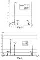
- the figure 3clearly shows a gain in the ionization efficiency according to whether or not the first stage is in operation.
- a gainratio of ion currents between the spectrum with operation of the first stage and the non-functioning spectrum of the first stage
- a gainis observed equal to 3.1 for the 208 Pb 3+ ion and 2.7 for the 208 Pb ion. 2+ .
- the figure 4shows the evolution of intensities of 208 Pb with the variation of the power of the micro-furnace.
- a direct gain in total intensity of 208 Pb (in particles)ranging from a gain of 1.4 (for a micro-oven power of 3.36 W) to 2.2 (for a micro-oven power of 5.37W) .
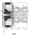
- FIG. 5illustrates a simplified schematic representation of a device 100 according to a second embodiment of the invention including a module intensities map, equimodules and vectors of the electromagnetic field prevailing in the device according to the invention
- the figure 5also includes a map of the intensity of the modules, equimodules and vectors of the electromagnetic field prevailing in the device 100 according to the invention.
- the intensity of the modulus of the magnetic fieldis represented by dotted lines: the modulus prevailing in the chamber 102 is all the more intense as the dotted lines are dense.
- the ionization zone 110here is an ECR zone with a higher frequency than the ECR zone of the figure 1
- This RCE zone 110is here typically a high density zone with a resonance zone operating at 29 GHz. As for the figure 1 this zone only ensures the ionization of the injected neutral particles and not the confinement of these same ionized particles.
- This resonant frequency at 29 GHzimplies the presence of a very high magnetic field to ensure the resonance phenomenon that will allow effective ionization of neutral particles (obtaining single-charged and multicharged ions).
- the soft iron cone element 106makes it possible to locally increase the value of the magnetic field module so as to obtain the resonance magnetic field at the ionization zone 110.
- the device 100 of the figure 5is identical to device 1 of the figure 1 and works in a similar way.
- Figures 6 and 7illustrate a simplified schematic representation of device 200 and 300 respectively according to a third and a fourth embodiment of the invention including a module intensities map, equimodules and vectors of the electromagnetic field prevailing in the device according to the invention .
- the devices 200 and 300are identical to the device 1 of the figure with the difference that the first ionization stage is not an RCE stage. We have kept the same references for the common elements with the device 1 of the figure 1 .
- the device 200 of the figure 6differs from device 1 of the figure 1 only in that the ionization source 201 is a surface ionization source, the ionization stage 207 of the device 200 therefore not being an ECR device.
- the end of the source 201is in the zone 10 forming the ionization zone of the device 200 in which the magnetic field is coaxial with the longitudinal axis AA 'of the chamber 2 of the device 200. It can be seen that the the permanent magnet 3 and the soft iron cone 6 have been preserved so as to obtain a concentration of the field module Magnetic at the ionization zone 10: this field concentration makes it possible to have ions with weaker Larmor rays and is particularly useful for heavy particles.
- the device 300 of the figure 7differs from device 1 of the figure 1 only in that the ionization source 301 is a source of laser excitation and ionization (one of the principles of which is that of a focused laser light beam which heats a target on a local scale; thermal expansion locally creates a shock wave which expels a "feather" plasma very hot and dense, another principle is a laser resonant ionization source for removing a peripheral electron), the ionization stage 307 of the device 300 is not a device RCE.
- the end of the source 301is in the zone 10 forming the ionization zone of the device 300 in which the magnetic field is coaxial with the longitudinal axis AA 'of the chamber 2 of the device 300. Again, it can be seen that that the permanent magnet 3 and the soft iron cone 6 have been preserved so as to obtain a concentration of the magnetic field module at the level of the ionization zone 10.
Landscapes
- Physics & Mathematics (AREA)
- Spectroscopy & Molecular Physics (AREA)
- Engineering & Computer Science (AREA)
- Chemical & Material Sciences (AREA)
- Combustion & Propulsion (AREA)
- Plasma & Fusion (AREA)
- Electron Sources, Ion Sources (AREA)
- Particle Accelerators (AREA)
Description
Translated fromFrenchLa présente invention concerne un dispositif générateur d'ions à résonance cyclotronique électronique.The present invention relates to an electron cyclotron resonance ion generating device.
De façon connue, les sources à résonance cyclotronique électronique, dites sources ECR, sont utilisées communément pour produire des ions mono-chargés ou multichargés (c'est-à-dire des atomes auxquels on a arraché un ou plusieurs électrons).In a known manner, electron cyclotron resonance sources, referred to as ECR sources, are commonly used to produce single-charged or multicharged ions (that is to say atoms to which one or more electrons have been torn off).
Le principe de ces sources ECR est de coupler, à l'intérieur d'une chambre sous vide alimentée en atomes (ces atomes peuvent provenir d'un gaz ou d'un métal), une onde haute-fréquence avec un champ magnétique B, de façon à obtenir les conditions dans lesquelles, une résonance cyclotronique est susceptible d'apparaître et d'ioniser les atomes présents, engendrant ainsi un plasma. La pression résiduelle régnant dans la chambre à vide est de l'ordre de 10-6 à 10-1 Pa.The principle of these ECR sources is to couple, inside a vacuum chamber fed with atoms (these atoms can come from a gas or a metal), a high-frequency wave with a magnetic field B, in order to obtain the conditions under which a cyclotron resonance is likely to appear and to ionize the atoms present, thus generating a plasma. The residual pressure prevailing in the vacuum chamber is of the order of 10-6 to 10-1 Pa.
Généralement, la chambre contenant le plasma présente une symétrie de révolution par rapport à un axe longitudinal. Le champ magnétique est produit par des moyens externes à la chambre sous vide. Ces moyens peuvent être constitués d'un ensemble de bobines parcourues d'un courant électrique ou d'un ensemble d'aimants permanents. Les bobines utilisées, si elles sont constituées de matériaux supraconducteurs, doivent être refroidies jusqu'à une température déterminée, par un système cryogénique approprié.Generally, the chamber containing the plasma has a symmetry of revolution with respect to a longitudinal axis. The magnetic field is produced by means external to the vacuum chamber. These means may consist of a set of coils with an electric current or a set of permanent magnets. The coils used, if they consist of superconducting materials, must be cooled to a specified temperature by a suitable cryogenic system.
La résonance cyclotronique est obtenue grâce à l'action conjuguée de l'onde haute fréquence injectée dans l'enceinte, et d'un champ magnétique présentant une structure dite "à minimum B". Le champ magnétique présente en particulier un module Br qui satisfait à la condition (1) de résonance cyclotronique électronique :
Un système d'extraction des ions, situé du côté de la chambre opposé à celui de l'injection de la haute fréquence, ou disposé latéralement par rapport à l'axe de la source en regard du plasma est également prévu.An ion extraction system, located on the side of the chamber opposite to that of the injection of the high frequency, or disposed laterally with respect to the axis of the source facing the plasma is also provided.
Dans ce type de source, la quantité d'ions pouvant être produite résulte de la compétition entre deux processus : d'une part la formation des ions par impact électronique sur des atomes neutres constituant le milieu gazeux à ioniser, et d'autre part, les pertes de ces mêmes ions par recombinaison avec les particules neutres ou chargées présentes dans le volume plasma ou bien par diffusion des atomes neutres jusqu'aux parois de l'enceinte.In this type of source, the quantity of ions that can be produced results from the competition between two processes: on the one hand the formation of ions by electronic impact on neutral atoms constituting the gaseous medium to be ionized, and on the other hand, the losses of these same ions by recombination with the neutral or charged particles present in the plasma volume or by diffusion of the neutral atoms to the walls of the chamber.
Il est prévu de confiner dans l'enceinte les ions formés ainsi que les électrons servant à leur ionisation. Ceci est réalisé en superposant au champ magnétique de symétrie axiale un champ magnétique de symétrie radiale. Ce champ magnétique radial est obtenu à l'aide d'une structure multipolaire constituée généralement par des aimants permanents. Un gradient de champ positif est créé dans toutes les directions (sur l'axe et vers la paroi de la chambre) et est décélérateur. Les électrons du plasma sont piégés dans un puits de potentiel magnétique axialement et radialement. Cette configuration de miroir magnétique n'est évidemment pas parfaite (lignes de fuite) et ceci est mis à profit pour que l'on puisse en extraire les particules chargées qui formeront le faisceau à la sortie de l'électrode plasma.It is planned to confine in the chamber the ions formed as well as the electrons used for their ionization. This is achieved by superimposing on the magnetic field of axial symmetry a magnetic field of radial symmetry. This radial magnetic field is obtained using a multipolar structure generally consisting of permanent magnets. A positive field gradient is created in all directions (on the axis and towards the wall of the chamber) and is decelerating. The plasma electrons are trapped in a magnetic potential well axially and radially. This magnetic mirror configuration is obviously not perfect (creepage) and this is used to extract the charged particles that will form the beam at the output of the plasma electrode.
La superposition du champ magnétique radial et du champ magnétique axial conduit à la formation de surfaces d'équimodule de champ magnétique, fermées n'ayant aucun contact avec les parois de l'enceinte. Le champ magnétique total est réglé de façon à ce qu'il existe au moins une surface magnétique complètement fermée sur laquelle la condition (1) de résonance cyclotronique électronique est satisfaite.The superposition of the radial magnetic field and the axial magnetic field leads to the formation of closed magnetic field equimodule surfaces having no contact with the walls of the enclosure. The total magnetic field is adjusted so that there is at least one completely closed magnetic surface on which the electronic cyclotron resonance condition (1) is satisfied.
La demande de brevet
Le brevet
La densité électronique des plasmas des sources RCE est comprise entre 109 et 1012 électrons par cm3. Les particules neutres sont injectées dans le volume de la chambre à vide contenant le plasma. Si elles ne sont pas ionisées au cours de leur premier trajet au sein du plasma, elles collent sur les parois de la chambre. Leur temps de collage dépend de l'espèce chimique à laquelle elles appartiennent. Ce temps peut être très important pour des particules dont les propriétés physico-chimiques autorisent une réaction avec les parois. Leur probabilité d'ionisation dépend donc directement de la capacité d'ionisation du plasma.The electron density of the ECR source plasmas is between 109 and 1012 electrons per cm3 . The neutral particles are injected into the volume of the vacuum chamber containing the plasma. If they are not ionized during their first journey within the plasma, they stick on the walls of the room. Their bonding time depends on the chemical species to which they belong. This time can be very important for particles whose physico-chemical properties allow a reaction with the walls. Their probability of ionization therefore depends directly on the ionization capacity of the plasma.
Des efficacités d'ionisation proches de 100% peuvent être observées pour les gaz non réactifs avec les parois. En effet, les rebonds successifs des particules sur les parois multiplient le nombre de trajets des particules dans le plasma et permettent leur ionisation s'ils ne sont pas ionisés au passage des zones d'excitation électronique les plus fortes du plasma (autour des zones de résonance).Ionization efficiencies close to 100% can be observed for non-reactive gases with the walls. Indeed, the successive rebounds of the particles on the walls multiply the number of paths of the particles in the plasma and allow their ionization if they are not ionized at the passage of the zones of the strongest electron excitation of the plasma (around the zones of resonance).
En revanche, il n'en est pas de même pour les éléments condensables (Pb, Ge par exemple) du tableau périodique de Mendeleïev. Ces derniers, s'ils ne sont pas ionisés au premier passage dans le plasma, sont collés aux parois dès qu'ils les atteignent et ne peuvent s'en décoller que si la température de la paroi est suffisante pour l'élément considéré. Dès lors, les sources d'ions ECR conventionnelles avec des parois froides conduisent à de faibles efficacités totales d'ionisation dans la mesure où les atomes qui ne sont pas ionisés à leur premier passage dans le plasma se condensent sur les parois de la chambre et sont perdus pour la production du faisceau. Ainsi, compte tenu des sections efficaces d'ionisation par impact électronique, les efficacités d'ionisation pour les éléments condensables sont de quelques pour mille, pour une onde de fréquence 2.45 GHz jusqu'à 20% pour une onde de fréquence 15 Ghz.On the other hand, it is not the same for the condensable elements (Pb, Ge for example) of Mendeleev's periodic table. The latter, if they are not ionized at the first passage in the plasma, are stuck to the walls as soon as they reach them and can only come off if the temperature of the wall is sufficient for the element in question. As a result, conventional ECR ion sources with cold walls lead to low total ionization efficiencies as atoms that are not ionized at their first pass through the plasma condense on the walls of the chamber and are lost for beam production. Thus, in view of the electron impact ionization cross sections, the ionization efficiencies for the condensable elements are from a few to a thousand, for a wave frequency of 2.45 GHz up to 20% for a wave frequency of 15 Ghz.
On notera qu'il en va de même pour la production d'ions radioactifs dont l'efficacité sera très dépendante de la durée de vie de ces éléments.Note that it is the same for the production of radioactive ions whose effectiveness will be very dependent on the life of these elements.
Pour les gaz non réactifs avec la paroi, l'efficacité d'ionisation est évidemment plus élevée que pour les éléments condensables ; toutefois, parallèlement, le temps total de transformation des particules neutres augmente, ce temps étant lié à la fois aux différents rebonds et au temps de décollage des particules.For non-reactive gases with the wall, the ionization efficiency is obviously higher than for the condensable elements; however, in parallel, the total transformation time of the neutral particles increases, this time being related to both the different rebounds and the take-off time of the particles.
Dans ce contexte, la présente invention a pour but de fournir un dispositif générateur d'ions à résonance cyclotronique électronique permettant d'augmenter la capacité d'ionisation directe avant tout rebond sur les parois de la chambre à vide.In this context, the object of the present invention is to provide an electronic cyclotron resonance ion generating device which makes it possible to increase the direct ionization capacity before any bounce on the walls of the vacuum chamber.
A cette fin, l'invention propose un dispositif générateur d'ions à résonance cyclotronique électronique comportant :
- une chambre étanche sous vide destinée à contenir un plasma, ladite chambre étant à symétrie axiale suivant un axe longitudinal,
- des moyens pour engendrer un champ magnétique dans ladite chambre, ledit champ magnétique possédant une symétrie de révolution par rapport au dit axe longitudinal,
- des moyens de propagation d'une onde haute-fréquence à l'intérieur de ladite chambre,
- un premier étage d'ionisation situé au niveau d'une extrémité de ladite chambre, ledit premier étage comportant une zone d'ionisation dans laquelle sont générés des ions, ledit champ magnétique étant sensiblement parallèle au dit axe longitudinal dans ladite zone d'ionisation,
- un deuxième étage de confinement magnétique desdits ions générés dans ladite zone d'ionisation, ledit deuxième étage utilisant une première onde haute-fréquence se propageant dans ladite chambre issue desdits moyens de propagation d'une onde haute-fréquence,
- a vacuum sealed chamber for containing a plasma, said chamber being axially symmetrical along a longitudinal axis,
- means for generating a magnetic field in said chamber, said magnetic field having a symmetry of revolution with respect to said longitudinal axis,
- means for propagating a high-frequency wave inside said chamber,
- a first ionization stage located at an end of said chamber, said first stage comprising an ionisation zone in which ions are generated, said magnetic field being substantially parallel to said longitudinal axis in said ionization zone,
- a second magnetic confinement stage of said ions generated in said ionization zone, said second stage using a first high-frequency wave propagating in said chamber resulting from said means of propagation of a high-frequency wave,
On entend par champ magnétique possédant une symétrie de révolution par rapport à l'axe longitudinal, un champ magnétique dont les composantes radiale et axiale sont symétriques quels que soient les points situés sur un cercle autour dudit axe.Magnetic field having a symmetry of revolution with respect to the longitudinal axis is understood to mean a magnetic field whose radial and axial components are symmetrical irrespective of the points situated on a circle about said axis.
Grâce à l'invention, on réduit le temps de transformation des particules neutres en ions tout en assurant une grande efficacité d'ionisation. Le dispositif selon l'invention présente un champ magnétique à symétrie de révolution définissant le volume d'un plasma contenu dans une chambre comprenant deux zones ou étages distincts. Les ions sont essentiellement créés dans la première zone tandis que la deuxième zone assure le confinement des ions selon le principe de la source à résonance cyclotronique électronique. Entre les deux zones, les directions des vecteurs du champ magnétique sont parallèles à l'axe commun aux deux étages, à savoir l'axe longitudinal de la chambre : on a donc entre ces deux zones un champ magnétique purement axial (pas de composante radiale du champ magnétique). Les deux zones ne présentent aucune rupture sur le plan magnétique et définissent un volume contenant un seul et même plasma, c'est-à-dire un seul et même ensemble composé d'ions, d'électrons, d'atomes et de molécules, globalement électriquement neutre (i.e. avec autant de charges positives que de charges négatives). Le fait d'utiliser des vecteurs de champ magnétique coaxiaux entre les deux étages entraîne implicitement que le champ magnétique est à symétrie de révolution et impose la migration des ions de la première zone vers la deuxième zone.Thanks to the invention, the transformation time of the neutral particles into ions is reduced while ensuring a high efficiency of ionization. The device according to the invention has a magnetic field with symmetry of revolution defining the volume of a plasma contained in a chamber comprising two distinct zones or stages. The ions are essentially created in the first zone while the second zone ensures the confinement of the ions according to the principle of the electron cyclotron resonance source. Between the two zones, the directions of the vectors of the magnetic field are parallel to the axis common to the two stages, namely the longitudinal axis of the chamber: there is thus between these two zones a purely axial magnetic field (no radial component magnetic field). The two zones have no magnetic break and define a volume containing a single plasma, that is to say a single set composed of ions, electrons, atoms and molecules, globally electrically neutral (ie with as many positive charges as negative charges). The fact of using coaxial magnetic field vectors between the two stages implies implicitly that the magnetic field is symmetrical of revolution and requires the migration of ions from the first zone to the second zone.
Dans le premier étage, l'efficacité d'ionisation d'une particule dépend des moyens utilisés pour réaliser cette ionisation. Les particules ionisées migrent vers le deuxième étage RCE dans lequel elles sont confinées voir multichargées ; on notera à ce titre que le deuxième étage peut conserver ou augmenter l'état de charge des ions provenant du premier étage.In the first stage, the ionization efficiency of a particle depends on the means used to achieve this ionization. The ionized particles migrate to the second ECR stage in which they are confined or even multicharged; it should be noted in this respect that the second stage can maintain or increase the state of charge of the ions coming from the first stage.
Les ions confinés par le deuxième étage peuvent alors être utilisés sous la forme d'un faisceau de particules mono ou multichargées. Le faisceau ainsi produit présentera les caractéristiques données par une source de type RCE à symétrie de révolution telle que décrite dans le brevet
Concernant l'ionisation de particules de faible durée de vie (atome radioactifs, molécules instables,...), le dispositif selon l'invention permet d'augmenter la probabilité de les ioniser avant qu'ils aient changé d'état en réduisant le temps nécessaire au processus de transformation.As regards the ionisation of particles of short duration (radioactive atoms, unstable molecules, etc.), the device according to the invention makes it possible to increase the probability of ionizing them before they have changed state by reducing the time required for the transformation process.
Par ailleurs, le parallélisme entre ledit champ magnétique et l'axe longitudinal est déterminé par le rayon de Larmor de l'ion d'intérêt (rayon de giration de l'ion autour des lignes de champ). Ainsi, le rayon de giration augmente avec la masse des ions d'intérêt. Dans la mesure où, selon l'invention, les particules ionisées dans la zone d'ionisation doivent migrer vers la zone de confinement, l'exigence de parallélisme du champ magnétique avec l'axe dépendra du rayon de Larmor de cet ion. On conçoit aisément que pour un ion d'intérêt de faible masse, on pourra tolérer un défaut de parallélisme plus important entre le champ magnétique et l'axe longitudinal que pour un ion d'intérêt de masse plus importante avec un rayon de Larmor élevé et qui pourrait, pour un champ magnétique présentant un angle trop important avec l'axe longitudinal, s'écarter de la direction prévue et ne pas migrer vers le deuxième étage. De façon générale, on peut dire que l'angle θ maximum entre les vecteurs de champ magnétique situés dans la zone d'ionisation et entre cette zone d'ionisation et l'entrée de la zone de confinement, doit rester inférieur à 30°. On notera qu'il est possible de diminuer le rayon de Larmor de l'ion d'intérêt en ayant un module de champ magnétique élevé dans la zone d'ionisation.Moreover, the parallelism between said magnetic field and the longitudinal axis is determined by the Larmor radius of the ion of interest (radius of gyration of the ion around the field lines). Thus, the radius of gyration increases with the mass of the ions of interest. Since, according to the invention, the ionized particles in the ionization zone must migrate towards the confinement zone, the requirement of parallelism of the magnetic field with the axis will depend on the Larmor radius of this ion. It is easy to understand that for an ion of interest of low mass, it will be possible to tolerate a greater parallelism error between the magnetic field and the longitudinal axis than for an ion of greater mass interest with a high Larmor radius and which could, for a magnetic field having too much angle with the longitudinal axis, deviate from the planned direction and not migrate towards the second stage. In general, it can be said that the maximum angle θ between the magnetic field vectors located in the ionization zone and between this ionization zone and the entry of the confinement zone must remain less than 30 °. Note that it is possible to decrease the Larmor radius of the ion of interest by having a high magnetic field module in the ionization zone.
Le dispositif selon l'invention peut également présenter une ou plusieurs des caractéristiques ci-dessous, considérées individuellement ou selon toutes les combinaisons techniquement possibles :
- Ledit premier étage d'ionisation est une source d'ions à résonance cyclotronique électronique ;
- Le dispositif selon l'invention comporte un guide d'ondes pour l'injection d'une deuxième onde haute-fréquence dans ladite zone d'ionisation ;
- Le dispositif selon l'invention comporte un système d'injection des éléments à ioniser agencé à proximité de la zone de résonance formant ladite zone d'ionisation de ladite source d'ions à résonance cyclotronique, ledit système restant hors de ladite zone de résonance ;
- Ledit système d'injection est un four injectant de la vapeur d'éléments condensable à ioniser dans ladite zone de résonance ;
- Ledit premier étage d'ionisation est choisi parmi les sources suivantes :
- o source à décharge,
- o source à ionisation de surface,
- o source à thermo-ionisation,
- o source à Laser,
- o source ionisation de champ,
- o source à échange de charge ;
- Le dispositif selon l'invention comporte des moyens pour augmenter localement le module du champ magnétique dans ladite zone d'ionisation ;
- lesdits moyens pour augmenter localement le module du champ magnétique sont formés par un anneau en fer doux ;
- lesdits moyens pour engendrer un champ magnétique dans ladite chambre comportent des aimants permanents dont l'axe de révolution se confond sensiblement avec ledit axe longitudinal ;
- lesdits moyens pour engendrer un champ magnétique dans ladite chambre comportent au moins une bobine, parcourue par un courant d'intensité déterminée, ladite bobine étant réalisée avec un matériau supraconducteur ou un matériau conventionnel ;
- Le dispositif selon l'invention comporte une zone d'extraction desdits ions localisée à l'extrémité opposée à celle dans laquelle se situe ledit premier étage d'ionisation, ledit champ magnétique étant sensiblement parallèle au dit axe longitudinal dans ladite zone d'extraction ;
- lesdits moyens pour engendrer un champ magnétique dans ladite chambre permettent de définir dans ledit deuxième étage de confinement magnétique au moins une ligne fermée de minima dudit champ magnétique, à l'intérieur d'un ou plusieurs volume(s) intérieur(s) à ladite chambre et délimité(s) par des surfaces d'équimodule du champ magnétique fermées dans l'espace.
- Said first ionization stage is an electron cyclotron resonance ion source;
- The device according to the invention comprises a waveguide for injecting a second high-frequency wave into said ionization zone;
- The device according to the invention comprises an injection system of the elements to be ionized arranged close to the resonance zone forming said ionization zone of said source of cyclotron resonance ions, said system remaining outside said resonance zone;
- Said injection system is an oven injecting condensable element vapor to be ionized in said resonance zone;
- Said first ionization stage is chosen from the following sources:
- o discharge source,
- o surface ionization source,
- o thermionic ionization source,
- o Laser source,
- o field ionization source,
- o source of charge exchange;
- The device according to the invention comprises means for locally increasing the modulus of the magnetic field in said ionization zone;
- said means for locally increasing the modulus of the magnetic field are formed by a soft iron ring;
- said means for generating a magnetic field in said chamber comprise permanent magnets whose axis of revolution substantially coincides with said longitudinal axis;
- said means for generating a magnetic field in said chamber comprises at least one coil, traversed by a current of determined intensity, said coil being made with a superconductive material or a conventional material;
- The device according to the invention comprises an extraction zone of said ions located at the end opposite to that in which said first ionization stage is located, said magnetic field being substantially parallel to said longitudinal axis in said extraction zone;
- said means for generating a magnetic field in said chamber makes it possible to define in said second magnetic confinement stage at least one closed minimum line of said magnetic field, within one or more volume (s) inside said chamber and delimited by equimodule surfaces of the magnetic field closed in space.
D'autres caractéristiques et avantages de l'invention ressortiront clairement de la description qui en est donnée ci-dessous, à titre indicatif et nullement limitatif, en référence aux figures annexées, parmi lesquelles :
- la
figure 1 est une représentation schématique simplifiée du dispositif selon un premier mode de réalisation de l'invention incluant une carte d'intensités du module, d'équimodules et de vecteurs du champ électromagnétique régnant dans le dispositif selon l'invention; - la
figure 2 est une vue en trois dimensions de la configuration mécanique du dispositif de lafigure 1 ; - la
figure 3 donne deux spectres d'ions multichargés respectivement avec et sans le fonctionnement du premier étage du dispositif de lafigure 1 ; - la
figure 4 donne trois spectres d'ions multichargés respectivement à trois puissances de chauffage différentes du micro-four utilisé pour l'injection des particules neutres dans le premier étage du dispositif de lafigure 1 ; - la
figure 5 est une représentation schématique simplifiée du dispositif selon un second mode de réalisation de l'invention incluant une carte d'intensités du module, d'équimodules et de vecteurs du champ électromagnétique régnant dans le dispositif selon l'invention ; - la
figure 6 est une représentation schématique simplifiée du dispositif selon un troisième mode de réalisation de l'invention incluant un dispositif générateur d'ions par thermo-ionisation, une carte d'intensités du module, d'équimodules et de vecteurs du champ électromagnétique régnant dans le dispositif selon l'invention ; - la
figure 7 est une représentation schématique simplifiée du dispositif selon un quatrième mode de réalisation de l'invention incluant un générateur d'ions par excitation laser, une carte d'intensités du module, d'équimodules et de vecteurs du champ électromagnétique régnant dans le dispositif selon l'invention.
- the
figure 1 is a simplified schematic representation of the device according to a first embodiment of the invention including a module intensities map, equimodules and vectors of the electromagnetic field prevailing in the device according to the invention; - the
figure 2 is a three-dimensional view of the mechanical configuration of the device of thefigure 1 ; - the
figure 3 gives two multicharged ion spectra respectively with and without the operation of the first stage of the device of thefigure 1 ; - the
figure 4 gives three spectra of multicharged ions respectively at three different heating powers of the micro-furnace used for the injection of the neutral particles in the first stage of the device of thefigure 1 ; - the
figure 5 is a simplified schematic representation of the device according to a second embodiment of the invention including a module intensities map, equimodules and vectors of the electromagnetic field prevailing in the device according to the invention; - the
figure 6 is a simplified schematic representation of the device according to a third embodiment of the invention including a device for ion generator by thermo-ionization, a module intensities map, equimodules and vectors of the electromagnetic field prevailing in the device according to the invention; - the
figure 7 is a simplified schematic representation of the device according to a fourth embodiment of the invention including a generator of ions by laser excitation, a module intensities map, equimodules and vectors of the electromagnetic field prevailing in the device according to the invention.
Dans toutes les figures, les éléments communs portent les mêmes numéros de référence.In all the figures, the common elements bear the same reference numbers.
La
Le dispositif 1 comporte :
une chambre 2 étanche sous vide ayant un axe de symétrie longitudinale AA';- trois aimants permanents 3, 4
et 5 sensiblement identiques ayant une forme d'anneau et disposés les uns à coté des autres de façon à ce que leur axe de révolution se confonde sensiblement avec l'axe longitudinal AA' de la chambre 2,l'aimant 3 se trouvant à une première extrémité du dispositif 1,l'aimant 5 à l'extrémité opposée et l'aimant 4 étant localisé entre l'aimant 3et l'aimant 5 ; - un élément conique en fer doux 6 agencé de sorte que son extrémité de section rétrécie se trouve à l'intérieur de l'aimant 4 intermédiaire.
- a vacuum sealed
chamber 2 having a longitudinal axis of symmetry AA '; - three substantially identical
permanent magnets chamber 2, themagnet 3 being at a first end of thedevice 1, themagnet 5 at the opposite end and themagnet 4 being located between themagnet 3 and themagnet 5; - a soft iron
conical element 6 arranged so that its narrowed section end is inside theintermediate magnet 4.
Les aimants permanents 3, 4 et 5 peuvent être des aimants monoblocs ou des aimants composés de plusieurs secteurs montés avec une aimantation dans le même sens.The
La
Ainsi, l'intensité du module du champ magnétique est représentée par des pointillés : le module régnant dans la chambre 2 est d'autant plus intense que les pointillés sont denses.Thus, the intensity of the modulus of the magnetic field is represented by dashed lines: the modulus prevailing in the
De même, plusieurs surfaces d'équimodules sont représentées sur la
Enfin, les vecteurs de champ magnétique sont représentés par des flèches.Finally, the magnetic field vectors are represented by arrows.
Le dispositif 1 comporte :
- un
premier étage d'ionisation 7 situé au niveau d'une extrémité de la chambre 2, lepremier étage 7 comportantune zone d'ionisation 10 ; - un deuxième étage de
confinement magnétique 8 des ions générés par lepremier étage 7 ; - une zone de
migration 12 des ions dupremier étage 7 vers le deuxième étage 8 ; une zone d'extraction 9 des ions, cette zone pouvant être latérale située dans lazone 8.
- a
first ionization stage 7 situated at one end of thechamber 2, thefirst stage 7 comprising anionization zone 10; - a second
magnetic confinement stage 8 of the ions generated by thefirst stage 7; - a
migration zone 12 of the ions of thefirst stage 7 to thesecond stage 8; - an
ion extraction zone 9, this zone being able to be lateral situated inzone 8.
La zone d'ionisation 10 est ici une zone RCE (on notera que les systèmes d'injection des ions et de l'onde haute fréquence ne sont pas représentés sur la
Le dispositif 1 comporte également un tube 14 dans lequel on insère un micro-four non représenté : ce micro-four permet par chauffage d'un composé à ioniser jusqu'à une pression de vapeur suffisante de produire des éléments condensables du tableau périodique de Mendeleïev (Pb par exemple). Le micro-four est également sensiblement placé selon l'axe longitudinal AA' et doit être très proche de la zone de résonance 10 sans toutefois pénétrer dans cette zone. Typiquement, le micro-four peut être placé 2 mm en retrait (cf. localisation illustrée par la référence 15) du bout du guide d'onde 13 : ce four est par exemple chargé de208Pb. Rappelons que l'ionisation d'un élément condensable est un critère fondamental pour qualifier le dispositif selon l'invention puisque les éléments condensables non ionisés au premier passage dans les dispositifs connus sont collés aux parois dès qu'ils les atteignent et ne peuvent s'en décoller que si la température de la paroi est suffisante pour l'élément considéré.The
Les ions produits par le premier étage 7 au niveau de la zone d'ionisation 10 sont pris en charge par le champ magnétique sensiblement parallèle à l'axe longitudinal AA' (i.e. composante radiale du champ magnétique est sensiblement nulle) à la fois dans la zone d'ionisation 10 puis entre la zone d'ionisation 10 et l'entrée du deuxième étage de confinement de sorte que les ions générés dans ladite zone d'ionisation migrent spontanément en s'enroulant autour des lignes de champ vers ledit deuxième étage de confinement 8 (on notera que l'ensemble des ions, mono et multichargés, est pris en charge et migre vers le deuxième étage 8). On notera également que le fait d'imposer un champ magnétique sensiblement colinéaire à l'axe AA' implique de fait d'avoir un champ magnétique à symétrie de révolution. Comme déjà mentionné plus haut, le parallélisme entre le champ magnétique et l'axe longitudinal AA' est déterminé par le rayon de Larmor de l'ion d'intérêt. Ainsi, le rayon de Larmor augmente avec la masse des ions d'intérêt (le rayon de giration de l'Ar est ainsi plus faible que le rayon de giration du Pb, plus lourd que l'Ar). Dans la mesure où, selon l'invention, les particules ionisées dans la zone d'ionisation 10 doivent migrer vers le deuxième étage de confinement 8, l'exigence de parallélisme du champ magnétique avec l'axe dépendra du rayon de Larmor de cet ion. On conçoit aisément que pour un ion d'intérêt de faible masse, on pourra tolérer un défaut de parallélisme plus important entre le champ magnétique et l'axe longitudinal que pour un ion d'intérêt de masse plus importante avec un rayon de Larmor élevé et qui pourrait, pour un champ magnétique présentant un angle trop important avec l'axe longitudinal AA', s'écarter de la direction prévue et ne pas migrer vers le deuxième étage 8. De façon générale, on peut dire que l'angle θ maximum entre les vecteurs de champ magnétique situés dans la zone d'ionisation et entre cette zone d'ionisation et l'entrée de la zone de confinement, doit rester inférieur à 30°. On notera qu'il est possible de diminuer le rayon de Larmor de l'ion d'intérêt en ayant un module de champ magnétique élevé dans la zone d'ionisation 10 : le cône de fer doux 6 permet de concentrer le champ magnétique dans cette zone.The ions produced by the
Les deux aimants permanents 4 et 5 servent à générer le champ magnétique à symétrie de révolution.The two
Le deuxième étage 8 forme donc une zone de confinement magnétique RCE : les aimants 4 et 5 sont choisis de manière que la somme vectorielle des champs magnétiques créés en chaque point du deuxième étage 8 conduise à obtenir un profil à lignes fermées de minimal |B|. La référence 16 sur la
On notera que les premier et deuxième étages 7 et 8 comportent un seul et même plasma continu.It will be noted that the first and
On notera également qu'il est possible d'utiliser un seul guide d'ondes pour injecter les deux ondes haute fréquence (par exemple une première fréquence pour le premier étage 7 d'ionisation égale à 18 GHz et une deuxième fréquence pour le second étage de confinement égale à 8 GHz transmises par le même guide d'ondes).It will also be noted that it is possible to use a single waveguide for injecting the two high frequency waves (for example a first frequency for the
On peut également utiliser un gaz support (injecté via un capillaire non représenté dans la chambre 2) qui permet d'augmenter la population électronique. Ce gaz support est de préférence un gaz dont les atomes sont de masse plus faible que ceux permettant l'obtention des ions d'intérêt. Ainsi, dans le cas de l'ionisation du208Pb, on peut utiliser un gaz support, par exemple l'He.It is also possible to use a carrier gas (injected via a capillary not shown in chamber 2) which makes it possible to increase the electronic population. This carrier gas is preferably a gas whose atoms are of lower mass than those for obtaining the ions of interest. So, in the case of the ionization of208 Pb, it is possible to use a carrier gas, for example He.
Bien entendu, le système de guidage d'onde 13 et le système d'injection des éléments neutres 14 sont reliés de façon parfaitement étanche à la chambre 2 au moyen de joints appropriés non représentés.Of course, the
Par ailleurs, l'injection des éléments neutres dans la zone d'ionisation a été plus particulièrement décrite dans le cas de l'utilisation d'un micro-four pour des éléments condensables; bien évidemment, l'invention est également applicable à d'autres sources connues de production d'éléments neutres (bouteille de gaz par exemple).Moreover, the injection of the neutral elements into the ionization zone has been more particularly described in the case of the use of a micro-furnace for condensable elements; obviously, the invention is also applicable to other known sources of production of neutral elements (gas bottle for example).
Avec un dispositif tel que représenté aux
La
On notera par ailleurs qu'un test (non représenté) de fonctionnement du premier étage seul (sans faire fonctionner l'étage de confinement RCE) montre une très faible production d'ions.Note also that a test (not shown) of operation of the first stage alone (without operating the confinement stage RCE) shows a very low production of ions.
Le champ magnétique dans l'exemple illustré aux
Le dispositif 100 comporte :
une chambre 102 étanche sous vide ayant un axe de symétrie longitudinale AA';- deux aimants permanents 104
et 105 sensiblement identiques ayant une forme d'anneau et disposés les uns à coté des autres de façon à ce que leur axe de révolution se confonde sensiblement avec l'axe longitudinal AA' de la chambre 102 ; une bobine 101 parcourue par un courant d'intensité déterminée et dont l'axe de révolution se confond sensiblement avec l'axe longitudinal AA' de la chambre 102- un élément conique en fer doux 106 agencé de sorte que son extrémité de section rétrécie se trouve à l'intérieur de la bobine 101.
- a vacuum sealed
chamber 102 having a longitudinal axis of symmetry AA '; - two substantially identical
permanent magnets chamber 102; - a
coil 101 traversed by a current of determined intensity and whose axis of revolution substantially coincides with the longitudinal axis AA 'of thechamber 102 - a soft
iron cone member 106 arranged so that its narrowed end section is within thecoil 101.
Comme pour la
Ainsi, l'intensité du module du champ magnétique est représentée par des pointillés : le module régnant dans la chambre 102 est d'autant plus intense que les pointillés sont denses.Thus, the intensity of the modulus of the magnetic field is represented by dotted lines: the modulus prevailing in the
De même, plusieurs surfaces d'équimodules sont représentées sur la
Enfin, les vecteurs de champ magnétique sont représentés par des flèches.Finally, the magnetic field vectors are represented by arrows.
Le dispositif 100 comporte :
- un premier étage d'ionisation 107 située au niveau d'une extrémité de la chambre 102, le
premier étage 7 comportantune zone d'ionisation 110 ; - un deuxième étage de
confinement magnétique 108 des ions générés par lepremier étage 7 ; - une zone de
migration 112 des ions dupremier étage 107 vers le deuxième étage 108 ; une zone d'extraction 109 des ions.
- a
first ionization stage 107 located at one end of thechamber 102, thefirst stage 7 having anionization zone 110; - a second
magnetic confinement stage 108 of the ions generated by thefirst stage 7; - a
migration zone 112 of the ions of thefirst stage 107 to thesecond stage 108; - an
extraction zone 109 of the ions.
La zone d'ionisation 110 est ici une zone RCE à plus haute fréquence que la zone RCE de la
A la seule différence de la bobine 101 qui permet d'utiliser une zone RCE de plus haute fréquence pour l'étage d'ionisation, le dispositif 100 de la
Les différents modes de réalisation décrits jusqu'à présent (
Ainsi, à la place d'un premier étage RCE, le premier étage d'ionisation peut également être choisi parmi les sources suivantes :
- source à décharge,
- source à ionisation de surface,
- source à thermo-ionisation,
- source à Laser,
- source ionisation de champ,
- source à échange de charge.
- discharge source,
- surface ionization source,
- thermionic ion source,
- source at Laser,
- ionization field source,
- source with charge exchange.
A titre d'illustration, les
Les dispositifs 200 et 300 sont identiques au dispositif 1 de la figure à la différence que le premier étage d'ionisation n'est pas un étage RCE. Nous avons conservé les mêmes références pour les éléments communs avec le dispositif 1 de la
Le dispositif 200 de la
Le dispositif 300 de la
Claims (13)
- An electron cyclotron resonance ion generator device (1, 100, 200, 300) including:- a vacuum sealed chamber (2, 102) for containing a plasma, said chamber (2, 102) being of axial symmetry along a longitudinal axis (AA'),- means (3, 4, 5, 6, 101, 104, 105, 106) for generating a magnetic field in said chamber (2, 102), said magnetic field having a revolution symmetry relative to said longitudinal axis (AA'),- means for propagating a high frequency wave inside said chamber (2, 102),said device (1, 100, 200, 300) beingcharacterised in that said chamber (2, 102) includes:- a first ionisation stage (7, 107, 207, 307) located at one end of said chamber (2, 102), said first stage including an ionisation zone (10, 110) in which ions are generated, said magnetic field being substantially parallel to said longitudinal axis (AA') in said ionisation zone (10, 110),- a second stage (8, 108) for magnetically confining said ions generated in said ionisation zone (10, 110), said second stage (8, 108) using a first high frequency wave propagating in said chamber (2, 102) from said means for propagating a high frequency wave,said magnetic field being substantially parallel to said longitudinal axis (AA') between said ionisation zone (10, 110) and said second confinement stage (8, 108) such that the ions generated in said ionisation zone (10, 110) migrate to said second confinement stage (8, 108) andin that said first and second stages (7, 107, 207, 307, 8, 108) include a same continuous plasma.
- The device (1, 100) according to claim 1,characterised in that the first ionisation stage (7, 107) is an electron cyclotron resonance ion source.
- The device (1) according to claim 2,characterised in that it includes a waveguide (13) for injecting a second high frequency wave into said ionisation zone (10).
- The device (1) according to one of claims 2 or 3,characterised in that it includes a system for injecting elements to be ionised arranged in the proximity of the resonance zone forming said ionisation zone (10) of said cyclotron resonance ion source, said system remaining off said resonance zone.
- The device (1) according to claim 4,characterised in that said injecting system is an oven injecting vapour of condensable elements to be ionised in said resonance zone.
- The device (1) according to claim 5,characterised in that said oven is arranged such that it is substantially parallel to said longitudinal axis.
- The device (200, 300) according to claim 1,characterised in that the first ionisation stage is chosen from the following sources:- discharge source,- surface ionisation source (207),- thermo-ionisation source,- laser source (307),- field ionisation source,- charge exchange source.
- The device (1, 100, 200, 300) according to one of the preceding claims,characterised in that it includes means (6, 106) for locally increasing the module of the magnetic field in said ionisation zone.
- The device (1, 100, 200, 300) according to the preceding claim,characterised in that said means (6, 106) for locally increasing the module of the magnetic field are formed by a soft iron ring.
- The device (1) according to one of the preceding claims,characterised in that said means for generating a magnetic field in said chamber include permanent magnets (3, 4, 5) the revolution axis of which is substantially the same as said longitudinal axis (AA').
- The device (100) according to one of the preceding claims,characterised in that said means for generating a magnetic field in said chamber include at least one coil (101) through which a current having a determined intensity passes.
- The device (1, 100, 200, 300) according to one of the preceding claims,characterised in that it includes a zone (9, 109) for extracting said ions located at the opposite end to that in which said first ionisation stage is located, said magnetic field being substantially parallel to said longitudinal axis (AA') in said extracting zone (9, 109).
- The device according to one of the preceding claims,characterised in that said means for generating a magnetic field in said chamber make it possible to define in said second magnetic confining stage at least one closed line of minima of said magnetic field, inside one or more volume(s) internal to said chamber and delimited by magnetic field-equimodular surfaces closed in space.
Applications Claiming Priority (2)
| Application Number | Priority Date | Filing Date | Title |
|---|---|---|---|
| FR0854502AFR2933532B1 (en) | 2008-07-02 | 2008-07-02 | ELECTRONIC CYCLOTRON RESONANCE ION GENERATING DEVICE |
| PCT/FR2009/051104WO2010001036A2 (en) | 2008-07-02 | 2009-06-11 | Electron cyclotron resonance ion generator |
Publications (2)
| Publication Number | Publication Date |
|---|---|
| EP2311061A2 EP2311061A2 (en) | 2011-04-20 |
| EP2311061B1true EP2311061B1 (en) | 2016-11-16 |
Family
ID=40342671
Family Applications (1)
| Application Number | Title | Priority Date | Filing Date |
|---|---|---|---|
| EP09772718.4ANot-in-forceEP2311061B1 (en) | 2008-07-02 | 2009-06-11 | Electron cyclotron resonance ion generator |
Country Status (5)
| Country | Link |
|---|---|
| US (1) | US8760055B2 (en) |
| EP (1) | EP2311061B1 (en) |
| JP (1) | JP5715562B2 (en) |
| FR (1) | FR2933532B1 (en) |
| WO (1) | WO2010001036A2 (en) |
Families Citing this family (2)
| Publication number | Priority date | Publication date | Assignee | Title |
|---|---|---|---|---|
| FR2969372B1 (en)* | 2010-12-21 | 2015-04-17 | Commissariat Energie Atomique | ELECTRONIC CYCLOTRON RESONANCE IONIZATION DEVICE |
| FR2985292B1 (en)* | 2011-12-29 | 2014-01-24 | Onera (Off Nat Aerospatiale) | PLASMIC PROPELLER AND METHOD FOR GENERATING PLASMIC PROPULSIVE THRUST |
Citations (1)
| Publication number | Priority date | Publication date | Assignee | Title |
|---|---|---|---|---|
| FR2668642A1 (en)* | 1990-10-25 | 1992-04-30 | Commissariat Energie Atomique | SOURCE OF HIGHLY LOADED IONS WITH POLARIZABLE PROBE AND ELECTRONIC CYCLOTRONIC RESONANCE. |
Family Cites Families (13)
| Publication number | Priority date | Publication date | Assignee | Title |
|---|---|---|---|---|
| JPS59194407A (en)* | 1983-04-19 | 1984-11-05 | Ulvac Corp | Electron cyclotron resonance ion source magnet device |
| FR2595868B1 (en)* | 1986-03-13 | 1988-05-13 | Commissariat Energie Atomique | ION SOURCE WITH ELECTRONIC CYCLOTRON RESONANCE WITH COAXIAL INJECTION OF ELECTROMAGNETIC WAVES |
| DE3905303C2 (en)* | 1988-02-24 | 1996-07-04 | Hitachi Ltd | Device for generating a plasma by means of microwaves |
| US4883968A (en)* | 1988-06-03 | 1989-11-28 | Eaton Corporation | Electron cyclotron resonance ion source |
| JP3010059B2 (en)* | 1990-09-20 | 2000-02-14 | 日本真空技術株式会社 | Ion source |
| JPH04262349A (en)* | 1991-02-15 | 1992-09-17 | Kobe Steel Ltd | Multi-valent heavy ion source and univalent heavy ion source |
| FR2676593B1 (en)* | 1991-05-14 | 1997-01-03 | Commissariat Energie Atomique | ION SOURCE WITH ELECTRONIC CYCLOTRONIC RESONANCE. |
| JPH069041U (en)* | 1992-07-07 | 1994-02-04 | 日新電機株式会社 | Ion source |
| JP2644958B2 (en)* | 1993-04-02 | 1997-08-25 | 株式会社日立製作所 | Ion source device and ion implantation device provided with the ion source device |
| FR2718568B1 (en)* | 1994-04-06 | 1996-07-05 | France Telecom | High energy implantation method from a low or medium current type implanter and corresponding devices. |
| FR2757310B1 (en) | 1996-12-18 | 2006-06-02 | Commissariat Energie Atomique | MAGNETIC SYSTEM, ESPECIALLY FOR ECR SOURCES, ALLOWING THE CREATION OF CLOSED EQUIMODULE B SURFACES OF ANY SHAPE AND DIMENSIONS |
| JP4249826B2 (en)* | 1998-12-02 | 2009-04-08 | 株式会社 Sen−Shi・アクセリス カンパニー | Multipolar permanent magnet device for ECR |
| FR2815954B1 (en)* | 2000-10-27 | 2003-02-21 | Commissariat Energie Atomique | PROCESS AND DEVICE FOR DEPOSIT BY PLASMA AT THE ELECTRONIC CYCLOTRON RESONANCE OF MONOPAROIS CARBON NANOTUBES AND NANOTUBES THUS OBTAINED |
- 2008
- 2008-07-02FRFR0854502Apatent/FR2933532B1/enactiveActive
- 2009
- 2009-06-11JPJP2011515536Apatent/JP5715562B2/ennot_activeExpired - Fee Related
- 2009-06-11WOPCT/FR2009/051104patent/WO2010001036A2/enactiveApplication Filing
- 2009-06-11EPEP09772718.4Apatent/EP2311061B1/ennot_activeNot-in-force
- 2009-06-11USUS13/002,105patent/US8760055B2/enactiveActive
Patent Citations (1)
| Publication number | Priority date | Publication date | Assignee | Title |
|---|---|---|---|---|
| FR2668642A1 (en)* | 1990-10-25 | 1992-04-30 | Commissariat Energie Atomique | SOURCE OF HIGHLY LOADED IONS WITH POLARIZABLE PROBE AND ELECTRONIC CYCLOTRONIC RESONANCE. |
Also Published As
| Publication number | Publication date |
|---|---|
| US20110210668A1 (en) | 2011-09-01 |
| EP2311061A2 (en) | 2011-04-20 |
| FR2933532A1 (en) | 2010-01-08 |
| WO2010001036A2 (en) | 2010-01-07 |
| US8760055B2 (en) | 2014-06-24 |
| JP2011526724A (en) | 2011-10-13 |
| FR2933532B1 (en) | 2010-09-03 |
| WO2010001036A3 (en) | 2010-02-25 |
| JP5715562B2 (en) | 2015-05-07 |
Similar Documents
| Publication | Publication Date | Title |
|---|---|---|
| EP1488443B1 (en) | Device for confinement of a plasma within a volume | |
| EP3344873B1 (en) | Gridded ion thruster with integrated solid propellant | |
| EP0238397B1 (en) | Electronic cyclotron resonance ion source with coaxial injection of electromagnetic waves | |
| WO2013098505A1 (en) | Plasma thruster and method for generating a plasma propulsion thrust | |
| EP0711100B1 (en) | Plasma production device, allowing a dissociation between microwave propagation and absorption zones | |
| EP0145586B1 (en) | Multicharged ion source with several electron cyclotron resonance regions | |
| EP2873306B1 (en) | Coaxial microwave applicator for plasma production | |
| EP0184475B1 (en) | Method and apparatus for igniting a hyperfrequency ion source | |
| EP0199625B1 (en) | Electron cyclotron resonance negative ion source | |
| EP2311061B1 (en) | Electron cyclotron resonance ion generator | |
| EP2652766B1 (en) | Electronic cyclotronic resonance ion source | |
| EP0946961B1 (en) | Magnetic system, particularly for ecr sources, for producing closed surfaces of equimodule b of any form and dimensions | |
| FR2672730A1 (en) | MODEL CONVERTER DEVICE AND POWER DIVIDER FOR MICROWAVE TUBE AND MICROWAVE TUBE COMPRISING SUCH A DEVICE. | |
| EP0483004B1 (en) | Electron cyclotron resonance ion source for highly charged ions with polarisable probe | |
| EP2656368A1 (en) | Electron cyclotron resonance ionization device | |
| EP0232651B1 (en) | Ion source operating at the electron cyclotron resonance | |
| EP0813223B1 (en) | Magnetic field generation means and ECR ion source using the same | |
| FR2999796A1 (en) | ELECTRONIC OPTICAL DEVICE | |
| FR3157655A1 (en) | Ion source | |
| FR3114476A1 (en) | Excitation device for transforming a gas into plasma in a dielectric capillary tube and laser-plasma accelerator. | |
| WO1999003314A1 (en) | Compact cyclotron and its use in proton therapy | |
| WO2025132161A1 (en) | Ion source | |
| FR2883410A1 (en) | PHOTON SOURCE COMPRISING A MULTICHARGED ION PLASMA SOURCE WITH ELECTRONIC CYCLOTRON RESONANCE. | |
| FR2779315A1 (en) | DEVICE INTENDED TO CREATE A MAGNETIC FIELD INSIDE A SPEAKER |
Legal Events
| Date | Code | Title | Description |
|---|---|---|---|
| PUAI | Public reference made under article 153(3) epc to a published international application that has entered the european phase | Free format text:ORIGINAL CODE: 0009012 | |
| 17P | Request for examination filed | Effective date:20110125 | |
| AK | Designated contracting states | Kind code of ref document:A2 Designated state(s):AT BE BG CH CY CZ DE DK EE ES FI FR GB GR HR HU IE IS IT LI LT LU LV MC MK MT NL NO PL PT RO SE SI SK TR | |
| AX | Request for extension of the european patent | Extension state:AL BA RS | |
| DAX | Request for extension of the european patent (deleted) | ||
| 17Q | First examination report despatched | Effective date:20111228 | |
| GRAP | Despatch of communication of intention to grant a patent | Free format text:ORIGINAL CODE: EPIDOSNIGR1 | |
| INTG | Intention to grant announced | Effective date:20160610 | |
| GRAS | Grant fee paid | Free format text:ORIGINAL CODE: EPIDOSNIGR3 | |
| GRAA | (expected) grant | Free format text:ORIGINAL CODE: 0009210 | |
| AK | Designated contracting states | Kind code of ref document:B1 Designated state(s):AT BE BG CH CY CZ DE DK EE ES FI FR GB GR HR HU IE IS IT LI LT LU LV MC MK MT NL NO PL PT RO SE SI SK TR | |
| REG | Reference to a national code | Ref country code:GB Ref legal event code:FG4D Free format text:NOT ENGLISH | |
| REG | Reference to a national code | Ref country code:CH Ref legal event code:EP | |
| REG | Reference to a national code | Ref country code:IE Ref legal event code:FG4D Free format text:LANGUAGE OF EP DOCUMENT: FRENCH | |
| REG | Reference to a national code | Ref country code:AT Ref legal event code:REF Ref document number:846621 Country of ref document:AT Kind code of ref document:T Effective date:20161215 | |
| REG | Reference to a national code | Ref country code:DE Ref legal event code:R096 Ref document number:602009042477 Country of ref document:DE | |
| PG25 | Lapsed in a contracting state [announced via postgrant information from national office to epo] | Ref country code:LV Free format text:LAPSE BECAUSE OF FAILURE TO SUBMIT A TRANSLATION OF THE DESCRIPTION OR TO PAY THE FEE WITHIN THE PRESCRIBED TIME-LIMIT Effective date:20161116 | |
| REG | Reference to a national code | Ref country code:NL Ref legal event code:MP Effective date:20161116 | |
| REG | Reference to a national code | Ref country code:LT Ref legal event code:MG4D | |
| REG | Reference to a national code | Ref country code:AT Ref legal event code:MK05 Ref document number:846621 Country of ref document:AT Kind code of ref document:T Effective date:20161116 | |
| PG25 | Lapsed in a contracting state [announced via postgrant information from national office to epo] | Ref country code:NO Free format text:LAPSE BECAUSE OF FAILURE TO SUBMIT A TRANSLATION OF THE DESCRIPTION OR TO PAY THE FEE WITHIN THE PRESCRIBED TIME-LIMIT Effective date:20170216 Ref country code:SE Free format text:LAPSE BECAUSE OF FAILURE TO SUBMIT A TRANSLATION OF THE DESCRIPTION OR TO PAY THE FEE WITHIN THE PRESCRIBED TIME-LIMIT Effective date:20161116 Ref country code:GR Free format text:LAPSE BECAUSE OF FAILURE TO SUBMIT A TRANSLATION OF THE DESCRIPTION OR TO PAY THE FEE WITHIN THE PRESCRIBED TIME-LIMIT Effective date:20170217 Ref country code:LT Free format text:LAPSE BECAUSE OF FAILURE TO SUBMIT A TRANSLATION OF THE DESCRIPTION OR TO PAY THE FEE WITHIN THE PRESCRIBED TIME-LIMIT Effective date:20161116 Ref country code:NL Free format text:LAPSE BECAUSE OF FAILURE TO SUBMIT A TRANSLATION OF THE DESCRIPTION OR TO PAY THE FEE WITHIN THE PRESCRIBED TIME-LIMIT Effective date:20161116 | |
| REG | Reference to a national code | Ref country code:FR Ref legal event code:PLFP Year of fee payment:9 | |
| PG25 | Lapsed in a contracting state [announced via postgrant information from national office to epo] | Ref country code:ES Free format text:LAPSE BECAUSE OF FAILURE TO SUBMIT A TRANSLATION OF THE DESCRIPTION OR TO PAY THE FEE WITHIN THE PRESCRIBED TIME-LIMIT Effective date:20161116 Ref country code:PT Free format text:LAPSE BECAUSE OF FAILURE TO SUBMIT A TRANSLATION OF THE DESCRIPTION OR TO PAY THE FEE WITHIN THE PRESCRIBED TIME-LIMIT Effective date:20170316 Ref country code:AT Free format text:LAPSE BECAUSE OF FAILURE TO SUBMIT A TRANSLATION OF THE DESCRIPTION OR TO PAY THE FEE WITHIN THE PRESCRIBED TIME-LIMIT Effective date:20161116 Ref country code:FI Free format text:LAPSE BECAUSE OF FAILURE TO SUBMIT A TRANSLATION OF THE DESCRIPTION OR TO PAY THE FEE WITHIN THE PRESCRIBED TIME-LIMIT Effective date:20161116 Ref country code:HR Free format text:LAPSE BECAUSE OF FAILURE TO SUBMIT A TRANSLATION OF THE DESCRIPTION OR TO PAY THE FEE WITHIN THE PRESCRIBED TIME-LIMIT Effective date:20161116 Ref country code:PL Free format text:LAPSE BECAUSE OF FAILURE TO SUBMIT A TRANSLATION OF THE DESCRIPTION OR TO PAY THE FEE WITHIN THE PRESCRIBED TIME-LIMIT Effective date:20161116 | |
| PG25 | Lapsed in a contracting state [announced via postgrant information from national office to epo] | Ref country code:CZ Free format text:LAPSE BECAUSE OF FAILURE TO SUBMIT A TRANSLATION OF THE DESCRIPTION OR TO PAY THE FEE WITHIN THE PRESCRIBED TIME-LIMIT Effective date:20161116 Ref country code:RO Free format text:LAPSE BECAUSE OF FAILURE TO SUBMIT A TRANSLATION OF THE DESCRIPTION OR TO PAY THE FEE WITHIN THE PRESCRIBED TIME-LIMIT Effective date:20161116 Ref country code:EE Free format text:LAPSE BECAUSE OF FAILURE TO SUBMIT A TRANSLATION OF THE DESCRIPTION OR TO PAY THE FEE WITHIN THE PRESCRIBED TIME-LIMIT Effective date:20161116 Ref country code:SK Free format text:LAPSE BECAUSE OF FAILURE TO SUBMIT A TRANSLATION OF THE DESCRIPTION OR TO PAY THE FEE WITHIN THE PRESCRIBED TIME-LIMIT Effective date:20161116 Ref country code:DK Free format text:LAPSE BECAUSE OF FAILURE TO SUBMIT A TRANSLATION OF THE DESCRIPTION OR TO PAY THE FEE WITHIN THE PRESCRIBED TIME-LIMIT Effective date:20161116 | |
| REG | Reference to a national code | Ref country code:DE Ref legal event code:R097 Ref document number:602009042477 Country of ref document:DE | |
| PG25 | Lapsed in a contracting state [announced via postgrant information from national office to epo] | Ref country code:IT Free format text:LAPSE BECAUSE OF FAILURE TO SUBMIT A TRANSLATION OF THE DESCRIPTION OR TO PAY THE FEE WITHIN THE PRESCRIBED TIME-LIMIT Effective date:20161116 Ref country code:BG Free format text:LAPSE BECAUSE OF FAILURE TO SUBMIT A TRANSLATION OF THE DESCRIPTION OR TO PAY THE FEE WITHIN THE PRESCRIBED TIME-LIMIT Effective date:20170216 | |
| PLBE | No opposition filed within time limit | Free format text:ORIGINAL CODE: 0009261 | |
| STAA | Information on the status of an ep patent application or granted ep patent | Free format text:STATUS: NO OPPOSITION FILED WITHIN TIME LIMIT | |
| 26N | No opposition filed | Effective date:20170817 | |
| PG25 | Lapsed in a contracting state [announced via postgrant information from national office to epo] | Ref country code:SI Free format text:LAPSE BECAUSE OF FAILURE TO SUBMIT A TRANSLATION OF THE DESCRIPTION OR TO PAY THE FEE WITHIN THE PRESCRIBED TIME-LIMIT Effective date:20161116 | |
| PG25 | Lapsed in a contracting state [announced via postgrant information from national office to epo] | Ref country code:MC Free format text:LAPSE BECAUSE OF FAILURE TO SUBMIT A TRANSLATION OF THE DESCRIPTION OR TO PAY THE FEE WITHIN THE PRESCRIBED TIME-LIMIT Effective date:20161116 | |
| REG | Reference to a national code | Ref country code:CH Ref legal event code:PL | |
| GBPC | Gb: european patent ceased through non-payment of renewal fee | Effective date:20170611 | |
| REG | Reference to a national code | Ref country code:IE Ref legal event code:MM4A | |
| PG25 | Lapsed in a contracting state [announced via postgrant information from national office to epo] | Ref country code:LU Free format text:LAPSE BECAUSE OF NON-PAYMENT OF DUE FEES Effective date:20170611 Ref country code:GB Free format text:LAPSE BECAUSE OF NON-PAYMENT OF DUE FEES Effective date:20170611 Ref country code:IE Free format text:LAPSE BECAUSE OF NON-PAYMENT OF DUE FEES Effective date:20170611 Ref country code:CH Free format text:LAPSE BECAUSE OF NON-PAYMENT OF DUE FEES Effective date:20170630 Ref country code:LI Free format text:LAPSE BECAUSE OF NON-PAYMENT OF DUE FEES Effective date:20170630 | |
| REG | Reference to a national code | Ref country code:BE Ref legal event code:MM Effective date:20170630 | |
| REG | Reference to a national code | Ref country code:FR Ref legal event code:PLFP Year of fee payment:10 | |
| PG25 | Lapsed in a contracting state [announced via postgrant information from national office to epo] | Ref country code:BE Free format text:LAPSE BECAUSE OF NON-PAYMENT OF DUE FEES Effective date:20170630 | |
| PG25 | Lapsed in a contracting state [announced via postgrant information from national office to epo] | Ref country code:MT Free format text:LAPSE BECAUSE OF FAILURE TO SUBMIT A TRANSLATION OF THE DESCRIPTION OR TO PAY THE FEE WITHIN THE PRESCRIBED TIME-LIMIT Effective date:20161116 | |
| PG25 | Lapsed in a contracting state [announced via postgrant information from national office to epo] | Ref country code:HU Free format text:LAPSE BECAUSE OF FAILURE TO SUBMIT A TRANSLATION OF THE DESCRIPTION OR TO PAY THE FEE WITHIN THE PRESCRIBED TIME-LIMIT; INVALID AB INITIO Effective date:20090611 | |
| PG25 | Lapsed in a contracting state [announced via postgrant information from national office to epo] | Ref country code:CY Free format text:LAPSE BECAUSE OF NON-PAYMENT OF DUE FEES Effective date:20161116 | |
| PG25 | Lapsed in a contracting state [announced via postgrant information from national office to epo] | Ref country code:MK Free format text:LAPSE BECAUSE OF FAILURE TO SUBMIT A TRANSLATION OF THE DESCRIPTION OR TO PAY THE FEE WITHIN THE PRESCRIBED TIME-LIMIT Effective date:20161116 | |
| PG25 | Lapsed in a contracting state [announced via postgrant information from national office to epo] | Ref country code:TR Free format text:LAPSE BECAUSE OF FAILURE TO SUBMIT A TRANSLATION OF THE DESCRIPTION OR TO PAY THE FEE WITHIN THE PRESCRIBED TIME-LIMIT Effective date:20161116 | |
| PG25 | Lapsed in a contracting state [announced via postgrant information from national office to epo] | Ref country code:IS Free format text:LAPSE BECAUSE OF FAILURE TO SUBMIT A TRANSLATION OF THE DESCRIPTION OR TO PAY THE FEE WITHIN THE PRESCRIBED TIME-LIMIT Effective date:20170316 | |
| PGFP | Annual fee paid to national office [announced via postgrant information from national office to epo] | Ref country code:FR Payment date:20230626 Year of fee payment:15 Ref country code:DE Payment date:20230620 Year of fee payment:15 | |
| REG | Reference to a national code | Ref country code:DE Ref legal event code:R119 Ref document number:602009042477 Country of ref document:DE | |
| PG25 | Lapsed in a contracting state [announced via postgrant information from national office to epo] | Ref country code:DE Free format text:LAPSE BECAUSE OF NON-PAYMENT OF DUE FEES Effective date:20250101 | |
| PG25 | Lapsed in a contracting state [announced via postgrant information from national office to epo] | Ref country code:FR Free format text:LAPSE BECAUSE OF NON-PAYMENT OF DUE FEES Effective date:20240630 |