EP2310207B1 - Container installation guide for a fluid ejector assembly - Google Patents
Container installation guide for a fluid ejector assemblyDownload PDFInfo
- Publication number
- EP2310207B1 EP2310207B1EP08780735.0AEP08780735AEP2310207B1EP 2310207 B1EP2310207 B1EP 2310207B1EP 08780735 AEP08780735 AEP 08780735AEP 2310207 B1EP2310207 B1EP 2310207B1
- Authority
- EP
- European Patent Office
- Prior art keywords
- container
- ink
- fluid
- assembly
- guide
- Prior art date
- Legal status (The legal status is an assumption and is not a legal conclusion. Google has not performed a legal analysis and makes no representation as to the accuracy of the status listed.)
- Not-in-force
Links
- 238000009434installationMethods0.000titleclaimsdescription41
- 239000012530fluidSubstances0.000titleclaimsdescription26
- 230000000903blocking effectEffects0.000claimsdescription4
- 239000000976inkSubstances0.000description55
- 239000007788liquidSubstances0.000description5
- 239000007789gasSubstances0.000description3
- 238000007641inkjet printingMethods0.000description3
- 238000010586diagramMethods0.000description2
- 230000000694effectsEffects0.000description2
- 238000010304firingMethods0.000description2
- 230000013011matingEffects0.000description2
- 238000007639printingMethods0.000description2
- 230000000712assemblyEffects0.000description1
- 238000000429assemblyMethods0.000description1
- 230000001413cellular effectEffects0.000description1
- 230000001419dependent effectEffects0.000description1
- 239000003814drugSubstances0.000description1
- 229940079593drugDrugs0.000description1
- 239000000446fuelSubstances0.000description1
- 238000003384imaging methodMethods0.000description1
- 230000007246mechanismEffects0.000description1
- 238000000034methodMethods0.000description1
- 239000000126substanceSubstances0.000description1
- 230000007723transport mechanismEffects0.000description1
Images


Classifications
- B—PERFORMING OPERATIONS; TRANSPORTING
- B41—PRINTING; LINING MACHINES; TYPEWRITERS; STAMPS
- B41J—TYPEWRITERS; SELECTIVE PRINTING MECHANISMS, i.e. MECHANISMS PRINTING OTHERWISE THAN FROM A FORME; CORRECTION OF TYPOGRAPHICAL ERRORS
- B41J2/00—Typewriters or selective printing mechanisms characterised by the printing or marking process for which they are designed
- B41J2/005—Typewriters or selective printing mechanisms characterised by the printing or marking process for which they are designed characterised by bringing liquid or particles selectively into contact with a printing material
- B41J2/01—Ink jet
- B41J2/17—Ink jet characterised by ink handling
- B41J2/175—Ink supply systems ; Circuit parts therefor
- B41J2/17503—Ink cartridges
- B41J2/1752—Mounting within the printer
- B—PERFORMING OPERATIONS; TRANSPORTING
- B41—PRINTING; LINING MACHINES; TYPEWRITERS; STAMPS
- B41J—TYPEWRITERS; SELECTIVE PRINTING MECHANISMS, i.e. MECHANISMS PRINTING OTHERWISE THAN FROM A FORME; CORRECTION OF TYPOGRAPHICAL ERRORS
- B41J25/00—Actions or mechanisms not otherwise provided for
- B41J25/34—Bodily-changeable print heads or carriages
Definitions
- InkJet printerstypically utilize a printhead that includes an array of orifices (also called nozzles) through which ink is ejected on to paper or other print media.
- One or more printheadsmay be mounted on a movable carriage that traverses back and forth across the width of the paper feeding through the printer.
- a printheadmay be an integral part of an ink cartridge or part of a discrete assembly to which ink is supplied from a separate, often detachable ink container.
- the usermust remove the shipping cap that covers the outlet of a new ink container before installing the container in the printhead assembly. While this might seem obvious, the process of installing an ink container can be difficult for users who are not familiar with this type of inkjet printing system, particularly for those users who may not always read and follow installation instructions that accompany the products.
- EP 1 048 468 A2describes an inkjet cartridge including an inkjet head, a holder, a pressure-controlling chamber and an ink container unit.
- the ink container unitis installed in the holder by a forward movement, while slightly rotating the container, guided by lateral guides, the bottom wall of the holder, and an upper guiding portion. Similar prior art is described in JP 11-078048 A .
- JP 2000-127428 Adescribes an ink tank, ink tank holder and inkjet head cartridge which allows to appraise whether an ink tank is mounted correctly on a tank holder.
- a movable leveris provided on the ink tank for this purpose. Similar prior art is disclosed in JP 2001-130022 A .
- the present inventionprovides a fluid ejector assembly according to claim 1. Embodiments of the invention are defined in the dependent claims.
- Embodiments of the disclosurewere developed to help the user position ink containers correctly during installation into a printhead assembly and to prevent the installation of an ink container from which the shipping cap has not been removed. Embodiments will be described, therefore, with reference to an inkjet printhead assembly that holds detachable/replaceable ink containers. Embodiments of the disclosure, however, are not limited to such implementations. Embodiments of the disclosure, for example, might also be implemented in other types of ink or fluid dispensing components. The example embodiments shown in the Figures and described below, therefore, illustrate but do not limit the scope of the disclosure.
- Fig. 1is a block diagram illustrating an inkjet printer 10 in which embodiments of the disclosure may be implemented.
- printer 10includes a carriage/printhead assembly 11 that includes a carriage 12 carrying a printhead assembly 14.
- Printer 10also includes detachable ink containers 16, 18, 20, 22, and 24 installed in assembly 11.
- Inkjet printer 10 and printhead assembly 14represent more generally a fluid-jet precision dispensing device and fluid ejector assembly for precisely dispensing a fluid, such as ink, as described in more detail below.
- Printhead assembly 14includes a printhead (not shown) through which ink from one or more containers 16-24 is ejected.
- printhead assembly 14may include two printheads -- one for a series of color containers 16-22 and one for a black ink container 24.
- An inkjet printheadis typically a small electromechanical assembly that contains an array of miniature thermal, piezoelectric or other devices that are energized or activated to eject small droplets of ink out of an associated array of orifices.
- a typical thermal inkjet printheadfor example, includes an orifice plate arrayed with ink ejection orifices and firing resistors formed on an integrated circuit chip.
- a print media transport mechanism 26advances print media 28 lengthwise past carriage 12 and printhead assembly 14.
- media transport 26may advance media 28 continuously past carriage 12.
- media transport 26may advance media 28 incrementally past carriage 12, stopping as each swath is printed and then advancing media 28 for printing the next swath.
- An electronic controller 30is operatively connected to a moveable scanning carriage 12, printhead assembly 14 and media transport 26. Controller 30 communicates with external devices through an input/output device 32, including receiving print data for inkjet imaging. The presence of an input/output device 32, however, does not preclude the operation of printer 10 as a stand alone unit. Controller 30 controls the movement of carriage 12 and media transport 26.
- Controller 30is electrically connected to each printhead in printhead assembly 14 to selectively energize the firing resistors, for example, to eject ink drops on to media 28. By coordinating the relative position of carriage 12 with media 28 and the ejection of ink drops, controller 30 produces the desired image on media 28.
- embodiments of the present disclosurepertain to any type of fluid-jet precision dispensing device or ejector assembly for dispensing a substantially liquid fluid.
- the fluid-jet precision dispensing deviceprecisely prints or dispenses a substantially liquid fluid in that the latter is not substantially or primarily composed of gases such as air.
- gasessuch as air.
- substantially liquid fluidsinclude inks in the case of inkjet printing devices.
- substantially liquid fluidsinclude drugs, cellular products, organisms, chemicals, fuel, and so on, which are not substantially or primarily composed of gases such as air and other types of gases.
- Figs. 2-4are perspective views of one embodiment of a carriage/printhead assembly 11.
- Ink containers 16-24are exploded out from carriage 12 in Figs. 3 and 4 to show ink inlets 34 to printhead assembly 14 ( Fig. 3 ) and ink outlets 36 from ink containers 16-24 ( Fig. 4 ).
- printhead assembly 14includes an ink inlet 34 positioned at each bay 38, 40, 42, 44, and 46 ( Fig. 3 ) for a corresponding ink container 16-24.
- Printhead assembly 14 and carriage 12may be integrated together as a single part or printhead assembly 14 may be detachable from carriage 12.
- container bays 38-46may extend out into carriage 12 as necessary or desirable to properly receive and hold containers 16-24.
- printhead assembly 14includes two printheads 48 and 50. Ink from color ink containers 16-22, for example, is ejected from printhead 48 and ink from a black container 24 is ejected from printhead 50.
- Each ink container 16-24includes an ink outlet 36 through which ink may flow from container 16-24 through an inlet 34 ( Fig. 3 ) to a corresponding printhead 48 or 50 through passageways (not shown) in printhead assembly 14.
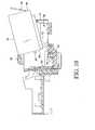
- Each ink container 16-24also include a latch 52 that snaps into the rear of each bay 38-46 to help secure each container 16-24 into a bay 38-46. As best seen in Fig.
- an installation guide 54 attached to printhead assembly 14spans container bays 38-46 at a level just above the tops of containers 16-24. As described in detail below, guide 54 helps the user position each container 16-24 correctly during installation into printhead assembly 14 and prevents the installation of an ink container 16-24 if the shipping cap has not been removed.
- Figs. 5-6 , 7-8 and 9-10are perspective and section view pairs of carriage/printhead assembly 11 with an ink container 16 in various installation positions to illustrate the effect of installation guide 54.
- the forward part 56 of container 16is referred to as the toe of the container and the rearward part 58 is referred to as the heel of the container.
- Container outlet 36is located toward the toe 56 and latch tab 52 is located at the heel 58.
- a key 60 at the front 56 of each container 16-24fits into a mating keyway 62 in printhead assembly 14 as indicated by direction arrow 64 in Fig. 6 .
- FIGs. 5-6show a correct, toe-to-heel installation.
- container 16is oriented with toe 56 down slightly and heel 58 up slightly so that the toe 56 can slide in under guide 54.
- a toe-to-heel installation motionbrings container outlet 36 in and down over printhead assembly inlet 34 at the front of bay 38 and then latch tab 52 at heel 58 down into the rear of bay 38.
- FIGs. 7-8show an incorrect, heel-to-toe installation blocked by guide 54.
- container 16is oriented with heel 58 down and toe 56 up in anticipation of installing container 16 with a heel-to-toe motion in which heel 58 is inserted first in towards bay 38 and then toe 56 is rotated down, as indicated by direction arrows 68 and 70 in Fig. 8 .
- Guide 54blocks toe 56 in this orientation to prevent the user from installing container 16 with a heel-to-toe motion (a motion that may not properly located container outlet 36 over printhead assembly inlet 34 and may permanently damage ink container 16 or printhead assembly 14).
- Figs. 9-10show an incorrect installation, in which a shipping cap 72 has not been removed from container outlet 36, blocked by guide 54.
- guide 54blocks the now too tall container 16 to prevent the user from trying to push container 16 in on printhead assembly inlet 34. Absent guide 54, attempting to install an ink container 16 without first removing shipping cap 72 may damage the filter or other parts of ink inlet 34. Blocking installation of an ink container 16 with shipping cap 72 installed, therefore, can prevent permanent damage to the fluid interconnection between container 16 and printhead assembly 14.
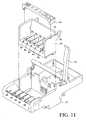
- Fig. 11is a perspective exploded view of one embodiment of a carriage/printhead assembly 11 in which carriage 12, printhead assembly 14 and container installation guide 54 are each discrete components.
- printhead assembly 14is attached to carriage 12 with a lever latch 74 or other suitable mechanism.
- Latch 74is shown in an open position in which printhead assembly 14 may be removed from or installed into carriage 12. (Latch 74 is rotated down, counterclockwise to secure printhead assembly 14 into position in carriage 12.)
- Container installation guide 54snaps onto a rim 76 along a top part 78 of printhead assembly 14, or is otherwise fastened to printhead assembly 14. The details of one example of a suitable snap fit between guide 54 and printhead assembly 14 is described below with reference to Figs. 12-16 .
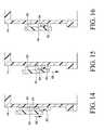
- Figs. 12 and 13are side elevation and section views, respectively, showing one example snap fit for fastening a detachable container installation guide 54 to a printhead assembly 14.
- Figs. 14-16are a sequence of detailed section views of printhead assembly top part 78 showing the installation of guide 54 onto printhead assembly 14.
- an L-shaped key 80is formed along the underside of rim 76 at the top part 78 of each side of printhead assembly 14.
- a protruding stop 82is formed adjacent to key 80.
- a mating keyway 84 on each end of guide 54fits onto key 80 when the ends of guide 54 are placed under rim 76 and snapped into position as best seen by noting direction arrows 86 and 88 in Figs. 14 and 15 , and by comparing the position of guide 54 all of Figs. 14, 15 and 16 .
- Guide 54is blocked to the front by key 80 and to the rear by protruding stop 82.
- guide 54is configured as a stationary, generally flat bridge that spans bays 38-46 from side to side over inlets 34 just above the tops of containers 16-24 when containers 16-24 are properly installed in bays 38-46.
- “Stationary” in this contextmeans stationary with respect to other parts of carriage and printhead assembly 11 even though guide 54 will necessarily move as part of assembly 11, for example as assembly 11 scans back and forth across the the print media during printing.
- This configuration and placement of guide 54blocks the installation of a container 16-24 using an incorrect, heel-to-toe installation motion or the installation of a container 16-24 that still has a shipping cap in place on outlet 36, without unduly impeding a correct installation.
- guide 54encourages a correct, toe-to-heel installation motion by "guiding" a container 16-24 toward the correct installation position.
- Other configurationsare possible.
- guide 54may be varied as necessary or desirable according to the particular geometry of carriage/printhead assembly 11 and ink containers 16-24, guide 54 should be configured to block an improper installation without also blocking or otherwise impeding a proper installation.
- guide 54should be placed no more than about 4.5mm above the tops of containers 16-24 when containers 16-24 are properly installed in bays 38-46.
- the installation guidemay be elevated more to increase the clearance for proper installation while still blocking an improper installation.
- a stationary guide 54is preferred.
Landscapes
- Ink Jet (AREA)
Description
- InkJet printers typically utilize a printhead that includes an array of orifices (also called nozzles) through which ink is ejected on to paper or other print media. One or more printheads may be mounted on a movable carriage that traverses back and forth across the width of the paper feeding through the printer. A printhead may be an integral part of an ink cartridge or part of a discrete assembly to which ink is supplied from a separate, often detachable ink container. For printhead assemblies that utilize detachable ink containers, it is important for the user to position the container correctly during installation to establish a good connection between the container outlet and the printhead assembly inlet and thereby ensure that ink will flow properly from the container to the printhead(s). Also, the user must remove the shipping cap that covers the outlet of a new ink container before installing the container in the printhead assembly. While this might seem obvious, the process of installing an ink container can be difficult for users who are not familiar with this type of inkjet printing system, particularly for those users who may not always read and follow installation instructions that accompany the products.
EP 1 048 468 A2 describes an inkjet cartridge including an inkjet head, a holder, a pressure-controlling chamber and an ink container unit. The ink container unit is installed in the holder by a forward movement, while slightly rotating the container, guided by lateral guides, the bottom wall of the holder, and an upper guiding portion. Similar prior art is described inJP 11-078048 A JP 2000-127428 A JP 2001-130022 A - The present invention provides a fluid ejector assembly according to claim 1. Embodiments of the invention are defined in the dependent claims.
Fig. 1 is a block diagram illustrating an inkjet printer.Figs. 2-4 are perspective views of one embodiment of a carriage/printhead assembly, such as might be used in the printer ofFig. 1 , with the ink containers exploded out from the carriage inFigs. 3 and4 to show the inlets to the printhead assembly (Fig. 3 ) and the outlets from the ink containers (Fig. 4 ).Figs. 5-6 ,7-8 and 9-10 are perspective and section view pairs of the assembly ofFigs. 2-4 with an ink container in various installation positions to illustrate the effect of the container installation guide.Figs. 5-6 show a correct, toe-to-heel installation.Figs. 7-8 show an incorrect, heel-to-toe installation blocked by the guide.Figs. 9-10 show an incorrect installation, in which the shipping cap has not been removed from container outlet, blocked by the guide.Fig. 11 is a perspective exploded view of one embodiment of a carriage/printhead assembly in which the carriage, printhead assembly and container installation guide are each discrete components fastened together.Figs. 12-16 illustrate one example snap fit for fastening a detachable container installation guide to a printhead assembly.- Embodiments of the disclosure were developed to help the user position ink containers correctly during installation into a printhead assembly and to prevent the installation of an ink container from which the shipping cap has not been removed. Embodiments will be described, therefore, with reference to an inkjet printhead assembly that holds detachable/replaceable ink containers. Embodiments of the disclosure, however, are not limited to such implementations. Embodiments of the disclosure, for example, might also be implemented in other types of ink or fluid dispensing components. The example embodiments shown in the Figures and described below, therefore, illustrate but do not limit the scope of the disclosure.
Fig. 1 is a block diagram illustrating aninkjet printer 10 in which embodiments of the disclosure may be implemented. Referring toFig. 1 ,printer 10 includes a carriage/printhead assembly 11 that includes acarriage 12 carrying aprinthead assembly 14.Printer 10 also includesdetachable ink containers assembly 11.Inkjet printer 10 andprinthead assembly 14 represent more generally a fluid-jet precision dispensing device and fluid ejector assembly for precisely dispensing a fluid, such as ink, as described in more detail below.Printhead assembly 14 includes a printhead (not shown) through which ink from one or more containers 16-24 is ejected. For example,printhead assembly 14 may include two printheads -- one for a series of color containers 16-22 and one for ablack ink container 24. An inkjet printhead is typically a small electromechanical assembly that contains an array of miniature thermal, piezoelectric or other devices that are energized or activated to eject small droplets of ink out of an associated array of orifices. A typical thermal inkjet printhead, for example, includes an orifice plate arrayed with ink ejection orifices and firing resistors formed on an integrated circuit chip.- A print
media transport mechanism 26advances print media 28 lengthwise pastcarriage 12 andprinthead assembly 14. For astationary carriage 12,media transport 26 may advancemedia 28 continuously pastcarriage 12. For a movable, scanningcarriage 12,media transport 26 may advancemedia 28 incrementally pastcarriage 12, stopping as each swath is printed and then advancingmedia 28 for printing the next swath. Anelectronic controller 30 is operatively connected to amoveable scanning carriage 12,printhead assembly 14 andmedia transport 26.Controller 30 communicates with external devices through an input/output device 32, including receiving print data for inkjet imaging. The presence of an input/output device 32, however, does not preclude the operation ofprinter 10 as a stand alone unit.Controller 30 controls the movement ofcarriage 12 andmedia transport 26.Controller 30 is electrically connected to each printhead inprinthead assembly 14 to selectively energize the firing resistors, for example, to eject ink drops on tomedia 28. By coordinating the relative position ofcarriage 12 withmedia 28 and the ejection of ink drops,controller 30 produces the desired image onmedia 28. - While this Description is at least substantially presented to inkjet-printing devices that eject ink onto media, those of ordinary skill within the art can appreciate that embodiments of the present disclosure are more generally not so limited. In general, embodiments of the present disclosure pertain to any type of fluid-jet precision dispensing device or ejector assembly for dispensing a substantially liquid fluid. The fluid-jet precision dispensing device precisely prints or dispenses a substantially liquid fluid in that the latter is not substantially or primarily composed of gases such as air. Examples of such substantially liquid fluids include inks in the case of inkjet printing devices. Other examples of substantially liquid fluids include drugs, cellular products, organisms, chemicals, fuel, and so on, which are not substantially or primarily composed of gases such as air and other types of gases. Therefore, while the Description is described in relation to an inkjet printer and inkjet printhead assembly for ejecting ink onto media, embodiments of the present disclosure more generally pertain to any type of fluid-jet precision dispensing device or fluid ejector structure for dispensing a substantially liquid fluid.
Figs. 2-4 are perspective views of one embodiment of a carriage/printhead assembly 11. Ink containers 16-24 are exploded out fromcarriage 12 inFigs. 3 and4 to showink inlets 34 to printhead assembly 14 (Fig. 3 ) andink outlets 36 from ink containers 16-24 (Fig. 4 ). Referring toFigs. 2-4 ,printhead assembly 14 includes anink inlet 34 positioned at eachbay Fig. 3 ) for a corresponding ink container 16-24.Printhead assembly 14 andcarriage 12 may be integrated together as a single part orprinthead assembly 14 may be detachable fromcarriage 12. For adetachable printhead assembly 14, container bays 38-46 may extend out intocarriage 12 as necessary or desirable to properly receive and hold containers 16-24.- Referring specifically to
Fig. 4 , in the embodiment shown,printhead assembly 14 includes twoprintheads printhead 48 and ink from ablack container 24 is ejected fromprinthead 50. Each ink container 16-24 includes anink outlet 36 through which ink may flow from container 16-24 through an inlet 34 (Fig. 3 ) to acorresponding printhead printhead assembly 14. Each ink container 16-24 also include alatch 52 that snaps into the rear of each bay 38-46 to help secure each container 16-24 into a bay 38-46. As best seen inFig. 2 , aninstallation guide 54 attached toprinthead assembly 14 spans container bays 38-46 at a level just above the tops of containers 16-24. As described in detail below,guide 54 helps the user position each container 16-24 correctly during installation intoprinthead assembly 14 and prevents the installation of an ink container 16-24 if the shipping cap has not been removed. Figs. 5-6 ,7-8 and 9-10 are perspective and section view pairs of carriage/printhead assembly 11 with anink container 16 in various installation positions to illustrate the effect ofinstallation guide 54. In the following description, theforward part 56 ofcontainer 16 is referred to as the toe of the container and therearward part 58 is referred to as the heel of the container.Container outlet 36 is located toward thetoe 56 andlatch tab 52 is located at theheel 58. A key 60 at thefront 56 of each container 16-24 fits into amating keyway 62 inprinthead assembly 14 as indicated bydirection arrow 64 inFig. 6 .Figs. 5-6 show a correct, toe-to-heel installation. Referring toFigs. 5 and6 ,container 16 is oriented withtoe 56 down slightly andheel 58 up slightly so that thetoe 56 can slide in underguide 54. A toe-to-heel installation motion, as indicated bydirection arrows Fig. 6 , bringscontainer outlet 36 in and down overprinthead assembly inlet 34 at the front ofbay 38 and then latchtab 52 atheel 58 down into the rear ofbay 38.Figs. 7-8 show an incorrect, heel-to-toe installation blocked byguide 54. Referring toFigs. 7 and8 ,container 16 is oriented withheel 58 down andtoe 56 up in anticipation of installingcontainer 16 with a heel-to-toe motion in whichheel 58 is inserted first in towardsbay 38 and thentoe 56 is rotated down, as indicated bydirection arrows Fig. 8 .Guide 54blocks toe 56 in this orientation to prevent the user from installingcontainer 16 with a heel-to-toe motion (a motion that may not properly locatedcontainer outlet 36 overprinthead assembly inlet 34 and may permanently damageink container 16 or printhead assembly 14).Figs. 9-10 show an incorrect installation, in which ashipping cap 72 has not been removed fromcontainer outlet 36, blocked byguide 54. Referring toFigs. 9 and10 , guide 54 blocks the now tootall container 16 to prevent the user from trying to pushcontainer 16 in onprinthead assembly inlet 34.Absent guide 54, attempting to install anink container 16 without first removingshipping cap 72 may damage the filter or other parts ofink inlet 34. Blocking installation of anink container 16 withshipping cap 72 installed, therefore, can prevent permanent damage to the fluid interconnection betweencontainer 16 andprinthead assembly 14.Fig. 11 is a perspective exploded view of one embodiment of a carriage/printhead assembly 11 in whichcarriage 12,printhead assembly 14 andcontainer installation guide 54 are each discrete components. Referring toFig. 11 ,printhead assembly 14 is attached tocarriage 12 with alever latch 74 or other suitable mechanism.Latch 74 is shown in an open position in whichprinthead assembly 14 may be removed from or installed intocarriage 12. (Latch 74 is rotated down, counterclockwise to secureprinthead assembly 14 into position incarriage 12.) Container installation guide 54 snaps onto arim 76 along atop part 78 ofprinthead assembly 14, or is otherwise fastened toprinthead assembly 14. The details of one example of a suitable snap fit betweenguide 54 andprinthead assembly 14 is described below with reference toFigs. 12-16 .Figs. 12 and 13 are side elevation and section views, respectively, showing one example snap fit for fastening a detachablecontainer installation guide 54 to aprinthead assembly 14.Figs. 14-16 are a sequence of detailed section views of printhead assemblytop part 78 showing the installation ofguide 54 ontoprinthead assembly 14. Referring toFigs. 12-16 , an L-shapedkey 80 is formed along the underside ofrim 76 at thetop part 78 of each side ofprinthead assembly 14. A protrudingstop 82 is formed adjacent to key 80. Amating keyway 84 on each end ofguide 54 fits onto key 80 when the ends ofguide 54 are placed underrim 76 and snapped into position as best seen by notingdirection arrows Figs. 14 and 15 , and by comparing the position ofguide 54 all ofFigs. 14, 15 and 16 .Guide 54 is blocked to the front by key 80 and to the rear by protrudingstop 82.- In the embodiments shown, guide 54 is configured as a stationary, generally flat bridge that spans bays 38-46 from side to side over
inlets 34 just above the tops of containers 16-24 when containers 16-24 are properly installed in bays 38-46. "Stationary" in this context means stationary with respect to other parts of carriage andprinthead assembly 11 even thoughguide 54 will necessarily move as part ofassembly 11, for example asassembly 11 scans back and forth across the the print media during printing. This configuration and placement ofguide 54 blocks the installation of a container 16-24 using an incorrect, heel-to-toe installation motion or the installation of a container 16-24 that still has a shipping cap in place onoutlet 36, without unduly impeding a correct installation. Thus, guide 54 encourages a correct, toe-to-heel installation motion by "guiding" a container 16-24 toward the correct installation position. Other configurations are possible. And, although the configuration and placement ofguide 54 may be varied as necessary or desirable according to the particular geometry of carriage/printhead assembly 11 and ink containers 16-24, guide 54 should be configured to block an improper installation without also blocking or otherwise impeding a proper installation. - In the embodiments shown, in which a rectangular ink container 16-24 has
outlets 36 that protrude only slightly from a substantially flat bottom surface, guide 54 should be placed no more than about 4.5mm above the tops of containers 16-24 when containers 16-24 are properly installed in bays 38-46. However, if the container outlets protrude further from the bottom of the ink container, or if an L-shaped container is used with a stepped bottom surface, then the installation guide may be elevated more to increase the clearance for proper installation while still blocking an improper installation. Also, astationary guide 54 is preferred. A movable guide, attached to the printhead assembly latch for example (lever latch 74 inFig. 11 ), is ineffective if the user fails to close/latch the latch. It has been observed in user testing that users don't always close the latch after installing the printhead assembly into the carriage (despite instruction to do so). Rather, users begin installing the ink containers with the latch up, thus allowing an incorrect heel-to-toe installation. - As noted at the beginning of this Description, the example embodiments shown in the figures and described above illustrate but do not limit the disclosure. Therefore, the foregoing description should not be construed to limit the scope of the disclosure, which is defined in the following claims.
Claims (4)
- A fluid ejector assembly (14), comprising:a bay (38-46) for holding a detachable fluid container (16-24) that includes a fluid outlet (36) at a forward part of the container;a fluid ejector (48, 50);a fluid inlet (34) at a forward part of the bay (38-46) through which fluid from a fluid container (16-24) installed in the bay (3 8-46) may pass to the fluid ejector; anda stationary guide (54) configured to block an improper installation of a fluid container (16-24) into the bay (3 8-46) without also blocking a proper installation of the fluid container (16-24) into the bay (38-46);wherein the bay (38-46) is at least partially defined by opposing sidewalls and a floor between the sidewalls, the inlet (34) located in the floor and the guide (54) extending between the sidewalls above the floor over the inlet (34); andwherein the guide (54) comprises a discrete part attached to and detachable from the sidewalls.
- A fluid ejector and carriage assembly (11), comprising: the fluid ejector assembly (14) of claim 1 and a carriage (12) carrying the fluid ejector assembly (14).
- The assembly of Claim 2, wherein the guide (54) is suspended over the bay (38-46) within 4.5 mm of the top of a container (16-24) when the container (16-24) is correctly installed in the bay (38-46) to block installation of a container (16-24) having a cap covering the outlet (36).
- The assembly of claim 2 or claim 3, wherein the fluid ejector assembly (14) is a printhead assembly including a printhead for ejecting ink and an ink inlet through which ink may enter the printhead assembly and pass to the printhead.
Applications Claiming Priority (1)
| Application Number | Priority Date | Filing Date | Title |
|---|---|---|---|
| PCT/US2008/065453WO2009145792A1 (en) | 2008-05-31 | 2008-05-31 | Container installation guide for a fluid ejector assembly |
Publications (3)
| Publication Number | Publication Date |
|---|---|
| EP2310207A1 EP2310207A1 (en) | 2011-04-20 |
| EP2310207A4 EP2310207A4 (en) | 2013-04-03 |
| EP2310207B1true EP2310207B1 (en) | 2014-08-27 |
Family
ID=41377399
Family Applications (1)
| Application Number | Title | Priority Date | Filing Date |
|---|---|---|---|
| EP08780735.0ANot-in-forceEP2310207B1 (en) | 2008-05-31 | 2008-05-31 | Container installation guide for a fluid ejector assembly |
Country Status (4)
| Country | Link |
|---|---|
| US (1) | US8727515B2 (en) |
| EP (1) | EP2310207B1 (en) |
| TW (1) | TW201006681A (en) |
| WO (1) | WO2009145792A1 (en) |
Families Citing this family (20)
| Publication number | Priority date | Publication date | Assignee | Title |
|---|---|---|---|---|
| WO2012103050A1 (en)* | 2011-01-27 | 2012-08-02 | Eastman Kodak Company | Carriage with capping surface for inkjet printhead |
| US8485637B2 (en) | 2011-01-27 | 2013-07-16 | Eastman Kodak Company | Carriage with capping surface for inkjet printhead |
| US9574864B2 (en) | 2015-03-27 | 2017-02-21 | International Business Machines Corporation | Gauge for installation of liners in substrate spin coating tools |
| CN205871501U (en)* | 2016-06-13 | 2017-01-11 | 珠海纳思达企业管理有限公司 | Snap -on ink horn |
| JP6897807B2 (en)* | 2018-10-31 | 2021-07-07 | セイコーエプソン株式会社 | Liquid containment |
| US11647860B1 (en) | 2022-05-13 | 2023-05-16 | Sharkninja Operating Llc | Flavored beverage carbonation system |
| US12096880B2 (en) | 2022-05-13 | 2024-09-24 | Sharkninja Operating Llc | Flavorant for beverage carbonation system |
| US11751585B1 (en) | 2022-05-13 | 2023-09-12 | Sharkninja Operating Llc | Flavored beverage carbonation system |
| US12213617B2 (en) | 2022-05-13 | 2025-02-04 | Sharkninja Operating Llc | Flavored beverage carbonation process |
| US11738988B1 (en) | 2022-11-17 | 2023-08-29 | Sharkninja Operating Llc | Ingredient container valve control |
| US11634314B1 (en) | 2022-11-17 | 2023-04-25 | Sharkninja Operating Llc | Dosing accuracy |
| US12084334B2 (en) | 2022-11-17 | 2024-09-10 | Sharkninja Operating Llc | Ingredient container |
| US12103840B2 (en) | 2022-11-17 | 2024-10-01 | Sharkninja Operating Llc | Ingredient container with sealing valve |
| US11745996B1 (en) | 2022-11-17 | 2023-09-05 | Sharkninja Operating Llc | Ingredient containers for use with beverage dispensers |
| USD1092208S1 (en) | 2022-12-23 | 2025-09-09 | Sharkninja Operating Llc | Cap of ingredient container |
| USD1091308S1 (en) | 2022-12-23 | 2025-09-02 | Sharkninja Operating Llc | Ingredient container |
| US11925287B1 (en) | 2023-03-22 | 2024-03-12 | Sharkninja Operating Llc | Additive container with inlet tube |
| US11871867B1 (en) | 2023-03-22 | 2024-01-16 | Sharkninja Operating Llc | Additive container with bottom cover |
| US12116257B1 (en) | 2023-03-22 | 2024-10-15 | Sharkninja Operating Llc | Adapter for beverage dispenser |
| US12005408B1 (en) | 2023-04-14 | 2024-06-11 | Sharkninja Operating Llc | Mixing funnel |
Family Cites Families (6)
| Publication number | Priority date | Publication date | Assignee | Title |
|---|---|---|---|---|
| JPH1178043A (en) | 1997-09-02 | 1999-03-23 | Seiko Epson Corp | Ink cartridge mounting mechanism and printer using the same |
| JP2000127428A (en) | 1998-10-27 | 2000-05-09 | Canon Inc | Ink tank, tank holder, inkjet head cartridge, ink supply system, and inkjet recording device |
| JP3450798B2 (en) | 1999-04-27 | 2003-09-29 | キヤノン株式会社 | Liquid supply system, liquid storage container used in the system, and ink jet head cartridge using the system |
| JP2001130022A (en)* | 1999-11-09 | 2001-05-15 | Canon Inc | Ink tank and inkjet recording device |
| TWI259149B (en)* | 2002-09-30 | 2006-08-01 | Canon Kk | Ink container and recording apparatus |
| JP4189690B2 (en)* | 2006-04-12 | 2008-12-03 | セイコーエプソン株式会社 | Liquid container |
- 2008
- 2008-05-31USUS12/995,131patent/US8727515B2/enactiveActive
- 2008-05-31EPEP08780735.0Apatent/EP2310207B1/ennot_activeNot-in-force
- 2008-05-31WOPCT/US2008/065453patent/WO2009145792A1/enactiveApplication Filing
- 2009
- 2009-06-01TWTW098117985Apatent/TW201006681A/enunknown
Also Published As
| Publication number | Publication date |
|---|---|
| EP2310207A4 (en) | 2013-04-03 |
| TW201006681A (en) | 2010-02-16 |
| US20110205297A1 (en) | 2011-08-25 |
| WO2009145792A1 (en) | 2009-12-03 |
| US8727515B2 (en) | 2014-05-20 |
| EP2310207A1 (en) | 2011-04-20 |
Similar Documents
| Publication | Publication Date | Title |
|---|---|---|
| EP2310207B1 (en) | Container installation guide for a fluid ejector assembly | |
| EP2527154B3 (en) | Combined ink family keying for an ink cartridge | |
| EP0968090B1 (en) | Ink container having electronic and mechanical features enabling plug compatibility between multiple supply sizes | |
| US8833912B2 (en) | Replaceable printing component | |
| EP3718772B1 (en) | Inkjet printing apparatus and ink tank | |
| US7156491B2 (en) | Separable key for establishing detachable printer component compatibility with a printer | |
| US6969148B2 (en) | Pivoting on-axis ink reservoir for inkjet printer | |
| US9132649B2 (en) | Removable guide element | |
| US7735985B2 (en) | Cartridge holder | |
| GB2321621A (en) | Ink-jet printer with off-axis replaceable ink cartridges of combined width less than the non-print zone | |
| US20030025764A1 (en) | Device for ensuring proper toe-heel installation of a detachable printer component | |
| WO2009126137A1 (en) | Fluid interconnection | |
| JP2006240209A (en) | Mode setting method and printer |
Legal Events
| Date | Code | Title | Description |
|---|---|---|---|
| PUAI | Public reference made under article 153(3) epc to a published international application that has entered the european phase | Free format text:ORIGINAL CODE: 0009012 | |
| 17P | Request for examination filed | Effective date:20101124 | |
| AK | Designated contracting states | Kind code of ref document:A1 Designated state(s):AT BE BG CH CY CZ DE DK EE ES FI FR GB GR HR HU IE IS IT LI LT LU LV MC MT NL NO PL PT RO SE SI SK TR | |
| AX | Request for extension of the european patent | Extension state:AL BA MK RS | |
| RIN1 | Information on inventor provided before grant (corrected) | Inventor name:MCFADDEN, BRUCE A. Inventor name:SMITH, MARK A. Inventor name:WELTER, DAVID Inventor name:HENDRICKS, JEFFREY T. Inventor name:GONZALES, CURT Inventor name:DOWELL, DANIEL D. | |
| RIN1 | Information on inventor provided before grant (corrected) | Inventor name:HENDRICKS, JEFFREY T. Inventor name:DOWELL, DANIEL D. Inventor name:MCFADDEN, BRUCE A. Inventor name:WELTER, DAVID Inventor name:SMITH, MARK A. Inventor name:GONZALES, CURT | |
| DAX | Request for extension of the european patent (deleted) | ||
| A4 | Supplementary search report drawn up and despatched | Effective date:20130228 | |
| RIC1 | Information provided on ipc code assigned before grant | Ipc:B41J 25/34 20060101ALI20130222BHEP Ipc:B41J 2/175 20060101AFI20130222BHEP Ipc:B41J 2/135 20060101ALI20130222BHEP | |
| GRAP | Despatch of communication of intention to grant a patent | Free format text:ORIGINAL CODE: EPIDOSNIGR1 | |
| INTG | Intention to grant announced | Effective date:20140530 | |
| GRAS | Grant fee paid | Free format text:ORIGINAL CODE: EPIDOSNIGR3 | |
| GRAA | (expected) grant | Free format text:ORIGINAL CODE: 0009210 | |
| AK | Designated contracting states | Kind code of ref document:B1 Designated state(s):AT BE BG CH CY CZ DE DK EE ES FI FR GB GR HR HU IE IS IT LI LT LU LV MC MT NL NO PL PT RO SE SI SK TR | |
| REG | Reference to a national code | Ref country code:GB Ref legal event code:FG4D | |
| REG | Reference to a national code | Ref country code:CH Ref legal event code:EP | |
| REG | Reference to a national code | Ref country code:AT Ref legal event code:REF Ref document number:684307 Country of ref document:AT Kind code of ref document:T Effective date:20140915 | |
| REG | Reference to a national code | Ref country code:IE Ref legal event code:FG4D | |
| REG | Reference to a national code | Ref country code:DE Ref legal event code:R096 Ref document number:602008034110 Country of ref document:DE Effective date:20141009 | |
| REG | Reference to a national code | Ref country code:AT Ref legal event code:MK05 Ref document number:684307 Country of ref document:AT Kind code of ref document:T Effective date:20140827 | |
| REG | Reference to a national code | Ref country code:LT Ref legal event code:MG4D | |
| REG | Reference to a national code | Ref country code:NL Ref legal event code:VDEP Effective date:20140827 | |
| PG25 | Lapsed in a contracting state [announced via postgrant information from national office to epo] | Ref country code:PT Free format text:LAPSE BECAUSE OF FAILURE TO SUBMIT A TRANSLATION OF THE DESCRIPTION OR TO PAY THE FEE WITHIN THE PRESCRIBED TIME-LIMIT Effective date:20141229 Ref country code:GR Free format text:LAPSE BECAUSE OF FAILURE TO SUBMIT A TRANSLATION OF THE DESCRIPTION OR TO PAY THE FEE WITHIN THE PRESCRIBED TIME-LIMIT Effective date:20141128 Ref country code:SE Free format text:LAPSE BECAUSE OF FAILURE TO SUBMIT A TRANSLATION OF THE DESCRIPTION OR TO PAY THE FEE WITHIN THE PRESCRIBED TIME-LIMIT Effective date:20140827 Ref country code:FI Free format text:LAPSE BECAUSE OF FAILURE TO SUBMIT A TRANSLATION OF THE DESCRIPTION OR TO PAY THE FEE WITHIN THE PRESCRIBED TIME-LIMIT Effective date:20140827 Ref country code:NO Free format text:LAPSE BECAUSE OF FAILURE TO SUBMIT A TRANSLATION OF THE DESCRIPTION OR TO PAY THE FEE WITHIN THE PRESCRIBED TIME-LIMIT Effective date:20141127 Ref country code:ES Free format text:LAPSE BECAUSE OF FAILURE TO SUBMIT A TRANSLATION OF THE DESCRIPTION OR TO PAY THE FEE WITHIN THE PRESCRIBED TIME-LIMIT Effective date:20140827 Ref country code:LT Free format text:LAPSE BECAUSE OF FAILURE TO SUBMIT A TRANSLATION OF THE DESCRIPTION OR TO PAY THE FEE WITHIN THE PRESCRIBED TIME-LIMIT Effective date:20140827 Ref country code:BG Free format text:LAPSE BECAUSE OF FAILURE TO SUBMIT A TRANSLATION OF THE DESCRIPTION OR TO PAY THE FEE WITHIN THE PRESCRIBED TIME-LIMIT Effective date:20141127 | |
| PG25 | Lapsed in a contracting state [announced via postgrant information from national office to epo] | Ref country code:CY Free format text:LAPSE BECAUSE OF FAILURE TO SUBMIT A TRANSLATION OF THE DESCRIPTION OR TO PAY THE FEE WITHIN THE PRESCRIBED TIME-LIMIT Effective date:20140827 Ref country code:AT Free format text:LAPSE BECAUSE OF FAILURE TO SUBMIT A TRANSLATION OF THE DESCRIPTION OR TO PAY THE FEE WITHIN THE PRESCRIBED TIME-LIMIT Effective date:20140827 Ref country code:HR Free format text:LAPSE BECAUSE OF FAILURE TO SUBMIT A TRANSLATION OF THE DESCRIPTION OR TO PAY THE FEE WITHIN THE PRESCRIBED TIME-LIMIT Effective date:20140827 Ref country code:IS Free format text:LAPSE BECAUSE OF FAILURE TO SUBMIT A TRANSLATION OF THE DESCRIPTION OR TO PAY THE FEE WITHIN THE PRESCRIBED TIME-LIMIT Effective date:20141227 Ref country code:LV Free format text:LAPSE BECAUSE OF FAILURE TO SUBMIT A TRANSLATION OF THE DESCRIPTION OR TO PAY THE FEE WITHIN THE PRESCRIBED TIME-LIMIT Effective date:20140827 | |
| PG25 | Lapsed in a contracting state [announced via postgrant information from national office to epo] | Ref country code:NL Free format text:LAPSE BECAUSE OF FAILURE TO SUBMIT A TRANSLATION OF THE DESCRIPTION OR TO PAY THE FEE WITHIN THE PRESCRIBED TIME-LIMIT Effective date:20140827 | |
| PG25 | Lapsed in a contracting state [announced via postgrant information from national office to epo] | Ref country code:DK Free format text:LAPSE BECAUSE OF FAILURE TO SUBMIT A TRANSLATION OF THE DESCRIPTION OR TO PAY THE FEE WITHIN THE PRESCRIBED TIME-LIMIT Effective date:20140827 Ref country code:SK Free format text:LAPSE BECAUSE OF FAILURE TO SUBMIT A TRANSLATION OF THE DESCRIPTION OR TO PAY THE FEE WITHIN THE PRESCRIBED TIME-LIMIT Effective date:20140827 Ref country code:IT Free format text:LAPSE BECAUSE OF FAILURE TO SUBMIT A TRANSLATION OF THE DESCRIPTION OR TO PAY THE FEE WITHIN THE PRESCRIBED TIME-LIMIT Effective date:20140827 Ref country code:RO Free format text:LAPSE BECAUSE OF FAILURE TO SUBMIT A TRANSLATION OF THE DESCRIPTION OR TO PAY THE FEE WITHIN THE PRESCRIBED TIME-LIMIT Effective date:20140827 Ref country code:CZ Free format text:LAPSE BECAUSE OF FAILURE TO SUBMIT A TRANSLATION OF THE DESCRIPTION OR TO PAY THE FEE WITHIN THE PRESCRIBED TIME-LIMIT Effective date:20140827 Ref country code:EE Free format text:LAPSE BECAUSE OF FAILURE TO SUBMIT A TRANSLATION OF THE DESCRIPTION OR TO PAY THE FEE WITHIN THE PRESCRIBED TIME-LIMIT Effective date:20140827 | |
| REG | Reference to a national code | Ref country code:DE Ref legal event code:R097 Ref document number:602008034110 Country of ref document:DE | |
| PG25 | Lapsed in a contracting state [announced via postgrant information from national office to epo] | Ref country code:PL Free format text:LAPSE BECAUSE OF FAILURE TO SUBMIT A TRANSLATION OF THE DESCRIPTION OR TO PAY THE FEE WITHIN THE PRESCRIBED TIME-LIMIT Effective date:20140827 | |
| PLBE | No opposition filed within time limit | Free format text:ORIGINAL CODE: 0009261 | |
| STAA | Information on the status of an ep patent application or granted ep patent | Free format text:STATUS: NO OPPOSITION FILED WITHIN TIME LIMIT | |
| 26N | No opposition filed | Effective date:20150528 | |
| PG25 | Lapsed in a contracting state [announced via postgrant information from national office to epo] | Ref country code:SI Free format text:LAPSE BECAUSE OF FAILURE TO SUBMIT A TRANSLATION OF THE DESCRIPTION OR TO PAY THE FEE WITHIN THE PRESCRIBED TIME-LIMIT Effective date:20140827 | |
| REG | Reference to a national code | Ref country code:CH Ref legal event code:PL | |
| PG25 | Lapsed in a contracting state [announced via postgrant information from national office to epo] | Ref country code:MC Free format text:LAPSE BECAUSE OF FAILURE TO SUBMIT A TRANSLATION OF THE DESCRIPTION OR TO PAY THE FEE WITHIN THE PRESCRIBED TIME-LIMIT Effective date:20140827 Ref country code:LI Free format text:LAPSE BECAUSE OF NON-PAYMENT OF DUE FEES Effective date:20150531 Ref country code:LU Free format text:LAPSE BECAUSE OF FAILURE TO SUBMIT A TRANSLATION OF THE DESCRIPTION OR TO PAY THE FEE WITHIN THE PRESCRIBED TIME-LIMIT Effective date:20150531 Ref country code:CH Free format text:LAPSE BECAUSE OF NON-PAYMENT OF DUE FEES Effective date:20150531 | |
| REG | Reference to a national code | Ref country code:IE Ref legal event code:MM4A | |
| REG | Reference to a national code | Ref country code:FR Ref legal event code:PLFP Year of fee payment:9 | |
| PG25 | Lapsed in a contracting state [announced via postgrant information from national office to epo] | Ref country code:IE Free format text:LAPSE BECAUSE OF NON-PAYMENT OF DUE FEES Effective date:20150531 | |
| PG25 | Lapsed in a contracting state [announced via postgrant information from national office to epo] | Ref country code:BE Free format text:LAPSE BECAUSE OF FAILURE TO SUBMIT A TRANSLATION OF THE DESCRIPTION OR TO PAY THE FEE WITHIN THE PRESCRIBED TIME-LIMIT Effective date:20140827 | |
| PG25 | Lapsed in a contracting state [announced via postgrant information from national office to epo] | Ref country code:MT Free format text:LAPSE BECAUSE OF FAILURE TO SUBMIT A TRANSLATION OF THE DESCRIPTION OR TO PAY THE FEE WITHIN THE PRESCRIBED TIME-LIMIT Effective date:20140827 | |
| REG | Reference to a national code | Ref country code:FR Ref legal event code:PLFP Year of fee payment:10 | |
| PG25 | Lapsed in a contracting state [announced via postgrant information from national office to epo] | Ref country code:HU Free format text:LAPSE BECAUSE OF FAILURE TO SUBMIT A TRANSLATION OF THE DESCRIPTION OR TO PAY THE FEE WITHIN THE PRESCRIBED TIME-LIMIT; INVALID AB INITIO Effective date:20080531 | |
| PG25 | Lapsed in a contracting state [announced via postgrant information from national office to epo] | Ref country code:TR Free format text:LAPSE BECAUSE OF FAILURE TO SUBMIT A TRANSLATION OF THE DESCRIPTION OR TO PAY THE FEE WITHIN THE PRESCRIBED TIME-LIMIT Effective date:20140827 | |
| REG | Reference to a national code | Ref country code:FR Ref legal event code:PLFP Year of fee payment:11 | |
| PGFP | Annual fee paid to national office [announced via postgrant information from national office to epo] | Ref country code:FR Payment date:20210608 Year of fee payment:15 | |
| PGFP | Annual fee paid to national office [announced via postgrant information from national office to epo] | Ref country code:GB Payment date:20210422 Year of fee payment:14 | |
| PGFP | Annual fee paid to national office [announced via postgrant information from national office to epo] | Ref country code:DE Payment date:20210716 Year of fee payment:15 | |
| GBPC | Gb: european patent ceased through non-payment of renewal fee | Effective date:20220531 | |
| PG25 | Lapsed in a contracting state [announced via postgrant information from national office to epo] | Ref country code:GB Free format text:LAPSE BECAUSE OF NON-PAYMENT OF DUE FEES Effective date:20220531 | |
| REG | Reference to a national code | Ref country code:DE Ref legal event code:R119 Ref document number:602008034110 Country of ref document:DE | |
| PG25 | Lapsed in a contracting state [announced via postgrant information from national office to epo] | Ref country code:DE Free format text:LAPSE BECAUSE OF NON-PAYMENT OF DUE FEES Effective date:20231201 | |
| PG25 | Lapsed in a contracting state [announced via postgrant information from national office to epo] | Ref country code:FR Free format text:LAPSE BECAUSE OF NON-PAYMENT OF DUE FEES Effective date:20230531 |