EP2310089B1 - Capacity fade adjusted charge level or recharge interval of a rechargeable power source of an implantable medical device, system and method - Google Patents
Capacity fade adjusted charge level or recharge interval of a rechargeable power source of an implantable medical device, system and methodDownload PDFInfo
- Publication number
- EP2310089B1 EP2310089B1EP09739274.0AEP09739274AEP2310089B1EP 2310089 B1EP2310089 B1EP 2310089B1EP 09739274 AEP09739274 AEP 09739274AEP 2310089 B1EP2310089 B1EP 2310089B1
- Authority
- EP
- European Patent Office
- Prior art keywords
- power source
- rechargeable power
- charge capacity
- time
- total charge
- Prior art date
- Legal status (The legal status is an assumption and is not a legal conclusion. Google has not performed a legal analysis and makes no representation as to the accuracy of the status listed.)
- Active
Links
- 238000000034methodMethods0.000titleclaimsdescription21
- 230000001419dependent effectEffects0.000claimsdescription8
- 238000012886linear functionMethods0.000claimsdescription2
- 238000002560therapeutic procedureMethods0.000description15
- 239000000126substanceSubstances0.000description13
- 230000001225therapeutic effectEffects0.000description12
- 210000004027cellAnatomy0.000description7
- 229910001416lithium ionInorganic materials0.000description5
- HBBGRARXTFLTSG-UHFFFAOYSA-NLithium ionChemical compound[Li+]HBBGRARXTFLTSG-UHFFFAOYSA-N0.000description4
- 230000003466anti-cipated effectEffects0.000description4
- 230000008859changeEffects0.000description4
- 238000006243chemical reactionMethods0.000description4
- 238000004891communicationMethods0.000description4
- 230000007423decreaseEffects0.000description4
- 230000002068genetic effectEffects0.000description4
- 229940079593drugDrugs0.000description3
- 239000003814drugSubstances0.000description3
- 239000000463materialSubstances0.000description3
- 239000008194pharmaceutical compositionSubstances0.000description3
- 238000001356surgical procedureMethods0.000description3
- 208000002193PainDiseases0.000description2
- 230000008901benefitEffects0.000description2
- 230000033228biological regulationEffects0.000description2
- 229960000074biopharmaceuticalDrugs0.000description2
- 230000003247decreasing effectEffects0.000description2
- 238000010586diagramMethods0.000description2
- 230000000694effectsEffects0.000description2
- 230000006698inductionEffects0.000description2
- 238000001802infusionMethods0.000description2
- 238000002955isolationMethods0.000description2
- 230000000926neurological effectEffects0.000description2
- 230000036407painEffects0.000description2
- 230000003071parasitic effectEffects0.000description2
- 102000004169proteins and genesHuman genes0.000description2
- 108090000623proteins and genesProteins0.000description2
- 230000000638stimulationEffects0.000description2
- 238000012546transferMethods0.000description2
- 238000002604ultrasonographyMethods0.000description2
- OKTJSMMVPCPJKN-UHFFFAOYSA-NCarbonChemical compound[C]OKTJSMMVPCPJKN-UHFFFAOYSA-N0.000description1
- WHXSMMKQMYFTQS-UHFFFAOYSA-NLithiumChemical compound[Li]WHXSMMKQMYFTQS-UHFFFAOYSA-N0.000description1
- 208000008238Muscle SpasticityDiseases0.000description1
- 206010028980NeoplasmDiseases0.000description1
- FAPWRFPIFSIZLT-UHFFFAOYSA-MSodium chlorideChemical compound[Na+].[Cl-]FAPWRFPIFSIZLT-UHFFFAOYSA-M0.000description1
- 239000000654additiveSubstances0.000description1
- 230000002921anti-spasmodic effectEffects0.000description1
- 239000002246antineoplastic agentSubstances0.000description1
- 229940124575antispasmodic agentDrugs0.000description1
- 230000005540biological transmissionEffects0.000description1
- -1biologicsSubstances0.000description1
- 230000036760body temperatureEffects0.000description1
- 238000004364calculation methodMethods0.000description1
- 201000011510cancerDiseases0.000description1
- 239000003990capacitorSubstances0.000description1
- 229910052799carbonInorganic materials0.000description1
- 230000000747cardiac effectEffects0.000description1
- 239000003795chemical substances by applicationSubstances0.000description1
- 150000001875compoundsChemical class0.000description1
- 238000012937correctionMethods0.000description1
- 229940127089cytotoxic agentDrugs0.000description1
- 238000013461designMethods0.000description1
- 229940039227diagnostic agentDrugs0.000description1
- 239000000032diagnostic agentSubstances0.000description1
- 238000007599dischargingMethods0.000description1
- 201000010099diseaseDiseases0.000description1
- 208000037265diseases, disorders, signs and symptomsDiseases0.000description1
- 238000002651drug therapyMethods0.000description1
- 239000003792electrolyteSubstances0.000description1
- 238000002594fluoroscopyMethods0.000description1
- 238000009472formulationMethods0.000description1
- 238000002695general anesthesiaMethods0.000description1
- 239000005556hormoneSubstances0.000description1
- 229940088597hormoneDrugs0.000description1
- 230000003116impacting effectEffects0.000description1
- 239000012535impuritySubstances0.000description1
- 230000001939inductive effectEffects0.000description1
- 238000007913intrathecal administrationMethods0.000description1
- 229910052744lithiumInorganic materials0.000description1
- 238000002690local anesthesiaMethods0.000description1
- 230000014759maintenance of locationEffects0.000description1
- 238000005297material degradation processMethods0.000description1
- 239000000203mixtureSubstances0.000description1
- 238000012544monitoring processMethods0.000description1
- 230000003387muscularEffects0.000description1
- 229940124583pain medicationDrugs0.000description1
- 239000002245particleSubstances0.000description1
- 230000008569processEffects0.000description1
- 238000002694regional anesthesiaMethods0.000description1
- 239000007784solid electrolyteSubstances0.000description1
- 239000002904solventSubstances0.000description1
- 208000018198spasticityDiseases0.000description1
- 210000000130stem cellAnatomy0.000description1
- 238000012360testing methodMethods0.000description1
- 239000013598vectorSubstances0.000description1
Images


Classifications
- A—HUMAN NECESSITIES
- A61—MEDICAL OR VETERINARY SCIENCE; HYGIENE
- A61N—ELECTROTHERAPY; MAGNETOTHERAPY; RADIATION THERAPY; ULTRASOUND THERAPY
- A61N1/00—Electrotherapy; Circuits therefor
- A61N1/18—Applying electric currents by contact electrodes
- A61N1/32—Applying electric currents by contact electrodes alternating or intermittent currents
- A61N1/36—Applying electric currents by contact electrodes alternating or intermittent currents for stimulation
- A61N1/362—Heart stimulators
- A61N1/37—Monitoring; Protecting
- A61N1/3706—Pacemaker parameters
- A61N1/3708—Pacemaker parameters for power depletion
- G—PHYSICS
- G01—MEASURING; TESTING
- G01R—MEASURING ELECTRIC VARIABLES; MEASURING MAGNETIC VARIABLES
- G01R31/00—Arrangements for testing electric properties; Arrangements for locating electric faults; Arrangements for electrical testing characterised by what is being tested not provided for elsewhere
- G01R31/36—Arrangements for testing, measuring or monitoring the electrical condition of accumulators or electric batteries, e.g. capacity or state of charge [SoC]
- G01R31/382—Arrangements for monitoring battery or accumulator variables, e.g. SoC
- G01R31/3828—Arrangements for monitoring battery or accumulator variables, e.g. SoC using current integration
- H—ELECTRICITY
- H01—ELECTRIC ELEMENTS
- H01M—PROCESSES OR MEANS, e.g. BATTERIES, FOR THE DIRECT CONVERSION OF CHEMICAL ENERGY INTO ELECTRICAL ENERGY
- H01M10/00—Secondary cells; Manufacture thereof
- H01M10/42—Methods or arrangements for servicing or maintenance of secondary cells or secondary half-cells
- H01M10/48—Accumulators combined with arrangements for measuring, testing or indicating the condition of cells, e.g. the level or density of the electrolyte
- A—HUMAN NECESSITIES
- A61—MEDICAL OR VETERINARY SCIENCE; HYGIENE
- A61N—ELECTROTHERAPY; MAGNETOTHERAPY; RADIATION THERAPY; ULTRASOUND THERAPY
- A61N1/00—Electrotherapy; Circuits therefor
- A61N1/18—Applying electric currents by contact electrodes
- A61N1/32—Applying electric currents by contact electrodes alternating or intermittent currents
- A61N1/36—Applying electric currents by contact electrodes alternating or intermittent currents for stimulation
- A61N1/372—Arrangements in connection with the implantation of stimulators
- A61N1/378—Electrical supply
- A61N1/3787—Electrical supply from an external energy source
- H—ELECTRICITY
- H01—ELECTRIC ELEMENTS
- H01M—PROCESSES OR MEANS, e.g. BATTERIES, FOR THE DIRECT CONVERSION OF CHEMICAL ENERGY INTO ELECTRICAL ENERGY
- H01M10/00—Secondary cells; Manufacture thereof
- H01M10/42—Methods or arrangements for servicing or maintenance of secondary cells or secondary half-cells
- H01M10/44—Methods for charging or discharging
- Y—GENERAL TAGGING OF NEW TECHNOLOGICAL DEVELOPMENTS; GENERAL TAGGING OF CROSS-SECTIONAL TECHNOLOGIES SPANNING OVER SEVERAL SECTIONS OF THE IPC; TECHNICAL SUBJECTS COVERED BY FORMER USPC CROSS-REFERENCE ART COLLECTIONS [XRACs] AND DIGESTS
- Y02—TECHNOLOGIES OR APPLICATIONS FOR MITIGATION OR ADAPTATION AGAINST CLIMATE CHANGE
- Y02E—REDUCTION OF GREENHOUSE GAS [GHG] EMISSIONS, RELATED TO ENERGY GENERATION, TRANSMISSION OR DISTRIBUTION
- Y02E60/00—Enabling technologies; Technologies with a potential or indirect contribution to GHG emissions mitigation
- Y02E60/10—Energy storage using batteries
Definitions
- the medical device industryproduces a wide variety of electronic devices for treating patient medical conditions using electrical stimulation.
- medical devicescan be surgically implanted or connected externally to the patient receiving treatment.
- Cliniciansuse medical devices alone or in combination with drug therapies and surgery to treat patient medical conditions.
- medical devicesprovide the best, and sometimes the only therapy to restore an individual to a more healthful condition and a fuller life.
- implantable medical devices designed to deliver therapeutic electrical stimulationinclude neurological stimulators and spinal stimulators, as well as pacemakers and defibrillators.
- implantable medical devicesprovide important, oftentimes life-sustaining medical care to patients from the power supplied by a single component power source, usually a battery, the ability to know the status of that power source is critical. When a power source's charge has nearly run down, the power source must either be replaced or recharged. The failure to do so could result in the untimely failure of the implantable medical device's ability to deliver therapy to the patient, with potential consequences up to and including patient death.
- a common solution to avoid having to conduct surgery to replace a depleted power sourceis to make the power source of the implantable medical device rechargeable via transcutaneous transmission of energy.
- An external power supplyis operatively coupled with the rechargeable power source of the implantable medical device, often through an inductive link, and charging current is delivered to the rechargeable power source until the rechargeable power source is replenished with charge.
- the implantable medical devicemay then continue to deliver therapy to the patient until the rechargeable power source has run down again and the process of recharging may then be repeated.
- the electrical characteristics of rechargeable batteriesmay tend to change either with the passage of time, with each charging and discharging cycle, or both.
- rechargeable power sourcescommonly in use in implantable medical devices, while the instantaneous voltage and current that may be delivered will tend to remain constant throughout the useful life of the rechargeable power source, the total amount of charge the rechargeable power source has the ability to store, i.e., the rechargeable power source capacity, may have a tendency to degrade.
- the tendency of the capacity of the rechargeable power source to degradecan be attributable to the effect of the passage of time, the number of charging cycles encountered, or both.
- the chemical nature of the rechargeable powermay allow the rechargeable power source to degrade over time. Repeated charge and discharge cycles of the rechargeable power source are also known to degrade the rechargeable power source over time.
- Capacity fadeThis phenomenon, known as “capacity fade", may create a challenge to the makers of implantable medical devices. If the amount of time that a rechargeable power source may provide charge is not known accurately, the rechargeable power source may run down at an unexpected and inopportune time thereby depriving potentially life-sustaining therapy to the patient.
- An embodimentprovides a system and method to more accurately determine how much charge remains or the recharge interval in the rechargeable power source of an implantable medical device, taking into account the capacity fade of the age of the rechargeable power source or the number of times the rechargeable power source has been charged and discharged.
- An embodimentfirst recognizes that, although the charge capacity of a rechargeable power source has decreased, the output voltage of the rechargeable power source may tend to correspond to the same ratio of charge remaining in the rechargeable power source over the rechargeable power source's charge capacity.
- the implantable medical devicemay measure the rechargeable power source voltage at two different times and also determine the amount of charge the rechargeable power source has delivered during that time.
- Electronic componentrymay determine the percentage of charge remaining at each of those times based on the measured rechargeable power source voltage, and subtract the second percentage from the first percentage to determine the total percentage decrease over the period of time. Then, dividing the amount of charge that was delivered between the two times by the percentage decrease of rechargeable power source charge determines the total charge capacity.
- another embodimentmore accurately determines capacity fade through means independent of the above described embodiment, perhaps to provide redundancy and improved accuracy.
- An embodimentmay further determine capacity fade based on a model that recognizes that capacity fade occurs as a function both of the amount of time the rechargeable power source has been in use, as well as the number of times the rechargeable power source has been recharged.
- the charge capacity of a rechargeable power sourceis reduced both with the passage of time and also with use, as each charge and discharge cycle results in a decreased capacity.
- An embodimentutilizes a model that is unique to each type of rechargeable power supply to factor in the passage of time and the number of recharge cycles to determine the present charge capacity of a rechargeable power source at any particular time.
- the present inventionfurther provides a system having an implantable medical device having a rechargeable power source having recharge interval until a recharge time when a charge level of the rechargeable power source is indicated, the rechargeable power source having an initial charge capacity, a present charge capacity and a present charge level.
- the systemalso has electronic componentry, operatively coupled to the implantable medical device, configured to record a cycle age by counting a number of recharges of the rechargeable power source indicative of a number of times the rechargeable power source has been recharged, record a chronological age of the rechargeable power source, determine the present charge capacity of the rechargeable power source by subtracting a charge capacity based on the cycle age of the rechargeable power source and a charge capacity based on the chronological age of the rechargeable power source from the initial charge capacity, measure a voltage of the rechargeable power source, determine a portion of the present charge capacity as a function of the rechargeable voltage, determine the present charge level as a function of the present charge capacity and the portion of charge capacity remaining, determine the recharge interval as a function of the present charge level and a programmed rate, and a user output, operatively coupled to the electrical componentry, configured to communicate the recharge interval to the user.
- the user outputis further configured to communicate the present charge capacity and the initial charge capacity to the user.
- the electronic componentryis further configured to determine the charge capacity corresponding to the number of recharges and the charge capacity corresponding to the age of the rechargeable power source using a model.
- the user outputis further configured to communicate a graphical depiction of the present charge capacity relative to the initial charge capacity to the user.
- the present inventionfurther provides a system having an implantable medical device having a rechargeable power source, the rechargeable power source having an initial charge capacity and a present charge capacity.
- the systemadditionally has electronic componentry, operatively coupled to the implantable medical device, configured to record a cycle age by counting a number of recharges of the rechargeable power source indicative of a number of times the rechargeable power source has been recharged, record a chronological age of the rechargeable power source, determine the present charge capacity of the rechargeable power source by subtracting a charge capacity based on the cycle age of the rechargeable power source and a charge capacity based on the chronological age of the rechargeable power source from the initial charge capacity, and a user output, operatively coupled to the electronic componentry, configured to conmmnicate the present charge capacity.
- the present inventionfurther provides, in an implantable medical device having a rechargeable power source, a method for determining a recharge interval until a recharge time when a charge level of the rechargeable power source reaches a value at which recharging of the rechargeable power source is indicated, the rechargeable power source having an initial charge capacity, a present charge capacity and a present charge level.
- a cycle ageis recorded by counting a number of recharges of the rechargeable power source indicative of a number of times the rechargeable power source has been recharged. Then a chronological age of the rechargeable power source is recorded.
- the present charge capacity of the rechargeable power sourceis determined by subtracting a charge capacity based on the cycle age of the rechargeable power source and a charge capacity based on the chronological age of the rechargeable power source from the initial charge capacity, measuring a voltage of the rechargeable power source, determining a portion of the present charge capacity as a function of the rechargeable voltage, finally determining the present charge level as a function of the present charge capacity and the portion of charge capacity remaining.
- the recharge intervalis determined as a function of the present charge level and a programmed rate, and outputted to a user.
- the present charge capacity and the initial charge capacityis outputted to the user.
- the charge capacity corresponding to the number of recharges and the charge capacity corresponding to the age of the rechargeable power sourceare determined using a model.
- the outputting stepoutputs a graphical depiction of the present charge capacity relative to the initial charge capacity.
- the present inventionfurther provides, in an implantable medical device having a rechargeable power source, a method for determining a present charge capacity of the rechargeable power source, the rechargeable power source having an initial charge capacity.
- a cycle ageis recorded by counting a number of recharges of the rechargeable power source indicative of a number of times the rechargeable power source has been recharged, and then a chronological age of the rechargeable power source is recorded.
- the present charge capacity of the rechargeable power sourceis determined by subtracting a charge capacity based on the cycle age of the rechargeable power source and a charge capacity based on the chronological age of the rechargeable power source from the initial charge capacity.
- the present charge capacity and the initial charge capacityare outputted to a user.
- the charge capacity corresponding to the number of recharges and the charge capacity corresponding to the age of the rechargeable power sourceare determined using a model.
- the outputting stepoutputs a graphical depiction of the present charge capacity relative to the initial charge capacity.
- the charge capacity of a rechargeable power sourcecan tend to decline or "fade” over time. This phenomenon can be due to a variety of factors. In Lithium-Ion batteries, fade can be traceable to issues of the growth of solid-electrolyte interfaces in lithium-ion cells incorporating carbon anodes. It can also be a result of lithium-ion molecule isolation as a result of chemical changes in the rechargeable power source, as well as the sequestering of lithium molecules. Host material degradation may also play a role, as the phase change of individual molecules, the isolation and fracture of elements of the rechargeable power source and blocked sites all reduce locations of accessible charge.
- Increased resistance in the rechargeable power source materialtends to reduce the efficiency of charge transfer, reducing the charge that can be drawn from the rechargeable power source.
- increased resistanceinclude particle-to-particle resistance within the rechargeable power source, separator resistance, as well as charge-transfer resistance out of the cell.
- Parasitic reactions occurring within the rechargeable power source cellmay also degrade the charge capacity, such as reactions from electrolytes and solvents that may tend to be present in the rechargeable power source cell, reactions from industrial additives and impurities in the chemical compound to of the rechargeable power source.
- a rechargeable power sourcehas a charge capacity or total charge capacity, i.e., the maximum amount of charge that a rechargeable power source is capable of storing at any particular point in time.
- the total charge capacityis a function of the age of the rechargeable power and, typically, degrades over time and/or over charge cycles. Total charge capacity is typically measured in ampere-hours, milliampere-hours, watt-hours or similar units.
- a charge level of a rechargeable power sourceis the amount of energy or amount of charge actually stored in the rechargeable power at a particular point in time. Charge level is typically measured in ampere-hours, watt-hours, coulombs or similar units.
- the of a rechargeable power sourceis similar to the charge level and represents the energy, typically in coulombs, actually stored in the rechargeable power source.
- the state of charge of a rechargeable power sourceis a fractional unit between zero and one representing the portion of the net charge stored in the rechargeable power source relative to the total charge capacity of the rechargeable battery.
- the state of chargeis typically measured or represented by a fraction, decimal or percentage value.
- the first state of charge of a rechargeable power sourceis a state of charge of the rechargeable measured or represented at a first point in time, e.g., the state of charge existing in the rechargeable power source at a point in time when recharging of the rechargeable power source is commenced.
- the state of charge of a rechargeable power sourcecan be assessed by, for example, either (A) measuring the voltage, e.g., of a cell, and comparing the voltage measured to a standard curve of voltage versus state of charge of a particular type or particular one of a rechargeable power source; or (B) measuring the amount of charge, e.g., coulombs, delivered by the rechargeable power source; or some combination of the two methods.
- Q totalQ total initial - ⁇ Q time - ⁇ Q cycles , wherein ⁇ Q (cycles) is generally a linear function of the number of cycles and ⁇ Q (time) is a linear or exponential decay function over time.
- An embodimentrelies on the determined fact that while the charge capacity of a rechargeable power source may decrease or fade, the voltage output from the rechargeable power source tends nevertheless to continue to correspond to a particular percentage of the charge capacity of the rechargeable power source at a given point in time.
- voltage level V1will tend to correspond to the percentage of the total charge capacity at a first time P1, regardless of what the total charge capacity of rechargeable power happens to be at any given moment.
- P1does not inform a user how much charge is actually remaining in the rechargeable power source.
- a percentage of total charge capacity at a second, initial time P2is determined and that percentage is used with P1 to determine both the total charge capacity and the charge level.
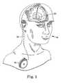
- FIG. 1A system with an implantable medical device having a rechargeable power source subject to capacity fade is depicted generically in FIG. 1 , which shows implantable medical device 16, for example, a neurological stimulator, implanted in patient 18.
- the implantable medical device 16is typically implanted by a surgeon in a sterile surgical procedure performed under local, regional, or general anesthesia.
- a lead 22is typically implanted with the distal end position at a desired therapeutic delivery site 23 and the proximal end tunneled under the skin to the location where the medical device 16 is to be implanted.
- Implantable medical device 16is generally implanted subcutaneously at depths, depending upon application and device 16, of from 1 centimeter (0.4 inches) to 2.5 centimeters (1 inch) where there is sufficient tissue to support the implanted system. Once medical device 16 is implanted into the patient 18, the incision can be sutured closed and medical device 16 can begin operation.
- Implantable medical device 16can be any of a number of medical devices such as an implantable therapeutic substance delivery device, implantable drug pump, electrical stimulator, cardiac pacemaker, cardioverter or defibrillator, as examples.
- implantable medical device 16is a drug infusion device, for example, implantable medical device 16 operates to infuse a therapeutic substance into patient 18.
- Implantable medical device 16can be used for a wide variety of therapies such as pain, spasticity, cancer, and many other medical conditions.
- the therapeutic substance contained in implantable medical device 16is a substance intended to have a therapeutic effect such as pharmaceutical compositions, genetic materials, biologics, and other substances.
- Pharmaceutical compositionsare chemical formulations intended to have a therapeutic effect such as intrathecal antispasmodics, pain medications, chemotherapeutic agents, and the like.
- Pharmaceutical compositionsare often configured to function in an implanted environment with characteristics such as stability at body temperature to retain therapeutic qualities, concentration to reduce the frequency of replenishment, and the like.
- Genetic materialsare substances intended to have a direct or indirect genetic therapeutic effect such as genetic vectors, genetic regulator elements, genetic structural elements, DNA, and the like.
- Biologicsare substances that are living matter or derived from living matter intended to have a therapeutic effect such as stem cells, platelets, hormones, biologically produced chemicals, and the like. Other substances may or may not be intended to have a therapeutic effect and are not easily classified such as saline solution, fluoroscopy agents, disease diagnostic agents and the like. Unless otherwise noted in the following paragraphs, a drug is synonymous with any therapeutic, diagnostic, or other substance that is delivered by the implantable infusion device.
- therapy module 28may deliver an electrical stimulus, such as an electrical pulse, or series of electrical pulses, either mono-polar or bi-polar, through one or more electrical leads and/or electrodes to provide specific or general benefit to that patient such as pain relief or muscular control.
- an electrical stimulussuch as an electrical pulse, or series of electrical pulses, either mono-polar or bi-polar, through one or more electrical leads and/or electrodes to provide specific or general benefit to that patient such as pain relief or muscular control.
- implantable medical device 16has a rechargeable power source 24, such as a Lithium ion battery, powering electronic componentry, such as electronics 26 and therapy module 28 in a conventional manner.
- Therapy module 28is coupled to patient 18 through one or more therapy connections 30, also conventionally.
- Rechargeable power source 24, electronics 26 and therapy module 28are contained in hermetically sealed housing 32.
- Secondary charging coil 34may be interior to housing 32 or attached to the exterior of housing 32. Secondary charging coil 34 is operatively coupled through electronics 26 to rechargeable power source 24.
- secondary charging coil 34could be contained in housing 32 or could be contained in a separate housing umbilically connected to electronics 26.
- Electronics 26help provide control of the charging rate of rechargeable power source 24 in a conventional manner.
- Magnetic shield 36is positioned between secondary charging coil 34 and housing 32 in order to protect rechargeable power source 24, electronics 26 and therapy module 28 from electromagnetic energy when secondary charging coil 34 is utilized to charge rechargeable power source 24.
- Rechargeable power source 24can be any of a variety power sources including a chemically based battery or a capacitor. Rechargeable power source may be a well known lithium ion battery.
- FIG. 3illustrates an alternative embodiment of implantable medical device 16 situated under cutaneous boundary 38.
- Implantable medical device 16is similar to the embodiment illustrated in FIG. 2 .
- charging regulation module 42is shown separate from electronics 26 controlling therapy module 28.
- charging regulation and therapy controlis conventional.
- Implantable medical device 16also has internal telemetry coil 44 configured in conventional manner to communicate through external telemetry coil 46 to an external programming device (not shown), charging unit 50 or other device in a conventional manner in order to both program and control implantable medical device 16 and to externally obtain information from implantable medical device 16 once implantable medical device 16 has been implanted.
- Internal telemetry coil 44rectangular in shape with dimensions of 1.85 inches (4.7 centimeters) by 1.89 inches (4.8 centimeters) constructed from 150 turns of 43 AWG wire, is sized to be larger than the diameter of secondary charging coil 34 in internal antenna 68.
- Secondary coil 34is constructed with 182 turns of 30 AWG wire with an inside diameter of 0.72 inches (1.83 centimeters) and an outside diameter of 1.43 inches (3.63 centimeters) with a height of 0.075 inches (0.19 centimeters).
- Magnetic shield 36is positioned between secondary charging coil 34 and housing 32 and sized to cover the footprint of secondary charging coil 34.
- Internal telemetry coil 44having a larger diameter than secondary coil 34, is not completely covered by magnetic shield 36 allowing implantable medical device 16 to communicate with the external programming device with internal telemetry coil 44 in spite of the presence of magnetic shield 36.
- Rechargeable power source 24can be charged while implantable medical device 16 is in place in a patient through the use of external charging device 48.
- external charging device 48consists of charging unit 50 and external antenna 52.
- Charging unit 50may contain electronic componentry, which may include the electronics necessary to drive primary coil 54 with an oscillating current in order to induce current in secondary coil 34 when primary coil 54 is placed in the proximity of secondary coil 34.
- Charging unit 50is operatively coupled to primary coil by cable 56.
- charging unit 50 and antenna 52may be combined into a single unit.
- Antenna 52may also optionally contain external telemetry coil 46 which may be operatively coupled to charging unit 50 if it is desired to communicate to or from implantable medical device 16 with external charging device 48.
- antenna 52may optionally contain external telemetry coil 46 which can be operatively coupled to an external programming device, either individually or together with external charging unit 48.
- Charging unit 50may further include a user output 51, such as a display or a means for producing an audio output, for transmitting information to a user.
- a user output 51may also be included in a patient programmer, a physician programmer, or any device operably coupled to implantable medical device 16 or charging unit 50.
- FIG. 4is a graphical depiction of model 410 of the relationship of voltage output 414 of rechargeable power source 24 to percentage of charge remaining 416 or "charge level" in rechargeable power source 24 to the total charge capacity of rechargeable power source 24.
- a particular voltage outputwill correspond to the same percentage of charge level over total charge capacity, depicted by curve 412.
- output voltagewill be approximately 4.0 volts.
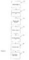
- FIG. 5illustrates a flow chart for determining the total charge capacity of rechargeable power source 24 in electronic componentry that may be included in implantable medical device 16, charging unit 50, a patient programmer, a physician programmer, or other devices that may be operably coupled to implantable medical device 16.
- the voltage output V1 1 of rechargeable power source 24is measured (510) and recorded in electronics 26.
- V1is transmitted to external charging device 48, which determines (512) a percentage of charge remaining P1 by referencing model 410.
- P1is determined (512) and stored in electronics 26.
- electronics 26determines (514) the net charge passed through rechargeable power source 24 or consumed by implantable medical device 16. This can be accomplished in a number of ways, including using a coulomb counter operatively coupled to rechargeable power source 24, using a current meter operatively coupled to rechargeable power source 24, or by characterizing the power consumption of the individual components of implantable medical device 16, and determining the amount of charge consumed based on those characteristics and device settings.
- voltage output V2 of rechargeable power source 24is measured (516) and stored, and percentage P2 is determined (518) in the same manner as P1.
- Percentage P2is then subtracted from P1 in order to determine (520) the change in percentage of charge level over the period of time, delta-P.
- the charge consumedis then divided by delta-P to determine (522) the total charge capacity of rechargeable power source 24.
- these calculationsmay occur either in electronics 26 of implantable medical device 16, or in external charging unit 48.
- a following step of multiplying P2 by the total charge capacitymay be performed to determine the present charge level, which may be outputted to a user. This further step may make the data more useful to more users by determining a time remaining until recharge by dividing the present charge level by an expected charge consumption (see FIG. 6 ).
- the amount of charge delivered by rechargeable power source 24was determined (514). In a further embodiment, that determined charge consumption may be utilized to determine how long, given the present charge level, the charge in rechargeable power source 24 may likely last until implantable medical device 16 indicates a recharge session is needed. By dividing the present charge level by the amount of charge consumed, adjusted for the amount of time over which the charge consumed was determined, an estimate of the amount of time remaining on the present charge level may be determined. In an alternative embodiment, the charge consumption variable may not be the determined value from (514), but rather from a longer-term determination of the amount of charge consumed per unit time, acquired in the same manner as the determination from (514), only over a longer period of time.
- the alternative embodimentmay carry the advantage of utilizing an average power consumption less-prone to short term variances in the amount of charge consumption than that utilized in FIG. 5 , while potentially carrying the disadvantage of being less-representative of the current nature of the utilization of the charge in rechargeable power source 24.
- Which of the possible embodiments may best serve to predict future performanceis a determination that may be dependent on the tendencies of individual patients 18 and characteristics of individual implantable medical devices 16.
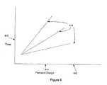
- FIG. 6shows a graphical representation 610 of the impact on the time until recharge 612 based on the percentage of charge in rechargeable power source 614 and the anticipated rate of power consumption 616, represented by a plurality of curves 616 representative of the possible amount of current consumption. Where the percentage charge remaining is low, then the amount of charge consumption may ultimately have minimal impact on the amount of time before recharging is indicated. By contrast, where the percentage of charge remaining is relatively high, the amount of charge consumption can have a significant impact on the amount of time remaining.
- FIG. 7is a graphical depiction of model 710 of the relationship of total charge capacity as a function of time and recharge cycles.
- Surface 712represents the charge capacity of rechargeable power supply, represented on Z-axis 714, based on the amount of time rechargeable power source 24 has been in operation, in other words a chronological age of rechargeable power source 24, represented on Y-axis 716, and the number of charge and discharge cycles rechargeable power source 24 has experienced, in other words, representative of a cycle age of rechargeable power source 24, represented on X-axis 718.
- the charge capacity of rechargeable power sourcemay be determined by referencing the corresponding location on surface 712.
- the impact of time on capacity fadeis determined by a number of factors, each of which are dependent on the particular rechargeable power supply 24 in question. Factors such as the chemistry of rechargeable power source 24, temperature and voltage output affect the impact of time on rechargeable power source 24. For instance, certain materials used in rechargeable power sources 24 may tend to degrade through parasitic reactions at a greater rate than other materials. Likewise, rechargeable power sources 24 operating at high temperatures may tend to degrade faster than rechargeable power sources 24 operating at low temperatures. Finally, a rechargeable power source 24 that operates at a relatively high voltage may naturally tend to deplete its charge faster than a rechargeable power source 24 that operates at a relatively lower voltage.
- the impact of time on capacity fademay be an exponential decay with the passage of time, with the passage of time having a greater impact on capacity fade toward the end of rechargeable power source's 24 life than at the beginning.
- rechargeable power source 24may impact how the inflow and outflow of charge impacts the ability to take and deliver charge. Where rechargeable power source 24 is comprised of a plurality of cells, balance between and among the various cells may have an impact on capacity after repeated recharge cycles. Voltage limits likewise may have an impact, as extreme voltages, either high or low, may impact capacity fade. The rate of the inflow of charge into rechargeable power source 24 may also tend to impact the charge capacity of rechargeable power source 24.
- the number of recharge cyclesmay have a linear relationship on capacity fade, with each recharge cycle reducing the total capacity by an amount approximately equal to that caused by every other recharge cycle.
- the impact of a recharge cycle on capacity fademay be reduced if rechargeable power source has not been charged from having essentially no charge to being essentially full to the total charge capacity.
- a recharge cycle that takes the charge level of rechargeable power source 24 from 25% of total charge capacity to 75% of total charge capacitymay result in only half the capacity fade as if the recharge cycle took the charge level from approximately 0% to approximately 100%.
- the relationship between the percentage change of charge level to total charge capacitymay be linear with respect to capacity fade.
- the relationshipmay not be linear, with capacity fade rather being dependent on a combination of, first, whether a recharge cycle of any kind has occurred, and, second, the amount of charge transferred.
- a recharge cycle that takes the charge level of rechargeable power source 24 from 25% of total charge capacity to 75% of total charge capacitymay result in three-quarters of the capacity fade as if the recharge cycle took the charge level from approximately 0% to approximately 100%.
- electronics 26determine if a recharge cycle has occurred (810), and if so, increment (812) a counter in electronics 26 tracking the number of recharge sessions that have occurred. In an embodiment, the counter is incremented by one with each recharge session. In an alternative embodiment, the counter is incremented based on a proportion of the total charge capacity the charge level of rechargeable power source was increased. Electronics 26 likewise updates and records (814) the amount of time since rechargeable power source has been active.
- the total charge capacityis outputted to a user via an external device other than external charging unit 48, such as a physician programmer or a patient programmer.
- Communicationmay be by telemetry, passive telemetry, radio frequency (RF), induction, ultrasound, audible sound, optics or other communication techniques.
- State of chargemay be represented, for example, by a bar graph.
- a usermay desire further information beyond the total charge capacity.
- the total charge capacityis used to determine other information to provide to a user.
- total charge capacityis outputted to a user via external charging device 48 along with the total charge capacity at the initial time, comparing the two values in graphical form (see FIG. 9 ).
- One examplewould be as a gas gauge, with the total charge capacity at the initial time representing the total area of the gauge, and the total are being divided into total charge capacity and lost charge capacity. While a pie chart is illustrated, other forms are possible, such as status bars, lines, grids, and other forms commonly known in the art. This information will allow a medical professional to make an accurate assessment of the degree to which capacity fade is impacting the performance of implantable medical device 16, and allow judgments to be made as to if and when implantable medical device 16 should be explanted from patient 18 and be replaced.
- the voltage output of rechargeable power source 24is measured (812), and used to determine (814) a percentage of present charge level that is currently represented by the charge level. This percentage is then used to determine (816) the present charge level by multiplying the percentage by the total charge capacity.
- the present charge levelis then outputted (818) to a user, in an embodiment as a gas gauge such as that used to display the total charge capacity compared with the total charge capacity at the initial time described above.
- a time until rechargeis estimated (820) based on past charge consumption, present settings, and anticipated patient 18 initiated therapy. The estimated time until recharge is then outputted (822) to a user via user output 51. Communication may be by telemetry, passive telemetry, radio frequency (RF), induction, ultrasound, audible sound, optics or other communication techniques. Time until recharge may be represented digitally or analog.
- a patient 18may have no interest in knowing total charge capacity or present charge level of their rechargeable power source 24, but would likely care to know a time until recharge. Thus, it is envisioned that only time until recharge would be displayed for patient 18. By contrast, a medical professional working with patient 18 may care to know total charge capacity, but not the other information.
- the above described datamay be selectable by a user, and the outputting steps (810), (818), (822) may or may not occur, dependent on the preferences of the user.
- FIG. 9shows an example of a graphical depiction of a total charge capacity at the initial time, total charge capacity and present charge level of rechargeable power source 24 that may be displayed on user output 51.
- the area enclosed under arc 912depicts the initial charge capacity of rechargeable power source 24.
- total charge capacity line 914moves from right to left over arc 912, with the farther right total charge capacity line 914 is, the greater the total charge capacity and the less fade has impacted the capacity of rechargeable power source 24.
- Present charge level line 916likewise moves from right to left across arc 912, but can, in no event, exceed total charge capacity, and thus present charge level line 916 can never exist to the right of total charge capacity line 914.
- two gas gaugesmay be displayed, one corresponding to total charge capacity relative to initial charge capacity, and another corresponding to present charge level relative to total charge capacity.
- the charge levels determined by each of the methodsare averaged, with the average utilized to determine time remaining.
- one determined charge levelmay be weighted more heavily than another, dependent on the characteristics of the particular rechargeable power source 24 and implantable medical device 16 and any tendency for one method or the other to provide more consistently accurate results.
- time until rechargemay be determined using just one determined charge level, but the charge level determined from the other method may be compared against the utilized charge level to verify that the two determined charge levels are generally consistent with one another. If the two charge levels are inconsistent with one another then a new test may be prompted. If the two charge levels remain inconsistent then one or the other may be utilized, or the determination of time until recharge may be deemed a failure and a note to that effect displayed to a user, in an embodiment on charging unit 50.
Landscapes
- Health & Medical Sciences (AREA)
- Heart & Thoracic Surgery (AREA)
- Engineering & Computer Science (AREA)
- Life Sciences & Earth Sciences (AREA)
- Biophysics (AREA)
- Biomedical Technology (AREA)
- Physics & Mathematics (AREA)
- General Physics & Mathematics (AREA)
- Electrochemistry (AREA)
- Chemical Kinetics & Catalysis (AREA)
- Chemical & Material Sciences (AREA)
- Manufacturing & Machinery (AREA)
- Cardiology (AREA)
- General Chemical & Material Sciences (AREA)
- Nuclear Medicine, Radiotherapy & Molecular Imaging (AREA)
- Radiology & Medical Imaging (AREA)
- Animal Behavior & Ethology (AREA)
- General Health & Medical Sciences (AREA)
- Public Health (AREA)
- Veterinary Medicine (AREA)
- Charge And Discharge Circuits For Batteries Or The Like (AREA)
Description
- The medical device industry produces a wide variety of electronic devices for treating patient medical conditions using electrical stimulation. Depending upon the medical condition, medical devices can be surgically implanted or connected externally to the patient receiving treatment. Clinicians use medical devices alone or in combination with drug therapies and surgery to treat patient medical conditions. For some medical conditions, medical devices provide the best, and sometimes the only therapy to restore an individual to a more healthful condition and a fuller life. Examples of implantable medical devices designed to deliver therapeutic electrical stimulation include neurological stimulators and spinal stimulators, as well as pacemakers and defibrillators.
- Because implantable medical devices provide important, oftentimes life-sustaining medical care to patients from the power supplied by a single component power source, usually a battery, the ability to know the status of that power source is critical. When a power source's charge has nearly run down, the power source must either be replaced or recharged. The failure to do so could result in the untimely failure of the implantable medical device's ability to deliver therapy to the patient, with potential consequences up to and including patient death.
- A common solution to avoid having to conduct surgery to replace a depleted power source is to make the power source of the implantable medical device rechargeable via transcutaneous transmission of energy. An external power supply is operatively coupled with the rechargeable power source of the implantable medical device, often through an inductive link, and charging current is delivered to the rechargeable power source until the rechargeable power source is replenished with charge. The implantable medical device may then continue to deliver therapy to the patient until the rechargeable power source has run down again and the process of recharging may then be repeated.
US 2003/114899 teaches recharging of a rechargeable power source of an implantable medical device.- However, the electrical characteristics of rechargeable batteries may tend to change either with the passage of time, with each charging and discharging cycle, or both. Among rechargeable power sources commonly in use in implantable medical devices, while the instantaneous voltage and current that may be delivered will tend to remain constant throughout the useful life of the rechargeable power source, the total amount of charge the rechargeable power source has the ability to store, i.e., the rechargeable power source capacity, may have a tendency to degrade. The tendency of the capacity of the rechargeable power source to degrade can be attributable to the effect of the passage of time, the number of charging cycles encountered, or both. The chemical nature of the rechargeable power may allow the rechargeable power source to degrade over time. Repeated charge and discharge cycles of the rechargeable power source are also known to degrade the rechargeable power source over time.
- This phenomenon, known as "capacity fade", may create a challenge to the makers of implantable medical devices. If the amount of time that a rechargeable power source may provide charge is not known accurately, the rechargeable power source may run down at an unexpected and inopportune time thereby depriving potentially life-sustaining therapy to the patient.
- An embodiment provides a system and method to more accurately determine how much charge remains or the recharge interval in the rechargeable power source of an implantable medical device, taking into account the capacity fade of the age of the rechargeable power source or the number of times the rechargeable power source has been charged and discharged.
- An embodiment first recognizes that, although the charge capacity of a rechargeable power source has decreased, the output voltage of the rechargeable power source may tend to correspond to the same ratio of charge remaining in the rechargeable power source over the rechargeable power source's charge capacity. The implantable medical device may measure the rechargeable power source voltage at two different times and also determine the amount of charge the rechargeable power source has delivered during that time. Electronic componentry may determine the percentage of charge remaining at each of those times based on the measured rechargeable power source voltage, and subtract the second percentage from the first percentage to determine the total percentage decrease over the period of time. Then, dividing the amount of charge that was delivered between the two times by the percentage decrease of rechargeable power source charge determines the total charge capacity.
- In addition, due to the nature of having an accurate picture of the charge capacity of a rechargeable power source at any given time, another embodiment more accurately determines capacity fade through means independent of the above described embodiment, perhaps to provide redundancy and improved accuracy. An embodiment may further determine capacity fade based on a model that recognizes that capacity fade occurs as a function both of the amount of time the rechargeable power source has been in use, as well as the number of times the rechargeable power source has been recharged. The charge capacity of a rechargeable power source is reduced both with the passage of time and also with use, as each charge and discharge cycle results in a decreased capacity. An embodiment utilizes a model that is unique to each type of rechargeable power supply to factor in the passage of time and the number of recharge cycles to determine the present charge capacity of a rechargeable power source at any particular time.
- In an embodiment, the present invention further provides a system having an implantable medical device having a rechargeable power source having recharge interval until a recharge time when a charge level of the rechargeable power source is indicated, the rechargeable power source having an initial charge capacity, a present charge capacity and a present charge level. The system also has electronic componentry, operatively coupled to the implantable medical device, configured to record a cycle age by counting a number of recharges of the rechargeable power source indicative of a number of times the rechargeable power source has been recharged, record a chronological age of the rechargeable power source, determine the present charge capacity of the rechargeable power source by subtracting a charge capacity based on the cycle age of the rechargeable power source and a charge capacity based on the chronological age of the rechargeable power source from the initial charge capacity, measure a voltage of the rechargeable power source, determine a portion of the present charge capacity as a function of the rechargeable voltage, determine the present charge level as a function of the present charge capacity and the portion of charge capacity remaining, determine the recharge interval as a function of the present charge level and a programmed rate, and a user output, operatively coupled to the electrical componentry, configured to communicate the recharge interval to the user.
- In an embodiment, the user output is further configured to communicate the present charge capacity and the initial charge capacity to the user.
- In an embodiment, the electronic componentry is further configured to determine the charge capacity corresponding to the number of recharges and the charge capacity corresponding to the age of the rechargeable power source using a model.
- In an embodiment, the user output is further configured to communicate a graphical depiction of the present charge capacity relative to the initial charge capacity to the user.
- In an embodiment, the present invention further provides a system having an implantable medical device having a rechargeable power source, the rechargeable power source having an initial charge capacity and a present charge capacity. The system additionally has electronic componentry, operatively coupled to the implantable medical device, configured to record a cycle age by counting a number of recharges of the rechargeable power source indicative of a number of times the rechargeable power source has been recharged, record a chronological age of the rechargeable power source, determine the present charge capacity of the rechargeable power source by subtracting a charge capacity based on the cycle age of the rechargeable power source and a charge capacity based on the chronological age of the rechargeable power source from the initial charge capacity, and a user output, operatively coupled to the electronic componentry, configured to conmmnicate the present charge capacity.
- In an embodiment, the present invention further provides, in an implantable medical device having a rechargeable power source, a method for determining a recharge interval until a recharge time when a charge level of the rechargeable power source reaches a value at which recharging of the rechargeable power source is indicated, the rechargeable power source having an initial charge capacity, a present charge capacity and a present charge level. First, a cycle age is recorded by counting a number of recharges of the rechargeable power source indicative of a number of times the rechargeable power source has been recharged. Then a chronological age of the rechargeable power source is recorded. The present charge capacity of the rechargeable power source is determined by subtracting a charge capacity based on the cycle age of the rechargeable power source and a charge capacity based on the chronological age of the rechargeable power source from the initial charge capacity, measuring a voltage of the rechargeable power source, determining a portion of the present charge capacity as a function of the rechargeable voltage, finally determining the present charge level as a function of the present charge capacity and the portion of charge capacity remaining. The recharge interval is determined as a function of the present charge level and a programmed rate, and outputted to a user.
- In an embodiment, the present charge capacity and the initial charge capacity is outputted to the user.
- In an embodiment, the charge capacity corresponding to the number of recharges and the charge capacity corresponding to the age of the rechargeable power source are determined using a model.
- In an embodiment, the outputting step outputs a graphical depiction of the present charge capacity relative to the initial charge capacity.
- In an embodiment, the present invention further provides, in an implantable medical device having a rechargeable power source, a method for determining a present charge capacity of the rechargeable power source, the rechargeable power source having an initial charge capacity. A cycle age is recorded by counting a number of recharges of the rechargeable power source indicative of a number of times the rechargeable power source has been recharged, and then a chronological age of the rechargeable power source is recorded. Then the present charge capacity of the rechargeable power source is determined by subtracting a charge capacity based on the cycle age of the rechargeable power source and a charge capacity based on the chronological age of the rechargeable power source from the initial charge capacity. Finally, the present charge capacity and the initial charge capacity are outputted to a user.
- In an embodiment, the charge capacity corresponding to the number of recharges and the charge capacity corresponding to the age of the rechargeable power source are determined using a model.
- In an embodiment, the outputting step outputs a graphical depiction of the present charge capacity relative to the initial charge capacity.
FIG. 1 shows an implantable medical device implanted in a patient;FIG. 2 shows a block diagram of an implantable medical device;FIG. 3 shows an expanded block diagram of an implantable medical device, and an external charger;FIG. 4 shows a graphical depiction of a model of charge level of a power source relative to output voltage;FIG. 5 is a flow chart of a method for determining the total charge capacity of a rechargeable power source;FIG. 6 shows a graphical representation of the impact on the time until recharge based on the percentage of charge in rechargeable power source and the anticipated rate of power consumption;FIG. 7 shows a graphical depiction of a model of the relationship of total charge capacity as a function of time and recharge cycles;FIG. 8 is a flow chart of a method for estimating a time until recharge of a rechargeable power source; andFIG. 9 shows an example of a graphical depiction of a total charge capacity at an initial time, total charge capacity and charge level of rechargeable power source.- The charge capacity of a rechargeable power source can tend to decline or "fade" over time. This phenomenon can be due to a variety of factors. In Lithium-Ion batteries, fade can be traceable to issues of the growth of solid-electrolyte interfaces in lithium-ion cells incorporating carbon anodes. It can also be a result of lithium-ion molecule isolation as a result of chemical changes in the rechargeable power source, as well as the sequestering of lithium molecules. Host material degradation may also play a role, as the phase change of individual molecules, the isolation and fracture of elements of the rechargeable power source and blocked sites all reduce locations of accessible charge. Increased resistance in the rechargeable power source material tends to reduce the efficiency of charge transfer, reducing the charge that can be drawn from the rechargeable power source. Examples of increased resistance include particle-to-particle resistance within the rechargeable power source, separator resistance, as well as charge-transfer resistance out of the cell. Parasitic reactions occurring within the rechargeable power source cell may also degrade the charge capacity, such as reactions from electrolytes and solvents that may tend to be present in the rechargeable power source cell, reactions from industrial additives and impurities in the chemical compound to of the rechargeable power source.
- A rechargeable power source has a charge capacity or total charge capacity, i.e., the maximum amount of charge that a rechargeable power source is capable of storing at any particular point in time. The total charge capacity is a function of the age of the rechargeable power and, typically, degrades over time and/or over charge cycles. Total charge capacity is typically measured in ampere-hours, milliampere-hours, watt-hours or similar units.
- A charge level of a rechargeable power source is the amount of energy or amount of charge actually stored in the rechargeable power at a particular point in time. Charge level is typically measured in ampere-hours, watt-hours, coulombs or similar units.
- The of a rechargeable power source is similar to the charge level and represents the energy, typically in coulombs, actually stored in the rechargeable power source.
- The state of charge of a rechargeable power source is a fractional unit between zero and one representing the portion of the net charge stored in the rechargeable power source relative to the total charge capacity of the rechargeable battery. The state of charge is typically measured or represented by a fraction, decimal or percentage value.
- The first state of charge of a rechargeable power source is a state of charge of the rechargeable measured or represented at a first point in time, e.g., the state of charge existing in the rechargeable power source at a point in time when recharging of the rechargeable power source is commenced.
- The net charge remaining or charge remaining in a rechargeable power source is a function of the total charge capacity multiplied by the state of charge:

This relationship can be expressed conversely during charging of the rechargeable power source in that the net charge remaining is a function of the total charge capacity times the state of charge subtracted from one:
The state of charge of a rechargeable power source can be assessed by, for example, either (A) measuring the voltage, e.g., of a cell, and comparing the voltage measured to a standard curve of voltage versus state of charge of a particular type or particular one of a rechargeable power source; or (B) measuring the amount of charge, e.g., coulombs, delivered by the rechargeable power source; or some combination of the two methods. - Prediction of the total charge capacity of the rechargeable power source (Qtotal) may be assessed either by (A) knowledge of the initial charge capacity, perhaps with appropriate correction due to fade, e.g., battery fade, that may account for the number of charge cycles and age of the rechargeable power source; or (B) assessing the state of charge of the rechargeable power source at two or more points, as well as the measured amount of charge delivered by the rechargeable power source between the same two points, according to the relationship:

An alternative way to assess the total charge capacity (Qtotal) is from a capacity fade model, for example:
wherein Δ Q (cycles) is generally a linear function of the number of cycles and Δ Q (time) is a linear or exponential decay function over time. - The amount of time remaining before a rechargeable power source needs to be recharged or until a charge cycle is complete, along a measured or estimated value of average current drain, can be shown in the relationship:

The foregoing basic relationships form a foundation for the following description. - An embodiment relies on the determined fact that while the charge capacity of a rechargeable power source may decrease or fade, the voltage output from the rechargeable power source tends nevertheless to continue to correspond to a particular percentage of the charge capacity of the rechargeable power source at a given point in time. Thus, voltage level V1 will tend to correspond to the percentage of the total charge capacity at a first time P1, regardless of what the total charge capacity of rechargeable power happens to be at any given moment. However, without knowing what the total charge capacity is, knowing P1 does not inform a user how much charge is actually remaining in the rechargeable power source. To determine this, a percentage of total charge capacity at a second, initial time P2 is determined and that percentage is used with P1 to determine both the total charge capacity and the charge level.
- A system with an implantable medical device having a rechargeable power source subject to capacity fade is depicted generically in
FIG. 1 , which shows implantablemedical device 16, for example, a neurological stimulator, implanted inpatient 18. The implantablemedical device 16 is typically implanted by a surgeon in a sterile surgical procedure performed under local, regional, or general anesthesia. Before implanting themedical device 16, alead 22 is typically implanted with the distal end position at a desiredtherapeutic delivery site 23 and the proximal end tunneled under the skin to the location where themedical device 16 is to be implanted. Implantablemedical device 16 is generally implanted subcutaneously at depths, depending upon application anddevice 16, of from 1 centimeter (0.4 inches) to 2.5 centimeters (1 inch) where there is sufficient tissue to support the implanted system. Oncemedical device 16 is implanted into thepatient 18, the incision can be sutured closed andmedical device 16 can begin operation. - Implantable
medical device 16 can be any of a number of medical devices such as an implantable therapeutic substance delivery device, implantable drug pump, electrical stimulator, cardiac pacemaker, cardioverter or defibrillator, as examples. - If implantable
medical device 16 is a drug infusion device, for example, implantablemedical device 16 operates to infuse a therapeutic substance intopatient 18. Implantablemedical device 16 can be used for a wide variety of therapies such as pain, spasticity, cancer, and many other medical conditions. - The therapeutic substance contained in implantable
medical device 16 is a substance intended to have a therapeutic effect such as pharmaceutical compositions, genetic materials, biologics, and other substances. Pharmaceutical compositions are chemical formulations intended to have a therapeutic effect such as intrathecal antispasmodics, pain medications, chemotherapeutic agents, and the like. Pharmaceutical compositions are often configured to function in an implanted environment with characteristics such as stability at body temperature to retain therapeutic qualities, concentration to reduce the frequency of replenishment, and the like. Genetic materials are substances intended to have a direct or indirect genetic therapeutic effect such as genetic vectors, genetic regulator elements, genetic structural elements, DNA, and the like. Biologics are substances that are living matter or derived from living matter intended to have a therapeutic effect such as stem cells, platelets, hormones, biologically produced chemicals, and the like. Other substances may or may not be intended to have a therapeutic effect and are not easily classified such as saline solution, fluoroscopy agents, disease diagnostic agents and the like. Unless otherwise noted in the following paragraphs, a drug is synonymous with any therapeutic, diagnostic, or other substance that is delivered by the implantable infusion device. - If implantable
medical device 16 is an electrical stimulator, for example,therapy module 28 may deliver an electrical stimulus, such as an electrical pulse, or series of electrical pulses, either mono-polar or bi-polar, through one or more electrical leads and/or electrodes to provide specific or general benefit to that patient such as pain relief or muscular control. - In
FIG. 2 , implantablemedical device 16 has arechargeable power source 24, such as a Lithium ion battery, powering electronic componentry, such aselectronics 26 andtherapy module 28 in a conventional manner.Therapy module 28 is coupled topatient 18 through one ormore therapy connections 30, also conventionally.Rechargeable power source 24,electronics 26 andtherapy module 28 are contained in hermetically sealedhousing 32.Secondary charging coil 34 may be interior tohousing 32 or attached to the exterior ofhousing 32.Secondary charging coil 34 is operatively coupled throughelectronics 26 torechargeable power source 24. In an alternative embodiment,secondary charging coil 34 could be contained inhousing 32 or could be contained in a separate housing umbilically connected toelectronics 26.Electronics 26 help provide control of the charging rate ofrechargeable power source 24 in a conventional manner.Magnetic shield 36 is positioned between secondary chargingcoil 34 andhousing 32 in order to protectrechargeable power source 24,electronics 26 andtherapy module 28 from electromagnetic energy whensecondary charging coil 34 is utilized to chargerechargeable power source 24. Rechargeable power source 24 can be any of a variety power sources including a chemically based battery or a capacitor. Rechargeable power source may be a well known lithium ion battery.FIG. 3 illustrates an alternative embodiment of implantablemedical device 16 situated undercutaneous boundary 38. Implantablemedical device 16 is similar to the embodiment illustrated inFIG. 2 . However, chargingregulation module 42 is shown separate fromelectronics 26controlling therapy module 28. Again, charging regulation and therapy control is conventional. Implantablemedical device 16 also hasinternal telemetry coil 44 configured in conventional manner to communicate throughexternal telemetry coil 46 to an external programming device (not shown), chargingunit 50 or other device in a conventional manner in order to both program and control implantablemedical device 16 and to externally obtain information from implantablemedical device 16 once implantablemedical device 16 has been implanted.Internal telemetry coil 44, rectangular in shape with dimensions of 1.85 inches (4.7 centimeters) by 1.89 inches (4.8 centimeters) constructed from 150 turns of 43 AWG wire, is sized to be larger than the diameter ofsecondary charging coil 34 ininternal antenna 68.Secondary coil 34 is constructed with 182 turns of 30 AWG wire with an inside diameter of 0.72 inches (1.83 centimeters) and an outside diameter of 1.43 inches (3.63 centimeters) with a height of 0.075 inches (0.19 centimeters).Magnetic shield 36 is positioned between secondary chargingcoil 34 andhousing 32 and sized to cover the footprint ofsecondary charging coil 34.Internal telemetry coil 44, having a larger diameter thansecondary coil 34, is not completely covered bymagnetic shield 36 allowing implantablemedical device 16 to communicate with the external programming device withinternal telemetry coil 44 in spite of the presence ofmagnetic shield 36.Rechargeable power source 24 can be charged while implantablemedical device 16 is in place in a patient through the use ofexternal charging device 48. In an embodiment,external charging device 48 consists of chargingunit 50 andexternal antenna 52. Chargingunit 50 may contain electronic componentry, which may include the electronics necessary to driveprimary coil 54 with an oscillating current in order to induce current insecondary coil 34 whenprimary coil 54 is placed in the proximity ofsecondary coil 34. Chargingunit 50 is operatively coupled to primary coil bycable 56. In an alternative embodiment, chargingunit 50 andantenna 52 may be combined into a single unit.Antenna 52 may also optionally containexternal telemetry coil 46 which may be operatively coupled to chargingunit 50 if it is desired to communicate to or from implantablemedical device 16 withexternal charging device 48. Alternatively,antenna 52 may optionally containexternal telemetry coil 46 which can be operatively coupled to an external programming device, either individually or together withexternal charging unit 48.- Charging
unit 50 may further include auser output 51, such as a display or a means for producing an audio output, for transmitting information to a user. Such auser output 51 may also be included in a patient programmer, a physician programmer, or any device operably coupled to implantablemedical device 16 or chargingunit 50. FIG. 4 is a graphical depiction ofmodel 410 of the relationship ofvoltage output 414 ofrechargeable power source 24 to percentage of charge remaining 416 or "charge level" inrechargeable power source 24 to the total charge capacity ofrechargeable power source 24. Regardless of the total charge capacity ofrechargeable power source 24, a particular voltage output will correspond to the same percentage of charge level over total charge capacity, depicted bycurve 412. In an embodiment, where the charge level equals the total charge capacity, output voltage will be approximately 4.0 volts. In an example, it may be desired that the voltage output stay above approximately 3.5 volts forrechargeable power source 24 to be able to continue to supply implantablemedical device 16 with suitable power.FIG. 5 illustrates a flow chart for determining the total charge capacity ofrechargeable power source 24 in electronic componentry that may be included in implantablemedical device 16, chargingunit 50, a patient programmer, a physician programmer, or other devices that may be operably coupled to implantablemedical device 16. During normal use of implantablemedical device 16, thevoltage output V1 1 ofrechargeable power source 24 is measured (510) and recorded inelectronics 26. V1 is transmitted toexternal charging device 48, which determines (512) a percentage of charge remaining P1 by referencingmodel 410. In an alternative embodiment, P1 is determined (512) and stored inelectronics 26. After some period of time during which implantablemedical device 16 functions normally, monitoring and delivering therapy,electronics 26 determines (514) the net charge passed throughrechargeable power source 24 or consumed by implantablemedical device 16. This can be accomplished in a number of ways, including using a coulomb counter operatively coupled torechargeable power source 24, using a current meter operatively coupled torechargeable power source 24, or by characterizing the power consumption of the individual components of implantablemedical device 16, and determining the amount of charge consumed based on those characteristics and device settings. At the end of the period of time, voltage output V2 ofrechargeable power source 24 is measured (516) and stored, and percentage P2 is determined (518) in the same manner as P1.- Percentage P2 is then subtracted from P1 in order to determine (520) the change in percentage of charge level over the period of time, delta-P. The charge consumed is then divided by delta-P to determine (522) the total charge capacity of
rechargeable power source 24. In various embodiments, these calculations may occur either inelectronics 26 of implantablemedical device 16, or inexternal charging unit 48. Once total charge capacity has been determined, a following step of multiplying P2 by the total charge capacity may be performed to determine the present charge level, which may be outputted to a user. This further step may make the data more useful to more users by determining a time remaining until recharge by dividing the present charge level by an expected charge consumption (seeFIG. 6 ). - In an embodiment, as part of determining the present charge level (see
FIG. 5 ) the amount of charge delivered byrechargeable power source 24 was determined (514). In a further embodiment, that determined charge consumption may be utilized to determine how long, given the present charge level, the charge inrechargeable power source 24 may likely last until implantablemedical device 16 indicates a recharge session is needed. By dividing the present charge level by the amount of charge consumed, adjusted for the amount of time over which the charge consumed was determined, an estimate of the amount of time remaining on the present charge level may be determined. In an alternative embodiment, the charge consumption variable may not be the determined value from (514), but rather from a longer-term determination of the amount of charge consumed per unit time, acquired in the same manner as the determination from (514), only over a longer period of time. The alternative embodiment may carry the advantage of utilizing an average power consumption less-prone to short term variances in the amount of charge consumption than that utilized inFIG. 5 , while potentially carrying the disadvantage of being less-representative of the current nature of the utilization of the charge inrechargeable power source 24. Which of the possible embodiments may best serve to predict future performance is a determination that may be dependent on the tendencies ofindividual patients 18 and characteristics of individual implantablemedical devices 16. FIG. 6 shows agraphical representation 610 of the impact on the time untilrecharge 612 based on the percentage of charge inrechargeable power source 614 and the anticipated rate ofpower consumption 616, represented by a plurality ofcurves 616 representative of the possible amount of current consumption. Where the percentage charge remaining is low, then the amount of charge consumption may ultimately have minimal impact on the amount of time before recharging is indicated. By contrast, where the percentage of charge remaining is relatively high, the amount of charge consumption can have a significant impact on the amount of time remaining.FIG. 7 is a graphical depiction ofmodel 710 of the relationship of total charge capacity as a function of time and recharge cycles.Surface 712 represents the charge capacity of rechargeable power supply, represented on Z-axis 714, based on the amount of timerechargeable power source 24 has been in operation, in other words a chronological age ofrechargeable power source 24, represented on Y-axis 716, and the number of charge and discharge cyclesrechargeable power source 24 has experienced, in other words, representative of a cycle age ofrechargeable power source 24, represented onX-axis 718. Thus, for any two values of cycles and time, the charge capacity of rechargeable power source may be determined by referencing the corresponding location onsurface 712.- The impact of time on capacity fade is determined by a number of factors, each of which are dependent on the particular
rechargeable power supply 24 in question. Factors such as the chemistry ofrechargeable power source 24, temperature and voltage output affect the impact of time onrechargeable power source 24. For instance, certain materials used inrechargeable power sources 24 may tend to degrade through parasitic reactions at a greater rate than other materials. Likewise,rechargeable power sources 24 operating at high temperatures may tend to degrade faster thanrechargeable power sources 24 operating at low temperatures. Finally, arechargeable power source 24 that operates at a relatively high voltage may naturally tend to deplete its charge faster than arechargeable power source 24 that operates at a relatively lower voltage. These factors all tend to be independent of actually recharging rechargeable power source and may tend to occur with any battery or other similar rechargeable power source. In various embodiments, the impact of time on capacity fade may be an exponential decay with the passage of time, with the passage of time having a greater impact on capacity fade toward the end of rechargeable power source's 24 life than at the beginning. - The impact of recharge cycles on capacity fade is likewise dependent on several factors. The mechanical design of
rechargeable power source 24 may impact how the inflow and outflow of charge impacts the ability to take and deliver charge. Whererechargeable power source 24 is comprised of a plurality of cells, balance between and among the various cells may have an impact on capacity after repeated recharge cycles. Voltage limits likewise may have an impact, as extreme voltages, either high or low, may impact capacity fade. The rate of the inflow of charge intorechargeable power source 24 may also tend to impact the charge capacity ofrechargeable power source 24. In various embodiments, the number of recharge cycles may have a linear relationship on capacity fade, with each recharge cycle reducing the total capacity by an amount approximately equal to that caused by every other recharge cycle. - In various embodiments, the impact of a recharge cycle on capacity fade may be reduced if rechargeable power source has not been charged from having essentially no charge to being essentially full to the total charge capacity. For instance, in an embodiment, a recharge cycle that takes the charge level of
rechargeable power source 24 from 25% of total charge capacity to 75% of total charge capacity may result in only half the capacity fade as if the recharge cycle took the charge level from approximately 0% to approximately 100%. In such an embodiment, the relationship between the percentage change of charge level to total charge capacity may be linear with respect to capacity fade. In alternative embodiments, the relationship may not be linear, with capacity fade rather being dependent on a combination of, first, whether a recharge cycle of any kind has occurred, and, second, the amount of charge transferred. Thus, in an embodiment, a recharge cycle that takes the charge level ofrechargeable power source 24 from 25% of total charge capacity to 75% of total charge capacity may result in three-quarters of the capacity fade as if the recharge cycle took the charge level from approximately 0% to approximately 100%. - Various alternative embodiments with alternative characteristics are possible and may be dependent on the physical characteristics of
rechargeable power source 24. For instance, a particular percentage increase in charge level relative to total charge capacity may result in a different impact on capacity fade than a different percentage increase in charge level depending on the starting charge level and ending charge level as a percentage of total charge capacity. In such an embodiment, there may be a greater impact on capacity fade if the starting charge level is relatively closer to 0% of total charge capacity or the ending charge level is relatively closer to 100% of total charge capacity. - In order to determine total charge capacity of rechargeable power source 24 (
FIG. 8 ),electronics 26 determine if a recharge cycle has occurred (810), and if so, increment (812) a counter inelectronics 26 tracking the number of recharge sessions that have occurred. In an embodiment, the counter is incremented by one with each recharge session. In an alternative embodiment, the counter is incremented based on a proportion of the total charge capacity the charge level of rechargeable power source was increased.Electronics 26 likewise updates and records (814) the amount of time since rechargeable power source has been active. When prompted by a user, it is determined (816) what the total charge capacity ofrechargeable power source 24 is based on the total charge capacity at the initial time ofrechargeable power source 24, the recorded time, and the recorded number of cycles, using the model depicted graphically inFIG. 7 . In an embodiment, this determination is made inelectronics 26. In an alternative embodiment, this determination is made inexternal charging device 48 after the data on total charge capacity at the second, initial time, recorded time and recorded number of cycles has been transmitted toexternal charging device 48. If determination (816) was conducted in implantablemedical device 16, the result is transmitted toexternal charging device 48 and outputted (818) to a user. Alternatively, if determination (816) was conducted inexternal charging device 48 it is simply outputted (818) to a user. In an embodiment, the total charge capacity is outputted to a user via an external device other thanexternal charging unit 48, such as a physician programmer or a patient programmer. Communication may be by telemetry, passive telemetry, radio frequency (RF), induction, ultrasound, audible sound, optics or other communication techniques. State of charge may be represented, for example, by a bar graph. - Commonly, a user may desire further information beyond the total charge capacity. In an embodiment (
FIG. 8 ), the total charge capacity is used to determine other information to provide to a user. In an embodiment, total charge capacity is outputted to a user viaexternal charging device 48 along with the total charge capacity at the initial time, comparing the two values in graphical form (seeFIG. 9 ). One example would be as a gas gauge, with the total charge capacity at the initial time representing the total area of the gauge, and the total are being divided into total charge capacity and lost charge capacity. While a pie chart is illustrated, other forms are possible, such as status bars, lines, grids, and other forms commonly known in the art. This information will allow a medical professional to make an accurate assessment of the degree to which capacity fade is impacting the performance of implantablemedical device 16, and allow judgments to be made as to if and when implantablemedical device 16 should be explanted frompatient 18 and be replaced. - In an alternative embodiment, the voltage output of
rechargeable power source 24 is measured (812), and used to determine (814) a percentage of present charge level that is currently represented by the charge level. This percentage is then used to determine (816) the present charge level by multiplying the percentage by the total charge capacity. The present charge level is then outputted (818) to a user, in an embodiment as a gas gauge such as that used to display the total charge capacity compared with the total charge capacity at the initial time described above. In an embodiment, a time until recharge is estimated (820) based on past charge consumption, present settings, and anticipatedpatient 18 initiated therapy. The estimated time until recharge is then outputted (822) to a user viauser output 51. Communication may be by telemetry, passive telemetry, radio frequency (RF), induction, ultrasound, audible sound, optics or other communication techniques. Time until recharge may be represented digitally or analog. - It is anticipated that the desirability of outputting various data, such as are described in the preceding paragraphs, may not be the same for every user. A patient 18 may have no interest in knowing total charge capacity or present charge level of their
rechargeable power source 24, but would likely care to know a time until recharge. Thus, it is envisioned that only time until recharge would be displayed forpatient 18. By contrast, a medical professional working withpatient 18 may care to know total charge capacity, but not the other information. Thus, in an embodiment the above described data may be selectable by a user, and the outputting steps (810), (818), (822) may or may not occur, dependent on the preferences of the user. FIG. 9 shows an example of a graphical depiction of a total charge capacity at the initial time, total charge capacity and present charge level ofrechargeable power source 24 that may be displayed onuser output 51. The area enclosed underarc 912 depicts the initial charge capacity ofrechargeable power source 24. As a result of capacity fade, totalcharge capacity line 914 moves from right to left overarc 912, with the farther right totalcharge capacity line 914 is, the greater the total charge capacity and the less fade has impacted the capacity ofrechargeable power source 24. Presentcharge level line 916 likewise moves from right to left acrossarc 912, but can, in no event, exceed total charge capacity, and thus presentcharge level line 916 can never exist to the right of totalcharge capacity line 914. In an alternative embodiment, two gas gauges may be displayed, one corresponding to total charge capacity relative to initial charge capacity, and another corresponding to present charge level relative to total charge capacity.- An embodiment combining the results of the methods of
FIGS. 5 and8 is envisioned. In such an embodiment, the charge levels determined by each of the methods are averaged, with the average utilized to determine time remaining. Alternatively, one determined charge level may be weighted more heavily than another, dependent on the characteristics of the particularrechargeable power source 24 and implantablemedical device 16 and any tendency for one method or the other to provide more consistently accurate results. As a further alternative embodiment, time until recharge may be determined using just one determined charge level, but the charge level determined from the other method may be compared against the utilized charge level to verify that the two determined charge levels are generally consistent with one another. If the two charge levels are inconsistent with one another then a new test may be prompted. If the two charge levels remain inconsistent then one or the other may be utilized, or the determination of time until recharge may be deemed a failure and a note to that effect displayed to a user, in an embodiment on chargingunit 50. - Thus, embodiments of the method for estimating time before recharging a battery is required, and a system therefore are disclosed. One skilled in the art will appreciate that the present invention can be practiced with embodiments other than those disclosed. The disclosed embodiments are presented for purposes of illustration and not limitation, and the present invention is limited only by the claims that follow.


Claims (13)
- A system, comprising:an implantable medical device (16) having a rechargeable power source (24) having a recharge interval until a time when recharge of said rechargeable power source is desired, said rechargeable power source having a voltage, a total charge capacity which changes over time and a charge level;electronic componentry (26), operatively coupled to said implantable medical device, configured to:record a cycle age by counting a number of recharges of said rechargeable power source indicative of a number of times said rechargeable power source has been recharged;record a chronological age of said rechargeable power source;determine said total charge capacity of said rechargeable power source at a first time by subtracting a charge capacity based, at least in part, on said cycle age of said rechargeable power source and a charge capacity based, at least in part, on said chronological age of said rechargeable power source from said total charge capacity at a second time, said second time being earlier than said first time;measure a voltage of said rechargeable power source;determine a state of charge as a function of said voltage;determine a charge level of said rechargeable power source as a function of said total charge capacity at said first time and said state of charge; anddetermine said recharge interval as a function of said charge level and a programmed rate; anda user output (610), operatively coupled to said electrical componentry, configured to communicate said recharge interval to said user.
- The system as in claim 1 wherein said cycle age is dependent, at least in part, on said number of recharges and a net charge passed through said rechargeable power source during each recharge of said rechargeable power source and said total charge capacity.
- The system as in claim 1 wherein said cycle age is comprised, at least in part, of a linear function based on a number of charge cycles.
- The system as in claim 1 wherein said chronological age is comprised, at least in part, of an exponential function based on time.
- The system as in claim 1 wherein said user output is further configured to communicate a graphical depiction of a present charge capacity relative to an initial charge capacity to said user.
- A system, comprising:an implantable medical device (16) having a rechargeable power source (24), said rechargeable power source having total charge capacity;electronic componentry (26), operatively coupled to said implantable medical device, configured to:record a cycle age by counting a number of recharges of said rechargeable power source indicative of a number of times said rechargeable power source has been recharged;record a chronological age of said rechargeable power source;determine said total charge capacity of said rechargeable power source at a first time by subtracting a charge capacity based on said cycle age of said rechargeable power source and a charge capacity based on said chronological age of said rechargeable power source from said total charge capacity at a second time, said second time being earlier than said first time; anda user output (610), operatively coupled to said electronic componentry, configured to communicate said total charge capacity at said first time.
- The system as in claim 6 wherein said user output is further configured to communicate a graphical depiction of a present charge capacity relative to an initial charge capacity to said user.
- A method for determining a recharge interval until a time when recharge of a rechargeable power source is desired, in an implantable medical device having a rechargeable power source, said rechargeable power source having a total charge capacity and a charge level, comprising the steps of:recording a cycle age by counting a number of recharges of said rechargeable power source indicative of a number of times said rechargeable power source has been recharged;recording a chronological age of said rechargeable power source;determining said total charge capacity of said rechargeable power source at a first time by subtracting a charge capacity based, at least in part, on said cycle age of said rechargeable power source and a charge capacity based, at least in part, on said chronological age of said rechargeable power source from said total charge capacity at a second time, said second time being earlier than said first time;measuring a voltage of said rechargeable power source;determining a portion of said present charge capacity as a function of said rechargeable voltage;determining said charge level as a function of said total charge capacity at said first time and said portion of charge capacity remaining;determining said recharge interval as a function of said total charge level at said first time and a programmed rate; andoutputting said recharge interval to a user.
- The method of claim 8 further comprising the step of outputting said total charge capacity at said first time and said total charge capacity at said second time to said user.
- The method as in claim 8 wherein said charge capacity as a function of said number of recharges and said charge capacity as a function of said age of said rechargeable power source are determined using a model.
- The method as in claim 9 wherein said outputting step outputs a graphical depiction of said total charge capacity at said first time relative to said total charge capacity at said second time.
- A method for determining a present charge capacity of arechargeable power source, in an implantable medical device having a rechargeable power source, said rechargeable power source having a total charge capacity, comprising the steps of:recording a cycle age by counting a number of recharges of said rechargeable power source indicative of a number of times said rechargeable power source has been recharged;recording a chronological age of said rechargeable power source;determining said total charge capacity of said rechargeable power source at a first time as a function of subtracting a charge capacity based on said cycle age of said rechargeable power source and a charge capacity based on said chronological age of said rechargeable power source from said total charge capacity at a second time, said second time being earlier than said first time;outputting said total charge capacity at said first time and said total charge capacity at said second time to a user.
- The method as in claim 12 wherein said outputting step outputs a graphical depiction of said total charge capacity at said first time relative to said initial charge capacity at said second time.
Applications Claiming Priority (2)
| Application Number | Priority Date | Filing Date | Title |
|---|---|---|---|
| US12/112,430US8314594B2 (en) | 2008-04-30 | 2008-04-30 | Capacity fade adjusted charge level or recharge interval of a rechargeable power source of an implantable medical device, system and method |
| PCT/US2009/031620WO2009134471A1 (en) | 2008-04-30 | 2009-01-22 | Capacity fade adjusted charge level or recharge interval of a rechargeable power source of an implantable medical device, system and method |
Publications (2)
| Publication Number | Publication Date |
|---|---|
| EP2310089A1 EP2310089A1 (en) | 2011-04-20 |
| EP2310089B1true EP2310089B1 (en) | 2013-07-10 |
Family
ID=40428031
Family Applications (1)
| Application Number | Title | Priority Date | Filing Date |
|---|---|---|---|
| EP09739274.0AActiveEP2310089B1 (en) | 2008-04-30 | 2009-01-22 | Capacity fade adjusted charge level or recharge interval of a rechargeable power source of an implantable medical device, system and method |
Country Status (3)
| Country | Link |
|---|---|
| US (1) | US8314594B2 (en) |
| EP (1) | EP2310089B1 (en) |
| WO (1) | WO2009134471A1 (en) |
Families Citing this family (49)
| Publication number | Priority date | Publication date | Assignee | Title |
|---|---|---|---|---|
| US20080103572A1 (en) | 2006-10-31 | 2008-05-01 | Medtronic, Inc. | Implantable medical lead with threaded fixation |
| EP2250513B1 (en)* | 2008-01-18 | 2014-12-17 | Medtronic, Inc. | Estimating remaining battery service life in an implantable medical device |
| RU2522425C2 (en)* | 2009-08-11 | 2014-07-10 | Сони Корпорейшн | Electronic device, electronic device charging method, computer programme, charge control apparatus and charge control method |
| GB2490295B (en)* | 2010-02-12 | 2014-07-30 | Poweroasis Ltd | Management of battery charging through coulomb counting |
| US8749201B2 (en)* | 2010-10-05 | 2014-06-10 | GM Global Technology Operations LLC | Battery pack capacity learn algorithm |
| JP2014502528A (en)* | 2010-12-20 | 2014-02-03 | アビオメド インコーポレイティド | Method and apparatus for accurately tracking charge available in a transdermal energy transmission system |
| EP2773423B1 (en) | 2011-11-04 | 2024-01-10 | Nevro Corporation | Medical device communication and charding assemblies for use with implantable signal generators |
| US9682243B2 (en)* | 2012-01-27 | 2017-06-20 | Medtronic, Inc. | Battery charging termination parameter based on previous charging session duration |
| US9362774B2 (en)* | 2012-01-27 | 2016-06-07 | Medtronic, Inc. | Battery charging top-off |
| US20190317463A1 (en) | 2012-05-19 | 2019-10-17 | Growing Energy Labs, Inc. | Adaptive energy storage operating system for multiple economic services |
| US9817376B1 (en) | 2012-05-19 | 2017-11-14 | Growing Energy Labs, Inc. | Adaptive energy storage operating system for multiple economic services |
| CA2882974C (en) | 2012-08-31 | 2018-10-23 | Alfred E. Mann Foundation For Scientific Research | Feedback controlled coil driver for inductive power transfer |
| CA2903843C (en) | 2013-03-15 | 2019-03-05 | Alfred E. Mann Foundation For Scientific Research | Current sensing multiple output current stimulators with fast turn on time |
| US9044614B2 (en) | 2013-03-15 | 2015-06-02 | Alfred E. Mann Foundation For Scientific Research | High voltage monitoring successive approximation analog to digital converter |
| JP6702856B2 (en) | 2013-05-03 | 2020-06-03 | アルフレッド イー. マン ファウンデーション フォー サイエンティフィック リサーチ | Reliable wire welding for embedded devices |
| EP2991726B1 (en) | 2013-05-03 | 2018-07-25 | Alfred E. Mann Foundation for Scientific Research | Multi-branch stimulation electrode for subcutaneous field stimulation |
| AU2014262147B2 (en) | 2013-05-03 | 2018-11-08 | Alfred E. Mann Foundation For Scientific Research | Implant recharger handshaking system and method |
| US9780596B2 (en) | 2013-07-29 | 2017-10-03 | Alfred E. Mann Foundation For Scientific Research | Microprocessor controlled class E driver |
| AU2014296322B2 (en) | 2013-07-29 | 2020-01-16 | Alfred E. Mann Foundation For Scientific Research | High efficiency magnetic link for implantable devices |
| AU2014296320B2 (en) | 2013-07-29 | 2018-07-26 | Alfred E. Mann Foundation For Scientific Research | Implant charging field control through radio link |
| GB2527075A (en) | 2014-03-17 | 2015-12-16 | Daassist As | Percutaneous system, devices and methods |
| CN106796672A (en)* | 2014-07-31 | 2017-05-31 | 发展能源实验室公司 | Using self adaptation Automated condtrol software prediction and optimization energy stores life cycle performance |
| US10682521B2 (en) | 2014-08-15 | 2020-06-16 | Axonics Modulation Technologies, Inc. | Attachment devices and associated methods of use with a nerve stimulation charging device |
| ES2782556T3 (en) | 2014-08-15 | 2020-09-15 | Axonics Modulation Tech Inc | System for neurostimulation electrode configurations based on neuronal location |
| CA2958210C (en) | 2014-08-15 | 2023-09-26 | Axonics Modulation Technologies, Inc. | Integrated electromyographic clinician programmer for use with an implantable neurostimulator |
| CA3208375A1 (en) | 2014-08-15 | 2016-02-18 | Axonics, Inc. | External pulse generator device and associated methods for trial nerve stimulation |
| AU2015301401B2 (en) | 2014-08-15 | 2020-01-16 | Axonics Modulation Technologies, Inc. | Electromyographic lead positioning and stimulation titration in a nerve stimulation system for treatment of overactive bladder |
| AU2015301398B2 (en) | 2014-08-15 | 2020-05-21 | Axonics Modulation Technologies, Inc. | Implantable lead affixation structure for nerve stimulation to alleviate bladder dysfunction and other indications |
| EP3191176B1 (en)* | 2014-10-22 | 2024-04-10 | Nevro Corp. | Systems and methods for extending the life of an implanted pulse generator battery |
| CA2973192C (en) | 2015-01-09 | 2023-04-04 | Axonics Modulation Technologies, Inc. | Improved antenna and methods of use for an implantable nerve stimulator |
| CN107427675B (en) | 2015-01-09 | 2021-10-26 | 艾克索尼克斯股份有限公司 | Patient remote control and associated method for use with a neurostimulation system |
| JP6751718B2 (en) | 2015-01-09 | 2020-09-09 | アクソニクス モジュレーション テクノロジーズ インコーポレイテッド | Mounting devices and related methods for use with neurostimulation charging devices |
| AU2016291554B2 (en) | 2015-07-10 | 2021-01-07 | Axonics Modulation Technologies, Inc. | Implantable nerve stimulator having internal electronics without ASIC and methods of use |
| WO2017025606A1 (en)* | 2015-08-12 | 2017-02-16 | Nuheart As | System, apparatus and method for improved contactless power transfer in implantable devices |
| US10893847B2 (en) | 2015-12-30 | 2021-01-19 | Nuheart As | Transcatheter insertion system |
| US9517338B1 (en) | 2016-01-19 | 2016-12-13 | Axonics Modulation Technologies, Inc. | Multichannel clip device and methods of use |
| US10195423B2 (en) | 2016-01-19 | 2019-02-05 | Axonics Modulation Technologies, Inc. | Multichannel clip device and methods of use |
| JP6876363B2 (en) | 2016-01-29 | 2021-05-26 | アクソニクス モジュレーション テクノロジーズ インコーポレイテッド | Methods and systems for frequency adjustment that optimize the charging of implantable neurostimulators |
| WO2017139784A1 (en) | 2016-02-12 | 2017-08-17 | Axonics Modulation Technologies, Inc. | External pulse generator device and associated methods for trial nerve stimulation |
| US10537672B2 (en) | 2016-10-07 | 2020-01-21 | Nuheart As | Transcatheter device and system for the delivery of intracorporeal devices |
| US10335528B2 (en) | 2016-10-07 | 2019-07-02 | Nuheart As | Transcatheter method and system for the delivery of intracorporeal devices |
| US10537670B2 (en) | 2017-04-28 | 2020-01-21 | Nuheart As | Ventricular assist device and method |
| US10888646B2 (en) | 2017-04-28 | 2021-01-12 | Nuheart As | Ventricular assist device and method |
| AU2018265016B2 (en)* | 2017-05-09 | 2023-01-05 | Nalu Medical, Inc. | Stimulation apparatus |
| WO2019165108A1 (en) | 2018-02-22 | 2019-08-29 | Axonics Modulation Technologies, Inc. | Neurostimulation leads for trial nerve stimulation and methods of use |
| US11642537B2 (en) | 2019-03-11 | 2023-05-09 | Axonics, Inc. | Charging device with off-center coil |
| US11439829B2 (en) | 2019-05-24 | 2022-09-13 | Axonics, Inc. | Clinician programmer methods and systems for maintaining target operating temperatures |
| WO2020242900A1 (en) | 2019-05-24 | 2020-12-03 | Axonics Modulation Technologies, Inc. | Trainer device for a neurostimulator programmer and associated methods of use with a neurostimulation system |
| US12420103B1 (en) | 2020-08-20 | 2025-09-23 | Axonics, Inc. | Neurostimulation leads with reduced current leakage |
Family Cites Families (43)
| Publication number | Priority date | Publication date | Assignee | Title |
|---|---|---|---|---|
| GB8528472D0 (en) | 1985-11-19 | 1985-12-24 | British Aerospace | Battery state of charge indicator |
| US5349540A (en) | 1989-05-12 | 1994-09-20 | Fraunhofer Gesellschaft Zur Foerder Der Angewandten Forschung E. V. | Apparatus for determining the state of physical properties of rechargeable electric energy storage devices |
| US4952862A (en) | 1989-09-29 | 1990-08-28 | At&T Bell Laboratories | Apparatus and method for adaptively predicting battery discharge reserve time |
| US5185566A (en) | 1990-05-04 | 1993-02-09 | Motorola, Inc. | Method and apparatus for detecting the state of charge of a battery |
| US5411537A (en) | 1993-10-29 | 1995-05-02 | Intermedics, Inc. | Rechargeable biomedical battery powered devices with recharging and control system therefor |
| US5789900A (en) | 1994-12-05 | 1998-08-04 | Fuji Photo Film Co., Ltd. | Device for protecting a secondary battery from overcharge and overdischarge |
| JPH0935756A (en) | 1995-07-20 | 1997-02-07 | Nippon Soken Inc | Charging device |
| US5690685A (en) | 1995-10-27 | 1997-11-25 | Angeion Corporation | Automatic battery-maintaining implantable cardioverter defibrillator and method for use |
| US6329793B1 (en) | 1996-07-29 | 2001-12-11 | Midtronics, Inc. | Method and apparatus for charging a battery |
| US6169387B1 (en) | 1997-12-22 | 2001-01-02 | Lifecor, Inc. | Battery management apparatus for portable electronic devices |
| US6072299A (en) | 1998-01-26 | 2000-06-06 | Medtronic Physio-Control Manufacturing Corp. | Smart battery with maintenance and testing functions |
| US6166518A (en) | 1999-04-26 | 2000-12-26 | Exonix Corporation | Implantable power management system |
| EP1048324A3 (en) | 1999-04-30 | 2002-10-16 | Medtronic, Inc. | Medical Li+ rechargeable powered implantable stimulator |
| US6516227B1 (en) | 1999-07-27 | 2003-02-04 | Advanced Bionics Corporation | Rechargeable spinal cord stimulator system |
| US7177690B2 (en) | 1999-07-27 | 2007-02-13 | Advanced Bionics Corporation | Implantable system having rechargeable battery indicator |
| US6553263B1 (en) | 1999-07-30 | 2003-04-22 | Advanced Bionics Corporation | Implantable pulse generators using rechargeable zero-volt technology lithium-ion batteries |
| US6820019B1 (en) | 1999-07-31 | 2004-11-16 | Medtronic, Inc. | Device and method for determining and communicating the remaining life of a battery in an implantable neurological tissue stimulating device |
| SE9904087D0 (en) | 1999-11-11 | 1999-11-11 | Pacesetter Ab | Recommended replacement time of an implantable medical device |
| US7167756B1 (en) | 2000-04-28 | 2007-01-23 | Medtronic, Inc. | Battery recharge management for an implantable medical device |
| US6842460B1 (en) | 2001-06-27 | 2005-01-11 | Nokia Corporation | Ad hoc network discovery menu |
| US6894456B2 (en) | 2001-11-07 | 2005-05-17 | Quallion Llc | Implantable medical power module |
| WO2003098774A1 (en) | 2002-05-17 | 2003-11-27 | Techno Core International Co., Ltd. | Secondary cell charger and charging method |
| EP2479866B1 (en) | 2002-06-10 | 2018-07-18 | City University of Hong Kong | Planar inductive battery charger |
| US6870349B2 (en) | 2002-07-24 | 2005-03-22 | International Business Machines Corporation | Battery life estimator |
| US6892148B2 (en) | 2002-12-29 | 2005-05-10 | Texas Instruments Incorporated | Circuit and method for measurement of battery capacity fade |
| US7123964B2 (en) | 2003-02-15 | 2006-10-17 | Medtronic, Inc. | Replacement indicator timer for implantable medical devices |
| US7245107B2 (en) | 2003-05-09 | 2007-07-17 | Enerdel, Inc. | System and method for battery charge control based on a cycle life parameter |
| US7317947B2 (en) | 2003-05-16 | 2008-01-08 | Medtronic, Inc. | Headset recharger for cranially implantable medical devices |
| US7263401B2 (en) | 2003-05-16 | 2007-08-28 | Medtronic, Inc. | Implantable medical device with a nonhermetic battery |
| US6928372B2 (en) | 2003-07-29 | 2005-08-09 | Motorola, Inc. | Method for estimating time to full-charge in a rechargeable battery |
| US8265770B2 (en) | 2003-10-02 | 2012-09-11 | Medtronic, Inc. | Driver circuitry switchable between energy transfer and telemetry for an implantable medical device |
| US7429849B2 (en) | 2003-11-26 | 2008-09-30 | Toyo System Co., Ltd. | Method and apparatus for confirming the charge amount and degradation state of a battery, a storage medium, an information processing apparatus, and an electronic apparatus |
| US7450991B2 (en) | 2004-05-28 | 2008-11-11 | Advanced Neuromodulation Systems, Inc. | Systems and methods used to reserve a constant battery capacity |
| US20050277994A1 (en) | 2004-06-09 | 2005-12-15 | Mcnamee Paul | Apparatus and method for estimating battery condition in implantable cardiac devices |
| JP2006046919A (en) | 2004-07-30 | 2006-02-16 | Casio Comput Co Ltd | Battery management apparatus and battery management program |
| US20070063683A1 (en) | 2005-09-16 | 2007-03-22 | Galea Technologies Sa | Process and device for recharging portable electronic devices |
| JP4155408B2 (en) | 2005-09-29 | 2008-09-24 | ソニー・エリクソン・モバイルコミュニケーションズ株式会社 | Charging device and charging system |
| US8060214B2 (en) | 2006-01-05 | 2011-11-15 | Cardiac Pacemakers, Inc. | Implantable medical device with inductive coil configurable for mechanical fixation |
| US7738965B2 (en) | 2006-04-28 | 2010-06-15 | Medtronic, Inc. | Holster for charging pectorally implanted medical devices |
| BRPI0711863B8 (en) | 2006-05-25 | 2021-06-22 | Koninklijke Philips Nv | patient monitoring system and patient monitoring method |
| JP2010504770A (en) | 2006-09-26 | 2010-02-18 | コーニンクレッカ フィリップス エレクトロニクス エヌ ヴィ | Remaining time display for rechargeable implantable medical devices |
| US8055343B2 (en) | 2006-10-20 | 2011-11-08 | Cardiac Pacemakers, Inc. | Dynamic battery management in an implantable device |
| US7772802B2 (en) | 2007-03-01 | 2010-08-10 | Eastman Kodak Company | Charging display system |
- 2008
- 2008-04-30USUS12/112,430patent/US8314594B2/enactiveActive
- 2009
- 2009-01-22EPEP09739274.0Apatent/EP2310089B1/enactiveActive
- 2009-01-22WOPCT/US2009/031620patent/WO2009134471A1/enactiveApplication Filing
Also Published As
| Publication number | Publication date |
|---|---|
| US8314594B2 (en) | 2012-11-20 |
| US20090273313A1 (en) | 2009-11-05 |
| EP2310089A1 (en) | 2011-04-20 |
| WO2009134471A1 (en) | 2009-11-05 |
Similar Documents
| Publication | Publication Date | Title |
|---|---|---|
| EP2310089B1 (en) | Capacity fade adjusted charge level or recharge interval of a rechargeable power source of an implantable medical device, system and method | |
| US8193766B2 (en) | Time remaining to charge an implantable medical device, charger indicator, system and method therefore | |
| US8639338B2 (en) | System and method for monitoring power source longevity of an implantable medical device | |
| US6671552B2 (en) | System and method for determining remaining battery life for an implantable medical device | |
| CN105377365B (en) | External device for determining an optimal implantable medical device for a patient using information determined during an external test stimulation phase | |
| EP2310090B1 (en) | Time to next recharge session feedback while recharging an implantable medical device, system and method therefore | |
| EP2310866B1 (en) | System and method for monitoring a power source of an implantable medical device | |
| EP1048324A2 (en) | Medical Li+ rechargeable powered implantable stimulator | |
| AU2015206703B2 (en) | Determining and forecasting end of life for an implantable medical device having a rechargeable battery | |
| WO2011159321A1 (en) | Charge level measurement | |
| EP4076636A1 (en) | Medical device and method for estimating time between voltage levels of a power source | |
| WO2014149252A1 (en) | Graphical display of remaining longevity of energy source of implantable medical device and associated method | |
| US20070255354A1 (en) | Variable recharge determination for an implantable medical device and method therefore | |
| US20240009469A1 (en) | System for determining an estimate of battery capacity for an implantable device |
Legal Events
| Date | Code | Title | Description |
|---|---|---|---|
| PUAI | Public reference made under article 153(3) epc to a published international application that has entered the european phase | Free format text:ORIGINAL CODE: 0009012 | |
| 17P | Request for examination filed | Effective date:20101130 | |
| AK | Designated contracting states | Kind code of ref document:A1 Designated state(s):AT BE BG CH CY CZ DE DK EE ES FI FR GB GR HR HU IE IS IT LI LT LU LV MC MK MT NL NO PL PT RO SE SI SK TR | |
| AX | Request for extension of the european patent | Extension state:AL BA RS | |
| DAX | Request for extension of the european patent (deleted) | ||
| GRAP | Despatch of communication of intention to grant a patent | Free format text:ORIGINAL CODE: EPIDOSNIGR1 | |
| GRAS | Grant fee paid | Free format text:ORIGINAL CODE: EPIDOSNIGR3 | |
| GRAA | (expected) grant | Free format text:ORIGINAL CODE: 0009210 | |
| AK | Designated contracting states | Kind code of ref document:B1 Designated state(s):AT BE BG CH CY CZ DE DK EE ES FI FR GB GR HR HU IE IS IT LI LT LU LV MC MK MT NL NO PL PT RO SE SI SK TR | |
| REG | Reference to a national code | Ref country code:GB Ref legal event code:FG4D | |
| RIN1 | Information on inventor provided before grant (corrected) | Inventor name:SCOTT, ERIK, R. Inventor name:GUY, DAVID, P. | |
| REG | Reference to a national code | Ref country code:AT Ref legal event code:REF Ref document number:620580 Country of ref document:AT Kind code of ref document:T Effective date:20130715 Ref country code:CH Ref legal event code:EP | |
| REG | Reference to a national code | Ref country code:IE Ref legal event code:FG4D | |
| REG | Reference to a national code | Ref country code:DE Ref legal event code:R096 Ref document number:602009017042 Country of ref document:DE Effective date:20130905 | |
| PG25 | Lapsed in a contracting state [announced via postgrant information from national office to epo] | Ref country code:SI Free format text:LAPSE BECAUSE OF FAILURE TO SUBMIT A TRANSLATION OF THE DESCRIPTION OR TO PAY THE FEE WITHIN THE PRESCRIBED TIME-LIMIT Effective date:20130710 | |
| REG | Reference to a national code | Ref country code:AT Ref legal event code:MK05 Ref document number:620580 Country of ref document:AT Kind code of ref document:T Effective date:20130710 | |
| REG | Reference to a national code | Ref country code:NL Ref legal event code:VDEP Effective date:20130710 | |
| REG | Reference to a national code | Ref country code:LT Ref legal event code:MG4D | |
| PG25 | Lapsed in a contracting state [announced via postgrant information from national office to epo] | Ref country code:AT Free format text:LAPSE BECAUSE OF FAILURE TO SUBMIT A TRANSLATION OF THE DESCRIPTION OR TO PAY THE FEE WITHIN THE PRESCRIBED TIME-LIMIT Effective date:20130710 Ref country code:NO Free format text:LAPSE BECAUSE OF FAILURE TO SUBMIT A TRANSLATION OF THE DESCRIPTION OR TO PAY THE FEE WITHIN THE PRESCRIBED TIME-LIMIT Effective date:20131010 Ref country code:IS Free format text:LAPSE BECAUSE OF FAILURE TO SUBMIT A TRANSLATION OF THE DESCRIPTION OR TO PAY THE FEE WITHIN THE PRESCRIBED TIME-LIMIT Effective date:20131110 Ref country code:SE Free format text:LAPSE BECAUSE OF FAILURE TO SUBMIT A TRANSLATION OF THE DESCRIPTION OR TO PAY THE FEE WITHIN THE PRESCRIBED TIME-LIMIT Effective date:20130710 Ref country code:LT Free format text:LAPSE BECAUSE OF FAILURE TO SUBMIT A TRANSLATION OF THE DESCRIPTION OR TO PAY THE FEE WITHIN THE PRESCRIBED TIME-LIMIT Effective date:20130710 Ref country code:PT Free format text:LAPSE BECAUSE OF FAILURE TO SUBMIT A TRANSLATION OF THE DESCRIPTION OR TO PAY THE FEE WITHIN THE PRESCRIBED TIME-LIMIT Effective date:20131111 Ref country code:BE Free format text:LAPSE BECAUSE OF FAILURE TO SUBMIT A TRANSLATION OF THE DESCRIPTION OR TO PAY THE FEE WITHIN THE PRESCRIBED TIME-LIMIT Effective date:20130710 Ref country code:CY Free format text:LAPSE BECAUSE OF FAILURE TO SUBMIT A TRANSLATION OF THE DESCRIPTION OR TO PAY THE FEE WITHIN THE PRESCRIBED TIME-LIMIT Effective date:20130717 Ref country code:HR Free format text:LAPSE BECAUSE OF FAILURE TO SUBMIT A TRANSLATION OF THE DESCRIPTION OR TO PAY THE FEE WITHIN THE PRESCRIBED TIME-LIMIT Effective date:20130710 | |
| PG25 | Lapsed in a contracting state [announced via postgrant information from national office to epo] | Ref country code:GR Free format text:LAPSE BECAUSE OF FAILURE TO SUBMIT A TRANSLATION OF THE DESCRIPTION OR TO PAY THE FEE WITHIN THE PRESCRIBED TIME-LIMIT Effective date:20131011 Ref country code:FI Free format text:LAPSE BECAUSE OF FAILURE TO SUBMIT A TRANSLATION OF THE DESCRIPTION OR TO PAY THE FEE WITHIN THE PRESCRIBED TIME-LIMIT Effective date:20130710 Ref country code:LV Free format text:LAPSE BECAUSE OF FAILURE TO SUBMIT A TRANSLATION OF THE DESCRIPTION OR TO PAY THE FEE WITHIN THE PRESCRIBED TIME-LIMIT Effective date:20130710 Ref country code:PL Free format text:LAPSE BECAUSE OF FAILURE TO SUBMIT A TRANSLATION OF THE DESCRIPTION OR TO PAY THE FEE WITHIN THE PRESCRIBED TIME-LIMIT Effective date:20130710 Ref country code:ES Free format text:LAPSE BECAUSE OF FAILURE TO SUBMIT A TRANSLATION OF THE DESCRIPTION OR TO PAY THE FEE WITHIN THE PRESCRIBED TIME-LIMIT Effective date:20131021 Ref country code:NL Free format text:LAPSE BECAUSE OF FAILURE TO SUBMIT A TRANSLATION OF THE DESCRIPTION OR TO PAY THE FEE WITHIN THE PRESCRIBED TIME-LIMIT Effective date:20130710 | |
| PG25 | Lapsed in a contracting state [announced via postgrant information from national office to epo] | Ref country code:CY Free format text:LAPSE BECAUSE OF FAILURE TO SUBMIT A TRANSLATION OF THE DESCRIPTION OR TO PAY THE FEE WITHIN THE PRESCRIBED TIME-LIMIT Effective date:20130710 | |
| PG25 | Lapsed in a contracting state [announced via postgrant information from national office to epo] | Ref country code:EE Free format text:LAPSE BECAUSE OF FAILURE TO SUBMIT A TRANSLATION OF THE DESCRIPTION OR TO PAY THE FEE WITHIN THE PRESCRIBED TIME-LIMIT Effective date:20130710 Ref country code:SK Free format text:LAPSE BECAUSE OF FAILURE TO SUBMIT A TRANSLATION OF THE DESCRIPTION OR TO PAY THE FEE WITHIN THE PRESCRIBED TIME-LIMIT Effective date:20130710 Ref country code:CZ Free format text:LAPSE BECAUSE OF FAILURE TO SUBMIT A TRANSLATION OF THE DESCRIPTION OR TO PAY THE FEE WITHIN THE PRESCRIBED TIME-LIMIT Effective date:20130710 Ref country code:RO Free format text:LAPSE BECAUSE OF FAILURE TO SUBMIT A TRANSLATION OF THE DESCRIPTION OR TO PAY THE FEE WITHIN THE PRESCRIBED TIME-LIMIT Effective date:20130710 Ref country code:DK Free format text:LAPSE BECAUSE OF FAILURE TO SUBMIT A TRANSLATION OF THE DESCRIPTION OR TO PAY THE FEE WITHIN THE PRESCRIBED TIME-LIMIT Effective date:20130710 | |
| PLBE | No opposition filed within time limit | Free format text:ORIGINAL CODE: 0009261 | |
| STAA | Information on the status of an ep patent application or granted ep patent | Free format text:STATUS: NO OPPOSITION FILED WITHIN TIME LIMIT | |
| PG25 | Lapsed in a contracting state [announced via postgrant information from national office to epo] | Ref country code:IT Free format text:LAPSE BECAUSE OF FAILURE TO SUBMIT A TRANSLATION OF THE DESCRIPTION OR TO PAY THE FEE WITHIN THE PRESCRIBED TIME-LIMIT Effective date:20130710 | |
| 26N | No opposition filed | Effective date:20140411 | |
| REG | Reference to a national code | Ref country code:DE Ref legal event code:R097 Ref document number:602009017042 Country of ref document:DE Effective date:20140411 | |
| PG25 | Lapsed in a contracting state [announced via postgrant information from national office to epo] | Ref country code:LU Free format text:LAPSE BECAUSE OF FAILURE TO SUBMIT A TRANSLATION OF THE DESCRIPTION OR TO PAY THE FEE WITHIN THE PRESCRIBED TIME-LIMIT Effective date:20140122 Ref country code:MC Free format text:LAPSE BECAUSE OF FAILURE TO SUBMIT A TRANSLATION OF THE DESCRIPTION OR TO PAY THE FEE WITHIN THE PRESCRIBED TIME-LIMIT Effective date:20130710 | |
| REG | Reference to a national code | Ref country code:CH Ref legal event code:PL | |
| GBPC | Gb: european patent ceased through non-payment of renewal fee | Effective date:20140122 | |
| PG25 | Lapsed in a contracting state [announced via postgrant information from national office to epo] | Ref country code:LI Free format text:LAPSE BECAUSE OF NON-PAYMENT OF DUE FEES Effective date:20140131 Ref country code:CH Free format text:LAPSE BECAUSE OF NON-PAYMENT OF DUE FEES Effective date:20140131 | |
| REG | Reference to a national code | Ref country code:FR Ref legal event code:ST Effective date:20140930 | |
| REG | Reference to a national code | Ref country code:IE Ref legal event code:MM4A | |
| PG25 | Lapsed in a contracting state [announced via postgrant information from national office to epo] | Ref country code:FR Free format text:LAPSE BECAUSE OF NON-PAYMENT OF DUE FEES Effective date:20140131 Ref country code:GB Free format text:LAPSE BECAUSE OF NON-PAYMENT OF DUE FEES Effective date:20140122 | |
| PG25 | Lapsed in a contracting state [announced via postgrant information from national office to epo] | Ref country code:IE Free format text:LAPSE BECAUSE OF NON-PAYMENT OF DUE FEES Effective date:20140122 | |
| PG25 | Lapsed in a contracting state [announced via postgrant information from national office to epo] | Ref country code:MT Free format text:LAPSE BECAUSE OF FAILURE TO SUBMIT A TRANSLATION OF THE DESCRIPTION OR TO PAY THE FEE WITHIN THE PRESCRIBED TIME-LIMIT Effective date:20130710 | |
| PG25 | Lapsed in a contracting state [announced via postgrant information from national office to epo] | Ref country code:BG Free format text:LAPSE BECAUSE OF FAILURE TO SUBMIT A TRANSLATION OF THE DESCRIPTION OR TO PAY THE FEE WITHIN THE PRESCRIBED TIME-LIMIT Effective date:20130710 | |
| PG25 | Lapsed in a contracting state [announced via postgrant information from national office to epo] | Ref country code:HU Free format text:LAPSE BECAUSE OF FAILURE TO SUBMIT A TRANSLATION OF THE DESCRIPTION OR TO PAY THE FEE WITHIN THE PRESCRIBED TIME-LIMIT; INVALID AB INITIO Effective date:20090122 Ref country code:TR Free format text:LAPSE BECAUSE OF FAILURE TO SUBMIT A TRANSLATION OF THE DESCRIPTION OR TO PAY THE FEE WITHIN THE PRESCRIBED TIME-LIMIT Effective date:20130710 | |
| PG25 | Lapsed in a contracting state [announced via postgrant information from national office to epo] | Ref country code:MK Free format text:LAPSE BECAUSE OF FAILURE TO SUBMIT A TRANSLATION OF THE DESCRIPTION OR TO PAY THE FEE WITHIN THE PRESCRIBED TIME-LIMIT Effective date:20130710 | |
| PGFP | Annual fee paid to national office [announced via postgrant information from national office to epo] | Ref country code:DE Payment date:20241218 Year of fee payment:17 |