EP2309618B1 - Base station, wireless headset and headband thereto - Google Patents
Base station, wireless headset and headband theretoDownload PDFInfo
- Publication number
- EP2309618B1 EP2309618B1EP09172547AEP09172547AEP2309618B1EP 2309618 B1EP2309618 B1EP 2309618B1EP 09172547 AEP09172547 AEP 09172547AEP 09172547 AEP09172547 AEP 09172547AEP 2309618 B1EP2309618 B1EP 2309618B1
- Authority
- EP
- European Patent Office
- Prior art keywords
- headband
- cradle
- headset
- base station
- points
- Prior art date
- Legal status (The legal status is an assumption and is not a legal conclusion. Google has not performed a legal analysis and makes no representation as to the accuracy of the status listed.)
- Active
Links
- 230000010287polarizationEffects0.000claimsdescription10
- 239000000463materialSubstances0.000claimsdescription7
- 229910000679solderInorganic materials0.000claimsdescription2
- 101001010782Drosophila melanogaster Fez family zinc finger protein ermProteins0.000description10
- 125000006850spacer groupChemical group0.000description4
- 230000001419dependent effectEffects0.000description3
- 230000000694effectsEffects0.000description2
- 230000013011matingEffects0.000description2
- 238000010276constructionMethods0.000description1
- 230000008878couplingEffects0.000description1
- 238000010168coupling processMethods0.000description1
- 238000005859coupling reactionMethods0.000description1
- 239000006185dispersionSubstances0.000description1
- 230000005484gravityEffects0.000description1
- 239000002184metalSubstances0.000description1
- 238000000034methodMethods0.000description1
- 239000012780transparent materialSubstances0.000description1
Images


Classifications
- H—ELECTRICITY
- H04—ELECTRIC COMMUNICATION TECHNIQUE
- H04R—LOUDSPEAKERS, MICROPHONES, GRAMOPHONE PICK-UPS OR LIKE ACOUSTIC ELECTROMECHANICAL TRANSDUCERS; DEAF-AID SETS; PUBLIC ADDRESS SYSTEMS
- H04R25/00—Deaf-aid sets, i.e. electro-acoustic or electro-mechanical hearing aids; Electric tinnitus maskers providing an auditory perception
- H—ELECTRICITY
- H02—GENERATION; CONVERSION OR DISTRIBUTION OF ELECTRIC POWER
- H02J—CIRCUIT ARRANGEMENTS OR SYSTEMS FOR SUPPLYING OR DISTRIBUTING ELECTRIC POWER; SYSTEMS FOR STORING ELECTRIC ENERGY
- H02J7/00—Circuit arrangements for charging or depolarising batteries or for supplying loads from batteries
- H02J7/0042—Circuit arrangements for charging or depolarising batteries or for supplying loads from batteries characterised by the mechanical construction
- H02J7/0044—Circuit arrangements for charging or depolarising batteries or for supplying loads from batteries characterised by the mechanical construction specially adapted for holding portable devices containing batteries
- H—ELECTRICITY
- H04—ELECTRIC COMMUNICATION TECHNIQUE
- H04R—LOUDSPEAKERS, MICROPHONES, GRAMOPHONE PICK-UPS OR LIKE ACOUSTIC ELECTROMECHANICAL TRANSDUCERS; DEAF-AID SETS; PUBLIC ADDRESS SYSTEMS
- H04R1/00—Details of transducers, loudspeakers or microphones
- H04R1/02—Casings; Cabinets ; Supports therefor; Mountings therein
- H04R1/04—Structural association of microphone with electric circuitry therefor
- H—ELECTRICITY
- H04—ELECTRIC COMMUNICATION TECHNIQUE
- H04R—LOUDSPEAKERS, MICROPHONES, GRAMOPHONE PICK-UPS OR LIKE ACOUSTIC ELECTROMECHANICAL TRANSDUCERS; DEAF-AID SETS; PUBLIC ADDRESS SYSTEMS
- H04R1/00—Details of transducers, loudspeakers or microphones
- H04R1/10—Earpieces; Attachments therefor ; Earphones; Monophonic headphones
- H04R1/1025—Accumulators or arrangements for charging
- H—ELECTRICITY
- H04—ELECTRIC COMMUNICATION TECHNIQUE
- H04R—LOUDSPEAKERS, MICROPHONES, GRAMOPHONE PICK-UPS OR LIKE ACOUSTIC ELECTROMECHANICAL TRANSDUCERS; DEAF-AID SETS; PUBLIC ADDRESS SYSTEMS
- H04R1/00—Details of transducers, loudspeakers or microphones
- H04R1/10—Earpieces; Attachments therefor ; Earphones; Monophonic headphones
- H04R1/105—Earpiece supports, e.g. ear hooks
- H—ELECTRICITY
- H04—ELECTRIC COMMUNICATION TECHNIQUE
- H04R—LOUDSPEAKERS, MICROPHONES, GRAMOPHONE PICK-UPS OR LIKE ACOUSTIC ELECTROMECHANICAL TRANSDUCERS; DEAF-AID SETS; PUBLIC ADDRESS SYSTEMS
- H04R1/00—Details of transducers, loudspeakers or microphones
- H04R1/08—Mouthpieces; Microphones; Attachments therefor
- H04R1/083—Special constructions of mouthpieces
- H—ELECTRICITY
- H04—ELECTRIC COMMUNICATION TECHNIQUE
- H04R—LOUDSPEAKERS, MICROPHONES, GRAMOPHONE PICK-UPS OR LIKE ACOUSTIC ELECTROMECHANICAL TRANSDUCERS; DEAF-AID SETS; PUBLIC ADDRESS SYSTEMS
- H04R1/00—Details of transducers, loudspeakers or microphones
- H04R1/10—Earpieces; Attachments therefor ; Earphones; Monophonic headphones
- H04R1/1008—Earpieces of the supra-aural or circum-aural type
- H—ELECTRICITY
- H04—ELECTRIC COMMUNICATION TECHNIQUE
- H04R—LOUDSPEAKERS, MICROPHONES, GRAMOPHONE PICK-UPS OR LIKE ACOUSTIC ELECTROMECHANICAL TRANSDUCERS; DEAF-AID SETS; PUBLIC ADDRESS SYSTEMS
- H04R1/00—Details of transducers, loudspeakers or microphones
- H04R1/10—Earpieces; Attachments therefor ; Earphones; Monophonic headphones
- H04R1/1058—Manufacture or assembly
- H—ELECTRICITY
- H04—ELECTRIC COMMUNICATION TECHNIQUE
- H04R—LOUDSPEAKERS, MICROPHONES, GRAMOPHONE PICK-UPS OR LIKE ACOUSTIC ELECTROMECHANICAL TRANSDUCERS; DEAF-AID SETS; PUBLIC ADDRESS SYSTEMS
- H04R2420/00—Details of connection covered by H04R, not provided for in its groups
- H04R2420/07—Applications of wireless loudspeakers or wireless microphones
Definitions
- the present inventionrelates to a base station, wireless headset and headband thereto where the headset is powered by a rechargeable battery comprised therein.
- the base stationhas a cradle with charging output contact points and the headset has a cradle-neck with charging input contact points and the wireless headset further comprises attachment sites corresponding to holding elements on the headband.
- Wireless headsetswhich may be worn alone on one ear or may be seated in and worn with a headband are known, and also it is known to provide a rechargeable battery with the headset.
- a base stationis customary, and the headset may be seated or cradled herein to gain contact with charging points to establish a charging voltage on the rechargeable battery.
- the cradling of the headsetis often prohibited when the headset is mounted in the headband, or possibly the headband is sticking out of the base station at an odd angle and constitutes a nuisance to the user at the desk where such a system is usually parked.
- a wireless headset with a rechargeable battery and base station theretowhere the headset may be used with or without a headband and where recharging of the rechargeable battery is facilitated both with the headset alone, and through the headband when the headset is mounted in the headset is thus desired.
- the headset batteryis charged through a connection running in the headband further design options becomes available, such as the provision of a large and exchangeable ear muff, and charging with the headband pointing out of the base station at the same angle irrespective of the positioning of a microphone boom arm.
- US patent 6130953discloses a headset including a housing, a resilient, convex headband fixed to the housing, and earphone fixed to the housing and displaceable relative to the end of the headband and a microphone fixed to a swivel arm that is on the housing.
- EP 1699212shows a headset with an optional headband.
- the headsetcomprises a cradle neck portion for reception in a cradle of a charger device.
- the headbandis mounted in such a way that it does not interfere with the charging of the headset.
- EP1548911shows various ways of mounting wireless headphones in a charging base station.
- WO 2006076916discloses a wireless headset which may be mounted for charging thereof in a charging base station.
- the headsetmay have a headband attached thereto,
- An object of the inventionis achieved by a base station, wireless headset and headband thereto where the headset is powered by a rechargeable battery comprised therein and where the base station has a cradle with charging output contact points and the headset has a cradle-neck with charging input contact points.
- the wireless headsetfurther comprises attachment sites corresponding to holding elements on the headband, wherein the headband comprises: - a headband cradle portion with charging output points corresponding to the charging input points of the headset, - a headband cradle-neck with charging input points, corresponding to the base station charging output points.
- the charging input points at the cradle neck portion of the headband and the charging output points at the cradle portion of the headbandare connected through electric leads.
- a systemcomprising a base station, a headset and a headband
- the greatest possible flexibilitymay be built into the system, such that the charging connection points at the base station are connectable to corresponding charging points at either the headset alone or at the headband part.
- the headbandwhich has a long bow part designed to reach across the head of a user will always come out of the base station in the same angle and can be arranged not to be in the way of other appliances residing on the desk or other working space of the user.
- the cradle neck arrangement at the headband and the headsetallows the user to remove the headset or the headband with headset with one hand, and cradle the device without changing the grip on the device or provide support with the other hand.
- the magnetic coupling at the cradlethus along with the other features of the cradle and cradle neck connections aids in facilitating the smooth operation of the device with one hand.
- connectionor “coupled” as used herein may include wirelessly connected or coupled.
- the term “and/or”includes any and all combinations of one or more of the associated listed items. The steps of any method disclosed herein do not have to be performed in the exact order disclosed, unless expressly stated otherwise.
- a small vignetteis provided displaying the x,y and z axis of the digital model of the embodiment of the invention from which the figures are derived, in order to facilitate easier reading of the figures.
- the base station 100, the wireless headset 200 and the headband 300are shown with the headset 200 and the headband 300 fastened to each other and placed in the base station 100.
- the headset 200is powered by a rechargeable battery 225 which is enclosed inside casing parts thereof.
- a sectional view of the headsetis shown, and here also the loudspeaker 226 is disclosed at a proximal part 230 of the headset.
- a distal part 240is provided at the end of a boom arm 239.
- a microphone unitis located, comprising one or more microphones 241.
- the base station 100has a cradle 101 and the headset 200 has a corresponding cradle-neck 201.
- the headset 200may be seated in the cradle 101 of the base station by way of the cradle neck 201 being shaped to fit into the cradle 101.
- the cradle 101mounts charging output points 111, 112 and the cradle-neck 201 of the headset 200 mounts charging input contact points 211, 212 and these charging input points 211, 212 are connected to the rechargeable battery 225 of the headset.
- the headset 200may be cradled in a charging position as shown in fig. 3 to ensure electrical connection between the base station 100 and the rechargeable battery 225 through the electrical contact points defined as output points 111, 112 of the base station and the input points 211, 212 of the headset respectively.
- the wireless headset 200has first attachment sites 203 at the cradle neck 201 and further attachment sites 202 at the casing body 230 for releasably attachment thereto of the headband 300 to form a headband-headset assembly.
- the headband 300comprises a cradle portion 301 mounting charging output points 311,312 providing a releasable mechanical attachment point between this headband cradle portion 301 and the headset cradle-neck portion 201 and simultaneous electrical connection between the headband charging output points 311,312 and the cradle neck input charging points 211,212 of the headset 200.
- the headband 300also comprises a headband cradle-neck 320 (se fig. 8 ) mounting charging input points 321,322 providing a releasable mechanical attachment point between this headband cradle neck 320 and the base station cradle 101 and simultaneous electrical connection between the headband charging input points 321,322 and the base station charging output points 111,112.
- a headband cradle-neck 320(se fig. 8 ) mounting charging input points 321,322 providing a releasable mechanical attachment point between this headband cradle neck 320 and the base station cradle 101 and simultaneous electrical connection between the headband charging input points 321,322 and the base station charging output points 111,112.
- the charging input points 321,322 at the cradle neck portion 320 of the headband 300 and the charging output points 311,312 at the cradle portion 301 of the headband 300are connected through electric leads 330, such that the headset battery 225 is chargeable through the headband 300 when seated in the headband 300 and the headband 300 is mounted in the base station cradle 101.
- the headset battery 225may be charged from the base station 100 when used alone as well as when used with the headband 300. In this way the user need not separate the headband and headset from each other in order to facilitate charging of the rechargeable battery. It is also noted that by providing the headband with a cradle neck portion of its own with charging points, and fitting the cradle of the base station, a very secure and mechanically reliable fixation of the assembled headset and headband in the base station may be provided, such that the added weight of the headband will not compromise the establishment of a secure electrical connection between the charging points of the base station 100 and the rechargeable battery 225 in the headset 200.
- the headband cradle neck portion 320 and the headband cradle portion 301are mutually rotatable with respect to each other allowing a boom arm 230 of the headset 200 to be rotated to a position wherein it points towards the user's mouth when the headband 300 with the headset 200 is mounted on the head of a user. This is illustrated in fig. 4b .
- This adjustment possibilityallows the user to personalize the headband and headset for the shape and proportions of his or her head, and it ensures that the microphone unit 240 may always be positioned close to the user's mouth.
- the electrical leads 330 between the charging input points 321,322 at the cradle neck portion 320 of the headband 300 and the charging output points 311,312 at the cradle portion 301 of the headband 300allow the mutual rotational positioning between the headband cradle neck portion 320 and the headband cradle portion 301 without disturbance to the electrical connection. In this manner the charging of the rechargeable battery 225 may take place when the headset, seated in the headband, is turned to any position with respect to the cradle neck portion 320. This is an important advantage to the user who regardless of the turning point of the boom arm may cradle the headband with headset in the base station and be sure of a good charging connection being established.
- the leads 330connect charging input points 321, 322 and charging output solder points 328,329.
- the leads 330are provided in the shape of a flexprint element, wherein the electrical leads are provided as lanes on a flexible sheet material, the lanes usually being generated in electrochemical processing which is well known and will not be further described.
- the charging input points 321,322are metal covered areas of the flexprint sheet material which are connectable from the outside through a suitable window in the cradle neck portion 320 of the headband 300.
- Each of the charging output points 311, 312constitute a multipart springloaded electrical connection element, and are soldered to each their charging output point 328, 329 respectively.
- the flexprintcomprise a coiled portion 345 and a cradle neck extension 346 from a first end of the coiled portion and a cradle extension 347 from a second end of the coiled portion.
- the flexible print board 330is soft and bendable it is possible to rotate the cradle extension 347 with respect to the cradle neck extension 346 while the coiled portion 345 absorbs the deformation. This rotation is naturally within certain limits, but from the shown position where the cradle and cradle neck portions are aligned with each other, the cradle is to be rotated 140deg to either side with respect to the cradle neck.
- the microphone boom in the headsetto be pointed to the user's mouth with the headset at the right ear as well as at the left ear of the user. And this can be done without disconnection of the headband and headset from each other, and any user may then without further ado take the headset to his or her preferred ear and adjust the microphone boom arm to the right position with respect to the mouth.
- the cradle neck portion 320is integrally molded with a ringshaped element 350 which features an internal cammed surface 351.
- the cradle portion 301is integrally shaped with a shell part 302 and the shell part is connected to a circular disc shaped cam follower element 352 by a suitable connection means such as by use of screws 356.
- the screws 356keep together the shell part 302 and the cam follower disc 352 and keep in place the holding elements 344, while the flexprint element 330 will be enclosed in between the shell 320 and the cam follower disc 352.
- the cam follower disc 352 and the shell 302are assembled from each their side of the ringshaped element 350, and form a sub-assembly, which is rotatable with respect to the ringshaped element 350.
- a sectional view of a 3D projection of the headbandis shown, to better illustrate the above elements.
- the ringshaped element 350 with the cammed surface 351is seen, and further opposed flanges 357 between the ringshaped element 350 and the cam follower disc 352 are disclosed, which serve as bearing in both radial and axial direction between the cam follower disk 352 and the ringshaped element 351.
- the cam follower diskis not massive but is shaped more like a wheel with spokes. This openness of the disk is acoustically important as it facilitates a more open fit, whereby the user of the headband with the headset seated therein also will receive a certain amount of sounds from the surrounding at this ear. Openings 318 in the shell part 302 of the headband ensure that sound from surroundings may reach the ear and this enhances the comfort for the user.
- Spring elements 360are provided to ensure the springiness of the holding element 344.
- Cam followers 358are shaped integrally with cam follower disk 352, and are provided to flex towards the cam surface 351 in order to securely position the microphone boom arm at well defined positions.
- the cam followers 358are arranged around the circumference of the disk 352 and each cam follower is provided at a flexible spring element 359 to ensure that the cam followers 358 remain in forceful contact with cam surface 351.
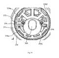
- An enlarged plane view of the cam follower disc 352 and cammed surface 351is provided in fig. 17 .
- the cam followers 358, of which there are four labeled 358a, 358b, 358c and 358d in fig. 17are evenly spaced around the circumference. As seen in fig.
- the flexprint coiled portion 345is seen positioned at the inner side of the reingshaped element 350 and enclosed between the cam follower disk 352 and the shell 302. At both sides of the coiled portion in the radial direction space is provided such that the coil 345 may move inwardly and outwardly in the radial direction when the cradle neck and cradle portions of the headband are moved with respect to each other.
- An outwardly directed flange 362is provided at the ringshaped element 350, and on this flange 362 the earmuff 363 may be attached.
- an oblong opening 369is provided and through this opening the sound from the loudspeaker 226 in the headset 200 will be guided towards the ear of the user.
- the flange 362has a triangular cut out portion 364 which facilitates mounting of the earmuff 363 on the flange 362, as the cut out portion allows the ear muff 363 to be mounted in simple rational motion between the flange 362 and the ear muff 363.
- the earmuff 363is shown in 3D projection in a sectional view, and here an inwardly flanged portion 365 can be seen, and this portion fits over the flange 362 in the described manner. This allows easy exchange of the earmuff 363, and this allows the user to choose the earmuff material and texture according to his or her liking.
- the base station 100has in a surface region at the cradle thereof 101 a first surface mounted magnetic means 113 displaying a first magnetic polarization and a second surface mounted magnetic means 114 adjacent thereto and displaying a second magnetic polarization which is opposite the first magnetic polarization.
- the first magnetic means 113is slightly larger than the second magnetic means 114.
- the magnetic means 113,114are simple round magnets being mounted in surface orifices to have an exterior surface flush with the surrounding surface region of the cradle portion to which they are attached.
- the headset 200has at a corresponding surface region at the cradling neck 201 at least a further surface mounted magnetic means 215 displaying only one of the first or the second polarization. In this way it is ensured that this further magnet is respectively attracted to and repulsed from the two magnetic means 113, 114 of the bases station cradle.
- the headset magnet 215is arranged to be attracted to the first magnet 113 of the base station cradle 101, and repulsed from the second magnet 114 thereof. In this way the three magnets together aid to get the headset cradle neck 201 rightly positioned within the base station cradle 101.
- the larger first magnet 113 at the base station cradle 101ensures a good holding force between the headset and the base station.
- the charging connection points 111,112 at the base station 100are spring biased towards the headset input charging points 211,212 and the magnetic attraction between the headset magnet 215 and the first magnet 113 of the base station cradle aids to ensure a spring biasing force of a minimum size between input and output charging points.
- first and second surface mounted magnetic means 313,314are provided.
- the magnetic means 313,314displays polarization to cause attractions forces there between and the first and second surface mounted magnetic means 113,114 of the base station 100 when the headband cradle-neck portion 320 is cradled in the base station cradle 101. In this way it is ensured that both magnets of the base station attract each its magnet in the headband when the headband is cradled in the base station.
- a double attraction forceresults, and this facilitate the fixation of the headband-headset assembly in the cradle 101 of the base station 100 and a forceful fixation is required especially as the boom arm 239 and headset 200, in the cradle portion 301 of the headband 300 may be rotated with respect to the cradle neck portion 320 of the headband 300 and cause off axis weight load on the cradle/cradle neck connection between base station 100 and headband 300. Also the headband-headset assembly is considerably heavier than the headset 200 alone and further magnetic attraction aids to carry this weight in the cradle 101 of the base station 100.
- the two separate magnetsmay be substituted by a single u shaped magnet embedded in the surface or by electromagnetic means. Possibly the magnetic means may be totally embedded such that they are invisible to the naked eye. Also magnets, which are more or less protruding from the surrounding surface or which are withdrawn to a subsurface level could be used.
- the headset 200has a loudspeaker 226 which is seated in an electronics housing part 230 at a proximal end thereof and a boomarm 239 with a microphone 241 at a distal end 240 thereof, whereby the cradle neck portion 201 is provided at the boomarm 239 adjacently to the electronics and housing part 230.
- the boomarm 239should preferably be a lightweight construction, which extends the microphone into proximity of the users mouth as far as possible, however without causing off-axis weight load on the headset when worn on the ear without the headband. Battery charging points at the distal end of the boomarm or at the proximal end of the housing part as have previously been proposed are not desirable, as it makes a balanced cradling in a base station difficult.
- a cradle neck portionshould be close to the center of gravity of the unit to ensure cradling and secure holding and connection to a base station.
- the base station cradle 101comprises guiding surfaces 133, 134 (best seen in fig. 4 , and 4a ) which corresponds to opposed guiding surfaces 233,244,333,334 of the boomarm 239 (seen in fig. 5 and 6 ) and of the headband 300 (seen in fig. 7 and 8 ) at cradle neck portions thereof.
- the guiding surfaces 133,134 of the base station cradleare arranged opposed to each other and embrace parts of the headset or headband, whichever is seated in the cradle.
- Many other ways of providing mechanical interacting surfaces to fixate the headset or the headband in the base stationare possible such as a simple outstanding hook on the base station and corresponding orifices on the headset and headband respectively.
- the various magnetic means 313, 314, 215, 113, 114 and the charging input and output connection pints 111, 112, 211, 212, 321, 322 of the base station, of the headset and of the head band cradle neck portionsare provided at the guiding surfaces 333, 334, 233, 324, 133, 134 and two electrical charging connection are placed respectively, one at each side of a corresponding magnetic means.
- the magnetic means 313, 314, 215, 113, 114 and the charging connection points 111, 112, 211, 212, 321, 322are shown, and at each instance, the magnets are placed centered between the guiding surfaces, and at each side of the magnet in the space between the guiding surface and the magnet a charging connection point is provided.
- the guiding surfaces of the base station 100will interact with opposed surfaces of the headset 200 or headband 300 respectively and ensure sideway fixation of the headset or headband in the base station whereas the magnets will aid to ensure that a connection force between the mating electrical connection points is maintained.
- an earhook 260is connectable to the headset 200 through an aperture 203 provided at the cradle neck portion 201 of the headset.
- the earhook 260is seen in fig. 3 , and as displayed, the headset 200 may be seated in the cradle 101 of the base station 100 with the earhook 260 mounted in the aperture 203. As seen in fig.
- the headband 300 and headset 200 assemblydoes not allow the earhook 260 to be mounted to the headset 200, and also this would be counter-productive, as the both the earhook 260 and the headband 300 serve to maintain the headset in an operational position on a users head, but in each their unique and well known manner.
- the headband 300further comprises movable protrusions 340, 341 sized to enter the earhook aperture 203 when the headset 200 is connected to the headband 300.
- the protrusions 340, 341are provided on flexible stags 342,343 on each side of the cradle portion 301 of the headband.
- the stags 342, 343,are springy movable in the direction away from each other, and as a result the headset cradle neck portion may be forced into the space between the stags forcing these away from each other, and when the headset cradle neck is secured in the cradle 301 of the headband, the protrusions 340, 431 will enter the through going aperture 203 from each their side and thus help to maintain the headset 200 and headband 300 together.
- the movable protrusions 340,341are part of the cradle portion 301 of the headband 300 as seen in fig. 7 , and they are arranged adjacently to the charging input and output points 311, 312, 211, 212 of the headband 200 and headset 300 respectively when the headset is cradled in the headband.
- connection points for chargingmaintain a secure electrical connection when the headset 200 is cradled in the headband 300.
- a further set of mating holding meansare provided between headset 200 and headband 300. These comprise a click in attachment site 202 on the headset 200 and corresponding holding element 344 on the headband cradle part.
- the attachment sites and holding elementsare repeated on opposed sides of the headband and the headset respectively.
- the holding elements 344are mounted springy such that they may click into and out of the attachment sites 202 in a manner well known in the art.
- the boom arm 239comprise a first arm 242 and second arm 243 defining a through going oblong opening 246.
- a name tag 247is attached between the arms.
- the name tagis optional for the user but offers a possibility of personalization of the headset, and this could be an advantage in settings where numerous individuals work with each their headset in the same room.
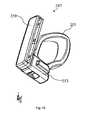
- the name tag 247is shown isolated in fig. 14 in a 3D projectional view.
- the tag 247comprises a transparent display window part 250 and name holder 251 where a slitformed opening 252 is defined between the display window and the name holder 251.
- the name tag 247further has a holder part 253 arranged generally perpendicular to the transparent display window 250 and name holder 251.
- the holder part 253comprise usual tongue and groove connection elements allowing the holder part to connect to corresponding tongue and grooves in the headset and thereby be securely seated between the arms of the headset boom proximal to the cradle neck part thereof as seen in Fig. 5 .
- the nametag 247is shown with a cheek-spacer 255, comprising a loop-shaped addition provided in the angle spanned between the window part 250 and the holder part 253.
- the cheek-spacer 255will prevent the boom arm 239 from touching the cheek of the user.
- Some usersmay not need a cheek-spacer due to the proportions of their head, and thus the user may choose to either use a name tag with or one without the cheek spacer 255.
- the cheek spacer 255may be made in many ways being either loop shaped as shown or having some other shape, whereby the general idea of the invention resides in the changeability between a nametag with and one without the cheek spacer 255 depending on the user's needs.
- the base stationhas a foot part 150 and an upright casing part 151 immovably connected to the foot part.
- the casing part 151is shaped as a six sided cube with six square and plane surfaces labeled 1, 2, 3, 4, 5 and 6.
- the cube 151appear fused to the foot part 150 at a corner constituted by the intersection of cube surfaces 1, 2 and 3, such that surface 4 of the cube will appear angled away from a vertical direction with relation to a desk top on which the foot 150 is placed.
- the cube surface 3will face towards the desk top at similar angle.
- the cradle 101is positioned on cube surface 4, adjacent to a top most corner, comprised of intersection of cube surfaces 4, 5 and 6, directly opposite the corner fused with the foot part 150.
- the headset 200 with or without the headband 300will rest at surface 4 when the headset is cradled for recharging of the battery 225.
- a rounded recess 7is provided, wherein either the headset casing part as seen in fig. 3 or the earmuff (shown in fig. 1 ) may be seated when the headset and/or the headband is cradled as described above.
- a toggle button 8is provided, such that the user may toggle between PC and line input to the headset.
- the various lines to the base stationare connected to the base station in the usual manner, and this is not shown or described in any further detail.
- electronicssuch as a wireless transmitter and control circuits for the recharging of the headset battery is provided.
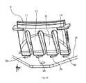
- a transparent light display 9is provided to this effect on the surface 4 of base station 100.
- a number of light diodes 20are provided inside the cube, and illuminates the front of the display 9 through each their light guide 11, 12, 13, 14 shaped integrally with the display 9.
- a corner of a printed circuit 15 boardis shown with the diodes 20 mounted thereon. The light from each diode 20 will travel through each its light guide 11, 12, 13, 14 and exit through the display 9.
- the light from each diode 20will either appear in a rather sharply limited area, above the light guide, or appear in rather fuzzy manner with a strong intensity at a central point and falling intensity going away from the central point.
- a material which causes some dispersion of the lightmay be chosen, in the event that a more smooth display action is wished.
- the intensity of the light from the diodes 11-14may be variable if wished.
- a materialis chosen which provides a fuzzy light, and the light intensity from the diodes is varied to the effect that a smooth advance of an illuminated area on the display 9 is achieved corresponding to the charging status of the rechargeable battery in the headset.
Landscapes
- Engineering & Computer Science (AREA)
- Physics & Mathematics (AREA)
- Acoustics & Sound (AREA)
- Signal Processing (AREA)
- Health & Medical Sciences (AREA)
- Otolaryngology (AREA)
- Power Engineering (AREA)
- General Health & Medical Sciences (AREA)
- Neurosurgery (AREA)
- Headphones And Earphones (AREA)
- Charge And Discharge Circuits For Batteries Or The Like (AREA)
- Mobile Radio Communication Systems (AREA)
Description
- The present invention relates to a base station, wireless headset and headband thereto where the headset is powered by a rechargeable battery comprised therein. The base station has a cradle with charging output contact points and the headset has a cradle-neck with charging input contact points and the wireless headset further comprises attachment sites corresponding to holding elements on the headband.
- Wireless headsets which may be worn alone on one ear or may be seated in and worn with a headband are known, and also it is known to provide a rechargeable battery with the headset. In such prior art systems a base station is customary, and the headset may be seated or cradled herein to gain contact with charging points to establish a charging voltage on the rechargeable battery. In such prior art systems, the cradling of the headset is often prohibited when the headset is mounted in the headband, or possibly the headband is sticking out of the base station at an odd angle and constitutes a nuisance to the user at the desk where such a system is usually parked.
- A wireless headset with a rechargeable battery and base station thereto where the headset may be used with or without a headband and where recharging of the rechargeable battery is facilitated both with the headset alone, and through the headband when the headset is mounted in the headset is thus desired. When the headset battery is charged through a connection running in the headband further design options becomes available, such as the provision of a large and exchangeable ear muff, and charging with the headband pointing out of the base station at the same angle irrespective of the positioning of a microphone boom arm.
US patent 6130953 discloses a headset including a housing, a resilient, convex headband fixed to the housing, and earphone fixed to the housing and displaceable relative to the end of the headband and a microphone fixed to a swivel arm that is on the housing.EP 1699212 shows a headset with an optional headband. The headset comprises a cradle neck portion for reception in a cradle of a charger device. The headband is mounted in such a way that it does not interfere with the charging of the headset.EP1548911 shows various ways of mounting wireless headphones in a charging base station.WO 2006076916 discloses a wireless headset which may be mounted for charging thereof in a charging base station. The headset may have a headband attached thereto,- An object of the invention is achieved by a base station, wireless headset and headband thereto where the headset is powered by a rechargeable battery comprised therein and where the base station has a cradle with charging output contact points and the headset has a cradle-neck with charging input contact points. The wireless headset further comprises attachment sites corresponding to holding elements on the headband, wherein the headband comprises: - a headband cradle portion with charging output points corresponding to the charging input points of the headset, - a headband cradle-neck with charging input points, corresponding to the base station charging output points. The charging input points at the cradle neck portion of the headband and the charging output points at the cradle portion of the headband are connected through electric leads.
- With the invention a system comprising a base station, a headset and a headband is provided, wherein the greatest possible flexibility may be built into the system, such that the charging connection points at the base station are connectable to corresponding charging points at either the headset alone or at the headband part. By having charging points at both headband and the headset the headband which has a long bow part designed to reach across the head of a user will always come out of the base station in the same angle and can be arranged not to be in the way of other appliances residing on the desk or other working space of the user. Further, the cradle neck arrangement at the headband and the headset allows the user to remove the headset or the headband with headset with one hand, and cradle the device without changing the grip on the device or provide support with the other hand. The magnetic coupling at the cradle thus along with the other features of the cradle and cradle neck connections aids in facilitating the smooth operation of the device with one hand.
- Further objects of the invention are achieved by the embodiments defined in the dependent claims and in the detailed description of the invention.
- As used herein, the singular forms "a," "an," and "the" are intended to include the plural forms as well (i.e. to have the meaning "at least one"), unless expressly stated otherwise. It will be further understood that the terms "includes," "comprises," "including," and/or "comprising," when used in this specification, specify the presence of stated features, integers, steps, operations, elements, and/or components, but do not preclude the presence or addition of one or more other features, integers, steps, operations, elements, components, and/or groups thereof. It will be understood that when an element is referred to as being "connected" or "coupled" to another element, it can be directly connected or coupled to the other element or intervening elements maybe present, unless expressly stated otherwise. Furthermore, "connected" or "coupled" as used herein may include wirelessly connected or coupled. As used herein, the term "and/or" includes any and all combinations of one or more of the associated listed items. The steps of any method disclosed herein do not have to be performed in the exact order disclosed, unless expressly stated otherwise.
- The invention will be explained more fully below in connection with a preferred embodiment and with reference to the drawings in which:
FIG. 1 shows the headset/headband combination cradled in the base station,FIG. 2 shows a section view of the headset in a 3d projection,FIG. 3 shows the headset with an ear hook cradled in the base station,FIG. 4 shows the base station with the cradle portion,FIG. 4a shows an enlarged view of a detail of the cradle in the base station shown infig. 4 ,FIG 4b shows the headset and headband combination with the headset turned away from the vertical position,FIG. 5 shows he boom portion of the headset in a 3d projection,FIG. 6 shows a side view of the headset electronic casing part,Fig. 7 shows a 3d projection of the cradle part of the headband without the headset mounted therein,Fig. 8 shows the element infig. 7 from a different angle,Fig. 9 shows an exploded view of the main parts of the headband,Fig. 10 shows the flexprint of the headband in a front view,Fig. 10a shows the flexpring offig. 10 in a side view,Fig. 11 shows the headband in a 3d projection and sectioned,Fig. 12 shows a detail of the headband in enlarged 3d projectional view,Fig. 13 shows a sectional view of the ear muff of the headband,Fig. 14 shows a 3d projection of the name tag,FIG. 15 shows the name tag with a cheek spacer andFIG. 16 shows the light display and underlying printed circuit board in 3d projection.- In most of the figures a small vignette is provided displaying the x,y and z axis of the digital model of the embodiment of the invention from which the figures are derived, in order to facilitate easier reading of the figures.
- In
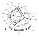
fig. 1 thebase station 100, thewireless headset 200 and theheadband 300 are shown with theheadset 200 and theheadband 300 fastened to each other and placed in thebase station 100. Theheadset 200 is powered by arechargeable battery 225 which is enclosed inside casing parts thereof. Infig. 2 a sectional view of the headset is shown, and here also theloudspeaker 226 is disclosed at aproximal part 230 of the headset. Distanced from the proximal part 230 adistal part 240 is provided at the end of aboom arm 239. Inside the distal part 240 a microphone unit is located, comprising one ormore microphones 241. Thebase station 100 has acradle 101 and theheadset 200 has a corresponding cradle-neck 201. As seen infig. 3 theheadset 200 may be seated in thecradle 101 of the base station by way of thecradle neck 201 being shaped to fit into thecradle 101. Thecradle 101 mountscharging output points neck 201 of theheadset 200 mounts charginginput contact points charging input points rechargeable battery 225 of the headset. Theheadset 200 may be cradled in a charging position as shown infig. 3 to ensure electrical connection between thebase station 100 and therechargeable battery 225 through the electrical contact points defined asoutput points input points - The
wireless headset 200 hasfirst attachment sites 203 at thecradle neck 201 andfurther attachment sites 202 at thecasing body 230 for releasably attachment thereto of theheadband 300 to form a headband-headset assembly. - The
headband 300 comprises acradle portion 301 mounting charging output points 311,312 providing a releasable mechanical attachment point between thisheadband cradle portion 301 and the headset cradle-neck portion 201 and simultaneous electrical connection between the headband charging output points 311,312 and the cradle neck input charging points 211,212 of theheadset 200. - The
headband 300 also comprises a headband cradle-neck 320 (sefig. 8 ) mounting charging input points 321,322 providing a releasable mechanical attachment point between thisheadband cradle neck 320 and thebase station cradle 101 and simultaneous electrical connection between the headband charging input points 321,322 and the base station charging output points 111,112. - The charging input points 321,322 at the
cradle neck portion 320 of theheadband 300 and the charging output points 311,312 at thecradle portion 301 of theheadband 300 are connected throughelectric leads 330, such that theheadset battery 225 is chargeable through theheadband 300 when seated in theheadband 300 and theheadband 300 is mounted in thebase station cradle 101. - The advantage of the above described arrangement is that the
headset battery 225 may be charged from thebase station 100 when used alone as well as when used with theheadband 300. In this way the user need not separate the headband and headset from each other in order to facilitate charging of the rechargeable battery. It is also noted that by providing the headband with a cradle neck portion of its own with charging points, and fitting the cradle of the base station, a very secure and mechanically reliable fixation of the assembled headset and headband in the base station may be provided, such that the added weight of the headband will not compromise the establishment of a secure electrical connection between the charging points of thebase station 100 and therechargeable battery 225 in theheadset 200. - The headband
cradle neck portion 320 and theheadband cradle portion 301 are mutually rotatable with respect to each other allowing aboom arm 230 of theheadset 200 to be rotated to a position wherein it points towards the user's mouth when theheadband 300 with theheadset 200 is mounted on the head of a user. This is illustrated infig. 4b . - This adjustment possibility allows the user to personalize the headband and headset for the shape and proportions of his or her head, and it ensures that the
microphone unit 240 may always be positioned close to the user's mouth. - The electrical leads 330 between the charging input points 321,322 at the
cradle neck portion 320 of theheadband 300 and the charging output points 311,312 at thecradle portion 301 of theheadband 300 allow the mutual rotational positioning between the headbandcradle neck portion 320 and theheadband cradle portion 301 without disturbance to the electrical connection. In this manner the charging of therechargeable battery 225 may take place when the headset, seated in the headband, is turned to any position with respect to thecradle neck portion 320. This is an important advantage to the user who regardless of the turning point of the boom arm may cradle the headband with headset in the base station and be sure of a good charging connection being established. - In
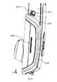
figs. 10 and 10a front view and side view are shown of theelectrical leads 330 inside of theheadband 300. The leads 330 connect charging input points 321, 322 and charging output solder points 328,329. The leads 330 are provided in the shape of a flexprint element, wherein the electrical leads are provided as lanes on a flexible sheet material, the lanes usually being generated in electrochemical processing which is well known and will not be further described. The charging input points 321,322 are metal covered areas of the flexprint sheet material which are connectable from the outside through a suitable window in thecradle neck portion 320 of theheadband 300. Each of the chargingoutput points charging output point figs. 10 and 10a it can be seen that the flexprint comprise a coiledportion 345 and acradle neck extension 346 from a first end of the coiled portion and acradle extension 347 from a second end of the coiled portion. As theflexible print board 330 is soft and bendable it is possible to rotate thecradle extension 347 with respect to thecradle neck extension 346 while the coiledportion 345 absorbs the deformation. This rotation is naturally within certain limits, but from the shown position where the cradle and cradle neck portions are aligned with each other, the cradle is to be rotated 140deg to either side with respect to the cradle neck. This allows the microphone boom in the headset to be pointed to the user's mouth with the headset at the right ear as well as at the left ear of the user. And this can be done without disconnection of the headband and headset from each other, and any user may then without further ado take the headset to his or her preferred ear and adjust the microphone boom arm to the right position with respect to the mouth. - In
fig. 9 it can be seen how thecradle neck portion 320 is integrally molded with aringshaped element 350 which features an internalcammed surface 351. Thecradle portion 301 is integrally shaped with ashell part 302 and the shell part is connected to a circular disc shapedcam follower element 352 by a suitable connection means such as by use ofscrews 356. Thescrews 356 keep together theshell part 302 and thecam follower disc 352 and keep in place the holdingelements 344, while theflexprint element 330 will be enclosed in between theshell 320 and thecam follower disc 352. Thecam follower disc 352 and theshell 302 are assembled from each their side of theringshaped element 350, and form a sub-assembly, which is rotatable with respect to theringshaped element 350. - In
fig. 11 a sectional view of a 3D projection of the headband is shown, to better illustrate the above elements. Theringshaped element 350 with thecammed surface 351 is seen, and further opposedflanges 357 between theringshaped element 350 and thecam follower disc 352 are disclosed, which serve as bearing in both radial and axial direction between thecam follower disk 352 and theringshaped element 351. It is clear from the figure also that the cam follower disk is not massive but is shaped more like a wheel with spokes. This openness of the disk is acoustically important as it facilitates a more open fit, whereby the user of the headband with the headset seated therein also will receive a certain amount of sounds from the surrounding at this ear.Openings 318 in theshell part 302 of the headband ensure that sound from surroundings may reach the ear and this enhances the comfort for the user.Spring elements 360 are provided to ensure the springiness of the holdingelement 344. Cam followers 358 are shaped integrally withcam follower disk 352, and are provided to flex towards thecam surface 351 in order to securely position the microphone boom arm at well defined positions. Thecam followers 358 are arranged around the circumference of thedisk 352 and each cam follower is provided at aflexible spring element 359 to ensure that thecam followers 358 remain in forceful contact withcam surface 351. An enlarged plane view of thecam follower disc 352 andcammed surface 351 is provided infig. 17 . Thecam followers 358, of which there are four labeled 358a, 358b, 358c and 358d infig. 17 are evenly spaced around the circumference. As seen infig. 17 they are provided such that twocam followers further cams followers 358c, 358d will be at the bottom between two cam projections. In this way two cam followers will be on their way "uphill" while the two others will be on their way "downhill" on the cammed surface. This ensures a rather smooth operation when the headset boom arm is turned with respect to the brace across the head.- Also in
fig. 11 the flexprint coiledportion 345 is seen positioned at the inner side of thereingshaped element 350 and enclosed between thecam follower disk 352 and theshell 302. At both sides of the coiled portion in the radial direction space is provided such that thecoil 345 may move inwardly and outwardly in the radial direction when the cradle neck and cradle portions of the headband are moved with respect to each other. An outwardly directedflange 362 is provided at theringshaped element 350, and on thisflange 362 theearmuff 363 may be attached. - Centrally in the cam follower disk an
oblong opening 369 is provided and through this opening the sound from theloudspeaker 226 in theheadset 200 will be guided towards the ear of the user. - As seen in
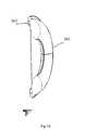
fig. 12 , theflange 362 has a triangular cut outportion 364 which facilitates mounting of theearmuff 363 on theflange 362, as the cut out portion allows theear muff 363 to be mounted in simple rational motion between theflange 362 and theear muff 363. Theearmuff 363 is shown in 3D projection in a sectional view, and here an inwardlyflanged portion 365 can be seen, and this portion fits over theflange 362 in the described manner. This allows easy exchange of theearmuff 363, and this allows the user to choose the earmuff material and texture according to his or her liking. - As best seen in
Fig. 4a , thebase station 100 has in a surface region at the cradle thereof 101 a first surface mountedmagnetic means 113 displaying a first magnetic polarization and a second surface mountedmagnetic means 114 adjacent thereto and displaying a second magnetic polarization which is opposite the first magnetic polarization. InFig. 4a the firstmagnetic means 113 is slightly larger than the secondmagnetic means 114. The magnetic means 113,114 are simple round magnets being mounted in surface orifices to have an exterior surface flush with the surrounding surface region of the cradle portion to which they are attached. - The
headset 200 has at a corresponding surface region at thecradling neck 201 at least a further surface mountedmagnetic means 215 displaying only one of the first or the second polarization. In this way it is ensured that this further magnet is respectively attracted to and repulsed from the twomagnetic means headset magnet 215 is arranged to be attracted to thefirst magnet 113 of thebase station cradle 101, and repulsed from thesecond magnet 114 thereof. In this way the three magnets together aid to get theheadset cradle neck 201 rightly positioned within thebase station cradle 101. This positioning is critical as small deviations from the right position will result in the charging points not gaining contact with each other. The largerfirst magnet 113 at thebase station cradle 101 ensures a good holding force between the headset and the base station. Also, the charging connection points 111,112 at thebase station 100 are spring biased towards the headset input charging points 211,212 and the magnetic attraction between theheadset magnet 215 and thefirst magnet 113 of the base station cradle aids to ensure a spring biasing force of a minimum size between input and output charging points. - At the
cradle neck portion 320 of theheadband 300 first and second surface mounted magnetic means 313,314 are provided. The magnetic means 313,314 displays polarization to cause attractions forces there between and the first and second surface mounted magnetic means 113,114 of thebase station 100 when the headband cradle-neck portion 320 is cradled in thebase station cradle 101. In this way it is ensured that both magnets of the base station attract each its magnet in the headband when the headband is cradled in the base station. A double attraction force results, and this facilitate the fixation of the headband-headset assembly in thecradle 101 of thebase station 100 and a forceful fixation is required especially as theboom arm 239 andheadset 200, in thecradle portion 301 of theheadband 300 may be rotated with respect to thecradle neck portion 320 of theheadband 300 and cause off axis weight load on the cradle/cradle neck connection betweenbase station 100 andheadband 300. Also the headband-headset assembly is considerably heavier than theheadset 200 alone and further magnetic attraction aids to carry this weight in thecradle 101 of thebase station 100. - The skilled artisan would readily know that the two separate magnets may be substituted by a single u shaped magnet embedded in the surface or by electromagnetic means. Possibly the magnetic means may be totally embedded such that they are invisible to the naked eye. Also magnets, which are more or less protruding from the surrounding surface or which are withdrawn to a subsurface level could be used.
- The
headset 200 has aloudspeaker 226 which is seated in anelectronics housing part 230 at a proximal end thereof and aboomarm 239 with amicrophone 241 at adistal end 240 thereof, whereby thecradle neck portion 201 is provided at theboomarm 239 adjacently to the electronics andhousing part 230. Theboomarm 239 should preferably be a lightweight construction, which extends the microphone into proximity of the users mouth as far as possible, however without causing off-axis weight load on the headset when worn on the ear without the headband. Battery charging points at the distal end of the boomarm or at the proximal end of the housing part as have previously been proposed are not desirable, as it makes a balanced cradling in a base station difficult. A cradle neck portion should be close to the center of gravity of the unit to ensure cradling and secure holding and connection to a base station. - The
base station cradle 101 comprises guidingsurfaces 133, 134 (best seen infig. 4 , and4a ) which corresponds to opposed guiding surfaces 233,244,333,334 of the boomarm 239 (seen infig. 5 and6 ) and of the headband 300 (seen infig. 7 and8 ) at cradle neck portions thereof. In the presented embodiment, the guiding surfaces 133,134 of the base station cradle are arranged opposed to each other and embrace parts of the headset or headband, whichever is seated in the cradle. Many other ways of providing mechanical interacting surfaces to fixate the headset or the headband in the base station are possible such as a simple outstanding hook on the base station and corresponding orifices on the headset and headband respectively. - The various
magnetic means output connection pints figs 4a ,5 and8 , themagnetic means base station 100 will interact with opposed surfaces of theheadset 200 orheadband 300 respectively and ensure sideway fixation of the headset or headband in the base station whereas the magnets will aid to ensure that a connection force between the mating electrical connection points is maintained. Thus a distance relation exist between the guiding surfaces of the base station and the guiding surfaces of the headset and headband respectively in that the distance between the guiding surfaces of the base station correspond to the width of the boom arm and the headband at the cradle neck portions thereof. - When the
headset 200 is to be worn alone without theheadband 300, some means of attaching the headset to the ear is needed and to this end anearhook 260 is connectable to theheadset 200 through anaperture 203 provided at thecradle neck portion 201 of the headset. Theearhook 260 is seen infig. 3 , and as displayed, theheadset 200 may be seated in thecradle 101 of thebase station 100 with theearhook 260 mounted in theaperture 203. As seen infig. 1 , theheadband 300 andheadset 200 assembly does not allow theearhook 260 to be mounted to theheadset 200, and also this would be counter-productive, as the both theearhook 260 and theheadband 300 serve to maintain the headset in an operational position on a users head, but in each their unique and well known manner. - At the
cradle portion 301 theheadband 300 further comprisesmovable protrusions earhook aperture 203 when theheadset 200 is connected to theheadband 300. Theprotrusions cradle portion 301 of the headband. Thestags cradle 301 of the headband, theprotrusions 340, 431 will enter the through goingaperture 203 from each their side and thus help to maintain theheadset 200 andheadband 300 together. - The movable protrusions 340,341 are part of the
cradle portion 301 of theheadband 300 as seen infig. 7 , and they are arranged adjacently to the charging input andoutput points headband 200 andheadset 300 respectively when the headset is cradled in the headband. Hereby it is ensured that the connection points for charging maintain a secure electrical connection when theheadset 200 is cradled in theheadband 300. - Apart from the protrusion mentioned above a further set of mating holding means are provided between
headset 200 andheadband 300. These comprise a click inattachment site 202 on theheadset 200 and corresponding holdingelement 344 on the headband cradle part. The attachment sites and holding elements are repeated on opposed sides of the headband and the headset respectively. The holdingelements 344 are mounted springy such that they may click into and out of theattachment sites 202 in a manner well known in the art. - As seen in
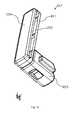
figs 1 ,3 and5 theboom arm 239 comprise afirst arm 242 andsecond arm 243 defining a through going oblong opening 246. As seen infig. 5 aname tag 247 is attached between the arms. The name tag is optional for the user but offers a possibility of personalization of the headset, and this could be an advantage in settings where numerous individuals work with each their headset in the same room. Thename tag 247 is shown isolated infig. 14 in a 3D projectional view. Thetag 247 comprises a transparentdisplay window part 250 andname holder 251 where aslitformed opening 252 is defined between the display window and thename holder 251. Into this slit formed opening the user may slide a piece of paper (not shown) with an identity sign printed or written thereon, such that the sign can be read through thetransparent display window 250. When mounted between the arms of theheadset boom 239 thedisplay window part 250 will be flush with the exterior surface of the twoarms opening 252 will be between the arms which prevent the paper with the identity sign thereon from falling out. Thename tag 247 further has aholder part 253 arranged generally perpendicular to thetransparent display window 250 andname holder 251. Theholder part 253 comprise usual tongue and groove connection elements allowing the holder part to connect to corresponding tongue and grooves in the headset and thereby be securely seated between the arms of the headset boom proximal to the cradle neck part thereof as seen inFig. 5 . - In
fig. 15 thenametag 247 is shown with a cheek-spacer 255, comprising a loop-shaped addition provided in the angle spanned between thewindow part 250 and theholder part 253. The cheek-spacer 255 will prevent theboom arm 239 from touching the cheek of the user. Some users may not need a cheek-spacer due to the proportions of their head, and thus the user may choose to either use a name tag with or one without the cheek spacer 255. The cheek spacer 255 may be made in many ways being either loop shaped as shown or having some other shape, whereby the general idea of the invention resides in the changeability between a nametag with and one without the cheek spacer 255 depending on the user's needs. - As seen in
figs. 1 ,3 and4 the base station has afoot part 150 and anupright casing part 151 immovably connected to the foot part. Thecasing part 151 is shaped as a six sided cube with six square and plane surfaces labeled 1, 2, 3, 4, 5 and 6. Thecube 151 appear fused to thefoot part 150 at a corner constituted by the intersection ofcube surfaces surface 4 of the cube will appear angled away from a vertical direction with relation to a desk top on which thefoot 150 is placed. Thecube surface 3 will face towards the desk top at similar angle. Thecradle 101 is positioned oncube surface 4, adjacent to a top most corner, comprised of intersection ofcube surfaces foot part 150. Theheadset 200 with or without theheadband 300 will rest atsurface 4 when the headset is cradled for recharging of thebattery 225. As best seen infig. 4 , at cube surface 4 arounded recess 7 is provided, wherein either the headset casing part as seen infig. 3 or the earmuff (shown infig. 1 ) may be seated when the headset and/or the headband is cradled as described above. Centrally in the recess atoggle button 8 is provided, such that the user may toggle between PC and line input to the headset. At thesurface 3 the various lines to the base station are connected to the base station in the usual manner, and this is not shown or described in any further detail. Inside thecube 151 electronics such as a wireless transmitter and control circuits for the recharging of the headset battery is provided. - In order that the user may see the charging status of the battery of a headset, a transparent
light display 9 is provided to this effect on thesurface 4 ofbase station 100. A number oflight diodes 20 are provided inside the cube, and illuminates the front of thedisplay 9 through each theirlight guide display 9. Infig. 16 a corner of a printedcircuit 15 board is shown with thediodes 20 mounted thereon. The light from eachdiode 20 will travel through each itslight guide display 9. Dependent on the transparency properties of the material used for thedisplay 9 and light guides 11 - 14 the light from eachdiode 20 will either appear in a rather sharply limited area, above the light guide, or appear in rather fuzzy manner with a strong intensity at a central point and falling intensity going away from the central point. By choosing a very transparent material for the light guides 11-14 and thedisplay 9, a discrete display of four clearly defined areas can be achieved and each area may be lit independently of the others. On the other hand, a material which causes some dispersion of the light may be chosen, in the event that a more smooth display action is wished. On top of this the intensity of the light from the diodes 11-14 may be variable if wished. In a preferred embodiment a material is chosen which provides a fuzzy light, and the light intensity from the diodes is varied to the effect that a smooth advance of an illuminated area on thedisplay 9 is achieved corresponding to the charging status of the rechargeable battery in the headset. - The invention is defined by the features of the independent claim(s). Preferred embodiments are defined in the dependent claims. Any reference numerals in the claims are intended to be non-limiting for their scope.
Claims (12)
- Base station (100), wireless headset (200) and headband (300) thereto where the headset (200) is powered by a rechargeable battery (225) comprised therein and where the base station (100) has a cradle (101) with charging output contact points (111,112) and the headset has a cradle-neck (201) with charging input contact points (211,212); where the wireless headset (200) further comprises attachment sites (203,202) corresponding to holding elements (340,341,344) on the headband (300), wherein the headband comprises: - a headband cradle portion (301) with charging output points (311,312) corresponding to the charging input points (211,212) of the headset (200), - a headband cradle-neck (320) with charging input points, (321,322) corresponding to the base station charging output points (111,112); whereby the charging input points (321,322) at the cradle neck portion of the headband (300) and the charging output points (311,312) at the cradle portion of the headband (300) are connected through electric leads (330).
- Base station, wireless headset and headband thereto as claimed in claim 1, wherein the headband cradle neck portion (320) and the headband cradle portion (301) are mutually rotatable with respect to each other.
- Base station and wireless headset as claimed in claim 2 wherein the electrical leads (330) between the charging input points (321,322) at the cradle neck portion (320) of the headband (300) and the charging output points (311,312) at the cradle portion (301) of the headband allow the mutual rotational positioning between the headband cradle neck portion (320) and the headband cradle portion (301) without disturbance to the electrical connection whereby leads (330) are provided in the shape of a flexprint element, wherein the electrical leads are provided as lanes on a flexible sheet material where the leads (330) connect charging input points (321, 322) and charging output solder points (328,329) and the flexprint comprise a coiled portion (345) so it is possible to rotate the cradle portion (301) with respect to the cradle neck portion (320) while the coiled portion (345) absorbs the deformation.
- Base station, wireless headset and headband thereto as claimed in claim 3 wherein the base station (100) in a surface region at the cradle comprise a first surface mounted magnetic means (114) displaying a first magnetic polarization and a second surface mounted magnetic means (113) adjacent thereto and displaying a second magnetic polarization which is opposite the first magnetic polarization and wherein also the headset (200) at a corresponding surface region at the cradle neck (201) comprise at least a further surface mounted magnetic means (215) displaying only one of the first or the second polarization ensuring attraction forces and repulsion forces respectively between this further magnetic means (215) and the two magnetic means (114,113) at the bases station cradle (101).
- Base station, wireless headset and headband thereto as claimed in claim 4 wherein first and second surface mounted magnetic means (313,314) are provided at the cradle-neck portion (320) of the headband (300) displaying polarization to cause attractions forces therebetween and the first and second surface mounted magnetic means (114,113) of the base station (100) when the headband cradle-neck portion (320) is cradled in the base station cradle (101).
- Base station, wireless headset and headband thereto as claimed in claim 4 wherein the headset (200) has a loudspeaker (226) provided in an electronics housing part (230) at a proximal end thereof and a boomarm (243) with a microphone (241) at a distal end thereof, whereby the headset cradle neck portion (201) is provided at the boomarm (243) adjacently to the electronics and housing part (230).
- Base station, wireless headset and headband thereto as claimed in claim 6 wherein the base station cradle (101) comprises guiding surfaces (133,134) which corresponds to opposed guiding surfaces (233,234) of the cradle neck portion (201) at the boomarm of the headset (200) and which corresponds to guiding surfaced (333,334) at the cradle neck portion (320) of the headband (300).
- Base station, wireless headset and headband thereto as claimed in claim 7, wherein the magnetic means (313, 314, 215, 113,114) and the charging input or output connection points (111,112, 211, 212, 321, 322) of the base station (100), of the headset (200) and of the head band cradle neck portions (320) are provided at the guiding surfaces (133, 134, 233, 234, 333, 334) and wherein two electrical charging connection (111, 112, 211, 212, 321, 322) are placed respectively, one at each side of a corresponding magnetic means (313, 314, 215, 113, 114).
- Base station, wireless headset and headband thereto as claimed in claim 8, wherein the guiding surfaces (133, 134) of the base station (100) comprises two opposed protruding wall parts with a distance therebetween corresponding to the width of the boom arm (243) and the headband (300) at the cradle neck portions (320) thereof and where magnetic means (113, 114) and electrical charging connection points (111, 112) are located between the two opposed protruding wall parts.
- Base station, wireless headset and headband thereto as claimed in claim 1 wherein an earhook (260) is connectable to the headset (200) through an earhook aperture (203) provided at the cradle neck portion (201) of the headset (200).
- Base station, wireless headset and headband thereto as claimed in claim 10 wherein the headband (300) at its cradle portion (301) further comprises movable protrusions (340, 341) sized to enter the earhook apertures (203).
- Base station, wireless headset and headband thereto as claimed in claim 11, wherein the movable protrusions (340, 341) are part of the cradle portion of the headband (300) and arranged adjacently to the charging input and output connection points (311,312) of the headband and headset respectively.
Priority Applications (10)
| Application Number | Priority Date | Filing Date | Title |
|---|---|---|---|
| DK09172547.3TDK2309618T3 (en) | 2009-10-08 | 2009-10-08 | Base station, wireless headset and headband thereto. |
| EP12175861.9AEP2521242B1 (en) | 2009-10-08 | 2009-10-08 | Base station, wireless headset and headband thereto. |
| DK12175861.9TDK2521242T3 (en) | 2009-10-08 | 2009-10-08 | Base station, wireless headset and headband thereto. |
| EP09172547AEP2309618B1 (en) | 2009-10-08 | 2009-10-08 | Base station, wireless headset and headband thereto |
| AU2010219415AAU2010219415B2 (en) | 2009-10-08 | 2010-09-13 | Base station, wireless headset and headband thereto |
| US12/923,799US8494205B2 (en) | 2009-10-08 | 2010-10-07 | Base station, wireless headset and headband thereto |
| CN201010501316.0ACN102036142B (en) | 2009-10-08 | 2010-10-08 | Base station, wireless headset and headband thereto |
| US13/925,163US9451347B2 (en) | 2009-10-08 | 2013-06-24 | Base station, wireless headset and headband thereto |
| US15/218,705US20170055059A1 (en) | 2009-10-08 | 2016-07-25 | Base Station, Wireless Headset and Headband Thereto |
| AU2016216671AAU2016216671A1 (en) | 2009-10-08 | 2016-08-18 | Base Station, Wireless Headset and Headband Thereto |
Applications Claiming Priority (1)
| Application Number | Priority Date | Filing Date | Title |
|---|---|---|---|
| EP09172547AEP2309618B1 (en) | 2009-10-08 | 2009-10-08 | Base station, wireless headset and headband thereto |
Related Child Applications (1)
| Application Number | Title | Priority Date | Filing Date |
|---|---|---|---|
| EP12175861.9ADivision-IntoEP2521242B1 (en) | 2009-10-08 | 2009-10-08 | Base station, wireless headset and headband thereto. |
Publications (2)
| Publication Number | Publication Date |
|---|---|
| EP2309618A1 EP2309618A1 (en) | 2011-04-13 |
| EP2309618B1true EP2309618B1 (en) | 2012-08-29 |
Family
ID=41785855
Family Applications (2)
| Application Number | Title | Priority Date | Filing Date |
|---|---|---|---|
| EP09172547AActiveEP2309618B1 (en) | 2009-10-08 | 2009-10-08 | Base station, wireless headset and headband thereto |
| EP12175861.9AActiveEP2521242B1 (en) | 2009-10-08 | 2009-10-08 | Base station, wireless headset and headband thereto. |
Family Applications After (1)
| Application Number | Title | Priority Date | Filing Date |
|---|---|---|---|
| EP12175861.9AActiveEP2521242B1 (en) | 2009-10-08 | 2009-10-08 | Base station, wireless headset and headband thereto. |
Country Status (5)
| Country | Link |
|---|---|
| US (3) | US8494205B2 (en) |
| EP (2) | EP2309618B1 (en) |
| CN (1) | CN102036142B (en) |
| AU (2) | AU2010219415B2 (en) |
| DK (2) | DK2521242T3 (en) |
Families Citing this family (17)
| Publication number | Priority date | Publication date | Assignee | Title |
|---|---|---|---|---|
| US9793739B2 (en)* | 2013-08-07 | 2017-10-17 | Sandisk Technologies Llc | Wireless power transmitting device |
| US10110984B2 (en)* | 2014-04-21 | 2018-10-23 | Apple Inc. | Wireless earphone |
| USD723011S1 (en) | 2014-09-04 | 2015-02-24 | Bluelounge Pte. Ltd. | Headphone stand |
| CN104954908A (en)* | 2015-06-23 | 2015-09-30 | 苏州凯枫瑞电子科技有限公司 | Multi-adjustment type headphones |
| CN104954907A (en)* | 2015-06-23 | 2015-09-30 | 苏州凯枫瑞电子科技有限公司 | Clamping adjusting type headphones |
| CN104954914A (en)* | 2015-06-25 | 2015-09-30 | 苏州凯枫瑞电子科技有限公司 | Environment-friendly type light-sensation power off type smart headphones |
| CN104954916A (en)* | 2015-06-25 | 2015-09-30 | 苏州凯枫瑞电子科技有限公司 | Headphones capable of being stored and provided with independent setter |
| DK3151582T3 (en) | 2015-09-30 | 2020-10-12 | Apple Inc | HEADPHONE WITH CHARGING SYSTEM CASE |
| DK3310072T3 (en)* | 2016-10-14 | 2019-10-28 | Sennheiser Communications As | FLAIR ELECTRICAL CONNECTOR HEARING DEVICE |
| US11159874B2 (en)* | 2017-03-20 | 2021-10-26 | Earshots Limited | Wearable device |
| CN109103690B (en)* | 2017-06-21 | 2023-11-28 | 歌尔科技有限公司 | Connecting mechanism |
| KR101927245B1 (en)* | 2018-01-12 | 2018-12-10 | (주)금오전자 | Stands combined charger for headphones |
| CN207939695U (en)* | 2018-02-12 | 2018-10-02 | 易力声科技(深圳)有限公司 | Make the earphone that charging is transmitted by earphone ferrule band |
| US10674244B2 (en)* | 2018-02-21 | 2020-06-02 | Bose Corporation | Audio device |
| CN111417044B (en)* | 2020-03-31 | 2022-02-25 | 歌尔股份有限公司 | Headphone charging device and headphone system |
| USD971832S1 (en) | 2020-10-09 | 2022-12-06 | ACCO Brands Corporation | Combined electronic device charger and stand |
| US11140469B1 (en) | 2021-05-03 | 2021-10-05 | Bose Corporation | Open-ear headphone |
Family Cites Families (19)
| Publication number | Priority date | Publication date | Assignee | Title |
|---|---|---|---|---|
| US3786391A (en)* | 1972-07-11 | 1974-01-15 | W Mathauser | Magnetic self-aligning electrical connector |
| FR2746997B1 (en)* | 1996-03-28 | 1998-11-20 | Pralus Charles | TELEPHONE ASSEMBLY TRANSFORMABLE INTO A TELEPHONE HELMET |
| DE19724667C1 (en) | 1997-06-11 | 1998-10-15 | Knowles Electronics Inc | Head phones and speaker kit e.g. for telephony or for voice communication with computer |
| US6233344B1 (en)* | 1998-06-10 | 2001-05-15 | Wren Clegg | Ear-hook boom microphone |
| WO2001001657A1 (en)* | 1999-06-24 | 2001-01-04 | Alvin Wai Lun Yip | Headset unit for use with a mobile telephone |
| DK174898B1 (en)* | 2002-06-20 | 2004-02-09 | Gn Netcom As | Headset |
| JP3794363B2 (en) | 2002-09-13 | 2006-07-05 | ソニー株式会社 | Charging apparatus and charging method |
| US7409234B2 (en)* | 2003-03-07 | 2008-08-05 | Cardo Systems, Inc. | Wireless communication headset with exchangeable attachments |
| DE102004001442A1 (en) | 2004-01-08 | 2005-09-22 | Sennheiser Electronic Gmbh & Co. Kg | headphone |
| DK200500021U4 (en) | 2005-01-18 | 2006-06-09 | Gn Netcom As | Headset with carrying style |
| US7265517B2 (en)* | 2005-03-03 | 2007-09-04 | Research In Motion Limited | Charger unit for an electronic device including a system for protective storage of an adapter plug |
| ATE483318T1 (en)* | 2005-03-04 | 2010-10-15 | Sennheiser Comm As | CONFIGURABLE HEADPHONES |
| US20070093279A1 (en)* | 2005-10-12 | 2007-04-26 | Craig Janik | Wireless headset system for the automobile |
| US20090061957A1 (en)* | 2007-08-30 | 2009-03-05 | Bauman Barry B | Solar operated battery headset |
| KR100849137B1 (en)* | 2007-11-02 | 2008-07-30 | 장애인표준사업장비클시스템 주식회사 | Wireless headset with aux terminal |
| US8295532B2 (en)* | 2008-01-11 | 2012-10-23 | Broadcom Corporation | Method and system for wireless headset instant on capability during battery charging |
| JP4292231B1 (en)* | 2008-03-24 | 2009-07-08 | 株式会社東芝 | Electronics |
| US8497657B2 (en)* | 2008-06-27 | 2013-07-30 | Microsoft Corporation | Docking station for electronic device |
| US20100137038A1 (en)* | 2008-12-01 | 2010-06-03 | Plantronics, Inc. | Interchangeable Docking Cradle |
- 2009
- 2009-10-08EPEP09172547Apatent/EP2309618B1/enactiveActive
- 2009-10-08DKDK12175861.9Tpatent/DK2521242T3/enactive
- 2009-10-08EPEP12175861.9Apatent/EP2521242B1/enactiveActive
- 2009-10-08DKDK09172547.3Tpatent/DK2309618T3/enactive
- 2010
- 2010-09-13AUAU2010219415Apatent/AU2010219415B2/ennot_activeCeased
- 2010-10-07USUS12/923,799patent/US8494205B2/enactiveActive
- 2010-10-08CNCN201010501316.0Apatent/CN102036142B/enactiveActive
- 2013
- 2013-06-24USUS13/925,163patent/US9451347B2/enactiveActive
- 2016
- 2016-07-25USUS15/218,705patent/US20170055059A1/ennot_activeAbandoned
- 2016-08-18AUAU2016216671Apatent/AU2016216671A1/ennot_activeAbandoned
Also Published As
| Publication number | Publication date |
|---|---|
| CN102036142A (en) | 2011-04-27 |
| EP2521242A1 (en) | 2012-11-07 |
| DK2521242T3 (en) | 2014-03-17 |
| US9451347B2 (en) | 2016-09-20 |
| US20110086677A1 (en) | 2011-04-14 |
| AU2016216671A1 (en) | 2016-09-15 |
| US8494205B2 (en) | 2013-07-23 |
| US20170055059A1 (en) | 2017-02-23 |
| CN102036142B (en) | 2015-04-08 |
| AU2010219415A1 (en) | 2011-04-28 |
| US20130315430A1 (en) | 2013-11-28 |
| EP2309618A1 (en) | 2011-04-13 |
| EP2521242B1 (en) | 2013-12-18 |
| AU2010219415B2 (en) | 2016-06-09 |
| DK2309618T3 (en) | 2012-11-05 |
Similar Documents
| Publication | Publication Date | Title |
|---|---|---|
| EP2309618B1 (en) | Base station, wireless headset and headband thereto | |
| US9113251B2 (en) | Headset | |
| KR101830397B1 (en) | Wireless pairing of earbuds and case | |
| EP3169081B1 (en) | Wireless earbuds and related methods | |
| US8983102B2 (en) | Speech processor headpiece | |
| JP2009069219A (en) | Tip cell with bone conduction speaker and eyeglass frame | |
| CN102245262A (en) | Integrated voice processor headpiece | |
| WO2012002605A1 (en) | Earring-type wireless speaker device and bone conduction speaker | |
| US20210211811A1 (en) | Multi-part eardrum-contact hearing aid placed deep in the ear canal | |
| US20250166605A1 (en) | Audio output module for use in artificial voice systems | |
| JP7663971B2 (en) | In-ear wearable device and panel assembly thereof | |
| EP1617632A1 (en) | Telephone transmitter/receiver | |
| JP2021111805A (en) | Earpieces and earphones with the earpieces |
Legal Events
| Date | Code | Title | Description |
|---|---|---|---|
| PUAI | Public reference made under article 153(3) epc to a published international application that has entered the european phase | Free format text:ORIGINAL CODE: 0009012 | |
| AK | Designated contracting states | Kind code of ref document:A1 Designated state(s):AT BE BG CH CY CZ DE DK EE ES FI FR GB GR HR HU IE IS IT LI LT LU LV MC MK MT NL NO PL PT RO SE SI SK SM TR | |
| AX | Request for extension of the european patent | Extension state:AL BA RS | |
| 17P | Request for examination filed | Effective date:20111013 | |
| RIC1 | Information provided on ipc code assigned before grant | Ipc:H02J 7/00 20060101AFI20111104BHEP Ipc:H04R 5/033 20060101ALI20111104BHEP Ipc:H04R 1/10 20060101ALI20111104BHEP | |
| GRAP | Despatch of communication of intention to grant a patent | Free format text:ORIGINAL CODE: EPIDOSNIGR1 | |
| GRAS | Grant fee paid | Free format text:ORIGINAL CODE: EPIDOSNIGR3 | |
| GRAA | (expected) grant | Free format text:ORIGINAL CODE: 0009210 | |
| AK | Designated contracting states | Kind code of ref document:B1 Designated state(s):AT BE BG CH CY CZ DE DK EE ES FI FR GB GR HR HU IE IS IT LI LT LU LV MC MK MT NL NO PL PT RO SE SI SK SM TR | |
| REG | Reference to a national code | Ref country code:GB Ref legal event code:FG4D | |
| REG | Reference to a national code | Ref country code:CH Ref legal event code:EP | |
| REG | Reference to a national code | Ref country code:AT Ref legal event code:REF Ref document number:573497 Country of ref document:AT Kind code of ref document:T Effective date:20120915 | |
| REG | Reference to a national code | Ref country code:IE Ref legal event code:FG4D | |
| REG | Reference to a national code | Ref country code:DE Ref legal event code:R096 Ref document number:602009009222 Country of ref document:DE Effective date:20121025 | |
| REG | Reference to a national code | Ref country code:DK Ref legal event code:T3 | |
| REG | Reference to a national code | Ref country code:AT Ref legal event code:MK05 Ref document number:573497 Country of ref document:AT Kind code of ref document:T Effective date:20120829 | |
| REG | Reference to a national code | Ref country code:NL Ref legal event code:VDEP Effective date:20120829 | |
| REG | Reference to a national code | Ref country code:LT Ref legal event code:MG4D Effective date:20120829 | |
| PG25 | Lapsed in a contracting state [announced via postgrant information from national office to epo] | Ref country code:HR Free format text:LAPSE BECAUSE OF FAILURE TO SUBMIT A TRANSLATION OF THE DESCRIPTION OR TO PAY THE FEE WITHIN THE PRESCRIBED TIME-LIMIT Effective date:20120829 Ref country code:NO Free format text:LAPSE BECAUSE OF FAILURE TO SUBMIT A TRANSLATION OF THE DESCRIPTION OR TO PAY THE FEE WITHIN THE PRESCRIBED TIME-LIMIT Effective date:20121129 Ref country code:AT Free format text:LAPSE BECAUSE OF FAILURE TO SUBMIT A TRANSLATION OF THE DESCRIPTION OR TO PAY THE FEE WITHIN THE PRESCRIBED TIME-LIMIT Effective date:20120829 Ref country code:IS Free format text:LAPSE BECAUSE OF FAILURE TO SUBMIT A TRANSLATION OF THE DESCRIPTION OR TO PAY THE FEE WITHIN THE PRESCRIBED TIME-LIMIT Effective date:20121229 Ref country code:FI Free format text:LAPSE BECAUSE OF FAILURE TO SUBMIT A TRANSLATION OF THE DESCRIPTION OR TO PAY THE FEE WITHIN THE PRESCRIBED TIME-LIMIT Effective date:20120829 Ref country code:LT Free format text:LAPSE BECAUSE OF FAILURE TO SUBMIT A TRANSLATION OF THE DESCRIPTION OR TO PAY THE FEE WITHIN THE PRESCRIBED TIME-LIMIT Effective date:20120829 | |
| PG25 | Lapsed in a contracting state [announced via postgrant information from national office to epo] | Ref country code:GR Free format text:LAPSE BECAUSE OF FAILURE TO SUBMIT A TRANSLATION OF THE DESCRIPTION OR TO PAY THE FEE WITHIN THE PRESCRIBED TIME-LIMIT Effective date:20121130 Ref country code:BE Free format text:LAPSE BECAUSE OF FAILURE TO SUBMIT A TRANSLATION OF THE DESCRIPTION OR TO PAY THE FEE WITHIN THE PRESCRIBED TIME-LIMIT Effective date:20120829 Ref country code:PT Free format text:LAPSE BECAUSE OF FAILURE TO SUBMIT A TRANSLATION OF THE DESCRIPTION OR TO PAY THE FEE WITHIN THE PRESCRIBED TIME-LIMIT Effective date:20121231 Ref country code:SI Free format text:LAPSE BECAUSE OF FAILURE TO SUBMIT A TRANSLATION OF THE DESCRIPTION OR TO PAY THE FEE WITHIN THE PRESCRIBED TIME-LIMIT Effective date:20120829 Ref country code:SE Free format text:LAPSE BECAUSE OF FAILURE TO SUBMIT A TRANSLATION OF THE DESCRIPTION OR TO PAY THE FEE WITHIN THE PRESCRIBED TIME-LIMIT Effective date:20120829 Ref country code:LV Free format text:LAPSE BECAUSE OF FAILURE TO SUBMIT A TRANSLATION OF THE DESCRIPTION OR TO PAY THE FEE WITHIN THE PRESCRIBED TIME-LIMIT Effective date:20120829 | |
| PG25 | Lapsed in a contracting state [announced via postgrant information from national office to epo] | Ref country code:NL Free format text:LAPSE BECAUSE OF FAILURE TO SUBMIT A TRANSLATION OF THE DESCRIPTION OR TO PAY THE FEE WITHIN THE PRESCRIBED TIME-LIMIT Effective date:20120829 Ref country code:ES Free format text:LAPSE BECAUSE OF FAILURE TO SUBMIT A TRANSLATION OF THE DESCRIPTION OR TO PAY THE FEE WITHIN THE PRESCRIBED TIME-LIMIT Effective date:20121210 Ref country code:RO Free format text:LAPSE BECAUSE OF FAILURE TO SUBMIT A TRANSLATION OF THE DESCRIPTION OR TO PAY THE FEE WITHIN THE PRESCRIBED TIME-LIMIT Effective date:20120829 Ref country code:EE Free format text:LAPSE BECAUSE OF FAILURE TO SUBMIT A TRANSLATION OF THE DESCRIPTION OR TO PAY THE FEE WITHIN THE PRESCRIBED TIME-LIMIT Effective date:20120829 Ref country code:CZ Free format text:LAPSE BECAUSE OF FAILURE TO SUBMIT A TRANSLATION OF THE DESCRIPTION OR TO PAY THE FEE WITHIN THE PRESCRIBED TIME-LIMIT Effective date:20120829 | |
| PG25 | Lapsed in a contracting state [announced via postgrant information from national office to epo] | Ref country code:MC Free format text:LAPSE BECAUSE OF NON-PAYMENT OF DUE FEES Effective date:20121031 Ref country code:IT Free format text:LAPSE BECAUSE OF FAILURE TO SUBMIT A TRANSLATION OF THE DESCRIPTION OR TO PAY THE FEE WITHIN THE PRESCRIBED TIME-LIMIT Effective date:20120829 Ref country code:SK Free format text:LAPSE BECAUSE OF FAILURE TO SUBMIT A TRANSLATION OF THE DESCRIPTION OR TO PAY THE FEE WITHIN THE PRESCRIBED TIME-LIMIT Effective date:20120829 Ref country code:PL Free format text:LAPSE BECAUSE OF FAILURE TO SUBMIT A TRANSLATION OF THE DESCRIPTION OR TO PAY THE FEE WITHIN THE PRESCRIBED TIME-LIMIT Effective date:20120829 | |
| PLBE | No opposition filed within time limit | Free format text:ORIGINAL CODE: 0009261 | |
| STAA | Information on the status of an ep patent application or granted ep patent | Free format text:STATUS: NO OPPOSITION FILED WITHIN TIME LIMIT | |
| REG | Reference to a national code | Ref country code:IE Ref legal event code:MM4A | |
| PG25 | Lapsed in a contracting state [announced via postgrant information from national office to epo] | Ref country code:BG Free format text:LAPSE BECAUSE OF FAILURE TO SUBMIT A TRANSLATION OF THE DESCRIPTION OR TO PAY THE FEE WITHIN THE PRESCRIBED TIME-LIMIT Effective date:20121129 Ref country code:IE Free format text:LAPSE BECAUSE OF NON-PAYMENT OF DUE FEES Effective date:20121008 | |
| 26N | No opposition filed | Effective date:20130530 | |
| REG | Reference to a national code | Ref country code:DE Ref legal event code:R097 Ref document number:602009009222 Country of ref document:DE Effective date:20130530 | |
| PG25 | Lapsed in a contracting state [announced via postgrant information from national office to epo] | Ref country code:CY Free format text:LAPSE BECAUSE OF FAILURE TO SUBMIT A TRANSLATION OF THE DESCRIPTION OR TO PAY THE FEE WITHIN THE PRESCRIBED TIME-LIMIT Effective date:20120829 Ref country code:MT Free format text:LAPSE BECAUSE OF FAILURE TO SUBMIT A TRANSLATION OF THE DESCRIPTION OR TO PAY THE FEE WITHIN THE PRESCRIBED TIME-LIMIT Effective date:20120829 | |
| PG25 | Lapsed in a contracting state [announced via postgrant information from national office to epo] | Ref country code:TR Free format text:LAPSE BECAUSE OF FAILURE TO SUBMIT A TRANSLATION OF THE DESCRIPTION OR TO PAY THE FEE WITHIN THE PRESCRIBED TIME-LIMIT Effective date:20120829 | |
| PG25 | Lapsed in a contracting state [announced via postgrant information from national office to epo] | Ref country code:LU Free format text:LAPSE BECAUSE OF NON-PAYMENT OF DUE FEES Effective date:20121008 Ref country code:SM Free format text:LAPSE BECAUSE OF FAILURE TO SUBMIT A TRANSLATION OF THE DESCRIPTION OR TO PAY THE FEE WITHIN THE PRESCRIBED TIME-LIMIT Effective date:20120829 | |
| REG | Reference to a national code | Ref country code:CH Ref legal event code:PL | |
| PG25 | Lapsed in a contracting state [announced via postgrant information from national office to epo] | Ref country code:LI Free format text:LAPSE BECAUSE OF NON-PAYMENT OF DUE FEES Effective date:20131031 Ref country code:HU Free format text:LAPSE BECAUSE OF FAILURE TO SUBMIT A TRANSLATION OF THE DESCRIPTION OR TO PAY THE FEE WITHIN THE PRESCRIBED TIME-LIMIT Effective date:20091008 Ref country code:CH Free format text:LAPSE BECAUSE OF NON-PAYMENT OF DUE FEES Effective date:20131031 | |
| REG | Reference to a national code | Ref country code:DE Ref legal event code:R082 Ref document number:602009009222 Country of ref document:DE Representative=s name:KILBURN & STRODE LLP, GB | |
| REG | Reference to a national code | Ref country code:DE Ref legal event code:R082 Ref document number:602009009222 Country of ref document:DE Representative=s name:KILBURN & STRODE LLP, GB Effective date:20150220 Ref country code:DE Ref legal event code:R081 Ref document number:602009009222 Country of ref document:DE Owner name:SENNHEISER COMMUNICATIONS A/S, DK Free format text:FORMER OWNER: SENNHEISER COMMUNICATIONS A/S, SOLROD STRAND, DK Effective date:20150220 | |
| PG25 | Lapsed in a contracting state [announced via postgrant information from national office to epo] | Ref country code:MK Free format text:LAPSE BECAUSE OF FAILURE TO SUBMIT A TRANSLATION OF THE DESCRIPTION OR TO PAY THE FEE WITHIN THE PRESCRIBED TIME-LIMIT Effective date:20120829 | |
| REG | Reference to a national code | Ref country code:FR Ref legal event code:PLFP Year of fee payment:7 | |
| REG | Reference to a national code | Ref country code:FR Ref legal event code:PLFP Year of fee payment:8 | |
| REG | Reference to a national code | Ref country code:FR Ref legal event code:PLFP Year of fee payment:9 | |
| REG | Reference to a national code | Ref country code:FR Ref legal event code:PLFP Year of fee payment:10 | |
| REG | Reference to a national code | Ref country code:DE Ref legal event code:R082 Ref document number:602009009222 Country of ref document:DE Ref country code:DE Ref legal event code:R081 Ref document number:602009009222 Country of ref document:DE Owner name:EPOS GROUP A/S, DK Free format text:FORMER OWNER: SENNHEISER COMMUNICATIONS A/S, BALLERUP, DK | |
| REG | Reference to a national code | Ref country code:GB Ref legal event code:732E Free format text:REGISTERED BETWEEN 20210715 AND 20210721 | |
| PGFP | Annual fee paid to national office [announced via postgrant information from national office to epo] | Ref country code:DK Payment date:20240930 Year of fee payment:16 | |
| PGFP | Annual fee paid to national office [announced via postgrant information from national office to epo] | Ref country code:GB Payment date:20240930 Year of fee payment:16 | |
| PGFP | Annual fee paid to national office [announced via postgrant information from national office to epo] | Ref country code:FR Payment date:20240930 Year of fee payment:16 | |
| PGFP | Annual fee paid to national office [announced via postgrant information from national office to epo] | Ref country code:DE Payment date:20241001 Year of fee payment:16 |