EP2308708B1 - Electric vehicle with range extension - Google Patents
Electric vehicle with range extensionDownload PDFInfo
- Publication number
- EP2308708B1 EP2308708B1EP09170400.7AEP09170400AEP2308708B1EP 2308708 B1EP2308708 B1EP 2308708B1EP 09170400 AEP09170400 AEP 09170400AEP 2308708 B1EP2308708 B1EP 2308708B1
- Authority
- EP
- European Patent Office
- Prior art keywords
- generator
- electric vehicle
- vehicle according
- engine
- internal combustion
- Prior art date
- Legal status (The legal status is an assumption and is not a legal conclusion. Google has not performed a legal analysis and makes no representation as to the accuracy of the status listed.)
- Active
Links
Images

Classifications
- B—PERFORMING OPERATIONS; TRANSPORTING
- B60—VEHICLES IN GENERAL
- B60W—CONJOINT CONTROL OF VEHICLE SUB-UNITS OF DIFFERENT TYPE OR DIFFERENT FUNCTION; CONTROL SYSTEMS SPECIALLY ADAPTED FOR HYBRID VEHICLES; ROAD VEHICLE DRIVE CONTROL SYSTEMS FOR PURPOSES NOT RELATED TO THE CONTROL OF A PARTICULAR SUB-UNIT
- B60W20/00—Control systems specially adapted for hybrid vehicles
- B60W20/10—Controlling the power contribution of each of the prime movers to meet required power demand
- B60W20/13—Controlling the power contribution of each of the prime movers to meet required power demand in order to stay within battery power input or output limits; in order to prevent overcharging or battery depletion
- B—PERFORMING OPERATIONS; TRANSPORTING
- B60—VEHICLES IN GENERAL
- B60K—ARRANGEMENT OR MOUNTING OF PROPULSION UNITS OR OF TRANSMISSIONS IN VEHICLES; ARRANGEMENT OR MOUNTING OF PLURAL DIVERSE PRIME-MOVERS IN VEHICLES; AUXILIARY DRIVES FOR VEHICLES; INSTRUMENTATION OR DASHBOARDS FOR VEHICLES; ARRANGEMENTS IN CONNECTION WITH COOLING, AIR INTAKE, GAS EXHAUST OR FUEL SUPPLY OF PROPULSION UNITS IN VEHICLES
- B60K6/00—Arrangement or mounting of plural diverse prime-movers for mutual or common propulsion, e.g. hybrid propulsion systems comprising electric motors and internal combustion engines
- B60K6/20—Arrangement or mounting of plural diverse prime-movers for mutual or common propulsion, e.g. hybrid propulsion systems comprising electric motors and internal combustion engines the prime-movers consisting of electric motors and internal combustion engines, e.g. HEVs
- B60K6/22—Arrangement or mounting of plural diverse prime-movers for mutual or common propulsion, e.g. hybrid propulsion systems comprising electric motors and internal combustion engines the prime-movers consisting of electric motors and internal combustion engines, e.g. HEVs characterised by apparatus, components or means specially adapted for HEVs
- B60K6/24—Arrangement or mounting of plural diverse prime-movers for mutual or common propulsion, e.g. hybrid propulsion systems comprising electric motors and internal combustion engines the prime-movers consisting of electric motors and internal combustion engines, e.g. HEVs characterised by apparatus, components or means specially adapted for HEVs characterised by the combustion engines
- B—PERFORMING OPERATIONS; TRANSPORTING
- B60—VEHICLES IN GENERAL
- B60K—ARRANGEMENT OR MOUNTING OF PROPULSION UNITS OR OF TRANSMISSIONS IN VEHICLES; ARRANGEMENT OR MOUNTING OF PLURAL DIVERSE PRIME-MOVERS IN VEHICLES; AUXILIARY DRIVES FOR VEHICLES; INSTRUMENTATION OR DASHBOARDS FOR VEHICLES; ARRANGEMENTS IN CONNECTION WITH COOLING, AIR INTAKE, GAS EXHAUST OR FUEL SUPPLY OF PROPULSION UNITS IN VEHICLES
- B60K6/00—Arrangement or mounting of plural diverse prime-movers for mutual or common propulsion, e.g. hybrid propulsion systems comprising electric motors and internal combustion engines
- B60K6/20—Arrangement or mounting of plural diverse prime-movers for mutual or common propulsion, e.g. hybrid propulsion systems comprising electric motors and internal combustion engines the prime-movers consisting of electric motors and internal combustion engines, e.g. HEVs
- B60K6/22—Arrangement or mounting of plural diverse prime-movers for mutual or common propulsion, e.g. hybrid propulsion systems comprising electric motors and internal combustion engines the prime-movers consisting of electric motors and internal combustion engines, e.g. HEVs characterised by apparatus, components or means specially adapted for HEVs
- B60K6/36—Arrangement or mounting of plural diverse prime-movers for mutual or common propulsion, e.g. hybrid propulsion systems comprising electric motors and internal combustion engines the prime-movers consisting of electric motors and internal combustion engines, e.g. HEVs characterised by apparatus, components or means specially adapted for HEVs characterised by the transmission gearings
- B—PERFORMING OPERATIONS; TRANSPORTING
- B60—VEHICLES IN GENERAL
- B60K—ARRANGEMENT OR MOUNTING OF PROPULSION UNITS OR OF TRANSMISSIONS IN VEHICLES; ARRANGEMENT OR MOUNTING OF PLURAL DIVERSE PRIME-MOVERS IN VEHICLES; AUXILIARY DRIVES FOR VEHICLES; INSTRUMENTATION OR DASHBOARDS FOR VEHICLES; ARRANGEMENTS IN CONNECTION WITH COOLING, AIR INTAKE, GAS EXHAUST OR FUEL SUPPLY OF PROPULSION UNITS IN VEHICLES
- B60K6/00—Arrangement or mounting of plural diverse prime-movers for mutual or common propulsion, e.g. hybrid propulsion systems comprising electric motors and internal combustion engines
- B60K6/20—Arrangement or mounting of plural diverse prime-movers for mutual or common propulsion, e.g. hybrid propulsion systems comprising electric motors and internal combustion engines the prime-movers consisting of electric motors and internal combustion engines, e.g. HEVs
- B60K6/22—Arrangement or mounting of plural diverse prime-movers for mutual or common propulsion, e.g. hybrid propulsion systems comprising electric motors and internal combustion engines the prime-movers consisting of electric motors and internal combustion engines, e.g. HEVs characterised by apparatus, components or means specially adapted for HEVs
- B60K6/38—Arrangement or mounting of plural diverse prime-movers for mutual or common propulsion, e.g. hybrid propulsion systems comprising electric motors and internal combustion engines the prime-movers consisting of electric motors and internal combustion engines, e.g. HEVs characterised by apparatus, components or means specially adapted for HEVs characterised by the driveline clutches
- B—PERFORMING OPERATIONS; TRANSPORTING
- B60—VEHICLES IN GENERAL
- B60K—ARRANGEMENT OR MOUNTING OF PROPULSION UNITS OR OF TRANSMISSIONS IN VEHICLES; ARRANGEMENT OR MOUNTING OF PLURAL DIVERSE PRIME-MOVERS IN VEHICLES; AUXILIARY DRIVES FOR VEHICLES; INSTRUMENTATION OR DASHBOARDS FOR VEHICLES; ARRANGEMENTS IN CONNECTION WITH COOLING, AIR INTAKE, GAS EXHAUST OR FUEL SUPPLY OF PROPULSION UNITS IN VEHICLES
- B60K6/00—Arrangement or mounting of plural diverse prime-movers for mutual or common propulsion, e.g. hybrid propulsion systems comprising electric motors and internal combustion engines
- B60K6/20—Arrangement or mounting of plural diverse prime-movers for mutual or common propulsion, e.g. hybrid propulsion systems comprising electric motors and internal combustion engines the prime-movers consisting of electric motors and internal combustion engines, e.g. HEVs
- B60K6/22—Arrangement or mounting of plural diverse prime-movers for mutual or common propulsion, e.g. hybrid propulsion systems comprising electric motors and internal combustion engines the prime-movers consisting of electric motors and internal combustion engines, e.g. HEVs characterised by apparatus, components or means specially adapted for HEVs
- B60K6/40—Arrangement or mounting of plural diverse prime-movers for mutual or common propulsion, e.g. hybrid propulsion systems comprising electric motors and internal combustion engines the prime-movers consisting of electric motors and internal combustion engines, e.g. HEVs characterised by apparatus, components or means specially adapted for HEVs characterised by the assembly or relative disposition of components
- B60K6/405—Housings
- B—PERFORMING OPERATIONS; TRANSPORTING
- B60—VEHICLES IN GENERAL
- B60K—ARRANGEMENT OR MOUNTING OF PROPULSION UNITS OR OF TRANSMISSIONS IN VEHICLES; ARRANGEMENT OR MOUNTING OF PLURAL DIVERSE PRIME-MOVERS IN VEHICLES; AUXILIARY DRIVES FOR VEHICLES; INSTRUMENTATION OR DASHBOARDS FOR VEHICLES; ARRANGEMENTS IN CONNECTION WITH COOLING, AIR INTAKE, GAS EXHAUST OR FUEL SUPPLY OF PROPULSION UNITS IN VEHICLES
- B60K6/00—Arrangement or mounting of plural diverse prime-movers for mutual or common propulsion, e.g. hybrid propulsion systems comprising electric motors and internal combustion engines
- B60K6/20—Arrangement or mounting of plural diverse prime-movers for mutual or common propulsion, e.g. hybrid propulsion systems comprising electric motors and internal combustion engines the prime-movers consisting of electric motors and internal combustion engines, e.g. HEVs
- B60K6/42—Arrangement or mounting of plural diverse prime-movers for mutual or common propulsion, e.g. hybrid propulsion systems comprising electric motors and internal combustion engines the prime-movers consisting of electric motors and internal combustion engines, e.g. HEVs characterised by the architecture of the hybrid electric vehicle
- B60K6/46—Series type
- B—PERFORMING OPERATIONS; TRANSPORTING
- B60—VEHICLES IN GENERAL
- B60L—PROPULSION OF ELECTRICALLY-PROPELLED VEHICLES; SUPPLYING ELECTRIC POWER FOR AUXILIARY EQUIPMENT OF ELECTRICALLY-PROPELLED VEHICLES; ELECTRODYNAMIC BRAKE SYSTEMS FOR VEHICLES IN GENERAL; MAGNETIC SUSPENSION OR LEVITATION FOR VEHICLES; MONITORING OPERATING VARIABLES OF ELECTRICALLY-PROPELLED VEHICLES; ELECTRIC SAFETY DEVICES FOR ELECTRICALLY-PROPELLED VEHICLES
- B60L50/00—Electric propulsion with power supplied within the vehicle
- B60L50/50—Electric propulsion with power supplied within the vehicle using propulsion power supplied by batteries or fuel cells
- B60L50/60—Electric propulsion with power supplied within the vehicle using propulsion power supplied by batteries or fuel cells using power supplied by batteries
- B60L50/61—Electric propulsion with power supplied within the vehicle using propulsion power supplied by batteries or fuel cells using power supplied by batteries by batteries charged by engine-driven generators, e.g. series hybrid electric vehicles
- B60L50/62—Electric propulsion with power supplied within the vehicle using propulsion power supplied by batteries or fuel cells using power supplied by batteries by batteries charged by engine-driven generators, e.g. series hybrid electric vehicles charged by low-power generators primarily intended to support the batteries, e.g. range extenders
- B—PERFORMING OPERATIONS; TRANSPORTING
- B60—VEHICLES IN GENERAL
- B60W—CONJOINT CONTROL OF VEHICLE SUB-UNITS OF DIFFERENT TYPE OR DIFFERENT FUNCTION; CONTROL SYSTEMS SPECIALLY ADAPTED FOR HYBRID VEHICLES; ROAD VEHICLE DRIVE CONTROL SYSTEMS FOR PURPOSES NOT RELATED TO THE CONTROL OF A PARTICULAR SUB-UNIT
- B60W10/00—Conjoint control of vehicle sub-units of different type or different function
- B60W10/04—Conjoint control of vehicle sub-units of different type or different function including control of propulsion units
- B60W10/06—Conjoint control of vehicle sub-units of different type or different function including control of propulsion units including control of combustion engines
- B—PERFORMING OPERATIONS; TRANSPORTING
- B60—VEHICLES IN GENERAL
- B60W—CONJOINT CONTROL OF VEHICLE SUB-UNITS OF DIFFERENT TYPE OR DIFFERENT FUNCTION; CONTROL SYSTEMS SPECIALLY ADAPTED FOR HYBRID VEHICLES; ROAD VEHICLE DRIVE CONTROL SYSTEMS FOR PURPOSES NOT RELATED TO THE CONTROL OF A PARTICULAR SUB-UNIT
- B60W10/00—Conjoint control of vehicle sub-units of different type or different function
- B60W10/04—Conjoint control of vehicle sub-units of different type or different function including control of propulsion units
- B60W10/08—Conjoint control of vehicle sub-units of different type or different function including control of propulsion units including control of electric propulsion units, e.g. motors or generators
- B—PERFORMING OPERATIONS; TRANSPORTING
- B60—VEHICLES IN GENERAL
- B60W—CONJOINT CONTROL OF VEHICLE SUB-UNITS OF DIFFERENT TYPE OR DIFFERENT FUNCTION; CONTROL SYSTEMS SPECIALLY ADAPTED FOR HYBRID VEHICLES; ROAD VEHICLE DRIVE CONTROL SYSTEMS FOR PURPOSES NOT RELATED TO THE CONTROL OF A PARTICULAR SUB-UNIT
- B60W10/00—Conjoint control of vehicle sub-units of different type or different function
- B60W10/24—Conjoint control of vehicle sub-units of different type or different function including control of energy storage means
- B60W10/26—Conjoint control of vehicle sub-units of different type or different function including control of energy storage means for electrical energy, e.g. batteries or capacitors
- B—PERFORMING OPERATIONS; TRANSPORTING
- B60—VEHICLES IN GENERAL
- B60W—CONJOINT CONTROL OF VEHICLE SUB-UNITS OF DIFFERENT TYPE OR DIFFERENT FUNCTION; CONTROL SYSTEMS SPECIALLY ADAPTED FOR HYBRID VEHICLES; ROAD VEHICLE DRIVE CONTROL SYSTEMS FOR PURPOSES NOT RELATED TO THE CONTROL OF A PARTICULAR SUB-UNIT
- B60W20/00—Control systems specially adapted for hybrid vehicles
- B—PERFORMING OPERATIONS; TRANSPORTING
- B62—LAND VEHICLES FOR TRAVELLING OTHERWISE THAN ON RAILS
- B62M—RIDER PROPULSION OF WHEELED VEHICLES OR SLEDGES; POWERED PROPULSION OF SLEDGES OR SINGLE-TRACK CYCLES; TRANSMISSIONS SPECIALLY ADAPTED FOR SUCH VEHICLES
- B62M3/00—Construction of cranks operated by hand or foot
- B62M3/003—Combination of crank axles and bearings housed in the bottom bracket
- F—MECHANICAL ENGINEERING; LIGHTING; HEATING; WEAPONS; BLASTING
- F16—ENGINEERING ELEMENTS AND UNITS; GENERAL MEASURES FOR PRODUCING AND MAINTAINING EFFECTIVE FUNCTIONING OF MACHINES OR INSTALLATIONS; THERMAL INSULATION IN GENERAL
- F16D—COUPLINGS FOR TRANSMITTING ROTATION; CLUTCHES; BRAKES
- F16D1/00—Couplings for rigidly connecting two coaxial shafts or other movable machine elements
- F16D1/06—Couplings for rigidly connecting two coaxial shafts or other movable machine elements for attachment of a member on a shaft or on a shaft-end
- F16D1/076—Couplings for rigidly connecting two coaxial shafts or other movable machine elements for attachment of a member on a shaft or on a shaft-end by clamping together two faces perpendicular to the axis of rotation, e.g. with bolted flanges
- F—MECHANICAL ENGINEERING; LIGHTING; HEATING; WEAPONS; BLASTING
- F16—ENGINEERING ELEMENTS AND UNITS; GENERAL MEASURES FOR PRODUCING AND MAINTAINING EFFECTIVE FUNCTIONING OF MACHINES OR INSTALLATIONS; THERMAL INSULATION IN GENERAL
- F16D—COUPLINGS FOR TRANSMITTING ROTATION; CLUTCHES; BRAKES
- F16D1/00—Couplings for rigidly connecting two coaxial shafts or other movable machine elements
- F16D1/10—Quick-acting couplings in which the parts are connected by simply bringing them together axially
- F—MECHANICAL ENGINEERING; LIGHTING; HEATING; WEAPONS; BLASTING
- F16—ENGINEERING ELEMENTS AND UNITS; GENERAL MEASURES FOR PRODUCING AND MAINTAINING EFFECTIVE FUNCTIONING OF MACHINES OR INSTALLATIONS; THERMAL INSULATION IN GENERAL
- F16D—COUPLINGS FOR TRANSMITTING ROTATION; CLUTCHES; BRAKES
- F16D3/00—Yielding couplings, i.e. with means permitting movement between the connected parts during the drive
- F16D3/16—Universal joints in which flexibility is produced by means of pivots or sliding or rolling connecting parts
- F16D3/18—Universal joints in which flexibility is produced by means of pivots or sliding or rolling connecting parts the coupling parts (1) having slidably-interengaging teeth
- F—MECHANICAL ENGINEERING; LIGHTING; HEATING; WEAPONS; BLASTING
- F16—ENGINEERING ELEMENTS AND UNITS; GENERAL MEASURES FOR PRODUCING AND MAINTAINING EFFECTIVE FUNCTIONING OF MACHINES OR INSTALLATIONS; THERMAL INSULATION IN GENERAL
- F16F—SPRINGS; SHOCK-ABSORBERS; MEANS FOR DAMPING VIBRATION
- F16F1/00—Springs
- F16F1/36—Springs made of rubber or other material having high internal friction, e.g. thermoplastic elastomers
- F16F1/373—Springs made of rubber or other material having high internal friction, e.g. thermoplastic elastomers characterised by having a particular shape
- F16F1/376—Springs made of rubber or other material having high internal friction, e.g. thermoplastic elastomers characterised by having a particular shape having projections, studs, serrations or the like on at least one surface
- B—PERFORMING OPERATIONS; TRANSPORTING
- B60—VEHICLES IN GENERAL
- B60W—CONJOINT CONTROL OF VEHICLE SUB-UNITS OF DIFFERENT TYPE OR DIFFERENT FUNCTION; CONTROL SYSTEMS SPECIALLY ADAPTED FOR HYBRID VEHICLES; ROAD VEHICLE DRIVE CONTROL SYSTEMS FOR PURPOSES NOT RELATED TO THE CONTROL OF A PARTICULAR SUB-UNIT
- B60W2510/00—Input parameters relating to a particular sub-units
- B60W2510/24—Energy storage means
- B60W2510/242—Energy storage means for electrical energy
- B60W2510/244—Charge state
- B—PERFORMING OPERATIONS; TRANSPORTING
- B60—VEHICLES IN GENERAL
- B60W—CONJOINT CONTROL OF VEHICLE SUB-UNITS OF DIFFERENT TYPE OR DIFFERENT FUNCTION; CONTROL SYSTEMS SPECIALLY ADAPTED FOR HYBRID VEHICLES; ROAD VEHICLE DRIVE CONTROL SYSTEMS FOR PURPOSES NOT RELATED TO THE CONTROL OF A PARTICULAR SUB-UNIT
- B60W2510/00—Input parameters relating to a particular sub-units
- B60W2510/24—Energy storage means
- B60W2510/242—Energy storage means for electrical energy
- B60W2510/246—Temperature
- B—PERFORMING OPERATIONS; TRANSPORTING
- B60—VEHICLES IN GENERAL
- B60W—CONJOINT CONTROL OF VEHICLE SUB-UNITS OF DIFFERENT TYPE OR DIFFERENT FUNCTION; CONTROL SYSTEMS SPECIALLY ADAPTED FOR HYBRID VEHICLES; ROAD VEHICLE DRIVE CONTROL SYSTEMS FOR PURPOSES NOT RELATED TO THE CONTROL OF A PARTICULAR SUB-UNIT
- B60W2520/00—Input parameters relating to overall vehicle dynamics
- B60W2520/10—Longitudinal speed
- B—PERFORMING OPERATIONS; TRANSPORTING
- B60—VEHICLES IN GENERAL
- B60W—CONJOINT CONTROL OF VEHICLE SUB-UNITS OF DIFFERENT TYPE OR DIFFERENT FUNCTION; CONTROL SYSTEMS SPECIALLY ADAPTED FOR HYBRID VEHICLES; ROAD VEHICLE DRIVE CONTROL SYSTEMS FOR PURPOSES NOT RELATED TO THE CONTROL OF A PARTICULAR SUB-UNIT
- B60W2540/00—Input parameters relating to occupants
- B60W2540/10—Accelerator pedal position
- B—PERFORMING OPERATIONS; TRANSPORTING
- B60—VEHICLES IN GENERAL
- B60W—CONJOINT CONTROL OF VEHICLE SUB-UNITS OF DIFFERENT TYPE OR DIFFERENT FUNCTION; CONTROL SYSTEMS SPECIALLY ADAPTED FOR HYBRID VEHICLES; ROAD VEHICLE DRIVE CONTROL SYSTEMS FOR PURPOSES NOT RELATED TO THE CONTROL OF A PARTICULAR SUB-UNIT
- B60W2540/00—Input parameters relating to occupants
- B60W2540/12—Brake pedal position
- Y—GENERAL TAGGING OF NEW TECHNOLOGICAL DEVELOPMENTS; GENERAL TAGGING OF CROSS-SECTIONAL TECHNOLOGIES SPANNING OVER SEVERAL SECTIONS OF THE IPC; TECHNICAL SUBJECTS COVERED BY FORMER USPC CROSS-REFERENCE ART COLLECTIONS [XRACs] AND DIGESTS
- Y02—TECHNOLOGIES OR APPLICATIONS FOR MITIGATION OR ADAPTATION AGAINST CLIMATE CHANGE
- Y02T—CLIMATE CHANGE MITIGATION TECHNOLOGIES RELATED TO TRANSPORTATION
- Y02T10/00—Road transport of goods or passengers
- Y02T10/10—Internal combustion engine [ICE] based vehicles
- Y02T10/40—Engine management systems
- Y—GENERAL TAGGING OF NEW TECHNOLOGICAL DEVELOPMENTS; GENERAL TAGGING OF CROSS-SECTIONAL TECHNOLOGIES SPANNING OVER SEVERAL SECTIONS OF THE IPC; TECHNICAL SUBJECTS COVERED BY FORMER USPC CROSS-REFERENCE ART COLLECTIONS [XRACs] AND DIGESTS
- Y02—TECHNOLOGIES OR APPLICATIONS FOR MITIGATION OR ADAPTATION AGAINST CLIMATE CHANGE
- Y02T—CLIMATE CHANGE MITIGATION TECHNOLOGIES RELATED TO TRANSPORTATION
- Y02T10/00—Road transport of goods or passengers
- Y02T10/60—Other road transportation technologies with climate change mitigation effect
- Y02T10/62—Hybrid vehicles
- Y—GENERAL TAGGING OF NEW TECHNOLOGICAL DEVELOPMENTS; GENERAL TAGGING OF CROSS-SECTIONAL TECHNOLOGIES SPANNING OVER SEVERAL SECTIONS OF THE IPC; TECHNICAL SUBJECTS COVERED BY FORMER USPC CROSS-REFERENCE ART COLLECTIONS [XRACs] AND DIGESTS
- Y02—TECHNOLOGIES OR APPLICATIONS FOR MITIGATION OR ADAPTATION AGAINST CLIMATE CHANGE
- Y02T—CLIMATE CHANGE MITIGATION TECHNOLOGIES RELATED TO TRANSPORTATION
- Y02T10/00—Road transport of goods or passengers
- Y02T10/60—Other road transportation technologies with climate change mitigation effect
- Y02T10/70—Energy storage systems for electromobility, e.g. batteries
- Y—GENERAL TAGGING OF NEW TECHNOLOGICAL DEVELOPMENTS; GENERAL TAGGING OF CROSS-SECTIONAL TECHNOLOGIES SPANNING OVER SEVERAL SECTIONS OF THE IPC; TECHNICAL SUBJECTS COVERED BY FORMER USPC CROSS-REFERENCE ART COLLECTIONS [XRACs] AND DIGESTS
- Y02—TECHNOLOGIES OR APPLICATIONS FOR MITIGATION OR ADAPTATION AGAINST CLIMATE CHANGE
- Y02T—CLIMATE CHANGE MITIGATION TECHNOLOGIES RELATED TO TRANSPORTATION
- Y02T10/00—Road transport of goods or passengers
- Y02T10/60—Other road transportation technologies with climate change mitigation effect
- Y02T10/7072—Electromobility specific charging systems or methods for batteries, ultracapacitors, supercapacitors or double-layer capacitors
Definitions
- the present inventionrelates to an electric vehicle with range extension with coupled internal combustion engine, which is a serial hybrid electric vehicle according to EU directives.
- an internal combustion engineis coupled with an electric machine as a generator.
- the internal combustion enginegives its power to the generator, which converts the rotary motion into electrical energy and supplies either the battery or the electric drive motor of the vehicle.
- the internal combustion enginecan be operated at all operating points to a very good efficiency, which positively influences the CO 2 emissions and the fuel consumption of the units.
- a critical factor of such aggregatesis the coupling of the internal combustion engine to the generator, since the high combustion engine of the engine large rotational inverses and deformations act on the crankshaft.
- various solutionsare known today, the type of generator playing an essential role.
- the previously known solutionsfor. B. according to the DE 197 35 021 A1 or DE 10 2007 024 126 A1 These are applications in so-called parallel hybrid vehicles, which have a complex coupling system, wherein coupling parts are axially coupled.
- a further objectis to allow an efficient length compensation of the generator shaft and the crankshaft in the event of temperature fluctuations. This object is achieved with the vehicle according to claim 5.
- Type 1Complete generator with independent bearing of the rotor shaft in a generator housing, as shown in the drawings, or Type 2: The disc generator is directly and without storage on the Engine housing or built on the crankshaft. In the present invention, only type 1 is considered.
- the generatoris suitable for mounting on different motors, the coupling can be done in principle via any connection of the shafts and the housing. Motor and generator are independent and are connected via a link.
- this designproves to be the most sensible solution, since due to the separate storage of the rotor of the generator, the air gap in the generator can be kept small in order to achieve high efficiency can.
- the bending moments in the crankshaft during combustion, as well as the bearing clearance on the short distance between the bearingscan be taken from the generator bearing, with a suitable arrangement, thus preventing contact between the rotor and the housing.
- the generatorcan serve the internal combustion engine as a flywheel, but this is not a problem due to the moments occurring, but is solved in the present solution.
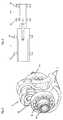
- FIG. 1which shows a section through an electric machine 1 with a coupled single-cylinder engine 2, left of the generator 3 of the range extender and right of the engine block 4 of the engine, here a single-cylinder engine arranged.
- the generator 3is located in a generator housing 5 and the engine block is located in a motor housing. 6
- crankshaft 7, the crank pin 8, the connecting rod 9, the piston 10 and the cylinder 11 and the electric driveis also hollow Rotor shaft 12 from the generator with the generator / rotor 13 can be seen.
- crankshaft 7 and the rotor shaft 12are connected via a self-centering connection 14, wherein on the crankshaft stub shaft 15 with spur teeth 16 and on the rotor shaft 12 a corresponding stub shaft 17 are arranged with spur toothing 18, said type of toothing in per se known Way self-centering effect.
- the two shaftsare connected by a connecting screw 19 and the two housings 5 and 6 are connected to each other by means of screws 20 without centering, since the Hirth toothing takes over the centering.
- This constructionrequires only a fixed bearing 21 in the form of a ball bearing for the rotor shaft 12 and a first Loselager 22 as ball or roller bearings in the generator housing or inner ring and a third and fourth Loselager 23 and 24 as roller bearings without axial start in the motor housing, wherein the inner ring on the Crankshaft pressed or the crankshaft directly serves as a running surface for the Loselager without inner ring.
- the Loselager 23 and 24can also be designed as a ball bearing with a sliding seat in the housing or on the shaft.
- the assembly processis the following: First, the shaft connection and then the housing are screwed together.
- the generatorBecause of the efficiency of the windings and the permanent magnets, the generator reacts very sensitively to the runners both in the radial and in the axial direction, and the efficiency drastically increases in large games deteriorates, it would be ideal if the generator can be exactly balanced out, and the entire length of the internal combustion engine can be accommodated and compensated despite the rigid connection.
- the axial distancing on the generatoris important because the speed and position detection of the generator via a front-mounted decoder / encoder is removed. Due to its design, this decoder can not overcome large axial distances.
- the axial alignment of generator housing and shaftis thus preferably made on the side of the decoder.
- the combustion enginecan be designed so that it can absorb the entire length of the shaft assembly in the crank mechanism.
- Crankshaft and connecting rodhave sufficient clearance in the axial direction to accommodate the expansion.
- the thrust bearing on the engineis eliminated.
- the crankshaft and the connecting rodhave only a start-up for limiting in the axial direction, which is used only in the pre-assembly state of the engine without the generator.
- the bearings on the enginecan be like in Fig. 4 be carried out with ball bearings as a loose bearing, or with roller bearings or roller bearings.
- the connecting rodhas sufficient clearance on the piston pin to accommodate the axial expansion can.
- the connecting rodis guided at the bottom between the crank webs.
Landscapes
- Engineering & Computer Science (AREA)
- Mechanical Engineering (AREA)
- Chemical & Material Sciences (AREA)
- Combustion & Propulsion (AREA)
- Transportation (AREA)
- General Engineering & Computer Science (AREA)
- Automation & Control Theory (AREA)
- Sustainable Energy (AREA)
- Sustainable Development (AREA)
- Power Engineering (AREA)
- Life Sciences & Earth Sciences (AREA)
- Electric Propulsion And Braking For Vehicles (AREA)
- Secondary Cells (AREA)
- Hybrid Electric Vehicles (AREA)
- Connection Of Motors, Electrical Generators, Mechanical Devices, And The Like (AREA)
- Charge And Discharge Circuits For Batteries Or The Like (AREA)
- Transition And Organic Metals Composition Catalysts For Addition Polymerization (AREA)
- Lubricants (AREA)
Description
Translated fromGermanDie vorliegende Erfindung bezieht sich auf ein Elektrofahrzeug mit Reichweitenverlängerung mit angekoppeltem Verbrennungsmotor, wobei es sich gemäss EU-Richtlinien um ein serielles Hybrid-Elektrofahrzeug handelt.The present invention relates to an electric vehicle with range extension with coupled internal combustion engine, which is a serial hybrid electric vehicle according to EU directives.
Bei diesem Typ Hybridfahrzeug, auch Elektrofahrzeug mit Range Extender genannt, wird ein Verbrennungsmotor mit einer Elektromaschine als Generator gekoppelt. Der Verbrennungsmotor gibt seine Leistung an den Generator ab, welcher die Drehbewegung in elektrische Energie umsetzt und entweder die Batterie oder den elektrischen Fahrmotor des Fahrzeugs versorgt. Auf diese Weise kann der Verbrennungsmotor in allen Betriebspunkten auf einem sehr guten Wirkungsgrad betrieben werden, was die CO2-Emissionen und den Treibstoffverbrauch der Aggregate positiv beeinflusst.In this type of hybrid vehicle, also called electric vehicle with range extender, an internal combustion engine is coupled with an electric machine as a generator. The internal combustion engine gives its power to the generator, which converts the rotary motion into electrical energy and supplies either the battery or the electric drive motor of the vehicle. In this way, the internal combustion engine can be operated at all operating points to a very good efficiency, which positively influences the CO2 emissions and the fuel consumption of the units.
Ein kritischer Faktor von solchen Aggregaten ist die Ankopplung des Verbrennungsmotors an den Generator, da durch die hohe Verbrennungskraft des Motors grosse Drehungleichheiten und Verformungen an der Kurbelwelle wirken. Um allgemein einen Generator an den Verbrennungsmotor zu koppeln sind heute verschiedene Lösungen bekannt, wobei die Bauart des Generator eine wesentliche Rolle spielt. Bei den vorbekannten Lösungen, z. B. gemäss der
In der
Von diesem Stand der Technik ausgehend ist es eine Aufgabe der Erfindung ein serielles Hybridelektrofahrzeug anzugeben, bei dem die Verbindung zwischen dem Verbrennungsmotor und dem Generator sehr genau ausgerichtet und verwindungssteif ausgebildet ist, jedoch sowohl Gewichtsersparnis als auch eine einfache Montage ermöglicht. Diese Aufgabe wird mit dem Fahrzeug gemäss Anspruch 1 gelöst.From this prior art, it is an object of the invention to provide a hybrid electric hybrid vehicle, in which the connection between the engine and the generator is very accurately aligned and torsionally stiff, but allows both weight savings and ease of assembly. This object is achieved with the vehicle according to claim 1.
Eine weitere Aufgabe ist es, im Falle von Temperaturschwankungen einen effizienten Längenausgleich der Generatorwelle und der Kurbelwelle zu ermöglichen. Diese Aufgabe wird mit dem Fahrzeug gemäss Anspruch 5 gelöst.A further object is to allow an efficient length compensation of the generator shaft and the crankshaft in the event of temperature fluctuations. This object is achieved with the vehicle according to
Die Erfindung wird im Folgenden anhand von Zeichnungen eines Ausführungsbeispiels näher erläutert.
- Fig. 1
- zeigt eine erfindungsgemässe Anordnung einer elektrischen Maschine mit einem angekoppelten Verbrennungsmotor,
- Fig. 2
- zeigt eine Ausschnittvergrösserung aus
Fig. 1 , - Fig. 3
- zeigt in einer perspektivischen Darstellung die Kurbelwelle des Verbrennungsmotors, und
- Fig. 4
- zeigt schematisch die Lagerung der Wellen.
- Fig. 1
- shows an inventive arrangement of an electrical machine with a coupled internal combustion engine,
- Fig. 2
- shows a detail enlargement
Fig. 1 . - Fig. 3
- shows in a perspective view of the crankshaft of the internal combustion engine, and
- Fig. 4
- shows schematically the storage of the waves.
Es gibt verschiedene Bauarten, um den Verbrennungsmotor mit dem Generator zu verbinden, zum Beispiel
Bauart 1: Kompletter Generator mit einer eigenständigen Lagerung der Rotorwelle in einem Generatorengehäuse, wie in den Zeichnungen dargestellt, oder Bauart 2: Der Scheibengenerator wird direkt und ohne Lagerung auf das Motorengehäuse bzw. auf die Kurbelwelle gebaut. In der vorliegenden Erfindung wird nur Bauart 1 berücksichtigt.There are several types to connect the combustion engine to the generator, for example
Type 1: Complete generator with independent bearing of the rotor shaft in a generator housing, as shown in the drawings, or Type 2: The disc generator is directly and without storage on the Engine housing or built on the crankshaft. In the present invention, only type 1 is considered.
Bei der vorliegenden Bauart gemäss den Zeichnungen eignet sich der Generator für den Anbau an unterschiedliche Motoren, wobei die Ankopplung im Prinzip über eine beliebige Verbindung der Wellen und der Gehäuse erfolgen kann. Motor und Generator sind eigenständig und werden über ein Bindeglied verbunden. Für einen Einzylinder-Motor mit einer sehr kurzen Kurbelwelle erweist sich diese Bauart als die sinnvollste Lösung, da auf Grund der separaten Lagerung des Rotors des Generators der Luftspalt im Generator klein gehalten werden kann, um einen hohen Wirkungsgrad erzielen zu können. Die Biegemomente in der Kurbelwelle bei der Verbrennung, sowie die Lagerspiele auf die kurze Distanz zwischen den Lagern können bei geeigneter Anordnung von der Generatorlagerung aufgenommen werden, womit ein Berühren von Rotor und Gehäuse verhindert wird.In the present design according to the drawings, the generator is suitable for mounting on different motors, the coupling can be done in principle via any connection of the shafts and the housing. Motor and generator are independent and are connected via a link. For a single-cylinder engine with a very short crankshaft, this design proves to be the most sensible solution, since due to the separate storage of the rotor of the generator, the air gap in the generator can be kept small in order to achieve high efficiency can. The bending moments in the crankshaft during combustion, as well as the bearing clearance on the short distance between the bearings can be taken from the generator bearing, with a suitable arrangement, thus preventing contact between the rotor and the housing.
Je nach Bauart und Stabilität der Wellenverbindung zwischen Verbrennungsmotor und Generator kann der Generator dem Verbrennungsmotor als Schwungmasse dienen, was aber aufgrund der auftretenden Momente nicht unproblematisch ist, jedoch bei vorliegender Lösung gelöst wird.Depending on the design and stability of the shaft connection between the engine and generator, the generator can serve the internal combustion engine as a flywheel, but this is not a problem due to the moments occurring, but is solved in the present solution.
Es sind verschiedene Lösungen für die Verbindung der Generator- mit der Kurbelwelle denkbar, so z. B.
- 1) Eine Elastomerkupplung, diese jedoch
- benötigt axial wie radial sehr viel Platz, Toleranzen müssen gross gewählt werden,
- kann die geforderten dynamischen schwellenden Drehmomente nicht aufnehmen, ansonsten viel zu gross,
- der Generator kann nicht als Schwungmasse des Motors dienen, der Motor braucht zusätzliche Schwungmasse = Kosten / Gewicht.
- 2) Verbindung der Wellen über einen Konus:
- Steife Verbindung, braucht aber Platz in der Länge und im Durchmesser, um genügend Steifigkeit zu erlangen,
- axiale Toleranzen sind problematisch, da bei der Montage die Einbauposition durch das Anzugsmoment nicht genau bestimmt werden kann,
- Montage und Demontage schwierig.
- 3) Innenverzahnung:
- Aufwändig in der Herstellung,
- die auftretenden Momente provozieren ein mechanisches Spiel und Laufgeräusche, falls eine Schiebetoleranz verwendet wird,
- Montage und Demontage problematisch bei Pressverbindungen,
- Montagelänge / Platzbedarf sind relativ gross.
- 4) Hirthverzahnung:
- Geringer Platzbedarf in axialer und radialer Richtung,
- exakte Ausdistanzierung mit kleinen Toleranzen,
- einfache Montage,
- absolut spielfreie Verbindung,
- vollständig Drehsteif, da vorgespannt und formschlüssig,
- geringes Gewicht,
- kostengünstig, da keine zusätzlichen Elemente notwendig, und
- hohe Präzision, guter Rundlauf, Selbstzentrierung,
- 1) An elastomer coupling, but this
- requires a lot of space both axially and radially, tolerances must be large,
- can not absorb the required dynamic swelling torques, otherwise too big,
- The generator can not serve as a flywheel of the engine, the engine needs additional flywheel = cost / weight.
- 2) Connection of the waves over a cone:
- Stiff connection, but needs space in the length and in the diameter, in order to obtain sufficient rigidity,
- Axial tolerances are problematic because during assembly the installation position can not be determined exactly by the tightening torque,
- Assembly and disassembly difficult.
- 3) Internal toothing:
- Elaborate in production,
- the moments occurring provoke a mechanical play and running noises, if a sliding tolerance is used,
- Assembly and disassembly problematic in press connections,
- Installation length / space requirement are relatively large.
- 4) Hirth toothing:
- Low space requirement in the axial and radial direction,
- exact balancing with small tolerances,
- easy installation,
- absolutely backlash-free connection,
- completely torsionally stiff, since pre-stressed and form-fitting,
- low weight,
- inexpensive, because no additional elements necessary, and
- high precision, good concentricity, self-centering,
Ausgehend von obiger Charakterisierung der vier Verbindungs-Beispiele folgt, dass die selbstzentrierende Axialverbindung, auch Hirth-Verzahnung genannt, die besten Voraussetzungen bringt.Based on the above characterization of the four connection examples, it follows that the self-centering axial connection, also called Hirth toothing, provides the best possible conditions.
In
Vom Verbrennungsmotor ist die Kurbelwelle 7, der Kurbelzapfen 8, der Pleuel 9, der Kolben 10 sowie der Zylinder 11 und vom elektrischen Antrieb die ebenfalls hohle Rotorwelle 12 vom Generator mit dem Generator/Rotor 13 ersichtlich.From the internal combustion engine, the
Wie aus
Als vorteilhafte Konsequenz einer solchen Verbindung ergibt sich eine grosse Vereinfachung der Lagerung der beiden Wellen, die einen einfachen Längenausgleich der Wellen bei Temperaturschwankungen ermöglicht. Diese Konstruktion benötigt nur ein Festlager 21 in Form eines Kugellagers für die Rotorwelle 12 und ein erstes Loselager 22 als Kugel- oder Rollenlager im Generatorengehäuse oder Innenring sowie ein drittes und viertes Loselager 23 und 24 als Rollenlager ohne Axialanlauf im Motorengehäuse, wobei der Innenring auf der Kurbelwelle gepresst oder die Kurbelwelle direkt als Lauffläche für das Loselager ohne Innenring dient.
Die Loselager 23 und 24 können auch als Kugellager mit einem Schiebesitz im Gehäuse oder auf der Welle ausgeführt werden.An advantageous consequence of such a connection results in a great simplification of the storage of the two waves, which allows a simple length compensation of the waves with temperature fluctuations. This construction requires only a fixed
The
Durch die oben angegebene Anordnung der Aggregate ergeben sich eine ganze Reihe von Vorteilen, wie z. B.
- einfache Montage mit nur einer Schraube durch die Hohlwelle des Generator,
- einfache Vormontage der beiden Komponenten Verbrennungsmotor und Generator,
- die Verbindung ist so ausgelegt, dass die Vorspannkraft der Schraube in jedem Zustand grösser ist als die vom Verbrennungsmotor auftretenden Dreh- und Biegemomente, die auf die Verzahnung wirken, womit eine sehr steife Verbindung ermöglicht wird und die hohe Drehmasse des Generators als Motorschwungmasse verwendet werden kann.
- easy assembly with only one screw through the hollow shaft of the generator,
- simple pre-assembly of the two components internal combustion engine and generator,
- the connection is designed so that the biasing force of the screw in each state is greater than the rotational and bending moments occurring from the engine, which act on the teeth, whereby a very rigid connection is made possible and the high rotational mass of the generator can be used as engine flywheel ,
Da die Verzahnung selbstzentrierend ist, entfallen zusätzliche Zentrierungen am Gehäuse. Damit kann eine Überbestimmtheit in der Montage vermieden werden und der Rundlauf und die Fluchtung der beiden Aggregate ist immer gegeben.
in axialer Richtung sind kleine Toleranzen möglich.Since the gearing is self-centering, eliminates additional centering on the housing. This over-determination in the assembly can be avoided and the concentricity and alignment of the two units is always given.
in the axial direction small tolerances are possible.
Der Montageablauf ist der Folgende: Zuerst wird die Wellenverbindung und anschliessend werden die Gehäuse zusammengeschraubt.The assembly process is the following: First, the shaft connection and then the housing are screwed together.
Durch die hohe Präzision der Hirthverzahnung in axialer Richtung besteht die Möglichkeit, den gesamten Wellenverbund lediglich mit einem Axiallager zu fixieren, durch die die bekannten Probleme bezüglich Längenausdehnungen infolge Temperatureinflüsse eliminiert werden können.Due to the high precision of the Hirth toothing in the axial direction, it is possible to fix the entire shaft assembly only with an axial bearing, by means of which the known problems with respect to length expansions due to temperature influences can be eliminated.
Da der Generator aufgrund der Effizienz der Wicklungen und der Permanentmagnete sehr sensibel auf die Laufspiele sowohl in radialer als auch in axialer Richtung reagiert und sich bei grossen Spielen der Wirkungsgrad drastisch verschlechtert, wäre es ideal, wenn der Generator genau ausdistanziert werden kann, und die gesamte Längenausdehnung am Verbrennungsmotor trotz der steifen Verbindung aufgenommen und ausgeglichen werden kann. Die axiale Distanzierung am Generator ist wichtig, da die Drehzahl- und Positionserfassung des Generators über einen stirnseitig angebrachten Decoder / Drehgeber abgenommen wird. Dieser Decoder vermag aufgrund seiner Bauweise keine grossen axialen Distanzen zu überwinden. Die axiale Ausrichtung von Generatorgehäuse und -Welle wird somit vorzugsweise auf der Seite des Decoders gemacht.Because of the efficiency of the windings and the permanent magnets, the generator reacts very sensitively to the runners both in the radial and in the axial direction, and the efficiency drastically increases in large games deteriorates, it would be ideal if the generator can be exactly balanced out, and the entire length of the internal combustion engine can be accommodated and compensated despite the rigid connection. The axial distancing on the generator is important because the speed and position detection of the generator via a front-mounted decoder / encoder is removed. Due to its design, this decoder can not overcome large axial distances. The axial alignment of generator housing and shaft is thus preferably made on the side of the decoder.
Der Verbrennungsmotor kann aus diesem Grund so konzipiert werden, dass er im Kurbeltrieb die gesamte Längenausdehnung des Wellenverbundes aufnehmen kann. Kurbelwelle und Pleuel haben in axialer Richtung genügend Spiel, um die Ausdehnung aufzunehmen. Das Axiallager am Motor entfällt. Die Kurbelwelle und der Pleuel haben lediglich einen Anlauf zur Begrenzung in axialer Richtung, welcher nur im Vormontagezustand des Motors ohne den Generator benutzt wird.For this reason, the combustion engine can be designed so that it can absorb the entire length of the shaft assembly in the crank mechanism. Crankshaft and connecting rod have sufficient clearance in the axial direction to accommodate the expansion. The thrust bearing on the engine is eliminated. The crankshaft and the connecting rod have only a start-up for limiting in the axial direction, which is used only in the pre-assembly state of the engine without the generator.
Sobald Motor und Generator gekoppelt werden, übernimmt der Generator die axiale Ausrichtung. Die Lager am Motor können wie in
Der Pleuel weist auf dem Kolbenbolzen genügend Spiel auf, um die axiale Ausdehnung aufnehmen zu können. Der Pleuel ist unten zwischen den Kurbelwangen geführt.The connecting rod has sufficient clearance on the piston pin to accommodate the axial expansion can. The connecting rod is guided at the bottom between the crank webs.
Auf diese Weise entsteht ein kompakter Verbund der Aggregate, wobei der Generator mit seiner grossen Drehmasse als Schwungrad am Verbrennungsmotor benutzt wird, womit eine erhebliche Gewichtseinsparung und eine Bauraum-Optimierung erzielt werden können.In this way, a compact composite of the aggregates, wherein the generator is used with its large rotating mass as flywheel on the engine, creating a considerable weight savings and space optimization can be achieved.
Claims (10)
- Series hybrid electric vehicle having a coupled internal combustion engine that serves for range extension,characterised in that the internal combustion engine (2) is coupled to the generator (13) of the range extender by means of a self-centring face gear (16, 18).
- Electric vehicle according to claim 1,characterised in that the crankshaft (7) of the internal combustion engine and the rotor shaft (12) of the generator each have shaft ends (15, 17) that are provided with matching face gears (16, 18).
- Electric vehicle according to claim 1 or 2,characterised in that the two hollow shafts (7, 12) are connected to each other by a connecting screw (19).
- Electric vehicle according to one of claims 1 to 3,characterised in that the generator (13) serves as the flywheel mass of the internal combustion engine.
- Electric vehicle according to one of claims 1 to 4,characterised in that a fixed bearing (21) and a first floating bearing (22) are provided on the generator side and the bearings on the engine side are in the form of floating bearings (23, 24) so as to be able to accommodate the linear expansion of the shafts due to temperature influence.
- Electric vehicle according to one of claims 1 to 5,characterised in that the fixed bearing (21) on the generator side is in the form of a ball bearing.
- Electric vehicle according to one of claims 1 to 5,characterised in that the floating bearings (22, 23, 24) on the generator and on the engine are in the form of roller bearings with inner rings (25).
- Electric vehicle according to one of claims 1 to 5,characterised in that the floating bearings (22, 23, 24) on the generator and on the engine are in the form of roller bearings whose inner rings are omitted as a result of construction space optimization und shaft dimensioning while the shafts directly serve as bearing surfaces.
- Electric vehicle according to one of claims 1 to 5,characterised in that the floating bearings (22, 23, 24) on the generator and on the engine are in the form of ball bearings, either the inner or the outer bearing ring being slidably mounted.
- Electric vehicle according to one of claims 1 to 9,characterised in that the internal combustion engine is a single-cylinder or a twin engine.
Priority Applications (20)
| Application Number | Priority Date | Filing Date | Title |
|---|---|---|---|
| EP09170400.7AEP2308708B1 (en) | 2009-09-16 | 2009-09-16 | Electric vehicle with range extension |
| EP10760186.6AEP2477831B1 (en) | 2009-09-16 | 2010-09-16 | Electric vehicle and on-board battery charging apparatus therefore |
| CN202310708331.XACN116653583A (en) | 2009-09-16 | 2010-09-16 | Electric vehicle and on-vehicle battery charging apparatus for the same |
| PCT/US2010/049167WO2011035056A2 (en) | 2009-09-16 | 2010-09-16 | Electric vehicle and on-board battery charging apparatus therefore |
| EP18183253.6AEP3403862A1 (en) | 2009-09-16 | 2010-09-16 | Electric vehicle and on-board battery charging apparatus therefor |
| US12/737,149US8496079B2 (en) | 2009-09-16 | 2010-09-16 | Electric vehicle and on-board battery charging apparatus therefore |
| CN201610806091.7ACN106314118B (en) | 2009-09-16 | 2010-09-16 | Electric vehicle and charging on-vehicle battery equipment for the electric vehicle |
| CN201910739585.1ACN110539626B (en) | 2009-09-16 | 2010-09-16 | Electric vehicle and on-vehicle battery charging apparatus for the same |
| RU2012113864/11ARU2570242C2 (en) | 2009-09-16 | 2010-09-16 | Electric vehicle and its onboard storage battery charging device |
| CA2773214ACA2773214C (en) | 2009-09-16 | 2010-09-16 | Electric vehicle and on-board battery charging apparatus therefore |
| AU2010295564AAU2010295564A1 (en) | 2009-09-16 | 2010-09-16 | Electric vehicle and on-board battery charging apparatus therefore |
| IN2181DEN2012IN2012DN02181A (en) | 2009-09-16 | 2010-09-16 | |
| CN201080046628.5ACN103153667B (en) | 2009-09-16 | 2010-09-16 | Electric vehicle and on-board battery charging device for the electric vehicle |
| US12/928,498US8555851B2 (en) | 2009-09-16 | 2010-12-13 | Lubrication arrangement for timing chain and cylinder head |
| US12/928,493US8323147B2 (en) | 2009-09-16 | 2010-12-13 | Electric vehicle and on-board battery charging apparatus therefor |
| US12/928,484US9802605B2 (en) | 2009-09-16 | 2010-12-13 | Electric vehicle and on-board battery charging apparatus therefor |
| US12/928,495US8269457B2 (en) | 2009-09-16 | 2010-12-13 | System and method for charging an on-board battery of an electric vehicle |
| US12/928,479US8387594B2 (en) | 2009-09-16 | 2010-12-13 | Electric vehicle and on-board battery charging apparatus therefor |
| US12/928,482US8567541B2 (en) | 2009-09-16 | 2010-12-13 | Electric vehicle and on-board battery charging apparatus therefor |
| US13/839,966US9187083B2 (en) | 2009-09-16 | 2013-03-15 | System and method for charging an on-board battery of an electric vehicle |
Applications Claiming Priority (1)
| Application Number | Priority Date | Filing Date | Title |
|---|---|---|---|
| EP09170400.7AEP2308708B1 (en) | 2009-09-16 | 2009-09-16 | Electric vehicle with range extension |
Publications (2)
| Publication Number | Publication Date |
|---|---|
| EP2308708A1 EP2308708A1 (en) | 2011-04-13 |
| EP2308708B1true EP2308708B1 (en) | 2016-08-17 |
Family
ID=41698231
Family Applications (3)
| Application Number | Title | Priority Date | Filing Date |
|---|---|---|---|
| EP09170400.7AActiveEP2308708B1 (en) | 2009-09-16 | 2009-09-16 | Electric vehicle with range extension |
| EP18183253.6APendingEP3403862A1 (en) | 2009-09-16 | 2010-09-16 | Electric vehicle and on-board battery charging apparatus therefor |
| EP10760186.6AActiveEP2477831B1 (en) | 2009-09-16 | 2010-09-16 | Electric vehicle and on-board battery charging apparatus therefore |
Family Applications After (2)
| Application Number | Title | Priority Date | Filing Date |
|---|---|---|---|
| EP18183253.6APendingEP3403862A1 (en) | 2009-09-16 | 2010-09-16 | Electric vehicle and on-board battery charging apparatus therefor |
| EP10760186.6AActiveEP2477831B1 (en) | 2009-09-16 | 2010-09-16 | Electric vehicle and on-board battery charging apparatus therefore |
Country Status (8)
| Country | Link |
|---|---|
| US (7) | US8496079B2 (en) |
| EP (3) | EP2308708B1 (en) |
| CN (4) | CN106314118B (en) |
| AU (1) | AU2010295564A1 (en) |
| CA (1) | CA2773214C (en) |
| IN (1) | IN2012DN02181A (en) |
| RU (1) | RU2570242C2 (en) |
| WO (1) | WO2011035056A2 (en) |
Cited By (1)
| Publication number | Priority date | Publication date | Assignee | Title |
|---|---|---|---|---|
| US12441175B2 (en) | 2020-09-04 | 2025-10-14 | Schaeffler Technologies AG & Co. KG | Drive unit and drive assembly |
Families Citing this family (85)
| Publication number | Priority date | Publication date | Assignee | Title |
|---|---|---|---|---|
| US9187083B2 (en) | 2009-09-16 | 2015-11-17 | Polaris Industries Inc. | System and method for charging an on-board battery of an electric vehicle |
| EP2308708B1 (en)* | 2009-09-16 | 2016-08-17 | swissauto powersport llc | Electric vehicle with range extension |
| US20130218386A1 (en) | 2010-08-04 | 2013-08-22 | Fisker Automotive, Inc. | Vehicle operation mode systems and methods |
| KR101241221B1 (en)* | 2010-12-06 | 2013-03-13 | 주식회사 이지트로닉스 | Charging system for mild hybrid vehicle |
| US8973693B2 (en) | 2011-02-11 | 2015-03-10 | Polaris Industries Inc. | Side by side all terrain vehicle |
| US8997908B2 (en) | 2011-02-11 | 2015-04-07 | Polaris Industries Inc. | Side-by-side all terrain vehicle |
| US9650078B2 (en) | 2011-02-11 | 2017-05-16 | Polaris Industries Inc. | Side-by-side all terrain vehicle |
| US8534400B2 (en)* | 2011-02-14 | 2013-09-17 | Ford Global Technologies, Llc | Electric vehicle and method of control for active auxiliary battery depletion |
| CN103958260A (en)* | 2011-04-08 | 2014-07-30 | 北极星工业有限公司 | Electric vehicle with range extender |
| AT511552B1 (en)* | 2011-05-30 | 2015-02-15 | Avl List Gmbh | GENERATOR FOR A MOTOR VEHICLE |
| JP5742607B2 (en)* | 2011-09-08 | 2015-07-01 | 三菱自動車工業株式会社 | Control device for hybrid electric vehicle |
| JP2014530786A (en)* | 2011-10-21 | 2014-11-20 | フィスカー オートモーティブ インコーポレイテッド | System and method for controlling driving of a vehicle |
| WO2013071128A2 (en)* | 2011-11-09 | 2013-05-16 | Magna E-Car Systems Of America, Inc. | Electric powertrain assembly and method of installation |
| US8948943B2 (en)* | 2011-12-29 | 2015-02-03 | Kawasaki Jukogyo Kabushiki Kaisha | Drive control system in series-hybrid vehicle |
| KR20140135246A (en)* | 2012-04-11 | 2014-11-25 | 혼다 기켄 고교 가부시키가이샤 | Electric power generation control system for hybrid automobile |
| US8892290B2 (en)* | 2012-05-04 | 2014-11-18 | Ford Global Technologies, Llc | Methods and systems for providing uniform driveline braking |
| AT512850B1 (en)* | 2012-05-10 | 2017-11-15 | Avl List Gmbh | Range extender system, especially for a motor vehicle |
| HK1210992A1 (en) | 2012-09-20 | 2016-05-13 | 北极星工业有限公司 | Utiliy vehicle |
| US9440671B2 (en) | 2012-09-20 | 2016-09-13 | Polaris Industries Inc. | Vehicle |
| US10246153B2 (en) | 2012-10-11 | 2019-04-02 | Polaris Industries Inc. | Side-by-side vehicle |
| CN107745746B (en) | 2012-10-11 | 2020-03-27 | 北极星工业有限公司 | Side-by-side vehicle |
| DE102012221731A1 (en) | 2012-11-28 | 2014-05-28 | Robert Bosch Gmbh | Method and device for determining an operating strategy for a range extender of an electric vehicle |
| US9789909B2 (en) | 2013-03-15 | 2017-10-17 | Polaris Industries Inc. | Utility vehicle |
| US9194278B2 (en) | 2013-03-15 | 2015-11-24 | Polaris Industries Inc. | Engine |
| TW201446567A (en)* | 2013-06-11 | 2014-12-16 | Hon Hai Prec Ind Co Ltd | Vehicle-mounted charging device |
| DE102013213477A1 (en) | 2013-07-10 | 2015-01-15 | Robert Bosch Gmbh | Method for operating a hybrid electric vehicle with range extension |
| US9428173B2 (en) | 2013-10-29 | 2016-08-30 | Toyota Motor Engineering & Manufacturing North America, Inc. | Vehicle battery pre-charge feature |
| US9272615B1 (en)* | 2013-11-07 | 2016-03-01 | David D. Cady | Vapor transport fuel intake system |
| DE102014111254B4 (en)* | 2014-08-07 | 2018-04-26 | Pierburg Gmbh | For different mounting positions of suitable range extenders |
| DE102014115043B4 (en) | 2014-10-16 | 2021-12-23 | Obrist Technologies Gmbh | Generator set |
| US20160108795A1 (en)* | 2014-10-20 | 2016-04-21 | Hyundai Motor Company | Method and system for controlling variable water pump based on flow rate control modes |
| US10300786B2 (en) | 2014-12-19 | 2019-05-28 | Polaris Industries Inc. | Utility vehicle |
| DE102015101929A1 (en)* | 2015-02-11 | 2016-08-11 | Dr. Ing. H.C. F. Porsche Aktiengesellschaft | Drive module for a motor vehicle |
| CN104786858B (en) | 2015-03-24 | 2017-03-29 | 至玥腾风科技投资集团有限公司 | A kind of stroke-increasing electric automobile |
| MX2017014403A (en) | 2015-05-15 | 2018-04-11 | Polaris Inc | UTILITY VEHICLE. |
| US10870465B2 (en)* | 2015-05-22 | 2020-12-22 | Polaris Industries Inc. | Power boost regulator |
| CA3118280C (en) | 2015-05-22 | 2024-01-02 | Polaris Industries Inc. | Power boost regulator |
| WO2016205223A1 (en) | 2015-06-19 | 2016-12-22 | Deka Products Limited Partnership | Direct current power plant |
| US10119464B2 (en)* | 2016-03-11 | 2018-11-06 | Toyota Motor Engineering & Manufacturing North America, Inc. | Engine assembly having a cover |
| JP6540565B2 (en)* | 2016-03-16 | 2019-07-10 | 株式会社オートネットワーク技術研究所 | Power supply system for vehicle, drive system for vehicle |
| DE102016206173A1 (en)* | 2016-04-13 | 2017-10-19 | Bayerische Motoren Werke Aktiengesellschaft | Method and device for operating a vehicle having an electrical energy storage hybrid vehicle with an electric motor and with an internal combustion engine |
| WO2017186227A1 (en)* | 2016-04-27 | 2017-11-02 | Schaeffler Technologies AG & Co. KG | Hybrid module and a drive arrangement for a motor vehicle |
| MX2018014607A (en) | 2016-06-14 | 2019-03-01 | Polaris Inc | Hybrid utility vehicle. |
| FR3053418B1 (en)* | 2016-06-30 | 2019-07-19 | Renault S.A.S | DEVICE FOR COUPLING IN ROTATION BETWEEN A FLYWHEEL AND A CRANKSHAFT |
| AT519017B1 (en)* | 2016-09-12 | 2018-03-15 | Avl List Gmbh | Combustion engine with a crankcase |
| US11807112B2 (en) | 2016-12-14 | 2023-11-07 | Bendix Commercial Vehicle Systems Llc | Front end motor-generator system and hybrid electric vehicle operating method |
| CA3000362A1 (en)* | 2017-04-11 | 2018-10-11 | Bendix Commercial Vehicle Systems Llc | Hybrid commercial vehicle thermal management using dynamic heat generator |
| CN107097654B (en)* | 2017-04-24 | 2019-02-12 | 清华大学 | Electric vehicle electromechanical composite energy storage system and energy control method |
| US10371249B1 (en) | 2017-05-24 | 2019-08-06 | Indian Motorcycle International, LLC | Engine |
| US10589621B1 (en) | 2017-05-24 | 2020-03-17 | Indian Motorcycle International, LLC | Two-wheeled vehicle |
| US10655536B1 (en) | 2017-05-24 | 2020-05-19 | Indian Motorcycle International, LLC | Engine |
| US10221727B1 (en) | 2017-05-24 | 2019-03-05 | Indian Motorcycle International, LLC | Engine |
| JP6812903B2 (en)* | 2017-05-26 | 2021-01-13 | トヨタ自動車株式会社 | Hybrid vehicle |
| US10707741B2 (en) | 2017-07-18 | 2020-07-07 | Polaris Industries Inc. | Voltage generator and a method of making a voltage generator |
| US10570872B2 (en) | 2018-02-13 | 2020-02-25 | Ford Global Technologies, Llc | System and method for a range extender engine of a hybrid electric vehicle |
| CN112424020A (en)* | 2018-05-04 | 2021-02-26 | 正道汽车公司 | Range-extended electric automobile with Lithium Titanate (LTO) battery with ultrahigh charge-discharge rate |
| CN108674171A (en)* | 2018-05-23 | 2018-10-19 | 杜春洪 | A kind of electric vehicle automatic clutch hybrid electric drive system |
| US10946736B2 (en) | 2018-06-05 | 2021-03-16 | Polaris Industries Inc. | All-terrain vehicle |
| US10682923B2 (en) | 2018-07-12 | 2020-06-16 | Lectrotech System Inc. | On-board charging system for electric vehicles |
| US11919405B2 (en) | 2018-09-14 | 2024-03-05 | Cummins Inc. | Vehicle with an integrated charging system |
| US10780770B2 (en) | 2018-10-05 | 2020-09-22 | Polaris Industries Inc. | Hybrid utility vehicle |
| CN109130894A (en)* | 2018-10-17 | 2019-01-04 | 奇瑞新能源汽车技术有限公司 | A kind of stroke-increasing electric automobile arrangement structure |
| CN110722966B (en)* | 2018-12-28 | 2021-06-22 | 长城汽车股份有限公司 | Vehicle heat dissipation control method and system |
| MX2021012802A (en) | 2019-04-30 | 2021-11-12 | Polaris Inc | VEHICLE. |
| US11370266B2 (en) | 2019-05-16 | 2022-06-28 | Polaris Industries Inc. | Hybrid utility vehicle |
| CN110261253B (en)* | 2019-06-26 | 2021-11-02 | 濮阳市立圆汽车电器有限公司 | Bending performance testing device of automobile charger interface |
| USD955952S1 (en) | 2019-07-25 | 2022-06-28 | Polaris Industries Inc. | Door for a utility vehicle |
| US11447040B2 (en) | 2019-07-26 | 2022-09-20 | Polaris Industries Inc. | Side-by-side vehicle |
| USD942344S1 (en) | 2019-07-26 | 2022-02-01 | Polaris Industries Inc. | Set of vehicle components |
| CN110949145A (en)* | 2019-11-29 | 2020-04-03 | 东风柳州汽车有限公司 | Range extender system of integrated motor of engine |
| RU2726733C1 (en)* | 2019-12-16 | 2020-07-15 | Александр Геннадьевич Арзамасцев | Arzamastsev method for production of electric energy by electric transport for its movement |
| RU199686U1 (en)* | 2020-01-20 | 2020-09-14 | Чинь-Ши ОУ | INTELLIGENT DEVICE FOR CHARGING AND POWER SUPPLY OF CARS AND MOTORCYCLES |
| US12187127B2 (en) | 2020-05-15 | 2025-01-07 | Polaris Industries Inc. | Off-road vehicle |
| US11691674B2 (en) | 2020-05-15 | 2023-07-04 | Polaris Industries Inc. | Off-road vehicle |
| CN111775730A (en)* | 2020-07-24 | 2020-10-16 | 上海元城汽车技术有限公司 | Range extender starting control method and device, vehicle control unit and medium |
| CN111976517B (en)* | 2020-07-24 | 2022-03-01 | 江铃汽车股份有限公司 | Emergency charging system for electric automobile and charging vehicle |
| CN112060931A (en)* | 2020-08-28 | 2020-12-11 | 江西省利广节能环保有限公司 | Electric automobile with power circulation generation by pushing and dragging front and rear wheels of running vehicle |
| DE102020123116A1 (en)* | 2020-09-04 | 2022-03-10 | Schaeffler Technologies AG & Co. KG | Drive unit and drive arrangement |
| CA3156559A1 (en) | 2021-05-05 | 2022-11-05 | Polaris Industries Inc. | Exhaust assembly for a utility vehicle |
| RS66663B1 (en) | 2021-07-21 | 2025-05-30 | Manitou Italia Srl | Telehandler with convertible propulsion |
| US20230313872A1 (en)* | 2022-04-04 | 2023-10-05 | Polaris Industries Inc. | Continuously variable transmission |
| MX2023006716A (en) | 2022-06-13 | 2023-12-14 | Polaris Inc | POWER TRAIN FOR UTILITY VEHICLE. |
| US12395007B1 (en) | 2022-06-29 | 2025-08-19 | Kazem Ganji | Solar power system with electric engine |
| USD1067123S1 (en) | 2023-01-20 | 2025-03-18 | Polaris Industries Inc. | Off-road vehicle |
| CN117261626B (en)* | 2023-10-27 | 2025-03-11 | 岚图汽车科技有限公司 | Range extender and vehicle |
Family Cites Families (182)
| Publication number | Priority date | Publication date | Assignee | Title |
|---|---|---|---|---|
| US1989585A (en)* | 1933-05-08 | 1935-01-29 | Chester S Bigelow | Oil warmer and cooler |
| GB684794A (en)* | 1949-10-07 | 1952-12-24 | Graeft & Stift Automobilfabrik | Improvements in and relating to internal combustion engines |
| US3523592A (en) | 1968-07-26 | 1970-08-11 | Kohler Co | Engine lubrication system |
| GB1281950A (en) | 1968-10-18 | 1972-07-19 | Hitachi Ltd | Ac generator directly coupled to an internal combustion engine |
| US4010725A (en) | 1974-11-14 | 1977-03-08 | White Cygnal G | Self-contained engine warmer |
| US4022272A (en)* | 1975-11-14 | 1977-05-10 | Chester O. Houston, Jr. | Transmission fluid heat radiator |
| IT1071519B (en)* | 1976-10-13 | 1985-04-10 | Fiat Spa | INTERNAL COMBUSTION ENGINE LUBRICATION OIL CUP |
| DE2823256C2 (en) | 1978-05-27 | 1985-05-23 | Robert Bosch Gmbh, 7000 Stuttgart | Electric generator |
| US4404936A (en)* | 1980-04-30 | 1983-09-20 | Mitsubishi Jukogyo Kabushiki Kaisha | Breather device for overhead valve engines |
| DE3123633A1 (en)* | 1981-06-15 | 1982-12-30 | Klöckner-Humboldt-Deutz AG, 5000 Köln | HEATING SYSTEM WITH LUBRICANT OIL REDUCTION FOR MOTOR VEHICLES |
| JPS58126434A (en) | 1982-01-23 | 1983-07-27 | Nissan Motor Co Ltd | Smoothing device of torque in internal-combustion engine |
| US4470389A (en)* | 1982-02-08 | 1984-09-11 | Kawasaki Jukogyo Kabushiki Kaisha | Breather-lubricator system for engines |
| JPS5939933A (en) | 1982-08-27 | 1984-03-05 | Yamaha Motor Co Ltd | portable power generator |
| JPS60209616A (en) | 1984-04-02 | 1985-10-22 | Fuji Heavy Ind Ltd | Lubricating apparatus for ohc engine |
| US4638172A (en) | 1984-11-27 | 1987-01-20 | Williams George A | Combination, a model vehicle engine and a direct-current generator |
| JPS61135910A (en) | 1984-12-04 | 1986-06-23 | Fuji Heavy Ind Ltd | Lubricant oil cooling device for engine |
| EP0197823A1 (en)* | 1985-03-20 | 1986-10-15 | Valeo | Heat exchanger for a motor vehicle, particularly of the type for exhaust gases |
| US4688529A (en)* | 1985-07-10 | 1987-08-25 | Kawasaki Jukogyo Kabushiki Kaisha | Lubricating system for horizontal cylinder overhead valve engine |
| GB2196486B (en) | 1986-08-25 | 1990-06-06 | Kubota Ltd | Forcedly air-cooled engine generator of vertical shaft-type |
| ES2007680A6 (en) | 1987-08-06 | 1989-07-01 | Fernandez De Velasco Y Sesena | Portable variable radio frequency generator |
| US5397991A (en)* | 1988-07-13 | 1995-03-14 | Electronic Development Inc. | Multi-battery charging system for reduced fuel consumption and emissions in automotive vehicles |
| US4898261A (en) | 1989-04-10 | 1990-02-06 | Brunswick Corporation | Water cooled plastic oil pan |
| DE3914154A1 (en)* | 1989-04-28 | 1990-11-08 | Eberspaecher J | HEATING SYSTEM, ESPECIALLY FOR MOTOR VEHICLES, WITH A COMBUSTION ENGINE AND A HEATING UNIT |
| JP2932607B2 (en)* | 1990-05-23 | 1999-08-09 | 日産自動車株式会社 | Electric car |
| DE4106497A1 (en) | 1991-03-01 | 1992-09-03 | Gerhard O Wirges | POWER GENERATOR |
| JP2827568B2 (en) | 1991-04-30 | 1998-11-25 | トヨタ自動車株式会社 | Hybrid vehicle drive system |
| JPH05131848A (en)* | 1991-11-15 | 1993-05-28 | Toyota Motor Corp | Hybrid car driving system control device |
| US5241932A (en)* | 1991-12-02 | 1993-09-07 | Ryobi Outdoor Products | Operator carried power tool having a four-cycle engine |
| US5359247A (en) | 1992-04-27 | 1994-10-25 | Sundstrand Corporation | Cooling arrangement and method for offset gearbox |
| US5255733A (en)* | 1992-08-10 | 1993-10-26 | Ford Motor Company | Hybird vehicle cooling system |
| DE4238364A1 (en) | 1992-11-13 | 1994-05-26 | Behr Gmbh & Co | Device for cooling drive components and for heating a passenger compartment of an electric vehicle |
| US5264764A (en)* | 1992-12-21 | 1993-11-23 | Ford Motor Company | Method for controlling the operation of a range extender for a hybrid electric vehicle |
| US5407130A (en) | 1993-07-20 | 1995-04-18 | Honda Giken Kogyo Kabushiki Kaisha | Motor vehicle heat storage device with coolant bypass |
| JP3094745B2 (en) | 1993-09-24 | 2000-10-03 | トヨタ自動車株式会社 | Hybrid vehicle power generation control device |
| US5408965A (en)* | 1993-10-04 | 1995-04-25 | Ford Motor Company | Internal combustion engine oil pan with oil cooler |
| DE4427322C2 (en) | 1994-08-02 | 2000-07-27 | Wolfgang Hill | Electricity generation unit for series hybrid vehicles and combined heat and power plants |
| JP2587202B2 (en) | 1994-08-22 | 1997-03-05 | 本田技研工業株式会社 | Power generation control device for hybrid vehicle |
| DE4433836C1 (en)* | 1994-09-22 | 1995-11-09 | Daimler Benz Ag | Device for heating an interior of an electric vehicle |
| DE4435613C1 (en)* | 1994-10-05 | 1996-03-28 | Fichtel & Sachs Ag | Hybrid drive for a road vehicle |
| DE4447138A1 (en)* | 1994-12-29 | 1997-12-11 | Karl Heinz | Arrangement for hybrid drive of vehicle esp. automobile |
| JP3087884B2 (en) | 1995-04-28 | 2000-09-11 | 本田技研工業株式会社 | Hybrid vehicle power generation control device |
| US6054844A (en)* | 1998-04-21 | 2000-04-25 | The Regents Of The University Of California | Control method and apparatus for internal combustion engine electric hybrid vehicles |
| US5842534A (en)* | 1995-05-31 | 1998-12-01 | Frank; Andrew A. | Charge depletion control method and apparatus for hybrid powered vehicles |
| US5546901A (en) | 1995-06-30 | 1996-08-20 | Briggs & Stratton Corporation | Engine housing for an engine-device assembly |
| TW487770B (en)* | 1995-12-15 | 2002-05-21 | Honda Motor Co Ltd | Lubricating system in a 4-stroke engine |
| US6047678A (en) | 1996-03-08 | 2000-04-11 | Ryobi North America, Inc. | Multi-position operator-carried four-cycle engine |
| JP3617183B2 (en)* | 1996-05-08 | 2005-02-02 | トヨタ自動車株式会社 | Electric vehicle power supply |
| EP0856427B1 (en)* | 1996-07-30 | 2006-03-01 | Denso Corporation | Hybrid car controller |
| DE19637817A1 (en)* | 1996-09-17 | 1998-03-19 | Laengerer & Reich Gmbh & Co | Device and method for cooling and preheating |
| JP3190008B2 (en)* | 1996-10-09 | 2001-07-16 | 本田技研工業株式会社 | Oil mist generator for lubrication in engines |
| JPH10246106A (en) | 1997-03-03 | 1998-09-14 | Kioritz Corp | 4-cycle internal combustion engine |
| US5971290A (en) | 1997-04-30 | 1999-10-26 | Honda Giken Kogyo Kabushiki Kaisha | Heat exchange system for electric vehicle |
| CN1268997A (en)* | 1997-07-08 | 2000-10-04 | 赖哈特研究及发展有限公司 | Improvements in and relating to internal combustion engine |
| DE19735021B4 (en) | 1997-08-13 | 2009-08-06 | Volkswagen Ag | Drive arrangement for a motor vehicle |
| EP0898352A1 (en) | 1997-08-22 | 1999-02-24 | Ecomag S.A. | Generator-set |
| DE19800904A1 (en)* | 1998-01-14 | 1999-07-15 | Stihl Maschf Andreas | Two stroke motor especially for portable power tools |
| DE19817333C5 (en)* | 1998-04-18 | 2007-04-26 | Conti Temic Microelectronic Gmbh | Electric drive unit consisting of electric motor and electronic module |
| US6213079B1 (en)* | 1998-06-03 | 2001-04-10 | Fuji Robin Kabushiki Kaisha | Lubricating apparatus for four-cycle engines |
| JP3559891B2 (en)* | 1998-06-22 | 2004-09-02 | 日産自動車株式会社 | Cooling structure of multilayer motor |
| EP0979929B1 (en)* | 1998-08-11 | 2004-12-15 | Wenko AG Burgdorf | Piston engine with rocker arm valve drive |
| GB2348630B (en) | 1998-09-09 | 2002-12-04 | Luk Lamellen & Kupplungsbau | Drive train |
| ATE283179T1 (en)* | 1998-09-14 | 2004-12-15 | Paice Corp | HYBRID VEHICLE |
| US6554088B2 (en) | 1998-09-14 | 2003-04-29 | Paice Corporation | Hybrid vehicles |
| JP3558264B2 (en)* | 1999-03-29 | 2004-08-25 | 株式会社日立ユニシアオートモティブ | Electric generator unit |
| GB2349483A (en) | 1999-04-28 | 2000-11-01 | Rover Group | An engine-driven generator assembly |
| US6119636A (en) | 1999-06-11 | 2000-09-19 | Fan; Guo Xiang | Portable generator |
| US6217758B1 (en)* | 1999-08-06 | 2001-04-17 | Dana Corporation | Oil sump arrangement with integral filter and heat exchanger |
| JP2001055941A (en)* | 1999-08-16 | 2001-02-27 | Honda Motor Co Ltd | Engine automatic start / stop control device |
| US6702052B1 (en) | 1999-09-22 | 2004-03-09 | Honda Giken Kogyo Kabushiki Kaisha | Control apparatus for hybrid vehicles |
| DE10000253B4 (en) | 2000-01-05 | 2008-04-17 | Zf Sachs Ag | drive system |
| JP3784608B2 (en)* | 2000-03-21 | 2006-06-14 | 本田技研工業株式会社 | Handheld four-cycle engine |
| US20020179354A1 (en) | 2000-05-02 | 2002-12-05 | Sail D. White Enterprises, Inc. | Extended range electric vehicle |
| US20010043808A1 (en)* | 2000-05-19 | 2001-11-22 | Ken Matsunaga | Heating apparatus for vehicle cabin |
| JP3866486B2 (en)* | 2000-05-23 | 2007-01-10 | 富士重工業株式会社 | Lubricating device for OHC type engine |
| JP2001329823A (en) | 2000-05-23 | 2001-11-30 | Fuji Heavy Ind Ltd | OHC type engine valve gear lubrication structure and OHC type engine cover member |
| JP2001336409A (en)* | 2000-05-29 | 2001-12-07 | Kioritz Corp | Internal combustion engine |
| US6397795B2 (en)* | 2000-06-23 | 2002-06-04 | Nicholas S. Hare | Engine with dry sump lubrication, separated scavenging and charging air flows and variable exhaust port timing |
| US6359344B1 (en) | 2000-09-12 | 2002-03-19 | Lincoln Global, Inc. | Electric generating domestic implement |
| US6333620B1 (en) | 2000-09-15 | 2001-12-25 | Transportation Techniques Llc | Method and apparatus for adaptively controlling a state of charge of a battery array of a series type hybrid electric vehicle |
| JP2002115573A (en)* | 2000-10-10 | 2002-04-19 | Honda Motor Co Ltd | Hybrid vehicle |
| JP3687518B2 (en)* | 2000-10-16 | 2005-08-24 | トヨタ自動車株式会社 | Engine preheat start hybrid vehicle |
| AT411091B (en)* | 2000-11-30 | 2003-09-25 | Kirchberger Roland Dipl Ing | FOUR-STROKE COMBUSTION ENGINE |
| US6622804B2 (en) | 2001-01-19 | 2003-09-23 | Transportation Techniques, Llc. | Hybrid electric vehicle and method of selectively operating the hybrid electric vehicle |
| JP3943340B2 (en)* | 2001-02-16 | 2007-07-11 | 富士重工業株式会社 | Bearing case for engine |
| EP1249590B1 (en) | 2001-04-13 | 2008-09-03 | Fuji Jukogyo Kabushiki Kaisha | Engine generator |
| US6777846B2 (en)* | 2001-04-16 | 2004-08-17 | Briggs & Stratton Corporation | Vehicle including a three-phase generator |
| US6362602B1 (en)* | 2001-05-03 | 2002-03-26 | Ford Global Technologies, Inc. | Strategy to control battery state of charge based on vehicle velocity |
| JP4147756B2 (en)* | 2001-08-10 | 2008-09-10 | アイシン・エィ・ダブリュ株式会社 | Electric vehicle drive control device, electric vehicle drive control method, and program |
| US20030070849A1 (en)* | 2001-10-17 | 2003-04-17 | Whittaker Clark Thomas | Auxiliary power unit for vehicles |
| JP3745273B2 (en)* | 2001-11-30 | 2006-02-15 | 本田技研工業株式会社 | Internal combustion engine control system for vehicle |
| DE10159087C2 (en)* | 2001-12-01 | 2003-11-13 | Porsche Ag | Internal combustion engine |
| JP3882994B2 (en)* | 2001-12-27 | 2007-02-21 | アイシン・エィ・ダブリュ株式会社 | Motor control unit cooling device |
| US6675562B2 (en) | 2002-02-19 | 2004-01-13 | Robert C. Lawrence | Portable modular implement system |
| US6591896B1 (en)* | 2002-05-23 | 2003-07-15 | Dennis Hansen | Method and system for providing a transmission fluid heat exchanger in-line with respect to an engine cooling system |
| SE522473C2 (en)* | 2002-06-20 | 2004-02-10 | Alfa Laval Corp Ab | A method and apparatus for purifying crankcase gas |
| DE10230941B4 (en)* | 2002-07-09 | 2011-07-28 | Robert Seuffer GmbH & Co. KG, 75365 | Method and device for controlling the operating temperature of an internal combustion engine |
| JP2004052672A (en) | 2002-07-19 | 2004-02-19 | Toyota Motor Corp | Hybrid vehicle and control method thereof |
| US6935297B2 (en) | 2002-07-24 | 2005-08-30 | Honda Giken Kogyo Kabushiki Kaisha | Lubricating system for 4-cycle engine |
| US20050052080A1 (en) | 2002-07-31 | 2005-03-10 | Maslov Boris A. | Adaptive electric car |
| DE10250303A1 (en) | 2002-10-29 | 2004-05-19 | Bayerische Motoren Werke Ag | Cylinder head of an internal combustion engine with a camshaft bearing strip |
| JP2004155264A (en)* | 2002-11-05 | 2004-06-03 | Denso Corp | Air conditioner for vehicle |
| US6952061B2 (en)* | 2002-11-28 | 2005-10-04 | Honda Motor Co., Ltd | Motor drive unit |
| DE10301609A1 (en)* | 2003-01-17 | 2004-07-29 | Robert Bosch Gmbh | Motor vehicle for running with a fuel cell source of power has an internal combustion engine and an auxiliary power supply device with a fuel cell |
| JP4246517B2 (en) | 2003-02-17 | 2009-04-02 | 富士重工業株式会社 | Engine generator |
| US20040177827A1 (en)* | 2003-03-13 | 2004-09-16 | Shore Line Industries, Inc. | Integral baffle and lubricant cooler |
| KR100519258B1 (en) | 2003-03-25 | 2005-10-07 | 최정훈 | electric car |
| US6769391B1 (en)* | 2003-04-11 | 2004-08-03 | Eci Engine Co., Ltd. | Four-stroke engine with an oil spray generating assembly for lubrication |
| US7080636B2 (en)* | 2003-05-05 | 2006-07-25 | Dichtungstechnik G. Bruss Gmbh & Co. Kg | Oil separating device for a combustion engine |
| JP4310683B2 (en)* | 2003-05-13 | 2009-08-12 | アイシン・エィ・ダブリュ株式会社 | Drive unit with built-in electric motor |
| CN100434658C (en) | 2003-08-18 | 2008-11-19 | 雅马哈发动机株式会社 | Valve trains with roller/rocker arms, four-stroke engines and motorcycles with four-stroke engines mounted thereon |
| CN2649780Y (en)* | 2003-08-29 | 2004-10-20 | 胡济荣 | Small-sized four-stroke general petrol engine with fog lubrication |
| US6941198B2 (en)* | 2003-09-10 | 2005-09-06 | Ford Motor Company | Method for controlling activation of a power source of a hybrid electric vehicle |
| JP4386704B2 (en)* | 2003-10-08 | 2009-12-16 | 本田技研工業株式会社 | Oil reservoir structure of internal combustion engine |
| JP2005130629A (en) | 2003-10-24 | 2005-05-19 | Toyota Motor Corp | Automobile |
| US6915770B2 (en) | 2003-10-27 | 2005-07-12 | Chi-Fang Lu | Lubricating oil supplying structure of an engine |
| JP2005138791A (en)* | 2003-11-10 | 2005-06-02 | Nsk Ltd | Shock absorbing steering column device |
| US7325526B2 (en)* | 2003-11-21 | 2008-02-05 | Husqvarna Outdoor Products Inc. | Four-stroke engine system |
| US7224132B2 (en) | 2004-01-22 | 2007-05-29 | Wavecrest Laboratories, Llc. | Portable range extender operable in automatic and manual modes |
| US7449793B2 (en) | 2004-02-18 | 2008-11-11 | Bluwav Systems, Llc | Portable range extender with autonomous control of starting and stopping operations |
| JP4583185B2 (en)* | 2004-03-04 | 2010-11-17 | 本田技研工業株式会社 | Multi-cylinder internal combustion engine |
| JP2005299469A (en) | 2004-04-09 | 2005-10-27 | Toyota Motor Corp | Hybrid vehicle warm-up control device |
| US8047451B2 (en)* | 2004-04-16 | 2011-11-01 | Mcnaughton Incorporated | Windshield heat and clean |
| FR2869571B1 (en)* | 2004-04-29 | 2007-06-22 | Renault Sas | HYBRID POWER UNIT AND METHOD OF OPERATION |
| JP2005323425A (en) | 2004-05-07 | 2005-11-17 | Denso Corp | Power generation system for vehicle |
| US7537070B2 (en) | 2004-06-22 | 2009-05-26 | Bluwav Systems Llc | Autonomous portable range extender |
| JP5090738B2 (en)* | 2004-07-13 | 2012-12-05 | トヨタ自動車株式会社 | Fuel supply device and fuel supply method |
| US7059311B2 (en)* | 2004-08-12 | 2006-06-13 | Shiloh Industries, Inc. | Air/oil separating device |
| US20060037595A1 (en)* | 2004-08-17 | 2006-02-23 | Dave Procknow | Reduced-emission single cylinder engine |
| US7451808B2 (en) | 2004-09-17 | 2008-11-18 | Behr Gmbh & Co. | Exchanging device for motor vehicles |
| JP2006177265A (en)* | 2004-12-22 | 2006-07-06 | Denso Corp | Thermoelectric generator |
| DE102005003077B4 (en)* | 2005-01-22 | 2011-06-16 | Audi Ag | Drive unit for a motor vehicle |
| TWI323312B (en)* | 2005-06-23 | 2010-04-11 | Honda Motor Co Ltd | Gas-liquid separation device of engine |
| JP4648774B2 (en) | 2005-06-23 | 2011-03-09 | 本田技研工業株式会社 | Engine with generator and method of assembling engine with generator |
| DE102005032633A1 (en)* | 2005-07-13 | 2007-01-25 | Robert Bosch Gmbh | Method for influencing the temperature of an electromechanical component and device for carrying out the method |
| DE602006002450D1 (en)* | 2005-08-03 | 2008-10-09 | Etg Ltd | Lubricating device for a four-stroke internal combustion engine of a power tool |
| US7624714B2 (en) | 2005-08-03 | 2009-12-01 | Etg Limited | Engine lubrication method |
| JP4509895B2 (en) | 2005-08-30 | 2010-07-21 | 本田技研工業株式会社 | Internal combustion engine |
| FR2890606B1 (en)* | 2005-09-13 | 2008-11-07 | Renault Sas | METHOD FOR CONTROLLING A MOTOR POWERTRAIN COMPRISING TWO COOLING CIRCUITS |
| GB2431704B (en) | 2005-10-26 | 2008-12-03 | Cooper Cameron Corp | Replaceable hirth coupling component |
| JP4539531B2 (en)* | 2005-10-26 | 2010-09-08 | トヨタ自動車株式会社 | Vehicle drive device |
| US20070144800A1 (en)* | 2005-11-30 | 2007-06-28 | Stone Kevin T | System and method for braking resistor supplemental heating |
| JP4497113B2 (en)* | 2006-03-16 | 2010-07-07 | トヨタ自動車株式会社 | Hybrid vehicle |
| JP4691465B2 (en)* | 2006-03-30 | 2011-06-01 | 本田技研工業株式会社 | Breather structure of internal combustion engine |
| JP2007278228A (en) | 2006-04-10 | 2007-10-25 | Toyota Motor Corp | Internal combustion engine |
| JP4981348B2 (en) | 2006-04-25 | 2012-07-18 | 本田技研工業株式会社 | Engine lubrication structure |
| DE102006041213B4 (en)* | 2006-09-02 | 2017-06-29 | Mahle International Gmbh | Device for crank chamber ventilation |
| KR20080028174A (en) | 2006-09-26 | 2008-03-31 | 한라공조주식회사 | Heating device for vehicles |
| US7880331B2 (en)* | 2006-12-29 | 2011-02-01 | Cummins Power Generation Ip, Inc. | Management of an electric power generation and storage system |
| US20080299448A1 (en)* | 2006-11-20 | 2008-12-04 | Derrick Scott Buck | Battery unit with temperature control device |
| US7918203B2 (en)* | 2007-01-25 | 2011-04-05 | Richard D Sposato | Motor oil heating system, product and method |
| US7637337B2 (en) | 2007-04-19 | 2009-12-29 | Ford Global Technologies, Llc | Transmission oil pan |
| US20080271937A1 (en)* | 2007-05-01 | 2008-11-06 | Ford Global Technologies, Llc | System and method for powering a power consuming vehicle accessory during an off state of the vehicle |
| US7769505B2 (en) | 2007-05-03 | 2010-08-03 | Gm Global Technology Operations, Inc. | Method of operating a plug-in hybrid electric vehicle |
| JP4183013B1 (en) | 2007-05-15 | 2008-11-19 | トヨタ自動車株式会社 | Vehicle and control method thereof |
| DK176934B1 (en) | 2007-05-18 | 2010-05-31 | Hans Jensen Lubricators As | Lubrication apparatus and method for dosing cylinder lubricating oil |
| DE102007024126A1 (en) | 2007-05-24 | 2008-12-04 | Zf Friedrichshafen Ag | Hybrid drive system for a vehicle |
| US7971666B2 (en)* | 2007-06-20 | 2011-07-05 | Ford Global Technologies, Llc | System and method of extending regenerative braking in a hybrid electric vehicle |
| JP4946854B2 (en)* | 2007-06-25 | 2012-06-06 | マツダ株式会社 | Control device and control method for hybrid vehicle |
| DE102007032726A1 (en)* | 2007-07-13 | 2009-01-22 | Dr. Ing. H.C. F. Porsche Aktiengesellschaft | Method for controlling a drive train and drive train |
| TW200905065A (en) | 2007-07-17 | 2009-02-01 | Si-Liang Lin | Engine lubrication loop device |
| US8346419B2 (en) | 2007-09-26 | 2013-01-01 | Tesla Motors, Inc. | Operation of a range extended electric vehicle |
| GB0721262D0 (en) | 2007-10-30 | 2007-12-05 | Ford Global Tech Llc | A method for heating the oil of an engine |
| GB0721747D0 (en) | 2007-11-06 | 2007-12-19 | Xylodyne Corp | Hybird electric off road vehicle extender |
| CN101445044B (en)* | 2008-10-11 | 2012-03-21 | 比亚迪股份有限公司 | Hybrid power system, control method thereof and vehicle using same |
| JP5194834B2 (en) | 2008-01-24 | 2013-05-08 | 日産自動車株式会社 | VEHICLE ELECTRIC SYSTEM CONTROL DEVICE AND CONTROL METHOD |
| JP4547011B2 (en)* | 2008-02-13 | 2010-09-22 | トヨタ自動車株式会社 | POWER OUTPUT DEVICE, VEHICLE EQUIPPED WITH THE SAME, DRIVE DEVICE, AND CONTROL METHOD FOR POWER OUTPUT DEVICE |
| JP2009220765A (en) | 2008-03-18 | 2009-10-01 | Toyota Motor Corp | Control device for hybrid vehicle |
| JP2009281330A (en) | 2008-05-23 | 2009-12-03 | Toyota Motor Corp | Hybrid vehicle |
| CN101301861A (en)* | 2008-06-19 | 2008-11-12 | 扬州金飞驰电动车有限公司 | Fuel auxiliary system of electric coach |
| FR2932720B1 (en)* | 2008-06-20 | 2010-08-20 | Valeo Systemes Thermiques | VENTILATION, HEATING AND / OR AIR CONDITIONING INSTALLATION OF A VEHICLE COMPRISING AT LEAST ONE THERMAL EXCHANGER WITHIN WHICH CIRCULATES A HEAT TRANSFER FLUID |
| US20100019722A1 (en) | 2008-07-22 | 2010-01-28 | Sanchez david m | Self-Charging Electric Vehicles (SC-EV) Regeneration Component |
| US8353265B2 (en)* | 2008-09-12 | 2013-01-15 | Ford Global Technologies, Llc | Efficient vehicle component heating |
| JP5086973B2 (en)* | 2008-11-07 | 2012-11-28 | トヨタ自動車株式会社 | Hybrid vehicle and control method thereof |
| DE102008058962A1 (en)* | 2008-11-25 | 2010-05-27 | Hengst Gmbh & Co.Kg | Crankcase ventilation device of an internal combustion engine |
| FR2941179A1 (en) | 2009-01-16 | 2010-07-23 | Renault Sas | ARRANGEMENT OF AN EXTENDER OF AUTONOMY ON AN ELECTRIC MOTOR VEHICLE |
| FR2941424B1 (en) | 2009-01-28 | 2012-08-17 | Renault Sas | SYSTEM AND METHOD FOR MANAGING AN EXTENDER OF AUTONOMY OF AN ELECTRIC VEHICLE |
| WO2011014784A2 (en)* | 2009-07-31 | 2011-02-03 | Carrier Corporation | Cooling system |
| EP2308708B1 (en)* | 2009-09-16 | 2016-08-17 | swissauto powersport llc | Electric vehicle with range extension |
| CN101701547A (en) | 2009-10-12 | 2010-05-05 | 力帆实业(集团)股份有限公司 | Extended range electric car on-board generator |
| DE102009051848A1 (en)* | 2009-10-28 | 2011-05-05 | Dr. Ing. H.C. F. Porsche Aktiengesellschaft | Internal combustion engine |
| JP4971414B2 (en) | 2009-12-14 | 2012-07-11 | 本田技研工業株式会社 | Control device for hybrid vehicle |
| CN101708694B (en) | 2009-12-16 | 2014-01-22 | 奇瑞汽车股份有限公司 | Control system of mileage increaser of electric vehicle and control method thereof |
- 2009
- 2009-09-16EPEP09170400.7Apatent/EP2308708B1/enactiveActive
- 2010
- 2010-09-16AUAU2010295564Apatent/AU2010295564A1/ennot_activeAbandoned
- 2010-09-16CNCN201610806091.7Apatent/CN106314118B/enactiveActive
- 2010-09-16CACA2773214Apatent/CA2773214C/enactiveActive
- 2010-09-16EPEP18183253.6Apatent/EP3403862A1/enactivePending
- 2010-09-16EPEP10760186.6Apatent/EP2477831B1/enactiveActive
- 2010-09-16RURU2012113864/11Apatent/RU2570242C2/ennot_activeIP Right Cessation
- 2010-09-16CNCN201080046628.5Apatent/CN103153667B/enactiveActive
- 2010-09-16CNCN201910739585.1Apatent/CN110539626B/enactiveActive
- 2010-09-16CNCN202310708331.XApatent/CN116653583A/enactivePending
- 2010-09-16USUS12/737,149patent/US8496079B2/enactiveActive
- 2010-09-16ININ2181DEN2012patent/IN2012DN02181A/enunknown
- 2010-09-16WOPCT/US2010/049167patent/WO2011035056A2/enactiveApplication Filing
- 2010-12-13USUS12/928,484patent/US9802605B2/enactiveActive
- 2010-12-13USUS12/928,482patent/US8567541B2/enactiveActive
- 2010-12-13USUS12/928,498patent/US8555851B2/enactiveActive
- 2010-12-13USUS12/928,479patent/US8387594B2/enactiveActive
- 2010-12-13USUS12/928,493patent/US8323147B2/enactiveActive
- 2010-12-13USUS12/928,495patent/US8269457B2/ennot_activeExpired - Fee Related
Cited By (1)
| Publication number | Priority date | Publication date | Assignee | Title |
|---|---|---|---|---|
| US12441175B2 (en) | 2020-09-04 | 2025-10-14 | Schaeffler Technologies AG & Co. KG | Drive unit and drive assembly |
Also Published As
| Publication number | Publication date |
|---|---|
| CN110539626B (en) | 2023-07-04 |
| US20110147106A1 (en) | 2011-06-23 |
| CN106314118B (en) | 2019-09-10 |
| US9802605B2 (en) | 2017-10-31 |
| CA2773214C (en) | 2018-07-24 |
| US20110155489A1 (en) | 2011-06-30 |
| US8555851B2 (en) | 2013-10-15 |
| WO2011035056A2 (en) | 2011-03-24 |
| IN2012DN02181A (en) | 2015-08-21 |
| CA2773214A1 (en) | 2011-03-24 |
| CN110539626A (en) | 2019-12-06 |
| US8269457B2 (en) | 2012-09-18 |
| RU2012113864A (en) | 2013-11-10 |
| US20110148354A1 (en) | 2011-06-23 |
| WO2011035056A3 (en) | 2011-10-27 |
| CN116653583A (en) | 2023-08-29 |
| US8567541B2 (en) | 2013-10-29 |
| RU2570242C2 (en) | 2015-12-10 |
| AU2010295564A1 (en) | 2012-05-03 |
| US20110298219A1 (en) | 2011-12-08 |
| EP2308708A1 (en) | 2011-04-13 |
| EP2477831A2 (en) | 2012-07-25 |
| CN103153667A (en) | 2013-06-12 |
| US20110155087A1 (en) | 2011-06-30 |
| CN103153667B (en) | 2016-09-28 |
| US8387594B2 (en) | 2013-03-05 |
| AU2010295564A8 (en) | 2012-09-13 |
| CN106314118A (en) | 2017-01-11 |
| US20110146614A1 (en) | 2011-06-23 |
| US8496079B2 (en) | 2013-07-30 |
| US20110165991A1 (en) | 2011-07-07 |
| WO2011035056A8 (en) | 2012-05-03 |
| EP3403862A1 (en) | 2018-11-21 |
| EP2477831B1 (en) | 2018-08-15 |
| US8323147B2 (en) | 2012-12-04 |
Similar Documents
| Publication | Publication Date | Title |
|---|---|---|
| EP2308708B1 (en) | Electric vehicle with range extension | |
| EP2710271B1 (en) | Bearing unit of a wind turbine | |
| DE10043593A1 (en) | Gear units for wind generators | |
| DE102012107419A1 (en) | Angle change mechanism for open rotor structure | |
| EP2573386A1 (en) | Drive system for a wind turbine | |
| DE102009017865A1 (en) | Generator arrangement for wind energy plant | |
| WO2021110194A1 (en) | Drive unit and drive assembly | |
| EP2541058A1 (en) | Drive system for a wind turbine | |
| EP2541096A1 (en) | Drive system for a wind turbine | |
| EP2915237B1 (en) | Dynamo-electrical machine with segmented stator structure and/or rotor structure | |
| DE102007048377A1 (en) | Bearing arrangement of a rotor hub of a wind turbine and method for their assembly | |
| WO2013004345A1 (en) | Drive train of a fluid flow power plant | |
| DE102005003077B4 (en) | Drive unit for a motor vehicle | |
| WO2011072819A1 (en) | Generator assembly for a wind power plant | |
| EP3971446A1 (en) | Generator gear, drive train, wind power system and computer program product | |
| DE102005061028B4 (en) | Drives of two laterally changeable rollers of a paint or dampening unit | |
| DE102012111847B4 (en) | Compact gear arrangement for high speeds and drive train with such a compact gear arrangement | |
| DE102007043610A1 (en) | Combustion engine for a motor vehicle comprises an unbalanced weight arranged on a unit which is connected to a crankshaft | |
| DE102007016218A1 (en) | Hybrid drive device for motor vehicle, has electric motor with rotor and stator arranged axially offset to force delivery shaft and/or input shaft under interconnection of gear wheel drive | |
| DE102012113138B4 (en) | Engine with a device for changing the compression ratio | |
| DE102021210026A1 (en) | Rotor assembly with rotor hollow shaft for a turbocharger with an additional electric motor drive and turbocharger | |
| EP2740932B1 (en) | Wind energy system | |
| EP1478080B1 (en) | Turbomachine | |
| WO2020015801A1 (en) | Assembly for the hybrid propulsion of a motor vehicle pump | |
| DE102019207534A1 (en) | Bearing unit of a rotor shaft for a charging device of an internal combustion engine, charging device and assembly method |
Legal Events
| Date | Code | Title | Description |
|---|---|---|---|
| PUAI | Public reference made under article 153(3) epc to a published international application that has entered the european phase | Free format text:ORIGINAL CODE: 0009012 | |
| AK | Designated contracting states | Kind code of ref document:A1 Designated state(s):AT BE BG CH CY CZ DE DK EE ES FI FR GB GR HR HU IE IS IT LI LT LU LV MC MK MT NL NO PL PT RO SE SI SK SM TR | |
| 17P | Request for examination filed | Effective date:20110923 | |
| REG | Reference to a national code | Ref country code:HK Ref legal event code:DE Ref document number:1152910 Country of ref document:HK | |
| 17Q | First examination report despatched | Effective date:20120627 | |
| GRAP | Despatch of communication of intention to grant a patent | Free format text:ORIGINAL CODE: EPIDOSNIGR1 | |
| INTG | Intention to grant announced | Effective date:20160226 | |
| GRAS | Grant fee paid | Free format text:ORIGINAL CODE: EPIDOSNIGR3 | |
| GRAA | (expected) grant | Free format text:ORIGINAL CODE: 0009210 | |
| AK | Designated contracting states | Kind code of ref document:B1 Designated state(s):AT BE BG CH CY CZ DE DK EE ES FI FR GB GR HR HU IE IS IT LI LT LU LV MC MK MT NL NO PL PT RO SE SI SK SM TR | |
| REG | Reference to a national code | Ref country code:GB Ref legal event code:FG4D Free format text:NOT ENGLISH | |
| REG | Reference to a national code | Ref country code:CH Ref legal event code:EP | |
| REG | Reference to a national code | Ref country code:IE Ref legal event code:FG4D Free format text:LANGUAGE OF EP DOCUMENT: GERMAN | |
| REG | Reference to a national code | Ref country code:AT Ref legal event code:REF Ref document number:820687 Country of ref document:AT Kind code of ref document:T Effective date:20160915 | |
| REG | Reference to a national code | Ref country code:FR Ref legal event code:PLFP Year of fee payment:8 | |
| REG | Reference to a national code | Ref country code:DE Ref legal event code:R096 Ref document number:502009012961 Country of ref document:DE | |
| REG | Reference to a national code | Ref country code:NL Ref legal event code:MP Effective date:20160817 | |
| REG | Reference to a national code | Ref country code:LT Ref legal event code:MG4D | |
| PG25 | Lapsed in a contracting state [announced via postgrant information from national office to epo] | Ref country code:FI Free format text:LAPSE BECAUSE OF FAILURE TO SUBMIT A TRANSLATION OF THE DESCRIPTION OR TO PAY THE FEE WITHIN THE PRESCRIBED TIME-LIMIT Effective date:20160817 Ref country code:NL Free format text:LAPSE BECAUSE OF FAILURE TO SUBMIT A TRANSLATION OF THE DESCRIPTION OR TO PAY THE FEE WITHIN THE PRESCRIBED TIME-LIMIT Effective date:20160817 Ref country code:NO Free format text:LAPSE BECAUSE OF FAILURE TO SUBMIT A TRANSLATION OF THE DESCRIPTION OR TO PAY THE FEE WITHIN THE PRESCRIBED TIME-LIMIT Effective date:20161117 Ref country code:HR Free format text:LAPSE BECAUSE OF FAILURE TO SUBMIT A TRANSLATION OF THE DESCRIPTION OR TO PAY THE FEE WITHIN THE PRESCRIBED TIME-LIMIT Effective date:20160817 Ref country code:IT Free format text:LAPSE BECAUSE OF FAILURE TO SUBMIT A TRANSLATION OF THE DESCRIPTION OR TO PAY THE FEE WITHIN THE PRESCRIBED TIME-LIMIT Effective date:20160817 Ref country code:LT Free format text:LAPSE BECAUSE OF FAILURE TO SUBMIT A TRANSLATION OF THE DESCRIPTION OR TO PAY THE FEE WITHIN THE PRESCRIBED TIME-LIMIT Effective date:20160817 | |
| PG25 | Lapsed in a contracting state [announced via postgrant information from national office to epo] | Ref country code:LV Free format text:LAPSE BECAUSE OF FAILURE TO SUBMIT A TRANSLATION OF THE DESCRIPTION OR TO PAY THE FEE WITHIN THE PRESCRIBED TIME-LIMIT Effective date:20160817 Ref country code:SE Free format text:LAPSE BECAUSE OF FAILURE TO SUBMIT A TRANSLATION OF THE DESCRIPTION OR TO PAY THE FEE WITHIN THE PRESCRIBED TIME-LIMIT Effective date:20160817 Ref country code:PT Free format text:LAPSE BECAUSE OF FAILURE TO SUBMIT A TRANSLATION OF THE DESCRIPTION OR TO PAY THE FEE WITHIN THE PRESCRIBED TIME-LIMIT Effective date:20161219 Ref country code:ES Free format text:LAPSE BECAUSE OF FAILURE TO SUBMIT A TRANSLATION OF THE DESCRIPTION OR TO PAY THE FEE WITHIN THE PRESCRIBED TIME-LIMIT Effective date:20160817 Ref country code:PL Free format text:LAPSE BECAUSE OF FAILURE TO SUBMIT A TRANSLATION OF THE DESCRIPTION OR TO PAY THE FEE WITHIN THE PRESCRIBED TIME-LIMIT Effective date:20160817 Ref country code:GR Free format text:LAPSE BECAUSE OF FAILURE TO SUBMIT A TRANSLATION OF THE DESCRIPTION OR TO PAY THE FEE WITHIN THE PRESCRIBED TIME-LIMIT Effective date:20161118 Ref country code:BE Free format text:LAPSE BECAUSE OF NON-PAYMENT OF DUE FEES Effective date:20160930 | |
| PG25 | Lapsed in a contracting state [announced via postgrant information from national office to epo] | Ref country code:RO Free format text:LAPSE BECAUSE OF FAILURE TO SUBMIT A TRANSLATION OF THE DESCRIPTION OR TO PAY THE FEE WITHIN THE PRESCRIBED TIME-LIMIT Effective date:20160817 Ref country code:EE Free format text:LAPSE BECAUSE OF FAILURE TO SUBMIT A TRANSLATION OF THE DESCRIPTION OR TO PAY THE FEE WITHIN THE PRESCRIBED TIME-LIMIT Effective date:20160817 | |
| REG | Reference to a national code | Ref country code:DE Ref legal event code:R097 Ref document number:502009012961 Country of ref document:DE | |
| PG25 | Lapsed in a contracting state [announced via postgrant information from national office to epo] | Ref country code:SM Free format text:LAPSE BECAUSE OF FAILURE TO SUBMIT A TRANSLATION OF THE DESCRIPTION OR TO PAY THE FEE WITHIN THE PRESCRIBED TIME-LIMIT Effective date:20160817 Ref country code:CZ Free format text:LAPSE BECAUSE OF FAILURE TO SUBMIT A TRANSLATION OF THE DESCRIPTION OR TO PAY THE FEE WITHIN THE PRESCRIBED TIME-LIMIT Effective date:20160817 Ref country code:DK Free format text:LAPSE BECAUSE OF FAILURE TO SUBMIT A TRANSLATION OF THE DESCRIPTION OR TO PAY THE FEE WITHIN THE PRESCRIBED TIME-LIMIT Effective date:20160817 Ref country code:SK Free format text:LAPSE BECAUSE OF FAILURE TO SUBMIT A TRANSLATION OF THE DESCRIPTION OR TO PAY THE FEE WITHIN THE PRESCRIBED TIME-LIMIT Effective date:20160817 Ref country code:BG Free format text:LAPSE BECAUSE OF FAILURE TO SUBMIT A TRANSLATION OF THE DESCRIPTION OR TO PAY THE FEE WITHIN THE PRESCRIBED TIME-LIMIT Effective date:20161117 | |
| PLBE | No opposition filed within time limit | Free format text:ORIGINAL CODE: 0009261 | |
| STAA | Information on the status of an ep patent application or granted ep patent | Free format text:STATUS: NO OPPOSITION FILED WITHIN TIME LIMIT | |
| REG | Reference to a national code | Ref country code:IE Ref legal event code:MM4A | |
| PG25 | Lapsed in a contracting state [announced via postgrant information from national office to epo] | Ref country code:MC Free format text:LAPSE BECAUSE OF FAILURE TO SUBMIT A TRANSLATION OF THE DESCRIPTION OR TO PAY THE FEE WITHIN THE PRESCRIBED TIME-LIMIT Effective date:20160817 | |
| 26N | No opposition filed | Effective date:20170518 | |
| GBPC | Gb: european patent ceased through non-payment of renewal fee | Effective date:20161117 | |
| PG25 | Lapsed in a contracting state [announced via postgrant information from national office to epo] | Ref country code:IE Free format text:LAPSE BECAUSE OF NON-PAYMENT OF DUE FEES Effective date:20160916 | |
| PG25 | Lapsed in a contracting state [announced via postgrant information from national office to epo] | Ref country code:SI Free format text:LAPSE BECAUSE OF FAILURE TO SUBMIT A TRANSLATION OF THE DESCRIPTION OR TO PAY THE FEE WITHIN THE PRESCRIBED TIME-LIMIT Effective date:20160817 Ref country code:LU Free format text:LAPSE BECAUSE OF NON-PAYMENT OF DUE FEES Effective date:20160916 | |
| REG | Reference to a national code | Ref country code:FR Ref legal event code:PLFP Year of fee payment:9 | |
| REG | Reference to a national code | Ref country code:AT Ref legal event code:MM01 Ref document number:820687 Country of ref document:AT Kind code of ref document:T Effective date:20160916 | |
| REG | Reference to a national code | Ref country code:BE Ref legal event code:MM Effective date:20160930 | |
| PG25 | Lapsed in a contracting state [announced via postgrant information from national office to epo] | Ref country code:GB Free format text:LAPSE BECAUSE OF NON-PAYMENT OF DUE FEES Effective date:20161117 | |
| PG25 | Lapsed in a contracting state [announced via postgrant information from national office to epo] | Ref country code:AT Free format text:LAPSE BECAUSE OF NON-PAYMENT OF DUE FEES Effective date:20160916 | |
| REG | Reference to a national code | Ref country code:HK Ref legal event code:WD Ref document number:1152910 Country of ref document:HK | |
| PG25 | Lapsed in a contracting state [announced via postgrant information from national office to epo] | Ref country code:CY Free format text:LAPSE BECAUSE OF FAILURE TO SUBMIT A TRANSLATION OF THE DESCRIPTION OR TO PAY THE FEE WITHIN THE PRESCRIBED TIME-LIMIT Effective date:20160817 Ref country code:HU Free format text:LAPSE BECAUSE OF FAILURE TO SUBMIT A TRANSLATION OF THE DESCRIPTION OR TO PAY THE FEE WITHIN THE PRESCRIBED TIME-LIMIT; INVALID AB INITIO Effective date:20090916 | |
| PG25 | Lapsed in a contracting state [announced via postgrant information from national office to epo] | Ref country code:MK Free format text:LAPSE BECAUSE OF FAILURE TO SUBMIT A TRANSLATION OF THE DESCRIPTION OR TO PAY THE FEE WITHIN THE PRESCRIBED TIME-LIMIT Effective date:20160817 Ref country code:MT Free format text:LAPSE BECAUSE OF FAILURE TO SUBMIT A TRANSLATION OF THE DESCRIPTION OR TO PAY THE FEE WITHIN THE PRESCRIBED TIME-LIMIT Effective date:20160817 Ref country code:TR Free format text:LAPSE BECAUSE OF FAILURE TO SUBMIT A TRANSLATION OF THE DESCRIPTION OR TO PAY THE FEE WITHIN THE PRESCRIBED TIME-LIMIT Effective date:20160817 Ref country code:IS Free format text:LAPSE BECAUSE OF FAILURE TO SUBMIT A TRANSLATION OF THE DESCRIPTION OR TO PAY THE FEE WITHIN THE PRESCRIBED TIME-LIMIT Effective date:20160817 | |
| REG | Reference to a national code | Ref country code:FR Ref legal event code:PLFP Year of fee payment:10 | |
| REG | Reference to a national code | Ref country code:CH Ref legal event code:PK Free format text:BERICHTIGUNGEN | |
| RIC2 | Information provided on ipc code assigned after grant | Ipc:B60K 6/24 20071001ALI20100304BHEP Ipc:F16D 1/10 20060101ALI20100304BHEP Ipc:B60K 6/38 20071001ALI20100304BHEP Ipc:B60K 6/46 20071001AFI20100304BHEP Ipc:B62M 3/00 20060101ALI20100304BHEP Ipc:F16F 1/376 20060101ALI20100304BHEP | |
| REG | Reference to a national code | Ref country code:CH Ref legal event code:PL | |
| REG | Reference to a national code | Ref country code:CH Ref legal event code:AECN Free format text:DAS PATENT WURDE AUFGRUND DES WEITERBEHANDLUNGSANTRAGS VOM 09.06.2020 GUTGEHEISSEN. | |
| REG | Reference to a national code | Ref country code:DE Ref legal event code:R081 Ref document number:502009012961 Country of ref document:DE Owner name:POLARIS TECHNOLOGY CENTER BURGDORF GMBH, CH Free format text:FORMER OWNER: SWISSAUTO POWERSPORT LLC, BURGDORF, CH | |
| PGFP | Annual fee paid to national office [announced via postgrant information from national office to epo] | Ref country code:DE Payment date:20240820 Year of fee payment:16 | |
| PGFP | Annual fee paid to national office [announced via postgrant information from national office to epo] | Ref country code:FR Payment date:20240820 Year of fee payment:16 | |
| PGFP | Annual fee paid to national office [announced via postgrant information from national office to epo] | Ref country code:CH Payment date:20241001 Year of fee payment:16 |