EP2308553A1 - Electro-nerve stimulator system and methods - Google Patents
Electro-nerve stimulator system and methodsDownload PDFInfo
- Publication number
- EP2308553A1 EP2308553A1EP10185417AEP10185417AEP2308553A1EP 2308553 A1EP2308553 A1EP 2308553A1EP 10185417 AEP10185417 AEP 10185417AEP 10185417 AEP10185417 AEP 10185417AEP 2308553 A1EP2308553 A1EP 2308553A1
- Authority
- EP
- European Patent Office
- Prior art keywords
- lead wire
- electrically conductive
- pulse generator
- connector
- fuse
- Prior art date
- Legal status (The legal status is an assumption and is not a legal conclusion. Google has not performed a legal analysis and makes no representation as to the accuracy of the status listed.)
- Granted
Links
Images


Classifications
- A—HUMAN NECESSITIES
- A61—MEDICAL OR VETERINARY SCIENCE; HYGIENE
- A61N—ELECTROTHERAPY; MAGNETOTHERAPY; RADIATION THERAPY; ULTRASOUND THERAPY
- A61N1/00—Electrotherapy; Circuits therefor
- A61N1/18—Applying electric currents by contact electrodes
- A61N1/32—Applying electric currents by contact electrodes alternating or intermittent currents
- A61N1/36—Applying electric currents by contact electrodes alternating or intermittent currents for stimulation
- A61N1/36014—External stimulators, e.g. with patch electrodes
- A61N1/36017—External stimulators, e.g. with patch electrodes with leads or electrodes penetrating the skin
- A—HUMAN NECESSITIES
- A61—MEDICAL OR VETERINARY SCIENCE; HYGIENE
- A61N—ELECTROTHERAPY; MAGNETOTHERAPY; RADIATION THERAPY; ULTRASOUND THERAPY
- A61N1/00—Electrotherapy; Circuits therefor
- A61N1/02—Details
- A61N1/04—Electrodes
- A61N1/0404—Electrodes for external use
- A61N1/0408—Use-related aspects
- A61N1/0456—Specially adapted for transcutaneous electrical nerve stimulation [TENS]
- A—HUMAN NECESSITIES
- A61—MEDICAL OR VETERINARY SCIENCE; HYGIENE
- A61N—ELECTROTHERAPY; MAGNETOTHERAPY; RADIATION THERAPY; ULTRASOUND THERAPY
- A61N1/00—Electrotherapy; Circuits therefor
- A61N1/02—Details
- A61N1/04—Electrodes
- A61N1/05—Electrodes for implantation or insertion into the body, e.g. heart electrode
- A61N1/0551—Spinal or peripheral nerve electrodes
- A—HUMAN NECESSITIES
- A61—MEDICAL OR VETERINARY SCIENCE; HYGIENE
- A61N—ELECTROTHERAPY; MAGNETOTHERAPY; RADIATION THERAPY; ULTRASOUND THERAPY
- A61N1/00—Electrotherapy; Circuits therefor
- A61N1/18—Applying electric currents by contact electrodes
- A61N1/32—Applying electric currents by contact electrodes alternating or intermittent currents
- A61N1/36—Applying electric currents by contact electrodes alternating or intermittent currents for stimulation
- A61N1/372—Arrangements in connection with the implantation of stimulators
- A61N1/375—Constructional arrangements, e.g. casings
- A61N1/3752—Details of casing-lead connections
Definitions
- the present inventionrelates generally to electro-nerve stimulation and more particularly to electro-nerve stimulation systems utilizing transcutaneous and percutaneous electrodes.
- An electro-nerve stimulation systemis disclosed in U.S. Patent Application No. 09/213,558 comprising a pulse generator electrically coupled by lead wires to an electrically conductive transcutaneous electrode (i.e., an electrode which does not penetrate the surface of the skin) and an electrically conductive percutaneous needle electrode (i.e., an electrode which penetrates the surface of the skin).
- the transcutaneous electrodeis positioned distally proximate the stimulation site.
- the percutaneous electrode needleis positioned to penetrate the patient's skin and is advanced into proximity with the stimulation site.
- electrical current pulses from the pulse generatortraverse the internal stimulation site by passing from the transcutaneous electrode to the percutaneous needle.
- This type of electro-nerve stimulation system disclosed in the '558 applicationhas been found to be effective for both nerve and muscle stimulation for treatment of numerous conditions, including urge incontinence, chronic pain, Parkinson's disease, multiple sclerosis and for general muscle and joint rehabilitation.
- electro-nerve stimulation systemas disclosed in the above referenced '558 application serves its intended purpose, non-medical professionals who use the system for self treatment and for treating others, may not readily appreciate the health risks associated with re-using the same electrodes that may have come in contact with another person's skin and bodily fluids. Accordingly, there is a need in the industry for an electro-nerve stimulation system which provides the features and advantages disclosed in the above referenced '558 application, but which is designed to effectively prevent the electrodes from being reused for a second treatment. To the accomplishment effectively preventing reuse of the electrodes, the retail cost of disposable electrodes and their associated lead wires must be relatively inexpensive so that any perceived benefit in attempting to reuse the disposable electrodes is outweighed by the difficulty in attempting to do so.
- the present inventionis an electro-nerve stimulation system comprising a pulse generator electrically coupled by first and second electrically conductive insulated lead wires to an electrically conductive transcutaneous electrode and an electrically conductive percutaneous needle electrode, respectively.
- One end of each of the first and second electrically conductive, insulated lead wiresare preferably fixedly secured to a single male keyed connector which is matingly receivable by a single female keyed receptacle on the pulse generator.
- the other end of the first lead wireis fixedly secured to the electrically conductive transcutaneous electrode.
- One face of the transcutaneous electrodeincludes an electrically conductive medical grade adhesive to removably adhere the electrode to the patient's skin near the desired stimulation site.
- an electrically conductive adaptorFixedly secured to the other end of the second lead wire is an electrically conductive adaptor.
- the electrically conductive adaptoris a tape member.
- the electrically conductive tape memberpreferably includes an electrically conductive adhesive portion and a non-adhesive portion.
- the percutaneous needle electrodeis preferably fixedly securable to the tape member by folding the adhesive portion of the tape member over the end of the percutaneous needle extending from the patient's skin.
- the transcutaneous electrode with the first lead wire secured theretois positioned and adhered to the patient's skin distally proximate the stimulation site.
- the percutaneous needle electrodewhich is not yet electrically connected to the electrically conductive tape member, is positioned to penetrate the patient's skin and is advanced into proximity with the stimulation site.
- the first ends of the lead wiresare electrically connected to the pulse generator by inserting the preferred single male connector into the mating female receptacle of the pulse generator.
- the pulse generatoris activated.
- the end of the percutaneous needle electrode projecting outwardly from the patient's skinis placed and held in contact with the non-adhesive portion of the electrically conductive tape.
- the position of the percutaneous needle electrodeis manipulated as needed until it is determined that the percutaneous needle is at the desired location in proximity to the desired stimulation site.
- the needleis preferably fixedly secured to the electrically conductive tape by folding the ends of the adhesive portion of the electrically conductive tape member over the projecting end of the needle electrode thereby forming an electrical connection therebetween. In this configuration, current pulses generated by the pulse generator traverse the internal stimulation site from the transcutaneous needle electrode to the percutaneous needle electrode.
- the adhesive on the face of the transcutaneous electrode for adhering to the patient's skinis preferably a single-use adhesive in that it will lose its adhesive properties upon removal such that it will not readily re-adhere to the patient's skin, thereby effectively rendering the transcutaneous electrode to a single use.
- the electrically conductive tape memberis also preferably adapted for only a single use in that once the ends of the adhesive portion of the tape member is folder over the end of the percutaneous needle electrode, the folded ends of the tape member cannot be readily reopened for removal of the percutaneous needle adhered therein without damaging the tape member.
- the preferred single male connectoris adapted for only a single use.
- the connectorincludes a fuse which will burn out after a preselected time period, thereby rendering the connector incapable of making an electrically conductive connection with the lead wire interfaces of pulse generator.
- the pulse generatormay generate a current spike to burn out the fuse.
- a serial read/write non-volatile EPROM chipmay be incorporated into the connector which is programmable to prevent an electrical connection with the lead wire interface of the pulse generator after a predetermined time period.
- the connectormay incorporate both a serial read/write non-volatile EPROM and a fuse in which the EPROM is programmable to burn out the fuse after a preselected time period or to generate a spike to burn out the fuse after expiration of a preselected time period.
- the adaptor secured to the second end of the second lead wiremay be a clip for connecting with the terminal end of the percutaneous needle electrode.
- the clipis preferably designed to fail after one use.
- the clipmay have a bridge member movable between an open position and a closed position by depressing the plunger. As current pulses from the pulse generator traverse the bridge member, the bridge member may burn out preventing its reuse, or alternatively, the bridge member may fixedly bond or weld to the terminal end of the percutaneous needle electrode preventing reuse of the electrode and clip.
- this embodimentmay also be used with one or more of the alternative single-use connector embodiments described above. If a single-use connector is used, the clip need not be a single-use clip.
- the electro-nerve stimulation apparatus 10 of the present inventioncomprises a pulse generator 12, a first electrically conductive, insulated lead wire 14, a second electrically conductive, insulated lead wire 16, an electrically conductive transcutaneous electrode 18 and an electrically conductive percutaneous needle electrode 20.
- the first lead wire 14has a first end 22 and a second end 24.
- the first end 22electrically couples to a first lead wire interface of the pulse generator 12.
- the transcutaneous electrode 18is preferably fixedly secured to the second end 24 of the first lead wire 14 as described in detail later.
- the second lead wire 16has a first end 30 and a second end 32.
- the first end 30 of the second lead wire 16electrically couples to a second lead wire interface of the pulse generator 12.
- Fixedly secured to the second end 32 of the second lead wireis an electrically conductive adaptor.
- the adaptoris preferably an electrically conductive tape member 38 as shown in FIG. 1 .
- the adaptormay be an electrically conductive clip 130 as illustrated in FIG. 12 , for example.
- the preferred electrically conductive tape member 38includes an electrically conductive adhesive portion 40 and an electrically conductive non-adhesive portion 42 the purpose of which will be described in detail later.
- first ends 22, 30 of the first and second lead wires 14, 16are fixedly secured to a single male connector 44 which is matingly receivable by a single mating female receptacle 46.
- the preferred single male connector 44 and single female receptacle 46are also preferably keyed in any conventional manner to ensure that the first lead wire 14 will only electrically couple with the first lead wire interface and that the second lead wire 16 will only electrically couple with the second lead wire interface. This safeguard will ensure that the current pulses generated by the pulse generator 12 will flow from the transcutaneous electrode 18 to the percutaneous needle electrode 20 as describe in detail later.
- the preferred transcutaneous electrode 18includes various layers sandwiched together, including a non-electrically conductive top layer 50, an intermediate electrically conductive foil 52, such as aluminum foil, and a bottom electrically conductive adhesive layer 54, preferably biocompatible and hypoallergenic, for adhering to the transcutaneous electrode 18 to the patient's skin as described later.
- a removable backing strip 56is preferably disposed over the lower face of the adhesive layer 54 which is then removed just prior to adhering the transcutaneous electrode 18 to the patient's skin.
- the adhesive 58Disposed between the lower face of the top layer 50 and the upper face of the electrically conductive layer 52 is another adhesive layer 58 which bonds the top non-conductive layer 50 to the intermediate conductive layer 54.
- the second end 24 of the first lead wire 14is disposed between the top non-conductive layer 50 and the intermediate conductive layer 52. A portion of the insulation is removed from the first lead wire 14 such that an electrical connection may be created with the electrically conductive layer 52.
- the adhesive 58preferably securely bonds the second end 24 of the first lead wire 14 to the conductive layer 52 to such that it cannot be readily removed therefrom without damaging the electrode 18.
- the adhesive comprising the bottom adhesive layer 54is preferably a single-use adhesive, meaning that the adhesive loses its adhesive properties upon its removal and will not readily re-adhere to the patient's skin, such that the transcutaneous electrode 18 is essentially non-reusable after one use.
- the tape member 38also preferably includes various layers sandwiched together, including a non-electrically conductive top layer 70, an intermediate electrically conductive foil layer 72, such as aluminum foil, and a bottom electrically conductive adhesive layer 74 preferably extending over only a portion of the tape member 38 (see also FIG. 4 ).
- the remaining portion of the tape member 38preferably does not include any adhesive.
- a removable backing strip 76is preferably disposed over the lower face of the bottom adhesive layer 74 which is then removed just prior to adhering the percutaneous needle electrode 20 thereto (discussed later).
- Another adhesive layer 78Disposed between the lower face of the top layer 70 and the upper face of the electrically conductive layer 72 is another adhesive layer 78 which bonds the top non-conductive layer 70 to the intermediate conductive layer 74.
- the second end 32 of the second lead wire 16is disposed between the top non-conductive layer 70 and the intermediate conductive layer 72. A portion of the insulation is removed from the second lead wire 16 such that an electrical connection may be created with the electrically conductive layer 72.
- the adhesive 78preferably securely bonds the second end 32 of the second lead wire 16 to the conductive layer 72 to such that it cannot be readily removed therefrom without damaging the tape member 38.
- the tape member 38is preferably adapted for only a single-use whereby the adhesive comprising the bottom adhesive layer 74 has sufficiently adhesive properties such that when the opposing ends of the tape member 38 are folded over onto each other and over the terminal end 92 of percutaneous needle electrode 20 (as discussed later) the ends of the tape member 38 cannot be readily unfolded thereby fixedly securing the percutaneous needle electrode 20 therebetween.
- the percutaneous needle electrode 20( FIG. 1 ) is preferably constructed out of medical grade stainless steel or other biocompatible electrically conductive metal.
- Theincludes a first end 90 for insertion into the patient's body in proximity to the preselected internal stimulation site (discussed later) and a second end 92 to which the tape member 38 is to be electrically coupled.
- the size of the needle electrode 20is preferably small, for example 34G needle electrode (0.22 x 10 mm), to minimize trauma during insertion.
- the second end 92 of the needle electrode 20preferably includes an enlarged portion to enable the electrically conductive tape member 38 to be more easily adhered thereto (discussed later).
- the pulse generator 12is preferably a small handheld, battery operated pulse generator that produces small electrical current pulses, preferably between 1-10 mA, which pass between the transcutaneous electrode 18 and the percutaneous needle electrode 20.
- the pulse generator 12may be of the type disclosed in US Patent Application No. 09/213,558 , which is incorporated herein by reference.
- a commercially available current pulse generator manufactured by Finetech-Medical for the treatment of dropped foothas also been determined to be suitable for the present invention with minor modification to achieve the functionality and desired features of the present invention. Those skilled in the art would readily appreciate how to make such modifications of the Fintech-Medical pulse generator and therefore further discussion as to these modifications is not warranted.
- the preferred pulse generator 12includes a first dial 100 used for selecting the desired current pulse for treatment, preferably in increments of 1mA.
- the preferred pulse generator 12further includes a second dial 102 for setting the desired treatment time preferably in five minute increments.
- the pulse generator 12preferably generates an audible and/or visible signals. For example, a audible and/or visible signal may be initially generated when the pulse generator is turned on and when the dial 102 is turned past each of the predefined time increments. Additionally, an audible and/or visual signal may be generated, for example, when one half of the remaining time selected for the treatment has expired. Also, when the time selected for the treatment expires, another audible and/or visual signal may be generated.
- the desired internal stimulation site 104 on the patient's body 106is determined depending on the treatment for which the electro-nerve stimulation system is to be used.
- the first end 90 of the percutaneous needle electrode 18is positioned to penetrate the patient's skin and is advanced into proximity with the preselected internal stimulation site.
- the adhesive backing 56 on the transcutaneous electrode 18is removed and the adhesive face 54 of the transcutaneous electrode 18 is pressed onto the surface of the patient's skin at the desired location, preferably distally (i.e., downstream) of the internal stimulation site.
- the adhesive backing 76 on the electrically conductive tape member 38is removed and the terminal end of the percutaneous needle electrode 20 (i.e.
- the percutaneous needle electrode 20is then preferably fixedly adhered to the tape member as shown in FIG. 5 by folding the ends of the tape member 38 over the terminal end 92 of the needle electrode 20.
- the first and second lead wires 14, 16are then electrically coupled to the pulse generator 12 by inserting the male connector 44 into the mating female receptacle 46.
- the pulse generator 12is activated to generate current pulses.
- the current pulses from the pulse generator 12traverse the internal stimulation site 104 by passing from the transcutaneous electrode 18 to the percutaneous needle electrode 20 as indicated by the arrow 108.
- the electrically conductive tape member 38includes a non-adhesive portion 42.
- the userwill be able to test whether the needle electrode 20 is properly positioned in proximity to the preselected internal stimulation site 104 to achieve the desired treatment results. If the needle electrode 20 is not properly positioned, the tape member 38 can simply be removed and the electrode needle repositioned or manipulated into the proper position.
- the connector 44may also be adapted to fail after a single use or after a predetermined time period.
- FIGs. 6-8illustrate possible embodiments for the connector 44 adapted for a single use.
- the connector 44may include two ports A and B corresponding to the first and second lead wires 14, 16 (also designated by corresponding reference letters A and B).
- a third port Cmay include a fuse 120 which may be adapted to burn out after a preselected time period, thereby rendering the connector 44 incapable of making an electrical connection between the first and second lead wires 14, 16 with the lead wire interfaces of the pulse generator 12.
- FIG. 6-8illustrate possible embodiments for the connector 44 adapted for a single use.
- the connector 44may include two ports A and B corresponding to the first and second lead wires 14, 16 (also designated by corresponding reference letters A and B).
- a third port Cmay include a fuse 120 which may be adapted to burn out after a preselected time period, thereby rendering the connector 44 incapable of making an electrical connection between the first and second lead wires 14, 16
- the connector 44may include a serial read/write non-volatile erasable, programmable read only memory (EPROM) chip 122 programmable to prevent the lead wires 14, 16 from making an electrical connection with the lead wire interfaces of the pulse generator 12 after a predetermined time period.
- EPROMerasable, programmable read only memory
- the connector 44may incorporate both a serial read/write non-volatile EPROM 122 and a fuse 120 in which the EPROM 122 is programmable to burn out the fuse after a preselected time period or to generate a current spike to burn out the fuse after expiration of a preselected time period.
- An illustrative electrical schematicis shown in FIG.
- a mechanical mechanismmay be employed in which a pin 128 is biased within port C.
- the mechanismis actuated to release the biased pin 128.
- the released pin 128prevents the connector from being reinserted into the female receptacle 46 thereby preventing the first and second lead wires 14, 16 from electrically coupling with the first and second lead wire interfaces of the pulse generator 12.
- the electrically conductive adaptormay comprise a clip 130 for connecting with the terminal end 92 of the percutaneous needle electrode 20.
- the clip 130may have a bridge member 132 movable between an open position and a closed position by depressing the plunger 134. As current pulses from the pulse generator 12 traverse the bridge member 132, the bridge member may burn out preventing its reuse , or alternatively, the bridge member may fixedly bond or weld to the terminal end 92 of the percutaneous needle electrode 20 preventing reuse of the electrode and clip 130.
- This embodimentmay also be used with one or more of the alternative connector 44 embodiments described above.
- the clipneed not be a single-use clip 130 as just described.
- the first and second lead wires 14may include intermediate lead wire connectors 136 so the entire lead wire set does not need replacing.
- single-use adhesives, single-use connectors, or single-use adaptorsas used herein does not mean that these devices must be completely incapable of reuse.
- single-useshould be understood as meaning that the disclosed structure, or its equivalent, for performing the intended function is sufficiently degraded or destroyed so that the structure does not perform its intended function as efficiently or that the structure is sufficiently degraded or destroyed to discourage or at least make it difficult to re-use the structure for its intended function.
- the apparatus and system 10 of the present inventionis particularly suited for the treatment of urinary urge incontinence.
- the percutaneous needle electrode 20is inserted into the patient's skin in proximity to the tibial nerve cephalic to the medial malleolus.
- the transcutaneous electrodeis adhered to the patient's skin distal to the percutaneous needle electrode.
- the nerve stimulation system of the present inventionis effective not only for the treatment of urge incontinence, but can also be effective for both nerve and muscle stimulation to treat numerous other conditions including gastro-reflux, chronic pain, Parkinson's disease, multiple sclerosis and general joint and muscle rehabilitation.
- an electro-nerve stimulation apparatuscomprising: a pulse generator for generating electrical pulses, said pulse generator having a first lead interface and a second lead interface ; a first electrically conductive, insulated lead wire having first and second ends, said first end of said first lead wire fixedly secured to a first connector for electrically coupling with said first lead wire interface of said pulse generator, said second end of said first lead wire operably secured to an electrically conductive transcutaneous electrode for delivering electrical pulses generated by the pulse generator to a patient's skin; a second electrically conductive, insulated lead wire having first and second ends, said first end of said second lead wire fixedly secured to a second connector for electrically coupling with said second lead wire interface of said pulse generator, said second end of said second lead wire fixedly secured to an electrically conductive adaptor for electrically connecting with a terminal end of a percutaneous needle electrode, said electrically conductive percutaneous needle electrode having another end insertable into a patient's body in proximity to an internal stimulation site to receive electrical pulses from said transcutaneous electrode;
- said electrically conductive transcutaneous electrodeincludes adhesive on a face thereof for removably securing said transcutaneous electrode onto said patient's body at a desired location.
- said adhesive on said face of said transcutaneous electrodeis a single-use adhesive such that upon removal of said transcutaneous electrode from said patient's skin said adhesive will not readily re-adhere to said patient's skin.
- said electrically conductive adaptorincludes an electrically conductive tape member having an adhesive portion.
- said terminal end of said percutaneous needle electrodeis fixedly adhered to said adhesive portion of said electrically conductive tape member, whereby said percutaneous needle electrode is not readily removable therefrom without damaging said tape member.
- said electrically conductive tape memberfurther includes a non-adhesive electrically conductive portion for testing proper placement of said other end of said percutaneous needle electrode in proximity to said internal stimulation site prior to adhering said terminal end of said percutaneous needle electrode to said adhesive portion of said electrically conductive tape member.
- said first and second connectors fixedly secured to said first ends of said first and second lead wirescomprise a single male connector and wherein said pulse generator includes a single mating female receptacle for electrically coupling said first and second lead wires with said first and second lead wire interfaces, and wherein said male connectors and said female receptacles are keyed to ensure proper orientation and electrical coupling of said first and second lead wires with the respective first and second lead interfaces of said pulse generator.
- said single male connectoris a single-use connector whereby said single male connector is not readily reusable.
- said single use connectorincludes a fuse adapted to burn out after a preselected time period.
- said single use connectorincludes an EPROM programmed to prevent electrical connection of said first and second lead wires with said first and second lead wire interfaces.
- said single use connectorincludes a fuse and an EPROM programmed to burn out said fuse after a predetermined time period.
- said single use connectorincludes a fuse and an EPROM programmed to generate a current spike to burn out said fuse after a predetermined time period.
- said electrically conductive adaptorincludes a clip having an electrically conductive bridge member movable between a first open position and a second closed position.
- said terminal end of said percutaneous needle electrodeis secured to said electrically conductive bridge member.
- said clipis a single-use clip.
- said bridge memberfails after a predetermined time period of current pulses traverse therethrough.
- said bridge memberwelds to said terminal end of said percutaneous needle electrode after a predetermined time period of current pulses traverse therethrough.
- said first and second connectors fixedly secured to said first ends of said first and second lead wirescomprise a single male connector and wherein said pulse generator includes a single mating female receptacle for electrically coupling said first and second lead wires with said first and second lead wire interfaces, and further wherein said single male connector and said mating single female receptacle are keyed to ensure proper orientation and electrical coupling of said first and second lead wires only with the respective first and second lead interfaces of said pulse generator.
- said single male connectoris a single-use connector whereby said single male connector is not readily reusable.
- said single use connectorincludes a fuse adapted to burn out after a preselected time period.
- said single use connectorincludes an EPROM programmed to prevent electrical connection of said first and second lead wires with said first and second lead wire interfaces.
- said single use connectorincludes a fuse and an EPROM programmed to burn out said fuse after a predetermined time period.
- said single use connectorincludes a fuse and an EPROM programmed to generate a current spike to burn out said fuse after a predetermined time period.
- a method for electro-nerve stimulationcomprising the steps of : (a) providing a pulse generator for generating electrical pulses, said pulse generator having a first lead interface and a second lead interface; (b) providing a first electrically conductive, insulated lead wire having first and second ends, said first end of said first lead wire fixedly secured to a connector for electrically coupling with said first lead wire interface of said pulse generator, said second end of said first lead wire operably secured to an electrically conductive transcutaneous electrode for delivering electrical pulses generated by said pulse generator to a patient's skin; (c) providing an electrically conductive percutaneous needle electrode, said electrically conductive percutaneous needle electrode having one end insertable into a patient's body in proximity to a preselected internal stimulation site to receive electrical pulses from said transcutaneous electrode; (d) providing a second electrically conductive, insulated lead wire having first and second ends, said first end of said second lead wire fixedly secured to a connector for electrically coupling with said second lead wire interface of said pulse generator, said second
- said electrically conductive transcutaneous electrodeincludes adhesive on a face thereof for removably securing said electrode onto said skin of said patient.
- said adhesive on said face of said transcutaneous electrodeis a single-use adhesive such that upon removal of said transcutaneous electrode from said patient's skin said adhesive will not readily re-adhere to said patient's skin.
- said electrically conductive adaptorincludes an electrically conductive tape member having an adhesive portion.
- said step of connecting said terminal end of said percutaneous needle electrode to said adaptorincludes the step of fixedly adhering said adhesive portion of said electrically conductive tape member to said terminal end, whereby said percutaneous needle electrode is not readily removable therefrom without damaging said tape member.
- said first and second connectors fixedly secured to said first ends of said first and second lead wirescomprise a single male connector and wherein said pulse generator includes a single mating female receptacle for electrically coupling said first and second lead wires with said first and second lead wire interfaces, and further wherein said single male connector and said mating single female receptacle are keyed to ensure proper orientation and electrical coupling of said first and second lead wires only with the respective first and second lead interfaces of said pulse generator.
- said single male connectoris a single-use connector whereby said single male connector is not readily reusable.
- said single use connectorincludes a fuse adapted to burn out after a preselected time period.
- said single use connectorincludes an EPROM programmed to prevent electrical connection of said first and second lead wires with said first and second lead wire interfaces.
- said single use connectorincludes a fuse and an EPROM programmed to burn out said fuse after a predetermined time period.
- said single use connectorincludes a fuse and an EPROM programmed to generate a current spike to burn out said fuse after a predetermined time period.
- said electrically conductive adaptorincludes a clip having an electrically conductive bridge member movable between a first open position and a second closed position.
- said step of connecting said terminal end of said percutaneous needle electrode to said adaptorincludes the step of connecting said terminal end of said percutaneous needle electrode to said electrically conductive bridge member.
- said clipis a single-use clip.
- said bridge memberfails after a predetermined time period of current pulses traverse therethrough.
- said bridge memberwelds to said terminal end of said percutaneous needle electrode after a predetermined time period of current pulses traverse therethrough.
- said first and second connectors fixedly secured to said first ends of said first and second lead wirescomprise a single male connector and wherein said pulse generator includes a single mating female receptacle for electrically coupling said first and second lead wires with said first and second lead wire interfaces, and further wherein said single male connector and said mating single female receptacle are keyed to ensure proper orientation and electrical coupling of said first and second lead wires only with the respective first and second lead interfaces of said pulse generator.
- said single male connectoris a single-use connector whereby said single male connector is not readily reusable.
- said single use connectorincludes a fuse adapted to burn out after a preselected time period.
- said single use connectorincludes an EPROM programmed to prevent electrical connection of said first and second lead wires with said first and second lead wire interfaces.
- said single use connectorincludes a fuse and an EPROM programmed to burn out said fuse after a predetermined time period.
Landscapes
- Health & Medical Sciences (AREA)
- Life Sciences & Earth Sciences (AREA)
- Biophysics (AREA)
- Heart & Thoracic Surgery (AREA)
- Engineering & Computer Science (AREA)
- Biomedical Technology (AREA)
- Nuclear Medicine, Radiotherapy & Molecular Imaging (AREA)
- Radiology & Medical Imaging (AREA)
- Animal Behavior & Ethology (AREA)
- General Health & Medical Sciences (AREA)
- Public Health (AREA)
- Veterinary Medicine (AREA)
- Electrotherapy Devices (AREA)
- Magnetic Treatment Devices (AREA)
Abstract
Description
- The present invention relates generally to electro-nerve stimulation and more particularly to electro-nerve stimulation systems utilizing transcutaneous and percutaneous electrodes.
- An electro-nerve stimulation system is disclosed in
U.S. Patent Application No. 09/213,558 comprising a pulse generator electrically coupled by lead wires to an electrically conductive transcutaneous electrode (i.e., an electrode which does not penetrate the surface of the skin) and an electrically conductive percutaneous needle electrode (i.e., an electrode which penetrates the surface of the skin). In use, the transcutaneous electrode is positioned distally proximate the stimulation site. The percutaneous electrode needle, is positioned to penetrate the patient's skin and is advanced into proximity with the stimulation site. In this configuration, electrical current pulses from the pulse generator traverse the internal stimulation site by passing from the transcutaneous electrode to the percutaneous needle. This type of electro-nerve stimulation system disclosed in the '558 application has been found to be effective for both nerve and muscle stimulation for treatment of numerous conditions, including urge incontinence, chronic pain, Parkinson's disease, multiple sclerosis and for general muscle and joint rehabilitation. - While the foregoing electro-nerve stimulation system as disclosed in the above referenced '558 application serves its intended purpose, non-medical professionals who use the system for self treatment and for treating others, may not readily appreciate the health risks associated with re-using the same electrodes that may have come in contact with another person's skin and bodily fluids. Accordingly, there is a need in the industry for an electro-nerve stimulation system which provides the features and advantages disclosed in the above referenced '558 application, but which is designed to effectively prevent the electrodes from being reused for a second treatment. To the accomplishment effectively preventing reuse of the electrodes, the retail cost of disposable electrodes and their associated lead wires must be relatively inexpensive so that any perceived benefit in attempting to reuse the disposable electrodes is outweighed by the difficulty in attempting to do so.
- The present invention is an electro-nerve stimulation system comprising a pulse generator electrically coupled by first and second electrically conductive insulated lead wires to an electrically conductive transcutaneous electrode and an electrically conductive percutaneous needle electrode, respectively. One end of each of the first and second electrically conductive, insulated lead wires are preferably fixedly secured to a single male keyed connector which is matingly receivable by a single female keyed receptacle on the pulse generator. The other end of the first lead wire is fixedly secured to the electrically conductive transcutaneous electrode. One face of the transcutaneous electrode includes an electrically conductive medical grade adhesive to removably adhere the electrode to the patient's skin near the desired stimulation site. Fixedly secured to the other end of the second lead wire is an electrically conductive adaptor. In the preferred embodiment the electrically conductive adaptor is a tape member. The electrically conductive tape member preferably includes an electrically conductive adhesive portion and a non-adhesive portion. The percutaneous needle electrode is preferably fixedly securable to the tape member by folding the adhesive portion of the tape member over the end of the percutaneous needle extending from the patient's skin.
- In use, the transcutaneous electrode with the first lead wire secured thereto is positioned and adhered to the patient's skin distally proximate the stimulation site. The percutaneous needle electrode, which is not yet electrically connected to the electrically conductive tape member, is positioned to penetrate the patient's skin and is advanced into proximity with the stimulation site. The first ends of the lead wires are electrically connected to the pulse generator by inserting the preferred single male connector into the mating female receptacle of the pulse generator. The pulse generator is activated. The end of the percutaneous needle electrode projecting outwardly from the patient's skin is placed and held in contact with the non-adhesive portion of the electrically conductive tape. The position of the percutaneous needle electrode is manipulated as needed until it is determined that the percutaneous needle is at the desired location in proximity to the desired stimulation site. Once it is determined that the percutaneous needle electrode is properly positioned, the needle is preferably fixedly secured to the electrically conductive tape by folding the ends of the adhesive portion of the electrically conductive tape member over the projecting end of the needle electrode thereby forming an electrical connection therebetween. In this configuration, current pulses generated by the pulse generator traverse the internal stimulation site from the transcutaneous needle electrode to the percutaneous needle electrode.
- The adhesive on the face of the transcutaneous electrode for adhering to the patient's skin is preferably a single-use adhesive in that it will lose its adhesive properties upon removal such that it will not readily re-adhere to the patient's skin, thereby effectively rendering the transcutaneous electrode to a single use. The electrically conductive tape member is also preferably adapted for only a single use in that once the ends of the adhesive portion of the tape member is folder over the end of the percutaneous needle electrode, the folded ends of the tape member cannot be readily reopened for removal of the percutaneous needle adhered therein without damaging the tape member. In addition, or alternatively, the preferred single male connector is adapted for only a single use. In one alternative embodiment, the connector includes a fuse which will burn out after a preselected time period, thereby rendering the connector incapable of making an electrically conductive connection with the lead wire interfaces of pulse generator. Alternatively, after expiration of the preselected time period, the pulse generator may generate a current spike to burn out the fuse. In yet another alternative embodiment, a serial read/write non-volatile EPROM chip may be incorporated into the connector which is programmable to prevent an electrical connection with the lead wire interface of the pulse generator after a predetermined time period. In yet another alternative embodiment, the connector may incorporate both a serial read/write non-volatile EPROM and a fuse in which the EPROM is programmable to burn out the fuse after a preselected time period or to generate a spike to burn out the fuse after expiration of a preselected time period.
- In still another alternative embodiment the adaptor secured to the second end of the second lead wire may be a clip for connecting with the terminal end of the percutaneous needle electrode. To prevent reuse of the needle electrode and the lead wire set, the clip is preferably designed to fail after one use. For example, the clip may have a bridge member movable between an open position and a closed position by depressing the plunger. As current pulses from the pulse generator traverse the bridge member, the bridge member may burn out preventing its reuse, or alternatively, the bridge member may fixedly bond or weld to the terminal end of the percutaneous needle electrode preventing reuse of the electrode and clip. In the alternative, or in addition thereto, this embodiment may also be used with one or more of the alternative single-use connector embodiments described above. If a single-use connector is used, the clip need not be a single-use clip.
- To the accomplishment of the above objectives, features and advantages, this invention may be embodied in the forms illustrated in the accompanying drawings, attention being called to the fact, however, that the drawings are illustrative only, and that changes may be made in the specific form illustrated and described within the scope of the appended claims.
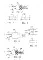
FIG. 1 illustrates the preferred embodiment of the electro-nerve stimulator system of the present invention.FIG. 2 is an exploded cross-sectional view of the preferred embodiment of the transcutaneous electrode of the present invention.FIG. 3 is an exploded cross-sectional view of the preferred embodiment of the electrically conductive tape member of the present invention.FIG. 4 illustrates the positioning of the terminal end of the percutaneous needle electrode onto the adhesive portion of the electrically conductive tape member of the present invention.FIG. 5 illustrates the electrically conductive tape member of the present invention fixedly adhered to the terminal end of the percutaneous needle electrode.FIG. 6 is a partial cross-sectional view of the preferred embodiment of single-use connector for an embodiment of the present invention.FIG. 7 is an electrical schematic for one embodiment of the single-use connector ofFIG. 6 .FIG. 8 is an electrical schematic for another embodiment of the single-use connector ofFIG. 6 .FIG. 9 illustrates another embodiment of a single use connector for an embodiment of the present invention.FIG. 10 is an electrical schematic for one embodiment of the single-use connector ofFIG. 9 .FIG. 11 illustrates another embodiment of a mechanical single use connector for an embodiment of the present invention.FIG. 12 illustrates another embodiment of the lead wire set for use with the present invention utilizing a clip for electrically coupling the lead wire to the percutaneous needle electrode.- The electro-
nerve stimulation apparatus 10 of the present invention, as illustrated inFIG. 1 , comprises apulse generator 12, a first electrically conductive, insulatedlead wire 14, a second electrically conductive, insulatedlead wire 16, an electrically conductivetranscutaneous electrode 18 and an electrically conductivepercutaneous needle electrode 20. - In the preferred embodiment of the
apparatus 10, thefirst lead wire 14 has afirst end 22 and asecond end 24. Thefirst end 22 electrically couples to a first lead wire interface of thepulse generator 12. Thetranscutaneous electrode 18 is preferably fixedly secured to thesecond end 24 of thefirst lead wire 14 as described in detail later. - The
second lead wire 16 has afirst end 30 and asecond end 32. Thefirst end 30 of thesecond lead wire 16 electrically couples to a second lead wire interface of thepulse generator 12. Fixedly secured to thesecond end 32 of the second lead wire is an electrically conductive adaptor. The adaptor is preferably an electricallyconductive tape member 38 as shown inFIG. 1 . In an alternative embodiment, the adaptor may be an electricallyconductive clip 130 as illustrated inFIG. 12 , for example. - The preferred electrically
conductive tape member 38 includes an electrically conductiveadhesive portion 40 and an electrically conductivenon-adhesive portion 42 the purpose of which will be described in detail later. - In the preferred embodiment, the first ends 22, 30 of the first and second
lead wires male connector 44 which is matingly receivable by a single matingfemale receptacle 46. The preferred singlemale connector 44 and singlefemale receptacle 46 are also preferably keyed in any conventional manner to ensure that thefirst lead wire 14 will only electrically couple with the first lead wire interface and that thesecond lead wire 16 will only electrically couple with the second lead wire interface. This safeguard will ensure that the current pulses generated by thepulse generator 12 will flow from thetranscutaneous electrode 18 to thepercutaneous needle electrode 20 as describe in detail later. - Referring now to
FIG. 2 , an exploded, cross-sectional view of the preferredtranscutaneous electrode 18 is illustrated. The preferredtranscutaneous electrode 18 includes various layers sandwiched together, including a non-electrically conductive top layer 50, an intermediate electricallyconductive foil 52, such as aluminum foil, and a bottom electrically conductive adhesive layer 54, preferably biocompatible and hypoallergenic, for adhering to thetranscutaneous electrode 18 to the patient's skin as described later. Aremovable backing strip 56 is preferably disposed over the lower face of the adhesive layer 54 which is then removed just prior to adhering thetranscutaneous electrode 18 to the patient's skin. Disposed between the lower face of the top layer 50 and the upper face of the electricallyconductive layer 52 is anotheradhesive layer 58 which bonds the top non-conductive layer 50 to the intermediate conductive layer 54. Thesecond end 24 of thefirst lead wire 14 is disposed between the top non-conductive layer 50 and the intermediateconductive layer 52. A portion of the insulation is removed from thefirst lead wire 14 such that an electrical connection may be created with the electricallyconductive layer 52. The adhesive 58 preferably securely bonds thesecond end 24 of thefirst lead wire 14 to theconductive layer 52 to such that it cannot be readily removed therefrom without damaging theelectrode 18. In the preferred embodiment, the adhesive comprising the bottom adhesive layer 54 is preferably a single-use adhesive, meaning that the adhesive loses its adhesive properties upon its removal and will not readily re-adhere to the patient's skin, such that thetranscutaneous electrode 18 is essentially non-reusable after one use. - Referring now to
FIG. 3 , an exploded, cross-sectional view of the preferred electricallyconductive tape member 38 is illustrated. Thetape member 38 also preferably includes various layers sandwiched together, including a non-electrically conductivetop layer 70, an intermediate electricallyconductive foil layer 72, such as aluminum foil, and a bottom electrically conductiveadhesive layer 74 preferably extending over only a portion of the tape member 38 (see alsoFIG. 4 ). The remaining portion of thetape member 38 preferably does not include any adhesive. Aremovable backing strip 76 is preferably disposed over the lower face of thebottom adhesive layer 74 which is then removed just prior to adhering thepercutaneous needle electrode 20 thereto (discussed later). Disposed between the lower face of thetop layer 70 and the upper face of the electricallyconductive layer 72 is another adhesive layer 78 which bonds the topnon-conductive layer 70 to the intermediateconductive layer 74. Thesecond end 32 of thesecond lead wire 16 is disposed between the topnon-conductive layer 70 and the intermediateconductive layer 72. A portion of the insulation is removed from thesecond lead wire 16 such that an electrical connection may be created with the electricallyconductive layer 72. The adhesive 78 preferably securely bonds thesecond end 32 of thesecond lead wire 16 to theconductive layer 72 to such that it cannot be readily removed therefrom without damaging thetape member 38. In the preferred embodiment, thetape member 38 is preferably adapted for only a single-use whereby the adhesive comprising thebottom adhesive layer 74 has sufficiently adhesive properties such that when the opposing ends of thetape member 38 are folded over onto each other and over theterminal end 92 of percutaneous needle electrode 20 (as discussed later) the ends of thetape member 38 cannot be readily unfolded thereby fixedly securing thepercutaneous needle electrode 20 therebetween. - The percutaneous needle electrode 20 (
FIG. 1 ) is preferably constructed out of medical grade stainless steel or other biocompatible electrically conductive metal. The includes afirst end 90 for insertion into the patient's body in proximity to the preselected internal stimulation site (discussed later) and asecond end 92 to which thetape member 38 is to be electrically coupled. The size of theneedle electrode 20 is preferably small, for example 34G needle electrode (0.22 x 10 mm), to minimize trauma during insertion. Thesecond end 92 of theneedle electrode 20 preferably includes an enlarged portion to enable the electricallyconductive tape member 38 to be more easily adhered thereto (discussed later). - Referring again to
FIG. 1 , thepulse generator 12 is preferably a small handheld, battery operated pulse generator that produces small electrical current pulses, preferably between 1-10 mA, which pass between thetranscutaneous electrode 18 and thepercutaneous needle electrode 20. Thepulse generator 12 may be of the type disclosed inUS Patent Application No. 09/213,558 preferred pulse generator 12 includes afirst dial 100 used for selecting the desired current pulse for treatment, preferably in increments of 1mA. Thepreferred pulse generator 12 further includes asecond dial 102 for setting the desired treatment time preferably in five minute increments. Thepulse generator 12 preferably generates an audible and/or visible signals. For example, a audible and/or visible signal may be initially generated when the pulse generator is turned on and when thedial 102 is turned past each of the predefined time increments. Additionally, an audible and/or visual signal may be generated, for example, when one half of the remaining time selected for the treatment has expired. Also, when the time selected for the treatment expires, another audible and/or visual signal may be generated. - As illustrated in
FIG. 1 , in use, the desiredinternal stimulation site 104 on the patient'sbody 106 is determined depending on the treatment for which the electro-nerve stimulation system is to be used. Thefirst end 90 of thepercutaneous needle electrode 18 is positioned to penetrate the patient's skin and is advanced into proximity with the preselected internal stimulation site. Theadhesive backing 56 on thetranscutaneous electrode 18 is removed and the adhesive face 54 of thetranscutaneous electrode 18 is pressed onto the surface of the patient's skin at the desired location, preferably distally (i.e., downstream) of the internal stimulation site. Theadhesive backing 76 on the electricallyconductive tape member 38 is removed and the terminal end of the percutaneous needle electrode 20 (i.e. the end extending from the patient's body) is positioned at approximately the midpoint of thetape member 38 as illustrated inFIG. 4 . Thepercutaneous needle electrode 20 is then preferably fixedly adhered to the tape member as shown inFIG. 5 by folding the ends of thetape member 38 over theterminal end 92 of theneedle electrode 20. The first and secondlead wires pulse generator 12 by inserting themale connector 44 into the matingfemale receptacle 46. Thepulse generator 12 is activated to generate current pulses. The current pulses from thepulse generator 12 traverse theinternal stimulation site 104 by passing from thetranscutaneous electrode 18 to thepercutaneous needle electrode 20 as indicated by thearrow 108. - It may be desirable to test whether the
percutaneous needle electrode 20 is properly positioned in proximity to theinternal stimulation site 104 prior to fixedly adhering theelectrode 20 to thetape member 38. Accordingly, in the preferred embodiment the electricallyconductive tape member 38 includes anon-adhesive portion 42. By holding theneedle electrode 20 against thenon-adhesive portion 42 of the electricallyconductive tape member 38 while the pulse generator is activated, the user will be able to test whether theneedle electrode 20 is properly positioned in proximity to the preselectedinternal stimulation site 104 to achieve the desired treatment results. If theneedle electrode 20 is not properly positioned, thetape member 38 can simply be removed and the electrode needle repositioned or manipulated into the proper position. - In order to further ensure that the
electrodes lead wires connector 44 may also be adapted to fail after a single use or after a predetermined time period.FIGs. 6-8 illustrate possible embodiments for theconnector 44 adapted for a single use. Theconnector 44 may include two ports A and B corresponding to the first and secondlead wires 14, 16 (also designated by corresponding reference letters A and B). A third port C may include afuse 120 which may be adapted to burn out after a preselected time period, thereby rendering theconnector 44 incapable of making an electrical connection between the first and secondlead wires pulse generator 12. Alternatively, as illustrated inFIG. 8 , theconnector 44 may include a serial read/write non-volatile erasable, programmable read only memory (EPROM)chip 122 programmable to prevent thelead wires pulse generator 12 after a predetermined time period. In yet another embodiment, as shown inFIGs 9-10 , theconnector 44 may incorporate both a serial read/writenon-volatile EPROM 122 and afuse 120 in which theEPROM 122 is programmable to burn out the fuse after a preselected time period or to generate a current spike to burn out the fuse after expiration of a preselected time period. An illustrative electrical schematic is shown inFIG. 10 for this embodiment which may include aresister 124 and azenor diode 126. In yet another alternative embodiment as shown inFIG. 11 , a mechanical mechanism may be employed in which apin 128 is biased within port C. In operation, upon insertion of theconnector 44 into thefemale receptacle 46 of thepulse generator 12 the mechanism is actuated to release thebiased pin 128. Upon removal of theconnector 44 from thefemale receptacle 46, the releasedpin 128 prevents the connector from being reinserted into thefemale receptacle 46 thereby preventing the first and secondlead wires pulse generator 12. - In still another alternative embodiment as illustrated in
FIG. 12 , the electrically conductive adaptor may comprise aclip 130 for connecting with theterminal end 92 of thepercutaneous needle electrode 20. Theclip 130 may have abridge member 132 movable between an open position and a closed position by depressing theplunger 134. As current pulses from thepulse generator 12 traverse thebridge member 132, the bridge member may burn out preventing its reuse , or alternatively, the bridge member may fixedly bond or weld to theterminal end 92 of thepercutaneous needle electrode 20 preventing reuse of the electrode andclip 130. This embodiment may also be used with one or more of thealternative connector 44 embodiments described above. If a single-use connector 44 as identified above is used with theclip 130, the clip need not be a single-use clip 130 as just described. Also as shown inFIG. 12 , the first and secondlead wires 14 may include intermediatelead wire connectors 136 so the entire lead wire set does not need replacing. - Naturally, it is not possible to design a system which is completely capable of preventing a determined individual from refurbishing the lead wires and/or electrodes so that they may be reused. Thus, reference to single-use adhesives, single-use connectors, or single-use adaptors as used herein does not mean that these devices must be completely incapable of reuse. Rather as used herein, the term "single-use" should be understood as meaning that the disclosed structure, or its equivalent, for performing the intended function is sufficiently degraded or destroyed so that the structure does not perform its intended function as efficiently or that the structure is sufficiently degraded or destroyed to discourage or at least make it difficult to re-use the structure for its intended function.
- The apparatus and
system 10 of the present invention is particularly suited for the treatment of urinary urge incontinence. Thepercutaneous needle electrode 20 is inserted into the patient's skin in proximity to the tibial nerve cephalic to the medial malleolus. The transcutaneous electrode is adhered to the patient's skin distal to the percutaneous needle electrode. Those skilled in the art will appreciate that the nerve stimulation system of the present invention is effective not only for the treatment of urge incontinence, but can also be effective for both nerve and muscle stimulation to treat numerous other conditions including gastro-reflux, chronic pain, Parkinson's disease, multiple sclerosis and general joint and muscle rehabilitation. - Although only certain exemplary embodiments of the invention have been described in detail above, those skilled in the art will readily appreciate that many modifications are possible without materially departing from the novel teachings and advantages of this invention. Accordingly, all such modifications are intended to be included within the scope of this invention as defined in the following claims.
- We disclose an electro-nerve stimulation apparatus, comprising: a pulse generator for generating electrical pulses, said pulse generator having a first lead interface and a second lead interface ; a first electrically conductive, insulated lead wire having first and second ends, said first end of said first lead wire fixedly secured to a first connector for electrically coupling with said first lead wire interface of said pulse generator, said second end of said first lead wire operably secured to an electrically conductive transcutaneous electrode for delivering electrical pulses generated by the pulse generator to a patient's skin; a second electrically conductive, insulated lead wire having first and second ends, said first end of said second lead wire fixedly secured to a second connector for electrically coupling with said second lead wire interface of said pulse generator, said second end of said second lead wire fixedly secured to an electrically conductive adaptor for electrically connecting with a terminal end of a percutaneous needle electrode, said electrically conductive percutaneous needle electrode having another end insertable into a patient's body in proximity to an internal stimulation site to receive electrical pulses from said transcutaneous electrode; a single-use mechanism comprising a part of at least one of said lead wire sets to effectively discourage re-use of the percutaneous and transcutaneous electrodes.
- Optionally, said electrically conductive transcutaneous electrode includes adhesive on a face thereof for removably securing said transcutaneous electrode onto said patient's body at a desired location.
- Optionally, said adhesive on said face of said transcutaneous electrode is a single-use adhesive such that upon removal of said transcutaneous electrode from said patient's skin said adhesive will not readily re-adhere to said patient's skin.
- Optionally, said electrically conductive adaptor includes an electrically conductive tape member having an adhesive portion.
- Optionally, said terminal end of said percutaneous needle electrode is fixedly adhered to said adhesive portion of said electrically conductive tape member, whereby said percutaneous needle electrode is not readily removable therefrom without damaging said tape member.
- Optionally, said electrically conductive tape member further includes a non-adhesive electrically conductive portion for testing proper placement of said other end of said percutaneous needle electrode in proximity to said internal stimulation site prior to adhering said terminal end of said percutaneous needle electrode to said adhesive portion of said electrically conductive tape member.
- Optionally, said first and second connectors fixedly secured to said first ends of said first and second lead wires comprise a single male connector and wherein said pulse generator includes a single mating female receptacle for electrically coupling said first and second lead wires with said first and second lead wire interfaces, and wherein said male connectors and said female receptacles are keyed to ensure proper orientation and electrical coupling of said first and second lead wires with the respective first and second lead interfaces of said pulse generator.
- Optionally, said single male connector is a single-use connector whereby said single male connector is not readily reusable.
- Optionally, said single use connector includes a fuse adapted to burn out after a preselected time period.
- Optionally, said single use connector includes an EPROM programmed to prevent electrical connection of said first and second lead wires with said first and second lead wire interfaces.
- Optionally, said single use connector includes a fuse and an EPROM programmed to burn out said fuse after a predetermined time period.
- Optionally, said single use connector includes a fuse and an EPROM programmed to generate a current spike to burn out said fuse after a predetermined time period.
- Optionally, said electrically conductive adaptor includes a clip having an electrically conductive bridge member movable between a first open position and a second closed position.
- Optionally, said terminal end of said percutaneous needle electrode is secured to said electrically conductive bridge member.
- Optionally, said clip is a single-use clip.
- Optionally, said bridge member fails after a predetermined time period of current pulses traverse therethrough.
- Optionally, said bridge member welds to said terminal end of said percutaneous needle electrode after a predetermined time period of current pulses traverse therethrough.
- Optionally, said first and second connectors fixedly secured to said first ends of said first and second lead wires comprise a single male connector and wherein said pulse generator includes a single mating female receptacle for electrically coupling said first and second lead wires with said first and second lead wire interfaces, and further wherein said single male connector and said mating single female receptacle are keyed to ensure proper orientation and electrical coupling of said first and second lead wires only with the respective first and second lead interfaces of said pulse generator.
- Optionally, said single male connector is a single-use connector whereby said single male connector is not readily reusable.
- Optionally, said single use connector includes a fuse adapted to burn out after a preselected time period.
- Optionally, said single use connector includes an EPROM programmed to prevent electrical connection of said first and second lead wires with said first and second lead wire interfaces.
- Optionally, said single use connector includes a fuse and an EPROM programmed to burn out said fuse after a predetermined time period.
- Optionally, said single use connector includes a fuse and an EPROM programmed to generate a current spike to burn out said fuse after a predetermined time period.
- We also disclose a method for electro-nerve stimulation, comprising the steps of : (a) providing a pulse generator for generating electrical pulses, said pulse generator having a first lead interface and a second lead interface; (b) providing a first electrically conductive, insulated lead wire having first and second ends, said first end of said first lead wire fixedly secured to a connector for electrically coupling with said first lead wire interface of said pulse generator, said second end of said first lead wire operably secured to an electrically conductive transcutaneous electrode for delivering electrical pulses generated by said pulse generator to a patient's skin; (c) providing an electrically conductive percutaneous needle electrode, said electrically conductive percutaneous needle electrode having one end insertable into a patient's body in proximity to a preselected internal stimulation site to receive electrical pulses from said transcutaneous electrode; (d) providing a second electrically conductive, insulated lead wire having first and second ends, said first end of said second lead wire fixedly secured to a connector for electrically coupling with said second lead wire interface of said pulse generator, said second end of said second lead wire fixedly secured to an electrically conductive adaptor; (e) providing a single-use mechanism comprising a part of at least one of said lead wire sets to effectively discourage re-use of said percutaneous and transcutaneous electrodes; (f) penetrating said patient's skin with said one end of said percutaneous needle electrode and advancing said one end into proximity with said preselected internal stimulation site; (g) electrically connecting a terminal end of said percutaneous needle electrode to said electrically conductive single-use adaptor; (h) adhering said transcutaneous electrode onto said patient's skin distal to said preselected internal stimulation site; (i) electrically coupling said first and second lead wires with said respective first and second lead wire interfaces of said pulse generator; (j) activating said pulse generator to generate electrical pulses that traverse the preselected internal stimulation site between said transcutaneous electrode and said percutaneous needle electrode.
- Optionally, said electrically conductive transcutaneous electrode includes adhesive on a face thereof for removably securing said electrode onto said skin of said patient.
- Optionally, said adhesive on said face of said transcutaneous electrode is a single-use adhesive such that upon removal of said transcutaneous electrode from said patient's skin said adhesive will not readily re-adhere to said patient's skin.
- Optionally, said electrically conductive adaptor includes an electrically conductive tape member having an adhesive portion.
- Optionally, said step of connecting said terminal end of said percutaneous needle electrode to said adaptor includes the step of fixedly adhering said adhesive portion of said electrically conductive tape member to said terminal end, whereby said percutaneous needle electrode is not readily removable therefrom without damaging said tape member.
- Optionally, including the step of testing proper placement of said one end of said percutaneous needle electrode in proximity to said preselected internal stimulation site prior to fixedly adhering said terminal end of said percutaneous needle electrode to said adhesive portion of said electrically conductive tape member by contacting said other end of said percutaneous needle with a non-adhesive electrically conductive portion of said electrically conductive tape member.
- Optionally, said first and second connectors fixedly secured to said first ends of said first and second lead wires comprise a single male connector and wherein said pulse generator includes a single mating female receptacle for electrically coupling said first and second lead wires with said first and second lead wire interfaces, and further wherein said single male connector and said mating single female receptacle are keyed to ensure proper orientation and electrical coupling of said first and second lead wires only with the respective first and second lead interfaces of said pulse generator.
- Optionally, said single male connector is a single-use connector whereby said single male connector is not readily reusable.
- Optionally, said single use connector includes a fuse adapted to burn out after a preselected time period.
- Optionally, said single use connector includes an EPROM programmed to prevent electrical connection of said first and second lead wires with said first and second lead wire interfaces.
- Optionally, said single use connector includes a fuse and an EPROM programmed to burn out said fuse after a predetermined time period.
- Optionally, said single use connector includes a fuse and an EPROM programmed to generate a current spike to burn out said fuse after a predetermined time period.
- Optionally, said electrically conductive adaptor includes a clip having an electrically conductive bridge member movable between a first open position and a second closed position.
- Optionally, said step of connecting said terminal end of said percutaneous needle electrode to said adaptor includes the step of connecting said terminal end of said percutaneous needle electrode to said electrically conductive bridge member.
- Optionally, said clip is a single-use clip.
- Optionally, said bridge member fails after a predetermined time period of current pulses traverse therethrough.
- Optionally, said bridge member welds to said terminal end of said percutaneous needle electrode after a predetermined time period of current pulses traverse therethrough.
- Optionally, said first and second connectors fixedly secured to said first ends of said first and second lead wires comprise a single male connector and wherein said pulse generator includes a single mating female receptacle for electrically coupling said first and second lead wires with said first and second lead wire interfaces, and further wherein said single male connector and said mating single female receptacle are keyed to ensure proper orientation and electrical coupling of said first and second lead wires only with the respective first and second lead interfaces of said pulse generator.
- Optionally, said single male connector is a single-use connector whereby said single male connector is not readily reusable.
- Optionally, said single use connector includes a fuse adapted to burn out after a preselected time period.
- Optionally, said single use connector includes an EPROM programmed to prevent electrical connection of said first and second lead wires with said first and second lead wire interfaces.
- Optionally, said single use connector includes a fuse and an EPROM programmed to burn out said fuse after a predetermined time period.
Claims (14)
- An electro-nerve stimulation apparatus, comprising:a pulse generator (12) for generating electrical pulses, said pulse generator having a first lead wire interface and a second lead wire interface;a first electrically conductive, insulated lead wire (14) having first (22) and second (24) ends, said first end of said first lead wire fixedly secured to a first connector for electrically coupling with said first lead wire interface of said pulse generator, said second end of said first lead wire operably secured to an electrically conductive transcutaneous electrode (18) for delivering electrical pulses generated by the pulse generator to a patient's skin;a second electrically conductive, insulated lead wire (16) having first (30) and second (32) ends, said first end of said second lead wire fixedly secured to a second connector for electrically coupling with said second lead wire interface of said pulse generator, said second end of said second lead wire fixedly secured to an electrically conductive adaptor (38, 130) for electrically connecting with a terminal end (92) of a percutaneous needle electrode (20); anda single-use connector (44) comprising said first and second connectors fixedly secured to said first ends of said first and second lead wires;wherein said pulse generator includes a mating receptacle (46) for electrically coupling said first and second lead wires with said first and second lead wire interfaces; andwherein said single-use connector is not readily reusable to effectively discourage re-use of the percutaneous and transcutaneous electrodes.
- The apparatus of claim 1 wherein said single-use connector includes a fuse (120) adapted to burn out after a preselected time period, or an EPROM (122) programmed to prevent electrical connection of said first and second lead wires with said first and second lead wire interfaces, or a fuse and an EPROM programmed to burn out said fuse after a predetermined time period, or a fuse and an EPROM programmed to generate a current spike to burn out said fuse after a predetermined time period, or a mechanical mechanism having a pin (128) biased within a port of the single-use connector for being released upon removal of the single-use connector from the receptacle.
- The apparatus of claims 1 and 2, wherein said single-use connector is a male connector, said mating receptacle is a female receptacle, and said male connector and said female receptacle are keyed to ensure proper orientation and electrical coupling of said first and second lead wires with the respective first and second lead wire interfaces of said pulse generator.
- The apparatus of claims 1, 2 and 3 wherein said electrically conductive adaptor includes a clip (130) having an electrically conductive bridge member (132) movable between a first open position and a second closed position, or an electrically conductive tape member (38) having an adhesive portion (74).
- An electro-nerve stimulation apparatus, comprising:a pulse generator (12) for generating electrical pulses, said pulse generator having a first lead wire interface and a second lead wire interface;a single connector (44); anda lead wire set removably connectable to the pulse generator and comprising;a first electrically conductive, insulated lead wire (14) having first (22) and second (24) ends, said first end of said first lead wire comprising a first connector for electrically coupling with said first lead wire interface of said pulse generator, said second end of said first lead wire operably comprising an electrically conductive transcutaneous electrode (18) for delivering electrical pulses generated by the pulse generator to a patient's skin;a second electrically conductive, insulated lead wire (16) having first (30) and second (32) ends, said first end of said second lead wire comprising a second connector for electrically coupling with said second lead wire interface of said pulse generator, said second end of said second lead wire comprising an electrically conductive attachment member (38, 130) for being electrically connecting with a percutaneous needle electrode (20); anda single-use mechanism (18, 38, 120, 122, 130) comprising a part of said lead wire set to effectively discourage re-use thereof;wherein said single conductor comprises said first and second connectors fixedly secured to said first ends of said first and second lead wires; andwherein said pulse generator includes a single mating receptacle (46) for electrically coupling said first and second lead wires with said first and second lead wire interfaces.
- The apparatus of claim 5 wherein said single use mechanism includes a fuse (120) adapted to burn out after a preselected time period, or an EPROM (122) programmed to prevent electrical connection of said first and second lead wires with said first and second lead wire interfaces, or a fuse and an EPROM programmed to burn out said fuse after a predetermined time period, or a fuse and an EPROM programmed to generate a current spike to burn out said fuse after a predetermined time period, or an electrically conductive bridge member (132) of a clip (130) that is movable between a first open position and a second closed position and that is adapted to burn out by current flow, or an electrically conductive bridge member (132) of a clip (130) that is movable between a first open position and a second closed position and that is adapted to fuse by current flow, or an electrically conductive adhesive layer (74) disposed on a tape member (38) wherein said attachment member comprises said tape member and has sufficient adhesive properties to resist unfolding of the tape when the ends thereof are folded over onto each over, or an electrically conductive single-use adhesive layer (54) disposed on the transcutaneous electrode for one-use adhesion to the patient's skin.
- The apparatus of claims 5 and 6 , wherein said single connector is a single male connector, said single mating receptacle is a single mating female receptacle, and said single male connector and said single mating female receptacle are keyed to ensure proper orientation and electrical coupling of said first and second lead wires only with the respective first and second lead wire interfaces of said pulse generator.
- A method for electro-nerve stimulation, comprising the steps of:providing a pulse generator (12) for generating electrical pulses, said pulse generator having a first lead wire interface and a second lead wire interface;providing a first electrically conductive, insulated lead wire (14) having first (22) and second (24) ends, said first end of said first lead wire fixedly secured to a connector for electrically coupling with said first lead wire interface of said pulse generator, said second end of said first lead wire operably secured to an electrically conductive transcutaneous electrode (18) for delivering electrical pulses generated by said pulse generator to a patient's skin;providing an electrically conductive percutaneous needle electrode (20), said electrically conductive percutaneous needle electrode having one end (90) insertable into a patient's body in proximity to a preselected internal stimulation site (104) to receive electrical pulses (108) from said transcutaneous electrode;providing a second electrically conductive, insulated lead wire (16) having first (30) and second (32) ends, said first end of said second lead wire fixedly secured to a connector for electrically coupling with said second lead wire interface of said pulse generator, said second end of said second lead wire fixedly secured to an electrically conductive adaptor (38, 130);penetrating said patient's skin with said one end of said percutaneous needle electrode and advancing said one end into proximity with said preselected internal stimulation site;electrically connecting a terminal end (92) of said percutaneous needle electrode to said electrically conductive single-use adaptor;adhering said transcutaneous electrode onto said patient's skin distal to said preselected internal stimulation site;electrically coupling said first and second lead wires with said respective first and second lead wire interfaces of said pulse generator; andactivating said pulse generator to generate electrical pulses that traverse the preselected internal stimulation site between said transcutaneous electrode and said percutaneous needle electrode;wherein said first and second connectors fixedly secured to said first ends of said first and second lead wires comprise a single-use connector (44);wherein said pulse generator includes a mating receptacle (56) for electrically coupling said first and second lead wires with said first and second lead wire interfaces; andwherein said single-use connector is not readily reusable to effectively discourage re-use of said percutaneous and transcutaneous electrodes.
- The method of claim 8 wherein said single-use connector includes a fuse (120) adapted to burn out after a preselected time period, or an EPROM (122) programmed to prevent electrical connection of said first and second lead wires with said first and second lead wire interfaces, or a fuse and an EPROM programmed to burn out said fuse after a predetermined time period, or a fuse and an EPROM programmed to generate a current spike to burn out said fuse after a predetermined time period, or a mechanical mechanism having a pin (128) biased within a port of the single-use connector for being released upon removal of the single-use connector from the receptacle.
- The method of claims 8 and 9, wherein said single-use connector is a male connector, said mating receptacle is a female receptacle, and said male connector and said female receptacle are keyed to ensure proper orientation and electrical coupling of said first and second lead wires with the respective first and second lead wire interfaces of said pulse generator.
- The method of claims 8, 9 and 10, wherein said electrically conductive adaptor includes a clip (130) having an electrically conductive bridge member (132) movable between a first open position and a second closed position, or an electrically conductive tape member (38) having an adhesive portion (74).
- A method for electro-nerve stimulation, comprising the steps of:providing a pulse generator (12) for generating electrical pulses, said pulse generator having a first lead wire interface and a second lead wire interface;providing a removably connectable lead wire set for the pulse generator;providing the lead wire set with a first electrically conductive, insulated lead wire (14) having first (22) and second (24) ends, said first end of said first lead wire comprising a connector for electrically coupling with said first lead wire interface of said pulse generator, said second end of said first lead wire operably comprising an electrically conductive transcutaneous electrode (18) for delivering electrical pulses generated by said pulse generator to a patient's skin;providing an electrically conductive percutaneous needle electrode (20), said electrically conductive percutaneous needle electrode having one end (90) insertable into a patient's body in proximity to a preselected internal stimulation site (104) to receive electrical pulses (108) from said transcutaneous electrode;providing the lead wire set with a second electrically conductive, insulated lead wire (16) having first (30) and second (32) ends, said first end of said second lead wire comprising a connector for electrically coupling with said second lead wire interface of said pulse generator, said second end of said second lead wire comprising an electrically conductive attachment member (38, 130);providing the lead wire set with a single-use mechanism (18, 38, 120, 122, 130) to effectively discourage re-use thereof;penetrating said patient's skin with said one end of said percutaneous needle electrode and advancing said one end into proximity with said preselected internal stimulation site;electrically connecting a terminal end (92) of said percutaneous needle electrode to said attachment member;adhering said transcutaneous electrode onto said patient's skin distal to said preselected internal stimulation site;electrically coupling said first and second lead wires with said respective first and second lead wire interfaces of said pulse generator; andactivating said pulse generator to generate electrical pulses that traverse the preselected internal stimulation site between said transcutaneous electrode and said percutaneous needle electrode;wherein said first and second connectors fixedly secured to said first ends of said first and second lead wires comprise a single connector (44) and wherein said pulse generator includes a single mating receptacle (46) for electrically coupling said first and second lead wires with said first and second lead wire interfaces.
- The method of claim 12 wherein said single use mechanism includes a fuse (120) adapted to burn out after a preselected time period, or an EPROM (122) programmed to prevent electrical connection of said first and second lead wires with said first and second lead wire interfaces, or a fuse and an EPROM programmed to burn out said fuse after a predetermined time period, or a fuse and an EPROM programmed to generate a current spike to burn out said fuse after a predetermined time period, or an electrically conductive bridge member (132) of a clip (130) that is movable between a first open position and a second closed position and that is adapted to burn out by current flow, or an electrically conductive bridge member (132) of a clip (130) that is movable between a first open position and a second closed position and that is adapted to fuse by current flow, or an electrically conductive adhesive layer (74) disposed on a tape member (38) wherein said attachment member comprises said tape member and has sufficient adhesive properties to resist unfolding of the tape when the ends thereof are folded over onto each over, or an electrically conductive single-use adhesive layer (54) disposed on the transcutaneous electrode for one-use adhesion to the patient's skin.
- The method of claims 12 and 13, wherein said single connector is a single male connector, said single mating receptacle is a single mating female receptacle, and said single male connector and said single mating female receptacle are keyed to ensure proper orientation and electrical coupling of said first and second lead wires only with the respective first and second lead wire interfaces of said pulse generator.
Applications Claiming Priority (2)
| Application Number | Priority Date | Filing Date | Title |
|---|---|---|---|
| US33607401P | 2001-10-18 | 2001-10-18 | |
| EP02786437AEP1444004B1 (en) | 2001-10-18 | 2002-10-18 | Electro-nerve stimulator system and methods |
Related Parent Applications (2)
| Application Number | Title | Priority Date | Filing Date |
|---|---|---|---|
| EP02786437ADivisionEP1444004B1 (en) | 2001-10-18 | 2002-10-18 | Electro-nerve stimulator system and methods |
| EP02786437.0Division | 2002-10-18 |
Publications (2)
| Publication Number | Publication Date |
|---|---|
| EP2308553A1true EP2308553A1 (en) | 2011-04-13 |
| EP2308553B1 EP2308553B1 (en) | 2014-01-29 |
Family
ID=23314453
Family Applications (2)
| Application Number | Title | Priority Date | Filing Date |
|---|---|---|---|
| EP10185417.2AExpired - LifetimeEP2308553B1 (en) | 2001-10-18 | 2002-10-18 | Electro-nerve stimulator system |
| EP02786437AExpired - LifetimeEP1444004B1 (en) | 2001-10-18 | 2002-10-18 | Electro-nerve stimulator system and methods |
Family Applications After (1)
| Application Number | Title | Priority Date | Filing Date |
|---|---|---|---|
| EP02786437AExpired - LifetimeEP1444004B1 (en) | 2001-10-18 | 2002-10-18 | Electro-nerve stimulator system and methods |
Country Status (9)
| Country | Link |
|---|---|
| US (1) | US7536226B2 (en) |
| EP (2) | EP2308553B1 (en) |
| AT (1) | ATE536907T1 (en) |
| AU (1) | AU2002349957A1 (en) |
| CA (1) | CA2463936C (en) |
| DK (2) | DK2308553T3 (en) |
| ES (2) | ES2377946T3 (en) |
| PT (2) | PT1444004E (en) |
| WO (1) | WO2003033068A2 (en) |
Cited By (2)
| Publication number | Priority date | Publication date | Assignee | Title |
|---|---|---|---|---|
| US8046082B2 (en) | 2006-05-18 | 2011-10-25 | Uroplasty, Inc. | Method and apparatus for stimulating a nerve of a patient |
| US8812114B2 (en) | 2001-10-18 | 2014-08-19 | Uroplasty, Inc. | Lead set for nerve stimulator and method of operation thereof |
Families Citing this family (86)
| Publication number | Priority date | Publication date | Assignee | Title |
|---|---|---|---|---|
| ATE479343T1 (en) | 2002-10-01 | 2010-09-15 | Nellcor Puritan Bennett Inc | USE OF A HEADBAND FOR VOLTAGE DISPLAY AND SYSTEM OF OXYMETER AND HEADBAND |
| US7047056B2 (en) | 2003-06-25 | 2006-05-16 | Nellcor Puritan Bennett Incorporated | Hat-based oximeter sensor |
| US8412297B2 (en) | 2003-10-01 | 2013-04-02 | Covidien Lp | Forehead sensor placement |
| US20100016929A1 (en)* | 2004-01-22 | 2010-01-21 | Arthur Prochazka | Method and system for controlled nerve ablation |
| WO2005070494A1 (en)* | 2004-01-22 | 2005-08-04 | Rehabtronics Inc. | Method of routing electrical current to bodily tissues via implanted passive conductors |
| US7212865B2 (en)* | 2004-05-25 | 2007-05-01 | Philip Cory | Nerve stimulator and method |
| US7729772B2 (en) | 2005-01-07 | 2010-06-01 | Uroplasty, Inc. | Implantable neuromodulation system and method |
| US10154792B2 (en)* | 2005-03-01 | 2018-12-18 | Checkpoint Surgical, Inc. | Stimulation device adapter |
| US7555345B2 (en) | 2005-03-11 | 2009-06-30 | Medtronic, Inc. | Implantable neurostimulator device |
| US7231256B2 (en)* | 2005-03-11 | 2007-06-12 | Medtronic, Inc. | Neurostimulation site screening |
| EP1899002A1 (en) | 2005-06-28 | 2008-03-19 | Bioness Development, Llc | Improvements to an implant, system and method using implanted passive conductors for routing electrical current |
| US9339641B2 (en) | 2006-01-17 | 2016-05-17 | Emkinetics, Inc. | Method and apparatus for transdermal stimulation over the palmar and plantar surfaces |
| US9610459B2 (en) | 2009-07-24 | 2017-04-04 | Emkinetics, Inc. | Cooling systems and methods for conductive coils |
| US20070167990A1 (en)* | 2006-01-17 | 2007-07-19 | Theranova, Llc | Method and apparatus for low frequency induction therapy for the treatment of urinary incontinence and overactive bladder |
| WO2007136713A2 (en)* | 2006-05-18 | 2007-11-29 | Uroplasty, Inc. | Lead set for nerve stimulator and method of operation thereof |
| JP2010505471A (en) | 2006-10-02 | 2010-02-25 | エムキネティクス, インコーポレイテッド | Method and apparatus for magnetic induction therapy |
| US11224742B2 (en) | 2006-10-02 | 2022-01-18 | Emkinetics, Inc. | Methods and devices for performing electrical stimulation to treat various conditions |
| US9005102B2 (en) | 2006-10-02 | 2015-04-14 | Emkinetics, Inc. | Method and apparatus for electrical stimulation therapy |
| US10786669B2 (en) | 2006-10-02 | 2020-09-29 | Emkinetics, Inc. | Method and apparatus for transdermal stimulation over the palmar and plantar surfaces |
| US8483820B2 (en)* | 2006-10-05 | 2013-07-09 | Bioness Inc. | System and method for percutaneous delivery of electrical stimulation to a target body tissue |
| US7987001B2 (en) | 2007-01-25 | 2011-07-26 | Warsaw Orthopedic, Inc. | Surgical navigational and neuromonitoring instrument |
| US8374673B2 (en) | 2007-01-25 | 2013-02-12 | Warsaw Orthopedic, Inc. | Integrated surgical navigational and neuromonitoring system having automated surgical assistance and control |
| WO2009026588A2 (en)* | 2007-08-23 | 2009-02-26 | Bioness Inc. | System for transmitting electrical current to a bodily tissue |
| US9757554B2 (en) | 2007-08-23 | 2017-09-12 | Bioness Inc. | System for transmitting electrical current to a bodily tissue |
| US8738137B2 (en) | 2007-08-23 | 2014-05-27 | Bioness Inc. | System for transmitting electrical current to a bodily tissue |
| US9008782B2 (en) | 2007-10-26 | 2015-04-14 | Medtronic, Inc. | Occipital nerve stimulation |
| US20090326602A1 (en) | 2008-06-27 | 2009-12-31 | Arkady Glukhovsky | Treatment of indications using electrical stimulation |
| WO2010014259A1 (en)* | 2008-08-01 | 2010-02-04 | Ndi Medical, Llc | Portable assemblies, systems, and methods for providing functional or therapeutic neurostimulation |
| US8364220B2 (en) | 2008-09-25 | 2013-01-29 | Covidien Lp | Medical sensor and technique for using the same |
| US8257274B2 (en) | 2008-09-25 | 2012-09-04 | Nellcor Puritan Bennett Llc | Medical sensor and technique for using the same |
| US8515515B2 (en) | 2009-03-25 | 2013-08-20 | Covidien Lp | Medical sensor with compressible light barrier and technique for using the same |
| US8781548B2 (en) | 2009-03-31 | 2014-07-15 | Covidien Lp | Medical sensor with flexible components and technique for using the same |
| JP2012521864A (en) | 2009-03-31 | 2012-09-20 | インスパイア・メディカル・システムズ・インコーポレイテッド | Percutaneous access method in a system for treating sleep-related abnormal breathing |
| WO2011011748A1 (en) | 2009-07-23 | 2011-01-27 | Emkinetics, Inc. | Method and apparatus for magnetic induction therapy |
| EP2493551A4 (en) | 2009-10-26 | 2013-04-17 | Emkinetics Inc | Method and apparatus for electromagnetic stimulation of nerve, muscle, and body tissues |
| US8588884B2 (en) | 2010-05-28 | 2013-11-19 | Emkinetics, Inc. | Microneedle electrode |
| US8788045B2 (en) | 2010-06-08 | 2014-07-22 | Bluewind Medical Ltd. | Tibial nerve stimulation |
| AT11956U1 (en) | 2010-06-30 | 2011-08-15 | Biegler Gmbh | ELECTRICAL STIMULATION DEVICE |
| US8788047B2 (en)* | 2010-11-11 | 2014-07-22 | Spr Therapeutics, Llc | Systems and methods for the treatment of pain through neural fiber stimulation |
| US9457186B2 (en) | 2010-11-15 | 2016-10-04 | Bluewind Medical Ltd. | Bilateral feedback |
| US9186504B2 (en) | 2010-11-15 | 2015-11-17 | Rainbow Medical Ltd | Sleep apnea treatment |
| US9076187B1 (en) | 2011-06-16 | 2015-07-07 | Advanced Uro-Solutions, Llc | Medical device payment system |
| CA2839532A1 (en) | 2011-06-16 | 2012-12-20 | Advanced Uro-Solutions, Llc | Percutaneous tibial nerve stimulator |
| WO2013071309A1 (en) | 2011-11-11 | 2013-05-16 | The Regents Of The University Of California | Transcutaneous spinal cord stimulation: noninvasive tool for activation of locomotor circuitry |
| WO2013111137A2 (en) | 2012-01-26 | 2013-08-01 | Rainbow Medical Ltd. | Wireless neurqstimulatqrs |
| DE102012010262B4 (en) | 2012-05-25 | 2014-07-03 | Albrecht Molsberger | Therapeutically applicable DC delivery device |
| WO2014087337A1 (en) | 2012-12-06 | 2014-06-12 | Bluewind Medical Ltd. | Delivery of implantable neurostimulators |
| BR112015017042B1 (en) | 2013-01-21 | 2022-03-03 | Cala Health, Inc | Device to treat tremor |
| WO2014144785A1 (en) | 2013-03-15 | 2014-09-18 | The Regents Of The University Of California | Multi-site transcutaneous electrical stimulation of the spinal cord for facilitation of locomotion |
| US10137299B2 (en) | 2013-09-27 | 2018-11-27 | The Regents Of The University Of California | Engaging the cervical spinal cord circuitry to re-enable volitional control of hand function in tetraplegic subjects |
| ES2546651B1 (en)* | 2014-03-24 | 2016-11-16 | Ionclinics And Deionic, S.L. | Device for the recovery of tendinopathies and fibrillar tears |
| CA2949843A1 (en) | 2014-06-02 | 2015-12-10 | Cala Health, Inc. | Systems and methods for peripheral nerve stimulation to treat tremor |
| WO2016028608A1 (en) | 2014-08-17 | 2016-02-25 | Nine Continents Medical, Inc. | Miniature implatable neurostimulator system for sciatic nerves and their branches |
| US12053630B2 (en) | 2014-08-17 | 2024-08-06 | Coloplast A/S | Implantable pulse generator with automatic jump-start |
| WO2016029159A2 (en) | 2014-08-21 | 2016-02-25 | The Regents Of The University Of California | Regulation of autonomic control of bladder voiding after a complete spinal cord injury |
| AU2015308779B2 (en) | 2014-08-27 | 2020-06-25 | The Regents Of The University Of California | Multi-electrode array for spinal cord epidural stimulation |
| US9764146B2 (en) | 2015-01-21 | 2017-09-19 | Bluewind Medical Ltd. | Extracorporeal implant controllers |
| US9597521B2 (en) | 2015-01-21 | 2017-03-21 | Bluewind Medical Ltd. | Transmitting coils for neurostimulation |
| US10004896B2 (en) | 2015-01-21 | 2018-06-26 | Bluewind Medical Ltd. | Anchors and implant devices |
| US9782589B2 (en) | 2015-06-10 | 2017-10-10 | Bluewind Medical Ltd. | Implantable electrostimulator for improving blood flow |
| EP4342516A3 (en) | 2015-06-10 | 2024-07-10 | Cala Health, Inc. | Systems and methods for peripheral nerve stimulation to treat tremor with detachable therapy and monitoring units |
| US20190022371A1 (en)* | 2015-08-06 | 2019-01-24 | The Regents Of The University Of California | Electrode array for transcutaneous electrical stimulation of the spinal cord and uses thereof |
| US11298533B2 (en) | 2015-08-26 | 2022-04-12 | The Regents Of The University Of California | Concerted use of noninvasive neuromodulation device with exoskeleton to enable voluntary movement and greater muscle activation when stepping in a chronically paralyzed subject |
| WO2017053847A1 (en) | 2015-09-23 | 2017-03-30 | Cala Health, Inc. | Systems and methods for peripheral nerve stimulation in the finger or hand to treat hand tremors |
| US11097122B2 (en) | 2015-11-04 | 2021-08-24 | The Regents Of The University Of California | Magnetic stimulation of the spinal cord to restore control of bladder and/or bowel |
| US10105540B2 (en) | 2015-11-09 | 2018-10-23 | Bluewind Medical Ltd. | Optimization of application of current |
| US9713707B2 (en) | 2015-11-12 | 2017-07-25 | Bluewind Medical Ltd. | Inhibition of implant migration |
| CA3011993C (en) | 2016-01-21 | 2024-05-14 | Cala Health, Inc. | Systems, methods and devices for peripheral neuromodulation for treating diseases related to overactive bladder |
| CA3033662A1 (en) | 2016-08-25 | 2018-03-01 | Cala Health, Inc. | Systems and methods for treating cardiac dysfunction through peripheral nerve stimulation |
| US12121729B2 (en) | 2016-09-23 | 2024-10-22 | Neural Integrative Solutions LLC | Method and apparatus for intraoperative monitoring of lead placement in dorsal root ganglion stimulation |
| US10124178B2 (en) | 2016-11-23 | 2018-11-13 | Bluewind Medical Ltd. | Implant and delivery tool therefor |
| US11235154B2 (en) | 2017-02-17 | 2022-02-01 | The University Of British Columbia | Apparatus and methods for maintaining physiological functions |
| EP3606604A4 (en) | 2017-04-03 | 2020-12-16 | Cala Health, Inc. | SYSTEMS, METHODS AND DEVICES FOR PERIPHERAL NEUROMODULATION FOR THE TREATMENT OF DISEASES RELATED TO OVERACTIVE BLADDER |
| WO2018217791A1 (en) | 2017-05-23 | 2018-11-29 | The Regents Of The University Of California | Accessing spinal networks to address sexual dysfunction |
| US20180353764A1 (en) | 2017-06-13 | 2018-12-13 | Bluewind Medical Ltd. | Antenna configuration |
| EP3974021B1 (en) | 2017-06-30 | 2023-06-14 | ONWARD Medical N.V. | A system for neuromodulation |
| US12357828B2 (en) | 2017-12-05 | 2025-07-15 | Ecole Polytechnique Federale De Lausanne (Epfl) | System for planning and/or providing neuromodulation |
| WO2019110400A1 (en) | 2017-12-05 | 2019-06-13 | Ecole Polytechnique Federale De Lausanne (Epfl) | A system for planning and/or providing neuromodulation |
| DE18205821T1 (en) | 2018-11-13 | 2020-12-24 | Gtx Medical B.V. | CONTROL SYSTEM FOR MOTION RECONSTRUCTION AND / OR RECOVERY FOR A PATIENT |
| EP3695878B1 (en) | 2019-02-12 | 2023-04-19 | ONWARD Medical N.V. | A system for neuromodulation |
| US11065461B2 (en) | 2019-07-08 | 2021-07-20 | Bioness Inc. | Implantable power adapter |
| US12251560B1 (en) | 2019-08-13 | 2025-03-18 | Cala Health, Inc. | Connection quality determination for wearable neurostimulation systems |
| US11890468B1 (en) | 2019-10-03 | 2024-02-06 | Cala Health, Inc. | Neurostimulation systems with event pattern detection and classification |
| DE19211698T1 (en) | 2019-11-27 | 2021-09-02 | Onward Medical B.V. | Neuromodulation system |
| EP3827875B1 (en) | 2019-11-27 | 2023-07-05 | ONWARD Medical N.V. | Neuromodulation system |
| US11400299B1 (en) | 2021-09-14 | 2022-08-02 | Rainbow Medical Ltd. | Flexible antenna for stimulator |
Citations (4)
| Publication number | Priority date | Publication date | Assignee | Title |
|---|---|---|---|---|
| US5857968A (en)* | 1997-11-24 | 1999-01-12 | Benja-Athon; Anuthep | Coupling device in electroacupuncture |
| US5951484A (en)* | 1997-08-01 | 1999-09-14 | Harbinger Medical, Inc. | Method of noninvasively determining a patient's susceptibility to arrhythmia |
| WO1999047204A1 (en)* | 1998-03-18 | 1999-09-23 | Urosurge, Inc. | Electro-nerve stimulator systems and methods |
| GB2336214A (en)* | 1998-01-16 | 1999-10-13 | David William Taylor | Preventionof multiple use of limited use devices |
Family Cites Families (20)
| Publication number | Priority date | Publication date | Assignee | Title |
|---|---|---|---|---|
| US3893462A (en) | 1972-01-28 | 1975-07-08 | Esb Inc | Bioelectrochemical regenerator and stimulator devices and methods for applying electrical energy to cells and/or tissue in a living body |
| US3995644A (en) | 1975-09-16 | 1976-12-07 | The United States Of America As Represented By The Administrator Of The National Aeronautics And Space Administration | Percutaneous connector device |
| US4408609A (en)* | 1980-04-01 | 1983-10-11 | Professional Staff Association Of The Rancho Los Amigos Hospital, Inc. | Electrical muscle stimulation for treatment of scoliosis and other spinal deformities |
| US4406288A (en) | 1981-04-06 | 1983-09-27 | Hugh P. Cash | Bladder control device and method |
| US4535785A (en) | 1982-09-23 | 1985-08-20 | Minnesota Mining And Manufacturing Co. | Method and apparatus for determining the viability and survival of sensori-neutral elements within the inner ear |
| US4519394A (en) | 1983-03-07 | 1985-05-28 | Trustees Of The University Of Pennsylvania | Method and apparatus for cathodic potential control in electrically induced osteogenesis |
| US5094242A (en) | 1988-11-07 | 1992-03-10 | Regents Of The University Of California | Implantable nerve stimulation device |
| US5056518A (en) | 1990-07-02 | 1991-10-15 | Electro-Biology, Inc. | Optimization of bone formation at cathodes |
| US5557210A (en) | 1992-11-20 | 1996-09-17 | Pacesetter, Inc. | Universal cable connector for temporarily connecting implantable stimulation leads and implantable stimulation devices with a non-implantable system analyzer |
| US5441520A (en) | 1993-04-06 | 1995-08-15 | Hewlett-Packard Corporation | Defibrillator patient connection system with automatic identification |
| US5776171A (en) | 1994-09-06 | 1998-07-07 | Case Western Reserve University | Functional neuromuscular stimulation system |
| US5695495A (en) | 1995-11-20 | 1997-12-09 | Ellman; Alan G. | Electrosurgical electrode for sclerotherapy |
| US5983141A (en) | 1996-06-27 | 1999-11-09 | Radionics, Inc. | Method and apparatus for altering neural tissue function |
| US5782892A (en) | 1997-04-25 | 1998-07-21 | Medtronic, Inc. | Medical lead adaptor for external medical device |
| US6055453A (en)* | 1997-08-01 | 2000-04-25 | Genetronics, Inc. | Apparatus for addressing needle array electrodes for electroporation therapy |
| US5906634A (en) | 1997-08-08 | 1999-05-25 | Cardiac Pacemakers, Inc. | Implantable device having a quick connect mechanism for leads |
| US6141585A (en) | 1998-05-08 | 2000-10-31 | Intermedics Inc. | Implantable cardiac stimulator with electrode-tissue interface characterization |
| US6516227B1 (en)* | 1999-07-27 | 2003-02-04 | Advanced Bionics Corporation | Rechargeable spinal cord stimulator system |
| US6904324B2 (en)* | 1999-12-01 | 2005-06-07 | Meagan Medical, Inc. | Method and apparatus for deploying a percutaneous probe |
| US6701190B2 (en)* | 2000-10-10 | 2004-03-02 | Meagan Medical, Inc. | System and method for varying characteristics of electrical therapy |
- 2002
- 2002-10-18EPEP10185417.2Apatent/EP2308553B1/ennot_activeExpired - Lifetime
- 2002-10-18PTPT02786437Tpatent/PT1444004E/enunknown
- 2002-10-18ESES02786437Tpatent/ES2377946T3/ennot_activeExpired - Lifetime
- 2002-10-18AUAU2002349957Apatent/AU2002349957A1/ennot_activeAbandoned
- 2002-10-18EPEP02786437Apatent/EP1444004B1/ennot_activeExpired - Lifetime
- 2002-10-18ESES10185417.2Tpatent/ES2450465T3/ennot_activeExpired - Lifetime
- 2002-10-18ATAT02786437Tpatent/ATE536907T1/enactive
- 2002-10-18WOPCT/US2002/033318patent/WO2003033068A2/ennot_activeApplication Discontinuation
- 2002-10-18PTPT101854172Tpatent/PT2308553E/enunknown
- 2002-10-18DKDK10185417.2Tpatent/DK2308553T3/enactive
- 2002-10-18CACA2463936Apatent/CA2463936C/ennot_activeExpired - Lifetime
- 2002-10-18USUS10/492,578patent/US7536226B2/ennot_activeExpired - Lifetime
- 2002-10-18DKDK02786437.0Tpatent/DK1444004T3/enactive
Patent Citations (4)
| Publication number | Priority date | Publication date | Assignee | Title |
|---|---|---|---|---|
| US5951484A (en)* | 1997-08-01 | 1999-09-14 | Harbinger Medical, Inc. | Method of noninvasively determining a patient's susceptibility to arrhythmia |
| US5857968A (en)* | 1997-11-24 | 1999-01-12 | Benja-Athon; Anuthep | Coupling device in electroacupuncture |
| GB2336214A (en)* | 1998-01-16 | 1999-10-13 | David William Taylor | Preventionof multiple use of limited use devices |
| WO1999047204A1 (en)* | 1998-03-18 | 1999-09-23 | Urosurge, Inc. | Electro-nerve stimulator systems and methods |
Cited By (4)
| Publication number | Priority date | Publication date | Assignee | Title |
|---|---|---|---|---|
| US8812114B2 (en) | 2001-10-18 | 2014-08-19 | Uroplasty, Inc. | Lead set for nerve stimulator and method of operation thereof |
| US9056194B2 (en) | 2001-10-18 | 2015-06-16 | Uroplasty, Llc | Lead set for nerve stimulator and method of operation thereof |
| US9265941B2 (en) | 2001-10-18 | 2016-02-23 | Uroplasty, Llc | Lead set for nerve stimulator and method of operation thereof |
| US8046082B2 (en) | 2006-05-18 | 2011-10-25 | Uroplasty, Inc. | Method and apparatus for stimulating a nerve of a patient |
Also Published As
| Publication number | Publication date |
|---|---|
| EP1444004A4 (en) | 2006-07-19 |
| ATE536907T1 (en) | 2011-12-15 |
| CA2463936A1 (en) | 2003-04-24 |
| WO2003033068A2 (en) | 2003-04-24 |
| AU2002349957A1 (en) | 2003-04-28 |
| EP1444004A2 (en) | 2004-08-11 |
| DK1444004T3 (en) | 2012-03-12 |
| ES2450465T3 (en) | 2014-03-24 |
| DK2308553T3 (en) | 2014-03-10 |
| ES2377946T3 (en) | 2012-04-03 |
| EP1444004B1 (en) | 2011-12-14 |
| EP2308553B1 (en) | 2014-01-29 |
| PT1444004E (en) | 2012-02-17 |
| WO2003033068A3 (en) | 2004-03-11 |
| CA2463936C (en) | 2013-04-02 |
| US7536226B2 (en) | 2009-05-19 |
| US20050171576A1 (en) | 2005-08-04 |
| PT2308553E (en) | 2014-03-04 |
Similar Documents
| Publication | Publication Date | Title |
|---|---|---|
| US7536226B2 (en) | Electro-nerve stimulator system and methods | |
| US8812114B2 (en) | Lead set for nerve stimulator and method of operation thereof | |
| EP2024006B1 (en) | Apparatus for stimulating a nerve of a patient | |
| AU2011248594B2 (en) | Systems and methods for percutaneous electrical stimulation | |
| AU774063B2 (en) | Electrical stimulation compress | |
| US20140324144A1 (en) | Minimally invasive methods for implanting a sacral stimulation lead | |
| AU2011248594A1 (en) | Systems and methods for percutaneous electrical stimulation | |
| CN115461935A (en) | Stimulus Lead Connection System | |
| AU2025226673A1 (en) | Nerve regeneration therapy system and method | |
| US8480427B2 (en) | Cable connector | |
| US20070255371A1 (en) | System and method for electrically probing and providing medical electrical stimulation | |
| US20240099632A1 (en) | Nerve stimulation patterns and device for detectability of nerve function and health | |
| GB2301287A (en) | Electrical stimulation for treatment of incontinence | |
| WO2007136713A2 (en) | Lead set for nerve stimulator and method of operation thereof |
Legal Events
| Date | Code | Title | Description |
|---|---|---|---|
| PUAI | Public reference made under article 153(3) epc to a published international application that has entered the european phase | Free format text:ORIGINAL CODE: 0009012 | |
| AC | Divisional application: reference to earlier application | Ref document number:1444004 Country of ref document:EP Kind code of ref document:P | |
| AK | Designated contracting states | Kind code of ref document:A1 Designated state(s):AT BE BG CH CY CZ DE DK EE ES FI FR GB GR IE IT LI LU MC NL PT SE SK TR | |
| RIN1 | Information on inventor provided before grant (corrected) | Inventor name:VAN HELVOIRT, PIET DL Inventor name:VAN AART, FRED Inventor name:WILLIAMS, JEFFREY, M. Inventor name:VAN DEN BIGGELAAR, HANS | |
| 17P | Request for examination filed | Effective date:20111011 | |
| RAP1 | Party data changed (applicant data changed or rights of an application transferred) | Owner name:UROPLASTY, INC. | |
| RIC1 | Information provided on ipc code assigned before grant | Ipc:A61N 1/36 20060101AFI20130320BHEP Ipc:A61M 5/50 20060101ALN20130320BHEP | |
| GRAP | Despatch of communication of intention to grant a patent | Free format text:ORIGINAL CODE: EPIDOSNIGR1 | |
| RIC1 | Information provided on ipc code assigned before grant | Ipc:A61M 5/50 20060101ALN20130415BHEP Ipc:A61N 1/36 20060101AFI20130415BHEP | |
| INTG | Intention to grant announced | Effective date:20130502 | |
| RIC1 | Information provided on ipc code assigned before grant | Ipc:A61M 5/50 20060101ALN20130909BHEP Ipc:A61N 1/36 20060101AFI20130909BHEP | |
| GRAP | Despatch of communication of intention to grant a patent | Free format text:ORIGINAL CODE: EPIDOSNIGR1 | |
| INTG | Intention to grant announced | Effective date:20131025 | |
| GRAS | Grant fee paid | Free format text:ORIGINAL CODE: EPIDOSNIGR3 | |
| GRAA | (expected) grant | Free format text:ORIGINAL CODE: 0009210 | |
| AC | Divisional application: reference to earlier application | Ref document number:1444004 Country of ref document:EP Kind code of ref document:P | |
| AK | Designated contracting states | Kind code of ref document:B1 Designated state(s):AT BE BG CH CY CZ DE DK EE ES FI FR GB GR IE IT LI LU MC NL PT SE SK TR | |
| REG | Reference to a national code | Ref country code:GB Ref legal event code:FG4D | |
| RIN1 | Information on inventor provided before grant (corrected) | Inventor name:WILLIAMS, JEFFREY, M. Inventor name:VAN AART, FRED Inventor name:VAN DEN BIGGELAAR, HANS Inventor name:VAN HELVOIRT, PIET DL | |
| REG | Reference to a national code | Ref country code:CH Ref legal event code:NV Representative=s name:BOVARD AG, CH Ref country code:CH Ref legal event code:EP | |
| REG | Reference to a national code | Ref country code:AT Ref legal event code:REF Ref document number:651361 Country of ref document:AT Kind code of ref document:T Effective date:20140215 | |
| REG | Reference to a national code | Ref country code:IE Ref legal event code:FG4D | |
| REG | Reference to a national code | Ref country code:PT Ref legal event code:SC4A Free format text:AVAILABILITY OF NATIONAL TRANSLATION Effective date:20140225 | |
| REG | Reference to a national code | Ref country code:DK Ref legal event code:T3 Effective date:20140303 | |
| REG | Reference to a national code | Ref country code:SE Ref legal event code:TRGR | |
| REG | Reference to a national code | Ref country code:DE Ref legal event code:R096 Ref document number:60245979 Country of ref document:DE Effective date:20140313 | |
| REG | Reference to a national code | Ref country code:NL Ref legal event code:T3 | |
| REG | Reference to a national code | Ref country code:ES Ref legal event code:FG2A Ref document number:2450465 Country of ref document:ES Kind code of ref document:T3 Effective date:20140324 | |
| REG | Reference to a national code | Ref country code:GR Ref legal event code:EP Ref document number:20140400359 Country of ref document:GR Effective date:20140317 | |
| REG | Reference to a national code | Ref country code:SK Ref legal event code:T3 Ref document number:E 15897 Country of ref document:SK | |
| PG25 | Lapsed in a contracting state [announced via postgrant information from national office to epo] | Ref country code:CY Free format text:LAPSE BECAUSE OF FAILURE TO SUBMIT A TRANSLATION OF THE DESCRIPTION OR TO PAY THE FEE WITHIN THE PRESCRIBED TIME-LIMIT Effective date:20140129 | |
| REG | Reference to a national code | Ref country code:DE Ref legal event code:R097 Ref document number:60245979 Country of ref document:DE | |
| PG25 | Lapsed in a contracting state [announced via postgrant information from national office to epo] | Ref country code:EE Free format text:LAPSE BECAUSE OF FAILURE TO SUBMIT A TRANSLATION OF THE DESCRIPTION OR TO PAY THE FEE WITHIN THE PRESCRIBED TIME-LIMIT Effective date:20140129 | |
| PLBE | No opposition filed within time limit | Free format text:ORIGINAL CODE: 0009261 | |
| STAA | Information on the status of an ep patent application or granted ep patent | Free format text:STATUS: NO OPPOSITION FILED WITHIN TIME LIMIT | |
| 26N | No opposition filed | Effective date:20141030 | |
| REG | Reference to a national code | Ref country code:DE Ref legal event code:R097 Ref document number:60245979 Country of ref document:DE Effective date:20141030 | |
| PG25 | Lapsed in a contracting state [announced via postgrant information from national office to epo] | Ref country code:MC Free format text:LAPSE BECAUSE OF FAILURE TO SUBMIT A TRANSLATION OF THE DESCRIPTION OR TO PAY THE FEE WITHIN THE PRESCRIBED TIME-LIMIT Effective date:20140129 Ref country code:LU Free format text:LAPSE BECAUSE OF FAILURE TO SUBMIT A TRANSLATION OF THE DESCRIPTION OR TO PAY THE FEE WITHIN THE PRESCRIBED TIME-LIMIT Effective date:20141018 | |
| REG | Reference to a national code | Ref country code:FR Ref legal event code:PLFP Year of fee payment:14 | |
| REG | Reference to a national code | Ref country code:FR Ref legal event code:PLFP Year of fee payment:15 | |
| PG25 | Lapsed in a contracting state [announced via postgrant information from national office to epo] | Ref country code:BE Free format text:LAPSE BECAUSE OF NON-PAYMENT OF DUE FEES Effective date:20161031 | |
| PGFP | Annual fee paid to national office [announced via postgrant information from national office to epo] | Ref country code:FI Payment date:20170224 Year of fee payment:15 Ref country code:CH Payment date:20170130 Year of fee payment:15 Ref country code:GR Payment date:20170222 Year of fee payment:15 Ref country code:SE Payment date:20170131 Year of fee payment:15 | |
| PG25 | Lapsed in a contracting state [announced via postgrant information from national office to epo] | Ref country code:BE Free format text:LAPSE BECAUSE OF NON-PAYMENT OF DUE FEES Effective date:20161031 | |
| PGFP | Annual fee paid to national office [announced via postgrant information from national office to epo] | Ref country code:BG Payment date:20170213 Year of fee payment:15 Ref country code:AT Payment date:20170223 Year of fee payment:15 Ref country code:IE Payment date:20170131 Year of fee payment:15 Ref country code:SK Payment date:20170131 Year of fee payment:15 Ref country code:DK Payment date:20170203 Year of fee payment:15 Ref country code:PT Payment date:20170131 Year of fee payment:15 Ref country code:CZ Payment date:20170201 Year of fee payment:15 Ref country code:BE Payment date:20170131 Year of fee payment:15 | |
| PGRI | Patent reinstated in contracting state [announced from national office to epo] | Ref country code:BE Effective date:20170201 | |
| PGFP | Annual fee paid to national office [announced via postgrant information from national office to epo] | Ref country code:TR Payment date:20170205 Year of fee payment:15 Ref country code:ES Payment date:20170131 Year of fee payment:15 | |
| REG | Reference to a national code | Ref country code:FR Ref legal event code:PLFP Year of fee payment:16 | |
| REG | Reference to a national code | Ref country code:DK Ref legal event code:EBP Effective date:20171031 | |
| REG | Reference to a national code | Ref country code:SE Ref legal event code:EUG | |
| REG | Reference to a national code | Ref country code:CH Ref legal event code:PL | |
| REG | Reference to a national code | Ref country code:AT Ref legal event code:MM01 Ref document number:651361 Country of ref document:AT Kind code of ref document:T Effective date:20171018 | |
| REG | Reference to a national code | Ref country code:SK Ref legal event code:MM4A Ref document number:E 15897 Country of ref document:SK Effective date:20171018 | |
| REG | Reference to a national code | Ref country code:IE Ref legal event code:MM4A | |
| PG25 | Lapsed in a contracting state [announced via postgrant information from national office to epo] | Ref country code:SK Free format text:LAPSE BECAUSE OF NON-PAYMENT OF DUE FEES Effective date:20171018 Ref country code:FI Free format text:LAPSE BECAUSE OF NON-PAYMENT OF DUE FEES Effective date:20171018 Ref country code:LI Free format text:LAPSE BECAUSE OF NON-PAYMENT OF DUE FEES Effective date:20171031 Ref country code:PT Free format text:LAPSE BECAUSE OF NON-PAYMENT OF DUE FEES Effective date:20180418 Ref country code:CH Free format text:LAPSE BECAUSE OF NON-PAYMENT OF DUE FEES Effective date:20171031 Ref country code:CZ Free format text:LAPSE BECAUSE OF NON-PAYMENT OF DUE FEES Effective date:20171018 | |
| REG | Reference to a national code | Ref country code:BE Ref legal event code:MM Effective date:20171031 | |
| PG25 | Lapsed in a contracting state [announced via postgrant information from national office to epo] | Ref country code:SE Free format text:LAPSE BECAUSE OF NON-PAYMENT OF DUE FEES Effective date:20171019 Ref country code:GR Free format text:LAPSE BECAUSE OF NON-PAYMENT OF DUE FEES Effective date:20180504 Ref country code:BE Free format text:LAPSE BECAUSE OF NON-PAYMENT OF DUE FEES Effective date:20171031 Ref country code:AT Free format text:LAPSE BECAUSE OF NON-PAYMENT OF DUE FEES Effective date:20171018 | |
| REG | Reference to a national code | Ref country code:FR Ref legal event code:PLFP Year of fee payment:17 | |
| PG25 | Lapsed in a contracting state [announced via postgrant information from national office to epo] | Ref country code:IE Free format text:LAPSE BECAUSE OF NON-PAYMENT OF DUE FEES Effective date:20171018 | |
| PG25 | Lapsed in a contracting state [announced via postgrant information from national office to epo] | Ref country code:DK Free format text:LAPSE BECAUSE OF NON-PAYMENT OF DUE FEES Effective date:20171031 | |
| REG | Reference to a national code | Ref country code:ES Ref legal event code:FD2A Effective date:20181221 | |
| PG25 | Lapsed in a contracting state [announced via postgrant information from national office to epo] | Ref country code:BG Free format text:LAPSE BECAUSE OF NON-PAYMENT OF DUE FEES Effective date:20180506 | |
| PG25 | Lapsed in a contracting state [announced via postgrant information from national office to epo] | Ref country code:ES Free format text:LAPSE BECAUSE OF NON-PAYMENT OF DUE FEES Effective date:20171019 | |
| PGFP | Annual fee paid to national office [announced via postgrant information from national office to epo] | Ref country code:IT Payment date:20191009 Year of fee payment:18 | |
| PG25 | Lapsed in a contracting state [announced via postgrant information from national office to epo] | Ref country code:IT Free format text:LAPSE BECAUSE OF NON-PAYMENT OF DUE FEES Effective date:20201018 | |
| PGFP | Annual fee paid to national office [announced via postgrant information from national office to epo] | Ref country code:NL Payment date:20210928 Year of fee payment:20 Ref country code:FR Payment date:20210913 Year of fee payment:20 | |
| PGFP | Annual fee paid to national office [announced via postgrant information from national office to epo] | Ref country code:GB Payment date:20210907 Year of fee payment:20 | |
| PGFP | Annual fee paid to national office [announced via postgrant information from national office to epo] | Ref country code:DE Payment date:20210908 Year of fee payment:20 | |
| PG25 | Lapsed in a contracting state [announced via postgrant information from national office to epo] | Ref country code:TR Free format text:LAPSE BECAUSE OF NON-PAYMENT OF DUE FEES Effective date:20171018 | |
| REG | Reference to a national code | Ref country code:DE Ref legal event code:R071 Ref document number:60245979 Country of ref document:DE | |
| REG | Reference to a national code | Ref country code:NL Ref legal event code:MK Effective date:20221017 | |
| REG | Reference to a national code | Ref country code:GB Ref legal event code:PE20 Expiry date:20221017 | |
| PG25 | Lapsed in a contracting state [announced via postgrant information from national office to epo] | Ref country code:GB Free format text:LAPSE BECAUSE OF EXPIRATION OF PROTECTION Effective date:20221017 |