EP2308539B1 - Device for supplying respiratory gas, humidifying device, respiratory gas tube, and connecting device therefor - Google Patents
Device for supplying respiratory gas, humidifying device, respiratory gas tube, and connecting device thereforDownload PDFInfo
- Publication number
- EP2308539B1 EP2308539B1EP10185455.2AEP10185455AEP2308539B1EP 2308539 B1EP2308539 B1EP 2308539B1EP 10185455 AEP10185455 AEP 10185455AEP 2308539 B1EP2308539 B1EP 2308539B1
- Authority
- EP
- European Patent Office
- Prior art keywords
- humidifying
- respiratory gas
- set forth
- supplying
- cpap
- Prior art date
- Legal status (The legal status is an assumption and is not a legal conclusion. Google has not performed a legal analysis and makes no representation as to the accuracy of the status listed.)
- Expired - Lifetime
Links
- 230000000241respiratory effectEffects0.000titleclaimsdescription66
- 230000008878couplingEffects0.000claimsabstractdescription52
- 238000010168coupling processMethods0.000claimsabstractdescription52
- 238000005859coupling reactionMethods0.000claimsabstractdescription52
- 230000000295complement effectEffects0.000claimsabstractdescription20
- XLYOFNOQVPJJNP-UHFFFAOYSA-NwaterSubstancesOXLYOFNOQVPJJNP-UHFFFAOYSA-N0.000claimsabstractdescription8
- 238000005304joiningMethods0.000claimsdescription11
- 230000002093peripheral effectEffects0.000claimsdescription6
- 230000005540biological transmissionEffects0.000claimsdescription2
- 238000007664blowingMethods0.000claims1
- 238000009434installationMethods0.000claims1
- 238000009530blood pressure measurementMethods0.000abstractdescription2
- 230000029058respiratory gaseous exchangeEffects0.000description164
- 239000007789gasSubstances0.000description124
- 239000007788liquidSubstances0.000description87
- 238000003860storageMethods0.000description36
- 239000012530fluidSubstances0.000description24
- 238000007789sealingMethods0.000description22
- 238000005192partitionMethods0.000description16
- 238000010438heat treatmentMethods0.000description14
- 239000000463materialSubstances0.000description12
- 239000003570airSubstances0.000description10
- 239000013536elastomeric materialSubstances0.000description8
- 239000007779soft materialSubstances0.000description5
- 238000009423ventilationMethods0.000description5
- 238000007599dischargingMethods0.000description4
- 238000004519manufacturing processMethods0.000description4
- 210000000056organAnatomy0.000description4
- 229920002379silicone rubberPolymers0.000description4
- 239000004945silicone rubberSubstances0.000description4
- 238000010276constructionMethods0.000description3
- 238000013461designMethods0.000description3
- 239000002184metalSubstances0.000description3
- 239000004033plasticSubstances0.000description3
- 208000023504respiratory system diseaseDiseases0.000description3
- 230000007704transitionEffects0.000description3
- 238000004140cleaningMethods0.000description2
- 238000004891communicationMethods0.000description2
- 238000001514detection methodMethods0.000description2
- 230000002349favourable effectEffects0.000description2
- 238000002347injectionMethods0.000description2
- 239000007924injectionSubstances0.000description2
- 238000000034methodMethods0.000description2
- 230000009467reductionEffects0.000description2
- 210000002345respiratory systemAnatomy0.000description2
- 238000009736wettingMethods0.000description2
- 208000000884Airway ObstructionDiseases0.000description1
- 206010041662SplinterDiseases0.000description1
- 239000011358absorbing materialSubstances0.000description1
- 239000012080ambient airSubstances0.000description1
- 238000004458analytical methodMethods0.000description1
- QVGXLLKOCUKJST-UHFFFAOYSA-Natomic oxygenChemical compound[O]QVGXLLKOCUKJST-UHFFFAOYSA-N0.000description1
- 239000011324beadSubstances0.000description1
- 238000011513continuous positive airway pressure therapyMethods0.000description1
- 238000005516engineering processMethods0.000description1
- 238000011010flushing procedureMethods0.000description1
- 239000006260foamSubstances0.000description1
- 230000005484gravityEffects0.000description1
- 238000003780insertionMethods0.000description1
- 230000037431insertionEffects0.000description1
- 238000003032molecular dockingMethods0.000description1
- 238000000465mouldingMethods0.000description1
- 239000001301oxygenSubstances0.000description1
- 229910052760oxygenInorganic materials0.000description1
- 230000008569processEffects0.000description1
- 230000004044responseEffects0.000description1
- 238000010321sleep therapyMethods0.000description1
- 239000000243solutionSubstances0.000description1
- 230000002269spontaneous effectEffects0.000description1
- 238000002560therapeutic procedureMethods0.000description1
- 238000012546transferMethods0.000description1
- 239000012780transparent materialSubstances0.000description1
- 238000013022ventingMethods0.000description1
Images


Classifications
- A—HUMAN NECESSITIES
- A61—MEDICAL OR VETERINARY SCIENCE; HYGIENE
- A61M—DEVICES FOR INTRODUCING MEDIA INTO, OR ONTO, THE BODY; DEVICES FOR TRANSDUCING BODY MEDIA OR FOR TAKING MEDIA FROM THE BODY; DEVICES FOR PRODUCING OR ENDING SLEEP OR STUPOR
- A61M16/00—Devices for influencing the respiratory system of patients by gas treatment, e.g. ventilators; Tracheal tubes
- A61M16/10—Preparation of respiratory gases or vapours
- A61M16/14—Preparation of respiratory gases or vapours by mixing different fluids, one of them being in a liquid phase
- A61M16/16—Devices to humidify the respiration air
- A—HUMAN NECESSITIES
- A61—MEDICAL OR VETERINARY SCIENCE; HYGIENE
- A61M—DEVICES FOR INTRODUCING MEDIA INTO, OR ONTO, THE BODY; DEVICES FOR TRANSDUCING BODY MEDIA OR FOR TAKING MEDIA FROM THE BODY; DEVICES FOR PRODUCING OR ENDING SLEEP OR STUPOR
- A61M16/00—Devices for influencing the respiratory system of patients by gas treatment, e.g. ventilators; Tracheal tubes
- A61M16/0057—Pumps therefor
- A61M16/0066—Blowers or centrifugal pumps
- A—HUMAN NECESSITIES
- A61—MEDICAL OR VETERINARY SCIENCE; HYGIENE
- A61M—DEVICES FOR INTRODUCING MEDIA INTO, OR ONTO, THE BODY; DEVICES FOR TRANSDUCING BODY MEDIA OR FOR TAKING MEDIA FROM THE BODY; DEVICES FOR PRODUCING OR ENDING SLEEP OR STUPOR
- A61M16/00—Devices for influencing the respiratory system of patients by gas treatment, e.g. ventilators; Tracheal tubes
- A61M16/08—Bellows; Connecting tubes ; Water traps; Patient circuits
- A61M16/0816—Joints or connectors
- A61M16/0841—Joints or connectors for sampling
- A61M16/0858—Pressure sampling ports
- A—HUMAN NECESSITIES
- A61—MEDICAL OR VETERINARY SCIENCE; HYGIENE
- A61M—DEVICES FOR INTRODUCING MEDIA INTO, OR ONTO, THE BODY; DEVICES FOR TRANSDUCING BODY MEDIA OR FOR TAKING MEDIA FROM THE BODY; DEVICES FOR PRODUCING OR ENDING SLEEP OR STUPOR
- A61M16/00—Devices for influencing the respiratory system of patients by gas treatment, e.g. ventilators; Tracheal tubes
- A61M16/08—Bellows; Connecting tubes ; Water traps; Patient circuits
- A61M16/0875—Connecting tubes
- A—HUMAN NECESSITIES
- A61—MEDICAL OR VETERINARY SCIENCE; HYGIENE
- A61M—DEVICES FOR INTRODUCING MEDIA INTO, OR ONTO, THE BODY; DEVICES FOR TRANSDUCING BODY MEDIA OR FOR TAKING MEDIA FROM THE BODY; DEVICES FOR PRODUCING OR ENDING SLEEP OR STUPOR
- A61M16/00—Devices for influencing the respiratory system of patients by gas treatment, e.g. ventilators; Tracheal tubes
- A61M16/10—Preparation of respiratory gases or vapours
- A61M16/105—Filters
- A—HUMAN NECESSITIES
- A61—MEDICAL OR VETERINARY SCIENCE; HYGIENE
- A61M—DEVICES FOR INTRODUCING MEDIA INTO, OR ONTO, THE BODY; DEVICES FOR TRANSDUCING BODY MEDIA OR FOR TAKING MEDIA FROM THE BODY; DEVICES FOR PRODUCING OR ENDING SLEEP OR STUPOR
- A61M16/00—Devices for influencing the respiratory system of patients by gas treatment, e.g. ventilators; Tracheal tubes
- A61M16/10—Preparation of respiratory gases or vapours
- A61M16/1075—Preparation of respiratory gases or vapours by influencing the temperature
- A61M16/109—Preparation of respiratory gases or vapours by influencing the temperature the humidifying liquid or the beneficial agent
- A—HUMAN NECESSITIES
- A61—MEDICAL OR VETERINARY SCIENCE; HYGIENE
- A61M—DEVICES FOR INTRODUCING MEDIA INTO, OR ONTO, THE BODY; DEVICES FOR TRANSDUCING BODY MEDIA OR FOR TAKING MEDIA FROM THE BODY; DEVICES FOR PRODUCING OR ENDING SLEEP OR STUPOR
- A61M16/00—Devices for influencing the respiratory system of patients by gas treatment, e.g. ventilators; Tracheal tubes
- A61M16/10—Preparation of respiratory gases or vapours
- A61M16/14—Preparation of respiratory gases or vapours by mixing different fluids, one of them being in a liquid phase
- A61M16/16—Devices to humidify the respiration air
- A61M16/162—Water-reservoir filling system, e.g. automatic
- A—HUMAN NECESSITIES
- A62—LIFE-SAVING; FIRE-FIGHTING
- A62B—DEVICES, APPARATUS OR METHODS FOR LIFE-SAVING
- A62B9/00—Component parts for respiratory or breathing apparatus
- A62B9/003—Means for influencing the temperature or humidity of the breathing gas
- A—HUMAN NECESSITIES
- A61—MEDICAL OR VETERINARY SCIENCE; HYGIENE
- A61M—DEVICES FOR INTRODUCING MEDIA INTO, OR ONTO, THE BODY; DEVICES FOR TRANSDUCING BODY MEDIA OR FOR TAKING MEDIA FROM THE BODY; DEVICES FOR PRODUCING OR ENDING SLEEP OR STUPOR
- A61M16/00—Devices for influencing the respiratory system of patients by gas treatment, e.g. ventilators; Tracheal tubes
- A61M16/10—Preparation of respiratory gases or vapours
- A61M16/105—Filters
- A61M16/106—Filters in a path
- A61M16/107—Filters in a path in the inspiratory path
- A—HUMAN NECESSITIES
- A61—MEDICAL OR VETERINARY SCIENCE; HYGIENE
- A61M—DEVICES FOR INTRODUCING MEDIA INTO, OR ONTO, THE BODY; DEVICES FOR TRANSDUCING BODY MEDIA OR FOR TAKING MEDIA FROM THE BODY; DEVICES FOR PRODUCING OR ENDING SLEEP OR STUPOR
- A61M16/00—Devices for influencing the respiratory system of patients by gas treatment, e.g. ventilators; Tracheal tubes
- A61M16/0003—Accessories therefor, e.g. sensors, vibrators, negative pressure
- A61M2016/0027—Accessories therefor, e.g. sensors, vibrators, negative pressure pressure meter
- A—HUMAN NECESSITIES
- A61—MEDICAL OR VETERINARY SCIENCE; HYGIENE
- A61M—DEVICES FOR INTRODUCING MEDIA INTO, OR ONTO, THE BODY; DEVICES FOR TRANSDUCING BODY MEDIA OR FOR TAKING MEDIA FROM THE BODY; DEVICES FOR PRODUCING OR ENDING SLEEP OR STUPOR
- A61M2205/00—General characteristics of the apparatus
- A61M2205/42—Reducing noise
- A—HUMAN NECESSITIES
- A61—MEDICAL OR VETERINARY SCIENCE; HYGIENE
- A61M—DEVICES FOR INTRODUCING MEDIA INTO, OR ONTO, THE BODY; DEVICES FOR TRANSDUCING BODY MEDIA OR FOR TAKING MEDIA FROM THE BODY; DEVICES FOR PRODUCING OR ENDING SLEEP OR STUPOR
- A61M2209/00—Ancillary equipment
- A61M2209/08—Supports for equipment
Definitions
- the inventionrelates to a device for supplying a breathing gas under pressure and a humidifying device for a device for supplying a breathing gas under pressure.
- a device for supplying a breathing gas under overpressure with a blower device for conveying the breathing gas, a housing device for receiving the blower device and a connecting device for connecting a moistening device for moistening the breathing gas conveyed by the conveyoris discussed. Furthermore, a humidification device for humidifying a respiratory gas and a breathing gas hose and a connection device for this purpose are discussed.
- WO 99/22793 A1WO 98/57691 A1 and US 5,564,415 each discloses a device for supplying gas to a person and a humidifier.
- Devices for supplying a respiratory gas under overpressureare used, in particular, in the field of sleep therapy for the treatment of sleep-related respiratory disorders.
- a respiratory gas under a predetermined pressureusually in the range of 5-20 mbar
- a pneumatic splinting of the upper respiratory tract of a patientis achieved in a physiologically well tolerated manner, whereby an obstruction of this airway area can be effectively prevented.
- the breathing gasis formed directly from the preferably sucked by a filter device ambient air.
- a filter deviceambient air.
- a humidifying deviceinto the respiratory gas path between the fan device and the respiratory mask via a hose adapter.
- CPAP devices with integrated humidifying deviceThere are also known CPAP devices with integrated humidifying device.
- the inventionhas for its object to provide a device for supplying a breathing gas and a designated humidification device that is robust and easy to handle and easily configured as needed.
- the connecting membersare aligned substantially in the joining direction.
- the main passage cross-section for the promoted by the blower device breathing gasis advantageously formed by a pipe socket, on which a part of a corresponding complementary trained moistening device provided connection portion can be plugged.
- connection elementsare formed in a device end face (front side).
- the surface portion of this device end faceis formed substantially complementary to an adjacent in joining position portion of the moistening device.
- connection devicehas said pipe socket for the passage of the respiratory gas and a line section adjacently arranged for coupling a pressure measuring line.
- the pipe socket for the passage of the respiratory gas and the line section for the Druckmeß admirare arranged according to a particularly preferred embodiment of the invention in a recess such that they do not substantially over a defined by the front end face of the device main plane. As a result, a particularly effective protection of these comparatively filigree CPAP device connection organs is given.
- the terminal meanscomprises, as required, the moistening device electrical terminal means for establishing an electrical connection with the moistening device.
- the moistening device electrical terminal meansfor establishing an electrical connection with the moistening device.
- the electrical connection memberscan also be used for transmitting electrical signals, for example, for the transmission of a level signal or for transmitting electrical signals that have been supplied, for example in the breathing tube connection device.
- a particularly effective coupling of the CPAP device with the intended for connection thereto humidifying device according to the inventionis achieved in that a manually releasable latching device is provided which holds the moistening device in a joining position.
- the CPAP deviceis acc. a particularly preferred embodiment of the invention in the bottom region formed such that the connecting members, in particular the said pipe socket are arranged at a vertical height level, which corresponds exactly to the height level of the moistening device provided by the connecting members.
- the side of the CPAP device and provided by the moistening device connecting members in the vertical directionare positioned so that when installing the CPAP device and the moistening device on a substantially flat surface, the moistening device can be pushed to the CPAP device , Wherein the required alignment of these two modules in the vertical direction is already achieved by the footprint.
- gem.a particularly preferred embodiment of the invention also provided centering.
- a particularly robust centering aidis in this case achieved by the inner wall of the pipe socket austecden recess is matched to the outer peripheral surface of the side provided by the moistening device connecting pin.
- a moistening deviceWith regard to a moistening device, the object stated at the outset is achieved by a moistening device discussed herein.
- a moistening devicecan be coupled in a simple manner by a layman to a corresponding CPAP device, without that this requires a professional assembly technology or a connection hose.
- the CPAP devicedoes not need to be raised for this purpose.
- a humidifier unitwhich can be coupled to a base unit which comprises a cartridge-like removable and reusable refill module.
- the refill modulecan be fixed in the humidifier unit via fixing devices, for example a bayonet closure device.
- the refill modulecan be partially or completely sealed in the humidifier.
- a spontaneous breathing of a patientis supported, by this a breathing gas is supplied under permanent overpressure.
- This overpressureachieves pneumatic upper airway splinting which can prevent any airway obstruction occurring during a patient's sleep phase.
- this positive pressure ventilationusually extends over the entire sleeping phase of the patient.
- the humidification of the respiratory gasis carried out by this is passed over a water bath and thereby absorbs moisture.
- this water bathusually a quantity of water of approx. 750ml is stored.
- the water bathis preferably heated slightly by means of a heater.
- an easy-to-handle device for humidifying a breathing gas and a CPAP device provided for use therewithare described, by which, or by which, a uniform humidification of the breathing gas can be achieved.
- a device for humidifying a respiratory gas with a liquid storage space for storing a liquida humidification area for loading the respiratory gas with the liquid by the respiratory gas in the humidification area comes into contact with the liquid, a breathing gas supply means for supplying the respiratory gas to the humidification area, and a breathing gas discharge device for discharging the humidified respiratory gas from the humidification area, wherein a partial quantity delivery device is provided, for passing only a subset of the liquid stored in the liquid storage space into the humidification area.
- the moistening device according to the inventionis particularly suitable for off-grid operation by means of battery or rechargeable battery.
- the humidification areais spatially separated from the liquid storage space.
- a fluid conduit deviceis preferably provided, via which the humidifying area communicates with the liquid storage space.
- a partition wallis provided which separates the humidification area from the liquid storage space.
- Said fluid conduit meansis preferably arranged such that it passes through the partition wall.
- the level in the humidification areais advantageously metered by venting the liquid storage space to dispense a portion of the liquid from the liquid storage space.
- the air for ventilation of the liquid storage spaceis sucked for this purpose according to a particularly preferred embodiment of the invention over the humidification area.
- the air supplyis preferably controlled by providing a metering line means extending between the liquid storage space and the humidification area, the conduit means having a first orifice at the liquid level in the humidification area and having a second orifice, which opens into the liquid storage space in an area above the storage space liquid level in the storage space.
- the first orificeis covered until the liquid level drops below the first orifice.
- aircan flow into the liquid space via the metering line device.
- the inflowing airagain enters a small amount of fluid in the humidification and the level of the liquid in the humidification area increases until the first orifice is again below the liquid level.
- the metering line deviceis formed by a pipe which passes through the partition in the vertical direction.
- the liquidis transferred from the liquid storage space into the humidification area by means of a pipe spigot which extends from the dividing wall into an area below the first mouth of the metering line device or the ventilation line device.
- the liquid reservoiris preferably formed by a pot-like housing part.
- This housing partis preferably formed from a transparent or translucent material. Due to the design of the housing part of a plastic material splinter protection and a further reduction of heat losses is achieved in an advantageous manner.
- the humidification areais formed in a tub element according to a particularly preferred embodiment of the invention.
- a particularly effective humidification of the respiratory gas in a still compact constructioncan be achieved in an advantageous manner in that air duct means are provided which are arranged such that the tub element is traversed substantially transversely or along a spiral path. As a result, intensive contact of the respiratory gas with the amount of liquid absorbed in the humidification area is achieved.
- a particularly intensive humidification of the respiratory gascan be achieved in that a heating device is provided for heating the amount of liquid stored in the humidification region.
- the heating deviceis preferably electrically operated, for example by a resistance heater.
- the resistance heateris preferably formed by a thin foil-like element that is thermally coupled to a bottom region of the well element.
- the tub elementpreferably has a bottom section which is formed from a material of high thermal conductivity, in particular of metal.
- the integral part forming the partition wallis sealingly inserted into the pan element via a first circumferential sealing device.
- the integral partpreferably also comprises a second circumferential sealing device, which sealingly closes the liquid storage space in connection with the dividing wall.
- the moistening unit thus formedcan be opened for refilling by the tub member is removed from the housing part forming the liquid reservoir.
- a mounting housingis provided according to a particularly preferred embodiment of the invention, in which at least the tub element can be used.
- the tub element or the erection housingis provided with a breathing tube connection device for connecting a breathing tube.
- a second tube connection deviceis provided in the area of the breathing tube connection device.
- a second hosepreferably of small diameter, which can be connected thereto, a pressure measurement can be carried out in a region following the wetting device, for example in the region of a CO 2 replacement valve.
- the second hose connection deviceis preferably arranged directly next to a breathing tube connecting pin.
- the provided by the moistening device connection structure for the breathing tubeand preferably also corresponds to the second insbes.
- Druckmeßschlauchin their construction of the corresponding provided on a CPAP device connection structure. This advantageously achieves compatibility of the hose connections both with the CPAP device and with the optionally interposed humidifying device.
- a robust embodiment that is advantageous from a production point of viewis provided by the fact that the second hose connection device and the breathing hose connection device are formed integrally with the tub element or the erection housing.
- the moistening devicehas connecting elements which allow an immediate docking of the moistening device to a corresponding CPAP device.
- the CPAP device and the moistening deviceare designed for this purpose according to a particularly preferred embodiment of the invention such that they can be coupled in a secure manner.
- a coupling of the second hose connection device provided on the humidification device with a connection device provided on the CPAP devicetakes place.
- the object underlying the inventionis also achieved by a device for moistening a breathing gas with a liquid storage space for storing a liquid, a humidification for chargaging the respiratory gas with the liquid the respiratory gas in the moistening region comes into contact with the liquid, a respiratory gas supply device for supplying the respiratory gas to the moistening region, and a breathing gas discharge device for discharging the moistened respiratory gas from the moistening region, wherein the liquid reservoir is formed by a housing part which is provided with a tub element for forming the Moistening is coupled, and that a Aufstellgephineau is provided for receiving a unit formed by the housing part and the tub member
- a CPAP devicewith an outer housing, a received in the outer housing conveyor for delivering a breathing gas to a Atemgasauslrawanschluß, a pressure detection device, a control device for controlling the conveyor depending on the detected pressure and a Druckmeßanschluß for connection of a pressure-sensing line wherein the Atemgasauslrawanschluß and the Druckmeßanschluß are complementary to humidifier side provided terminal members
- a modular CPAP systemis created in an advantageous manner, which can be easily and quickly configured as required by a layman.
- the CPAP device system according to the inventionis characterized by a high level of complexity and, moreover, is transportable as a stable unit.
- the inventionfurther relates to a breathing tube Anschußvoriques for coupling a breathing tube formed of a flexible material with a CPAP device and provided with a corresponding connection device breathing tube.
- Such breathing tubesare used in particular in the therapy of sleep-related respiratory disorders.
- the respiratory gasis supplied to a patient under a predetermined overpressure, which may be alternating during a respiratory cycle, in order to achieve a pneumatic splinting of the upper respiratory tract.
- the breathing tubecan be attached directly or via an elastic plug-in sleeve on a side provided by a CPAP device connecting pin.
- the pressure measuring tubeis in this case either plugged onto a tube section provided coaxially in the interior of the connecting pin or led out of the latter via a small hole formed in the breathing tube and plugged separately onto a corresponding pressure-sensing connecting pin provided on the CPAP device.
- connection structures with integrated connection organs for a pressure measuring tubethere is the problem of a comparatively high respiratory resistance and a difficult cleaning.
- systems with free out led Druckmeßschlauchthere is the problem that the connection of the Druckmeßschlauches u. U is forgotten whereby an unacceptably high pressure increase in the breathing gas can come.
- a robust and easy-to-handle breathing tube systemis provided according to another idea, which is characterized by a relatively low respiratory resistance and in which a proper coupling of the breathing tube is ensured with a CPAP device without special attention.
- a breathing tube connecting devicewith a base body, a respiratory gas passageway formed in the base body, and a Atemschlauchitatisabrough for receiving an end portion of a breathing tube, which is characterized in that in the base body in a an additional coupling portion is formed to the center of the breathing gas passage channel radially offset region, for coupling a supplementary hose line with a provided by a breathing gas source complementary connection structure.
- the base bodyis preferably formed of an elastomeric material whereby a particularly reliable sealing with the complementary connection structure and a sufficient fixation of the plug can be achieved.
- the hose line connected to the additional coupling sectionis usually a pressure measuring line.
- this additional hose linecan also be designed as an analysis line for taking a breathing gas sample or as a flushing line for replacing spent breathing gas or as a supply line, for example, for oxygen.
- the passage cross section of the breathing gas passagewaysubstantially corresponds to the passage cross section of the breathing tube. This advantageously prevents the connector from significantly increasing the respiratory resistance.
- the breathing gas passagewaypreferably has a substantially circular cross-section and can be attached to a device-side connection pin with a slight press fit.
- the respiratory gas passagewayis formed in its attachable to the connecting pin portion so that the inner wall of the connecting pin connects substantially continuously to the inner wall of the subsequent region of the breathing gas passageway.
- the auxiliary coupling portionis preferably formed by a cylindrical bore portion formed in the base body and extending substantially parallel to the longitudinal center axis of the breathing gas passageway.
- the inner diameter of the breathing gas passagewayis preferably in the range of 15 to 24mm, preferably 19mm - the inner diameter of the auxiliary coupling portion is in the range of 3 to 8mm, preferably 4mm.
- a particularly convenient embodiment of the inventionis preferably given by the fact that extends in the interior of the base body, a channel portion which leads from the additional coupling portion in the respiratory gas passageway.
- the channel sectionpreferably has a sufficient cross section for receiving the additional hose line.
- the additional hoseis inserted in a sealing manner in the channel section in particular glued.
- the auxiliary hose lineis preferably led to a front end side of the base body through the channel section and into the coupling section.
- a breathing tube attachment portionis advantageously formed in which the breathing tube is fastened in a sealing manner, in particular glued or vulcanized.
- the inner region of the breathing gas passageway channelis formed such that a substantially stepless transition is achieved in the breathing tube. This also achieves an effective reduction of the respiratory resistance.
- the base portionis molded onto the breathing tube and / or the auxiliary hose line.
- the base bodyis preferably formed from a particularly transparent or translucent elastomeric material, in particular silicone rubber.
- a breathing tube for a CPAP deviceis advantageously provided with a tube body which is formed from a flexible material, a guided in the tube body Druckmeßschlauch, and a terminal plug structure provided at the end of the hose body, wherein the terminal plug structure is formed of an elastomeric material and a channel portion is formed in the terminal plug structure via which the pressure measuring tube is led out of a breathing gas line section into a coupling section laterally adjacent to a breathing gas line section.
- the coupling portion receiving portion of the connector-plug structureis preferably nose-like radially over an outer peripheral surface of the breathing tube connecting portion forth whereby a particularly effective pre-positioning of the connector can be achieved.
- blowersare usually accommodated in a preferably sound-insulated housing part and connected to a line system which leads to a moistening device or directly to a coupling section for connecting a breathing tube.
- This coupling portionis generally formed as a short pipe spigot on which the breathing tube can be plugged in a sealing manner.
- CPAP devicesfor providing comparatively high breathing gas pressure level
- a Druckmeßschlauchis used, via which the pressure to be monitored is tapped at a defined measuring point and fed to a, for example, integrated in the CPAP device pressure transducer.
- the pressure measuring tubeis here similar to the breathing hose plugged onto a connecting pin in a sealing manner.
- Atemschlauch- Druckmeßschlauch- and humidifierit often comes here to compatibility problems.
- the Atemgas pen foundedsis preferably formed by a tubular pin whose inner diameter substantially corresponds to the inner diameter of a breathing tube.
- the Druckmeßschlauchanschlußis preferably formed by a tubular pin.
- a particularly effective protection of the two pipe spigotsis given by the fact that the two pipe pins are recessed in a recess.
- a particularly robust embodiment of the inventionwhich is advantageous from a production point of view, is provided in that the pressure-measuring hose connection device and the breathing gas passage device are integrally formed.
- the terminal structure componentis provided with a plate portion according to a particular aspect of the present invention, wherein the Atemgas once Arthurs Superior passes through the plate portion.
- This Plattenabschittpreferably forms a labyrinth cover, which is coated with a sound-absorbing soft material. This soft material acts advantageously at the same time as a seal between adjacent sections of the labyrinth.
- the terminal structure componentcan be formed in a particularly advantageous manner as a plastic injection molded part with integrally formed integrally on the plate portion pipe sections.
- the plate portionis advantageously provided with a sealing device for placing the component on a labyrinth box in a sealing manner.
- a plug connection deviceis provided in an advantageous manner, in particular for fixing the structural component to a floor structure of a CPAP device.
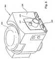
- the device arrangement showncomprises a CPAP device generally designated by the reference numeral 1 and a moistening device 2 connected thereto in modular fashion.
- the CPAP device 1here has a substantially block-shaped or box-shaped housing 3 which has a front end face 4, two opposite one another in pairs and mutually substantially parallel side surfaces 5, 6 and a relative to the front end face 4 in the rear region of the housing 3 arranged rear 7 and an upper top surface 8, in the region of the front end face 4, a connecting device 9 is provided which in the illustrated here Embodiment a breathing gas connection piece 10, a Druckmeßschlauchanschlußstutzen 11 and an electrical connection device 12 has.
- the breathing gas connection piece 10 and the Druckmeßschlauchanschlußstutzen 11are arranged in a recess 13 shown here only hinted substantially completely sunk.
- the contact elements of an electrical connection device 12are received in a recess, so that these connecting members also not or not substantially survive over a defined by the front face 4 surface.
- the front end face 4is formed slightly arched, resulting in a particularly effective support the centering of the moistening device 2.
- the breathing gas connection piece 10 and the Druckmeßschlauchanschlußstutzen 11are aligned such that they extend substantially parallel to the direction indicated by the arrow 14 joining direction.
- the CPAP device 1has in its bottom area Uberstellorgane (here adjustable feet 15), which are designed such that the connecting members of the connecting device 9 are held at a predetermined vertical height level, which is exactly matched to the corresponding height level of the connecting members of the moistening device 2.
- Aufstellorganehere adjustable feet 15
- the moistening device 2comprises a base body 16 and a liquid reservoir 17 accommodated therein.
- the fluid reservoir 17can be removed from the base housing 16, for example, for adding moistening fluid.
- the base housinghas a correspondingly complementary to the front end face 4 of the CPAP device 1 formed pad portion 18, in which the below still with reference to Fig. 2 located in detail explained connecting organs.
- the base housing 16is in turn provided with connecting members, which correspond in their construction and in their arrangement substantially the already described with respect.
- the CPAP device 1 connecting device 9.This makes it possible to connect the provided for example for connection to the CPAP device 1 hose connector directly to the moistening device 2. In this case, a connection of the Druckmeßschlauches is achieved simultaneously.
- the moistening device 2also has adjustable feet 20, through which the part of the moistening device in the region of the pad portion 18 provided Connection are held at a vertical height level, which corresponds to the height level of the connecting device 9.
- connection device 9is complementary to the provided by the moistening device 2 connecting device 21 is formed.
- the two connection devices 9 and 21, as shown by the arrow 22,can be brought together in Füwolf.
- a particularly effective pre-positioning of the connecting members, in particular the breathing gas connection piece 10 and the corresponding counterpart 23is achieved in this embodiment in that the counterpart 23 is also centered by the inner wall 24 of the recess 13.
- the breathing gas connection piece 10 and provided by the moistening device 2 counterpart 23are at exactly the same vertical height level.
- a connection structureis provided which corresponds in its essential dimensions to the connection structure provided on the side of the CPAP device.
- the breathing tube connector 25 shown herecan thus be coupled, if necessary, directly to the CPAP device 1 or to the moistening device 2. Due to an integrated into the humidifier Druckmeßharms ein is even when the breathing tube connector 25 is connected to the humidifier 2, a connection between the Druckmeßschlauch 26 and the Druckmeßschlauchanschlußstutzen 11 given.
- CPAP device arrangementmay be used as described in the following application example.
- the moistening device according to the inventionalso placed on the table surface and attached along a table surface parallel to the front face of the CPAP device 1 substantially perpendicular joining direction on the CPAP device.
- connection devices 9 and 21provided on the part of the CPAP device 1 and part of the moistening device 2 connection devices 9 and 21 in joining position.
- electrical connection device 12is also a power supply provided by the moistening device 2 heating device.
- the representation acc. Fig. 3shows a longitudinal sectional view through a device for humidifying a breathing gas (hereinafter referred to as moistening device) acc. a preferred embodiment of the invention.
- moistening devicea device for humidifying a breathing gas
- the embodiment of the moistening device shown herecomprises a refilling unit 203 formed from a tub element 1 and a pot part 202 coupled thereto, which can be removed in a simple manner from a set-up housing 204 which is designed in several parts.
- the tub member 201 and the pot member 202are coupled to each other in a sealing manner.
- the coupling of tub element 201 and cup part 202takes place via a sealing structure 206, which has a first sealing ring 207 and a second sealing ring 208 in the embodiment shown here.
- the two sealing rings 207 and 208are received in circumferential grooves, which are formed in a separating element 209.
- the separating element 209has an here formed integrally partition wall 205.
- the partition wall 205separates the inner portion of the cup portion 202 from the inner portion of the tub member 201.
- a liquid reservoir 10is formed in connection with the partition wall 205, in which initially the majority of the liquid provided for moistening the respiratory gas is stored.
- a separate moistening regionis formed in which only a subset of the moistening liquid is received.
- the level a, the liquid received in the tub member 201is maintained at a predetermined level by a metering device.
- fluidis supplied successively or continuously from the fluid reservoir 210.
- a preferred embodiment of a metering device provided for this purposeis used in conjunction with Fig. 2 will be described in detail.
- the tub member 201is here formed substantially cup-like and has a Atemgaszutrittsö réelle 211 and a breathing gas outlet opening 212.
- a CPAP deviceVia the breathing gas inlet opening 211, according to the breathing activity of a patient, the respiratory gas conveyed by a CPAP device, not shown here, can flow into the tub element 201.
- a deflecting device 213By means of a deflecting device 213, which is shown here only in a simplified manner, the inflowing respiratory gas is conducted onto the liquid present in the tub element 201. In this case, the supplied breathing gas accumulates with moisture. The correspondingly humidified breathing gas can then flow out via the respiratory gas outlet opening 212.
- the tub element 201can be heated by means of a heating device 214 in the embodiment shown here.
- the heater 214is composed of a heating element disposed in the erecting housing 204 so that the bottom portion of the tub member 201 can be intimately contacted therewith.
- the bottom region 215 of the heating element 201is formed from a material of high thermal conductivity, for example metal. In the latter embodiment, said bottom portion 215 may, for example, in the insert molding process in the actual main body of the tub member 201 be formed.
- the tub member 201is formed such that it can be used self-positioning in light fitting in the erection housing 204. In this case, the breathing gas inlet opening 211 and the respiratory gas outlet opening are aligned with correspondingly complementary openings or lines formed in the erection housing 204.
- the erection housing 4is provided with a connecting piece 216 which, in the embodiment shown here, can be attached directly to a correspondingly complementary connecting section of a CPAP device.
- a further connection piece 217is provided, which can be coupled to a provided on the part of a CPAP device pressure detection terminal.
- the connecting piece 217forms part of a line system, which is ultimately connected to the provided on an opposite side of the moistening pressure measuring connection piece 218 in connection.
- a pressure measuring hosecan be connected to this pressure measuring connection 218 for detecting the pressure in the region of the breathing hose, a gas exchange valve or possibly also directly in the mask area.
- the erection housing 204is provided with a breathing tube connection piece 219.
- the hose connection members formed on the output side of the humidification deviceare identical to those of a CPAP device in that corresponding connection hoses can either be connected directly to the CPAP device or, if necessary, when using the humidifying device only to the output side of the humidification device 202
- Reference numeral 16 marked connecting pieceis provided a connector means not shown here, via which an electrical connection between the heater 214 and provided on the part of the CPAP device power supply device can be produced. Possibly. It is also possible to transmit electrical signals, for example pressure measuring signals, via this plug connection device.
- the erection housing 204is further provided with a fastening device 220, via which the moistening device can be mechanically comparatively rigidly coupled to a CPAP device.
- a metering devicefor metering the amount of fluid in the tub element 201 will be described.
- the liquid front room 210 and the humidification area formed in the tub member 201are separated from each other via the partition wall 205. If necessary, the fluid stored in the liquid storage space 210 can be transferred to the humidification area via a fluid line device.
- the control of the fluid Vietnamesestromestakes place here by controlling the Luftnachschreib in the liquid reservoir.
- the regulation of the air feedtakes place via a metering line device 222, which, similar to the aforementioned fluid line device 221, passes vertically through the dividing wall 205.
- the dosing line device 222has a first orifice 223 and a second orifice 224.
- the first orifice 223is disposed at the level of the target level a. As long as the first orifice 223 is closed by the fluid contained in the tub element 201, no air can flow into the liquid storage space 210, so that again no fluid can flow out of the liquid storage space 210 via the fluid conduit device 221. As soon as the level a drops below the level of the first orifice, air can flow into the liquid reservoir, which in turn allows fluid to pass from the liquid reservoir 210 into the well element 201 or the separate humidification area formed therein.
- the fluid conduit device 221has an exit orifice 225, which lies slightly below the nominal level indicated here by the letters a.
- the fluid conduit device 221, the dosing line device 222 and the partition wall 5are formed in the embodiment shown here by an integral part.
- the cup part 202can also be provided with a corresponding, sealingly closable refill opening.
- the cup portion 202, the dividing wall integral part and the tub membermay each be cleaned separately.
- the dosing line device 222is such designed such that the second orifice 224 provided thereon is above the maximum fill level of the liquid storage space 210.
- Fig. 5is the preceding in connection with the Fig. 3 and 4 described moistening device shown in perspective.
- the pot partwhich is preferably formed from a transparent material, can be seen here as a cup which is essentially cylindrical. This cup is inserted in a likewise cylindrical, formed in the erection housing 204 receiving portion. In the area of the cup part 202, the erection housing 204 is designed such that the cup part can be grasped with one hand.
- Fig. 3 described connecting piece 217 or Druckmeßanschlußstutzen 218provided. Below the said connection piece is the in Fig.
- the back side 226 of the moistening deviceis corresponding to the front of one below in connection with Fig. 6a trained CPAP device so that the moistening device can be connected to the modular CPAP device with virtually no gap.
- CPAP devicehas a substantially cuboid housing in the upper region of a handle device 230 is provided via which the CPAP device can be taken in an ergonomically advantageous manner.
- a front end face connecting members 231are provided for connecting at least one breathing tube.
- a breathing tube fitting pin 32 and a pressure measuring tube fitting pin 233are provided.
- the arrangement of these connecting memberssubstantially corresponds to the arrangement of in connection with Figure 3 connecting members 216 and 217.
- the connecting members 231are further formed such that the part of the moistening device ( Figure 3 ) provided connecting members 216, 217 directly on or can be plugged.
- In the bottom region of the CPAP devicefurther engagement structures are provided which are engageable with complementarily formed engaging portions of the moistening device in engagement.
- the connecting members 231are here sunk in such a way that they do not project beyond an outer insbesonder front surface of the housing.
- Fig. 6bis the preceding in connection with the Figures 3 . 4 and 5 described moistening device with a view of the front area shown.
- the connecting pieces 216 and 217are similar to the side of the CPAP device sunk.
- the connecting piecesare surrounded by a plug receiving space 34 in which a preferably formed of a soft material, in particular silicone rubber plug can be inserted.
- the plug receiving space 234is preferably formed such that a corresponding plug slides on both the respective pin 216, 217 and along the wall of the plug receiving space 234.
- the inventionis not limited to the embodiments described above.
- refill unitswhich in the structure and the moistening principle deviate from the described moistening device.
- the tub element of the moistening unitin such a way that it can be connected directly to the CPAP device while dispensing with the positioning housing.
- the moistening device describedcan also be connected with the interposition of a hose with a source of breathing gas.
- the refill unitcan also be arranged as a substantially trough-like unit under the CPAP device.
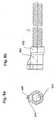
- connection device 302which here comprises a base body 303 formed of an elastomeric material esp. Silicone rubber with two molded coupling portions 304,305.
- the two coupling sections 304, 305are integrally formed by mutually parallel and circular in cross section tube zones.
- the inner diameter of the respective tube zoneis slightly smaller than the outer diameter of the connecting pin entering the two tube zones when the plug is connected and slightly widened.
- a fastening section 306is formed, in which the breathing hose 301 is fixed via a ring element 307.
- the ring member 307is also formed here of an elastomeric material and bonded to the outer surface of the breathing tube.
- the Druckmeßschlauch 308opens via a formed in the base body 2 through-channel 309 in the coupling portion 305.
- the Druckmeßschlauch 308is glued or vulcanized into the base body 302.
- the passageway 309is formed so that the Druckmeßschlauch 308 is only slightly curved.
- the angle a between the longitudinal center axis of the coupling portion 304 and the longitudinal center axis of the feedthrough channel 309is preferably less than 35 °.
- the respiratory gas conduit region 311 formed in the base body 303also passes essentially continuously into the interior region of the breathing tube 301.
- hoses 301, 308With appropriate elasticity of the hoses 301, 308, it is possible to guide them to the end face 312 of the base body 303, so that the device-side coupling members can enter directly into the hoses 301, 308.
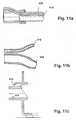
- FIGS. 8a and 8bBased on FIGS. 8a and 8b the outer shape of the base body gem.
- an effective pre-positioning of the base bodyis achieved in a recess provided on the device side.
- This nose-like radially projecting regiondrops continuously from the breathing tube-side end of the base body 303.
- a peripheral bead 315is provided, via which a force flow, which is favorable under mechanical aspects, between hose and plug structure is achieved.
- a preferred embodiment of a device-side connection structureis shown, which is formed substantially complementary to the coupling sections 304, 305 formed in the base body 303 of the plug.
- the spigot portion indicated here by the reference numeral 316passes in joining position into the coupling portion 304.
- the spigot portion indicated by the reference numeral 317engages in the joining position with the coupling portion.
- the two journal sections 316, 317are recessed in a recess 318.
- This in Figure 10 shown terminal structure componentcomprises a breathing gas passage means, which is designed here as a tubular pin 401.
- This tube pin 401leaving a gap between a further tube pin 402 adjacent.
- This pipe plug 402forms a Druckmeßschlauchanschluß issued.
- Both tube pins 401, 402are recessed in a recess 403. This recess is surrounded by a front cover plate 404.
- the cover plate 4 and those the recess 403 bounding wallare integrally formed.
- a base plate 405which here forms a cover plate for a labyrinth arrangement.
- This labyrinth arrangementnot described in detail here, forms an extended breathing gas guide path for absorbing any noise generated by a blower device.
- the base plate 405is insbes. Foam coated on the rear side not visible here with a sound-absorbing material.
- connection channel 406is formed, via which the inner region of the pipe pin 402 can be coupled to a pressure converter arranged on a control board.
- the terminal structure componentis further provided with fastening means 407, 408 via which this component is fixable in a CPAP device in a simple exchangeable manner.
- 11Ashows here a ergonomically favorable handle compact connector with integrated Druckmeßschlauch be operation.
- Terminal structure componentcan be connected to a corresponding CPAP device.
- Fig. 11cshows a simplified simplified coupling portion of a humidifier, which can be attached directly to the structure of the invention to a CPAP device.
- the pin identified by the reference numeral 411engages with the pipe spigot 401 and the bore portion 412 engages with the pipe spigot 402.
Landscapes
- Health & Medical Sciences (AREA)
- Pulmonology (AREA)
- General Health & Medical Sciences (AREA)
- Life Sciences & Earth Sciences (AREA)
- Emergency Medicine (AREA)
- Biomedical Technology (AREA)
- Heart & Thoracic Surgery (AREA)
- Hematology (AREA)
- Engineering & Computer Science (AREA)
- Animal Behavior & Ethology (AREA)
- Anesthesiology (AREA)
- Public Health (AREA)
- Veterinary Medicine (AREA)
- Business, Economics & Management (AREA)
- Emergency Management (AREA)
- Air Humidification (AREA)
- Respiratory Apparatuses And Protective Means (AREA)
- Feeding And Controlling Fuel (AREA)
- Magnetic Resonance Imaging Apparatus (AREA)
Abstract
Description
Translated fromGermanDie Erfindung betrifft eine Vorrichtung zur Zufuhr eines Atemgases unter Überdruck und eine Befeuchtungsvorrichtung für eine Vorrichtung zur Zufuhr eines Atemgases unter Überdruck.The invention relates to a device for supplying a breathing gas under pressure and a humidifying device for a device for supplying a breathing gas under pressure.
Eine Vorrichtung zur Zufuhr eines Atemgases unter Überdruck mit einer Gebläseeinrichtung zur Förderung des Atemgases, einer Gehäuseeinrichtung zur Aufnahme der Gebläseeinrichtung und einer Anschlußeinrichtung zum Anschluß einer Befeuchtungsvorrichtung zur Befeuchtung des seitens der Fördereinrichtung geförderten Atemgases wird diskutiert. Ferner werden eine Befeuchtungsvorrichtung zur Befeuchtung eines Atemgases sowie einen Atemgasschlauch und eine Anschlußvorrichtung hierfür diskutiert.A device for supplying a breathing gas under overpressure with a blower device for conveying the breathing gas, a housing device for receiving the blower device and a connecting device for connecting a moistening device for moistening the breathing gas conveyed by the conveyor is discussed. Furthermore, a humidification device for humidifying a respiratory gas and a breathing gas hose and a connection device for this purpose are discussed.
Vorrichtungen zur Zufuhr eines Atemgases unter Überdruck finden insbesondere im Bereich der Schlaftherapie zur Behandlung schlafbezogener Atmungsstörungen Anwendung. Durch Zuführung des Atemgases unter einem vorbestimmten Überdruck üblicherweise im Bereich von 5-20 mbar wird auf physiologisch gut verträgliche Weise eine pneumatische Schienung der oberen Atemwege eines Patienten erreicht, wodurch einer Obstruktion dieses Atemwegsbereiches auf wirkungsvolle Weise vorgebeugt werden kann.Devices for supplying a respiratory gas under overpressure are used, in particular, in the field of sleep therapy for the treatment of sleep-related respiratory disorders. By supplying the respiratory gas under a predetermined pressure usually in the range of 5-20 mbar, a pneumatic splinting of the upper respiratory tract of a patient is achieved in a physiologically well tolerated manner, whereby an obstruction of this airway area can be effectively prevented.
Üblicherweise wird das Atemgas unmittelbar aus der vorzugsweise über eine Filtereinrichtung angesaugten Umgebungsluft gebildet. In Abhängigkeit von den insbesondere jahreszeitlich bedingt schwankenden klimatischen Verhältnissen hat es sich als vorteilhaft erwiesen, das dem Patienten beispielsweise über eine Gebläseeinrichtung unter einem geregelten, ggf. alternierenden Druck, zugeführte Atemgas zeitweise zu befeuchten. Hierzu ist es möglich, beispielsweise über ein Schlauchzwischenstück eine Befeuchtungseinrichtung in den Atemgasweg zwischen Gebläseeinrichtung und Atemmaske einzufügen. Es sind auch CPAP-Geräte mit integrierter Befeuchtungsvorrichtung bekannt.Usually, the breathing gas is formed directly from the preferably sucked by a filter device ambient air. Depending on the particular seasonally fluctuating climatic conditions, it has proven to be advantageous to temporarily moisten the patient, for example via a blower device under a controlled, possibly alternating pressure, supplied breathing gas. For this purpose, it is possible, for example, to insert a humidifying device into the respiratory gas path between the fan device and the respiratory mask via a hose adapter. There are also known CPAP devices with integrated humidifying device.
Bei den lediglich in eine Schlauchleitung eingesteckten Befeuchtungsvorrichtungen besteht jedoch häufig das Problem einer ungenügenden Standfestigkeit. Bei CPAP-Geräten mit integrierter Befeuchtungsvorrichtung muß diese ständig mitgeführt werden, auch wenn vorübergehend kein Bedarf nach einer Befeuchtung des Atemgases besteht.However, with the humidifying devices merely inserted in a hose line, there is often the problem of insufficient stability. In CPAP devices with integrated humidification device, this must be constantly carried, even if there is no temporary need for humidification of the respiratory gas.
Unter dem Eindruck dieses Problems liegt der Erfindung die Aufgabe zugrunde, eine Vorrichtung zur Zufuhr eines Atemgases sowie eine hierfür vorgesehene Befeuchtungsvorrichtung zu schaffen, die robust und einfach handhabbar sowie auf einfache Weise bedarfsgerecht konfigurierbar ist.Under the impression of this problem, the invention has for its object to provide a device for supplying a breathing gas and a designated humidification device that is robust and easy to handle and easily configured as needed.
Die Erfindung ist durch die Ansprüche definiert.The invention is defined by the claims.
Durch die hierin diskutierten Vorrichtungen wird es auf vorteilhafte Weise möglich, einfach und ohne Bedarf nach einer fachmännischen Montagetechnik eine Befeuchtungsvorrichtung unmittelbar seitlich an ein CPAP-Gerät anzukoppeln, ohne daß das CPAP-Gerät hierzu angehoben werden muß. In vorteilhafter Weise wirken hierbei untere Aufstellabschnitte über welche das CPAP-Gerät aufgestellt ist, unmittelbar als Führungseinrichtung, die ein einfaches Anschieben der Befeuchtungsvorrichtung an das CPAP-Gerät ermöglicht. Besteht beispielsweise vorübergehend kein Bedarf nach einer Befeuchtungsvorrichtung, oder soll die Befeuchtungsvorrichtung zum Zwecke der Reinigung vorübergehend von dem CPAP-Gerät getrennt werden, so kann das CPAP-Gerät unverändert an seinem Aufstellungsort verbleiben, und die Befeuchtungsvorrichtung kann einfach zur Seite hin abgenommen insbesondere abgezogen werden.By means of the devices discussed herein, it is advantageously possible to simply and without the need for a professional assembly technique couple a humidifier immediately laterally to a CPAP device without having to raise the CPAP device therefor. Advantageously, in this case lower Aufstellabschnitte act on which the CPAP device is set up, directly as a guide device that allows easy insertion of the moistening device to the CPAP device. For example, if there is no temporary need for a moistening device, or if the moistening device is to be temporarily disconnected from the CPAP device for the purpose of cleaning, the CPAP device may remain unaltered at its location and the moistening device may simply be withdrawn sideways, especially withdrawn ,
Gemäß einer besonders bevorzugten Ausführungsform der Erfindung sind die Anschlußorgane im wesentlichen in Fügerichtung ausgerichtet. Insbesondere der Hauptdurchgangsquerschnitt für das seitens der Gebläseeinrichtung geförderte Atemgas ist in vorteilhafter Weise durch einen Rohrstutzen gebildet, auf welchen ein seitens einer entsprechend komplementär ausgebildeten Befeuchtungsvorrichtung vorgesehener Anschlußabschnitt aufgesteckt werden kann.According to a particularly preferred embodiment of the invention, the connecting members are aligned substantially in the joining direction. In particular, the main passage cross-section for the promoted by the blower device breathing gas is advantageously formed by a pipe socket, on which a part of a corresponding complementary trained moistening device provided connection portion can be plugged.
Eine insbesondere unter ästhetischen Gesichtspunkten sowie im Hinblick auf einen symmetrischen Aufbau des CPAP-Gerätesystems vorteilhafte Ausführungsform der Erfindung ist dadurch gegeben, daß die entsprechenden Anschlußorgane in einer Geräte-Stirnseite (Frontseite) ausgebildet sind. Der Flächenabschnitt dieser Geräte-Stirnseite ist im wesentlichen komplementär zu einem in Fügestellung benachbarten Abschnitt der Befeuchtungsvorrichtung ausgebildet.An embodiment of the invention that is advantageous, in particular, from an aesthetic point of view as well as with regard to a symmetrical design of the CPAP device system is given by the fact that the corresponding connection elements are formed in a device end face (front side). The surface portion of this device end face is formed substantially complementary to an adjacent in joining position portion of the moistening device.
Eine insbesondere im Hinblick' auf eine besonders zuverlässige Ankoppelung einer Druckmeßleitung vorteilhafte Ausführungsform der Erfindung ist dadurch gegeben, daß die Anschlußeinrichtung den besagten Rohrstutzen zur Durchleitung des Atemgases und einen diesem benachbart angeordneten Leitungsabschnitt zur Ankoppelung einer Druckmeßleitung aufweist.An embodiment of the invention which is particularly advantageous with regard to a particularly reliable coupling of a pressure measuring line is given by the fact that the connecting device has said pipe socket for the passage of the respiratory gas and a line section adjacently arranged for coupling a pressure measuring line.
Der Rohrstutzen für die Durchleitung des Atemgases und der Leitungsabschnitt für die Druckmeßleitung sind gemäß einer besonders bevorzugten Ausführungsform der Erfindung in einer Ausnehmung derart angeordnet, daß diese im wesentlichen nicht über eine durch die vordere Stirnfläche des Gerätes definierte Hauptebene überstehen. Hierdurch ist ein besonders wirkungsvoller Schutz dieser vergleichsweise filigranen CPAP-Gerät-Anschlußorgane gegeben.The pipe socket for the passage of the respiratory gas and the line section for the Druckmeßleitung are arranged according to a particularly preferred embodiment of the invention in a recess such that they do not substantially over a defined by the front end face of the device main plane. As a result, a particularly effective protection of these comparatively filigree CPAP device connection organs is given.
Gemäß einem besonderen Aspekt der vorliegenden Erfindung umfaßt die Anschlußeinrichtung zum bedarfsweisen Anschluß der Befeuchtungseinrichtung-Elektroanschlußorgane zur Schaffung einer elektrischen Verbindung mit der Befeuchtungsvorrichtung. Über diese Elektroanschlußorgane wird es auf vorteilhafte Weise möglich, eine Heizeinrichtung der Befeuchtungsvorrichtung mit Spannung zu versorgen, ohne, daß hierzu manuell ein entsprechendes Spannungsversorgungskabel an die Befeuchtungsvorrichtung angeschlossen werden muß. Die Elektroanschlußorgane können auch zur Übertragung elektrischer Signale, beispielsweise zur Übertragung eines Füllstandssignales oder auch zur Übertragung elektrischer Signale verwendet werden, die beispielsweise im Bereich der Atemschlauchanschlußeinrichtung zugeführt wurden.According to a particular aspect of the present invention, the terminal means comprises, as required, the moistening device electrical terminal means for establishing an electrical connection with the moistening device. About this electrical connection elements, it is possible in an advantageous manner to provide a heating device of the humidifying device with voltage, without that manually a corresponding power cable must be connected to the moistening device. The electrical connection members can also be used for transmitting electrical signals, for example, for the transmission of a level signal or for transmitting electrical signals that have been supplied, for example in the breathing tube connection device.
Eine besonders wirkungsvolle Koppelung des CPAP-Gerätes mit der zum Anschluß hieran vorgesehenen Befeuchtungsvorrichtung wird erfindungsgemäß dadurch erreicht, daß eine manuell in Lösestellung bringbare Verrastungseinrichtung vorgesehen ist, die die Befeuchtungsvorrichtung in einer Fügestellung hält. Dadurch wird es auf vorteilhafte Weise möglich, die Befeuchtungsvorrichtung äußerst gewichtssparend auszubilden, ohne daß hierbei die Gefahr besteht, daß diese versehentlich über den angeschlossenen Atemgasschlauch vom CPAP-Gerät abgezogen und von ihrer Aufstellfläche (z.B. Beistelltisch) heruntergezogen wird.A particularly effective coupling of the CPAP device with the intended for connection thereto humidifying device according to the invention is achieved in that a manually releasable latching device is provided which holds the moistening device in a joining position. This makes it possible in an advantageous manner to form the humidifying extremely weight-saving, without the risk that this accidentally withdrawn via the connected breathing gas hose from the CPAP device and pulled down from its footprint (e.g., side table).
Das CPAP-Gerät ist gem. einer besonders bevorzugten Ausführungsform der Erfindung im Bodenbereich derart ausgebildet, daß die Anschlußorgane, insbesondere der genannte Rohrstutzen auf einem vertikalen Höhenniveau angeordnet sind, das exakt dem Höhenniveau der seitens der Befeuchtungsvorrichtung vorgesehenen Anschlußorgane entspricht.The CPAP device is acc. a particularly preferred embodiment of the invention in the bottom region formed such that the connecting members, in particular the said pipe socket are arranged at a vertical height level, which corresponds exactly to the height level of the moistening device provided by the connecting members.
In vorteilhafter Weise sind die seitens des CPAP-Gerätes als auch die seitens der Befeuchtungsvorrichtung vorgesehenen Anschlußorgane in vertikaler Richtung derart positioniert, daß bei Aufstellung des CPAP-Gerätes und der Befeuchtungsvorrichtung auf einer im wesentlichen planen Unterlage die Befeuchtungsvorrichtung an das CPAP-Gerät herangeschoben werden kann, wobei die erforderliche Ausrichtung dieser beiden Module in vertikaler Richtung bereits durch die Standfläche erreicht wird. Um auch in seitlicher Richtung eine ausreichende Zentrierung der beiden Module zu erreichen, sind gem. einer besonders bevorzugten Ausführungsform der Erfindung ebenfalls Zentrierhilfen vorgesehen. Eine besonders robuste Zentrierhilfe wird hierbei erreicht, indem die Innenwandung der den Rohrstutzen ausnehmenden Ausnehmung auf die Außenumfangsfläche des seitens der Befeuchtungsvorrichtung vorgesehenen Anschlußzapfens abgestimmt ist.Advantageously, the side of the CPAP device and provided by the moistening device connecting members in the vertical direction are positioned so that when installing the CPAP device and the moistening device on a substantially flat surface, the moistening device can be pushed to the CPAP device , Wherein the required alignment of these two modules in the vertical direction is already achieved by the footprint. In order to achieve sufficient centering of the two modules in the lateral direction, gem. a particularly preferred embodiment of the invention also provided centering. A particularly robust centering aid is in this case achieved by the inner wall of the pipe socket ausnehmenden recess is matched to the outer peripheral surface of the side provided by the moistening device connecting pin.
Hinsichtlich einer Befeuchtungsvorrichtung wird die eingangs angegebene Aufgabe durch eine hierin diskutierte Befeuchtungsvorrichtung gelöst. Eine derartige Befeuchtungsvorrichtung kann auf einfache Weise auch von einem Laien an ein entsprechendes CPAP-Gerät angekoppelt werden, ohne daß es hierzu einer fachmännischen Montagetechnik oder eines Verbindungsschlauches bedarf. Das CPAP-Gerät muß hierzu nicht angehoben werden.With regard to a moistening device, the object stated at the outset is achieved by a moistening device discussed herein. Such a humidification device can be coupled in a simple manner by a layman to a corresponding CPAP device, without that this requires a professional assembly technology or a connection hose. The CPAP device does not need to be raised for this purpose.
In vorteilhafter Weise wird eine an ein Basisgerät ankoppelbare Befeuchtereinheit geschaffen welche ein kartuschenartiges entnehmbares und wieder einsetzbares Nachfüllmodul umfaßt. Das Nachfüllmodul kann über Fixiereinrichtungen beispielsweise eine Bajonetverschlußeinrichtung in der Befeuchtereinheit fixiert werden. Durch Dichteinrichtungen kann das Nachfüllmodul abschnittsweise oder vollständig in der Befeuchtereinheit abgedichtet werden.In an advantageous manner, a humidifier unit which can be coupled to a base unit is provided which comprises a cartridge-like removable and reusable refill module. The refill module can be fixed in the humidifier unit via fixing devices, for example a bayonet closure device. By sealing means, the refill module can be partially or completely sealed in the humidifier.
Im Rahmen einer CPAP-Therapie erfolgt eine Unterstützung der Spontanatmung eines Patienten, indem diesem ein Atemgas unter permantentem Überdruck zugeführt wird. Durch diesen Überdruck wird eine pneumatische Schienung der oberen Atemwege erreicht, wodurch etwaigen während der Schlafphase eines Patienten auftretenden Atemwegsobstruktionen vorgebeugt werden kann. Bei einer derartigen Behandlung schlafbezogener Atmungsstörungen erstreckt sich diese Überdruckbeatmung üblicherweise über die gesamte Schlafphase des Patienten. Im Hinblick auf eine verbesserte physiologische Verträglichkeit der Überdruckbeatmung hat es sich als vorteilhaft erwiesen, das dem Patienten zugeführte Atemgas zu befeuchten. Üblicherweise erfolgt die Befeuchtung des Atemgases, indem dieses über ein Wasserbad geführt wird und hierbei Feuchtigkeit aufnimmt. In diesem Wasserbad wird üblicherweise eine Wassermenge von ca. 750ml bevorratet. Das Wasserbad wird vorzugsweise mittels einer Heizeinrichtung leicht erwärmt. Bei diesen herkömmlichen Befeuchtungsvorrichtungen hat sich gezeigt, daß die absolute Feuchtigkeit des Atemgases über die gesamte Schlafphase gesehen teilweise erheblichen Schwankungen unterliegt.As part of a CPAP therapy, a spontaneous breathing of a patient is supported, by this a breathing gas is supplied under permanent overpressure. This overpressure achieves pneumatic upper airway splinting which can prevent any airway obstruction occurring during a patient's sleep phase. In such treatment of sleep-disordered breathing, this positive pressure ventilation usually extends over the entire sleeping phase of the patient. In view of an improved physiological compatibility of the positive pressure ventilation, it has proved to be advantageous to moisten the breathing gas supplied to the patient. Usually, the humidification of the respiratory gas is carried out by this is passed over a water bath and thereby absorbs moisture. In this water bath usually a quantity of water of approx. 750ml is stored. The water bath is preferably heated slightly by means of a heater. In these conventional humidifying devices, it has been shown that the absolute humidity of the respiratory gas over the entire sleeping phase is sometimes subject to considerable fluctuations.
Zur Lösung dieses Problems wird gemäß einem besonderen Asparkt der vorliegenden Erfindung, eine einfach handhabbare Vorrichtung zur Befeuchtung eines Atemgases sowie ein zur Verwendung hiermit vorgesehenes CPAP-Gerät beschrieben, durch welche, bzw. durch welches, eine gleichmäßige Befeuchtung des Atemgases erreicht werden kann. Dies wird erreicht durch eine Vorrichtung zur Befeuchtung eines Atemgases mit einem Flüssigkeitsvorratsraum zur Bevorratung einer Flüssigkeit, einem Befeuchtungsbereich zur Befrachtung des Atemgases mit der Flüssigkeit, indem das Atemgas in dem Befeuchtungsbereich mit der Flüssigkeit in Kontakt tritt, einer Atemgaszuleitungseinrichtung zur Zuleitung des Atemgases zu dem Befeuchtungsbereich, und einer Atemgasableitungseinrichtung zur Ableitung des befeuchteten Atemgases aus dem Befeuchtungsbereich, wobei eine Teilmengenabgabeeinrichtung vorgesehen ist, zur Weitergabe lediglich einer Teilmenge der in dem Flüssigkeitsvorratsraum bevorrateten Flüssigkeit in den Befeuchtungsbereich.To solve this problem, according to a particular aspect of the present invention, an easy-to-handle device for humidifying a breathing gas and a CPAP device provided for use therewith are described, by which, or by which, a uniform humidification of the breathing gas can be achieved. This is achieved by a device for humidifying a respiratory gas with a liquid storage space for storing a liquid, a humidification area for loading the respiratory gas with the liquid by the respiratory gas in the humidification area comes into contact with the liquid, a breathing gas supply means for supplying the respiratory gas to the humidification area, and a breathing gas discharge device for discharging the humidified respiratory gas from the humidification area, wherein a partial quantity delivery device is provided, for passing only a subset of the liquid stored in the liquid storage space into the humidification area.
Dadurch wird es auf vorteilhafte Weise möglich, bereits kurzfristig nach Inbetriebnahme des Gerätes ein bedarfsgerecht befeuchtetes Atemgas bereitzustellen. Bei gewünschter Erwärmung des Befeuchtungsmediums kann diese rasch und unter vergleichsweise geringem Leistungsbezug erreicht werden. Infolge des geringen Leistungsbezugs der Heizeinrichtung eignet sich die erfindungsgemäße Befeuchtungsvorrichtung in besonderem Maße für den netzunabhängigen Betrieb mittels Batterie bzw. Akku.This makes it possible in an advantageous manner, already shortly after commissioning of the device to provide a demand-humidified breathing gas. When desired heating of the humidifying medium, this can be achieved quickly and with comparatively low power consumption. As a result of the low power consumption of the heater, the moistening device according to the invention is particularly suitable for off-grid operation by means of battery or rechargeable battery.
Gemäß einer besonders bevorzugten Ausführungsform der Erfindung ist der Befeuchtungsbereich räumlich von dem Flüssigkeitsvorratsraum getrennt. Zur bedarfsgerechten Zuleitung des Befeuchtungsmediums aus dem Flüssigkeitsvorratsraum ist vorzugsweise eine Fluidleitungseinrichtung vorgesehen, über welche der Befeuchtungsbereich mit dem Flüssigkeitsvorratsraum in Verbindung steht.According to a particularly preferred embodiment of the invention, the humidification area is spatially separated from the liquid storage space. In order to supply the humidifying medium from the liquid storage space as needed, a fluid conduit device is preferably provided, via which the humidifying area communicates with the liquid storage space.
Zwischen dem Befeuchtungsbereich und dem Flüssigkeitsvorratsraum ist gemäß einer bevorzugten Ausführungsform der Erfindung eine Trennwand vorgesehen, die den Befeuchtungsbereich von dem Flüssigkeitsvorratsraum trennt. Die genannte Fluidleitungseinrichtung ist vorzugsweise derart angeordnet, daß diese die Trennwand durchsetzt.Between the humidification area and the liquid storage space, according to a preferred embodiment of the invention, a partition wall is provided which separates the humidification area from the liquid storage space. Said fluid conduit means is preferably arranged such that it passes through the partition wall.
Eine im Hinblick auf eine besonders vorteilhafte Handhabbarkeit und zuverlässige Befüllung des Befeuchtungsbereiches vorteilhafte Ausführungsform der Erfindung ist dadurch gegeben, daß der Flüssigkeitsvorratsraum in Gebrauchsposition der Vorrichtung oberhalb des Befeuchtungsbereiches angeordnet ist. Hierdurch wird es möglich, das Befeuchtungsmedium infolge seiner Schwerkraft in den Befeuchtungsbereich zu leiten. Die Abgabe einer Teilmenge der Flüssigkeit in den Befeuchtungsbereich erfolgt in vorteilhafter Weise in Abhängigkeit von einem Flüssigkeitspegelstand in dem Befeuchtungsbereich. Dadurch wird es möglich, in dem Befeuchtungsbereich permanent eine bestimmte Mindestmenge an Befeuchtungsflüssigkeit zur Verfügung zu halten.An advantageous with regard to a particularly advantageous handling and reliable filling of the humidification embodiment of the invention is given by the fact that the liquid storage space is arranged in the use position of the device above the humidification. This makes it possible to direct the humidifying medium into the humidifying area due to its gravity. The delivery of a subset of the liquid into the moistening area advantageously takes place as a function of a liquid level in the moistening area. This makes it possible to permanently maintain a certain minimum amount of moistening liquid in the moistening area.
Der Füllstand-in dem Befeuchtungsbereich wird auf vorteilhafte Weise dosiert, indem zur Abgabe einer Teilmenge der Flüssigkeit aus dem Flüssigkeitsvorratsraum der Flüssigkeitsvorratsraum belüftet wird. Die Luft zur Belüftung des Flüssigkeitsvorratsraumes wird hierzu gemäß einer besonders bevorzugten Ausführungsform der Erfindung über den Befeuchtungbereich angesaugt.The level in the humidification area is advantageously metered by venting the liquid storage space to dispense a portion of the liquid from the liquid storage space. The air for ventilation of the liquid storage space is sucked for this purpose according to a particularly preferred embodiment of the invention over the humidification area.
Die Steuerung der Luftzufuhr erfolgt vorzugsweise, indem eine Dosier-Leitungseinrichtung vorgesehen ist, die sich zwischen dem Flüssigkeitvorratsraum und dem Befeuchtungsbereich erstreckt, wobei die Leitungseinrichtung eine erste Mündung aufweist, die sich auf Höhe des Flüssigkeitspegels in dem Befeuchtungsbereich befindet, und eine zweite Mündung aufweist, die in den Flüssigkeitsvorratsraum in einen Bereich oberhalb des Vorratsraum-Flüssigkeitspegels in den Vorratsraum mündet. Durch die in dem Befeuchtungsbereich befindliche Flüssigkeit wird hierbei die erste Mündung derart lange bedeckt, bis der Flüssigkeitspegel unter die erste Mündung absinkt. Sobald die erste Mündung freigegeben wird, kann über die Dosierleitungseinrichtung Luft in den Flüssigkeitsraum nachströmen. Infolge der nachströmenden Luft gelangt wieder eine geringe Menge Fluid in den Befeuchtungsbereich und der Pegelstand der Flüssigkeit in dem Befeuchtungsbereich steigt, bis die erste Mündung sich wieder unterhalb des Flüssigkeitsspiegels befindet.The air supply is preferably controlled by providing a metering line means extending between the liquid storage space and the humidification area, the conduit means having a first orifice at the liquid level in the humidification area and having a second orifice, which opens into the liquid storage space in an area above the storage space liquid level in the storage space. By the liquid present in the humidification area in this case the first orifice is covered until the liquid level drops below the first orifice. As soon as the first orifice is released, air can flow into the liquid space via the metering line device. As a result of the inflowing air again enters a small amount of fluid in the humidification and the level of the liquid in the humidification area increases until the first orifice is again below the liquid level.
In vorteilhafter Weise ist die Dosier-Leitungseinrichtung durch eine Rohrleitung gebildet, die die Trennwand in vertikaler Richtung durchsetzt.Advantageously, the metering line device is formed by a pipe which passes through the partition in the vertical direction.
Die Überleitung der Flüssigkeit aus dem Flüssigkeitsvorratsraum in den Befeuchtungsbereich erfolgt durch einen Rohrzapfen, der sich von der Trennwand aus in einen Bereich unterhalb der ersten Mündung der Dosier-Leitungseinrichtung bzw. der Belüftungsleitungseinrichtung erstreckt.The liquid is transferred from the liquid storage space into the humidification area by means of a pipe spigot which extends from the dividing wall into an area below the first mouth of the metering line device or the ventilation line device.
Eine unter fertigungstechnischen Gesichtspunkten günstig herstellbare sowie robuste Ausführungsform des Befeuchters ist dadurch gegeben, daß die Trennwand und die beiden Fluidleitungseinrichtungen integral ausgebildet sind.An economically feasible under manufacturing aspects and robust embodiment of the humidifier is given by the fact that the partition and the two fluid conduit means are integrally formed.
Der Flüssigkeitsvorratsraum ist vorzugsweise durch ein topfartiges Gehäuseteil gebildet. Dieses Gehäuseteil ist vorzugsweise aus einem transparenten oder transluzenten Material gebildet. Durch die Ausbildung des Gehäuseteiles aus einem Kunststoffmaterial wird in vorteilhafter Weise ein Splitterschutz sowie eine nochmalige Verringerung der Wärmeverluste erreicht.The liquid reservoir is preferably formed by a pot-like housing part. This housing part is preferably formed from a transparent or translucent material. Due to the design of the housing part of a plastic material splinter protection and a further reduction of heat losses is achieved in an advantageous manner.
Der Befeuchtungsbereich ist gemäß einer besonders bevorzugten Ausführungsform der Erfindung in einem Wannenelement gebildet. Eine besonders wirkungsvolle Befeuchtung des Atemgases bei weiterhin kompaktem Aufbau kann in vorteilhafter Weise dadurch erreicht werden, daß Luftleitungseinrichtungen vorgesehen sind, die derart angeordnet sind, daß das Wannenelement im wesentlichen quer oder entlang eines Spiralweges durchströmt wird. Hierdurch wird ein intensiver Kontakt des Atemgases mit der in dem Befeuchtungsbereich aufgenommenen Flüssigkeitsteilmenge erreicht.The humidification area is formed in a tub element according to a particularly preferred embodiment of the invention. A particularly effective humidification of the respiratory gas in a still compact construction can be achieved in an advantageous manner in that air duct means are provided which are arranged such that the tub element is traversed substantially transversely or along a spiral path. As a result, intensive contact of the respiratory gas with the amount of liquid absorbed in the humidification area is achieved.
Eine besonders intensive Befeuchtung des Atemgases kann dadurch erreicht werden, daß eine Heizeinrichtung vorgesehen ist zum Erwärmen der in dem Befeuchtungsbereich bevorrateten Flüssigkeitsteilmenge. Die Heizeinrichtung ist vorzugsweise elektrisch betrieben, beispielsweise durch eine Widerstandsheizung. Die Widerstandsheizung ist vorzugsweise durch ein dünnes folienartiges Element gebildet, das mit einem Bodenbereich des Wannenelementes thermisch gekoppelt ist. Vorzugsweise weist hierzu das Wannenelement einen Bodenabschnitt auf, der aus einem Werkstoff hoher Wärmeleitfähigkeit, insbesondere aus Metall, gebildet ist. Alternativ dazu oder auch in Kombination hiermit, ist es auch möglich, die Heizeinrichtung unmittelbar in einen Wandungsabschnitt, insbesondere Bodenabschnitt, des Befeuchtungsbereiches zu integrieren.A particularly intensive humidification of the respiratory gas can be achieved in that a heating device is provided for heating the amount of liquid stored in the humidification region. The heating device is preferably electrically operated, for example by a resistance heater. The resistance heater is preferably formed by a thin foil-like element that is thermally coupled to a bottom region of the well element. For this purpose, the tub element preferably has a bottom section which is formed from a material of high thermal conductivity, in particular of metal. Alternatively, or in combination herewith, it is also possible to integrate the heating device directly into a wall section, in particular floor section, of the humidification area.
In vorteilhafter Weise ist das die Trennwand bildende Integralteil über eine erste Umfangsdichteinrichtung abdichtend in das Wanneneelement eingesetzt. Das Integralteil umfaßt vorzugsweise auch eine zweite Umfangsdichtungseinrichtung, die in Verbindung mit der Trennwand den Flüssigkeitsvorratsraum abdichtend verschließt. Die derart gebildete Befeuchtungseinheit kann zum Nachfüllen geöffnet werden, indem das Wannenelement von dem den Flüssigkeitsvorratsraum bildenden Gehäuseteil abgenommen wird.Advantageously, the integral part forming the partition wall is sealingly inserted into the pan element via a first circumferential sealing device. The integral part preferably also comprises a second circumferential sealing device, which sealingly closes the liquid storage space in connection with the dividing wall. The moistening unit thus formed can be opened for refilling by the tub member is removed from the housing part forming the liquid reservoir.
Zur Aufnahme der beschriebenen Befeuchtungseinheit ist gemäß einer besonders bevorzugten Ausführungsform der Erfindung ein Aufstellgehäuse vorgesehen, in welches wenigstens das Wannenelement einsetzbar ist. In vorteilhafter Weise ist das Wannenelement oder das Aufstellgehäuse mit einer Atemschlauchanschlußeinrichtung versehen, zum Anschluß eines Atemschlauches. In dem Bereich der Atemschlauchanschlußeinrichtung ist gemäß einer besonders bevorzugten Ausführungsform der Erfindung eine Zweitschlauchanschlußeinrichtung vorgesehen. Über einen hieran anschließbaren Zweitschlauch von vorzugsweise geringem Durchmesser kann eine Druckmessung in einem der Befeuchtungsvorrichtung abfolgenden Bereich beispielsweise im Bereich eines CO2-Austauschventiles vorgenommen werden. Die Zweitschlauchanschlußeinrichtung ist vorzugsweise unmittelbar neben einem Atemschlauchanschlußzapfen angeordnet. In vorteilhafter Weise entspricht die seitens der Befeuchtungsvorrichtung vorgesehene Anschlußstruktur für den Atemschlauch und vorzugsweise auch die für den Zweit- insbes. Druckmeßschlauch in ihrem Aufbau der entsprechend an einem CPAP-Gerät vorgesehenen Anschlußstruktur. Dadurch wird auf vorteilhafte Weise eine Kompatibilität der Schlauchanschlüsse sowohl mit dem CPAP-Gerät als auch mit der ggf. zwischengeschalteten Befeuchtungseinrichtung erreicht.To accommodate the humidification unit described, a mounting housing is provided according to a particularly preferred embodiment of the invention, in which at least the tub element can be used. Advantageously, the tub element or the erection housing is provided with a breathing tube connection device for connecting a breathing tube. In the area of the breathing tube connection device, according to a particularly preferred embodiment of the invention, a second tube connection device is provided. By way of a second hose, preferably of small diameter, which can be connected thereto, a pressure measurement can be carried out in a region following the wetting device, for example in the region of a CO2 replacement valve. The second hose connection device is preferably arranged directly next to a breathing tube connecting pin. Advantageously, the provided by the moistening device connection structure for the breathing tube and preferably also corresponds to the second insbes. Druckmeßschlauch in their construction of the corresponding provided on a CPAP device connection structure. This advantageously achieves compatibility of the hose connections both with the CPAP device and with the optionally interposed humidifying device.
Eine robuste und unter fertigungstechnischen Gesichtspunkten vorteilhafte Ausführungsform ist hierbei dadurch gegeben, daß die Zweitschlauchanschlußeinrichtung und die Atemschlauchanschlußeinrichtung integral mit dem Wannenelement oder dem Aufstellgehäuse ausgebildet sind.A robust embodiment that is advantageous from a production point of view is provided by the fact that the second hose connection device and the breathing hose connection device are formed integrally with the tub element or the erection housing.
Gemäß einer besonders bevorzugten Ausführungsform der Erfindung weist die Befeuchtungsvorrichtung Anschlussorgane auf die ein unmittelbares Andocken der Befeuchtungseinrichtung an ein entsprechendes CPAP-Gerät ermöglichen.In accordance with a particularly preferred embodiment of the invention, the moistening device has connecting elements which allow an immediate docking of the moistening device to a corresponding CPAP device.
Das CPAP-Gerät und die Befeuchtungsvorrichtung sind hierzu gemäß einer besonders bevorzugten Ausführungsform der Erfindung derart ausgebildet, daß diese auf sichere Weise koppelbar sind. Hierbei erfolgt vorzugsweise auch eine Koppelung der an der Befeuchtungseinrichtung vorgesehenen Zweitschlauchanschlußeinrichtung mit einer CPAP-geräteseitig vorgesehenen Anschlußeinrichtung.The CPAP device and the moistening device are designed for this purpose according to a particularly preferred embodiment of the invention such that they can be coupled in a secure manner. In this case, preferably also a coupling of the second hose connection device provided on the humidification device with a connection device provided on the CPAP device takes place.
Unabhängig von den vorangehend beschriebenen Maßnahmen oder auch in vorteilhafter Weise in Kombination hiermit wird die eingangs angegebene, der Erfindung zugrundeliegende Aufgabe auch gelöst durch eine Vorrichtung zur Befeuchtung eines Atemgases mit einem Flüssigkeitsvorratsraum zur Bevorratung einer Flüssigkeit, einem Befeuchtungsbereich zur Befrachtung des Atemgases mit der Flüssigkeit indem das Atemgas in dem Befeuchtungsbereich mit der Flüssigkeit in Kontakt tritt, einer Atemgaszuleitungseinrichtung zur Zuleitung des Atemgases zu dem Befeuchtungsbereich, und- einer Atemgasableitungseinrichtung zur Ableitung des befeuchteten Atemgases aus dem Befeuchtungsbereich wobei der Flüssigkeitsvorratsraum durch ein Gehäuseteil gebildet ist, das mit einem Wannenelement zur Bildung des Befeuchtungsbereiches gekoppelt ist, und daß ein Aufstellgehäuseteil vorgesehen ist, zur Aufnahme einer durch das Gehäuseteil und das Wannenelement gebildeten EinheitRegardless of the measures described above or in an advantageous manner in combination with this, the object underlying the invention is also achieved by a device for moistening a breathing gas with a liquid storage space for storing a liquid, a humidification for chargaging the respiratory gas with the liquid the respiratory gas in the moistening region comes into contact with the liquid, a respiratory gas supply device for supplying the respiratory gas to the moistening region, and a breathing gas discharge device for discharging the moistened respiratory gas from the moistening region, wherein the liquid reservoir is formed by a housing part which is provided with a tub element for forming the Moistening is coupled, and that a Aufstellgehäuseteil is provided for receiving a unit formed by the housing part and the tub member
Hinsichtlich eines CPAP-Gerätes wird die eingangs angegebene Aufgabe gelöst durch ein CPAP-Gerät mit einem Außengehäuse, einer in dem Außengehäuse aufgenommen Fördereinrichtung zur Förderung eines Atemgases zu einem Atemgasauslaßanschluß, einer Druckerfassungseinrichtung, einer Steuereinrichtung zur Steuerung der Fördereinrichtung in Abhängigkeit von dem erfaßten Druck und einem Druckmeßanschluß zum Anschluß einer Druckerfassungsleitung wobei der Atemgasauslaßanschluß und der Druckmeßanschluß komplementär zu befeuchterseitig vorgesehenen Anschlußorganen ausgebildet sindWith regard to a CPAP device, the above-mentioned object is achieved by a CPAP device with an outer housing, a received in the outer housing conveyor for delivering a breathing gas to a Atemgasauslaßanschluß, a pressure detection device, a control device for controlling the conveyor depending on the detected pressure and a Druckmeßanschluß for connection of a pressure-sensing line wherein the Atemgasauslaßanschluß and the Druckmeßanschluß are complementary to humidifier side provided terminal members
Hierdurch wird auf vorteilhafte Weise ein modulartig aufgebautes CPAP-System geschaffen, das einfach und schnell auch von einem Laien bedarfsgerecht konfiguriert werden kann. Auch in einem vollständig ausgebauten Zustand zeichnet sich das erfindungsgemäße CPAP-Gerätesystem durch eine hohe Komplexität aus und ist überdies als stabile Einheit transportfähig.As a result, a modular CPAP system is created in an advantageous manner, which can be easily and quickly configured as required by a layman. Even in a fully expanded state, the CPAP device system according to the invention is characterized by a high level of complexity and, moreover, is transportable as a stable unit.
Die Erfindung betrifft weiterhin auch eine Atemschlauch-Anschußvorrichtung zur Koppelung eines aus einem flexiblen Material gebildeten Atemschlauches mit einem CPAP-Gerät sowie einen mit einer entsprechenden Anschlußvorrichtung versehenen Atemschlauch.The invention further relates to a breathing tube Anschußvorrichtung for coupling a breathing tube formed of a flexible material with a CPAP device and provided with a corresponding connection device breathing tube.
Derartige Atemschläuche finden insbesondere bei der Therapie schlafbezogener Atmungsstörungen Anwendung. Hierbei wird das Atemgas unter einem vorbestimmten ggf. während eines Atemzyklus alternierenden Überdruck einem Patienten zugeführt, zur Erreichung einer pneumatischen Schienung der oberen Atemwege.Such breathing tubes are used in particular in the therapy of sleep-related respiratory disorders. In this case, the respiratory gas is supplied to a patient under a predetermined overpressure, which may be alternating during a respiratory cycle, in order to achieve a pneumatic splinting of the upper respiratory tract.
Zur Steuerung des Atemgasdruckes ist es bekannt, über einen Druckmeßschlauch den Druck im Bereich einer Atemmaske oder in einem vorzugsweise hiervon um den etwa 10 bis 15-fachen Innen-Durchmesser des Atemgasschlauches beabstandeten Bereich zu erfassen. Dieser Druckmeßschlauch ist üblicherweise in den Atemschlauch eingeschoben.To control the respiratory gas pressure, it is known to detect the pressure in the region of a breathing mask or in a preferably spaced-apart by about 10 to 15 times the inner diameter of the breathing gas hose area via a Druckmeßschlauch. This pressure measuring tube is usually inserted into the breathing tube.
Der Atemschlauch kann unmittelbar oder über eine elastische Steckmuffe auf einen seitens eines CPAP-Gerätes vorgesehenen Anschlußzapfen aufgesteckt werden. Der Druckmeßschlauch wird hierbei entweder auf einen koaxial im inneren des Anschlußzapfens vorgesehenen Rohrabschnitt aufgesteckt oder über ein kleines in dem Atemschlauch ausgebildetes Loch aus diesem herausgeführt und separat auf einen entsprechenden am CPAP-Gerät vorgesehenen Druckerfassungs-Anschlußzapfen aufgesteckt. Bei den bekannten Atemschlauch-Anschlußstrukturen mit integrierten Anschlußorganen für einen Druckmeßschlauch besteht das Problem eines vergleichsweise hohen respiratorischen Widerstands sowie einer schwierigen Reinigung. Bei Systemen mit frei heraus geführtem Druckmeßschlauch besteht das Problem, daß der Anschluß des Druckmeßschlauches u.U vergessen wird wodurch es zu einem unzulässig hohen Druckanstieg bei der Atemgaszufuhr kommen kann.The breathing tube can be attached directly or via an elastic plug-in sleeve on a side provided by a CPAP device connecting pin. The pressure measuring tube is in this case either plugged onto a tube section provided coaxially in the interior of the connecting pin or led out of the latter via a small hole formed in the breathing tube and plugged separately onto a corresponding pressure-sensing connecting pin provided on the CPAP device. In the known breathing tube connection structures with integrated connection organs for a pressure measuring tube, there is the problem of a comparatively high respiratory resistance and a difficult cleaning. In systems with free out led Druckmeßschlauch there is the problem that the connection of the Druckmeßschlauches u. U is forgotten whereby an unacceptably high pressure increase in the breathing gas can come.
Im Hinblick auf diesen Sachverhalt wird gemäß einem weiteren Lösungsgedanken, ein robustes und einfach handhabbares Atemschlauchsystem geschaffen das sich durch einen vergleichsweise geringen respiratorischen Widerstand auszeichnet und bei welchem auch ohne besondere Aufmerksamkeit eine korrekte Koppelung des Atemschlauches mit einem CPAP-Gerät gewährleistet ist.In view of this situation, a robust and easy-to-handle breathing tube system is provided according to another idea, which is characterized by a relatively low respiratory resistance and in which a proper coupling of the breathing tube is ensured with a CPAP device without special attention.
Dies wird erfindungsgemäß gelöst durch eine Atemschlauch-Anschlußvorrichtung mit einem Basiskörper, einem in dem Basiskörper gebildeten Atemgasdurchgangskanal, und einem Atemschlauchverbindungsabschnitt zur Aufnahme eines Endabschnittes eines Atemschlauches, die sich dadurch auszeichnet, daß in dem Basiskörper in einem zum Zentrum des Atemgasdurchgangskanal radial versetzten Bereich ein Zusatz-Koppelungsabschnitt ausgebildet ist, zur Koppelung einer Zusatzschlauchleitung mit einer seitens einer Atemgasquelle vorgesehenen komplementären Anschlußstruktur.This is inventively achieved by a breathing tube connecting device with a base body, a respiratory gas passageway formed in the base body, and a Atemschlauchverbindungsabschnitt for receiving an end portion of a breathing tube, which is characterized in that in the base body in a an additional coupling portion is formed to the center of the breathing gas passage channel radially offset region, for coupling a supplementary hose line with a provided by a breathing gas source complementary connection structure.
Der Basiskörper ist vorzugsweise aus einem elastomeren Material gebildet wodurch eine besonders zuverlässige Abdichtung mit der komplementären Anschlußstruktur sowie eine hinreichende Fixierung des Steckers erreicht werden kann.The base body is preferably formed of an elastomeric material whereby a particularly reliable sealing with the complementary connection structure and a sufficient fixation of the plug can be achieved.
Bei der genannten, mit dem Zusatz-Koppelungsabschnitt verbundenen Schlauchleitung handelt es sich im Regelfall um eine Druckmeßleitung. Diese Zusatz-Schlauchleitung kann jedoch auch als Analyseleitung zur Entnahme einer Atemgasprobe oder als Spülleitung zum Austausch verbrauchten Atemgases öder auch als Zufuhrleitung z.B für Sauerstoff ausgebildet sein.The hose line connected to the additional coupling section is usually a pressure measuring line. However, this additional hose line can also be designed as an analysis line for taking a breathing gas sample or as a flushing line for replacing spent breathing gas or as a supply line, for example, for oxygen.
Gemäß einer besonders bevorzugten Ausführungsform der Erfindung entspricht der Durchgangsquerschnitt des Atemgasdurchgangskanales im wesentlichen dem Durchgangsquerschnitt des Atemschlauches. Hierdurch wird auf vorteilhafte Weise vermieden, daß der Anschlußstecker in erheblichem Maße zu einer Erhöhung des respiratorischen Widerstandes beiträgt.According to a particularly preferred embodiment of the invention, the passage cross section of the breathing gas passageway substantially corresponds to the passage cross section of the breathing tube. This advantageously prevents the connector from significantly increasing the respiratory resistance.
Der Atemgasdurchgangskanal weist vorzugsweise einen im wesentlichen kreisförmigen Querschnitt auf und ist unter leichtem Preß-Sitz auf einen geräteseitig vorgesehenen Anschlußzapfen aufsteckbar. Vorzugsweise ist der Atemgasdurchgangskanal in seinem auf den Anschlußzapfen aufsteckbaren Bereich so ausgebildet, daß die Innenwandung des Anschlußzapfens sich im wesentlichen stufenlos an die Innenwandung des abfolgenden Bereiches des Atemgasdurchgangskanales anschließt.The breathing gas passageway preferably has a substantially circular cross-section and can be attached to a device-side connection pin with a slight press fit. Preferably, the respiratory gas passageway is formed in its attachable to the connecting pin portion so that the inner wall of the connecting pin connects substantially continuously to the inner wall of the subsequent region of the breathing gas passageway.
Der Zusatz-Koppelungsabschnitt ist vorzugsweise durch einen in dem Basiskörper ausgebildeten zylindrischen Bohrungsabschnitt gebildet, der sich im wesentlichen parallel zur Längsmittelachse des Atemgasdurchgangskanales erstreckt. Der Innendurchmesser des Atemgasdurchgangskanales liegt vorzugsweise im Bereich von 15 bis 24mm vorzugsweise 19mm - der Innendurchmesser des Zusatz-Koppelungsabschnittes im Bereich von 3 bis 8mm vorzugsweise bei 4mm.The auxiliary coupling portion is preferably formed by a cylindrical bore portion formed in the base body and extending substantially parallel to the longitudinal center axis of the breathing gas passageway. The inner diameter of the breathing gas passageway is preferably in the range of 15 to 24mm, preferably 19mm - the inner diameter of the auxiliary coupling portion is in the range of 3 to 8mm, preferably 4mm.
Eine besonders günstig handhabbare Ausführungsform der Erfindung ist vorzugsweise dadurch gegeben, daß sich im Inneren des Basiskörpers ein Kanalabschnitt erstreckt, der von dem Zusatz-Koppelungsabschnitt in den Atemgasdurchgangskanal führt. Der Kanalabschnitt weist vorzugsweise einen zur Aufnahme der Zusatzschlauchleitung ausreichenden Querschnitt auf.A particularly convenient embodiment of the invention is preferably given by the fact that extends in the interior of the base body, a channel portion which leads from the additional coupling portion in the respiratory gas passageway. The channel section preferably has a sufficient cross section for receiving the additional hose line.
In vorteilhafter Weise ist die Zusatzschlauchleitung in abdichtender Weise in den Kanalabschnitt eingefügt insbesondere eingeklebt. Die Zusatzschlauchleitung ist vorzugsweise bis zu einer vorderen Stirnseite des Basiskörpers durch den Kanalabschnitt hindurch und in den Koppelungsabschnitt hineingeführt.Advantageously, the additional hose is inserted in a sealing manner in the channel section in particular glued. The auxiliary hose line is preferably led to a front end side of the base body through the channel section and into the coupling section.
In einem der vorderen Stirnseite des Basiskörpers abgewandten Bereich ist in vorteilhafter Weise ein Atemschlauchbefestigungsabschnitt ausgebildet in welchen der Atemschlauch in abdichtender,Weise befestigt insbesondere eingeklebt oder einvulkanisiert ist. Alternativ hierzu oder auch in Kombination mit diesen Maßnahmen ist es auch möglich, in dem Atemschlauchbefestigungsabschnitt eine Innengewindezone auszubilden, die komplementär zur Außenumfangsfläche eines Atmeschlauches der eine Spiraleinlage aufweist, geformt ist.In an area facing away from the front end side of the base body, a breathing tube attachment portion is advantageously formed in which the breathing tube is fastened in a sealing manner, in particular glued or vulcanized. Alternatively, or in combination with these measures, it is also possible to form in the breathing tube attachment portion an internal thread zone which is complementary to the outer peripheral surface of a breathing tube having a spiral insert molded.
Auch zum Aternschlauch hin wird gemäß einer bevorzugten Ausführungsform der Erfindung der Innenbereich des Atemgasdurchgangskanales derart ausgebildet, daß ein im wesentlichen stufenloser Übergang in den Atemschlauch erreicht wird. Hierdurch wird ebenfalls eine wirkungsvolle Verringerung des respiratorischen Widerstandes erreicht.Also towards the Aternschlauch out according to a preferred embodiment of the invention, the inner region of the breathing gas passageway channel is formed such that a substantially stepless transition is achieved in the breathing tube. This also achieves an effective reduction of the respiratory resistance.
Eine besonders sichere und belastbare Koppelung von Atemschlauch und Steckerstruktur wird dadurch erreicht, daß der Basisabschnitt an den Atemschlauch und/oder die Zusatzschlauchleitung angespritzt ist. Der Basiskörper ist vorzugsweise aus einem insbesondere transparenten oder transluzenten elastomeren Material insbesondere Silikonkautschuk gebildet.A particularly safe and reliable coupling of breathing tube and connector structure is achieved in that the base portion is molded onto the breathing tube and / or the auxiliary hose line. The base body is preferably formed from a particularly transparent or translucent elastomeric material, in particular silicone rubber.
Mit der beschriebenen Anschlußstruktur wird in vorteilhafter Weise ein Atemschlauch für ein CPAP-Gerät geschaffen mit einem Schlauchkörper der aus einem flexiblen Material gebildet ist, einem in dem Schlauchkörper geführten Druckmeßschlauch, und einer am Ende des Schlauchkörpers vorgesehenen Anschluß-Steckerstruktur, wobei die Anschluß-Steckerstruktur aus einem elastomeren Material gebildet ist und in der Anschlußsteckerstruktur ein Kanalabschnitt ausgebildet ist über welchen der Druckmeßschlauch aus einem Atemgasleitungsbereich heraus in einen Koppelungsabschnitt geführt ist der sich seitlich neben einem Atemgasleitungsabschnitt befindet.With the described connection structure, a breathing tube for a CPAP device is advantageously provided with a tube body which is formed from a flexible material, a guided in the tube body Druckmeßschlauch, and a terminal plug structure provided at the end of the hose body, wherein the terminal plug structure is formed of an elastomeric material and a channel portion is formed in the terminal plug structure via which the pressure measuring tube is led out of a breathing gas line section into a coupling section laterally adjacent to a breathing gas line section.
Der den Koppelungsabschnitt aufnehmende Bereich der Anschluß-Steckerstruktur steht vorzugsweise nasenartig radial über eine Außenumfangsfläche des Atemschlauchverbindungsabschnitts hervor wodurch eine besonders wirkungsvolle Vorpositionierung des Steckers erreicht werden kann.The coupling portion receiving portion of the connector-plug structure is preferably nose-like radially over an outer peripheral surface of the breathing tube connecting portion forth whereby a particularly effective pre-positioning of the connector can be achieved.
Zur Behandlung schlafbezogener Atmungsstörungen ist es bekannt, einem Patienten ein ggf. befeuchtetes Atemgas unter einem vorgegebenen Überdruck zuzuführen. Die Bereitstellung des Atemgases unter Überdruck erfolgt hierbei in den meisten Fällen über drehzahlgeregelte Gebläse. Diese Gebläse sind üblicherweise in einem vorzugsweise schallgedämmten Gehäuseteil aufgenommen und an ein Leitungssystem angeschlossen welches zu einer Befeuchtungseinrichtung oder unmittelbar zu einem Koppelungsabschnitt zum Anschluß eines Atemschlauches führt. Dieser Koppelungsabschnitt ist allgemein als kurzer Rohrzapfen ausgebildet, auf welchen der Atemschlauch in abdichtender Weise aufgesteckt werden kann.For the treatment of sleep-related respiratory disorders, it is known to supply a patient with a possibly humidified breathing gas under a predetermined overpressure. The provision of the respiratory gas under overpressure takes place here in most cases via speed-controlled blower. These blowers are usually accommodated in a preferably sound-insulated housing part and connected to a line system which leads to a moistening device or directly to a coupling section for connecting a breathing tube. This coupling portion is generally formed as a short pipe spigot on which the breathing tube can be plugged in a sealing manner.
Insbesondere bei CPAP-Geräten zur Bereitstellung vergleichsweise hoher Atemgasdruckpegel hat es sich als vorteilhaft erwiesen den momentanen Druck im Atemschlauch oder innerhalb einer Atemmaske zu erfassen. Hierzu wird üblicherweise ein Druckmeßschlauch verwendet, über welchen der zu überwachende Druck an einer definierten Meßstelle abgegriffen und einem beispielsweise in das CPAP-Gerät integrierten Druckwandler zugeführt wird. Der Druckmeßschlauch wird hierbei ähnlich wie der Atemschlauch auf einen Anschlußzapfen in abdichtender Weise aufgesteckt. Im Hinblick auf die Vielzahl verbreiteter Atemschlauch- Druckmeßschlauch- und Befeuchtersysteme kommt es hier häufig zu Kompatibilitätsproblemen.In particular, in CPAP devices for providing comparatively high breathing gas pressure level, it has proven to be advantageous to detect the instantaneous pressure in the breathing tube or within a breathing mask. For this purpose, usually a Druckmeßschlauch is used, via which the pressure to be monitored is tapped at a defined measuring point and fed to a, for example, integrated in the CPAP device pressure transducer. The pressure measuring tube is here similar to the breathing hose plugged onto a connecting pin in a sealing manner. In view of the variety of common Atemschlauch- Druckmeßschlauch- and humidifier it often comes here to compatibility problems.
Dieses wird gemäß einem weiteren Lösungsgedanken durch ein Anschlußstrukturbauteil für ein CPAP-Gerät mit einer rohrförmigen Atemgasdurchleitungseinrichtung deren Durchgangsquerschnitt im wesentlichen dem Durchgangsquerschnitt eines zum Anschluß daran vorgesehenen Atemschlauches entspricht, und einer Druckmeßschlauchanschlußeinrichtung zum Anschluß eines Druckmeßschlauches, wobei die Atemgasdurchleitungseinrichtung und die Druckmeßschlauchanschlußeinrichtung nebeneinanderliegend angeordnet sind.This is according to a further solution thought through a terminal structure component for a CPAP device with a tubular breathing gas passage means whose passage cross-section substantially the passage cross section of the Connection thereto provided respiratory hose, and a Druckmeßschlauchanschlußeinrichtung for connecting a Druckmeßschlauches, wherein the Atemgasdurchleitungseinrichtung and the Druckmeßschlauchanschlußeinrichtung are arranged side by side.
Dadurch wird es auf vorteilhafte Weise möglich einen herkömmlichen Atemschlauch, einen herkömmlichen Druckmeßschlauch oder auch einen Atemschlauch mit einem Kombinationsstecker an das entsprechend ausgebildete CPAP-Gerät anzuschließen.This advantageously makes it possible to connect a conventional breathing tube, a conventional pressure measuring tube or even a breathing tube with a combination plug to the correspondingly designed CPAP device.
Die Atemgasdurchleitungseinrichtung ist vorzugsweise durch einen Rohrzapfen gebildet dessen Innendurchmesser im wesentlichen dem Innendurchmesser eines Atemschlauches entspricht. Auch die Druckmeßschlauchanschlußeinrichtung ist vorzugsweise durch einen Rohrzapfen gebildet. Ein besonders wirkungsvoller Schutz der beiden Rohrzapfen ist dadurch gegeben, daß die beiden Rohrzapfen in einer Ausnehmung versenkt angeordnet sind.The Atemgasdurchleitungseinrichtung is preferably formed by a tubular pin whose inner diameter substantially corresponds to the inner diameter of a breathing tube. The Druckmeßschlauchanschlußeinrichtung is preferably formed by a tubular pin. A particularly effective protection of the two pipe spigots is given by the fact that the two pipe pins are recessed in a recess.
Eine besonders robuste und unter fertigungstechnischen Gesichtspunkten vorteilhafte Ausführungsform der Erfindung ist dadurch gegeben, daß die Druckmeßschlauchanschlußeinrichtung und die Atemgasdurchleitungseinrichtung integral ausgebildet sind.A particularly robust embodiment of the invention, which is advantageous from a production point of view, is provided in that the pressure-measuring hose connection device and the breathing gas passage device are integrally formed.
Das Anschlußstrukturbauteil ist gemäß einem besonderen Aspekt der vorliegenden Erfindung mit einem Plattenabschnitt versehen, wobei die Atemgasdurchleitungseinrichtung den Plattenabschnitt durchsetzt. Dieser Plattenabschitt bildet vorzugsweise eine Labyrinth-Abdeckung, die mit einem schalldämpfenden Weichmaterial beschichtet ist. Dieses Weichstoffmaterial wirkt in vorteilhafter Weise zugleich als Abdichtung zwischen benachbarten Abschnitten des Labyrinthes.The terminal structure component is provided with a plate portion according to a particular aspect of the present invention, wherein the Atemgasdurchleitungseinrichtung passes through the plate portion. This Plattenabschitt preferably forms a labyrinth cover, which is coated with a sound-absorbing soft material. This soft material acts advantageously at the same time as a seal between adjacent sections of the labyrinth.
Eine weitere unter fertigungstechnischen Gesichtspunkten vorteilhafte Ausführungsform der Erfindung ist dadurch gegeben, daß sich beide Rohrzapfen im wesentlichen senkrecht von dem Platenabschnitt aus erstrecken. Das Anschlußstrukturbauteil läßt sich hierbei in besonders vorteilhafter Weise als Kunststoff-Spritzteil mit integral d.h. einstückig an dem Plattenabschnitt angeformten Rohrabschnitten ausbilden.Another advantageous embodiment of the invention under production aspects is given by the fact that both tubular pins extend substantially perpendicularly from the Platenabschnitt. The terminal structure component can be formed in a particularly advantageous manner as a plastic injection molded part with integrally formed integrally on the plate portion pipe sections.
Der Plattenabschnitt ist in vorteilhafter Weise mit einer Dichtungseinrichtung versehen, zum Aufsetzen des Bauteiles auf einen Labyrinthkasten in abdichtender Weise. Zur Fixierung des Anschlußstrukturbauteiles ist in vorteilhafter Weise eine Steckverbindungseinrichtung vorgesehen, insbesondere zur Fixierung des Strukturbauteiles an einer Bodenstruktur eines CPAP-Gerätes.The plate portion is advantageously provided with a sealing device for placing the component on a labyrinth box in a sealing manner. For fixing the terminal structure component, a plug connection device is provided in an advantageous manner, in particular for fixing the structural component to a floor structure of a CPAP device.
Die folgenden Punkte werden diskutiert.
- 1. Vorrichtung zur Befeuchtung eines Atemgases mit:
- einem Flüssigkeitsvorratsraum zur Bevorratung einer Flüssigkeit,
- einem Befeuchtungsbereich zur Befrachtung des Atemgases mit der Flüssigkeit indem das Atemgas in dem Befeuchtungsbereich mit der Flüssigkeit in Kontakt tritt,
- einer Atemgaszuleitungseinrichtung zur Zuleitung des Atemgases zu dem Befeuchtungsbereich, und
- einer Atemgasableitungseinrichtung zur Ableitung des befeuchteten Atemgases aus dem Befeuchtungsbereich,
- 2.
Vorrichtung nach Punkt 1, dadurch gekennzeichnet, daß der Befeuchtungsbereich räumlich von dem Flüssigkeitsvorratsraum getrennt ist. - 3.
Vorrichtung nach Punkt 2, dadurch gekennzeichnet, daß der Befeuchtungsbereich mit dem Flüssigkeitsvorratsraum über eine Fluidleitungseinrichtung in Verbindung steht. - 4. Vorrichtung nach wenigstens einem der Punkte 1
bis 3, dadurch gekennzeichnet, daß eine Trennwand vorgesehen ist, die den Befeuchtungsbereich von dem Flüssigkeitsvorratsraum trennt. - 5. Vorrichtung nach Punkt 4, dadurch, gekennzeichnet, daß die Fluidleitungseinrichtung die Trennwand durchsetzt.
- 6. Vorrichtung nach wenigstens einem der Punkte 1
bis 5, dadurch gekennzeichnet, daß der Flüssigkeitsvorratsraum in Gebrauchsposition der Vorrichtung oberhalb des Befeuchtungsbereiches angeordnet ist. - 7. Vorrichtung nach wenigstens einem der Punkte 1
bis 6, dadurch gekennzeichnet, daß die Abgabe einer Teilmenge der Flüssigkeit in den Befeuchtungsbereich in Abhängigkeit von einem Flüssigkeitspegel in dem Befeuchtungsbereich veranlaßt wird. - 8. Vorrichtung nach wenigstens einem der Punkte 1
bis 7, dadurch gekennzeichnet, daß zur Abgabe einer Teilmenge der Flüssigkeit aus dem Flüssigkeitsvorratsraum der Flüssigkeitsvorratsraum belüftet wird. - 9.
Vorrichtung nach Punkt 8, dadurch gekennzeichnet, daß die Luft zur Belüftung des Flüssigkeitsvorratsraumes über den Befeuchtungbereich angesaugt wird. - 10.
Vorrichtung nach Punkt 8oder 9, dadurch gekennzeichnet, daß eine Dosier-Leitungseinrichtung vorgesehen ist die sich zwischen dem Flüssigkeitvorratsraum und dem Befeuchtungsbereich erstreckt, wobei die Dosier-Leitungseinrichtung eine erste Mündung aufweist die sich auf Höhe des Flüssigkeitspegels in dem Befeuchtungsbereich befindet , und eine zweite Mündung aufweist, die sich in dem Flüssigkeitsvorratsraum in einem Bereich oberhalb des Flüssigkeitspegels in dem Vorratsraum, befindet. - 11.
Vorrichtung nach Punkt 10, dadurch gekennzeichnet, daß die Dosier-Leitungseinrichtung durch eine Rohrleitung gebildet ist welche die Trennwand in vertikaler Richtung durchsetzt. - 12. Vorrichtung nach wenigstens einem der Punkte 1
bis 11, dadurch gekennzeichnet, daß die Fluidleitungseinrichtung durch einen Rohrzapfen gebildet ist, der sich von der Trennwand aus in einen Bereich unterhalb der ersten Mündung der Dosier-Leitungseinrichtung erstreckt. - 13. Vorrichtung nach wenigstens einem der Punkte 1
bis 12, dadurch gekennzeichnet, daß die Trennwand und die beiden Leitungseinrichtungen integral ausgebildet sind. - 14. Vorrichtung nach wenigstens einem der Punkte 1
bis 13, dadurch gekennzeichnet, daß der Flüssigkeitsvorratsraum durch ein topfartiges Gehäuseteil gebildet ist. - 15. Vorrichtung nach wenigstens einem der Punkte 1
bis 14, dadurch gekennzeichnet, daß der Befeuchtungsbereich in einem Wannenelement gebildet ist. - 16.
Vorrichtung nach Punkt 15, dadurch gekennzeichnet, daß Luftleitungseinrichtungen vorgesehen sind die derart angeordnet sind daß das Wannenelement im wesentlichen quer oder entlang eines Spiralweges durchströmt wird. - 17. Vorrichtung nach wenigstens einem der Punkte 1
bis 16, dadurch gekennzeichnet, daß eine Heizeinrichtung vorgesehen ist, zum Erwärmen der in dem Befeuchtungsbereich bevorrateten Flüssigkeitsteilmenge. - 18.
Vorrichtung nach Punkt 17, dadurch gekennzeichnet, daß die Heizeinrichtung elektrisch betrieben ist. - 19. Vorrichtung nach wenigstens einem der Punkte 15
bis 18, dadurch gekennzeichnet, daß das Wannenelement einen Bodenabschnitt aufweist der aus einem Werkstoff hoher Wärmeleitfähigkeit insbesondere aus Metall, gebildet ist. - 20. Vorrichtung nach wenigstens einem der Punkte 1 bis 19, dadurch gekennzeichnet, daß das die Trennwand bildende Integralteil über eine erste Umfangsdichteinrichtung abdichtend in das Wanneneelement eingesetzt ist, und daß das Integralteil ferner eine zweite Umfangsdichtungseinrichtung aufweist die in Verbindung mit der Trennwand den Flüssigkeitsvorratsraum abdichtend verschließt.
- 21. Vorrichtung nach wenigstens einem der Punkte 1
bis 20, dadurch gekennzeichnet, daß ein Aufstellgehäuse vorgesehen ist, zur Aufnahme wenigstens des Wannenelementes. - 22. Vorrichtung nach wenigstens einem der Punkte 16
bis 21, dadurch gekennzeichnet, daß das Wannenelement oder das Aufstellgehäuse mit einer Atemschlauchanschlußeinrichtung versehen ist, zum Anschluß eines Atemschlauches. - 23.
Vorrichtung nach Punkt 22, dadurch gekennzeichnet, daß im Bereich der Atemschlauchanschlußeinrichtung eine Zweitschlauchanschlußeinrichtung vorgesehen ist. - 24.
Vorrichtung nach Punkt 23, dadurch gekennzeichnet, daß die Zweitschlauchanschlußeinrichtung und die Atemschlauchanschlußeinrichtung integral mit dem Wannenelement oder dem Aufstellgehäuse ausgebildet sind. - 25. Vorrichtung zur Befeuchtung eines Atemgases mit einem Flüssigkeitsvorratsraum zur Bevorratung einer Flüssigkeit, einem Befeuchtungsbereich zur Befrachtung des Atemgases mit der Flüssigkeit indem das Atemgas in dem Befeuchtungsbereich mit der Flüssigkeit in Kontakt tritt, einer Atemgaszuleitungseinrichtung zur Zuleitung des Atemgases zu dem Befeuchtungsbereich, und- einer Atemgasableitungseinrichtung zur Ableitung des befeuchteten Atemgases aus dem Befeuchtungsbereich insbesondere nach wenigstens einem der Punkte 16 bis 39, dadurch gekennzeichnet, daß der Flüssigkeitsvorratsraum durch ein Gehäuseteil gebildet ist, das mit einem Wannenelement zur Bildung des Befeuchtungsbereiches gekoppelt ist, und daß ein Aufstellgehäuseteil vorgesehen ist, zur Aufnahme einer durch das Gehäuseteil und das Wannenelement gebildeten Einheit.
- 26.
Vorrichtung nach Punkt 25, dadurch gekennzeichnet, daß das Aufstellgehäuse mit Anschlußeinrichtungen versehen ist, zur Koppelung des Aufstellgehäuses unmittelbar mit einem CPAP-Gerät. - 27. CPAP-Gerät mit einem Außengehäuse, einer in dem Außengehäuse aufgenommen Fördereinrichtung zur Förderung eines Atemgases zu einem Atemgasauslaßanschluß, einer Druckerfassungseinrichtung, einer Steuereinrichtung zur Steuerung der Fördereinrichtung in Abhängigkeit von dem erfaßten Druck und einem Druckmeßanschluß zum Anschluß einer Druckerfassungsleitung, dadurch gekennzeichnet, daß der Atemgasauslaßanschluß und der Druckmeßanschluß komplementär zu befeuchterseitig vorgesehenen Anschlußorganen ausgebildet sind.
- 28. CPAP-Gerät nach Punkt 27, dadurch gekennzeichnet, daß eine ElektroAnschlußeinrichtung vorgesehen ist, zur Schaffung einer elektrischen Verbindung mit einer Befeuchtungsvorrichtung.
- 29. CPAP-Gerät nach Punkt 28, dadurch gekennzeichnet, daß die Elektroanschlußeinrichtung ein Steckverbindungsorgan aufweist, das bei Ankoppelung der Befeuchtungsvorrichtung in Koppelungsstellung gelangt.
- 30. CPAP-Gerät nach wenigstens einem der Punkte 27 bis 29, dadurch gekennzeichnet, daß die Koppelungsorgane in einem Seitenbereich insbesondere Stirnseitenbereich des Gerätes angeordnet sind.
- 31.CPAP-Gerät nach wenigstens einem der Punkte 27 bis 30, dadurch gekennzeichnet, daß die seitens der Befeuchtungsvorrichtung ausgangsseitig vorgesehenen Schlauchanschlußorgane den seitens des CPAP-Gerätes ausgangsseitig vorgesehenen Schlauchanschlußorganen entsprechen.
- 32.Atemschlauch-Anschlußvorrichtung mit:
- einem Basiskörper (303),
- einem in dem Basiskörper (303) gebildeten Atemgasdurchgangskanal (311),
- einem Atemschlauchverbindungsabschnitt (306) zur Aufnahme eines Endabschnittes eines Atemschlauches (301) derart, daß dieser mit dem Atemgasdurchgangskanal (311) in Verbindung steht,
- dadurch gekennzeichnet, daß in dem Basiskörper (303) in einem zum Zentrum des Atemgasdurchgangskanales (311) radial versetzten Bereich ein Zusatz-Koppelungsabschnitt (305) ausgebildet ist, zur Koppelung einer Zusatzschlauchleitung (308) mit einer seitens einer Atemgasquelle vorgesehenen komplementären Anschlußstruktur (316,317).
- 33. Atemschlauch-Anschlußvorrichtung nach Punkt 32, dadurch gekennzeichnet, daß der Basiskörper (303) aus einem elastomeren Material gebildet ist.
- 34.Atemschlauch-Anschlußvorrichtung nach Punkt 32 oder 33, dadurch gekennzeichnet, daß der Zusatz-Koppelungsabschnitt (305) einen Koppelungsabschnitt für eine durch die Zusatzschlauchleitung gebildete Druckmeßleitung (308) bildet.
- 35.Atemschlauch-Anschlußvorrichtung nach wenigstens einem der Punkte 32 bis 34, dadurch gekennzeichnet, daß der Durchgangsquerschnitt des Atemgasdurchgangskanales (311) im wesentlichen dem Durchgangsquerschnitt des Atemschlauches (301) entspricht.
- 36. Atemschlauch-Anschlußvorrichtung nach wenigstens einem der Punkte 32 bis 35, dadurch gekennzeichnet, daß der Atemgasdurchgangskanal (311) einen im wesentlichen kreisförmigen Querschnitt aufweist.
- 37. Atemschlauch-Anschlußvorrichtung nach wenigstens einem der Punkte 32 bis 36, dadurch gekennzeichnet, daß der Zusatz-Koppelungsabschnitt durch einen in dem Basiskörper (303) ausgebildeten zylindrischen Bohrungsabschnitt gebildet ist, der sich im wesentlichen parallel zur Längsmittelachse des Atemgasdurchgangskanales (311) erstreckt.
- 38. Atemschlauch-Anschlußvorrichtung nach wenigstens einem der Punkte 32 bis 37, dadurch gekennzeichnet, daß der Innendurchmesser des Atemgasdurchgangskanales (311)
im Bereich von 15 bis 24mm vorzugsweise 19mm liegt und daß der Innendurchmesser des Zusatz-Koppelungsabschnittes (305)im Bereich von 3 bis 8mm vorzugsweise 4mm liegt. - 39. Atemschlauch-Anschlußvorrichtung nach wenigstens einem der Punkte 32 bis 38, dadurch gekennzeichnet, daß sich im Inneren des Basiskörpers (303) ein Kanalabschnitt (309) erstreckt, der von dem Zusatz-Koppelungsabschnitt (305) in den Atemgasdurchgangskanal (311) führt.
- 40. Atemschlauch-Anschlußvorrichtung nach Punkt 39, dadurch gekennzeichnet, daß der Kanalabschnitt (309) einen zur Aufnahme der Zusatzschlauchleitung (308) ausreichenden Querschnitt aufweist.
- 41. Atemschlauch-Anschlußvorrichtung nach wenigstens einem der Punkte 32 bis 40, dadurch gekennzeichnet, daß in den Kanalabschnitt die Zusatzschlauchleitung (308) in abdichtender Weise eingefügt insbesondere eingeklebt oder fixiert ist.
- 42. Atemschlauch-Anschlußvorrichtung nach wenigstens einem der Punkte 32 bis 41, dadurch gekennzeichnet, daß die Zusatzschlauchleitung (308) bis zu einer vorderen Stirnseite (312) des Basiskörpers (303) durch den Kanalabschnitt (309) hindurch und in den Koppelungsabschnitt (305) hineingeführt ist.
- 43. Atemschlauch-Anschlußvorrichtung nach wenigstens einem der Punkte 32 bis 42, dadurch gekennzeichnet, daß in einem der vorderen Stirnseite (312) des Basiskörpers (303) abgewandten Bereich ein Atemschlauchbefestigungsabschnitt (306) ausgebildet ist in weichem der Atemschlauch (301) in abdichtender Weise befestigt insbesondere eingeklebt oder einvulkanisiert ist.
- 44. Atemschlauch-Anschlußvorrichtung nach wenigstens einem der Punkte 32 bis 43, dadurch gekennzeichnet, daß in dem Atemschlauchbefestigungsabschnitt (306) eine Innengewindezone ausgebildet ist, die komplementär zur Außenumfangsfläche eines Atemschlauches (301) der eine Spiraleinlage aufweist, ausgebildet ist.
- 45. Atemschlauch-Anschlußvorrichtung nach wenigstens einem der Punkte 32 bis 44, dadurch gekennzeichnet, daß der Innenbereich des Atemgasdurchgangskanales (311) derart ausgebildet ist, daß ein im wesentlichen stufenloser Übergang in den Atemschlauch (301) erreicht wird.
- 46. Atemschlauch-Anschlußvorrichtung nach wenigstens einem der Punkte 32 bis 45, dadurch gekennzeichnet, daß der Basisabschnitt (303) an den Atemschlauch (301) und/oder die Zusatzschlauchleitung (308) angespritzt ist.
- 47. Atemschlauch-Anschlußvorrichtung nach wenigstens einem der Punkte 32 bis 46, dadurch gekennzeichnet, daß der Basiskörper (303) aus einem insbesondere transparenten oder transluzenten elastomeren Material insbesondere Silikonkautschuk gebildet ist.
- 48. Atemschlauch für ein CPAP-Gerät mit:
- einem Schlauchkörper (301) der aus einem flexiblen Material gebildet ist,
- einem in dem Schlauchkörper (301) geführten Druckmeßschlauch (308), und
- einer am Ende des Schlauchkörpers (301) vorgesehenen Anschluß-Steckerstruktur (302),
- 49. Anschlußstrukturbauteil für ein CPAP-Gerät mit:
- einer rohrförmigen Atemgasdurchleitungseinrichtung deren Durchgangsquerschnitt im wesentlichen dem Durchgangsquerschnitt eines zum Anschluß daran vorgesehenen Atemschlauches entspricht, und
- einer Druckmeßschlauchanschlußeinrichtung zum Anschluß eines Druckmeßschlauches, wobei die Atemgasdurchleitungseinrichtung und die Druckmeßschlauchanschlußeinrichtung nebeneinanderliegend angeordnet sind.
- 50. Anschlußstrukturbauteil nach Punkt 49, dadurch gekennzeichnet, daß die Atemgasdurchleitungseinrichtung durch einen Rohrzapfen (401) gebildet ist.
- 51. Anschlußstrukturbauteil nach Punkt 49 oder 50, dadurch gekennzeichnet, daß die Druckmeßschlauchanschlußeinrichtung durch einen Rohrzapfen (402) gebildet ist.
- 52. Anschlußstrukturbauteil nach einem der Punkte 49 bis 51, dadurch gekennzeichnet, daß die beiden Rohrzapfen (401,402) in einer Ausnehmung (403) versenkt angeordnet sind.
- 53. Anschlußstrukturbauteil nach wenigstens einem der Punkte 49 bis 52, dadurch gekennzeichnet, daß die Druckmeßschlauchanschlußeinrichtung und die Atemgasdurchleitungseinrichtung integral ausgebildet sind.
- 54. Anschlußstrukturbauteil nach wenigstens einem der Punkte 49 bis 53, dadurch gekennzeichnet, daß dieses einen Plattenabschnitt aufweist und daß die Atemgasdurchleitungseinrichtung den Plattenabschnitt durchsetzt.
- 55. Anschlußstrukturbauteil nach Punkt 49, dadurch gekennzeichnet, daß der Plattenabschnitt eine Labyrinth-Abdeckung bildet.
- 56. Anschlußstrukturbauteil nach Punkt - 54 oder 55, dadurch gekennzeichnet, daß der Plattenabschnitt mit einem schalldämpfenden Weichmaterial beschichtet ist.
- 57. Anschlußstrukturbauteil nach Punkt 56, dadurch gekennzeichnet, daß das Weichmaterial zwischen benachbarten Abschnitten des Labyrinthes bildet.
- 58. Anschlußstrukturbauteil nach wenigstens einem der Punkte 49 bis 57, dadurch gekennzeichnet, daß sich die beiden Rohrzapfen im wesentlichen senkrecht von dem Plattenabschnitt aus erstrecken.
- 59. Anschlußstrukturbauteil nach wenigstens einem der Punkte 49 bis 58, dadurch gekennzeichnet, daß dieses als Kunststoff-Spritzteil ausgebildet ist und die Rohrabschnitte und der Plattenabschnitt integral ausgebildet sind.
- 60. Anschlußstrukturbauteil nach wenigstens einem der Punkte 49 bis 59, dadurch gekennzeichnet, daß der Plattenabschnitt mit einer Dichtungseinrichtung versehen ist, zum Aufsetzen des Bauteiles auf einen Labyrinthkasten in abdichtender Weise.
- 61. Anschlußstrukturbauteil nach wenigstens einem der Punkte 49 bis 60, dadurch gekennzeichnet, daß eine Steckverbindungseinrichtung vorgesehen ist, zur Fixierung des Anschlußstrukturbauteiles in einem CPAP-Gerät.
- 62. Anschlußstrukturbauteil nach wenigstens einem der Punkte 49 bis 61, dadurch gekennzeichnet, daß die Steckverbindungseinrichtung an einer Bodenstruktur eines CPAP-Gerätes fixierbar ist.
- 63. Vorrichtung zur Zufuhr eines Atemgases unter Überdruck mit:
- einer Gebläseeinrichtung zur Förderung des Atemgases,
- einer Gehäuseeinrichtung mit einem Bodenbereich,
- einem Deckflächenbereich und einem sich zwischen dem Deckflächenbereich und dem Deckelbereich aufwärts erstreckenden Seitenbereich sowie mit einer Anschlußeinrichtung zum Anschluß einer Befeuchtungsvorrichtung zu Befeuchtung des Atemgases, wobei die Anschlußeinrichtung in dem Seitenbereich der Vorrichtung angeordnet ist, derart, daß die Befeuchtungsvorrichtung seitlich ankoppelbar ist.
- 64. Befeuchtungsvorrichtung für ein CPAP-Gerät mit einem Basisgehäuse und einem Aufnahmebehälter zur Bevorratung von Befeuchtungswasser zum Anschluß an ein CPAP-Gerät, insbesondere nach Punkt 63, dadurch gekennzeichnet, daß die Befeuchtungsvorrichtung eine Anschlußeinrichtung (21) aufweist, die eine Ankoppelung unmittelbar an im Seitenbereich eines CPAP-Gerätes vorgesehene Anschlußorgane (9) ermöglicht, derart, daß die Befeuchtungsvorrichtung (2) sich in Koppelungsstellung neben dem CPAP-Gerät befindet.
- 1. A device for humidifying a breathing gas with:
- a liquid storage space for storing a liquid,
- a humidification area for loading the respiratory gas with the liquid in which the respiratory gas in the humidification area comes into contact with the liquid,
- a breathing gas supply means for supplying the breathing gas to the humidification area, and
- a Atemgasableitungseinrichtung for discharging the humidified breathing gas from the humidification,
- 2. Device according to
item 1, characterized in that the moistening area is spatially separated from the liquid storage space. - 3. A device according to
item 2, characterized in that the humidification is in communication with the liquid storage space via a fluid conduit means. - 4. The device according to at least one of the
items 1 to 3, characterized in that a partition wall is provided which separates the humidifying area of the liquid storage space. - 5. The device according to item 4, characterized in that the fluid conduit means passes through the partition wall.
- 6. The device according to at least one of the
items 1 to 5, characterized in that the liquid storage space is arranged in the use position of the device above the humidification area. - 7. The device according to at least one of
items 1 to 6, characterized in that the delivery of a subset of the liquid is caused in the humidification in response to a liquid level in the humidification. - 8. The device according to at least one of the
items 1 to 7, characterized in that is vented to deliver a subset of the liquid from the liquid storage space of the liquid storage space. - 9. Device according to
item 8, characterized in that the air is sucked in for the ventilation of the liquid storage space via the humidification. - 10. The device according to
item - 11. The device according to
item 10, characterized in that the metering line device is formed by a pipe which passes through the partition in the vertical direction. - 12. The device according to at least one of
items 1 to 11, characterized in that the fluid conduit means is formed by a tubular pin which extends from the partition into a region below the first mouth of the metering line means. - 13. The device according to at least one of the
items 1 to 12, characterized in that the partition wall and the two conduit means are integrally formed. - 14. The device according to at least one of the
items 1 to 13, characterized in that the liquid storage space is formed by a cup-shaped housing part. - 15. The device according to at least one of the
items 1 to 14, characterized in that the humidification is formed in a tub member. - 16. The device according to
item 15, characterized in that air duct means are provided which are arranged such that the tub member is traversed substantially transversely or along a spiral path. - 17. The device according to at least one of the
items 1 to 16, characterized in that a heating device is provided for heating the stocked in the humidification liquid subset. - 18. Device according to
item 17, characterized in that the heating device is electrically operated. - 19. The device according to at least one of the
points 15 to 18, characterized in that the tub element has a bottom portion which is formed of a material of high thermal conductivity, in particular of metal. - 20. The device according to at least one of
items 1 to 19, characterized in that the dividing wall forming integral part is sealingly inserted into the tubing element via a first circumferential sealing means, and in that the integral part further comprises a second circumferential sealing means sealing in communication with the partition the liquid reservoir closes. - 21. The device according to at least one of the
items 1 to 20, characterized in that an erection housing is provided for receiving at least the tub element. - 22. Device according to at least one of the
points 16 to 21, characterized in that the tub element or the erection housing is provided with a breathing hose connection means for connecting a breathing tube. - 23. Device according to
item 22, characterized in that a second hose connection device is provided in the region of the breathing hose connection device. - 24. The device according to
item 23, characterized in that the second hose connection means and the breathing hose connection means are formed integrally with the tub member or the erection housing. - 25. Apparatus for moistening a respiratory gas with a liquid storage space for storing a liquid, a moistening area for loading the respiratory gas with the liquid by the respiratory gas in the moistening area comes into contact with the liquid, a breathing gas supply means for supplying the respiratory gas to the moistening, and- one Breathing gas discharge device for discharging the humidified breathing gas from the humidifying area, in particular according to at least one of the
points 16 to 39, characterized in that the liquid storage space is formed by a housing part which is coupled to a tub element for forming the humidifying area, and in that a Aufstellgehäuseteil is provided Receiving a unit formed by the housing part and the tub element. - 26. The device according to
item 25, characterized in that the erection housing is provided with connection means for coupling the erection housing directly with a CPAP device. - 27. A CPAP device having an outer housing, a conveyor housed in the outer housing for conveying a breathing gas to a Atemgasauslaßanschluß, a pressure detecting device, a control device for controlling the conveyor in dependence on the detected pressure and a Druckmeßanschluß for connecting a pressure sensing line, characterized in that the Atemgasauslaßanschluß and the Druckmeßanschluß are complementary to humidifier provided terminal members.
- 28. CPAP device according to item 27, characterized in that an electrical connection device is provided to provide an electrical connection with a moistening device.
- 29. CPAP device according to item 28, characterized in that the electrical connection device has a plug-in connection element which arrives in the coupling position when the moistening device is coupled.
- 30. CPAP device according to at least one of the points 27 to 29, characterized in that the coupling members are arranged in a side region, in particular front side region of the device.
- 31.CPAP device according to at least one of the items 27 to 30, characterized in that the output side of the moistening device provided hose connection members correspond to the side of the CPAP device provided on the hose connection organs.
- 32.Atem tube connection device with:
- a base body (303),
- a breathing gas passageway (311) formed in the base body (303),
- a breathing tube connecting portion (306) for receiving an end portion of a breathing tube (301) so as to communicate with the breathing gas passageway (311),
- characterized in that in the base body (303) in an area radially offset to the center of the breathing gas passage channel (311) an additional coupling portion (305) is formed for coupling an additional hose line (308) having a complementary port structure (316, 317) provided by a source of breathing gas.
- 33. breathing tube connecting device according to item 32, characterized in that the base body (303) is formed of an elastomeric material.
- 34.Atemschlauch connecting device according to item 32 or 33, characterized in that the additional coupling portion (305) forms a coupling portion for a pressure measuring line formed by the additional hose (308).
- 35.Atemschlauch connecting device according to at least one of the points 32 to 34, characterized in that the passage cross-section of the breathing gas passageway (311) substantially corresponds to the passage cross-section of the breathing tube (301).
- 36. Breathing hose connecting device according to at least one of the points 32 to 35, characterized in that the breathing gas passage channel (311) has a substantially circular cross-section.
- 37. A breathing tube connecting device according to at least one of the points 32 to 36, characterized in that the additional coupling portion is formed by a in the base body (303) formed cylindrical bore portion which extends substantially parallel to the longitudinal central axis of the breathing gas passageway (311).
- 38. The breathing tube connecting device according to at least one of items 32 to 37, characterized in that the inner diameter of the Atemgasdurchgangskanales (311) in the range of 15 to 24mm preferably 19mm and that the inner diameter of the additional coupling portion (305) in the range of 3 to 8mm preferably 4mm is.
- 39. breathing tube connecting device according to at least one of the points 32 to 38, characterized in that in the interior of the base body (303) has a channel section (309) leading from the auxiliary coupling portion (305) into the breathing gas passageway (311).
- 40. Breathing hose connecting device according to item 39, characterized in that the channel section (309) has a sufficient for receiving the additional hose line (308) cross-section.
- 41. breathing tube connecting device according to at least one of the points 32 to 40, characterized in that in the channel section, the additional hose line (308) inserted in a sealing manner, in particular glued or fixed.
- 42. Breathing hose connecting device according to at least one of the points 32 to 41, characterized in that the auxiliary hose line (308) up to a front end side (312) of the base body (303) through the channel portion (309) and into the coupling portion (305) is led into it.
- 43. The breathing tube connecting device according to at least one of the points 32 to 42, characterized in that in a front end face (312) of the base body (303) facing away from a breathing tube attachment portion (306) is formed in soft the breathing tube (301) in a sealing manner fastened in particular glued or vulcanized.
- 44. The breathing tube connecting device according to at least one of items 32 to 43, characterized in that in the breathing tube attachment portion (306) is formed a female threaded zone which is complementary to the outer peripheral surface of a breathing tube (301) having a spiral insert is formed.
- 45. breathing tube connecting device according to at least one of the points 32 to 44, characterized in that the inner region of the breathing gas passageway (311) is formed such that a substantially continuous transition into the breathing tube (301) is achieved.
- 46. Breathing hose connecting device according to at least one of the points 32 to 45, characterized in that the base portion (303) to the breathing tube (301) and / or the auxiliary hose line (308) is molded.
- 47. Breathing hose connecting device according to at least one of the points 32 to 46, characterized in that the base body (303) is formed from a particular transparent or translucent elastomeric material, in particular silicone rubber.
- 48. Breathing tube for a CPAP device with:
- a hose body (301) formed of a flexible material,
- a in the hose body (301) guided Druckmeßschlauch (308), and
- a terminal plug structure (302) provided at the end of the hose body (301),
- 49. Terminal structure component for a CPAP device with:
- a tubular breathing gas passage means whose passage cross section substantially corresponds to the passage cross section of a breathing tube provided for connection thereto, and
- a Druckmeßschlauchanschlußeinrichtung for connecting a Druckmeßschlauches, wherein the Atemgasdurchleitungseinrichtung and the Druckmeßschlauchanschlußeinrichtung are arranged side by side.
- 50. Terminal structure component according to item 49, characterized in that the breathing gas passage means is formed by a tubular pin (401).
- 51. The terminal structure component according to item 49 or 50, characterized in that the Druckmeßschlauchanschlußeinrichtung by a tubular pin (402) is formed.
- 52. Terminal structure component according to one of the points 49 to 51, characterized in that the two pipe pins (401,402) are recessed in a recess (403).
- 53. Terminal structure component according to at least one of the points 49 to 52, characterized in that the Druckmeßschlauchanschlußeinrichtung and the breathing gas passage means are integrally formed.
- 54. Terminal structure component according to at least one of the points 49 to 53, characterized in that it has a plate portion and that the Atemgasdurchleitungseinrichtung passes through the plate portion.
- 55. terminal structure component according to item 49, characterized in that the plate portion forms a labyrinth cover.
- 56. Terminal structure component according to item - 54 or 55, characterized in that the plate portion is coated with a sound-absorbing soft material.
- 57. Terminal structure component according to item 56, characterized in that the soft material forms between adjacent sections of the labyrinth.
- 58. A terminal structure component according to at least one of the points 49 to 57, characterized in that the two tubular pins extend substantially perpendicularly from the plate portion.
- 59. terminal structure component according to at least one of the points 49 to 58, characterized in that this is designed as a plastic injection molded part and the pipe sections and the plate portion are integrally formed.
- 60. terminal structure component according to at least one of the points 49 to 59, characterized in that the plate portion is provided with a sealing means for placing the component on a labyrinth box in a sealing manner.
- 61. Terminal structure component according to at least one of the points 49 to 60, characterized in that a plug connection device is provided for fixing the terminal structure component in a CPAP device.
- 62. Terminal structure component according to at least one of the points 49 to 61, characterized in that the plug connection device can be fixed to a bottom structure of a CPAP device.
- 63. Device for supplying a respiratory gas under overpressure with:
- a blower device for conveying the respiratory gas,
- a housing device with a bottom area,
- a cover surface region and a side region extending upwards between the cover surface region and the cover region, and with connecting means for connecting a moistening device for moistening the respiratory gas, wherein the connection device is arranged in the lateral region of the device, such that the moistening device can be coupled laterally.
- 64. moistening device for a CPAP device with a base housing and a receptacle for storing moistening water for connection to a CPAP device, in particular according to item 63, characterized in that the moistening device has a connecting device (21) which is a coupling directly to in Side of a CPAP device provided connecting members (9) allows such that the moistening device (2) is in the coupling position next to the CPAP device.
Weitere Einzelheiten und Merkmale der Erfindung ergeben sich aus der nachfolgenden Beschreibung eines bevorzugten Ausführungsbeispiels der Erfindung in Verbindung mit der Zeichnung. Es zeigen:
- Fig. 1
- eine Geräteanordnung, bestehend aus einem CPAP-Gerät und einer unmittelbar an die Front- bzw. Stirnseite seitlich ankoppelbaren Befeuchtungsvorrichtung;
- Fig. 2
- eine vereinfachte Schnittansicht zur Erläuterung des modularen Aufbaus der CPAP-Geräteanordnung gem.
Fig. 1 . - Fig. 3
- eine vereinfachte Längsschnittansicht durch eine erfindungsgemäße Befeuchtungsvorrichtung;
- Fig. 4
- eine vereinfachte Schnittansicht entlang der in
Fig.3 angegebenen Schnittlinie A-A; - Fig. 5
- eine perspektivische Ansicht der Befeuchtungsvorrichtung nach
den Figuren 3 und 4 mit Blick auf die zum Anschluß an ein CPAP-Gerät vorgesehenen Steckverbindungsanschlüsse; - Fig.6a
- eine perspektivische Ansicht eines CPAP-Gerätes mit einer zur Befeuchtungsvorrichtung komplementären Anschlußstruktur;
- Fig.6b
- eine perspektivische Ansicht auf die Befeuchtungsvorrichutung nach
Fig. 5 jedoch mit Blick auf die atemschlauchseitigen Anschlußstrukturen.
- Fig. 7
- eine vereinfachte Axialschnittansicht durch einen Endabschnitt eines Atemschlauches und zugehöriger Anschlußvorrichtung;
- Fig. 8a
- eine Vorderansicht des Basiskörpers der Anschlußvorrichtung:
- Fig. 8b
- eine Seitenansicht des Atemschlauches mit daran angebrachter Anschlußvorrichtung.
- Fig. 9
- eine vereinfachte Schnittansicht zur Erläuterung einer geeigneten geräteseitigen komplementären Anschlußstruktur.
- Fig. 10
- eine perspektivische Ansicht eines Strukturbauteiles gemäß einer bevorzugten Ausführungsform der Erfindung;
- Fig. 11a,b,c
- drei verschiedene kompatible Anschlußmöglichkeiten.
- Fig. 1
- a device arrangement, consisting of a CPAP device and a directly to the front or end side laterally coupled humidifying device;
- Fig. 2
- a simplified sectional view for explaining the modular structure of the CPAP device arrangement acc.
Fig. 1 , - Fig. 3
- a simplified longitudinal sectional view through a moistening device according to the invention;
- Fig. 4
- a simplified sectional view along the in
Figure 3 specified section line AA; - Fig. 5
- a perspective view of the moistening device according to Figures 3 and 4 with respect to the provided for connection to a CPAP device connector terminals;
- 6a
- a perspective view of a CPAP device with a moistening device complementary terminal structure;
- Figure 6b
- a perspective view of the Befeuchtungsvorrichutung after
Fig. 5 however, with a view to the breathing tube side connection structures.
- Fig. 7
- a simplified axial sectional view through an end portion of a breathing tube and associated connection device;
- Fig. 8a
- a front view of the base body of the connecting device:
- Fig. 8b
- a side view of the breathing tube attached thereto connecting device.
- Fig. 9
- a simplified sectional view for explaining a suitable device-side complementary terminal structure.
- Fig. 10
- a perspective view of a structural component according to a preferred embodiment of the invention;
- Fig. 11a, b, c
- three different compatible connection options.
Die in
Bei der hier dargestellten Ausführungsform ist die vordere Stirnfläche 4 schwach gewölbt ausgebildet, wodurch sich eine besonders wirkungsvolle Unterstützung der Zentrierung der Befeuchtungsvorrichtung 2 ergibt. Der Atemgasanschlußstutzen 10 und der Druckmeßschlauchanschlußstutzen 11 sind derart ausgerichtet, daß dieser sich im wesentlichen parallel zu der durch den Pfeil 14 vereinfacht angedeuteten Fügerichtung erstrecken.In the embodiment shown here, the front end face 4 is formed slightly arched, resulting in a particularly effective support the centering of the
Das CPAP-Gerät 1 weist in seinem Bodenbereich Aufstellorgane (hier Stellfüße 15) auf, die derart ausgebildet sind, daß die Anschlußorgane der Anschlußeinrichtung 9 auf einem vorbestimmten vertikalen Höhenniveau gehalten sind, das exakt auf das entsprechende Höhenniveau der Anschlußorgane der Befeuchtungsvorrichtung 2 abgestimmt ist.The
Die Befeuchtungsvorrichtung 2 umfaßt einen Basiskörper 16 und einen hierin aufgenommenen Flüssigkeitsvorratsbehälter 17. Der Flüssigkeitsvorratsbehälter 17 ist beispielsweise zum Nachfüllen von Befeuchtungsflüssigkeit aus dem Basisgehäuse 16 entnehmbar. Das Basisgehäuse weist einen entsprechend komplementär zu der vorderen Stirnfläche 4 des CPAP-Gerätes 1 ausgebildeten Anschlußflächenabschnitt 18 auf, in welchem sich die nachfolgend noch unter Bezugnahme auf
Auf einer dem Anschlußflächenabschnitt 18 hier gegenüberliegenden Seite ist das Basisgehäuse 16 wiederum mit Anschlußorganen versehen, die in ihrem Aufbau und in ihrer Anordnung im wesentlichen der bereits bzgl. des CPAP-Gerätes 1 beschriebenen Anschlußeinrichtung 9 entsprechen. Dadurch wird es möglich, die beispielsweise zum Anschluß an das CPAP-Gerät 1 vorgesehenen Schlauchanschlußstecker unmittelbar auch an die Befeuchtungsvorrichtung 2 anzuschließen. Hierbei wird gleichzeitig ein Anschluß des Druckmeßschlauches erreicht.On a side opposite the
Die Befeuchtungsvorrichtung 2 weist ebenfalls Stellfüße 20 auf, durch welche die seitens der Befeuchtungsvorrichtung im Bereich des Anschlußflächenabschnittes 18 vorgesehenen Anschlußorgange auf einem vertikalen Höhenniveau gehalten sind, das dem Höhenniveau der Anschlußeinrichtung 9 entspricht.The
Wie aus
Zunächst wird davon ausgegangen, daß das CPAP-Gerät 1 bereits auf einer Tischfläche aufgestellt ist, und nunmehr das seitens des CPAP-Gerätes 1 geförderte Atemgas befeuchtet werden soll.First, it is assumed that the
Hierzu wird, wie in
Zum Einfüllen von Befeuchtungswasser in den Flüssigkeitsvorratsbehälter 17 wird dieser aus dem Basisgehäuse 16 der Befeuchtungsvorrichtung entnommen. Nachdem der Flüssigkeitsvorratsbehälter gefüllt ist, kann dieser wieder in das Basisgehäuse 16 eingesetzt werden. Das aus zwei seitlich ankoppelbaren Modulen mit einer kartuschenartig entnehmbaren Nachfülleinheit gebildete CPAP-Gerätesystem ist nunmehr betriebsbereit.For filling of dampening water in the
Die Darstellung gem.
Das Wannenelement 201 und das Topfteil 202 sind in abdichtender Weise miteinander gekoppelt. Die Koppelung von Wannenelement 201 und Topfteil 202 erfolgt über eine Dichtungsstruktur 206, die bei der hier dargestellten Ausführungsform einen ersten Dichtring 207 und einen zweiten Dichtring 208 aufweist. Die beiden Dichtringe 207 und 208 sind in Umfangsnuten aufgenommen, die in einem Trennelement 209 ausgebildet sind. Das Trennelement 209 weist eine hier integral ausgebildete Trennwand 205 auf.The
Die Trennwand 205 trennt den Innenbereich des Topfteils 202 von dem Innenbereich des Wannenelements 201.The
In dem Topfteil 202 ist in Verbindung mit der Trennwand 205 ein Flüssigkeitsvorratsraum 10 gebildet, in welchem zunächst der überwiegende Teil der zur Befeuchtung des Atemgases vorgesehenen Flüssigkeit bevorratet ist. In dem unterhalb des Topfteils 202 angeordneten Wannenelement 201 ist ein separater Befeuchtungsbereich gebildet, in dem lediglich eine Teilmenge der Befeuchtungsflüssigkeit aufgenommen ist. Der Pegelstand a, der in dem Wannenelement 201 aufgenommenen Flüssigkeit wird über eine Dosiereinrichtung auf einem vorbestimmten Füllstandsniveau gehalten. Im Zuge des allmählichen Verbrauchs des in dem Wannenelement 201 befindlichen Fluides wird sukzessive oder kontinuierlich aus dem Flüssigkeitsvorratsraum 210 Fluid nachgeführt. Eine bevorzugte Ausführungsform einer hierzu vorgesehenen Dosiereinrichtung wird in Verbindung mit
Das Wannenelement 201 ist hier im wesentlichen schalenartig ausgebildet und weist eine Atemgaszutrittsöffnung 211 und eine Atemgasaustrittsöffnung 212 auf. Über die Atemgaszutrittsöffnung 211 kann entsprechend der Atemtätigkeit eines Patienten das seitens eines, hier nicht dargestellten, CPAP-Gerätes geförderte Atemgas in das Wannenelement 201 einströmen. Mittels einer hier lediglich vereinfacht dargestellten Umlenkeinrichtung 213 wird das zuströmende Atemgas auf die in dem Wannenelement 201 befindliche Flüssigkeit aufgeleitet. Hierbei reichert sich das zugeführte Atemgas mit Feuchtigkeit an. Das entsprechend befeuchtete Atemgas kann anschließend über die Atemgasaustrittsöffnung 212 abströmen.The
Das Wannenelement 201 ist bei der hier dargestellten Ausführungsform mittels einer Heizeinrichtung 214 beheizbar. Die Heizeinrichtung 214 besteht aus einem Heizelement, das in dem Aufstellgehäuse 204 derart angeordnet ist, daß der Bodenbereich des Wannenelements 201 mit dieser in innigen Kontakt treten kann. Zur Steigerung der Wärmeübertragung zwischen den in dem Wannenelement 201 befindlichen Fluid und der Heizeinrichtung 214 ist der Bodenbereich 215 des Wannelements 201 aus einem Werkstoff hoher Wärmeleitfähigkeit, beispielsweise Metall, ausgebildet. Bei der letztgenannten Ausführungsform kann der genannte Bodenbereich 215 beispielsweise im Insert-Molding-Verfahren in den eigentlichen Hauptkörper des Wannenelements 201 eingeformt sein. Das Wannenelement 201 ist derart ausgebildet, daß dieses in leichter Passung in das Aufstellgehäuse 204 selbstpositionierend eingesetzt werden kann. Hierbei fluchten die Atemgaszutrittsöffnung 211 und die Atemgasaustrittsöffnung mit entsprechend komplementär in dem Aufstellgehäuse 204 ausgebildeten Öffnungen bzw. Leitungen.The
In dem der Atemgaszutrittsöffnung 211 benachbarten Bereich ist das Aufstellgehäuse 4 mit einem Anschlußstutzen 216 versehen, welcher bei der hier dargestellten Ausführungsform unmittelbar an einen entsprechend komplementär ausgebildeten Anschlußabschnitt eines CPAP-Gerätes aufgesteckt werden kann. In unmittelbarer Nachbarschaft des Anschlußstutzens 216 ist ein weiterer Anschlußstutzen 217 vorgesehen, der mit einem seitens eines CPAP-Gerätes vorgesehenen Druckerfassungsanschluß koppelbar ist. Der Anschlußstutzen 217 bildet Teil eines Leitungssystems, das letztendlich mit dem auf einer gegenüberliegenden Seite der Befeuchtungsvorrichtung vorgesehenen Druckmeßanschlußstutzen 218 in Verbindung steht. An diesen Druckmeßanschluß 218 kann insbesondere ein Druckmeßschlauch angeschlossen werden zum Erfassen des Druckes im Bereich des Atemschlauches, eines Gaswechselventiles oder ggf. auch unmittelbar im Maskenbereich.In the region adjacent to the respiratory gas inlet opening 211, the erection housing 4 is provided with a connecting
Unterhalb des Druckmeßanschlußstutzens 218 ist das Aufstellgehäuse 204 mit einem Atemschlauchanschlußstutzen 219 versehen. Die ausgangsseitig an der Befeuchtungsvorrichtung gebildeten Schlauchanschlußorgane sind derart identisch mit jenem eines CPAP-Gerätes ausgebildet, daß entsprechende Verbindungsschläuche wahlweise entweder direkt an dem CPAP-Gerät angeschlossen werden können oder bedarfsweise bei Verwendung der Befeuchtungsvorrichtung erst an die Ausgangsseite der Befeuchtungsvorrichtung 202. Unterhalb des durch das Bezugszeichen 16 gekennzeichneten Anschlußstutzens ist eine hier nicht dargestellte Steckverbindungseinrichtung vorgesehen, über welche eine elektrische Verbindung zwischen der Heizeinrichtung 214 und einer seitens des CPAP-Gerätes vorgesehenen Spannungsversorgungseinrichtung herstellbar ist. Ggf. ist es auch möglich, über diese Steckverbindungseinrichtung elektrische Signale, beispielsweise Druckmeßsignale zu übertragen.Below the
Das Aufstellgehäuse 204 ist weiterhin mit einer Befestigungseinrichtung 220 versehen, über welche die Befeuchtungsvorrichtung mit einem CPAP-Gerät mechanisch vergleichsweise starr gekoppelt werden kann.The
Unter Bezugnahme auf
Die Fluidleitungseinrichtung 221, die Dosierleitungseinrichtung 222 und die Trennwand 5 sind bei der hier gezeigten Ausführungsform durch ein Integralteil gebildet. Zum Einbringen der Flüssigkeit in den Flüssigkeitsvorratsraum ist es möglich, das genannte Integralteil von dem Topfteil 202 abzuziehen. Ggf. kann das Topfteil 202 auch mit einer entsprechenden, abdichtend verschließbaren Nachfüllöffnung versehen sein. Das Topfteil 202, das die Trennwand aufweisende Integralteil und das Wannenelement können jeweils separat gereinigt werden. Die Dosierleitungseinrichtung 222 ist derart ausgebildet, daß die daran vorgesehene zweite Mündung 224 oberhalb des maximalen Füllstandsniveaus des Flüssigkeitsvorratsraumes 210 liegt.The
In
Im seitlichen Bereich des Außengehäuses sind Schaltorgane 227 vorgesehen, über welche zum einen die Temperatur der Flüssigkeit in dem Wannenelement 201 sowie die Einschaltzeit der Befeuchtungsvorrichtung eingestellt werden können.In the lateral region of the outer housing switching elements 227 are provided, via which on the one hand, the temperature of the liquid in the
Die Rückseite 226 der Befeuchtungsvorrichtung ist entsprechend der Vorderseite eines nachfolgend in Verbindung mit
Das in
Bei der gezeigten Ausführungsform sind ein Atemschlauchanschlußzapfen 32 und ein Druckmeßschlauchanschlußzapfen 233 vorgesehen. Die Anordnung dieser Anschlußorgane entspricht im wesentlichen der Anordnung der in Verbindung mit
In
Der Steckeraufnahmeraum 234 ist vorzugsweise derart ausgebildet, daß ein entsprechender Stecker sowohl auf dem jeweiligen Zapfen 216, 217 als auch entlang der Wandung des Steckeraufnahmeraumes 234 gleitet.The
Die Erfindung ist nicht auf die vorangehend beschriebenen Ausführungsbeispiele beschränkt. beispielsweise ist es auch möglich, die beschriebene Befeuchtungsvorrichtung unmittelbar in ein entsprechendes CPAP-Gerät zu integrieren. In das auf einfache Weise an ein CPAP-Gerät andockbare Aufstellgehäuse können auch Nachfülleinheiten eingesetzt werden die in ihrem Aufbau und angewandtem Befeuchtungsprinzip von der beschriebenen Befeuchtungvorrichtung abweichen. Es ist auch möglich, das Wannenelement der Befeuchtungseinheit derart auszubilden, daß dieses unter Verzicht auf das Aufstellgehäuse unmittelbar an das CPAP-Gerät angeschlossen werden kann. Die beschriebene Befeuchtungseinrichtung kann auch unter Zwischenschaltung einer Schlauchleitung mit einer Atemgasquelle verbunden werden. Die Nachfülleinheit kann auch als im wesentlichen wannenartige Einheit unter dem CPAP-Gerät angeordnet werden.The invention is not limited to the embodiments described above. For example, it is also possible to integrate the moistening device described directly into a corresponding CPAP device. It is also possible to use refill units which in the structure and the moistening principle deviate from the described moistening device. It is also possible to design the tub element of the moistening unit in such a way that it can be connected directly to the CPAP device while dispensing with the positioning housing. The moistening device described can also be connected with the interposition of a hose with a source of breathing gas. The refill unit can also be arranged as a substantially trough-like unit under the CPAP device.
Der in
Die beiden Koppelungsabschnitte 304, 305 sind integral durch zueinander parallele und im Querschnitt kreisförmige Rohrzonen gebildet. Der Innendurchmesser der jeweiligen Rohrzone ist geringfügig kleiner als der Außendurchmesser der bei angeschlossenem und hierbei leicht geweitetem Stecker in die beiden Rohrzonen eintretenden Anschlußzapfen.The two
Im schlauchseitigen Bereich des Basiskörpers ist ein Befestigungsabschnitt 306 gebildet in welchem der Atemschlauch 301 über ein Ringelement 307 fixiert ist. Das Ringelement 307 ist hier ebenfalls aus einem elastomeren Material gebildet und mit der Außenfläche des Atemschlauches verklebt.In the hose-side region of the base body, a
Im Inneren des Atemschlauches 301 ist ein Zusatzschlauch - hier Druckmeßschlauch 308 geführt. Der Druckmeßschlauch 308 mündet über einen in dem Basiskörper 2 gebildeten Durchführungskanal 309 in den Koppelungsabschnitt 305. Der Druckmeßschlauch 308 ist in den Basiskörper 302 eingeklebt bzw. einvulkanisiert. Der Durchführungskanal 309 ist derart ausgebildet, daß der Druckmeßschlauch 308 nur schwach gekrümmt wird. Der Winkel a zwischen der Längsmittelachse des Koppelungsabschnittes 304 und der Längsmittelachse des Durchführungskanales 309 ist vorzugsweise kleiner als 35°.Inside the
Der Übergang der Innenwandung des Druckmeßschlauches 309 in den Koppelungsabschnitt 305 erfolgt hier im wesentlichen stufenlos. hierzu ist ein entsprechender Absatz 310 am Ende des Durchführungskanales 309 ausgebildet.The transition of the inner wall of the
Auch der in dem Basiskörper 303 gebildete Atemgasleitungsbereich 311 geht hier im wesentlichen stufenlos in den Innenbereich des Atemschlauches 301 über.The respiratory gas conduit region 311 formed in the
Bei entsprechender Elastizität der Schläuche 301, 308 ist es möglich diese bis zur Stirnfläche 312 des Basiskörpers 303 zu führen, so daß die geräteseitigen Koppelungsorgane unmittelbar in die Schläuche 301, 308 eintreten können.With appropriate elasticity of the
Anhand der
Dieser nasenartig radial auskragende Bereich fällt zu atemschlauchseitigen Ende des Basiskörpers 303 kontinuierlich ab. Im Bereich des schlauchseitigen Endes ist ein Umfangswulst 315 vorgesehen über welchen ein unter mechanischen Gesichtspunkten günstiger Kraftfluss zwischen Schlauch und Steckerstruktur erreicht wird.This nose-like radially projecting region drops continuously from the breathing tube-side end of the
In
Der hier durch das Bezugszeichen 316 gekennzeichnete Zapfenabschnitt gelangt in Fügestellung in den Koppelungsabschnitt 304. Der durch das Bezugszeichen 317 gekennzeichnete Zapfenabschnitt gelangt in Fügestellung mit dem Koppelungsabschnitt in Eingriff. Die beiden Zapfenabschnitte 316, 317 sind in einer Ausnehmung 318 versenkt angeordnet. Durch jene die Ausnehmung 318 begrenzende Innenwandung wird in Verbindung mit der in
Das in
In einem dem schlauchseitigen Ende des Rohrzapfens 401 abgewandten Bereich mündet dieser in eine Basisplatte 405, die hier eine Abdeckplatte für eine Labyrinthanordnung bildet. Diese hier nicht näher beschriebene Labyrinthanordnung bildet einen verlängerten Atemgasführungsweg zur Absorption etwaiger seitens einer Gebläseeinrichtung erzeugter Geräusche. Die Basisplatte 405 ist auf der hier nicht sichtbaren Rückseite mit einem schallabsorbierenden Material insbes. Schaumstoff beschichtet.In a region remote from the hose-side end of the
In einem zwischen der Basisplatte 405 und der Abdeckplatte 404 liegenden Bereich ist ein Anschlußkanal 406 ausgebildet über welchen der Innenbereich des Rohrzapfens 402 mit einem auf einer Steuerungsplatine angeordneten Druckwandler koppelbar ist.In a region lying between the
Das Anschlußstrukturbauteil ist weiter mit Befestigungseinrichtungen 407, 408 versehen über welche dieses Bauteil in einem CPAP-Gerät auf einfach austauschbare Weise fixierbar ist.The terminal structure component is further provided with fastening means 407, 408 via which this component is fixable in a CPAP device in a simple exchangeable manner.
An das gezeigte Anschlußstrukturbauteil sind insbesondere jedoch nicht ausschließlich die in den
Claims (18)
- Apparatus (1) for supplying a respiratory gas under an increased pressure comprising:- a blowing device for delivering the respiratory gas,- a housing device (3) having a bottom region,- a top surface region (8) and a side region extending upwardly between the top surface region (8) and the bottom region, and a connecting device (9) for directly connecting a humidifying apparatus (2) for humidifying the respiratory gas, wherein the connecting device (9) is arranged in the side region of the apparatus (1) such that the humidifying apparatus (2) can be laterally coupled thereto, in such a way that the apparatus (1) and the humidifying apparatus (2) are set up on a substantially flat support and that the humidifying apparatus (2) is disposed in a coupling position beside the apparatus (1) for supplying respiratory gas under an increased pressure.
- Apparatus (1) as set forth in claim 1characterised in that there is provided a latching device for holding the humidifying apparatus (2) in a joined position.
- Apparatus (1) as set forth in claim 2 wherein the latching device further facilitates manual releasability of the humidifying apparatus (2) from the connecting device (9).
- Apparatus (1) as set forth in at least one of the preceding claimscharacterised in that there is provided a support member (15) arranged such that the connecting device (9) is held at a level in respect of height which is matched to the vertical level in respect of height of the connecting members (21) provided on the humidifying apparatus (2).
- Apparatus (1) as set forth in any one of the preceding claimscharacterised in that the connecting device (9) is oriented substantially in a joining direction (14).
- Apparatus (1) as set forth in at least one of the preceding claimscharacterised in that the connecting device (9) comprises connecting members and that at least one of the connecting members is formed by a connecting portion (10).
- Apparatus (1) as set forth in at least one of the preceding claimscharacterised in that a surface portion of the side region is of a substantially complementary configuration to a portion of the humidifying apparatus (2), which portion is adjacent in the joined position.
- Apparatus (1) as set forth in at least one of the preceding claims wherein in the bottom region there are provided engagement structures which can be brought into engagement with engagement portions of a substantially complementary configuration on the humidifying apparatus (2).
- Apparatus (1) as set forth in at least one of the preceding claimscharacterised in that the connecting device (9) has said connecting portion (10) for conducting the respiratory gas therethrough and a conduit portion (11) for coupling a pressure-measuring conduit.
- Apparatus (1) as set forth in claim 8 with the features of claim 6characterised in that the connecting portion (10) and the conduit portion (11) are arranged in mutually adjacent relationship.
- Apparatus (1) as set forth in at least one of the preceding claimscharacterised in that the two connecting portions (10) are arranged in an opening (13).
- Apparatus (1) as set forth in at least one of the preceding claimscharacterised in that said connecting device (9) does not project substantially beyond a surface defined by the side region (4) of the apparatus (1).
- Apparatus (1) as set forth in at least one of the preceding claimscharacterised in that the connecting device (9) further includes electrical connecting members (12) for affording an electrical connection to the humidifying apparatus (2).
- Apparatus (1) as set forth in claim 13characterised in that the electrical connecting members (12) are adapted for transmitting electrical signals, particularly for supplying voltage to the humidifying apparatus (2) and/or the transmission of a filling level signal.
- Apparatus (1) as set forth in at least one of the preceding claimscharacterised in that centering aids are provided, wherein preferably the inside wall of the opening which receives the connecting portion (10) is matched to the outside peripheral surface of the connecting projection (216) provided on the humidifying apparatus (2).
- A humidifying apparatus (2) for an apparatus (1) for supplying a respiratory gas under an increased pressure comprising a base housing (16) and a receiving container (17) for storing humidifying water for connection to an apparatus (1) for supplying a respiratory gas under an increased pressure, in particular as set forth in one of claims 1 through 15,characterised in that the humidifying apparatus (2) has a connecting device (21) which permits coupling directly to a connecting device (9) provided in the side region of an apparatus (1) for supplying a respiratory gas under an increased pressure, in such a way that the humidifying apparatus (2) is disposed in the coupling position beside the apparatus (1) for supplying a respiratory gas under an increased pressure, wherein the humidifying apparatus (2) is adapted to be coupled to the apparatus (1) for supplying a respiratory gas under an increased pressure such that the apparatus (1) for supplying a respiratory gas under an increased pressure and the humidifying apparatus (2) are set up on a substantially flat support.
- A humidifying apparatus (2) as set forth in claim 16characterised in that the humidifier connecting device (21) is of a complementary configuration to the connecting device (9) provided on the side of the apparatus (1) for supplying a respiratory gas under an increased pressure.
- A humidifying apparatus (2) as set forth in claim 16 or 17 further comprising an installation housing (204) and a fixing device (220) to mechanically couple the humidifying apparatus (2) to the apparatus (1) for supplying a respiratory gas under an increased pressure.
Applications Claiming Priority (6)
| Application Number | Priority Date | Filing Date | Title |
|---|---|---|---|
| DE19936499ADE19936499A1 (en) | 1999-08-05 | 1999-08-05 | Breathing gas moistening arrangement, having dosage arrangement for conveying part of fluid from storage chamber into moistening area |
| DE1999149283DE19949283C2 (en) | 1999-10-13 | 1999-10-13 | Breathing hose connection device and breathing hose provided with it |
| DE29918048UDE29918048U1 (en) | 1999-10-13 | 1999-10-13 | Connection structure component for a breathing tube |
| DE1999149292DE19949292A1 (en) | 1999-10-13 | 1999-10-13 | Equipment supplying respirable gas with humidifier which is readily detachable for cleaning includes blower for gas supply, casing unit and side extension for connection of humidifier |
| EP06006804.6AEP1669098B1 (en) | 1999-08-05 | 2000-08-04 | Device for supplying respiratory gas, humidifying device, respiratory gas tube, and connecting device therefor |
| EP00953159AEP1210139B1 (en) | 1999-08-05 | 2000-08-04 | Apparatus for supplying a respiratory gas and humidifying apparatus |
Related Parent Applications (5)
| Application Number | Title | Priority Date | Filing Date |
|---|---|---|---|
| EP06006804.6ADivisionEP1669098B1 (en) | 1999-08-05 | 2000-08-04 | Device for supplying respiratory gas, humidifying device, respiratory gas tube, and connecting device therefor |
| EP06006804.6ADivision-IntoEP1669098B1 (en) | 1999-08-05 | 2000-08-04 | Device for supplying respiratory gas, humidifying device, respiratory gas tube, and connecting device therefor |
| EP00953159ADivisionEP1210139B1 (en) | 1999-08-05 | 2000-08-04 | Apparatus for supplying a respiratory gas and humidifying apparatus |
| EP00953159.1Division | 2000-08-04 | ||
| EP06006804.6Division | 2006-03-30 |
Publications (3)
| Publication Number | Publication Date |
|---|---|
| EP2308539A2 EP2308539A2 (en) | 2011-04-13 |
| EP2308539A3 EP2308539A3 (en) | 2013-01-16 |
| EP2308539B1true EP2308539B1 (en) | 2016-04-20 |
Family
ID=27438973
Family Applications (4)
| Application Number | Title | Priority Date | Filing Date |
|---|---|---|---|
| EP10185455.2AExpired - LifetimeEP2308539B1 (en) | 1999-08-05 | 2000-08-04 | Device for supplying respiratory gas, humidifying device, respiratory gas tube, and connecting device therefor |
| EP00953159AExpired - LifetimeEP1210139B1 (en) | 1999-08-05 | 2000-08-04 | Apparatus for supplying a respiratory gas and humidifying apparatus |
| EP06006804.6AExpired - LifetimeEP1669098B1 (en) | 1999-08-05 | 2000-08-04 | Device for supplying respiratory gas, humidifying device, respiratory gas tube, and connecting device therefor |
| EP10185462.8AExpired - LifetimeEP2345449B1 (en) | 1999-08-05 | 2000-08-04 | Respiratory gas tube, connecting device therefor and connecting device structure |
Family Applications After (3)
| Application Number | Title | Priority Date | Filing Date |
|---|---|---|---|
| EP00953159AExpired - LifetimeEP1210139B1 (en) | 1999-08-05 | 2000-08-04 | Apparatus for supplying a respiratory gas and humidifying apparatus |
| EP06006804.6AExpired - LifetimeEP1669098B1 (en) | 1999-08-05 | 2000-08-04 | Device for supplying respiratory gas, humidifying device, respiratory gas tube, and connecting device therefor |
| EP10185462.8AExpired - LifetimeEP2345449B1 (en) | 1999-08-05 | 2000-08-04 | Respiratory gas tube, connecting device therefor and connecting device structure |
Country Status (8)
| Country | Link |
|---|---|
| US (11) | US7096864B1 (en) |
| EP (4) | EP2308539B1 (en) |
| JP (1) | JP4695318B2 (en) |
| AT (1) | ATE342084T1 (en) |
| AU (1) | AU6570600A (en) |
| DE (3) | DE50013613D1 (en) |
| ES (1) | ES2574232T3 (en) |
| WO (1) | WO2001010489A2 (en) |
Families Citing this family (175)
| Publication number | Priority date | Publication date | Assignee | Title |
|---|---|---|---|---|
| EP2308539B1 (en)* | 1999-08-05 | 2016-04-20 | ResMed R&D Germany GmbH | Device for supplying respiratory gas, humidifying device, respiratory gas tube, and connecting device therefor |
| US7111624B2 (en) | 2000-03-21 | 2006-09-26 | Fisher & Paykel Healthcare Limited | Apparatus for delivering humidified gases |
| US7588029B2 (en) | 2000-03-21 | 2009-09-15 | Fisher & Paykel Healthcare Limited | Humidified gases delivery apparatus |
| US7120354B2 (en) | 2000-03-21 | 2006-10-10 | Fisher & Paykel Healthcare Limited | Gases delivery conduit |
| US6918389B2 (en) | 2000-03-21 | 2005-07-19 | Fisher & Paykel Healthcare Limited | Breathing assistance apparatus |
| AU2002211121B2 (en) | 2000-10-16 | 2005-11-03 | Fisher & Paykel Healthcare Limited | Improvements to apparatus used for the humidification of gases in medical procedures |
| US6571794B1 (en) | 2000-10-19 | 2003-06-03 | Mallinckrodt, Inc. | Multi-lumen hose for respirators |
| AU2002231456B2 (en)* | 2001-02-16 | 2007-05-24 | ResMed Pty Ltd | Air pressure signal monitoring in apparatus for treating sleep disordered breathing |
| WO2002066106A1 (en) | 2001-02-16 | 2002-08-29 | Resmed Limited | Humidifier with structure to prevent backflow of liquid through the humidifier inlet |
| WO2002066107A1 (en)* | 2001-02-16 | 2002-08-29 | Resmed Limited | Air pressure signal monitoring in apparatus for treating sleep disordered breathing |
| DE10139881B4 (en)* | 2001-08-20 | 2017-06-08 | Resmed R&D Germany Gmbh | Apparatus for supplying a breathing gas and method for controlling the same |
| US7320323B2 (en) | 2001-10-22 | 2008-01-22 | Map Medizin-Technologie Gmbh | Breathing mask device and application device and frontal support device thereof |
| EP1542757B1 (en)* | 2002-09-17 | 2020-01-15 | Fisher & Paykel Healthcare Limited | Apparatus for delivering humidified gases |
| ES2568459T3 (en)* | 2002-11-12 | 2016-04-29 | Fisher & Paykel Healthcare Limited | Respiratory aid |
| WO2004052438A1 (en) | 2002-12-06 | 2004-06-24 | Fisher & Paykel Healthcare Limited | Mouthpiece |
| DE10310462B4 (en)* | 2003-03-11 | 2017-01-05 | Löwenstein Medical Technology S.A. | Apparatus for ventilation |
| DE10322431B4 (en)* | 2003-05-19 | 2021-07-01 | Löwenstein Medical Technology S.A. | Method for supplying breathing gas and device for ventilation |
| JP4865545B2 (en) | 2003-06-20 | 2012-02-01 | レスメド・リミテッド | Breathable gas supply device with humidifier |
| AU2003903139A0 (en) | 2003-06-20 | 2003-07-03 | Resmed Limited | Breathable gas apparatus with humidifier |
| AU2004261138C1 (en)* | 2003-08-01 | 2011-03-10 | Fisher & Paykel Healthcare Limited | Device for supplying a respiratory gas with integrated humidifier |
| JP4728957B2 (en) | 2003-08-20 | 2011-07-20 | フィッシャー アンド ペイケル ヘルスケア リミテッド | Humidifier water chamber |
| EP1684836A1 (en)* | 2003-11-05 | 2006-08-02 | MAP Medizin-Technologie GmbH | Device for supplying a respiratory gas and air-conduction structure provided in said device |
| US7350519B2 (en)* | 2003-12-29 | 2008-04-01 | Timothy Alan Duncan | Method and apparatus for delivering an additive with a CPAP machine |
| DE102005007773B4 (en)* | 2004-02-20 | 2025-03-13 | Löwenstein Medical Technology S.A. | Modular device for humidifying breathing gas |
| WO2005079726A1 (en) | 2004-02-23 | 2005-09-01 | Fisher & Paykel Healthcare Limited | Breathing assistance apparatus |
| US9072852B2 (en) | 2004-04-02 | 2015-07-07 | Fisher & Paykel Healthcare Limited | Breathing assistance apparatus |
| EP3936180B1 (en) | 2004-04-02 | 2023-11-29 | Fisher & Paykel Healthcare Limited | Breathing assistance apparatus |
| EP4049703B1 (en) | 2004-08-20 | 2023-09-27 | Fisher & Paykel Healthcare Limited | Apparatus for measuring properties of gases supplied to a patient |
| FR2875138B1 (en) | 2004-09-15 | 2008-07-11 | Mallinckrodt Dev France Sa | CONTROL METHOD FOR A HEATING HUMIDIFIER |
| DE102006034028B4 (en)* | 2005-08-01 | 2025-07-10 | Löwenstein Medical Technology S.A. | Ventilation device |
| US8739780B2 (en)* | 2005-08-15 | 2014-06-03 | Resmed Limited | Low cost CPAP flow generator and humidifier assembly |
| US7677246B2 (en)* | 2005-09-23 | 2010-03-16 | Ric Investments, Llc | Modular pressure support system |
| BRPI0709503A2 (en)* | 2006-04-10 | 2011-07-19 | Aeiomed Inc | device for providing positive airway pressure for the treatment of sleep apnea, chronic pulmonary obstruction and snoring |
| BRPI0709500A2 (en)* | 2006-04-10 | 2011-07-26 | Aeiomed Inc | apparatus for providing positive airway pressure for the treatment of sleep apnea, chronic pulmonary obstruction and snoring, and method for providing positive air pressure for the treatment of sleep apnea, chronic pulmonary obstruction and snoring |
| WO2007149446A2 (en)* | 2006-06-16 | 2007-12-27 | Aeiomed, Inc. | Modular positive airway pressure therapy apparatus and methods |
| DE202007019687U1 (en) | 2006-07-14 | 2015-07-14 | Fisher & Paykel Healthcare Ltd. | Respiratory support device |
| DE102006044091A1 (en)* | 2006-09-20 | 2008-04-03 | Carl Zeiss Microimaging Gmbh | Control module and control system for influencing sample environment parameters of an incubation system, method for controlling a microscope assembly and computer program product |
| DE102006045739B3 (en)* | 2006-09-27 | 2007-08-30 | Dräger Medical AG & Co. KG | Respiration device for patient, has connection device provided between operating and control units of respirator and humidifier, where device transmits data between control units and has additional unit for transmitting electric energy |
| AU2022287611B2 (en) | 2006-11-06 | 2025-01-02 | Fisher & Paykel Healthcare Limited | Method and apparatus for increasing therapy compliance |
| BRPI0718544B8 (en) | 2006-11-06 | 2021-06-22 | Fisher & Paykel Healthcare Ltd | integrated blower and humidification system to deliver heated humidified gases to a user |
| US20080221930A1 (en) | 2007-03-09 | 2008-09-11 | Spacelabs Medical, Inc. | Health data collection tool |
| AU2008202487B2 (en) | 2007-06-05 | 2013-07-04 | Resmed Motor Technologies Inc. | Blower with Bearing Tube |
| US8365726B2 (en)* | 2007-06-07 | 2013-02-05 | Resmed Limited | Tub for humidifier |
| US8550075B2 (en)* | 2007-06-28 | 2013-10-08 | Resmed Limited | Removable and/or replaceable humidifier |
| EP3871722A1 (en)* | 2007-07-18 | 2021-09-01 | Vapotherm, Inc. | System for delivering a heated and humidified gas |
| USD798437S1 (en) | 2007-07-30 | 2017-09-26 | Fisher & Paykel Healthcare Limited | Breathing apparatus |
| WO2009045198A1 (en)* | 2007-10-05 | 2009-04-09 | Vapotherm, Inc. | Hyperthermic humidification system |
| USD640784S1 (en) | 2007-10-05 | 2011-06-28 | Vapotherm, Inc. | Hyperthermic humidification system |
| US8905023B2 (en) | 2007-10-05 | 2014-12-09 | Vapotherm, Inc. | Hyperthermic humidification system |
| US9802022B2 (en) | 2008-03-06 | 2017-10-31 | Resmed Limited | Humidification of respiratory gases |
| US9505164B2 (en) | 2009-12-30 | 2016-11-29 | Schauenburg Technology Se | Tapered helically reinforced hose and its manufacture |
| DE102008022663B4 (en) | 2008-05-07 | 2012-10-31 | Schauenburg Hose Technology Gmbh | Stretch hose |
| US10792451B2 (en) | 2008-05-12 | 2020-10-06 | Fisher & Paykel Healthcare Limited | Patient interface and aspects thereof |
| US10258757B2 (en) | 2008-05-12 | 2019-04-16 | Fisher & Paykel Healthcare Limited | Patient interface and aspects thereof |
| NZ618492A (en) | 2008-06-05 | 2015-09-25 | Resmed Ltd | Treatment of respiratory conditions |
| US11660413B2 (en) | 2008-07-18 | 2023-05-30 | Fisher & Paykel Healthcare Limited | Breathing assistance apparatus |
| EP2337604B1 (en) | 2008-09-17 | 2018-01-24 | ResMed Limited | Humidification of respiratory gases |
| EP2349428B1 (en) | 2008-10-10 | 2017-09-20 | Fisher & Paykel Healthcare Limited | Nasal pillows for a patient interface |
| US8453640B2 (en) | 2008-11-12 | 2013-06-04 | Resmed Limited | Positive airway pressure device |
| WO2010080709A1 (en) | 2009-01-08 | 2010-07-15 | Hancock Medical | Self-contained, intermittent positive airway pressure systems and methods for treating sleep apnea, snoring, and other respiratory disorders |
| US9964238B2 (en) | 2009-01-15 | 2018-05-08 | Globalmed, Inc. | Stretch hose and hose production method |
| JP5759390B2 (en)* | 2009-02-13 | 2015-08-05 | コーニンクレッカ フィリップス エヌ ヴェ | Pressure support device and operation method thereof |
| US20100242961A1 (en)* | 2009-03-31 | 2010-09-30 | Nellcor Puritan Bennett Llc | Systems and methods for preventing water damage in a breathing assistance system |
| US20100300446A1 (en)* | 2009-05-26 | 2010-12-02 | Nellcor Puritan Bennett Llc | Systems and methods for protecting components of a breathing assistance system |
| US8931481B2 (en) | 2009-06-04 | 2015-01-13 | Redmed Limited | Flow generator chassis assembly with suspension seal |
| CN102481431B (en)* | 2009-06-05 | 2015-09-16 | 费雪派克医疗保健有限公司 | The heater support of humidifier |
| AU2010206053B2 (en) | 2009-07-31 | 2014-08-07 | ResMed Pty Ltd | Wire Heated Tube with Temperature Control System, Tube Type Detection, and Active Over Temperature Protection for Humidifier for Respiratory Apparatus |
| CN102667423B (en) | 2009-10-16 | 2016-06-08 | 太空实验室健康护理有限公司 | light enhanced flow tube |
| US9604020B2 (en) | 2009-10-16 | 2017-03-28 | Spacelabs Healthcare Llc | Integrated, extendable anesthesia system |
| EP2501423A4 (en) | 2009-11-18 | 2014-10-29 | Fisher & Paykel Healthcare Ltd | Nasal interface |
| GB2489379B (en) | 2009-12-23 | 2016-01-13 | Fisher & Paykel Healthcare Ltd | Patient interface and headgear |
| US9302068B2 (en) | 2009-12-28 | 2016-04-05 | Koninklijke Philips N.V. | Humidity control in a pressure support system |
| US20130239965A1 (en)* | 2010-01-15 | 2013-09-19 | Koninklijke Philips Electronics N.V. | Humidification system with signal transmission optimization |
| EP3503115A3 (en) | 2010-03-21 | 2019-10-23 | Spacelabs Healthcare LLC | Patient monitoring system |
| EP2624903B1 (en) | 2010-10-08 | 2018-05-16 | Fisher & Paykel Healthcare Limited | Breathing assistance apparatus |
| WO2012068567A1 (en) | 2010-11-19 | 2012-05-24 | Spacelabs Healthcare, Llc | Dual serial bus interface |
| BR112013015207A2 (en)* | 2010-12-17 | 2021-11-16 | Spacelabs Healthcare Llc | Extendable, integrated anesthesia system |
| US8327846B2 (en) | 2011-02-08 | 2012-12-11 | Hancock Medical, Inc. | Positive airway pressure system with head position control |
| CA2826102C (en)* | 2011-02-09 | 2019-12-03 | Becton, Dickinson And Company | One-piece molded catheter and method of manufacture |
| US9629566B2 (en) | 2011-03-11 | 2017-04-25 | Spacelabs Healthcare Llc | Methods and systems to determine multi-parameter managed alarm hierarchy during patient monitoring |
| US10603456B2 (en) | 2011-04-15 | 2020-03-31 | Fisher & Paykel Healthcare Limited | Interface comprising a nasal sealing portion |
| GB2529079B (en) | 2011-04-15 | 2016-06-22 | Fisher & Paykel Healthcare Ltd | An elbow assembly for a mask |
| CN107551376B (en)* | 2011-05-06 | 2021-05-18 | 费雪派克医疗保健有限公司 | medical circuit components |
| DK3685877T3 (en) | 2011-06-03 | 2023-10-02 | Fisher & Paykel Healthcare Ltd | MEDICAL TUBES CONSISTING OF CONDUCTIVE FILAMENTS AND METHODS OF PRODUCTION |
| EP4169560B1 (en) | 2011-07-13 | 2025-09-17 | Fisher & Paykel Healthcare Limited | Bearing mount for a compressor or blower for providing respiratory assistance |
| ITRE20110054A1 (en)* | 2011-07-19 | 2013-01-20 | Starmed S P A | OPENABLE HELMET FOR NON-INVASIVE VENTILATION OF PATIENTS |
| US9649459B2 (en) | 2011-09-26 | 2017-05-16 | Resmed Paris Sas | Ventilator apparatus and method |
| US10213573B2 (en) | 2011-12-22 | 2019-02-26 | Resmed Limited | Humidifiers for respiratory apparatus |
| EP3738638A1 (en) | 2012-03-15 | 2020-11-18 | Fisher & Paykel Healthcare Limited | Respiratory gas humidification system |
| GB2575894A (en) | 2012-04-27 | 2020-01-29 | Fisher & Paykel Healthcare Ltd | Usability features for respiratory humidification system |
| US10398861B2 (en) | 2012-05-23 | 2019-09-03 | Fisher & Paykel Healthcare Limited | Flow path fault detection method for a respiratory assistance apparatus |
| GB2553475B8 (en) | 2012-08-08 | 2019-01-02 | Fisher & Paykel Healthcare Ltd | Headgear for patient interface |
| EP4279106A3 (en) | 2012-09-04 | 2024-01-17 | Fisher & Paykel Healthcare Limited | Valsalva mask |
| SG10201701548TA (en)* | 2012-09-07 | 2017-03-30 | Fisher & Paykel Healthcare Ltd | Humidification chamber for a respiratory assistance apparatus |
| GB2575363B (en) | 2012-11-14 | 2020-04-22 | Fisher & Paykel Healthcare Ltd | Zone heating for respiratory circuits |
| US9795756B2 (en) | 2012-12-04 | 2017-10-24 | Mallinckrodt Hospital Products IP Limited | Cannula for minimizing dilution of dosing during nitric oxide delivery |
| SMT201700286T1 (en) | 2012-12-04 | 2017-07-18 | Ino Therapeutics Llc | Cannula for minimizing dilution of dosing during nitric oxide delivery |
| GB2527210B (en) | 2012-12-04 | 2020-02-05 | Fisher & Paykel Healthcare Ltd | A Breathing Tube and Method of Manufacturing a Breathing Tube |
| CN205515844U (en) | 2012-12-18 | 2016-08-31 | 费雪派克医疗保健有限公司 | Breathe auxiliary device and be used for assembly of motor |
| WO2014117179A1 (en) | 2013-01-28 | 2014-07-31 | Hancock Medical, Inc. | Position control devices and methods for use with positive airway pressure systems |
| NZ710078A (en) | 2013-02-01 | 2017-01-27 | Resmed Ltd | Wire heated tube with temperature control system for humidifier for respiratory apparatus |
| US9861778B2 (en) | 2013-03-15 | 2018-01-09 | Resmed Limited | Humidifier reservoir |
| CN115337517A (en) | 2013-03-15 | 2022-11-15 | 瑞思迈私人有限公司 | Humidifier reservoir |
| US10052250B2 (en) | 2013-05-07 | 2018-08-21 | Intersurgical S.P.A. | Openable helmet of non-invasive ventilation of patients |
| US10987026B2 (en) | 2013-05-30 | 2021-04-27 | Spacelabs Healthcare Llc | Capnography module with automatic switching between mainstream and sidestream monitoring |
| JP6663850B2 (en)* | 2013-09-13 | 2020-03-13 | フィッシャー アンド ペイケル ヘルスケア リミテッド | Humidification system connection |
| GB2584026B (en) | 2013-09-13 | 2021-03-17 | Fisher & Paykel Healthcare Ltd | A heater base for supplying humidified gases to a patient |
| US10814091B2 (en) | 2013-10-24 | 2020-10-27 | Fisher & Paykel Healthcare Limited | System for delivery of respiratory gases |
| US20150165146A1 (en) | 2013-12-17 | 2015-06-18 | Bruce Bowman | Humidification system and positive airway pressure apparatus incorporating same |
| EP4166176B1 (en) | 2013-12-17 | 2025-08-06 | ResMed Pty Ltd | Apparatus for use in treating a respiratory disorder |
| CN106029147B (en)* | 2013-12-20 | 2020-01-21 | 费雪派克医疗保健有限公司 | Humidification system connection |
| CN104771846A (en)* | 2014-01-14 | 2015-07-15 | 杨兴明 | Airflow mask |
| US10449319B2 (en) | 2014-02-07 | 2019-10-22 | Fisher & Paykel Healthcare Limited | Respiratory humidification system |
| CN111265754B (en) | 2014-03-17 | 2023-06-06 | 费雪派克医疗保健有限公司 | Medical tube for respiratory system |
| US11173272B2 (en) | 2014-05-02 | 2021-11-16 | Fisher & Paykel Healthcare Limited | Gas humidification arrangement |
| CN110124174A (en) | 2014-05-13 | 2019-08-16 | 费雪派克医疗保健有限公司 | Availability aspect for breathing humidification system |
| CN106535971B (en) | 2014-06-03 | 2020-12-04 | 费雪派克医疗保健有限公司 | Flow mixers for respiratory therapy systems |
| US9857027B2 (en)* | 2014-07-03 | 2018-01-02 | Applied Materials, Inc. | Apparatus and method for self-regulating fluid chemical delivery |
| SG11201700351VA (en) | 2014-07-18 | 2017-02-27 | Fisher & Paykel Healthcare Ltd | Headgear clip arrangement |
| WO2016028525A1 (en) | 2014-08-18 | 2016-02-25 | Hancock Medical, Inc. | Portable pap device with humidification |
| WO2016032343A1 (en) | 2014-08-25 | 2016-03-03 | Fisher & Paykel Healthcare Limited | Respiratory mask and related portions, components or sub-assemblies |
| JP6931326B2 (en) | 2014-09-16 | 2021-09-01 | フィッシャー アンド ペイケル ヘルスケア リミテッド | Headgear assembly and interface assembly with headgear |
| US10828452B2 (en) | 2014-09-16 | 2020-11-10 | Fisher & Paykel Healthcare Limited | Intramold headgear |
| US10646680B2 (en) | 2014-09-19 | 2020-05-12 | Fisher & Paykel Healthcare Limited | Headgear assemblies and interface assemblies with headgear |
| WO2016080847A1 (en)* | 2014-11-17 | 2016-05-26 | Fisher & Paykel Healthcare Limited | Humidification of respiratory gases |
| WO2016089224A1 (en)* | 2014-12-03 | 2016-06-09 | Fisher & Paykel Healthcare Limited | Respiratory gas therapy |
| US10596345B2 (en) | 2014-12-31 | 2020-03-24 | Vapotherm, Inc. | Systems and methods for humidity control |
| CA2977729A1 (en) | 2015-03-04 | 2016-09-09 | Fisher & Paykel Healthcare Limited | Mask system headgear |
| USD776802S1 (en) | 2015-03-06 | 2017-01-17 | Hancock Medical, Inc. | Positive airway pressure system console |
| US10398871B2 (en) | 2015-03-31 | 2019-09-03 | Vapotherm, Inc. | Systems and methods for patient-proximate vapor transfer for respiratory therapy |
| EP4186548A1 (en) | 2015-04-02 | 2023-05-31 | Hill-Rom Services PTE. LTD. | Mask leakage detection for a respiratory device |
| NZ737589A (en) | 2015-06-24 | 2023-03-31 | Fisher & Paykel Healthcare Ltd | Breathing assistance apparatus |
| WO2017043981A1 (en) | 2015-09-09 | 2017-03-16 | Po-Yen Liu | Zone heating for respiratory circuits |
| EP4293255B1 (en) | 2015-09-23 | 2025-03-05 | ResMed Pty Ltd | Vent adaptor for a respiratory therapy system |
| AU2017234345B2 (en) | 2016-03-16 | 2022-03-03 | Fisher & Paykel Healthcare Limited | Intra-mould substrate |
| EP3430284B1 (en) | 2016-03-16 | 2021-07-14 | Fisher & Paykel Healthcare Limited | Directional lock for interface headgear arrangement |
| SG11201807699TA (en) | 2016-03-16 | 2018-10-30 | Fisher & Paykel Healthcare Ltd | Strap assembly, strap connector, headgear, headgear assembly, method of forming headgear, tubular connector, patient interface and method of joining straps |
| USD882066S1 (en) | 2016-05-13 | 2020-04-21 | Fisher & Paykel Healthcare Limited | Frame for a breathing mask |
| EP3457926A4 (en) | 2016-05-19 | 2020-09-09 | Hancock Medical, Inc. | SYSTEM FOR DETECTING POSITIONAL OBSTRUCTIVE SLEEP APNEA |
| CN118001537A (en) | 2016-09-21 | 2024-05-10 | 瑞思迈私人有限公司 | Transfer port and transfer port adapter for patient interface |
| CA3037853A1 (en) | 2016-09-28 | 2018-04-05 | Fisher & Paykel Healthcare Limited | A yoke for headgear |
| AU2017341838A1 (en) | 2016-10-14 | 2019-05-02 | Vapotherm, Inc. | Systems and methods for high velocity nasal insufflation |
| EP4218879A1 (en)* | 2016-11-22 | 2023-08-02 | ResMed Pty Ltd | Humidifier reservoir |
| EP3551978B1 (en) | 2016-12-07 | 2022-01-26 | Fisher&Paykel Healthcare Limited | Sensing arrangements for medical devices |
| US11400247B2 (en) | 2016-12-22 | 2022-08-02 | Fisher & Paykel Healthcare Limited | Breathing assistance apparatus |
| EP3544662B1 (en) | 2016-12-22 | 2024-11-27 | Fisher & Paykel Healthcare Limited | Medical tubes and methods of manufacture |
| JP7027429B2 (en) | 2017-01-06 | 2022-03-01 | レスメド・プロプライエタリー・リミテッド | Ventilation adapter for respiratory treatment system |
| US11052214B2 (en) | 2017-01-30 | 2021-07-06 | Globalmed, Inc. | Heated respiratory hose wiring |
| USD824020S1 (en) | 2017-02-23 | 2018-07-24 | Fisher & Paykel Healthcare Limited | Cushion assembly for breathing mask assembly |
| USD823454S1 (en) | 2017-02-23 | 2018-07-17 | Fisher & Paykel Healthcare Limited | Cushion assembly for breathing mask assembly |
| USD823455S1 (en) | 2017-02-23 | 2018-07-17 | Fisher & Paykel Healthcare Limited | Cushion assembly for breathing mask assembly |
| CN114288512B (en) | 2017-04-23 | 2024-12-13 | 费雪派克医疗保健有限公司 | Respiratory assistance equipment |
| US12102764B2 (en) | 2017-06-26 | 2024-10-01 | Fisher & Paykel Healthcare Limited | Respiratory mask system |
| WO2019123348A1 (en) | 2017-12-21 | 2019-06-27 | Fisher & Paykel Healthcare Limited | Respiratory mask system |
| EP3765135B1 (en) | 2018-03-16 | 2024-11-27 | Fisher & Paykel Healthcare Limited | Headgear with lock disengagement mechanism |
| US11338105B2 (en) | 2018-03-27 | 2022-05-24 | Globalmed, Inc. | Respiratory humidification device |
| CN112512615A (en)* | 2018-05-09 | 2021-03-16 | 斐雪派克医疗保健有限公司 | Medical component having thermoplastic molded article bonded to substrate |
| EP3793653B1 (en) | 2018-05-14 | 2023-10-25 | Covidien LP | Systems and methods for ventilation humidification |
| US20210268224A1 (en)* | 2018-08-30 | 2021-09-02 | Fisher & Paykel Healthcare Limited | A humidification assembly |
| USD899598S1 (en) | 2018-09-04 | 2020-10-20 | 3B Medical, Inc. | CPAP device |
| EP4623979A2 (en) | 2018-10-26 | 2025-10-01 | BMC Medical Co., Ltd. | Humidification assembly |
| US11712529B2 (en) | 2018-12-13 | 2023-08-01 | ResMed Pty Ltd | Pneumatic block for respiratory pressure therapy device |
| WO2020128829A1 (en) | 2018-12-18 | 2020-06-25 | ResMed Pty Ltd | Humidifier reservoir |
| WO2020175032A1 (en)* | 2019-02-28 | 2020-09-03 | 株式会社村田製作所 | Respiratory blowing device |
| CN116637264A (en)* | 2019-04-17 | 2023-08-25 | 瑞思迈私人有限公司 | CPAP system |
| JPWO2020217798A1 (en)* | 2019-04-23 | 2021-12-23 | 株式会社村田製作所 | CPAP device |
| JPWO2020217843A1 (en)* | 2019-04-26 | 2020-10-29 | ||
| CN118902469A (en) | 2019-06-26 | 2024-11-08 | 太空实验室健康护理有限公司 | Modifying monitored physiological data using data of body worn sensors |
| WO2021010027A1 (en)* | 2019-07-12 | 2021-01-21 | 株式会社村田製作所 | Cpap device |
| EP4051351A1 (en)* | 2019-10-31 | 2022-09-07 | ResMed Sensor Technologies Limited | Systems and methods for injecting substances into a respiratory system |
| CN110801566B (en)* | 2019-11-11 | 2022-02-15 | 华北理工大学 | A clinical oxygen humidification device for respiratory nursing |
| US12064562B2 (en) | 2020-03-12 | 2024-08-20 | Vapotherm, Inc. | Respiratory therapy unit with non-contact sensing and control |
| US12427282B2 (en) | 2020-09-09 | 2025-09-30 | Covidien Lp | Systems and methods for active humidification in ventilatory support |
| CN112843411B (en)* | 2021-01-12 | 2022-03-11 | 四川大学华西医院 | A non-invasive ventilator with automatic heating and humidification |
| US11712530B1 (en)* | 2022-09-23 | 2023-08-01 | Nanotronics Health, LLC. | Non-invasive respiratory device with a vertical connection interface |
Family Cites Families (307)
| Publication number | Priority date | Publication date | Assignee | Title |
|---|---|---|---|---|
| DE275612C (en) | ||||
| USRE19826E (en)* | 1936-01-21 | aisenstein | ||
| US756289A (en) | 1904-01-15 | 1904-04-05 | Talkophone Syndicate Ltd | Graphophone, phonograph, or the like. |
| US1085833A (en) | 1913-04-17 | 1914-02-03 | Clay Wilson | Inhaler. |
| US1974843A (en) | 1932-11-05 | 1934-09-25 | Scanlan Morris Company | Gas humidifying device |
| US2220669A (en) | 1936-06-26 | 1940-11-05 | Allen Sherman Hoff Co | Impeller for centrifugal pumps |
| US2598978A (en) | 1950-05-29 | 1952-06-03 | Mary De Martin | Bed lamp with alarm clock |
| US2780708A (en) | 1953-06-23 | 1957-02-05 | Blue Ridge Glass Corp | Electric resistance heater |
| US2945619A (en)* | 1954-09-21 | 1960-07-19 | Mclure Carl Ballard | Stage expansion reaction turbines |
| US3171353A (en)* | 1962-02-27 | 1965-03-02 | Kenton D Mcmahan | Centrifugal fluid pump |
| US3316910A (en)* | 1963-12-20 | 1967-05-02 | Thomas A Davis | Method and apparatus for dissolving renal calculi |
| JPS424385Y1 (en) | 1965-09-01 | 1967-03-09 | ||
| US3638926A (en)* | 1967-09-27 | 1972-02-01 | Alfred W Melville | Humidification |
| US3873806A (en)* | 1969-06-11 | 1975-03-25 | George W Schossow | Vaporizer-humidifier |
| US3584401A (en)* | 1969-07-01 | 1971-06-15 | Burtek Inc | Educational display device and method |
| US3659604A (en) | 1970-03-30 | 1972-05-02 | Fisher & Paykel | Humidifying means |
| US3612710A (en) | 1970-04-30 | 1971-10-12 | Carrier Corp | Centrifugal refrigerant gas compressor |
| US3620638A (en) | 1970-08-24 | 1971-11-16 | J Arthur Kaye | Liquid propulsion device |
| US3690317A (en)* | 1970-10-29 | 1972-09-12 | Bendix Corp | Sonic nebulizer |
| US3789837A (en)* | 1970-12-11 | 1974-02-05 | J Liddall | Automatic therapeutic ventilator |
| US3864440A (en)* | 1972-01-21 | 1975-02-04 | Respiratory Care | Humidifier and heater for delivered gas |
| US3806102A (en)* | 1972-06-20 | 1974-04-23 | Arirco Inc | Medical humidifier |
| US4051205A (en)* | 1972-09-13 | 1977-09-27 | Graham Cameron Grant | Apparatus for saturated gas delivery |
| US4060576A (en)* | 1972-09-13 | 1977-11-29 | Graham Cameron Grant | Method and apparatus for vapor saturated gas delivery |
| US3954920A (en)* | 1973-09-04 | 1976-05-04 | Parkland International Inc. | Gas humidification system |
| US4098853A (en) | 1974-03-25 | 1978-07-04 | Chemetron Corporation | Humidifier and automatic control system therefor |
| CH576791A5 (en) | 1974-03-28 | 1976-06-30 | Hoffmann La Roche | |
| JPS5938440B2 (en)* | 1975-01-31 | 1984-09-17 | 株式会社日立製作所 | fluid rotating machine |
| US4037994A (en)* | 1975-03-31 | 1977-07-26 | Bird F M | Pressure unloading valve device for compressor |
| AU503578B2 (en) | 1975-09-10 | 1979-09-13 | Grant, Graham Cameron | Task humidifier for respiratory gas |
| US4171190A (en) | 1976-11-08 | 1979-10-16 | Molded Products Company | Blower motor mounting assembly |
| US4152379A (en) | 1977-05-26 | 1979-05-01 | Airco, Inc. | Anesthesia humidifier |
| FR2408739A1 (en) | 1977-11-10 | 1979-06-08 | Materiel Telephonique | MONOBLOC PUMPING DEVICE WITH AMBIVALENT OPERATION |
| JPS5836560Y2 (en) | 1978-06-21 | 1983-08-17 | 河口湖精密株式会社 | decorative parts |
| US4222971A (en) | 1978-11-14 | 1980-09-16 | Eilert Richard L | Humidifier liner |
| US4237080A (en)* | 1979-01-11 | 1980-12-02 | Skuttle Mfg. Co. | Humidifier assemblies |
| JPS55104925U (en) | 1979-01-19 | 1980-07-22 | ||
| JPS5820892B2 (en) | 1979-02-02 | 1983-04-26 | 小名浜堺化学株式会社 | Production method of basic ferric sulfate |
| US4243396A (en)* | 1979-04-16 | 1981-01-06 | Becton, Dickinson And Company | Humidifier separator |
| DE3005094C2 (en) | 1980-02-12 | 1983-02-24 | Klein, Schanzlin & Becker Ag, 6710 Frankenthal | Centrifugal pump with double volute casing |
| DE3007755C2 (en) | 1980-02-29 | 1983-01-27 | Drägerwerk AG, 2400 Lübeck | Anesthetic facility |
| US4336798A (en)* | 1980-10-06 | 1982-06-29 | Anthony V. Beran | Medical corrugated respiratory tube |
| US4327080A (en)* | 1981-07-13 | 1982-04-27 | E. R. Squibb & Sons, Inc. | Novel Bendroflumethiazide formulations and method |
| JPS5830846U (en) | 1981-08-21 | 1983-02-28 | 因幡電工株式会社 | Plug for leak testing of fluid piping |
| JPS5836560A (en) | 1981-08-27 | 1983-03-03 | 日本ゼオン株式会社 | blood pump |
| JPS5836560B2 (en) | 1981-10-28 | 1983-08-10 | 松下電器産業株式会社 | audio circuit device |
| FR2528127A1 (en)* | 1982-06-04 | 1983-12-09 | Creusot Loire | HIGH-SPEED INTEGRATED ELECTRIC CENTRIFUGAL MOTORCYMO COMPRESSOR |
| US4576616A (en)* | 1982-07-27 | 1986-03-18 | Proto-Med. Inc. | Method and apparatus for concentrating oxygen |
| US4532088A (en)* | 1983-05-19 | 1985-07-30 | Inspiron Corporation | Heated respiratory therapy humidifier |
| US4753758A (en)* | 1983-05-19 | 1988-06-28 | Intertech Resources Inc. | Respiratory humidifier |
| US4657713A (en)* | 1983-05-19 | 1987-04-14 | Intertech Resources Inc. | Heated respiratory therapy humidifier |
| JPS59188465U (en) | 1983-05-31 | 1984-12-14 | 田辺 潤 | Running starter |
| ATE44470T1 (en) | 1983-11-08 | 1989-07-15 | Bunnell Life Systems Inc | HUMIDIFIER, ESPECIALLY FOR RESPIRATORY ASSISTANCE SYSTEMS. |
| JPS61179161A (en) | 1983-11-10 | 1986-08-11 | シチズン時計株式会社 | Humidifier for anesthetic device |
| US5127800A (en)* | 1984-03-20 | 1992-07-07 | Baker Hughes Incorporated | Flow-stabilizing volute pump and liner |
| JPS6159776A (en) | 1984-08-30 | 1986-03-27 | Semiconductor Res Found | light triggered thyristor |
| US4767576A (en) | 1984-10-15 | 1988-08-30 | Cimco | Nebulizer with auxiliary gas input |
| US4629590A (en) | 1984-10-15 | 1986-12-16 | Cimco | Nebulizer |
| US4621632A (en)* | 1984-11-01 | 1986-11-11 | Bear Medical Systems, Inc. | Humidifier system |
| EP0346566A3 (en) | 1984-12-27 | 1990-05-02 | Teijin Limited | Oxygen enriching apparatus |
| US4676237A (en)* | 1985-01-29 | 1987-06-30 | Boutade Worldwide Investments Nv | Inhaler device |
| US4644790A (en) | 1985-04-01 | 1987-02-24 | Sharp Kabushiki Kaisha | Liquid level indicator for humidifier |
| GB2173274B (en) | 1985-04-04 | 1989-02-01 | Boc Group Plc | Improvements in inhalation apparatus |
| JPH0334373Y2 (en) | 1985-04-30 | 1991-07-22 | ||
| DE3620066A1 (en)* | 1985-06-21 | 1987-01-02 | Kendall & Co | DEVICE FOR DELIVERING LIQUID |
| US4926856A (en)* | 1985-06-21 | 1990-05-22 | Hudson Oxygen Therapy Sales Company | Feeding system |
| DD239337A1 (en) | 1985-07-15 | 1986-09-24 | Zittau Kreiskrankenhaus | VENTILATION UNIT WITH UNIVERSAL VALVE COMBINATION FOR NEONATOLOGY |
| US4953546A (en) | 1985-07-16 | 1990-09-04 | Transpirator Technologies, Inc. | Method and apparatus for pulmonary and cariovascular conditioning of the young of large animals |
| SE459204B (en) | 1986-01-27 | 1989-06-12 | Laxao Bruks Ab | SEAT AND DEVICE FOR MANUFACTURING THE FORM PIECE OF BINDING IMPRESSED MINERAL WOOL |
| GB2192136B (en) | 1986-07-04 | 1991-01-02 | Virotherm Lab Ltd | Medical breathing apparatus |
| JPH0737195Y2 (en) | 1986-09-10 | 1995-08-23 | 矢崎総業株式会社 | Gas alarm device |
| US4870961A (en) | 1986-09-22 | 1989-10-03 | Barnard Gordon D | Medical ventilator tube and manifold assembly |
| DE3642637A1 (en) | 1986-12-13 | 1988-06-23 | Ruetgerswerke Ag | METHOD FOR PRODUCING COMPONENTS |
| IT1200044B (en) | 1986-12-31 | 1989-01-05 | Elmed Ginevri Srl | CONSTANT FLOW PRESSURE BREATHER AND CONTROLLED VENTILATION |
| JPH0626894B2 (en) | 1987-01-12 | 1994-04-13 | 沖電気工業株式会社 | Method for manufacturing wire dot print head |
| US4799287A (en)* | 1987-05-04 | 1989-01-24 | Belanger, Inc. | Blower housing construction |
| US5322057A (en) | 1987-07-08 | 1994-06-21 | Vortran Medical Technology, Inc. | Intermittent signal actuated nebulizer synchronized to operate in the exhalation phase, and its method of use |
| US5080093A (en) | 1987-07-08 | 1992-01-14 | Vortran Medical Technology, Inc. | Intermittant signal actuated nebulizer |
| US4823787A (en)* | 1987-07-09 | 1989-04-25 | Carmeli Adahan | Portable ventilator apparatus |
| US4807616A (en)* | 1987-07-09 | 1989-02-28 | Carmeli Adahan | Portable ventilator apparatus |
| US4941469A (en) | 1987-11-12 | 1990-07-17 | Carmeli Adahan | Portable ventilator apparatus |
| NZ221689A (en)* | 1987-09-07 | 1990-09-26 | Fisher & Paykel | Humidifier: float in gas chamber controls water inlet |
| US4802819A (en)* | 1987-09-14 | 1989-02-07 | Mcneil (Ohio) Corporation | Centrifugal pump |
| US4838258A (en)* | 1987-10-26 | 1989-06-13 | Gibeck-Dryden Corporation | Gas sampling lumen for breathing system |
| US5259370A (en) | 1987-11-12 | 1993-11-09 | Cimco, Inc. | Nebulizer heater |
| US4819625A (en)* | 1987-11-12 | 1989-04-11 | Cimco, Inc. | Nebulizer heater |
| JPH0626894Y2 (en) | 1987-12-26 | 1994-07-20 | 株式会社精工舎 | Motor driven blade actuation device |
| US4921642A (en) | 1987-12-03 | 1990-05-01 | Puritan-Bennett Corporation | Humidifier module for use in a gas humidification assembly |
| US4906417A (en)* | 1988-02-08 | 1990-03-06 | Associated Mills Inc. | Humidifier |
| GB8809039D0 (en) | 1988-04-16 | 1988-05-18 | Virotherm Lab | Medical breathing apparatus |
| DE3823242A1 (en) | 1988-07-08 | 1990-02-22 | Lang Volker | Y adapter with integrated water trap and automatic condensate eliminating system for connecting ventilated patients to ventilator tubing systems |
| JPH0219168A (en) | 1988-07-08 | 1990-01-23 | Atom Kk | humidifier |
| US5014338A (en) | 1988-12-21 | 1991-05-07 | Glucksman Dov Z | Portable air humidifier |
| US4943704A (en) | 1989-02-06 | 1990-07-24 | Ryder International Corporation | Humidifier apparatus |
| US4946348A (en)* | 1989-02-14 | 1990-08-07 | Airflow Research & Manufacturing Corporation | Centrifugal fan with airfoil vanes in annular volute envelope |
| US4973234A (en) | 1989-10-23 | 1990-11-27 | Davidson Textron Inc. | Shell mold mechanism |
| US5061405A (en) | 1990-02-12 | 1991-10-29 | Emerson Electric Co. | Constant humidity evaporative wicking filter humidifier |
| US4993411A (en)* | 1990-04-06 | 1991-02-19 | Medway | Ultrasonic oxygen humidifier |
| US5237987A (en)* | 1990-06-07 | 1993-08-24 | Infrasonics, Inc. | Human lung ventilator system |
| JPH0469434A (en) | 1990-07-06 | 1992-03-04 | Fujitsu Ltd | gear system |
| CN2086150U (en) | 1990-10-12 | 1991-10-09 | 吴诗德 | Oxygen thermal insulation damp device |
| DE9014848U1 (en)* | 1990-10-26 | 1991-02-07 | Carl Heyer GmbH, 5427 Bad Ems | Device on inhalation devices with a container holder for storing a liquid container |
| FR2674133B1 (en) | 1991-03-21 | 1993-06-11 | Taema | RESPIRATORY GAS PRESSURE SUPPLY SYSTEM AND METHOD FOR CONTROLLING SUCH A SYSTEM. |
| GB9108370D0 (en) | 1991-04-18 | 1991-06-05 | Clement Clarke Int | Measurement apparatus |
| US5529060A (en) | 1991-05-22 | 1996-06-25 | Fisher & Paykel Limited | Humidifiers with control systems to prevent condensation |
| US5199009A (en) | 1991-09-03 | 1993-03-30 | Geno Svast | Reminder clock |
| SE503089C2 (en)* | 1991-09-20 | 1996-03-25 | Gibeck Respiration Ab | Apparatus for connecting a patient to a respirator comprising a humidifier heat exchanger and use of a humidifier for heat exchanger in this apparatus |
| AU660718B2 (en)* | 1991-10-04 | 1995-07-06 | Fisher & Paykel Healthcare Limited | Improvements in or relating to humidifiers |
| JPH05104681A (en) | 1991-10-15 | 1993-04-27 | Bridgestone Corp | Vibration damping material |
| DE4138098C2 (en) | 1991-11-19 | 1996-07-04 | Devilbiss Medizinische Produkt | Device for providing warm humidified breathing gas |
| ES2057723T5 (en) | 1991-12-11 | 1999-01-01 | Hewlett Packard Gmbh | CHASSIS OF A DEVICE. |
| US5271391A (en)* | 1991-12-20 | 1993-12-21 | Linda Graves | Apparatus for delivering a continuous positive airway pressure to an infant |
| DE4244493A1 (en) | 1992-01-18 | 1993-07-22 | Eilentropp Hew Kabel | |
| US5231979A (en)* | 1992-02-14 | 1993-08-03 | Puritan-Bennett Corporation | Humidifier for CPAP device |
| JPH05285220A (en) | 1992-04-13 | 1993-11-02 | Daikin Ind Ltd | humidifier |
| JPH0626894A (en) | 1992-07-06 | 1994-02-04 | Fujitsu Ten Ltd | Abnormality judging device |
| EP0589429B1 (en) | 1992-09-23 | 1999-02-17 | FISHER & PAYKEL LIMITED | Humidifier with dual float valves |
| US5794219A (en)* | 1996-02-20 | 1998-08-11 | Health Hero Network, Inc. | Method of conducting an on-line auction with bid pooling |
| US5899855A (en)* | 1992-11-17 | 1999-05-04 | Health Hero Network, Inc. | Modular microprocessor-based health monitoring system |
| US5960403A (en) | 1992-11-17 | 1999-09-28 | Health Hero Network | Health management process control system |
| US5913310A (en)* | 1994-05-23 | 1999-06-22 | Health Hero Network, Inc. | Method for diagnosis and treatment of psychological and emotional disorders using a microprocessor-based video game |
| US5933136A (en)* | 1996-12-23 | 1999-08-03 | Health Hero Network, Inc. | Network media access control system for encouraging patient compliance with a treatment plan |
| US5956501A (en) | 1997-01-10 | 1999-09-21 | Health Hero Network, Inc. | Disease simulation system and method |
| US6101478A (en)* | 1997-04-30 | 2000-08-08 | Health Hero Network | Multi-user remote health monitoring system |
| US5832448A (en) | 1996-10-16 | 1998-11-03 | Health Hero Network | Multiple patient monitoring system for proactive health management |
| US5940801A (en)* | 1994-04-26 | 1999-08-17 | Health Hero Network, Inc. | Modular microprocessor-based diagnostic measurement apparatus and method for psychological conditions |
| US5918603A (en)* | 1994-05-23 | 1999-07-06 | Health Hero Network, Inc. | Method for treating medical conditions using a microprocessor-based video game |
| US5601435A (en) | 1994-11-04 | 1997-02-11 | Intercare | Method and apparatus for interactively monitoring a physiological condition and for interactively providing health related information |
| US5951300A (en) | 1997-03-10 | 1999-09-14 | Health Hero Network | Online system and method for providing composite entertainment and health information |
| US6023686A (en)* | 1996-02-20 | 2000-02-08 | Health Hero Network | Method for conducting an on-line bidding session with bid pooling |
| US5879163A (en)* | 1996-06-24 | 1999-03-09 | Health Hero Network, Inc. | On-line health education and feedback system using motivational driver profile coding and automated content fulfillment |
| US5887133A (en)* | 1997-01-15 | 1999-03-23 | Health Hero Network | System and method for modifying documents sent over a communications network |
| US5997476A (en) | 1997-03-28 | 1999-12-07 | Health Hero Network, Inc. | Networked system for interactive communication and remote monitoring of individuals |
| US5897493A (en)* | 1997-03-28 | 1999-04-27 | Health Hero Network, Inc. | Monitoring system for remotely querying individuals |
| US5985559A (en) | 1997-04-30 | 1999-11-16 | Health Hero Network | System and method for preventing, diagnosing, and treating genetic and pathogen-caused disease |
| US5329939A (en) | 1992-12-11 | 1994-07-19 | Cimco, Inc. | Humidifier with liquid level control |
| JP3203846B2 (en) | 1992-12-25 | 2001-08-27 | 株式会社ブリヂストン | Manufacturing method of laminate |
| GB9307733D0 (en) | 1993-04-14 | 1993-06-02 | Msa Britain Ltd | Respiratory protective device |
| JP3000826B2 (en) | 1993-07-19 | 2000-01-17 | 株式会社デンソー | In-vehicle receiver for road-to-vehicle communication |
| US5637687A (en)* | 1993-08-31 | 1997-06-10 | Wiggins; James C. | Methods and compositions for isolating nucleic acids |
| DE9317450U1 (en) | 1993-11-15 | 1994-06-09 | Metrax Gmbh, 78628 Rottweil | Ventilator |
| JPH07145795A (en) | 1993-11-22 | 1995-06-06 | Pacific Ind Co Ltd | Centrifugal blower with flow sensor and its drive device |
| CA2110851C (en) | 1993-12-07 | 2003-04-01 | Technimeca Medic (2002) Inc. | Device for preventing gas-lock during the transfer of a liquid in a closed system, an arrangement containing the same and a method of use |
| FR2714985B1 (en) | 1994-01-11 | 1996-04-12 | Lenfant Jean Pierre | Method for memorizing and restoring a secret code. |
| JPH07275362A (en) | 1994-04-08 | 1995-10-24 | Teijin Ltd | Respiration promoting device of air duct positive pressure type |
| US5391063A (en)* | 1994-04-25 | 1995-02-21 | General Motors Corporation | Magnet assembly for electric fuel pump |
| EP0760138A4 (en) | 1994-04-26 | 1998-04-01 | Raya Systems Inc | Modular microprocessor-based diagnostic measurement system for psychological conditions |
| DE9409231U1 (en) | 1994-06-07 | 1994-11-03 | Madaus Schwarzer Medizintechnik GmbH & Co. KG, 81245 München | Respirator for sleep medicine |
| DE19534001B4 (en) | 1994-09-20 | 2006-05-18 | Fisher & Paykel, East Tamaki | humidification chamber |
| SE503771C2 (en)* | 1994-12-01 | 1996-09-02 | Gibeck Respiration Ab | Device for moisture-heat exchanger |
| US5551419A (en) | 1994-12-15 | 1996-09-03 | Devilbiss Health Care, Inc. | Control for CPAP apparatus |
| US5483616A (en) | 1994-12-21 | 1996-01-09 | Duracraft Corporation | Humidifier tank with improved handle |
| JP2563766B2 (en) | 1994-12-27 | 1996-12-18 | 株式会社長野計器製作所 | Gas fuel gauge |
| US5537997A (en)* | 1995-01-26 | 1996-07-23 | Respironics, Inc. | Sleep apnea treatment apparatus and passive humidifier for use therewith |
| US5888053A (en)* | 1995-02-10 | 1999-03-30 | Ebara Corporation | Pump having first and second outer casing members |
| DE19515739C2 (en) | 1995-05-03 | 1997-09-11 | Holger Krohn | Method and device for generating health-friendly breathing air in nasal positive pressure respirators |
| US5598837A (en)* | 1995-06-06 | 1997-02-04 | Respironics, Inc. | Passive humidifier for positive airway pressure devices |
| US5564415A (en)* | 1995-06-07 | 1996-10-15 | Lifecare International, Inc. | Humidifier for a ventilator |
| US6338473B1 (en)* | 1995-06-08 | 2002-01-15 | Resmed Limited | Humidifier |
| AUPN344095A0 (en) | 1995-06-08 | 1995-07-06 | Rescare Limited | A humidifier |
| US5651775A (en)* | 1995-07-12 | 1997-07-29 | Walker; Richard Bradley | Medication delivery and monitoring system and methods |
| JPH0960932A (en) | 1995-08-29 | 1997-03-04 | Sanyo Electric Co Ltd | Evaporating type humidifier |
| EP0760247A3 (en) | 1995-08-30 | 1997-04-23 | Devilbiss Health Care Inc | Oxygen concentrator monitoring system |
| US5928177A (en) | 1995-09-15 | 1999-07-27 | Cobe Laboratories, Inc. | Technique for loading a pump header within a peristaltic pump of a dialysis machine |
| US5848592A (en)* | 1995-09-25 | 1998-12-15 | Sibley; Nels B. | Air filter |
| CN2239819Y (en) | 1995-10-12 | 1996-11-13 | 杨守诠 | Oxygen inhalator for hyperbaric oxygen chamber |
| AUPN616795A0 (en)* | 1995-10-23 | 1995-11-16 | Rescare Limited | Ipap duration in bilevel cpap or assisted respiration treatment |
| US6308706B1 (en) | 1996-03-08 | 2001-10-30 | LAMMERS LéON | Device and process for monitoring the respiration parameters of an artificial respiration system |
| FR2746656B1 (en) | 1996-03-26 | 1999-05-28 | System Assistance Medical | PRESSURE SENSOR NEBULIZER |
| JPH09269848A (en) | 1996-03-28 | 1997-10-14 | Internatl Business Mach Corp <Ibm> | Docking device for portable computer |
| US5735017A (en) | 1996-03-29 | 1998-04-07 | Bissell Inc. | Compact wet/dry vacuum cleaner with flexible bladder |
| GB9610814D0 (en) | 1996-05-23 | 1996-07-31 | D H Haden Plc | Apparatus for making beverages |
| DE19630466C2 (en)* | 1996-07-27 | 1998-05-07 | Nikolaus Netzer | Device for supplying gas for sleep apnea |
| US5878743A (en) | 1996-09-23 | 1999-03-09 | Respironics, Inc. | Pressure sensitive flow control valve |
| CA2222830C (en)* | 1996-12-02 | 2004-03-30 | Fisher & Paykel Limited | Humidifier sleep apnea treatment apparatus |
| US6032119A (en)* | 1997-01-16 | 2000-02-29 | Health Hero Network, Inc. | Personalized display of health information |
| FI101564B (en) | 1997-01-17 | 1998-07-15 | Flaekt Woods Ab | High pressure fan |
| AU6262998A (en) | 1997-01-31 | 1998-08-25 | Healthdyne Technologies, Inc. | Method and apparatus for treating airway disorders |
| US6186140B1 (en) | 1997-03-14 | 2001-02-13 | 3M Innovative Properties Company | Respiratory filter element having a storage device for keeping track of filter usage and a system for use therewith |
| US6131571A (en) | 1997-04-30 | 2000-10-17 | University Of Florida | Ventilation apparatus and anesthesia delivery system |
| US5943473A (en)* | 1997-05-29 | 1999-08-24 | Levine; Walter | Heated cartridge humidifier |
| JPH11398A (en)* | 1997-06-11 | 1999-01-06 | Fukuda Sangyo:Kk | Oxygen therapy oxygen concentrator |
| CA2443306C (en)* | 1997-06-17 | 2005-11-22 | Fisher & Paykel Limited | Respiratory humidification system |
| AUPO742297A0 (en) | 1997-06-18 | 1997-07-10 | Resmed Limited | An apparatus for supplying breathable gas |
| US6189870B1 (en)* | 1997-07-01 | 2001-02-20 | Gordon Withall | Dual port medical oxygen humidifier |
| DE19732287A1 (en) | 1997-07-26 | 1999-01-28 | Bayerische Motoren Werke Ag | Multifunction control device |
| US5916493A (en)* | 1997-08-12 | 1999-06-29 | Pegasus Research Corporation | Humidifier system |
| SE508440C2 (en) | 1997-09-11 | 1998-10-05 | Siemens Elema Ab | inspiration Hose |
| JP2001516623A (en) | 1997-09-19 | 2001-10-02 | レスピロニックス・インコーポレイテッド | Medical respirator |
| AUPP015097A0 (en)* | 1997-11-03 | 1997-11-27 | Resmed Limited | A mounting body |
| AUPP015197A0 (en)* | 1997-11-03 | 1997-11-27 | Resmed Limited | A muffler for an apparatus for supplying breathable gas |
| ES2252871T3 (en) | 1997-11-07 | 2006-05-16 | Acist Medical Systems, Inc. | ANGIOGRAPHIC INJECTOR SYSTEM WITH MULTIPLE FLUID PROCESSOR. |
| JP3910703B2 (en)* | 1997-11-14 | 2007-04-25 | 株式会社共立 | Portable air blower |
| DE19752672C1 (en) | 1997-11-28 | 1999-03-04 | Buhler Motor Gmbh | Setting drive housing |
| US6119693A (en) | 1998-01-16 | 2000-09-19 | Resmed Limited | Forehead support for facial mask |
| US6257171B1 (en)* | 1998-01-16 | 2001-07-10 | Animal Care Systems, Inc. | Animal caging and biological storage systems |
| US6083007A (en) | 1998-04-02 | 2000-07-04 | Hewlett-Packard Company | Apparatus and method for configuring training for a product and the product |
| WO1999064747A1 (en) | 1998-06-11 | 1999-12-16 | Resmed Limited | A housing for a centrifugal impeller |
| US6095505A (en) | 1998-07-15 | 2000-08-01 | Pegasus Research Corporation | Patient-end humidifier |
| US5844862A (en) | 1998-07-22 | 1998-12-01 | Cocatre-Zilgien; Jan H. | Skin temperature radio telemetry and alarms |
| US6554798B1 (en) | 1998-08-18 | 2003-04-29 | Medtronic Minimed, Inc. | External infusion device with remote programming, bolus estimator and/or vibration alarm capabilities |
| US6158978A (en) | 1998-08-26 | 2000-12-12 | Cary Products Co., Inc. | Blower housing motor mount adapter and gaskets |
| USD419658S (en)* | 1998-08-28 | 2000-01-25 | Resmed Limited | Humidifier |
| US6185095B1 (en) | 1998-08-28 | 2001-02-06 | Hewlett-Packard Company | Computer docking station with retractable release lever |
| US20030062045A1 (en)* | 1998-09-18 | 2003-04-03 | Respironics, Inc. | Medical ventilator |
| DE29817685U1 (en) | 1998-10-05 | 1999-05-06 | Hoffrichter, Helmut, 19057 Schwerin | Coupling device for a respirator with a humidifier |
| WO2000021602A1 (en) | 1998-10-13 | 2000-04-20 | Fisher & Paykel Limited | Respiratory humidification chamber |
| US6210116B1 (en)* | 1998-11-05 | 2001-04-03 | John E. Kuczaj | High efficiency pump impeller |
| AUPP693398A0 (en) | 1998-11-05 | 1998-12-03 | Resmed Limited | Fault diagnosis in CPAP and NIPPV devices |
| GB2375715B (en) | 1998-11-18 | 2003-03-26 | Intersurgical Ltd | Medical respiratory apparatus |
| US6161095A (en) | 1998-12-16 | 2000-12-12 | Health Hero Network, Inc. | Treatment regimen compliance and efficacy with feedback |
| US6279574B1 (en) | 1998-12-04 | 2001-08-28 | Bunnell, Incorporated | Variable flow and pressure ventilation system |
| US6129524A (en) | 1998-12-07 | 2000-10-10 | Turbodyne Systems, Inc. | Motor-driven centrifugal air compressor with axial airflow |
| US6052511A (en) | 1998-12-18 | 2000-04-18 | Honeywell Inc. | Humidifier with removable water supply tank |
| AUPP789698A0 (en) | 1998-12-23 | 1999-01-21 | Resmed Limited | An apparatus for supplying breathable gas |
| DE19901780C1 (en) | 1999-01-18 | 2000-05-25 | Map Gmbh | Blower for respirator has vane wheel with flow path having compressor stage between inlet and outlet and spiral opening in housing wall |
| DE19903732B4 (en) | 1999-01-30 | 2007-12-13 | Gottlieb Weinmann - Geräte für Medizin und Arbeitsschutz - GmbH + Co KG | Apparatus for ventilation and method for processing a respiratory gas |
| US6202991B1 (en)* | 1999-02-03 | 2001-03-20 | Nicholas Edward Coniglio | Bubble humidifier with valve inlet for supplying liquid therein |
| JP3895068B2 (en) | 1999-02-17 | 2007-03-22 | 帝人株式会社 | humidifier |
| DE10021782B4 (en) | 1999-05-04 | 2018-01-18 | Resmed R&D Germany Gmbh | Device for supplying a breathing gas under overpressure |
| US6398197B1 (en) | 1999-05-10 | 2002-06-04 | Fisher & Paykel Limited | Water chamber |
| FR2793684B1 (en) | 1999-05-17 | 2001-08-10 | Ethypharm Lab Prod Ethiques | USE OF BIODEGRADABLE MICROSPHERES RELEASING ANTI-CANCER AGENT FOR THE TREATMENT OF GLIOBLASTOMA, PROCESS FOR PREPARING SUCH MICROSPHERES AND SUSPENSION CONTAINING THEM |
| DE29909611U1 (en) | 1999-06-02 | 1999-09-02 | Hoffrichter, Helmut, Dipl.-Ing., 19057 Schwerin | Arrangement for a heatable humidifier |
| WO2000078380A1 (en)* | 1999-06-23 | 2000-12-28 | Graham Cameron Grant | Respiration assistor |
| US6435180B1 (en)* | 1999-07-01 | 2002-08-20 | J&M Distributors Limited | Method and apparatus for delivering humidified air to a face mask |
| US6615831B1 (en)* | 1999-07-02 | 2003-09-09 | Respironics, Inc. | Pressure support system and method and a pressure control valve for use in such system and method |
| US6192883B1 (en) | 1999-08-03 | 2001-02-27 | Richard L. Miller, Jr. | Oxygen flow control system and method |
| EP2308539B1 (en) | 1999-08-05 | 2016-04-20 | ResMed R&D Germany GmbH | Device for supplying respiratory gas, humidifying device, respiratory gas tube, and connecting device therefor |
| DE19936499A1 (en) | 1999-08-05 | 2001-02-08 | Map Gmbh | Breathing gas moistening arrangement, having dosage arrangement for conveying part of fluid from storage chamber into moistening area |
| US6275652B1 (en) | 1999-08-09 | 2001-08-14 | The Holmes Group, Inc. | Heating element for a humidifier |
| JP3634204B2 (en) | 1999-08-31 | 2005-03-30 | 長野計器株式会社 | Apnea detector |
| GB2353904A (en) | 1999-09-02 | 2001-03-07 | Alberice Meters Ltd | Mains supply socket attached to a printed circuit board (PCB) |
| EP1087322A3 (en) | 1999-09-23 | 2001-10-10 | RXVP, Inc. | Method and apparatus for monitoring patient activity |
| US7063086B2 (en) | 1999-09-23 | 2006-06-20 | Fisher & Paykel Healthcare Limited | Breathing assistance apparatus |
| AUPQ339099A0 (en)* | 1999-10-13 | 1999-11-04 | Resmed Limited | A humidifier |
| US7225809B1 (en) | 1999-11-01 | 2007-06-05 | Ric Investments, Llc | Method and apparatus for monitoring and controlling a medical device |
| US6837260B1 (en)* | 1999-11-02 | 2005-01-04 | Respironics, Inc. | Pressure support system having a two-piece assembly |
| US6678215B1 (en) | 1999-12-28 | 2004-01-13 | G. Victor Treyz | Digital audio devices |
| USD454393S1 (en)* | 2000-07-14 | 2002-03-12 | Resmed Limited | Flow generator |
| US6577899B2 (en) | 2000-01-21 | 2003-06-10 | Medtronic Minimed, Inc. | Microprocessor controlled ambulatory medical apparatus with hand held communication device |
| JP3475174B2 (en)* | 2000-02-10 | 2003-12-08 | 東芝テック株式会社 | Electric pump |
| SE0000605D0 (en) | 2000-02-24 | 2000-02-24 | Siemens Elema Ab | Conduit for connecting a fluid transfer device to a patient |
| JP3654125B2 (en) | 2000-02-29 | 2005-06-02 | 株式会社日立製作所 | Rotating electric machine |
| US6918389B2 (en)* | 2000-03-21 | 2005-07-19 | Fisher & Paykel Healthcare Limited | Breathing assistance apparatus |
| US7111624B2 (en) | 2000-03-21 | 2006-09-26 | Fisher & Paykel Healthcare Limited | Apparatus for delivering humidified gases |
| US20020022973A1 (en) | 2000-03-24 | 2002-02-21 | Jianguo Sun | Medical information management system and patient interface appliance |
| DE10016005B4 (en) | 2000-03-31 | 2007-11-22 | Map Medizin-Technologie Gmbh | Device for breathing gas humidification |
| US6314237B1 (en) | 2000-05-16 | 2001-11-06 | Appliance Development Corporation | Vapor generator |
| DE20010553U1 (en) | 2000-06-19 | 2000-11-23 | Hoffrichter, Helmut, 19061 Schwerin | Humidifier for a ventilator |
| US6622724B1 (en) | 2000-06-19 | 2003-09-23 | Respironics, Inc. | Impeller and a pressure support system and method using such an impeller |
| US6349724B1 (en) | 2000-07-05 | 2002-02-26 | Compumedics Sleep Pty. Ltd. | Dual-pressure blower for positive air pressure device |
| DE10037688A1 (en) | 2000-08-01 | 2002-02-21 | Messer Griesheim Gmbh | Device for producing oxygen-enriched breath comprises absorber consisting of outer housing and inner housing and fan with sound absorbing unit arranged in region of its air outlet |
| AU2001287176A1 (en)* | 2000-08-14 | 2002-02-25 | Taga Medical Technologies, Inc. | Cpap humidifier |
| AU2001293320A1 (en) | 2000-09-04 | 2002-03-22 | Louis Francois Louw | Nebulizer |
| KR100356506B1 (en) | 2000-09-27 | 2002-10-18 | 엘지전자 주식회사 | Turbo compressor |
| US6546930B1 (en) | 2000-09-29 | 2003-04-15 | Mallinckrodt Inc. | Bi-level flow generator with manual standard leak adjustment |
| US6718974B1 (en)* | 2000-10-06 | 2004-04-13 | Mallinckrodt, Inc. | CPAP humidifier having sliding access door |
| US7056289B2 (en) | 2000-11-06 | 2006-06-06 | The Johns Hopkins University | Method and system for outpatient monitoring |
| ATE468874T1 (en) | 2000-12-29 | 2010-06-15 | Resmed Ltd | CHARACTERIZATION OF MASK SYSTEMS |
| JP4606601B2 (en) | 2001-01-10 | 2011-01-05 | 鹿島建設株式会社 | Exhaust fan air volume control system |
| WO2002066106A1 (en) | 2001-02-16 | 2002-08-29 | Resmed Limited | Humidifier with structure to prevent backflow of liquid through the humidifier inlet |
| AUPR315401A0 (en) | 2001-02-16 | 2001-03-15 | Resmed Limited | An apparatus for supplying clean breathable gas |
| WO2002066107A1 (en) | 2001-02-16 | 2002-08-29 | Resmed Limited | Air pressure signal monitoring in apparatus for treating sleep disordered breathing |
| JP4754078B2 (en) | 2001-02-23 | 2011-08-24 | テルモ株式会社 | Syringe pump and liquid feeding method |
| JP2002253672A (en) | 2001-03-06 | 2002-09-10 | Teijin Ltd | Method for processing information for apparatus for feeding gas for respiration |
| JP4693269B2 (en) | 2001-04-10 | 2011-06-01 | 帝人株式会社 | Home medical equipment maintenance inspection system |
| US6666660B2 (en) | 2001-04-27 | 2003-12-23 | The Hoover Company | Motor-fan assembly for a floor cleaning machine |
| US6615444B2 (en) | 2001-05-09 | 2003-09-09 | The Hoover Company | Dirt collection system for a vacuum cleaner |
| USD468017S1 (en) | 2001-08-16 | 2002-12-31 | Airsep Corporation | Portable oxygen supply apparatus |
| USD487311S1 (en)* | 2001-08-27 | 2004-03-02 | Resmed Limited | Air delivery device |
| AU147283S (en) | 2001-08-27 | 2002-04-05 | Resmed Ltd | An air delivery device |
| AU147335S (en) | 2001-08-27 | 2002-04-17 | Resmed Ltd | An air delivery device |
| FR2830577B1 (en)* | 2001-10-10 | 2004-03-05 | Taema | TWO-STAGE COMPRESSOR IN PARTICULAR FOR A BREATHING APPARATUS |
| US6967900B2 (en) | 2001-10-22 | 2005-11-22 | Maverick Industries, Inc. | Combination clock radio, weather station and message organizer |
| US8517012B2 (en)* | 2001-12-10 | 2013-08-27 | Resmed Limited | Multiple stage blowers and volutes therefor |
| US6910483B2 (en)* | 2001-12-10 | 2005-06-28 | Resmed Limited | Double-ended blower and volutes therefor |
| ATE397727T1 (en) | 2001-12-10 | 2008-06-15 | Resmed Ltd | TWO-SIDED FAN AND SPIRAL HOUSING |
| JP2003187038A (en)* | 2001-12-13 | 2003-07-04 | Allied Tereshisu Kk | Facility control system and method |
| US6775882B2 (en)* | 2002-01-11 | 2004-08-17 | Royal Appliance Mfg. Co. | Stick vacuum with dirt cup |
| US6604390B1 (en)* | 2002-01-24 | 2003-08-12 | Sean Nooner | Device for securing an insulated chest to a stationary member |
| US20030208465A1 (en) | 2002-04-12 | 2003-11-06 | Respironics, Inc. | Method for managing medical information and medical information management system |
| AUPS192602A0 (en) | 2002-04-23 | 2002-05-30 | Resmed Limited | Nasal mask |
| SE0201854D0 (en) | 2002-06-18 | 2002-06-18 | Siemens Elema Ab | Medical ventilation |
| US20030236450A1 (en) | 2002-06-24 | 2003-12-25 | Kocinski Richard J. | System for remotely monitoring and controlling CPAP apparatus |
| US6874771B2 (en)* | 2002-08-09 | 2005-04-05 | Kaz, Inc. | Humidifier with a heating disc |
| US7089930B2 (en) | 2002-08-20 | 2006-08-15 | Audiopack Technologies, Inc. | Wireless heads-up display for a self-contained breathing apparatus |
| DE20213232U1 (en) | 2002-08-23 | 2003-03-20 | EUROmed Medical Partners GmbH, 17268 Groß Dölln | Respirator, comprising noise absorbing housing for accommodation of turbine provided with inner layer of foam rubber |
| KR100739673B1 (en) | 2002-10-10 | 2007-07-13 | 삼성전자주식회사 | How to Manage Defects Using Temporary Defect Management Area |
| CN1314192C (en) | 2002-11-05 | 2007-05-02 | 南京航空航天大学 | Piezoelectric travelling-wave type ring-shape supersonic motor |
| ES2568459T3 (en)* | 2002-11-12 | 2016-04-29 | Fisher & Paykel Healthcare Limited | Respiratory aid |
| US6896478B2 (en)* | 2002-12-16 | 2005-05-24 | Visteon Global Technologies, Inc. | Dual fan blower with axial expansion |
| USD493520S1 (en)* | 2003-05-30 | 2004-07-27 | Resmed Limited | Flow generator casing |
| USD493884S1 (en) | 2003-05-30 | 2004-08-03 | Resmed Limited | Flow generator casing with humidifier |
| JP4865545B2 (en) | 2003-06-20 | 2012-02-01 | レスメド・リミテッド | Breathable gas supply device with humidifier |
| AU2003903139A0 (en) | 2003-06-20 | 2003-07-03 | Resmed Limited | Breathable gas apparatus with humidifier |
| AU2003903138A0 (en)* | 2003-06-20 | 2003-07-03 | Resmed Limited | Method and apparatus for improving the comfort of cpap |
| EP1651158B1 (en) | 2003-07-28 | 2018-11-07 | Salter Labs | Respiratory therapy system including a nasal cannula assembly |
| JP4728957B2 (en)* | 2003-08-20 | 2011-07-20 | フィッシャー アンド ペイケル ヘルスケア リミテッド | Humidifier water chamber |
| DE102005007773B4 (en) | 2004-02-20 | 2025-03-13 | Löwenstein Medical Technology S.A. | Modular device for humidifying breathing gas |
| US7413173B2 (en)* | 2004-09-10 | 2008-08-19 | Ric Investments, Llc | Molded water chamber base plate for use in a humidifier and ventilator assembly |
| US20070036662A1 (en)* | 2005-08-05 | 2007-02-15 | C.R.F Societa Consortilla Per Azioni | Multistage motor-compressor for the compression of a fluid |
| US8739780B2 (en) | 2005-08-15 | 2014-06-03 | Resmed Limited | Low cost CPAP flow generator and humidifier assembly |
| US7677246B2 (en)* | 2005-09-23 | 2010-03-16 | Ric Investments, Llc | Modular pressure support system |
| EP2217312A4 (en) | 2007-11-05 | 2017-12-06 | ResMed Ltd. | Ventilation system and control thereof |
| WO2009156921A1 (en) | 2008-06-27 | 2009-12-30 | Koninklijke Philips Electronics N.V. | Humidifier for a breathing system |
| JP5104681B2 (en) | 2008-09-16 | 2012-12-19 | 豊田合成株式会社 | Steering wheel with airbag device |
| JP5759390B2 (en) | 2009-02-13 | 2015-08-05 | コーニンクレッカ フィリップス エヌ ヴェ | Pressure support device and operation method thereof |
- 2000
- 2000-08-04EPEP10185455.2Apatent/EP2308539B1/ennot_activeExpired - Lifetime
- 2000-08-04EPEP00953159Apatent/EP1210139B1/ennot_activeExpired - Lifetime
- 2000-08-04WOPCT/EP2000/007602patent/WO2001010489A2/enactiveIP Right Grant
- 2000-08-04JPJP2001515003Apatent/JP4695318B2/ennot_activeExpired - Lifetime
- 2000-08-04DEDE50013613Tpatent/DE50013613D1/ennot_activeExpired - Lifetime
- 2000-08-04ESES10185455.2Tpatent/ES2574232T3/ennot_activeExpired - Lifetime
- 2000-08-04EPEP06006804.6Apatent/EP1669098B1/ennot_activeExpired - Lifetime
- 2000-08-04USUS10/048,786patent/US7096864B1/ennot_activeExpired - Lifetime
- 2000-08-04DEDE10082260.6Tpatent/DE10082260B4/ennot_activeExpired - Lifetime
- 2000-08-04AUAU65706/00Apatent/AU6570600A/ennot_activeAbandoned
- 2000-08-04EPEP10185462.8Apatent/EP2345449B1/ennot_activeExpired - Lifetime
- 2000-08-04ATAT00953159Tpatent/ATE342084T1/ennot_activeIP Right Cessation
- 2000-08-04DEDE20022730Upatent/DE20022730U1/ennot_activeExpired - Lifetime
- 2006
- 2006-05-01USUS11/414,432patent/US7938112B2/ennot_activeExpired - Fee Related
- 2010
- 2010-12-02USUS12/958,718patent/US8469025B2/ennot_activeExpired - Fee Related
- 2013
- 2013-06-13USUS13/916,930patent/US9545493B2/ennot_activeExpired - Fee Related
- 2015
- 2015-07-06USUS14/791,744patent/US9302067B2/ennot_activeExpired - Fee Related
- 2015-07-06USUS14/791,775patent/US9272116B2/ennot_activeExpired - Fee Related
- 2015-12-11USUS14/965,976patent/US9555211B2/ennot_activeExpired - Fee Related
- 2016
- 2016-02-12USUS15/042,474patent/US9545494B2/ennot_activeExpired - Fee Related
- 2016-12-09USUS15/373,526patent/US9884163B2/ennot_activeExpired - Fee Related
- 2017
- 2017-12-19USUS15/846,815patent/US10052450B2/ennot_activeExpired - Fee Related
- 2018
- 2018-08-09USUS16/059,261patent/US20180344965A1/ennot_activeAbandoned
Also Published As
Similar Documents
| Publication | Publication Date | Title |
|---|---|---|
| EP2308539B1 (en) | Device for supplying respiratory gas, humidifying device, respiratory gas tube, and connecting device therefor | |
| EP2760517B1 (en) | Connection system for a respiratory humidifier | |
| EP2703034B1 (en) | Device for the humidification of respiratory gas | |
| DE3139135C2 (en) | Apparatus for delivering a stream of heated, humidified air to the nasal mucous membranes of a patient | |
| DE102005063661B3 (en) | Modular device for humidifying breathing gas | |
| EP1171182A1 (en) | Breathing apparatus | |
| DE19936499A1 (en) | Breathing gas moistening arrangement, having dosage arrangement for conveying part of fluid from storage chamber into moistening area | |
| EP4028086A1 (en) | Vaporizer cartridge and inhaler comprising such a vaporizer cartridge | |
| DE69920690T2 (en) | APPARATUS FOR ILLUMINATING HUMIDITY | |
| DE3329926A1 (en) | HUMIDIFIER | |
| DE3620066A1 (en) | DEVICE FOR DELIVERING LIQUID | |
| DE19949292A1 (en) | Equipment supplying respirable gas with humidifier which is readily detachable for cleaning includes blower for gas supply, casing unit and side extension for connection of humidifier | |
| AU2005201817B2 (en) | Device for Supplying a Respiratory Gas, Humidifying Device, Respiratory Gas Tube, and Connecting Device Therefor |
Legal Events
| Date | Code | Title | Description |
|---|---|---|---|
| PUAI | Public reference made under article 153(3) epc to a published international application that has entered the european phase | Free format text:ORIGINAL CODE: 0009012 | |
| AC | Divisional application: reference to earlier application | Ref document number:1210139 Country of ref document:EP Kind code of ref document:P Ref document number:1669098 Country of ref document:EP Kind code of ref document:P | |
| AK | Designated contracting states | Kind code of ref document:A2 Designated state(s):AT BE CH CY DE DK ES FI FR GB GR IE IT LI LU MC NL PT SE | |
| RIN1 | Information on inventor provided before grant (corrected) | Inventor name:LANG, BERND Inventor name:KLOPP, ANDREAS Inventor name:MAYER, WOLFGANG Inventor name:SCHAETZL, STEFAN Inventor name:GENGER, HARALD Inventor name:MADAUS, STEFAN Inventor name:VOEGELE, HARALD | |
| PUAL | Search report despatched | Free format text:ORIGINAL CODE: 0009013 | |
| AK | Designated contracting states | Kind code of ref document:A3 Designated state(s):AT BE CH CY DE DK ES FI FR GB GR IE IT LI LU MC NL PT SE | |
| RIC1 | Information provided on ipc code assigned before grant | Ipc:A62B 9/00 20060101ALI20121211BHEP Ipc:A61M 16/10 20060101ALI20121211BHEP Ipc:A61M 16/08 20060101AFI20121211BHEP Ipc:A61M 16/16 20060101ALI20121211BHEP | |
| RAP1 | Party data changed (applicant data changed or rights of an application transferred) | Owner name:RESMED R&D GERMANY GMBH | |
| 17P | Request for examination filed | Effective date:20130211 | |
| 17Q | First examination report despatched | Effective date:20131025 | |
| GRAP | Despatch of communication of intention to grant a patent | Free format text:ORIGINAL CODE: EPIDOSNIGR1 | |
| INTG | Intention to grant announced | Effective date:20151014 | |
| GRAS | Grant fee paid | Free format text:ORIGINAL CODE: EPIDOSNIGR3 | |
| GRAA | (expected) grant | Free format text:ORIGINAL CODE: 0009210 | |
| AC | Divisional application: reference to earlier application | Ref document number:1669098 Country of ref document:EP Kind code of ref document:P Ref document number:1210139 Country of ref document:EP Kind code of ref document:P | |
| AK | Designated contracting states | Kind code of ref document:B1 Designated state(s):AT BE CH CY DE DK ES FI FR GB GR IE IT LI LU MC NL PT SE | |
| REG | Reference to a national code | Ref country code:GB Ref legal event code:FG4D Free format text:NOT ENGLISH | |
| REG | Reference to a national code | Ref country code:CH Ref legal event code:EP | |
| REG | Reference to a national code | Ref country code:AT Ref legal event code:REF Ref document number:791722 Country of ref document:AT Kind code of ref document:T Effective date:20160515 | |
| REG | Reference to a national code | Ref country code:IE Ref legal event code:FG4D Free format text:LANGUAGE OF EP DOCUMENT: GERMAN | |
| REG | Reference to a national code | Ref country code:DE Ref legal event code:R096 Ref document number:50016443 Country of ref document:DE | |
| REG | Reference to a national code | Ref country code:ES Ref legal event code:FG2A Ref document number:2574232 Country of ref document:ES Kind code of ref document:T3 Effective date:20160616 | |
| REG | Reference to a national code | Ref country code:CH Ref legal event code:NV Representative=s name:VOSSIUS AND PARTNER, CH | |
| REG | Reference to a national code | Ref country code:CH Ref legal event code:PFA Owner name:RESMED R&D GERMANY GMBH, DE Free format text:FORMER OWNER: RESMED R&D GERMANY GMBH, DE | |
| REG | Reference to a national code | Ref country code:SE Ref legal event code:TRGR | |
| REG | Reference to a national code | Ref country code:FR Ref legal event code:PLFP Year of fee payment:17 | |
| REG | Reference to a national code | Ref country code:NL Ref legal event code:MP Effective date:20160420 | |
| PG25 | Lapsed in a contracting state [announced via postgrant information from national office to epo] | Ref country code:NL Free format text:LAPSE BECAUSE OF FAILURE TO SUBMIT A TRANSLATION OF THE DESCRIPTION OR TO PAY THE FEE WITHIN THE PRESCRIBED TIME-LIMIT Effective date:20160420 Ref country code:FI Free format text:LAPSE BECAUSE OF FAILURE TO SUBMIT A TRANSLATION OF THE DESCRIPTION OR TO PAY THE FEE WITHIN THE PRESCRIBED TIME-LIMIT Effective date:20160420 | |
| PGFP | Annual fee paid to national office [announced via postgrant information from national office to epo] | Ref country code:CH Payment date:20160824 Year of fee payment:17 | |
| PG25 | Lapsed in a contracting state [announced via postgrant information from national office to epo] | Ref country code:GR Free format text:LAPSE BECAUSE OF FAILURE TO SUBMIT A TRANSLATION OF THE DESCRIPTION OR TO PAY THE FEE WITHIN THE PRESCRIBED TIME-LIMIT Effective date:20160721 Ref country code:PT Free format text:LAPSE BECAUSE OF FAILURE TO SUBMIT A TRANSLATION OF THE DESCRIPTION OR TO PAY THE FEE WITHIN THE PRESCRIBED TIME-LIMIT Effective date:20160822 | |
| PGFP | Annual fee paid to national office [announced via postgrant information from national office to epo] | Ref country code:SE Payment date:20160823 Year of fee payment:17 | |
| PG25 | Lapsed in a contracting state [announced via postgrant information from national office to epo] | Ref country code:BE Free format text:LAPSE BECAUSE OF NON-PAYMENT OF DUE FEES Effective date:20160831 | |
| REG | Reference to a national code | Ref country code:DE Ref legal event code:R097 Ref document number:50016443 Country of ref document:DE | |
| PG25 | Lapsed in a contracting state [announced via postgrant information from national office to epo] | Ref country code:DK Free format text:LAPSE BECAUSE OF FAILURE TO SUBMIT A TRANSLATION OF THE DESCRIPTION OR TO PAY THE FEE WITHIN THE PRESCRIBED TIME-LIMIT Effective date:20160420 | |
| PLBE | No opposition filed within time limit | Free format text:ORIGINAL CODE: 0009261 | |
| STAA | Information on the status of an ep patent application or granted ep patent | Free format text:STATUS: NO OPPOSITION FILED WITHIN TIME LIMIT | |
| 26N | No opposition filed | Effective date:20170123 | |
| PG25 | Lapsed in a contracting state [announced via postgrant information from national office to epo] | Ref country code:MC Free format text:LAPSE BECAUSE OF FAILURE TO SUBMIT A TRANSLATION OF THE DESCRIPTION OR TO PAY THE FEE WITHIN THE PRESCRIBED TIME-LIMIT Effective date:20160420 | |
| REG | Reference to a national code | Ref country code:IE Ref legal event code:MM4A | |
| PG25 | Lapsed in a contracting state [announced via postgrant information from national office to epo] | Ref country code:IE Free format text:LAPSE BECAUSE OF NON-PAYMENT OF DUE FEES Effective date:20160804 | |
| REG | Reference to a national code | Ref country code:FR Ref legal event code:PLFP Year of fee payment:18 | |
| PG25 | Lapsed in a contracting state [announced via postgrant information from national office to epo] | Ref country code:LU Free format text:LAPSE BECAUSE OF NON-PAYMENT OF DUE FEES Effective date:20160804 | |
| REG | Reference to a national code | Ref country code:AT Ref legal event code:MM01 Ref document number:791722 Country of ref document:AT Kind code of ref document:T Effective date:20160804 | |
| PG25 | Lapsed in a contracting state [announced via postgrant information from national office to epo] | Ref country code:AT Free format text:LAPSE BECAUSE OF NON-PAYMENT OF DUE FEES Effective date:20160804 | |
| REG | Reference to a national code | Ref country code:CH Ref legal event code:PL | |
| PG25 | Lapsed in a contracting state [announced via postgrant information from national office to epo] | Ref country code:SE Free format text:LAPSE BECAUSE OF NON-PAYMENT OF DUE FEES Effective date:20170805 Ref country code:LI Free format text:LAPSE BECAUSE OF NON-PAYMENT OF DUE FEES Effective date:20170831 Ref country code:CH Free format text:LAPSE BECAUSE OF NON-PAYMENT OF DUE FEES Effective date:20170831 | |
| PG25 | Lapsed in a contracting state [announced via postgrant information from national office to epo] | Ref country code:CY Free format text:LAPSE BECAUSE OF FAILURE TO SUBMIT A TRANSLATION OF THE DESCRIPTION OR TO PAY THE FEE WITHIN THE PRESCRIBED TIME-LIMIT Effective date:20160420 | |
| REG | Reference to a national code | Ref country code:FR Ref legal event code:PLFP Year of fee payment:19 | |
| PGFP | Annual fee paid to national office [announced via postgrant information from national office to epo] | Ref country code:DE Payment date:20190723 Year of fee payment:20 Ref country code:ES Payment date:20190902 Year of fee payment:20 Ref country code:IT Payment date:20190821 Year of fee payment:20 Ref country code:FR Payment date:20190730 Year of fee payment:20 | |
| PGFP | Annual fee paid to national office [announced via postgrant information from national office to epo] | Ref country code:GB Payment date:20190731 Year of fee payment:20 | |
| REG | Reference to a national code | Ref country code:DE Ref legal event code:R071 Ref document number:50016443 Country of ref document:DE | |
| REG | Reference to a national code | Ref country code:GB Ref legal event code:PE20 Expiry date:20200803 | |
| PG25 | Lapsed in a contracting state [announced via postgrant information from national office to epo] | Ref country code:GB Free format text:LAPSE BECAUSE OF EXPIRATION OF PROTECTION Effective date:20200803 | |
| REG | Reference to a national code | Ref country code:ES Ref legal event code:FD2A Effective date:20220128 | |
| PG25 | Lapsed in a contracting state [announced via postgrant information from national office to epo] | Ref country code:ES Free format text:LAPSE BECAUSE OF EXPIRATION OF PROTECTION Effective date:20200805 |