EP2308388A1 - Internal backbone structural chassis for a surgical device - Google Patents
Internal backbone structural chassis for a surgical deviceDownload PDFInfo
- Publication number
- EP2308388A1 EP2308388A1EP10251741AEP10251741AEP2308388A1EP 2308388 A1EP2308388 A1EP 2308388A1EP 10251741 AEP10251741 AEP 10251741AEP 10251741 AEP10251741 AEP 10251741AEP 2308388 A1EP2308388 A1EP 2308388A1
- Authority
- EP
- European Patent Office
- Prior art keywords
- housing
- chassis
- instrument
- power head
- firing rod
- Prior art date
- Legal status (The legal status is an assumption and is not a legal conclusion. Google has not performed a legal analysis and makes no representation as to the accuracy of the status listed.)
- Granted
Links
Images


Classifications
- A—HUMAN NECESSITIES
- A61—MEDICAL OR VETERINARY SCIENCE; HYGIENE
- A61B—DIAGNOSIS; SURGERY; IDENTIFICATION
- A61B17/00—Surgical instruments, devices or methods
- A61B17/068—Surgical staplers, e.g. containing multiple staples or clamps
- A61B17/072—Surgical staplers, e.g. containing multiple staples or clamps for applying a row of staples in a single action, e.g. the staples being applied simultaneously
- A61B17/07207—Surgical staplers, e.g. containing multiple staples or clamps for applying a row of staples in a single action, e.g. the staples being applied simultaneously the staples being applied sequentially
- A—HUMAN NECESSITIES
- A61—MEDICAL OR VETERINARY SCIENCE; HYGIENE
- A61B—DIAGNOSIS; SURGERY; IDENTIFICATION
- A61B17/00—Surgical instruments, devices or methods
- A61B2017/00017—Electrical control of surgical instruments
- A—HUMAN NECESSITIES
- A61—MEDICAL OR VETERINARY SCIENCE; HYGIENE
- A61B—DIAGNOSIS; SURGERY; IDENTIFICATION
- A61B17/00—Surgical instruments, devices or methods
- A61B2017/00017—Electrical control of surgical instruments
- A61B2017/00022—Sensing or detecting at the treatment site
- A—HUMAN NECESSITIES
- A61—MEDICAL OR VETERINARY SCIENCE; HYGIENE
- A61B—DIAGNOSIS; SURGERY; IDENTIFICATION
- A61B17/00—Surgical instruments, devices or methods
- A61B2017/00017—Electrical control of surgical instruments
- A61B2017/00022—Sensing or detecting at the treatment site
- A61B2017/00084—Temperature
- A—HUMAN NECESSITIES
- A61—MEDICAL OR VETERINARY SCIENCE; HYGIENE
- A61B—DIAGNOSIS; SURGERY; IDENTIFICATION
- A61B17/00—Surgical instruments, devices or methods
- A61B2017/00367—Details of actuation of instruments, e.g. relations between pushing buttons, or the like, and activation of the tool, working tip, or the like
- A61B2017/00398—Details of actuation of instruments, e.g. relations between pushing buttons, or the like, and activation of the tool, working tip, or the like using powered actuators, e.g. stepper motors, solenoids
- A—HUMAN NECESSITIES
- A61—MEDICAL OR VETERINARY SCIENCE; HYGIENE
- A61B—DIAGNOSIS; SURGERY; IDENTIFICATION
- A61B17/00—Surgical instruments, devices or methods
- A61B2017/0046—Surgical instruments, devices or methods with a releasable handle; with handle and operating part separable
- A61B2017/00464—Surgical instruments, devices or methods with a releasable handle; with handle and operating part separable for use with different instruments
- A—HUMAN NECESSITIES
- A61—MEDICAL OR VETERINARY SCIENCE; HYGIENE
- A61B—DIAGNOSIS; SURGERY; IDENTIFICATION
- A61B17/00—Surgical instruments, devices or methods
- A61B2017/0046—Surgical instruments, devices or methods with a releasable handle; with handle and operating part separable
- A61B2017/00473—Distal part, e.g. tip or head
- A—HUMAN NECESSITIES
- A61—MEDICAL OR VETERINARY SCIENCE; HYGIENE
- A61B—DIAGNOSIS; SURGERY; IDENTIFICATION
- A61B17/00—Surgical instruments, devices or methods
- A61B2017/00477—Coupling
- A—HUMAN NECESSITIES
- A61—MEDICAL OR VETERINARY SCIENCE; HYGIENE
- A61B—DIAGNOSIS; SURGERY; IDENTIFICATION
- A61B17/00—Surgical instruments, devices or methods
- A61B2017/00477—Coupling
- A61B2017/00482—Coupling with a code
- A—HUMAN NECESSITIES
- A61—MEDICAL OR VETERINARY SCIENCE; HYGIENE
- A61B—DIAGNOSIS; SURGERY; IDENTIFICATION
- A61B17/00—Surgical instruments, devices or methods
- A61B2017/00681—Aspects not otherwise provided for
- A61B2017/00734—Aspects not otherwise provided for battery operated
- A—HUMAN NECESSITIES
- A61—MEDICAL OR VETERINARY SCIENCE; HYGIENE
- A61B—DIAGNOSIS; SURGERY; IDENTIFICATION
- A61B17/00—Surgical instruments, devices or methods
- A61B17/28—Surgical forceps
- A61B17/29—Forceps for use in minimally invasive surgery
- A61B2017/2926—Details of heads or jaws
- A61B2017/2927—Details of heads or jaws the angular position of the head being adjustable with respect to the shaft
- A—HUMAN NECESSITIES
- A61—MEDICAL OR VETERINARY SCIENCE; HYGIENE
- A61B—DIAGNOSIS; SURGERY; IDENTIFICATION
- A61B17/00—Surgical instruments, devices or methods
- A61B17/28—Surgical forceps
- A61B17/29—Forceps for use in minimally invasive surgery
- A61B2017/2926—Details of heads or jaws
- A61B2017/2931—Details of heads or jaws with releasable head
- A—HUMAN NECESSITIES
- A61—MEDICAL OR VETERINARY SCIENCE; HYGIENE
- A61B—DIAGNOSIS; SURGERY; IDENTIFICATION
- A61B17/00—Surgical instruments, devices or methods
- A61B17/32—Surgical cutting instruments
- A61B2017/320052—Guides for cutting instruments
- A—HUMAN NECESSITIES
- A61—MEDICAL OR VETERINARY SCIENCE; HYGIENE
- A61B—DIAGNOSIS; SURGERY; IDENTIFICATION
- A61B90/00—Instruments, implements or accessories specially adapted for surgery or diagnosis and not covered by any of the groups A61B1/00 - A61B50/00, e.g. for luxation treatment or for protecting wound edges
- A61B90/36—Image-producing devices or illumination devices not otherwise provided for
- A61B90/37—Surgical systems with images on a monitor during operation
Definitions
- This applicationrelates to a power head for a surgical apparatus, and more particularly, to a battery compartment and battery removal and to mounting of components of the power head.
- Surgical devices and/or staplers that include batteriesmay require a means to remove them for disposal, recycling or recharging purposes.
- Contact or exposure to contamination from the external surface of a used surgical device, gloves or garmentswill classify the battery pack as hazardous medical waste. This classification creates higher disposal costs and eliminates a hospital's ability to recycle or reuse the batteries.
- chassis assembly platformsare incorporated into the housing or handle set cover (HSC) of the device. These components are limited to certain materials, shapes and processes which in turn limits accuracy and strength.
- the present disclosurerelates to a chassis for mounting a set of operating components of a power head of a surgical instrument.
- the power headhas a housing enabling access to an interior volume of the power head encompassed by the housing.
- the set of operating componentshave a proper configuration for alignment when mounted within the interior volume encompassed by the housing.
- the chassisis configured to provide the proper configuration for alignment for either the set of operating components mounted on the chassis if the chassis and set of operating components are mounted within the interior volume of the housing and a replacement set of operating components of the power head mounted on the chassis if the chassis and replacement set of operating components are mounted within the interior volume of the housing.
- the chassisis formed from metal and the housing is formed from a polymer.
- distalrefers to that portion of the powered surgical instrument, or component thereof, farther from the user while the term “proximal” refers to that portion of the powered surgical instrument or component thereof, closer to the user.
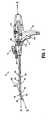
- powered surgical instrument 10includes a housing 110, an endoscopic portion 140 defining a first longitudinal axis A-A extending therethrough, and an end effector 160, defining a second longitudinal axis B-B extending therethrough.
- Endoscopic portion 140extends distally from housing 110 and the end effector 160 is disposed adjacent a distal portion of endoscopic portion 140.
- the components of the housing 110are sealed against infiltration of particulate and/or fluid contamination and help prevent damage of the component by the sterilization process.
- end effector 160includes a first jaw member having one or more surgical fasteners (e.g., cartridge assembly 164) and a second opposing jaw member including an anvil portion for deploying and forming the surgical fasteners (e.g., an anvil assembly 162).
- the staplesare housed in cartridge assembly 164 to apply linear rows of staples to body tissue either in simultaneous or sequential manner.
- Either one or both of the anvil assembly 162 and the cartridge assembly 164are movable in relation to one another between an open position in which the anvil assembly 162 is spaced from cartridge assembly 164 and an approximated or clamped position in which the anvil assembly 162 is in juxtaposed alignment with cartridge assembly 164.
- end effector 160is attached to a mounting portion 166, which is pivotably attached to a body portion 168.
- Body portion 168may be integral with endoscopic portion 140 of powered surgical instrument 10, or may be removably attached to the instrument 10 to provide a replaceable, disposable loading unit (DLU) or single use loading unit (SULU) (e.g., loading unit 169).
- DLUdisposable loading unit
- SULUsingle use loading unit
- the reusable portionmay be configured for sterilization and re-use in a subsequent surgical procedure.
- the loading unit 169may be connectable to endoscopic portion 140 through a bayonet connection. It is envisioned that the loading unit 169 has an articulation link connected to mounting portion 166 of the loading unit 169 and the articulation link is connected to a linkage rod so that the end effector 160 is articulated as the linkage rod is translated in the distal-proximal direction along first longitudinal axis A-A. Other means of connecting end effector 160 to endoscopic portion 140 to allow articulation may be used, such as a flexible tube or a tube comprising a plurality of pivotable members.
- the loading unit 169may incorporate or be configured to incorporate various end effectors, such as vessel sealing devices, linear stapling devices, circular stapling devices, cutters, etc. Such end effectors may be coupled to endoscopic portion 140 of powered surgical instrument 10.
- the loading unit 169may include a linear stapling end effector that does not articulate.
- An intermediate flexible shaftmay be included between handle portion 112 and loading unit. It is envisioned that the incorporation of a flexible shaft may facilitate access to and/or within certain areas of a patient's body.
- housing 110includes a handle portion 112 having a main drive switch 114 disposed thereon.
- the switch 114may include first and second switches 114a and 114b formed together as a toggle switch.
- the handle portion 112, which defines a handle axis H-H,is configured to be grasped by fingers of a user.
- the handle portion 112has an ergonomic shape providing ample palm grip leverage which helps prevent the handle portion 112 from being squeezed out of the user's hand during operation.
- Each switch 114a and 114bis shown as being disposed at a suitable location on handle portion 112 to facilitate its depression by a user's finger or fingers.
- the instrument 10includes two separates switches 114a and 114b separated by a rib feature.
- switches 114a, 114bmay be used for starting and/or stopping movement of drive motor 200 ( FIG. 4 ).
- the switch 114ais configured to activate the drive motor 200 in a first direction to advance firing rod 220 ( FIG. 6 ) in a distal direction thereby clamping the anvil and the cartridge assemblies 162 and 164.
- the switch 114bmay be configured to retract the firing rod 220 to open the anvil and cartridge assemblies 162 and 164 by activating the drive motor 200 in a reverse direction.
- a mechanical lock out(not shown) is actuated, preventing further progression of stapling and cutting by the loading unit 169.
- the lockoutis redundantly backed up with software to prevent the cutting of tissue after the staples have been previously deployed.
- the togglehas a first position for activating switch 114a, a second position for activating switch 114b, and a neutral position between the first and second positions. The details of operation of the drive components of the instrument 10 are discussed in more detail below.
- the housing 110in particular the handle portion 112, includes switch shields 117a and 117b.
- the switch shields 117a and 117bmay have a rib-like shape surrounding the bottom portion of the switch 114a and the top portion of the switch 114b, respectively.
- the switch shield 117a and 117bprevent accidental activation of the switch 114. Further, the switches 114a and 114b have high tactile feedback requiring increased pressure for activation.
- the switches 114a and 114bare configured as multi-speed (e.g., two or more), incremental or variable speed switches which control the speed of the drive motor 200 and the firing rod 220 in a non-linear manner.
- switches 114a, bcan be pressure-sensitive. This type of control interface allows for gradual increase in the rate of speed of the drive components from a slower and more precise mode to a faster operation.
- the switch 114bmay be disconnected electronically until a fail safe switch is pressed.
- a third switch 114cmay also be used for this purpose.
- the fail safecan be overcome by pressing and holding the switch 114b for a predetermined period of time from about 100 ms to about 2 seconds.
- the firing rod 220then automatically retracts to its initial position unless the switches 114a and 114b are activated (e.g., pressed and released) during the retraction mode to stop the retraction. Subsequent pressing of the switch 114b after the release thereof resumes the retraction. Alternatively, the retraction of the firing rod 220 can continue to full retraction even if the switch 114b is released, in other embodiments. Other embodiments include an auto retract mode of the firing rod 220 that fully retracts the firing rod 220 even if switch 114b is released. The mode may be interrupted at any time if one of the switches 114a or 114b is actuated.
- the switches 114a and 114bare coupled to a non-linear speed control circuit 115 which can be implemented as a voltage regulation circuit, a variable resistance circuit, or a microelectronic pulse width modulation circuit.
- the switches 114a and 144bmay interface with the control circuit 115 by displacing or actuating variable control devices, such as rheostatic devices, multiple position switch circuit, linear and/or rotary variable displacement transducers, linear and/or rotary potentiometers, optical encoders, ferromagnetic sensors, and Hall Effect sensors.
- switches 114a and 114bto operate the drive motor 200 in multiple speed modes, such as gradually increasing the speed of the drive motor 200 either incrementally or gradually depending on the type of the control circuit 115 being used, based on the depression of the switches 114a and 114b.
- the switch 114cmay also be included ( FIGS. 1 , 2 and 4 ), wherein depression thereof may mechanically and/or electrically change the mode of operation from clamping to firing.
- the switch 114cis recessed within the housing 110 and has high tactile feedback to prevent false actuations. Providing a separate control switch to initialize the firing mode allows the jaws of the end effector to be repeatedly opened and closed, so that the instrument 10 is used as a grasper until the switch 114c is pressed, thus activating the stapling and/or cutting mode.
- the switch 114may include one or more microelectronic switches, for example.
- a microelectronic membrane switchprovides a tactile feel, small package size, ergonomic size and shape, low profile, the ability to include molded letters on the switch, symbols, depictions and/or indications, and a low material cost.
- switches 114(such as microelectronic membrane switches) may be sealed to help facilitate sterilization of the instrument 10, as well as helping to prevent particle and/or fluid contamination.
- other input devicesmay include voice input technology, which may include hardware and/or software incorporated in a control system 501 ( FIG. 20 ), or a separate digital module connected thereto.
- the voice input technologymay include voice recognition, voice activation, voice rectification and/or embedded speech.
- the usermay be able to control the operation of the instrument in whole or in part through voice commands, thus freeing one or both of the user's hands for operating other instruments.
- Voice or other audible outputmay also be used to provide the user with feedback.
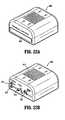
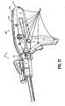
- FIGS. 2A and 2Billustrate a variant of surgical instrument 10. More particularly, surgical instrument 10' includes a housing 110' that is configured with a handle 112' having a partial hour-glass shape. Surgical instrument 10' provides an alternative ergonomic configuration to surgical instrument 10.
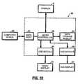
- the user interface 120includes a screen 122 and a plurality of switches 124.
- the user interface 120may display various types of operational parameters of the instrument 10 such as "mode” (e.g., rotation, articulation or actuation), which may be communicated to user interface via a sensor, "status” (e.g., angle of articulation, speed of rotation, or type of actuation) and “feedback,” such as whether staples have been fired based on the information reported by the sensors disposed in the instrument 10, along with error and other codes (e.g., improper loading, replace battery, battery level, the estimated number of firings remaining or any non-functioning sub systems).
- modee.g., rotation, articulation or actuation
- statuse.g., angle of articulation, speed of rotation, or type of actuation
- feedbacksuch as whether staples have been fired based on the information reported by the sensors disposed in the instrument 10, along with error and other codes (e.g., improper loading, replace battery, battery level,
- the screen 122may be an LCD screen, a plasma screen, an electroluminescent screen and the like. In one embodiment the screen 122 may be a touch screen, obviating the need for the switches 124.
- the touch screenmay incorporate resistive, surface wave, capacitive, infrared, strain gauge, optical, dispersive signal or acoustic pulse recognition touch screen technologies.
- the touch screenmay be used to allow the user to provide input while viewing operational feedback. This approach allows sealed screen components to help sterilize the instrument 10, as well as preventing particle and/or fluid contamination.
- the screen 122is pivotably or rotatably mounted to the instrument 10 for flexibility in viewing screen during use or preparation (e.g., via a hinge or ball-and-socket mount).
- the switches 124may be used for starting and/or stopping movement of the instrument 10 as well as selecting the type of single use loading unit (SULU) or disposable loading unit (DLU), the pivot direction, speed and/or torque. It is also envisioned that at least one switch 124 can be used for selecting an emergency mode that overrides various settings. The switches 124 may also be used for selecting various options on the screen 122, such as responding to prompts while navigating user interface menus and selecting various settings, allowing a user input different tissue types, and various sizes and lengths of staple cartridges.
- SULUsingle use loading unit
- DLUdisposable loading unit
- the switches 124may be formed from a micro-electronic tactile or non-tactile membrane, a polyester membrane, elastomer, plastic or metal keys of various shapes and sizes. Additionally, switches may be positioned at different heights from one another and/or may include raised indicia or other textural features (e.g., concavity or convexity) to allow a user to depress an appropriate switch without the need to look at user interface 120.
- switchesmay be formed from a micro-electronic tactile or non-tactile membrane, a polyester membrane, elastomer, plastic or metal keys of various shapes and sizes. Additionally, switches may be positioned at different heights from one another and/or may include raised indicia or other textural features (e.g., concavity or convexity) to allow a user to depress an appropriate switch without the need to look at user interface 120.
- the user interface 120may include one or more visual outputs 123 which may include one or more colored visible lights or light emitting diodes ("LED") to relay feedback to the user.
- the visual outputs 123may include corresponding indicators of various shapes, sizes and colors having numbers and/or text which identify the visual outputs 123.
- the visual outputs 123are disposed on top of the housing 110 such that the outputs 123 are raised and protrude in relation to the housing 110 providing for better visibility thereof.
- the multiple lightsdisplay in a certain combination to illustrate a specific operational mode to the user.
- the visual outputs 123include a first light (e.g., yellow) 123a, a second light (e.g., green) 123b and a third light (e.g., red) 123c.
- the lightsare operated in a particular combination associated with a particular operational mode as listed in Table 1 below.
- Table 1 Light Combination Operational Mode Light Status No loading unit 169 or staple cartridgeis loaded.
- First Light Off Second Light Off Third Light Off Light StatusThe loading unit 169 and/or staple cartridge is properly loaded First Light On and power is activated, allowing the end effector 160 to clamp Second Light Off as a grasper and articulate.
- Third Light Off Light Status A used loading unit 169 or staple cartridgeis loaded. First Light Flashing Second Light Off Third Light Off Light Status Instrument 10 is deactivated and prevented from firing staples First Light N/A or cutting. Second Light Off Third Light N/A Light Status A new loading unit 169 is loaded, the end effector 160 is fully First Light On clamped and the instrument 10 is in firing staple and cutting Second Light On modes. Third Light Off Light Status Due to high stapling forces a "thick tissue" mode is in effect, First Light On providing for a pulsed or progression time delay during which Second Light Flashing tissue is compressed. Third Light Off Light Status No system errors detected. First Light N/A Second Light N/A Third Light Off Light Status Tissue thickness and/or firing load is too high, this warning can First Light On be overridden. Second Light On Third Light On Light Status Functional system error is detected, instrument 10 should be First Light N/A replaced. Second Light N/A Third Light Flashing First light N/A Second light N/A Third light ON Replace the battery pack or the power source is not properly connected.
- the visual output 123may include a single multi-colored LED which display a particular color associated with the operational modes as discussed above with respect to the first, second and third lights in Table 1.
- the user interface 120also includes audio outputs 125 (e.g., tones, bells, buzzers, integrated speaker, etc.) to communicate various status changes to the user such as lower battery, empty cartridge, etc.
- the audible feedbackcan be used in conjunction with or in lieu of the visual outputs 123.
- the audible feedbackmay be provided in the forms of clicks, snaps, beeps, rings and buzzers in single or multiple pulse sequences.
- a simulated mechanical soundmay be prerecorded which replicates the click and/or snap sounds generated by mechanical lockouts and mechanisms of conventional non-powered instruments.
- the instrument 10may include one or more microphones or other voice input devices which can be used to determine the background noise levels and adjust the audible feedback volumes accordingly for clear feedback recognition.
- the instrument 10may also provide for haptic or vibratory feedback through a haptic mechanism (not explicitly shown) within the housing 110.
- the haptic feedbackmay be used in conjunction with the auditory and visual feedback or in lieu thereof to avoid confusion with the operating room equipment which relies on audio and visual feedback.
- the haptic mechanismmay be an asynchronous motor that vibrates in a pulsating manner.
- the vibrationsare at a frequency of about 20 Hz or above, in embodiments from about 20 Hz to about 60 Hz, and providing a displacement having an amplitude of 2 mm or lower, in embodiments from about 0.25 mm to about 2 mm, to limit the vibratory effects from reaching the loading unit 169.
- user interface 120includes different colors and/or intensities of text on screen and/or on switches for further differentiation between the displayed items.
- the visual, auditory or haptic feedbackcan be increased or decreased in intensity.
- the intensity of the feedbackmay be used to indicate that the forces on the instrument are becoming excessive.
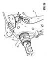
- FIGS. 2 , 3 and 4illustrate an articulation mechanism 170, including an articulation housing 172, a powered articulation switch 174, an articulation motor 132 and a manual articulation knob 176.
- the articulation switch 174may be a rocker and/or a slide switch having an arm 174a and 174b on each side of the housing 110 allowing for either right or left hand usage thereof.
- Translation of the powered articulation switch 174activates the articulation motor 132.
- Pivoting of the manual articulation knob 176will actuate the articulation gear 233 of the articulation mechanism 170 as shown in FIG. 5 .
- Actuation of articulation mechanism 170causes the end effector 160 to move from its first position, where longitudinal axis B-B is substantially aligned with longitudinal axis A-A, towards a position in which longitudinal axis B-B is disposed at an angle to longitudinal axis A-A.
- a plurality of articulated positionsis achieved.
- the powered articulation switch 174may also incorporate similar non-linear speed controls as the clamping mechanism as controlled by the switches 114a and 114b.
- the housing 110includes switch shields 117c and 117d having a wing-like shape and extending from the top surface of the housing 110 over the switch 174.
- the switch shields 117c or 117dprevent accidental activation of the switch 174 when the instrument 10 is placed down or from physical obstructions during use and require the user to reach below the shield 169 in order to activate the articulation mechanism 170.
- Rotation of a rotation knob 182 about first longitudinal axis A-Acauses housing assembly 180 as well as articulation housing 172 and manual articulation knob 176 to rotate about first longitudinal axis A-A, and thus causes corresponding rotation of distal portion 224 of firing rod 220 and end effector 160 about first longitudinal axis A-A.
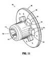
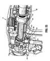
- the articulation mechanism 170is electro-mechanically coupled to first and second conductive rings 157 and 159 which are disposed on housing nose assembly 155 as shown in FIGS. 4 and 26 .
- the conductive rings 157 and 159may be soldered, glued, press fit, snap fit or crimped onto the nose assembly 155 and are in electrical contact with the power source 400 thereby providing electrical power to the articulation mechanism 170.
- the nose assembly 155may be modular (e.g., separate from the housing 110) and may be attached to the housing 110 during assembly to facilitate the aforementioned methods of mounting the rings.
- the articulation mechanism 170includes one or more brush and/or spring loaded contacts in contact with the conductive rings 157 and 159 such that as the housing assembly 180 is rotated along with the articulation housing 172 the articulation mechanism 170 is in continuous contact with the conductive rings 157 and 159 thereby receiving electrical power from the power source 400.
- articulation housing 172powered articulation switch 174, manual articulation knob 176 and providing articulation to end effector 160 are described in detail in commonly-owned U.S. Patent Application Serial No. 11/724,733 filed March 15, 2007 , the contents of which are hereby incorporated by reference in their entirety. It is envisioned that any combinations of limit switches, proximity sensors (e.g., optical and/or ferromagnetic), linear variable displacement transducers and shaft encoders which may be disposed within housing 110, may be utilized to control and/or record an articulation angle of end effector 160 and/or position of the firing rod 220.
- limit switchese.g., optical and/or ferromagnetic
- linear variable displacement transducers and shaft encoderswhich may be disposed within housing 110, may be utilized to control and/or record an articulation angle of end effector 160 and/or position of the firing rod 220.
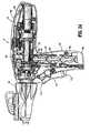
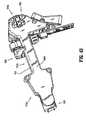
- FIGS. 4 , 5-10 and 11-12illustrate various internal components of the instrument 10, including a drive motor 200, an internally threaded drive tube 210 and a firing rod 220 having a proximal portion 222 and a distal portion 224.
- the drive tube 210is rotatable about drive tube axis C-C extending therethrough.
- Drive motor 200is disposed in mechanical cooperation with drive tube 210 and is configured to rotate the drive tube 210 about drive gear axis C-C.
- the drive motor 200may be an electrical motor or a gear motor, which may include gearing incorporated within its housing.
- the housing 110may be formed from two halves 110a and 110b as illustrated in FIG. 3 .
- the two housing portion halves 110a and 110bmay be attached to each other using screws at boss locators 111 which align the housing portions 110a and 110b.
- ultrasonic welding directorsmay be used to attach halves 110a and 110b to seal the housing from external contamination.
- the housing 110may be formed from plastic and may include rubber support members applied to the internal surface of the housing 110 via a two-shot molding process. The rubber support members may isolate the vibration of the drive components (e.g., drive motor 200) from the rest of the instrument 10.
- the housing halves 110a and 110bmay be attached to each via a thin section of plastic (e.g., a living hinge) that interconnects the halves 110a and 110b allowing the housing 110 to be opened by breaking away the halves 110a and 110b.
- a thin section of plastice.g., a living hinge
- the drive componentsmay be mounted on a support plate allowing the drive components to be removed from the housing 110 after the instrument 10 has been used.
- the support plate mounting in conjunction with the hinged housing halves 110a and 110bprovide for reusability and recyclability of specific internal components while limiting contamination thereof.
- FIG. 4Aillustrates the internal components of the variant surgical instrument 10'.
- FIG. 4Ais provided for a general comparison with respect to FIG. 4 and will not be discussed in detail herein.
- Firing rod coupling 190provides a link between the proximal portion 222 and the distal portion 224 of the firing rod 220. Specifically, the firing rod coupling 190 enables rotation of the distal portion 224 of the firing rod 220 with respect to proximal portion 222 of firing rod 220. Thus, firing rod coupling 190 enables proximal portion 222 of firing rod 220 to remain non-rotatable, as discussed below with reference to an alignment plate 350, while allowing rotation of distal portion 224 of firing rod 220 (e.g., upon rotation of rotation knob 182).
- the proximal portion 222 of firing rod 220includes a threaded portion 226, which extends through an internally-threaded portion 212 of drive tube 210.
- This relationship between firing rod 220 and drive tube 210causes firing rod 220 to move distally and/or proximally, in the directions of arrows D and E, along threaded portion 212 of drive tube 210 upon rotation of drive tube 210 in response to the rotation of the drive motor 200.
- a first directione.g., clockwise
- firing rod 220moves proximally.
- the firing rod 220is disposed at its proximal-most position.
- a second directione.g., counter-clockwise
- firing rod 220moves distally.
- the firing rod 220is disposed at its distal-most position.
- the firing rod 220is distally and proximally translatable within particular limits. Specifically, a first end 222a of proximal portion 222 of firing rod 220 acts as a mechanical stop in combination with alignment plate 350. That is, upon retraction when firing rod 220 is translated proximally, first end 222a contacts a distal surface 351 of alignment plate 350, thus preventing continued proximal translation of firing rod 220 as shown in FIG. 6 . Additionally, threaded portion 226 of the proximal portion 222 acts as a mechanical stop in combination with alignment plate 350.
- the alignment plate 350includes an aperture therethrough, which has a non-round cross-section.
- the non-round cross-section of the apertureprevents rotation of proximal portion 222 of firing rod 220, thus limiting proximal portion 222 of firing rod 220 to axial translation therethrough.
- a proximal bearing 354 and a distal bearing 356are disposed at least partially around drive tube 210 for facilitation of rotation of drive tube 210, while helping align drive tube 210 within housing 110.
- the drive tube 210includes a distal radial flange 210a and a proximal radial flange 210b on each end of the drive tube 210 which retain the drive tube 210 between the distal bearing 356 and the proximal bearing 354, respectively.
- Rotation of drive tube 210 in a first directioncorresponds with distal translation of the firing rod 220 which actuates jaw member 162 or 164 (i.e., anvil and cartridge assemblies 162, 164) of the end effector 160 to grasp or clamp tissue held therebetween. Additional distal translation of firing rod 220 ejects surgical fasteners from the end effector 160 to fasten tissue by actuating cam bars and/or an actuation sled 74 ( FIG. 9 ). Further, the firing rod 220 may also be configured to actuate a knife (not explicitly shown) to sever tissue.
- Proximal translation of firing rod 220 corresponding with rotation of the drive tube 210 in a second directionactuates the anvil and cartridge assemblies 162, 164 and/or knife to retract or return to corresponding pre-fired positions.
- a second directione.g., clockwise
- firing and otherwise actuating end effector 160are described in detail in commonly-owned U.S. Patent No. 6,953,139 to Milliman et al. (the '139 Milliman patent), the disclosure of which is hereby incorporated by reference herein.
- FIG. 8shows a partial exploded view of the loading unit 169.
- the end effector 160may be actuated by an axial drive assembly 213 having a drive beam or drive member 266.
- the distal end of the drive beam 213may include a knife blade.
- the drive beam 213includes a retention flange 40 having a pair of cam members 40a which engage the anvil and the cartridge assembly 162 and 164 during advancement of the drive beam 213 longitudinally.
- the drive beam 213advances an actuation sled 74 longitudinally through the staple cartridge 164.
- the sled 74has cam wedges for engaging pushers 68 disposed in slots of the cartridge assembly 164, as the sled 74 is advanced. Staples 66 disposed in the slots are driven through tissue and against the anvil assembly 162 by the pushers 66.
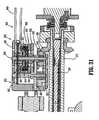
- a drive motor shaft 202is shown extending from a transmission 204 that is attached to drive motor 200.
- Drive motor shaft 202is in mechanical cooperation with clutch 300.
- Drive motor shaft 202is rotated by the drive motor 200, thus resulting in rotation of clutch 300.
- Clutch 300includes a clutch plate 302 and a spring 304 and is shown having wedged portions 306 disposed on clutch plate 302, which are configured to mate with an interface (e.g., wedges 214) disposed on a proximal face 216 of drive tube 210.
- Spring 304is illustrated between transmission 204 and drive tube 210. Specifically, and in accordance with the embodiment illustrated in FIG. 10 , spring 304 is illustrated between clutch face 302 and a clutch washer 308. Additionally, drive motor 200 and transmission 204 are mounted on a motor mount 310. As illustrated in FIG. 8 , motor mount 310 is adjustable proximally and distally with respect to housing 110 via slots 312 disposed in motor mount 310 and protrusions 314 disposed on housing 110.
- the clutch 300is implemented as a slip bi-directional clutch to limit torque and high inertia loads on the drive components.
- Wedged portions 306 of clutch 300are configured and arranged to slip with respect to wedges 214 of proximal face 216 of drive tube 210 unless a threshold force is applied to clutch plate 302 via clutch spring 304. Further, when spring 304 applies the threshold force needed for wedged portions 306 and wedges 214 to engage without slipping, drive tube 210 will rotate upon rotation of drive motor 200.
- wedged portions 306 and/or wedges 214are configured to slip in one and/or both directions (i.e., clockwise and/or counter-clockwise) with respect to one another when a firing force is attained on the firing rod 220.
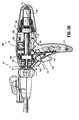
- FIG. 10Aillustrates a partial enlarged view of the internal components of surgical instrument surgical instrument 10' as described above with respect to FIGS. 2A , 2B and 4A . Again, in a similar manner, FIG. 10A is provided for a general comparison with respect to FIG. 10 and will not be discussed in detail herein. Some of the components that are common with surgical instrument 10 have been identified with the corresponding identification numerals pertaining to surgical instrument 10.
- the clutch 300is shown with a unidirectional clutch plate 700.
- the clutch plate 700includes a plurality of wedged portions 702 each having a slip face 704 and a grip face 706.
- the slip face 704has a curved edge which engages the wedges 214 of the drive tube 210 up to a predetermined load.
- the grip face 706has a flat edge which fully engages the drive tube 210 and prevents slippage.
- This featurehelps to assure that jaws 162, 164 will open under retraction during extreme load scenarios.
- the clutch plate 700When the clutch plate 700 is rotated in a forward direction (e.g., clockwise), the slip faces 704 of the wedged portions 702 engage the wedges 214 and limit the torque being transferred to the drive tube 210. Thus, if the load being applied to a slip face 704 is over the limit, the clutch 300 slips and the drive tube 210 is not rotated. This can prevent high load damage to the end effector 160 or tissue from the motor and drive components. More specifically, the drive mechanism of the instrument 10 can drive the firing rod 220 in a forward direction with less torque than in reverse.
- an electronic clutchmay also be used to increase or decrease the motor potential (e.g., driving the drive rod 220 in forward or reverse along with the drive motor 200, drive tube 210, clutch assembly 300, alignment plate 350, and any portion of the firing rod 220) as discussed in more detail below.
- drive motor shaft 202includes a D-shaped or non-round cross-section 708, which includes a substantially flat portion 710 and a rounded portion 712.
- drive motor shaft 202will not “slip” with respect to clutch plate 700 upon rotation of drive motor shaft 202. That is, rotation of drive motor shaft 202 will result in a slip-less rotation of clutch plate 700.
- the loading unitin certain embodiments according to the present disclosure, includes an axial drive assembly that cooperates with firing rod 220 to approximate anvil assembly 162 and cartridge assembly 164 of end effector 160, and fire staples from the staple cartridge.
- the axial drive assemblymay include a beam that travels distally through the staple cartridge and may be retracted after the staples have been fired, as discussed above and as disclosed in certain embodiments of the '139 Milliman patent.
- the instrument 10includes a power source 400 which may be a rechargeable battery (e.g., lead-based, nickel-based, lithium-ion based, etc.). It is also envisioned that the power source 400 includes at least one disposable battery. The disposable battery may be between about 9 volts and about 30 volts.
- the power source 400includes one or more battery cells 401 depending on the energy and voltage potential needs of the instrument 10. Further, the power source 400 may include one or more ultracapacitors 402 which act as supplemental power storage due to their much higher energy density than conventional capacitors. Ultracapacitors 402 can be used in conjunction with the cells 401 during high energy draw. The ultracapacitors 402 can be used for a burst of power when energy is desired/required more quickly than can be provided solely by the cells 401 (e.g., when clamping thick tissue, rapid firing, clamping, etc.), as cells 401 are typically slow-drain devices from which current cannot be quickly drawn. This configuration can reduce the current load on the cells thereby reducing the number of cells 401. Ultracapacitors 402 can also regulate the system voltage, providing more consistent speed of motor 200 and firing rod 220. It is envisioned that cells 401 can be connected to the ultracapacitors 402 to charge the capacitors.
- the power source 400may be removable along with the drive motor 200 to provide for recycling of theses components and reuse of the instrument 10.
- the power source 400may be an external battery pack which is worn on a belt and/or harness by the user and wired to the instrument 10 during use.
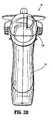
- the power source 400is enclosed within an insulating shield 404 which may be formed from an absorbent, flame resistant and retardant material.
- the shield 404electrically and thermally isolates components of the instrument 10 from the power source 400. More specifically, the shield 400 prevents heat generated by the power source 400 from heating other components of the instrument 10.
- the shield 404may also be configured to absorb any chemicals or fluids which may leak from the cells 402 during heavy use and/or damage.
- the power source 400may be coupled to a power adapter 406 which is configured to connect to an external power source (e.g., DC transformer).
- the external power sourcemay be used to recharge the power source 400 or provide for additional power requirements.
- the power adapter 406may also be configured to interface with electrosurgical generators which can then supply power to the instrument 10.
- the instrument 10also includes an AC-to-DC power source which converts RF energy from the electrosurgical generators and powers the instrument 10.
- the power source 400is recharged using an inductive charging interface.
- the power source 400is coupled to an inductive coil (not explicitly shown) disposed within the proximal portion of the housing 110.
- the inductive coilUpon being placed within an electromagnetic field, the inductive coil converts the energy into electrical current that is then used to charge the power source 400.
- the electromagnetic fieldmay be produced by a base station (not explicitly shown) which is configured to interface with the proximal portion of the housing 110, such that the inductive coil is enveloped by the electromagnetic field. This configuration eliminates the need for external contacts and allows for the proximal portion of the housing 110 to seal the power source 400 and the inductive coil within a water-proof environment which prevents exposure to fluids and contamination.
- the instrument 10also includes one or more safety circuits such as a discharge circuit 410 and a motor and battery operating module 412.
- a discharge circuit 410for clarity, wires and other circuit elements interconnecting various electronic components of the instrument 10 are not shown, but such electromechanical connections wires are contemplated by the present disclosure. Certain components of the instrument 10 communicate wirelessly.
- the discharge circuit 410is coupled to a switch 414 and a resistive load 417 which are in turn coupled to the power source 400.
- the switch 414may be a user activated or an automatic (e.g., timer, counter) switch which is activated when the power source 400 needs to be fully discharged for a safe and low temperature disposal (e.g., at the end of surgical procedure).
- the load 417is electrically connected to the power source 400 such that the potential of the power source 400 is directed to the load 417.
- the automatic switchmay be a timer or a counter which is automatically activated after a predetermined operational time period or number of uses to discharge the power source 400.
- the load 417has a predetermined resistance sufficient to fully and safely discharge all of the cells 401.
- the motor and battery operating module 412is coupled to one or more thermal sensors 413 which determine the temperature within the drive motor 200 and the power source 400 to ensure safe operation of the instrument 10.
- the sensorsmay be an ammeter for determining the current draw within the power source 400, a thermistor, a thermopile, a thermocouple, a thermal infrared sensor and the like. Monitoring temperature of these components allows for a determination of the load being placed thereon. The increase in the current flowing through these components causes an increase in temperature therein. The temperature and/or current draw data may then be used to control the power consumption in an efficient manner or assure safe levels of operation.
- the power source 400is authentic and/or valid (e.g., conforms to strict quality and safety standards) and operating within a predetermined temperature range. Authentication that the power source 400 is valid minimizes risk of injury to the patient and/or the user due to poor quality.
- the power source 400is shown having one or more battery cells 401, the thermal sensor 413 and an embedded microcontroller 405 coupled thereto.
- the microcontroller 405is coupled through wired and/or wireless communication protocols to microcontroller 500 ( FIGS. 6 , 13 and 20 ) of the instrument 10 to authenticate the power source 400.
- the thermal sensor 413can be coupled directly to the microcontroller 500 instead of being coupled to the embedded microcontroller 405.
- the thermal sensor 413may be a thermistor, a thermopile, a thermocouple, a thermal infrared sensor, a resistance temperature detector, linear active thermistor, temperature-responsive color changing strips, bimetallic contact switches, and the like.
- the thermal sensor 413reports the measured temperature to the microcontroller 405 and/or microcontroller 500.
- the embedded microcontroller 405executes a so-called challenge-response authentication algorithm with the microcontroller 500 which is illustrated in FIG. 13 .
- the power source 400is connected to the instrument 10 and the instrument 10 is switched on.
- the microcontroller 500sends a challenge request to the embedded microcontroller 405.
- the microcontroller 500may request the battery temperature from microcontroller 405 which receives it from thermal sensor 413.
- the microcontroller 405interprets the challenge request and generates a response as a reply to the request.
- the responsemay include an identifier, such as a unique serial number stored in a radio frequency identification tag or in memory of the microcontroller 405, a unique electrical measurable value of the power source 400 (e.g., resistance, capacitance, inductance, etc.).
- the responseincludes the temperature measured by the thermal sensor 413.
- step 634the microcontroller 500 decodes the response to obtain the identifier and the measured temperature.
- step 636the microcontroller 500 determines if the power source 400 is authentic based on the identifier, by comparing the identifier against a pre-approved list of authentic identifiers. If the identifier is not valid, the instrument 10 is not going to operate and displays an error code or a "failure to authenticate battery" message via the user interface 120. If the identifier is valid, the process proceeds to step 640 where the measured temperature is analyzed to determine if the measurement is within a predetermined operating range. If the temperature is outside the limit, the instrument 10 also displays an error message. Thus, if the temperature is within the predetermined limit and the identifier is valid, in step 642, the instrument commences operation, which may include providing a "battery authenticated" message to the user.
- sensorsfor providing feedback information relating to the function of the instrument 10 are illustrated. Any combination of sensors may be disposed within the instrument 10 to determine its operating stage, such as, staple cartridge load detection as well as status thereof, articulation, clamping, rotation, stapling, cutting and retracting, and the like.
- the sensorscan be actuated by rotational encoders, proximity, displacement or contact of various internal components of the instrument 10 (e.g., firing rod 220, drive motor 200, etc.).
- the sensorscan be rheostats (e.g., variable resistance devices), current monitors, conductive sensors, capacitive sensors, inductive sensors, thermal-based sensors, limit actuated switches, multiple position switch circuits, pressure transducers, linear and/or rotary variable displacement transducers, linear and/or rotary potentiometers, optical encoders, ferromagnetic sensors, Hall Effect sensors, and proximity switches.
- the sensorsmeasure rotation, velocity, acceleration, deceleration, linear and/or angular displacement, detection of mechanical limits (e.g., stops), etc. This is attained by implementing multiple indicators arranged in either linear or rotational arrays on the mechanical drive components of the instrument 10.
- the sensorsthen transmit the measurements to the microcontroller 500 which determines the operating status of the instrument 10.
- the microcontroller 500also adjusts the motor speed or torque of the instrument 10 based on the measured feedback.
- linear displacement sensorse.g., linear displacement sensor 237 FIG. 4
- slippage of the clutch 300does not affect the position, velocity and acceleration measurements recorded by the sensors.
- a load switch 230is disposed within the housing nose assembly 155.
- the switch 230is connected in series with the power source 400, preventing activation of the microcontroller 500 and instrument 10 unless the loading unit 169 is properly loaded into the instrument 10. If the loading unit 169 is not loaded into the instrument 10, the connection to the power source 400 is open, thereby preventing use of any electronic or electric components of the instrument 10. This prevents any possible current draw from the power source 400 allowing the power source 400 to maintain a maximum potential over its specified shelf life.
- the switch 230acts as a so-called "power-on" switch which prevents false activation of the instrument 10 since the switch is inaccessible to external manipulation and can only be activated by the insertion of the loading unit 169.
- the switch 230is activated by displacement of sensor plate 360 to the sensor tube 362 which displaces the sensor cap 364 as the loading unit 169 is inserted into the endoscopic portion 140.
- the power from the power source 400is supplied to the electronic components (e.g., sensors, microcontroller 500, etc.) of the instrument 10 providing the user with access to the user interface 120 and other inputs/outputs. This also activates the visual outputs 123 to light up according to the light combination indicative of a properly loaded loading unit 169 wherein all the lights are off as described in Table 1.
- the endoscopic portion 140includes a sensor plate 360 therein which is in mechanical contact with a sensor tube also disposed within the endoscopic portion 140 and around the distal portion 224 of firing rod 220.
- the distal portion 224 of the firing rod 220passes through an opening 368 at a distal end of a sensor cap 364.
- the sensor cap 364includes a spring and abuts the switch 230. This allows the sensor cap 364 to be biased against the sensor tube 362 which rests on the distal end of the sensor cap 364 without passing through the opening 368. Biasing of the sensor tube 362 then pushes out the sensor plate 360 accordingly.
- the proximal portion 171When the loading unit 169 is loaded into the endoscopic portion 140, the proximal portion 171 abuts the sensor plate 360 and displaces the plate 360 in a proximal direction. The sensor plate 360 then pushes the sensor tube 362 in the proximal direction which then applies pressure on the sensor cap 364 thereby compressing the spring 366 and activating the switch 230 denoting that the loading unit 169 has been properly inserted.
- the switch 230determines whether the loading unit 169 is loaded correctly based on the position thereof. If the loading unit 169 is improperly loaded, no switches are activated and an error code is relayed to the user via the user interface 120 (e.g., all the lights are off as described in Table 1). If the loading unit 169 has already been fired, any mechanical lockouts have been previously activated or the staple cartridge has been used, the instrument 10 relays the error via the user interface 120, e.g., the first light 123a is flashing.
- a second lock-out switchcoupled to the microcontroller 500 (see FIG. 6 ) may be implemented in the instrument 10 as a bioimpedance, capacitance or pressure sensor disposed on the top surface of, or within, the handle portion 112 configured to be activated when the user grasps the instrument 10.
- a bioimpedance, capacitance or pressure sensordisposed on the top surface of, or within, the handle portion 112 configured to be activated when the user grasps the instrument 10.
- the instrument 10includes a position calculator 416 for determining and outputting current linear position of the firing rod 220.
- the position calculator 416is electrically connected to a linear displacement sensor 237 and a rotation speed detecting apparatus 418 is coupled to the drive motor 200.
- the apparatus 418includes an encoder 420 coupled to the motor for producing two or more encoder pulse signals in response to the rotation of the drive motor 200.
- the encoder 420transmits the pulse signals to the apparatus 418 which then determines the rotational speed of the drive motor 200.
- the position calculator 416thereafter determines the linear speed and position of the firing rod based on the rotational speed of the drive motor 200 since the rotation speed is directly proportional to the linear speed of the firing rod 220.
- the position calculator 416 and the speed calculator 422are coupled to the microcontroller 500 which controls the drive motor 200 in response to the sensed feedback form the calculators 416 and 422. This configuration is discussed in more detail below with respect to FIG. 20 .
- the instrument 10includes first and second indicators 320a, 320b disposed on the firing rod 220, which determine the limits of firing rod 220.
- the linear displacement sensor 237determines the location of firing rod 220 with respect to drive tube 210 and/or housing 110.
- a limit switchmay be activated (e.g., shaft start position sensor 231 and clamp position sensor 232) by sensing first and second indicators 320a and/or 320b (e.g., bumps, grooves, indentations, etc.) passing thereby to determine the limits of firing rod 220 and mode of the instrument 10 (e.g., clamping, grasping, firing, sealing, cutting, retracting).
- the feedback received from first and second indicators 320a, 320bmay be used to determine when firing rod 220 should stop its axial movement (e.g., when drive motor 200 should cease) depending on the size of the particular loading unit attached thereto.
- the first actuation of the position sensor 231is activated by the first indicator 320a which denotes that operation of the instrument 10 has commenced.
- the firing rod 220is moved further distally to initiate clamping, which moves first indicator 320a to interface with clamp position sensor 232. Further advancement of the firing rod 220 moves the second indicator 320b to interface with the position sensor 232 which indicates that the instrument 10 has been fired.
- the position calculator 416is coupled to a linear displacement sensor 237 disposed adjacent to the firing rod 220.
- the linear displacement sensor 237may be a magnetic sensor.
- the firing rod 220may include magnets or magnetic features.
- the magnetic sensormay be a ferromagnetic sensor or a Hall Effect sensor which is configured to detect changes in a magnetic field. As the firing rod 220 is translated linearly due to the rotation of the drive motor 200, the change in the magnetic field in response to the translation motion is registered by the magnetic sensor.
- the magnetic sensortransmits data relating to the changes in the magnetic field to the position calculator 416 which then determines the position of the firing rod 220 as a function of the magnetic field data.
- a select portion of the firing rod 220may be a magnetic material, such as the threads of the internally-threaded portion 212 or other notches (e.g., indicators 320a and/or 320b) disposed on the firing rod 220 may include or be made from a magnetic material.
- the position calculator 416thereafter determines the distance and the position of the firing rod 220 by summing the number of cyclical changes in the magnetic field and multiplies the sum by a predetermined distance between the threads and/or notches.
- the linear displacement sensor 237may be a potentiometer or a rheostat.
- the firing rod 220includes a contact (e.g., wiper terminal) disposed in electromechanical contact with the linear displacement sensor 237.
- the contactslides along the surface of the linear displacement sensor 237 as the firing rod 220 is moved in the distal direction by the drive motor 200.
- the voltage of the potentiometer and the resistance of the rheostatvary accordingly.
- the variation in voltage and resistanceis transmitted to the position calculator 416 which then extrapolates the distance traveled by the firing rod 220 and/or the firing rod coupling 190 and the position thereof.
- the position calculator 416is coupled to one or more switches 421 which are actuated by the threads of the internally-threaded portion 212 or the indicators 320a and/or 320b as the firing rod 220 and the firing rod coupling 190 are moved in the distal direction.
- the position calculator 416counts the number of threads which activated the switch 421 and then multiplies the number by a predetermined distance between the threads or the indicators 320a and/or 320b.
- the instrument 10also includes a speed calculator 422 which determines the current speed of a linearly moving firing rod 220 and/or the torque being provided by the drive motor 200.
- the speed calculator 422is connected to the linear displacement sensor 237 which allows the speed calculator 422 to determine the speed of the firing rod 220 based on the rate of change of the displacement thereof.
- the speed calculator 422is coupled to the rotation speed detecting apparatus 424 which includes the encoder 426.
- the encoder 426transmits the pulses correlating to the rotation of the drive motor 200 which the speed calculator 422 then uses to calculate the linear speed of the firing rod 220.
- the speed calculator 422is coupled to a rotational sensor 239 which detects the rotation of the drive tube 210, thus, measuring the rate of rotation of the drive tube 210 which allows for determination of the linear velocity of the firing rod 220.
- the speed calculator 422is also coupled to a voltage sensor 428 which measures the back electromotive force ("EMF") induced in the drive motor 200.
- EMFback electromotive force
- the back EMF voltage of the drive motor 200is directly proportional to the rotational speed of the drive motor 200 which, as discussed above, is used to determine the linear speed of the firing rod 220.
- Monitoring of the speed of the drive motor 200can also be accomplished by measuring the voltage across the terminals thereof under constant current conditions. An increase in a load of the drive motor 200 yields a decrease in the voltage applied at the motor terminals, which is directly related to the decrease in the speed of the motor. Thus, measuring the voltage across the drive motor 200 provides for determining the load being placed thereon. In addition, by monitoring the change of the voltage over time (dV/dt), the microprocessor 500 can detect a quick drop in voltage which correlates to a large change in the load or an increase in temperature of the drive motor 200 and/or the power source 400.
- the speed calculator 422is coupled to a current sensor 430 (e.g., an ammeter).
- the current sensor 430is in electrical communication with a shunt resistor 432 which is coupled to the drive motor 200.
- the current sensor 430measures the current being drawn by the drive motor 200 by measuring the voltage drop across the resistor 432. Since the voltage applied to power the drive motor 200 is proportional to the rotational speed of the drive motor 200 and, hence, the linear speed of the firing rod 220, the speed calculator 422 determines the speed of the firing rod 220 based on the voltage potential of the drive motor 200.
- the current sensor 430may also be coupled to the power source 400 to determine the current draw thereof which allows for analysis of the load on the end effector 160. This may be indicative of the tissue type being stapled since various tissue have different tensile properties which affect the load being exerted on the instrument 10 and the power source 400 and/or the motor 200.
- the speed calculator 422may also be coupled to a second voltage sensor (not explicitly shown) for determining the voltage within the power source 400 thereby calculating the power draw directly from the source.
- a second voltage sensor(not explicitly shown) for determining the voltage within the power source 400 thereby calculating the power draw directly from the source.
- the change in current over time (dl/dt)can be monitored to detect quick spikes in the measurements which correspond to a large increase in applied torque by the drive motor 200.
- the current sensor 430is used to determine the torque and the load of the drive motor 200.
- the velocity of the firing rod 220 as measured by the speed calculator 422may be then compared to the current draw of the drive motor 200 to determine whether the drive motor 200 is operating properly. Namely, if the current draw is not commensurate (e.g., large) with the velocity (e.g., low) of the firing rod 220 then the motor 200 is malfunctioning (e.g., locked, stalled, etc.). If a stall situation is detected, or the current draw exceeds predetermined limits, the position calculator 416 then determines whether the firing rod 220 is at a mechanical stop.
- the microcontroller 500can shut down the drive motor 200 or enters a pulse and/or pause mode (e.g., discontinuous supply of power to the drive motor 200) to prevent damage to the motor 200, battery or power source 400, and microcontroller 500, to unlock the instrument 10 and to retract the firing rod 220.
- a pulse and/or pause modee.g., discontinuous supply of power to the drive motor 200
- the speed calculator 422compares the rotation speed of the drive tube 210 as detected by the rotation sensor 239 and that of the drive motor 200 based on the measurements from and the rotation speed detecting apparatus 424. This comparison allows the speed calculator 422 to determine whether there is clutch activation problem (e.g., slippage) if there is a discrepancy between the rotation of the clutch 300 and that of the drive tube 210. If slippage is detected, the position calculator 416 then determines whether the firing rod 220 is at a mechanical stop. If this is the case, then the microcontroller 500 can shut down the instrument 10 or enter a pulse and/or pause mode (e.g., discontinuous supply of power to the drive motor 200), or retract the firing rod 220.
- clutch activation probleme.g., slippage
- the instrument 10also includes sensors adapted to detect articulation of the end effector 160.
- the instrument 10includes a rotation sensor 241 adapted to indicate the start position, the rotational direction and the angular displacement of the rotating housing assembly 180 at the start of the procedure as detected by the shaft start position sensor 231.
- the rotation sensor 241operates by counting the number of indicators disposed on the inner surface of the rotation knob 182 by which the rotation knob 182 has been rotated. The count is then transmitted to the microcontroller 500 which then determines the rotational position of the endoscopic portion 142. This can be communicated wirelessly or through an electrical connection on the endoscopic portion and wires to the microcontroller 500.
- the instrument 10also includes an articulation sensor 235 which determines articulation of the end effector 160.
- the articulation sensor 235counts the number of features 263 disposed on the articulation gear 233 by which the articulation knob 176 has been rotated from its 0° position, namely the center position of the articulation knob 176 and, hence, of the end effector 160 as shown in FIG. 5 .
- the 0° positionand can be designated by a central unique indicator 265 also disposed on the articulation gear 233 which corresponds with the first position of the end effector 160, where longitudinal axis B-B is substantially aligned with longitudinal axis A-A.
- the countis then transmitted to the microcontroller 500 which then determines the articulation position of the end effector 160 and reports the articulation angle via the interface 120.
- the featurescan include protrusions, magnetic material, transmitters, etc.
- the articulation anglecan be used for the so-called "auto stop” mode.
- the instrument 10automatically stops the articulation of the end effector 160 when the end effector 160 is at its central first position. Namely, as the end effector 160 is articulated from a position in which longitudinal axis B-B is disposed at an angle to longitudinal axis A-A towards the first position, the articulation is stopped when the longitudinal axis B-B is substantially aligned with longitudinal axis A-A. This position is detected by the articulation sensor 235 based on the central indicator. This mode allows the endoscopic portion 140 to be extracted without the user having to manually align the end effector 160.
- the present disclosureprovides a loading unit identification system 440 which allows the instrument 10 to identify the loading unit 169 and to determine operational status thereof.
- the identification system 440provides information to the instrument 10 on staple size, cartridge length, type of the loading unit 169, status of cartridge, proper engagement, and the like. This information allows the instrument to adjust clamping forces, speed of clamping and firing and end of stroke for various length staple cartridges.
- the loading unit identification system 440may also be adapted to determine and communicate to the instrument 10 (e.g., a control system 501 shown in FIG. 20 ) various information, including the speed, power, torque, clamping, travel length and strength limitations for operating the particular end effector 160.
- the control system 501may also determine the operational mode and adjust the voltage, clutch spring loading and stop points for travel of the components.
- the identification systemmay include a component (e.g., a microchip, emitter or transmitter) disposed in the end effector 160 that communicates (e.g., wirelessly, via infrared signals, etc.) with the control system 501, or a receiver therein.
- a signalmay be sent via firing rod 220, such that firing rod 220 functions as a conduit for communications between the control system 501 and end effector 160.
- the signalscan be sent through an intermediate interface, such as a feedback controller 603 ( FIGS. 21-23 ).
- the sensors discussed abovemay be used to determine if the staples have been fired from the staple cartridge, whether they have been fully fired, whether and the extent to which the beam has been retracted proximally through the staple cartridge and other information regarding the operation of the loading unit.
- the loading unitincorporates components for identifying the type of loading unit, and/or staple cartridge loaded on the instrument 10, including magnetic, optical, infra red, cellular, radio frequency or conductive identification chips.
- the type of loading unit and/or staple cartridgemay be received by an associated receiver within the control system 501, or an external device in the operating room for providing feedback, control and/or inventory analysis.
- Informationcan be transmitted to the instrument 10 via a variety of communication protocols (e.g., wired or wireless) between the loading unit 169 and the instrument 10.
- the informationcan be stored within the loading unit 169 in a microcontroller, microprocessor, nonvolatile memory, radio frequency identification tags, and identifiers of various types such as optical, color, displacement, magnetic, electrical, binary and gray coding (e.g., conductance, resistance, capacitance, impedance).
- the loading unit 169 and the instrument 10include corresponding wireless transceivers, an identifier 442 and an interrogator 444 respectively.
- the identifier 442includes memory or may be coupled to a microcontroller for storing various identification and status information regarding the loading unit 169.
- the instrument 10interrogates the identifier 442 via the interrogator 444 for an identifying code.
- the identifier 442replies with the identifying code corresponding to the loading unit 169.
- the identifier 442is configured to provide the instrument 10 with updates as to the status of the loading unit 169 (e.g., mechanical and/or electrical malfunction, position, articulation, etc.).
- the identifier 442 and the interrogator 444are configured to communicate with each other using one or more of the following communication protocols such as Bluetooth®, ANT3®, KNX®, ZWave®, X10® Wireless USB®, IrDA®, Nanonet®, Tiny OS®, ZigBee®, 802.11 IEEE, and other radio, infrared, UHF, VHF communications and the like.
- the transceiver 400may be a radio frequency identification (RFID) tag either active or passive, depending on the interrogator capabilities of the transceiver 402.
- RFIDradio frequency identification
- FIGS. 15A and 15Billustrate additional embodiments of the loading unit 169 having various types of identification devices.
- a proximal end 171 of the loading unit 169 having an electrical identifier 173is shown.
- the identifier 173may include one or more resistors, capacitors, inductors and is coupled with a corresponding electrical contact 181 disposed on the distal end of the endoscopic portion 140.
- the contactmay include slip rings, brushes and/or fixed contacts disposed in the endoscopic portion.
- the identifier 173may be disposed on any location of the loading unit 168 and may be formed on a flexible or fixed circuit or may be traced directly on the surface of the loading unit 169.
- the interrogator contactWhen the loading unit 169 is coupled with the endoscopic portion 140, the contact applies a small current through the electrical identifier 173.
- the interrogator contactalso includes a corresponding electrical sensor which measures the resistance, impedance, capacitance, and/or impedance of the identifier 173.
- the identifier 173has a unique electrical property (e.g., frequency, wave patterns, etc.) which corresponds to the identifying code of the loading unit 169, thus, when the electrical property thereof is determined, the instrument 10 determines the identity of the loading unit 169 based on the measured property.
- the identifier 173may be a magnetic identifier such as gray coded magnets and/or ferrous nodes incorporating predetermined unique magnetic patterns identifying the loading unit 169 by the identifying code.
- the magnetic identifieris read via a magnetic sensor (e.g., ferromagnetic sensor, Hall Effect sensor, etc.) disposed at the distal end of the endoscopic portion 140.
- the magnetic sensortransmits the magnetic data to the instrument 10 which then determines the identity of the loading unit 169.
- the contacts 181behave as a non-contact antenna of a conductive ink or flex circuit in which the contacts 181 excite identifier 173 to emit a frequency identification signal.
- FIG. 15Billustrates the proximal end 171 of the loading unit 169 having one or more protrusions 175.
- the protrusions 175can be of any shape, such as divots, bumps, strips, etc., of various dimensions.
- the protrusions 175interface with corresponding displacement sensors 183 disposed within the proximal segment of the endoscopic portion 140. The sensors are displaced when the protrusions 175 are inserted into the endoscopic portion. The amount of the displacement is analyzed by the sensors and converted into identification data, allowing the instrument 10 to determine staple size, cartridge length, type of the loading unit 169, proper engagement, and the like.
- the displacement sensorscan be switches, contacts, magnetic sensors, optical sensors, variable resistors, linear and rotary variable displacement transducers which can be spring loaded.
- the switchesare configured to transmit binary code to the instrument 10 based on their activation status. More specifically, some protrusions 175 extend a distance sufficient to selectively activate some of the switches, thereby generating a unique code based on the combination of the protrusions 175.
- the protrusion 175can be color coded.
- the displacement sensors 183include a color sensor configured to determine the color of the protrusion 175 to measure one or more properties of the loading unit 169 based on the color and transmits the information to the instrument 10.
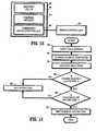
- FIG. 16shows a method for identifying the loading unit 169 and providing status information concerning the loading unit 169 to the instrument 10.
- step 650it is determined whether the loading unit 169 is properly loaded into the instrument 10. This may be determined by detecting whether contact has been made with the identifier 173 and/or protrusions 175. If the loading unit 169 is properly loaded, in step 652, the loading unit 169 communicates to the instrument 10 a ready status (e.g., turning on the first light of the visual outputs 123).
- the instrument 10verifies whether the loading unit 169 has been previously fired. This may be accomplished by providing one or more fired sensors 900 disposed in the cartridge assembly 164 ( FIG. 9 ) which determine whether any of the staples 66 have been fired.
- the fired sensor 900may be a switch or a fuse which is triggered when the sled 74 is advanced in the distal direction which is indicative of the end effector 160 being used.
- the fired sensor 900may be coupled to the identifier 442 which then stores a value indicative of the previously fired status.
- a second fired sensor 900may be placed distal of the last row of staples 66 such that when the sensor 900 is triggered, it is indicated that firing of the cartridge assembly 164 is complete.
- the instrument 10If the loading unit 169 was fired, in step 656, the instrument 10 provides an error response (e.g., flashing the first light of the visual outputs 123). If the loading unit 169 has not been fired, in step 658 the loading unit 169 provides identification and status information (e.g., first light is turned on) to the instrument 10 via the identification system 440. The determination whether the loading unit 169 has been fired is made based on the saved "previously fired" signal saved in the memory of the identifier 442 as discussed in more detail below with respect to step 664. In step 660, the instrument 10 adjusts its operating parameters in response to the information received from the loading unit 169.
- an error responsee.g., flashing the first light of the visual outputs 123.
- identification and status informatione.g., first light is turned on
- step 662The user performs a surgical procedure via the instrument 10 in step 662. Once the procedure is complete and the loading unit 169 has been fired, the instrument 10 transmits a "previously fired” signal to the loading unit 169. In step 664, the loading unit 169 saves the "previously fired” signal in the memory of the identifier 442 for future interrogations by the instrument 10 as discussed with respect to step 654.
- the loading unit 169includes one or more tissue sensors disposed within the end effector 160 for detecting the type of object being grasped, such recognizing non-tissue objects and the tissue type of the object.
- the sensorscan also be configured to determine amount of blood flow being passed between the jaw members of the end effector 160. More specifically, a first tissue sensor 177 is disposed at a distal portion of the anvil assembly 162 and a second tissue sensor 179 is disposed at a distal portion of the cartridge assembly 164.
- the sensors 177 and 179are coupled to the identifier 442 allowing for transmission of sensor data to the microcontroller 500 of the instrument 10.
- the sensors 177 and 179are adapted to generate a field and/or waves in one or more arrays or frequencies therebetween.
- the sensors 177 and 179may be acoustic, ultrasonic, ferromagnetic, Hall Effect sensors, laser, infrared, radio frequency, or piezoelectric devices.
- the sensors 177 and 179are calibrated for ignoring commonly occurring material, such as air, bodily fluids and various types of human tissue and for categorizing specific tissue types (e.g., scar tissue, lung, stomach, sphincter) or detecting certain types of foreign matter.
- the foreign mattermay be bone, tendons, cartilage, nerves, major arteries and non-tissue matter, such as ceramic, metal, plastic, etc.
- the sensors 177 and 179detect the foreign material passing between the anvil and cartridge assemblies 162 and 164 based on the absorption, reflection and/or filtering of the field signals generated by the sensors. If the material reduces or reflects a signal, such that the material is outside the calibration range and is, therefore, foreign, the sensors 177 and 179 transmit the interference information to the microcontroller 500 which then determines the type of the material being grasped by the end effector 160. The determination may be made by comparing the interference signals with a look up table listing various types of materials and their associated interference ranges. The microcontroller 500 then alerts the user of the foreign material being grasped as well as the identity thereof. This allows the user to prevent clamping, cutting or stapling through areas containing foreign matter or the control system 501 can alter the performance of the drive motor 200 for specific tissue scenarios.
- FIG. 20illustrates a control system 501 including the microcontroller 500 which is coupled to the position and speed calculators 416 and 422, the loading unit identification system 440, the user interface 120, the drive motor 200, and a data storage module 502.
- the microcontroller 500may be directly coupled to various sensors (e.g., first and second tissue sensors 177 and 179, the load switch 230, shaft start position sensor 231, clamp position sensor 232, articulation sensor 235, linear displacement sensor 237, rotational sensor 239, firing rod rotation sensor 241, motor and battery operating module 412, rotation speed detecting apparatus 418, switches 421, voltage sensor 428, current sensor 430, the interrogator 444, etc.).
- sensorse.g., first and second tissue sensors 177 and 179, the load switch 230, shaft start position sensor 231, clamp position sensor 232, articulation sensor 235, linear displacement sensor 237, rotational sensor 239, firing rod rotation sensor 241, motor and battery operating module 412, rotation speed detecting apparatus 418, switches 421, voltage
- the microcontroller 500includes internal memory which stores one or more software applications (e.g., firmware) for controlling the operation and functionality of the instrument 10.
- the microcontroller 500processes input data from the user interface 120 and adjusts the operation of the instrument 10 in response to the inputs.
- the adjustments to the instrument 10may including powering the instrument 10 on or off, speed control by means of voltage regulation or voltage pulse width modulation, torque limitation by reducing duty cycle or pulsing the voltage on and off to limit average current delivery during a predetermined period of time.
- the microcontroller 500is coupled to the user interface 120 via a user feedback module 504 which is configured to inform the user of operational parameters of the instrument 10.
- the user feedback module 504instructs the user interface 120 to output operational data on the screen 122.
- the outputs from the sensorsare transmitted to the microcontroller 500 which then sends feedback to the user instructing the user to select a specific mode, speed or function for the instrument 10 in response thereto.
- the loading unit identification system 440instructs the microcontroller 500 which end effector is on the loading unit.
- the control system 501is capable of storing information relating to the force applied to firing rod 220 and/or end effector 160, such that when the loading unit 169 is identified the microcontroller 500 automatically selects the operating parameters for the instrument 10. This allows for control of the force being applied to the firing rod 220 so that firing rod 220 can drive the particular end effector 160 that is on the loading unit in use at the time.
- the microcontroller 500also analyzes the calculations from the position and speed calculators 416 and 422 and other sensors to determine the actual position and/or speed of the firing rod 220 and operating status of components of the instrument 10. The analysis may include interpretation of the sensed feedback signal from the calculators 416 and 422 to control the movement of the firing rod 220 and other components of the instrument 10 in response to the sensed signal.
- the microcontroller 500is configured to limit the travel of the firing rod 220 once the firing rod 220 has moved beyond a predetermined point as reported by the position calculator 416. Additional parameters which may be used by the microcontroller 500 to control the instrument 10 include motor and/or battery temperature, number of cycles remaining and used, remaining battery life, tissue thickness, current status of the end effector, transmission and reception, external device connection status, etc.
- the instrument 10includes various sensors configured to measure current (e.g., ammeter), voltage (e.g., voltmeter), proximity (e.g., optical sensors), temperature (e.g., thermocouples, thermistors, etc.), and force (e.g., strain gauges, load cells, etc.) to determine for loading conditions on the loading unit 169.
- currente.g., ammeter
- voltagee.g., voltmeter
- proximitye.g., optical sensors
- temperaturee.g., thermocouples, thermistors, etc.
- forcee.g., strain gauges, load cells, etc.
- Monitoring of load conditionsmay be performed by one or more of the following methods: monitoring speed of the drive motor 200, monitoring torque being applied by the motor, proximity of jaw members 162 and 164, monitoring temperature of components of the instrument 10, measuring the load on the firing rod 220 via a strain sensor 185 ( FIG. 4 ) and/or other load bearing components of the instrument 10. Speed and torque monitoring is discussed above with respect to FIG. 6 and the speed calculator 422.
- Measuring the distance between the jaw members 162 and 164can also be indicative of load conditions on the end effector 160 and/or the instrument 10.
- the jaw members 162 and 164When large amounts of force are imparted on the jaw members 162 and 164, the jaw members are deflected outwards.
- the jaw members 162 and 164are parallel to each other during normal operation, however, during deformation, the jaw members are at an angle relative to each other. Thus, measuring the angle between the jaw members 162 and 164 allows for a determination of the deformation of the jaw members due to the load being exerted thereon.
- the jaw membersmay include strain gauges 187 and 189 as shown in FIG. 17 to directly measure the load being exerted thereon.
- one or more proximity sensors 191 and 193can be disposed at the distal tips of the jaw members 162 and 164 to measure the angle therebetween. These measurements are then transmitted to the microcontroller 500 which analyzes the angle and/or strain measurements and alerts the user of the stress on the end effector 160.
- the firing rod 220 or other load-bearing componentsinclude one or more strain gauges and/or load sensors disposed thereon. Under high strain conditions, the pressure exerted on the instrument 10 and/or the end effector 160 is translated to the firing rod 220 causing the firing rod 220 to deflect, leading to increased strain thereon. The strain gauges then report the stress measurements to the microcontroller 500. In another embodiment, a position, strain or force sensor may be disposed on the clutch plate 302.
- the sensors disposed in the instrument 10 and/or the end effector 160indicate to the microprocessor 500 that the end effector 160 is deployed about abnormal tissue (e.g., low or high load conditions).
- abnormal tissuee.g., low or high load conditions.
- Low load conditionsare indicative of a small amount of tissue being grasped by the end effector 160 and high load conditions denote that too much tissue and/or a foreign object (e.g., tube, staple line, clips, etc.) is being grasped.
- the microprocessor 500thereafter indicates to the user via the user interface 120 that a more appropriate loading unit 169 and/or instrument 10 should be chosen.
- the sensorscan alert the user of a variety of errors. Sensors may communicate to the microcontroller 500 that a staple cartridge or a portion of the instrument 10 is faulty. In addition, the sensors can detect sudden spikes in the force exerted on the knife, which is indicative of encountering a foreign body. Monitoring of force spikes could also be used to detect the end of the firing stroke, such as when the firing rod 220 encounters the end of the stapling cartridge and runs into a hard stop. This hard stop creates a force spike which is relatively larger than those observed during normal operation of the instrument 10 and could be used to indicate to the microcontroller that the firing rod 220 has reached the end of loading unit 169.
- Measuring of the force spikescan be combined with positional feedback measurements (e.g., from an encoder, linear variable displacement transducer, linear potentiometer, etc.) as discussed with respect to position and speed calculators 416 and 422. This allows for use of various types of staple cartridges (e.g., multiple lengths) with the instrument 10 without modifying the end effector 160.
- positional feedback measurementse.g., from an encoder, linear variable displacement transducer, linear potentiometer, etc.
- the instrument 10When force spikes are encountered, the instrument 10 notifies the user of the condition and takes preventative measures by entering a so-called “pulse”, or pulse width modulation (PWM) or an electronic clutching mode, which is discussed in more detail below.
- PWMpulse width modulation
- the drive motor 200is controlled to run only in short bursts to allow for the pressure between the grasped tissue and the end effector 160 to equalize.
- the electronic clutchinglimits the torque exerted by the drive motor 200 and prevents situations where high amounts of current are drawn from the power source 400. This, in turn, prevents damage to electronic and mechanical components due to overheating which accompanies overloading and high current draw situations.
- the microcontroller 500controls the drive motor 200 through a motor driver via a pulse width modulated control signal.
- the motor driveris configured to adjust the speed of the drive motor 200 either in clockwise or counter-clockwise direction.
- the motor driveris also configured to switch between a plurality of operational modes which include an electronic motor braking mode, a constant speed mode, an electronic clutching mode, and a controlled current activation mode. In electronic braking mode, two terminal of the drive motor 200 are shorted and the generated back EMF counteracts the rotation of the drive motor 200 allowing for faster stopping and greater positional precision in adjusting the linear position of the firing rod 220.
- the speed calculator 422in conjunction with the microcontroller 500 and/or the motor driver adjust the rotational speed of the drive motor 200 to ensure constant linear speed of the firing rod 220.
- the electronic clutching modeinvolves repeat engagement and/or disengagement of the clutch 300 from the drive motor 200 in response to sensed feedback signals from the position and speed calculators 416 and 422.
- controlled current activation modethe current is either ramped up or down to prevent damaging current and torque spiked when transitioning between static to dynamic mode to provide for so-called "soft start” and "soft stop.”
- the data storage module 502records the data from the sensors coupled to the microcontroller 500. In addition, the data storage module 502 records the identifying code of the loading unit 169, the status of the end effector 100, number of stapling cycles during the procedure, etc.
- the data storage module 502is also configured to connect to an external device such as a personal computer, a PDA, a smartphone, a storage device (e.g., Secure Digital® card, Compact Flash® card, MemoryStick®, etc. through a wireless or wired data port 503. This allows the data storage module 502 to transmit performance data to the external device for subsequent analysis and/or storage.
- the data port 503also allows for so-called "in the field" upgrades of firmware of the microcontroller 500.
- a feedback control system 601is shown in FIGS. 21-23 .
- the systemincludes a feedback controller 603 which is shown in FIGS. 22A-B .
- the instrument 10is connected to the feedback controller 603 via the data port 502 which may be either wired (e.g., Firewire®, USB®, Serial RS232®, Serial RS485®, USART®, Ethernet®, etc.) or wireless (e.g., Bluetooth®, ANT3®, KNX®, ZWave®, X10® Wireless USB®, IrDA®, Nanonet®, Tiny OS®, ZigBee®, 802.11 IEEE, and other radio, infrared, UHF, VHF communications and the like).
- wirede.g., Firewire®, USB®, Serial RS232®, Serial RS485®, USART®, Ethernet®, etc.
- wirelesse.g., Bluetooth®, ANT3®, KNX®, ZWave®, X10® Wireless USB
- the feedback controller 603is configured to store the data transmitted thereto by the instrument 10 as well as process and analyze the data.
- the feedback controller 603is also connected to other devices, such as a video display 604, a video processor 605 and a computing device 606 (e.g., a personal computer, a PDA, a smartphone, a storage device, etc.).
- the video processor 605is used for processing output data generated by the feedback controller 603 for output on the video display 604.
- the computing device 606is used for additional processing of the feedback data.
- the results of the sensor feedback analysis performed by the microcontroller 600may be stored internally for later retrieval by the computing device 606.
- the feedback controller 603includes a data port 607 ( FIG. 22B ) coupled to the microcontroller 600 which allows the feedback controller 603 to be connected to the computing device 606.
- the data port 607may provide for wired and/or wireless communication with the computing device 606 providing for an interface between the computing device 606 and the feedback controller 603 for retrieval of stored feedback data, configuration of operating parameters of the feedback controller 603 and upgrade of firmware and/or other software of the feedback controller 603.
- the feedback controller 603is further illustrated in FIGS. 22A-B .
- the feedback controller 603includes a housing 610 and a plurality of input and output ports, such as a video input 614, a video output 616, a heads-up ("HUD") display output 618.
- the feedback controller 603also includes a screen 620 for displaying status information concerning the feedback controller 603.
- the feedback controller 603includes a microcontroller 600 and a data storage module 602.
- the microcontroller 600 and the data storage module 602provide a similar functionality as the microcontroller 500 and the data storage module 502 of the instrument 10. Providing these components in a stand-alone module, in the form of the feedback controller 603, alleviates the need to have these components within the instrument 10.
- the data storage module 602may include one or more internal and/or external storage devices, such as magnetic hard drives, flash memory (e.g., Secure Digital® card, Compact Flash® card, MemoryStick®, etc.)
- the data storage module 602is used by the feedback controller 603 to store feedback data from the instrument 10 for later analysis of the data by the computing device 606.
- the feedback dataincludes information supplied by the sensors disposed within the instrument 10 and the like.
- the microcontroller 600is configured to supplant and/or supplement the control circuitry, if present, of the instrument 10.
- the microcontroller 600includes internal memory which stores one or more software application (e.g., firmware) for controlling the operation and functionality of the instrument 10.
- the microcontroller 600processes input data from the user interface 120 and adjusts the operation of the instrument 10 in response to the inputs.
- the microcontroller 600is coupled to the user interface 120 via a user feedback module 504 which is configured to inform the user of operational parameters of the instrument 10. More specifically, the instrument 10 is configured to connect to the feedback controller 603 wirelessly or through a wired connection via a data port 407 ( FIG. 6 ).
- the microcontroller 600is connected to the drive motor 200 and is configured and arranged to monitor the battery impedance, voltage, temperature and/or current draw and to control the operation of the instrument 10.
- the load or loads on battery 400, transmission, drive motor 200 and drive components of the instrument 10are determined to control a motor speed if the load or loads indicate a damaging limitation is reached or approached. For example, the energy remaining in battery 400, the number of firings remaining, whether battery 400 must be replaced or charged, and/or approaching the potential loading limits of the instrument 10 may be determined.
- the microcontroller 600may also be connected to one or more of the sensors of the instrument 10 discussed above.
- the microcontroller 600is also configured to control the operation of drive motor 200 in response to the monitored information.
- Pulse modulation control schemeswhich may include an electronic clutch, may be used in controlling the instrument 10.
- the microcontroller 600can regulate the voltage supply of the drive motor 200 or supply a pulse modulated signal thereto to adjust the power and/or torque output to prevent system damage or optimize energy usage.
- an electric braking circuitmay be used for controlling drive motor 200, which uses the existing back electromotive force of rotating drive motor 200 to counteract and substantially reduce the momentum of drive tube 210.
- the electric braking circuitimproves the control of drive motor 200 and/or drive tube 210 for stopping accuracy and/or shift location of powered surgical instrument 10.
- Sensors for monitoring components of powered surgical instrument 10 and to help prevent overloading of powered surgical instrument 10may include thermal-type sensors, such as thermal sensors, thermistors, thermopiles, thermo-couples and/or thermal infrared imaging and provide feedback to the microcontroller 600.
- the microcontroller 600may control the components of powered surgical instrument 10 in the event that limits are reached or approached and such control can include cutting off the power from the power source 400, temporarily interrupting the power or going into a pause mode and/or pulse modulation to limit the energy used.
- the microcontroller 600can also monitor the temperature of components to determine when operation can be resumed. The above uses of the microcontroller 600 may be used independently of or factored with current, voltage, temperature and/or impedance measurements.
- the result of the analysis and processing of the data by the microcontroller 600is output on video display 604 and/or the HUD display 622.
- the video display 604may be any type of display such as an LCD screen, a plasma screen, electroluminescent screen and the like.
- the video display 604may include a touch screen and may incorporate resistive, surface wave, capacitive, infrared, strain gauge, optical, dispersive signal or acoustic pulse recognition touch screen technologies.
- the touch screenmay be used to allow the user to provide input while viewing operational feedback.
- the HUD display 622may be projected onto any surface visible to the user during surgical procedures, such as lenses of a pair of glasses and/or goggles, a face shield, and the like. This allows the user to visualize vital feedback information from the feedback controller 603 without losing focus on the procedure.
- the feedback controller 603includes an on-screen display module 624 and a HUD module 626.
- the modules 626process the output of the microcontroller 600 for display on the respective displays 604 and 622. More specifically, the OSD module 624 overlays text and/or graphical information from the feedback controller 603 over other video images received from the surgical site via cameras disposed therein.
- the modified video signal having overlaid textis transmitted to the video display 604 allowing the user to visualize useful feedback information from the instrument 10 and/or feedback controller 603 while still observing the surgical site.
- FIGS. 24-25illustrate another embodiment of the instrument 10'.
- the instrument 10'includes a power source 400' having a plurality of cells 401 arranged in a straight series configuration.
- the power source 400'is inserted vertically into a vertical battery chamber 800 within the handle portion 112.
- the battery chamber 800includes spring contacts 802 within the top portion thereof to push downward the power source 400'.
- the spring contacts 802may include contacts to electrically couple with the power source 400'.
- the power source 400'is held within the battery chamber 800 via a battery cap 804 which is configured to slide in a distal direction to lock in place.
- the cap 804 and the handle 112may include tongue and groove couplings to keep the cap 804 from sliding out.
- the power source 400'is biased against the cap 804 due to the downward force of the spring contacts 802. As the cap 804 is slid in a proximal direction, the power source 400' is ejected from the battery chamber 800 by the spring contacts 802.
- FIG. 25shows another embodiment of the rotational sensor 239 which detects the rotation of the drive tube 210, thus, measuring the rate of rotation of the drive tube 210 which allows for determination of the linear velocity of the firing rod 220.
- the rotational sensor 239includes an encoder wheel 810 mounted to drive tube 210 and an optical reader 812 (e.g., photo interrupter).
- the optical reader 812is configured to determine the number of interruptions in a light beam which is continuously provided between two opposing edges 814 and 816 thereof.
- the wheel 810rotates with the drive tube 210 and includes a plurality of slits 811 therethrough.
- the outer edge of the wheel 810is disposed between the opposing edges of the optical reader 812 such that the light being transmitted between the edges 814 and 816 shines through the slits 811.
- the light beam between the edges 814 and 816is interrupted by the wheel 810 as the drive tube 210 is rotated.
- the optical reader 812measures the number of interruptions in the light beam and rate of occurrences thereof and transmits these measurements to the speed calculator 422 which then determines the speed of the drive rod 220 as discussed above.
- FIGS. 27-32show the instrument 10' having a retraction assembly 820 for retracting the firing rod 220 from a fired position.
- the retraction assembly 820provides for a manually driven mechanical interface with the drive tube 210 allowing for manual retraction of the firing rod 220 via ratcheting action of the retraction assembly 820. This may be useful in certain situations, to give the user of the instrument manual control over the position of the firing rod 220 (e.g., electrical malfunction, stuck end effector 160, etc.).
- the retraction assembly 820may be configured as a modular assembly which can be inserted into the instrument 10'.
- the retraction assembly 820includes a retraction chassis 822 having a top portion 823 and a bottom portion 825.
- the retraction assembly 820interfaces mechanically with the drive tube 210 via a drive gear 826 and a retraction gear 824.
- First spur gear 830is rigidly attached to the retraction gear 824.
- the drive gear 826is attached to the drive tube 210 and is translated in response to the rotation of the drive tube 210. Conversely, rotation of the drive gear 826 imparts rotation on the drive tube 210.
- the drive gear 826 and the retraction gear 824may be bevel gears allowing the gears 824 and 826 to interface in an orthogonal manner.
- the retraction gear 824is coupled to a first spindle 828 which is disposed in a substantially orthogonal manner between the top and bottom portions 823 and 825 of the retraction chassis 822.
- the first spindle 828is rotatable around a longitudinal axis defined thereby.
- the first spindle 828further includes first spur gear 830 attached thereto and to the retraction gear 824.
- the first spur gear 830interfaces with a second spur gear 832 disposed on a second spindle 834 which is also is disposed in a substantially perpendicular manner between the top and bottom portions 823 and 825 of the retraction chassis 822 and is rotatable around a longitudinal axis defined thereby.
- the second spur gear 832interfaces mechanically with a third spur gear 836 which is disposed on the first spindle 828.
- the third spur gear 836is attached to a first clutch portion 838 of a unidirectional clutch assembly 840.
- the clutch assembly 840further includes a second clutch portion 840 rotatably disposed on the first spindle 828 above the first clutch portion 838 with a spring 843 disposed between the first and second clutch portions 838 and 842 thereby biasing the first and second clutch portions 838 and 842 toward a raised non-interlocking configuration (e.g., first configuration) as shown in FIG. 31 .
- Rotation of the drive tube 210 and/or the drive gear 826imparts rotation on the retraction gear 824 and the first, second and third spur gears 830, 832 and 836 along with the first portion 838 and the respective spindles 828 and 834. Since, the second clutch portion 842 can rotate about the spindle 828 and is separated from the first clutch portion 838 by the spring 843; the rotation of the first portion 838 is not translated thereto.
- the first and second clutch portions 838 and 842include a plurality of interlocking teeth 844 having a flat interlocking surface 846 and a sloping slip surface 848.
- the retraction assembly 820is actuated by a retraction lever 845.
- the second clutch portion 842is pushed downwards by the retraction lever 845 thereby interfacing the teeth 844.
- the slip surfaces 848allow for the interlocking surfaces 846 to come in contact with each other thereby allowing rotation of the second clutch portion 842 to rotate the first clutch portion 838 and all of the interfacing gears.
- the retraction lever 845includes a camming portion 847 and a handle 849 attached thereto.
- the camming portion 847includes an opening 853 which houses a unidirectional needle clutch 855 which is in mechanical cooperation with a fitting 856 which is operatively coupled to the first spindle 828 thereby allowing the retraction lever 845 to rotate about the first spindle 828.
- the lever 845includes a one or more camming members 850 each having a camming surface 852.
- the lever 845is disposed along a lever pocket 860 of the housing 110 as shown in FIG. 27 .
- the lever 845is pushed up by the spring 843 against the top portion 823 and the camming members 850 are disposed within corresponding cam pockets 858.
- the lever 845is also maintained in the first configuration by a return extension spring 862 mounted between the top portion 823 and the camming portion 847.
- the camming members 850 and the lever pocket 860limit the rotational range of the lever 845.
- the camming members 850interface with the corresponding cam pockets 823 and push the camming portion 847 of the lever 845 in a downward direction.
- the downward movementcompresses the spring 843 and pushes the first and second clutch portions 838 and 842 together interlocking the teeth 844 thereby engaging the portions 838 and 842 in a second configuration.
- Rotation of the camming portion 847 in a counterclockwise directionactuates the needle clutch 855 which interfaces with the fitting 856 and is axially coupled to the first spindle 828.
- the lever 845can be rotated until the handle 849 abuts the housing 110 as shown in FIG. 28 . Thereafter, the lever 845 is brought back to its first configuration by the return extension spring 862 which rides in the radial groove 854. This raises the camming portion 847 allowing the second clutch portion 842 to also move upward and disengage the first clutch portion 838.
- the needle clutch 855releases the fitting 856 allowing the lever 845 to return to the first configuration without affecting the movement of the drive tube 210.
- the lever 845may be retracted once again to continue to ratchet the driving rod 220.
- the assemblycan be configured for one or more movements of the lever 845 to partially or fully retract the firing rod 220.
- a sealed battery pack compartment, and/or a sealed instrument housing and/or a sealed handle assemblycan be configured as part of a surgical apparatus according to the present disclosure to prevent contamination of batteries of battery-powered surgical apparatuses.
- the perimeter at which sealing of the battery pack occurscan be extended, in one embodiment, from the battery pack to the handle assembly and in yet another embodiment to the instrument housing.
- surgical instrument 10"is illustrated.
- Surgical instrument 10"is substantially identical to surgical instrument 10' except that surgical instrument 10" includes at least one battery-retaining structure such as battery chamber or compartment 800' that differs from battery chamber or compartment 800.
- surgical instrument 10'also includes a power head
- surgical instrument 10"includes a power head 900' that is configured to include the battery chamber or compartment 800'.
- the power head 900'is the portion of the surgical instrument 10" extending from proximal portion 118 of the housing 110 to a distal portion 118' of the housing portion 110.
- Power head 900'includes, as defined below with respect to FIG. 38 and FIGS.
- the battery chamber 800'includes an upper end 800'a and a lower end 800'b.
- at least one battery 451' or a plurality of the cells or batteries 451' forming a battery pack 451may be oriented either in a side-by-side configuration 451a as illustrated in FIG. 35 or in an end-to-end configuration 451 b as illustrated in FIG. 36 .
- a batterymay include, in addition to battery cells 451', a capacitor or an induction coil each storing electrical charge or a fuel cell or other suitable power supply mechanism.
- the battery cells 451' in configurations 451 a and 451 bprovide a cell alignment/shape/configuration that facilitates ejection of the cell or battery pack 451' from the battery chamber 800' so as to avoid medical contamination of the individual battery cells 451' or of the battery pack 451 either during or after the ejection process.
- the battery packs in the side-by-side configuration 451ainclude terminal connector strips 902 that alternately extend between and connect positive and negative polarized terminals of the battery cells 451'.
- the battery pack 451includes an upper end 452a' and a lower end 452a".
- the battery packs in the end-to-end configuration 451 binclude terminal connector strips 902 that are disposed only at the longitudinal ends of the battery cells 451'.
- the battery pack 451includes an upper end 452b' and a lower end 452b".
- Alignment posts and/or keys 920may be disposed on the perimeter or exterior of the battery pack 451 to ensure correct orientation during mating/loading into the battery chamber 800'. Correct orientation also ensures proper battery terminal polarity within the battery chamber 800' or housing of the device.
- Electrical contacts 906may be disposed at the upper end 800'a of the battery chamber 800' to mate with the corresponding polarized terminals on the particular battery pack 451 and are in electrical communication with power circuitry (not shown).
- the contacts 906may serve at least two functions.
- the contacts 906may be spring loaded positive and negative electrical connections 802.
- the upper ends 452a', 452b' of either battery pack configuration 451 a or 451 b, respectivelyare inserted through the chamber port 910 so that the alignment keys 920 can align properly within the chamber 800' via receptacles (not shown) until contact is made with the contacts 906 that are spring loaded and that are located at the upper end 800'a of the chamber 800'.
- the battery chamber 800'includes ribbing 904 in the instrument housing 110 to captivate, isolate and easily eject the battery pack 451. The ribbing 904 assists in containing and aligning the battery pack 451 and defines a battery ejection path within the battery chamber 800' that forms at least one battery-retaining structure of the power head 900'.
- the contacts 906When compressed by contact with the battery pack 451, the contacts 906 create a compression force that tends to eject the battery pack 451 in a direction, as shown by arrow A, towards the lower end 800'b of the battery chamber 800' back through the chamber port 910, thus further defining the battery-ejection path through the chamber port 910.
- a battery chamber access door 912is configured to sealingly interface with chamber port 910 at the lower end 800'b of the chamber 800'.
- the access door 912is rotatably mounted on the handle portion 112 via an offset hinge or pivot connection 914 that is disposed to enable the access door 912 to rotatably swing downwardly or upwardly, as shown by arrow B, either away from the chamber port 910 or towards the chamber port 910, respectively, to either expose or seal the chamber port 910, respectively.
- the hinge or pivot connection 914may include a spring (not shown) to leverage an additional closure force, as explained below.
- the access door 912includes a free end 912a that rotatably swings downwardly and upwardly as shown by arrow B and a fixed end 912b that is mounted at the offset hinge or pivot connection 914.
- the free end 912ais configured as a receiving end 916 to engage with, and receive, a barb on a latch, as discussed below.
- the hinge or pivot connection 914is mounted on a distal side 112b of the handle portion 112, as illustrated in FIG. 34 .
- a latch 930having an upper arm 930a with an end 930a' and a lower arm 930b with a lower end 930b', is movably mounted within the handle portion 112 in the vicinity of a proximal side 112a via a pivot connection 932 that is disposed to enable the latch 930 to rotatably swing around the pivot connection 932 such that the ends 930a and 930b of the latch 930 rock alternately to and from the proximal side 112a.
- the lower arm 930b of the latch 930is configured as an engaging end or barb 934 that engages with or meshes with the receiving end 916 of the access door 912, thereby engaging the end or barb 934 of the latch 930.
- an energy storage mechanism 936e.g., a compression spring, may also be disposed in the interior of the handle portion 112 on the proximal side 112a so as to limit motion of the upper arm 930a of the latch 930 in the proximal direction towards proximal side 112a and to bias motion of the upper arm 930a towards the distal side 112b.
- a battery chamber access actuation mechanism 940e.g., an elongated push button as shown, may be disposed in a recessed aperture 942 on the proximal side 112a of the handle portion 112.
- the battery chamber access mechanism 940is configured to be actuated by a user of the surgical instrument 10".
- the recessed aperture 942penetrates through the proximal side 112a and enables contact between the access actuation mechanism 940 and the lower arm 930b of the latch 930.
- the battery chamber access actuation mechanism 940urges the lower arm 930b in the distal direction, thereby forcing the latch 930 to rotatably swing around the pivot connection 932, against the compression force of the spring 936, and causing disengagement of the engaging end or barb 934 of the latch 930 from the receiving end 916 of the access door 912.
- the disengagement of the engaging end or barb 934 of the latch 930 from the receiving end 916 of the access door 912enables the access door 912 to rotatably swing or rotate downwardly in the direction of arrow B by pivoting around the hinge or pivot connection 914, thereby transferring the access door 912 from a closed position, as shown, to an open position (not shown) and at least partially exposing the chamber port 910.
- Disposal of the battery chamber access actuation mechanism 940 in the recessed aperture 942reduces the probability of inadvertent actuation of the battery pack 451 during a surgical procedure.
- An interlock feature(not shown), e.g., a mechanical feature such as a cap, may be provided to lock the battery chamber access actuation mechanism 940 during the surgical procedure. If the battery pack 451 does not perform adequately during the surgical procedure, the power head 900' may be removed from the operating area to perform the ejection of the battery pack 451.
- the rotating or swinging of the access door 912is further enabled by the compression force, created by the contacts 906, that, as described above, tend to eject the battery pack 451 in a direction, as shown by arrow A, towards the lower end 800'b of the battery chamber back through the chamber port 910.
- the combination of the rotating or swinging of the access door 912, together with the compression force, and the assistance of gravity,enables the battery pack 451 to overcome constraining frictional forces and to be ejected in a direction that may include the direction of gravity into a sterile environment or container for charging, non-hazardous waste disposal, or recycling.
- surgical apparatus 10"is configured to enable ejection of the at least one battery cell 451' of the battery pack 451 by one hand of a user without medical contamination thereof.
- the access actuation mechanism 940thus provides access to the battery chamber 800' by opening the access door 912.
- the access door 912serves as a hinged housing cover for the power head 900'. More particularly, since the battery chamber 800' forms at least one battery-retaining structure of the power head 900', the battery-retaining structure further includes the hinged cover or access door 912.
- the hinged cover or access door 912When the hinged cover or access door 912 is in a closed position, the hinged cover or access door 912 prevents access to the at least one battery 451' and when the hinged cover or access door 912 is in an open position, the hinged cover or access door 912 enables ejection of the at least one battery 451' from the at least one battery-retaining structure along the battery ejection path.
- an electrical componentincludes an electronic component.
- structure that breaks or interrupts the electrical connection or electrical communication from the battery pack 451may further include a breakable foil or wire bridge. It is also contemplated that a slow discharge resistor or circuit may be incorporated into the power head 900' to slowly drain the battery at a safe, low temperature rate to further assist in handling and disposability.
- the buttoncan be a switch to activate one or more solenoids that translate output shafts to unlatch the battery door and/or release a spring force to eject the battery.
- the energy storage mechanism 936e.g., the compression spring
- the compression springmay also be disposed in the interior of the handle portion 112 on the proximal side 112a so as to limit motion of the upper arm 930a of the latch 930 in the proximal direction towards proximal side 112a and to bias motion of the upper arm 930a towards the distal side 112b, may be replaced by a solenoid (not shown) that is activated by the battery chamber access actuation mechanism 940.
- All or part of the spring ejection forces for the battery pack 451can be restrained or isolated from the pack with a pin or latch so that the battery pack 451 does not normally experience the compression force from the spring 802 during routine operation.
- the resulting potential energy from the spring 802can then be released by a separate mechanism (not shown) activated when the battery ejection button is depressed.
- the power head 900' of the surgical apparatus or instrument 10"further includes at least one sealing member 950 that extends around the one or more battery-retaining structures, e.g., battery chamber 800', such that the sealing member 950 is configured to enable ejection of at least one battery cell 451' of the battery pack 451, or of the entire battery pack 451, from the one or more battery-retaining structures, e.g., the battery chamber 800', along the battery-ejection path as described above without medical contamination of the battery cell(s) 451' or the battery pack 451.
- the sealing member 950that extends around the one or more battery-retaining structures, e.g., battery chamber 800', such that the sealing member 950 is configured to enable ejection of at least one battery cell 451' of the battery pack 451, or of the entire battery pack 451, from the one or more battery-retaining structures, e.g., the battery chamber 800', along the battery-ejection path as described above without medical contamination of the battery cell(s) 451' or the battery pack 451.
- the sealing member 950may incorporate an O-ring or gasket 960 that forms a perimeter on the sealing member 950, that may extend from a position 960a on the proximal side 112a of handle 112 to a position 960b on the distal side 112b of handle 112, to enable the access door 912 to open during ejection of the battery cell(s) 451' or the battery pack 451.
- the power head 900' of the surgical apparatus or instrument 10"includes a handle assembly, e.g., handle portion 112, wherein the handle assembly or handle portion 112 includes the one or more battery-retaining structures, e.g., battery chamber 800', and wherein at least one sealing member 952 extends around the handle assembly or handle portion 112 or the one or more battery-retaining structures such as battery chamber 800' such that the one or more sealing members 952 are configured to enable ejection of at least one battery cell 451', or the entire battery pack 451, from the one or more battery-retaining structures, e.g., battery chamber 800', along the battery-ejection path as described above without medical contamination of the battery cell(s) 451' or the battery pack 451.
- a handle assemblye.g., handle portion 112
- the handle assembly or handle portion 112includes the one or more battery-retaining structures, e.g., battery chamber 800'
- at least one sealing member 952extends around the handle assembly or handle portion 112 or the one or more battery-
- sealing member 952may incorporate O-ring or gasket 960, that may extend from a position 960a on the proximal side 112a of handle 112 to a position 960b on the distal side 112b of handle 112, to enable the access door 912 to open during ejection of the battery cell(s) 451' or the battery pack 451.
- the power head 900' of the surgical apparatus or instrument 10"includes an instrument housing, e.g., instrument housing 110, wherein the instrument housing 110 includes the one or more battery-retaining structures, e.g., battery compartment 800', wherein sealing member 954 extends around the instrument housing 110 or the one or more battery-retaining structures such as battery chamber 800' such that the one or more sealing members 954 are configured to enable ejection of at least one battery cell 451', or the entire battery pack 451, from the one or more battery-retaining structures, e.g., battery chamber 800', without medical contamination of the battery cell(s) 451' or the battery pack 451.
- the instrument housing 110includes the one or more battery-retaining structures, e.g., battery compartment 800'
- sealing member 954extends around the instrument housing 110 or the one or more battery-retaining structures such as battery chamber 800' such that the one or more sealing members 954 are configured to enable ejection of at least one battery cell 451', or the entire battery pack 451, from the one or more battery-retaining
- sealing member 954may incorporate O-ring or gasket 960, that may extend from a position 960a on the proximal side 112a of handle 112 to a position 960b on the distal side 112b of handle 112, to enable the access door 912 to open during ejection of the battery cell(s) 451' or the battery pack 451.
- the sealing members 950, 952 and 954 of the power head 900'provide an integral or separate seal or gasket or adhesive system between the battery pack 451 and other housing components, while allowing electrical communication between the battery pack 451 and the contacts 906 that may be spring loaded positive and negative electrical connections 802.
- the present disclosurerelates also to the power head 900' having at least one battery-retaining retaining structure, e.g., battery chamber 800', that is configured to retain at least one battery cell 451'.
- the one or more battery-retaining structuresare configured to enable ejection of the battery cell(s) 451' without medical contamination thereof, e.g., by ejection along a battery ejection path defined by the ribbing 904 within the battery chamber 800'.
- the at least one battery-retaining structuree.g., battery chamber 800'
- the at least one battery-retaining structureis configured to enable ejection of the battery cell(s) 451' by one hand of a user.
- the ejection of the battery cell(s) 451'occurs without medical contamination thereof, e.g., by ejection along a battery ejection path defined by the ribbing 904 within the battery chamber 800'.
- the power head 900'includes at least one energy storage mechanism, e.g., spring 802, that is operatively coupled to the one or more battery-retaining structures, e.g., battery chamber 800', wherein actuation of the one or more energy storage mechanisms, e.g., spring 802, enables ejection of the battery cell(s) 451' without medical contamination thereof, e.g., by ejection along a battery ejection path defined by the ribbing 904 within the battery chamber 800'.
- the one energy storage mechanisme.g., spring 802
- the spring 802may be replaced by a solenoid (not shown) that is activated by battery chamber access actuation mechanism 940.
- the power head 900'includes at least one energy storage mechanism, e.g., spring 802, that is operatively coupled to the one or more battery-retaining structures, e.g., battery chamber 800', and is configured wherein actuation of the one or more energy storage mechanisms, e.g., spring 802 via actuation of the battery chamber access actuation mechanism 940, enables ejection of the battery cell(s) 451' by one hand of a user and is configured wherein the ejection of the battery cell(s) 451' by the one hand of a user enables ejection of the battery cell(s) 451' without medical contamination thereof, e.g., by ejection along a battery ejection path defined by the ribbing 904 within the battery chamber 800'.
- spring 802that is operatively coupled to the one or more battery-retaining structures, e.g., battery chamber 800', and is configured wherein actuation of the one or more energy storage mechanisms, e.g., spring 802 via
- FIGS. 4-12illustrate various internal components of the instrument 10, including a drive motor 200, a drive tube 210 and a firing rod 220 having a proximal portion 222 and a distal portion 224.
- the drive tube 210is rotatable about drive tube axis C-C extending therethrough.
- Drive motor 200is disposed in mechanical cooperation with drive tube 210 and is configured to rotate the drive tube 210 about drive gear axis C-C.
- the drive motor 200may be an electrical motor or a gear motor, which may include gearing incorporated within its housing.
- the housing 110may be formed from two halves 110a and 110b as illustrated in FIG. 3 .
- the two housing portion halves 110a and 110bmay be attached to each other using screws at boss locators 111 which align the housing portions 110a and 110b.
- ultrasonic welding directorsmay be used to attach halves 110a and 110b to seal the housing from external contamination.
- the housing 110may be formed from plastic and may include rubber support members applied to the internal surface of the housing 110 via a two-shot molding process. The rubber support members may isolate the vibration of the drive components (e.g., drive motor 200) from the rest of the instrument 10.
- the housing halves 110a and 110bmay be attached to each other via a thin section of plastic (e.g., a living hinge) that interconnects the halves 110a and 110b allowing the housing 110 to be opened by breaking away the halves 110a and 110b (see FIG. 3 ).
- a thin section of plastice.g., a living hinge
- the drive componentsmay be mounted on a support plate allowing the drive components to be removed from the housing 110 after the instrument 10 has been used.
- the support plate mounting in conjunction with the hinged housing halves 110a and 110bprovide for reusability and recyclability of specific internal components while limiting contamination to the specific internal components.
- the support platea separate, internal, structural member or chassis for the surgical instrument or device, a stronger and higher precision assembly can be produced that is easier to assemble, service, reprocess, reuse or recycle.
- such a structural member or chassiscan be much smaller and therefore more accurate dimensionally than an all inclusive handle set cover, e.g., the housing 110 with at least the first and second housing portions 110a and 110b, when produced with similar manufacturing processes.
- Additional datum planes and locating featurescan also be designed into the structural member or chassis because of its geometry that is substantially independent of the exterior surface design of the housing 110.
- the exterior surface geometry of the housing 110can hinder many aspects of strength and limit numerous aspects of "net shape" molded features.
- the structural member or chassismay be formed of higher strength/performance materials and/or additional structure as compared to the handle set cover, thereby improving the robustness and fatigue life of at least the operating components contained within the housing 110. That is, the additional precision, alignment and strength can benefit the mechanisms, bearings, gears, clutches, and/or couplings of the surgical instrument 10 or 10', particularly for instruments that are driven and/or powered by electromechanical or pneumatic subsystems that operate under higher linear and/or rotation speeds/loads. Added structure from the structural member or chassis can support extreme or repetitive fatigue loads preventing deformation which can result in misalignment and/or mechanical failures.
- Integrating fastener mounting points and/or features into sides of the structural member or chassisallows the housing portions 110a and 110b to be easily removed or replaced while maintaining all of the functional assembly alignments.
- Componentsmay be assembled from multiple planes of access thereby simplifying the overall assembling, servicing, reprocessing, reusing and recycling of the surgical instrument.
- power head 900' of surgical instrument 10"includes the first housing portion 110a and the second housing portion 110b defining the plurality of ports or boss locators 111, which as described above with respect to FIG. 3 , align the two housing halves or portions 110a and 110b to each other and are disposed within the second housing portion 110b to enable joining of the first housing portion 110a and the second housing portion 110b.
- power head 900' of surgical instrument 10"'includes a structural member or chassis 1001 for mounting a set of operating components 1000 of the power head 900' and/or surgical instrument 10".
- the housing 110being formed of the first housing portion 110a and the second housing portion 110b, enables access to an interior volume 1002 of the power head 900' of surgical instrument 10"' that is encompassed by the housing 110.
- a set of operating componentsare mounted in the interior volume 1002.
- the set of operating components 1000includes, among others, drive motor 200 (and associated gear assembly), proximal bearing 354 and distal bearing 356, drive tube 210, powered articulation switch 174, and portions of switch 114, that may include first and second switches 114a and 114b formed together as a toggle switch external to the interior volume 1002 and having an internal interface 114' that is substantially disposed within the interior volume 1002, and position and limit switches (e.g., shaft start position sensor 231 and clamp position sensor 232) that are disposed within the interior volume 1002.
- drive motor 200and associated gear assembly
- proximal bearing 354 and distal bearing 356drive tube 210
- powered articulation switch 174and portions of switch 114, that may include first and second switches 114a and 114b formed together as a toggle switch external to the interior volume 1002 and having an internal interface 114' that is substantially disposed within the interior volume 1002, and position and limit switches (e.g., shaft start position sensor 231 and clamp position sensor 232) that are disposed within
- the boss locators 111align the two housing halves 110a and 110b to join together as housing 110.
- the boss locators 111also enable the proper configuration for alignment of the set of operating components 1000.
- the set of operating components 1000may be mounted on the chassis 1001 rather than directly on the housing halve or portion 110a as applicable to power head 900' of surgical instrument 10 (see FIG. 4 ).
- the chassis 1001includes boss locator ports 111' that are configured to align with the boss locators 111 of the housing halves or portions 110a and 110b (see FIG. 38 ).
- the chassis 1001is configured with a proximal portion 1010a, a central portion 1010b, and a distal portion 1010c, wherein the proximal portion 1010a, the central portion 1010b and the distal portion 1010c are operatively connected therebetween or integrally formed therebetween to yield the chassis 1001.
- the proximal portion 1010ais configured with a first recess 1012 and a second recess 1014, both recesses being formed within the chassis 1001 to receive particular components of the set of operating components 1000.
- the second recess 1014is distal to the first recess 1012. More particularly, first recess 1012 is configured to receive and align the drive motor 200 (and associated gear assembly) while the second recess 1014 is configured to receive and align the proximal bearing 354 (see FIG. 38 ).
- the proximal portion 1010ahas a proximal portion 1011 with a partially oval-shaped cross section and is adjacent to a distal portion 1013 that has a trapezoidal-shaped cross section.
- the first recess 1012is formed in the proximal portion 1011 that has a partially oval-shaped cross section while the second recess 1014 is formed within the distal portion 1013 that has a trapezoidal-shaped cross section.
- the central portion 1010bwhich may be semi-cylindrically shaped with a corresponding rectangular-shaped cross section, is configured with a recess 1016 formed within the chassis 1001.
- the recess 1016is configured to receive and align the drive tube 210.
- the distal portion 1010chas a trapezoidal-shaped cross section with a recess 1017 formed therein that is configured to receive and align the distal bearing 356.
- the distal portion 1010chas a generally T-shaped aperture 1020 that is distal to the recess 1017.
- the aperture 1020is configured to enable receipt, retention and alignment of the position and limit switches, e.g., shaft start position sensor 231 and clamp position sensor 232.
- the distal portion 1010cfurther includes a slot 1022 formed therein and disposed between the recess 1017 and the aperture 1020.
- the slot 1022serves as a datum for alignment of the set 1000 of operating components and is configured and disposed to retain and align the alignment plate 350 which locates the firing rod 220 concentrically, as previously described with respect to FIGS. 6 and 7 .
- the alignment plate 350includes an aperture 355 therethrough, which has a non-round cross-section (see FIG. 7 ).
- the non-round cross-section of the aperture 355prevents rotation of proximal portion 222 of firing rod 220, thus limiting proximal portion 222 of firing rod 220 to axial translation therethrough.
- the alignment plate 350also functions as a bearing support and mechanical stop.
- the distal surface 351 of the alignment plate 350is also used as a mounting face and datum for the start position sensor 231 and the clamp position sensor 232.
- the distal portion 1010cfurther includes a downwardly directed protrusion or extension 1024 in which is formed a recess 1026 that is configured to receive and align the internal interface 114' of the toggle switch 114, and that is substantially disposed within the interior volume 1002.
- the chassis 1001is configured to provide the proper configuration for alignment for the set of operating components 1000 mounted on the chassis 1001 if the chassis 1001 and set of operating components 1000 are mounted within the interior volume 1002 of the housing 110. Though not explicitly illustrated in FIGS. 37-43 , the chassis 1001 is configured to provide the proper configuration for alignment for a replacement set of operating components (not explicitly shown) of the surgical instrument 10"' mounted on the chassis 1001 if the chassis 1001 and replacement set of operating components are mounted within the interior volume 1002 of the housing 110. Thus the chassis 1001 is configured to provide the proper configuration for alignment for the set of operating components 1000 and/or the replacement set of operating components including either the set of operating components 1000 or the replacement set of operating components.
- the replacement set of operating componentsis generally identical to an original set of operating components 1000 that would be first provided by the manufacturer with the power head 900" of surgical instrument 10"', the replacement set of operating components need only be identical to the original set of operating components 1000 to the extent necessary to maintain alignment, fit and suitable operability of the surgical instrument 10"' when inserted within the interior volume 1002.
- the housing 110includes at least first housing portion 110a and second housing portion 110b. At least the first housing portion 110a is removable to expose at least a portion of the interior volume 1002 of the surgical instrument 10"'.
- the first housing portion 110adefines a plurality of ports 111 and the second housing portion 110b defines a plurality of ports 1010 that are disposed to enable the proper configuration for alignment of the set of operating components 1000 and of a replacement set of operating components (not explicitly shown) if the first housing portion 110a and the second housing portion 110b are joined together.
- the chassis 1001defines a plurality of ports 111' that are disposed to enable the proper configuration for alignment of the set of operating components 1000 and of a replacement set of operating components (not explicitly shown) if or wherein the first housing portion 110a and the second housing portion 110b are joined together and if or wherein the chassis 1001 and the set of operating components 1000 or replacement set of operating components are mounted within the interior volume 1002 of the housing 110.
- clips, buckles, snaps, quick turn fasteners or other suitable connectorsmake be incorporated at appropriate locations on the first and second housing portions 110a and 110b, respectively, and/or on the chassis 1001 to provide ease of disassembly.
- the chassis 1001can be made from ferrous, conductive or magnetic metals to shield electronic components, e.g., the control switch 114 or shaft start position sensor 231 and clamp position sensor 232, from radio frequency (RF) noise and electro-magnetic interference (EMI).
- the structural member/chassis 1001can also be operatively coupled or operatively connected to such components, including the drive motor 200, as a common ground for direct current (DC) applications.
- FIGS. 40-41illustrate exploded views of the surgical instrument 10"' showing first and second housing portions 110a and 110b and, as described above with respect to FIGS. 37-39 , the set of operating components 1000 mounted on the chassis 1001.
- the electrosurgical instrument 10'includes a rotating front end interchange assembly 1050 that is operatively coupled to the power head 900" to enable the power head 10" to drive and operate the firing rod 220 (see FIG. 6 ).
- the rotating front end interchange assembly 1050includes an interface connection 1052 to enable interchanging of front end 1054 of firing rod 220.
- a Tyco Healthcare Model EGIA front end 1054is shown.
- the interchange assembly 1050is configured to receive and operate other front ends 1054, e.g., Tyco Healthcare Model EEA having a circular cross-section, Model EEA having a circular cross-section, Model TA having a right angle cross-section, or a cutter, a cautery, an RF energy, or a clamp or a grasper front end.
- FIG. 42is a view of an open side 1001 a of the chassis 1001 showing the set of operating components 1000 as mounted on the chassis 1001 with the open side 1001 a facing the viewer.
- FIG. 43is a view of a closed side 1001b of the chassis 1001 showing the set of operating components 1000 as mounted on the chassis 1001 with the closed side 1001 b facing the viewer.
- the chassis 1001is formed from metal and the housing 110 is formed from a polymer.
- the set of operating components 1000 or the replacement set of operating componentsincludes at least one electrical component, e.g., battery cell(s) 451' (see FIGS. 40-41 ), and the chassis 1001 is configured to enable electrical grounding of the electrical component.
- a power head 900' of a surgical instrumentsuch as surgical instrument 10"
- the power head 900'includes the chassis 1001 improves reusability or reprocessing of costly components by enabling easier removal/disposal of a contaminated housing or cover while enabling maintaining all or many critical component assembly alignments and positions.
- chassis 1001provides the following advantages:
Landscapes
- Health & Medical Sciences (AREA)
- Life Sciences & Earth Sciences (AREA)
- Surgery (AREA)
- Heart & Thoracic Surgery (AREA)
- Engineering & Computer Science (AREA)
- Biomedical Technology (AREA)
- Nuclear Medicine, Radiotherapy & Molecular Imaging (AREA)
- Medical Informatics (AREA)
- Molecular Biology (AREA)
- Animal Behavior & Ethology (AREA)
- General Health & Medical Sciences (AREA)
- Public Health (AREA)
- Veterinary Medicine (AREA)
- Surgical Instruments (AREA)
Abstract
Description
- This application claims priority to
U.S. Provisional Patent Application No. 61/248,971 by Zemlok et al. U.S. Provisional Patent Application No. 61/248,504 by Zemlok U.S. Patent Application 12/189,834 by Zemlok US 2009/0090763 A1 , which claims priority toU.S. Provisional Patent Application No. 60/997854 by Zemlok et al. - This application relates to a power head for a surgical apparatus, and more particularly, to a battery compartment and battery removal and to mounting of components of the power head.
- Surgical devices and/or staplers that include batteries may require a means to remove them for disposal, recycling or recharging purposes. Contact or exposure to contamination from the external surface of a used surgical device, gloves or garments will classify the battery pack as hazardous medical waste. This classification creates higher disposal costs and eliminates a hospital's ability to recycle or reuse the batteries.
- In other aspects related to production of waste, size reductions and ever increasing functional requirements of surgical devices continually drive demands for higher performance internal components. These components may require rare materials or intensive processing methods. Additionally the components are generally more complex, higher precision and require tighter tolerance constraints to produce. These higher cost parts may also lead the designs towards greater reusability. To properly combine all of these complex components and subassemblies together into a precise, robust, high quality device, a chassis or assembly platform which accurately locates, aligns and positions them together is required. This chassis must also have enough strength and structure to resist deformation and fatigue which are counterproductive to an assembly's robustness, precision alignments and tolerances.
- Most chassis assembly platforms are incorporated into the housing or handle set cover (HSC) of the device. These components are limited to certain materials, shapes and processes which in turn limits accuracy and strength.
- When a housing of a surgical instrument power head becomes contaminated, reusability or reprocessing of costly internal components often is impeded because of the difficulty of removing the internal components from the contaminated housing without also contaminating the internal components.
- To advance the state of the art with respect to reducing contaminated medical waste, the present disclosure relates to a chassis for mounting a set of operating components of a power head of a surgical instrument. The power head has a housing enabling access to an interior volume of the power head encompassed by the housing. The set of operating components have a proper configuration for alignment when mounted within the interior volume encompassed by the housing. The chassis is configured to provide the proper configuration for alignment for either the set of operating components mounted on the chassis if the chassis and set of operating components are mounted within the interior volume of the housing and a replacement set of operating components of the power head mounted on the chassis if the chassis and replacement set of operating components are mounted within the interior volume of the housing. In one embodiment, the chassis is formed from metal and the housing is formed from a polymer.
- Various embodiments of the subject instrument are described herein with reference to the drawings wherein:
FIG. 1 is a perspective view of a powered surgical instrument according to an embodiment of the present disclosure;FIG. 2 is a partial enlarged perspective view of the powered surgical instrument according to the embodiment of the present disclosure ofFIG. 1 ;FIG. 2A is a partial enlarged perspective view of a variant of the powered surgical instrument according to the embodiment of the present disclosure ofFIGS. 1 and2 ;FIG. 2B is a proximal end view of the variant of the powered surgical instrument ofFIG. 2A ;FIG. 3 is a partial enlarged plan view of the powered surgical instrument according to the embodiment of the present disclosure ofFIG. 1 ;FIG. 4 is a partial perspective sectional view of internal components of the powered surgical instrument ofFIG. 1 in accordance with an embodiment of the present disclosure;FIG. 4A is a partial perspective view of internal components of the variant of the powered surgical instrument ofFIG. 4 ;FIG. 5 is a perspective view of an articulation mechanism with parts separated of the powered surgical instrument ofFIG. 1 in accordance with an embodiment of the present disclosure;FIG. 6 is a partial cross-sectional view showing internal components of the powered surgical instrument according to the embodiment of the present disclosure ofFIG. 1 disposed in a first position;FIG. 7 is a partial cross-sectional view showing internal components of the powered surgical instrument according to the embodiment of the present disclosure ofFIG. 1 disposed in a second position;FIG. 8 is a perspective view of the mounting assembly and the proximal body portion of a loading unit with parts separated of the powered surgical instrument ofFIG. 1 in accordance with an embodiment of the present disclosure;FIG. 9 is a side cross-sectional view of an end effector of the powered surgical instrument ofFIG. 1 in accordance with an embodiment of the present disclosure;FIG. 10 is a partial enlarged side view showing internal components of the powered surgical instrument according to the embodiment of the present disclosure ofFIG. 1 ;FIG. 10A is a partial enlarged view of the internal components of the variant of the powered surgical instrument ofFIG. 4A ;FIG. 11 is a perspective view of a unidirectional clutch plate of the powered surgical instrument ofFIG. 1 in accordance with an embodiment of the present disclosure;FIG. 12 is a partial enlarged side view showing internal components of the powered surgical instrument according to the embodiment of the present disclosure ofFIG. 1 ;FIG. 13 is a schematic diagram of a power source of the powered surgical instrument according to the embodiment of the present disclosure ofFIG. 1 ;FIG. 14 is a flow chart diagram illustrating a method for authenticating the power source of the powered surgical instrument ofFIG. 1 ;FIGS. 15A-B are partial perspective rear views of a loading unit of the powered surgical instrument according to the embodiment of the present disclosure ofFIG. 1 ;FIG. 16 is a flow chart diagram illustrating a method for authenticating the loading unit of the powered surgical instrument according to the embodiment of the present disclosure ofFIG. 1 ;FIG. 17 is a perspective view of the loading unit of the powered surgical instrument according to the embodiment of the present disclosure ofFIG. 1 ;FIG. 18 is a side cross-sectional view of the end effector of the powered surgical instrument ofFIG. 1 in accordance with an embodiment of the present disclosure;FIG. 19 is a side cross-sectional view of the powered surgical instrument ofFIG. 1 in accordance with an embodiment of the present disclosure;FIG. 20 is a schematic diagram of a control system of the powered surgical instrument according to the embodiment of the present disclosure ofFIG. 1 ;FIG. 21 is a schematic diagram of a feedback control system according to the present disclosure;FIGS. 22A-B are perspective front and rear views of a feedback controller of the feedback control system according to the embodiment of the present disclosure;FIG. 23 is a schematic diagram of the feedback controller according to the embodiment of the present disclosure;FIG. 24 is a partial sectional view of internal components of a powered surgical instrument in accordance with an embodiment of the present disclosure;FIG. 25 is a partial perspective sectional view of internal components of the powered surgical instrument in accordance with an embodiment of the present disclosure;FIG. 26 is a partial perspective view of a nose assembly of the powered surgical instrument in accordance with an embodiment of the present disclosure;FIG. 27 is a partial perspective view of a retraction lever of the powered surgical instrument in accordance with an embodiment of the present disclosure;FIG. 28 is a partial perspective view of the powered surgical instrument in accordance with an embodiment of the present disclosure;FIG. 29 is a perspective view of the powered surgical instrument in accordance with an embodiment of the present disclosure;FIG. 30 is a perspective view of a modular retraction assembly of the powered surgical instrument in accordance with an embodiment of the present disclosure;FIG. 31 is an enlarged partial sectional view of internal components of a powered surgical instrument in accordance with an embodiment of the present disclosure; andFIG. 32 is an enlarged partial sectional view of internal components of a powered surgical instrument in accordance with an embodiment of the present disclosure.FIG. 33 is a perspective view of a powered surgical instrument having one or more sealing members around a power head of the instrument according to an embodiment of the present disclosure;FIG. 34 is a cross-sectional view of the power head ofFIG. 33 illustrating the internal components of the power head and the one or more sealing members;FIG. 35 is a perspective view illustrating a battery pack or power supply pack for the power head ofFIGS. 33 and34 according to one embodiment of the present disclosure;FIG. 36 is another perspective view of the battery pack or power supply pack ofFIG. 35 having a sealing member according to one embodiment of the present disclosure;FIG. 37 is a perspective view of the exterior of the housing of the power head of the surgical instrument according to the present disclosure;FIG. 38 is a cross-sectional view of the power head ofFIG. 37 illustrating a set of operating components mounted on a structural member or chassis according to one embodiment of the present disclosure;FIG. 39 is a view of one side of the structural member or chassis showing the features for mounting the operating components according to one embodiment of the present disclosure;FIG. 40 is an exploded perspective view of the power head ofFIG. 36 showing the housing portions and a set of operating components mounted on the structural member or chassis according to the present disclosure;FIG. 41 is another exploded perspective view of the power head ofFIG. 36 showing the housing portions and a set of operating components mounted on the structural member or chassis according to the present disclosure;FIG. 42 is a view of the side of the structural member or chassis as illustrated inFIG. 39 and illustrating a set of operating components mounted on the structural member or chassis; andFIG. 43 is a view of another side of the structural member or chassis and illustrating a set of operating components mounted on the structural member or chassis.- Embodiments of the presently disclosed powered surgical instrument are now described in detail with reference to the drawings, in which like reference numerals designate identical or corresponding elements in each of the several views. As used herein the term "distal" refers to that portion of the powered surgical instrument, or component thereof, farther from the user while the term "proximal" refers to that portion of the powered surgical instrument or component thereof, closer to the user.
- Additionally, in the drawings and in the description that follows, terms such as "front", "rear", "upper", "lower", "top", "bottom" and the like are used simply for convenience of description and are not intended to limit the disclosure thereto.
- A powered surgical instrument, e.g., a surgical stapler, in accordance with the present disclosure is referred to in the figures as
reference numeral 10. Referring initially toFIG. 1 , poweredsurgical instrument 10 includes ahousing 110, anendoscopic portion 140 defining a first longitudinal axis A-A extending therethrough, and anend effector 160, defining a second longitudinal axis B-B extending therethrough.Endoscopic portion 140 extends distally fromhousing 110 and theend effector 160 is disposed adjacent a distal portion ofendoscopic portion 140. In an embodiment, the components of thehousing 110 are sealed against infiltration of particulate and/or fluid contamination and help prevent damage of the component by the sterilization process. - According to an embodiment of the present disclosure,
end effector 160 includes a first jaw member having one or more surgical fasteners (e.g., cartridge assembly 164) and a second opposing jaw member including an anvil portion for deploying and forming the surgical fasteners (e.g., an anvil assembly 162). In certain embodiments, the staples are housed incartridge assembly 164 to apply linear rows of staples to body tissue either in simultaneous or sequential manner. Either one or both of theanvil assembly 162 and thecartridge assembly 164 are movable in relation to one another between an open position in which theanvil assembly 162 is spaced fromcartridge assembly 164 and an approximated or clamped position in which theanvil assembly 162 is in juxtaposed alignment withcartridge assembly 164. - It is further envisioned that
end effector 160 is attached to a mountingportion 166, which is pivotably attached to abody portion 168.Body portion 168 may be integral withendoscopic portion 140 of poweredsurgical instrument 10, or may be removably attached to theinstrument 10 to provide a replaceable, disposable loading unit (DLU) or single use loading unit (SULU) (e.g., loading unit 169). In certain embodiments, the reusable portion may be configured for sterilization and re-use in a subsequent surgical procedure. - The
loading unit 169 may be connectable toendoscopic portion 140 through a bayonet connection. It is envisioned that theloading unit 169 has an articulation link connected to mountingportion 166 of theloading unit 169 and the articulation link is connected to a linkage rod so that theend effector 160 is articulated as the linkage rod is translated in the distal-proximal direction along first longitudinal axis A-A. Other means of connectingend effector 160 toendoscopic portion 140 to allow articulation may be used, such as a flexible tube or a tube comprising a plurality of pivotable members. - The
loading unit 169 may incorporate or be configured to incorporate various end effectors, such as vessel sealing devices, linear stapling devices, circular stapling devices, cutters, etc. Such end effectors may be coupled toendoscopic portion 140 of poweredsurgical instrument 10. Theloading unit 169 may include a linear stapling end effector that does not articulate. An intermediate flexible shaft may be included betweenhandle portion 112 and loading unit. It is envisioned that the incorporation of a flexible shaft may facilitate access to and/or within certain areas of a patient's body. - With reference to
FIG. 2 , an enlarged view of thehousing 110 is illustrated according to an embodiment of the present disclosure. In the illustrated embodiment,housing 110 includes ahandle portion 112 having amain drive switch 114 disposed thereon. Theswitch 114 may include first andsecond switches handle portion 112, which defines a handle axis H-H, is configured to be grasped by fingers of a user. Thehandle portion 112 has an ergonomic shape providing ample palm grip leverage which helps prevent thehandle portion 112 from being squeezed out of the user's hand during operation. Eachswitch handle portion 112 to facilitate its depression by a user's finger or fingers. In another embodiment, theinstrument 10 includes two separates switches 114a and 114b separated by a rib feature. - Additionally, and with reference to
FIGS. 1 and2 ,switches FIG. 4 ). In one embodiment, theswitch 114a is configured to activate thedrive motor 200 in a first direction to advance firing rod 220 (FIG. 6 ) in a distal direction thereby clamping the anvil and thecartridge assemblies switch 114b may be configured to retract thefiring rod 220 to open the anvil andcartridge assemblies drive motor 200 in a reverse direction. Once the stapling and cutting mode has been initiated, during the retraction mode, a mechanical lock out (not shown) is actuated, preventing further progression of stapling and cutting by theloading unit 169. The lockout is redundantly backed up with software to prevent the cutting of tissue after the staples have been previously deployed. The toggle has a first position for activatingswitch 114a, a second position for activatingswitch 114b, and a neutral position between the first and second positions. The details of operation of the drive components of theinstrument 10 are discussed in more detail below. - The
housing 110, in particular thehandle portion 112, includes switch shields 117a and 117b. The switch shields 117a and 117b may have a rib-like shape surrounding the bottom portion of theswitch 114a and the top portion of theswitch 114b, respectively. Theswitch shield switch 114. Further, theswitches - In one embodiment, the
switches drive motor 200 and thefiring rod 220 in a non-linear manner. For example,switches 114a, b can be pressure-sensitive. This type of control interface allows for gradual increase in the rate of speed of the drive components from a slower and more precise mode to a faster operation. To prevent accidental activation of retraction, theswitch 114b may be disconnected electronically until a fail safe switch is pressed. In addition athird switch 114c may also be used for this purpose. Additionally or alternatively, the fail safe can be overcome by pressing and holding theswitch 114b for a predetermined period of time from about 100 ms to about 2 seconds. The firingrod 220 then automatically retracts to its initial position unless theswitches switch 114b after the release thereof resumes the retraction. Alternatively, the retraction of the firingrod 220 can continue to full retraction even if theswitch 114b is released, in other embodiments. Other embodiments include an auto retract mode of the firingrod 220 that fully retracts the firingrod 220 even ifswitch 114b is released. The mode may be interrupted at any time if one of theswitches - The
switches speed control circuit 115 which can be implemented as a voltage regulation circuit, a variable resistance circuit, or a microelectronic pulse width modulation circuit. Theswitches 114a and 144b may interface with thecontrol circuit 115 by displacing or actuating variable control devices, such as rheostatic devices, multiple position switch circuit, linear and/or rotary variable displacement transducers, linear and/or rotary potentiometers, optical encoders, ferromagnetic sensors, and Hall Effect sensors. This allows theswitches drive motor 200 in multiple speed modes, such as gradually increasing the speed of thedrive motor 200 either incrementally or gradually depending on the type of thecontrol circuit 115 being used, based on the depression of theswitches - In a particular embodiment, the
switch 114c may also be included (FIGS. 1 ,2 and4 ), wherein depression thereof may mechanically and/or electrically change the mode of operation from clamping to firing. Theswitch 114c is recessed within thehousing 110 and has high tactile feedback to prevent false actuations. Providing a separate control switch to initialize the firing mode allows the jaws of the end effector to be repeatedly opened and closed, so that theinstrument 10 is used as a grasper until theswitch 114c is pressed, thus activating the stapling and/or cutting mode. Theswitch 114 may include one or more microelectronic switches, for example. For example, a microelectronic membrane switch provides a tactile feel, small package size, ergonomic size and shape, low profile, the ability to include molded letters on the switch, symbols, depictions and/or indications, and a low material cost. Additionally, switches 114 (such as microelectronic membrane switches) may be sealed to help facilitate sterilization of theinstrument 10, as well as helping to prevent particle and/or fluid contamination. - As an alternative to, or in addition to
switches 114, other input devices may include voice input technology, which may include hardware and/or software incorporated in a control system 501 (FIG. 20 ), or a separate digital module connected thereto. The voice input technology may include voice recognition, voice activation, voice rectification and/or embedded speech. The user may be able to control the operation of the instrument in whole or in part through voice commands, thus freeing one or both of the user's hands for operating other instruments. Voice or other audible output may also be used to provide the user with feedback. - Prior to continuing the description of
surgical instrument 10,FIGS. 2A and2B illustrate a variant ofsurgical instrument 10. More particularly, surgical instrument 10' includes a housing 110' that is configured with a handle 112' having a partial hour-glass shape. Surgical instrument 10' provides an alternative ergonomic configuration tosurgical instrument 10. - Returning again to the description of
surgical instrument 10 and referring toFIG. 3 , aproximal area 118 ofhousing 110 having auser interface 120 is shown. Theuser interface 120 includes ascreen 122 and a plurality ofswitches 124. Theuser interface 120 may display various types of operational parameters of theinstrument 10 such as "mode" (e.g., rotation, articulation or actuation), which may be communicated to user interface via a sensor, "status" (e.g., angle of articulation, speed of rotation, or type of actuation) and "feedback," such as whether staples have been fired based on the information reported by the sensors disposed in theinstrument 10, along with error and other codes (e.g., improper loading, replace battery, battery level, the estimated number of firings remaining or any non-functioning sub systems). - The
screen 122 may be an LCD screen, a plasma screen, an electroluminescent screen and the like. In one embodiment thescreen 122 may be a touch screen, obviating the need for theswitches 124. The touch screen may incorporate resistive, surface wave, capacitive, infrared, strain gauge, optical, dispersive signal or acoustic pulse recognition touch screen technologies. The touch screen may be used to allow the user to provide input while viewing operational feedback. This approach allows sealed screen components to help sterilize theinstrument 10, as well as preventing particle and/or fluid contamination. In certain embodiments, thescreen 122 is pivotably or rotatably mounted to theinstrument 10 for flexibility in viewing screen during use or preparation (e.g., via a hinge or ball-and-socket mount). - The
switches 124 may be used for starting and/or stopping movement of theinstrument 10 as well as selecting the type of single use loading unit (SULU) or disposable loading unit (DLU), the pivot direction, speed and/or torque. It is also envisioned that at least oneswitch 124 can be used for selecting an emergency mode that overrides various settings. Theswitches 124 may also be used for selecting various options on thescreen 122, such as responding to prompts while navigating user interface menus and selecting various settings, allowing a user input different tissue types, and various sizes and lengths of staple cartridges. - The
switches 124 may be formed from a micro-electronic tactile or non-tactile membrane, a polyester membrane, elastomer, plastic or metal keys of various shapes and sizes. Additionally, switches may be positioned at different heights from one another and/or may include raised indicia or other textural features (e.g., concavity or convexity) to allow a user to depress an appropriate switch without the need to look atuser interface 120. - In addition to the
screen 124, theuser interface 120 may include one or morevisual outputs 123 which may include one or more colored visible lights or light emitting diodes ("LED") to relay feedback to the user. Thevisual outputs 123 may include corresponding indicators of various shapes, sizes and colors having numbers and/or text which identify thevisual outputs 123. Thevisual outputs 123 are disposed on top of thehousing 110 such that theoutputs 123 are raised and protrude in relation to thehousing 110 providing for better visibility thereof. - The multiple lights display in a certain combination to illustrate a specific operational mode to the user. In one embodiment, the
visual outputs 123 include a first light (e.g., yellow) 123a, a second light (e.g., green) 123b and a third light (e.g., red) 123c. The lights are operated in a particular combination associated with a particular operational mode as listed in Table 1 below.Table 1 Light Combination Operational Mode Light Status No loading unit 169 or staple cartridge is loaded.First Light Off Second Light Off Third Light Off Light Status The loading unit 169 and/or staple cartridge is properly loadedFirst Light On and power is activated, allowing the end effector 160 to clampSecond Light Off as a grasper and articulate. Third Light Off Light Status A used loading unit 169 or staple cartridge is loaded.First Light Flashing Second Light Off Third Light Off Light Status Instrument 10 is deactivated and prevented from firing staples First Light N/A or cutting. Second Light Off Third Light N/A Light Status A new loading unit 169 is loaded, theend effector 160 is fullyFirst Light On clamped and the instrument 10 is in firing staple and cuttingSecond Light On modes. Third Light Off Light Status Due to high stapling forces a "thick tissue" mode is in effect, First Light On providing for a pulsed or progression time delay during which Second Light Flashing tissue is compressed. Third Light Off Light Status No system errors detected. First Light N/A Second Light N/A Third Light Off Light Status Tissue thickness and/or firing load is too high, this warning can First Light On be overridden. Second Light On Third Light On Light Status Functional system error is detected, instrument 10 should beFirst Light N/A replaced. Second Light N/A Third Light Flashing First light N/A Second light N/A Third light ON Replace the battery pack or the power source is not properly connected. - In another embodiment, the
visual output 123 may include a single multi-colored LED which display a particular color associated with the operational modes as discussed above with respect to the first, second and third lights in Table 1. - The
user interface 120 also includes audio outputs 125 (e.g., tones, bells, buzzers, integrated speaker, etc.) to communicate various status changes to the user such as lower battery, empty cartridge, etc. The audible feedback can be used in conjunction with or in lieu of thevisual outputs 123. The audible feedback may be provided in the forms of clicks, snaps, beeps, rings and buzzers in single or multiple pulse sequences. In one embodiment, a simulated mechanical sound may be prerecorded which replicates the click and/or snap sounds generated by mechanical lockouts and mechanisms of conventional non-powered instruments. This eliminates the need to generate such mechanical sounds through the actual components of theinstrument 10 and also avoids the use of beeps and other electronic sounds which are usually associated with other operating room equipment, thereby preventing confusion from extraneous audible feedback. Theinstrument 10 may include one or more microphones or other voice input devices which can be used to determine the background noise levels and adjust the audible feedback volumes accordingly for clear feedback recognition. - The
instrument 10 may also provide for haptic or vibratory feedback through a haptic mechanism (not explicitly shown) within thehousing 110. The haptic feedback may be used in conjunction with the auditory and visual feedback or in lieu thereof to avoid confusion with the operating room equipment which relies on audio and visual feedback. The haptic mechanism may be an asynchronous motor that vibrates in a pulsating manner. In one embodiment, the vibrations are at a frequency of about 20 Hz or above, in embodiments from about 20 Hz to about 60 Hz, and providing a displacement having an amplitude of 2 mm or lower, in embodiments from about 0.25 mm to about 2 mm, to limit the vibratory effects from reaching theloading unit 169. - It is also envisioned that
user interface 120 includes different colors and/or intensities of text on screen and/or on switches for further differentiation between the displayed items. The visual, auditory or haptic feedback can be increased or decreased in intensity. For example, the intensity of the feedback may be used to indicate that the forces on the instrument are becoming excessive. FIGS. 2 ,3 and4 illustrate anarticulation mechanism 170, including anarticulation housing 172, apowered articulation switch 174, anarticulation motor 132 and amanual articulation knob 176. Thearticulation switch 174 may be a rocker and/or a slide switch having anarm housing 110 allowing for either right or left hand usage thereof. Translation of thepowered articulation switch 174 activates thearticulation motor 132. Pivoting of themanual articulation knob 176 will actuate thearticulation gear 233 of thearticulation mechanism 170 as shown inFIG. 5 . Actuation ofarticulation mechanism 170, by eitherswitch 174 orknob 176, causes theend effector 160 to move from its first position, where longitudinal axis B-B is substantially aligned with longitudinal axis A-A, towards a position in which longitudinal axis B-B is disposed at an angle to longitudinal axis A-A. Preferably, a plurality of articulated positions is achieved. Thepowered articulation switch 174 may also incorporate similar non-linear speed controls as the clamping mechanism as controlled by theswitches - Further, the
housing 110 includes switch shields 117c and 117d having a wing-like shape and extending from the top surface of thehousing 110 over theswitch 174. The switch shields 117c or 117d prevent accidental activation of theswitch 174 when theinstrument 10 is placed down or from physical obstructions during use and require the user to reach below theshield 169 in order to activate thearticulation mechanism 170. - Rotation of a
rotation knob 182 about first longitudinal axis A-A causeshousing assembly 180 as well asarticulation housing 172 andmanual articulation knob 176 to rotate about first longitudinal axis A-A, and thus causes corresponding rotation ofdistal portion 224 of firingrod 220 andend effector 160 about first longitudinal axis A-A. Thearticulation mechanism 170 is electro-mechanically coupled to first and secondconductive rings housing nose assembly 155 as shown inFIGS. 4 and26 . The conductive rings 157 and 159 may be soldered, glued, press fit, snap fit or crimped onto thenose assembly 155 and are in electrical contact with thepower source 400 thereby providing electrical power to thearticulation mechanism 170. Thenose assembly 155 may be modular (e.g., separate from the housing 110) and may be attached to thehousing 110 during assembly to facilitate the aforementioned methods of mounting the rings. Thearticulation mechanism 170 includes one or more brush and/or spring loaded contacts in contact with theconductive rings housing assembly 180 is rotated along with thearticulation housing 172 thearticulation mechanism 170 is in continuous contact with theconductive rings power source 400. - Further details of
articulation housing 172,powered articulation switch 174,manual articulation knob 176 and providing articulation to endeffector 160 are described in detail in commonly-ownedU.S. Patent Application Serial No. 11/724,733 filed March 15, 2007 housing 110, may be utilized to control and/or record an articulation angle ofend effector 160 and/or position of the firingrod 220. FIGS. 4 ,5-10 and11-12 illustrate various internal components of theinstrument 10, including adrive motor 200, an internally threadeddrive tube 210 and afiring rod 220 having aproximal portion 222 and adistal portion 224. Thedrive tube 210 is rotatable about drive tube axis C-C extending therethrough.Drive motor 200 is disposed in mechanical cooperation withdrive tube 210 and is configured to rotate thedrive tube 210 about drive gear axis C-C. In one embodiment, thedrive motor 200 may be an electrical motor or a gear motor, which may include gearing incorporated within its housing.- The
housing 110 may be formed from twohalves FIG. 3 . The twohousing portion halves boss locators 111 which align thehousing portions halves housing 110 may be formed from plastic and may include rubber support members applied to the internal surface of thehousing 110 via a two-shot molding process. The rubber support members may isolate the vibration of the drive components (e.g., drive motor 200) from the rest of theinstrument 10. - The
housing halves halves housing 110 to be opened by breaking away thehalves - In one embodiment, the drive components (e.g., including a
drive motor 200, adrive tube 210 and afiring rod 220, etc.) may be mounted on a support plate allowing the drive components to be removed from thehousing 110 after theinstrument 10 has been used. The support plate mounting in conjunction with the hingedhousing halves FIG. 4A illustrates the internal components of the variant surgical instrument 10'.FIG. 4A is provided for a general comparison with respect toFIG. 4 and will not be discussed in detail herein.- Returning again to the description of
surgical instrument 10 and with reference toFIGS. 4 ,5 ,6 and7 , a firingrod coupling 190 is illustrated. Firingrod coupling 190 provides a link between theproximal portion 222 and thedistal portion 224 of the firingrod 220. Specifically, the firingrod coupling 190 enables rotation of thedistal portion 224 of the firingrod 220 with respect toproximal portion 222 of firingrod 220. Thus, firingrod coupling 190 enablesproximal portion 222 of firingrod 220 to remain non-rotatable, as discussed below with reference to analignment plate 350, while allowing rotation ofdistal portion 224 of firing rod 220 (e.g., upon rotation of rotation knob 182). - With reference to
FIGS. 6 and7 , theproximal portion 222 of firingrod 220 includes a threadedportion 226, which extends through an internally-threadedportion 212 ofdrive tube 210. This relationship between firingrod 220 and drivetube 210causes firing rod 220 to move distally and/or proximally, in the directions of arrows D and E, along threadedportion 212 ofdrive tube 210 upon rotation ofdrive tube 210 in response to the rotation of thedrive motor 200. As thedrive tube 210 rotates in a first direction (e.g., clockwise), firingrod 220 moves proximally. As illustrated inFIG. 6 , the firingrod 220 is disposed at its proximal-most position. As thedrive tube 210 rotates in a second direction (e.g., counter-clockwise), firingrod 220 moves distally. As illustrated inFIG. 6 , the firingrod 220 is disposed at its distal-most position. - The firing
rod 220 is distally and proximally translatable within particular limits. Specifically, afirst end 222a ofproximal portion 222 of firingrod 220 acts as a mechanical stop in combination withalignment plate 350. That is, upon retraction when firingrod 220 is translated proximally,first end 222a contacts adistal surface 351 ofalignment plate 350, thus preventing continued proximal translation of firingrod 220 as shown inFIG. 6 . Additionally, threadedportion 226 of theproximal portion 222 acts as a mechanical stop in combination withalignment plate 350. That is, when firingrod 220 is translated distally, the threadedportion 226 contacts aproximal surface 353 of thealignment plate 350, thus preventing further distal translation of firingrod 220 as shownFIG. 7 . Thealignment plate 350 includes an aperture therethrough, which has a non-round cross-section. The non-round cross-section of the aperture prevents rotation ofproximal portion 222 of firingrod 220, thus limitingproximal portion 222 of firingrod 220 to axial translation therethrough. Further, aproximal bearing 354 and adistal bearing 356 are disposed at least partially arounddrive tube 210 for facilitation of rotation ofdrive tube 210, while helping aligndrive tube 210 withinhousing 110. Thedrive tube 210 includes a distalradial flange 210a and a proximalradial flange 210b on each end of thedrive tube 210 which retain thedrive tube 210 between thedistal bearing 356 and theproximal bearing 354, respectively. - Rotation of
drive tube 210 in a first direction (e.g., counter-clockwise) corresponds with distal translation of the firingrod 220 which actuatesjaw member 162 or 164 (i.e., anvil andcartridge assemblies 162, 164) of theend effector 160 to grasp or clamp tissue held therebetween. Additional distal translation of firingrod 220 ejects surgical fasteners from theend effector 160 to fasten tissue by actuating cam bars and/or an actuation sled 74 (FIG. 9 ). Further, the firingrod 220 may also be configured to actuate a knife (not explicitly shown) to sever tissue. Proximal translation of firingrod 220 corresponding with rotation of thedrive tube 210 in a second direction (e.g., clockwise) actuates the anvil andcartridge assemblies end effector 160 are described in detail in commonly-ownedU.S. Patent No. 6,953,139 to Milliman et al. (the '139 Milliman patent), the disclosure of which is hereby incorporated by reference herein. FIG. 8 shows a partial exploded view of theloading unit 169. Theend effector 160 may be actuated by anaxial drive assembly 213 having a drive beam or drivemember 266. The distal end of thedrive beam 213 may include a knife blade. In addition, thedrive beam 213 includes aretention flange 40 having a pair ofcam members 40a which engage the anvil and thecartridge assembly drive beam 213 longitudinally. Thedrive beam 213 advances anactuation sled 74 longitudinally through thestaple cartridge 164. As shown inFIG. 9 , thesled 74 has cam wedges for engagingpushers 68 disposed in slots of thecartridge assembly 164, as thesled 74 is advanced.Staples 66 disposed in the slots are driven through tissue and against theanvil assembly 162 by thepushers 66.- With reference to
FIG. 10 , adrive motor shaft 202 is shown extending from atransmission 204 that is attached to drivemotor 200. Drivemotor shaft 202 is in mechanical cooperation withclutch 300. Drivemotor shaft 202 is rotated by thedrive motor 200, thus resulting in rotation ofclutch 300.Clutch 300 includes aclutch plate 302 and aspring 304 and is shown having wedgedportions 306 disposed onclutch plate 302, which are configured to mate with an interface (e.g., wedges 214) disposed on aproximal face 216 ofdrive tube 210. Spring 304 is illustrated betweentransmission 204 and drivetube 210. Specifically, and in accordance with the embodiment illustrated inFIG. 10 ,spring 304 is illustrated betweenclutch face 302 and aclutch washer 308. Additionally, drivemotor 200 andtransmission 204 are mounted on amotor mount 310. As illustrated inFIG. 8 ,motor mount 310 is adjustable proximally and distally with respect tohousing 110 viaslots 312 disposed inmotor mount 310 andprotrusions 314 disposed onhousing 110.- In an embodiment of the disclosure, the clutch 300 is implemented as a slip bi-directional clutch to limit torque and high inertia loads on the drive components.
Wedged portions 306 ofclutch 300 are configured and arranged to slip with respect towedges 214 ofproximal face 216 ofdrive tube 210 unless a threshold force is applied toclutch plate 302 viaclutch spring 304. Further, whenspring 304 applies the threshold force needed for wedgedportions 306 andwedges 214 to engage without slipping,drive tube 210 will rotate upon rotation ofdrive motor 200. It is envisioned that wedgedportions 306 and/orwedges 214 are configured to slip in one and/or both directions (i.e., clockwise and/or counter-clockwise) with respect to one another when a firing force is attained on thefiring rod 220. FIG. 10A illustrates a partial enlarged view of the internal components of surgical instrument surgical instrument 10' as described above with respect toFIGS. 2A ,2B and4A . Again, in a similar manner,FIG. 10A is provided for a general comparison with respect toFIG. 10 and will not be discussed in detail herein. Some of the components that are common withsurgical instrument 10 have been identified with the corresponding identification numerals pertaining tosurgical instrument 10.- Returning again to the description of
surgical instrument 10 and with reference toFIGS. 11 and12 , the clutch 300 is shown with a unidirectionalclutch plate 700. Theclutch plate 700 includes a plurality of wedgedportions 702 each having aslip face 704 and agrip face 706. Theslip face 704 has a curved edge which engages thewedges 214 of thedrive tube 210 up to a predetermined load. Thegrip face 706 has a flat edge which fully engages thedrive tube 210 and prevents slippage. When theclutch plate 700 is rotated in a reverse direction (e.g., counter-clockwise), thegrip face 706 of the wedgedportions 702 engage thewedges 214 without slipping, providing for full torque from thedrive motor 200. This feature helps to assure thatjaws clutch plate 700 is rotated in a forward direction (e.g., clockwise), the slip faces 704 of the wedgedportions 702 engage thewedges 214 and limit the torque being transferred to thedrive tube 210. Thus, if the load being applied to aslip face 704 is over the limit, the clutch 300 slips and thedrive tube 210 is not rotated. This can prevent high load damage to theend effector 160 or tissue from the motor and drive components. More specifically, the drive mechanism of theinstrument 10 can drive the firingrod 220 in a forward direction with less torque than in reverse. In addition, an electronic clutch may also be used to increase or decrease the motor potential (e.g., driving thedrive rod 220 in forward or reverse along with thedrive motor 200,drive tube 210,clutch assembly 300,alignment plate 350, and any portion of the firing rod 220) as discussed in more detail below. - It is further envisioned that drive
motor shaft 202 includes a D-shaped ornon-round cross-section 708, which includes a substantially flat portion 710 and arounded portion 712. Thus, whiledrive motor shaft 202 is translatable with respect toclutch plate 700, drivemotor shaft 202 will not "slip" with respect toclutch plate 700 upon rotation ofdrive motor shaft 202. That is, rotation ofdrive motor shaft 202 will result in a slip-less rotation ofclutch plate 700. - The loading unit, in certain embodiments according to the present disclosure, includes an axial drive assembly that cooperates with firing
rod 220 toapproximate anvil assembly 162 andcartridge assembly 164 ofend effector 160, and fire staples from the staple cartridge. The axial drive assembly may include a beam that travels distally through the staple cartridge and may be retracted after the staples have been fired, as discussed above and as disclosed in certain embodiments of the '139 Milliman patent. - With reference to
FIG. 4 , theinstrument 10 includes apower source 400 which may be a rechargeable battery (e.g., lead-based, nickel-based, lithium-ion based, etc.). It is also envisioned that thepower source 400 includes at least one disposable battery. The disposable battery may be between about 9 volts and about 30 volts. - The
power source 400 includes one ormore battery cells 401 depending on the energy and voltage potential needs of theinstrument 10. Further, thepower source 400 may include one ormore ultracapacitors 402 which act as supplemental power storage due to their much higher energy density than conventional capacitors. Ultracapacitors 402 can be used in conjunction with thecells 401 during high energy draw. Theultracapacitors 402 can be used for a burst of power when energy is desired/required more quickly than can be provided solely by the cells 401 (e.g., when clamping thick tissue, rapid firing, clamping, etc.), ascells 401 are typically slow-drain devices from which current cannot be quickly drawn. This configuration can reduce the current load on the cells thereby reducing the number ofcells 401. Ultracapacitors 402 can also regulate the system voltage, providing more consistent speed ofmotor 200 and firingrod 220. It is envisioned thatcells 401 can be connected to theultracapacitors 402 to charge the capacitors. - The
power source 400 may be removable along with thedrive motor 200 to provide for recycling of theses components and reuse of theinstrument 10. In another embodiment, thepower source 400 may be an external battery pack which is worn on a belt and/or harness by the user and wired to theinstrument 10 during use. - The
power source 400 is enclosed within an insulatingshield 404 which may be formed from an absorbent, flame resistant and retardant material. Theshield 404 electrically and thermally isolates components of theinstrument 10 from thepower source 400. More specifically, theshield 400 prevents heat generated by thepower source 400 from heating other components of theinstrument 10. In addition, theshield 404 may also be configured to absorb any chemicals or fluids which may leak from thecells 402 during heavy use and/or damage. - The
power source 400 may be coupled to apower adapter 406 which is configured to connect to an external power source (e.g., DC transformer). The external power source may be used to recharge thepower source 400 or provide for additional power requirements. Thepower adapter 406 may also be configured to interface with electrosurgical generators which can then supply power to theinstrument 10. In this configuration, theinstrument 10 also includes an AC-to-DC power source which converts RF energy from the electrosurgical generators and powers theinstrument 10. - In another embodiment the
power source 400 is recharged using an inductive charging interface. Thepower source 400 is coupled to an inductive coil (not explicitly shown) disposed within the proximal portion of thehousing 110. Upon being placed within an electromagnetic field, the inductive coil converts the energy into electrical current that is then used to charge thepower source 400. The electromagnetic field may be produced by a base station (not explicitly shown) which is configured to interface with the proximal portion of thehousing 110, such that the inductive coil is enveloped by the electromagnetic field. This configuration eliminates the need for external contacts and allows for the proximal portion of thehousing 110 to seal thepower source 400 and the inductive coil within a water-proof environment which prevents exposure to fluids and contamination. - With reference to
FIG. 6 , theinstrument 10 also includes one or more safety circuits such as adischarge circuit 410 and a motor andbattery operating module 412. For clarity, wires and other circuit elements interconnecting various electronic components of theinstrument 10 are not shown, but such electromechanical connections wires are contemplated by the present disclosure. Certain components of theinstrument 10 communicate wirelessly. - The
discharge circuit 410 is coupled to aswitch 414 and aresistive load 417 which are in turn coupled to thepower source 400. Theswitch 414 may be a user activated or an automatic (e.g., timer, counter) switch which is activated when thepower source 400 needs to be fully discharged for a safe and low temperature disposal (e.g., at the end of surgical procedure). Once theswitch 414 is activated, theload 417 is electrically connected to thepower source 400 such that the potential of thepower source 400 is directed to theload 417. The automatic switch may be a timer or a counter which is automatically activated after a predetermined operational time period or number of uses to discharge thepower source 400. Theload 417 has a predetermined resistance sufficient to fully and safely discharge all of thecells 401. - The motor and
battery operating module 412 is coupled to one or morethermal sensors 413 which determine the temperature within thedrive motor 200 and thepower source 400 to ensure safe operation of theinstrument 10. The sensors may be an ammeter for determining the current draw within thepower source 400, a thermistor, a thermopile, a thermocouple, a thermal infrared sensor and the like. Monitoring temperature of these components allows for a determination of the load being placed thereon. The increase in the current flowing through these components causes an increase in temperature therein. The temperature and/or current draw data may then be used to control the power consumption in an efficient manner or assure safe levels of operation. - In order to ensure safe and reliable operation of the
instrument 10, it is desirable to ensure that thepower source 400 is authentic and/or valid (e.g., conforms to strict quality and safety standards) and operating within a predetermined temperature range. Authentication that thepower source 400 is valid minimizes risk of injury to the patient and/or the user due to poor quality. - With reference to
FIG. 13 , thepower source 400 is shown having one ormore battery cells 401, thethermal sensor 413 and an embeddedmicrocontroller 405 coupled thereto. Themicrocontroller 405 is coupled through wired and/or wireless communication protocols to microcontroller 500 (FIGS. 6 ,13 and20 ) of theinstrument 10 to authenticate thepower source 400. In one embodiment, thethermal sensor 413 can be coupled directly to themicrocontroller 500 instead of being coupled to the embeddedmicrocontroller 405. Thethermal sensor 413 may be a thermistor, a thermopile, a thermocouple, a thermal infrared sensor, a resistance temperature detector, linear active thermistor, temperature-responsive color changing strips, bimetallic contact switches, and the like. Thethermal sensor 413 reports the measured temperature to themicrocontroller 405 and/ormicrocontroller 500. - The embedded
microcontroller 405 executes a so-called challenge-response authentication algorithm with themicrocontroller 500 which is illustrated inFIG. 13 . Instep 630, thepower source 400 is connected to theinstrument 10 and theinstrument 10 is switched on. Themicrocontroller 500 sends a challenge request to the embeddedmicrocontroller 405. In addition themicrocontroller 500 may request the battery temperature frommicrocontroller 405 which receives it fromthermal sensor 413. Instep 632, themicrocontroller 405 interprets the challenge request and generates a response as a reply to the request. The response may include an identifier, such as a unique serial number stored in a radio frequency identification tag or in memory of themicrocontroller 405, a unique electrical measurable value of the power source 400 (e.g., resistance, capacitance, inductance, etc.). In addition, the response includes the temperature measured by thethermal sensor 413. - In
step 634, themicrocontroller 500 decodes the response to obtain the identifier and the measured temperature. Instep 636, themicrocontroller 500 determines if thepower source 400 is authentic based on the identifier, by comparing the identifier against a pre-approved list of authentic identifiers. If the identifier is not valid, theinstrument 10 is not going to operate and displays an error code or a "failure to authenticate battery" message via theuser interface 120. If the identifier is valid, the process proceeds to step 640 where the measured temperature is analyzed to determine if the measurement is within a predetermined operating range. If the temperature is outside the limit, theinstrument 10 also displays an error message. Thus, if the temperature is within the predetermined limit and the identifier is valid, instep 642, the instrument commences operation, which may include providing a "battery authenticated" message to the user. - Referring back to
FIGS. 4 and6 a plurality of sensors for providing feedback information relating to the function of theinstrument 10 are illustrated. Any combination of sensors may be disposed within theinstrument 10 to determine its operating stage, such as, staple cartridge load detection as well as status thereof, articulation, clamping, rotation, stapling, cutting and retracting, and the like. The sensors can be actuated by rotational encoders, proximity, displacement or contact of various internal components of the instrument 10 (e.g., firingrod 220, drivemotor 200, etc.). - In the illustrated embodiments, the sensors can be rheostats (e.g., variable resistance devices), current monitors, conductive sensors, capacitive sensors, inductive sensors, thermal-based sensors, limit actuated switches, multiple position switch circuits, pressure transducers, linear and/or rotary variable displacement transducers, linear and/or rotary potentiometers, optical encoders, ferromagnetic sensors, Hall Effect sensors, and proximity switches. The sensors measure rotation, velocity, acceleration, deceleration, linear and/or angular displacement, detection of mechanical limits (e.g., stops), etc. This is attained by implementing multiple indicators arranged in either linear or rotational arrays on the mechanical drive components of the
instrument 10. The sensors then transmit the measurements to themicrocontroller 500 which determines the operating status of theinstrument 10. In addition, themicrocontroller 500 also adjusts the motor speed or torque of theinstrument 10 based on the measured feedback. - In embodiments where the clutch 300 is implemented as a slip clutch as shown in
FIGS. 11 and12 , linear displacement sensors (e.g.,linear displacement sensor 237FIG. 4 ) are positioned distally of the clutch 300 to provide accurate measurements. In this configuration, slippage of the clutch 300 does not affect the position, velocity and acceleration measurements recorded by the sensors. - With reference to
FIG. 4 , aload switch 230 is disposed within thehousing nose assembly 155. Theswitch 230 is connected in series with thepower source 400, preventing activation of themicrocontroller 500 andinstrument 10 unless theloading unit 169 is properly loaded into theinstrument 10. If theloading unit 169 is not loaded into theinstrument 10, the connection to thepower source 400 is open, thereby preventing use of any electronic or electric components of theinstrument 10. This prevents any possible current draw from thepower source 400 allowing thepower source 400 to maintain a maximum potential over its specified shelf life. - Thus, the
switch 230 acts as a so-called "power-on" switch which prevents false activation of theinstrument 10 since the switch is inaccessible to external manipulation and can only be activated by the insertion of theloading unit 169. InFIGS. 18 and19 , theswitch 230 is activated by displacement ofsensor plate 360 to thesensor tube 362 which displaces thesensor cap 364 as theloading unit 169 is inserted into theendoscopic portion 140. Once theswitch 230 is activated, the power from thepower source 400 is supplied to the electronic components (e.g., sensors,microcontroller 500, etc.) of theinstrument 10 providing the user with access to theuser interface 120 and other inputs/outputs. This also activates thevisual outputs 123 to light up according to the light combination indicative of a properly loadedloading unit 169 wherein all the lights are off as described in Table 1. - More specifically, as shown in
FIGS. 18 and19 , theendoscopic portion 140 includes asensor plate 360 therein which is in mechanical contact with a sensor tube also disposed within theendoscopic portion 140 and around thedistal portion 224 of firingrod 220. Thedistal portion 224 of the firingrod 220 passes through anopening 368 at a distal end of asensor cap 364. Thesensor cap 364 includes a spring and abuts theswitch 230. This allows thesensor cap 364 to be biased against thesensor tube 362 which rests on the distal end of thesensor cap 364 without passing through theopening 368. Biasing of thesensor tube 362 then pushes out thesensor plate 360 accordingly. - When the
loading unit 169 is loaded into theendoscopic portion 140, theproximal portion 171 abuts thesensor plate 360 and displaces theplate 360 in a proximal direction. Thesensor plate 360 then pushes thesensor tube 362 in the proximal direction which then applies pressure on thesensor cap 364 thereby compressing thespring 366 and activating theswitch 230 denoting that theloading unit 169 has been properly inserted. - Once the
loading unit 169 is inserted into the endoscopic portion, theswitch 230 also determines whether theloading unit 169 is loaded correctly based on the position thereof. If theloading unit 169 is improperly loaded, no switches are activated and an error code is relayed to the user via the user interface 120 (e.g., all the lights are off as described in Table 1). If theloading unit 169 has already been fired, any mechanical lockouts have been previously activated or the staple cartridge has been used, theinstrument 10 relays the error via theuser interface 120, e.g., thefirst light 123a is flashing. - In one embodiment, a second lock-out switch (not shown) coupled to the microcontroller 500 (see
FIG. 6 ) may be implemented in theinstrument 10 as a bioimpedance, capacitance or pressure sensor disposed on the top surface of, or within, thehandle portion 112 configured to be activated when the user grasps theinstrument 10. Thus, unless theinstrument 10 is grasped properly, all switches are disabled. - In one embodiment, with reference to
FIG. 6 , theinstrument 10 includes aposition calculator 416 for determining and outputting current linear position of the firingrod 220. Theposition calculator 416 is electrically connected to alinear displacement sensor 237 and a rotationspeed detecting apparatus 418 is coupled to thedrive motor 200. Theapparatus 418 includes anencoder 420 coupled to the motor for producing two or more encoder pulse signals in response to the rotation of thedrive motor 200. Theencoder 420 transmits the pulse signals to theapparatus 418 which then determines the rotational speed of thedrive motor 200. Theposition calculator 416 thereafter determines the linear speed and position of the firing rod based on the rotational speed of thedrive motor 200 since the rotation speed is directly proportional to the linear speed of the firingrod 220. Theposition calculator 416 and thespeed calculator 422 are coupled to themicrocontroller 500 which controls thedrive motor 200 in response to the sensed feedback form thecalculators FIG. 20 . - The
instrument 10 includes first andsecond indicators firing rod 220, which determine the limits of firingrod 220. Thelinear displacement sensor 237 determines the location of firingrod 220 with respect to drivetube 210 and/orhousing 110. For instance, a limit switch may be activated (e.g., shaftstart position sensor 231 and clamp position sensor 232) by sensing first andsecond indicators 320a and/or 320b (e.g., bumps, grooves, indentations, etc.) passing thereby to determine the limits of firingrod 220 and mode of the instrument 10 (e.g., clamping, grasping, firing, sealing, cutting, retracting). Further, the feedback received from first andsecond indicators rod 220 should stop its axial movement (e.g., whendrive motor 200 should cease) depending on the size of the particular loading unit attached thereto. - More specifically, as the firing
rod 220 is moved in the distal direction from its resting (e.g., initial) position, the first actuation of theposition sensor 231 is activated by thefirst indicator 320a which denotes that operation of theinstrument 10 has commenced. As the operation continues, the firingrod 220 is moved further distally to initiate clamping, which movesfirst indicator 320a to interface withclamp position sensor 232. Further advancement of the firingrod 220 moves thesecond indicator 320b to interface with theposition sensor 232 which indicates that theinstrument 10 has been fired. - As discussed above, the
position calculator 416 is coupled to alinear displacement sensor 237 disposed adjacent to thefiring rod 220. In one embodiment, thelinear displacement sensor 237 may be a magnetic sensor. The firingrod 220 may include magnets or magnetic features. The magnetic sensor may be a ferromagnetic sensor or a Hall Effect sensor which is configured to detect changes in a magnetic field. As thefiring rod 220 is translated linearly due to the rotation of thedrive motor 200, the change in the magnetic field in response to the translation motion is registered by the magnetic sensor. The magnetic sensor transmits data relating to the changes in the magnetic field to theposition calculator 416 which then determines the position of the firingrod 220 as a function of the magnetic field data. - In one embodiment, a select portion of the firing
rod 220 may be a magnetic material, such as the threads of the internally-threadedportion 212 or other notches (e.g.,indicators 320a and/or 320b) disposed on thefiring rod 220 may include or be made from a magnetic material. This allows for correlation of the cyclical variations in the magnetic field with each discrete translation of the threads as the magnetized portions of the firingrod 220 are linearly translated. Theposition calculator 416 thereafter determines the distance and the position of the firingrod 220 by summing the number of cyclical changes in the magnetic field and multiplies the sum by a predetermined distance between the threads and/or notches. - In one embodiment, the
linear displacement sensor 237 may be a potentiometer or a rheostat. The firingrod 220 includes a contact (e.g., wiper terminal) disposed in electromechanical contact with thelinear displacement sensor 237. The contact slides along the surface of thelinear displacement sensor 237 as the firingrod 220 is moved in the distal direction by thedrive motor 200. As the contact slides across the potentiometer and/or the rheostat, the voltage of the potentiometer and the resistance of the rheostat vary accordingly. Thus, the variation in voltage and resistance is transmitted to theposition calculator 416 which then extrapolates the distance traveled by the firingrod 220 and/or thefiring rod coupling 190 and the position thereof. - In one embodiment, the
position calculator 416 is coupled to one ormore switches 421 which are actuated by the threads of the internally-threadedportion 212 or theindicators 320a and/or 320b as the firingrod 220 and thefiring rod coupling 190 are moved in the distal direction. Theposition calculator 416 counts the number of threads which activated theswitch 421 and then multiplies the number by a predetermined distance between the threads or theindicators 320a and/or 320b. - The
instrument 10 also includes aspeed calculator 422 which determines the current speed of a linearly movingfiring rod 220 and/or the torque being provided by thedrive motor 200. Thespeed calculator 422 is connected to thelinear displacement sensor 237 which allows thespeed calculator 422 to determine the speed of the firingrod 220 based on the rate of change of the displacement thereof. - The
speed calculator 422 is coupled to the rotationspeed detecting apparatus 424 which includes the encoder 426. The encoder 426 transmits the pulses correlating to the rotation of thedrive motor 200 which thespeed calculator 422 then uses to calculate the linear speed of the firingrod 220. In another embodiment, thespeed calculator 422 is coupled to arotational sensor 239 which detects the rotation of thedrive tube 210, thus, measuring the rate of rotation of thedrive tube 210 which allows for determination of the linear velocity of the firingrod 220. - The
speed calculator 422 is also coupled to avoltage sensor 428 which measures the back electromotive force ("EMF") induced in thedrive motor 200. The back EMF voltage of thedrive motor 200 is directly proportional to the rotational speed of thedrive motor 200 which, as discussed above, is used to determine the linear speed of the firingrod 220. - Monitoring of the speed of the
drive motor 200 can also be accomplished by measuring the voltage across the terminals thereof under constant current conditions. An increase in a load of thedrive motor 200 yields a decrease in the voltage applied at the motor terminals, which is directly related to the decrease in the speed of the motor. Thus, measuring the voltage across thedrive motor 200 provides for determining the load being placed thereon. In addition, by monitoring the change of the voltage over time (dV/dt), themicroprocessor 500 can detect a quick drop in voltage which correlates to a large change in the load or an increase in temperature of thedrive motor 200 and/or thepower source 400. - In a further embodiment, the
speed calculator 422 is coupled to a current sensor 430 (e.g., an ammeter). Thecurrent sensor 430 is in electrical communication with ashunt resistor 432 which is coupled to thedrive motor 200. Thecurrent sensor 430 measures the current being drawn by thedrive motor 200 by measuring the voltage drop across theresistor 432. Since the voltage applied to power thedrive motor 200 is proportional to the rotational speed of thedrive motor 200 and, hence, the linear speed of the firingrod 220, thespeed calculator 422 determines the speed of the firingrod 220 based on the voltage potential of thedrive motor 200. - The
current sensor 430 may also be coupled to thepower source 400 to determine the current draw thereof which allows for analysis of the load on theend effector 160. This may be indicative of the tissue type being stapled since various tissue have different tensile properties which affect the load being exerted on theinstrument 10 and thepower source 400 and/or themotor 200. - The
speed calculator 422 may also be coupled to a second voltage sensor (not explicitly shown) for determining the voltage within thepower source 400 thereby calculating the power draw directly from the source. In addition, the change in current over time (dl/dt) can be monitored to detect quick spikes in the measurements which correspond to a large increase in applied torque by thedrive motor 200. Thus, thecurrent sensor 430 is used to determine the torque and the load of thedrive motor 200. - In addition, the velocity of the firing
rod 220 as measured by thespeed calculator 422 may be then compared to the current draw of thedrive motor 200 to determine whether thedrive motor 200 is operating properly. Namely, if the current draw is not commensurate (e.g., large) with the velocity (e.g., low) of the firingrod 220 then themotor 200 is malfunctioning (e.g., locked, stalled, etc.). If a stall situation is detected, or the current draw exceeds predetermined limits, theposition calculator 416 then determines whether the firingrod 220 is at a mechanical stop. If this is the case, then themicrocontroller 500 can shut down thedrive motor 200 or enters a pulse and/or pause mode (e.g., discontinuous supply of power to the drive motor 200) to prevent damage to themotor 200, battery orpower source 400, andmicrocontroller 500, to unlock theinstrument 10 and to retract thefiring rod 220. - In one embodiment, the
speed calculator 422 compares the rotation speed of thedrive tube 210 as detected by therotation sensor 239 and that of thedrive motor 200 based on the measurements from and the rotationspeed detecting apparatus 424. This comparison allows thespeed calculator 422 to determine whether there is clutch activation problem (e.g., slippage) if there is a discrepancy between the rotation of the clutch 300 and that of thedrive tube 210. If slippage is detected, theposition calculator 416 then determines whether the firingrod 220 is at a mechanical stop. If this is the case, then themicrocontroller 500 can shut down theinstrument 10 or enter a pulse and/or pause mode (e.g., discontinuous supply of power to the drive motor 200), or retract thefiring rod 220. - In addition to linear and/or rotational displacement of the firing
rod 220 and other drive components, theinstrument 10 also includes sensors adapted to detect articulation of theend effector 160. With reference toFIG. 4 , theinstrument 10 includes arotation sensor 241 adapted to indicate the start position, the rotational direction and the angular displacement of therotating housing assembly 180 at the start of the procedure as detected by the shaftstart position sensor 231. Therotation sensor 241 operates by counting the number of indicators disposed on the inner surface of therotation knob 182 by which therotation knob 182 has been rotated. The count is then transmitted to themicrocontroller 500 which then determines the rotational position of the endoscopic portion 142. This can be communicated wirelessly or through an electrical connection on the endoscopic portion and wires to themicrocontroller 500. - The
instrument 10 also includes anarticulation sensor 235 which determines articulation of theend effector 160. Thearticulation sensor 235 counts the number offeatures 263 disposed on thearticulation gear 233 by which thearticulation knob 176 has been rotated from its 0° position, namely the center position of thearticulation knob 176 and, hence, of theend effector 160 as shown inFIG. 5 . The 0° position and can be designated by a centralunique indicator 265 also disposed on thearticulation gear 233 which corresponds with the first position of theend effector 160, where longitudinal axis B-B is substantially aligned with longitudinal axis A-A. The count is then transmitted to themicrocontroller 500 which then determines the articulation position of theend effector 160 and reports the articulation angle via theinterface 120. The features can include protrusions, magnetic material, transmitters, etc. - In addition, the articulation angle can be used for the so-called "auto stop" mode. During this operational mode, the
instrument 10 automatically stops the articulation of theend effector 160 when theend effector 160 is at its central first position. Namely, as theend effector 160 is articulated from a position in which longitudinal axis B-B is disposed at an angle to longitudinal axis A-A towards the first position, the articulation is stopped when the longitudinal axis B-B is substantially aligned with longitudinal axis A-A. This position is detected by thearticulation sensor 235 based on the central indicator. This mode allows theendoscopic portion 140 to be extracted without the user having to manually align theend effector 160. - With reference to
FIG. 1 , the present disclosure provides a loadingunit identification system 440 which allows theinstrument 10 to identify theloading unit 169 and to determine operational status thereof. Theidentification system 440 provides information to theinstrument 10 on staple size, cartridge length, type of theloading unit 169, status of cartridge, proper engagement, and the like. This information allows the instrument to adjust clamping forces, speed of clamping and firing and end of stroke for various length staple cartridges. - The loading
unit identification system 440 may also be adapted to determine and communicate to the instrument 10 (e.g., acontrol system 501 shown inFIG. 20 ) various information, including the speed, power, torque, clamping, travel length and strength limitations for operating theparticular end effector 160. Thecontrol system 501 may also determine the operational mode and adjust the voltage, clutch spring loading and stop points for travel of the components. More specifically, the identification system may include a component (e.g., a microchip, emitter or transmitter) disposed in theend effector 160 that communicates (e.g., wirelessly, via infrared signals, etc.) with thecontrol system 501, or a receiver therein. It is also envisioned that a signal may be sent via firingrod 220, such that firingrod 220 functions as a conduit for communications between thecontrol system 501 andend effector 160. In another embodiment, the signals can be sent through an intermediate interface, such as a feedback controller 603 (FIGS. 21-23 ). - By way of example, the sensors discussed above may be used to determine if the staples have been fired from the staple cartridge, whether they have been fully fired, whether and the extent to which the beam has been retracted proximally through the staple cartridge and other information regarding the operation of the loading unit. In certain embodiments of the present disclosure, the loading unit incorporates components for identifying the type of loading unit, and/or staple cartridge loaded on the
instrument 10, including magnetic, optical, infra red, cellular, radio frequency or conductive identification chips. The type of loading unit and/or staple cartridge may be received by an associated receiver within thecontrol system 501, or an external device in the operating room for providing feedback, control and/or inventory analysis. - Information can be transmitted to the
instrument 10 via a variety of communication protocols (e.g., wired or wireless) between theloading unit 169 and theinstrument 10. The information can be stored within theloading unit 169 in a microcontroller, microprocessor, nonvolatile memory, radio frequency identification tags, and identifiers of various types such as optical, color, displacement, magnetic, electrical, binary and gray coding (e.g., conductance, resistance, capacitance, impedance). - In one embodiment, the
loading unit 169 and theinstrument 10 include corresponding wireless transceivers, anidentifier 442 and aninterrogator 444 respectively. Theidentifier 442 includes memory or may be coupled to a microcontroller for storing various identification and status information regarding theloading unit 169. Once theloading unit 169 is coupled to theinstrument 10, theinstrument 10 interrogates theidentifier 442 via theinterrogator 444 for an identifying code. In response to the interrogatory, theidentifier 442 replies with the identifying code corresponding to theloading unit 169. During operation, once identification has occurred, theidentifier 442 is configured to provide theinstrument 10 with updates as to the status of the loading unit 169 (e.g., mechanical and/or electrical malfunction, position, articulation, etc.). - The
identifier 442 and theinterrogator 444 are configured to communicate with each other using one or more of the following communication protocols such as Bluetooth®, ANT3®, KNX®, ZWave®, X10® Wireless USB®, IrDA®, Nanonet®, Tiny OS®, ZigBee®, 802.11 IEEE, and other radio, infrared, UHF, VHF communications and the like. In one embodiment, thetransceiver 400 may be a radio frequency identification (RFID) tag either active or passive, depending on the interrogator capabilities of thetransceiver 402. FIGS. 15A and 15B illustrate additional embodiments of theloading unit 169 having various types of identification devices. With reference toFIG. 15A , aproximal end 171 of theloading unit 169 having anelectrical identifier 173 is shown. Theidentifier 173 may include one or more resistors, capacitors, inductors and is coupled with a correspondingelectrical contact 181 disposed on the distal end of theendoscopic portion 140. The contact may include slip rings, brushes and/or fixed contacts disposed in the endoscopic portion. Theidentifier 173 may be disposed on any location of theloading unit 168 and may be formed on a flexible or fixed circuit or may be traced directly on the surface of theloading unit 169.- When the
loading unit 169 is coupled with theendoscopic portion 140, the contact applies a small current through theelectrical identifier 173. The interrogator contact also includes a corresponding electrical sensor which measures the resistance, impedance, capacitance, and/or impedance of theidentifier 173. Theidentifier 173 has a unique electrical property (e.g., frequency, wave patterns, etc.) which corresponds to the identifying code of theloading unit 169, thus, when the electrical property thereof is determined, theinstrument 10 determines the identity of theloading unit 169 based on the measured property. - In one embodiment, the
identifier 173 may be a magnetic identifier such as gray coded magnets and/or ferrous nodes incorporating predetermined unique magnetic patterns identifying theloading unit 169 by the identifying code. The magnetic identifier is read via a magnetic sensor (e.g., ferromagnetic sensor, Hall Effect sensor, etc.) disposed at the distal end of theendoscopic portion 140. The magnetic sensor transmits the magnetic data to theinstrument 10 which then determines the identity of theloading unit 169. It can also be envisioned that thecontacts 181 behave as a non-contact antenna of a conductive ink or flex circuit in which thecontacts 181 exciteidentifier 173 to emit a frequency identification signal. FIG. 15B illustrates theproximal end 171 of theloading unit 169 having one ormore protrusions 175. Theprotrusions 175 can be of any shape, such as divots, bumps, strips, etc., of various dimensions. Theprotrusions 175 interface withcorresponding displacement sensors 183 disposed within the proximal segment of theendoscopic portion 140. The sensors are displaced when theprotrusions 175 are inserted into the endoscopic portion. The amount of the displacement is analyzed by the sensors and converted into identification data, allowing theinstrument 10 to determine staple size, cartridge length, type of theloading unit 169, proper engagement, and the like. The displacement sensors can be switches, contacts, magnetic sensors, optical sensors, variable resistors, linear and rotary variable displacement transducers which can be spring loaded. The switches are configured to transmit binary code to theinstrument 10 based on their activation status. More specifically, someprotrusions 175 extend a distance sufficient to selectively activate some of the switches, thereby generating a unique code based on the combination of theprotrusions 175.- In another embodiment, the
protrusion 175 can be color coded. Thedisplacement sensors 183 include a color sensor configured to determine the color of theprotrusion 175 to measure one or more properties of theloading unit 169 based on the color and transmits the information to theinstrument 10. FIG. 16 shows a method for identifying theloading unit 169 and providing status information concerning theloading unit 169 to theinstrument 10. Instep 650 it is determined whether theloading unit 169 is properly loaded into theinstrument 10. This may be determined by detecting whether contact has been made with theidentifier 173 and/orprotrusions 175. If theloading unit 169 is properly loaded, instep 652, theloading unit 169 communicates to the instrument 10 a ready status (e.g., turning on the first light of the visual outputs 123).- In
step 654, theinstrument 10 verifies whether theloading unit 169 has been previously fired. This may be accomplished by providing one or more firedsensors 900 disposed in the cartridge assembly 164 (FIG. 9 ) which determine whether any of thestaples 66 have been fired. The firedsensor 900 may be a switch or a fuse which is triggered when thesled 74 is advanced in the distal direction which is indicative of theend effector 160 being used. The firedsensor 900 may be coupled to theidentifier 442 which then stores a value indicative of the previously fired status. A second firedsensor 900 may be placed distal of the last row ofstaples 66 such that when thesensor 900 is triggered, it is indicated that firing of thecartridge assembly 164 is complete. - If the
loading unit 169 was fired, instep 656, theinstrument 10 provides an error response (e.g., flashing the first light of the visual outputs 123). If theloading unit 169 has not been fired, instep 658 theloading unit 169 provides identification and status information (e.g., first light is turned on) to theinstrument 10 via theidentification system 440. The determination whether theloading unit 169 has been fired is made based on the saved "previously fired" signal saved in the memory of theidentifier 442 as discussed in more detail below with respect to step 664. Instep 660, theinstrument 10 adjusts its operating parameters in response to the information received from theloading unit 169. - The user performs a surgical procedure via the
instrument 10 instep 662. Once the procedure is complete and theloading unit 169 has been fired, theinstrument 10 transmits a "previously fired" signal to theloading unit 169. Instep 664, theloading unit 169 saves the "previously fired" signal in the memory of theidentifier 442 for future interrogations by theinstrument 10 as discussed with respect to step 654. - With reference to
FIG. 17 , theloading unit 169 includes one or more tissue sensors disposed within theend effector 160 for detecting the type of object being grasped, such recognizing non-tissue objects and the tissue type of the object. The sensors can also be configured to determine amount of blood flow being passed between the jaw members of theend effector 160. More specifically, afirst tissue sensor 177 is disposed at a distal portion of theanvil assembly 162 and asecond tissue sensor 179 is disposed at a distal portion of thecartridge assembly 164. Thesensors identifier 442 allowing for transmission of sensor data to themicrocontroller 500 of theinstrument 10. - The
sensors sensors sensors - The
sensors cartridge assemblies sensors microcontroller 500 which then determines the type of the material being grasped by theend effector 160. The determination may be made by comparing the interference signals with a look up table listing various types of materials and their associated interference ranges. Themicrocontroller 500 then alerts the user of the foreign material being grasped as well as the identity thereof. This allows the user to prevent clamping, cutting or stapling through areas containing foreign matter or thecontrol system 501 can alter the performance of thedrive motor 200 for specific tissue scenarios. FIG. 20 illustrates acontrol system 501 including themicrocontroller 500 which is coupled to the position andspeed calculators unit identification system 440, theuser interface 120, thedrive motor 200, and adata storage module 502. In addition themicrocontroller 500 may be directly coupled to various sensors (e.g., first andsecond tissue sensors load switch 230, shaftstart position sensor 231, clampposition sensor 232,articulation sensor 235,linear displacement sensor 237,rotational sensor 239, firingrod rotation sensor 241, motor andbattery operating module 412, rotationspeed detecting apparatus 418, switches 421,voltage sensor 428,current sensor 430, theinterrogator 444, etc.).- The
microcontroller 500 includes internal memory which stores one or more software applications (e.g., firmware) for controlling the operation and functionality of theinstrument 10. Themicrocontroller 500 processes input data from theuser interface 120 and adjusts the operation of theinstrument 10 in response to the inputs. The adjustments to theinstrument 10 may including powering theinstrument 10 on or off, speed control by means of voltage regulation or voltage pulse width modulation, torque limitation by reducing duty cycle or pulsing the voltage on and off to limit average current delivery during a predetermined period of time. - The
microcontroller 500 is coupled to theuser interface 120 via auser feedback module 504 which is configured to inform the user of operational parameters of theinstrument 10. Theuser feedback module 504 instructs theuser interface 120 to output operational data on thescreen 122. In particular, the outputs from the sensors are transmitted to themicrocontroller 500 which then sends feedback to the user instructing the user to select a specific mode, speed or function for theinstrument 10 in response thereto. - The loading
unit identification system 440 instructs themicrocontroller 500 which end effector is on the loading unit. In an embodiment, thecontrol system 501 is capable of storing information relating to the force applied to firingrod 220 and/orend effector 160, such that when theloading unit 169 is identified themicrocontroller 500 automatically selects the operating parameters for theinstrument 10. This allows for control of the force being applied to thefiring rod 220 so that firingrod 220 can drive theparticular end effector 160 that is on the loading unit in use at the time. - In one embodiment, the
microcontroller 500 also analyzes the calculations from the position andspeed calculators rod 220 and operating status of components of theinstrument 10. The analysis may include interpretation of the sensed feedback signal from thecalculators rod 220 and other components of theinstrument 10 in response to the sensed signal. Themicrocontroller 500 is configured to limit the travel of the firingrod 220 once the firingrod 220 has moved beyond a predetermined point as reported by theposition calculator 416. Additional parameters which may be used by themicrocontroller 500 to control theinstrument 10 include motor and/or battery temperature, number of cycles remaining and used, remaining battery life, tissue thickness, current status of the end effector, transmission and reception, external device connection status, etc. - In one embodiment, the
instrument 10 includes various sensors configured to measure current (e.g., ammeter), voltage (e.g., voltmeter), proximity (e.g., optical sensors), temperature (e.g., thermocouples, thermistors, etc.), and force (e.g., strain gauges, load cells, etc.) to determine for loading conditions on theloading unit 169. During operation of theinstrument 10 it is desirable to know the forces being exerted by theinstrument 10 on the target tissue during the approximation process and during the firing process. Detection of abnormal loads (e.g., outside a predetermined load range) indicates a problem with theinstrument 10 and/or clamped tissue which is communicated to the user. - Monitoring of load conditions may be performed by one or more of the following methods: monitoring speed of the
drive motor 200, monitoring torque being applied by the motor, proximity ofjaw members instrument 10, measuring the load on thefiring rod 220 via a strain sensor 185 (FIG. 4 ) and/or other load bearing components of theinstrument 10. Speed and torque monitoring is discussed above with respect toFIG. 6 and thespeed calculator 422. - Measuring the distance between the
jaw members end effector 160 and/or theinstrument 10. When large amounts of force are imparted on thejaw members jaw members jaw members strain gauges FIG. 17 to directly measure the load being exerted thereon. Alternatively, one ormore proximity sensors jaw members microcontroller 500 which analyzes the angle and/or strain measurements and alerts the user of the stress on theend effector 160. - In another embodiment, the firing
rod 220 or other load-bearing components include one or more strain gauges and/or load sensors disposed thereon. Under high strain conditions, the pressure exerted on theinstrument 10 and/or theend effector 160 is translated to thefiring rod 220 causing the firingrod 220 to deflect, leading to increased strain thereon. The strain gauges then report the stress measurements to themicrocontroller 500. In another embodiment, a position, strain or force sensor may be disposed on theclutch plate 302. - During the approximation process, as the
end effector 160 is clamped about tissue, the sensors disposed in theinstrument 10 and/or theend effector 160 indicate to themicroprocessor 500 that theend effector 160 is deployed about abnormal tissue (e.g., low or high load conditions). Low load conditions are indicative of a small amount of tissue being grasped by theend effector 160 and high load conditions denote that too much tissue and/or a foreign object (e.g., tube, staple line, clips, etc.) is being grasped. Themicroprocessor 500 thereafter indicates to the user via theuser interface 120 that a moreappropriate loading unit 169 and/orinstrument 10 should be chosen. - During the firing process, the sensors can alert the user of a variety of errors. Sensors may communicate to the
microcontroller 500 that a staple cartridge or a portion of theinstrument 10 is faulty. In addition, the sensors can detect sudden spikes in the force exerted on the knife, which is indicative of encountering a foreign body. Monitoring of force spikes could also be used to detect the end of the firing stroke, such as when the firingrod 220 encounters the end of the stapling cartridge and runs into a hard stop. This hard stop creates a force spike which is relatively larger than those observed during normal operation of theinstrument 10 and could be used to indicate to the microcontroller that the firingrod 220 has reached the end ofloading unit 169. Measuring of the force spikes can be combined with positional feedback measurements (e.g., from an encoder, linear variable displacement transducer, linear potentiometer, etc.) as discussed with respect to position andspeed calculators instrument 10 without modifying theend effector 160. - When force spikes are encountered, the
instrument 10 notifies the user of the condition and takes preventative measures by entering a so-called "pulse", or pulse width modulation (PWM) or an electronic clutching mode, which is discussed in more detail below. During this mode thedrive motor 200 is controlled to run only in short bursts to allow for the pressure between the grasped tissue and theend effector 160 to equalize. The electronic clutching limits the torque exerted by thedrive motor 200 and prevents situations where high amounts of current are drawn from thepower source 400. This, in turn, prevents damage to electronic and mechanical components due to overheating which accompanies overloading and high current draw situations. - The
microcontroller 500 controls thedrive motor 200 through a motor driver via a pulse width modulated control signal. The motor driver is configured to adjust the speed of thedrive motor 200 either in clockwise or counter-clockwise direction. The motor driver is also configured to switch between a plurality of operational modes which include an electronic motor braking mode, a constant speed mode, an electronic clutching mode, and a controlled current activation mode. In electronic braking mode, two terminal of thedrive motor 200 are shorted and the generated back EMF counteracts the rotation of thedrive motor 200 allowing for faster stopping and greater positional precision in adjusting the linear position of the firingrod 220. - In the constant speed mode, the
speed calculator 422 in conjunction with themicrocontroller 500 and/or the motor driver adjust the rotational speed of thedrive motor 200 to ensure constant linear speed of the firingrod 220. The electronic clutching mode involves repeat engagement and/or disengagement of the clutch 300 from thedrive motor 200 in response to sensed feedback signals from the position andspeed calculators - The
data storage module 502 records the data from the sensors coupled to themicrocontroller 500. In addition, thedata storage module 502 records the identifying code of theloading unit 169, the status of the end effector 100, number of stapling cycles during the procedure, etc. Thedata storage module 502 is also configured to connect to an external device such as a personal computer, a PDA, a smartphone, a storage device (e.g., Secure Digital® card, Compact Flash® card, MemoryStick®, etc. through a wireless or wireddata port 503. This allows thedata storage module 502 to transmit performance data to the external device for subsequent analysis and/or storage. Thedata port 503 also allows for so-called "in the field" upgrades of firmware of themicrocontroller 500. - A
feedback control system 601 is shown inFIGS. 21-23 . The system includes afeedback controller 603 which is shown inFIGS. 22A-B . Theinstrument 10 is connected to thefeedback controller 603 via thedata port 502 which may be either wired (e.g., Firewire®, USB®, Serial RS232®, Serial RS485®, USART®, Ethernet®, etc.) or wireless (e.g., Bluetooth®, ANT3®, KNX®, ZWave®, X10® Wireless USB®, IrDA®, Nanonet®, Tiny OS®, ZigBee®, 802.11 IEEE, and other radio, infrared, UHF, VHF communications and the like). - With reference to
FIG. 21 , thefeedback controller 603 is configured to store the data transmitted thereto by theinstrument 10 as well as process and analyze the data. Thefeedback controller 603 is also connected to other devices, such as avideo display 604, avideo processor 605 and a computing device 606 (e.g., a personal computer, a PDA, a smartphone, a storage device, etc.). Thevideo processor 605 is used for processing output data generated by thefeedback controller 603 for output on thevideo display 604. Thecomputing device 606 is used for additional processing of the feedback data. In one embodiment, the results of the sensor feedback analysis performed by themicrocontroller 600 may be stored internally for later retrieval by thecomputing device 606. - The
feedback controller 603 includes a data port 607 (FIG. 22B ) coupled to themicrocontroller 600 which allows thefeedback controller 603 to be connected to thecomputing device 606. Thedata port 607 may provide for wired and/or wireless communication with thecomputing device 606 providing for an interface between thecomputing device 606 and thefeedback controller 603 for retrieval of stored feedback data, configuration of operating parameters of thefeedback controller 603 and upgrade of firmware and/or other software of thefeedback controller 603. - The
feedback controller 603 is further illustrated inFIGS. 22A-B . Thefeedback controller 603 includes ahousing 610 and a plurality of input and output ports, such as avideo input 614, avideo output 616, a heads-up ("HUD")display output 618. Thefeedback controller 603 also includes ascreen 620 for displaying status information concerning thefeedback controller 603. - Components of the
feedback controller 603 are shown inFIG. 23 . Thefeedback controller 603 includes amicrocontroller 600 and adata storage module 602. Themicrocontroller 600 and thedata storage module 602 provide a similar functionality as themicrocontroller 500 and thedata storage module 502 of theinstrument 10. Providing these components in a stand-alone module, in the form of thefeedback controller 603, alleviates the need to have these components within theinstrument 10. - The
data storage module 602 may include one or more internal and/or external storage devices, such as magnetic hard drives, flash memory (e.g., Secure Digital® card, Compact Flash® card, MemoryStick®, etc.) Thedata storage module 602 is used by thefeedback controller 603 to store feedback data from theinstrument 10 for later analysis of the data by thecomputing device 606. The feedback data includes information supplied by the sensors disposed within theinstrument 10 and the like. - The
microcontroller 600 is configured to supplant and/or supplement the control circuitry, if present, of theinstrument 10. Themicrocontroller 600 includes internal memory which stores one or more software application (e.g., firmware) for controlling the operation and functionality of theinstrument 10. Themicrocontroller 600 processes input data from theuser interface 120 and adjusts the operation of theinstrument 10 in response to the inputs. Themicrocontroller 600 is coupled to theuser interface 120 via auser feedback module 504 which is configured to inform the user of operational parameters of theinstrument 10. More specifically, theinstrument 10 is configured to connect to thefeedback controller 603 wirelessly or through a wired connection via a data port 407 (FIG. 6 ). - In a disclosed embodiment, the
microcontroller 600 is connected to thedrive motor 200 and is configured and arranged to monitor the battery impedance, voltage, temperature and/or current draw and to control the operation of theinstrument 10. The load or loads onbattery 400, transmission, drivemotor 200 and drive components of theinstrument 10 are determined to control a motor speed if the load or loads indicate a damaging limitation is reached or approached. For example, the energy remaining inbattery 400, the number of firings remaining, whetherbattery 400 must be replaced or charged, and/or approaching the potential loading limits of theinstrument 10 may be determined. Themicrocontroller 600 may also be connected to one or more of the sensors of theinstrument 10 discussed above. - The
microcontroller 600 is also configured to control the operation ofdrive motor 200 in response to the monitored information. Pulse modulation control schemes, which may include an electronic clutch, may be used in controlling theinstrument 10. For example, themicrocontroller 600 can regulate the voltage supply of thedrive motor 200 or supply a pulse modulated signal thereto to adjust the power and/or torque output to prevent system damage or optimize energy usage. - In one embodiment, an electric braking circuit may be used for controlling
drive motor 200, which uses the existing back electromotive force of rotatingdrive motor 200 to counteract and substantially reduce the momentum ofdrive tube 210. The electric braking circuit improves the control ofdrive motor 200 and/or drivetube 210 for stopping accuracy and/or shift location of poweredsurgical instrument 10. Sensors for monitoring components of poweredsurgical instrument 10 and to help prevent overloading of poweredsurgical instrument 10 may include thermal-type sensors, such as thermal sensors, thermistors, thermopiles, thermo-couples and/or thermal infrared imaging and provide feedback to themicrocontroller 600. Themicrocontroller 600 may control the components of poweredsurgical instrument 10 in the event that limits are reached or approached and such control can include cutting off the power from thepower source 400, temporarily interrupting the power or going into a pause mode and/or pulse modulation to limit the energy used. Themicrocontroller 600 can also monitor the temperature of components to determine when operation can be resumed. The above uses of themicrocontroller 600 may be used independently of or factored with current, voltage, temperature and/or impedance measurements. - The result of the analysis and processing of the data by the
microcontroller 600 is output onvideo display 604 and/or theHUD display 622. Thevideo display 604 may be any type of display such as an LCD screen, a plasma screen, electroluminescent screen and the like. In one embodiment, thevideo display 604 may include a touch screen and may incorporate resistive, surface wave, capacitive, infrared, strain gauge, optical, dispersive signal or acoustic pulse recognition touch screen technologies. The touch screen may be used to allow the user to provide input while viewing operational feedback. TheHUD display 622 may be projected onto any surface visible to the user during surgical procedures, such as lenses of a pair of glasses and/or goggles, a face shield, and the like. This allows the user to visualize vital feedback information from thefeedback controller 603 without losing focus on the procedure. - The
feedback controller 603 includes an on-screen display module 624 and aHUD module 626. Themodules 626 process the output of themicrocontroller 600 for display on therespective displays OSD module 624 overlays text and/or graphical information from thefeedback controller 603 over other video images received from the surgical site via cameras disposed therein. The modified video signal having overlaid text is transmitted to thevideo display 604 allowing the user to visualize useful feedback information from theinstrument 10 and/orfeedback controller 603 while still observing the surgical site. FIGS. 24-25 illustrate another embodiment of the instrument 10'. The instrument 10' includes a power source 400' having a plurality ofcells 401 arranged in a straight series configuration. The power source 400' is inserted vertically into avertical battery chamber 800 within thehandle portion 112. Thebattery chamber 800 includesspring contacts 802 within the top portion thereof to push downward the power source 400'. In one embodiment, thespring contacts 802 may include contacts to electrically couple with the power source 400'. The power source 400' is held within thebattery chamber 800 via abattery cap 804 which is configured to slide in a distal direction to lock in place. Thecap 804 and thehandle 112 may include tongue and groove couplings to keep thecap 804 from sliding out. The power source 400' is biased against thecap 804 due to the downward force of thespring contacts 802. As thecap 804 is slid in a proximal direction, the power source 400' is ejected from thebattery chamber 800 by thespring contacts 802.FIG. 25 shows another embodiment of therotational sensor 239 which detects the rotation of thedrive tube 210, thus, measuring the rate of rotation of thedrive tube 210 which allows for determination of the linear velocity of the firingrod 220. Therotational sensor 239 includes anencoder wheel 810 mounted to drivetube 210 and an optical reader 812 (e.g., photo interrupter). Theoptical reader 812 is configured to determine the number of interruptions in a light beam which is continuously provided between two opposingedges wheel 810 rotates with thedrive tube 210 and includes a plurality ofslits 811 therethrough.- The outer edge of the
wheel 810 is disposed between the opposing edges of theoptical reader 812 such that the light being transmitted between theedges slits 811. In other words, the light beam between theedges wheel 810 as thedrive tube 210 is rotated. Theoptical reader 812 measures the number of interruptions in the light beam and rate of occurrences thereof and transmits these measurements to thespeed calculator 422 which then determines the speed of thedrive rod 220 as discussed above. FIGS. 27-32 show the instrument 10' having aretraction assembly 820 for retracting the firingrod 220 from a fired position. Theretraction assembly 820 provides for a manually driven mechanical interface with thedrive tube 210 allowing for manual retraction of the firingrod 220 via ratcheting action of theretraction assembly 820. This may be useful in certain situations, to give the user of the instrument manual control over the position of the firing rod 220 (e.g., electrical malfunction,stuck end effector 160, etc.). Theretraction assembly 820 may be configured as a modular assembly which can be inserted into the instrument 10'.- With reference to
FIG. 30 , theretraction assembly 820 includes aretraction chassis 822 having atop portion 823 and abottom portion 825. Theretraction assembly 820 interfaces mechanically with thedrive tube 210 via adrive gear 826 and aretraction gear 824.First spur gear 830 is rigidly attached to theretraction gear 824. Thedrive gear 826 is attached to thedrive tube 210 and is translated in response to the rotation of thedrive tube 210. Conversely, rotation of thedrive gear 826 imparts rotation on thedrive tube 210. Thedrive gear 826 and theretraction gear 824 may be bevel gears allowing thegears - The
retraction gear 824 is coupled to afirst spindle 828 which is disposed in a substantially orthogonal manner between the top andbottom portions retraction chassis 822. Thefirst spindle 828 is rotatable around a longitudinal axis defined thereby. Thefirst spindle 828 further includesfirst spur gear 830 attached thereto and to theretraction gear 824. Thefirst spur gear 830 interfaces with asecond spur gear 832 disposed on asecond spindle 834 which is also is disposed in a substantially perpendicular manner between the top andbottom portions retraction chassis 822 and is rotatable around a longitudinal axis defined thereby. - The
second spur gear 832 interfaces mechanically with athird spur gear 836 which is disposed on thefirst spindle 828. Thethird spur gear 836 is attached to a firstclutch portion 838 of a unidirectionalclutch assembly 840. Theclutch assembly 840 further includes a secondclutch portion 840 rotatably disposed on thefirst spindle 828 above the firstclutch portion 838 with aspring 843 disposed between the first and secondclutch portions clutch portions FIG. 31 . - Rotation of the
drive tube 210 and/or thedrive gear 826 imparts rotation on theretraction gear 824 and the first, second and third spur gears 830, 832 and 836 along with thefirst portion 838 and therespective spindles clutch portion 842 can rotate about thespindle 828 and is separated from the firstclutch portion 838 by thespring 843; the rotation of thefirst portion 838 is not translated thereto. - The first and second
clutch portions teeth 844 having aflat interlocking surface 846 and asloping slip surface 848. (FIG. 30 ) Theretraction assembly 820 is actuated by aretraction lever 845. As shown inFIG. 32 , the secondclutch portion 842 is pushed downwards by theretraction lever 845 thereby interfacing theteeth 844. The slip surfaces 848 allow for the interlockingsurfaces 846 to come in contact with each other thereby allowing rotation of the secondclutch portion 842 to rotate the firstclutch portion 838 and all of the interfacing gears. - The
retraction lever 845 includes acamming portion 847 and ahandle 849 attached thereto. Thecamming portion 847 includes anopening 853 which houses a unidirectional needle clutch 855 which is in mechanical cooperation with a fitting 856 which is operatively coupled to thefirst spindle 828 thereby allowing theretraction lever 845 to rotate about thefirst spindle 828. - With reference to
FIG. 29 , thelever 845 includes a one ormore camming members 850 each having acamming surface 852. In the first configuration, thelever 845 is disposed along alever pocket 860 of thehousing 110 as shown inFIG. 27 . By nesting thelever 845 into thehousing 110, a longer lever can be utilized which gives the user a much greater mechanical advantage over other manual retraction systems. Thelever 845 is pushed up by thespring 843 against thetop portion 823 and thecamming members 850 are disposed within corresponding cam pockets 858. Thelever 845 is also maintained in the first configuration by areturn extension spring 862 mounted between thetop portion 823 and thecamming portion 847. Thecamming members 850 and thelever pocket 860 limit the rotational range of thelever 845. - As the
lever 845 is pulled out of thelever pocket 860, thecamming members 850 interface with the corresponding cam pockets 823 and push thecamming portion 847 of thelever 845 in a downward direction. The downward movement compresses thespring 843 and pushes the first and secondclutch portions teeth 844 thereby engaging theportions camming portion 847 in a counterclockwise direction actuates theneedle clutch 855 which interfaces with the fitting 856 and is axially coupled to thefirst spindle 828. Continual rotation of thelever 845 rotates theclutch assembly 840 which in turn rotates the fitting 856 which is keyed to theupper clutch 842, which is now mated to thelower clutch 838. This lower clutch 838 is fastened to thethird spur gear 836 which then drives the spur gears 836, 832 and 830 and the retraction and drivegears drive tube 210 and retracts thedrive rod 220. - The
lever 845 can be rotated until thehandle 849 abuts thehousing 110 as shown inFIG. 28 . Thereafter, thelever 845 is brought back to its first configuration by thereturn extension spring 862 which rides in theradial groove 854. This raises thecamming portion 847 allowing the secondclutch portion 842 to also move upward and disengage the firstclutch portion 838. Theneedle clutch 855 releases the fitting 856 allowing thelever 845 to return to the first configuration without affecting the movement of thedrive tube 210. Once thelever 845 is returned to the first configuration, thelever 845 may be retracted once again to continue to ratchet the drivingrod 220. Thus, the assembly can be configured for one or more movements of thelever 845 to partially or fully retract thefiring rod 220. - With respect to other aspects of the present disclosure, to advance the state of the art of minimizing medical waste, it is contemplated that a sealed battery pack compartment, and/or a sealed instrument housing and/or a sealed handle assembly can be configured as part of a surgical apparatus according to the present disclosure to prevent contamination of batteries of battery-powered surgical apparatuses. Thus, the perimeter at which sealing of the battery pack occurs can be extended, in one embodiment, from the battery pack to the handle assembly and in yet another embodiment to the instrument housing.
- More particularly, referring to
FIGS. 33-36 ,surgical instrument 10" is illustrated.Surgical instrument 10" is substantially identical to surgical instrument 10' except thatsurgical instrument 10" includes at least one battery-retaining structure such as battery chamber or compartment 800' that differs from battery chamber orcompartment 800. In addition, although surgical instrument 10' also includes a power head),surgical instrument 10" includes a power head 900' that is configured to include the battery chamber or compartment 800'. As defined herein, the power head 900' is the portion of thesurgical instrument 10" extending fromproximal portion 118 of thehousing 110 to a distal portion 118' of thehousing portion 110. Power head 900' includes, as defined below with respect toFIG. 38 andFIGS. 4-12 , a set of operating components that provide power and operate thesurgical instrument 10" and that are mounted within or adjacent thehousing 110. For reference purposes, the battery chamber 800' includes an upper end 800'a and a lower end 800'b. As illustrated inFIGS. 35 and 36 , at least one battery 451' or a plurality of the cells or batteries 451' forming abattery pack 451 may be oriented either in a side-by-side configuration 451a as illustrated inFIG. 35 or in an end-to-end configuration 451 b as illustrated inFIG. 36 . As defined herein, a battery may include, in addition to battery cells 451', a capacitor or an induction coil each storing electrical charge or a fuel cell or other suitable power supply mechanism. The battery cells 451' inconfigurations battery pack 451 either during or after the ejection process. The battery packs in the side-by-side configuration 451a include terminal connector strips 902 that alternately extend between and connect positive and negative polarized terminals of the battery cells 451'. Inconfiguration 451 a, thebattery pack 451 includes anupper end 452a' and alower end 452a". - The battery packs in the end-to-
end configuration 451 b include terminal connector strips 902 that are disposed only at the longitudinal ends of the battery cells 451'. Inconfiguration 451b, thebattery pack 451 includes anupper end 452b' and alower end 452b". Alignment posts and/orkeys 920 may be disposed on the perimeter or exterior of thebattery pack 451 to ensure correct orientation during mating/loading into the battery chamber 800'. Correct orientation also ensures proper battery terminal polarity within the battery chamber 800' or housing of the device. Electrical contacts 906 may be disposed at the upper end 800'a of the battery chamber 800' to mate with the corresponding polarized terminals on theparticular battery pack 451 and are in electrical communication with power circuitry (not shown). Thecontacts 906 may serve at least two functions.- In one embodiment, referring to
FIG. 34 , thecontacts 906 may be spring loaded positive and negativeelectrical connections 802. During loading of thebattery pack 451 into the battery chamber 800' throughbattery chamber port 910, the upper ends 452a', 452b' of eitherbattery pack configuration chamber port 910 so that thealignment keys 920 can align properly within the chamber 800' via receptacles (not shown) until contact is made with thecontacts 906 that are spring loaded and that are located at the upper end 800'a of the chamber 800'. The battery chamber 800' includesribbing 904 in theinstrument housing 110 to captivate, isolate and easily eject thebattery pack 451. Theribbing 904 assists in containing and aligning thebattery pack 451 and defines a battery ejection path within the battery chamber 800' that forms at least one battery-retaining structure of the power head 900'. - When compressed by contact with the
battery pack 451, thecontacts 906 create a compression force that tends to eject thebattery pack 451 in a direction, as shown by arrowA, towards the lower end 800'b of the battery chamber 800' back through thechamber port 910, thus further defining the battery-ejection path through thechamber port 910. - A battery
chamber access door 912 is configured to sealingly interface withchamber port 910 at the lower end 800'b of the chamber 800'. Theaccess door 912 is rotatably mounted on thehandle portion 112 via an offset hinge orpivot connection 914 that is disposed to enable theaccess door 912 to rotatably swing downwardly or upwardly, as shown by arrowB, either away from thechamber port 910 or towards thechamber port 910, respectively, to either expose or seal thechamber port 910, respectively. The hinge orpivot connection 914 may include a spring (not shown) to leverage an additional closure force, as explained below. Theaccess door 912 includes a free end 912a that rotatably swings downwardly and upwardly as shown by arrowB and a fixed end 912b that is mounted at the offset hinge orpivot connection 914. The free end 912a is configured as a receivingend 916 to engage with, and receive, a barb on a latch, as discussed below. In one embodiment, the hinge orpivot connection 914 is mounted on adistal side 112b of thehandle portion 112, as illustrated inFIG. 34 . - As mentioned above, a
latch 930, having anupper arm 930a with anend 930a' and alower arm 930b with alower end 930b', is movably mounted within thehandle portion 112 in the vicinity of aproximal side 112a via apivot connection 932 that is disposed to enable thelatch 930 to rotatably swing around thepivot connection 932 such that theends latch 930 rock alternately to and from theproximal side 112a. Thelower arm 930b of thelatch 930 is configured as an engaging end orbarb 934 that engages with or meshes with the receivingend 916 of theaccess door 912, thereby engaging the end orbarb 934 of thelatch 930. - In one embodiment, an
energy storage mechanism 936, e.g., a compression spring, may also be disposed in the interior of thehandle portion 112 on theproximal side 112a so as to limit motion of theupper arm 930a of thelatch 930 in the proximal direction towardsproximal side 112a and to bias motion of theupper arm 930a towards thedistal side 112b. - A battery chamber
access actuation mechanism 940, e.g., an elongated push button as shown, may be disposed in a recessedaperture 942 on theproximal side 112a of thehandle portion 112. The batterychamber access mechanism 940 is configured to be actuated by a user of thesurgical instrument 10". The recessedaperture 942 penetrates through theproximal side 112a and enables contact between theaccess actuation mechanism 940 and thelower arm 930b of thelatch 930. - When the battery chamber
access actuation mechanism 940 is depressed in the distal direction towardsdistal side 112b, the battery chamberaccess actuation mechanism 940 urges thelower arm 930b in the distal direction, thereby forcing thelatch 930 to rotatably swing around thepivot connection 932, against the compression force of thespring 936, and causing disengagement of the engaging end orbarb 934 of thelatch 930 from the receivingend 916 of theaccess door 912. The disengagement of the engaging end orbarb 934 of thelatch 930 from the receivingend 916 of theaccess door 912 enables theaccess door 912 to rotatably swing or rotate downwardly in the direction of arrowB by pivoting around the hinge orpivot connection 914, thereby transferring theaccess door 912 from a closed position, as shown, to an open position (not shown) and at least partially exposing thechamber port 910. Disposal of the battery chamberaccess actuation mechanism 940 in the recessedaperture 942 reduces the probability of inadvertent actuation of thebattery pack 451 during a surgical procedure. An interlock feature (not shown), e.g., a mechanical feature such as a cap, may be provided to lock the battery chamberaccess actuation mechanism 940 during the surgical procedure. If thebattery pack 451 does not perform adequately during the surgical procedure, the power head 900' may be removed from the operating area to perform the ejection of thebattery pack 451. - The rotating or swinging of the
access door 912 is further enabled by the compression force, created by thecontacts 906, that, as described above, tend to eject thebattery pack 451 in a direction, as shown by arrowA, towards the lower end 800'b of the battery chamber back through thechamber port 910. The combination of the rotating or swinging of theaccess door 912, together with the compression force, and the assistance of gravity, enables thebattery pack 451 to overcome constraining frictional forces and to be ejected in a direction that may include the direction of gravity into a sterile environment or container for charging, non-hazardous waste disposal, or recycling. The streamlined configuration of thebattery pack 451, together with the provision of theribbing 904 in the battery chamber 800', facilitates both loading and ejection of thebattery pack 451 from the battery chamber 800'. Thus,surgical apparatus 10" is configured to enable ejection of the at least one battery cell 451' of thebattery pack 451 by one hand of a user without medical contamination thereof. Theaccess actuation mechanism 940 thus provides access to the battery chamber 800' by opening theaccess door 912. In effect, theaccess door 912 serves as a hinged housing cover for the power head 900'. More particularly, since the battery chamber 800' forms at least one battery-retaining structure of the power head 900', the battery-retaining structure further includes the hinged cover oraccess door 912. When the hinged cover oraccess door 912 is in a closed position, the hinged cover oraccess door 912 prevents access to the at least one battery 451' and when the hinged cover oraccess door 912 is in an open position, the hinged cover oraccess door 912 enables ejection of the at least one battery 451' from the at least one battery-retaining structure along the battery ejection path. - Additionally, the spring loaded positive and negative
electrical connections 802 ofcontacts 906 provide structure that breaks or interrupts the electrical connection or electrical communication from thebattery pack 451 to all external contacts, including to at least one electrical component, within the power head 900' to assist in handling and disposability of thebattery pack 451. As defined herein, an electrical component includes an electronic component. - It is contemplated that structure that breaks or interrupts the electrical connection or electrical communication from the
battery pack 451 may further include a breakable foil or wire bridge. It is also contemplated that a slow discharge resistor or circuit may be incorporated into the power head 900' to slowly drain the battery at a safe, low temperature rate to further assist in handling and disposability. - In a separate embodiment, the button can be a switch to activate one or more solenoids that translate output shafts to unlatch the battery door and/or release a spring force to eject the battery. For example, the
energy storage mechanism 936, e.g., the compression spring, that may also be disposed in the interior of thehandle portion 112 on theproximal side 112a so as to limit motion of theupper arm 930a of thelatch 930 in the proximal direction towardsproximal side 112a and to bias motion of theupper arm 930a towards thedistal side 112b, may be replaced by a solenoid (not shown) that is activated by the battery chamberaccess actuation mechanism 940. - All or part of the spring ejection forces for the
battery pack 451 can be restrained or isolated from the pack with a pin or latch so that thebattery pack 451 does not normally experience the compression force from thespring 802 during routine operation.. The resulting potential energy from thespring 802 can then be released by a separate mechanism (not shown) activated when the battery ejection button is depressed. - In one embodiment, as illustrated in
FIGS. 33-34 , the power head 900' of the surgical apparatus orinstrument 10" further includes at least one sealingmember 950 that extends around the one or more battery-retaining structures, e.g., battery chamber 800', such that the sealingmember 950 is configured to enable ejection of at least one battery cell 451' of thebattery pack 451, or of theentire battery pack 451, from the one or more battery-retaining structures, e.g., the battery chamber 800', along the battery-ejection path as described above without medical contamination of the battery cell(s) 451' or thebattery pack 451. The sealingmember 950 may incorporate an O-ring orgasket 960 that forms a perimeter on the sealingmember 950, that may extend from aposition 960a on theproximal side 112a ofhandle 112 to aposition 960b on thedistal side 112b ofhandle 112, to enable theaccess door 912 to open during ejection of the battery cell(s) 451' or thebattery pack 451. - In one embodiment, the power head 900' of the surgical apparatus or
instrument 10" includes a handle assembly, e.g., handleportion 112, wherein the handle assembly or handleportion 112 includes the one or more battery-retaining structures, e.g., battery chamber 800', and wherein at least one sealingmember 952 extends around the handle assembly or handleportion 112 or the one or more battery-retaining structures such as battery chamber 800' such that the one ormore sealing members 952 are configured to enable ejection of at least one battery cell 451', or theentire battery pack 451, from the one or more battery-retaining structures, e.g., battery chamber 800', along the battery-ejection path as described above without medical contamination of the battery cell(s) 451' or thebattery pack 451. In a similar manner as with respect to sealingmember 950, sealingmember 952 may incorporate O-ring orgasket 960, that may extend from aposition 960a on theproximal side 112a ofhandle 112 to aposition 960b on thedistal side 112b ofhandle 112, to enable theaccess door 912 to open during ejection of the battery cell(s) 451' or thebattery pack 451. - In one embodiment, the power head 900' of the surgical apparatus or
instrument 10" includes an instrument housing, e.g.,instrument housing 110, wherein theinstrument housing 110 includes the one or more battery-retaining structures, e.g., battery compartment 800', wherein sealingmember 954 extends around theinstrument housing 110 or the one or more battery-retaining structures such as battery chamber 800' such that the one ormore sealing members 954 are configured to enable ejection of at least one battery cell 451', or theentire battery pack 451, from the one or more battery-retaining structures, e.g., battery chamber 800', without medical contamination of the battery cell(s) 451' or thebattery pack 451. Again, as with respect to sealingmembers member 954 may incorporate O-ring orgasket 960, that may extend from aposition 960a on theproximal side 112a ofhandle 112 to aposition 960b on thedistal side 112b ofhandle 112, to enable theaccess door 912 to open during ejection of the battery cell(s) 451' or thebattery pack 451. - As can be appreciated from the foregoing description of the sealing
members members battery pack 451 and other housing components, while allowing electrical communication between thebattery pack 451 and thecontacts 906 that may be spring loaded positive and negativeelectrical connections 802. - As can also be appreciated from the foregoing description, the present disclosure relates also to the power head 900' having at least one battery-retaining retaining structure, e.g., battery chamber 800', that is configured to retain at least one battery cell 451'. The one or more battery-retaining structures are configured to enable ejection of the battery cell(s) 451' without medical contamination thereof, e.g., by ejection along a battery ejection path defined by the
ribbing 904 within the battery chamber 800'. - In one embodiment, the at least one battery-retaining structure, e.g., battery chamber 800', is configured to enable ejection of the battery cell(s) 451' by one hand of a user. The ejection of the battery cell(s) 451' occurs without medical contamination thereof, e.g., by ejection along a battery ejection path defined by the
ribbing 904 within the battery chamber 800'. - In one embodiment, as illustrated in
FIG. 34 , the power head 900' includes at least one energy storage mechanism, e.g.,spring 802, that is operatively coupled to the one or more battery-retaining structures, e.g., battery chamber 800', wherein actuation of the one or more energy storage mechanisms, e.g.,spring 802, enables ejection of the battery cell(s) 451' without medical contamination thereof, e.g., by ejection along a battery ejection path defined by theribbing 904 within the battery chamber 800'. - In a similar manner as described above with respect to
energy storage mechanism 936, thespring 802 may be replaced by a solenoid (not shown) that is activated by battery chamberaccess actuation mechanism 940. - In one embodiment, as also illustrated in
FIG. 34 , the power head 900' includes at least one energy storage mechanism, e.g.,spring 802, that is operatively coupled to the one or more battery-retaining structures, e.g., battery chamber 800', and is configured wherein actuation of the one or more energy storage mechanisms, e.g.,spring 802 via actuation of the battery chamberaccess actuation mechanism 940, enables ejection of the battery cell(s) 451' by one hand of a user and is configured wherein the ejection of the battery cell(s) 451' by the one hand of a user enables ejection of the battery cell(s) 451' without medical contamination thereof, e.g., by ejection along a battery ejection path defined by theribbing 904 within the battery chamber 800'. - Returning again to
FIGS. 4-12 , as described previously,FIGS. 4-12 illustrate various internal components of theinstrument 10, including adrive motor 200, adrive tube 210 and afiring rod 220 having aproximal portion 222 and adistal portion 224. Thedrive tube 210 is rotatable about drive tube axis C-C extending therethrough.Drive motor 200 is disposed in mechanical cooperation withdrive tube 210 and is configured to rotate thedrive tube 210 about drive gear axis C-C. In one embodiment, thedrive motor 200 may be an electrical motor or a gear motor, which may include gearing incorporated within its housing. - The
housing 110 may be formed from twohalves FIG. 3 . The twohousing portion halves boss locators 111 which align thehousing portions halves housing 110 may be formed from plastic and may include rubber support members applied to the internal surface of thehousing 110 via a two-shot molding process. The rubber support members may isolate the vibration of the drive components (e.g., drive motor 200) from the rest of theinstrument 10. - The
housing halves halves housing 110 to be opened by breaking away thehalves FIG. 3 ). - In one embodiment, the drive components (e.g., including a
drive motor 200, adrive tube 210 and afiring rod 220, etc.) may be mounted on a support plate allowing the drive components to be removed from thehousing 110 after theinstrument 10 has been used. The support plate mounting in conjunction with the hingedhousing halves - More particularly, by providing as the support plate a separate, internal, structural member or chassis for the surgical instrument or device, a stronger and higher precision assembly can be produced that is easier to assemble, service, reprocess, reuse or recycle.
- Generally, such a structural member or chassis can be much smaller and therefore more accurate dimensionally than an all inclusive handle set cover, e.g., the
housing 110 with at least the first andsecond housing portions housing 110. The exterior surface geometry of thehousing 110 can hinder many aspects of strength and limit numerous aspects of "net shape" molded features. - Higher precision manufacturing methods or processes can be also applied to the structural member or chassis to increase accuracy and decrease required tolerances as compared to the handle set cover. The structural member or chassis may be formed of higher strength/performance materials and/or additional structure as compared to the handle set cover, thereby improving the robustness and fatigue life of at least the operating components contained within the
housing 110. That is, the additional precision, alignment and strength can benefit the mechanisms, bearings, gears, clutches, and/or couplings of thesurgical instrument 10 or 10', particularly for instruments that are driven and/or powered by electromechanical or pneumatic subsystems that operate under higher linear and/or rotation speeds/loads. Added structure from the structural member or chassis can support extreme or repetitive fatigue loads preventing deformation which can result in misalignment and/or mechanical failures. - Integrating fastener mounting points and/or features into sides of the structural member or chassis allows the
housing portions - Referring now to
FIGS. 37-43 , power head 900' ofsurgical instrument 10" includes thefirst housing portion 110a and thesecond housing portion 110b defining the plurality of ports orboss locators 111, which as described above with respect toFIG. 3 , align the two housing halves orportions second housing portion 110b to enable joining of thefirst housing portion 110a and thesecond housing portion 110b. - Referring particularly to
FIGS. 37-38 , in one embodiment according to the present disclosure, power head 900' ofsurgical instrument 10"' includes a structural member orchassis 1001 for mounting a set ofoperating components 1000 of the power head 900' and/orsurgical instrument 10". Thehousing 110, being formed of thefirst housing portion 110a and thesecond housing portion 110b, enables access to aninterior volume 1002 of the power head 900' ofsurgical instrument 10"' that is encompassed by thehousing 110. As described above with respect toFIGS. 4-12 , a set of operating components are mounted in theinterior volume 1002. More particularly, the set ofoperating components 1000 includes, among others, drive motor 200 (and associated gear assembly),proximal bearing 354 anddistal bearing 356,drive tube 210,powered articulation switch 174, and portions ofswitch 114, that may include first andsecond switches interior volume 1002 and having an internal interface 114' that is substantially disposed within theinterior volume 1002, and position and limit switches (e.g., shaftstart position sensor 231 and clamp position sensor 232) that are disposed within theinterior volume 1002. - As described above, the
boss locators 111 align the twohousing halves housing 110. In addition, since the set ofoperating components 1000 have a proper configuration for alignment when mounted within theinterior volume 1002 encompassed by thehousing 110, theboss locators 111 also enable the proper configuration for alignment of the set ofoperating components 1000. - In one embodiment according to the present disclosure, the set of
operating components 1000 may be mounted on thechassis 1001 rather than directly on the housing halve orportion 110a as applicable to power head 900' of surgical instrument 10 (seeFIG. 4 ). - As illustrated in
FIG. 39 , thechassis 1001 includes boss locator ports 111' that are configured to align with theboss locators 111 of the housing halves orportions FIG. 38 ). Thechassis 1001 is configured with aproximal portion 1010a, acentral portion 1010b, and adistal portion 1010c, wherein theproximal portion 1010a, thecentral portion 1010b and thedistal portion 1010c are operatively connected therebetween or integrally formed therebetween to yield thechassis 1001. Theproximal portion 1010a is configured with afirst recess 1012 and asecond recess 1014, both recesses being formed within thechassis 1001 to receive particular components of the set ofoperating components 1000. Thesecond recess 1014 is distal to thefirst recess 1012. More particularly,first recess 1012 is configured to receive and align the drive motor 200 (and associated gear assembly) while thesecond recess 1014 is configured to receive and align the proximal bearing 354 (seeFIG. 38 ). In the exemplary embodiment illustrated inFIG. 38 , theproximal portion 1010a has aproximal portion 1011 with a partially oval-shaped cross section and is adjacent to adistal portion 1013 that has a trapezoidal-shaped cross section. Thefirst recess 1012 is formed in theproximal portion 1011 that has a partially oval-shaped cross section while thesecond recess 1014 is formed within thedistal portion 1013 that has a trapezoidal-shaped cross section. - The
central portion 1010b, which may be semi-cylindrically shaped with a corresponding rectangular-shaped cross section, is configured with arecess 1016 formed within thechassis 1001. Therecess 1016 is configured to receive and align thedrive tube 210. - In the exemplary embodiment illustrated in
FIG. 39 , in conjunction withFIG. 38 , thedistal portion 1010c has a trapezoidal-shaped cross section with arecess 1017 formed therein that is configured to receive and align thedistal bearing 356. Thedistal portion 1010c has a generally T-shapedaperture 1020 that is distal to therecess 1017. Theaperture 1020 is configured to enable receipt, retention and alignment of the position and limit switches, e.g., shaftstart position sensor 231 and clampposition sensor 232. Thedistal portion 1010c further includes aslot 1022 formed therein and disposed between therecess 1017 and theaperture 1020. Theslot 1022 serves as a datum for alignment of theset 1000 of operating components and is configured and disposed to retain and align thealignment plate 350 which locates the firingrod 220 concentrically, as previously described with respect toFIGS. 6 and7 . Again, thealignment plate 350 includes anaperture 355 therethrough, which has a non-round cross-section (seeFIG. 7 ). The non-round cross-section of theaperture 355 prevents rotation ofproximal portion 222 of firingrod 220, thus limitingproximal portion 222 of firingrod 220 to axial translation therethrough. Thealignment plate 350 also functions as a bearing support and mechanical stop. Thedistal surface 351 of thealignment plate 350 is also used as a mounting face and datum for thestart position sensor 231 and theclamp position sensor 232. - The
distal portion 1010c further includes a downwardly directed protrusion orextension 1024 in which is formed arecess 1026 that is configured to receive and align the internal interface 114' of thetoggle switch 114, and that is substantially disposed within theinterior volume 1002. - As can be appreciated from the foregoing description, the
chassis 1001 is configured to provide the proper configuration for alignment for the set ofoperating components 1000 mounted on thechassis 1001 if thechassis 1001 and set ofoperating components 1000 are mounted within theinterior volume 1002 of thehousing 110. Though not explicitly illustrated inFIGS. 37-43 , thechassis 1001 is configured to provide the proper configuration for alignment for a replacement set of operating components (not explicitly shown) of thesurgical instrument 10"' mounted on thechassis 1001 if thechassis 1001 and replacement set of operating components are mounted within theinterior volume 1002 of thehousing 110. Thus thechassis 1001 is configured to provide the proper configuration for alignment for the set ofoperating components 1000 and/or the replacement set of operating components including either the set ofoperating components 1000 or the replacement set of operating components. Those skilled in the art will recognize that although the replacement set of operating components is generally identical to an original set ofoperating components 1000 that would be first provided by the manufacturer with thepower head 900" ofsurgical instrument 10"', the replacement set of operating components need only be identical to the original set ofoperating components 1000 to the extent necessary to maintain alignment, fit and suitable operability of thesurgical instrument 10"' when inserted within theinterior volume 1002. - Referring to
FIG. 37 , and as described above with respect toFIGS. 4-12 , thehousing 110 includes at leastfirst housing portion 110a andsecond housing portion 110b. At least thefirst housing portion 110a is removable to expose at least a portion of theinterior volume 1002 of thesurgical instrument 10"'. Thefirst housing portion 110a defines a plurality ofports 111 and thesecond housing portion 110b defines a plurality ofports 1010 that are disposed to enable the proper configuration for alignment of the set ofoperating components 1000 and of a replacement set of operating components (not explicitly shown) if thefirst housing portion 110a and thesecond housing portion 110b are joined together. - In addition, as illustrated in
FIG. 39 , thechassis 1001 defines a plurality of ports 111' that are disposed to enable the proper configuration for alignment of the set ofoperating components 1000 and of a replacement set of operating components (not explicitly shown) if or wherein thefirst housing portion 110a and thesecond housing portion 110b are joined together and if or wherein thechassis 1001 and the set ofoperating components 1000 or replacement set of operating components are mounted within theinterior volume 1002 of thehousing 110. - It is contemplated that clips, buckles, snaps, quick turn fasteners or other suitable connectors make be incorporated at appropriate locations on the first and
second housing portions chassis 1001 to provide ease of disassembly. - The
chassis 1001 can be made from ferrous, conductive or magnetic metals to shield electronic components, e.g., thecontrol switch 114 or shaftstart position sensor 231 and clampposition sensor 232, from radio frequency (RF) noise and electro-magnetic interference (EMI). The structural member/chassis 1001 can also be operatively coupled or operatively connected to such components, including thedrive motor 200, as a common ground for direct current (DC) applications. FIGS. 40-41 illustrate exploded views of thesurgical instrument 10"' showing first andsecond housing portions FIGS. 37-39 , the set ofoperating components 1000 mounted on thechassis 1001.- The electrosurgical instrument 10'" includes a rotating front
end interchange assembly 1050 that is operatively coupled to thepower head 900" to enable thepower head 10" to drive and operate the firing rod 220 (seeFIG. 6 ). The rotating frontend interchange assembly 1050 includes aninterface connection 1052 to enable interchanging offront end 1054 of firingrod 220. A Tyco Healthcare Model EGIAfront end 1054 is shown. Theinterchange assembly 1050 is configured to receive and operate otherfront ends 1054, e.g., Tyco Healthcare Model EEA having a circular cross-section, Model EEA having a circular cross-section, Model TA having a right angle cross-section, or a cutter, a cautery, an RF energy, or a clamp or a grasper front end. FIG. 42 is a view of anopen side 1001 a of thechassis 1001 showing the set ofoperating components 1000 as mounted on thechassis 1001 with theopen side 1001 a facing the viewer.FIG. 43 is a view of aclosed side 1001b of thechassis 1001 showing the set ofoperating components 1000 as mounted on thechassis 1001 with theclosed side 1001 b facing the viewer.- In one embodiment, the
chassis 1001 is formed from metal and thehousing 110 is formed from a polymer. The set ofoperating components 1000 or the replacement set of operating components (not shown) includes at least one electrical component, e.g., battery cell(s) 451' (seeFIGS. 40-41 ), and thechassis 1001 is configured to enable electrical grounding of the electrical component. - Thus, as can be appreciated from the above disclosure, a power head 900' of a surgical instrument such as
surgical instrument 10", wherein the power head 900' includes thechassis 1001 improves reusability or reprocessing of costly components by enabling easier removal/disposal of a contaminated housing or cover while enabling maintaining all or many critical component assembly alignments and positions. In addition,chassis 1001 provides the following advantages: - enables additional durability, strength and structural support for the
surgical instrument 10"; - enables utilization or deployment as a chassis platform for mounting components, fasteners and removable housing covers;
- enables easier multi-plane accessibility for assembling or repairing parts versus a single plane housing cover assembly configuration;
- enables greater endurance of multiple cycles of installing and removing fasteners for multiple reprocess, service and/or repair cycles vs. standard plastic housing fastener bosses;
- enables higher tolerance datum positioning for accurate bearing and mechanism alignment as compared to net molded housing assembly methods;
- enables utilization or deployment as an electrical ground platform for all components within a DC or microelectronic device; and
- creates Radio Frequency (RF) and Electromagnetic Interference (EMI) shielding for electronic components within the device.
- It will be understood that various modifications may be made to the embodiments shown herein. Therefore, the above description should not be construed as limiting, but merely as exemplifications of preferred embodiments. Those skilled in the art will envision other modifications within the scope and spirit of the claims appended hereto.
Claims (11)
- A chassis for mounting a set of operating components of a power head of a hand-held surgical instrument,
the power head having a housing enabling access to an interior volume of the power head encompassed by the housing,
the set of operating components having a proper configuration for alignment when mounted within the interior volume encompassed by the housing,
wherein the chassis is configured to provide the proper configuration for alignment for either of:the set of operating components mounted on the chassis if the chassis and set of operating components are mounted within the interior volume of the housing, anda replacement set of operating components of the power head mounted on the chassis if the chassis and replacement set of operating components are mounted within the interior volume of the housing. - The chassis according to claim 1, wherein the chassis is formed from metal and the housing is formed from a polymer.
- The chassis according to claim 2, wherein the set of operating components includes at least one electrical component and wherein the chassis is configured to enable electrical grounding of the at least one electrical component.
- The chassis according to any preceding claim,
wherein the power head comprises a housing formed of two halves that are attached to each other at at least two boss locators on each housing half, the boss locators disposed to align the two housing halves to each other,
the chassis comprising at least two boss locator ports that are configured and disposed to align with the at least two boss locators on each housing half. - The chassis according to claim 4,
wherein the power head comprises a firing rod that causes ejection of surgical fasteners via translation of the firing rod,
the chassis further comprising a slot formed therein, the slot configured and disposed as a datum for alignment of the firing rod with respect to the power head. - A power head for a hand-held surgical apparatus having
an interior volume formed within the power head; and
a chassis for mounting a set of operating components of the power head,
the interior volume configured to receive the chassis. - The power head according to claim 6, the power head having a housing enabling access to the interior volume of the power head, the interior volume encompassed by the housing,
the set of operating components having a proper configuration for alignment when mounted within the interior volume encompassed by the housing,
wherein the chassis is configured to provide the proper configuration for alignment for either of:the set of operating components mounted on the chassis if the chassis and set of operating components are mounted within the interior volume of the housing, anda replacement set of operating components of the power head mounted on the chassis if the chassis and replacement set of operating components are mounted within the interior volume of the housing. - The power head according to claim 7, wherein the chassis is formed from metal and the housing is formed from a polymer.
- The power head according to claim 8, wherein the set of operating components includes at least one electrical component and wherein the chassis is configured to enable electrical grounding of the at least one electrical component.
- The power head according to claim 1,
wherein the power head comprises a housing formed of two halves that are attached to each other at at least two boss locators on each housing half, the boss locators disposed to align the two housing halves to each other,
the chassis comprising at least two boss locator ports that are configured and disposed to align with the at least two boss locators on each housing half. - The power head according to claim 10,
wherein the power head comprises a firing rod that causes ejection of surgical fasteners via translation of the firing rod,
the chassis further comprising a slot formed therein, the slot configured and disposed as a datum for alignment of the firing rod with respect to the power head.
Priority Applications (1)
| Application Number | Priority Date | Filing Date | Title |
|---|---|---|---|
| EP16197745.9AEP3158948A3 (en) | 2009-10-05 | 2010-10-05 | Internal backbone structural chassis for a surgical device |
Applications Claiming Priority (3)
| Application Number | Priority Date | Filing Date | Title |
|---|---|---|---|
| US24850409P | 2009-10-05 | 2009-10-05 | |
| US24897109P | 2009-10-06 | 2009-10-06 | |
| US12/895,897US9113880B2 (en) | 2007-10-05 | 2010-10-01 | Internal backbone structural chassis for a surgical device |
Related Child Applications (1)
| Application Number | Title | Priority Date | Filing Date |
|---|---|---|---|
| EP16197745.9ADivisionEP3158948A3 (en) | 2009-10-05 | 2010-10-05 | Internal backbone structural chassis for a surgical device |
Publications (2)
| Publication Number | Publication Date |
|---|---|
| EP2308388A1true EP2308388A1 (en) | 2011-04-13 |
| EP2308388B1 EP2308388B1 (en) | 2016-12-07 |
Family
ID=43587255
Family Applications (2)
| Application Number | Title | Priority Date | Filing Date |
|---|---|---|---|
| EP10251741.4AActiveEP2308388B1 (en) | 2009-10-05 | 2010-10-05 | Internal backbone structural chassis for a surgical device |
| EP16197745.9APendingEP3158948A3 (en) | 2009-10-05 | 2010-10-05 | Internal backbone structural chassis for a surgical device |
Family Applications After (1)
| Application Number | Title | Priority Date | Filing Date |
|---|---|---|---|
| EP16197745.9APendingEP3158948A3 (en) | 2009-10-05 | 2010-10-05 | Internal backbone structural chassis for a surgical device |
Country Status (7)
| Country | Link |
|---|---|
| US (1) | US9113880B2 (en) |
| EP (2) | EP2308388B1 (en) |
| JP (1) | JP2011078772A (en) |
| CN (1) | CN102028509A (en) |
| AU (1) | AU2010226969B8 (en) |
| CA (1) | CA2716235C (en) |
| ES (1) | ES2611081T3 (en) |
Cited By (203)
| Publication number | Priority date | Publication date | Assignee | Title |
|---|---|---|---|---|
| WO2012166510A1 (en)* | 2011-05-27 | 2012-12-06 | Ethicon Endo-Surgery, Inc. | Robotically-controlled motorized surgical cutting and fastening instrument |
| EP2875785A1 (en)* | 2013-10-17 | 2015-05-27 | Covidien LP | Chip assembly for surgical instruments |
| US9271799B2 (en) | 2011-05-27 | 2016-03-01 | Ethicon Endo-Surgery, Llc | Robotic surgical system with removable motor housing |
| US9283054B2 (en) | 2013-08-23 | 2016-03-15 | Ethicon Endo-Surgery, Llc | Interactive displays |
| US9282962B2 (en) | 2010-09-30 | 2016-03-15 | Ethicon Endo-Surgery, Llc | Adhesive film laminate |
| US9289206B2 (en) | 2007-03-15 | 2016-03-22 | Ethicon Endo-Surgery, Llc | Lateral securement members for surgical staple cartridges |
| US9289212B2 (en) | 2010-09-17 | 2016-03-22 | Ethicon Endo-Surgery, Inc. | Surgical instruments and batteries for surgical instruments |
| US9301753B2 (en) | 2010-09-30 | 2016-04-05 | Ethicon Endo-Surgery, Llc | Expandable tissue thickness compensator |
| US9307988B2 (en) | 2005-08-31 | 2016-04-12 | Ethicon Endo-Surgery, Llc | Staple cartridges for forming staples having differing formed staple heights |
| US9307986B2 (en) | 2013-03-01 | 2016-04-12 | Ethicon Endo-Surgery, Llc | Surgical instrument soft stop |
| US9307987B2 (en) | 2009-12-24 | 2016-04-12 | Ethicon Endo-Surgery, Llc | Surgical cutting instrument that analyzes tissue thickness |
| US9320520B2 (en) | 2006-01-31 | 2016-04-26 | Ethicon Endo-Surgery, Inc. | Surgical instrument system |
| US9326770B2 (en) | 2006-01-31 | 2016-05-03 | Ethicon Endo-Surgery, Llc | Surgical instrument |
| US9326768B2 (en) | 2005-08-31 | 2016-05-03 | Ethicon Endo-Surgery, Llc | Staple cartridges for forming staples having differing formed staple heights |
| US9332987B2 (en) | 2013-03-14 | 2016-05-10 | Ethicon Endo-Surgery, Llc | Control arrangements for a drive member of a surgical instrument |
| US9332984B2 (en) | 2013-03-27 | 2016-05-10 | Ethicon Endo-Surgery, Llc | Fastener cartridge assemblies |
| US9332974B2 (en) | 2010-09-30 | 2016-05-10 | Ethicon Endo-Surgery, Llc | Layered tissue thickness compensator |
| US9345481B2 (en) | 2013-03-13 | 2016-05-24 | Ethicon Endo-Surgery, Llc | Staple cartridge tissue thickness sensor system |
| US9351730B2 (en) | 2011-04-29 | 2016-05-31 | Ethicon Endo-Surgery, Llc | Tissue thickness compensator comprising channels |
| US9358005B2 (en) | 2010-09-30 | 2016-06-07 | Ethicon Endo-Surgery, Llc | End effector layer including holding features |
| US9364233B2 (en) | 2010-09-30 | 2016-06-14 | Ethicon Endo-Surgery, Llc | Tissue thickness compensators for circular surgical staplers |
| US9364230B2 (en) | 2012-06-28 | 2016-06-14 | Ethicon Endo-Surgery, Llc | Surgical stapling instruments with rotary joint assemblies |
| US9370364B2 (en) | 2008-10-10 | 2016-06-21 | Ethicon Endo-Surgery, Llc | Powered surgical cutting and stapling apparatus with manually retractable firing system |
| US9370358B2 (en) | 2006-01-31 | 2016-06-21 | Ethicon Endo-Surgery, Llc | Motor-driven surgical cutting and fastening instrument with tactile position feedback |
| US9386985B2 (en) | 2012-10-15 | 2016-07-12 | Ethicon Endo-Surgery, Llc | Surgical cutting instrument |
| US9393015B2 (en) | 2009-02-06 | 2016-07-19 | Ethicon Endo-Surgery, Llc | Motor driven surgical fastener device with cutting member reversing mechanism |
| US9402626B2 (en) | 2006-03-23 | 2016-08-02 | Ethicon Endo-Surgery, Llc | Rotary actuatable surgical fastener and cutter |
| US9408604B2 (en) | 2006-09-29 | 2016-08-09 | Ethicon Endo-Surgery, Llc | Surgical instrument comprising a firing system including a compliant portion |
| US9480476B2 (en) | 2010-09-30 | 2016-11-01 | Ethicon Endo-Surgery, Llc | Tissue thickness compensator comprising resilient members |
| US9486214B2 (en) | 2009-02-06 | 2016-11-08 | Ethicon Endo-Surgery, Llc | Motor driven surgical fastener device with switching system configured to prevent firing initiation until activated |
| US9498219B2 (en) | 2008-02-14 | 2016-11-22 | Ethicon Endo-Surgery, Llc | Detachable motor powered surgical instrument |
| US9522029B2 (en) | 2008-02-14 | 2016-12-20 | Ethicon Endo-Surgery, Llc | Motorized surgical cutting and fastening instrument having handle based power source |
| US9549735B2 (en) | 2013-12-23 | 2017-01-24 | Ethicon Endo-Surgery, Llc | Fastener cartridge comprising a firing member including fastener transfer surfaces |
| US9572577B2 (en) | 2013-03-27 | 2017-02-21 | Ethicon Endo-Surgery, Llc | Fastener cartridge comprising a tissue thickness compensator including openings therein |
| US9574644B2 (en) | 2013-05-30 | 2017-02-21 | Ethicon Endo-Surgery, Llc | Power module for use with a surgical instrument |
| US9585663B2 (en) | 2004-07-28 | 2017-03-07 | Ethicon Endo-Surgery, Llc | Surgical stapling instrument configured to apply a compressive pressure to tissue |
| US9585657B2 (en) | 2008-02-15 | 2017-03-07 | Ethicon Endo-Surgery, Llc | Actuator for releasing a layer of material from a surgical end effector |
| US9585658B2 (en) | 2007-06-04 | 2017-03-07 | Ethicon Endo-Surgery, Llc | Stapling systems |
| US9585660B2 (en) | 2010-01-07 | 2017-03-07 | Ethicon Endo-Surgery, Llc | Method for testing a surgical tool |
| US9592052B2 (en) | 2005-08-31 | 2017-03-14 | Ethicon Endo-Surgery, Llc | Stapling assembly for forming different formed staple heights |
| US9592054B2 (en) | 2011-09-23 | 2017-03-14 | Ethicon Endo-Surgery, Llc | Surgical stapler with stationary staple drivers |
| US9592053B2 (en) | 2010-09-30 | 2017-03-14 | Ethicon Endo-Surgery, Llc | Staple cartridge comprising multiple regions |
| US9597075B2 (en) | 2010-07-30 | 2017-03-21 | Ethicon Endo-Surgery, Inc. | Tissue acquisition arrangements and methods for surgical stapling devices |
| US9603598B2 (en) | 2007-01-11 | 2017-03-28 | Ethicon Endo-Surgery, Llc | Surgical stapling device with a curved end effector |
| US9603991B2 (en) | 2004-07-28 | 2017-03-28 | Ethicon Endo-Surgery, Llc | Surgical stapling instrument having a medical substance dispenser |
| US9629629B2 (en) | 2013-03-14 | 2017-04-25 | Ethicon Endo-Surgey, LLC | Control systems for surgical instruments |
| US9629814B2 (en) | 2010-09-30 | 2017-04-25 | Ethicon Endo-Surgery, Llc | Tissue thickness compensator configured to redistribute compressive forces |
| US9642620B2 (en) | 2013-12-23 | 2017-05-09 | Ethicon Endo-Surgery, Llc | Surgical cutting and stapling instruments with articulatable end effectors |
| US9649111B2 (en) | 2012-06-28 | 2017-05-16 | Ethicon Endo-Surgery, Llc | Replaceable clip cartridge for a clip applier |
| US9649110B2 (en) | 2013-04-16 | 2017-05-16 | Ethicon Llc | Surgical instrument comprising a closing drive and a firing drive operated from the same rotatable output |
| US9655614B2 (en) | 2008-09-23 | 2017-05-23 | Ethicon Endo-Surgery, Llc | Robotically-controlled motorized surgical instrument with an end effector |
| US9662110B2 (en) | 2007-06-22 | 2017-05-30 | Ethicon Endo-Surgery, Llc | Surgical stapling instrument with an articulatable end effector |
| US9681870B2 (en) | 2013-12-23 | 2017-06-20 | Ethicon Llc | Articulatable surgical instruments with separate and distinct closing and firing systems |
| US9687231B2 (en) | 2008-02-13 | 2017-06-27 | Ethicon Llc | Surgical stapling instrument |
| US9687236B2 (en) | 2010-10-01 | 2017-06-27 | Ethicon Endo-Surgery, Inc. | Surgical instrument having a power control circuit |
| US9690362B2 (en) | 2014-03-26 | 2017-06-27 | Ethicon Llc | Surgical instrument control circuit having a safety processor |
| US9687237B2 (en) | 2011-09-23 | 2017-06-27 | Ethicon Endo-Surgery, Llc | Staple cartridge including collapsible deck arrangement |
| US9693777B2 (en) | 2014-02-24 | 2017-07-04 | Ethicon Llc | Implantable layers comprising a pressed region |
| US9724094B2 (en) | 2014-09-05 | 2017-08-08 | Ethicon Llc | Adjunct with integrated sensors to quantify tissue compression |
| US9724092B2 (en) | 2013-12-23 | 2017-08-08 | Ethicon Llc | Modular surgical instruments |
| US9724098B2 (en) | 2012-03-28 | 2017-08-08 | Ethicon Endo-Surgery, Llc | Staple cartridge comprising an implantable layer |
| US9730697B2 (en) | 2012-02-13 | 2017-08-15 | Ethicon Endo-Surgery, Llc | Surgical cutting and fastening instrument with apparatus for determining cartridge and firing motion status |
| US9743929B2 (en) | 2014-03-26 | 2017-08-29 | Ethicon Llc | Modular powered surgical instrument with detachable shaft assemblies |
| US9757123B2 (en) | 2007-01-10 | 2017-09-12 | Ethicon Llc | Powered surgical instrument having a transmission system |
| US9795382B2 (en) | 2005-08-31 | 2017-10-24 | Ethicon Llc | Fastener cartridge assembly comprising a cam and driver arrangement |
| US9795384B2 (en) | 2013-03-27 | 2017-10-24 | Ethicon Llc | Fastener cartridge comprising a tissue thickness compensator and a gap setting element |
| US9801627B2 (en) | 2014-09-26 | 2017-10-31 | Ethicon Llc | Fastener cartridge for creating a flexible staple line |
| US9808246B2 (en) | 2015-03-06 | 2017-11-07 | Ethicon Endo-Surgery, Llc | Method of operating a powered surgical instrument |
| US9814462B2 (en) | 2010-09-30 | 2017-11-14 | Ethicon Llc | Assembly for fastening tissue comprising a compressible layer |
| US9820738B2 (en) | 2014-03-26 | 2017-11-21 | Ethicon Llc | Surgical instrument comprising interactive systems |
| US9826978B2 (en) | 2010-09-30 | 2017-11-28 | Ethicon Llc | End effectors with same side closure and firing motions |
| US9833241B2 (en) | 2014-04-16 | 2017-12-05 | Ethicon Llc | Surgical fastener cartridges with driver stabilizing arrangements |
| US9839427B2 (en) | 2005-08-31 | 2017-12-12 | Ethicon Llc | Fastener cartridge assembly comprising a fixed anvil and a staple driver arrangement |
| US9839429B2 (en) | 2008-02-15 | 2017-12-12 | Ethicon Endo-Surgery, Llc | Stapling system comprising a lockout |
| US9839428B2 (en) | 2013-12-23 | 2017-12-12 | Ethicon Llc | Surgical cutting and stapling instruments with independent jaw control features |
| US9844375B2 (en) | 2014-12-18 | 2017-12-19 | Ethicon Llc | Drive arrangements for articulatable surgical instruments |
| US9844376B2 (en) | 2014-11-06 | 2017-12-19 | Ethicon Llc | Staple cartridge comprising a releasable adjunct material |
| US9844374B2 (en) | 2014-12-18 | 2017-12-19 | Ethicon Llc | Surgical instrument systems comprising an articulatable end effector and means for adjusting the firing stroke of a firing member |
| US9861359B2 (en) | 2006-01-31 | 2018-01-09 | Ethicon Llc | Powered surgical instruments with firing system lockout arrangements |
| US9867618B2 (en) | 2008-02-14 | 2018-01-16 | Ethicon Llc | Surgical stapling apparatus including firing force regulation |
| US9895148B2 (en) | 2015-03-06 | 2018-02-20 | Ethicon Endo-Surgery, Llc | Monitoring speed control and precision incrementing of motor for powered surgical instruments |
| US9895147B2 (en) | 2005-11-09 | 2018-02-20 | Ethicon Llc | End effectors for surgical staplers |
| US9901342B2 (en) | 2015-03-06 | 2018-02-27 | Ethicon Endo-Surgery, Llc | Signal and power communication system positioned on a rotatable shaft |
| US9907620B2 (en) | 2012-06-28 | 2018-03-06 | Ethicon Endo-Surgery, Llc | Surgical end effectors having angled tissue-contacting surfaces |
| US9913648B2 (en) | 2011-05-27 | 2018-03-13 | Ethicon Endo-Surgery, Llc | Surgical system |
| US9913642B2 (en) | 2014-03-26 | 2018-03-13 | Ethicon Llc | Surgical instrument comprising a sensor system |
| US9918704B2 (en) | 2011-03-14 | 2018-03-20 | Ethicon Llc | Surgical instrument |
| US9924961B2 (en) | 2015-03-06 | 2018-03-27 | Ethicon Endo-Surgery, Llc | Interactive feedback system for powered surgical instruments |
| US9924944B2 (en) | 2014-10-16 | 2018-03-27 | Ethicon Llc | Staple cartridge comprising an adjunct material |
| US9943309B2 (en) | 2014-12-18 | 2018-04-17 | Ethicon Llc | Surgical instruments with articulatable end effectors and movable firing beam support arrangements |
| US9987000B2 (en) | 2014-12-18 | 2018-06-05 | Ethicon Llc | Surgical instrument assembly comprising a flexible articulation system |
| US9993248B2 (en) | 2015-03-06 | 2018-06-12 | Ethicon Endo-Surgery, Llc | Smart sensors with local signal processing |
| US9993258B2 (en) | 2015-02-27 | 2018-06-12 | Ethicon Llc | Adaptable surgical instrument handle |
| US10004498B2 (en) | 2006-01-31 | 2018-06-26 | Ethicon Llc | Surgical instrument comprising a plurality of articulation joints |
| US10028744B2 (en) | 2015-08-26 | 2018-07-24 | Ethicon Llc | Staple cartridge assembly including staple guides |
| US10039529B2 (en) | 2010-09-17 | 2018-08-07 | Ethicon Llc | Power control arrangements for surgical instruments and batteries |
| US10045779B2 (en) | 2015-02-27 | 2018-08-14 | Ethicon Llc | Surgical instrument system comprising an inspection station |
| US10045781B2 (en) | 2014-06-13 | 2018-08-14 | Ethicon Llc | Closure lockout systems for surgical instruments |
| US10045776B2 (en) | 2015-03-06 | 2018-08-14 | Ethicon Llc | Control techniques and sub-processor contained within modular shaft with select control processing from handle |
| US10052044B2 (en) | 2015-03-06 | 2018-08-21 | Ethicon Llc | Time dependent evaluation of sensor data to determine stability, creep, and viscoelastic elements of measures |
| US10052102B2 (en) | 2015-06-18 | 2018-08-21 | Ethicon Llc | Surgical end effectors with dual cam actuated jaw closing features |
| US10058963B2 (en) | 2006-01-31 | 2018-08-28 | Ethicon Llc | Automated end effector component reloading system for use with a robotic system |
| US10064688B2 (en) | 2006-03-23 | 2018-09-04 | Ethicon Llc | Surgical system with selectively articulatable end effector |
| US10064621B2 (en) | 2012-06-15 | 2018-09-04 | Ethicon Llc | Articulatable surgical instrument comprising a firing drive |
| US10076325B2 (en) | 2014-10-13 | 2018-09-18 | Ethicon Llc | Surgical stapling apparatus comprising a tissue stop |
| US10076326B2 (en) | 2015-09-23 | 2018-09-18 | Ethicon Llc | Surgical stapler having current mirror-based motor control |
| US10085751B2 (en) | 2015-09-23 | 2018-10-02 | Ethicon Llc | Surgical stapler having temperature-based motor control |
| US10085748B2 (en) | 2014-12-18 | 2018-10-02 | Ethicon Llc | Locking arrangements for detachable shaft assemblies with articulatable surgical end effectors |
| US10105139B2 (en) | 2015-09-23 | 2018-10-23 | Ethicon Llc | Surgical stapler having downstream current-based motor control |
| US10117649B2 (en) | 2014-12-18 | 2018-11-06 | Ethicon Llc | Surgical instrument assembly comprising a lockable articulation system |
| US10130363B2 (en) | 2010-09-29 | 2018-11-20 | Ethicon Llc | Staple cartridge |
| US10130359B2 (en) | 2006-09-29 | 2018-11-20 | Ethicon Llc | Method for forming a staple |
| US10172620B2 (en) | 2015-09-30 | 2019-01-08 | Ethicon Llc | Compressible adjuncts with bonding nodes |
| US10172619B2 (en) | 2015-09-02 | 2019-01-08 | Ethicon Llc | Surgical staple driver arrays |
| US10180463B2 (en) | 2015-02-27 | 2019-01-15 | Ethicon Llc | Surgical apparatus configured to assess whether a performance parameter of the surgical apparatus is within an acceptable performance band |
| US10188385B2 (en) | 2014-12-18 | 2019-01-29 | Ethicon Llc | Surgical instrument system comprising lockable systems |
| US10211586B2 (en) | 2017-06-28 | 2019-02-19 | Ethicon Llc | Surgical shaft assemblies with watertight housings |
| US10206676B2 (en) | 2008-02-14 | 2019-02-19 | Ethicon Llc | Surgical cutting and fastening instrument |
| US10213201B2 (en) | 2015-03-31 | 2019-02-26 | Ethicon Llc | Stapling end effector configured to compensate for an uneven gap between a first jaw and a second jaw |
| US10226249B2 (en) | 2013-03-01 | 2019-03-12 | Ethicon Llc | Articulatable surgical instruments with conductive pathways for signal communication |
| US10238386B2 (en) | 2015-09-23 | 2019-03-26 | Ethicon Llc | Surgical stapler having motor control based on an electrical parameter related to a motor current |
| US10245033B2 (en) | 2015-03-06 | 2019-04-02 | Ethicon Llc | Surgical instrument comprising a lockable battery housing |
| US10245029B2 (en) | 2016-02-09 | 2019-04-02 | Ethicon Llc | Surgical instrument with articulating and axially translatable end effector |
| US10258336B2 (en) | 2008-09-19 | 2019-04-16 | Ethicon Llc | Stapling system configured to produce different formed staple heights |
| US10258331B2 (en) | 2016-02-12 | 2019-04-16 | Ethicon Llc | Mechanisms for compensating for drivetrain failure in powered surgical instruments |
| US10258418B2 (en) | 2017-06-29 | 2019-04-16 | Ethicon Llc | System for controlling articulation forces |
| US10265068B2 (en) | 2015-12-30 | 2019-04-23 | Ethicon Llc | Surgical instruments with separable motors and motor control circuits |
| US10271851B2 (en) | 2016-04-01 | 2019-04-30 | Ethicon Llc | Modular surgical stapling system comprising a display |
| US10271849B2 (en) | 2015-09-30 | 2019-04-30 | Ethicon Llc | Woven constructs with interlocked standing fibers |
| US10278780B2 (en) | 2007-01-10 | 2019-05-07 | Ethicon Llc | Surgical instrument for use with robotic system |
| USD847989S1 (en) | 2016-06-24 | 2019-05-07 | Ethicon Llc | Surgical fastener cartridge |
| US10285705B2 (en) | 2016-04-01 | 2019-05-14 | Ethicon Llc | Surgical stapling system comprising a grooved forming pocket |
| US10292704B2 (en) | 2015-12-30 | 2019-05-21 | Ethicon Llc | Mechanisms for compensating for battery pack failure in powered surgical instruments |
| US10299878B2 (en) | 2015-09-25 | 2019-05-28 | Ethicon Llc | Implantable adjunct systems for determining adjunct skew |
| US10307159B2 (en) | 2016-04-01 | 2019-06-04 | Ethicon Llc | Surgical instrument handle assembly with reconfigurable grip portion |
| US10307170B2 (en) | 2017-06-20 | 2019-06-04 | Ethicon Llc | Method for closed loop control of motor velocity of a surgical stapling and cutting instrument |
| USD850617S1 (en) | 2016-06-24 | 2019-06-04 | Ethicon Llc | Surgical fastener cartridge |
| US10314589B2 (en) | 2006-06-27 | 2019-06-11 | Ethicon Llc | Surgical instrument including a shifting assembly |
| USD851762S1 (en) | 2017-06-28 | 2019-06-18 | Ethicon Llc | Anvil |
| US10327767B2 (en) | 2017-06-20 | 2019-06-25 | Ethicon Llc | Control of motor velocity of a surgical stapling and cutting instrument based on angle of articulation |
| US10327769B2 (en) | 2015-09-23 | 2019-06-25 | Ethicon Llc | Surgical stapler having motor control based on a drive system component |
| US10335145B2 (en) | 2016-04-15 | 2019-07-02 | Ethicon Llc | Modular surgical instrument with configurable operating mode |
| USD854151S1 (en) | 2017-06-28 | 2019-07-16 | Ethicon Llc | Surgical instrument shaft |
| US10357247B2 (en) | 2016-04-15 | 2019-07-23 | Ethicon Llc | Surgical instrument with multiple program responses during a firing motion |
| US10363037B2 (en) | 2016-04-18 | 2019-07-30 | Ethicon Llc | Surgical instrument system comprising a magnetic lockout |
| US10363036B2 (en) | 2015-09-23 | 2019-07-30 | Ethicon Llc | Surgical stapler having force-based motor control |
| US10368865B2 (en) | 2015-12-30 | 2019-08-06 | Ethicon Llc | Mechanisms for compensating for drivetrain failure in powered surgical instruments |
| US10368864B2 (en) | 2017-06-20 | 2019-08-06 | Ethicon Llc | Systems and methods for controlling displaying motor velocity for a surgical instrument |
| US10390841B2 (en) | 2017-06-20 | 2019-08-27 | Ethicon Llc | Control of motor velocity of a surgical stapling and cutting instrument based on angle of articulation |
| US10398434B2 (en) | 2017-06-29 | 2019-09-03 | Ethicon Llc | Closed loop velocity control of closure member for robotic surgical instrument |
| US10398433B2 (en) | 2007-03-28 | 2019-09-03 | Ethicon Llc | Laparoscopic clamp load measuring devices |
| US10405859B2 (en) | 2016-04-15 | 2019-09-10 | Ethicon Llc | Surgical instrument with adjustable stop/start control during a firing motion |
| US10413294B2 (en) | 2012-06-28 | 2019-09-17 | Ethicon Llc | Shaft assembly arrangements for surgical instruments |
| US10420549B2 (en) | 2008-09-23 | 2019-09-24 | Ethicon Llc | Motorized surgical instrument |
| US10426481B2 (en) | 2014-02-24 | 2019-10-01 | Ethicon Llc | Implantable layer assemblies |
| US10426467B2 (en) | 2016-04-15 | 2019-10-01 | Ethicon Llc | Surgical instrument with detection sensors |
| US10426463B2 (en) | 2006-01-31 | 2019-10-01 | Ehticon LLC | Surgical instrument having a feedback system |
| US10426471B2 (en) | 2016-12-21 | 2019-10-01 | Ethicon Llc | Surgical instrument with multiple failure response modes |
| US10441285B2 (en) | 2012-03-28 | 2019-10-15 | Ethicon Llc | Tissue thickness compensator comprising tissue ingrowth features |
| US10448948B2 (en) | 2016-02-12 | 2019-10-22 | Ethicon Llc | Mechanisms for compensating for drivetrain failure in powered surgical instruments |
| US10448950B2 (en) | 2016-12-21 | 2019-10-22 | Ethicon Llc | Surgical staplers with independently actuatable closing and firing systems |
| US10456137B2 (en) | 2016-04-15 | 2019-10-29 | Ethicon Llc | Staple formation detection mechanisms |
| US10485536B2 (en) | 2010-09-30 | 2019-11-26 | Ethicon Llc | Tissue stapler having an anti-microbial agent |
| US10492785B2 (en) | 2016-12-21 | 2019-12-03 | Ethicon Llc | Shaft assembly comprising a lockout |
| US10499890B2 (en) | 2006-01-31 | 2019-12-10 | Ethicon Llc | Endoscopic surgical instrument with a handle that can articulate with respect to the shaft |
| US10517596B2 (en) | 2016-12-21 | 2019-12-31 | Ethicon Llc | Articulatable surgical instruments with articulation stroke amplification features |
| US10517590B2 (en) | 2007-01-10 | 2019-12-31 | Ethicon Llc | Powered surgical instrument having a transmission system |
| US10517594B2 (en) | 2014-10-29 | 2019-12-31 | Ethicon Llc | Cartridge assemblies for surgical staplers |
| US10542979B2 (en) | 2016-06-24 | 2020-01-28 | Ethicon Llc | Stamped staples and staple cartridges using the same |
| US10568652B2 (en) | 2006-09-29 | 2020-02-25 | Ethicon Llc | Surgical staples having attached drivers of different heights and stapling instruments for deploying the same |
| US10568625B2 (en) | 2016-12-21 | 2020-02-25 | Ethicon Llc | Staple cartridges and arrangements of staples and staple cavities therein |
| US10575868B2 (en) | 2013-03-01 | 2020-03-03 | Ethicon Llc | Surgical instrument with coupler assembly |
| US10617412B2 (en) | 2015-03-06 | 2020-04-14 | Ethicon Llc | System for detecting the mis-insertion of a staple cartridge into a surgical stapler |
| US10660640B2 (en) | 2008-02-14 | 2020-05-26 | Ethicon Llc | Motorized surgical cutting and fastening instrument |
| US10675035B2 (en) | 2010-09-09 | 2020-06-09 | Ethicon Llc | Surgical stapling head assembly with firing lockout for a surgical stapler |
| US10687806B2 (en) | 2015-03-06 | 2020-06-23 | Ethicon Llc | Adaptive tissue compression techniques to adjust closure rates for multiple tissue types |
| US10716614B2 (en) | 2017-06-28 | 2020-07-21 | Ethicon Llc | Surgical shaft assemblies with slip ring assemblies with increased contact pressure |
| US10736636B2 (en) | 2014-12-10 | 2020-08-11 | Ethicon Llc | Articulatable surgical instrument system |
| US10736628B2 (en) | 2008-09-23 | 2020-08-11 | Ethicon Llc | Motor-driven surgical cutting instrument |
| US10758233B2 (en) | 2009-02-05 | 2020-09-01 | Ethicon Llc | Articulatable surgical instrument comprising a firing drive |
| US10765429B2 (en) | 2017-09-29 | 2020-09-08 | Ethicon Llc | Systems and methods for providing alerts according to the operational state of a surgical instrument |
| US10796471B2 (en) | 2017-09-29 | 2020-10-06 | Ethicon Llc | Systems and methods of displaying a knife position for a surgical instrument |
| US10828028B2 (en) | 2016-04-15 | 2020-11-10 | Ethicon Llc | Surgical instrument with multiple program responses during a firing motion |
| US10835249B2 (en) | 2015-08-17 | 2020-11-17 | Ethicon Llc | Implantable layers for a surgical instrument |
| US10856868B2 (en) | 2016-12-21 | 2020-12-08 | Ethicon Llc | Firing member pin configurations |
| US10881396B2 (en) | 2017-06-20 | 2021-01-05 | Ethicon Llc | Surgical instrument with variable duration trigger arrangement |
| US10945727B2 (en) | 2016-12-21 | 2021-03-16 | Ethicon Llc | Staple cartridge with deformable driver retention features |
| US10973516B2 (en) | 2016-12-21 | 2021-04-13 | Ethicon Llc | Surgical end effectors and adaptable firing members therefor |
| US10980539B2 (en) | 2015-09-30 | 2021-04-20 | Ethicon Llc | Implantable adjunct comprising bonded layers |
| US11039836B2 (en) | 2007-01-11 | 2021-06-22 | Cilag Gmbh International | Staple cartridge for use with a surgical stapling instrument |
| US11141153B2 (en) | 2014-10-29 | 2021-10-12 | Cilag Gmbh International | Staple cartridges comprising driver arrangements |
| US11179150B2 (en) | 2016-04-15 | 2021-11-23 | Cilag Gmbh International | Systems and methods for controlling a surgical stapling and cutting instrument |
| US11213293B2 (en) | 2016-02-09 | 2022-01-04 | Cilag Gmbh International | Articulatable surgical instruments with single articulation link arrangements |
| US11224426B2 (en) | 2016-02-12 | 2022-01-18 | Cilag Gmbh International | Mechanisms for compensating for drivetrain failure in powered surgical instruments |
| US11272927B2 (en) | 2008-02-15 | 2022-03-15 | Cilag Gmbh International | Layer arrangements for surgical staple cartridges |
| US11284890B2 (en) | 2016-04-01 | 2022-03-29 | Cilag Gmbh International | Circular stapling system comprising an incisable tissue support |
| US11517325B2 (en) | 2017-06-20 | 2022-12-06 | Cilag Gmbh International | Closed loop feedback control of motor velocity of a surgical stapling and cutting instrument based on measured displacement distance traveled over a specified time interval |
| US11564686B2 (en) | 2017-06-28 | 2023-01-31 | Cilag Gmbh International | Surgical shaft assemblies with flexible interfaces |
| TWI834559B (en)* | 2023-05-19 | 2024-03-01 | 和碩聯合科技股份有限公司 | Adapter |
| US12161328B2 (en) | 2016-06-24 | 2024-12-10 | Cilag Gmbh International | Staple cartridge comprising wire staples and stamped staples |
| WO2025090923A1 (en)* | 2023-10-27 | 2025-05-01 | Colgate-Palmolive Company | Method of manufacturing a personal care implement |
| US12429242B2 (en) | 2022-01-18 | 2025-09-30 | Computime Electronics (Shenzhen) Co. Ltd. | Thermostat with detachable dial control |
| US12433590B2 (en) | 2016-06-24 | 2025-10-07 | Cilag Gmbh International | Stapling system for use with wire staples and stamped staples |
Families Citing this family (811)
| Publication number | Priority date | Publication date | Assignee | Title |
|---|---|---|---|---|
| US5865361A (en) | 1997-09-23 | 1999-02-02 | United States Surgical Corporation | Surgical stapling apparatus |
| US10285694B2 (en) | 2001-10-20 | 2019-05-14 | Covidien Lp | Surgical stapler with timer and feedback display |
| US7464847B2 (en) | 2005-06-03 | 2008-12-16 | Tyco Healthcare Group Lp | Surgical stapler with timer and feedback display |
| US10105140B2 (en) | 2009-11-20 | 2018-10-23 | Covidien Lp | Surgical console and hand-held surgical device |
| US11311291B2 (en) | 2003-10-17 | 2022-04-26 | Covidien Lp | Surgical adapter assemblies for use between surgical handle assembly and surgical end effectors |
| US10022123B2 (en) | 2012-07-09 | 2018-07-17 | Covidien Lp | Surgical adapter assemblies for use between surgical handle assembly and surgical end effectors |
| US11890012B2 (en) | 2004-07-28 | 2024-02-06 | Cilag Gmbh International | Staple cartridge comprising cartridge body and attached support |
| US11998198B2 (en) | 2004-07-28 | 2024-06-04 | Cilag Gmbh International | Surgical stapling instrument incorporating a two-piece E-beam firing mechanism |
| US8905977B2 (en) | 2004-07-28 | 2014-12-09 | Ethicon Endo-Surgery, Inc. | Surgical stapling instrument having an electroactive polymer actuated medical substance dispenser |
| US7947034B2 (en) | 2004-07-30 | 2011-05-24 | Tyco Healthcare Group Lp | Flexible shaft extender and method of using same |
| US11291443B2 (en) | 2005-06-03 | 2022-04-05 | Covidien Lp | Surgical stapler with timer and feedback display |
| CN101495046B (en) | 2005-07-27 | 2012-12-12 | Tyco医疗健康集团 | e.g. shafts for electromechanical surgical equipment |
| US11484312B2 (en) | 2005-08-31 | 2022-11-01 | Cilag Gmbh International | Staple cartridge comprising a staple driver arrangement |
| US11246590B2 (en) | 2005-08-31 | 2022-02-15 | Cilag Gmbh International | Staple cartridge including staple drivers having different unfired heights |
| US8800838B2 (en) | 2005-08-31 | 2014-08-12 | Ethicon Endo-Surgery, Inc. | Robotically-controlled cable-based surgical end effectors |
| US20110024477A1 (en) | 2009-02-06 | 2011-02-03 | Hall Steven G | Driven Surgical Stapler Improvements |
| US8763879B2 (en) | 2006-01-31 | 2014-07-01 | Ethicon Endo-Surgery, Inc. | Accessing data stored in a memory of surgical instrument |
| US11224427B2 (en) | 2006-01-31 | 2022-01-18 | Cilag Gmbh International | Surgical stapling system including a console and retraction assembly |
| US11793518B2 (en) | 2006-01-31 | 2023-10-24 | Cilag Gmbh International | Powered surgical instruments with firing system lockout arrangements |
| US11278279B2 (en) | 2006-01-31 | 2022-03-22 | Cilag Gmbh International | Surgical instrument assembly |
| US8161977B2 (en) | 2006-01-31 | 2012-04-24 | Ethicon Endo-Surgery, Inc. | Accessing data stored in a memory of a surgical instrument |
| US7740159B2 (en)* | 2006-08-02 | 2010-06-22 | Ethicon Endo-Surgery, Inc. | Pneumatically powered surgical cutting and fastening instrument with a variable control of the actuating rate of firing with mechanical power assist |
| US20110087276A1 (en)* | 2009-10-09 | 2011-04-14 | Ethicon Endo-Surgery, Inc. | Method for forming a staple |
| US11980366B2 (en) | 2006-10-03 | 2024-05-14 | Cilag Gmbh International | Surgical instrument |
| US8584921B2 (en) | 2006-10-06 | 2013-11-19 | Covidien Lp | Surgical instrument with articulating tool assembly |
| US8459520B2 (en) | 2007-01-10 | 2013-06-11 | Ethicon Endo-Surgery, Inc. | Surgical instrument with wireless communication between control unit and remote sensor |
| US11291441B2 (en) | 2007-01-10 | 2022-04-05 | Cilag Gmbh International | Surgical instrument with wireless communication between control unit and remote sensor |
| US8157145B2 (en) | 2007-05-31 | 2012-04-17 | Ethicon Endo-Surgery, Inc. | Pneumatically powered surgical cutting and fastening instrument with electrical feedback |
| US11564682B2 (en) | 2007-06-04 | 2023-01-31 | Cilag Gmbh International | Surgical stapler device |
| US8534528B2 (en) | 2007-06-04 | 2013-09-17 | Ethicon Endo-Surgery, Inc. | Surgical instrument having a multiple rate directional switching mechanism |
| US7905380B2 (en) | 2007-06-04 | 2011-03-15 | Ethicon Endo-Surgery, Inc. | Surgical instrument having a multiple rate directional switching mechanism |
| US7832408B2 (en) | 2007-06-04 | 2010-11-16 | Ethicon Endo-Surgery, Inc. | Surgical instrument having a directional switching mechanism |
| US7753245B2 (en) | 2007-06-22 | 2010-07-13 | Ethicon Endo-Surgery, Inc. | Surgical stapling instruments |
| US11849941B2 (en) | 2007-06-29 | 2023-12-26 | Cilag Gmbh International | Staple cartridge having staple cavities extending at a transverse angle relative to a longitudinal cartridge axis |
| US8061576B2 (en) | 2007-08-31 | 2011-11-22 | Tyco Healthcare Group Lp | Surgical instrument |
| US8517241B2 (en) | 2010-04-16 | 2013-08-27 | Covidien Lp | Hand-held surgical devices |
| US10779818B2 (en) | 2007-10-05 | 2020-09-22 | Covidien Lp | Powered surgical stapling device |
| US10498269B2 (en) | 2007-10-05 | 2019-12-03 | Covidien Lp | Powered surgical stapling device |
| US7766209B2 (en)* | 2008-02-13 | 2010-08-03 | Ethicon Endo-Surgery, Inc. | Surgical stapling instrument with improved firing trigger arrangement |
| US8453908B2 (en)* | 2008-02-13 | 2013-06-04 | Ethicon Endo-Surgery, Inc. | Surgical stapling instrument with improved firing trigger arrangement |
| US8540133B2 (en)* | 2008-09-19 | 2013-09-24 | Ethicon Endo-Surgery, Inc. | Staple cartridge |
| US7793812B2 (en) | 2008-02-14 | 2010-09-14 | Ethicon Endo-Surgery, Inc. | Disposable motor-driven loading unit for use with a surgical cutting and stapling apparatus |
| US8459525B2 (en) | 2008-02-14 | 2013-06-11 | Ethicon Endo-Sugery, Inc. | Motorized surgical cutting and fastening instrument having a magnetic drive train torque limiting device |
| US7866527B2 (en) | 2008-02-14 | 2011-01-11 | Ethicon Endo-Surgery, Inc. | Surgical stapling apparatus with interlockable firing system |
| US8584919B2 (en) | 2008-02-14 | 2013-11-19 | Ethicon Endo-Sugery, Inc. | Surgical stapling apparatus with load-sensitive firing mechanism |
| US8752749B2 (en) | 2008-02-14 | 2014-06-17 | Ethicon Endo-Surgery, Inc. | Robotically-controlled disposable motor-driven loading unit |
| US8622274B2 (en) | 2008-02-14 | 2014-01-07 | Ethicon Endo-Surgery, Inc. | Motorized cutting and fastening instrument having control circuit for optimizing battery usage |
| US8758391B2 (en) | 2008-02-14 | 2014-06-24 | Ethicon Endo-Surgery, Inc. | Interchangeable tools for surgical instruments |
| US11986183B2 (en) | 2008-02-14 | 2024-05-21 | Cilag Gmbh International | Surgical cutting and fastening instrument comprising a plurality of sensors to measure an electrical parameter |
| US20090206141A1 (en) | 2008-02-15 | 2009-08-20 | Ethicon Endo-Surgery, Inc. | Buttress material having an activatable adhesive |
| US8608044B2 (en) | 2008-02-15 | 2013-12-17 | Ethicon Endo-Surgery, Inc. | Feedback and lockout mechanism for surgical instrument |
| US20100069942A1 (en)* | 2008-09-18 | 2010-03-18 | Ethicon Endo-Surgery, Inc. | Surgical instrument with apparatus for measuring elapsed time between actions |
| PL3476312T3 (en) | 2008-09-19 | 2024-03-11 | Ethicon Llc | Surgical stapler with apparatus for adjusting staple height |
| US7896214B2 (en) | 2008-09-23 | 2011-03-01 | Tyco Healthcare Group Lp | Tissue stop for surgical instrument |
| US8628544B2 (en) | 2008-09-23 | 2014-01-14 | Covidien Lp | Knife bar for surgical instrument |
| US11648005B2 (en) | 2008-09-23 | 2023-05-16 | Cilag Gmbh International | Robotically-controlled motorized surgical instrument with an end effector |
| US9050083B2 (en) | 2008-09-23 | 2015-06-09 | Ethicon Endo-Surgery, Inc. | Motorized surgical instrument |
| US7988028B2 (en) | 2008-09-23 | 2011-08-02 | Tyco Healthcare Group Lp | Surgical instrument having an asymmetric dynamic clamping member |
| US8414577B2 (en) | 2009-02-05 | 2013-04-09 | Ethicon Endo-Surgery, Inc. | Surgical instruments and components for use in sterile environments |
| US8485413B2 (en)* | 2009-02-05 | 2013-07-16 | Ethicon Endo-Surgery, Inc. | Surgical stapling instrument comprising an articulation joint |
| US20100193566A1 (en)* | 2009-02-05 | 2010-08-05 | Ethicon Endo-Surgery, Inc. | Surgical stapling instrument |
| US8397971B2 (en)* | 2009-02-05 | 2013-03-19 | Ethicon Endo-Surgery, Inc. | Sterilizable surgical instrument |
| RU2525225C2 (en) | 2009-02-06 | 2014-08-10 | Этикон Эндо-Серджери, Инк. | Improvement of drive surgical suturing instrument |
| US8292154B2 (en) | 2009-04-16 | 2012-10-23 | Tyco Healthcare Group Lp | Surgical apparatus for applying tissue fasteners |
| US10383629B2 (en)* | 2009-08-10 | 2019-08-20 | Covidien Lp | System and method for preventing reprocessing of a powered surgical instrument |
| US20110036891A1 (en)* | 2009-08-11 | 2011-02-17 | Tyco Healthcare Group Lp | Surgical stapler with visual positional indicator |
| US8733612B2 (en)* | 2009-08-17 | 2014-05-27 | Covidien Lp | Safety method for powered surgical instruments |
| US8342378B2 (en) | 2009-08-17 | 2013-01-01 | Covidien Lp | One handed stapler |
| US20110114697A1 (en)* | 2009-11-19 | 2011-05-19 | Ethicon Endo-Surgery, Inc. | Circular stapler introducer with multi-lumen sheath |
| US8136712B2 (en) | 2009-12-10 | 2012-03-20 | Ethicon Endo-Surgery, Inc. | Surgical stapler with discrete staple height adjustment and tactile feedback |
| US8220688B2 (en) | 2009-12-24 | 2012-07-17 | Ethicon Endo-Surgery, Inc. | Motor-driven surgical cutting instrument with electric actuator directional control assembly |
| US8267300B2 (en)* | 2009-12-30 | 2012-09-18 | Ethicon Endo-Surgery, Inc. | Dampening device for endoscopic surgical stapler |
| US8789740B2 (en) | 2010-07-30 | 2014-07-29 | Ethicon Endo-Surgery, Inc. | Linear cutting and stapling device with selectively disengageable cutting member |
| US20120078244A1 (en) | 2010-09-24 | 2012-03-29 | Worrell Barry C | Control features for articulating surgical device |
| US10945731B2 (en) | 2010-09-30 | 2021-03-16 | Ethicon Llc | Tissue thickness compensator comprising controlled release and expansion |
| US11925354B2 (en) | 2010-09-30 | 2024-03-12 | Cilag Gmbh International | Staple cartridge comprising staples positioned within a compressible portion thereof |
| US12213666B2 (en) | 2010-09-30 | 2025-02-04 | Cilag Gmbh International | Tissue thickness compensator comprising layers |
| US8893949B2 (en) | 2010-09-30 | 2014-11-25 | Ethicon Endo-Surgery, Inc. | Surgical stapler with floating anvil |
| US9220501B2 (en) | 2010-09-30 | 2015-12-29 | Ethicon Endo-Surgery, Inc. | Tissue thickness compensators |
| US9314246B2 (en) | 2010-09-30 | 2016-04-19 | Ethicon Endo-Surgery, Llc | Tissue stapler having a thickness compensator incorporating an anti-inflammatory agent |
| US11298125B2 (en) | 2010-09-30 | 2022-04-12 | Cilag Gmbh International | Tissue stapler having a thickness compensator |
| US11812965B2 (en) | 2010-09-30 | 2023-11-14 | Cilag Gmbh International | Layer of material for a surgical end effector |
| US9113862B2 (en) | 2010-09-30 | 2015-08-25 | Ethicon Endo-Surgery, Inc. | Surgical stapling instrument with a variable staple forming system |
| US9307989B2 (en) | 2012-03-28 | 2016-04-12 | Ethicon Endo-Surgery, Llc | Tissue stapler having a thickness compensator incorportating a hydrophobic agent |
| US9301752B2 (en) | 2010-09-30 | 2016-04-05 | Ethicon Endo-Surgery, Llc | Tissue thickness compensator comprising a plurality of capsules |
| US8899461B2 (en) | 2010-10-01 | 2014-12-02 | Covidien Lp | Tissue stop for surgical instrument |
| US8292150B2 (en) | 2010-11-02 | 2012-10-23 | Tyco Healthcare Group Lp | Adapter for powered surgical devices |
| US20120211542A1 (en)* | 2011-02-23 | 2012-08-23 | Tyco Healthcare Group I.P | Controlled tissue compression systems and methods |
| US8800841B2 (en) | 2011-03-15 | 2014-08-12 | Ethicon Endo-Surgery, Inc. | Surgical staple cartridges |
| US8926598B2 (en) | 2011-03-15 | 2015-01-06 | Ethicon Endo-Surgery, Inc. | Surgical instruments with articulatable and rotatable end effector |
| JP5327260B2 (en)* | 2011-03-30 | 2013-10-30 | ブラザー工業株式会社 | Cutting device |
| US9649113B2 (en)* | 2011-04-27 | 2017-05-16 | Covidien Lp | Device for monitoring physiological parameters in vivo |
| US8490850B2 (en) | 2011-04-29 | 2013-07-23 | Covidien Lp | Circular stapler with controlled tissue compression |
| US11207064B2 (en) | 2011-05-27 | 2021-12-28 | Cilag Gmbh International | Automated end effector component reloading system for use with a robotic system |
| US9451959B2 (en) | 2011-06-09 | 2016-09-27 | Covidien Lp | Surgical fastener applying apparatus |
| US9271728B2 (en) | 2011-06-09 | 2016-03-01 | Covidien Lp | Surgical fastener applying apparatus |
| US9289209B2 (en) | 2011-06-09 | 2016-03-22 | Covidien Lp | Surgical fastener applying apparatus |
| CN102813551A (en)* | 2011-06-12 | 2012-12-12 | 封晏 | High-frequency minimally invasive surgery instrument for vascular melt closed cutting |
| US8763876B2 (en) | 2011-06-30 | 2014-07-01 | Covidien Lp | Surgical instrument and cartridge for use therewith |
| US20130012958A1 (en) | 2011-07-08 | 2013-01-10 | Stanislaw Marczyk | Surgical Device with Articulation and Wrist Rotation |
| US9155537B2 (en) | 2011-08-08 | 2015-10-13 | Covidien Lp | Surgical fastener applying apparatus |
| US9539007B2 (en) | 2011-08-08 | 2017-01-10 | Covidien Lp | Surgical fastener applying aparatus |
| US9724095B2 (en) | 2011-08-08 | 2017-08-08 | Covidien Lp | Surgical fastener applying apparatus |
| JP5859650B2 (en) | 2011-08-25 | 2016-02-10 | アンドコントロルEndocontrol | Surgical instrument with disengageable handle |
| US8833632B2 (en) | 2011-09-06 | 2014-09-16 | Ethicon Endo-Surgery, Inc. | Firing member displacement system for a stapling instrument |
| US9492146B2 (en) | 2011-10-25 | 2016-11-15 | Covidien Lp | Apparatus for endoscopic procedures |
| US9480492B2 (en) | 2011-10-25 | 2016-11-01 | Covidien Lp | Apparatus for endoscopic procedures |
| US11207089B2 (en) | 2011-10-25 | 2021-12-28 | Covidien Lp | Apparatus for endoscopic procedures |
| US9016539B2 (en) | 2011-10-25 | 2015-04-28 | Covidien Lp | Multi-use loading unit |
| US8740036B2 (en) | 2011-12-01 | 2014-06-03 | Covidien Lp | Surgical instrument with actuator spring arm |
| US9241757B2 (en)* | 2012-01-13 | 2016-01-26 | Covidien Lp | System and method for performing surgical procedures with a reusable instrument module |
| US9636091B2 (en) | 2012-01-13 | 2017-05-02 | Covidien Lp | Hand-held electromechanical surgical system |
| US8894647B2 (en)* | 2012-01-13 | 2014-11-25 | Covidien Lp | System and method for performing surgical procedures with a reusable instrument module |
| US10299815B2 (en) | 2012-01-19 | 2019-05-28 | Covidien Lp | Surgical instrument with clam releases mechanism |
| US8864010B2 (en) | 2012-01-20 | 2014-10-21 | Covidien Lp | Curved guide member for articulating instruments |
| US8979827B2 (en) | 2012-03-14 | 2015-03-17 | Covidien Lp | Surgical instrument with articulation mechanism |
| US9078653B2 (en) | 2012-03-26 | 2015-07-14 | Ethicon Endo-Surgery, Inc. | Surgical stapling device with lockout system for preventing actuation in the absence of an installed staple cartridge |
| US9198662B2 (en) | 2012-03-28 | 2015-12-01 | Ethicon Endo-Surgery, Inc. | Tissue thickness compensator having improved visibility |
| MX358135B (en) | 2012-03-28 | 2018-08-06 | Ethicon Endo Surgery Inc | Tissue thickness compensator comprising a plurality of layers. |
| CN202617368U (en)* | 2012-04-24 | 2012-12-19 | 中兴通讯股份有限公司 | Mobile terminal |
| US9526497B2 (en)* | 2012-05-07 | 2016-12-27 | Covidien Lp | Surgical instrument with articulation mechanism |
| US11871901B2 (en) | 2012-05-20 | 2024-01-16 | Cilag Gmbh International | Method for situational awareness for surgical network or surgical network connected device capable of adjusting function based on a sensed situation or usage |
| US10080563B2 (en) | 2012-06-01 | 2018-09-25 | Covidien Lp | Loading unit detection assembly and surgical device for use therewith |
| US9868198B2 (en) | 2012-06-01 | 2018-01-16 | Covidien Lp | Hand held surgical handle assembly, surgical adapters for use between surgical handle assembly and surgical loading units, and methods of use |
| US9597104B2 (en) | 2012-06-01 | 2017-03-21 | Covidien Lp | Handheld surgical handle assembly, surgical adapters for use between surgical handle assembly and surgical end effectors, and methods of use |
| US9226792B2 (en) | 2012-06-12 | 2016-01-05 | Medtronic Advanced Energy Llc | Debridement device and method |
| US9364220B2 (en) | 2012-06-19 | 2016-06-14 | Covidien Lp | Apparatus for endoscopic procedures |
| US9028494B2 (en)* | 2012-06-28 | 2015-05-12 | Ethicon Endo-Surgery, Inc. | Interchangeable end effector coupling arrangement |
| US11278284B2 (en) | 2012-06-28 | 2022-03-22 | Cilag Gmbh International | Rotary drive arrangements for surgical instruments |
| US9561038B2 (en) | 2012-06-28 | 2017-02-07 | Ethicon Endo-Surgery, Llc | Interchangeable clip applier |
| JP6290201B2 (en) | 2012-06-28 | 2018-03-07 | エシコン・エンド−サージェリィ・インコーポレイテッドEthicon Endo−Surgery,Inc. | Lockout for empty clip cartridge |
| BR112014032776B1 (en) | 2012-06-28 | 2021-09-08 | Ethicon Endo-Surgery, Inc | SURGICAL INSTRUMENT SYSTEM AND SURGICAL KIT FOR USE WITH A SURGICAL INSTRUMENT SYSTEM |
| US8747238B2 (en) | 2012-06-28 | 2014-06-10 | Ethicon Endo-Surgery, Inc. | Rotary drive shaft assemblies for surgical instruments with articulatable end effectors |
| US9125662B2 (en) | 2012-06-28 | 2015-09-08 | Ethicon Endo-Surgery, Inc. | Multi-axis articulating and rotating surgical tools |
| US12383267B2 (en) | 2012-06-28 | 2025-08-12 | Cilag Gmbh International | Robotically powered surgical device with manually-actuatable reversing system |
| US20140005718A1 (en) | 2012-06-28 | 2014-01-02 | Ethicon Endo-Surgery, Inc. | Multi-functional powered surgical device with external dissection features |
| US9119657B2 (en)* | 2012-06-28 | 2015-09-01 | Ethicon Endo-Surgery, Inc. | Rotary actuatable closure arrangement for surgical end effector |
| US9101385B2 (en) | 2012-06-28 | 2015-08-11 | Ethicon Endo-Surgery, Inc. | Electrode connections for rotary driven surgical tools |
| US9072536B2 (en) | 2012-06-28 | 2015-07-07 | Ethicon Endo-Surgery, Inc. | Differential locking arrangements for rotary powered surgical instruments |
| US9232944B2 (en) | 2012-06-29 | 2016-01-12 | Covidien Lp | Surgical instrument and bushing |
| US9839480B2 (en) | 2012-07-09 | 2017-12-12 | Covidien Lp | Surgical adapter assemblies for use between surgical handle assembly and surgical end effectors |
| US10492814B2 (en) | 2012-07-09 | 2019-12-03 | Covidien Lp | Apparatus for endoscopic procedures |
| US9402604B2 (en) | 2012-07-20 | 2016-08-02 | Covidien Lp | Apparatus for endoscopic procedures |
| US8906001B2 (en) | 2012-10-10 | 2014-12-09 | Covidien Lp | Electromechanical surgical apparatus including wire routing clock spring |
| US9364217B2 (en) | 2012-10-16 | 2016-06-14 | Covidien Lp | In-situ loaded stapler |
| US9421014B2 (en) | 2012-10-18 | 2016-08-23 | Covidien Lp | Loading unit velocity and position feedback |
| US10478182B2 (en)* | 2012-10-18 | 2019-11-19 | Covidien Lp | Surgical device identification |
| US9265585B2 (en)* | 2012-10-23 | 2016-02-23 | Covidien Lp | Surgical instrument with rapid post event detection |
| US8956355B2 (en) | 2012-11-30 | 2015-02-17 | Gyrus Acmi, Inc. | Integrated blade assembly and identification circuit |
| US9522003B2 (en)* | 2013-01-14 | 2016-12-20 | Intuitive Surgical Operations, Inc. | Clamping instrument |
| US10277097B2 (en)* | 2013-01-14 | 2019-04-30 | Intuitive Surgical Operations, Inc. | Motor assembly |
| US9782187B2 (en) | 2013-01-18 | 2017-10-10 | Covidien Lp | Adapter load button lockout |
| US9345480B2 (en) | 2013-01-18 | 2016-05-24 | Covidien Lp | Surgical instrument and cartridge members for use therewith |
| US10918364B2 (en) | 2013-01-24 | 2021-02-16 | Covidien Lp | Intelligent adapter assembly for use with an electromechanical surgical system |
| US9386984B2 (en) | 2013-02-08 | 2016-07-12 | Ethicon Endo-Surgery, Llc | Staple cartridge comprising a releasable cover |
| US9216013B2 (en) | 2013-02-18 | 2015-12-22 | Covidien Lp | Apparatus for endoscopic procedures |
| US9421003B2 (en) | 2013-02-18 | 2016-08-23 | Covidien Lp | Apparatus for endoscopic procedures |
| US10092292B2 (en) | 2013-02-28 | 2018-10-09 | Ethicon Llc | Staple forming features for surgical stapling instrument |
| BR112015021157B1 (en)* | 2013-03-01 | 2021-11-30 | Ethicon Endo-Surgery, Inc. | SURGICAL INSTRUMENT TO WORK ON TISSUE |
| US10561432B2 (en) | 2013-03-05 | 2020-02-18 | Covidien Lp | Pivoting screw for use with a pair of jaw members of a surgical instrument |
| US9358036B2 (en) | 2013-03-12 | 2016-06-07 | Gyrus Acmi, Inc. | Blade positioning device |
| US9492189B2 (en) | 2013-03-13 | 2016-11-15 | Covidien Lp | Apparatus for endoscopic procedures |
| US9629628B2 (en) | 2013-03-13 | 2017-04-25 | Covidien Lp | Surgical stapling apparatus |
| US9717498B2 (en) | 2013-03-13 | 2017-08-01 | Covidien Lp | Surgical stapling apparatus |
| US12161322B2 (en) | 2013-03-13 | 2024-12-10 | Covidien Lp | Surgical stapling apparatus |
| US9814463B2 (en) | 2013-03-13 | 2017-11-14 | Covidien Lp | Surgical stapling apparatus |
| US9668729B2 (en) | 2013-03-13 | 2017-06-06 | Covidien Lp | Surgical stapling apparatus |
| US9510827B2 (en) | 2013-03-25 | 2016-12-06 | Covidien Lp | Micro surgical instrument and loading unit for use therewith |
| US9775610B2 (en) | 2013-04-09 | 2017-10-03 | Covidien Lp | Apparatus for endoscopic procedures |
| US9700318B2 (en) | 2013-04-09 | 2017-07-11 | Covidien Lp | Apparatus for endoscopic procedures |
| BR112015026109B1 (en) | 2013-04-16 | 2022-02-22 | Ethicon Endo-Surgery, Inc | surgical instrument |
| US9801646B2 (en) | 2013-05-30 | 2017-10-31 | Covidien Lp | Adapter load button decoupled from loading unit sensor |
| US9445810B2 (en) | 2013-06-12 | 2016-09-20 | Covidien Lp | Stapling device with grasping jaw mechanism |
| US9797486B2 (en) | 2013-06-20 | 2017-10-24 | Covidien Lp | Adapter direct drive with manual retraction, lockout and connection mechanisms |
| MX369362B (en) | 2013-08-23 | 2019-11-06 | Ethicon Endo Surgery Llc | Firing member retraction devices for powered surgical instruments. |
| RU2669856C2 (en)* | 2013-08-23 | 2018-10-16 | ЭТИКОН ЭНДО-СЕРДЖЕРИ, ЭлЭлСи | Surgical instrument, body for application with surgical instrument and surgical instrument assembly |
| BR112016003537B1 (en)* | 2013-08-23 | 2023-01-17 | Ethicon Endo-Surgery, Llc | SURGICAL INSTRUMENT, EQUIPPED WITH A MOTOR, WITH SECONDARY BATTERY PROVISIONS |
| US9662108B2 (en) | 2013-08-30 | 2017-05-30 | Covidien Lp | Surgical stapling apparatus |
| US20140171986A1 (en) | 2013-09-13 | 2014-06-19 | Ethicon Endo-Surgery, Inc. | Surgical Clip Having Comliant Portion |
| US9955966B2 (en) | 2013-09-17 | 2018-05-01 | Covidien Lp | Adapter direct drive with manual retraction, lockout, and connection mechanisms for improper use prevention |
| US9962157B2 (en)* | 2013-09-18 | 2018-05-08 | Covidien Lp | Apparatus and method for differentiating between tissue and mechanical obstruction in a surgical instrument |
| US10478189B2 (en)* | 2015-06-26 | 2019-11-19 | Ethicon Llc | Method of applying an annular array of staples to tissue |
| CN104510512B (en) | 2013-09-30 | 2019-02-05 | 德昌电机(深圳)有限公司 | Medical Devices electric drive system |
| JP6148964B2 (en)* | 2013-10-17 | 2017-06-14 | 日本航空電子工業株式会社 | connector |
| US9974540B2 (en) | 2013-10-18 | 2018-05-22 | Covidien Lp | Adapter direct drive twist-lock retention mechanism |
| CN105682567B (en) | 2013-11-04 | 2021-09-10 | 柯惠Lp公司 | Surgical fastener applying apparatus |
| JP6366708B2 (en) | 2013-11-04 | 2018-08-01 | コヴィディエン リミテッド パートナーシップ | Surgical fastener application device |
| CN105682568B (en) | 2013-11-04 | 2018-10-23 | 柯惠Lp公司 | Surgical fasteners bringing device |
| US9295522B2 (en) | 2013-11-08 | 2016-03-29 | Covidien Lp | Medical device adapter with wrist mechanism |
| US10236616B2 (en) | 2013-12-04 | 2019-03-19 | Covidien Lp | Adapter assembly for interconnecting surgical devices and surgical attachments, and surgical systems thereof |
| US20150196363A1 (en)* | 2013-12-07 | 2015-07-16 | Insurgical Inc. | Limited-use tool disposable enclosure |
| US9918713B2 (en) | 2013-12-09 | 2018-03-20 | Covidien Lp | Adapter assembly for interconnecting electromechanical surgical devices and surgical loading units, and surgical systems thereof |
| ES2755485T3 (en)* | 2013-12-09 | 2020-04-22 | Covidien Lp | Adapter assembly for the interconnection of electromechanical surgical devices and surgical load units, and surgical systems thereof |
| US9867613B2 (en) | 2013-12-19 | 2018-01-16 | Covidien Lp | Surgical staples and end effectors for deploying the same |
| US20150173756A1 (en) | 2013-12-23 | 2015-06-25 | Ethicon Endo-Surgery, Inc. | Surgical cutting and stapling methods |
| US9839424B2 (en) | 2014-01-17 | 2017-12-12 | Covidien Lp | Electromechanical surgical assembly |
| US9962161B2 (en) | 2014-02-12 | 2018-05-08 | Ethicon Llc | Deliverable surgical instrument |
| US9974541B2 (en) | 2014-02-14 | 2018-05-22 | Covidien Lp | End stop detection |
| US9848874B2 (en) | 2014-02-14 | 2017-12-26 | Covidien Lp | Small diameter endoscopic stapler |
| US9301691B2 (en) | 2014-02-21 | 2016-04-05 | Covidien Lp | Instrument for optically detecting tissue attributes |
| CN106413578B (en)* | 2014-03-26 | 2019-09-06 | 伊西康内外科有限责任公司 | Surgery suturing appliance system |
| BR112016021943B1 (en) | 2014-03-26 | 2022-06-14 | Ethicon Endo-Surgery, Llc | SURGICAL INSTRUMENT FOR USE BY AN OPERATOR IN A SURGICAL PROCEDURE |
| BR112016021815B1 (en)* | 2014-03-26 | 2022-07-19 | Ethicon Endo-Surgery, Llc. | METHOD TO CONTROL A SURGICAL INSTRUMENT |
| US12232723B2 (en) | 2014-03-26 | 2025-02-25 | Cilag Gmbh International | Systems and methods for controlling a segmented circuit |
| US20180132850A1 (en)* | 2014-03-26 | 2018-05-17 | Ethicon Llc | Surgical instrument comprising a sensor system |
| US10130382B2 (en)* | 2014-03-27 | 2018-11-20 | Medtronic Xomed, Inc. | Powered surgical handpiece having a surgical tool with an RFID tag |
| US9757126B2 (en) | 2014-03-31 | 2017-09-12 | Covidien Lp | Surgical stapling apparatus with firing lockout mechanism |
| BR112016023825B1 (en) | 2014-04-16 | 2022-08-02 | Ethicon Endo-Surgery, Llc | STAPLE CARTRIDGE FOR USE WITH A SURGICAL STAPLER AND STAPLE CARTRIDGE FOR USE WITH A SURGICAL INSTRUMENT |
| CN106456176B (en) | 2014-04-16 | 2019-06-28 | 伊西康内外科有限责任公司 | Fastener Cartridge Including Extensions With Different Configurations |
| CN106456159B (en) | 2014-04-16 | 2019-03-08 | 伊西康内外科有限责任公司 | Fastener Cartridge Assembly and Nail Retainer Cover Arrangement |
| US20150297225A1 (en) | 2014-04-16 | 2015-10-22 | Ethicon Endo-Surgery, Inc. | Fastener cartridges including extensions having different configurations |
| US10080552B2 (en) | 2014-04-21 | 2018-09-25 | Covidien Lp | Adapter assembly with gimbal for interconnecting electromechanical surgical devices and surgical loading units, and surgical systems thereof |
| US9668733B2 (en) | 2014-04-21 | 2017-06-06 | Covidien Lp | Stapling device with features to prevent inadvertent firing of staples |
| US9872722B2 (en)* | 2014-05-05 | 2018-01-23 | Covidien Lp | Wake-up system and method for powered surgical instruments |
| US10175127B2 (en)* | 2014-05-05 | 2019-01-08 | Covidien Lp | End-effector force measurement drive circuit |
| US11428591B2 (en) | 2014-05-05 | 2022-08-30 | Covidien Lp | End-effector force measurement drive circuit |
| US9861366B2 (en) | 2014-05-06 | 2018-01-09 | Covidien Lp | Ejecting assembly for a surgical stapler |
| US9913643B2 (en) | 2014-05-09 | 2018-03-13 | Covidien Lp | Interlock assemblies for replaceable loading unit |
| EP3142569B1 (en) | 2014-05-15 | 2023-12-27 | Covidien LP | Surgical fastener applying apparatus |
| US9713466B2 (en) | 2014-05-16 | 2017-07-25 | Covidien Lp | Adaptor for surgical instrument for converting rotary input to linear output |
| US10251725B2 (en) | 2014-06-09 | 2019-04-09 | Covidien Lp | Authentication and information system for reusable surgical instruments |
| US9987099B2 (en)* | 2014-06-18 | 2018-06-05 | Covidien Lp | Disposable housings for encasing handle assemblies |
| US9763661B2 (en) | 2014-06-26 | 2017-09-19 | Covidien Lp | Adapter assembly for interconnecting electromechanical surgical devices and surgical loading units, and surgical systems thereof |
| US11311294B2 (en) | 2014-09-05 | 2022-04-26 | Cilag Gmbh International | Powered medical device including measurement of closure state of jaws |
| BR112017004361B1 (en) | 2014-09-05 | 2023-04-11 | Ethicon Llc | ELECTRONIC SYSTEM FOR A SURGICAL INSTRUMENT |
| US9387050B2 (en) | 2014-09-15 | 2016-07-12 | Gyrus Acmi Inc. | Surgical system having detachable component and state detection circuit for detection of state of attachment of detachable component |
| US10105142B2 (en) | 2014-09-18 | 2018-10-23 | Ethicon Llc | Surgical stapler with plurality of cutting elements |
| CN107427300B (en) | 2014-09-26 | 2020-12-04 | 伊西康有限责任公司 | Surgical suture buttresses and auxiliary materials |
| US11523821B2 (en) | 2014-09-26 | 2022-12-13 | Cilag Gmbh International | Method for creating a flexible staple line |
| US11504192B2 (en) | 2014-10-30 | 2022-11-22 | Cilag Gmbh International | Method of hub communication with surgical instrument systems |
| MX389118B (en) | 2014-12-18 | 2025-03-20 | Ethicon Llc | SURGICAL INSTRUMENT WITH AN ANVIL THAT CAN BE SELECTIVELY MOVED ON A DISCRETE, NON-MOBILE AXIS RELATIVE TO A STAPLE CARTRIDGE. |
| US10173310B2 (en) | 2015-02-06 | 2019-01-08 | Milwaukee Electric Tool Corporation | Gas spring-powered fastener driver |
| US10376302B2 (en) | 2015-02-18 | 2019-08-13 | Medtronic Xomed, Inc. | Rotating electrical connector for RF energy enabled tissue debridement device |
| US10188456B2 (en) | 2015-02-18 | 2019-01-29 | Medtronic Xomed, Inc. | Electrode assembly for RF energy enabled tissue debridement device |
| AU2016219980B2 (en) | 2015-02-18 | 2020-09-03 | Medtronic Xomed, Inc. | RF energy enabled tissue debridement device |
| US9820825B2 (en) | 2015-02-20 | 2017-11-21 | Gyrus Acmi Inc. | Surgical system having plurality of detachably attachable components and circuit for detecting target states of detachably attachable components and performing control based on detected target states, and method for providing surgical system |
| US10039545B2 (en) | 2015-02-23 | 2018-08-07 | Covidien Lp | Double fire stapling |
| US10285698B2 (en) | 2015-02-26 | 2019-05-14 | Covidien Lp | Surgical apparatus |
| US10085749B2 (en) | 2015-02-26 | 2018-10-02 | Covidien Lp | Surgical apparatus with conductor strain relief |
| BR112017018221B1 (en)* | 2015-02-27 | 2022-08-30 | Ethicon Llc | DEVICE |
| US11154301B2 (en) | 2015-02-27 | 2021-10-26 | Cilag Gmbh International | Modular stapling assembly |
| JP2020121162A (en) | 2015-03-06 | 2020-08-13 | エシコン エルエルシーEthicon LLC | Time dependent evaluation of sensor data to determine stability element, creep element and viscoelastic element of measurement |
| US10441279B2 (en) | 2015-03-06 | 2019-10-15 | Ethicon Llc | Multiple level thresholds to modify operation of powered surgical instruments |
| US9918717B2 (en) | 2015-03-18 | 2018-03-20 | Covidien Lp | Pivot mechanism for surgical device |
| US10463368B2 (en) | 2015-04-10 | 2019-11-05 | Covidien Lp | Endoscopic stapler |
| US11432902B2 (en) | 2015-04-10 | 2022-09-06 | Covidien Lp | Surgical devices with moisture control |
| US10274021B2 (en) | 2015-04-17 | 2019-04-30 | Viant As&O Holding, Llc | Two stage torque limiter |
| US10299789B2 (en) | 2015-05-05 | 2019-05-28 | Covidie LP | Adapter assembly for surgical stapling devices |
| US10117650B2 (en) | 2015-05-05 | 2018-11-06 | Covidien Lp | Adapter assembly and loading units for surgical stapling devices |
| US10039532B2 (en) | 2015-05-06 | 2018-08-07 | Covidien Lp | Surgical instrument with articulation assembly |
| EP4245227A3 (en) | 2015-05-08 | 2024-01-17 | Bolder Surgical, LLC | Surgical stapler |
| CN107635481B (en) | 2015-05-25 | 2021-01-05 | 柯惠有限合伙公司 | Minor diameter surgical suturing device |
| US10349941B2 (en) | 2015-05-27 | 2019-07-16 | Covidien Lp | Multi-fire lead screw stapling device |
| US10172615B2 (en) | 2015-05-27 | 2019-01-08 | Covidien Lp | Multi-fire push rod stapling device |
| CN107771060B (en)* | 2015-06-18 | 2021-06-04 | 伊西康有限责任公司 | Dual-articulation drive system structure for articulating surgical instruments |
| US10405855B2 (en)* | 2015-06-26 | 2019-09-10 | Ethicon Llc | Firing circuit for surgical stapler |
| US10194911B2 (en) | 2015-06-26 | 2019-02-05 | Ethicon Llc | Surgical stapler with ready state indicator |
| US10517602B2 (en)* | 2015-06-26 | 2019-12-31 | Ethicon Llc | Surgical stapler with reversible polarity |
| US10188386B2 (en)* | 2015-06-26 | 2019-01-29 | Ethicon Llc | Surgical stapler with anvil state indicator |
| US10265066B2 (en)* | 2015-06-26 | 2019-04-23 | Ethicon Llc | Surgical stapler with incomplete firing indicator |
| US10548599B2 (en) | 2015-07-20 | 2020-02-04 | Covidien Lp | Endoscopic stapler and staple |
| US9987012B2 (en) | 2015-07-21 | 2018-06-05 | Covidien Lp | Small diameter cartridge design for a surgical stapling instrument |
| US10064622B2 (en) | 2015-07-29 | 2018-09-04 | Covidien Lp | Surgical stapling loading unit with stroke counter and lockout |
| US10045782B2 (en) | 2015-07-30 | 2018-08-14 | Covidien Lp | Surgical stapling loading unit with stroke counter and lockout |
| RU2725081C2 (en) | 2015-08-26 | 2020-06-29 | ЭТИКОН ЭлЭлСи | Strips with surgical staples allowing the presence of staples with variable properties and providing simple loading of the cartridge |
| MX2022009705A (en) | 2015-08-26 | 2022-11-07 | Ethicon Llc | Surgical staples comprising hardness variations for improved fastening of tissue. |
| MX2018002392A (en) | 2015-08-26 | 2018-08-01 | Ethicon Llc | Staple cartridge assembly comprising various tissue compression gaps and staple forming gaps. |
| MX2022006189A (en) | 2015-09-02 | 2022-06-16 | Ethicon Llc | Surgical staple configurations with camming surfaces located between portions supporting surgical staples. |
| AU2016326371B2 (en) | 2015-09-25 | 2020-07-23 | Covidien Lp | Robotic surgical assemblies and instrument drive connectors thereof |
| US10314578B2 (en)* | 2015-09-29 | 2019-06-11 | Ethicon Llc | Battery drain circuit for surgical instrument |
| US11890015B2 (en) | 2015-09-30 | 2024-02-06 | Cilag Gmbh International | Compressible adjunct with crossing spacer fibers |
| US10213204B2 (en) | 2015-10-02 | 2019-02-26 | Covidien Lp | Micro surgical instrument and loading unit for use therewith |
| US10772632B2 (en) | 2015-10-28 | 2020-09-15 | Covidien Lp | Surgical stapling device with triple leg staples |
| US10595864B2 (en) | 2015-11-24 | 2020-03-24 | Covidien Lp | Adapter assembly for interconnecting electromechanical surgical devices and surgical loading units, and surgical systems thereof |
| US10111660B2 (en) | 2015-12-03 | 2018-10-30 | Covidien Lp | Surgical stapler flexible distal tip |
| US10952726B2 (en) | 2015-12-10 | 2021-03-23 | Covidien Lp | Handheld electromechanical surgical instruments |
| US10966717B2 (en) | 2016-01-07 | 2021-04-06 | Covidien Lp | Surgical fastener apparatus |
| US10660623B2 (en) | 2016-01-15 | 2020-05-26 | Covidien Lp | Centering mechanism for articulation joint |
| EP4299021A3 (en)* | 2016-01-29 | 2024-06-05 | Forcen Inc. | Sensor film for endoscopic instruments |
| BR112018016098B1 (en) | 2016-02-09 | 2023-02-23 | Ethicon Llc | SURGICAL INSTRUMENT |
| US10349937B2 (en) | 2016-02-10 | 2019-07-16 | Covidien Lp | Surgical stapler with articulation locking mechanism |
| US10420559B2 (en) | 2016-02-11 | 2019-09-24 | Covidien Lp | Surgical stapler with small diameter endoscopic portion |
| JP7010838B2 (en) | 2016-04-01 | 2022-01-26 | エシコン エルエルシー | Surgical staple fasteners |
| CN109219405B (en)* | 2016-04-01 | 2022-05-24 | 伊西康有限责任公司 | Surgical Suture System |
| US10617413B2 (en) | 2016-04-01 | 2020-04-14 | Ethicon Llc | Closure system arrangements for surgical cutting and stapling devices with separate and distinct firing shafts |
| CN109310432B (en)* | 2016-04-01 | 2021-08-24 | 伊西康有限责任公司 | Surgical stapling system including jaw attachment lockout |
| BR112018069899B1 (en)* | 2016-04-01 | 2023-05-09 | Ethicon Llc | SURGICAL INSTRUMENT |
| US10492783B2 (en) | 2016-04-15 | 2019-12-03 | Ethicon, Llc | Surgical instrument with improved stop/start control during a firing motion |
| US11607239B2 (en) | 2016-04-15 | 2023-03-21 | Cilag Gmbh International | Systems and methods for controlling a surgical stapling and cutting instrument |
| US20170296173A1 (en) | 2016-04-18 | 2017-10-19 | Ethicon Endo-Surgery, Llc | Method for operating a surgical instrument |
| US11317917B2 (en) | 2016-04-18 | 2022-05-03 | Cilag Gmbh International | Surgical stapling system comprising a lockable firing assembly |
| EP4104775A1 (en)* | 2016-04-18 | 2022-12-21 | Ethicon LLC | Surgical instrument comprising a lockout |
| US10561419B2 (en) | 2016-05-04 | 2020-02-18 | Covidien Lp | Powered end effector assembly with pivotable channel |
| US11065022B2 (en) | 2016-05-17 | 2021-07-20 | Covidien Lp | Cutting member for a surgical instrument |
| USD826405S1 (en) | 2016-06-24 | 2018-08-21 | Ethicon Llc | Surgical fastener |
| US10500000B2 (en) | 2016-08-16 | 2019-12-10 | Ethicon Llc | Surgical tool with manual control of end effector jaws |
| US10631857B2 (en) | 2016-11-04 | 2020-04-28 | Covidien Lp | Loading unit for surgical instruments with low profile pushers |
| US11642126B2 (en) | 2016-11-04 | 2023-05-09 | Covidien Lp | Surgical stapling apparatus with tissue pockets |
| US11116594B2 (en) | 2016-11-08 | 2021-09-14 | Covidien Lp | Surgical systems including adapter assemblies for interconnecting electromechanical surgical devices and end effectors |
| US10492784B2 (en) | 2016-11-08 | 2019-12-03 | Covidien Lp | Surgical tool assembly with compact firing assembly |
| US10463371B2 (en) | 2016-11-29 | 2019-11-05 | Covidien Lp | Reload assembly with spent reload indicator |
| US9833256B1 (en) | 2016-12-14 | 2017-12-05 | Ethicon Endo-Surgery, Llc | Ultrasonic surgical instrument with transducer slip joint |
| JP7010956B2 (en) | 2016-12-21 | 2022-01-26 | エシコン エルエルシー | How to staple tissue |
| US10993715B2 (en) | 2016-12-21 | 2021-05-04 | Ethicon Llc | Staple cartridge comprising staples with different clamping breadths |
| US11134942B2 (en) | 2016-12-21 | 2021-10-05 | Cilag Gmbh International | Surgical stapling instruments and staple-forming anvils |
| US20180168615A1 (en) | 2016-12-21 | 2018-06-21 | Ethicon Endo-Surgery, Llc | Method of deforming staples from two different types of staple cartridges with the same surgical stapling instrument |
| US20180168625A1 (en) | 2016-12-21 | 2018-06-21 | Ethicon Endo-Surgery, Llc | Surgical stapling instruments with smart staple cartridges |
| MX2019007295A (en) | 2016-12-21 | 2019-10-15 | Ethicon Llc | Surgical instrument system comprising an end effector lockout and a firing assembly lockout. |
| US11090048B2 (en) | 2016-12-21 | 2021-08-17 | Cilag Gmbh International | Method for resetting a fuse of a surgical instrument shaft |
| US11419606B2 (en) | 2016-12-21 | 2022-08-23 | Cilag Gmbh International | Shaft assembly comprising a clutch configured to adapt the output of a rotary firing member to two different systems |
| US10813638B2 (en) | 2016-12-21 | 2020-10-27 | Ethicon Llc | Surgical end effectors with expandable tissue stop arrangements |
| CN110087565A (en) | 2016-12-21 | 2019-08-02 | 爱惜康有限责任公司 | Surgical stapling system |
| JP7010957B2 (en) | 2016-12-21 | 2022-01-26 | エシコン エルエルシー | Shaft assembly with lockout |
| US11684367B2 (en) | 2016-12-21 | 2023-06-27 | Cilag Gmbh International | Stepped assembly having and end-of-life indicator |
| US10758229B2 (en) | 2016-12-21 | 2020-09-01 | Ethicon Llc | Surgical instrument comprising improved jaw control |
| US10898186B2 (en) | 2016-12-21 | 2021-01-26 | Ethicon Llc | Staple forming pocket arrangements comprising primary sidewalls and pocket sidewalls |
| US10687810B2 (en) | 2016-12-21 | 2020-06-23 | Ethicon Llc | Stepped staple cartridge with tissue retention and gap setting features |
| US10695055B2 (en) | 2016-12-21 | 2020-06-30 | Ethicon Llc | Firing assembly comprising a lockout |
| US20180168648A1 (en) | 2016-12-21 | 2018-06-21 | Ethicon Endo-Surgery, Llc | Durability features for end effectors and firing assemblies of surgical stapling instruments |
| JP6983893B2 (en) | 2016-12-21 | 2021-12-17 | エシコン エルエルシーEthicon LLC | Lockout configuration for surgical end effectors and replaceable tool assemblies |
| JP2020501815A (en) | 2016-12-21 | 2020-01-23 | エシコン エルエルシーEthicon LLC | Surgical stapling system |
| US10709901B2 (en) | 2017-01-05 | 2020-07-14 | Covidien Lp | Implantable fasteners, applicators, and methods for brachytherapy |
| US10952767B2 (en) | 2017-02-06 | 2021-03-23 | Covidien Lp | Connector clip for securing an introducer to a surgical fastener applying apparatus |
| US20180235618A1 (en) | 2017-02-22 | 2018-08-23 | Covidien Lp | Loading unit for surgical instruments with low profile pushers |
| US10849621B2 (en) | 2017-02-23 | 2020-12-01 | Covidien Lp | Surgical stapler with small diameter endoscopic portion |
| US11350915B2 (en) | 2017-02-23 | 2022-06-07 | Covidien Lp | Surgical stapler with small diameter endoscopic portion |
| US10299790B2 (en) | 2017-03-03 | 2019-05-28 | Covidien Lp | Adapter with centering mechanism for articulation joint |
| US10660641B2 (en) | 2017-03-16 | 2020-05-26 | Covidien Lp | Adapter with centering mechanism for articulation joint |
| US11324502B2 (en) | 2017-05-02 | 2022-05-10 | Covidien Lp | Surgical loading unit including an articulating end effector |
| US10603035B2 (en) | 2017-05-02 | 2020-03-31 | Covidien Lp | Surgical loading unit including an articulating end effector |
| US10524784B2 (en) | 2017-05-05 | 2020-01-07 | Covidien Lp | Surgical staples with expandable backspan |
| US10390826B2 (en) | 2017-05-08 | 2019-08-27 | Covidien Lp | Surgical stapling device with elongated tool assembly and methods of use |
| CA3063301C (en)* | 2017-05-12 | 2024-06-18 | Cyber Surgery, S.L. | Self-identifying surgical clamp, fiducial element for use with such a clamp and kits comprising such clamps and fiducial elements |
| US11311295B2 (en) | 2017-05-15 | 2022-04-26 | Covidien Lp | Adaptive powered stapling algorithm with calibration factor |
| US10420551B2 (en) | 2017-05-30 | 2019-09-24 | Covidien Lp | Authentication and information system for reusable surgical instruments |
| US10478185B2 (en) | 2017-06-02 | 2019-11-19 | Covidien Lp | Tool assembly with minimal dead space |
| US10624633B2 (en) | 2017-06-20 | 2020-04-21 | Ethicon Llc | Systems and methods for controlling motor velocity of a surgical stapling and cutting instrument |
| US10881399B2 (en) | 2017-06-20 | 2021-01-05 | Ethicon Llc | Techniques for adaptive control of motor velocity of a surgical stapling and cutting instrument |
| USD890784S1 (en) | 2017-06-20 | 2020-07-21 | Ethicon Llc | Display panel with changeable graphical user interface |
| US11382638B2 (en) | 2017-06-20 | 2022-07-12 | Cilag Gmbh International | Closed loop feedback control of motor velocity of a surgical stapling and cutting instrument based on measured time over a specified displacement distance |
| US10980537B2 (en) | 2017-06-20 | 2021-04-20 | Ethicon Llc | Closed loop feedback control of motor velocity of a surgical stapling and cutting instrument based on measured time over a specified number of shaft rotations |
| US10888321B2 (en) | 2017-06-20 | 2021-01-12 | Ethicon Llc | Systems and methods for controlling velocity of a displacement member of a surgical stapling and cutting instrument |
| US10779820B2 (en) | 2017-06-20 | 2020-09-22 | Ethicon Llc | Systems and methods for controlling motor speed according to user input for a surgical instrument |
| USD879808S1 (en) | 2017-06-20 | 2020-03-31 | Ethicon Llc | Display panel with graphical user interface |
| US11653914B2 (en) | 2017-06-20 | 2023-05-23 | Cilag Gmbh International | Systems and methods for controlling motor velocity of a surgical stapling and cutting instrument according to articulation angle of end effector |
| US10813639B2 (en) | 2017-06-20 | 2020-10-27 | Ethicon Llc | Closed loop feedback control of motor velocity of a surgical stapling and cutting instrument based on system conditions |
| US10646220B2 (en) | 2017-06-20 | 2020-05-12 | Ethicon Llc | Systems and methods for controlling displacement member velocity for a surgical instrument |
| US11090046B2 (en) | 2017-06-20 | 2021-08-17 | Cilag Gmbh International | Systems and methods for controlling displacement member motion of a surgical stapling and cutting instrument |
| USD879809S1 (en) | 2017-06-20 | 2020-03-31 | Ethicon Llc | Display panel with changeable graphical user interface |
| US11071554B2 (en) | 2017-06-20 | 2021-07-27 | Cilag Gmbh International | Closed loop feedback control of motor velocity of a surgical stapling and cutting instrument based on magnitude of velocity error measurements |
| US10772629B2 (en) | 2017-06-27 | 2020-09-15 | Ethicon Llc | Surgical anvil arrangements |
| US10987103B2 (en)* | 2017-06-27 | 2021-04-27 | Ethicon Llc | Powered surgical instrument with latching feature preventing removal of battery pack |
| US10856869B2 (en) | 2017-06-27 | 2020-12-08 | Ethicon Llc | Surgical anvil arrangements |
| US11324503B2 (en) | 2017-06-27 | 2022-05-10 | Cilag Gmbh International | Surgical firing member arrangements |
| US10993716B2 (en) | 2017-06-27 | 2021-05-04 | Ethicon Llc | Surgical anvil arrangements |
| US11266405B2 (en) | 2017-06-27 | 2022-03-08 | Cilag Gmbh International | Surgical anvil manufacturing methods |
| US11090049B2 (en) | 2017-06-27 | 2021-08-17 | Cilag Gmbh International | Staple forming pocket arrangements |
| US11484310B2 (en) | 2017-06-28 | 2022-11-01 | Cilag Gmbh International | Surgical instrument comprising a shaft including a closure tube profile |
| EP3420947B1 (en) | 2017-06-28 | 2022-05-25 | Cilag GmbH International | Surgical instrument comprising selectively actuatable rotatable couplers |
| USD869655S1 (en) | 2017-06-28 | 2019-12-10 | Ethicon Llc | Surgical fastener cartridge |
| US11246592B2 (en) | 2017-06-28 | 2022-02-15 | Cilag Gmbh International | Surgical instrument comprising an articulation system lockable to a frame |
| USD906355S1 (en) | 2017-06-28 | 2020-12-29 | Ethicon Llc | Display screen or portion thereof with a graphical user interface for a surgical instrument |
| US10903685B2 (en) | 2017-06-28 | 2021-01-26 | Ethicon Llc | Surgical shaft assemblies with slip ring assemblies forming capacitive channels |
| US11259805B2 (en) | 2017-06-28 | 2022-03-01 | Cilag Gmbh International | Surgical instrument comprising firing member supports |
| US10758232B2 (en) | 2017-06-28 | 2020-09-01 | Ethicon Llc | Surgical instrument with positive jaw opening features |
| US10765427B2 (en) | 2017-06-28 | 2020-09-08 | Ethicon Llc | Method for articulating a surgical instrument |
| US10932772B2 (en) | 2017-06-29 | 2021-03-02 | Ethicon Llc | Methods for closed loop velocity control for robotic surgical instrument |
| US10898183B2 (en) | 2017-06-29 | 2021-01-26 | Ethicon Llc | Robotic surgical instrument with closed loop feedback techniques for advancement of closure member during firing |
| US11007022B2 (en) | 2017-06-29 | 2021-05-18 | Ethicon Llc | Closed loop velocity control techniques based on sensed tissue parameters for robotic surgical instrument |
| US11471155B2 (en) | 2017-08-03 | 2022-10-18 | Cilag Gmbh International | Surgical system bailout |
| US11944300B2 (en) | 2017-08-03 | 2024-04-02 | Cilag Gmbh International | Method for operating a surgical system bailout |
| US11304695B2 (en) | 2017-08-03 | 2022-04-19 | Cilag Gmbh International | Surgical system shaft interconnection |
| US11974742B2 (en) | 2017-08-03 | 2024-05-07 | Cilag Gmbh International | Surgical system comprising an articulation bailout |
| US10624636B2 (en) | 2017-08-23 | 2020-04-21 | Covidien Lp | Surgical stapling device with floating staple cartridge |
| ES2912566T3 (en)* | 2017-08-23 | 2022-05-26 | Covidien Lp | Contactless unit load detection |
| US10772700B2 (en) | 2017-08-23 | 2020-09-15 | Covidien Lp | Contactless loading unit detection |
| US10806452B2 (en) | 2017-08-24 | 2020-10-20 | Covidien Lp | Loading unit for a surgical stapling instrument |
| US10966720B2 (en) | 2017-09-01 | 2021-04-06 | RevMedica, Inc. | Surgical stapler with removable power pack |
| US10695060B2 (en) | 2017-09-01 | 2020-06-30 | RevMedica, Inc. | Loadable power pack for surgical instruments |
| US11331099B2 (en) | 2017-09-01 | 2022-05-17 | Rev Medica, Inc. | Surgical stapler with removable power pack and interchangeable battery pack |
| US10743872B2 (en) | 2017-09-29 | 2020-08-18 | Ethicon Llc | System and methods for controlling a display of a surgical instrument |
| USD907648S1 (en) | 2017-09-29 | 2021-01-12 | Ethicon Llc | Display screen or portion thereof with animated graphical user interface |
| USD907647S1 (en) | 2017-09-29 | 2021-01-12 | Ethicon Llc | Display screen or portion thereof with animated graphical user interface |
| US11399829B2 (en) | 2017-09-29 | 2022-08-02 | Cilag Gmbh International | Systems and methods of initiating a power shutdown mode for a surgical instrument |
| USD917500S1 (en) | 2017-09-29 | 2021-04-27 | Ethicon Llc | Display screen or portion thereof with graphical user interface |
| US10729501B2 (en) | 2017-09-29 | 2020-08-04 | Ethicon Llc | Systems and methods for language selection of a surgical instrument |
| US11801098B2 (en) | 2017-10-30 | 2023-10-31 | Cilag Gmbh International | Method of hub communication with surgical instrument systems |
| US11291510B2 (en) | 2017-10-30 | 2022-04-05 | Cilag Gmbh International | Method of hub communication with surgical instrument systems |
| US11311342B2 (en) | 2017-10-30 | 2022-04-26 | Cilag Gmbh International | Method for communicating with surgical instrument systems |
| US11026687B2 (en) | 2017-10-30 | 2021-06-08 | Cilag Gmbh International | Clip applier comprising clip advancing systems |
| US11911045B2 (en) | 2017-10-30 | 2024-02-27 | Cllag GmbH International | Method for operating a powered articulating multi-clip applier |
| US11317919B2 (en) | 2017-10-30 | 2022-05-03 | Cilag Gmbh International | Clip applier comprising a clip crimping system |
| US11229436B2 (en) | 2017-10-30 | 2022-01-25 | Cilag Gmbh International | Surgical system comprising a surgical tool and a surgical hub |
| US11090075B2 (en) | 2017-10-30 | 2021-08-17 | Cilag Gmbh International | Articulation features for surgical end effector |
| US11925373B2 (en) | 2017-10-30 | 2024-03-12 | Cilag Gmbh International | Surgical suturing instrument comprising a non-circular needle |
| US11134944B2 (en) | 2017-10-30 | 2021-10-05 | Cilag Gmbh International | Surgical stapler knife motion controls |
| US11510741B2 (en) | 2017-10-30 | 2022-11-29 | Cilag Gmbh International | Method for producing a surgical instrument comprising a smart electrical system |
| US11564756B2 (en) | 2017-10-30 | 2023-01-31 | Cilag Gmbh International | Method of hub communication with surgical instrument systems |
| US10842490B2 (en) | 2017-10-31 | 2020-11-24 | Ethicon Llc | Cartridge body design with force reduction based on firing completion |
| US10779903B2 (en) | 2017-10-31 | 2020-09-22 | Ethicon Llc | Positive shaft rotation lock activated by jaw closure |
| US10925603B2 (en) | 2017-11-14 | 2021-02-23 | Covidien Lp | Reload with articulation stabilization system |
| US10863987B2 (en) | 2017-11-16 | 2020-12-15 | Covidien Lp | Surgical instrument with imaging device |
| US10932650B2 (en) | 2017-11-27 | 2021-03-02 | Karl Storz Imaging, Inc. | Medical scope button system providing user feedback without the need for direct sight or activation test |
| US10869666B2 (en) | 2017-12-15 | 2020-12-22 | Ethicon Llc | Adapters with control systems for controlling multiple motors of an electromechanical surgical instrument |
| US10687813B2 (en) | 2017-12-15 | 2020-06-23 | Ethicon Llc | Adapters with firing stroke sensing arrangements for use in connection with electromechanical surgical instruments |
| US10828033B2 (en)* | 2017-12-15 | 2020-11-10 | Ethicon Llc | Handheld electromechanical surgical instruments with improved motor control arrangements for positioning components of an adapter coupled thereto |
| US10743874B2 (en) | 2017-12-15 | 2020-08-18 | Ethicon Llc | Sealed adapters for use with electromechanical surgical instruments |
| US11071543B2 (en) | 2017-12-15 | 2021-07-27 | Cilag Gmbh International | Surgical end effectors with clamping assemblies configured to increase jaw aperture ranges |
| US11197670B2 (en) | 2017-12-15 | 2021-12-14 | Cilag Gmbh International | Surgical end effectors with pivotal jaws configured to touch at their respective distal ends when fully closed |
| US10966718B2 (en) | 2017-12-15 | 2021-04-06 | Ethicon Llc | Dynamic clamping assemblies with improved wear characteristics for use in connection with electromechanical surgical instruments |
| US10743875B2 (en) | 2017-12-15 | 2020-08-18 | Ethicon Llc | Surgical end effectors with jaw stiffener arrangements configured to permit monitoring of firing member |
| US10779825B2 (en) | 2017-12-15 | 2020-09-22 | Ethicon Llc | Adapters with end effector position sensing and control arrangements for use in connection with electromechanical surgical instruments |
| US11033267B2 (en) | 2017-12-15 | 2021-06-15 | Ethicon Llc | Systems and methods of controlling a clamping member firing rate of a surgical instrument |
| US10779826B2 (en) | 2017-12-15 | 2020-09-22 | Ethicon Llc | Methods of operating surgical end effectors |
| US11006955B2 (en) | 2017-12-15 | 2021-05-18 | Ethicon Llc | End effectors with positive jaw opening features for use with adapters for electromechanical surgical instruments |
| US11020112B2 (en) | 2017-12-19 | 2021-06-01 | Ethicon Llc | Surgical tools configured for interchangeable use with different controller interfaces |
| US10716565B2 (en) | 2017-12-19 | 2020-07-21 | Ethicon Llc | Surgical instruments with dual articulation drivers |
| US11045270B2 (en) | 2017-12-19 | 2021-06-29 | Cilag Gmbh International | Robotic attachment comprising exterior drive actuator |
| USD910847S1 (en) | 2017-12-19 | 2021-02-16 | Ethicon Llc | Surgical instrument assembly |
| US10835330B2 (en) | 2017-12-19 | 2020-11-17 | Ethicon Llc | Method for determining the position of a rotatable jaw of a surgical instrument attachment assembly |
| US10729509B2 (en) | 2017-12-19 | 2020-08-04 | Ethicon Llc | Surgical instrument comprising closure and firing locking mechanism |
| US11076853B2 (en) | 2017-12-21 | 2021-08-03 | Cilag Gmbh International | Systems and methods of displaying a knife position during transection for a surgical instrument |
| US11311290B2 (en) | 2017-12-21 | 2022-04-26 | Cilag Gmbh International | Surgical instrument comprising an end effector dampener |
| US11179151B2 (en) | 2017-12-21 | 2021-11-23 | Cilag Gmbh International | Surgical instrument comprising a display |
| US12336705B2 (en) | 2017-12-21 | 2025-06-24 | Cilag Gmbh International | Continuous use self-propelled stapling instrument |
| US11129680B2 (en) | 2017-12-21 | 2021-09-28 | Cilag Gmbh International | Surgical instrument comprising a projector |
| US20190201034A1 (en) | 2017-12-28 | 2019-07-04 | Ethicon Llc | Powered stapling device configured to adjust force, advancement speed, and overall stroke of cutting member based on sensed parameter of firing or clamping |
| US11132462B2 (en) | 2017-12-28 | 2021-09-28 | Cilag Gmbh International | Data stripping method to interrogate patient records and create anonymized record |
| US11166772B2 (en) | 2017-12-28 | 2021-11-09 | Cilag Gmbh International | Surgical hub coordination of control and communication of operating room devices |
| US20190201039A1 (en) | 2017-12-28 | 2019-07-04 | Ethicon Llc | Situational awareness of electrosurgical systems |
| US20190201090A1 (en) | 2017-12-28 | 2019-07-04 | Ethicon Llc | Capacitive coupled return path pad with separable array elements |
| US11317937B2 (en) | 2018-03-08 | 2022-05-03 | Cilag Gmbh International | Determining the state of an ultrasonic end effector |
| US11202570B2 (en) | 2017-12-28 | 2021-12-21 | Cilag Gmbh International | Communication hub and storage device for storing parameters and status of a surgical device to be shared with cloud based analytics systems |
| US11051876B2 (en) | 2017-12-28 | 2021-07-06 | Cilag Gmbh International | Surgical evacuation flow paths |
| US11857152B2 (en) | 2017-12-28 | 2024-01-02 | Cilag Gmbh International | Surgical hub spatial awareness to determine devices in operating theater |
| US11304763B2 (en) | 2017-12-28 | 2022-04-19 | Cilag Gmbh International | Image capturing of the areas outside the abdomen to improve placement and control of a surgical device in use |
| US11419667B2 (en) | 2017-12-28 | 2022-08-23 | Cilag Gmbh International | Ultrasonic energy device which varies pressure applied by clamp arm to provide threshold control pressure at a cut progression location |
| US11234756B2 (en) | 2017-12-28 | 2022-02-01 | Cilag Gmbh International | Powered surgical tool with predefined adjustable control algorithm for controlling end effector parameter |
| US11633237B2 (en) | 2017-12-28 | 2023-04-25 | Cilag Gmbh International | Usage and technique analysis of surgeon / staff performance against a baseline to optimize device utilization and performance for both current and future procedures |
| US11419630B2 (en) | 2017-12-28 | 2022-08-23 | Cilag Gmbh International | Surgical system distributed processing |
| US11786245B2 (en) | 2017-12-28 | 2023-10-17 | Cilag Gmbh International | Surgical systems with prioritized data transmission capabilities |
| US11576677B2 (en) | 2017-12-28 | 2023-02-14 | Cilag Gmbh International | Method of hub communication, processing, display, and cloud analytics |
| US11096693B2 (en) | 2017-12-28 | 2021-08-24 | Cilag Gmbh International | Adjustment of staple height of at least one row of staples based on the sensed tissue thickness or force in closing |
| US12062442B2 (en) | 2017-12-28 | 2024-08-13 | Cilag Gmbh International | Method for operating surgical instrument systems |
| US10918310B2 (en) | 2018-01-03 | 2021-02-16 | Biosense Webster (Israel) Ltd. | Fast anatomical mapping (FAM) using volume filling |
| US11410259B2 (en) | 2017-12-28 | 2022-08-09 | Cilag Gmbh International | Adaptive control program updates for surgical devices |
| US11179208B2 (en) | 2017-12-28 | 2021-11-23 | Cilag Gmbh International | Cloud-based medical analytics for security and authentication trends and reactive measures |
| US12127729B2 (en) | 2017-12-28 | 2024-10-29 | Cilag Gmbh International | Method for smoke evacuation for surgical hub |
| US11786251B2 (en) | 2017-12-28 | 2023-10-17 | Cilag Gmbh International | Method for adaptive control schemes for surgical network control and interaction |
| US11364075B2 (en) | 2017-12-28 | 2022-06-21 | Cilag Gmbh International | Radio frequency energy device for delivering combined electrical signals |
| US11100631B2 (en) | 2017-12-28 | 2021-08-24 | Cilag Gmbh International | Use of laser light and red-green-blue coloration to determine properties of back scattered light |
| US11266468B2 (en) | 2017-12-28 | 2022-03-08 | Cilag Gmbh International | Cooperative utilization of data derived from secondary sources by intelligent surgical hubs |
| US20190201142A1 (en) | 2017-12-28 | 2019-07-04 | Ethicon Llc | Automatic tool adjustments for robot-assisted surgical platforms |
| US11896443B2 (en) | 2017-12-28 | 2024-02-13 | Cilag Gmbh International | Control of a surgical system through a surgical barrier |
| US12396806B2 (en) | 2017-12-28 | 2025-08-26 | Cilag Gmbh International | Adjustment of a surgical device function based on situational awareness |
| US11291495B2 (en) | 2017-12-28 | 2022-04-05 | Cilag Gmbh International | Interruption of energy due to inadvertent capacitive coupling |
| US11423007B2 (en) | 2017-12-28 | 2022-08-23 | Cilag Gmbh International | Adjustment of device control programs based on stratified contextual data in addition to the data |
| US20190201112A1 (en) | 2017-12-28 | 2019-07-04 | Ethicon Llc | Computer implemented interactive surgical systems |
| US11464559B2 (en) | 2017-12-28 | 2022-10-11 | Cilag Gmbh International | Estimating state of ultrasonic end effector and control system therefor |
| US11744604B2 (en) | 2017-12-28 | 2023-09-05 | Cilag Gmbh International | Surgical instrument with a hardware-only control circuit |
| WO2019133144A1 (en) | 2017-12-28 | 2019-07-04 | Ethicon Llc | Detection and escalation of security responses of surgical instruments to increasing severity threats |
| US11589888B2 (en) | 2017-12-28 | 2023-02-28 | Cilag Gmbh International | Method for controlling smart energy devices |
| US11864728B2 (en) | 2017-12-28 | 2024-01-09 | Cilag Gmbh International | Characterization of tissue irregularities through the use of mono-chromatic light refractivity |
| US11389164B2 (en) | 2017-12-28 | 2022-07-19 | Cilag Gmbh International | Method of using reinforced flexible circuits with multiple sensors to optimize performance of radio frequency devices |
| US11147607B2 (en) | 2017-12-28 | 2021-10-19 | Cilag Gmbh International | Bipolar combination device that automatically adjusts pressure based on energy modality |
| US11559308B2 (en) | 2017-12-28 | 2023-01-24 | Cilag Gmbh International | Method for smart energy device infrastructure |
| US11540855B2 (en) | 2017-12-28 | 2023-01-03 | Cilag Gmbh International | Controlling activation of an ultrasonic surgical instrument according to the presence of tissue |
| US20190206569A1 (en) | 2017-12-28 | 2019-07-04 | Ethicon Llc | Method of cloud based data analytics for use with the hub |
| US11026751B2 (en) | 2017-12-28 | 2021-06-08 | Cilag Gmbh International | Display of alignment of staple cartridge to prior linear staple line |
| US11559307B2 (en) | 2017-12-28 | 2023-01-24 | Cilag Gmbh International | Method of robotic hub communication, detection, and control |
| US11678881B2 (en) | 2017-12-28 | 2023-06-20 | Cilag Gmbh International | Spatial awareness of surgical hubs in operating rooms |
| US12096916B2 (en) | 2017-12-28 | 2024-09-24 | Cilag Gmbh International | Method of sensing particulate from smoke evacuated from a patient, adjusting the pump speed based on the sensed information, and communicating the functional parameters of the system to the hub |
| US10758310B2 (en) | 2017-12-28 | 2020-09-01 | Ethicon Llc | Wireless pairing of a surgical device with another device within a sterile surgical field based on the usage and situational awareness of devices |
| US11284936B2 (en) | 2017-12-28 | 2022-03-29 | Cilag Gmbh International | Surgical instrument having a flexible electrode |
| US11056244B2 (en) | 2017-12-28 | 2021-07-06 | Cilag Gmbh International | Automated data scaling, alignment, and organizing based on predefined parameters within surgical networks |
| US11424027B2 (en) | 2017-12-28 | 2022-08-23 | Cilag Gmbh International | Method for operating surgical instrument systems |
| US11013563B2 (en) | 2017-12-28 | 2021-05-25 | Ethicon Llc | Drive arrangements for robot-assisted surgical platforms |
| US11464535B2 (en) | 2017-12-28 | 2022-10-11 | Cilag Gmbh International | Detection of end effector emersion in liquid |
| US10892995B2 (en) | 2017-12-28 | 2021-01-12 | Ethicon Llc | Surgical network determination of prioritization of communication, interaction, or processing based on system or device needs |
| US11076921B2 (en) | 2017-12-28 | 2021-08-03 | Cilag Gmbh International | Adaptive control program updates for surgical hubs |
| US11937769B2 (en) | 2017-12-28 | 2024-03-26 | Cilag Gmbh International | Method of hub communication, processing, storage and display |
| US11308075B2 (en) | 2017-12-28 | 2022-04-19 | Cilag Gmbh International | Surgical network, instrument, and cloud responses based on validation of received dataset and authentication of its source and integrity |
| US11304745B2 (en) | 2017-12-28 | 2022-04-19 | Cilag Gmbh International | Surgical evacuation sensing and display |
| US11903601B2 (en) | 2017-12-28 | 2024-02-20 | Cilag Gmbh International | Surgical instrument comprising a plurality of drive systems |
| US11896322B2 (en) | 2017-12-28 | 2024-02-13 | Cilag Gmbh International | Sensing the patient position and contact utilizing the mono-polar return pad electrode to provide situational awareness to the hub |
| US11273001B2 (en) | 2017-12-28 | 2022-03-15 | Cilag Gmbh International | Surgical hub and modular device response adjustment based on situational awareness |
| US11571234B2 (en) | 2017-12-28 | 2023-02-07 | Cilag Gmbh International | Temperature control of ultrasonic end effector and control system therefor |
| US11376002B2 (en) | 2017-12-28 | 2022-07-05 | Cilag Gmbh International | Surgical instrument cartridge sensor assemblies |
| US11832840B2 (en) | 2017-12-28 | 2023-12-05 | Cilag Gmbh International | Surgical instrument having a flexible circuit |
| US11832899B2 (en) | 2017-12-28 | 2023-12-05 | Cilag Gmbh International | Surgical systems with autonomously adjustable control programs |
| US11324557B2 (en) | 2017-12-28 | 2022-05-10 | Cilag Gmbh International | Surgical instrument with a sensing array |
| US11969216B2 (en) | 2017-12-28 | 2024-04-30 | Cilag Gmbh International | Surgical network recommendations from real time analysis of procedure variables against a baseline highlighting differences from the optimal solution |
| US11311306B2 (en) | 2017-12-28 | 2022-04-26 | Cilag Gmbh International | Surgical systems for detecting end effector tissue distribution irregularities |
| US11602393B2 (en) | 2017-12-28 | 2023-03-14 | Cilag Gmbh International | Surgical evacuation sensing and generator control |
| US11432885B2 (en) | 2017-12-28 | 2022-09-06 | Cilag Gmbh International | Sensing arrangements for robot-assisted surgical platforms |
| US11179175B2 (en) | 2017-12-28 | 2021-11-23 | Cilag Gmbh International | Controlling an ultrasonic surgical instrument according to tissue location |
| US11969142B2 (en) | 2017-12-28 | 2024-04-30 | Cilag Gmbh International | Method of compressing tissue within a stapling device and simultaneously displaying the location of the tissue within the jaws |
| US11818052B2 (en) | 2017-12-28 | 2023-11-14 | Cilag Gmbh International | Surgical network determination of prioritization of communication, interaction, or processing based on system or device needs |
| US11109866B2 (en) | 2017-12-28 | 2021-09-07 | Cilag Gmbh International | Method for circular stapler control algorithm adjustment based on situational awareness |
| US11304720B2 (en) | 2017-12-28 | 2022-04-19 | Cilag Gmbh International | Activation of energy devices |
| US11257589B2 (en) | 2017-12-28 | 2022-02-22 | Cilag Gmbh International | Real-time analysis of comprehensive cost of all instrumentation used in surgery utilizing data fluidity to track instruments through stocking and in-house processes |
| US11446052B2 (en) | 2017-12-28 | 2022-09-20 | Cilag Gmbh International | Variation of radio frequency and ultrasonic power level in cooperation with varying clamp arm pressure to achieve predefined heat flux or power applied to tissue |
| US11529187B2 (en) | 2017-12-28 | 2022-12-20 | Cilag Gmbh International | Surgical evacuation sensor arrangements |
| US12376855B2 (en) | 2017-12-28 | 2025-08-05 | Cilag Gmbh International | Safety systems for smart powered surgical stapling |
| US11659023B2 (en) | 2017-12-28 | 2023-05-23 | Cilag Gmbh International | Method of hub communication |
| US11253315B2 (en) | 2017-12-28 | 2022-02-22 | Cilag Gmbh International | Increasing radio frequency to create pad-less monopolar loop |
| US11278281B2 (en) | 2017-12-28 | 2022-03-22 | Cilag Gmbh International | Interactive surgical system |
| US11304699B2 (en) | 2017-12-28 | 2022-04-19 | Cilag Gmbh International | Method for adaptive control schemes for surgical network control and interaction |
| US11612444B2 (en) | 2017-12-28 | 2023-03-28 | Cilag Gmbh International | Adjustment of a surgical device function based on situational awareness |
| US11696760B2 (en) | 2017-12-28 | 2023-07-11 | Cilag Gmbh International | Safety systems for smart powered surgical stapling |
| US10898622B2 (en) | 2017-12-28 | 2021-01-26 | Ethicon Llc | Surgical evacuation system with a communication circuit for communication between a filter and a smoke evacuation device |
| US11998193B2 (en) | 2017-12-28 | 2024-06-04 | Cilag Gmbh International | Method for usage of the shroud as an aspect of sensing or controlling a powered surgical device, and a control algorithm to adjust its default operation |
| US11666331B2 (en) | 2017-12-28 | 2023-06-06 | Cilag Gmbh International | Systems for detecting proximity of surgical end effector to cancerous tissue |
| US11160605B2 (en) | 2017-12-28 | 2021-11-02 | Cilag Gmbh International | Surgical evacuation sensing and motor control |
| WO2019136041A1 (en) | 2018-01-04 | 2019-07-11 | Covidien Lp | Robotic surgical instrument including high articulation wrist assembly with torque transmission and mechanical manipulation |
| US10945732B2 (en) | 2018-01-17 | 2021-03-16 | Covidien Lp | Surgical stapler with self-returning assembly |
| KR20250038836A (en)* | 2018-02-27 | 2025-03-19 | 어플라이드 메디컬 리소시스 코포레이션 | Surgical stapler having a powered handle |
| CA3090020A1 (en) | 2018-03-02 | 2019-09-06 | Covidien Lp | Surgical stapling instrument |
| US11986233B2 (en) | 2018-03-08 | 2024-05-21 | Cilag Gmbh International | Adjustment of complex impedance to compensate for lost power in an articulating ultrasonic device |
| US12303159B2 (en) | 2018-03-08 | 2025-05-20 | Cilag Gmbh International | Methods for estimating and controlling state of ultrasonic end effector |
| US11534196B2 (en) | 2018-03-08 | 2022-12-27 | Cilag Gmbh International | Using spectroscopy to determine device use state in combo instrument |
| US11259830B2 (en) | 2018-03-08 | 2022-03-01 | Cilag Gmbh International | Methods for controlling temperature in ultrasonic device |
| US11589865B2 (en) | 2018-03-28 | 2023-02-28 | Cilag Gmbh International | Methods for controlling a powered surgical stapler that has separate rotary closure and firing systems |
| US11207067B2 (en) | 2018-03-28 | 2021-12-28 | Cilag Gmbh International | Surgical stapling device with separate rotary driven closure and firing systems and firing member that engages both jaws while firing |
| US11213294B2 (en) | 2018-03-28 | 2022-01-04 | Cilag Gmbh International | Surgical instrument comprising co-operating lockout features |
| US11219453B2 (en) | 2018-03-28 | 2022-01-11 | Cilag Gmbh International | Surgical stapling devices with cartridge compatible closure and firing lockout arrangements |
| US11090047B2 (en) | 2018-03-28 | 2021-08-17 | Cilag Gmbh International | Surgical instrument comprising an adaptive control system |
| US11471156B2 (en) | 2018-03-28 | 2022-10-18 | Cilag Gmbh International | Surgical stapling devices with improved rotary driven closure systems |
| US11278280B2 (en) | 2018-03-28 | 2022-03-22 | Cilag Gmbh International | Surgical instrument comprising a jaw closure lockout |
| US11096688B2 (en) | 2018-03-28 | 2021-08-24 | Cilag Gmbh International | Rotary driven firing members with different anvil and channel engagement features |
| US11896230B2 (en) | 2018-05-07 | 2024-02-13 | Covidien Lp | Handheld electromechanical surgical device including load sensor having spherical ball pivots |
| US11399839B2 (en) | 2018-05-07 | 2022-08-02 | Covidien Lp | Surgical devices including trocar lock and trocar connection indicator |
| US11534172B2 (en) | 2018-05-07 | 2022-12-27 | Covidien Lp | Electromechanical surgical stapler including trocar assembly release mechanism |
| US10849622B2 (en) | 2018-06-21 | 2020-12-01 | Covidien Lp | Articulated stapling with fire lock |
| US11241233B2 (en) | 2018-07-10 | 2022-02-08 | Covidien Lp | Apparatus for ensuring strain gauge accuracy in medical reusable device |
| US11272948B2 (en)* | 2018-07-10 | 2022-03-15 | Covidien Lp | Hand-held surgical instruments |
| US10736631B2 (en) | 2018-08-07 | 2020-08-11 | Covidien Lp | End effector with staple cartridge ejector |
| US11596496B2 (en) | 2018-08-13 | 2023-03-07 | Covidien Lp | Surgical devices with moisture control |
| USD914878S1 (en) | 2018-08-20 | 2021-03-30 | Ethicon Llc | Surgical instrument anvil |
| US10912559B2 (en) | 2018-08-20 | 2021-02-09 | Ethicon Llc | Reinforced deformable anvil tip for surgical stapler anvil |
| US11083458B2 (en) | 2018-08-20 | 2021-08-10 | Cilag Gmbh International | Powered surgical instruments with clutching arrangements to convert linear drive motions to rotary drive motions |
| US10779821B2 (en) | 2018-08-20 | 2020-09-22 | Ethicon Llc | Surgical stapler anvils with tissue stop features configured to avoid tissue pinch |
| US20200054321A1 (en) | 2018-08-20 | 2020-02-20 | Ethicon Llc | Surgical instruments with progressive jaw closure arrangements |
| US11324501B2 (en) | 2018-08-20 | 2022-05-10 | Cilag Gmbh International | Surgical stapling devices with improved closure members |
| US10856870B2 (en) | 2018-08-20 | 2020-12-08 | Ethicon Llc | Switching arrangements for motor powered articulatable surgical instruments |
| US11045192B2 (en) | 2018-08-20 | 2021-06-29 | Cilag Gmbh International | Fabricating techniques for surgical stapler anvils |
| US10842492B2 (en) | 2018-08-20 | 2020-11-24 | Ethicon Llc | Powered articulatable surgical instruments with clutching and locking arrangements for linking an articulation drive system to a firing drive system |
| US11207065B2 (en) | 2018-08-20 | 2021-12-28 | Cilag Gmbh International | Method for fabricating surgical stapler anvils |
| US11291440B2 (en) | 2018-08-20 | 2022-04-05 | Cilag Gmbh International | Method for operating a powered articulatable surgical instrument |
| US11253256B2 (en) | 2018-08-20 | 2022-02-22 | Cilag Gmbh International | Articulatable motor powered surgical instruments with dedicated articulation motor arrangements |
| US11039834B2 (en) | 2018-08-20 | 2021-06-22 | Cilag Gmbh International | Surgical stapler anvils with staple directing protrusions and tissue stability features |
| US10849620B2 (en) | 2018-09-14 | 2020-12-01 | Covidien Lp | Connector mechanisms for surgical stapling instruments |
| US11510669B2 (en) | 2020-09-29 | 2022-11-29 | Covidien Lp | Hand-held surgical instruments |
| US11871924B2 (en) | 2018-09-21 | 2024-01-16 | Covidien Lp | Hand-held surgical instruments |
| US11395655B2 (en) | 2019-12-06 | 2022-07-26 | Covidien Lp | Hand-held surgical instruments |
| CN119791782A (en)* | 2018-09-24 | 2025-04-11 | 史赛克公司 | Ultrasonic surgical handpiece assembly |
| US11090051B2 (en) | 2018-10-23 | 2021-08-17 | Covidien Lp | Surgical stapling device with floating staple cartridge |
| US11197673B2 (en) | 2018-10-30 | 2021-12-14 | Covidien Lp | Surgical stapling instruments and end effector assemblies thereof |
| US11717276B2 (en) | 2018-10-30 | 2023-08-08 | Covidien Lp | Surgical devices including adapters and seals |
| US10912563B2 (en) | 2019-01-02 | 2021-02-09 | Covidien Lp | Stapling device including tool assembly stabilizing member |
| US11331100B2 (en) | 2019-02-19 | 2022-05-17 | Cilag Gmbh International | Staple cartridge retainer system with authentication keys |
| US11317915B2 (en) | 2019-02-19 | 2022-05-03 | Cilag Gmbh International | Universal cartridge based key feature that unlocks multiple lockout arrangements in different surgical staplers |
| US11369377B2 (en) | 2019-02-19 | 2022-06-28 | Cilag Gmbh International | Surgical stapling assembly with cartridge based retainer configured to unlock a firing lockout |
| US11464511B2 (en) | 2019-02-19 | 2022-10-11 | Cilag Gmbh International | Surgical staple cartridges with movable authentication key arrangements |
| US11357503B2 (en) | 2019-02-19 | 2022-06-14 | Cilag Gmbh International | Staple cartridge retainers with frangible retention features and methods of using same |
| US11344297B2 (en) | 2019-02-28 | 2022-05-31 | Covidien Lp | Surgical stapling device with independently movable jaws |
| US11259808B2 (en) | 2019-03-13 | 2022-03-01 | Covidien Lp | Tool assemblies with a gap locking member |
| US11147551B2 (en) | 2019-03-25 | 2021-10-19 | Cilag Gmbh International | Firing drive arrangements for surgical systems |
| US11147553B2 (en) | 2019-03-25 | 2021-10-19 | Cilag Gmbh International | Firing drive arrangements for surgical systems |
| US11172929B2 (en) | 2019-03-25 | 2021-11-16 | Cilag Gmbh International | Articulation drive arrangements for surgical systems |
| US11696761B2 (en) | 2019-03-25 | 2023-07-11 | Cilag Gmbh International | Firing drive arrangements for surgical systems |
| US11284893B2 (en) | 2019-04-02 | 2022-03-29 | Covidien Lp | Stapling device with articulating tool assembly |
| US11284892B2 (en) | 2019-04-02 | 2022-03-29 | Covidien Lp | Loading unit and adapter with modified coupling assembly |
| US11241228B2 (en) | 2019-04-05 | 2022-02-08 | Covidien Lp | Surgical instrument including an adapter assembly and an articulating surgical loading unit |
| US11369378B2 (en) | 2019-04-18 | 2022-06-28 | Covidien Lp | Surgical instrument including an adapter assembly and an articulating surgical loading unit |
| US11426251B2 (en) | 2019-04-30 | 2022-08-30 | Cilag Gmbh International | Articulation directional lights on a surgical instrument |
| US11471157B2 (en) | 2019-04-30 | 2022-10-18 | Cilag Gmbh International | Articulation control mapping for a surgical instrument |
| US11253254B2 (en) | 2019-04-30 | 2022-02-22 | Cilag Gmbh International | Shaft rotation actuator on a surgical instrument |
| US11432816B2 (en) | 2019-04-30 | 2022-09-06 | Cilag Gmbh International | Articulation pin for a surgical instrument |
| US11452528B2 (en) | 2019-04-30 | 2022-09-27 | Cilag Gmbh International | Articulation actuators for a surgical instrument |
| US11903581B2 (en) | 2019-04-30 | 2024-02-20 | Cilag Gmbh International | Methods for stapling tissue using a surgical instrument |
| US11648009B2 (en) | 2019-04-30 | 2023-05-16 | Cilag Gmbh International | Rotatable jaw tip for a surgical instrument |
| USD964564S1 (en) | 2019-06-25 | 2022-09-20 | Cilag Gmbh International | Surgical staple cartridge retainer with a closure system authentication key |
| USD950728S1 (en) | 2019-06-25 | 2022-05-03 | Cilag Gmbh International | Surgical staple cartridge |
| USD952144S1 (en) | 2019-06-25 | 2022-05-17 | Cilag Gmbh International | Surgical staple cartridge retainer with firing system authentication key |
| US11298132B2 (en) | 2019-06-28 | 2022-04-12 | Cilag GmbH Inlernational | Staple cartridge including a honeycomb extension |
| US11259803B2 (en) | 2019-06-28 | 2022-03-01 | Cilag Gmbh International | Surgical stapling system having an information encryption protocol |
| US11464601B2 (en) | 2019-06-28 | 2022-10-11 | Cilag Gmbh International | Surgical instrument comprising an RFID system for tracking a movable component |
| US11478241B2 (en) | 2019-06-28 | 2022-10-25 | Cilag Gmbh International | Staple cartridge including projections |
| US11627959B2 (en) | 2019-06-28 | 2023-04-18 | Cilag Gmbh International | Surgical instruments including manual and powered system lockouts |
| US11638587B2 (en) | 2019-06-28 | 2023-05-02 | Cilag Gmbh International | RFID identification systems for surgical instruments |
| US11399837B2 (en) | 2019-06-28 | 2022-08-02 | Cilag Gmbh International | Mechanisms for motor control adjustments of a motorized surgical instrument |
| US11553971B2 (en) | 2019-06-28 | 2023-01-17 | Cilag Gmbh International | Surgical RFID assemblies for display and communication |
| US11684434B2 (en) | 2019-06-28 | 2023-06-27 | Cilag Gmbh International | Surgical RFID assemblies for instrument operational setting control |
| US11298127B2 (en) | 2019-06-28 | 2022-04-12 | Cilag GmbH Interational | Surgical stapling system having a lockout mechanism for an incompatible cartridge |
| US20200405306A1 (en)* | 2019-06-28 | 2020-12-31 | Ethicon Llc | Surgical instrument including a firing system bailout |
| US11051807B2 (en) | 2019-06-28 | 2021-07-06 | Cilag Gmbh International | Packaging assembly including a particulate trap |
| US11497492B2 (en) | 2019-06-28 | 2022-11-15 | Cilag Gmbh International | Surgical instrument including an articulation lock |
| US11426167B2 (en) | 2019-06-28 | 2022-08-30 | Cilag Gmbh International | Mechanisms for proper anvil attachment surgical stapling head assembly |
| US11219455B2 (en) | 2019-06-28 | 2022-01-11 | Cilag Gmbh International | Surgical instrument including a lockout key |
| US11376098B2 (en) | 2019-06-28 | 2022-07-05 | Cilag Gmbh International | Surgical instrument system comprising an RFID system |
| US11246678B2 (en) | 2019-06-28 | 2022-02-15 | Cilag Gmbh International | Surgical stapling system having a frangible RFID tag |
| US11771419B2 (en) | 2019-06-28 | 2023-10-03 | Cilag Gmbh International | Packaging for a replaceable component of a surgical stapling system |
| US11224497B2 (en) | 2019-06-28 | 2022-01-18 | Cilag Gmbh International | Surgical systems with multiple RFID tags |
| US11660163B2 (en) | 2019-06-28 | 2023-05-30 | Cilag Gmbh International | Surgical system with RFID tags for updating motor assembly parameters |
| US11523822B2 (en) | 2019-06-28 | 2022-12-13 | Cilag Gmbh International | Battery pack including a circuit interrupter |
| US11241235B2 (en) | 2019-06-28 | 2022-02-08 | Cilag Gmbh International | Method of using multiple RFID chips with a surgical assembly |
| US11291451B2 (en) | 2019-06-28 | 2022-04-05 | Cilag Gmbh International | Surgical instrument with battery compatibility verification functionality |
| US12004740B2 (en) | 2019-06-28 | 2024-06-11 | Cilag Gmbh International | Surgical stapling system having an information decryption protocol |
| US11259890B2 (en) | 2019-07-05 | 2022-03-01 | Covidien Lp | Surgical stapling instruments and surgical loading units thereof |
| EP3998960A4 (en) | 2019-07-19 | 2022-12-14 | Revmedica, Inc. | Surgical stapler with removable power pack |
| US12279770B2 (en) | 2019-07-19 | 2025-04-22 | RevMedica, Inc. | Power pack for activating surgical instruments and providing user feedback |
| US12279771B2 (en) | 2019-07-19 | 2025-04-22 | RevMedica, Inc. | Power pack for activating surgical instruments and providing user feedback |
| US12357307B2 (en) | 2022-05-13 | 2025-07-15 | RevMedica, Inc. | Power pack for activating surgical instruments and providing user feedback |
| US12290257B2 (en) | 2019-07-19 | 2025-05-06 | RevMedica, Inc. | Surgical clip applier with removable power pack |
| US11224424B2 (en) | 2019-08-02 | 2022-01-18 | Covidien Lp | Linear stapling device with vertically movable knife |
| US11202686B2 (en)* | 2019-08-21 | 2021-12-21 | Ethicon LLC. | Manual knife bailout monitoring using inductive coupling |
| US11406385B2 (en) | 2019-10-11 | 2022-08-09 | Covidien Lp | Stapling device with a gap locking member |
| US11123068B2 (en) | 2019-11-08 | 2021-09-21 | Covidien Lp | Surgical staple cartridge |
| US11534163B2 (en) | 2019-11-21 | 2022-12-27 | Covidien Lp | Surgical stapling instruments |
| US11076850B2 (en) | 2019-11-26 | 2021-08-03 | Covidien Lp | Surgical instrument including an adapter assembly and an articulating surgical loading unit |
| US11974743B2 (en) | 2019-12-02 | 2024-05-07 | Covidien Lp | Linear stapling device with a gap locking member |
| US11707274B2 (en) | 2019-12-06 | 2023-07-25 | Covidien Lp | Articulating mechanism for surgical instrument |
| US11109862B2 (en) | 2019-12-12 | 2021-09-07 | Covidien Lp | Surgical stapling device with flexible shaft |
| US12383260B2 (en) | 2019-12-13 | 2025-08-12 | Covidien Lp | Surgical stapler with universal tip reload |
| US11737747B2 (en) | 2019-12-17 | 2023-08-29 | Covidien Lp | Hand-held surgical instruments |
| US11291446B2 (en) | 2019-12-18 | 2022-04-05 | Covidien Lp | Surgical instrument including an adapter assembly and an articulating surgical loading unit |
| US11911032B2 (en) | 2019-12-19 | 2024-02-27 | Cilag Gmbh International | Staple cartridge comprising a seating cam |
| US11304696B2 (en) | 2019-12-19 | 2022-04-19 | Cilag Gmbh International | Surgical instrument comprising a powered articulation system |
| US12035913B2 (en) | 2019-12-19 | 2024-07-16 | Cilag Gmbh International | Staple cartridge comprising a deployable knife |
| US11291447B2 (en) | 2019-12-19 | 2022-04-05 | Cilag Gmbh International | Stapling instrument comprising independent jaw closing and staple firing systems |
| US11576672B2 (en) | 2019-12-19 | 2023-02-14 | Cilag Gmbh International | Surgical instrument comprising a closure system including a closure member and an opening member driven by a drive screw |
| US11504122B2 (en) | 2019-12-19 | 2022-11-22 | Cilag Gmbh International | Surgical instrument comprising a nested firing member |
| US11529139B2 (en) | 2019-12-19 | 2022-12-20 | Cilag Gmbh International | Motor driven surgical instrument |
| US11701111B2 (en) | 2019-12-19 | 2023-07-18 | Cilag Gmbh International | Method for operating a surgical stapling instrument |
| US11446029B2 (en) | 2019-12-19 | 2022-09-20 | Cilag Gmbh International | Staple cartridge comprising projections extending from a curved deck surface |
| US11607219B2 (en) | 2019-12-19 | 2023-03-21 | Cilag Gmbh International | Staple cartridge comprising a detachable tissue cutting knife |
| US11559304B2 (en) | 2019-12-19 | 2023-01-24 | Cilag Gmbh International | Surgical instrument comprising a rapid closure mechanism |
| US11844520B2 (en) | 2019-12-19 | 2023-12-19 | Cilag Gmbh International | Staple cartridge comprising driver retention members |
| US11529137B2 (en) | 2019-12-19 | 2022-12-20 | Cilag Gmbh International | Staple cartridge comprising driver retention members |
| US11464512B2 (en) | 2019-12-19 | 2022-10-11 | Cilag Gmbh International | Staple cartridge comprising a curved deck surface |
| US11234698B2 (en) | 2019-12-19 | 2022-02-01 | Cilag Gmbh International | Stapling system comprising a clamp lockout and a firing lockout |
| US11931033B2 (en) | 2019-12-19 | 2024-03-19 | Cilag Gmbh International | Staple cartridge comprising a latch lockout |
| US11583275B2 (en) | 2019-12-27 | 2023-02-21 | Covidien Lp | Surgical instruments including sensor assembly |
| US11278282B2 (en) | 2020-01-31 | 2022-03-22 | Covidien Lp | Stapling device with selective cutting |
| US11452524B2 (en) | 2020-01-31 | 2022-09-27 | Covidien Lp | Surgical stapling device with lockout |
| US12156651B2 (en) | 2020-02-03 | 2024-12-03 | Covidien Lp | Surgical stapling device |
| JP2023523507A (en) | 2020-02-14 | 2023-06-06 | コヴィディエン リミテッド パートナーシップ | A cartridge holder for surgical staples and having ridges on the peripheral wall for gripping tissue |
| CN115103642A (en) | 2020-02-14 | 2022-09-23 | 柯惠有限合伙公司 | surgical stapler |
| US11344301B2 (en) | 2020-03-02 | 2022-05-31 | Covidien Lp | Surgical stapling device with replaceable reload assembly |
| US11344302B2 (en) | 2020-03-05 | 2022-05-31 | Covidien Lp | Articulation mechanism for surgical stapling device |
| US11246593B2 (en) | 2020-03-06 | 2022-02-15 | Covidien Lp | Staple cartridge |
| US11707278B2 (en) | 2020-03-06 | 2023-07-25 | Covidien Lp | Surgical stapler tool assembly to minimize bleeding |
| US11357505B2 (en) | 2020-03-10 | 2022-06-14 | Covidien Lp | Surgical stapling apparatus with firing lockout mechanism |
| US11317911B2 (en) | 2020-03-10 | 2022-05-03 | Covidien Lp | Tool assembly with replaceable cartridge assembly |
| US11406383B2 (en) | 2020-03-17 | 2022-08-09 | Covidien Lp | Fire assisted powered EGIA handle |
| US12108953B2 (en) | 2020-03-24 | 2024-10-08 | Covidien Lp | Surgical stapling device with replaceable staple cartridge |
| US11426159B2 (en) | 2020-04-01 | 2022-08-30 | Covidien Lp | Sled detection device |
| US11331098B2 (en) | 2020-04-01 | 2022-05-17 | Covidien Lp | Sled detection device |
| US11504117B2 (en) | 2020-04-02 | 2022-11-22 | Covidien Lp | Hand-held surgical instruments |
| US11937794B2 (en) | 2020-05-11 | 2024-03-26 | Covidien Lp | Powered handle assembly for surgical devices |
| US11406387B2 (en) | 2020-05-12 | 2022-08-09 | Covidien Lp | Surgical stapling device with replaceable staple cartridge |
| US11191537B1 (en) | 2020-05-12 | 2021-12-07 | Covidien Lp | Stapling device with continuously parallel jaws |
| US11690694B2 (en) | 2020-05-19 | 2023-07-04 | Covidien Lp | Powered surgical instruments and methods of identifying tissue types therewith |
| US11534167B2 (en) | 2020-05-28 | 2022-12-27 | Covidien Lp | Electrotaxis-conducive stapling |
| USD966512S1 (en) | 2020-06-02 | 2022-10-11 | Cilag Gmbh International | Staple cartridge |
| USD974560S1 (en) | 2020-06-02 | 2023-01-03 | Cilag Gmbh International | Staple cartridge |
| USD975278S1 (en) | 2020-06-02 | 2023-01-10 | Cilag Gmbh International | Staple cartridge |
| USD975851S1 (en) | 2020-06-02 | 2023-01-17 | Cilag Gmbh International | Staple cartridge |
| USD967421S1 (en) | 2020-06-02 | 2022-10-18 | Cilag Gmbh International | Staple cartridge |
| USD975850S1 (en) | 2020-06-02 | 2023-01-17 | Cilag Gmbh International | Staple cartridge |
| USD976401S1 (en) | 2020-06-02 | 2023-01-24 | Cilag Gmbh International | Staple cartridge |
| US11191538B1 (en) | 2020-06-08 | 2021-12-07 | Covidien Lp | Surgical stapling device with parallel jaw closure |
| US12016557B2 (en) | 2020-06-10 | 2024-06-25 | Covidien Lp | Sealed electrical connection between surgical loading unit and adapter |
| US11844517B2 (en) | 2020-06-25 | 2023-12-19 | Covidien Lp | Linear stapling device with continuously parallel jaws |
| US11324500B2 (en) | 2020-06-30 | 2022-05-10 | Covidien Lp | Surgical stapling device |
| US12023027B2 (en) | 2020-07-02 | 2024-07-02 | Covidien Lp | Surgical stapling device with compressible staple cartridge |
| US12349902B2 (en) | 2020-07-09 | 2025-07-08 | Covidien Lp | Powered handle assembly for surgical devices |
| US11446028B2 (en) | 2020-07-09 | 2022-09-20 | Covidien Lp | Tool assembly with pivotable clamping beam |
| US11517305B2 (en) | 2020-07-09 | 2022-12-06 | Covidien Lp | Contoured staple pusher |
| US12245767B2 (en) | 2020-07-13 | 2025-03-11 | Covidien Lp | Handheld electromechanical surgical system |
| EP4185215A4 (en) | 2020-07-21 | 2024-04-03 | Covidien LP | Shipping cover for staple cartridge |
| US11871925B2 (en) | 2020-07-28 | 2024-01-16 | Cilag Gmbh International | Surgical instruments with dual spherical articulation joint arrangements |
| US11266402B2 (en) | 2020-07-30 | 2022-03-08 | Covidien Lp | Sensing curved tip for surgical stapling instruments |
| US11439392B2 (en) | 2020-08-03 | 2022-09-13 | Covidien Lp | Surgical stapling device and fastener for pathological exam |
| US11395654B2 (en) | 2020-08-07 | 2022-07-26 | Covidien Lp | Surgical stapling device with articulation braking assembly |
| US11602342B2 (en) | 2020-08-27 | 2023-03-14 | Covidien Lp | Surgical stapling device with laser probe |
| US11660091B2 (en) | 2020-09-08 | 2023-05-30 | Covidien Lp | Surgical device with seal assembly |
| US11678878B2 (en) | 2020-09-16 | 2023-06-20 | Covidien Lp | Articulation mechanism for surgical stapling device |
| US11571192B2 (en) | 2020-09-25 | 2023-02-07 | Covidien Lp | Adapter assembly for surgical devices |
| US11660092B2 (en) | 2020-09-29 | 2023-05-30 | Covidien Lp | Adapter for securing loading units to handle assemblies of surgical stapling instruments |
| US11963683B2 (en) | 2020-10-02 | 2024-04-23 | Cilag Gmbh International | Method for operating tiered operation modes in a surgical system |
| US11911030B2 (en)* | 2020-10-02 | 2024-02-27 | Cilag Gmbh International | Communication capability of a surgical device with component |
| US11406384B2 (en) | 2020-10-05 | 2022-08-09 | Covidien Lp | Stapling device with drive assembly stop member |
| US11576674B2 (en) | 2020-10-06 | 2023-02-14 | Covidien Lp | Surgical stapling device with articulation lock assembly |
| US11452526B2 (en) | 2020-10-29 | 2022-09-27 | Cilag Gmbh International | Surgical instrument comprising a staged voltage regulation start-up system |
| US11931025B2 (en) | 2020-10-29 | 2024-03-19 | Cilag Gmbh International | Surgical instrument comprising a releasable closure drive lock |
| US11517390B2 (en) | 2020-10-29 | 2022-12-06 | Cilag Gmbh International | Surgical instrument comprising a limited travel switch |
| US11779330B2 (en) | 2020-10-29 | 2023-10-10 | Cilag Gmbh International | Surgical instrument comprising a jaw alignment system |
| US11896217B2 (en) | 2020-10-29 | 2024-02-13 | Cilag Gmbh International | Surgical instrument comprising an articulation lock |
| USD1013170S1 (en) | 2020-10-29 | 2024-01-30 | Cilag Gmbh International | Surgical instrument assembly |
| US11534259B2 (en) | 2020-10-29 | 2022-12-27 | Cilag Gmbh International | Surgical instrument comprising an articulation indicator |
| US11844518B2 (en) | 2020-10-29 | 2023-12-19 | Cilag Gmbh International | Method for operating a surgical instrument |
| USD980425S1 (en) | 2020-10-29 | 2023-03-07 | Cilag Gmbh International | Surgical instrument assembly |
| US11617577B2 (en) | 2020-10-29 | 2023-04-04 | Cilag Gmbh International | Surgical instrument comprising a sensor configured to sense whether an articulation drive of the surgical instrument is actuatable |
| US11717289B2 (en) | 2020-10-29 | 2023-08-08 | Cilag Gmbh International | Surgical instrument comprising an indicator which indicates that an articulation drive is actuatable |
| US12053175B2 (en) | 2020-10-29 | 2024-08-06 | Cilag Gmbh International | Surgical instrument comprising a stowed closure actuator stop |
| US11890007B2 (en) | 2020-11-18 | 2024-02-06 | Covidien Lp | Stapling device with flex cable and tensioning mechanism |
| US11849943B2 (en) | 2020-12-02 | 2023-12-26 | Cilag Gmbh International | Surgical instrument with cartridge release mechanisms |
| US11627960B2 (en) | 2020-12-02 | 2023-04-18 | Cilag Gmbh International | Powered surgical instruments with smart reload with separately attachable exteriorly mounted wiring connections |
| US11744581B2 (en) | 2020-12-02 | 2023-09-05 | Cilag Gmbh International | Powered surgical instruments with multi-phase tissue treatment |
| US11944296B2 (en) | 2020-12-02 | 2024-04-02 | Cilag Gmbh International | Powered surgical instruments with external connectors |
| US11678882B2 (en) | 2020-12-02 | 2023-06-20 | Cilag Gmbh International | Surgical instruments with interactive features to remedy incidental sled movements |
| US11737751B2 (en) | 2020-12-02 | 2023-08-29 | Cilag Gmbh International | Devices and methods of managing energy dissipated within sterile barriers of surgical instrument housings |
| US11653920B2 (en) | 2020-12-02 | 2023-05-23 | Cilag Gmbh International | Powered surgical instruments with communication interfaces through sterile barrier |
| US11653915B2 (en) | 2020-12-02 | 2023-05-23 | Cilag Gmbh International | Surgical instruments with sled location detection and adjustment features |
| US20220167973A1 (en)* | 2020-12-02 | 2022-06-02 | Ethicon Llc | Surgical systems with detachable shaft reload detection |
| US11890010B2 (en) | 2020-12-02 | 2024-02-06 | Cllag GmbH International | Dual-sided reinforced reload for surgical instruments |
| US11737774B2 (en) | 2020-12-04 | 2023-08-29 | Covidien Lp | Surgical instrument with articulation assembly |
| US11819200B2 (en) | 2020-12-15 | 2023-11-21 | Covidien Lp | Surgical instrument with articulation assembly |
| US11553914B2 (en) | 2020-12-22 | 2023-01-17 | Covidien Lp | Surgical stapling device with parallel jaw closure |
| WO2022140080A1 (en) | 2020-12-23 | 2022-06-30 | Covidien Lp | Surgical instrument including a decoupling mechanism |
| US11759206B2 (en) | 2021-01-05 | 2023-09-19 | Covidien Lp | Surgical stapling device with firing lockout mechanism |
| US11744582B2 (en) | 2021-01-05 | 2023-09-05 | Covidien Lp | Surgical stapling device with firing lockout mechanism |
| CN116669636A (en)* | 2021-01-08 | 2023-08-29 | 直观外科手术操作公司 | Surgical stapling instrument |
| CN112799145B (en)* | 2021-01-25 | 2023-06-06 | 常州安康医疗器械有限公司 | Anastomotic nail detector of linear type and arc-shaped anastomat |
| US11517313B2 (en) | 2021-01-27 | 2022-12-06 | Covidien Lp | Surgical stapling device with laminated drive member |
| US11759207B2 (en) | 2021-01-27 | 2023-09-19 | Covidien Lp | Surgical stapling apparatus with adjustable height clamping member |
| US11793514B2 (en) | 2021-02-26 | 2023-10-24 | Cilag Gmbh International | Staple cartridge comprising sensor array which may be embedded in cartridge body |
| US12108951B2 (en) | 2021-02-26 | 2024-10-08 | Cilag Gmbh International | Staple cartridge comprising a sensing array and a temperature control system |
| US11925349B2 (en) | 2021-02-26 | 2024-03-12 | Cilag Gmbh International | Adjustment to transfer parameters to improve available power |
| US11751869B2 (en) | 2021-02-26 | 2023-09-12 | Cilag Gmbh International | Monitoring of multiple sensors over time to detect moving characteristics of tissue |
| US11696757B2 (en) | 2021-02-26 | 2023-07-11 | Cilag Gmbh International | Monitoring of internal systems to detect and track cartridge motion status |
| US11730473B2 (en) | 2021-02-26 | 2023-08-22 | Cilag Gmbh International | Monitoring of manufacturing life-cycle |
| US12324580B2 (en) | 2021-02-26 | 2025-06-10 | Cilag Gmbh International | Method of powering and communicating with a staple cartridge |
| US11950779B2 (en) | 2021-02-26 | 2024-04-09 | Cilag Gmbh International | Method of powering and communicating with a staple cartridge |
| US11980362B2 (en) | 2021-02-26 | 2024-05-14 | Cilag Gmbh International | Surgical instrument system comprising a power transfer coil |
| US11812964B2 (en) | 2021-02-26 | 2023-11-14 | Cilag Gmbh International | Staple cartridge comprising a power management circuit |
| US11749877B2 (en) | 2021-02-26 | 2023-09-05 | Cilag Gmbh International | Stapling instrument comprising a signal antenna |
| US11950777B2 (en) | 2021-02-26 | 2024-04-09 | Cilag Gmbh International | Staple cartridge comprising an information access control system |
| US11701113B2 (en) | 2021-02-26 | 2023-07-18 | Cilag Gmbh International | Stapling instrument comprising a separate power antenna and a data transfer antenna |
| US11723657B2 (en) | 2021-02-26 | 2023-08-15 | Cilag Gmbh International | Adjustable communication based on available bandwidth and power capacity |
| US11744583B2 (en) | 2021-02-26 | 2023-09-05 | Cilag Gmbh International | Distal communication array to tune frequency of RF systems |
| US12178535B2 (en) | 2021-03-01 | 2024-12-31 | RevMedica, Inc. | Power pack for activating surgical instruments |
| KR102285936B1 (en) | 2021-03-04 | 2021-08-04 | 아이메디컴(주) | Power tool for orthopedic surgery |
| US11717300B2 (en) | 2021-03-11 | 2023-08-08 | Covidien Lp | Surgical stapling apparatus with integrated visualization |
| US11717291B2 (en) | 2021-03-22 | 2023-08-08 | Cilag Gmbh International | Staple cartridge comprising staples configured to apply different tissue compression |
| US11737749B2 (en)* | 2021-03-22 | 2023-08-29 | Cilag Gmbh International | Surgical stapling instrument comprising a retraction system |
| US11723658B2 (en) | 2021-03-22 | 2023-08-15 | Cilag Gmbh International | Staple cartridge comprising a firing lockout |
| US11826042B2 (en) | 2021-03-22 | 2023-11-28 | Cilag Gmbh International | Surgical instrument comprising a firing drive including a selectable leverage mechanism |
| US11759202B2 (en) | 2021-03-22 | 2023-09-19 | Cilag Gmbh International | Staple cartridge comprising an implantable layer |
| US11826012B2 (en) | 2021-03-22 | 2023-11-28 | Cilag Gmbh International | Stapling instrument comprising a pulsed motor-driven firing rack |
| US11806011B2 (en) | 2021-03-22 | 2023-11-07 | Cilag Gmbh International | Stapling instrument comprising tissue compression systems |
| US11832816B2 (en) | 2021-03-24 | 2023-12-05 | Cilag Gmbh International | Surgical stapling assembly comprising nonplanar staples and planar staples |
| US12102323B2 (en) | 2021-03-24 | 2024-10-01 | Cilag Gmbh International | Rotary-driven surgical stapling assembly comprising a floatable component |
| US11896219B2 (en) | 2021-03-24 | 2024-02-13 | Cilag Gmbh International | Mating features between drivers and underside of a cartridge deck |
| US11896218B2 (en) | 2021-03-24 | 2024-02-13 | Cilag Gmbh International | Method of using a powered stapling device |
| US11944336B2 (en) | 2021-03-24 | 2024-04-02 | Cilag Gmbh International | Joint arrangements for multi-planar alignment and support of operational drive shafts in articulatable surgical instruments |
| US11793516B2 (en) | 2021-03-24 | 2023-10-24 | Cilag Gmbh International | Surgical staple cartridge comprising longitudinal support beam |
| US11857183B2 (en) | 2021-03-24 | 2024-01-02 | Cilag Gmbh International | Stapling assembly components having metal substrates and plastic bodies |
| US11744603B2 (en) | 2021-03-24 | 2023-09-05 | Cilag Gmbh International | Multi-axis pivot joints for surgical instruments and methods for manufacturing same |
| US11786239B2 (en) | 2021-03-24 | 2023-10-17 | Cilag Gmbh International | Surgical instrument articulation joint arrangements comprising multiple moving linkage features |
| US11903582B2 (en) | 2021-03-24 | 2024-02-20 | Cilag Gmbh International | Leveraging surfaces for cartridge installation |
| US11849945B2 (en) | 2021-03-24 | 2023-12-26 | Cilag Gmbh International | Rotary-driven surgical stapling assembly comprising eccentrically driven firing member |
| US11786243B2 (en) | 2021-03-24 | 2023-10-17 | Cilag Gmbh International | Firing members having flexible portions for adapting to a load during a surgical firing stroke |
| US11849944B2 (en) | 2021-03-24 | 2023-12-26 | Cilag Gmbh International | Drivers for fastener cartridge assemblies having rotary drive screws |
| US11974750B2 (en) | 2021-03-26 | 2024-05-07 | Covidien Lp | Surgical staple cartridge |
| US11497495B2 (en) | 2021-03-31 | 2022-11-15 | Covidien Lp | Continuous stapler strip for use with a surgical stapling device |
| US11666330B2 (en) | 2021-04-05 | 2023-06-06 | Covidien Lp | Surgical stapling device with lockout mechanism |
| US11576670B2 (en) | 2021-05-06 | 2023-02-14 | Covidien Lp | Surgical stapling device with optimized drive assembly |
| US11812956B2 (en) | 2021-05-18 | 2023-11-14 | Covidien Lp | Dual firing radial stapling device |
| US11696755B2 (en) | 2021-05-19 | 2023-07-11 | Covidien Lp | Surgical stapling device with reload assembly removal lockout |
| CN117337154A (en) | 2021-05-21 | 2024-01-02 | 柯惠有限合伙公司 | Articulated assemblies for surgical devices |
| CN113288271B (en)* | 2021-05-25 | 2022-05-27 | 常州安康医疗器械有限公司 | Can prevent chamber mirror anastomat of nail storehouse mistake swing |
| US11510673B1 (en) | 2021-05-25 | 2022-11-29 | Covidien Lp | Powered stapling device with manual retraction |
| US11771423B2 (en) | 2021-05-25 | 2023-10-03 | Covidien Lp | Powered stapling device with manual retraction |
| US11701119B2 (en) | 2021-05-26 | 2023-07-18 | Covidien Lp | Powered stapling device with rack release |
| US11826047B2 (en) | 2021-05-28 | 2023-11-28 | Cilag Gmbh International | Stapling instrument comprising jaw mounts |
| US11576675B2 (en) | 2021-06-07 | 2023-02-14 | Covidien Lp | Staple cartridge with knife |
| US11617579B2 (en) | 2021-06-29 | 2023-04-04 | Covidien Lp | Ultra low profile surgical stapling instrument for tissue resections |
| US11707275B2 (en) | 2021-06-29 | 2023-07-25 | Covidien Lp | Asymmetrical surgical stapling device |
| US11602344B2 (en) | 2021-06-30 | 2023-03-14 | Covidien Lp | Surgical stapling apparatus with firing lockout assembly |
| US11786248B2 (en) | 2021-07-09 | 2023-10-17 | Covidien Lp | Surgical stapling device including a buttress retention assembly |
| US11819209B2 (en)* | 2021-08-03 | 2023-11-21 | Covidien Lp | Hand-held surgical instruments |
| US11540831B1 (en) | 2021-08-12 | 2023-01-03 | Covidien Lp | Staple cartridge with actuation sled detection |
| US11779334B2 (en) | 2021-08-19 | 2023-10-10 | Covidien Lp | Surgical stapling device including a manual retraction assembly |
| US12023028B2 (en) | 2021-08-20 | 2024-07-02 | Covidien Lp | Articulating surgical stapling apparatus with pivotable knife bar guide assembly |
| US11707277B2 (en) | 2021-08-20 | 2023-07-25 | Covidien Lp | Articulating surgical stapling apparatus with pivotable knife bar guide assembly |
| US11576671B1 (en) | 2021-08-20 | 2023-02-14 | Covidien Lp | Small diameter linear surgical stapling apparatus |
| US11883028B2 (en) | 2021-09-08 | 2024-01-30 | Covidien Lp | Systems and methods for post-operative anastomotic leak detection |
| US11864761B2 (en) | 2021-09-14 | 2024-01-09 | Covidien Lp | Surgical instrument with illumination mechanism |
| US11653922B2 (en) | 2021-09-29 | 2023-05-23 | Covidien Lp | Surgical stapling device with firing lockout mechanism |
| US11660094B2 (en) | 2021-09-29 | 2023-05-30 | Covidien Lp | Surgical fastening instrument with two-part surgical fasteners |
| US11849949B2 (en) | 2021-09-30 | 2023-12-26 | Covidien Lp | Surgical stapling device with firing lockout member |
| US12035909B2 (en) | 2021-10-13 | 2024-07-16 | Covidien Lp | Surgical stapling device with firing lockout mechanism |
| US12279845B2 (en) | 2021-10-18 | 2025-04-22 | Cilag Gmbh International | Cable-driven actuation system for robotic surgical tool attachment |
| US11877745B2 (en) | 2021-10-18 | 2024-01-23 | Cilag Gmbh International | Surgical stapling assembly having longitudinally-repeating staple leg clusters |
| US11957337B2 (en) | 2021-10-18 | 2024-04-16 | Cilag Gmbh International | Surgical stapling assembly with offset ramped drive surfaces |
| US12239317B2 (en) | 2021-10-18 | 2025-03-04 | Cilag Gmbh International | Anvil comprising an arrangement of forming pockets proximal to tissue stop |
| US11980363B2 (en) | 2021-10-18 | 2024-05-14 | Cilag Gmbh International | Row-to-row staple array variations |
| US12251105B2 (en) | 2021-10-20 | 2025-03-18 | Cilag Gmbh International | Lockout arrangements for surgical instruments |
| US12432790B2 (en) | 2021-10-28 | 2025-09-30 | Cilag Gmbh International | Method and device for transmitting UART communications over a security short range wireless communication |
| US11937816B2 (en) | 2021-10-28 | 2024-03-26 | Cilag Gmbh International | Electrical lead arrangements for surgical instruments |
| US12089841B2 (en) | 2021-10-28 | 2024-09-17 | Cilag CmbH International | Staple cartridge identification systems |
| US12268389B2 (en) | 2021-11-12 | 2025-04-08 | Covidien Lp | Surgical stapling device with firing lockout |
| US12213674B2 (en)* | 2021-12-08 | 2025-02-04 | Covidien Lp | Determination of premature staple ejection |
| US12343033B2 (en)* | 2022-04-18 | 2025-07-01 | Verb Surgical Inc. | Method and system for estimating temperature of an ultrasonic instrument |
| US12137905B2 (en) | 2022-05-16 | 2024-11-12 | Covidien Lp | Gas-powered continuous feed surgical fastening device |
| US12193666B2 (en) | 2022-05-27 | 2025-01-14 | Covidien Lp | Replaceable staple cartridge with retractable knife |
| US20230404572A1 (en)* | 2022-06-17 | 2023-12-21 | Cilag Gmbh International | Smart circular staplers |
| US12239319B2 (en)* | 2022-09-29 | 2025-03-04 | Cilag Gmbh International | Adjustment of a motor control command signal to adapt to system changes |
Citations (8)
| Publication number | Priority date | Publication date | Assignee | Title |
|---|---|---|---|---|
| US5732871A (en)* | 1993-12-06 | 1998-03-31 | Ethicon, Inc. | Surgical stapling instrument with articulated stapling head assembly on rotatable and flexible support shaft |
| US6953139B2 (en) | 1997-09-23 | 2005-10-11 | United States Surgical Corporation | Surgical stapling apparatus |
| EP1980214A2 (en)* | 2007-04-09 | 2008-10-15 | Tyco Healthcare Group, LP | Surgical stapling apparatus with powered retraction |
| EP1982657A2 (en)* | 2007-04-17 | 2008-10-22 | Tyco Healthcare Group, LP | Flexible endoluminal surgical instrument |
| US20090057369A1 (en)* | 2005-07-26 | 2009-03-05 | Smith Kevin W | Electrically Self-Powered Surgical Instrument With Manual Release |
| WO2009032838A1 (en)* | 2007-09-08 | 2009-03-12 | Merck & Co., Inc. | Microdrive and modular microdrive assembly for positioning instruments in animal bodies |
| US20090090763A1 (en) | 2007-10-05 | 2009-04-09 | Tyco Healthcare Group Lp | Powered surgical stapling device |
| EP2092898A2 (en)* | 2008-02-14 | 2009-08-26 | Ethicon Endo-Surgery, Inc. | Surgical stapling apparatus with reprocessible handle assembly |
Family Cites Families (33)
| Publication number | Priority date | Publication date | Assignee | Title |
|---|---|---|---|---|
| DE29813484U1 (en)* | 1998-07-29 | 1998-12-17 | Andreas Stihl AG & Co., 71336 Waiblingen | Drive unit of a hand-held implement |
| US7247161B2 (en) | 2002-03-22 | 2007-07-24 | Gyrus Ent L.L.C. | Powered surgical apparatus, method of manufacturing powered surgical apparatus, and method of using powered surgical apparatus |
| US20050080345A1 (en) | 2002-10-11 | 2005-04-14 | Finburgh Simon E. | Apparatus and methods for non-invasively measuring hemodynamic parameters |
| US7380695B2 (en)* | 2003-05-20 | 2008-06-03 | Ethicon Endo-Surgery, Inc. | Surgical stapling instrument having a single lockout mechanism for prevention of firing |
| JP5113522B2 (en) | 2004-10-07 | 2013-01-09 | トランスメディクス, インク. | System and method for organ management ex-vivo |
| US7784663B2 (en)* | 2005-03-17 | 2010-08-31 | Ethicon Endo-Surgery, Inc. | Surgical stapling instrument having load sensing control circuitry |
| CA2609970C (en) | 2005-06-03 | 2014-08-12 | Tyco Healthcare Group Lp | Battery powered surgical instrument |
| US8573462B2 (en)* | 2006-05-19 | 2013-11-05 | Ethicon Endo-Surgery, Inc. | Electrical surgical instrument with optimized power supply and drive |
| US20070090611A1 (en)* | 2005-10-18 | 2007-04-26 | Hardinge, Inc. | Hydraulic workholding assembly |
| US20070188603A1 (en) | 2005-10-21 | 2007-08-16 | Riederer Thomas P | Stereoscopic display cart and system |
| US7607557B2 (en) | 2005-11-04 | 2009-10-27 | Ethicon Endo-Surgery, Inc. | Surgical stapling instruments structured for pump-assisted delivery of medical agents |
| US7673780B2 (en) | 2005-11-09 | 2010-03-09 | Ethicon Endo-Surgery, Inc. | Articulation joint with improved moment arm extension for articulating an end effector of a surgical instrument |
| CA2867838C (en) | 2005-12-14 | 2016-08-02 | Stryker Corporation | Medical surgical waste collection and disposal system including a rover and a docker, the docker having features facilitating the alignment of the docker with the rover |
| US7464846B2 (en) | 2006-01-31 | 2008-12-16 | Ethicon Endo-Surgery, Inc. | Surgical instrument having a removable battery |
| US7753904B2 (en)* | 2006-01-31 | 2010-07-13 | Ethicon Endo-Surgery, Inc. | Endoscopic surgical instrument with a handle that can articulate with respect to the shaft |
| US20080021334A1 (en) | 2006-07-19 | 2008-01-24 | Finburgh Simon E | Apparatus and methods for non-invasively measuring hemodynamic parameters |
| US20100286791A1 (en) | 2006-11-21 | 2010-11-11 | Goldsmith David S | Integrated system for the ballistic and nonballistic infixion and retrieval of implants |
| US7721931B2 (en) | 2007-01-10 | 2010-05-25 | Ethicon Endo-Surgery, Inc. | Prevention of cartridge reuse in a surgical instrument |
| US7721936B2 (en) | 2007-01-10 | 2010-05-25 | Ethicon Endo-Surgery, Inc. | Interlock and surgical instrument including same |
| US7738971B2 (en) | 2007-01-10 | 2010-06-15 | Ethicon Endo-Surgery, Inc. | Post-sterilization programming of surgical instruments |
| US7431188B1 (en) | 2007-03-15 | 2008-10-07 | Tyco Healthcare Group Lp | Surgical stapling apparatus with powered articulation |
| US7810693B2 (en) | 2007-05-30 | 2010-10-12 | Ethicon Endo-Surgery, Inc. | Surgical stapling and cutting instrument with articulatable end effector |
| US7798386B2 (en) | 2007-05-30 | 2010-09-21 | Ethicon Endo-Surgery, Inc. | Surgical instrument articulation joint cover |
| US8444631B2 (en) | 2007-06-14 | 2013-05-21 | Macdonald Dettwiler & Associates Inc | Surgical manipulator |
| US7441685B1 (en)* | 2007-06-22 | 2008-10-28 | Ethicon Endo-Surgery, Inc. | Surgical stapling instrument with a return mechanism |
| US7556185B2 (en) | 2007-08-15 | 2009-07-07 | Tyco Healthcare Group Lp | Surgical instrument with flexible drive mechanism |
| US7624902B2 (en) | 2007-08-31 | 2009-12-01 | Tyco Healthcare Group Lp | Surgical stapling apparatus |
| CA2709634C (en) | 2007-12-21 | 2017-04-25 | Benny Hon Bun Yeung | Surgical manipulator |
| US7819298B2 (en) | 2008-02-14 | 2010-10-26 | Ethicon Endo-Surgery, Inc. | Surgical stapling apparatus with control features operable with one hand |
| US7861906B2 (en) | 2008-02-14 | 2011-01-04 | Ethicon Endo-Surgery, Inc. | Surgical stapling apparatus with articulatable components |
| US7793812B2 (en) | 2008-02-14 | 2010-09-14 | Ethicon Endo-Surgery, Inc. | Disposable motor-driven loading unit for use with a surgical cutting and stapling apparatus |
| US7819296B2 (en) | 2008-02-14 | 2010-10-26 | Ethicon Endo-Surgery, Inc. | Surgical stapling apparatus with retractable firing systems |
| US7789283B2 (en) | 2008-06-06 | 2010-09-07 | Tyco Healthcare Group Lp | Knife/firing rod connection for surgical instrument |
- 2010
- 2010-10-01USUS12/895,897patent/US9113880B2/enactiveActive
- 2010-10-04CACA2716235Apatent/CA2716235C/ennot_activeExpired - Fee Related
- 2010-10-05ESES10251741.4Tpatent/ES2611081T3/enactiveActive
- 2010-10-05EPEP10251741.4Apatent/EP2308388B1/enactiveActive
- 2010-10-05AUAU2010226969Apatent/AU2010226969B8/ennot_activeCeased
- 2010-10-05JPJP2010226065Apatent/JP2011078772A/ennot_activeWithdrawn
- 2010-10-05EPEP16197745.9Apatent/EP3158948A3/enactivePending
- 2010-10-08CNCN2010105894549Apatent/CN102028509A/enactivePending
Patent Citations (8)
| Publication number | Priority date | Publication date | Assignee | Title |
|---|---|---|---|---|
| US5732871A (en)* | 1993-12-06 | 1998-03-31 | Ethicon, Inc. | Surgical stapling instrument with articulated stapling head assembly on rotatable and flexible support shaft |
| US6953139B2 (en) | 1997-09-23 | 2005-10-11 | United States Surgical Corporation | Surgical stapling apparatus |
| US20090057369A1 (en)* | 2005-07-26 | 2009-03-05 | Smith Kevin W | Electrically Self-Powered Surgical Instrument With Manual Release |
| EP1980214A2 (en)* | 2007-04-09 | 2008-10-15 | Tyco Healthcare Group, LP | Surgical stapling apparatus with powered retraction |
| EP1982657A2 (en)* | 2007-04-17 | 2008-10-22 | Tyco Healthcare Group, LP | Flexible endoluminal surgical instrument |
| WO2009032838A1 (en)* | 2007-09-08 | 2009-03-12 | Merck & Co., Inc. | Microdrive and modular microdrive assembly for positioning instruments in animal bodies |
| US20090090763A1 (en) | 2007-10-05 | 2009-04-09 | Tyco Healthcare Group Lp | Powered surgical stapling device |
| EP2092898A2 (en)* | 2008-02-14 | 2009-08-26 | Ethicon Endo-Surgery, Inc. | Surgical stapling apparatus with reprocessible handle assembly |
Cited By (548)
| Publication number | Priority date | Publication date | Assignee | Title |
|---|---|---|---|---|
| US10314590B2 (en) | 2004-07-28 | 2019-06-11 | Ethicon Llc | Articulating surgical stapling instrument incorporating a two-piece e-beam firing mechanism |
| US9585663B2 (en) | 2004-07-28 | 2017-03-07 | Ethicon Endo-Surgery, Llc | Surgical stapling instrument configured to apply a compressive pressure to tissue |
| US10278702B2 (en) | 2004-07-28 | 2019-05-07 | Ethicon Llc | Stapling system comprising a firing bar and a lockout |
| US9737302B2 (en) | 2004-07-28 | 2017-08-22 | Ethicon Llc | Surgical stapling instrument having a restraining member |
| US9737303B2 (en) | 2004-07-28 | 2017-08-22 | Ethicon Llc | Articulating surgical stapling instrument incorporating a two-piece E-beam firing mechanism |
| US9844379B2 (en) | 2004-07-28 | 2017-12-19 | Ethicon Llc | Surgical stapling instrument having a clearanced opening |
| US10292707B2 (en) | 2004-07-28 | 2019-05-21 | Ethicon Llc | Articulating surgical stapling instrument incorporating a firing mechanism |
| US10485547B2 (en) | 2004-07-28 | 2019-11-26 | Ethicon Llc | Surgical staple cartridges |
| US10293100B2 (en) | 2004-07-28 | 2019-05-21 | Ethicon Llc | Surgical stapling instrument having a medical substance dispenser |
| US10383634B2 (en) | 2004-07-28 | 2019-08-20 | Ethicon Llc | Stapling system incorporating a firing lockout |
| US9603991B2 (en) | 2004-07-28 | 2017-03-28 | Ethicon Endo-Surgery, Llc | Surgical stapling instrument having a medical substance dispenser |
| US9592052B2 (en) | 2005-08-31 | 2017-03-14 | Ethicon Endo-Surgery, Llc | Stapling assembly for forming different formed staple heights |
| US10159482B2 (en) | 2005-08-31 | 2018-12-25 | Ethicon Llc | Fastener cartridge assembly comprising a fixed anvil and different staple heights |
| US9326768B2 (en) | 2005-08-31 | 2016-05-03 | Ethicon Endo-Surgery, Llc | Staple cartridges for forming staples having differing formed staple heights |
| US10321909B2 (en) | 2005-08-31 | 2019-06-18 | Ethicon Llc | Staple cartridge comprising a staple including deformable members |
| US9844373B2 (en) | 2005-08-31 | 2017-12-19 | Ethicon Llc | Fastener cartridge assembly comprising a driver row arrangement |
| US9307988B2 (en) | 2005-08-31 | 2016-04-12 | Ethicon Endo-Surgery, Llc | Staple cartridges for forming staples having differing formed staple heights |
| US10420553B2 (en) | 2005-08-31 | 2019-09-24 | Ethicon Llc | Staple cartridge comprising a staple driver arrangement |
| US9839427B2 (en) | 2005-08-31 | 2017-12-12 | Ethicon Llc | Fastener cartridge assembly comprising a fixed anvil and a staple driver arrangement |
| US10070863B2 (en) | 2005-08-31 | 2018-09-11 | Ethicon Llc | Fastener cartridge assembly comprising a fixed anvil |
| US10278697B2 (en) | 2005-08-31 | 2019-05-07 | Ethicon Llc | Staple cartridge comprising a staple driver arrangement |
| US10463369B2 (en) | 2005-08-31 | 2019-11-05 | Ethicon Llc | Disposable end effector for use with a surgical instrument |
| US10932774B2 (en) | 2005-08-31 | 2021-03-02 | Ethicon Llc | Surgical end effector for forming staples to different heights |
| US10271845B2 (en) | 2005-08-31 | 2019-04-30 | Ethicon Llc | Fastener cartridge assembly comprising a cam and driver arrangement |
| US10271846B2 (en) | 2005-08-31 | 2019-04-30 | Ethicon Llc | Staple cartridge for use with a surgical stapler |
| US10842488B2 (en) | 2005-08-31 | 2020-11-24 | Ethicon Llc | Fastener cartridge assembly comprising a fixed anvil and different staple heights |
| US10869664B2 (en) | 2005-08-31 | 2020-12-22 | Ethicon Llc | End effector for use with a surgical stapling instrument |
| US9848873B2 (en) | 2005-08-31 | 2017-12-26 | Ethicon Llc | Fastener cartridge assembly comprising a driver and staple cavity arrangement |
| US10729436B2 (en) | 2005-08-31 | 2020-08-04 | Ethicon Llc | Robotically-controlled surgical stapling devices that produce formed staples having different lengths |
| US10842489B2 (en) | 2005-08-31 | 2020-11-24 | Ethicon Llc | Fastener cartridge assembly comprising a cam and driver arrangement |
| US9795382B2 (en) | 2005-08-31 | 2017-10-24 | Ethicon Llc | Fastener cartridge assembly comprising a cam and driver arrangement |
| US10245032B2 (en) | 2005-08-31 | 2019-04-02 | Ethicon Llc | Staple cartridges for forming staples having differing formed staple heights |
| US9561032B2 (en) | 2005-08-31 | 2017-02-07 | Ethicon Endo-Surgery, Llc | Staple cartridge comprising a staple driver arrangement |
| US10245035B2 (en) | 2005-08-31 | 2019-04-02 | Ethicon Llc | Stapling assembly configured to produce different formed staple heights |
| US10149679B2 (en) | 2005-11-09 | 2018-12-11 | Ethicon Llc | Surgical instrument comprising drive systems |
| US9968356B2 (en) | 2005-11-09 | 2018-05-15 | Ethicon Llc | Surgical instrument drive systems |
| US10028742B2 (en) | 2005-11-09 | 2018-07-24 | Ethicon Llc | Staple cartridge comprising staples with different unformed heights |
| US9895147B2 (en) | 2005-11-09 | 2018-02-20 | Ethicon Llc | End effectors for surgical staplers |
| US10098636B2 (en) | 2006-01-31 | 2018-10-16 | Ethicon Llc | Surgical instrument having force feedback capabilities |
| US9861359B2 (en) | 2006-01-31 | 2018-01-09 | Ethicon Llc | Powered surgical instruments with firing system lockout arrangements |
| US10342533B2 (en) | 2006-01-31 | 2019-07-09 | Ethicon Llc | Surgical instrument |
| US10426463B2 (en) | 2006-01-31 | 2019-10-01 | Ehticon LLC | Surgical instrument having a feedback system |
| US10004498B2 (en) | 2006-01-31 | 2018-06-26 | Ethicon Llc | Surgical instrument comprising a plurality of articulation joints |
| US9517068B2 (en) | 2006-01-31 | 2016-12-13 | Ethicon Endo-Surgery, Llc | Surgical instrument with automatically-returned firing member |
| US10335144B2 (en) | 2006-01-31 | 2019-07-02 | Ethicon Llc | Surgical instrument |
| US9451958B2 (en) | 2006-01-31 | 2016-09-27 | Ethicon Endo-Surgery, Llc | Surgical instrument with firing actuator lockout |
| US10463384B2 (en) | 2006-01-31 | 2019-11-05 | Ethicon Llc | Stapling assembly |
| US9320520B2 (en) | 2006-01-31 | 2016-04-26 | Ethicon Endo-Surgery, Inc. | Surgical instrument system |
| US10743849B2 (en) | 2006-01-31 | 2020-08-18 | Ethicon Llc | Stapling system including an articulation system |
| US10842491B2 (en) | 2006-01-31 | 2020-11-24 | Ethicon Llc | Surgical system with an actuation console |
| US9370358B2 (en) | 2006-01-31 | 2016-06-21 | Ethicon Endo-Surgery, Llc | Motor-driven surgical cutting and fastening instrument with tactile position feedback |
| US10201363B2 (en) | 2006-01-31 | 2019-02-12 | Ethicon Llc | Motor-driven surgical instrument |
| US10893853B2 (en) | 2006-01-31 | 2021-01-19 | Ethicon Llc | Stapling assembly including motor drive systems |
| US10499890B2 (en) | 2006-01-31 | 2019-12-10 | Ethicon Llc | Endoscopic surgical instrument with a handle that can articulate with respect to the shaft |
| US10463383B2 (en) | 2006-01-31 | 2019-11-05 | Ethicon Llc | Stapling instrument including a sensing system |
| US10993717B2 (en) | 2006-01-31 | 2021-05-04 | Ethicon Llc | Surgical stapling system comprising a control system |
| US10010322B2 (en) | 2006-01-31 | 2018-07-03 | Ethicon Llc | Surgical instrument |
| US10058963B2 (en) | 2006-01-31 | 2018-08-28 | Ethicon Llc | Automated end effector component reloading system for use with a robotic system |
| US10278722B2 (en) | 2006-01-31 | 2019-05-07 | Ethicon Llc | Motor-driven surgical cutting and fastening instrument |
| US10653417B2 (en) | 2006-01-31 | 2020-05-19 | Ethicon Llc | Surgical instrument |
| US10052099B2 (en) | 2006-01-31 | 2018-08-21 | Ethicon Llc | Surgical instrument system comprising a firing system including a rotatable shaft and first and second actuation ramps |
| US11051811B2 (en) | 2006-01-31 | 2021-07-06 | Ethicon Llc | End effector for use with a surgical instrument |
| US10052100B2 (en) | 2006-01-31 | 2018-08-21 | Ethicon Llc | Surgical instrument system configured to detect resistive forces experienced by a tissue cutting implement |
| US11058420B2 (en) | 2006-01-31 | 2021-07-13 | Cilag Gmbh International | Surgical stapling apparatus comprising a lockout system |
| US10485539B2 (en) | 2006-01-31 | 2019-11-26 | Ethicon Llc | Surgical instrument with firing lockout |
| US10299817B2 (en) | 2006-01-31 | 2019-05-28 | Ethicon Llc | Motor-driven fastening assembly |
| US9326770B2 (en) | 2006-01-31 | 2016-05-03 | Ethicon Endo-Surgery, Llc | Surgical instrument |
| US9326769B2 (en) | 2006-01-31 | 2016-05-03 | Ethicon Endo-Surgery, Llc | Surgical instrument |
| US10070861B2 (en) | 2006-03-23 | 2018-09-11 | Ethicon Llc | Articulatable surgical device |
| US10064688B2 (en) | 2006-03-23 | 2018-09-04 | Ethicon Llc | Surgical system with selectively articulatable end effector |
| US9402626B2 (en) | 2006-03-23 | 2016-08-02 | Ethicon Endo-Surgery, Llc | Rotary actuatable surgical fastener and cutter |
| US10213262B2 (en) | 2006-03-23 | 2019-02-26 | Ethicon Llc | Manipulatable surgical systems with selectively articulatable fastening device |
| US9492167B2 (en) | 2006-03-23 | 2016-11-15 | Ethicon Endo-Surgery, Llc | Articulatable surgical device with rotary driven cutting member |
| US10314589B2 (en) | 2006-06-27 | 2019-06-11 | Ethicon Llc | Surgical instrument including a shifting assembly |
| US10420560B2 (en) | 2006-06-27 | 2019-09-24 | Ethicon Llc | Manually driven surgical cutting and fastening instrument |
| US10695053B2 (en) | 2006-09-29 | 2020-06-30 | Ethicon Llc | Surgical end effectors with staple cartridges |
| US10568652B2 (en) | 2006-09-29 | 2020-02-25 | Ethicon Llc | Surgical staples having attached drivers of different heights and stapling instruments for deploying the same |
| US9603595B2 (en) | 2006-09-29 | 2017-03-28 | Ethicon Endo-Surgery, Llc | Surgical instrument comprising an adjustable system configured to accommodate different jaw heights |
| US10595862B2 (en) | 2006-09-29 | 2020-03-24 | Ethicon Llc | Staple cartridge including a compressible member |
| US9706991B2 (en) | 2006-09-29 | 2017-07-18 | Ethicon Endo-Surgery, Inc. | Staple cartridge comprising staples including a lateral base |
| US11406379B2 (en) | 2006-09-29 | 2022-08-09 | Cilag Gmbh International | Surgical end effectors with staple cartridges |
| US10130359B2 (en) | 2006-09-29 | 2018-11-20 | Ethicon Llc | Method for forming a staple |
| US9408604B2 (en) | 2006-09-29 | 2016-08-09 | Ethicon Endo-Surgery, Llc | Surgical instrument comprising a firing system including a compliant portion |
| US10172616B2 (en) | 2006-09-29 | 2019-01-08 | Ethicon Llc | Surgical staple cartridge |
| US10448952B2 (en) | 2006-09-29 | 2019-10-22 | Ethicon Llc | End effector for use with a surgical fastening instrument |
| US10342541B2 (en) | 2006-10-03 | 2019-07-09 | Ethicon Llc | Surgical instruments with E-beam driver and rotary drive arrangements |
| US10206678B2 (en) | 2006-10-03 | 2019-02-19 | Ethicon Llc | Surgical stapling instrument with lockout features to prevent advancement of a firing assembly unless an unfired surgical staple cartridge is operably mounted in an end effector portion of the instrument |
| US10433918B2 (en) | 2007-01-10 | 2019-10-08 | Ethicon Llc | Surgical instrument system configured to evaluate the load applied to a firing member at the initiation of a firing stroke |
| US11000277B2 (en) | 2007-01-10 | 2021-05-11 | Ethicon Llc | Surgical instrument with wireless communication between control unit and remote sensor |
| US10441369B2 (en) | 2007-01-10 | 2019-10-15 | Ethicon Llc | Articulatable surgical instrument configured for detachable use with a robotic system |
| US10751138B2 (en) | 2007-01-10 | 2020-08-25 | Ethicon Llc | Surgical instrument for use with a robotic system |
| US10517682B2 (en) | 2007-01-10 | 2019-12-31 | Ethicon Llc | Surgical instrument with wireless communication between control unit and remote sensor |
| US10517590B2 (en) | 2007-01-10 | 2019-12-31 | Ethicon Llc | Powered surgical instrument having a transmission system |
| US10278780B2 (en) | 2007-01-10 | 2019-05-07 | Ethicon Llc | Surgical instrument for use with robotic system |
| US12004743B2 (en) | 2007-01-10 | 2024-06-11 | Cilag Gmbh International | Staple cartridge comprising a sloped wall |
| US9757123B2 (en) | 2007-01-10 | 2017-09-12 | Ethicon Llc | Powered surgical instrument having a transmission system |
| US11006951B2 (en) | 2007-01-10 | 2021-05-18 | Ethicon Llc | Surgical instrument with wireless communication between control unit and sensor transponders |
| US11064998B2 (en) | 2007-01-10 | 2021-07-20 | Cilag Gmbh International | Surgical instrument with wireless communication between a control unit of a robotic system and remote sensor |
| US9700321B2 (en) | 2007-01-11 | 2017-07-11 | Ethicon Llc | Surgical stapling device having supports for a flexible drive mechanism |
| US9675355B2 (en) | 2007-01-11 | 2017-06-13 | Ethicon Llc | Surgical stapling device with a curved end effector |
| US9603598B2 (en) | 2007-01-11 | 2017-03-28 | Ethicon Endo-Surgery, Llc | Surgical stapling device with a curved end effector |
| US9750501B2 (en) | 2007-01-11 | 2017-09-05 | Ethicon Endo-Surgery, Llc | Surgical stapling devices having laterally movable anvils |
| US9724091B2 (en) | 2007-01-11 | 2017-08-08 | Ethicon Llc | Surgical stapling device |
| US9775613B2 (en) | 2007-01-11 | 2017-10-03 | Ethicon Llc | Surgical stapling device with a curved end effector |
| US9655624B2 (en) | 2007-01-11 | 2017-05-23 | Ethicon Llc | Surgical stapling device with a curved end effector |
| US9730692B2 (en) | 2007-01-11 | 2017-08-15 | Ethicon Llc | Surgical stapling device with a curved staple cartridge |
| US9999431B2 (en) | 2007-01-11 | 2018-06-19 | Ethicon Endo-Surgery, Llc | Surgical stapling device having supports for a flexible drive mechanism |
| US11039836B2 (en) | 2007-01-11 | 2021-06-22 | Cilag Gmbh International | Staple cartridge for use with a surgical stapling instrument |
| US10912575B2 (en) | 2007-01-11 | 2021-02-09 | Ethicon Llc | Surgical stapling device having supports for a flexible drive mechanism |
| US9757130B2 (en) | 2007-02-28 | 2017-09-12 | Ethicon Llc | Stapling assembly for forming different formed staple heights |
| US9872682B2 (en) | 2007-03-15 | 2018-01-23 | Ethicon Llc | Surgical stapling instrument having a releasable buttress material |
| US9289206B2 (en) | 2007-03-15 | 2016-03-22 | Ethicon Endo-Surgery, Llc | Lateral securement members for surgical staple cartridges |
| US10398433B2 (en) | 2007-03-28 | 2019-09-03 | Ethicon Llc | Laparoscopic clamp load measuring devices |
| US10363033B2 (en) | 2007-06-04 | 2019-07-30 | Ethicon Llc | Robotically-controlled surgical instruments |
| US10327765B2 (en) | 2007-06-04 | 2019-06-25 | Ethicon Llc | Drive systems for surgical instruments |
| US9795381B2 (en) | 2007-06-04 | 2017-10-24 | Ethicon Endo-Surgery, Llc | Robotically-controlled shaft based rotary drive systems for surgical instruments |
| US10368863B2 (en) | 2007-06-04 | 2019-08-06 | Ethicon Llc | Robotically-controlled shaft based rotary drive systems for surgical instruments |
| US9987003B2 (en) | 2007-06-04 | 2018-06-05 | Ethicon Llc | Robotic actuator assembly |
| US10441280B2 (en) | 2007-06-04 | 2019-10-15 | Ethicon Llc | Robotically-controlled shaft based rotary drive systems for surgical instruments |
| US9750498B2 (en) | 2007-06-04 | 2017-09-05 | Ethicon Endo Surgery, Llc | Drive systems for surgical instruments |
| US10299787B2 (en) | 2007-06-04 | 2019-05-28 | Ethicon Llc | Stapling system comprising rotary inputs |
| US9585658B2 (en) | 2007-06-04 | 2017-03-07 | Ethicon Endo-Surgery, Llc | Stapling systems |
| US9662110B2 (en) | 2007-06-22 | 2017-05-30 | Ethicon Endo-Surgery, Llc | Surgical stapling instrument with an articulatable end effector |
| US10765424B2 (en) | 2008-02-13 | 2020-09-08 | Ethicon Llc | Surgical stapling instrument |
| US9687231B2 (en) | 2008-02-13 | 2017-06-27 | Ethicon Llc | Surgical stapling instrument |
| US10238385B2 (en) | 2008-02-14 | 2019-03-26 | Ethicon Llc | Surgical instrument system for evaluating tissue impedance |
| US9498219B2 (en) | 2008-02-14 | 2016-11-22 | Ethicon Endo-Surgery, Llc | Detachable motor powered surgical instrument |
| US9980729B2 (en) | 2008-02-14 | 2018-05-29 | Ethicon Endo-Surgery, Llc | Detachable motor powered surgical instrument |
| US9999426B2 (en) | 2008-02-14 | 2018-06-19 | Ethicon Llc | Detachable motor powered surgical instrument |
| US10004505B2 (en) | 2008-02-14 | 2018-06-26 | Ethicon Llc | Detachable motor powered surgical instrument |
| US10463370B2 (en) | 2008-02-14 | 2019-11-05 | Ethicon Llc | Motorized surgical instrument |
| US9901345B2 (en) | 2008-02-14 | 2018-02-27 | Ethicon Llc | Stapling assembly |
| US10265067B2 (en) | 2008-02-14 | 2019-04-23 | Ethicon Llc | Surgical instrument including a regulator and a control system |
| US9901344B2 (en) | 2008-02-14 | 2018-02-27 | Ethicon Llc | Stapling assembly |
| US10470763B2 (en) | 2008-02-14 | 2019-11-12 | Ethicon Llc | Surgical cutting and fastening instrument including a sensing system |
| US10307163B2 (en) | 2008-02-14 | 2019-06-04 | Ethicon Llc | Detachable motor powered surgical instrument |
| US9877723B2 (en) | 2008-02-14 | 2018-01-30 | Ethicon Llc | Surgical stapling assembly comprising a selector arrangement |
| US10238387B2 (en) | 2008-02-14 | 2019-03-26 | Ethicon Llc | Surgical instrument comprising a control system |
| US9872684B2 (en) | 2008-02-14 | 2018-01-23 | Ethicon Llc | Surgical stapling apparatus including firing force regulation |
| US9867618B2 (en) | 2008-02-14 | 2018-01-16 | Ethicon Llc | Surgical stapling apparatus including firing force regulation |
| US9522029B2 (en) | 2008-02-14 | 2016-12-20 | Ethicon Endo-Surgery, Llc | Motorized surgical cutting and fastening instrument having handle based power source |
| US10660640B2 (en) | 2008-02-14 | 2020-05-26 | Ethicon Llc | Motorized surgical cutting and fastening instrument |
| US10206676B2 (en) | 2008-02-14 | 2019-02-19 | Ethicon Llc | Surgical cutting and fastening instrument |
| US10779822B2 (en) | 2008-02-14 | 2020-09-22 | Ethicon Llc | System including a surgical cutting and fastening instrument |
| US9839429B2 (en) | 2008-02-15 | 2017-12-12 | Ethicon Endo-Surgery, Llc | Stapling system comprising a lockout |
| US9770245B2 (en) | 2008-02-15 | 2017-09-26 | Ethicon Llc | Layer arrangements for surgical staple cartridges |
| US11272927B2 (en) | 2008-02-15 | 2022-03-15 | Cilag Gmbh International | Layer arrangements for surgical staple cartridges |
| US9913647B2 (en) | 2008-02-15 | 2018-03-13 | Ethicon Llc | Disposable loading unit for use with a surgical instrument |
| US9585657B2 (en) | 2008-02-15 | 2017-03-07 | Ethicon Endo-Surgery, Llc | Actuator for releasing a layer of material from a surgical end effector |
| US10058327B2 (en) | 2008-02-15 | 2018-08-28 | Ethicon Llc | End effector coupling arrangements for a surgical cutting and stapling instrument |
| US10856866B2 (en) | 2008-02-15 | 2020-12-08 | Ethicon Llc | Surgical end effector having buttress retention features |
| US11058418B2 (en) | 2008-02-15 | 2021-07-13 | Cilag Gmbh International | Surgical end effector having buttress retention features |
| US10390823B2 (en) | 2008-02-15 | 2019-08-27 | Ethicon Llc | End effector comprising an adjunct |
| US10258336B2 (en) | 2008-09-19 | 2019-04-16 | Ethicon Llc | Stapling system configured to produce different formed staple heights |
| US10898184B2 (en) | 2008-09-23 | 2021-01-26 | Ethicon Llc | Motor-driven surgical cutting instrument |
| US10765425B2 (en) | 2008-09-23 | 2020-09-08 | Ethicon Llc | Robotically-controlled motorized surgical instrument with an end effector |
| US10238389B2 (en) | 2008-09-23 | 2019-03-26 | Ethicon Llc | Robotically-controlled motorized surgical instrument with an end effector |
| US10485537B2 (en) | 2008-09-23 | 2019-11-26 | Ethicon Llc | Motorized surgical instrument |
| US10456133B2 (en) | 2008-09-23 | 2019-10-29 | Ethicon Llc | Motorized surgical instrument |
| US11617575B2 (en) | 2008-09-23 | 2023-04-04 | Cilag Gmbh International | Motor-driven surgical cutting instrument |
| US9655614B2 (en) | 2008-09-23 | 2017-05-23 | Ethicon Endo-Surgery, Llc | Robotically-controlled motorized surgical instrument with an end effector |
| US10105136B2 (en) | 2008-09-23 | 2018-10-23 | Ethicon Llc | Robotically-controlled motorized surgical instrument with an end effector |
| US10130361B2 (en) | 2008-09-23 | 2018-11-20 | Ethicon Llc | Robotically-controller motorized surgical tool with an end effector |
| US10045778B2 (en) | 2008-09-23 | 2018-08-14 | Ethicon Llc | Robotically-controlled motorized surgical instrument with an end effector |
| US10736628B2 (en) | 2008-09-23 | 2020-08-11 | Ethicon Llc | Motor-driven surgical cutting instrument |
| US10420549B2 (en) | 2008-09-23 | 2019-09-24 | Ethicon Llc | Motorized surgical instrument |
| US10149683B2 (en) | 2008-10-10 | 2018-12-11 | Ethicon Llc | Powered surgical cutting and stapling apparatus with manually retractable firing system |
| US9370364B2 (en) | 2008-10-10 | 2016-06-21 | Ethicon Endo-Surgery, Llc | Powered surgical cutting and stapling apparatus with manually retractable firing system |
| US11129615B2 (en) | 2009-02-05 | 2021-09-28 | Cilag Gmbh International | Surgical stapling system |
| US10758233B2 (en) | 2009-02-05 | 2020-09-01 | Ethicon Llc | Articulatable surgical instrument comprising a firing drive |
| US9393015B2 (en) | 2009-02-06 | 2016-07-19 | Ethicon Endo-Surgery, Llc | Motor driven surgical fastener device with cutting member reversing mechanism |
| US9486214B2 (en) | 2009-02-06 | 2016-11-08 | Ethicon Endo-Surgery, Llc | Motor driven surgical fastener device with switching system configured to prevent firing initiation until activated |
| US10420550B2 (en) | 2009-02-06 | 2019-09-24 | Ethicon Llc | Motor driven surgical fastener device with switching system configured to prevent firing initiation until activated |
| US9307987B2 (en) | 2009-12-24 | 2016-04-12 | Ethicon Endo-Surgery, Llc | Surgical cutting instrument that analyzes tissue thickness |
| US9585660B2 (en) | 2010-01-07 | 2017-03-07 | Ethicon Endo-Surgery, Llc | Method for testing a surgical tool |
| US10470770B2 (en) | 2010-07-30 | 2019-11-12 | Ethicon Llc | Circular surgical fastening devices with tissue acquisition arrangements |
| US9597075B2 (en) | 2010-07-30 | 2017-03-21 | Ethicon Endo-Surgery, Inc. | Tissue acquisition arrangements and methods for surgical stapling devices |
| US10675035B2 (en) | 2010-09-09 | 2020-06-09 | Ethicon Llc | Surgical stapling head assembly with firing lockout for a surgical stapler |
| US10595835B2 (en) | 2010-09-17 | 2020-03-24 | Ethicon Llc | Surgical instrument comprising a removable battery |
| US10492787B2 (en) | 2010-09-17 | 2019-12-03 | Ethicon Llc | Orientable battery for a surgical instrument |
| US10039529B2 (en) | 2010-09-17 | 2018-08-07 | Ethicon Llc | Power control arrangements for surgical instruments and batteries |
| US9289212B2 (en) | 2010-09-17 | 2016-03-22 | Ethicon Endo-Surgery, Inc. | Surgical instruments and batteries for surgical instruments |
| US10188393B2 (en) | 2010-09-17 | 2019-01-29 | Ethicon Llc | Surgical instrument battery comprising a plurality of cells |
| US10130363B2 (en) | 2010-09-29 | 2018-11-20 | Ethicon Llc | Staple cartridge |
| US10213198B2 (en) | 2010-09-30 | 2019-02-26 | Ethicon Llc | Actuator for releasing a tissue thickness compensator from a fastener cartridge |
| US10485536B2 (en) | 2010-09-30 | 2019-11-26 | Ethicon Llc | Tissue stapler having an anti-microbial agent |
| US9592050B2 (en) | 2010-09-30 | 2017-03-14 | Ethicon Endo-Surgery, Llc | End effector comprising a distal tissue abutment member |
| US9795383B2 (en) | 2010-09-30 | 2017-10-24 | Ethicon Llc | Tissue thickness compensator comprising resilient members |
| US9788834B2 (en) | 2010-09-30 | 2017-10-17 | Ethicon Llc | Layer comprising deployable attachment members |
| US10335148B2 (en) | 2010-09-30 | 2019-07-02 | Ethicon Llc | Staple cartridge including a tissue thickness compensator for a surgical stapler |
| US10588623B2 (en) | 2010-09-30 | 2020-03-17 | Ethicon Llc | Adhesive film laminate |
| US9844372B2 (en) | 2010-09-30 | 2017-12-19 | Ethicon Llc | Retainer assembly including a tissue thickness compensator |
| US10335150B2 (en) | 2010-09-30 | 2019-07-02 | Ethicon Llc | Staple cartridge comprising an implantable layer |
| US9282962B2 (en) | 2010-09-30 | 2016-03-15 | Ethicon Endo-Surgery, Llc | Adhesive film laminate |
| US9301753B2 (en) | 2010-09-30 | 2016-04-05 | Ethicon Endo-Surgery, Llc | Expandable tissue thickness compensator |
| US9801634B2 (en) | 2010-09-30 | 2017-10-31 | Ethicon Llc | Tissue thickness compensator for a surgical stapler |
| US9592053B2 (en) | 2010-09-30 | 2017-03-14 | Ethicon Endo-Surgery, Llc | Staple cartridge comprising multiple regions |
| US9808247B2 (en) | 2010-09-30 | 2017-11-07 | Ethicon Llc | Stapling system comprising implantable layers |
| US10149682B2 (en) | 2010-09-30 | 2018-12-11 | Ethicon Llc | Stapling system including an actuation system |
| US10363031B2 (en) | 2010-09-30 | 2019-07-30 | Ethicon Llc | Tissue thickness compensators for surgical staplers |
| US10182819B2 (en) | 2010-09-30 | 2019-01-22 | Ethicon Llc | Implantable layer assemblies |
| US9848875B2 (en) | 2010-09-30 | 2017-12-26 | Ethicon Llc | Anvil layer attached to a proximal end of an end effector |
| US9814462B2 (en) | 2010-09-30 | 2017-11-14 | Ethicon Llc | Assembly for fastening tissue comprising a compressible layer |
| US10028743B2 (en) | 2010-09-30 | 2018-07-24 | Ethicon Llc | Staple cartridge assembly comprising an implantable layer |
| US9924947B2 (en) | 2010-09-30 | 2018-03-27 | Ethicon Llc | Staple cartridge comprising a compressible portion |
| US9332974B2 (en) | 2010-09-30 | 2016-05-10 | Ethicon Endo-Surgery, Llc | Layered tissue thickness compensator |
| US10398436B2 (en) | 2010-09-30 | 2019-09-03 | Ethicon Llc | Staple cartridge comprising staples positioned within a compressible portion thereof |
| US10136890B2 (en) | 2010-09-30 | 2018-11-27 | Ethicon Llc | Staple cartridge comprising a variable thickness compressible portion |
| US10194910B2 (en) | 2010-09-30 | 2019-02-05 | Ethicon Llc | Stapling assemblies comprising a layer |
| US10405854B2 (en) | 2010-09-30 | 2019-09-10 | Ethicon Llc | Surgical stapling cartridge with layer retention features |
| US9826978B2 (en) | 2010-09-30 | 2017-11-28 | Ethicon Llc | End effectors with same side closure and firing motions |
| US9861361B2 (en) | 2010-09-30 | 2018-01-09 | Ethicon Llc | Releasable tissue thickness compensator and fastener cartridge having the same |
| US10265072B2 (en) | 2010-09-30 | 2019-04-23 | Ethicon Llc | Surgical stapling system comprising an end effector including an implantable layer |
| US10265074B2 (en) | 2010-09-30 | 2019-04-23 | Ethicon Llc | Implantable layers for surgical stapling devices |
| US9358005B2 (en) | 2010-09-30 | 2016-06-07 | Ethicon Endo-Surgery, Llc | End effector layer including holding features |
| US9364233B2 (en) | 2010-09-30 | 2016-06-14 | Ethicon Endo-Surgery, Llc | Tissue thickness compensators for circular surgical staplers |
| US9629814B2 (en) | 2010-09-30 | 2017-04-25 | Ethicon Endo-Surgery, Llc | Tissue thickness compensator configured to redistribute compressive forces |
| US10258330B2 (en) | 2010-09-30 | 2019-04-16 | Ethicon Llc | End effector including an implantable arrangement |
| US9572574B2 (en) | 2010-09-30 | 2017-02-21 | Ethicon Endo-Surgery, Llc | Tissue thickness compensators comprising therapeutic agents |
| US10258332B2 (en) | 2010-09-30 | 2019-04-16 | Ethicon Llc | Stapling system comprising an adjunct and a flowable adhesive |
| US9615826B2 (en) | 2010-09-30 | 2017-04-11 | Ethicon Endo-Surgery, Llc | Multiple thickness implantable layers for surgical stapling devices |
| US10064624B2 (en) | 2010-09-30 | 2018-09-04 | Ethicon Llc | End effector with implantable layer |
| US9566061B2 (en) | 2010-09-30 | 2017-02-14 | Ethicon Endo-Surgery, Llc | Fastener cartridge comprising a releasably attached tissue thickness compensator |
| US9833236B2 (en) | 2010-09-30 | 2017-12-05 | Ethicon Llc | Tissue thickness compensator for surgical staplers |
| US9700317B2 (en) | 2010-09-30 | 2017-07-11 | Ethicon Endo-Surgery, Llc | Fastener cartridge comprising a releasable tissue thickness compensator |
| US9480476B2 (en) | 2010-09-30 | 2016-11-01 | Ethicon Endo-Surgery, Llc | Tissue thickness compensator comprising resilient members |
| US9833238B2 (en) | 2010-09-30 | 2017-12-05 | Ethicon Endo-Surgery, Llc | Retainer assembly including a tissue thickness compensator |
| US10463372B2 (en) | 2010-09-30 | 2019-11-05 | Ethicon Llc | Staple cartridge comprising multiple regions |
| US9883861B2 (en) | 2010-09-30 | 2018-02-06 | Ethicon Llc | Retainer assembly including a tissue thickness compensator |
| US9687236B2 (en) | 2010-10-01 | 2017-06-27 | Ethicon Endo-Surgery, Inc. | Surgical instrument having a power control circuit |
| US9974529B2 (en) | 2011-03-14 | 2018-05-22 | Ethicon Llc | Surgical instrument |
| US10045769B2 (en) | 2011-03-14 | 2018-08-14 | Ethicon Llc | Circular surgical staplers with foldable anvil assemblies |
| US9980713B2 (en) | 2011-03-14 | 2018-05-29 | Ethicon Llc | Anvil assemblies with collapsible frames for circular staplers |
| US10588612B2 (en) | 2011-03-14 | 2020-03-17 | Ethicon Llc | Collapsible anvil plate assemblies for circular surgical stapling devices |
| US10130352B2 (en) | 2011-03-14 | 2018-11-20 | Ethicon Llc | Surgical bowel retractor devices |
| US9918704B2 (en) | 2011-03-14 | 2018-03-20 | Ethicon Llc | Surgical instrument |
| US9351730B2 (en) | 2011-04-29 | 2016-05-31 | Ethicon Endo-Surgery, Llc | Tissue thickness compensator comprising channels |
| US10117652B2 (en) | 2011-04-29 | 2018-11-06 | Ethicon Llc | End effector comprising a tissue thickness compensator and progressively released attachment members |
| US9271799B2 (en) | 2011-05-27 | 2016-03-01 | Ethicon Endo-Surgery, Llc | Robotic surgical system with removable motor housing |
| US10485546B2 (en) | 2011-05-27 | 2019-11-26 | Ethicon Llc | Robotically-driven surgical assembly |
| US9913648B2 (en) | 2011-05-27 | 2018-03-13 | Ethicon Endo-Surgery, Llc | Surgical system |
| US10130366B2 (en) | 2011-05-27 | 2018-11-20 | Ethicon Llc | Automated reloading devices for replacing used end effectors on robotic surgical systems |
| WO2012166510A1 (en)* | 2011-05-27 | 2012-12-06 | Ethicon Endo-Surgery, Inc. | Robotically-controlled motorized surgical cutting and fastening instrument |
| US10071452B2 (en) | 2011-05-27 | 2018-09-11 | Ethicon Llc | Automated end effector component reloading system for use with a robotic system |
| US10426478B2 (en) | 2011-05-27 | 2019-10-01 | Ethicon Llc | Surgical stapling systems |
| US10335151B2 (en) | 2011-05-27 | 2019-07-02 | Ethicon Llc | Robotically-driven surgical instrument |
| US10524790B2 (en) | 2011-05-27 | 2020-01-07 | Ethicon Llc | Robotically-controlled surgical stapling devices that produce formed staples having different lengths |
| US10231794B2 (en) | 2011-05-27 | 2019-03-19 | Ethicon Llc | Surgical stapling instruments with rotatable staple deployment arrangements |
| US10383633B2 (en) | 2011-05-27 | 2019-08-20 | Ethicon Llc | Robotically-driven surgical assembly |
| US9775614B2 (en) | 2011-05-27 | 2017-10-03 | Ethicon Endo-Surgery, Llc | Surgical stapling instruments with rotatable staple deployment arrangements |
| US10004506B2 (en) | 2011-05-27 | 2018-06-26 | Ethicon Llc | Surgical system |
| US10420561B2 (en) | 2011-05-27 | 2019-09-24 | Ethicon Llc | Robotically-driven surgical instrument |
| US9687237B2 (en) | 2011-09-23 | 2017-06-27 | Ethicon Endo-Surgery, Llc | Staple cartridge including collapsible deck arrangement |
| US9592054B2 (en) | 2011-09-23 | 2017-03-14 | Ethicon Endo-Surgery, Llc | Surgical stapler with stationary staple drivers |
| US9730697B2 (en) | 2012-02-13 | 2017-08-15 | Ethicon Endo-Surgery, Llc | Surgical cutting and fastening instrument with apparatus for determining cartridge and firing motion status |
| US9724098B2 (en) | 2012-03-28 | 2017-08-08 | Ethicon Endo-Surgery, Llc | Staple cartridge comprising an implantable layer |
| US10441285B2 (en) | 2012-03-28 | 2019-10-15 | Ethicon Llc | Tissue thickness compensator comprising tissue ingrowth features |
| US9918716B2 (en) | 2012-03-28 | 2018-03-20 | Ethicon Llc | Staple cartridge comprising implantable layers |
| US10064621B2 (en) | 2012-06-15 | 2018-09-04 | Ethicon Llc | Articulatable surgical instrument comprising a firing drive |
| US10413294B2 (en) | 2012-06-28 | 2019-09-17 | Ethicon Llc | Shaft assembly arrangements for surgical instruments |
| US10639115B2 (en) | 2012-06-28 | 2020-05-05 | Ethicon Llc | Surgical end effectors having angled tissue-contacting surfaces |
| US9364230B2 (en) | 2012-06-28 | 2016-06-14 | Ethicon Endo-Surgery, Llc | Surgical stapling instruments with rotary joint assemblies |
| US10383630B2 (en) | 2012-06-28 | 2019-08-20 | Ethicon Llc | Surgical stapling device with rotary driven firing member |
| US11622766B2 (en) | 2012-06-28 | 2023-04-11 | Cilag Gmbh International | Empty clip cartridge lockout |
| US9907620B2 (en) | 2012-06-28 | 2018-03-06 | Ethicon Endo-Surgery, Llc | Surgical end effectors having angled tissue-contacting surfaces |
| US10874391B2 (en) | 2012-06-28 | 2020-12-29 | Ethicon Llc | Surgical instrument system including replaceable end effectors |
| US10258333B2 (en) | 2012-06-28 | 2019-04-16 | Ethicon Llc | Surgical fastening apparatus with a rotary end effector drive shaft for selective engagement with a motorized drive system |
| US9649111B2 (en) | 2012-06-28 | 2017-05-16 | Ethicon Endo-Surgery, Llc | Replaceable clip cartridge for a clip applier |
| US11058423B2 (en) | 2012-06-28 | 2021-07-13 | Cilag Gmbh International | Stapling system including first and second closure systems for use with a surgical robot |
| US10420555B2 (en) | 2012-06-28 | 2019-09-24 | Ethicon Llc | Hand held rotary powered surgical instruments with end effectors that are articulatable about multiple axes |
| US10485541B2 (en) | 2012-06-28 | 2019-11-26 | Ethicon Llc | Robotically powered surgical device with manually-actuatable reversing system |
| US9408606B2 (en) | 2012-06-28 | 2016-08-09 | Ethicon Endo-Surgery, Llc | Robotically powered surgical device with manually-actuatable reversing system |
| US9386985B2 (en) | 2012-10-15 | 2016-07-12 | Ethicon Endo-Surgery, Llc | Surgical cutting instrument |
| US9700309B2 (en) | 2013-03-01 | 2017-07-11 | Ethicon Llc | Articulatable surgical instruments with conductive pathways for signal communication |
| US9358003B2 (en) | 2013-03-01 | 2016-06-07 | Ethicon Endo-Surgery, Llc | Electromechanical surgical device with signal relay arrangement |
| US10575868B2 (en) | 2013-03-01 | 2020-03-03 | Ethicon Llc | Surgical instrument with coupler assembly |
| US10226249B2 (en) | 2013-03-01 | 2019-03-12 | Ethicon Llc | Articulatable surgical instruments with conductive pathways for signal communication |
| US9468438B2 (en) | 2013-03-01 | 2016-10-18 | Eticon Endo-Surgery, LLC | Sensor straightened end effector during removal through trocar |
| US9307986B2 (en) | 2013-03-01 | 2016-04-12 | Ethicon Endo-Surgery, Llc | Surgical instrument soft stop |
| US9782169B2 (en) | 2013-03-01 | 2017-10-10 | Ethicon Llc | Rotary powered articulation joints for surgical instruments |
| US9554794B2 (en) | 2013-03-01 | 2017-01-31 | Ethicon Endo-Surgery, Llc | Multiple processor motor control for modular surgical instruments |
| US10285695B2 (en) | 2013-03-01 | 2019-05-14 | Ethicon Llc | Articulatable surgical instruments with conductive pathways |
| US9398911B2 (en) | 2013-03-01 | 2016-07-26 | Ethicon Endo-Surgery, Llc | Rotary powered surgical instruments with multiple degrees of freedom |
| US9326767B2 (en) | 2013-03-01 | 2016-05-03 | Ethicon Endo-Surgery, Llc | Joystick switch assemblies for surgical instruments |
| US9345481B2 (en) | 2013-03-13 | 2016-05-24 | Ethicon Endo-Surgery, Llc | Staple cartridge tissue thickness sensor system |
| US9883860B2 (en) | 2013-03-14 | 2018-02-06 | Ethicon Llc | Interchangeable shaft assemblies for use with a surgical instrument |
| US9332987B2 (en) | 2013-03-14 | 2016-05-10 | Ethicon Endo-Surgery, Llc | Control arrangements for a drive member of a surgical instrument |
| US9888919B2 (en) | 2013-03-14 | 2018-02-13 | Ethicon Llc | Method and system for operating a surgical instrument |
| US10470762B2 (en) | 2013-03-14 | 2019-11-12 | Ethicon Llc | Multi-function motor for a surgical instrument |
| US9808244B2 (en) | 2013-03-14 | 2017-11-07 | Ethicon Llc | Sensor arrangements for absolute positioning system for surgical instruments |
| US9351727B2 (en) | 2013-03-14 | 2016-05-31 | Ethicon Endo-Surgery, Llc | Drive train control arrangements for modular surgical instruments |
| US9351726B2 (en) | 2013-03-14 | 2016-05-31 | Ethicon Endo-Surgery, Llc | Articulation control system for articulatable surgical instruments |
| US9629629B2 (en) | 2013-03-14 | 2017-04-25 | Ethicon Endo-Surgey, LLC | Control systems for surgical instruments |
| US10238391B2 (en) | 2013-03-14 | 2019-03-26 | Ethicon Llc | Drive train control arrangements for modular surgical instruments |
| US9629623B2 (en) | 2013-03-14 | 2017-04-25 | Ethicon Endo-Surgery, Llc | Drive system lockout arrangements for modular surgical instruments |
| US9687230B2 (en) | 2013-03-14 | 2017-06-27 | Ethicon Llc | Articulatable surgical instrument comprising a firing drive |
| US9795384B2 (en) | 2013-03-27 | 2017-10-24 | Ethicon Llc | Fastener cartridge comprising a tissue thickness compensator and a gap setting element |
| US9332984B2 (en) | 2013-03-27 | 2016-05-10 | Ethicon Endo-Surgery, Llc | Fastener cartridge assemblies |
| US9572577B2 (en) | 2013-03-27 | 2017-02-21 | Ethicon Endo-Surgery, Llc | Fastener cartridge comprising a tissue thickness compensator including openings therein |
| US9649110B2 (en) | 2013-04-16 | 2017-05-16 | Ethicon Llc | Surgical instrument comprising a closing drive and a firing drive operated from the same rotatable output |
| US9801626B2 (en) | 2013-04-16 | 2017-10-31 | Ethicon Llc | Modular motor driven surgical instruments with alignment features for aligning rotary drive shafts with surgical end effector shafts |
| US9826976B2 (en) | 2013-04-16 | 2017-11-28 | Ethicon Llc | Motor driven surgical instruments with lockable dual drive shafts |
| US10149680B2 (en) | 2013-04-16 | 2018-12-11 | Ethicon Llc | Surgical instrument comprising a gap setting system |
| US10405857B2 (en) | 2013-04-16 | 2019-09-10 | Ethicon Llc | Powered linear surgical stapler |
| US10136887B2 (en) | 2013-04-16 | 2018-11-27 | Ethicon Llc | Drive system decoupling arrangement for a surgical instrument |
| US9844368B2 (en) | 2013-04-16 | 2017-12-19 | Ethicon Llc | Surgical system comprising first and second drive systems |
| US9867612B2 (en) | 2013-04-16 | 2018-01-16 | Ethicon Llc | Powered surgical stapler |
| US9814460B2 (en) | 2013-04-16 | 2017-11-14 | Ethicon Llc | Modular motor driven surgical instruments with status indication arrangements |
| US9574644B2 (en) | 2013-05-30 | 2017-02-21 | Ethicon Endo-Surgery, Llc | Power module for use with a surgical instrument |
| US10828032B2 (en) | 2013-08-23 | 2020-11-10 | Ethicon Llc | End effector detection systems for surgical instruments |
| US9510828B2 (en) | 2013-08-23 | 2016-12-06 | Ethicon Endo-Surgery, Llc | Conductor arrangements for electrically powered surgical instruments with rotatable end effectors |
| US9808249B2 (en) | 2013-08-23 | 2017-11-07 | Ethicon Llc | Attachment portions for surgical instrument assemblies |
| US10201349B2 (en) | 2013-08-23 | 2019-02-12 | Ethicon Llc | End effector detection and firing rate modulation systems for surgical instruments |
| US9924942B2 (en) | 2013-08-23 | 2018-03-27 | Ethicon Llc | Motor-powered articulatable surgical instruments |
| US10624634B2 (en) | 2013-08-23 | 2020-04-21 | Ethicon Llc | Firing trigger lockout arrangements for surgical instruments |
| US9775609B2 (en) | 2013-08-23 | 2017-10-03 | Ethicon Llc | Tamper proof circuit for surgical instrument battery pack |
| US11918209B2 (en) | 2013-08-23 | 2024-03-05 | Cilag Gmbh International | Torque optimization for surgical instruments |
| US9445813B2 (en) | 2013-08-23 | 2016-09-20 | Ethicon Endo-Surgery, Llc | Closure indicator systems for surgical instruments |
| US9987006B2 (en) | 2013-08-23 | 2018-06-05 | Ethicon Llc | Shroud retention arrangement for sterilizable surgical instruments |
| US9283054B2 (en) | 2013-08-23 | 2016-03-15 | Ethicon Endo-Surgery, Llc | Interactive displays |
| US9700310B2 (en) | 2013-08-23 | 2017-07-11 | Ethicon Llc | Firing member retraction devices for powered surgical instruments |
| US10441281B2 (en) | 2013-08-23 | 2019-10-15 | Ethicon Llc | surgical instrument including securing and aligning features |
| US10463365B2 (en) | 2013-10-17 | 2019-11-05 | Covidien Lp | Chip assembly for surgical instruments |
| EP2875785A1 (en)* | 2013-10-17 | 2015-05-27 | Covidien LP | Chip assembly for surgical instruments |
| US11103242B2 (en) | 2013-10-17 | 2021-08-31 | Covidien Lp | Chip assembly for surgical instruments |
| US9763662B2 (en) | 2013-12-23 | 2017-09-19 | Ethicon Llc | Fastener cartridge comprising a firing member configured to directly engage and eject fasteners from the fastener cartridge |
| US9585662B2 (en) | 2013-12-23 | 2017-03-07 | Ethicon Endo-Surgery, Llc | Fastener cartridge comprising an extendable firing member |
| US9642620B2 (en) | 2013-12-23 | 2017-05-09 | Ethicon Endo-Surgery, Llc | Surgical cutting and stapling instruments with articulatable end effectors |
| US10265065B2 (en) | 2013-12-23 | 2019-04-23 | Ethicon Llc | Surgical staples and staple cartridges |
| US9724092B2 (en) | 2013-12-23 | 2017-08-08 | Ethicon Llc | Modular surgical instruments |
| US9681870B2 (en) | 2013-12-23 | 2017-06-20 | Ethicon Llc | Articulatable surgical instruments with separate and distinct closing and firing systems |
| US9839428B2 (en) | 2013-12-23 | 2017-12-12 | Ethicon Llc | Surgical cutting and stapling instruments with independent jaw control features |
| US9968354B2 (en) | 2013-12-23 | 2018-05-15 | Ethicon Llc | Surgical staples and methods for making the same |
| US9549735B2 (en) | 2013-12-23 | 2017-01-24 | Ethicon Endo-Surgery, Llc | Fastener cartridge comprising a firing member including fastener transfer surfaces |
| US9839423B2 (en) | 2014-02-24 | 2017-12-12 | Ethicon Llc | Implantable layers and methods for modifying the shape of the implantable layers for use with a surgical fastening instrument |
| US9775608B2 (en) | 2014-02-24 | 2017-10-03 | Ethicon Llc | Fastening system comprising a firing member lockout |
| US9839422B2 (en) | 2014-02-24 | 2017-12-12 | Ethicon Llc | Implantable layers and methods for altering implantable layers for use with surgical fastening instruments |
| US9693777B2 (en) | 2014-02-24 | 2017-07-04 | Ethicon Llc | Implantable layers comprising a pressed region |
| US9884456B2 (en) | 2014-02-24 | 2018-02-06 | Ethicon Llc | Implantable layers and methods for altering one or more properties of implantable layers for use with fastening instruments |
| US9757124B2 (en) | 2014-02-24 | 2017-09-12 | Ethicon Llc | Implantable layer assemblies |
| US10426481B2 (en) | 2014-02-24 | 2019-10-01 | Ethicon Llc | Implantable layer assemblies |
| US9913642B2 (en) | 2014-03-26 | 2018-03-13 | Ethicon Llc | Surgical instrument comprising a sensor system |
| US10004497B2 (en) | 2014-03-26 | 2018-06-26 | Ethicon Llc | Interface systems for use with surgical instruments |
| US9733663B2 (en) | 2014-03-26 | 2017-08-15 | Ethicon Llc | Power management through segmented circuit and variable voltage protection |
| US10028761B2 (en) | 2014-03-26 | 2018-07-24 | Ethicon Llc | Feedback algorithms for manual bailout systems for surgical instruments |
| US9730695B2 (en) | 2014-03-26 | 2017-08-15 | Ethicon Endo-Surgery, Llc | Power management through segmented circuit |
| US10013049B2 (en) | 2014-03-26 | 2018-07-03 | Ethicon Llc | Power management through sleep options of segmented circuit and wake up control |
| US11497488B2 (en) | 2014-03-26 | 2022-11-15 | Cilag Gmbh International | Systems and methods for controlling a segmented circuit |
| US9820738B2 (en) | 2014-03-26 | 2017-11-21 | Ethicon Llc | Surgical instrument comprising interactive systems |
| US10201364B2 (en) | 2014-03-26 | 2019-02-12 | Ethicon Llc | Surgical instrument comprising a rotatable shaft |
| US10117653B2 (en) | 2014-03-26 | 2018-11-06 | Ethicon Llc | Systems and methods for controlling a segmented circuit |
| US9826977B2 (en) | 2014-03-26 | 2017-11-28 | Ethicon Llc | Sterilization verification circuit |
| EP3524172A1 (en)* | 2014-03-26 | 2019-08-14 | Ethicon LLC | Surgical instrument comprising interactive systems |
| US9804618B2 (en) | 2014-03-26 | 2017-10-31 | Ethicon Llc | Systems and methods for controlling a segmented circuit |
| EP3524171A1 (en)* | 2014-03-26 | 2019-08-14 | Ethicon LLC | Surgical instrument comprising interactive systems |
| US9743929B2 (en) | 2014-03-26 | 2017-08-29 | Ethicon Llc | Modular powered surgical instrument with detachable shaft assemblies |
| US9750499B2 (en) | 2014-03-26 | 2017-09-05 | Ethicon Llc | Surgical stapling instrument system |
| US9690362B2 (en) | 2014-03-26 | 2017-06-27 | Ethicon Llc | Surgical instrument control circuit having a safety processor |
| US10136889B2 (en) | 2014-03-26 | 2018-11-27 | Ethicon Llc | Systems and methods for controlling a segmented circuit |
| US10542988B2 (en) | 2014-04-16 | 2020-01-28 | Ethicon Llc | End effector comprising an anvil including projections extending therefrom |
| US9833241B2 (en) | 2014-04-16 | 2017-12-05 | Ethicon Llc | Surgical fastener cartridges with driver stabilizing arrangements |
| US10327776B2 (en) | 2014-04-16 | 2019-06-25 | Ethicon Llc | Surgical stapling buttresses and adjunct materials |
| US9844369B2 (en) | 2014-04-16 | 2017-12-19 | Ethicon Llc | Surgical end effectors with firing element monitoring arrangements |
| US11517315B2 (en) | 2014-04-16 | 2022-12-06 | Cilag Gmbh International | Fastener cartridges including extensions having different configurations |
| US11185330B2 (en) | 2014-04-16 | 2021-11-30 | Cilag Gmbh International | Fastener cartridge assemblies and staple retainer cover arrangements |
| US9877721B2 (en) | 2014-04-16 | 2018-01-30 | Ethicon Llc | Fastener cartridge comprising tissue control features |
| US10010324B2 (en) | 2014-04-16 | 2018-07-03 | Ethicon Llc | Fastener cartridge compromising fastener cavities including fastener control features |
| US10299792B2 (en) | 2014-04-16 | 2019-05-28 | Ethicon Llc | Fastener cartridge comprising non-uniform fasteners |
| US10470768B2 (en) | 2014-04-16 | 2019-11-12 | Ethicon Llc | Fastener cartridge including a layer attached thereto |
| US10045781B2 (en) | 2014-06-13 | 2018-08-14 | Ethicon Llc | Closure lockout systems for surgical instruments |
| US9757128B2 (en) | 2014-09-05 | 2017-09-12 | Ethicon Llc | Multiple sensors with one sensor affecting a second sensor's output or interpretation |
| US9788836B2 (en) | 2014-09-05 | 2017-10-17 | Ethicon Llc | Multiple motor control for powered medical device |
| US10111679B2 (en) | 2014-09-05 | 2018-10-30 | Ethicon Llc | Circuitry and sensors for powered medical device |
| US9724094B2 (en) | 2014-09-05 | 2017-08-08 | Ethicon Llc | Adjunct with integrated sensors to quantify tissue compression |
| US10135242B2 (en) | 2014-09-05 | 2018-11-20 | Ethicon Llc | Smart cartridge wake up operation and data retention |
| US10016199B2 (en) | 2014-09-05 | 2018-07-10 | Ethicon Llc | Polarity of hall magnet to identify cartridge type |
| US9737301B2 (en) | 2014-09-05 | 2017-08-22 | Ethicon Llc | Monitoring device degradation based on component evaluation |
| US10327764B2 (en) | 2014-09-26 | 2019-06-25 | Ethicon Llc | Method for creating a flexible staple line |
| US9801627B2 (en) | 2014-09-26 | 2017-10-31 | Ethicon Llc | Fastener cartridge for creating a flexible staple line |
| US10426477B2 (en) | 2014-09-26 | 2019-10-01 | Ethicon Llc | Staple cartridge assembly including a ramp |
| US9801628B2 (en) | 2014-09-26 | 2017-10-31 | Ethicon Llc | Surgical staple and driver arrangements for staple cartridges |
| US10206677B2 (en) | 2014-09-26 | 2019-02-19 | Ethicon Llc | Surgical staple and driver arrangements for staple cartridges |
| US10076325B2 (en) | 2014-10-13 | 2018-09-18 | Ethicon Llc | Surgical stapling apparatus comprising a tissue stop |
| US10052104B2 (en) | 2014-10-16 | 2018-08-21 | Ethicon Llc | Staple cartridge comprising a tissue thickness compensator |
| US9924944B2 (en) | 2014-10-16 | 2018-03-27 | Ethicon Llc | Staple cartridge comprising an adjunct material |
| US11141153B2 (en) | 2014-10-29 | 2021-10-12 | Cilag Gmbh International | Staple cartridges comprising driver arrangements |
| US10517594B2 (en) | 2014-10-29 | 2019-12-31 | Ethicon Llc | Cartridge assemblies for surgical staplers |
| US9844376B2 (en) | 2014-11-06 | 2017-12-19 | Ethicon Llc | Staple cartridge comprising a releasable adjunct material |
| US10736636B2 (en) | 2014-12-10 | 2020-08-11 | Ethicon Llc | Articulatable surgical instrument system |
| US9844375B2 (en) | 2014-12-18 | 2017-12-19 | Ethicon Llc | Drive arrangements for articulatable surgical instruments |
| US10245027B2 (en) | 2014-12-18 | 2019-04-02 | Ethicon Llc | Surgical instrument with an anvil that is selectively movable about a discrete non-movable axis relative to a staple cartridge |
| US10004501B2 (en) | 2014-12-18 | 2018-06-26 | Ethicon Llc | Surgical instruments with improved closure arrangements |
| US9968355B2 (en) | 2014-12-18 | 2018-05-15 | Ethicon Llc | Surgical instruments with articulatable end effectors and improved firing beam support arrangements |
| US10117649B2 (en) | 2014-12-18 | 2018-11-06 | Ethicon Llc | Surgical instrument assembly comprising a lockable articulation system |
| US9943309B2 (en) | 2014-12-18 | 2018-04-17 | Ethicon Llc | Surgical instruments with articulatable end effectors and movable firing beam support arrangements |
| US9987000B2 (en) | 2014-12-18 | 2018-06-05 | Ethicon Llc | Surgical instrument assembly comprising a flexible articulation system |
| US10085748B2 (en) | 2014-12-18 | 2018-10-02 | Ethicon Llc | Locking arrangements for detachable shaft assemblies with articulatable surgical end effectors |
| US10188385B2 (en) | 2014-12-18 | 2019-01-29 | Ethicon Llc | Surgical instrument system comprising lockable systems |
| US9844374B2 (en) | 2014-12-18 | 2017-12-19 | Ethicon Llc | Surgical instrument systems comprising an articulatable end effector and means for adjusting the firing stroke of a firing member |
| US9993258B2 (en) | 2015-02-27 | 2018-06-12 | Ethicon Llc | Adaptable surgical instrument handle |
| US10180463B2 (en) | 2015-02-27 | 2019-01-15 | Ethicon Llc | Surgical apparatus configured to assess whether a performance parameter of the surgical apparatus is within an acceptable performance band |
| US10045779B2 (en) | 2015-02-27 | 2018-08-14 | Ethicon Llc | Surgical instrument system comprising an inspection station |
| US10226250B2 (en) | 2015-02-27 | 2019-03-12 | Ethicon Llc | Modular stapling assembly |
| US10159483B2 (en) | 2015-02-27 | 2018-12-25 | Ethicon Llc | Surgical apparatus configured to track an end-of-life parameter |
| US10321907B2 (en) | 2015-02-27 | 2019-06-18 | Ethicon Llc | System for monitoring whether a surgical instrument needs to be serviced |
| US10182816B2 (en) | 2015-02-27 | 2019-01-22 | Ethicon Llc | Charging system that enables emergency resolutions for charging a battery |
| US10245028B2 (en) | 2015-02-27 | 2019-04-02 | Ethicon Llc | Power adapter for a surgical instrument |
| US10245033B2 (en) | 2015-03-06 | 2019-04-02 | Ethicon Llc | Surgical instrument comprising a lockable battery housing |
| US9924961B2 (en) | 2015-03-06 | 2018-03-27 | Ethicon Endo-Surgery, Llc | Interactive feedback system for powered surgical instruments |
| US9901342B2 (en) | 2015-03-06 | 2018-02-27 | Ethicon Endo-Surgery, Llc | Signal and power communication system positioned on a rotatable shaft |
| US10045776B2 (en) | 2015-03-06 | 2018-08-14 | Ethicon Llc | Control techniques and sub-processor contained within modular shaft with select control processing from handle |
| US9993248B2 (en) | 2015-03-06 | 2018-06-12 | Ethicon Endo-Surgery, Llc | Smart sensors with local signal processing |
| US10548504B2 (en) | 2015-03-06 | 2020-02-04 | Ethicon Llc | Overlaid multi sensor radio frequency (RF) electrode system to measure tissue compression |
| US10617412B2 (en) | 2015-03-06 | 2020-04-14 | Ethicon Llc | System for detecting the mis-insertion of a staple cartridge into a surgical stapler |
| US10052044B2 (en) | 2015-03-06 | 2018-08-21 | Ethicon Llc | Time dependent evaluation of sensor data to determine stability, creep, and viscoelastic elements of measures |
| US10687806B2 (en) | 2015-03-06 | 2020-06-23 | Ethicon Llc | Adaptive tissue compression techniques to adjust closure rates for multiple tissue types |
| US10729432B2 (en) | 2015-03-06 | 2020-08-04 | Ethicon Llc | Methods for operating a powered surgical instrument |
| US9808246B2 (en) | 2015-03-06 | 2017-11-07 | Ethicon Endo-Surgery, Llc | Method of operating a powered surgical instrument |
| US10206605B2 (en) | 2015-03-06 | 2019-02-19 | Ethicon Llc | Time dependent evaluation of sensor data to determine stability, creep, and viscoelastic elements of measures |
| US9895148B2 (en) | 2015-03-06 | 2018-02-20 | Ethicon Endo-Surgery, Llc | Monitoring speed control and precision incrementing of motor for powered surgical instruments |
| US10433844B2 (en) | 2015-03-31 | 2019-10-08 | Ethicon Llc | Surgical instrument with selectively disengageable threaded drive systems |
| US10213201B2 (en) | 2015-03-31 | 2019-02-26 | Ethicon Llc | Stapling end effector configured to compensate for an uneven gap between a first jaw and a second jaw |
| US10390825B2 (en) | 2015-03-31 | 2019-08-27 | Ethicon Llc | Surgical instrument with progressive rotary drive systems |
| US10052102B2 (en) | 2015-06-18 | 2018-08-21 | Ethicon Llc | Surgical end effectors with dual cam actuated jaw closing features |
| US10835249B2 (en) | 2015-08-17 | 2020-11-17 | Ethicon Llc | Implantable layers for a surgical instrument |
| US11058425B2 (en) | 2015-08-17 | 2021-07-13 | Ethicon Llc | Implantable layers for a surgical instrument |
| US10166026B2 (en) | 2015-08-26 | 2019-01-01 | Ethicon Llc | Staple cartridge assembly including features for controlling the rotation of staples when being ejected therefrom |
| US10980538B2 (en) | 2015-08-26 | 2021-04-20 | Ethicon Llc | Surgical stapling configurations for curved and circular stapling instruments |
| US10433845B2 (en) | 2015-08-26 | 2019-10-08 | Ethicon Llc | Surgical staple strips for permitting varying staple properties and enabling easy cartridge loading |
| US11103248B2 (en) | 2015-08-26 | 2021-08-31 | Cilag Gmbh International | Surgical staples for minimizing staple roll |
| US10470769B2 (en) | 2015-08-26 | 2019-11-12 | Ethicon Llc | Staple cartridge assembly comprising staple alignment features on a firing member |
| US10028744B2 (en) | 2015-08-26 | 2018-07-24 | Ethicon Llc | Staple cartridge assembly including staple guides |
| US10357251B2 (en) | 2015-08-26 | 2019-07-23 | Ethicon Llc | Surgical staples comprising hardness variations for improved fastening of tissue |
| US11058426B2 (en) | 2015-08-26 | 2021-07-13 | Cilag Gmbh International | Staple cartridge assembly comprising various tissue compression gaps and staple forming gaps |
| US10390829B2 (en) | 2015-08-26 | 2019-08-27 | Ethicon Llc | Staples comprising a cover |
| US10098642B2 (en) | 2015-08-26 | 2018-10-16 | Ethicon Llc | Surgical staples comprising features for improved fastening of tissue |
| US10213203B2 (en) | 2015-08-26 | 2019-02-26 | Ethicon Llc | Staple cartridge assembly without a bottom cover |
| US10188394B2 (en) | 2015-08-26 | 2019-01-29 | Ethicon Llc | Staples configured to support an implantable adjunct |
| US10517599B2 (en) | 2015-08-26 | 2019-12-31 | Ethicon Llc | Staple cartridge assembly comprising staple cavities for providing better staple guidance |
| US10357252B2 (en) | 2015-09-02 | 2019-07-23 | Ethicon Llc | Surgical staple configurations with camming surfaces located between portions supporting surgical staples |
| US10238390B2 (en) | 2015-09-02 | 2019-03-26 | Ethicon Llc | Surgical staple cartridges with driver arrangements for establishing herringbone staple patterns |
| US10314587B2 (en) | 2015-09-02 | 2019-06-11 | Ethicon Llc | Surgical staple cartridge with improved staple driver configurations |
| US10251648B2 (en) | 2015-09-02 | 2019-04-09 | Ethicon Llc | Surgical staple cartridge staple drivers with central support features |
| US10172619B2 (en) | 2015-09-02 | 2019-01-08 | Ethicon Llc | Surgical staple driver arrays |
| US10238386B2 (en) | 2015-09-23 | 2019-03-26 | Ethicon Llc | Surgical stapler having motor control based on an electrical parameter related to a motor current |
| US10105139B2 (en) | 2015-09-23 | 2018-10-23 | Ethicon Llc | Surgical stapler having downstream current-based motor control |
| US10327769B2 (en) | 2015-09-23 | 2019-06-25 | Ethicon Llc | Surgical stapler having motor control based on a drive system component |
| US10076326B2 (en) | 2015-09-23 | 2018-09-18 | Ethicon Llc | Surgical stapler having current mirror-based motor control |
| US10363036B2 (en) | 2015-09-23 | 2019-07-30 | Ethicon Llc | Surgical stapler having force-based motor control |
| US10085751B2 (en) | 2015-09-23 | 2018-10-02 | Ethicon Llc | Surgical stapler having temperature-based motor control |
| US10299878B2 (en) | 2015-09-25 | 2019-05-28 | Ethicon Llc | Implantable adjunct systems for determining adjunct skew |
| US10980539B2 (en) | 2015-09-30 | 2021-04-20 | Ethicon Llc | Implantable adjunct comprising bonded layers |
| US10561420B2 (en) | 2015-09-30 | 2020-02-18 | Ethicon Llc | Tubular absorbable constructs |
| US10285699B2 (en) | 2015-09-30 | 2019-05-14 | Ethicon Llc | Compressible adjunct |
| US10524788B2 (en) | 2015-09-30 | 2020-01-07 | Ethicon Llc | Compressible adjunct with attachment regions |
| US10172620B2 (en) | 2015-09-30 | 2019-01-08 | Ethicon Llc | Compressible adjuncts with bonding nodes |
| US10478188B2 (en) | 2015-09-30 | 2019-11-19 | Ethicon Llc | Implantable layer comprising a constricted configuration |
| US10307160B2 (en) | 2015-09-30 | 2019-06-04 | Ethicon Llc | Compressible adjunct assemblies with attachment layers |
| US11690623B2 (en) | 2015-09-30 | 2023-07-04 | Cilag Gmbh International | Method for applying an implantable layer to a fastener cartridge |
| US10433846B2 (en) | 2015-09-30 | 2019-10-08 | Ethicon Llc | Compressible adjunct with crossing spacer fibers |
| US10271849B2 (en) | 2015-09-30 | 2019-04-30 | Ethicon Llc | Woven constructs with interlocked standing fibers |
| US10327777B2 (en) | 2015-09-30 | 2019-06-25 | Ethicon Llc | Implantable layer comprising plastically deformed fibers |
| US10368865B2 (en) | 2015-12-30 | 2019-08-06 | Ethicon Llc | Mechanisms for compensating for drivetrain failure in powered surgical instruments |
| US12324579B2 (en) | 2015-12-30 | 2025-06-10 | Cilag Gmbh International | Mechanisms for compensating for battery pack failure in powered surgical instruments |
| US10292704B2 (en) | 2015-12-30 | 2019-05-21 | Ethicon Llc | Mechanisms for compensating for battery pack failure in powered surgical instruments |
| US10265068B2 (en) | 2015-12-30 | 2019-04-23 | Ethicon Llc | Surgical instruments with separable motors and motor control circuits |
| US11213293B2 (en) | 2016-02-09 | 2022-01-04 | Cilag Gmbh International | Articulatable surgical instruments with single articulation link arrangements |
| US10433837B2 (en) | 2016-02-09 | 2019-10-08 | Ethicon Llc | Surgical instruments with multiple link articulation arrangements |
| US10413291B2 (en) | 2016-02-09 | 2019-09-17 | Ethicon Llc | Surgical instrument articulation mechanism with slotted secondary constraint |
| US10653413B2 (en) | 2016-02-09 | 2020-05-19 | Ethicon Llc | Surgical instruments with an end effector that is highly articulatable relative to an elongate shaft assembly |
| US10470764B2 (en) | 2016-02-09 | 2019-11-12 | Ethicon Llc | Surgical instruments with closure stroke reduction arrangements |
| US10245029B2 (en) | 2016-02-09 | 2019-04-02 | Ethicon Llc | Surgical instrument with articulating and axially translatable end effector |
| US10245030B2 (en) | 2016-02-09 | 2019-04-02 | Ethicon Llc | Surgical instruments with tensioning arrangements for cable driven articulation systems |
| US10258331B2 (en) | 2016-02-12 | 2019-04-16 | Ethicon Llc | Mechanisms for compensating for drivetrain failure in powered surgical instruments |
| US10448948B2 (en) | 2016-02-12 | 2019-10-22 | Ethicon Llc | Mechanisms for compensating for drivetrain failure in powered surgical instruments |
| US11224426B2 (en) | 2016-02-12 | 2022-01-18 | Cilag Gmbh International | Mechanisms for compensating for drivetrain failure in powered surgical instruments |
| US10357246B2 (en) | 2016-04-01 | 2019-07-23 | Ethicon Llc | Rotary powered surgical instrument with manually actuatable bailout system |
| US10271851B2 (en) | 2016-04-01 | 2019-04-30 | Ethicon Llc | Modular surgical stapling system comprising a display |
| US10314582B2 (en) | 2016-04-01 | 2019-06-11 | Ethicon Llc | Surgical instrument comprising a shifting mechanism |
| US10675021B2 (en) | 2016-04-01 | 2020-06-09 | Ethicon Llc | Circular stapling system comprising rotary firing system |
| US10307159B2 (en) | 2016-04-01 | 2019-06-04 | Ethicon Llc | Surgical instrument handle assembly with reconfigurable grip portion |
| US10420552B2 (en) | 2016-04-01 | 2019-09-24 | Ethicon Llc | Surgical stapling system configured to provide selective cutting of tissue |
| US10342543B2 (en) | 2016-04-01 | 2019-07-09 | Ethicon Llc | Surgical stapling system comprising a shiftable transmission |
| US10285705B2 (en) | 2016-04-01 | 2019-05-14 | Ethicon Llc | Surgical stapling system comprising a grooved forming pocket |
| US10413293B2 (en) | 2016-04-01 | 2019-09-17 | Ethicon Llc | Interchangeable surgical tool assembly with a surgical end effector that is selectively rotatable about a shaft axis |
| US10531874B2 (en) | 2016-04-01 | 2020-01-14 | Ethicon Llc | Surgical cutting and stapling end effector with anvil concentric drive member |
| US10413297B2 (en) | 2016-04-01 | 2019-09-17 | Ethicon Llc | Surgical stapling system configured to apply annular rows of staples having different heights |
| US11284890B2 (en) | 2016-04-01 | 2022-03-29 | Cilag Gmbh International | Circular stapling system comprising an incisable tissue support |
| US10709446B2 (en) | 2016-04-01 | 2020-07-14 | Ethicon Llc | Staple cartridges with atraumatic features |
| US10433849B2 (en) | 2016-04-01 | 2019-10-08 | Ethicon Llc | Surgical stapling system comprising a display including a re-orientable display field |
| US11045191B2 (en) | 2016-04-01 | 2021-06-29 | Cilag Gmbh International | Method for operating a surgical stapling system |
| US10485542B2 (en) | 2016-04-01 | 2019-11-26 | Ethicon Llc | Surgical stapling instrument comprising multiple lockouts |
| US10376263B2 (en) | 2016-04-01 | 2019-08-13 | Ethicon Llc | Anvil modification members for surgical staplers |
| US10682136B2 (en) | 2016-04-01 | 2020-06-16 | Ethicon Llc | Circular stapling system comprising load control |
| US10456140B2 (en) | 2016-04-01 | 2019-10-29 | Ethicon Llc | Surgical stapling system comprising an unclamping lockout |
| US10426467B2 (en) | 2016-04-15 | 2019-10-01 | Ethicon Llc | Surgical instrument with detection sensors |
| US10405859B2 (en) | 2016-04-15 | 2019-09-10 | Ethicon Llc | Surgical instrument with adjustable stop/start control during a firing motion |
| US10456137B2 (en) | 2016-04-15 | 2019-10-29 | Ethicon Llc | Staple formation detection mechanisms |
| US11179150B2 (en) | 2016-04-15 | 2021-11-23 | Cilag Gmbh International | Systems and methods for controlling a surgical stapling and cutting instrument |
| US10357247B2 (en) | 2016-04-15 | 2019-07-23 | Ethicon Llc | Surgical instrument with multiple program responses during a firing motion |
| US10828028B2 (en) | 2016-04-15 | 2020-11-10 | Ethicon Llc | Surgical instrument with multiple program responses during a firing motion |
| US10335145B2 (en) | 2016-04-15 | 2019-07-02 | Ethicon Llc | Modular surgical instrument with configurable operating mode |
| US10478181B2 (en) | 2016-04-18 | 2019-11-19 | Ethicon Llc | Cartridge lockout arrangements for rotary powered surgical cutting and stapling instruments |
| US10368867B2 (en) | 2016-04-18 | 2019-08-06 | Ethicon Llc | Surgical instrument comprising a lockout |
| US10433840B2 (en) | 2016-04-18 | 2019-10-08 | Ethicon Llc | Surgical instrument comprising a replaceable cartridge jaw |
| US10426469B2 (en) | 2016-04-18 | 2019-10-01 | Ethicon Llc | Surgical instrument comprising a primary firing lockout and a secondary firing lockout |
| US10363037B2 (en) | 2016-04-18 | 2019-07-30 | Ethicon Llc | Surgical instrument system comprising a magnetic lockout |
| US12433590B2 (en) | 2016-06-24 | 2025-10-07 | Cilag Gmbh International | Stapling system for use with wire staples and stamped staples |
| USD850617S1 (en) | 2016-06-24 | 2019-06-04 | Ethicon Llc | Surgical fastener cartridge |
| US11000278B2 (en) | 2016-06-24 | 2021-05-11 | Ethicon Llc | Staple cartridge comprising wire staples and stamped staples |
| US12161328B2 (en) | 2016-06-24 | 2024-12-10 | Cilag Gmbh International | Staple cartridge comprising wire staples and stamped staples |
| US10675024B2 (en) | 2016-06-24 | 2020-06-09 | Ethicon Llc | Staple cartridge comprising overdriven staples |
| US10542979B2 (en) | 2016-06-24 | 2020-01-28 | Ethicon Llc | Stamped staples and staple cartridges using the same |
| US10702270B2 (en) | 2016-06-24 | 2020-07-07 | Ethicon Llc | Stapling system for use with wire staples and stamped staples |
| USD847989S1 (en) | 2016-06-24 | 2019-05-07 | Ethicon Llc | Surgical fastener cartridge |
| US10492785B2 (en) | 2016-12-21 | 2019-12-03 | Ethicon Llc | Shaft assembly comprising a lockout |
| US11191539B2 (en) | 2016-12-21 | 2021-12-07 | Cilag Gmbh International | Shaft assembly comprising a manually-operable retraction system for use with a motorized surgical instrument system |
| US10603036B2 (en) | 2016-12-21 | 2020-03-31 | Ethicon Llc | Articulatable surgical instrument with independent pivotable linkage distal of an articulation lock |
| US10856868B2 (en) | 2016-12-21 | 2020-12-08 | Ethicon Llc | Firing member pin configurations |
| US10426471B2 (en) | 2016-12-21 | 2019-10-01 | Ethicon Llc | Surgical instrument with multiple failure response modes |
| US10568625B2 (en) | 2016-12-21 | 2020-02-25 | Ethicon Llc | Staple cartridges and arrangements of staples and staple cavities therein |
| US10893864B2 (en) | 2016-12-21 | 2021-01-19 | Ethicon | Staple cartridges and arrangements of staples and staple cavities therein |
| US10448950B2 (en) | 2016-12-21 | 2019-10-22 | Ethicon Llc | Surgical staplers with independently actuatable closing and firing systems |
| US11160551B2 (en) | 2016-12-21 | 2021-11-02 | Cilag Gmbh International | Articulatable surgical stapling instruments |
| US10918385B2 (en) | 2016-12-21 | 2021-02-16 | Ethicon Llc | Surgical system comprising a firing member rotatable into an articulation state to articulate an end effector of the surgical system |
| US10973516B2 (en) | 2016-12-21 | 2021-04-13 | Ethicon Llc | Surgical end effectors and adaptable firing members therefor |
| US11571210B2 (en) | 2016-12-21 | 2023-02-07 | Cilag Gmbh International | Firing assembly comprising a multiple failed-state fuse |
| US10945727B2 (en) | 2016-12-21 | 2021-03-16 | Ethicon Llc | Staple cartridge with deformable driver retention features |
| US10517596B2 (en) | 2016-12-21 | 2019-12-31 | Ethicon Llc | Articulatable surgical instruments with articulation stroke amplification features |
| US10517595B2 (en) | 2016-12-21 | 2019-12-31 | Ethicon Llc | Jaw actuated lock arrangements for preventing advancement of a firing member in a surgical end effector unless an unfired cartridge is installed in the end effector |
| US10307170B2 (en) | 2017-06-20 | 2019-06-04 | Ethicon Llc | Method for closed loop control of motor velocity of a surgical stapling and cutting instrument |
| US10881396B2 (en) | 2017-06-20 | 2021-01-05 | Ethicon Llc | Surgical instrument with variable duration trigger arrangement |
| US10368864B2 (en) | 2017-06-20 | 2019-08-06 | Ethicon Llc | Systems and methods for controlling displaying motor velocity for a surgical instrument |
| US10390841B2 (en) | 2017-06-20 | 2019-08-27 | Ethicon Llc | Control of motor velocity of a surgical stapling and cutting instrument based on angle of articulation |
| US11517325B2 (en) | 2017-06-20 | 2022-12-06 | Cilag Gmbh International | Closed loop feedback control of motor velocity of a surgical stapling and cutting instrument based on measured displacement distance traveled over a specified time interval |
| US10327767B2 (en) | 2017-06-20 | 2019-06-25 | Ethicon Llc | Control of motor velocity of a surgical stapling and cutting instrument based on angle of articulation |
| US10211586B2 (en) | 2017-06-28 | 2019-02-19 | Ethicon Llc | Surgical shaft assemblies with watertight housings |
| US11564686B2 (en) | 2017-06-28 | 2023-01-31 | Cilag Gmbh International | Surgical shaft assemblies with flexible interfaces |
| USD851762S1 (en) | 2017-06-28 | 2019-06-18 | Ethicon Llc | Anvil |
| USD854151S1 (en) | 2017-06-28 | 2019-07-16 | Ethicon Llc | Surgical instrument shaft |
| US10716614B2 (en) | 2017-06-28 | 2020-07-21 | Ethicon Llc | Surgical shaft assemblies with slip ring assemblies with increased contact pressure |
| US10258418B2 (en) | 2017-06-29 | 2019-04-16 | Ethicon Llc | System for controlling articulation forces |
| US10398434B2 (en) | 2017-06-29 | 2019-09-03 | Ethicon Llc | Closed loop velocity control of closure member for robotic surgical instrument |
| US10765429B2 (en) | 2017-09-29 | 2020-09-08 | Ethicon Llc | Systems and methods for providing alerts according to the operational state of a surgical instrument |
| US10796471B2 (en) | 2017-09-29 | 2020-10-06 | Ethicon Llc | Systems and methods of displaying a knife position for a surgical instrument |
| US12429242B2 (en) | 2022-01-18 | 2025-09-30 | Computime Electronics (Shenzhen) Co. Ltd. | Thermostat with detachable dial control |
| TWI834559B (en)* | 2023-05-19 | 2024-03-01 | 和碩聯合科技股份有限公司 | Adapter |
| WO2025090923A1 (en)* | 2023-10-27 | 2025-05-01 | Colgate-Palmolive Company | Method of manufacturing a personal care implement |
Also Published As
| Publication number | Publication date |
|---|---|
| JP2011078772A (en) | 2011-04-21 |
| EP3158948A2 (en) | 2017-04-26 |
| AU2010226969A1 (en) | 2011-04-21 |
| EP2308388B1 (en) | 2016-12-07 |
| CN102028509A (en) | 2011-04-27 |
| CA2716235A1 (en) | 2011-04-05 |
| US9113880B2 (en) | 2015-08-25 |
| ES2611081T3 (en) | 2017-05-04 |
| EP3158948A3 (en) | 2017-06-28 |
| AU2010226969B8 (en) | 2015-04-29 |
| CA2716235C (en) | 2017-12-19 |
| US20110017801A1 (en) | 2011-01-27 |
| AU2010226969B2 (en) | 2015-04-02 |
| AU2010226969A8 (en) | 2015-04-09 |
Similar Documents
| Publication | Publication Date | Title |
|---|---|---|
| US10760932B2 (en) | Methods to shorten calibration times for powered devices | |
| EP2308388B1 (en) | Internal backbone structural chassis for a surgical device | |
| AU2019257371B2 (en) | Powered surgical stapling device | |
| EP2305136A2 (en) | Battery ejection design for a surgical device | |
| EP3047806B1 (en) | Powered surgical stapling device | |
| EP3195815A1 (en) | Powered surgical stapling device |
Legal Events
| Date | Code | Title | Description |
|---|---|---|---|
| PUAI | Public reference made under article 153(3) epc to a published international application that has entered the european phase | Free format text:ORIGINAL CODE: 0009012 | |
| AK | Designated contracting states | Kind code of ref document:A1 Designated state(s):AL AT BE BG CH CY CZ DE DK EE ES FI FR GB GR HR HU IE IS IT LI LT LU LV MC MK MT NL NO PL PT RO RS SE SI SK SM TR | |
| AX | Request for extension of the european patent | Extension state:BA ME | |
| 17P | Request for examination filed | Effective date:20111011 | |
| RAP1 | Party data changed (applicant data changed or rights of an application transferred) | Owner name:COVIDIEN LP | |
| 17Q | First examination report despatched | Effective date:20150309 | |
| GRAP | Despatch of communication of intention to grant a patent | Free format text:ORIGINAL CODE: EPIDOSNIGR1 | |
| INTG | Intention to grant announced | Effective date:20160617 | |
| GRAS | Grant fee paid | Free format text:ORIGINAL CODE: EPIDOSNIGR3 | |
| GRAA | (expected) grant | Free format text:ORIGINAL CODE: 0009210 | |
| AK | Designated contracting states | Kind code of ref document:B1 Designated state(s):AL AT BE BG CH CY CZ DE DK EE ES FI FR GB GR HR HU IE IS IT LI LT LU LV MC MK MT NL NO PL PT RO RS SE SI SK SM TR | |
| REG | Reference to a national code | Ref country code:GB Ref legal event code:FG4D | |
| REG | Reference to a national code | Ref country code:CH Ref legal event code:EP Ref country code:AT Ref legal event code:REF Ref document number:851019 Country of ref document:AT Kind code of ref document:T Effective date:20161215 | |
| REG | Reference to a national code | Ref country code:IE Ref legal event code:FG4D | |
| REG | Reference to a national code | Ref country code:DE Ref legal event code:R096 Ref document number:602010038590 Country of ref document:DE | |
| PG25 | Lapsed in a contracting state [announced via postgrant information from national office to epo] | Ref country code:LV Free format text:LAPSE BECAUSE OF FAILURE TO SUBMIT A TRANSLATION OF THE DESCRIPTION OR TO PAY THE FEE WITHIN THE PRESCRIBED TIME-LIMIT Effective date:20161207 | |
| REG | Reference to a national code | Ref country code:LT Ref legal event code:MG4D | |
| REG | Reference to a national code | Ref country code:NL Ref legal event code:MP Effective date:20161207 | |
| PG25 | Lapsed in a contracting state [announced via postgrant information from national office to epo] | Ref country code:NO Free format text:LAPSE BECAUSE OF FAILURE TO SUBMIT A TRANSLATION OF THE DESCRIPTION OR TO PAY THE FEE WITHIN THE PRESCRIBED TIME-LIMIT Effective date:20170307 Ref country code:SE Free format text:LAPSE BECAUSE OF FAILURE TO SUBMIT A TRANSLATION OF THE DESCRIPTION OR TO PAY THE FEE WITHIN THE PRESCRIBED TIME-LIMIT Effective date:20161207 Ref country code:GR Free format text:LAPSE BECAUSE OF FAILURE TO SUBMIT A TRANSLATION OF THE DESCRIPTION OR TO PAY THE FEE WITHIN THE PRESCRIBED TIME-LIMIT Effective date:20170308 Ref country code:LT Free format text:LAPSE BECAUSE OF FAILURE TO SUBMIT A TRANSLATION OF THE DESCRIPTION OR TO PAY THE FEE WITHIN THE PRESCRIBED TIME-LIMIT Effective date:20161207 | |
| REG | Reference to a national code | Ref country code:ES Ref legal event code:FG2A Ref document number:2611081 Country of ref document:ES Kind code of ref document:T3 Effective date:20170504 | |
| REG | Reference to a national code | Ref country code:AT Ref legal event code:MK05 Ref document number:851019 Country of ref document:AT Kind code of ref document:T Effective date:20161207 | |
| PG25 | Lapsed in a contracting state [announced via postgrant information from national office to epo] | Ref country code:HR Free format text:LAPSE BECAUSE OF FAILURE TO SUBMIT A TRANSLATION OF THE DESCRIPTION OR TO PAY THE FEE WITHIN THE PRESCRIBED TIME-LIMIT Effective date:20161207 Ref country code:RS Free format text:LAPSE BECAUSE OF FAILURE TO SUBMIT A TRANSLATION OF THE DESCRIPTION OR TO PAY THE FEE WITHIN THE PRESCRIBED TIME-LIMIT Effective date:20161207 Ref country code:FI Free format text:LAPSE BECAUSE OF FAILURE TO SUBMIT A TRANSLATION OF THE DESCRIPTION OR TO PAY THE FEE WITHIN THE PRESCRIBED TIME-LIMIT Effective date:20161207 | |
| PG25 | Lapsed in a contracting state [announced via postgrant information from national office to epo] | Ref country code:NL Free format text:LAPSE BECAUSE OF FAILURE TO SUBMIT A TRANSLATION OF THE DESCRIPTION OR TO PAY THE FEE WITHIN THE PRESCRIBED TIME-LIMIT Effective date:20161207 | |
| PG25 | Lapsed in a contracting state [announced via postgrant information from national office to epo] | Ref country code:EE Free format text:LAPSE BECAUSE OF FAILURE TO SUBMIT A TRANSLATION OF THE DESCRIPTION OR TO PAY THE FEE WITHIN THE PRESCRIBED TIME-LIMIT Effective date:20161207 Ref country code:CZ Free format text:LAPSE BECAUSE OF FAILURE TO SUBMIT A TRANSLATION OF THE DESCRIPTION OR TO PAY THE FEE WITHIN THE PRESCRIBED TIME-LIMIT Effective date:20161207 Ref country code:RO Free format text:LAPSE BECAUSE OF FAILURE TO SUBMIT A TRANSLATION OF THE DESCRIPTION OR TO PAY THE FEE WITHIN THE PRESCRIBED TIME-LIMIT Effective date:20161207 Ref country code:SK Free format text:LAPSE BECAUSE OF FAILURE TO SUBMIT A TRANSLATION OF THE DESCRIPTION OR TO PAY THE FEE WITHIN THE PRESCRIBED TIME-LIMIT Effective date:20161207 Ref country code:IS Free format text:LAPSE BECAUSE OF FAILURE TO SUBMIT A TRANSLATION OF THE DESCRIPTION OR TO PAY THE FEE WITHIN THE PRESCRIBED TIME-LIMIT Effective date:20170407 | |
| PG25 | Lapsed in a contracting state [announced via postgrant information from national office to epo] | Ref country code:BG Free format text:LAPSE BECAUSE OF FAILURE TO SUBMIT A TRANSLATION OF THE DESCRIPTION OR TO PAY THE FEE WITHIN THE PRESCRIBED TIME-LIMIT Effective date:20170307 Ref country code:BE Free format text:LAPSE BECAUSE OF FAILURE TO SUBMIT A TRANSLATION OF THE DESCRIPTION OR TO PAY THE FEE WITHIN THE PRESCRIBED TIME-LIMIT Effective date:20161207 Ref country code:SM Free format text:LAPSE BECAUSE OF FAILURE TO SUBMIT A TRANSLATION OF THE DESCRIPTION OR TO PAY THE FEE WITHIN THE PRESCRIBED TIME-LIMIT Effective date:20161207 Ref country code:AT Free format text:LAPSE BECAUSE OF FAILURE TO SUBMIT A TRANSLATION OF THE DESCRIPTION OR TO PAY THE FEE WITHIN THE PRESCRIBED TIME-LIMIT Effective date:20161207 Ref country code:PT Free format text:LAPSE BECAUSE OF FAILURE TO SUBMIT A TRANSLATION OF THE DESCRIPTION OR TO PAY THE FEE WITHIN THE PRESCRIBED TIME-LIMIT Effective date:20170407 Ref country code:PL Free format text:LAPSE BECAUSE OF FAILURE TO SUBMIT A TRANSLATION OF THE DESCRIPTION OR TO PAY THE FEE WITHIN THE PRESCRIBED TIME-LIMIT Effective date:20161207 | |
| REG | Reference to a national code | Ref country code:DE Ref legal event code:R097 Ref document number:602010038590 Country of ref document:DE | |
| REG | Reference to a national code | Ref country code:FR Ref legal event code:PLFP Year of fee payment:8 | |
| PLBE | No opposition filed within time limit | Free format text:ORIGINAL CODE: 0009261 | |
| STAA | Information on the status of an ep patent application or granted ep patent | Free format text:STATUS: NO OPPOSITION FILED WITHIN TIME LIMIT | |
| 26N | No opposition filed | Effective date:20170908 | |
| PG25 | Lapsed in a contracting state [announced via postgrant information from national office to epo] | Ref country code:SI Free format text:LAPSE BECAUSE OF FAILURE TO SUBMIT A TRANSLATION OF THE DESCRIPTION OR TO PAY THE FEE WITHIN THE PRESCRIBED TIME-LIMIT Effective date:20161207 Ref country code:DK Free format text:LAPSE BECAUSE OF FAILURE TO SUBMIT A TRANSLATION OF THE DESCRIPTION OR TO PAY THE FEE WITHIN THE PRESCRIBED TIME-LIMIT Effective date:20161207 | |
| PG25 | Lapsed in a contracting state [announced via postgrant information from national office to epo] | Ref country code:MC Free format text:LAPSE BECAUSE OF FAILURE TO SUBMIT A TRANSLATION OF THE DESCRIPTION OR TO PAY THE FEE WITHIN THE PRESCRIBED TIME-LIMIT Effective date:20161207 | |
| REG | Reference to a national code | Ref country code:CH Ref legal event code:PL | |
| PG25 | Lapsed in a contracting state [announced via postgrant information from national office to epo] | Ref country code:LU Free format text:LAPSE BECAUSE OF NON-PAYMENT OF DUE FEES Effective date:20171005 Ref country code:CH Free format text:LAPSE BECAUSE OF NON-PAYMENT OF DUE FEES Effective date:20171031 Ref country code:LI Free format text:LAPSE BECAUSE OF NON-PAYMENT OF DUE FEES Effective date:20171031 | |
| REG | Reference to a national code | Ref country code:FR Ref legal event code:PLFP Year of fee payment:9 | |
| PG25 | Lapsed in a contracting state [announced via postgrant information from national office to epo] | Ref country code:MT Free format text:LAPSE BECAUSE OF NON-PAYMENT OF DUE FEES Effective date:20171005 | |
| PGFP | Annual fee paid to national office [announced via postgrant information from national office to epo] | Ref country code:IE Payment date:20180920 Year of fee payment:9 | |
| PG25 | Lapsed in a contracting state [announced via postgrant information from national office to epo] | Ref country code:HU Free format text:LAPSE BECAUSE OF FAILURE TO SUBMIT A TRANSLATION OF THE DESCRIPTION OR TO PAY THE FEE WITHIN THE PRESCRIBED TIME-LIMIT; INVALID AB INITIO Effective date:20101005 | |
| PG25 | Lapsed in a contracting state [announced via postgrant information from national office to epo] | Ref country code:CY Free format text:LAPSE BECAUSE OF NON-PAYMENT OF DUE FEES Effective date:20161207 | |
| PG25 | Lapsed in a contracting state [announced via postgrant information from national office to epo] | Ref country code:MK Free format text:LAPSE BECAUSE OF FAILURE TO SUBMIT A TRANSLATION OF THE DESCRIPTION OR TO PAY THE FEE WITHIN THE PRESCRIBED TIME-LIMIT Effective date:20161207 | |
| PG25 | Lapsed in a contracting state [announced via postgrant information from national office to epo] | Ref country code:TR Free format text:LAPSE BECAUSE OF FAILURE TO SUBMIT A TRANSLATION OF THE DESCRIPTION OR TO PAY THE FEE WITHIN THE PRESCRIBED TIME-LIMIT Effective date:20161207 | |
| PG25 | Lapsed in a contracting state [announced via postgrant information from national office to epo] | Ref country code:AL Free format text:LAPSE BECAUSE OF FAILURE TO SUBMIT A TRANSLATION OF THE DESCRIPTION OR TO PAY THE FEE WITHIN THE PRESCRIBED TIME-LIMIT Effective date:20161207 | |
| PG25 | Lapsed in a contracting state [announced via postgrant information from national office to epo] | Ref country code:IE Free format text:LAPSE BECAUSE OF NON-PAYMENT OF DUE FEES Effective date:20191005 | |
| PGFP | Annual fee paid to national office [announced via postgrant information from national office to epo] | Ref country code:GB Payment date:20200921 Year of fee payment:11 | |
| PGFP | Annual fee paid to national office [announced via postgrant information from national office to epo] | Ref country code:IT Payment date:20200917 Year of fee payment:11 | |
| GBPC | Gb: european patent ceased through non-payment of renewal fee | Effective date:20211005 | |
| PG25 | Lapsed in a contracting state [announced via postgrant information from national office to epo] | Ref country code:GB Free format text:LAPSE BECAUSE OF NON-PAYMENT OF DUE FEES Effective date:20211005 | |
| PG25 | Lapsed in a contracting state [announced via postgrant information from national office to epo] | Ref country code:IT Free format text:LAPSE BECAUSE OF NON-PAYMENT OF DUE FEES Effective date:20211005 | |
| PGFP | Annual fee paid to national office [announced via postgrant information from national office to epo] | Ref country code:FR Payment date:20240919 Year of fee payment:15 | |
| PGFP | Annual fee paid to national office [announced via postgrant information from national office to epo] | Ref country code:DE Payment date:20240919 Year of fee payment:15 | |
| PGFP | Annual fee paid to national office [announced via postgrant information from national office to epo] | Ref country code:ES Payment date:20241104 Year of fee payment:15 |