EP2308367B1 - Asymmetrical anoscope - Google Patents
Asymmetrical anoscopeDownload PDFInfo
- Publication number
- EP2308367B1 EP2308367B1EP10251765.3AEP10251765AEP2308367B1EP 2308367 B1EP2308367 B1EP 2308367B1EP 10251765 AEP10251765 AEP 10251765AEP 2308367 B1EP2308367 B1EP 2308367B1
- Authority
- EP
- European Patent Office
- Prior art keywords
- anoscope
- flange
- wing
- insertion device
- tissue
- Prior art date
- Legal status (The legal status is an assumption and is not a legal conclusion. Google has not performed a legal analysis and makes no representation as to the accuracy of the status listed.)
- Not-in-force
Links
- 238000003780insertionMethods0.000claimsdescription52
- 230000037431insertionEffects0.000claimsdescription52
- 238000001356surgical procedureMethods0.000claimsdescription10
- 230000002093peripheral effectEffects0.000claimsdescription6
- 210000001519tissueAnatomy0.000description47
- 238000000034methodMethods0.000description14
- 208000014617hemorrhoidDiseases0.000description8
- 210000002255anal canalAnatomy0.000description5
- 210000000436anusAnatomy0.000description5
- 238000010304firingMethods0.000description5
- 239000000463materialSubstances0.000description3
- 230000001154acute effectEffects0.000description2
- 230000004323axial lengthEffects0.000description2
- 230000001419dependent effectEffects0.000description2
- 230000010339dilationEffects0.000description2
- 238000007373indentationMethods0.000description2
- 238000007689inspectionMethods0.000description2
- 210000004400mucous membraneAnatomy0.000description2
- 230000007704transitionEffects0.000description2
- 206010056990Intestinal prolapseDiseases0.000description1
- 210000001072colonAnatomy0.000description1
- 238000010276constructionMethods0.000description1
- 230000000916dilatatory effectEffects0.000description1
- -1e.g.Substances0.000description1
- 238000010879hemorrhoidectomyMethods0.000description1
- 229920000515polycarbonatePolymers0.000description1
- 239000004417polycarbonateSubstances0.000description1
- 210000000664rectumAnatomy0.000description1
- 238000012800visualizationMethods0.000description1
Images


Classifications
- A—HUMAN NECESSITIES
- A61—MEDICAL OR VETERINARY SCIENCE; HYGIENE
- A61B—DIAGNOSIS; SURGERY; IDENTIFICATION
- A61B1/00—Instruments for performing medical examinations of the interior of cavities or tubes of the body by visual or photographical inspection, e.g. endoscopes; Illuminating arrangements therefor
- A61B1/31—Instruments for performing medical examinations of the interior of cavities or tubes of the body by visual or photographical inspection, e.g. endoscopes; Illuminating arrangements therefor for the rectum, e.g. proctoscopes, sigmoidoscopes, colonoscopes
- A—HUMAN NECESSITIES
- A61—MEDICAL OR VETERINARY SCIENCE; HYGIENE
- A61B—DIAGNOSIS; SURGERY; IDENTIFICATION
- A61B1/00—Instruments for performing medical examinations of the interior of cavities or tubes of the body by visual or photographical inspection, e.g. endoscopes; Illuminating arrangements therefor
- A61B1/00064—Constructional details of the endoscope body
- A61B1/00105—Constructional details of the endoscope body characterised by modular construction
- A—HUMAN NECESSITIES
- A61—MEDICAL OR VETERINARY SCIENCE; HYGIENE
- A61B—DIAGNOSIS; SURGERY; IDENTIFICATION
- A61B1/00—Instruments for performing medical examinations of the interior of cavities or tubes of the body by visual or photographical inspection, e.g. endoscopes; Illuminating arrangements therefor
- A61B1/00147—Holding or positioning arrangements
- A61B1/00154—Holding or positioning arrangements using guiding arrangements for insertion
- A—HUMAN NECESSITIES
- A61—MEDICAL OR VETERINARY SCIENCE; HYGIENE
- A61B—DIAGNOSIS; SURGERY; IDENTIFICATION
- A61B1/00—Instruments for performing medical examinations of the interior of cavities or tubes of the body by visual or photographical inspection, e.g. endoscopes; Illuminating arrangements therefor
- A61B1/32—Devices for opening or enlarging the visual field, e.g. of a tube of the body
- A—HUMAN NECESSITIES
- A61—MEDICAL OR VETERINARY SCIENCE; HYGIENE
- A61B—DIAGNOSIS; SURGERY; IDENTIFICATION
- A61B17/00—Surgical instruments, devices or methods
- A61B17/02—Surgical instruments, devices or methods for holding wounds open, e.g. retractors; Tractors
- A61B17/0218—Surgical instruments, devices or methods for holding wounds open, e.g. retractors; Tractors for minimally invasive surgery
- A—HUMAN NECESSITIES
- A61—MEDICAL OR VETERINARY SCIENCE; HYGIENE
- A61B—DIAGNOSIS; SURGERY; IDENTIFICATION
- A61B17/00—Surgical instruments, devices or methods
- A61B17/04—Surgical instruments, devices or methods for suturing wounds; Holders or packages for needles or suture materials
- A61B17/0469—Suturing instruments for use in minimally invasive surgery, e.g. endoscopic surgery
- A—HUMAN NECESSITIES
- A61—MEDICAL OR VETERINARY SCIENCE; HYGIENE
- A61B—DIAGNOSIS; SURGERY; IDENTIFICATION
- A61B17/00—Surgical instruments, devices or methods
- A61B17/068—Surgical staplers, e.g. containing multiple staples or clamps
- A—HUMAN NECESSITIES
- A61—MEDICAL OR VETERINARY SCIENCE; HYGIENE
- A61B—DIAGNOSIS; SURGERY; IDENTIFICATION
- A61B17/00—Surgical instruments, devices or methods
- A61B17/12—Surgical instruments, devices or methods for ligaturing or otherwise compressing tubular parts of the body, e.g. blood vessels or umbilical cord
- A61B17/12009—Implements for ligaturing other than by clamps or clips, e.g. using a loop with a slip knot
- A61B17/12013—Implements for ligaturing other than by clamps or clips, e.g. using a loop with a slip knot for use in minimally invasive surgery, e.g. endoscopic surgery
- A—HUMAN NECESSITIES
- A61—MEDICAL OR VETERINARY SCIENCE; HYGIENE
- A61B—DIAGNOSIS; SURGERY; IDENTIFICATION
- A61B17/00—Surgical instruments, devices or methods
- A61B17/34—Trocars; Puncturing needles
- A61B17/3417—Details of tips or shafts, e.g. grooves, expandable, bendable; Multiple coaxial sliding cannulas, e.g. for dilating
- A61B17/3421—Cannulas
- A61B17/3423—Access ports, e.g. toroid shape introducers for instruments or hands
- A—HUMAN NECESSITIES
- A61—MEDICAL OR VETERINARY SCIENCE; HYGIENE
- A61B—DIAGNOSIS; SURGERY; IDENTIFICATION
- A61B17/00—Surgical instruments, devices or methods
- A61B2017/0042—Surgical instruments, devices or methods with special provisions for gripping
- A—HUMAN NECESSITIES
- A61—MEDICAL OR VETERINARY SCIENCE; HYGIENE
- A61B—DIAGNOSIS; SURGERY; IDENTIFICATION
- A61B17/00—Surgical instruments, devices or methods
- A61B2017/0042—Surgical instruments, devices or methods with special provisions for gripping
- A61B2017/00438—Surgical instruments, devices or methods with special provisions for gripping connectable to a finger
- A—HUMAN NECESSITIES
- A61—MEDICAL OR VETERINARY SCIENCE; HYGIENE
- A61B—DIAGNOSIS; SURGERY; IDENTIFICATION
- A61B17/00—Surgical instruments, devices or methods
- A61B17/34—Trocars; Puncturing needles
- A61B17/3417—Details of tips or shafts, e.g. grooves, expandable, bendable; Multiple coaxial sliding cannulas, e.g. for dilating
- A61B17/3421—Cannulas
- A61B2017/345—Cannulas for introduction into a natural body opening
- A61B2017/3452—Cannulas for introduction into a natural body opening for the rectum, e.g. for hemorrhoid surgery
Definitions
- the present disclosurerelates to an insertion device that is adapted for positioning within an opening in tissue to facilitate access to an internal treatment site with a surgical instrument. More particularly, the present disclosure relates to an anoscope kit for use with a surgical fastener applying apparatus.
- Anoscopesgenerally comprise a hollow body that is configured and dimensioned for insertion into an opening in the patient's tissue; either an opening that is natural and pre-existing, e.g., the patient's anus, or an opening that is formed by a clinician, e.g., an incision.
- the hollow body of the anoscopewill generally include structure that is configured and dimensioned to dilate, and cover, the opening in the patient's tissue, as well as structure at the distal end thereof that is configured and dimensioned to accommodate the target tissue, e.g., hemorrhoidal tissue, such as a gap, notch, or slot.
- tissuee.g., hemorrhoidal tissue, such as a gap, notch, or slot.
- anoscopesare particularly useful in the inspection and treatment of hemorrhoidal tissue, as well as tissue positioned adjacent thereto, e.g., mucosal tissue, during hemorrhoid procedures. During these procedures, the clinician will usually excise the target tissue, and thereafter suture the treated area.
- US 6083241 Adiscloses an insertion device comprising an anoscope having a flange and two wings.
- An anoscope including structure that is configured and dimensioned to increase maneuverability and manipulation of the anoscopewould be desirable in the interests of allowing a clinician to more easily access the tissue that is the subject of the surgical procedure.
- an insertion devicefor use during a surgical procedure to enlarge an opening in a patient's tissue to facilitate access to an internal treatment site with a surgical instrument.
- the disclosed insertion deviceincludes an anoscope with a flange, and an elongate body having proximal and distal ends that extends distally from the flange along a longitudinal axis.
- the anoscopeincludes a configuration that is asymmetrical about a plane extending along the longitudinal axis that bisects the flange.
- the body of the anoscopemay include a first opening spaced longitudinally from a second opening, wherein the first and second openings are aligned along the longitudinal axis.
- the flangecan include first and second circumferentially spaced ends defining a gap therebetween that is configured and dimensioned to receive tissue.
- the anoscopeincludes at least one wing that extends outwardly from the flange relative to the longitudinal axis.
- the anoscopemay include a single wing positioned either adjacent one of the ends of the flange, or alternatively, between the ends of the flange.
- the anoscopemay include a first wing and a second wing.
- the first wingmay extend outwardly from the flange a first distance
- the second wingmay extend outwardly from the flange a second, greater distance.
- the wing(s)may include a lip extending along a periphery creating a surface adjacent the lip to facilitate maneuverability.
- the presently disclosed insertion devicemay also include a dilator that is configured and dimensioned for positioning within the body of the anoscope.
- the insertion devicemay include a port defining a longitudinal opening therethrough that is configured and dimensioned to receive the anoscope, wherein the port itself is configured and dimensioned for positioning within the opening in the tissue.
- the portmay include a pair of wings extending outwardly therefrom along an axis that is transverse in relation to the longitudinal axis such that the longitudinal axis and the transverse axis define an acute angle therebetween.
- the angle defined between the longitudinal axis and the transverse axismay be approximately equal to 55°.
- an insertion devicethat includes an anoscope with a flange, and an elongate body having proximal and distal ends that extends distally from the flange along a longitudinal axis.
- the anoscopeincludes a configuration that is symmetrical about a plane extending along the longitudinal axis that bisects the flange.
- the anoscopeincludes a pair of wings that extend outwardly from the flange relative to the longitudinal axis and curve outwardly away from the distal end, wherein each of the wings includes a lip extending in a proximal direction that is positioned along a peripheral edge thereof.
- the distal end of the anoscopepreferably includes a closed distal tip that is configured and dimensioned to facilitate atraumatic advancement and/or rotation of the anoscope.
- an insertion deviceincluding a port defining a longitudinal opening therethrough that is configured and dimensioned for positioning within the opening in the tissue, an anoscope that is configured and dimensioned for positioning within the longitudinal opening of the port, and a dilator that is configured and dimensioned for positioning within the body of the anoscope.
- the anoscopeincludes a flange, and an elongate body extending distally from the flange along a longitudinal axis.
- the anoscopehas a configuration that is asymmetrical about a plane extending along the longitudinal axis that bisects the flange.
- the anoscopemay also include at least one wing extending outwardly from the flange relative to the longitudinal axis.
- the port of the insertion devicemay include a pair of wings that extend outwardly therefrom, wherein at least one of the wings includes an aperture that is configured and dimensioned to receive a flexible member such as a suture to facilitate attachment of the port to the patient's tissue. It is envisioned that the wings may extend outwardly along an axis that is transverse in relation to the longitudinal axis such that the longitudinal axis and the transverse axis define an acute angle therebetween.
- proximalshould be understood as referring to the portion of the insertion device, or component thereof, that is closer to the clinician during proper use
- distalshould be understood as referring to the portion of the insertion device, or component thereof, that is further from the clinician during proper use
- the terms "hemorrhoidal tissue,” and the likeshould be understood as referring to hemorrhoidal tissue, as well as tissue positioned adjacent to hemorrhoidal tissue, including mucosal tissue.
- hemorrhoid procedureshould be understood to encompass surgical hemorrhoidectomies, hemorrhoidopexies, mucosectomies, procedures for the treatment of colon prolapse, and all such related procedures.
- the present disclosed insertion devicecan also be used for surgical procedures other than hemorrhoid procedures.
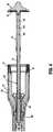
- FIGS. 1 and 2illustrate one embodiment of the presently disclosed insertion device, which is identified by the reference character 1000.
- the insertion device 1000is configured and dimensioned for use during a surgical procedure to enlarge an opening in a patient's tissue to facilitate access to an internal treatment site with a surgical instrument.
- the insertion device 1000will be discussed in the context of a surgical hemorrhoid procedure by way of example, wherein the target hemorrhoidal tissue "H" (see FIGS. 13, 14 ) is removed from a patient's anal canal using a surgical fastener applying apparatus.
- FIGS. 3 and 4an exemplary embodiment of a suitable surgical fastener applying apparatus, which is identified by the reference character 10, will be described, and a brief overview of the structure and operation of the surgical fastener applying apparatus 10 will be provided. Additional details regarding the surgical fastener applying apparatus 10 can be obtained through reference to U.S. Patent Application Serial No. 12/550,443 filed on August 31, 2009 , published as US 2010089971 A . It should be understood however, that other surgical fastener applying apparatus can be used with the insertion devices disclosed herein.
- the surgical fastener applying apparatus 10includes a handle assembly 12, a central body portion 14 with an outer tube 16, and a distal head portion 18.
- the handle assembly 12includes a stationary handle 20, a firing trigger 22, and a rotatable approximation knob 24.
- the head portion 18 of the surgical fastener applying apparatus 10includes an anvil assembly 26 and a shell assembly 28.
- the anvil assemblyis repositionable between an un-approximated position, wherein the anvil assembly 26 is spaced a distance from the shell assembly 28 (as in FIG. 3 ), and an approximated position, wherein the anvil assembly 26 is closer to the shell assembly 28 to clamp tissue therebetween (see e.g. FIG. 15 ).
- the anvil assembly 26When the surgical fastener applying apparatus 10 is assembled, the anvil assembly 26 is positioned within an anvil retainer 30 that is movable relative to the shell assembly 28 via an operative connection to the approximation knob 24. Accordingly, during use of the surgical fastener applying apparatus 10, rotation of the approximation knob 24 effectuates movement of the anvil retainer 30, and consequently, the anvil assembly 26, in relation to the shell assembly 28 to thereby transition the anvil assembly 26 between the un-approximated and approximated positions.
- the surgical fastener applying apparatus 10further includes a firing mechanism to facilitate the ejection of a plurality of surgical fasteners 32 ( FIG. 4 ) from the shell assembly 28 which are arranged in a circular array(s).
- the firing mechanismincludes the aforementioned firing trigger 20 ( FIG. 3 ), which is operatively connected to a pusher back 34 ( FIG. 4 ) component of the shell assembly 28.
- actuation (pivoting) of the firing trigger 20Upon actuation (pivoting) of the firing trigger 20, distal movement thereof causes corresponding distal movement of the pusher back 34 via a pusher link to eject the surgical fasteners 32 from the shell assembly 28.
- the surgical fasteners 32are forced into engagement with depressions (pockets) on an anvil plate 36 ( FIG.
- a circular knife member 38is advanced distally through the pusher back 34 into engagement with the anvil assembly 26 to thereby sever tissue positioned between the anvil assembly 26 and the shell assembly 28.
- the insertion device 1000includes an obturator 1100 with a dilating tip 1102, an anoscope 1200, and a port 1300.
- the anoscope 1200 and the port 1300may be formed, either partially or wholly, from a clear material, e.g., polycarbonate, to facilitate the visualization of target tissue, as well as any adjacent or surrounding tissue, during the surgical procedure.
- a clear materiale.g., polycarbonate
- alternative materials of constructione.g., materials allowing less light to pass through the anoscope 1200 and the port 1300, are within the scope of the present disclosure.
- the anoscope 1200includes a dished proximal flange 1202, and a sleeve 1204 with respective proximal and distal ends 1206, 1208 that are spaced apart along a longitudinal axis "Y.”
- the flange 1202extends outwardly from the proximal end 1206 of the sleeve 1204 relative to the longitudinal axis "Y,” and includes respective first and second circumferentially spaced ends 1210, 1212.
- the ends 1210, 1212 of the flange 1202are connected by an arcuate portion 1214, and define a gap "G".
- the arcuate portion 1214may define an arc of approximately 180°. However, the arc defined by the arcuate portion 1214 may be either larger or smaller in alternative embodiments of the present disclosure.
- the anoscope 1200further includes a single wing 1216 that extends outwardly from the flange 1202 relative to the longitudinal axis "Y" in a manner resulting in a configuration that is asymmetrical about a plane extending along the longitudinal axis "Y” that bisects the flange 1202.
- the wing 1216is configured and dimensioned for manual engagement by the clinician to facilitate manipulation of the anoscope 1200 during the course of the surgical hemorrhoid procedure.
- the wing 1216may be positioned adjacent one of the ends 1210, 1212 of the flange 1202, e.g., the second end 1212, as shown in FIG. 1 .
- the wing 1216may be positioned at a location between the ends 1210, 1212 of the flange 1202.
- an embodiment of the anoscopegenerally designated by reference numeral 1200', is illustrated wherein the wing 1216' is positioned at a location equidistant from the ends 1210', 1212' of the flange 1202' such that the wing 1216' is positioned opposite the gap "G"' defined between the ends 1210', 1212'.
- the arcuate portionmay define an arc of approximately 180°, although smaller or greater arcs are also contemplated.
- the configurationis symmetrical about a plane extending along the longitudinal axis "Y" that bisects the flange 1202', and the wing 1216' provides the clinician with a way to ascertain the position of the gap "G" to facilitate accurate placement of the anoscope relative to the target tissue H.
- the wing 1216'preferably angles upwardly similar to the wings of the embodiment of Figure 17 and has a lip along a periphery to facilitate maneuverability.
- the anoscope of FIG. 5is otherwise the same as the anoscope of FIG. 1 and can be used with the port and dilator of FIG. 1 .
- the wing 1216includes a proximal surface 1218 which may be substantially uniform in configuration, i.e., a proximal surface 1218 that is free from any indentations, protrusions, or other such irregularities.
- the proximal surface 1218 of the wing 1216may include textured surfaces, or the like to facilitate manual manipulation of the anoscope 1200 by the clinician.
- the sleeve 1204 of the anoscope 1200extends distally from the flange 1202 and defines an internal dimension that allows for removable reception of the obturator 1100 therein.
- the sleeve 1204includes a closed distal tip 1220 having an atraumatic, e.g., conical configuration. This configuration facilitates the dilation of tissue, such as the patient's anal canal, and thus, insertion and advancement of the anoscope 1200, as well as rotation of the anoscope 1200 once positioned internally.
- the sleeve 1204amay include markings 1222a to assist the clinician in the placement of purse strings.
- the markingsare placed along an exterior of the body, adjacent distal opening 1230a.
- the markingsextend around the entire body from edge 1241a to edge 1242a of distal opening 1230a.
- the markings 1222aallow the clinician to easily ascertain the depth to which the anoscope 1200a has been inserted within the opening in the patient's tissue, e.g., the depth within the patient's anal canal.
- the markings 1222afacilitate the placement of purse strings at a consistent distance from the opening in the patient's tissue. Although five markings 1220 are shown, a different number of markings is also contemplated. In all other respects, anoscope 1200a is the same as anoscope 1200 of FIG. 1 and can be utilized with the port and dilator of FIG. 1 .
- the sleeve 1204also includes an open region 1224 that extends longitudinally therethrough along the axis "Y," and a bridge 1226 that spans the open region 1224 to thereby divide the open region 1224 into respective proximal and distal openings 1228, 1230.
- the bridge 1226may extend across the open region 1224 to define an arc having any suitable dimensions. For example, as illustrated in FIG. 1 , the arc defined by the bridge 1226 may extend less than 180°. However, an arc greater than 180° is also within the scope of the present disclosure.
- the configuration of the bridge 1226may be altered or varied in alterative embodiments of the anoscope 1200 to realize any suitable axial length.
- the bridge 1226defines an axial length of about 1.5 cm (approximately .59 inches), and is positioned such that respective proximal and distal ends 1232, 1234 of the bridge 1226 are located about 3 cm (approximately 1.18 inches) and about 4.5 cm (approximately 1.77 inches) from the proximal end 1206 of the sleeve 1204, i.e., from the point of contact between the flange 1202 and the sleeve 1204.
- the distal opening 1230 in the sleeve 1204will be positioned above (proximally) of the dentate line, which is located in the human anal canal about 2 cm (approximately .78 inches) from the anus. With the distal opening 1230 positioned proximally of the dentate line, purse stringing, and subsequent tissue removal, will also occur proximally of the dentate line.
- the port 1300defines an internal dimension that allows for removable reception of the anoscope 1200, and includes a pair of wings 1302 that are configured and dimensioned for manual engagement by the clinician to facilitate handling and manipulation of the port 1300 during the course of the surgical procedure.
- the wings 1302extend outwardly from the port 1300 relative to the longitudinal axis "Y.” Specifically, the wings 1302 each extend along an axis "T" ( FIG. 7 ) that is transverse in relation to the longitudinal axis "Y” to subtend an angle ⁇ therewith. It is envisioned that the angle ⁇ may lie substantially within the range of approximately 45° to approximately 90°.
- the axis "T" along which the wings 1302 extendsdefines an angle of approximately 55° with the longitudinal axis "Y.”
- larger and smaller values for the angle ⁇are also contemplated.
- the wings 1302 of the port 1300include a pair of apertures 1304 that are configured and dimensioned to receive a flexible member (not shown), such as a suture, that can be secured to the patient's tissue in order to facilitate fixation of the port 1300 relative thereto.
- a flexible membersuch as a suture
- an embodiment of the port 1300 in which the wings 1302 have a different number of apertures or are devoid of the aperturesis also contemplated.
- the insertion device 1000( FIGS. 1, 2 ) will be discussed in connection with the surgical fastener applying apparatus 10 ( FIGS. 3, 4 ) in the context of a surgical hemorrhoid procedure, it being understood that the other insertion devices (i.e. other anoscopes) disclosed herein would be used in a similar manner.
- the anvil assembly 26Prior to insertion, the anvil assembly 26 is removed from the anvil retainer 30, and the insertion device 1000 is assembled as illustrated in FIG. 2 .
- the anoscope 1200is positioned coaxially within the port 1300
- the obturator 1100is positioned coaxially within the sleeve 1204 of the anoscope 1200.
- the assembled insertion device 1000is then inserted transanally into an opening in the patient's tissue such that the bridge 1226 is positioned above the dentate line (see FIG. 8 ). Thereafter, the obturator 1100 is removed, leaving the anoscope 1200 positioned within port 1300, as seen in FIG. 9 , such that the port 1300 extends from the patient's anus. Either prior or subsequent to assembly of the insertion device 1000, the port 1300 may be optionally fixed to the patient's tissue by the aforementioned flexible member (not shown).
- the target tissuee.g., internal hemorrhoidal tissue "H”
- the distal opening 1230 in the sleeve 1204such that the tissue "H” is positioned within the sleeve 1204 of the anoscope 1200.
- the clinicianthen attaches a length of suture "S" to the target tissue "H," a procedure which is generally referred to as "purse stringing.”
- the anoscope 1200can be rotated within the port 1300 to one or more subsequent positions, exemplified in the transition between FIGS. 10, 11, and 12 , such that additional internal hemorrhoidal tissue "H,” if any, can be received within the distal opening 1230, and purse stringed.
- the anoscope 1200is removed from the patient's anus.
- the anvil assembly 26 ( FIG. 13 ) of the surgical fastener applying apparatus 10is then inserted through the port 1300 into the patient's anal cavity, and the two ends of the suture "S" are attached to the anvil assembly 26.
- the ends of the suture "S”are inserted into aperture 40B of the apertures 40A-40C ( FIGS. 3 , 4 , 13 ) formed in a center rod 42 component of the anvil assembly 26.
- the apertures 40A-40C through which the ends of the suture "S" are insertedis dependent upon the amount of tissue the clinician wishes to draw into the shell assembly 28 during approximation of the anvil assembly 26 and the shell assembly 28, the proximalmost aperture 40A providing the greatest amount of tissue.
- the length of the suture "S”is such that the suture "S” extends from the port 1300 after positioning within the select aperture 40A-40C.
- the anvil assembly 26is re-connected to the surgical fastener applying apparatus 10 by positioning the anvil assembly 26 within the anvil retainer 30, as shown in FIG. 14 .
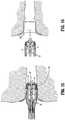
- the approximation knob 24 ( FIG. 3 ) of apparatus 10is rotated to move the anvil assembly 26 proximally towards the shell assembly 28 such that the target tissue "H” is drawn into, and positioned within, the shell assembly 28, as shown in FIG. 15 .
- the surgical fastener applying apparatus 10is then fired to sever and fasten the target tissue "H.” After severing of the tissue "H,” the surgical fastener applying apparatus 10 can be removed from the port 1300 with the tissue "H" positioned within the shell assembly 28, as shown in FIG. 16 .
- FIGS. 17 and 18alternative embodiments of the anoscope component of the presently disclosed insertion device 1000 ( FIG. 1 ) will be discussed.
- Each embodiment of the anoscope discussed herein belowis similar to the anoscope 1200 that was discussed above with respect to FIGS. 1 and 2 , for example, and accordingly, will only be described with respect to any differences therefrom.
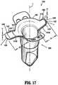
- FIG. 17illustrates an embodiment of the anoscope in accordance with the present invention that is identified by the reference character 1400 and is shown positioned within the port 1300.
- the anoscope 1400includes a first wing 1416A and a second wing 1416B that each extend outwardly from the dished flange 1402.
- the wings 1416A, 1416Bare positioned adjacent the ends 1410, 1412 of the flange 1402, respectively. More specifically, in the illustrated embodiment, the ends 1410, 1412 of the flange 1402, and thus, the wings 1416A, 1416B, are diametrically opposed.
- the wings 1416A, 1416Bmay be spaced from the ends 1410, 1412 of the flange 1402.
- the structure of the first wing 1416Adiffers from that of the second wing 1416B such that the configuration of the anoscope 1400 is asymmetrical about a plane extending along the longitudinal axis "Y" that bisects the flange 1402.
- the configuration of the anoscope 1400is asymmetrical about a plane extending along the longitudinal axis "Y" that bisects the flange 1402.
- the first wing 1416Aextends outwardly from the flange 1402 a first distance "X1," whereas the second wing 1416B extends outwardly from the flange 1402 a second, greater distance "X2.”
- the shorter distance "X1" defined by the first wing 1416Areduces the likelihood that the first wing 1416A will interfere with manipulation of the anoscope 1400 during the surgical procedure via contact with the patient's tissue.
- the wings 1416A, 1416Binclude a raised protrusion 1436.
- the protrusions 1436extend away from the wings 1416A, 1416B in a proximal direction to define a height "H,” and corresponding adjacent area 1438 to thereby enhance maneuverability of the anoscope 1400.
- the protrusions 1436are configured as ribs, or flanges, 1440 that are positioned adjacent a peripheral edge "P" of the wings 1416A, 1416B. It should be understood, however, that in alternative embodiments of the anoscope 1400, the protrusion 1436 may assume any configuration suitable for the intended purpose of increasing the clinician's control over, and ability to manipulate, the anoscope 1400, and that other configurations for the protrusion 1436 are not beyond the scope of the present disclosure.
- the wings 1416A, 1416Bmay be devoid of the protrusions 1436 such that the wings 1416A, 1416B include a substantially uniform proximal surface 1418, i.e., a surface that is free from any indentations, protrusions, or other such irregularities, as discussed above with respect to the anoscope 1200 ( FIGS. 1, 2 ).
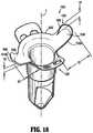
- FIG. 18illustrates another embodiment of the anoscope that is identified by the reference character 1500 and is shown positioned within the port 1300.
- the anoscope 1500includes a first wing 1516A and a second wing 1516B that each extend outwardly from the dished flange 1502.
- the structure of the first wing 1516Ais identical to that of the second wing 1516B such that the configuration of the anoscope 1500 is symmetrical about a plane extending along the longitudinal axis "Y" that bisects the flange 1502.
- the first wing 1516A and the second wing 1516Beach extend outwardly from the flange 1502 a distance "X3.”
- the wings 1516A and 1516Bcurve proximally forming arcuate regions.
- the wings 1516A, 1516Bmay each include a raised protrusion 1536.
- the protrusions 1536extend away from the wings 1516A, 1516B in the proximal direction to define a height "H2" that is greater than the height "H” defined by the protrusions 1436 included on the wings 1416A, 1416B of the anoscope 1400 ( FIG. 17 ).
- the increased height "H2" of the protrusions 1536increases both the depth of the surfaces 1538 defined thereby, as well as the surface area available for contact with the clinician, e.g., with the clinician's finger(s). Thus, the increased height "H2" of the protrusions 1536 further increases the clinician's control over, and ability to manipulate, the anoscope 1500.
- protrusions 1536may assume alternative configurations in additional embodiments of the anoscope 1500, and that the protrusions 1536 (as well as protrusions 1436 of FIG. 17 ) may be spaced from the peripheral edge "P" of the wings without departing from the scope of the present disclosure.
Landscapes
- Health & Medical Sciences (AREA)
- Life Sciences & Earth Sciences (AREA)
- Surgery (AREA)
- General Health & Medical Sciences (AREA)
- Public Health (AREA)
- Veterinary Medicine (AREA)
- Nuclear Medicine, Radiotherapy & Molecular Imaging (AREA)
- Animal Behavior & Ethology (AREA)
- Molecular Biology (AREA)
- Engineering & Computer Science (AREA)
- Biomedical Technology (AREA)
- Heart & Thoracic Surgery (AREA)
- Medical Informatics (AREA)
- Pathology (AREA)
- Biophysics (AREA)
- Radiology & Medical Imaging (AREA)
- Physics & Mathematics (AREA)
- Optics & Photonics (AREA)
- Reproductive Health (AREA)
- Vascular Medicine (AREA)
- Surgical Instruments (AREA)
Description
- The present disclosure relates to an insertion device that is adapted for positioning within an opening in tissue to facilitate access to an internal treatment site with a surgical instrument. More particularly, the present disclosure relates to an anoscope kit for use with a surgical fastener applying apparatus.
- A medical device used in the dilation and/or inspection of an internal treatment site, e.g., a treatment site within a patient's anus, rectum, and/or colon, is often referred to as an anoscope. Anoscopes generally comprise a hollow body that is configured and dimensioned for insertion into an opening in the patient's tissue; either an opening that is natural and pre-existing, e.g., the patient's anus, or an opening that is formed by a clinician, e.g., an incision. The hollow body of the anoscope will generally include structure that is configured and dimensioned to dilate, and cover, the opening in the patient's tissue, as well as structure at the distal end thereof that is configured and dimensioned to accommodate the target tissue, e.g., hemorrhoidal tissue, such as a gap, notch, or slot.
- After positioning the anoscope within the opening in the patient's tissue, the interior of the hollow body provides a passage through which the clinician can inspect the internal treatment site, and perform the surgical procedure. For example, anoscopes are particularly useful in the inspection and treatment of hemorrhoidal tissue, as well as tissue positioned adjacent thereto, e.g., mucosal tissue, during hemorrhoid procedures. During these procedures, the clinician will usually excise the target tissue, and thereafter suture the treated area.
- The two part form of claim 1 is based on
US 2009/0005647 A1 .US 6083241 A discloses an insertion device comprising an anoscope having a flange and two wings. - An anoscope including structure that is configured and dimensioned to increase maneuverability and manipulation of the anoscope would be desirable in the interests of allowing a clinician to more easily access the tissue that is the subject of the surgical procedure.
- The invention is described in claim 1.
- Preferred embodiments are described in the dependent claims.
- In one aspect of the present disclosure, an insertion device is disclosed for use during a surgical procedure to enlarge an opening in a patient's tissue to facilitate access to an internal treatment site with a surgical instrument. The disclosed insertion device includes an anoscope with a flange, and an elongate body having proximal and distal ends that extends distally from the flange along a longitudinal axis. In one embodiment, the anoscope includes a configuration that is asymmetrical about a plane extending along the longitudinal axis that bisects the flange.
- It is envisioned that the body of the anoscope may include a first opening spaced longitudinally from a second opening, wherein the first and second openings are aligned along the longitudinal axis.
- The flange can include first and second circumferentially spaced ends defining a gap therebetween that is configured and dimensioned to receive tissue. In one embodiment, the anoscope includes at least one wing that extends outwardly from the flange relative to the longitudinal axis. For example, the anoscope may include a single wing positioned either adjacent one of the ends of the flange, or alternatively, between the ends of the flange. In another embodiment, rather than just a single wing, the anoscope may include a first wing and a second wing. In this embodiment, it is envisioned that the first wing may extend outwardly from the flange a first distance, whereas the second wing may extend outwardly from the flange a second, greater distance. To enhance maneuverability of the anoscope, the wing(s) may include a lip extending along a periphery creating a surface adjacent the lip to facilitate maneuverability.
- The presently disclosed insertion device may also include a dilator that is configured and dimensioned for positioning within the body of the anoscope.
- The insertion device may include a port defining a longitudinal opening therethrough that is configured and dimensioned to receive the anoscope, wherein the port itself is configured and dimensioned for positioning within the opening in the tissue. It is envisioned that the port may include a pair of wings extending outwardly therefrom along an axis that is transverse in relation to the longitudinal axis such that the longitudinal axis and the transverse axis define an acute angle therebetween. For example, the angle defined between the longitudinal axis and the transverse axis may be approximately equal to 55°.
- The present disclosure also provides in another aspect, an insertion device that includes an anoscope with a flange, and an elongate body having proximal and distal ends that extends distally from the flange along a longitudinal axis. The anoscope includes a configuration that is symmetrical about a plane extending along the longitudinal axis that bisects the flange. The anoscope includes a pair of wings that extend outwardly from the flange relative to the longitudinal axis and curve outwardly away from the distal end, wherein each of the wings includes a lip extending in a proximal direction that is positioned along a peripheral edge thereof.
- The distal end of the anoscope preferably includes a closed distal tip that is configured and dimensioned to facilitate atraumatic advancement and/or rotation of the anoscope.
- In yet another aspect of the present disclosure, an insertion device is disclosed including a port defining a longitudinal opening therethrough that is configured and dimensioned for positioning within the opening in the tissue, an anoscope that is configured and dimensioned for positioning within the longitudinal opening of the port, and a dilator that is configured and dimensioned for positioning within the body of the anoscope. The anoscope includes a flange, and an elongate body extending distally from the flange along a longitudinal axis. The anoscope has a configuration that is asymmetrical about a plane extending along the longitudinal axis that bisects the flange.
- It is envisioned that the anoscope may also include at least one wing extending outwardly from the flange relative to the longitudinal axis.
- The port of the insertion device may include a pair of wings that extend outwardly therefrom, wherein at least one of the wings includes an aperture that is configured and dimensioned to receive a flexible member such as a suture to facilitate attachment of the port to the patient's tissue. It is envisioned that the wings may extend outwardly along an axis that is transverse in relation to the longitudinal axis such that the longitudinal axis and the transverse axis define an acute angle therebetween.
- These and other features of the presently disclosed insertion device will become more readily apparent to those skilled in the art through reference to the detailed description of various embodiments of the present disclosure that follows.
- Various embodiments of the present disclosure are described herein below with reference to the drawings, wherein:
FIG. 1 is a front, perspective view of an insertion device including an obturator, an anoscope, and a port in accordance with one embodiment of the present disclosure;FIG. 2 is a side, perspective view of the insertion device ofFIG. 1 upon assembly;FIG. 3 is a side, perspective view of a surgical fastener applying apparatus for use with the presently disclosed insertion device during a surgical procedure;FIG. 4 is a partial, longitudinal, cross-sectional view of a portion of the surgical fastener applying apparatus illustrating anvil and shell assembly components thereof;FIG. 5 is a top, perspective view of an alternative embodiment of the presently disclosed insertion device with the obturator removed;FIG. 6 is a top, perspective view of another embodiment of the presently disclosed insertion device with the obturator removed;FIG. 7 is a side, plan view of the port component of the insertion device ofFIG. 1 ;FIG. 8 is a longitudinal, cross-sectional view of the insertion device ofFIG. 1 shown assembled and positioned within a patient;FIG. 9 is a longitudinal, cross-sectional view of the insertion device ofFIG. 1 positioned within a patient following removal of the obturator;FIGS. 10-12 are proximal, end views of the insertion device positioned within a patient following removal of the obturator illustrating a purse stringing procedure in which a suture is attached to target tissue;FIG. 13 is a longitudinal, cross-sectional view of the port component of the insertion device ofFIG. 1 and the anvil assembly of the surgical fastener applying apparatus ofFIG. 3 positioned within a patient following purse stringing and illustrating attachment of the suture to the anvil assembly of the apparatis;FIG. 14 is a partial, longitudinal, cross-sectional view of the port component of the insertion device ofFIG. 1 and the anvil assembly of the surgical fastener applying apparatus ofFIG. 3 positioned within a patient following purse stringing and attachment of the anvil assembly to an anvil retainer of the surgical apparatus;FIG. 15 is a partial, longitudinal, cross-sectional view illustrating a distal end of the surgical fastener applying apparatus ofFIG. 3 positioned within the port component of the insertion device ofFIG. 1 following approximation of the anvil assembly and the shell assembly of the apparatus; andFIG. 16 is a partial, longitudinal, cross-sectional view of the distal end of the surgical fastener applying apparatus ofFIG. 3 following removal from the port component of the insertion device ofFIG. 1 from the patient illustrating the removed target tissue within the shell assembly of the apparatus;FIG. 17 is a top, perspective view of another embodiment of the presently disclosed insertion device in accordance with the present invention, with the obturator removed; andFIG. 18 is a top, perspective view of still another embodiment of the presently disclosed insertion device with the obturator removed.- The presently disclosed insertion device will now be described in detail with reference to the drawings, wherein like reference numerals designate identical or corresponding elements. Throughout the following description, the term "proximal" should be understood as referring to the portion of the insertion device, or component thereof, that is closer to the clinician during proper use, and the term "distal" should be understood as referring to the portion of the insertion device, or component thereof, that is further from the clinician during proper use. Additionally, the terms "hemorrhoidal tissue," and the like, should be understood as referring to hemorrhoidal tissue, as well as tissue positioned adjacent to hemorrhoidal tissue, including mucosal tissue. While the presently disclosed insertion device is particularly suited for surgical hemorrhoid procedures, the term "hemorrhoid procedure" should be understood to encompass surgical hemorrhoidectomies, hemorrhoidopexies, mucosectomies, procedures for the treatment of colon prolapse, and all such related procedures. The present disclosed insertion device can also be used for surgical procedures other than hemorrhoid procedures.
FIGS. 1 and 2 illustrate one embodiment of the presently disclosed insertion device, which is identified by thereference character 1000. Theinsertion device 1000 is configured and dimensioned for use during a surgical procedure to enlarge an opening in a patient's tissue to facilitate access to an internal treatment site with a surgical instrument. During the following discussion, theinsertion device 1000 will be discussed in the context of a surgical hemorrhoid procedure by way of example, wherein the target hemorrhoidal tissue "H" (seeFIGS. 13, 14 ) is removed from a patient's anal canal using a surgical fastener applying apparatus.- Referring to
FIGS. 3 and4 , an exemplary embodiment of a suitable surgical fastener applying apparatus, which is identified by thereference character 10, will be described, and a brief overview of the structure and operation of the surgicalfastener applying apparatus 10 will be provided. Additional details regarding the surgicalfastener applying apparatus 10 can be obtained through reference toU.S. Patent Application Serial No. 12/550,443 filed on August 31, 2009 US 2010089971 A . It should be understood however, that other surgical fastener applying apparatus can be used with the insertion devices disclosed herein. - The surgical
fastener applying apparatus 10 includes ahandle assembly 12, acentral body portion 14 with anouter tube 16, and adistal head portion 18. Thehandle assembly 12 includes astationary handle 20, a firingtrigger 22, and arotatable approximation knob 24. - The
head portion 18 of the surgicalfastener applying apparatus 10 includes ananvil assembly 26 and ashell assembly 28. The anvil assembly is repositionable between an un-approximated position, wherein theanvil assembly 26 is spaced a distance from the shell assembly 28 (as inFIG. 3 ), and an approximated position, wherein theanvil assembly 26 is closer to theshell assembly 28 to clamp tissue therebetween (see e.g.FIG. 15 ). - When the surgical
fastener applying apparatus 10 is assembled, theanvil assembly 26 is positioned within ananvil retainer 30 that is movable relative to theshell assembly 28 via an operative connection to theapproximation knob 24. Accordingly, during use of the surgicalfastener applying apparatus 10, rotation of theapproximation knob 24 effectuates movement of theanvil retainer 30, and consequently, theanvil assembly 26, in relation to theshell assembly 28 to thereby transition theanvil assembly 26 between the un-approximated and approximated positions. - The surgical
fastener applying apparatus 10 further includes a firing mechanism to facilitate the ejection of a plurality of surgical fasteners 32 (FIG. 4 ) from theshell assembly 28 which are arranged in a circular array(s). The firing mechanism includes the aforementioned firing trigger 20 (FIG. 3 ), which is operatively connected to a pusher back 34 (FIG. 4 ) component of theshell assembly 28. Upon actuation (pivoting) of the firingtrigger 20, distal movement thereof causes corresponding distal movement of the pusher back 34 via a pusher link to eject thesurgical fasteners 32 from theshell assembly 28. Upon ejection from theshell assembly 28, thesurgical fasteners 32 are forced into engagement with depressions (pockets) on an anvil plate 36 (FIG. 4 ) component of theanvil assembly 26 to thereby form thesurgical fasteners 32. Contemporaneously with ejection of thesurgical fasteners 32, acircular knife member 38 is advanced distally through the pusher back 34 into engagement with theanvil assembly 26 to thereby sever tissue positioned between theanvil assembly 26 and theshell assembly 28. - Referring back to
FIGS. 1 and 2 , the components and structure of theinsertion device 1000 will be discussed in detail. Theinsertion device 1000 includes anobturator 1100 with adilating tip 1102, ananoscope 1200, and aport 1300. In one embodiment of theinsertion device 1000, it is envisioned that theanoscope 1200 and theport 1300 may be formed, either partially or wholly, from a clear material, e.g., polycarbonate, to facilitate the visualization of target tissue, as well as any adjacent or surrounding tissue, during the surgical procedure. However, alternative materials of construction, e.g., materials allowing less light to pass through theanoscope 1200 and theport 1300, are within the scope of the present disclosure. - The
anoscope 1200 includes a dishedproximal flange 1202, and asleeve 1204 with respective proximal anddistal ends flange 1202 extends outwardly from theproximal end 1206 of thesleeve 1204 relative to the longitudinal axis "Y," and includes respective first and second circumferentially spaced ends 1210, 1212. The ends 1210, 1212 of theflange 1202 are connected by anarcuate portion 1214, and define a gap "G". Thearcuate portion 1214 may define an arc of approximately 180°. However, the arc defined by thearcuate portion 1214 may be either larger or smaller in alternative embodiments of the present disclosure. - The
anoscope 1200 further includes asingle wing 1216 that extends outwardly from theflange 1202 relative to the longitudinal axis "Y" in a manner resulting in a configuration that is asymmetrical about a plane extending along the longitudinal axis "Y" that bisects theflange 1202. Thewing 1216 is configured and dimensioned for manual engagement by the clinician to facilitate manipulation of theanoscope 1200 during the course of the surgical hemorrhoid procedure. In one embodiment of theanoscope 1200, thewing 1216 may be positioned adjacent one of theends flange 1202, e.g., thesecond end 1212, as shown inFIG. 1 . Alternatively, however, thewing 1216 may be positioned at a location between theends flange 1202. - Referring to
FIG. 5 , an embodiment of the anoscope, generally designated by reference numeral 1200', is illustrated wherein the wing 1216' is positioned at a location equidistant from the ends 1210', 1212' of the flange 1202' such that the wing 1216' is positioned opposite the gap "G"' defined between the ends 1210', 1212'. The arcuate portion may define an arc of approximately 180°, although smaller or greater arcs are also contemplated. In this embodiment, the configuration is symmetrical about a plane extending along the longitudinal axis "Y" that bisects the flange 1202', and the wing 1216' provides the clinician with a way to ascertain the position of the gap "G" to facilitate accurate placement of the anoscope relative to the target tissue H. The wing 1216' preferably angles upwardly similar to the wings of the embodiment ofFigure 17 and has a lip along a periphery to facilitate maneuverability. The anoscope ofFIG. 5 is otherwise the same as the anoscope ofFIG. 1 and can be used with the port and dilator ofFIG. 1 . - Referring again to
FIGS. 1 and 2 , thewing 1216 includes aproximal surface 1218 which may be substantially uniform in configuration, i.e., aproximal surface 1218 that is free from any indentations, protrusions, or other such irregularities. Alternatively, theproximal surface 1218 of thewing 1216 may include textured surfaces, or the like to facilitate manual manipulation of theanoscope 1200 by the clinician. - The
sleeve 1204 of theanoscope 1200 extends distally from theflange 1202 and defines an internal dimension that allows for removable reception of theobturator 1100 therein. Thesleeve 1204 includes a closeddistal tip 1220 having an atraumatic, e.g., conical configuration. This configuration facilitates the dilation of tissue, such as the patient's anal canal, and thus, insertion and advancement of theanoscope 1200, as well as rotation of theanoscope 1200 once positioned internally. - In one embodiment of the anoscope 1200a, which can be seen in
FIG. 6 , thesleeve 1204a may includemarkings 1222a to assist the clinician in the placement of purse strings. The markings are placed along an exterior of the body, adjacentdistal opening 1230a. Preferably, the markings extend around the entire body fromedge 1241a to edge 1242a ofdistal opening 1230a. Specifically, themarkings 1222a allow the clinician to easily ascertain the depth to which theanoscope 1200a has been inserted within the opening in the patient's tissue, e.g., the depth within the patient's anal canal. By allowing the clinician to easily determine the depth to which theanoscope 1200a has been inserted, themarkings 1222a facilitate the placement of purse strings at a consistent distance from the opening in the patient's tissue. Although fivemarkings 1220 are shown, a different number of markings is also contemplated. In all other respects,anoscope 1200a is the same asanoscope 1200 ofFIG. 1 and can be utilized with the port and dilator ofFIG. 1 . - Returning to
FIGS. 1 and 2 , thesleeve 1204 also includes anopen region 1224 that extends longitudinally therethrough along the axis "Y," and abridge 1226 that spans theopen region 1224 to thereby divide theopen region 1224 into respective proximal anddistal openings bridge 1226 may extend across theopen region 1224 to define an arc having any suitable dimensions. For example, as illustrated inFIG. 1 , the arc defined by thebridge 1226 may extend less than 180°. However, an arc greater than 180° is also within the scope of the present disclosure. - The configuration of the
bridge 1226 may be altered or varied in alterative embodiments of theanoscope 1200 to realize any suitable axial length. In one particular embodiment, thebridge 1226 defines an axial length of about 1.5 cm (approximately .59 inches), and is positioned such that respective proximal anddistal ends bridge 1226 are located about 3 cm (approximately 1.18 inches) and about 4.5 cm (approximately 1.77 inches) from theproximal end 1206 of thesleeve 1204, i.e., from the point of contact between theflange 1202 and thesleeve 1204. In this embodiment, during the course of a hemorrhoid procedure, upon insertion of theanoscope 1200 into the patient's anal canal, thedistal opening 1230 in thesleeve 1204 will be positioned above (proximally) of the dentate line, which is located in the human anal canal about 2 cm (approximately .78 inches) from the anus. With thedistal opening 1230 positioned proximally of the dentate line, purse stringing, and subsequent tissue removal, will also occur proximally of the dentate line. - With reference now to
FIGS. 1 and7 , theport 1300 of theinsertion device 1000 will be discussed. Theport 1300 defines an internal dimension that allows for removable reception of theanoscope 1200, and includes a pair ofwings 1302 that are configured and dimensioned for manual engagement by the clinician to facilitate handling and manipulation of theport 1300 during the course of the surgical procedure. Thewings 1302 extend outwardly from theport 1300 relative to the longitudinal axis "Y." Specifically, thewings 1302 each extend along an axis "T" (FIG. 7 ) that is transverse in relation to the longitudinal axis "Y" to subtend an angle α therewith. It is envisioned that the angle α may lie substantially within the range of approximately 45° to approximately 90°. For example, in the embodiment of theport 1300 illustrated inFIGS. 1 and7 , the axis "T" along which thewings 1302 extends defines an angle of approximately 55° with the longitudinal axis "Y." However, larger and smaller values for the angle α are also contemplated. - As best seen in
FIG. 1 , thewings 1302 of theport 1300 include a pair ofapertures 1304 that are configured and dimensioned to receive a flexible member (not shown), such as a suture, that can be secured to the patient's tissue in order to facilitate fixation of theport 1300 relative thereto. However, an embodiment of theport 1300 in which thewings 1302 have a different number of apertures or are devoid of the apertures is also contemplated. - The use and operation of the insertion device 1000 (
FIGS. 1, 2 ) will be discussed in connection with the surgical fastener applying apparatus 10 (FIGS. 3, 4 ) in the context of a surgical hemorrhoid procedure, it being understood that the other insertion devices (i.e. other anoscopes) disclosed herein would be used in a similar manner. Prior to insertion, theanvil assembly 26 is removed from theanvil retainer 30, and theinsertion device 1000 is assembled as illustrated inFIG. 2 . Specifically, theanoscope 1200 is positioned coaxially within theport 1300, and theobturator 1100 is positioned coaxially within thesleeve 1204 of theanoscope 1200. The assembledinsertion device 1000 is then inserted transanally into an opening in the patient's tissue such that thebridge 1226 is positioned above the dentate line (seeFIG. 8 ). Thereafter, theobturator 1100 is removed, leaving theanoscope 1200 positioned withinport 1300, as seen inFIG. 9 , such that theport 1300 extends from the patient's anus. Either prior or subsequent to assembly of theinsertion device 1000, theport 1300 may be optionally fixed to the patient's tissue by the aforementioned flexible member (not shown). - As seen in
FIG. 9 , following removal of theobturator 1100, the target tissue, e.g., internal hemorrhoidal tissue "H," is received by thedistal opening 1230 in thesleeve 1204 such that the tissue "H" is positioned within thesleeve 1204 of theanoscope 1200. The clinician then attaches a length of suture "S" to the target tissue "H," a procedure which is generally referred to as "purse stringing." Thereafter, theanoscope 1200 can be rotated within theport 1300 to one or more subsequent positions, exemplified in the transition betweenFIGS. 10, 11, and 12 , such that additional internal hemorrhoidal tissue "H," if any, can be received within thedistal opening 1230, and purse stringed. - After purse stringing is completed, the
anoscope 1200 is removed from the patient's anus. The anvil assembly 26 (FIG. 13 ) of the surgicalfastener applying apparatus 10 is then inserted through theport 1300 into the patient's anal cavity, and the two ends of the suture "S" are attached to theanvil assembly 26. For instance, in the illustrated embodiment of the surgicalfastener applying apparatus 10, the ends of the suture "S" are inserted intoaperture 40B of theapertures 40A-40C (FIGS. 3 ,4 ,13 ) formed in acenter rod 42 component of theanvil assembly 26. Theapertures 40A-40C through which the ends of the suture "S" are inserted is dependent upon the amount of tissue the clinician wishes to draw into theshell assembly 28 during approximation of theanvil assembly 26 and theshell assembly 28, theproximalmost aperture 40A providing the greatest amount of tissue. The length of the suture "S" is such that the suture "S" extends from theport 1300 after positioning within theselect aperture 40A-40C. - Following attachment of the suture "S" to the
center rod 42, theanvil assembly 26 is re-connected to the surgicalfastener applying apparatus 10 by positioning theanvil assembly 26 within theanvil retainer 30, as shown inFIG. 14 . Next, the approximation knob 24 (FIG. 3 ) ofapparatus 10 is rotated to move theanvil assembly 26 proximally towards theshell assembly 28 such that the target tissue "H" is drawn into, and positioned within, theshell assembly 28, as shown inFIG. 15 . The surgicalfastener applying apparatus 10 is then fired to sever and fasten the target tissue "H." After severing of the tissue "H," the surgicalfastener applying apparatus 10 can be removed from theport 1300 with the tissue "H" positioned within theshell assembly 28, as shown inFIG. 16 . - With reference now to
FIGS. 17 and18 , alternative embodiments of the anoscope component of the presently disclosed insertion device 1000 (FIG. 1 ) will be discussed. Each embodiment of the anoscope discussed herein below is similar to theanoscope 1200 that was discussed above with respect toFIGS. 1 and 2 , for example, and accordingly, will only be described with respect to any differences therefrom. FIG. 17 illustrates an embodiment of the anoscope in accordance with the present invention that is identified by thereference character 1400 and is shown positioned within theport 1300. In contrast to the aforedescribed anoscope 1200 (FIGS. 1, 2 ), which includes only asingle wing 1216, theanoscope 1400 includes afirst wing 1416A and asecond wing 1416B that each extend outwardly from the dishedflange 1402. In the illustrated embodiment, thewings ends flange 1402, respectively. More specifically, in the illustrated embodiment, theends flange 1402, and thus, thewings anoscope 1400, however, it is envisioned that thewings ends flange 1402.- The structure of the
first wing 1416A differs from that of thesecond wing 1416B such that the configuration of theanoscope 1400 is asymmetrical about a plane extending along the longitudinal axis "Y" that bisects theflange 1402. In the specific embodiment of theanoscope 1400 illustrated inFIG. 17 , thefirst wing 1416A extends outwardly from the flange 1402 a first distance "X1," whereas thesecond wing 1416B extends outwardly from the flange 1402 a second, greater distance "X2." The shorter distance "X1" defined by thefirst wing 1416A reduces the likelihood that thefirst wing 1416A will interfere with manipulation of theanoscope 1400 during the surgical procedure via contact with the patient's tissue. - To facilitate manual engagement with the
wings wings protrusion 1436. Theprotrusions 1436 extend away from thewings adjacent area 1438 to thereby enhance maneuverability of theanoscope 1400. - In the illustrated embodiment, the
protrusions 1436 are configured as ribs, or flanges, 1440 that are positioned adjacent a peripheral edge "P" of thewings anoscope 1400, theprotrusion 1436 may assume any configuration suitable for the intended purpose of increasing the clinician's control over, and ability to manipulate, theanoscope 1400, and that other configurations for theprotrusion 1436 are not beyond the scope of the present disclosure. It is also envisioned that thewings protrusions 1436 such that thewings proximal surface 1418, i.e., a surface that is free from any indentations, protrusions, or other such irregularities, as discussed above with respect to the anoscope 1200 (FIGS. 1, 2 ). FIG. 18 illustrates another embodiment of the anoscope that is identified by thereference character 1500 and is shown positioned within theport 1300. Like theanoscope 1400 described with respect toFIG. 17 , theanoscope 1500 includes afirst wing 1516A and asecond wing 1516B that each extend outwardly from the dishedflange 1502. However, in contrast to the first andsecond wings anoscope 1400, the structure of thefirst wing 1516A is identical to that of thesecond wing 1516B such that the configuration of theanoscope 1500 is symmetrical about a plane extending along the longitudinal axis "Y" that bisects theflange 1502. In the specific embodiment of theanoscope 1500 illustrated inFIG. 18 , thefirst wing 1516A and thesecond wing 1516B each extend outwardly from the flange 1502 a distance "X3." Thewings - To facilitate manual engagement with the
wings FIG. 17 ), it is envisioned that thewings protrusion 1536. Theprotrusions 1536 extend away from thewings protrusions 1436 included on thewings FIG. 17 ). The increased height "H2" of theprotrusions 1536 increases both the depth of thesurfaces 1538 defined thereby, as well as the surface area available for contact with the clinician, e.g., with the clinician's finger(s). Thus, the increased height "H2" of theprotrusions 1536 further increases the clinician's control over, and ability to manipulate, theanoscope 1500. - Although illustrated as a rib, or flange, 1540 that extends along the peripheral edge "P" of the
wings protrusions 1536 may assume alternative configurations in additional embodiments of theanoscope 1500, and that the protrusions 1536 (as well asprotrusions 1436 ofFIG. 17 ) may be spaced from the peripheral edge "P" of the wings without departing from the scope of the present disclosure. - Persons skilled in the art will understand that the devices and methods specifically described herein and illustrated in the accompanying drawings are non-limiting exemplary embodiments. It is envisioned that the elements and features illustrated or described in connection with one exemplary embodiment may be combined with the elements and features of another without departing from the scope of the present disclosure. As well, one skilled in the art will appreciate further features and advantages of the invention based on the above-described embodiments. Accordingly, the invention is not to be limited by what has been particularly shown and described, except as indicated by the appended claims.
Claims (3)
- An insertion device (1000) for use during surgical procedure to enlarge an opening in a patient's tissue to facilitate access to an internal treatment site with a surgical instrument, the insertion device comprising:an anoscope (1400), andan elongate body having proximal and distal ends extending distally along a longitudinal axis, andwherein the anoscope further includes at least one wing extending outwardly from the flange relative to the longitudinal axis and wherein the at least one wing includes a protrusion extending in a proximal direction, the protrusion positioned adjacent a peripheral edge of the at least one wing,characterized in that:the anoscope includes a flange (1402),the elongate body extends distally from the flange,the at least one wing includes a first wing (1416A) and a second wing (1416B) and the first wing extends outwardly from the flange a first distance, and the second wing extends outwardly from the flange a second greater distance, the first and second wings each having a protrusion (1436) extending in a proximal direction, the protusions positioned adjacent a peripheral edge of the first and second wings, and wherein the anoscope includes a configuration of the first and second wings and the flange that is asymmetrical about a plane extending along the longitudinal axis that bisects the flange.
- The insertion device of claim 1, wherein the flange (1402) includes first and second circumferentially spaced ends defining a gap therebetween configured and dimensioned to receive tissue, wherein at least one wing is positioned adjacent one of the ends of the flange.
- The insertion device of claim 1 or claim 2, wherein the flange (1402) includes first and second circumferentially spaced ends defining a gap therebetween configured and dimensioned to receive tissue, wherein at least one wing is positioned between the ends of the flange.
Priority Applications (1)
| Application Number | Priority Date | Filing Date | Title |
|---|---|---|---|
| EP11186019.3AEP2409636B1 (en) | 2009-10-08 | 2010-10-07 | Anoscope |
Applications Claiming Priority (2)
| Application Number | Priority Date | Filing Date | Title |
|---|---|---|---|
| US24965209P | 2009-10-08 | 2009-10-08 | |
| US12/880,215US9204789B2 (en) | 2009-10-08 | 2010-09-13 | Asymmetrical anoscope |
Related Child Applications (2)
| Application Number | Title | Priority Date | Filing Date |
|---|---|---|---|
| EP11186019.3ADivision-IntoEP2409636B1 (en) | 2009-10-08 | 2010-10-07 | Anoscope |
| EP11186019.3ADivisionEP2409636B1 (en) | 2009-10-08 | 2010-10-07 | Anoscope |
Publications (2)
| Publication Number | Publication Date |
|---|---|
| EP2308367A1 EP2308367A1 (en) | 2011-04-13 |
| EP2308367B1true EP2308367B1 (en) | 2017-03-01 |
Family
ID=43415315
Family Applications (2)
| Application Number | Title | Priority Date | Filing Date |
|---|---|---|---|
| EP10251765.3ANot-in-forceEP2308367B1 (en) | 2009-10-08 | 2010-10-07 | Asymmetrical anoscope |
| EP11186019.3ANot-in-forceEP2409636B1 (en) | 2009-10-08 | 2010-10-07 | Anoscope |
Family Applications After (1)
| Application Number | Title | Priority Date | Filing Date |
|---|---|---|---|
| EP11186019.3ANot-in-forceEP2409636B1 (en) | 2009-10-08 | 2010-10-07 | Anoscope |
Country Status (4)
| Country | Link |
|---|---|
| US (2) | US9204789B2 (en) |
| EP (2) | EP2308367B1 (en) |
| CA (1) | CA2716140A1 (en) |
| ES (1) | ES2621207T3 (en) |
Families Citing this family (19)
| Publication number | Priority date | Publication date | Assignee | Title |
|---|---|---|---|---|
| US8348837B2 (en)* | 2008-12-09 | 2013-01-08 | Covidien Lp | Anoscope |
| CN103829986A (en)* | 2012-11-27 | 2014-06-04 | 上海众仁生物医药科技有限公司 | Nail-free anastomat |
| CA2896382C (en)* | 2012-12-29 | 2017-06-13 | Suzhou Touchstone International Medical Science Co., Ltd. | Circular stapler and staple head assembly thereof |
| WO2014124022A2 (en)* | 2013-02-05 | 2014-08-14 | University Of South Florida | Laparoscopic tool with obturator |
| US9968348B2 (en)* | 2013-02-25 | 2018-05-15 | DePuy Synthes Products, Inc. | Surgical access tube |
| US9414830B2 (en)* | 2013-06-14 | 2016-08-16 | Covidien Lp | Surgical access assembly including adhesive members for secure attachment to skin surfaces |
| CN104107073B (en)* | 2014-07-08 | 2017-11-14 | 金黑鹰 | A kind of expansion type per anum Minimally Invasive Surgery device |
| US20170112371A1 (en)* | 2015-10-27 | 2017-04-27 | George Percy McGown | Anoscope |
| IT201600121462A1 (en)* | 2016-11-30 | 2018-05-30 | Thd Spa | Proctoscope. |
| EP3687372B1 (en) | 2017-09-29 | 2022-11-30 | Gregory Piskun | Rubber band ligation system for treatment of hemorrhoids |
| US11389193B2 (en) | 2018-10-02 | 2022-07-19 | Covidien Lp | Surgical access device with fascial closure system |
| USD1051379S1 (en)* | 2020-01-21 | 2024-11-12 | Pirum Solmed Ltd | Height-adjustable anoscope |
| JP2023514193A (en) | 2020-02-11 | 2023-04-05 | エンボディ,インコーポレイテッド | Surgical cannula with removable pressure seal |
| CN111973132A (en)* | 2020-08-06 | 2020-11-24 | 常州安康医疗器械有限公司 | Adjustable anoscope |
| IT202000026966A1 (en) | 2020-11-11 | 2022-05-11 | 2038 Innovation Company S R L | ANOSCOPE WITH DOUBLE INSERT |
| CN113713238B (en)* | 2021-09-03 | 2023-03-24 | 牡丹江医学院附属红旗医院 | Anorectal surgical operation instrument and using method thereof |
| JP2025522955A (en)* | 2022-07-19 | 2025-07-17 | ピラム ソルメド リミテッド | Medical Devices |
| DE102022002849A1 (en)* | 2022-08-05 | 2024-02-08 | Primed Halberstadt Medizintechnik Gmbh | Proctoscope and method for using a proctoscope |
| US12220110B1 (en)* | 2023-09-27 | 2025-02-11 | King Faisal University | Self-fixing transparent proctoscope |
Family Cites Families (84)
| Publication number | Priority date | Publication date | Assignee | Title |
|---|---|---|---|---|
| US295798A (en)* | 1884-03-25 | Speculum | ||
| US267906A (en)* | 1882-11-21 | Speculum | ||
| US357216A (en)* | 1887-02-08 | Speculum | ||
| US457787A (en)* | 1891-08-18 | Rectal | ||
| US314132A (en)* | 1885-03-17 | Rectal | ||
| US2290571A (en)* | 1940-04-03 | 1942-07-21 | Peyton Thomas Roy | Rectal dilator |
| US2469880A (en) | 1947-08-05 | 1949-05-10 | Maurice H Kowan | Proctoscope |
| US2754822A (en)* | 1954-02-15 | 1956-07-17 | Emelock Melvin | Instrument for the administration of suppositories |
| US2769441A (en) | 1954-10-22 | 1956-11-06 | Abramson Daniel Jerome | Speculum |
| US2922415A (en) | 1957-09-05 | 1960-01-26 | Gary J Campagna | Anoscope |
| US3051176A (en)* | 1959-12-11 | 1962-08-28 | Alberti Franz | Rectoscopic devices |
| US3132645A (en)* | 1963-01-04 | 1964-05-12 | Monarch Molding Inc | Orificial diagnostic instrument |
| US3459175A (en)* | 1966-04-08 | 1969-08-05 | Roscoe E Miller | Medical device for control of enemata |
| US3701347A (en) | 1970-03-04 | 1972-10-31 | Joseph W Belkin | Proctoscope |
| US4220155A (en)* | 1978-05-11 | 1980-09-02 | Colorado State University Research Foundation | Apparatus for spaying large animals |
| US4341211A (en)* | 1981-09-08 | 1982-07-27 | Kline Larry H | Lubricating object applicator |
| US4834067A (en) | 1986-05-30 | 1989-05-30 | Block Irving R | Instrument for internal hemorrhoidectomy |
| DE3717607A1 (en) | 1987-05-25 | 1988-12-08 | Elke Technik Fritz Kerner Gmbh | Speculum |
| SU1616624A1 (en) | 1987-07-14 | 1990-12-30 | Предприятие П/Я А-3697 | Surgical suturing apparatus |
| SE460455B (en) | 1987-09-30 | 1989-10-16 | Astra Meditec Ab | SURGICAL INSTRUMENT FOR BONDING INTERNAL WEAVES |
| DE4102427C2 (en) | 1991-01-28 | 1994-05-26 | Enrico Dormia | Obturator as an insertion aid for a medical endoscope |
| EP0591253A4 (en) | 1991-06-06 | 1995-07-05 | Meditech Int Pty Ltd | Speculum. |
| US5256149A (en) | 1992-02-14 | 1993-10-26 | Ethicon, Inc. | Trocar having transparent cannula and method of using |
| US5351674A (en) | 1992-03-11 | 1994-10-04 | Hawks Robert A | Inlet tube for a speculum |
| USD353197S (en) | 1993-04-15 | 1994-12-06 | Hawks Robert A | Rectal speculum |
| US5404870A (en) | 1993-05-28 | 1995-04-11 | Ethicon, Inc. | Method of using a transanal inserter |
| USD360261S (en) | 1993-06-18 | 1995-07-11 | Swanson Larry S | Medical speculum |
| US5425736A (en) | 1993-11-09 | 1995-06-20 | Wadsworth; Legrand D. | Ligature tool to tension and fasten clips on surgical tubing |
| US5464412A (en) | 1994-07-12 | 1995-11-07 | Budding; Jacobus | Solo operated hemorrhoid ligator rectoscope |
| US5503109A (en)* | 1994-12-02 | 1996-04-02 | Sporn; Joseph S. | Grooming brush with ergonomic handle |
| USD384412S (en) | 1995-10-20 | 1997-09-30 | Sensor Devices, Inc. | Rectal probe |
| US5741273A (en) | 1996-03-08 | 1998-04-21 | O'regan; Patrick J. | Elastic band ligation device for treatment of hemorrhoids |
| US6152936A (en) | 1996-09-23 | 2000-11-28 | Esd Medical, Llc | Surgical loop delivery device |
| US5716329A (en) | 1996-09-30 | 1998-02-10 | Dieter; Michael A. | Disposable expandable speculum |
| US5916150A (en) | 1997-08-29 | 1999-06-29 | Sillman; Jonathon S. | Speculum for simultaneously viewing and removing obstructions |
| DE19800400A1 (en) | 1998-01-08 | 1999-07-15 | Bayer Ag | Substituted guanidine derivatives |
| US5931776A (en) | 1998-03-09 | 1999-08-03 | Dotolo Research Corporation | Speculum having dissolvable tip |
| DE69920896T2 (en) | 1998-04-23 | 2005-11-17 | Boston Scientific Ltd., St. Michael | MEDICAL DEVICE WHICH ENABLES ACCESS TO THE BODY |
| US6136009A (en) | 1998-05-06 | 2000-10-24 | Ensurg, Inc. | Ligating band dispenser |
| US6599302B2 (en) | 1998-06-10 | 2003-07-29 | Converge Medical, Inc. | Aortic aneurysm treatment systems |
| US6126594A (en) | 1998-07-21 | 2000-10-03 | Bayer; Izhack | Anoscope for internal hemorrhoidectomy |
| US5957902A (en) | 1998-09-28 | 1999-09-28 | Teves; Leonides Y. | Surgical tool for enlarging puncture opening made by trocar |
| US6102271A (en) | 1998-11-23 | 2000-08-15 | Ethicon Endo-Surgery, Inc. | Circular stapler for hemorrhoidal surgery |
| US6083241A (en)* | 1998-11-23 | 2000-07-04 | Ethicon Endo-Surgery, Inc. | Method of use of a circular stapler for hemorrhoidal procedure |
| US6142933A (en) | 1998-11-23 | 2000-11-07 | Ethicon Endo-Surgery, Inc. | Anoscope for hemorrhoidal surgery |
| JP3056731B1 (en) | 1998-12-03 | 2000-06-26 | 昌純 高田 | Self-propelled colonoscope advancement aid |
| JP2000325301A (en) | 1999-05-18 | 2000-11-28 | Asahi Optical Co Ltd | Colonoscope insertion aid |
| GB2357247B (en) | 1999-12-17 | 2002-01-02 | Singapore Polytechnic | Speculum |
| US6428473B1 (en) | 2000-02-18 | 2002-08-06 | Genzyme Corporation | Illuminated rectal retractor |
| US6497654B1 (en) | 2000-02-18 | 2002-12-24 | Genzyme Corporation | Illuminated rectal retractor |
| EP1265522A1 (en) | 2000-03-23 | 2002-12-18 | Atropos Limited | An insertion device for an endoscope |
| US6547798B1 (en) | 2000-05-04 | 2003-04-15 | Inbae Yoon | Ring applicator and method for applying elastic rings to anatomical tissue structures |
| US6364852B1 (en) | 2000-08-17 | 2002-04-02 | Sin Hang Lee | Device for reduction of the anal cushions in the treatment of minor hemorrhoidal disease |
| TW510788B (en) | 2000-08-24 | 2002-11-21 | Surgical Connections Inc | Surgical stabilizer devices and methods |
| IT1316922B1 (en) | 2000-09-01 | 2003-05-13 | Paolo Fontana | OPERATOR ANOSCOPE. |
| US7037314B2 (en) | 2001-01-09 | 2006-05-02 | Armstrong David N | Multiple band ligator and anoscope system and method for using same |
| US20060009797A1 (en) | 2001-01-09 | 2006-01-12 | Armstrong David N | Anoscope |
| US20020170184A1 (en)* | 2001-09-04 | 2002-11-21 | Lothe Arlan Duane | Control system for a handheld tool |
| US6506157B1 (en) | 2001-09-05 | 2003-01-14 | Jack Teigman | Dual doppler artery ligation and hemorrhoid treatment system |
| CA2363473C (en)* | 2001-11-20 | 2010-10-19 | Marc G. Morin | Anoscope |
| DE10231004A1 (en)* | 2002-07-09 | 2004-01-22 | Dwl Elektronische Systeme Gmbh | proctoscope |
| ITMO20020246A1 (en) | 2002-09-09 | 2004-03-10 | Francesco Sias | ROTATING OPERATING ANOSCOPE. |
| US7452329B2 (en)* | 2003-01-21 | 2008-11-18 | Thd S.P.A. | Retractor for operations on the arteria haemorroidalis |
| US20040260152A1 (en) | 2003-06-20 | 2004-12-23 | Jeanene Sant | Speculum assembly |
| EP1796532A2 (en) | 2004-05-25 | 2007-06-20 | Innovative Gynecological Solutions, Inc | Speculum |
| US20070043264A1 (en) | 2004-05-25 | 2007-02-22 | Innovative Gynecological Solutions, Llc | Speculum |
| WO2006033122A1 (en)* | 2004-09-21 | 2006-03-30 | Sapi Med S.P.A. | Medical device for precision surgery |
| US7731651B2 (en) | 2005-03-17 | 2010-06-08 | Spiration, Inc. | Device to deploy a resilient sleeve to constrict on body tissue |
| ATE433300T1 (en)* | 2005-10-26 | 2009-06-15 | Carlo Rebuffat | ANOSCOPE FOR ANORECTAL DIAGNOSIS AND OPERATION |
| AU2006338436B2 (en)* | 2006-02-14 | 2012-07-26 | Thd S.P.A. | A process and a device for surgical treatment of rectal and haemorrhoidal prolapse |
| EP2004035B1 (en)* | 2006-04-11 | 2009-07-29 | Ali Dogan Bozdag | Anoscope |
| USD564657S1 (en) | 2006-08-08 | 2008-03-18 | Yih-Chiou Tsai | Proctoscope |
| US8821515B2 (en) | 2006-10-16 | 2014-09-02 | Boston Scientific Scimed, Inc. | Ligating instrument |
| US8728096B2 (en) | 2006-10-24 | 2014-05-20 | Boston Scientific Scimed, Inc. | Ligating band dispenser with a sliding deployment system |
| EP1929959B1 (en) | 2006-12-04 | 2010-04-07 | Ethicon Endo-Surgery, Inc. | A surgical device for transanally accessing the rectum of a patient |
| WO2008130675A1 (en) | 2007-04-18 | 2008-10-30 | Delaney Conor P | Anoscope for inspection and/or surgery |
| AT505002B1 (en)* | 2007-04-23 | 2008-10-15 | Ami Gmbh | DEVICE FOR USE IN THE TREATMENT OF A HEMORRHOIDENEPROLAP |
| MX2009013568A (en)* | 2007-06-11 | 2010-04-21 | Valentx Inc | Endoscopic delivery devices and methods. |
| EP2225999B1 (en) | 2007-12-27 | 2012-04-25 | Suzhou Touchstone International Medical Science Co., Ltd. | Auxiliary instrument for anorectal surgery |
| US20090192352A1 (en)* | 2008-01-24 | 2009-07-30 | P Regadas F Sergio | Operating Anoscope For Transanal Endoscopic Microsurgery |
| CA2653118A1 (en)* | 2008-02-07 | 2009-08-07 | Karl Storz Gmbh & Co. Kg | Surgical instrument |
| US8808177B2 (en)* | 2008-06-10 | 2014-08-19 | Thd S.P.A. | Medical surgical device for treating coloproctological pathologies |
| US8231042B2 (en)* | 2008-11-06 | 2012-07-31 | Tyco Healthcare Group Lp | Surgical stapler |
| US8348837B2 (en)* | 2008-12-09 | 2013-01-08 | Covidien Lp | Anoscope |
- 2010
- 2010-09-13USUS12/880,215patent/US9204789B2/enactiveActive
- 2010-09-30CACA2716140Apatent/CA2716140A1/ennot_activeAbandoned
- 2010-10-07EPEP10251765.3Apatent/EP2308367B1/ennot_activeNot-in-force
- 2010-10-07EPEP11186019.3Apatent/EP2409636B1/ennot_activeNot-in-force
- 2010-10-07ESES10251765.3Tpatent/ES2621207T3/enactiveActive
- 2015
- 2015-10-26USUS14/922,649patent/US20160038016A1/ennot_activeAbandoned
Non-Patent Citations (1)
| Title |
|---|
| None* |
Also Published As
| Publication number | Publication date |
|---|---|
| EP2409636A1 (en) | 2012-01-25 |
| CA2716140A1 (en) | 2011-04-08 |
| ES2621207T3 (en) | 2017-07-03 |
| EP2409636B1 (en) | 2017-08-02 |
| US20160038016A1 (en) | 2016-02-11 |
| US9204789B2 (en) | 2015-12-08 |
| EP2308367A1 (en) | 2011-04-13 |
| US20110087075A1 (en) | 2011-04-14 |
Similar Documents
| Publication | Publication Date | Title |
|---|---|---|
| EP2308367B1 (en) | Asymmetrical anoscope | |
| EP1929959B1 (en) | A surgical device for transanally accessing the rectum of a patient | |
| EP2196135B1 (en) | Anoscope | |
| JP4566500B2 (en) | Surgical stapling instrument | |
| US8770460B2 (en) | Shield for surgical stapler and method of use | |
| US8424535B2 (en) | Circular surgical stapler with mating anvil and shell assembly | |
| US8181838B2 (en) | Surgical stapling device | |
| EP1928291B1 (en) | Surgical assembly including tissue occlusion device | |
| EP1949863B1 (en) | A tissue clamp for endolumenal local excision of tissue | |
| US20130310856A1 (en) | Suture Passer Guides and Related Kits and Methods | |
| EP2974700B1 (en) | Gastric tubes and methods of use | |
| JP2010511450A (en) | Tissue clamp for transanal hemorrhoid fixation or hemorrhoid resection | |
| ES2638570T3 (en) | Anoscope |
Legal Events
| Date | Code | Title | Description |
|---|---|---|---|
| PUAI | Public reference made under article 153(3) epc to a published international application that has entered the european phase | Free format text:ORIGINAL CODE: 0009012 | |
| AK | Designated contracting states | Kind code of ref document:A1 Designated state(s):AL AT BE BG CH CY CZ DE DK EE ES FI FR GB GR HR HU IE IS IT LI LT LU LV MC MK MT NL NO PL PT RO RS SE SI SK SM TR | |
| AX | Request for extension of the european patent | Extension state:BA ME | |
| 17P | Request for examination filed | Effective date:20111007 | |
| RAP1 | Party data changed (applicant data changed or rights of an application transferred) | Owner name:COVIDIEN LP | |
| 17Q | First examination report despatched | Effective date:20151211 | |
| RIC1 | Information provided on ipc code assigned before grant | Ipc:A61B 17/00 20060101ALN20160704BHEP Ipc:A61B 1/31 20060101AFI20160704BHEP | |
| GRAP | Despatch of communication of intention to grant a patent | Free format text:ORIGINAL CODE: EPIDOSNIGR1 | |
| INTG | Intention to grant announced | Effective date:20160913 | |
| RIC1 | Information provided on ipc code assigned before grant | Ipc:A61B 1/31 20060101AFI20160905BHEP Ipc:A61B 17/00 20060101ALN20160905BHEP | |
| GRAS | Grant fee paid | Free format text:ORIGINAL CODE: EPIDOSNIGR3 | |
| GRAA | (expected) grant | Free format text:ORIGINAL CODE: 0009210 | |
| AK | Designated contracting states | Kind code of ref document:B1 Designated state(s):AL AT BE BG CH CY CZ DE DK EE ES FI FR GB GR HR HU IE IS IT LI LT LU LV MC MK MT NL NO PL PT RO RS SE SI SK SM TR | |
| REG | Reference to a national code | Ref country code:GB Ref legal event code:FG4D | |
| REG | Reference to a national code | Ref country code:CH Ref legal event code:EP Ref country code:AT Ref legal event code:REF Ref document number:870321 Country of ref document:AT Kind code of ref document:T Effective date:20170315 | |
| REG | Reference to a national code | Ref country code:IE Ref legal event code:FG4D | |
| REG | Reference to a national code | Ref country code:DE Ref legal event code:R096 Ref document number:602010040330 Country of ref document:DE | |
| REG | Reference to a national code | Ref country code:ES Ref legal event code:FG2A Ref document number:2621207 Country of ref document:ES Kind code of ref document:T3 Effective date:20170703 | |
| REG | Reference to a national code | Ref country code:NL Ref legal event code:MP Effective date:20170301 | |
| REG | Reference to a national code | Ref country code:LT Ref legal event code:MG4D | |
| REG | Reference to a national code | Ref country code:AT Ref legal event code:MK05 Ref document number:870321 Country of ref document:AT Kind code of ref document:T Effective date:20170301 | |
| PG25 | Lapsed in a contracting state [announced via postgrant information from national office to epo] | Ref country code:FI Free format text:LAPSE BECAUSE OF FAILURE TO SUBMIT A TRANSLATION OF THE DESCRIPTION OR TO PAY THE FEE WITHIN THE PRESCRIBED TIME-LIMIT Effective date:20170301 Ref country code:LT Free format text:LAPSE BECAUSE OF FAILURE TO SUBMIT A TRANSLATION OF THE DESCRIPTION OR TO PAY THE FEE WITHIN THE PRESCRIBED TIME-LIMIT Effective date:20170301 Ref country code:NO Free format text:LAPSE BECAUSE OF FAILURE TO SUBMIT A TRANSLATION OF THE DESCRIPTION OR TO PAY THE FEE WITHIN THE PRESCRIBED TIME-LIMIT Effective date:20170601 Ref country code:HR Free format text:LAPSE BECAUSE OF FAILURE TO SUBMIT A TRANSLATION OF THE DESCRIPTION OR TO PAY THE FEE WITHIN THE PRESCRIBED TIME-LIMIT Effective date:20170301 Ref country code:GR Free format text:LAPSE BECAUSE OF FAILURE TO SUBMIT A TRANSLATION OF THE DESCRIPTION OR TO PAY THE FEE WITHIN THE PRESCRIBED TIME-LIMIT Effective date:20170602 | |
| PG25 | Lapsed in a contracting state [announced via postgrant information from national office to epo] | Ref country code:SE Free format text:LAPSE BECAUSE OF FAILURE TO SUBMIT A TRANSLATION OF THE DESCRIPTION OR TO PAY THE FEE WITHIN THE PRESCRIBED TIME-LIMIT Effective date:20170301 Ref country code:RS Free format text:LAPSE BECAUSE OF FAILURE TO SUBMIT A TRANSLATION OF THE DESCRIPTION OR TO PAY THE FEE WITHIN THE PRESCRIBED TIME-LIMIT Effective date:20170301 Ref country code:LV Free format text:LAPSE BECAUSE OF FAILURE TO SUBMIT A TRANSLATION OF THE DESCRIPTION OR TO PAY THE FEE WITHIN THE PRESCRIBED TIME-LIMIT Effective date:20170301 Ref country code:AT Free format text:LAPSE BECAUSE OF FAILURE TO SUBMIT A TRANSLATION OF THE DESCRIPTION OR TO PAY THE FEE WITHIN THE PRESCRIBED TIME-LIMIT Effective date:20170301 Ref country code:BG Free format text:LAPSE BECAUSE OF FAILURE TO SUBMIT A TRANSLATION OF THE DESCRIPTION OR TO PAY THE FEE WITHIN THE PRESCRIBED TIME-LIMIT Effective date:20170601 | |
| REG | Reference to a national code | Ref country code:FR Ref legal event code:PLFP Year of fee payment:8 | |
| PG25 | Lapsed in a contracting state [announced via postgrant information from national office to epo] | Ref country code:NL Free format text:LAPSE BECAUSE OF FAILURE TO SUBMIT A TRANSLATION OF THE DESCRIPTION OR TO PAY THE FEE WITHIN THE PRESCRIBED TIME-LIMIT Effective date:20170301 | |
| PG25 | Lapsed in a contracting state [announced via postgrant information from national office to epo] | Ref country code:SK Free format text:LAPSE BECAUSE OF FAILURE TO SUBMIT A TRANSLATION OF THE DESCRIPTION OR TO PAY THE FEE WITHIN THE PRESCRIBED TIME-LIMIT Effective date:20170301 Ref country code:RO Free format text:LAPSE BECAUSE OF FAILURE TO SUBMIT A TRANSLATION OF THE DESCRIPTION OR TO PAY THE FEE WITHIN THE PRESCRIBED TIME-LIMIT Effective date:20170301 Ref country code:CZ Free format text:LAPSE BECAUSE OF FAILURE TO SUBMIT A TRANSLATION OF THE DESCRIPTION OR TO PAY THE FEE WITHIN THE PRESCRIBED TIME-LIMIT Effective date:20170301 Ref country code:EE Free format text:LAPSE BECAUSE OF FAILURE TO SUBMIT A TRANSLATION OF THE DESCRIPTION OR TO PAY THE FEE WITHIN THE PRESCRIBED TIME-LIMIT Effective date:20170301 | |
| PG25 | Lapsed in a contracting state [announced via postgrant information from national office to epo] | Ref country code:PL Free format text:LAPSE BECAUSE OF FAILURE TO SUBMIT A TRANSLATION OF THE DESCRIPTION OR TO PAY THE FEE WITHIN THE PRESCRIBED TIME-LIMIT Effective date:20170301 Ref country code:SM Free format text:LAPSE BECAUSE OF FAILURE TO SUBMIT A TRANSLATION OF THE DESCRIPTION OR TO PAY THE FEE WITHIN THE PRESCRIBED TIME-LIMIT Effective date:20170301 Ref country code:IS Free format text:LAPSE BECAUSE OF FAILURE TO SUBMIT A TRANSLATION OF THE DESCRIPTION OR TO PAY THE FEE WITHIN THE PRESCRIBED TIME-LIMIT Effective date:20170701 Ref country code:PT Free format text:LAPSE BECAUSE OF FAILURE TO SUBMIT A TRANSLATION OF THE DESCRIPTION OR TO PAY THE FEE WITHIN THE PRESCRIBED TIME-LIMIT Effective date:20170703 | |
| REG | Reference to a national code | Ref country code:DE Ref legal event code:R097 Ref document number:602010040330 Country of ref document:DE | |
| PLBE | No opposition filed within time limit | Free format text:ORIGINAL CODE: 0009261 | |
| STAA | Information on the status of an ep patent application or granted ep patent | Free format text:STATUS: NO OPPOSITION FILED WITHIN TIME LIMIT | |
| PG25 | Lapsed in a contracting state [announced via postgrant information from national office to epo] | Ref country code:DK Free format text:LAPSE BECAUSE OF FAILURE TO SUBMIT A TRANSLATION OF THE DESCRIPTION OR TO PAY THE FEE WITHIN THE PRESCRIBED TIME-LIMIT Effective date:20170301 | |
| 26N | No opposition filed | Effective date:20171204 | |
| PG25 | Lapsed in a contracting state [announced via postgrant information from national office to epo] | Ref country code:SI Free format text:LAPSE BECAUSE OF FAILURE TO SUBMIT A TRANSLATION OF THE DESCRIPTION OR TO PAY THE FEE WITHIN THE PRESCRIBED TIME-LIMIT Effective date:20170301 | |
| PG25 | Lapsed in a contracting state [announced via postgrant information from national office to epo] | Ref country code:MC Free format text:LAPSE BECAUSE OF FAILURE TO SUBMIT A TRANSLATION OF THE DESCRIPTION OR TO PAY THE FEE WITHIN THE PRESCRIBED TIME-LIMIT Effective date:20170301 | |
| REG | Reference to a national code | Ref country code:CH Ref legal event code:PL | |
| PG25 | Lapsed in a contracting state [announced via postgrant information from national office to epo] | Ref country code:LI Free format text:LAPSE BECAUSE OF NON-PAYMENT OF DUE FEES Effective date:20171031 Ref country code:LU Free format text:LAPSE BECAUSE OF NON-PAYMENT OF DUE FEES Effective date:20171007 Ref country code:CH Free format text:LAPSE BECAUSE OF NON-PAYMENT OF DUE FEES Effective date:20171031 | |
| REG | Reference to a national code | Ref country code:BE Ref legal event code:MM Effective date:20171031 | |
| PG25 | Lapsed in a contracting state [announced via postgrant information from national office to epo] | Ref country code:BE Free format text:LAPSE BECAUSE OF NON-PAYMENT OF DUE FEES Effective date:20171031 | |
| REG | Reference to a national code | Ref country code:FR Ref legal event code:PLFP Year of fee payment:9 | |
| PG25 | Lapsed in a contracting state [announced via postgrant information from national office to epo] | Ref country code:MT Free format text:LAPSE BECAUSE OF NON-PAYMENT OF DUE FEES Effective date:20171007 | |
| PG25 | Lapsed in a contracting state [announced via postgrant information from national office to epo] | Ref country code:HU Free format text:LAPSE BECAUSE OF FAILURE TO SUBMIT A TRANSLATION OF THE DESCRIPTION OR TO PAY THE FEE WITHIN THE PRESCRIBED TIME-LIMIT; INVALID AB INITIO Effective date:20101007 | |
| PG25 | Lapsed in a contracting state [announced via postgrant information from national office to epo] | Ref country code:CY Free format text:LAPSE BECAUSE OF NON-PAYMENT OF DUE FEES Effective date:20170301 | |
| PGFP | Annual fee paid to national office [announced via postgrant information from national office to epo] | Ref country code:IE Payment date:20190920 Year of fee payment:10 | |
| PG25 | Lapsed in a contracting state [announced via postgrant information from national office to epo] | Ref country code:MK Free format text:LAPSE BECAUSE OF FAILURE TO SUBMIT A TRANSLATION OF THE DESCRIPTION OR TO PAY THE FEE WITHIN THE PRESCRIBED TIME-LIMIT Effective date:20170301 | |
| PG25 | Lapsed in a contracting state [announced via postgrant information from national office to epo] | Ref country code:TR Free format text:LAPSE BECAUSE OF FAILURE TO SUBMIT A TRANSLATION OF THE DESCRIPTION OR TO PAY THE FEE WITHIN THE PRESCRIBED TIME-LIMIT Effective date:20170301 | |
| PG25 | Lapsed in a contracting state [announced via postgrant information from national office to epo] | Ref country code:AL Free format text:LAPSE BECAUSE OF FAILURE TO SUBMIT A TRANSLATION OF THE DESCRIPTION OR TO PAY THE FEE WITHIN THE PRESCRIBED TIME-LIMIT Effective date:20170301 | |
| PGFP | Annual fee paid to national office [announced via postgrant information from national office to epo] | Ref country code:FR Payment date:20200917 Year of fee payment:11 Ref country code:GB Payment date:20200921 Year of fee payment:11 | |
| PGFP | Annual fee paid to national office [announced via postgrant information from national office to epo] | Ref country code:ES Payment date:20201102 Year of fee payment:11 Ref country code:IT Payment date:20200917 Year of fee payment:11 Ref country code:DE Payment date:20200917 Year of fee payment:11 | |
| PG25 | Lapsed in a contracting state [announced via postgrant information from national office to epo] | Ref country code:IE Free format text:LAPSE BECAUSE OF NON-PAYMENT OF DUE FEES Effective date:20201007 | |
| REG | Reference to a national code | Ref country code:DE Ref legal event code:R119 Ref document number:602010040330 Country of ref document:DE | |
| GBPC | Gb: european patent ceased through non-payment of renewal fee | Effective date:20211007 | |
| PG25 | Lapsed in a contracting state [announced via postgrant information from national office to epo] | Ref country code:GB Free format text:LAPSE BECAUSE OF NON-PAYMENT OF DUE FEES Effective date:20211007 Ref country code:DE Free format text:LAPSE BECAUSE OF NON-PAYMENT OF DUE FEES Effective date:20220503 | |
| PG25 | Lapsed in a contracting state [announced via postgrant information from national office to epo] | Ref country code:FR Free format text:LAPSE BECAUSE OF NON-PAYMENT OF DUE FEES Effective date:20211031 | |
| PG25 | Lapsed in a contracting state [announced via postgrant information from national office to epo] | Ref country code:IT Free format text:LAPSE BECAUSE OF NON-PAYMENT OF DUE FEES Effective date:20211007 | |
| REG | Reference to a national code | Ref country code:ES Ref legal event code:FD2A Effective date:20221128 | |
| PG25 | Lapsed in a contracting state [announced via postgrant information from national office to epo] | Ref country code:ES Free format text:LAPSE BECAUSE OF NON-PAYMENT OF DUE FEES Effective date:20211008 |