EP2306914B1 - Flexible spine components having a concentric slot - Google Patents
Flexible spine components having a concentric slotDownload PDFInfo
- Publication number
- EP2306914B1 EP2306914B1EP09774588.9AEP09774588AEP2306914B1EP 2306914 B1EP2306914 B1EP 2306914B1EP 09774588 AEP09774588 AEP 09774588AEP 2306914 B1EP2306914 B1EP 2306914B1
- Authority
- EP
- European Patent Office
- Prior art keywords
- slot
- stabilization system
- flexible
- spinal
- threaded
- Prior art date
- Legal status (The legal status is an assumption and is not a legal conclusion. Google has not performed a legal analysis and makes no representation as to the accuracy of the status listed.)
- Active
Links
- 230000006641stabilisationEffects0.000claimsdescription55
- 238000011105stabilizationMethods0.000claimsdescription55
- 239000013536elastomeric materialSubstances0.000claimsdescription17
- 240000001624Espostoa lanataSpecies0.000claims1
- 239000007943implantSubstances0.000description18
- 238000000034methodMethods0.000description18
- 239000000463materialSubstances0.000description16
- 210000000988bone and boneAnatomy0.000description13
- 230000004927fusionEffects0.000description12
- WYTGDNHDOZPMIW-RCBQFDQVSA-NalstonineNatural productsC1=CC2=C3C=CC=CC3=NC2=C2N1C[C@H]1[C@H](C)OC=C(C(=O)OC)[C@H]1C2WYTGDNHDOZPMIW-RCBQFDQVSA-N0.000description9
- 239000000945fillerSubstances0.000description8
- 229920001971elastomerPolymers0.000description6
- 239000000806elastomerSubstances0.000description6
- 238000005452bendingMethods0.000description5
- 229910052751metalInorganic materials0.000description5
- 239000002184metalSubstances0.000description5
- 239000007787solidSubstances0.000description5
- 230000001419dependent effectEffects0.000description4
- 229920000642polymerPolymers0.000description4
- 230000000087stabilizing effectEffects0.000description4
- 238000004873anchoringMethods0.000description3
- 230000035876healingEffects0.000description3
- 238000002513implantationMethods0.000description3
- 210000003041ligamentAnatomy0.000description3
- 238000004519manufacturing processMethods0.000description3
- 230000008569processEffects0.000description3
- 206010041569spinal fractureDiseases0.000description3
- 241001465754MetazoaSpecies0.000description2
- 239000000560biocompatible materialSubstances0.000description2
- 150000001875compoundsChemical class0.000description2
- 230000006835compressionEffects0.000description2
- 238000007906compressionMethods0.000description2
- 238000010276constructionMethods0.000description2
- 238000005520cutting processMethods0.000description2
- 230000006378damageEffects0.000description2
- 230000003247decreasing effectEffects0.000description2
- 238000011161developmentMethods0.000description2
- 238000005538encapsulationMethods0.000description2
- 238000001727in vivoMethods0.000description2
- 208000014674injuryDiseases0.000description2
- 210000004705lumbosacral regionAnatomy0.000description2
- 230000000737periodic effectEffects0.000description2
- 239000011148porous materialSubstances0.000description2
- 238000011160researchMethods0.000description2
- 239000012858resilient materialSubstances0.000description2
- 230000004044responseEffects0.000description2
- 125000006850spacer groupChemical group0.000description2
- 210000001519tissueAnatomy0.000description2
- 208000010392Bone FracturesDiseases0.000description1
- 208000037408Device failureDiseases0.000description1
- JOYRKODLDBILNP-UHFFFAOYSA-NEthyl urethaneChemical compoundCCOC(N)=OJOYRKODLDBILNP-UHFFFAOYSA-N0.000description1
- 206010017076FractureDiseases0.000description1
- 108091081062Repeated sequence (DNA)Proteins0.000description1
- 206010064127Solar lentigoDiseases0.000description1
- 201000006490SpondylolysisDiseases0.000description1
- RTAQQCXQSZGOHL-UHFFFAOYSA-NTitaniumChemical compound[Ti]RTAQQCXQSZGOHL-UHFFFAOYSA-N0.000description1
- 208000027418Wounds and injuryDiseases0.000description1
- 230000002159abnormal effectEffects0.000description1
- 230000009471actionEffects0.000description1
- 210000003484anatomyAnatomy0.000description1
- 238000013459approachMethods0.000description1
- 230000036770blood supplyEffects0.000description1
- 230000008859changeEffects0.000description1
- 238000004891communicationMethods0.000description1
- 230000008878couplingEffects0.000description1
- 238000010168coupling processMethods0.000description1
- 238000005859coupling reactionMethods0.000description1
- 230000007812deficiencyEffects0.000description1
- 230000002950deficientEffects0.000description1
- 238000013461designMethods0.000description1
- 238000012938design processMethods0.000description1
- 208000037265diseases, disorders, signs and symptomsDiseases0.000description1
- 208000035475disorderDiseases0.000description1
- 230000009977dual effectEffects0.000description1
- -1for exampleSubstances0.000description1
- 238000003384imaging methodMethods0.000description1
- 230000003100immobilizing effectEffects0.000description1
- 238000003780insertionMethods0.000description1
- 230000037431insertionEffects0.000description1
- 238000003698laser cuttingMethods0.000description1
- 230000007246mechanismEffects0.000description1
- 238000003801millingMethods0.000description1
- 238000006386neutralization reactionMethods0.000description1
- 235000015097nutrientsNutrition0.000description1
- 230000000399orthopedic effectEffects0.000description1
- RGCLLPNLLBQHPF-HJWRWDBZSA-NphosphamidonChemical compoundCCN(CC)C(=O)C(\Cl)=C(/C)OP(=O)(OC)OCRGCLLPNLLBQHPF-HJWRWDBZSA-N0.000description1
- 229920001296polysiloxanePolymers0.000description1
- 230000003252repetitive effectEffects0.000description1
- 238000002271resectionMethods0.000description1
- 230000000630rising effectEffects0.000description1
- 231100000241scarToxicity0.000description1
- 239000012781shape memory materialSubstances0.000description1
- 230000035939shockEffects0.000description1
- 210000000278spinal cordAnatomy0.000description1
- 208000005198spinal stenosisDiseases0.000description1
- 229910001220stainless steelInorganic materials0.000description1
- 239000010935stainless steelSubstances0.000description1
- 238000010561standard procedureMethods0.000description1
- 238000001356surgical procedureMethods0.000description1
- 210000000115thoracic cavityAnatomy0.000description1
- 239000010936titaniumSubstances0.000description1
- 229910052719titaniumInorganic materials0.000description1
- 230000008733traumaEffects0.000description1
- XLYOFNOQVPJJNP-UHFFFAOYSA-NwaterSubstancesOXLYOFNOQVPJJNP-UHFFFAOYSA-N0.000description1
Images


Classifications
- A—HUMAN NECESSITIES
- A61—MEDICAL OR VETERINARY SCIENCE; HYGIENE
- A61B—DIAGNOSIS; SURGERY; IDENTIFICATION
- A61B17/00—Surgical instruments, devices or methods
- A61B17/56—Surgical instruments or methods for treatment of bones or joints; Devices specially adapted therefor
- A61B17/58—Surgical instruments or methods for treatment of bones or joints; Devices specially adapted therefor for osteosynthesis, e.g. bone plates, screws or setting implements
- A61B17/68—Internal fixation devices, including fasteners and spinal fixators, even if a part thereof projects from the skin
- A61B17/70—Spinal positioners or stabilisers, e.g. stabilisers comprising fluid filler in an implant
- A61B17/7001—Screws or hooks combined with longitudinal elements which do not contact vertebrae
- A61B17/7002—Longitudinal elements, e.g. rods
- A61B17/7019—Longitudinal elements having flexible parts, or parts connected together, such that after implantation the elements can move relative to each other
- A61B17/7026—Longitudinal elements having flexible parts, or parts connected together, such that after implantation the elements can move relative to each other with a part that is flexible due to its form
- A—HUMAN NECESSITIES
- A61—MEDICAL OR VETERINARY SCIENCE; HYGIENE
- A61F—FILTERS IMPLANTABLE INTO BLOOD VESSELS; PROSTHESES; DEVICES PROVIDING PATENCY TO, OR PREVENTING COLLAPSING OF, TUBULAR STRUCTURES OF THE BODY, e.g. STENTS; ORTHOPAEDIC, NURSING OR CONTRACEPTIVE DEVICES; FOMENTATION; TREATMENT OR PROTECTION OF EYES OR EARS; BANDAGES, DRESSINGS OR ABSORBENT PADS; FIRST-AID KITS
- A61F2/00—Filters implantable into blood vessels; Prostheses, i.e. artificial substitutes or replacements for parts of the body; Appliances for connecting them with the body; Devices providing patency to, or preventing collapsing of, tubular structures of the body, e.g. stents
- A61F2/02—Prostheses implantable into the body
- A61F2/30—Joints
- A61F2/44—Joints for the spine, e.g. vertebrae, spinal discs
- A—HUMAN NECESSITIES
- A61—MEDICAL OR VETERINARY SCIENCE; HYGIENE
- A61B—DIAGNOSIS; SURGERY; IDENTIFICATION
- A61B17/00—Surgical instruments, devices or methods
- A61B17/56—Surgical instruments or methods for treatment of bones or joints; Devices specially adapted therefor
- A61B17/58—Surgical instruments or methods for treatment of bones or joints; Devices specially adapted therefor for osteosynthesis, e.g. bone plates, screws or setting implements
- A61B17/68—Internal fixation devices, including fasteners and spinal fixators, even if a part thereof projects from the skin
- A61B17/70—Spinal positioners or stabilisers, e.g. stabilisers comprising fluid filler in an implant
- A61B17/7001—Screws or hooks combined with longitudinal elements which do not contact vertebrae
- A61B17/7002—Longitudinal elements, e.g. rods
- A61B17/7019—Longitudinal elements having flexible parts, or parts connected together, such that after implantation the elements can move relative to each other
- A61B17/7031—Longitudinal elements having flexible parts, or parts connected together, such that after implantation the elements can move relative to each other made wholly or partly of flexible material
- A—HUMAN NECESSITIES
- A61—MEDICAL OR VETERINARY SCIENCE; HYGIENE
- A61B—DIAGNOSIS; SURGERY; IDENTIFICATION
- A61B17/00—Surgical instruments, devices or methods
- A61B17/56—Surgical instruments or methods for treatment of bones or joints; Devices specially adapted therefor
- A61B17/58—Surgical instruments or methods for treatment of bones or joints; Devices specially adapted therefor for osteosynthesis, e.g. bone plates, screws or setting implements
- A61B17/68—Internal fixation devices, including fasteners and spinal fixators, even if a part thereof projects from the skin
- A61B17/70—Spinal positioners or stabilisers, e.g. stabilisers comprising fluid filler in an implant
- A61B17/7001—Screws or hooks combined with longitudinal elements which do not contact vertebrae
- A61B17/7041—Screws or hooks combined with longitudinal elements which do not contact vertebrae with single longitudinal rod offset laterally from single row of screws or hooks
- A—HUMAN NECESSITIES
- A61—MEDICAL OR VETERINARY SCIENCE; HYGIENE
- A61F—FILTERS IMPLANTABLE INTO BLOOD VESSELS; PROSTHESES; DEVICES PROVIDING PATENCY TO, OR PREVENTING COLLAPSING OF, TUBULAR STRUCTURES OF THE BODY, e.g. STENTS; ORTHOPAEDIC, NURSING OR CONTRACEPTIVE DEVICES; FOMENTATION; TREATMENT OR PROTECTION OF EYES OR EARS; BANDAGES, DRESSINGS OR ABSORBENT PADS; FIRST-AID KITS
- A61F2/00—Filters implantable into blood vessels; Prostheses, i.e. artificial substitutes or replacements for parts of the body; Appliances for connecting them with the body; Devices providing patency to, or preventing collapsing of, tubular structures of the body, e.g. stents
- A61F2/02—Prostheses implantable into the body
- A61F2/30—Joints
- A61F2/44—Joints for the spine, e.g. vertebrae, spinal discs
- A61F2/442—Intervertebral or spinal discs, e.g. resilient
- A61F2/4425—Intervertebral or spinal discs, e.g. resilient made of articulated components
- A—HUMAN NECESSITIES
- A61—MEDICAL OR VETERINARY SCIENCE; HYGIENE
- A61F—FILTERS IMPLANTABLE INTO BLOOD VESSELS; PROSTHESES; DEVICES PROVIDING PATENCY TO, OR PREVENTING COLLAPSING OF, TUBULAR STRUCTURES OF THE BODY, e.g. STENTS; ORTHOPAEDIC, NURSING OR CONTRACEPTIVE DEVICES; FOMENTATION; TREATMENT OR PROTECTION OF EYES OR EARS; BANDAGES, DRESSINGS OR ABSORBENT PADS; FIRST-AID KITS
- A61F2/00—Filters implantable into blood vessels; Prostheses, i.e. artificial substitutes or replacements for parts of the body; Appliances for connecting them with the body; Devices providing patency to, or preventing collapsing of, tubular structures of the body, e.g. stents
- A61F2/02—Prostheses implantable into the body
- A61F2/30—Joints
- A61F2002/30001—Additional features of subject-matter classified in A61F2/28, A61F2/30 and subgroups thereof
- A61F2002/30316—The prosthesis having different structural features at different locations within the same prosthesis; Connections between prosthetic parts; Special structural features of bone or joint prostheses not otherwise provided for
- A61F2002/30329—Connections or couplings between prosthetic parts, e.g. between modular parts; Connecting elements
- A61F2002/30405—Connections or couplings between prosthetic parts, e.g. between modular parts; Connecting elements made by screwing complementary threads machined on the parts themselves
- A—HUMAN NECESSITIES
- A61—MEDICAL OR VETERINARY SCIENCE; HYGIENE
- A61F—FILTERS IMPLANTABLE INTO BLOOD VESSELS; PROSTHESES; DEVICES PROVIDING PATENCY TO, OR PREVENTING COLLAPSING OF, TUBULAR STRUCTURES OF THE BODY, e.g. STENTS; ORTHOPAEDIC, NURSING OR CONTRACEPTIVE DEVICES; FOMENTATION; TREATMENT OR PROTECTION OF EYES OR EARS; BANDAGES, DRESSINGS OR ABSORBENT PADS; FIRST-AID KITS
- A61F2/00—Filters implantable into blood vessels; Prostheses, i.e. artificial substitutes or replacements for parts of the body; Appliances for connecting them with the body; Devices providing patency to, or preventing collapsing of, tubular structures of the body, e.g. stents
- A61F2/02—Prostheses implantable into the body
- A61F2/30—Joints
- A61F2002/30001—Additional features of subject-matter classified in A61F2/28, A61F2/30 and subgroups thereof
- A61F2002/30316—The prosthesis having different structural features at different locations within the same prosthesis; Connections between prosthetic parts; Special structural features of bone or joint prostheses not otherwise provided for
- A61F2002/30535—Special structural features of bone or joint prostheses not otherwise provided for
- A61F2002/30537—Special structural features of bone or joint prostheses not otherwise provided for adjustable
- A61F2002/3055—Special structural features of bone or joint prostheses not otherwise provided for adjustable for adjusting length
- A—HUMAN NECESSITIES
- A61—MEDICAL OR VETERINARY SCIENCE; HYGIENE
- A61F—FILTERS IMPLANTABLE INTO BLOOD VESSELS; PROSTHESES; DEVICES PROVIDING PATENCY TO, OR PREVENTING COLLAPSING OF, TUBULAR STRUCTURES OF THE BODY, e.g. STENTS; ORTHOPAEDIC, NURSING OR CONTRACEPTIVE DEVICES; FOMENTATION; TREATMENT OR PROTECTION OF EYES OR EARS; BANDAGES, DRESSINGS OR ABSORBENT PADS; FIRST-AID KITS
- A61F2/00—Filters implantable into blood vessels; Prostheses, i.e. artificial substitutes or replacements for parts of the body; Appliances for connecting them with the body; Devices providing patency to, or preventing collapsing of, tubular structures of the body, e.g. stents
- A61F2/02—Prostheses implantable into the body
- A61F2/30—Joints
- A61F2002/30001—Additional features of subject-matter classified in A61F2/28, A61F2/30 and subgroups thereof
- A61F2002/30316—The prosthesis having different structural features at different locations within the same prosthesis; Connections between prosthetic parts; Special structural features of bone or joint prostheses not otherwise provided for
- A61F2002/30535—Special structural features of bone or joint prostheses not otherwise provided for
- A61F2002/30563—Special structural features of bone or joint prostheses not otherwise provided for having elastic means or damping means, different from springs, e.g. including an elastomeric core or shock absorbers
- A—HUMAN NECESSITIES
- A61—MEDICAL OR VETERINARY SCIENCE; HYGIENE
- A61F—FILTERS IMPLANTABLE INTO BLOOD VESSELS; PROSTHESES; DEVICES PROVIDING PATENCY TO, OR PREVENTING COLLAPSING OF, TUBULAR STRUCTURES OF THE BODY, e.g. STENTS; ORTHOPAEDIC, NURSING OR CONTRACEPTIVE DEVICES; FOMENTATION; TREATMENT OR PROTECTION OF EYES OR EARS; BANDAGES, DRESSINGS OR ABSORBENT PADS; FIRST-AID KITS
- A61F2/00—Filters implantable into blood vessels; Prostheses, i.e. artificial substitutes or replacements for parts of the body; Appliances for connecting them with the body; Devices providing patency to, or preventing collapsing of, tubular structures of the body, e.g. stents
- A61F2/02—Prostheses implantable into the body
- A61F2/30—Joints
- A61F2002/30001—Additional features of subject-matter classified in A61F2/28, A61F2/30 and subgroups thereof
- A61F2002/30316—The prosthesis having different structural features at different locations within the same prosthesis; Connections between prosthetic parts; Special structural features of bone or joint prostheses not otherwise provided for
- A61F2002/30535—Special structural features of bone or joint prostheses not otherwise provided for
- A61F2002/30565—Special structural features of bone or joint prostheses not otherwise provided for having spring elements
- A61F2002/30566—Helical springs
- A—HUMAN NECESSITIES
- A61—MEDICAL OR VETERINARY SCIENCE; HYGIENE
- A61F—FILTERS IMPLANTABLE INTO BLOOD VESSELS; PROSTHESES; DEVICES PROVIDING PATENCY TO, OR PREVENTING COLLAPSING OF, TUBULAR STRUCTURES OF THE BODY, e.g. STENTS; ORTHOPAEDIC, NURSING OR CONTRACEPTIVE DEVICES; FOMENTATION; TREATMENT OR PROTECTION OF EYES OR EARS; BANDAGES, DRESSINGS OR ABSORBENT PADS; FIRST-AID KITS
- A61F2/00—Filters implantable into blood vessels; Prostheses, i.e. artificial substitutes or replacements for parts of the body; Appliances for connecting them with the body; Devices providing patency to, or preventing collapsing of, tubular structures of the body, e.g. stents
- A61F2/02—Prostheses implantable into the body
- A61F2/30—Joints
- A61F2002/30001—Additional features of subject-matter classified in A61F2/28, A61F2/30 and subgroups thereof
- A61F2002/30621—Features concerning the anatomical functioning or articulation of the prosthetic joint
- A61F2002/30649—Ball-and-socket joints
- A—HUMAN NECESSITIES
- A61—MEDICAL OR VETERINARY SCIENCE; HYGIENE
- A61F—FILTERS IMPLANTABLE INTO BLOOD VESSELS; PROSTHESES; DEVICES PROVIDING PATENCY TO, OR PREVENTING COLLAPSING OF, TUBULAR STRUCTURES OF THE BODY, e.g. STENTS; ORTHOPAEDIC, NURSING OR CONTRACEPTIVE DEVICES; FOMENTATION; TREATMENT OR PROTECTION OF EYES OR EARS; BANDAGES, DRESSINGS OR ABSORBENT PADS; FIRST-AID KITS
- A61F2/00—Filters implantable into blood vessels; Prostheses, i.e. artificial substitutes or replacements for parts of the body; Appliances for connecting them with the body; Devices providing patency to, or preventing collapsing of, tubular structures of the body, e.g. stents
- A61F2/02—Prostheses implantable into the body
- A61F2/30—Joints
- A61F2/30767—Special external or bone-contacting surface, e.g. coating for improving bone ingrowth
- A61F2/30771—Special external or bone-contacting surface, e.g. coating for improving bone ingrowth applied in original prostheses, e.g. holes or grooves
- A61F2002/30841—Sharp anchoring protrusions for impaction into the bone, e.g. sharp pins, spikes
- A—HUMAN NECESSITIES
- A61—MEDICAL OR VETERINARY SCIENCE; HYGIENE
- A61F—FILTERS IMPLANTABLE INTO BLOOD VESSELS; PROSTHESES; DEVICES PROVIDING PATENCY TO, OR PREVENTING COLLAPSING OF, TUBULAR STRUCTURES OF THE BODY, e.g. STENTS; ORTHOPAEDIC, NURSING OR CONTRACEPTIVE DEVICES; FOMENTATION; TREATMENT OR PROTECTION OF EYES OR EARS; BANDAGES, DRESSINGS OR ABSORBENT PADS; FIRST-AID KITS
- A61F2220/00—Fixations or connections for prostheses classified in groups A61F2/00 - A61F2/26 or A61F2/82 or A61F9/00 or A61F11/00 or subgroups thereof
- A61F2220/0025—Connections or couplings between prosthetic parts, e.g. between modular parts; Connecting elements
- A—HUMAN NECESSITIES
- A61—MEDICAL OR VETERINARY SCIENCE; HYGIENE
- A61F—FILTERS IMPLANTABLE INTO BLOOD VESSELS; PROSTHESES; DEVICES PROVIDING PATENCY TO, OR PREVENTING COLLAPSING OF, TUBULAR STRUCTURES OF THE BODY, e.g. STENTS; ORTHOPAEDIC, NURSING OR CONTRACEPTIVE DEVICES; FOMENTATION; TREATMENT OR PROTECTION OF EYES OR EARS; BANDAGES, DRESSINGS OR ABSORBENT PADS; FIRST-AID KITS
- A61F2310/00—Prostheses classified in A61F2/28 or A61F2/30 - A61F2/44 being constructed from or coated with a particular material
- A61F2310/00005—The prosthesis being constructed from a particular material
- A61F2310/00011—Metals or alloys
Definitions
- This inventionrelates to improved flexible elements for the stabilization of a structure having flexible and non-flexible components. Specifically the invention relates to flexible rod connectors that can be used for dynamically stabilizing a portion of the spine by stabilizing two or more bone segments. Additionally, the flexible elements can be used as a vertebral body replacement implant for the replacement of one or multiple spinal vertebra which can possess, at least in one direction, the stiffness properties of the vertebra/disc combination.
- fixation devicesfor the treatment of vertebrae deformities and injuries is well known in the art.
- Various fixation devicesare used in medical treatment to correct curvatures and deformities, treat trauma and remedy various abnormal spinal conditions.
- Spinal fusionis the standard method of treatment for many conditions including spondylolysis, spinal stenosis and other disc disorders. Since fusions expanded to treat more conditions and the number of procedures is rising each year, it was apparent that many surgeons believed this procedure is the best possible treatment for their patients.
- spinal implant deviceshave been used in conjunction with fusion, including rigid systems such as bone plates, intravertebral cages, rods and hooks, and pedicle screws.
- pedicle screwsare the most reliable spinal implant, providing stabilization even in the event of pseudoarthrodesis.
- This posterior stabilization systeminvolves variable-angle screws inserted into the pedicle of the vertebrae. Fluoroscopic pedicle screws can be detected by radiographic and fluoroscopic imaging during placement, improving the success rate of surgery. These rigid implants can be inserted from an anterior or a posterior approach, although the majority of physicians use the posterior technique.
- U.S. Patent No. 6,645,207 to Dixonteaches a posterior system comprised of bone plates, clamps and pedicle screws that allow axial stress in order to improve the fusion procedure by placing it under pressure. Compression at the graft interface is crucial to establishing blood supply and nutrients to the graft.
- Dynamic stabilizationis an alternative to vertebral body fusion that stabilizes the damaged spine while permitting motion.
- the instruments used in dynamic fixationemanate from devices used in conjunction with fusion and are embodied in many different inventions.
- Pedicle screwsare used with the majority of these "soft" stabilization methods, and provide physiologic support and controlled motion by attaching to elastic ligaments or metal rods.
- Soft stabilization devicesare designed to restore the biomechanics of a functional spinal segment. Although the soft stabilizing devices relieve many problems caused by fusion, they also increase the chance of implant failure or improper insertion.
- the Graf ligamentis one of the earliest nonfusion techniques, consisting of elastic bands looped around pedicle screws.
- U.S. Patent No. 5,092,866 to Breard and Grafdescribes this system of non-metallic loops, secured to either the spinous processes or pedicle screws, which permit the patient certain degrees of flexional and torsional movements.
- the semi-elastic ligamentkeeps sufficient space between the vertebrae which encourages proper healing. This idea has been sophisticated by subsequent researchers who have produced new methods to neutralize unstable vertebrae and the following are some typical inventions in this field.
- 6,966,910 to Ritlanddescribes two pedicle screws anchoring a metallic rod component with several embodiments, including multiple geometries and dual rods.
- the geometry of the metal rodsproduce the flexible or semi-elastic stabilization.
- U.S. Patent No. 5,282,863 to Burtonteaches a system that achieves dynamic fixation of the spinal column by using a non-metallic, porous material as the rod component, rather than conventional metallic rods, to increase flexibility of the implant.
- U.S. Patent No. 7,018,379 to Drewryteaches a system of bone screws and fasteners that attach a flexible elongated member which is tensioned to provide corrective forces to the spine.
- Another motion-preserving device presented in U.S. Patent No. 6,989,011 to Paulincorporates at least one tube with helical slits down the length. This dynamic rod or rods act to support a vertebral motion segment and allow controlled degrees of movement.
- the angular range of the '011 rodcan be modified by altering the pitch and direction of the slits.
- 6,293,949 to Justisuses a longitudinal member at least partially composed of a pseudoelastic shape-memory material that is anchored by bone screws.
- the longitudinal memberreforms to a new configuration under stress then returns to the initial configuration when the stress is removed, providing flexible support for the cervical spine
- spinal column implantsVarious implants have been developed to address structural failure of various parts of the spinal column.
- the prior art with respect to spinal column implantsfalls into two general categories: intervertebral disc prostheses, and rigid vertebral body prostheses.
- Vertebral body prostheseshave been disclosed in US Patents such as 3,426,364 , 4,401,112 , 4,554,914 , 4,599,086 , 4,932,975 , and 5,571,192 .
- the referenced patentstypically are composed of a rigid, height adjustable device, typically a threaded cylinder or turnbuckle mechanism with anchoring plates.
- Another type of replacement deviceis composed of individual elements that are sized and adapted to be fitted together to provide support to the adjacent vertebra. This type of device has been described in US Patents 5,147,404 and 5,192,327 .
- the rods disclosed hereinprovide a flexible implant that will flex, bend or curve to allow or duplicate the natural movement of the spinal segments.
- a stabilization system as described in the preamble of claim 1is known from US 2007/016190 A1 .
- the flexible shaft of the known stabilization systemis slotted in a helical, or spiral, configuration along the shaft, said slot following a serpentine path.
- the present inventionovercomes the deficiencies and problems evident in the prior art as described herein above by combining the following features into an integral, longitudinally, laterally and torsionally flexible component.
- the present inventionrelates to a stabilization system as claimed hereafter.
- Preferred embodiments of the inventionare set forth in the dependent claims.
- a spine stabilization system for attachment to vertebral bodies to restore or maintain vertebral motion and provide support to the spinal columnis disclosed.
- the systemconsists of a,spinal element having a distal attachment end and a proximal attachment end.
- the center of the element, between the distal and proximal attachment endshas at least one flexible center section that has at least one slot of substantial length and width extending in a generally concentric path, or circumferential manner, following a serpentine or predetermined path generally around the tubular member.
- a serpentine pathcan be superimposed on the circumferential slot in the form of a generally sinusoidal wave.
- the sinusoidal waveforms dovetail-like teeth, which have a narrow base region and an anterior region which is wider than the base region.
- adjacent teethinterlock.
- the teethcan have a configuration as illustrated in U.S. Patent No. 4,328,839 .
- a stabilization system as described in the preamble of claim 1is known.
- the flexible portions of this known stabilization systemare a pair of springs, having different spring rates, parallel to a longitudinal axis.
- a flexible shaft as described in the preamble of claim 1is known from US 6,053,922 .
- this known flexible shaftis a medullary reamer slotted in a serpentine manner to form teeth with said slot following a helical, or spiral path along the length of the device.
- a stabilization system as described in the preamble of claim 1is known from US 2005/0065516 A1 .
- the flexible shaft of this known stabilization systemis a slot following a helical, or spiral path along the length of the device.
- the slotcan extend the entire length of the element or the proximal and distal attachment ends can be solid with the slotted section only being in the center.
- the slothas a width of about 1.0% to about 20% of the diameter of the spinal element.
- the elementcan be a tube having a hollow inside core forming an inner diameter and an exterior wall forming an exterior diameter having an inner diameter from about 10% to about 85% of the exterior diameter.
- the slotis cut at an angle normal to the shaft using a computer controlled cutting technique such as laser cutting, water jet cutting, milling or other means. Additionally, this slot can be cut at an angle to the normal, preferably from normal to about 45 degrees from the normal, so as to provide an undercut slot.
- the ratio of the amplitude of the serpentine path of the circumferential slot to the distance between slotsis in the range from greater than 0.1 to about 0.8 and preferably in the range of about .04 to .06 for many applications. It will, however be evident to those skilled in the art that the preferred slot distance, as well as width of slot will depend on the end use, e.g. use on a large animal would require different dimensioning than use on a human
- a plurality of slotscan be employed, relative to a shaft having a single slot of identical pattern.
- the serpentine, circumferential pathforms a plurality of teeth and complimentary recesses on opposite sides of the slot.
- the slothas sufficient width to form an unbound joint that permits limited movement in any direction between the teeth and the recesses, thereby providing controlled flexibility in all directions upon application of tensile, compressive, and/or torsion forces.
- the slotcan have increased width in one direction compared to another direction to provide increased flexibility in one direction.
- the flexible componentcan also have different degrees of flexibility along the length of the shaft. The varied flexibility can be achieved by having the width of the slot and/or the spacing of the circumferential slots vary along the length of the shaft.
- the varied flexibilitycorresponds to the spacing of the circumferential slot along the length of the shaft and/or the length of the section of the shaft having the circumferential slots.
- the width of the circumferential slotcan vary along the length of the shaft to provide the varied flexibility.
- the rigidity of the flexible shaftcan be achieved through the design of the slot pattern, thereby enabling the use of thinner walls than would otherwise be required to produce equivalent rigidity.
- the slotcan be filled, partially or entirely along the path of the slot, with a resilient material to control and vary rigidity. Further rigidity can be achieved by encapsulating the entire shaft thus forming an elastomer enclosed member.
- the resilient materialcan be an elastomer compound, such as urethane or a silicone compound, which can be of sufficient thickness to fill the slot and to encapsulate the entire shaft.
- the rigidity of the flexible shaftcan be further achieved or varied through the use of filler material having different stiffness properties, thereby enabling the use of thinner walls than would otherwise be require to produce equivalent rigidity.
- the elementcan have the elastomeric material in any or all of the following combinations: filling at least one of the at least one slot; at least a portion of the inside core; encompass at least a portion of the exterior diameter.
- Attachment membersare used at the proximal and distal attachment ends to attach the element to the vertebral bodies.
- One or more central attachment memberscan be used to affix the element, in between the attachment ends, to vertebral bodies.
- a preferred diameteris from about 0.5 to 1.0 inches.
- the attachment members at the proximal end and distal endare affixed to a superior and an inferior vertebra.
- the proximal and distal attachment endshave threaded receiving areas to receive attachment members.
- one of said threaded receiving areasis a right hand thread and the second a left hand thread.
- the attachment memberscan comprise a threaded end cap, a threaded rod threadably engage with the end cap, a ball end attached to the threaded rod, and an end plate dimensioned to rotatably receive the ball end on one surface and securing member receiving areas on a second surface.
- the securing member receiving areascan be nails affixed to the end plate or a plate surface that is conducive for bone ingrowth.
- a flexible spinal element having a length to span the distanceis selected and a first attachment member is attached to the superior vertebra and a second attachment member attached to the inferior vertebra. The spinal element is then attached to the first and second attachment members.
- the disclosed systemhas several closely related embodiments, all using the flexible spinal element.
- the selection of a specific embodiment for a particular applicationwill be obvious to one skilled in the medical arts upon reading the teachings herein.
- amplitudeshall refer to the maximum absolute value of the periodically varying quantity of the slot.
- frequencyshall refer to the number of times a specified phenomenon occurs within a specified interval:
- Biofidelicshall refer to the mechanical structures that attempt to duplicates biological structures with a high accuracy of fidelity.
- spinal elementshall refer to a solid rod or tube manufactured of a biocompatible material that can receive a slot or cut to provide flexibility.
- elementshall refer to a solid rod or tube manufactured of a material that can receive a slot or cut to provide flexibility.
- dynamic stabilization systemsshall refer to spinal instrumentation devices that stabilizes the damaged spine while permitting motion.
- the present inventionis directed to dynamic stabilization systems that can be used with the anterior, antero-lateral, lateral, and/or posterior portions of at least one motion segment unit of the spine.
- the systems of the inventionare designed to be conformable to the spinal anatomy and provide controlled, dynamic stabilization.
- the system of the inventioncan be used on the cervical, thoracic, lumbar, and sacral segments of the spine.
- the size and mass increase of the vertebrae in the spine from the cervical to the lumbar portionsis directly related to an increased capacity for supporting larger loads. This increase in load bearing capacity, however, is paralleled by a decrease in flexibility and an increase in susceptibility to strain.
- rigid immobilization systemsare used in the lumbar segment, the flexibility is decreased even further beyond the natural motion restriction of that segment. Replacing the conventional rigid immobilization systems with the disclosed spine stabilization system restores a more natural movement and provides added support to the strain-susceptible area.
- One embodiment of the stabilization system of the present inventionwhen used for spinal stabilization, includes bone fasteners, for example pedicle screws, the disclosed end plates or hooks, and at least one of the disclosed flexible spinal elements, with or without additional connecting rods.
- the flexible elementadvantageously provides desirable properties for bending or twisting that allows the system to accommodate the natural spine movement.
- the flexible elementpreferably approximates or resembles a relatively circular metallic or polymeric tube or rod with an appropriately formed series of slots that extends circumferentially around the shaft, the basic concept of which is described by Krause et al (U.S. Patent Nos. 6,053,922 and 6,447,518 ).
- the spinal element and flexible segments of the elementcan be combined with a polymeric material as described hereinafter.
- the central portion of the flexible elementis hollow, resembling a hollow tube.
- a materialsuch as metal or polymeric materials
- extruding a material, such as metal or polymeric materials, through a diecan form the tube with one or more of the patterns described hereinafter then be cut into the extruded material.
- a tubecan have a slit or serpentine cut along at least a portion of the tube or the tube can have a plurality of slits cut into its surface, by using a laser or by other suitable methods.
- the inventionrelates to a flexible spine stabilization system having one or more flexible segments within a spinal element.
- the flexibilityis created through the use of at least one circumferential slot formed in the spinal element. Additional flexible segments also have at least one circumferential slot.
- One or more fastenersare connected to or in communication with the distal and proximal attached ends of the spinal elements as known in the medical arts.
- the flexible spine stabilization systemhas a flexible segment that has at least one circumferential slot within a section of the spinal element that is embedded within a polymer or other flexible material so as to fill the slot with the flexible material.
- the flexible spine stabilization systemuses a hollow flexible element that encompasses a polymer or other flexible material within its central core without extending into the circumferential slot(s).
- a further embodimentuses a flexible slotted segment within the spinal element that contains a polymer or other flexible material within the central core with the flexible material extending radially outward through the circumferential slot(s).
- the flexible spine stabilization systemcan further incorporate a flexible slotted segment that contains a polymer or other flexible material within the central core of the spinal element and/or flexible segment that extends radially outward through the slot and encompasses the outer surface of the spinal element and/or the flexible segment.
- Another important aspect of this inventiontherefore lies in providing a prosthesis for total replacement of a vertebral body and adjacent discs that will provide the flexibility and stiffness of the resected vertebra and, when properly in place, provides a stress environment at the prosthesis/bone interface similar to normal in vivo conditions.
- the inventioncan be utilized to produce an implant in which the normal ranges of movement are preserved, the prosthesis permitting limited longitudinal flexure, slight compression and expansion, and even a limited degree of torsional movement that at least approximates a normal vertebral response.
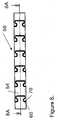
- the example of the dynamic stabilization system of the present inventiongenerally consists of a spinal element 50 and pedicle screws 20, as illustrated in Figure 1 , which are connected to two or more vertebra 10, 10', 10" and 10"' spanning the area fused or damaged area.
- the spinal element 50 in this embodimentgenerally consists of a hollow tube having an outer surface 54 and a hollow central core 55 as illustrated in Figures 2 and 5 hereinafter.
- a slot 60is cut through the wall 52 of the spinal element 50 to form a serpentine, circumferential path that extends around the entire, or partial, length of the spinal element 50.
- Multiple circumferential slots 60', 60" ...60 nare situated continually at prescribed or varying intervals over all or most of the length of the spinal element 50 enabling the majority of the element 50 to flex.
- the number of slots “n”can vary dependent upon the flexibility desired. The flexibility will be dependent upon the spacing "C” as well as the amplitude "A” of the serpentine slot 60 and the solid section 54 between slots 60. Typically the ratio of the amplitude to the spacing (A/C) is between 0.1 and 0.9.
- pedicle screws 20are illustrated herein as being attached to the proximal attachment end 28, the distal attachment end 30, as well as the central portion of the spinal element 50, hooks or other known attachment members can be substituted as known in the art. It should be noted that the pedicle screws can be affixed to slotted portions of the spinal element as well as the non-slotted portions.
- the dynamic stabilization system of the present inventiongenerally consists of a spinal element 350 and pedicle screws 20 which are connected to two or more vertebra 10, 10', 10" and 10'" spanning the fused or damaged area.
- the spinal element 50generally consists of a hollow tube having an outer surface 54 and a hollow central core 351 as illustrated in Figure 4 .
- a slots 360 , 360', 360", ... 360 nare cut through the wall 352 of section of the spinal element 350 to form a flexible segment 355.
- the slots 360 ... 360 nallow for flexibility only within the flexible segments 355 and 355'.
- the sections of the spinal element 350 that are not slottedremain relatively rigid and are used for attachment with the pedicle screws 320 at the proximal attachment end 356 distal attachment end 358 and/or central section 357.
- Figures 3 and 4illustrate two flexible sections 355 and 355', the number of flexible sections would be dictated by the number of vertebral discs requiring flexible support and would be obvious to those skilled in the art.
- the sectional view 3A-3A of spinal element 50 of Figure 2is shown in Figure 5 .
- a magnified view 5A of the slot 60is illustrated in Figure 6 .
- the slot 60is representative of all the slots disclosed herein in that way that it is cut through the wall 52 into the core 51.
- the slots disclosed hereinare of different patterns, this is purely a function of flexibility and all have the same basic construction.
- the criticality to the disclosed inventionlies in the ratios and dimensions rather than the process of placing a rod or tube.
- no reference numbers specific to other figuresare used, as the criteria are applicable to all slot configurations.
- the width of the slotshould not exceed about 0.075 of an inch in a rod having a diameter in the range from about 0.10 to about 1.0 inches, with a general width of about 0.005 to about 0.025 inches. Or alternatively stated, the slot width is between about 2.5% and about 20% of the diameter of the spinal element.
- the slot widthtypically determines the flexibility of the element; a larger slot width produces a more flexible element then an element with a smaller slot width.
- the serpentine pattern of slot 60 n+1is offset or staggered a rotational distance OFS from the adjacent slot 60 n .
- the bending characteristicsi.e. the bending strength and flexibility, can be changed to provide differences or uniformity with respect to the rotational axis.
- a biocompatible resilient flexible or elastomeric material 70fills only the slot 60 of the spinal element 50.
- the exterior surface 54 of the spinal element 50remains uncovered by the material 70 as does the interior surface 53.
- the addition of the elastomeric material 70 to the slot 60provides resistance to the flexibility of the spinal element 50 as well as preventing tissue and scar ingrowth into the slot. It should also be noted that the elastomeric material does not necessarily have to fill all slots in the rod, with the placement of filled and unfilled slots affecting the flexibility.
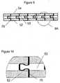
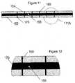
- the elastomeric material 170completely fills the central core 155 and the slot 160 but does not cover the outer surface 154 of the element 150.
- the elastomeric material 170can fill the only central core 155 adjacent to the slot or slots 160, or alternatively the entire central core 155. By filling the central core 155, flexibility is further decreased. By adjusting the amount of the central core 155 that is filled, the flexibility can be adjusted. Section 111 A is illustrated in Figure 12 in greater detail.
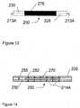
- the elastomeric material 270encapsulates the spinal rod 250 as well as filling the slots 260.
- the interior surface 230 and exterior surface 228are covered with the elastomeric material 270 and the slots 260 are filled to prevent tissue ingrowth into the slots 260 and increase the stiffness of the spinal element.
- the core 255, of the spinal element 250remains hollow as seen in section 213A-213A in Figure 14 .
- the elastomeric material 270also fills the slots 260 passing through wall 252 as shown in Figure 15 of the enlarged section 214A, it should be noted that the elastomeric material 270 can alternatively only encapsulate the spinal element 250 without filling the slots 260.
- the spinal element 250can be covered with the elastomeric material with the slots being either filled or unfilled.
- the encapsulationcan be only at the portion of the rod that is flexible or can extend the entire length of the rod.
- the addition of the elastomeric material 270increases the resistance to flexing and is not reflective of the advantages of encapsulating the spinal element 250 with the elastomeric material 270.
- the elastomeric material 370fills the central core 351, slot 360 and covers the outer surface 354.
- the elastomeric material as illustrated in all Figures hereincan either fill the central core adjacent to the slots or the entire length. This embodiment provides the greatest resistance to flexing when using the hollow tube.
- elastomeric material used hereincan also be varied in its material properties, thereby further controlling the amount of flexibility.
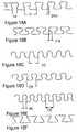
- FIG. 18 A-FA variety of slot patterns are illustrated in Figure 18 A-F .
- the patternsare representative of patterns which can be used and are not intended to be all inclusive.
- the patternhas a cycle length C, which includes a neck region NA.
- the wider the neck regionthe greater the strength of the connector, that is, the greater the torsional forces which the flexible shaft can transmit.
- the ability of the device to interlockis dependent in part upon the amount of overlap or dovetailing, indicated as DTA for Figure 18A and DTB for Figure 18B .
- the pattern of 18Cdoes not provide dovetailing, and requires full encapsulation for structural integrity. Additional patterns, as shown in Figures 18D, 18E, and 18F can have a configuration as illustrated in U.S. Patent No. 6,447,518 .
- the spinal element disclosed heretoforeis used as a central section of a vertebral body replacement implant 1600.
- the flexible portion of the implantis formed of rigid biocompatible material such as, for example, stainless steel or titanium.
- the disclosed implantcan be used in the cavity left after removal of a diseased or defective vertebra 1690" in a human or animal spine.
- the vertebral body replacement 1600is situated spanning the diseased vertebra 1690" and attached to the adjacent vertebra 1690'and 1690"'.
- the spinal element 1610is connected to an upper endplate 1620' and lower endplate 1620" by means of a threaded rods 1622' and 1622" respectively.
- the threaded rod 1622' and 1622"are movably secured to end caps 1615' 1615" respectively through internal treads 1616' and 1616" in the endcaps 1615' and 1615" to allow for height adjustment.
- the end caps 1615' and 1615"can be affixed to the spinal element 1620 during manufacture or by other means known in the medical arts.
- one endplate 1620'has right handed thread and the opposite endplate 1620" has a left handed thread such that rotating the spinal element 1610 will cause an increase in the overall distance between the endplates 1620' and 1620" from the spinal element 1610 and rotation in the opposite direction will reduce the overall distance.
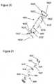
- the balls 1623' and 1623" at the ends of the threaded rods 1622' and 1622"are attached to the endplates 1622' 1622" through sockets 1624' and 1624" or similar rotational allowance coupling to allow for angular alignment to the vertebra, one end of which is illustrated in an exploded view in Figure 20 .
- the spinal element 1610has a circumferential, serpentine slot 1660 machined in the body.
- the slot 1660 configuration and properties of the cylindrical body and optional elastomeric fillerare designed to duplicate the stiffness, within a reasonable allowance, of the vertebra and adjacent intervertebral disc of human specimens.
- the slot 1660 cut into the spinal element 1610can have an elastomer (not shown) or otherwise flexible material interposed within the slot 1660 and/or the central core of the spinal element, as describe previously, to further enhance the flexibility of the shaft and to alter the torsional response or bending stiffness of the member.
- the elastomercan additionally be used as a shock absorbing or cushioning member.
- the elastomercan encapsulate the entire shaft or coupler, thus forming a tubular construction.
- the interior of the spinal element 1610can be threaded fully or partially and the threaded rods 1622' 1622" affixed directly to the spinal element 1610 thereby eliminating the endcaps 1615' 1615".
- the upper and lower endplates 1620' 1620"are configured to provide anchoring with the adjacent vertebra by means of spikes 1625', 1625" (illustrated), screws or other means.
- the end platescan contain holes through which the screws or pins can be passed into the adjacent vertebra.
- the screws or fixation pinswould pass through the implant endplate and/or alignment disc to rigidly fix the implant to the adjacent vertebra and allow for the natural curvature of the spine. It the thickness of the endplates will preferably be supplied in various thicknesses to compensate for the height of the removed vertebra and discs.
- the method of implantation of the spinal element as configured as a vertebral body replacement implant 1600 of a diseased or fracture vertebra 1690 to restore the height and functionality of the spinal columnis described. This method does not form part of the invention but is described for understanding the invention.
- the assembled endplates 1620' 1620" and threaded rod 1622' 1622" as shown in Figure 21are affixed into the appropriate sized spinal element 1610 with endcaps 1615' 1615" previously attached.
- the endcaps 1615' 1615"can be affixed to the spinal element 1610 at the time of manufacture or subsequently as known in the medical arts.
- the spinal element 1610 and endplates 1620' 1620"are dimensioned to allow for minimum or appropriate height, upon addition of the endplates 1620' and 1620" to be inserted in the prepared cavity of the vertebra 1690.
- the spinal element 1610is rotated to expand the implant 1600 to engage the upper endplate 1620' and the lower endplate 1620" to the adjacent vertebra 1510' and 1510" through spikes 1625', 1625" or other means known in the medical arts.
- surface of the endplate interfacing with the vertebracan be harmonious to facilitate and promote bone ingrowth.
- sintered metal surfaces and other porous materialshave been found particularly effective for that purpose. While a detailed discussion is believed unnecessary, it will be appreciated that the attachment screws are particularly important for initial fixation and for immobilizing the implant with respect to the adjoining vertebrae so that bone ingrowth may ultimately occur, at which time the ingrowth becomes a major factor in maintaining fixation.
- Another major factor in achieving and maintaining fixationis the limited yieldability of the prosthesis that, by mimicking the action of the replaced components, reduces the stresses at the bone/prosthesis interfaces.
Landscapes
- Health & Medical Sciences (AREA)
- Orthopedic Medicine & Surgery (AREA)
- Neurology (AREA)
- Life Sciences & Earth Sciences (AREA)
- Engineering & Computer Science (AREA)
- Biomedical Technology (AREA)
- General Health & Medical Sciences (AREA)
- Veterinary Medicine (AREA)
- Surgery (AREA)
- Heart & Thoracic Surgery (AREA)
- Public Health (AREA)
- Animal Behavior & Ethology (AREA)
- Molecular Biology (AREA)
- Medical Informatics (AREA)
- Nuclear Medicine, Radiotherapy & Molecular Imaging (AREA)
- Cardiology (AREA)
- Oral & Maxillofacial Surgery (AREA)
- Transplantation (AREA)
- Vascular Medicine (AREA)
- Prostheses (AREA)
- Surgical Instruments (AREA)
Description
- This invention relates to improved flexible elements for the stabilization of a structure having flexible and non-flexible components. Specifically the invention relates to flexible rod connectors that can be used for dynamically stabilizing a portion of the spine by stabilizing two or more bone segments. Additionally, the flexible elements can be used as a vertebral body replacement implant for the replacement of one or multiple spinal vertebra which can possess, at least in one direction, the stiffness properties of the vertebra/disc combination.
- The use of fixation devices for the treatment of vertebrae deformities and injuries is well known in the art. Various fixation devices are used in medical treatment to correct curvatures and deformities, treat trauma and remedy various abnormal spinal conditions. Spinal fusion is the standard method of treatment for many conditions including spondylolysis, spinal stenosis and other disc disorders. Since fusions expanded to treat more conditions and the number of procedures is rising each year, it was apparent that many surgeons believed this procedure is the best possible treatment for their patients. Over the past decades, a variety of spinal implant devices have been used in conjunction with fusion, including rigid systems such as bone plates, intravertebral cages, rods and hooks, and pedicle screws.
- Research shows that, when used properly, pedicle screws are the most reliable spinal implant, providing stabilization even in the event of pseudoarthrodesis. This posterior stabilization system involves variable-angle screws inserted into the pedicle of the vertebrae. Fluoroscopic pedicle screws can be detected by radiographic and fluoroscopic imaging during placement, improving the success rate of surgery. These rigid implants can be inserted from an anterior or a posterior approach, although the majority of physicians use the posterior technique.
U.S. Patent No. 6,645,207 to Dixon teaches a posterior system comprised of bone plates, clamps and pedicle screws that allow axial stress in order to improve the fusion procedure by placing it under pressure. Compression at the graft interface is crucial to establishing blood supply and nutrients to the graft. The '207 patent demonstrates that physiological loads arid stresses are important to achieve proper healing or adjustment of a damaged vertebrae. Similar patents in this field includeU.S. Patent No. 5,437,669 to Yuan,U.S. Patent No. 5,474,555 to Puno , andU.S. Patent No. 6,468,276 to McKay . - There are severe limitations of the fusion procedure including unnatural stresses on the vertebrae adjacent to the fusion, extreme limitation of flexional and torsional movements, and frequent in vivo failure of rigid constructs. These problems stimulated research on dynamic stabilization devices. Dynamic stabilization is an alternative to vertebral body fusion that stabilizes the damaged spine while permitting motion. The instruments used in dynamic fixation emanate from devices used in conjunction with fusion and are embodied in many different inventions. Pedicle screws are used with the majority of these "soft" stabilization methods, and provide physiologic support and controlled motion by attaching to elastic ligaments or metal rods. Soft stabilization devices are designed to restore the biomechanics of a functional spinal segment. Although the soft stabilizing devices relieve many problems caused by fusion, they also increase the chance of implant failure or improper insertion.
- Allowing certain degrees of physiologic motion while maintaining proper rigidity to enhance healing is the most difficult aspect of the design process in the field of dynamic spinal stabilization. The Graf ligament is one of the earliest nonfusion techniques, consisting of elastic bands looped around pedicle screws.
U.S. Patent No. 5,092,866 to Breard and Graf describes this system of non-metallic loops, secured to either the spinous processes or pedicle screws, which permit the patient certain degrees of flexional and torsional movements. The semi-elastic ligament keeps sufficient space between the vertebrae which encourages proper healing. This idea has been sophisticated by subsequent researchers who have produced new methods to neutralize unstable vertebrae and the following are some typical inventions in this field.U.S. Patent No. 6,966,910 to Ritland describes two pedicle screws anchoring a metallic rod component with several embodiments, including multiple geometries and dual rods. In the '910 device, the geometry of the metal rods produce the flexible or semi-elastic stabilization.U.S. Patent No. 5,282,863 to Burton teaches a system that achieves dynamic fixation of the spinal column by using a non-metallic, porous material as the rod component, rather than conventional metallic rods, to increase flexibility of the implant.U.S. Patent No. 7,083,621 to Shaolian that utilizes ball-and-socket connections between rods and bone screws that dynamically stabilize the damaged spine. The specialized rods described in the '621 patent can be inserted into the portals of the bone anchors and allow for angular articulation of the device.U.S. Patent No. 7,018,379 to Drewry teaches a system of bone screws and fasteners that attach a flexible elongated member which is tensioned to provide corrective forces to the spine. Another motion-preserving device presented inU.S. Patent No. 6,989,011 to Paul incorporates at least one tube with helical slits down the length. This dynamic rod or rods act to support a vertebral motion segment and allow controlled degrees of movement. The angular range of the '011 rod can be modified by altering the pitch and direction of the slits.U.S. Patent No. 6,293,949 to Justis uses a longitudinal member at least partially composed of a pseudoelastic shape-memory material that is anchored by bone screws. The longitudinal member reforms to a new configuration under stress then returns to the initial configuration when the stress is removed, providing flexible support for the cervical spine - Subsequent researchers who have produced new methods to neutralize unstable vertebrae have sophisticated the idea introduced by Gaf. A flexible posterior stabilization system, DYNESYS (dynamic neutralization system) developed in 1994 and now marketed by Zimmer (Warsaw, IN), is now gaining popularity among orthopedic surgeons in the US as an alternative to fusion. Anchored by pedicle screws, Dynesys uses preloaded stabilizing cords and spacers to provide uniform system rigidity. With the development of soft stabilization methods, fusion has become an outdated and inelegant technique that permanently eliminates normal biomechanical motion of the spine. The dynamic stabilization systems are important alternatives to fusion and are the future for the treatment of vertebral instability.
- A need has thus arisen for improvements in dynamic stabilization instruments, and the present invention offers that advancement through the development of the flexible connecting rod for posterior implantation on damaged vertebrae.
- In another application when a vertebra is broken, crushed or diseased, it is frequently necessary to ablate the body of the crushed or diseased vertebra. In order, however to prevent the spinal column from collapsing with damage to the spinal cord running in the vertebral foramen forward of the vertebral body, it is necessary to employ a spacer. This device is braced vertically between the bodies of the adjacent vertebrae and holds them apart at the desired spacing. A substitute vertebra with biofidelic properties would provide the optimum replacement
- Various implants have been developed to address structural failure of various parts of the spinal column. The prior art with respect to spinal column implants falls into two general categories: intervertebral disc prostheses, and rigid vertebral body prostheses.
- Vertebral body prostheses have been disclosed in US Patents such as
3,426,364 ,4,401,112 ,4,554,914 ,4,599,086 ,4,932,975 , and5,571,192 . The referenced patents typically are composed of a rigid, height adjustable device, typically a threaded cylinder or turnbuckle mechanism with anchoring plates. Another type of replacement device is composed of individual elements that are sized and adapted to be fitted together to provide support to the adjacent vertebra. This type of device has been described inUS Patents 5,147,404 and5,192,327 . - The devices presented in the above patents are intended for situations where it is necessary to remove a vertebral body. That, in turn, requires the resection of adjacent intervertebral discs. A problem common to all of such prior devices however is that they adequately provide the structure of the removed vertebral body but fail to provide the flexibility of the removed intervertebral discs.
- The rods disclosed herein provide a flexible implant that will flex, bend or curve to allow or duplicate the natural movement of the spinal segments.
- A stabilization system as described in the preamble of
claim 1 is known fromUS 2007/016190 A1 . The flexible shaft of the known stabilization system is slotted in a helical, or spiral, configuration along the shaft, said slot following a serpentine path. - The present invention overcomes the deficiencies and problems evident in the prior art as described herein above by combining the following features into an integral, longitudinally, laterally and torsionally flexible component.
- The present invention relates to a stabilization system as claimed hereafter. Preferred embodiments of the invention are set forth in the dependent claims.
- A spine stabilization system for attachment to vertebral bodies to restore or maintain vertebral motion and provide support to the spinal column is disclosed. The system consists of a,spinal element having a distal attachment end and a proximal attachment end. The center of the element, between the distal and proximal attachment ends has at least one flexible center section that has at least one slot of substantial length and width extending in a generally concentric path, or circumferential manner, following a serpentine or predetermined path generally around the tubular member. A serpentine path can be superimposed on the circumferential slot in the form of a generally sinusoidal wave. Preferably, the sinusoidal wave forms dovetail-like teeth, which have a narrow base region and an anterior region which is wider than the base region. Thus, adjacent teeth interlock. The teeth can have a configuration as illustrated in
U.S. Patent No. 4,328,839 . - It is noticed that from
US 2007/016204 A1 a stabilization system as described in the preamble ofclaim 1 is known. However, the flexible shaft of this known stabilization system is slotted in a serpentine manner to form teeth with said slot following a helical, or spiral path along the length of the device. - Further, it is noticed that also from
US 2005/0203517 A1 a stabilization system as described in the preamble ofclaim 1 is known from. However, the flexible shaft of this known stabilization system is a slot following a helical, or spiral path along the length of the device. - Further, it is noticed that also from
US 2005/0293657 A1 a stabilization system as described in the preamble ofclaim 1 is known However, the flexible portion of this known stabilization system is a metal helical spring. - Further, it is noticed that also from WO 03/047442 A1 a stabilization system as described in the preamble of
claim 1 is known. However, the flexible portions of this known stabilization system are a pair of springs, having different spring rates, parallel to a longitudinal axis. - Further, it is noticed that a flexible shaft as described in the preamble of
claim 1 is known fromUS 6,053,922 . However, this known flexible shaft is a medullary reamer slotted in a serpentine manner to form teeth with said slot following a helical, or spiral path along the length of the device. - Further, it is noticed that a stabilization system as described in the preamble of
claim 1 is known fromUS 2005/0065516 A1 . However, the flexible shaft of this known stabilization system is a slot following a helical, or spiral path along the length of the device. - Multiple slotted sections are separated by non-slotted areas. The slot can extend the entire length of the element or the proximal and distal attachment ends can be solid with the slotted section only being in the center. The slot has a width of about 1.0% to about 20% of the diameter of the spinal element. The element can be a tube having a hollow inside core forming an inner diameter and an exterior wall forming an exterior diameter having an inner diameter from about 10% to about 85% of the exterior diameter. Advantageously, the slot is cut at an angle normal to the shaft using a computer controlled cutting technique such as laser cutting, water jet cutting, milling or other means. Additionally, this slot can be cut at an angle to the normal, preferably from normal to about 45 degrees from the normal, so as to provide an undercut slot. In a preferred embodiment, the ratio of the amplitude of the serpentine path of the circumferential slot to the distance between slots is in the range from greater than 0.1 to about 0.8 and preferably in the range of about .04 to .06 for many applications. It will, however be evident to those skilled in the art that the preferred slot distance, as well as width of slot will depend on the end use, e.g. use on a large animal would require different dimensioning than use on a human
- To increase the flexibility of the component, a plurality of slots can be employed, relative to a shaft having a single slot of identical pattern. The serpentine, circumferential path forms a plurality of teeth and complimentary recesses on opposite sides of the slot. The slot has sufficient width to form an unbound joint that permits limited movement in any direction between the teeth and the recesses, thereby providing controlled flexibility in all directions upon application of tensile, compressive, and/or torsion forces. In a similar manner the slot can have increased width in one direction compared to another direction to provide increased flexibility in one direction. The flexible component can also have different degrees of flexibility along the length of the shaft. The varied flexibility can be achieved by having the width of the slot and/or the spacing of the circumferential slots vary along the length of the shaft. The varied flexibility corresponds to the spacing of the circumferential slot along the length of the shaft and/or the length of the section of the shaft having the circumferential slots. Alternatively, the width of the circumferential slot can vary along the length of the shaft to provide the varied flexibility. The rigidity of the flexible shaft can be achieved through the design of the slot pattern, thereby enabling the use of thinner walls than would otherwise be required to produce equivalent rigidity.
- In some embodiments the slot can be filled, partially or entirely along the path of the slot, with a resilient material to control and vary rigidity. Further rigidity can be achieved by encapsulating the entire shaft thus forming an elastomer enclosed member. The resilient material can be an elastomer compound, such as urethane or a silicone compound, which can be of sufficient thickness to fill the slot and to encapsulate the entire shaft. The rigidity of the flexible shaft can be further achieved or varied through the use of filler material having different stiffness properties, thereby enabling the use of thinner walls than would otherwise be require to produce equivalent rigidity.
- The element can have the elastomeric material in any or all of the following combinations: filling at least one of the at least one slot; at least a portion of the inside core; encompass at least a portion of the exterior diameter. Attachment members are used at the proximal and distal attachment ends to attach the element to the vertebral bodies. One or more central attachment members can be used to affix the element, in between the attachment ends, to vertebral bodies.
- When the spinal element is used to replace one or more diseased or fractured vertebra, a preferred diameter is from about 0.5 to 1.0 inches. The attachment members at the proximal end and distal end are affixed to a superior and an inferior vertebra. The proximal and distal attachment ends have threaded receiving areas to receive attachment members. Preferably one of said threaded receiving areas is a right hand thread and the second a left hand thread. The attachment members can comprise a threaded end cap, a threaded rod threadably engage with the end cap, a ball end attached to the threaded rod, and an end plate dimensioned to rotatably receive the ball end on one surface and securing member receiving areas on a second surface. The securing member receiving areas can be nails affixed to the end plate or a plate surface that is conducive for bone ingrowth.
- To stabilize a diseased or fractured vertebra to restore or maintain vertebral motion and provide support to the spinal column the distance between healthy superior vertebra and inferior vertebra adjacent to said diseased or fractured vertebra is determined. A flexible spinal element having a length to span the distance is selected and a first attachment member is attached to the superior vertebra and a second attachment member attached to the inferior vertebra. The spinal element is then attached to the first and second attachment members.
- The disclosed system has several closely related embodiments, all using the flexible spinal element. The selection of a specific embodiment for a particular application will be obvious to one skilled in the medical arts upon reading the teachings herein.
- It is a further object of this invention to provide a tubular device which will have certain axial, bending and torsional stiffness for a vertebral body replacement implant.
- These and other objects, features, advantages and aspects of the present invention will be better understood with reference to the following detailed description of the preferred embodiments when read in conjunction with the appended drawing figures.
Figure 1 is a schematic representation of a flexible spinal element attached to the lumbar region of the spine and having circumferential slots extending the majority of the length of the element in accordance with the invention;Figure 2 is a schematic representation of a flexible spinal element attached to the lumbar region of the spine and having the circumferential slots extending only between the attachment members in accordance with the invention;Figure 3 is a schematic representation of the flexible spinal rod ofFigure 1 , showing general pattern of the circumferential serpentine slots along the length of the rod in accordance with the invention;Figure 4 is perspective view of spinal element ofFigure 2 , showing the segmental segments containing the serpentine slots between attachment areas.Figure 5 is a cross sectional view of the flexible spinal rod through the longitudinal axis ofFigure 3 , showing general pattern of the serpentine, circumferential slots along the length of the rod in accordance with the invention;Figure 6 is an exploded view ofsection 5A showing the gap and interlocking of the serpentine slot;Figure 7A is an illustration of variation of the change in orientation of the serpentine slot relative to the adjacent slot whereby the teeth of each adjacent circumferential slot is staggered or offset a variable distance;Figure 7B is a cross sectional view of the flexible spinal rod through the longitudinal axis ofFigure 7A , showing general pattern of the offset serpentine, circumferential slots along the length of the rod in accordance with the invention;Figure 7C is an exploded view ofsection 7B showing the gap and interlocking of the serpentine slot of two slots that have been offset or staggered;Figure 8 is a schematic representation of the flexible spinal rod ofFigure 1 , showing general pattern of the circumferential serpentine slots with an elastomer filler material in the slot;Figure 9 is a sectional illustration though thelongitudinal axis 8A-8A shown inFigure 8 of the spinal element showing the slot with a resilient filler in a portion of the slot in accordance with the invention;Figure 10 is a magnified view of thearea 9A inFigure 9 in accordance with the invention;Figure 11 is a sectional illustration though the longitudinal axis, 8A-8A of the spinal element inFigure 8 showing the resilient filler occupying the central core and filling the slot in accordance with the invention;Figure 12 is a magnified view of thearea 111 A ofFigure 11 in accordance with the invention;Figure 13 is an exterior view of the spinal element with the center portion encapsulated with a resilient filler;Figure 14 is a sectional illustration though thelongitudinal axis 213A of the spinal element inFigure 13 showing the filled slot with a resilient filler encapsulating the entire tube but not filling the central core;Figure 15 is a magnified view of thearea 214A inFigure 14 in accordance with the invention;Figure 16 is a sectional illustration though the longitudinal axis of the spinal element showing the resilient filler occupying the central core and encapsulating the entire tube in accordance with the invention;Figure 17 is a magnified view of thearea 16A ofFigure 16 in accordance with the invention;Figure 18a - 18f show schematic representations of additional spiral slit patterns in accordance with the invention;Figure 19 is schematic representation of one embodiment of the spinal element as a vertebral replacement inserted between vertebra of the spine in accordance with the invention;Figure 20 is an illustration of the disclosed vertebral body replacement consisting of a central flexible core with and the previously described serpentine circumferential slots and adjustable height end caps for securing the device to the adjacent vertebra in accordance with the invention; andFigure 21 is an exploded view of the vertebral body replacement in accordance with the invention.- The term slot as used herein, is defined in theAmerican Heritage Dictionary, 3rd Edition, Copyright 1994, as follows:
- For the purposes herein the terms "slit" and "slot" are used interchangeably, consistent with their definitions, as follows:
- slot n. 1. A narrow opening; a groove or slit: a slot for coins in a vending machine; a mail slot.
- 2. A gap between a main and an auxiliary airfoil to provide space for airflow and facilitate the smooth passage of air over the wing.
- For the purposes herein the term pitch as used herein is defined as:
- pitch - n.1. The distance traveled by a machine screw in one revolution.
- 2. The distance between two corresponding points on adjacent screw threads or gear teeth.
- For the purposes herein the term "cycle" shall refer to:
- Cycle - 1. An interval of time during which a characteristic, often regularly repeated event or sequence of events occurs: Sunspots increase and decrease in intensity in an 11-year cycle.
- 2.a. A single complete execution of a periodically repeated phenomenon: A year constitutes a cycle of the seasons.
- 2b. A periodically repeated sequence of events: cycle includes two halves of the sine-wave like undulation of the slot path.
- For the purposes herein the term "amplitude" shall refer to the maximum absolute value of the periodically varying quantity of the slot.
- For the purposes herein the term "frequency" shall refer to the number of times a specified phenomenon occurs within a specified interval:
- Frequency.
- 1 a. Number of repetitions of a complete sequence of values of a periodic function per unit variation of an independent variable.
- 1 b. Number of complete cycles of a periodic process occurring per unit time.
- 1 c. Number of repetitions per unit time of a complete waveform, as of an electric current. The number of times the cycles form a repetitive pattern in one unit of length is the frequency of the slot pattern. The number of cycles "C" of the slot undulations superimposed upon the circumferential path which are present in one revolution around the shaft, is referred to as the cycles per revolution.
- For the purposes herein the coined term "Biofidelic" shall refer to the mechanical structures that attempt to duplicates biological structures with a high accuracy of fidelity.
- For the purposes herein the term "spinal element" shall refer to a solid rod or tube manufactured of a biocompatible material that can receive a slot or cut to provide flexibility.
- For the purposes herein the term "element" shall refer to a solid rod or tube manufactured of a material that can receive a slot or cut to provide flexibility.
- For the purposes herein the term "dynamic stabilization systems" shall refer to spinal instrumentation devices that stabilizes the damaged spine while permitting motion.
- While the present invention will be described more fully hereinafter with reference to the accompanying drawings, in which particular embodiments directed to spinal stabilization implantation are shown, it is to be understood at the outset that persons skilled in the art can modify the invention herein described while achieving the functions and results of this invention for any appropriate use. Accordingly, the descriptions that follow are to be understood as illustrative and exemplary of specific structures, aspects and features within the broad scope of the present invention and not as limiting of such broad scope.
- The present invention is directed to dynamic stabilization systems that can be used with the anterior, antero-lateral, lateral, and/or posterior portions of at least one motion segment unit of the spine. The systems of the invention are designed to be conformable to the spinal anatomy and provide controlled, dynamic stabilization.
- The system of the invention can be used on the cervical, thoracic, lumbar, and sacral segments of the spine. The size and mass increase of the vertebrae in the spine from the cervical to the lumbar portions is directly related to an increased capacity for supporting larger loads. This increase in load bearing capacity, however, is paralleled by a decrease in flexibility and an increase in susceptibility to strain. When rigid immobilization systems are used in the lumbar segment, the flexibility is decreased even further beyond the natural motion restriction of that segment. Replacing the conventional rigid immobilization systems with the disclosed spine stabilization system restores a more natural movement and provides added support to the strain-susceptible area.
- One embodiment of the stabilization system of the present invention, when used for spinal stabilization, includes bone fasteners, for example pedicle screws, the disclosed end plates or hooks, and at least one of the disclosed flexible spinal elements, with or without additional connecting rods. The flexible element advantageously provides desirable properties for bending or twisting that allows the system to accommodate the natural spine movement. The flexible element preferably approximates or resembles a relatively circular metallic or polymeric tube or rod with an appropriately formed series of slots that extends circumferentially around the shaft, the basic concept of which is described by
Krause et al (U.S. Patent Nos. 6,053,922 and6,447,518 ). In another embodiment, the spinal element and flexible segments of the element can be combined with a polymeric material as described hereinafter. - In some embodiments the central portion of the flexible element is hollow, resembling a hollow tube. A skilled artisan would appreciate that there are several ways to form a hollow tube, regardless of whether it is circular or any other cross-sectional shape. For example, extruding a material, such as metal or polymeric materials, through a die, can form the tube with one or more of the patterns described hereinafter then be cut into the extruded material. For instance, a tube can have a slit or serpentine cut along at least a portion of the tube or the tube can have a plurality of slits cut into its surface, by using a laser or by other suitable methods.
- The following examples describe embodiments using a solid rod or tube. It should be understood that in these examples the flexible elements described herein can be replaced with flexible elements having different shapes or configurations, including, but not limited to, the many variations described herein.
- The invention relates to a flexible spine stabilization system having one or more flexible segments within a spinal element. The flexibility is created through the use of at least one circumferential slot formed in the spinal element. Additional flexible segments also have at least one circumferential slot. One or more fasteners are connected to or in communication with the distal and proximal attached ends of the spinal elements as known in the medical arts. In another embodiment the flexible spine stabilization system has a flexible segment that has at least one circumferential slot within a section of the spinal element that is embedded within a polymer or other flexible material so as to fill the slot with the flexible material. In an additional embodiment the flexible spine stabilization system uses a hollow flexible element that encompasses a polymer or other flexible material within its central core without extending into the circumferential slot(s). A further embodiment uses a flexible slotted segment within the spinal element that contains a polymer or other flexible material within the central core with the flexible material extending radially outward through the circumferential slot(s). The flexible spine stabilization system can further incorporate a flexible slotted segment that contains a polymer or other flexible material within the central core of the spinal element and/or flexible segment that extends radially outward through the slot and encompasses the outer surface of the spinal element and/or the flexible segment.
- Another important aspect of this invention therefore lies in providing a prosthesis for total replacement of a vertebral body and adjacent discs that will provide the flexibility and stiffness of the resected vertebra and, when properly in place, provides a stress environment at the prosthesis/bone interface similar to normal in vivo conditions. Specifically, the invention can be utilized to produce an implant in which the normal ranges of movement are preserved, the prosthesis permitting limited longitudinal flexure, slight compression and expansion, and even a limited degree of torsional movement that at least approximates a normal vertebral response.
- The example of the dynamic stabilization system of the present invention generally consists of a
spinal element 50 and pedicle screws 20, as illustrated inFigure 1 , which are connected to two ormore vertebra spinal element 50 in this embodiment generally consists of a hollow tube having anouter surface 54 and a hollowcentral core 55 as illustrated inFigures 2 and5 hereinafter. Aslot 60 is cut through thewall 52 of thespinal element 50 to form a serpentine, circumferential path that extends around the entire, or partial, length of thespinal element 50. Multiplecircumferential slots 60', 60" ...60n are situated continually at prescribed or varying intervals over all or most of the length of thespinal element 50 enabling the majority of theelement 50 to flex. The number of slots "n" can vary dependent upon the flexibility desired. The flexibility will be dependent upon the spacing "C" as well as the amplitude "A" of theserpentine slot 60 and thesolid section 54 betweenslots 60. Typically the ratio of the amplitude to the spacing (A/C) is between 0.1 and 0.9. Although pedicle screws 20 are illustrated herein as being attached to theproximal attachment end 28, thedistal attachment end 30, as well as the central portion of thespinal element 50, hooks or other known attachment members can be substituted as known in the art. It should be noted that the pedicle screws can be affixed to slotted portions of the spinal element as well as the non-slotted portions. - In
Figure 4 the dynamic stabilization system of the present invention generally consists of aspinal element 350 and pedicle screws 20 which are connected to two ormore vertebra Figure 1 , thespinal element 50 generally consists of a hollow tube having anouter surface 54 and a hollowcentral core 351 as illustrated inFigure 4 . Aslots wall 352 of section of thespinal element 350 to form aflexible segment 355. In this embodiment theslots 360 ... 360n allow for flexibility only within theflexible segments 355 and 355'. The sections of thespinal element 350 that are not slotted remain relatively rigid and are used for attachment with the pedicle screws 320 at theproximal attachment end 356distal attachment end 358 and/orcentral section 357. AlthoughFigures 3 and4 illustrate twoflexible sections 355 and 355', the number of flexible sections would be dictated by the number of vertebral discs requiring flexible support and would be obvious to those skilled in the art. - The
sectional view 3A-3A ofspinal element 50 ofFigure 2 is shown inFigure 5 . A magnifiedview 5A of theslot 60 is illustrated inFigure 6 . Theslot 60 is representative of all the slots disclosed herein in that way that it is cut through thewall 52 into thecore 51. Although the slots disclosed herein are of different patterns, this is purely a function of flexibility and all have the same basic construction. The criticality to the disclosed invention lies in the ratios and dimensions rather than the process of placing a rod or tube. In the following description of the criteria of the slots, no reference numbers specific to other figures are used, as the criteria are applicable to all slot configurations. - In order to provide the desired flexibility, while maintaining support, the width of the slot should not exceed about 0.075 of an inch in a rod having a diameter in the range from about 0.10 to about 1.0 inches, with a general width of about 0.005 to about 0.025 inches. Or alternatively stated, the slot width is between about 2.5% and about 20% of the diameter of the spinal element. The slot width typically determines the flexibility of the element; a larger slot width produces a more flexible element then an element with a smaller slot width.
- In the embodiment illustrated in
Figures 7A, 7B, and 7C , the serpentine pattern ofslot 60n+1 is offset or staggered a rotational distance OFS from theadjacent slot 60n. By staggering the serpentine pattern as illustrated, the bending characteristics, i.e. the bending strength and flexibility, can be changed to provide differences or uniformity with respect to the rotational axis. - In the embodiment illustrated in
Figures 8 ,9 and 10 , a biocompatible resilient flexible orelastomeric material 70 fills only theslot 60 of thespinal element 50. Theexterior surface 54 of thespinal element 50 remains uncovered by thematerial 70 as does theinterior surface 53. The addition of theelastomeric material 70 to theslot 60 provides resistance to the flexibility of thespinal element 50 as well as preventing tissue and scar ingrowth into the slot. It should also be noted that the elastomeric material does not necessarily have to fill all slots in the rod, with the placement of filled and unfilled slots affecting the flexibility. - In
Figures 11 and 12 theelastomeric material 170 completely fills thecentral core 155 and theslot 160 but does not cover theouter surface 154 of the element 150. Theelastomeric material 170 can fill the onlycentral core 155 adjacent to the slot orslots 160, or alternatively the entirecentral core 155. By filling thecentral core 155, flexibility is further decreased. By adjusting the amount of thecentral core 155 that is filled, the flexibility can be adjusted.Section 111 A is illustrated inFigure 12 in greater detail. - In
Figures 13, 14 and15 theelastomeric material 270 encapsulates thespinal rod 250 as well as filling theslots 260. In this embodiment, theinterior surface 230 andexterior surface 228 are covered with theelastomeric material 270 and theslots 260 are filled to prevent tissue ingrowth into theslots 260 and increase the stiffness of the spinal element. Thecore 255, of thespinal element 250, however, remains hollow as seen insection 213A-213A inFigure 14 . Although in these figures theelastomeric material 270 also fills theslots 260 passing throughwall 252 as shown inFigure 15 of theenlarged section 214A, it should be noted that theelastomeric material 270 can alternatively only encapsulate thespinal element 250 without filling theslots 260. Additionally, just the interior or exterior of the spinal element can be covered with the elastomeric material with the slots being either filled or unfilled. The encapsulation can be only at the portion of the rod that is flexible or can extend the entire length of the rod. As noted above, the addition of theelastomeric material 270 increases the resistance to flexing and is not reflective of the advantages of encapsulating thespinal element 250 with theelastomeric material 270. - In
Figures 16 and 17 , theelastomeric material 370 fills thecentral core 351,slot 360 and covers theouter surface 354. As stated with reference toFigures 13 and 14 , the elastomeric material as illustrated in all Figures herein can either fill the central core adjacent to the slots or the entire length. This embodiment provides the greatest resistance to flexing when using the hollow tube. - It should be noted that the elastomeric material used herein can also be varied in its material properties, thereby further controlling the amount of flexibility.
- A variety of slot patterns are illustrated in
Figure 18 A-F . The patterns are representative of patterns which can be used and are not intended to be all inclusive. As illustrated inFigure 18A , the pattern has a cycle length C, which includes a neck region NA. The wider the neck region the greater the strength of the connector, that is, the greater the torsional forces which the flexible shaft can transmit. The ability of the device to interlock is dependent in part upon the amount of overlap or dovetailing, indicated as DTA forFigure 18A and DTB forFigure 18B . The pattern of 18C, does not provide dovetailing, and requires full encapsulation for structural integrity. Additional patterns, as shown inFigures 18D, 18E, and 18F can have a configuration as illustrated inU.S. Patent No. 6,447,518 . - In another embodiment of the invention illustrated in
Figures 19 -21 , the spinal element disclosed heretofore is used as a central section of a vertebralbody replacement implant 1600. As with the embodiments disclosed heretofore, the flexible portion of the implant is formed of rigid biocompatible material such as, for example, stainless steel or titanium. Through the addition of theendplates 1620' and 1620", the disclosed implant can be used in the cavity left after removal of a diseased ordefective vertebra 1690" in a human or animal spine. Thevertebral body replacement 1600 is situated spanning thediseased vertebra 1690" and attached to theadjacent vertebra 1690'and 1690"'. - The
spinal element 1610, as shown inFigures 20 and 21 , is connected to an upper endplate 1620' andlower endplate 1620" by means of a threadedrods 1622' and 1622" respectively. The threadedrod 1622' and 1622" are movably secured to end caps 1615' 1615" respectively throughinternal treads 1616' and 1616" in theendcaps 1615' and 1615" to allow for height adjustment. The end caps 1615' and 1615" can be affixed to thespinal element 1620 during manufacture or by other means known in the medical arts. Preferably one endplate 1620' has right handed thread and theopposite endplate 1620" has a left handed thread such that rotating thespinal element 1610 will cause an increase in the overall distance between theendplates 1620' and 1620" from thespinal element 1610 and rotation in the opposite direction will reduce the overall distance. Theballs 1623' and 1623" at the ends of the threadedrods 1622' and 1622" are attached to the endplates 1622' 1622" throughsockets 1624' and 1624" or similar rotational allowance coupling to allow for angular alignment to the vertebra, one end of which is illustrated in an exploded view inFigure 20 . Attachment to the upper endplate 1620' and thelower endplate 1620" to the adjacent vertebra 1510' and 1510" is throughspikes 1625' and 1625" respectively, or other means known in the medical arts. Thespinal element 1610,Figures 20 and 21 , has a circumferential,serpentine slot 1660 machined in the body. Theslot 1660 configuration and properties of the cylindrical body and optional elastomeric filler are designed to duplicate the stiffness, within a reasonable allowance, of the vertebra and adjacent intervertebral disc of human specimens. Theslot 1660 cut into thespinal element 1610 can have an elastomer (not shown) or otherwise flexible material interposed within theslot 1660 and/or the central core of the spinal element, as describe previously, to further enhance the flexibility of the shaft and to alter the torsional response or bending stiffness of the member. The elastomer can additionally be used as a shock absorbing or cushioning member. To facilitate manufacture, and to provide protection of the tubular member, the elastomer can encapsulate the entire shaft or coupler, thus forming a tubular construction. Alternatively, the interior of thespinal element 1610 can be threaded fully or partially and the threaded rods 1622' 1622" affixed directly to thespinal element 1610 thereby eliminating the endcaps 1615' 1615". - The upper and lower endplates 1620' 1620" are configured to provide anchoring with the adjacent vertebra by means of
spikes 1625', 1625" (illustrated), screws or other means. The end plates can contain holes through which the screws or pins can be passed into the adjacent vertebra. The screws or fixation pins would pass through the implant endplate and/or alignment disc to rigidly fix the implant to the adjacent vertebra and allow for the natural curvature of the spine. It the thickness of the endplates will preferably be supplied in various thicknesses to compensate for the height of the removed vertebra and discs. - The method of implantation of the spinal element as configured as a vertebral
body replacement implant 1600 of a diseased orfracture vertebra 1690 to restore the height and functionality of the spinal column is described. This method does not form part of the invention but is described for understanding the invention. The assembled endplates 1620' 1620" and threaded rod 1622' 1622" as shown inFigure 21 are affixed into the appropriate sizedspinal element 1610 with endcaps 1615' 1615" previously attached. The endcaps 1615' 1615" can be affixed to thespinal element 1610 at the time of manufacture or subsequently as known in the medical arts. Thespinal element 1610 and endplates 1620' 1620" are dimensioned to allow for minimum or appropriate height, upon addition of theendplates 1620' and 1620" to be inserted in the prepared cavity of thevertebra 1690. Thespinal element 1610 is rotated to expand theimplant 1600 to engage the upper endplate 1620' and thelower endplate 1620" to the adjacent vertebra 1510' and 1510" throughspikes 1625', 1625" or other means known in the medical arts. - It is to be understood that surface of the endplate interfacing with the vertebra can be harmonious to facilitate and promote bone ingrowth. As well known in the art, sintered metal surfaces and other porous materials have been found particularly effective for that purpose. While a detailed discussion is believed unnecessary, it will be appreciated that the attachment screws are particularly important for initial fixation and for immobilizing the implant with respect to the adjoining vertebrae so that bone ingrowth may ultimately occur, at which time the ingrowth becomes a major factor in maintaining fixation. Another major factor in achieving and maintaining fixation is the limited yieldability of the prosthesis that, by mimicking the action of the replaced components, reduces the stresses at the bone/prosthesis interfaces.
- While the foregoing has disclosed embodiments of the invention in considerable detail, it will understood by those skilled in the art that many of these details may be varied without departing from the scope of the invention.
Claims (13)
- A stabilization system for attachment to vertebral bodies to restore or maintain vertebral motion and provide support to the spinal column, said stabilization system has an elongated element (50, 350, 1600) comprising:(i) a distal attachment end (30, 356, 1615');(ii) a proximal attachment end (28, 358, 1615"); and(iii) at least one flexible center section (355), said center section being positioned between said distal end and said proximal end, each of said at least one flexible center section having at least one slot (60, 360, 1660) extending around said elongated element following a serpentine path, said serpentine path forming a plurality of interlocking teeth,characterized in that said at least one flexible center section having at least one further slot, said slot and further slot being separated from each other and being concentric and extending circumferentially and circularly around said elongated element.
- The stabilization system of claim 1characterized in that said element comprises a tube (1610), said tube having a hollow inside core (351) forming an inner diameter (352) and an exterior wall (354) forming an exterior diameter.
- The stabilization system of claim 2,characterized in that said inner diameter ranging from about 10% to about 85% of said exterior diameter.
- The stabilization system of claim 1, 2 or 3,characterized in that said element is a cylinder having a diameter ranging from about 0.5 to 1.0 inches.
- The stabilization system of any one of the preceding claims,characterized in that said slot (60, 1660) has a width of about 1.0% to 20% of the diameter of said spinal element.
- The stabilization system of any one of the preceding claims,characterized in that said stabilization system further comprises an elastomeric material (70) at at least one of: said slot and further slot (60); within at least one portion of said inside core (351) adjacent to said at least one flexible center section (355); within said insider core (351) to extend through, and fill, said slots (60); encompass at least a portion of said exterior diameter (354); encompass at least a portion of said exterior diameter (354) and extends into said slots (60).
- The stabilization system of any one of the preceding claims,characterized in that said proximal attachment (358) end and said distal attachment end (356) are non-slotted.
- The stabilization system of any one of the preceding claims,characterized in that a first of said at least one flexible center section (355) and a second of said at least one flexible center section (355') is separated by a non-slotted section (357).
- The stabilization system of any one of the preceding claims,characterized in that said elongated element comprising at least two attachment members (1620', 1620"), said at least two attachment members (1620', 1620") to affix at least said proximal end cap (1615") and said distal end cap (1615').
- The stabilization system of claim 9characterized in that said elongated element at said proximal end cap (1615") and said distal end cap (1615') have threaded receiving areas (1616", 1616') to receive said attachment members (1620', 1620"), one of said threaded receiving areas (1616", 1616') being a right hand thread and a second of said threaded receiving areas being a left hand thread.
- The stabilization system of claim 9 or 10characterized in that each of said attachment members (1620', 1620"), comprise:a. a threaded end cap (1615', 1615"),b. a threaded rod (1622', 1622"), said threaded rod (1622', 1622") being dimensioned to threadably engage with said end cap (1615', 1615"),c. ball end (1623', 1623"), said ball end being attached to said threaded rod (1622', 1622"),d. an end plate (1620', 1620"), said end plate (1620', 1620") being dimensioned to rotatably receive said ball end (1623', 1623"), and having securing member receiving areas (1624', 1624").
- The stabilization system of claim 11characterized in that a first of said threaded end cap (1615') has a right hand thread and a second of said threaded end cap (1615") has a left hand thread or conversely, first of said threaded end cap (1615') has a left hand thread and a second of said threaded end cap (1615") has a right hand thread.
- The stabilization system of claim 11 or 12characterized in that said securing member receiving areas are nails affixed to said end plate.
Applications Claiming Priority (2)
| Application Number | Priority Date | Filing Date | Title |
|---|---|---|---|
| US7789208P | 2008-07-03 | 2008-07-03 | |
| PCT/US2009/049646WO2010003139A1 (en) | 2008-07-03 | 2009-07-03 | Flexible spine components having a concentric slot |
Publications (3)
| Publication Number | Publication Date |
|---|---|
| EP2306914A1 EP2306914A1 (en) | 2011-04-13 |
| EP2306914A4 EP2306914A4 (en) | 2013-04-24 |
| EP2306914B1true EP2306914B1 (en) | 2016-11-23 |
Family
ID=41466349
Family Applications (1)
| Application Number | Title | Priority Date | Filing Date |
|---|---|---|---|
| EP09774588.9AActiveEP2306914B1 (en) | 2008-07-03 | 2009-07-03 | Flexible spine components having a concentric slot |
Country Status (3)
| Country | Link |
|---|---|
| US (1) | US8353935B2 (en) |
| EP (1) | EP2306914B1 (en) |
| WO (1) | WO2010003139A1 (en) |
Families Citing this family (72)
| Publication number | Priority date | Publication date | Assignee | Title |
|---|---|---|---|---|
| FR2812185B1 (en) | 2000-07-25 | 2003-02-28 | Spine Next Sa | SEMI-RIGID CONNECTION PIECE FOR RACHIS STABILIZATION |
| US7833250B2 (en) | 2004-11-10 | 2010-11-16 | Jackson Roger P | Polyaxial bone screw with helically wound capture connection |
| US10729469B2 (en) | 2006-01-09 | 2020-08-04 | Roger P. Jackson | Flexible spinal stabilization assembly with spacer having off-axis core member |
| US7862587B2 (en) | 2004-02-27 | 2011-01-04 | Jackson Roger P | Dynamic stabilization assemblies, tool set and method |
| US10258382B2 (en) | 2007-01-18 | 2019-04-16 | Roger P. Jackson | Rod-cord dynamic connection assemblies with slidable bone anchor attachment members along the cord |
| US8292926B2 (en) | 2005-09-30 | 2012-10-23 | Jackson Roger P | Dynamic stabilization connecting member with elastic core and outer sleeve |
| US8353932B2 (en) | 2005-09-30 | 2013-01-15 | Jackson Roger P | Polyaxial bone anchor assembly with one-piece closure, pressure insert and plastic elongate member |
| US8876868B2 (en) | 2002-09-06 | 2014-11-04 | Roger P. Jackson | Helical guide and advancement flange with radially loaded lip |
| US7621918B2 (en) | 2004-11-23 | 2009-11-24 | Jackson Roger P | Spinal fixation tool set and method |
| US7377923B2 (en) | 2003-05-22 | 2008-05-27 | Alphatec Spine, Inc. | Variable angle spinal screw assembly |
| US7766915B2 (en) | 2004-02-27 | 2010-08-03 | Jackson Roger P | Dynamic fixation assemblies with inner core and outer coil-like member |
| US8926670B2 (en) | 2003-06-18 | 2015-01-06 | Roger P. Jackson | Polyaxial bone screw assembly |
| US7776067B2 (en) | 2005-05-27 | 2010-08-17 | Jackson Roger P | Polyaxial bone screw with shank articulation pressure insert and method |
| US11419642B2 (en) | 2003-12-16 | 2022-08-23 | Medos International Sarl | Percutaneous access devices and bone anchor assemblies |
| US7527638B2 (en) | 2003-12-16 | 2009-05-05 | Depuy Spine, Inc. | Methods and devices for minimally invasive spinal fixation element placement |
| US7179261B2 (en) | 2003-12-16 | 2007-02-20 | Depuy Spine, Inc. | Percutaneous access devices and bone anchor assemblies |
| JP2007525274A (en) | 2004-02-27 | 2007-09-06 | ロジャー・ピー・ジャクソン | Orthopedic implant rod reduction instrument set and method |
| US8152810B2 (en) | 2004-11-23 | 2012-04-10 | Jackson Roger P | Spinal fixation tool set and method |
| US7160300B2 (en) | 2004-02-27 | 2007-01-09 | Jackson Roger P | Orthopedic implant rod reduction tool set and method |
| US11241261B2 (en) | 2005-09-30 | 2022-02-08 | Roger P Jackson | Apparatus and method for soft spinal stabilization using a tensionable cord and releasable end structure |
| US7651502B2 (en) | 2004-09-24 | 2010-01-26 | Jackson Roger P | Spinal fixation tool set and method for rod reduction and fastener insertion |
| US8926672B2 (en) | 2004-11-10 | 2015-01-06 | Roger P. Jackson | Splay control closure for open bone anchor |
| US9216041B2 (en) | 2009-06-15 | 2015-12-22 | Roger P. Jackson | Spinal connecting members with tensioned cords and rigid sleeves for engaging compression inserts |
| US9168069B2 (en) | 2009-06-15 | 2015-10-27 | Roger P. Jackson | Polyaxial bone anchor with pop-on shank and winged insert with lower skirt for engaging a friction fit retainer |
| WO2006057837A1 (en) | 2004-11-23 | 2006-06-01 | Jackson Roger P | Spinal fixation tool attachment structure |
| US8444681B2 (en) | 2009-06-15 | 2013-05-21 | Roger P. Jackson | Polyaxial bone anchor with pop-on shank, friction fit retainer and winged insert |
| US7901437B2 (en) | 2007-01-26 | 2011-03-08 | Jackson Roger P | Dynamic stabilization member with molded connection |
| US8105368B2 (en) | 2005-09-30 | 2012-01-31 | Jackson Roger P | Dynamic stabilization connecting member with slitted core and outer sleeve |
| US9867640B2 (en) | 2006-12-07 | 2018-01-16 | Nexus Spine, LLC | Press-on pedicle screw assembly |
| CA2670988C (en) | 2006-12-08 | 2014-03-25 | Roger P. Jackson | Tool system for dynamic spinal implants |
| US8366745B2 (en) | 2007-05-01 | 2013-02-05 | Jackson Roger P | Dynamic stabilization assembly having pre-compressed spacers with differential displacements |
| US8475498B2 (en) | 2007-01-18 | 2013-07-02 | Roger P. Jackson | Dynamic stabilization connecting member with cord connection |
| US8308801B2 (en)* | 2007-02-12 | 2012-11-13 | Brigham Young University | Spinal implant |
| US9314346B2 (en)* | 2007-02-12 | 2016-04-19 | Brigham Young University | Spinal implant |
| US10842535B2 (en)* | 2007-02-14 | 2020-11-24 | William R. Krause | Flexible spine components having multiple slots |
| US9138263B2 (en)* | 2007-02-14 | 2015-09-22 | William R. Krause | Flexible spine components |
| US8979904B2 (en) | 2007-05-01 | 2015-03-17 | Roger P Jackson | Connecting member with tensioned cord, low profile rigid sleeve and spacer with torsion control |
| US10383660B2 (en) | 2007-05-01 | 2019-08-20 | Roger P. Jackson | Soft stabilization assemblies with pretensioned cords |
| US8894687B2 (en) | 2011-04-25 | 2014-11-25 | Nexus Spine, L.L.C. | Coupling system for surgical construct |
| US20090248077A1 (en)* | 2008-03-31 | 2009-10-01 | Derrick William Johns | Hybrid dynamic stabilization |
| AU2010260521C1 (en) | 2008-08-01 | 2013-08-01 | Roger P. Jackson | Longitudinal connecting member with sleeved tensioned cords |
| CA2743721A1 (en)* | 2009-02-19 | 2010-08-26 | Anton E. Bowden | Compliant dynamic spinal implant |
| WO2010096829A2 (en) | 2009-02-23 | 2010-08-26 | Crocker Spinal, L.L.C. | Press-on link for surgical screws |
| CN103826560A (en) | 2009-06-15 | 2014-05-28 | 罗杰.P.杰克逊 | Polyaxial Bone Anchor with Socket Stem and Winged Inserts with Friction Fit Compression Collars |
| US11229457B2 (en) | 2009-06-15 | 2022-01-25 | Roger P. Jackson | Pivotal bone anchor assembly with insert tool deployment |
| US9668771B2 (en) | 2009-06-15 | 2017-06-06 | Roger P Jackson | Soft stabilization assemblies with off-set connector |
| US8998959B2 (en) | 2009-06-15 | 2015-04-07 | Roger P Jackson | Polyaxial bone anchors with pop-on shank, fully constrained friction fit retainer and lock and release insert |
| EP2485654B1 (en) | 2009-10-05 | 2021-05-05 | Jackson P. Roger | Polyaxial bone anchor with non-pivotable retainer and pop-on shank, some with friction fit |
| US9157497B1 (en) | 2009-10-30 | 2015-10-13 | Brigham Young University | Lamina emergent torsional joint and related methods |
| US8231659B2 (en) | 2010-07-30 | 2012-07-31 | Warsaw Orthopedic | Anchoring mechanism |
| AU2011299558A1 (en) | 2010-09-08 | 2013-05-02 | Roger P. Jackson | Dynamic stabilization members with elastic and inelastic sections |
| WO2012177412A2 (en) | 2011-06-07 | 2012-12-27 | Brigham Young University | Serpentine spinal stability device and associated methods |
| DE102012202797B4 (en)* | 2011-07-12 | 2021-05-20 | Ngmedical Gmbh | Dynamic movement element of a spinal implant |
| US9144506B2 (en)* | 2011-08-11 | 2015-09-29 | Jeff Phelps | Interbody axis cage |
| US20130090690A1 (en)* | 2011-10-06 | 2013-04-11 | David A. Walsh | Dynamic Rod Assembly |
| US8911479B2 (en) | 2012-01-10 | 2014-12-16 | Roger P. Jackson | Multi-start closures for open implants |
| US10695097B2 (en)* | 2012-07-05 | 2020-06-30 | Spinesave Ag | Elastic rod having different degrees of stiffness for the surgical treatment of the spine |
| US8911478B2 (en) | 2012-11-21 | 2014-12-16 | Roger P. Jackson | Splay control closure for open bone anchor |
| US10058354B2 (en) | 2013-01-28 | 2018-08-28 | Roger P. Jackson | Pivotal bone anchor assembly with frictional shank head seating surfaces |
| US8852239B2 (en) | 2013-02-15 | 2014-10-07 | Roger P Jackson | Sagittal angle screw with integral shank and receiver |
| US9566092B2 (en) | 2013-10-29 | 2017-02-14 | Roger P. Jackson | Cervical bone anchor with collet retainer and outer locking sleeve |
| US9717533B2 (en) | 2013-12-12 | 2017-08-01 | Roger P. Jackson | Bone anchor closure pivot-splay control flange form guide and advancement structure |
| US9451993B2 (en) | 2014-01-09 | 2016-09-27 | Roger P. Jackson | Bi-radial pop-on cervical bone anchor |
| US9597119B2 (en) | 2014-06-04 | 2017-03-21 | Roger P. Jackson | Polyaxial bone anchor with polymer sleeve |
| US10064658B2 (en) | 2014-06-04 | 2018-09-04 | Roger P. Jackson | Polyaxial bone anchor with insert guides |
| US9642651B2 (en) | 2014-06-12 | 2017-05-09 | Brigham Young University | Inverted serpentine spinal stability device and associated methods |
| US10624683B2 (en) | 2018-04-25 | 2020-04-21 | Loubert S. Suddaby | Segmented alignment rod assembly |
| US11317949B2 (en) | 2018-04-25 | 2022-05-03 | Loubert S. Suddaby | Segmented alignment rod assembly |
| US11580268B2 (en) | 2018-04-25 | 2023-02-14 | Loubert S. Suddaby | Method of creating a customized segmented alignment rod for alignment of a spine |
| US11583318B2 (en) | 2018-12-21 | 2023-02-21 | Paradigm Spine, Llc | Modular spine stabilization system and associated instruments |
| US11672545B2 (en) | 2020-11-04 | 2023-06-13 | Avalign Technologies, Inc. | Rotationally balanced slot pattern for flexible shafts |
| US12364525B2 (en) | 2023-03-24 | 2025-07-22 | Sg, Llc | Bendable orthopedic fasteners |
Family Cites Families (33)
| Publication number | Priority date | Publication date | Assignee | Title |
|---|---|---|---|---|
| US4328839A (en) | 1980-09-19 | 1982-05-11 | Drilling Development, Inc. | Flexible drill pipe |
| FR2575059B1 (en)* | 1984-12-21 | 1988-11-10 | Daher Youssef | SHORING DEVICE FOR USE IN A VERTEBRAL PROSTHESIS |
| US4743260A (en) | 1985-06-10 | 1988-05-10 | Burton Charles V | Method for a flexible stabilization system for a vertebral column |
| US5147404A (en) | 1987-12-07 | 1992-09-15 | Downey Ernest L | Vertebra prosthesis |
| FR2642645B1 (en) | 1989-02-03 | 1992-08-14 | Breard Francis | FLEXIBLE INTERVERTEBRAL STABILIZER AND METHOD AND APPARATUS FOR CONTROLLING ITS VOLTAGE BEFORE PLACEMENT ON THE RACHIS |
| WO1991016020A1 (en) | 1990-04-26 | 1991-10-31 | Danninger Medical Technology, Inc. | Transpedicular screw system and method of use |
| US5192327A (en) | 1991-03-22 | 1993-03-09 | Brantigan John W | Surgical prosthetic implant for vertebrae |
| CH686610A5 (en)* | 1991-10-18 | 1996-05-15 | Pina Vertriebs Ag | Compression implant. |
| US5584831A (en) | 1993-07-09 | 1996-12-17 | September 28, Inc. | Spinal fixation device and method |
| US5437669A (en) | 1993-08-12 | 1995-08-01 | Amei Technologies Inc. | Spinal fixation systems with bifurcated connectors |
| DE4423257C2 (en)* | 1994-07-02 | 2001-07-12 | Ulrich Heinrich | Implant to be inserted between the vertebral body of the spine as a placeholder |
| US6447518B1 (en) | 1995-07-18 | 2002-09-10 | William R. Krause | Flexible shaft components |
| AU6499596A (en) | 1995-07-18 | 1997-02-18 | Edwards, Garland U. | Flexible shaft |
| US6296644B1 (en)* | 1998-08-26 | 2001-10-02 | Jean Saurat | Spinal instrumentation system with articulated modules |
| US6293949B1 (en) | 2000-03-01 | 2001-09-25 | Sdgi Holdings, Inc. | Superelastic spinal stabilization system and method |
| US6645207B2 (en) | 2000-05-08 | 2003-11-11 | Robert A. Dixon | Method and apparatus for dynamized spinal stabilization |
| FR2819711B1 (en)* | 2001-01-23 | 2003-08-01 | Stryker Spine Sa | POSITION ADJUSTMENT SYSTEM FOR A SPINAL SURGERY INSTRUMENT |
| US6783527B2 (en) | 2001-10-30 | 2004-08-31 | Sdgi Holdings, Inc. | Flexible spinal stabilization system and method |
| IL162363A0 (en)* | 2001-12-07 | 2005-11-20 | Mathys Medizinaltechnik Ag | Damping element |
| US6966910B2 (en) | 2002-04-05 | 2005-11-22 | Stephen Ritland | Dynamic fixation device and method of use |
| US20030220643A1 (en)* | 2002-05-24 | 2003-11-27 | Ferree Bret A. | Devices to prevent spinal extension |
| FR2844180B1 (en)* | 2002-09-11 | 2005-08-05 | Spinevision | CONNECTING ELEMENT FOR THE DYNAMIC STABILIZATION OF A SPINAL FIXING SYSTEM AND SPINAL FASTENING SYSTEM COMPRISING SUCH A MEMBER |
| US7473267B2 (en) | 2003-04-25 | 2009-01-06 | Warsaw Orthopedic, Inc. | System and method for minimally invasive posterior fixation |
| US6986771B2 (en)* | 2003-05-23 | 2006-01-17 | Globus Medical, Inc. | Spine stabilization system |
| US7766915B2 (en)* | 2004-02-27 | 2010-08-03 | Jackson Roger P | Dynamic fixation assemblies with inner core and outer coil-like member |
| US20050203513A1 (en) | 2003-09-24 | 2005-09-15 | Tae-Ahn Jahng | Spinal stabilization device |
| US7137985B2 (en) | 2003-09-24 | 2006-11-21 | N Spine, Inc. | Marking and guidance method and system for flexible fixation of a spine |
| WO2005030067A1 (en)* | 2003-09-29 | 2005-04-07 | Synthes Gmbh | Damping element |
| US20050131407A1 (en)* | 2003-12-16 | 2005-06-16 | Sicvol Christopher W. | Flexible spinal fixation elements |
| DE102004011685A1 (en)* | 2004-03-09 | 2005-09-29 | Biedermann Motech Gmbh | Spine supporting element, comprising spiraled grooves at outer surface and three plain areas |
| US20070016204A1 (en) | 2005-07-14 | 2007-01-18 | Medical Device Concepts Llc. | Spinal buttress device and method |
| US20070016190A1 (en) | 2005-07-14 | 2007-01-18 | Medical Device Concepts Llc | Dynamic spinal stabilization system |
| US8043339B2 (en)* | 2007-10-24 | 2011-10-25 | Zimmer Spine, Inc. | Flexible member for use in a spinal column and method for making |
- 2009
- 2009-07-03WOPCT/US2009/049646patent/WO2010003139A1/enactiveApplication Filing
- 2009-07-03EPEP09774588.9Apatent/EP2306914B1/enactiveActive
- 2009-07-03USUS12/497,593patent/US8353935B2/ennot_activeExpired - Fee Related
Also Published As
| Publication number | Publication date |
|---|---|
| US20090270921A1 (en) | 2009-10-29 |
| EP2306914A4 (en) | 2013-04-24 |
| WO2010003139A1 (en) | 2010-01-07 |
| EP2306914A1 (en) | 2011-04-13 |
| US8353935B2 (en) | 2013-01-15 |
Similar Documents
| Publication | Publication Date | Title |
|---|---|---|
| EP2306914B1 (en) | Flexible spine components having a concentric slot | |
| US9801663B2 (en) | Flexible spine components | |
| US7744630B2 (en) | Facet repair and stabilization | |
| US7927358B2 (en) | Spinal stabilization device | |
| US7867256B2 (en) | Device for dynamic stabilization of bones or bone fragments | |
| US5415661A (en) | Implantable spinal assist device | |
| US6626909B2 (en) | Apparatus and method for spine fixation | |
| US8460341B2 (en) | Dynamic facet replacement system | |
| US9326794B2 (en) | Rod-shaped implant element with flexible section | |
| US8097022B2 (en) | Flexible coupling members for spinal stabilization members | |
| US7666211B2 (en) | Vertebral disc annular fibrosis tensioning and lengthening device | |
| US10842535B2 (en) | Flexible spine components having multiple slots | |
| US20080125777A1 (en) | Vertebral Stabilizer Having Adjustable Rigidity | |
| US20090093819A1 (en) | Anisotropic spinal stabilization rod | |
| KR20060020596A (en) | Dynamic stabilization device for bones or bone segments, especially the rib cage spine | |
| EP1490002A4 (en) | Apparatus and method for replacing vertebral elements | |
| AU2007349214A1 (en) | Vertebral rods and methods of use |
Legal Events
| Date | Code | Title | Description |
|---|---|---|---|
| PUAI | Public reference made under article 153(3) epc to a published international application that has entered the european phase | Free format text:ORIGINAL CODE: 0009012 | |
| 17P | Request for examination filed | Effective date:20110203 | |
| AK | Designated contracting states | Kind code of ref document:A1 Designated state(s):AT BE BG CH CY CZ DE DK EE ES FI FR GB GR HR HU IE IS IT LI LT LU LV MC MK MT NL NO PL PT RO SE SI SK SM TR | |
| AX | Request for extension of the european patent | Extension state:AL BA RS | |
| DAX | Request for extension of the european patent (deleted) | ||
| A4 | Supplementary search report drawn up and despatched | Effective date:20130325 | |
| RIC1 | Information provided on ipc code assigned before grant | Ipc:A61B 17/70 20060101AFI20130319BHEP Ipc:A61F 2/44 20060101ALI20130319BHEP | |
| 17Q | First examination report despatched | Effective date:20140305 | |
| GRAP | Despatch of communication of intention to grant a patent | Free format text:ORIGINAL CODE: EPIDOSNIGR1 | |
| INTG | Intention to grant announced | Effective date:20160606 | |
| GRAS | Grant fee paid | Free format text:ORIGINAL CODE: EPIDOSNIGR3 | |
| GRAA | (expected) grant | Free format text:ORIGINAL CODE: 0009210 | |
| AK | Designated contracting states | Kind code of ref document:B1 Designated state(s):AT BE BG CH CY CZ DE DK EE ES FI FR GB GR HR HU IE IS IT LI LT LU LV MC MK MT NL NO PL PT RO SE SI SK SM TR | |
| REG | Reference to a national code | Ref country code:GB Ref legal event code:FG4D | |
| REG | Reference to a national code | Ref country code:CH Ref legal event code:EP | |
| REG | Reference to a national code | Ref country code:IE Ref legal event code:FG4D | |
| REG | Reference to a national code | Ref country code:AT Ref legal event code:REF Ref document number:847132 Country of ref document:AT Kind code of ref document:T Effective date:20161215 | |
| REG | Reference to a national code | Ref country code:DE Ref legal event code:R096 Ref document number:602009042641 Country of ref document:DE | |
| REG | Reference to a national code | Ref country code:NL Ref legal event code:FP | |
| PG25 | Lapsed in a contracting state [announced via postgrant information from national office to epo] | Ref country code:LV Free format text:LAPSE BECAUSE OF FAILURE TO SUBMIT A TRANSLATION OF THE DESCRIPTION OR TO PAY THE FEE WITHIN THE PRESCRIBED TIME-LIMIT Effective date:20161123 | |
| REG | Reference to a national code | Ref country code:LT Ref legal event code:MG4D | |
| REG | Reference to a national code | Ref country code:AT Ref legal event code:MK05 Ref document number:847132 Country of ref document:AT Kind code of ref document:T Effective date:20161123 | |
| PG25 | Lapsed in a contracting state [announced via postgrant information from national office to epo] | Ref country code:SE Free format text:LAPSE BECAUSE OF FAILURE TO SUBMIT A TRANSLATION OF THE DESCRIPTION OR TO PAY THE FEE WITHIN THE PRESCRIBED TIME-LIMIT Effective date:20161123 Ref country code:GR Free format text:LAPSE BECAUSE OF FAILURE TO SUBMIT A TRANSLATION OF THE DESCRIPTION OR TO PAY THE FEE WITHIN THE PRESCRIBED TIME-LIMIT Effective date:20170224 Ref country code:LT Free format text:LAPSE BECAUSE OF FAILURE TO SUBMIT A TRANSLATION OF THE DESCRIPTION OR TO PAY THE FEE WITHIN THE PRESCRIBED TIME-LIMIT Effective date:20161123 Ref country code:NO Free format text:LAPSE BECAUSE OF FAILURE TO SUBMIT A TRANSLATION OF THE DESCRIPTION OR TO PAY THE FEE WITHIN THE PRESCRIBED TIME-LIMIT Effective date:20170223 | |
| PG25 | Lapsed in a contracting state [announced via postgrant information from national office to epo] | Ref country code:PL Free format text:LAPSE BECAUSE OF FAILURE TO SUBMIT A TRANSLATION OF THE DESCRIPTION OR TO PAY THE FEE WITHIN THE PRESCRIBED TIME-LIMIT Effective date:20161123 Ref country code:PT Free format text:LAPSE BECAUSE OF FAILURE TO SUBMIT A TRANSLATION OF THE DESCRIPTION OR TO PAY THE FEE WITHIN THE PRESCRIBED TIME-LIMIT Effective date:20170323 Ref country code:FI Free format text:LAPSE BECAUSE OF FAILURE TO SUBMIT A TRANSLATION OF THE DESCRIPTION OR TO PAY THE FEE WITHIN THE PRESCRIBED TIME-LIMIT Effective date:20161123 Ref country code:ES Free format text:LAPSE BECAUSE OF FAILURE TO SUBMIT A TRANSLATION OF THE DESCRIPTION OR TO PAY THE FEE WITHIN THE PRESCRIBED TIME-LIMIT Effective date:20161123 Ref country code:AT Free format text:LAPSE BECAUSE OF FAILURE TO SUBMIT A TRANSLATION OF THE DESCRIPTION OR TO PAY THE FEE WITHIN THE PRESCRIBED TIME-LIMIT Effective date:20161123 Ref country code:HR Free format text:LAPSE BECAUSE OF FAILURE TO SUBMIT A TRANSLATION OF THE DESCRIPTION OR TO PAY THE FEE WITHIN THE PRESCRIBED TIME-LIMIT Effective date:20161123 | |
| REG | Reference to a national code | Ref country code:FR Ref legal event code:PLFP Year of fee payment:9 | |
| PG25 | Lapsed in a contracting state [announced via postgrant information from national office to epo] | Ref country code:CZ Free format text:LAPSE BECAUSE OF FAILURE TO SUBMIT A TRANSLATION OF THE DESCRIPTION OR TO PAY THE FEE WITHIN THE PRESCRIBED TIME-LIMIT Effective date:20161123 Ref country code:DK Free format text:LAPSE BECAUSE OF FAILURE TO SUBMIT A TRANSLATION OF THE DESCRIPTION OR TO PAY THE FEE WITHIN THE PRESCRIBED TIME-LIMIT Effective date:20161123 Ref country code:EE Free format text:LAPSE BECAUSE OF FAILURE TO SUBMIT A TRANSLATION OF THE DESCRIPTION OR TO PAY THE FEE WITHIN THE PRESCRIBED TIME-LIMIT Effective date:20161123 Ref country code:SK Free format text:LAPSE BECAUSE OF FAILURE TO SUBMIT A TRANSLATION OF THE DESCRIPTION OR TO PAY THE FEE WITHIN THE PRESCRIBED TIME-LIMIT Effective date:20161123 Ref country code:RO Free format text:LAPSE BECAUSE OF FAILURE TO SUBMIT A TRANSLATION OF THE DESCRIPTION OR TO PAY THE FEE WITHIN THE PRESCRIBED TIME-LIMIT Effective date:20161123 | |
| REG | Reference to a national code | Ref country code:DE Ref legal event code:R097 Ref document number:602009042641 Country of ref document:DE | |
| PG25 | Lapsed in a contracting state [announced via postgrant information from national office to epo] | Ref country code:BG Free format text:LAPSE BECAUSE OF FAILURE TO SUBMIT A TRANSLATION OF THE DESCRIPTION OR TO PAY THE FEE WITHIN THE PRESCRIBED TIME-LIMIT Effective date:20170223 Ref country code:BE Free format text:LAPSE BECAUSE OF FAILURE TO SUBMIT A TRANSLATION OF THE DESCRIPTION OR TO PAY THE FEE WITHIN THE PRESCRIBED TIME-LIMIT Effective date:20161123 Ref country code:IT Free format text:LAPSE BECAUSE OF FAILURE TO SUBMIT A TRANSLATION OF THE DESCRIPTION OR TO PAY THE FEE WITHIN THE PRESCRIBED TIME-LIMIT Effective date:20161123 Ref country code:SM Free format text:LAPSE BECAUSE OF FAILURE TO SUBMIT A TRANSLATION OF THE DESCRIPTION OR TO PAY THE FEE WITHIN THE PRESCRIBED TIME-LIMIT Effective date:20161123 | |
| PLBE | No opposition filed within time limit | Free format text:ORIGINAL CODE: 0009261 | |
| STAA | Information on the status of an ep patent application or granted ep patent | Free format text:STATUS: NO OPPOSITION FILED WITHIN TIME LIMIT | |
| 26N | No opposition filed | Effective date:20170824 | |
| PG25 | Lapsed in a contracting state [announced via postgrant information from national office to epo] | Ref country code:SI Free format text:LAPSE BECAUSE OF FAILURE TO SUBMIT A TRANSLATION OF THE DESCRIPTION OR TO PAY THE FEE WITHIN THE PRESCRIBED TIME-LIMIT Effective date:20161123 | |
| REG | Reference to a national code | Ref country code:NL Ref legal event code:MM Effective date:20170801 | |
| PG25 | Lapsed in a contracting state [announced via postgrant information from national office to epo] | Ref country code:NL Free format text:LAPSE BECAUSE OF NON-PAYMENT OF DUE FEES Effective date:20170801 | |
| PG25 | Lapsed in a contracting state [announced via postgrant information from national office to epo] | Ref country code:LU Free format text:LAPSE BECAUSE OF NON-PAYMENT OF DUE FEES Effective date:20170703 | |
| REG | Reference to a national code | Ref country code:FR Ref legal event code:PLFP Year of fee payment:10 | |
| PG25 | Lapsed in a contracting state [announced via postgrant information from national office to epo] | Ref country code:MT Free format text:LAPSE BECAUSE OF NON-PAYMENT OF DUE FEES Effective date:20170703 | |
| PG25 | Lapsed in a contracting state [announced via postgrant information from national office to epo] | Ref country code:HU Free format text:LAPSE BECAUSE OF FAILURE TO SUBMIT A TRANSLATION OF THE DESCRIPTION OR TO PAY THE FEE WITHIN THE PRESCRIBED TIME-LIMIT; INVALID AB INITIO Effective date:20090703 Ref country code:MC Free format text:LAPSE BECAUSE OF FAILURE TO SUBMIT A TRANSLATION OF THE DESCRIPTION OR TO PAY THE FEE WITHIN THE PRESCRIBED TIME-LIMIT Effective date:20161123 | |
| PG25 | Lapsed in a contracting state [announced via postgrant information from national office to epo] | Ref country code:CY Free format text:LAPSE BECAUSE OF NON-PAYMENT OF DUE FEES Effective date:20161123 | |
| PGFP | Annual fee paid to national office [announced via postgrant information from national office to epo] | Ref country code:IE Payment date:20190723 Year of fee payment:11 | |
| PG25 | Lapsed in a contracting state [announced via postgrant information from national office to epo] | Ref country code:MK Free format text:LAPSE BECAUSE OF FAILURE TO SUBMIT A TRANSLATION OF THE DESCRIPTION OR TO PAY THE FEE WITHIN THE PRESCRIBED TIME-LIMIT Effective date:20161123 | |
| PGFP | Annual fee paid to national office [announced via postgrant information from national office to epo] | Ref country code:CH Payment date:20190719 Year of fee payment:11 | |
| PG25 | Lapsed in a contracting state [announced via postgrant information from national office to epo] | Ref country code:TR Free format text:LAPSE BECAUSE OF FAILURE TO SUBMIT A TRANSLATION OF THE DESCRIPTION OR TO PAY THE FEE WITHIN THE PRESCRIBED TIME-LIMIT Effective date:20161123 | |
| PG25 | Lapsed in a contracting state [announced via postgrant information from national office to epo] | Ref country code:IS Free format text:LAPSE BECAUSE OF FAILURE TO SUBMIT A TRANSLATION OF THE DESCRIPTION OR TO PAY THE FEE WITHIN THE PRESCRIBED TIME-LIMIT Effective date:20170323 | |
| REG | Reference to a national code | Ref country code:CH Ref legal event code:PL | |
| PG25 | Lapsed in a contracting state [announced via postgrant information from national office to epo] | Ref country code:LI Free format text:LAPSE BECAUSE OF NON-PAYMENT OF DUE FEES Effective date:20200731 Ref country code:IE Free format text:LAPSE BECAUSE OF NON-PAYMENT OF DUE FEES Effective date:20200703 Ref country code:CH Free format text:LAPSE BECAUSE OF NON-PAYMENT OF DUE FEES Effective date:20200731 | |
| PGFP | Annual fee paid to national office [announced via postgrant information from national office to epo] | Ref country code:GB Payment date:20220720 Year of fee payment:14 | |
| PGFP | Annual fee paid to national office [announced via postgrant information from national office to epo] | Ref country code:FR Payment date:20220720 Year of fee payment:14 | |
| GBPC | Gb: european patent ceased through non-payment of renewal fee | Effective date:20230703 | |
| PG25 | Lapsed in a contracting state [announced via postgrant information from national office to epo] | Ref country code:GB Free format text:LAPSE BECAUSE OF NON-PAYMENT OF DUE FEES Effective date:20230703 | |
| PG25 | Lapsed in a contracting state [announced via postgrant information from national office to epo] | Ref country code:FR Free format text:LAPSE BECAUSE OF NON-PAYMENT OF DUE FEES Effective date:20230731 | |
| PGFP | Annual fee paid to national office [announced via postgrant information from national office to epo] | Ref country code:DE Payment date:20240821 Year of fee payment:16 |