EP2303385B1 - Stepwise advancement of a medical tool - Google Patents
Stepwise advancement of a medical toolDownload PDFInfo
- Publication number
- EP2303385B1 EP2303385B1EP09766329.8AEP09766329AEP2303385B1EP 2303385 B1EP2303385 B1EP 2303385B1EP 09766329 AEP09766329 AEP 09766329AEP 2303385 B1EP2303385 B1EP 2303385B1
- Authority
- EP
- European Patent Office
- Prior art keywords
- tool
- guide wire
- cycle
- movement
- phase
- Prior art date
- Legal status (The legal status is an assumption and is not a legal conclusion. Google has not performed a legal analysis and makes no representation as to the accuracy of the status listed.)
- Not-in-force
Links
- 230000033001locomotionEffects0.000claimsdescription113
- 125000004122cyclic groupChemical group0.000claimsdescription62
- 230000000694effectsEffects0.000claimsdescription62
- 238000009825accumulationMethods0.000claimsdescription44
- 210000004204blood vesselAnatomy0.000claimsdescription28
- 230000004044responseEffects0.000claimsdescription28
- 230000002401inhibitory effectEffects0.000claimsdescription16
- 230000000747cardiac effectEffects0.000description34
- 238000000034methodMethods0.000description16
- 210000000056organAnatomy0.000description15
- 239000000463materialSubstances0.000description11
- 210000001367arteryAnatomy0.000description9
- 239000000523sampleSubstances0.000description9
- 210000004351coronary vesselAnatomy0.000description8
- 230000003205diastolic effectEffects0.000description7
- 238000003384imaging methodMethods0.000description7
- 230000000241respiratory effectEffects0.000description7
- 230000001360synchronised effectEffects0.000description5
- 230000000149penetrating effectEffects0.000description4
- 238000002224dissectionMethods0.000description3
- 238000003780insertionMethods0.000description3
- 230000037431insertionEffects0.000description3
- 230000036772blood pressureEffects0.000description2
- 238000006073displacement reactionMethods0.000description2
- 239000012530fluidSubstances0.000description2
- 230000006870functionEffects0.000description2
- 238000005259measurementMethods0.000description2
- 230000035515penetrationEffects0.000description2
- 210000002254renal arteryAnatomy0.000description2
- 238000002679ablationMethods0.000description1
- 230000009471actionEffects0.000description1
- 238000004458analytical methodMethods0.000description1
- 238000002399angioplastyMethods0.000description1
- 230000008901benefitEffects0.000description1
- 239000003364biologic glueSubstances0.000description1
- 239000000090biomarkerSubstances0.000description1
- 238000001574biopsyMethods0.000description1
- 238000002725brachytherapyMethods0.000description1
- 210000001715carotid arteryAnatomy0.000description1
- 230000008859changeEffects0.000description1
- 238000012512characterization methodMethods0.000description1
- 238000002512chemotherapyMethods0.000description1
- 238000007887coronary angioplastyMethods0.000description1
- 239000003814drugSubstances0.000description1
- 229940079593drugDrugs0.000description1
- 230000002526effect on cardiovascular systemEffects0.000description1
- 238000002594fluoroscopyMethods0.000description1
- 230000002262irrigationEffects0.000description1
- 238000003973irrigationMethods0.000description1
- 230000004807localizationEffects0.000description1
- 238000012986modificationMethods0.000description1
- 230000004048modificationEffects0.000description1
- 239000013307optical fiberSubstances0.000description1
- 238000006213oxygenation reactionMethods0.000description1
- 238000012856packingMethods0.000description1
- 238000002428photodynamic therapyMethods0.000description1
- 230000035790physiological processes and functionsEffects0.000description1
- 238000012545processingMethods0.000description1
- 238000012827research and developmentMethods0.000description1
- 230000035807sensationEffects0.000description1
- 238000004088simulationMethods0.000description1
- 230000000638stimulationEffects0.000description1
- 239000000126substanceSubstances0.000description1
- 238000009423ventilationMethods0.000description1
- 230000000007visual effectEffects0.000description1
Images


Classifications
- A—HUMAN NECESSITIES
- A61—MEDICAL OR VETERINARY SCIENCE; HYGIENE
- A61B—DIAGNOSIS; SURGERY; IDENTIFICATION
- A61B5/00—Measuring for diagnostic purposes; Identification of persons
- A61B5/06—Devices, other than using radiation, for detecting or locating foreign bodies ; Determining position of diagnostic devices within or on the body of the patient
- A—HUMAN NECESSITIES
- A61—MEDICAL OR VETERINARY SCIENCE; HYGIENE
- A61B—DIAGNOSIS; SURGERY; IDENTIFICATION
- A61B6/00—Apparatus or devices for radiation diagnosis; Apparatus or devices for radiation diagnosis combined with radiation therapy equipment
- A61B6/52—Devices using data or image processing specially adapted for radiation diagnosis
- A61B6/5211—Devices using data or image processing specially adapted for radiation diagnosis involving processing of medical diagnostic data
- A61B6/5217—Devices using data or image processing specially adapted for radiation diagnosis involving processing of medical diagnostic data extracting a diagnostic or physiological parameter from medical diagnostic data
- A—HUMAN NECESSITIES
- A61—MEDICAL OR VETERINARY SCIENCE; HYGIENE
- A61B—DIAGNOSIS; SURGERY; IDENTIFICATION
- A61B6/00—Apparatus or devices for radiation diagnosis; Apparatus or devices for radiation diagnosis combined with radiation therapy equipment
- A61B6/54—Control of apparatus or devices for radiation diagnosis
- A61B6/541—Control of apparatus or devices for radiation diagnosis involving acquisition triggered by a physiological signal
- A—HUMAN NECESSITIES
- A61—MEDICAL OR VETERINARY SCIENCE; HYGIENE
- A61F—FILTERS IMPLANTABLE INTO BLOOD VESSELS; PROSTHESES; DEVICES PROVIDING PATENCY TO, OR PREVENTING COLLAPSING OF, TUBULAR STRUCTURES OF THE BODY, e.g. STENTS; ORTHOPAEDIC, NURSING OR CONTRACEPTIVE DEVICES; FOMENTATION; TREATMENT OR PROTECTION OF EYES OR EARS; BANDAGES, DRESSINGS OR ABSORBENT PADS; FIRST-AID KITS
- A61F2/00—Filters implantable into blood vessels; Prostheses, i.e. artificial substitutes or replacements for parts of the body; Appliances for connecting them with the body; Devices providing patency to, or preventing collapsing of, tubular structures of the body, e.g. stents
- A61F2/95—Instruments specially adapted for placement or removal of stents or stent-grafts
- A61F2/9517—Instruments specially adapted for placement or removal of stents or stent-grafts handle assemblies therefor
- A—HUMAN NECESSITIES
- A61—MEDICAL OR VETERINARY SCIENCE; HYGIENE
- A61M—DEVICES FOR INTRODUCING MEDIA INTO, OR ONTO, THE BODY; DEVICES FOR TRANSDUCING BODY MEDIA OR FOR TAKING MEDIA FROM THE BODY; DEVICES FOR PRODUCING OR ENDING SLEEP OR STUPOR
- A61M25/00—Catheters; Hollow probes
- A61M25/01—Introducing, guiding, advancing, emplacing or holding catheters
- A61M25/09—Guide wires
- A61M25/09041—Mechanisms for insertion of guide wires
- G—PHYSICS
- G16—INFORMATION AND COMMUNICATION TECHNOLOGY [ICT] SPECIALLY ADAPTED FOR SPECIFIC APPLICATION FIELDS
- G16H—HEALTHCARE INFORMATICS, i.e. INFORMATION AND COMMUNICATION TECHNOLOGY [ICT] SPECIALLY ADAPTED FOR THE HANDLING OR PROCESSING OF MEDICAL OR HEALTHCARE DATA
- G16H50/00—ICT specially adapted for medical diagnosis, medical simulation or medical data mining; ICT specially adapted for detecting, monitoring or modelling epidemics or pandemics
- G16H50/30—ICT specially adapted for medical diagnosis, medical simulation or medical data mining; ICT specially adapted for detecting, monitoring or modelling epidemics or pandemics for calculating health indices; for individual health risk assessment
- A—HUMAN NECESSITIES
- A61—MEDICAL OR VETERINARY SCIENCE; HYGIENE
- A61B—DIAGNOSIS; SURGERY; IDENTIFICATION
- A61B17/00—Surgical instruments, devices or methods
- A61B17/00234—Surgical instruments, devices or methods for minimally invasive surgery
- A61B2017/00238—Type of minimally invasive operation
- A61B2017/00243—Type of minimally invasive operation cardiac
- A61B2017/00247—Making holes in the wall of the heart, e.g. laser Myocardial revascularization
- A61B2017/00252—Making holes in the wall of the heart, e.g. laser Myocardial revascularization for by-pass connections, i.e. connections from heart chamber to blood vessel or from blood vessel to blood vessel
- A—HUMAN NECESSITIES
- A61—MEDICAL OR VETERINARY SCIENCE; HYGIENE
- A61B—DIAGNOSIS; SURGERY; IDENTIFICATION
- A61B17/00—Surgical instruments, devices or methods
- A61B2017/00681—Aspects not otherwise provided for
- A61B2017/00694—Aspects not otherwise provided for with means correcting for movement of or for synchronisation with the body
- A61B2017/00703—Aspects not otherwise provided for with means correcting for movement of or for synchronisation with the body correcting for movement of heart, e.g. ECG-triggered
- A—HUMAN NECESSITIES
- A61—MEDICAL OR VETERINARY SCIENCE; HYGIENE
- A61B—DIAGNOSIS; SURGERY; IDENTIFICATION
- A61B17/00—Surgical instruments, devices or methods
- A61B17/22—Implements for squeezing-off ulcers or the like on inner organs of the body; Implements for scraping-out cavities of body organs, e.g. bones; for invasive removal or destruction of calculus using mechanical vibrations; for removing obstructions in blood vessels, not otherwise provided for
- A61B2017/22038—Implements for squeezing-off ulcers or the like on inner organs of the body; Implements for scraping-out cavities of body organs, e.g. bones; for invasive removal or destruction of calculus using mechanical vibrations; for removing obstructions in blood vessels, not otherwise provided for with a guide wire
- A61B2017/22042—Details of the tip of the guide wire
- A61B2017/22044—Details of the tip of the guide wire with a pointed tip
- A—HUMAN NECESSITIES
- A61—MEDICAL OR VETERINARY SCIENCE; HYGIENE
- A61B—DIAGNOSIS; SURGERY; IDENTIFICATION
- A61B17/00—Surgical instruments, devices or methods
- A61B17/22—Implements for squeezing-off ulcers or the like on inner organs of the body; Implements for scraping-out cavities of body organs, e.g. bones; for invasive removal or destruction of calculus using mechanical vibrations; for removing obstructions in blood vessels, not otherwise provided for
- A61B2017/22094—Implements for squeezing-off ulcers or the like on inner organs of the body; Implements for scraping-out cavities of body organs, e.g. bones; for invasive removal or destruction of calculus using mechanical vibrations; for removing obstructions in blood vessels, not otherwise provided for for crossing total occlusions, i.e. piercing
- A—HUMAN NECESSITIES
- A61—MEDICAL OR VETERINARY SCIENCE; HYGIENE
- A61B—DIAGNOSIS; SURGERY; IDENTIFICATION
- A61B6/00—Apparatus or devices for radiation diagnosis; Apparatus or devices for radiation diagnosis combined with radiation therapy equipment
- A61B6/50—Apparatus or devices for radiation diagnosis; Apparatus or devices for radiation diagnosis combined with radiation therapy equipment specially adapted for specific body parts; specially adapted for specific clinical applications
- A61B6/503—Apparatus or devices for radiation diagnosis; Apparatus or devices for radiation diagnosis combined with radiation therapy equipment specially adapted for specific body parts; specially adapted for specific clinical applications for diagnosis of the heart
- A—HUMAN NECESSITIES
- A61—MEDICAL OR VETERINARY SCIENCE; HYGIENE
- A61B—DIAGNOSIS; SURGERY; IDENTIFICATION
- A61B8/00—Diagnosis using ultrasonic, sonic or infrasonic waves
- A61B8/02—Measuring pulse or heart rate
- A—HUMAN NECESSITIES
- A61—MEDICAL OR VETERINARY SCIENCE; HYGIENE
- A61F—FILTERS IMPLANTABLE INTO BLOOD VESSELS; PROSTHESES; DEVICES PROVIDING PATENCY TO, OR PREVENTING COLLAPSING OF, TUBULAR STRUCTURES OF THE BODY, e.g. STENTS; ORTHOPAEDIC, NURSING OR CONTRACEPTIVE DEVICES; FOMENTATION; TREATMENT OR PROTECTION OF EYES OR EARS; BANDAGES, DRESSINGS OR ABSORBENT PADS; FIRST-AID KITS
- A61F2/00—Filters implantable into blood vessels; Prostheses, i.e. artificial substitutes or replacements for parts of the body; Appliances for connecting them with the body; Devices providing patency to, or preventing collapsing of, tubular structures of the body, e.g. stents
- A61F2/95—Instruments specially adapted for placement or removal of stents or stent-grafts
- A61F2/958—Inflatable balloons for placing stents or stent-grafts
- A—HUMAN NECESSITIES
- A61—MEDICAL OR VETERINARY SCIENCE; HYGIENE
- A61M—DEVICES FOR INTRODUCING MEDIA INTO, OR ONTO, THE BODY; DEVICES FOR TRANSDUCING BODY MEDIA OR FOR TAKING MEDIA FROM THE BODY; DEVICES FOR PRODUCING OR ENDING SLEEP OR STUPOR
- A61M25/00—Catheters; Hollow probes
- A61M25/01—Introducing, guiding, advancing, emplacing or holding catheters
- A61M25/09—Guide wires
- A61M2025/09116—Design of handles or shafts or gripping surfaces thereof for manipulating guide wires
Definitions
- the present inventiongenerally relates to medical apparatus. Specifically, the present invention relates to stepwise advancement of a medical tool, within a body organ, in accordance with a motion cycle of that organ.
- Guide wiresare commonly used in the course of trans-catheter endovascular interventions. Among the usages of such guide wires is the penetration of total or near-total occlusions in a blood vessel, such as an artery.
- the arterymoves in accordance with a cyclical physiological cycle, such as the cardiac cycle in the case of a coronary artery, or the respiratory cycle in the case of a renal artery.
- a cyclical physiological cyclesuch as the cardiac cycle in the case of a coronary artery, or the respiratory cycle in the case of a renal artery.
- such motion of the arteryalso comprises a change in its geometrical shape, such as an angle at which it is bent.
- PCT Application WO 08/107905 to Iddandescribes an apparatus for use with a portion of a subject's body that moves as a result of cyclic activity of a body system.
- An imaging deviceacquires a plurality of image frames of the portion.
- a sensorsenses a phase of the cyclic activity.
- a medical toolperforms a function with respect to the portion.
- a control unitgenerates a stabilized set of image frames of the medical tool disposed within the portion, actuates the tool to perform the function, or move, in response to the sensor sensing that the cyclic activity is at a given phase thereof, and inhibits the tool from performing the action or moving in response to the sensor sensing that the cyclic activity is not at the given phase.
- a displayfacilitates use of the tool by displaying the stabilized set of image frames.
- US Patent 4,545,390 to Learydescribes a guide wire for guiding a very small diameter catheter, such as a coronary dilatation on catheter used in coronary angioplasty techniques.
- US Patent 4,758,233 to Rydelldescribes a hand-operated device for inflating the expander on a balloon-type catheter and for perfusing fluids through the catheter and out its distal end.
- US Patent 4,723,938 to Goodin et al.describes an inflation/deflation device for an angioplasty balloon catheter which permits quick inflation to an approximate working pressure followed by a fine but slower adjustment to a final desired pressure.
- PCT Publication WO 94/010904 to NardellaPCT Publication WO 06/066122 to Sra
- PCT Publication WO 06/066124 to SraPCT Publication WO 05/026891 to Mostafavi
- PCT Publication WO 01/43642 to HeuscherPCT Publication WO 03/096894 to Ho et al.
- PCT Publication WO 05/124689 to Manzkeand
- the present inventionprovides apparatus for use with a portion of a body of a subject that moves as a result of cyclic activity of a body system of the subject, the apparatus comprising: a sensor for sensing a phase of the cyclic activity; characterized in that the apparatus further comprises: a tool configured to be moved with respect to the portion of the subject's body by being pushed by a user; and a tool modulator comprising: a gate, configured: in a first cycle of the cyclic activity, to allow movement of at least a distal portion of the tool in a distal direction, in response to the sensor sensing that the cyclic activity is at a first given phase thereof, following the given phase in the first cycle and prior to an occurrence of the given phase in a subsequent cycle of the cyclic activity, to inhibit the movement of the distal portion of the tool, and in a second cycle of the cyclic activity, subsequent to the inhibiting of the movement, to allow movement of the at least the distal portion of the tool in the distal direction, in response to
- the present inventionfurther provides a method for automatically controlling movement of a tool when the tool is used with a portion of a body of a subject that moves as a result of cyclic activity of a body system of the subject, the method comprising: sensing a phase of the cyclic activity; in a first cycle of the cyclic activity, allowing movement of at least a distal portion of the tool in a distal direction with respect to the portion, in response to sensing that the cyclic activity is at a first given phase thereof, following the given phase in the first cycle, and prior to an occurrence of the given phase in a subsequent cycle of the cyclic activity: inhibiting the movement of the distal portion of the tool, and in response to a user pushing the tool, facilitating an accumulation selected from the group consisting of: an accumulation of the tool in a housing, and an accumulation of elastic energy in the tool; and in a second cycle of the cyclic activity, subsequent to the inhibiting of the movement of the distal portion of the tool, allowing movement of the at least the dis
- a guide wireWhen a guide wire is used for penetrating an occlusion within an artery that changes its shape as a result of organ motion, it may result in (a) the guide wire being pushed along the artery, at some phases of the motion cycle, but (b) in an undesirable direction, for example, toward the wall of the artery, at other phases of the motion cycle. In some cases, the ability to penetrate the occlusion with the guide wire is therefore hindered. In other cases, advancement of the guide wire towards the wall of the artery results in a perforation or dissection of the artery's wall. Such perforation or dissection typically creates some amount of clinical risk.
- apparatus and methodsare provided for the advancement of an endovascular medical tool, such as a guide wire, within a body organ, in accordance with a motion cycle of that organ.
- a guide wireis advanced with a coronary artery in synchronization with the cardiac cycle.
- a guide wireis advanced within a renal artery in synchronization with the respiratory cycle.
- a guide wireis advanced within a carotid artery in synchronization with the cardiac cycle.
- a medial toolis advanced through a bronchial lumen in synchronization with the respiratory cycle.
- embodiments of the current inventionoffer measures for reducing the aforementioned risk of a guide wire being advanced in an undesirable direction.
- embodiments of the current inventionmay reduce the aforementioned risk of a guide wire being advanced into the wall of a blood vessel and creating a perforation or a dissection of that wall.
- advancing a guide wire in the synchronized manner described hereinwill, in some cases, improve the efficacy of the guide wire in penetrating an occlusion.
- the guide wireis advanced within a coronary vessel in a stepwise manner, only at a selected phase of the cardiac cycle.
- the selected phase of the cardiac cycleis a diastolic or end-diastolic phase, when the blood vessels are relatively further spread apart and less twisted.
- synchronized stepwise advancement in a diastolic or end-diastolic phasetypically results in the guide wire being advanced, during a greater portion of its forward motion, along the vessel and, during a lesser portion of its forward motion, towards the wall of the vessel. That, in turn, typically reduces the likelihood of the guide wire perforating or dissecting the vessel wall, and typically increases the efficacy of the guide wire penetrating a possible occlusion in the vessel.
- the guide wireis advanced within a carotid vessel in a stepwise manner, only at a selected phase of the cardiac cycle. In yet another embodiment, the guide wire is advanced within a renal vessel in a stepwise manner, only at a selected phase of the respiratory cycle.
- the aforementioned selected phase of the cardiac cyclemay be sensed by means of the patient's ECG signal, a signal derived from the patient's ECG signal, the patient's blood pressure, the patient's heartbeat, on-line processing of an image stream of the organ with which the vessel is associated, a location sensor on or within the patient's body, a displacement sensor on or within the patient's body, or any combination thereof.
- the aforementioned selected phase of the respiratory cyclemay be sensed by a belt placed around the patient's chest, a motion sensor, an oxygenation sensor, a displacement sensor on or within the patient's body, a location sensor on or within the patient's body, or any combination thereof.
- the stepwise advancement of the guide wireis achieved via a guide wire motion modulator (also referred to herein as a "guide wire modulator").
- the guide wire motion modulatoris situated outside the patient's body, along the proximal section of the guide wire and proximally to the sheath or guiding catheter through which the guide wire is inserted into the patient's body.
- apparatusfor use with a portion of a body of a subject that moves as a result of cyclic activity of a body system of the subject, the apparatus including:
- the tool modulatoris configured to provide force feedback to the user that is smoothened with respect to the cyclic activity.
- the given phaseincludes a phase selected from the group consisting of a diastolic phase and an end-diastolic phase, and the gate is configured to allow movement of the distal portion of the tool in the distal direction, in response to the sensor sensing that the cyclic activity is at the selected phase.
- the gateis configured to allow continuous movement of the tool in a proximal direction, when the tool is being withdrawn from the portion of the subject's body.
- the accumulation facilitatorincludes a pushing element configured to push a portion of the tool at least partially in a non-distal direction, in response to the user pushing the tool in the distal direction.
- the accumulation facilitatoris configured to facilitate accumulation of the tool in the tool modulator.
- the accumulation facilitatoris configured to facilitate accumulation of energy in the tool.
- the accumulation facilitatoris configured to facilitate accumulation of elastic energy in the tool.
- the toolincludes a guide wire configured to be moved within a blood vessel of the subject.
- the gateby inhibiting the movement of the distal portion of the tool, is configured to inhibit a distal portion of the guide wire from moving in an undesirable direction with respect to the blood vessel.
- the gateby inhibiting the movement of the distal portion of the tool, is configured to inhibit a distal portion of the guide wire from puncturing the blood vessel.
- a method for automatically controlling movement of a tool when the tool is used with a portion of a body of a subject that moves as a result of cyclic activity of a body system of the subjectincluding:
- apparatusfor use with a portion of a body of a subject that moves as a result of cyclic activity of a body system of the subject, the apparatus including:
- apparatusfor use with a side branch of a main blood vessel, which side branch moves as a result of cyclic activity of a body system of the subject, the apparatus including:
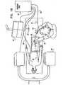
- Figs. 1A and 1Bare schematic illustrations of respective views of a guide wire motion modulator 20 being used by a physician, in accordance with an embodiment of the invention.
- a toolsuch as a guide wire 22 is advanced by the physician's hand 24 within arterial system 26 of the patient.
- the actual forward motion of guide wire 22is modulated by guide wire motion modulator 20.
- Guide wire motion modulator 20receives, from control unit 30, a synchronization signal 32 over a line 34.
- Control unit 30derives synchronization signal 32 from an ECG signal 36 of the patient, which is received via a line 38.
- the guide wire motion modulatoris used for advancing a coronary guide wire.
- Images of the advancement of guide wire 22 within arterial system 26 of the patientare typically generated by a fluoroscopy system 40 and displayed on a monitor 42.
- guide wire 22is inserted into arterial system 26 via a guiding catheter (not shown), the guiding catheter typically being connected to a proximal side of the apparatus.
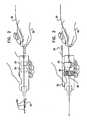
- Figs. 2 and 3are schematic illustrations of guide wire motion modulator 20, in accordance with an embodiment of the present invention.
- the guide wire motion modulatorcomprises a housing that contains therein a mechanical gate 50 and an energy and/or material accumulation facilitator 52.
- gate 50is a vise.
- Guide wire 22is advanced by physician hand 24 and is inserted through gate 50.
- Gate 50is activated (e.g., opened and closed), in synchronization with a measurement of a physiological cycle of the patient, such as the patient's ECG.
- the actual forward motion of guide wire 22is enabled when gate 50 is open and disabled when gate 50 is closed.
- energy and/or material accumulation facilitator 52accumulating energy (i.e., elastic energy) in the wire, and, typically, does not result in immediate forward motion of guide wire 22 distally, past the guide wire motion modulator.
- energy and/or material accumulation facilitator 52typically facilitates the accumulation of a portion of guide wire 22 inside guide wire motion modulator 20.
- energy and/or material accumulation facilitator 52comprises a pushing element such as a knob, as shown.
- Energy and/or material accumulation facilitator 52typically facilitates the accumulation of energy and/or material (such as guide wire 22) in response to the guide wire being pushed forwards while gate 50 is closed.
- the energy and/or material the accumulation of which is facilitated by energy and/or material accumulation facilitator 52, while the gate is closed,is typically released when the gate is subsequently opened. At least a portion of the released energy and/or material is used to advance the guide wire distally.
- the guide wire motion modulatoris used for advancing a coronary guide wire.
- an outer surface of accumulation facilitator 52pushes guide wire 22 (as shown), while in other embodiments, guide wire 22 passes through a lumen (not shown) of accumulation facilitator 52, such that movement of the lumen pushes guide wire 22 and thereby facilitates the accumulation of energy and/or material.
- Guide wire 22can typically be pulled back freely when gate 50 is open, for example, when the guide wire is withdrawn from the vessel.
- gate 50is maintained open continuously during the withdrawal of guide wire 22.
- guide wire motion modulator 20may include a sensor (not shown), such as a microswitch, i.e., an electric switch that is able to be actuated by very little physical force.
- the sensordetects when guide wire 22 is being moved in the proximal direction, and gate 50 is maintained open continuously in response to the sensor detecting that guide wire 22 is being moved in the proximal direction.
- the stepwise advancement of the guide wire during distal advancement of the guide wireis indicated by arrows 53 of Fig. 2 .
- the continuous movement of the guide wire during withdrawal of the guide wireis indicated by arrow 54 of Fig. 2 .
- guide wire 22is advanced by physician hand 24 via guide wire motion modulator 20.
- guide wire 22is inserted via slot 60 in gate 50.
- the opening and closing of gate 50is controlled via synchronization signal 32 which is transmitted to guide wire motion modulator 20 via line 34.
- gate 50is opened so that when the physician hand 24 pushes guide wire 22 forward, the distal section of guide wire 22 is advanced within the patient's blood vessel.
- gate 50is opened after a defmed period of time has elapsed since an event, for example, since when the gate was last closed.
- gate 50is opened after a period of time has elapsed since the gate was previously opened that is equal to the typical length of time of the subject's cardiac cycle.
- gate 50closes. Any further pushing of guide wire 22 by physician hand 24 does not result in a forward motion of the distal section of guide wire 22 within the patient's blood vessels.
- knob 52pushes guide wire 22 sideways (or in a different direction) within the guide wire motion modulator so that the pushing of guide wire 22 by physician hand 24 is translated into curvature of guide wire 22 within the guide wire motion modulator.
- at least some of the energy imparted to the guide wire by the physician advancing the guide wireis stored by the guide wire in the form of elastic energy associated with the curvature of guide wire 22.
- movement of knob 52is activated by synchronization signal 32.
- knob 52 and gate 50, or parts thereof,are connected rigidly to one another so that they move in tandem.
- knob 52 and gate 50form a single integrated component.
- elements of guide wire motion modulator 20are powered by an internal power supply, such as a battery. In an embodiment, elements of the guide wire motion modulator are powered by an external power supply.
- lines 34 and 38are wired (as shown in Fig. 1B ). In an embodiment, line 34 and/or line 38 is wireless.
- Figs. 4A and 4Bare schematic illustrations of gate 50 of guide wire motion modulator 20, in open and closed configurations, respectively, in accordance with an embodiment of the present invention.
- gate 50is an electromagnetic gate that includes a solenoid 70. As described hereinabove, gate 50 modulates the advancement of guide wire 22.
- Plunger 72enables the forward motion of guide wire 22 when in an open position as in Fig. 4A , and, typically, eliminates the forward motion of guide wire 22 when pressed into a closed position, by spring 74, as shown in Fig. 4B .
- solenoid 70which is powered by line 76, pulls plunger 72 away from guide wire 22 and enables the advancement of guide wire 22.
- solenoid 70releases plunger 72.
- Plunger 72having been released by the solenoid, is then pushed by spring 74, such that the plunger squeezes guide wire 22 and hinders advancement of the guide wire.
- solenoid 70pulls and/or releases plunger 72 after a defined period of time has elapsed since an event.
- the solenoidmay pull and/or release the plunger when a defmed period of time has elapsed since the time the gate was previously opened, or closed.
- Figs. 5A-Dare schematic illustrations of a sequence of steps in the operation of guide wire motion modulator 20, in accordance with an embodiment of the present invention.
- input synchronization signal 32received via line 34, indicates that the heart is the selected phase of the cardiac cycle.
- the selected phase of the cardiac cycleis a diastolic or end-diastolic phase, when the blood vessels are relatively further spread apart and less twisted.
- gate 50is open.
- gate 50includes one or more voice coils that are actuated by synchronization signal 32. In the configuration shown in Fig.
- input synchronization signal 32indicates that the selected phase in the cardiac cycle has ended, has approximately ended, or is about to end.
- Gate 50closes, and knob 52 begins to apply a deforming force to guide wire 22. Since the gate is closed, any further pushing of guide wire 22 by physician hand 24 typically does not result in a forward motion of distal section 80 of guide wire 22.
- Fig. 5Cinput synchronization signal 32, received via line 34, indicates that the cardiac cycle is still not at the selected phase.
- gate 50is closed, and knob 52 pushes guide wire 22 sideways (or in a different direction that includes a nonforward (i.e., a non-distal) component, such as an upward or a downward component).
- a nonforwardi.e., a non-distal
- Any further pushing of guide wire 22 by physician hand 24typically does not result in a forward motion of distal section 80 of guide wire 22 within the vessel. Instead, any such further pushing of guide wire 22 by physician hand 24 is typically translated into further curvature of guide wire 22.
- the curving of the guide wireconstitutes an accumulation of elastic energy within the guide wire.
- Fig. 5Dinput synchronization signal 32, received via line 34, indicates that the heart is again at, or approximately at, the selected phase of the cardiac cycle.
- gate 50is opened, and knob 52 is released toward its original position, as in Fig. 5A .
- the guide wire motion modulatorcomprises an additional component.
- the additional componentcauses the straightening of guide wire 22 to generate movement of the guide wire in the distal direction (i.e., away from the physician's hand and forward into the patient's body) and not in the proximal direction.
- sequence 5A through 5Dis repeated during each cardiac cycle for as long as physician hand 24 pushes guide wire 22 forward.
- advancement of distal section 80 of guide wire 22 within the vesseloccurs, predominantly, during the selected phase in the cardiac cycle.
- gate 50is configured not to open during the selected phase of every cardiac cycle of the subject. Rather, the gate is configured to open during the selected phase of every Nth cycle, e.g., every second, or third cycle.
- the gateopens in response to (a) the cardiac cycle being at the selected phase, and (b) another physiological event (e.g., the subject's respiratory cycle being at a selected phase, the subject's heart rate being within a designated range, and/or the subject's blood pressure being within a designated range).
- another physiological evente.g., the subject's respiratory cycle being at a selected phase, the subject's heart rate being within a designated range, and/or the subject's blood pressure being within a designated range.
- guide wire motion modulator 20generates force feedback that does not vary with respect to the cyclic activity of the blood vessel, or force feedback that is smoothened with respect to the cyclic activity of the blood vessel.
- physician hand 24pushes guide wire 22 forward continuously, and, while doing so, the guide wire motion modulator provides feedback to the physician, such that the physician receives continuous sensation of guide wire 22 advancing distally.
- guide wire 22is actually advanced intermittently, in a stepwise manner and in synchronization with the patient's cardiac cycle.
- Figs. 6A-Care schematic illustrations of the forward motion of guide wire 22 through an occlusion 90 in a vessel 92, the progress of the guide wire being modulated by guide wire motion modulator 20, in accordance with an embodiment of the present invention.
- the vesselis a coronary artery.
- input synchronization signal 32indicates that the heart is at, or approximately at, the selected phase of the cardiac cycle.
- the selected phase of the cardiac cycleis a diastolic or end-diastolic phase, when the coronary arteries are relatively further spread apart and less twisted.
- the guide wire motion modulatorallows distal section 80 of guide wire 22 to advance through occlusion 90 in vessel 92.
- input synchronization signal 32indicates that the cardiac cycle is outside the selected phase.
- the guide wire motion modulatoris configured to interpret the systolic phase of the cardiac cycle as being outside of the selected phase.
- vessel 92becomes twisted during the systolic phase. During this phase, even when the guide wire is pushed forward by the physician, the guide wire motion modulator does not allow distal section 80 of the guide wire to advance through occlusion 90 in vessel 92.
- input synchronization signal 32indicates that the heart is again at, or approximately at, the selected phase of the cardiac cycle.
- the selected phase of the cardiac cycleis a diastolic or end-diastolic phase, when the coronary arteries are relatively further spread apart and less twisted.
- the guide wire motion modulatorallows distal section 80 of the guide wire to advance through occlusion 90 in vessel 92, by a distance D relative to its prior position.
- guide wire motion modulator 20is used to facilitate the insertion of guide wire 22 into a side branch, such as side branch 94.
- the guide wire motion modulateallows the guide wire to advance only during a given phase of the cardiac cycle. Typically, this ensures that the angle between the side branch and the main vessel does not vary substantially while the guide wire is advanced into the side branch, thereby facilitating the insertion of the guide wire into the side branch.
- embodiments relating to endovascular guide wire advancementhave been described, the scope of the present inversion includes applying the apparatus and methods described herein to other medical tools or probes being moved within, or relative to, a body lumen or organ.
- embodiments of the present inventionmay be applied to the advancement of an atherectomy device (e.g., a directional or a rotational atherectomy device) through a coronary artery.
- an atherectomy devicee.g., a directional or a rotational atherectomy device
- the advancement of the atherectomy deviceis synchronized with the subject's cardiac cycle.
- an energy and/or material accumulation facilitatoraccumulates energy in the atherectomy device and/or accumulates a portion of the atherectomy device inside an atherectomy device motion modulator.
- the atherectomy deviceis advanced during a phase of the cardiac cycle during which the coronary artery is relatively straight and/or compliant (e.g., the diastolic or end-diastolic phase of the cardiac cycle). Further typically, advancing the atherectomy device during such a phase, and inhibiting advancement of the atherectomy device during other phases of the cardiac cycle, facilitates penetration of an occlusion by the atherectomy device.
- the scope of the present inventionincludes synchronizing the movement of a medical tool with a different physiological cycle of the subject, e.g., the subject's respiratory cycle.
- the medical tool that is advanced in a stepwise mannerincludes any one of the following tools, or any combination thereof: a cardiovascular catheter, a stent delivery and/or placement and/or retrieval tool, a balloon delivery and/or placement and/or retrieval tool, a valve delivery and/or placement and/or retrieval tool, a graft delivery and/or placement and/or retrieval tool, a tool for the delivery and/or placement and/or retrieval of an implantable device or of parts of such device, an implantable device or parts thereof, a guide wire, a suturing tool, a biopsy tool, an aspiration tool, a navigational tool, a localization tool, a probe comprising one or more location sensors, a tissue characterization probe, a probe for the analysis of fluid, a measurement probe, an electrophysiological probe, a stimulation probe, an ablation tool, a tool for penetrating or opening partial or total occlusions in blood vessels, a drug or substance delivery tool, a chemotherapy tool, a photo
Landscapes
- Health & Medical Sciences (AREA)
- Life Sciences & Earth Sciences (AREA)
- Engineering & Computer Science (AREA)
- Medical Informatics (AREA)
- Public Health (AREA)
- Biomedical Technology (AREA)
- General Health & Medical Sciences (AREA)
- Veterinary Medicine (AREA)
- Animal Behavior & Ethology (AREA)
- Heart & Thoracic Surgery (AREA)
- Biophysics (AREA)
- Pathology (AREA)
- Surgery (AREA)
- Physics & Mathematics (AREA)
- Molecular Biology (AREA)
- Nuclear Medicine, Radiotherapy & Molecular Imaging (AREA)
- Optics & Photonics (AREA)
- High Energy & Nuclear Physics (AREA)
- Physiology (AREA)
- Radiology & Medical Imaging (AREA)
- Hematology (AREA)
- Anesthesiology (AREA)
- Pulmonology (AREA)
- Computer Vision & Pattern Recognition (AREA)
- Human Computer Interaction (AREA)
- Vascular Medicine (AREA)
- Transplantation (AREA)
- Oral & Maxillofacial Surgery (AREA)
- Cardiology (AREA)
- Data Mining & Analysis (AREA)
- Databases & Information Systems (AREA)
- Epidemiology (AREA)
- Primary Health Care (AREA)
- Media Introduction/Drainage Providing Device (AREA)
- Surgical Instruments (AREA)
Description
- The present patent application claims priority of
US Provisional Patent Application No. 61/129,331 to Iddan, filed on June 19, 2008 - (a) PCT Application
PCT/IL2008/000316 to Iddan, filed on March 09, 2008 - (b)
US Patent Application 12/075,244 to Tolkowsky, filed March 10, 2008 - (c)
US Patent Application 12/075,214 to Iddan, filed March 10, 2008 - (d)
US Patent Application 12/075,252 to Iddan, filed March 10, 2008 - The present invention generally relates to medical apparatus. Specifically, the present invention relates to stepwise advancement of a medical tool, within a body organ, in accordance with a motion cycle of that organ.
- Guide wires are commonly used in the course of trans-catheter endovascular interventions. Among the usages of such guide wires is the penetration of total or near-total occlusions in a blood vessel, such as an artery. In some cases, the artery moves in accordance with a cyclical physiological cycle, such as the cardiac cycle in the case of a coronary artery, or the respiratory cycle in the case of a renal artery. In some cases, such motion of the artery also comprises a change in its geometrical shape, such as an angle at which it is bent.
PCT Application WO 08/107905 to Iddan US Patent 4,545,390 to Leary describes a guide wire for guiding a very small diameter catheter, such as a coronary dilatation on catheter used in coronary angioplasty techniques.US Patent 4,758,233 to Rydell describes a hand-operated device for inflating the expander on a balloon-type catheter and for perfusing fluids through the catheter and out its distal end.US Patent 4,723,938 to Goodin et al. describes an inflation/deflation device for an angioplasty balloon catheter which permits quick inflation to an approximate working pressure followed by a fine but slower adjustment to a final desired pressure.- The following references may be of interest:
US Patent 4,865,043 to Shimoni ,US Patent 3,954,098 to Dick et al. ,US Patent 4,382,184 to Wernikoff ,US Patent 4,016,87 to Schiff ,US Patent 3,871,360 to Van Horn et al. ,US Patent 4,031,884 to Henzel ,US Patent 4,994,965 to Crawford et al. ,US Patent 4,878,115 to Elion ,US Patent 4,709,385 to Pfeiler ,US Patent 4,270,143 to Morris ,US Patent 4,758,223 to Rydell ,US Patent 4,723,938 to Goodin et al. ,US Patent 6,937,696 to Mostafavi ,US Patent 6,246,898 to Vesely et al. ,US Patent 6,666,863 to Wentzel et al. ,US Patent 5,176,619 to Segalowitz ,US Patent 5,830,222 to Makower ,US Patent 4,245,647 to Randall ,US Patent 4,316,218 to Gay ,US Patent 4,849,906 to Chodos et al. ,US Patent 5,062,056 to Lo et al. ,US Patent 5,630,414 to Horbaschek ,US Patent 6,442,415 to Bis et al. ,US Patent 6,473,635 to Rasche ,US Patent 4,920,413 to Nakamura ,US Patent 6,233,478 to Liu ,US Patent 5,764,723 to Weinberger ,US Patent 5,619,995 to Lobodzinski ,US Patent 4,991,589 to Hongo et al. ,US Patent 5,538,494 to Matsuda ,US Patent 5,020,516 to Biondi ,US Patent 7,209,779 to Kaufman ,US Patent 6,858,003 to Evans et al. ,US Patent 6,786,896 to Madhani et al. ,US Patent 6,999,852 to Green ,US Patent 7,155,315 to Niemeyer et al. ,US Patent 5,971,976 to Wang et al. ,US Patent 6,377,011 to Ben-Ur ,US Patent 6,711,436 to Duhaylongsod ,US Patent 7,269,457 to Shafer ,US Patent 6,959,266 to Mostafavi ,US Patent 7,191,100 to Mostafavi ,US Patent 6,708,052 to Mao et al. ,US Patent 7,180,976 to Wink et al. ,US Patent 7,085,342 to Younis et al. ,US Patent 6,731,973 to Voith ,US Patent 6,728,566 to Subramanyan ,US Patent 5,766,208 to McEwan ,US Patent 6,704,593 to Stainsby ,US Patent 6,973,202 to Mostafavi ;US Patent Application Publication 2006/0058647 to Strommer et al. ,US Patent Application Publication 2007/0173861 to Strommer ,US Patent Application Publication 2007/0208388 to Jahns ,US Patent Application Publication 2007/0219630 to Chu ,US Patent Application Publication 2004/0176681 to Mao et al. ,US Patent Application Publication 2005/0090737 to Burrel et al. ,US Patent Application Publication 2006/0287595 to Maschke ,US Patent Application Publication 2007/0142907 to Moaddeb et al. ,US Patent Application Publication 2007/0106146 to Altmann et al. ,US Patent Application Publication 2005/0054916 to Mostafavi ,US Patent Application Publication 2003/0018251 to Solomon ,US Patent Application Publication 2002/0049375 to Strommer et al. ,US Patent Application Publication 2005/0137661 to Sra ,US Patent Application Publication 2005/0143777 to Sra ,US Patent Application Publication 2004/0077941 to Reddy et al. ;PCT Publication WO 94/010904 to Nardella PCT Publication WO 06/066122 to Sra PCT Publication WO 06/066124 to Sra PCT Publication WO 05/026891 to Mostafavi PCT Publication WO 01/43642 to Heuscher PCT Publication WO 03/096894 to Ho et al. PCT Publication WO 05/124689 to Manzke - "Catheter Insertion Simulation with Combined Visual and Haptic Feedback," by Zorcolo et al. (Center for Advanced Studies, Research and Development in Sardinia)
- The present invention provides apparatus for use with a portion of a body of a subject that moves as a result of cyclic activity of a body system of the subject, the apparatus comprising: a sensor for sensing a phase of the cyclic activity; characterized in that the apparatus further comprises: a tool configured to be moved with respect to the portion of the subject's body by being pushed by a user; and a tool modulator comprising: a gate, configured: in a first cycle of the cyclic activity, to allow movement of at least a distal portion of the tool in a distal direction, in response to the sensor sensing that the cyclic activity is at a first given phase thereof, following the given phase in the first cycle and prior to an occurrence of the given phase in a subsequent cycle of the cyclic activity, to inhibit the movement of the distal portion of the tool, and in a second cycle of the cyclic activity, subsequent to the inhibiting of the movement, to allow movement of the at least the distal portion of the tool in the distal direction, in response to the sensor sensing that the second cycle of the cyclic activity is at the given phase thereof; and an accumulation facilitator configured, following the given phase in the first cycle and prior to the occurrence of the given phase in the subsequent cycle of the cyclic activity, and in response to the user pushing the tool, to facilitate an accumulation selected from the group consisting of: an accumulation of the tool in the tool modulator, and an accumulation of elastic energy in the tool.
- The present invention further provides a method for automatically controlling movement of a tool when the tool is used with a portion of a body of a subject that moves as a result of cyclic activity of a body system of the subject, the method comprising: sensing a phase of the cyclic activity; in a first cycle of the cyclic activity, allowing movement of at least a distal portion of the tool in a distal direction with respect to the portion, in response to sensing that the cyclic activity is at a first given phase thereof, following the given phase in the first cycle, and prior to an occurrence of the given phase in a subsequent cycle of the cyclic activity: inhibiting the movement of the distal portion of the tool, and in response to a user pushing the tool, facilitating an accumulation selected from the group consisting of: an accumulation of the tool in a housing, and an accumulation of elastic energy in the tool; and in a second cycle of the cyclic activity, subsequent to the inhibiting of the movement of the distal portion of the tool, allowing movement of the at least the distal portion of the tool in the distal direction, in response to sensing that the second cycle of the cyclic activity is at the given phase thereof.
- When a guide wire is used for penetrating an occlusion within an artery that changes its shape as a result of organ motion, it may result in (a) the guide wire being pushed along the artery, at some phases of the motion cycle, but (b) in an undesirable direction, for example, toward the wall of the artery, at other phases of the motion cycle. In some cases, the ability to penetrate the occlusion with the guide wire is therefore hindered. In other cases, advancement of the guide wire towards the wall of the artery results in a perforation or dissection of the artery's wall. Such perforation or dissection typically creates some amount of clinical risk.
- Separately, when a guide wire is steered towards a side branch whose angle relative to the main artery varies in the course of the motion cycle, entering that side branch may require multiple, repeated attempts.
- In some embodiments of the present invention, apparatus and methods are provided for the advancement of an endovascular medical tool, such as a guide wire, within a body organ, in accordance with a motion cycle of that organ. In some embodiments, a guide wire is advanced with a coronary artery in synchronization with the cardiac cycle. In some embodiments, a guide wire is advanced within a renal artery in synchronization with the respiratory cycle. In some embodiments, a guide wire is advanced within a carotid artery in synchronization with the cardiac cycle. In some embodiments, a medial tool is advanced through a bronchial lumen in synchronization with the respiratory cycle.
- It is hypothesized by the inventors that embodiments of the current invention offer measures for reducing the aforementioned risk of a guide wire being advanced in an undesirable direction. For example, embodiments of the current invention may reduce the aforementioned risk of a guide wire being advanced into the wall of a blood vessel and creating a perforation or a dissection of that wall. It is also hypothesized by the inventors that advancing a guide wire in the synchronized manner described herein will, in some cases, improve the efficacy of the guide wire in penetrating an occlusion. Separately, it is also hypothesized by the inventors that advancing a guide wire in the synchronized manner described herein, will, in some cases, facilitate inserting the guide wire into a side branch, the angle of which, relative to the main lumen, varies in the course of the vessel's motion cycle.
- In an embodiment, the guide wire is advanced within a coronary vessel in a stepwise manner, only at a selected phase of the cardiac cycle. In an embodiment, the selected phase of the cardiac cycle is a diastolic or end-diastolic phase, when the blood vessels are relatively further spread apart and less twisted. Compared to unsynchronized advancement of the guide wire (for example, continuous advancement of the guide wire throughout the cardiac cycle), synchronized stepwise advancement in a diastolic or end-diastolic phase typically results in the guide wire being advanced, during a greater portion of its forward motion, along the vessel and, during a lesser portion of its forward motion, towards the wall of the vessel. That, in turn, typically reduces the likelihood of the guide wire perforating or dissecting the vessel wall, and typically increases the efficacy of the guide wire penetrating a possible occlusion in the vessel.
- In another embodiment, the guide wire is advanced within a carotid vessel in a stepwise manner, only at a selected phase of the cardiac cycle. In yet another embodiment, the guide wire is advanced within a renal vessel in a stepwise manner, only at a selected phase of the respiratory cycle.
- The aforementioned selected phase of the cardiac cycle may be sensed by means of the patient's ECG signal, a signal derived from the patient's ECG signal, the patient's blood pressure, the patient's heartbeat, on-line processing of an image stream of the organ with which the vessel is associated, a location sensor on or within the patient's body, a displacement sensor on or within the patient's body, or any combination thereof.
- The aforementioned selected phase of the respiratory cycle may be sensed by a belt placed around the patient's chest, a motion sensor, an oxygenation sensor, a displacement sensor on or within the patient's body, a location sensor on or within the patient's body, or any combination thereof.
- In an embodiment, the stepwise advancement of the guide wire is achieved via a guide wire motion modulator (also referred to herein as a "guide wire modulator"). In an embodiment, the guide wire motion modulator is situated outside the patient's body, along the proximal section of the guide wire and proximally to the sheath or guiding catheter through which the guide wire is inserted into the patient's body.
- There is therefore provided, in accordance with an embodiment of the present invention, apparatus for use with a portion of a body of a subject that moves as a result of cyclic activity of a body system of the subject, the apparatus including:
- a sensor for sensing a phase of the cyclic activity;
- a tool configured to be moved with respect to the portion of the subject's body by being pushed by a user; and
- a tool modulator including:
- a gate, configured:
- in a first cycle of the cyclic activity, to allow movement of at least a distal portion of the tool in a distal direction, in response to the sensor sensing that the cyclic activity is at a first given phase thereof,
- following the given phase in the first cycle and prior to an occurrence of the given phase in a subsequent cycle of the cyclic activity, to inhibit the movement of the distal portion of the tool, and
- in a second cycle of the cyclic activity, subsequent to the inhibiting of the movement, to allow movement of the at least the distal portion of the tool in the distal direction, in response to the sensor sensing that the second cycle of the cyclic activity is at the given phase thereof; and
- an accumulation facilitator configured, following the given phase in the first cycle and prior to the occurrence of the given phase in the subsequent cycle of the cyclic activity, and in response to the user pushing the tool, to facilitate an accumulation selected from the group consisting of: an accumulation of the tool in the tool modulator, and an accumulation of energy in the tool.
- a gate, configured:
- In an embodiment, the tool modulator is configured to provide force feedback to the user that is smoothened with respect to the cyclic activity.
- In an embodiment, the given phase includes a phase selected from the group consisting of a diastolic phase and an end-diastolic phase, and the gate is configured to allow movement of the distal portion of the tool in the distal direction, in response to the sensor sensing that the cyclic activity is at the selected phase.
- In an embodiment, the gate is configured to allow continuous movement of the tool in a proximal direction, when the tool is being withdrawn from the portion of the subject's body.
- In an embodiment, the accumulation facilitator includes a pushing element configured to push a portion of the tool at least partially in a non-distal direction, in response to the user pushing the tool in the distal direction.
- In an embodiment, the accumulation facilitator is configured to facilitate accumulation of the tool in the tool modulator.
- In an embodiment, the accumulation facilitator is configured to facilitate accumulation of energy in the tool.
- In an embodiment, the accumulation facilitator is configured to facilitate accumulation of elastic energy in the tool.
- In an embodiment, the tool includes a guide wire configured to be moved within a blood vessel of the subject.
- In an embodiment:
- by allowing movement of at least the distal portion of the tool in the distal direction, the gate is configured to allow movement of a distal portion of the guide wire into a side branch that branches from the blood vessel, when the side branch is at a first angle from the blood vessel, and
- by inhibiting movement of at least the distal portion of the tool, the gate is configured to inhibit movement of the distal portion of the guide wire into the side branch, when the side branch is at another angle from the blood vessel.
- In an embodiment, the gate, by inhibiting the movement of the distal portion of the tool, is configured to inhibit a distal portion of the guide wire from moving in an undesirable direction with respect to the blood vessel.
- In an embodiment, the gate, by inhibiting the movement of the distal portion of the tool, is configured to inhibit a distal portion of the guide wire from puncturing the blood vessel.
- Herein described is a method for automatically controlling movement of a tool when the tool is used with a portion of a body of a subject that moves as a result of cyclic activity of a body system of the subject, the method including:
- sensing a phase of the cyclic activity;
- in a first cycle of the cyclic activity, allowing movement of at least a distal portion of the tool in a distal direction with respect to the portion, in response to sensing that the cyclic activity is at a first given phase thereof,
- following the given phase in the first cycle, and prior to an occurrence of the given phase in a subsequent cycle of the cyclic activity:
- inhibiting the movement of the distal portion of the tool, and
- in response to a user pushing the tool, facilitating an accumulation selected from the group consisting of: an accumulation of the tool in a housing, and an accumulation of energy in the tool; and
- in a second cycle of the cyclic activity, subsequent to the inhibiting of the movement of the distal portion of the tool, allowing movement of the at least the distal portion of the tool in the distal direction, in response to sensing that the second cycle of the cyclic activity is at the given phase thereof.
- There is additionally provided, in accordance with an embodiment of the present invention, apparatus for use with a portion of a body of a subject that moves as a result of cyclic activity of a body system of the subject, the apparatus including:
- a sensor for sensing a phase of the cyclic activity;
- a guide wire configured to be moved with respect to the portion of the subject's body; and
- a guide wire modulator configured:
- (a) during movement of the guidewire in a distal direction with respect to the portion of the subject's body,
in a first cycle of the cyclic activity, to allow movement of at least a distal portion of the guide wire in the distal direction, in response to the sensor sensing that the cyclic activity is at a first given phase thereof,
following the given phase in the first cycle and prior to an occurrence of the given phase in a subsequent cycle of the cyclic activity, to inhibit the movement of the distal portion of the guide wire, and
in a second cycle of the cyclic activity, subsequent to the inhibiting of the movement, to allow movement of the at least the distal portion of the guide wire in the distal direction, in response to the sensor sensing that the second cycle of the cyclic activity is at the given phase thereof, and - (b) during withdrawal of the guide wire from the portion of the subject's body, to allow continuous movement of the guide wire in the proximal direction.
- (a) during movement of the guidewire in a distal direction with respect to the portion of the subject's body,
- There is further provided, in accordance with an embodiment of the present invention, apparatus for use with a side branch of a main blood vessel, which side branch moves as a result of cyclic activity of a body system of the subject, the apparatus including:
- a sensor for sensing a phase of the cyclic activity;
- a guide wire configured to be moved with respect to the portion of the subject's body; and
- a guide wire modulator configured:
- in a first cycle of the cyclic activity, to allow movement of a distal portion of the guide wire into the side branch, in response to the sensor sensing that the cyclic activity is at a first given phase thereof, when the side branch is at a first angle from the main blood vessel,
- following the given phase in the first cycle and prior to an occurrence of the given phase in a subsequent cycle of the cyclic activity, to inhibit movement of the distal portion of the guide wire into the side branch, when the side branch is at another angle from the main blood vessel, and
- in a second cycle of the cyclic activity, subsequent to the inhibiting of the movement, to allow movement of the at least the distal portion of the guide wire into the side branch, in response to the sensor sensing that the second cycle of the cyclic activity is at the given phase thereof, when the side branch is at the first angle from the main blood vessel.
- The present invention will be more fully understood from the following detailed description of embodiments thereof, taken together with the drawings, in which:
Figs. 1A and1B are schematic illustrations of respective views of a guide wire motion modulator being used by a physician, in accordance with an embodiment of the present invention;Figs. 2 and 3 , are schematic illustrations of the guide wire motion modulator in operation, in accordance with an embodiment of the present invention;Figs. 4A and 4B are schematic illustrations of a gate of the guide wire motion modulator, in open and closed configurations, respectively, in accordance with an embodiment of the present invention;Figs. 5A-D are schematic illustrations of a sequence of steps in the operation of the guide wire motion modulator, in accordance with an embodiment of the present invention; andFigs. 6A-C are schematic illustrations of the forward motion of a guide wire through an occlusion in a vessel, the progress of the guide wire being modulated by a guide wire motion modulator, in accordance with an embodiment of the present invention.- Reference is now made to
Figs. 1A and1B , which are schematic illustrations of respective views of a guidewire motion modulator 20 being used by a physician, in accordance with an embodiment of the invention. In an embodiment, a tool such as aguide wire 22 is advanced by the physician'shand 24 withinarterial system 26 of the patient. The actual forward motion ofguide wire 22 is modulated by guidewire motion modulator 20. Guidewire motion modulator 20 receives, fromcontrol unit 30, asynchronization signal 32 over aline 34.Control unit 30 derivessynchronization signal 32 from anECG signal 36 of the patient, which is received via aline 38. In an embodiment, the guide wire motion modulator is used for advancing a coronary guide wire. Images of the advancement ofguide wire 22 withinarterial system 26 of the patient are typically generated by afluoroscopy system 40 and displayed on amonitor 42. In some embodiments,guide wire 22 is inserted intoarterial system 26 via a guiding catheter (not shown), the guiding catheter typically being connected to a proximal side of the apparatus. - Reference is now made to
Figs. 2 and 3 , which are schematic illustrations of guidewire motion modulator 20, in accordance with an embodiment of the present invention. The guide wire motion modulator comprises a housing that contains therein amechanical gate 50 and an energy and/ormaterial accumulation facilitator 52. Typically,gate 50 is a vise.Guide wire 22 is advanced byphysician hand 24 and is inserted throughgate 50.Gate 50 is activated (e.g., opened and closed), in synchronization with a measurement of a physiological cycle of the patient, such as the patient's ECG. In an embodiment, the actual forward motion ofguide wire 22 is enabled whengate 50 is open and disabled whengate 50 is closed. At times whenphysician hand 24 pushes guidewire 22 forward whilegate 50 is closed, at least some of the energy associated with the pushing ofguide wire 22 is accumulated by energy and/ormaterial accumulation facilitator 52 accumulating energy (i.e., elastic energy) in the wire, and, typically, does not result in immediate forward motion ofguide wire 22 distally, past the guide wire motion modulator. As shown inFig. 3 , energy and/ormaterial accumulation facilitator 52 typically facilitates the accumulation of a portion ofguide wire 22 inside guidewire motion modulator 20. In some embodiments, energy and/ormaterial accumulation facilitator 52 comprises a pushing element such as a knob, as shown. Energy and/ormaterial accumulation facilitator 52 typically facilitates the accumulation of energy and/or material (such as guide wire 22) in response to the guide wire being pushed forwards whilegate 50 is closed. The energy and/or material the accumulation of which is facilitated by energy and/ormaterial accumulation facilitator 52, while the gate is closed, is typically released when the gate is subsequently opened. At least a portion of the released energy and/or material is used to advance the guide wire distally. In some embodiments, the guide wire motion modulator is used for advancing a coronary guide wire. - In some embodiments, an outer surface of
accumulation facilitator 52 pushes guide wire 22 (as shown), while in other embodiments,guide wire 22 passes through a lumen (not shown) ofaccumulation facilitator 52, such that movement of the lumen pushesguide wire 22 and thereby facilitates the accumulation of energy and/or material. Guide wire 22 can typically be pulled back freely whengate 50 is open, for example, when the guide wire is withdrawn from the vessel. For some applications,gate 50 is maintained open continuously during the withdrawal ofguide wire 22. For example, guidewire motion modulator 20 may include a sensor (not shown), such as a microswitch, i.e., an electric switch that is able to be actuated by very little physical force. The sensor detects whenguide wire 22 is being moved in the proximal direction, andgate 50 is maintained open continuously in response to the sensor detecting thatguide wire 22 is being moved in the proximal direction. The stepwise advancement of the guide wire during distal advancement of the guide wire is indicated byarrows 53 ofFig. 2 . The continuous movement of the guide wire during withdrawal of the guide wire is indicated byarrow 54 ofFig. 2 .- As shown in
Fig. 3 ,guide wire 22 is advanced byphysician hand 24 via guidewire motion modulator 20. Specifically,guide wire 22 is inserted viaslot 60 ingate 50. The opening and closing ofgate 50 is controlled viasynchronization signal 32 which is transmitted to guidewire motion modulator 20 vialine 34. During a selected phase in the patient's cardiac cycle, and as indicated bysignal 32,gate 50 is opened so that when thephysician hand 24 pushes guidewire 22 forward, the distal section ofguide wire 22 is advanced within the patient's blood vessel. In some embodiments,gate 50 is opened after a defmed period of time has elapsed since an event, for example, since when the gate was last closed. In some embodiments,gate 50 is opened after a period of time has elapsed since the gate was previously opened that is equal to the typical length of time of the subject's cardiac cycle. Wheninput synchronization signal 32 indicates that the selected phase in the cardiac cycle is over, or alternatively after a defined period of time has elapsed since an event (for example, after the typical length of time of the selected phase has elapsed sincegate 50 was opened),gate 50 closes. Any further pushing ofguide wire 22 byphysician hand 24 does not result in a forward motion of the distal section ofguide wire 22 within the patient's blood vessels. Instead, whilegate 50 is closed and guidewire 22 continues to be pushed forward byphysician hand 24,knob 52 pushes guidewire 22 sideways (or in a different direction) within the guide wire motion modulator so that the pushing ofguide wire 22 byphysician hand 24 is translated into curvature ofguide wire 22 within the guide wire motion modulator. In some embodiments, at least some of the energy imparted to the guide wire by the physician advancing the guide wire is stored by the guide wire in the form of elastic energy associated with the curvature ofguide wire 22. In an embodiment, movement ofknob 52 is activated bysynchronization signal 32. In an embodiment,knob 52 andgate 50, or parts thereof, are connected rigidly to one another so that they move in tandem. In an embodiment,knob 52 andgate 50 form a single integrated component. - In an embodiment, elements of guide
wire motion modulator 20 are powered by an internal power supply, such as a battery. In an embodiment, elements of the guide wire motion modulator are powered by an external power supply. In an embodiment, lines 34 and 38 are wired (as shown inFig. 1B ). In an embodiment,line 34 and/orline 38 is wireless. - Reference is now made to
Figs. 4A and 4B , which are schematic illustrations ofgate 50 of guidewire motion modulator 20, in open and closed configurations, respectively, in accordance with an embodiment of the present invention. In some embodiments,gate 50 is an electromagnetic gate that includes asolenoid 70. As described hereinabove,gate 50 modulates the advancement ofguide wire 22.Plunger 72 enables the forward motion ofguide wire 22 when in an open position as inFig. 4A , and, typically, eliminates the forward motion ofguide wire 22 when pressed into a closed position, byspring 74, as shown inFig. 4B . - As shown in
Fig. 4A , whensignal 32, received vialine 34, indicates that the patient's physiological cycle is at (or approximately at) the selected phase in the patient's physiological cycle,solenoid 70, which is powered byline 76, pullsplunger 72 away fromguide wire 22 and enables the advancement ofguide wire 22. - As shown in
Fig. 4B , whensignal 32 indicates that the patient's physiological cycle is no longer at the selectedphase solenoid 70releases plunger 72.Plunger 72, having been released by the solenoid, is then pushed byspring 74, such that the plunger squeezes guidewire 22 and hinders advancement of the guide wire. - In some embodiments,
solenoid 70 pulls and/or releasesplunger 72 after a defined period of time has elapsed since an event. For example, the solenoid may pull and/or release the plunger when a defmed period of time has elapsed since the time the gate was previously opened, or closed. - Reference is now made to
Figs. 5A-D , which are schematic illustrations of a sequence of steps in the operation of guidewire motion modulator 20, in accordance with an embodiment of the present invention. InFig. 5A ,input synchronization signal 32, received vialine 34, indicates that the heart is the selected phase of the cardiac cycle. In an embodiment, the selected phase of the cardiac cycle is a diastolic or end-diastolic phase, when the blood vessels are relatively further spread apart and less twisted. As shown inFig. 5A ,gate 50 is open. In an embodiment,gate 50 includes one or more voice coils that are actuated bysynchronization signal 32. In the configuration shown inFig. 5A , whenphysician hand 24 pushes guidewire 22 forward,distal section 80 ofguide wire 22 is advanced within a portion of the vessel that is distal to the guide wire motion modulator.Knob 52 is positioned nearguide wire 22 and, typically, applies substantially no force to guidewire 22. - In
Fig. 5B ,input synchronization signal 32, received vialine 34, indicates that the selected phase in the cardiac cycle has ended, has approximately ended, or is about to end.Gate 50 closes, andknob 52 begins to apply a deforming force to guidewire 22. Since the gate is closed, any further pushing ofguide wire 22 byphysician hand 24 typically does not result in a forward motion ofdistal section 80 ofguide wire 22. - In
Fig. 5C ,input synchronization signal 32, received vialine 34, indicates that the cardiac cycle is still not at the selected phase. As a result,gate 50 is closed, andknob 52 pushes guidewire 22 sideways (or in a different direction that includes a nonforward (i.e., a non-distal) component, such as an upward or a downward component). Any further pushing ofguide wire 22 byphysician hand 24 typically does not result in a forward motion ofdistal section 80 ofguide wire 22 within the vessel. Instead, any such further pushing ofguide wire 22 byphysician hand 24 is typically translated into further curvature ofguide wire 22. Typically, the curving of the guide wire constitutes an accumulation of elastic energy within the guide wire. - In
Fig. 5D ,input synchronization signal 32, received vialine 34, indicates that the heart is again at, or approximately at, the selected phase of the cardiac cycle. As a result,gate 50 is opened, andknob 52 is released toward its original position, as inFig. 5A . Typically, the portion of the guide wire that became curved, straightens, thereby releasing the accumulated elastic energy in the form of forward motion ofdistal section 80 of the guide wire. In an embodiment, the guide wire motion modulator comprises an additional component. Whengate 50 is opened, andknob 52 is released, the additional component causes the straightening ofguide wire 22 to generate movement of the guide wire in the distal direction (i.e., away from the physician's hand and forward into the patient's body) and not in the proximal direction. - Typically, sequence 5A through 5D is repeated during each cardiac cycle for as long as
physician hand 24 pushes guidewire 22 forward. As a result, advancement ofdistal section 80 ofguide wire 22 within the vessel occurs, predominantly, during the selected phase in the cardiac cycle. In some embodiments,gate 50 is configured not to open during the selected phase of every cardiac cycle of the subject. Rather, the gate is configured to open during the selected phase of every Nth cycle, e.g., every second, or third cycle. Alternatively, the gate opens in response to (a) the cardiac cycle being at the selected phase, and (b) another physiological event (e.g., the subject's respiratory cycle being at a selected phase, the subject's heart rate being within a designated range, and/or the subject's blood pressure being within a designated range). - In some embodiments, guide
wire motion modulator 20 generates force feedback that does not vary with respect to the cyclic activity of the blood vessel, or force feedback that is smoothened with respect to the cyclic activity of the blood vessel. In an embodiment,physician hand 24 pushes guidewire 22 forward continuously, and, while doing so, the guide wire motion modulator provides feedback to the physician, such that the physician receives continuous sensation ofguide wire 22 advancing distally. Conversely,guide wire 22 is actually advanced intermittently, in a stepwise manner and in synchronization with the patient's cardiac cycle. - Reference is now made to
Figs. 6A-C , which are schematic illustrations of the forward motion ofguide wire 22 through anocclusion 90 in avessel 92, the progress of the guide wire being modulated by guidewire motion modulator 20, in accordance with an embodiment of the present invention. In an embodiment, the vessel is a coronary artery. - In
Fig. 6A ,input synchronization signal 32 indicates that the heart is at, or approximately at, the selected phase of the cardiac cycle. In an embodiment, the selected phase of the cardiac cycle is a diastolic or end-diastolic phase, when the coronary arteries are relatively further spread apart and less twisted. The guide wire motion modulator allowsdistal section 80 ofguide wire 22 to advance throughocclusion 90 invessel 92. - In
Fig. 6B ,input synchronization signal 32 indicates that the cardiac cycle is outside the selected phase. In an embodiment, the guide wire motion modulator is configured to interpret the systolic phase of the cardiac cycle as being outside of the selected phase. In an embodiment,vessel 92 becomes twisted during the systolic phase. During this phase, even when the guide wire is pushed forward by the physician, the guide wire motion modulator does not allowdistal section 80 of the guide wire to advance throughocclusion 90 invessel 92. - In
Fig. 6C ,input synchronization signal 32 indicates that the heart is again at, or approximately at, the selected phase of the cardiac cycle. In an embodiment, the selected phase of the cardiac cycle is a diastolic or end-diastolic phase, when the coronary arteries are relatively further spread apart and less twisted. The guide wire motion modulator allowsdistal section 80 of the guide wire to advance throughocclusion 90 invessel 92, by a distance D relative to its prior position. - In
Figs. 6A-C , it may be observed that the angle betweenmain blood vessel 92 andside branch 94, which branches from the main blood vessel, is greater during diastole (as shown inFigs. 6A and 6C ) than during systole (as shown inFig. 6B ). As described hereinabove, in some embodiments, guidewire motion modulator 20 is used to facilitate the insertion ofguide wire 22 into a side branch, such asside branch 94. For some applications, the guide wire motion modulate allows the guide wire to advance only during a given phase of the cardiac cycle. Typically, this ensures that the angle between the side branch and the main vessel does not vary substantially while the guide wire is advanced into the side branch, thereby facilitating the insertion of the guide wire into the side branch. US Patent Application 12/075,244, to Tolkowsky et al., filed March 10, 2008 US Patent Application 12/075,214, to Iddan et al., filed March 10, 2008 US Patent Application 12/075,252, to Iddan et al., filed March 10,2008 - Although embodiments relating to endovascular guide wire advancement have been described, the scope of the present inversion includes applying the apparatus and methods described herein to other medical tools or probes being moved within, or relative to, a body lumen or organ. For example, embodiments of the present invention may be applied to the advancement of an atherectomy device (e.g., a directional or a rotational atherectomy device) through a coronary artery. In a similar manner to that described with respect to guide
wire 22, the advancement of the atherectomy device is synchronized with the subject's cardiac cycle. During the phase of the cardiac cycle in which advancement of the tool through the subject's blood vessel is impeded, an energy and/or material accumulation facilitator accumulates energy in the atherectomy device and/or accumulates a portion of the atherectomy device inside an atherectomy device motion modulator. Typically, the atherectomy device is advanced during a phase of the cardiac cycle during which the coronary artery is relatively straight and/or compliant (e.g., the diastolic or end-diastolic phase of the cardiac cycle). Further typically, advancing the atherectomy device during such a phase, and inhibiting advancement of the atherectomy device during other phases of the cardiac cycle, facilitates penetration of an occlusion by the atherectomy device. - Although embodiments have been described according to which the movement of a tool is synchronized with a subject's cardiac cycle, the scope of the present invention includes synchronizing the movement of a medical tool with a different physiological cycle of the subject, e.g., the subject's respiratory cycle.
- In additional embodiments, the medical tool that is advanced in a stepwise manner includes any one of the following tools, or any combination thereof: a cardiovascular catheter, a stent delivery and/or placement and/or retrieval tool, a balloon delivery and/or placement and/or retrieval tool, a valve delivery and/or placement and/or retrieval tool, a graft delivery and/or placement and/or retrieval tool, a tool for the delivery and/or placement and/or retrieval of an implantable device or of parts of such device, an implantable device or parts thereof, a guide wire, a suturing tool, a biopsy tool, an aspiration tool, a navigational tool, a localization tool, a probe comprising one or more location sensors, a tissue characterization probe, a probe for the analysis of fluid, a measurement probe, an electrophysiological probe, a stimulation probe, an ablation tool, a tool for penetrating or opening partial or total occlusions in blood vessels, a drug or substance delivery tool, a chemotherapy tool, a photodynamic therapy tool, a brachytherapy tool, a local irradiation tool, a laser device, a tool for delivering energy, a tool for delivering markers or biomarkers, a tool for delivering biological glue, an irrigation device, a suction device, a ventilation device, a device for delivering and/or placing and/or retrieving a lead of an electrophysiological device, a lead of an electrophysiological device, a packing device, an imaging device, a sensing probe, a probe comprising an optical fiber, a robotic tool, a tool that is controlled remotely. In a particular embodiment, techniques described herein are applied to both a guide wire and another tool in this list.
- It will be appreciated by persons skilled in the art that the present invention is not limited to what has been particularly shown end described hereinabove. Rather, the present invention includes both combinations and subcombinations of the various features described hereinabove, as well as variations and modifications thereof that are not in the prior art, which would occur to persons skilled in the art upon reading the foregoing description.
all entitled "Apparatuses and methods for performing medical procedures on cyclically-moving body organs,".
Claims (11)
- Apparatus for use with a portion of a body of a subject that moves as a result of cyclic activity of a body system of the subject the apparatus comprising:a sensor for sensing a phase of the cyclic activity;a tool (22) configured to be moved with respect to the portion of the subject's body by being pushed by a user; anda tool modulator (20) comprising:a gate (50), configured:in a first cycle of the cyclic activity, to allow movement of at least a distal portion (80) of the tool in a distal direction, in response to the sensor sensing that the cyclic activity is at a first given phase thereof,following the given phase in the first cycle and prior to an occurrence of the given phase in a subsequent cycle of the cyclic activity, to inhibit the movement of the distal portion (80) of the tool, andin a second cycle of the cyclic activity, subsequent to the inhibiting of the movement, to allow movement of the at least the distal portion (80) of the tool in the distal direction, in response to the sensor sensing that the second cycle of the cyclic activity is at the given phase thereof;characterized in that the apparatus further comprises:an accumulation facilitator (52) configured, following the given phase in the first cycle and prior to the occurrence of the given phase in the subsequent cycle of the cyclic activity, and in response to the user pushing the tool (22), to facilitate an accumulation selected from the group consisting of: an accumulation of the tool in the tool modulator, and an accumulation of elastic energy in the tool.
- Apparatus according to claim 1, wherein the tool modulator (20) is configured to provide force feedback to the user that is smoothened with respect to the cyclic activity.
- Apparatus according to claim 1, wherein the given phase includes a phase selected from the group consisting of a diastelic phase and an end-diastolic phase, and wherein the gate (50) is configured to allow movement of the distal portion (80) of the tool in the distal direction, in response to the ensor sensing that the cyclic activity is at the selected phase.
- Apparatus according to claim 1, wherein the gate (50) is configured to allow continuous movement of the tool (22) in a proximal direction, when the tool (22) is being withdrawn from the portion of the subject's body.
- Apparatus according to claim 1, wherein the accumulation facilitator (52) comprises a pushing element configured to push a portion of the tool (22) at least partially in a non-distal direction, in response to the user pushing the tool (22) in the distal direction.
- Apparatus according to claim 1, wherein the accumulation facilitator (52) is configured to facilitate accumulation of the tool (22) in the tool modulator.
- Apparatus according to claim 1, wherein the accumulation facilitator (52) is configured to facilitate accumulation of elastic energy in the tool.
- Apparatus according to claim 1, wherein the tool (22) comprises a guide wire configured to be moved within a blood vessel (92) of the subject.
- Apparatus according to claim 8, wherein:by allowing movement of at least the distal portion (80) of the tool in the distal direction, the gate (50) is configured to allow movement of a distal portion (80) of the guide wire into a side branch (94) that branches from the blood vessel (92), when the side branch (94) is at a first angle from the blood vessel (92), andby inhibiting movement of at least the distal portion (80) of the tool, the gate (50) is configured to inhibit movement of the distal portion (80) of the guide wire into the side branch (94), when the side branch (94) is at another angle from the blood vessel (92).
- Apparatus according to claim 8, wherein the gate (50), by inhibiting the movement of the distal portion (80) of the tool, is configured to inhibit a distal portion (80) of the guide wire from moving in an undesirable direction with respect to the blood vessel (92).
- Apparatus according to claim 10, wherein the gate (50), by inhibiting the movement of the distal portion (80) of the tool, is configured to inhibit a distal portion (80) of the guide wire from puncturing the blood vessel (92).
Applications Claiming Priority (2)
| Application Number | Priority Date | Filing Date | Title |
|---|---|---|---|
| US12933108P | 2008-06-19 | 2008-06-19 | |
| PCT/IL2009/000610WO2009153794A1 (en) | 2008-06-19 | 2009-06-18 | Stepwise advancement of a medical tool |
Publications (3)
| Publication Number | Publication Date |
|---|---|
| EP2303385A1 EP2303385A1 (en) | 2011-04-06 |
| EP2303385A4 EP2303385A4 (en) | 2011-08-10 |
| EP2303385B1true EP2303385B1 (en) | 2013-12-11 |
Family
ID=41433755
Family Applications (1)
| Application Number | Title | Priority Date | Filing Date |
|---|---|---|---|
| EP09766329.8ANot-in-forceEP2303385B1 (en) | 2008-06-19 | 2009-06-18 | Stepwise advancement of a medical tool |
Country Status (4)
| Country | Link |
|---|---|
| US (1) | US8700130B2 (en) |
| EP (1) | EP2303385B1 (en) |
| ES (1) | ES2450391T3 (en) |
| WO (1) | WO2009153794A1 (en) |
Families Citing this family (44)
| Publication number | Priority date | Publication date | Assignee | Title |
|---|---|---|---|---|
| US9375164B2 (en) | 2007-03-08 | 2016-06-28 | Sync-Rx, Ltd. | Co-use of endoluminal data and extraluminal imaging |
| US9968256B2 (en) | 2007-03-08 | 2018-05-15 | Sync-Rx Ltd. | Automatic identification of a tool |
| WO2008107905A2 (en) | 2007-03-08 | 2008-09-12 | Sync-Rx, Ltd. | Imaging and tools for use with moving organs |
| US11064964B2 (en) | 2007-03-08 | 2021-07-20 | Sync-Rx, Ltd | Determining a characteristic of a lumen by measuring velocity of a contrast agent |
| US10716528B2 (en) | 2007-03-08 | 2020-07-21 | Sync-Rx, Ltd. | Automatic display of previously-acquired endoluminal images |
| US8781193B2 (en) | 2007-03-08 | 2014-07-15 | Sync-Rx, Ltd. | Automatic quantitative vessel analysis |
| US11197651B2 (en) | 2007-03-08 | 2021-12-14 | Sync-Rx, Ltd. | Identification and presentation of device-to-vessel relative motion |
| US9305334B2 (en) | 2007-03-08 | 2016-04-05 | Sync-Rx, Ltd. | Luminal background cleaning |
| US9629571B2 (en) | 2007-03-08 | 2017-04-25 | Sync-Rx, Ltd. | Co-use of endoluminal data and extraluminal imaging |
| US10362962B2 (en) | 2008-11-18 | 2019-07-30 | Synx-Rx, Ltd. | Accounting for skipped imaging locations during movement of an endoluminal imaging probe |
| US9101286B2 (en) | 2008-11-18 | 2015-08-11 | Sync-Rx, Ltd. | Apparatus and methods for determining a dimension of a portion of a stack of endoluminal data points |
| US11064903B2 (en) | 2008-11-18 | 2021-07-20 | Sync-Rx, Ltd | Apparatus and methods for mapping a sequence of images to a roadmap image |
| US9974509B2 (en) | 2008-11-18 | 2018-05-22 | Sync-Rx Ltd. | Image super enhancement |
| US9095313B2 (en) | 2008-11-18 | 2015-08-04 | Sync-Rx, Ltd. | Accounting for non-uniform longitudinal motion during movement of an endoluminal imaging probe |
| US8855744B2 (en) | 2008-11-18 | 2014-10-07 | Sync-Rx, Ltd. | Displaying a device within an endoluminal image stack |
| US9144394B2 (en) | 2008-11-18 | 2015-09-29 | Sync-Rx, Ltd. | Apparatus and methods for determining a plurality of local calibration factors for an image |
| US8337512B2 (en)* | 2008-12-08 | 2012-12-25 | Siemens Aktiengesellschaft | Device and workflow for minimally-invasive therapy, in particular needle guidance |
| DE102009040430B4 (en)* | 2009-09-07 | 2013-03-07 | Fraunhofer-Gesellschaft zur Förderung der angewandten Forschung e.V. | Apparatus, method and computer program for overlaying an intra-operative live image of an operating area or the operating area with a preoperative image of the operating area |
| JP5775881B2 (en)* | 2010-01-15 | 2015-09-09 | イマージョン コーポレーションImmersion Corporation | System and method for minimally invasive surgical tools with tactile feedback |
| EP2863802B1 (en) | 2012-06-26 | 2020-11-04 | Sync-RX, Ltd. | Flow-related image processing in luminal organs |
| US9351698B2 (en) | 2013-03-12 | 2016-05-31 | Lightlab Imaging, Inc. | Vascular data processing and image registration systems, methods, and apparatuses |
| US9375553B2 (en)* | 2013-04-25 | 2016-06-28 | Freddy Dwight CHRISMAN | Compression torque device |
| US20160175564A1 (en)* | 2013-08-05 | 2016-06-23 | Vascular Imaging Corporation | Guidewire torque handle |
| US9539090B2 (en) | 2014-01-16 | 2017-01-10 | Cook Medical Technologies Llc | Transaortic valve access device |
| EP3176753B1 (en) | 2014-04-10 | 2018-10-24 | Sync-RX, Ltd. | Image analysis in the presence of a medical device |
| JP6486966B2 (en) | 2014-05-14 | 2019-03-20 | エスワイエヌシー‐アールエックス、リミテッド | Object identification |
| US10499813B2 (en) | 2014-09-12 | 2019-12-10 | Lightlab Imaging, Inc. | Methods, systems and apparatus for temporal calibration of an intravascular imaging system |
| US10105107B2 (en) | 2015-01-08 | 2018-10-23 | St. Jude Medical International Holding S.À R.L. | Medical system having combined and synergized data output from multiple independent inputs |
| US10109058B2 (en) | 2015-05-17 | 2018-10-23 | Lightlab Imaging, Inc. | Intravascular imaging system interfaces and stent detection methods |
| US9996921B2 (en) | 2015-05-17 | 2018-06-12 | LIGHTLAB IMAGING, lNC. | Detection of metal stent struts |
| US10646198B2 (en) | 2015-05-17 | 2020-05-12 | Lightlab Imaging, Inc. | Intravascular imaging and guide catheter detection methods and systems |
| US10222956B2 (en) | 2015-05-17 | 2019-03-05 | Lightlab Imaging, Inc. | Intravascular imaging user interface systems and methods |
| EP3324830B1 (en) | 2015-07-25 | 2023-01-04 | Lightlab Imaging, Inc. | Intravascular data visualization method and device |
| EP3347857A1 (en) | 2015-09-10 | 2018-07-18 | Koninklijke Philips N.V. | Automatic image feature removal |
| JP6894896B2 (en) | 2015-11-18 | 2021-06-30 | ライトラボ・イメージング・インコーポレーテッド | X-ray image feature detection and alignment systems and methods |
| ES2851548T3 (en) | 2015-11-23 | 2021-09-07 | Lightlab Imaging Inc | Shadow detection and validation in intravascular images |
| JP7027331B2 (en) | 2016-04-14 | 2022-03-01 | ライトラボ・イメージング・インコーポレーテッド | Identification of blood vessel branches |
| US10667698B2 (en)* | 2016-05-12 | 2020-06-02 | Masayoshi Yoshida | Methods for estimating post-PCI fractional flow reserve |
| US10631754B2 (en) | 2016-05-16 | 2020-04-28 | Lightlab Imaging, Inc. | Intravascular absorbable stent detection and diagnostic methods and systems |
| WO2017221159A1 (en) | 2016-06-22 | 2017-12-28 | Sync-Rx, Ltd. | Updating an indication of a lumen location |
| CN109310387B (en) | 2016-06-22 | 2023-07-04 | Sync-Rx有限公司 | Estimating an intraluminal path of an intraluminal device along a lumen |
| US20180099124A1 (en)* | 2016-10-06 | 2018-04-12 | Medtronic Vascular, Inc. | System and method for crossing a native heart valve with a guidewire |
| US10478599B2 (en) | 2016-11-17 | 2019-11-19 | Vascugenix LLC | Compression torque device |
| JP2024531341A (en) | 2021-08-17 | 2024-08-29 | ボストン サイエンティフィック サイムド,インコーポレイテッド | Intravascular imaging system with automated calcium analysis and treatment guidance |
Family Cites Families (295)
| Publication number | Priority date | Publication date | Assignee | Title |
|---|---|---|---|---|
| US3871360A (en) | 1973-07-30 | 1975-03-18 | Brattle Instr Corp | Timing biological imaging, measuring, and therapeutic timing systems |
| FR2273505A1 (en) | 1974-06-07 | 1976-01-02 | Inst Nat Sante Rech Med | RESPIRATORY AND HEART CYCLE CORRELATION DEVICE, AND APPLICATION TO HEART RATE MEASUREMENT |
| US3954098A (en) | 1975-01-31 | 1976-05-04 | Dick Donald E | Synchronized multiple image tomographic cardiography |
| US4016871A (en) | 1975-03-06 | 1977-04-12 | Peter Schiff | Electronic synchronizer-monitor system for controlling the timing of mechanical assistance and pacing of the heart |
| US4382184A (en) | 1978-11-24 | 1983-05-03 | Cardiac Imaging Limited Partnership | Apparatus and method for simultaneously displaying relative displacements of a fluctuating biological object |
| US4245647A (en) | 1978-12-06 | 1981-01-20 | General Electric Company | Arrhythmia rejection circuit for gated cardiac image display systems |
| US4270143A (en) | 1978-12-20 | 1981-05-26 | General Electric Company | Cross-correlation video tracker and method |
| US4316218A (en) | 1980-03-28 | 1982-02-16 | The United States Of America Government As Represented By The Secretary Of The Army | Video tracker |
| US4545390A (en) | 1982-09-22 | 1985-10-08 | C. R. Bard, Inc. | Steerable guide wire for balloon dilatation procedure |
| DE3670745D1 (en) | 1985-02-04 | 1990-05-31 | Siemens Ag | X-RAY DIAGNOSTIC DEVICE FOR SUBTRACTION ANGIOGRAPHY. |
| US4712560A (en) | 1985-08-09 | 1987-12-15 | General Electric Company | Apparatus and method of acquiring physiological gating signals for magnetic resonance imaging of moving objects |
| IL76397A0 (en) | 1985-09-13 | 1986-01-31 | Elscint Ltd | System for decision making and implementation in imaging systems |
| US4758223A (en) | 1986-07-02 | 1988-07-19 | Schneider-Shiley (Usa) Inc. | Inflation device for angioplasty catheter |
| US4723938A (en) | 1986-12-24 | 1988-02-09 | Schneider-Shiley (Usa) Inc. | Single plunger inflation device for angioplasty catheter |
| US4849906A (en) | 1987-08-24 | 1989-07-18 | Hughes Aircraft Company | Dual mode video tracker |
| JP2557410B2 (en) | 1987-09-22 | 1996-11-27 | 株式会社東芝 | Ultrasonic Doppler blood flow imaging device |
| US4878115A (en) | 1987-09-25 | 1989-10-31 | University Of Kentucky Research Foundation | Dynamic coronary roadmapping |
| US5020516A (en) | 1988-03-31 | 1991-06-04 | Cardiopulmonary Corporation | Circulatory assist method and apparatus |
| US4994965A (en) | 1988-11-23 | 1991-02-19 | General Electric Company | Method for reducing motion induced image artifacts in projection imaging |
| US4920413A (en) | 1989-02-28 | 1990-04-24 | Olympus Optical Co., Ltd. | Blood-vessel endoscope system for storing a frozen picture in synchronization with heart pulsation |
| DE3914619A1 (en) | 1989-05-03 | 1990-11-08 | Kontron Elektronik | DEVICE FOR TRANSOESOPHAGEAL ECHOCARDIOGRAPHY |
| US5176619A (en) | 1989-05-05 | 1993-01-05 | Jacob Segalowitz | Heart-assist balloon pump with segmented ventricular balloon |
| US5062056A (en) | 1989-10-18 | 1991-10-29 | Hughes Aircraft Company | Apparatus and method for tracking a target |
| US5457754A (en) | 1990-08-02 | 1995-10-10 | University Of Cincinnati | Method for automatic contour extraction of a cardiac image |
| US5177796A (en) | 1990-10-19 | 1993-01-05 | International Business Machines Corporation | Image data processing of correlated images |
| US5457728A (en) | 1990-11-14 | 1995-10-10 | Cedars-Sinai Medical Center | Coronary tracking display |
| US5054045A (en) | 1990-11-14 | 1991-10-01 | Cedars-Sinai Medical Center | Coronary tracking display |
| US5054492A (en) | 1990-12-17 | 1991-10-08 | Cardiovascular Imaging Systems, Inc. | Ultrasonic imaging catheter having rotational image correlation |
| US5330496A (en) | 1991-05-06 | 1994-07-19 | Alferness Clifton A | Vascular catheter assembly for tissue penetration and for cardiac stimulation and methods thereof |
| JP3167367B2 (en) | 1991-09-09 | 2001-05-21 | 株式会社東芝 | Cardiovascular diagnostic device |
| US5619995A (en) | 1991-11-12 | 1997-04-15 | Lobodzinski; Suave M. | Motion video transformation system and method |
| US6963792B1 (en) | 1992-01-21 | 2005-11-08 | Sri International | Surgical method |
| US5537490A (en) | 1992-06-04 | 1996-07-16 | Matsushita Electric Industrial Co., Ltd. | Line image processing method |
| US5293574A (en) | 1992-10-23 | 1994-03-08 | General Electric Company | Digital x-ray imaging system with automatic tracking |
| US5429144A (en) | 1992-10-30 | 1995-07-04 | Wilk; Peter J. | Coronary artery by-pass method |
| US5792157A (en)* | 1992-11-13 | 1998-08-11 | Scimed Life Systems, Inc. | Expandable intravascular occlusion material removal devices and methods of use |
| US5423806A (en) | 1993-10-01 | 1995-06-13 | Medtronic, Inc. | Laser extractor for an implanted object |
| US5538494A (en) | 1994-03-17 | 1996-07-23 | Hitachi, Ltd. | Radioactive beam irradiation method and apparatus taking movement of the irradiation area into consideration |
| DE4413458C2 (en) | 1994-04-18 | 1997-03-27 | Siemens Ag | X-ray diagnostic device for subtraction angiography |
| US5486192A (en)* | 1994-06-03 | 1996-01-23 | Walinsky; Paul | Cyclic coronary angioplasty system |
| US5573012A (en) | 1994-08-09 | 1996-11-12 | The Regents Of The University Of California | Body monitoring and imaging apparatus and method |
| US6246898B1 (en) | 1995-03-28 | 2001-06-12 | Sonometrics Corporation | Method for carrying out a medical procedure using a three-dimensional tracking and imaging system |
| US5613492A (en) | 1995-03-31 | 1997-03-25 | New York University | Method and product for improved images in magnetic resonance imaging using multiple breatholding |
| US5577502A (en) | 1995-04-03 | 1996-11-26 | General Electric Company | Imaging of interventional devices during medical procedures |
| US5596990A (en) | 1995-06-06 | 1997-01-28 | Yock; Paul | Rotational correlation of intravascular ultrasound image with guide catheter position |
| ATE440559T1 (en) | 1995-10-13 | 2009-09-15 | Medtronic Vascular Inc | DEVICE FOR INTERSTITIAL TRANSVASCULAR PROCEDURES |
| US5971976A (en) | 1996-02-20 | 1999-10-26 | Computer Motion, Inc. | Motion minimization and compensation system for use in surgical procedures |
| US7269457B2 (en) | 1996-04-30 | 2007-09-11 | Medtronic, Inc. | Method and system for vagal nerve stimulation with multi-site cardiac pacing |
| US20070208388A1 (en) | 1996-04-30 | 2007-09-06 | Jahns Scott E | Method and system for nerve stimulation and cardiac sensing prior to and during a medical procedure |
| US5916194A (en)* | 1996-05-24 | 1999-06-29 | Sarcos, Inc. | Catheter/guide wire steering apparatus and method |
| US5764723A (en) | 1996-10-16 | 1998-06-09 | The Trustees Of Columbia University In The City Of New York | Apparatus and method to gate a source for radiation therapy |
| US6331181B1 (en) | 1998-12-08 | 2001-12-18 | Intuitive Surgical, Inc. | Surgical robotic tools, data architecture, and use |
| US5809105A (en) | 1997-03-19 | 1998-09-15 | General Electric Company | Noise filter for digital x-ray imaging system |
| US6095976A (en) | 1997-06-19 | 2000-08-01 | Medinol Ltd. | Method for enhancing an image derived from reflected ultrasound signals produced by an ultrasound transmitter and detector inserted in a bodily lumen |
| US6195445B1 (en) | 1997-06-30 | 2001-02-27 | Siemens Corporate Research, Inc. | Motion compensation of an image sequence using optimal polyline tracking |
| WO1999007354A2 (en) | 1997-08-08 | 1999-02-18 | Duke University | Compositions, apparatus and methods for facilitating surgical procedures |
| US6711436B1 (en) | 1997-08-08 | 2004-03-23 | Duke University | Compositions, apparatus and methods for facilitating surgical procedures |
| US5924976A (en) | 1997-08-21 | 1999-07-20 | Stelzer; Paul | Minimally invasive surgery device |
| US6148095A (en) | 1997-09-08 | 2000-11-14 | University Of Iowa Research Foundation | Apparatus and method for determining three-dimensional representations of tortuous vessels |
| EP2362286B1 (en) | 1997-09-19 | 2015-09-02 | Massachusetts Institute Of Technology | Robotic apparatus |
| US5876343A (en) | 1997-09-23 | 1999-03-02 | Scimed Life Systems, Inc. | Methods and apparatus for blood speckle detection in an intravascular ultrasound imaging system |
| US5885218A (en) | 1997-11-07 | 1999-03-23 | Scimed Life Systems, Inc. | Method and apparatus for spatial filtering in an intravascular ultrasound imaging system |
| US5921934A (en) | 1997-11-25 | 1999-07-13 | Scimed Life Systems, Inc. | Methods and apparatus for non-uniform rotation distortion detection in an intravascular ultrasound imaging system |
| IL123646A (en) | 1998-03-11 | 2010-05-31 | Refael Beyar | Remote control catheterization |
| US6482217B1 (en) | 1998-04-10 | 2002-11-19 | Endicor Medical, Inc. | Neuro thrombectomy catheter |
| US6088488A (en) | 1998-04-17 | 2000-07-11 | General Electric Company | Vascular imaging with adaptive averaging |
| US20050004503A1 (en) | 1998-09-01 | 2005-01-06 | Samson Wilfred J. | Method and apparatus for treating acute myocardial infarction with hypothermic perfusion |
| DE19843408C2 (en) | 1998-09-22 | 2000-10-26 | Siemens Ag | Method for reproducing x-ray images when positioning a catheter inserted into a vessel and device for carrying out the method |
| AU5882599A (en) | 1998-09-24 | 2000-04-10 | Super Dimension Ltd. | System and method for determining the location of a catheter during an intra-body medical procedure |
| US6233478B1 (en) | 1998-09-28 | 2001-05-15 | Advanced Research & Technology Institute | Apparatus and method for constructing computed tomography image slices of an object undergoing cyclic motion |
| US6621889B1 (en) | 1998-10-23 | 2003-09-16 | Varian Medical Systems, Inc. | Method and system for predictive physiological gating of radiation therapy |
| US6973202B2 (en) | 1998-10-23 | 2005-12-06 | Varian Medical Systems Technologies, Inc. | Single-camera tracking of an object |
| US6937696B1 (en) | 1998-10-23 | 2005-08-30 | Varian Medical Systems Technologies, Inc. | Method and system for predictive physiological gating |
| US6468265B1 (en) | 1998-11-20 | 2002-10-22 | Intuitive Surgical, Inc. | Performing cardiac surgery without cardioplegia |
| US6538634B1 (en)* | 1998-12-18 | 2003-03-25 | Kent Ridge Digital Labs | Apparatus for the simulation of image-guided surgery |
| US6424885B1 (en) | 1999-04-07 | 2002-07-23 | Intuitive Surgical, Inc. | Camera referenced control in a minimally invasive surgical apparatus |
| US7778688B2 (en) | 1999-05-18 | 2010-08-17 | MediGuide, Ltd. | System and method for delivering a stent to a selected position within a lumen |
| US7343195B2 (en) | 1999-05-18 | 2008-03-11 | Mediguide Ltd. | Method and apparatus for real time quantitative three-dimensional image reconstruction of a moving organ and intra-body navigation |
| US6126608A (en) | 1999-05-18 | 2000-10-03 | Pie Medical Equipment B.V. | Portable ultrasound diagnostic system with handsfree display |
| US8442618B2 (en) | 1999-05-18 | 2013-05-14 | Mediguide Ltd. | Method and system for delivering a medical device to a selected position within a lumen |
| US7386339B2 (en) | 1999-05-18 | 2008-06-10 | Mediguide Ltd. | Medical imaging and navigation system |
| US20020058869A1 (en) | 1999-05-19 | 2002-05-16 | Oskar Axelsson | Methods of magnetic resonance imaging (MRI) using contract agent solutions formed from the dissolution of hyperpolarised materials |
| JP3668865B2 (en) | 1999-06-21 | 2005-07-06 | 株式会社日立製作所 | Surgical device |
| US6709427B1 (en) | 1999-08-05 | 2004-03-23 | Kensey Nash Corporation | Systems and methods for delivering agents into targeted tissue of a living being |
| US6442415B1 (en) | 1999-08-12 | 2002-08-27 | Magnetic Moments, L.L.C. | Contrast-enhanced coronary artery and coronary artery bypass graft imaging using an aortic root catheter injection with either magnetic resonance angiography or computed tomographic angiography |
| US6996430B1 (en) | 1999-08-16 | 2006-02-07 | Super Dimension Ltd | Method and system for displaying cross-sectional images of a body |
| EP1135748A1 (en) | 1999-09-30 | 2001-09-26 | Koninklijke Philips Electronics N.V. | Image processing method and system for following a moving object in an image sequence |
| DE19946948A1 (en) | 1999-09-30 | 2001-04-05 | Philips Corp Intellectual Pty | Method and arrangement for determining the position of a medical instrument |
| US6377011B1 (en) | 2000-01-26 | 2002-04-23 | Massachusetts Institute Of Technology | Force feedback user interface for minimally invasive surgical simulator and teleoperator and other similar apparatus |
| US6496716B1 (en) | 2000-02-11 | 2002-12-17 | Anatoly Langer | Method and apparatus for stabilization of angiography images |
| US6454715B2 (en) | 2000-04-11 | 2002-09-24 | Scimed Life Systems, Inc. | Methods and apparatus for blood speckle detection in an intravascular ultrasound imaging system |
| US6856827B2 (en) | 2000-04-28 | 2005-02-15 | Ge Medical Systems Global Technology Company, Llc | Fluoroscopic tracking and visualization system |
| US7321677B2 (en) | 2000-05-09 | 2008-01-22 | Paieon Inc. | System and method for three-dimensional reconstruction of an artery |
| US6532380B1 (en) | 2000-06-30 | 2003-03-11 | Cedars Sinai Medical Center | Image guidance for coronary stent deployment |
| US6796972B1 (en) | 2000-07-14 | 2004-09-28 | Edwards Lifesciences Llc | Catheter anchoring balloon structure with irrigation |
| DE10040403A1 (en) | 2000-08-18 | 2002-02-28 | Impella Cardiotech Ag | Intracardiac blood pump |
| US7031504B1 (en) | 2000-09-26 | 2006-04-18 | Vital Images, Inc. | Image data based retrospective temporal selection of medical images |
| US6980675B2 (en) | 2000-10-18 | 2005-12-27 | Paieon, Inc. | Method for processing images of coronary arteries |
| US6616596B1 (en) | 2000-11-28 | 2003-09-09 | Abiomed, Inc. | Cardiac assistance systems having multiple layers of inflatable elements |
| US6643533B2 (en) | 2000-11-28 | 2003-11-04 | Ge Medical Systems Global Technology Company, Llc | Method and apparatus for displaying images of tubular structures |
| US6718055B1 (en) | 2000-12-05 | 2004-04-06 | Koninklijke Philips Electronics, N.V. | Temporal and spatial correction for perfusion quantification system |
| US6491636B2 (en) | 2000-12-07 | 2002-12-10 | Koninklijke Philips Electronics N.V. | Automated border detection in ultrasonic diagnostic images |
| US6666863B2 (en) | 2001-03-01 | 2003-12-23 | Scimed Life Systems, Inc. | Device and method for percutaneous myocardial revascularization |
| US7065395B2 (en) | 2001-03-19 | 2006-06-20 | Ge Medical Systems Global Technology Company, Llc | Method and apparatus for cardiac radiological examination in coronary angiography |
| US20030018251A1 (en) | 2001-04-06 | 2003-01-23 | Stephen Solomon | Cardiological mapping and navigation system |
| US6708052B1 (en) | 2001-04-11 | 2004-03-16 | Harbor Ucla Research And Education Institute | Method and apparatus for cardiac imaging with minimized cardiac motion artifact |
| US6704593B2 (en) | 2001-04-19 | 2004-03-09 | Sunnybrook & Women's College Health Centre | Realtime MR scan prescription using physiological information |
| NL1018881C2 (en) | 2001-05-08 | 2002-11-25 | Blue Medical Devices B V | Balloon catheter for dilating vessels and lumina comprise inflatable balloon with ends attached to it's catheter tube |
| US6731973B2 (en) | 2001-06-12 | 2004-05-04 | Ge Medical Systems Information Technologies, Inc. | Method and apparatus for processing physiological data |
| US7201761B2 (en) | 2001-06-29 | 2007-04-10 | Medtronic, Inc. | Method and apparatus for resecting and replacing an aortic valve |
| US7209779B2 (en) | 2001-07-17 | 2007-04-24 | Accuimage Diagnostics Corp. | Methods and software for retrospectively gating a set of images |
| NL1018864C2 (en)* | 2001-08-31 | 2003-03-03 | Technologiestichting Stw | Device and method for generating three-dimensional images with tissue hardness information. |
| US7289652B2 (en) | 2001-11-21 | 2007-10-30 | Koninklijke Philips Electronics, N. V. | Medical viewing system and method for detecting and enhancing structures in noisy images |
| US6728566B1 (en) | 2001-11-21 | 2004-04-27 | Koninklijke Philips Electronics, N.V. | Vessel tracking and tree extraction method and apparatus |
| BR0214571A (en) | 2001-11-29 | 2006-05-30 | Therakos Inc | Methods for pre-treating an individual with extracorporeal photopheresis and / or apoptotic cells |
| US6589176B2 (en) | 2001-12-05 | 2003-07-08 | Koninklijke Philips Electronics N.V. | Ultrasonic image stabilization system and method |
| US7134994B2 (en) | 2002-05-20 | 2006-11-14 | Volcano Corporation | Multipurpose host system for invasive cardiovascular diagnostic measurement acquisition and display |
| DE60328983D1 (en) | 2002-06-04 | 2009-10-08 | Koninkl Philips Electronics Nv | HYBRID THREE-DIMENSIONAL RECONSTRUCTION OF CORONARY ARTERIES BY ROTATION ANGIOGRAPHY |
| US7314446B2 (en) | 2002-07-22 | 2008-01-01 | Ep Medsystems, Inc. | Method and apparatus for time gating of medical images |
| DE10233668A1 (en) | 2002-07-24 | 2004-02-19 | Siemens Ag | Data record processing method for a data record for capacity describing a tubular vessel in the body and its surroundings defines a working point for a cutting area |
| US7074188B2 (en) | 2002-08-26 | 2006-07-11 | The Cleveland Clinic Foundation | System and method of characterizing vascular tissue |
| US7359554B2 (en) | 2002-08-26 | 2008-04-15 | Cleveland Clinic Foundation | System and method for identifying a vascular border |
| US7927275B2 (en) | 2002-08-26 | 2011-04-19 | The Cleveland Clinic Foundation | System and method of aquiring blood-vessel data |
| US6659953B1 (en) | 2002-09-20 | 2003-12-09 | Acuson Corporation | Morphing diagnostic ultrasound images for perfusion assessment |
| DE10247299A1 (en) | 2002-10-10 | 2004-04-22 | Philips Intellectual Property & Standards Gmbh | Image processing unit for medical X-ray apparatus comparing actual image of body volume with preceding image for adjacent movement phase of imaged body volume |
| US20040077941A1 (en) | 2002-10-21 | 2004-04-22 | Ge Medical Systems Global Technology Company, Llc | Method and system for image improvement with ECG gating and dose reduction in CT imaging |
| US6835177B2 (en) | 2002-11-06 | 2004-12-28 | Sonosite, Inc. | Ultrasonic blood vessel measurement apparatus and method |
| US20050273050A1 (en) | 2002-11-19 | 2005-12-08 | Nihon University | Balloon catheter and device for injecting medical treatment method |
| US7599730B2 (en) | 2002-11-19 | 2009-10-06 | Medtronic Navigation, Inc. | Navigation system for cardiac therapies |
| US7697972B2 (en) | 2002-11-19 | 2010-04-13 | Medtronic Navigation, Inc. | Navigation system for cardiac therapies |
| AU2003302577A1 (en) | 2002-12-02 | 2004-06-23 | Yeda Research And Development Co. Ltd. | Characterization of arteriosclerosis by optical imaging |
| US7925327B2 (en) | 2002-12-04 | 2011-04-12 | Koninklijke Philips Electronics N.V. | Apparatus and method for assisting the navigation of a catheter in a vessel |
| JP2006512950A (en) | 2003-01-07 | 2006-04-20 | コーニンクレッカ フィリップス エレクトロニクス エヌ ヴィ | Method and apparatus for tracking medical instruments |
| US7155046B2 (en) | 2003-02-12 | 2006-12-26 | Pie Medical Imaging Bv | Method of determining physical parameters of bodily structures |
| CN100569187C (en) | 2003-02-25 | 2009-12-16 | 皇家飞利浦电子股份有限公司 | Intravascular imaging |
| JP4421203B2 (en) | 2003-03-20 | 2010-02-24 | 株式会社東芝 | Luminous structure analysis processing device |
| DE10319546A1 (en) | 2003-04-30 | 2004-11-25 | Siemens Ag | Automatic vein structure anomaly detection procedure recognises vein structure in tomography data, prepares skeletal path and classifies by comparison with characteristic values |
| US7171257B2 (en) | 2003-06-11 | 2007-01-30 | Accuray Incorporated | Apparatus and method for radiosurgery |
| US7628785B2 (en) | 2003-06-13 | 2009-12-08 | Piezo Technologies | Endoscopic medical treatment involving acoustic ablation |
| EP1654704A2 (en) | 2003-07-21 | 2006-05-10 | Paieon Inc. | Method and system for identifying an optimal image within a series of images that depict a moving organ |
| US20050031176A1 (en) | 2003-08-08 | 2005-02-10 | Hertel Sarah R. | Method and apparatus of multi-modality image fusion |
| CN1929781A (en) | 2003-08-21 | 2007-03-14 | 依斯克姆公司 | Automated methods and systems for vascular plaque detection and analysis |
| EP1665168A1 (en) | 2003-09-04 | 2006-06-07 | Philips Intellectual Property & Standards GmbH | Device and method for displaying ultrasound images of a vessel |
| US8571639B2 (en) | 2003-09-05 | 2013-10-29 | Varian Medical Systems, Inc. | Systems and methods for gating medical procedures |
| US7935055B2 (en) | 2003-09-19 | 2011-05-03 | Siemens Medical Solutions Usa, Inc. | System and method of measuring disease severity of a patient before, during and after treatment |
| WO2005031635A1 (en) | 2003-09-25 | 2005-04-07 | Paieon, Inc. | System and method for three-dimensional reconstruction of a tubular organ |
| US20060259137A1 (en) | 2003-10-06 | 2006-11-16 | Jason Artof | Minimally invasive valve replacement system |
| US7697974B2 (en) | 2003-10-10 | 2010-04-13 | Ge Medical Systems Global Technology Company, Llc | Methods and apparatus for analysis of angiographic and other cyclical images |
| US7280863B2 (en) | 2003-10-20 | 2007-10-09 | Magnetecs, Inc. | System and method for radar-assisted catheter guidance and control |
| US7308299B2 (en) | 2003-10-22 | 2007-12-11 | General Electric Company | Method, apparatus and product for acquiring cardiac images |
| CA2449080A1 (en) | 2003-11-13 | 2005-05-13 | Centre Hospitalier De L'universite De Montreal - Chum | Apparatus and method for intravascular ultrasound image segmentation: a fast-marching method |
| EP1684819A2 (en) | 2003-11-20 | 2006-08-02 | Angiotech International Ag | Polymer compositions and methods for their use |
| FR2862786B1 (en) | 2003-11-21 | 2006-01-06 | Ge Med Sys Global Tech Co Llc | METHOD FOR ELASTICALLY REPRESENTING AN IMAGE APPLIED TO DIGITALIZED SUBTRACT ANGIOGRAPHY |
| US20050137661A1 (en) | 2003-12-19 | 2005-06-23 | Sra Jasbir S. | Method and system of treatment of cardiac arrhythmias using 4D imaging |
| US20050143777A1 (en) | 2003-12-19 | 2005-06-30 | Sra Jasbir S. | Method and system of treatment of heart failure using 4D imaging |
| US7215802B2 (en) | 2004-03-04 | 2007-05-08 | The Cleveland Clinic Foundation | System and method for vascular border detection |
| US7811294B2 (en)* | 2004-03-08 | 2010-10-12 | Mediguide Ltd. | Automatic guidewire maneuvering system and method |
| JP4795658B2 (en) | 2004-03-23 | 2011-10-19 | 富士フイルム株式会社 | Difference image acquisition method, difference image acquisition device, and program thereof |
| US20050228359A1 (en) | 2004-04-07 | 2005-10-13 | Doyle Aiden J | Method and apparatus for treating acute stroke |
| US7085342B2 (en) | 2004-04-22 | 2006-08-01 | Canamet Canadian National Medical Technologies Inc | Method for tracking motion phase of an object for correcting organ motion artifacts in X-ray CT systems |
| US7397935B2 (en) | 2004-05-10 | 2008-07-08 | Mediguide Ltd. | Method for segmentation of IVUS image sequences |
| EP1761899B1 (en) | 2004-06-18 | 2009-01-28 | Philips Intellectual Property & Standards GmbH | Artifact reduction |
| US7339585B2 (en) | 2004-07-19 | 2008-03-04 | Pie Medical Imaging B.V. | Method and apparatus for visualization of biological structures with use of 3D position information from segmentation results |
| EP4197447A1 (en) | 2004-08-16 | 2023-06-21 | Corindus, Inc. | Image-guided navigation for catheter-based interventions |
| US20060074285A1 (en) | 2004-09-24 | 2006-04-06 | Paieon Inc. | Apparatus and method for fusion and in-operating-room presentation of volumetric data and 3-D angiographic data |
| US20080021331A1 (en) | 2004-09-29 | 2008-01-24 | Yeda Research And Development Co. Ltd. | Characterization of moving objects in a stationary background |
| US7822291B2 (en) | 2004-10-28 | 2010-10-26 | Siemens Medical Solutions Usa, Inc. | Non-rigid multi-modal registration using statistical learning methods |
| US7713210B2 (en) | 2004-11-23 | 2010-05-11 | St. Jude Medical, Atrial Fibrillation Division, Inc. | Method and apparatus for localizing an ultrasound catheter |
| US20070219630A1 (en) | 2004-11-24 | 2007-09-20 | Xi Chu | Devices and Methods for Beating Heart Cardiac Surgeries |
| US7604631B2 (en) | 2004-12-15 | 2009-10-20 | Boston Scientific Scimed, Inc. | Efficient controlled cryogenic fluid delivery into a balloon catheter and other treatment devices |
| US7930014B2 (en) | 2005-01-11 | 2011-04-19 | Volcano Corporation | Vascular image co-registration |
| US8611983B2 (en)* | 2005-01-18 | 2013-12-17 | Philips Electronics Ltd | Method and apparatus for guiding an instrument to a target in the lung |
| US7756308B2 (en) | 2005-02-07 | 2010-07-13 | Stereotaxis, Inc. | Registration of three dimensional image data to 2D-image-derived data |
| US7542800B2 (en) | 2005-04-05 | 2009-06-02 | Cardiac Pacemakers, Inc. | Method and apparatus for synchronizing neural stimulation to cardiac cycles |
| US8491484B2 (en) | 2005-04-12 | 2013-07-23 | Scimed Life Systems, Inc. | Forward looking imaging guidewire |
| US7773787B2 (en) | 2005-04-19 | 2010-08-10 | Siemens Medical Solutions Usa, Inc. | Method and apparatus for detecting blood vessel boundaries using multi-scale mean-shift ray propagation |
| US10143398B2 (en) | 2005-04-26 | 2018-12-04 | Biosense Webster, Inc. | Registration of ultrasound data with pre-acquired image |
| US20060253024A1 (en) | 2005-04-26 | 2006-11-09 | Altmann Andres C | Software product for three-dimensional cardiac imaging using ultrasound contour reconstruction |
| WO2006114721A2 (en) | 2005-04-26 | 2006-11-02 | Koninklijke Philips Electronics N.V. | Medical viewing system and method for detecting and enhancing static structures in noisy images using motion of the image acquisition means |
| US7604601B2 (en) | 2005-04-26 | 2009-10-20 | Biosense Webster, Inc. | Display of catheter tip with beam direction for ultrasound system |
| US8870779B2 (en) | 2005-04-26 | 2014-10-28 | Biosense Webster, Inc. | Display of two-dimensional ultrasound fan |
| US20060241445A1 (en) | 2005-04-26 | 2006-10-26 | Altmann Andres C | Three-dimensional cardial imaging using ultrasound contour reconstruction |
| CN101212928B (en) | 2005-05-06 | 2011-02-09 | 耶德研究和发展有限公司 | Imaging and analysis of movement of erythrocytes |
| DE102005027951A1 (en) | 2005-06-16 | 2007-01-04 | Siemens Ag | Medical system for introducing a catheter into a vessel |
| WO2007002685A2 (en) | 2005-06-24 | 2007-01-04 | Volcano Corporation | Co-registration of graphical image data representing three-dimensional vascular features |
| NZ566067A (en) | 2005-07-21 | 2009-11-27 | Cleveland Clinic Foundation | Medical oscillating compliance devices and uses thereof |
| DE102005037427A1 (en) | 2005-08-08 | 2007-02-15 | Siemens Ag | Method for recording and evaluating vascular examination data |
| US7740584B2 (en) | 2005-08-16 | 2010-06-22 | The General Electric Company | Method and system for mapping physiology information onto ultrasound-based anatomic structure |
| CA2620196A1 (en) | 2005-08-24 | 2007-03-01 | Traxtal Inc. | System, method and devices for navigated flexible endoscopy |
| US7343032B2 (en) | 2005-09-01 | 2008-03-11 | Fujifilm Corporation | Method and apparatus for automatic and dynamic vessel detection |
| US7970187B2 (en) | 2005-09-06 | 2011-06-28 | Pie Medical Imaging B.V. | Method, apparatus and computer program for contour detection of vessels using x-ray densitometry |
| US8167932B2 (en) | 2005-10-18 | 2012-05-01 | Edwards Lifesciences Corporation | Heart valve delivery system with valve catheter |
| US7918793B2 (en) | 2005-10-28 | 2011-04-05 | Biosense Webster, Inc. | Synchronization of ultrasound imaging data with electrical mapping |
| US7729746B2 (en) | 2005-11-04 | 2010-06-01 | Siemens Aktiengesellschaft | Three-dimensional co-registration between intravascular and angiographic data |
| US20070142907A1 (en) | 2005-12-16 | 2007-06-21 | Micardia Corporation | Adjustable prosthetic valve implant |
| US9717468B2 (en) | 2006-01-10 | 2017-08-01 | Mediguide Ltd. | System and method for positioning an artificial heart valve at the position of a malfunctioning valve of a heart through a percutaneous route |
| US20090281418A1 (en) | 2006-04-03 | 2009-11-12 | Koninklijke Philips Electomics N.V. | Determining tissue surrounding an object being inserted into a patient |
| US20070255139A1 (en) | 2006-04-27 | 2007-11-01 | General Electric Company | User interface for automatic multi-plane imaging ultrasound system |
| EP2036037B1 (en) | 2006-05-18 | 2013-04-17 | Resonant Medical Inc. | Methods and systems for segmentation using boundary reparameterization |
| WO2007146880A2 (en) | 2006-06-09 | 2007-12-21 | Traxtal Inc. | System for image-guided endovascular prosthesis and method for using same |
| WO2007144815A2 (en) | 2006-06-16 | 2007-12-21 | Koninklijke Philips Electronics N.V. | Automated hierarchical splitting of anatomical trees |
| US8126289B2 (en) | 2006-06-20 | 2012-02-28 | Ophthalmic Imaging Systems | Device, method and system for automatic montage of segmented retinal images |
| US20080008366A1 (en) | 2006-06-20 | 2008-01-10 | Vladimir Desh | Simultaneous visualization, analysis and navigation of multi-modality medical imaging data |
| WO2008007350A1 (en) | 2006-07-09 | 2008-01-17 | Paieon Inc. | A tool and method for optimal positioning of a device within a tubular organ |
| US8911406B2 (en)* | 2006-07-12 | 2014-12-16 | Kensey Nash Corporation | Guide wire exchange catheter system |
| US7693349B2 (en) | 2006-08-15 | 2010-04-06 | General Electric Company | Systems and methods for interactive image registration |
| US7916912B2 (en) | 2006-09-14 | 2011-03-29 | Siemens Israel Ltd. | Efficient border extraction of image feature |
| EP2074589A2 (en) | 2006-10-06 | 2009-07-01 | Koninklijke Philips Electronics N.V. | Spatial characterization of a structure located within an object by identifying 2d representations of the structure within section planes |
| US8029447B2 (en) | 2006-10-10 | 2011-10-04 | Volcano Corporation | Multipurpose host system for invasive cardiovascular diagnostic measurement acquisition including an enhanced dynamically configured graphical display |
| US7885441B2 (en) | 2006-10-11 | 2011-02-08 | General Electric Company | Systems and methods for implant virtual review |
| US20080146923A1 (en) | 2006-10-20 | 2008-06-19 | General Electric Company | Composite ultrasound 3D intracardiac volume by aggregation of individual ultrasound 3D intracardiac segments |
| US8795346B2 (en) | 2006-11-20 | 2014-08-05 | Boston Scientific Scimed, Inc. | Semi rigid edge protection design for stent delivery system |
| US8077939B2 (en) | 2006-11-22 | 2011-12-13 | General Electric Company | Methods and systems for enhanced plaque visualization |
| JP5394930B2 (en) | 2006-11-22 | 2014-01-22 | コーニンクレッカ フィリップス エヌ ヴェ | Combined with X-ray transvascularly collected data |
| US8111895B2 (en) | 2006-12-06 | 2012-02-07 | Siemens Medical Solutions Usa, Inc. | Locally adaptive image enhancement for digital subtraction X-ray imaging |
| US7831076B2 (en) | 2006-12-08 | 2010-11-09 | Biosense Webster, Inc. | Coloring electroanatomical maps to indicate ultrasound data acquisition |
| US20080146942A1 (en) | 2006-12-13 | 2008-06-19 | Ep Medsystems, Inc. | Catheter Position Tracking Methods Using Fluoroscopy and Rotational Sensors |
| US7992100B2 (en) | 2006-12-21 | 2011-08-02 | Sectra Ab | Dynamic slabbing to render views of medical image data |
| WO2008081396A2 (en) | 2006-12-29 | 2008-07-10 | Koninklijke Philips Electronics, N.V. | Improved image registration and methods for compensating intraoperative motion in image-guided interventional procedures |
| CN107126182B (en) | 2007-01-19 | 2020-06-16 | 桑尼布鲁克健康科学中心 | Scanning mechanism for imaging probe |
| WO2012014212A2 (en) | 2010-07-29 | 2012-02-02 | Sync-Rx, Ltd. | Co-use of endoluminal data and extraluminal imaging |
| US10716528B2 (en) | 2007-03-08 | 2020-07-21 | Sync-Rx, Ltd. | Automatic display of previously-acquired endoluminal images |
| US8781193B2 (en) | 2007-03-08 | 2014-07-15 | Sync-Rx, Ltd. | Automatic quantitative vessel analysis |
| US9629571B2 (en) | 2007-03-08 | 2017-04-25 | Sync-Rx, Ltd. | Co-use of endoluminal data and extraluminal imaging |
| WO2008107905A2 (en) | 2007-03-08 | 2008-09-12 | Sync-Rx, Ltd. | Imaging and tools for use with moving organs |
| US8821376B2 (en) | 2007-03-12 | 2014-09-02 | David Tolkowsky | Devices and methods for performing medical procedures in tree-like luminal structures |
| DE102007013624B4 (en) | 2007-03-21 | 2017-02-09 | Siemens Healthcare Gmbh | Device for positioning a stent that can be deployed for vessel support |
| US7778488B2 (en) | 2007-03-23 | 2010-08-17 | Varian Medical Systems International Ag | Image deformation using multiple image regions |
| DE102007019328A1 (en) | 2007-04-24 | 2008-11-06 | Siemens Ag | Method for the high-resolution representation of filigree vascular implants in angiographic images |
| WO2008136771A1 (en) | 2007-05-02 | 2008-11-13 | Agency For Science, Technology And Research | Motion compensated image averaging |
| DE102007021035A1 (en) | 2007-05-04 | 2008-11-13 | Siemens Ag | Image processing, image visualization and image archiving system for the contra-merging and visualization of coregistered image data |
| US8364242B2 (en) | 2007-05-17 | 2013-01-29 | General Electric Company | System and method of combining ultrasound image acquisition with fluoroscopic image acquisition |
| WO2009009223A2 (en) | 2007-05-19 | 2009-01-15 | The Regents Of The University Of California | Co-registration for dual pet-transrectal ultrasound (pet-trus) prostate imaging |
| WO2009013636A2 (en) | 2007-05-22 | 2009-01-29 | The University Of Western Ontario | A method for automatic boundary segmentation of object in 2d and/or 3d image |
| US9173638B2 (en) | 2007-06-04 | 2015-11-03 | Biosense Webster, Inc. | Cardiac mechanical assessment using ultrasound |
| JP4934513B2 (en) | 2007-06-08 | 2012-05-16 | 株式会社日立メディコ | Ultrasonic imaging device |
| US9596993B2 (en) | 2007-07-12 | 2017-03-21 | Volcano Corporation | Automatic calibration systems and methods of use |
| WO2009021179A1 (en) | 2007-08-09 | 2009-02-12 | Volcano Corporation | Controller user interface for a catheter lab intravascular ultrasound system |
| US8086000B2 (en) | 2007-08-27 | 2011-12-27 | Pie Medical Imaging B.V. | Method, apparatus and computer program for quantitative bifurcation analysis on angiographic images |
| US8271068B2 (en) | 2007-10-02 | 2012-09-18 | Siemens Aktiengesellschaft | Method for dynamic road mapping |
| US8244020B2 (en) | 2007-10-18 | 2012-08-14 | Siemens Aktiengesellschaft | Method and system for intelligent digital subtraction |
| US20090105579A1 (en) | 2007-10-19 | 2009-04-23 | Garibaldi Jeffrey M | Method and apparatus for remotely controlled navigation using diagnostically enhanced intra-operative three-dimensional image data |
| US20100246910A1 (en) | 2007-11-14 | 2010-09-30 | Koninklijke Philips Electronics N.V. | Method of automatically correcting mis-orientation of medical images |
| US20090171201A1 (en) | 2007-12-31 | 2009-07-02 | Olson Eric S | Method and apparatus for real-time hemodynamic monitoring |
| US8165361B2 (en) | 2008-01-14 | 2012-04-24 | General Electric Company | System and method for image based multiple-modality cardiac image alignment |
| US8275201B2 (en) | 2008-03-06 | 2012-09-25 | Tyco Healthcare Group Lp | Image enhancement and application functionality for medical and other uses |
| US8050474B2 (en) | 2008-04-11 | 2011-11-01 | Siemens Medical Solutions Usa, Inc. | System for generation of a composite medical image of vessel structure |
| JP5180367B2 (en) | 2008-04-17 | 2013-04-10 | パイエオン インコーポレイテッド | Method and apparatus for navigating a therapy device to a specified location |
| US20090264753A1 (en) | 2008-04-22 | 2009-10-22 | General Electric Company | Method & system for multi-modality imaging of sequentially obtained pseudo-steady state data |
| US8052605B2 (en) | 2008-05-07 | 2011-11-08 | Infraredx | Multimodal catheter system and method for intravascular analysis |
| US8155411B2 (en) | 2008-07-22 | 2012-04-10 | Pie Medical Imaging B.V. | Method, apparatus and computer program for quantitative bifurcation analysis in 3D using multiple 2D angiographic images |
| US8189886B2 (en) | 2008-08-13 | 2012-05-29 | Carestream Health, Inc. | Method for detecting anatomical structures |
| US8542903B2 (en) | 2008-08-27 | 2013-09-24 | General Electric Company | Method and system for delineation of vasculature |
| US9547902B2 (en) | 2008-09-18 | 2017-01-17 | Siemens Healthcare Gmbh | Method and system for physiological image registration and fusion |
| AU2009305771B2 (en) | 2008-10-14 | 2013-08-15 | Lightlab Imaging, Inc. | Methods for stent strut detection and related measurement and display using optical coherence tomography |
| US20100123715A1 (en) | 2008-11-14 | 2010-05-20 | General Electric Company | Method and system for navigating volumetric images |
| US9974509B2 (en) | 2008-11-18 | 2018-05-22 | Sync-Rx Ltd. | Image super enhancement |
| US20100135546A1 (en) | 2008-11-28 | 2010-06-03 | General Electric Company | Landmark guides for registration of multi-modality medical images |
| US9412044B2 (en) | 2009-06-09 | 2016-08-09 | Siemens Aktiengesellschaft | Method of compensation of respiratory motion in cardiac imaging |
| US8457374B2 (en) | 2009-06-22 | 2013-06-04 | Siemens Medical Solutions Usa, Inc. | System for detecting catheterization devices |
| US8934684B2 (en) | 2009-07-31 | 2015-01-13 | Siemens Aktiengesellschaft | Method and system for facilitating an image guided medical procedure |
| US8909323B2 (en) | 2009-08-06 | 2014-12-09 | Siemens Medical Solutions Usa, Inc. | System for processing angiography and ultrasound image data |
| WO2011015952A1 (en) | 2009-08-07 | 2011-02-10 | Medinol Ltd. | Method and system for stabilizing a series of intravascular ultrasound images and extracting vessel lumen from the images |
| WO2011025943A2 (en) | 2009-08-28 | 2011-03-03 | Dartmouth College | System and method for providing patient registration without fiducials |
| DE102009039987A1 (en) | 2009-09-03 | 2011-03-17 | Siemens Aktiengesellschaft | Iterative CT image filter for noise reduction |
| US8433115B2 (en) | 2009-09-17 | 2013-04-30 | Siemens Aktiengesellschaft | System and method for multi-image based stent visibility enhancement |
| DE102009043069A1 (en) | 2009-09-25 | 2011-04-07 | Siemens Aktiengesellschaft | Visualization method and imaging system |
| US20110083670A1 (en) | 2009-10-12 | 2011-04-14 | Walacavage Alexander J | Breathing apparatus and associated methods of use |
| CN102665569B (en) | 2009-10-12 | 2015-05-13 | 硅谷医疗器械有限公司 | Intravascular ultrasound system for co-registered imaging |
| US8409098B2 (en) | 2009-10-14 | 2013-04-02 | St. Jude Medical, Atrial Fibrillation Division, Inc. | Method and apparatus for collection of cardiac geometry based on optical or magnetic tracking |
| RU2567213C2 (en) | 2009-10-22 | 2015-11-10 | Конинклейке Филипс Электроникс Н.В. | Alignment of ordered stack of images of sample |
| US8396276B2 (en) | 2009-10-26 | 2013-03-12 | Boston Scientific Scimed, Inc. | Systems and methods for performing an image-based gating procedure during an IVUS imaging procedure |
| US20120245460A1 (en) | 2009-12-03 | 2012-09-27 | Cedars-Sinai Medical Center | Method of determining ischemia using paired stress and rest scans |
| US9451924B2 (en) | 2009-12-30 | 2016-09-27 | General Electric Company | Single screen multi-modality imaging displays |
| US8548213B2 (en) | 2010-03-16 | 2013-10-01 | Siemens Corporation | Method and system for guiding catheter detection in fluoroscopic images |
| US8787635B2 (en) | 2010-05-03 | 2014-07-22 | Siemens Aktiengesellschaft | Optimization of multiple candidates in medical device or feature tracking |
| US8855396B2 (en) | 2010-05-25 | 2014-10-07 | Siemens Medical Solutions Usa, Inc. | System for detecting an invasive anatomical instrument |
| US8565859B2 (en) | 2010-06-29 | 2013-10-22 | Siemens Aktiengesellschaft | Method and system for image based device tracking for co-registration of angiography and intravascular ultrasound images |
| US8867801B2 (en) | 2010-07-13 | 2014-10-21 | Siemens Aktiengesellschaft | Method for determining properties of a vessel in a medical image |
| US8157742B2 (en) | 2010-08-12 | 2012-04-17 | Heartflow, Inc. | Method and system for patient-specific modeling of blood flow |
| EP3659490B1 (en) | 2010-08-20 | 2025-10-01 | Veran Medical Technologies, Inc. | Apparatus and method for four dimensional soft tissue navigation |
| US8553954B2 (en) | 2010-08-24 | 2013-10-08 | Siemens Medical Solutions Usa, Inc. | Automated system for anatomical vessel characteristic determination |
| JP5750160B2 (en) | 2010-09-02 | 2015-07-15 | パイ メディカル イメージング ビー ヴイPie Medical Imaging B.V. | Method and apparatus for quantitative analysis of tree in which tubular organs are recursively separated |
| US8727995B2 (en) | 2010-09-09 | 2014-05-20 | Siemens Medical Solutions Usa, Inc. | Reduction of motion artifacts in ultrasound imaging with a flexible ultrasound transducer |
| US9119540B2 (en) | 2010-09-16 | 2015-09-01 | Siemens Aktiengesellschaft | Method and system for non-invasive assessment of coronary artery disease |
| US8515146B2 (en) | 2010-10-26 | 2013-08-20 | Siemens Aktiengesellschaft | Deformable motion correction for stent visibility enhancement |
| EP2453408B1 (en) | 2010-11-12 | 2013-06-05 | General Electric Company | Method for processing radiographic images for stenosis detection |
| EP2642927A1 (en) | 2010-11-24 | 2013-10-02 | Boston Scientific Scimed, Inc. | Systems and methods for concurrently displaying a plurality of images using an intra vascular ultrasound imaging system |
| JP6144670B2 (en) | 2011-04-08 | 2017-06-07 | ボルケーノ コーポレイション | Distributed medical sensing system and method |
| WO2012138874A2 (en) | 2011-04-08 | 2012-10-11 | Volcano Corporation | Medical sensing communication system and method |
| EP2727080B1 (en) | 2011-06-29 | 2019-03-13 | The Regents of The University of Michigan | Analysis of temporal changes in registered tomographic images |
| US9295447B2 (en) | 2011-08-17 | 2016-03-29 | Volcano Corporation | Systems and methods for identifying vascular borders |
| EP2570079B1 (en) | 2011-09-13 | 2017-06-14 | Pie Medical Imaging BV | Method and apparatus for determining optimal 3D reconstruction of an object |
| US8849375B2 (en) | 2011-11-01 | 2014-09-30 | Siemens Medical Solutions Usa, Inc. | System for detecting rotation angle of a catheter in an X-ray image |
| JP6373758B2 (en) | 2011-11-16 | 2018-08-15 | ボルケーノ コーポレイション | Medical measurement system and method |
- 2009
- 2009-06-18EPEP09766329.8Apatent/EP2303385B1/ennot_activeNot-in-force
- 2009-06-18USUS12/487,315patent/US8700130B2/ennot_activeExpired - Fee Related
- 2009-06-18ESES09766329.8Tpatent/ES2450391T3/enactiveActive
- 2009-06-18WOPCT/IL2009/000610patent/WO2009153794A1/enactiveApplication Filing
Also Published As
| Publication number | Publication date |
|---|---|
| ES2450391T3 (en) | 2014-03-24 |
| US20090306547A1 (en) | 2009-12-10 |
| EP2303385A1 (en) | 2011-04-06 |
| WO2009153794A1 (en) | 2009-12-23 |
| US8700130B2 (en) | 2014-04-15 |
| EP2303385A4 (en) | 2011-08-10 |
Similar Documents
| Publication | Publication Date | Title |
|---|---|---|
| EP2303385B1 (en) | Stepwise advancement of a medical tool | |
| JP6734837B2 (en) | Devices and methods for endovascular access and treatment | |
| EP2967601B1 (en) | Systems and apparatus for treating blood vessels | |
| JP6449182B2 (en) | Intraluminal valve generation system | |
| US8328841B2 (en) | Embolization coil delivery systems and methods | |
| US9511205B2 (en) | Catheter-type therapeutic or diagnostic instrument provided with shaped wire members and catheter tube to be used together with shaped wire members | |
| US10080868B2 (en) | Catheter systems with a blocking mechanism and methods for bypassing an occlusion in a blood vessel | |
| US20080221442A1 (en) | Imaging for use with moving organs | |
| CN108472148A (en) | Through catheter insertion system | |
| US10390889B2 (en) | Removable navigation system and method for a medical device | |
| JPH0347276A (en) | Apparatus for removing atherosclerotic oc- clusion | |
| US12053602B2 (en) | Methods and devices for vascular access | |
| CN115988999A (en) | Suction system and method and inflation port catheter | |
| US9381319B2 (en) | Vascular delivery devices | |
| US9999530B2 (en) | Diastolic coronary stent deployment system for precise bifurcation lesion stenting | |
| CN109350324B (en) | Distal bendable stent implantation device | |
| EP3238771A1 (en) | Swivel enhanced guidewire | |
| JP2023551757A (en) | Reentry device for recanalizing vessels using subintimal techniques | |
| WO2015036979A2 (en) | Controllable loop-forming guidewire system |
Legal Events
| Date | Code | Title | Description |
|---|---|---|---|
| PUAI | Public reference made under article 153(3) epc to a published international application that has entered the european phase | Free format text:ORIGINAL CODE: 0009012 | |
| 17P | Request for examination filed | Effective date:20110117 | |
| AK | Designated contracting states | Kind code of ref document:A1 Designated state(s):AT BE BG CH CY CZ DE DK EE ES FI FR GB GR HR HU IE IS IT LI LT LU LV MC MK MT NL NO PL PT RO SE SI SK TR | |
| AX | Request for extension of the european patent | Extension state:AL BA RS | |
| A4 | Supplementary search report drawn up and despatched | Effective date:20110708 | |
| RIC1 | Information provided on ipc code assigned before grant | Ipc:A61M 25/01 20060101AFI20110704BHEP | |
| RIN1 | Information on inventor provided before grant (corrected) | Inventor name:TOLKOWSKY, DAVID Inventor name:IDDAN, GAVRIEL Inventor name:BLANK, JACOB Inventor name:COHEN, RAN | |
| DAX | Request for extension of the european patent (deleted) | ||
| RIC1 | Information provided on ipc code assigned before grant | Ipc:A61M 25/10 20060101ALI20120120BHEP Ipc:G06T 5/00 20060101ALI20120120BHEP Ipc:A61M 25/09 20060101AFI20120120BHEP | |
| 17Q | First examination report despatched | Effective date:20120905 | |
| REG | Reference to a national code | Ref country code:DE Ref legal event code:R079 Ref document number:602009020704 Country of ref document:DE Free format text:PREVIOUS MAIN CLASS: A61M0025010000 Ipc:A61B0006000000 | |
| RIC1 | Information provided on ipc code assigned before grant | Ipc:A61B 6/00 20060101AFI20130415BHEP Ipc:A61B 17/22 20060101ALI20130415BHEP Ipc:A61M 25/09 20060101ALI20130415BHEP Ipc:A61B 17/00 20060101ALI20130415BHEP Ipc:A61F 2/95 20130101ALI20130415BHEP Ipc:A61F 2/958 20130101ALI20130415BHEP | |
| GRAP | Despatch of communication of intention to grant a patent | Free format text:ORIGINAL CODE: EPIDOSNIGR1 | |
| INTG | Intention to grant announced | Effective date:20130712 | |
| GRAS | Grant fee paid | Free format text:ORIGINAL CODE: EPIDOSNIGR3 | |
| GRAA | (expected) grant | Free format text:ORIGINAL CODE: 0009210 | |
| AK | Designated contracting states | Kind code of ref document:B1 Designated state(s):AT BE BG CH CY CZ DE DK EE ES FI FR GB GR HR HU IE IS IT LI LT LU LV MC MK MT NL NO PL PT RO SE SI SK TR | |
| REG | Reference to a national code | Ref country code:GB Ref legal event code:FG4D | |
| REG | Reference to a national code | Ref country code:CH Ref legal event code:EP | |
| REG | Reference to a national code | Ref country code:AT Ref legal event code:REF Ref document number:644034 Country of ref document:AT Kind code of ref document:T Effective date:20140115 | |
| REG | Reference to a national code | Ref country code:IE Ref legal event code:FG4D | |
| REG | Reference to a national code | Ref country code:DE Ref legal event code:R096 Ref document number:602009020704 Country of ref document:DE Effective date:20140206 | |
| REG | Reference to a national code | Ref country code:ES Ref legal event code:FG2A Ref document number:2450391 Country of ref document:ES Kind code of ref document:T3 Effective date:20140324 | |
| REG | Reference to a national code | Ref country code:NL Ref legal event code:VDEP Effective date:20131211 | |
| REG | Reference to a national code | Ref country code:AT Ref legal event code:MK05 Ref document number:644034 Country of ref document:AT Kind code of ref document:T Effective date:20131211 | |
| PG25 | Lapsed in a contracting state [announced via postgrant information from national office to epo] | Ref country code:SE Free format text:LAPSE BECAUSE OF FAILURE TO SUBMIT A TRANSLATION OF THE DESCRIPTION OR TO PAY THE FEE WITHIN THE PRESCRIBED TIME-LIMIT Effective date:20131211 Ref country code:LT Free format text:LAPSE BECAUSE OF FAILURE TO SUBMIT A TRANSLATION OF THE DESCRIPTION OR TO PAY THE FEE WITHIN THE PRESCRIBED TIME-LIMIT Effective date:20131211 Ref country code:NL Free format text:LAPSE BECAUSE OF FAILURE TO SUBMIT A TRANSLATION OF THE DESCRIPTION OR TO PAY THE FEE WITHIN THE PRESCRIBED TIME-LIMIT Effective date:20131211 Ref country code:FI Free format text:LAPSE BECAUSE OF FAILURE TO SUBMIT A TRANSLATION OF THE DESCRIPTION OR TO PAY THE FEE WITHIN THE PRESCRIBED TIME-LIMIT Effective date:20131211 Ref country code:NO Free format text:LAPSE BECAUSE OF FAILURE TO SUBMIT A TRANSLATION OF THE DESCRIPTION OR TO PAY THE FEE WITHIN THE PRESCRIBED TIME-LIMIT Effective date:20140311 Ref country code:HR Free format text:LAPSE BECAUSE OF FAILURE TO SUBMIT A TRANSLATION OF THE DESCRIPTION OR TO PAY THE FEE WITHIN THE PRESCRIBED TIME-LIMIT Effective date:20131211 | |
| REG | Reference to a national code | Ref country code:LT Ref legal event code:MG4D | |
| PG25 | Lapsed in a contracting state [announced via postgrant information from national office to epo] | Ref country code:CY Free format text:LAPSE BECAUSE OF FAILURE TO SUBMIT A TRANSLATION OF THE DESCRIPTION OR TO PAY THE FEE WITHIN THE PRESCRIBED TIME-LIMIT Effective date:20131211 Ref country code:LV Free format text:LAPSE BECAUSE OF FAILURE TO SUBMIT A TRANSLATION OF THE DESCRIPTION OR TO PAY THE FEE WITHIN THE PRESCRIBED TIME-LIMIT Effective date:20131211 Ref country code:AT Free format text:LAPSE BECAUSE OF FAILURE TO SUBMIT A TRANSLATION OF THE DESCRIPTION OR TO PAY THE FEE WITHIN THE PRESCRIBED TIME-LIMIT Effective date:20131211 | |
| PG25 | Lapsed in a contracting state [announced via postgrant information from national office to epo] | Ref country code:EE Free format text:LAPSE BECAUSE OF FAILURE TO SUBMIT A TRANSLATION OF THE DESCRIPTION OR TO PAY THE FEE WITHIN THE PRESCRIBED TIME-LIMIT Effective date:20131211 Ref country code:BE Free format text:LAPSE BECAUSE OF FAILURE TO SUBMIT A TRANSLATION OF THE DESCRIPTION OR TO PAY THE FEE WITHIN THE PRESCRIBED TIME-LIMIT Effective date:20131211 Ref country code:IS Free format text:LAPSE BECAUSE OF FAILURE TO SUBMIT A TRANSLATION OF THE DESCRIPTION OR TO PAY THE FEE WITHIN THE PRESCRIBED TIME-LIMIT Effective date:20140411 | |
| PG25 | Lapsed in a contracting state [announced via postgrant information from national office to epo] | Ref country code:CZ Free format text:LAPSE BECAUSE OF FAILURE TO SUBMIT A TRANSLATION OF THE DESCRIPTION OR TO PAY THE FEE WITHIN THE PRESCRIBED TIME-LIMIT Effective date:20131211 Ref country code:SK Free format text:LAPSE BECAUSE OF FAILURE TO SUBMIT A TRANSLATION OF THE DESCRIPTION OR TO PAY THE FEE WITHIN THE PRESCRIBED TIME-LIMIT Effective date:20131211 Ref country code:PL Free format text:LAPSE BECAUSE OF FAILURE TO SUBMIT A TRANSLATION OF THE DESCRIPTION OR TO PAY THE FEE WITHIN THE PRESCRIBED TIME-LIMIT Effective date:20131211 Ref country code:PT Free format text:LAPSE BECAUSE OF FAILURE TO SUBMIT A TRANSLATION OF THE DESCRIPTION OR TO PAY THE FEE WITHIN THE PRESCRIBED TIME-LIMIT Effective date:20140411 Ref country code:RO Free format text:LAPSE BECAUSE OF FAILURE TO SUBMIT A TRANSLATION OF THE DESCRIPTION OR TO PAY THE FEE WITHIN THE PRESCRIBED TIME-LIMIT Effective date:20131211 | |
| REG | Reference to a national code | Ref country code:DE Ref legal event code:R097 Ref document number:602009020704 Country of ref document:DE | |
| PLBE | No opposition filed within time limit | Free format text:ORIGINAL CODE: 0009261 | |
| STAA | Information on the status of an ep patent application or granted ep patent | Free format text:STATUS: NO OPPOSITION FILED WITHIN TIME LIMIT | |
| PG25 | Lapsed in a contracting state [announced via postgrant information from national office to epo] | Ref country code:DK Free format text:LAPSE BECAUSE OF FAILURE TO SUBMIT A TRANSLATION OF THE DESCRIPTION OR TO PAY THE FEE WITHIN THE PRESCRIBED TIME-LIMIT Effective date:20131211 | |
| 26N | No opposition filed | Effective date:20140912 | |
| REG | Reference to a national code | Ref country code:DE Ref legal event code:R097 Ref document number:602009020704 Country of ref document:DE Effective date:20140912 | |
| PG25 | Lapsed in a contracting state [announced via postgrant information from national office to epo] | Ref country code:LU Free format text:LAPSE BECAUSE OF FAILURE TO SUBMIT A TRANSLATION OF THE DESCRIPTION OR TO PAY THE FEE WITHIN THE PRESCRIBED TIME-LIMIT Effective date:20140618 Ref country code:MC Free format text:LAPSE BECAUSE OF FAILURE TO SUBMIT A TRANSLATION OF THE DESCRIPTION OR TO PAY THE FEE WITHIN THE PRESCRIBED TIME-LIMIT Effective date:20131211 | |
| REG | Reference to a national code | Ref country code:CH Ref legal event code:PL | |
| PG25 | Lapsed in a contracting state [announced via postgrant information from national office to epo] | Ref country code:SI Free format text:LAPSE BECAUSE OF FAILURE TO SUBMIT A TRANSLATION OF THE DESCRIPTION OR TO PAY THE FEE WITHIN THE PRESCRIBED TIME-LIMIT Effective date:20131211 | |
| REG | Reference to a national code | Ref country code:IE Ref legal event code:MM4A | |
| PG25 | Lapsed in a contracting state [announced via postgrant information from national office to epo] | Ref country code:LI Free format text:LAPSE BECAUSE OF NON-PAYMENT OF DUE FEES Effective date:20140630 Ref country code:IE Free format text:LAPSE BECAUSE OF NON-PAYMENT OF DUE FEES Effective date:20140618 Ref country code:CH Free format text:LAPSE BECAUSE OF NON-PAYMENT OF DUE FEES Effective date:20140630 | |
| PG25 | Lapsed in a contracting state [announced via postgrant information from national office to epo] | Ref country code:MT Free format text:LAPSE BECAUSE OF FAILURE TO SUBMIT A TRANSLATION OF THE DESCRIPTION OR TO PAY THE FEE WITHIN THE PRESCRIBED TIME-LIMIT Effective date:20131211 | |
| PG25 | Lapsed in a contracting state [announced via postgrant information from national office to epo] | Ref country code:GR Free format text:LAPSE BECAUSE OF FAILURE TO SUBMIT A TRANSLATION OF THE DESCRIPTION OR TO PAY THE FEE WITHIN THE PRESCRIBED TIME-LIMIT Effective date:20140312 Ref country code:IT Free format text:LAPSE BECAUSE OF FAILURE TO SUBMIT A TRANSLATION OF THE DESCRIPTION OR TO PAY THE FEE WITHIN THE PRESCRIBED TIME-LIMIT Effective date:20131211 Ref country code:BG Free format text:LAPSE BECAUSE OF FAILURE TO SUBMIT A TRANSLATION OF THE DESCRIPTION OR TO PAY THE FEE WITHIN THE PRESCRIBED TIME-LIMIT Effective date:20131211 | |
| REG | Reference to a national code | Ref country code:FR Ref legal event code:PLFP Year of fee payment:8 | |
| PG25 | Lapsed in a contracting state [announced via postgrant information from national office to epo] | Ref country code:HU Free format text:LAPSE BECAUSE OF FAILURE TO SUBMIT A TRANSLATION OF THE DESCRIPTION OR TO PAY THE FEE WITHIN THE PRESCRIBED TIME-LIMIT; INVALID AB INITIO Effective date:20090618 Ref country code:TR Free format text:LAPSE BECAUSE OF FAILURE TO SUBMIT A TRANSLATION OF THE DESCRIPTION OR TO PAY THE FEE WITHIN THE PRESCRIBED TIME-LIMIT Effective date:20131211 | |
| PGFP | Annual fee paid to national office [announced via postgrant information from national office to epo] | Ref country code:GB Payment date:20160630 Year of fee payment:8 | |
| PGFP | Annual fee paid to national office [announced via postgrant information from national office to epo] | Ref country code:FR Payment date:20160630 Year of fee payment:8 | |
| PGFP | Annual fee paid to national office [announced via postgrant information from national office to epo] | Ref country code:DE Payment date:20160831 Year of fee payment:8 | |
| PGFP | Annual fee paid to national office [announced via postgrant information from national office to epo] | Ref country code:ES Payment date:20160725 Year of fee payment:8 | |
| REG | Reference to a national code | Ref country code:DE Ref legal event code:R119 Ref document number:602009020704 Country of ref document:DE | |
| GBPC | Gb: european patent ceased through non-payment of renewal fee | Effective date:20170618 | |
| REG | Reference to a national code | Ref country code:FR Ref legal event code:ST Effective date:20180228 | |
| PG25 | Lapsed in a contracting state [announced via postgrant information from national office to epo] | Ref country code:DE Free format text:LAPSE BECAUSE OF NON-PAYMENT OF DUE FEES Effective date:20180103 Ref country code:GB Free format text:LAPSE BECAUSE OF NON-PAYMENT OF DUE FEES Effective date:20170618 | |
| PG25 | Lapsed in a contracting state [announced via postgrant information from national office to epo] | Ref country code:FR Free format text:LAPSE BECAUSE OF NON-PAYMENT OF DUE FEES Effective date:20170630 | |
| PG25 | Lapsed in a contracting state [announced via postgrant information from national office to epo] | Ref country code:MK Free format text:LAPSE BECAUSE OF FAILURE TO SUBMIT A TRANSLATION OF THE DESCRIPTION OR TO PAY THE FEE WITHIN THE PRESCRIBED TIME-LIMIT Effective date:20131211 | |
| REG | Reference to a national code | Ref country code:ES Ref legal event code:FD2A Effective date:20181112 | |
| PG25 | Lapsed in a contracting state [announced via postgrant information from national office to epo] | Ref country code:ES Free format text:LAPSE BECAUSE OF NON-PAYMENT OF DUE FEES Effective date:20170619 |