EP2303366B1 - Medicament delivery device - Google Patents
Medicament delivery deviceDownload PDFInfo
- Publication number
- EP2303366B1 EP2303366B1EP09757409.9AEP09757409AEP2303366B1EP 2303366 B1EP2303366 B1EP 2303366B1EP 09757409 AEP09757409 AEP 09757409AEP 2303366 B1EP2303366 B1EP 2303366B1
- Authority
- EP
- European Patent Office
- Prior art keywords
- housing part
- locking
- locking member
- plunger rod
- housing
- Prior art date
- Legal status (The legal status is an assumption and is not a legal conclusion. Google has not performed a legal analysis and makes no representation as to the accuracy of the status listed.)
- Active
Links
Images

Classifications
- A—HUMAN NECESSITIES
- A61—MEDICAL OR VETERINARY SCIENCE; HYGIENE
- A61M—DEVICES FOR INTRODUCING MEDIA INTO, OR ONTO, THE BODY; DEVICES FOR TRANSDUCING BODY MEDIA OR FOR TAKING MEDIA FROM THE BODY; DEVICES FOR PRODUCING OR ENDING SLEEP OR STUPOR
- A61M5/00—Devices for bringing media into the body in a subcutaneous, intra-vascular or intramuscular way; Accessories therefor, e.g. filling or cleaning devices, arm-rests
- A61M5/178—Syringes
- A61M5/20—Automatic syringes, e.g. with automatically actuated piston rod, with automatic needle injection, filling automatically
- A61M5/2066—Automatic syringes, e.g. with automatically actuated piston rod, with automatic needle injection, filling automatically comprising means for injection of two or more media, e.g. by mixing
- A—HUMAN NECESSITIES
- A61—MEDICAL OR VETERINARY SCIENCE; HYGIENE
- A61M—DEVICES FOR INTRODUCING MEDIA INTO, OR ONTO, THE BODY; DEVICES FOR TRANSDUCING BODY MEDIA OR FOR TAKING MEDIA FROM THE BODY; DEVICES FOR PRODUCING OR ENDING SLEEP OR STUPOR
- A61M5/00—Devices for bringing media into the body in a subcutaneous, intra-vascular or intramuscular way; Accessories therefor, e.g. filling or cleaning devices, arm-rests
- A61M5/178—Syringes
- A61M5/20—Automatic syringes, e.g. with automatically actuated piston rod, with automatic needle injection, filling automatically
- A61M2005/2073—Automatic syringes, e.g. with automatically actuated piston rod, with automatic needle injection, filling automatically preventing premature release, e.g. by making use of a safety lock
- A—HUMAN NECESSITIES
- A61—MEDICAL OR VETERINARY SCIENCE; HYGIENE
- A61M—DEVICES FOR INTRODUCING MEDIA INTO, OR ONTO, THE BODY; DEVICES FOR TRANSDUCING BODY MEDIA OR FOR TAKING MEDIA FROM THE BODY; DEVICES FOR PRODUCING OR ENDING SLEEP OR STUPOR
- A61M5/00—Devices for bringing media into the body in a subcutaneous, intra-vascular or intramuscular way; Accessories therefor, e.g. filling or cleaning devices, arm-rests
- A61M5/178—Syringes
- A61M5/24—Ampoule syringes, i.e. syringes with needle for use in combination with replaceable ampoules or carpules, e.g. automatic
- A61M5/2448—Ampoule syringes, i.e. syringes with needle for use in combination with replaceable ampoules or carpules, e.g. automatic comprising means for injection of two or more media, e.g. by mixing
- A—HUMAN NECESSITIES
- A61—MEDICAL OR VETERINARY SCIENCE; HYGIENE
- A61M—DEVICES FOR INTRODUCING MEDIA INTO, OR ONTO, THE BODY; DEVICES FOR TRANSDUCING BODY MEDIA OR FOR TAKING MEDIA FROM THE BODY; DEVICES FOR PRODUCING OR ENDING SLEEP OR STUPOR
- A61M5/00—Devices for bringing media into the body in a subcutaneous, intra-vascular or intramuscular way; Accessories therefor, e.g. filling or cleaning devices, arm-rests
- A61M5/178—Syringes
- A61M5/28—Syringe ampoules or carpules, i.e. ampoules or carpules provided with a needle
- A61M5/284—Syringe ampoules or carpules, i.e. ampoules or carpules provided with a needle comprising means for injection of two or more media, e.g. by mixing
Definitions
- the present inventionrelates to an injector for administering, dispensing or delivering medicaments in a safe and reliable way. More particularly, it relates to injection device for manually penetrating a needle arranged to said device and automatic injecting a drug mixture from a multiple chamber container.
- medicamentsthat can be stored for a long time and that are filled in containers as e.g. cartridges, syringes, ampoules, canisters or the like, containing a ready-to-use medicament in liquid state.
- a medicament agente.g. lyophilized, powdered or concentrated liquid
- a diluente.g. water, dextrox solution or saline solution
- a patient himself/herself, a physician, a nurse, hospital personnel or trained personshas/have to perform the mixing within a limited time period prior to the delivery of a dose of medicament to a patient.
- some medicament agentsare subject to meet significant chemical changes while mixing. Such sensitive medicament agents require a particular treatment so that, when mixing said medicament agents with a diluent, unreasonable mixing force will degrade said medicament agents.
- multi-chamber containerscomprising at least two chambers, known as multi-chamber containers.
- These multi-chambered containerscomprise a first chamber containing the medicament agent and at least a second chamber containing the diluent. These chambers are sealed off with stoppers in order that the medicament agents do not become degraded.
- redirecting passagesare opened between the chambers, usually by depressing a distal stopper and in turn a divider stopper of the container somewhat. The passages allow the mixing of the medicament agent and the diluent and the medicament is ready for delivery.
- a self-injection device arranged with a dual-chamber container, wherein both the mixing and the injection are done automatically by mechanical means, as springs and other means,is disclosed in US 4,755,169 .
- a similar solutionis disclosed in US 6,793,646 wherein the mixing of a dual-chamber cartridge is done is done automatically by springs upon activation of the device and the injection is done by manually applying a force to a plunger rod forwardly.
- a drawback with these devicesis that the mixing force, to which medicament agents are subject to, is too high at the beginning due to Hookes law. Hence, the medicament agents can be degraded.
- One important safety aspect when handling an auto-injector which is used to achieve a manual mixing and an automatic injectionis the locking of the injection means, e.g. a compressed spring actuating on a plunger rod, before the manual mixing have been completely.
- the injection meanse.g. a compressed spring actuating on a plunger rod
- WO2007/115424A1Another such a device is disclosed in WO2007/115424A1 which relates to an injection device having a container holder having a multi-chamber container within, which is manually movable relative to the injection device for the purpose of mixing the components within the multi-chamber container.
- the devicefurther comprises a spring which can bear on a part of the injection device, and a coupling element for coupling the container holder to the spring such that, during the movement of the container holder into the injection device, the spring is tensioned.
- the devicealso comprises an activation knob and a push button, wherein the activation knob has to be rotated for forcing the push button to protrude from the housing and thereby setting the device in a ready for injection delivery state.
- WO 01/74423 A1discloses an injection device according to the preamble of claim 1.
- the aim of the inventionis to provide an injection device which is uncomplicated and easy to use, which is safe both before, during and after use and which displays a high degree of functionality and dose accuracy.
- an injection devicefor manually penetrating a needle arranged to said device and automatic injecting a medicament mixture
- the devicebeing of the type comprising a second housing part; a first housing part into which a multi-chamber container is arranged and wherein said first housing part is arranged to be manually displaced into said second housing for mixing at least two substances arranged inside said container; a plunger rod arranged to act on a stopper arranged inside said container; drive force means capable of pushing said plunger rod for acting on said stopper, an activation member comprising flexible locking means releasibly connected to said plunger rod for holding said plunger rod and thereby said drive force means in a pre-tensioned state, and a push button protruding from said second housing part; characterised in that said device further comprises a locking member being arranged around said activation member and being axially slidable in relation to said activation member between a first position wherein said locking member completely surrounds said locking means and a second position wherein said locking member partially
- said activation memberfurther comprises hook means arranged to interact with radially holding means arranged on the inner circumference surface of the second housing part for locking said push button when said push button is depressed before said locking member is moved from the first position to the second position and thereby avoiding premature activation of the device.
- said hook meanscomprises at least one flexible tongue arranged with an outwardly directed hook at the outer end arranged to interact with said radially holding means being an annular ring provided with a circumferential ledge with a shape corresponding to the hook and further comprises and a protrusion, with an inclined surface, a distance along each tongue.
- the locking membercomprises at least one distally extending tongue arranged to come in contact with the inclined surface of the protrusion when the locking member is displaced from the first position to the second position, whereby the hook is moved inwards and are free to pass inside the radially holding means.
- the devicefurther comprises a compression spring arranged surrounding the locking member, between the radially holding means and a second annular part of the holding member.
- said flexible locking meanscomprises generally radially extending inwards directed ledges and that said plunger rod comprises a circumferential groove having a shape as for the ledges to fit into said groove.
- the inner surface of the second housing partis arranged with threads corresponding to threads arranged on the outer surface of the first housing part, and the inner surface of the second housing part is arranged a number of annular protrusions which are intended to fit into corresponding annular recesses on the outer surface of the first housing part for locking said two housing parts after the substances has been mixed.
- distal part/endrefers to the part/end of the delivery device, or the parts/ends of the members thereof, which is/are located the furthest away from the medicament delivery site of the patient.
- proximal part/endrefers to the part/end of the delivery device, or the parts/ends of the members thereof, which, is/are located closest to the medicament delivery site of the patient.
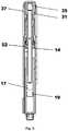
- the embodiment shown in the drawingscomprises a proximal part 10 and a distal part 20, Figs. 1-5 .
- the proximal part 10comprises a generally tubular first housing part 12 having elongated openings for viewing a multi-chamber container 16 which is arranged inside, Fig. 1 , and a somewhat narrowing proximal end.
- the multi-chamber container 16comprises at least two medicament substances arranged in each chamber, a distal stopper 17, a proximal stopper 19, and redirecting passages between the chambers.
- the distal end of the first housing partis arranged with annular threads 18 on its outer surface.
- the distal endis arranged with a neck portion having an inner diameter that is larger than the inner diameter of the rest of the body and thereby creating an annular ledge 14 between these two inner surfaces.
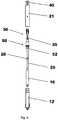
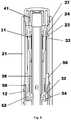
- Figs. 1-5show the distal part or power unit 20 of the injector according to the invention. It comprises a second housing part 21, a plunger rod 25 formed as a tubular member and with an outer diameter somewhat smaller than the inner diameter of the container body to be used, a drive force means, an activation member 30 and a locking member 50.
- the plunger rod 25is arranged with a circumferential groove 26 with a certain width.
- a drive force meanse.g. a helical compression spring, is pre-tensioned arranged and inside the spring a spring guide (not shown) is placed, as described below.
- the activation member 30Surrounding the plunger rod is the activation member 30 as e.g. an activator sleeve with a mainly tubular shape. Its proximal end comprises flexible locking means so as to form flexible tongues 39.
- Each tonguehas an inclined transition surface 32 which meets with a band-shaped part 34 with enlarged diameter.
- the activator sleeveis further provided with hook means so as to form at least one flexible tongue 31.
- Each tongue 31is arranged with an outwardly directed hook 37 at the outer end and a protrusion 33, with an inclined surface, a distance along each tongue.
- the distal end of the activator sleeveis arranged with a push button 35 protruding from said second housing part.
- a cover 40having two tongues 41 attached to its outer edge and directed in the proximal direction of the device is attached to the push button.
- a locking member 50hereafter named actuator sleeve, also of a generally tubular form, is slidably arranged in relation to said activator between a first position wherein said locking member completely surrounds said locking means and a second position wherein said locking member partially surrounds said locking means after said locking member has been axially displaced by said first housing when said first housing has been displaced into said second housing part, as will be described.
- the actuator sleevecomprises a distal end with at least one distally extending tongue and a proximal end with a first annular part 52 on its outer surface. At a distance from the first annular part 52, a second annular part 56 ending in a ledge 58 is arranged on the outer surface.
- the second housing part 21is of a generally tubular shape, where the inner surface of the proximal end is arranged with threads 22 corresponding to the threads 18 of the first housing part 12 and provided with a number of annular protrusions which are intended to fit into the corresponding annular recesses on the inner surface of the second housing part 21.
- the inner surface of the second housing partcomprises radially holding means. Said radially holding means being an annular ring 23 provided with a circumferential ledge 24 with a shape corresponding to the hook 37 of the activator sleeve.
- a compression spring(not shown) is arranged surrounding the actuator sleeve 50 between the annular ring 23 and the second annular part 56 of the actuator sleeve.
- the injectorwill be delivered to the user as shown in Fig. 1 , where a multi-chamber container is placed in the first housing part and the second housing part is attached to the proximal part.
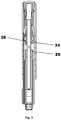
- the first housing partWhen a mixing is to be performed, the first housing part is screwed into the second housing part until the plunger rod, which is static in relation to the container, has shifted the distal stopper axially with respect to the container such that medicament substances inside said multi-chamber container have been completely mixed, see Fig 2 .
- the annular protrusions provided on the first housing part 12fits into the corresponding annular recesses on the inner surface of the second housing part 21, and thereby locking said two bodies.
- the distal end part of the first housing part 12surrounds the proximal part of the actuator sleeve 50 such that the distal end ledge 14 of the first housing part 12 comes into contact with the proximal end of the first annular part 52 and with the ledge 58 respectively.
- the actuator sleeve 50is pushed axially towards the distal end of the device against the force of the compression spring acting between the second annular part 56 of the actuator sleeve and the annular ring 23 of the second housing part 21.
- the part of the band-shaped part 34is then partially situated outside the proximal part of the actuator sleeve.
- the at least one distally extending tongue of the actuator sleevewill then come in contact with the inclined surface of the protrusion 33 of the at least one tongue 31 on the activator sleeve whereby the hook 37 is moved inwards and are free to pass inside the circumferential ledge 24.
- the next stepis to connect a needle or a safety pen needle to the proximal end of the first housing part 12 if the container is not a syringe, and to achieve a manual penetration of the needle into an injection site as e.g. the tissue of a patient.
- the userWhen activating the injection, the user merely depresses the cover 40 over the push button, Fig. 3 ., wherein the tongues 41 axially slides over the at least one flexible tongue 31. This causes the activator sleeve to be moved towards the proximal end of the device whereby the hooks 37 pass inside the circumferential ledge 24 and the band shaped part 34 is completely out of the actuator sleeve.
- the resilient properties of the tongues 39 of the activator sleevecauses the ledges 36 to move out of the groove 26 of the plunger rod, which then is free to move due to the helical compression spring inside the plunger rod.
- the force of the compression springurges the plunger rod to push on the stopper of the container and the liquid medicament is injected into the patient until the stopper reaches the inner proximal end of the container.
- the flexible locking meansare arranged to be released from said plunger rod only after said locking member is moved from the first position to the second position and said push button is axially moved into the second housing part, such that the flexible locking means comes completely out of contact with the locking member. If the mixing is not completely performed i.e. the first housing part has not been completely displaced into the second housing part such that said first housing part has not come into contact with said actuator sleeve, then said actuator sleeve has not been axially displaced towards the distal end of the device due to the force exerted by the compression spring arranged between the annular ring 23 and the second annular part 56 of the actuator sleeve. Moreover, if the user attempts to depress the push button before the mixing is completely done, the outwardly directed hooks 37 of the flexible tongues 31 will engage the annular ring 23 for avoiding premature activation of the device.
Landscapes
- Health & Medical Sciences (AREA)
- Vascular Medicine (AREA)
- Engineering & Computer Science (AREA)
- Anesthesiology (AREA)
- Biomedical Technology (AREA)
- Heart & Thoracic Surgery (AREA)
- Hematology (AREA)
- Life Sciences & Earth Sciences (AREA)
- Animal Behavior & Ethology (AREA)
- General Health & Medical Sciences (AREA)
- Public Health (AREA)
- Veterinary Medicine (AREA)
- Infusion, Injection, And Reservoir Apparatuses (AREA)
Description
- The present invention relates to an injector for administering, dispensing or delivering medicaments in a safe and reliable way. More particularly, it relates to injection device for manually penetrating a needle arranged to said device and automatic injecting a drug mixture from a multiple chamber container.
- There are a type of medicaments that can be stored for a long time and that are filled in containers as e.g. cartridges, syringes, ampoules, canisters or the like, containing a ready-to-use medicament in liquid state. However, there are also other type of medicaments that are a mixture of two substances, a medicament agent (e.g. lyophilized, powdered or concentrated liquid) and a diluent (e.g. water, dextrox solution or saline solution), wherein these type of medicaments can not be pre-mixed and stored for a long time because the medicament agent is unstable and can be degraded and loses its effect quickly. Hence, a user, e.g. a patient himself/herself, a physician, a nurse, hospital personnel or trained persons, has/have to perform the mixing within a limited time period prior to the delivery of a dose of medicament to a patient. Further, some medicament agents are subject to meet significant chemical changes while mixing. Such sensitive medicament agents require a particular treatment so that, when mixing said medicament agents with a diluent, unreasonable mixing force will degrade said medicament agents.
- In order to facilitate the mixing, a number of containers for mixing have been developed comprising at least two chambers, known as multi-chamber containers. These multi-chambered containers comprise a first chamber containing the medicament agent and at least a second chamber containing the diluent. These chambers are sealed off with stoppers in order that the medicament agents do not become degraded. When the medicament agent is to be mixed shortly before administering, redirecting passages are opened between the chambers, usually by depressing a distal stopper and in turn a divider stopper of the container somewhat. The passages allow the mixing of the medicament agent and the diluent and the medicament is ready for delivery.
- The above mentioned requirements can be achieved by simple medicament delivery devices, such as a common hypodermic syringe, but the procedure is of course rather awkward, in particular for users not used to handle these devices. In order to facilitate for the patient themselves to administer the medicament with a predetermined dose in an easy, safe and reliable way and also to facilitate the administration of medicaments for hospital personnel in the same facilitated way, a number of automatic and semi-automatic devices have been developed in combination with these multiple-chamber solutions for obtaining a mixing before delivery.
- A self-injection device arranged with a dual-chamber container, wherein both the mixing and the injection are done automatically by mechanical means, as springs and other means, is disclosed in
US 4,755,169 . A similar solution is disclosed inUS 6,793,646 wherein the mixing of a dual-chamber cartridge is done is done automatically by springs upon activation of the device and the injection is done by manually applying a force to a plunger rod forwardly. A drawback with these devices is that the mixing force, to which medicament agents are subject to, is too high at the beginning due to Hookes law. Hence, the medicament agents can be degraded. - Another solution is disclosed in
WO 2004004809 , wherein both the mixing and the injection are done automatically by electronics controlled means. A drawback with this device is that the electronics are dependent on batteries and is very sensitive to noise, moisture, water, etc.; which can result in malfunctions. Even more the manufacture of these devices is more expensive than the manufacture of mechanical devices. - In
US 6,319,225 the mixing of a dual-chamber ampoule is done manually. The device is set to be vertical on a flat plane and then a downward press on its proximal case causes a relative upward movement of its plunger rod pressing a stopper of the ampoule with eye observation on actions inside the ampoule, such that a mixing is obtained. Though inUS 6,319,225 is disclosed that the best suitable process for mixing a medicament agent with a diluent, is by performing manual control of the diluent flow with adequate slowness which will be monitored by eye observation; a drawback with this device is that the mixing force, to which medicament agents are subject to, can be high if the user is stressed and wants to use the device as soon as possible. Hence, the medicament agents can be degraded. - Moreover, the handling and safety aspects of injector devices, having a certain degree of automatic functions, as well as immediate accessibility in emergency situations are issues that attract a lot of attention when developing this type of devices.
- One important safety aspect when handling an auto-injector which is used to achieve a manual mixing and an automatic injection, is the locking of the injection means, e.g. a compressed spring actuating on a plunger rod, before the manual mixing have been completely.
- One such a device is disclosed in
US 6,893,420 wherein a self-injection device is arranged with a dual-chamber body. The mixing is done manually by a screw-tightening operation and the device comprises locking means for locking a latch means that prevent the automatic penetration and injection means from being released before the mixing has been completely finished. However, this solution is rather bulky and relies also on many components acting in co-operation and in sequence, one triggering another, which may lead to a mal-function, mal-dose accuracy, or that the device becomes complicated, hence not user friendly. This device suffers from the drawback that locking means has to be actively removed from the device after the mixing has been finished. This is a step which is not intuitive for a user, who will try to push the locking means instead of removing them. Another drawback is the dose accuracy, since the penetration starts pushing the stoppers, the medicament will start to be expelled during the whole penetration sequence, leading to so called wet injections and delivering of medicament through the whole penetration tissue instead of injecting the required dose at the intended penetration depth. - Another such a device is disclosed in
WO2007/115424A1 which relates to an injection device having a container holder having a multi-chamber container within, which is manually movable relative to the injection device for the purpose of mixing the components within the multi-chamber container. The device further comprises a spring which can bear on a part of the injection device, and a coupling element for coupling the container holder to the spring such that, during the movement of the container holder into the injection device, the spring is tensioned. The device also comprises an activation knob and a push button, wherein the activation knob has to be rotated for forcing the push button to protrude from the housing and thereby setting the device in a ready for injection delivery state. However, this solution suffers from the drawback that the activation knob has to be actively manipulated for releasing the push button after the mixing has been finished. This is a step which is not intuitive for a user, who will try to find where the push button or activation means are located instead of rotating the knob. - Even though the devices according to
US 6,893,420 andWO2007/115424A have proved to function well and displays a degree of safety, there is always a desire for improvements of such devices, among them being the design of the mechanism in order to simplify the manufacture and assembly in order to reduce costs but at the same time maintain or even improve the reliability of the safety and function of the device. WO 01/74423 A1 - The aim of the invention is to provide an injection device which is uncomplicated and easy to use, which is safe both before, during and after use and which displays a high degree of functionality and dose accuracy.
- According to one aspect of the invention, an injection device for manually penetrating a needle arranged to said device and automatic injecting a medicament mixture, the device being of the type comprising a second housing part; a first housing part into which a multi-chamber container is arranged and wherein said first housing part is arranged to be manually displaced into said second housing for mixing at least two substances arranged inside said container; a plunger rod arranged to act on a stopper arranged inside said container; drive force means capable of pushing said plunger rod for acting on said stopper, an activation member comprising flexible locking means releasibly connected to said plunger rod for holding said plunger rod and thereby said drive force means in a pre-tensioned state, and a push button protruding from said second housing part; characterised in that said device further comprises a locking member being arranged around said activation member and being axially slidable in relation to said activation member between a first position wherein said locking member completely surrounds said locking means and a second position wherein said locking member partially surrounds said locking means after said locking member has been axially displaced by said first housing when said first housing has been displaced into said second housing part; and wherein said flexible locking means are arranged to be released from said plunger rod only after said locking member is moved from the first position to the second position and said push button is axially moved into the second housing part, such that the flexible locking means comes completely out of contact with the locking member.
- According to the invention, said activation member further comprises hook means arranged to interact with radially holding means arranged on the inner circumference surface of the second housing part for locking said push button when said push button is depressed before said locking member is moved from the first position to the second position and thereby avoiding premature activation of the device.
- According to the invention, said hook means comprises at least one flexible tongue arranged with an outwardly directed hook at the outer end arranged to interact with said radially holding means being an annular ring provided with a circumferential ledge with a shape corresponding to the hook and further comprises and a protrusion, with an inclined surface, a distance along each tongue.
- According to a further aspect of the invention it is characterised in that the locking member comprises at least one distally extending tongue arranged to come in contact with the inclined surface of the protrusion when the locking member is displaced from the first position to the second position, whereby the hook is moved inwards and are free to pass inside the radially holding means.
According to a another aspect of the invention it is characterised in that that the device further comprises a compression spring arranged surrounding the locking member, between the radially holding means and a second annular part of the holding member. - Other aspects of the invention are that said flexible locking means comprises generally radially extending inwards directed ledges and that said plunger rod comprises a circumferential groove having a shape as for the ledges to fit into said groove.
- According to another aspect of the invention, the inner surface of the second housing part is arranged with threads corresponding to threads arranged on the outer surface of the first housing part, and the inner surface of the second housing part is arranged a number of annular protrusions which are intended to fit into corresponding annular recesses on the outer surface of the first housing part for locking said two housing parts after the substances has been mixed.
- These and other aspects of and advantages with the present invention will become apparent from the following detailed description and from the accompanying drawings.
- In the following detailed description of the invention, reference will be made to the accompanying drawings, of which
- Fig. 1
- is a cross-sectional side view of the auto-injector according to the invention in a pre-mixed position,
- Fig. 2
- is a cross-sectional side view of the auto-injector according to the invention in a medicament mixed position,
- Fig. 3
- is a cross-sectional side view of the auto-injector according to the invention in a final position,
- Fig. 4
- is an exploded view of the auto-injector according to the invention,
- Fig. 5
- is a zoomed view of the distal part of the auto-injector according to the invention.
- In the present application, when the term "distal part/end" is used, this refers to the part/end of the delivery device, or the parts/ends of the members thereof, which is/are located the furthest away from the medicament delivery site of the patient. Correspondingly, when the term "proximal part/end" is used, this refers to the part/end of the delivery device, or the parts/ends of the members thereof, which, is/are located closest to the medicament delivery site of the patient.
- The embodiment shown in the drawings comprises a
proximal part 10 and adistal part 20,Figs. 1-5 . - The
proximal part 10 comprises a generally tubularfirst housing part 12 having elongated openings for viewing amulti-chamber container 16 which is arranged inside,Fig. 1 , and a somewhat narrowing proximal end. Themulti-chamber container 16 comprises at least two medicament substances arranged in each chamber, adistal stopper 17, aproximal stopper 19, and redirecting passages between the chambers. The distal end of the first housing part is arranged withannular threads 18 on its outer surface. Moreover, the distal end is arranged with a neck portion having an inner diameter that is larger than the inner diameter of the rest of the body and thereby creating anannular ledge 14 between these two inner surfaces. Figs. 1-5 show the distal part orpower unit 20 of the injector according to the invention. It comprises asecond housing part 21, aplunger rod 25 formed as a tubular member and with an outer diameter somewhat smaller than the inner diameter of the container body to be used, a drive force means, anactivation member 30 and a lockingmember 50. Theplunger rod 25 is arranged with acircumferential groove 26 with a certain width. Inside the plunger rod a drive force means (not shown) e.g. a helical compression spring, is pre-tensioned arranged and inside the spring a spring guide (not shown) is placed, as described below.- Surrounding the plunger rod is the
activation member 30 as e.g. an activator sleeve with a mainly tubular shape. Its proximal end comprises flexible locking means so as to formflexible tongues 39. Each tongue has aninclined transition surface 32 which meets with a band-shapedpart 34 with enlarged diameter. On the inner surface adjacent the transition surface an annular inwardly directedledge 36 is arranged, with a shape as to fit into thegroove 26 of the plunger rod for holding the plunger rod and thereby said drive force means in a pre-tensioned state. The activator sleeve is further provided with hook means so as to form at least oneflexible tongue 31. Eachtongue 31 is arranged with an outwardly directedhook 37 at the outer end and aprotrusion 33, with an inclined surface, a distance along each tongue. The distal end of the activator sleeve is arranged with apush button 35 protruding from said second housing part. Acover 40 having twotongues 41 attached to its outer edge and directed in the proximal direction of the device is attached to the push button. - Around the
activator sleeve 30, a lockingmember 50, hereafter named actuator sleeve, also of a generally tubular form, is slidably arranged in relation to said activator between a first position wherein said locking member completely surrounds said locking means and a second position wherein said locking member partially surrounds said locking means after said locking member has been axially displaced by said first housing when said first housing has been displaced into said second housing part, as will be described. The actuator sleeve comprises a distal end with at least one distally extending tongue and a proximal end with a firstannular part 52 on its outer surface. At a distance from the firstannular part 52, a secondannular part 56 ending in aledge 58 is arranged on the outer surface. - The
second housing part 21 is of a generally tubular shape, where the inner surface of the proximal end is arranged withthreads 22 corresponding to thethreads 18 of thefirst housing part 12 and provided with a number of annular protrusions which are intended to fit into the corresponding annular recesses on the inner surface of thesecond housing part 21. Moreover, the inner surface of the second housing part comprises radially holding means. Said radially holding means being anannular ring 23 provided with acircumferential ledge 24 with a shape corresponding to thehook 37 of the activator sleeve. - Further, a compression spring (not shown) is arranged surrounding the
actuator sleeve 50 between theannular ring 23 and the secondannular part 56 of the actuator sleeve. - The function of the injector according to the invention will now be described in connection with the
figures 1-4 . - The injector will be delivered to the user as shown in
Fig. 1 , where a multi-chamber container is placed in the first housing part and the second housing part is attached to the proximal part. - When a mixing is to be performed, the first housing part is screwed into the second housing part until the plunger rod, which is static in relation to the container, has shifted the distal stopper axially with respect to the container such that medicament substances inside said multi-chamber container have been completely mixed, see
Fig 2 . In this mixed position, the annular protrusions provided on thefirst housing part 12 fits into the corresponding annular recesses on the inner surface of thesecond housing part 21, and thereby locking said two bodies. - At the same time the distal end part of the
first housing part 12 surrounds the proximal part of theactuator sleeve 50 such that thedistal end ledge 14 of thefirst housing part 12 comes into contact with the proximal end of the firstannular part 52 and with theledge 58 respectively. - Moreover, when the mixing is performed, the
actuator sleeve 50 is pushed axially towards the distal end of the device against the force of the compression spring acting between the secondannular part 56 of the actuator sleeve and theannular ring 23 of thesecond housing part 21. The part of the band-shapedpart 34 is then partially situated outside the proximal part of the actuator sleeve. The at least one distally extending tongue of the actuator sleeve will then come in contact with the inclined surface of theprotrusion 33 of the at least onetongue 31 on the activator sleeve whereby thehook 37 is moved inwards and are free to pass inside thecircumferential ledge 24. - The next step is to connect a needle or a safety pen needle to the proximal end of the
first housing part 12 if the container is not a syringe, and to achieve a manual penetration of the needle into an injection site as e.g. the tissue of a patient. When activating the injection, the user merely depresses thecover 40 over the push button,Fig. 3 ., wherein thetongues 41 axially slides over the at least oneflexible tongue 31. This causes the activator sleeve to be moved towards the proximal end of the device whereby thehooks 37 pass inside thecircumferential ledge 24 and the band shapedpart 34 is completely out of the actuator sleeve. The resilient properties of thetongues 39 of the activator sleeve causes theledges 36 to move out of thegroove 26 of the plunger rod, which then is free to move due to the helical compression spring inside the plunger rod. The force of the compression spring urges the plunger rod to push on the stopper of the container and the liquid medicament is injected into the patient until the stopper reaches the inner proximal end of the container. - It is to be understood that the flexible locking means are arranged to be released from said plunger rod only after said locking member is moved from the first position to the second position and said push button is axially moved into the second housing part, such that the flexible locking means comes completely out of contact with the locking member. If the mixing is not completely performed i.e. the first housing part has not been completely displaced into the second housing part such that said first housing part has not come into contact with said actuator sleeve, then said actuator sleeve has not been axially displaced towards the distal end of the device due to the force exerted by the compression spring arranged between the
annular ring 23 and the secondannular part 56 of the actuator sleeve. Moreover, if the user attempts to depress the push button before the mixing is completely done, the outwardly directed hooks 37 of theflexible tongues 31 will engage theannular ring 23 for avoiding premature activation of the device. - It is to be understood that the embodiment described above and shown in the drawings is to be regarded as a non-limiting example of the invention and that it is defined be the patent claims.
Claims (6)
- Injection device for manually penetrating a needle arranged to said device and automatic injecting a medicament mixture, the device being of the type comprising:- a second housing part (21);- a first housing part (12) into which a multi-chamber container is arranged and wherein said first housing part is arranged to be manually displaced into said second housing for mixing at least two substances arranged inside said container;- a plunger rod (25) arranged to act on a stopper arranged inside said container;- drive force means capable of pushing said plunger rod for acting on said stopper,- an activation member (30) comprising flexible locking means releasibly connected to said plunger rod for holding said plunger rod and thereby said drive force means in a pre-tensioned state, and a push button protruding from said second housing part;- a locking member (50) being arranged around said activation member and being axially slidable in relation to said activation member between a first position wherein said locking member completely surrounds said locking means and a second position wherein said locking member partially surrounds said locking means after said locking member has been axially displaced by said first housing when said first housing has been displaced into said second housing part; and wherein said flexible locking means are arranged to be released from said plunger rod only after said locking member is moved from the first position to the second position and said push button is axially moved into the second housing part, such that the flexible locking means comes completely out of contact with the locking member;characterised in that said activation member further comprises hook means comprising at least one flexible tongue (31) arranged with an outwardly directed hook (37) at the outer end arranged to interact with radially holding means being an annular ring (23) provided with a circumferential ledge (24) with a shape corresponding to the hook (37) and arranged on the inner circumference surface of the second housing part for locking said push button when said push button is depressed before said locking member is moved from the first position to the second position and thereby avoiding premature activation of the device, said hook means further comprising a protrusion (33), with an inclined surface, a distance along each tongue.
- A device according to claim 1characterised in that the locking member comprises at least one distally extending tongue arranged to come in contact with the inclined surface of the protrusion (33) when the locking member is displaced from the first position to the second position, whereby the hook (37) is moved inwards and are free to pass inside the radially holding means.
- A device according to any one of the claims 1-2,characterised in that the device further comprises a compression spring arranged surrounding the locking member, between the radially holding means and a second annular part (56) of the holding member.
- A device according to any one of the claims 1-3,characterised in that said flexible locking means comprises generally radially extending inwards directed ledges (36) and that said plunger rod comprises a circumferential groove (26) having a shape as for the ledges to fit into said groove.
- A device according to any one of the preceding claims,characterised in that the inner surface of the second housing part is arranged with threads (22) corresponding to threads (18) arranged on the outer surface of the first housing part.
- A device according to any of the preceding claims,characterised in that inner surface of the second housing part is arranged a number of annular protrusions which are intended to fit into corresponding annular recesses on the outer surface of the first housing part for locking said two housing parts after the substances has been mixed.
Applications Claiming Priority (3)
| Application Number | Priority Date | Filing Date | Title |
|---|---|---|---|
| US5792808P | 2008-06-02 | 2008-06-02 | |
| SE0801303 | 2008-06-02 | ||
| PCT/EP2009/056350WO2009147026A1 (en) | 2008-06-02 | 2009-05-26 | Medicament delivery device |
Publications (2)
| Publication Number | Publication Date |
|---|---|
| EP2303366A1 EP2303366A1 (en) | 2011-04-06 |
| EP2303366B1true EP2303366B1 (en) | 2019-10-02 |
Family
ID=41138898
Family Applications (1)
| Application Number | Title | Priority Date | Filing Date |
|---|---|---|---|
| EP09757409.9AActiveEP2303366B1 (en) | 2008-06-02 | 2009-05-26 | Medicament delivery device |
Country Status (5)
| Country | Link |
|---|---|
| US (1) | US8372031B2 (en) |
| EP (1) | EP2303366B1 (en) |
| CN (1) | CN102076371B (en) |
| AU (1) | AU2009254014B2 (en) |
| WO (1) | WO2009147026A1 (en) |
Families Citing this family (29)
| Publication number | Priority date | Publication date | Assignee | Title |
|---|---|---|---|---|
| WO2003068290A2 (en) | 2002-02-11 | 2003-08-21 | Antares Pharma, Inc. | Intradermal injector |
| IL157981A (en) | 2003-09-17 | 2014-01-30 | Elcam Medical Agricultural Cooperative Ass Ltd | Auto-injector |
| HUE042286T2 (en) | 2005-01-24 | 2019-06-28 | Antares Pharma Inc | Needle-filled pre-filled syringe |
| WO2007131013A1 (en) | 2006-05-03 | 2007-11-15 | Antares Pharma, Inc. | Two-stage reconstituting injector |
| WO2007131025A1 (en) | 2006-05-03 | 2007-11-15 | Antares Pharma, Inc. | Injector with adjustable dosing |
| EP3636301A1 (en) | 2008-03-10 | 2020-04-15 | Antares Pharma, Inc. | Injector safety device |
| US8376993B2 (en) | 2008-08-05 | 2013-02-19 | Antares Pharma, Inc. | Multiple dosage injector |
| JP5732039B2 (en) | 2009-03-20 | 2015-06-10 | アンタレス・ファーマ・インコーポレーテッド | Hazardous drug injection system |
| US8529503B2 (en)* | 2009-04-24 | 2013-09-10 | Shl Group Ab | Medicament delivery device |
| WO2011053225A1 (en)* | 2009-10-26 | 2011-05-05 | Shl Group Ab | Medicament delivery device |
| US8986245B2 (en) | 2010-02-09 | 2015-03-24 | Shl Group Ab | Medicament delivery device |
| US9962490B2 (en) | 2012-08-14 | 2018-05-08 | Shl Group Ab | Medicament delivery device |
| US11957885B2 (en) | 2010-02-09 | 2024-04-16 | Shl Medical Ag | Medicament delivery device |
| WO2012030276A1 (en)* | 2010-08-31 | 2012-03-08 | Shl Group Ab | Medicament delivery device |
| US8961455B2 (en) | 2010-08-31 | 2015-02-24 | Shl Group Ab | Medicament delivery device |
| AU2012212720B2 (en)* | 2011-02-03 | 2015-01-22 | Shl Medical Ag | Medicament delivery device |
| US9220660B2 (en) | 2011-07-15 | 2015-12-29 | Antares Pharma, Inc. | Liquid-transfer adapter beveled spike |
| US8496619B2 (en) | 2011-07-15 | 2013-07-30 | Antares Pharma, Inc. | Injection device with cammed ram assembly |
| US9486583B2 (en) | 2012-03-06 | 2016-11-08 | Antares Pharma, Inc. | Prefilled syringe with breakaway force feature |
| EP4186545A1 (en) | 2012-04-06 | 2023-05-31 | Antares Pharma, Inc. | Needle assisted jet injection administration of testosterone compositions |
| US9364610B2 (en) | 2012-05-07 | 2016-06-14 | Antares Pharma, Inc. | Injection device with cammed ram assembly |
| EP2906272B1 (en)* | 2012-10-12 | 2018-12-05 | SHL Medical AG | Medicament delivery device |
| FI3659647T3 (en) | 2013-02-11 | 2024-03-28 | Antares Pharma Inc | NEEDLE-ASSISTED SPRAY INJECTOR WITH REDUCED TRIGGER FORCE |
| CA2905031C (en) | 2013-03-11 | 2018-01-23 | Hans PFLAUMER | Dosage injector with pinion system |
| WO2014165136A1 (en) | 2013-03-12 | 2014-10-09 | Antares Pharma, Inc. | Constant volume prefilled syringes and kits thereof |
| EP2988799B1 (en)* | 2013-04-23 | 2019-02-27 | E3D Agricultural Cooperative Association Ltd. | Automatic injection device for administration of high viscosity medication |
| AT514484B1 (en) | 2013-06-24 | 2015-05-15 | Pharma Consult Gmbh | Activator for an auto-injector |
| TWI637762B (en) | 2016-06-23 | 2018-10-11 | 卡貝歐洲有限公司 | Medicament delivery device |
| EP3654918A1 (en)* | 2017-07-20 | 2020-05-27 | Janssen Biotech, Inc. | Drug mixing device |
Family Cites Families (4)
| Publication number | Priority date | Publication date | Assignee | Title |
|---|---|---|---|---|
| WO2000062839A2 (en)* | 1999-04-16 | 2000-10-26 | Becton Dickinson And Company | Pen style injector with automated substance combining feature |
| FR2806916B1 (en)* | 2000-03-31 | 2002-11-29 | Sedat | INJECTION SYRINGE OF AN EXTEMPORANEOUS MIXTURE |
| DE102006017209A1 (en)* | 2006-04-12 | 2007-10-18 | Tecpharma Licensing Ag | Injection device with tension spring and tensioning element |
| WO2009100550A1 (en)* | 2008-02-11 | 2009-08-20 | Tecpharma Licensing Ag | Administering apparatus comprising a blockable actuation element |
- 2009
- 2009-05-26USUS12/995,516patent/US8372031B2/enactiveActive
- 2009-05-26WOPCT/EP2009/056350patent/WO2009147026A1/enactiveApplication Filing
- 2009-05-26EPEP09757409.9Apatent/EP2303366B1/enactiveActive
- 2009-05-26CNCN200980124829XApatent/CN102076371B/enactiveActive
- 2009-05-26AUAU2009254014Apatent/AU2009254014B2/enactiveActive
Non-Patent Citations (1)
| Title |
|---|
| None* |
Also Published As
| Publication number | Publication date |
|---|---|
| WO2009147026A1 (en) | 2009-12-10 |
| EP2303366A1 (en) | 2011-04-06 |
| CN102076371B (en) | 2013-07-31 |
| US20110087163A1 (en) | 2011-04-14 |
| AU2009254014A1 (en) | 2009-12-10 |
| AU2009254014B2 (en) | 2012-05-24 |
| CN102076371A (en) | 2011-05-25 |
| US8372031B2 (en) | 2013-02-12 |
Similar Documents
| Publication | Publication Date | Title |
|---|---|---|
| EP2303366B1 (en) | Medicament delivery device | |
| EP2533834B1 (en) | Medicament delivery device | |
| EP2611482B1 (en) | Medicament delivery device | |
| US11173252B2 (en) | Medicament delivery device | |
| EP2906272B1 (en) | Medicament delivery device | |
| EP2611481B1 (en) | Medicament delivery device | |
| US11957885B2 (en) | Medicament delivery device | |
| US20210338934A1 (en) | Medicament delivery device | |
| DK2611481T3 (en) | DRUG ADMINISTRATIVE DEVICE |
Legal Events
| Date | Code | Title | Description |
|---|---|---|---|
| PUAI | Public reference made under article 153(3) epc to a published international application that has entered the european phase | Free format text:ORIGINAL CODE: 0009012 | |
| 17P | Request for examination filed | Effective date:20101202 | |
| AK | Designated contracting states | Kind code of ref document:A1 Designated state(s):AT BE BG CH CY CZ DE DK EE ES FI FR GB GR HR HU IE IS IT LI LT LU LV MC MK MT NL NO PL PT RO SE SI SK TR | |
| AX | Request for extension of the european patent | Extension state:AL BA RS | |
| DAX | Request for extension of the european patent (deleted) | ||
| RAP1 | Party data changed (applicant data changed or rights of an application transferred) | Owner name:SHL GROUP AB | |
| RAP1 | Party data changed (applicant data changed or rights of an application transferred) | Owner name:SHL MEDICAL AG | |
| GRAP | Despatch of communication of intention to grant a patent | Free format text:ORIGINAL CODE: EPIDOSNIGR1 | |
| STAA | Information on the status of an ep patent application or granted ep patent | Free format text:STATUS: GRANT OF PATENT IS INTENDED | |
| RIC1 | Information provided on ipc code assigned before grant | Ipc:A61M 5/20 20060101AFI20190412BHEP Ipc:A61M 5/24 20060101ALI20190412BHEP Ipc:A61M 5/28 20060101ALI20190412BHEP | |
| INTG | Intention to grant announced | Effective date:20190516 | |
| GRAS | Grant fee paid | Free format text:ORIGINAL CODE: EPIDOSNIGR3 | |
| GRAA | (expected) grant | Free format text:ORIGINAL CODE: 0009210 | |
| STAA | Information on the status of an ep patent application or granted ep patent | Free format text:STATUS: THE PATENT HAS BEEN GRANTED | |
| AK | Designated contracting states | Kind code of ref document:B1 Designated state(s):AT BE BG CH CY CZ DE DK EE ES FI FR GB GR HR HU IE IS IT LI LT LU LV MC MK MT NL NO PL PT RO SE SI SK TR | |
| REG | Reference to a national code | Ref country code:GB Ref legal event code:FG4D | |
| REG | Reference to a national code | Ref country code:CH Ref legal event code:EP Ref country code:AT Ref legal event code:REF Ref document number:1185501 Country of ref document:AT Kind code of ref document:T Effective date:20191015 | |
| REG | Reference to a national code | Ref country code:DE Ref legal event code:R096 Ref document number:602009060006 Country of ref document:DE | |
| REG | Reference to a national code | Ref country code:IE Ref legal event code:FG4D | |
| REG | Reference to a national code | Ref country code:NL Ref legal event code:MP Effective date:20191002 | |
| REG | Reference to a national code | Ref country code:LT Ref legal event code:MG4D | |
| REG | Reference to a national code | Ref country code:AT Ref legal event code:MK05 Ref document number:1185501 Country of ref document:AT Kind code of ref document:T Effective date:20191002 | |
| PG25 | Lapsed in a contracting state [announced via postgrant information from national office to epo] | Ref country code:BG Free format text:LAPSE BECAUSE OF FAILURE TO SUBMIT A TRANSLATION OF THE DESCRIPTION OR TO PAY THE FEE WITHIN THE PRESCRIBED TIME-LIMIT Effective date:20200102 Ref country code:FI Free format text:LAPSE BECAUSE OF FAILURE TO SUBMIT A TRANSLATION OF THE DESCRIPTION OR TO PAY THE FEE WITHIN THE PRESCRIBED TIME-LIMIT Effective date:20191002 Ref country code:NO Free format text:LAPSE BECAUSE OF FAILURE TO SUBMIT A TRANSLATION OF THE DESCRIPTION OR TO PAY THE FEE WITHIN THE PRESCRIBED TIME-LIMIT Effective date:20200102 Ref country code:PT Free format text:LAPSE BECAUSE OF FAILURE TO SUBMIT A TRANSLATION OF THE DESCRIPTION OR TO PAY THE FEE WITHIN THE PRESCRIBED TIME-LIMIT Effective date:20200203 Ref country code:PL Free format text:LAPSE BECAUSE OF FAILURE TO SUBMIT A TRANSLATION OF THE DESCRIPTION OR TO PAY THE FEE WITHIN THE PRESCRIBED TIME-LIMIT Effective date:20191002 Ref country code:GR Free format text:LAPSE BECAUSE OF FAILURE TO SUBMIT A TRANSLATION OF THE DESCRIPTION OR TO PAY THE FEE WITHIN THE PRESCRIBED TIME-LIMIT Effective date:20200103 Ref country code:SE Free format text:LAPSE BECAUSE OF FAILURE TO SUBMIT A TRANSLATION OF THE DESCRIPTION OR TO PAY THE FEE WITHIN THE PRESCRIBED TIME-LIMIT Effective date:20191002 Ref country code:LV Free format text:LAPSE BECAUSE OF FAILURE TO SUBMIT A TRANSLATION OF THE DESCRIPTION OR TO PAY THE FEE WITHIN THE PRESCRIBED TIME-LIMIT Effective date:20191002 Ref country code:ES Free format text:LAPSE BECAUSE OF FAILURE TO SUBMIT A TRANSLATION OF THE DESCRIPTION OR TO PAY THE FEE WITHIN THE PRESCRIBED TIME-LIMIT Effective date:20191002 Ref country code:AT Free format text:LAPSE BECAUSE OF FAILURE TO SUBMIT A TRANSLATION OF THE DESCRIPTION OR TO PAY THE FEE WITHIN THE PRESCRIBED TIME-LIMIT Effective date:20191002 Ref country code:NL Free format text:LAPSE BECAUSE OF FAILURE TO SUBMIT A TRANSLATION OF THE DESCRIPTION OR TO PAY THE FEE WITHIN THE PRESCRIBED TIME-LIMIT Effective date:20191002 Ref country code:LT Free format text:LAPSE BECAUSE OF FAILURE TO SUBMIT A TRANSLATION OF THE DESCRIPTION OR TO PAY THE FEE WITHIN THE PRESCRIBED TIME-LIMIT Effective date:20191002 | |
| PG25 | Lapsed in a contracting state [announced via postgrant information from national office to epo] | Ref country code:IS Free format text:LAPSE BECAUSE OF FAILURE TO SUBMIT A TRANSLATION OF THE DESCRIPTION OR TO PAY THE FEE WITHIN THE PRESCRIBED TIME-LIMIT Effective date:20200224 Ref country code:CZ Free format text:LAPSE BECAUSE OF FAILURE TO SUBMIT A TRANSLATION OF THE DESCRIPTION OR TO PAY THE FEE WITHIN THE PRESCRIBED TIME-LIMIT Effective date:20191002 Ref country code:HR Free format text:LAPSE BECAUSE OF FAILURE TO SUBMIT A TRANSLATION OF THE DESCRIPTION OR TO PAY THE FEE WITHIN THE PRESCRIBED TIME-LIMIT Effective date:20191002 | |
| REG | Reference to a national code | Ref country code:DE Ref legal event code:R097 Ref document number:602009060006 Country of ref document:DE | |
| PG2D | Information on lapse in contracting state deleted | Ref country code:IS | |
| PG25 | Lapsed in a contracting state [announced via postgrant information from national office to epo] | Ref country code:DK Free format text:LAPSE BECAUSE OF FAILURE TO SUBMIT A TRANSLATION OF THE DESCRIPTION OR TO PAY THE FEE WITHIN THE PRESCRIBED TIME-LIMIT Effective date:20191002 Ref country code:EE Free format text:LAPSE BECAUSE OF FAILURE TO SUBMIT A TRANSLATION OF THE DESCRIPTION OR TO PAY THE FEE WITHIN THE PRESCRIBED TIME-LIMIT Effective date:20191002 Ref country code:RO Free format text:LAPSE BECAUSE OF FAILURE TO SUBMIT A TRANSLATION OF THE DESCRIPTION OR TO PAY THE FEE WITHIN THE PRESCRIBED TIME-LIMIT Effective date:20191002 Ref country code:IS Free format text:LAPSE BECAUSE OF FAILURE TO SUBMIT A TRANSLATION OF THE DESCRIPTION OR TO PAY THE FEE WITHIN THE PRESCRIBED TIME-LIMIT Effective date:20200202 | |
| PLBE | No opposition filed within time limit | Free format text:ORIGINAL CODE: 0009261 | |
| STAA | Information on the status of an ep patent application or granted ep patent | Free format text:STATUS: NO OPPOSITION FILED WITHIN TIME LIMIT | |
| PG25 | Lapsed in a contracting state [announced via postgrant information from national office to epo] | Ref country code:IT Free format text:LAPSE BECAUSE OF FAILURE TO SUBMIT A TRANSLATION OF THE DESCRIPTION OR TO PAY THE FEE WITHIN THE PRESCRIBED TIME-LIMIT Effective date:20191002 Ref country code:SK Free format text:LAPSE BECAUSE OF FAILURE TO SUBMIT A TRANSLATION OF THE DESCRIPTION OR TO PAY THE FEE WITHIN THE PRESCRIBED TIME-LIMIT Effective date:20191002 | |
| 26N | No opposition filed | Effective date:20200703 | |
| PG25 | Lapsed in a contracting state [announced via postgrant information from national office to epo] | Ref country code:SI Free format text:LAPSE BECAUSE OF FAILURE TO SUBMIT A TRANSLATION OF THE DESCRIPTION OR TO PAY THE FEE WITHIN THE PRESCRIBED TIME-LIMIT Effective date:20191002 | |
| PG25 | Lapsed in a contracting state [announced via postgrant information from national office to epo] | Ref country code:MC Free format text:LAPSE BECAUSE OF FAILURE TO SUBMIT A TRANSLATION OF THE DESCRIPTION OR TO PAY THE FEE WITHIN THE PRESCRIBED TIME-LIMIT Effective date:20191002 | |
| REG | Reference to a national code | Ref country code:BE Ref legal event code:MM Effective date:20200531 | |
| PG25 | Lapsed in a contracting state [announced via postgrant information from national office to epo] | Ref country code:LU Free format text:LAPSE BECAUSE OF NON-PAYMENT OF DUE FEES Effective date:20200526 | |
| PG25 | Lapsed in a contracting state [announced via postgrant information from national office to epo] | Ref country code:IE Free format text:LAPSE BECAUSE OF NON-PAYMENT OF DUE FEES Effective date:20200526 | |
| PG25 | Lapsed in a contracting state [announced via postgrant information from national office to epo] | Ref country code:BE Free format text:LAPSE BECAUSE OF NON-PAYMENT OF DUE FEES Effective date:20200531 | |
| PG25 | Lapsed in a contracting state [announced via postgrant information from national office to epo] | Ref country code:TR Free format text:LAPSE BECAUSE OF FAILURE TO SUBMIT A TRANSLATION OF THE DESCRIPTION OR TO PAY THE FEE WITHIN THE PRESCRIBED TIME-LIMIT Effective date:20191002 Ref country code:MT Free format text:LAPSE BECAUSE OF FAILURE TO SUBMIT A TRANSLATION OF THE DESCRIPTION OR TO PAY THE FEE WITHIN THE PRESCRIBED TIME-LIMIT Effective date:20191002 Ref country code:CY Free format text:LAPSE BECAUSE OF FAILURE TO SUBMIT A TRANSLATION OF THE DESCRIPTION OR TO PAY THE FEE WITHIN THE PRESCRIBED TIME-LIMIT Effective date:20191002 | |
| PG25 | Lapsed in a contracting state [announced via postgrant information from national office to epo] | Ref country code:MK Free format text:LAPSE BECAUSE OF FAILURE TO SUBMIT A TRANSLATION OF THE DESCRIPTION OR TO PAY THE FEE WITHIN THE PRESCRIBED TIME-LIMIT Effective date:20191002 | |
| P01 | Opt-out of the competence of the unified patent court (upc) registered | Effective date:20230425 | |
| PGFP | Annual fee paid to national office [announced via postgrant information from national office to epo] | Ref country code:DE Payment date:20250528 Year of fee payment:17 | |
| PGFP | Annual fee paid to national office [announced via postgrant information from national office to epo] | Ref country code:GB Payment date:20250520 Year of fee payment:17 | |
| PGFP | Annual fee paid to national office [announced via postgrant information from national office to epo] | Ref country code:FR Payment date:20250526 Year of fee payment:17 | |
| PGFP | Annual fee paid to national office [announced via postgrant information from national office to epo] | Ref country code:CH Payment date:20250601 Year of fee payment:17 |