EP2303365B1 - Medicament delivery device with a damper - Google Patents
Medicament delivery device with a damperDownload PDFInfo
- Publication number
- EP2303365B1 EP2303365B1EP09749709.3AEP09749709AEP2303365B1EP 2303365 B1EP2303365 B1EP 2303365B1EP 09749709 AEP09749709 AEP 09749709AEP 2303365 B1EP2303365 B1EP 2303365B1
- Authority
- EP
- European Patent Office
- Prior art keywords
- plunger rod
- compartment
- sleeve
- fluid
- medicament
- Prior art date
- Legal status (The legal status is an assumption and is not a legal conclusion. Google has not performed a legal analysis and makes no representation as to the accuracy of the status listed.)
- Not-in-force
Links
- 239000003814drugSubstances0.000titleclaimsdescription34
- 239000012530fluidSubstances0.000claimsdescription21
- 238000002347injectionMethods0.000description9
- 239000007924injectionSubstances0.000description9
- 239000007788liquidSubstances0.000description4
- 230000006835compressionEffects0.000description3
- 238000007906compressionMethods0.000description3
- 239000003921oilSubstances0.000description3
- 230000035515penetrationEffects0.000description3
- 238000013016dampingMethods0.000description2
- 229940079593drugDrugs0.000description2
- 239000000443aerosolSubstances0.000description1
- 229940090047auto-injectorDrugs0.000description1
- 230000007850degenerationEffects0.000description1
- 230000000694effectsEffects0.000description1
- 239000011521glassSubstances0.000description1
- 239000004519greaseSubstances0.000description1
- 239000000463materialSubstances0.000description1
- 229920000642polymerPolymers0.000description1
- 229920001296polysiloxanePolymers0.000description1
- 239000012858resilient materialSubstances0.000description1
- 230000000979retarding effectEffects0.000description1
- 239000000243solutionSubstances0.000description1
- 239000007921spraySubstances0.000description1
Images


Classifications
- A—HUMAN NECESSITIES
- A61—MEDICAL OR VETERINARY SCIENCE; HYGIENE
- A61M—DEVICES FOR INTRODUCING MEDIA INTO, OR ONTO, THE BODY; DEVICES FOR TRANSDUCING BODY MEDIA OR FOR TAKING MEDIA FROM THE BODY; DEVICES FOR PRODUCING OR ENDING SLEEP OR STUPOR
- A61M5/00—Devices for bringing media into the body in a subcutaneous, intra-vascular or intramuscular way; Accessories therefor, e.g. filling or cleaning devices, arm-rests
- A61M5/178—Syringes
- A61M5/31—Details
- A61M5/315—Pistons; Piston-rods; Guiding, blocking or restricting the movement of the rod or piston; Appliances on the rod for facilitating dosing ; Dosing mechanisms
- A61M5/31511—Piston or piston-rod constructions, e.g. connection of piston with piston-rod
- A—HUMAN NECESSITIES
- A61—MEDICAL OR VETERINARY SCIENCE; HYGIENE
- A61M—DEVICES FOR INTRODUCING MEDIA INTO, OR ONTO, THE BODY; DEVICES FOR TRANSDUCING BODY MEDIA OR FOR TAKING MEDIA FROM THE BODY; DEVICES FOR PRODUCING OR ENDING SLEEP OR STUPOR
- A61M11/00—Sprayers or atomisers specially adapted for therapeutic purposes
- A61M11/006—Sprayers or atomisers specially adapted for therapeutic purposes operated by applying mechanical pressure to the liquid to be sprayed or atomised
- A61M11/007—Syringe-type or piston-type sprayers or atomisers
- A—HUMAN NECESSITIES
- A61—MEDICAL OR VETERINARY SCIENCE; HYGIENE
- A61M—DEVICES FOR INTRODUCING MEDIA INTO, OR ONTO, THE BODY; DEVICES FOR TRANSDUCING BODY MEDIA OR FOR TAKING MEDIA FROM THE BODY; DEVICES FOR PRODUCING OR ENDING SLEEP OR STUPOR
- A61M5/00—Devices for bringing media into the body in a subcutaneous, intra-vascular or intramuscular way; Accessories therefor, e.g. filling or cleaning devices, arm-rests
- A61M5/178—Syringes
- A61M5/31—Details
- A61M5/315—Pistons; Piston-rods; Guiding, blocking or restricting the movement of the rod or piston; Appliances on the rod for facilitating dosing ; Dosing mechanisms
- A61M5/31501—Means for blocking or restricting the movement of the rod or piston
- A—HUMAN NECESSITIES
- A61—MEDICAL OR VETERINARY SCIENCE; HYGIENE
- A61M—DEVICES FOR INTRODUCING MEDIA INTO, OR ONTO, THE BODY; DEVICES FOR TRANSDUCING BODY MEDIA OR FOR TAKING MEDIA FROM THE BODY; DEVICES FOR PRODUCING OR ENDING SLEEP OR STUPOR
- A61M5/00—Devices for bringing media into the body in a subcutaneous, intra-vascular or intramuscular way; Accessories therefor, e.g. filling or cleaning devices, arm-rests
- A61M5/178—Syringes
- A61M5/20—Automatic syringes, e.g. with automatically actuated piston rod, with automatic needle injection, filling automatically
- A61M2005/2086—Automatic syringes, e.g. with automatically actuated piston rod, with automatic needle injection, filling automatically having piston damping means, e.g. axially or rotationally acting retarders
- A—HUMAN NECESSITIES
- A61—MEDICAL OR VETERINARY SCIENCE; HYGIENE
- A61M—DEVICES FOR INTRODUCING MEDIA INTO, OR ONTO, THE BODY; DEVICES FOR TRANSDUCING BODY MEDIA OR FOR TAKING MEDIA FROM THE BODY; DEVICES FOR PRODUCING OR ENDING SLEEP OR STUPOR
- A61M5/00—Devices for bringing media into the body in a subcutaneous, intra-vascular or intramuscular way; Accessories therefor, e.g. filling or cleaning devices, arm-rests
- A61M5/178—Syringes
- A61M5/24—Ampoule syringes, i.e. syringes with needle for use in combination with replaceable ampoules or carpules, e.g. automatic
- A61M2005/2418—Ampoule syringes, i.e. syringes with needle for use in combination with replaceable ampoules or carpules, e.g. automatic comprising means for damping shocks on ampoule
- A—HUMAN NECESSITIES
- A61—MEDICAL OR VETERINARY SCIENCE; HYGIENE
- A61M—DEVICES FOR INTRODUCING MEDIA INTO, OR ONTO, THE BODY; DEVICES FOR TRANSDUCING BODY MEDIA OR FOR TAKING MEDIA FROM THE BODY; DEVICES FOR PRODUCING OR ENDING SLEEP OR STUPOR
- A61M5/00—Devices for bringing media into the body in a subcutaneous, intra-vascular or intramuscular way; Accessories therefor, e.g. filling or cleaning devices, arm-rests
- A61M5/178—Syringes
- A61M5/31—Details
- A61M5/315—Pistons; Piston-rods; Guiding, blocking or restricting the movement of the rod or piston; Appliances on the rod for facilitating dosing ; Dosing mechanisms
- A61M5/31501—Means for blocking or restricting the movement of the rod or piston
- A61M2005/3151—Means for blocking or restricting the movement of the rod or piston by friction
- A—HUMAN NECESSITIES
- A61—MEDICAL OR VETERINARY SCIENCE; HYGIENE
- A61M—DEVICES FOR INTRODUCING MEDIA INTO, OR ONTO, THE BODY; DEVICES FOR TRANSDUCING BODY MEDIA OR FOR TAKING MEDIA FROM THE BODY; DEVICES FOR PRODUCING OR ENDING SLEEP OR STUPOR
- A61M5/00—Devices for bringing media into the body in a subcutaneous, intra-vascular or intramuscular way; Accessories therefor, e.g. filling or cleaning devices, arm-rests
- A61M5/178—Syringes
- A61M5/20—Automatic syringes, e.g. with automatically actuated piston rod, with automatic needle injection, filling automatically
- A61M5/2033—Spring-loaded one-shot injectors with or without automatic needle insertion
- A—HUMAN NECESSITIES
- A61—MEDICAL OR VETERINARY SCIENCE; HYGIENE
- A61M—DEVICES FOR INTRODUCING MEDIA INTO, OR ONTO, THE BODY; DEVICES FOR TRANSDUCING BODY MEDIA OR FOR TAKING MEDIA FROM THE BODY; DEVICES FOR PRODUCING OR ENDING SLEEP OR STUPOR
- A61M5/00—Devices for bringing media into the body in a subcutaneous, intra-vascular or intramuscular way; Accessories therefor, e.g. filling or cleaning devices, arm-rests
- A61M5/178—Syringes
- A61M5/28—Syringe ampoules or carpules, i.e. ampoules or carpules provided with a needle
Definitions
- the present inventionrelates to a device for a medicament delivery device and in particular a damping device capable of dampening the force from a plunger rod acting on a stopper of a container arranged in said medicament delivery device.
- Medicament delivery devicesas e.g. injectors for injecting medicament into the tissue of patients have become widely used, and in particular since these injectors have facilitated for larger groups of patients to self-administer their drugs, due to the functionalities of the injectors.
- Examples of functionalities of the injectorsare auto-penetration and/or auto-injection.
- a common design for auto-injection that could also be used for the preceding penetrationis to have a loaded compression spiral spring acting on a plunger rod, which in turn is acting on a stopper arranged in a medicament cartridge or syringe.
- the springis released, a high force will be acting on the plunger rod and thus the stopper and the body of the syringe.
- the springis at very high tension, particularly at the beginning of its stroke, why forces applied may be considerable.
- the stopperhas adhered to the inner wall of the cartridge or syringe, for example due to the material properties of the stopper and long time storage. In order to handle this, the spring has to be dimensioned such that it has the necessary force to release the stopper.
- the dampercomprises a stator part attached to the injector head (plunger rod) and a toothed rotor wheel engaging a toothed rail. During movement of the injector head the rotor wheel is also moved, and a retarding force is obtained between the rotor wheel and the rail.
- the damperis a viscous damper with a piston arranged in a cylinder in the injector head. During movement oil in the cylinder passes flow restrictions in the piston, thereby creating a dampening action.
- the rotational damperis rather bulky and comprises many components.
- the viscous damperrequires seals so that the oil cannot escape into the injector, which could be a problem when storing the injector for longer periods.
- many types of oilsare not compatible with many types of polymers, thereby risking degeneration of the components of the injector.
- Document GB 2 414 404discloses an injector arranged with a dampening means comprising a compartment in a second part of a plunger rod comprising highly viscous fluid and a first part of the plunger rod releasibly attached to the second part.
- a dampening meanscomprising a compartment in a second part of a plunger rod comprising highly viscous fluid and a first part of the plunger rod releasibly attached to the second part.
- Document WO 031097133intends to solve the same problem as GB 2 414 404 , but instead of a viscous fluid, a compartment in the front part of a plunger rod contains air, which air is pressed through a small aperture by a second part of the plunger rod acting on the compartment.
- US2004/024367is in many ways similar to D1 except that a hydraulic fluid is used instead of air.
- EP1795218relates to an injection device wherein a syringe is supported at its front end to avoid damage to the syringe.
- a damper for a medicament delivery devicewhich device comprises a medicament container comprising a proximal opening with or for receiving a dose delivery means, an axially movable stopper, and an enclosure containing medicament; a plunger rod having opposing proximal and distal ends; and force means operably connected to said plunger rod for exerting a force on said plunger rod such that said plunger is moved within said container;
- said dampercomprises a tubular sleeve having opposing proximal and distal ends; said sleeve comprises a compartment formed by a closed end wall at the proximal end of the sleeve and the proximal end of the plunger rod which is positioned in an open end at the distal end of the sleeve; and wherein said compartment comprises a sealable and resilient pad, a fluid, and at least one passage for expelling said fluid in an annular space between said sleeve and an inner wall of
- said resilient padis arranged and designed to cover said at least one passage when said resilient pad is in a released position.
- said fluidis arranged between an impermeable surface of said resilient pad and the proximal end of the plunger rod, such that said fluid is capable of being expelled through said at least one passage when said resilient pad is compressed and thereby freeing said at least one passage due to a force applied on said compartment by said plunger rod.
- At least one groove having a predetermined lengthis axially extending on the outer circumference surface of the plunger rod forming at least one passage between the distal inner circumferential surface of the sleeve and the proximal outer circumferential surface of the plunger rod for leading any air entrapped inside the compartment.
- the at least one passageis covered before the compartment is exposed to pressure and that the fluid may be a liquid with high viscosity and is arranged between the moving plunger rod and the resilient pad, the liquid will act as a hydraulic damper due to the shear force in the viscous liquid.
- distal part/endrefers to the part/end of the medicament delivery device, or the parts/ends of the members thereof, which under use of the medicament delivery device is located the furthest away from the medicament delivery site of the patient.
- proximal part/endrefers to the part/end of the medicament delivery device, or the parts/ends of the members thereof, which under use of the injection device is located closest to the medicament delivery site of the patient.
- the present inventionis to be used in a medicament delivery device comprising a medicament container 12, a plunger rod 18 having opposing proximal and distal ends, and force means operably connected to said plunger rod for exerting a force on said plunger rod such that said plunger is moved within said container.
- the medicament containercomprises a proximal opening with or for receiving a dose delivery means 16 means as e.g. an injection needle, an aerosol nozzle, a nebulising nozzle, a spray nozzle; an axially movable stopper 14, and an enclosure containing medicament.
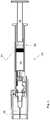
- a medicament delivery deviceas in e.g. an injector 10, is schematically shown.
- Said injectorcomprises: a container 12 arranged with a stopper 14 movable inside said container for expelling medicament through a dose delivery means 16 attached to the container when the stopper is moved by a plunger rod 18.
- a dose delivery means 16attached to the container when the stopper is moved by a plunger rod 18.
- the container 12is shown as a syringe and the dose delivery means is shown as a needle 16.
- the plunger rodis connected to a power pack (not shown) that may comprise a force means as e.g. a compression spiral spring, a torque spring or the like that is held in a loaded state or that may be loaded to a loaded state.
- a force meansas e.g. a compression spiral spring, a torque spring or the like that is held in a loaded state or that may be loaded to a loaded state.
- a damper 20At the proximal end of the plunger rod, a damper 20 according to the present invention is arranged. In the embodiment shown in Fig. 2 , it comprises a tubular sleeve 22 having opposing proximal and distal ends. Said sleeve comprises a compartment formed by a closed end wall at the proximal end of the sleeve and the proximal end of the plunger rod which is positioned in an open end at the distal end of the sleeve. The sleeve also comprises an inner diameter that is somewhat smaller than the outer diameter of the plunger rod and an outer diameter that is somewhat smaller than the inner diameter of the container.
- the compartmentcomprises a sealable and resilient pad, a fluid 24, and at least one passage 26 for expelling said fluid in an annular space 32 between said sleeve and an inner wall of said container, thereby creating a dampening force, upon movement of said plunger rod.
- the at least one passage 26is arranged at a predetermined distance from the closed end wall and around the circumferential surface of the sleeve.
- the sealable and resilient pad 28is arranged adjacent the closed end wall at the proximal end of the sleeve and comprises a resilient material and an impermeable surface 29, as will be explained below.
- the padcovers the at least one passage when it is adapted in a released position, as seen in Fig. 2 .
- the rest of the compartmentis filled with the fluid 24 e.g. a liquid with rather high viscosity, such as silicone grease, a gel or the like.
- the annular space 32may also comprises small channels created by a ribbed outer surface of the sleeve.
- the damper according to the present inventionis intended to function as follows.
- the closed end wall of the damperabuts the stopper 14.
- the stopperalso starts to move towards the proximal end of the medicament delivery device as the proximal end of the plunger rod slides into the compartment. This causes a pressure buildup in the fluid inside the compartment, which in turn causes a compression of the resilient pad 28. Any air entrapped inside the compartment will be forced out through the at least one groove 30.
- the resilient pad 28When the resilient pad 28 has been compressed to a certain extent the at least one passage 26 are freed, whereby the fluid is forced through said at least one passage out into the annular space 32. Because of the high viscosity and other suitable properties of the fluid, it will provide a dampening effect on the plunger rod as it moves because of the shear forces in the fluid.
- the size of the compartmentis preferably chosen such that it corresponds to the size of the annular gap.
Landscapes
- Health & Medical Sciences (AREA)
- Engineering & Computer Science (AREA)
- Anesthesiology (AREA)
- Biomedical Technology (AREA)
- Heart & Thoracic Surgery (AREA)
- Hematology (AREA)
- Life Sciences & Earth Sciences (AREA)
- Animal Behavior & Ethology (AREA)
- General Health & Medical Sciences (AREA)
- Public Health (AREA)
- Veterinary Medicine (AREA)
- Vascular Medicine (AREA)
- Mechanical Engineering (AREA)
- Infusion, Injection, And Reservoir Apparatuses (AREA)
Description
- The present invention relates to a device for a medicament delivery device and in particular a damping device capable of dampening the force from a plunger rod acting on a stopper of a container arranged in said medicament delivery device.
- Medicament delivery devices as e.g. injectors for injecting medicament into the tissue of patients have become widely used, and in particular since these injectors have facilitated for larger groups of patients to self-administer their drugs, due to the functionalities of the injectors.
- Examples of functionalities of the injectors are auto-penetration and/or auto-injection. A common design for auto-injection that could also be used for the preceding penetration is to have a loaded compression spiral spring acting on a plunger rod, which in turn is acting on a stopper arranged in a medicament cartridge or syringe. When the spring is released, a high force will be acting on the plunger rod and thus the stopper and the body of the syringe. Often the spring is at very high tension, particularly at the beginning of its stroke, why forces applied may be considerable. It is not uncommon that the stopper has adhered to the inner wall of the cartridge or syringe, for example due to the material properties of the stopper and long time storage. In order to handle this, the spring has to be dimensioned such that it has the necessary force to release the stopper.
- This in turn, a well as the sudden impact of the plunger rod on the stopper, increases the risk of breaking the cartridge or syringe that often is made of glass. This situation has to be avoided, because if it occurs, the patient may not be able to receive any medication, which might be fatal.
- One solution to this problem is disclosed in
WO 00/24441 - According to another embodiment, the damper is a viscous damper with a piston arranged in a cylinder in the injector head. During movement oil in the cylinder passes flow restrictions in the piston, thereby creating a dampening action.
- However, both embodiments disclosed in
WO 00/24441 - Document
GB 2 414 404 - Document
WO 031097133 GB 2 414 404 US2004/024367 is in many ways similar to D1 except that a hydraulic fluid is used instead of air.- None of the documents
GB 2 414 404 WO 031097133 EP1795218 relates to an injection device wherein a syringe is supported at its front end to avoid damage to the syringe.- It is an object of the present invention to remedy the problems of the state of the art and to provide a suitable damping means that does not take up additional space nor affect the components of the medicament delivery device during storage.
- The object is obtained with a medicament delivery device according to the features of independent claim 1.
- According to a main aspect of the invention it is characterised by a damper for a medicament delivery device, which device comprises a medicament container comprising a proximal opening with or for receiving a dose delivery means, an axially movable stopper, and an enclosure containing medicament; a plunger rod having opposing proximal and distal ends; and force means operably connected to said plunger rod for exerting a force on said plunger rod such that said plunger is moved within said container; wherein said damper comprises a tubular sleeve having opposing proximal and distal ends; said sleeve comprises a compartment formed by a closed end wall at the proximal end of the sleeve and the proximal end of the plunger rod which is positioned in an open end at the distal end of the sleeve; and wherein said compartment comprises a sealable and resilient pad, a fluid, and at least one passage for expelling said fluid in an annular space between said sleeve and an inner wall of said container, thereby creating a dampening force, upon movement of said plunger rod.
- According to another aspect of the invention, said resilient pad is arranged and designed to cover said at least one passage when said resilient pad is in a released position.
- According to a further aspect of the invention, said fluid is arranged between an impermeable surface of said resilient pad and the proximal end of the plunger rod, such that said fluid is capable of being expelled through said at least one passage when said resilient pad is compressed and thereby freeing said at least one passage due to a force applied on said compartment by said plunger rod.
- According to yet an aspect of the invention, at least one groove having a predetermined length is axially extending on the outer circumference surface of the plunger rod forming at least one passage between the distal inner circumferential surface of the sleeve and the proximal outer circumferential surface of the plunger rod for leading any air entrapped inside the compartment.
- There are a number of advantages with the present invention. Due to that the at least one passage is covered before the compartment is exposed to pressure and that the fluid may be a liquid with high viscosity and is arranged between the moving plunger rod and the resilient pad, the liquid will act as a hydraulic damper due to the shear force in the viscous liquid.
- These and other aspects of and advantages with the present invention will become apparent from the following detailed description and from the accompanying drawings.
- In the following detailed description of the invention, reference will be made to the accompanying drawings, of which
- Fig. 1
- is a detailed view in cross-section of an injector comprising the present invention,
- Fig. 2
- is a part view of an embodiment of a damper according to the present invention unaffected, and
- Fig. 3
- is the view of
Fig. 2 when the damper is being affected. - In the present application, when the term "distal part/end" is used, this refers to the part/end of the medicament delivery device, or the parts/ends of the members thereof, which under use of the medicament delivery device is located the furthest away from the medicament delivery site of the patient. Correspondingly, when the term "proximal part/end" is used, this refers to the part/end of the medicament delivery device, or the parts/ends of the members thereof, which under use of the injection device is located closest to the medicament delivery site of the patient. The present invention is to be used in a medicament delivery device comprising a
medicament container 12, aplunger rod 18 having opposing proximal and distal ends, and force means operably connected to said plunger rod for exerting a force on said plunger rod such that said plunger is moved within said container. The medicament container comprises a proximal opening with or for receiving a dose delivery means 16 means as e.g. an injection needle, an aerosol nozzle, a nebulising nozzle, a spray nozzle; an axiallymovable stopper 14, and an enclosure containing medicament. InFig. 1 , a medicament delivery device, as in e.g. aninjector 10, is schematically shown. Said injector comprises: acontainer 12 arranged with astopper 14 movable inside said container for expelling medicament through a dose delivery means 16 attached to the container when the stopper is moved by aplunger rod 18. InFig. 1 thecontainer 12 is shown as a syringe and the dose delivery means is shown as aneedle 16. - The plunger rod is connected to a power pack (not shown) that may comprise a force means as e.g. a compression spiral spring, a torque spring or the like that is held in a loaded state or that may be loaded to a loaded state. When the resilient force means is released from its loaded state, the plunger rod is displaced towards the proximal end of the medicament delivery device and thus the stopper is also displaced towards the proximal end of the medicament delivery device for expelling medicament through the dose delivery means.
- At the proximal end of the plunger rod, a
damper 20 according to the present invention is arranged. In the embodiment shown inFig. 2 , it comprises atubular sleeve 22 having opposing proximal and distal ends. Said sleeve comprises a compartment formed by a closed end wall at the proximal end of the sleeve and the proximal end of the plunger rod which is positioned in an open end at the distal end of the sleeve. The sleeve also comprises an inner diameter that is somewhat smaller than the outer diameter of the plunger rod and an outer diameter that is somewhat smaller than the inner diameter of the container. The compartment comprises a sealable and resilient pad, afluid 24, and at least onepassage 26 for expelling said fluid in anannular space 32 between said sleeve and an inner wall of said container, thereby creating a dampening force, upon movement of said plunger rod. - The at least one
passage 26 is arranged at a predetermined distance from the closed end wall and around the circumferential surface of the sleeve. The sealable andresilient pad 28 is arranged adjacent the closed end wall at the proximal end of the sleeve and comprises a resilient material and animpermeable surface 29, as will be explained below. The pad covers the at least one passage when it is adapted in a released position, as seen inFig. 2 . The rest of the compartment is filled with the fluid 24 e.g. a liquid with rather high viscosity, such as silicone grease, a gel or the like. At the proximal end of the plunger rod, at least onegroove 30 having a predetermined length is axially extending on the outer circumference surface of the plunger rod forming at least one passage between the distal inner circumferential surface of the sleeve and the proximal outer circumferential surface of the plunger rod. Theannular space 32 may also comprises small channels created by a ribbed outer surface of the sleeve. - The damper according to the present invention is intended to function as follows. The closed end wall of the damper abuts the
stopper 14. When a force is applied on theplunger rod 18 for delivering medicament, it is moved towards the proximal end of the medicament delivery device with a high force. The stopper also starts to move towards the proximal end of the medicament delivery device as the proximal end of the plunger rod slides into the compartment. This causes a pressure buildup in the fluid inside the compartment, which in turn causes a compression of theresilient pad 28. Any air entrapped inside the compartment will be forced out through the at least onegroove 30. - When the
resilient pad 28 has been compressed to a certain extent the at least onepassage 26 are freed, whereby the fluid is forced through said at least one passage out into theannular space 32. Because of the high viscosity and other suitable properties of the fluid, it will provide a dampening effect on the plunger rod as it moves because of the shear forces in the fluid. In this aspect, the size of the compartment is preferably chosen such that it corresponds to the size of the annular gap. - It is to be understood that the embodiment described above and shown in the drawings is to be regarded as a non-limiting example of the present invention and that it may be modified in many ways within the scope of the patent claims
Claims (1)
- Damper for a medicament delivery device, which device comprises- a container (12) containing medicament,- a stopper (14) arranged in said container and movable for expelling said medicament through a dose delivery means (16),- a plunger rod (18) acting on said stopper, and force means capable of exerting a force on said plunger rod,wherein said damper comprises- a tubular sleeve having opposing proximal and distal ends; said sleeve comprises a compartment (22) formed by a closed end wall at the proximal end of the sleeve and the proximal end of the plunger rod which is positioned in an open end at the distal end of the sleeve;- a fluid arranged inside said compartment (22);- at least one passage (26) formed between said compartment and an annular space (32) between said sleeve and the inner wall of said container (12);characterised in that- said fluid has a high viscosity;- a resilient and sealable pad, comprising an impermeable surface (29) arranged against said fluid, which pad is positioned in said compartment and arranged and designed to cover said at least one passage when said resilient pad is in a released position,whereby, when said force means is activated for exerting a force applied on said compartment by said plunger rod for expelling medicament, said resilient pad is compressed such that said at least one passage is freed, expelling said fluid in an annular space (32) between said plunger rod (18) and the inner wall of said container (12), thereby creating a dampening force, and
wherein at least one groove (30) having a predetermined length is axially extending on the outer circumference surface of the plunger rod forming at least one passage between the distal inner circumferential surface of the sleeve and the proximal outer circumferential surface of the plunger rod for leading any air entrapped inside the compartment.
Applications Claiming Priority (2)
| Application Number | Priority Date | Filing Date | Title |
|---|---|---|---|
| SE0801166 | 2008-05-20 | ||
| PCT/EP2009/055385WO2009141219A1 (en) | 2008-05-20 | 2009-05-05 | Device for a medicament delivery device |
Publications (2)
| Publication Number | Publication Date |
|---|---|
| EP2303365A1 EP2303365A1 (en) | 2011-04-06 |
| EP2303365B1true EP2303365B1 (en) | 2017-07-26 |
Family
ID=41134555
Family Applications (1)
| Application Number | Title | Priority Date | Filing Date |
|---|---|---|---|
| EP09749709.3ANot-in-forceEP2303365B1 (en) | 2008-05-20 | 2009-05-05 | Medicament delivery device with a damper |
Country Status (8)
| Country | Link |
|---|---|
| US (1) | US8551054B2 (en) |
| EP (1) | EP2303365B1 (en) |
| JP (1) | JP5167407B2 (en) |
| CN (1) | CN102099069B (en) |
| AU (1) | AU2009249848B2 (en) |
| DK (1) | DK2303365T3 (en) |
| ES (1) | ES2637346T3 (en) |
| WO (1) | WO2009141219A1 (en) |
Families Citing this family (28)
| Publication number | Priority date | Publication date | Assignee | Title |
|---|---|---|---|---|
| GB0913136D0 (en)* | 2009-07-28 | 2009-09-02 | Ucb Pharma Sa | Auto-injector |
| JP5807022B2 (en) | 2010-02-18 | 2015-11-10 | サノフィ−アベンティス・ドイチュラント・ゲゼルシャフト・ミット・ベシュレンクテル・ハフツング | Automatic syringe |
| DK2536452T3 (en) | 2010-02-18 | 2019-01-02 | Sanofi Aventis Deutschland | autoinjector |
| GB2483860B (en)* | 2010-09-21 | 2015-08-05 | Medical House Ltd | Injection device |
| EP2468337A1 (en)* | 2010-12-21 | 2012-06-27 | Sanofi-Aventis Deutschland GmbH | Back-end device for an auto-injector and auto-injector |
| GB2487235A (en) | 2011-01-17 | 2012-07-18 | Owen Mumford Ltd | Injection device with pneumatic damping of the drive mechanism |
| JP6257601B2 (en)* | 2012-05-31 | 2018-01-10 | ケアベイ・ヨーロッパ・リミテッドCarebay Europe Limited | Drug delivery device |
| US8652100B1 (en) | 2013-03-08 | 2014-02-18 | Teva Pharmaceutical Industries, Ltd. | Re-useable injector device for syringe |
| EP2774640B1 (en)* | 2013-03-08 | 2014-12-31 | Teva Pharmaceutical Industries, Ltd. | Re-useable injector device for syringe |
| US8591463B1 (en) | 2013-03-08 | 2013-11-26 | Teva Pharmaceutical Industries Ltd. | Re-useable injector device for syringe |
| EP2967066B1 (en) | 2013-03-15 | 2019-10-23 | Aerpio Therapeutics, Inc. | Compositions, formulations and methods for treating ocular diseases |
| US20150050277A1 (en) | 2013-03-15 | 2015-02-19 | Aerpio Therapeutics Inc. | Compositions and methods for treating ocular diseases |
| USD745664S1 (en) | 2013-11-25 | 2015-12-15 | Teva Pharmaceutical Industries, Ltd. | Injector device for a syringe |
| MX388536B (en)* | 2014-05-07 | 2025-03-20 | Amgen Inc | AUTO-INJECTOR WITH SHOCK-REDUCING ELEMENTS. |
| JP6662916B2 (en)* | 2015-07-03 | 2020-03-11 | エス・ハー・エル・メディカル・アクチェンゲゼルシャフトShl Medical Ag | Drug delivery device |
| GB2541227A (en)* | 2015-08-13 | 2017-02-15 | Owen Mumford Ltd | Injector Device |
| WO2017032590A1 (en)* | 2015-08-26 | 2017-03-02 | Carebay Europe Ltd | Medicament delivery device and assembly of electronic device and the medicament delivery device |
| EP3141275A1 (en) | 2015-09-14 | 2017-03-15 | Carebay Europe Ltd. | Medicament delivery device |
| US11116912B2 (en) | 2015-11-20 | 2021-09-14 | Shl Medical Ag | Needle shield mechanism and a medicament delivery device comprising the needle shield mechanism |
| EP3389746B1 (en) | 2015-12-14 | 2020-04-01 | SHL Medical AG | Medicament delivery device |
| GB2549750A (en) | 2016-04-27 | 2017-11-01 | Owen Mumford Ltd | Medicament delivery device |
| US11324895B2 (en) | 2016-11-01 | 2022-05-10 | Sanofi-Aventis Deutschland Gmbh | Feedback mechanism for an injection device |
| CA3040540A1 (en) | 2016-11-10 | 2018-05-17 | Oyagen, Inc. | Methods of treating and inhibiting ebola virus infection |
| MX2019015472A (en) | 2017-06-22 | 2020-02-19 | Amgen Inc | Device activation impact/shock reduction. |
| CN112292167B (en)* | 2018-04-19 | 2023-01-20 | 赛诺菲 | Force reduction in an injection device |
| US11738025B2 (en) | 2020-02-04 | 2023-08-29 | Oyagen, Inc. | Method for treating coronavirus infections |
| US20240316287A1 (en)* | 2021-01-03 | 2024-09-26 | FPrin, LLC | Damped autoinjectors |
| WO2024156428A1 (en)* | 2023-01-25 | 2024-08-02 | Shl Medical Ag | Plunger rod, sub-assembly and medicament delivery device |
Family Cites Families (10)
| Publication number | Priority date | Publication date | Assignee | Title |
|---|---|---|---|---|
| US4632672A (en)* | 1985-10-07 | 1986-12-30 | Minnesota Mining And Manufacturing Company | Self venting syringe plunger |
| GB9111600D0 (en)* | 1991-05-30 | 1991-07-24 | Owen Mumford Ltd | Improvements relating to injection devices |
| GB9504878D0 (en)* | 1995-03-10 | 1995-04-26 | Weston Medical Ltd | Viscously coupled actuator |
| US6090078A (en)* | 1997-09-30 | 2000-07-18 | Becton, Dickinson And Company | Dampening devices and methods for needle retracting safety vascular access devices |
| SE9803662D0 (en) | 1998-10-26 | 1998-10-26 | Pharmacia & Upjohn Ab | autoinjector |
| GB0211294D0 (en)* | 2002-05-17 | 2002-06-26 | Owen Mumford Ltd | Improvements relating to injection devices |
| AU2003257994A1 (en)* | 2002-07-31 | 2004-02-16 | Alza Corporation | Injection device providing automatic needle retraction |
| GB2414404B (en)* | 2004-05-28 | 2009-06-03 | Cilag Ag Int | Injection device |
| GB2414401B (en)* | 2004-05-28 | 2009-06-17 | Cilag Ag Int | Injection device |
| GB2414399B (en)* | 2004-05-28 | 2008-12-31 | Cilag Ag Int | Injection device |
- 2009
- 2009-05-05EPEP09749709.3Apatent/EP2303365B1/ennot_activeNot-in-force
- 2009-05-05DKDK09749709.3Tpatent/DK2303365T3/enactive
- 2009-05-05ESES09749709.3Tpatent/ES2637346T3/enactiveActive
- 2009-05-05AUAU2009249848Apatent/AU2009249848B2/ennot_activeCeased
- 2009-05-05CNCN2009801284135Apatent/CN102099069B/ennot_activeExpired - Fee Related
- 2009-05-05JPJP2011509912Apatent/JP5167407B2/ennot_activeExpired - Fee Related
- 2009-05-05USUS12/993,523patent/US8551054B2/enactiveActive
- 2009-05-05WOPCT/EP2009/055385patent/WO2009141219A1/enactiveApplication Filing
Non-Patent Citations (1)
| Title |
|---|
| None* |
Also Published As
| Publication number | Publication date |
|---|---|
| DK2303365T3 (en) | 2017-08-28 |
| WO2009141219A1 (en) | 2009-11-26 |
| JP2011520540A (en) | 2011-07-21 |
| AU2009249848B2 (en) | 2012-03-29 |
| CN102099069A (en) | 2011-06-15 |
| CN102099069B (en) | 2013-11-27 |
| US20110071477A1 (en) | 2011-03-24 |
| ES2637346T3 (en) | 2017-10-11 |
| AU2009249848A1 (en) | 2009-11-26 |
| JP5167407B2 (en) | 2013-03-21 |
| EP2303365A1 (en) | 2011-04-06 |
| US8551054B2 (en) | 2013-10-08 |
Similar Documents
| Publication | Publication Date | Title |
|---|---|---|
| EP2303365B1 (en) | Medicament delivery device with a damper | |
| AU2023202885B2 (en) | Single-use auto-injector | |
| EP2162170B1 (en) | One shot injector with dual springs | |
| EP1909872B1 (en) | Single use syringe with impulse reduction system | |
| EP3003440B1 (en) | Piston for use a syringe with specific dimensional ratio of a sealing structure | |
| KR100377976B1 (en) | Spring drive distributor | |
| EP2595679B1 (en) | Dual chamber passive retraction needle syringe | |
| WO2005115511A1 (en) | Injection device | |
| CN108430543A (en) | Autoinjector with needle guard trigger | |
| CN109414550B (en) | Syringe with reduced break-away force | |
| EP3400982B1 (en) | Cartridge holder for a drug delivery device | |
| US11980742B2 (en) | Drug delivery device with a hydraulic trigger mechanism | |
| CA2537056A1 (en) | Device for injecting an injectable product | |
| EP2167176B1 (en) | Syringe assembly including reuse prevention mechanism |
Legal Events
| Date | Code | Title | Description |
|---|---|---|---|
| PUAI | Public reference made under article 153(3) epc to a published international application that has entered the european phase | Free format text:ORIGINAL CODE: 0009012 | |
| 17P | Request for examination filed | Effective date:20101122 | |
| AK | Designated contracting states | Kind code of ref document:A1 Designated state(s):AT BE BG CH CY CZ DE DK EE ES FI FR GB GR HR HU IE IS IT LI LT LU LV MC MK MT NL NO PL PT RO SE SI SK TR | |
| AX | Request for extension of the european patent | Extension state:AL BA RS | |
| RIN1 | Information on inventor provided before grant (corrected) | Inventor name:GUILLLERMO, CARLOS | |
| DAX | Request for extension of the european patent (deleted) | ||
| 17Q | First examination report despatched | Effective date:20140303 | |
| REG | Reference to a national code | Ref country code:DE Ref legal event code:R079 Ref document number:602009047365 Country of ref document:DE Free format text:PREVIOUS MAIN CLASS: A61M0005200000 Ipc:A61M0011000000 | |
| RIC1 | Information provided on ipc code assigned before grant | Ipc:A61M 5/24 20060101ALI20170208BHEP Ipc:A61M 5/315 20060101ALI20170208BHEP Ipc:A61M 5/20 20060101ALI20170208BHEP Ipc:A61M 5/28 20060101ALI20170208BHEP Ipc:A61M 11/00 20060101AFI20170208BHEP | |
| GRAP | Despatch of communication of intention to grant a patent | Free format text:ORIGINAL CODE: EPIDOSNIGR1 | |
| INTG | Intention to grant announced | Effective date:20170329 | |
| GRAS | Grant fee paid | Free format text:ORIGINAL CODE: EPIDOSNIGR3 | |
| GRAA | (expected) grant | Free format text:ORIGINAL CODE: 0009210 | |
| AK | Designated contracting states | Kind code of ref document:B1 Designated state(s):AT BE BG CH CY CZ DE DK EE ES FI FR GB GR HR HU IE IS IT LI LT LU LV MC MK MT NL NO PL PT RO SE SI SK TR | |
| REG | Reference to a national code | Ref country code:GB Ref legal event code:FG4D | |
| REG | Reference to a national code | Ref country code:CH Ref legal event code:EP | |
| REG | Reference to a national code | Ref country code:AT Ref legal event code:REF Ref document number:911885 Country of ref document:AT Kind code of ref document:T Effective date:20170815 | |
| REG | Reference to a national code | Ref country code:IE Ref legal event code:FG4D | |
| REG | Reference to a national code | Ref country code:DK Ref legal event code:T3 Effective date:20170825 | |
| REG | Reference to a national code | Ref country code:SE Ref legal event code:TRGR | |
| REG | Reference to a national code | Ref country code:DE Ref legal event code:R096 Ref document number:602009047365 Country of ref document:DE | |
| REG | Reference to a national code | Ref country code:ES Ref legal event code:FG2A Ref document number:2637346 Country of ref document:ES Kind code of ref document:T3 Effective date:20171011 | |
| RAP2 | Party data changed (patent owner data changed or rights of a patent transferred) | Owner name:SHL GROUP AB | |
| REG | Reference to a national code | Ref country code:NL Ref legal event code:MP Effective date:20170726 | |
| REG | Reference to a national code | Ref country code:LT Ref legal event code:MG4D | |
| REG | Reference to a national code | Ref country code:AT Ref legal event code:MK05 Ref document number:911885 Country of ref document:AT Kind code of ref document:T Effective date:20170726 | |
| PG25 | Lapsed in a contracting state [announced via postgrant information from national office to epo] | Ref country code:AT Free format text:LAPSE BECAUSE OF FAILURE TO SUBMIT A TRANSLATION OF THE DESCRIPTION OR TO PAY THE FEE WITHIN THE PRESCRIBED TIME-LIMIT Effective date:20170726 Ref country code:NL Free format text:LAPSE BECAUSE OF FAILURE TO SUBMIT A TRANSLATION OF THE DESCRIPTION OR TO PAY THE FEE WITHIN THE PRESCRIBED TIME-LIMIT Effective date:20170726 Ref country code:FI Free format text:LAPSE BECAUSE OF FAILURE TO SUBMIT A TRANSLATION OF THE DESCRIPTION OR TO PAY THE FEE WITHIN THE PRESCRIBED TIME-LIMIT Effective date:20170726 Ref country code:NO Free format text:LAPSE BECAUSE OF FAILURE TO SUBMIT A TRANSLATION OF THE DESCRIPTION OR TO PAY THE FEE WITHIN THE PRESCRIBED TIME-LIMIT Effective date:20171026 Ref country code:HR Free format text:LAPSE BECAUSE OF FAILURE TO SUBMIT A TRANSLATION OF THE DESCRIPTION OR TO PAY THE FEE WITHIN THE PRESCRIBED TIME-LIMIT Effective date:20170726 Ref country code:LT Free format text:LAPSE BECAUSE OF FAILURE TO SUBMIT A TRANSLATION OF THE DESCRIPTION OR TO PAY THE FEE WITHIN THE PRESCRIBED TIME-LIMIT Effective date:20170726 | |
| PG25 | Lapsed in a contracting state [announced via postgrant information from national office to epo] | Ref country code:PL Free format text:LAPSE BECAUSE OF FAILURE TO SUBMIT A TRANSLATION OF THE DESCRIPTION OR TO PAY THE FEE WITHIN THE PRESCRIBED TIME-LIMIT Effective date:20170726 Ref country code:GR Free format text:LAPSE BECAUSE OF FAILURE TO SUBMIT A TRANSLATION OF THE DESCRIPTION OR TO PAY THE FEE WITHIN THE PRESCRIBED TIME-LIMIT Effective date:20171027 Ref country code:IS Free format text:LAPSE BECAUSE OF FAILURE TO SUBMIT A TRANSLATION OF THE DESCRIPTION OR TO PAY THE FEE WITHIN THE PRESCRIBED TIME-LIMIT Effective date:20171126 Ref country code:LV Free format text:LAPSE BECAUSE OF FAILURE TO SUBMIT A TRANSLATION OF THE DESCRIPTION OR TO PAY THE FEE WITHIN THE PRESCRIBED TIME-LIMIT Effective date:20170726 Ref country code:BG Free format text:LAPSE BECAUSE OF FAILURE TO SUBMIT A TRANSLATION OF THE DESCRIPTION OR TO PAY THE FEE WITHIN THE PRESCRIBED TIME-LIMIT Effective date:20171026 | |
| PG25 | Lapsed in a contracting state [announced via postgrant information from national office to epo] | Ref country code:RO Free format text:LAPSE BECAUSE OF FAILURE TO SUBMIT A TRANSLATION OF THE DESCRIPTION OR TO PAY THE FEE WITHIN THE PRESCRIBED TIME-LIMIT Effective date:20170726 Ref country code:CZ Free format text:LAPSE BECAUSE OF FAILURE TO SUBMIT A TRANSLATION OF THE DESCRIPTION OR TO PAY THE FEE WITHIN THE PRESCRIBED TIME-LIMIT Effective date:20170726 | |
| REG | Reference to a national code | Ref country code:DE Ref legal event code:R097 Ref document number:602009047365 Country of ref document:DE | |
| REG | Reference to a national code | Ref country code:FR Ref legal event code:PLFP Year of fee payment:10 | |
| PG25 | Lapsed in a contracting state [announced via postgrant information from national office to epo] | Ref country code:SK Free format text:LAPSE BECAUSE OF FAILURE TO SUBMIT A TRANSLATION OF THE DESCRIPTION OR TO PAY THE FEE WITHIN THE PRESCRIBED TIME-LIMIT Effective date:20170726 Ref country code:EE Free format text:LAPSE BECAUSE OF FAILURE TO SUBMIT A TRANSLATION OF THE DESCRIPTION OR TO PAY THE FEE WITHIN THE PRESCRIBED TIME-LIMIT Effective date:20170726 Ref country code:IT Free format text:LAPSE BECAUSE OF FAILURE TO SUBMIT A TRANSLATION OF THE DESCRIPTION OR TO PAY THE FEE WITHIN THE PRESCRIBED TIME-LIMIT Effective date:20170726 | |
| PLBE | No opposition filed within time limit | Free format text:ORIGINAL CODE: 0009261 | |
| STAA | Information on the status of an ep patent application or granted ep patent | Free format text:STATUS: NO OPPOSITION FILED WITHIN TIME LIMIT | |
| 26N | No opposition filed | Effective date:20180430 | |
| PGFP | Annual fee paid to national office [announced via postgrant information from national office to epo] | Ref country code:DK Payment date:20180514 Year of fee payment:10 Ref country code:CH Payment date:20180516 Year of fee payment:10 | |
| PG25 | Lapsed in a contracting state [announced via postgrant information from national office to epo] | Ref country code:SI Free format text:LAPSE BECAUSE OF FAILURE TO SUBMIT A TRANSLATION OF THE DESCRIPTION OR TO PAY THE FEE WITHIN THE PRESCRIBED TIME-LIMIT Effective date:20170726 | |
| PGFP | Annual fee paid to national office [announced via postgrant information from national office to epo] | Ref country code:SE Payment date:20180511 Year of fee payment:10 | |
| REG | Reference to a national code | Ref country code:BE Ref legal event code:MM Effective date:20180531 | |
| PG25 | Lapsed in a contracting state [announced via postgrant information from national office to epo] | Ref country code:MC Free format text:LAPSE BECAUSE OF FAILURE TO SUBMIT A TRANSLATION OF THE DESCRIPTION OR TO PAY THE FEE WITHIN THE PRESCRIBED TIME-LIMIT Effective date:20170726 | |
| REG | Reference to a national code | Ref country code:IE Ref legal event code:MM4A | |
| PG25 | Lapsed in a contracting state [announced via postgrant information from national office to epo] | Ref country code:LU Free format text:LAPSE BECAUSE OF NON-PAYMENT OF DUE FEES Effective date:20180505 | |
| PG25 | Lapsed in a contracting state [announced via postgrant information from national office to epo] | Ref country code:IE Free format text:LAPSE BECAUSE OF NON-PAYMENT OF DUE FEES Effective date:20180505 | |
| PG25 | Lapsed in a contracting state [announced via postgrant information from national office to epo] | Ref country code:BE Free format text:LAPSE BECAUSE OF NON-PAYMENT OF DUE FEES Effective date:20180531 | |
| REG | Reference to a national code | Ref country code:DE Ref legal event code:R081 Ref document number:602009047365 Country of ref document:DE Owner name:SHL MEDICAL AG, CH Free format text:FORMER OWNER: SHL GROUP AB, NACKA STRAND, SE | |
| REG | Reference to a national code | Ref country code:GB Ref legal event code:732E Free format text:REGISTERED BETWEEN 20190801 AND 20190807 | |
| REG | Reference to a national code | Ref country code:ES Ref legal event code:FD2A Effective date:20190913 | |
| PG25 | Lapsed in a contracting state [announced via postgrant information from national office to epo] | Ref country code:ES Free format text:LAPSE BECAUSE OF NON-PAYMENT OF DUE FEES Effective date:20180506 | |
| REG | Reference to a national code | Ref country code:CH Ref legal event code:PL | |
| REG | Reference to a national code | Ref country code:DK Ref legal event code:EBP Effective date:20190531 | |
| PG25 | Lapsed in a contracting state [announced via postgrant information from national office to epo] | Ref country code:MT Free format text:LAPSE BECAUSE OF NON-PAYMENT OF DUE FEES Effective date:20180505 Ref country code:SE Free format text:LAPSE BECAUSE OF NON-PAYMENT OF DUE FEES Effective date:20190506 Ref country code:CH Free format text:LAPSE BECAUSE OF NON-PAYMENT OF DUE FEES Effective date:20190531 Ref country code:LI Free format text:LAPSE BECAUSE OF NON-PAYMENT OF DUE FEES Effective date:20190531 | |
| PG25 | Lapsed in a contracting state [announced via postgrant information from national office to epo] | Ref country code:TR Free format text:LAPSE BECAUSE OF FAILURE TO SUBMIT A TRANSLATION OF THE DESCRIPTION OR TO PAY THE FEE WITHIN THE PRESCRIBED TIME-LIMIT Effective date:20170726 | |
| PG25 | Lapsed in a contracting state [announced via postgrant information from national office to epo] | Ref country code:DK Free format text:LAPSE BECAUSE OF NON-PAYMENT OF DUE FEES Effective date:20190531 | |
| REG | Reference to a national code | Ref country code:SE Ref legal event code:EUG | |
| PG25 | Lapsed in a contracting state [announced via postgrant information from national office to epo] | Ref country code:PT Free format text:LAPSE BECAUSE OF FAILURE TO SUBMIT A TRANSLATION OF THE DESCRIPTION OR TO PAY THE FEE WITHIN THE PRESCRIBED TIME-LIMIT Effective date:20170726 Ref country code:HU Free format text:LAPSE BECAUSE OF FAILURE TO SUBMIT A TRANSLATION OF THE DESCRIPTION OR TO PAY THE FEE WITHIN THE PRESCRIBED TIME-LIMIT; INVALID AB INITIO Effective date:20090505 | |
| PG25 | Lapsed in a contracting state [announced via postgrant information from national office to epo] | Ref country code:CY Free format text:LAPSE BECAUSE OF FAILURE TO SUBMIT A TRANSLATION OF THE DESCRIPTION OR TO PAY THE FEE WITHIN THE PRESCRIBED TIME-LIMIT Effective date:20170726 Ref country code:MK Free format text:LAPSE BECAUSE OF NON-PAYMENT OF DUE FEES Effective date:20170726 | |
| PGFP | Annual fee paid to national office [announced via postgrant information from national office to epo] | Ref country code:GB Payment date:20220401 Year of fee payment:14 Ref country code:FR Payment date:20220422 Year of fee payment:14 Ref country code:DE Payment date:20220406 Year of fee payment:14 | |
| REG | Reference to a national code | Ref country code:DE Ref legal event code:R119 Ref document number:602009047365 Country of ref document:DE | |
| GBPC | Gb: european patent ceased through non-payment of renewal fee | Effective date:20230505 | |
| PG25 | Lapsed in a contracting state [announced via postgrant information from national office to epo] | Ref country code:DE Free format text:LAPSE BECAUSE OF NON-PAYMENT OF DUE FEES Effective date:20231201 Ref country code:GB Free format text:LAPSE BECAUSE OF NON-PAYMENT OF DUE FEES Effective date:20230505 | |
| PG25 | Lapsed in a contracting state [announced via postgrant information from national office to epo] | Ref country code:FR Free format text:LAPSE BECAUSE OF NON-PAYMENT OF DUE FEES Effective date:20230531 |